Product Specification 1 / 24 LB070W02 Liquid Crystal Display Ver. 1.1 May. 06, 2003 C.S. KYOUNG /G.Manager Title 7.0”W (480 X RGB X 234) TFT-LCD BUYER MODEL SIGNATURE DATE / / / Product Engineering Dept. LG. Philips LCD Co., Ltd APPROVED BY DATE REVIEWED BY PREPARED BY J.D. KIM /Manager C.S. SO /Engineer A5 SUFFIX LB070W02 MODEL LG.Philips LCD Co., Ltd. SUPPLIER SPECIFICATION FOR APPROVAL ( ● ) Preliminary Specification ( ) Final Specification

Welcome message from author
This document is posted to help you gain knowledge. Please leave a comment to let me know what you think about it! Share it to your friends and learn new things together.
Transcript
Product Specification
1 / 24
LB070W02Liquid Crystal Display
Ver. 1.1 May. 06, 2003
C.S. KYOUNG /G.Manager
Title 7.0”W (480 X RGB X 234) TFT-LCD
BUYER
MODEL
SIGNATURE DATE
/
/
/
Product Engineering Dept.LG. Philips LCD Co., Ltd
APPROVED BY DATE
REVIEWED BY
PREPARED BY
J.D. KIM /Manager
C.S. SO /Engineer
A5SUFFIX
LB070W02MODEL
LG.Philips LCD Co., Ltd.SUPPLIER
SPECIFICATIONFOR
APPROVAL
( ● ) Preliminary Specification( ) Final Specification
Product Specification
2 / 24
LB070W02Liquid Crystal Display
Ver. 1.1 May. 06, 2003
PREL
IMIN
ARY SP
ECIFI
CATION
CONTENTS
Record of Revisions0
Precautions12
Packing11
International Standards10
Reliability Test9
Mechanical Characteristics8
Electro-optical Characteristics7
Electrical Characteristics6
Absolute Maximum Ratings5
Interface (Input Terminal)4
General Specification3
Features2
Summary1
PAGEITEMNO.
Product Specification
3 / 24
LB070W02Liquid Crystal Display
Ver. 1.1 May. 06, 2003
PREL
IMIN
ARY SP
ECIFI
CATION
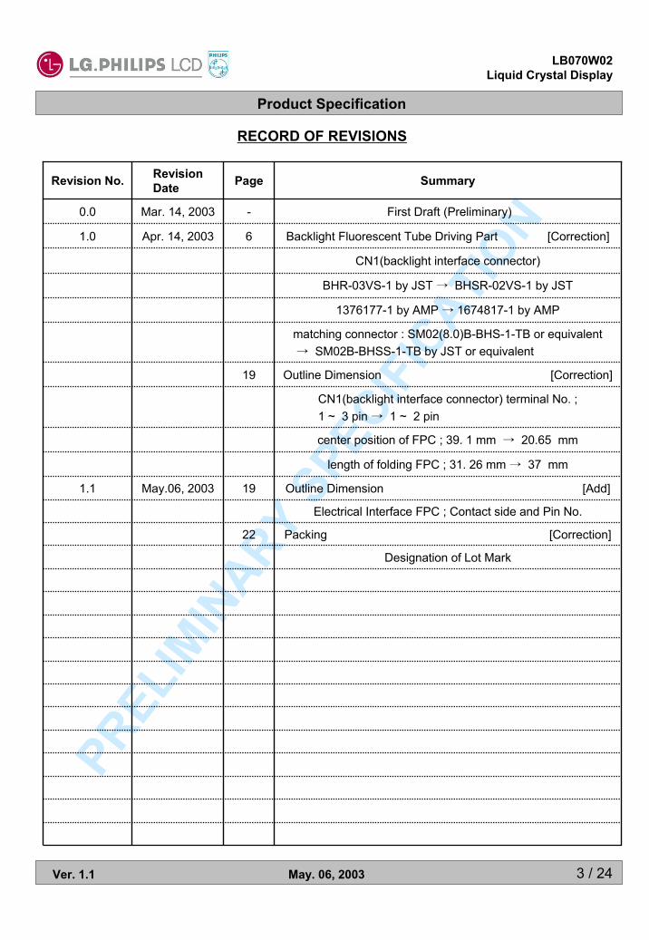
Outline Dimension [Add]19May.06, 20031.1
Backlight Fluorescent Tube Driving Part [Correction]6Apr. 14, 20031.0
CN1(backlight interface connector)
BHR-03VS-1 by JST → BHSR-02VS-1 by JST
1376177-1 by AMP → 1674817-1 by AMP
matching connector : SM02(8.0)B-BHS-1-TB or equivalent → SM02B-BHSS-1-TB by JST or equivalent
Outline Dimension [Correction]19
CN1(backlight interface connector) terminal No. ;1 ~ 3 pin → 1 ~ 2 pin
center position of FPC ; 39. 1 mm → 20.65 mm
length of folding FPC ; 31. 26 mm → 37 mm
First Draft (Preliminary)-Mar. 14, 20030.0
Designation of Lot Mark
Packing [Correction]22
Electrical Interface FPC ; Contact side and Pin No.
SummaryPageRevision DateRevision No.
RECORD OF REVISIONS
Product Specification
4 / 24
LB070W02Liquid Crystal Display
Ver. 1.1 May. 06, 2003
PREL
IMIN
ARY SP
ECIFI
CATION
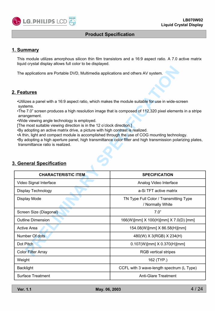
1. Summary
3. General Specification
This module utilizes amorphous silicon thin film transistors and a 16:9 aspect ratio. A 7.0 active matrix liquid crystal display allows full color to be displayed.
The applications are Portable DVD, Multimedia applications and others AV system.
Analog Video InterfaceVideo Signal Interface
7.0”Screen Size (Diagonal)
0.107(W)[mm] X 0.370(H)[mm]Dot Pitch
Anti-Glare TreatmentSurface Treatment
CCFL with 3 wave-length spectrum (L Type)Backlight
162 (TYP.)Weight
RGB vertical stripesColor Filter Array
480(W) X 3(RGB) X 234(H)Number Of dots
154.08(W)[mm] X 86.58(H)[mm]Active Area
166(W)[mm] X 100(H)[mm] X 7.0(D) [mm]Outline Dimension
TN Type Full Color / Transmitting Type/ Normally White
Display Mode
a-Si TFT active matrixDisplay Technology
SPECIFICATIONCHARACTERISTIC ITEM
2. Features
•Utilizes a panel with a 16:9 aspect ratio, which makes the module suitable for use in wide-screen systems.•The 7.0” screen produces a high resolution image that is composed of 112,320 pixel elements in a stripearrangement.•Wide viewing angle technology is employed. [The most suitable viewing direction is in the 12 o’clock direction.]•By adopting an active matrix drive, a picture with high contrast is realized.•A thin, light and compact module is accomplished through the use of COG mounting technology.•By adopting a high aperture panel, high transmittance color filter and high transmission polarizing plates, transmittance ratio is realized.
Product Specification
5 / 24
LB070W02Liquid Crystal Display
Ver. 1.1 May. 06, 2003
PREL
IMIN
ARY SP
ECIFI
CATION
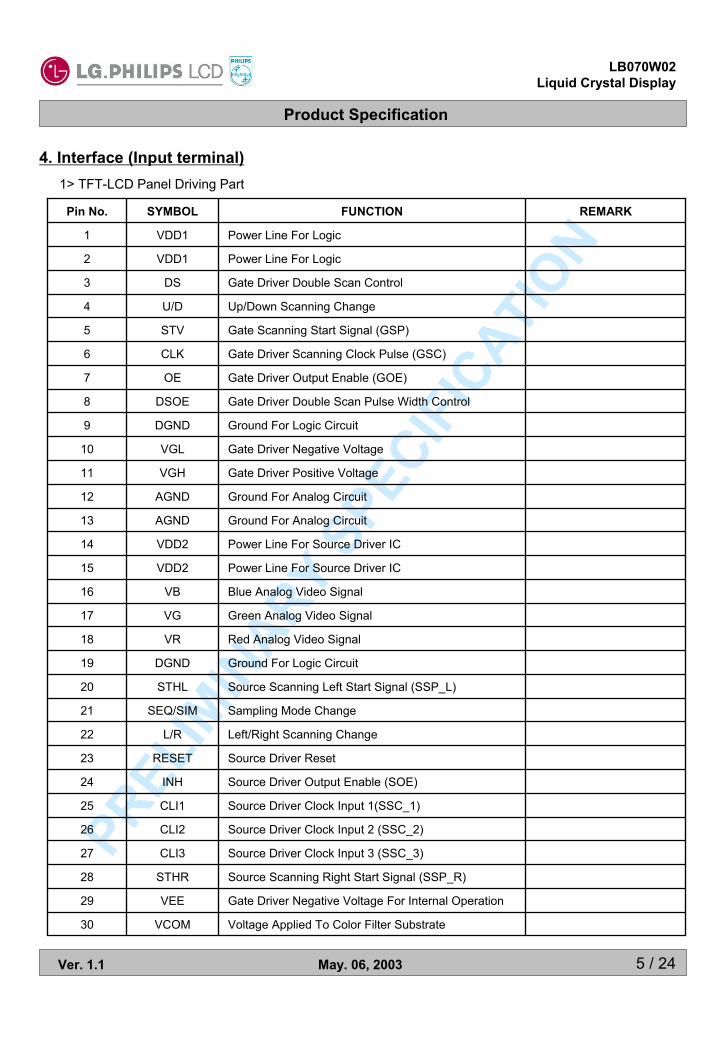
Source Driver Output Enable (SOE)INH24
Source Driver Clock Input 1(SSC_1)CLI125
Source Driver Clock Input 2 (SSC_2)CLI226
Source Driver Clock Input 3 (SSC_3)CLI327
Source Scanning Right Start Signal (SSP_R)STHR28
Gate Driver Negative Voltage For Internal OperationVEE29
Voltage Applied To Color Filter SubstrateVCOM30
Source Driver ResetRESET23
Left/Right Scanning ChangeL/R22
Sampling Mode ChangeSEQ/SIM21
Source Scanning Left Start Signal (SSP_L)STHL20
Ground For Logic CircuitDGND19
Red Analog Video SignalVR18
Green Analog Video SignalVG17
Blue Analog Video SignalVB16
Power Line For Source Driver ICVDD215
Power Line For Source Driver ICVDD214
Ground For Analog CircuitAGND13
Ground For Analog CircuitAGND12
Gate Driver Positive VoltageVGH11
Gate Driver Negative VoltageVGL10
Ground For Logic CircuitDGND9
Gate Driver Double Scan Pulse Width ControlDSOE8
Gate Driver Output Enable (GOE)OE7
Gate Driver Scanning Clock Pulse (GSC)CLK6
Gate Scanning Start Signal (GSP)STV5
Up/Down Scanning ChangeU/D4
Gate Driver Double Scan ControlDS3
Power Line For LogicVDD12
Power Line For LogicVDD11
REMARKFUNCTIONSYMBOLPin No.
4. Interface (Input terminal)1> TFT-LCD Panel Driving Part
Product Specification
6 / 24
LB070W02Liquid Crystal Display
Ver. 1.1 May. 06, 2003
PREL
IMIN
ARY SP
ECIFI
CATION
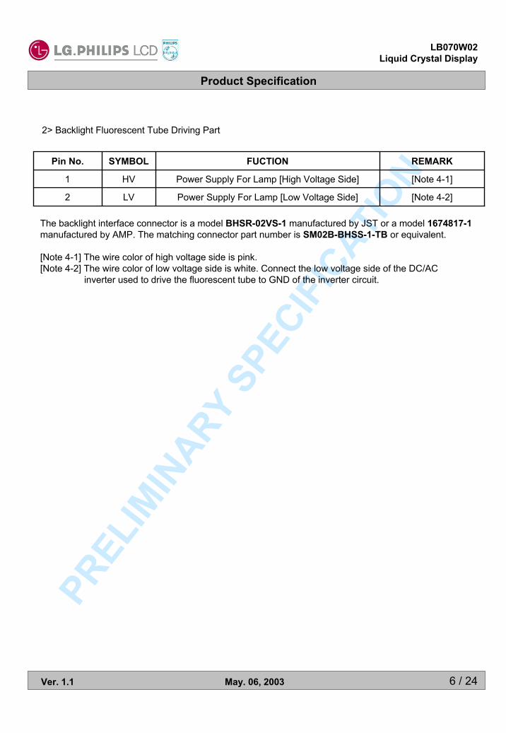
The backlight interface connector is a model BHSR-02VS-1 manufactured by JST or a model 1674817-1manufactured by AMP. The matching connector part number is SM02B-BHSS-1-TB or equivalent.
[Note 4-1] The wire color of high voltage side is pink.[Note 4-2] The wire color of low voltage side is white. Connect the low voltage side of the DC/AC
inverter used to drive the fluorescent tube to GND of the inverter circuit.
2> Backlight Fluorescent Tube Driving Part
[Note 4-2]Power Supply For Lamp [Low Voltage Side]LV2
[Note 4-1]
REMARK
Power Supply For Lamp [High Voltage Side]HV1
FUCTIONSYMBOLPin No.
Product Specification
7 / 24
LB070W02Liquid Crystal Display
Ver. 1.1 May. 06, 2003
PREL
IMIN
ARY SP
ECIFI
CATION
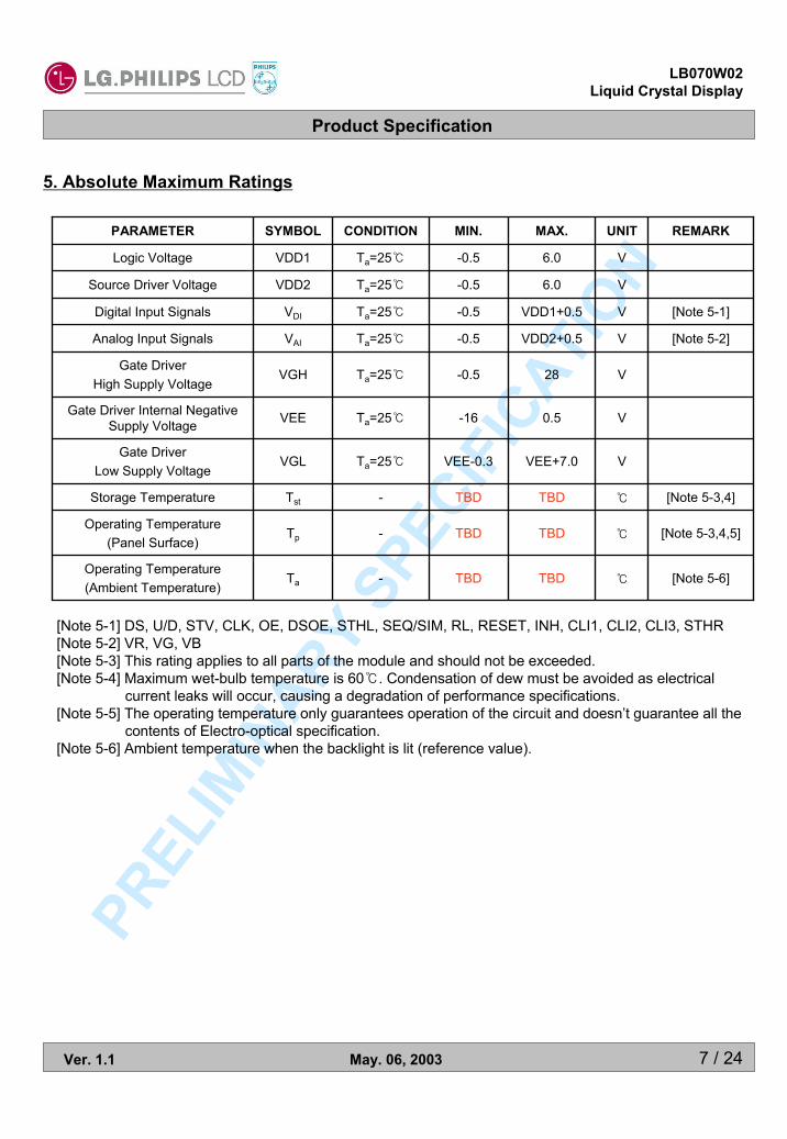
5. Absolute Maximum Ratings
[Note 5-6]℃TBDTBD-TaOperating Temperature(Ambient Temperature)
[Note 5-3,4,5]℃TBDTBD-TpOperating Temperature
(Panel Surface)
[Note 5-3,4]℃TBDTBD-TstStorage Temperature
VVEE+7.0VEE-0.3Ta=25℃VGLGate Driver
Low Supply Voltage
V0.5-16Ta=25℃VEEGate Driver Internal Negative Supply Voltage
V28-0.5Ta=25℃VGHGate Driver
High Supply Voltage
[Note 5-2]VVDD2+0.5-0.5Ta=25℃VAIAnalog Input Signals
[Note 5-1]VVDD1+0.5-0.5Ta=25℃VDIDigital Input Signals
V6.0-0.5Ta=25℃VDD2Source Driver Voltage
V6.0-0.5Ta=25℃VDD1Logic Voltage
REMARKUNITMAX.MIN.CONDITIONSYMBOLPARAMETER
[Note 5-1] DS, U/D, STV, CLK, OE, DSOE, STHL, SEQ/SIM, RL, RESET, INH, CLI1, CLI2, CLI3, STHR[Note 5-2] VR, VG, VB[Note 5-3] This rating applies to all parts of the module and should not be exceeded.[Note 5-4] Maximum wet-bulb temperature is 60℃. Condensation of dew must be avoided as electrical
current leaks will occur, causing a degradation of performance specifications.[Note 5-5] The operating temperature only guarantees operation of the circuit and doesn’t guarantee all the
contents of Electro-optical specification.[Note 5-6] Ambient temperature when the backlight is lit (reference value).

Product Specification
8 / 24
LB070W02Liquid Crystal Display
Ver. 1.1 May. 06, 2003
PREL
IMIN
ARY SP
ECIFI
CATION
6. Electrical Characteristics
1> Recommended Operating Conditions
◈ TFT-LCD Panel Driving SectionTa=25℃
VTBDTBDTBDVGLDCDC
Low SupplyVoltage
V5.55.04.5VDD2Source Driver Supply Voltage
Low Level
High Level
VTBDTBDTBDVCOMDCDC
Component
Color FilterSubstrate Voltage
VP-PTBDTBDTBDVCOMACAC
Component
VVDD2-0.2-VSS+0.2VVIAnalog Video Signal Input Voltage
VTBDTBDTBDVEE
VP-PTBDTBDTBDVGLACAC
Internal NegativeSupply Voltage
VTBDTBDTBDVGHHigh Supply Voltage
Gate Driver
V0.2VDD1-0VIL
VVDD1-0.8VDD1VIHDigital Input Signal
V3.63.33.0VDD1Logic Supply Voltage
REMARKUNITMAX.TYP.MIN.SYMBOLPARAMETER
***** Cautionary Matter : When applying or disconnecting power, please be sure that such action issimultaneously carried out for all power supplies. In addition, apply input signals only after powerhas been turned on.
-Source Driver : Turn on power to VDD1, logic input, VDD2, and video signal input in this order.Turn off power in the reverse order.
-Gate Driver : Turn on power to VDD1, VEE, VGL, VGH, and logic input in this order. Turn off power in the reverse order.
Product Specification
9 / 24
LB070W02Liquid Crystal Display
Ver. 1.1 May. 06, 2003
PREL
IMIN
ARY SP
ECIFI
CATION
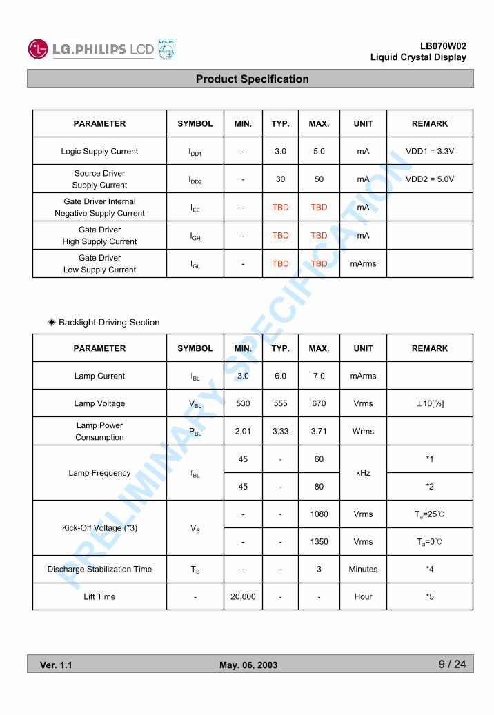
◈ Backlight Driving Section
*160-45
*4Minutes3--TSDischarge Stabilization Time
*5Hour--20,000-Lift Time
Ta=0℃Vrms1350--
Ta=25℃Vrms1080--VSKick-Off Voltage (*3)
*2kHz
80-45fBLLamp Frequency
Wrms3.713.332.01PBLLamp PowerConsumption
±10[%]Vrms670555530VBLLamp Voltage
mArms7.06.03.0IBLLamp Current
REMARKUNITMAX.TYP.MIN.SYMBOLPARAMETER
VDD1 = 3.3VmA5.03.0-IDD1Logic Supply Current
VDD2 = 5.0VmA5030-IDD2Source Driver
Supply Current
mATBDTBD-IGHGate Driver
High Supply Current
mArmsTBDTBD-IGLGate Driver
Low Supply Current
mATBDTBD-IEEGate Driver Internal
Negative Supply Current
REMARKUNITMAX.TYP.MIN.SYMBOLPARAMETER

Product Specification
10 / 24
LB070W02Liquid Crystal Display
Ver. 1.1 May. 06, 2003
PREL
IMIN
ARY SP
ECIFI
CATION
* 1 : The frequency range can be kept within ±10% range of electrical and optical characteristics. * 2 : The frequency range will not affect to lamp life and reliability characteristics.
(The lamp frequency should be selected as different as possible from display horizontalsynchronous signal (Including harmonic frequency of this scanning frequency) to avoid “Beat”interference which may be observed on the screen as horizontal stripes like moving wave.This phenomenon is caused by interference between lamp (CCFL) lighting frequency andLCD horizontal synchronous signal.)
* 3 : The “MAX” of “Kick-Off Voltage” means the minimum voltage for inverter to turn on the CCFLnormally in the LCD module. However this isn’t the values that we can assure stability ofstarting lamp on condition that the module is installed in your set.It is careful that “Kick-Off Voltage” is changed by an increase of stray capacitance in your set,inverter method, value of ballast capacitor in your inverter and so on.Especially, the value of “Kick-Off Voltage” is higher in low temperature condition than innormal temperature condition, because impedance of CCFL is increased.
* 4 : The time needed to achieve not less than 95%brightness of the center part of lamp. The brightness of the lamp after lighted for 5 minutes is defined as 100%.
* 5 : “Life time” is defined as the lamp brightness decrease to 50% original brightness at IBL=TYP;continuous lighting, Ta=25℃.
Inverter should be designed to be subject to the conditions below;
A. Both the area and the peak under the positive and negative cycles of the waveform of the lampcurrent and lamp voltage should be symmetric.(The symmetric ratio should be larger than 90%)
B. There should not be any spikes in the waveform.C. The waveform should be close to a sine wave whenever possible.D. Lamp current should not exceed the “MAX” value under the “Operating Temperature” (it is
prohibited to exceed the “MAX” value even if it is operated in the non-guaranteed temperature).When lamp current exceed the maximum value for a long time, it may cause a smoking andignition. Therefore, it is recommended that the inverter have the current limited circuit that isused as a protection circuit and/or the lamp current-controlled inverter.
Product Specification
11 / 24
LB070W02Liquid Crystal Display
Ver. 1.1 May. 06, 2003
PREL
IMIN
ARY SP
ECIFI
CATION
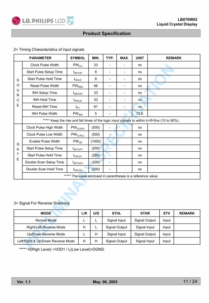
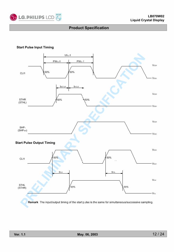
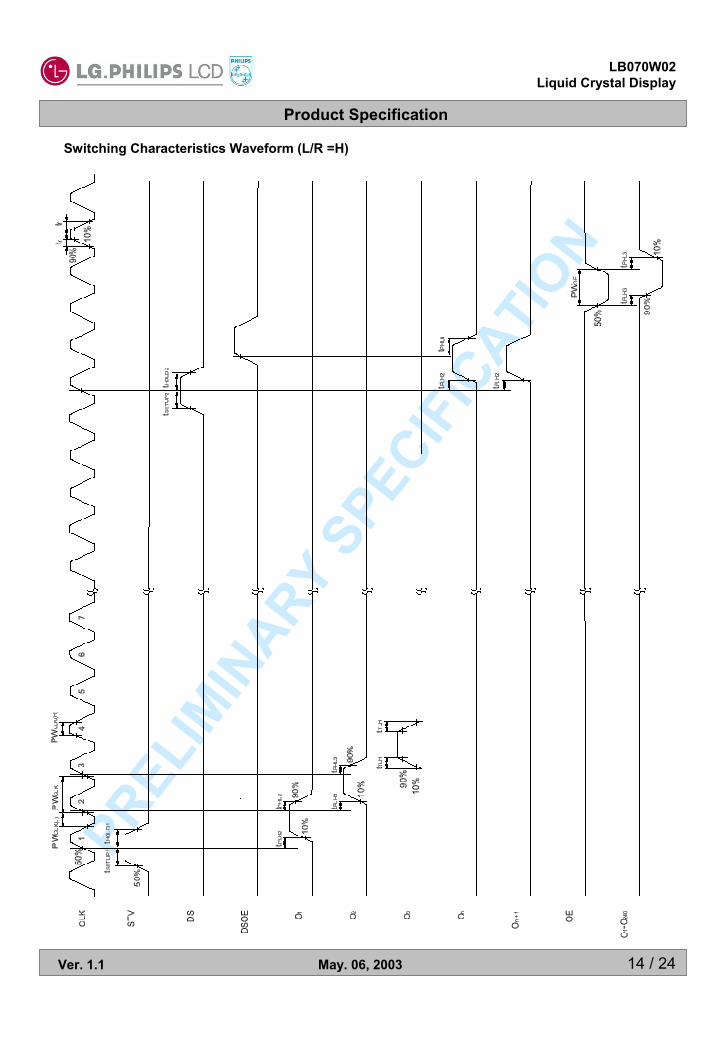
2> Timing Characteristics of input signals
***** The value enclosed in parentheses is a reference value.
ns-(200)tHOLD2Double Scan Hold Time
ns-(200)tSETUP2Double Scan Setup Time
ns-(200)tHOLD1Start Pulse Hold Time
ns-(200)tSETUP1Start Pulse Setup Time
ns-(1000)PWOEEnable Pulse Width
ns-(500)PWCLK(L)Clock Pulse Low Width
ns-(500)PWCLK(H)Clock Pulse High Width
GATE
***** Keep the rise and fall times of the logic input signals to within tr=tf=5ns (10 to 90%).
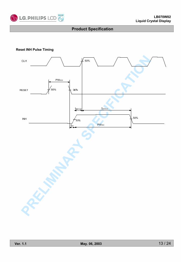
CLK--5PWINHINH Pulse Width
ns--81tR-IReset-INH Time
ns--33tIHOLDINH Hold Time
ns--33tISETUPINH Setup Time
ns--66PWRESReset Pulse Width
ns--8tHOLDStart Pulse Hold Time
ns--8tSETUPStart Pulse Setup Time
ns--33PWCLIClock Pulse Width
SOURCE
REMARKUNITMAX.TYP.MIN.SYMBOLPARAMETER
3> Signal For Reverse Scanning
Input
Input
Input
Input
STV
H
H
L
L
U/D
Signal Output
Signal Input
Signal Output
Signal Input
STHL
Signal Input
Signal Output
Signal Input
Signal Output
STHR
HLeft/Right & Up/Down Reverse Mode
LUp/Down Reverse Mode
HRight/Left Reverse Mode
LNormal Mode
REMARKL/RMODE
***** H(High Level) =VDD1 / L(Low Level)=DGND
Product Specification
12 / 24
LB070W02Liquid Crystal Display
Ver. 1.1 May. 06, 2003
PREL
IMIN
ARY SP
ECIFI
CATION
Start Pulse Input Timing
Start Pulse Output Timing
Product Specification
13 / 24
LB070W02Liquid Crystal Display
Ver. 1.1 May. 06, 2003
PREL
IMIN
ARY SP
ECIFI
CATION
Reset INH Pulse Timing
Product Specification
14 / 24
LB070W02Liquid Crystal Display
Ver. 1.1 May. 06, 2003
PREL
IMIN
ARY SP
ECIFI
CATION
Switching Characteristics Waveform (L/R =H)

Product Specification
15 / 24
LB070W02Liquid Crystal Display
Ver. 1.1 May. 06, 2003
PREL
IMIN
ARY SP
ECIFI
CATION
7. Electro-optical Characteristics
ms
ms
。
。
。
。
-
-
-
cd/m2
UNIT
-20-τdFall[Note 7-4]
-5-Θ=0。
τrRiseResponseTime
--40Θdφ=270°
--50Θuφ=90°
--60Θrφ=0° [Note 7-2][Note 7-3]
--60
CR≥10
Θlφ=180°
ViewingAngle
0.3440.3290.314Wy
[Note 7-1]0.3280.3130.298
IBL=6mArmsWxWhite Color
Chromaticity
[Note 7-2]-400TBDOptimalCRContrast Ratio
[Note 7-1]-(350)TBDIBL=6mArmsYLuminance
REMARKMAX.TYP.MIN.CONDITIONSYMBOLPARAMETER
Ta=25℃
Photo detectorField = 1 °
Center
LCD Module
Optical Stage(x,y)
; Pritchard 880 orequivalent
500mm
Measuring Condition ;-Measuring surroundings : Dark Room-Measuring temperature : Ta=25℃-Adjust operating voltage to get optimum contrast at the center of the display.-Measured value at the center point of LCD panel after more than 30 minutes while backlight turning on.
Product Specification
16 / 24
LB070W02Liquid Crystal Display
Ver. 1.1 May. 06, 2003
PREL
IMIN
ARY SP
ECIFI
CATION
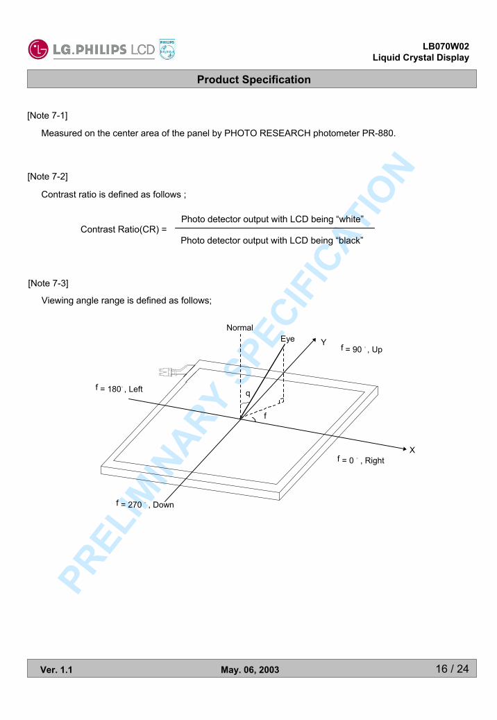
[Note 7-1]
Measured on the center area of the panel by PHOTO RESEARCH photometer PR-880.
[Note 7-2]
Contrast ratio is defined as follows ;
Contrast Ratio(CR) =Photo detector output with LCD being “white”
Photo detector output with LCD being “black”
Normal
YEye
f
q
f = 0 。, Right
f = 180。, Left
f = 270 。, Down
f = 90 。, Up
X
[Note 7-3]
Viewing angle range is defined as follows;
Product Specification
17 / 24
LB070W02Liquid Crystal Display
Ver. 1.1 May. 06, 2003
PREL
IMIN
ARY SP
ECIFI
CATION
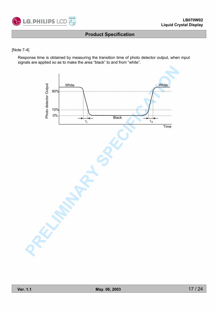
[Note 7-4]
Response time is obtained by measuring the transition time of photo detector output, when input signals are applied so as to make the area “black” to and from “white”.
0%10%
90%
White White
Black
Time
Phot
o de
tect
or O
utpu
t
τr τd

Product Specification
18 / 24
LB070W02Liquid Crystal Display
Ver. 1.1 May. 06, 2003
PREL
IMIN
ARY SP
ECIFI
CATION
8. Mechanical Characteristics
-
g
mm
mm
mm
mm
mm
mm
mm
UNIT
162 (TYP.)
86.58
154.08
89.6
157.2
7.0 (TYP.)
100
166
Anti-Glare TreatmentSurface Treatment
Weight
Height
WideActive Display Area
Height
WideBezel Area
Depth
Height
Wide
Outline Dimension
REMARKSPECIFICATIONPARAMETER
Product Specification
19 / 24
LB070W02Liquid Crystal Display
Ver. 1.1 May. 06, 2003
PREL
IMIN
ARY SP
ECIFI
CATION
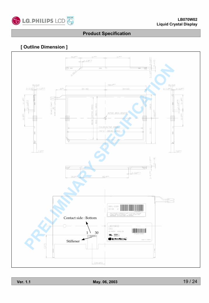
[ Outline Dimension ]
Contact side : Bottom
Stiffener
1 30
Product Specification
20 / 24
LB070W02Liquid Crystal Display
Ver. 1.1 May. 06, 2003
PREL
IMIN
ARY SP
ECIFI
CATION
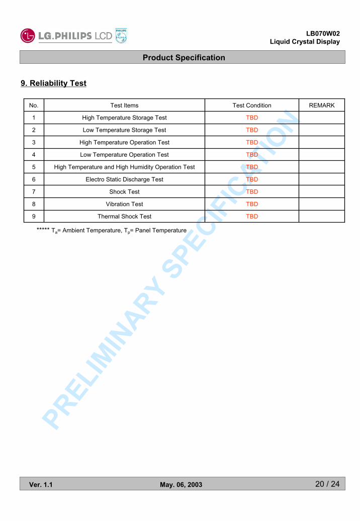
9. Reliability Test
TBD
TBD
TBD
TBD
TBD
TBD
TBD
TBD
TBD
Test Condition REMARK
High Temperature and High Humidity Operation Test5
Thermal Shock Test9
Vibration Test8
Shock Test7
Electro Static Discharge Test6
Low Temperature Operation Test4
High Temperature Operation Test3
Low Temperature Storage Test2
High Temperature Storage Test1
Test ItemsNo.
***** Ta= Ambient Temperature, Tp= Panel Temperature
Product Specification
21 / 24
LB070W02Liquid Crystal Display
Ver. 1.1 May. 06, 2003
PREL
IMIN
ARY SP
ECIFI
CATION
10. International Standards
10-1. Safety
a) UL 1950 Third Edition, Underwriters Laboratories, Inc. Jan. 28, 1995.Standard for Safety of Information Technology Equipment Including Electrical Business Equipment.
b) CAN/CSA C22.2 No. 950-95 Third Edition, Canadian Standards Association, Jan. 28, 1995.Standard for Safety of Information Technology Equipment Including Electrical Business Equipment.
c) EN 60950 : 1992+A1: 1993+A2: 1993+A3: 1995+A4: 1997+A11: 1997IEC 950 : 1991+A1: 1992+A2: 1993+A3: 1995+A4: 1996European Committee for Electrotechnical Standardization(CENELEC)EUROPEAN STANDARD for Safety of Information Technology Equipment Including ElectricalBusiness Equipment.
10-2. EMC
a) ANSI C63.4 “Methods of Measurement of Radio-Noise Emissions from Low-Voltage Electricaland Electrical Equipment in the Range of 9kHZ to 40GHz. “American National StandardsInstitute(ANSI), 1992
b) C.I.S.P.R “Limits and Methods of Measurement of Radio Interface Characteristics ofInformation Technology Equipment.“ International Special Committee on Radio Interference
c) EN 55022 “Limits and Methods of Measurement of Radio Interface Characteristics ofInformation Technology Equipment.“ European Committee for Electrotechnical Standardization(CENELEC), 1998
Product Specification
22 / 24
LB070W02Liquid Crystal Display
Ver. 1.1 May. 06, 2003
PREL
IMIN
ARY SP
ECIFI
CATION
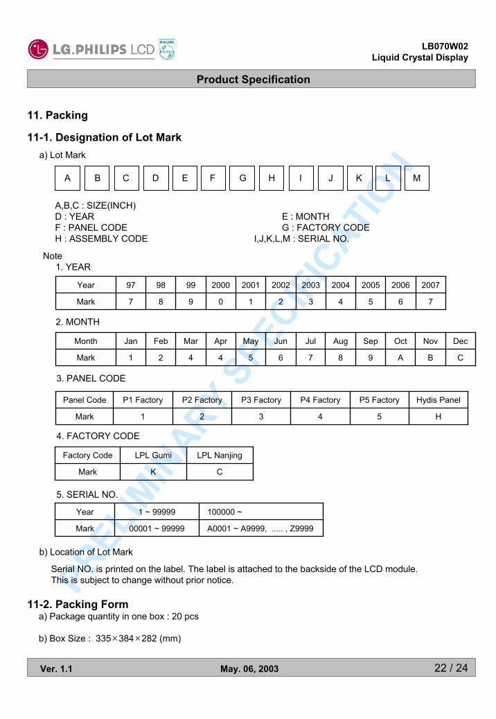
11. Packing
11-1. Designation of Lot Mark
11-2. Packing Forma) Package quantity in one box : 20 pcs
b) Box Size : 335×384×282 (mm)
a) Lot Mark
A B C D E F G H I J K L M
A,B,C : SIZE(INCH)D : YEAR E : MONTHF : PANEL CODE G : FACTORY CODEH : ASSEMBLY CODE I,J,K,L,M : SERIAL NO.
Note1. YEAR
b) Location of Lot Mark
2. MONTH
Serial NO. is printed on the label. The label is attached to the backside of the LCD module.This is subject to change without prior notice.
5. SERIAL NO.
Mark
Year
6
2006
2
2002
3
2003
4
2004
5
2005
0
2000
1
2001
7987
2007999897
B
Nov
Mark
Month
A
Oct
6
Jun
7
Jul
8
Aug
9
Sep
4
Apr
5
May
C421
DecMarFebJan
A0001 ~ A9999, ..... , Z999900001 ~ 99999Mark
100000 ~1 ~ 99999Year
4. FACTORY CODE
Mark
Factory Code
CK
LPL NanjingLPL Gumi
3. PANEL CODE
5
P5 Factory
4
P4 Factory
3
P3 Factory
H
Hydis Panel
2
P2 Factory
Mark
Panel Code
1
P1 Factory
Product Specification
23 / 24
LB070W02Liquid Crystal Display
Ver. 1.1 May. 06, 2003
PREL
IMIN
ARY SP
ECIFI
CATION
12. PRECAUTIONS
Please pay attention to the following when you use this TFT LCD module.
12-1. MOUNTING PRECAUTIONS(1) You must mount a module using holes arranged in four corners or four sides.(2) You should consider the mounting structure so that uneven force(ex. Twisted stress) is not applied
to the module.And the case on which a module is mounted should have sufficient strength so that external forceis not transmitted directly to the module.
(3) Please attach a transparent protective plate to the surface in order to protect the polarizer.Transparent protective plate should have sufficient strength in order to the resist external force.
(4) You should adopt radiation structure to satisfy the temperature specification.(5) Acetic acid type and chlorine type materials for the cover case are not describe because the former
generates corrosive gas of attacking the polarizer at high temperature and the latter causes circuitbreak by electro-chemical reaction.
(6) Do not touch, push or rub the exposed polarizers with glass, tweezers or anything harder than HBpencil lead. And please do not rub with dust clothes with chemical treatment.Do not touch the surface of polarizer for bare hand or greasy cloth.(Some cosmetics are determinedto the polarizer.)
(7) When the surface becomes dusty, please wipe gently with absorbent cotton or other soft materialslike chamois soaks with petroleum benzene. Normal-hexane is recommended for cleaning theadhesives used to attach front / rear polarizers. Do not use acetone, toluene and alcohol becausethey cause chemical damage to the polarizer.
(8) Wipe off saliva or water drops as soon as possible. Their long time contact with polarizer causesdeformations and color fading.
(9) Do not open the case because inside circuits do not have sufficient strength.
12-2. OPERATING PRECAUTIONS
(1) The spike noise causes the mis-operation of circuits. It should be lower than following voltage :V=±200mV(Over and under shoot voltage)
(2) Response time depends on the temperature.(In lower temperature, it becomes longer.)(3) Brightness depends on the temperature. (In lower temperature, it becomes lower.)
And in lower temperature, response time(required time that brightness is stable after turned on)becomes longer.
(4) Be careful for condensation at sudden temperature change. Condensation makes damage topolarizer or electrical contacted parts. And after fading condensation, smear or spot will occur.
(5) When fixed patterns are displayed for a long time, remnant image is likely to occur.(6) Module has high frequency circuits. Sufficient suppression to the electromagnetic interference
shall be done by system manufacturers. Grounding and shielding methods may be important tominimized the interference.

Product Specification
24 / 24
LB070W02Liquid Crystal Display
Ver. 1.1 May. 06, 2003
PREL
IMIN
ARY SP
ECIFI
CATION
Since a module is composed of electronic circuits, it is not strong to electrostatic discharge. Make certainthat treatment persons are connected to ground through wrist band etc. And don’t touch interface pin directly.
12-3. ELECTROSTATIC DISCHARGE CONTROL
Strong light exposure causes degradation of polarizer and color filter.
12-4. PRECAUTIONS FOR STRONG LIGHT EXPOSURE
When storing modules as spares for a long time, the following precautions are necessary.(1) Store them in a dark place. Do not expose the module to sunlight or fluorescent light. Keep the
temperature between 5°C and 35°C at normal humidity.(2) The polarizer surface should not come in contact with any other object.
It is recommended that they be stored in the container in which they were shipped.
12-5. STORAGE
(1) When the protection film is peeled off, static electricity is generated between the film and polarizer.This should be peeled off slowly and carefully by people who are electrically grounded and with wellion-blown equipment or in such a condition, etc.
(2) The protection film is attached to the polarizer with a small amount of glue. If some stress is appliedto rub the protection film against the polarizer during the time you peel off the film, the glue is apt toremain on the polarizer.Please carefully peel off the protection film without rubbing it against the polarizer.
(3) When the module with protection film attached is stored for a long time, sometimes there remains avery small amount of glue still on the polarizer after the protection film is peeled off.
(4) You can remove the glue easily. When the glue remains on the polarizer surface or its vestige isrecognized, please wipe them off with absorbent cotton waste or other soft material like chamoissoaked with normal-hexane.
12-6. HANDLING PRECAUTIONS FOR PROTECTION FILM
Related Documents