Section Contents LINEAR 445 BEARING SERIES BEARING DESCRIPTION PAGE INFORMATION LINEAR BEARINGS, GENERAL OVERVIEW 450 P / N IDENTIFICATION LINEAR BEARINGS 460 COMPONENTS LFS LINEAR BEARINGS 469 COMPONENTS TS..W LINEAR BEARINGS 469 COMPONENTS LFL LINEAR BEARINGS 469 COMPONENTS LFCL LINEAR BEARINGS 469 COMPONENTS LFR LINEAR BEARINGS 469 COMPONENTS RUE LINEAR BEARINGS 469 COMPONENTS KUSE LINEAR BEARINGS 469 COMPONENTS KUVE LINEAR BEARINGS 469 COMPONENTS KUVS LINEAR BEARINGS 469 COMPONENTS KUE LINEAR BEARINGS 469 COMPONENTS KUME LINEAR BEARINGS 469 RUE LINEAR RECIRCULATING ROLLER BEARING AND GUIDEWAY ASSEMBLIES 470 RUE..H LINEAR RECIRCULATING ROLLER BEARING AND GUIDEWAY ASSEMBLIES 472 RUKS LOCKING ELEMENT 474 APLU SHEET STEEL WIPER 476 BPLU LUBRICATION ADAPTER PLATE 477 SMDE MINIMAL QUANTITY LUBRICANT METERING UNIT 478 RUDS DAMPING CARRIAGE 479 KUSE LINEAR RECIRCULATING BALL BEARING AND GUIDEWAY ASSEMBLIES 480 KUSE..L LINEAR RECIRCULATING BALL BEARING AND GUIDEWAY ASSEMBLIES 482 KUSE..H LINEAR RECIRCULATING BALL BEARING AND GUIDEWAY ASSEMBLIES 484 KUSE..HL LINEAR RECIRCULATING BALL BEARING AND GUIDEWAY ASSEMBLIES 486 APLSE SHEET STEEL WIPER 488 AB KOL KWSE COLLECTOR WIPER 489 BPLSE LUBRICATION ADAPTER PLATE 490 FBALG KWSE BELLOWS 491 KUVE FOUR-ROW LINEAR RECIRCULATING BALL BEARING AND GUIDEWAYASSEMBLY 492 KUVE..S,..SN, ..H FOUR-ROW LINEAR RECIRCULATING BALL BEARING AND GUIDEWAYASSEMBLY 494 KUVE..W,..WL FOUR-ROW LINEAR RECIRCULATING BALL BEARING AND GUIDEWAYASSEMBLY 496 KUE LINEAR RECIRCULATING BALL BEARING AND GUIDEWAY ASSEMBLIES 498 KUE..H LINEAR RECIRCULATING BALL BEARING AND GUIDEWAY ASSEMBLIES 500 APLE SHEET STEEL WIPER 502 BPLE LUBRICATION ADAPTER PLATE 503 FBALG KWE BELLOWS 504 KUVS LINEAR BALL BEARING UNITS 506 KWVK..AL CARRIAGES 508 TKVD GUIDEWAYS 508

Welcome message from author
This document is posted to help you gain knowledge. Please leave a comment to let me know what you think about it! Share it to your friends and learn new things together.
Transcript

Section ContentsLINEAR
445
BEARING SERIES BEARING DESCRIPTION PAGE
INFORMATION LINEAR BEARINGS, GENERAL OVERVIEW 450
P / N IDENTIFICATION LINEAR BEARINGS 460
COMPONENTS LFS LINEAR BEARINGS 469
COMPONENTS TS..W LINEAR BEARINGS 469
COMPONENTS LFL LINEAR BEARINGS 469
COMPONENTS LFCL LINEAR BEARINGS 469
COMPONENTS LFR LINEAR BEARINGS 469
COMPONENTS RUE LINEAR BEARINGS 469
COMPONENTS KUSE LINEAR BEARINGS 469
COMPONENTS KUVE LINEAR BEARINGS 469
COMPONENTS KUVS LINEAR BEARINGS 469
COMPONENTS KUE LINEAR BEARINGS 469
COMPONENTS KUME LINEAR BEARINGS 469
RUE LINEAR RECIRCULATING ROLLER BEARING AND GUIDEWAY ASSEMBLIES 470
RUE..H LINEAR RECIRCULATING ROLLER BEARING AND GUIDEWAY ASSEMBLIES 472
RUKS LOCKING ELEMENT 474
APLU SHEET STEEL WIPER 476
BPLU LUBRICATION ADAPTER PLATE 477
SMDE MINIMAL QUANTITY LUBRICANT METERING UNIT 478
RUDS DAMPING CARRIAGE 479
KUSE LINEAR RECIRCULATING BALL BEARING AND GUIDEWAY ASSEMBLIES 480
KUSE..L LINEAR RECIRCULATING BALL BEARING AND GUIDEWAY ASSEMBLIES 482
KUSE..H LINEAR RECIRCULATING BALL BEARING AND GUIDEWAY ASSEMBLIES 484
KUSE..HL LINEAR RECIRCULATING BALL BEARING AND GUIDEWAY ASSEMBLIES 486
APLSE SHEET STEEL WIPER 488
AB KOL KWSE COLLECTOR WIPER 489
BPLSE LUBRICATION ADAPTER PLATE 490
FBALG KWSE BELLOWS 491
KUVE FOUR-ROW LINEAR RECIRCULATING BALL BEARING AND GUIDEWAY ASSEMBLY 492
KUVE..S,..SN, ..H FOUR-ROW LINEAR RECIRCULATING BALL BEARING AND GUIDEWAY ASSEMBLY 494
KUVE..W,..WL FOUR-ROW LINEAR RECIRCULATING BALL BEARING AND GUIDEWAY ASSEMBLY 496
KUE LINEAR RECIRCULATING BALL BEARING AND GUIDEWAY ASSEMBLIES 498
KUE..H LINEAR RECIRCULATING BALL BEARING AND GUIDEWAY ASSEMBLIES 500
APLE SHEET STEEL WIPER 502
BPLE LUBRICATION ADAPTER PLATE 503
FBALG KWE BELLOWS 504
KUVS LINEAR BALL BEARING UNITS 506
KWVK..AL CARRIAGES 508
TKVD GUIDEWAYS 508

Section ContentsLINEAR
446
BEARING SERIES BEARING DESCRIPTION PAGE
KUME MINIATURE LINEAR RECIRCULATING BALL BEARING AND GUIDEWAY ASSEMBLIES 510
LFCL TRACK ROLLER LINEAR GUIDANCE SYSTEMS WITH HOLLOW SECTION CARRIAGE 512
LFL..SF TRACK ROLLER LINEAR GUIDANCE SYSTEMS WITH OPEN CARRIAGE 514
LFKL..SF TRACK ROLLER LINEAR GUIDANCE SYSTEMS WITH COMPACT CARRIAGE 516
LFDL TRACK ROLLER LINEAR GUIDANCE SYSTEMS WITH BOGIE CARRIAGE 518
LFR TRACK ROLLERS 520
LFZ BOLTS 521
LFE BOLTS 522
LFZ..A1 BOLTS 523
LFS GUIDEWAYS 524
LFS..C GUIDEWAYS 524
LFS..F GUIDEWAYS 524
LFS..M GUIDEWAYS 526
LFS..N GUIDEWAYS 526
LFS..CH GUIDEWAYS 528
LFS..FH GUIDEWAYS 528
LFS..R CURVED GUIDEWAYS 530
TSNW SHAFT AND SUPPORT RAIL UNITS 531
TSNW..G SHAFT AND SUPPORT RAIL UNITS 532
TSUW SHAFT AND SUPPORT RAIL UNITS 533
TSSW SHAFT AND SUPPORT RAIL UNITS 534
TSMW SHAFT AND SUPPORT RAIL UNITS 535
AB LFR CAP WIPERS 536
AB W LUBRICATION AND WIPER UNITS 536
ANS LFS END PLATES 537
AB LUBRICATION AND WIPER UNITS 538
ABAL SIDE PLATES 538
PAH END STOPS 539
KA LFS END COVERS 540
NAD GROOVE STRIPS 540
ABTKO LFKL ADAPTER 541
KX MAX3 INCH SELF-ALIGNING LINEAR BALL BEARINGS - CLOSED 542
KXO MAX3 INCH SELF-ALIGNING LINEAR BALL BEARINGS - OPEN 542
KGX MAX3 INCH SELF-ALIGNING LINEAR BALL BEARINGS - CLOSED WITH HOUSING 544
KGXO MAX3 INCH SELF-ALIGNING LINEAR BALL BEARINGS - OPEN WITH HOUSING 544
KTX TANDEM MAX3 INCH LINEAR BALL BEARINGS - CLOSED WITH HOUSING 546
KTXO TANDEM MAX3 INCH LINEAR BALL BEARINGS - OPEN WITH HOUSING 546
KS MAX3 METRIC SELF-ALIGNING LINEAR BALL BEARINGS - CLOSED 548
KSO MAX3 METRIC SELF-ALIGNING LINEAR BALL BEARINGS - OPEN 548

Section ContentsLINEAR
447
BEARING SERIES BEARING DESCRIPTION PAGE
KGSG MAX3 METRIC SELF-ALIGNING LINEAR BALL BEARINGS - CLOSED WITH CAST 2 BOLT HOUSING 550
KGSS MAX3 METRIC SELF-ALIGNING LINEAR BALL BEARINGS - ADJ. CLEARANCE WITH CAST 2 BOLT HOUSING 550
KGSO MAX3 METRIC SELF-ALIGNING LINEAR BALL BEARINGS - OPEN WITH CAST 2 BOLT HOUSING 550
KGSAG MAX3 METRIC SELF-ALIGNING LINEAR BALL BEARINGS - CLOSED WITH CAST 4 BOLT HOUSING 552
KGSAS MAX3 METRIC SELF-ALIGNING LINEAR BALL BEARINGS - ADJ. CLEARANCE WITH CAST 4 BOLT HOUSING 552
KGSAO MAX3 METRIC SELF-ALIGNING LINEAR BALL BEARINGS - OPEN WITH CAST 4 BOLT HOUSING 552
KGSNG MAX3 METRIC SELF-ALIGNING LINEAR BALL BEARINGS - CLOSED WITH EXTRUDED HOUSING 554
KGSNS MAX3 METRIC SELF-ALIGNING LINEAR BALL BEARINGS - ADJ. CLEARANCE WITH EXTRUDED HOUSING 554
KGSNO MAX3 METRIC SELF-ALIGNING LINEAR BALL BEARINGS - ADJ. CLEARANCE OPEN WITH EXTRUDED HOUSING 556
KGSNOS MAX3 METRIC SELF-ALIGNING LINEAR BALL BEARINGS - OPEN WITH EXTRUDED HOUSING 556
KTSG TANDEM MAX3 METRIC LINEAR BALL BEARINGS - CLOSED WITH EXTRUDED HOUSING 558
KTSS TANDEM MAX3 METRIC LINEAR BALL BEARINGS - ADJUSTABLE CLEARANCE WITH EXTRUDED HOUSING 558
KTSO TANDEM MAX3 METRIC LINEAR BALL BEARINGS - OPEN WITH EXTRUDED HOUSING 560
KTSOS TANDEM MAX3 METRIC LINEAR BALL BEARINGS - ADJ. CLEARANCE WITH OPEN EXTRUDED HOUSING 560
KGSC TANDEM MAX3 METRIC LINEAR BALL BEARINGS - OPEN WITH SIDE MOUNTED HOUSING 562
KGSCS TANDEM MAX3 METRIC LINEAR BALL BEARINGS - ADJUSTABLE CLEARANCE WITH SIDE MOUNTED HOUSING 562
KTFS TANDEM MAX3 METRIC LINEAR BALL BEARINGS - CLOSED WITH SIDE MOUNTED HOUSING 564
KH LINEAR BALL BEARINGS 566
KGHK LINEAR BALL BEARING AND HOUSING UNITS 568
KTHK LINEAR BALL BEARING AND HOUSING UNITS 570
KGHW LINEAR BALL BEARING AND HOUSING UNITS 572
KGHWT LINEAR BALL BEARING AND HOUSING UNITS 574
KN SELF-ALIGNING LINEAR BALL BEARINGS 576
KNO SELF-ALIGNING LINEAR BALL BEARINGS, OPEN 576
KGN SELF-ALIGNING LINEAR BALL BEARING AND HOUSING UNITS 578
KGNS SELF-ALIGNING LINEAR BALL BEARING AND HOUSING UNITS 578
KGNO SELF-ALIGNING LINEAR BALL BEARING AND HOUSING UNITS 580
KGNC SELF-ALIGNING LINEAR BALL BEARING AND HOUSING UNITS 582

Section ContentsLINEAR
448
BEARING SERIES BEARING DESCRIPTION PAGE
KTN TANDEM LINEAR BALL BEARING AND HOUSING UNITS 584
KTNO TANDEM LINEAR BALL BEARING AND HOUSING UNITS - OPEN 586
KTFN LINEAR BALL BEARING AND HOUSING UNITS 588
KB LINEAR BALL BEARINGS 590
KBO LINEAR BALL BEARINGS 590
KBS LINEAR BALL BEARINGS 590
KGB LINEAR BALL BEARING AND HOUSING UNITS 592
KGBO LINEAR BALL BEARING AND HOUSING UNITS 592
KGBS LINEAR BALL BEARING AND HOUSING UNITS 592
KGBA LINEAR BALL BEARING AND HOUSING UNITS 594
KGBAO LINEAR BALL BEARING AND HOUSING UNITS 594
KGBAS LINEAR BALL BEARING AND HOUSING UNITS 594
KTB LINEAR BALL BEARING AND HOUSING UNITS 596
KTBO LINEAR BALL BEARING AND HOUSING UNITS 596
PAB PERMAGLIDE LINEAR PLAIN BEARINGS 598
PAGBA PERMAGLIDE LINEAR PLAIN BEARINGS 600
W SHAFTS 602
WH SHAFTS 604
TSNW SHAFT AND SUPPORT RAIL UNITS 605
TSWW SHAFT AND SUPPORT RAIL UNITS 605
TSUW SHAFT AND SUPPORT RAIL UNITS 606
TSNW..G SHAFT AND SUPPORT RAIL UNITS 607
TSSW SHAFT AND SUPPORT RAIL UNITS 608
TSWWA SHAFT AND SUPPORT RAIL UNITS 609
GWH..B SHAFT SUPPORT BLOCKS 610
GWN..B SHAFT SUPPORT BLOCKS 611
GW SHAFT SUPPORT BLOCKS 612
TSN SUPPORT RAILS 613
KBZ LINEAR BALL BEARINGS 615
KBZ..OP LINEAR BALL BEARINGS 616
KNZ SELF ALIGNING LINEAR BALL BEARINGS 617
KNZ..OP SELF ALIGNING LINEAR BALL BEARINGS 618
KGNZ SELF ALIGNING MOUNTED UNITS 619
KGNZ..OP SELF ALIGNING MOUNTED UNITS 620
KTNZ SELF ALIGNING TANDEM MOUNTED UNITS 621
KTNZ..OP SELF ALIGNING TANDEM MOUNTED UNITS 622
WZ PRECISION GROUND SHAFTS 623
WZ..PDT PRECISION GROUND SHAFTS 624
TSWZ SHAFT SUPPORT RAILS 625

449
BEARING SERIES BEARING DESCRIPTION PAGE
TSWZ..PD SHAFT SUPPORT RAILS 626
TSUZ SHAFT SUPPORT RAILS 627
TSUZ..PD SHAFT SUPPORT RAILS 628
MLFZ RAIL 629
LFL CARRIAGE 630
LFSB RAIL 630
LFKL CARRIAGE 631
MLF..ZR LINEAR MODULAR UNIT WITH TRACK ROLLER GUIDANCE SYSTEM AND TOOTHED BELT DRIVE 632
MKUE..ZR LINEAR MODULAR UNIT WITH RECIRCULATING BALL BEARING GUIDANCE SYSTEM AND TOOTHED BELT DRIVE 634
MKUE..KGT LINEAR MODULAR UNIT WITH RECIRCULATING BALL BEARING GUIDANCE SYSTEM AND BALL SCREW DRIVE 636
RUS LINEAR ROLLER BEARING BLOCK, WITH SEPARATOR 638
RUSZ INCH LINEAR ROLLER BEARING BLOCK, WITH SEPARATOR 640
PR LINEAR ROLLER BEARING BLOCK, FULL COMPLEMENT 642
VUS ADJUSTING GIBS 644
RUSV LINEAR ROLLER BEARINGS WITH INTEGRAL ADJUSTING GIB 646
RGT PLANETARY ROLLER SCREW 648
KGS ROLLED THREAD BALL SCREWS 658
KGF FLANGED BALL NUT FOR BALL SCREWS 659
KGM CYLINDRICAL BALL NUT FOR BALL SCREWS 660
KGS ROLLED THREAD BALL SCREW - FORM D ENDS 661
KGS ROLLED THREAD BALL SCREW - FORM W, N AND Z ENDS 662
BF LINEAR FLAT STEEL CAGE & ROLLERS, SINGLE ROW 663
FF LINEAR FLAT PLASTIC CAGE & ROLLERS, SINGLE ROW, SNAP CONNECTORS 663
H LINEAR FLAT ALUMINUM CAGE & ROLLERS, SINGLE ROW 663
HR LINEAR FLAT ALUMINUM & PLASTIC CAGE & CYLINDRICAL ROLLERS, SINGLE ROW 663
FF..ZW LINEAR FLAT PLASTIC CAGE & ROLLERS, DOUBLE ROW, SNAP CONNECTORS 664
H..ZW LINEAR FLAT ALUMINUM CAGE & ROLLERS, DOUBLE ROW 664
HR..ZW LINEAR FLAT STEEL CAGE & ROLLERS, DOUBLE ROW 664
FFW LINEAR FLAT PLASTIC CAGE & ROLLERS, DOUBLE ROW AT 90 DEGREE BEND, SNAP CONNECTORS 665
HRW LINEAR FLAT STEEL CAGE & ROLLERS, DOUBLE ROW AT 90 DEGREE BEND 665
HW LINEAR FLAT ALUMINUM CAGE & ROLLERS, DOUBLE ROW AT 90 DEGREE BEND 665
Section ContentsLINEAR

450
General InformationLINEAR
INTRODUCTIONMany years of field experience have contributed to theoptimization of INA products and systems for linearmovement to meet the high demands of modern machinedesign; they have the following advantages:
� Very low and uniform resistance to displacement,giving improved positioning and running accuracy;
� The negative influences due to shock loading whichoccur in conventional rolling element guidance sys-tems as the elements enter the load zone are re-duced in INA guidance systems by means of specialdesign features.
INA linear guidance systems have extremely high preci-sion and operate virtually wear-free due to their rollingmotion so that their high accuracy is maintained through-out the operating life.
A wide range of linear guidance systems are available,each designed for maximum rigidity. By selecting the opti-mum type of guidance and preloading of linear bearings,virtually any rigidity requirement can be fulfilled.
INA linear products have an extremely high load carryingcapacity due to their optimum use of available space andmanufacturing quality. Guidance systems for almost allload carrying requirements can be produced from thecomprehensive product range.
INA Linear Roller Bearing And Guideway AssembliesSeries RUEINA linear recirculating roller bearing and guideway as-semblies of series RUE are high accuracy, ready-to-as-semble linear guidance units which can take high loads.They have a full complement rolling element systemwhich is preloaded as standard and allows high runningand positioning accuracy.
The basic static and dynamic load ratings of RUE assem-blies are nearly twice that of comparable ball and guide-way assemblies.
The rigidity of recirculating roller bearing and guidewayassemblies is considerably higher than that of ball bear-ing and guideway assemblies. While some competitorsargue that the rigidity can be improved by means of highpreloads on the recirculating ball system, this is entirely atthe expense of the life.
The linear recirculating roller bearing and guideway as-sembly also has a high crash safety.
The carriage is sealed on all sides. As opposed to thecompetition, the whole body of the guideways is groundwhich provides optimum sealing.
When these assemblies are used in machine tools, brassclosing plugs are particularly advantageous.
The RUE unit is interchangeable with the ball bearing andguideway assemblies of the same section height pro-duced by our competitors but they have considerablyhigher load ratings and rigidity. Due to the technical ad-vantages of the roller system, the next smallest RUE unitcan often be used compared to ball bearing and guide-way assemblies.
The carriage can be fixed from above or below with 6screws. The guideway has twice as many screws as theguideways produced by the competitors. Recirculatingroller bearing and guideway assemblies may be com-bined with the damping carriage RUDS to counteractvibration, giving the benefits of both a sliding and a rollingguidance system. Plastic deformation of the rolling ele-ments no longer occurs as the smaller damping gap andthe increased surface area of the damping carriage re-duce the specific contact load considerably.

451
General InformationLINEAR
Linear Recirculating Ball Bearing AndGuideway AssembliesSeries KUSESix-track linear recirculating ball bearing and guidewayassemblies of series KUSE have the highest load ratingof any recirculating ball bearing guidance system with thesame envelope dimensions, and allow very high accelera-tions and velocities. Linear ball bearing and guidewayassemblies of series KUSE should be classified betweenthe traditional linear ball bearing and linear roller bearingguideway assemblies.
Linear ball bearing and guideway assemblies of seriesKUSE derive their high load carrying capacity from the sixtracks of preloaded balls. They can take loads from alldirections and moments about all axes. The low frictioncharacteristics of this new linear recirculating ball systemallows very high accelerations and velocities.
Linear Ball Bearing And Guideway AssembliesSeries KUVSINA linear guidance systems with recirculating ball bear-ing units, series KUVS, are four row linear guidance sys-tems. Two of the main features of these assemblies arewide support distances and adjustable bearing clearance.
Linear recirculating ball bearing units of series KUVShave a high load carrying capacity in spite of their smallboundary dimensions. They run on guideways of seriesTKVD with raceways on one or both sides. These unitscan be screwed into a carriage KWVK..AL which canform a four row linear ball bearing and guideway assem-bly when combined with the TKVD guideways.
INA Linear Ball Bearing And Guideway AssembliesSeries KUEINA linear ball bearing and guideway assemblies areready-to-assemble linear guidance systems. They consistof one or more carriages on a guideway TKD. Linear ballbearing and guideway assemblies of series KUE have afour point contact recirculating ball system.
Due to their special features, INA linear recirculating ballbearing and guideway assemblies can meet the demandsof modern guidance designs:
� Accuracy INA linear ball bearing and guideway assemblies areextremely accurate rolling bearings. They are clear-ance-free and operate with extremely low frictionand completely free from stick-slip.
� High load carrying capacity and rigidityINA linear ball bearing and guideway assemblieshave an extremely high load carrying capacity andrigidity for their dimensions.
� Load directionsINA recirculating linear ball bearings can take loadsin all perpendicular directions and moments about allaxes. They need only one guideway for fixing: coun-terstay designs are therefore superfluous.
� Low section heightINA linear ball bearing and guideway assemblieshave an extremely low section height. This allows avery compact design of guidance system.
In addition, KUE assemblies have the following importantfeatures:
� High running and positioning accuracy(clearance-free)
� High reliability� Easy mounting
INA linear ball bearing and guideway assemblies aresupplied ready for assembly. This allows economicaldesigns of guidance systems.
� InterchangeabilityThe components of a linear ball bearing and guide-way assembly can be interchanged within the samepreload and accuracy class.

General InformationLINEAR
INA Track Roller Linear Guidance SystemSeries LFDue to its modern and innovative design, the INA trackroller linear guidance system offers the following advan-tages:
� Straightforward modular designThe modular construction of the INA track roller lin-ear guidance system allows individual guidance ele-ments to be combined as required. Depending onthe requirements, complete units may be used orvariants may be produced with single guideways onthe inside or outside combined with different rollers.
� Robust, wear-resistant, reliable systemVertical and horizontal motion can be achieved evenin contaminated environments. Reliable operationand a long operating life are ensured, together withlow maintenance requirements.
� High load carrying capacityLoads can be taken from all directions and momentsabout all axes. Depending on the load case, differentguidance elements with differing high load carryingcapacities are available to the user.
� High accuracyDue to the production process, the guideways havea high accuracy, providing clearance-free and low-friction operation. LF systems can be used in anymounting position.
� Unlimited stroke at high traverse speedsThe INA track roller linear guidance system allowslinear motion of any length and speeds up to 10 m/s.
� Straightforward assemblyINA track roller linear guidance systems are suppliedready for mounting. The user has the option, de-pending on the guideway type, of fixing from aboveor below. The premounted carriage can be set clear-ance-free. The system can be matched to the cus-tomer’s specific requirements.
� High wear resistance due to the optimized profile ofthe track rollers and the rolled precision steel shaftshardened to HRC 60
� Long life� The load carrying capacity can be considerably in-
creased if required by adding more track rollers� Relubrication facility� The individual components are easily interchange-
able� Systems have low mass due to the use of anodized
aluminium components
� Systems are also available in corrosion resistant andblack anodized versions
� There are many potential applications in almost allareas
� The standard version is readily available from stock� The track rollers are lubricated for life� Various sealing options and accessories are avail-
able
452

453
General InformationLINEAR
INA Linear Ball BearingsSeries KHINA linear ball bearings of series KH are linear recirculat-ing ball bearing units of very small radial section height.They consist of a drawn and hardened outer cup and aplastic cage. The outer cup, cage and balls form a closedlinear bearing which is ready to assemble. These unitsare suitable for applications where long travel distances,low space requirements and predominantly maintenance-free operation are required.
Linear ball bearings of series KH have the following ad-vantages:
� Optimum price/performance ratio� Very small radial section height� Axial location is not required� Double lip contact sealing rings on KH...P and
KH...PP� Optimum sealing� Lubricant is retained in the bearing� Relubrication via slots in the ball recirculation chan-
nel� Long operating life� Operating temperature up to 120�C
Cage: polyamide 66-GKSealing rings: polyester elastomer
INA ball bearings are superior bearings not only in termsof their resistance to temperature but also in their otherfeatures such as:
� Smooth running� Load carrying capacity� Rigidity
Good rigidity is achieved in all directions due to the uni-form spacing of the rows.
INA Linear Ball Bearings
Linear ball bearings of this series consist of a cage andseveral load plates. The high-strength plastic cage guidesthe balls. The hardened load plates have a ground profile
Series KN/KS MAX3
INA linear ball bearings of series KN, KNO, KS and KSOare linear recirculating ball bearing units which can compensate for misalignments due to their special design.
on the raceway side.
The KN/KS series offer:
• Ground races for smoothest operation
• Self aligning in any housing
• Completely interchangable with other standard makes
• Lower noise level
• Lighter weight
• Wiper seals float with the bearing
• Linear ball bearings KNO..PP with all-around sealing have additional reinforced longitudinal seals
• Cost effective bearings for round shaft rails
In addition, the KS offers:• Larger load capability due to increased number
of ball rows
• Greater misalignment capability
• Longer bearing life due to the internal lubricationresevoirs

General InformationLINEAR
INA Linear Ball BearingsSeries KBINA linear ball bearings of series KB consist of a hard-ened and ground outer ring and a cage in which the ballsare guided. The balls in the return zones are held in placeby spring elements. This ensures that even heavilyloaded or preloaded bearings have a uniform, low resis-tance to displacement.
INA linear ball bearings of closed (KB), adjustable (KBS)and open version (KBO) have 4 to 6 rows of balls to sup-port the load and are used where high precision and loadcarrying capacity are required.
Linear ball bearings of series KBS have a split outer ringwhich allows the operating clearance to be adjusted.
Linear ball bearings of series KBO have a segment cutout of the outer ring:they are suitable for applications with shafts with continu-ous support.
Linear ball bearings of series KB, KBS and KBO can berelubricated.
The ground outside diameter on the linear ball bearingsseries KB are suitable as raceways for rolling bearings sothat bearing units for linear and rotary motion can becreated.
The special recirculation design provides a uniform, lowresistance to displacement with extremely smooth run-ning even in highly loaded and preloaded linear ball bear-ings.
Bearings of series KB are completely interchangeablewith the bearings of our competitors.
INA ShaftsSeries W, WH, WZINA shafts of series W, WH and WZ are suitable for guid-ance systems with closed, protected linear bearing unitsand are used in a wide range of applications in theconstruction of equipment and automatic machinery.
� INA shafts are surface hardened, precision groundand made from high grade steels.
� High material quality� High surface hardness and surface quality� High dimensional and geometrical accuracy ensure
excellent running characteristics.� Steel shafts are available in standard lengths ex
stock and can be cut to the customer’s require-ments. They can be produced with various end con-figurations and other machined features.
� Special versions are available in other materials, e.g.corrosion-resistant steel.
� Shafts of 5 mm diameter are available in lengths upto about 3700 mm and shafts of 6 mm diameter andabove in lengths up to about 4000 mm.
� INA can supply composite shafts where the lengthrequired exceeds the maximum single piece length.
� Special versions are available on request with othertolerances and special surface coatings and as un-hardened shafts.
Shafts and support rails of series TSCW, TSNW, TSSW,TSUW, TSWW and TSWWA complete the INA linearrange and remove the need for expensive, time consum-ing customer designs.
Support rails have the following advantages:
� They prevent flexing of the shaft� They ensure correct functioning of the linear guid-
ance system� Low section height� High rigidity
454

455
General InformationLINEAR
INA Linear Ball BearingsSeries KBZLinear ball bearings of series KBZ and KBZ..OP consistof a hardened and ground solid outer ring and a retainer.The outer ring is machined from high-carbon bearingsteel. The retainer is manufactured from a high strengthengineered resin. Series KBZ..OP have a segment re-moved from the outer ring for applications with supportedshafts.
� Ground races for smoothest operation.� Self Aligning in any housing.� Completely interchangeable with other standard
makes.� Lower noise level.� Lighter weight.
Linear Recirculating Ball Bearing AndGuideway AssembliesSeries KUVEThe four-row linear recirculating ball bearing and guide-way assembly KUVE comprises a total of six carriagecross-sections. The four rows of balls are preloaded. Theunit has a high load carrying capacity; it can take loadsfrom all directions and moments about all axes.
The special design of the recirculating ball system ensur-es low resistance to displacement and allows high veloci-ties and accelerations.
Series KNZ/KX MAX 3
Linear ball bearings of series KNZ.. and KX.. consist of a precision molded retainer of a high strength engineered resin and hardened and ground bearing races. Series KNZ..OP..and KXO.. bearings have a segment removed for applications requiring supported shafts.
The KNZ/KX series offer:
� Cost effective bearings for round shaft rails.� Wiper seals float with the bearing.
In addition, the KX offers:• Larger load capability due to increased number
of ball rows
• Greater misalignment capability
• Longer bearing life due to the internal lubricationreservoirs

General InformationLINEAR
Linear Modular UnitsSeries MLFThe linear modular unit MLF allows small to mediumloads to be moved with a high positional accuracy atspeeds up to 7.5m/s1) and with a maximum accelerationof 40m/s2 1). When combined with a suitable controldrive, a high repeatability can be achieved, usually within�0.08 mm.
The profiled support rails, which have high bending andtorsional rigidity, allow the unit to operate without sup-ports, even on longer modular units.
All the aluminium components are anodized.
A corrosion resistant execution is also available: suffixVA.
Design� Profiled support rail LFS..M consisting of an anod-
ized aluminium rail with hardened and ground steelrods inlaid on both sides. T-grooves provide variousinstallation possibilities.
� Compact carriage in an enclosed design with integraltoothed belt tensioner on both sides, lubrication andwiper unit. The carriage can be set clearance-free bymeans of two eccentric bolts.
� Return units with integral brush wipers and ball bear-ings which are lubricated for life.
1) These values are reduced when bellows are used.
Linear Modular UnitsSeries MKUEINA linear ball bearing and guideway assemblies areused in the linear modular units series MKUE. They arepreloaded and operate virtually free from stick-slip.
The guidance accuracy of MKUE linear modular units isincreased by machining the guideway seating surfaces onthe support rail.
The INA linear modular unit with recirculating ball guid-ance system allows medium to high loads to be movedquickly and with a very high guidance accuracy.
The drive is via either a toothed belt or a ball screw.
Maximum traverse speeds are:
Toothed belt drive 3 m/sBall screw drive 1.73m/s
When the toothed belt drive is combined with a suitablecontrol drive, a high repeatability can be achieved, usuallywithin �0.08 mm.
The profiled support rails, which have high bending andtorsional rigidity, allow the unit to operate without sup-ports, even on longer units.
All the aluminium components are anodized.
Design� Profiled support rail made from anodized aluminium
with integral ball bearing and guideway assemblyKUE. T-grooves provide various installation possibili-ties.
Linear Modular Unit MKUE 25 ZR..N� Carriage with two T-grooves (with threaded holes if
required) and integral belt tensioners on both ends� Return unit with ball bearing lubricated for life.
Linear Modular Unit MKUE 25 KGT� Carriage with threaded holes� Preloaded double nut for leads of 5 and 10 mm.
Accuracy 50 µm/300 mm� INA axial angular contact ball bearings series ZKLF
are used for the spindle bearing arrangements: thebearings are greased for life
� Bellows are used to protect the ball screw spindleand the KUE system.
456

457
General InformationLINEAR
INA Linear Roller BearingsSeries RUSINA linear roller bearings are manufactured in severalbasic types and meet the highest technical demands. Lin-ear recirculating roller bearing systems are suitable forlinear guidance systems in machine tools where highguidance and positioning accuracy with long strokes arerequired.
Linear roller bearings have the following advantages:
� Very high accuracy� Increased compressive rigidity� High load carrying capacity� High functional reliability� Very low frictional values compared to other linear
guidance systems� Very smooth running due to the special design of the
supporting elements with compensation for bounce
Due to their robustness, linear roller bearings of seriesPR are also suitable for use at high temperatures as wellas for extremely high velocities and accelerations.
With INA linear roller bearings of series RUSV..KS, thereis no need for a separate adjusting gib. This gives advan-tages including:
� Fewer components� Low section height� Quicker, simpler mounting
INA also supplies a setting device for exact, repeatable,quick and straightforward adjustment of preload in linearroller bearings.
INA Adjusting GibsSeries VUS and VUSZINA Adjusting Gibs of series VUS and VUSZ are used forheight adjustment or preloading of linear roller bearings.They consist of two ground wedges which are guided to-gether by a central key. A plate fixed on one end facesupports the adjusting screw and the locking screw. Lu-brication ducts in the adjusting gibs allow for the lubrica-tion of the linear bearings through the rolling element re-turn zone in their supporting face.

General InformationLINEAR
INA Planetary Roller ScrewsSeries RGTThe most significant advantage of these units over ballscrews is the increased number of contact points per unitvolume which provides a high load carrying capacity. Thespecific contact load of a roller screw drive is lower andthe life longer compared to ball screw drives with thesame dimensions.
Compared to the more widespread ball screw drives,planetary roller screws have greater rigidity, lower axialclearance and higher limiting speeds which are aboutthree times those of ball screw drives. RGT units are verycompact and robust, require only a small amount ofspace, and large ball screw drives can be replaced bysmall RGT units. Straightforward mounting and disman-tling allow the nut to be mounted where access is difficult.
� Low sensitivity to shock loading� High functional reliability under extreme conditions� Extremely high displacement speeds� Low internal friction — no stick-slip, high efficiency
(up to 93%).
Excellent positioning and repeat accuracy throughout theoperating life. Extremely accurate positioning is possible(2 µm) due to the small lead (1 mm) with very small ad-vance movement. At high displacement speeds, a highpositioning accuracy can be achieved with a large lead.
Special machining operations (e.g. shortening a spindle)can be quickly carried out.
The optimum solution for a particular application can beachieved with special setting of the nut e.g. reduction ofthe frictional moment.
INA planetary roller screws, Series RGT, basically consistof a screw (shaft) and a roller nut. Several planetary roll-ers are arranged parallel to the axis between the screwand the roller nut.
Roller NutThe roller nut can be supplied split or as one piece. Thetwo halves of the split roller nut (9), see next page, areheld together by the key (7). During installation of theplanetary roller screw the roller nut is preloaded. A shim(8) is used to control the preload. The one-piece roller nutcannot be preloaded.
Internally geared rings (4) are situated in the ends of theroller nut engaging with the external gearing provided ateach end of the planetary rollers (5). The spacing of theplanetary rollers, is provided by the carrier plates (3)which also function as labyrinth seal. The plates are re-tained by the snap rings (2).
Planetary RollersThe planetary rollers (5) have a journal at each end whichare guided by the holes of the carrier plates. The gearedends of the planetary rollers mesh with the internallygeared rings in the nut. The planetary rollers have asingle-start thread with a crowned flank. This allows thestresses created by the thread meshing to be distributedon larger ellipses which also reduce the harmful edgestresses. The planetary rollers rotate slip-free in the rollernut. They have no axial movement relative to the rollernut as the axial travel increments at the points of contactbetween both elements are equal.
Screw ShaftScrews are manufactured from surface hardened, casehardening steel. The thread angle is 90 degrees. Screwsin standard design are available with a nominal diameterd0 from 5 mm to 20 mm. The standard ends configurationprescribes a straight journal on the floating side and pro-vision for lock nut and driving system on the locating side.The screws are available in different lengths. Strokesfrom 25 mm to 1200 mm are possible, depending on thenominal diameter.
Screws with a nominal diameter d0 between 24 and 63mm are special designs. Their dimensions are pre-deter-mined by the following dimension tables. The largest pos-sible screw diameter d0 is 250 mm.
All screws are available with custom tailored ends config-uration.
458

459
General InformationLINEAR
1 SCREW (SHAFT)2 SNAP RING3 CARRIER PLATE4 INTERNALLY GEARED RING5 PLANETARY ROLLER6 LOCATING PIN7 KEY8 SHIM9 ROLLER NUT
Special Request VariationsINA planetary roller screws are available upon request inthe following special designs:
� One-piece roller nut (not preloaded, higher loadratings, small axial clearance)
� Roller nut with flanges, middle or side flange
INA Planetary roller screws are also available upon re-quest with:
� Left hand thread� Inch pitch thread� Hollow shaft
If aggressive media is acting on the planetary rollerscrew, corrosion resistant material should be chosen.Contact INA for details.
DESIGN OF THE INA PLANETARY ROLLER SCREWWITH SPLIT ROLLER NUT
WipersIf planetary roller screws are subject to heavy contamina-tion, the roller nut can be equipped with wiper seals uponrequest.

Part Number IdentificationLINEAR
LINEAR RECIRCULATING ROLLERBEARING & GUIDEWAY ASSEMBLY
RAIL SIZE(SYSTEM SIZE)
55 OEER U LD H W2 1000
ROLLER
RECIRCULATING
UNIT DESIGNVERSION
CARRIAGE CONFIGURATION
H Narrow, MountingFrom The Top
— Standard, Flanged
CARRIAGE LENGTH
L Long Version
— Standard Version
LUBRICATIONSUFFIX
OE Oil
FE Grease
Number Of CarriagesPer Assembly
Guideway LengthIn mm
/
460
461
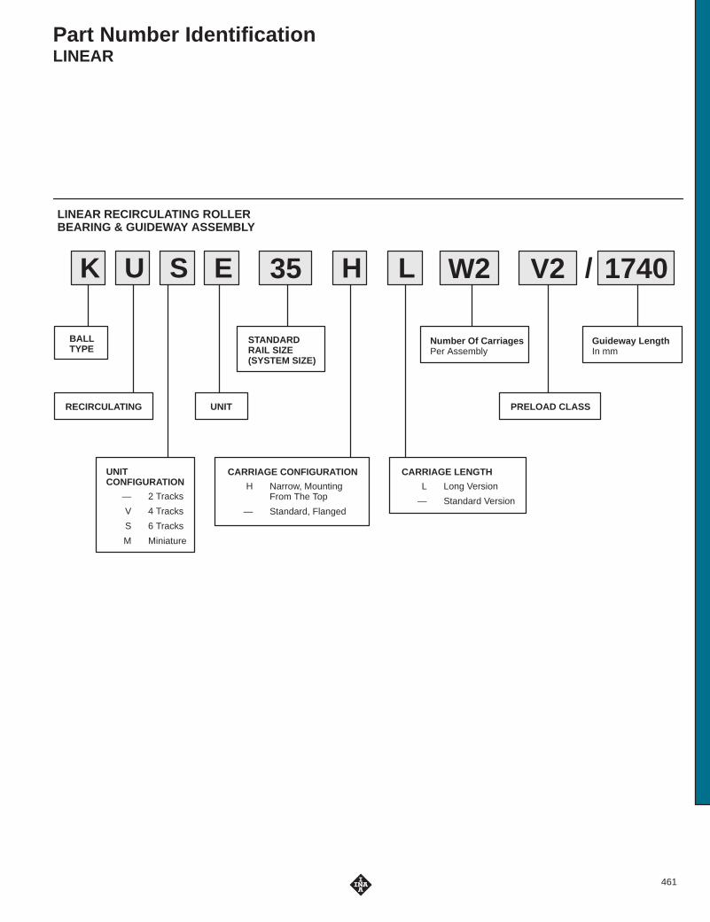
Part Number IdentificationLINEAR
LINEAR RECIRCULATING ROLLERBEARING & GUIDEWAY ASSEMBLY
W235SK U LE H V2 1740
BALLTYPE
RECIRCULATING
UNITCONFIGURATION
— 2 Tracks
V 4 Tracks
S 6 Tracks
M Miniature
STANDARDRAIL SIZE(SYSTEM SIZE)
CARRIAGE CONFIGURATION
H Narrow, MountingFrom The Top
— Standard, Flanged
CARRIAGE LENGTH
L Long Version
— Standard Version
Number Of CarriagesPer Assembly
/
PRELOAD CLASSUNIT
Guideway LengthIn mm

Part Number IdentificationLINEAR
LINEAR GUIDANCE SYSTEMS
32VK U S
RECIRCULATING
BALL DESIGNSERIES
BEARINGSIZE
SINGLE BEARING UNIT
32TKVD
RAIL SERIES SIZE
1000
LengthIn mm
/
462

463
Part Number IdentificationLINEAR
LF CARRIAGES & RAILS
32LLF K SF
SYSTEMTYPE
RAIL SIZE(CARRIAGE SIZE)
DESIGN CONFIGURATION
K Wrap Around Style,With Front & Longitudinal Wipers
C Hollow
— Standard
D Bogey Type(To Be Used In Curved Rails)Or Two Rollers / Cartridge
E Single Roller Cartridge
CARRIAGE
K Cartridge
4 CONCENTRIC SCREWSNot Adjustable
32 NZZLF S 1000
SYSTEMTYPE
RAIL WIDTHIn Millimeters
RAIL CONFIGURATION
C Hollow
F Flat
N, NZZ T-Bolt Mounting
M Module
— Standard
H Half Rail
R Curved Rail
ZZ Wide Profile
/
DENOTES RAIL ONLY
LENGTHIn Millimeters

Part Number IdentificationLINEAR
BALL
T N
METRIC HOUSING UNITS
PP40
BEARING USED
H KH
N KN
B KB
Bearing boreIn mm
HOUSINGCONFIGURATION
O Open
C Side Mount
K AS
SEALS
P One Seal
PP 2 Seals
— No Seals
O S
NUMBER OFBEARINGSIN HOUSING
T 2
G 1
ADJUSTABLECLEARANCE
RELUBRICATINGFEATURE
464
UNIT CONFIGURATIONG Single Housed
T Tandem Housed
— Bearing Only
BEARINGX Inch,
Self-Aligning
S Metric,Self-Aligning
BALL
HOUSING STYLE— Cast 2-Bolt Housing
A Cast 4-Bolt Housing
N Extruded Housing
C Side Mount Housing
MAX3 INCH & METRIC BEARINGS & HOUSING UNITS
BOREFor X Series (Inch)
16ths Of An Inch
For S Series (Metric)In mm
DESIGNCONFIGURATION
G Closed
S Adjustable
O Open
SEALSP One Seal
PP Two Seals
— No Seals
PP16XG
NOTE: Extruded HousingStandard On Tandem Units
K

465
Part Number IdentificationLINEAR
BALL
B Z
INCH BEARINGS & HOUSING UNITS
OP16
BEARING DESIGN
B Solid Metal Outer
N Self AligningZ Inch Dimension
Shaft SizeIn SixteenthsOf An Inch
BEARING CONFIGURATION
OP Open
ADJ Adjustable
— Closed
K PP
SEALS
P One Seal
PP 2 Seals
— No Seals
G Housing
T TandemTwin Bearing In Housing
G B Z OP16K PP

Part Number IdentificationLINEAR
SHAFT
W H
SHAFTS(METRIC & INCH)
50 J5 1000x
SHAFT SERIES
M Metric
Z Inch
H Hollow, Metric
TOLERANCE CLASS
— h6
L Large
S Small
SHAFT OD (NOMINAL)
Millimeters
Inches
MATERIAL
— InductionHardened Steel
X46CR13 Stainless Steel
LENGTH
In mm Or Inches
RAIL CONFIGURATION
W Standard Height
N Full Profile Body
S Flange (Side) Mount
U Low Profile(Bottom) Mount
TS W
SUPPORT RAILS(METRIC & INCH)
50W A 1000x
ASSEMBLY WITH SHAFT
W With Shaft
— Rail Support Only
CONFIGURATION
A Narrow Body
— Standard Body
Z Inch Dimension
SHAFT DIAMETER
Millimeters
Sixteenths Of An Inch
OVERALL LENGTH
In mm For Metric Series,
Inch For Inch Series
SHAFT SUPPORT RAIL
466

467
Part Number IdentificationLINEAR
BALL
B O
METRIC BALL BUSHINGS
PP25 58
BEARING DESIGN
B Solid Metal Outer,Ground
N Self Aligning
H Light Series,Drawn Shell Type
BEARING CONFIGURATION
O Open
S Adjustable
— Closed
Nominal ShaftIn mm
SEALS
P One Seal
PP 2 Seals
— No Seals
With Lubrication HolesOn Outer Ring
K AS
Overall LengthIn mm
PLANETARY ROLLER SCREWS
8BRGT L KL 10
PLANETARYROLLERSCREW
2 100 150 R
SERIES
L Light
— Standard
NUT CONFIGURATION
— Standard, Split Nut
B Solid Nut
SCREWPITCHDIAMETERIn Millimeters
SCREW LEADIn Millimeters
USABLE STROKELENGTHIn Millimeters
/
OVERALL SCREWLENGTHIn Millimeters
RIGHT HANDTHREAD
QUALITYCLASS

468
KGF EE-0520N
SERIESKGF Flanged Ball Nut
KGM Cylindrical Ball Nut
DESIGND Per DIN 69051
N Per INA Standard
NOMINALPITCH DIA.In Millimeters
LEADIn Millimeters
SEALSBlank Without End Seals
EE With End Seals
BALL NUTS
KGS 1250050-0520
SERIESKGS Ball Screw Shaft
LEAD ACCURACY023 23 Micron/300 mm
050 50 Micron/300mm
NOMINALPITCH DIA.In Millimeters
LEADIn Millimeters
BALL SCREWSHAFT - DW
OVERALLSHAFT LENGTHIn Millimeters
END MACHINING OPTIONSBlank Form Z & Form Z
DW Form D & Form WDN Form D & Form NDZ Form D & Form ZCS per customer specification
KGT 1250-0520N
SERIESKGT Ball Screw
Assembly
LEAD ACCURACY023 23 Micron/300 mm
050 50 Micron/300mm
NOMINALPITCH DIA.In Millimeters
LEAD In Millimeters
BALL SCREWASSEMBLY - DW050
/
EEFM /
NUT DESIGND Per DIN 69051
N Per INA Standard NUT CONFIGURATIONF Single Flanged Nut (1 KGF)M Single Cylindrical Nut (1 KGM)
FM Double Preloaded Nut Unit (1 KGF 1 KGM)MM Double Preloaded Nut Unit (2 KGM)
NUT SEAL SUFFIXBlank Without
End Seals
EE WithEnd Seals
OVERALLSHAFTLENGTHIn Millimeters
END MACHINING OPTIONSBlank Form Z & Form Z
DW Form D & Form WDN Form D & Form NDZ Form D & Form ZCS per customer specification
Part Number IdentificationLINEAR

469
Part Number IdentificationLINEARCOMPONENT / FAMILY
LFS, LFS..C, M, TS..W, LFL, LFCL, LFR..
RUE, KUSE, KUVE, KUVS, KUE, KUME
FAMILYCOMPONENT LFS LFS..C,M TS.W LFL LFCL LFR..
Cap wiper ––– ––– ––– ––– ––– AB LFR
Lube & wiper unit ––– ––– AB..W AB/AB..LFL ––– AB..W
Side plates ––– ––– ––– ABAL ––– –––
End stops PAH ––– ––– ––– ––– –––
End plate ––– ANS LFS ––– ––– ––– –––
End Cover ––– KA LFS..C,M,CH ––– ––– KA LFS..CL –––
Cover strip ––– NAD ––– ––– ––– –––
Measuring system LMS LMS LMS ––– ––– –––
FAMILYCOMPONENT RUE KUSE KUVE KUVS KUE KUME
Cap wiper ––– ––– ––– ––– ––– AB LFR
Closing plugs (plastic) KA..TN KA..TN KA..TN KA..TN KA..TN KA..TN
Closing plugs (brass) KA..M KA..M ––– ––– KA..M –––
Mounting rail MSX MKSD MKVD ––– MKD MKMD
Hydraulic mounting device MVH ––– ––– ––– ––– –––
Cover strip ABDU ADBSE ––– ––– ––– –––
Sheet steel wiper APLU APLSE APLVE ––– APLE –––
Spring loaded scraper ––– AB KOL KWSE ––– ––– ––– –––
Braking element RUKS..D ––– ––– ––– ––– –––
Lube adapter plate BPLU BLSE ––– ––– BPLE –––
Grease lube adapter ––– SMAD KFE SMAD KFE ––– SMAD KFE –––
Oil lube adapter ––– SMAD KOE SMAD KOE ––– SMAD KOE –––
Lube metering unit SMDE ––– ––– ––– ––– –––
Damping carriage RUDS ––– ––– ––– ––– –––
Bellows ––– FBALG ––– ––– FBALG –––

Linear Recirculating Roller BearingAnd Guideway AssembliesRUE..D, RUE..DL, RUE 65 L SERIES
For details on part numbers, descriptive suffixes and various technical references, please refer to front of this section.For engineering or technical information contact your local sales representative or call Distributor Sales (800)523-6572 or Linear Sales (800)462-3399.
Linear roller bearingand guideway
assemblyGrease Lubrication
PART NUMBER
Linear roller bearingand guideway
assemblyOil Lubrication
PART NUMBER
CARRIAGE 1)
PART NUMBER
CARRIAGE
MASS
kg
GUIDEWAY
PARTNUMBER
GUIDEWAY
MASS
kg/m
GUIDEWAY
ClosingPlugs 2)
COVERINGSTRIP
L3)
mm
H
mm
A
mm
C4)
mm
RUE 35 D FE RUE 35 D OE RWU 35 D 2.0 TSX 35 D 5.9 KA 15 ADB 18 2960 48 100 120
RUE 35 D L FE RUE 35 D L OE RWU 35 D L 2.7 TSX 35 D 5.9 KA 15 ADB 18 2960 48 100 143
RUE 45 D FE RUE 45 D OE RWU 45 D 3.3 TSX 45 D 9.4 KA 20 ADB 23 2940 60 120 141
RUE 45 D L FE RUE 45 D L OE RWU 45 D L 4.4 TSX 45 D 9.4 KA 20 ADB 23 2940 60 120 175
RUE 55 D FE RUE 55 D OE RWU 55 D 5.6 TSX 55 D 13.3 KA 24 ADB 27 2520 70 140 170
RUE 55 D L OE RWU 55 D L 7.5 13.3 KA 24 ADB 27 2520 70 140 210
RUE 65 D L FE RUE 65 D L OE RWU 65 D L 14.4 TSX 65 D 21.5 KA 26 ADB 29 2520 90 170 252.8
RUE..D FE has lubrication nipple to DIN 71 412-A M8�1.RUE..D OE has connector with union nut similar to DIN 3 871-A.RUE 25 available on request.RUE..U: Linear roller bearing and guideway assembly with guideway for fixing from below, available on request.
1) Suffix FE for grease lubrication, suffix OE for oil lubrication.2) Closing plugs KA..TN are included with the delivery.3) Maximum length L of single-piece guideways, longer guideways are supplied as multi-piece guideways and are marked accordingly.4) Minimum covered length for sealing the lubrication connections.5) Dimensions C5 and C6 are dependent on the guideway length L.6) Position of the lubrication hole in the adjacent construction.7) Maximum diameter of the lubrication hole in the adjacent construction.8) Maximum length of fixing screw: H8 +3 mm.9) If there is a possibility of settling, the fixing screws should be secured against rotation.
DIAMETERS AND TIGHTENING TORQUES FOR THREADS AND SCREWS 9)
PART NUMBER K1For screws to DIN 912-12.9
K2For screws to DIN 912-12.9
K3Through holes for screws to
DIN 912-12.9
K6Through holes for screws to
DIN 7 984-8.8
Nmmax.
Nmmax.
Nmmax.
Nmmax.
RUE 35 D M8 41 M10 41 M8 41 M8 24
RUE 35 D L M8 41 M10 41 M8 41 M8 24
RUE 45 D M12 140 M12 83 M10 83 M10 48
RUE 45 D L M12 140 M12 83 M10 83 M10 48
RUE 55 D M14 220 M14 140 M12 140 M12 83
RUE 55 D L M14 220 M14 140 M12 140 M12 83
RUE 65 L M16 340 M16 220 M14 220 M14 130
RUE 55 D L FE TSX 55 D
470

Load directions
�� ��
���
�
�
�
�� ��
���
���
RUE..D(View rotated through 90�)
RUE..D
�� ���������� � ��� ��
�
��
��
��
������ �� ����
�� � ��� ��
!��"��� #��
!�$���"�������"�� %�
���&���
��
��
�'
�!
���&���
(�
��
�)
�*
AK2 K6 K2
Marking Locating face
Hh
h1
H8H3
Markinga A1
K3H1
H5 H7 H6
Locating face
A1
mm
A2
mm
a–0.005–0.035
mm
C1
mm
C2
mm
C3
mm
C4
mm
C55)
min.
mm
C55)
max.
mm
C65)
min.
mm
C65)
max.
mm
C76)
mm
d17)
max.
mm
H1
mm
H3
mm
H5
mm
H6
mm
H7
mm
H88)
mm
h
mm
h1
mm
33 82 34 91.4 62 52 40 20 31 20 31 14.3 6 6.5 6.6 8 20 12 11.1 30 19
33 82 34 114.4 62 52 40 20 31 20 31 25.8 6 6.5 6.6 8 20 12 11.1 30 19
37.5 100 45 107.5 80 60 52.5 20 41 20 41 16.2 6 8.5 8.5 8 26 15 13.5 38 22
37.5 100 45 141.7 80 60 52.5 20 41 20 41 33.3 6 8.5 8.5 8 26 15 13.5 38 22
43.5 116 53 130.8 95 70 60 20 47 20 47 21.2 6 11 10 12 31 18 15.5 45 28
43.5 116 53 170.5 95 70 60 20 47 20 47 41 6 11 10 12 31 18 15.5 45 28
53.5 142 63 207.6 110 82 75 20 61 20 61 49 6 11 10.2 15 39.2 23 23 53.8 30.3
LOAD CARRYING CAPACITY TABLE
PART NUMBER BASIC LOAD RATINGS MOMENT RATINGSPART NUMBER
C
kN
C0
kN
M0x
Nm
M0y
Nm
M0z
Nm
RUE 35 D 59 134 990 2140 1925
RUE 35 D L 70 169 1255 3370 3035
RUE 45 D 92 205 1805 3870 3485
RUE 45 D L 115 275 2410 6770 6095
RUE 55 D 135 305 3130 7035 6335
RUE 55 D L 167 405 4120 12010 10815
RUE 65 D L 270 640 7600 24000 21500
471

Linear Recirculating Roller BearingAnd Guideway AssembliesRUE..D H, RUE..D HL SERIES
For details on part numbers, descriptive suffixes and various technical references, please refer to front of this section.For engineering or technical information contact your local sales representative or call Distributor Sales (800)523-6572 or Linear Sales (800)462-3399.
Linear roller bearingand guideway
assemblyGrease Lubrication
PART NUMBER
Linear roller bearingand guideway
assemblyOil Lubrication
PART NUMBER
CARRIAGE 1)
PART NUMBER
CARRIAGE
MASS
kg
GUIDEWAY
PARTNUMBER
GUIDEWAY
MASS
kg/m
GUIDEWAY
ClosingPlugs 2)
COVERINGSTRIP
L3)
mm
H
mm
A
mm
C4)
mm
RUE 35 D H FE RUE 35 D H OE RWU 35 D H 1.7 TSX 35 D 5.9 KA 15 ADB 18 2 960 55 70 120
RUE 35 D HL FE RUE 35 D HL OE RWU 35 D HL 2.4 TSX 35 D 5.9 KA 15 ADB 18 2 960 55 70 143
RUE 45 D H FE RUE 45 D H OE RWU 45 D H 3.1 TSX 45 D 9.4 KA 20 ADB 23 2 940 70 86 141
RUE 45 D HL FE RUE 45 D HL OE RWU 45 D HL 4.0 TSX 45 D 9.4 KA 20 ADB 23 2 940 70 86 175
RUE 55 D H FE RUE 55 D H OE RWU 55 D H 5.3 TSX 55 D 13.3 KA 24 ADB 24 2 520 80 100 170
RUE 55 D HL FE RUE 55 D HL OE RWU 55 D HL 6.7 TSX 55 D 13.3 KA 24 ADB 24 2 520 80 100 210
RUE 65 D HL FE RUE 65 D HL OE RWU 65 D HL 13.6 TSX 65 D 21.5 KA 26 ADB 26 2 520 100 126 252.8
RUE..D H FE has lubrication nipple to DIN 71 412-A M8�1.RUE..D H OE has connector with union nut similar to DIN 3 871-A.RUE..DU: Linear roller bearing and guideway assembly with guideway for fixing from below, available on request.
1) Suffix FE for grease lubrication, suffix OE for oil lubrication.2) Closing plugs KA..TN are included with the delivery.3) Maximum length L of single-piece guideways, longer guideways are supplied as multi-piece guideways and are marked accordingly.4) Minimum covered length for sealing the lubrication connections.5) Dimensions C5 and C6 are dependent on the guideway length L.6) Position of the lubrication hole in the adjacent construction.7) Maximum diameter of the lubrication hole in the adjacent construction.8) If there is a possibility of settling, the fixing screws should be secured against rotation.
DIAMETERS AND TIGHTENING TORQUES FOR THREADS AND SCREWS 8)
PART NUMBER K1For screws to DIN 912-12.9
K2For screws to DIN 912-12.9
Nmmax.
Nmmax.
RUE 35 D H M8 41 M8 41
RUE 35 D HL M8 41 M8 41
RUE 45 D H M12 140 M10 83
RUE 45 D HL M12 140 M10 83
RUE 55 D H M14 220 M12 140
RUE 55 D HL M14 220 M12 140
RUE 65 D HL M16 340 M14 220
472

RUE..D H(View rotated through 90�)RUE..D H
��
!��"��� #��
������ �� ���� �� � �����(
�
�)��
�*
�
�
!
�'
��
��
���&���
!�$���"���
����"�� %�
���&���
�� ���������� � ��� ��
��
�
(�
+
+�
,,�
���&���
���&���
� ��
+�
!��"��� #��
+�
+)
+'
!��"��� #��
Load directions
�� ��
�� ��
���
�
�
�
���
���
A1
mm
A2
mm
a–0.005–0.035
mm
C1
mm
C2
mm
C4
mm
C55)
min.
mm
C55)
max.
mm
C65)
min.
mm
C65)
max.
mm
C76)
mm
d17)
max.
mm
H1
mm
H3
mm
H5
mm
H6
mm
H7
mm
h
mm
h1
mm
18 50 34 91.4 50 40 20 31 20 31 20.3 6 6.5 13.6 10.8 41 10 30 19
18 50 34 114.4 72 40 20 31 20 31 20.8 6 6.5 13.6 10.8 41 10 30 19
20.5 60 45 107.5 60 52.5 20 41 20 41 26.2 6 8.5 18.5 13.7 52 12.5 38 22
20.5 60 45 141.7 80 52.5 20 41 20 41 33.3 6 8.5 18.5 13.7 52 12.5 38 22
23.5 75 53 130.8 75 60 20 47 20 47 31.2 6 11 20 16 61 15 45 28
23.5 75 53 170.5 95 60 20 47 20 47 41 6 11 20 16 61 15 45 28
31.5 76 63 207.6 120 75 20 61 20 61 43.8 6 11 20.2 15 71.2 20 53.8 30.3
LOAD CARRYING CAPACITY TABLE
PART NUMBER BASIC LOAD RATINGS MOMENT RATINGSPART NUMBER
C
kN
C0
kN
M0x
Nm
M0y
Nm
M0z
Nm
RUE 35 D H 59 134 990 2140 1925
RUE 35 D HL 70 169 1255 3370 3035
RUE 45 D H 92 205 1805 3870 3485
RUE 45 D HL 115 275 2410 6770 6095
RUE 55 D H 135 305 3130 7035 6335
RUE 55 D HL 167 405 4120 12010 10815
RUE 65 D HL 270 640 7600 24000 21500
473

Position of oil connector, impermissible combinationsPosition of oil connector, possible combinations
Locking ElementRUKS..D SERIES
For details on part numbers, descriptive suffixes and various technical references, please refer to front of this section.For engineering or technical information contact your local sales representative or call Distributor Sales (800)523-6572 or Linear Sales (800)462-3399.
���
(�
+�
+*
(�
+�
+
+'
�'�-���
�'�-���
�'�-���
�'�-���
PART NUMBER MASS
kg
A
mm
H
mm
C
mm
A2
mm
A3
mm
C1
mm
C2
mm
C3
mm
C7
mm
RUKS 35 D S 2.8 98 48 135 82 24.5 113 62 52 32
RUKS 35 D O 2.8 98 48 135 82 – 113 62 52 32
RUKS 35 DH S 2.8 68 55 135 50 34.5 113 50 – 38
RUKS 35 DH O 2.8 68 55 135 50 – 113 50 – 38
RUKS 45 D S 4.5 118 60 156 100 22 134 80 60 33.5
RUKS 45 D O 4.5 118 60 156 100 – 134 80 60 33.5
RUKS 45 DH S 4.5 84 70 156 60 39 134 60 – 43.5
RUKS 45 DH O 4.5 84 70 156 60 – 134 60 – 43.5
RUKS 55 D S 7.6 138 70 185 116 18.5 163 95 70 40.5
RUKS 55 D O 7.6 138 70 185 116 – 163 95 70 40.5
RUKS 55 DH S 7.6 98 80 185 75 38.5 163 75 – 50.5
RUKS 55 DH O 7.6 98 80 185 75 – 163 75 – 50.5
474

Locking ElementRUKS..D SERIES
For details on part numbers, descriptive suffixes and various technical references, please refer to front of this section.For engineering or technical information contact your local sales representative or call Distributor Sales (800)523-6572 or Linear Sales (800)462-3399.
���
(�
+�
+*
(�
+�
+
+'
RUKS..D S RUKS..D O
�'�-�'�
�'�-�'�
��
�'
�� �
�
����
.�� ����"��
��
�'
�� �
�
����
.�� #��% %�
d1max.
mm
H1
mm
H3
mm
H7
mm
H9
mm
Suitable forguideway
K2
For screws toDIN 912-12.9
K2max.
Nm
K3
Through hole for screws toDIN 912-12.9
K3max.
Nm
PART NUMBER
6 6.5 21 12 13.2 TSX 35 D M10 41 M8 41 RUKS 35 D S
6 6.5 21 12 – TSX 35 D M10 41 M8 41 RUKS 35 D O
6 6.5 42 10 20.2 TSX 35 D M8 41 – – RUKS 35 DH S
6 6.5 42 10 – TSX 35 D M8 41 – – RUKS 35 DH O
6 8,5 27 15 15.6 TSX 45 D M12 83 M10 83 RUKS 45 D S
6 8.5 27 15 – TSX 45 D M12 83 M10 83 RUKS 45 D O
6 8.5 53 10 25.6 TSX 45 D M10 83 – – RUKS 45 DH S
6 8.5 53 10 – TSX 45 D M10 83 – – RUKS 45 DH O
6 11 32 18 18.8 TSX 55 D M14 140 M12 140 RUKS 55 D S
6 11 32 18 – TSX 55 D M14 140 M12 140 RUKS 55 D O
6 11 62 15 28.8 TSX 55 D M12 140 – – RUKS 55 DH S
6 11 62 15 – TSX 55 D M12 140 – – RUKS 55 DH O
475

Sheet Steel WiperAPLU SERIES
For details on part numbers, descriptive suffixes and various technical references, please refer to front of this section.For engineering or technical information contact your local sales representative or call Distributor Sales (800)523-6572 or Linear Sales (800)462-3399.
!�$���"��� ������/0� '�11���2� �3��
4��,"����� "��5������ ��� ��
��
+�
+��
�*
�'
PART NUMBER MASS
g
A5
mm
H3
mm
H10
mm
C7
mm
Suitable for linear recirculating roller bearingand guideway assembly
APLU 35 D 60 66.7 6.6 39.7 6.5 RUE 35 D RUE 35 D LU 35 60 66
13.6
39 6 5
RUE 35 D H RUE 35 D HL
APLU 45 D 75 81.5 8.5 49.3 6.5 RUE 45 D RUE 45 D LU 5 5 8 5
18.5
9 3 6 5
RUE 45 D H RUE 45 D HL
APLU 55 D 90 94.8 10 56.8 7.5 RUE 55 D RUE 55 D LU 55 90 9 8
20
56 8 5
RUE 55 D H RUE 55 D HL
APLU 65 D 105 120.3 10.2 76.2 6.3 – RUE 65 D L
20.2 – RUE 65 D HL
476

Lubrication Adapter PlateBPLU SERIES
For details on part numbers, descriptive suffixes and various technical references, please refer to front of this section.For engineering or technical information contact your local sales representative or call Distributor Sales (800)523-6572 or Linear Sales (800)462-3399.
������ �� ���� �� � ��� ����
+�
+��
�3
PART NUMBER
GREASE LUBRICATION
PART NUMBER
OIL LUBRICATION
MASS
g
A5
mm
H3
mm
H10
mm
C8
mm
Suitable for linear recirculating roller bearingand guideway assembly
BPLU 35 D FE BPLU 35 D OE 95 66.7 7.5 39.7 14 RUE 35 D RUE 35 D LU 35 U 35 O 95 66
11.5
39
RUE 35 D H RUE 35 D HL
BPLU 45 D FE BPLU 45 D OE 120 81.5 8 49.3 14 RUE 45 D RUE 45 D LU 5 U 5 O 0 8 5
15
9 3
RUE 45 D H RUE 45 D HL
BPLU 55 D FE BPLU 55 D OE 150 94.8 10 56.8 14 RUE 55 D RUE 55 D LU 55 U 55 O 50 9 8
20
56 8
RUE 55 D H RUE 55 D HL
BPLU 65 D FE BPLU 65 D OE 190 120.8 10.2 76.2 14 – RUE 65 D L
20.2 – RUE 65 D HL
BPLU..D FE has lubrication nipple to DIN 71 412-A M8�1.
BPLU..D OE has connector with union nut similar to DIN 3 871-A.
The lubrication nipple or connector can be replaced by a screw plug M8�1.
In series RUE..D H and RUE..D HL, the lubrication nipple protrudes about 9 mm from the side of the carriage.
477

Minimal Quantity LubricantMetering UnitSMDE SERIES
For details on part numbers, descriptive suffixes and various technical references, please refer to front of this section.For engineering or technical information contact your local sales representative or call Distributor Sales (800)523-6572 or Linear Sales (800)462-3399.
!�$���"��� ����"�� �", �������" ������ "� /0� �113'�2�
+�
+��
��
�'
�3
�
6���$���"��� #��� ��� �%�
126
608
�'
!�$���"�������"�� %�
6���$���"��� #��� �$�7�
126
608
SMDE..D S SMDE..D O
PART NUMBER MASS
g
A5
mm
H3
mm
H10
mm
C7with
RUE..DRUE..D H
mm
C7with
RUE..LRUE..D HL
mm
C8
mm
d1max
mm
Suitable for linear recirculating roller bearingand guideway assembly
SMDE 35 D S 170 66.9 6.6 41.1 44 55.5 25 – RUE 35 D RUE 35 D L
SMDE 35 D O 170 66.9 – 41.1 37.2 48.7 25 6 RUE 35 D RUE 35 D L
SMDE 35 D HS 200 66.9 13.6 48.1 50 50.5 25 – RUE 35 D H RUE 35 D HL
SMDE 35 D HO 200 66.9 – 48.1 43.2 43.7 25 6 RUE 35 D H RUE 35 D HL
SMDE 45 D S 200 81.7 8.5 51.2 44.8 61.8 25 – RUE 45 D RUE 45 D L
SMDE 45 D O 200 81.7 – 51.2 38 55 25 6 RUE 45 D RUE 45 D L
SMDE 45 D HS 260 81.7 18.5 61.2 54.8 61.8 25 – RUE 45 D H RUE 45 D HL
SMDE 45 D HO 260 81.7 – 61.2 48 55 25 6 RUE 45 D H RUE 45 D HL
SMDE 55 D S 240 95 10 58.9 51.5 71.5 25 – RUE 55 D RUE 55 D L
SMDE 55 D O 240 95 – 58.9 44.7 64.7 25 6 RUE 55 D RUE 55 D L
SMDE 55 D HS 340 95 20 68.9 61.5 71.5 25 – RUE 55 D H RUE 55 D HL
SMDE 55 D HO 340 95 – 68.9 54.7 64.7 25 6 RUE 55 D H RUE 55 D HL
SMDE 65 D S 500 121 10.2 78.5 – 85 25 – – RUE 65 D L
SMDE 65 D O 500 121 10.2 78.5 – 78.2 25 6 – RUE 65 D L
SMDE 65 D HS 500 121 20.2 88.5 – 80 25 – – RUE 65 D HL
SMDE 65 D HO 500 121 20.2 88.5 – 73.2 25 6 – RUE 65 D HL
In series RUE..D H and RUE..D HL, the lubrication connector protrudes about 9 mm from the side of the carriage.
478

Damping CarriageRUDS SERIES
For details on part numbers, descriptive suffixes and various technical references, please refer to front of this section.For engineering or technical information contact your local sales representative or call Distributor Sales (800)523-6572 or Linear Sales (800)462-3399.
�
�������
+�
(�
+�
+� +
∅ �
��)-���
RUDS (View rotated through 90�)
�
�� ��
��
�� ��
��
PART NUMBER MASS
kg/100 mm
A
mm
H
mm
H1
mm
H2
mm
H3
m
A1
mm
C1
mm
C2
mm
C3
mm
K22)
3)
Suitable for linear recirculating rollerbearing and guideway assembly
RUDS 35 D 2.1 98 48 6.5 36 21 82 37.5 75 75 M10 M8 RUE 35 D RUE 35 D L
RUDS 35 D H 1.8 68 55 6.5 – 42 50 37.5 75 75 M8 – RUE 35 D H RUE 35 D HL
RUDS 45 D 3.6 118 60 8.5 45 27 100 37.5 75 75 M12 M10 RUE 45 D RUE 45 D L
RUDS 45 D H 3 84 70 8.5 – 53 60 37.5 75 75 M10 – RUE 45 D H RUE 45 D HL
RUDS 55 D 4.4 138 70 11 52 32 116 37.5 75 75 M14 M12 RUE 55 D RUE 55 D L
RUDS 55 D H 3.7 98 80 11 – 62 75 37.5 75 75 M12 – RUE 55 D H RUE 55 D HL
RUDS 65 D 5 168 90 11 67 40.2 142 37.5 75 75 M16 M14 – RUE 65 D L
RUDS 65 D H 4.6 124 100 11 – 72.2 76 37.5 75 75 M16 – – RUE 65 D HL
�8 "��%��% ����", 9� � ��� ��� ��" 6:/ )�� � ��� ��� ��" 6:/ )�� � ��� ���
�8 ��� �� "� /0� *��2���*�",���% ����", #�� 6:/��/ +9 �" ��� " ���� ; (�
�8 (� � ",����, ,��� #�� �� "� /0� *��2���*�
479

Linear Recirculating Ball Bearing And GuidewayAssembliesKUSE SERIES
For details on part numbers, descriptive suffixes and various technical references, please refer to front of this section.For engineering or technical information contact your local sales representative or call Distributor Sales (800)523-6572 or Linear Sales (800)462-3399.
L
C6C4C5
a
K7
hH9
Guideway TKSD..U for mounting from below, suffix U (example: KUSE..U)
DIMENSION TABLE · Dimensions in mm
UNIT CARRIAGE GUIDEWAY DIMENSIONS MOUNTING DIMENSIONS
PART NUMBER PARTNUMBER
MASS
kg
PARTNUMBER
MASS
kg/m
CLOSINGPLUGS
COVERINGSTRIP
L1) H A C2) A1 A2 a
–0.005–0.03
a3
KUSE 20 KWSE 20 0.43 TKSD 20 2.3 KA 10 TN ADB 13 1,980 30 63 71 21.5 53 20 5
KUSE 25 KWSE 25 0.6 TKSD 25 3.1 KA 11 TN ADB 13 1,980 36 70 81.5 23.5 57 23 6.5
KUSE 30 KWSE 30 1.2 TKSD 30 4.4 KA 15 TN ADB 18 2 ,000 42 90 91.2 31 72 28 9
KUSE 35 KWSE 35 1.5 TKSD 35 6.5 KA 15 TN ADB 18 2 ,960 48 100 106.7 33 82 34 9
KUSE 45 KWSE 45 3.15 TKSD 45 11.3 KA 20 TN ADB 23 2,940 60 120 136.5 37.5 100 45 10
KUSE 55 KWSE 55 4.9 TKSD 55 15.7 KA 24 TN ADB 23 2 ,520 70 140 158 43.5 116 53 12
1) Maximum length L of single piece guideway; longer guideways are supplied as multi-piece guideways and are marked accordingly.
2) Minimum covered length for sealing the lubrication connections.3) Dimensions C5 and C6 are dependent on the guideway length L.4) Position of the lubrication hole in the adjacent construction.5) Maximum diameter of the lubrication hole in the adjacent construction.6) When mounting from above: maximum length of fixing screw for the central fixing holes H8 +3 mm.7) If there is a possibility of settling, the fixing screws should be secured against rotation.
DIAMETERS AND TIGHTENING TORQUES FOR THREADS AND SCREWS7)
PART NUMBER K1for screws to DIN 912-12.9
K2for screws to DIN 912-12.9
K3Through holes for screws toDIN 912-12.9
K6Through holes for screws toDIN 7 984-8.8
K7for screws to DIN 912-12.9
Nmmax.
Nmmax.
Nmmax.
Nmmax.
Nmmax.
KUSE 20 M5 10 M6 10 M5 10 M5 5.8 M6 17
KUSE 25 M6 17 M8 24 M6 17 M6 10 M6 17
KUSE 30 M8 41 M10 41 M8 41 M8 24 M8 41
KUSE 35 M8 41 M10 41 M8 41 M8 24 M8 41
KUSE 45 M12 140 M12 83 M10 83 M10 48 M12 140
KUSE 55 M14 220 M14 140 M12 140 M12 83 M14 220
480

��
�����&���
(�
�� ��
!
!�$���"�������"�� %�
�)
�
�' ��
� �*
!��"��� #��
(�
��
�
����
(� < /0� '�11���2��)
+
+�+�+�
,
(�
�� �
+�,�
()
+3
���&���!��"���#��
Load directions
��)-��3
00
0
000
���
����
�
�
���
KUSE, plan view X(rotated through 90�)
KUSE
C1 C2 C3 C4 C53) C6
3) C74) d1
5) H1 H2 H4 H5 H86) H9 h h1
min. max. min. max. max.
52 40 35 60 20 53 20 53 9.8 3 4.6 5 10 10.4 7.2 10 18 10.3
60.5 45 40 60 20 53 20 53 12.8 3 5.2 5 10 9.5 9.5 12 21.7 12.7
67.2 52 44 80 20 71 20 71 12.6 4.5 5.5 6 12 11.9 10 15 25 14
77.7 62 52 80 20 71 20 71 11.7 4.5 6.6 6.5 13 13 12 15 29.7 18.7
102.5 80 60 105 20 94 20 94 15.8 6 8.6 9 15 15.5 15 20 37.2 21.2
117.7 95 70 120 20 107 20 107 19.2 6 10.8 12 18 18.6 17 22 44 27
LOAD CARRYING CAPACITY TABLE
PART NUMBER BASIC LOAD RATINGS MOMENT RATINGS
LOAD DIRECTION I: COMPRESSIVE LOAD
LOAD DIRECTION II: TENSILE LOAD
LOAD DIRECTION III: LATERAL LOAD
C
kN
C0
kN
C
kN
C0
kN
C
kN
C0
kN
M0x
Nm
M0y
Nm
M0z
Nm
KUSE 20 22 52 17.5 33.5 16.3 36 358 333 303
KUSE 25 28 67 22.9 43 21.3 46 535 486 442
KUSE 30 40 80 33 60 30.5 64 896 762 694
KUSE 35 55 102 45 79 42 85 1 ,454 1,173 1,069
KUSE 45 80 174 65 117 59 126 2 ,794 2,237 2,037
KUSE 55 102 230 81 147 75 157 4 ,114 3,141 2 ,861
481

Linear Recirculating Ball Bearing And Guideway AssembliesKUSE..L SERIES
For details on part numbers, descriptive suffixes and various technical references, please refer to front of this section.For engineering or technical information contact your local sales representative or call Distributor Sales (800)523-6572 or Linear Sales (800)462-3399.
L
C6C4C5
a
K7
hH9
Guideway TKSD..U for mounting from below, suffix U (example: KUSE..U)
DIMENSION TABLE · Dimensions in mm
UNIT Carriage GUIDEWAY DIMENSIONS MOUNTING DIMENSIONS
PART NUMBER PART NUMBER MASS
kg
PART NUMBER MASS
kg/m
CLOSINGPLUGS
COVERINGSTRIP
L1) H A C2) A1 A2 a
–0.005–0.03
a3
KUSE 20 L KWSE 20 L 0.6 TKSD 20 2.3 KA 10 TN ADB 13 1 ,980 30 63 90.8 21.5 53 20 5
KUSE 25 L KWSE 25 L 0.82 TKSD 25 3.1 KA 11 TN ADB 13 1,980 36 70 104 23.5 57 23 6.5
KUSE 30 L KWSE 30 L 1.6 TKSD 30 4.4 KA 15 TN ADB 18 2,000 42 90 118.7 31 72 28 9
KUSE 35 L KWSE 35 L 2.1 TKSD 35 6.5 KA 15 TN ADB 18 2,960 48 100 138.4 33 82 34 9
KUSE 45 L KWSE 45 L 4.2 TKSD 45 11.3 KA 20 TN ADB 23 2 ,940 60 120 172.2 37.5 100 45 10
KUSE 55 L KWSE 55 L 6.6 TKSD 55 15.7 KA 24 TN ADB 23 2 ,520 70 140 198 43.5 116 53 12
1) Maximum length L of single piece guideway; longer guideways are supplied as multi-piece guideways and are marked accordingly.
2) Minimum covered length for sealing the lubrication connections.3) Dimensions C5 and C6 are dependent on the guideway length L.4) Position of the lubrication hole in the adjacent construction.5) Maximum diameter of the lubrication hole in the adjacent construction.6) When mounting from above: maximum length of fixing screw for the central fixing holes H8 +3 mm.7) If there is a possibility of settling, the fixing screws should be secured against rotation.
DIAMETERS AND TIGHTENING TORQUES FOR THREADS AND SCREWS7)
PART NUMBER K1for screws to DIN 912-12.9
K2for screws to DIN 912–12.9
K3Through holes for screws toDIN 912-12.9
K6Through holes for screws toDIN 7 984-8.8
K7for screws to DIN 912-12.9
Nmmax.
Nmmax.
Nmmax.
Nmmax.
Nmmax.
KUSE 20 L M5 10 M6 10 M5 10 M5 5.8 M6 17
KUSE 25 L M6 17 M8 24 M6 17 M6 10 M6 17
KUSE 30 L M8 41 M10 41 M8 41 M8 24 M8 41
KUSE 35 L M8 41 M10 41 M8 41 M8 24 M8 41
KUSE 45 L M12 140 M12 83 M10 83 M10 48 M12 140
KUSE 55 L M14 220 M14 140 M12 140 M12 83 M14 220
482

��
�����&���
(�
�� ��!
!�$���"�������"�� %�
�)
�
�' ��
� �*
!��"��� #��
(� ��
�
����
(� < /0� '�11���2��)
+
+�+�+�
,
(�
�� �
+�,�
()
+3
���&���!��"���#��
Load directions
��)-��3
00
0
000
���
����
�
�
���
KUSE..L, plan view X(rotated through 90�)
KUSE..L
C1 C2 C3 C4 C53) C6
3} C74) d1
5) H1 H2 H4 H5 H86) H9 h h1
min. max. min max. max.
71.8 40 35 60 20 53 20 53 19.7 3 4.6 5 10 10.4 7.2 10 18 10.3
83 45 40 60 20 53 20 53 24 3 5.2 5 10 9.5 9.5 12 21.7 12.7
94.7 52 44 80 20 71 20 71 26.3 4.5 5.5 6 12 11.9 10 15 25 14
109.4 62 52 80 20 71 20 71 27.5 4.5 6.6 6.5 13 13 12 15 29.7 18.7
138.2 80 60 105 20 94 20 94 33.6 6 8.6 9 15 15.5 15 20 37.2 21.2
157.7
�
95 70 120 20 107 20 107 39.2 6 10.8 12 18 18.6 17 22 44 27
LOAD CARRYING CAPACITY TABLE
PART NUMBER BASIC LOAD RATINGS MOMENT RATINGS
LOAD DIRECTION I: COMPRESSIVE LOAD
LOAD DIRECTION II: TENSILE LOAD
LOAD DIRECTION III: LATERAL LOAD
C
kN
C0
kN
C
kN
C0
kN
C
kN
C0
kN
M0x
Nm
M0y
Nm
M0z
Nm
KUSE 20 L 28 72 22.2 46.5 18.9 50 494 619 564.6
KUSE 25 L 35.3 93.7 28.9 59.8 24.7 64 736 903 823
KUSE 30 L 51 113 42.4 84.3 36.5 90 1,265 1,478 1,346
KUSE 35 L 70 145 57.3 112.4 49.5 120 2 ,054 2 ,275 2,072
KUSE 45 L 98 236 79.3 159 69 170 3,792 4,011 3,654
KUSE 55 L 125.4 312 100.6 199.4 87 214 5,584 5 ,633 5,132
483

Linear Recirculating Ball Bearing And Guideway AssembliesKUSE..H SERIES
For details on part numbers, descriptive suffixes and various technical references, please refer to front of this section.For engineering or technical information contact your local sales representative or call Distributor Sales (800)523-6572 or Linear Sales (800)462-3399.
L
C6C4C5
a
K7
hH9
Guideway TKSD..U for mounting from below, suffix U (example: KUSE..U)
DIMENSION TABLE · Dimensions in mm
UNIT CARRIAGE GUIDEWAY DIMENSIONS MOUNTING DIMENSIONS
PART NUMBER PART NUMBER MASS
kg
PART NUMBER Mass
kg/m
CLOSINGPLUGS
COVERINGSTRIP
L1) H A C2) A1 A2 a
–0.005–0.03
a3
KUSE 20 H KWSE 20 H 0.32 TKSD 20 2.3 KA 10 TN ADB 13 1,980 30 44 71 12 32 20 6
KUSE 25 H KWSE 25 H 0.5 TKSD 25 3.1 KA 11 TN ADB 13 1,980 40 48 81.5 12.5 35 23 6.5
KUSE 30 H KWSE 30 H 0.9 TKSD 30 4.4 KA 15 TN ADB 18 2,000 45 60 91.2 16 40 28 10
KUSE 35 H KWSE 35 H 1.3 TKSD 35 6.5 KA 15 TN ADB 18 2,960 55 70 106.7 18 50 34 10
KUSE 45 H KWSE 45 H 2.75 TKSD 45 11.3 KA 20 TN ADB 23 2,940 70 86 136.5 20.5 60 45 13
KUSE 55 H KWSE 55 H 4.5 TKSD 55 15.7 KA 24 TN ADB 23 2,520 80 100 158 23.5 75 53 12.5
1) Maximum length L of single piece guideway; longer guideways are supplied as multi-piece guideways and are marked accordingly.
2) Minimum covered length for sealing the lubrication connections.3) Dimensions C5 and C6 are dependent on the guideway length L.4) Position of the lubrication hole in the adjacent construction.5) Maximum diameter of the lubrication hole in the adjacent construction.6) If there is a possibility of settling, the fixing screws should be secured against rotation.
DIAMETERS AND TIGHTENING TORQUES FOR THREADS AND SCREWS6)
PART NUMBER K1for screws to DIN 912-12.9
K2for screws to DIN 912-12.9
K7for screws to DIN 912-12.9
Nmmax.
Nmmax.
Nmmax.
KUSE 20 H M5 10 M5 10 M6 17
KUSE 25 H M6 17 M6 17 M6 17
KUSE 30 H M8 41 M8 41 M8 41
KUSE 35 H M8 41 M8 41 M8 41
KUSE 45 H M12 140 M10 83 M12 140
KUSE 55 H M14 220 M12 140 M14 220
484

DIN 71 412-A M6Locating face
Marking
aA1
H
h
H5 H6
H1
h1
Aa3 A2
H2
K2C1
C6
194C
C2
Marking
Locating face
Lubrication connector d1
C7
C4L
C5
K1
Load directions
���
���
���
0
00
000
�� ��
�� ��
�
�
�
KUSE..H, plan view(rotated through 90�)
KUSE..H
C1 C2 C4 C53) C6
3) C74) d1
5) H1 H2 H5 H6 H9 h h1
min. max. min. max. max.
52 36 60 20 53 20 53 11.8 3 4.6 5 6.25 5.8 10 18 10.3
60.5 35 60 20 53 20 53 17.8 3 5.2 5 10 10 12 21.7 12.7
67.2 40 80 20 71 20 71 18.6 4.5 5.5 6 11 9.5 15 25 14
77.7 50 80 20 71 20 71 17.7 4.5 6.6 6.5 14 14.2 15 29.7 18.7
102.5 60 105 20 94 20 94 25.8 6 8.6 9 17 18.5 20 37.2 21.2
117.7 75 120 20 107 20 107 29.2 6 10.8 12 19 20 22 44 27
LOAD CARRYING CAPACITY TABLE
PART NUMBER BASIC LOAD RATINGS MOMENT RATINGS
LOAD DIRECTION I: COMPRESSIVE LOAD
LOAD DIRECTION II: TENSILE LOAD
LOAD DIRECTION III: LATERAL LOAD
C
kN
C0
kN
C
kN
C0
kN
C
kN
C0
kN
M0x
Nm
M0y
Nm
M0z
Nm
KUSE 20 H 22 52 17.5 33.5 16.3 36 358 333 303
KUSE 25 H 28 67 22.9 43 21.3 46 535 486 442
KUSE 30 H 40 80 33 60 30.5 64 896 762 694
KUSE 35 H 55 102 45 79 42 85 1,454 1,173 1,069
KUSE 45 H 80 174 65 117 59 126 2,794 2,237 2,037
KUSE 55 H 102 230 81 147 75 157 4,114 3,141 2,861
485

Linear Recirculating Ball Bearing And Guideway AssembliesKUSE..HL SERIES
For details on part numbers, descriptive suffixes and various technical references, please refer to front of this section.For engineering or technical information contact your local sales representative or call Distributor Sales (800)523-6572 or Linear Sales (800)462-3399.
L
C6C4C5
a
K7
hH9
Guideway TKSD..U for mounting from below, suffix U (example: KUSE..U)
DIMENSION TABLE · Dimensions in mm
UNIT CARRIAGE GUIDEWAY DIMENSIONS MOUNTING DIMENSIONS
PART NUMBER PART NUMBER MASS
kg
PARTNUMBER
MASS
kg/m
CLOSINGPLUGS
COVERINGSTRIP
L1) H A C2) A1 A2 a
–0.05–0.03
a3
KUSE 20 HL KWSE 20 HL 0.44 TKSD 20 2.3 KA 10 TN ADB 13 1,980 30 44 90.8 12 32 20 6
KUSE 25 HL KWSE 25 HL 0.7 TKSD 25 3.15 KA 11 TN ADB 13 1,980 40 48 104 12.5 35 23 6.5
KUSE 30 HL KWSE 30 HL 1.2 TKSD 30 4.4 KA 15 TN ADB 18 2,000 45 60 118.7 16 40 28 10
KUSE 35 HL KWSE 35 HL 1.8 TKSD 35 6.5 KA 15 TN ADB 18 2,960 55 70 138.4 18 50 34 10
KUSE 45 HL KWSE 45 HL 3.7 TKSD 45 11.3 KA 20 TN ADB 23 2,940 70 86 172.2 20.5 60 45 13
KUSE 55 HL KWSE 55 HL 5.9 TKSD 55 15.7 KA 24 TN ADB 23 2,520 80 100 198 23.5 75 53 12.5
1) Maximum length L of single piece guideway; longer guideways are supplied as multi-piece guideways and are marked accordingly.
2) Minimum covered length for sealing the lubrication connections.3) Dimensions C5 and C6 are dependent on the guideway length L.4) Position of the lubrication hole in the adjacent construction.5) Maximum diameter of the lubrication hole in the adjacent construction.6) If there is a possibility of settling, the fixing screws should be secured against rotation.
DIAMETERS AND TIGHTENING TORQUES FOR THREADS AND SCREWS6)
PART NUMBER K1for screws to DIN 912-12.9
K2for screws to DIN 912-12.9
K7for screws to DIN 912-12.9
Nmmax.
Nmmax.
Nmmax.
KUSE 20 HL M5 10 M5 10 M6 17
KUSE 25 HL M6 17 M6 17 M6 17
KUSE 30 HL M8 41 M8 41 M8 41
KUSE 35 HL M8 41 M8 41 M8 41
KUSE 45 HL M12 140 M10 83 M12 140
KUSE 55 HL M14 220 M12 140 M14 220
486

X
DIN 71 412-A M6Locating face
Marking
aA1
H
h
H5 H6
H1
h1
Aa3 A2
H2
K2
C1
4 19C
C2C7
L
C4 C5
C6
K1
Lubricationconnector d1
Marking
Locating face
Load directions
��)-�3�
���
���
���
0
00
000
�� ��
�� ��
�
�
�
KUSE..HL, plan view X(rotated through 90�)KUSE..HL
C1 C2 C4 C53) C6
3) C74) d1
5) H1 H2 H5 H6 H9 h h1
min max. min. max. max.
71.8 50 60 20 53 20 53 14.7 3 4.6 5 6.25 5.8 10 18 10.3
83 50 60 20 53 20 53 21.5 3 5.2 5 10 10 12 21.7 12.7
94.7 60 80 20 71 20 71 22.3 4.5 5.5 6 11 9.5 15 25 14
109.4 72 80 20 71 20 71 22.5 4.5 6.6 6.5 14 14.2 15 29.7 18.7
138.2 80 105 20 94 20 94 33.6 6 8.6 9 17 18.5 20 37.2 21.2
157.7 95 120 20 107 20 107 39.2 6 10.8 12 19 20 22 44 27
LOAD CARRYING CAPACITY TABLE
PART NUMBER BASIC LOAD RATINGS MOMENT RATINGS
LOAD DIRECTION I: COMPRESSIVE LOAD
LOAD DIRECTION II: TENSILE LOAD
LOAD DIRECTION III: LATERAL LOAD
C
kN
C0
kN
C
kN
C0
kN
C
kN
C0
kN
M0x
Nm
M0y
Nm
M0z
Nm
KUSE 20 HL 28 72 22.2 46.5 18.9 50 494 619 564
KUSE 25 HL 35.3 93.7 28.9 59.8 24.7 64 736 903 823
KUSE 30 HL 51 113 42.4 84.3 36.5 90 1,265 1,478 1,346
KUSE 35 HL 70 145 57.3 112.4 49.5 120 2,054 2,275 2,072
KUSE 45 HL 98 236 79.3 159 69 170 3,792 4,011 3,654
KUSE 55 HL 125.4 312 100.6 199.4 87 214 5,584 5,633 5,132
487

Sheet Steel WiperAPLSE SERIES
For details on part numbers, descriptive suffixes and various technical references, please refer to front of this section.For engineering or technical information contact your local sales representative or call Distributor Sales (800)523-6572 or Linear Sales (800)462-3399.
+)
��
+*
!�$���"��� ������/0� '�1���2� �3�� 4��,"�����
"��5������ ��� ��
���
���
�3 �*
DIMENSION TABLE · Dimensions in mm
PART NUMBER MASS DIMENSIONS SUITABLE FOR LINEAR RECIRCULATING BALL BEARING
gA4 H9 C8 H6
LINEAR RECIRCULATING BALL BEARING AND GUIDEWAY ASSEMBLY
APLSE 20 26 42.8 24.9 0.8 5.8 KUSE 20 KUSE 20 LS 0 6 8 9 0 8
5.8 KUSE 20 H KUSE 20 HL
APLSE 25 27 46 30.1 0.8 6 KUSE 25 KUSE 25 LS 5 6 30 0 8
10 KUSE 25 H KUSE 25 HL
APLSE 30 31 58 35.8 0.8 6.5 KUSE 30 KUSE 30 LS 30 3 58 35 8 0 8
9.5 KUSE 30 H KUSE 30 HL
APLSe 35 34 68 40.7 0.8 7.2 KUSE 35 KUSE 35 LSe 35 3 68 0 0 8
14.2 KUSE 35 H KUSE 35 HL
APLSE 45 40 84 50.7 0.8 8.5 KUSE 45 KUSE 45 LS 5 0 8 50 0 8
8.5 KUSE 45 H KUSE 45 HL
APLSE 55 46 96.4 58.5 0.8 10 KUSE 55 KUSE 55 L
20 KUSE 55 H KUSE 55 HL
When fitting the wiper, it must be ensured that the gap between the guideway and the sheet steel wiper is of the correct size (see figure above).
488

Collector WiperAB KOL KWSE SERIES
For details on part numbers, descriptive suffixes and various technical references, please refer to front of this section.For engineering or technical information contact your local sales representative or call Distributor Sales (800)523-6572 or Linear Sales (800)462-3399.
!�$���"��� ������/0� '�1���2� �3��
4��,"����� "��5������ ��� ��
+)
+*
����
�* �*
DIMENSION TABLE · Dimensions in mm
PART NUMBER MASS DIMENSIONS SUITABLE FOR LINEAR RECIRCULATING BALL BEARING
gA4 H9 C9 H6
LINEAR RECIRCULATING BALL BEARING AND GUIDEWAY ASSEMBLY
AB KOL KWSE 20 46 42.8 24.9 9 5.8 KUSE 20 KUSE 20 L
5.8 KUSE 20 H KUSE 20 HL
AB KOL KWSE 25 51 46 30.1 9 6 KUSE 25 KUSE 25 L
10 KUSE 25 H KUSE 25 HL
AB KOL KWSE 30 69 58 35.8 9 6.5 KUSE 30 KUSE 30 L
9.5 KUSE 30 H KUSE 30 HL
AB KOL KWSE 35 82 68 40.7 9 7.2 KUSE 35 KUSE 35 L
14.2 KUSE 35 H KUSE 35 HL
AB KOL KWSE 45 109 84 50.7 11 8.5 KUSE 45 KUSE 45 L
18.5 KUSE 45 H KUSE 45 HL
AB KOL KWSE 55 136 96.4 58.5 11 10 KUSE 55 KUSE 55 L
20 KUSE 55 H KUSE 55 HL
If the collector wiper AB KOL KWSE is used, the covering strip ADBSE or closing plugs KA..M must be used.
489

Lubrication Adapter PlateBPLSE SERIES
For details on part numbers, descriptive suffixes and various technical references, please refer to front of this section.For engineering or technical information contact your local sales representative or call Distributor Sales (800)523-6572 or Linear Sales (800)462-3399.
+)
��
+*
!�$���"��� ������/0� '�1���2� �3��
4��,"�����"��5������ ��� ��
��
)��
DIMENSION TABLE · Dimensions in mm
PART NUMBER Mass DIMENSIONS SUITABLE FOR LINEAR RECIRCULATING BALL BEARING
gA4 H9 H6
LINEAR RECIRCULATING BALL BEARING AND GUIDEWAY ASSEMBLY
BPLSE 20 29 42.8 24.9 5.8 KUSE 20 KUSE 20 LS 0 9 8 9
5.8 KUSE 20 H KUSE 20 HL
BPLSE 25 35 46 30.1 6 KUSE 25 KUSE 25 LS 5 35 6 30
10 KUSE 25 H KUSE 25 HL
BPLSE 30 52 58 35.8 6.5 KUSE 30 KUSE 30 LS 30 5 58 35 8
9.5 KUSE 30 H KUSE 30 HL
BPLSE 35 67 68 40.7 7.2 KUSE 35 KUSE 35 LS 35 6 68 0
14.2 KUSE 35 H KUSE 35 HL
BPLSE 45 98 84 50.7 8.5 KUSE 45 KUSE 45 LS 5 98 8 50
18.5 KUSE 45 H KUSE 45 HL
BPLSE 55 128 96.4 58.5 10 KUSE 55 KUSE 55 LS 55 8 96 58 5
20 KUSE 55 H KUSE 55 HL
The lubrication nipple to DIN 71412-A M8�1 can be replaced by a screw plug M8�1.
Note:
In series KUSE..H and KUSE..HL. the lubrication nipple protrudes about 9 mm from the side of the carriage.
490

BellowsFBALG KWSE SERIES
For details on part numbers, descriptive suffixes and various technical references, please refer to front of this section.For engineering or technical information contact your local sales representative or call Distributor Sales (800)523-6572 or Linear Sales (800)462-3399.
!��� != !���
��
�
�����
���
!
��� ������
�
����
+ ,�
+�
,�
,�
Dimension table · Dimensions in mm
PART NUMBER DIMENSIONS SUITABLE FOR LINEAR RECIRCULATING BALL BEARING
A a11) a2 H H1 h1 h2 h3 ApF
2) lp min3)
RECIRCULATING BALL BEARING AND GUIDEWAY ASSEMBLY
FBALG KWSE120 63 42.8 21 30 4.8 24.9 11 24.2 14.5 2.5 KUSE 20 KUSE 20 L
44 30 KUSE 20 H KUSE 20 HL
FBALG KWSE125 70 46 24 36 5.4 30.1 11 30 14.5 2.5 KUSE 25 KUSE 25 L
48 40 KUSE 25 H KUSE 25 HL
FBALG KWSE130 90 58 29 42 5.7 35.8 14 35.5 18 2.5 KUSE 30 KUSE 30 L
60 45 KUSE 30 H KUSE 30 HL
FBALG KWSE135 100 68 35 48 6.8 40.7 16 40.8 22.5 2.5 KUSE 35 KUSE 35 L
70 55 KUSE 35 H KUSE 35 HL
FBALG KWSE145 120 84 46 60 8.8 50.7 19 51.5 27 2.5 KUSE 45 KUSE 45 L
86 70 KUSE 45 H KUSE 45 HL
FBALG KWSE155 140 96.4 56 70 11 58.5 21 60 31.5 2.5 KUSE 55 KUSE 55 L
100 80 KUSE 55 H KUSE 55 HL
1) Maximum width of bellows in end gauge.2) Expansion per pleat.3) Compression per pleat.
491

PARTNUMBER
Nmmax.
Nmmax.
Nmmax.
Nmmax.
Nmmax.
KUVE 15 M4 5 M5 5.8 M4 5 M4 2.8 – –
KUVE 20 M5 10 M6 10 M5 10 – – M5 10
KUVE 20 L M5 10 M6 10 M5 10 – – M5 10
KUVE 20 N M5 10 M6 10 M5 10 M5 5.8 – –
KUVE 25 M6 17 M8 24 M6 17 – – M6 17
KUVE 25 L M6 17 M8 24 M6 17 – – M6 17
KUVE 25 N M6 17 M8 24 M6 17 M6 10 – –
KUVE 30 M8 41 M10 41 M8 41 M8 24 – –
KUVE 30 L M8 41 M10 41 M8 41 M8 24 – –
KUVE 30 N M8 41 M10 41 M8 41 M8 24 – –
KUVE 35 M8 41 M10 41 M8 41 – – M8 41
KUVE 35 L M8 41 M10 41 M8 41 – – M8 41
KUVE 35 N M8 41 M10 41 M8 41 M8 24 – –
KUVE 45 M12 140 M12 83 M10 83 – – M10 83
KUVE 45 L M12 140 M12 83 M10 83 – – M10 83
KUVE 45 N M12 140 M12 83 M10 83 M10 48 – –
PARTNUMBER
PARTNUMBER
MASS
kg
PARTNUMBER
MASS
kg/m
CLOSINGPLUGS
L1) H A C A1 A2 a-0.005-0.03
a3
KUVE 15 KWVE 15 0.25 TKVD 15 1.5 KA 08 TN A 1200 24 47 55.6 16 38 15 4.5
KUVE 20 KWVE 20 0.58 TKVD 20 2.2 KA 10 TN A 1980 30 63 69.8 21.5 53 20 5
KUVE 20 L KWVE 20 L 0.8 TKVD 20 2.2 KA 10 TN A 1980 30 63 87.3 21.5 53 20 5
KUVE 20 N KWVE 20 N 0.47 TKVD 20 2.2 KA 10 TN A 1980 27 63 69.8 21.5 53 20 5
KUVE 25 KWVE 25 0.71 TKVD 25 2.7 KA 11 TN A 1980 36 70 81.7 23.5 57 23 6.5
KUVE 25 L KWVE 25 L 1 TKVD 25 2.7 KA 11 TN A 1980 36 70 107.5 23.5 57 23 6.5
KUVE 25 N KWVE 25 N 0.57 TKVD 25 2.7 KA 11 TN A 1980 31 70 81.7 23.5 57 23 6.5
KUVE 30 KWVE 30 1.4 TKVD 30 4.3 KA 15 TN A 2000 42 90 97.6 31 72 28 9
KUVE 30 L KWVE 30 L 1.83 TKVD 30 4.3 KA 15 TN A 2000 42 90 122.6 31 72 28 9
KUVE 30 N KWVE 30 N 1.12 TKVD 30 4.3 KA 15 TN A 2000 38 90 97.6 31 72 28 9
KUVE 35 KWVE 35 2.02 TKVD 35 5.7 KA 15 TN A 2960 48 100 110.4 33 82 34 9
KUVE 35 L KWVE 35 L 2.71 TKVD 35 5.7 KA 15 TN A 2960 48 100 140.2 33 82 34 9
KUVE 35 N KWVE 35 N 1.62 TKVD 35 5.7 KA 15 TN A 2960 44 100 110.4 33 82 34 9
KUVE 45 KWVE 45 3.75 TKVD 45 9.2 KA 20 TN A 2940 60 120 139 37.5 100 45 10
KUVE 45 L KWVE 45 L 4.7 TKVD 45 9.2 KA 20 TN A 2940 60 120 167.5 37.5 100 45 10
KUVE 45 N KWVE 45 N 3 TKVD 45 9.2 KA 20 TN A 2940 52 120 139 37.5 100 45 10
Four-RowLinear Recirculating Ball BearingAnd Guideway AssemblyKUVE, KUVE..L, KUVE..N SERIES
For details on part numbers, descriptive suffixes and various technical references, please refer to front of this section.
For engineering or technical information contact your local sales representative or call Distributor Sales (800)523-6572.
492
DIMENSION TABLE • Dimensions in mm
DIMENSIONS MOUNTING DIMENSIONSGUIDEWAYSCARRIAGEUNIT
DIAMETERS AND TIGHTENING TORQUES FOR THREADS AND SCREWS4)
K3Through holes for screws to
DIN 912-12.9
K6Through holes for screws to
DIN 7 984-8.8
K2For screws to DIN 912-12.9
K1For screws to DIN 912-12.9
K6Through holes for screws to
DIN 912-12.9
1) Maximum length L of single piece guideway;longer guideways are supplied as multi-piece guideways and are marked accordingly.
2) Dimensions C5 and C5 are dependent on the guideway length L; see page NO TAG for calculation method.3) When mounting from above: maximum length of fixing screw for the central fixing holes H8 +3mm.4) If there is a possibility of settling, the fixing screws should be secured against rotation.

C1 C2 C3 C4 C52)
min.
C52)
max.
C62)
min.
C62)
max.
H1 H2 H4 H5 H6 H83) h h1
39.8 30 26 60 20 53 20 53 4.5 4.5 7.6 7.6 4 5.8 15.1 8.2
50.4 40 35 60 20 53 20 53 4.8 5 10 11 4.8 7.5 17 9.1
67.9 40 35 60 20 53 20 53 4.8 5 10 11 4.8 7.5 17 9.1
50.4 40 35 60 20 53 20 53 4.8 5 8 8.6 4.8 6 17 9.1
60.7 45 40 60 20 53 20 53 5.4 5 10 10,9 4.8 10 18.7 8.7
86.5 45 40 60 20 53 20 53 5.4 5 10 10.9 4.8 10 18.7 8.7
60.7 45 40 60 20 53 20 53 5.4 5 10 9.3 4.8 8 18.7 8.7
72 52 44 80 20 71 20 71 6.2 6 12 13.8 4.8 12 23.5 11.5
97 52 44 80 20 71 20 71 6.2 6 12 13.8 4.8 12 23.5 11.5
72 52 44 80 20 71 20 71 6.2 6 12 9.8 4.8 9 23.5 11.5
80 62 52 80 20 71 20 71 7 6.5 13 14.3 4.8 12 27 15
109.8 62 52 80 20 71 20 71 7 6.5 13 14.3 4.8 12 27 15
80 62 52 80 20 71 20 71 7 6.5 13 10.3 4.8 11.7 27 15
102.5 80 60 105 20 94 20 94 10 9 15 19.8 4.8 15 34.2 16.2
131.1 80 60 105 20 94 20 94 10 9 15 19.8 4.8 15 34.2 16.2
102.5 80 60 105 20 94 20 94 10 9 15 17.2 4.8 11 34.2 16.2
PARTNUMBER
C
kN
C0
kN
M0X
Nm
M0y
Nm
M0z
Nm
KUVE 15 7.2 14.5 150 100 100
KUVE 20 13.1 27 332 240 240
KUVE 20 L 16.2 36.5 452 430 430
KUVE 20 N 13.1 27 332 240 240
KUVE 25 17.9 37 510 395 395
KUVE 25 L 23.4 54 745 825 825
KUVE 25 N 17.9 37 510 395 395
KUVE 30 27.5 55 970 700 700
KUVE 30 L 34.5 74 1310 1240 1240
KUVE 30 N 27.5 55 970 700 700
KUVE 35 38 72 1465 1020 1020
KUVE 35 L 47.5 100 2025 1890 1890
KUVE 35 N 38 72 1465 1020 1020
KUVE 45 69 141 3610 2485 2485
KUVE 45 L 82 181 4635 4000 4000
KUVE 45 N 69 141 3610 2485 2485
Load directions
���
���
����
�
�
KUVEKUVE, plan view X(rotated through 90°)
!��"��� #�� ���&���
��
�
�� <
(� ()
/0� '�11���2� �)
+�+�+�
+
,(�
�� �
+�,�
+3 +)
��
��
���&���
(�
�� ��
!
�*
!��"��� #����
�
(�
��
�
�)
493
DIMENSION TABLE • Dimensions in mm
MOUNTING DIMENSIONS
LOAD CARRYING CAPACITY TABLE
BASIC LOAD RATINGS MOMENT RATINGS

PARTNUMBER
Nmmax.
Nmmax.
KUVE 15 S M4 5 M4 5
KUVE 15 H M4 5 M4 5
KUVE 20 S M5 10 M5 10
KUVE 20 SN M5 10 M5 10
KUVE 25 S M6 17 M6 17
KUVE 25 SN M6 17 M6 17
KUVE 25 H M6 17 M6 17
KUVE 30 S M8 41 M8 41
KUVE 30 SN M8 41 M8 41
KUVE 30 H M8 41 M8 41
KUVE 35 S M8 41 M8 41
KUVE 35 SN M8 41 M8 41
KUVE 35 H M8 41 M8 41
KUVE 45 S M12 140 M10 83
KUVE 45 SN M12 140 M10 83
KUVE 45 H M12 140 M10 83
PARTNUMBER
PARTNUMBER
MASS
kg
PARTNUMBER
MASS
kg/m
CLOSINGPLUGS
L1) H A C A1 A2 a-0.005-0.03
a3
KUVE 15 S KWVE 15 S 0.19 TKVD 15 1.5 KA 08 TN A 1200 24 34 55.6 9.5 26 15 4
KUVE 15 H KWVE 15 H 0.23 TKVD 15 1.5 KA 08 TN A 1200 28 34 55.6 9.5 26 15 4
KUVE 20 S KWVE 20 S 0.46 TKVD 20 2.2 KA 10 TN A 1980 30 44 69.8 12 32 20 6
KUVE 20 SN KWVE 20 SN 0.36 TKVD 20 2.2 KA 10 TN A 1980 27 44 69.8 12 32 20 6
KUVE 25 S KWVE 25 S 0.56 TKVD 25 2.7 KA 11 TN A 1980 36 48 81.7 12.5 35 23 6.5
KUVE 25 SN KWVE 25 SN 0.45 TKVD 25 2.7 KA 11 TN A 1980 31 48 81.7 12.5 35 23 6.5
KUVE 25 H KWVE 25 H 0.65 TKVD 25 2.7 KA 11 TN A 1980 40 48 81.7 12.5 35 23 6.5
KUVE 30 S KWVE 30 S 1.09 TKVD 30 4.3 KA 15 TN A 2000 42 60 97.6 16 40 28 10
KUVE 30 SN KWVE 30 SN 0.87 TKVD 30 4.3 KA 15 TN A 2000 38 60 97.6 16 40 28 10
KUVE 30 H KWVE 30 H 1.27 TKVD 30 4.3 KA 15 TN A 2000 45 60 97.6 16 40 28 10
KUVE 35 S KWVE 35 S 1.6 TKVD 35 5.7 KA 15 TN A 2960 48 70 110.4 18 50 34 10
KUVE 35 SN KWVE 35 SN 1.27 TKVD 35 5.7 KA 15 TN A 2960 44 70 110.4 18 50 34 10
KUVE 35 H KWVE 35 H 1.84 TKVD 35 5.7 KA 15 TN A 2960 55 70 110.4 18 50 34 10
KUVE 45 S KWVE 45 S 2.8 TKVD 45 9.2 KA 20 TN A 2940 60 86 139 20.5 60 45 13
KUVE 45 SN KWVE 45 SN 2.3 TKVD 45 9.2 KA 20 TN A 2940 52 86 139 20.5 60 45 13
KUVE 45 H KWVE 45 H 3.5 TKVD 45 9.2 KA 20 TN A 2940 70 86 139 20.5 60 45 13
494
Four-RowLinear Recirculating Ball BearingAnd Guideway AssemblyKUVE..S, KUVE..SN, KUVE..H SERIES
For details on part numbers, descriptive suffixes and various technical references, please refer to front of this section.
For engineering or technical information contact your local sales representative or call Distributor Sales (800)523-6572.
DIMENSION TABLE • Dimensions in mm
DIMENSIONS MOUNTING DIMENSIONSGUIDEWAYSCARRIAGEUNIT
DIAMETERS AND TIGHTENING TORQUES FOR THREADS AND SCREWS4)
K2for screws to DIN 912-12.9
K1for screws to DIN 912-12.9
1) Maximum length L of single piece guideway;longer guideways are supplied as multi-piece guideways and are marked accordingly.
2) Dimensions C5 and C5 are dependent on the guideway length L; see page NO TAG for calculation method.3) When mounting from above: maximum length of fixing screw for the central fixing holes H8 +3mm.4) If there is a possibility of settling, the fixing screws should be secured against rotation.

C1 C2 C4 C52)
min.
C52)
max.
C62)
min.
C62)
max.
H1 H2 H4 H6 h h1
39.8 26 60 20 53 20 53 4.5 4.5 6 4 15.1 8.2
39.8 26 60 20 53 20 53 4.5 4.5 6 8 15.1 8.2
50.4 36 60 20 53 20 53 4.8 5 7.5 8 17 9.1
50.4 36 60 20 53 20 53 4.8 5 7.5 5 17 9.1
60.7 35 60 20 53 20 53 5.4 5 10 11 18.7 8.7
60.7 35 60 20 53 20 53 5.4 5 8 6 18.7 8.7
60.7 35 60 20 53 20 53 5.4 5 10 15 18.7 8.7
72 40 80 20 71 20 71 6.2 6 13.5 11.25 23.5 11.5
72 40 80 20 71 20 71 6.2 6 11 7.25 23.5 11.5
72 40 80 20 71 20 71 6.2 6 13.5 14.25 23.5 11.5
80 50 80 20 71 20 71 7 6.5 13.5 12.3 27 15
80 50 80 20 71 20 71 7 6.5 13.5 8.3 27 15
80 50 80 20 71 20 71 7 6.5 13.5 19.3 27 15
102.5 60 105 20 94 20 94 10 9 17 16.5 34.2 16.2
102.5 60 105 20 94 20 94 10 9 16.5 8.5 34.2 16.2
102.5 60 105 20 94 20 94 10 9 17 26.5 34.2 16.2
PARTNUMBER
C
kN
C0
kN
M0X
Nm
M0y
Nm
M0z
Nm
KUVE 15 S 7.2 14.5 150 100 100
KUVE 15 H 7.2 14.5 150 100 100
KUVE 20 S 13.1 27 332 240 240
KUVE 20 SN 13.1 27 332 240 240
KUVE 25 S 17.9 37 510 395 395
KUVE 25 SN 17.9 37 510 395 395
KUVE 25 H 17.9 37 510 395 395
KUVE 30 S 27.5 55 970 700 700
KUVE 30 SN 27,5 55 970 700 700
KUVE 30 H 27,5 55 970 700 700
KUVE 35 S 38 72 1465 1020 1020
KUVE 35 SN 38 72 1465 1020 1020
KUVE 35 H 38 72 1465 1020 1020
KUVE 45 S 69 141 3610 2485 2485
KUVE 45 SN 69 141 3610 2485 2485
KUVE 45 H 69 141 3610 2485 2485 ���!���
�"#
�"$
�"%#
%
$
Load directions
KUVE..HKUVE..H, plan view X(rotated through 90°)
�
� � ��
�����
�
��
��
������� ����
�� ����
�
��������� ����
��
�� ��� ��������� ��
�����
��
�� �
���
����
�
495
DIMENSION TABLE • Dimensions in mm
MOUNTING DIMENSIONS
LOAD CARRYING CAPACITY TABLE
BASIC LOAD RATINGS MOMENT RATINGS

Four-row Linear RecirculatingBall Bearing And Guideway AssemblyKUVE..W, KUVE..WL SERIES
For details on part numbers, descriptive suffixes and various technical references, please refer to front of this section.For engineering or technical information contact your local sales representative or call Distributor Sales (800)523-6572 or Linear Sales (800)462-3399.
DIMENSION TABLE · Dimensions in mm
UNIT CARRIAGE GUIDEWAY DIMENSIONS MOUNTING DIMENSIONS
PART NUMBER PART NUMBER MASS PART NUMBER MASS CLOSING PLUGS L1) H A C A1 A2 A4 A5
kg kg/m
KUVE 20 W KWVE 20 W 0.56 TKVD 20 W 5 KA 08..A 1 ,500 27 80 69.8 19 70 24 9
KUVE 25 WL KWVE 25 WL 1.46 TKVD 25 W 9.4 KA 11..A 1 ,980 35 120 107.8 25.5 107 40 14.5
KUVE 30 W KWVE 30 W 1.95 TKVD 30 W 13.6 KA 15..A 2 ,000 42 142 97.6 31 124 50 15
KUVE 35 WL KWVE 35 WL 4.11 TKVD 35 W 17.4 KA 15..A 2 ,960 50 162 140.2 36 144 60 15
1) Maximum length L of single piece guideway; longer guideways are supplied as multi-piece guideways and are marked accordingly.
2) Dimensions C5 and C6 are dependent on the guideway length L.3) When mounting from above: maximum length of fixing screw for the central fixing holes H8 +3 mm.4) If there is a possibility of settling, the fixing screws should be secured against rotation.
DIAMETERS AND TIGHTENING TORQUES FOR THREADS AND SCREWS5)
PART NUMBER K1for screws toDIN 912-12.9
K2for screws toDIN 912-12.9
K3for screws toDIN 912-12.9
K6for screws toDIN 7984–8.8
K6for screws toDIN 912-12.9
Nmmax.
Nmmax.
Nmmax.
Nmmax.
Nmmax.
KUVE 20 W M4 5 M6 10 M5 10 M5 5.8 – –
KUVE 25 WL M6 17 M8 24 M6 17 – – M6 17
KUVE 30 W M8 41 M10 41 M8 41 M8 24 – –
KUVE 35 WL M8 41 M10 41 M8 41 – – M8 41
496

KUVE..WKUVE..W, plan view X(rotated through 90°)
������� ���� ������
����
�
�� �� ��
�
��
�
��
��
� �
��� ��������� ��
�& ��
�� �
���!���
�"#
�"$
�"%
#
%
$
Load directions
�� � ��
�����
�
�
��
��
��
������� ����
����
��
a–0.005–0.030
a3 C1 C2 C4 C52) C6
2) H1 H2 H4 H5 H6 H83) h h1
–0.030min. max. min. max.
42 5 50.4 40 60 20 53 20 53 4.6 5 10 10.6 5 6 17 10
69 6.5 86.5 60 80 20 71 20 71 5.2 5 10 9.9 10 10 18.7 8.7
80 9 72 52 80 20 71 20 71 6 6 12 13.8 11.25 12 23.5 11.5
90 9 109.8 80 80 20 71 20 71 6.8 6.5 13 16.3 14.3 13 27 15
LOAD CARRYING CAPACITY TABLE
PART NUMBER BASIC LOADRATINGS
MOMENT RATINGS
CkN
C0kN
M0xNm
M0yNm
M0zNm
KUVE 20 W 13.1 26.9 687 240 240
KUVE 25 WL 23.4 54 2 ,225 825 825
KUVE 30 W 27.5 55 2 ,660 700 700
KUVE 35 WL 47.5 100 5 ,550 1 ,890 1 ,890
497

For details on part numbers, descriptive suffixes and various technical references, please refer to front of this section.For engineering or technical information contact your local sales representative or call Distributor Sales (800)523-6572 or Linear Sales (800)462-3399.
Linear RecirculatingBall Bearing AndGuideway AssembliesKUE SERIES
DIMENSION TABLE · Dimensions in mm
UNIT CARRIAGE GUIDEWAY DIMENSIONS MOUNTING DIMENSIONS
PART NUMBER PART NUMBER MASS
kg
PART NUMBER MASS
kg/m
L1) H A C A1 A2 a–0,004–0,05
a3
KUE 15 KWE 15 0.17 TKD 15 1.5 1,200 24 47 54.5 16 38 15 4.5
KUE 20 KWE 20 0.45 TKD 20 2.2 1,980 30 63 70.5 21.5 53 20 5
KUE 25 KWE 25 0.65 TKD 25 2.8 1,980 36 70 80.7 23.5 57 23 6.5
KUE 30 KWE 30 1.2 TKD 30 4.2 2,000 42 90 93 31 72 28 9
KUE 35 KWE 35 1.7 TKD 35 5.6 2,960 48 100 106.4 33 82 34 9
1) Maximum length L of single piece guideway; longer guideways are supplied as multi-piece guideways.2) Dimensions C5 and C6 are dependent on the guideway length L.3) Lubrication nipple with tapered head to DIN 71 412,
except for KUE 15 (drive fit lubrication nipple).4) A drive fit lubrication nipple and closing plug are supplied loose with the carriage.5) If there is a possibility of settling, the fixing screws should be secured against rotation.
DIAMETERS AND TIGHTENING TORQUES FOR THREADS AND SCREWS5)
PART NUMBER K1for screws toDIN 912-12.9
K2for screws toDIN 912-12.9
K3Through holes for screws toDIN 912-12.9
K53)
Lubrication connector
Nmmax.
Nmmax.
Nmmax.
KUE 15 M4 5 M5 5.8 M4 5 NIP A14)
KUE 20 M5 10 M6 10 M5 10 NIP KE M6
KUE 25 M6 17 M8 24 M6 17 NIP KE M6
KUE 30 M8 41 M10 41 M8 41 NIP KE M6
KuE 35 M8 41 M10 41 M8 41 NIP KE M6
498

�
�
��
�
�� �� ��
�
��
���
��
��
�
�
�����������
��
��
������� ����
��
��
�
���
��� ��
�
��
Load directions
�' �"
�' �"
�"#
�"$
�"%
#
%
$
KUE, plan view X(rotated through 90�)
KUE
ACCESSORIES
C1 C2 C3 C4 C52) C6
2) H1 H2 H4 H5 H6 h h1 CLOSING PLUGS1 2 3 4
min. max. min. max.
1 2 4 5 6 1
38.6 30 1.5 60 20 53 20 53 4.8 4.5 7.5 7 4 15 7.7 KA 08 TN
49.3 40 14 60 20 53 20 53 5 5 11.6 10 6.5 16.5 8.3 KA 10 TN
56.5 45 14 60 20 53 20 53 6.5 5 11.5 10 10 18 8.7 KA 11 TN
65.7 52 14 80 20 71 20 71 7 6 14.6 10 13 21.5 10 KA 15 TN
75.5 62 14 80 20 71 20 71 8 6.5 20.1 13 16 23 11.5 KA 15 TN
LOAD CARRYING CAPACITY TABLE
PART NUMBER BASIC LOAD RATINGS MOMENT RATINGS
dyn. stat.
C C0 M0x M0y M0z
kN kN Nm Nm Nm
KUE 15 6,5 9.2 73 56 56
KUE 20 13.3 18 190 154 154
KUE 25 16.2 20.9 253 185 185
KUE 30 22.5 29.7 437 335 335
KUE 35 28 37 658 450 450
499

For details on part numbers, descriptive suffixes and various technical references, please refer to front of this section.For engineering or technical information contact your local sales representative or call Distributor Sales (800)523-6572 or Linear Sales (800)462-3399.
Linear RecirculatingBall Bearing AndGuideway AssembliesKUE..H SERIES
DIMENSION TABLE · Dimensions in mm
Unit CARRIAGE GUIDEWAY DIMENSIONS MOUNTING DIMENSIONS
PART NUMBER PART NUMBER MASS PART NUMBER MASS L1) H A C A1 A2 a a3PART NUMBER PART NUMBER
kg
PART NUMBER
kg/m
L ) H A C A1 A2
–0.004–0.05
a3
KUE 15 H KWE 15 H 0.17 TKD 15 1.5 1,200 28 34 54.5 9.5 26 15 4
KUE 20 H KWE 20 H 0.35 TKD 20 2.2 1,980 30 44 70.5 12 32 20 6
KUE 25 H KWE 25 H 0.55 TKD 25 2.8 1,980 40 48 80.7 12.5 35 23 6.5
KUE 30 H KWE 30 H 0.9 TKD 30 4.2 2,000 45 60 93 16 40 28 10
KUE 35 H KWE 35 H 1.46 TKD 35 5.6 2,960 55 70 106.4 18 50 34 10
1) Maximum length L of single piece guideway; longer guideways are supplied as multi-piece guideways.2) Dimensions C5 and C6 are dependent on the guideway length L.3) Maximum length of fixing screw.4) Lubrication nipple with tapered head to DIN 71 412,
except for KUE 15 H (drive fit lubrication nipple).5) A drive fit lubrication nipple and closing plug are supplied loose with the carriage.6) If there is a possibility of settling, the fixing screws should be secured against rotation.
DIAMETERS AND TIGHTENINGTORQUES FOR THREADS AND SCREWS6)
PART NUMBER K1for screws toDIN 912-12.9
K2for screws toDIN 912-12.9
K54)
Lubrication connector
Nmmax.
Nmmax.
KUE 15 H M4 5 M4 5 NIP A15)
KUE 20 H M5 10 M5 10 NIP KE M6
KUE 25 H M6 17 M6 17 NIP KE M6
KUE 30 H M8 41 M8 41 NIP KE M6
KuE 35 H M8 41 M8 41 NIP KE M6
500

�
�
��
�
�� ��
��
���
��
�
�
�����������
��
�������
��
������� ����
�� ��
�
���
��� ��
�
�
���( (������)
���!���
�' �"
�' �"
�"#
�"$
�"%
#
%
$
KUE, plan view X(rotated through 90�)
KUE..H
ACCESSORIES
C1 C2 C3 C4 C52) C6
2) H1 H2 H53) H6 h h1 CLOSING PLUGSC2 C3 C4
min. max. min. max.
H1 H2 H5 ) H6 h h1 CLOSING PLUGS
38.6 26 1.5 60 20 53 20 53 4.8 4.5 5 8 15 7.7 KA 08 TN
49.3 36 14 60 20 53 20 53 5 5 6.25 6.5 16.5 8.3 KA 10 TN
56.5 35 14 60 20 53 20 53 6.5 5 8 14 18 8.7 KA 11 TN
65.7 40 14 80 20 71 20 71 7 6 10 16 21.5 10 KA 15 TN
75.5 50 14 80 20 71 20 71 8 6.5 12 23 23 11.5 KA 15 TN
LOAD CARRYING CAPACITY TABLE
PART NUMBER BASIC LOAD RATINGS MOMENT RATINGS
dyn. stat.
C C0 M0x M0y M0z
kN kN Nm Nm Nm
KUE 15 H 6.5 9.2 73 56 56
KUE 20 H 13.3 18 190 154 154
KUE 25 H 16.2 20.9 253 185 185
KUE 30 H 22.5 29.7 437 335 335
KUE 35 H 28 37 658 450 450
501

For details on part numbers, descriptive suffixes and various technical references, please refer to front of this section.For engineering or technical information contact your local sales representative or call Distributor Sales (800)523-6572 or Linear Sales (800)462-3399.
Sheet Steel WiperAPLE SERIES
�*+������ �,,-���� ����������&��
.� ��������/*�0�#1 �'� �0
��
��
�&
�� ��
DIMENSION TABLE · Dimensions in mm
PART NUMBER MASS DIMENSIONS SUITABLE FOR LINEARRECIRCULATING BALL BEARING AND
A4 H8 C3 C7 H6
RECIRCULATING BALL BEARING AND GUIDEWAY ASSEMBLY
g
APLE 20 35 40 24 19 1.2 6.5 KUE 20 0 35 0 9
6.5 KUE 20 H
APLE 25 39 44 25.3 19 1.2 10 KUE 25 5 39 5 3 9
14 KUE 25 H
APLE 30 43 55 28 19 1.2 13 KUE 30 30 3 55 8 9
16 KUE 30 H
APLE 35 47 66 30.5 19 1.5 16 KUE 35 35 66 30 5 9 5
23 KUE 35 H
1) When fitting the sheet steel wiper, it must be ensured that there is an even gap of ca. 0.1 mmbetween the guideway and the wiper.
502

For details on part numbers, descriptive suffixes and various technical references, please refer to front of this section.For engineering or technical information contact your local sales representative or call Distributor Sales (800)523-6572 or Linear Sales (800)462-3399.
Lubrication Adapter PlateBPLE SERIES
�*+������ �,,-���� ����������&��
.� ����� ���/*�0�#1 �'� �0
��
��
�&
��
�&
DIMENSION TABLE · Dimensions in mm
PART NUMBER MASS DIMENSIONS SUITABLE FOR LINEARRECIRCULATING BALL BEARING
A4 H8 C7 C8 H6
RECIRCULATING BALL BEARINGAND
GUIDEWAY ASSEMBLYg
GUIDEWAY ASSEMBLY
BPLE 20 25 42 23.5 12 6.5 6.5 KUE 20 0 5 3 5 6 5
6.5 KUE 20 H
BPLE 25 34 46.5 26 12 6.5 10 KUE 25 5 3 6 5 6 6 5
14 KUE 25 H
BPLE 30 44 58 28 12 6.5 13 KUE 30 30 58 8 6 5
16 KUE 30 H
BPLE 35 54 68 31 12 6.5 16 KUE 35 35 5 68 3 6 5
23 KUE 35 H
The lubrication nipple to DIN 71 412-A M8�1 can be replaced by a screw plug M8�1.
Note:In series KUE..H. the lubrication nipple protrudes about 9 mmfrom the side of the carriage.
503

For details on part numbers, descriptive suffixes and various technical references, please refer to front of this section.For engineering or technical information contact your local sales representative or call Distributor Sales (800)523-6572 or Linear Sales (800)462-3399.
BellowsFBALG KWE SERIES
�,2
�
��
�
����
�
�
��
�'� -,��0�
�0��3�0�#
��
0�#1 �
�
�
�
DIMENSION TABLE · Dimensions in mm
PART NUMBER DIMENSIONS SUITABLE FOR LINEAR RECIRCULATING BALL
A a11) a2 H H1 h1 h2 h3 ApF
2) lp min3)
LINEAR RECIRCULATING BALLBEARING AND GUIDEWAY
SSA a1
1) a2 H H1 h1 h2 h3 ApF2) lp min
3) BEARING AND GUIDEWAYASSEMBLY
FBALG KWE 20 63 42 21 30 5.5 23.5 12 23.5 13 2.5 KUE 20G 0
44 42 21 30 5.5 23.5 12 23.5 13 2.5 KUE 20 H
FBALG KWE 25 70 46.5 24 36 6.5 26 14 26 13 2.5 KUE 25G 5
48 46.5 24 40 6.5 26 14 26 13 2.5 KUE 25 H
FBALG KWE 30 90 58 29 42 7.5 28 13.5 29 15.5 2.5 KUE 30G 30
60 58 29 45 7.5 28 13.5 29 15.5 2.5 KUE 30 H
FBALG KWE 35 100 68 35 48 8 31 15.5 32 19 2.5 KUE 35G 35
70 68 35 55 8 31 15.5 32 19 2.5 KUE 35 H
1) Maximum width of bellows in end gauge.
2) Expansion per pleat.
3) Compression per pleat.
504

505

For details on part numbers, descriptive suffixes and various technical references, please refer to front of this section.For engineering or technical information contact your local sales representative or call Distributor Sales (800)523-6572 or Linear Sales (800)462-3399.
Linear Ball Bearing UnitsKUVS SERIES
GuidewaysTKVD SERIES
Load directions
�' �"
�' �"
�"#
�"$
�"%
%
#$
DIMENSION TABLE · Dimensions in mm
LINEAR RECIRCULATING GUIDEWAYS DIMENSIONS MOUNTING DIMENSIONSLINEAR RECIRCULATING BALL BEARING UNITS
GUIDEWAYS DIMENSIONS MOUNTING DIMENSIONS
PART NUMBER MASS PART NUMBER MASS CLOSING PLUGS H A C h a L3) A1 A2 A3 A4 A5
kg kg/m
)
KUVS 32 0.025 TKVD 32 2.3 KA 8 TN 11 51.6 47 10 31.8 2,000 9.9 5.5 40.6 18 6.9
KUVS 42 0.085 TKVD 42 5.54 KA 8 TN 19 75 71 18 42 2,000 16.5 10 55 24 9
KUVS 42 0.085 TKVD 14 1.45 KA 8 TN 15 30 71 14 13.5 1,500 16.5 10 16.2 6 –
KUVS 69 0.2 TKVD 69 12.42 KA 11 TN 25 114 96 24 69 2,000 22.5 13 88 40 14.5
KUVS 69 0.2 TKVD 19 2.66 KA 11 TN 20 42 96 19 19.5 2,000 22.5 13 22.2 8 –
1) For two linear ball bearing units with TKVD 32, TKVD 42 and TKVD 69 and for one linear ball bearing unit with TKVD 14 and TKVD 19.
2) The usable load carrying capacity is influenced by the connections between the guidance elements and the adjacent construction.
3) Maximum length L of a single piece guideway; longer guideways are supplied as multi-piece guideways and are marked accordingly.
4) Dimensions C5 and C6 are dependent on the length of the guideway;5) If there is a possibility of settling, the fixing screws should be secured against rotation.
DIAMETERS AND TIGHTENING TORQUES FOR THREADS AND SCREWS5)
PART NUMBER K1for screws to DIN
912-12.9
K2for screws to DIN
912-12.9
K3for screws to DIN
912-12.9
Nmmax.
Nmmax.
Nmmax.
KUVS 32 M3 2.5 M3 1.5 – –
KUVS 42 M3 2.5 M4 3 M3 2.5
KUVS 69 M5 10 M6 10 M5 10
KUVS 69 M5 10 M6 10 M5 10
506

�
�
�
����
� �
�
��
�� ��
�
��
��
��
�
�
�
�*+������ �-�
��
��
��
��
��
Plan view X (rotated through 90�)KUVS with TKVD 14. TKVD 19 (end view and cross section)
���!���
�
��
�
��
����
���
� �
�
���
��
���!���
�
��
���
��
�
��
��
�*+������ �-�
Plan view X (rotated through 90�)Two KUVS with TKVD 32, TKVD 42 and TKVD 69
LOAD CARRYING CAPACITY1)2)
BASIC LOAD RATINGS MOMENT RATINGS
C1 C2 C4 C54) C6
4) H1 H2 H3 C C0 M0x M0y M0z
min. max. min. max. kN kN Nm Nm Nm
29.8 15 40 5 35 5 35 0.5 10.5 6 5.7 10.6 203 51 51
48.5 20 60 5 55 5 55 5.5 13.5 7.3 13.5 26 648 211 211
48.5 20 60 5 55 5 55 1.5 13.5 7.3 6.75 13 – – –
64 35 60 7 53 7 53 7.5 17.5 9.5 26 46.5 1,872 492 492
64 35 60 7 53 7 53 2.5 17.5 9.5 13 23.25 – – –
507

For details on part numbers, descriptive suffixes and various technical references, please refer to front of this section.For engineering or technical information contact your local sales representative or call Distributor Sales (800)523-6572 or Linear Sales (800)462-3399.
CarriagesKWVK..AL SERIES
GuidewaysTKVD SERIES
Load directions
���!���
�' �"
�' �"
�"#
�"$
�"%
#
%
$
DIMENSION TABLE · Dimensions in mm
CARRIAGES GUIDEWAYS DIMENSIONS MOUNTING DIMENSIONSCARRIAGES GUIDEWAYS
PART NUMBER MASS PART NUMBER MASS CLOSING PLUGS H A C h a L2) A1 A2 A3 A4 A5 A6 A7 A8
kg kg/m
KWVK 32 AL 0.17 TKVD 32 2.3 KA 8 TN 26 62 50 10 31.8 2,000 15.1 10.7 40.6 18 6.9 51.6 – –
KWVK 42 AL 0.45 TKVD 42 5.54 KA 8 TN 35 87 75 18 42 2,000 22.5 16 55 24 9 75 31 25
KWVK 69 AL 1.1 TKVD 69 12.42 KA 11 TN 47 130 100 24 69 2,000 30.5 21 88 40 14.5 114 42.5 45
1) The usable load carrying capacity is influenced by the connections between the guidance elementsand the adjacent construction.
2) Maximum length L of a single piece guideway; longer guideways are supplied as multi-piece guideways and are marked accordingly.
3) Dimensions C5 and C6 are dependent on the length of the guideway.4) If there is a possibility of settling, the fixing screws should be secured against rotation.
DIAMETERS AND TIGHTENING TORQUES FOR THREADS AND SCREWS4)
PART NUMBER K1for screws to DIN
912-12.9
K2for screws to DIN
7 984-8.8
K4for screws to DIN 913
Nmmax.
Nmmax.
KWVK 32 AL M3 2.5 M3 0.6 M3
KWVK 42 AL M3 2.5 M4 2.1 M4
KWVK 69 AL M5 10 M6 4.8 M6
508

�
�
�
�
�
��
�� �� ��
��
��
��
��
��
��
��
��
�
�
Detail X Cross-section of carriages KWVK..AL
���!���
�'�
�'�
&'�
�'��
��'�
�
�'�
��'�
�"
&
34 �� �� 34 �� �� 34 �� ��
"'� �
��
"'� �
"'�
���!���
(
��
(
��
(
�� ���
�
�
34 �� ��
34 �� ��
34 �� ��
�
�
��
�� �&
��
�� �&
�
Plan view X(rotated through 90�)KWVK..AL on TKVD
LOAD CARRYING CAPACITY1)
BASIC LOAD RATINGS MOMENT RATINGS
C2 C3 C4 C53) C6
3) d H1 H2 h1 C C0 M0x M0y M0z
min. max. min. max. kN kN kN kN kN
15 25 40 5 35 5 35 4.2 0.5 6 7.5 5.7 10.6 203 51 51
20 40 60 5 55 5 55 4.2 5.5 12 8 13.5 26 648 211 211
35 55 60 7 53 7 53 4.2 7.5 17 11 26 46.5 1872 412 492
509

For details on part numbers, descriptive suffixes and various technical references, please refer to front of this section.For engineering or technical information contact your local sales representative or call Distributor Sales (800)523-6572 or Linear Sales (800)462-3399.
Miniature Linear Recirculating BallBearing And Guideway AssembliesKUME SERIES
Load directions
C, C0
C, C0M0x
M0z
M0yx
y
z
DIMENSION TABLE · Dimensions in mm
UNIT CARRIAGE GUIDEWAY CLOSING PLUG DIMENSIONS MOUNTING DIMENSIONS
PART NUMBER PART NUMBER MASS PART NUMBER MASS
CLOSING PLUG
L1) H A C A1 A2 a
0 005
a3
kg kg/m–0.005–0.05
KUME 9 KWME 9 0.016 TKMD 9 0.31 – 280 10 20 29.15 5.5 15 9 2.5
KUME 12 KWME 12 0.036 TKMD 12 0.56 – 470 13 27 34.3 7.5 20 12 3.5
KUME 15 KWME 15 0.06 TKMD 15 1.1 KA 8 TN 1200 16 32 42 8.5 25 15 3.5
1) Maximum length L of single piece guideway; longer guideways are supplied as multi-piece guideways and are marked accordingly.
2) Dimensions C5 and C6 are dependent on the guideway length.3) If there is a possibility of settling, the fixing screws should be secured against rotation.
DIAMETERS AND TIGHTENING TORQUES FOR THREADS AND SCREWS3)
PART NUMBER K1for screws toDIN 912-12.9
K2for screws to DIN 912-12.9
Nmmax.
Nmmax.
KUME 9 M2 1 M2 0.5
KUME 12 M3 2.5 M3 1.5
KUME 15 M3 2.5 M3 1.5
510

H3
Hh
h1 H1
A1a
H5
Aa3A2
Locatingface
K2 X
Marking
1,5C
LC6
C1C2
C5 C4
Locating face
Marking
K1
KUME 9, KUME 12, plan view X (rotated through 90�)KUME 9, KUME 12
a
AA2
Locatingface
Marking
H5
H1h1
h
H
X K2
A1
a3
C
C4
Marking
Locating face
K1
C1
C2
C5
L
C6
KUME 15, plan view X(rotated through 90�)
KUME 15
LOAD CARRYING CAPACITY
BASIC LOAD RATINGS MOMENT RATINGS
C1 C2 C4 C52) C6
2) H1 H5 h h1 C C0 M0x M0y M0z
min. max. min. max. N N Nm Nm Nm
18.35 13 20 5 15 5 15 2.25 2.5 5.5 2.5 1,340 2,060 8.8 5.8 5.8
22 15 25 5 20 5 20 3.05 3.5 7.5 3 2,150 3,200 20.8 11.3 11.3
30.6 20 40 6 34 6 34 3.5 4.0 11 4.1 3,750 6,800 65 33 33
511

Track Roller Linear GuidanceSystems With Hollow SectionCarriageLFCL SERIESAnd GuidewaysLFS,LFS..C,LFS..CE,LFS..N SERIES
For details on part numbers, descriptive suffixes and various technical references, please refer to front of this section.For engineering or technical information contact your local sales representative or call Distributor Sales (800)523-6572 or Linear Sales (800)462-3399.
�
����
����
��
��
��
�
�
� ����- ��� )���5)�� ��LFCL with LFS, LFS..C
DIMENSION TABLE · Dimensions in mm
CARRIAGE1) MASS CONTAINS TRACK ROLLER
GUIDEWAYS MASS DIMENSIONS MOUNTINGDIMENSIONSTRACK ROLLER
CARRIAGE GUIDEWAY
H A C h a L2) A1 A2 A3
�g �g/m
LFCL 25 440 LFR 50/8 KDD LFS 25 1,100 32 80 110 15 25 2,000 47 47 69
LFCL 25 440 LFR 50/8 KDD LFS 25 N 1,000 32 80 110 15 25 2,000 47 47 69
LFCL 42 1,000 LFR 5201 KDD LFS 42 C1) 2,200 39 116 150 20 42 8,000 73 73 98.5
LFCL 42 1,000 LFR 5201 KDD LFS 42 CE1) 2,200 39 116 150 20 42 8,000 73 73 98.5
LFCL 867) 2,200 LFR 5301 KDD LFS 86 C1) 4,400 59 190 235 34 86 8,000 124 124 151.5
Corrosion-resistant executions: LFCL..VA, LFS..VA. Guideway without holes: LFS..OL.1) The shape of the hollow sections is dependent on the size.2) Maximum length of single-piece guideways,
longer guideways are supplied as multi-piece guideways and are marked accordingly.3) Dimensions C5 and C6 are dependent on the guideway length L.4) For screws to DIN 912-8.8, washers to DIN 433 are required for maximum loading.5) Recommended distance between screws.6) For screws to DIN 931/933-8.8, special washers are included in the delivery.7) Additional T-groove in center of carriage.8) Load carrying capacity table is not valid for LFCL..VA and LFS..VA.
LOAD CARRYING CAPACITY TABLE8)
PART NUMBER LOADS MOMENTSPART NUMBER
Fy max
N
F0y max
N
Fz max
N
F0z max
N
Mx max
Nm
M0x max
Nm
My max
Nm
M0y max
Nm
Mz max
Nm
M0z max
Nm
LFCL 25 with LFS 25 850 1,400 1,000 1,000 9 15 26 26 22 36
LFCL 25 with LFS 25 N 850 1,400 1,000 1,000 9 15 26 26 22 36
LFCL 42 with LFS 42 C 1,500 2,500 3,000 3,000 27 42 127 127 63 106
LFCL 42 with LFS 42 CE 1,500 2,500 3,500 3,500 27 42 148 148 63 106
LFCL 86 with LFS 86 C 2,400 4,000 4,500 4,500 74 124 360 360 192 320
512

�
���
�� ��
��
� ��
�� �
$
% #
�����
��
����
�
���
��� ����- ��� )���5)�� ��LFCL with LFS..N LFCL with LFS, LFS..C, LFS..N
(view rotated through 90°)
a1 a2 C2 C3 C4 C53) C6
3) H1 H2 H3 K14) K41 2 2 4 1 2 3 1 )
MAXIMUM LENGTH OF MOUNTING SCREW
FOR Kmin. max. min. max. min. max.
FOR K4
21 19 52 13 26 62.5 10 54 10 54 30.5 21.5 15.4 M5 M6 10
21 19 52 13 26 62.55) – – – – 30.5 21.5 15.4 M56) M6 10
28 32 85 15 55 125 12 113 12 113 38.1 26.4 18 M8 M8 12
28 32 85 15 55 62.5 12 51 12 51 38.1 26.4 18 M8 M8 12
71 76 155 18 119 250 17 235 17 235 48.4 33.9 23.4 M12 M10 14
513

Track Roller Linear Guidance Systems With Open CarriageLFL..SF SERIESAnd GuidewaysLFS, LFS..C, LFS..CE, LFS..N, LFS..NZZ,LFS..F, LFS..FE SERIES
For details on part numbers, descriptive suffixes and various technical references, please refer to front of this section.For engineering or technical information contact your local sales representative or call Distributor Sales (800)523-6572 or Linear Sales (800)462-3399.
DIMENSION TABLE · Dimensions in mm
CARRIAGE MASS CONTAINS TRACK ROLLER
GUIDEWAYS MASS DIMENSIONS MOUNTING DIMENSIONSCARRIAGE MASS CONTAINS TRACK ROLLER
GUIDEWAYS MASS
CARRIAGE GUIDEWAY
H A C h a L1) A1 A2 A3 a1 a2H A C h a L ) A3 a1 a2
�g �g/m �0.2
LFL 20 SF 160 LFR 50/5 KDD-4 LFS 20 600 22 55 50 12.2 20 2,000 40 34 –8) 17 16
LFL 32 SF 400 LFR 50/8 KDD LFS 32 C 1,100 35.5 80 90 20 32 6,000 59 54 56 24 26
LFL 32 SF 400 LFR 50/8 KDD LFS 32 CE 1,100 35.5 80 90 20 32 6,000 59 54 56 24 26
LFL 32 SF 400 LFR 50/8 KDD LFS 32 F 1,000 25.5 80 90 10 32 4,000 59 54 56 – 26
LFL 32 SF 400 LFR 50/8 KDD LFS 32 N 1,400 35.5 80 90 20 32 6,000 59 54 56 24 26
LFL 52 SF 1,000 LFR 5201 KDD LFS 52 C 3,000 54.3 120 100 34 52 8,000 90 83 65 40 42
LFL 52 SF 1,000 LFR 5201 KDD LFS 52 CE 3,000 54.3 120 100 34 52 8,000 90 83 65 40 42
LFL 52 SF 1,000 LFR 5201 KDD LFS 52 F 3,000 44.2 120 100 18 52 4,000 90 83 65 – 42
LFL 52 SF 1,000 LFR 5201 KDD LFS 52 NZZ 3,900 54.3 120 100 34 52 8,000 90 83 65 46.5 42
LFL 52 E SF 1,900 LFR 5301 KDD LFS 52 CE 3,000 60.4 135 150 34 52 8,000 105 90 65 40 42
LFL 52 E SF 1,900 LFR 5301 KDD LFS 52 FE 3,000 44.2 135 150 18 52 4,000 105 90 65 40 42
LFL 52 SF 1,000 LFR 5201 KDD LFS 52 4,400 54.3 120 100 34 52 8,000 90 83 65 40 42
LFL 52 SF 1,000 LFR 5201 KDD LFS 52 E 4,400 54.3 120 100 34 52 8,000 90 83 65 40 42
LOAD CARRYING CAPACITY TABLE7)
PART NUMBER LOADS MOMENTS
Fy max
N
F0y max
N
Fz max
N
F0z max
N
Mx max
Nm
M0x max
Nm
My max
Nm
M0y max
Nm
Mz max
Nm
M0z max
Nm
LFL 20 SF with LFS 20 400 660 700 700 4 6 8.6 8.6 4.8 8
LFL 32 SF with LFS 32 C 850 1,400 930 930 11 18 27 27 26 43
LFL 32 SF with LFS 32 CE 850 1,400 1,300 1,300 11 18 39 39 26 43
LFL 32 SF with LFS 32 F 850 1,400 1,000 1,000 11 18 30 30 26 43
LFL 32 SF with LFS 32 N 850 1,400 1,000 1,000 11 18 30 30 26 43
LFL 52 SF with LFS 52 C 1,500 2,500 2,000 2,000 33 52 60 60 47 78
LFL 52 SF with LFS 52 CE 1,500 2,500 3,500 3,500 33 52 105 105 47 78
LFL 52 SF with LFS 52 F 1,500 2,500 2,500 2,500 33 52 75 75 47 78
LFL 52 SF with LFS 52 NZZ 1,500 2,500 2,500 2,500 33 52 75 75 47 78
LFL 52 E SF with LFS 52 CE 2,400 4,000 4,000 4,000 51 84 208 208 126 210
LFL 52 E SF with LFS 52 FE 2,400 4,000 4,000 4,000 51 84 208 208 126 210
514

���
��
����
�� �
��
�
���
��
� ��
��
�
�� � � � $
% #
��
��
�� ��
LFL..SF with LFS..N, LFS..NZZLFL..SF with LFS..F, LFS..FE
���!�"�
���!�"�
���
����
��
���
��
�
�
����
��
���
��
�
LFL..SF with LFS, LFS..C, LFS..CELFL..SF with LFS, LFS..C, LFS..CE, LFS..F, LFS..FE, LFS..N, LFS..NZZ (view rotated through 90°)
C2 C3 C4 C52) C6
2) C7 H1 H2 H3 H4 K13) K3 K4 MA
4)
STANDARD CORROSION–RESISTANT
�0.2 min. max. min. max. max. Nm Nm
24 38 62.5 9 54 9 54 – 20.5 13 9 – M4 M38) M5 2.5 2.5
60 70 125 11 116 11 116 7 31.9 20.4 14 7 M6 M6 M8 15 12
60 70 62.5 11 52 11 52 7 31.9 20.4 14 7 M6 M6 M8 15 12
60 70 125 11 116 11 116 7 31.9 20.4 14 7 M69) M6 M8 15 12
60 70 1255) – – – – 7 31.9 20.4 14 7 M66) M6 M8 15 12
60 70 250 17 235 17 235 12 46.3 29.2 19.5 9.75 M10 M6 M10 40 23
60 70 125 17 110 17 110 12 46.3 29.2 19.5 9.75 M10 M6 M10 40 23
60 70 250 17 235 17 235 12 46.3 29.2 19.5 9.75 M109) M6 M10 40 23
60 70 2505) – – – – 12 46.3 29.2 19.5 9.75 M106) M6 M10 40 23
105 110 125 17 110 17 110 12 53.7 35.2 24 12 M10 M6 M10 40 23
105 110 125 17 110 17 110 12 53.7 35.2 24 12 M10 M6 M10 40 23
60 70 250 17 235 17 235 12 53.5 29.2 19.5 9.75 M10 M6 M10 40 23
60 70 125 17 110 17 110 12 53.5 29.2 19.5 9.75 M10 M6 M10 40 23
Corrosion-resistant executions: LFL..VA, LFS..VA. Guideway without holes: LFS..OL.1) Maximum length of single-piece guideways,
longer guideways are supplied as multi-piece guideways and are marked accordingly.2) Dimensions C5 and C6 are dependent on the guideway length L.3) For screws to DIN 912-8.8, washers to DIN 433 are required for maximum loading.4) Tightening torque for LFZ and LFE, bolts LFZ are supplied tightened to MA.5) Recommended distance between screws.6) For screws to DIN 931/933-8.8, special washers are included in the delivery.7) Load carrying capacity table is not valid for LFL..VA and LFS..VA.8) Holes for mounting from below for AB LFL 20.9) Countersink depth for screws to DIN 6 912.
515

Track Roller Linear GuidanceSystems With Compact CarriageLFKL..SF SERIESAnd GuidewaysLFS, LFS..C, LFS..CE, LFS..CEE, LFS..F,LFS..FE, LFS..N, LFS..NZZ SERIES
For details on part numbers, descriptive suffixes and various technical references, please refer to front of this section.For engineering or technical information contact your local sales representative or call Distributor Sales (800)523-6572 or Linear Sales (800)462-3399.
�
���
��
���
��
��
LFKL..SF with LFS, LFS..C
DIMENSION TABLE · Dimensions in mm
CARRIAGE MASS CONTAINS TRACK ROLLER
GUIDEWAYS MASS DIMENSIONS MOUNTING DIMENSIONSCARRIAGE MASS CONTAINS TRACK ROLLER
GUIDEWAYS MASS
CARRIAGE GUIDEWAY
H A C h a L1) A1 A2 a1 a21 2 1 2
�g �g/m
LFKL 20 SF5) 200 LFR 50/5 KDD-4 LFS 20 600 22 56 69 12.2 20 2,000 39 34 17 16
LFKL 25 SF5) 300 LFR 50/5 KDD LFS 25 1,100 25 65 85 15 25 2,000 50 40 21 19
LFKL 25 SF5) 300 LFR 50/5 KDD LFS 25 N 1,000 25 65 85 15 25 2,000 50 40 21 19
LFKL 32 SF 700 LFR 50/8 KDD LFS 32 C 1,100 35.5 86 112 20 32 6,000 59 54 24 26
LFKL 32 SF 700 LFR 50/8 KDD LFS 32 CE 1,100 35.5 86 112 20 32 6,000 59 54 24 26
LFKL 32 SF 700 LFR 50/8 KDD LFS 32 F 1,000 25.5 86 112 10 32 4,000 59 54 – 26
LFKL 32 SF 700 LFR 50/8 KDD LFS 32 N 1,400 35.5 86 112 20 32 6,000 59 54 24 26
LFKL 52 SF 1,500 LFR 5201 KDD LFS 52 C 3,000 54.3 130 136 34 52 8,000 90 83 40 42
LFKL 52 SF 1,500 LFR 5201 KDD LFS 52 CE 3,000 54.3 130 136 34 52 8,000 90 83 40 42
LFKL 52 SF 1,500 LFR 5201 KDD LFS 52 F 3,000 38.2 130 136 18 52 4,000 90 83 – 42
LFKL 52 SF 1,500 LFR 5201 KDD LFS 52 NZZ 3,900 54.3 130 136 34 52 8,000 90 83 46.5 42
LFKL 52 E SF 2,900 LFR 5301 KDD LFS 52 CE 3,000 60.4 145 186 34 52 8,000 105 90 40 42
LFKL 52 E SF 2,900 LFR 5301 KDD LFS 52 FE 3,000 38.2 145 186 18 52 4,000 105 90 – 42
LFKL 52 EE SF 3,900 LFR 5302 KDD LFS 52 CEE 4,300 60.4 155 205 34 52 8,000 115 95.3 40 42
LOAD CARRYING CAPACITY TABLE8)
PART NUMBER LOADS MOMENTS
Fy max
N
F0y max
N
Fz max
N
F0z max
N
Mx max
Nm
M0x max
Nm
My max
Nm
M0y max
Nm
Mz max
Nm
M0z max
Nm
LFKL 20 SF with LFS 20 400 660 700 700 4 6 12 12 6.8 11.4
LFKL 25 SF with LFS 25 400 660 700 700 4 6 16 16 9 15
LFKL 25 SF with LFS 25 N 400 660 700 700 4 6 16 16 9 15
LFKL 32 SF with LFS 32 C 850 1,400 930 930 11 18 27 27 26 43
LFKL 32 SF with LFS 32 CE 850 1,400 1,300 1,300 11 18 39 39 26 43
LFKL 32 SF with LFS 32 F 850 1,400 1,000 1,000 11 18 30 30 26 43
LFKL 32 SF with LFS 32 N 850 1,400 1,000 1,000 11 18 30 30 26 43
LFKL 52 SF with LFS 52 C 1,500 2,500 2,000 2,000 33 52 60 60 47 78
LFKL 52 SF with LFS 52 CE 1,500 2,500 3,500 3,500 33 52 105 105 47 78
LFKL 52 SF with LFS 52 F 1,500 2,500 2,500 2,500 33 52 75 75 47 78
LFKL 52 SF with LFS 52 NZZ 1,500 2,500 2,500 2,500 33 52 75 75 47 78
LFKL 52 E SF with LFS 52 CE 2,400 4,000 4,000 4,000 51 84 208 208 126 210
LFKL 52 E SF with LFS 52 FE 2,400 4,000 4,500 4,500 51 84 236 236 126 210
LFKL 52 EE SF with LFS 52 CEE 4,800 8,000 6,500 6,500 101 166 390 390 288 480
516

�
��
�� �
��
�
� �$
% #�� ��
�� ��
��
�
��
�� �
��
�� �
LFKL..SF with LFS..F
���!���
�
��
�� �
�� ���
LFKL..SF with LFS..N LFKL..SF with LFS, LFS..C, LFS..N, LFS..NZZ(view rotated through 90°)
C1 C2 C3 C4 C52) C6
3) H1 H2 H3 K13) K4 MA
4)1 2 3 4 1 2 3 1 ) 4
STANDARD CORROSION-RESISTANT
min. max. min. max. Nm Nm
5 34 49 62.5 9 54 9 54 20.5 13 8.7 M4 M5 2.5 2.5
5 45 60 62.5 10 54 10 54 23.5 14.4 9 M5 M5 2.5 2.5
5 45 60 62.56) – – – – 23.5 14.4 9 M57) M5 2.5 2.5
7 60 70 125 11 116 11 116 32 20.5 14 M6 M8 15 12
7 60 70 62.5 11 52 11 52 32 20.5 14 M6 M8 15 12
7 60 70 125 11 116 11 116 32 20.5 14 M68) M8 15 12
7 60 70 1256) – – – – 32 20.5 14 M67) M8 15 12
10 60 70 250 17 235 17 235 46.1 29.2 19.4 M10 M10 40 23
10 60 70 125 17 110 17 110 46.1 29.2 19.4 M10 M10 40 23
10 60 70 250 17 235 17 235 46.1 29.2 19.4 M10 M10 40 23
10 60 70 2506) – – – – 46.1 29.2 19.4 M107) M10 40 23
10 105 110 125 17 110 17 110 53.8 35.3 24 M10 M10 40 23
10 105 110 125 17 110 17 110 53.8 35.3 24 M108) M10 40 23
10 120 140 62.5 17 49 17 49 55 35.3 24 M10 M12 70 39
Corrosion-resistant executions: LFKL..VA, LFS..VA. Guideway without holes: LFS..OL.
1) Maximum length of single-piece guideways, longer guideways are supplied as multi-piece guideways and are marked accordingly.
2) Dimensions C5 and C6 are dependent on the guideway length L3) For screws to DIN 912-8.8, washers to DIN 433
are required for maximum loading; for guideways LFS..F and LFS..FE, countersink depth for screws to DIN 6 912.
4) Tightening torque for track roller bolts, concentric bolts supplied tightened to MA.
5) Without lubricating nipples, relubrication possible via end face holes.
6) Recommended distance between screws.7) For screws to DIN 931/933-8.8,
special washers are included in the delivery.8) Load carrying capacity table is not valid for
LFKL..VA and LFS..VA.
517

Track Roller Linear GuidanceSystems With Bogie CarriageLFDL SERIESAnd GuidewaysLFS..R SERIES
For details on part numbers, descriptive suffixes and various technical references, please refer to front of this section.For engineering or technical information contact your local sales representative or call Distributor Sales (800)523-6572 or Linear Sales (800)462-3399.
LFDL with LFS..R
DIMENSION TABLE · Dimensions in mm
CARRIAGE MASS CONTAINS TRACK ROLLER GUIDEWAYS MASS DIMENSIONS
CURVED ELEMENT CARRIAGE GUIDEWAY
H A C h �
�g �g
H A C h a �
LFDL 32 1,500 LFR 50/8 KDD LFS 32 R-100/ 90 500 43.5 80 100 20 32 90�
LFDL 32 1,500 LFR 50/8 KDD LFS 32 R-100/180 1,000 43.5 80 100 20 32 180�
LFDL 32 1,500 LFR 50/8 KDD LFS 32 R-100/360 2,000 43.5 80 100 20 32 360�
LFDL 32 1,500 LFR 50/8 KDD LFS 32 R-300/ 90 1,700 43.5 80 100 20 32 90�
LFDL 32 1,500 LFR 50/8 KDD LFS 32 R-300/180 3,400 43.5 80 100 20 32 180�
LFDL 32 1,500 LFR 50/8 KDD LFS 32 R-300/360 6,800 43.5 80 100 20 32 360�
LFDL 32 1,500 LFR 50/8 KDD LFS 32 R-500/ 90 2,900 43.5 80 100 20 32 90�
LFDL 32 1 500 LFR 50/8 KDD LFS 32 R-500/180 5,800 43.5 80 100 20 32 180�
LFDL 32 1 500 LFR 50/8 KDD LFS 32 R-500/360 11,600 43.5 80 100 20 32 360�
LFDL 52 1,500 LFR 5201 KDD LFS 52 R-150/ 90 2,000 66.1 120 150 34 52 90�
LFDL 52 2,500 LFR 5201 KDD LFS 52 R-150/180 4,000 66.1 120 150 34 52 180�
LFDL 52 2,500 LFR 5201 KDD LFS 52 R-150/360 8,000 66.1 120 150 34 52 360�
LFDL 52 2,500 LFR 5201 KDD LFS 52 R-300/ 90 4,500 66.1 120 150 34 52 90�
LFDL 52 2,500 LFR 5201 KDD LFS 52 R-300/180 9,000 66.1 120 150 34 52 180�
LFDL 52 2,500 LFR 5201 KDD LFS 52 R-300/360 18,000 66.1 120 150 34 52 360�
LFDL 52 2,500 LFR 5201 KDD LFS 52 R-500/ 90 7,800 66.1 120 150 34 52 90�
LFDL 52 2,500 LFR 5201 KDD LFS 52 R-500/180 15,600 66.1 120 150 34 52 180�
LFDL 52 2,500 LFR 5201 KDD LFS 52 R-500/360 31,200 66.1 120 150 34 52 360�
Corrosion-resistant executions: LFDL..VA, LFS..R VA. Guideway without holes: LFS..R OL.1) For screws to DIN 912-8.8.2) Number of holes on reference circle r1.3) Tightening torque for bolts LFZ and LFE, bolts LFZ are supplied tightened to MA.
LOAD CARRYING CAPACITY TABLE
PART NUMBER LOADS MOMENTSPART NUMBER
Fy max
N
F0y max
N
Fz max
N
F0z max
N
Mx max
Nm
M0x max
Nm
My max
Nm
M0y max
Nm
Mz max
Nm
M0z max
Nm
LFDL 32 with LFS 32 R-100/ 90 850 1,400 1,000 1,000 11 18 13 13 11 18
LFDL 32 with LFS 32 R-100/180 850 1,400 1,000 1,000 11 18 13 13 11 18
LFDL 32 with LFS 32 R-300/ 90 850 1,400 1,000 1,000 11 18 13 13 11 18
LFDL 32 with LFS 32 R-300/180 850 1,400 1,000 1,000 11 18 13 13 11 18
LFDL 32 with LFS 32 R-500/ 90 850 1,400 1,000 1,000 11 18 13 13 11 18
LFDL 32 with LFS 32 R-500/180 850 1,400 1,000 1,000 11 18 13 13 11 18
LFDL 52 with LFS 52 R-150/ 90 1,500 2,500 2,500 2,500 31 31 41 41 25 25
LFDL 52 with LFS 52 R-150/180 1,500 2,500 2,500 2,500 31 31 41 41 25 25
LFDL 52 with LFS 52 R-300/ 90 1,500 2,500 2,500 2,500 31 31 41 41 25 25
LFDL 52 with LFS 52 R-300/180 1,500 2,500 2,500 2,500 31 31 41 41 25 25
LFDL 52 with LFS 52 R-500/ 90 1,500 2,500 2,500 2,500 31 31 41 41 25 25
LFDL 52 with LFS 52 R-500/180 1,500 2,500 2,500 2,500 31 31 41 41 25 25
518

�
� ��
�
��
$
% #
��
� �
���
�
���� �
��
��
��
��
LFS..R-../90
���!���
�
"'� �
�
��
� 6 �"�
���!��"
� 6 �&"�
�"'� �
��
��"'�
��
�
��"'�
��
LFS..R-../180
LFDL with LFS..RLFDL with LFS..R(view rotated through 90°)
MOUNTING DIMENSIONS
A1 A2 a1 a2 C2 C3 H1 H2 H3 H5 K11) K4 K5 K6 x2) r1 � �/2 MA
3)1 2 1 2 2 3 1 2 3 5 1 ) 4 5 6 ) 1 2
STANDARD
Nm
CORROSIONRESISTANT
Nm
60 54 24 26 60 70 43 29.2 9 5 M6 M8 30 M10 3 84 30 15 15 12
60 54 24 26 60 70 43 29.2 9 5 M6 M8 30 M10 6 84 30 15 15 12
60 54 24 26 60 70 43 29.2 9 5 M6 M8 30 M10 12 84 30 – 15 12
60 54 24 26 60 70 43 29.2 9 5 M6 M8 30 M10 4 284 22.5 11.25 15 12
60 54 24 26 60 70 43 29.2 9 5 M6 M8 30 M10 8 284 22.5 11.25 15 12
60 54 24 26 60 70 43 29.2 9 5 M6 M8 30 M10 12 284 22.5 – 15 12
60 54 24 26 60 70 43 29.2 9 5 M6 M8 30 M10 5 484 18 9 15 12
60 54 24 26 60 70 43 29.2 9 5 M6 M8 30 M10 10 484 18 9 15 12
60 54 24 26 60 70 43 29.2 9 5 M6 M8 30 M10 12 484 18 – 15 12
90 83 40 42 76 90 65.3 41 11 6 M10 M10 34 M12 3 124 30 15 40 23
90 83 40 42 76 90 65.3 41 11 6 M10 M10 34 M12 6 124 30 15 40 23
90 83 40 42 76 90 65.3 41 11 6 M10 M10 34 M12 12 124 30 – 40 23
90 83 40 42 76 90 65.3 41 11 6 M10 M10 34 M12 4 274 22.5 11.25 40 23
90 83 40 42 76 90 65.3 41 11 6 M10 M10 34 M12 8 274 22.5 11.25 40 23
90 83 40 42 76 90 65.3 41 11 6 M10 M10 34 M12 12 274 22.5 – 40 23
90 83 40 42 76 90 65.3 41 11 6 M10 M10 34 M12 5 474 18 9 40 23
90 83 40 42 76 90 65.3 41 11 6 M10 M10 34 M12 10 474 18 9 40 23
90 83 40 42 76 90 65.3 41 11 6 M10 M10 34 M12 12 474 18 – 40 23
519

Track RollersLFR SERIES
For details on part numbers, descriptive suffixes and various technical references, please refer to front of this section.For engineering or technical information contact your local sales representative or call Distributor Sales (800)523-6572 or Linear Sales (800)462-3399.
�(�3
��
�
78"'��
(8"'""&
�
��
DIMENSION TABLE – TRACK ROLLER · Dimensions in mm
PART NUMBER MASS DIMENSIONS BASIC LOAD RATINGSPART NUMBER MASS
A4 B C D d dLW r AS TRACK ROLLER
�
g
A4 B C D d dLW
toDIN 620
dyn.Cw (105m) N
stat.C0wN
FrpermN
F0rpermN
LFR 50/5 KDD-4 10 9 8 7 16 5 4 0.2 1,200 860 1,300 1,780
LFR 50/5 KDD 10 10.5 8 7 17 5 6 0.2 1,270 890 1,300 1,780
LFR 50/8 KDD 20 14 – 11 24 8 6 0.3 3,670 2,280 1,300 4,560
LFR 5201 KDD 80 20.65 – 15.9 35 12 10 0.6 8,500 5,100 5,100 10,200
LFR 5301 KDD 100 24 – 19 42 12 10 0.6 13,000 7,700 7,500 14,200
LFR 5201-12 KDD 80 21.75 – 15.9 35 12 12 0.6 8,400 5,000 5,100 10,000
LFR 5302 KDD 170 26.65 – 19 47 15 10 1 16,200 9 200 6 200 18 400
LFR 5204-16 KDD 230 31.5 22.6 20.6 52 20 16 1 16,800 9,500 12,100 16,600
LFR 5206-20 KDD 250 41 25.8 23.8 72 25 20 1 24,500 16,600 20,700 33,200
LFR 5206-25 KDD 250 43.5 25.8 23.8 72 25 25 1 29,200 16,400 23,100 32,800
LFR 5207-30 KDD 660 51 29 27 80 30 30 1 38,000 20,800 21,400 36,200
LFR 5208-40 KDD 1,360 62.5 38 36 98 40 40 1.1 54,800 29,000 55,000 58,000
Track rollers LFR with an outside diameter of 52 mm or greater can be relubricated through the inner ring.
Track rollers in corrosion-resistant execution: LFR..NPP VA.
1) Available on request.
520

BoltsLFZ SERIES
For details on part numbers, descriptive suffixes and various technical references, please refer to front of this section.For engineering or technical information contact your local sales representative or call Distributor Sales (800)523-6572 or Linear Sales (800)462-3399.
�2
� (
��
��
�
�
9�
DIMENSION TABLE – CONCENTRIC BOLTS · Dimensions in mm
PART NUMBER MASS DIMENSIONS SUITABLE FOR TRACKROLLER
PART NUMBER
�
gC C1 C2 D d K1 S2 AF
SUITABLE FOR TRACKROLLER
LFZ 51) 10 19.5 9.5 16 –1) 5 M4 –1) 32) LFR 50/5..-4
LFZ 51) 10 19.5 9.5 16 –1) 5 M4 –1) 32) LFR 50/5
LFZ 8 20 28.3 14 24.3 14 8 M8 1 13 LFR 50/8
LFZ 12 40 43 22 36 21 12 M10 1.8 17 LFR 5201
LFZ 12/M12 60 50.8 24 43.8 19 12 M12 1.8 17 LFR 5301
LFZ 15 60 50.8 26 43.8 21 15 M12 1.8 19 LFR 5302
Concentric bolts in corrosion-resistant execution: LFZ..VA.
Washers included in the delivery.1) No washers required.2) Hexagonal socket. Outside diameter of head 10 mm.
521

BoltsLFE SERIES
For details on part numbers, descriptive suffixes and various technical references, please refer to front of this section.For engineering or technical information contact your local sales representative or call Distributor Sales (800)523-6572 or Linear Sales (800)462-3399.
�2
9�
�
�2�
��
:
�
��
� �
9�
(
DIMENSION TABLE – ECCENTRIC BOLTS · Dimensions in mm
PART NUMBER MASS DIMENSIONS SUITABLE FOR TRACKROLLER
PART NUMBER
�
gC C2 C1 D d E K1 K2 S1 S2 AF AF1
SUITABLE FOR TRACKROLLER
LFE 5-0.51) 10 20.5 – 9 –1) 5 0.5 M4 M4 2.9 –1) 7 22) LFR 50/5..-4
LFE 5-0.51) 10 20.5 – 9 –1) 5 0.5 M4 M4 2.9 –1) 7 22) LFR 50/5
LFE 8-1 20 33.2 3.5 13.7 14 8 1 M8 M8�0.75 4 1 13 5 LFR 50/8
LFE 12-1 40 50 5 19.5 21 12 1 M10 M10 8 1.8 17 6 LFR 5201
LFE 12-1/M12 60 57 5 24 19 12 1 M12 M12 6.5 1.8 17 6 LFR 5301
LFE 15-1 60 57 5 24 21 15 1 M12 M12 6.5 1.8 19 6 LFR 5302
Eccentric bolts in corrosion-resistant execution: LFE..VA.
The nut and washer are included in the delivery.1) No washers required.2) Hexagonal socket.
522

BoltsLFZ..A1, LFE..A1 SERIES
For details on part numbers, descriptive suffixes and various technical references, please refer to front of this section.For engineering or technical information contact your local sales representative or call Distributor Sales (800)523-6572 or Linear Sales (800)462-3399.
:
(( � �
�
�
�2�
��
��
� � ��
9� 9�
(�
��
��
��
�2
LFZ..A1 LFE..A1
DIMENSION TABLE · Dimensions in mm
PART NUMBER MASS DIMENSIONS SUITABLE FOR TRACK ROLLER
PART NUMBER
gd C C1 C2 C3 D D1 d1
h9E K M S1 S2 AF AF1
SUITABLE FOR TRACK ROLLER
LFZ 12� 45 A1 40 12 50 16 45 – 20 21 – – M10�1.5 – 8 2 17 17 LFR 5201-12 KDD
LFE 12� 45 A1 40 12 50 16 45 30 20 21 10 0.75 M10�1.5 – 8 2 17 17 LFR 5201-12 KDD
LFZ 20� 67 A1 200 20 75 23 67 – 30 30 – – M16�1.5 5.9 13 3 27 24 LFR 5204-16 KDD
LFE 20� 67 A1 200 20 75 23 67 45 30 30 17 1 M16�1.5 5.9 13 3 27 24 LFR 5204-16 KDD
LFZ 25� 82 A1 400 25 92 30 82 – 40 37 – – M20�1.5 5.9 16 3 36 30 LFR 5206-20, 25 KDD
LFE 25� 82 A1 400 25 92 30 82 57 40 37 22 1 M20�1.5 5.9 16 3 36 30 LFR 5206-20 25 KDD
LFZ 30� 95 A1 620 30 107 32 95 – 45 44 – – M24�1.5 5.9 19 4 41 36 LFR 5207-30 KDD
LFE 30� 95 A1 620 30 107 32 95 67 45 44 27 1 M24�1.5 5.9 19 4 41 36 LFR 5207-30 KDD
LFZ 40�107 A1 1,100 40 117 42 107 – 55 56 36 – M30�1.5 5.9 24 4 46 46 LFR 5208-40
LFE 40�107 A1 1,100 40 117 42 107 72 55 56 36 1 M30�1.5 5.9 24 4 46 46 LFR 5208-40
Bolts LFZ 40..A1 and LFE 40..A1 suitable for track roller LFR 5208 are available on request.
Bolts in corrosion-resistant execution: suffix VA.
The nut and washer are included in the delivery.
523

For details on part numbers, descriptive suffixes and various technical references, please refer to front of this section.For engineering or technical information contact your local sales representative or call Distributor Sales (800)523-6572 or Linear Sales (800)462-3399.
�
��
�
�
(�3
�
��
�
Neutral axes
���!���
%
$$
%
�$
GuidewaysLFS, LFS..C..,LFS..F.. SERIES
LFS
DIMENSION TABLE · Dimensions in mm
PART NUMBER MASS DIMENSIONS MOUNTING DIMENSIONS
a h L1) a1 a2 C4 C52) C6
2) dLW
�g/m min. max. min. max.
LFS 20 600 20 12.2 2,000 17 16 62.5 9 54 9 54 4
LFS 25 1,100 25 15 2,000 21 19 62.5 10 54 10 54 6
LFS 32 1,600 32 20 6,000 24 26 125 11 116 11 116 6
LFS 32 E 1,600 32 20 6,000 24 26 62.5 11 52 11 52 6
LFS 32 C4) 1,100 32 20 6,000 24 26 125 11 116 11 116 6
LFS 32 CE4) 1,100 32 20 6,000 24 26 62.5 11 52 11 52 6
LFS 32 F 1,000 32 10 4,000 – 26 125 11 116 11 116 6
LFS 42 C4) 2,200 42 20 8,000 28 32 125 12 113 12 113 10
LFS 42 CE4) 2,200 42 20 8,000 28 32 62.5 12 51 12 51 10
LFS 42 F 1,000 42 15 4,000 – 32 125 12 51 12 51 10
LFS 52 4,400 52 34 8,000 40 42 250 17 235 17 235 10
LFS 52 E 4,400 52 34 8,000 40 42 125 17 110 17 110 10
LFS 52 EE 4,400 52 34 8,000 40 42 62.5 17 49 17 49 10
LFS 52 C4) 3,000 52 34 8,000 40 42 250 17 235 17 235 10
LFS 52 CE4) 3,000 52 34 8,000 40 42 125 17 110 17 110 10
LFS 52 CEE4) 3,000 52 34 8,000 40 42 62.5 17 49 17 49 10
LFS 52 F 3,000 52 18 4,000 – 42 250 17 235 17 235 10
LFS 52 FE 3,000 52 18 4,000 – 42 125 17 110 17 110 10
LFS 86 C4) 4,400 86 34 8,000 71 76 250 17 235 17 235 10
LFS 86 CE4) 4,400 86 34 8,000 71 76 125 17 110 17 110 10
Guideway in corrosion-resistant execution: LFS..VA. Guideways LFS, LFS..C and LFS..F available without holes: LFS..OL, LFS..C OL, LFS..F OL.
1) Maximum length of single-piece guideways, longer guideways are supplied as multi-piece guideways and are marked accordingly.
2) Dimensions C5 and C6 are dependent on the guideway length L.3) For maximum loading Fz or F0z, washers to DIN 433 are required.4) The shape of the hollow sections is dependent on the size.5) Countersink depth for screws to DIN 6 912.6) If washers to DIN 433 are used, screws to DIN 6 912 are recommended.
524

�
��
�� ��
�
�� �
� (�3
�
�
��
�
�
(�3
�
��
�
�
;�(��)(� 0���(
LFS..C LFS, LFS..C, LFS..F(view rotated through 90°)
LFS..F
MODULUS OF ELASTICITY
SURFACE DATA
h4 h3 K13) K2
OF ELASTICITYCROSS-SECTIONAL
AREANEUTRAL AXISh4 h3 K1 ) K2 CROSS SECTIONAL
AREAy-y z-z
N/mm2 mm2
ly
mm4
Wy
mm3
ez
mm
lz
mm4
Wz
mm3
9 4.6 4.5 8 72,000 165 3,065 362 6.4 2,053 324
10.6 6.5 5.5 10 72,000 237 6,390 608 7.5 4,510 600
15 8 6.6 12 72,000 440 20,100 1,440 10.4 14,100 1,360
15 8 6.6 12 72,000 440 20,100 1,440 10.4 14,100 1,360
15 8 6.5 12 72,000 261 18,305 1,165 10.1 10,072 995
15 8 6.5 12 72,000 261 18,305 1,165 10.1 10,072 995
5 6.55) 6.5 12 72,000 230 11,300 810 5 2,190 438
12.6 86) 9 15 72,000 358 33,929 1,858 10.1 14,052 1,391
12.6 86) 9 15 72,000 358 33,929 1,858 10.1 14,052 1,391
7.5 75) 9 15 72,000 370 29,280 1,864 7.5 16,200 2,160
25.1 13 11 19 72,000 1,170 138,624 5,878 17.8 113,037 6,350
25.1 13 11 19 72,000 1,170 138,624 5,878 17.8 113,037 6,350
25.1 15 11 19 72,000 1,170 138,624 5,878 17.8 113,037 6,350
25.1 13 11 19 72,000 649 113,821 4,896 17.1 74,878 4,378
25.1 13 11 19 72,000 649 113,821 4,896 17.1 74,878 4,378
25.1 13 11 19 72,000 649 113,821 4,896 17.1 74,878 4,378
9 105) 11 19 72,000 670 84,000 3,610 9 19,900 2,211
9 105) 11 19 72,000 670 84,000 3,610 9 19,900 2,211
25.1 136) 13 21 72,000 1,185 613,720 16,587 17.5 155,160 8,866
25.1 136) 13 21 72,000 1,185 613,720 16,587 17.5 155,160 8,866
525

GuidewaysLFS..N, LFS..NZZ, LFS..M, LFS..ZZ SERIES
For details on part numbers, descriptive suffixes and various technical references, please refer to front of this section.For engineering or technical information contact your local sales representative or call Distributor Sales (800)523-6572 or Linear Sales (800)462-3399.
�
��
��
��
(�3
�
��
�� � �
�
�
�
��
��
�
� �
� ������
��
�
�
�
(�3
Neutral axes
���!���
LFS..N, LFS 52 NZZ(view rotated through 90�)
���!���
%
$$
%
�$
�
LFS..N LFS 52 NZZ
DIMENSION TABLE · Dimensions in mm
PART NUMBER MASS DIMENSIONS MOUNTING DIMENSIONS
a h L1) a1 a2 a32) a4 a5 a6 a7 C4
3) dLW h1 h2 h3) 1 2 3 ) 4 5 6 7 LW 1 2 3
�g/m
LFS 25 N 1,000 25 15 2,000 21 19 5.5 8.2 – – – 62.5 6 3 5 –
LFS 25 M 3,500 25 46 2,000 56 19 – 26.5 5.2 30 – – 6 – 22 –
LFS 32 N 1,400 32 20 6,000 24 26 6.5 10.5 10.5 – – 125 6 4 6 –
LFS 32 M 6,400 32 66.5 6,000 75 26 – – 10.2 43 – – 6 – 25 –
LFS 52 NZZ 3,900 52 34 8,000 46.5 42 11 18.5 18.5 4.7 – 250 10 6.4 9 –
LFS 52 M 11,200 52 98.6 8,000 112 42 18 44 10.2 80 52 – 10 – 25 –
LFS 120 ZZ 7,900 120 25 6,000 100 110 – – 18 68 28 2505) 10 – – 13
Guideway in corrosion-resistant execution: LFS..VA.
Guideway LFS 120 NZZ available without holes: LFS 120 NZZ OL.1) Maximum length of single-piece guideways,
longer guideways are supplied as multi-piece guideways and are marked accordingly.2) For screws to DIN 931/933-8.8,
special washers are included in the delivery for guideways LFS..N and LFS 52 NZZ.3) Recommended distance between screws.4) Core hole M8 centrally, distance from bottom edge of guideway: 57.5 mm.5) C5 min, C6 min = 17 mm, C5 max, C6 max = 235 mm.
526

��
�����
(�3
� �
&������
���� �-� �&
� �
�
���� �-� �&
����- � ����29 �� � < �29 �� �
��'�
��'�
�'&
& �"
����- � ����29 �� �
&'�
�'�
�'�
� ��'�
����- =�"'�
�'�
�
LFS 120 ZZ5) (view rotated through 90�)
���!���
���!��&
LFS 120 ZZ
�
��
�� �
(�3 �
�
�
��
��
�
�
����
���
����
LFS..M LFS..M (view rotated through 90°)
MODULUS OF ELASTICITY
SURFACE DATA
h4 h5 h6 h7 h8 K1 K2
OF ELASTICITYCROSS-
SECTIONALNEUTRAL AXIS4 5 6 7 8 1 2
SECTIONALAREA y-y z-z
N/mm2 mm2
ly
mm4
Wy
mm3
ez
mm
lz
mm4
Wz
mm3
10.6 – – – – M5 – 72,000 192 5,980 570 8 4,420 530
41.6 31.5 – 1.6 – – – 72,000 1,156 314,429 11,230 19.4 186,693 9,623
15 – – 1.6 – M6 – 72,000 360 19,600 1,400 11.1 12,600 1,135
61 47 – 1.6 – – – 72,000 2,206 1 ,000,234 26,672 36.8 762,105 20,707
25.1 10 6 5 – M10 – 72,000 994 170,350 7,327 16.8 82,786 4,927.
89.7 65.4 – 1.8 7.5 – – 72,000 3 ,691 3,717,250 66,380 42.6 3,014,470 55,462
16.1 – – 2.5 7.5 ∅ 11 ∅ 19 72,000 2,468 2,330,980 40,751 12.5 117,074 9,365
527

GuidewaysLFS..CH, LFS..FH SERIES
For details on part numbers, descriptive suffixes and various technical references, please refer to front of this section.For engineering or technical information contact your local sales representative or call Distributor Sales (800)523-6572 or Linear Sales (800)462-3399.
Neutral axes
���!���
%
$$
%
�$
DIMENSION TABLE · Dimensions in mm
PART NUMBER MASS DIMENSIONS MOUNTING DIMENSIONSPART NUMBER MASS
a h L1) a1 a2 a6 C4 C52) C6
2)) 1 2 6 4
�g/m min. max. min. max.
LFS 32 CH 900 26 20 4,000 24 23 13 125 11 116 11 116
LFS 32 CHE 900 26 20 4,000 24 23 13 62.5 11 52 11 52
LFS 32 FH 800 26 10 4,000 – 23 13 125 11 116 11 116
LFS 32 FHE 800 26 10 4,000 – 23 13 62.5 11 52 11 52
LFS 52 CH 2,100 42 34 8,000 36 37 21 250 17 235 17 235
LFS 52 CHE 2,100 42 34 8,000 36 37 21 125 17 110 17 110
LFS 52 CHEE 2,100 42 34 8,000 36 37 21 62.5 17 49 17 49
LFS 52 FH 2,300 42 18 8,000 – 37 21 250 17 235 17 235
LFS 52 FHE 2,300 42 18 8,000 – 37 21 125 17 110 17 110
LFS 52 FHEE 2,300 42 18 8,000 – 37 21 62.5 17 49 17 49
Guideway in corrosion-resistant execution: LFS..VA.
Guideways LFS..CH and LFS..FH available without holes: LFS..CH OL, LFS..FH OL.1) Maximum length of single-piece guideways,
longer guideways are supplied as multi-piece guideways and are marked accordingly.2) Dimensions C5 and C6 are dependent on the guideway length L.3) For screws to DIN 912-8.8, washers to DIN 433 are required for maximum loading.4) Countersink depth for screws to DIN 6 912.
528

�
����
�
�
� �
��
(�3
�
�
��
��
�
�
�
(�3 �
�� �� ��
;�(��)(� 0���(
LFS..CH LFS..FH LFS..CH, LFS..FHview rotated through 90°)
MODULUS OF ELASTICITY
SURFACE DATA
dLW h3 h4 h6 K13) K2
MODULUS OF ELASTICITY
CROSS-SECTIONAL
NEUTRAL AXISLW 3 4 6 1 ) 2SECTIONAL
AREA y-y z-z
N/mm2 mm2ly
mm4Wy
mm3ez
mmlz
mm4Wz
mm3
6 8 15 2 6.5 12 72,000 220 12,374 1,267 11.4 9,118 799
6 8 15 2 6.5 12 72,000 220 12,374 1,267 11.4 9,118 799
6 6.5 5 – 6.5 12 72,000 216 8,681 790 5 1,897 379
6 6.5 5 – 6.5 12 72,000 216 8,681 790 5 1,897 379
10 13 25.1 3 11 19 72,000 555 75,367 4,558 16 62,469 3,904
10 13 25.1 8 11 19 72,000 555 75,367 4,558 16 62,469 3,904
10 13 25.1 8 11 19 72,000 555 75,367 4,558 16 62,469 3,904
10 104) 9 – 11 19 72,000 629 66,642 3,765 9 17,798 1,977
10 104) 9 – 11 19 72,000 629 66,642 3,765 9 17,798 1,977
10 104) 9 – 11 19 72,000 629 66,642 3,765 9 17,798 1,977
529

Curved GuidewaysLFS..R SERIES
For details on part numbers, descriptive suffixes and various technical references, please refer to front of this section.For engineering or technical information contact your local sales representative or call Distributor Sales (800)523-6572 or Linear Sales (800)462-3399.
�
"'� �
�
��
� 6 �"�
�
��
�
(�3
�
�
��
�
��"'�
��
LFS..R
� 6 �&"�
�"'� �
��
��"'�
��
�
LFS..R LFS..R
LFS..R../180 LFS..R../360
DIMENSION TABLE · Dimensions in mm
PART NUMBER MASS DIMENSIONS
CURVED ELEMENTg
a h � a1 a2 dLW h3 h4 K11) K2 x2) r r1 � �/2
LFS 32 R 100/ 90 500 32 20 90� 24 26 6 6.5 15 6.5 12 3 100 84 30 15
LFS 32 R 100/180 1,000 32 20 180� 24 26 6 6.5 15 6.5 12 6 100 84 30 15
LFS 32 R 100/360 2,000 32 20 360� 24 26 6 6.5 15 6.5 12 12 100 84 30 –
LFS 32 R 300/ 90 1,700 32 20 90� 24 26 6 6.5 15 6.5 12 4 300 284 22.5 11.25
LFS 32 R 300/180 3,400 32 20 180� 24 26 6 6.5 15 6.5 12 8 300 284 22.5 11.25
LFS 32 R 300/360 6,800 32 20 360� 24 26 6 6.5 15 6.5 12 12 300 284 22.5 –
LFS 32 R 500/ 90 2,900 32 20 90� 24 26 6 6.5 15 6.5 12 5 500 484 18 9
LFS 32 R 500/180 5,800 32 20 180� 24 26 6 6.5 15 6.5 12 10 500 484 18 9
LFS 32 R 500/360 11,600 32 20 360� 24 26 6 6.5 15 6.5 12 12 500 484 18 –
LFS 52 R 150/ 90 2,000 52 34 90� 40 42 10 13 25.1 11 19 3 150 124 30 15
LFS 52 R 150/180 4,000 52 34 180� 40 42 10 13 25.1 11 19 6 150 124 30 15
LFS 52 R 150/360 8,000 52 34 360� 40 42 10 13 25.1 11 19 12 150 124 30 –
LFS 52 R 300/ 90 4,500 52 34 90� 40 42 10 13 25.1 11 19 4 300 274 22.5 11.25
LFS 52 R 300/180 9,000 52 34 180� 40 42 10 13 25.1 11 19 8 300 274 22.5 11.25
LFS 52 R 300/360 9,000 52 34 360� 40 42 10 13 25.1 11 19 12 300 274 22.5 –
LFS 52 R 500/ 90 7,800 52 34 90� 40 42 10 13 25.1 11 19 5 500 474 18 9
LFS 52 R 500/180 15,600 52 34 180� 40 42 10 13 25.1 11 19 10 500 474 18 9
LFS 52 R 500/360 15,600 52 34 360� 40 42 10 13 25.1 11 19 12 500 474 18 –
Guideway LFS..R in corrosion-resistant execution: LFS..R VA.
Guideway LFS..R without holes: LFS..R OL.1) For screws to DIN 912-8.8.2) Number of holes on curved section r1.
530

Shaft And Support Rail UnitsTSNW SERIES
For details on part numbers, descriptive suffixes and various technical references, please refer to front of this section.For engineering or technical information contact your local sales representative or call Distributor Sales (800)523-6572 or Linear Sales (800)462-3399.
(�3��
�
�
������
�
�
"'� >?$�@
�� �� ��
�
��
DIMENSION TABLE · Dimensions in mm
SHAFT DIAMETER
PART NUMBER MASS DIMENSIONS MOUNTING DIMENSIONSDIAMETER
dLW a1 h41) L2) a3 a4 a6 C4 C5/C6
3) C5/C63) h1 K1
4) K7
h6 kg/m
1
�0.02 �3
3 4 6 4
min. max.
1 1 )
DIN 6 912
12 TSNW 12 1.67 40 22 6,000 5.4 15 29 75 20 69 5 4.5 M4 �20
16 TSNW 16 2.95 45 26 6,000 7 19 33 100 20 93 5 5.5 M5 �20
20 TSNW 20 3.95 52 32 6,000 8.1 23 37 100 20 92 6 6.6 M6 �25
25 TSNW 25 5.6 57 36 6,000 10.3 26 42 120 20 110 6 6.6 M8 �30
30 TSNW 30 7.88 69 42 6,000 11 29 51 150 20 139 7 9 M10�35
40 TSNW 40 12.83 73 50 6,000 15 36 55 200 20 189 8 9 M10�40
50 TSNW 50 19.38 84 60 6,000 19 40 63 200 20 188 9 11 M12�45
1) With reference to the nominal shaft diameter, measured while clamped.2) Maximum length of single-piece units, longer units are supplied as several pieces. Depending on the length of the shaft and support rail unit, the support rail is composed of several pieces.3) Dimensions C5 and C6 are dependent on the length of the shaft and support rail unit.4) For fixing screws to DIN 6 912 and spring washers to DIN 7 980.
531

Shaft And SupportRail UnitsTSNW..G4 d�25mm,TSNW..G5 d�25mm SERIES
For details on part numbers, descriptive suffixes and various technical references, please refer to front of this section.For engineering or technical information contact your local sales representative or call Distributor Sales (800)523-6572 or Linear Sales (800)462-3399.
�
(�3��
�
�
�����
�
�
�
�� �� �� ��
"'� >?$�@
DIMENSION TABLE · Dimensions in mm
SHAFT DIAMETER
dLW
PART NUMBER MASS DIMENSIONS MOUNTING DIMENSIONS
dLWa1 h4
1) L2) a3 a6 C4 C5/C63) C5/C6
3) h1 h7 K14) K6 K7 ACCURACY
CLASS5)
h6 kg/m �2 min. max. DIN 6 912
)
12 TSNW 12 G4 1.6 40 22�0.1 4,000 5 29 75 20 69 5 0.2 4.5 4.5 M4 �18 G4 0.03
16 TSNW 16 G4 2.5 45 26�0.1 4,000 6.8 33 100 20 93 5 0.2 5.5 5.5 M5 �20 G4 0.03
20 TSNW 20 G4 3.8 52 32�0.1 4,000 7.8 37 100 20 92 6 0.2 6.6 6.6 M6 �25 G4 0.03
25 TSNW 25 G4 5.3 57 36�0.1 4,000 9.8 42 120 20 110 6 0.3 6.6 9 M8 �30 G4 0.03
30 TSNW 30 G5 7.5 69 42�0.15 4,000 11 51 150 20 139 7 0.3 9 11 M10�35 G5 0.04
40 TSNW 40 G5 12.4 73 50�0.15 4,000 14.5 55 200 20 189 8 0.3 9 11 M10�40 G5 0.04
50 TSNW 50 G5 18.9 84 60�0.15 4,000 18.5 63 200 20 188 9 0.3 11 13.5 M12�45 G5 0.05
1) With reference to the nominal shaft diameter, measured while clamped.2) Maximum length of single-piece units, the shaft protrudes beyond the support rail by about 2.5 mm at each end;
longer units are supplied as several pieces.3) Dimensions C5 and C6 are dependent on the length of the shaft and support rail unit.4) For fixing screws to DIN 6 912 and spring washers to DIN 7 980.5) Value for the maximum variation of dimension h4,
measured on the same rail over a distance of 1 000 mm.
532

Shaft And Support Rail UnitsTSUW SERIES
For details on part numbers, descriptive suffixes and various technical references, please refer to front of this section.For engineering or technical information contact your local sales representative or call Distributor Sales (800)523-6572 or Linear Sales (800)462-3399.
(�3��
�
� � �&
�
���� ���
"'� >?$�@
�� ��
�
�� ��
DIMENSION TABLE · Dimensions in mm
SHAFT DIAMETER
dLW
PART NUMBER MASS DIMENSIONS MOUNTING DIMENSIONS
dLWa1 h4
1) L2) a23) a3 C4 C5/C6
4) C5/C64) h1 K1 K6 H8
h6 kg/m �0.02 �3 min. max.
12 TSUW 12 1.1 11 14.5 6,000 5.5 5.4 75 20 70 3 M4 4.5 16
16 TSUW 16 1.88 14 18 6,000 7 7 75 20 70 3 M5 5.5 19
20 TSUW 20 2.92 17 22 6,000 8.5 8.1 75 20 69 3 M6 6.6 23
25 TSUW 25 4.42 21 26 6,000 10.5 10.3 75 20 68 3 M8 9 28.5
30 TSUW 30 6.22 23 30 6,000 11.5 11 100 20 92 3 M10 11 32
40 TSUW 40 11.03 30 39 6,000 15 15 100 20 91 4 M12 13.5 39.5
50 TSUW 50 16.98 35 46 6,000 17.5 19 100 20 90 5 M14 15.5 46
1) With reference to the nominal shaft diameter, measured while clamped.2) Maximum length of single-piece units (TSUW 12: L = 1600 �1.2 mm),
longer units are supplied as several pieces.Depending on the length of the shaft and support rail unit, the support rail is composed of several pieces.
3) Available on request with a2 �0.02.4) Dimensions C5 and C6 are dependent on the length of the shaft and support rail unit.
533

Shaft and Support Rail UnitsTSSW SERIES
For details on part numbers, descriptive suffixes and various technical references, please refer to front of this section.For engineering or technical information contact your local sales representative or call Distributor Sales (800)523-6572 or Linear Sales (800)462-3399.
(�3��
� �
��������
� �
���
�� ��
�
"'� >?$�@
��
� �
��
DIMENSION TABLE · Dimensions in mm
SHAFT DIAMETER
DLW
PART NUMBER MASS DIMENSIONS MOUNTING DIMENSIONS
DLWa1 h4
1) L2) a21) a3 a4 a5
3) C4 C5/C64) C5/C6
4) h1 h6 h7 K13) K5
3)
h6 kg/m �0.01 �3 �0.012 min. max. �0.15
20 TSSW 20 4.12 15 52 6,000 7.5 8.1 4 8.5 50 20 42 36.5 30 15 6.6 11
25 TSSW 25 5.98 20 62 6,000 10 10.3 5.5 11 60 20 50 38.5 36 18 9 15
30 TSSW 30 8.68 25 72 6,000 12.5 11 7 13.5 75 20 64 43 42 21 11 18
40 TSSW 40 14.3 30 88 6,000 15 15 8.5 16 100 20 88 53 50 25 13.5 20
50 TSSW 50 21.47 35 105 6,000 17.5 19 9 18.5 100 20 86 64.5 60 30 15.5 24
1) With reference to the nominal shaft diameter, measured while clamped.2) Maximum length of single-piece units, longer units are supplied as several pieces.
Depending on the length of the shaft and support rail unit, the support rail is composed of several pieces.3) For fixing screws to DIN 912-8.8 and spring washers to DIN 7 980.4) Dimensions C5 and C6 are dependent on the length of the shaft and support rail unit
534

Shaft And SupportRail UnitsTSMW SERIES
For details on part numbers, descriptive suffixes and various technical references, please refer to front of this section.For engineering or technical information contact your local sales representative or call Distributor Sales (800)523-6572 or Linear Sales (800)462-3399.
(�3��
� �
�
� �
�
��
����
��
�
&�
�
�� �� �� ��
T-grooves
���!��&
��'� & �"
�'&
��'�
DIMENSION TABLE · Dimensions in mm
SHAFT DIAMETER
PART NUMBER MASS DIMENSIONSDIAMETER
dLW a1 h41) L2) a3 a4 a5 a6 C4 C5/
C64)
C5/C6
4)h1 h5 h6 h7 h8 K1 K7
h6 kg/m �3 min. max.
20 TSMW 20 6.3 65 65 6,000 7.8 30 14 40 75 20 42 25 29 – 44 18 4.65 M6
25 TSMW 25 8.9 75 75 6,000 10 40 18 45 75 20 50 25 34 – 47 18 4.65 M8
30 TSMW 30 12.3 90 90 6,000 11 50 32 60 100 20 64 25 43 – 57 20 5.5 M10
40 TSMW 403) 20.3 110 110 6,000 14.5 64 40 70 100 20 88 25 58 25 70 20 5.5 M12
1) With reference to the nominal shaft diameter, measured while clamped.2) Maximum length of single-piece units, longer units are supplied as several pieces.
Shaft and support rail units up to the maximum length are supplied with a single-piece support rail.3) Available on request.4) Dimensions C5 and C6 are dependent on the length of the shaft and support rail unit
535

Lubrication And Wiper UnitsAB W SERIES
Cap WipersAB LFR, AB LFL SERIES
For details on part numbers, descriptive suffixes and various technical references, please refer to front of this section.For engineering or technical information contact your local sales representative or call Distributor Sales (800)523-6572 or Linear Sales (800)462-3399.
�
����
���
��
(�3
��
�����
���!���
AB LFL 20
��
����
����'&
��
����'�
&
��
��
�
AB LFR
���!��&
�
��
��
��
��
���
��
��
AB W
DIMENSION TABLE · Dimensions in mm
PART NUMBER MASS DIMENSIONS SUITABLE FOR TRACK ROLLER
LFRdLw A C H A1 A2 C1 C2 H1 H2 H3
LFR
kg �0.1
AB W 10 0.03 10 22.5 10 45 10 4.5 3 5 49 4 40.3 LFR 5201-10 KDD
AB W 12 0.03 12 22.5 10 45 10 4.5 3 5 51 4 42.3 LFR 5201-12 KDD
AB W 16 0.03 16 22.5 10 45 10 4.5 3 5 52 4 43.3 LFR 5204-16 KDD
AB W 20 0.03 20 22.5 10 45 10 4.5 3 5 54 4 45.3 LFR 5206-20 KDD
AB W 25 0.03 25 37 10 45 21 5.5 3 5 54 3.5 45.3 LFR 5206-25 KDD
AB W 30 0.03 30 37 10 45 21 5.5 3 5 59 3.5 50.3 LFR 5207-30 KDD
AB W 40 0.03 40 37 10 45 21 5.5 3 5 71 3.5 62.3 LFR 5208-40 KDD
DIMENSION TABLE · Dimensions in mm
PART NUMBER MASS DIMENSIONS SUITABLE FORPART NUMBER
�
g
A1 A3 A4 A5 C1 C2
�0.1
H1 K4 K5
+0.1
TRACK ROLLER CARRIAGE
AB LFL 20 9 21.3 16.5 10.8 1 50 42.5 11.5 M3 10 LFR 50/..4 LFL 20
AB LFL 20 9 21.3 16.5 10.8 1 50 42.5 11.5 M3 10 LFR 50/5 –
AB LFR 50/8 20 31.6 25.9 15.6 2 51 28.5 15 M3 15 LFR 50/8 LFCL 25
AB LFR 5201 20 43.3 33.4 22.3 2 56 40 21.3 M3 20 LFR 5201 –
AB LFR 5201-LFCL 20 43.3 33.4 22.3 2 56 40 19.8 M3 20 – LFCL 42
AB LFR 5301 30 50 38.7 26 2 76 46 25 M3 20 LFR 5301 LFCL 86
AB LFR 53021) – – – – – – – – – – LFR 5302 –
1) Please consult INA engineering service.
536

End PlatesANS LFS SERIES
For details on part numbers, descriptive suffixes and various technical references, please refer to front of this section.For engineering or technical information contact your local sales representative or call Distributor Sales (800)523-6572 or Linear Sales (800)462-3399.
�
�
��
�
�
� �
�
�
��
ANS LFS 42 CANS LFS 120
ANS LFS 52 C
���!���
ANS LFS..FH
���!���
�
�
�
��
�
����
�
��
ANS LFS 25ANS LFS 32ANS LFS 52
DIMENSION TABLE · Dimensions in mm
PART NUMBER DIMENSIONS SUITABLE FOR GUIDEWAYPART NUMBER
A A1 A2 C C1 H h1 h2 K
SUITABLE FOR GUIDEWAY
ANS LFS 20 14.5 – – 6 12 11 6.2 – M5 LFS 20
ANS LFS 25 20 – – 5 7 14 4 7 M3 LFS 25
ANS LFS 32 30 – – 6 7 20 5 10 M4 LFS 32
ANS LFS 32 F 26 11 – 6 7 9 5 – M4 LFS 32 F
ANS LFS 32 FH 22 9 9 6 7 9 5 – M3 LFS 32 FH
ANS LFS 32 N 26 11 – 6 7 9 15 – M4 LFS 32 N
ANS LFS 42 C 35.5 17 – 8 7 18 8 – M4 LFS 42 C
ANS LFS 52 45 – – 10 10 30 7 15 M6 LFS 52
ANS LFS 52 F 42 21 – 8 10 16 9 – M5 LFS 52 F
ANS LFS 52 FH 37 6.5 21 8 10 16 9 – M5 LFS 52 FH
ANS LFS 52 NZZ 42 21 – 8 10 16 24 – M4 LFS 52 NZZ
ANS LFS 86C 80 54 – 8 10 30 17.5 – M5 LFS 86 C
ANS LFS 120 114 80 – 5 10 16 8 – M6 LFS 120
537

Lubrication And Wiper UnitsAB SERIES
Side PlatesABAL SERIES
For details on part numbers, descriptive suffixes and various technical references, please refer to front of this section.For engineering or technical information contact your local sales representative or call Distributor Sales (800)523-6572 or Linear Sales (800)462-3399.
�
�
��
��
�
��
��
∅ ���
ABAL
���!���
ABAL
���!���
�
��
�
��
��
AB AB(view rotated through 90°)
DIMENSION TABLE · Dimensions in mm
PART NUMBER MASS DIMENSIONS SUITABLE FOR TRACKROLLER
PART NUMBER
�
g
A A3 C1 C7 H1 H4 H5 K4for screws to
DIN 7 972
SUITABLE FOR TRACKROLLER
AB 32 30 80 6 11 5 32 7 7 St 2.9 LFL 32
AB 32 30 80 6 11 5 32 7 7 St 2.9 LFDL 32
AB 52 100 120 20 18 8.5 49.5 9.5 15 St 4.8 LFL 52
AB 52 100 120 20 18 8.5 49.5 9.5 15 St 4.8 LFDL 52
AB 52/1 130 135 20 18 8.5 55 12 20.6 St 4.8 LFL 52 E
DIMENSION TABLE · Dimensions in mm
PART NUMBER MASS DIMENSIONS SUITABLE FOR CARRIAGE
PART NUMBER
�
g
A A1 C C7 H1
SUITABLE FOR CARRIAGE
ABAL 32 30 86 3 112 100 32 LFL 32
ABAL 52 40 130 5 136 117 49.5 LFL 52
ABAL 52/1 50 145 5 186 167 55 LFL 52 E
538

End StopsPAH, PASTP SERIES
For details on part numbers, descriptive suffixes and various technical references, please refer to front of this section.For engineering or technical information contact your local sales representative or call Distributor Sales (800)523-6572 or Linear Sales (800)462-3399.
���
�
�A2
�
��
��
��
��
��
�
PASTP
���!���
�
��
�
�
PAH PAH
DIMENSION TABLE · Dimensions in mm
PART NUMBER MASS DIMENSIONS SUITABLE FOR GUIDEWAYPART NUMBER
�
g
A A1 C C1 D H H1 H3 H4 H5 A/F
SUITABLE FOR GUIDEWAY
PAH 32 50 46 21 30 15 10 39 32 19 7 14 5 LFS 32 C, N
PAH 52 170 75 35 43 20 16 70.5 58 36.5 9.5 30 6 LFS 52 C, NZZ
DIMENSION TABLE · Dimensions in mm
PART NUMBER MASS DIMENSIONS SUITABLE FOR GUIDEWAYPART NUMBER
�
g
D H3 K5 H
SUITABLE FOR GUIDEWAY
PASTP 20 8 20 7 M5 22.2 LFS 20
PASTP 25 8 20 7 M5 25 LFS 25
PASTP 32 10 16 11 M6 31 LFS 32
PASTP 42 10 16 11 M6 31 LFS 42 C
PASTP 52 10 20 11 M8 45 LFS 52
PASTP 86 10 20 11 M8 45 LFS 86 C
539

Groove StripsNAD SERIES
End CoversKA LFS..C, KA LFS..M SERIES
For details on part numbers, descriptive suffixes and various technical references, please refer to front of this section.For engineering or technical information contact your local sales representative or call Distributor Sales (800)523-6572 or Linear Sales (800)462-3399.
�'&
�
�'�
�'�
&'�
�'�
�'�
��'�
KA LFS..C
���!���
KA LFS..M
���!���
�&
&
�
��
���&
&
�� ��
NAD
DIMENSION TABLE · Dimensions in mm
PART NUMBER MASS SUITABLE FOR GUIDEWAY
�
g/m
NAD 5�B5,7 12 LFS 25 M
NAD 8�11,5 27 LFS 32 M
NAD 8�11,5 27 LFS 52 M
DIMENSION TABLE · Dimensions in mm
PART NUMBER MASS DIMENSIONS SUITABLE FOR GUIDEWAYPART NUMBER
�
g
a8 a9 c1 h8 h9
SUITABLE FOR GUIDEWAY
KA LFS 25 M 10 24.4 55.4 3 45.4 30.9 LFS 25 M
KA LFS 32 C 10 31.4 23.4 3 19.4 – LFS 32 C
KA LFS 32 M 12 31.4 74.4 3 59.9 46.4 LFS 32 M
KA LFS 42 C 12 41.4 27.4 3 19.4 – LFS 42 C
KA LFS 52 C 13 51.6 39.4 3 33.4 – LFS 52 C
KA LFS 52 M 15 51.6 111.4 4 98 64.8 LFS 52 M
KA LFS 86 C 15 85.6 70.4 4 33.4 – LFS 86 C
540

AdapterABTKO LFKL SERIES
For details on part numbers, descriptive suffixes and various technical references, please refer to front of this section.For engineering or technical information contact your local sales representative or call Distributor Sales (800)523-6572 or Linear Sales (800)462-3399.
��
��
�
�
��
ABTKO LFKL ABTKO LFKL
DIMENSION TABLE · Dimensions in mm
PART NUMBER MASS DIMENSIONS SUITABLE FOR CARRIAGEPART NUMBER
�
g
A H1 C7 C1
SUITABLE FOR CARRIAGE
ABTKO LFKL 32 200 86 32 39 7 LFKL 32
ABTKO LFKL 52 400 130 46.1 39 10 LFKL 52
ABTKO LFKL 52 E 500 145 53.8 39 10 LFKL 52 E
ABTKO LFKL 52 EE 500 155 55 39 10 LFKL 52 EE
541

SHAFTDIAMETER
PARTNUMBER1)
WEIGHT
lbs
d D C
1/2 KX 08 0.0430 0.500-0.005 0.875 1.250-0.020
KXO 08 0.0317 0.500-0.005 0.875 1.250-0.020
5/8 KX 10 0.0875 0.625-0.005 1.125 1.500-0.020
KXO 10 0.0719 0.625-0.005 1.125 1.500-0.020
3/4 KX 12 0.1155 0.750-0.005 1.250 1.625-0.020
KXO 12 0.0948 0.750-0.005 1.250 1.625-0.020
1 KX 16 0.2425 1.000-0.005 1.563 2.250-0.020
KXO 16 0.1962 1.000-0.005 1.563 2.250-0.020
11/4KX 20 0.4861 1.250-0.006 2.000 2.625-0.025
KXO 20 0.3933 1.250-0.006 2.000 2.625-0.025
11/2KX 24 0.7749 1.500-0.006 2.375 3.000-0.030
KXO 24 0.6283 1.500-0.006 2.375 3.000-0.030
2 KX 32 1.5139 2.000-0.008 3.000 4.000-0.040
KXO 32 1.2269 2.000-0.008 3.000 4.000-0.040
DIMENSION TABLE • Inch Dimensions
Self-Aligning Linear Ball BearingsKX, KX..PP, KXO, KXO..PP SERIES• MAX3 Maximum Performance• Closed and open• With gap seal or contact seal on both sides
For details on part numbers, descriptive suffixes and various technical references, please refer to front of this section.
For engineering or technical information contact your local sales representative or call Distributor Sales (800)523-6572.
542
1) Linear ball bearings sealed on both sides: suffix “PP”.2) Load ratings apply only for hardened (670 to 840 HV) and ground shaft raceways.3) Load rating in main load direction.4) Load ratings to ISO/C 14 728-1 (maximum values).
DIMENSIONS
Misalignment compensation ±40'
KX, KX..PP

D1 C7 C1 α
deg.
d1 t S
NUMBER OF
BALL ROWS DYN.C0
lbf
STAT.C0
lbf
ACCESSORIES
SUITABLESNAP RINGS TO
N1400
SHAFTDIAMETER
0.821 0.046 1.032-0.020 - - - - 6 275 200 1/2 x .035 1/2- - 1.032-0.020 60 0.136 - 0.625 4 2603) 1903) 1/2 x .0351.059 0.056 1.112-0.020 - - - - 10 290 260 5/8 x .035 5/8- - 1.112-0.020 60 0.105 0.039 0.125 8 2903) 2603) 5/8 x .0351.176 0.056 1.272-0.020 - - - - 10 430 370 3/4 x .042 3/4- - 1.272-0.020 60 0.136 0.059 0.125 8 4303) 3703) 3/4 x .0421.469 0.068 1.886-0.020 - - - - 10 810 720 1 x .042 1
- - 1.886-0.020 64 0.136 0.047 0.125 8 8103) 7203) 1 x .042
1.886 0.068 2.011-0.025 - - - - 10 1490 1190 11/4x .050 11/4
- - 2.011-0.025 64 0.201 0.090 0.188 8 14903) 11903) 11/4x .050
2.239 0.086 2.422-0.030 - - - - 10 2090 1550 11/2x .050 11/2
- - 2.422-0.030 64 0.201 0.090 0.188 8 20903) 15503) 11/2x .050
2.838 0.103 3.206-0.040 - - - - 10 3500 2750 2 x .062 2
- - 3.206-0.040 60 0.265 0.090 0.312 8 35003) 27503) 2 x .062
543
LOAD RATINGS2)4)MOUNTING DIMENSION
DIMENSION TABLE • Inch Dimensions
KXO, KXO..PPMain load direction4)
KXO, KXO..PP
Location holes

SHAFTDIAMETER
PARTNUMBER1)
WEIGHT
lbs
d A C1 H A4 A5
±0.001
A6 A7
1/2 KGX 08 0.249 0.500 2.000 1.688 1.250 1.375 1.000 - -
KGXO 08 0.216 0.500 2.000 1.500 1.100 - 1.000 0.688 0.905
5/8 KGX 10 0.464 0.625 2.500 1.938 1.625 1.750 1.250 - -
KGXO 10 0.395 0.625 2.500 1.750 1.375 - 1.250 0.875 1.095
3/4 KGX 12 0.581 0.750 2.750 2.063 1.750 1.875 1.375 - -
KGXO 12 0.495 0.750 2.750 1.875 1.535 - 1.375 0.937 1.161
1 KGX 16 1.213 1.000 3.250 2.813 2.188 2.375 1.625 - -
KGXO 16 1.053 1.000 3.250 2.625 1.975 - 1.625 1.188 1.457
11/4 KGX 20 2.430 1.250 4.000 3.625 2.813 3.000 2.000 - -
KGXO 20 2.104 1.250 4.000 3.375 2.458 - 2.000 1.500 1.831
11/2 KGX 24 3.573 1.500 4.750 4.000 3.250 3.500 2.375 - -
KGXO 24 3.154 1.500 4.750 3.750 2.910 - 2.375 1.750 2.087
2 KGX 32 7.196 2.000 6.000 5.000 4.063 4.500 3.000 - -
KGXO 32 6.306 2.000 6.000 4.750 3.660 - 3.000 2.250 2.638
544
1) Linear ball bearings sealed on both sides: suffix “PP”.2) Load ratings apply only for hardened (670 to 840 HV) and ground shaft raceways.3) Load rating in main load direction.4) Load ratings to ISO/C 14 728-1 (maximum values).
DIMENSION TABLE • Inch Dimensions
DIMENSIONS MOUNTING DIMENSIONS
Self-Aligning Mounted UnitsKGX, KGX..PP, KGXO, KGXO..PP SERIES• MAX3 Maximum Performance• Closed and open• Linear ball bearing with gap seal or contact seal on both sides
For details on part numbers, descriptive suffixes and various technical references, please refer to front of this section.
For engineering or technical information contact your local sales representative or call Distributor Sales (800)523-6572.
KGX, KGX..PP

C7 H2
±0.001
H3 H4 H8 T E α
deg.
A1
±0.01
C2
±0.01
K3 dyn.Clbf
stat.C0
lbf
SHAFTDIAMETER
0.844 0.687 0.690 1.125 0.250 NIP A1 - - 1.688 1.000 0.156 275 200 1/20.520 0.687 0.370 - 0.250 NIP A1 0.313 60 1.688 1.000 0.156 2603) 1903)
1.260 0.875 0.700 1.437 0.281 1/4-28 - - 2.125 1.125 0.188 290 260 5/8 0.875 0.875 0.450 - 0.281 1/4-28 0.375 60 2.125 1.130 0.188 2903) 2603)
1.340 0.937 0.937 1.563 0.313 1/4-28 - - 2.375 1.250 0.188 430 370 3/4 0.937 0.937 0.510 - 0.313 1/4-28 0.438 60 2.375 1.250 0.188 4303) 3703)
1.950 1.187 1.187 1.938 0.375 1/4-28 - - 2.875 1.750 0.218 810 720 1
1.312 1.187 0.730 - 0.375 1/4-28 0.563 60 2.875 1.750 0.218 8103) 7203)
2.430 1.500 1.500 2.500 0.437 1/4-28 - - 3.500 2.000 0.218 1490 1190 11/4 1.688 1.500 0.800 - 0.437 1/4-28 0.625 60 3.500 2.000 0.218 14903) 11903)
2.750 1.750 1.750 2.875 0.500 1/4-28 - - 4.125 2.500 0.281 2090 1550 11/2 1.875 1.750 0.840 - 0.500 1/4-28 0.750 60 4.125 2.500 0.281 20903) 15503)
3.420 2.125 2.125 3.625 0.625 1/4-28 - - 5.250 3.250 0.406 3500 2750 2
2.375 2.125 1.100 - 0.625 1/4-28 1.000 60 5.250 3.250 0.406 35003) 27503)
545
LOAD RATINGS2)4)MOUNTING DIMENSIONS
DIMENSION TABLE • Inch Dimensions
KGXO, KGXO..PP
KGX, KGX..PP, KGXO, KGXO..PPMain load direction4)

SHAFT DIAMETER
PARTNUMBER1)
WEIGHT
lbs
d A C1 H A4 A5
±0.001
A6 A7
1/2 KTX 08 0.443 0.500 2.000 3.50 1.250 1.375 1.000 - -
KTXO 08 0.369 0.500 2.000 3.50 1.100 - 1.000 0.688 0.905
5/8 KTX 10 1.065 0.625 2.500 4.00 1.625 1.750 1.250 - -
KTXO 10 0.887 0.625 2.500 4.00 1.375 - 1.250 0.875 1.095
3/4 KTX 12 1.253 0.750 2.750 4.50 1.750 1.875 1.375 - -
KTXO 12 1.071 0.750 2.750 4.50 1.535 - 1.375 0.937 1.161
1 KTX 16 2.597 1.000 3.250 6.00 2.188 2.375 1.625 - -
KTXO 16 2.228 1.000 3.250 6.00 1.975 - 1.625 1.188 1.457
11/4 KTX 20 5.529 1.250 4.000 7.50 2.813 3.000 2.000 - -
KTXO 20 4.774 1.250 4.000 7.50 2.485 - 2.000 1.500 1.831
11/2 KTX 24 8.316 1.500 4.750 9.00 3.250 3.500 2.375 - -
KTXO 24 7.378 1.500 4.750 9.00 2.910 - 2.375 1.750 2.087
Self-Aligning Tandem Mounted UnitsKTX, KTX..PP, KTXO, KTXO..PP SERIES• MAX3 Maximum Performance• Closed and open• Linear ball bearing with gap seal or contact seal on both sides
For details on part numbers, descriptive suffixes and various technical references, please refer to front of this section.
For engineering or technical information contact your local sales representative or call Distributor Sales (800)523-6572.
546
1) Linear ball bearings sealed on both sides: suffix “PP”.2) Load ratings apply only for hardened (670 to 840 HV) and ground shaft raceways.3) Load rating in main load direction.4) Load ratings to ISO/C 14 728-1 (maximum values).
DIMENSION TABLE • Inch Dimensions
DIMENSIONS MOUNTING DIMENSIONS
KTX, KTX..PP

C7 H2
±0.001
H3 H4 H8 T E α
deg.
A1
±0.01
C2
±0.01
K3 dyn.Clbf
stat.Clbf
SHAFT DIAMETER
1.750 0.687 0.687 1.125 0.250 NIP A1 - - 1.688 2.500 0.156 550 400 1/21.750 0.687 0.370 - 0.250 NIP A1 0.313 60 1.688 2.500 0.156 5203) 3803)
2.000 0.875 0.875 1.437 0.281 1/4-28 - - 2.125 3.000 0.188 580 520 5/8 2.000 0.875 0.450 - 0.281 1/4-28 0.375 60 2.125 3.000 0.188 5803) 5203)
2.250 0.937 0.937 1.563 0.313 1/4-28 - - 2.375 3.500 0.188 860 740 3/4 2.250 0.937 0.510 - 0.313 1/4-28 0.438 60 2.375 3.500 0.188 8603) 7403)
3.000 1.187 1.187 1.938 0.375 1/4-28 - - 2.875 4.500 0.218 1620 1440 1
3.000 1.187 0.730 - 0.375 1/4-28 0.563 60 2.875 4.500 0.218 16203) 14403)
3.750 1.500 1.500 2.500 0.437 1/4-28 - - 3.500 5.500 0.218 3000 2380 11/4 3.750 1.500 0.800 - 0.437 1/4-28 0.625 60 3.500 5.500 0.218 30003) 23803)
4.500 1.750 1.750 2.875 0.500 1/4-28 - - 4.125 6.500 0.281 4200 3100 11/2 4.500 1.750 0.800 - 0.500 1/4-28 0.750 60 4.125 6.500 0.281 42003) 31003)
547
LOAD RATINGS2)4)MOUNTING DIMENSIONS
DIMENSION TABLE • Inch Dimensions
KTXO, KTXO..PP
KTX, KTX..PP, KTXO, KTXO..PPMain load direction4)

SHAFTDIAMETER
d
PARTNUMBER1)
MASS
≈kgd D C A6
2) C1
H13
12 KS 12 0.018 12 22 32 - 22.6
KSO 12 0.013 12 22 32 7.6 -
16 KS 16 0.028 16 26 36 - 24.6
KSO 16 0.019 16 26 36 10.1 -
20 KS 20 0.051 20 32 45 - 31.2
KSO 20 0.038 20 32 45 10 -
25 KS 25 0.102 25 40 58 - 43.7
KSO 25 0.075 25 40 58 12.5 -
30 KS 30 0.172 30 47 68 - 51.7
KSO 30 0.135 30 47 68 14.3 -
40 KS 40 0.335 40 62 80 - 60.3
KSO 40 0.259 40 62 80 18.2 -
50 KS 50 0.589 50 75 100 - 77.3
KSO 50 0.454 50 75 100 22.7 -
Self-Aligning Linear Ball BearingsKS, KS..PP, KSO, KSO..PP SERIES• MAX3 Maximum Performance• Light range - metric sizes• Closed and open designs• Gap seals or contact seals on both sides
For details on part numbers, descriptive suffixes and various technical references, please refer to front of this section.
For engineering or technical information contact your local sales representative or call Distributor Sales (800)523-6572.
548
1) Linear ball bearings sealed on both sides: suffix “PP”.2) Dimension A6 on diameter d.3) Hole arrangement symmetrical with bearing width C.4) The basic load ratings apply only for hardened (670 to 840 HV) and ground shaft raceways.
Basic load ratings in accordance with DIN 636-1.5) Basic load rating in main load direction.
DIMENSION TABLE • Dimensions in mm
DIMENSIONS MOUNTING DIMENSIONS
Compensation of misalignment ±40'
KS, KS..PP

C7 D1 H10 K13) K4
3) α
DEGREES
BALL ROWS
QUANTITY dyn.Cmax
N
stat.C0max
N
SUITABLESNAP RING TO DIN 471
SHAFTDIAMETER
d
1.3 21 - 3 - - 8 900 810 22x1.2 12
- - - 3 3 78 6 900 810 -
1.3 25 - 3 - - 8 1,430 1,160 27x1.2 16
- - - 3 3 78 6 1,430 1,160 -
1.6 30.7 - 3 - - 8 2,200 1,730 33x1.5 20
- - - 3 3 60 6 2,200 1,730 -
1.85 38 - 3.5 - - 8 3,950 3,250 42x1.75 25
- - 1.5 3.5 3 60 6 3,950 3,250 -
1.85 44.7 - 3.5 - - 8 5,900 4,500 48x1.75 30
- - 2 3.5 3 57 6 5,900 4,500 -
2.15 59.4 - 3.5 - - 8 10,200 7,200 63x2 40
- - 1.5 3.5 3 54 6 10,200 7,200 -
2.65 71.4 - 4.5 - - 8 15,100 10,400 75x2.5 50
- - 2.5 4.5 5 54 6 15,100 10,400 -
549
BASIC LOAD RATINGS 4)5)
DIMENSION TABLE • Dimensions in mm
ACCESSORIESMOUNTING DIMENSIONS
KSO, KSO..PP
Fixing holes

SHAFTDIAMETER
d
PARTNUMBER
MASS
≈kg
d A C H A1
±0.15
A4 A61)
12 KGSG 12 PP 0.08 12 52 32 35.8 42 31.6 -
KGSS 12 PP 0.08 12 52 32 35.8 42 31.6 -
KGSO 12 PP 0.07 12 52 32 - 42 31.6 7.6
16 KGSG 16 PP 0.13 16 56 36 37.5 46 35 -
KGSS 16 PP 0.13 16 56 36 37.5 46 35 -
KGSO 16 PP 0.12 16 56 36 - 46 35 10.1
20 KGSG 20 PP 0.27 20 70 45 47.5 58 45 -
KGSS 20 PP 0.27 20 70 45 47.5 58 45 -
KGSO 20 PP 0.23 20 70 45 - 58 45 10
25 KGSG 25 PP 0.51 25 80 58 57.5 68 55 -
KGSS 25 PP 0.51 25 80 58 57.5 68 55 -
KGSO 25 PP 0.44 25 80 58 - 68 55 12.5
30 KGSG 30 PP 0.83 30 88 68 66.5 76 63 -
KGSS 30 PP 0.83 30 88 68 66.5 76 63 -
KGSO 30 PP 0.73 30 88 68 - 76 63 13.6
40 KGSG 40 PP 1.21 40 108 80 83.5 94 77 -
KGSS 40 PP 1.21 40 108 80 83.5 94 77 -
KGSO 40 PP 1.05 40 108 80 - 94 77 18.2
50 KGSG 50 PP 2.53 50 135 100 98 116 96 -
KGSS 50 PP 2.53 50 135 100 98 116 96 -
KGSO 50 PP 1.98 50 135 100 - 116 96 22.7
Linear Ball BearingsKGSG..PP, KGSS..PP, KGSO..PP SERIES• MAX3 Maximum Performance• Closed and open designs• Contact seals on both sides
For details on part numbers, descriptive suffixes and various technical references, please refer to front of this section.
For engineering or technical information contact your local sales representative or call Distributor Sales (800)523-6572.
550
1) Dimensions A6 on diameter d.2) For fixing screws to EN ISO 4762-8.8.
If there is a possibility of settling, the fixing screws should be secured against rotation.3) The basic load ratings apply only to hardened (670 to 840 HV) and ground shaft raceways.
Basic load ratings in accordance with DIN 636-1.
DIMENSION TABLE • Dimensions in mm
DIMENSIONS MOUNTING DIMENSIONS
KGSG..PP

C1 C3 D H1 H2
±0.015
H8 K32) K5
2) α
Degrees
A/F
BALLROWS
QUANTITY dyn.Cmax
N
stat.C0max
N
SHAFTDIAMETER
20 12 22 - 20 6 5.5 10 - - 8 900 810 12
20 12 22 - 20 6 5.5 10 - 2 8 900 810
20 12 22 32.3 20 6 5.5 10 78 - 6 900 810
22 15 26 - 20 6 5.5 10 - - 8 1,430 1,160 16
22 15 26 - 20 6 5.5 10 - 2 8 1,430 1,160
22 15 26 33.6 20 6 5.5 10 78 - 6 1,430 1,160
28 20 32 - 25 8 6.6 11 - - 8 2,200 1,730 20
28 20 32 - 25 8 6.6 11 - 3 8 2,200 1,730
28 20 32 44.5 25 8 6.6 11 60 - 6 2,200 1,730
40 28 40 - 30 10 6.6 11 - - 8 3,950 3,250 25
40 28 40 - 30 10 6.6 11 - 3 8 3,950 3,250
40 28 40 53.8 30 10 6.6 11 60 - 6 3,950 3,250
48 32 47 - 35 10 6.6 11 - - 8 5,900 4,500 30
48 32 47 - 35 10 6.6 11 - 4 8 5,900 4,500
48 32 47 63.1 35 10 6.6 11 54 - 6 5,900 4,500
56 40 62 - 45 12 9 15 - - 8 10,200 7,200 40
56 40 62 - 45 12 9 15 - 4 8 10,200 7,200
56 40 62 79.3 45 12 9 15 54 - 6 10,200 7,200
72 52 75 - 50 14 11 18 - - 8 15,100 10,400 50
72 52 75 - 50 14 11 18 - 5 8 15,100 10,400
72 52 75 92.8 50 14 11 18 54 - 6 15,100 10,400
551
DIMENSION TABLE • Dimensions in mm
BASIC LOAD RATINGS3)MOUNTING DIMENSIONS
KGSO..PP

SHAFTDIAMETER
d
PARTNUMBER
MASS≈kg
d A C H A1
±0.15
A5 A61)
12 KGSAG 12 PP 0.06 12 42 32 34 32 21 -
KGSAS 12 PP 0.06 12 42 32 34 32 21 -
KGSAO 12 PP 0.05 12 42 32 - 32 21 7.6
16 KGSAG 16 PP 0.11 16 50 36 41 40 25 -
KGSAS 16 PP 0.11 16 50 36 41 40 25 -
KGSAO 16 PP 0.1 16 50 36 - 40 25 10.1
20 KGSAG 20 PP 0.17 20 60 45 47.5 45 30 -
KGSAS 20 PP 0.17 20 60 45 47.5 45 30 -
KGSAO 20 PP 0.15 20 60 45 - 45 30 10
25 KGSAG 25 PP 0.34 25 74 58 60 60 37 -
KGSAS 25 PP 0.34 25 74 58 60 60 37 -
KGSAO 25 PP 0.3 25 74 58 - 60 37 12.5
30 KGSAG 30 PP 0.54 30 84 68 67 68 42 -
KGSAS 30 PP 0.54 30 84 68 67 68 42 -
KGSAO 30 PP 0.48 30 84 68 - 68 42 13.6
40 KGSAG 40 PP 0.98 40 108 80 87 86 54 -
KGSAS 40 PP 0.98 40 108 80 87 86 54 -
KGSAO 40 PP 0.84 40 108 80 - 86 54 18.2
50 KGSAG 50 PP 1.63 50 130 100 98 108 65 -
KGSAS 50 PP 1.63 50 130 100 98 108 65 -
KGSAO 50 PP 1.17 50 130 100 - 108 65 22.7
Linear Ball Bearing UnitsKGSAG..PP, KGSAS..PP, KGSAO..PP SERIES• MAX3 Maximum Performance• Closed and open designs• Contact seals on both sides
For details on part numbers, descriptive suffixes and various technical references, please refer to front of this section.
For engineering or technical information contact your local sales representative or call Distributor Sales (800)523-6572.
552
1) Dimensions A6 on diameter d.2) For fixing screws to EN ISO 4762-8.8.
If there is a possibility of settling, the fixing screws should be secured against rotation.3) The basic load ratings apply only to hardened (670 to 840 HV) and ground shaft raceways.
Basic load ratings in accordance with DIN 636-1.
DIMENSION TABLE • Dimensions in mm
DIMENSIONS MOUNTING DIMENSIONS
KGSAG..PP

C1 C2
±0.015
C3 D
h5
H1 H2
±0.01
H8
-0.5
K32) K5
2) α
Degrees
A/F
BALLROWS
QUANTITY
dyn.Cmax
N
stat.C0max
N
SHAFTDIAMETER
d
32 23 20 22 - 18 4.8 4.7 8 - - 8 900 810 12
32 23 20 22 - 18 4.8 4.7 8 - 7 8 900 810
32 23 20 22 30.4 18 4.8 4.7 8 78 - 6 900 810
35 26 22 26 - 22 5.4 4.7 8 - - 8 1,430 1,160 16
35 26 22 26 - 22 5.4 4.7 8 - 7 8 1,430 1,160
35 26 22 26 36.8 22 5.4 4.7 8 78 - 6 1,430 1,160
42 32 28 32 - 25 6.7 4.7 8 - - 8 2,200 1,730 20
42 32 28 32 - 25 6.7 4.7 8 - 7 8 2,200 1,730
42 32 28 32 44.5 25 6.7 4.7 8 60 - 6 2,200 1,730
54 40 40 40 - 30 7.8 5.7 10 - - 8 3,950 3,250 25
54 40 40 40 - 30 7.8 5.7 10 - 8 8 3,950 3,250
54 40 40 40 56 30 7.8 5.7 10 60 - 6 3,950 3,250
60 45 48 47 - 35 8.7 6.8 11 - - 8 5,900 4,500 30
60 45 48 47 - 35 8.7 6.8 11 - 10 8 5,900 4,500
60 45 48 47 63.5 35 8.7 6.8 11 54 - 6 5,900 4,500
78 58 56 62 - 45 11 9.2 15 - - 8 10,200 7,200 40
78 58 56 62 - 45 11 9.2 15 - 13 8 10,200 7,200
78 58 56 62 82.4 45 11 9.2 15 54 - 6 10,200 7,200
70 50 72 75 - 50 12.5 9.2 15 - - 8 15,100 10,400 50
70 50 72 75 - 50 12.5 9.2 15 - 13 8 15,100 10,400
70 50 72 75 92.8 50 12.5 9.2 15 54 - 6 15,100 10,400
553
DIMENSION TABLE • Dimensions in mm
BASIC LOAD RATINGS3)MOUNTING DIMENSIONS
KGSAO..PP KGSAS..PP

SHAFTDIAMETER
d
PARTNUMBER
MASS≈kg
d A C H A1
±0.15
A4 A5
±0.01
C21)
±0.15
D
12 KGSNG 12 PP AS 0.1 12 43 32 35 32 34 21.5 23 22
KGSNS 12 PP AS 0.1 12 43 32 35 32 34 21.5 23 22
16 KGSNG 16 PP AS 0.17 16 53 37 42 40 40 26.5 26 26
KGSNS 16 PP AS 0.17 16 53 37 42 40 40 26.5 26 26
20 KGSNG 20 PP AS 0.27 20 60 45 50 45 44 30 32 32
KGSNS 20 PP AS 0.27 20 60 45 50 45 44 30 32 32
25 KGSNG 25 PP AS 0.56 25 78 58 60 60 59.4 39 40 40
KGSNS 25 PP AS 0.56 25 78 58 60 60 59.4 39 40 40
30 KGSNG 30 PP AS 0.83 30 87 68 70 68 63 43.5 45 47
KGSNS 30 PP AS 0.83 30 87 68 70 68 63 43.5 45 47
40 KGSNG 40 PP AS 1.55 40 108 80 90 86 76 54 58 62
KGSNS 40 PP AS 1.55 40 108 80 90 86 76 54 58 62
50 KGSNG 50 PP AS 2.7 50 132 100 105 108 90 66 50 75
KGSNS 50 PP AS 2.7 50 132 100 105 108 90 66 50 75
Linear Ball Bearing UnitsKGSNG..PP AS, KGSNS..PP AS SERIES • MAX3 Maximum Performance• Light range - metric sizes• Sealed, greased with relubrication facility
For details on part numbers, descriptive suffixes and various technical references, please refer to front of this section.
For engineering or technical information contact your local sales representative or call Distributor Sales (800)523-6572.
554
DIMENSION TABLE • Dimensions in mm
DIMENSIONS MOUNTING DIMENSIONS
1) Dimension C2 and lubrication hole symmetrical with bearing width C.2) For fixing screws to EN ISO 4762-8.8.
If there is a possibility of settling, the fixing screws should be secured against rotation.3) Centring for dowel hole.4) The basic load ratings apply only to hardened (670 to 840
KGSNG..PP AS

H2
+0.008-0.016
H5 H6 H7 H8 K2 K32) K4
3) K52) K8
1) A/F
BALLROWS
QUANTITY dyn.Cmax
N
stat.C0max
N
SHAFTDIAMETER
d
18 5.4 25.3 11 16.5 M 5 4.3 4 8 NIP 4 MZ - 8 900 810 12
18 5.4 25.3 11 16.5 M 5 4.3 4 8 NIP 4 MZ 2.5 8 900 810
22 6.9 28 13 21 M 6 5.3 4 10 NIP 4 MZ - 8 1,430 1,160 16
22 6.9 28 13 21 M 6 5.3 4 10 NIP 4 MZ 3 8 1,430 1,160
25 7.4 32.8 18 24 M 8 6.6 5 11 NIP 4 MZ - 8 2,200 1,730 20
25 7.4 32.8 18 24 M 8 6.6 5 11 NIP 4 MZ 4 8 2,200 1,730
30 8.3 40 22 29 M10 8.4 6 15 NIP 5 MZ - 8 3,950 3,250 25
30 8.3 40 22 29 M10 8.4 6 15 NIP 5 MZ 5 8 3,950 3,250
35 9.3 44.7 22 34 M10 8.4 6 15 NIP 5 MZ - 8 5,900 4,500 30
35 9.3 44.7 22 34 M10 8.4 6 15 NIP 5 MZ 5 8 5,900 4,500
45 11.7 55.9 26 44 M12 10.5 8 18 NIP 5 MZ - 8 10,200 7,200 40
45 11.7 55.9 26 44 M12 10.5 8 18 NIP 5 MZ 6 8 10,200 7,200
50 10.6 60 35 49 M16 13.5 10 20 NIP 6 MZ - 8 15,100 10,400 50
50 10.6 60 35 49 M16 13.5 10 20 NIP 6 MZ 8 8 15,100 10,400
555
DIMENSION TABLE • Dimensions in mm
BASIC LOAD RATINGS3)MOUNTING DIMENSIONS
KGSNS..PP AS

SHAFTDIAMETER
d
PARTNUMBER
MASS
≈kg
d A C H A1
±0.15
A5
±0.01
A61) C2
2)
±0.15
D
12 KGSNO 12 PP AS 0.09 12 43 32 28 32 21.5 7.6 23 22
KGSNOS 12 PP AS 0.09 12 43 32 28 32 21.5 7.6 23 22
16 KGSNO 16 PP AS 0.15 16 53 37 35 40 26.5 8.9 26 26
KGSNOS 16 PP AS 0.15 16 53 37 35 40 26.5 8.9 26 26
20 KGSNO 20 PP AS 0.25 20 60 45 42 45 30 9.2 32 32
KGSNOS 20 PP AS 0.25 20 60 45 42 45 30 9.2 32 32
25 KGSNO 25 PP AS 0.52 25 78 58 51 60 39 11.9 40 40
KGSNOS 25 PP AS 0.52 25 78 58 51 60 39 11.9 40 40
30 KGSNO 30 PP AS 0.76 30 87 68 60 68 43.5 14.3 45 47
KGSNOS 30 PP AS 0.76 30 87 68 60 68 43.5 14.3 45 47
40 KGSNO 40 PP AS 1.4 40 108 80 77 86 54 18.8 58 62
KGSNOS 40 PP AS 1.4 40 108 80 77 86 54 18.8 58 62
50 KGSNO 50 PP AS 2.4 50 132 100 88 108 66 22.7 50 75
KGSNOS 50 PP AS 2.4 50 132 100 88 108 66 22.7 50 75
Linear Ball Bearing UnitsKGSNO..PP AS, KGSNOS..PP AS SERIES • MAX3 Maximum Performance• Light range - metric sizes• Sealed, greased with relubrication facility
For details on part numbers, descriptive suffixes and various technical references, please refer to front of this section.
For engineering or technical information contact your local sales representative or call Distributor Sales (800)523-6572.
556
1) Dimension A6 on diameter C.2) Dimension C2 and lurication hole symmetrical with bearings width C.3) For fixing screws to EN ISO 4762-8.8.
If there is a possibility of settling, the fixing screws should be secured against rotation.4) The basic load ratings apply only to hardened (670 to 840 HV) and ground shaft raceways.5) Centring hole to DIN 332, type A.
DIMENSION TABLE • Dimensions in mm
DIMENSIONS MOUNTING DIMENSIONS
KGSNO..PP AS

H2
+0.008-0.016
H5 H7 H8 K2 K33) K4
5) K53) K8
2) A/F α
Degrees
BALLROWS
QUANTITY dyn.Cmax
N
stat.C0max
N
SHAFTDIAMETER
d
18 6.1 11 16.5 M 5 4.3 1.6 x 3.35 8 NIP 4 MZ - 78 6 900 810 12
18 6.1 11 16.5 M 5 4.3 1.6 x 3.35 8 NIP 4 MZ 2.5 78 6 900 810
22 7.5 13 21 M 6 5.3 1.6 x 3.35 10 NIP 4 MZ - 68 6 1,430 1,160 16
22 7.5 13 21 M 6 5.3 1.6 x 3.35 10 NIP 4 MZ 2.5 68 6 1,430 1,160
25 8 18 24 M 8 6.6 2 x 4.25 11 NIP 4 MZ - 55 6 2,200 1,730 20
25 8 18 24 M 8 6.6 2 x 4.25 11 NIP 4 MZ 2.5 55 6 2,200 1,730
30 8.8 22 29 M10 8.4 2.5 x 5.3 15 NIP 5 MZ - 57 6 3,950 3,250 25
30 8.8 22 29 M10 8.4 2.5 x 5.3 15 NIP 5 MZ 3 57 6 3,950 3,250
35 9.7 22 34 M10 8.4 2.5 x 5.3 15 NIP 5 MZ - 57 6 5,900 4,500 30
35 9.7 22 34 M10 8.4 2.5 x 5.3 15 NIP 5 MZ 3 57 6 5,900 4,500
45 12.4 26 44 M12 10.5 3.15 x 6.7 18 NIP 5 MZ - 56 6 10,200 7,200 40
45 12.4 26 44 M12 10.5 3.15 x 6.7 18 NIP 5 MZ 4 56 6 10,200 7,200
50 11.1 35 49 M16 13.5 4 x 8.5 20 NIP 6 MZ - 54 6 15,100 10,400 50
50 11.1 35 49 M16 13.5 4 x 8.5 20 NIP 6 MZ 5 54 6 15,100 10,400
557
DIMENSION TABLE • Dimensions in mm
BASIC LOAD RATINGS3)MOUNTING DIMENSIONS
KGSNOS..PP AS

SHAFTDIAMETER
d
PARTNUMBER
MASS≈kg
d A C H A1
±0.15
A5
±0.01
C21)
±0.15
C31) D
12 KTSG 12 PP AS 0.21 12 43 70 35 32 21.5 56 24 22
KTSS 12 PP AS 0.21 12 43 70 35 32 21.5 56 24 22
16 KTSG 16 PP AS 0.38 16 53 78 42 40 26.5 64 26 26
KTSS 16 PP AS 0.38 16 53 78 42 40 26.5 64 26 26
20 KTSG 20 PP AS 0.55 20 60 96 50 45 30 76 33 32
KTSS 20 PP AS 0.55 20 60 96 50 45 30 76 33 32
25 KTSG 25 PP AS 1.13 25 78 122 60 60 39 94 44 40
KTSS 25 PP AS 1.13 25 78 122 60 60 39 94 44 40
30 KTSG 30 PP AS 1.78 30 87 142 70 68 43.5 106 54 47
KTSS 30 PP AS 1.78 30 87 142 70 68 43.5 106 54 47
Linear Ball Bearing UnitsKTSG..PP AS, KTSS..PP AS SERIES • MAX3 Maximum Performance• Closed and open designs• Contact seals on both sides
For details on part numbers, descriptive suffixes and various technical references, please refer to front of this section.
For engineering or technical information contact your local sales representative or call Distributor Sales (800)523-6572.
558
1) Dimensions and lubrication hole symmetrical with bearing width C.2) For fixing screws to EN ISO 4762-8.8.
If there is a possibility of settling, the fixing screws should be secured against rotation.3) Centring for dowel hole.4) Lubrication nipple.5) The basic load ratings apply only to hardened (670 to 840 HV) and ground shaft raceways.
Basic load ratings in accordance with DIN 636-1.
DIMENSION TABLE • Dimensions in mm
DIMENSIONS MOUNTING DIMENSIONS
KTSG..PP AS

H2
+0.008-0.016
H5 H6 H7 H8 K2 K32) K4
3) K52) K8
4) A/F
BALLROWS
QUANTITY dyn.Cmax
N
stat.C0max
N
SHAFTDIAMETER
d
18 6 25.3 11 16.5 M 5 4.3 4 8 NIP 4 MZ - 8 1,460 1,620 12
18 6 25.3 11 16.5 M 5 4.3 4 8 NIP 4 MZ 2.5 8 1,460 1,620
22 7.5 28 13 21 M 6 5.3 4 10 NIP 4 MZ - 8 2,330 2,320 16
22 7.5 28 13 21 M 6 5.3 4 10 NIP 4 MZ 3 8 2,330 2,320
25 8 32.8 18 24 M 8 6.6 5 11 NIP 4 MZ - 8 3,650 3,450 20
25 8 32.8 18 24 M 8 6.6 5 11 NIP 4 MZ 4 8 3,650 3,450
30 9 40 22 29 M10 8.4 6 15 NIP 5 MZ - 8 6,400 6,500 25
30 9 40 22 29 M10 8.4 6 15 NIP 5 MZ 5 8 6,400 6,500
35 10 44.7 22 34 M10 8.4 6 15 NIP 5 MZ - 8 9,600 9,000 30
35 10 44.7 22 34 M10 8.4 6 15 NIP 5 MZ 5 8 9,600 9,000
559
DIMENSION TABLE • Dimensions in mm
BASIC LOAD RATINGS3)MOUNTING DIMENSIONS
KTSS..PP AS(same dimensions as KTSG..PP AS)

SHAFTDIAMETER
d
PARTNUMBER
MASS
≈kg
d A C H A1
±0.15
A5
±0.01
A61) C2
2)
±0.15
C32) D
12 KTSO 12 PP AS 0.118 12 43 70 28 32 21.5 6.5 56 24 22
KTSOS 12 PP AS 0.18 12 43 70 28 32 21.5 6.5 56 24 22
16 KTSO 16 PP AS 0.34 16 53 78 35 40 26.5 8.9 64 26 26
KTSOS 16 PP AS 0.34 16 53 78 35 40 26.5 8.9 64 26 26
20 KTSO 20 PP AS 0.51 20 60 96 42 45 30 9.2 76 33 32
KTSOS 20 PP AS 0.51 20 60 96 42 45 30 9.2 76 33 32
25 KTSO 25 PP AS 1.03 25 78 122 51 60 39 11.9 94 44 40
KTSOS 25 PP AS 1.03 25 78 122 51 60 39 11.9 94 44 40
30 KTSO 30 PP AS 1.8 30 87 142 60 68 43.5 14.3 106 54 47
KTSOS 30 PP AS 1.8 30 87 142 60 68 43.5 14.3 106 54 47
Linear Ball Bearing UnitsKTSO..PP AS, KTSOS..PP AS SERIES • MAX3 Maximum Performance• Open design• Contact seals on both sides
For details on part numbers, descriptive suffixes and various technical references, please refer to front of this section.
For engineering or technical information contact your local sales representative or call Distributor Sales (800)523-6572.
560
1) Dimensions A6 on diameter d. 2) Dimensions and lubrication hole symmetrical with bearing width C.3) For fixing screws to EN ISO 4762-8.8.
If there is a possibility of settling, the fixing screws should be secured against rotation.4) Lubrication nipple.5) The basic load ratings apply only to hardened (670 to 840 HV) and ground shaft raceways.
Basic load ratings in accordance with DIN 636-1.6) Centring hole to DIN 332, type A.
DIMENSION TABLE • Dimensions in mm
DIMENSIONS MOUNTING DIMENSIONS
KTSO..PP AS

H2
+0.008-0.016
H5 H7 H8 K2 K33) K4
6) K53) K8
4) A/F α
Degrees
BALLROWS
QUANTITY dyn.Cmax
N
stat.C0max
N
SHAFTDIAMETER
d
18 6.1 11 16.5 M 5 4.3 1.6 x 3.35 8 NIP 4 MZ - 66 6 1,460 1,620 12
18 6.1 11 16.5 M 5 4.3 1.6 x 3.35 8 NIP 4 MZ 2.5 66 6 1,460 1,620
22 7.5 13 21 M 6 5.3 1.6 x 3.35 10 NIP 4 MZ - 68 6 2,330 2,320 16
22 7.5 13 21 M 6 5.3 1.6 x 3.35 10 NIP 4 MZ 2.5 68 6 2,330 2,320
25 8 18 24 M 8 6.6 2.0 x 4.25 11 NIP 4 MZ - 55 6 3,650 3,450 20
25 8 18 24 M 8 6.6 2.0 x 4.25 11 NIP 4 MZ 2.5 55 6 3,650 3,450
30 8.8 22 29 M10 8.4 2.5 x 5.3 15 NIP 5 MZ - 57 6 6,400 6,500 25
30 8.8 22 29 M10 8.4 2.5 x 5.3 15 NIP 5 MZ 3 57 6 6,400 6,500
35 9.7 22 34 M10 8.4 2.5 x 5.3 15 NIP 5 MZ - 57 6 9,600 9,000 30
35 9.7 22 34 M10 8.4 2.5 x 5.3 15 NIP 5 MZ 3 57 6 9,600 9,000
561
DIMENSION TABLE • Dimensions in mm
BASIC LOAD RATINGS3)MOUNTING DIMENSIONS
KTSOS..PP AS(Same dimensions as KTSO..PP AS)

SHAFTDIAMETER
d
PARTNUMBER
MASS
≈kg
d A C H A2
±0.15
A3 A5
±0.01
A61) C2
2)
±0.15
C32)
20 KGSC 20 PP AS 0.35 20 60 47 60 39 51 17 9.2 30 36
KGSCS 20 PP AS 0.35 20 60 47 60 39 51 17 9.2 30 36
25 KGSC 25 PP AS 0.68 25 75 58 72 49 64 21 12 36 45
KGSCS 25 PP AS 0.68 25 75 58 72 49 64 21 12 36 45
30 KGSC 30 PP AS 1 30 86 68 82 59 76 25 14.3 42 52
KGSCS 30 PP AS 1 30 86 68 82 59 76 25 14.3 42 52
40 KGSC 40 PP AS 1.8 40 110 80 100 75 97 32 18.8 48 60
KGSCS 40 PP AS 1.8 40 110 80 100 75 97 32 18.8 48 60
50 KGSC 50 PP AS 2.9 50 127 100 115 88 109 38 22.7 62 80
KGSCS 50 PP AS 2.9 50 127 100 115 88 109 38 22.7 62 80
562
1) Dimension A6 on diameter d. 2) Dimension C2 and lubrication hole symmetrical with bearing width C.3) Centring for dowel hole.4) For fixing screws to EN ISO 4762-8.8.
If there is a possibility of settling, the fixing screws should be secured against rotation.5) The basic load ratings apply only to hardened (670 to 840 HV) and ground shaft raceways.
DIMENSION TABLE • Dimensions in mm
DIMENSIONS MOUNTING DIMENSIONS
KGSC..PP AS
Linear Ball Bearing UnitsKGSC..PP AS, KGSCS..PP AS SERIES • MAX3 Maximum Performance• Light range - metric sizes• Sealed, greased with relubrication facility
For details on part numbers, descriptive suffixes and various technical references, please refer to front of this section.
For engineering or technical information contact your local sales representative or call Distributor Sales (800)523-6572.

D H2
+0.008-0.016
H5 H6 H7 H8 K2 K33) K4
4) K53) K8
2) A/F α
Degrees
BALL ROWS
QUANTITYdyn.Cmax
N
stat.C0max
N
SHAFTDIAMETER
d
32 30 8.3 37.5 18 42.6 M10 8.4 6 15 NIP 4 MZ - 55 6 2,200 1,730 20
32 30 8.3 37.5 18 42.6 M10 8.4 6 15 NIP 4 MZ 2.5 55 6 2,200 1,730
40 35 8.2 45 22 50.6 M12 10.5 8 18 NIP 5 MZ - 57 6 3,950 3,250 25
40 35 8.2 45 22 50.6 M12 10.5 8 18 NIP 5 MZ 3 57 6 3,950 3,250
47 40 9 52 29 55.6 M16 13.5 10 20 NIP 5 MZ - 57 6 5,900 4,500 30
47 40 9 52 29 55.6 M16 13.5 10 20 NIP 5 MZ 3 57 6 5,900 4,500
62 45 9.5 60 36 67.6 M20 15.5 12 24 NIP 5 MZ - 56 6 10,200 7,200 40
62 45 9.5 60 36 67.6 M20 15.5 12 24 NIP 5 MZ 4 56 6 10,200 7,200
75 50 8.6 70 36 78.8 M20 17.5 12 26 NIP 6 MZ - 54 6 15,100 10,400 50
75 50 8.6 70 36 78.8 M20 17.5 12 26 NIP 6 MZ 5 54 6 15,100 10,400
563
DIMENSION TABLE • Dimensions in mm
BASIC LOAD RATINGS3)MOUNTING DIMENSIONS
KGSCS..PP AS

SHAFTDIAMETER
d
PARTNUMBER
MASS≈kg
d A C H A1
±0.15
C1 C3 C7 D
12 KTFS 12 PP AS 0.2 12 41 70 34 32 40 10 35 22
16 KTFS 16 PP AS 0.3 16 50 78 40 38 50 10 39 26
20 KTFS 20 PP AS 0.5 20 60 96 50 45 60 10 48 32
25 KTFS 25 PP AS 1 25 74 122 60 56 73 10 61 40
30 KTFS 30 PP AS 1.4 30 84 142 70 64 82 10 71 47
Linear Ball Bearing UnitsKTFS..PP AS SERIES • MAX3 Maximum Performance• Light range - metric sizes• Sealed, greased with relubrication facility
For details on part numbers, descriptive suffixes and various technical references, please refer to front of this section.
For engineering or technical information contact your local sales representative or call Distributor Sales (800)523-6572.
564
1) Recommendation: locating bore D1 H7. 2) The basic load ratings apply only to hardened (670 to 840 HV) and ground shaft raceways.
DIMENSION TABLE • Dimensions in mm
DIMENSIONS MOUNTING DIMENSIONS

D11)
g7
D2
-0.1-0.3
H1
±0.15
H7 K2 K3 K8
BALL ROWSQUANTITY
dyn.Cmax
N
stat.C0max
N
SHAFTDIAMETER
d
30 30 24 13 M 6 5.3 M8x1 8 1,460 1,620 12
35 35 28 18 M 8 6.6 M8x1 8 2,330 2,320 16
42 42 35 22 M10 8.4 M8x1 8 3,650 3,450 20
52 52 42 26 M12 10.5 M8x1 8 6,400 6,500 25
61 61 50 35 M16 13.5 M8x1 8 9,600 9,000 30
565
DIMENSION TABLE • Dimensions in mm
BASIC LOAD RATINGS3)MOUNTING DIMENSIONS
KTFS..PP AS

Linear Ball BearingsKH SERIES� Compact Range� With Relubrication Facility
For details on part numbers, descriptive suffixes and various technical references, please refer to front of this section.For engineering or technical information contact your local sales representative or call Distributor Sales (800)523-6572 or Linear Sales (800)462-3399.
�
�
�
�������
�
∅ �
KH KH..PP
DIMENSION TABLE · Dimensions in mm
SHAFTDIA
PART NUMBER1) MASS DIMENSIONS MOUNTING DIMENSIONS BASIC LOAD RATINGS2)SHAFTDIA.
PART NUMBER )
g
d D C C7 K8 dyn.C min
N
stat.C0 min
N
dyn.C max
N
stat.C0 max
N
6 KH 0622 7 6 12 22 4 2 340 239 390 340
8 KH 0824 12 8 15 24 6 2 410 280 475 400
10 KH 1026 14.5 10 17 26 6 2.5 510 370 590 520
12 KH 1228 18.5 12 19 28 6 2.5 670 510 800 740
14 KH 1428 20.5 14 21 28 6 2.5 690 520 830 760
16 KH 1630 27.5 16 24 30 7 2.5 890 620 1 ,060 910
20 KH 2030 32.5 20 28 30 7 2.5 1,110 790 1 ,170 1 ,010
25 KH 2540 66 25 35 40 8 2.5 2,280 1,670 2 ,420 2 ,130
30 KH 3050 95 30 40 50 8 2.5 3,300 2,700 3 ,300 3 ,100
40 KH 4060 182 40 52 60 9 2.5 5,300 4,450 5 ,300 4 ,950
50 KH 5070 252 50 62 70 9 2.5 6,800 6,300 6 ,800 7 ,000
1) Linear ball bearings sealed on both sides: suffix “PP”.2) The basic load ratings are only valid for hardened (670 to 840 HV) and ground shaft raceways.
566

567

Linear Ball Bearing And Housing UnitsKGHK..B PP AS SERIES� Compact Range� Sealed, Greased, With Relubrication Facility
For details on part numbers, descriptive suffixes and various technical references, please refer to front of this section.For engineering or technical information contact your local sales representative or call Distributor Sales (800)523-6572 or Linear Sales (800)462-3399.
DIMENSION TABLE · Dimensions in mm
SHAFTDIAMETER
PART NUMBER MASS DIMENSIONS MOUNTING DIMENSIONSSHAFTDIAMETER
PART NUMBER
kg
d A C H A1
�0.15
A4 C7
6 KGHK 06 B PP AS 0.04 6 32 22 27 23 25 4
8 KGHK 08 B PP AS 0.05 8 32 24 27 23 25 5
10 KGHK 10 B PP AS 0.07 10 40 26 33 29 32 5
12 KGHK 12 B PP AS 0.08 12 40 28 33 29 32 5.5
14 KGHK 14 B PP AS 0.1 14 43 28 36.5 34 34 5.5
16 KGHK 16 B PP AS 0.11 16 43 30 36.5 34 34 6
20 KGHK 20 B PP AS 0.15 20 53 30 42.5 40 40 6
25 KGHK 25 B PP AS 0.27 25 60 40 52.5 48 44 8
30 KGHK 30 B PP AS 0.4 30 67 50 60 53 49.5 9
40 KGHK 40 B PP AS 0.75 40 87 60 73.5 69 63 10
50 KGHK 50 B PP AS 1.25 50 103 70 92 82 74 12
1) For fixing screws to DIN 912-8.8 and spring washer to DIN 7 980.2) Lubrication nipple.3) The basic load ratings are only valid for hardened (670 to 840 HV) and ground shaft raceways.
568

��
�
� ��
��
�
��
��
�
�
��
�
�
�
� �
KGHK..B PP AS
BASIC LOAD RATINGS3) SHAFTDIAMETERD H2
+0.010–0.014
H6 H7 H8 H9 K2 K31) K5
1) K82) dyn.
CN
stat.C0N
SHAFTDIAMETER
12 13 19.5 9 13 9 M4 3.4 M3 NIP A1 340 239 6
15 14 19.5 9 13 9 M4 3.4 M3 NIP A1 410 280 8
17 16 24 11 16 11 M5 4.3 M4 NIP A1 510 370 10
19 17 24 11 16 11 M5 4.3 M4 NIP A1 670 510 12
21 18 26.8 11 18 13 M5 4.3 M4 NIP A1 690 520 14
24 19 26.8 11 18 13 M5 4.3 M4 NIP A1 890 620 16
28 23 28.5 13 22 15 M6 5.3 M5 NIP A2 1,110 790 20
35 27 35.5 18 26 17.5 M8 6.6 M6 NIP A2 2,280 1,670 25
40 30 41.5 18 29 18 M8 6.6 M6 NIP A2 3,300 2,700 30
52 39 48 22 38 23 M10 8.4 M8 NIP A2 5,300 4,450 40
62 47 61 26 46 28 M12 10.5 M10 NIP A2 6,800 6,300 50
569

Linear Ball BearingAnd Housing UnitsKTHK..B PP AS SERIES� Compact Range� Sealed, Greased, With Relubrication Facility
For details on part numbers, descriptive suffixes and various technical references, please refer to front of this section.For engineering or technical information contact your local sales representative or call Distributor Sales (800)523-6572 or Linear Sales (800)462-3399.
DIMENSION TABLE · Dimensions in mm
SHAFTDIAMETER
PART NUMBER MASS DIMENSIONS MOUNTING DIMENSIONSSHAFTDIAMETER
PART NUMBER
kg
d A C H A1
�0.15
A4 C21)
�0.15
12 KTHK 12 B PP AS 0.17 12 40 60 33 29 32 35
16 KTHK 16 B PP AS 0.23 16 43 65 36.5 34 34 40
20 KTHK 20 B PP AS 0.32 20 53 65 42.5 40 40 45
25 KTHK 25 B PP AS 0.58 25 60 85 52.5 48 44 55
30 KTHK 30 B PP AS 0.85 30 67 105 60 53 49.6 70
40 KTHK 40 B PP AS 1.6 40 87 125 73.5 69 63 85
50 KTHK 50 B PP AS 2.7 50 103 145 92 82 74 100
1) Dimension C2 and lubrication hole centered on bearing width C.2) For fixing screws to DIN 912-8.8 and spring washer to DIN 7 980.3) Lubrication nipple.4) The basic load ratings are only valid for hardened (670 to 840 HV) and ground shaft raceways
and uniform loading on both the linear ball bearings.
570

��
��
��
��
�
���
�
�
��
��
�
��
��
KTHK..B PP AS
BASIC LOAD RATINGS4) SHAFTDIAMETERD H2
+0.010–0.014
H6 H7 H8 H9 K2 K32) K5
2) K83) dyn.
CN
stat.C0N
SHAFTDIAMETER
19 17 24 11 16 11 M5 4.3 M4 NIP A1 1,090 1,020 12
24 19 26.8 11 18 13 M5 4.3 M4 NIP A1 1,440 1,240 16
28 23 28.5 13 22 15 M6 5.3 M5 NIP A2 1,800 1,580 20
35 27 35.5 18 26 17.5 M8 6.6 M6 NIP A2 3,700 3,350 25
40 30 41.5 18 29 18 M8 6.6 M6 NIP A2 5,400 5,400 30
52 39 48 22 38 22 M10 8.4 M8 NIP A2 8,600 8,900 40
62 47 61 26 46 26 M12 10.5 M10 NIP M8x1 11,000 12,600 50
571

Linear Ball BearingAnd Housing UnitsKGHW..PP SERIES� Adjusting Range� Sealed, Greased
For details on part numbers, descriptive suffixes and various technical references, please refer to front of this section.For engineering or technical information contact your local sales representative or call Distributor Sales (800)523-6572 or Linear Sales (800)462-3399.
DIMENSION TABLE · Dimensions in mm
SHAFT DIAMETER PART NUMBER MASS DIMENSIONSSHAFT DIAMETER PART NUMBER
kg
d A
�0.5
C H
16 KGHW 16 PP 0.2 16 85.7 30 43.2
20 KGHW 20 PP 0.25 20 85.7 30 43.2
25 KGHW 25 PP 0.39 25 108 40 56.5
1) The basic load ratings are only valid for hardened (670 to 840 HV) and ground shaft raceways.
572

�
� � ��
�
��
��
�
��
��
�
�
�
KGHW..PP
MOUNTING DIMENSIONS BASIC LOAD RATINGS1) SHAFTDIAMETER
A1
�0.25
C1 C3 C7 D D1 H2
�0.2
H6 K3 dyn.CN
stat.C0N
SHAFTDIAMETER
68.3 25.4 18.8 13.2 24 32 22.2 3 9.5 890 620 16
68.3 25.4 18.8 13.2 28 32 22.2 3 9.5 1,110 790 20
86 32 23.5 14.5 35 39.5 28.6 4 11.5 2,280 1,670 25
573

Linear Ball BearingAnd Housing UnitsKGHWT..PP SERIES� Adjusting Range� Sealed, Greased
For details on part numbers, descriptive suffixes and various technical references, please refer to front of this section.For engineering or technical information contact your local sales representative or call Distributor Sales (800)523-6572 or Linear Sales (800)462-3399.
DIMENSION TABLE · Dimensions in mm
SHAFT DIAMETER PART NUMBER MASS DIMENSIONSSHAFT DIAMETER PART NUMBER
kg
d A C H
16 KGHWT 16 PP 0.19 16 81 30 58.7
20 KGHWT 20 PP 0.18 20 81 30 58.7
25 KGHWT 25 PP 0.28 25 90.5 40 66
1) The basic load ratings are only valid for hardened (670 to 840 HV) and ground shaft raceways.
574

�� � � ��
��
��
�
� �
��
�
KGHWT..PP
MOUNTING DIMENSIONS BASIC LOAD RATINGS1) SHAFT DIAMETER
A1
�0.15
C1
�0.5
C3
+1
D D1 D2 K3 dyn.CN
stat.C0N
SHAFT DIAMETER
63.5 4 14 24 30 44 7 890 620 16
63.5 4 14 28 32 44 7 1,110 790 20
71.5 4.4 16 35 40 51 8.7 2,280 1,670 25
575

Linear Ball BearingsKN, KNO SERIES� Light Range� With Relubrication Facility
For details on part numbers, descriptive suffixes and various technical references, please refer to front of this section.For engineering or technical information contact your local sales representative or call Distributor Sales (800)523-6572 or Linear Sales (800)462-3399.
�
��
�
� � ��
��
�
������
����
Misalignment compensation �30′
KN
DIMENSION TABLE · Dimensions in mm
SHAFTDIAMETER
PART NUMBER MASS DIMENSIONS MOUNTING DIMENSIONSDIAMETER
kg
d D C A62) C1
H13
C7 D1
12 KN 1232 0.02 12 22 32 – 22.6 1.3 21
KNO 1232 0.02 12 22 32 6.5 – – –
16 KN 1636 0.03 16 26 36 – 24.6 1.3 256
KNO 1636 0.02 16 26 36 9 – – –
20 KN 2045 0.06 20 32 45 – 31.2 1.6 30.70
KNO 2045 0.05 20 32 45 9 – – –
25 KN 2558 0.13 25 40 58 – 43.7 1.85 385
KNO 2558 0.11 25 40 58 11.5 – – –
30 KN 3068 0.19 30 47 68 – 51.7 1.85 44.730
KNO 3068 0.16 30 47 68 14 – – –
40 KN 4080 0.35 40 62 80 – 60.3 2.15 59.40
KNO 4080 0.3 40 62 80 19 – – –
50 KN 50100 0.56 50 75 100 – 77.3 2.65 71.450
KNO 50100 0.47 50 75 100 22.5 – – –
1) Linear ball bearings sealed on both sides: suffix “PP”.2) Dimension A6 on diameter d.3) Hole position centered on bearing width C.4) The basic load ratings are only valid for hardened (670 to 840 HV) and ground shaft raceways.5) Basic load rating in main load direction.
576

�
�
�
��
�
� � ��
������
Fixing holes
��
�
�
�� ����
��
�
�� � � �� ����
��
�
���
�� ����
��
����
�� �� ��� ������ �������
KN..PP KNO, KNO..PP
ACCESSORIES
MOUNTINGDIMENSION
BALL ROWS BASIC LOAD RATINGS4) SUITABLE CIRCLIPS TO
DIN 471
SHAFTDIAMETER
H9 H10 K43) �
Grad
b1 max. NUMBER dyn.C min
N
stat.C0 min
N
dyn.C max
N
stat.C0 max
N
CIRCLIPS TODIN 471
DIAMETER
0.7 – 3 – 1.5 5 730 510 870 740 22�1.2 12
0.7 – 3 66 1.5 4 – – 8405) 6405) –
0.7 – 3 – 1.5 5 870 620 1,040 910 26�1.2 16
0.7 – 3 68 1.5 4 – – 1,0005) 7505) –
6
0.9 – 3 – 2.5 6 1,730 1,230 1,830 1,570 32�1.5 20
0.9 – 3 55 2.5 5 – – 1,7405) 1,2405) –
0
1.4 – 3 – 2.5 6 3,100 2,220 3,250 2,850 42�1.75 25
1.4 1.5 3 57 2.5 5 – – 3,1005) 2,2605) –
5
2.2 – 3 – 2.5 6 3,750 2,850 3,950 3,650 48�1.75 30
2.2 2 3 57 2.5 5 – – 3,7505) 2,8505) –
30
2.2 – 3 – 3 6 6,900 4,900 7,300 6,300 63�2 40
2.2 1.5 3 56 3 5 – – 6,9005) 4,9005) –
0
2.3 – 5 – 3 6 10,000 7,200 10,600 9,200 75�2.5 50
2.3 2.5 5 54 3 5 – – 10,0005) 7,2005) –
50
577

Linear Ball BearingAnd Housing UnitsKGN..B PP AS,KGNS..B PP AS SERIES� Light range� Sealed, Greased, With Relubrication Facility
For details on part numbers, descriptive suffixes and various technical references, please refer to front of this section.For engineering or technical information contact your local sales representative or call Distributor Sales (800)523-6572 or Linear Sales (800)462-3399.
�
�
�
�
��
�
���
�
��
�
��
��
�
��
��
KGN..B PP AS
DIMENSION TABLE · Dimensions in mm
SHAFT DIAMETER
PART NUMBER MASS Dimensions MOUNTING DIMENSIONSSHAFT DIAMETER
PART NUMBER
kg
d A C H A1 A4 A5
�0.01
C21) D
12 KGN 12 B PP AS 0.1 12 43 32 35 32�0.15 34 21.5 23�0.15 22
KGNS 12 B PP AS 0.1 12 43 32 35 32�0.15 34 21.5 23�0.15 22
16 KGN 16 B PP AS 0.17 16 53 37 42 40�0.15 40 26.5 26�0.15 266
KGNS 16 B PP AS 0.17 16 53 37 42 40�0.15 40 26.5 26�0.15 26
20 KGN 20 B PP AS 0.27 20 60 45 50 45�0.15 44 30 32�0.15 320
KGNS 20 B PP AS 0.27 20 60 45 50 45�0.15 44 30 32�0.15 32
25 KGN 25 B PP AS 0.56 25 78 58 60 60�0.15 59.5 39 40�0.15 405
KGNS 25 B PP AS 0.56 25 78 58 60 60�0.15 59.5 39 40�0.15 40
30 KGN 30 B PP AS 0.83 30 87 68 70 68�0.15 63 43.5 45�0.15 4730
KGNS 30 B PP AS 0.83 30 87 68 70 68�0.15 63 43.5 45�0.15 47
40 KGN 40 B PP AS 1.55 40 108 80 90 86�0.15 76 54 58�0.15 620
KGNS 40 B PP AS 1.55 40 108 80 90 86�0.15 76 54 58�0.15 62
50 KGN 50 B PP AS 2.7 50 132 100 105 108�0.2 90 66 50�0.2 7550
KGNS 50 B PP AS 2.7 50 132 100 105 108�0.2 90 66 50�0.2 75
1) Dimension C2 and lubrication hole centered on bearing width C.2) For fixing screws to DIN 912-8.8 and spring washer to DIN 7 980.3) Centring for dowel hole.4) Lubrication nipple.5) The basic load ratings are only valid for hardened (670 to 840 HV) and ground shaft raceways.
578

����
��
��
�
KGNS..B PP AS View X
BALL ROWS BASIC LOAD RATINGS5) SHAFTDIAMETER
H2+0.008–0.016
H3 H5 H6 H7 H8 K2 K32) K4
3) K52) K8
1)4) A/F NUMBER dyn.CN
stat.C0N
SHAFTDIAMETER
18 18 6 25.5 11 16.5 M5 4.3 4 8 NIP A1 – 5 780 560 12
18 18 6 25.5 11 16.5 M5 4.3 4 8 NIP A1 2.5 5 780 560
22 22 7 28 13 21 M6 5.3 4 10 NIP A1 – 5 1,000 750 16
22 22 7 28 13 21 M6 5.3 4 10 NIP A1 3 5 1,000 750
6
25 25 7.5 33 18 24 M8 6.6 5 11 NIP A1 – 6 1,740 1,240 20
25 25 7.5 33 18 24 M8 6.6 5 11 NIP A1 4 6 1,740 1,240
0
30 30 8.5 40 22 29 M10 8.4 6 15 NIP A2 – 6 3,100 2,230 25
30 30 8.5 40 22 29 M10 8.4 6 15 NIP A2 5 6 3,100 2,230
5
35 35 9.5 44.5 22 34 M10 8.4 6 15 NIP A2 – 6 3,800 2,900 30
35 35 9.5 44.5 22 34 M10 8.4 6 15 NIP A2 5 6 3,800 2,900
30
45 45 11 56 26 44 M12 10.5 8 18 NIP A2 – 6 6,900 4,950 40
45 45 11 56 26 44 M12 10.5 8 18 NIP A2 6 6 6,900 4,950
0
50 50 11 60 35 49 M16 13.5 10 20 NIP A2 – 6 10,100 7,300 50
50 50 11 60 35 49 M16 13.5 10 20 NIP A2 8 6 10,100 7,300
50
579

Linear Ball BearingAnd Housing UnitsKGNO..PP AS, KGNOS..PP AS SERIES� Light Range� Sealed, Greased, With Relubrication Facility
For details on part numbers, descriptive suffixes and various technical references, please refer to front of this section.For engineering or technical information contact your local sales representative or call Distributor Sales (800)523-6572 or Linear Sales (800)462-3399.
���
�
���
�
���
�� ��
��
��
�
��
�
� �
KGNO..PP AS
DIMENSION TABLE · Dimensions in mm
SHAFTDIAMETER
PART NUMBER MASS DIMENSIONS MOUNTING DIMENSIONSSHAFTDIAMETER
PART NUMBER
kg
d A C H A1 A5
�0.01
A61) C2
2) D H2+0.008–0.016
12 KGNO 12 PP AS 0.09 12 43 32 28 32�0.15 21.5 6.5 23�0.15 22 18
KGNOS 12 PP AS 0.09 12 43 32 28 32�0.15 21.5 6.5 23�0.15 22 18
16 KGNO 16 PP AS 0.15 16 53 37 35 40�0.15 26.5 9 26�0.15 26 226
KGNOS 16 PP AS 0.15 16 53 37 35 40�0.15 26.5 9 26�0.15 26 22
20 KGNO 20 PP AS 0,25 20 60 45 42 45�0,15 30 9 32�0,15 32 25
KGNOS 20 PP AS 0.25 20 60 45 42 45�0.15 30 9 32�0.15 32 25
25 KGNO 25 PP AS 0.52 25 78 58 51 60�0.15 39 11.5 40�0.15 40 305
KGNOS 25 PP AS 0.52 25 78 58 51 60�0.15 39 11.5 40�0.15 40 30
30 KGNO 30 PP AS 0.76 30 87 68 60 68�0.15 43.5 14 45�0.15 47 3530
KGNOS 30 PP AS 0.76 30 87 68 60 68�0.15 43.5 14 45�0.15 47 35
40 KGNO 40 PP AS 1.4 40 108 80 77 86�0.15 54 19 58�0.15 62 450
KGNOS 40 PP AS 1.4 40 108 80 77 86�0.15 54 19 58�0.15 62 45
50 KGNO 50 PP AS 2.4 50 132 100 88 108�0.2 66 22.5 50�0.2 75 5050
KGNOS 50 PP AS 2.4 50 132 100 88 108�0.2 66 22.5 50�0.2 75 50
In the interim, linear ball bearing and housing units KGNO..PP AS and KGNOS..PP AS with profile grooves will still be supplied.
1) Dimension A6 on diameter d.2) Dimension C2 and lubrication hole centered on bearing width C.3) For fixing screws to DIN 912-8.8 and spring washer to DIN 7 980.4) Centring for dowel hole.5) The basic load ratings are only valid for hardened (670 to 840 HV) and ground shaft raceways.
580

���
�
��
��
KGNOS..PP AS View X
BALL ROWS BASIC LOAD RATINGS5) SHAFTDIAMETER
H3 H5 H7 H8 K2 K33) K4
4) K53) K8
2) A/F �
Grad
NUMBER dyn.CN
stat.C0N
DIAMETER
8 6 11 16.5 M5 4.3 4 8 M6 – 66 4 840 640 12
8 6 11 16.5 M5 4.3 4 8 M6 2.5 66 4 840 640
10 7.5 13 21 M6 5.3 4 10 M6 – 68 4 1,000 750 16
10 7.5 13 21 M6 5.3 4 10 M6 2.5 68 4 1,000 750
6
11 8 18 24 M8 6.6 5 11 M6 – 55 5 1,740 1,240 20
11 8 18 24 M8 6.6 5 11 M6 2.5 55 5 1,740 1,240
0
12.5 9 22 29 M10 8.4 6 15 M8�1 – 57 5 3,100 2,260 25
12.5 9 22 29 M10 8.4 6 15 M8�1 3 57 5 3,100 2,260
5
14 9.5 22 34 M10 8.4 6 15 M8�1 – 57 5 3,750 2,850 30
14 9.5 22 34 M10 8.4 6 15 M8�1 3 57 5 3,750 2,850
30
17.5 12 26 44 M12 10.5 8 18 M8�1 – 56 5 6,900 4,900 40
17.5 12 26 44 M12 10.5 8 18 M8�1 4 56 5 6,900 4,900
0
17.5 12 35 49 M16 13.5 10 20 M8�1 – 54 5 10,000 7,200 50
17.5 12 35 49 M16 13.5 10 20 M8�1 5 54 5 10,000 7,200
50
581

Linear Ball BearingAnd Housing UnitsKGNC..PP AS,KGNCS..PP AS SERIES� Light Range� Sealed, Greased,With Relubrication Facility
For details on part numbers, descriptive suffixes and various technical references, please refer to front of this section.For engineering or technical information contact your local sales representative or call Distributor Sales (800)523-6572 or Linear Sales (800)462-3399.
KGNC..PP AS
�
���
��
��
�
��
��
�
�
�
�
�
��
�
��
��
��
DIMENSION TABLE · Dimensions in mm
SHAFTDIAMETER
PART NUMBER MASS DIMENSIONS MOUNTING DIMENSIONSSHAFTDIAMETER
PART NUMBER
kg
d A C H A2
�0.15
A3 A5
�0.01
A61) C2
2)
�0.15
C32) D
20 KGNC 20 PP AS 0.35 20 60 47 60 39 51 17 9 30 36 320
KGNCS 20 PP AS 0.35 20 60 47 60 39 51 17 9 30 36 32
25 KGNC 25 PP AS 0.68 25 75 58 72 49 64 21 11.5 36 45 405
KGNCS 25 PP AS 0.68 25 75 58 72 49 64 21 11.5 36 45 40
30 KGNC 30 PP AS 1 30 86 68 82 59 76 25 14 42 52 4730
KGNCS 30 PP AS 1 30 86 68 82 59 76 25 14 42 52 47
40 KGNC 40 PP AS 1.8 40 110 80 100 75 97 32 19 48 60 620
KGNCS 40 PP AS 1.8 40 110 80 100 75 97 32 19 48 60 62
50 KGNC 50 PP AS 2.9 50 127 100 115 88 109 38 22.5 62 80 7550
KGNCS 50 PP AS 2.9 50 127 100 115 88 109 38 22.5 62 80 75
In the interim, linear ball bearing and housing units KGNC..PP AS and KGNCS..PP AS with profile grooves will still be supplied.
1) Dimension A6 on diameter d.2) Dimension C2,, C3 and lubrication hole centered on bearing width C.3) Centring for dowel hole.4) For fixing screws to DIN 912-8.8 and spring washer to DIN 7 980.5) The basic load ratings are only valid for hardened (670 to 840 HV) and ground shaft raceways.
582

��
�
���
KGNCS..PP AS
BALL ROWS BASIC LOAD RATINGS5) SHAFTDIAMETERH2
+0.008–0.016
H5 H6 H7 H8 K2 K33) K4
4) K53) K8
2) A/F �
Grad
NUMBER dyn.CN
stat.C0N
SHAFTDIAMETER
30 8 37.5 18 42.5 M10 8.4 6 15 M6 – 55 5 1,740 1,240 20
30 8 37.5 18 42.5 M10 8.4 6 15 M6 2.5 55 5 1,740 1,240
35 8 45 22 50.5 M12 10.5 8 18 M8�1 – 57 5 3,100 2,269 25
35 8 45 22 50.5 M12 10.5 8 18 M8�1 3 57 5 3,100 2,260
5
40 9 52 29 55.5 M16 13.5 10 20 M8�1 – 57 5 3,750 2,850 30
40 9 52 29 55.5 M16 13.5 10 20 M8�1 3 57 5 3,750 2,850
30
45 9 60 36 67.5 M20 15.5 12 24 M8�1 – 56 5 6,900 4,900 40
45 9 60 36 67.5 M20 15.5 12 24 M8�1 4 56 5 6,900 4,900
50 9 70 36 79 M20 17.5 12 26 M8�1 – 54 5 10,000 7,200 50
50 9 70 36 79 M20 17.5 12 26 M8�1 5 54 5 10,000 7,200
583

Linear Ball BearingAnd Housing UnitsKTN..B PP AS,KTNS..B PP AS SERIES� Light Range� Sealed, Greased, With Relubrication Facility
For details on part numbers, descriptive suffixes and various technical references, please refer to front of this section.For engineering or technical information contact your local sales representative or call Distributor Sales (800)523-6572 or Linear Sales (800)462-3399.
���
�
��
��
�
��
�
����� ��
�
� �
�
DIMENSION TABLE · Dimensions in mm
SHAFTDIAMETER
PART NUMBER MASS DIMENSIONS MOUNTING DIMENSIONSSHAFTDIAMETER
PART NUMBER
kg
d A C H A1 A4 A5
�0.01
C21) C3
1) D
12 KTN 12 B PP AS 0.21 12 43 70 35 32�0.15 34 21.5 56�0.15 24 22
KTNS 12 B PP AS 0.21 12 43 70 35 32�0.15 34 21.5 56�0.15 24 22
16 KTN 16 B PP AS 0.35 16 53 78 42 40�0.15 40 26.5 64�0.15 26 266
KTNS 16 B PP AS 0.35 16 53 78 42 40�0.15 40 26.5 64�0.15 26 26
20 KTN 20 B PP AS 0.56 20 60 96 50 45�0.15 44 30 76�0.15 33 320
KTNS 20 B PP AS 0.56 20 60 96 50 45�0.15 44 30 76�0.15 33 32
25 KTN 25 B PP AS 1.15 25 78 122 60 60�0.15 59.5 39 94�0.2 44 405
KTNS 25 B PP AS 1.15 25 78 122 60 60�0.15 59.5 39 94�0.2 44 40
30 KTN 30 B PP AS 1.7 30 87 142 70 68�0.15 63 43.5 106�0.2 54 4730
KTNS 30 B PP AS 1.7 30 87 142 70 68�0.15 63 43.5 106�0.2 54 47
In the interim, linear ball bearing and housing units KTN..B PP AS and KTNS..B PP AS with profile grooves will still be supplied.
1) Dimension C2, C3 and lubrication hole centered on bearing width C.2) For fixing screws to DIN 912-8.8 and spring washer to DIN 7 980.3) Centring for dowel hole.4) Lubrication nipple.5) The basic load ratings are only valid for hardened (670 to 840 HV) and ground shaft raceways.
584 584

���
�
��
��
��
�
KTNS..B PP AS View X (rotated through 90°)
BALL ROWS BASIC LOAD RATINGS5) SHAFTDIAMETER
H2+0.008–0.016
H3 H5 H6 H7 H8 K2 K32) K4
3) K52) K8
4) A/F NUMBER dyn.CN
stat.C0N
SHAFTDIAMETER
18 18 6 25.6 11 16.5 M5 4.3 4 8 NIP A1 – 5 1,270 1,110 12
18 18 6 25.6 11 16.5 M5 4.3 4 8 NIP A1 2.5 5 1,270 1,110
22 22 7 28 13 21 M6 5.3 4 10 NIP A1 – 5 1,620 1,500 16
22 22 7 28 13 21 M6 5.3 4 10 NIP A1 3 5 1,620 1,500
6
25 25 7.5 33 18 24 M8 6.6 5 11 NIP A1 – 6 2,850 2,480 20
25 25 7.5 33 18 24 M8 6.6 5 11 NIP A1 4 6 2,850 2,480
0
30 30 8.5 40 22 29 M10 8.4 6 15 NIP A2 – 6 5,000 4,450 25
30 30 8.5 40 22 29 M10 8.4 6 15 NIP A2 5 6 5,000 4,450
5
35 35 9.5 44.5 22 34 M10 8.4 6 15 NIP A2 – 6 6,100 5,800 30
35 35 9.5 44.5 22 34 M10 8.4 6 15 NIP A2 5 6 6,100 5,800
30
585

Linear Ball BearingAnd Housing UnitsKTNO..PP AS,KTNOS..PP AS SERIES� Light Range� Sealed, Greased, With Relubrication Facility
For details on part numbers, descriptive suffixes and various technical references, please refer to front of this section.For engineering or technical information contact your local sales representative or call Distributor Sales (800)523-6572 or Linear Sales (800)462-3399.
���
��
��
�
��
�
��
�
�
�� ��� ��
�
�
��
�
DIMENSION TABLE · Dimensions in mm
SHAFTDIAMETER
PART NUMBER MASS DIMENSIONS MOUNTING DIMENSIONSSHAFTDIAMETER
PART NUMBER
kg
d A C H A1 A5
�0.01
A61) C2
2) C32) D H2
+0.008–0.016
12 KTNO 12 PP AS 0.19 12 43 70 28 32�0.15 21.5 6.5 56�0.15 24 22 18
KTNOS 12 PP AS 0.19 12 43 70 28 32�0.15 21.5 6.5 56�0.15 24 22 18
16 KTNO 16 PP AS 0.31 16 53 78 35 40�0.15 26.5 9 64�0.15 26 26 226
KTNOS 16 PP AS 0.31 16 53 78 35 40�0.15 26.5 9 64�0.15 26 26 22
20 KTNO 20 PP AS 0.52 20 60 96 42 45�0.15 30 9 76�0.15 33 32 250
KTNOS 20 PP AS 0.52 20 60 96 42 45�0.15 30 9 76�0.15 33 32 25
25 KTNO 25 PP AS 1.06 25 78 122 51 60�0.15 39 11.5 94�0.2 44 40 305
KTNOS 25 PP AS 1.06 25 78 122 51 60�0.15 39 11.5 94�0.2 44 40 30
30 KTNO 30 PP AS 1.55 30 87 142 60 68�0.15 43.5 14 106�0.2 54 47 3530
KTNOS 30 PP AS 1.55 30 87 142 60 68�0.15 43.5 14 106�0.2 54 47 35
In the interim. linear ball bearing and housing units KTNO..PP AS and KTNOS..PP AS with profile grooves will still be supplied.
1) Dimension A6 on diameter d.2) Dimension C2, C3 and lubrication hole centered on bearing width C.3) For fixing screws to DIN 912-8.8 and spring washer to DIN 7 980.
4) Centring for dowel hole.5) The basic load ratings are only valid for hardened (670 to 840 HV) and ground shaft raceways.
586

���
�
��
��
��
KTNOS..PP AS View X (rotated through 90°)
BALL ROWS BASIC LOAD RATINGS5) SHAFTDIAMETERH3 H5 H7 H8 K2 K3
3) K44) K5
3) K82) A/F �
Grad
NUMBER dyn.CN
stat.C0N
SHAFTDIAMETER
8 6 11 16.5 M5 4.3 4 8 M6 – 66 4 1,370 1,270 12
8 6 11 16.5 M5 4.3 4 8 M6 2.5 66 4 1,370 1,270
10 7.5 13 21 M6 5.3 4 10 M6 – 68 4 1,620 1,500 16
10 7.5 13 21 M6 5.3 4 10 M6 2.5 68 4 1,620 1,500
6
11 8 18 24 M8 6.6 5 11 M6 – 55 5 2,850 2,480 20
11 8 18 24 M8 6.6 5 11 M6 2.5 55 5 2,850 2,480
0
12.5 9 22 29 M10 8.4 6 15 M8�1 – 57 5 5,100 4,550 25
12.5 9 22 29 M10 8.4 6 15 M8�1 3 57 5 5,100 4,550
5
14 9.5 22 34 M10 8.4 6 15 M8�1 – 57 5 6,100 5,700 30
14 9.5 22 34 M10 8.4 6 15 M8�1 3 57 5 6,100 5,700
30
587

Linear Ball BearingAnd Housing UnitsKTFN..PP AS SERIES� Light Range� Sealed, Greased, With Relubrication Facility
For details on part numbers, descriptive suffixes and various technical references, please refer to front of this section.For engineering or technical information contact your local sales representative or call Distributor Sales (800)523-6572 or Linear Sales (800)462-3399.
DIMENSION TABLE · Dimensions in mm
SHAFTDIAMETER
PART NUMBER MASS DIMENSIONS MOUNTING DIMENSIONSSHAFTDIAMETER
PART NUMBER
kg
d A C H A1
�0.15
C1 C3 C7
12 KTFN 12 PP AS 0.2 12 42 70 34 32 46 10 35
16 KTFN 16 PP AS 0.3 16 50 78 40 38 50 10 39
20 KTFN 20 PP AS 0.5 20 60 96 50 45 60 10 48
25 KTFN 25 PP AS 1 25 74 122 60 56 73 10 61
30 KTFN 30 PP AS 1.4 30 84 142 70 64 82 10 71
1) Recommended tolerance for housing bore: D1 H7.2) The basic load ratings are only valid for hardened (670 to 840 HV) and ground shaft raceways.
588

�
�� ��
�� �� �
�
�
�
�
�
��
� ��
�
�
KTFN..PP AS
BALL ROWS BASIC LOAD RATINGS2) SHAFTDIAMETERD D1
1)g7
D2–0.1–0.3
H1
�0.15
H7 K2 K3 K8 NUMBER dyn.CN
stat.C0N
SHAFTDIAMETER
22 30 30 24 13 M6 5.3 M8�1 5 1,270 1,110 12
26 35 35 28 18 M8 6.6 M8�1 5 1,620 1,500 16
32 42 42 35 22 M10 8.4 M8�1 6 2,850 2,480 20
40 52 52 42 26 M12 10.5 M8�1 6 5,000 4,450 25
47 61 61 50 35 M16 13.5 M8�1 6 6,100 5,800 30
589

Linear Ball BearingsKB, KBS, KBO SERIES� Heavy Range
For details on part numbers, descriptive suffixes and various technical references, please refer to front of this section.For engineering or technical information contact your local sales representative or call Distributor Sales (800)523-6572 or Linear Sales (800)462-3399.
��
�
�
�
� ��
DIMENSION TABLE · Dimensions in mm
SHAFT DIAMETER
PART NUMBER MASS DIMENSIONS MOUNTING DIMENSIONSDIAMETER
kg
dDeviations2)
D2)
h5
C
h12
A63) C1
H13
12 KB 1232 – 0.04 22 32 – 22.6
– KBS 1232 – 0.04 12+0.008 22 32 – 22.6
– – KBO 1232 0.03
12
22 32 7.7 22.6
16 KB 1636 – – 0.050 009
26 36 – 24.66
– KBS 1636 – 0.05 16+0.009–0.001 26 36 – 24.6
– – KBO 1636 0.04
–0.001
26 36 10.1 24.6
20 KB 2045 – – 0.090 009
32 45 – 31.20
– KBS 2045 – 0.09 20+0.009–0.001 32 45 – 31.2
– – KBO 2045 0.07
–0.001
32 45 10 31.2
25 KB 2558 – – 0.190 011
40 58 – 43.75
– KBS 2558 – 0.19 25+0.011–0.001 40 58 – 43.7
– – KBO 2558 0.15
–0.001
40 58 12.5 43.7
30 KB 3068 – – 0.30 011
47 68 – 51.730
– KBS 3068 – 0.3 30+0.011–0.001 47 68 – 51.7
– – KBO 3068 0.24
–0.001
47 68 13.6 51.7
40 KB 4080 – – 0.60 013
62 80 – 60.30
– KBS 4080 – 0.6 40+0.013–0.002 62 80 – 60.3
– – KBO 4080 0.52
–0.002
62 80 18.2 60.3
50 KB 50100 – – 10 013
75 100 – 77.350
– KBS 50100 – 1 50+0.013–0.002 75 100 – 77.3
– – KBO 50100 0.85
–0.002
75 100 22.7 77.3
1) Linear ball bearings sealed on both sides: suffix “PP”.Linear ball bearings with relubrication facility: suffix “AS”.
2) The tolerances are valid for series KB.3) Dimension A6 on diameter d.4) Groove dimensions suitable for circlips to DIN 471.5) Bore position centered on bearing width C.6) The basic load ratings are only valid for hardened (670 to 840 HV) and ground shaft raceways.7) Basic load rating in main load direction.
590

�
��
��
�
� �
� �
KB..PP AS KBS..AS, KBS..PP AS KBO..AS, KBO..PP AS
BALL ROWS BASIC LOAD RATINGS6) SHAFTDIAMETER
C74) C8 D1
4) H9 K45) K8 �
Grad
�
Grad
NUMBER dyn.C min
N
stat.C0 min
N
dyn.Cmax
N
stat.C0 max
N
DIAMETER
1.3 – 21 – – 1.5 – – 5 540 385 640 570 12
1.3 1 21 – – 1.5 – – 5 540 385 640 570
1.3 – 21 1.2 2.2 1.5 78 64 4 – – 6007) 4457)
1.3 – 24.9 – – 2 – – 5 710 530 840 780 16
1.3 1 24.9 – – 2 – – 5 710 530 840 780
6
1.3 – 24.9 1.2 2.2 2 78 64 4 – – 8007) 6207)
1.6 – 30.3 – – 2 – – 6 1,570 1,230 1,660 1,570 20
1.6 1 30.3 – – 2 – – 6 1,570 1,230 1,660 1,570
0
1.6 – 30.3 1.2 2.2 2 60 52 5 – – 1,6007) 1,2807)
1.85 – 37.5 – – 2.5 – – 6 2,800 2,220 2,950 2,850 25
1.85 1 37.5 – – 2.5 – – 6 2,800 2,220 2,950 2,850
5
1.85 – 37.5 1.5 3 2.5 60 53 5 – – 2,8507) 2,3307)
1.85 – 44.5 – – 2.5 – – 6 3,600 2,850 3,800 3,600 30
1.85 1 44.5 – – 2.5 – – 6 3,600 2,850 3,800 3,600
30
1.85 – 44.5 1.5 3 2.5 54 55 5 – – 3,7007) 3,0007)
2.15 – 59 – – 3 – – 6 6,000 4,400 6,400 5,600 40
2.15 1 59 – – 3 – – 6 6,000 4,400 6,400 5,600
0
2.15 – 59 1.5 3 3 54 54 5 – – 6,1007) 4,6007)
2.65 – 72 – – 4 – – 6 8,700 6,300 9,200 8,000 50
2.65 1 72 – – 4 – – 6 8,700 6,300 9,200 8,000
50
2.65 – 72 1.5 3 4 54 54 5 – – 8,9007) 6,6007)
591

Linear Ball BearingAnd Housing UnitsKGB..PP AS, KGBS..PP AS,KGBO..PP AS SERIES� Heavy Range� Sealed, Greased, With Relubrication Facility
For details on part numbers, descriptive suffixes and various technical references, please refer to front of this section.For engineering or technical information contact your local sales representative or call Distributor Sales (800)523-6572 or Linear Sales (800)462-3399.
���
��
�
��
�
����
��
����
�
� �
�
KGB..PP AS
DIMENSION TABLE · Dimensions in mm
SHAFTDIAMETER
PART NUMBER MASS DIMENSIONS MOUNTING DIMENSIONSDIAMETER
kg
dDeviations1)
A C
h12
H A1 A4 A5
12 KGB 1232 PP AS – – 0.1 52 32 35.8 42�0.15 31.6 26�0.02
– KGBS 1232 PP AS – 0.1 12+0.008 52 32 35.8 42�0.15 31.6 26�0.02
– – KGBO 1232 PP AS 0.09
12
52 32 – 42�0.15 31.6 26�0.02
16 KGB 1636 PP AS – – 0.140 009
56 36 37.5 46�0.15 35 28�0.026
– KGBS 1636 PP AS – 0.14 16+0.009–0.001 56 36 37.5 46�0.15 35 28�0.02
– – KGBO 1636 PP AS 0.12
–0.001
56 36 – 46�0.15 35 28�0.02
20 KGB 2045 PP AS – – 0.30 009
70 45 48 58�0.15 46 35�0.020
– KGBS 2045 PP AS – 0.3 20+0.009–0.001 70 45 48 58�0.15 46 35�0.02
– – KGBO 2045 PP AS 0.25
–0.001
70 45 – 58�0.15 46 35�0.02
25 KGB 2558 PP AS – – 0.580 011
80 58 58 68�0.15 56 40�0.025
– KGBS 2558 PP AS – 0.58 25+0.011–0.001 80 58 58 68�0.15 56 40�0.02
– – KGBO 2558 PP AS 0.49
–0.001
80 58 – 68�0.15 56 40�0.02
30 KGB 3068 PP AS – – 0.90 011
88 68 67 76�0.2 64 44�0.0230
– KGBS 3068 PP AS – 0.9 30+0.011–0.001 88 68 67 76�0.2 64 44�0.02
– – KGBO 3068 PP AS 0.78
–0.001
88 68 – 76�0.2 64 44�0.02
40 KGB 4080 PP AS – – 1.430 013
108 80 83.5 94�0.2 77 54�0.020
– KGBS 4080 PP AS – 1.43 40+0.013–0.002 108 80 83.5 94�0.2 77 54�0.02
– – KGBO 4080 PP AS 1.28
–0.002
108 80 – 94�0.2 77 54�0.02
50 KGB 50100 PP AS – – 2.780 013
135 100 98 116�0.2 96 67.5�0.0550
– KGBS 50100 PP AS – 2.78 50+0.013–0.002 135 100 98 116�0.2 96 67.5�0.05
– – KGBO 50100 PP AS 2.46
–0.002
135 100 – 116�0.2 96 67.5�0.05
1) The tolerances are valid for series KGB..PP AS only.2) Dimension A6 on diameter d.3) For fixing screws to DIN 912-8.8 and spring washer to DIN 7 980.5) The basic load ratings are only valid for hardened (670 to 840 HV) and ground shaft raceways.
592

�
�
�
��
���
�
KGBO..PP AS KGBO, KGBO..PP AS KGBS, KGBS..PP AS
INALUBRICATION
NIPPLE4)
BALLROWS
BASIC LOAD RATINGS5)
SHAFTDIAMETER
A62) C1 C3 C7 D1)
h5
H1 H2
�0.015
H3 H8 K33) K5
3) �
Grad
A/F
LUBRICATION NIPPLE4)
T NUMBER dyn.CN
stat.C0N
DIAMETER
– 20 12 10 22 – 20 15 6 5.5 10 – – NIP A1 5 540 385 12
– 20 12 10 22 – 20 15 6 5.5 10 – 2 NIP A1 5 540 385 12
7.7 20 12 7 22 32 20 15 6 5.5 10 78 – NIP A1 4 600 445
– 22 15 11 26 – 20 15 6 5.5 10 – – NIP A1 5 710 530 16
– 22 15 11 26 – 20 15 6 5.5 10 – 2 NIP A1 5 710 530
6
10.1 22 15 7 26 33.5 20 15 6 5.5 10 78 – NIP A1 4 800 620
– 28 20 14 32 – 25 21 8 6.6 11 – – NIP A1 6 1,570 1,230 20
– 28 20 14 32 – 25 21 8 6.6 11 – 3 NIP A1 6 1,570 1,230
0
10 28 20 10 32 45 25 21 8 6.6 11 60 – NIP A1 5 1,600 1,280
– 40 28 20 40 – 30 23 10 6.6 11 – – NIP A1 6 2,800 2,220 25
– 40 28 20 40 – 30 23 10 6.6 11 – 3 NIP A1 6 2,800 2,220
5
12.5 40 28 15 40 54.5 30 23 10 6.6 11 60 – NIP A1 5 2,850 2,330
– 48 32 24 47 – 35 25 10 6.6 11 – – NIP A2 6 3,600 2,850 30
– 48 32 24 47 – 35 25 10 6.6 11 – 4 NIP A2 6 3,600 2,850
30
13.6 48 32 19 47 63.5 35 25 10 6.6 11 54 – NIP A2 5 3,700 3,000
– 56 40 28 62 – 45 30 12 9 15 – – NIP A2 6 6,000 4,400 40
– 56 40 28 62 – 45 30 12 9 15 – 4 NIP A2 6 6,000 4,400
0
18.2 56 40 23 62 79.5 45 30 12 9 15 54 – NIP A2 5 6,100 4,600
– 72 52 36 75 – 50 34 14 11 18 – – NIP A2 6 8,700 6,300 50
– 72 52 36 75 – 50 34 14 11 18 – 5 NIP A2 6 8,700 6,300
50
22.7 72 52 28 75 93 50 34 14 11 18 54 – NIP A2 5 8,900 6,600
593

Linear Ball BearingAnd Housing UnitsKGBA..PP AS, KGBAS..PP AS,KGBAO..PP AS SERIES� Heavy Range� Sealed, Greased, With Relubrication Facility
For details on part numbers, descriptive suffixes and various technical references, please refer to front of this section.For engineering or technical information contact your local sales representative or call Distributor Sales (800)523-6572 or Linear Sales (800)462-3399.
���
�� �
�
�� ��
�
��
�
�
��
��
� �
��KGBA..PP AS
DIMENSION TABLE · Dimensions in mm
SHAFTDIAMETER
PART NUMBER MASS DIMENSIONS MOUNTING DIMENSIONSDIAMETER
kg
dDeviations1)
A C
h12
H A1 A5
12 KGBA 1232 PP AS – – 0.08 42 32 34 32�0.15 21�0.01
– KGBAS 1232 PP AS – 0.08 12+0.008 42 32 34 32�0.15 21�0.01
– – KGBAO 1232 PP AS 0.07 42 32 – 32�0.15 21�0.01
16 KGBA 1636 PP AS – – 0.120 009
50 36 41 40�0.15 25�0.016
– KGBAS 1636 PP AS – 0.12 16+0.009–0.001 50 36 41 40�0.15 25�0.01
– – KGBAO 1636 PP AS 0.1
–0.001
50 36 – 40�0.15 25�0.01
20 KGBA 2045 PP AS – – 0.20 009
60 45 47.5 45�0.15 30�0.010
– KGBAS 2045 PP AS – 0.2 20+0.009–0.001 60 45 47.5 45�0.15 30�0.01
– – KGBAO 2045 PP AS 0.17
–0.001
60 45 – 45�0.15 30�0.01
25 KGBA 2558 PP AS – – 0.410 011
74 58 60 60�0.2 37�0.015
– KGBAS 2558 PP AS – 0.41 25+0.011–0.001 74 58 60 60�0.2 37�0.01
– – KGBAO 2558 PP AS 0.35
–0.001
74 58 – 60�0.2 37�0.01
30 KGBA 3068 PP AS – – 0.610 011
84 68 67 68�0.2 42�0.0130
– KGBAS 3068 PP AS – 0.61 30+0.011–0.001 84 68 67 68�0.2 42�0.01
– – KGBAO 3068 PP AS 0.53
–0.001
84 68 – 68�0.2 42�0.01
40 KGBA 4080 PP AS – – 1.20 013
108 80 87 86�0.2 54�0.0150
– KGBAS 4080 PP AS – 1.2 40+0.013–0.002 108 80 87 86�0.2 54�0.015
– – KGBAO 4080 PP AS 1.07
–0.002
108 80 – 86�0.2 54�0.015
50 KGBA 50100 PP AS – – 1.880 013
130 100 98 108�0.2 65�0.01550
– KGBAS 50100 PP AS – 1.88 50+0.013–0.002 130 100 98 108�0.2 65�0.015
– – KGBAO 50100 PP AS 1.65
–0.002
130 100 – 108�0.2 65�0.015
1) The tolerances are valid for series KGBA..PP AS only.2) Dimension A6 on diameter d.3) For fixing screws to DIN 912-8.8 and spring washer to DIN 7 980.5) The basic load ratings are only valid for hardened (670 to 840 HV) and ground shaft raceways.
594

��
���
��
�
�
��
�
��
����
KGBAS.PP AS KGBAO..PP AS KGBAO..PP AS
INA LUBRICATION
NIPPLE
BALLROWS
BASIC LOAD RATINGS5)
SHAFTDIAMETER
A62) C1 C2 C3 D1)
h5
H1 H21) H3 H8
–0.5
K33) K5
3) �
Grad
A/F A/F1
LUBRICATION NIPPLE
T NUMBER dyn.CN
stat.C0N
DIAMETER
– 32 23�0,15 20 22 – 18�0,01 15 4,8 4,7 8 – – – NIP A1 5 540 385 12
– 32 23�0.15 20 22 – 18�0.01 15 4.8 4.7 8 – 7 – NIP A1 5 540 385 12
7.7 32 23�0.15 20 22 30.5 18�0.01 7.8 4.8 4.7 8 78 – 2 NIP A1 4 600 445
– 35 26�0.15 22 26 – 22�0.01 15 5.4 4.7 8 – – – NIP A1 5 710 530 16
– 35 26�0.15 22 26 – 22�0.01 15 5.4 4.7 8 – 7 – NIP A1 5 710 530
6
10.1 35 26�0.15 22 26 37 22�0.01 10 5.4 4.7 8 78 – 2.5 NIP A1 4 800 620
– 42 32�0.15 28 32 – 25�0.01 21 6.7 4.7 8 – – – NIP A1 6 1,570 1,230 20
– 42 32�0.15 28 32 – 25�0.01 21 6.7 4.7 8 – 7 – NIP A1 6 1,570 1,230
0
10 42 32�0.15 28 32 44.5 25�0.01 11 6.7 4.7 8 60 – 2.5 NIP A1 5 1,600 1,280
– 54 40�0.2 40 40 – 30�0.01 23 7.8 5.7 10 – – – NIP A1 6 2,800 2,220 25
– 54 40�0.2 40 40 – 30�0.01 23 7.8 5.7 10 – 8 – NIP A1 6 2,800 2,220
5
12.5 54 40�0.2 40 40 56 30�0.01 13 7.8 5.7 10 60 – 3 NIP A1 5 2,850 2,330
– 60 45�0.2 48 47 – 35�0.01 25 8.7 6.8 11 – – – NIP A2 6 3,600 2,850 30
– 60 45�0.2 48 47 – 35�0.01 25 8.7 6.8 11 – 10 – NIP A2 6 3,600 2,850
30
13.6 60 45�0.2 48 47 63.5 35�0.01 14 8.7 6.8 11 54 – 3 NIP A2 5 3,700 3,000
– 78 58�0.2 56 62 – 45�0.01 30 11 9.2 15 – – – NIP A2 6 6,000 4,400 40
– 78 58�0.2 56 62 – 45�0.01 30 11 9.2 15 – 13 – NIP A2 6 6,000 4,400
0
18.2 78 58�0.2 56 62 82.5 45�0.01 18 11 9.2 15 54 – 4 NIP A2 5 6,100 4,600
– 70 50�0.2 72 75 – 50�0.015 34 12.5 9.2 15 – – – NIP A2 6 8,700 6,300 50
– 70 50�0.2 72 75 – 50�0.015 34 12.5 9.2 15 – 13 – NIP A2 6 8,700 6,300
50
22.7 70 50�0.2 72 75 93 50�0.015 19 12.5 9.2 15 54 – 4 NIP A2 5 8,900 6,600
595

Linear Ball BearingAnd Housing UnitsKTB..B PP AS,KTBO..PP AS SERIES� Heavy Range� Sealed, Greased, With Relubrication Facility
For details on part numbers, descriptive suffixes and various technical references, please refer to front of this section.For engineering or technical information contact your local sales representative or call Distributor Sales (800)523-6572 or Linear Sales (800)462-3399.
��� �
�
�
�
��
��
�
��
� � ��
��
KTB..B PP AS
DIMENSION TABLE · Dimensions in mm
SHAFTDIAMETER
PART NUMBER MASS DIMENSIONS MOUNTING DIMENSIONS
kg
dDeviations1)
A H A1 A62) C1 C2 D
12 KTB 12 B PP AS – 0.3112+0.008
43 35 30�0.15 – 76 40�0.15 22
– KTBO 12 PP AS 0.2612+0.008
42 30 30�0.15 7.7 76 40�0.15 22
16 KTB 16 B PP AS – 0.46 16+0.0090 001
53 42 36�0.15 – 84 45�0.15 26
– KTBO 16 PP AS 0.3616+0.009
–0.00150 35 36�0.15 10.1 84 45�0.15 26
20 KTB 20 B PP AS – 0.8 20+0.0090 001
60 50 45�0.15 – 104 55�0.15 32
– KTBO 20 PP AS 0.6220+0.009
–0.00160 42 45�0.15 10 104 55�0.15 32
25 KTB 25 B PP AS – 1.49 25+0.0110 001
78 60 54�0.15 – 130 70�0.2 40
– KTBO 25 PP AS 1.1825+0.011
–0.00174 51 54�0.15 12.5 130 70�0.2 40
30 KTB 30 B PP AS – 2.3 30+0.0110 001
87 70 62�0.15 – 152 85�0.2 47
– KTBO 30 PP AS 1.8430+0.011
–0.00184 60 62�0.15 13.6 152 85�0.2 47
1) The tolerances are valid for series KTB..B PP AS only.2) Dimension A6 on diameter d.3) The basic load ratings are only valid for hardened (670 to 840 HV) and ground shaft raceways
and uniform loading on both the linear ball bearings.
596

��
����
��
� ��
����
��
�
KTBO..PP AS
K3 FOR FIXING SCREWS
BASIC LOAD RATINGS3) SHAFTDIAMETER
H2
�0.015
H3 H7 H8 K2 K8 �
Grad
DIN 912 DIN 6 912 dyn.CN
stat.C0N
18 10 13 28 M6 NIP A1 – M5 – 880 770 12
18 6 13 24.5 M6 M6 78 – M5 980 890
22 12 13 35 M6 NIP A1 – M5 – 1,150 1,060 16
22 8 13 29.5 M6 M6 78 – M5 1,290 1,240
25 13 18 37 M8 NIP A1 – M6 – 2,550 2,450 20
25 9 18 35.5 M8 M6 60 – M6 2,600 2,550
30 15 22 49 M10 NIP A2 – M8 – 4,550 4,450 25
30 9 22 43 M10 M8�1 60 – M8 4,650 4,650
35 16 26 52 M12 NIP A2 – M10 – 5,900 5,700 30
35 11 26 50.5 M12 M8�1 54 – M10 6,000 6,000
597

598
Permaglide Linear Plain BearingsPAB..PP AS, PABO..PP AS SERIES� Plain Bearing Range� Sealed, Greased, With Relubrication Facility
For details on part numbers, descriptive suffixes and various technical references, please refer to front of this section.For engineering or technical information contact your local sales representative or call Distributor Sales (800)523-6572 or Linear Sales (800)462-3399.
�
�
�
��
�
PAB..PP AS
DIMENSION TABLE · Dimensions in mm
SHAFT DIAMETER PART NUMBER MASS DIMENSIONSSHAFT DIAMETER PART NUMBER
kg
d D1)
h7
C
h12
12 PAB 1232 PP AS 0.026 12 22 32
PABO 1232 PP AS 0.021 12 22 32
16 PAB 1636 PP AS 0.034 16 26 366
PABO 1636 PP AS 0.028 16 26 36
20 PAB 2045 PP AS 0.068 20 32 450
PABO 2045 PP AS 0.058 20 32 45
25 PAB 2558 PP AS 0.132 25 40 585
PABO 2558 PP AS 0.113 25 40 58
30 PAB 3068 PP AS 0.169 30 47 6830
PABO 3068 PP AS 0.143 30 47 68
40 PAB 4080 PP AS 0.426 40 62 800
PABO 4080 PP AS 0.362 40 62 80
50 PAB 50100 PP AS 0.773 50 75 10050
PABO 50100 PP AS 0.657 50 75 100
1) The tolerances are valid for series PAB..PP AS only.2) Bores and grooves centered on bearing width C.3) Groove dimensions suitable for circlips to DIN 471.4) Dimension A6 on diameter d.5) The basic static load ratings stated here are not valid if the above elements are fitted in housings
– as shown on the following pages.

�
��
��
�PABO..PP AS
MOUNTING DIMENSIONS BASIC LOAD RATINGS5) SHAFT DIAMETER
C12)
H13
C73)
H13
D1 A64) H9 K4
3) K83)
H13
�
Grad
stat.C0N
SHAFT DIAMETER
22.6 1.3 21 – – – 2.5 – 60,000 12
22.6 1.3 21 7.7 1.2 2.2 2.5 78 60,000
24.6 1.3 24.9 – – – 2.5 – 96,000 16
24.6 1.3 24.9 10.1 1.2 2.2 2.5 78 96,000
6
31.2 1.6 30.3 – – – 2.5 – 150,000 20
31.2 1.6 30.3 10 1.2 2.2 2.5 60 150,000
0
43.7 1.85 37.5 – – – 2.5 – 250,000 25
43.7 1.85 37.5 12.5 1.5 3 2.5 60 250,000
5
51.7 1.85 44.5 – – – 3 – 375,000 30
51.7 1.85 44.5 13.6 1.5 3 3 54 375 000
30
60.3 2.15 59 – – – 3 – 600,000 40
60.3 2.15 59 18.2 1.5 3 3 54 600,000
0
77.3 2.65 72 – – – 4 – 1,000,000 50
77.3 2.65 72 22.7 1.5 3 4 54 1,000,000
50
599

Permaglide Linear Plain Bearing UnitsPAGBA..PP AS,PAGBAO..PP AS SERIES� Plain Bearing Range� Sealed, Greased, With Relubrication Facility
For details on part numbers, descriptive suffixes and various technical references, please refer to front of this section.For engineering or technical information contact your local sales representative or call Distributor Sales (800)523-6572 or Linear Sales (800)462-3399.
���
��
�
����
�
��
����
�
�
�
�PAGBA..PP AS
DIMENSION TABLE · Dimensions in mm
SHAFTDIAMETER
PART NUMBER MASS DIMENSIONS MOUNTING DIMENSIONSDIAMETER
kg
d A C
h12
H A1 A5 A61)
12 PAGBA 1232 PP AS – 0.07 12 42 32 34 32�0.15 21�0.01 –
– PAGBAO 1232 PP AS 0.06 12 42 32 – 32�0.15 21 7.7
16 PAGBA 1636 PP AS – 0.1 16 50 36 41 40�0.15 25�0.01 –6
– PAGBAO 1636 PP AS 0.09 16 50 36 – 40�0.15 25 10.1
20 PAGBA 2045 PP AS – 0.18 20 60 45 47.5 45�0.15 30�0.01 –0
– PAGBAO 2045 PP AS 0.16 20 60 45 – 45�0.15 30 10
25 PAGBA 2558 PP AS – 0.35 25 74 58 60 60�0.2 37�0.01 –5
– PAGBAO 2558 PP AS 0.31 25 74 58 – 60�0.2 37 12.5
30 PAGBA 3068 PP AS – 0.48 30 84 68 67 68�0.2 42�0.01 –30
– PAGBAO 3068 PP AS 0.43 30 84 68 – 68�0.2 42 13.6
40 PAGBA 4080 PP AS – 1.07 40 108 80 87 86�0.2 54�0.015 –0
– PAGBAO 4080 PP AS 0.91 40 108 80 – 86�0.2 54 18.2
50 PAGBA 50100 PP AS – 1.65 50 130 100 98 108�0.2 65�0.015 –50
– PAGBAO 50100 PP AS 1.46 50 130 100 – 108�0.2 65 22.7
1) Dimension A6 on diameter d.2) The tolerances are valid for series PAGBA..PP AS only.3) For fixing screws to DIN 912-8.8 and spring washer to DIN 7 980.
600

���
��
�
��
��
�PAGBAO..PP AS
INALUBRICATION NIPPLE4)
SHAFTDIAMETER
C1 C2 C3 D2)
h7
H1 H2 H3 H8
–0.5
K33) K5
3) A/F �
Grad
T
DIAMETER
32 23�0.15 20 22 – 18�0.01 15 4.8 4.7 8 – – NIP A1 12
32 23�0.15 20 22 30.5 18 7.8 4.8 4.7 8 2 78 NIP A1
35 26�0.15 22 26 – 22�0.01 15 5.4 4.7 8 – – NIP A1 16
35 26�0.15 22 26 36.8 22 10 5.4 4.7 8 2.5 78 NIP A1
6
42 32�0.15 28 32 – 25�0.01 21 6.7 4.7 8 – – NIP A1 20
42 32�0.15 28 32 44.5 25 11 6.7 4.7 8 2.5 60 NIP A1
0
54 40�0.2 40 40 – 30�0.01 23 7.8 5.7 10 – – NIP A1 25
54 40�0.2 40 40 56 30 13 7.8 5.7 10 3 60 NIP A1
5
60 45�0.2 48 47 – 35�0.01 25 8.7 6.8 11 – – NIP A2 30
60 45�0.2 48 47 63.5 35 14 8.7 6.8 11 3 54 NIP A2
30
78 58�0.2 56 62 – 45�0.01 30 11 9.2 15 – – NIP A2 40
78 58�0.2 56 62 82.4 45 18 11 9.2 15 4 54 NIP A2
0
70 50�0.2 72 75 – 50�0.015 34 12.5 9.2 15 – – NIP A2 50
70 50�0.2 72 75 92.8 50 19 12.5 9.2 15 4 54 NIP A2
50
601

ShaftsW SERIES
For details on part numbers, descriptive suffixes and various technical references, please refer to front of this section.For engineering or technical information contact your local sales representative or call Distributor Sales (800)523-6572 or Linear Sales (800)462-3399.
��� ����� �����
�������
�����������
DIMENSION TABLE · Dimensions in mm
SHAFT DIAMETER
PART NUMBER MASS LENGTH TOLERANCES IN �m ROUNDNESS PARALLELISM SURFACEHARDNESSDIAMETER
STANDARDTOLERANCE
SPECIAL TOLERANCES1) t1t22)
HARDNESSDEPTH
RHT3)
dLWLW
kg/m Lmax h6 j5 f7 �m �m min.
5 W 5 0.15 3,600 0–8 – – 4 5 0.4
6 W 6 0.22 4,000 0–8 – – 4 5 0.4
8 W 8 0.39 4,000 0–9 – – 4 6 0.4
10 W 10 0.61 6,000 0–9 – – 4 6 0.4
12 W 12 0.89 6,000 0–11 +5–3 –16–34 5 8 0.6
14 W 14 1.21 6,000 0–11 +5–3 –16–34 5 8 0.6
15 W 15 1.37 6,000 0–11 – –16–34 5 8 0.6
16 W 16 1.57 6,000 0–11 +5–3 –16–34 5 8 0.6
18 W 18 1.98 6,000 0–11 – –16–34 5 8 0.6
20 W 20 2.45 6,000 0–13 +5–4 –20–41 6 9 0.9
24 W 24 3.55 6,000 0–13 – – 6 9 0.9
25 W 25 3.83 6,000 0–13 +5–4 –20–41 6 9 0.9
30 W 30 5.51 6,000 0–13 +5–4 –20–41 6 9 0.9
32 W 32 6.3 6,000 0–16 – –25–50 7 11 1.5
40 W 40 9.8 6,000 0–16 +6–5 – 7 11 1.5
50 W 50 15.3 6,000 0–16 +6–5 – 7 11 1.5
60 W 60 22.1 6,000 0–19 – – 8 13 2.2
80 W 80 39.2 6,000 0–19 – – 8 13 2.2
1) Only for shafts made from quenched and tempered steel.2) Measured diameter variation.3) According to DIN 6 773, Part 3.
602

RecommendedThreaded Holes
For details on part numbers, descriptive suffixes and various technical references, please refer to front of this section.For engineering or technical information contact your local sales representative or call Distributor Sales (800)523-6572 or Linear Sales (800)462-3399.
���
� �
����
����
����
�
���� !���"# ��
���� !���"# ��
���� !���"# ��
���� !���"# ��
���� !���"# ��
���$���
Recommended threaded holes for shafts W
DIMENSION TABLE · Dimensions in mm
PARTNUMBER1)
AXIAL THREAD RADIAL THREADPARTNUMBER1)
DIMENSIONS
K6 C4 C5min, C6min2)
HOLE PATTERNH7 H8 K5 K7
03 04–05
W 5
W 6
W 8 M3
W 10 M3 M4
W 12 M4 M5 75 120 10 8 2 5 M4
W 14 M4 M5 M6
W 15 M5 M6 M8
W 16 M5 M6 M8 75 100 150 10 9 2,5 6 M5
W 18 M6 M8 M10
W 20 150 10 9 2.5 6 M5
M6 M8 M10 75 100 150 15 11 3 7 M6
W 24 M8 M10 M12
W 25 150 15 3 x K6 + K7 11 3 7 M6
M8 M10 M12 75 120 200 15 15 3 9 M8
W 30 150 15 11 3 7 M6
M10 M12 M16 100 150 200 20 17 3.5 11 M10
W 32 M10 M12 M16
W 40 M10 M12 M16 150 200 300 20 19 4 11 M10
M10 M12 M16 100 20 21 4 13 M12
W 50 150 20 19 4 11 M10
M12 M16 M20 200 300 20 21 4 13 M12
M12 M16 M20 100 20 25 4 15 M14
W 60 M16 M20 M24
W 80 M16 M20 M24
2) The dimensions C5 and C6 are dependent on the length of the shaft.
The axial threaded holes should be taken into consideration when using hole patterns 04 and 05.
603

ShaftsWH SERIES� Hollow shafts
For details on part numbers, descriptive suffixes and various technical references, please refer to front of this section.For engineering or technical information contact your local sales representative or call Distributor Sales (800)523-6572 or Linear Sales (800)462-3399.
���
�
�� ��� �����
�����������
���������
DIMENSION TABLE · Dimensions in mm
SHAFT DIAMETER
d
PART NUMBER MASS Length INSIDE DIAMETER
TOLERANCES IN MM
ROUNDNESS PARALLELISM SURFACEHARDNESS DEPTHDIAMETER
dLW
kg/mL d1) D
h7t1�m
t22)�m
Rht3)min.
20 WH 20 1.25 6,000 14 0–21 6 9 0.9
25 WH 25 2.35 6,000 15.6 0–21 6 9 0.9
30 WH 30 3.5 6,000 18.2 0–21 6 9 0.9
40 WH 40 4.99 6,000 28.1 0–25 7 11 1.5
50 WH 50 9.97 6,000 29.7 0–25 7 11 1.5
60 WH 60 14.2 6,000 36 0–30 8 13 2.2
80 WH 80 19.5 6,000 56.9 0–30 8 13 2.2
1) Wall thickness tolerance of initial material: �4%.2) Measured diameter variation.3) According to DIN 6 773. Part 3.
604

Shaft And SupportRail UnitsTSWW, TSNW SERIES
For details on part numbers, descriptive suffixes and various technical references, please refer to front of this section.For engineering or technical information contact your local sales representative or call Distributor Sales (800)523-6572 or Linear Sales (800)462-3399.
���!�
��
��
!�!�!�
%�
%�
��� �����
� � �
�
�
DIMENSION TABLE · Dimensions in mm
SHAFTDIAMETER
dLW
PART NUMBER MASS DIMENSIONS MOUNTING DIMENSIONS
dLWa1 h4
1) L2) a3 a4 a6 C4 C5/C63) C5/C6
3) h1 K14) K7
h6 kg/m �0.02 �3 min. max. DIN 6 912
12 TSWW 12 1.67 40 22 6,000 6 19.5 29 120 20 114 5 4.5 M4 �20
TSNW 12 1.67 40 22 6,000 5.4 15 29 75 20 69 5 4.5 M4 �20
16 TSWW 16 3.15 54 32 6,000 7.5 24.2 41 150 20 143 6 5.5 M5 �306
TSNW 16 2.95 45 26 6,000 7 19 33 100 20 93 5 5.5 M5 �20
20 TSWW 20 4.03 54 34.02 6,000 7.5 24.2 41 150 20 143 6 5.5 M5 �300
TSNW 20 3.95 52 32 6,000 8.1 23 37 100 20 92 6 6.6 M6 �25
25 TSWW 25 5.9 65 39.66 6,000 10 29.8 51 150 20 142 6 6.6 M6 �355
TSNW 25 5.6 57 36 6,000 10.3 26 42 120 20 110 6 6.6 M8 �30
30 TSWW 30 7.58 65 42.19 6,000 10 29.8 51 150 20 142 6 6.6 M6 �3530
TSNW 30 7.88 69 42 6,000 11 29 51 150 20 139 7 9 M10�35
40 TSWW 40 14.25 85 60 6,000 17 46 65 150 20 139 10 9 M10�500
TSNW 40 12.83 73 50 6,000 15 36 55 200 20 189 8 9 M10�40
50 TSWW 50 19.75 85 65.05 6,000 17 46 65 150 20 139 10 9 M10�5050
TSNW 50 19.38 84 60 6,000 19 40 63 200 20 188 9 11 M12�45
1) With reference to the nominal shaft diameter. measured while clamped.2) Maximum length of single piece shaft and support rail units:
Depending on the length of the shaft and support rail unit, the rail is composed of several individual sections.
3) The dimensions C5 and C6 are dependent on the length of the shaft and support rail unit.4) TSWW: for fixing screws to DIN 912 or DIN 933 (TSWW 12, DIN 6 912)
and spring washer or washer to DIN 7 980 or DIN 125.TSNW: for fixing screws to DIN 6 912 and spring washer to DIN 7 980.
605

Shaft And SupportRail UnitTSUW SERIES
For details on part numbers, descriptive suffixes and various technical references, please refer to front of this section.For engineering or technical information contact your local sales representative or call Distributor Sales (800)523-6572 or Linear Sales (800)462-3399.
���
!�
��
%� %� ��
��!�!� ���
��� �����
� �
�
� �
DIMENSION TABLE · Dimensions in mm
SHAFTDIAMETER
d
PART NUMBER MASS DIMENSIONS MOUNTING DIMENSIONS
dLWa1 h4
1) L2) a23) a3 C4 C5/C6
4) C5/C64) h1 K1 K6 H8
h6 kg/m �0.02 �3 min. max.
12 TSUW 12 1.1 11 14.5 6,000 5.5 5.4 75 20 70 3 M4 4.5 16
16 TSUW 16 1.88 14 18 6 ,000 7 7 75 20 70 3 M5 5.5 19
20 TSUW 20 2.92 17 22 6 ,000 8.5 8.1 75 20 69 3 M6 6.6 23
25 TSUW 25 4.42 21 26 6 ,000 10.5 10.3 75 20 68 3 M8 9 28.5
30 TSUW 30 6.22 23 30 6 ,000 11.5 11 100 20 92 3 M10 11 32
40 TSUW 40 11.03 30 39 6 ,000 15 15 100 20 91 4 M12 13.5 39.5
50 TSUW 50 16.98 35 46 6 ,000 17.5 19 100 20 90 5 M14 15.5 46
1) With reference to the nominal shaft diameter, measured while clamped.2) Maximum length of single piece shaft and support rail units (TSUW 12: L = 1,600 �1.2 mm);
Depending on the length of the shaft and support rail unit, the rail is composed of several individual sections.
3) Available on request with a2 �0.02.4) The dimensions C5 and C6 are dependent on the length of the shaft and support rail unit.
606

Shaft And SupportRail UnitsTSNW..G4 d �25 mm,TSNW..G5 d �25 mm SERIES
For details on part numbers, descriptive suffixes and various technical references, please refer to front of this section.For engineering or technical information contact your local sales representative or call Distributor Sales (800)523-6572 or Linear Sales (800)462-3399.
�
���!�
��
��
��!�!�
%�
%�
%�
� � � �
��� �����
DIMENSION TABLE · Dimensions in mm
SHAFTDIAMETER
dLW
PART NUMBER MASS DIMENSIONS MOUNTING DIMENSIONS
dLWa1 h4
1) L2) a3 a6 C4 C5/C63) C5/C6
3) h1 h7 K14) K6 K7 ACCURACY
CLASS5)
h6 kg/m �2 min. max. DIN 6 912
)
12 TSNW 12 G4 1.6 40 22�0.1 4,000 5 29 75 20 69 5 0.2 4.5 4.5 M4 �18 G4 0.03
16 TSNW 16 G4 2.5 45 26�0.1 4,000 6.8 33 100 20 93 5 0.2 5.5 5.5 M5 �20 G4 0.03
20 TSNW 20 G4 3.8 52 32�0.1 4,000 7.8 37 100 20 92 6 0.2 6.6 6.6 M6 �25 G4 0.03
25 TSNW 25 G4 5.3 57 36�0.1 4,000 9.8 42 120 20 110 6 0.3 6.6 9 M8 �30 G4 0.03
30 TSNW 30 G5 7.5 69 42�0.15 4,000 11 51 150 20 139 7 0.3 9 11 M10�35 G5 0.04
40 TSNW 40 G5 12.4 73 50�0.15 4,000 14.5 55 200 20 189 8 0.3 9 11 M10�40 G5 0.04
50 TSNW 50 G5 18.9 84 60�0.15 4,000 18.5 63 200 20 188 9 0.3 11 13.5 M12�45 G5 0.05
1) With reference to the nominal shaft diameter, measured while clamped.2) Maximum length of single piece shaft and support rail units:
the shaft is longer than the support rail by 2.5 mm at each end.3) The dimensions C5 and C6 are dependent on the length of the shaft and support rail unit.4) For fixing screws to DIN 6 912 and spring washer to DIN 7 980.5) Maximum variation of dimension h4, measured on the same rail over a distance of 1,000 mm.
607

Shaft And SupportRail UnitTSSW SERIES
For details on part numbers, descriptive suffixes and various technical references, please refer to front of this section.For engineering or technical information contact your local sales representative or call Distributor Sales (800)523-6572 or Linear Sales (800)462-3399.
���!�
%�%�
!�!�
!�
!�
�� �� %�%�
�� ��� �����
�
� � � �
DIMENSION TABLE · Dimensions in mm
SHAFTDIAMETER
dLW
PART NUMBER MASS DIMENSIONS MOUNTING DIMENSIONS
dLWa1 h4
1) L2) a21) a3 a4 a5
3) C4 C5/C64) C5/C6
4) h1 h6 h7 K13) K5
3)
h6 kg/m �0.01 �3 �0.012 min. max. �0.15
20 TSSW 20 4.12 15 52 6,000 7.5 8.1 4 8.5 50 20 42 36.5 30 15 6.6 11
25 TSSW 25 5.98 20 62 6,000 10 10.3 5.5 11 60 20 50 38.5 36 18 9 15
30 TSSW 30 8.68 25 72 6,000 12.5 11 7 13.5 75 20 64 43 42 21 11 18
40 TSSW 40 14.3 30 88 6,000 15 15 8.5 16 100 20 88 53 50 25 13.5 20
50 TSSW 50 21.47 35 105 6,000 17.5 19 9 18.5 100 20 86 64.5 60 30 15.5 24
1) With reference to the nominal shaft diameter, measured while clamped.2) Maximum length of single piece shaft and support rail units.
Depending on the length of the shaft and support rail unit, the rail is composed of several individual sections.3) For fixing screws to DIN 912-8.8 and spring washer to DIN 7 980.4) The dimensions C5 and C6 are dependent on the length of the shaft and support rail unit.
608

Shaft And SupportRail UnitTSWWA SERIES
For details on part numbers, descriptive suffixes and various technical references, please refer to front of this section.For engineering or technical information contact your local sales representative or call Distributor Sales (800)523-6572 or Linear Sales (800)462-3399.
���!�
!�
����
!�!�
%�
%�
��°
��� �����
� � �
�
�
DIMENSION TABLE · Dimensions in mm
SHAFTDIAMETER
dLW
PART NUMBER MASS DIMENSIONS MOUNTING DIMENSIONS
dLWa1 h4
1) L2) a3 a4 a6 C4 C5/C63) C5/C6
3) h1 K14)
h6 kg/m �0.02 �3 min. max.
12 TSWWA 12 1.93 43 28 6,000 5.4 9 29 75 20 69 5 4.5
16 TSWWA 16 2.8 48 30 6,000 7 10 33 100 20 93 5 5.5
20 TSWWA 20 4.12 56 38 6,000 8.1 11 37 100 20 92 6 6.6
25 TSWWA 25 5.83 60 42 6,000 10.3 14 42 120 20 110 6 6.6
30 TSWWA 30 8.5 74 53 6,000 11 14 51 150 20 139 8 9
40 TSWWA 40 13.33 78 60 6,000 15 18 55 200 20 189 8 9
50 TSWWA 50 20.33 90 75 6,000 19 22 63 200 20 188 10 11
1) With reference to the nominal shaft diameter, measured while clamped.2) Maximum length of single piece shaft and support rail units.
Depending on the length of the shaft and support rail unit, the rail is composed of several individual sections.3) The dimensions C5 and C6 are dependent on the length of the shaft and support rail unit.4) For fixing screws to DIN 912 or DIN 933
and spring washer or washer to DIN 7 980 or DIN 125.
609

Shaft Support BlocksGWH..B SERIES
For details on part numbers, descriptive suffixes and various technical references, please refer to front of this section.For engineering or technical information contact your local sales representative or call Distributor Sales (800)523-6572 or Linear Sales (800)462-3399.
�
��
�
����
��
��
�� ��
��
��
���
DIMENSION TABLE · Dimensions in mm
SHAFTDIAMETER
PART NUMBER MASS DIMENSIONS MOUNTING DIMENSIONSDIAMETER
kg
D
H8
A C H A1
�0.15
A4 H2
�0.01
H6 H7 H8 K2 K31) K6
1) A/F
6 GWH 06 B 0.03 6 32 16 27 22 25 15 19.5 11 13 M5 4.3 M4 2.5
8 GWH 08 B 0.03 8 32 16 27 22 25 16 19.5 11 13 M5 4.3 M4 2.5
10 GWH 10 B 0.05 10 40 18 33 27 32 18 24 13 16 M6 5.3 M5 3
12 GWH 12 B 0.05 12 40 18 33 27 32 19 24 13 16 M6 5.3 M5 3
14 GWH 14 B 0.07 14 43 20 36.5 32 34 20 25.5 13 18 M6 5.3 M5 3
16 GWH 16 B 0.07 16 43 20 36.5 32 34 22 25.5 13 18 M6 5.3 M5 3
20 GWH 20 B 0.12 20 53 24 42.5 39 40 25 28 18 22 M8 6.6 M6 4
25 GWH 25 B 0.17 25 60 28 52.5 44 44 31 33 22 26 M10 8.4 M8 5
30 GWH 30 B 0.22 30 67 30 60 49 49.5 34 41.5 22 29 M10 8.4 M8 5
40 GWH 40 B 0.48 40 87 40 79.5 66 63 42 44.5 26 38 M12 10.5 M10 6
50 GWH 50 B 0.82 50 103 50 92 80 74 50 61 34 46 M16 13.5 M12 8
In the interim, shaft support blocks GWH..B with profile grooves will still be supplied.1) For fixing screws to DIN 912-8.8 and spring washer to DIN 7 980.
610

Shaft Support BlocksGWN..B SERIES
For details on part numbers, descriptive suffixes and various technical references, please refer to front of this section.For engineering or technical information contact your local sales representative or call Distributor Sales (800)523-6572 or Linear Sales (800)462-3399.
��
���
����
��
����
��
��
���
�����
��
�
��
DIMENSION TABLE · Dimensions in mm
SHAFTDIAMETER
PARTNUMBER
MASS DIMENSIONS MOUNTING DIMENSIONSDIAMETER NUMBER
kg
D
H8
A C H A1 A2 A4 A5
�0.01
C3 H2
�0.01
H4 H6 H7 H8 K2 K3 K4 K61) A/F
12 GWN 12 B 0.06 12 43 20 35 30�0.15 20 34 21.5 13 20 5.5 26.5 13 16.5 M6 5.3 4 M5 3
16 GWN 16 B 0.1 16 53 24 42 38�0.15 26 40 26.5 16 25 7 29.5 18 21 M8 6.6 5 M6 4
20 GWN 20 B 0.17 20 60 30 50 42�0.15 30 44 30 20 30 7.5 34 22 25 M10 8.4 6 M8 5
25 GWN 25 B 0.33 25 78 38 60 56�0.15 40 59.5 39 25 35 8.5 41.5 26 30 M12 10.5 8 M10 6
30 GWN 30 B 0.45 30 87 40 70 64�0.15 45 63 43.5 26 40 9.5 46 26 34 M12 10.5 8 M10 6
40 GWN 40 B 0.85 40 108 48 90 82�0.15 65 76 54 32 50 11 57.5 34 44 M16 13.5 10 M12 8
50 GWN 50 B 1.4 50 132 58 105 100�0.2 70 90 66 36 60 11 62 43 49 M20 17.5 12 M16 10
In the interim, shaft support blocks GWN..B with profile grooves will still be supplied.1) For fixing screws to DIN 912-8.8 and spring washer to DIN 7 980.
611

Shaft Support BlocksGW, GWA SERIES
For details on part numbers, descriptive suffixes and various technical references, please refer to front of this section.For engineering or technical information contact your local sales representative or call Distributor Sales (800)523-6572 or Linear Sales (800)462-3399.
��
�
��
��
����
���
���
DIMENSION TABLE · Dimensions in mm
SHAFTDIAMETER
PART NUMBER MASS DIMENSIONS MOUNTING DIMENSIONSSHAFTDIAMETER
PART NUMBER
kg
D A C H A1 A4 H2
�0.015
H8 K31) K5
1) A/F
10 GW 10 0.03 10 37 11 30 28�0.15 18 17 5 3.4 8 2.50
GWA 10 0.03 10 37 11 30 28�0.15 18 17 5 4.5 9 2.5
12 GW 12 0.04 12 42 12 35 32�0.15 20 20 5.5 4.5 10 3
GWA 12 0.04 12 42 12 35 32�0.15 20 20 5.5 5.5 11 3
14 GW 14 0.06 14 46 14 38 36�0.15 23 22 6 4.5 10 3
GWA 14 0.06 14 46 14 38 36�0.15 23 22 6 5.5 11 3
16 GW 16 0.08 16 50 16 42 40�0.15 26 25 6.5 4.5 10 36
GWA 16 0.08 16 50 16 42 40�0.15 26 25 6.5 5.5 11 3
20 GW 20 0.15 20 60 20 50 45�0.15 32 30 7.5 4.5 10 30
GWA 20 0.15 20 60 20 50 45�0.15 32 30 8 5.5 11 3
25 GW 25 0.26 25 74 25 58 60�0.15 38 35 8.5 5.5 11 45
GWA 25 0.26 25 74 25 58 60�0.15 38 35 9 6.6 13 4
30 GW 30 0.38 30 84 28 68 68�0.2 45 40 9.5 6.6 13 530
GWA 30 0.38 30 84 28 68 68�0.2 45 40 10 9 18 5
40 GW 40 0.67 40 108 32 86 86�0.2 56 50 12 9 18 60
GWA 40 0.67 40 108 32 86 86�0.2 56 50 12 11 22 6
50 GW 50 1.38 50 130 40 100 108�0.2 80 60 14 9 18 650
GWA 50 1.38 50 130 40 100 108�0.2 80 60 14 11 22 6
1) For fixing screws to DIN 912-8.8 and spring washer to DIN 7 980.
612

Support RailsTSN..G G4 d �25 mm,TSN..G G5 d �25 mm,TSN..G4 d �25 mm,TSN..G5 d �25 mm SERIES
For details on part numbers, descriptive suffixes and various technical references, please refer to front of this section.For engineering or technical information contact your local sales representative or call Distributor Sales (800)523-6572 or Linear Sales (800)462-3399.
���!�
��
�� %�
%�
%���!�!�
� � � �
�
DIMENSION TABLE · Dimensions in mm
SHAFTDIAMETER
dLW
PART NUMBER MASS DIMENSIONS MOUNTING DIMENSIONS
dLWa1 h4
1) L2) a3 a6 C4 C5/C63) h1 h7 K1
4) K6 K7 ACCURACYCLASS5)
h6 kg/m �2 min. max. DIN 6 912
)
12 TSN 12 G G4 0.72 40 22�0.1 4,000 5 29 75 20 69 5 0.2 4.5 4.5 M4 �18 G4 0.03
TSN 12 G4 0.72 40 22�0.1 4,000 5 – – – – 5 0.2 – – M4 �18 G4 0.03
16 TSN 16 G G4 0.88 45 26�0.1 4,000 6.8 33 100 20 93 5 0.2 5.5 5.5 M5 �20 G4 0.036
TSN 16 G4 0.93 45 26�0.1 4,000 6.8 – – – – 5 0.2 – – M5 �20 G4 0.03
20 TSN 20 G G4 1.28 52 32�0.1 4,000 7.8 37 100 20 92 6 0.2 6.6 6.6 M6 �25 G4 0.030
TSN 20 G4 1.35 52 32�0.1 4,000 7.8 – – – – 6 0.2 – – M6 �25 G4 0.03
25 TSN 25 G G4 1.43 57 36�0.1 4,000 9.8 42 120 20 110 6 0.3 6.6 9 M8 �30 G4 0.035
TSN 25 G4 1.47 57 36�0.1 4,000 9.8 – – – – 6 0.3 – – M8 �30 G4 0.03
30 TSN 30 G G5 1.9 69 42�0.15 4,000 11 51 150 20 119 7 0.3 9 11 M10�35 G5 0.0430
TSN 30 G5 1.99 69 42�0.15 4,000 11 – – – – 7 0.3 – – M10�35 G5 0.04
40 TSN 40 G G5 2.53 73 50�0.15 4,000 14.5 55 200 20 189 8 0.3 9 11 M10�40 G5 0.040
TSN 40 G5 2.6 73 50�0.15 4,000 14.5 – – – – 8 0.3 – – M10�40 G5 0.04
50 TSN 50 G G5 3.46 84 60�0.15 4,000 18.5 63 200 20 188 9 0.3 11 13.5 M12�45 G5 0.0550
TSN 50 G5 3.6 84 60�0.15 4,000 18.5 – – – – 9 0.3 – – M12�45 G5 0.05
1) With reference to the nominal shaft diameter, measured while clamped.2) Maximum length of support rail.3) The dimensions C5 and C6 are dependent on the length of the shaft and support rail unit.4) For fixing screws to DIN 6 912 and spring washer to DIN 7 980.5) Maximum variation of dimension h4, measured on the same rail over a distance of 1,000 mm.
613

Support RailsTSN..G SERIES
For details on part numbers, descriptive suffixes and various technical references, please refer to front of this section.For engineering or technical information contact your local sales representative or call Distributor Sales (800)523-6572 or Linear Sales (800)462-3399.
���
!�
��
��
!�!�!�
%�
%�
�
DIMENSION TABLE · Dimensions in mm
SHAFT DIAMETER
dLW
PART NUMBER MASS DIMENSIONS MOUNTING DIMENSIONS
dLWa1 h4
1) a3 a6 L h1 K12) K7
h6 kg DIN 6 912
12 TSN 1250 G 0.04 40 22�0.02 5.4 29 50 5 4.5 M4 �20
16 TSN 1660 G 0.07 45 26�0.02 7 33 60 5 5.5 M5 �20
20 TSN 2070 G 0.1 52 32�0.02 8.1 37 70 6 6.6 M6 �25
25 TSN 2580 G 0.15 57 36�0.02 10.3 42 80 6 6.6 M8 �30
30 TSN 3090 G 0.19 69 42�0.02 11 51 90 7 9 M10�35
40 TSN 40120 G 0.3 73 50�0.02 15 55 120 8 9 M10�40
50 TSN 50150 G 0.6 84 60�0.02 19 63 150 9 11 M12�45
1) With reference to the nominal shaft diameter, measured while clamped.2) For fixing screws to DIN 6 912 and spring washer to DIN 7 980.
614

For details on part numbers, descriptive suffixes and various technical references, please refer to front of this section.For engineering or technical information contact your local sales representative or call Distributor Sales (800)523-6572 or Linear Sales (800)462-3399.
Linear Ball BearingsKBZ..(PP) SERIES
PART NUMBER576 SEALSUFFIX
SHAFTDIA.
inch
WGT.
lbs.
Fw
inch
D
inch
C
inch
D1
inch
b
inch
C1
inch
NO.BALLROWS
LOADRATINGS
dyn. lbf.
KBZ 04 PP 1/4 0.02 0.250 0.500 0.750 0.469 0.039 0.511 4 48
KBZ 06 PP 3/8 0.03 0.375 0.625 0.875 0.588 0.039 0.636 4 54
KBZ 08 PP 1/2 0.08 0.500 0.875 1.250 0.821 0.046 0.963 4 158
KBZ 10 PP 5/8 0.17 0.625 1.125 1.500 1.059 0.056 1.104 4 231
KBZ 12 PP 3/4 0.21 0.750 1.250 1.625 1.176 0.056 1.166 5 287
KBZ 16 PP 1 0.66 1.000 1.563 2.250 1.469 0.068 1.755 6 417
KBZ 20 PP 1–1/4 0.97 1.250 2.000 2.625 1.886 0.068 2.005 6 668
KBZ 24 PP 1–1/2 1.48 1.500 2.375 3.000 2.239 0.086 2.412 6 972
KBZ 32 PP 2 2.51 2.000 3.000 4.000 2.838 0.103 3.192 6 1800
The dynamic load rating is based on a travel life expectancy of 2 x 106 inches.
615

For details on part numbers, descriptive suffixes and various technical references, please refer to front of this section.For engineering or technical information contact your local sales representative or call Distributor Sales (800)523-6572 or Linear Sales (800)462-3399.
Linear Ball BearingsKBZ..OP (PP) SERIES
PART NUMBER SEALSUFFIX
SHAFTDIA.
inch
WGT.
lbs.
FwNom.Dim.
inch
DNom.Dim.
inch
CNom.Dim.
inch
D1
inch
b
inch
C1Nom.Dim.
inch
E
inch
a
deg
NO.BALLROWS
LOADRATINGS
dyn. lbf.
KBZ 08 OP PP 1/2 0.06 0.500 0.875 1.250 0.821 0.046 0.963 0.313 80 3 158
KBZ 10 OP PP 5/8 0.13 0.625 1.125 1.500 1.059 0.056 1.104 0.375 80 3 231
KBZ 12 OP PP 3/4 0.17 0.750 1.250 1.625 1.176 0.056 1.166 0.438 60 4 259
KBZ 16 OP PP 1 0.37 1.000 1.563 2.250 1.469 0.068 1.755 0.563 50 5 346
KBZ 20 OP PP 1–1/4 1.26 1.250 2.000 2.625 1.886 0.068 2.005 0.625 50 5 555
KBZ 24 OP PP 1–1/2 1.26 1.500 2.375 3.000 2.239 0.086 2.412 0.750 50 5 817
KBZ 32 OP PP 2 2.16 2.000 3.000 4.000 2.838 0.103 3.192 1.000 50 5 1490
The dynamic load rating is based on a travel life expectancy of 2 x 106 inches.
616

For details on part numbers, descriptive suffixes and various technical references, please refer to front of this section.For engineering or technical information contact your local sales representative or call Distributor Sales (800)523-6572 or Linear Sales (800)462-3399.
Self Aligning Linear Ball BearingsKNZ..(PP) SERIES
PART NUMBER SEALSUFFIX
SHAFTDIA.
inch
WGT.
lbs.
Fw
inch
D
inch
C
inch
D1
inch
b
inch
C1
inch
NO.BALLROWS
LOADRATINGS
dyn. lbf.
LOADRATINGS
stat. lbf.
KNZ 04 PP 1/4 0.008 0.250 0.500 0.750 0.469 0.039 0.515 4 50 30
KNZ 06 PP 3/8 0.013 0.375 0.625 0.875 0.588 0.039 0.703 4 80 40
KNZ 08 PP 1/2 0.042 0.500 0.875 1.250 0.821 0.046 1.032 4 200 110
KNZ 10 PP 5/8 0.101 0.625 1.125 1.500 1.059 0.056 1.112 5 340 190
KNZ 12 PP 3/4 0.123 0.750 1.250 1.625 1.176 0.056 1.272 6 480 270
KNZ 16 PP 1 0.265 1.000 1.563 2.250 1.469 0.068 1.886 6 840 490
KNZ 20 PP 1–1/4 0.485 1.250 2.000 2.625 1.886 0.068 2.011 6 1270 710
KNZ 24 PP 1–1/2 0.750 1.500 2.375 3.000 2.239 0.086 2.422 6 1600 850
KNZ 32 PP 2 1.400 2.000 3.000 4.000 2.838 0.103 3.206 6 2600 1460
The dynamic load rating is based on a travel life expectancy of 2 x 106 inches.
617

For details on part numbers, descriptive suffixes and various technical references, please refer to front of this section.For engineering or technical information contact your local sales representative or call Distributor Sales (800)523-6572 or Linear Sales (800)462-3399.
Self Aligning Linear Ball BearingsKNZ..OP (PP) SERIES
KNZ 08 OP
KNZ 12-32 OPKNZ 10 OP
PARTNUMBER
SEALSUFFIX
SHAFTDIA.
inch
WGT.
lbs.
Fw
inch
D
inch
C
inch
D1
inch
b
inch
C1
inch
C2
inch
E
inch
a
deg
d1
inch
t
inch
s
inch
NO.BALLROWS
LOADRTGS.
dyn. lbf.
LOADRTGS.
stat. lbf.
KNZ 08 OP PP 1/2 0.033 0.500 0.875 1.250 0.821 0.046 1.032 0.063 0.313 30 0.136 — 0.625 3 200 110
KNZ 10 OP PP 5/8 0.082 0.625 1.125 1.500 1.059 0.056 1.112 0.125 0.375 30 0.105 0.039 0.125 4 390 230
KNZ 12 OP PP 3/4 0.101 0.750 1.250 1.625 1.176 0.056 1.272 0.125 0.438 30 0.136 0.059 0.125 5 480 280
KNZ 16 OP PP 1 0.220 1.000 1.563 2.250 1.469 0.068 1.886 0.125 0.563 30 0.136 0.047 0.125 5 870 500
KNZ 20 OP PP 1–1/4 0.400 1.250 2.000 2.625 1.886 0.068 2.011 0.188 0.625 30 0.201 0.090 0.188 5 1300 730
KNZ 24 OP PP 1–1/2 0.620 1.500 2.375 3.000 2.239 0.086 2.422 0.188 0.750 30 0.201 0.090 0.188 5 1630 870
KNZ 32 OP PP 2 1.158 2.000 3.000 4.000 2.838 0.103 3.206 0.312 1.000 30 0.265 — 0.312 5 2650 1490
618

For details on part numbers, descriptive suffixes and various technical references, please refer to front of this section.For engineering or technical information contact your local sales representative or call Distributor Sales (800)523-6572 or Linear Sales (800)462-3399.
Self Aligning Mounted UnitsKGNZ..PP SERIES
PART NUMBER SEALSUFFIX
SHAFTDIA.
inch
WGT.
lbs.
d
inch
A
inch
C
inch
A1�.001
inch
H�.001
inch
A3
inch
H1
inch
H2
inch
KGNZ 04 PP 1/4 0.1 0.25 1.63 1.188 0.813 0.437 1.000 0.813 0.188
KGNZ 06 PP 3/8 0.14 0.375 1.75 1.313 0.875 0.500 1.125 0.938 0.188
KGNZ 08 PP 1/2 0.29 0.500 2.00 1.688 1.000 0.687 1.375 1.250 0.250
KGNZ 10 PP 5/8 0.53 0.625 2.50 1.938 1.250 0.875 1.750 1.625 0.281
KGNZ 12 PP 3/4 0.64 0.750 2.75 2.063 1.375 0.937 1.875 1.750 0.313
KGNZ 16 PP 1 1.36 1.000 3.25 2.813 1.625 1.187 2.375 2.188 0.375
KGNZ 20 PP 1–1/4 2.86 1.250 4.00 3.625 2.000 1.500 3.000 2.813 0.437
KGNZ 24 PP 1–1/2 4.19 1.500 4.75 4.000 2.375 1.750 3.500 3.250 0.500
KGNZ 32 PP 2 7.92 2.000 6.00 5.000 3.000 2.125 4.500 4.063 0.625
PART NUMBER SEALSUFFIX
SHAFTDIA.
inch
H3
inch
C2
inch
H4
inch
T
inch
A2�.01
inch
C1�.01
inch
d1
inch
DYN. LOADC
lbf
STAT. LOADC0
lbf
KGNZ 04 PP 1/4 0.750 0.590 0.437 NIP A1 1.312 0.750 0.156 50 30
KGNZ 06 PP 3/8 0.875 0.660 0.500 NIP A1 1.437 0.875 0.156 80 40
KGNZ 08 PP 1/2 1.125 0.844 0.690 NIP A1 1.688 1.000 0.156 200 110
KGNZ 10 PP 5/8 1.437 1.260 0.700 1/4–28 2.125 1.125 0.188 340 190
KGNZ 12 PP 3/4 1.563 1.340 0.937 1/4–28 2.375 1.250 0.188 480 270
KGNZ 16 PP 1 1.938 1.950 1.187 1/4–28 2.875 1.750 0.218 840 490
KGNZ 20 PP 1–1/4 2.500 2.430 1.500 1/4–28 3.500 2.000 0.218 1270 710
KGNZ 24 PP 1–1/2 2.875 2.750 1.750 1/4–28 4.125 2.500 0.281 1600 850
KGNZ 32 PP 2 3.625 3.420 2.125 1/4–28 5.250 3.250 0.406 2600 1460
619

For details on part numbers, descriptive suffixes and various technical references, please refer to front of this section.For engineering or technical information contact your local sales representative or call Distributor Sales (800)523-6572 or Linear Sales (800)462-3399.
Self Aligning Mounted UnitsKGNZ..OP PP SERIES
PART NUMBER SEALSUFFIX
SHAFTDIA.
inch
WGT.
lbs.
d
inch
A
inch
C
inch
A1�.001
inch
H�.001
inch
A3
inch
A4
inch
H1
inch
H2
inch
KGNZ OP 08 PP 1/2 0.22 0.500 2.000 1.500 1.000 0.687 0.688 0.905 1.100 0.250
KGNZ OP 10 PP 5/8 0.41 0.625 2.500 1.750 1.250 0.875 0.875 1.095 1.375 0.281
KGNZ OP 12 PP 3/4 0.52 0.750 2.750 1.875 1.375 0.937 0.937 1.161 1.535 0.313
KGNZ OP 16 PP 1 1.17 1.000 3.250 2.625 1.625 1.187 1.188 1.457 1.975 0.375
KGNZ OP 20 PP 1–1/4 2.38 1.250 4.000 3.375 2.000 1.500 1.500 1.831 2.485 0.437
KGNZ OP 24 PP 1–1/2 3.57 1.500 4.750 3.750 2.375 1.750 1.750 2.087 2.910 0.500
KGNZ OP 32 PP 2 6.38 2.000 6.000 4.750 3.000 2.125 2.250 2.638 3.660 0.625
PART NUMBER SEALSUFFIX
SHAFTDIA.
inch
H3
inch
C2
inch
T
inch
E
inch
∝
deg
A2�.01
inch
C1�.01
inch
d1
inch
DYN. LOADC
lbf
STAT. LOADC0
lbf
KGNZ OP 08 PP 1/2 0.370 0.520 NIP A1 0.313 30 1.688 1.00 0.156 200 110
KGNZ OP 10 PP 5/8 0.450 0.875 1/4-28 0.375 30 2.125 1.13 0.188 390 230
KGNZ OP 12 PP 3/4 0.510 0.937 1/4-28 0.438 30 2.375 1.25 0.188 480 280
KGNZ OP 16 PP 1 0.730 1.312 1/4-28 0.563 30 2.875 1.75 0.218 870 500
KGNZ OP 20 PP 1–1/4 0.800 1.688 1/4-28 0.625 30 3.500 2.00 0.218 1300 730
KGNZ OP 24 PP 1–1/2 0.840 1.875 1/4-28 0.750 30 4.125 2.50 0.281 1630 870
KGNZ OP 32 PP 2 1.100 2.375 1/4-28 1.000 30 5.250 3.25 0.406 2650 1490
620

For details on part numbers, descriptive suffixes and various technical references, please refer to front of this section.For engineering or technical information contact your local sales representative or call Distributor Sales (800)523-6572 or Linear Sales (800)462-3399.
Self AligningTandem Mounted UnitsKTNZ..PP SERIES
PART NUMBER SEALSUFFIX
SHAFTDIA.
inch
WGT.
lbs.
d
inch
A
inch
C
inch
A1�.001
inch
H�.001
inch
A3
inch
H1
inch
H2
inch
KTNZ 04 PP 1/4 0.21 0.250 1.63 2.50 0.813 0.437 1.000 0.813 0.188
KTNZ 06 PP 3/8 0.27 0.375 1.75 2.75 0.875 0.500 1.125 0.938 0.188
KTNZ 08 PP 1/2 0.51 0.500 2.00 3.50 1.000 0.687 1.375 1.250 0.250
KTNZ 10 PP 5/8 0.97 0.625 2.50 4.00 1.250 0.875 1.750 1.625 0.281
KTNZ 12 PP 3/4 1.25 0.750 2.75 4.50 1.375 0.937 1.875 1.750 0.313
KTNZ 16 PP 1 2.58 1.000 3.25 6.00 1.625 1.187 2.375 2.188 0.375
KTNZ 20 PP 1–1/4 4.94 1.250 4.00 7.50 2.000 1.500 3.000 2.813 0.437
KTNZ 24 PP 1–1/2 7.73 1.500 4.75 9.00 2.375 1.750 3.500 3.250 0.500
PART NUMBER SEALSUFFIX
SHAFTDIA.
inch
H3
inch
C2
inch
H4
inch
T
inch
A2�.01
inch
C1�.01
inch
d1
inch
DYN. LOADC
lbf
STAT. LOADC0
lbf
KTNZ 04 PP 1/4 0.750 1.250 0.437 NIP A1 1.312 2.000 0.156 80 60
KTNZ 06 PP 3/8 0.875 1.375 0.500 NIP A1 1.437 2.250 0.156 130 80
KTNZ 08 PP 1/2 1.125 1.750 0.687 NIP A1 1.688 2.500 0.156 320 220
KTNZ 10 PP 5/8 1.437 2.000 0.875 1/4-28 2.125 3.000 0.188 550 380
KTNZ 12 PP 3/4 1.563 2.250 0.937 1/4-28 2.375 3.500 0.188 780 540
KTNZ 16 PP 1 1.938 3.000 1.187 1/4-28 2.875 4.500 0.218 1360 980
KTNZ 20 PP 1–1/4 2.500 3.750 1.500 1/4-28 3.500 5.500 0.218 2060 1420
KTNZ 24 PP 1–1/2 2.875 4.500 1.750 1/4-28 4.125 6.500 0.281 2600 1700
621

For details on part numbers, descriptive suffixes and various technical references, please refer to front of this section.For engineering or technical information contact your local sales representative or call Distributor Sales (800)523-6572 or Linear Sales (800)462-3399.
Self AligningTandem Mounted UnitsKTNZ..OP PP SERIES
PART NUMBER SEALSUFFIX
SHAFTDIA.
inch
WGT.
lbs.
d
inch
A
inch
C
inch
A1�.001
inch
H�.001
inch
A3
inch
A4
inch
H1
inch
H2
inch
KTNZ 08 OP PP 1/2 0.49 0.500 2.000 3.50 1.000 0.687 0.688 0.905 1.100 0.250
KTNZ 10 OP PP 5/8 0.90 0.625 2.500 4.00 1.250 0.875 0.875 1.095 1.375 0.281
KTNZ 12 OP PP 3/4 1.15 0.750 2.750 4.50 1.375 0.937 0.937 1.161 1.535 0.313
KTNZ 16 OP PP 1 2.38 1.000 3.250 6.00 1.625 1.187 1.188 1.457 1.975 0.375
KTNZ 20 OP PP 1–1/4 4.61 1.250 4.000 7.50 2.000 1.500 1.500 1.831 2.485 0.437
KTNZ 24 OP PP 1–1/2 7.28 1.500 4.750 9.00 2.375 1.750 1.750 2.087 2.910 0.500
PART NUMBER SEALSUFFIX
SHAFTDIA.
inch
H3
inch
C2
inch
T
inch
E
inch
∝
deg
A2�.01
inch
C1�.01
inch
d1
inch
DYN. LOADC
lbf
STAT. LOADC0
lbf
KTNZ 08 OP PP 1/2 0.370 1.75 NIP A1 0.313 30 1.688 2.50 0.156 320 220
KTNZ 10 OP PP 5/8 0.450 2.00 1/4–28 0.375 30 2.125 3.00 0.188 630 460
KTNZ 12 OP PP 3/4 0.510 2.25 1/4–28 0.438 30 2.375 3.50 0.188 780 560
KTNZ 16 OP PP 1 0.730 3.00 1/4–28 0.563 30 2.875 4.50 0.218 1410 1000
KTNZ 20 OP PP 1–1/4 0.800 3.75 1/4–28 0.625 30 3.500 5.50 0.218 2110 1460
KTNZ 24 OP PP 1–1/2 0.800 4.50 1/4–28 0.750 30 4.125 6.50 0.281 2650 1740
622

For details on part numbers, descriptive suffixes and various technical references, please refer to front of this section.For engineering or technical information contact your local sales representative or call Distributor Sales (800)523-6572 or Linear Sales (800)462-3399.
Precision Ground ShaftsWZ, WZ..X46CR13 SERIES
PART NUMBERSTANDARD”L” CLASS
PART NUMBERSTANDARD”S” CLASS
PART NUMBERSTAINLESS
STEEL
SHAFTDIA.nom
inch
ROUNDNESSt1
inch
TAPERt21)
inch
HARDNESSDEPTH
min
inch
SURFACEFINISHING
max
WZ1/4�L WZ1/4�S — 1/4 0.0002 0.0002 0.016 RMS 12
WZ3/8�L WZ3/8�S WZ3/8�X46CR13L 3/8 0.0002 0.0002 0.016 RMS 12
WZ1/2�L WZ1/2�S WZ1/2�X46CR13L 1/2 0.0002 0.0002 0.024 RMS 12
WZ5/8�L WZ5/8�S WZ5/8�X46CR13L 5/8 0.0002 0.0003 0.024 RMS 12
WZ3/4�L WZ3/4�S WZ3/4�X46CR13L 3/4 0.0002 0.0004 0.035 RMS 12
WZ1�L WZ1�S WZ1�X46CR13L 1 0.0002 0.0004 0.035 RMS 12
WZ1–1/8�L — — 1-1/8 0.0002 0.0004 0.035 RMS 12
WZ1–1/4�L WZ1–1/4�S — 1-1/4 0.0002 0.0004 0.059 RMS 12
WZ1–1/2�L WZ1–1/2�S WZ1–1/2�X46CR13L 1-1/2 0.0002 0.0004 0.059 RMS 12
WZ2�L WZ2�S — 2 0.0003 0.0004 0.087 RMS 12
1) Measurement of diameter difference
623

For details on part numbers, descriptive suffixes and various technical references, please refer to front of this section.For engineering or technical information contact your local sales representative or call Distributor Sales (800)523-6572 or Linear Sales (800)462-3399.
Precision Ground ShaftsWZ..PDT, WZ..X46CR13 PDT SERIES
PART NUMBERSTANDARD
PART NUMBERSTAINLESS STEEL
SHAFT DIA.nom
inch
HOLE SPACINGX
THREAD SIZEd
WZ1/2�PDT WZ1/2�X46CR13PDT 1/2 4 6–32
WZ5/8�PDT — 5/8 4 8–32
WZ3/4�PDT WZ0–3/4�X46CR13PDT 3/4 6 10–32
WZ1�PDT WZ1–0/0�X46CR13PDT 1 6 1/4–20
WZ1–1/4�PDT — 1-1/4 6 5/16–18
WZ1–1/2�PDT WZ1–1/2�X46CR13PDT 1-1/2 8 3/8–16
WZ2�PDT — 2 8 1/2–13
Please specify distance from shaft end to first hole with order
624

For details on part numbers, descriptive suffixes and various technical references, please refer to front of this section.For engineering or technical information contact your local sales representative or call Distributor Sales (800)523-6572 or Linear Sales (800)462-3399.
Shaft Support RailsTSWZ SERIES
PART NUMBER SHAFTDIA.
inch
WGT.
lbsft
A
inch
H 2)
� .002
inch
H1
inch
A1 3)
� .002
inch
TSWZ 08 1/2 0.60 1.50 1.125 0.188 0.750
TSWZ 10 5/8 0.78 1.63 1.125 0.250 0.813
TSWZ 12 3/4 1.01 1.75 1.500 0.250 0.875
TSWZ 16 1 1.37 2.13 1.750 0.250 1.063
TSWZ 20 1-1/4 1.98 2.50 2.125 0.313 1.250
TSWZ 24 1-1/2 3.03 3.00 2.500 0.375 1.500
TSWZ 32 2 4.80 3.75 3.250 0.500 1.875
1) Maximum length L = 48 inches2) With reference to the nominal shaft diameter, measured while clamped.
625

For details on part numbers, descriptive suffixes and various technical references, please refer to front of this section.For engineering or technical information contact your local sales representative or call Distributor Sales (800)523-6572 or Linear Sales (800)462-3399.
Shaft Support RailsTSWZ..PD SERIES
PART NUMBER SHAFTDIA.
inch
WGT.
lbs.
A
inch
H 3)
inch
H1
inch
A2
inch
A3
inch
A1
inch
d3
inch
t
inch
d1
inch
d2
inch
A4
inch
G
inch
TSWZ 08 PD 1/2 0.60 1.50 1.125 0.188 0.208 0.250 0.750 0.281 0.169 0.169 1.000 4
TSWZ 10 PD 5/8 0.78 1.63 1.125 0.250 0.251 0.313 0.813 0.312 0.193 0.193 1.125 4
TSWZ 12 PD 3/4 1.01 1.75 1.500 0.250 0.294 0.375 0.875 0.375 0.221 0.221 1.250 6
TSWZ 16 PD 1 1.37 2.13 1.750 0.250 0.379 0.500 1.063 0.437 0.281 0.281 1.500 6
TSWZ 20 PD 1-1/4 1.98 2.50 2.125 0.313 0.465 0.563 1.250 0.531 0.343 0.343 1.875 6
TSWZ 24 PD 1-1/2 3.03 3.00 2.500 0.375 0.550 0.688 1.500 0.625 0.406 0.343 2.250 8
TSWZ 32 PD 2 4.80 3.75 3.250 0.500 0.721 0.875 1.875 0.812 0.531 0.406 2.750 8
1) Maximum length L = 48 inches2) The dimension C is dependent on the length of the support rail. It should always be equal at both ends.3) With reference to the nominal shaft diameter, measured while clamped.
0.150
0.180
0.220
0.272
0.325
0.390
0.540
626

For details on part numbers, descriptive suffixes and various technical references, please refer to front of this section.For engineering or technical information contact your local sales representative or call Distributor Sales (800)523-6572 or Linear Sales (800)462-3399.
Shaft Support RailsTSUZ SERIES
PART NUMBER SHAFTDIA.
inch
WGT.
lbsft
d
inch
A
inch
H 2)
� .002
inch
H1
inch
A1 3)
� .002
inch
A2
inch
TSUZ 08 1/2 0.11 0.50 0.37 0.562 0.120 0.185 0.216
TSUZ 10 5/8 0.17 0.63 0.45 0.687 0.120 0.225 0.269
TSUZ 12 3/4 0.20 0.75 0.51 0.750 0.120 0.225 0.317
TSUZ 16 1 0.35 1.00 0.69 1.000 0.120 0.345 0.422
TSUZ 20 1-1/4 0.44 1.25 0.78 1.187 0.200 0.390 0.523
TSUZ 24 1-1/2 0.58 1.50 0.93 1.375 0.200 0.465 0.625
TSUZ 32 2 0.89 2.00 1.18 1.750 0.250 0.590 0.824
1) Maximum length L = 48 inches.2) With reference to the nominal shaft diameter, measured while clamped.
627

For details on part numbers, descriptive suffixes and various technical references, please refer to front of this section.For engineering or technical information contact your local sales representative or call Distributor Sales (800)523-6572 or Linear Sales (800)462-3399.
Shaft Support RailsTSUZ..PD SERIES
PART NUMBER SHAFTDIA.
inch
WGT.
lbs/ft
d
inch
A
inch
H3
inch
H1
inch
A1 4)
inch
A2
inch
d2
inch
G
inch
TSUZ 08 PD 1/2 0.11 0.50 0.37 0.562 0.120 0.185 0.216 0.169 4
TSUZ 10 PD 5/8 0.17 0.63 0.45 0.687 0.120 0.225 0.269 0.193 4
TSUZ 12 PD 3/4 0.20 0.75 0.51 0.750 0.120 0.255 0.317 0.221 6
TSUZ 16 PD 1 0.35 1.00 0.69 1.000 0.120 0.345 0.422 0.281 6
TSUZ 20 PD 1-1/4 0.44 1.25 0.78 1.187 0.200 0.390 0.523 0.343 6
TSUZ 24 PD 1-1/2 0.58 1.50 0.93 1.375 0.200 0.465 0.623 0.406 8
TSUZ 32 PD 2 0.89 2.00 1.18 1.750 0.250 0.590 0.824 0.531 8
1) Maximum length L = 48 inches.2) The dimension C is dependent on the length of the support rail. It should always be equal at both ends.3) With reference to the nominal shaft diameter, measured while clamped.
628

Unitized Compact SystemMLFZ SERIES
Rail, Integral Design Carriage
For details on part numbers, descriptive suffixes and various technical references, please refer to front of this section.For engineering or technical information contact your local sales representative or call Distributor Sales (800)523-6572 or Linear Sales (800)462-3399.
MLFZ 20
MLFZ 28
T-NUTDETAIL
DIMENSION TABLE – Dimensions in mm
PARTNUMBER
B B1 B2 B3 D1 H H1 H2 H3 H4 H5 K1 L L1 L3 L4 L5 O T
MLFZ 20 MI 31.75 19 31.75 19 – 31.8 20.8 – – – – #6-32 63.5 – – – – – –
MLFZ 28 ZR 44.45 31.75 44.45 31.8 26 44.5 33.5 12.7 19.05 9.53 19.05 – 114.3 60 33.88 25.4 8.46 6-32 1.19
PARTNUMBER
WEIGHTS ALLOWABLE LOADS
N
ALLOWABLE MOMENTS
Nm
MOMENTOF INERTIA
BELTTYPE
Go
g
G100
g
Gc
g
Fy Foy Fz Foz Mx Mox My Moy Mz Moz ly
mm^4
lz
mm^4
MLFZ 20 MI 185 121 105 350 350 300 650 2 2.9 3.5 5.8 5.9 5.9 11950 31880 –
MLFZ 28 ZR 720 215 192 350 350 300 650 3.3 4.9 3.5 5.8 5.9 5.9 62300 159900 16T5
1. For maximum lengths please contact factory.
2. Custom carriages can be provided to suit individual requirements.
3. Load ratings valid for fully supported elements.
4. Load ratings not valid for corrosion resistant series.
629

Beam RailLFSB SERIES
Standard CarriageLFL SERIES
For details on part numbers, descriptive suffixes and various technical references, please refer to front of this section.For engineering or technical information contact your local sales representative or call Distributor Sales (800)523-6572 or Linear Sales (800)462-3399.
LFSB with LFL TOP VIEW
DIMENSION TABLE – Dimensions in mm
PARTNUMBER
RAIL
WEIGHT PARTNUMBER
CARRIAGE
WEIGHT DIMENSIONS LOAD CALCULATIONS
CARRIAGE RAIL LOADCURVE 3)
ALLOWABLELOADS
ALLOWABLEMOMENTS
MOMENTOF INERTIA
g/m g
H A C h a L2) Fy
N
Fz
N
Mx
Nm
My
Nm
Mz
Nm
ly
mm4
lz
mm4
LFSB 32 9970 LFL 90-80 400 135.6 80 90 120.2 32 4000 2 850 1000 11 30 26 1.485 x 10⁶ 4.72 x 10⁶
LFSB 52 18600 LFL 100-120 1000 177.4 120 100 157.2 52 4000 3 1500 2500 33 75 47 5.25 x 10⁶ 15.9 x 10⁶
LFSB 52 18600 LFL 150-155 1900 183.4 135 150 157.2 52 4000 4 2400 4500 51 105 126 5.25 x 10⁶ 15.9 x 10⁶
MOUNTING DIMENSIONS – Dimensions in mm
PART NUMBERRAIL
WEIGHT
g/m
PART NUMBERCARRIAGE
A1 A2 A3 a1 a2 C1 C2 C3 H1 H2 H3 H4 h5 K3 K4
LFSB 32 9970 LFL 90-80 59 54 56 63.5 26 7 60 70 35 20.4 14 7 101.6 M6 M8
LFSB 52 18600 LFL 100-120 90 83 65 88.9 42 12 60 70 53.5 29.2 19.5 9.75 127 M6 M10
LFSB 52 18600 LFL 150-135 105 90 65 88.9 42 12 105 110 59 35.2 24 12 127 M6 M10
1. The beam rail is designed as a rigid, light weight beam, suitable for end mounting.
2. Contact factory for longer lengths.
3. Not valid for corrosion resistant series.
630

Beam RailLFSB SERIES
Enclosed, Sealed CarriageLFKL SERIES
For details on part numbers, descriptive suffixes and various technical references, please refer to front of this section.For engineering or technical information contact your local sales representative or call Distributor Sales (800)523-6572 or Linear Sales (800)462-3399.
LFSB with LFKL TOP VIEW
DIMENSION TABLE – Dimensions in mm
PARTNUMBER
RAIL
WEIGHT PARTNUMBER
CARRIAGE
WEIGHT DIMENSIONS LOAD CALCULATIONS
CARRIAGE RAIL LOADCURVE 4)
ALLOWABLELOADS
ALLOWABLEMOMENTS
MOMENTOF INERTIA
g/m g
H A C h a L2) Fy
N
Fz
N
Mx
Nm
My
Nm
Mz
Nm
ly
mm4
lz
mm4
LFSB 32 9970 LFKL 112-86 700 135.7 86 112 120.2 32 4000 2 850 1000 11 30 26 1.485 x 10⁶ 4.72 x 10⁶
LFSB 52 18600 LFKL 136-130 1500 177.2 130 136 157.2 52 4000 3 1500 2500 33 75 47 5.25 x 10⁶ 15.9 x 10⁶
LFSB 52 18600 LFKL 186-145 2900 183.5 145 186 157.2 52 4000 4 2400 4500 51 105 126 5.25 x 10⁶ 15.9 x 10⁶
LFSB 52 18600 LFKL 205-155 3900 183.5 155 205 157.2 52 4000 5 4800 8000 101 480 288 5.25 x 10⁶ 15.9 x 10⁶
MOUNTING DIMENSIONS – Dimensions in mm
PARTNUMBER
RAIL
WEIGHT
g/m
PART NUMBERCARRIAGE
A1 A2 a1 a2 C1 C2 C3 H1 H2 H3 h5 K4 K5
LFSB 32 1000 LFKL 112-86 59 54 63.5 26 7 60 70 32 20.3 14 101.6 M8 18
LFSB 52 3000 LFKL 136-130 90 83 88.9 42 10 60 70 46.1 29 19.5 127 M10 30
LFSB 52 3000 LFKL 186-145 105 90 88.9 42 10 105 110 53.8 35.3 24 127 M10 30
LFSB 52 3000 LFKL 205-155 115 95 112 42 10 120 140 55 35.3 24 127 M12 34
1. Rail end support mounting holes can be provided to suit individual requirements.
2. Enclosed carriages are provided with felt shaft wipers with provision for lubrication, and a running bottom sealing element.
3. Contact factory for longer lengths.
4. Not valid for corrosion resistant series.
631
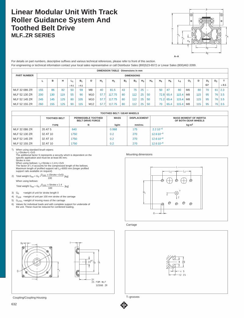
Linear Modular Unit With TrackRoller Guidance System AndToothed Belt DriveMLF..ZR SERIES
For details on part numbers, descriptive suffixes and various technical references, please refer to front of this section.For engineering or technical information contact your local sales representative or call Distributor Sales (800)523-6572 or Linear Sales (800)462-3399.
A–A
Mounting dimensions
Carriage
Coupling/Coupling Housing T–grooves
DIMENSION TABLE · Dimensions in mm
PART NUMBER DIMENSIONS
L B H L1 B1 O H1 H2 B2 B3 H3 H4 H5 H6 L3 O1 D D1 D2 T
�0.1 �0.1 G7 �0.1
MLF 32 086 ZR 155 86 82 50 59 M8 40 81.5 43 75 25 – 50 47 80 M6 80 70 61 2.3
MLF 52 130 ZR 200 130 119 55 90 M10 57.7 117.75 80 112 25 50 72.8 65.4 115.4 M8 115 95 76 3.5
MLF 52 145 ZR 245 145 125 80 105 M10 57.7 117.75 80 112 25 50 71.2 65.4 115.4 M8 115 95 76 3.5
MLF 52 155 ZR 260 155 125 90 115 M12 57.7 117.75 80 112 25 50 70 65.4 115.4 M8 115 95 76 3.5
TOOTHED BELT / GEAR WHEELS
TOOTHED BELT PERMISSIBLE TOOTHEDBELT DRIVE FORCE
MASS DISPLACEMENT MASS MOMENT OF INERTIAOF BOTH GEAR WHEELS
TYPE N kg/m mm/rev. kg.m2
MLF 32 086 ZR 20 AT 5 640 0.068 175 2.2.10–4
MLF 52 130 ZR 32 AT 10 1750 0.2 270 12.6.10–4
MLF 52 145 ZR 32 AT 10 1750 0.2 270 12.6.10–4
MLF 52 155 ZR 32 AT 10 1750 0.2 270 12.6.10–4
1) When using standard brush wipers:L2=Stroke+L+2xSThe additional factor S represents a security which is dependent on thespecific application and must be at least 85 mm;Stroke in mmWhen using bellows: L2=Stroke x 1.4+L+2xSThe factor of 1.4 accounts for the compressed length of the bellows.Maximum length of profiled support rail L2=6000 mm (longer profiledsupport rails available on request)
Gtot = G0 +G100 x (Stroke +2xS)100
[kg]2) Total weight
Gtot = G0 +G100 x Stroke x 1.4100
[kg]Total weight
When using bellows:
3) G0 =weight of unit for stroke length 0
4) G100 =weight of unit per 100 mm stroke of the carriage
5) GLFKL =weight of moving mass of the carriage
6) Values for individual loads and with complete support for underside ofthe unit. These must be reduced for combined loading.
632

Linear Modular Unit With TrackRoller Guidance System AndToothed Belt DriveMLF..ZR SERIES
For details on part numbers, descriptive suffixes and various technical references, please refer to front of this section.For engineering or technical information contact your local sales representative or call Distributor Sales (800)523-6572 or Linear Sales (800)462-3399.
A–A
MLF 52130 ZR AR
MASS2) PERMISSIBLE LOADS6) PERMISSIBLE MOMENTS6) GEOMETRICAL MOMENTS OFINERTIA cm4
G03) G100
4) GLFKL5) Fyperm Foyperm Fzperm Fozperm Mxperm Moxperm Myperm Moyperm Mzperm Mozperm
INERTIA cm4
kg kg kg N N N N Nm Nm Nm Nm Nm Nm ly lz
4.8 0.6 0.8 850 1400 1000 1000 11 18 30 30 26 43 100 76
12 1.28 2 1500 2500 3500 3500 33 52 105 105 47 78 392 304
13.9 1.28 3.2 2400 4000 4500 4500 51 84 236 236 126 210 392 304
15.7 1.28 5 4800 7900 8000 8000 101 166 480 480 288 474 392 304
633

Linear Modular Unit WithRecirculating Ball Bearing Guidance System And Toothed Belt DriveMKUE..ZR..N SERIES
For details on part numbers, descriptive suffixes and various technical references, please refer to front of this section.For engineering or technical information contact your local sales representative or call Distributor Sales (800)523-6572 or Linear Sales (800)462-3399.
A–A
Mounting dimensions
Carriage
Coupling/Coupling Housing T–grooves
STANDARD CARRIAGE WITH T-GROOVES (CARRIAGE AVAILABLE WITH HOLES)
DIMENSION TABLE · Dimensions in mm
PART NUMBER DIMENSIONS
L B H B1 H1 H2 L1 H3 H4 B2 B3 O D D1 D2 T
�0.2 �0.1 G7 �0.1
MKUE 25 ZR..N 250 110 125 80 57.7 115.5 263 25 75 80 112 M8 115 95 76 3.5
TOOTHED BELT / GEAR WHEELS
TOOTHED BELT PERMISSIBLE TOOTHEDBELT DRIVE FORCE
MASS DISPLACEMENT MASS MOMENT OF INERTIAOF BOTH GEAR WHEELS
TYPE N kg/m mm/rev. kg.m2
MKUE 25 ZR..N 50 AT 10 1880 0.315 250 30.6.10–4
1) L2=Stroke+L1+2xSThe additional factor S represents a security which is dependent on thespecific application and must be at least 85 mm;Stroke in mmMaximum length of profiled support rail L2=4000 mm (longer profiledsupport rails available on request)
Gtot = G0 +G100 x (Stroke +2xS)100
[kg]2) Total weight
3) G0 =weight of unit for stroke length 0
4) G100 =weight of unit per 100 mm stroke of the carriage
5) GMKWE=weight of moving mass of the carriage
6) Values with complete support for underside of the unit
634

Linear Modular Unit WithRecirculating Ball Bearing Guidance System And Toothed Belt DriveMKUE..ZR..N SERIES
For details on part numbers, descriptive suffixes and various technical references, please refer to front of this section.For engineering or technical information contact your local sales representative or call Distributor Sales (800)523-6572 or Linear Sales (800)462-3399.
A–A
MKUE 25 ZR AR N
MASS2) BASIC LOAD RATINGS6) PERMISSIBLE STATIC MOMENT6)
STATIC
GEOMETRICAL MOMENTS OFINERTIA cm4
GO3) G100
4) GMKWE5) C C0 M0
INERTIA cm4
kg kg kg kN kN Nm ly lz
16.2 1.66 3,8 26.3 41.8 411 733 517
635

Linear Modular Unit With Recirculating Ball Bearing Guidance System And Ball Screw DriveMKUE..KGT SERIES
For details on part numbers, descriptive suffixes and various technical references, please refer to front of this section.For engineering or technical information contact your local sales representative or call Distributor Sales (800)523-6572 or Linear Sales (800)462-3399.
A–A
Mounting dimensions
Carriage
Coupling/Coupling Housing T–grooves
DIMENSION TABLE · Dimensions in mm
PART NUMBER SPINDLE DIMENSIONS
L B H L1 B1 O d H1 H2 L3 L4 H3 H4 B2
d0xP7) �0.1 �0.1 ∅ h6
MKUE 25 KGT 5 32X5 200 110 125 55 80 M10 19 80 124.5 39 67 25 75 80
MKUE 25 KGT 10 32X10 200 110 125 55 80 M10 19 80 124.5 39 67 25 75 80
MKUE 25 KGT 40 32X40 200 110 125 55 80 M10 19 80 124.5 39 67 25 75 80
1) L2=Stroke � 1.2 + L +2�SS=spindle lead P;stroke in mmMaximum length of profiled Support rail L2 = 4000 mm (longer profiledsupport rails available on request).Modular units with a stroke length over 1200 mm can be fitted withmovable spindle supports.
Gtot = G0 + G100 x Stroke x 1.2100
[kg]2) Total weight
3) G0 = weight of unit for stroke length 0
4) G100 = wieght of unit per 100 mm stroke of the carriage
5) GMKWE= weight of moving mass of the carriage
6) Values with complete support for underside of the unit
7) d0 � P = nominal spindle diameter�spindle lead
636

Linear Modular Unit With Recirculating Ball Bearing Guidance System And Ball Screw DriveMKUE..KGT SERIES
For details on part numbers, descriptive suffixes and various technical references, please refer to front of this section.For engineering or technical information contact your local sales representative or call Distributor Sales (800)523-6572 or Linear Sales (800)462-3399.
A–A
MKUE 25 KGT 10
MASS2) BASIC LOAD RATINGS6) PERMISSIBLE STATIC MOMENT6)
STATIC
GEOMETRICAL MOMENTSOF INERTIA cm4
B3 H5 B4 O1 GO3) G100
4) GMKWE5) C C0 M0
OF INERTIA cm4
kg kg kg kN kN Nm ly lz
112 70 90 M8 17.4 2 4.3 26.3 41.8 411 717 408
112 70 90 M8 17.4 2 4.3 26.3 41.8 411 717 408
112 70 90 M8 17.4 2 4.3 26.3 41.8 411 717 408
637

Linear Roller BearingsRUS, RUS..KS SERIES
For details on part numbers, descriptive suffixes and various technical references, please refer to front of this section.For engineering or technical information contact your local sales representative or call Distributor Sales (800)523-6572 or Linear Sales (800)462-3399.
RUS 19 069 to RUS 38 206
Wiper
Head Piece
DIMENSION TABLE · Dimensions in mm
PART NUMBER MASS DIMENSIONS
H L B L1 L2 L3 LW a
kg
RUS 19 069 0.16 19 69 27 75 44 – 10 0.2
RUS 19 069 KS 0.19 19 – 27 – 44 76 10 0.2
RUS 19 105 0.27 19 105 27 111 78.5 – 10 0.2
RUS 19 105 KS 0.29 19 – 27 – 78.5 112 10 0.2
RUS 26 086 0.41 26 86 40 92 53 – 14 0.2
RUS 26 086 KS 0.49 26 – 40 – 53 92 14 0.2
RUS 26 102 0.53 26 102 40 108 69 – 14 0.2
RUS 26 102 KS 0.61 26 – 40 – 69 108 14 0.2
RUS 26 126 0.70 26 126 40 132 93 – 14 0.2
RUS 26 126 KS 0.78 26 – 40 – 93 132 14 0.2
RUS 38 134 1.27 38 133 52 133 85 – 20 0.2
RUS 38 134 KS 1.53 38 – 52 – 85 136 20 0.2
RUS 38 206 2.28 38 206 52 206 158 – 20 0.2
RUS 38 206 KS 2.53 38 – 52 – 158 209 20 0.2
RUS 65 210 7.5 65 211 76 234 134 – 30 0.5
RUS 85 280*) 16 85 281 104 303 185 – 40 0.5
1) If the lubricating nipple is replacedby tube or pipe connections, the threadlength must not exceed 6 mm.
2) Minimum length to be supported
3) UG guideway for RUS 85 280 available on request
*) Available on request
638

RUS 19 069 KS to RUS 38 206 KS RUS 65 210 and RUS 85 280
Figure 1 Figure 2
Lubrication holes are provided on both sidesfor funnel type grease nipples DIN 3405-D6(supplied with the bearing) or either tubeor pipe connection. If no lubrication connectionis to be provided the holes should be pluggedwith the lubricating nipples.
Funnel type lubricating nipples DIN 3405-AM 8x1are mounted in the head pieces. They can bereplaced by tube or pipe connections.
Funnel type lubricating nippleDIN 3405–AM 61)
Funnel type lubricating nippleDIN 3405–AM 8 x 1(Figure 2)
Hole for funnel type lubricating nippleDIN 3405-D6 on both sides(Figure 1)
BASIC LOAD RATINGS MOUNTING DIMENSIONS K FOR FIXINGSCREWS TO DIN 912
MATCHING ADJUSTINGGIBS
MATCHINGGUIDEWAYS
dyn. stat. L42) E F G e g p p1
SCREWS TO DIN 912 GIBS GUIDEWAYS
CN
C0N
�0.1 �0.1
42,000 33,000 50 25.5 20.6 M4 15.5 6 – – M3 VUS 19 069 UG 6628UV 5323
42,000 33,000 50 25.5 20.6 M4 15.5 6 – 10 M3 VUS 19 069
UG 66 8UV 5323UFA 3210
68,000 61,000 85 50 20.6 M4 15.5 6 – – M3 VUS 19 105UFA 3210UFK 3210UFB 4710
68,000 61,000 85 50 20.6 M4 15.5 6 – 10 M3 VUS 19 105UFB 4710
76,000 56,000 63 28 30 M6 21 10 – – M4 VUS 26 086 UG 9741UV 7532
76,000 56,000 63 28 30 M6 21 10 – 13.5 M4 VUS 26 086
UG 9UV 7532UFA 4710
95,000 75,000 79 44 30 M6 21 10 – – M4 VUS 26 102UFA 4710UFK 4710UFB 6412
95,000 75,000 79 44 30 M6 21 10 – 13.5 M4 VUS 26 102UFB 6412
122,000 103,000 103 68 30 M6 21 10 – – M4 VUS 26 126
122,000 103,000 103 68 30 M6 21 10 – 13.5 M4 VUS 26 126
179,000 133,000 100 51 41 M8 31 14 – – M6 VUS 38 134 UG 12 553UV 9542
179,000 133,000 100 51 41 M8 31 14 – 19.5 M6 VUS 38 134
UG 553UV 9542UFA 6412
305,000 265,000 172 102 41 M8 31 14 – – M6 VUS 38 206UFA 6412UFK 6412UFB 7812
305,000 265,000 172 102 41 M8 31 14 – 19.5 M6 VUS 38 206UFB 7812
465,000 345,000 – 76 62 M10 55 22 26 34 M8 VUS 65 210 UG 16 260UV 13 863UV 13 863UFA 8815UFK 8815UFK 8815UFB 10 615
840,000 620,000 – 101.5 82.5 M14 73 30 33 45 M10 VUS 85 280 UG....3)
UV 16 977UV 16 977UFA 11 518UFK 11 518UFK 11 518UFB 14 0185
639

Linear Roller BearingsRUSZ, RUSZ..KS SERIES
For details on part numbers, descriptive suffixes and various technical references, please refer to front of this section.For engineering or technical information contact your local sales representative or call Distributor Sales (800)523-6572 or Linear Sales (800)462-3399.
RUS 19 069 to RUS 38 206
Wiper
Head Piece
DIMENSION TABLE · Dimensions in mm
PART NUMBER DIMENSIONS
H L B L1 L2 L3 LW a
RUSZ 12044 19.05 69 25.4 75 44 – 10 0.2
RUSZ 18059 28.57 94 38.1 100 60 – 14 0.2
RUSZ 24084 38.1 133 50.8 133 85 – 20 0.2
RUSZ 12044 KS 19.05 69 25.4 75 44 76 10 0.2
RUSZ 18059 KS 28.57 94 38.1 100 60 132 14 0.2
RUSZ 24084 KS 38.1 133 50.8 133 85 136 20 0.2
1) If the lubricating nipple is replacedby tube or pipe connections, the threadlength must not exceed 6 mm.
2) Minimum length to be supported
640

RUS 19 069 KS to RUS 38 206 KS RUS 65 210 and RUS 85 280
Figure 1 Figure 2
Lubrication holes are provided on both sidesfor funnel type grease nipples DIN 3405-D6(supplied with the bearing) or either tubeor pipe connection. If no lubrication connectionis to be provided the holes should be pluggedwith the lubricating nipples.
Funnel type lubricating nipples DIN 3405-AM 8x1are mounted in the head pieces. They can bereplaced by tube or pipe connections.
Funnel type lubricating nippleDIN 3405–AM 61)
Funnel type lubricating nippleDIN 3405–AM 8 x 1(Figure 2)
Hole for funnel type lubricating nippleDIN 3405-D6 on both sides(Figure 1)
BASIC LOAD RATINGS MOUNTING DIMENSIONS K FOR FIXINGSCREWS TO DIN 912
MATCHING ADJUSTINGGIBS
MATCHINGGUIDEWAYS
dyn. stat. L42) E F G e g p p1
SCREWS TO DIN 912 GIBS GUIDEWAYS
CN
C0N
�0.1 �0.1
42000 33000 50 25.5 20.6 – 15.5 – – – M3x22 VUSZ 12044 UG6628UV5323UFA/UFK3210UFB4710
86000 65000 71 38 31 – 23.6 – – – M4x30 VUSZ 18059 UG9745UV7532UFA/UFK4710UFB6412
179000 133000 100 51 41 – 32.1 – – – M5x45 VUSZ 24084 UG12553UV9542UFA/UFK6412UFB7812
42000 33000 50 25.5 20.6 – 15.5 – – – M3x22 VUSZ 12044 UG6628UV5323UFA/UFK3210UFB4710
86000 65000 71 38 31 – 23.6 – – – M4x30 VUSZ 18059 UG9745UV7532UFA/UFK4710UFB6412
179000 133000 100 51 41 – 32.1 – – – M5x45 VUSZ 24084 UG12553UV9542UFA/UFK6412UFB7812
641

Linear Roller BearingsPR SERIES
For details on part numbers, descriptive suffixes and various technical references, please refer to front of this section.For engineering or technical information contact your local sales representative or call Distributor Sales (800)523-6572 or Linear Sales (800)462-3399.
DIMENSION TABLE · Dimensions in mm
PART NUMBER MASS DIMENSIONS
H L B L2 LW a
kg
PR 14 032 0.095 14.285 51 22.23 31 9 0.2
PR 14 044 0.2 19.05 69 25.4 42 10 0.35
PR 14 061 0.65 28.57 96 38.1 58.5 16 0.35
PR 14 089 1.75 38.1 142 50.8 90 20 0.4
PR 14 135 5.65 57.15 196 76.2 126 30 0.5
PR 14 182 13.25 76.2 264 101.6 167 40 0.6
1) UG guideway for PR 14 182 available on request
2) Not available from stock. Please check delivery time.
Ordering examples:
Linear roller bearing PR 14 061with a tolerance for the nominal height H of –10 to –15 �m:PR 14 061 –10 –15
Linear roller bearing PR 14 135with a tolerance for the nominal height H of –10 to –20 �m:PR 14 135 –10 –20
642

Linear Roller BearingsPR SERIES
For details on part numbers, descriptive suffixes and various technical references, please refer to front of this section.For engineering or technical information contact your local sales representative or call Distributor Sales (800)523-6572 or Linear Sales (800)462-3399.
BASIC LOAD RATINGS MOUNTING DIMENSIONS K FOR FIXINGSCREWS TO DIN 912
MATCHINGADJUSTING GIBS
MATCHING GUIDEWAYS
dyn. stat. E F eSCREWS TO DIN 912 ADJUSTING GIBS
CN
C0N
�0.1 �0.1
21,700 17,600 19 17.1 10 M2.5 – UG 6628 UFA 3210
UV 5323 UFK 3210
44,000 37,500 25.5 20.6 14 M3 VUSZ 12 044 UG 6628 UFA 3210
UV 5323 UFK 3210
UFB 4710
107,000 86,000 38 31 20.8 M4 VUSZ 18 059 UG 9741 UFA 4710
UV 7532 UFK 4710
UFB 6412
205,000 171,000 51 41 28 M5 VUSZ 24 084 UG 12 553 UFA 6412
UV 9542 UFK 6412
UFB 7812
435,000 345,000 76.2 62 42 M6 VUSZ 36 1352) UG 16 260 UFA 8815
UV 13 863 UFK 8815
UFB 10 615
790,000 620,000 101.6 82.5 56 M8 VUSZ 48 1822) UG....1) UFA 11 518
UV 16 977 UFK 11 518
UFB 14 018
643

Adjusting GibsVUS, METRIC SIZES SERIESVUSZ, INCH SIZES SERIES
For details on part numbers, descriptive suffixes and various technical references, please refer to front of this section.For engineering or technical information contact your local sales representative or call Distributor Sales (800)523-6572 or Linear Sales (800)462-3399.
Adjusting screw AF1
Lubrication hole
Locking and releasescrew AF2
DIMENSION TABLE · Dimensions in mm
PART NUMBER MASS DIMENSIONS MOUNTING DIMENSIONS
B H L L1 L2 E F b C
kg min. max. max. �0.1 �0.1
VUS 19 069 0.24 26.5 16 78 73 62 25.5 20.6 4 16.5
VUS 19 105 0.32 26.5 16 123 119 100 50 20.6 3.5 25
VUS 26 086 0.6 39.5 25 97 89 75 28 30 6 20.5
VUS 26 102 0.71 39.5 25 113 105 91 44 30 6 20.5
VUS 26 126 0.9 39.5 25 137 129 115 68 30 6 20.5
VUS 38 134 1.47 51.5 30 141 131 115 51 41 7 28
VUS 38 206 2.1 51.5 25 250 240 200 102 41 5 49
DIMENSION TABLE · Dimensions in mm
PART NUMBER MASS DIMENSIONS MOUNTING DIMENSIONS
B H L L1 L2 E F b C
kg min. max. max. �0.1 �0.1
VUSZ 12 044 0.19 25 16 78 73 62 25.5 191) 4 16.5
VUSZ 18 059 0.63 37.6 25 107 99 85 38 31 6 20.5
VUSZ 24 084 1.38 50 30 141 131 115 51 41 7 28
1) Distance between the mounting holes in the top wedge of the gib; deviates from the bottom wedge
644

Top View
DIMENSION TABLE · Dimensions in mm
G1, K FOR FIXINGSCREW TO DIN 912
HEIGHT CHANGE ADJUSTINGSCREW
LOCKINGAND
MATCHING LINEARROLLER BEARINGS
M d d1 A GSCREW TO DIN 912
�H PER SCREWSCREW AND
RELEASESCREW
ROLLER BEARINGS
max. max.ROTATION AF1
RELEASESCREW
AF2
16.5 3.5 12 7 M 4 M 3 0.35 0.035 3 2 RUS 19 069
29 3.5 12 15 M 4 M 3 0.5 0.023 3 2.5 RUS 19 105
19.5 5 16 8 M 6 M 4 0.4 0.05 6 3 RUS 26 086
27.5 5 16 8 M 6 M 4 0.4 0.05 6 3 RUS 26 102
39.5 5 16 8 M 6 M 4 0.4 0.05 6 3 RUS 26 126
30.5 5 22 8 M 8 M 6 0.4 0.062 8 4 RUS 38 134
61 5 22 30 – M 6 1 0.05 8 5 RUS 38 206
DIMENSION TABLE · Dimensions in mm
G1, K FOR FIXINGSCREW TO DIN 912
HEIGHT CHANGE ADJUSTINGSCREW
LOCKINGAND
MATCHING LINEARROLLER BEARINGS
M d d1 A GSCREW TO DIN 912
�H PER SCREWSCREW AND
RELEASESCREW
ROLLER BEARINGS
max. max.ROTATION AF1
RELEASESCREW
AF2
16.5 3.5 12 7 – M 3 0.35 0.035 3 2 PR 14 044
20 5 16 8 – M 4 0.4 0.05 6 3 PR 14 061
30.5 5 22 8 – M 5 0.4 0.062 8 4 PR 14 089
645

Linear Roller Bearings With Integral Adjusting GibRUSV..KS SERIES
For details on part numbers, descriptive suffixes and various technical references, please refer to front of this section.For engineering or technical information contact your local sales representative or call Distributor Sales (800)523-6572 or Linear Sales (800)462-3399.
Funnel type lubricatingnipple DIN 3405-AM 61)
MarkingHead piece
DIMENSION TABLE · Dimensions in mm
PART NUMBER MASS DIMENSIONS BASIC LOAD RATINGS
H L B LW a L1 L2 L3 L4 d1 dyn. stat.
kg �
CN
C0N
RUSV 30 069 KS 0.32 30 69 27 10 0.3 75 43.5 82 45 12 42,000 33,000
RUSV 30 105 KS 0.46 30 105 27 10 0.3 111 78.5 117 79 12 68,000 61,000
RUSV 42 086 KS 0.81 42 86 40 14 0.3 92 52.4 98 54 16 76,000 56,000
RUSV 42 102 KS 0.99 42 102 40 14 0.3 108 68.4 114 70 16 95,000 75,000
RUSV 42 126 KS 1.26 42 126 40 14 0.3 132 92.4 138 94 16 122,000 103,000
RUSV 60 134 KS 2.25 60 134 52 20 0.3 133 85 143 86 22 179,000 133,000
RUSV 60 206 KS 3.47 60 206 52 20 0.3 206 158 216 159 22 305,000 265,000
1) If the lubricating nipple is replaced by tube or pipe connections,the thread length must not exceed 6mm.
646

TOP VIEW
Marking
AF1 AF2
DIMENSION TABLE · Dimensions in mm
MOUNTING DIMENSIONS ADJUSTINGSCREW
LOCKINGAND
HEIGHT CHANGE MATCHINGLINEAR ROLLER
MATCHINGGUIDEWAY
C E F i P1 P2 P3 d KSCREW AND
RELEASESCREW
A �H PERSCREW
LINEAR ROLLERBEARINGS
GUIDEWAY
AF1
SCREW
AF2 max. max.
SCREWROTATION
5 25 19 4 21 33 9 2.5 M 4 3 2 7 0.37 0.035 RUS 19 069 KS UG 6628
5 45 19 4 21 53 9 2.5 M 4 3 2 7 0.37 0.023 RUS 19 105 KS UV 5323
UFA 3210
UFK 3210
UFB 4710
8 23 26 6 29.5 38 14.5 3 M 6 6 3 10 0.52 0.05 RUS 26 086 KS UG 9741
8 38 26 6 29.5 53 14.5 3 M 6 6 3 10 0.52 0.05 RUS 26 102 KS UV 7532
8 58 26 6 29.5 73 14.5 3 M 6 6 3 10 0.52 0.05 RUS 26 126 KS UFA 4710
UFK 4710
UFB 6412
10 45 35 8 41.5 65 18 4 M 8 8 4 15 0.78 0.062 RUS 38 134 KS UG 12 553
10 115 35 8 41.5 145 18 4 M 8 8 4 15 0.78 0.05 RUS 38 206 KS UV 9542
UFA 6412
UFK 6412
UFB 7812
647

Planetary Roller ScrewRGT SERIES� Split roller nut, preloaded� Standard ends configuration
For details on part numbers, descriptive suffixes and various technical references, please refer to front of this section.For engineering or technical information contact your local sales representative or call Distributor Sales (800)523-6572 or Linear Sales (800)462-3399.
DIMENSION TABLE · Dimensions in mm
NOMINALDIAMETER
PARTNUMBER
MASS DIMENSIONS – SCREW SHAFTDIAMETER NUMBER
PITCH STROKE d1 d2 d3 d4 d5 l0 l1 l2 l3 l4 l5
d0d0
P H kg
ISOh6 –0.005
ISOh6
5 RGT 5. 1. 25 0.084 5 M6X0.5 6 10 4 113 11 22 34 75 14
RGT 5. 1. 50 0.088 5 M6X0.5 6 10 4 138 11 22 34 100 14
RGT 5. 1. 75 0.092 5 M6X0.5 6 10 4 163 11 22 34 125 14
RGT 5. 1. 100 0.096 5 M6X0.5 6 10 4 188 11 22 34 150 14
8 RGT 8. 1. 25 0.11 5 M6X0.5 6 10 6 120 11 22 34 82 16
RGT 8. 1. 50 0.121 5 M6X0.5 6 10 6 145 11 22 34 107 16
RGT 8. 1. 100 0.141 5 M6X0.5 6 10 6 195 11 22 34 157 16
RGT 8. 1. 150 0.16 5 M6X0.5 6 10 6 245 11 22 34 207 16
RGT 8. 1. 200 0.18 5 M6X0.5 6 10 6 295 11 22 34 257 16
RGT 8. 2. 25 0.11 5 M6X0.5 6 10 6 120 11 22 34 82 16
RGT 8. 2. 50 0.121 5 M6X0.5 6 10 6 145 11 22 34 107 16
RGT 8. 2. 100 0.141 5 M6X0.5 6 10 6 195 11 22 34 157 16
RGT 8. 2. 150 0.16 5 M6X0.5 6 10 6 245 11 22 34 207 16
RGT 8. 2. 200 0.18 5 M6X0.5 6 10 6 295 11 22 34 257 16
RGT 8. 4. 25 0.11 5 M6X0.5 6 10 6 120 11 22 34 82 16
RGT 8. 4. 50 0.121 5 M6X0.5 6 10 6 145 11 22 34 107 16
RGT 8. 4. 100 0.141 5 M6X0.5 6 10 6 195 11 22 34 157 16
RGT 8. 4. 150 0.16 5 M6X0.5 6 10 6 245 11 22 34 207 16
RGT 8. 4. 200 0.18 5 M6X0.5 6 10 6 295 11 22 34 257 16
RGT 8. 5. 25 0.11 5 M6X0.5 6 10 6 120 11 22 34 82 16
RGT 8. 5. 50 0.121 5 M6X0.5 6 10 6 145 11 22 34 107 16
RGT 8. 5. 100 0.141 5 M6X0.5 6 10 6 195 11 22 34 157 16
RGT 8. 5. 150 0.16 5 M6X0.5 6 10 6 245 11 22 34 207 16
RGT 8. 5. 200 0.18 5 M6X0.5 6 10 6 295 11 22 34 257 16
1) Limiting speed of the planetary roller screw. Critical speed nmax and limiting speed of the rolling bearings should be considered.
648

Locating bearing end Floating bearing end
NUT KEY TODIN 6885
LOAD RATINGS SPRINGS RATIO LIMITING SPEED1) LOCATINGBEARING
FLOATINGBEARING
SEAL LOCK NUT
D h CDIN 6885
dyn. stat. CK ng grease
BEARING BEARING
ISOg6 h12
CN
C0N
N2/3 /��m rpm
19 1.3 31 3X3X10 5,300 5,400 27 6,000 ZKLN0624.2RS HK0408TN G4X8X2 ZM06
19 1.3 31 3X3X10 5,300 5,400 27 6,000 ZKLN0624.2RS HK0408TN G4X8X2 ZM06
19 1.3 31 3X3X10 5,300 5,400 27 6,000 ZKLN0624.2RS HK0408TN G4X8X2 ZM06
19 1.3 31 3X3X10 5,300 5,400 27 6,000 ZKLN0624.2RS HK0408TN G4X8X2 ZM06
21 1.3 31 3X3X10 3,100 3,950 31 5,800 ZKLN0624.2RS NK6/10TN G6X12X2 ZM06
21 1.3 31 3X3X10 3,100 3,950 31 5,800 ZKLN0624.2RS NK6/10TN G6X12X2 ZM06
21 1.3 31 3X3X10 3,100 3,950 31 5,800 ZKLN0624.2RS NK6/10TN G6X12X2 ZM06
21 1.3 31 3X3X10 3,100 3,950 31 5,800 ZKLN0624.2RS NK6/10TN G6X12X2 ZM06
21 1.3 31 3X3X10 3,100 3,950 31 5,800 ZKLN0624.2RS NK6/10TN G6X12X2 ZM06
21 1.3 31 3X3X10 6,200 4,550 21 5,800 ZKLN0624.2RS NK6/10TN G6X12X2 ZM06
21 1.3 31 3X3X10 6,200 4,550 21 5,800 ZKLN0624.2RS NK6/10TN G6X12X2 ZM06
21 1.3 31 3X3X10 6,200 4,550 21 5,800 ZKLN0624.2RS NK6/10TN G6X12X2 ZM06
21 1.3 31 3X3X10 6,200 4,550 21 5,800 ZKLN0624.2RS NK6/10TN G6X12X2 ZM06
21 1.3 31 3X3X10 6,200 4,550 21 5,800 ZKLN0624.2RS NK6/10TN G6X12X2 ZM06
21 1.3 31 3X3X10 12,200 4,800 15 5,800 ZKLN0624.2RS NK6/10TN G6X12X2 ZM06
21 1.3 31 3X3X10 12,200 4,800 15 5,800 ZKLN0624.2RS NK6/10TN G6X12X2 ZM06
21 1.3 31 3X3X10 12,200 4,800 15 5,800 ZKLN0624.2RS NK6/10TN G6X12X2 ZM06
21 1.3 31 3X3X10 12,200 4,800 15 5,800 ZKLN0624.2RS NK6/10TN G6X12X2 ZM06
21 1.3 31 3X3X10 12,200 4,800 15 5,800 ZKLN0624.2RS NK6/10TN G6X12X2 ZM06
21 1.3 31 3X3X10 15,200 4,800 13 5,800 ZKLN0624.2RS NK6/10TN G6X12X2 ZM06
21 1.3 31 3X3X10 15,200 4,800 13 5,800 ZKLN0624.2RS NK6/10TN G6X12X2 ZM06
21 1.3 31 3X3X10 15,200 4,800 13 5,800 ZKLN0624.2RS NK6/10TN G6X12X2 ZM06
21 1.3 31 3X3X10 15,200 4,800 13 5,800 ZKLN0624.2RS NK6/10TN G6X12X2 ZM06
21 1.3 31 3X3X10 15,200 4,800 13 5,800 ZKLN0624.2RS NK6/10TN G6X12X2 ZM06
649

Planetary Roller ScrewRGT SERIES� Split roller nut, preloaded� Standard ends configuration
For details on part numbers, descriptive suffixes and various technical references, please refer to front of this section.For engineering or technical information contact your local sales representative or call Distributor Sales (800)523-6572 or Linear Sales (800)462-3399.
DIMENSION TABLE (Contd.) · Dimensions in mm
NOMINALDIAMETER
PARTNUMBER
MASS DIMENSIONS – SCREW SHAFTDIAMETER NUMBER
PITCH STROKE d1 d2 d3 d4 d5 l0 l1 l2 l3 l4 l5
d0d0
P H kg
ISOh6 –0.005
ISOh6
12 RGT 12. 1. 100 0.293 10 M12X1 12 18 10 220 20 33 53 161 20
RGT 12. 1. 200 0.382 10 M12X1 12 18 10 320 20 33 53 261 20
RGT 12. 1. 300 0.47 10 M12X1 12 18 10 420 20 33 53 361 20
RGT 12. 1. 400 0.559 10 M12X1 12 18 10 520 20 33 53 461 20
RGT 12. 1. 500 0.648 10 M12X1 12 18 10 620 20 33 53 561 20
RGT 12. 2. 100 0.293 10 M12X1 12 18 10 220 20 33 53 161 20
RGT 12. 2. 200 0.382 10 M12X1 12 18 10 320 20 33 53 261 20
RGT 12. 2. 300 0.47 10 M12X1 12 18 10 420 20 33 53 361 20
RGT 12. 2. 400 0.559 10 M12X1 12 18 10 520 20 33 53 461 20
RGT 12. 2. 500 0.648 10 M12X1 12 18 10 620 20 33 53 561 20
RGT 12. 4. 100 0.293 10 M12X1 12 18 10 220 20 33 53 161 20
RGT 12. 4. 200 0.382 10 M12X1 12 18 10 320 20 33 53 261 20
RGT 12. 4. 300 0.47 10 M12X1 12 18 10 420 20 33 53 361 20
RGT 12. 4. 400 0.559 10 M12X1 12 18 10 520 20 33 53 461 20
RGT 12. 4. 500 0.648 10 M12X1 12 18 10 620 20 33 53 561 20
RGT 12. 5. 100 0.293 10 M12X1 12 18 10 220 20 33 53 161 20
RGT 12. 5. 200 0.382 10 M12X1 12 18 10 320 20 33 53 261 20
RGT 12. 5. 300 0.47 10 M12X1 12 18 10 420 20 33 53 361 20
RGT 12. 5. 400 0.559 10 M12X1 12 18 10 520 20 33 53 461 20
RGT 12. 5. 500 0.648 10 M12X1 12 18 10 620 20 33 53 561 20
1) Limiting speed of the planetary roller screw. Critical speed nmax and limiting speed of the rolling bearings should be considered.
650

Locating bearing end Floating bearing end
NUT KEY TODIN 6885
LOAD RATINGS SPRING RATIO LIMITING SPEED1) LOCATING BEARING FLOATINGBEARING
SEAL LOCKNUT
D h CDIN 6885
dyn. stat. CK ng grease
BEARING NUT
ISOg6 h12
CN
C0N
N2/3 /��m rpm
32 1.7 31 4X4X14 3,700 6,400 38 5,600 ZKLN1242.2RS ZKLF1255.2RS NK10/12TN G10X17X3 ZM12
32 1.7 31 4X4X14 3,700 6,400 38 5,600 ZKLN1242.2RS ZKLF1255.2RS NK10/12TN G10X17X3 ZM12
32 1.7 31 4X4X14 3,700 6,400 38 5,600 ZKLN1242.2RS ZKLF1255.2RS NK10/12TN G10X17X3 ZM12
32 1.7 31 4X4X14 3,700 6,400 38 5,600 ZKLN1242.2RS ZKLF1255.2RS NK10/12TN G10X17X3 ZM12
32 1.7 31 4X4X14 3,700 6,400 38 5,600 ZKLN1242.2RS ZKLF1255.2RS NK10/12TN G10X17X3 ZM12
26 2 31 4X4X14 4,900 5,000 27 5,600 ZKLN1242.2RS ZKLF1255.2RS NK10/12TN G10X17X3 ZM12
26 2 31 4X4X14 4,900 5,000 27 5,600 ZKLN1242.2RS ZKLF1255.2RS NK10/12TN G10X17X3 ZM12
26 2 31 4X4X14 4,900 5,000 27 5,600 ZKLN1242.2RS ZKLF1255.2RS NK10/12TN G10X17X3 ZM12
26 2 31 4X4X14 4,900 5,000 27 5,600 ZKLN1242.2RS ZKLF1255.2RS NK10/12TN G10X17X3 ZM12
26 2 31 4X4X14 4,900 5,000 27 5,600 ZKLN1242.2RS ZKLF1255.2RS NK10/12TN G10X17X3 ZM12
26 2 31 4X4X14 9,700 5,500 19 5,600 ZKLN1242.2RS ZKLF1255.2RS NK10/12TN G10X17X3 ZM12
26 2 31 4X4X14 9,700 5,500 19 5,600 ZKLN1242.2RS ZKLF1255.2RS NK10/12TN G10X17X3 ZM12
26 2 31 4X4X14 9,700 5,500 19 5,600 ZKLN1242.2RS ZKLF1255.2RS NK10/12TN G10X17X3 ZM12
26 2 31 4X4X14 9,700 5,500 19 5,600 ZKLN1242.2RS ZKLF1255.2RS NK10/12TN G10X17X3 ZM12
26 2 31 4X4X14 9,700 5,500 19 5,600 ZKLN1242.2RS ZKLF1255.2RS NK10/12TN G10X17X3 ZM12
26 2 31 4X4X14 12,100 5,500 17 5,600 ZKLN1242.2RS ZKLF1255.2RS NK10/12TN G10X17X3 ZM12
26 2 31 4X4X14 12,100 5,500 17 5,600 ZKLN1242.2RS ZKLF1255.2RS NK10/12TN G10X17X3 ZM12
26 2 31 4X4X14 12,100 5,500 17 5,600 ZKLN1242.2RS ZKLF1255.2RS NK10/12TN G10X17X3 ZM12
26 2 31 4X4X14 12,100 5,500 17 5,600 ZKLN1242.2RS ZKLF1255.2RS NK10/12TN G10X17X3 ZM12
26 2 31 4X4X14 12,100 5,500 17 5,600 ZKLN1242.2RS ZKLF1255.2RS NK10/12TN G10X17X3 ZM12
651

Planetary Roller ScrewRGT SERIES� Split roller nut, preloaded� Standard ends configuration
For details on part numbers, descriptive suffixes and various technical references, please refer to front of this section.For engineering or technical information contact your local sales representative or call Distributor Sales (800)523-6572 or Linear Sales (800)462-3399.
DIMENSION TABLE (Contd.) · Dimensions in mm
NOMINALDIAMETER
PARTNUMBER
MASS DIMENSIONS – SCREW SHAFTDIAMETER NUMBER
PITCH STROKE d1 d2 d3 d4 d5 l0 l1 l2 l3 l4 l5
d0d0
P H kg
ISOh6 –0.005
ISOh6
15 RGT 15. 2. 100 0.501 12 M15X1 15 22 12 224 20 31 53 165 20
RGT 15. 2. 200 0.64 12 M15X1 15 22 12 324 20 31 53 265 20
RGT 15. 2. 300 0.779 12 M15X1 15 22 12 424 20 31 53 365 20
RGT 15. 2. 400 0.917 12 M15X1 15 22 12 524 20 31 53 465 20
RGT 15. 2. 500 1.056 12 M15X1 15 22 12 624 20 31 53 565 20
RGT 15. 2. 600 1.195 12 M15X1 15 22 12 724 20 31 53 665 20
RGT 15. 4. 100 0.501 12 M15X1 15 22 12 224 20 31 53 165 20
RGT 15. 4. 200 0.64 12 M15X1 15 22 12 324 20 31 53 265 20
RGT 15. 4. 300 0.779 12 M15X1 15 22 12 424 20 31 53 365 20
RGT 15. 4. 400 0.917 12 M15X1 15 22 12 524 20 31 53 465 20
RGT 15. 4. 500 1.056 12 M15X1 15 22 12 624 20 31 53 565 20
RGT 15. 4. 600 1.195 12 M15X1 15 22 12 724 20 31 53 665 20
RGT 15. 5. 100 0.501 12 M15X1 15 22 12 224 20 31 53 165 20
RGT 15. 5. 200 0.64 12 M15X1 15 22 12 324 20 31 53 265 20
RGT 15. 5. 300 0.779 12 M15X1 15 22 12 424 20 31 53 365 20
RGT 15. 5. 400 0.917 12 M15X1 15 22 12 524 20 31 53 465 20
RGT 15. 5. 500 1.056 12 M15X1 15 22 12 624 20 31 53 565 20
RGT 15. 5. 600 1.195 12 M15X1 15 22 12 724 20 31 53 665 20
1) Limiting speed of the planetary roller screw. Critical speed nmax and limiting speed of the rolling bearings should be considered.
652

Locating bearing end Floating bearing end
NUT KEY TODIN 6885
BASIC LOAD RATINGS SPRING RATIO LIMITING SPEED1) LOCATING BEARING FLOATINGBEARING
SEAL LOCKNUT
D h CDIN 6885
dyn. stat. CK ng grease
BEARING NUT
ISOg6 h12
CN
C0N
N2/3 /��m rpm
34 1.7 35 4X4X14 6,100 8,000 34 5,500 ZKLN1545.2RS ZKLF1560.2RS NK12/12TN G12X19X3 ZM15
34 1.7 35 4X4X14 6,100 8,000 34 5,500 ZKLN1545.2RS ZKLF1560.2RS NK12/12TN G12X19X3 ZM15
34 1.7 35 4X4X14 6,100 8,000 34 5,500 ZKLN1545.2RS ZKLF1560.2RS NK12/12TN G12X19X3 ZM15
34 1.7 35 4X4X14 6,100 8,000 34 5,500 ZKLN1545.2RS ZKLF1560.2RS NK12/12TN G12X19X3 ZM15
34 1.7 35 4X4X14 6,100 8,000 34 5,500 ZKLN1545.2RS ZKLF1560.2RS NK12/12TN G12X19X3 ZM15
34 1.7 35 4X4X14 6,100 8,000 34 5,500 ZKLN1545.2RS ZKLF1560.2RS NK12/12TN G12X19X3 ZM15
34 1.7 35 4X4X14 12,200 8,900 24 5,500 ZKLN1545.2RS ZKLF1560.2RS NK12/12TN G12X19X3 ZM15
34 1.7 35 4X4X14 12,200 8,900 24 5,500 ZKLN1545.2RS ZKLF1560.2RS NK12/12TN G12X19X3 ZM15
34 1.7 35 4X4X14 12,200 8,900 24 5,500 ZKLN1545.2RS ZKLF1560.2RS NK12/12TN G12X19X3 ZM15
34 1.7 35 4X4X14 12,200 8,900 24 5,500 ZKLN1545.2RS ZKLF1560.2RS NK12/12TN G12X19X3 ZM15
34 1.7 35 4X4X14 12,200 8,900 24 5,500 ZKLN1545.2RS ZKLF1560.2RS NK12/12TN G12X19X3 ZM15
34 1.7 35 4X4X14 12,200 8,900 24 5,500 ZKLN1545.2RS ZKLF1560.2RS NK12/12TN G12X19X3 ZM15
34 1.7 35 4X4X14 15,200 9,100 21 5,500 ZKLN1545.2RS ZKLF1560.2RS NK12/12TN G12X19X3 ZM15
34 1.7 35 4X4X14 15,200 9,100 21 5,500 ZKLN1545.2RS ZKLF1560.2RS NK12/12TN G12X19X3 ZM15
34 1.7 35 4X4X14 15,200 9,100 21 5,500 ZKLN1545.2RS ZKLF1560.2RS NK12/12TN G12X19X3 ZM15
34 1.7 35 4X4X14 15,200 9,100 21 5,500 ZKLN1545.2RS ZKLF1560.2RS NK12/12TN G12X19X3 ZM15
34 1.7 35 4X4X14 15,200 9,100 21 5,500 ZKLN1545.2RS ZKLF1560.2RS NK12/12TN G12X19X3 ZM15
34 1.7 35 4X4X14 15,200 9,100 21 5,500 ZKLN1545.2RS ZKLF1560.2RS NK12/12TN G12X19X3 ZM15
653

Planetary Roller ScrewRGT SERIES� Split roller nut, preloaded� Standard ends configuration
For details on part numbers, descriptive suffixes and various technical references, please refer to front of this section.For engineering or technical information contact your local sales representative or call Distributor Sales (800)523-6572 or Linear Sales (800)462-3399.
DIMENSION TABLE (Contd.) · Dimensions in mm
NOMINALDIAMETER
PARTNUMBER
MASS DIMENSIONS – SCREW SHAFTDIAMETER NUMBER
PITCH STROKE d1 d2 d3 d4 d5 l0 l1 l2 l3 l4 l5
d0d0
P H kg
ISOh6 –0.005
ISOh6
20 RGT 20. 2. 400 1.713 12 M15X1 15 22 12 546 20 31 53 487 20
RGT 20. 2. 500 1.96 12 M15X1 15 22 12 646 20 31 53 587 20
RGT 20. 2. 600 2.207 12 M15X1 15 22 12 746 20 31 53 687 20
RGT 20. 2. 800 2.7 12 M15X1 15 22 12 946 20 31 53 887 20
RGT 20. 2. 1000 3.193 12 M15X1 15 22 12 1146 20 31 53 1087 20
RGT 20. 2. 1200 3.686 12 M15X1 15 22 12 1346 20 31 53 1287 20
RGT 20. 4. 400 1.713 12 M15X1 15 22 12 546 20 31 53 487 20
RGT 20. 4. 500 1.96 12 M15X1 15 22 12 646 20 31 53 587 20
RGT 20. 4. 600 2.207 12 M15X1 15 22 12 746 20 31 53 687 20
RGT 20. 4. 800 2.7 12 M15X1 15 22 12 946 20 31 53 887 20
RGT 20. 4. 1000 3.193 12 M15X1 15 22 12 1146 20 31 53 1087 20
RGT 20. 4. 1200 3.686 12 M15X1 15 22 12 1346 20 31 53 1287 20
RGT 20. 5. 400 1.713 12 M15X1 15 22 12 546 20 31 53 487 20
RGT 20. 5. 500 1.96 12 M15X1 15 22 12 646 20 31 53 587 20
RGT 20. 5. 600 2.207 12 M15X1 15 22 12 746 20 31 53 687 20
RGT 20. 5. 800 2.7 12 M15X1 15 22 12 946 20 31 53 887 20
RGT 20. 5. 1000 3.193 12 M15X1 15 22 12 1146 20 31 53 1087 20
RGT 20. 5. 1200 3.686 12 M15X1 15 22 12 1346 20 31 53 1287 20
RGT 20. 6. 400 1.713 12 M15X1 15 22 12 546 20 31 53 487 20
RGT 20. 6. 500 1.96 12 M15X1 15 22 12 646 20 31 53 587 20
RGT 20. 6. 600 2.207 12 M15X1 15 22 12 746 20 31 53 687 20
RGT 20. 6. 800 2.7 12 M15X1 15 22 12 946 20 31 53 887 20
RGT 20. 6. 1000 3.193 12 M15X1 15 22 12 1146 20 31 53 1087 20
RGT 20. 6. 1200 3.686 12 M15X1 15 22 12 1346 20 31 53 1287 20
1) Limiting speed of the planetary roller screw. Critical speed nmax and limiting speed of the rolling bearings should be considered.
654

Locating bearing end Floating bearing end
NUT KEY TODIN 6885
LOAD RATINGS SPRING RATIO LIMITING SPEED1) LOCATING BEARING FLOATINGBEARING
SEAL LOCKNUT
D h CDIN 6885
dyn. stat. CK ng grease
BEARING NUT
ISOg6 h12
CN
C0N
N2/3 /��m rpm
42 1.7 55 4X4X18 10,900 21,800 61 5,200 ZKLN1545.2RS ZKLF1560.2RS NK12/12TN G12X19X3 ZM15
42 1.7 55 4X4X18 10,900 21,800 61 5,200 ZKLN1545.2RS ZKLF1560.2RS NK12/12TN G12X19X3 ZM15
42 1.7 55 4X4X18 10,900 21,800 61 5,200 ZKLN1545.2RS ZKLF1560.2RS NK12/12TN G12X19X3 ZM15
42 1.7 55 4X4X18 10,900 21,800 61 5,200 ZKLN1545.2RS ZKLF1560.2RS NK12/12TN G12X19X3 ZM15
42 1.7 55 4X4X18 10,900 21,800 61 5,200 ZKLN1545.2RS ZKLF1560.2RS NK12/12TN G12X19X3 ZM15
42 1.7 55 4X4X18 10,900 21,800 61 5,200 ZKLN1545.2RS ZKLF1560.2RS NK12/12TN G12X19X3 ZM15
42 1.7 55 4X4X18 21,700 25,000 42 5,200 ZKLN1545.2RS ZKLF1560.2RS NK12/12TN G12X19X3 ZM15
42 1.7 55 4X4X18 21,700 25,000 42 5,200 ZKLN1545.2RS ZKLF1560.2RS NK12/12TN G12X19X3 ZM15
42 1.7 55 4X4X18 21,700 25,000 42 5,200 ZKLN1545.2RS ZKLF1560.2RS NK12/12TN G12X19X3 ZM15
42 1.7 55 4X4X18 21,700 25,000 42 5,200 ZKLN1545.2RS ZKLF1560.2RS NK12/12TN G12X19X3 ZM15
42 1.7 55 4X4X18 21,700 25,000 42 5,200 ZKLN1545.2RS ZKLF1560.2RS NK12/12TN G12X19X3 ZM15
42 1.7 55 4X4X18 21,700 25,000 42 5,200 ZKLN1545.2RS ZKLF1560.2RS NK12/12TN G12X19X3 ZM15
42 1.7 55 4X4X18 27,000 26,000 38 5,200 ZKLN1545.2RS ZKLF1560.2RS NK12/12TN G12X19X3 ZM15
42 1.7 55 4X4X18 27,000 26,000 38 5,200 ZKLN1545.2RS ZKLF1560.2RS NK12/12TN G12X19X3 ZM15
42 1.7 55 4X4X18 27,000 26,000 38 5,200 ZKLN1545.2RS ZKLF1560.2RS NK12/12TN G12X19X3 ZM15
42 1.7 55 4X4X18 27,000 26,000 38 5,200 ZKLN1545.2RS ZKLF1560.2RS NK12/12TN G12X19X3 ZM15
42 1.7 55 4X4X18 27,000 26,000 38 5,200 ZKLN1545.2RS ZKLF1560.2RS NK12/12TN G12X19X3 ZM15
42 1.7 55 4X4X18 27,000 26,000 38 5,200 ZKLN1545.2RS ZKLF1560.2RS NK12/12TN G12X19X3 ZM15
42 1.7 55 4X4X18 32,500 26,500 34 5,200 ZKLN1545.2RS ZKLF1560.2RS NK12/12TN G12X19X3 ZM15
42 1.7 55 4X4X18 32,500 26,500 34 5,200 ZKLN1545.2RS ZKLF1560.2RS NK12/12TN G12X19X3 ZM15
42 1.7 55 4X4X18 32,500 26,500 34 5,200 ZKLN1545.2RS ZKLF1560.2RS NK12/12TN G12X19X3 ZM15
42 1.7 55 4X4X18 32,500 26,500 34 5,200 ZKLN1545.2RS ZKLF1560.2RS NK12/12TN G12X19X3 ZM15
42 1.7 55 4X4X18 32,500 26,500 34 5,200 ZKLN1545.2RS ZKLF1560.2RS NK12/12TN G12X19X3 ZM15
42 1.7 55 4X4X18 32,500 26,500 34 5,200 ZKLN1545.2RS ZKLF1560.2RS NK12/12TN G12X19X3 ZM15
655

Planetary Roller ScrewRGT SERIES� Split roller nut, preloaded� Special ends configuration*)
For details on part numbers, descriptive suffixes and various technical references, please refer to front of this section.For engineering or technical information contact your local sales representative or call Distributor Sales (800)523-6572 or Linear Sales (800)462-3399.
DIMENSION TABLE · Dimensions in mm
NOMINALDIAMETER
PART NUMBER NUT DIMENSIONS KEY TODIN 6885
SPRING RATIO LIMITING SPEED1) LOAD RATINGSDIAMETER
PITCH D h CDIN 6885
CK ng grease dyn. stat.
d0d0
P
ISOg6 h12
N2/3 /��m rpm
CN
C0N
24 RGT 24. 2 48 1.7 55 4X4X18 75 5,000 13,200 32,000
RGT 24. 4 48 1.7 55 4X4X18 52 5,000 26,000 37,500
RGT 24. 5 48 1.7 55 4X4X18 46 5,000 32,500 39,000
RGT 24. 6 48 1.7 55 4X4X18 42 5,000 39,000 40,000
27 RGT 27. 2 55 1.7 55 4X4X18 76 4,900 13,400 35,000
RGT 27. 4 55 1.7 55 4X4X18 53 4,900 26,500 41,500
RGT 27. 5 55 1.7 55 4X4X18 47 4,900 33,000 43,000
RGT 27. 6 55 1.7 55 4X4X18 43 4,900 39,500 44,500
RGT 27. 8 55 1.7 55 4X4X18 37 4,900 53,000 45,500
30 RGT 30. 2 62 1.7 55 5X5X22 78 4,700 13,500 38,000
RGT 30. 4 62 1.7 55 5X5X22 54 4,700 27,000 45,000
RGT 30. 5 62 1.7 55 5X5X22 48 4,700 33,500 47,000
RGT 30. 6 62 1.7 55 5X5X22 44 4,700 40,000 48,500
RGT 30. 8 62 1.7 55 5X5X22 38 4,700 53,000 50,000
36 RGT 36. 2 75 1.7 68 5X5X22 108 4,400 18,300 65,000
RGT 36. 4 75 1.7 68 5X5X22 74 4,400 36,000 78,000
RGT 36. 5 75 1.7 68 5X5X22 65 4,400 45,000 82,000
RGT 36. 6 75 1.7 68 5X5X22 59 4,400 54,000 85,000
RGT 36. 8 75 1.7 68 5X5X22 51 4,400 72,000 89,000
39 RGT 39. 2 80 1.7 72 5X5X25 117 4,200 19,800 76,000
RGT 39. 4 80 1.7 72 5X5X25 80 4,200 39,500 92,000
RGT 39. 5 80 1.7 72 5X5X25 71 4,200 49,000 97,000
RGT 39. 10 80 1.7 72 5X5X25 56 4,200 97,000 109,000
48 RGT 48. 5 96 2.7 95 6X6X40 91 3,800 62,000 155,000
RGT 48. 10 96 2.7 95 6X6X40 63 3,800 124,000 178,000
63 RGT 63. 5 118 3.5 115 8X7X45 116 3,000 78,000 250,000
RGT 63. 10 118 3.5 115 8X7X45 80 3,000 155,000 295,000
1) Limiting speed of the planetary roller screw. Critical speed nmax and limiting speed of the rolling bearings should be considered.
*) Available on request.
656

Planetary Roller ScrewRGT SERIES� One–piece roller nut, not preloaded� Special ends configuration*)
For details on part numbers, descriptive suffixes and various technical references, please refer to front of this section.For engineering or technical information contact your local sales representative or call Distributor Sales (800)523-6572 or Linear Sales (800)462-3399.
DIMENSION TABLE · Dimensions in mm
NOMINALDIAMETER
PART NUMBER NUT DIMENSIONS KEY TODIN 6885
SPRING RATIO LIMITING SPEED1) LOAD RATINGSDIAMETER
PITCH D h CDIN 6885
CK ng grease dyn. stat.
d0d0
P
ISOg6 h12
N2/3 /��m rpm
CN
C0N
24 RGT 24. 2 48 1.7 55 4X4X18 124 5,000 22,400 69,000
RGT 24. 4 48 1.7 55 4X4X18 86 5,000 44,500 80,000
RGT 24. 5 48 1.7 55 4X4X18 64 5,000 55,000 83,000
RGT 24. 6 48 1.7 55 4X4X18 69 5,000 66,000 85,000
27 RGT 27. 2 55 1.7 55 4X4X18 127 4,900 22,700 75,000
RGT 27. 4 55 1.7 55 4X4X18 87 4,900 45,000 88,000
RGT 27. 5 55 1.7 55 4X4X18 78 4,900 56,000 92,000
RGT 27. 6 55 1.7 55 4X4X18 71 4,900 67,000 94,000
RGT 27. 8 55 1.7 55 4X4X18 61 4,900 89,000 98,000
30 RGT 30. 2 62 1.7 55 5X5X22 130 4,700 23,000 81,000
RGT 30. 4 62 1.7 55 5X5X22 89 4,700 45,500 96,000
RGT 30. 5 62 1.7 55 5X5X22 79 4,700 57,000 100,000
RGT 30. 6 62 1.7 55 5X5X22 72 4,700 68,000 103,000
RGT 30. 8 62 1.7 55 5X5X22 62 4,700 90,000 107,000
36 RGT 36. 2 75 1.7 68 5X5X22 176 4,400 31,000 136,000
RGT 36. 4 75 1.7 68 5X5X22 121 4,400 61,000 165,000
RGT 36. 5 75 1.7 68 5X5X22 107 4,400 76,000 173,000
RGT 36. 6 75 1.7 68 5X5X22 97 4,400 91,000 179,000
RGT 36. 8 75 1.7 68 5X5X22 84 4,400 121,000 188,000
39 RGT 39. 2 80 1.7 72 5X5X25 191 4,200 33,000 159,000
RGT 39. 4 80 1.7 72 5X5X25 131 4,200 66,000 193,000
RGT 39. 5 80 1.7 72 5X5X25 116 4,200 82,000 203,000
RGT 39. 10 80 1.7 72 5X5X25 91 4,200 163,000 228,000
48 RGT 48. 5 96 2.7 95 6X6X40 148 3,800 104,000 320,000
RGT 48. 10 96 2.7 95 6X6X40 103 3,800 206,000 370,000
63 RGT 63. 5 118 3.5 115 8X7X45 188 3,000 129,000 520,000
RGT 63. 10 118 3.5 115 8X7X45 129 3,000 255,000 610,000
1) Limiting speed of the planetary roller screw. Critical speed nmax and limiting speed of the rolling bearings should be considered.
*) Available on request.
657

658
Rolled Ball ScrewsSERIES KGS• Metric dimensions• High strength steel Cf53 (SAE1055)• Induction hardened to 60 HRC• Gothic arch thread form
For details on part numbers, descriptive suffixes and various technical references, please refer to front of this section.For engineering or technical information contact your local sales representative or call Distributor Sales (800)523-6572.
NOMINALPITCH
DIAMETER
d0
DESIGNATION ACCURACYCLASS
(µm/300 mm)
d0
mm
LeadP
mm
d1
mm
d2
mm
NUMBEROF STARTS
Lmax1)
mm
MASS
(kg/m)
16 KGS 1605 23 / 50 16 5 15.5 12.9 1 5600 1.26
KGS 1610 23 / 50 16 10 15.4 13.0 2 5600 1.26
20 KGS 2005 23 / 50 20 5 19.5 16.9 1 5600 2.04
KGS 2020 23 / 50 20 20 19.5 16.9 4 5600 2.07
KGS 2050 23 / 50 20 50 19.1 16.5 5 5600 2.04
25 KGS 2505 23 / 50 25 5 24.5 21.9 1 5600 3.33
KGS 2510 23 / 50 25 10 24.5 21.9 1 5600 3.33
KGS 2520 23 / 50 25 20 24.6 22.0 4 5600 3.33
KGS 2525 23 / 50 25 25 24.5 22.0 5 5600 3.33
KGS 2550 23 / 50 25 50 24.5 21.5 5 5600 3.33
32 KGS 3205 23 / 50 32 5 31.5 28.9 1 5600 5.61
KGS 3210 23 / 50 32 10 31.7 27.3 1 5600 5.60
KGS 3220 23 / 50 32 20 31.7 27.9 2 5600 5.61
KGS 3240 23 / 50 32 40 30.9 28.3 4 5600 5.61
40 KGS 4005 23 / 50 40 5 39.5 36.9 1 5600 9.03
KGS 4010 23 / 50 40 10 39.5 34.1 2 5600 8.33
KGS 4020 23 / 50 40 20 39.7 35.9 2 5600 9.01
KGS 4040 23 / 50 40 40 38.9 36.3 4 5600 9.01
50 KGS 5010 50 50 10 49.5 44.1 1 5600 13.48
KGS 5020 50 50 20 49.5 44.1 2 5600 13.50
63 KGS 6310 50 63 10 62.5 57.1 1 5600 22.04
KGS 6320 50 63 20 62.5 57.1 2 5600 22.03

659
Flanged Ball NutsSERIES KGF• Metric dimensions• Flange mounting• Optimized internal ball return systems• Buna contact seals• Threaded lubrication port• 3000 rpm speed limit
For details on part numbers, descriptive suffixes and various technical references, please refer to front of this section.
For engineering or technical information contact your local sales representative or call Distributor Sales (800)523-6572.NOMINAL
PITCHDIAMETER
d0
DESIGNATION
d0 LEAD
SEALSUFFIX
FORM HOLEPATTERN
D1
mm
D4
mm
D5
mm
D6
mm
L1
mm
L2
mm
L6
mm
L7
mm
L8
mm
L9
mm
L10
mm
LUBEHOLE
G
AXIALBACKLASH
MAXDYN
C(kN)
STATC
(kN)
16 KGF D 16 05 EE E 1 28 38 5.5 48 10 42 - 10 40 10 5 M6 0.08 12.0 12.7
KGF D 16 10 EE E 1 28 38 5.5 48 10 55 - 10 40 10 5 M6 0.08 23.0 26.0
20 KGF N 20 05 EE E 3 32 45 7 55 8 44 - 12 - 8 6 M6 0.08 14.0 17.0
KGF N 20 20 EE S 3 35 50 7 62 4 30 8 10 - 8 5 M6 0.08 12.0 19.2
KGF N 20 50 EE S 3 35 50 7 62 10 56 9 10 - 8 5 M6 0.15 18.0 22.0
25 KGF D 25 05 EE E 1 40 51 6.6 62 10 42 - 10 48 10 5 M6 0.08 15.0 22.4
KGF D 25 10 EE E 1 40 51 6.6 62 16 55 - 10 48 10 5 M6 0.08 17.5 25.0
KGF D 25 20 EE S 1 40 51 6.6 62 4 35 10.5 10 48 8 5 M6 0.15 19.0 23.5
KGF D 25 25 EE S 1 40 51 6.6 62 9 35 8 10 -1) 8 5 M6 0.08 21.0 31.0
KGF D 25 50 EE S 1 40 51 6.6 62 10 58 10.5 10 48 8 5 M6 0.15 22.5 29.0
32 KGF N 32 05 EE E 3 45 58 7 70 10 59 - 16 - 8 8 M6 0.08 24.0 49.0
KGF N 32 10 EE E 3 53 68 7 80 10 73 - 16 - 8 8 M8x1 0.08 44.0 53.0
KGF D 32 20 EE E 1 53 65 9 80 16 80 - 12 62 10 6 M6 0.08 42.5 61.0
KGF N 32 40 EE S 3 53 68 7 80 14 45 7.5 16 - 10 8 M6 0.08 17.0 32.0
40 KGF D 40 05 EE E 2 63 78 9 93 10 57 - 14 70 10 7 M6 0.08 26.0 63.5
KGF D 40 10 EE E 2 63 78 9 95 16 71 - 14 70 10 7 M8x1 0.08 50.0 70.0
KGF D 40 20 EE E 2 63 78 9 93 16 80 - 14 70 10 7 M8x1 0.08 44.5 77.0
KGF D 40 40 EE S 2 63 78 9 93 16 85 7.5 14 -1) 10 7 M8x1 0.08 42.0 93.0
50 KGF D 50 10 EE E 2 75 93 11 110 16 95 - 16 85 10 8 M8x1 0.08 78.0 153.0
KGF D 50 20 EE E 2 85 103 11 125 22 95 - 18 95 10 9 M8x1 0.08 82.0 137.0
63 KGF D 63 10 EE E 2 90 108 11 125 16 97 - 18 95 10 9 M8x1 0.08 86.0 200.0
KGF D 63 20 EE E 2 95 115 13.5 135 25 99 - 20 100 10 10 M8x1 0.08 85.0 170.0
Notes1) Round flange.
LOAD RATINGS
Hole pattern 1 Hole pattern 2 Hole Pattern 3

660
Cylindrical Ball NutsSERIES KGM• Metric dimensions• Cylindrical mounting• Optimized internal ball return systems• Buna contact seals• Radial lubrication hole and groove• 3000 rpm speed limit
For details on part numbers, descriptive suffixes and various technical references, please refer to front of this section.
For engineering or technical information contact your local sales representative or call Distributor Sales (800)523-6572.NOMINAL
PITCHDIAMETER
d0
DESIGNATION
d0 LEAD
SEALSUFFIX
FORM D1
mm
D81)
mm
L2
mm
L8
mm
L9
mm
L10
mm
BxT AXIALBACKLASH
MAXDYN
C(kN)
STATC
(kN)
16 KGM D 16 05 EE E 28 3 34 7 7 20 5x2 0.08 12.5 12.7
KGM D 16 10 EE E 28 3 50 7 15 20 5x2 0.08 23.0 26.0
20 KGM N 20 05 EE E 32 3 34 7 7 20 5x2 0.08 14.0 17.0
KGM N 20 20 EE S 35 1.5 30 11.5 9 12 5x3 0.08 12.0 19.2
KGM N 20 50 EE S 35 1.5 56 16 18 20 5x3 0.15 18.0 22.0
25 KGM D 25 05 EE E 40 3 34 7 7 20 5x2 0.08 15.0 22.4
KGM D 25 10 EE E 40 3 45 7.5 12.5 20 5x2 0.08 17.5 25.0
KGM D 25 20 EE S 40 1.5 35 14 11.5 12 5x3 0.15 19.0 23.5
KGM D 25 25 EE S 40 1.5 35 11.5 11 13 5x3 0.08 21.0 31.0
KGM D 25 50 EE S 40 1.5 58 17 19 20 5x3 0.15 22.5 29.0
32 KGM N 32 05 EE E 45 3 45 7.5 8 30 6x2.5 0.08 24.0 49.0
KGM N 32 10 EE E 53 4 60 10 15 30 6x2.5 0.08 44.0 53.0
KGM N 32 20 EE E 53 3 70 7.5 20 30 6x2.5 0.08 42.5 61.0
KGM N 32 40 EE S 532) 1.5 45 13 10 25 6x4 0.08 17.0 32.0
40 KGM D 40 05 EE E 63 3 45 7.5 8 30 6x2.5 0.08 26.0 63.5
KGM D 40 10 EE E 63 4 60 10 15 30 6x2.5 0.08 50.0 70.0
KGM D 40 20 EE E 63 3 70 7.5 20 30 6x2.5 0.08 44.5 77.0
KGM D 40 40 EE S 63 1.5 85 15 27.5 30 6x3.5 0.08 42.0 93.0
50 KGM D 50 10 EE E 75 4 82 11 23 36 6x2,5 0.08 78.0 153.0
KGM N 50 20 EE E 85 4 82 10 23 36 6x2,5 0.08 82.0 137.0
63 KGM D 63 10 EE E 90 4 82 11 23 36 6x2.5 0.08 86.0 200.0
KGM D 63 20 EE E 95 4 82 10 23 36 6x2.5 0.08 85.0 170.0
LOAD RATINGS
Notes1) Position of lubrication hole not defined on circumference.2) D1 -0.2/-0.8 is D1 -1/-1.5

661
NOMINALPITCH
DIAMETERd0
D4
mm
D5
mm
D6
mm
D7
mm
L6
mm
L7
mm
N x S
mm
LOCKNUT MAX.AXIALLOAD(kN)
16 55 42 22 42 8 25 3 x M6 ZKLF 1255.2RS ZKLN 1242.2RS ZM12 12
20 60 46 25 45 8 25 3 x M6 ZKLF 1560.2RS ZKLN 1545.2RS ZM15 14
25 68 53 32 52 10 28 4 x M6 ZKLF 2068.2RS ZKLN 2052.2RS ZM20 16
32 75 58 38 57 12 28 4 x M6 ZKLF 2575.2RS ZKLN 2557.2RS ZM25 20
40 80 63 45 62 12 28 6 x M6 ZKLF 3080.2RS ZKLN 3062.2RS ZM30 22
NOMINALPITCH
DIAMETERd0
D1k6
mm
D2
mm
D3k6
mm
L1
mm
L2
mm
L3
mm
L4
mm
KEYWAYTO DIN 6885
w x depth x L6
16 9 M12x1 12 20 30 55 2.5 3 x 1.8 x 16
20 11 M15x1 15 23 33 58 3.5 4 x 2.5 x 16
25 14 M20x1 20 30 42 70 4 5 x 3 x 22
32 19 M25x1.5 25 40 54 82 6 6 x 3.5 x 28
40 24 M30x1.5 30 50 64 92 7 8 x 4 x 36
Standard Screw EndsFORM D• “Fixed” drive end support configuration• Designed for INA ballscrew support bearings and locknuts• Locknut threads to 6g tolerance class• Standard metric keyways
For details on part numbers, descriptive suffixes and various technical references, please refer to front of this section.For engineering or technical information contact your local sales representative or call Distributor Sales (800)523-6572.
BEARING
NotesBearings and locknut must be ordered separately. For more information, see INA publication ZAE.
Form D with 2KLF and 2M Form D with 2KLN and 2M

662
NOMINALPITCH
DIAMETERd0
D1k6
mm
D2
mm
D3
mm
L1
mm
L2
mm
L3
mm
L4
mm
INANEEDLE ROLLER
BEARING
INASNAP RING
16 12 11.5 24 18 14 1.1 13 NA 4901 2RS WR 12
20 15 14.4 28 18 14 1.3 13 NA 4902 2RS WR 15
25 20 19.2 37 22 18 1.3 17 NA 4904 2RS WR 20
32 25 24 42 23 18 1.3 17 NA 4905 2RS WR 25
40 30 29 47 23 18 1.6 17 NA 4906 2RS WR 30
50 40 38.5 62 30 23 1.6 22 NA 4908 2RS WR 40
63 50 48.5 62 30.5 23 1.6 22 NA 4910 2RS WR 50
NOMINALPITCH
DIAMETERd0
D1k6
mm
D2
mm
D3
mm
L1
mm
L2
mm
L3
mm
L4
mm
BEARING SHAFT RING PER DIN 471
16 12 11.5 28 12 8 1.1 8 6001 2RS 12x1
20 15 14.2 32 13 9 1.3 9 6002 2RS 15x1
25 20 18.8 42 16 12 1.3 12 6004 2RS 20x1.2
32 25 23.7 52 20 15 1.3 15 6205 2RS 25x1.2
40 30 28.6 62 21 16 1.6 16 6206 2RS 30x1.5
50 40 38.5 80 25 18 1.85 18 6208 2RS 40x1.75
63 55 52 100 29 21 2.15 21 6211 2RS 55x2
Standard Screw EndsFORM W AND N AND Z• Radial end support configurations W & N• Designed for INA bearings and retaining rings• Form Z - cut and chamfer only
For details on part numbers, descriptive suffixes and various technical references, please refer to front of this section.For engineering or technical information contact your local sales representative or call Distributor Sales (800)523-6572.
Form W
Form N
NotesBearings must be ordered separately. For more information, see INA publication 517.Shaft rings not included.
NotesBearings must be ordered separately. For more information, see INA publication 517.Shaft rings not included.
Form Z Form N
Form W

INA-HYDRELFlat Cage AssembliesFF, H, BF, HR SERIES� Single row
For details on part numbers, descriptive suffixes and various technical references, please refer to front of this section.For engineering or technical information contact your local sales representative or call Distributor Sales (800)523-6572 or Linear Sales (800)462-3399.
Products and company names are trademarks or registered trademarksof their respective companies.
H, BF SERIESFF SERIES
HR SERIES
PART NUMBER WGT.
g/LK=1000 mm
B
mm
Dw
mm
Lw
mm
t
mm
e
mm
a
mm
Lkmax.
mm
l3
mm
ZeROLLERSPER CAGE
Number
DYN. LOADPER 10
ROLLERSC
N
STAT. LOADPER 10
ROLLERSC0
N
FF2010 – – – 46 10 2 6.8 – – 2 – 32 7 11800 28000
– H10 – – 63 10 2 6.8 4.5 3.5 – 3000 – – 11800 28000
FF2515 – – – 84 15 2.5 9.8 – – 2.5 – 45 8 21200 52000
– H15 – – 120 15 2.5 9.8 5 3.5 – 3000 – – 21200 52000
FF3020 – – – 148 20 3 13.8 – – 3 – 60 9 35500 88000
– H20 – – 202 20 3 13.8 6 4.5 – 3000 – – 35500 88000
– – BF3020 – 342 20 3 15.8 6 4.5 – 2000 – – 39500 102000
FF3525 – – – 221 25 3.5 17.8 – – 3 – 75 10 53000 132000
– H25 – – 294 25 3.5 17.8 7 5 – 3000 – – 53000 132000
– – BF5015 – 375 15 5 11.8 8 5.5 – 2000 – – 60000 123000
– – BF5023 – 530 23 5 19.8 8 5.5 – 2000 – – 91000 211000
– – BF5032 – 722 32 5 27.8 8 5.5 – 2000 – – 119000 300000
– – – HR50 105 10.5 5 5 10 6.5 – 3000 – – 30000 51000
– – BF7028 – 875 28 7 24 11 7.5 – 2000 – – 165000 365000
– – BF7035 – 1080 35 7 30 11 7.5 – 2000 – – 197000 455000
– – – HR70 295 17 7 10 13 8.5 – 3000 – – 82000 148000
– – – HR100 598 24 10 14 17 10 – 3000 – – 169000 295000
– – BF12022 – 1220 22 12 18 16 10 – 2000 – – 260000 460000
– – BF12040 – 1970 40 12 36 16 10 – 2000 – – 455000 930000
663

INA-HYDRELFlat Cage AssembliesFF..ZW, H..ZW, HR..ZW SERIES� Double row
For details on part numbers, descriptive suffixes and various technical references, please refer to front of this section.For engineering or technical information contact your local sales representative or call Distributor Sales (800)523-6572 or Linear Sales (800)462-3399.
FF..ZW SERIES
H..ZW SERIES HR..ZW SERIES
PART NUMBER WGT.
g/LK=1000 mm
B
mm
B1
mm
Dw
mm
Lw
mm
t
mm
e
mm
a
mm
Lkmax.
mm
l3
mm
ZeROLLERSPER CAGE
Number
DYN. LOADPER 10
ROLLERSC
N
STAT. LOADPER 10
ROLLERSC0
N
FF 2025 ZWA – – 94 25 10 2 6.8 – – 2 – 32 7 20200 56000
– H 24 ZW – 138 24 10.5 2 6.8 4.5 3.5 – 3000 – – 20200 56000
FF 2535 ZW – – 182 35 15 2.5 9.8 – – 2.4 – 45 8 36500 103000
– H 34 ZW – 239 33.5 14.3 2.5 9.8 5.5 4 – 3000 – – 36500 103000
FF 3045 ZW – – 315 45 20 3 13.8 – – 3 – 60 9 61000 177000
– H 44 ZW – 408 44 19 3 13.8 6 4.5 – 3000 – – 61000 177000
FF 3555 ZW – – 464 55 25 3.5 17.8 – – 3.2 – 75 10 90000 265000
– H 55 ZW – 598 55 24 3.5 17.8 7 5 – 3000 – – 90000 265000
– – HR 50 ZW 215 24 10.5 5 5 10 6.5 – 3000 – – 51000 101000
– – HR 70 ZW 602 40 17 7 10 13 8.5 – 3000 – – 141000 295000
– – HR 100 ZW 1233 55 24 10 14 17 10 – 3000 – – 290000 590000
664

INA-HYDRELAngled Flat Cage AssembliesFFW, HW, HRW SERIES� Double row with 90� bend
For details on part numbers, descriptive suffixes and various technical references, please refer to front of this section.For engineering or technical information contact your local sales representative or call Distributor Sales (800)523-6572 or Linear Sales (800)462-3399.
FFW SERIES
HW SERIES LOAD DIRECTIONHRW SERIES
PART NUMBER WGT.
g/LK=1000 mm
S
mm
B1
mm
Dw
mm
Lw
mm
t
mm
e
mm
a
mm
Lkmax.
mm
l3
mm
ZeROLLERSPER CAGE
Number
DYN. LOADPER 10
ROLLERSC
N
STAT. LOADPER 10
ROLLERSC0
N
HW10 – 219 10 8 2 4.8 4 3 – 1000 – – 10700 27400
FFW 2025 ZWA – – 94 15 10 2 6.8 – – 2 – 32 7 14300 40000
– HW15 – 138 15 10.5 2 6.8 4.5 3.5 – 3000 – – 14300 40000
FFW 2535 – – 182 20.5 15 2.5 9.8 – – 2.4 – 45 8 25500 73000
– HW20 – 239 20 14.3 2.5 9.8 5.5 4 – 3000 – – 25500 73000
FFW 3045 – – 315 26 20 3 13.8 – – 3 – 60 9 43000 125000
– HW25 – 408 25 19 3 13.8 6 4.5 – 3000 – – 43000 125000
FFW 3555 – – 464 31.5 25 3.5 17.8 – – 3.2 – 75 10 64000 187000
– HW30 – 598 30 24 3.5 17.8 7 5 – 3000 – – 64000 187000
– – HRW 50 215 15.5 10.5 5 5 10 6.5 – 3000 – – 36500 72000
– – HRW 70 602 25 17 7 10 13 8.5 – 3000 – – 99000 209000
– – HRW100 1233 34 24 10 14 17 10 – 3000 – – 205000 415000
The basic load ratings are valid for the condition that the two sections of the cage are symmetrical to the load direction (see diagram below).
665

666
NOTES
Related Documents


