brands you trust. Noz-Chek® - High Performance Nozzle-Type Non-Slam Check Valve www.craneenergy.com

Welcome message from author
This document is posted to help you gain knowledge. Please leave a comment to let me know what you think about it! Share it to your friends and learn new things together.
Transcript

brands you trust.
Noz-Chek® - High Performance Nozzle-TypeNon-Slam Check Valve
www.craneenergy.com
2
www.craneenergy.com
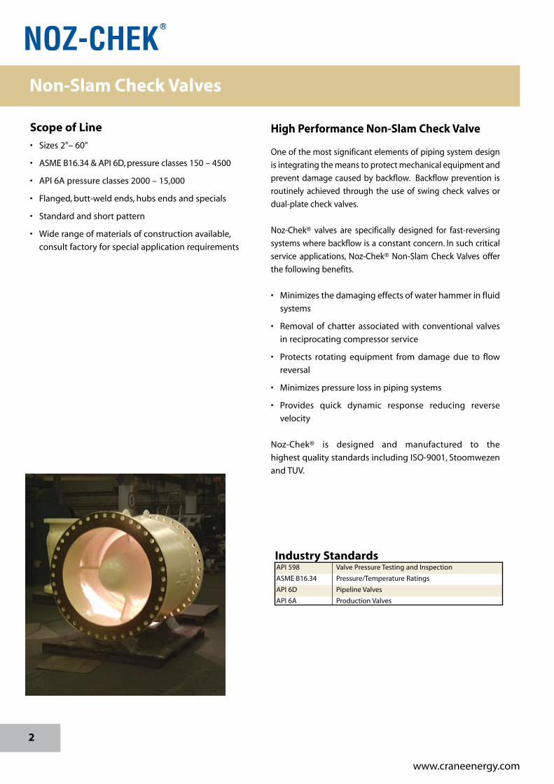
Scope of Line
• Sizes2"–60"
• ASMEB16.34&API6D,pressureclasses150–4500
• API6Apressureclasses2000–15,000
• Flanged,butt-weldends,hubsendsandspecials
• Standardandshortpattern
• Widerangeofmaterialsofconstructionavailable,
consultfactoryforspecialapplicationrequirements
Industry StandardsAPI598 ValvePressureTestingandInspection
ASMEB16.34 Pressure/TemperatureRatings
API6D PipelineValves
API6A ProductionValves
High Performance Non-Slam Check Valve
Oneofthemostsignificantelementsofpipingsystemdesign
isintegratingthemeanstoprotectmechanicalequipmentand
preventdamagecausedbybackflow. Backflowprevention is
routinely achieved through the use of swing check valves or
dual-platecheckvalves.
Noz-Chek® valves are specifically designed for fast-reversing
systemswherebackflowisaconstantconcern.Insuchcritical
service applications, Noz-Chek® Non-Slam CheckValves offer
thefollowingbenefits.
• Minimizesthedamagingeffectsofwaterhammerinfluid
systems
• Removal of chatter associated with conventional valves
inreciprocatingcompressorservice
• Protects rotating equipment from damage due to flow
reversal
• Minimizespressurelossinpipingsystems
• Provides quick dynamic response reducing reverse
velocity
Noz-Chek® is designed and manufactured to the
highestqualitystandardsincludingISO-9001,Stoomwezen
andTUV.
Non-Slam Check Valves
3
www.craneenergy.com
Features
Extensive research and development, coupled with valid
design procedures, have resulted in these unique Noz-
Chek®features:
• Fewmovingparts—Discistheonlymovingpart,
minimizing wear.
• Axialmovementofdisc—Discandseating
configurationgivestreamlinedflowpathwithventuri
effect,resultinginlowpressuredrop.
• Shortstrokeofspring-assisteddisc—Inletflowvelocity
movesdiscaxiallywithshortstroke.Inresponsetoflow
velocityreduction,acompressedspringinitiatesvalve
closure
andprovidesquickresponse.
• Springoptions—Choiceofspringaffects
criticalvelocityandvalveresponse.Selection
ismadeonengineeringevaluationofspecific
applications.Inabsenceofthisdata,a
standardspringwillbeprovided.
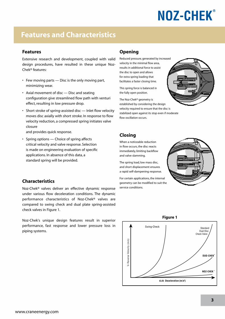
Characteristics
Noz-Chek® valves deliver an effective dynamic response
under various flow deceleration conditions. The dynamic
performance characteristics of Noz-Chek® valves are
compared to swing check and dual plate spring-assisted
checkvalvesinFigure1.
Noz-Chek's unique design features result in superior
performance, fast response and lower pressure loss in
pipingsystems.
OpeningReducedpressure,generatedbyincreased
velocityintheminimalflowarea,
resultsinadditionalforcetoassist
thedisctoopenandallows
forextraspringloadingthat
facilitatesafasterclosingtime.
Thisspringforceisbalancedin
thefullyopenposition.
TheNoz-Chek®geometryis
establishedbyconsideringthedesign
velocityrequiredtoensurethatthediscis
stabilizedopenagainstitsstopevenifmoderate
flowoscillationoccurs.
ClosingWhenanoticeablereduction
inflowoccurs,thediscreacts
immediately,limitingbackflow
andvalveslamming.
Thespringload,lowmassdisc,
andshortdisplacementensures
arapidself-dampeningresponse.
Forcertainapplications,theinternal
geometrycanbemodifiedtosuitthe
serviceconditions.
Swing-Check StandardDual Disc
Check Valve
Vr R
ever
se V
eloc
ity (
m/s
)
DUO-CHEK ®
NOZ-CHEK ®
dv/dt Deceleration (m/s )2
Figure 1
Features and Characteristics

4
www.craneenergy.com
Manufacturing Capabilities
Noz-Chek®valvescanbefurnishedinsizesfrom2"(50mm)to
60"(1500mm),andinpressureclassesfromASMEClass150
through4500andAPIratingsfrom2000to15,000psiCWP.
A variety of body and trim material is offered, including
carbonsteel,ductileiron,alloysteels,stainlesssteelandduplex
steel.Coatingsmaybeprovidedforaddedcorrosionorwear
resistance.Hard-facingandweldoverlaysmayalsobesupplied.
Seatsmaybemetal-to-metalorbubble-tightresilient.
Total Quality Management
CRANE® is guided by a commitment to total quality
management with a focus in customer satisfaction.
Design, manufacturing and testing procedures are
certified to ISO 9001, EN 29001 and ASME/ASQC Q91
Quality Assurance. This quality management system
isalsoapprovedbyStoomwezenandTUV.
Design
Computer-aided design (CAD) systems at CRANE® are
helpfulindevelopingsounddesigns.Finiteelementanalysis
is utilized to conduct simulated stress analyses for various
valvestructurestoprovedesignintegrity.Flowmodelingis
appliedtooptimizepressuredropcharacteristics.Computer-
generated spring designs and disc weight studies have
improvedtheNoz-Chek®valveresponsetimes.
Quality Management
5
www.craneenergy.com
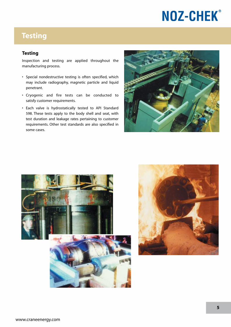
Testing
Inspection and testing are applied throughout the
manufacturingprocess.
• Special nondestructive testing is often specified, which
may include radiography, magnetic particle and liquid
penetrant.
• Cryogenic and fire tests can be conducted to
satisfycustomerrequirements.
• Each valve is hydrostatically tested to API Standard
598. These tests apply to the body shell and seat, with
test duration and leakage rates pertaining to customer
requirements. Other test standards are also specified in
somecases.
Testing
6
www.craneenergy.com
Applications
GasTransmission
• CompressorSuction/Discharge/Bypass
PowerGeneration
• Feedwater
• Coolingwater
• Blowdown
• Steam
Petrochemical/ChemicalProcessing
• ExtremeUnits
• PropyleneUnits
HydrocarbonProcessing
• CatalyticCracking
• Hydrotreating
WaterTransmission
• Pipeline
• PumpCompressorStation
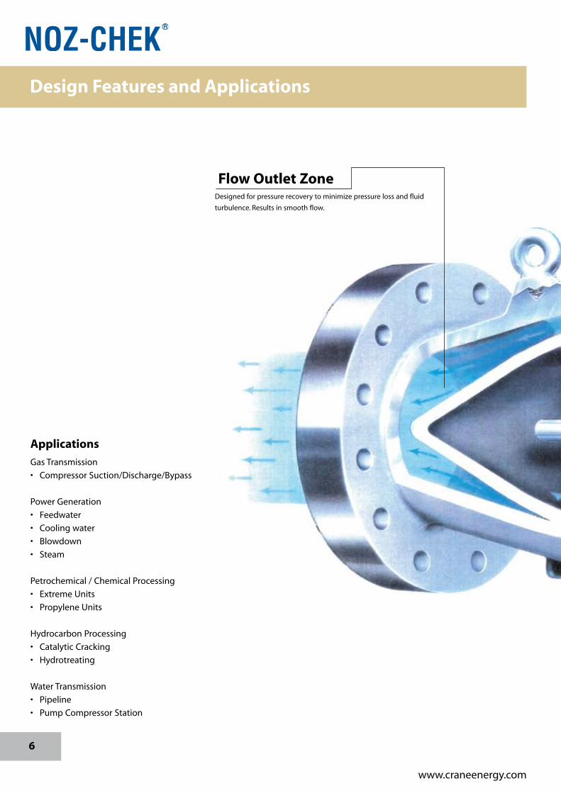
Flow Outlet ZoneDesignedforpressurerecoverytominimizepressurelossandfluid
turbulence.Resultsinsmoothflow.
Design Features and Applications
7
www.craneenergy.com
Spring
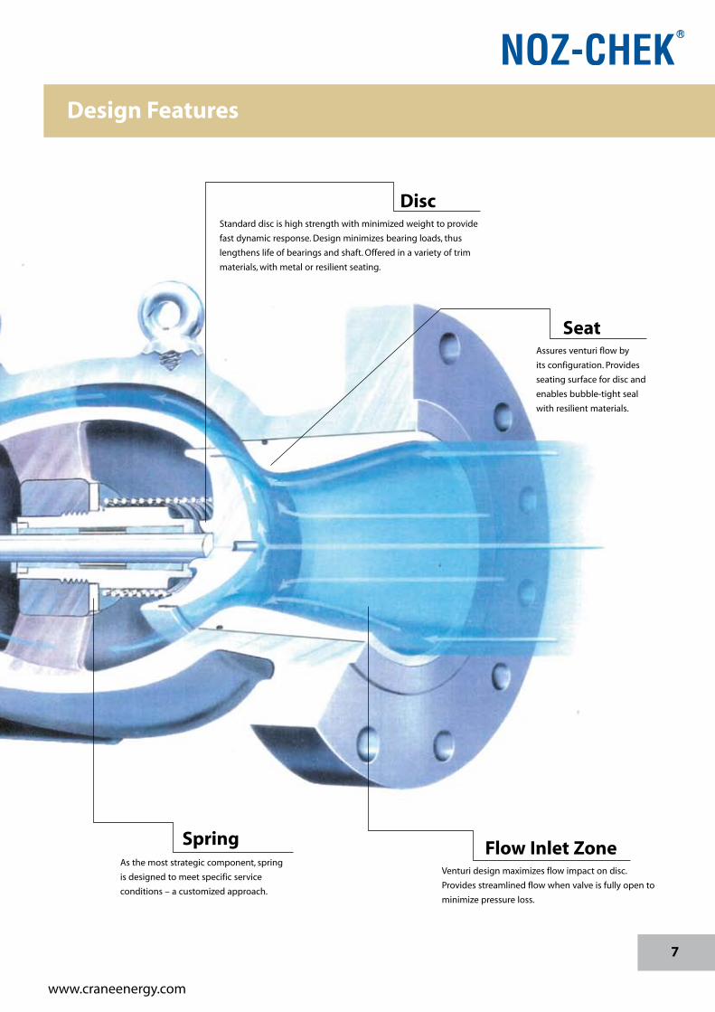
DiscStandarddiscishighstrengthwithminimizedweighttoprovide
fastdynamicresponse.Designminimizesbearingloads,thus
lengthenslifeofbearingsandshaft.Offeredinavarietyoftrim
materials,withmetalorresilientseating.
Flow Inlet ZoneVenturidesignmaximizesflowimpactondisc.
Providesstreamlinedflowwhenvalveisfullyopento
minimizepressureloss.
SeatAssuresventuriflowby
itsconfiguration.Provides
seatingsurfacefordiscand
enablesbubble-tightseal
withresilientmaterials.
Asthemoststrategiccomponent,spring
isdesignedtomeetspecificservice
conditions–acustomizedapproach.
Design Features
8
www.craneenergy.com
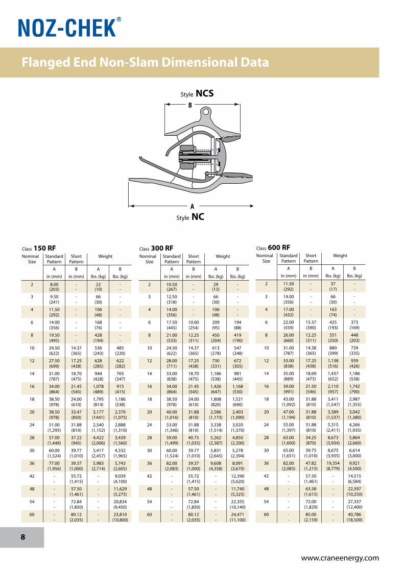
Class 300 RF Nominal Standard Short Weight Size Pattern Pattern
A B A B
in(mm) in(mm) lbs.(kg) lbs.(kg)
2 10.50 - 29 - (267) - (13) -
3 12.50 - 66 - (318) - (30) -
4 14.00 - 106 - (356) - (48) -
6 17.50 10.00 209 194 (445) (254) (95) (88)
8 21.00 12.25 450 419 (533) (311) (204) (190)
10 24.50 14.37 613 547 (622) (365) (278) (248)
12 28.00 17.25 730 672 (711) (438) (331) (305)
14 33.00 18.70 1,186 981 (838) (475) (538) (445)
16 34.00 21.45 1,426 1,168 (864) (545) (647) (530)
18 38.50 24.00 1,808 1,521 (978) (610) (820) (690)
20 40.00 31.88 2,586 2,403 (1,016) (810) (1,173) (1,090)
24 53.00 31.88 3,338 3,020 (1,346) (810) (1,514) (1,370)
28 59.00 40.75 5,262 4,850 (1,499) (1,035) (2,387) (2,200)
30 60.00 39.77 5,831 5,278 (1,524) (1,010) (2,645) (2,394)
36 82.00 39.37 9,608 8,091 (2,083) (1,000) (4,358) (3,670)
42 - 55.72 - 12,390 - (1,415) - (5,620)
48 - 57.50 - 11,740 - (1,461) - (5,325)
54 - 72.84 - 22,355 - (1,850) - (10,140)
60 - 80.12 - 24,471 - (2,035) - (11,100)
Class 600 RF Nominal Standard Short Weight Size Pattern Pattern
A B A B
in(mm) in(mm) lbs.(kg) lbs.(kg)
2 11.50 - 37 - (292) - (17) -
3 14.00 - 66 - (356) - (30) -
4 17.00 - 163 - (432) - (74) -
6 22.00 15.37 425 373 (559) (390) (193) (169)
8 26.00 12.25 551 448 (660) (311) (250) (203)
10 31.00 14.38 880 739 (787) (365) (399) (335)
12 33.00 17.25 1,138 939 (838) (438) (516) (426)
14 35.00 18.69 1,437 1,186 (889) (475) (652) (538)
16 39.00 21.50 2,110 1,742 (991) (546) (957) (790)
18 43.00 31.88 3,411 2,987 (1,092) (810) (1,547) (1,355)
20 47.00 31.88 3,389 3,042 (1,194) (810) (1,537) (1,380)
24 55.00 31.88 5,315 4,266 (1,397) (810) (2,411) (1,935)
28 63.00 34.25 8,673 5,864 (1,600) (870) (3,934) (2,660)
30 65.00 39.75 8,675 6,614 (1,651) (1,010) (3,935) (3,000)
36 82.00 47.82 19,354 9,921 (2,083) (1,215) (8,779) (4,500)
42 - 57.50 - 14,515 - (1,461) - (6,584)
48 - 63.58 - 22,597 - (1,615) - (10,250)
54 - 72.00 - 27,337 - (1,829) - (12,400)
60 - 85.00 - 40,786 - (2,159) - (18,500)
Class 150 RF Nominal Standard Short Weight Size Pattern Pattern
A B A B
in(mm) in(mm) lbs.(kg) lbs.(kg)
2 8.00 - 22 - (203) - (10) -
3 9.50 - 66 - (241) - (30) -
4 11.50 - 106 - (292) - (48) -
6 14.00 - 168 - (356) - (76) -
8 19.50 - 428 - (495) - (194) -
10 24.50 14.37 536 485 (622) (365) (243) (220)
12 27.50 17.25 628 622 (699) (438) (285) (282)
14 31.00 18.70 944 765 (787) (475) (428) (347)
16 34.00 21.45 1,078 915 (864) (545) (489) (415)
18 38.50 24.00 1,795 1,186 (978) (610) (814) (538)
20 38.50 33.47 3,177 2,370 (978) (850) (1441) (1,075)
24 51.00 31.88 2,540 2,888 (1,295) (810) (1,152) (1,310)
28 57.00 37.22 4,422 3,439 (1,448) (945) (2,006) (1,560)
30 60.00 39.77 5,417 4,332 (1,524) (1,010) (2,457) (1,965)
36 77.00 39.37 5,983 5,743 (1,956) (1,000) (2,714) (2,605)
42 - 55.72 - 9,039 - (1,415) - (4,100)
48 - 57.50 - 11,629 - (1,461) - (5,275)
54 - 72.84 - 20,834 - (1,850) - (9,450)
60 - 80.12 - 23,810 - (2,035) - (10,800)
B
A
Style NCS
Style NC
Flanged End Non-Slam Dimensional Data
9
www.craneenergy.com
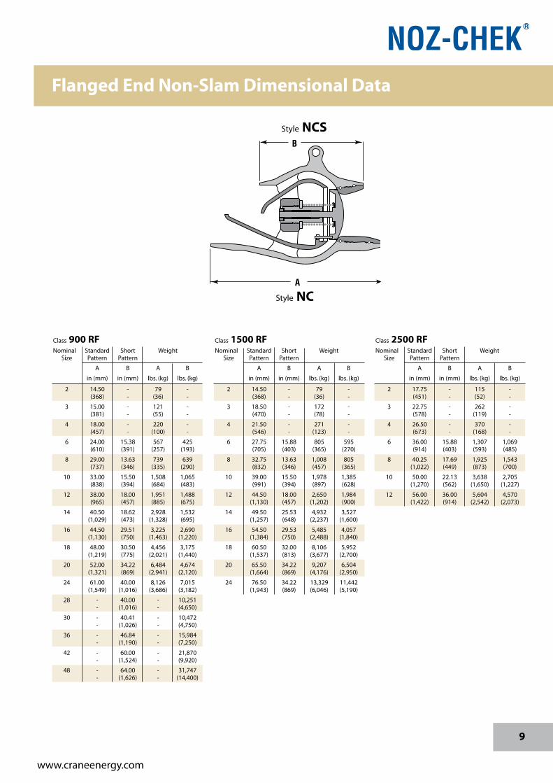
Class 2500 RF Nominal Standard Short Weight Size Pattern Pattern
A B A B
in(mm) in(mm) lbs.(kg) lbs.(kg)
2 17.75 - 115 - (451) - (52) -
3 22.75 - 262 - (578) - (119) -
4 26.50 - 370 - (673) - (168) -
6 36.00 15.88 1,307 1,069 (914) (403) (593) (485)
8 40.25 17.69 1,925 1,543 (1,022) (449) (873) (700)
10 50.00 22.13 3,638 2,705 (1,270) (562) (1,650) (1,227)
12 56.00 36.00 5,604 4,570 (1,422) (914) (2,542) (2,073)
Class 900 RF Nominal Standard Short Weight Size Pattern Pattern
A B A B
in(mm) in(mm) lbs.(kg) lbs.(kg)
2 14.50 - 79 - (368) - (36) -
3 15.00 - 121 - (381) - (55) -
4 18.00 - 220 - (457) - (100) -
6 24.00 15.38 567 425 (610) (391) (257) (193)
8 29.00 13.63 739 639 (737) (346) (335) (290)
10 33.00 15.50 1,508 1,065 (838) (394) (684) (483)
12 38.00 18.00 1,951 1,488 (965) (457) (885) (675)
14 40.50 18.62 2,928 1,532 (1,029) (473) (1,328) (695)
16 44.50 29.51 3,225 2,690 (1,130) (750) (1,463) (1,220)
18 48.00 30.50 4,456 3,175 (1,219) (775) (2,021) (1,440)
20 52.00 34.22 6,484 4,674 (1,321) (869) (2,941) (2,120)
24 61.00 40.00 8,126 7,015 (1,549) (1,016) (3,686) (3,182)
28 - 40.00 - 10,251 - (1,016) - (4,650)
30 - 40.41 - 10,472 - (1,026) - (4,750)
36 - 46.84 - 15,984 - (1,190) - (7,250)
42 - 60.00 - 21,870 - (1,524) - (9,920)
48 - 64.00 - 31,747 - (1,626) - (14,400)
Class 1500 RF Nominal Standard Short Weight Size Pattern Pattern
A B A B
in(mm) in(mm) lbs.(kg) lbs.(kg)
2 14.50 - 79 - (368) - (36) -
3 18.50 - 172 - (470) - (78) -
4 21.50 - 271 - (546) - (123) -
6 27.75 15.88 805 595 (705) (403) (365) (270)
8 32.75 13.63 1,008 805 (832) (346) (457) (365)
10 39.00 15.50 1,978 1,385 (991) (394) (897) (628)
12 44.50 18.00 2,650 1,984 (1,130) (457) (1,202) (900)
14 49.50 25.53 4,932 3,527 (1,257) (648) (2,237) (1,600)
16 54.50 29.53 5,485 4,057 (1,384) (750) (2,488) (1,840)
18 60.50 32.00 8,106 5,952 (1,537) (813) (3,677) (2,700)
20 65.50 34.22 9,207 6,504 (1,664) (869) (4,176) (2,950)
24 76.50 34.22 13,329 11,442 (1,943) (869) (6,046) (5,190)
B
A
Style NCS
Style NC
Flanged End Non-Slam Dimensional Data
10
www.craneenergy.com
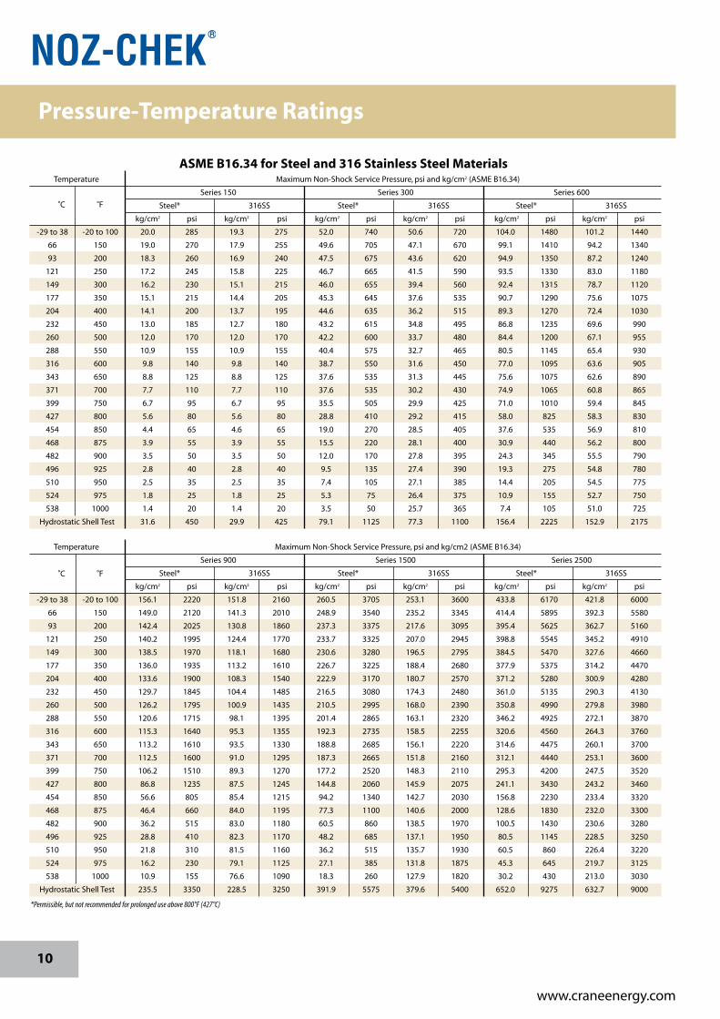
ASME B16.34 for Steel and 316 Stainless Steel Materials Temperature MaximumNon-ShockServicePressure,psiandkg/cm2(ASMEB16.34)
Series150 Series300 Series600
Steel* 316SS Steel* 316SS Steel* 316SS
kg/cm2 psi kg/cm2 psi kg/cm2 psi kg/cm2 psi kg/cm2 psi kg/cm2 psi
-29to38 -20to100 20.0 285 19.3 275 52.0 740 50.6 720 104.0 1480 101.2 1440
66 150 19.0 270 17.9 255 49.6 705 47.1 670 99.1 1410 94.2 1340
93 200 18.3 260 16.9 240 47.5 675 43.6 620 94.9 1350 87.2 1240
121 250 17.2 245 15.8 225 46.7 665 41.5 590 93.5 1330 83.0 1180
149 300 16.2 230 15.1 215 46.0 655 39.4 560 92.4 1315 78.7 1120
177 350 15.1 215 14.4 205 45.3 645 37.6 535 90.7 1290 75.6 1075
204 400 14.1 200 13.7 195 44.6 635 36.2 515 89.3 1270 72.4 1030
232 450 13.0 185 12.7 180 43.2 615 34.8 495 86.8 1235 69.6 990
260 500 12.0 170 12.0 170 42.2 600 33.7 480 84.4 1200 67.1 955
288 550 10.9 155 10.9 155 40.4 575 32.7 465 80.5 1145 65.4 930
316 600 9.8 140 9.8 140 38.7 550 31.6 450 77.0 1095 63.6 905
343 650 8.8 125 8.8 125 37.6 535 31.3 445 75.6 1075 62.6 890
371 700 7.7 110 7.7 110 37.6 535 30.2 430 74.9 1065 60.8 865
399 750 6.7 95 6.7 95 35.5 505 29.9 425 71.0 1010 59.4 845
427 800 5.6 80 5.6 80 28.8 410 29.2 415 58.0 825 58.3 830
454 850 4.4 65 4.6 65 19.0 270 28.5 405 37.6 535 56.9 810
468 875 3.9 55 3.9 55 15.5 220 28.1 400 30.9 440 56.2 800
482 900 3.5 50 3.5 50 12.0 170 27.8 395 24.3 345 55.5 790
496 925 2.8 40 2.8 40 9.5 135 27.4 390 19.3 275 54.8 780
510 950 2.5 35 2.5 35 7.4 105 27.1 385 14.4 205 54.5 775
524 975 1.8 25 1.8 25 5.3 75 26.4 375 10.9 155 52.7 750
538 1000 1.4 20 1.4 20 3.5 50 25.7 365 7.4 105 51.0 725
HydrostaticShellTest 31.6 450 29.9 425 79.1 1125 77.3 1100 156.4 2225 152.9 2175
°C °F
*Permissible, but not recommended for prolonged use above 800°F (427°C)
Temperature MaximumNon-ShockServicePressure,psiandkg/cm2(ASMEB16.34)
Series900 Series1500 Series2500
Steel* 316SS Steel* 316SS Steel* 316SS
kg/cm2 psi kg/cm2 psi kg/cm2 psi kg/cm2 psi kg/cm2 psi kg/cm2 psi
-29to38 -20to100 156.1 2220 151.8 2160 260.5 3705 253.1 3600 433.8 6170 421.8 6000
66 150 149.0 2120 141.3 2010 248.9 3540 235.2 3345 414.4 5895 392.3 5580
93 200 142.4 2025 130.8 1860 237.3 3375 217.6 3095 395.4 5625 362.7 5160
121 250 140.2 1995 124.4 1770 233.7 3325 207.0 2945 398.8 5545 345.2 4910
149 300 138.5 1970 118.1 1680 230.6 3280 196.5 2795 384.5 5470 327.6 4660
177 350 136.0 1935 113.2 1610 226.7 3225 188.4 2680 377.9 5375 314.2 4470
204 400 133.6 1900 108.3 1540 222.9 3170 180.7 2570 371.2 5280 300.9 4280
232 450 129.7 1845 104.4 1485 216.5 3080 174.3 2480 361.0 5135 290.3 4130
260 500 126.2 1795 100.9 1435 210.5 2995 168.0 2390 350.8 4990 279.8 3980
288 550 120.6 1715 98.1 1395 201.4 2865 163.1 2320 346.2 4925 272.1 3870
316 600 115.3 1640 95.3 1355 192.3 2735 158.5 2255 320.6 4560 264.3 3760
343 650 113.2 1610 93.5 1330 188.8 2685 156.1 2220 314.6 4475 260.1 3700
371 700 112.5 1600 91.0 1295 187.3 2665 151.8 2160 312.1 4440 253.1 3600
399 750 106.2 1510 89.3 1270 177.2 2520 148.3 2110 295.3 4200 247.5 3520
427 800 86.8 1235 87.5 1245 144.8 2060 145.9 2075 241.1 3430 243.2 3460
454 850 56.6 805 85.4 1215 94.2 1340 142.7 2030 156.8 2230 233.4 3320
468 875 46.4 660 84.0 1195 77.3 1100 140.6 2000 128.6 1830 232.0 3300
482 900 36.2 515 83.0 1180 60.5 860 138.5 1970 100.5 1430 230.6 3280
496 925 28.8 410 82.3 1170 48.2 685 137.1 1950 80.5 1145 228.5 3250
510 950 21.8 310 81.5 1160 36.2 515 135.7 1930 60.5 860 226.4 3220
524 975 16.2 230 79.1 1125 27.1 385 131.8 1875 45.3 645 219.7 3125
538 1000 10.9 155 76.6 1090 18.3 260 127.9 1820 30.2 430 213.0 3030
HydrostaticShellTest 235.5 3350 228.5 3250 391.9 5575 379.6 5400 652.0 9275 632.7 9000
°C °F
Pressure-Temperature Ratings

11
www.craneenergy.com
• DesignedtomeetASME,BSandAPIstandards
• Sizes2through72inches(50through1800mm)
Duo-Chek®
• Ratedto200and285psishutoff
• Sizes2through48inches(50through1200mm)
Center Line® ResilientSeatedButterflyValves
HighPerformanceButterflyValves
• Soft,metalorfiresafeseats
• ASMEPressureClass150,300and600
• Sizes2through48inches(50through1200mm)
Flowseal®
HighPerformanceWaferandLugCheckValves
CRANE® Valves
12
www.craneenergy.com
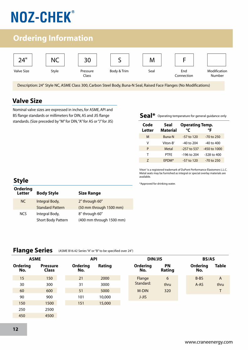
Description:24"StyleNC,ASMEClass300,CarbonSteelBody,Buna-NSeal,RaisedFaceFlanges(NoModifications)
ValveSize Style Pressure Body&Trim Seal End Modification Class Connection Number
24" NC 30 S M F
Flange Series (ASMEB16.42Series“A”or“B”tobespecifiedover24")
ASME API DIN/JIS BS/AS
Ordering Pressure Ordering Rating Ordering PN Ordering Table No. Class No. No. Rating No.
15 150 21 2000 Flange 6 B-BS A
30 300 31 3000 Standard: thru A-AS thru
60 600 51 5000 M-DIN 320 T
90 900 101 10,000 J-JIS
150 1500 151 15,000
250 2500
450 4500
OperatingtemperatureforgeneralguidanceonlySeal* Code Seal Operating Temp. Letter Material °C °F M Buna-N -57to120 -70to250
V Viton-B® -40to204 -40to400
P Metal -257to537 -450to1000
T PTFE -196to204 -328to400
Z EPDM* -57to120 -70to250 Viton®isaregisteredtrademarkofDuPontPerformanceElastomersL.L.C.Metalseatsmaybefurnishedasintegralorspecialoverlaymaterialsareavailable.
*Approvedfordrinkingwater.
Valve SizeNominalvalvesizesareexpressedininches,forASME,APIand
BSflangestandardsormillimetersforDIN,ASandJISflange
standards.(Sizeprecededby“M”forDIN,“A”forASor“J”forJIS)
Style Ordering Letter Body Style Size Range
NC IntegralBody, 2"through60"
StandardPattern (50mmthrough1500mm)
NCS IntegralBody, 8"through60"
ShortBodyPattern (400mmthrough1500mm)
Ordering Information

13
www.craneenergy.com
End Connections
Letter Connections
F Flanged-RaisedFaced
X Flanged-FlatFaced
G Grayloc®End
P FlangedSmoothFinish
R FlangedRingJoint
W ButtWeld
Grayloc®isaregisteredtrademarkofOceaneeringInternational,Inc.
Ordering
Amodificationnumberisassignedwhennon-
standardfeatures,materialmixesordocumentation
areordered.
Modifications
Standard Body & Disc MaterialsCode Body Disc
S ASTMA216GRWCBcarbonsteel alloysteel
C ASTMA351GRCF8M316stainlesssteel stainlesssteel
E ASTMA217GRCA15410stainlesssteel 11-13chrome
DD BSEN1563GREN-GJS-450-10**ductileiron stainlesssteel
GC ASTMA352GRLCClowtemp.carbonsteel alloysteel
DZ ASTMA890GR4Aduplexstainlesssteel DuplexSS **alsoavailableinASTMA395a
Spring MaterialSpring Maximum RecommendedMaterial Operating Temperatures °C °F
316StainlessSteel 120 250
Inconel600® 315 600
InconelX-750® 537 1000
Inconel® is a registered trademark of Special Metals Corporation. Fortemperatures up to 600°F (315°C), Inconel will be furnished as standard.For service temperatures above 600°F (315°C), Inconel X-750 springswil be specified. Other alloy spring materials are available to meet specificservicerequirements.
Description:24"StyleNC,ASMEClass300,CarbonSteelBody,Buna-NSeal,RaisedFaceFlanges(NoModifications)
ValveSize Style Pressure Body&Trim Seal End Modification Class Connection Number
24" NC 30 S M F
Ordering Information
14
www.craneenergy.com
Notes
15
www.craneenergy.com
Notes
© 2011 CRANE Energy Flow Solutions, www.craneenergy.com
www.flowoffluids.com
CRANE Energy Flow Solutions®
www.craneenergy.com
Crane Co., and its subsidiaries cannot accept responsibility for possible errors in catalogues, brochures, other printed materials, and website information. Crane Co. reserves the right to alter its products without notice, including products already on order provided that such alteration can be made without changes being necessary in specifications already agreed. All trademarks in this material are property of the Crane Co. or its subsidiaries. The Crane and Crane brands logotype (Aloyco®, Center Line®, Compac-Noz®, Crane®, Duo-Chek®, Flowseal®, Jenkins®, Krombach®, Noz-Chek®, Pacific Valves®, Stockham®, Triangle®, Uni-Chek®) are registered trademarks of Crane Co. All rights reserved.
EG-N
C-C
T-EN
-A16
-17-
1111
(CV
-701
)
®
NUCLEAR
CRANE Energy Global Headquarters
4526 Research Forest Drive, Suite 400
The Woodlands, Texas 77381 U.S.A.
Tel.: (1) 936-271-6500
Fax.: (1) 936-271-6510
Sydney Australia Operations
148 - 154 Dunheved Circuit
St. Mary's NSW 2760
Tel: +61-2-9623-0234
Fax: +61-2-9673-3870
Belfast, Northern Ireland Operations
6 Alexander Road
Cregagh, Belfast BT6 9HJ
Tel.: (442) 890-704222
Fax.: (442) 890-401582
Related Documents