Two IFC Construction of by Raymond Wong Wai Man The project dates back to 1996 when the foundation work contract was awarded to Aoki Corporation, the main contractor for the MTRC's Hong Kong Station, as part of the overall station's contract. The contract originally included the foundation works for an 88-storey office tower, in which 72 bored piles with 3 m diameters were to be constructed; as well as the cut- off system using diaphragm walls around the entire site, bored piles for the podium structure and barrettes for a hotel building to the west of the site. Structural arrangements The superstructure is an 88-storey composite building with five additional basement levels going down to -32 mPD. The highest point of the tower is 420 mPD. The general footprint of the building is about 57 m by 57 m but at the roof level this area is reduced to 39 m x An aerial view of the entire International Finance Centre development and MTR Hong Kong Station at the Stage I Central Reclamation in 1997

Welcome message from author
This document is posted to help you gain knowledge. Please leave a comment to let me know what you think about it! Share it to your friends and learn new things together.
Transcript

Two IFCConstruction of by Raymond Wong Wai Man
The project dates back to 1996
when the foundation work
contract was awarded to Aoki
Corporation, the main contractor
for the MTRC's Hong Kong
Station, as part of the overall
station's contract. The contract
originally included the foundation
works for an 88-storey office
tower, in which 72 bored piles
with 3 m diameters were to be
constructed; as well as the cut-
off system using diaphragm walls
around the entire site, bored piles
for the podium structure and
barrettes for a hotel building to
the west of the site.
Structural arrangementsThe superstructure is an 88-storeycomposi te bui ld ing wi th f iveadditional basement levels goingdown to -32 mPD. The highest pointof the tower is 420 mPD. Thegeneral footprint of the building isabout 57 m by 57 m but at the rooflevel this area is reduced to 39 m x
An aerial view of the entire International Finance Centre development and MTR Hong Kong Station at theStage I Central Reclamation in 1997
39 m. The gross floor area of theGrade-A office building is about 180,000 sq m and the typical floor-to-floor height is 4.2 m. The structureis designed to last for 120 years.
The structural system consists ofa central reinforced concrete corewall linked by steel beams andout r iggers to e igh t ex ter io rcomposite mega-columns. Twosecondary columns are located ateach corner of the building to
support the gravity load. Compositeslabs are used as floor slabs,comprising 460 mm deep steelsecondary beams spanning from thecore wall to the 900 mm deepprimary girders spanning betweenthe mega-columns. Four sets ofoutrigger and belt truss systems areprovided to stabilise and strengthenthe external steel frame onto thecore wall. The core wall measures29 m by 27 m at its base with a
maximum wall thickness of 1.5 m.The wall is made of Grade 60reinforced concrete. The corehouses the pr imary bui ld ingfunctions, including the elevators,stairs, toilets and mechanical roomsfor building services facilities.
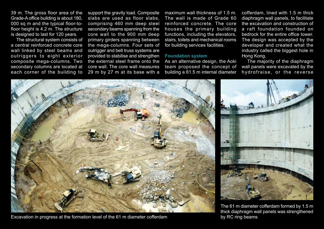
Foundation systemAs an alternative design, the Aokiteam proposed the concept ofbuilding a 61.5 m internal diameter
cofferdam, lined with 1.5 m thickdiaphragm wall panels, to facilitatethe excavation and construction ofa raft foundation founded onbedrock for the entire office tower.The design was accepted by thedeveloper and created what theindustry called the biggest hole inHong Kong.
The majority of the diaphragmwall panels were excavated by thehydro f ra ise , o r the reverse
Excavation in progress at the formation level of the 61 m diameter cofferdam
The 61 m diameter cofferdam formed by 1.5 mthick diaphragm wall panels was strengthenedby RC ring beams

circulation trench cutting machine.The average depth of the panelswas about 55 m, with the toe groutedand installed with shear pins toensure stability.
As the excavation proceeded, acapping beam at the top of thecofferdam and four ring beams wereprovided as stiffening elements tothe diaphragm wall panels. By theprovision of a compression ringusing the cofferdam, the excavationcould be extended safely down tobedrock, averaging about 40 m fromground level. The initial excavationwas relatively straightforward for
merely cutting through reclaimedsand fill layers. However, the laterstage of excavation was much moredifficult and time consuming for itinvolved cutting into partially andslightly decomposed granite layers,where a non-explosive demolitionagent was used. Meanwhile, alocalised depression of the rock levelto the south west of the tower baseappeared with a maximum depth ofrock up to -50 mPD, which was toodeep for normal open excavation. Inthis location, barrettes (rectangular-section piles) were installed toprovide support to the building raft.
The whole excavation process wascarried out down to the formationlevel at -32 mPD. Including thetreatment to the localised bedrock,the work took about 16 months tocomple te . However , due toeconomic reasons after 1997, theproject was suspended for about twoyears.
Foundation work resumed inearly 2000. Immediately from the topof the formation surface, a 6.5 m-deep heavily reinforced slab wasconstructed to serve as the raft forthe entire building tower, with avolume of about 20,000 cu m of
concrete. Starter provisions for thecore wall and gusseted bases for theinstallation of the mega-columnswere also provided here to connectto the construction of the upperstructure.
The mega-columnsThere are eight mega-columnsrising from the raft at the base of thecofferdam up to the roof at 420 mPD,supporting the external frame of theentire building. The first section ofthe mega-columns, stretching frombasement level 5 to the 6/F levelwhere the transfer truss is located,
The core wall of the Two IFC tower ascending from theraft at the bottom of the cofferdam. Also note the mega-columns anchored to the plinths by gusset plates
Close-up view of the plinth at a mega-column

has six sub-stanchions formed by90 mm-thick plates with averageweights of steel up to 9.7 ton/m.Due to the heavy weight, thestanchions were installed in shortsections and connected by weldingand non-welded bearing splices.Mobile cranes stationed on theground level around the cofferdamwere used to fac i l i t a te theinstallation process. In order tospeed up the work by allowing themega-columns to be installed atthe earliest float, the contract fors t r uc tu ra l s t ee l wo rks wassubdivided into two stages, for
installation of the mega-columnsbelow 6/F and the rest of the worksfor the superstructure above 6/F,and awarded to two independentnomina ted sub-con t rac to rs ,corresponding to approximately5,000 tons and 19,000 tons ofstructural steel works respectively.
As construction of the basementslab proceeded in a bottom-upmanner, the mega-columns werethen encased in concrete, withreinforcing steel bars fixed aroundthe stanchions to increase thestrength and st i ffness of thecolumns.
A view into the cofferdam with the core wall and mega-columns in positionclose to ground level
Forming the transfer truss at 6/F at its early stage. Also note the sizereduction of the mega-columns at this level
Detail of the south elevation of the transfer truss at 6/F

Steel sections stacked on the site for forming the mega-columns
Work stations around the sides of the cofferdamon ground level, forming an important base toserve construction activities inside the cofferdam
Fixing steel bars (50 mm diameter bars at the basesection) around the stanchions of a mega-columnbefore encasing it in concrete

Construction of the core wallConstruction of the core wallcommenced in May 2000, startingfrom the raft at the bottom of thecofferdam. Due to the non-typicallayout and to save time in makingmodifications to the form in theconfined environment inside thecofferdam, a gang form systemcomposed of timber panel-typeshutters stiffened by aluminiumstuds was used. The mobi lecranes stat ioned around thecofferdam on ground level wereused for the installation of thefo rmwork . The cons t ruc t iontechnique followed a bottom-upand floor-by-floor approach, witht h e v e r t i c a l w a l l s e c t i o n scompleted first and followed by thefloor slabs until reaching groundlevel. Construction joints were alsoprovided at the sides bounded bythe mega-co lumns to a l l owseparation between the slab andthe cofferdam, as well as providefuture connection to the basementof the podium portion.
Starting from the ground level,another set o f s tee l shut terformwork was used to replace theoriginal timber panel-type setup upto the 3/F level. From the 4/F levelonwards, the form was modifiedwith the addition of a girder frame,hydraulic jack and clamp system,
Close-up view of the formwork systemused for the construction of the core wallat the early stage. Another climb form setwould be used to replace this when thecore wall reached ground level
Forming the floor slab inside the cofferdam with aconstruction joint in place for breaking through to jointo the adjoining basement floors later

transforming it into a climb form.I n o r d e r t o a c h i e v e m o r eeffective operation, the core wallwas sub-divided into two portionsby the use of two independentlycontrollable lifting systems, withcons t ruc t ion jo in t i ng in themiddle where the tie memberswere located. The floor cycle fortypical floors was maintained atfour to f ive days, with certainexpected delays at floors wheret h e o u t r i g g e r s y s t e m w a slocated, or where the wall startedto reduce in size.
Erection of the first section ofclimb form at the ground level
The first section of core wall (westernsection) being concreted while the erectionof the eastern section was in progress

The climb form, composedof two separate cl imbsystems, was used toconstruct the 780 sq mcentral core
A view of the climb form at a building corner when itwas in the released position ready for lifting to the nextworking level
The shutter panels, girdersupport and hydraulic jackarrangement of the climb form,as seen from inside one of thecore shafts
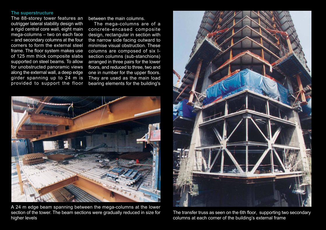
The superstructureThe 88-storey tower features anoutrigger lateral stability design witha rigid central core wall, eight mainmega-columns – two on each face– and secondary columns at the fourcorners to form the external steelframe. The floor system makes useof 125 mm thick composite slabssupported on steel beams. To allowfor unobstructed panoramic viewsalong the external wall, a deep edgegirder spanning up to 24 m isprovided to support the f loor
between the main columns.The mega-columns are of a
concrete-encased composi tedesign, rectangular in section withthe narrow side facing outward tominimise visual obstruction. Thesecolumns are composed of six I-section columns (sub-stanchions)arranged in three pairs for the lowerfloors, and reduced to three, two andone in number for the upper floors.They are used as the main loadbearing elements for the building's
The transfer truss as seen on the 6th floor, supporting two secondarycolumns at each corner of the building’s external frame
A 24 m edge beam spanning between the mega-columns at the lowersection of the tower. The beam sections were gradually reduced in size forhigher levels

exterior frame. In order to reducecosts and increase the stiffness ofthe columns, reinforcement barsranging from 4 per cent to 2 per centof the column section are positionedaround the per imeter of thestanchions. The encasing concreteused for the columns is of grade 60(Basement up to 52/F) and grade 45(53/F and above). One self-climbingform system for each column wasused for the encasement works atthe mega-columns.
Other spectacular features in thesuperstructure are the belt truss andoutrigger systems provided in thecomposite frame to stiffen the entire88-storey structure. The first sets ofthe belt truss system are located on6/F and 7/F and serve to provide atransfer arrangement to spread theload of the columns from the upperstructure down to the mega-columns. Meanwhile, the other threesets of outrigger systems, located on
Concreting to the composite mega-column
A mega-column with the reinforcingbars fixed in position and ready forthe concrete encasement
Two sets of climb forms for the mega-columns on the building exteriorThe climb form in position ready forencasing
The climb form in its open mold readyfor repositioning to an upper floor

32/F-33/F, 53/F-54/F and 65/F-66/F respectively, act as strengtheningcomponents to improve the rigidityof the structure and to reduce theeffect of deflection on the buildingdue to wind load. The outrigger andbelt truss systems in general includea built-in inner steel frame servingas an anchor truss, which isembedded in the RC core using atwo-stage casting (retro-installation)process, and an external frame inthe form of belt truss acting as anexternal stiffening member andtaking up the gravity loads from thecorner columns.
The outriggers and the belttrusses are connected by semi-rigidjoints located inside column slots,which can be made adjustable witha series of packing shims. Thisdesign is to cater for the differentialshortening between the RC core andthe perimeter columns duringconstruction of the tower as well asthe slight shortening that occursthroughout the life span of thebuilding. This design concept wasoriginally used in the construction ofCheung Kong Center.
Drawing showing the open and shut moldof the climb form for the mega-columns
Building elevation showing thebasic configuration of thetransfer/belt truss at 6/F
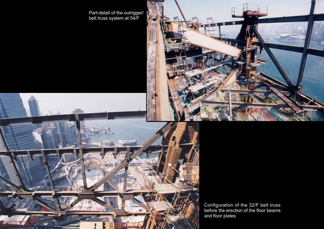
Configuration of the 32/F belt trussbefore the erection of the floor beamsand floor plates
Part-detail of the outrigger/belt truss system at 54/F

Part-detail of the outrigger/belt truss system at 65/F
Installation of the outriggersystem at 32/F — anchorframe starting to be installedonto recessed positions onthe core wall

Installation of the outriggersystem at 32/F — anchorframe being installed onto thecore wall recess. The framewas encased in reinforcedconcrete at a later stage, aftercompletion of the floor system
Close up of the anchor frame before it wasencased as part of the retro-installation
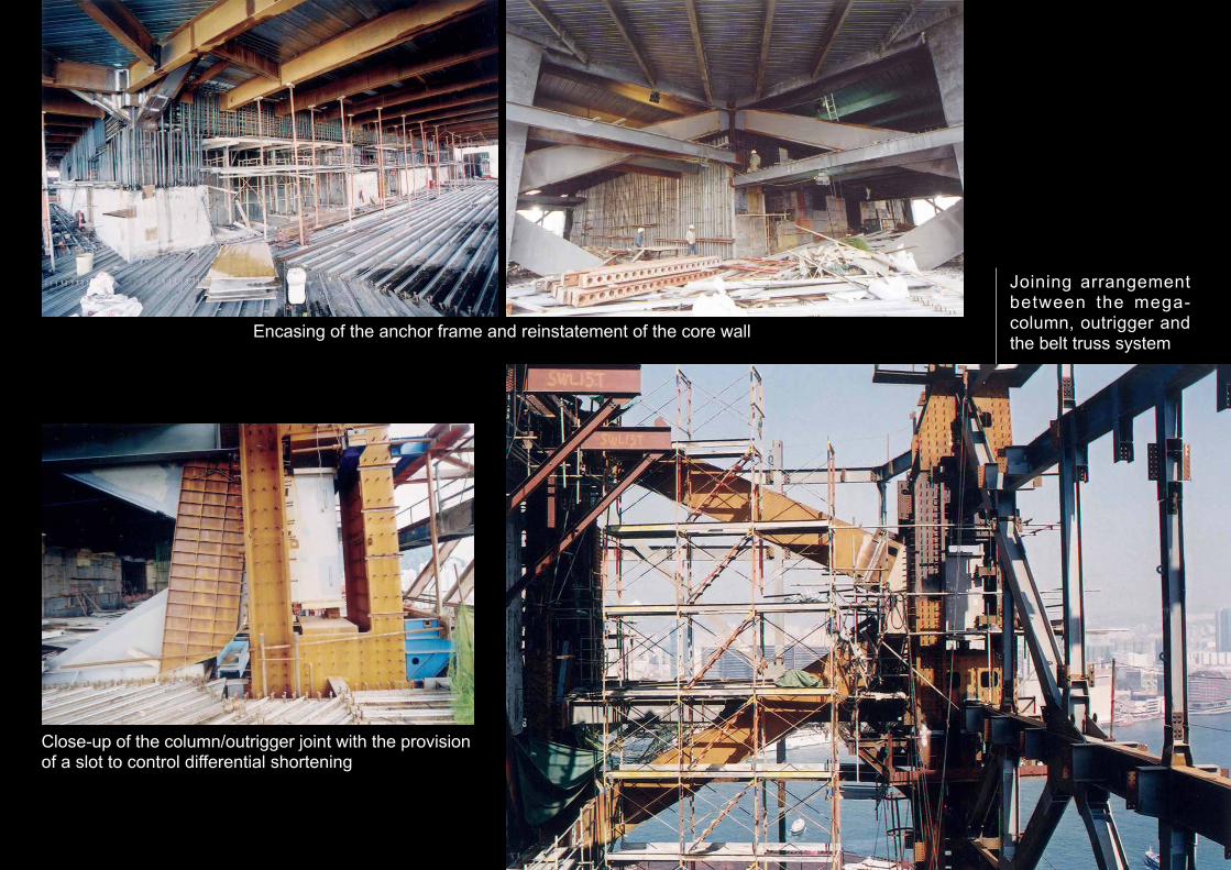
Encasing of the anchor frame and reinstatement of the core wall
Joining arrangementbetween the mega-column, outrigger andthe belt truss system
Close-up of the column/outrigger joint with the provisionof a slot to control differential shortening

Column joint after the column is encased in reinforced concrete
The arrangement of the outrigger system used at Cheung KongCenter (at 59/F)
Close up of the outrigger/belt truss joining arrangement as employed atCheung Kong Center, bearing similarities in design to the Two IFCarrangement

Basement of the podium
The 38,000 sq m, f ive- levelbasement beneath the podium wasconstructed using a top-downapproach. In order to achieve this,steel stanchions were positionedinto the bored piles and connectedto the foundation by gusset plate.The stanchions were used assupports to the upper basementslabs as the excavat ion andcasting process proceeded. Acoupl ing ar rangement us ingcouplers welded to the sides of thestanchions was provided at levelswhere the basement slab waslocated. Due to the huge size ofthe basement, the excavation andconstruction work was sub-dividedinto nine phases in order to confinethe construction to controllablesegments. The basement workcommenced in June 2000 and tookabout 18 months to complete.
Getting rid of the huge amountof excavated spoil was one of thedifficult problems faced in theproject. To tackle the problem,three temporary access shaftswere formed on the slab of thebasement, located at the east,middle and west of the podium.The shafts were used to transportthe spoil from the excavation pointvertically to the ground surface. Atthe same time, specially designedrack-type lifting devices (materialhoists) equipped with 3 cu m
Commencement of the top-down basement. The workarrangement with steelstanchions supporting theground floor slab and thebasement excavat ion/construction underneathcan clearly be seen
With the ground slab beingcast in position, excavationf o r t h e b a s e m e n tproceeded in convenientphases. The excavationwas initially carried outa round the muck-ou topenings provisioned onthe g round s lab andg r a d u a l l y e x t e n d e dhorizontally and downwardin a zigzag manner untilbasement f loors werecompleted

tiltable bucket was installed ateach sha f t to remove spo i lefficiently and quickly from theb a s e m e n t . F o r h o r i z o n t a lt ranspor ta t ion , a temporaryunloading pier with an elevatedlinking bridge was provided on thenearby seawall to allow dumpingvehicles to remove spoil from thesite and unload them onto barges.
I n o r d e r t o e x p e d i t e t h eexcavation and casting works, adouble bit method was adopted toconstruct the basement slab. Themethod was to excavate twobasement levels at a time and thencas t t he s l ab o f t he l owe rbasement in an advanced phase.
One of the openings provisioned on the ground slab for mucking-out duringthe basement excavation process
Looking into the muck-out opening with the excavation arrangementclearly seen
Spoil removal hoist with the bucket/hopper set-up for unloading atground level
Operation of the spoil removal hoistinside the muck-out opening
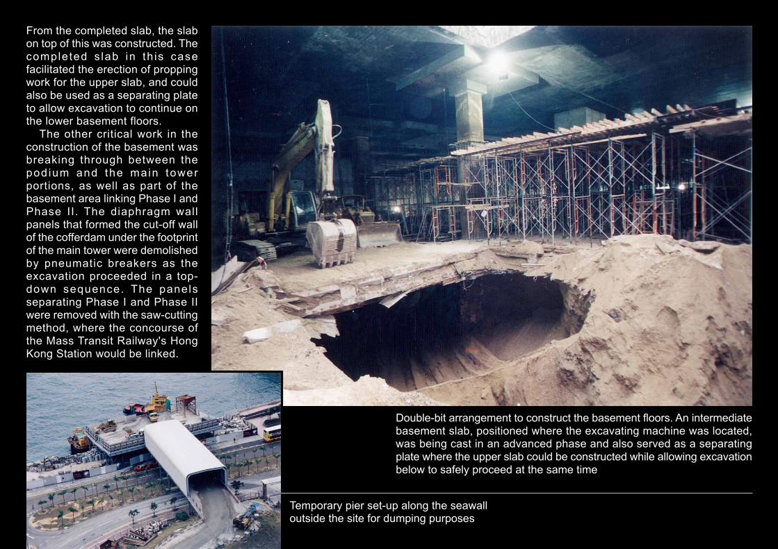
From the completed slab, the slabon top of this was constructed. Thecompleted s lab in th is casefacilitated the erection of proppingwork for the upper slab, and couldalso be used as a separating plateto allow excavation to continue onthe lower basement floors.
The other critical work in theconstruction of the basement wasbreaking through between thepodium and the main towerportions, as well as part of thebasement area linking Phase I andPhase II. The diaphragm wallpanels that formed the cut-off wallof the cofferdam under the footprintof the main tower were demolishedby pneumatic breakers as theexcavation proceeded in a top-down sequence. The panelsseparating Phase I and Phase IIwere removed with the saw-cuttingmethod, where the concourse ofthe Mass Transit Railway's HongKong Station would be linked.
Temporary pier set-up along the seawalloutside the site for dumping purposes
Double-bit arrangement to construct the basement floors. An intermediatebasement slab, positioned where the excavating machine was located,was being cast in an advanced phase and also served as a separatingplate where the upper slab could be constructed while allowing excavationbelow to safely proceed at the same time

Another section seen throughone of the muck-out openingswith the double-bit constructionarrangement clearly shown
Breaking through into the existing diaphragm wallpanels with the saw-cutting method. After removingthe wall, the existing MTR Hong Kong Stationconcourse could be linked to the new concourseextension inside the Two IFC basement
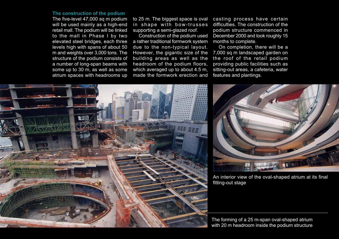
The construction of the podium
The five-level 47,000 sq m podiumwill be used mainly as a high-endretail mall. The podium will be linkedto the mall in Phase I by twoelevated steel bridges, each threelevels high with spans of about 50m and weights over 3,000 tons. Thestructure of the podium consists ofa number of long-span beams withsome up to 30 m, as well as someatrium spaces with headrooms up
to 25 m. The biggest space is ovali n shape w i t h bow- t russessupporting a semi-glazed roof.
Construction of the podium useda rather traditional formwork systemdue to the non-typical layout.However, the gigantic size of thebuilding areas as well as theheadroom of the podium floors,which averaged up to about 4.5 m,made the formwork erection and
casting process have certaindifficulties. The construction of thepodium structure commenced inDecember 2000 and took roughly 15months to complete.
On completion, there will be a7,000 sq m landscaped garden onthe roof of the retai l podiumproviding public facilities such assitting-out areas, a cafeteria, waterfeatures and plantings.
The forming of a 25 m-span oval-shaped atriumwith 20 m headroom inside the podium structure
An interior view of the oval-shaped atrium at its finalfitting-out stage
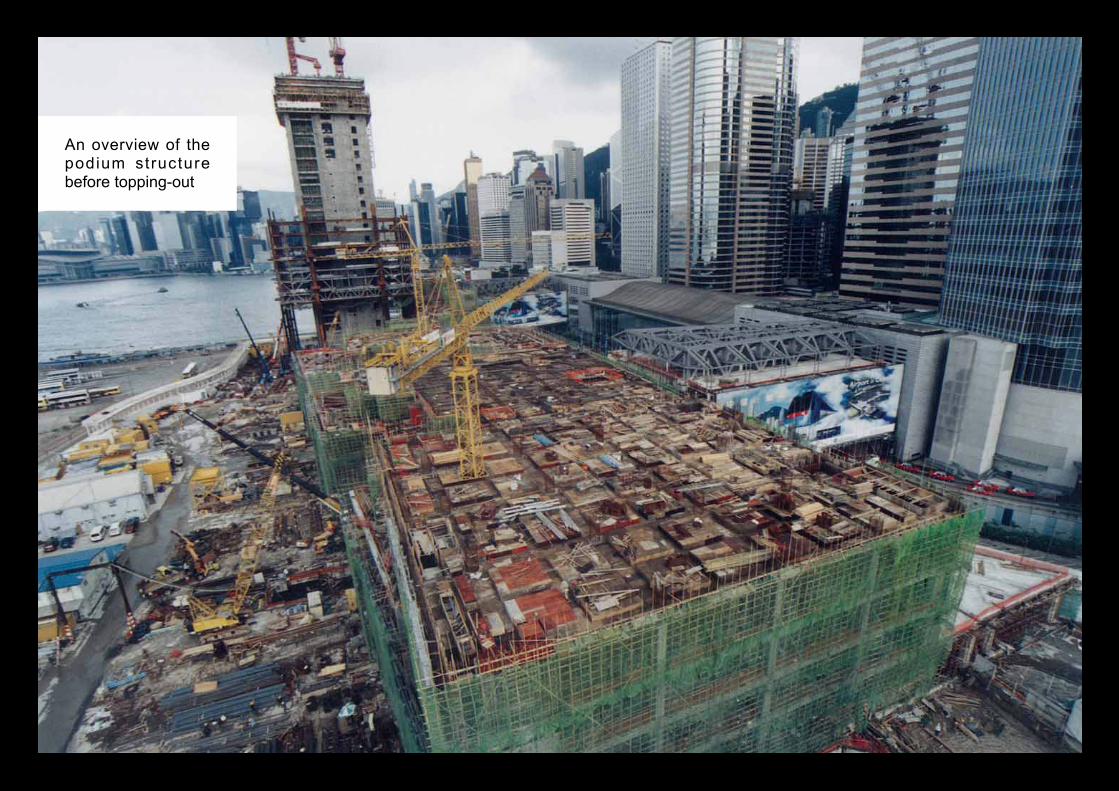
An overview of thepodium structurebefore topping-out

An aerial view of the podium from the Two IFC tower
A close up look at the podium structure which used rathertraditional timber formwork in construction

Elevation of the podiumexterior with a series of glasshoods as spectacular rooffeatures
A close up look at one of the threeglass hoods on the roof deckduring its installation

Construction of the vehicular ramp
There is a vehicular ramp on thewest side of the site to provideaccess for vehicles to enter thebasement carpark underneath thepodium structure. The constructionof the ramp employed a bottom-upapproach within a 42 m square-shaped cofferdam shaft, formed bydiaphragm wall on four sides andbraced by five layers of 1.2 mdiameter s tee l tubes a t the
corners. A 4 m thick RC raft wasconstructed on the formationsurface at about -28 mPD, onwhich a circular-shaped centralcore and a spiral ramp wereconstructed. This ramp also servedas the vehicular outlet throughwhich excavated spoil could beremoved using dump trucks duringthe basement excavation andconstruction process.
42 m X 42 m cofferdam formed on the western part of the site for theconstruction of a vehicular ramp as access into the carpark in the futurebasement
Ground support with waling beams and a corner bracing arrangement tofacilitate excavation to form the 32 m deep cofferdam pit
Fixing the reinforcing bars to form the foundation raft inside the cofferdam.This foundation will support the vehicular ramp as well as part of thesuperstructure of the future hotel in the IFC Phase 2 development

A panoramic view inside the circular ramp during the construction process
A detailed look at the gang-form system for theconstruction of the circular core and the steelbar fixings before the concreting of the ramp

Overall observations
The construction of such a superhigh-rise project presents a rangeof practical problems beyond thel a y m a n ' s i m a g i n a t i o n . F o rexample, at the peak of theconstruction period, there weremore than 1,200 workers from 50different trades working at thesame t ime on the si te. Dai lyconsumption and del ivery ofmaterials to the site could be asmuch as 300 tons per day, withcash flow close to $100 million permonth. Some very heavy items,such as components o f theoutrigger system, were as heavyas 15 tons (there were more than
40 pieces in total) and wererequired to be hoisted to 55/F.There are altogether more than50,000 structural steel membersmaking up the entire superstructure— a very demanding figure wherecranage output is concerned.
The successful running of aproject of this scale is a truechallenge to the contractor in termsof engineering, construct ion,safety and overall management.The accomplishment of Two IFC isa m a s t e r p i e c e t h a t s e t s amilestone showcasing the overallachievement of the Hong Kong'sconstruction industry.
An artist’s impression of the fully developed InternationalFinance Centre
Heavy steel components waiting onthe ground before hoisting to workspots at high levels of the tower
Related Documents