Aisys User’s Reference Manual - Part 2 of 2 Software Revision 3.X Setup, Cleaning, Maintenance, Parts, Specifications

Welcome message from author
This document is posted to help you gain knowledge. Please leave a comment to let me know what you think about it! Share it to your friends and learn new things together.
Transcript

Aisys
User’s Reference Manual - Part 2 of 2
Software Revision 3.X
Setup, Cleaning, Maintenance, Parts, Specifications

User Responsibility
This Product will perform in conformity with the description thereof contained in this User’s Reference manual and accompanying labels and/or inserts, when assembled, operated, maintained, and repaired in accordance with the instructions provided. This Product must be checked periodically. A defective Product should not be used. Parts that are broken, missing, plainly worn, distorted, or contaminated should be replaced immediately. Should repair or replacement become necessary, Datex-Ohmeda recommends that a telephonic or written request for service advice be made to the nearest Datex-Ohmeda Customer Service Center. This Product or any of its parts should not be repaired other than in accordance with written instructions provided by Datex-Ohmeda and by Datex-Ohmeda trained personnel. The Product must not be altered without the prior written approval of Datex-Ohmeda. The user of this Product shall have the sole responsibility for any malfunction which results from improper use, faulty maintenance, improper repair, damage, or alteration by anyone other than Datex-Ohmeda.
CAUTION U.S. Federal law restricts this device to sale by or on the order of a licensed medical practitioner. Outside the U.S.A., check local laws for any restriction that may apply.
Datex-Ohmeda products have unit serial numbers with coded logic which indicates a product group code, the year of manufacture, and a sequential unit number for identification. The serial number can be in one of two formats.
Aisys, Carestation, Advanced Breathing System, Aladin, Aladin2, ComWheel, D-fend, Disposable Multi Absorber, Easy-Fil, Reusable Multi Absorber, PSVPro, and SmartVent are registered trademarks of Datex-Ohmeda, Inc.
Other brand names or product names used in this manual are trademarks or registered trademarks of their respective holders.
A A A X 11111 A A A X X 111111 A A
The X represents an alpha character indicating the year the product was manufactured; H = 2004, J = 2005, etc.IIII and O are not used.
The X X represents a number indicating the year the product was manufactured; 04 = 2004, 05 = 2005, etc.

Table of Contents
1 Setup and Connections
Canister setup . . . . . . . . . . . . . . . . . . . . . . . . . . . . . . . . . . . . . . . . . . . . . . . . . 1-3
When to change the absorbent . . . . . . . . . . . . . . . . . . . . . . . . . . . . . . . 1-5
Removing a canister . . . . . . . . . . . . . . . . . . . . . . . . . . . . . . . . . . . . . . . . 1-5
Removing an EZchange Canister . . . . . . . . . . . . . . . . . . . . . . . . . . . . . . 1-5
Reusable Multi Absorber canister filling . . . . . . . . . . . . . . . . . . . . . . . . 1-6
Electrical connections . . . . . . . . . . . . . . . . . . . . . . . . . . . . . . . . . . . . . . . . . . . 1-8
Port . . . . . . . . . . . . . . . . . . . . . . . . . . . . . . . . . . . . . . . . . . . . . . . . . . . . . . 1-8
Outlets . . . . . . . . . . . . . . . . . . . . . . . . . . . . . . . . . . . . . . . . . . . . . . . . . . . 1-8
Mains inlet . . . . . . . . . . . . . . . . . . . . . . . . . . . . . . . . . . . . . . . . . . . . . . . . 1-8
Serial port . . . . . . . . . . . . . . . . . . . . . . . . . . . . . . . . . . . . . . . . . . . . . . . . . 1-9
Pneumatic connections . . . . . . . . . . . . . . . . . . . . . . . . . . . . . . . . . . . . . . . . 1-10
Pipeline Inlets . . . . . . . . . . . . . . . . . . . . . . . . . . . . . . . . . . . . . . . . . . . . 1-10
Scavenging . . . . . . . . . . . . . . . . . . . . . . . . . . . . . . . . . . . . . . . . . . . . . . . 1-10
Sample gas return port . . . . . . . . . . . . . . . . . . . . . . . . . . . . . . . . . . . . . 1-11
Pneumatic power outlet . . . . . . . . . . . . . . . . . . . . . . . . . . . . . . . . . . . . 1-11
Suction regulator (optional) . . . . . . . . . . . . . . . . . . . . . . . . . . . . . . . . . 1-12
Auxiliary O2 flowmeter (optional) . . . . . . . . . . . . . . . . . . . . . . . . . . . . . 1-12
How to install gas cylinders . . . . . . . . . . . . . . . . . . . . . . . . . . . . . . . . . . . . . 1-13
High-pressure leak test . . . . . . . . . . . . . . . . . . . . . . . . . . . . . . . . . . . . . 1-13
How to attach equipment to the top of the machine . . . . . . . . . . . . . . . . . 1-14
Installation notes . . . . . . . . . . . . . . . . . . . . . . . . . . . . . . . . . . . . . . . . . . . . . . 1-14
2 Cleaning and Sterilization
Breathing system autoclavable parts . . . . . . . . . . . . . . . . . . . . . . . . . . . . . . 2-3
Special requirements . . . . . . . . . . . . . . . . . . . . . . . . . . . . . . . . . . . . . . . 2-4
How to clean and disinfect the flow sensors . . . . . . . . . . . . . . . . . . . . . . . . . 2-5
CIDEX disinfection . . . . . . . . . . . . . . . . . . . . . . . . . . . . . . . . . . . . . . . . . . 2-5
Remove the breathing system bag hose . . . . . . . . . . . . . . . . . . . . . . . . . . . . 2-8
Remove the breathing system . . . . . . . . . . . . . . . . . . . . . . . . . . . . . . . . . . . . 2-8
M1076286 i

Aisys Carestation
Disassemble the breathing system . . . . . . . . . . . . . . . . . . . . . . . . . . . . . . . . 2-9
Disassemble the bellows assembly . . . . . . . . . . . . . . . . . . . . . . . . . . . . . . . 2-15
Assemble the bellows assembly . . . . . . . . . . . . . . . . . . . . . . . . . . . . . . . . . 2-17
Bellows assembly test . . . . . . . . . . . . . . . . . . . . . . . . . . . . . . . . . . . . . . . . . . 2-19
Assemble the breathing system . . . . . . . . . . . . . . . . . . . . . . . . . . . . . . . . . . 2-21
Install the breathing system . . . . . . . . . . . . . . . . . . . . . . . . . . . . . . . . . . . . . 2-26
Remove the AGSS receiver . . . . . . . . . . . . . . . . . . . . . . . . . . . . . . . . . . . . . . 2-27
Remove the AGSS receiver filter . . . . . . . . . . . . . . . . . . . . . . . . . . . . . . . . . . 2-29
Absorber canister . . . . . . . . . . . . . . . . . . . . . . . . . . . . . . . . . . . . . . . . . . . . . 2-30
Mechanical cleaning in washer or washer-disinfector . . . . . . . . . . . . 2-30
Manual cleaning . . . . . . . . . . . . . . . . . . . . . . . . . . . . . . . . . . . . . . . . . . 2-30
High level disinfection . . . . . . . . . . . . . . . . . . . . . . . . . . . . . . . . . . . . . . 2-30
Aladin cassette cleaning . . . . . . . . . . . . . . . . . . . . . . . . . . . . . . . . . . . . . . . . 2-31
EZchange Canister and condenser . . . . . . . . . . . . . . . . . . . . . . . . . . . . . . . 2-31
3 User Maintenance
Repair policy . . . . . . . . . . . . . . . . . . . . . . . . . . . . . . . . . . . . . . . . . . . . . . . . . . 3-2
Maintenance summary and schedule . . . . . . . . . . . . . . . . . . . . . . . . . . . . . . 3-2
User maintenance . . . . . . . . . . . . . . . . . . . . . . . . . . . . . . . . . . . . . . . . . . 3-2
Datex-Ohmeda approved service . . . . . . . . . . . . . . . . . . . . . . . . . . . . . . 3-3
Circuit O2 cell replacement . . . . . . . . . . . . . . . . . . . . . . . . . . . . . . . . . . . . . . . 3-4
Flow and pressure calibration . . . . . . . . . . . . . . . . . . . . . . . . . . . . . . . . . . . . 3-5
Circuit O2 cell calibration . . . . . . . . . . . . . . . . . . . . . . . . . . . . . . . . . . . . . . . . 3-5
21% O2 calibration . . . . . . . . . . . . . . . . . . . . . . . . . . . . . . . . . . . . . . . . . 3-5
100% O2 calibration . . . . . . . . . . . . . . . . . . . . . . . . . . . . . . . . . . . . . . . . 3-5
Airway gas calibration . . . . . . . . . . . . . . . . . . . . . . . . . . . . . . . . . . . . . . . . . . . 3-6
Backlight test . . . . . . . . . . . . . . . . . . . . . . . . . . . . . . . . . . . . . . . . . . . . . . . . . . 3-6
How to help prevent water buildup . . . . . . . . . . . . . . . . . . . . . . . . . . . . . . . . 3-6
ii M1076286

Table of Contents
4 Parts
Flow sensor module . . . . . . . . . . . . . . . . . . . . . . . . . . . . . . . . . . . . . . . . . . . . 4-2
Breathing circuit module . . . . . . . . . . . . . . . . . . . . . . . . . . . . . . . . . . . . . . . . . 4-3
Bellows . . . . . . . . . . . . . . . . . . . . . . . . . . . . . . . . . . . . . . . . . . . . . . . . . . . . . . . 4-4
Absorber canister . . . . . . . . . . . . . . . . . . . . . . . . . . . . . . . . . . . . . . . . . . . . . . 4-5
Exhalation valve assembly . . . . . . . . . . . . . . . . . . . . . . . . . . . . . . . . . . . . . . . 4-6
AGSS . . . . . . . . . . . . . . . . . . . . . . . . . . . . . . . . . . . . . . . . . . . . . . . . . . . . . . . . 4-7
EZchange Canister system . . . . . . . . . . . . . . . . . . . . . . . . . . . . . . . . . . . . . . . 4-8
Condenser . . . . . . . . . . . . . . . . . . . . . . . . . . . . . . . . . . . . . . . . . . . . . . . . . . . . 4-9
Test tools and system parts . . . . . . . . . . . . . . . . . . . . . . . . . . . . . . . . . . . . . 4-10
5 Specifications and Theory of Operation
System pneumatic circuits . . . . . . . . . . . . . . . . . . . . . . . . . . . . . . . . . . . . . . . 5-2
Gas supplies . . . . . . . . . . . . . . . . . . . . . . . . . . . . . . . . . . . . . . . . . . . . . . 5-4
O2 flow . . . . . . . . . . . . . . . . . . . . . . . . . . . . . . . . . . . . . . . . . . . . . . . . . . . 5-4
Air and N2O . . . . . . . . . . . . . . . . . . . . . . . . . . . . . . . . . . . . . . . . . . . . . . . 5-4
Mixed gas . . . . . . . . . . . . . . . . . . . . . . . . . . . . . . . . . . . . . . . . . . . . . . . . . 5-4
EZchange Canister . . . . . . . . . . . . . . . . . . . . . . . . . . . . . . . . . . . . . . . . . . 5-5
Condenser . . . . . . . . . . . . . . . . . . . . . . . . . . . . . . . . . . . . . . . . . . . . . . . . 5-5
Pneumatic specifications . . . . . . . . . . . . . . . . . . . . . . . . . . . . . . . . . . . . . . . . 5-5
Gas supplies . . . . . . . . . . . . . . . . . . . . . . . . . . . . . . . . . . . . . . . . . . . . . . 5-5
ACGO port relief . . . . . . . . . . . . . . . . . . . . . . . . . . . . . . . . . . . . . . . . . . . . 5-6
Non-circle circuit relief . . . . . . . . . . . . . . . . . . . . . . . . . . . . . . . . . . . . . . 5-6
Electrical power . . . . . . . . . . . . . . . . . . . . . . . . . . . . . . . . . . . . . . . . . . . . . . . . 5-7
Power cord . . . . . . . . . . . . . . . . . . . . . . . . . . . . . . . . . . . . . . . . . . . . . . . . 5-7
Battery information . . . . . . . . . . . . . . . . . . . . . . . . . . . . . . . . . . . . . . . . . 5-7
Electrical block diagram . . . . . . . . . . . . . . . . . . . . . . . . . . . . . . . . . . . . . . . . . 5-8
Flow specifications . . . . . . . . . . . . . . . . . . . . . . . . . . . . . . . . . . . . . . . . . . . . 5-10
Breathing system specifications . . . . . . . . . . . . . . . . . . . . . . . . . . . . . . . . . 5-11
Gas scavenging . . . . . . . . . . . . . . . . . . . . . . . . . . . . . . . . . . . . . . . . . . . 5-13
Physical specifications . . . . . . . . . . . . . . . . . . . . . . . . . . . . . . . . . . . . . . . . . 5-13
Environmental requirements . . . . . . . . . . . . . . . . . . . . . . . . . . . . . . . . . . . . 5-14
Airway module specifications . . . . . . . . . . . . . . . . . . . . . . . . . . . . . . . . . . . . 5-14
Gas specifications . . . . . . . . . . . . . . . . . . . . . . . . . . . . . . . . . . . . . . . . . 5-14
Typical performance . . . . . . . . . . . . . . . . . . . . . . . . . . . . . . . . . . . . . . . 5-15
Suction regulators (optional) . . . . . . . . . . . . . . . . . . . . . . . . . . . . . . . . . . . . 5-15
M1076286 iii
Aisys Carestation
Ventilator theory . . . . . . . . . . . . . . . . . . . . . . . . . . . . . . . . . . . . . . . . . . . . . . 5-16
O2 monitoring . . . . . . . . . . . . . . . . . . . . . . . . . . . . . . . . . . . . . . . . . . . . . 5-16
Modes . . . . . . . . . . . . . . . . . . . . . . . . . . . . . . . . . . . . . . . . . . . . . . . . . . . 5-17
Ventilation operating specifications . . . . . . . . . . . . . . . . . . . . . . . . . . . . . . 5-24
Pneumatics . . . . . . . . . . . . . . . . . . . . . . . . . . . . . . . . . . . . . . . . . . . . . . 5-24
Fresh gas compensation . . . . . . . . . . . . . . . . . . . . . . . . . . . . . . . . . . . . 5-24
Pressure . . . . . . . . . . . . . . . . . . . . . . . . . . . . . . . . . . . . . . . . . . . . . . . . . 5-24
Volume . . . . . . . . . . . . . . . . . . . . . . . . . . . . . . . . . . . . . . . . . . . . . . . . . . 5-25
Oxygen . . . . . . . . . . . . . . . . . . . . . . . . . . . . . . . . . . . . . . . . . . . . . . . . . . 5-25
Ventilator accuracy data . . . . . . . . . . . . . . . . . . . . . . . . . . . . . . . . . . . . . . . . 5-26
Electronically controlled vaporizer and Aladin cassette . . . . . . . . . . . . . . . 5-27
Aladin2 cassettes . . . . . . . . . . . . . . . . . . . . . . . . . . . . . . . . . . . . . . . . . . 5-28
Aladin cassettes . . . . . . . . . . . . . . . . . . . . . . . . . . . . . . . . . . . . . . . . . . 5-29
Electromagnetic compatibility (EMC) . . . . . . . . . . . . . . . . . . . . . . . . . . . . . . 5-30
Guidance and manufacturer's declaration - electromagnetic emissions . . . . . . . . . . . . . . . . . . . . . . . . . . . . . . . . . . 5-30
Guidance and manufacturer's declaration - electromagnetic immunity . . . . . . . . . . . . . . . . . . . . . . . . . . . . . . . . . . 5-31
Recommended separation distances . . . . . . . . . . . . . . . . . . . . . . . . . 5-33
Electrical safety . . . . . . . . . . . . . . . . . . . . . . . . . . . . . . . . . . . . . . . . . . . . . . . 5-34
IEC-60601-1 Classification . . . . . . . . . . . . . . . . . . . . . . . . . . . . . . . . . . . . . 5-34
6 Super User Mode
Install/Service menu . . . . . . . . . . . . . . . . . . . . . . . . . . . . . . . . . . . . . . . . . . . . 6-2
Using super user mode . . . . . . . . . . . . . . . . . . . . . . . . . . . . . . . . . . . . . . 6-3
Menus . . . . . . . . . . . . . . . . . . . . . . . . . . . . . . . . . . . . . . . . . . . . . . . . . . . . . . . 6-4
Warranty
Index
iv M1076286
1 Setup and Connections
In this section Canister setup . . . . . . . . . . . . . . . . . . . . . . . . . . . . . . . . . . . . . . . . . . . . . . . . . 1-3
Electrical connections . . . . . . . . . . . . . . . . . . . . . . . . . . . . . . . . . . . . . . . . . . . 1-8
Pneumatic connections . . . . . . . . . . . . . . . . . . . . . . . . . . . . . . . . . . . . . . . . 1-10
How to install gas cylinders . . . . . . . . . . . . . . . . . . . . . . . . . . . . . . . . . . . . . 1-13
How to attach equipment to the top of the machine . . . . . . . . . . . . . . . . . 1-14
Installation notes . . . . . . . . . . . . . . . . . . . . . . . . . . . . . . . . . . . . . . . . . . . . . . 1-14
M1076286 1-1

Aisys Carestation
Important Datex-Ohmeda strongly recommends the use of O2 monitoring with this equipment. Refer to local standards for mandatory monitoring.
European Standard EN 740 and International Standard IEC 60601-2-13/ISO 8835-1 require exhaled volume monitoring, O2 monitoring (in accordance with EN 12598, or ISO 7767) and CO2 monitoring (in accordance with EN 864 or ISO 9918) be used with this equipment.
European Standard EN 740 and International Standard IEC 60601-2-13/ISO 8835-1 also require anesthetic agent monitoring (in accordance with ISO 11196) be used when anesthetic vaporizers are in use.
WARNING Always make sure that the pipeline supply hoses and the breathing circuit components are not toxic and will not:
• Cause an allergic reaction in the patient.
• React with the anesthetic gases or agent to produce dangerous by-products.
w To prevent incorrect values or equipment malfunction, use only Datex-Ohmeda cables, hoses and tubing.
w This system operates correctly at the electrical interference levels of IEC 60601-1-2. Higher levels can cause nuisance alarms that may stop mechanical ventilation.
w To help prevent false alarms from devices with high-intensity electrical fields:
• Keep the electrosurgical leads away from the breathing system, the flow sensors and the oxygen cell.
• Do not allow the electrosurgical leads to contact any part of the anesthesia system.
• Do not use cell phones near the anesthesia system.
w To protect the patient when electrosurgical equipment is used:
• Monitor the correct operation of all life support and monitoring equipment.
• Keep backup manual ventilation available in case the electrosurgical equipment prevents safe use of the ventilator.
1-2 M1076286
1 Setup and Connections
w Do not use antistatic breathing tubes or masks. They can cause burns if used near high frequency surgical equipment.
Canister setup
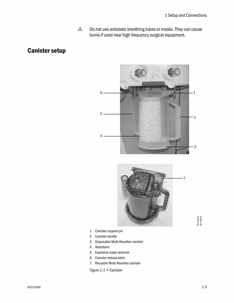
1. Canister support pin2. Canister handle3. Disposable Multi Absorber canister4. Absorbent5. Expiratory water reservoir6. Canister release latch7. Reusable Multi Absorber canister
Figure 1-1 • Canister
1
2
3
4
5
6
7
AB.7
4p04
2AB
.74p
043
M1076286 1-3

Aisys Carestation
WARNING Obey applicable safety precautions:
• Do not use the absorber with chloroform or trichloroethylene.
• The Disposable Multi Absorber is a sealed unit which should not be opened or refilled.
• Avoid skin or eye contact with the contents of the absorber. In the event of skin or eye contact, immediately rinse the affected area with water and seek medical assistance.
• Do not change the absorber during ventilation unless the EZchange Canister system is installed.
• Change absorbent often to prevent the buildup of non-metabolic gases when the system is not in use.
• Inspect absorbent color at the end of a case. During non-use, absorbent can go back to the original color. Refer to the absorbent labeling for more information about color changes.
• If the absorbent completely dries out, it may give off carbon monoxide (CO) when exposed to anesthetic agents. For safety, replace the absorbent.
• Desiccated (dehydrated) absorbent material may produce dangerous chemical reactions when exposed to inhalation anesthetics. Adequate precautions should be taken to ensure that absorbent does not dry out. Turn off all gases when finished using the system.
The absorber canister is available in two versions: Disposable Multi Absorber and Reusable Multi Absorber. Both are removed and installed on the breathing system in the same way.
Each canister holds 800 grams of loose absorbent. Datex-Ohmeda recommends MedisorbTM absorbent.
Both absorber versions should only be used with mixtures of air, oxygen, nitrous oxide, halothane, enflurane, isoflurane, desflurane and sevoflurane.
1-4 M1076286

1 Setup and Connections
When to change theabsorbent
A gradual color change of the absorbent in the canister indicates absorption of carbon dioxide. The color change of the absorbent is only a rough indicator. Use carbon dioxide monitoring to determine when to change the canister.
Discard the absorbent when it has changed color. If left standing for several hours, absorbent may regain its original color giving a misleading indication of activity.
Read the canister instructions completely before using the product.
Removing a canister 1. Hold the canister by the handle and push on the release latch to unlock the canister.
2. Remove the canister by tilting it downward and off the two support pins.
Removing an EZchangeCanister
1. Hold the canister by the handle and push the canister cradle release latch to unlock the canister cradle.
2. Slide the canister up and out of the cradle.
AB.7
4p05
8
AB.7
5p08
8AB
.75p
089
M1076286 1-5

Aisys Carestation
Reusable MultiAbsorber canister
filling
1. Turn the canister upside down and, using your thumbs, turn the cover locking ring counterclockwise to unlock it.
2. Push up to release the seal.
3. Lift off the cover to remove it.
4. Remove and properly discard the foam filters, the absorbent, and any water in the reservoir.
WARNING Be careful when draining condensate from the absorber. The liquid is caustic and may burn skin.
5. To clean and disinfect the canister, see “Absorber canister” in section 2 “Cleaning and Sterilization.”
AB.4
p044
AB.7
4p04
6
AB.7
4p04
7
1-6 M1076286

1 Setup and Connections
6. Place a new filter in the bottom of the canister, pour absorbent into the canister and place a new filter over the absorbent before closing and locking the cover. Wipe off any absorbent dust.
7. Align the cover slots with the canister locking tabs and press the cover down into place. Turn the cover locking ring clockwise to lock the cover in place. Ensure cover is properly sealed to prevent leaks and spillage. Alignment of the arrows helps to indicate correct assembly.
WARNING The filters must be in place to help prevent dust and particles from entering the breathing circuit.
8. When replacing the canister, make sure it is resting on both support pins before latching it into place.
M1076286 1-7

Aisys Carestation
Electrical connections
Port The port for the battery backup of the monitor is located above the isolated outlets.
Outlets Labels show outlet voltage ratings and circuit breaker amp ratings. These are isolated outlets. Regularly test the leakage current.
Mains inlet Arrow shows the mains power inlet and cord.
AB.7
5p08
7
AB.7
5p.0
09
AB.7
5p.0
08
1-8 M1076286

1 Setup and Connections
Serial port The system has an RS-232C electrical interface. The RS-232C connector allows serial input/output of commands and data. The 15-pin connector is located on the back of the display unit.
The 15-pin female D connector - Data Communications Equipment configuration (DCE):
• Pin 1 - Monitor On/Standby
• Pin 5 - Signal ground
• Pin 6 - Receive data
• Pin 9 - Monitor On/Standby Return
• Pin 13 - Transmit data
AB.7
5p09
0
M1076286 1-9

Aisys Carestation
Pneumatic connections
CAUTION Use only medical grade gas supplies. Other types of gas supplies may contain water, oil, or other contaminants which could affect the operation of the pneumatic system.
The gas supplies provide gas to these optional devices through internal connections:
• venturi suction regulator (optional).
• auxiliary O2 flowmeter (optional).
Pipeline Inlets
Scavenging The scavenging assembly is located below the bellows on the breathing system. Adapters may be necessary to interface to the scavenging connector.
See “Operation and Tutorial” in Part 1 of the User’s Reference manual for more scavenging information.
AB.7
5p.0
10
AB.9
1p04
5
1-10 M1076286

1 Setup and Connections
Sample gas return port Connect the Datex-Ohmeda sample gas exhaust tube to the gas return port. Exhaust gas will be directed to the scavenging system.
Pneumatic power outlet
AB.7
5p.1
09
AB.7
5p.0
07
M1076286 1-11

Aisys Carestation
Suction regulator(optional)
Venturi regulators use the system air or O2 supply. Vacuum regulators must be connected to an external vacuum supply.
1. Overflow safety trap2. External vacuum (non-venturi) connection3. Splash guard4. Collection bottle connection
Auxiliary O2 flowmeter(optional)
1. Auxiliary O2 flow control2. Auxiliary O2 outlet
123
4
AB.7
5p.0
07
1
2
AB.7
5o01
1
1-12 M1076286
1 Setup and Connections
How to install gas cylinders
CAUTION Do not leave gas cylinder valves open if the pipeline supply is in use. Cylinder supplies could be depleted, leaving an insufficient reserve supply in case of pipeline failure.
1. Locate the cylinder wrench.
2. Close the cylinder valve on the cylinder to be replaced.
3. Loosen the cylinder connector.
4. Remove the used cylinder and the used gasket.
5. Remove the cap from the cylinder valve on the new cylinder.
6. Point the cylinder outlet away from all items that can be damaged by a release of high-pressure gas.
7. Quickly open and close the cylinder valve. This removes dirt from the cylinder outlet.
WARNING No gasket or more than one gasket can cause a leak.
8. Install a new gasket.
9. Install a new cylinder.
10. Perform a “High-pressure leak test.”
High-pressure leak test 1. Turn on the system.
2. Disconnect pipeline supplies.
3. Turn off the auxiliary O2 flowmeter and the venturi suction.
4. Open the cylinder.
5. Record the cylinder pressure.
6. Close the cylinder.
• If the cylinder pressure decreases more than 690 kPa (100 psi) in one minute there is a significant leak.
7. To repair a leak, install a new cylinder gasket and tighten the adapter.
8. Repeat the leak test. If the leak continues, do not use the system.
M1076286 1-13

Aisys Carestation
How to attach equipment to the top of the machine
WARNING The top of the machine has a weight limit of 45 kg (100 lb).
1. Locate the clips or slots.
2. Install the straps.
3. Fully tighten the straps.
4. Make sure the straps hold the equipment in position.
WARNING Fully tighten the straps. If straps are not fully tightened, equipment can fall off the top of the machine.
Installation notes
When the system is installed, the Datex-Ohmeda representative will check the following items and change them if necessary.
WARNING These items can only be changed by qualified personnel. Ensure configurations conform to local requirements.
• Automatic calculation of VE alarm limits during mechanical ventilation.
• Altitude.
• Ventilator drive gas.
• Upgrade, activation and deactivation of monitoring and ventilation features.
1-14 M1076286
2 Cleaning and Sterilization
In this section Breathing system autoclavable parts . . . . . . . . . . . . . . . . . . . . . . . . . . . . . . 2-3
How to clean and disinfect the flow sensors . . . . . . . . . . . . . . . . . . . . . . . . . 2-5
Remove the breathing system bag hose . . . . . . . . . . . . . . . . . . . . . . . . . . . . 2-8
Remove the breathing system . . . . . . . . . . . . . . . . . . . . . . . . . . . . . . . . . . . . 2-8
Disassemble the breathing system . . . . . . . . . . . . . . . . . . . . . . . . . . . . . . . . 2-9
Disassemble the bellows assembly . . . . . . . . . . . . . . . . . . . . . . . . . . . . . . . 2-15
Assemble the bellows assembly . . . . . . . . . . . . . . . . . . . . . . . . . . . . . . . . . 2-17
Bellows assembly test . . . . . . . . . . . . . . . . . . . . . . . . . . . . . . . . . . . . . . . . . . 2-19
Assemble the breathing system . . . . . . . . . . . . . . . . . . . . . . . . . . . . . . . . . . 2-21
Install the breathing system . . . . . . . . . . . . . . . . . . . . . . . . . . . . . . . . . . . . . 2-26
Remove the AGSS receiver . . . . . . . . . . . . . . . . . . . . . . . . . . . . . . . . . . . . . . 2-27
Remove the AGSS receiver filter . . . . . . . . . . . . . . . . . . . . . . . . . . . . . . . . . . 2-29
Absorber canister . . . . . . . . . . . . . . . . . . . . . . . . . . . . . . . . . . . . . . . . . . . . . 2-30
Aladin cassette cleaning . . . . . . . . . . . . . . . . . . . . . . . . . . . . . . . . . . . . . . . . 2-31
EZchange Canister and condenser . . . . . . . . . . . . . . . . . . . . . . . . . . . . . . . 2-31
M1076286 2-1

Aisys Carestation
WARNING Obey applicable safety precautions:
• Read the material safety data sheet for each cleaning agent.
• Read the manual for all sterilization equipment to be used.
• Wear gloves and safety glasses. A damaged O2 cell can leak and cause burns. Do not breathe the fumes.
CAUTION To help prevent damage:
• Refer to the manufacturer’s data if you have questions about a cleaning agent.
• Follow hospital procedures for cleaning areas of the machine not specified in this section.
• Do not use organic, halogenated, or petroleum-based solvents, anesthetic agents, glass cleaners, acetone, or other harsh cleaning agents.
• Do not use abrasive cleaning agents (such as steel wool, silver polish or cleaner).
• Keep all liquids away from electronic parts.
• Do not permit liquid to go into the equipment housings.
• Do not soak synthetic rubber parts for more than 15 minutes. Swelling or faster aging can occur.
• Only autoclave parts marked 134°C.
• Cleaning solutions must have a pH of 7.0 to 10.5.
2-2 M1076286

2 Cleaning and Sterilization
Breathing system autoclavable parts
1. Bellows assembly2. APL valve ramp3. APL valve diaphragm4. Breathing circuit module (O2 cell not autoclavable)5. Absorber canister (reusable only)6. Flow sensor cover*7. Flow sensor module (plastic flow sensors not autoclavable)8. Exhalation valve assembly9. Condenser module10. Condenser11. EZchange Canister module
Figure 2-1 • Autoclavable assemblies
*This part is not compatible with other anesthesia systems.
1
2
3
4
5
6
7
8
AB.8
2.00
8
9
10
11
AB.8
2.04
5AB
.82.
048
M1076286 2-3

Aisys Carestation
Special requirements • To clean the circuit O2 cell, wipe it with a damp cloth.
• If the flow sensors are plastic, refer to the “How to clean and disinfect the flow sensors” procedure. Do not get the electrical connectors wet.
• Autoclave metal flow sensors at 134°C.
• Disassemble the bellows assembly before washing. If not, it will take a very long time to dry. Hang the bellows upside down (extended) to dry. If not, the convolutions can stick together.
• Parts marked 134°C are autoclavable or washable by hand or machine (mild detergent pH <10.5). Rinse and dry completely. All parts except the O2 cell and disposable flow sensors can be washed.
WARNING Do not use talc, zinc stearate, calcium carbonate, corn starch or equivalent materials to prevent tackiness. These materials can go into the patient’s lungs and airways and cause irritation or injury.
CAUTION Do not put the circuit O2 cell or flow sensor connector in liquid.
w Do not autoclave the circuit O2 cell or the plastic flow sensors.
w Do not insert any objects into the flow sensor to clean the interior surfaces. Damage to the flow sensor can occur. Use a damp cloth to clean external surfaces if needed.
2-4 M1076286
2 Cleaning and Sterilization
How to clean and disinfect the flow sensors
CAUTION Do not autoclave plastic flow sensors.
w Do not use high pressure gas or brushes to clean the flow sensors.
w Only use cleaning solvents that are approved for use with polycarbonates (e.g., Do not use CIDEX Plus).
Note Autoclavable metal flow sensors are available and can be sterilized at 134°C.
WARNING The pressure transducer internal to the anesthesia machine is not included as part of the flow sensor sterilization or disinfection procedures. Therefore, the entire flow sensing circuit cannot be sterilized or disinfected.
CIDEX disinfection Both Datex-Ohmeda and the manufacturer of CIDEX (Johnson & Johnson) have tested this procedure.
• CIDEX must be 14 day mixture, with activator vial.
• One liter of this solution cleans four flow sensors.
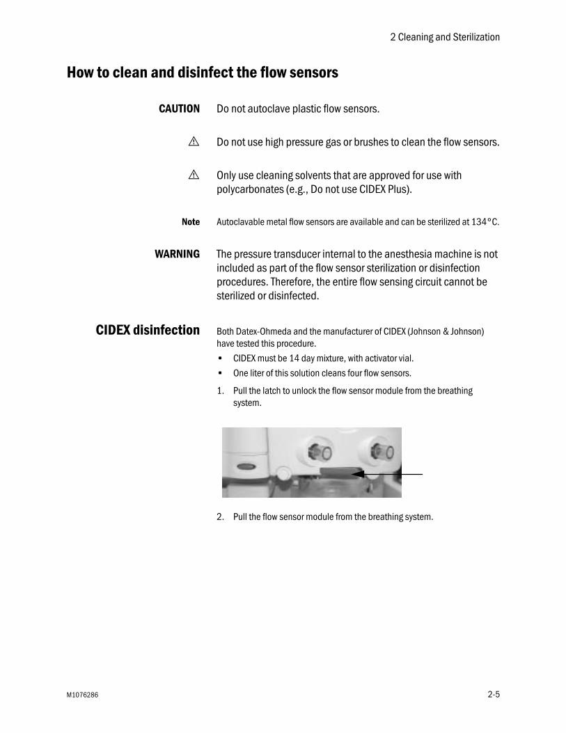
1. Pull the latch to unlock the flow sensor module from the breathing system.
2. Pull the flow sensor module from the breathing system.
M1076286 2-5

Aisys Carestation
3. Remove the flow sensors from the module.
• Completely loosen the thumbscrew (1).
• Pull off the flow sensor cover (2) from the flow sensor holder.
• Remove the flow sensor connectors (3) from the flow sensor holder.
• Pull the flow sensors (4) from the flow sensor holder.
4. Submerge the flow sensor and tubes in activated CIDEX solution. Keep the connector dry.
5. Keep the flow sensors and tubes in the solution for the required period.
6. Submerge the flow sensor and tubes in distilled water. Again, do not get the connector wet.
7. Rinse as indicated in CIDEX instructions.
8. Repeat steps 6 and 7 to remove the CIDEX.
1 23
4
2-6 M1076286
2 Cleaning and Sterilization
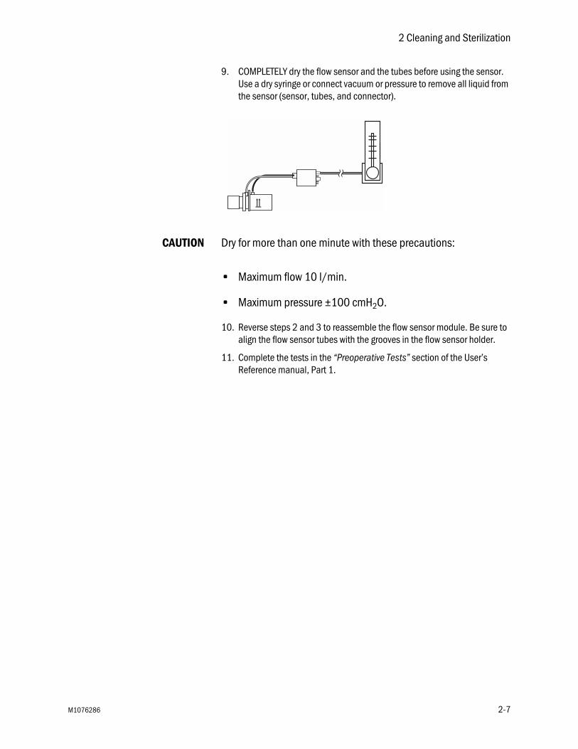
9. COMPLETELY dry the flow sensor and the tubes before using the sensor. Use a dry syringe or connect vacuum or pressure to remove all liquid from the sensor (sensor, tubes, and connector).
CAUTION Dry for more than one minute with these precautions:
• Maximum flow 10 l/min.
• Maximum pressure ±100 cmH2O.
10. Reverse steps 2 and 3 to reassemble the flow sensor module. Be sure to align the flow sensor tubes with the grooves in the flow sensor holder.
11. Complete the tests in the “Preoperative Tests” section of the User’s Reference manual, Part 1.
M1076286 2-7

Aisys Carestation
Remove the breathing system bag hose
1. Disconnect the bag hose (1) from the bag hose connector (2). Also remove the hose from the clip (3).
2. If bag arm option is present, remove the bag port elbow from the bag arm support. Push down on the release latch and slide the bag port elbow out of the holder.
Remove the breathing system
1. Hold the canister by the handle and push on the release latch to unlock the canister.
2. Remove the canister by tilting it downward and off the two support pins.
3. Push the release button (1) and gently pull the latch handle (2) to release the breathing system.
2
13
12
2-8 M1076286
2 Cleaning and Sterilization
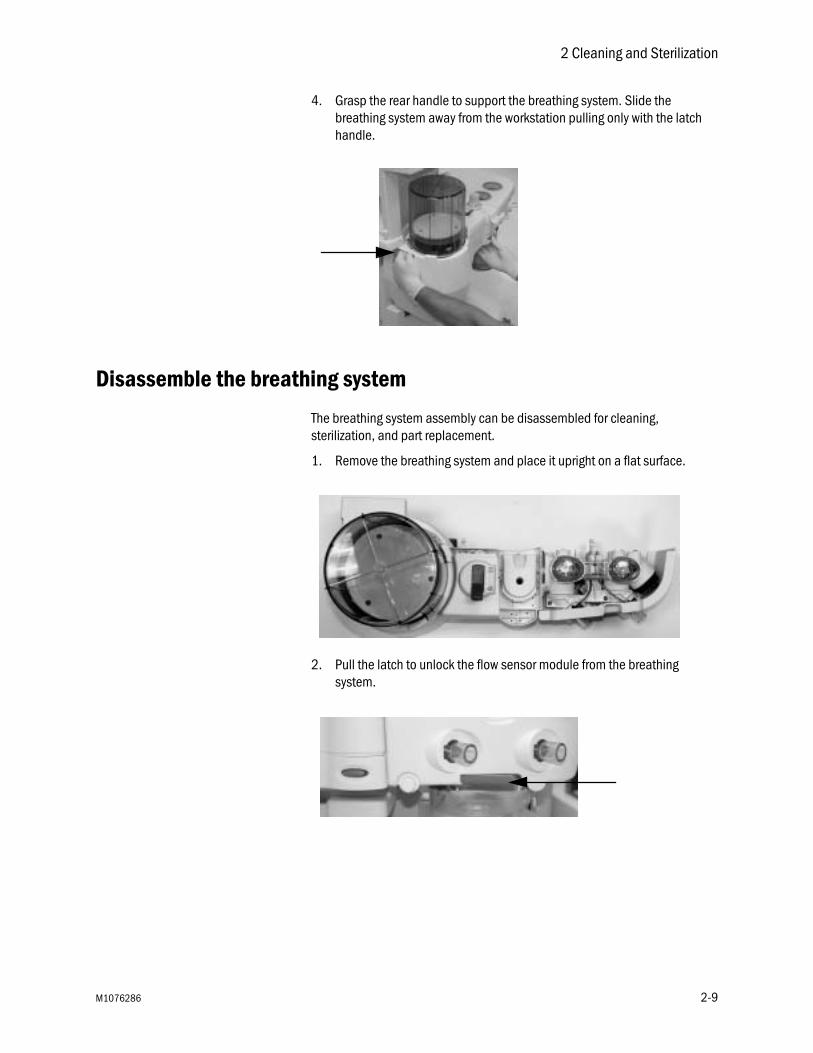
4. Grasp the rear handle to support the breathing system. Slide the breathing system away from the workstation pulling only with the latch handle.
Disassemble the breathing system
The breathing system assembly can be disassembled for cleaning, sterilization, and part replacement.
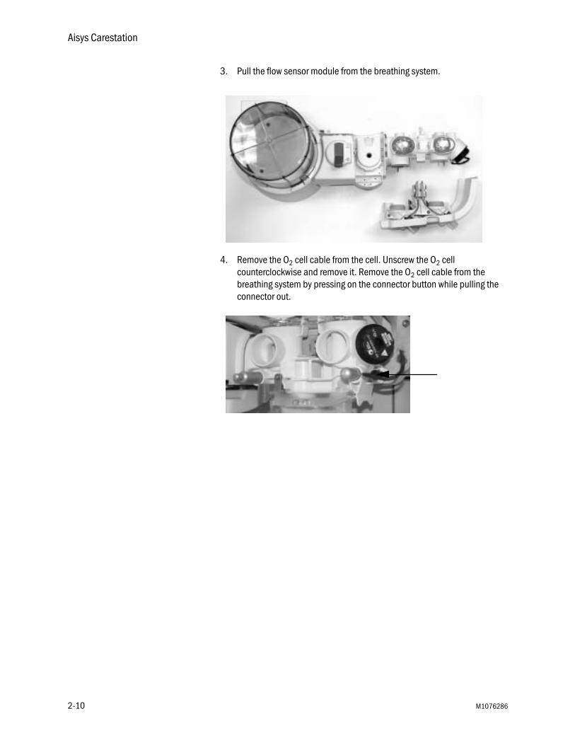
1. Remove the breathing system and place it upright on a flat surface.
2. Pull the latch to unlock the flow sensor module from the breathing system.
M1076286 2-9
Aisys Carestation
3. Pull the flow sensor module from the breathing system.
4. Remove the O2 cell cable from the cell. Unscrew the O2 cell counterclockwise and remove it. Remove the O2 cell cable from the breathing system by pressing on the connector button while pulling the connector out.
2-10 M1076286

2 Cleaning and Sterilization
5. Remove the flow sensors from the module.
• Completely loosen the thumbscrew (1).
• Pull off the flow sensor cover (2) from the flow sensor holder.
• Remove the flow sensor connectors (3) from the flow sensor holder.
• Pull the flow sensors (4) from the flow sensor holder.
6. Rotate the breathing circuit module counterclockwise at the point shown by the dotted line.
1 23
4
M1076286 2-11

Aisys Carestation
7. After rotating, separate the two sections by pulling them apart.
8. On the breathing circuit module, remove the check valve circuit lens (1) by squeezing the latches (2) together and pulling up on the lens. Lift out the check valve assemblies (3).
1
23 3
2-12 M1076286

2 Cleaning and Sterilization
9. Press the latch (1) to unlock the ramp (2). Rotate the ramp and remove the tabs from the slots (3) to remove the ramp.
10. Lift the APL valve diaphragm to remove it.
2
1
3
M1076286 2-13

Aisys Carestation
11. Turn over the bellows base assembly, grasp the bellows manifold with three fingers in the openings at the points shown and pull straight away to remove it.
12. With the breathing system removed, the exhalation valve assembly can be removed for cleaning if desired. Loosen the two thumbscrews indicated and lift the assembly off.
2-14 M1076286

2 Cleaning and Sterilization
Disassemble the bellows assembly
The bellows assembly can be disassembled for cleaning, sterilization, and part replacement.
1. Turn the housing counterclockwise and lift.
2. Remove the bottom edge of the bellows from the rim.
3. Push the latch toward the center and remove the rim.
M1076286 2-15
Aisys Carestation
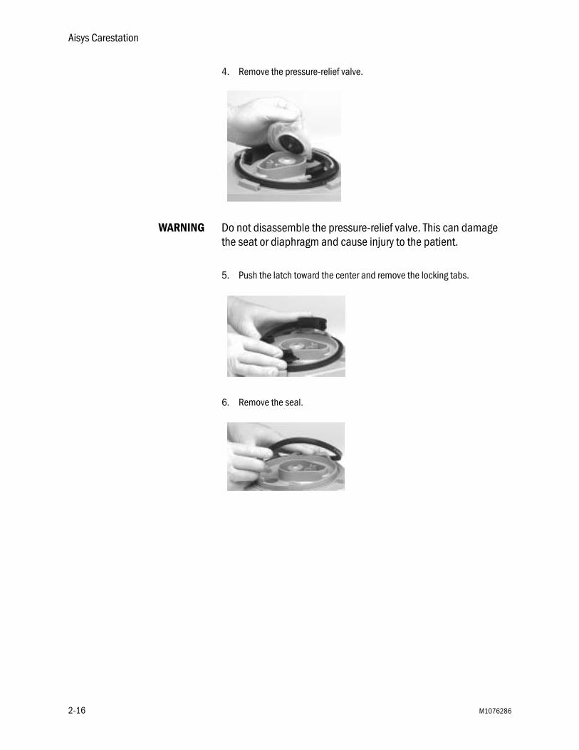
4. Remove the pressure-relief valve.
WARNING Do not disassemble the pressure-relief valve. This can damage the seat or diaphragm and cause injury to the patient.
5. Push the latch toward the center and remove the locking tabs.
6. Remove the seal.
2-16 M1076286

2 Cleaning and Sterilization
Assemble the bellows assembly
1. Install the seal. Verify the arrow and the groove on the seal point up.
2. Push the latch toward the center and attach the locking tabs.
3. Install the pressure-relief valve.
4. Push the latch toward the center and install the rim. A double-click should be heard when the rim is installed.
M1076286 2-17
Aisys Carestation
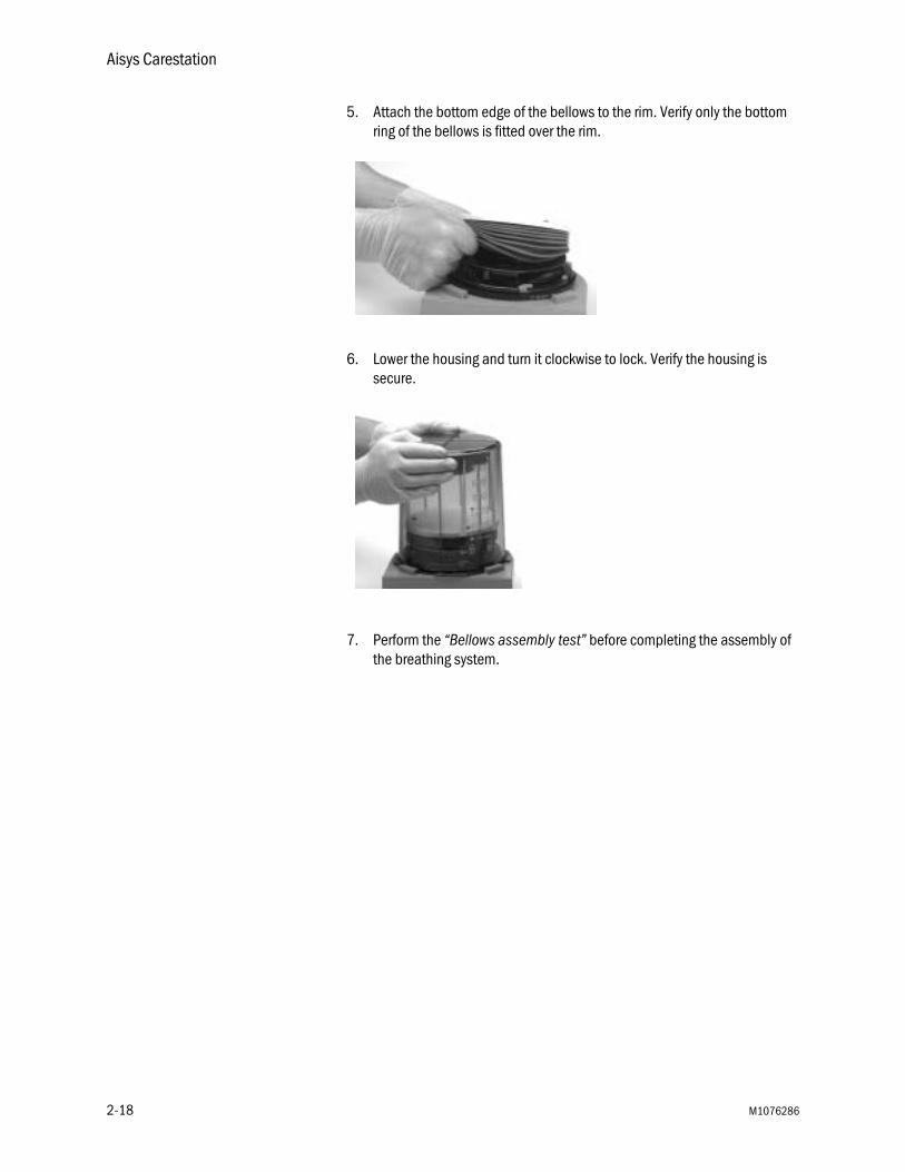
5. Attach the bottom edge of the bellows to the rim. Verify only the bottom ring of the bellows is fitted over the rim.
6. Lower the housing and turn it clockwise to lock. Verify the housing is secure.
7. Perform the “Bellows assembly test” before completing the assembly of the breathing system.
2-18 M1076286

2 Cleaning and Sterilization
Bellows assembly test
WARNING Objects in the breathing system can stop gas flow to the patient. This can cause injury or death:
• Do not use a test plug that is small enough to fall into the breathing system.
• Make sure that there are no test plugs or other objects caught in the breathing system.
w The bellows assembly tests do not replace the preoperative tests. Always complete the tests in the section “Preoperative Tests” before using the system on a patient.
These tests make sure that all components are correctly assembled. These are not an alternative to a complete system checkout. If the bellows assembly operates correctly, complete the assembly of the breathing system. If there is a problem, disassemble the bellows assembly. Verify proper assembly and look for and replace damaged parts.
1. Hold the bellows assembly vertical and use the appropriate test plugs to seal the ports shown.
M1076286 2-19
Aisys Carestation
2. Invert the bellows assembly. The bellows must not fall within one minute. If it does:
• The ports are not tightly sealed.
• The bellows is incorrectly installed.
• The seal inside the bellows is not correctly installed (with its groove pointed up).
• Parts are damaged.
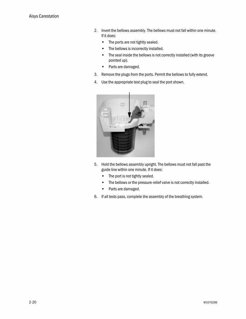
3. Remove the plugs from the ports. Permit the bellows to fully extend.
4. Use the appropriate test plug to seal the port shown.
5. Hold the bellows assembly upright. The bellows must not fall past the guide line within one minute. If it does:
• The port is not tightly sealed.
• The bellows or the pressure-relief valve is not correctly installed.
• Parts are damaged.
6. If all tests pass, complete the assembly of the breathing system.
2-20 M1076286

2 Cleaning and Sterilization
Assemble the breathing system
1. Replace the exhalation valve assembly. Tighten the two thumbscrews.
2. Turn over the bellows base assembly. Replace the manifold. Be sure to insert it correctly into the ports as shown. Then, press on the center of the manifold to snap it into place on the bellows base assembly.
M1076286 2-21
Aisys Carestation
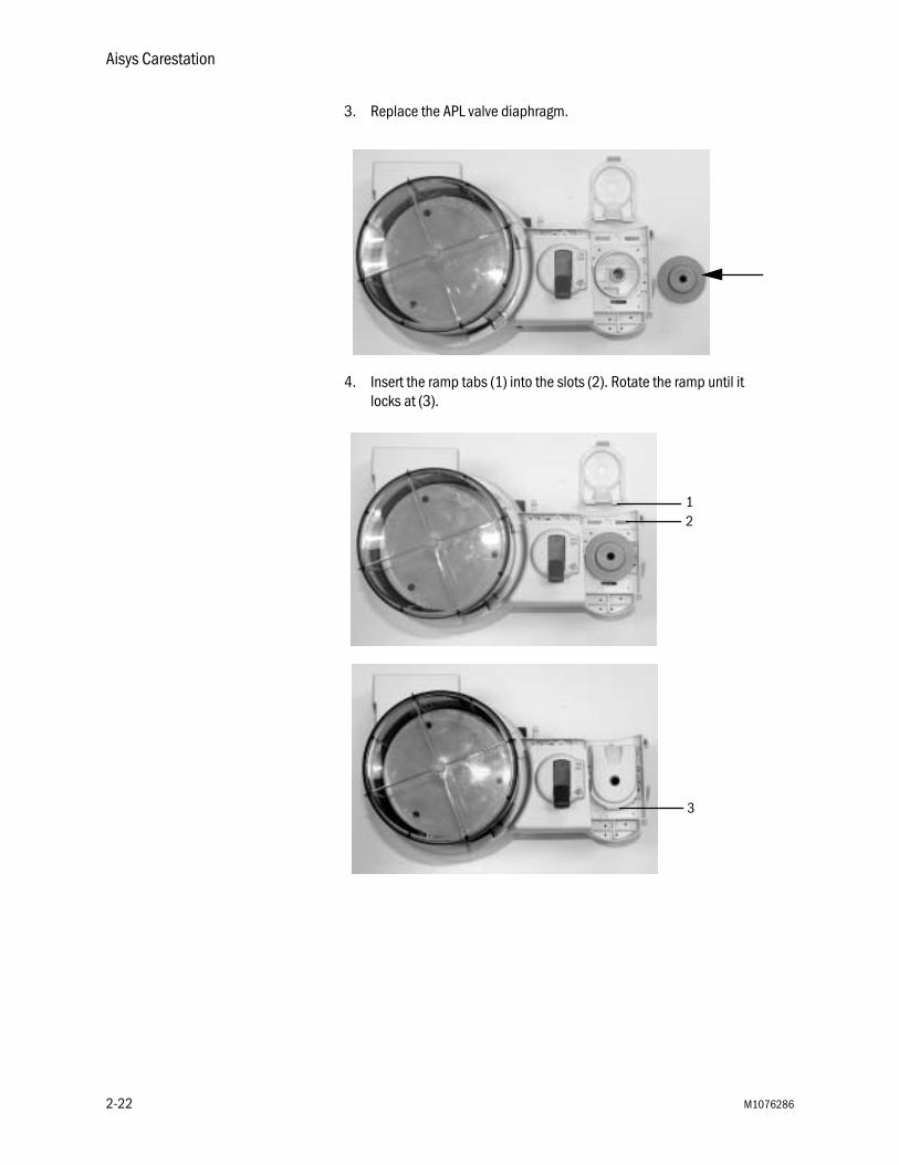
3. Replace the APL valve diaphragm.
4. Insert the ramp tabs (1) into the slots (2). Rotate the ramp until it locks at (3).
12
3
2-22 M1076286

2 Cleaning and Sterilization
5. On the breathing circuit module, insert the check valve assemblies (1). Push the check valve circuit lens (2) down onto the latches (3) to lock the lens.
6. Insert the breathing circuit module into the bellows assembly aligned as shown.
7. Rotate the breathing circuit module clockwise at the point shown by the dotted line to attach it to the bellows assembly.
2
31 1
M1076286 2-23

Aisys Carestation
8. Make sure the o-ring (1) is on the O2 cell. Replace the cell by screwing it in clockwise. Connect the O2 cell cable (2).
9. Attach the flow sensors to the module:
• Insert the flow sensors (1) into the flow sensor holder. Note the groove locations.
• Attach the flow sensor connectors (2) to the flow sensor holder.
• Attach the cover (3) to the flow sensor holder.
• Tighten the thumbscrew (4) to fasten the cover.
1
2
4 32
1
2-24 M1076286

2 Cleaning and Sterilization
10. Attach the flow sensor module to the breathing system.
11. Push the latch closed to lock the flow sensor module onto the breathing system.
12. This is the assembled breathing system.
M1076286 2-25

Aisys Carestation
Install the breathing system
1. Locate the guide pin openings.
2. Align the openings with the guide pins as shown.
2-26 M1076286

2 Cleaning and Sterilization
3. Holding the rear handle and the latch handle as shown, slide the breathing system onto the guide pins.
4. Use the grip under the latch handle to push the breathing system in fully until it latches firmly.
5. Install the absorber canister and bag hose.
6. Complete the tests in the “Preoperative Tests” section of the User’s Reference manual, Part 1.
Remove the AGSS receiver
The AGSS receiver may be removed for cleaning and sterilization.
1. On the side of the system, loosen the two thumbscrews to release the system side panel.
M1076286 2-27

Aisys Carestation
2. Slide the side panel out by removing its tabs from their slots.
3. Loosen the thumbscrew and remove the reservoir.
CAUTION Do not autoclave the reservoir. Damage to the reservoir will occur.
4. Loosen the thumbscrew and lower the receiver to remove it.
5. Replace the filter as necessary. (See “Remove the AGSS receiver filter.”)
6. Do these steps in the opposite order to replace the receiver, reservoir, and the side panel.
7. Complete the tests in the “Preoperative Tests” section of the User’s Reference manual, Part 1.
2-28 M1076286
2 Cleaning and Sterilization
Remove the AGSS receiver filter
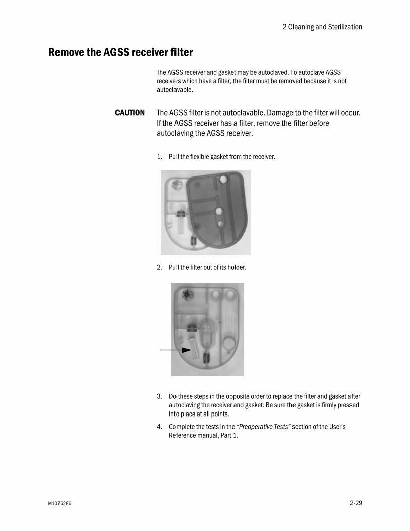
The AGSS receiver and gasket may be autoclaved. To autoclave AGSS receivers which have a filter, the filter must be removed because it is not autoclavable.
CAUTION The AGSS filter is not autoclavable. Damage to the filter will occur. If the AGSS receiver has a filter, remove the filter before autoclaving the AGSS receiver.
1. Pull the flexible gasket from the receiver.
2. Pull the filter out of its holder.
3. Do these steps in the opposite order to replace the filter and gasket after autoclaving the receiver and gasket. Be sure the gasket is firmly pressed into place at all points.
4. Complete the tests in the “Preoperative Tests” section of the User’s Reference manual, Part 1.
M1076286 2-29
Aisys Carestation
Absorber canister
The absorber canister is available in two versions: Disposable Multi Absorber and Reusable Multi Absorber. Only the Reusable Multi Absorber canister may be cleaned. Refer to “Removing a canister” in section 1, “Setup and Connections.”
Mechanical cleaning inwasher or washer-
disinfector
1. Place the reusable canister (without filters) and the lid in the washer or washer-disinfector and clean them using the appropriate procedures.
2. If the washer or washer-disinfector is not used for disinfection of equipment, Datex-Ohmeda recommends that a further high level disinfection is conducted.
3. Ensure the canister is dry before replacing the filters and refilling with absorbent. Refer to “Removing a canister” in section 1, “Setup and Connections.”
Manual cleaning Datex-Ohmeda recommends that manual cleaning is always followed by a high level disinfection.
1. Flush the reusable canister and the lid with fresh running water.
2. Clean the canister and lid under total immersion in a sink with water and cleaning agent for at least 3 minutes. The water temperature should be approximately 40°C (104°F).
3. Flush the canister and lid with fresh running water.
4. Ensure the canister is dry before replacing the filters and refilling with absorbent. Refer to “Removing a canister” in section 1, “Setup and Connections.”
High level disinfection 1. Always clean the canister before high level disinfection.
2. The canister can be steam autoclaved. Maximum recommended temperature is 134°C (273°F).
3. Ensure the canister is dry before replacing the filters and refilling with absorbent. Refer to “Removing a canister” in section 1, “Setup and Connections.”
2-30 M1076286

2 Cleaning and Sterilization
Aladin cassette cleaning
Remove the cassette from the machine. Clean the cassette surface with a cloth moistened in mild soap solution.
CAUTION Do not wipe Aladin cassettes with alcohol-based detergents. This may damage the surface of the cassette.
EZchange Canister and condenser
The EZchange Canister and the condenser can be removed for cleaning, sterilization, and part replacement. They can be removed as part of the breathing system or on their own.
To remove the EZchange Canister and the condenser as part of the breathing system, see “Remove the breathing system” in this section. Then place the breathing system on its side on a flat surface.
1. EZchange Canister module2. Condenser reservoir3. Condenser4. Release latch
Figure 2-2 • EZchange Canister and condenser
1
2
3
4
AB.7
5p80
M1076286 2-31
Aisys Carestation
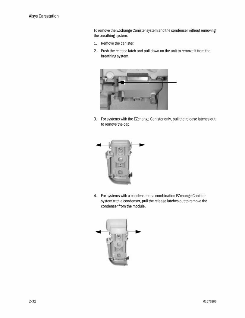
To remove the EZchange Canister system and the condenser without removing the breathing system:
1. Remove the canister.
2. Push the release latch and pull down on the unit to remove it from the breathing system.
3. For systems with the EZchange Canister only, pull the release latches out to remove the cap.
4. For systems with a condenser or a combination EZchange Canister system with a condenser, pull the release latches out to remove the condenser from the module.
2-32 M1076286
2 Cleaning and Sterilization
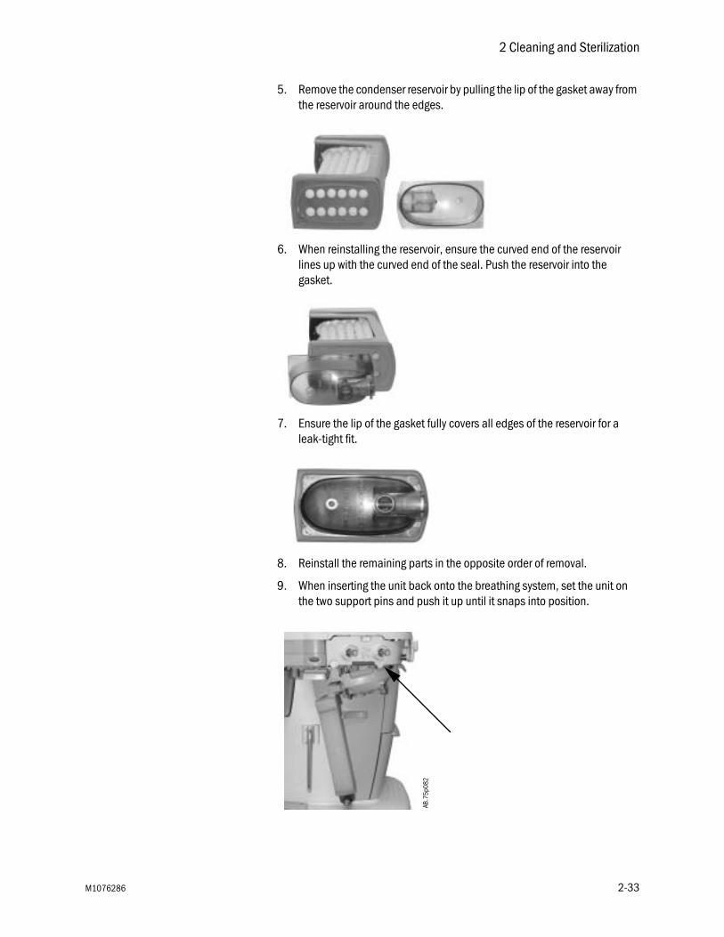
5. Remove the condenser reservoir by pulling the lip of the gasket away from the reservoir around the edges.
6. When reinstalling the reservoir, ensure the curved end of the reservoir lines up with the curved end of the seal. Push the reservoir into the gasket.
7. Ensure the lip of the gasket fully covers all edges of the reservoir for a leak-tight fit.
8. Reinstall the remaining parts in the opposite order of removal.
9. When inserting the unit back onto the breathing system, set the unit on the two support pins and push it up until it snaps into position.
AB.7
5p08
2
M1076286 2-33

Aisys Carestation
2-34 M1076286

3 User Maintenance
WARNING To help prevent fires:
• Only use lubricants approved for anesthesia or O2 equipment, such as Krytox.
• Do not use lubricants that contain oil or grease. They may burn or explode in high O2 concentrations.
• All covers used on the system must be made from antistatic (conductive) materials. Static electricity can cause fires.
• Desiccated (dehydrated) absorbent material may produce dangerous chemical reactions when exposed to inhalation anesthetics. Adequate precautions should be taken to ensure that absorbent does not dry out. Turn off all gases when finished using the system.
w Obey infection control and safety procedures. Used equipment may contain blood and body fluids.
w Movable parts and removable components may present a pinch or a crush hazard. Use care when moving or replacing system parts and components.
In this section Repair policy . . . . . . . . . . . . . . . . . . . . . . . . . . . . . . . . . . . . . . . . . . . . . . . . . . 3-2
Maintenance summary and schedule . . . . . . . . . . . . . . . . . . . . . . . . . . . . . . 3-2
Circuit O2 cell replacement . . . . . . . . . . . . . . . . . . . . . . . . . . . . . . . . . . . . . . . 3-4
Flow and pressure calibration . . . . . . . . . . . . . . . . . . . . . . . . . . . . . . . . . . . . 3-5
Circuit O2 cell calibration . . . . . . . . . . . . . . . . . . . . . . . . . . . . . . . . . . . . . . . . 3-5
Airway gas calibration . . . . . . . . . . . . . . . . . . . . . . . . . . . . . . . . . . . . . . . . . . . 3-6
Backlight test . . . . . . . . . . . . . . . . . . . . . . . . . . . . . . . . . . . . . . . . . . . . . . . . . . 3-6
How to help prevent water buildup . . . . . . . . . . . . . . . . . . . . . . . . . . . . . . . . 3-6
M1076286 3-1

Aisys Carestation
Repair policy
Do not use malfunctioning equipment. Make all necessary repairs or have the equipment serviced by a Datex-Ohmeda trained service representative. After repair, test the equipment to ensure that it is functioning properly, in accordance with the manufacturer’s published specifications.
To ensure full reliability, have all repairs and service done by a Datex-Ohmeda trained service representative. If this cannot be done, replacement and maintenance of those parts listed in this manual may be undertaken by a competent, trained individual having experience in the repair of devices of this nature.
CAUTION No repair should ever be attempted by anyone not having experience in the repair of devices of this nature.
Replace damaged parts with components manufactured or sold by Datex-Ohmeda. Then test the unit to ascertain that it complies with the manufacturer’s published specifications.
Contact the local Datex-Ohmeda Field Service Representative for service assistance.
Maintenance summary and schedule
These schedules indicate the minimum frequency of maintenance based on typical usage of 2000 hours per year. You should service the equipment more frequently if you use it more than the typical yearly usage.
Note Local policies or regulations may require that maintenance be performed more frequently than stated here.
User maintenance
Minimum Frequency Maintenance
Daily • Clean the external surfaces.• Perform 21% O2 calibration.• Check the condenser reservoir. Drain if needed.
Monthly • Perform a Backlight test.• Perform 100% O2 calibration.
During cleaning and setup
Inspect the parts for damage. Replace or repair as necessary.
3-2 M1076286

3 User Maintenance
Datex-Ohmedaapproved service
This is the minimum level of maintenance recommended by Datex-Ohmeda. Local regulations may contain additional maintenance requirements. Datex-Ohmeda advocates compliance with local regulations which meet or exceed this minimum level of maintenance.
As necessary • Install new cylinder gaskets on cylinder yokes.• Empty the water reservoir and replace the absorbent
in the canister.• Empty the overflow trap on the optional suction
regulator.• Replace the circuit O2 cell.
(Under typical use the cell meets specifications for 1 year.)
• Replace the disposable flow sensors (plastic).(Under typical use the sensor meets specifications for a minimum of 3 months.)
• Replace the autoclavable flow sensors (metal).(Under typical use the sensor meets specifications for a minimum of 1 year.)
• Replace the receiver filter (active gas scavenging only).
• Calibrate the airway modules every 6 months or when there are indications of errors in the gas readings. Calibrate airway modules that get extensive usage every 2 months.
• Inspect and clean the fan filters (display, power supply, and airway module).
Minimum Frequency Maintenance
Minimum Frequency Maintenance
12 months Have a Datex-Ohmeda trained service representative complete the scheduled service maintenance checks, tests, calibrations and parts replacement as defined in the Technical Reference manual.
M1076286 3-3
Aisys Carestation
Circuit O2 cell replacement
WARNING Handle and dispose of O2 cells according to your biohazard policies. Do not incinerate.
Note It may take a new O2 cell 90 minutes to stabilize. If the O2 cell calibration fails after a new O2 cell had been installed, wait 90 minutes and repeat the calibration.
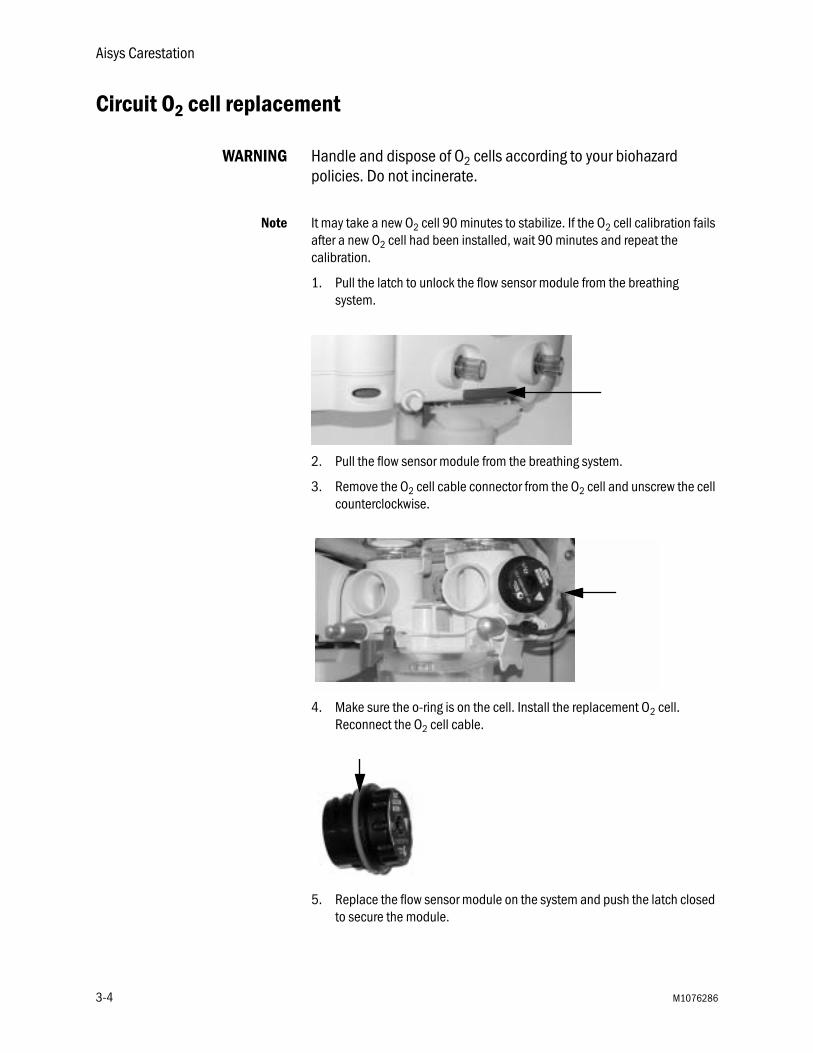
1. Pull the latch to unlock the flow sensor module from the breathing system.
2. Pull the flow sensor module from the breathing system.
3. Remove the O2 cell cable connector from the O2 cell and unscrew the cell counterclockwise.
4. Make sure the o-ring is on the cell. Install the replacement O2 cell. Reconnect the O2 cell cable.
5. Replace the flow sensor module on the system and push the latch closed to secure the module.
3-4 M1076286

3 User Maintenance
Flow and pressure calibration
Important Calibrate the flow sensors if the room temperature changes by more than 5˚C.
1. Set the Bag/Vent switch to Bag.
2. Remove the flow sensor module.
3. Wait for ‘No insp flow sensor’ and ‘No exp flow sensor’ alarms to occur.
4. Reinsert the flow sensor module. Wait for alarms to clear.
5. Start mechanical ventilation when ready.
Circuit O2 cell calibration
21% O2 calibration 1. Push the Main Menu key.
2. Select Calibration.
3. Select Circuit O2 Cell.
4. Remove the flow sensor module. Unscrew the O2 cell to expose it to room air.
5. Select 21% O2 and push the ComWheel to start calibration.
6. Put the O2 cell back in and reconnect the flow sensor module when the calibration passes.
100% O2 calibration 1. Ensure patient Y-piece is not plugged or there is no patient tubing connected to the system.
2. (ACGO option only.) Set the ACGO switch to Circle.
3. Set the Bag/Vent switch to Vent.
4. Select 100% O2 and push the ComWheel to start the calibration.
5. System will flow O2 to calibrate.
M1076286 3-5
Aisys Carestation
Airway gas calibration
The airway gas selection is only available on the Calibration menu when the system detects an airway module and the module has completed the warm up phase. Refer to the “Airway Module” section in Part 1 of the User’s Reference manual for calibration instructions.
Backlight test
1. Push the Main Menu key.
2. Select Calibration.
3. Select Backlight Test.
4. Select Start Test.
5. The display will show the test running on light 1 and then on light 2. If the display goes completely blank or flickers during the test, one of the lights has failed. Contact a Datex-Ohmeda trained service representative to replace the backlights.
How to help prevent water buildup
Pooled water in the flow sensors or water in the sensing lines may cause false alarms. Small beads of water or a foggy appearance in the flow sensors is OK.
Water results from exhaled gas and the chemical reaction between CO2 and the absorbent that takes place within the absorber canister.
At lower fresh gas flows more water builds up because less gas is scavenged and:
• More CO2 stays in the absorber to react and produce water,
• More moist, exhaled gas stays in the patient circuit and the absorber.
Solutions:
• Empty the water reservoir in the canister when changing the absorbent.
• Ensure that water condensing in the breathing circuit tubes is kept lower than the flow sensors and is not allowed to drain back into the flow sensors.
• Water condensation in the breathing circuit tubing can be reduced by using a Heat and Moisture Exchange (HME) filter at the patient airway connection.
3-6 M1076286
4 Parts
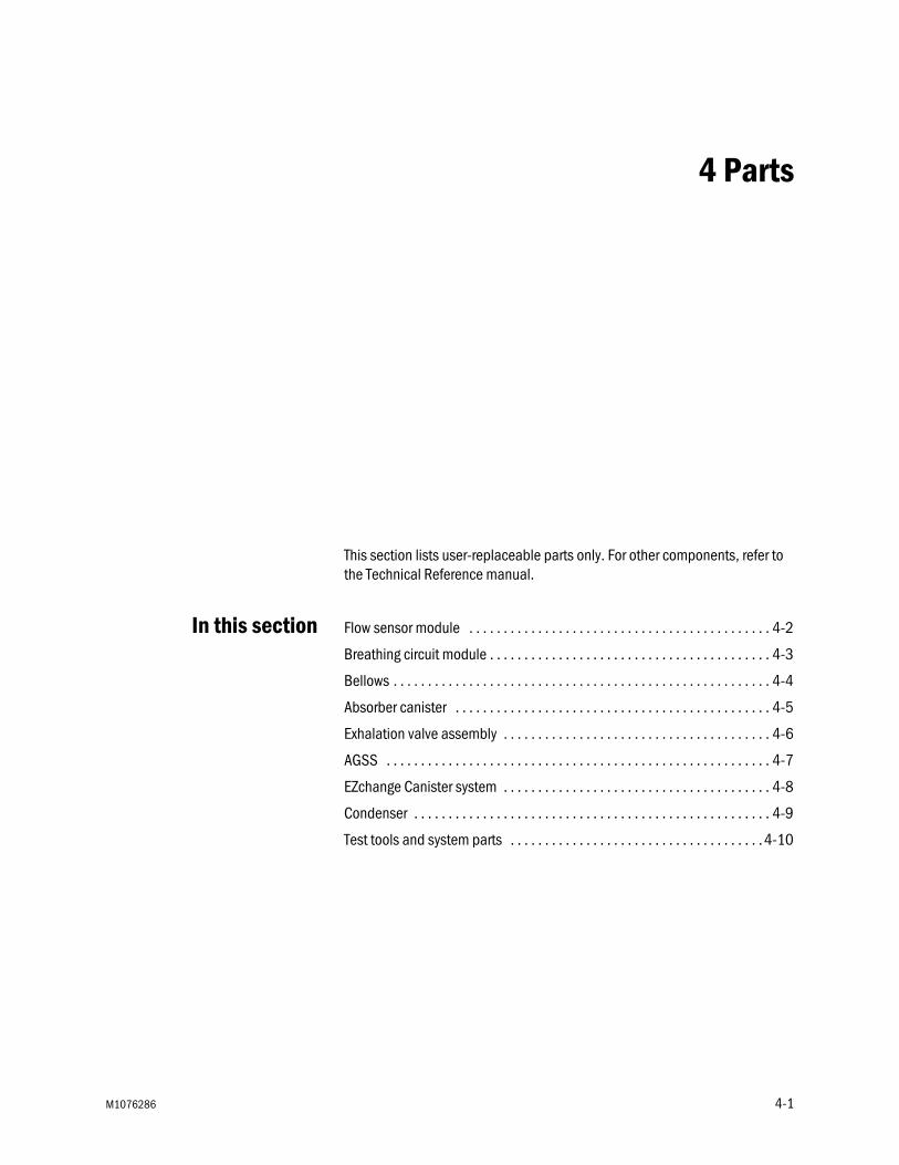
This section lists user-replaceable parts only. For other components, refer to the Technical Reference manual.
In this section Flow sensor module . . . . . . . . . . . . . . . . . . . . . . . . . . . . . . . . . . . . . . . . . . . . 4-2
Breathing circuit module . . . . . . . . . . . . . . . . . . . . . . . . . . . . . . . . . . . . . . . . . 4-3
Bellows . . . . . . . . . . . . . . . . . . . . . . . . . . . . . . . . . . . . . . . . . . . . . . . . . . . . . . . 4-4
Absorber canister . . . . . . . . . . . . . . . . . . . . . . . . . . . . . . . . . . . . . . . . . . . . . . 4-5
Exhalation valve assembly . . . . . . . . . . . . . . . . . . . . . . . . . . . . . . . . . . . . . . . 4-6
AGSS . . . . . . . . . . . . . . . . . . . . . . . . . . . . . . . . . . . . . . . . . . . . . . . . . . . . . . . . 4-7
EZchange Canister system . . . . . . . . . . . . . . . . . . . . . . . . . . . . . . . . . . . . . . . 4-8
Condenser . . . . . . . . . . . . . . . . . . . . . . . . . . . . . . . . . . . . . . . . . . . . . . . . . . . . 4-9
Test tools and system parts . . . . . . . . . . . . . . . . . . . . . . . . . . . . . . . . . . . . . 4-10
M1076286 4-1
Aisys Carestation
Flow sensor module
2
3
1
AB.8
2.01
9
Item Description Stock number
Flow sensor module (does not include flow sensors) 1407-7022-0001 Flow sensor cover 1011-3283-0002 Flow sensor cuff 1407-3004-0003 Flow sensor, disposable (plastic) 1503-3858-000
Flow sensor, autoclavable (metal) 1503-3244-000
4-2 M1076286

4 Parts
Breathing circuit module
1
2
3
45
AB.8
2.02
1
Item Description Stock number
Breathing circuit module (does not include O2 cell, O-ring, or cable)
1407-7002-000
1 Check valves circuit lens 1407-3101-0002 Check valve assembly 1406-8219-0003 O-ring for O2 cell 1406-3466-0004 O2 cell (includes O-ring) 6050-0004-1105 Cable, O2 cell 1009-5570-000– Plug, includes O-ring (for units without O2 sensing) 1503-3857-000– O-ring for plug 1406-3466-000
M1076286 4-3

Aisys Carestation
Bellows
1
2
3
45
6
7
8
AB.8
2.01
8
Item Description Stock number
1 Bellows housing 1500-3117-0002 Bellows 1500-3378-0003 Rim 1500-3351-0004 Pressure relief valve assembly 1500-3377-0005 Latch, rim 1500-3352-0006 Manifold, bellows base 1407-3702-0007 Bellows base with latch 1407-7006-0008 Seal, base 1500-3359-000– Diaphragm, APL 1406-3331-000– Poppet, APL valve 1406-3332-000– Cage, APL 1406-3333-000
4-4 M1076286

4 Parts
Absorber canister
3
4
5
1
2
AB.8
2.01
7
Item Description Stock number
1 Multi absorber, reusable (includes 40 pack of foam) (does not include absorbent)
1407-7004-000
2 Cover assembly, CO2 canister 1009-8240-0003 Foam, CO2 canister (pack of 40) 1407-3201-0004 O-ring 1407-3204-0005 Canister, CO2, with handle 1407-3200-000– Multi absorber, disposable, white to violet,
(pack of 6)8003138
– Multi absorber, disposable, pink to white, (pack of 6) 8003963
M1076286 4-5
Aisys Carestation
Exhalation valve assembly
AB.8
2.03
5
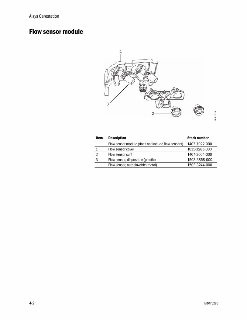
Description Stock number
Exhalation valve assembly 1407-7005-000
4-6 M1076286
4 Parts
AGSS
Description Stock number
Common
Cap 3.18 barb silicone 1406-3524-000Connector, inlet 30 mm male to 19 mm male M1003947Connector, inlet 30 mm male to 30 mm male M1003134O-ring for connector, 21.95 ID 1406-3558-000O-ring for receiver, 22 ID 1407-3104-000O-ring for thumbscrews, 4.47 ID 1407-3923-000Reservoir scavenger 1407-3903-000Seal, down tube scavenger 1407-3904-000Seal, receiver scavenger 1407-3901-000Thumbscrew M6 X 28.5 1406-3305-000Thumbscrew, M6 X 43 1406-3304-000Valve, unidirectional (complete assembly) 1406-8219-000Passive AGSSAdapter, outlet 30 mm female to 19 mm male (pack of 5) 1500-3376-000Exhaust hose 8004461Plug assembly 30 mm ISO 1407-3909-000Screw, shoulder 4 dia X 4 L M3 X 0.5 sst 1407-3915-000Active AGSS, adjustable flowBag with 30 mm male connector 8004460Plug assembly 30 mm ISO 1407-3909-000Active AGSS, high flowFilter, 225 micrometer nylon screen AGSS 1406-3521-000Seal, filter scavenger 1407-3902-000Active AGSS, low flowFilter, 225 micrometer nylon screen AGSS 1406-3521-000Seal, filter scavenger 1407-3902-000
M1076286 4-7

Aisys Carestation
EZchange Canister system
1
2
AB.8
2.04
4
3
3
4
AB.8
2.05
7
Item Description Stock number
1 EZchange Canister module, includes valve and cap 1407-7021-0002 Valve 1407-3126-0003 Cap 1407-3130-0004 Condenser 1407-7024-000– EZchange Canister module with condenser 1407-7027-000
4-8 M1076286
4 Parts
Condenser
AB.8
2.04
5
1
2
Item Description Stock number
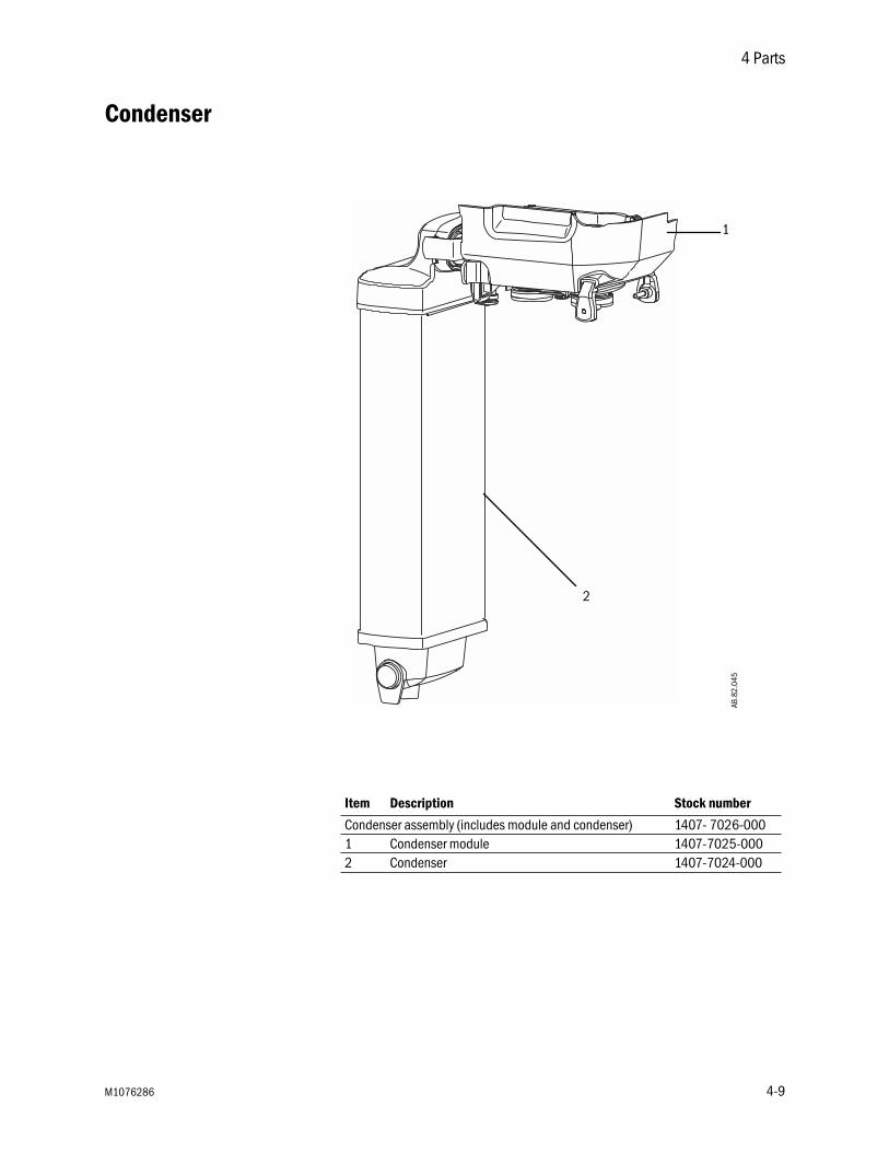
Condenser assembly (includes module and condenser) 1407- 7026-0001 Condenser module 1407-7025-0002 Condenser 1407-7024-000
M1076286 4-9

Aisys Carestation
Test tools and system parts
Description Stock number
Airway module calibration gas 755583Airway module calibration gas (US only) 755571Airway module exhaust line 8004463Calibration gas regulator 755534Calibration gas regulator (US only) M1006864Cylinder gasket (pin indexed cylinders only) 0210-5022-300Cylinder wrench (DIN 477 and high-pressure hose) 1202-3651-000Cylinder wrench for pin-indexed cylinder 0219-3415-800DIN O2 plug (cylinder connection) 1202-7146-000Handle for yoke tee 0219-3372-600Negative low pressure leak test device 0309-1319-800Positive low pressure leak test device (BSI) 1001-8975-000Positive low pressure leak test device (ISO) 1001-8976-000Positive pressure leak test adapter 1009-3119-000Ring, sealing gasket (for DIN 477 and O2 high-pressure hose) 1001-3812-000Ring, sealing gasket (for N2O high-pressure hose) 1202-3641-000Test lung 0219-7210-300Test plug 2900-0001-000Touch-up paint, Neutral Gray N7 (Medium Dark), 18 ml 1006-4198-000Touch-up paint, Neutral Gray N8 (Medium), 18 ml 1006-4199-000Touch-up paint, Neutral Gray N9 (Light), 18 ml 1006-4200-000Yoke plug 0206-3040-542
4-10 M1076286
5 Specifications and Theory of Operation
Note All specifications are nominal and subject to change without notice.
In this section System pneumatic circuits . . . . . . . . . . . . . . . . . . . . . . . . . . . . . . . . . . . . . . . 5-2
Pneumatic specifications . . . . . . . . . . . . . . . . . . . . . . . . . . . . . . . . . . . . . . . . 5-5
Electrical power . . . . . . . . . . . . . . . . . . . . . . . . . . . . . . . . . . . . . . . . . . . . . . . . 5-7
Electrical block diagram . . . . . . . . . . . . . . . . . . . . . . . . . . . . . . . . . . . . . . . . . 5-8
Flow specifications . . . . . . . . . . . . . . . . . . . . . . . . . . . . . . . . . . . . . . . . . . . . 5-10
Breathing system specifications . . . . . . . . . . . . . . . . . . . . . . . . . . . . . . . . . 5-11
Physical specifications . . . . . . . . . . . . . . . . . . . . . . . . . . . . . . . . . . . . . . . . . 5-13
Environmental requirements . . . . . . . . . . . . . . . . . . . . . . . . . . . . . . . . . . . . 5-14
Airway module specifications . . . . . . . . . . . . . . . . . . . . . . . . . . . . . . . . . . . . 5-14
Suction regulators (optional) . . . . . . . . . . . . . . . . . . . . . . . . . . . . . . . . . . . . 5-15
Ventilator theory . . . . . . . . . . . . . . . . . . . . . . . . . . . . . . . . . . . . . . . . . . . . . . 5-16
Ventilation operating specifications . . . . . . . . . . . . . . . . . . . . . . . . . . . . . . 5-24
Ventilator accuracy data . . . . . . . . . . . . . . . . . . . . . . . . . . . . . . . . . . . . . . . . 5-26
Electronically controlled vaporizer and Aladin cassette . . . . . . . . . . . . . . . 5-27
Electromagnetic compatibility (EMC) . . . . . . . . . . . . . . . . . . . . . . . . . . . . . . 5-30
Electrical safety . . . . . . . . . . . . . . . . . . . . . . . . . . . . . . . . . . . . . . . . . . . . . . . 5-34
IEC-60601-1 Classification . . . . . . . . . . . . . . . . . . . . . . . . . . . . . . . . . . . . . 5-34
M1076286 5-1
Aisys Carestation
System pneumatic circuits
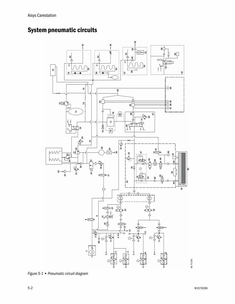
Figure 5-1 • Pneumatic circuit diagram
AB.7
5.03
6
P
PPNC
NO NC
NO NO
P
P
P
P
P P
PP
PP
4444
1
3 3 3
5 5 5
62
13
14 6
15 16
12
1011
9
8
31
30
2928
17
18
19
20
21
22
23
24
25
26
27
70
71
72 7374
75
4748
4950
45
67
69
13
66
68
7778
7644
46
7 7
63
65
64
66
NO
NC
53
52
54
51
53
56
54
55
53
62
54
57
61
5859
60
P
PP
T
43
3642
41
4035
3438 39
37
3233
79
80
81
82
83
8484
85
86
5-2 M1076286
5 Specifications and Theory of Operation
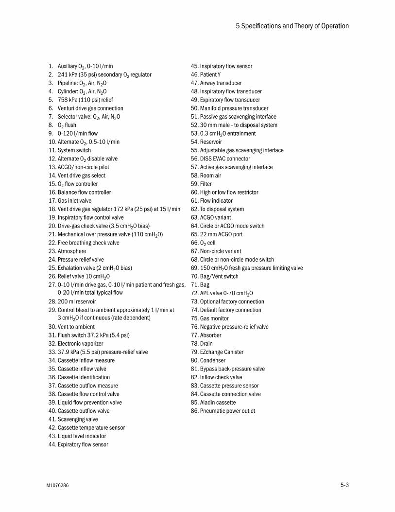
1. Auxiliary O2, 0-10 l/min 45. Inspiratory flow sensor2. 241 kPa (35 psi) secondary O2 regulator 46. Patient Y3. Pipeline: O2, Air, N2O 47. Airway transducer4. Cylinder: O2, Air, N2O 48. Inspiratory flow transducer5. 758 kPa (110 psi) relief 49. Expiratory flow transducer6. Venturi drive gas connection 50. Manifold pressure transducer7. Selector valve: O2, Air, N2O 51. Passive gas scavenging interface8. O2 flush 52. 30 mm male - to disposal system9. 0-120 l/min flow 53. 0.3 cmH2O entrainment10. Alternate O2, 0.5-10 l/min 54. Reservoir11. System switch 55. Adjustable gas scavenging interface12. Alternate O2 disable valve 56. DISS EVAC connector13. ACGO/non-circle pilot 57. Active gas scavenging interface14. Vent drive gas select 58. Room air15. O2 flow controller 59. Filter16. Balance flow controller 60. High or low flow restrictor17. Gas inlet valve 61. Flow indicator18. Vent drive gas regulator 172 kPa (25 psi) at 15 l/min 62. To disposal system19. Inspiratory flow control valve 63. ACGO variant20. Drive-gas check valve (3.5 cmH2O bias) 64. Circle or ACGO mode switch21. Mechanical over pressure valve (110 cmH2O) 65. 22 mm ACGO port22. Free breathing check valve 66. O2 cell23. Atmosphere 67. Non-circle variant24. Pressure relief valve 68. Circle or non-circle mode switch25. Exhalation valve (2 cmH2O bias) 69. 150 cmH2O fresh gas pressure limiting valve26. Relief valve 10 cmH2O 70. Bag/Vent switch27. 0-10 l/min drive gas, 0-10 l/min patient and fresh gas,
0-20 l/min total typical flow71. Bag72. APL valve 0-70 cmH2O
28. 200 ml reservoir 73. Optional factory connection29. Control bleed to ambient approximately 1 l/min at
3 cmH2O if continuous (rate dependent)74. Default factory connection75. Gas monitor
30. Vent to ambient 76. Negative pressure-relief valve31. Flush switch 37.2 kPa (5.4 psi) 77. Absorber32. Electronic vaporizer 78. Drain33. 37.9 kPa (5.5 psi) pressure-relief valve 79. EZchange Canister34. Cassette inflow measure 80. Condenser35. Cassette inflow valve 81. Bypass back-pressure valve36. Cassette identification 82. Inflow check valve37. Cassette outflow measure 83. Cassette pressure sensor38. Cassette flow control valve 84. Cassette connection valve39. Liquid flow prevention valve 85. Aladin cassette40. Cassette outflow valve 86. Pneumatic power outlet41. Scavenging valve42. Cassette temperature sensor43. Liquid level indicator44. Expiratory flow sensor
M1076286 5-3

Aisys Carestation
Gas supplies Pressurized gas supplies enter the system through a pipeline or cylinder connection. All connections have indexed fittings, filters, and check valves.
A regulator decreases the cylinder pressures to the appropriate system pressure. A pressure relief valve helps protect the system from high pressures.
To help prevent problems with the gas supplies:
• Install yoke plugs on all empty cylinder connections.
• When a pipeline supply is connected, keep the cylinder valve closed.
• Disconnect the pipeline supplies when the system is not in use.
WARNING Do not leave gas cylinder valves open if the pipeline supply is in use. Cylinder supplies could be depleted, leaving an insufficient reserve supply in case of pipeline failure.
O2 flow Pipeline or regulated cylinder pressure supplies O2 directly to the O2 channel of the gas mixer and to the ventilator if O2 is configured as drive gas. If the pressure is too low, an alarm appears on the display. A second regulator decreases the pressure for the flush valve and the auxiliary O2 flowmeter.
The flush valve supplies high flows (between 35 and 50 l/min) of O2 to the fresh gas outlet when the O2 flush button is pushed. The flush switch uses pressure changes to monitor the position of the flush valve.
Air and N2O Pipeline or regulated cylinder pressure supplies air directly to the air channel of the gas mixer and to the ventilator if air is configured as drive gas. If the pressure is too low, an alarm appears on the display.
Pipeline or regulated cylinder pressure supplies N2O directly to the N2O channel of the gas mixer. If the pressure is too low, an alarm appears on the display.
Mixed gas Either Air or N2O can be selected as the balance gas. The balance gas flow is controlled by the mixer. When Alternate O2 control is in use, only O2 is flowing and balance gas is disabled.
The mixed gas goes from the mixer outlet through the vaporizer to the fresh gas outlet and into the breathing system. A pressure-relief valve sets the maximum outlet pressure.
5-4 M1076286

5 Specifications and Theory of Operation
EZchange Canister When activated, this mode permits continued ventilation and rebreathing of exhaled gases without any gas passing through the absorbent.
Condenser The condenser removes water in the system that is produced from the reaction of CO2 gas with the absorbent during low flow anesthesia (fresh gas flows less than 1.5 l/min). The condenser is connected between the outlet of the absorber canister and the inlet of the circuit module. Moisture in the gas is condensed into water droplets, which run into the condenser's reservoir.
Pneumatic specifications
CAUTION All gases supplied to the system must be medical grade.
Gas supplies
Pipeline gases O2, Air, N2O
Cylinder gases O2, N2O, Air (3 cylinder maximum)
Cylinder connections Pin indexedNut and gland DIN 477
Primary regulator output pressure
Pin indexed: The primary regulator is set to pressure less than 345 kPa (50 psi).DIN-477: The primary regulator is set to pressure less than 414 kPa (60 psi)
Pressure-relief valve Approximately 758 kPa (110 psi)
Pipeline connections (filtered)
DISS-Male; DISS-Female; DIN 13252; AS 4059 (Australian); S90-116 (French Air Liquide); BSPP 3/8 (Scandinavian) or NIST (ISO 5359). All fittings available for O2, Air, and N2O.
Pressure displays On system display
Pipeline inlet pressure 280 to 600 kPa (41 to 87 psi)
Flush flow 35 l/min to 50 l/min
O2 supply pressure at which N2O shutoff
O2 pipeline less than 252 kPa (36 psi), O2 cylinder less than 2633 kPa (381 psi)
M1076286 5-5
Aisys Carestation
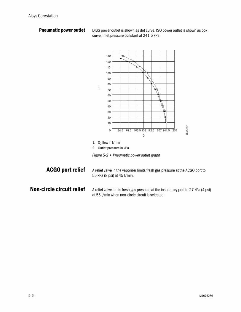
Pneumatic power outlet DISS power outlet is shown as dot curve. ISO power outlet is shown as box curve. Inlet pressure constant at 241.5 kPa.
1. O2 flow in l/min2. Outlet pressure in kPa
Figure 5-2 • Pneumatic power outlet graph
ACGO port relief A relief valve in the vaporizer limits fresh gas pressure at the ACGO port to 55 kPa (8 psi) at 45 l/min.
Non-circle circuit relief A relief valve limits fresh gas pressure at the inspiratory port to 27 kPa (4 psi) at 55 l/min when non-circle circuit is selected.
1
2 AB.7
5.05
7
5-6 M1076286

5 Specifications and Theory of Operation
Electrical power
Power cord
WARNING Unplug the system power cord to run the system on the battery power if the integrity of the protective earth conductor is in doubt.
Battery information The system is not a portable unit; sealed lead acid batteries supply backup power in the event of a power failure.
• Capacity to operate for 90 minutes under typical operating conditions; 30 minutes under heavy workload.
• System functions to specifications through the transition to battery power.
Only Datex-Ohmeda trained service representatives are to replace the battery. Batteries must be disposed of in accordance with applicable regulatory requirements in effect at the time and place of disposal.
Supply voltage 100-120 or 220-240 Vac ± 10% at 50 or 60 HzInlet circuit breakers 100-120 V ac 220-240 V ac
15 A 8 AOutlet circuit breakers 100-120 V ac 220-240 V ac Japan
(3) 2 A(1) 3A
(3) 1 A(1) 2 A
(2) 2A(1) 4A
System leakage current limit - do not exceed:
UL and CSA rated systems (USA and Canada): <300 µamps for the system and all systems connected to electrical outlets.IEC rated systems (Not USA and Canada): <500 µamps for the system and all systems connected to electrical outlets.Note: Products connected to the electrical outlets may increase the leakage current above these limits.
Resistance to ground <0.2 Ω
Length 5 metersVoltage rating 100 to 240 V acCurrent carrying capacity 10 A for 220-240 V ac
15 A for 100-120 V acType Three conductor power supply cord (medical grade
where required).
M1076286 5-7

Aisys Carestation
Electrical block diagram
AB.7
5.10
1
6
43321 5
7
9 10
8
12 11
30
1314
28
29 27 31
3233
34
35
36
37
38
39
40
41
49
50
51
4748
5352464443
4542
56
26
19
25
15
18
20
55
16
1724 23 22 21
57
59 58
60
62
63
61
6667
6465
7372
7574
68
69
70
7177
78
79
76
80
818283
54
5-8 M1076286
5 Specifications and Theory of Operation
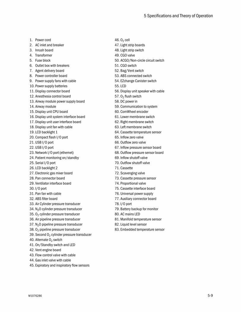
1. Power cord 46. O2 cell2. AC inlet and breaker 47. Light strip boards3. Inrush board 48. Light strip switch4. Transformer 49. CGO valve5. Fuse block 50. ACGO/Non-circle circuit switch6. Outlet box with breakers 51. CGO switch7. Agent delivery board 52. Bag/Vent switch8. Power controller board 53. ABS connected switch9. Power supply fans with cable 54. EZchange Canister switch10. Power supply batteries 55. LCD11. Display connector board 56. Display unit speaker with cable12. Anesthesia control board 57. O2 flush switch13. Airway module power supply board 58. DC power in14. Airway module 59. Communication to system15. Display unit CPU board 60. ComWheel encoder16. Display unit system interface board 61. Lower membrane switch17. Display unit user interface board 62. Right membrane switch18. Display unit fan with cable 63. Left membrane switch19. LCD backlight 1 64. Cassette temperature sensor20. Compact flash I/O port 65. Inflow zero valve21. USB I/O port 66. Outflow zero valve22. USB I/O port 67. Inflow pressure sensor board23. Network I/O port (ethernet) 68. Outflow pressure sensor board24. Patient monitoring on/standby 69. Inflow shutoff valve25. Serial I/O port 70. Outflow shutoff valve26. LCD backlight 2 71. Cassette27. Electronic gas mixer board 72. Scavenging valve28. Pan connector board 73. Cassette pressure sensor29. Ventilator interface board 74. Proportional valve30. I/O port 75. Cassette interface board31. Pan fan with cable 76. Universal power supply32. ABS filter board 77. Auxiliary connector board33. Air Cylinder pressure transducer 78. I/O port34. N2O cylinder pressure transducer 79. Battery backup for monitor35. O2 cylinder pressure transducer 80. AC mains LED36. Air pipeline pressure transducer 81. Manifold temperature sensor37. N2O pipeline pressure transducer 82. Liquid level sensor38. O2 pipeline pressure transducer 83. Embedded temperature sensor39. Second O2 cylinder pressure transducer40. Alternate O2 switch41. On/Standby switch and LED42. Vent engine board43. Flow control valve with cable44. Gas inlet valve with cable45. Expiratory and inspiratory flow sensors
M1076286 5-9
Aisys Carestation
Flow specifications
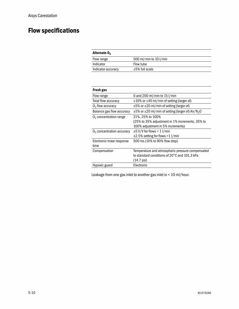
Leakage from one gas inlet to another gas inlet is < 10 ml/hour.
Alternate O2
Flow range 500 ml/min to 10 l/minIndicator Flow tubeIndicator accuracy ±5% full scale
Fresh gas
Flow range 0 and 200 ml/min to 15 l/minTotal flow accuracy ±10% or ±40 ml/min of setting (larger of)O2 flow accuracy ±5% or ±20 ml/min of setting (larger of)Balance gas flow accuracy ±5% or ±20 ml/min of setting (larger of) Air/N2OO2 concentration range 21%, 25% to 100%
(25% to 35% adjustment in 1% increments, 35% to 100% adjustment in 5% increments)
O2 concentration accuracy ±5 V/V for flows < 1 l/min±2.5% setting for flows >1 l/min
Electronic mixer response time
500 ms (10% to 90% flow step)
Compensation Temperature and atmospheric pressure compensated to standard conditions of 20°C and 101.3 kPa (14.7 psi)
Hypoxic guard Electronic
5-10 M1076286

5 Specifications and Theory of Operation
Breathing system specifications
Volume ventilator side 2730 ml; bag side 1215 ml
with EZchange Canister system and condenser: ventilator side 3445 ml; bag side 1930 ml
Absorbent 950 ml canister
Connections Auxiliary Common Gas Outlet: ISO 5356 type connector on the front of the system (Standard 22 mm OD or 15 mm ID conical friction fit connectors)
System leakage ≤ 150 ml/min total at 3 kPa (30 cmH2O)with EZchange Canister system and condenser (both in absorber mode and with canister removed)
System compliance Volume of gas lost due to internal compliance (bag mode only) 1.82 ml/0.098 kPa (1 cmH2O)55 ml/3 kPa (30 cmH2O)
with EZchange Canister system and condenser:2.67 ml/0.098 kPa (1 cmH2O)80 ml/3 kPa (30 cmH2O)
Pressure required to open inspiratory or expiratory valves
Dry: 0.49 cmH2OWet: 0.91 cmH2O
Pressure generated by a wet unidirectional valve
0.81 cmH2O
APL valve Approximately 0 to 70 cmH2O
M1076286 5-11

Aisys Carestation
Breathing system resistance in bag mode*
l/min kPa cmH2O
5 0.06 0.630 0.22 2.260 0.52 5.3
EZchange Canister system and condenser, absorber mode5 0.06 0.630 0.24 2.460 0.57 5.8
EZchange Canister system and condenser, canister removed5 0.06 0.630 0.21 2.160 0.49 5.0
* Values include patient circuit tubing and Y-piece - 4.9 kPa (0.5 cmH2O) at 1 l/s. Patient circuit tubing and breathing system configurations may affect resistance.
Pressure Flow Data (APL Valve Completely Open)
Flow (l/min) Flow (l/s) APL Pressure cmH2O
3 0.05 0.7810 0.17 1.1430 0.51 1.4360 1.0 2.6170 1.17 3.21
5-12 M1076286

5 Specifications and Theory of Operation
Gas scavenging
Physical specifications
All specifications are approximate values and can change without notice.
CAUTION Do not subject the system to excessive shock and vibration.
w Do not place excessive weight on flat surfaces or drawers.
All scavenging
Positive pressure relief 10 cmH2O
Passive scavenging
Negative pressure relief 0.3 cmH2O
Outlet connector 30 mm male taper ISO
Active scavenging
Disposal system type Outlet connector * Flow range Pressure
Adjustable flow DISS EVAC Up to 30 l/min 305 mmHg (12 inHg)Minimum vacuum
High flow, low vacuum BS6834 50 to 80 l/min 1.6 kPa(12 mmHg)
Low flow, high vacuum DISS EVAC 36 ±4 l/min 305 mmHg (12 inHg)Minimum vacuum
Low flow, low vacuum 12.7 mm hose barb 40 to 60 l/min n/a (venturi)Low flow, low vacuum 25 mm barb 40 to 60 l/min n/a (venturi)Low flow, low vacuum 30 mm ISO taper 40 to 60 l/min n/a (venturi)*Other market-specific connectors may be available.Particle filter at the outlet has a pore size of 225 microns. All flow data uses a new filter.
System Height 136 cmWidth 76 cmDepth 76 cmWeight 135 kgTop of machine weight limit 45 kgOptional top shelf weight limit 23 kg
Casters 13 cm with brakes on the front castersDrawers 23 cm H x 33 cm W x 27 cm D Ventilator display 146 x 184 mm (31 cm diagonal)
M1076286 5-13

Aisys Carestation
Environmental requirements
Airway module specifications
Use only airway modules that have anesthetic agent monitoring and O2 monitoring on this system. The following modules can be used on this system: E-CAiO, E-CAiOV, E-CAiOVX, M-CAiO, M-CAiOV, and M-CAiOVX. (E series modules must be software version 4.5 and above. M series modules must be software revision 3.2 and above.)
Gas specifications
Operation Storage Compensation Range
Temperature 10 to 40 °COxygen cell operates to specifications at 10 to 40 °C
-25 to 60°COxygen cell storage is -15 to 50°C, 10 to 95% RH, 500 to 800 mmHg
N/A
Humidity 15 to 95% RH, non-condensing 10 to 95% RH, non-condensing N/AAltitude 500 to 800 mmHg
(3565 to -440 meters)375 to 800 mmHg (5860 to -440 meters)
525 to 795 mmHg (3,000 to -100 meters)
Airway humidity 0 to 100% condensingSampling delay 2.5 seconds typical with a 3 m sampling lineTotal system response time 2.9 seconds typical with a 3 m sampling line,
including sampling delay and rise timeWarm-up time 2 minutes for operation with CO2, O2, and N2O
5 minutes for operation of anesthetic agents3O minutes for full specifications
Accuracy under different conditions:
• Ambient temperature 10 to 40°C, within ±5°C of calibration
• Ambient pressure 500 to 800 mmHg, ±50 mmHg of calibration
• Ambient humidity 10 to 98% RH, ±20% RH of calibration
• During warm-up 10 to 30 minutes, under normal conditions.
• During warm-up 2 to 10 minutes (anesthetic agents 5 to 10 minutes), under normal conditions.
CO2 ± (0.3 vol% + 4% of reading) ± (0.4 vol% + 7% of reading)O2 ± (2 vol% +2% of reading) ± (3 vol% + 3% of reading)N2O ± (3 vol% + 3% of reading) ± (3 vol% + 5% of reading)Hal, Enf, Iso, Sev, Des
± 0.2 vol% + 10% of reading ± (0.3 vol% + 10% of reading)
5-14 M1076286

5 Specifications and Theory of Operation
Typical performance
Suction regulators (optional)
CO2 Measurement range 0 to 15 vol% (0 to 15 kPa, O to 113 mmHg).Measurement rise time <400 ms typical.Accuracy ± (0.2 vol% +2% of reading).Gas cross effects <2 vol% (O2, N2O, anesthetic agents).
O2 Measurement range 0 to 100 vol%.Measurement rise time <400 ms typical.Accuracy ± (1 vol% +2% of reading).Gas cross effects <1 vol% anesthetic agents, <2 vol% N2O.
N2O Measurement range 0 to 100 vol%. Measurement rise time <450 ms typical.Accuracy ± (2 vol% +2% of reading).Gas cross effects <2 vol% anesthetic agents.
Anesthetic agents Measurement range Hal, Enf, Iso 0 to 6 vol%.Measurement range Sev 0 to 8 vol%.Measurement range Des 0 to 20 vol%.Measurement rise time <400 ms typical.Accuracy ± (0.15 vol% +5% of reading).Gas cross effects <0.15 vol% N2O.
Venturi suction regulator
Supply Air or O2 from system gas supply
Drive gas consumption 52 l/min
Minimum vacuum 450 mmHg with pipeline drive gas at 280 kPa (41 psi)(At sea level. Performance is reduced at higher elevations.)
Minimum flow 20 l/min
Accuracy ±5% of full scale
Continuous suction regulator
Supply External vacuum
Vacuum levels 0 though full line vacuum
Minimum flow 20 l/min
Accuracy ±5% of full scale
M1076286 5-15

Aisys Carestation
Ventilator theory
The ventilator pneumatics are at the rear of the breathing system. A precision valve controls gas flow to the patient. During inspiration, this gas flow closes the exhalation valve and pushes the bellows down. During expiration, a small flow pressurizes the exhalation diaphragm to supply PEEP pressure.
Volume and pressure measurements come from flow sensors in the flow sensor module. Two tubes from each sensor connect to a transducer that measures the pressure change across the sensor, which changes with the flow. A third transducer measures airway pressures at the inspiratory flow sensor.
The ventilator uses the data from the flow sensors for volume-related numerics and alarms. The ventilator also uses the flow sensors to adjust its output for changes in fresh gas flow, small leaks, and gas compression upstream of the breathing circuit. There is adjustment for compression in the patient circuit.
For better precision a small quantity of gas bleeds through a resistor to help keep the pressure on the exhalation valve constant. At high airway pressures, this can cause a slight hiss during inspiration.
WARNING Always connect the expiratory flow sensor. If it is not connected, the patient disconnect alarm can not operate correctly.
O2 monitoring O2 monitoring measures O2 concentration in the patient circuit. The O2 concentration measured from the O2 cell is shown on the ventilator display.
The O2 cell is an electrochemical device (galvanic cell). Oxygen diffuses through a membrane into the cell and oxidizes a base metal electrode. This oxidation produces an electrical current proportional to the partial pressure of the oxygen at the electrode’s sensing surface. The base metal electrode gradually wears out from the oxidation process.
The voltage from the cell cartridge is affected by the temperature of the monitored gas mixture. A thermistor in the cell’s housing automatically compensates for temperature changes in the cell.
O2 monitoring uses signal processing and analyzing circuitry to convert the cell signal into a corresponding % oxygen value. The system displays this value and compares it to saved alarm limits. If the value falls outside the limits, the monitor produces the appropriate alarms.
5-16 M1076286

5 Specifications and Theory of Operation
Modes The system has six modes of mechanical ventilation:
• volume control (VCV).
• pressure control (PCV) (optional).
• synchronized intermittent mandatory/pressure support (SIMV/PSV) (optional).
• pressure support (PSVPro) (optional).
• synchronized intermittent mandatory-pressure control (SIMV-PC) (optional).
• pressure control-volume guaranteed (PCV-VG) (optional).
Volume control mode
1. Paw2. Pmax3. PEEP4. Time
Figure 5-3 • Volume control diagram
Volume control supplies a set tidal volume. The ventilator calculates a flow based on the set tidal volume and the length of the inspiratory time (TI) to deliver that tidal volume. It then adjusts that output by measuring delivered volumes at the flow sensors. Since the ventilator adjusts output, it can compensate for breathing system compliance, fresh gas flow, and moderate breathing system leaks.
A typical volume-controlled pressure waveform increases throughout the entire inspiratory period, and rapidly decreases at the start of expiration. An optional inspiratory pause is available to improve gas distribution.
Volume control mode settings:
• TV
• RR
• I:E
• Tpause
• PEEP
• Pmax
TETI
1
2
3
4
AB.9
1.03
8
M1076286 5-17

Aisys Carestation
Pressure control mode
1. Paw2. Pmax3. Pinsp4. PEEP5. Time
Figure 5-4 • Pressure control diagram
Pressure control supplies a constant set pressure during inspiration. The ventilator calculates the inspiratory time from the frequency and I:E ratio settings. A high initial flow pressurizes the circuit to the set inspiratory pressure. The flow then decreases to maintain the set pressure (Pinspired).
Pressure sensors in the ventilator measure patient airway pressure. The ventilator automatically adjusts the flow to maintain the set inspiratory pressure.
Pressure control mode settings:
• Pinsp
• RR
• I:E
• PEEP
• Pmax
• Rise Rate
TETI
1
2
3
4
5
AB.9
1.03
9
5-18 M1076286

5 Specifications and Theory of Operation
SIMV/PSV mode
1. Mandatory SIMV breath2. Spontaneous pressure supported breath3. Paw4. Psupport5. PEEP6. Time
Figure 5-5 • SIMV/PSV diagram
Synchronized Intermittent Mandatory Ventilation (SIMV) is a mode in which periodic volume breaths are delivered to the patient at preset intervals (time-triggered). Between the machine delivered breaths, the patient can breathe spontaneously at the rate, tidal volume and timing that the patient desires.
At the specified time interval, the ventilator will wait for the next inspiratory effort from the patient. The sensitivity of this effort is adjusted using the flow trigger level. When the ventilator senses the beginning of inspiration it synchronously delivers a volume breath using the set tidal volume, and inspiratory time that is set on the ventilator. If the patient fails to make an inspiratory effort during the trigger window time interval, the ventilator will deliver a machine breath to the patient. The ventilator will always deliver the specific number of breaths per minute that the clinician has set.
In SIMV, the spontaneous breaths can be pressure supported to assist the patient in overcoming the resistance of the patient circuit and the artificial airway. When the Psupport level is set, the ventilator will deliver the pressure support level to the patient during inspiration. PEEP can also be used in combination with this mode.
Spontaneous breaths that occur during this mode are indicated by a color change in the waveform.
SIMV/PSV mode settings:• TV • RR• Tinsp• Tpause• Psupport• PEEP• Pmax• Trig. Window• Flow Trigger• End of Breath• Rise Rate
TI
2
1
3
45
AB.9
1.04
0
6
M1076286 5-19

Aisys Carestation
PSVPro mode
1. Paw2. PEEP3. Time
Figure 5-6 • PSVPro diagram
PSVPro is pressure supported ventilation with apnea backup.
PSVPro is a spontaneous mode of ventilation that provides a constant pressure once the ventilator senses that the patient has made an inspiratory effort. In this mode, the user sets the Pressure Support (Psupport) and PEEP levels. The patient establishes the rate, inspiratory flow and inspiratory time. The tidal volume is determined by the pressure, lung characteristics and patient effort.
PSVPro uses an inspiration termination level that establishes when the ventilator will stop the pressure supported breath and cycle to the expiratory phase. The inspiration termination level is user adjustable from 5% to 50%. This parameter sets the percent of the peak inspiratory flow that the ventilator uses to end the inspiratory phase of the breath and to cycle into the expiratory phase. If the inspiration termination is set to 30% then the ventilator will stop inspiration when the flow decelerates to a level equal to 30% of the measured peak inspiratory flow. The lower the setting the longer the inspiratory time and conversely, the higher the setting the shorter the inspiratory phase.
An apnea backup mode is provided in the event the patient stops breathing. When setting this mode the user adjusts the inspiratory pressure (Pinsp), respiratory rate and the inspiratory time (Tinsp). As long as the patient is triggering the ventilator and the apnea alarm does not activate, the patient will get pressure-supported breaths and the ventilator will not deliver machine breaths.
If the patient stops triggering the ventilator for the set apnea delay time, the apnea alarm will activate and the ventilator will automatically switch to the backup mode that is SIMV (Pressure Control) + PSV mode. Once in this mode the ventilator will begin delivering machine Pressure Control breaths at the inspiratory pressure level, inspiratory time and rate that the user has set. If, during this mode, the patient takes spontaneous breaths in between the machine breaths, the patient will receive pressure supported breaths.
TI
1
2
3 AB.9
1.04
1
5-20 M1076286

5 Specifications and Theory of Operation
1. Mandatory pressure control breath2. Spontaneous pressure supported breath3. Paw4. Psupport5. PEEP6. Time
Figure 5-7 • Backup mode SIMV-PC+PSV
When the ventilator switches to the backup mode, the alarm text “Backup Mode Active” will be displayed and will remain in the low priority message site until PSVPro is reinstated or until another mode is selected. To reactivate the PSVPro mode the user must go into the Ventilation Mode menu and select PSVPro. Upon selecting PSVPro the ventilator will immediately begin providing pressure supported breaths to the patient using the established settings.
Spontaneous breaths that occur during this mode are indicated by a color change in the waveform.
PSVPro mode settings:
• Psupport
• PEEP
• Trig. Window
• Flow Trigger
• End of Breath
• Pmax
• Backup Time
• Pinsp
• RR
• Tinsp
• Rise Rate
TI
2
1
3
45
6 AB.9
1.04
2
M1076286 5-21

Aisys Carestation
SIMV-PC mode Synchronized Intermittent Mandatory Ventilation, Pressure Controlled mode is a mode in which a relatively slow mandatory breathing rate is set with pressure-controlled breathing. This mode combines mandatory breaths with spontaneous breath support. If a trigger event occurs within the synchronization window, a new pressure-controlled breath is initiated. If a trigger event occurs elsewhere during the expiratory phase, a support for a spontaneous breath is provided with pressure support added as set by the clinician.
SIMV-PC mode settings:
• Pinsp
• RR
• Tinsp
• Psupport
• PEEP
• Pmax
• Trig. Window
• Flow Trigger
• End of Breath
• Rise Rate
5-22 M1076286

5 Specifications and Theory of Operation
PCV-VG mode In PCV-VG, a tidal volume is set and the ventilator delivers that volume using a decelerating flow and a constant pressure. The ventilator will adjust the inspiratory pressure needed to deliver the set tidal volume breath-by-breath so that the lowest pressure is used. The pressure range that the ventilator will use is between the PEEP + 2 cmH2O level on the low end and 5 cmH2O below Pmax on the high end. The inspiratory pressure change between breaths is a maximum of ±3 cmH2O.
This mode will deliver breaths with the efficiency of pressure controlled ventilation, yet still compensate for changes in the patient’s lung characteristics. PCV-VG begins by first delivering a volume breath at the set tidal volume. The patient’s compliance is determined from this volume breath and the inspiratory pressure level is then established for the next PCV-VG breath.
PCV-VG mode settings:
• TV
• RR
• I:E
• PEEP
• Pmax
• Rise Rate
1. Paw waveform2. Tinsp3. Texp4. Variable pressure to deliver desired TV5. PEEP6. Flow waveform7. TV
Figure 5-8 • PCV-VG waveforms
2
1
3
4
5
67
AB.9
8.03
4
M1076286 5-23

Aisys Carestation
Ventilation operating specifications
Pneumatics
Fresh gascompensation
Pressure
Gas source Anesthesia systemGas composition Medical air or O2 Nominal supply pressure 350 kPa (50 psi)Pressure range at inlet 240 to 700 kPa (35 to 101 psi)Peak gas flow 120 l/min at 240 kPa (35 psi), 0.75 secondsContinuous gas flow 80 l/min at 240 kPa (35 psi)Flow valve range 1 to 120 l/min at 240 kPa (35 psi)
Flow compensation range 200 ml/min to 15 l/minGas composition O2, N2O, Air, anesthetic agents
Patient airway pressure range -20 to +120 cmH2O, +/-1 cmH2O resolutionHigh pressure alarm set range 12 to 100 cmH2O, 1 cm incrementSustained pressure alarm range 6 to 30 cmH2O, 1 cm incrementDisplay range -20 to 120 cmH2O
5-24 M1076286

5 Specifications and Theory of Operation
Volume
Oxygen
Tidal volume display range 0 to 9999 ml, 1 ml resolutionSetting range 20 to 1500 mlMinute volume 0.0 to 99.9 liters, 0.1 liter resolutionBreath rate (breaths per minute) 4 to 100 bpm (non-spontaneous)
2 to 60 bpm (spontaneous)1 bpm resolution
Volume sensor type Variable flow orifice
Display range 0 to 100% O2
Display resolution 1% incrementsSensor type Galvanic fuel cellMeasurement range 0 to 100% O2
Measurement accuracy Better than ± 3% of full scaleCell response time 35 seconds
Note: Response time of cell and adapter is measured using the test method described in ISO 7767 (1997).
Low O2 alarm range 18% to 99%High O2 alarm setting 19% to 100% or Off
Note: Low O2 limit may not be set above the high O2 limit, nor may the high O2 limit be set below the low O2 limit.
Expected cell life Four months of shelf life (23°C room air) and one year of normal operation.
M1076286 5-25

Aisys Carestation
Ventilator accuracy data
The following accuracy data are based on patient conditions and settings described in ASTM F1101. The ventilator is assumed to be operating in volume mode. For the following to be true, the ventilator is operating with 100 percent oxygen in the breathing system; or, it is connected to an anesthesia gas analyzer. If the ventilator is operating without being connected to an anesthesia gas analyzer, additional errors are described in the gas composition chart.
Minimum detectable breath size is 5 ml.
Figure 5-9 • Gas Composition Related Errors
Volume delivery accuracy > 210 ml tidal volume - accuracy better than 7%< 210 ml but > 60 ml tidal volume - accuracy better than 15 ml< 60 ml tidal volume - accuracy better than 10 ml
Volume monitoring accuracy > 210 ml tidal volume - accuracy better than 9%< 210 ml but > 60 ml tidal volume - accuracy better than 18 ml< 60 ml tidal volume - accuracy better than 10 ml
Inspiratory pressure delivery accuracy
greater of ±10% or ±3 cmH2O
PEEP delivery accuracy ±1.5 cmH2OPressure monitoring accuracy greater of ±5% or ±2 cmH2ONote: Gas composition errors may be in addition to the above normalized accuracy. When adding errors, positive errors can have the effect of nulling out negative errors.Note: Use of anesthetic agent could affect the errors by approximately -0.95%/% volume agent in normal mode.
0
10
20
30
40
50
60
70
80
20 30 40 50 60 70 80 90 100
% O2
% N2O
> +10%
> ± 5%
> -10%
AB.7
4.02
7
5-26 M1076286

5 Specifications and Theory of Operation
Electronically controlled vaporizer and Aladin cassette
Electronically controlled vaporizer for delivery of five agents: Halothane, Isoflurane, Enflurane, Sevoflurane, and Desflurane. The cassettes can be handled safely without excessive leakage of anesthetic agent to the environment.
Agent setting ranges
Halothane, Enflurane, Isoflurane Off, 0.2 to 5% in fresh gas flow, resolution 0.1%
Sevoflurane Off, 0.2 to 8% in fresh gas flow,resolution 0.1%
Desflurane Off, 1 to 18% in fresh gas flow,resolution 0.2%
Accuracy
Halothane, Enflurane, Isoflurane, and Sevoflurane in typical operating conditions.Fresh gas flow range 1 to 10 l/min. Ambient temperature 18 to 25°C.
±10% of setting or ±0.2% v/v, whichever is the greatest
Halothane, Enflurane, Isoflurane, and Sevoflurane in other operating conditions.Fresh gas flow range 0.2 to 15 l/min. Ambient temperature 18 to 25°C.
±20% of setting or ±0.4% v/v, whichever is the greatest
Desflurane in typical operating conditions.Fresh gas flow range 1 to 10 l/min. Ambient temperature 10 to 35°C.
±10% of setting or ±0.5% v/v, whichever is the greatest
Desflurane in other operating conditions.Fresh gas flow range 0.2 to 15 l/min. Ambient temperature 10 to 35°C.
±20% of setting or ±1% v/v, whichever is the greatest
Note: Sevoflurane concentrations above 5% may not be reached if the ambient temperature is below 18°C and the fresh gas flow is above 5 l/min.Note: Sevoflurane and Desflurane concentration at high fresh gas flows (5 > l/min) and high concentration settings (SEV >5%; DES > 12%) will decline after some minutes of use. The rate of decline will increase with higher setting, higher fresh gas flow, and lower temperature.Note: The effect of the fresh gas composition and back pressure on the agent concentration are included in the accuracy specifications.Note: Ambient pressure does not affect delivery performance.
Response time
To 90% of step; measured at fresh gas outlet
< 7 s at fresh gas flow of 2 l/min
M1076286 5-27

Aisys Carestation
Aladin2 cassettes
Filling
Filling system Easy-Fil: Adapter filler system for Halothane, Isoflurane, Enflurane, and Sevoflurane.Quick-Fil: Filler system compatible to Abbott’s system for Sevoflurane.Saf-T-Fil: Filler system compatible to the Datex-Ohmeda Saf-T-Fil bottle for Desflurane.
Filling speed > 2 ml/s
Overfilling protection Overfilling prevention systems built into the cassettes.
Liquid capacity Hal, Enf, Iso, Sev Des
Maximum 220 ml 260 ml
Normal fill when indicator shows empty
140 ml (residual volume 80 ml)
180 ml(residual volume 80 ml)
Cassette
Empty weight 2.8 kg
Height 7 cm
Depth 24 cm
Width 14 cm
5-28 M1076286
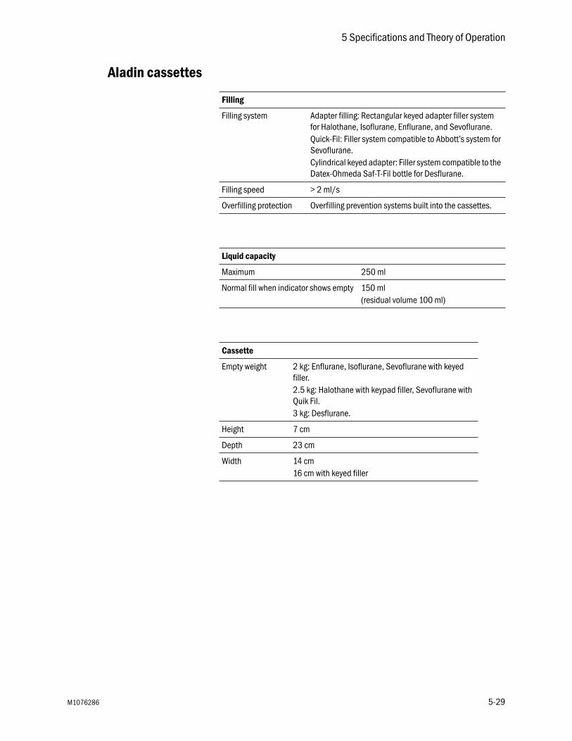
5 Specifications and Theory of Operation
Aladin cassettes
Filling
Filling system Adapter filling: Rectangular keyed adapter filler system for Halothane, Isoflurane, Enflurane, and Sevoflurane.Quick-Fil: Filler system compatible to Abbott’s system for Sevoflurane.Cylindrical keyed adapter: Filler system compatible to the Datex-Ohmeda Saf-T-Fil bottle for Desflurane.
Filling speed > 2 ml/s
Overfilling protection Overfilling prevention systems built into the cassettes.
Liquid capacity
Maximum 250 ml
Normal fill when indicator shows empty 150 ml (residual volume 100 ml)
Cassette
Empty weight 2 kg: Enflurane, Isoflurane, Sevoflurane with keyed filler.2.5 kg: Halothane with keypad filler, Sevoflurane with Quik Fil.3 kg: Desflurane.
Height 7 cm
Depth 23 cm
Width 14 cm16 cm with keyed filler
M1076286 5-29

Aisys Carestation
Electromagnetic compatibility (EMC)
Changes or modifications to this equipment not expressly approved by Datex-Ohmeda could cause EMC issues with this or other equipment. Contact Datex-Ohmeda for assistance. This device is designed and tested to comply with applicable regulations regarding EMC as follows.
WARNING Use of portable phones or other radio frequency (RF) emitting equipment near the system may cause unexpected or adverse operation. Monitor operation when RF emitters are in the vicinity.
w Use of other electrical equipment on or near this system may cause interference. Verify normal operation of equipment in your configuration before use on patients.
Guidance andmanufacturer's
declaration -electromagnetic
emissions
The system is suitable for use in the specified electromagnetic environment. The customer and/or the user of the system should assure that it is used in an electromagnetic environment as described below.
Emissions test Compliance Electromagnetic environment guidance
RF emissionsCISPR 11
Group 1 The system uses RF energy only for its internal function. Therefore, its RF emissions are very low and are not likely to cause any interference in nearby electronic equipment.
RF emissionsCISPR 11
Class B The system is suitable for use in all establishments, including domestic establishments and those directly connected to the public low-voltage power supply network that supplies buildings used for domestic purposes.
Harmonic emissionsIEC 61000-3-2 Class A
Class A
Voltage fluctuations/flicker emissionsIEC 61000-3-3
Complies
5-30 M1076286

5 Specifications and Theory of Operation
Guidance andmanufacturer's
declaration -electromagnetic
immunity
The system is suitable for use in the specified electromagnetic environment. The customer and/or the user of the system should assure that it is used in an electromagnetic environment as described below.
Power immunity
Immunity test IEC 60601-1-2 test level Compliance level Electromagnetic environment guidance
Electrostatic discharge (ESD) IEC 61000-4-2
± 6 kV contact± 8 kV air
± 6 kV contact± 8 kV air
Floors should be wood, concrete, or ceramic tile. If floors are covered with synthetic material, the relative humidity should be at least 30%.
Electrical fast transient/burst IEC 61000-4-4
± 2 kV for power supply lines±1 kV for input/output lines
± 2 kV for power supply lines±1 kV for input/output lines
Mains power quality should be that of a typical commercial and/or hospital environment.
Surge IEC 61000-4-5
± 1 kV differential mode±2 kV common mode
± 1 kV differential mode±2 kV common mode
Mains power quality should be that of a typical commercial and/or hospital environment.
Voltage dips, short interruptions and voltage variations on power supply input linesIEC 61000-4-11
< 5% UT (> 95% dip in UT) for 0.5 cycle40% UT (60% dip in UT) for 5 cycles70% UT (30% dip in UT) for 25 cycles< 5% UT (> 95% dip in UT) for 5 sec.
< 5% UT (> 95% dip in UT) for 0.5 cycle40% UT (60% dip in UT) for 5 cycles70% UT (30% dip in UT) for 25 cycles< 5% UT (> 95% dip in UT) for 5 sec.
Mains power quality should be that of a typical commercial and/or hospital environment. If the user of the system requires continued operation during power mains interruptions, it is recommended that the system be powered from an uninterruptible power supply or a battery.
Power frequency (50/60 Hz) magnetic fieldIEC 61000-4-8 3
3 A/m 3 A/m If display distortion or other abnormalities occur, it may be necessary to position the Anaesthetic System further from sources of power frequency magnetic fields or to install magnetic shielding. The power frequency magnetic field should be measured in the intended installation location to assure that it is sufficiently low.
Note: UT is the AC mains voltage before application of the test level.
M1076286 5-31
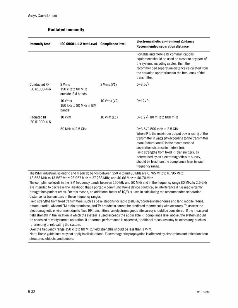
Aisys Carestation
Radiated immunity
Immunity test IEC 60601-1-2 test Level Compliance levelElectromagnetic environment guidanceRecommended separation distance
Portable and mobile RF communications equipment should be used no closer to any part of the system, including cables, than the recommended separation distance calculated from the equation appropriate for the frequency of the transmitter.
Conducted RFIEC 61000-4-6
3 Vrms150 kHz to 80 MHz outside ISM bands
3 Vrms (V1) D=3.5√P
10 Vrms150 kHz to 80 MHz in ISM bands
10 Vrms (V2) D=12√P
Radiated RFIEC 61000-4-6
10 V/m 10 V/m (E1) D=1.2√P 80 mHz to 800 mHz
80 MHz to 2.5 GHz D=3.5√P 800 mHz to 2.5 GHzWhere P is the maximum output power rating of the transmitter in watts (W) according to the transmitter manufacturer and D is the recommended separation distance in meters (m).Field strengths from fixed RF transmitters, as determined by an electromagnetic site survey, should be less than the compliance level in each frequency range.
The ISM (industrial, scientific and medical) bands between 150 kHz and 80 MHz are 6.765 MHz to 6.795 MHz;13.553 MHz to 13.567 MHz; 26.957 MHz to 27.283 MHz; and 40.66 MHz to 40.70 MHz.The compliance levels in the ISM frequency bands between 150 kHz and 80 MHz and in the frequency range 80 MHz to 2.5 GHz are intended to decrease the likelihood that a portable communications device could cause interference if it is inadvertently brought into patient areas. For this reason, an additional factor of 10/3 is used in calculating the recommended separation distance for transmitters in these frequency ranges.Field strengths from fixed transmitters, such as base stations for radio (cellular/cordless) telephones and land mobile radios, amateur radio, AM and FM radio broadcast, and TV broadcast cannot be predicted theoretically with accuracy. To assess the electromagnetic environment due to fixed RF transmitters, an electromagnetic site survey should be considered. If the measured field strength in the location in which the system is used exceeds the applicable RF compliance level above, the system should be observed to verify normal operation. If abnormal performance is observed, additional measures may be necessary, such as re-orienting or relocating the system.Over the frequency range 150 kHz to 80 MHz, field strengths should be less than 1 V/m.Note: These guidelines may not apply in all situations. Electromagnetic propagation is affected by absorption and reflection from structures, objects, and people.
5-32 M1076286

5 Specifications and Theory of Operation
Recommendedseparation distances
The system is intended for use in the electromagnetic environment in which radiated RF disturbances are controlled. The customer or the user of the system can help prevent electromagnetic interference by maintaining a minimum distance between portable and mobile RF communications equipment (transmitters) and the system as recommended below, according to the maximum power of the communications equipment.
Rated maximum output power of transmitterwatts (W)
Separation distance in meters (m) according to frequency of the transmitter
150 kHz to 80 MHzOutside ISM bands
150 kHz to 80 MHzIn ISM bands
80 MHz to 800 MHz 800 MHz to 2.5 GHz
0.01 0.35 1.2 0.12 0.23
0.1 1.1 3.8 0.38 0.73
1 3.5 12 1.2 2.3
10 11 38 3.8 7.3
100 35 120 12 23
For transmitters rated at a maximum output power not listed above, the recommended separation distance D in meters (m) can be determined using the equation applicable to the frequency of the transmitter, where P is the maximum output power rating of the transmitter in watts (W) according to the transmitter manufacturer.
Note 1: At 80 MHz to 800 MHz the separation distance for the higher frequency range applies.
Note 2: The ISM (Industrial, Scientific and Medical) bands between 150 kHz and 80 MHz are 6.765 MHz to 6.795 MHz; 13.553 MHz to 13.567 MHz; 26.957 MHz to 27.283 MHz; and 40.66 MHz to 40.70 MHz.
Note 3: An additional factor of 10/3 is used in calculating the recommended separation distance for transmitters in the ISM frequency bands between 150 kHz and 80 MHz and in the frequency range 80 MHz to 2.5 GHz to decrease the likelihood that mobile/portable communications equipment could cause interference if it is inadvertently brought into patient areas.
Note 4: These guidelines may not apply in all situations. Electromagnetic propagation is affected by absorption and reflection from structures, objects, and people.
M1076286 5-33

Aisys Carestation
Electrical safety
The system provides connections for items such as printers, visual displays and hospital information networks. When these items (non-medical equipment) are combined with the system, these precautions must be followed:
• Don’t place items not approved to IEC 60601-1 closer than 1.5 m to the patient.
• All items (medical electrical equipment or non-medical electrical equipment) connected to the system by a signal input/signal output cable must be supplied from an AC power source which uses a separating transformer (in accordance with IEC 60989) or be provided with an additional protective earth conductor.
• If a portable multiple socket outlet assembly is used as an AC power source, it must comply with IEC 60601-1. The assembly must not be placed on the floor. Using more than one portable multiple socket outlet assembly is not recommended. Using an extension cord is not recommended.
Do not connect non-medical electrical equipment directly to the AC outlet at the wall instead of an AC power source which uses a separating transformer. Doing so may increase enclosure leakage current above levels allowed by IEC 60601-1 in normal conditions and under single-fault conditions. This may cause an unsafe electrical shock to the patient or operator.
After connecting anything to these outlets, conduct a complete system leakage current test (according to IEC 60601-1).
WARNING An operator of the medical electrical system must not touch non-medical electrical equipment and the patient simultaneously. This may cause an unsafe electrical shock to the patient.
IEC-60601-1 Classification
The system is classified as follows.
• Class I equipment.
• Type B equipment.
• Type BF equipment.
• Ordinary equipment.
• Not for use with flammable anesthetics.
• Continuous operation.
5-34 M1076286
6 Super User Mode
In this section Install/Service menu . . . . . . . . . . . . . . . . . . . . . . . . . . . . . . . . . . . . . . . . . . . . 6-2
Menus . . . . . . . . . . . . . . . . . . . . . . . . . . . . . . . . . . . . . . . . . . . . . . . . . . . . . . . 6-4
M1076286 6-1

Aisys Carestation
Install/Service menu
WARNING Do not enter the Install/Service menu when a patient is connected to the system. Gas flow will cease, and the system must be powered down in order to restart gas flow.
Important Changes made in the super user mode will affect the system configuration. All changes made are permanent and preserved until changed again.
Several settings can be changed in the super user mode. These changes should only be made by the person responsible for the configuration of the system.
The Installation and Service menus are password protected.
The system must be turned off in order to exit the Install/Service menu. Go to Main Menu - Screen Setup - Install Service. Enter the password16, 4, 34.
Install/Service - Page 1
Trends SetupColors and Units
Cumulative Gas UsageShow Alarm Limits Yes Yes or No
External Gas Monitor Yes Yes or NoSave Default Case
Factory DefaultsParameter Settings
Install/Service - Page 2Exit
Install/Service - Page 2
Fresh Gas Controls O2% O2%, Flow, UserVCV Cardiac Bypass No Yes or No
InstallationService
Install/Service - Page 1Exit
6-2 M1076286
6 Super User Mode
Using super user mode Set the Default Trend and configure the graphic trend pages through the Trends Setup menu.
Set the colors and the units of parameters through the Colors and Units menu.
View the gas used and reset the gas usage in the Cumulative Gas Usage menu. Select Reset Usage to set all cumulative agent totals to 0.0, all cumulate gas usage to 0, and to set the displayed date to the current date in the inactive right column.
Set Show Alarm Limits to Yes display the alarm limits next to the measured values on the normal screen.
Set the External Gas Monitor to Yes only if the system uses a stand-alone monitor for O2, agent, and CO2. Selecting Yes will disable the O2 limit alarms and the ‘O2 monitoring not connected’ alarm when there is no O2 cell or airway module detected in the system. The ‘AA, CO2 monitoring not connected’ alarm will also be disabled.
Select Save Default Case to save the air, N2O, circuit, ventilator settings, and alarms settings from the last case as defaults.
Factory defaults are the settings installed by the manufacturer. These cannot be changed. To return the system to the factory defaults, select Factory Defaults.
Set the volume conditions and the CO2 humidity compensation through the Parameters Setup menu. Set the volume calculation conditions to be based on ATPD (ambient temperature and pressure, dry humidity conditions) or BTPS (body temperature, ambient pressure, saturated humidity condition). Set the humidity compensation type in CO2 partial pressure values to wet or dry.
M1076286 6-3

Aisys Carestation
Menus
The following is a list of the menu selections available.
Not all menu items are available depending on the system configuration. Inactive menu items are grayed out and are not selectable.
Menu selections shown are the factory default values. The options are listed to the right of the menu shown.
*The Field 1, Field 2, and Field 3 selections are the same for all fields.
Trends Setup
Default Trend Num Num, Graph, SetGraphical Trends
Previous Menu
Graphical Trends
Page 1Page 2Page 3Page 4Page 5
Previous Menu
Page 1
Field 1 Pres * Off, Pres, MVexp, CO2, O2, Bal, AA1, AA2, MAC, N2O, TVexp, Spont, Pmean, rr+co2, Compl, VO2
Field 2 TVexpField 3 CO2
Previous Menu
6-4 M1076286
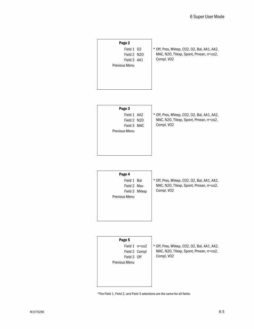
6 Super User Mode
*The Field 1, Field 2, and Field 3 selections are the same for all fields.
Page 2
Field 1 O2 * Off, Pres, MVexp, CO2, O2, Bal, AA1, AA2, MAC, N2O, TVexp, Spont, Pmean, rr+co2, Compl, VO2
Field 2 N2OField 3 AA1
Previous Menu
Page 3
Field 1 AA2 * Off, Pres, MVexp, CO2, O2, Bal, AA1, AA2, MAC, N2O, TVexp, Spont, Pmean, rr+co2, Compl, VO2
Field 2 N2OField 3 MAC
Previous Menu
Page 4
Field 1 Bal * Off, Pres, MVexp, CO2, O2, Bal, AA1, AA2, MAC, N2O, TVexp, Spont, Pmean, rr+co2, Compl, VO2
Field 2 MacField 3 MVexp
Previous Menu
Page 5
Field 1 rr+co2 * Off, Pres, MVexp, CO2, O2, Bal, AA1, AA2, MAC, N2O, TVexp, Spont, Pmean, rr+co2, Compl, VO2
Field 2 ComplField 3 Off
Previous Menu
M1076286 6-5

Aisys Carestation
Colors and Units
ColorsWeight kg kg or lb
CO2 % %, kPa or mmHgGas Supply Pressure kPa psi, kPa or bar
Paw cmH2O kPa, hPa, cmH2O, mmHg or mbarPrevious Menu
Colors
Paw Yellow Yellow, White, Green, Red or BlueFlow Green Yellow, White, Green, Red or BlueResp White Yellow, White, Green, Red or BlueCO2 White Yellow, White, Green, Red or Blue
Previous Menu
Cumulative Gas Usage
Reset UsageDesflurane
EnfluraneHalothaneIsoflurane
SevofluraneO2 (*1000)Air (*1000)
N2O (*1000)Previous Menu
Parameter Settings
TV Based on ATPD ATPD or BTPSCO2 Numbers Dry Dry or Wet
Previous Menu
6-6 M1076286

Warranty
This Product is sold by Datex-Ohmeda under the warranties set forth in the following paragraphs. Such warranties are extended only with respect to the purchase of this Product directly from Datex-Ohmeda or Datex-Ohmeda’s Authorized Dealers as new merchandise and are extended to the Buyer thereof, other than for the purpose of resale.
For a period of twelve (12) months from the date of original delivery to Buyer or to Buyer’s order, but in no event for a period of more than two years from the date of original delivery by Datex-Ohmeda to a Datex-Ohmeda Authorized Dealer, this Product, other than its expendable parts, is warranted against functional defects in materials and workmanship and to conform to the description of the Product contained in this User’s Reference manual and accompanying labels and/or inserts, provided that the same is properly operated under the conditions of normal use, that regular periodic maintenance and service is performed and that replacements and repairs are made in accordance with the instructions provided. This same warranty is made for a period of thirty (30) days with respect to expendable parts. The foregoing warranties shall not apply if the Product has been repaired other than by Datex-Ohmeda or in accordance with written instructions provided by Datex-Ohmeda, or altered by anyone other than Datex-Ohmeda, or if the Product has been subject to abuse, misuse, negligence, or accident.
Datex-Ohmeda’s sole and exclusive obligation and Buyer’s sole and exclusive remedy under the above warranties is limited to repairing or replacing, free of charge, at Datex-Ohmeda’s option, a Product, which is telephonically reported to the nearest Datex-Ohmeda Customer Service Center and which, if so advised by Datex-Ohmeda, is thereafter returned with a statement of the observed deficiency, not later than seven (7) days after the expiration date of the applicable warranty, to the Datex-Ohmeda Customer Service and Distribution Center during normal business hours, transportation charges prepaid, and which, upon Datex-Ohmeda’s examination, is found not to conform with above warranties. Datex-Ohmeda shall not be otherwise liable for any damages including but not limited to incidental damages, consequential damages, or special damages.
There are no express or implied warranties which extend beyond the warranties hereinabove set forth. Datex-Ohmeda makes no warranty of merchantability or fitness for a particular purpose with respect to the product or parts thereof.

Index
A
Absorber canister 2-30, 4-5cleaning 2-30disinfection 2-30filling 1-6removing 1-5setup 1-3
AGSSremove receiver 2-27remove receiver filter 2-29
B
Backlight test 3-6Bellows assembly
assemble 2-17disassemble 2-15test 2-19
Breathing systemassembly 2-21cleanable parts 2-3disassembly 2-9installing 2-26removal 2-8remove bag hose 2-8specifications 5-11
C
Calibration100% O2 3-521% O2 3-5backlight test 3-6O2 cell 3-5
Circuitnon-circle relief 5-6
Cleaningcautions 2-2
Condenser cleaning 2-31Connections
electrical 1-8pneumatic 1-10
Cylinderinstallation 1-13
E
Electromagnetic compatibility 5-30EZchange Canister
removal 1-5
F
Flow sensors 2-3, 4-2cleaning and disinfection 2-5prevent water buildup 3-6
I
Install/Servicemenu 6-2password 6-2
M
Mains inlet 1-8Maintenance schedule 3-2
O
O2 cellcalibration 3-5replacement 3-4
P
Pneumaticconnections 1-10specifications 5-5system pneumatic circuits 5-2
R
Repair policy 3-2
S
Scavenging 1-10specifications 5-13
Serial port 1-9
M1076286 I-1

Aisys Carestation
Specificationsairway module 5-14breathing system 5-11flow 5-10gas 5-14physical 5-13pneumatic 5-5ventilation operating 5-24
Suction regulator 1-12Super User mode 6-1
V
Ventilation modes 5-17pressure control 5-18PSVPro 5-20SIMV/PSV 5-19SIMV-PC 5-22volume control 5-17
Ventilatoraccuracy data 5-26modes 5-17operating specifications 5-24theory 5-16
W
Water buildupprevention 3-6
I-2 M1076286

AisysUser’s Reference Manual EnglishM107628605 06 18 05 02Printed in USA©Datex-Ohmeda, Inc. All rights reserved
Related Documents


