For the calibrations to which this accreditation applies, please refer to the laboratory’s Calibration Scope of Accreditation. Accredited Laboratory A2LA has accredited PRECISION METROLOGY, INC. Milwaukee, WI for technical competence in the field of Calibration This laboratory is accredited in accordance with the recognized International Standard ISO/IEC 17025:2005 General requirements for the competence of testing and calibration laboratories. This laboratory also meets the requirements of ANSI/NCSLI Z540-1-1994 and R205 – Specific Requirements: Calibration Laboratory Accreditation Program. This accreditation demonstrates technical competence for a defined scope and the operation of a laboratory quality management system (refer to joint ISO-ILAC-IAF Communiqué dated 8 January 2009). Presented this 4 th day of December 2017. _______________________ President and CEO For the Accreditation Council Certificate Number 1078.01 Valid to January 31, 2019

Welcome message from author
This document is posted to help you gain knowledge. Please leave a comment to let me know what you think about it! Share it to your friends and learn new things together.
Transcript
For the calibrations to which this accreditation applies, please refer to the laboratory’s Calibration Scope of Accreditation.
Accredited Laboratory
A2LA has accredited
PRECISION METROLOGY, INC. Milwaukee, WI
for technical competence in the field of
Calibration
This laboratory is accredited in accordance with the recognized International Standard ISO/IEC 17025:2005 General
requirements for the competence of testing and calibration laboratories. This laboratory also meets the requirements of
ANSI/NCSLI Z540-1-1994 and R205 – Specific Requirements: Calibration Laboratory Accreditation Program. This accreditation
demonstrates technical competence for a defined scope and the operation of a laboratory quality management system (refer to
joint ISO-ILAC-IAF Communiqué dated 8 January 2009).
Presented this 4th day of December 2017.
_______________________
President and CEO
For the Accreditation Council
Certificate Number 1078.01
Valid to January 31, 2019

(A2LA Cert. No. 1078.01) 12/04/2017 Page 1 of 48
SCOPE OF ACCREDITATION TO ISO/IEC 17025:2005 & ANSI/NCSL Z540-1-1994
PRECISION METROLOGY, INC.10
7350 North Teutonia Avenue Milwaukee, WI 53209
Carol Shipley Phone: 414 351 7420
CALIBRATION
Valid To: January 31, 2019 Certificate Number: 1078.01 In recognition of the successful completion of the A2LA evaluation process, accreditation is granted to this laboratory to perform the following calibrations1, 10: I. Acoustical Quantities
Parameter/Equipment
Range
CMC2, 8 ()
Comments
Sound Level
Source Measure (Meters)
(85 to 140) dB (20 to 140) dB
0.20 dB + 0.032 % 0.32 dB
Piston phone, transducer Sound level calibrator
Sound Level3
Source/Measure (Meters)
(20 to 140) dB
0.60 dB
Sound level calibrator
II. Chemical
Parameter/Equipment
Range
CMC2, 4 ()
Comments
Conductivity Meters
10 µS/cm 100 µS/cm 1000 µS/cm 1400 µS/cm 10 000 µS/cm
0.68 µS/cm + 0.6R 1.2 µS/cm + 0.6R 4.5 µS/cm + 0.6R 6.9 µS/cm + 0.6R 55 µS/cm + 0.6R
Conductivity solutions

(A2LA Cert. No. 1078.01) 12/04/2017 Page 2 of 48
Parameter/Equipment
Range
CMC2 ()
Comments
pH Meters3
4 pH 7 pH 10 pH
0.014 pH 0.014 pH 0.014 pH
Standard buffers
III. Dimensional
Parameter/Equipment
Range
CMC2, 4 ()
Comments
Angle Blocks
Up to 60
(0.36 + 1.1 *Ө/20) arcsec,
Sine bar, gage blocks, gage amp & probe, Where Ө = angle
Angle Plates3
Up to 30 in
(120 + 6H) µin
Gage amp. probe, indi-square and test indicator
Arbor – Straightness
Up to 24 in
(35 + 9L) µin
Gage amp w/probe
Articulating Arm3 (CMM) –
Single Point Articulation Max Deviation 2sSPAT
Effective Diameter Volumetric
Max Deviation Range 2RMS
(2 to 10.5) ft 1 in (25.4 mm) (16 to 36) in (52 to 76) in (16 to 36) in (52 to 76) in (16 to 76) in
110 µin (2.8µm) 22 µin (0.56 µm) 82 µin (2.1 µm) 60 µin + 7.5 µin/in 60 µin + 7.0 µin/in 85 µin + 11 µin/in 85 µin + 9.9 µin/in 0.98 µin/in
ASME B89.4.22-2004
Bench Center –
Center Parallelism Base Flatness & Base Parallelism
Up to 24 in Up to 24 in
(68 + 4L) µin (62 +2.5L) µin
Gage amp w/probe
(A2LA Cert. No. 1078.01) 12/04/2017 Page 3 of 48
Parameter/Equipment
Range
CMC2, 4 ()
Comments
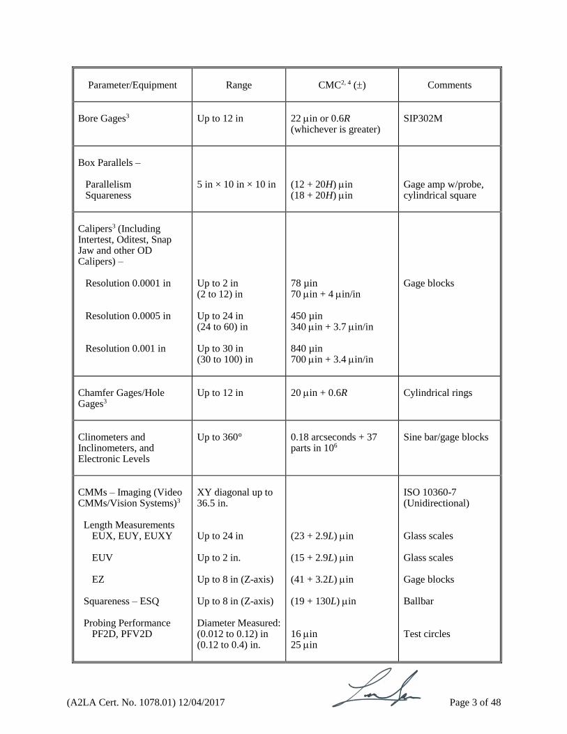
Bore Gages3
Up to 12 in
22 in or 0.6R (whichever is greater)
SIP302M
Box Parallels –
Parallelism Squareness
5 in × 10 in × 10 in
(12 + 20H) in (18 + 20H) in
Gage amp w/probe, cylindrical square
Calipers3 (Including Intertest, Oditest, Snap Jaw and other OD Calipers) –
Resolution 0.0001 in Resolution 0.0005 in Resolution 0.001 in
Up to 2 in (2 to 12) in Up to 24 in (24 to 60) in Up to 30 in (30 to 100) in
78 µin 70 in + 4 in/in 450 µin 340 in + 3.7 in/in 840 µin 700 in + 3.4 in/in
Gage blocks
Chamfer Gages/Hole Gages3
Up to 12 in
20 in + 0.6R
Cylindrical rings
Clinometers and Inclinometers, and Electronic Levels
Up to 360°
0.18 arcseconds + 37 parts in 106
Sine bar/gage blocks
CMMs – Imaging (Video CMMs/Vision Systems)3
Length Measurements EUX, EUY, EUXY EUV EZ
Squareness – ESQ
Probing Performance
PF2D, PFV2D
XY diagonal up to 36.5 in. Up to 24 in Up to 2 in. Up to 8 in (Z-axis) Up to 8 in (Z-axis) Diameter Measured: (0.012 to 0.12) in (0.12 to 0.4) in.
(23 + 2.9L) in (15 + 2.9L) in (41 + 3.2L) in (19 + 130L) in 16 in 25 in
ISO 10360-7 (Unidirectional) Glass scales Glass scales Gage blocks Ballbar Test circles

(A2LA Cert. No. 1078.01) 12/04/2017 Page 4 of 48
Parameter/Equipment
Range
CMC2, 4 ()
Comments
CMMs3 –
Length Error (EL) Repeatability Range (R0) Length Volume Probing Analysis Bi-directional
Up to 52 in Up to 52 in Up to 114 in on each axis Up to 36 in for shortest axis Up to 30 in
38 in + 5.2 in/in 22 in + 3 in/in 38 in + 5.2 in/in 82 in + 13 in/in 2 µm (40 + 10L) µin
ASME B89.4.1.10360.2 ASME B89.4.1.2000 Ball bar Test probe
Coating Thickness Shims/Precision Shims
25 µin to 0.5 in
19 µin + 82 µin/in
Heidenhain-Certo CT 6001
Concentricity Gage
N/A
130 in + 8 μin/in
Indicator, bench center
Cylindrical Plugs3
Up to 4 in (4 to 8.5) in (8.5 to 20) in
4 in + 5 in/in 4 in + 5.4 in/in 5.2 in + 5.5 in/in
ULM, gage blocks
Cylindrical Rings3
(0.1 to 8.5) in (8.5 to 18) in (18 to 36) in
(11 + 3.3D) µin (13 + 3.3 D) µin (50 + 3D) µin
ULM, gage blocks
Cylindrical Squares
Up to 12 in
(13 + 9H) in
Gage amp w/probe; H is the height of the cylinder from the base in inches.
External Spline Gages3 –
Measurement Over Pins Circular Tooth Thickness Major Diameter
Up to 8 in Up to 8 in Up to 8 in Up to 8 in
(170 + 28D) in (110 + 16L) µin (28 + 12D) in
UMM Optical comparator UMM
(A2LA Cert. No. 1078.01) 12/04/2017 Page 5 of 48
Parameter/Equipment
Range
CMC2, 4 ()
Comments
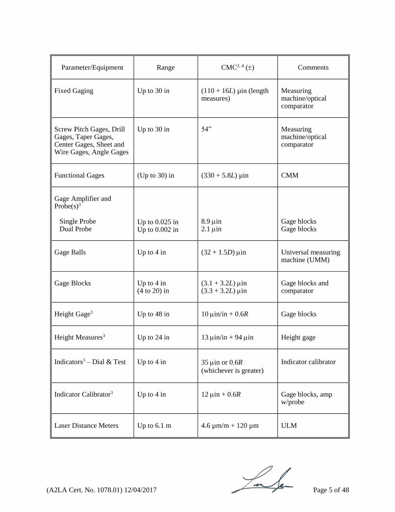
Fixed Gaging
Up to 30 in
(110 + 16L) µin (length measures)
Measuring machine/optical comparator
Screw Pitch Gages, Drill Gages, Taper Gages, Center Gages, Sheet and Wire Gages, Angle Gages
Up to 30 in
54”
Measuring machine/optical comparator
Functional Gages
(Up to 30) in
(330 + 5.8L) µin
CMM
Gage Amplifier and Probe(s)3
Single Probe Dual Probe
Up to 0.025 in Up to 0.002 in
8.9 in 2.1 in
Gage blocks Gage blocks
Gage Balls
Up to 4 in
(32 + 1.5D) in
Universal measuring machine (UMM)
Gage Blocks
Up to 4 in (4 to 20) in
(3.1 + 3.2L) in (3.3 + 3.2L) in
Gage blocks and comparator
Height Gage3
Up to 48 in
10 in/in + 0.6R
Gage blocks
Height Measures3
Up to 24 in
13 in/in + 94 in
Height gage
Indicators3 – Dial & Test
Up to 4 in
35 in or 0.6R
(whichever is greater)
Indicator calibrator
Indicator Calibrator3
Up to 4 in
12 in + 0.6R
Gage blocks, amp w/probe
Laser Distance Meters
Up to 6.1 m
4.6 µm/m + 120 µm
ULM

(A2LA Cert. No. 1078.01) 12/04/2017 Page 6 of 48
Parameter/Equipment
Range
CMC2, 4, 8 ()
Comments
Length & Thickness Standards, Feeler Gages3 –
Steel Field Calibration
Up to 4 in (4 to 8.5) in (8.5 to 20) in (20 to 120) in Up to 16 in
4 in + 5 in/in 4 in + 5.4 in/in 5.2 µin + 5.5 µin/in 3.7 µin/in + 14 µin 5 µin + 14 µin/in + 4 in/in/°C
ULM, gage blocks ULM ULM, gage blocks, Relative to 20/°C
Levels (Spirit, Bubble, Machinist)3
Up to 96 in
5.1 arcseconds + 37 ppm
Surface plate and gage blocks
Linear Measurement of Machine Tools (ULMs)3
Up to 20 ft
1.5 μin/in + 0.58 μin
Laser
Linear Scales/Reticles and Stage Micrometers –
2D 1D
Up to 12 in Up to 30 in
(115 + 15L) in 11 in + 1.5 in/in
Vision system Gitterperioden interferometer
Micrometers3 –
Inside Depth Tri-Bores Outside Groove Bench Thread (Screw, Thread, Pitch, Point)
Up to 294 in Up to 12 in Up to 11 in Up to 42 in Up to 4 in Up to 42 in Up to 4 in
12 in + 7 in /in + 0.2R 18 in/in + 0.64R 18 in/in + 0.7R 18 in/in + 0.64R 18 in/in + 0.64R 18 in/in + 0.64R 18 in/in + 0.64R
ULM, gage blocks or rings
Microscopes3 –
Reticule Magnification
Up to 25 mm Up to 1000x
23 m 2.4 %
Stage micrometer
(A2LA Cert. No. 1078.01) 12/04/2017 Page 7 of 48
Parameter/Equipment
Range
CMC2, 4 ()
Comments
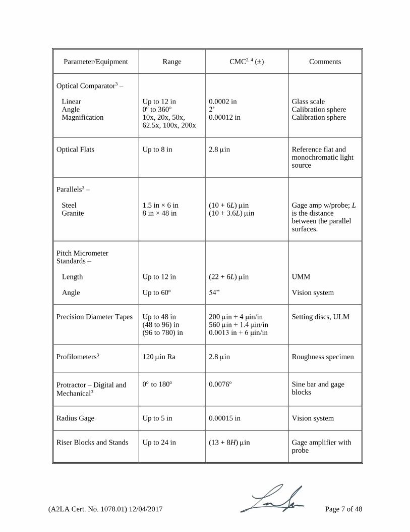
Optical Comparator3 –
Linear Angle Magnification
Up to 12 in 0º to 360 10x, 20x, 50x, 62.5x, 100x, 200x
0.0002 in 2’ 0.00012 in
Glass scale Calibration sphere Calibration sphere
Optical Flats
Up to 8 in
2.8 in
Reference flat and monochromatic light source
Parallels3 –
Steel Granite
1.5 in × 6 in 8 in × 48 in
(10 + 6L) in (10 + 3.6L) in
Gage amp w/probe; L is the distance between the parallel surfaces.
Pitch Micrometer Standards – Length Angle
Up to 12 in Up to 60
(22 + 6L) in 54”
UMM Vision system
Precision Diameter Tapes
Up to 48 in (48 to 96) in (96 to 780) in
200 in + 4 μin/in 560 in + 1.4 μin/in 0.0013 in + 6 μin/in
Setting discs, ULM
Profilometers3
120 in Ra
2.8 in
Roughness specimen
Protractor – Digital and
Mechanical3
0 to 180
0.0076º
Sine bar and gage blocks
Radius Gage
Up to 5 in
0.00015 in
Vision system
Riser Blocks and Stands
Up to 24 in
(13 + 8H) in
Gage amplifier with probe

(A2LA Cert. No. 1078.01) 12/04/2017 Page 8 of 48
Parameter/Equipment
Range
CMC2, 4 ()
Comments
Roundness (Test Circles)
(0.3 to 3.1) mm (3.1 to 10) mm
(0.16 + 0.08D) µm (0.53 + 0.006D) µm
Imaging CMM
Roundness Testers3 –
Coning Error Axial Error Radial Accuracy Z-Axis straightness
Up to 16 in Up to 16 in Up to 16 in (0.1 to 12) in
11 in 11 in 11 in (14 + 12H) in
Test ball and riser cylinder Test ball Test ball Cylindrical square; In the CMC, H is the height of the cylinder from the base in inches.
Rules/Scales3
Up to 100 in
(86 + 16L) in
UMM
Sine Plates/Bars3 –
Flatness/Parallelism & Parallelism Cylinder to Base Angle Calibration Center of Rolls
Up to 20 in 0º to 90º Up to 20 in
50 in 0.00045º 16 µin/in
Gage amp w/probe, angle blocks and gage blocks
Sand Sieves
20 µm to 125 mm
(3.2 + 6.9L) µm
ASTM E11, vision system
Snap Gages3
Up to 20 in
88 + 13L µin
Box parallel with gage amp and probe
Squares3 –
Master Granite Steel
Up to 30 in Up to 30 in Up to 30 in
(56 + 5H) µin (42 + 6H) in (42 + 6H) in
Gage amp and probe Indi-square and test indicator Master square and gage blocks
(A2LA Cert. No. 1078.01) 12/04/2017 Page 9 of 48
Parameter/Equipment
Range
CMC2, 4 ()
Comments
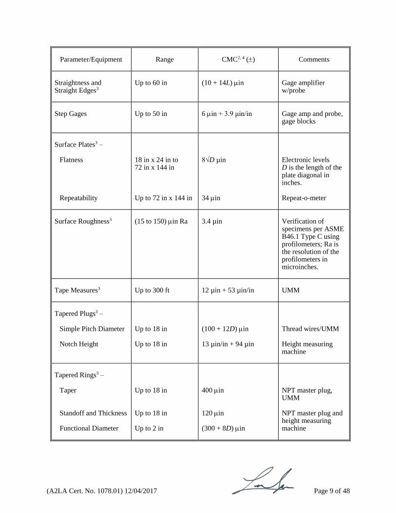
Straightness and Straight Edges3
Up to 60 in
(10 + 14L) in
Gage amplifier w/probe
Step Gages
Up to 50 in
6 in + 3.9 μin/in
Gage amp and probe, gage blocks
Surface Plates3 –
Flatness Repeatability
18 in x 24 in to 72 in x 144 in Up to 72 in x 144 in
8√D µin 34 in
Electronic levels D is the length of the plate diagonal in inches. Repeat-o-meter
Surface Roughness3
(15 to 150) in Ra
3.4 µin
Verification of specimens per ASME B46.1 Type C using profilometers; Ra is the resolution of the profilometers in microinches.
Tape Measures3
Up to 300 ft
12 µin + 53 µin/in
UMM
Tapered Plugs3 –
Simple Pitch Diameter Notch Height
Up to 18 in Up to 18 in
(100 + 12D) in 13 µin/in + 94 µin
Thread wires/UMM Height measuring machine
Tapered Rings3 –
Taper Standoff and Thickness
Functional Diameter
Up to 18 in Up to 18 in Up to 2 in
400 in 120 in (300 + 8D) in
NPT master plug, UMM NPT master plug and height measuring machine
(A2LA Cert. No. 1078.01) 12/04/2017 Page 10 of 48
Parameter/Equipment
Range
CMC2, 4 ()
Comments
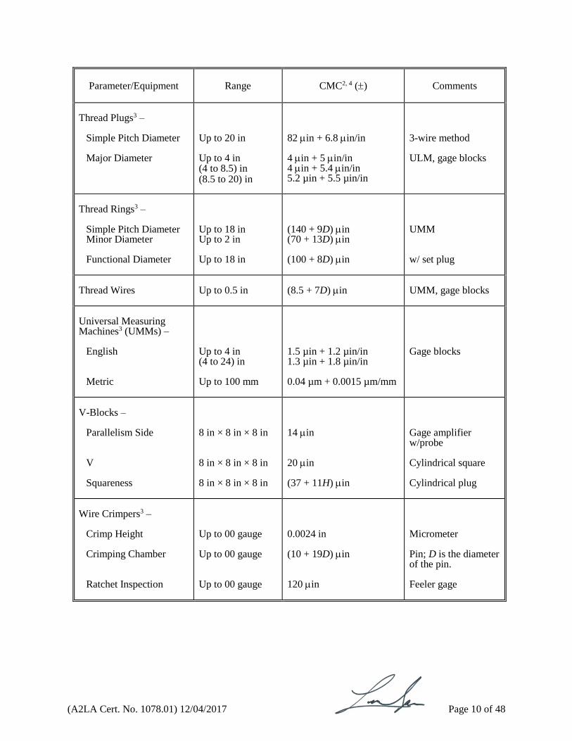
Thread Plugs3 –
Simple Pitch Diameter Major Diameter
Up to 20 in Up to 4 in (4 to 8.5) in (8.5 to 20) in
82 in + 6.8 in/in 4 in + 5 in/in 4 in + 5.4 in/in 5.2 µin + 5.5 µin/in
3-wire method ULM, gage blocks
Thread Rings3 –
Simple Pitch Diameter Minor Diameter Functional Diameter
Up to 18 in Up to 2 in Up to 18 in
(140 + 9D) in (70 + 13D) in (100 + 8D) in
UMM w/ set plug
Thread Wires
Up to 0.5 in
(8.5 + 7D) in
UMM, gage blocks
Universal Measuring Machines3 (UMMs) –
English Metric
Up to 4 in (4 to 24) in Up to 100 mm
1.5 µin + 1.2 µin/in 1.3 µin + 1.8 µin/in 0.04 µm + 0.0015 µm/mm
Gage blocks
V-Blocks –
Parallelism Side V Squareness
8 in × 8 in × 8 in 8 in × 8 in × 8 in 8 in × 8 in × 8 in
14 in 20 in (37 + 11H) in
Gage amplifier w/probe Cylindrical square Cylindrical plug
Wire Crimpers3 –
Crimp Height Crimping Chamber Ratchet Inspection
Up to 00 gauge Up to 00 gauge Up to 00 gauge
0.0024 in (10 + 19D) in 120 in
Micrometer Pin; D is the diameter of the pin. Feeler gage
(A2LA Cert. No. 1078.01) 12/04/2017 Page 11 of 48
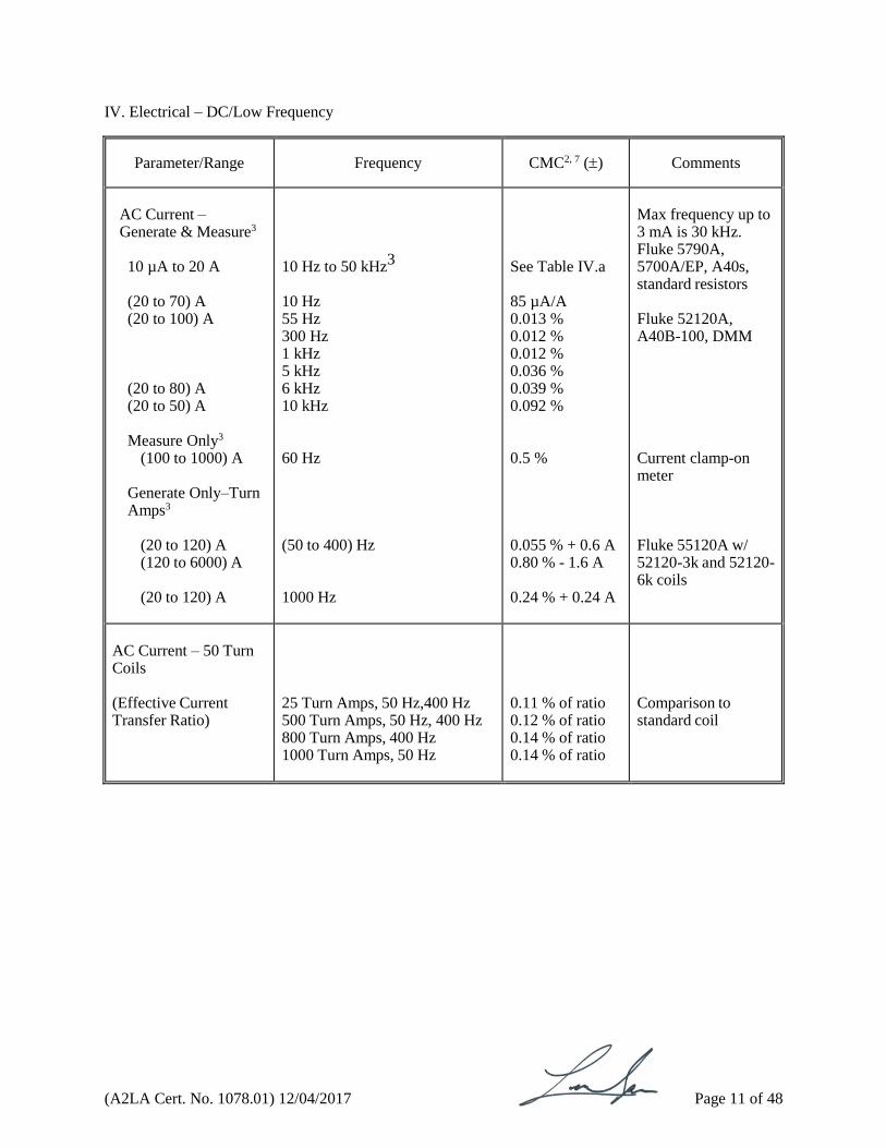
IV. Electrical – DC/Low Frequency
Parameter/Range
Frequency
CMC2, 7 ()
Comments
AC Current – Generate & Measure3
10 µA to 20 A (20 to 70) A (20 to 100) A (20 to 80) A (20 to 50) A
Measure Only3
(100 to 1000) A
Generate Only–Turn Amps3
(20 to 120) A (120 to 6000) A (20 to 120) A
10 Hz to 50 kHz3
10 Hz 55 Hz 300 Hz 1 kHz 5 kHz 6 kHz 10 kHz
60 Hz
(50 to 400) Hz
1000 Hz
See Table IV.a
85 µA/A 0.013 % 0.012 % 0.012 % 0.036 % 0.039 % 0.092 %
0.5 %
0.055 % + 0.6 A 0.80 % - 1.6 A 0.24 % + 0.24 A
Max frequency up to 3 mA is 30 kHz. Fluke 5790A, 5700A/EP, A40s, standard resistors Fluke 52120A, A40B-100, DMM Current clamp-on meter Fluke 55120A w/ 52120-3k and 52120- 6k coils
AC Current – 50 Turn Coils (Effective Current Transfer Ratio)
25 Turn Amps, 50 Hz,400 Hz 500 Turn Amps, 50 Hz, 400 Hz 800 Turn Amps, 400 Hz 1000 Turn Amps, 50 Hz
0.11 % of ratio 0.12 % of ratio 0.14 % of ratio 0.14 % of ratio
Comparison to standard coil
(A2LA Cert. No. 1078.01) 12/04/2017 Page 12 of 48
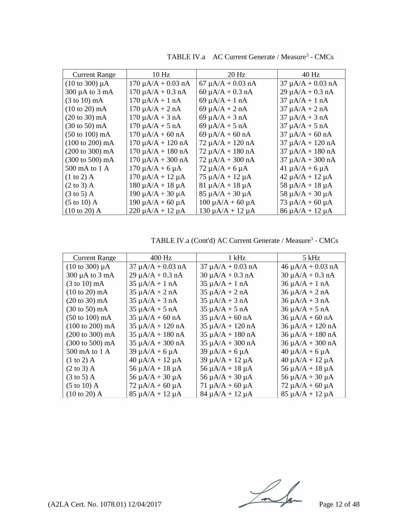
TABLE IV.a AC Current Generate / Measure3 - CMCs
Current Range 10 Hz 20 Hz 40 Hz
(10 to 300) µA 170 µA/A + 0.03 nA 67 µA/A + 0.03 nA 37 µA/A + 0.03 nA
300 µA to 3 mA 170 µA/A + 0.3 nA 60 µA/A + 0.3 nA 29 µA/A + 0.3 nA
(3 to 10) mA 170 µA/A + 1 nA 69 µA/A + 1 nA 37 µA/A + 1 nA
(10 to 20) mA 170 µA/A + 2 nA 69 µA/A + 2 nA 37 µA/A + 2 nA
(20 to 30) mA 170 µA/A + 3 nA 69 µA/A + 3 nA 37 µA/A + 3 nA
(30 to 50) mA 170 µA/A + 5 nA 69 µA/A + 5 nA 37 µA/A + 5 nA
(50 to 100) mA 170 µA/A + 60 nA 69 µA/A + 60 nA 37 µA/A + 60 nA
(100 to 200) mA 170 µA/A + 120 nA 72 µA/A + 120 nA 37 µA/A + 120 nA
(200 to 300) mA 170 µA/A + 180 nA 72 µA/A + 180 nA 37 µA/A + 180 nA
(300 to 500) mA 170 µA/A + 300 nA 72 µA/A + 300 nA 37 µA/A + 300 nA
500 mA to 1 A 170 µA/A + 6 µA 72 µA/A + 6 µA 41 µA/A + 6 µA
(1 to 2) A 170 µA/A + 12 µA 75 µA/A + 12 µA 42 µA/A + 12 µA
(2 to 3) A 180 µA/A + 18 µA 81 µA/A + 18 µA 58 µA/A + 18 µA
(3 to 5) A 190 µA/A + 30 µA 85 µA/A + 30 µA 58 µA/A + 30 µA
(5 to 10) A 190 µA/A + 60 µA 100 µA/A + 60 µA 73 µA/A + 60 µA
(10 to 20) A 220 µA/A + 12 µA 130 µA/A + 12 µA 86 µA/A + 12 µA
TABLE IV.a (Cont'd) AC Current Generate / Measure3 - CMCs
Current Range 400 Hz 1 kHz 5 kHz
(10 to 300) µA 37 µA/A + 0.03 nA 37 µA/A + 0.03 nA 46 µA/A + 0.03 nA 300 µA to 3 mA 29 µA/A + 0.3 nA 30 µA/A + 0.3 nA 30 µA/A + 0.3 nA (3 to 10) mA 35 µA/A + 1 nA 35 µA/A + 1 nA 36 µA/A + 1 nA (10 to 20) mA 35 µA/A + 2 nA 35 µA/A + 2 nA 36 µA/A + 2 nA (20 to 30) mA 35 µA/A + 3 nA 35 µA/A + 3 nA 36 µA/A + 3 nA (30 to 50) mA 35 µA/A + 5 nA 35 µA/A + 5 nA 36 µA/A + 5 nA (50 to 100) mA 35 µA/A + 60 nA 35 µA/A + 60 nA 36 µA/A + 60 nA (100 to 200) mA 35 µA/A + 120 nA 35 µA/A + 120 nA 36 µA/A + 120 nA (200 to 300) mA 35 µA/A + 180 nA 35 µA/A + 180 nA 36 µA/A + 180 nA (300 to 500) mA 35 µA/A + 300 nA 35 µA/A + 300 nA 36 µA/A + 300 nA 500 mA to 1 A 39 µA/A + 6 µA 39 µA/A + 6 µA 40 µA/A + 6 µA (1 to 2) A 40 µA/A + 12 µA 39 µA/A + 12 µA 40 µA/A + 12 µA (2 to 3) A 56 µA/A + 18 µA 56 µA/A + 18 µA 56 µA/A + 18 µA (3 to 5) A 56 µA/A + 30 µA 56 µA/A + 30 µA 56 µA/A + 30 µA (5 to 10) A 72 µA/A + 60 µA 71 µA/A + 60 µA 72 µA/A + 60 µA (10 to 20) A 85 µA/A + 12 µA 84 µA/A + 12 µA 85 µA/A + 12 µA

(A2LA Cert. No. 1078.01) 12/04/2017 Page 13 of 48
TABLE IV.a (Cont'd) AC Current Generate / Measure3 - CMCs
Parameter/Range
Frequency
CMC2, 6 ()
Comments
AC Power3 – Generate PF = 1
(29 to 330) µA (0.33 to 3.3) mA 3.3 mA to 3.3 A (29 to 330) µA (0.33 to 3.3) mA (3.3 to 330) mA 330 mA to 3 A (29 to 330) µA (0.33 to 3.3) mA (3.3 to 330) mA 330 mA to 1.1 A (1.1 to 3) A (3 to 11) A (11 to 20.5) A
(10 to 20) Hz 1 mV to 33 V (20 to 45) Hz 1 mV to 33 V (45 to 100) Hz 1 mV to 1020 V
0.19 % 0.17 % 0.15 % 0.15 % 0.11 % 0.080 % 0.15 % 0.13 % 0.088 % 0.041 % 0.052 % 0.054 % 0.065 % 0.12 %
Fluke 5520A
Current Range 10kHz 20kHz 50KHz
(10 to 300) µA 46 µA/A + 0.03 nA 62 µA/A + 0.03 nA 79 µA/A + 0.03 nA
300 µA to 3 mA 30 µA/A + 0.3 nA 45 µA/A + 0.3 nA 48 µA/A + 0.3 nA
(3 to 10) mA 36 µA/A + 1 nA 36 µA/A + 1 nA 60 µA/A + 1 nA
(10 to 20) mA 36 µA/A + 2 nA 36 µA/A + 2 nA 63 µA/A + 2 nA
(20 to 30) mA 36 µA/A + 3 nA 36 µA/A + 3 nA 63 µA/A + 3 nA
(30 to 50) mA 36 µA/A + 5 nA 36 µA/A + 5 nA 63 µA/A + 5 nA
(50 to 100) mA 36 µA/A + 60 nA 39 µA/A + 60 nA 68 µA/A + 60 nA
(100 to 200) mA 36 µA/A + 120 nA 39 µA/A + 120 nA 68 µA/A + 120 nA
(200 to 300) mA 36 µA/A + 180 nA 39 µA/A + 180 nA 72 µA/A + 180 nA
(300 to 500) mA 36 µA/A + 300 nA 39 µA/A + 300 nA 72 µA/A + 300 nA
500 mA to 1 A 40 µA/A + 6 µA 52 µA/A + 6 µA 110 µA/A + 6 µA
(1 to 2) A 40 µA/A + 12 µA 52 µA/A + 12 µA 110 µA/A + 12 µA
(2 to 3) A 56 µA/A + 18 µA 61 µA/A + 18 µA 120 µA/A + 18 µA
(3 to 5) A 56 µA/A + 30 µA 70 µA/A + 30 µA 160 µA/A + 30 µA
(5 to 10) A 72 µA/A + 60 µA 89 µA/A + 60 µA 130 µA/A + 60 µA
(10 to 20) A 85 µA/A + 12 µA 110 µA/A + 12 µA 150 µA/A + 12 µA
(A2LA Cert. No. 1078.01) 12/04/2017 Page 14 of 48
Parameter/Range
Frequency
CMC2, 6 ()
Comments
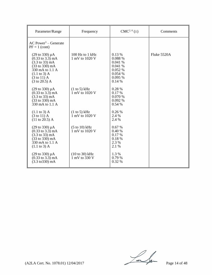
AC Power3 – Generate PF = 1 (cont)
(29 to 330) µA (0.33 to 3.3) mA (3.3 to 33) mA (33 to 330) mA 330 mA to 1.1 A (1.1 to 3) A (3 to 11) A (3 to 20.5) A (29 to 330) µA (0.33 to 3.3) mA (3.3 to 33) mA (33 to 330) mA 330 mA to 1.1 A (1.1 to 3) A (3 to 11) A (11 to 20.5) A (29 to 330) µA (0.33 to 3.3) mA (3.3 to 33) mA (33 to 330) mA 330 mA to 1.1 A (1.1 to 3) A (29 to 330) µA (0.33 to 3.3) mA (3.3 to330) mA
100 Hz to 1 kHz 1 mV to 1020 V (1 to 5) kHz 1 mV to 1020 V (1 to 5) kHz 1 mV to 1020 V (5 to 10) kHz 1 mV to 1020 V (10 to 30) kHz 1 mV to 330 V
0.13 % 0.088 % 0.041 % 0.041 % 0.052 % 0.054 % 0.095 % 0.14 % 0.28 % 0.17 % 0.070 % 0.092 % 0.54 % 0.26 % 2.4 % 2.4 % 0.67 % 0.40 % 0.17 % 0.18 % 2.3 % 2.1 % 1.3 % 0.79 % 0.32 %
Fluke 5520A

(A2LA Cert. No. 1078.01) 12/04/2017 Page 15 of 48
Parameter/Range
Frequency
CMC2, 7 ()
Comments
AC Voltage – Measure & Generate3
(0.6 to 2.2) mV (2.2 to 7) mV (7 to 22) mV
(22 to 70) mV (70 to 220) mV
(10 to 20) Hz (20 to 40) Hz 40 Hz to 20 kHz (20 to 50) kHz (50 to 100) kHz (100 to 300) kHz (300 to 500) kHz 500 kHz to 1 MHz (10 to 20) Hz (20 to 40) Hz 40 Hz to 20 kHz (20 to 50) kHz (50 to 100) kHz (100 to 300) kHz (300 to 500) kHz 500 kHz to 1 MHz (10 to 20) Hz (20 to 40) Hz 40 Hz to 20 kHz (20 to 50) kHz (50 to 100) kHz (100 to 300) kHz (300 to 500) kHz 500 kHz to 1 MHz (10 to 20) Hz (20 to 40) Hz 40 Hz to 20 kHz (20 to 50) kHz (50 to 100) kHz (100 to 300) kHz (300 to 500) kHz 500 kHz to 1 MHz (10 to 20) Hz (20 to 40) Hz 40 Hz to 20 kHz (20 to 50) kHz (50 to 100) kHz (100 to 300) kHz (300 to 500) kHz 500 kHz to 1 MHz
0.14 % + 1.1 µV 0.062 % + 1.1 µV 0.040 % + 1.1 µV 0.067 % + 1.6 µV 0.097 % + 2.0 µV 0.19 % + 3.2 µV 0.19 % + 6.3 µV 0.31 % + 6.3 µV 0.068 % + 1.1 µV 0.032 % + 1.1 µV 0.021 % + 1.1 µV 0.034 % + 1.6 µV 0.049 % + 2.0 µV 0.096 % + 3.2 µV 0.11 % + 6.3 µV 0.19 % + 6.3 µV 0.024 % + 1.1 µV 0.016 % + 1.1 µV 0.0096 % + 1.1 µV 0.018 % + 1.6 µV 0.026 % + 2.0 µV 0.066 % + 3.2 µV 0.074 % + 6.3 µV 0.14 % + 6.3 µV 0.022 % + 1.2 µV 0.012 % + 1.2 µV 0.0071 % + 1.2 µV 0.012 % + 1.6 µV 0.025 % + 2.0 µV 0.048 % + 3.2 µV 0.063 % + 6.3 µV 0.096 % + 6.3 µV 0.017 % + 1.2 µV 0.0076 % + 1.2 µV 0.0037 % + 1.2 µV 0.0058 % + 1.6 µV 0.013 % + 2.0 µV 0.022 % + 3.2 µV 0.031 % + 6.3 µV 0.079 % + 6.3 µV
Fluke 5790A, 5720A
(A2LA Cert. No. 1078.01) 12/04/2017 Page 16 of 48
Parameter/Range
Frequency
CMC2, 7 ()
Comments
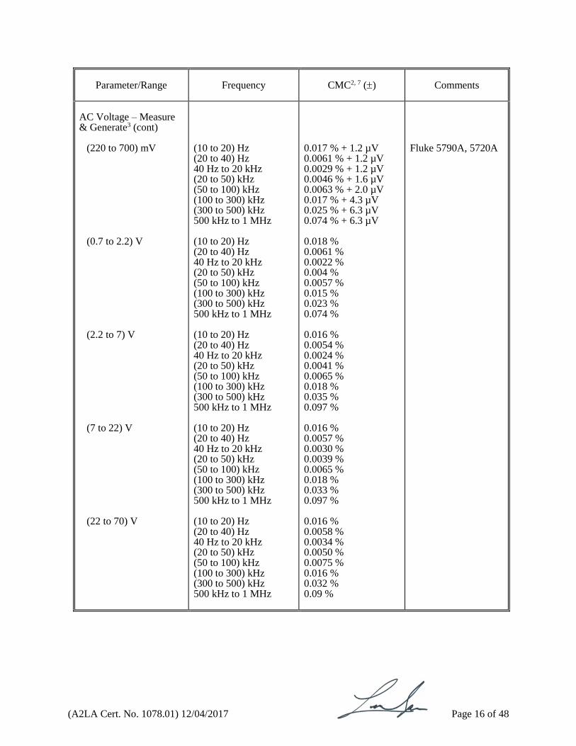
AC Voltage – Measure & Generate3 (cont)
(220 to 700) mV (0.7 to 2.2) V (2.2 to 7) V (7 to 22) V (22 to 70) V
(10 to 20) Hz (20 to 40) Hz 40 Hz to 20 kHz (20 to 50) kHz (50 to 100) kHz (100 to 300) kHz (300 to 500) kHz 500 kHz to 1 MHz (10 to 20) Hz (20 to 40) Hz 40 Hz to 20 kHz (20 to 50) kHz (50 to 100) kHz (100 to 300) kHz (300 to 500) kHz 500 kHz to 1 MHz (10 to 20) Hz (20 to 40) Hz 40 Hz to 20 kHz (20 to 50) kHz (50 to 100) kHz (100 to 300) kHz (300 to 500) kHz 500 kHz to 1 MHz (10 to 20) Hz (20 to 40) Hz 40 Hz to 20 kHz (20 to 50) kHz (50 to 100) kHz (100 to 300) kHz (300 to 500) kHz 500 kHz to 1 MHz (10 to 20) Hz (20 to 40) Hz 40 Hz to 20 kHz (20 to 50) kHz (50 to 100) kHz (100 to 300) kHz (300 to 500) kHz 500 kHz to 1 MHz
0.017 % + 1.2 µV 0.0061 % + 1.2 µV 0.0029 % + 1.2 µV 0.0046 % + 1.6 µV 0.0063 % + 2.0 µV 0.017 % + 4.3 µV 0.025 % + 6.3 µV 0.074 % + 6.3 µV 0.018 % 0.0061 % 0.0022 % 0.004 % 0.0057 % 0.015 % 0.023 % 0.074 % 0.016 % 0.0054 % 0.0024 % 0.0041 % 0.0065 % 0.018 % 0.035 % 0.097 % 0.016 % 0.0057 % 0.0030 % 0.0039 % 0.0065 % 0.018 % 0.033 % 0.097 % 0.016 % 0.0058 % 0.0034 % 0.0050 % 0.0075 % 0.016 % 0.032 % 0.09 %
Fluke 5790A, 5720A

(A2LA Cert. No. 1078.01) 12/04/2017 Page 17 of 48
Parameter/Range
Frequency
CMC2, 7 ()
Comments
AC Voltage – Measure & Generate3 (cont)
(70 to 220) V* (220 to 700) V (700 to 1000) V**
(10 to 20) Hz (20 to 40) Hz 40 Hz to 20 kHz (20 to 50) kHz (50 to 100) kHz (100 to 300) kHz (300 to 500) kHz (10 to 20) Hz (20 to 40) Hz 40 Hz to 20 kHz (20 to 50) kHz (50 to 100) kHz (10 to 20) Hz (20 to 40) Hz 40 Hz to 20 kHz (20 to 50) kHz (50 to 100) kHz
0.016 % 0.0058 % 0.0034 % 0.0056 % 0.0080 % 0.017 % 0.039 % 0.016 % 0.0080 % 0.0038 % 0.011 % 0.040 % 0.016 % 0.0080 % 0.0036 % 0.011 % 0.040 %
Fluke 5790A, 5720A *Subject to 2.2 x 10⁷ V-Hz limitation Fluke 5790A, 5720A, 5725A ** Measure only
AC High Voltage – Measure3
(1 to 5) kV (5 to 35) kV (35 to 75) kV
(50 to 60) Hz
0.2 % + 1 V 0.4 % + 65 V 0.4 % + 49 V
Vitrek 4700A
AC High Voltage – Generate3
(1 to 5) kV
60 Hz
0.24 % + 1 V
Assoc. res. 3565D

(A2LA Cert. No. 1078.01) 12/04/2017 Page 18 of 48
Parameter/Range
Frequency
CMC2, 5 ()
Comments
AC Voltage – Measure3 ≤ 2 MHz
(0 to 10) mV (10 to 100) mV (0.1 to 1) V
(1 to 10) V
(10 to 100) V (100 to 700) V
(1 to 40) Hz 40 Hz to 1 kHz (1 to 20) kHz (20 to 50) kHz (50 to 100) kHz (100 to 300) kHz (1 to 40) Hz 40Hz to 1kHz (1 to 20) kHz (20 to 50) kHz (50 to 100) kHz (100 to 300) kHz 300 kHz to 1 MHz (1 to 2) MHz (1 to 40) Hz 40 Hz to 1kHz (1 to 20) kHz (20 to 50) kHz (50 to 100) kHz (100 to 300) kHz 300 kHz to 1 MHz (1 to 2) MHz (1 to 40) Hz 40 Hz to 1 kHz (1 to 20) kHz (20 to 50) kHz (50 to 100) kHz (100 to 300) kHz 300 kHz to 1 MHz (1 to 2) MHz (1 to 40) Hz 40 Hz to 1 kHz (1 to 20) kHz (20 to 50) kHz (50 to 100) kHz (100 to 300) kHz 300 kHz to 1 MHz (1 to 40) Hz 40 Hz to 1 kHz (1 to 20) kHz (20 to 50) kHz (50 to 100) kHz
0.023 % + 2 µV 0.018 % + 0.74 µV 0.026 % + 0.74 µV 0.069 % + 0.74 µV 0.34 % + 0.74 µV 2.7 % + 1.4 µV 0.033 % + 2.7 µV 0.014 % + 1.4 µV 0.019 % + 1.4 µV 0.037 % + 1.4 µV 0.067 % + 1.4 µV 0.22 % + 6.7 µV 0.68 % + 6.7 µV 1.1 % + 6.7 µV 0.0047 % + 27 µV 0.0047 % + 14 µV 0.0094 %+ 14 µV 0.020 % + 14 µV 0.054 % + 14 µV 0.20 % + 67 µV 0.67 % + 67 µV 1.1 % + 67 µV 0.0077 % + 0.27 mV 0.0062 % + 0.14 mV 0.0099 % + 0.14 mV 0.021 % + 0.14 mV 0.054 % + 0.14 mV 0.21 % + 0.67 mV 0.67 % + 0.67 mV 1.1 % + 0.67 mV 0.025 % + 2.7 mV 0.016 % + 1.4 mV 0.014 % + 1.4 mV 0.025 % + 1.4 mV 0.082 % + 1.4 mV 0.27 % + 6.7 mV 1.1 % + 6.7 mV 0.033 % + 27 mV 0.027 % + 14 mV 0.041 % + 14 mV 0.081 % + 14 mV 0.21 % + 14 mV
Agilent/HP 3458A
(A2LA Cert. No. 1078.01) 12/04/2017 Page 19 of 48
Parameter/Range
Frequency
CMC2, 5, 7, 8 ()
Comments
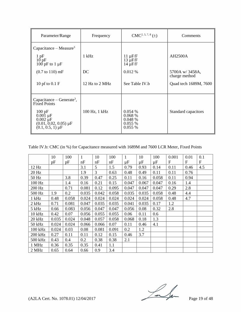
Capacitance – Measure3
1 pF 10 pF 100 pF to 1 µF (0.7 to 110) mF 10 pf to 0.1 F
1 kHz DC 12 Hz to 2 MHz
11 µF/F 13 µF/F 14 µF/F 0.012 % See Table IV.b
AH2500A 5700A w/ 3458A, charge method Quad tech 1689M, 7600
Capacitance – Generate3, Fixed Points
100 pF 0.001 µF 0.002 µF (0.01, 0.02, 0.05) µF (0.1, 0.5, 1) µF
100 Hz, 1 kHz
0.054 % 0.068 % 0.048 % 0.055 % 0.055 %
Standard capacitors
Table IV.b: CMC (in %) for Capacitance measured with 1689M and 7600 LCR Meter, Fixed Points
10
pF
100
pF
1
nF
10
nF
100
nF
1
µF
10
µF
100
µF
0.001
F
0.01
F
0.1
F
12 Hz 3.1 5 1.5 0.79 0.93 0.14 0.11 0.46 4.5
20 Hz 1.9 3 0.63 0.48 0.49 0.11 0.11 0.76
50 Hz 3.8 0.39 0.47 0.25 0.11 0.16 0.058 0.11 0.94
100 Hz 1.4 0.16 0.21 0.15 0.047 0.067 0.047 0.16 1.4
200 Hz 0.71 0.081 0.12 0.095 0.047 0.047 0.047 0.29 2.8
500 Hz 1.9 0.2 0.035 0.042 0.058 0.035 0.035 0.058 0.48 4.4
1 kHz 0.48 0.058 0.024 0.024 0.024 0.024 0.024 0.058 0.48 4.7
2 kHz 0.71 0.081 0.047 0.035 0.035 0.041 0.035 0.17 1.2
5 kHz 0.66 0.083 0.056 0.047 0.047 0.056 0.08 0.32 2.8
10 kHz 0.42 0.07 0.056 0.055 0.055 0.06 0.11 0.6
20 kHz 0.035 0.024 0.048 0.057 0.058 0.068 0.18 1.3
50 kHz 0.024 0.024 0.066 0.066 0.07 0.11 0.46 4.1
100 kHz 0.024 0.03 0.08 0.081 0.091 0.2 1.2
200 kHz 0.27 0.11 0.11 0.12 0.15 0.46 3.7
500 kHz 0.43 0.4 0.2 0.38 0.38 2.1
1 MHz 0.36 0.35 0.35 0.41 1.1
2 MHz 0.65 0.64 0.66 0.9 3.4
(A2LA Cert. No. 1078.01) 12/04/2017 Page 20 of 48
Parameter/Equipment
Range
CMC2, 7 ()
Comments
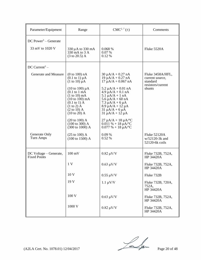
DC Power3 – Generate
33 mV to 1020 V
330 A to 330 mA 330 mA to 3 A (3 to 20.5) A
0.068 % 0.07 % 0.12 %
Fluke 5520A
DC Current3 –
Generate and Measure
Generate Only Turn Amps
(0 to 100) nA (0.1 to 1) µA (1 to 10) µA (10 to 100) µA (0.1 to 1 mA (1 to 10) mA (10 to 100) mA (0.1 to 1) A (1 to 2) A (2 to 10) A (10 to 20) A (20 to 100) A (100 to 300) A (300 to 1000) A (25 to 100) A (100 to 1500) A
30 µA/A + 0.27 nA 19 µA/A + 0.27 nA 17 µA/A + 0.067 nA 5.2 µA/A + 0.01 nA 4.9 µA/A + 0.1 nA 5.1 µA/A + 1 nA 5.6 µA/A + 60 nA 7.3 µA/A + 6 µA 8.9 µA/A + 12 µA 31 µA/A + 6 µA 31 µA/A + 12 µA 27 µA/A + 18 µA/°C 0.011 % + 18 µA/°C 0.077 % + 18 µA/°C 0.09 % 0.52 %
Fluke 3458A/HFL, current source, standard resistors/current shunts Fluke 52120A w/52120-3k and 52120-6k coils
DC Voltage – Generate, Fixed Points
100 mV 1 V 10 V 19 V 100 V 1000 V
0.82 μV/V 0.63 μV/V 0.55 μV/V 1.1 µV/V 0.63 μV/V 0.82 μV/V
Fluke 732B, 752A, HP 34420A Fluke 732B, 752A, HP 34420A Fluke 732B Fluke 732B, 720A, 752A, HP 34420A Fluke 732B, 752A, HP 34420A Fluke 732B, 752A, HP 34420A
(A2LA Cert. No. 1078.01) 12/04/2017 Page 21 of 48
Parameter/Equipment
Range
CMC2, 7, 8 ()
Comments
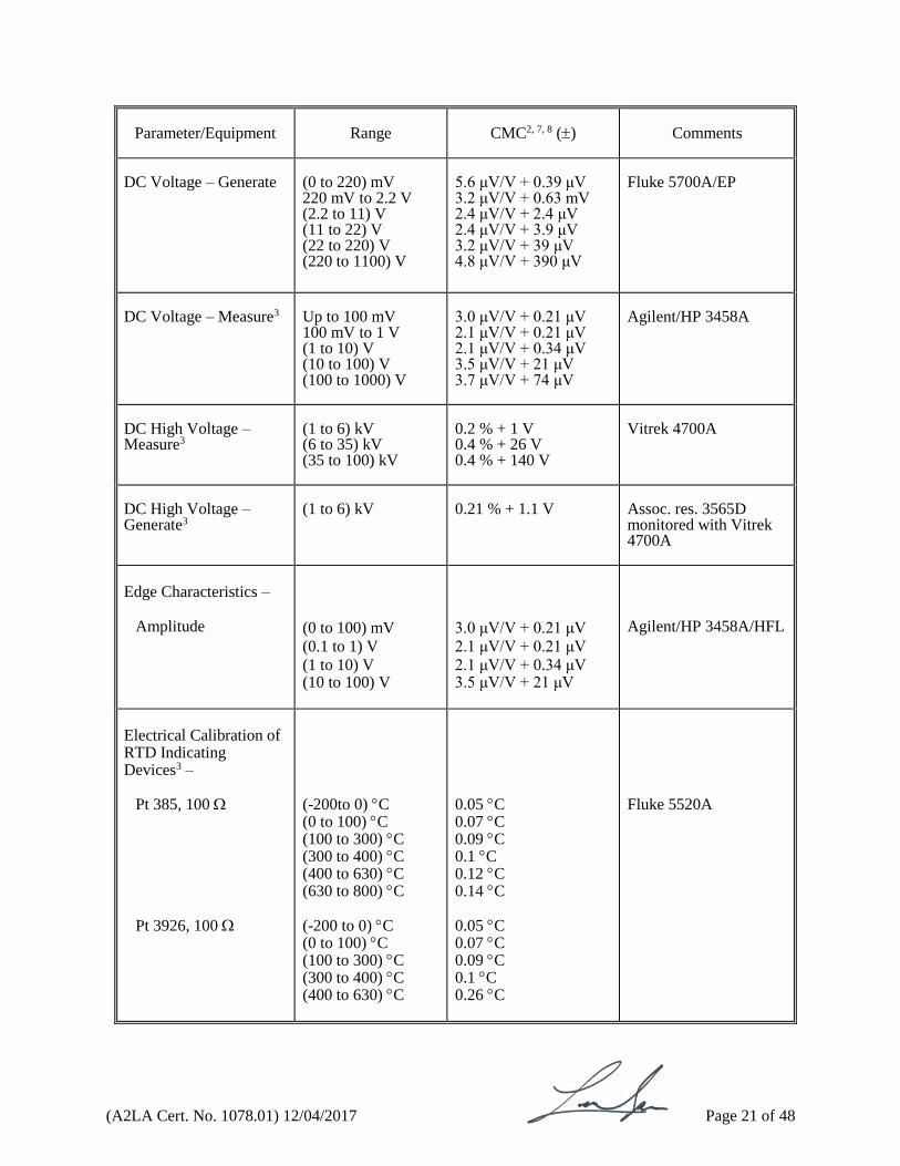
DC Voltage – Generate
(0 to 220) mV 220 mV to 2.2 V (2.2 to 11) V (11 to 22) V (22 to 220) V (220 to 1100) V
5.6 μV/V + 0.39 μV 3.2 μV/V + 0.63 mV 2.4 μV/V + 2.4 μV 2.4 μV/V + 3.9 μV 3.2 μV/V + 39 μV 4.8 μV/V + 390 μV
Fluke 5700A/EP
DC Voltage – Measure3
Up to 100 mV 100 mV to 1 V (1 to 10) V (10 to 100) V (100 to 1000) V
3.0 μV/V + 0.21 μV 2.1 μV/V + 0.21 μV 2.1 μV/V + 0.34 μV 3.5 μV/V + 21 μV 3.7 μV/V + 74 μV
Agilent/HP 3458A
DC High Voltage – Measure3
(1 to 6) kV (6 to 35) kV (35 to 100) kV
0.2 % + 1 V 0.4 % + 26 V 0.4 % + 140 V
Vitrek 4700A
DC High Voltage – Generate3
(1 to 6) kV
0.21 % + 1.1 V
Assoc. res. 3565D monitored with Vitrek 4700A
Edge Characteristics –
Amplitude
(0 to 100) mV
(0.1 to 1) V
(1 to 10) V (10 to 100) V
3.0 μV/V + 0.21 μV
2.1 μV/V + 0.21 μV
2.1 μV/V + 0.34 μV 3.5 μV/V + 21 μV
Agilent/HP 3458A/HFL
Electrical Calibration of RTD Indicating Devices3 –
Pt 385, 100 Pt 3926, 100
(-200to 0) C (0 to 100) C (100 to 300) C (300 to 400) C (400 to 630) C (630 to 800) C (-200 to 0) C (0 to 100) C (100 to 300) C (300 to 400) C (400 to 630) C
0.05 C 0.07 C 0.09 C 0.1 C 0.12 C 0.14 C 0.05 C 0.07 C 0.09 C 0.1 C 0.26 C
Fluke 5520A
(A2LA Cert. No. 1078.01) 12/04/2017 Page 22 of 48
Parameter/Equipment
Range
CMC2, 7 ()
Comments
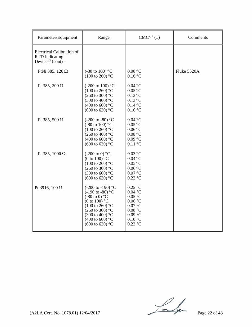
Electrical Calibration of RTD Indicating Devices3 (cont) –
PtNi 385, 120
Pt 385, 200 Pt 385, 500 Pt 385, 1000
Pt 3916, 100
(-80 to 100) C (100 to 260) C (-200 to 100) C (100 to 260) C (260 to 300) C (300 to 400) C (400 to 600) C (600 to 630) C (-200 to -80) C (-80 to 100) C (100 to 260) C (260 to 400) C (400 to 600) C (600 to 630) C (-200 to 0) C (0 to 100) C (100 to 260) C (260 to 300) C (300 to 600) C (600 to 630) C (-200 to -190) °C (-190 to -80) °C (-80 to 0) °C (0 to 100) °C (100 to 260) °C (260 to 300) °C (300 to 400) °C (400 to 600) °C (600 to 630) °C
0.08 C 0.16 C 0.04 C 0.05 C 0.12 C 0.13 C 0.14 C 0.16 C 0.04 C 0.05 C 0.06 C 0.08 C 0.09 C 0.11 C 0.03 C 0.04 C 0.05 C 0.06 C 0.07 C 0.23 C 0.25 °C 0.04 °C 0.05 °C 0.06 °C 0.07 °C 0.08 °C 0.09 °C 0.10 °C 0.23 °C
Fluke 5520A
(A2LA Cert. No. 1078.01) 12/04/2017 Page 23 of 48
Parameter/Equipment
Range
CMC2 ()
Comments
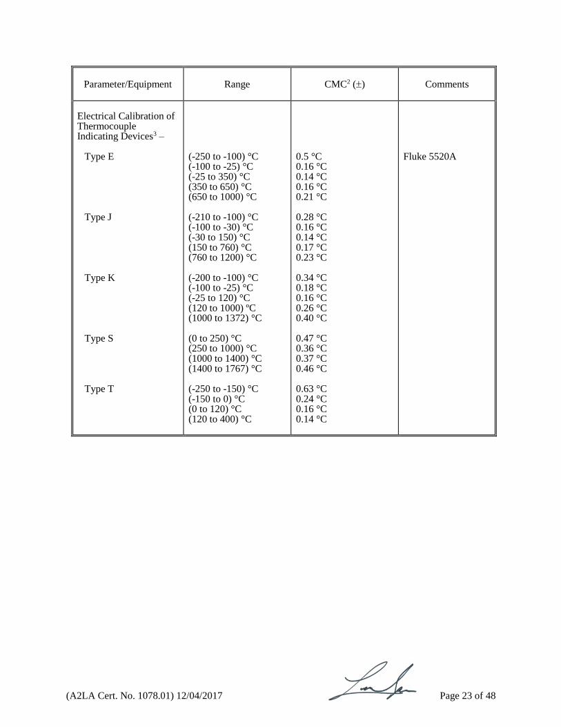
Electrical Calibration of Thermocouple Indicating Devices3 –
Type E
Type J Type K Type S Type T
(-250 to -100) °C (-100 to -25) °C (-25 to 350) °C (350 to 650) °C (650 to 1000) °C (-210 to -100) °C (-100 to -30) °C (-30 to 150) °C (150 to 760) °C (760 to 1200) °C (-200 to -100) °C (-100 to -25) °C (-25 to 120) °C (120 to 1000) ºC (1000 to 1372) °C (0 to 250) °C (250 to 1000) °C (1000 to 1400) °C (1400 to 1767) °C (-250 to -150) °C (-150 to 0) °C (0 to 120) °C (120 to 400) °C
0.5 °C 0.16 °C 0.14 °C 0.16 °C 0.21 °C 0.28 °C 0.16 °C 0.14 °C 0.17 °C 0.23 °C 0.34 °C 0.18 °C 0.16 °C 0.26 °C 0.40 °C 0.47 °C 0.36 °C 0.37 °C 0.46 °C 0.63 °C 0.24 °C 0.16 °C 0.14 °C
Fluke 5520A

(A2LA Cert. No. 1078.01) 12/04/2017 Page 24 of 48
Parameter/Range
Frequency
CMC2, 8 ()
Comments
High Frequency Capacitance - Generate Fixed Points3 –
1 pF 10 pF 100 pF
1000 pF
0.01 F
0.1 F 1.0F
1 kHz 1 MHz 2 MHz 3 MHz 4 MHz 5 MHz 10 MHz 13 MHz 1 kHz (1, 2) MHz 3 MHz 4 MHz 5 MHz 10 MHz 13 MHz 1 kHz 1 MHz 2 MHz 3 MHz 4 MHz 5 MHz 10 MHz 13 MHz 1 kHz 1 MHz 2 MHz 3 MHz 4 MHz 5 MHz 10 MHz 13 MHz (0.12, 1, 10, 100) kHz (0.12, 1, 10, 100) kHz 0.12 kHz (1, 10) kHz 100 kHz
0.007 % 0.01 % 0.023 % 0.041 % 0.063 % 0.088 % 0.26 % 0.38 % 62 parts in 106 62 parts in 106 64 parts in 106 67 parts in 106 72 parts in 106 0.013 % 0.017 % 61 parts in 106 62 parts in 106 68 parts in 106 82 parts in 106 0.01 % 0.014 % 0.034 % 0.049 % 63 parts in 106 80 parts in 106 0.016 % 0.028 % 0.046 % 0.064 % 0.2 % 0.29 % 63 parts in 106 63 parts in 106 69 parts in 106 63 parts in 106 85 parts in 106
Agilent/HP 16380A series capacitors

(A2LA Cert. No. 1078.01) 12/04/2017 Page 25 of 48
Parameter/Range
Frequency
CMC2, 8 ()
Comments
Inductance3 –
Measure (12 Hz to 2 MHz) Generate – Fixed Points
0.1 H to 10 H 100 H (1, 5, 10, 100) mH (1, 2, 5) H
See Table IV.c 0.026 % 0.11 % 0.11 %
LCR meters Standard inductors
Table IVc: Inductance Measure CMC (in %) measured with 1689M and 7600 LCR Meters
Freq. 0.1
µH
1
µH
10
µH
100
µH
1
mH
10
mH
100
mH
1
H
5
H
10
H
12 Hz 0.81 1.3 1.1 1.1 1.1
20 Hz 4.8 0.49 0.71 0.58 0.56 0.56
50 Hz 0.97 0.11 0.17 0.26 0.26 0.26
100 Hz 3.6 0.37 0.048 0.069 0.11 0.16 0.16
200 Hz 1.8 0.19 0.048 0.048 0.058 0.11 0.085
500 Hz 4.8 0.49 0.060 0.036 0.036 0.036 0.051 0.036
1 kHz 1.2 0.13 0.024 0.024 0.024 0.024 0.024 0.024
2 kHz 0.90 0.13 0.036 0.042 0.036 0.036 0.048 0.048
5 kHz 3.2 0.37 0.084 0.048 0.062 0.062 0.055 0.079 0.096
10 kHz 1.7 0.22 0.079 0.064 0.062 0.064 0.069 0.097 0.26
20 kHz 0.94 0.15 0.074 0.066 0.066 0.067 0.081 0.030 0.048
50 kHz 4.7 0.54 0.12 0.080 0.075 0.075 0.16 0.50 0.058 0.11
100 kHz 3.4 0.42 0.13 0.095 0.091 0.092 0.21 1.9 0.11 0.20
200 kHz 2.7 0.38 0.15 0.13 0.13 0.13 0.68 4.6
500 kHz 2.4 0.44 0.25 0.23 0.46 0.50 1.9
1 MHz 2.5 0.60 0.41 0.40 0.40 0.96
2 MHz 2.7 0.92 0.75 0.73 0.76 4.3
Parameter/Range
Frequency
CMC2 ()
Comments
Phase – Generate
5 Vrms (Voltage Ratio = 1) 50 m to 100 Vrms
1 Hz to 1 kHz (1 to 6.25) kHz (6.25 to 50) kHz (50 to 200) kHz 1 Hz to 1 kHz (1 to 6.25) kHz (6.25 to 50) kHz (50 to 200) kHz
6.6 m° 5.2 m° 13 m° 21 m° (6.5 + (0.05 · Ratio))m° (11 + (0.1 · Ratio))m° (19 + (0.15 · Ratio))m° (41 + (0.4 · Ratio))m°
Clark-Hess 5500-2 Ratio= ratio of the larger voltage divided by the smaller voltage
(A2LA Cert. No. 1078.01) 12/04/2017 Page 26 of 48
Parameter/Range
Frequency
CMC2 ()
Comments
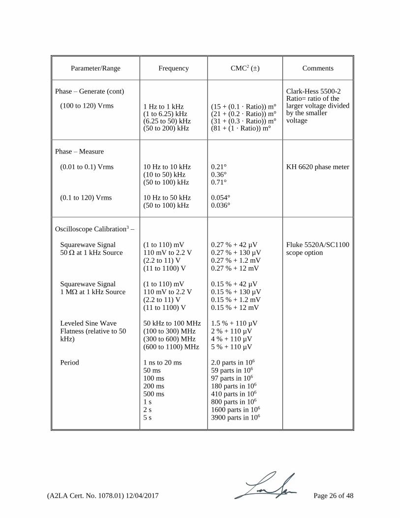
Phase – Generate (cont)
(100 to 120) Vrms
1 Hz to 1 kHz (1 to 6.25) kHz (6.25 to 50) kHz (50 to 200) kHz
(15 + (0.1 · Ratio)) m° (21 + (0.2 · Ratio)) m° (31 + (0.3 · Ratio)) m° (81 + (1 · Ratio)) m°
Clark-Hess 5500-2 Ratio= ratio of the larger voltage divided by the smaller voltage
Phase – Measure
(0.01 to 0.1) Vrms (0.1 to 120) Vrms
10 Hz to 10 kHz (10 to 50) kHz (50 to 100) kHz 10 Hz to 50 kHz (50 to 100) kHz
0.21° 0.36° 0.71° 0.054° 0.036°
KH 6620 phase meter
Oscilloscope Calibration3 –
Squarewave Signal 50 at 1 kHz Source Squarewave Signal 1 M at 1 kHz Source Leveled Sine Wave Flatness (relative to 50 kHz) Period
(1 to 110) mV 110 mV to 2.2 V (2.2 to 11) V (11 to 1100) V (1 to 110) mV 110 mV to 2.2 V (2.2 to 11) V (11 to 1100) V 50 kHz to 100 MHz (100 to 300) MHz (300 to 600) MHz (600 to 1100) MHz 1 ns to 20 ms 50 ms 100 ms 200 ms 500 ms 1 s 2 s 5 s
0.27 % + 42 µV 0.27 % + 130 µV 0.27 % + 1.2 mV 0.27 % + 12 mV 0.15 % + 42 µV 0.15 % + 130 µV 0.15 % + 1.2 mV 0.15 % + 12 mV 1.5 % + 110 µV 2 % + 110 µV 4 % + 110 µV 5 % + 110 µV 2.0 parts in 106 59 parts in 106 97 parts in 106 180 parts in 106 410 parts in 106 800 parts in 106 1600 parts in 106 3900 parts in 106
Fluke 5520A/SC1100 scope option
(A2LA Cert. No. 1078.01) 12/04/2017 Page 27 of 48
Parameter/Range
Frequency
CMC2, 8 ()
Comments
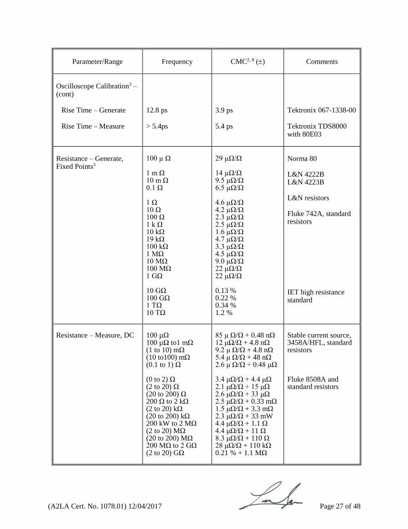
Oscilloscope Calibration3 – (cont)
Rise Time – Generate
Rise Time – Measure
12.8 ps > 5.4ps
3.9 ps 5.4 ps
Tektronix 067-1338-00 Tektronix TDS8000 with 80E03
Resistance – Generate, Fixed Points3
100 µ Ω 1 m Ω 10 m Ω 0.1 Ω 1 Ω 10 Ω 100 Ω 1 k Ω 10 kΩ 19 kΩ 100 kΩ 1 MΩ 10 MΩ 100 MΩ 1 GΩ 10 GΩ 100 GΩ 1 TΩ 10 TΩ
29 µΩ/Ω 14 µΩ/Ω 9.5 µΩ/Ω 6.5 µΩ/Ω 4.6 µΩ/Ω 4.2 µΩ/Ω 2.3 µΩ/Ω 2.5 µΩ/Ω 1.6 µΩ/Ω 4.7 µΩ/Ω 3.3 µΩ/Ω 4.5 µΩ/Ω 9.0 µΩ/Ω 22 µΩ/Ω 22 µΩ/Ω 0.13 % 0.22 % 0.34 % 1.2 %
Norma 80 L&N 4222B L&N 4223B L&N resistors Fluke 742A, standard resistors IET high resistance standard
Resistance – Measure, DC
100 µΩ 100 µΩ to1 mΩ (1 to 10) mΩ (10 to100) mΩ (0.1 to 1) Ω (0 to 2) Ω (2 to 20) Ω (20 to 200) Ω 200 Ω to 2 kΩ (2 to 20) kΩ (20 to 200) kΩ 200 kW to 2 MΩ (2 to 20) MΩ (20 to 200) MΩ 200 MΩ to 2 GΩ (2 to 20) GΩ
85 μ Ω/Ω + 0.48 nΩ 12 μΩ/Ω + 4.8 nΩ 9.2 μ Ω/Ω + 4.8 nΩ 5.4 μ Ω/Ω + 48 nΩ 2.6 μ Ω/Ω + 0.48 μΩ 3.4 μΩ/Ω + 4.4 μΩ 2.1 μΩ/Ω + 15 μΩ 2.6 μΩ/Ω + 33 μΩ 2.5 μΩ/Ω + 0.33 mΩ 1.5 μΩ/Ω + 3.3 mΩ 2.3 μΩ/Ω + 33 mW 4.4 μΩ/Ω + 1.1 Ω 4.4 μΩ/Ω + 11 Ω 8.3 μΩ/Ω + 110 Ω 28 μΩ/Ω + 110 kΩ 0.21 % + 1.1 MΩ
Stable current source, 3458A/HFL, standard resistors Fluke 8508A and standard resistors

(A2LA Cert. No. 1078.01) 12/04/2017 Page 28 of 48
Parameter/Range
Frequency
CMC2, 8 ()
Comments
Resistance – Measure, DC (cont)
100 MΩ to 1 GΩ (1 to 10) GΩ (10 to 100) GΩ 100 GΩ to 1 TΩ (1 to 10) TΩ (10 to 100) TΩ
0.081 % 0.12 % 0.24 % 0.35 % 0.59 % 1.2 %
6500A
Resistance – Measure, AC
10 Hz to 2 MHz
See Table IV.d
LCR meters
Table IV.d: AC Resistance Measure CMC (in %) measured with LCR Meters
0.1 Ω
1 Ω
10 Ω
100 Ω
1 kΩ
10 kΩ
100 kΩ
200 kΩ
500 kΩ
1 MΩ
12 Hz 0.60 0.11 0.11 0.11 0.11 0.11 1.7 20 Hz 0.60 0.11 0.11 0.11 0.11 0.11 0.85 2.8 4.6 50 Hz 3.1 0.31 0.058 0.058 0.058 0.058 0.058 0.38 1.3 2.0 100 Hz 2.3 0.23 0.047 0.047 0.047 0.047 0.047 0.23 0.70 1.2 200 Hz 2.3 0.23 0.047 0.047 0.047 0.047 0.047 0.15 0.44 0.70 500 Hz 1.5 0.16 0.035 0.035 0.035 0.035 0.035 0.10 0.29 0.44 1 kHz 0.77 0.09 0.024 0.024 0.024 0.024 0.024 0.082 0.24 0.35 2 kHz 1.0 0.15 0.035 0.035 0.035 0.035 0.047 0.075 0.21 0.31 5 kHz 0.90 0.14 0.047 0.047 0.047 0.047 0.063 0.072 0.20 0.30 10 kHz 1.0 0.14 0.062 0.055 0.055 0.055 0.063 0.073 0.21 0.30 20 kHz 1.1 0.16 0.066 0.057 0.057 0.057 0.067 0.077 0.22 0.33 50 kHz 1.4 0.19 0.077 0.066 0.065 0.066 0.31 0.37 1.1 1.7 100 kHz 1.9 0.26 0.10 0.081 0.079 0.081 0.40 0.47 1.5 2.2 200 kHz 3.0 0.39 0.14 0.11 0.11 0.12 0.56 0.68 2.2 3.4 500 kHz 0.79 0.26 0.20 0.20 0.26 1.1 1.4 4.2 1 MHz 1.5 0.45 0.35 0.35 0.70 1.9 2.4 2 MHz 2.8 0.85 0.65 0.64 1.4 3.5 4.5
(A2LA Cert. No. 1078.01) 12/04/2017 Page 29 of 48
V. Electrical – RF/Microwave
Parameter/Range
Frequency
CMC2, 8 ()
Comments
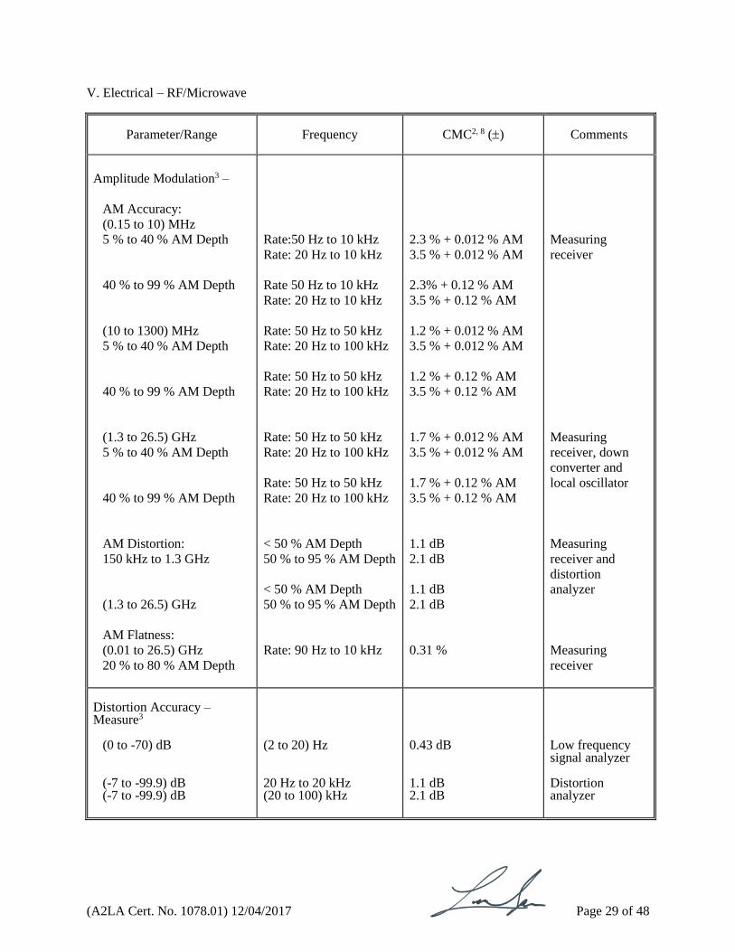
Amplitude Modulation3 –
AM Accuracy:
(0.15 to 10) MHz
5 % to 40 % AM Depth
40 % to 99 % AM Depth
(10 to 1300) MHz
5 % to 40 % AM Depth
40 % to 99 % AM Depth
(1.3 to 26.5) GHz
5 % to 40 % AM Depth
40 % to 99 % AM Depth
AM Distortion:
150 kHz to 1.3 GHz
(1.3 to 26.5) GHz
AM Flatness:
(0.01 to 26.5) GHz
20 % to 80 % AM Depth
Rate:50 Hz to 10 kHz
Rate: 20 Hz to 10 kHz
Rate 50 Hz to 10 kHz
Rate: 20 Hz to 10 kHz
Rate: 50 Hz to 50 kHz
Rate: 20 Hz to 100 kHz
Rate: 50 Hz to 50 kHz
Rate: 20 Hz to 100 kHz
Rate: 50 Hz to 50 kHz
Rate: 20 Hz to 100 kHz
Rate: 50 Hz to 50 kHz
Rate: 20 Hz to 100 kHz
< 50 % AM Depth
50 % to 95 % AM Depth
< 50 % AM Depth
50 % to 95 % AM Depth
Rate: 90 Hz to 10 kHz
2.3 % + 0.012 % AM
3.5 % + 0.012 % AM
2.3% + 0.12 % AM
3.5 % + 0.12 % AM
1.2 % + 0.012 % AM
3.5 % + 0.012 % AM
1.2 % + 0.12 % AM
3.5 % + 0.12 % AM
1.7 % + 0.012 % AM
3.5 % + 0.012 % AM
1.7 % + 0.12 % AM
3.5 % + 0.12 % AM
1.1 dB
2.1 dB
1.1 dB
2.1 dB
0.31 %
Measuring
receiver
Measuring
receiver, down
converter and
local oscillator
Measuring
receiver and
distortion
analyzer
Measuring
receiver
Distortion Accuracy – Measure3
(0 to -70) dB (-7 to -99.9) dB (-7 to -99.9) dB
(2 to 20) Hz
20 Hz to 20 kHz (20 to 100) kHz
0.43 dB 1.1 dB 2.1 dB
Low frequency signal analyzer Distortion analyzer
(A2LA Cert. No. 1078.01) 12/04/2017 Page 30 of 48
Parameter/Range
Frequency
CMC2, 8 ()
Comments
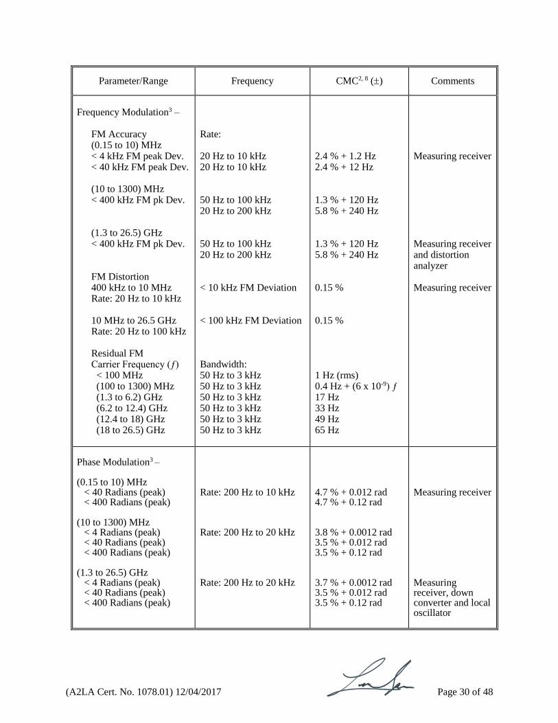
Frequency Modulation3 –
FM Accuracy (0.15 to 10) MHz < 4 kHz FM peak Dev. < 40 kHz FM peak Dev. (10 to 1300) MHz < 400 kHz FM pk Dev. (1.3 to 26.5) GHz < 400 kHz FM pk Dev. FM Distortion 400 kHz to 10 MHz Rate: 20 Hz to 10 kHz 10 MHz to 26.5 GHz Rate: 20 Hz to 100 kHz Residual FM Carrier Frequency (ƒ)
< 100 MHz (100 to 1300) MHz (1.3 to 6.2) GHz (6.2 to 12.4) GHz (12.4 to 18) GHz (18 to 26.5) GHz
Rate: 20 Hz to 10 kHz 20 Hz to 10 kHz 50 Hz to 100 kHz 20 Hz to 200 kHz 50 Hz to 100 kHz 20 Hz to 200 kHz < 10 kHz FM Deviation < 100 kHz FM Deviation Bandwidth: 50 Hz to 3 kHz 50 Hz to 3 kHz 50 Hz to 3 kHz 50 Hz to 3 kHz 50 Hz to 3 kHz 50 Hz to 3 kHz
2.4 % + 1.2 Hz 2.4 % + 12 Hz 1.3 % + 120 Hz 5.8 % + 240 Hz 1.3 % + 120 Hz 5.8 % + 240 Hz 0.15 % 0.15 % 1 Hz (rms) 0.4 Hz + (6 x 10⁻⁹) ƒ 17 Hz 33 Hz 49 Hz 65 Hz
Measuring receiver Measuring receiver and distortion analyzer Measuring receiver
Phase Modulation3 – (0.15 to 10) MHz
< 40 Radians (peak) < 400 Radians (peak)
(10 to 1300) MHz
< 4 Radians (peak) < 40 Radians (peak) < 400 Radians (peak)
(1.3 to 26.5) GHz
< 4 Radians (peak) < 40 Radians (peak) < 400 Radians (peak)
Rate: 200 Hz to 10 kHz Rate: 200 Hz to 20 kHz Rate: 200 Hz to 20 kHz
4.7 % + 0.012 rad 4.7 % + 0.12 rad 3.8 % + 0.0012 rad 3.5 % + 0.012 rad 3.5 % + 0.12 rad 3.7 % + 0.0012 rad 3.5 % + 0.012 rad 3.5 % + 0.12 rad
Measuring receiver Measuring receiver, down converter and local oscillator
(A2LA Cert. No. 1078.01) 12/04/2017 Page 31 of 48
Parameter/Range
Frequency
CMC2, 8 ()
Comments
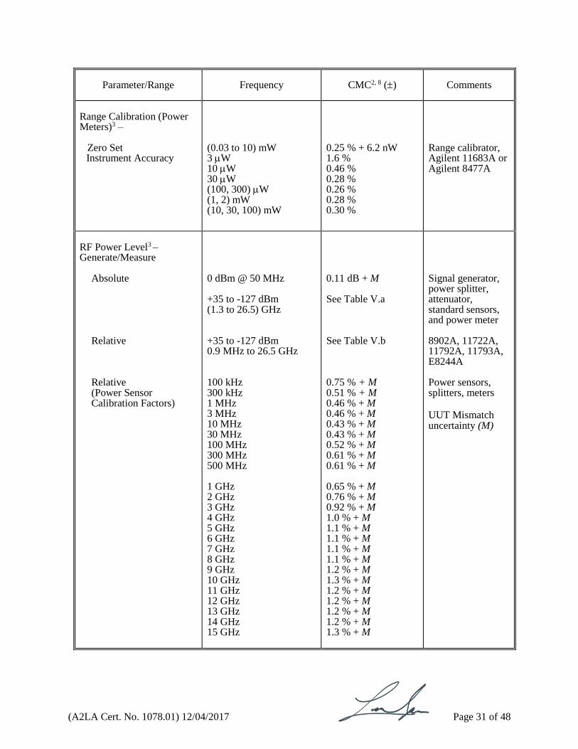
Range Calibration (Power Meters)3 –
Zero Set Instrument Accuracy
(0.03 to 10) mW 3 W 10 W 30 W (100, 300) W (1, 2) mW (10, 30, 100) mW
0.25 % + 6.2 nW 1.6 % 0.46 % 0.28 % 0.26 % 0.28 % 0.30 %
Range calibrator, Agilent 11683A or Agilent 8477A
RF Power Level3 – Generate/Measure
Absolute Relative Relative (Power Sensor Calibration Factors)
0 dBm @ 50 MHz +35 to -127 dBm (1.3 to 26.5) GHz +35 to -127 dBm 0.9 MHz to 26.5 GHz 100 kHz 300 kHz 1 MHz 3 MHz 10 MHz 30 MHz 100 MHz 300 MHz 500 MHz 1 GHz 2 GHz 3 GHz 4 GHz 5 GHz 6 GHz 7 GHz 8 GHz 9 GHz 10 GHz 11 GHz 12 GHz 13 GHz 14 GHz 15 GHz
0.11 dB + M See Table V.a See Table V.b 0.75 % + M 0.51 % + M 0.46 % + M 0.46 % + M 0.43 % + M 0.43 % + M 0.52 % + M 0.61 % + M 0.61 % + M 0.65 % + M 0.76 % + M 0.92 % + M 1.0 % + M 1.1 % + M 1.1 % + M 1.1 % + M 1.1 % + M 1.2 % + M 1.3 % + M 1.2 % + M 1.2 % + M 1.2 % + M 1.2 % + M 1.3 % + M
Signal generator, power splitter, attenuator, standard sensors, and power meter 8902A, 11722A, 11792A, 11793A, E8244A Power sensors, splitters, meters UUT Mismatch uncertainty (M)
(A2LA Cert. No. 1078.01) 12/04/2017 Page 32 of 48
Parameter/Range
Frequency
CMC2, 8 ()
Comments
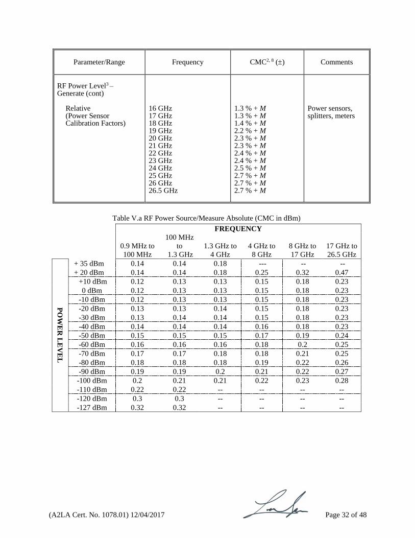
RF Power Level3 – Generate (cont)
Relative (Power Sensor Calibration Factors)
16 GHz 17 GHz 18 GHz 19 GHz 20 GHz 21 GHz 22 GHz 23 GHz 24 GHz 25 GHz 26 GHz 26.5 GHz
1.3 % + M 1.3 % + M 1.4 % + M 2.2 % + M 2.3 % + M 2.3 % + M 2.4 % + M 2.4 % + M 2.5 % + M 2.7 % + M 2.7 % + M 2.7 % + M
Power sensors, splitters, meters
Table V.a RF Power Source/Measure Absolute (CMC in dBm)
FREQUENCY
0.9 MHz to
100 MHz
100 MHz
to
1.3 GHz
1.3 GHz to
4 GHz
4 GHz to
8 GHz
8 GHz to
17 GHz
17 GHz to
26.5 GHz
PO
WE
R L
EV
EL
+ 35 dBm 0.14 0.14 0.18 --- -- --
+ 20 dBm 0.14 0.14 0.18 0.25 0.32 0.47
+10 dBm 0.12 0.13 0.13 0.15 0.18 0.23
0 dBm 0.12 0.13 0.13 0.15 0.18 0.23
-10 dBm 0.12 0.13 0.13 0.15 0.18 0.23
-20 dBm 0.13 0.13 0.14 0.15 0.18 0.23
-30 dBm 0.13 0.14 0.14 0.15 0.18 0.23
-40 dBm 0.14 0.14 0.14 0.16 0.18 0.23
-50 dBm 0.15 0.15 0.15 0.17 0.19 0.24
-60 dBm 0.16 0.16 0.16 0.18 0.2 0.25
-70 dBm 0.17 0.17 0.18 0.18 0.21 0.25
-80 dBm 0.18 0.18 0.18 0.19 0.22 0.26
-90 dBm 0.19 0.19 0.2 0.21 0.22 0.27
-100 dBm 0.2 0.21 0.21 0.22 0.23 0.28
-110 dBm 0.22 0.22 -- -- -- --
-120 dBm 0.3 0.3 -- -- -- --
-127 dBm 0.32 0.32 -- -- -- --
(A2LA Cert. No. 1078.01) 12/04/2017 Page 33 of 48
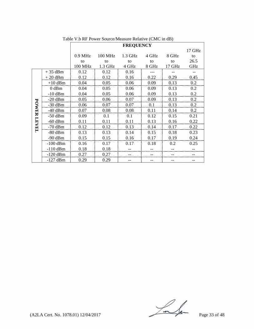
Table V.b RF Power Source/Measure Relative (CMC in dB)
FREQUENCY
0.9 MHz
to
100 MHz
100 MHz
to
1.3 GHz
1.3 GHz
to
4 GHz
4 GHz
to
8 GHz
8 GHz
to
17 GHz
17 GHz
to
26.5
GHz
PO
WE
R L
EV
EL
+ 35 dBm 0.12 0.12 0.16 --- -- --
+ 20 dBm 0.12 0.12 0.16 0.22 0.29 0.45
+10 dBm 0.04 0.05 0.06 0.09 0.13 0.2
0 dBm 0.04 0.05 0.06 0.09 0.13 0.2
-10 dBm 0.04 0.05 0.06 0.09 0.13 0.2
-20 dBm 0.05 0.06 0.07 0.09 0.13 0.2
-30 dBm 0.06 0.07 0.07 0.1 0.13 0.2
-40 dBm 0.07 0.08 0.08 0.11 0.14 0.2
-50 dBm 0.09 0.1 0.1 0.12 0.15 0.21
-60 dBm 0.11 0.11 0.11 0.13 0.16 0.22
-70 dBm 0.12 0.12 0.13 0.14 0.17 0.22
-80 dBm 0.13 0.13 0.14 0.15 0.18 0.23
-90 dBm 0.15 0.15 0.16 0.17 0.19 0.24
-100 dBm 0.16 0.17 0.17 0.18 0.2 0.25
-110 dBm 0.18 0.18 -- -- -- --
-120 dBm 0.27 0.27 -- -- -- --
-127 dBm 0.29 0.29 -- -- -- --

(A2LA Cert. No. 1078.01) 12/04/2017 Page 34 of 48
Parameter/Equipment
Range
CMC2 ()
Comments
S-Parameters3 – Reflection S11/22 Magnitude and Phase –
3.5 mm – Magnitude
Phase Magnitude
(0 to 1) lin Phase
(0 to 0.2) lin
(0.2 to 1) lin 7 mm – Magnitude
(0 to 1) lin Phase
(0 to 0.2) lin
(0.2 to 1) lin
N-Type – Magnitude
(0 to 1) lin
(1.5 to 26.5) GHz (0.01 to 1.0) lin (0 to 0.01) lin (0.01 to 0.1) lin (0.01 to 0.5) lin (0.5 to 1) lin 300 kHz to 1.3 GHz (1.3 to 3.0) GHz (3.0 to 6.0) GHz 300 kHz to 1.3 GHz (1.3 to 3.0) GHz (3.0 to 6.0) GHz 300 kHz to 1.3 GHz (1.3 to 3.0) GHz (3.0 to 6.0) GHz 300 kHz to 1.3 GHz (1.3 to 3.0) GHz (3.0 to 6.0) GHz 300 kHz to 1.3 GHz (1.3 to 3.0) GHz (3.0 to 6.0) GHz 300 kHz to 1.3 GHz (1.3 to 3.0) GHz (3.0 to 6.0) GHz 100 kHz to 0.3 GHz (0.3 to 1.3) GHz (1.3 to 3.0) GHz (3.0 to 6.0) GHz
( 0.012 to 0.040) lin ( 7.4 to 180) deg ( 0.095 to 20) deg ( 0.54 to 2.3) deg ( 0.50 to 1.1) deg ( 0.005 to 0.015) lin ( 0.008 to 0.02) lin ( 0.015 to 0.032) lin ( 180 to 2) deg ( 180 to 3) deg ( 180 to 4.5) deg ( 2 to 1) deg ( 3 to 1.5) deg ( 4.5 to 2) deg ( 0.001 to 0.006) lin ( 0.001 to 0.01) lin ( 0.005 to 0.018) lin ( 180 to 1) deg ( 180 to 1.5) deg ( 180 to 2) deg ( 1 to 5) deg ( 1.5 to 0.5) deg ( 2 to 1) deg 0.0085 lin ( 0.005 to 0.018) lin ( 0.005 to 0.025) lin ( 0.01 to 0.05) lin
8510C Network analyzer 85052D, calibration kit, and 85053B verification kit 8753ES Network Analyzer 850431B calibration kit, 85029B verification kit 3577A Spectrum analyzer B5032B verification kit

(A2LA Cert. No. 1078.01) 12/04/2017 Page 35 of 48
Parameter/Equipment
Range
CMC2 ()
Comments
S-Parameters3 – Reflection S11/22 Magnitude and Phase (cont)–
Phase (0 to 0.2) lin
(0.2 to 1) lin
300 kHz to 1.3 GHz (1.3 to 3.0) GHz (3.0 to 6.0) GHz 300 kHz to 1.3 GHz (1.3 to 3.0) GHz (3.0 to 6.0) GHz
( 180 to 1.5) deg ( 180 to 2) deg ( 180 to 4) deg ( 1.5 to 1) deg ( 2.0 to 1.5) deg ( 4 to 3) deg
3577A Spectrum analyzer B5032B verification kit
S-Parameters3 – Transmission S12/S21 Magnitude and Phase –
3.5 mm (0 to 20) dB (20 to 40) dB (10 to -90) dB
7 mm
(10 to -90) dB N-Type
(10 to -90) dB
(1.5 to 26.5) GHz (1.5 to 26.5) GHz 300 kHz to 1.3 GHz (1.3 to 3.0) GHz (3.0 to 6.0) GHz 300 kHz to 1.3 GHz (1.3 to 3.0) GHz (3.0 to 6.0) GHz 300 kHz to 1.3 GHz (1.3 to 3.0) GHz (3.0 to 6.0) GHz
( 0.11 to 0.29) dB ( 1.2 to 12) deg ( 0.13 to 0.68) dB ( 1.5 to 19) deg ( 0.3 to 6.0) dB ( 0.25 to 80) deg ( 0.04 to 6.0) dB ( 0.35 to 90) deg ( 0.06 to 9.0) dB ( 0.67 to 180) deg ( 0.03 to 5.0) dB ( 0.26 to 80) deg ( 0.03 to 5.0) dB ( 0.26 to 90) deg ( 0.05 to 10) dB ( 0.54 to 180) deg ( 0.03 to 6.0) dB ( 0.2 to 80) deg ( 0.04 to 6.0) dB ( 0.44 to 90) deg ( 0.1 to 9.0) dB ( 0.67 to 90) deg
Network analyzer with S-parameter test set, calibration kit, and cables, system verification with verification kit (see reflection)
(A2LA Cert. No. 1078.01) 12/04/2017 Page 36 of 48
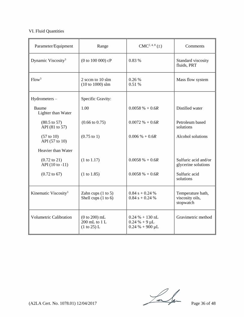
VI. Fluid Quantities
Parameter/Equipment
Range
CMC2, 4, 8 ()
Comments
Dynamic Viscosity3
(0 to 100 000) cP
0.83 %
Standard viscosity fluids, PRT
Flow3
2 sccm to 10 slm (10 to 1000) slm
0.26 % 0.51 %
Mass flow system
Hydrometers –
Baume Lighter than Water
(80.5 to 57) API (81 to 57) (57 to 10) API (57 to 10)
Heavier than Water
(0.72 to 21) API (10 to -11)
(0.72 to 67)
Specific Gravity: 1.00 (0.66 to 0.75)
(0.75 to 1)
(1 to 1.17) (1 to 1.85)
0.0058 % + 0.6R 0.0072 % + 0.6R 0.006 % + 0.6R 0.0058 % + 0.6R 0.0058 % + 0.6R
Distilled water Petroleum based solutions Alcohol solutions Sulfuric acid and/or glycerine solutions Sulfuric acid solutions
Kinematic Viscosity3
Zahn cups (1 to 5) Shell cups (1 to 6)
0.84 s + 0.24 % 0.84 s + 0.24 %
Temperature bath, viscosity oils, stopwatch
Volumetric Calibration
(0 to 200) mL 200 mL to 1 L (1 to 25) L
0.24 % + 130 nL 0.24 % + 9 µL 0.24 % + 900 µL
Gravimetric method

(A2LA Cert. No. 1078.01) 12/04/2017 Page 37 of 48
VII. Foundry-Industry Specific Calibrations
Parameter/Equipment
Range
CMC2, 4, 8 ()
Comments
AFS Clay Tester9
300 s
0.42 s
Stopwatch
Mold Strength Tester9
(0 to 50) psi
0.20 % + 0.6R
Mold strength tester and balances
Moisture Teller9
(100 to 300) F
2.0 F
Temperature calibrator
Permmeter9
25 perms 90 perms 160 perms
1.6 perms 5.3 perms 9.4 perms
Perm standard
Sand Rammer9 (Compactability Tester)
(0.6 to 0.9) inches
0.0066 in + 0.6R
Impact rings with caliper
Sand Specimen Tube3
2.0 in
0.0014 in
Bore gage
Sand (Green) Strength Machine9
(0 to 500) psi
0.93 % + 0.82 psi
Master force proving gage
Welders3
(1 to 50) V (1 to 750) A
1.0 % 1.0 %
Loadbank and DMM
Wet Tensile Tester9 –
Load Temperature Load Rate
0.449 N/cm2 (300 to 320) F 0.05 N/cm2/s
0.002 N/cm2 0.70 F 0.0017 N/cm2/s
Dead weight Thermometer Stopwatch
(A2LA Cert. No. 1078.01) 12/04/2017 Page 38 of 48
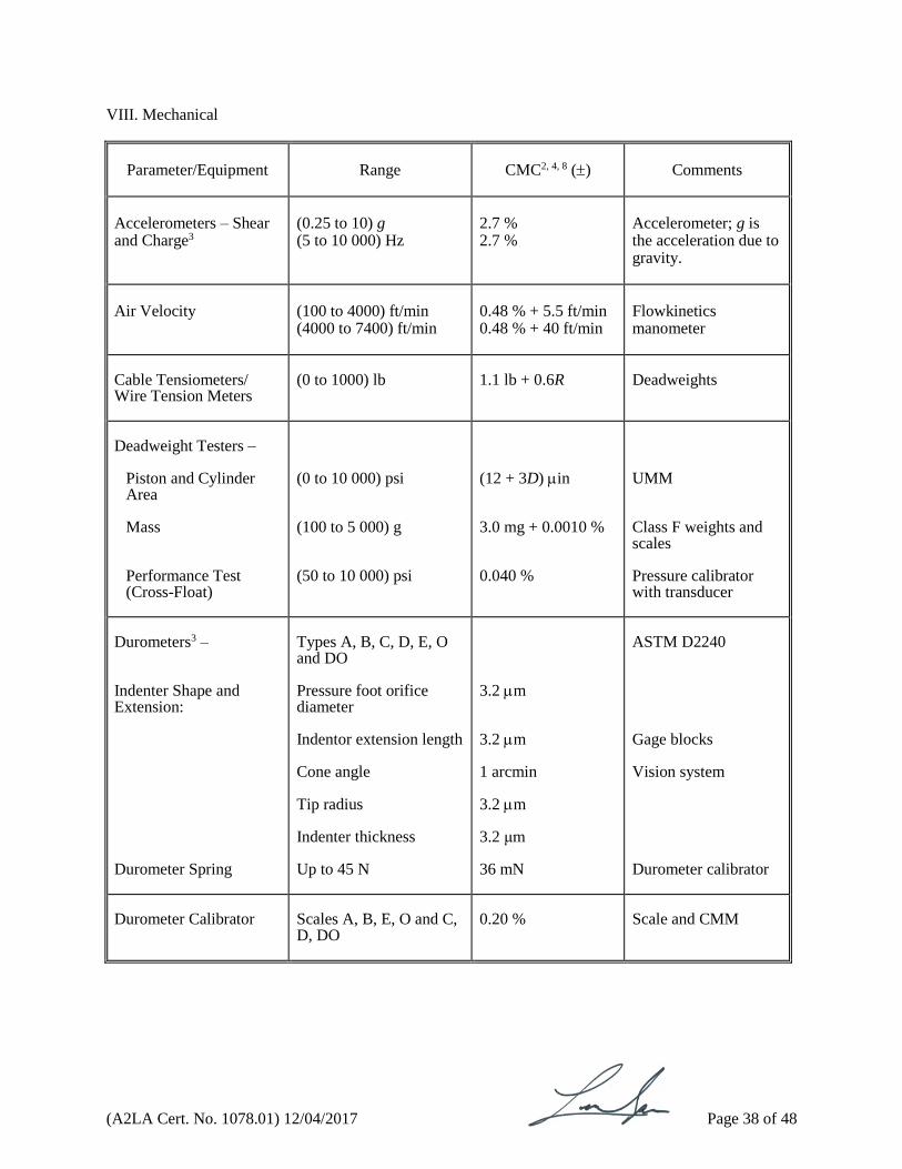
VIII. Mechanical
Parameter/Equipment
Range
CMC2, 4, 8 ()
Comments
Accelerometers – Shear and Charge3
(0.25 to 10) g (5 to 10 000) Hz
2.7 % 2.7 %
Accelerometer; g is the acceleration due to gravity.
Air Velocity
(100 to 4000) ft/min (4000 to 7400) ft/min
0.48 % + 5.5 ft/min 0.48 % + 40 ft/min
Flowkinetics manometer
Cable Tensiometers/ Wire Tension Meters
(0 to 1000) lb
1.1 lb + 0.6R
Deadweights
Deadweight Testers –
Piston and Cylinder Area Mass Performance Test (Cross-Float)
(0 to 10 000) psi (100 to 5 000) g (50 to 10 000) psi
(12 + 3D) in 3.0 mg + 0.0010 % 0.040 %
UMM Class F weights and scales Pressure calibrator with transducer
Durometers3 – Indenter Shape and Extension: Durometer Spring
Types A, B, C, D, E, O and DO Pressure foot orifice diameter Indentor extension length Cone angle Tip radius Indenter thickness Up to 45 N
3.2 m 3.2 m 1 arcmin 3.2 m 3.2 μm 36 mN
ASTM D2240 Gage blocks Vision system Durometer calibrator
Durometer Calibrator
Scales A, B, E, O and C, D, DO
0.20 %
Scale and CMM
(A2LA Cert. No. 1078.01) 12/04/2017 Page 39 of 48
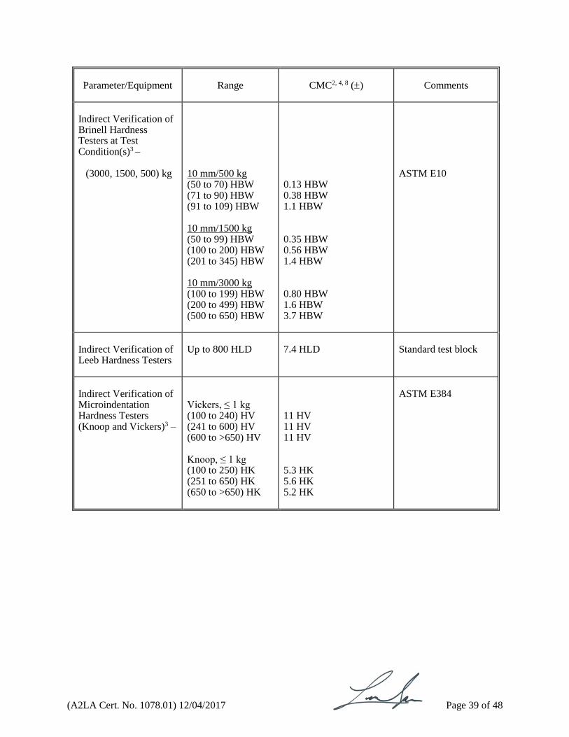
Parameter/Equipment
Range
CMC2, 4, 8 ()
Comments
Indirect Verification of Brinell Hardness Testers at Test Condition(s)3 –
(3000, 1500, 500) kg
10 mm/500 kg (50 to 70) HBW (71 to 90) HBW (91 to 109) HBW 10 mm/1500 kg (50 to 99) HBW (100 to 200) HBW (201 to 345) HBW 10 mm/3000 kg (100 to 199) HBW (200 to 499) HBW (500 to 650) HBW
0.13 HBW 0.38 HBW 1.1 HBW
0.35 HBW 0.56 HBW 1.4 HBW 0.80 HBW 1.6 HBW 3.7 HBW
ASTM E10
Indirect Verification of Leeb Hardness Testers
Up to 800 HLD
7.4 HLD
Standard test block
Indirect Verification of Microindentation Hardness Testers (Knoop and Vickers)3 –
Vickers, ≤ 1 kg (100 to 240) HV (241 to 600) HV (600 to >650) HV Knoop, ≤ 1 kg (100 to 250) HK (251 to 650) HK (650 to >650) HK
11 HV 11 HV 11 HV 5.3 HK 5.6 HK 5.2 HK
ASTM E384
(A2LA Cert. No. 1078.01) 12/04/2017 Page 40 of 48
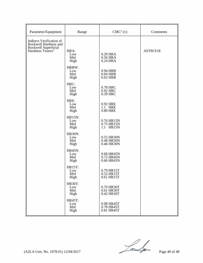
Parameter/Equipment
Range
CMC2 ()
Comments
Indirect Verification of Rockwell Hardness and Rockwell Superficial Hardness Testers3
HRA:
Low Mid High
HRBW:
Low Mid High
HRC:
Low Mid High
HRE:
Low Mid High
HR15N: Low Mid High
HR30N:
Low Mid High
HR45N: Low Mid High
HR15T: Low Mid High
HR30T:
Low Mid High
HR45T:
Low Mid High
0.29 HRA 0.56 HRA 0.24 HRA 0.94 HRB 0.69 HRB 0.62 HRB 0.78 HRC 0.92 HRC 0.39 HRC 0.92 HRE 1.1 HRE 0.89 HRE 0.76 HR15N 0.75 HR15N 1.1 HR15N
0.55 HR30N 0.48 HR30N 0.46 HR30N 0.68 HR45N 0.72 HR45N 0.66 HR45N 0.79 HR15T 0.52 HR15T 0.61 HR15T 0.70 HR30T 0.61 HR30T 0.42 HR30T 0.98 HR45T 0.78 HR45T 0.81 HR45T
ASTM E18

(A2LA Cert. No. 1078.01) 12/04/2017 Page 41 of 48
Parameter/Equipment
Range
CMC2, 4, 8 ()
Comments
Load Cells & Transducers – Load Cells, Force Gauges, Force Rings, and Dynamometers
(0 to 3325) lbf (up to 2 000) lbf (2 to 5.5) klbf (5.5 to 10) klbf (10 to 50) klbf
0.01 % rdg 0.036 % rdg + 0.60 lbf 0.028 % rdg + 1.9 lbf 0.028 % rdg + 4.0 lbf 0.21 % rdg + 19 lbf
Dead weights, comparison to master load cell
Mass
1 mg to 50 g (50 to 220) g (220 to 400) g 400 g to 1.2 kg (1.2 to 8.2) kg (8.2 to 30) kg
17 µg 35 µg 0.14 mg 3.7 mg 12 mg 0.11 g
By comparison
Mass3
(2 to 30) kg
0.20 g
By comparison
Pressure/Vacuum Gauges & Transducers3 Barometric
To 1 inH2O (>1 to 5) inH2O (>5 to 10) inH2O (>10 to 100) inH2O (>100 to 400) inH2O (-15 to 15) psig (>15 to 88) psig (>88 to 350) psig (> 350 to 1000) psig (>1000 to 1485) psig (>1485 to 3000) psig (>3000 to 6000) psig (>6000 to 10 000) psig To 30 psia (>30 to 200) psia (>200 to 1000) psia (>1000 to 1500) psia (10 to 17) psig
0.0006 inH2O 0.0031 inH2O 0.0061 inH2O 0.0016 % rdg + 0.0058 inH2O 0.0015 % rdg + 0.0015 inH2O 0.0069 % rdg + 0.0023 psig 0.0005 % rdg + 0.0051 psig 0.0052 % rdg + 0.0008 psig 0.0152 % rdg + 0.0091 psig 0.15 psig 0.004 % rdg + 0.242 psig 0.0007 % rdg + 0.656 psig 0.0038 % rdg + 0.745 psig 0.0065 % rdg + 0.0015 psia 0.0083 % rdg + 0.0066 psia 0.0152 % rdg + 0.0077 psia 0.15 psia 0.0007 % rdg + 0.0015 psia
Pressure calibrators and sensors
Refractometers3
(0 to 100) %
0.02 % + 0.6R
Standard solutions
(A2LA Cert. No. 1078.01) 12/04/2017 Page 42 of 48
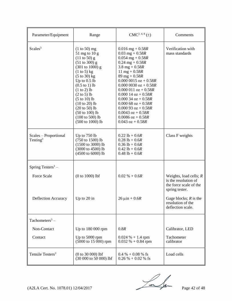
Parameter/Equipment
Range
CMC2, 4, 8 ()
Comments
Scales3
(1 to 50) mg 51 mg to 10 g (11 to 50) g (51 to 300) g (301 to 1000) g (1 to 5) kg (5 to 30) kg Up to 0.5 lb (0.5 to 1) lb (1 to 2) lb (2 to 5) lb (5 to 10) lb (10 to 20) lb (20 to 50) lb (50 to 100) lb (100 to 500) lb (500 to 1000) lb
0.016 mg + 0.58R 0.03 mg + 0.58R 0.054 mg + 0.58R 0.24 mg + 0.58R 3.8 mg + 0.58R 11 mg + 0.58R 89 mg + 0.58R 0.000 0015 oz + 0.58R 0.000 0030 oz + 0.58R 0.000 011 oz + 0.58R 0.000 14 oz + 0.58R 0.000 34 oz + 0.58R 0.000 68 oz + 0.58R 0.000 93 oz + 0.58R 0.0043 oz + 0.58R 0.0086 oz + 0.58R 0.043 oz + 0.58R
Verification with mass standards
Scales – Proportional Testing3
Up to 750 lb (750 to 1500) lb (1500 to 3000) lb (3000 to 4500) lb (4500 to 6000) lb
0.22 lb + 0.6R 0.28 lb + 0.6R 0.36 lb + 0.6R 0.42 lb + 0.6R 0.48 lb + 0.6R
Class F weights
Spring Testers3 –
Force Scale
Deflection Accuracy
(0 to 1000) lbf Up to 20 in
0.02 % + 0.6R 26 in + 0.6R
Weights, load cells; R is the resolution of the force scale of the spring tester. Gage blocks; R is the resolution of the deflection scale.
Tachometers3 –
Non-Contact Contact
Up to 180 000 rpm Up to 5000 rpm (5000 to 15 000) rpm
0.8R 0.024 % + 1.4 rpm 0.032 % + 0.84 rpm
Calibrator, LED Tachometer calibrator
Tensile Testers3
(0 to 30 000) lbf (30 000 to 50 000) lbf
0.4 % + 0.08 % fs 0.26 % + 0.02 % fs
Load cells
(A2LA Cert. No. 1078.01) 12/04/2017 Page 43 of 48
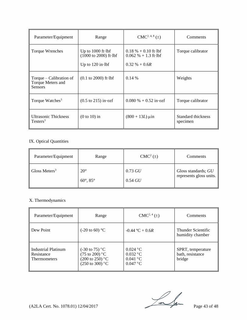
Parameter/Equipment
Range
CMC2, 4, 8 ()
Comments
Torque Wrenches
Up to 1000 ft·lbf (1000 to 2000) ft·lbf Up to 120 in·lbf
0.18 % + 0.10 ft·lbf 0.062 % + 1.3 ft·lbf 0.32 % + 0.6R
Torque calibrator
Torque – Calibration of Torque Meters and Sensors
(0.1 to 2000) ft·lbf
0.14 %
Weights
Torque Watches3
(0.5 to 215) in·ozf
0.080 % + 0.52 in·ozf
Torque calibrator
Ultrasonic Thickness Testers3
(0 to 10) in
(800 + 13L) in
Standard thickness specimen
IX. Optical Quantities
Parameter/Equipment
Range
CMC2 ()
Comments
Gloss Meters3
20° 60°, 85°
0.73 GU 0.54 GU
Gloss standards; GU represents gloss units.
X. Thermodynamics
Parameter/Equipment
Range
CMC2, 4 ()
Comments
Dew Point
(-20 to 60) °C
-0.44 ºC + 0.6R
Thunder Scientific humidity chamber
Industrial Platinum Resistance Thermometers
(-30 to 75) C (75 to 200) C (200 to 250) C (250 to 300) C
0.024 C 0.032 C 0.041 C 0.047 C
SPRT, temperature bath, resistance bridge

(A2LA Cert. No. 1078.01) 12/04/2017 Page 44 of 48
Parameter/Equipment
Range
CMC2, 4 ()
Comments
Infrared Thermometers – Measuring Equipment3
(-15 to 120) °C (35 to 500) °C (500 to 1100) °C
0.6 ºC + 0.6R 0.8 ºC + 0.6R 1.6 ºC + 0.0043 ºC/ ºC
Hart 9132 radiation source Isotech Pegasus 92R radiation source
Temperature Measuring Devices – Probe Type, Thermometers, RTD’s, Thermocouples 3
(-30 to 650) °C (650 to 1100) °C
0.013 % rdg +0.0028 °C or 0.011 °C
(Whichever is greater) 0.011 % rdg +0.45 °C
Temperature Source, SPRT
Relative Humidity – Measure
Hygrometer Psychrometer
(10 to 95) % RH (5 to 35) °C
0.7 % RH + 0.6R 0.1 °C + 0.84R
Humidity generator, Thunder Scientific 2500ST Comparison to SPRT in temp bath
Temperature –Measuring Equipment3
(-10 to 50) C (50 to 650) C
0.04 ºC + 0.6R 0.045 ºC + 0.6R
Dry-wells, PRT
Thermocouples and Thermocouple Wire
(-80 to 650) C
0.42 C
Comparison to SPRT with Agilent 3458A
XI. Time & Frequency
Parameter/Equipment
Range
CMC2, 4 ()
Comments
Frequency – Measuring Equipment & Measure
10 MHz 0.01 Hz to 200 kHz
3 parts in 1011
3 parts in 1011 + 1.4 µHz + 0.58R
GPS Function generator, signal generator, frequency counter or spectrum analyzer with ext. GPS timebase
(A2LA Cert. No. 1078.01) 12/04/2017 Page 45 of 48
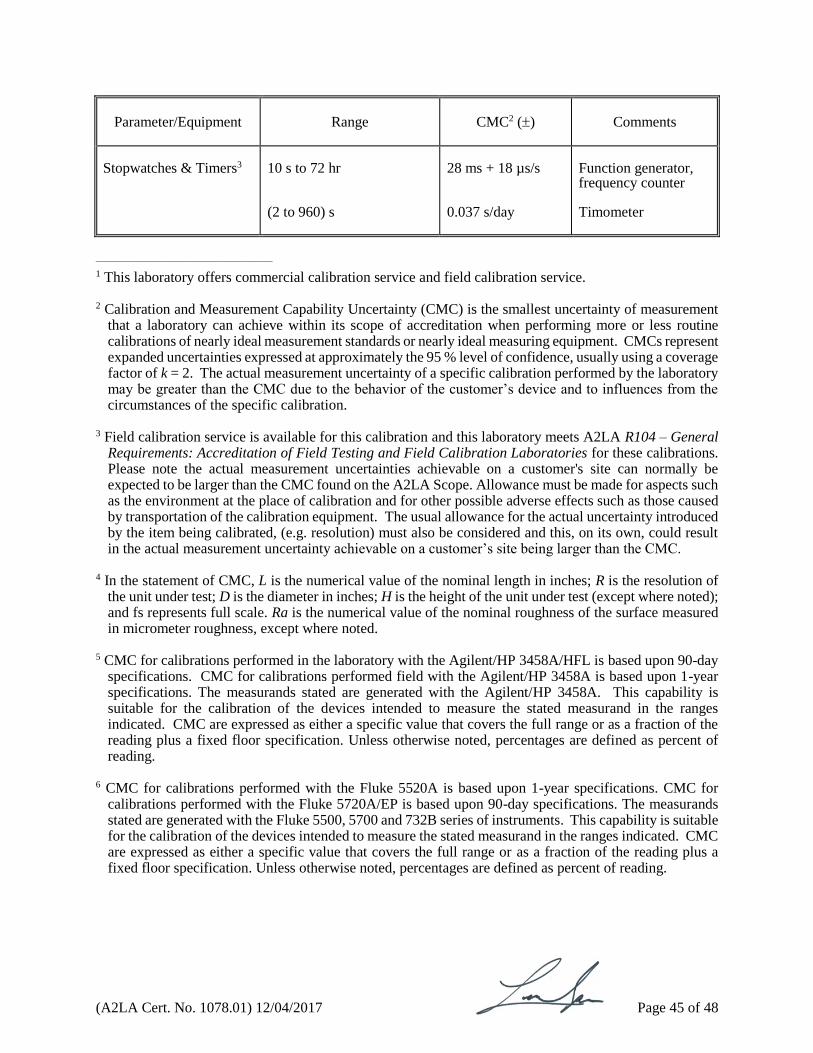
Parameter/Equipment
Range
CMC2 ()
Comments
Stopwatches & Timers3
10 s to 72 hr (2 to 960) s
28 ms + 18 µs/s 0.037 s/day
Function generator, frequency counter Timometer
______________________________________
1 This laboratory offers commercial calibration service and field calibration service. 2 Calibration and Measurement Capability Uncertainty (CMC) is the smallest uncertainty of measurement
that a laboratory can achieve within its scope of accreditation when performing more or less routine calibrations of nearly ideal measurement standards or nearly ideal measuring equipment. CMCs represent expanded uncertainties expressed at approximately the 95 % level of confidence, usually using a coverage factor of k = 2. The actual measurement uncertainty of a specific calibration performed by the laboratory may be greater than the CMC due to the behavior of the customer’s device and to influences from the circumstances of the specific calibration.
3 Field calibration service is available for this calibration and this laboratory meets A2LA R104 – General Requirements: Accreditation of Field Testing and Field Calibration Laboratories for these calibrations. Please note the actual measurement uncertainties achievable on a customer's site can normally be expected to be larger than the CMC found on the A2LA Scope. Allowance must be made for aspects such as the environment at the place of calibration and for other possible adverse effects such as those caused by transportation of the calibration equipment. The usual allowance for the actual uncertainty introduced by the item being calibrated, (e.g. resolution) must also be considered and this, on its own, could result in the actual measurement uncertainty achievable on a customer’s site being larger than the CMC.
4 In the statement of CMC, L is the numerical value of the nominal length in inches; R is the resolution of
the unit under test; D is the diameter in inches; H is the height of the unit under test (except where noted); and fs represents full scale. Ra is the numerical value of the nominal roughness of the surface measured in micrometer roughness, except where noted.
5 CMC for calibrations performed in the laboratory with the Agilent/HP 3458A/HFL is based upon 90-day
specifications. CMC for calibrations performed field with the Agilent/HP 3458A is based upon 1-year specifications. The measurands stated are generated with the Agilent/HP 3458A. This capability is suitable for the calibration of the devices intended to measure the stated measurand in the ranges indicated. CMC are expressed as either a specific value that covers the full range or as a fraction of the reading plus a fixed floor specification. Unless otherwise noted, percentages are defined as percent of reading.
6 CMC for calibrations performed with the Fluke 5520A is based upon 1-year specifications. CMC for
calibrations performed with the Fluke 5720A/EP is based upon 90-day specifications. The measurands stated are generated with the Fluke 5500, 5700 and 732B series of instruments. This capability is suitable for the calibration of the devices intended to measure the stated measurand in the ranges indicated. CMC are expressed as either a specific value that covers the full range or as a fraction of the reading plus a fixed floor specification. Unless otherwise noted, percentages are defined as percent of reading.
(A2LA Cert. No. 1078.01) 12/04/2017 Page 46 of 48
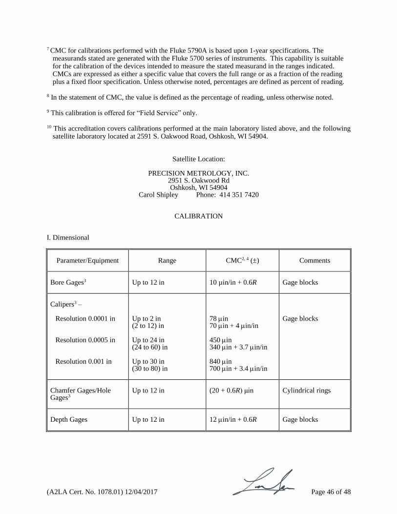
7 CMC for calibrations performed with the Fluke 5790A is based upon 1-year specifications. The measurands stated are generated with the Fluke 5700 series of instruments. This capability is suitable for the calibration of the devices intended to measure the stated measurand in the ranges indicated. CMCs are expressed as either a specific value that covers the full range or as a fraction of the reading plus a fixed floor specification. Unless otherwise noted, percentages are defined as percent of reading.
8 In the statement of CMC, the value is defined as the percentage of reading, unless otherwise noted.
9 This calibration is offered for “Field Service” only. 10 This accreditation covers calibrations performed at the main laboratory listed above, and the following
satellite laboratory located at 2591 S. Oakwood Road, Oshkosh, WI 54904.
Satellite Location:
PRECISION METROLOGY, INC.
2951 S. Oakwood Rd Oshkosh, WI 54904
Carol Shipley Phone: 414 351 7420
CALIBRATION
I. Dimensional
Parameter/Equipment
Range
CMC2, 4 ()
Comments
Bore Gages3
Up to 12 in
10 µin/in + 0.6R
Gage blocks
Calipers3 –
Resolution 0.0001 in Resolution 0.0005 in Resolution 0.001 in
Up to 2 in (2 to 12) in Up to 24 in (24 to 60) in Up to 30 in (30 to 80) in
78 in 70 in + 4 in/in 450 in 340 in + 3.7 in/in 840 in 700 in + 3.4 in/in
Gage blocks
Chamfer Gages/Hole Gages3
Up to 12 in
(20 + 0.6R) μin
Cylindrical rings
Depth Gages
Up to 12 in
12 in/in + 0.6R
Gage blocks
(A2LA Cert. No. 1078.01) 12/04/2017 Page 47 of 48
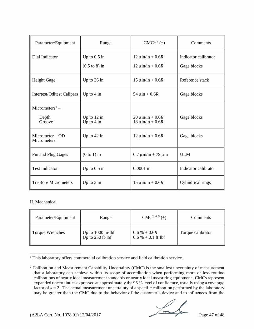
Parameter/Equipment
Range
CMC2, 4 ()
Comments
Dial Indicator
Up to 0.5 in (0.5 to 8) in
12 in/in + 0.6R 12 in/in + 0.6R
Indicator calibrator Gage blocks
Height Gage
Up to 36 in
15 in/in + 0.6R
Reference stack
Intertest/Oditest Calipers
Up to 4 in
54 in + 0.6R
Gage blocks
Micrometers3 –
Depth Groove
Up to 12 in Up to 4 in
20 in/in + 0.6R 18 in/in + 0.6R
Gage blocks
Micrometer – OD Micrometers
Up to 42 in
12 in/in + 0.6R
Gage blocks
Pin and Plug Gages
(0 to 1) in
6.7 in/in + 79 in
ULM
Test Indicator
Up to 0.5 in
0.0001 in
Indicator calibrator
Tri-Bore Micrometers
Up to 3 in
15 in/in + 0.6R
Cylindrical rings
II. Mechanical
Parameter/Equipment
Range
CMC2, 4, 5 ()
Comments
Torque Wrenches
Up to 1000 in·lbf Up to 250 ft·lbf
0.6 % + 0.6R 0.6 % + 0.1 ft·lbf
Torque calibrator
1 This laboratory offers commercial calibration service and field calibration service. 2 Calibration and Measurement Capability Uncertainty (CMC) is the smallest uncertainty of measurement
that a laboratory can achieve within its scope of accreditation when performing more or less routine calibrations of nearly ideal measurement standards or nearly ideal measuring equipment. CMCs represent expanded uncertainties expressed at approximately the 95 % level of confidence, usually using a coverage factor of k = 2. The actual measurement uncertainty of a specific calibration performed by the laboratory may be greater than the CMC due to the behavior of the customer’s device and to influences from the
(A2LA Cert. No. 1078.01) 12/04/2017 Page 48 of 48
circumstances of the specific calibration.
3 Field calibration service is available for this calibration and this laboratory meets A2LA R104 – General Requirements: Accreditation of Field Testing and Field Calibration Laboratories for these calibrations. Please note the actual measurement uncertainties achievable on a customer's site can normally be expected to be larger than the CMC found on the A2LA Scope. Allowance must be made for aspects such as the environment at the place of calibration and for other possible adverse effects such as those caused by transportation of the calibration equipment. The usual allowance for the actual uncertainty introduced by the item being calibrated, (e.g. resolution) must also be considered and this, on its own, could result in the actual measurement uncertainty achievable on a customer’s site being larger than the CMC.
4 In the statement of CMC, R is the resolution of the unit under test, H is the height from the base in inches 5 In the statement of CMC, the value is defined as the percentage of reading, unless otherwise noted.
Related Documents