Extract from Draft Cycle Plan Report, 2 Nov 2016 DRAFT FOR COMMENTS Draft Cycle Design Guidelines, 2 Nov 2016 1 1. CYCLING INCLUSIVE PLAN AND DESIGN The CBP (Comprehensive Bicycle Plan for Pune) is a masterplan that provides information about the kind of cycling infrastructure that is needed at each road of the road network, but does not provide detailed designs for roads. These design guidelines are not a complete cycling design manual, but provide concise guidance for a proper design of cycling infrastructure in Pune. Existing cycling infrastructure in Pune, is of such quality that most cycle tracks is barely used by cyclists. These guidelines, therefore, include a focus on some of the typical challenges for the design of cycle tracks (and lanes) in Pune with the objective to increase cycling-infrastructure usage and cycling in the city. These guidelines should be a more detailed specification of the Urban Street Design Guidelines. Regarding cycle track design, the USDG is very short and without a lot of specific guidance on dimensions or design details. These design guidelines aim to fill those gaps. On the other hand, the USDG provides many cross-sections for different roads with different right of way. These design guidelines, however, provide design principles that can then be applied at different roads. Above all, these design guidelines are meant to be a tool to assist consultants in the design of good quality cycling infrastructure. Like any manual or guidelines, they are not a replacement for expertise and should, in time, be accompanied by proper capacity building to consultants who will use these guidelines. 1.1. INTRODUCTION To make cycling safer and more attractive, much more needs to be done than providing cycle tracks and cycle lanes. In the case of Pune and other Indian cities, there are many aspects of road planning and design that discourage cycling and make it less safe. Cycling-inclusive planning and design makes cycling more attractive and safer. Underneath several key cycling-inclusive planning and design measures are explained together with references to the less cycling-inclusive practices today. Cycling-inclusive planning and design is essential to enable Pune to reach its ambitious targets for cycling

Welcome message from author
This document is posted to help you gain knowledge. Please leave a comment to let me know what you think about it! Share it to your friends and learn new things together.
Transcript

Extract from Draft Cycle Plan Report, 2 Nov 2016 DRAFT FOR COMMENTS
Draft Cycle Design Guidelines, 2 Nov 2016 1
1. CYCLING INCLUSIVE PLAN AND
DESIGN
The CBP (Comprehensive Bicycle Plan for Pune) is a masterplan that provides
information about the kind of cycling infrastructure that is needed at each road of the
road network, but does not provide detailed designs for roads. These design guidelines
are not a complete cycling design manual, but provide concise guidance for a proper
design of cycling infrastructure in Pune. Existing cycling infrastructure in Pune, is of such
quality that most cycle tracks is barely used by cyclists. These guidelines, therefore,
include a focus on some of the typical challenges for the design of cycle tracks (and
lanes) in Pune with the objective to increase cycling-infrastructure usage and cycling in
the city.
These guidelines should be a more detailed specification of the Urban Street Design
Guidelines. Regarding cycle track design, the USDG is very short and without a lot of
specific guidance on dimensions or design details. These design guidelines aim to fill
those gaps. On the other hand, the USDG provides many cross-sections for different
roads with different right of way. These design guidelines, however, provide design
principles that can then be applied at different roads.
Above all, these design guidelines are meant to be a tool to assist consultants in the
design of good quality cycling infrastructure. Like any manual or guidelines, they are not
a replacement for expertise and should, in time, be accompanied by proper capacity
building to consultants who will use these guidelines.
1.1. INTRODUCTION
To make cycling safer and more attractive, much more needs to be done than providing
cycle tracks and cycle lanes. In the case of Pune and other Indian cities, there are many
aspects of road planning and design that discourage cycling and make it less safe.
Cycling-inclusive planning and design makes cycling more attractive and safer.
Underneath several key cycling-inclusive planning and design measures are explained
together with references to the less cycling-inclusive practices today. Cycling-inclusive
planning and design is essential to enable Pune to reach its ambitious targets for cycling

Extract from Draft Cycle Plan Report, 2 Nov 2016 DRAFT FOR COMMENTS
Draft Cycle Design Guidelines, 2 Nov 2016 2
(25% of journeys) which have only been met in (European) cities that have implemented
all the following cycling-inclusive planning and design measures.
1.2. DEMOTORIZATION OF THE CORE CITY
There are several methods of reducing traffic in the core city area. One of the major idea
is to make it free from motorised vehicles. Following sections explains the decongestion
concept and potential challenges that will be faced in case of Pune.
1.2.1. CAR-FREE CITY-CENTRES
One of the factors that has contributed enormously in making cycling a success in the
world's most cycling-friendly cities (for instance in the Netherlands or Denmark) is the
development of car free city-centres. By closing off, or severely limiting access to these
areas a situation is created where cycling (and public transport) becomes a more
attractive mode of transport to reach the city-centre than the car. Experience in many
European cities show that the creation of bicycle and pedestrian-friendly city-centres
with limited access for motorised vehicles has many advantages:
The quality of life improves and real-estate prices go up.
Tourism flourishes. This leads to more spending in hotels, restaurants and shops in the
city-centre.
Air quality improves and accident rates drop drastically.
Figure 1: De-motorization of 'Nyhavn' in Copenhagen has led to a flourishing local economy and increased spending by
tourists and visitors of the city (Left: 1970, Right: present situation)
1.2.2. DECONGESTION
Experiences in countless cities in Europe and elsewhere show that few measures are
more successful in reducing congestion in a city than making it impossible to cross the

Extract from Draft Cycle Plan Report, 2 Nov 2016 DRAFT FOR COMMENTS
Draft Cycle Design Guidelines, 2 Nov 2016 3
city-centre by making certain streets and areas in the city-centre car free. The figure
below explains this clearly:
1. Picture on the left: While streets in the city-centre are often narrow, they attract the
greatest amount of traffic (see picture on the left) and thus are subject to serious
congestion. Also in Pune, the combination of a lot of through traffic and many people
that want to access the many destinations in the core city leads to serious congestion in
the core city.
2. Picture on the right: By taking out through traffic and make city-centre streets
pedestrian and cycling-only streets (as has been done in cities in The Netherlands,
Denmark, Germany, France and many other countries since the 1970's) traffic volumes
reduce significantly and congestion improves.
Figure 2: Congested city with city-centre open for motorised traffic (left) and decongested car free city-centre
1.2.3. DEMOTORIZATION OF THE CORE CITY OF PUNE
The only way to resolve the congestion in and improve the liveability of the core city is
to make, at least certain streets in the core city, car and motor cycle free to remove
through traffic from the core city. Countless cities in Europe and the United States saw
the economies of their inner cities dying because of congestion and pollution and
discovered that only demotorization helped to bring back businesses, residents and
clients.
For a successful demotorization of the core city the following needs to be done:
Create an inner ring road around the core city.
Make it impossible to cross the core city by car or motorcycle by creating streets that are
only open to non-motorized transport in such a way that cars and motorcycles cannot
Extract from Draft Cycle Plan Report, 2 Nov 2016 DRAFT FOR COMMENTS
Draft Cycle Design Guidelines, 2 Nov 2016 4
cross the core city, but instead go around it by using the inner ring road (see figure
below).
Create a parking plan and policy that requires all visitors with motor vehicles to pay for
parking (see section 3.3).
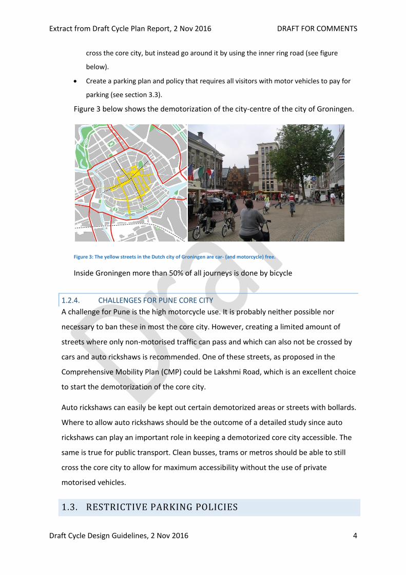
Figure 3 below shows the demotorization of the city-centre of the city of Groningen.
Figure 3: The yellow streets in the Dutch city of Groningen are car- (and motorcycle) free.
Inside Groningen more than 50% of all journeys is done by bicycle
1.2.4. CHALLENGES FOR PUNE CORE CITY
A challenge for Pune is the high motorcycle use. It is probably neither possible nor
necessary to ban these in most the core city. However, creating a limited amount of
streets where only non-motorised traffic can pass and which can also not be crossed by
cars and auto rickshaws is recommended. One of these streets, as proposed in the
Comprehensive Mobility Plan (CMP) could be Lakshmi Road, which is an excellent choice
to start the demotorization of the core city.
Auto rickshaws can easily be kept out certain demotorized areas or streets with bollards.
Where to allow auto rickshaws should be the outcome of a detailed study since auto
rickshaws can play an important role in keeping a demotorized core city accessible. The
same is true for public transport. Clean busses, trams or metros should be able to still
cross the core city to allow for maximum accessibility without the use of private
motorised vehicles.
1.3. RESTRICTIVE PARKING POLICIES
Extract from Draft Cycle Plan Report, 2 Nov 2016 DRAFT FOR COMMENTS
Draft Cycle Design Guidelines, 2 Nov 2016 5
Between 1990 and 2010 Amsterdam saw cycle trips to the city-centre increase from 15
to 25% of all journeys, mostly at the expense of the car1. In this period, relatively few
new cycle tracks to the city-centre were constructed, instead it was particularly an
increase of the price of paid parking in the city-centre that made that more and more
visitors came to the city-centre by bicycle instead of by car. Currently (2016) parking a
car in the city-centre of Amsterdam costs 5 Euros (Rs. 375) per hour.
Paid parking reduces the demand for motorised trips and makes alternative modes of
transport more attractive. In the case of Pune, it is essential that both cars and
motorcycles pay for parking.
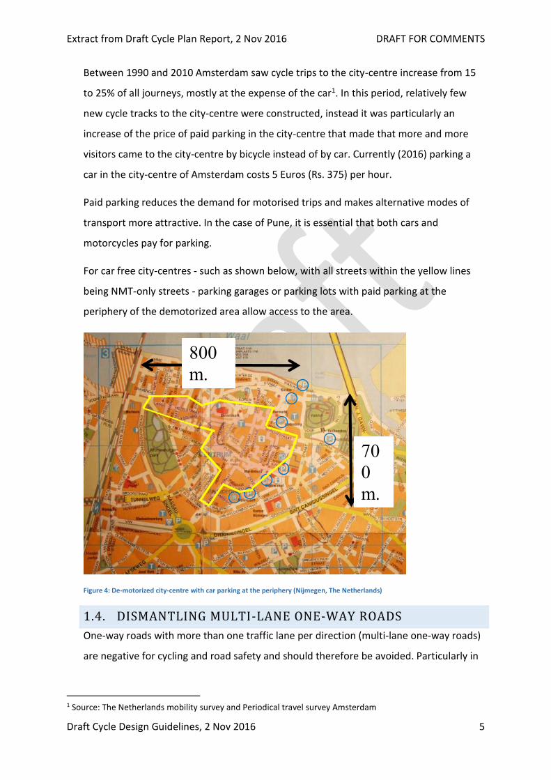
For car free city-centres - such as shown below, with all streets within the yellow lines
being NMT-only streets - parking garages or parking lots with paid parking at the
periphery of the demotorized area allow access to the area.
Figure 4: De-motorized city-centre with car parking at the periphery (Nijmegen, The Netherlands)
1.4. DISMANTLING MULTI-LANE ONE-WAY ROADS
One-way roads with more than one traffic lane per direction (multi-lane one-way roads)
are negative for cycling and road safety and should therefore be avoided. Particularly in
1 Source: The Netherlands mobility survey and Periodical travel survey Amsterdam
800
m.
70
0
m.
Extract from Draft Cycle Plan Report, 2 Nov 2016 DRAFT FOR COMMENTS
Draft Cycle Design Guidelines, 2 Nov 2016 6
centrally located areas (such as FC Road and JM Road), a one-way traffic system is not
appropriate because of the following reasons:
Road safety: The (maximum) speeds of motorised traffic at one-way roads with more
than one lane of traffic increase. This leads to a worsening of the road safety (one of the
main problems mentioned in the CMP) particularly for pedestrians and cyclists crossing
the road. This means that in highly commercial areas with many pedestrians, one-way
roads should be removed.2
Road safety and directness: Cyclists still will move (and want to move) in two directions.
Even when this is provided for in the designs, cyclists moving against traffic on one-ways
creates serious problems at intersections - where motorised traffic has free turns where
traffic does not stop. This lead to problems for road safety and directness for cyclists.
Therefore, multi-lane one-way roads should be avoided.
Road safety: For pedestrians and cyclists crossing the road, on one-way roads, traffic
does not always come from the same direction like on two ways (where you always look
right first). This leads to more accidents with cyclists and pedestrians crossing the street.
Road safety and directness: Right-turns on multi-lane one-way roads are almost
impossible to negotiate for cyclists because they need to cross several lanes of fast
moving traffic (see photo below).
Road safety: On multi-lane, one-way roads application of central traffic islands to make
it easier and safer for pedestrians and cyclists to cross cannot (safely) be applied.
Directness: One-way roads lead to detours for motorised traffic and thus more
kilometres travelled on urban roads. This also lead to higher traffic volumes at
intersections where vehicles would not need to come if they could reach their
destination without having to make a loop.
2 Note that because of road safety problems with cyclists and pedestrians multi-lane one-
way roads have been removed everywhere in cities in The Netherlands in the 1970's.

Extract from Draft Cycle Plan Report, 2 Nov 2016 DRAFT FOR COMMENTS
Draft Cycle Design Guidelines, 2 Nov 2016 7
Figure 5: JM Road in Pune: Cyclists that want to turn right here must weave across 4 lanes of traffic
To conclude: One-way roads are an American invention that was meant to 'improve the
flow of motorised traffic'. In car-country the US with very few pedestrians and cyclists,
this seemed to work relatively well. However, since the 2000's, because of the negative
effects for cycling, walking and road safety, many cities in the US are changing their one-
way streets back to two-way streets.3
1.5. FLYOVERS
When promoting cycling, flyovers should not be implemented for the following reasons:
Flyovers are a short-term measure that in the long-term leads to more traffic and more
serious congestion at locations where flyovers are not constructed.
Flyovers typically start in the centre of the road and thus lead to dangerous weaving
manoeuvres for cyclists at busy times when trying to access the flyover. This is because
cyclists need to cross lanes of fast moving traffic where traffic lights cannot be placed.
Cyclists using the flyover would need to ascend which means significant additional
effort.
Speeds on flyovers can be high, therefore flyovers should have cycle tracks. This
significantly increases the costs of the flyover and in practice is often not done creating
an environment hostile to cycling.
Cyclists that avoid the climb
3 See the article One Way? Wrong Way? here: http://articles.courant.com/2009-12-27/news/hc-plc-condon-one-way-streets.artdec27_1_two-way-streets-downtown-traffic. Quote: "Will it be time to remove some or all of the one-ways? That seems to be the trend across the country."
Extract from Draft Cycle Plan Report, 2 Nov 2016 DRAFT FOR COMMENTS
Draft Cycle Design Guidelines, 2 Nov 2016 8
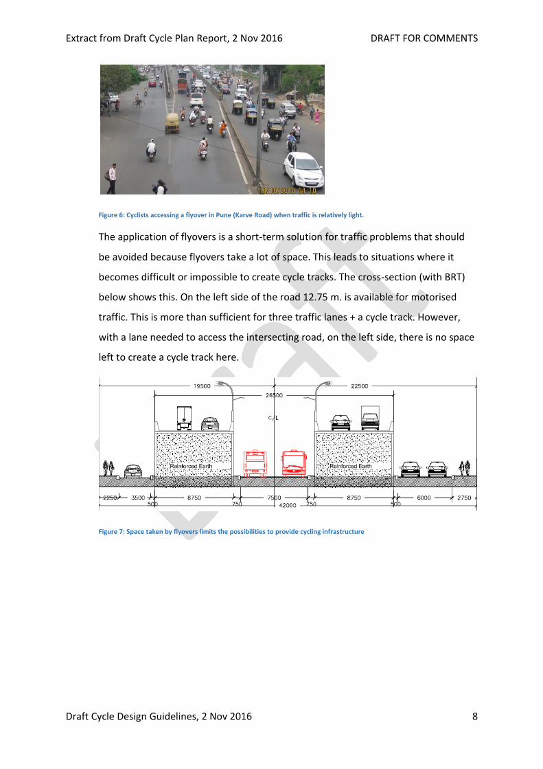
Figure 6: Cyclists accessing a flyover in Pune (Karve Road) when traffic is relatively light.
The application of flyovers is a short-term solution for traffic problems that should
be avoided because flyovers take a lot of space. This leads to situations where it
becomes difficult or impossible to create cycle tracks. The cross-section (with BRT)
below shows this. On the left side of the road 12.75 m. is available for motorised
traffic. This is more than sufficient for three traffic lanes + a cycle track. However,
with a lane needed to access the intersecting road, on the left side, there is no space
left to create a cycle track here.
Figure 7: Space taken by flyovers limits the possibilities to provide cycling infrastructure

Extract from Draft Cycle Plan Report, 2 Nov 2016 DRAFT FOR COMMENTS
Draft Cycle Design Guidelines, 2 Nov 2016 9
2. MAIN REQUIREMENTS FOR CYCLING-
INFRASTRUCTURE PLANNING AND
DESIGN
This section of the report discuses about the requirements that need to be in place to
guarantee a cycle friendly infrastructure in our cities. Also, the same requirements were
taken into consideration while analysing the present cycle infrastructure in the city
through street audit data.
2.1. INTRODUCTION AND CHARACTERISTICS OF CYCLISTS
Cyclists, like other road users, have certain requirements. Five main requirements can be
distinguished to guarantee cycle-friendly infrastructure. These requirements should be
met as good as possible and can be used to:
Properly design cycling infrastructure.
Evaluate cycling infrastructure designs before implementation.
Evaluate cycling infrastructure after implementation.
Each of the five requirements need to be met at network level, road section level,
intersection level and road surface level. Below each of the five requirements are
explained one by one.
2.2. COHERENCE
Cycling infrastructure forms a coherent and recognizable whole.
Criteria: Ease of finding; freedom of route choice; continuity of routes; consistency of
quality; completeness of the network.
2.2.1. COHERENCE AT NETWORK LEVEL
Coherence is important at network level. A coherent network allows cyclists to make
their whole journey on cycle-friendly infrastructure. Missing links - locations where
cycling infrastructure does not connect or is not provided - lead to a less complete and
coherent network.
2.2.2. COHERENCE AT ROAD SECTION LEVEL
Extract from Draft Cycle Plan Report, 2 Nov 2016 DRAFT FOR COMMENTS
Draft Cycle Design Guidelines, 2 Nov 2016 10
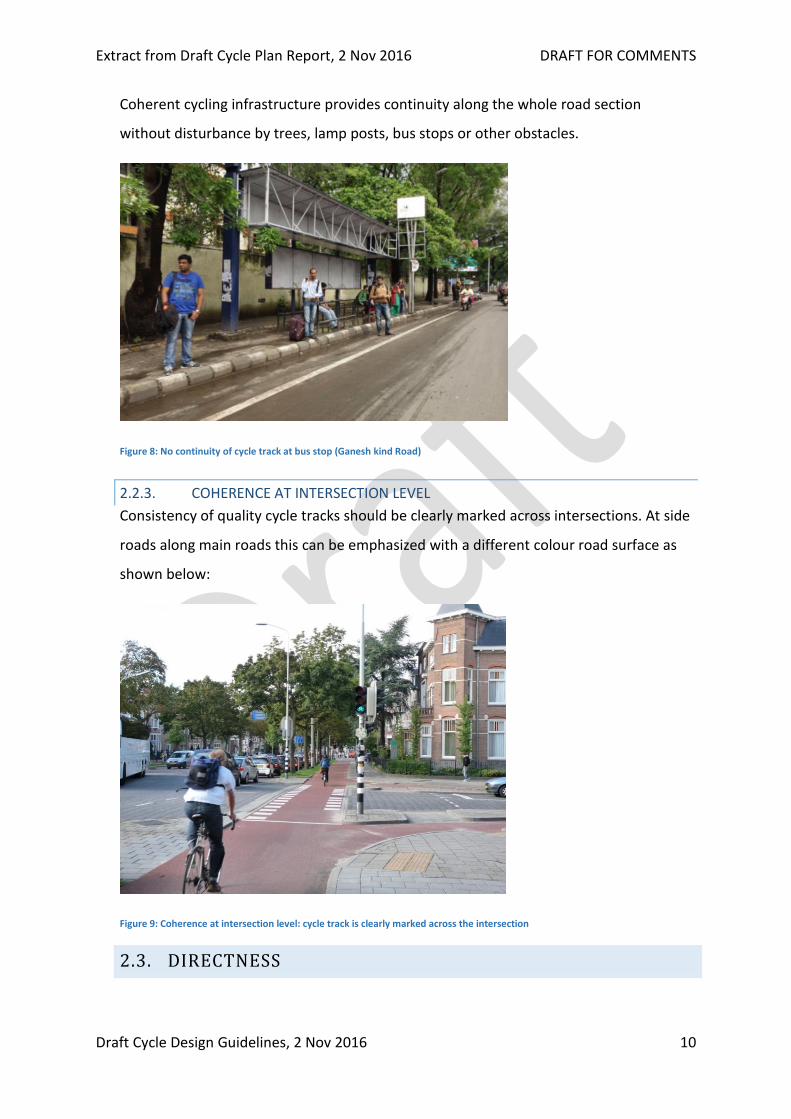
Coherent cycling infrastructure provides continuity along the whole road section
without disturbance by trees, lamp posts, bus stops or other obstacles.
Figure 8: No continuity of cycle track at bus stop (Ganesh kind Road)
2.2.3. COHERENCE AT INTERSECTION LEVEL
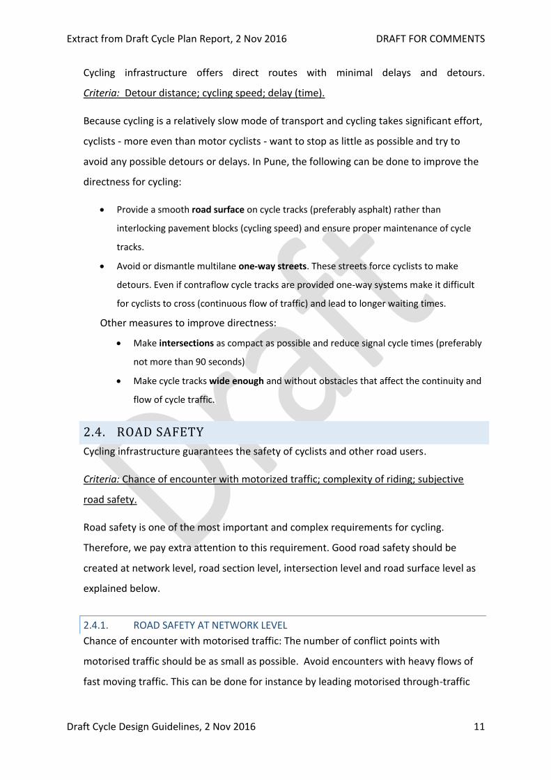
Consistency of quality cycle tracks should be clearly marked across intersections. At side
roads along main roads this can be emphasized with a different colour road surface as
shown below:
Figure 9: Coherence at intersection level: cycle track is clearly marked across the intersection
2.3. DIRECTNESS
Extract from Draft Cycle Plan Report, 2 Nov 2016 DRAFT FOR COMMENTS
Draft Cycle Design Guidelines, 2 Nov 2016 11
Cycling infrastructure offers direct routes with minimal delays and detours.
Criteria: Detour distance; cycling speed; delay (time).
Because cycling is a relatively slow mode of transport and cycling takes significant effort,
cyclists - more even than motor cyclists - want to stop as little as possible and try to
avoid any possible detours or delays. In Pune, the following can be done to improve the
directness for cycling:
Provide a smooth road surface on cycle tracks (preferably asphalt) rather than
interlocking pavement blocks (cycling speed) and ensure proper maintenance of cycle
tracks.
Avoid or dismantle multilane one-way streets. These streets force cyclists to make
detours. Even if contraflow cycle tracks are provided one-way systems make it difficult
for cyclists to cross (continuous flow of traffic) and lead to longer waiting times.
Other measures to improve directness:
Make intersections as compact as possible and reduce signal cycle times (preferably
not more than 90 seconds)
Make cycle tracks wide enough and without obstacles that affect the continuity and
flow of cycle traffic.
2.4. ROAD SAFETY
Cycling infrastructure guarantees the safety of cyclists and other road users.
Criteria: Chance of encounter with motorized traffic; complexity of riding; subjective
road safety.
Road safety is one of the most important and complex requirements for cycling.
Therefore, we pay extra attention to this requirement. Good road safety should be
created at network level, road section level, intersection level and road surface level as
explained below.
2.4.1. ROAD SAFETY AT NETWORK LEVEL
Chance of encounter with motorised traffic: The number of conflict points with
motorised traffic should be as small as possible. Avoid encounters with heavy flows of
fast moving traffic. This can be done for instance by leading motorised through-traffic
Extract from Draft Cycle Plan Report, 2 Nov 2016 DRAFT FOR COMMENTS
Draft Cycle Design Guidelines, 2 Nov 2016 12
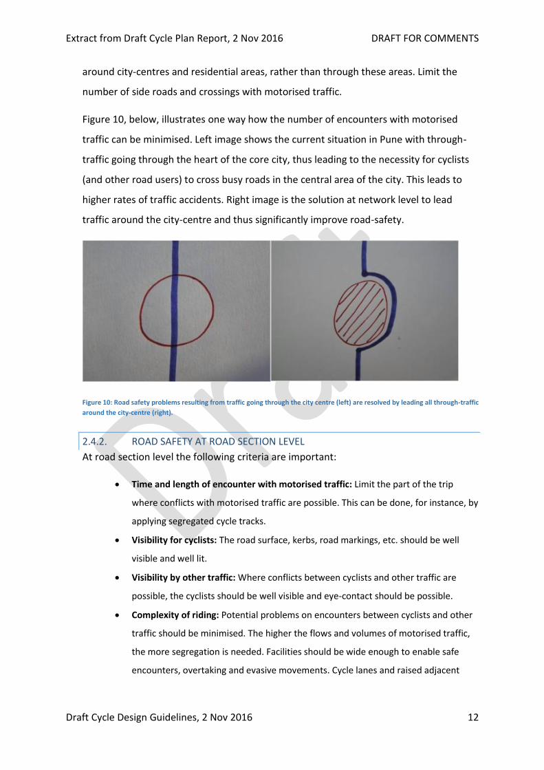
around city-centres and residential areas, rather than through these areas. Limit the
number of side roads and crossings with motorised traffic.
Figure 10, below, illustrates one way how the number of encounters with motorised
traffic can be minimised. Left image shows the current situation in Pune with through-
traffic going through the heart of the core city, thus leading to the necessity for cyclists
(and other road users) to cross busy roads in the central area of the city. This leads to
higher rates of traffic accidents. Right image is the solution at network level to lead
traffic around the city-centre and thus significantly improve road-safety.
Figure 10: Road safety problems resulting from traffic going through the city centre (left) are resolved by leading all through-traffic
around the city-centre (right).
2.4.2. ROAD SAFETY AT ROAD SECTION LEVEL
At road section level the following criteria are important:
Time and length of encounter with motorised traffic: Limit the part of the trip
where conflicts with motorised traffic are possible. This can be done, for instance, by
applying segregated cycle tracks.
Visibility for cyclists: The road surface, kerbs, road markings, etc. should be well
visible and well lit.
Visibility by other traffic: Where conflicts between cyclists and other traffic are
possible, the cyclists should be well visible and eye-contact should be possible.
Complexity of riding: Potential problems on encounters between cyclists and other
traffic should be minimised. The higher the flows and volumes of motorised traffic,
the more segregation is needed. Facilities should be wide enough to enable safe
encounters, overtaking and evasive movements. Cycle lanes and raised adjacent

Extract from Draft Cycle Plan Report, 2 Nov 2016 DRAFT FOR COMMENTS
Draft Cycle Design Guidelines, 2 Nov 2016 13
cycle tracks should never be two-way to avoid that cyclists will end up on the
carriageway in the case of conflicts between approaching cyclists.
Figure 11: Lack of road safety at road section level due to narrow cycle track
Figure 11 shows an example of a very narrow cycle track. The limited width here has a
negative impact on the requirements road safety and comfort. On top of this, raised
adjacent cycle tracks should never be two-way to avoid conflicts and the risk that
cyclists end up on the carriageway.
2.4.3. ROAD SAFETY AT INTERSECTIONS LEVEL
Many accidents happen at intersections. Hence this is a location where much can be
done to improve road safety for cyclists. In many cases changing the geometry of the
intersection is necessary after which cycle facilities can be added to allow for safe
crossing.
Complexity of riding: The chance of conflicts and (severe) accidents with cyclists is
minimised by: Reducing the crossing distance (keep intersection compact), Enabling eye-
contact between road users, reducing waiting times (to discourage cyclists to jump the
red light), Reducing speed differences between motorised modes and cyclists by slowing
down motorised traffic at the intersection, Providing space for overtaking and deviating
manoeuvres, Changing one-way roads for general traffic into two-way roads in order to
avoid confusion from which direction vehicles are coming, to reduce the need for cyclists

Extract from Draft Cycle Plan Report, 2 Nov 2016 DRAFT FOR COMMENTS
Draft Cycle Design Guidelines, 2 Nov 2016 14
to weave between cars and to avoid that cyclists will use the road in contra-flow
direction, Removing slip roads (free left-turn at intersections).
Chance of blinding: Cyclists are not blinded by motorised vehicles’ headlights. Figure
12, below, shows an example of a right-turn slip road (left-turning in the Indian
situation). For cyclists (and other vehicles) going straight and passing the slip road, there
is a potential conflict with vehicles leaving the slip road with relatively high speeds.
These designs are made with the speed and flow of motor vehicles in mind, but this has
a very negative effect on the road safety for cyclists. In cycle-friendly countries like the
Netherlands slip roads are no longer applied in urban areas. Closing the free slip and
leading vehicles via the heart of the junction is the solution here.
Figure 12: Lack of Road safety. Right-turn slip roads allow vehicles to keep their speed when turning right
2.4.4. ROAD SAFETY AT ROAD SURFACE LEVEL
Chance of encounter with motorised traffic: The state of the road surface does not
induce cyclists to abstain from using provided cycle facilities. The road surface of a cycle
lane or cycle track should be at least as smooth as that of the carriageway.
Complexity of riding: The road surface makes it easy to cycle and keep course. The state
of the road surface does not distract the cyclist from traffic or force the cyclist into
dangerous manoeuvres. The road surface is rough enough (also when wet) to enable
safe cycling.
2.5. COMFORT
Cycling infrastructure enables quick and comfortable cycling.

Extract from Draft Cycle Plan Report, 2 Nov 2016 DRAFT FOR COMMENTS
Draft Cycle Design Guidelines, 2 Nov 2016 15
Criteria: Hindrance from traffic; smoothness of road surface; chance of stopping;
hindrance from weather.
Most important to ensure comfortable cycling are: A smooth road surface (refer Figure
13). Limited hindrance from traffic by creating a wide enough verge (separation)
between cycle track and carriageway. Limited hindrance from the weather (sun, heat,
rain) by providing trees along the cycle track. No hindrance from obstacles on the cycle
tracks.
Figure 13: A smooth road surface, also at intersections, leads to better comfort.
In Pune, many cycle tracks are not comfortable because of a bad uneven road surface
(block pavement), obstacles such as trees, lamp posts and bollards.
2.6. ATTRACTIVENESS
Cycling infrastructure provides an attractive cycling experience for cyclists.
Criteria: Experience of surroundings; sense of social safety; chance of blinding.
Attractiveness is probably the most subjective of the five requirements with everyone
having their own opinion on what is attractive. In general, we can say that attractive
cycling conditions at least must do with ‘social safety’ and an attractive environment.
Social insecurity can be minimised by leading cycle routes through areas where there are
people and by providing sufficient lighting. An attractive cycling environment, on the
other hand, has much to do with aesthetics of the built environment (architecture) and a
pleasant natural environment (green space).

Extract from Draft Cycle Plan Report, 2 Nov 2016 DRAFT FOR COMMENTS
Draft Cycle Design Guidelines, 2 Nov 2016 16
2.6.1. ATTRACTIVENESS AT NETWORK LEVEL
Figure 14 shows an example of attractive routing. At road section level this cycle track
could have been made even more attractive by providing a greater separation with the
carriageway. Also, other aspects at network level include:
Environmental quality: Select a routing that is attractive for cyclists. Routes that lead
through green areas, lively urban areas and are quiet and with clean air.
Social safety: Select a routing that doesn’t lead through deserted areas and which
avoids areas known for delinquency.
Figure 14: Attractive cycle route along a park in the Turkish city of Antalya
2.6.2. ATTRACTIVENESS AT ROAD SECTION LEVEL
Environmental quality: The direct surroundings of the cycle facility are (made) attractive
for cyclists. Well-designed and lively and provide trees and attractive street furniture.
Social safety: Cycle facilities are visible for other road users and well lit. No walls or
bushes that could provide a shelter for potential offenders.
2.6.3. ATTRACTIVENESS AT ROAD SURFACE LEVEL
Aesthetic quality: The appearance of the road surface fits with the character of the
surroundings. Note that the requirement attractiveness does not apply at intersection
level.

Extract from Draft Cycle Plan Report, 2 Nov 2016 DRAFT FOR COMMENTS
Draft Cycle Design Guidelines, 2 Nov 2016 17
3. PRINCIPLES OF CYCLING
INFRASTRUCTURE AT ROAD
SECTIONS
There are three main types of cycling route infrastructure: Segregated cycle tracks, cycle
lanes and shared use. Below the different types of cycling infrastructure are shown in
Table 1 with mention of the types of streets where they should be applied.
Table 1: Three types of cycling infrastructure
Segregated Cycle Track Cycle Lane Shared use
Physical segregation Visual segregation No Segregation
High speeds and volumes
of motorised traffic
Medium speeds and
volumes of motorised
traffic
Low speeds and volumes
of motorised traffic
In the paragraphs below, the design and application of cycle tracks, cycle lanes and
shared use are explained.
3.1. CYCLE TRACKS
Cycle tracks are further divided into 3 categories unlike cycle lanes and shared use roads.
Following are the details for the 3 categories of cycle tracks:
3.1.1. RAISED SEGREGATED CYCLE TRACKS Cycle tracks need to be applied along the main roads to protect cyclists from high
volumes of fast moving traffic. There are different types of cycle tracks. For Pune, the
design as shown below Figure 15 is recommended:
Extract from Draft Cycle Plan Report, 2 Nov 2016 DRAFT FOR COMMENTS
Draft Cycle Design Guidelines, 2 Nov 2016 18
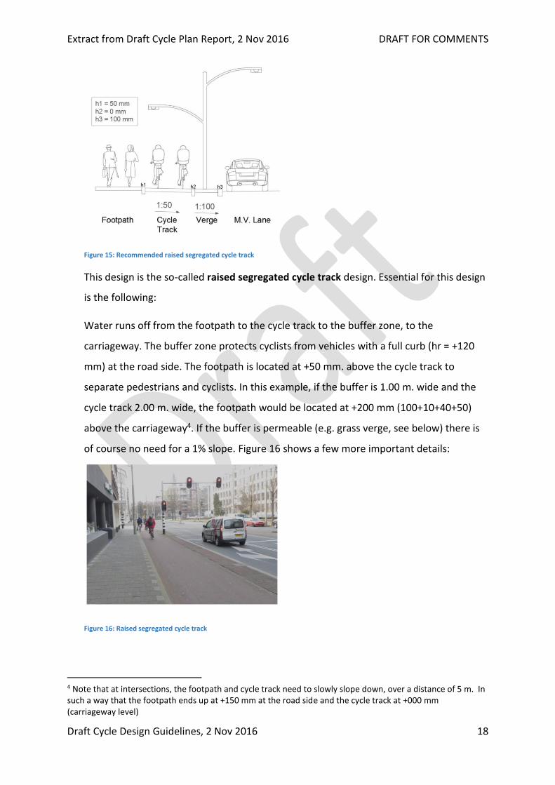
Figure 15: Recommended raised segregated cycle track
This design is the so-called raised segregated cycle track design. Essential for this design
is the following:
Water runs off from the footpath to the cycle track to the buffer zone, to the
carriageway. The buffer zone protects cyclists from vehicles with a full curb (hr = +120
mm) at the road side. The footpath is located at +50 mm. above the cycle track to
separate pedestrians and cyclists. In this example, if the buffer is 1.00 m. wide and the
cycle track 2.00 m. wide, the footpath would be located at +200 mm (100+10+40+50)
above the carriageway4. If the buffer is permeable (e.g. grass verge, see below) there is
of course no need for a 1% slope. Figure 16 shows a few more important details:
Figure 16: Raised segregated cycle track
4 Note that at intersections, the footpath and cycle track need to slowly slope down, over a distance of 5 m. In such a way that the footpath ends up at +150 mm at the road side and the cycle track at +000 mm (carriageway level)
Extract from Draft Cycle Plan Report, 2 Nov 2016 DRAFT FOR COMMENTS
Draft Cycle Design Guidelines, 2 Nov 2016 19
The cycle track should be constructed in, preferably coloured, asphalt (with concrete
being a second-best option). The footpath and buffer zone should be constructed in
pavement blocks or other permeable material. There should be a material and colour
difference between cycle track and footpath, and between cycle track and buffer zone.
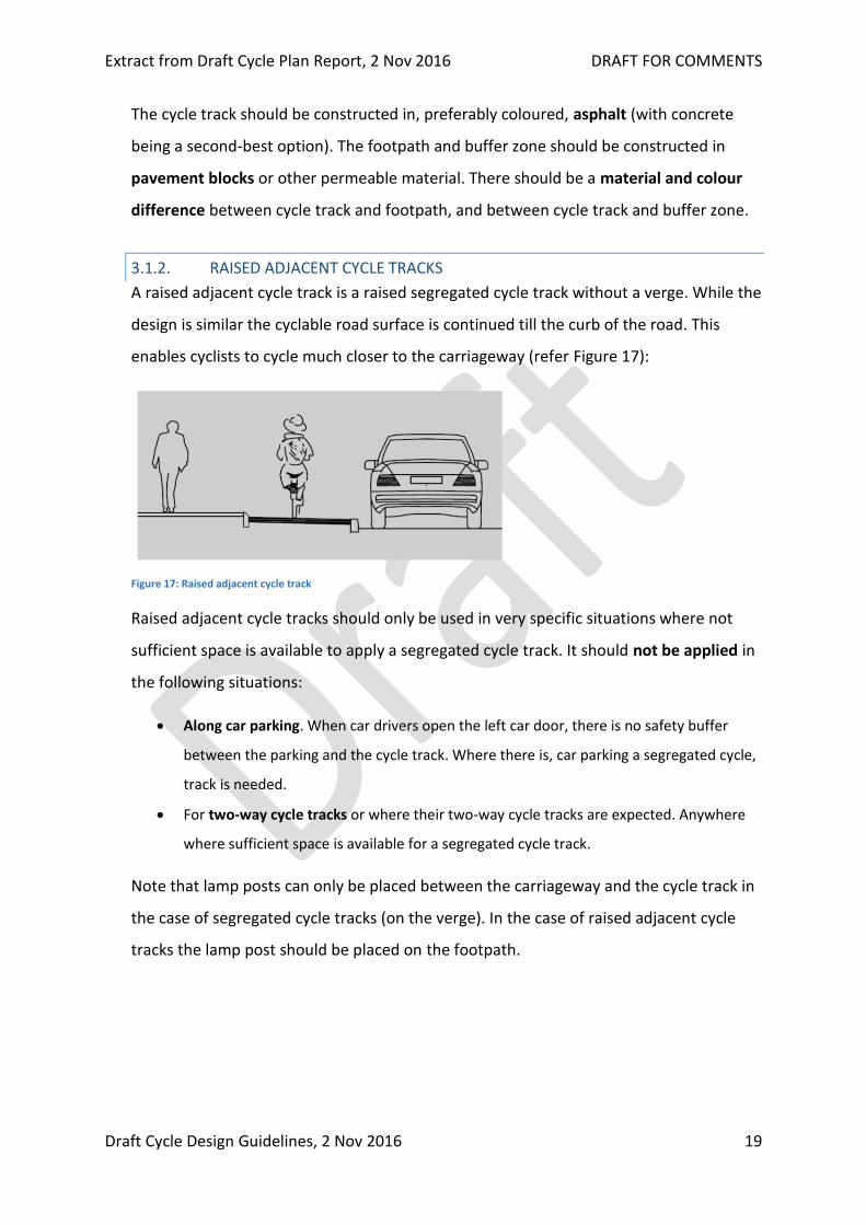
3.1.2. RAISED ADJACENT CYCLE TRACKS
A raised adjacent cycle track is a raised segregated cycle track without a verge. While the
design is similar the cyclable road surface is continued till the curb of the road. This
enables cyclists to cycle much closer to the carriageway (refer Figure 17):
Figure 17: Raised adjacent cycle track
Raised adjacent cycle tracks should only be used in very specific situations where not
sufficient space is available to apply a segregated cycle track. It should not be applied in
the following situations:
Along car parking. When car drivers open the left car door, there is no safety buffer
between the parking and the cycle track. Where there is, car parking a segregated cycle,
track is needed.
For two-way cycle tracks or where their two-way cycle tracks are expected. Anywhere
where sufficient space is available for a segregated cycle track.
Note that lamp posts can only be placed between the carriageway and the cycle track in
the case of segregated cycle tracks (on the verge). In the case of raised adjacent cycle
tracks the lamp post should be placed on the footpath.
Extract from Draft Cycle Plan Report, 2 Nov 2016 DRAFT FOR COMMENTS
Draft Cycle Design Guidelines, 2 Nov 2016 20
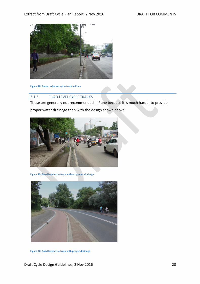
Figure 18: Raised adjacent cycle track in Pune
3.1.3. ROAD LEVEL CYCLE TRACKS
These are generally not recommended in Pune because it is much harder to provide
proper water drainage then with the design shown above:
Figure 19: Road level cycle track without proper drainage
Figure 20: Road level cycle track with proper drainage

Extract from Draft Cycle Plan Report, 2 Nov 2016 DRAFT FOR COMMENTS
Draft Cycle Design Guidelines, 2 Nov 2016 21
However, when well-constructed with proper drainage, road level cycle tracks can be an
easy and efficient way to create cycle tracks by replacing a part of the carriageway with
a cycle track. It can be applied under the following conditions: When using the existing
road surface: Only where existing road surface is of very good quality. Separate drainage
is provided on the cycle track (refer Figure 20).
Cyclists and pedestrians
Separation of cyclists and pedestrians: Pedestrians move at much lower speeds than
cyclists and behave very different than cyclists. Therefore, it is very important that the
footpath and cycle track are physically segregated. This can be done in two ways:
1. By vertical segregation with a height difference (+50 mm) as shown before.
2. By horizontal segregation with a zone with trees and/or lamp posts (see below). In this
case, it is important that the buffer zone has a different material and colour than
footpath and the cycle track.
Figure 21: Horizontal segregation
Figure 22: Vertical segregation (h1=50mm)
Shared paths for pedestrians and cyclists are not recommended alongside urban roads
because this create conflicts between cyclists and pedestrians.
Extract from Draft Cycle Plan Report, 2 Nov 2016 DRAFT FOR COMMENTS
Draft Cycle Design Guidelines, 2 Nov 2016 22
For Pune, it is also not recommended to apply cycle tracks and footpaths only
segregated by a line and/or material difference because this will lead to even more
pedestrians encroaching on the footpath than is happening already today.
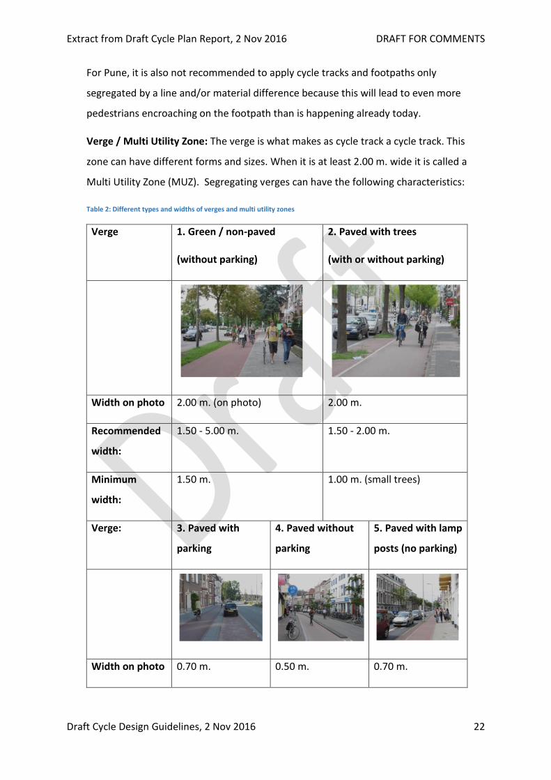
Verge / Multi Utility Zone: The verge is what makes as cycle track a cycle track. This
zone can have different forms and sizes. When it is at least 2.00 m. wide it is called a
Multi Utility Zone (MUZ). Segregating verges can have the following characteristics:
Table 2: Different types and widths of verges and multi utility zones
Verge 1. Green / non-paved
(without parking)
2. Paved with trees
(with or without parking)
Width on photo 2.00 m. (on photo) 2.00 m.
Recommended
width:
1.50 - 5.00 m. 1.50 - 2.00 m.
Minimum
width:
1.50 m. 1.00 m. (small trees)
Verge: 3. Paved with
parking
4. Paved without
parking
5. Paved with lamp
posts (no parking)
Width on photo 0.70 m. 0.50 m. 0.70 m.
Extract from Draft Cycle Plan Report, 2 Nov 2016 DRAFT FOR COMMENTS
Draft Cycle Design Guidelines, 2 Nov 2016 23
Recommended
width:
1.00 m.-2.00m. 0.70 -2.00 m. 1.00 m.-2.00 m.
Minimum
width:
0.70 m. (safe
distance for door
opening)
0.50 m. 1.00 m. (to allow
for safe distance to
lamp post)
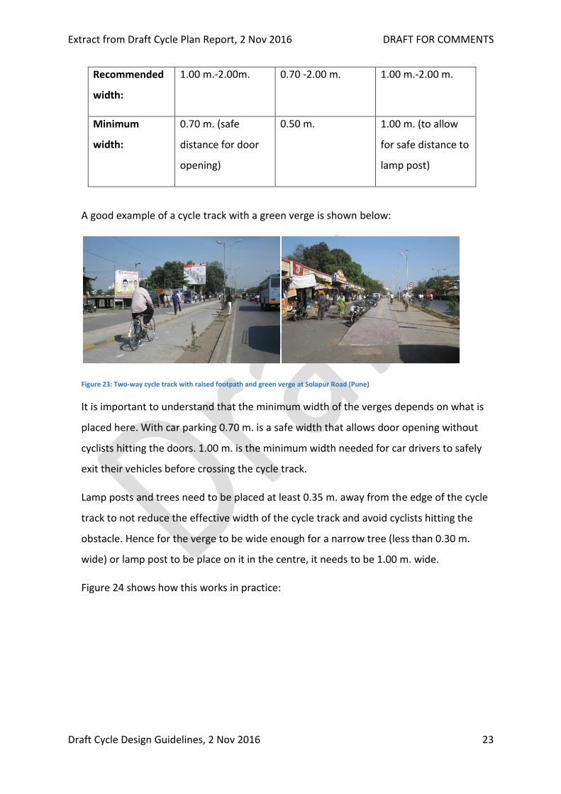
A good example of a cycle track with a green verge is shown below:
Figure 23: Two-way cycle track with raised footpath and green verge at Solapur Road (Pune)
It is important to understand that the minimum width of the verges depends on what is
placed here. With car parking 0.70 m. is a safe width that allows door opening without
cyclists hitting the doors. 1.00 m. is the minimum width needed for car drivers to safely
exit their vehicles before crossing the cycle track.
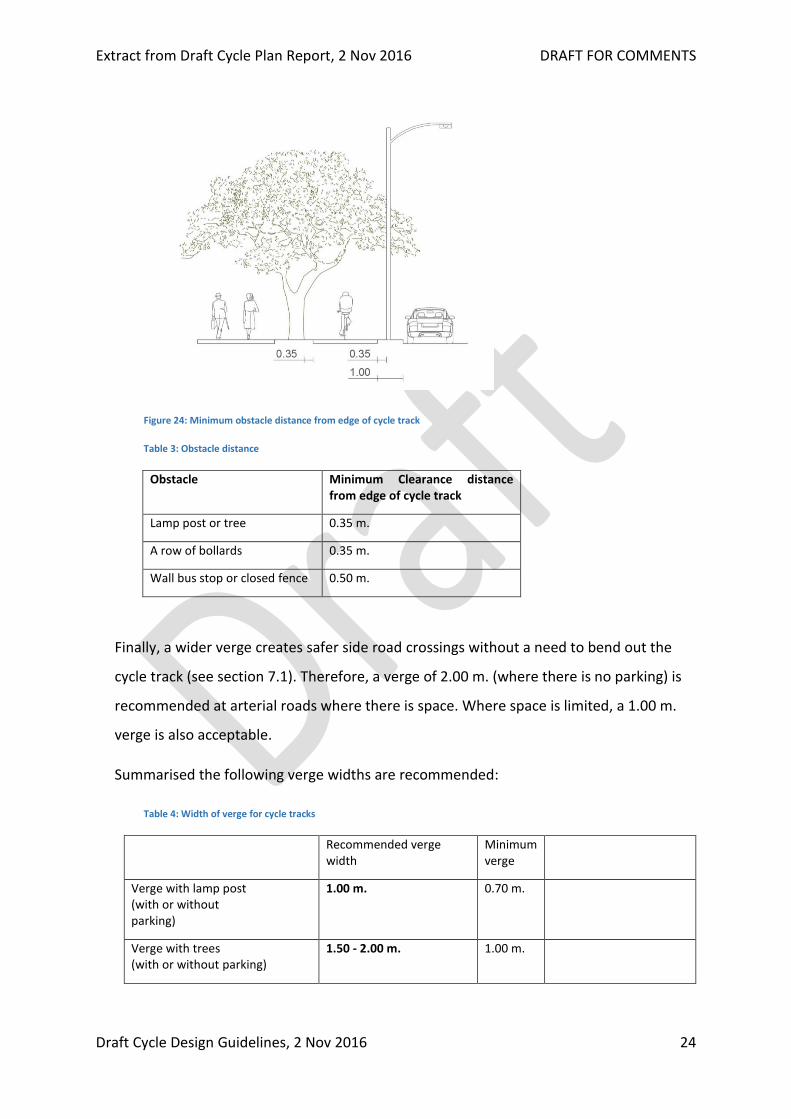
Lamp posts and trees need to be placed at least 0.35 m. away from the edge of the cycle
track to not reduce the effective width of the cycle track and avoid cyclists hitting the
obstacle. Hence for the verge to be wide enough for a narrow tree (less than 0.30 m.
wide) or lamp post to be place on it in the centre, it needs to be 1.00 m. wide.
Figure 24 shows how this works in practice:
Extract from Draft Cycle Plan Report, 2 Nov 2016 DRAFT FOR COMMENTS
Draft Cycle Design Guidelines, 2 Nov 2016 24
Figure 24: Minimum obstacle distance from edge of cycle track
Table 3: Obstacle distance
Obstacle Minimum Clearance distance from edge of cycle track
Lamp post or tree 0.35 m.
A row of bollards 0.35 m.
Wall bus stop or closed fence 0.50 m.
Finally, a wider verge creates safer side road crossings without a need to bend out the
cycle track (see section 7.1). Therefore, a verge of 2.00 m. (where there is no parking) is
recommended at arterial roads where there is space. Where space is limited, a 1.00 m.
verge is also acceptable.
Summarised the following verge widths are recommended:
Table 4: Width of verge for cycle tracks
Recommended verge width
Minimum verge
Verge with lamp post (with or without parking)
1.00 m. 0.70 m.
Verge with trees (with or without parking)
1.50 - 2.00 m. 1.00 m.
Extract from Draft Cycle Plan Report, 2 Nov 2016 DRAFT FOR COMMENTS
Draft Cycle Design Guidelines, 2 Nov 2016 25
Narrow verge without trees, lamp posts and parking
0.70 m. 0.50 m.
Arterial road 2.00 m.
1.00 m. + 2.00 m. parking (preferred without parking)
1.00 m. Preferably with trees
Sub-arterial road 1.00 m. + 2.00 m. parking 1.00 m. Trees between parking
Collector road 1.00 m. + 2.00 m. parking
1.00 m. (no parking, with lamp posts)
0.70 m. (without lamp posts)
0.70 m. 0.70 m.
0.50 m.
Trees between parking
Without lamp posts
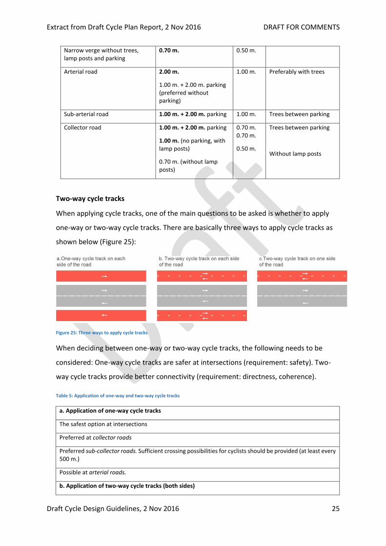
Two-way cycle tracks
When applying cycle tracks, one of the main questions to be asked is whether to apply
one-way or two-way cycle tracks. There are basically three ways to apply cycle tracks as
shown below (Figure 25):
Figure 25: Three ways to apply cycle tracks
When deciding between one-way or two-way cycle tracks, the following needs to be
considered: One-way cycle tracks are safer at intersections (requirement: safety). Two-
way cycle tracks provide better connectivity (requirement: directness, coherence).
Table 5: Application of one-way and two-way cycle tracks
a. Application of one-way cycle tracks
The safest option at intersections
Preferred at collector roads
Preferred sub-collector roads. Sufficient crossing possibilities for cyclists should be provided (at least every 500 m.)
Possible at arterial roads.
b. Application of two-way cycle tracks (both sides)

Extract from Draft Cycle Plan Report, 2 Nov 2016 DRAFT FOR COMMENTS
Draft Cycle Design Guidelines, 2 Nov 2016 26
Accident risk at intersections twice as high as with one-way cycle track
Can be applied where contraflow use of one-way cycle tracks is likely (where there is less than one crossing per 500 m. and many destinations along that side of the road)
Possible at arterial roads with ROW of 55 m and over (at both sides of the road!) where frequent contraflow cycle use is expected (or observed)
c. Application of two-way cycle track (on one sides)
Note: This is not a standard design and should only be provided at specific situations after study of the connectivity for cyclists.
For through cycle routes along canals or rail-lines (at the side of the canal or railway).
Condition: The main road needs to have cycle crossings at every side road on the opposite site of the main road.
Possible on collector roads in very specific situations where this leads to better accessibility for cyclists.
Because arterial roads have fewer possibilities for crossing than roads of lower hierarchy,
contraflow use of one-way cycle tracks is more likely on these roads. Therefore, at
arterial road 2.50 m. wide one-way cycle tracks are proposed (these are also wide
enough for two-way use). Two-way cycle tracks can be applied at extra wide arterial
roads (> 3 lanes per direction and ROW > 55 m.). Because two-way cycle tracks are less
safe at intersections it is essential to create a safe design at major intersections as well as
minor side road. This is explained in chapter 6.
At sub-arterial roads and collector roads, crossing the street is easier and (ideally)
possible at many locations. Therefore, here, one-way cycle tracks are the default option.
On collector roads, also cycle lanes can be applied.
Width of cycle tracks: Figure 26 shows that, for a cyclist to comfortably overtake another
cyclist, 2.00 m. is the minimum width for one-way cycle tracks derived by adding up the
width of the cyclists and the distance they keep to edges and obstacles. With a low edge
(h2 = 0), theoretically a width of even 1.80 m. is possible, but this makes overtaking
difficult and is not recommended for Pune5. On routes with higher volumes of cycle
traffic the cycle track width should be greater. On such routes 2.50 m. is preferred. Two-
way cycle tracks should be wider.
5 The USDG advises a minimum width of 2.00 m. for one-way and a minimum of 2.50 m. for two-way cycle tracks.

Extract from Draft Cycle Plan Report, 2 Nov 2016 DRAFT FOR COMMENTS
Draft Cycle Design Guidelines, 2 Nov 2016 27
Figure 26: Minimum width for one-way cycle track
Below in Table 6, recommendations for cycle track widths in Pune are given6:
Table 6: Recommendations for cycle track widths in Pune
Cyclists in peak hour in one direction
Width
One-way cycle
tracks
0 - 150 2.00 m.
> 150 2.50 m.
At collector roads 2.00 m.7
At sub-arterial roads 2.20 m.8
At arterial roads 2.50 m.
Cyclist in peak hour (sum of two directions)
Width
Two-way cycle tracks
0 - 50 2.50 m.
50 - 150 3.00 m.
> 150 3.50 m.
At arterial roads 3.00 m.
Because at arterial roads there are fewer locations where cyclists can cross, some
contraflow use of one-way cycle tracks is likely. Therefore, here one-way cycle tracks
should preferably be 2.50 m. wide independent of the number of cyclists.
On sub-arterial roads, there are more locations where crossing is possible, hence here a
smaller width can be applied. 2.20 m. is appropriate, but where space is available or
volumes of cyclists are high, 2.50 m. can also be applied.
6 In the USDG one-way cycle tracks are either 2.00 or 2.50 m. wide. 7 Depending on available space and amount of cyclists. 8 Depending on available space and amount of cyclists.
Extract from Draft Cycle Plan Report, 2 Nov 2016 DRAFT FOR COMMENTS
Draft Cycle Design Guidelines, 2 Nov 2016 28
In Pune, the busiest cycle routes – as per to our counts - have about 150 cyclists in the
busiest peak hour in two directions (Bhajirao Road, FC Road) or 75 cyclists per hour per
direction (on each side of the road). Hence, for these roads, currently 2.00 m. wide one-
way cycle tracks are still possible, but when applied along sub-arterial or arterial roads
wider widths, as per Table 6 , are recommended.
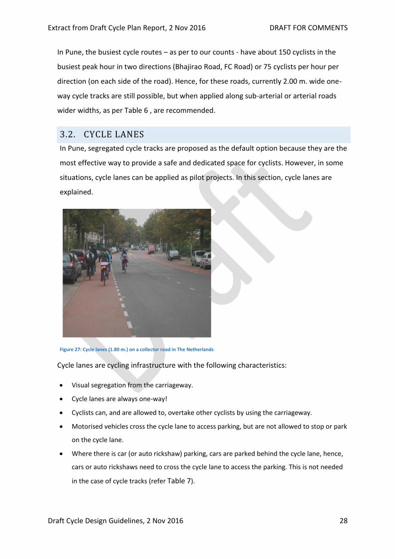
3.2. CYCLE LANES
In Pune, segregated cycle tracks are proposed as the default option because they are the
most effective way to provide a safe and dedicated space for cyclists. However, in some
situations, cycle lanes can be applied as pilot projects. In this section, cycle lanes are
explained.
Figure 27: Cycle lanes (1.80 m.) on a collector road in The Netherlands
Cycle lanes are cycling infrastructure with the following characteristics:
Visual segregation from the carriageway.
Cycle lanes are always one-way!
Cyclists can, and are allowed to, overtake other cyclists by using the carriageway.
Motorised vehicles cross the cycle lane to access parking, but are not allowed to stop or park
on the cycle lane.
Where there is car (or auto rickshaw) parking, cars are parked behind the cycle lane, hence,
cars or auto rickshaws need to cross the cycle lane to access the parking. This is not needed
in the case of cycle tracks (refer Table 7).
Extract from Draft Cycle Plan Report, 2 Nov 2016 DRAFT FOR COMMENTS
Draft Cycle Design Guidelines, 2 Nov 2016 29
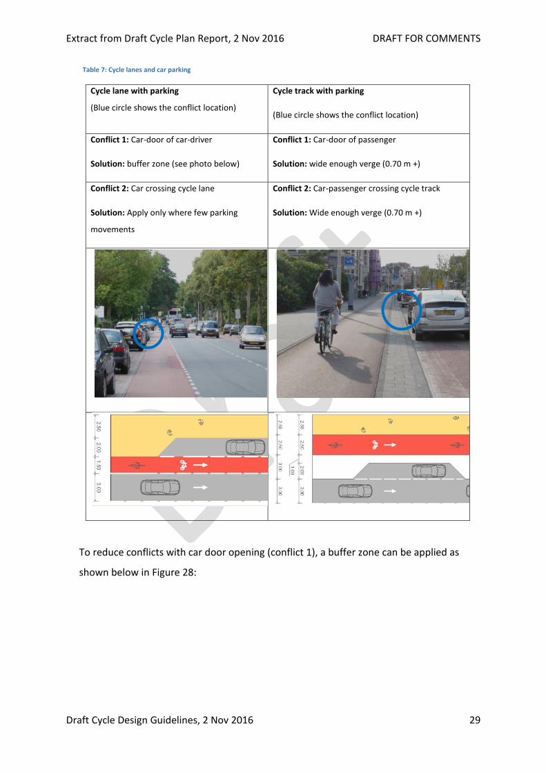
Table 7: Cycle lanes and car parking
Cycle lane with parking
(Blue circle shows the conflict location)
Cycle track with parking
(Blue circle shows the conflict location)
Conflict 1: Car-door of car-driver
Solution: buffer zone (see photo below)
Conflict 1: Car-door of passenger
Solution: wide enough verge (0.70 m +)
Conflict 2: Car crossing cycle lane
Solution: Apply only where few parking
movements
Conflict 2: Car-passenger crossing cycle track
Solution: Wide enough verge (0.70 m +)
To reduce conflicts with car door opening (conflict 1), a buffer zone can be applied as
shown below in Figure 28:

Extract from Draft Cycle Plan Report, 2 Nov 2016 DRAFT FOR COMMENTS
Draft Cycle Design Guidelines, 2 Nov 2016 30
Figure 28: Cycle lane with buffer zone at car parking
A buffer zone of 0.80 m. is a safe protection against drivers opening their doors. This is
recommended because Indian drivers are not used to cycle lanes and will probably easily
forget to think about them when opening the door of their vehicles.
Until today, cycle lanes have not yet been applied in Pune. Because they do not provide
physical segregation, their use should be limited. Invasion by motorcycles, and possibly
also cars is very likely. Below, the conditions for the application of cycle lanes in Pune are
given. Application of cycle lanes is possible under the following conditions:
I. On collector roads (roads with 1 lane per direction)
II. Where there is no car or M2W parking or where there are few parking movements
(e.g. residential parking only).
III. After implementation, a period of education and enforcement is needed to avoid
illegal parking on the cycle lane.
IV. Cycle lanes are always one-way!
Recommended
Width of cycle lanes 1.80

Extract from Draft Cycle Plan Report, 2 Nov 2016 DRAFT FOR COMMENTS
Draft Cycle Design Guidelines, 2 Nov 2016 31
3.3. SHARED USE
On local streets (access streets) cyclists can share the street with motorised traffic.
Following are the important things:
I. 30 km/h speed limit
II. Limited width of carriageway (4.00 - 7.00 m.), no traffic lanes marked.
III. Parallel parking bays can be applied.
IV. Particularly at inner city access street, a different pavement is recommended. For
instance, brick pavement.
V. Traffic calming measures, such as speed humps, need to be applied.
See Urban Street design guidelines for further details.
Figure 29: Street with shared use and parallel parking
Extract from Draft Cycle Plan Report, 2 Nov 2016 DRAFT FOR COMMENTS
Draft Cycle Design Guidelines, 2 Nov 2016 32
4. CYCLING INFRASTRUCTURE IN
RELATION TO STREET TYPOLOGY
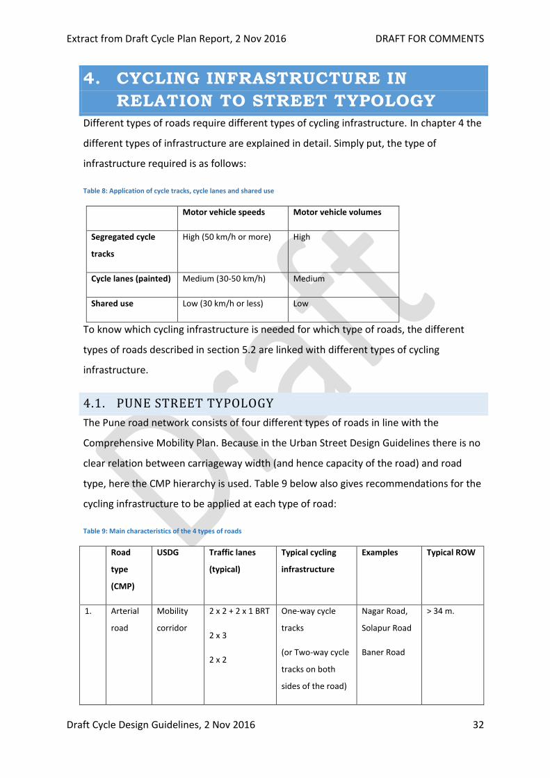
Different types of roads require different types of cycling infrastructure. In chapter 4 the
different types of infrastructure are explained in detail. Simply put, the type of
infrastructure required is as follows:
Table 8: Application of cycle tracks, cycle lanes and shared use
Motor vehicle speeds Motor vehicle volumes
Segregated cycle
tracks
High (50 km/h or more) High
Cycle lanes (painted) Medium (30-50 km/h) Medium
Shared use Low (30 km/h or less) Low
To know which cycling infrastructure is needed for which type of roads, the different
types of roads described in section 5.2 are linked with different types of cycling
infrastructure.
4.1. PUNE STREET TYPOLOGY
The Pune road network consists of four different types of roads in line with the
Comprehensive Mobility Plan. Because in the Urban Street Design Guidelines there is no
clear relation between carriageway width (and hence capacity of the road) and road
type, here the CMP hierarchy is used. Table 9 below also gives recommendations for the
cycling infrastructure to be applied at each type of road:
Table 9: Main characteristics of the 4 types of roads
Road
type
(CMP)
USDG Traffic lanes
(typical)
Typical cycling
infrastructure
Examples Typical ROW
1. Arterial
road
Mobility
corridor
2 x 2 + 2 x 1 BRT
2 x 3
2 x 2
One-way cycle
tracks
(or Two-way cycle
tracks on both
sides of the road)
Nagar Road,
Solapur Road
Baner Road
> 34 m.
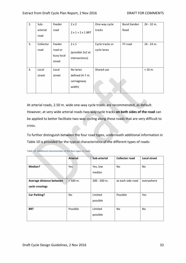
Extract from Draft Cycle Plan Report, 2 Nov 2016 DRAFT FOR COMMENTS
Draft Cycle Design Guidelines, 2 Nov 2016 33
2. Sub-
arterial
road
Feeder
road
2 x 2
2 x 1 + 2 x 1 BRT
One-way cycle
tracks
Bund Garden
Road
24 - 32 m.
3. Collector
road
Feeder
road or
busy local
street
2 x 1
(possible 2x2 at
intersections)
Cycle tracks or
cycle lanes
ITI road 16 - 24 m.
4. Local
street
Local
street
No lanes
defined (4-7 m.
carriageway
width)
Shared use < 16 m.
At arterial roads, 2.50 m. wide one-way cycle tracks are recommended, as default.
However, at very wide arterial roads two-way cycle tracks on both sides of the road can
be applied to better facilitate two-way cycling along these roads that are very difficult to
cross.
To further distinguish between the four road types, underneath additional information in
Table 10 is provided for the typical characteristics of the different types of roads:
Table 10: Additional characteristics of the four types of roads
Arterial Sub-arterial Collector road Local street
Median? Yes Yes, low
median
No No
Average distance between
cycle crossings
> 500 m. 200 - 500 m. at each side road everywhere
Car Parking? No Limited
possible
Possible Yes
BRT Possible Limited
possible
No No
Extract from Draft Cycle Plan Report, 2 Nov 2016 DRAFT FOR COMMENTS
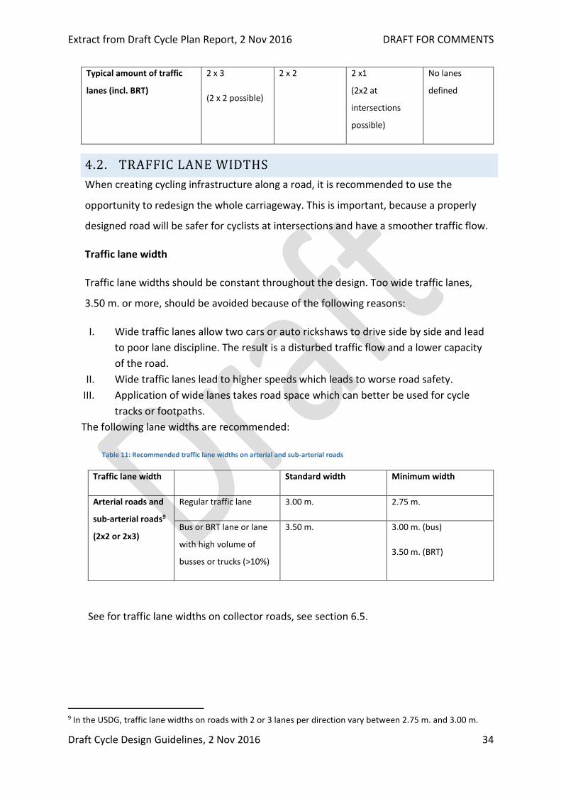
Draft Cycle Design Guidelines, 2 Nov 2016 34
Typical amount of traffic
lanes (incl. BRT)
2 x 3
(2 x 2 possible)
2 x 2 2 x1
(2x2 at
intersections
possible)
No lanes
defined
4.2. TRAFFIC LANE WIDTHS
When creating cycling infrastructure along a road, it is recommended to use the
opportunity to redesign the whole carriageway. This is important, because a properly
designed road will be safer for cyclists at intersections and have a smoother traffic flow.
Traffic lane width
Traffic lane widths should be constant throughout the design. Too wide traffic lanes,
3.50 m. or more, should be avoided because of the following reasons:
I. Wide traffic lanes allow two cars or auto rickshaws to drive side by side and lead
to poor lane discipline. The result is a disturbed traffic flow and a lower capacity
of the road.
II. Wide traffic lanes lead to higher speeds which leads to worse road safety.
III. Application of wide lanes takes road space which can better be used for cycle
tracks or footpaths.
The following lane widths are recommended:
Table 11: Recommended traffic lane widths on arterial and sub-arterial roads
Traffic lane width Standard width Minimum width
Arterial roads and
sub-arterial roads9
(2x2 or 2x3)
Regular traffic lane 3.00 m. 2.75 m.
Bus or BRT lane or lane
with high volume of
busses or trucks (>10%)
3.50 m. 3.00 m. (bus)
3.50 m. (BRT)
See for traffic lane widths on collector roads, see section 6.5.
9 In the USDG, traffic lane widths on roads with 2 or 3 lanes per direction vary between 2.75 m. and 3.00 m.
Extract from Draft Cycle Plan Report, 2 Nov 2016 DRAFT FOR COMMENTS
Draft Cycle Design Guidelines, 2 Nov 2016 35
Local roads where cyclists share the road have no delineated traffic lanes. Here the total
width of the road can vary between 4.00 and 7.00 m. depending on traffic volumes and
the presence of parking.
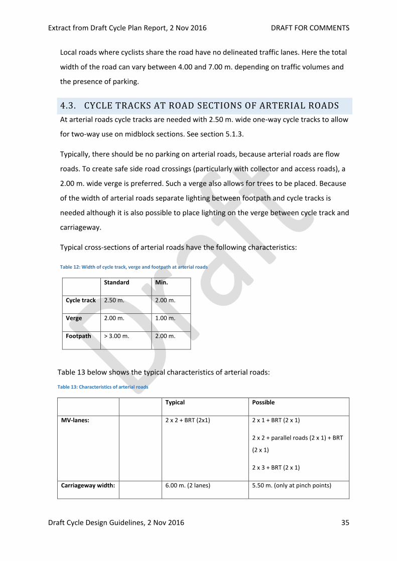
4.3. CYCLE TRACKS AT ROAD SECTIONS OF ARTERIAL ROADS
At arterial roads cycle tracks are needed with 2.50 m. wide one-way cycle tracks to allow
for two-way use on midblock sections. See section 5.1.3.
Typically, there should be no parking on arterial roads, because arterial roads are flow
roads. To create safe side road crossings (particularly with collector and access roads), a
2.00 m. wide verge is preferred. Such a verge also allows for trees to be placed. Because
of the width of arterial roads separate lighting between footpath and cycle tracks is
needed although it is also possible to place lighting on the verge between cycle track and
carriageway.
Typical cross-sections of arterial roads have the following characteristics:
Table 12: Width of cycle track, verge and footpath at arterial roads
Standard Min.
Cycle track 2.50 m. 2.00 m.
Verge 2.00 m. 1.00 m.
Footpath > 3.00 m. 2.00 m.
Table 13 below shows the typical characteristics of arterial roads:
Table 13: Characteristics of arterial roads
Typical Possible
MV-lanes: 2 x 2 + BRT (2x1) 2 x 1 + BRT (2 x 1)
2 x 2 + parallel roads (2 x 1) + BRT
(2 x 1)
2 x 3 + BRT (2 x 1)
Carriageway width: 6.00 m. (2 lanes) 5.50 m. (only at pinch points)
Extract from Draft Cycle Plan Report, 2 Nov 2016 DRAFT FOR COMMENTS
Draft Cycle Design Guidelines, 2 Nov 2016 36
9.00 m. ( 3 lanes)
Maximum speed: 50 km/h
Traffic volumes: > 3000
PCU/hr. in
two
directions
ROW: > 34 m. 28 - 34 m. (2 x 1 + BRT)
Cycling
infrastructure:
Segregated one-way cycle
tracks. 2.50 m wide
Segregated two-way cycle tracks.
3.00 m. wide
Verge: 2.00 m. with trees 1.00 m. where lack of space
Car parking: No
Median: 1.00 m at both sides of BRT 0.50 m. where there is lack of
space
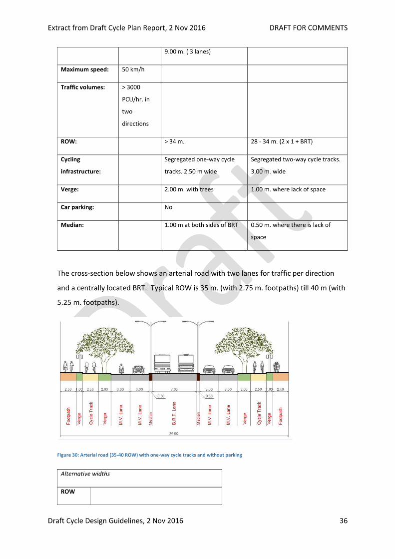
The cross-section below shows an arterial road with two lanes for traffic per direction
and a centrally located BRT. Typical ROW is 35 m. (with 2.75 m. footpaths) till 40 m (with
5.25 m. footpaths).
Figure 30: Arterial road (35-40 ROW) with one-way cycle tracks and without parking
Alternative widths
ROW
Extract from Draft Cycle Plan Report, 2 Nov 2016 DRAFT FOR COMMENTS
Draft Cycle Design Guidelines, 2 Nov 2016 37
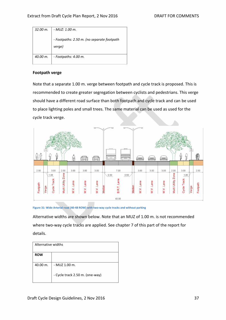
Footpath verge
Note that a separate 1.00 m. verge between footpath and cycle track is proposed. This is
recommended to create greater segregation between cyclists and pedestrians. This verge
should have a different road surface than both footpath and cycle track and can be used
to place lighting poles and small trees. The same material can be used as used for the
cycle track verge.
Figure 31: Wide Arterial road (40-48 ROW) with two-way cycle tracks and without parking
Alternative widths are shown below. Note that an MUZ of 1.00 m. is not recommended
where two-way cycle tracks are applied. See chapter 7 of this part of the report for
details.
Alternative widths
ROW
40.00 m. - MUZ 1.00 m.
- Cycle track 2.50 m. (one-way)
32.00 m. - MUZ: 1.00 m.
- Footpaths: 2.50 m. (no separate footpath
verge)
40.00 m. - Footpaths: 4.00 m.

Extract from Draft Cycle Plan Report, 2 Nov 2016 DRAFT FOR COMMENTS
Draft Cycle Design Guidelines, 2 Nov 2016 38
45.00 m. - Medians: 1.00 m.
- Footpaths: 3.00 m.
48.00 m. - Medians: 1.00 m.
- Footpaths: 4.50 m.
Arterial roads with a width of 45 m. or over can also be designed as 2x2 lanes + BRT +
parallel roads.
4.4. CYCLE TRACKS AT ROAD SECTIONS OF SUB-ARTERIAL
ROADS
Typically, sub-arterial roads are the connectors between arterial roads and collector
roads. In some cases, however, sub-arterial roads also connect directly to local access
roads.
Table 14: Characteristics of sub-arterial roads
Typical Possible
MV-lanes: 2 x 2 2 x 3 at intersections
Carriageway
width:
6.00 m. or 6.50 m. (with busses) 5.50 m. (only at pinch points)
Maximum speed: 50 km/h
Traffic volumes: 2000-4000
PCU/hr. in two
directions
(peak hour)
ROW: 24-32 m.
Cycling
infrastructure:
Segregated cycle tracks. 2.20 m.
wide
Verge: 1.00 m. where there is parking
3.00 m. at locations without
parking
Car parking: Often present 2.00 m.
Median: 2.00 m. low median 1.00 m. low median

Extract from Draft Cycle Plan Report, 2 Nov 2016 DRAFT FOR COMMENTS
Draft Cycle Design Guidelines, 2 Nov 2016 39
The design of sub-arterial roads is very similar to that of arterial roads. With three main
differences:
I. Typically, no BRT which makes the road narrower and easier to cross.
II. Parallel parking can be applied at specific locations.
III. Wide and low median (2.00 m.) to be provided to allow for simple creation of
safe crossings for pedestrians and cyclists. Also at certain side roads where MV-
traffic is not allowed to cross.
Slightly narrower cycle tracks because of less contraflow use because more cycle crossing
possibilities per kilometre.
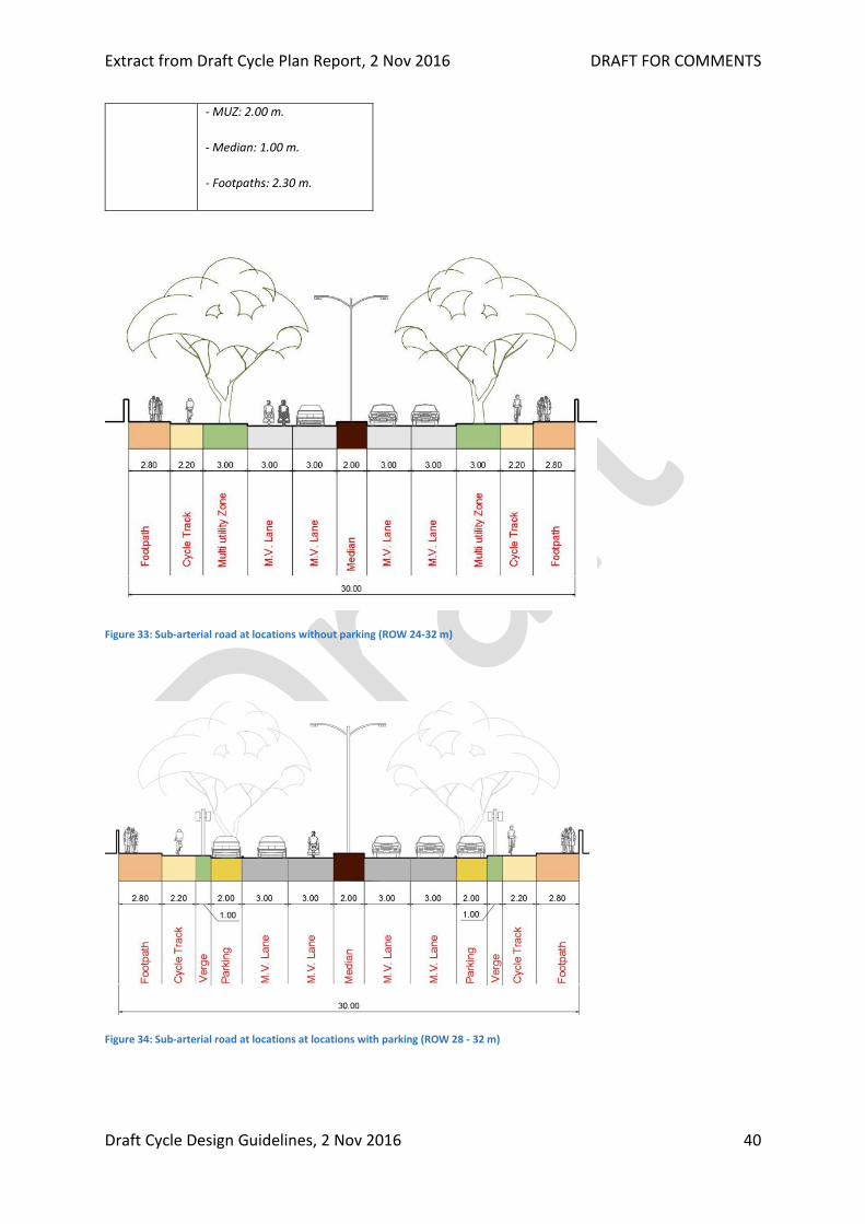
Figure 32: Sub-arterial road at locations without parking (ROW 24-32 m)
Alternative widths
ROW
24.00 m. - No car parking
- MUZ: 1.00 m.
- Median: 1.00 m.
- Footpaths: 2.30 m.
26.00 m. - No car parking
Extract from Draft Cycle Plan Report, 2 Nov 2016 DRAFT FOR COMMENTS
Draft Cycle Design Guidelines, 2 Nov 2016 40
Figure 33: Sub-arterial road at locations without parking (ROW 24-32 m)
Figure 34: Sub-arterial road at locations at locations with parking (ROW 28 - 32 m)
- MUZ: 2.00 m.
- Median: 1.00 m.
- Footpaths: 2.30 m.
Extract from Draft Cycle Plan Report, 2 Nov 2016 DRAFT FOR COMMENTS
Draft Cycle Design Guidelines, 2 Nov 2016 41
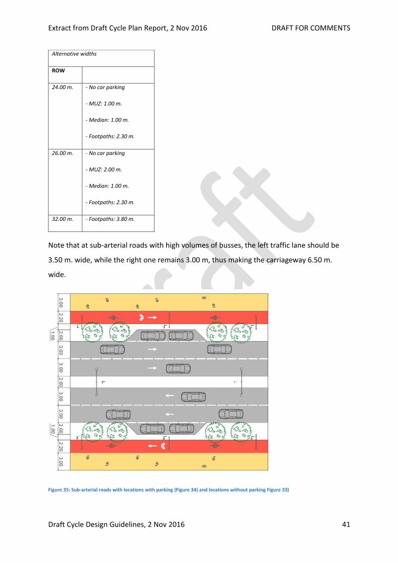
Note that at sub-arterial roads with high volumes of busses, the left traffic lane should be
3.50 m. wide, while the right one remains 3.00 m, thus making the carriageway 6.50 m.
wide.
Figure 35: Sub-arterial roads with locations with parking (Figure 34) and locations without parking Figure 33)
Alternative widths
ROW
24.00 m. - No car parking
- MUZ: 1.00 m.
- Median: 1.00 m.
- Footpaths: 2.30 m.
26.00 m. - No car parking
- MUZ: 2.00 m.
- Median: 1.00 m.
- Footpaths: 2.30 m.
32.00 m. - Footpaths: 3.80 m.
Extract from Draft Cycle Plan Report, 2 Nov 2016 DRAFT FOR COMMENTS
Draft Cycle Design Guidelines, 2 Nov 2016 42
4.5. CYCLING INFRASTRUCTURE AT ROAD SECTIONS OF
COLLECTOR ROADS
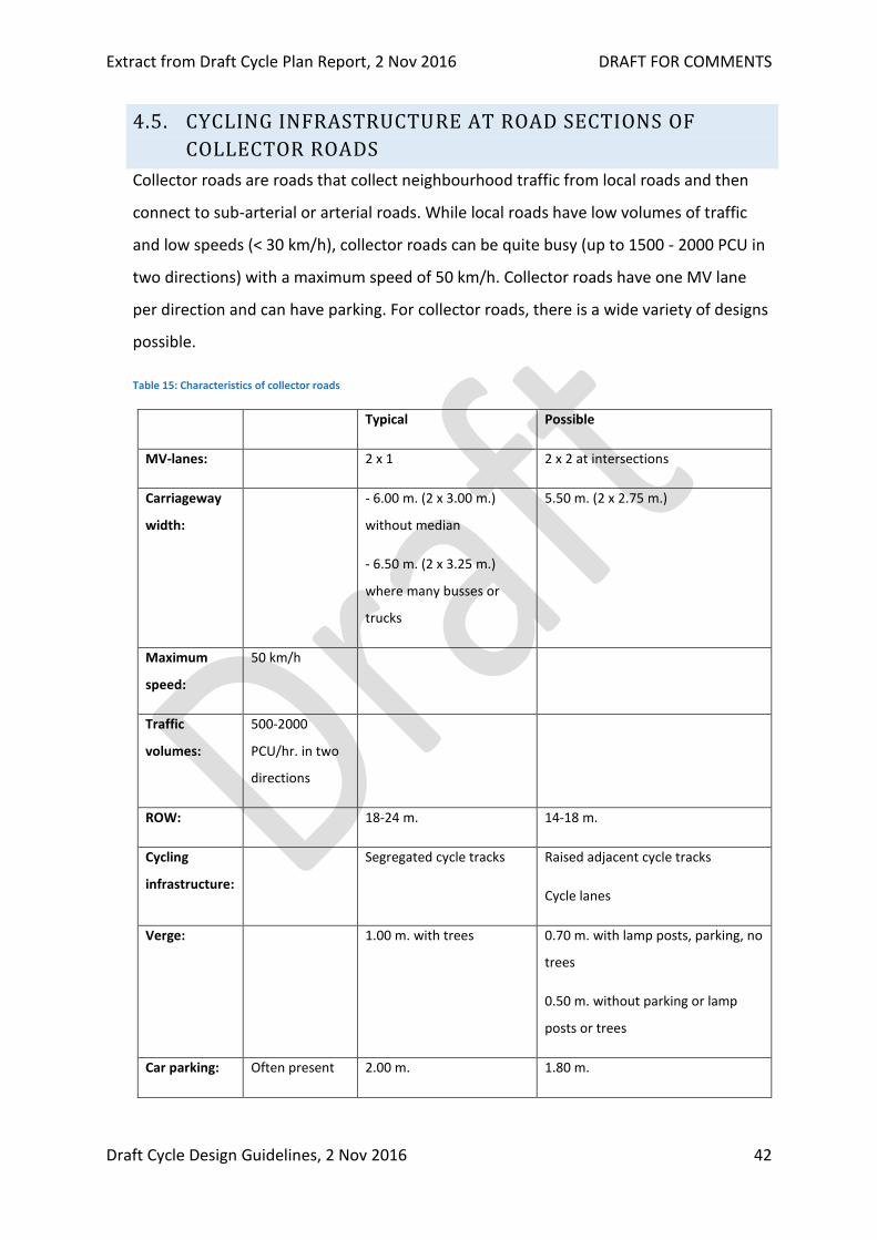
Collector roads are roads that collect neighbourhood traffic from local roads and then
connect to sub-arterial or arterial roads. While local roads have low volumes of traffic
and low speeds (< 30 km/h), collector roads can be quite busy (up to 1500 - 2000 PCU in
two directions) with a maximum speed of 50 km/h. Collector roads have one MV lane
per direction and can have parking. For collector roads, there is a wide variety of designs
possible.
Table 15: Characteristics of collector roads
Typical Possible
MV-lanes: 2 x 1 2 x 2 at intersections
Carriageway
width:
- 6.00 m. (2 x 3.00 m.)
without median
- 6.50 m. (2 x 3.25 m.)
where many busses or
trucks
5.50 m. (2 x 2.75 m.)
Maximum
speed:
50 km/h
Traffic
volumes:
500-2000
PCU/hr. in two
directions
ROW: 18-24 m. 14-18 m.
Cycling
infrastructure:
Segregated cycle tracks Raised adjacent cycle tracks
Cycle lanes
Verge: 1.00 m. with trees
0.70 m. with lamp posts, parking, no
trees
0.50 m. without parking or lamp
posts or trees
Car parking: Often present 2.00 m. 1.80 m.
Extract from Draft Cycle Plan Report, 2 Nov 2016 DRAFT FOR COMMENTS
Draft Cycle Design Guidelines, 2 Nov 2016 43
Median: Not present 1.00-2.00 m. low median
In the following sections, we show different types of designs for collector roads. Types
are not just defined by the right of way, but also by the number of lanes at intersections,
whether car parking is provided or not and the type of cycling infrastructure. While the
design of arterial and sub-arterial roads is rather straightforward, for collector roads
there are many different options that can be applied.
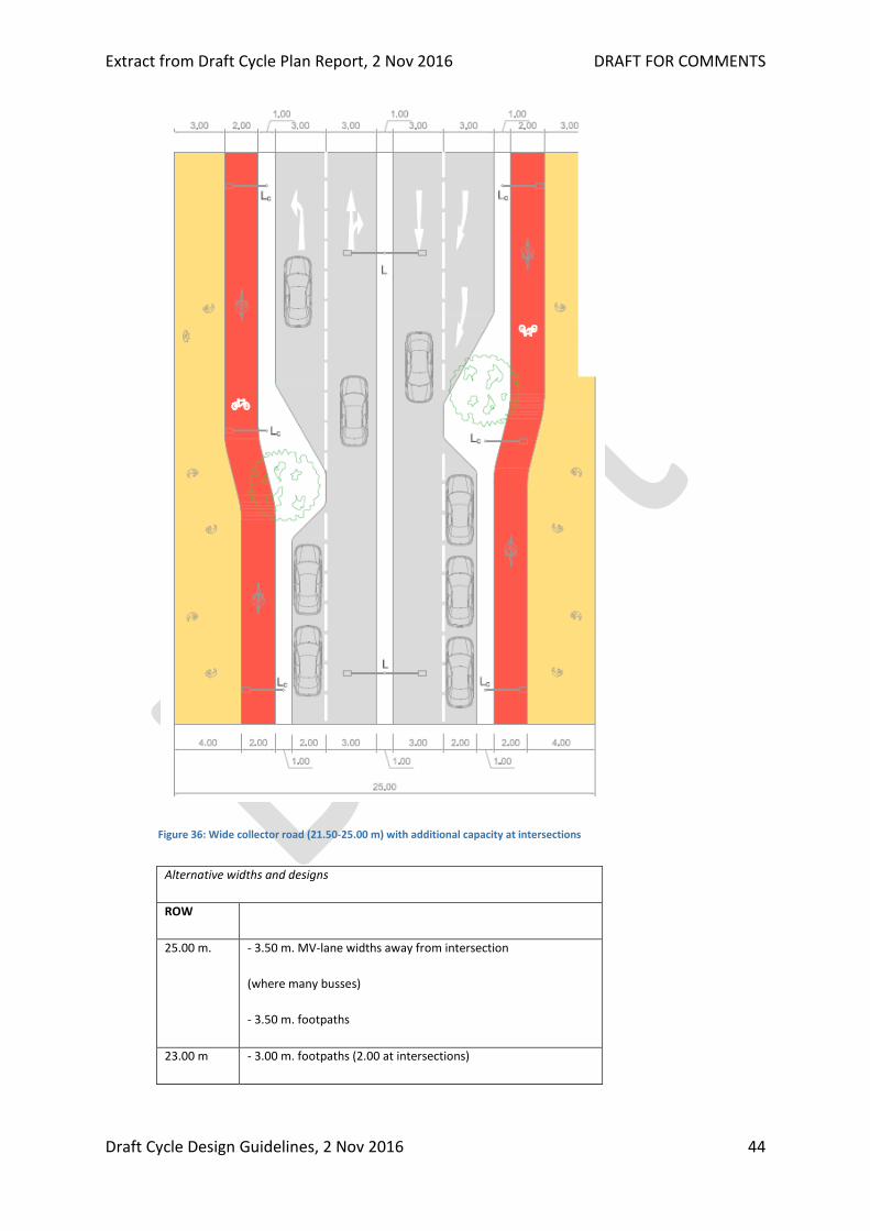
4.5.1. WIDE COLLECTOR ROADS: 21-25 M. RIGHT OF WAY
The widest collector roads can be up to 24 m. ROW or even wider. In this case the
typical design is a 2x1 lanes carriageway with a median and widening to 2x2 at the
intersections to increase capacity. Away from the intersection the additional available
space can be used for car parking or, if car parking is not needed, a wider MUZ and/or
wider footpath. And of course, where needed, for the provision of bus stops. Because
the capacity of a road is mostly determined by the capacity of the intersection, the
capacity of this design is only a little lower than the capacity of a full 2x2 lane road.
Figure 36 and Figure 37 how this design.
Extract from Draft Cycle Plan Report, 2 Nov 2016 DRAFT FOR COMMENTS
Draft Cycle Design Guidelines, 2 Nov 2016 44
Figure 36: Wide collector road (21.50-25.00 m) with additional capacity at intersections
Alternative widths and designs
ROW
25.00 m. - 3.50 m. MV-lane widths away from intersection
(where many busses)
- 3.50 m. footpaths
23.00 m - 3.00 m. footpaths (2.00 at intersections)

Extract from Draft Cycle Plan Report, 2 Nov 2016 DRAFT FOR COMMENTS
Draft Cycle Design Guidelines, 2 Nov 2016 45
Figure 37: Wide collector road (21.50-25.00 m) at road sections (away from the intersection)
4.5.2. COLLECTOR ROAD 18 - 22 M. WITH PARKING
Typically, collector roads do have parallel parking. While This can be on one side of the
road or on both sides of the road. Below, a standard design (with ROW 20 m.) is shown
with parking on both sides of the road.
Figure 38: Collector road (18.50 - 22.00 m.) with parking on both sides
21.50 m. At intersection:
- 2.00 m. footpaths
- 2.75 m. traffic lanes
- 0.75 m. verges

Extract from Draft Cycle Plan Report, 2 Nov 2016 DRAFT FOR COMMENTS
Draft Cycle Design Guidelines, 2 Nov 2016 46
Figure 38 shows that 20.00 m. is the minimum ROW needed to comfortably apply
cycle tracks and parking on both sides of the road. With smaller ROWs, particularly
below 19.00 m, preferably parking is only applied on one side of the road as is shown
below in Figure 39. However, as shown in the table above, parking on both sides of
the road can still be accommodated up to a width of 18.50 m.
Alternative widths
ROW
18.50 m. - 2.00 m. footpaths
- 2.00 m. cycle tracks
- 0.70 m verge with lamp posts
- 1.80 m. parking
- 5.50 m. carriageway
19.00 m. - 2.00 m. footpaths
- 2.00 m. cycle tracks
- 0.70 m verge with lamp posts
- 1.80 m. parking
- 6.00 m. carriageway
22.00 m. - 3.00 m. footpath
ROW
17.50 m. - 0.75 m. verges

Extract from Draft Cycle Plan Report, 2 Nov 2016 DRAFT FOR COMMENTS
Draft Cycle Design Guidelines, 2 Nov 2016 47
Figure 39: Collector road (18 m) with segregated cycle tracks and parking on one side
4.5.3. COLLECTOR ROAD WITH SEGREGATED CYCLE TRACKS (15-18 M.) WITHOUT
PARKING
On collector roads where no parking needs to be provided, proper cycling infrastructure
can easily be provided up to a ROW of 15.00 m. Figure 40 below shows a design for a
collector road with a ROW of 18 m. with 1.00 m. verges and the lamp posts in the verge.
Figure 41 is the same design with a 16 m. ROW and 2.00 m. footpaths. Figure 42 shows a
design with maximum footpath width and the lamp posts on the footpath. Because
lamp posts are nor placed in the verge, the verge can be as narrow as 0.50 m. on
collector roads.
Figure 40: Collector road (18 m) with segregated cycle tracks and without parking.

Extract from Draft Cycle Plan Report, 2 Nov 2016 DRAFT FOR COMMENTS
Draft Cycle Design Guidelines, 2 Nov 2016 48
Below the same design is shown for a 16 m. wide road with 2.00 m. wide footpaths.
Figure 41: Collector road (16 m) with segregated cycle tracks and without parking.
It is possible to apply segregated cycle tracks at collector roads with even narrower ROWs
by moving the lamp posts onto the footpath. In that case the verges can be narrowed to
0.50 m. as shown in Figure 42 below.
Alternative widths and designs
ROW
18.00 m. - Footpaths: 2.75 m.
- MV-lanes: 3.25 m.
(roads with many trucks
and busses)

Extract from Draft Cycle Plan Report, 2 Nov 2016 DRAFT FOR COMMENTS
Draft Cycle Design Guidelines, 2 Nov 2016 49
Figure 42: Collector road (18 m) with segregated cycle tracks, without parking and with lamp posts on the footpath
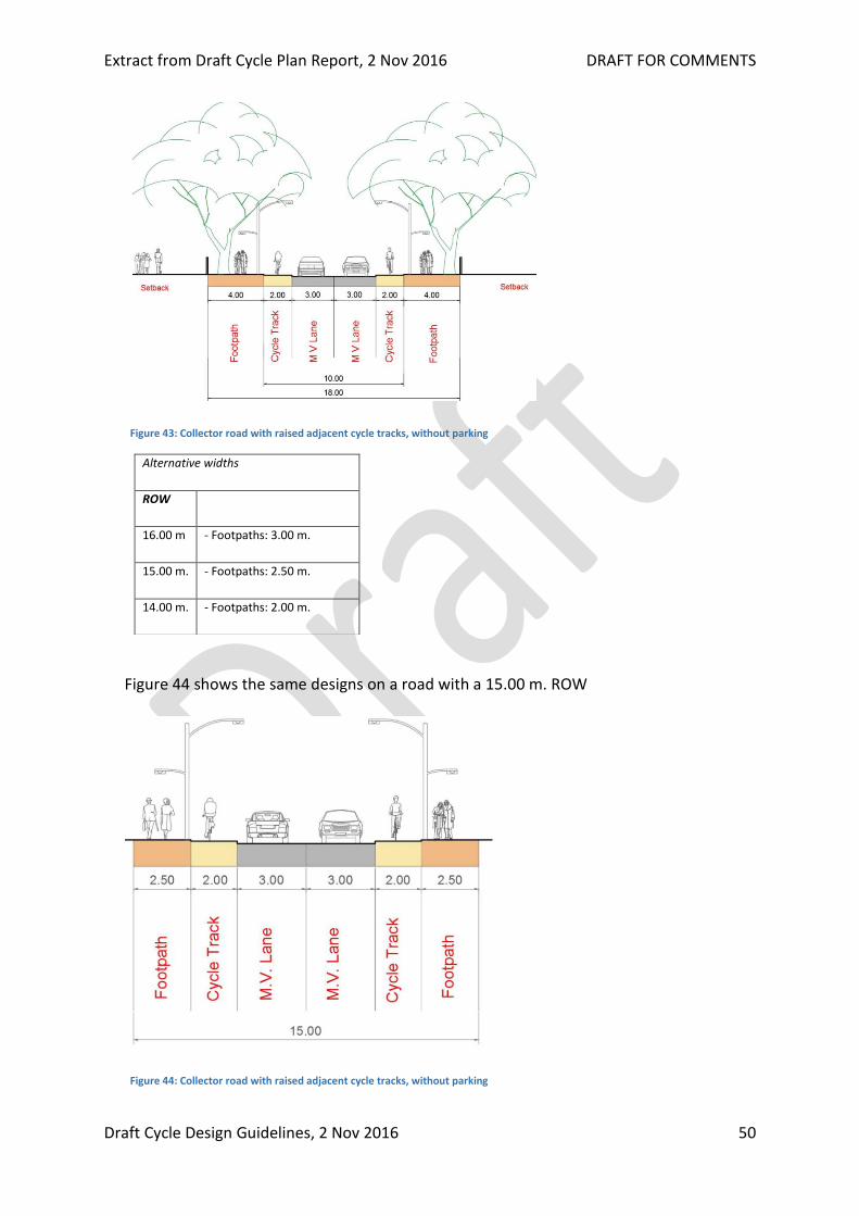
4.5.4. COLLECTOR ROAD WITH RAISED ADJACENT CYCLE TRACKS (14-18 M.) WITHOUT
PARKING
To create more pedestrian space, or apply cycle tracks at roads with even an even
smaller ROW, it is also possible to apply raised adjacent cycle tracks. This is possible at
locations where there is no parking. However, in most cases the designs shown above
(Figure 41 and Figure 42) are preferred because they provide better segregation
between cyclists and motorised traffic.
Alternative widths
ROW
16.00 m. - Footpaths: 2.50 m.
15.00 m. - Footpaths: 2.00 m.
Extract from Draft Cycle Plan Report, 2 Nov 2016 DRAFT FOR COMMENTS
Draft Cycle Design Guidelines, 2 Nov 2016 50
Figure 43: Collector road with raised adjacent cycle tracks, without parking
Figure 44 shows the same designs on a road with a 15.00 m. ROW
Figure 44: Collector road with raised adjacent cycle tracks, without parking
Alternative widths
ROW
16.00 m - Footpaths: 3.00 m.
15.00 m. - Footpaths: 2.50 m.
14.00 m. - Footpaths: 2.00 m.
Extract from Draft Cycle Plan Report, 2 Nov 2016 DRAFT FOR COMMENTS
Draft Cycle Design Guidelines, 2 Nov 2016 51
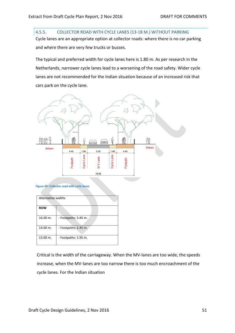
4.5.5. COLLECTOR ROAD WITH CYCLE LANES (13-18 M.) WITHOUT PARKING
Cycle lanes are an appropriate option at collector roads: where there is no car parking
and where there are very few trucks or busses.
The typical and preferred width for cycle lanes here is 1.80 m. As per research in the
Netherlands, narrower cycle lanes lead to a worsening of the road safety. Wider cycle
lanes are not recommended for the Indian situation because of an increased risk that
cars park on the cycle lane.
Figure 45: Collector road with cycle lanes
Critical is the width of the carriageway. When the MV-lanes are too wide, the speeds
increase, when the MV-lanes are too narrow there is too much encroachment of the
cycle lanes. For the Indian situation
Alternative widths
ROW
16.00 m. - Footpaths: 3.45 m.
14.00 m. - Footpaths: 2.45 m.
13.00 m. - Footpaths: 1.95 m.

Extract from Draft Cycle Plan Report, 2 Nov 2016 DRAFT FOR COMMENTS
Draft Cycle Design Guidelines, 2 Nov 2016 52
5.50 m. is considered appropriate. Only on routes with many trucks or busses a wider
MV-lane needs to be applied, however in this case segregated cycle tracks or raised
adjacent cycle tracks are preferred. Note that cycle lanes are always one-way!
4.6. CYCLING INFRASTRUCTURE AT ROAD SECTIONS OF LOCAL
ACCESS ROADS
Neighbourhood streets or access roads are roads with low traffic volumes. The most
important measures here to allow safe cycling are:
Making the street a 30 km/h street with speed humps or other speed reducing
measures.
Reducing the volumes of motorised traffic by disabling through traffic or creating a one-
way street.
Table 16: Characteristics of local access roads
Typical Possible
MV-lanes: No traffic lanes marked No traffic lanes marked
Carriageway
width:
5.00 - 7.00 m. incl. on-street
parking
4.00 - 4.75 m. (one-way traffic with or
without parking)
Maximum
speed:
30 km/h
Traffic volumes: < 500 PCU/hr. in two
directions
(peak hour)
ROW: 10.00 -16.00 m. 8.00 - 10.00 m.
Cycling
infrastructure:
Shared use Cycle lanes
Two-way cycle track (at main cycle
routes)
Verge: n.a. 1.00 m. in case of two-way cycle track
Car parking: On-street not marked
Preferably parallel
Marked with parking bays
Preferably parallel parking but
perpendicular parking is also possible

Extract from Draft Cycle Plan Report, 2 Nov 2016 DRAFT FOR COMMENTS
Draft Cycle Design Guidelines, 2 Nov 2016 53
Median / lane
marking
No median
No lane marking
The appropriate width of an access road depends on the most common use. Table 17
shows how the appropriate width can be calculated by adding up measuring segments
for vehicles and obstacle distances.10
Table 17: Measuring segments for 30 km/h access roads
Measuring width of 30 km/h access roads
Measuring segment Width needed
cyclists 0.75 m.
autorickshaw 1.20 m.
passenger car 1.85 m.
goods vehicle or bus 2.60 m.
bicycle - edge (curb) 0.25 m.
bicycle - parked vehicle 0.50 m.
bicycle - bicycle (in same direction) 0.25 m.
bicycle - moving vehicle 0.85 m.
vehicle - vehicle (both moving) 0.30 m.
moving vehicle - curb 0.25 m.
Typical access roads have no traffic lanes marked. Using the dimensions of Table 17
different widths for access roads can be determined. For instance, on busier access roads
where it is possible that two cars meet each other together with one cyclists, a width of
6.00 m. is appropriate as shown in Figure 46.
10 The obstacle distances (distances between vehicles and between vehicles and immoveable obstacles) come from research in The Netherlands. In India vehicles pass each other at a much closer distance. However, for safe cycling (and general traffic), larger passing distances are preferred.
Extract from Draft Cycle Plan Report, 2 Nov 2016 DRAFT FOR COMMENTS
Draft Cycle Design Guidelines, 2 Nov 2016 54
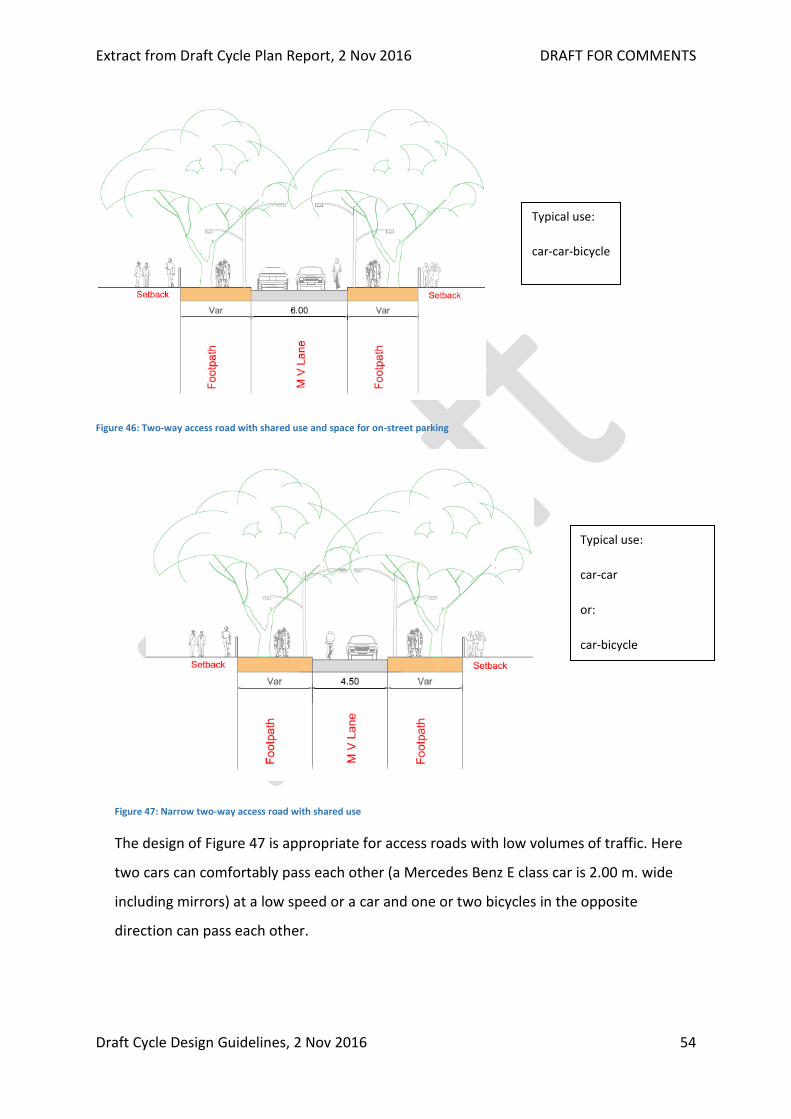
Figure 46: Two-way access road with shared use and space for on-street parking
Figure 47: Narrow two-way access road with shared use
The design of Figure 47 is appropriate for access roads with low volumes of traffic. Here
two cars can comfortably pass each other (a Mercedes Benz E class car is 2.00 m. wide
including mirrors) at a low speed or a car and one or two bicycles in the opposite
direction can pass each other.
Typical use:
car-car
or:
car-bicycle
Typical use:
car-car-bicycle
Extract from Draft Cycle Plan Report, 2 Nov 2016 DRAFT FOR COMMENTS
Draft Cycle Design Guidelines, 2 Nov 2016 55
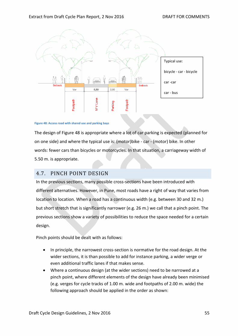
Figure 48: Access road with shared use and parking bays
The design of Figure 48 is appropriate where a lot of car parking is expected (planned for
on one side) and where the typical use is: (motor)bike - car - (motor) bike. In other
words: fewer cars than bicycles or motorcycles. In that situation, a carriageway width of
5.50 m. is appropriate.
4.7. PINCH POINT DESIGN
In the previous sections, many possible cross-sections have been introduced with
different alternatives. However, in Pune, most roads have a right of way that varies from
location to location. When a road has a continuous width (e.g. between 30 and 32 m.)
but short stretch that is significantly narrower (e.g. 26 m.) we call that a pinch point. The
previous sections show a variety of possibilities to reduce the space needed for a certain
design.
Pinch points should be dealt with as follows:
In principle, the narrowest cross-section is normative for the road design. At the
wider sections, it is than possible to add for instance parking, a wider verge or
even additional traffic lanes if that makes sense.
Where a continuous design (at the wider sections) need to be narrowed at a
pinch point, where different elements of the design have already been minimised
(e.g. verges for cycle tracks of 1.00 m. wide and footpaths of 2.00 m. wide) the
following approach should be applied in the order as shown:
Typical use:
bicycle - car - bicycle
car -car
car - bus

Extract from Draft Cycle Plan Report, 2 Nov 2016 DRAFT FOR COMMENTS
Draft Cycle Design Guidelines, 2 Nov 2016 56
Measure to reduce the space needed Absolute minimum width to be applied
1. Remove car-parking on one or both sides of the
carriageway
2. Reduce the width of traffic lanes 2.75 m.
3. Reduce the amount of traffic lanes e.g. from 3 per direction to 2 per
direction or from 2 to 1 per direction
4. Reduce the footpath to absolute minimum 1.75 m.
5. Reduce cycle track verge with lamp post to
absolute minimum
0.50 m.
6. Reduce cycle track to absolute minimum 1.75 m. (for one-way)
7. Apply shared cycle track/footpath Below 3.50 m. a shared cycle
track/footpath is generally preferred
over a separate footpath and cycle track
of less than 1.75 m. each.
Note that these are conditional. This means that an absolute minimum width footpath
(4.) should only be applied after parking has been removed (1.) and traffic lanes widths
have been reduced (2.) and a study has been done to see if the amount of traffic lanes
can be reduced (3.).
Hence, shared cycle tracks/footpaths should only be applied after all the measures 1 till
6 have been applied or at least seriously studied before. Shared footpath/cycle tracks
should never be a first option or easy way out to maintain MV-space.
Extract from Draft Cycle Plan Report, 2 Nov 2016 DRAFT FOR COMMENTS
Draft Cycle Design Guidelines, 2 Nov 2016 57
5. CYCLING INFRASTRUCTURE AT
INTERSECTIONS
Intersections are the locations where most accidents happen with cyclists. Therefore,
proper intersection design is important. Because the clear majority of cycling
infrastructure in Pune will be cycle tracks, this chapter focuses on the design of cycle
tracks at side roads and intersections, with a few references to cycle lanes at
intersections.
To create a safe intersection for cycling, first the geometry of the intersection needs to
be adapted, after that cycle tracks can be added.
Safe intersection designs will:
I. Reduce speeds
II. Reduce crossing distance
III. Reduce amount of locations with encounters
IV. Make intersection comprehensible
V. Provide good pre-visibility
VI. Assure good visibility: car car, car bicycle
VII. Provide exclusive space for cyclists
Key design measures that lead to those goals are:
Make the intersection as compact as possible. Wide intersections as shown below in Figure
49, lead to: more chaos, higher speeds and more accidents.
Use narrow radii. For large intersections curb radii of 10.00 m. or less are recommended.11
Provide proper road marking leading into and on the intersection.
11 In the Urban Street Design Guidelines radii as small as 4.00 m. are recommended for sub-arterial roads.

Extract from Draft Cycle Plan Report, 2 Nov 2016 DRAFT FOR COMMENTS
Draft Cycle Design Guidelines, 2 Nov 2016 58
Figure 49: Wide and inappropriate intersection geometry
5.1. DESIGN OF SIDE ROADS AND PROPERTY ENTRANCES
Before focusing on large intersections, we look at the design at side roads. Side roads
are access roads that connect to a road of higher hierarchy as follows:
I. Access road x Collector road
II. Access road x Sub-arterial road
III. Access road x arterial road (this combination should be avoided but is still quite
common in Pune).
Priority rules: Cyclists cycling on a cycle track along the main carriageway should have
priority over vehicles turning into the side road. While in India cyclists are generally
expected to yield for turning motor vehicles, the infrastructure design should support a
change in this behaviour. To reduce conflicts between cyclists on the cycle track and
vehicles leaving or entering side roads, it is important to reduce the speeds of
motorised vehicles that cross the cycle track. In the next section is explained how to do
this.
5.1.1. ELEVATED CROSSINGS AT SIDE ROADS WITH CYCLE TRACKS
Wherever cycle tracks on main roads (arterial, sub-arterial) or collector roads pass side
roads (local street) or property entrances, the cycle track and footpath should continue
at level while motor vehicles entering the side road or property entrances must drive up
a ramp. In this case, ideally, the cycle track is located at some distance from the main
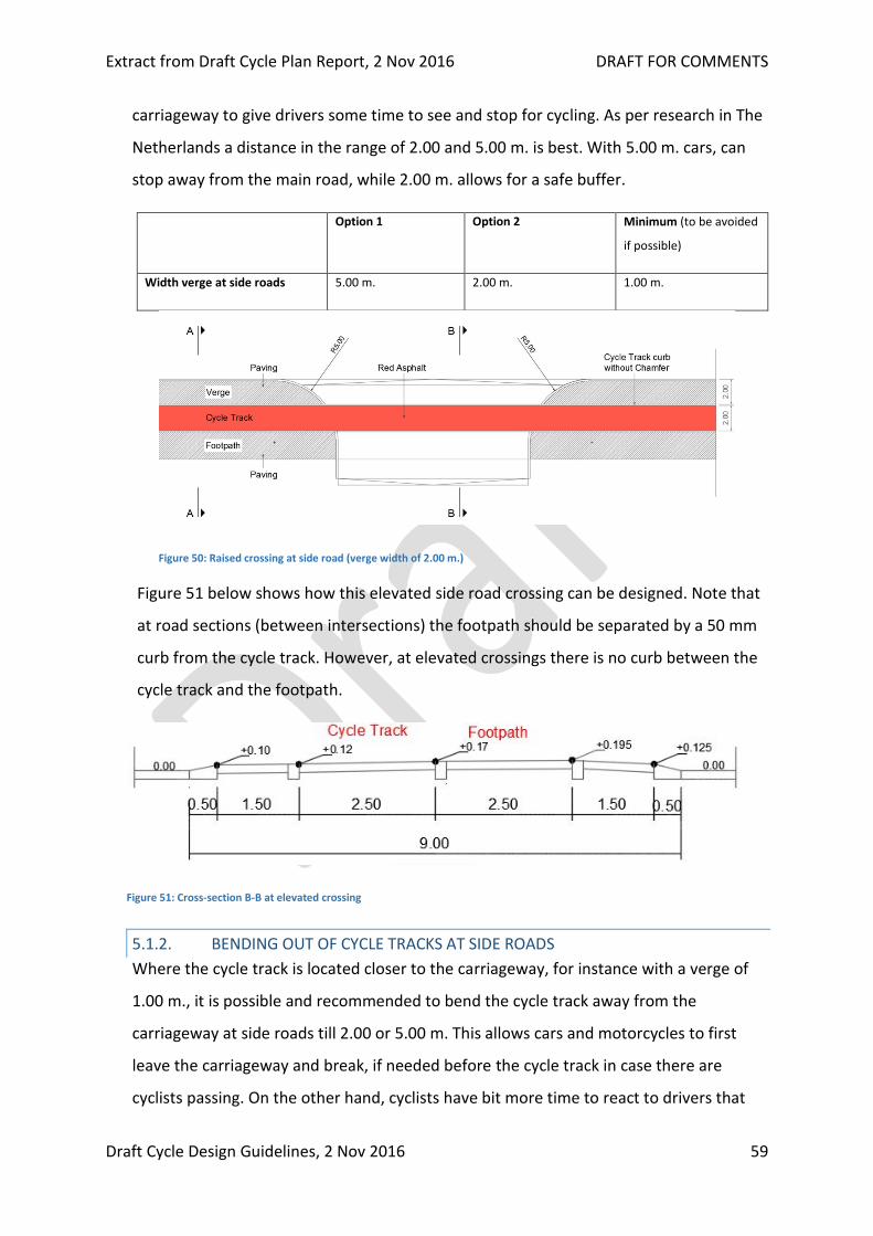
Extract from Draft Cycle Plan Report, 2 Nov 2016 DRAFT FOR COMMENTS
Draft Cycle Design Guidelines, 2 Nov 2016 59
carriageway to give drivers some time to see and stop for cycling. As per research in The
Netherlands a distance in the range of 2.00 and 5.00 m. is best. With 5.00 m. cars, can
stop away from the main road, while 2.00 m. allows for a safe buffer.
Option 1 Option 2 Minimum (to be avoided
if possible)
Width verge at side roads 5.00 m. 2.00 m. 1.00 m.
Figure 50: Raised crossing at side road (verge width of 2.00 m.)
Figure 51 below shows how this elevated side road crossing can be designed. Note that
at road sections (between intersections) the footpath should be separated by a 50 mm
curb from the cycle track. However, at elevated crossings there is no curb between the
cycle track and the footpath.
Figure 51: Cross-section B-B at elevated crossing
5.1.2. BENDING OUT OF CYCLE TRACKS AT SIDE ROADS
Where the cycle track is located closer to the carriageway, for instance with a verge of
1.00 m., it is possible and recommended to bend the cycle track away from the
carriageway at side roads till 2.00 or 5.00 m. This allows cars and motorcycles to first
leave the carriageway and break, if needed before the cycle track in case there are
cyclists passing. On the other hand, cyclists have bit more time to react to drivers that

Extract from Draft Cycle Plan Report, 2 Nov 2016 DRAFT FOR COMMENTS
Draft Cycle Design Guidelines, 2 Nov 2016 60
do not stop when crossing the cycle track because they are further away from the
carriageway, thus increasing the road safety. Bending out 2.00 m. is also possible where
space is limited.
Note: Motor vehicles that turn left or right and cross the cycle track should yield to
cyclists as well as pedestrians moving along the main road.
Figure 52 below shows how to bend out a cycle track at a side road (or intersection):
Figure 52: Bending out of a cycle track at side road
C2 = 5.00 m.
L1 = 30.00 m
L2 = 5.00 m
R = 3.00 m.
R1 = 12.00 m or more
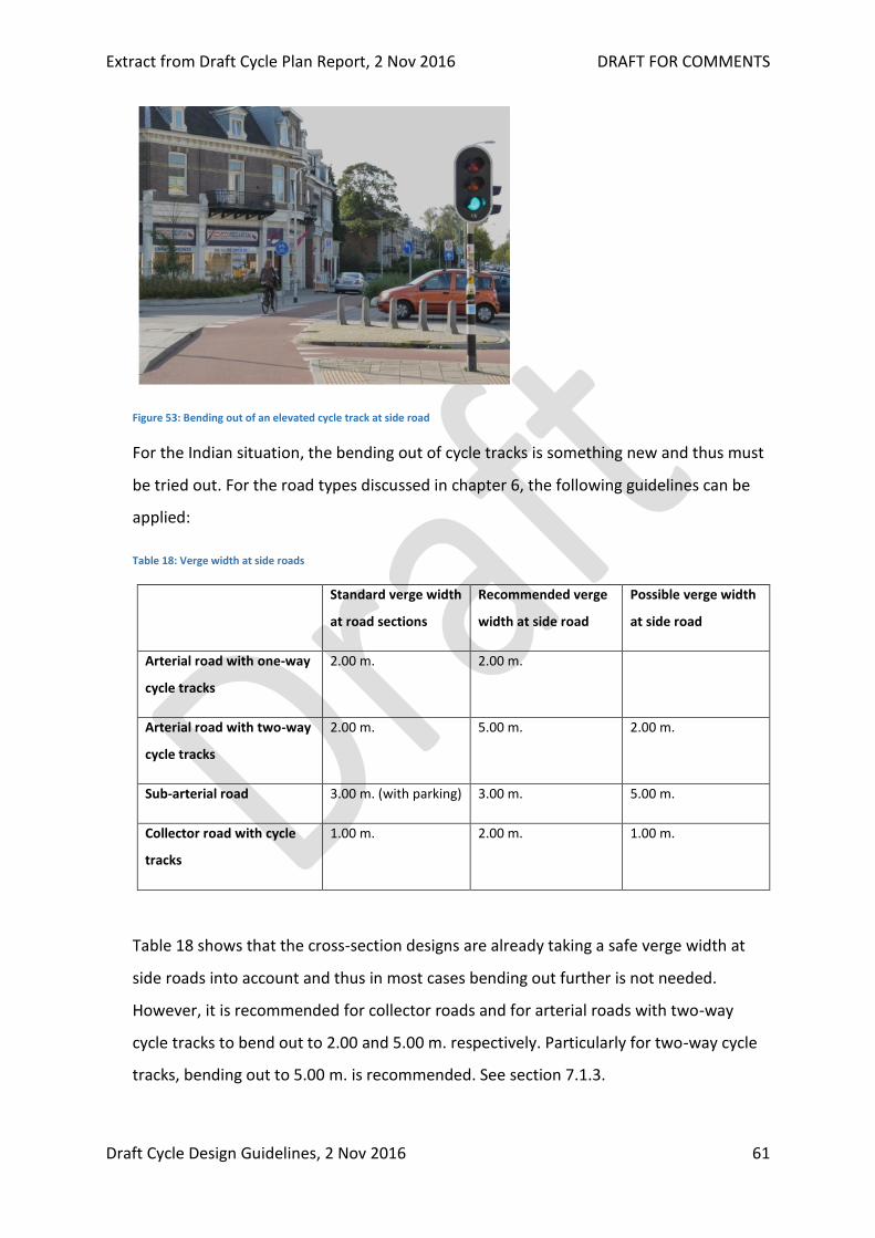
Extract from Draft Cycle Plan Report, 2 Nov 2016 DRAFT FOR COMMENTS
Draft Cycle Design Guidelines, 2 Nov 2016 61
Figure 53: Bending out of an elevated cycle track at side road
For the Indian situation, the bending out of cycle tracks is something new and thus must
be tried out. For the road types discussed in chapter 6, the following guidelines can be
applied:
Table 18: Verge width at side roads
Standard verge width
at road sections
Recommended verge
width at side road
Possible verge width
at side road
Arterial road with one-way
cycle tracks
2.00 m. 2.00 m.
Arterial road with two-way
cycle tracks
2.00 m. 5.00 m. 2.00 m.
Sub-arterial road 3.00 m. (with parking) 3.00 m. 5.00 m.
Collector road with cycle
tracks
1.00 m. 2.00 m. 1.00 m.
Table 18 shows that the cross-section designs are already taking a safe verge width at
side roads into account and thus in most cases bending out further is not needed.
However, it is recommended for collector roads and for arterial roads with two-way
cycle tracks to bend out to 2.00 and 5.00 m. respectively. Particularly for two-way cycle
tracks, bending out to 5.00 m. is recommended. See section 7.1.3.
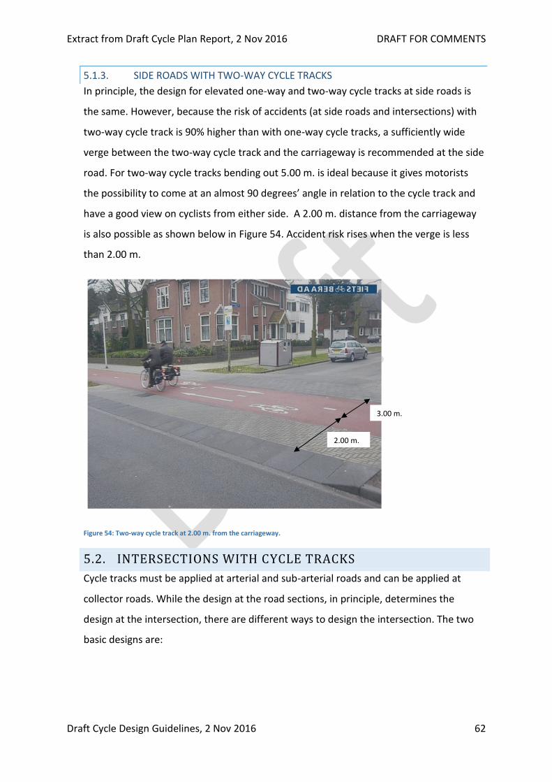
Extract from Draft Cycle Plan Report, 2 Nov 2016 DRAFT FOR COMMENTS
Draft Cycle Design Guidelines, 2 Nov 2016 62
5.1.3. SIDE ROADS WITH TWO-WAY CYCLE TRACKS
In principle, the design for elevated one-way and two-way cycle tracks at side roads is
the same. However, because the risk of accidents (at side roads and intersections) with
two-way cycle track is 90% higher than with one-way cycle tracks, a sufficiently wide
verge between the two-way cycle track and the carriageway is recommended at the side
road. For two-way cycle tracks bending out 5.00 m. is ideal because it gives motorists
the possibility to come at an almost 90 degrees’ angle in relation to the cycle track and
have a good view on cyclists from either side. A 2.00 m. distance from the carriageway
is also possible as shown below in Figure 54. Accident risk rises when the verge is less
than 2.00 m.
Figure 54: Two-way cycle track at 2.00 m. from the carriageway.
5.2. INTERSECTIONS WITH CYCLE TRACKS
Cycle tracks must be applied at arterial and sub-arterial roads and can be applied at
collector roads. While the design at the road sections, in principle, determines the
design at the intersection, there are different ways to design the intersection. The two
basic designs are:
2.00 m.
3.00 m.
Extract from Draft Cycle Plan Report, 2 Nov 2016 DRAFT FOR COMMENTS
Draft Cycle Design Guidelines, 2 Nov 2016 63
1. Segregated design at intersections
This is the standard design. The cycle track is continued at the intersection, thus
providing maximum protection and continuity for cyclists.
2. Unsegregated design at intersections
Here the cycle track is converted into a cycle lane prior to the intersection and
bike boxes are created to enable cyclists to turn right. This is the design proposed
in the Urban Street Design Guidelines.
These two solutions are fundamentally different. In section 7.2.1 the segregated
intersection design is shown and explained. In section 7.2.2 the unsegregated
intersection design is shown. Section 7.2.3 explains the advantages and disadvantages of
both options.
5.2.1. INTERSECTIONS WITH ONE-WAY CYCLE TRACKS AND SEGREGATED DESIGN
An example of the so-called segregated design12 is shown below. Basically, this is a
design where, typically, at all arms the cycle track is bend out to 5.00 m. from the
carriageway. This design has the following particularities:
At each corner, oval islands (A), protect the cyclists against motorised traffic.
Cyclists do not mix with motorised traffic and thus need their own traffic lights. This also
alows for a separate phasing for cyclists which makes the crossing even safer.
Cyclist turning right, see blue arrows, will cross in two stages. In most cases, this means
that cyclists will cross one arm, then wait, and then cross the other arm. Signal phasing
can be set in such a way that delays for cyclists are limited as much as possible.
Central traffic islands (B) are not a necessity, but make the crossing safer, particularly
when traffic lights are not working
12 This design is used in the Netherlands at all locations where roads with cycle tracks intersect and has proven to be very safe and comfortable for cyclists.

Extract from Draft Cycle Plan Report, 2 Nov 2016 DRAFT FOR COMMENTS
Draft Cycle Design Guidelines, 2 Nov 2016 64
Figure 55: Segregated design at intersection with one-way cycle tracks
Figure 56: Segregated design at intersection with one-way cycle tracks
Below a design is shown in Figure 57 of an intersection between an arterial road and a
sub-arterial road as recommended the previous section:

Extract from Draft Cycle Plan Report, 2 Nov 2016 DRAFT FOR COMMENTS
Draft Cycle Design Guidelines, 2 Nov 2016 65
Figure 57: Intersection of a typical arterial road with central BRT-lanes and a typical sub-arterial road with parking
Figure 57 shows a number of things:
I. The arterial road is the main road. This mean that left-turning traffic has to yield for cyclists
going straight along the arterial road unless traffic lights indicate otherwise (conflict free
traffic light settings).
II. Cyclists have a 2.50 m. wide central median (two in the arterial road) as a safe refuge
halfway the crossing.
III. All cycle tracks are bend out till 5.00 m. distance from the carriageway.
5.2.2. INTERSECTIONS WITH TWO-WAY CYCLE TRACKS WITH SEGREGATED DESIGN
A segregated intersection design with two-way cycle tracks is very like that with one-way
cycle tracks. The most important difference is the turning radii in the cycle track, which
R10.0

Extract from Draft Cycle Plan Report, 2 Nov 2016 DRAFT FOR COMMENTS
Draft Cycle Design Guidelines, 2 Nov 2016 66
needs to allow cyclist to cycle in two directions.
Figure 58: Intersection with two-way cycle trackson two arms and a one-way cycle track on the other arm (left)
5.2.3. CYCLE TRACKS WITH UNSEGREGATED DESIGN AT INTERSECTIONS
It seems obvious to continue cycle tracks at the intersection as shown in section 7.2.1
and 7.2.2. There is however another design possibility as proposed in the Urban Street
Design Guidelines where cyclists are mixed with motorised traffic at intersections. This
can be done by using bicycle boxes. The bicycle box is a Dutch invention used to allow
cyclists to turn right (in the Indian situation) by moving ahead of motorised traffic. In The
Netherlands, this solution is only used in combination with cycle lanes at the arms of the
intersection, not in combination with cycle tracks.
In the USDG this design is proposed for all intersections, including those with segregated
cycle tracks. With some adaptation, this is possible. Figure 59 shows how bicycle boxes
can be applied before the zebra. This is the standard approach.
Bicycle boxes before zebra crossing
The figure below shows how bicycle boxes can be applied before the zebra crossing. For
a successful and safe application of bicycle boxes, lane discipline by drivers and separate
lanes for separate directions is important. The figure below shows that, at green, cyclists
first weave across one lane of traffic to get to the cycle lane and the cycle box to turn
right. After that cyclists, can turn right without there being a conflict with motorised
traffic that goes straight or turns right.
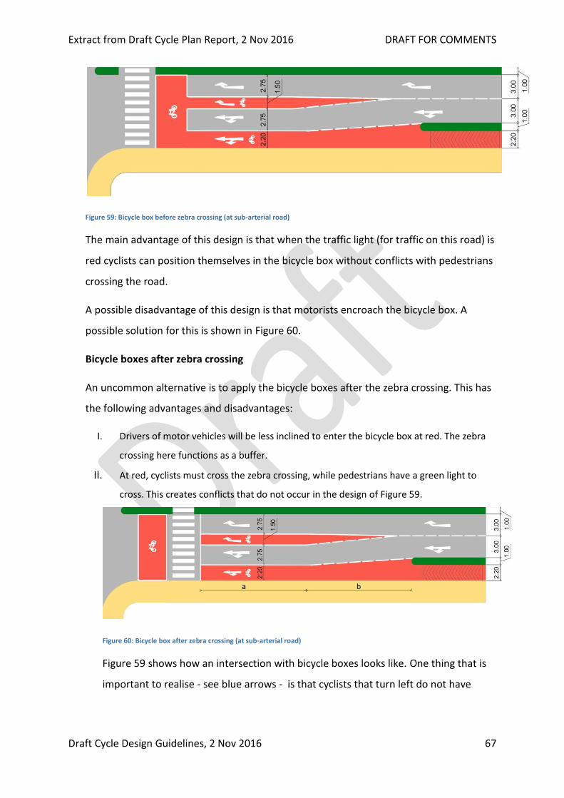
Extract from Draft Cycle Plan Report, 2 Nov 2016 DRAFT FOR COMMENTS
Draft Cycle Design Guidelines, 2 Nov 2016 67
Figure 59: Bicycle box before zebra crossing (at sub-arterial road)
The main advantage of this design is that when the traffic light (for traffic on this road) is
red cyclists can position themselves in the bicycle box without conflicts with pedestrians
crossing the road.
A possible disadvantage of this design is that motorists encroach the bicycle box. A
possible solution for this is shown in Figure 60.
Bicycle boxes after zebra crossing
An uncommon alternative is to apply the bicycle boxes after the zebra crossing. This has
the following advantages and disadvantages:
I. Drivers of motor vehicles will be less inclined to enter the bicycle box at red. The zebra
crossing here functions as a buffer.
II. At red, cyclists must cross the zebra crossing, while pedestrians have a green light to
cross. This creates conflicts that do not occur in the design of Figure 59.
Figure 60: Bicycle box after zebra crossing (at sub-arterial road)
Figure 59 shows how an intersection with bicycle boxes looks like. One thing that is
important to realise - see blue arrows - is that cyclists that turn left do not have

Extract from Draft Cycle Plan Report, 2 Nov 2016 DRAFT FOR COMMENTS
Draft Cycle Design Guidelines, 2 Nov 2016 68
segregation and can thus be hindered by cars and motorcycles turning left. This is
not the case in the segregated design shown in Figure 55 till Figure 58.
Figure 61: Intersection with bicycle boxes before the zebra (design from USDG)
Because both the segregated and the unsegregated design have advantages and
disadvantages, they are compared in the next section.
5.2.4. COMPARING SEGREGATED AND UNSEGREGATED DESIGNS AT INTERSECTIONS
The segregated and the unsegregated design, both have their advantages and
disadvantages. The basic difference is that the segregated design has better road safety
and the unsegregated design better directness (less delay) for cyclists turning right.
An overview of advantages of both designs is given in table below:
Table 19: Advantages and disadvantages of segregated and unsegregated designs
Segregated design
(cycle tracks)
Unsegregated design
(cycle lanes and bike boxes)
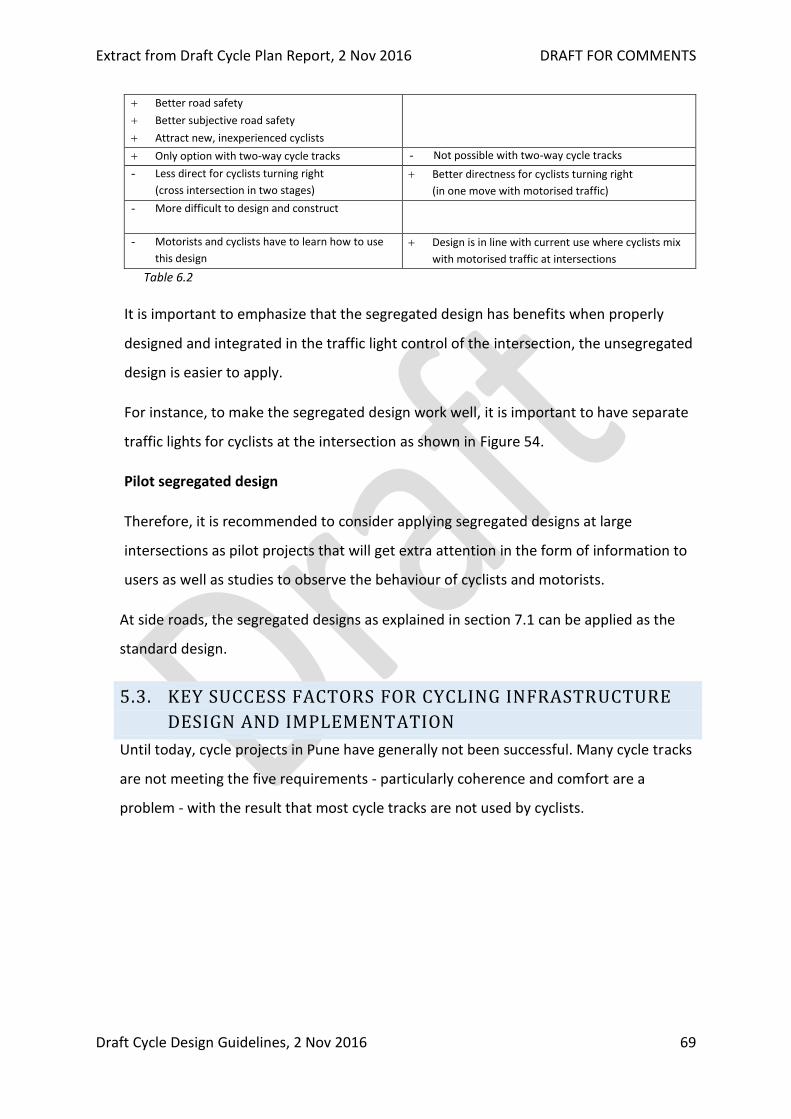
Extract from Draft Cycle Plan Report, 2 Nov 2016 DRAFT FOR COMMENTS
Draft Cycle Design Guidelines, 2 Nov 2016 69
Better road safety
Better subjective road safety
Attract new, inexperienced cyclists
Only option with two-way cycle tracks - Not possible with two-way cycle tracks
- Less direct for cyclists turning right
(cross intersection in two stages)
Better directness for cyclists turning right
(in one move with motorised traffic)
- More difficult to design and construct
- Motorists and cyclists have to learn how to use
this design
Design is in line with current use where cyclists mix
with motorised traffic at intersections
Table 6.2
It is important to emphasize that the segregated design has benefits when properly
designed and integrated in the traffic light control of the intersection, the unsegregated
design is easier to apply.
For instance, to make the segregated design work well, it is important to have separate
traffic lights for cyclists at the intersection as shown in Figure 54.
Pilot segregated design
Therefore, it is recommended to consider applying segregated designs at large
intersections as pilot projects that will get extra attention in the form of information to
users as well as studies to observe the behaviour of cyclists and motorists.
At side roads, the segregated designs as explained in section 7.1 can be applied as the
standard design.
5.3. KEY SUCCESS FACTORS FOR CYCLING INFRASTRUCTURE
DESIGN AND IMPLEMENTATION
Until today, cycle projects in Pune have generally not been successful. Many cycle tracks
are not meeting the five requirements - particularly coherence and comfort are a
problem - with the result that most cycle tracks are not used by cyclists.
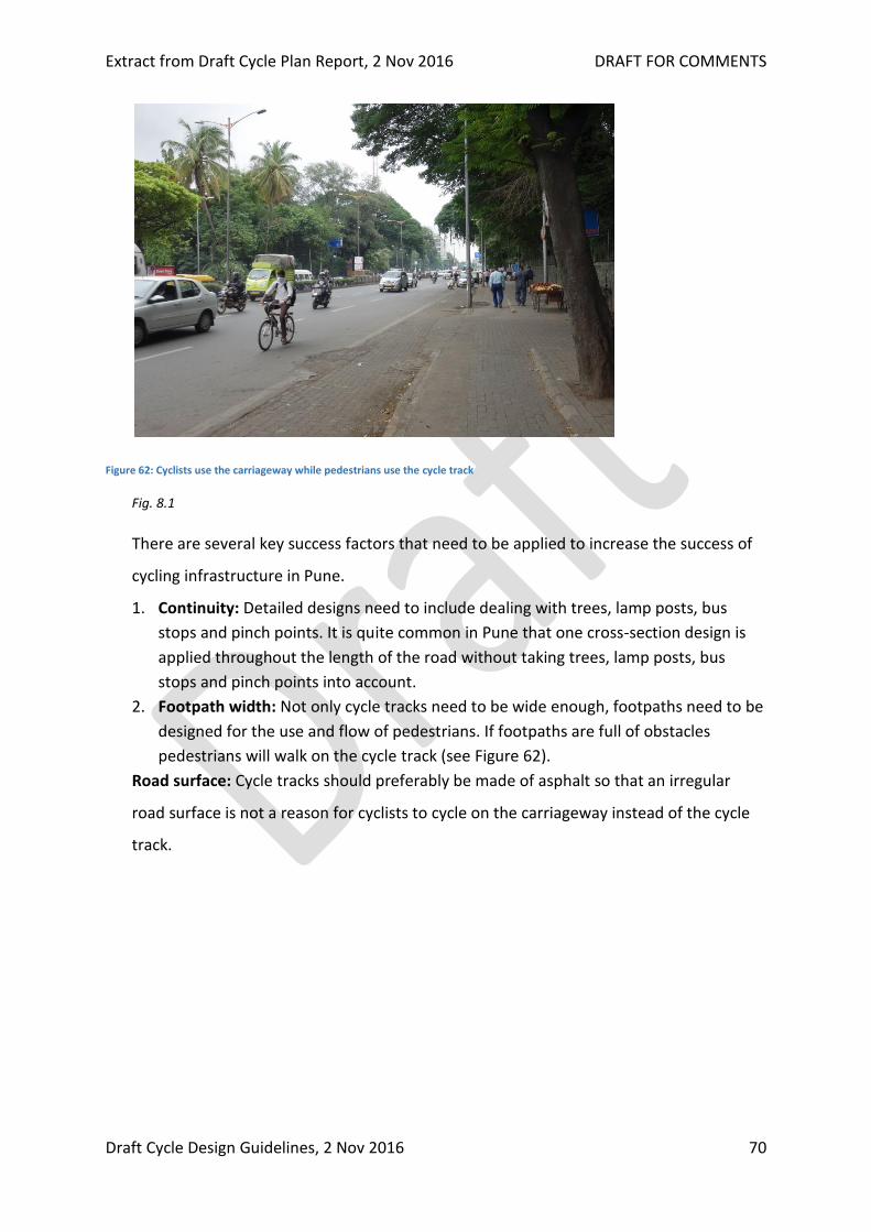
Extract from Draft Cycle Plan Report, 2 Nov 2016 DRAFT FOR COMMENTS
Draft Cycle Design Guidelines, 2 Nov 2016 70
Figure 62: Cyclists use the carriageway while pedestrians use the cycle track
Fig. 8.1
There are several key success factors that need to be applied to increase the success of
cycling infrastructure in Pune.
1. Continuity: Detailed designs need to include dealing with trees, lamp posts, bus
stops and pinch points. It is quite common in Pune that one cross-section design is
applied throughout the length of the road without taking trees, lamp posts, bus
stops and pinch points into account.
2. Footpath width: Not only cycle tracks need to be wide enough, footpaths need to be
designed for the use and flow of pedestrians. If footpaths are full of obstacles
pedestrians will walk on the cycle track (see Figure 62).
Road surface: Cycle tracks should preferably be made of asphalt so that an irregular
road surface is not a reason for cyclists to cycle on the carriageway instead of the cycle
track.
Related Documents


