Efficient and Balanced Routing in Energy-Constrained Wireless Sensor Networks for Data Collection Miguel Navarro and Yao Liang Department of Computer and Information Science Indiana University – Purdue University, Indianapolis, Indiana, USA {mignavar, yliang} @cs.iupui.edu Abstract Cost-based routing protocols are the main approach used in practical wireless sensor network (WSN) deployments for data collection applications with energy constrains; however, those routing protocols lead to the concentration of most of the data traffic on some specific nodes which provide the best available routes, thus significantly increasing their energy consumption. Consequently, nodes providing the best routes are potentially the first ones to deplete their batteries and stop working. In this paper, we introduce a new routing strategy for energy efficient and balanced data collection in WSNs, which can be applied to any cost-based routing solution to exploit suboptimal network routing alternatives based on the parent set concept. While still taking advantage of the stable routing topologies built in cost-based routing protocols, our approach adds a random component into the process of packet forwarding to achieve a better network lifetime in WSNs. We evaluate the implementation of our approach against other state-of-the-art WSN routing protocols through thorough testbed experiments and simulations, and demonstrate that our approach achieves a significant reduction in the energy consumption of the routing layer in the busiest nodes ranging from 11% to 59%, while maintaining over 99% reliability. Categories and Subject Descriptors C.2.1 [Network Architecture and Design]: Wireless communication; C.2.2 [Network Protocols]: Routing protocols General Terms Design, Experimentation, Performance, Reliability Keywords Energy efficiency, wireless sensor networks, routing protocol, network lifetime, data collection, load balancing 1 Introduction Wireless Sensor Networks (WSNs) have emerged as a promising alternative to traditional data-collection mechanisms (i.e., data loggers and sensing stations) enabling cost-effective implementations in various sciences and engineering domains. WSN nodes, typically deployed outdoors in harsh environments, are resource constrained (i.e., memory, computing, bandwidth, and energy), which poses great communication challenges for multi-hop WSN deployments. In some cases, energy constrains in WSN nodes can be mitigated by the use of energy harvesting mechanisms [1-3], whereas in many other situations WSN deployments have to rely on batteries as their main energy source [4-9] (e.g., due to space constrains, limited sun exposure). While many WSN routing approaches have been proposed in the literature, only a few have actually been implemented and tested in real scenarios. Among them, some routing solutions have attempted to address energy efficiency issues based on cross-layer designs [10, 11], limiting their practical applications because of the complexity of re-implementing and replicating the original cross-layer dynamics in other hardware platforms. As a result, many reported real-world energy-constrained WSN deployments continue relying on cost-based routing protocols [6-9]. Our work is motivated by the urgent need to extend the network lifetime (i.e., the time for the first WSN node to deplete its batteries) in such energy constrained WSN deployments for data collection applications. Moreover, for WSN deployments where battery replacements are possible, it would reduce the field maintenance visits, including maintenance costs, time, and effort in long-term battery-powered WSN deployments. Cost-based WSN routing protocols [12, 13] have become the de facto standard for multi-hop data collection applications, and their principles have also been adopted by the IETF Roll working group standard RPL [14]. However, one major drawback of cost- based WSN routing protocols is that they tend to concentrate most of the data traffic on specific nodes that provide the best available routes. As a result, the energy consumption across the network is highly unbalanced and the busiest nodes end up depleting their batteries much faster than their neighbors, removing the best available routes first, and potentially partitioning the network. To address this problem, in this paper we present Energy Efficient Routing (EER), a new routing strategy for data collection WSNs, which exploits the WSN topology redundancy based on a controlled randomized approach without any additional routing overhead. EER, based on the concept of parent set, allows to select suboptimal paths in routing, reducing the data traffic load on the busiest nodes, resulting in an overall cost-effective solution that extends the network lifetime 1 . This improvement is achieved 1 We discuss the differences between our definition of parent set and the potential parents in RPL in Section 2. 101 International Conference on Embedded Wireless Systems and Networks (EWSN) 2016 15–17 February, Graz, Austria © 2016 Copyright is held by the authors. Permission is granted for indexing in the ACM Digital Library ISBN: 978-0-9949886-0-7

Welcome message from author
This document is posted to help you gain knowledge. Please leave a comment to let me know what you think about it! Share it to your friends and learn new things together.
Transcript
Efficient and Balanced Routing in Energy-Constrained
Wireless Sensor Networks for Data Collection
Miguel Navarro and Yao Liang Department of Computer and Information Science
Indiana University – Purdue University, Indianapolis, Indiana, USA {mignavar, yliang} @cs.iupui.edu
Abstract Cost-based routing protocols are the main approach used in
practical wireless sensor network (WSN) deployments for data collection applications with energy constrains; however, those routing protocols lead to the concentration of most of the data traffic on some specific nodes which provide the best available routes, thus significantly increasing their energy consumption. Consequently, nodes providing the best routes are potentially the first ones to deplete their batteries and stop working. In this paper, we introduce a new routing strategy for energy efficient and balanced data collection in WSNs, which can be applied to any cost-based routing solution to exploit suboptimal network routing alternatives based on the parent set concept. While still taking advantage of the stable routing topologies built in cost-based routing protocols, our approach adds a random component into the process of packet forwarding to achieve a better network lifetime in WSNs. We evaluate the implementation of our approach against other state-of-the-art WSN routing protocols through thorough testbed experiments and simulations, and demonstrate that our approach achieves a significant reduction in the energy consumption of the routing layer in the busiest nodes ranging from 11% to 59%, while maintaining over 99% reliability.
Categories and Subject Descriptors C.2.1 [Network Architecture and Design]: Wireless
communication; C.2.2 [Network Protocols]: Routing protocols
General Terms Design, Experimentation, Performance, Reliability
Keywords Energy efficiency, wireless sensor networks, routing protocol,
network lifetime, data collection, load balancing
1 Introduction Wireless Sensor Networks (WSNs) have emerged as a
promising alternative to traditional data-collection mechanisms (i.e., data loggers and sensing stations) enabling cost-effective
implementations in various sciences and engineering domains. WSN nodes, typically deployed outdoors in harsh environments, are resource constrained (i.e., memory, computing, bandwidth, and energy), which poses great communication challenges for multi-hop WSN deployments. In some cases, energy constrains in WSN nodes can be mitigated by the use of energy harvesting mechanisms [1-3], whereas in many other situations WSN deployments have to rely on batteries as their main energy source [4-9] (e.g., due to space constrains, limited sun exposure).
While many WSN routing approaches have been proposed in the literature, only a few have actually been implemented and tested in real scenarios. Among them, some routing solutions have attempted to address energy efficiency issues based on cross-layer designs [10, 11], limiting their practical applications because of the complexity of re-implementing and replicating the original cross-layer dynamics in other hardware platforms. As a result, many reported real-world energy-constrained WSN deployments continue relying on cost-based routing protocols [6-9].
Our work is motivated by the urgent need to extend the network lifetime (i.e., the time for the first WSN node to deplete its batteries) in such energy constrained WSN deployments for data collection applications. Moreover, for WSN deployments where battery replacements are possible, it would reduce the field maintenance visits, including maintenance costs, time, and effort in long-term battery-powered WSN deployments.
Cost-based WSN routing protocols [12, 13] have become the de facto standard for multi-hop data collection applications, and their principles have also been adopted by the IETF Roll working group standard RPL [14]. However, one major drawback of cost-based WSN routing protocols is that they tend to concentrate most of the data traffic on specific nodes that provide the best available routes. As a result, the energy consumption across the network is highly unbalanced and the busiest nodes end up depleting their batteries much faster than their neighbors, removing the best available routes first, and potentially partitioning the network.
To address this problem, in this paper we present Energy Efficient Routing (EER), a new routing strategy for data collection WSNs, which exploits the WSN topology redundancy based on a controlled randomized approach without any additional routing overhead. EER, based on the concept of parent set, allows to select suboptimal paths in routing, reducing the data traffic load on the busiest nodes, resulting in an overall cost-effective solution that extends the network lifetime1. This improvement is achieved
1 We discuss the differences between our definition of parent set and the
potential parents in RPL in Section 2.
101
International Conference on Embedded Wireless Systems and Networks (EWSN) 201615–17 February, Graz, Austria© 2016 Copyright is held by the authors. Permission is granted for indexing in the ACM Digital LibraryISBN: 978-0-9949886-0-7

by leveraging on the establishment of a stable routing topology, but replacing the best forwarder with a random selection from the parent set, defined as the subset of neighbor nodes that provide feasible routing progress towards the sink(s). Consequently, all neighbor nodes in the parent set share the responsibility of packet forwarding, instead of a single parent node.
EER is aimed for battery-powered multi-hop WSNs for data collection, and focuses on the energy efficiency and balance achieved by the routing layer, which can certainly be further complemented by the energy efficiency of the MAC layer, while maintaining high reliability. Therefore, our approach can be applied to many different kinds of cost-based routing solutions, including those implemented as cross-layer optimizations to further improve their network lifetimes.
To demonstrate the proposed EER, we implement it based on the Collection Tree Protocol (CTP) [13], forming a new routing protocol called CTP+EER. We validate CTP+EER against the state-of-the art routing protocols: CTP and Opportunistic Routing in WSNs (ORW) [15], and evaluate their reliability and energy efficiency in detail.
The main contributions of our work are: • We present EER, a new routing strategy that self-adapts to
network conditions without the need of complicated configuration parameters, providing an energy efficient and balanced alternative for practical data collection WSN deployments. Relying on the concept of parent set, EER exploits the suboptimal network routing alternatives in WSNs, and also provides a new diagnosis mechanism that identifies nodes with strong or weak network redundancy.
• We develop CTP+EER, which extends CTP with our proposed routing strategy EER. In our implementation, the original CTP provides resource management logic and link quality estimations, while all routing logic is now controlled by EER.
• We formulate the analytical performance model for cost-based routing protocols (e.g., CTP) and their EER extensions (e.g., CTP+EER). Specifically, we provide the redundancy conditions of the network topology that guarantee CTP+EER to improve the energy efficiency at the routing layer in comparison with CTP.
• We evaluate our CTP+EER protocol and demonstrate that it is significantly more energy efficient and balanced than CTP and ORW in testbed experiments and simulations, where CTP+EER can improve the energy consumption of the routing layer, ranging from 11% to 59%, while achieving over 99% reliability.
We discuss related works in Section 2. In Section 3 we present our EER approach and the development of CTP+EER. Section 4 presents our analytical performance model. Section 5 provides our evaluation via testbed experiments and simulations. And finally, in Section 6 we present our conclusions and future work.
2 Related Works WSN routing protocols for data collection have been proposed
and compared based on bandwidth utilization, reliability, latency, and energy efficiency, where CTP [13] is often used as the benchmark protocol. Protocols like BCP [16], BRE [17], and Arbutus [18] are mainly concerned about improving bandwidth utilization, increasing the total amount of traffic supported by the network, while maintaining high reliability. These works operate on high-power conditions and thus address different scenarios than those in energy constrained data collection applications, which are the main focus of our work.
ORW [15] presents an opportunistic routing protocol for data collection applications in WSNs. The opportunistic component in ORW improves the energy efficiency of duty-cycled implementations by reducing preamble times in low power transmissions. While our work also considers multiple nodes as potential forwarders, our parent set considers link quality more strictly for possible parents and excludes nodes at the same level as the sending node, avoiding potential routing loops that affect the overall protocol performance, as we will discuss in the following sections. In addition, unlike ORW’s forwarder set, we introduce an explicit construction of the parent set, enabling the examination of the topology redundancy for network diagnosis, while remaining a sender-based approach leveraging on cost-based routing mechanisms. In this paper, CTP+EER is evaluated versus ORW since in both protocols the contributions of the routing layer to the total energy efficiency can be clearly differentiated from the contributions of the MAC layer.
Other works like Dozer [10] and LWB [11] have opted for cross-layer implementations, which tightly couple the behavior of routing and MAC layers. Dozer implements a basic cost-based routing protocol on top of a locally synchronized TDMA-based MAC layer. On the other hand, LWB coordinates fast network floods based on global synchronization and scheduling. Cross-layer implementations present additional challenges when they need to be implemented in multiple platforms (e.g., Micaz, TelosB, IRIS). For instance, the protocol stack needs to be re-implemented and communication parameters need to be re-configured accordingly for each new platform to replicate the desired cross-layer behaviors when using different hardware. An example would be when a WSN node from one platform requires longer time to acknowledge data packets, in which faster platforms would have to consume additional energy for idle listening in order to avoid unnecessary packet retransmissions. EER differs from these cross-layer solutions in that it concentrates on the energy efficiency and balance achieved by the routing layer, while the main factors contributing to lower energy consumption in Dozer and LWB correspond to the MAC layer (i.e., time synchronization and scheduling). Authors of [19] present BFC, a combination of a routing protocol that removes routing packets with an adaptive LPL implementation. However, it is not clear how much contribution to the total energy efficiency in BFC comes from the MAC layer and/or routing layer. In addition, we consider that key energy efficiency factors from Dozer, LWB, and BFC are complementary to our work, since EER can be implemented on top of MAC layers that support time synchronization, scheduling, or adaptive LPL. Similarly, EER can be applied to cost-based approaches such as Dozer and BFC to further improve their network lifetimes.
Another category of related works is multipath routing, considering that with EER consecutive data packets may travel through different paths under a given WSN topology. However, the existing WSN multipath routing aims to achieve higher reliability and lower delay in data transmissions either by forwarding packets over multiple paths simultaneously, at the cost of increasing the network energy consumption [20, 21], or by using alternative paths as a backup in the event that the initial path fails [22, 23]. Our approach differs from these works because we use alternative routes as a proactive and consistent routing strategy for energy efficiency and balance, rather than reacting to a failed path event. RPL [14] defines a subset of neighbor nodes (also named a parent set) as potential parents for data collection and whenever the current best parent node fails, a new best parent node is selected from this candidate set, similar to [22, 23]. In
102

summary, these multipath routing protocols and RPL do not focus on load balancing, incurring in higher energy consumption.
A recent approach named ORPL-LB is presented for load balancing in WSNs in [24]. It adapts the nodes’ wakeup interval to control the number of potential forwarders based on an opportunistic extension of RPL. Nevertheless, ORPL-LB still has the same drawbacks of ORW because its duty cycle adaptation runs on top of the original forwarder set which may include nodes that create routing loops. Other works on load balancing for WSNs mainly rely on one of the following methods: topology control, clustering, or adding an additional term into the routing cost function [25]. Topology control and clustering mechanisms are not directly relevant to our work, since they focus more on dense networks or require WSN nodes with special hardware components [26, 27]. Solutions that add a load balancing term into the routing cost function are proposed in [28] and [29] based on estimations of the energy available on WSN nodes, and in [18] based on the traffic processed by each node. The main drawback in these works is that defining the weight of the added load balancing term depends on each specific network scenario, and therefore, it requires a complex configuration process. Our work takes a different approach where the load balancing effect is determined by the WSN routing topology itself, without the need of additional configuration parameters. Moreover, works that rely on energy estimations must consider hardware dependent factors such as battery capacity, chemistry, age, number of charging cycles, type of sensors in WSN nodes, and environmental factors such as temperature and humidity, which introduce high variability affecting energy estimations and making this kind of methods difficult to use in practical WSN deployments.
Probabilistic approaches have been reported based on random walks [30, 31], which traded load balancing for higher energy consumption. Another probabilistic approach is presented in [32], where the routing protocol forwards packets to random nodes from the CTP routing table, following a distribution based on routing costs. However, this method has the issue of forwarding packets to the opposite of the cost gradient direction (i.e., forwarding packets to child nodes), which increases the number of hops, routing loops, and routing packets, and also affects the total energy consumption.
Finally, optimization-based approaches have also been reported [33-35]; however, most of these works introduce assumptions not practical in real scenarios (e.g., centralized computations, offline solutions, and static routing topologies), their evaluations are mostly based on numerical simulations, and they have not yet been tested in real implementations.
3 Energy Efficient and Balanced Routing The design of EER follows two main objectives: improve the
network lifetime, defined as the time for the first node in the network to deplete its batteries, and maintain high reliability in the context of data collection applications. To achieve these goals, EER introduces the parent set concept for energy efficient and balanced WSN routing, which exploits the redundancy offered by the WSN topology diversity and reduces the traffic processed by the busiest nodes that provide the best routes in the network.
3.1 Energy Efficiency The main components consuming energy in WSN nodes are
the transceiver and external sensors. In our work, we focus on the energy consumed by the transceiver, assuming that sensors have a negligible effect (e.g., low cost temperature and humidity sensors), or that other techniques are in place to manage them.
The main tasks of the transceiver affecting the network lifetime are transmissions, receptions, and idle listening. The energy consumption tradeoffs between these tasks are defined by the MAC layer, where asynchronous approaches incur in idle listening and more expensive transmissions, while synchronous approaches avoid idle listening and have short transmissions at the expense of additional control traffic overhead. Nevertheless, even at moderate data rates the total traffic load in a WSN node, which is determined by the routing layer, can be significantly increased so that the task of transmissions becomes the most energy consuming in the busiest nodes critical to the network lifetime.
3.2 Method In general, cost-based WSN routing protocols disseminate cost
information (e.g., the expected number of transmissions ETX [36]) and neighbor information carried by routing packets. EER relies on the strength of these protocols for maintaining the routing topology, while exploiting the network redundancy for energy efficiency and balance. To this end, we first propose how to measure the network redundancy, and then we show how to exploit it for energy efficiency.
For measuring the network redundancy, we introduce the concept of parent set, which defines a group of neighbors of a sending node that can provide feasible routing progress towards the sink(s). A parent set includes the primary parent node, which is the best available neighbor (i.e., the node that minimizes the routing cost of the current sending node), and additional neighbor nodes that can still provide routing progress. The parent set of a node will change dynamically throughout the node lifetime. For example, as routing costs of neighbor nodes increase over time, they may no longer be considered as members of the parent set. We note that only the information of the primary parent node is needed for establishing the routing topology, and thus the information from the other nodes in the parent set is not disseminated in routing packets.
Figure 1. An example of the parent set of a sending node x with primary parent node P.
Given a node x, the feasibility of the routing progress can be defined by (1), (2), and (3), which are the conditions for a neighbor node i to enter the parent set of node x. In these equations, LCxi represents the link cost between nodes x and i; LinkCostTH represents the maximum link cost considered by the routing protocol; NCi represents the routing cost of node i; NCPrntX represents the routing cost of the primary parent of node x; and LCPrntX represents the link cost between node x and its primary parent node. Equation (1) sets the maximum link cost threshold for any link to be considered by the routing protocol, which determines the neighborhood of node x. Equation (2) defines that a neighbor node can be considered in the parent set, only if routing progress can be made through it. In other words, if a member of the parent set is used in the route, it should not increase the total node routing cost by one perfect transmission compared to the use of the primary parent node. However, (2)
103
would allow paths to be formed between members of the parent set and the primary parent node, which may occur especially when the link quality between the primary parent and the original sending node is lower compared to that of other neighbors. This situation not only increases the overall network routing cost, as data packets now travel through longer paths, but also reduces the load balancing effect of the parent set because the primary parent node is still included in the new longer path. To avoid this problem, we define (3) to guarantee that the route through a parent set member i will not include the primary parent node of the original sending node x. The effect of conditions defined by (1), (2) and (3) is illustrated in Figure 1. As shown in the figure, the link cost between node x and the black nodes is higher than the maximum value defined by (1), and therefore, those nodes are not considered as neighbors of x. Node P corresponds to the primary parent of node x. Equation (2) removes nodes that provide routing progress with lower link quality from the parent set, as those highlighted in orange. And finally, (3) guarantees that the path through members of the parent set does not include the node P, defining the nodes (shown in green) as the members of the parent set of node x.
LCxi < LinkCostTH (1)
NCi + LCxi < NCPrntX + LCPrntX + 1.0 (2)
NCi < NCPrntX + 1.0 (3)
Once the parent set is created at each node, a uniform distribution is used to randomly select one of its members as the next hop whenever forwarding a data packet, ultimately distributing the data traffic across all nodes in the parent set. In this way, the parent set is controlling the use of suboptimal routes, exploiting good alternatives provided by the network topology, and thus improving the overall traffic balance. In the event that the topology does not offer any appropriate route alternatives, our method will reduce to a regular cost-based routing protocol, while still providing the network diagnosis that will be discussed later in this section.
3.3 Implementation 3.3.1 Architecture
In principle, the proposed EER can be effectively implemented into any cost-based routing protocol. To demonstrate, we have extended CTP [13], the de facto standard for multi-hop WSN data collection, to implement our proposed EER routing strategy. We refer to this implementation of the resulting new routing protocol as CTP+EER, where resource management logic and link quality estimation is provided by the original CTP and all routing logic is now controlled by EER.
CTP, using the ETX [36] as routing cost metric, has an architecture defined by three major components (see [12] and [13] for more details): • The Link Estimator computes and maintains the link cost of
neighbor nodes. The link ETX is computed taking into account both inbound and outbound link qualities, which are then passed through an exponential smoothing filter. Inbound link quality is computed based on routing packets and outbound link quality is based on data packet transmissions and their acknowledgements.
• The Routing Engine controls routing packet transmissions based on the Trickle algorithm [37]. It manages the routing table with node ETX values, and it is also in charge of selecting the parent node.
• The Forwarding Engine is in charge of forwarding data packets, either generated by the sending node or received from its neighbors. It controls data packet retransmissions and indicates the Link Estimator when to update the outbound link quality in the event of packet loss. It also performs loop detection, identifying packets received from nodes with lower ETX as inconsistencies. When this occurs, new routing packets are requested from neighbor nodes, through the Routing Engine, to update the local information before attempting to forward data packets.
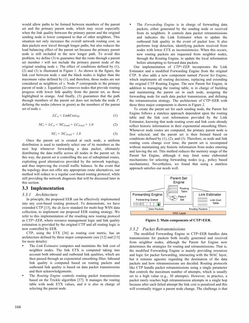
Our implementation of CTP+EER incorporates the Link Estimator and a modified Forwarding Engine from the original CTP. It also adds a new component named Parent Set Engine, which implements all routing decisions, replacing and extending the original CTP Routing Engine. The new Parent Set Engine, in addition to managing the routing table, is in charge of building and maintaining the parent set in each node, assigning the forwarding node for each data packet transmission, and defining the retransmission strategy. The architecture of CTP+EER with these three major components is shown in Figure 2.
To create the parent set for each sending node, the Parent Set Engine follows a stateless approach dependent upon the routing table and the link cost information provided by the Link Estimator, knowing that node routing costs and link costs already reflect historic information in their exponential smoothing filters. Whenever node routes are computed, the primary parent node is first selected, and the parent set is then formed based on conditions defined by (1), (2), and (3). Therefore, as node and link routing costs change over time, the parent set is recomputed without maintaining any historic information from nodes entering and leaving the set. This method reduces the memory usage of the Parent Set Engine, although it may limit some elaborated mechanisms for selecting forwarding nodes (e.g., policy based mechanisms). Nevertheless, we found that using a stateless approach satisfies our needs well.
Figure 2. Main components of CTP+EER.
3.3.2 Packet Retransmissions The modified Forwarding Engine in CTP+EER handles data
transmissions for packets both locally generated and received from neighbor nodes, although the Parent Set Engine now determines the strategies for routing and retransmissions. That is, the modified Forwarding Engine is mainly providing resources and logic for packet forwarding, interacting with the MAC layer, but it remains agnostic regarding the destination of the data packets and how retransmissions are decided. Routing protocols like CTP handle packet retransmissions using a single parameter that controls the maximum number of attempts, which is usually set to a high value (e.g., 30 attempts). However, in practice, a packet rarely reaches high retransmission attempts in a single hop because after each failed attempt the link cost is penalized and this will eventually trigger a parent node change. The challenge is that
104

as the path routing cost through the current parent node increases due to link cost penalizations, the sending node may end up transmitting a data packet to neighbors initially considered as child nodes. Since this process is faster than the dissemination of node routing costs, routing loops are likely to be created. The main cause behind this problem is that the retransmission policy does not differentiate between random errors (i.e., link quality problems that could be overcome using retransmissions) and bursty or permanent errors that require re-routing.
Figure 3. General flowchart of the packet forwarding process in CTP+EER.
In CTP+EER, we cannot use the same retransmission policy as the original CTP because it would completely ignore random errors in the links when selecting a new forwarding node from the parent set on each retransmission attempt. This would reduce the load balancing effect, as nodes with slightly better link qualities will receive most of the traffic load. In our implementation we opted to allow each sending node to have a number of retransmissions per link equivalent to the worst link quality considered by the routing protocol, LinkCostTH (e.g., 5 retransmissions, equivalent to a 20% probability of success). After such retransmissions, another member from the parent set is randomly chosen, until either the packet is successfully acknowledged or the global maximum number of retransmissions is reached. It should be noted that in our implementation, similar to CTP, retransmissions are controlled at the routing level, without using link layer retransmissions. In this way, we have a more accurate estimation of the link costs; otherwise, the routing layer only penalizes links that failed after the maximum number of link layer retransmissions. Figure 3 presents the general flowchart of the packet-forwarding process in CTP+EER, where the Parent Set Engine performs highlighted tasks and the Link Estimator updates link costs (dashed tasks).
3.3.3 Loop Detection By definition, the parent set in EER does not allow routing
loops to be introduced; nonetheless, delays in the dissemination of node routing costs not only affect the retransmission strategy, as discussed above, but also affect the loop detection mechanism of the Forwarding Engine. When the node routing cost of potential forwarders (i.e., members of the parent set) increases, this information takes some time to reach neighbor nodes, including the sending node. Meanwhile, the sending node will continue transmitting data packets based on its local information and setting its own node routing cost in the packet header, causing inconsistencies from the point of view of the receiving node. An example of this situation is illustrated in Figure 4, where the values in the network represent the link and node ETX. The table in the figure shows the local node routing costs known by node X before detecting the increment of the node ETX in B. If node X selects node B as the forwarder, when B receives a data packet from X it will detect an inconsistency and trigger new routing packets. We note that this can also occur with parent nodes in CTP; however, in CTP+EER this would be more likely to occur as the parent set size increases, especially if we consider that in data collection applications the maximum interval for routing packets is usually larger than the inter-packet interval of data packets. To address this problem, we relaxed the loop-detection condition by adding the cost of one perfect transmission to the routing cost indicated in received packets, as defined in (4). This condition prevents generating unnecessary routing packets for inconsistencies detected from neighbor nodes at the same routing cost level (e.g., among members of the parent set). Then, the parent set of the node will be updated when the next routing packet is received.
PacketCost + 1.0 < ReceiverNodeCost (4)
Our implementation of CTP+EER benefits from not requiring specific configurations other than the original parameters in CTP. In addition, EER does not introduce any new fields to the protocol header, other than the size of the parent set that may be included as instrumentation data. Finally, by randomly selecting forwarding nodes from the parent set, no changes have been applied to the routing cost function.
Figure 4. An example of a routing cost inconsistency in EER without relaxing the loop-detection condition.
3.4 Parent Set Size for Network Diagnosis The size of the parent set in EER provides a new indicator for
network topology diagnosis. By including the size of the parent set as network instrumentation in data packets, end-users will have a better understanding of the network routing redundancy.
The size of the parent set ranges from one, containing only the primary parent node, up to a maximum threshold (potentially the size of the routing table). Therefore, a larger parent set reflects a node with higher routing redundancy, indicating that the node can distribute its traffic among multiple neighbors and also if a link failure occurs, the node still has other potential forwarders as
105

suitable choices before attempting to re-route or being disconnected from the network.
This observation can be generalized for identifying any node with strong or weak network redundancy by examining the size of parent sets containing this node (i.e., parent set of child nodes). If all parent sets containing a given node are of size larger than one, then the node would not correspond to an articulation node (i.e., a sufficient condition), defining a strong node. This is a direct consequence from (3), which does not allow alternative routes of child nodes to go through a strong node, and therefore if the strong node fails, the children would not be disconnected from the network. On the other hand, if any child of a given node has a parent set size equal to one, the child may still be connected via re-routing if the parent node fails, defining a weak parent node. Still, having child nodes with parent set of size one is an undesirable situation because it reduces the load balancing effect of EER and in the event of a failure in a weak node, re-routing for locating a new path that prevents the network partition requires additional routing traffic for updating and disseminating the new node routing costs. Therefore, in practical WSN deployments, the parent set size can be used to diagnose nodes with weak network redundancy, providing new information for relocating the weak nodes or deploying new relay nodes.
4 Analytical Performance Model To further analyze the impact of the proposed ERR on energy
consumption and network lifetime, we now present an analytical model to compare the behavior of any cost-based routing protocol R (e.g., CTP) and the corresponding EER-extended routing protocol R+EER (e.g., CTP+EER). The connection between R+EER and any cost-based routing approach R is that the parent of a node in the latter will always be a member of the parent set in the former (e.g., the primary parent node). Our performance model analyzes the redundancy conditions of the network topology and their implications on practical WSN deployments.
Table 1. Parameters of the Analytical Model of CTP+EER
Parameter Definition
! Set of nodes in the network, where! ! = !. !!" is the neighborhood set of the sink(s).
! Adjacency matrix. Aij represents the link from node i to node j
! Link cost matrix. Lij indicates the link ETX from node i to node j
!! Size of the parent set of node i
!! Traffic processed by node i (generated and forwarded packets)
!! Traffic generated by node i
!! CTP parent of node i
! Additional link cost introduced by the parent set
!!!" Average link cost of the node with maximum energy consumption in EER
!!"# Link cost of the node with maximum energy consumption in CTP
The network model considers the topology of a WSN with N nodes represented as a destination oriented acyclic graph with adjacency matrix !, where !!" represents the link from node i to node j. Note that the network topology graph of R is a subset of the topology graph of R+EER, by the definition that the parent set
in R+EER includes the parent node defined by R. Nevertheless, a parent node in R may not necessarily correspond to the primary parent node in R+EER, since multiple nodes can have the same routing costs. In this paper, we focus our analytical model on the study of CTP versus CTP+EER. The parameters of the model are defined in Table 1.
When comparing CTP+EER and CTP using the same configuration parameters (e.g., frequency of routing packets) and MAC layer protocol, the main improvement on the total energy consumption will be determined by the differences in data traffic transmissions on each node (i.e., effect of the parent set in EER). Therefore to simplify the model complexity, we consider the energy consumed from data packet transmissions as the main factor influencing the network lifetime.
Assuming that both protocols are working under the same conditions and using the same energy sources, we define the maximum network energy consumption (NEC) for each routing protocol, which is inversely proportional of the network lifetime (i.e., the time for the first node to deplete its batteries). Equations (5) and (6) formulate the NEC of CTP+EER and CTP respectively, based on the maximum energy consumed in the worst-case scenarios by each individual node ! ∈!. From (5) and (6) we can observe that the impact of locally generated traffic can be neglected compared to that of traffic received from neighbor nodes in each sampling interval. Therefore, we can ignore the locally generated traffic term !! from (5) and (6).
!"#!"# = max !!"!
!!!!! + !!! ∙ !!!! (5)
!"#!"#!!!" = max !!"!
!!!
!!!!
+ !!! ∙ !!"!!
!
!!!!! (6)
It can be seen from (6) that the energy consumption of a sending node with CTP+EER depends on the parent set size of its child nodes and the weighted average quality of outgoing links to members of its parent set. This weighted average link quality for CTP+EER in (6) can be rewritten in terms of the link cost between the sending node and the parent node in CTP, as shown in (7), where ! ∈ ! [1,2) indicates the additional link cost introduced by suboptimal nodes in the parent set of CTP+EER with respect to CTP.
!!"!!
!
!!!= !!!"! (7)
THEOREM 1. Let !! ≥ !2 for every ! ∈ !\!!" . Then, the NEC of CTP+EER is lower than that of CTP.
PROOF. For each node ! ∈! there is a corresponding term in (5) and (6). Then, the energy consumption of every node ! in CTP will be higher than the corresponding node in CTP+EER when
!!"!
!!!!! ∙ !!"! > !!"
!
!!!
!!!!
∙ !!!"! !,
which is valid for !! > !, where n indicates any child node in the network. For nodes in !!", CTP+EER and CTP always use the same links (i.e., links from the sending node to the corresponding sink) and therefore !!!" = 1 and !!!" = 1 . Then, the energy consumption condition for these nodes is satisfied as long as nodes in the second hop level distribute the traffic received by the
106
busiest children of the sink in CTP. This means that nodes in CTP+EER need ! ≥ !2, which is the initial assumption.
For nodes that are not in !!", from (7) and the parent set definition in (1), (2), and (3), we know that ! < 2, therefore !! ≥ !2 satisfies the previous energy consumption condition.
Now, for every node ! ∈ !\!!" there are two options: first, if a node x has the maximum energy consumption in both (5) and (6), then the proof is complete, and the maximum network energy consumption, NEC, of CTP+EER would be lower than that of CTP. In the second case, we have that the nodes with maximum energy consumption in CTP+EER and CTP are different. Now we assume that node y and node x correspond to the nodes with maximum energy consumption in CTP+EER and CTP, respectively. From the previous case, we know that the energy consumed by y in CTP is higher compared to energy the same node consumes in CTP+EER. Then, since x is the node with the highest energy consumption in CTP, we have that
!"#$%&!!"# > !"#$%&!!"# > !"#$%&!!!".
This proves that the maximum network energy consumption, NEC, would be higher in CTP compared to CTP+EER. !
Theorem 1 indicates that if all nodes have redundancy with a parent set size greater than or equal to two, excluding the children of the sink(s) that do not require this condition, then CTP+EER is more energy efficient than CTP. Although, the condition in Theorem 1 is very strict for practical WSN deployments, we can still obtain an important observation from the theorem proof: if ! = 1, then only one children from every node requires some level of redundancy for CTP+EER to reduce the maximum network energy consumption with respect to CTP. Likewise, as ! increases, more redundancy is needed for child nodes.
In the following theorems we formalize this observation showing that only some children need to provide redundancy for a node in CTP+EER to reduce its node energy consumption compared to CTP. With the same arguments, we can show that this situation only needs to occur in some nodes of the network (i.e., busiest nodes) for CTP+EER to reduce the maximum network energy consumption compared to CTP.
THEOREM 2. Let the children that concentrate ! ! + 1 out of the total received traffic of a node i in CTP provide redundancy with ! > ! and ! > ! ! − 1 (! − !) in CTP+EER; then the energy consumption of node i in CTP+EER is lower than its corresponding node energy consumption in CTP.
PROOF. Assuming that the node i has M children, the energy consumption condition from the proof of Theorem 1 can be rewritten for a single node as follows:
!!! ∙ !!"! +⋯+ !!! ∙ !!"! + !!!!! ∙ !!"! +⋯+ !!! ∙ !!"! !!!>
!!!!!!
∙ !!!"! +⋯+ !!!!!!
∙ !!!"! +!!!!!!!!!!
∙ !!!"! +⋯+ !!!!!!
∙ !!!"!,
where the child nodes !!, !!, . . . , !!! are sorted by their CTP traffic as
!!! > !!! > ⋯ > !!! > !!!!! > ⋯ > !!! . After reorganizing the terms, the condition can be written as:
0 > !!!!!!"!!!!
− !!"! +⋯+ !!!!!!"!!!!
− !!"! +
!!!!!!!!"!!!!!!
− !!"! +⋯+ !!!!!!"!!!!
− !!"! .
Now, if the top k children concentrate most of the traffic, we have that
!!! +⋯+ !!! = !!λ,
!!!!! +⋯+ !!! = λ.
In the worst case, only those k children have redundancy. We can simplify the expression unifying the parent set sizes as
!!! = !!! = ⋯ = !!! = !,
!!!!! = ⋯ = !!! = 1. The energy consumption condition can be factorized as
0 >!!!"!! − !!"! !!! +⋯+ !!!
+ !!!"! − !!"! !!!!! +⋯+ !!! .
Replacing the total traffic, we have
0 >!!!"!! − !!"! βλ + !!!"! − !!"! λ,
and finally, we can solve for β.
β >!!!"! − !!"!!!"! −
!!!"!!
= ! ! − 1! − ! , ! > !. (8)
From (8) it can be seen that if the k children that concentrate β β + 1 out of the total received traffic of node i in CTP provide redundancy with ! > ! in CTP+EER, the energy consumption of node i in CTP+EER would be lower than its corresponding node energy consumption in CTP. !
THEOREM 3. Let the nodes that concentrate !/(! + 1) out of the total network traffic in CTP improve their node energy consumption in CTP+EER according to Theorem 2, for !!! > ! (!!!" !!"#); then CTP+EER reduces the network energy consumption compared to CTP.
PROOF. First we sort all N nodes in the network by their processed traffic in CTP as
!! > !! > ⋯ > !! > !!!! > ⋯ > !!,
where
!! + !! +⋯+ !! = !Λ,
!!!! +⋯+ !! = Λ.
Then, if the busiest g nodes in the network reduce their node energy consumption in CTP+EER compared to CTP, we have the following two options: first, if the node with the maximum energy consumption in CTP+EER from (6) is in the top g nodes, then the proof is complete by Theorem 2. The second case is the opposite situation, where the node with maximum energy consumption in CTP+EER is not in the top g nodes. Here we can assume that in the worst case g = N − 1 , and that the node with maximum energy consumption in CTP+EER is processing all remaining traffic with an additional link cost !, related to the node with maximum energy consumption in CTP, as shown in (9).
!! = !!!!" !!"# . (9)
107

In a worst-case scenario, we can assume that the node with maximum energy consumption in CTP is also concentrating ω/(ω + 1) out the total network traffic. Then, we have
! ∙ Λ ∙ !!"# > Λ ∙ !!!" ,
and solving for ! , we obtain ! > ! , proving that CTP+EER improves the network energy consumption compared to CTP if the nodes that process ω/(ω + 1) out of the total network traffic in CTP satisfy Theorem 2 for ! > !, where ! is defined in (9). !
From Theorem 2 and Theorem 3, we can see that the redundancy conditions are highly dependent on the value of ! from (7). For example, when comparing specific nodes, if ! = 1.3, according to Theorem 2 only those child nodes that concentrate 50% of the node traffic in CTP need to have network redundancy with ! ≥ 2 for CTP+EER to reduce the energy consumption of the sending node. Other child nodes that concentrate the remaining 50% of the node traffic are not required to have network redundancy in CTP+EER. In addition, when we consider the entire network, from Theorem 3 we have that if ! = 1.3, only the busiest nodes that concentrate 57% of the total network traffic in CTP need to satisfy Theorem 2 for CTP+EER to improve the maximum network energy consumption.
We can also observe that when using the parent set for diagnosis of network redundancy as defined in Section 3, nodes with very weak network redundancy (i.e., nodes only within the parent sets of size one) indeed correspond to nodes that do not satisfy Theorem 2 (i.e., sufficient condition). Then, as weak nodes are identified, their network redundancy can be addressed (e.g., node relocations, deploying additional redundancy nodes) proactively; hence the diagnosis from the parent set can lead the network to satisfy the requirements of Theorem 3. In the next section we will discuss in more detail practical values of !, and how Theorem 3 can be satisfied even in the presence of weak nodes.
5 Evaluation To validate our CTP+EER routing protocol, we performed a
series of WSN experiments and simulations developed in TinyOS 2.1.2, and compared the results of CTP+EER with those obtained by CTP and ORW, which are two state-of-the-art approaches using traditional cost-based and opportunistic routing strategies, respectively. WSN experiments were conducted in the publicly available Indriya testbed [38] deployed at the National University of Singapore, using 95 TelosB motes accessible at the time of the experiments (between January and August 2015). Further evaluations were conducted using Cooja [39] to emulate the same TinyOS applications compiled for TelosB motes and used for the testebd experiments.
Our validation is based on the following metrics: • Packet Reception Rate (PRR): defined for each node as the
ratio between the number of data packets received at the sink and the number of generated packets.
• Transmission Cost: defined for each node as the ratio between the total number of data packet transmissions (i.e., generated, forwarded, and retransmitted packets) and the number of generated packets.
• Duty Cycle: defined for each node as the percentage of time the radio is active.
The three routing protocols are evaluated using a WSN application with an average inter-packet interval (IPI) of 4 minutes, a reasonable value for requirements in data collection applications with low rates. All protocols also use the same LPL implementation based on the CC2420 driver included in TinyOS, although ORW introduces some modifications as discussed in
[15]. CTP+EER and CTP are configured with an LPL wakeup interval of 1 second, while ORW is configured with 2 seconds (denoted as ORW(2s)), which resulted in the optimal configuration for each protocol in our tests. We also repeated the experiments with ORW using the LPL wakeup interval configuration of 1 second (denoted as ORW(1s)), and discuss its effects on the duty cycle. The sink node in all the experiment scenarios is awake 100% of the time.
To achieve a fair comparison, we examined other default parameters of the LPL implementation for TelosB motes in TinyOS. We found that the default time interval for listening after an LPL sleep interval is actually not large enough to detect a data packet transmission and to receive the corresponding acknowledgement. To achieve fast data packet acknowledgements, CTP+EER and CTP were configured to use TinyOS hardware acknowledgments, whereas ORW continued using the default TinyOS software acknowledgments due to the unavailability of hardware acknowledgments in its implementation. The LPL listening time is controlled by the maximum number of Clear Channel Assessment (CCA) checks done by the CC2420 driver, which defines a default value of 400. For this value, we found that basic packet transmissions over a single hop are correctly acknowledged only around 60% to 70% of the time, depending on the data packet size, introducing unnecessary packet retransmissions and increasing the energy consumption. In our validation, we use data packets with a payload size of 60 Bytes, and we found that using 1100 maximum CCA checks resulted in 100% acknowledged packets for transmissions between TelosB motes in scenarios with low interference, a configuration that was used for the three routing protocols in our tests.
At the routing level, CTP+EER and CTP use a maximum Trickle timer interval of 30 minutes for routing packets and a maximum of 10 retransmission attempts for data packets, while ORW uses its default parameters. For our tests with CTP+EER, we also defined a maximum parent set size of 5 neighbor nodes.
5.1 Experiments in Indriya The 95 TelosB motes used in Indriya are distributed among
three floors, and we chose node one as the sink, which is located in a corner of the first floor. Our tests are based on average values of 2-hour runs repeated at least 4 times, for each routing protocol.
Figure 5. Path length distribution in Indriya based on CTP.
We start by characterizing the WSN topology in Indriya and we use the average hop counts obtained by CTP, which always uses the best available neighbor to forward data packets, and provides an accurate distribution of nodes by hop count in the testbed. As shown in Figure 5, WSN nodes in Indriya are heavily concentrated close to the sink node, where the farthest nodes are located 5 hops away, but 67% of the nodes are within 3 hops of the sink. We use these average hop counts obtained from CTP to
108
sort the nodes based on their path distance in the discussion of the following results.
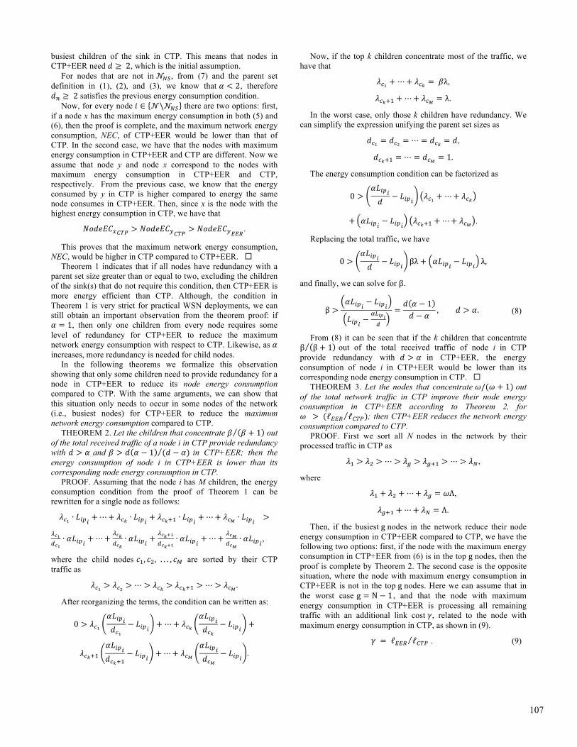
Table 2. Average Performance of CTP+EER versus CTP and ORW in Indriya
Protocol PRR [%] Tx Cost Duty Cycle [%]
Avg. Min. Max. Avg. Min. Max. Avg. Min. Max.
CTP+EER 99.41 ±0.61 97.68 100 2.77
±2.66 1.01 13.20 3.27 ±0.69 2.36 6.15
CTP 98.81 ±1.17 94.30 100 2.68
±3.92 1.00 24.36 3.20 ±0.92 2.36 7.81
ORW-2s 95.99 ±3.04 90.03 100 4.66
±2.66 1.02 18.96 1.62 ±0.79 0.34 5.97
ORW-1s 95.68 ±3.03 80.59 100 2.99
±2.31 1.06 15.79 4.13 ±2.02 1.69 6.93
(a) PRR for nodes based on their path distance.
(b) Transmission cost for nodes based on their path distance.
(c) Duty cycle for nodes based on their path distance.
Figure 6. Results from experiments in Indriya.
5.1.1 Reliability We compare the reliability of the routing protocols based on
their PRR. The results obtained are summarized in Table 2, showing that CTP+EER has the highest average node PRR, with lowest standard deviation, among the three routing protocols in
our experiments. Detailed results for each node are shown in Figure 6a with nodes sorted based on their path distance. It can be seen that overall, nodes with CTP+EER achieve the highest PRR without drastic fluctuations as observed for CTP and ORW. One observation for ORW is that the node PRR consistently decreases as the node path distance to the sink increases. As a result, nodes located 4 or 5 hops away can have up to a 10% lower PRR in ORW compared to CTP+EER. The parent set in CTP+EER explicitly addresses this problem by providing routing progress after each transmission, as discussed in Section 3. The effectiveness of CTP+EER is shown by the average PRR higher than 99%, evidencing high network reliability. 5.1.2 Energy Efficiency and Balance
We evaluate the energy efficiency and balance of the routing protocols based on the transmission cost and duty cycle. The transmission cost provides a routing level indicator of the traffic load on each node. On the other hand, the duty cycle provides a direct metric on energy consumption, which includes the effects from both routing and MAC layers. Also, the node with the maximum duty cycle corresponds to the node that determines the network lifetime. These results need to be interpreted based on the PRR achieved by each routing protocol, since lower PRRs may reduce the data traffic load processed by the busiest nodes in the network, influencing their transmission cost and duty cycle.
Figure 6b shows the average node transmission cost for the three routing protocols. It can be seen that CTP has nodes with the highest transmission cost, corresponding to the busiest nodes in the first two hops of the network topology. In contrast, CTP+EER and ORW do better in distributing the traffic load, especially for nodes within two hops from the sink. In particular, as shown in Table 2, CTP+EER is able to reduce the maximum transmission cost by 45% and 30%, compared to CTP and ORW(2s), respectively. These results, together with the lowest average transmission cost of CTP, reveal how unbalanced the traffic is for WSN nodes with CTP. The experiments show that CTP+EER is able to improve the energy efficiency at the routing layer, while achieving the highest average PRR among all the three tested routing protocols.
As shown in Figure 6b, the node with the maximum transmission cost in ORW(2s) is located 3 hops away from the sink, which reflects that ORW is experiencing looping packets. These looping packets are dropped when detected, causing the lower PRR observed in Figure 6a.
Regarding the results of duty cycles, as shown in Figure 6c and Table 2, nodes in CTP reach the highest duty cycle of 7.81%, whereas CTP+ERR achieves a maximum duty cycle 21% lower than CTP, and only 3% higher than ORW(2s). Note that when using the same LPL wakeup interval of 1 second, CTP+EER actually achieves a maximum duty cycle 11% lower than ORW(1s). 5.1.3 Network Redundancy
We examine the network topology redundancy offered by Indriya using the size of the parent set as an indicator. Figure 7 shows a representation of the network topology when using CTP+EER, where the sink node is shown in the middle of the diagram, and edges connect nodes to their most frequent forwarder. Nodes are highlighted based on their diagnosis, where black nodes correspond to nodes with strong network redundancy, and weak nodes are highlighted in red or yellow. Red nodes are the ones that in the case of failure would at least temporarily disconnect all their children (i.e., all their children have an average parent set of size one), while yellow nodes are the ones that would disconnect at least one child.
109

The diagnosis of the topology in Indriya via CTP+EER discovered 5 nodes with the lowest level of redundancy (i.e., red nodes). These nodes are receiving most of the traffic from 23 direct children and 24 extended children (i.e., children of direct children), covering the traffic from about 50% of the nodes in the network. With additional 6 yellow weak nodes, there are a total of 11 weak nodes at the risk of partitioning the network. This weak network redundancy would certainly exist with CTP, but would not be identified before the network is finally partitioned due to the failure of one of the red or yellow nodes from Figure 7.
In a practical WSN deployment, once these weak nodes are identified, their locations can be analyzed to determine if they can be relocated or if additional WSN nodes can be deployed to provide new alternative paths towards the sink.
Figure 7. Representation of the network topology of experiments using CTP+EER in Indriya.
5.1.4 Performance Model Verification The experiment results also allow us to examine the network
topology observed in Indriya based on our analytical model introduced in Section 4. From the link quality of the nodes in CTP+EER and CTP, we found that ! has an average of 1.01 ± 0.03, with a maximum value of 1.30. For this maximum value of !, nodes in CTP+EER can improve their energy efficiency if child nodes responsible for 50% of the node traffic in CTP have a parent set size greater than or equal to 2 in CTP+EER. In Indriya, this condition is in fact satisfied for all the black nodes in Figure 7 with strong network redundancy; red weak nodes do not satisfy Theorem 2, but yellow weak nodes may or may not satisfy
Theorem 2, depending on the specific traffic distribution of their children.
In a worst-case scenario, ! from Theorem 3 can be assumed as the maximum !, which was 1.30 in our case. Then, for this value of ! and from Theorem 3 we know that nodes concentrating 57% of the traffic in CTP must satisfy Theorem 2 for CTP+EER to improve the maximum network energy consumption. Since only the weak nodes in Figure 7 are at the risk of not satisfying Theorem 2, we computed the traffic load processed by these weak nodes in CTP, which concentrate up to 29% of the total network traffic. Therefore, as all the other nodes have strong network redundancy and satisfy Theorem 2, we can confirm that the network in Indriya satisfies Theorem 3 in our tests.
5.2 Simulations in Cooja Knowing the limitations of the network topologies in WSN
testbeds available to the community, we further conduct our validation of CTP+EER using the Cooja simulator. Our simulations use the Unit Disk Graph Medium (UDGM) with exponential distance loss as radio model and a maximum link quality of 90% to account for uniform random noise during packet transmissions. The assumptions in this radio model are idealistic, but our main objective with the simulations is to evaluate the three routing protocols under different topologies, based on the results observed from the above testbed experiments. Our simulations in Cooja ran 24 hours of the WSN application. 5.2.1 Effect of the Network Topology
Our experiments in Indriya captured a behavior in ORW, which reduces the PRR for nodes with a larger path distance from the sink. To further investigate this situation, we started using a simple rectangular topology of 20 WSN nodes distributed along 7 hops with three nodes in each hop level and one node in the last level. The three routing protocols were simulated in this topology and the summary of the results is shown in Table 3.
As expected, CTP+EER and CTP achieve similar PRRs above 99%. CTP+EER also reduces the maximum transmission cost by 46% and the maximum duty cycle of the busiest nodes that define the network lifetime by 24%, compared to results obtained by CTP. Again, ORW(2s) suffers from additional packet drops, reducing its average node PRR to 86.36%. CTP+EER still improves the maximum transmission cost and maximum duty cycle by 11% compared to ORW(2s). Note that the PRR of
Table 3. Summary of Results from Simulations with 20 WSN Nodes
Protocol PRR [%] Avg. Min. Max.
CTP+EER 99.97 ± 0.07 99.74 100 CTP 99.96 ± 0.09 99.73 100
ORW-2s 86.36 ± 7.35 76.98 100
Protocol Transmission Cost Avg. Min. Max.
CTP+EER 4.11 ± 2.94 1.01 8.96 CTP 4.17 ± 5.71 1.01 16.90
ORW-2s 7.06 ± 2.01 2.43 10.07
Protocol Duty Cycle Avg. Min. Max.
CTP+EER 2.75 ± 0.52 2.20 3.77 CTP 2.72 ± 0.86 2.12 4.98
ORW-2s 2.65 ± 0.93 1.04 4.25
Figure 8. Improvement of the transmission cost in CTP+EER compared to CTP in simulations with random topologies.
Figure 9. Improvement of the duty cycle in CTP+EER compared to CTP in simulations with random topologies.
110

ORW(2s) further decreased compared to that obtained in the Indriya testbed, due to the more even distribution of nodes across the different hop levels. When routing loops occur, a higher percentage of the nodes in the network would be affected, unlike the Indriya testbed where nodes are heavily concentrated close to the sink. Similar to the results obtained from Indriya, the lower PRR of ORW(2s) still affects the results for the transmission costs and duty cycles, where nodes closer to the sink process less traffic due to packet drops, but nodes involved in the routing loops increase their energy consumption. This confirms that ORW reduces the performance of nodes located farther from the sink, depending on the network topology and the distribution of the nodes in the network. 5.2.2 Random Network Topologies
We also conducted our evaluation using random network topologies of 100 WSN nodes. For these scenarios, the first 2 hops of the networks are fixed with 4 and 5 nodes, respectively, where nodes in the second hop can communicate with at least 2 nodes from the first hop. The remaining nodes are uniformly and randomly distributed in an area of 350x350m2, where WSN nodes have a maximum transmission range of 50m, and the sink is located in one of the corners. Controlling the first two hops of the network guarantees that nodes are not heavily concentrated around the sink and also creates potential critical nodes with a minimum network redundancy.
Considering the lower PRR performance of ORW in our previous experiments and simulations, we now focus on the improvement of CTP+EER in comparison with CTP. In this scenario, simulations are repeated for 10 random topologies, which results in networks with 10 hops in diameter, with up to 15 nodes in each hop level.
For these simulations, CTP+EER and CTP achieve an average PRR of 99.88% ± 0.02% and 99.93% ± 0.01, respectively. In all simulation trials, both routing protocols maintain node PRRs higher than 99%, showing that they have no problems processing the traffic load in the network under the assumptions of the radio model.
As shown in Figure 8, CTP+EER reduces the maximum transmission cost in all simulation trials compared to CTP, with the improvements ranging from 33.29% to 59.66%. The improvements of CTP+EER in the maximum duty cycle are shown in Figure 9, achieving reductions between 7.06% and 35.67%. The load balancing effect of the parent set in CTP+EER can be clearly seen in the figures, greatly reducing the energy consumption in the busiest nodes with CTP and thus increasing the network lifetime.
5.3 Discussion Our evaluation results show that overall CTP+EER achieves
and maintains high reliability, with average PPRs above 99%, in both testbed experiments and simulations. CTP, which is characterized for achieving high reliability, has similar PRR results in the simulations but a slightly lower performance in the testbed. The link diversity introduced by the parent set in CTP+EER allowed WSN nodes to explore additional paths reducing the number of packet drops. Overall, CTP+EER improves the energy efficiency at the routing layer compared to CTP by reducing the maximum transmission costs, which is observed in the testbed and in all simulations. The energy efficiency of the routing layer in CTP+EER results in reductions of the maximum duty cycle ranging from 7% up to 35% compared to CTP, extending the network lifetime.
ORW presented a different behavior in the testbed, where nodes located far from the base station have PRRs up to 10%
lower than the same nodes in CTP+EER. This is confirmed in simulations using a topology with WSN nodes more evenly distributed across multiple hops. In these scenarios, the lower PRR in ORW is mainly caused by packets looping between nodes with similar routing costs (i.e., EDC in ORW), which are dropped when detected.
In comparison with the optimal ORW(2s) configuration, CTP+EER reduces the maximum transmission costs about 30% and was only 3% higher for the maximum duty cycle in the testbed, when ORW(2s) runs on a different MAC layer configuration that saved close to half of the energy CTP+EER consumed in LPL idle listening. The improvement of the energy efficiency at the routing layer of CTP+EER compared to ORW is confirmed by the 11% reduction of the maximum duty cycle compared to ORW(1s) in the testbed experiments, when both routing protocols were using the same LPL wakeup intervals of the MAC layer configuration. Moreover, in the simulation with a larger network diameter and nodes more evenly distributed across the different hop levels, CTP+EER reduces both maximum transmission cost and the maximum duty cycle by about 11%, when compared to ORW(2s).
We note that the improvement in the maximum transmission cost (i.e., energy efficiency at the routing layer) indicates the potential improvement in maximum duty cycle (i.e., network lifetime), where the duty cycle captures the effect in energy consumption from both routing and MAC layers.
Finally, the analysis of the parent set size for different nodes has shown that even though the WSN topology may present nodes with weak network redundancy and high network traffic, CTP+EER would still be able to improve the energy efficiency compared to CTP and ORW. For example, while the topology in Indriya has multiple weak nodes close to the sink in our tests, CTP+EER is able to meet the worst-case redundancy requirements derived from our analytical performance model and therefore is also able to improve the network energy efficiency.
6 Conclusions In this paper we present Energy Efficient Routing (EER), a
new routing approach for energy-constrained data collection applications in multi-hop WSNs. Our approach introduces the concept of parent set for energy efficiency and balance in WSN routing, exploiting the redundancy offered by the network topology and leveraging on suboptimal and randomized routing alternatives in a controlled way. These route alternatives reduce the data traffic load on critical nodes, while maintaining high reliability in the network. In addition, our proposed EER also provides a new diagnosis mechanism for the network topology redundancy. EER can be implemented into any cost-based routing protocol, while remaining independent of the MAC layer. We demonstrate its implementation into CTP, which forms the new routing protocol CTP+EER.
Our evaluation shows that CTP+EER overcomes the energy efficiency issues of traditional cost-based routing protocols and the reliability issues of state-of-the-art opportunistic routing protocols. In this way, CTP+EER defines a middle ground between sender-based and opportunistic routing, which combines high reliability and energy efficiency. Our CTP+EER achieved average PRRs over 99% in our testbed experiments and simulation scenarios, and at the same time, improved the maximum transmission cost ranging from 11% to 59%. This energy efficiency of the routing layer resulted in the reductions of the maximum duty cycle ranging from 7% to 35%, when using the same asynchronous LPL configuration. Such high reliability and improvement of the network lifetime make CTP+EER very
111

suitable for data collection applications in real-world energy-constrained WSN deployments.
Our work on ERR is not only complimentary to other cost-based WSN routing protocols, but also to other energy-efficient MAC layer implementations, to further extend the network lifetime of practical WSN deployments.
EER could be further improved by exploring new mechanisms for the member selection of the parent set (e.g., modified receiver-based approaches based on members of the parent set), which we plan to undertake in our future work.
7 Acknowledgements This work is supported in part by U.S. National Science
Foundation under grant CNS-1320132.
8 References [1] G. Barrenetxea, F. Ingelrest, G. Schaefer, M. Vetterli, O. Couach,
and M. Parlange, "Sensorscope: Out-of-the-box environmental monitoring," in IPSN 2008, pp. 332-343.
[2] B. Kerkez, S. D. Glaser, R. C. Bales, and M. W. Meadows, "Design and performance of a wireless sensor network for catchment�scale snow and soil moisture measurements," Water Resources Research, vol. 48, 2012.
[3] C. Skalka and J. Frolik, "Snowcloud: A complete data gathering system for snow hydrology research," in Real-World Wireless Sensor Networks. Springer, 2014, pp. 3-14.
[4] R. Szewczyk, A. Mainwaring, J. Polastre, J. Anderson, and D. Culler, "An analysis of a large scale habitat monitoring application," in ACM Sensys 2004, pp. 214-226.
[5] G. Tolle, J. Polastre, R. Szewczyk, D. Culler, N. Turner, K. Tu, et al., "A macroscope in the redwoods," in Sensys 2005, pp. 51-63.
[6] X. Mao, X. Miao, Y. He, X.-Y. Li, and Y. Liu, "CitySee: Urban CO 2 monitoring with sensors," in INFOCOM 2012, pp. 1611-1619.
[7] Y. Liu, Y. He, M. Li, J. Wang, K. Liu, and X. Li, "Does wireless sensor network scale? A measurement study on GreenOrbs," IEEE Transactions on Parallel and Distributed Systems, vol. 24, pp. 1983-1993, 2013.
[8] M. Navarro, T. Davis, G. Villalba, Y. Li, X. Zhong, N. Erratt, et al., "Towards Long-Term Multi-Hop WSN Deployments for Environmental Monitoring: An Experimental Network Evaluation," Journal of Sensor and Actuator Networks, vol. 3, pp. 297-330, 2014.
[9] M. Z. A. Bhuiyan, G. Wang, J. Cao, and J. Wu, "Sensor placement with multiple objectives for structural health monitoring," ACM Transactions on Sensor Networks (TOSN), vol. 10, p. 68, 2014.
[10] N. Burri, P. Von Rickenbach, and R. Wattenhofer, "Dozer: ultra-low power data gathering in sensor networks," in IPSN 2007,pp.450-459.
[11] F. Ferrari, M. Zimmerling, L. Mottola, and L. Thiele, "Low-power wireless bus," in ACM Sensys 2012, pp. 1-14.
[12] A. Woo, T. Tong, and D. Culler, "Taming the underlying challenges of reliable multihop routing in sensor networks," in ACM Sensys, 2003, pp. 14-27.
[13] O. Gnawali, R. Fonseca, K. Jamieson, M. Kazandjieva, D. Moss, and P. Levis, "CTP: An efficient, robust, and reliable collection tree protocol for wireless sensor networks," TOSN, vol. 10, p. 16, 2013.
[14] T. Winer, P. Thubert, A. Brandt, J. Hui, R. Kelsey, P. Levis, et al. RPL: IPv6 Routing Protocol for Low-Power and Lossy Networks, 2012.
[15] O. Landsiedel, E. Ghadimi, S. Duquennoy, and M. Johansson, "Low power, low delay: opportunistic routing meets duty cycling," in ACM/IEEE IPSN 2012, pp. 185-196.
[16] S. Moeller, A. Sridharan, B. Krishnamachari, and O. Gnawali, "Routing without routes: the backpressure collection protocol," in ACM/IEEE IPSN 2010, pp. 279-290.
[17] M. H. Alizai, O. Landsiedel, J. Á. B. Link, S. Götz, and K. Wehrle, "Bursty traffic over bursty links," in ACM Sensys, 2009, pp. 71-84.
[18] D. Puccinelli and M. Haenggi, "Reliable data delivery in large-scale low-power sensor networks," ACM TOSN, vol. 6, p. 28, 2010.
[19] D. Puccinelli, S. Giordano, M. Zuniga, and P. J. Marrón, "Broadcast-free collection protocol," in ACM Sensys, 2012, pp. 29-42.
[20] B. Deb, S. Bhatnagar, and B. Nath, "ReInForM: Reliable information forwarding using multiple paths in sensor networks," in IEEE LCN, 2003, pp. 406-415.
[21] W. Lou, "An efficient N-to-1 multipath routing protocol in wireless sensor networks," in IEEE MASS, 2005, pp. 8.
[22] H. Hassanein and J. Luo, "Reliable energy aware routing in wireless sensor networks," in IEEE DSSNS, 2006, pp. 54-64.
[23] A. B. Bagula and K. G. Mazandu, "Energy constrained multipath routing in wireless sensor networks," in Ubiquitous Intelligence and Computing, ed: Springer, 2008, pp. 453-467.
[24] M. Michel, S. Duquennoy, B. Quoitin, and T. Voigt, "Load-Balanced Data Collection through Opportunistic Routing," in DCOSS, 2015, pp. 62-70.
[25] F. Ishmanov, A. S. Malik, and S. W. Kim, "Energy consumption balancing (ECB) issues and mechanisms in wireless sensor networks (WSNs): a comprehensive overview," European Transactions on Telecommunications, vol. 22, pp. 151-167, 2011.
[26] W. R. Heinzelman, A. Chandrakasan, and H. Balakrishnan, "Energy-efficient communication protocol for wireless microsensor networks," in HICSS 2000, p. 10 pp. vol. 2.
[27] C. Y. Wan, S. B. Eisenman, A. T. Campbell, and J. Crowcroft, "Overload traffic management for sensor networks," ACM Transactions on Sensor Networks (TOSN), vol. 3, p. 18, 2007.
[28] R. C. Shah and J. M. Rabaey, "Energy aware routing for low energy ad hoc sensor networks," in IEEE WCNC, 2002, pp. 350-355.
[29] C. S. Ok, S. Lee, P. Mitra, and S. Kumara, "Distributed energy balanced routing for wireless sensor networks," Computers & Industrial Engineering, vol. 57, pp. 125-135, 2009.
[30] H. Tian, H. Shen, and T. Matsuzawa, "Randomwalk routing for wireless sensor networks," in PDCAT 2005, pp. 196-200.
[31] S. D. Servetto and G. Barrenechea, "Constrained random walks on random graphs: routing algorithms for large scale wireless sensor networks," in 1st ACM international workshop on Wireless sensor networks and applications, 2002, pp. 12-21.
[32] X. Vilajosana, J. Llosa, J. C. Pacho, I. Vilajosana, A. A. Juan, J. L. Vicario, et al., "Zero: probabilistic routing for deploy and forget wireless sensor networks," Sensors, vol. 10, pp. 8920-8937, 2010.
[33] R. Kacimi, R. Dhaou, and A. L. Beylot, "Load balancing techniques for lifetime maximizing in wireless sensor networks," Ad Hoc Netw., vol. 11, pp. 2172-2186, 2013.
[34] L. Shancang, Z. Shanshan, W. Xinheng, Z. Kewang, and L. Ling, "Adaptive and Secure Load-Balancing Routing Protocol for Service-Oriented Wireless Sensor Networks," Systems Journal, IEEE, vol. 8, pp. 858-867, 2014.
[35] F. Bouabdallah, N. Bouabdallah, and R. Boutaba, "On balancing energy consumption in wireless sensor networks," IEEE Transactions on Vehicular Technology, vol. 58, pp.2909-2924, 2009.
[36] D. S. De Couto, "High-throughput routing for multi-hop wireless networks," Massachusetts Institute of Technology, 2004.
[37] P. Levis, N. Patel, D. Culler, and S. Shenker, "Trickle: a self-regulating algorithm for code propagation and maintenance in wireless sensor networks," presented at the Proceedings of the 1st conference on Symposium on Networked Systems Design and Implementation - Volume 1, San Francisco, California, 2004.
[38] M. Doddavenkatappa, M. C. Chan, and A. L. Ananda, "Indriya: A low-cost, 3D wireless sensor network testbed," in Testbeds and Research Infrastructure. Development of Networks and Communities, Springer, 2012, pp. 302-316.
[39] F. Osterlind, A. Dunkels, J. Eriksson, N. Finne, and T. Voigt, "Cross-level sensor network simulation with cooja," in IEEE LCN 2006, pp. 641-648.
112
Related Documents