140 Sanguk Lee et al. ETRI Journal, Volume 27, Number 2, April 2005 In this paper, we present design features, implementation, and validation of a satellite simulator subsystem for the Korea Multi-Purpose Satellite-2 (KOMPSAT-2). The satellite simulator subsystem is implemented on a personal computer to minimize costs and trouble on embedding onboard flight software into the simulator. An object- oriented design methodology is employed to maximize software reusability. Also, instead of a high-cost commercial database, XML is used for the manipulation of spacecraft characteristics data, telecommand, telemetry, and simulation data. The KOMPSAT-2 satellite simulator subsystem is validated by various simulations for autonomous onboard launch and early orbit phase operations, anomaly operation, and science fine mode operation. It is also officially verified by successfully passing various tests such as the satellite simulator subsystem test, mission control element system integration test, interface test, site installation test, and acceptance test. Keywords: Satellite, satellite control system, orbit, satellite operation. Manuscript received May 13, 2004; revised Nov. 18, 2004. Sanguk Lee (phone: +82 42 860 5653, email: [email protected]), Byoung-Sun Lee (email: [email protected]), and Jaehoon Kim (email: [email protected]) are with Digital Broadcasting Division, ETRI, Daejeon, Korea. Sungki Cho (email: [email protected]) is with Space Geodesy Research Group, KASI, Daejeon, Korea. I. Introduction Korea Multi-Purpose Satellite-1 (KOMPSAT-1), which was launched in 1999, is still in robust operation beyond its expected lifetime of three years. For KOMPSAT-1 and its successor KOMPSAT-2, Electronics and Telecommunications Research Institute (ETRI), Daejeon, Korea, developed the mission control element (MCE) and delivered it to the Korea Aerospace Research Institute (KARI), Daejeon, Korea. The Korean ground station of KOMPSAT-2 consists of the MCE and the image reception and processing element. The MCE of KOMPSAT-2, which is equipped with a multi-spectral camera (1 m panchromatic and 4 m multi-spectral), provides the mission analysis and planning and satellite control capabilities necessary for carrying out the KOMPSAT-2 mission. Space-ground communications are based on the Consultative Committee for Space Data Systems (CCSDS) standard format. Figure 1 shows the simplified functional schematics of the system. KOMPSAT-2 MCE consists of four subsystems: tracking, telemetry, and command subsystem (TTC); satellite operation subsystem (SOS) [1]; mission analysis and planning subsystem (MAPS) [2]; and satellite simulator subsystem (SIM) [3]. The functional completeness and stability of the KOMPSAT-1 MCE system has been verified via the operation of KOMPSAT-1 from its launch and early orbit phase (LEOP) to normal operation phases. For KOMPSAT-2, TTC provides the S-band uplink and downlink communications interface with the satellite, the CCSDS command and telemetry processing, and tracking capabilities. SOS provides spacecraft command generation and execution, satellite health state monitoring, and housekeeping telemetry data processing. MAPS provides mission planning, incorporates user requests, defines configurations, and prepares Design, Implementation, and Validation of KOMPSAT-2 Software Simulator Sanguk Lee, Sungki Cho, Byoung-Sun Lee, and Jaehoon Kim

Welcome message from author
This document is posted to help you gain knowledge. Please leave a comment to let me know what you think about it! Share it to your friends and learn new things together.
Transcript

140 Sanguk Lee et al. ETRI Journal, Volume 27, Number 2, April 2005
In this paper, we present design features, implementation, and validation of a satellite simulator subsystem for the Korea Multi-Purpose Satellite-2 (KOMPSAT-2). The satellite simulator subsystem is implemented on a personal computer to minimize costs and trouble on embedding onboard flight software into the simulator. An object-oriented design methodology is employed to maximize software reusability. Also, instead of a high-cost commercial database, XML is used for the manipulation of spacecraft characteristics data, telecommand, telemetry, and simulation data. The KOMPSAT-2 satellite simulator subsystem is validated by various simulations for autonomous onboard launch and early orbit phase operations, anomaly operation, and science fine mode operation. It is also officially verified by successfully passing various tests such as the satellite simulator subsystem test, mission control element system integration test, interface test, site installation test, and acceptance test.
Keywords: Satellite, satellite control system, orbit, satellite operation.
Manuscript received May 13, 2004; revised Nov. 18, 2004. Sanguk Lee (phone: +82 42 860 5653, email: [email protected]), Byoung-Sun Lee (email:
[email protected]), and Jaehoon Kim (email: [email protected]) are with Digital Broadcasting Division, ETRI, Daejeon, Korea.
Sungki Cho (email: [email protected]) is with Space Geodesy Research Group, KASI, Daejeon, Korea.
I. Introduction
Korea Multi-Purpose Satellite-1 (KOMPSAT-1), which was launched in 1999, is still in robust operation beyond its expected lifetime of three years. For KOMPSAT-1 and its successor KOMPSAT-2, Electronics and Telecommunications Research Institute (ETRI), Daejeon, Korea, developed the mission control element (MCE) and delivered it to the Korea Aerospace Research Institute (KARI), Daejeon, Korea.
The Korean ground station of KOMPSAT-2 consists of the MCE and the image reception and processing element. The MCE of KOMPSAT-2, which is equipped with a multi-spectral camera (1 m panchromatic and 4 m multi-spectral), provides the mission analysis and planning and satellite control capabilities necessary for carrying out the KOMPSAT-2 mission. Space-ground communications are based on the Consultative Committee for Space Data Systems (CCSDS) standard format. Figure 1 shows the simplified functional schematics of the system. KOMPSAT-2 MCE consists of four subsystems: tracking, telemetry, and command subsystem (TTC); satellite operation subsystem (SOS) [1]; mission analysis and planning subsystem (MAPS) [2]; and satellite simulator subsystem (SIM) [3]. The functional completeness and stability of the KOMPSAT-1 MCE system has been verified via the operation of KOMPSAT-1 from its launch and early orbit phase (LEOP) to normal operation phases. For KOMPSAT-2, TTC provides the S-band uplink and downlink communications interface with the satellite, the CCSDS command and telemetry processing, and tracking capabilities. SOS provides spacecraft command generation and execution, satellite health state monitoring, and housekeeping telemetry data processing. MAPS provides mission planning, incorporates user requests, defines configurations, and prepares
Design, Implementation, and Validation of KOMPSAT-2 Software Simulator
Sanguk Lee, Sungki Cho, Byoung-Sun Lee, and Jaehoon Kim

ETRI Journal, Volume 27, Number 2, April 2005 Sanguk Lee et al. 141
Fig. 1. Schematics of the KOMPSAT-2 MCE.
TM signal
TC signal KOMPSAT-2 satellite
s-band
Primary MCE
Antenna pointing data
Antenna tracking data
Command plan/mission timelineSOH TM/GPS data TC logs
TM (RT+PB)
TC
TC
Simulated TM
TM/Antenna tracking data
TC/Orbit state data
Initial orbit element
DGPS data
Playback SOH TM Mission timeline/orbit state data/POD result data
Payload operational request/ antenna angle data
Orbit propagation data/ remaining fuel dataWeather data
External ground stations
International GPS service site
Launch site MAPS
Weather source
TTC
SOS SIM
IRPE
mission schedules. MAPS also provides KOMPSAT-2 operational support functions such as orbit determination and prediction, and antenna positioning data generation for tracking.
SIM is a comprehensive application software system that simulates the dynamic behavior of KOMPSAT-2 by the use of mathematical models. SIM is utilized for command verification, operator training, satellite control procedure validation, functional validation of the on-board flight software, and anomaly analysis.
SIM receives telecommands (TCs), distributes them to the corresponding subsystem models, and sends the results to the SOS in TM format. SIM supports a user friendly graphical user interface (GUI) for user input/output. SIM is capable of operating in real-time connection mode to SOS as well as in stand-alone mode. SIM also operates in variable speed operation modes for convenience on simulations and analysis environments.
SIM provides an XML format database containing various events and initialization data for the spacecraft status. SIM is composed of a PC, its peripherals, and simulation software. Figure 2 shows the functional architecture of KOMPSAT-2 SIM. KOMPSAT-1 MCE was developed using a structured design methodology. Object-oriented analysis (OOA) and object-oriented design (OOD) methodologies [4], [5] were employed for KOMPSAT-2 MCE.
Design features, implementations, and validation of
Fig. 2. SIM functional architecture.
SIM
SOSTC
Simulated TM
MAPSOrbit propagation
data/remaining fuel data
TC pkt Tracking
data
TTCReference time data
GUI Est. I/F SIM operator
TM pkt
TC data
TM data
Groundsimulation
S/C model
FSW
Simulator kernel
KOMPSAT-2 SIM are presented in this paper.
Unlike KOMPSAT-1 SIM, which was developed based on the structured design methodology, KOMPSAT-2 SIM is implemented on a PC (in spite of its relative instability) with an Intel CPU instead of on an HP workstation to minimize costs and the problem of embedding the onboard flight software into the simulator due to the byte- and bit-swap problem between the different processors [6], [7]. OOA/OOD methodology is employed to maximize the reusability and extensibility of the software for KOMPSAT-2 SIM. XML is used for spacecraft characteristics data, TC and TM information data, and simulation data instead of an expensive commercial database. Consequently, we can reduce costs for the system development and effort on embedding the flight software. Because the

142 Sanguk Lee et al. ETRI Journal, Volume 27, Number 2, April 2005
KOMPSAT-2 system used heritages in the sense of the algorithm of the KOMPSAT-1 system [3], KOMPSAT-2 SIM could use the proven heritages of KOMPSAT-1 SIM such as the flight dynamics model, space environment model, some sensors, some actuators, and so on. Validation of models from heritage and new models was done in unit and module tests during the development phase. In this paper, the overall validation of the KOMPSAT-2 SIM function is presented by various simulations such as autonomous onboard LEOP operations, anomaly orbit adjust operations, and science fine mode operation.
II. SIM Design
Design of SIM was carried out using OOA/OOD methodology and is described as the use case model, domain model, user interface design, logical view, implementation view, process view, and deployment view [4], [5]. For OOA/OOD, the standard UML notation was used as a common language to specify, construct, visualize, and document for the design of the object-oriented software system using Rational Rose [8].
1. Use Case Model
SIM is a software system which simulates the dynamic behavior of KOMPSAT-2 by use of mathematical models. Use case modeling is expressed as a use case diagram, which describes system requirements in the viewpoint of the user. A use case diagram describes the external view of the system. Then, each use case description, a basic flow, and an alternative flow are presented. Also, pre-condition/post conditions of each use case are described. Figure 3 is a part of a use case diagram of SIM. Following is an example of the use case modeling of a “Login” of KOMPSAT-2 SIM. The last item, entitled “Source”, is a SIM subsystem specification identification (ID) used to trace the specification in the design phase.
• Use-case specifications
login • Description
Only the authorized operator is allowed to use SIM. • Flow of Events
Basic Flow The use-case is used as an operator starts SIM.
1. SIM requires the operator’s ID and password input. 2. The operator inputs an ID and password. 3. SIM verifies the ID and password and displays a main
window for the authorized operator. Alternative Flow: Invalid ID/Password
If an operator is not authorized, SIM displays an error
message and returns to the login window.
• Pre-Conditions None
• Post-Conditions None
• Source SIM32400A: Secure Operation
2. Domain Model
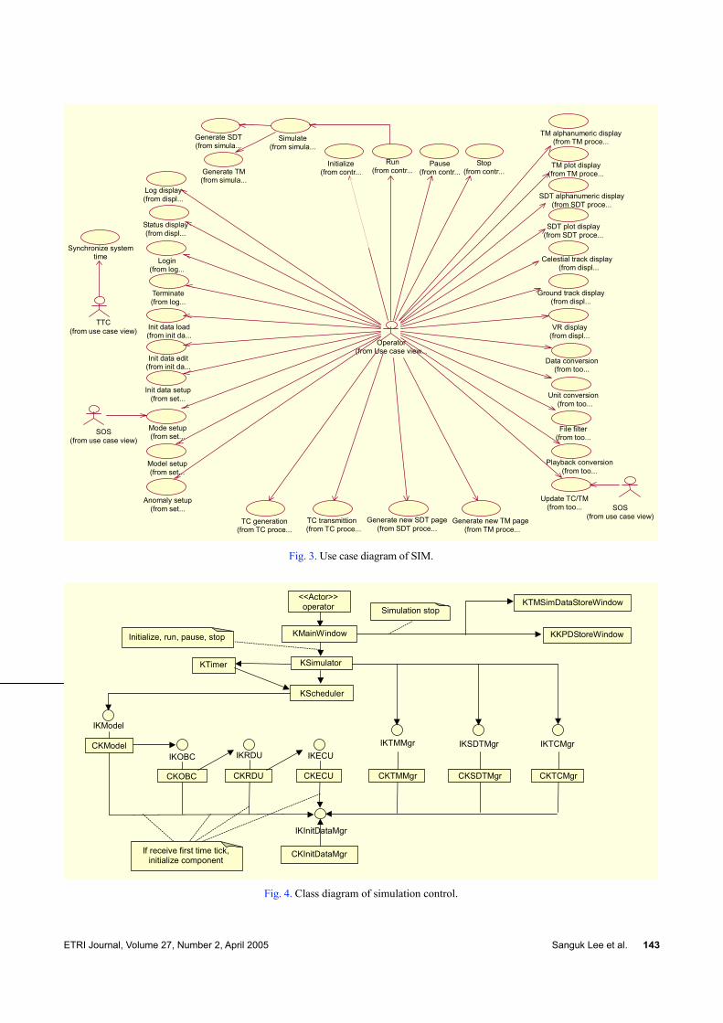
A domain model describes how the use case is realized. Domain modeling can be expressed by a class diagram, which describes interaction between related classes. Figure 4 is a domain modeling of the simulation control function in terms of class diagram. This diagram shows how a simulation is controlled in SIM. Once the operator issues an initialization command for simulation from KMainwindow, KSimulator requests KTimer to issue a time tick. One time tick is sent to KScheduler. Then KScheduler sends an execution command for CKModel, CKOBC, CKInitDataMgr, and so on via interfaces, which are eventually realized as a common object model (COM) [9]. After the initialization, the run command allows KSimulator to issue repeated time tick requests to KTimer every quarter second. Likewise, the pause command pauses the time tick generation and the resume command resumes the time tick generation. The stop command requests the termination of the time tick generation and the storage of simulation data and key parameter data (KPD) [10].
3. User Interface (UI) Design
The navigational structure of the UI based on use case modeling is partially presented in the form of tree diagrams in Fig. 5.
As an example, a model setup window as shown in Fig. 6 provides a tool to change model fidelity and parameters for the simulation during run time or before a simulation starts.
4. Logical View Design
A logical view of SIM decomposes into conceptual packages and describes connections between them. Figure 7 shows a logical view of a SIM subsystem, which consists of packages as follows:
• Kernel for setup and control • User interface for providing user operation and displaying
variable data and simulation status in various ways • On-board computer (OBC) for the embedded flight
software of the onboard processor OBC • Remote drive unit (RDU) for embedded flight software of
ETRI Journal, Volume 27, Number 2, April 2005 Sanguk Lee et al. 143
Fig. 3. Use case diagram of SIM.
SOS (from use case view)
SOS (from use case view)
Synchronize system time
TTC (from use case view)
Log display (from displ...
Status display (from displ...
Login (from log...
Terminate (from log...
Init data load (from init da...
Init data edit (from init da...
Init data setup (from set...
Model setup (from set...
Mode setup (from set...
Anomaly setup (from set...
TC generation (from TC proce...
TC transmittion (from TC proce...
Generate new TM page (from TM proce...
TM alphanumeric display(from TM proce...
TM plot display (from TM proce...
Pause (from contr...
Stop (from contr...
Generate new SDT page (from SDT proce...
SDT alphanumeric display (from SDT proce...
SDT plot display (from SDT proce...
Celestial track display (from displ...
Ground track display(from displ...
VR display (from displ...
Data conversion (from too...
Unit conversion (from too...
File filter (from too...
Playback conversion (from too...
Operator (from Use case view...
Update TC/TM (from too...
Initialize (from contr...Generate TM
(from simula...
Generate SDT (from simula...
Run (from contr...
Simulate (from simula...
Fig. 4. Class diagram of simulation control.
CKInitDataMgr
CKECU
<<Actor>> operator
KKPDStoreWindow
KTMSimDataStoreWindow
IKOBC IKRDU
IKInitDataMgr
IKECU
CKRDU
IKModel
KScheduler
KTimer
IKTCMgr IKTMMgr IKSDTMgr
KSimulator
If receive first time tick, initialize component
Initialize, run, pause, stop
Simulation stop
KMainWindow
CKModel
CKOBC CKTMMgr CKTCMgr CKSDTMgr

144 Sanguk Lee et al. ETRI Journal, Volume 27, Number 2, April 2005
Fig. 5. User interface structure of SIM.
<<Window>> KLogin Window
<<Window>> KMainWindow
<<Window>> KLogWindow
<<Window>> KStatusWindow
<<Window>> KHelp Web Broswer
<<Window>> KInit Data Load Window
<<Window>> KInit Data Edit Window
<<Window>> KInit Data Setup Window
<<Window>> KMode Setup Window
<<Window>> KModel Setup Window
<<Window>> KAnomaly Setup Window
<<Window>> KInitialize Window
<<Window>> KRun Window <<Window>>
KPause Window <<Window>>
KStop Window <<Window>>
KTCGeneration Window <<Window>>
KTCTransmission Window <<Window>>
KTMNew Page Setup Window
<<Window>> KInit Data Open Window
<<Window>> KInit Data Save Window
<<Window>> KDo You Save Change Window
<<Window>> KOrbit Data Load Window
<<Window>> KPert Accel Select Window
<<Window>> KDist Torq Select Window
<<Window>> KSenser Noise Set Window
<<Window>> KTMSim Data Store Window
<<Window>> KKPD Store Window
<<Window>> KTMData Page Open Window
<<Window>> KTMData Page Save Window
Fig. 6. Model setup window.
the onboard processor RDU • Electric control unit (ECU) for the embedded flight software
of the onboard processor ECU • Models which consist of orbit and attitude dynamics, space
environment, electrical power subsystem (EPS), payloads, ground station, thermal control subsystem, telemetry, command & ranging (TC&R), sensors, and actuator
• TCProcess for generation and transmission • TMProcess for SDTProcess for UI display • SecurityMgr for security management during login • TMMgr for TM extraction from TM stream and
decomposition, and engineering unit conversion • InitDataMgr for initialization data management • TCMgr for TC generation and transmission • SDTMgr for simulation data management • EXTINTERFACE for interface with SOS, TTC and MAPS
subsystems • Thread for management of threads and critical sections • Socket providing socket server and client.
Fig. 7. Logical view of SIM subsystem.
InitDataMgr
LogMgr
UI
SecurityMgr
Kernel
FSWECU FSWRDU FSWOBC
Model
TCMgr
TMMgr
SDT Mgr
Socket
EXT INTERFACE
Thread
In Fig. 8, a sensor package is shown as an example of a spacecraft subsystem modeling structure to maximize reusability and extendibility of the model. In SIM, all the subsystem models are constructed as shown in Fig. 8. The subsystem models are inherited from KAbstractModel class, KSCSubsystem class, KSensor class, and static model class (for example, KCES_S). KAbstractModel class contains basic operations and variables that are commonly used in all the models in SIM. KSCSubsystem class includes common functions and variables for spacecraft hardware subsystem models. KSensor class contains common sensor functions and variables. Static model classes inherit the functions and variables from those classes, and contain the main functions and variables for the specific subsystem models.
The functions in static models do not contain core algorithms of the models. The core algorithms are implemented in each model class. This design provides extensibility and reusability to developers. For example, the conical earth sensor (CES) model in Fig. 9 has three parameter classes, two CES core models, and one static model. The initial design for the CES model was constructed by KCES_S, KCES, and KCESParameter-A. After a minor specification change of the CES device by the spacecraft bus manufacturer, the CES model in SIM needs to add a new parameter and KParameter-B. It is not necessary to delete the KParameter-A class. The developer only needs to add a new parameter class and reuse all the other related classes without any major modification.

ETRI Journal, Volume 27, Number 2, April 2005 Sanguk Lee et al. 145
Fig. 8. Logical view of sensor package.
KSCSubsystem(from COMMONS)
KAbstractModel (from COMMONS)
KPOT
KTAM
KSTA
KCES
KFSS
KCSS KTAC
KGyro KCESParameter-A
KTACParameter-A
KTAMParameter
KSTAParameter
KFSSParameter
KGyroParameter
KPOTParameter
KCSSParameter
KSensor
KCES_S
KCSS_S
KFSS_S
KGyro_S
KPOT_S
KTAC_S
KTAM_S
KSTA_S
KCESParameter-B
KTACParameter-B
KCES-C KCESParameter-C
Fig. 9. CES and related classes.
KSensor
KSCSubsystem (from Commons)
KAbstractModel (from Commons)
K1CESParameter
KOrbit (from FDS1)
K1CES m_EarthFOV : double m_Status : int m_pitchError : double m_rollError : double m_warmupFlag : int
relateModel() simulate() init() K1CES() <<virtual>> ~K1CES() doAnomaly() doNormal() setDataToDataMgr() calculateCount() calculateLoad() calculateInterference() calcuateReduction() calculateStatus() setWarmupFlag()
#m_pKSun#m_pKPCU #m_pKMoon #m_pKEarth #m_pKOrbit
K1CES_Sm_count[2] : int
getCount() K1CES_S() <<virtual>> ~K1CES_S()
<<typedef>> KCESINITDATA(from Commons)
KEarth (from ENV)
K1PCU (from EPS)
KSun (from ENV)
K1CES-S
KMoon (from ENV)
Fig. 10. Sequence diagram of “calculateCount” method.
Calculate earth half cone angle
Check the sun/moon interference and determine moon_presence
Check the intersection between CES scan and earth horizon
Check the min. chord length
Range reduction
Generates output with noise option
Calculate pitch and roll pointing error

146 Sanguk Lee et al. ETRI Journal, Volume 27, Number 2, April 2005
Figure 9 shows the detailed design of the CES class and its related classes. Figure 10 shows the sequence diagram of the “calculateCount” method for the CES class in a flow chart format. When a major model change for CES is required, the developer needs to add a new CES core class, KCES-C and KCESParameter_C. In this case, other related classes such as KAbstractModel, KSCSubsystem, KSensor, and KCES_S do not require modification.
5. Implementation View Design
The implementation view describes the actual software modules, their relations, and contents along with a consideration of the requirements. Figure 11 shows an implementation view diagram of the control package as an example.
Fig. 11. Implementation view of control package.
KScheduler. cpp
KScheduler.h KTimer.h KTimer. cpp
KSimulator.h KSimulator.cpp
KScheduler.obj KTimer.obj KSimulator.obj
SIM.EXE
6. Process View Design
The process view describes the execution structure of the SIM system along with a consideration of the requirements related to performance, reliability, expandability, system management, and synchronization.
SIM has only one executable file (EXE) and a number of dynamic link libraries (DLLs) that are driven by the EXE as independent processes, as shown in Fig. 12 [9].
7. Deployment View Design
In deployment view, the SIM architecture is described in the physical point of view. Figure 13 shows the process, DLLs, and SIM platform and its operating system.
III. SIM Implementation
1. SIM Hardware Implementation Environment
The hardware configuration and equipment specifications
Fig. 12. Process view of SIM.
SIM.EXE
MODEL.DLL
IKModel SDTMgr.DLL
IKSDTMgr
TMProcess.DLL
IKTMMgr
SecurityMgr.DLL
IKSecurityMgr
SDTProcess.DLL
IKLogMgr
InitDataMgr.DLL
IKInitDataMgr FSWOBC.DLL
IKOBC IKTCMgr
LogMgr.DLL
TMMgr.DLL
TCMgr.DLL
Fig. 13. Deployment view of SIM.
SIM (PC-Windows 2000)
SIM.EXE SecurityMgr.DLL LogMgr.DLL TMMGR.DLL TCMgr.DLL FSWOBC.DLL FSWRDU.DLL FSWEPS.DLL MODEL.DLL SDTMgr.DLL InitDataMgr.DLL SDTProcess.DLL TMProcess.DLL
Fig. 14. Hardware configuration and KOMPSAT-2 SIM.
SOS MAPS TTC
MCE LAN
PC server
SIM main computer operator’s console
Disk
MCE printer
for KOMPSAT-2 SIM are shown in Fig. 14 and Table 1, respectively.
While KOMPSAT-1 SIM was developed on an HP workstation and one virtual reality (VR) display PC,

ETRI Journal, Volume 27, Number 2, April 2005 Sanguk Lee et al. 147
KOMPSAT-2 SIM is developed on a PC running Windows 2000 as an operating system. Also, the time synchronization between the MCE subsystems was realized by the network time protocol (NTP) within 5 ms. TTC equipped with a Global Positioning System (GPS) receiver is the timing server. The PC also contains a VR graphic display of the KOMPSAT-2 attitude and orbit motion. The hardware platform change reduced costs down to 1/4 of that of KOMPSAT-1 SIM.
Table 1. SIM hardware elements.
Usage Element Specification
Simulator main computer
- Main memory (2 GB) - Hard disk (36 GB*2) - 3.0 GHz Intel CPU
Display device - Color graphic monitor (20˝)
Simulator operation
External interface - Ethernet LAN transceiver
2. SIM Software Implementation Environment
The SIM software environment is shown in Table 2. The SIM VR is implemented using OpenGL instead of WTK, which is a commercial tool for a 3 dimensional display [11].
For data management, XML and text files were used for spacecraft characteristics data, TC and TM information, initialization data, and KPD. The SIM software environment change brought the cost reduction up to 50%.
Table 2. SIM software environments.
Element Specifications
Operating system - MS Windows 2000
Programming language - C++ : GUI, models - C : FSW embedded
Data management - XML & Text files
Library - Open GL : VR display
3. KOMPSAT-2 Flight Software Embedding
Embedding flight software is important for the simulation fidelity of a satellite simulator. There are three different approaches for embedding the flight software into the satellite simulator: utilization of a processor emulator executing the actual flight software image, re-compilation of the flight software sources within the simulator infrastructure, and development of a set of abstract models representing the required flight software functionality. The recompilation
method was used for KOMPSAT-2 SIM. KOMPSAT-1 SIM was implemented on an HP workstation whose processor was different from the satellite onboard processor (Intel). During the KOMPSAT-1 SIM development, we have experienced a “byte and bit” ordering problem due to the infrastructure difference. Also, infrastructure-oriented system calls such as inp(), inpw(), outp(), and outpw() were rewritten specifically for SIM [6]. To avoid those problems, a PC was used as the target platform and the Object-Oriented Programming technique as a function overloading technique [7]. Also, system calls on a VRTX [11] operating system were replaced with functions produced by function overloading. Data exchanges between processors realized as DLL were implemented as a COM as shown in Fig. 12. KPD in electrically erasable programmable read only memory (EEPROM) was emulated with the file that contains KPD to support a KPD patch upload.
Employing the OOA/OOD methodology required more effort to get used to, but it helped to reduce effort on embedding the flight software. Changing the platform was also a key factor to reduce effort for embedding the flight software. The manpower required for KOMPSAT-2 SIM was reduced into one half of KOMPSAT-1 by taking into account the burden of the new methodology and heritage of KOMPSAT-1 SIM.
4. SIM GUI and VR Display for Comprehension
KOMPSAT-2 SIM was implemented as one process to drive and manage several DLLs as shown in Fig. 13. Those DLLs are the implementation of element packages for SIM in implementation and process views. Figure 15 shows the main window configuration, ground track window, and VR display window.
Fig. 15. Main window configuration of KOMPSAT-2 SIM.

148 Sanguk Lee et al. ETRI Journal, Volume 27, Number 2, April 2005
For a user’s comprehension of satellite operation, KOMPSAT-2 SIM provides a ground track view, celestial track view, and VR display. In particular, the VR display can display the satellite orbit and attitude motion dynamically, using not only dynamic simulation data but also real-time and playback TM data from the satellite.
IV. KOMPSAT-2 SIM Validation
The functions, which are defined on KOMPSAT-2 SIM specifications, were validated officially via a SIM subsystem test and MCE system integration test. A functional verification of the hardware unit model and flight dynamics model were performed via an independent unit test during the implementation phase. In this section, the simulation results of a solar array deployment and its test, an orbit adjust operation, and normal operations are presented for the overall validation of the KOMPSAT-2 SIM software.
1. LEOP Simulation for Autonomous Onboard Operations
Generally, a low earth orbit (LEO) satellite mission is categorized into a launch and early orbit operations, routine mission operations, and contingency operations [10]. Here, we focus on the simulation of the LEOP operations. LEOP operations include several steps: pre-launch; launch; solar array deployment; acquisition maneuver; orbit adjustment; and normal mode activation. In SIM, a simulation initiates at the time of the launch vehicle separation. In Table 3, the initial data used for the simulation of LEOP operations are listed in this paper.
After the separation from the launch vehicle, all the operations are autonomous. The separation wakes up the on-board computers, and on-board relative time command sequences (RTCSs) are performed automatically. In SIM, the series of RTCSs are executed and the spacecraft models and on-board flight software react as a real satellite. SIM activates
Table 3. Initial data for LEOP simulation.
Data Value
Separation time 2005/10/03/08:15:00
Semi-major axis 7055.40 km
Eccentricity 0.00221
Inclination 98.137°
RA of ascending node 174.560°
Argument of perigee 215.908°
Mean anomaly 218.676°
the on-board flight software, executes solar array deployment and its test, and then enters the sun point mode using RTCS.
In Figs. 16 and 17, attitude rates and coarse sun sensor output are shown from the satellite separation from the launch vehicle. The solar array deployment test was performed at around the 600th second as shown in Figs. 16 and 17. The solar array deployment test was done by firing thrusters and by checking the change of moment of inertia before and after solar array deployment.
After the solar array deployment test, the attitude and orbit control subsystem (AOCS) pointed and maintained the solar array in nominal to the sun-line within 8 degrees of accuracy per axis, which satisfies the mission requirement for sun point mode, by using thrusters and coarse sun sensors. The spacecraft remained sun pointed until commanded by the
Fig. 16. Attitude rates TM in sun point mode.
Fig. 17. Coarse sun sensor pitch and yaw measured angle TM in sun point mode.

ETRI Journal, Volume 27, Number 2, April 2005 Sanguk Lee et al. 149
ground station to begin an Earth search.
2. Earth Search Maneuver and Attitude Hold Mode Operation
In an Earth search maneuver operation, the ground station acquires the spacecraft status of the health data. Then, the ground station prepares an Earth search and attitude hold mode.
When the state of health, orbit determination, uplink and verification of loads, and commanding are acceptable to the ground control system, the ground control system commands the spacecraft to begin an Earth search in an appropriate time.
Figures 18 and 19 show the time history of attitude error and attitude rate during the Earth search and attitude hold modes.
In Figs. 18 and 19, ground commands for Earth searching
Fig. 18. Attitude error TM in Earth search and attitude hold mode.
Fig. 19. Attitude rate TM in Earth search and attitude hold mode.
were transmitted at around the 6600th second, and the spacecraft then automatically entered attitude hold mode. In this mode, the spacecraft maintained a nadir pointing by 3-axis attitude control with thrusters. As mission requirements, the rate limit during an Earth search maneuver is less than 2 degrees/seconds, roll and pitch errors after maneuver are 1.5 degrees, yaw error is 2.0 degrees, and rate error after the maneuver is 1.1 degrees/seconds.
3. Anomaly Orbit Adjust Operations
The operation scenario assumed an anomaly condition where the orbit size of KOMPSAT-2 was about 15 km lower than the expected altitude. This scenario also requires a 180 degrees orbit phase difference between KOMPSAT-1 and KOMPSAT-2. The mission planning for the orbit adjust burns for both the altitude makeup and orbit phase difference constraint is generated by using KOMPSAT-2 MAPS in KOMPSAT-2 MCE [2], [13] and STK. Orbit makeup burns and orbit transfer burns are conducted in the attitude hold mode.
In Table 4, the orbit ephemeris at the specific epoch and corresponding simulation results are listed.
The orbit ephemeris data in Table 4 is provided by using MAPS and STK [14].
In Table 4, the orbit ephemeris at the time of separation shows that the orbit phase difference between K1 and K2 was 202.051 degrees. A specific epoch and orbit ephemeris data before the delta-velocity (Delta-V) maneuver for orbit adjusts are listed next in Table 4.
The Delta-V burn started at 2005-10-04 15:03:06 and the burn duration was 411 seconds. After the Delta-V burn, the semi-major axis became 7071.84 km in simulation, and the orbit phase difference became 180 degrees. Figure 20 shows semi-major axis variation during the orbit adjust operation. A 90-degree pitch maneuver was executed before the Delta-V burn operation. As Fig. 20 shows, the Delta-V burn starts at about the 2000th second, that is 2005-10-04 15:03:06, and the semi-major axis sharply increases during the 411-second burn duration.
4. Roll Maneuvers in Science Fine Mode
In KOMPSAT-2 normal operation, science fine mode is used for a high resolution multi spectral camera mission. In this mode, star trackers and reaction wheels are the main attitude sensor and actuator, and pointing accuracy is less than 0.015 degrees for roll and pitch and 0.025 degrees for yaw angle. Figures 21 and 22 show the roll angle and attitude errors in –30 and +30 degree maneuvers in science fine mode, respectively.

150 Sanguk Lee et al. ETRI Journal, Volume 27, Number 2, April 2005
Table 4. Data for orbit adjustment.
Separation
2005-10-03 08:15:00 Before Delta-V burn 2005-10-04 14:30:00
After Delta-V burn 2005-10-04 15:10:00
K1 K2 K2-SIM K1 K2 K2-SIM K1 K2 K2-SIM
a 7055.40 7045.84 7045.84 7063.76 7049.40 7049.33 7071.81 7072.23 7071.84
e 0.00221 0.0031 0.0031 0.00062 0.00145 0.00144 0.00096 0.00044 0.00040
i 98.137 98.139 98.139 98.131 98.138 98.138 98.127 98.132 98.132
Ω 174.560 174.563 174.563 175.796 175.812 175.812 175.828 175.843 175.843
ω 215.908 8.529 8.529 154.678 353.066 352.567 155.112 345.283 340.748
M 218.676 224.004 224.004 68.132 48.509 49.313 213.737 202.584 208.109
ω+ M 434.584 232.533 232.533 222.810 401.575 401.880 368.849 547.687 548.557
Fig. 20. Anomaly orbit adjust maneuver.
Fig. 21. Roll angle in science fine mode.
Fig. 22. Attitude error in science fine mode.
V. Conclusions
The design features, implementations, and validation of KOMPSAT-2 SIM were presented. SIM was implemented on a PC workstation to minimize costs and trouble on embedding the onboard flight software into the simulator. OOA/OOD methodology is employed to maximize the reusability and expandability of the software.
Instead of a high cost commercial database, XML was used for the data management of spacecraft characteristics data, TC, TM, and simulation data. We significantly reduced the overall costs and effort for the system development down to 40% of the KOMPSAT-1 SIM development by considering the advantage of KOMPSAT-1 heritage and the disadvantage of employing a new methodology.
All requirements defined in the KOMPSAT-2 MCE were

ETRI Journal, Volume 27, Number 2, April 2005 Sanguk Lee et al. 151
verified through official tests such as subsystem tests and system integration. Each of the test items was mapped to the MCE system specifications via a verification matrix.
The KOMPSAT-2 MCE system was delivered to Korea Aerospace Research Institute. Installation and acceptance tests based on KOMPSAT-2 MCE system integration test were successfully finished by KARI engineers.
References
[1] Hee-Sook Mo, Ho-Jin Lee, and Seong-Pal Lee, “Development and Testing of Satellite Operation System for Korea Multipurpose Satellite- I,” ETRI J., vol. 22, no. 1, Mar. 2000.
[2] Chang-Hee Won, Jeong-Sook Lee, Byoung-Sun Lee, and Jong-Won Eun, “Mission Analysis and Planning System for Korea Multipurpose Satellite-I, “ETRI J., vol. 21, no. 3, Sept. 1999.
[3] Wan Sik Choi, Sanguk Lee, Jong Won Eun, Hanjun Choi, and Dong Suk Chae, “Design Implementation and Validation of the KOMPSAT Spacecraft Simulator,” KSAS Int’l J. vol. 1, no. 2, 2000, pp. 50-67.
[4] Sanguk Lee, Sungki Cho, Jae Hoon Kim, and Seong-Pal Lee, “Object-Oriented Design of KOMPSAT-2 Simulator Including Onboard Flight Software,” 14th Int’l Conf. in System Science, Wroclaw, Poland, 2001.
[5] J. J. Odell and J. Martin, Object Oriented Method: A Foundation, Prentice-Hall, 1995.
[6] Sanguk Lee, W. S. Choi, and D. S. Chae, “Implementation of KOMPSAT Simulator Interfaces between Flight Software and S/C Subsystem Model,” KSAS J., vol. 27, no. 3, 1999, pp. 125-131.
[7] Sanguk Lee, Oh-Ryong Kwon, H. J. Lee, “Feasibility Study on Development of Satellite Simulator Using Multithreading and Shared Memory,” KSAS J., vol. 29, no. 2, 2001, pp. 145-150.
[8] http://www.rational.com/ [9] http://www.microsoft.com/
[10] K. Carison, KOMPSAT Flight Operation Handbook, TRW 1999. [11] Microtec Research, VRTX x86/rm Operating System,1995. [12] Sense8 Cooperation, WorldToolKit Reference Manual, 1997. [13] Byoung-Sun Lee, Jeong-Sook Lee, Jae-Hoon Kim, Seong-Pal
Lee, Hae-Dong Kim, Eun-Kyou Kim, and Hae-Jin Choi, “Operational Report of the Mission Analysis and Planning System for the KOMPSAT-I,” ETRI J., vol. 25, no. 5, Oct. 2003, pp. 387-400.
[14] http://www.stk.com/
Sanguk Lee received the BS from Yonsei University, Seoul, Korea, in 1988 and the MS and PhD degrees in aerospace engineering from Auburn University, Alabama, U.S.A, in 1991 and 1994. He joined Electronics Telecommunications Research Institute(ETRI), in 1993 and developed Advanced Real-Time
Satellite Simulator (ARTSS) for KOREASAT-1, KOMPSAT-1 SIM, and KOMPSAT-2 SIM. Currently, he is working on COMS-1 Satellite Ground Control System. He is a Principal Research Engineer of Communications Satellite Development Group at ETRI, Daejeon, Korea. His research interests are in satellite dynamics and control, modeling, simulation, ground control system, and optimal control. He is a Senior Member of American Institute of Aeronautics and Astronautics, member of the Korean Space Science Society, Korea, Society for Aeronautical and Space Sciences, Korean Society Aeronautical Science and Operation, and ICASE. He is a member of the editorial board in Journal of the Korean Society for Aeronautical Science and Flight Operation.
Sungki Cho received the BS in astronomy from Yonsei University, Seoul, South Korea in 1990, and the MS and PhD degrees in aerospace engineering from Auburn University, Alabama, U.S.A., in 1995 and 1999. He was a Senior Research Engineer in ETRI from 2000 to 2004. He developed KOMPSAT-2 SIM and
participated in COMS-1 Satellite Ground Control System. Currently, he is a Senior Research Engineer of Space Geodesy Research Group at Korea Astronomy and Space Science Institute, Daejeon, Korea. His research interests are in dynamics and control of satellites, satellite ground control system, and GNSS applications. He is a member of American Institute of Aeronautics and Astronautics, member of American Astronautical Society, member of Institute of Navigation, member of the Korean Space Science Society, Korea, Society for Aeronautical and Space Sciences, and member of Institute of Control Automation and System Engineering.

152 Sanguk Lee et al. ETRI Journal, Volume 27, Number 2, April 2005
Byoung-Sun Lee received the BS, MS, and PhD degrees in astronomy and space sciences from Yonsei University, Seoul, Korea in 1986, 1988, and 2001. He joined ETRI in 1989, where he was involved in developing the KOREASAT project. From 1992 to 1994, he was a Visiting Engineer in Lockheed-Martin Astrospace in the
U.S.A. and Martra-Marconi Space in the U.K. for the KOREASAT project. From 1995 to 1999, he participated in the KOMPSAT-1 Ground Mission Control Project as a Senior Member of Research Staff in Mission Analysis and Planning Subsystem. He is now working for the KOMPSAT-2 and COMS-1 Ground Mission Control Project as a Principal Member of Research Staff. His research interests are tracking and orbit determination of satellites and station-keeping maneuvers of collocated geostationary satellites. He is a member of the Korean Space Science Society, Korea Society for Aeronautical and Space Sciences, American Astronautical Society, and Institute of Control, Automation, and Systems Engineers. He is a member of the editorial board in Journal of Astronomy and Space Sciences.
Jaehoon Kim received the PhD degree in computer engineering from Chungbuk National University, Cheongju, Korea in 2001. He joined ETRI in 1983, where he was involved in developing the Intelligent Network and KOREASAT Projects. From 1992 to 1994, he was an OJT Engineer in Martra-Marconi Space
in the U.K. for the KOREASAT Project. From 1995 to 1999, he participated in the KOMPSAT-1 Ground Mission Control Project as a Principal Member of Engineering Staff in System Engineering. He is now working for the KOMPSAT-2 Ground Mission Control Project as a Team Leader. His research interests are in security in satellite communications, fault diagnosis of satellites using AI technologies, and systems modeling using objected-oriented technologies. He is a member of the Korean Space Science Society and Korea Society for Aeronautical and Space Sciences.
Related Documents