PCMM Devices in an SRC-Managed Network Modified: 2015-06-23 Copyright © 2015, Juniper Networks, Inc.

Welcome message from author
This document is posted to help you gain knowledge. Please leave a comment to let me know what you think about it! Share it to your friends and learn new things together.
Transcript

PCMM Devices in an SRC-Managed Network
Modified: 2015-06-23
Copyright © 2015, Juniper Networks, Inc.

Juniper Networks, Inc.1133 Innovation WaySunnyvale, California 94089USA408-745-2000www.juniper.net
Copyright © 2015, Juniper Networks, Inc. All rights reserved.
Juniper Networks, Junos, Steel-Belted Radius, NetScreen, and ScreenOS are registered trademarks of Juniper Networks, Inc. in the UnitedStates and other countries. The Juniper Networks Logo, the Junos logo, and JunosE are trademarks of Juniper Networks, Inc. All othertrademarks, service marks, registered trademarks, or registered service marks are the property of their respective owners.
Juniper Networks assumes no responsibility for any inaccuracies in this document. Juniper Networks reserves the right to change, modify,transfer, or otherwise revise this publication without notice.
PCMMDevices in an SRC-Managed NetworkCopyright © 2015, Juniper Networks, Inc.All rights reserved.
The information in this document is current as of the date on the title page.
YEAR 2000 NOTICE
Juniper Networks hardware and software products are Year 2000 compliant. Junos OS has no known time-related limitations through theyear 2038. However, the NTP application is known to have some difficulty in the year 2036.
ENDUSER LICENSE AGREEMENT
The Juniper Networks product that is the subject of this technical documentation consists of (or is intended for use with) Juniper Networkssoftware. Use of such software is subject to the terms and conditions of the End User License Agreement (“EULA”) posted athttp://www.juniper.net/support/eula.html. By downloading, installing or using such software, you agree to the terms and conditions ofthat EULA.
Copyright © 2015, Juniper Networks, Inc.ii

Table of Contents
About the Documentation . . . . . . . . . . . . . . . . . . . . . . . . . . . . . . . . . . . . . . . . . . . . xi
Documentation and Release Notes . . . . . . . . . . . . . . . . . . . . . . . . . . . . . . . . . . xi
Supported Platforms . . . . . . . . . . . . . . . . . . . . . . . . . . . . . . . . . . . . . . . . . . . . . xi
Documentation Conventions . . . . . . . . . . . . . . . . . . . . . . . . . . . . . . . . . . . . . . . xi
Documentation Conventions . . . . . . . . . . . . . . . . . . . . . . . . . . . . . . . . . . . . . . xii
Documentation Feedback . . . . . . . . . . . . . . . . . . . . . . . . . . . . . . . . . . . . . . . . xiv
Requesting Technical Support . . . . . . . . . . . . . . . . . . . . . . . . . . . . . . . . . . . . . xiv
Self-Help Online Tools and Resources . . . . . . . . . . . . . . . . . . . . . . . . . . . xv
Opening a Case with JTAC . . . . . . . . . . . . . . . . . . . . . . . . . . . . . . . . . . . . . xv
Part 1 Overview
Chapter 1 Software Features Overview . . . . . . . . . . . . . . . . . . . . . . . . . . . . . . . . . . . . . . . . . 3
SRC Component Overview . . . . . . . . . . . . . . . . . . . . . . . . . . . . . . . . . . . . . . . . . . . . 3
Chapter 2 Using PCMM Policy Servers . . . . . . . . . . . . . . . . . . . . . . . . . . . . . . . . . . . . . . . . . . 7
JPS Overview . . . . . . . . . . . . . . . . . . . . . . . . . . . . . . . . . . . . . . . . . . . . . . . . . . . . . . . 7
JPS Framework . . . . . . . . . . . . . . . . . . . . . . . . . . . . . . . . . . . . . . . . . . . . . . . . . . . . . . 8
JPS Interfaces . . . . . . . . . . . . . . . . . . . . . . . . . . . . . . . . . . . . . . . . . . . . . . . . . . . . . . . 8
Application Manager to Policy Server Interface . . . . . . . . . . . . . . . . . . . . . . . . . 9
Policy Server to RKS Interface . . . . . . . . . . . . . . . . . . . . . . . . . . . . . . . . . . . . . . 9
Policy Server to CMTS Interface . . . . . . . . . . . . . . . . . . . . . . . . . . . . . . . . . . . . . 9
Using the NIC Resolver . . . . . . . . . . . . . . . . . . . . . . . . . . . . . . . . . . . . . . . . . . . . . . . . 9
Part 2 Configuration
Chapter 3 Configuration Tasks for JPS . . . . . . . . . . . . . . . . . . . . . . . . . . . . . . . . . . . . . . . . . 13
Configuring the JPS (SRC CLI) . . . . . . . . . . . . . . . . . . . . . . . . . . . . . . . . . . . . . . . . . 13
Configuring the JPS (C-Web Interface) . . . . . . . . . . . . . . . . . . . . . . . . . . . . . . . . . . 14
Modifying the JPS Configuration (SRC CLI) . . . . . . . . . . . . . . . . . . . . . . . . . . . . . . . 15
Modifying the JPS Configuration (C-Web Interface) . . . . . . . . . . . . . . . . . . . . . . . . 15
Configuring General Properties for the JPS (C-Web Interface) . . . . . . . . . . . . 15
Specifying a Policy Server Identifier in Messages (C-Web Interface) . . . . . . . 15
Configuring Logging Destinations (C-Web Interface) . . . . . . . . . . . . . . . . . . . 16
Specifying Connections to the Application Managers (C-Web Interface) . . . 16
Specifying Connections to RKSs (C-Web Interface) . . . . . . . . . . . . . . . . . . . . 16
Configuring General Properties for the JPS (SRC CLI) . . . . . . . . . . . . . . . . . . . . . . . 17
Specifying Policy Server Identifiers in Messages (SRC CLI) . . . . . . . . . . . . . . . . . . 18
Configuring Logging Destinations for the JPS (SRC CLI) . . . . . . . . . . . . . . . . . . . . 18
Configuring JPS to Store Log Messages in a File (SRC CLI) . . . . . . . . . . . . . . . . . . 19
Configuring JPS to Send Log Messages to System Logging Facility (SRC CLI) . . . 20
Specifying Connections to the Application Managers (SRC CLI) . . . . . . . . . . . . . 20
iiiCopyright © 2015, Juniper Networks, Inc.

Specifying Connections to CMTS Devices (SRC CLI) . . . . . . . . . . . . . . . . . . . . . . . 22
Specifying Connections to CMTS Devices (C-Web Interface) . . . . . . . . . . . . . . . . 24
Configuring the SAE to Interact with the JPS (SRC CLI) . . . . . . . . . . . . . . . . . . . . . 25
Configuring the SAE to Interact with the JPS (C-Web Interface) . . . . . . . . . . . . . . 25
Adding Objects for Policy Servers to the Directory (SRC CLI) . . . . . . . . . . . . . . . . 26
Adding Objects for Policy Servers to the Directory (C-Web Interface) . . . . . . . . . . 27
Configuring Initialization Scripts (SRC CLI) . . . . . . . . . . . . . . . . . . . . . . . . . . . . . . . 27
Configuring Initialization Scripts (C-Web Interface) . . . . . . . . . . . . . . . . . . . . . . . . 28
Enabling State Synchronization (SRC CLI) . . . . . . . . . . . . . . . . . . . . . . . . . . . . . . . 29
Enabling State Synchronization (C-Web Interface) . . . . . . . . . . . . . . . . . . . . . . . . 30
Chapter 4 Configuration Tasks for RKS Pairs . . . . . . . . . . . . . . . . . . . . . . . . . . . . . . . . . . . 31
Configuring Connections to RKSs (SRC CLI) . . . . . . . . . . . . . . . . . . . . . . . . . . . . . . 31
Specifying Connections to RKSs (SRC CLI) . . . . . . . . . . . . . . . . . . . . . . . . . . . 31
Configuring RKS Pairs (SRC CLI) . . . . . . . . . . . . . . . . . . . . . . . . . . . . . . . . . . . 33
Configuring RKS Pairs (C-Web Interface) . . . . . . . . . . . . . . . . . . . . . . . . . . . . . . . . 35
Configuring Connections for RKS Pairs (C-Web Interface) . . . . . . . . . . . . . . . 35
Configuring RKS Pairs for Associated Application Managers (C-Web
Interface) . . . . . . . . . . . . . . . . . . . . . . . . . . . . . . . . . . . . . . . . . . . . . . . . . . 35
Specifying Connections to CMTS Devices (C-Web Interface) . . . . . . . . . . . . 36
Configuring RKS Pairs for Associated Application Managers (SRC CLI) . . . . . . . . 36
Chapter 5 Configuration Tasks for Subscriber IP Pools Managed by CMTS . . . . . . . . . 39
Modifying the Subscriber Configuration (SRC CLI) . . . . . . . . . . . . . . . . . . . . . . . . 39
Modifying the Subscriber Configuration (C-Web Interface) . . . . . . . . . . . . . . . . . 40
Configuring Subscriber IP Pools as IP Address Ranges (SRC CLI) . . . . . . . . . . . . 40
Configuring Subscriber IP Pools as IP Address Ranges (C-Web Interface) . . . . . . 41
Configuring Subscriber IP Pools as IP Subnets (SRC CLI) . . . . . . . . . . . . . . . . . . . 41
Configuring Subscriber IP Pools as IP Subnets (C-Web Interface) . . . . . . . . . . . . 42
Chapter 6 Configuration Tasks for Application Managers for JPS . . . . . . . . . . . . . . . . . 43
Specifying Application Managers for the Policy Server (SRC CLI) . . . . . . . . . . . . . 43
Specifying Application Managers for the Policy Server (C-Web Interface) . . . . . . 45
Specifying Application Manager Identifiers for Policy Servers (SRC CLI) . . . . . . . 45
Specifying Application Manager Identifiers for Policy Servers (C-Web
Interface) . . . . . . . . . . . . . . . . . . . . . . . . . . . . . . . . . . . . . . . . . . . . . . . . . . . . . 46
Chapter 7 Configuration Statements . . . . . . . . . . . . . . . . . . . . . . . . . . . . . . . . . . . . . . . . . . 47
Configuration Statements for the JPS . . . . . . . . . . . . . . . . . . . . . . . . . . . . . . . . . . . 47
Part 3 Administration
Chapter 8 Managing the JPS . . . . . . . . . . . . . . . . . . . . . . . . . . . . . . . . . . . . . . . . . . . . . . . . . 51
Starting the JPS (SRC CLI) . . . . . . . . . . . . . . . . . . . . . . . . . . . . . . . . . . . . . . . . . . . . 51
Starting the JPS (C-Web Interface) . . . . . . . . . . . . . . . . . . . . . . . . . . . . . . . . . . . . . 51
Restarting the JPS (SRC CLI) . . . . . . . . . . . . . . . . . . . . . . . . . . . . . . . . . . . . . . . . . . 52
Restarting the JPS (C-Web Interface) . . . . . . . . . . . . . . . . . . . . . . . . . . . . . . . . . . . 52
Stopping the JPS (SRC CLI) . . . . . . . . . . . . . . . . . . . . . . . . . . . . . . . . . . . . . . . . . . . 53
Stopping the JPS (C-Web Interface) . . . . . . . . . . . . . . . . . . . . . . . . . . . . . . . . . . . . 53
Displaying JPS Status (SRC CLI) . . . . . . . . . . . . . . . . . . . . . . . . . . . . . . . . . . . . . . . 53
Displaying JPS Status (C-Web Interface) . . . . . . . . . . . . . . . . . . . . . . . . . . . . . . . . 54
Copyright © 2015, Juniper Networks, Inc.iv
PCMM Devices in an SRC-Managed Network

Chapter 9 Routine Monitoring . . . . . . . . . . . . . . . . . . . . . . . . . . . . . . . . . . . . . . . . . . . . . . . . 55
Monitoring the JPS . . . . . . . . . . . . . . . . . . . . . . . . . . . . . . . . . . . . . . . . . . . . . . . . . . 55
Viewing Server Process Information . . . . . . . . . . . . . . . . . . . . . . . . . . . . . . . . . . . . 56
Viewing JPS State . . . . . . . . . . . . . . . . . . . . . . . . . . . . . . . . . . . . . . . . . . . . . . . . . . 56
Viewing Performance Statistics for the JPS Interfaces . . . . . . . . . . . . . . . . . . 56
Viewing Network Connections for the Application Manager . . . . . . . . . . . . . 56
Viewing Network Connections for the CMTS Device . . . . . . . . . . . . . . . . . . . . 57
Viewing Performance Statistics for the CMTS Locator . . . . . . . . . . . . . . . . . . 57
Viewing Message Handler Information . . . . . . . . . . . . . . . . . . . . . . . . . . . . . . . 57
Viewing Information About the JPS Server Process (C-Web Interface) . . . . . . . . . 57
Viewing JPS AM Statistics (C-Web Interface) . . . . . . . . . . . . . . . . . . . . . . . . . . . . 58
Viewing JPS AM Connections (C-Web Interface) . . . . . . . . . . . . . . . . . . . . . . . . . . 59
Viewing JPS CMTS Statistics (C-Web Interface) . . . . . . . . . . . . . . . . . . . . . . . . . . 59
Viewing JPS CMTS Connections (C-Web Interface) . . . . . . . . . . . . . . . . . . . . . . . 60
Viewing JPS CMTS Locator Statistics (C-Web Interface) . . . . . . . . . . . . . . . . . . . . 61
Viewing JPS Message Handler Statistics (C-Web Interface) . . . . . . . . . . . . . . . . . 61
Viewing JPS Message Flow Statistics (C-Web Interface) . . . . . . . . . . . . . . . . . . . 62
Viewing JPS RKS Statistics (C-Web Interface) . . . . . . . . . . . . . . . . . . . . . . . . . . . . 63
Part 4 Index
Index . . . . . . . . . . . . . . . . . . . . . . . . . . . . . . . . . . . . . . . . . . . . . . . . . . . . . . . . . 67
vCopyright © 2015, Juniper Networks, Inc.
Table of Contents

Copyright © 2015, Juniper Networks, Inc.vi
PCMM Devices in an SRC-Managed Network

List of Figures
Part 1 Overview
Chapter 2 Using PCMM Policy Servers . . . . . . . . . . . . . . . . . . . . . . . . . . . . . . . . . . . . . . . . . . 7
Figure 1: PCMM Architectural Framework . . . . . . . . . . . . . . . . . . . . . . . . . . . . . . . . . 8
viiCopyright © 2015, Juniper Networks, Inc.

Copyright © 2015, Juniper Networks, Inc.viii
PCMM Devices in an SRC-Managed Network

List of Tables
About the Documentation . . . . . . . . . . . . . . . . . . . . . . . . . . . . . . . . . . . . . . . . . . xi
Table 1: Notice Icons . . . . . . . . . . . . . . . . . . . . . . . . . . . . . . . . . . . . . . . . . . . . . . . . . xii
Table 2: Notice Icons . . . . . . . . . . . . . . . . . . . . . . . . . . . . . . . . . . . . . . . . . . . . . . . . xiii
Table 3: Text Conventions . . . . . . . . . . . . . . . . . . . . . . . . . . . . . . . . . . . . . . . . . . . . xiii
Part 1 Overview
Chapter 1 Software Features Overview . . . . . . . . . . . . . . . . . . . . . . . . . . . . . . . . . . . . . . . . . 3
Table 4: Descriptions of SRC Components . . . . . . . . . . . . . . . . . . . . . . . . . . . . . . . . 3
ixCopyright © 2015, Juniper Networks, Inc.

Copyright © 2015, Juniper Networks, Inc.x
PCMM Devices in an SRC-Managed Network

About the Documentation
• Documentation and Release Notes on page xi
• Supported Platforms on page xi
• Documentation Conventions on page xi
• Documentation Feedback on page xiv
• Requesting Technical Support on page xiv
Documentation and Release Notes
To obtain the most current version of all Juniper Networks®
technical documentation,
see the product documentation page on the Juniper Networks website at
http://www.juniper.net/techpubs/.
If the information in the latest release notes differs from the information in the
documentation, follow the product Release Notes.
Juniper Networks Books publishes books by Juniper Networks engineers and subject
matter experts. These books go beyond the technical documentation to explore the
nuances of network architecture, deployment, and administration. The current list can
be viewed at http://www.juniper.net/books.
Supported Platforms
For the features described in this document, the following platforms are supported:
• C Series
Documentation Conventions
Table 1 on page xii defines notice icons used in this guide.
xiCopyright © 2015, Juniper Networks, Inc.

Table 1: Notice Icons
DescriptionMeaningIcon
Indicates important features or instructions.Informational note
Indicates a situation that might result in loss of data or hardware damage.Caution
Alerts you to the risk of personal injury or death.Warning
Alerts you to the risk of personal injury from a laser.Laser warning
Indicates helpful information.Tip
Alerts you to a recommended use or implementation.Best practice
Documentation Conventions
Table 1 on page xii defines the notice icons used in this guide. Table 3 on page xiii defines
text conventions used throughout this documentation.
Copyright © 2015, Juniper Networks, Inc.xii
PCMM Devices in an SRC-Managed Network

Table 2: Notice Icons
DescriptionMeaningIcon
Indicates important features or instructions.Informational note
Indicates a situation that might result in loss of data or hardware damage.Caution
Alerts you to the risk of personal injury or death.Warning
Alerts you to the risk of personal injury from a laser.Laser warning
Indicates helpful information.Tip
Alerts you to a recommended use or implementation.Best practice
Table 3: Text Conventions
ExamplesDescriptionConvention
• Specify the keyword exp-msg.
• Run the install.sh script.
• Use the pkgadd tool.
• To cancel the configuration, click Cancel.
• Represents keywords, scripts, and tools intext.
• Represents a GUI element that the userselects, clicks, checks, or clears.
Bold text like this
user@host# set cache-entry-agecache-entry-age
Represents text that the user must type.Bold text like this
nic-locators { login { resolution { resolver-name /realms/ login/A1; key-type LoginName; value-type SaeId; }
Represents information as displayed on yourterminal’s screen, such as CLI commands inoutput displays.
Fixed-width text like this
• system ldap server{stand-alone;
• Use the request saemodify device failover
command with the force option
• user@host# . . .
• http://www.juniper.net/techpubs/software/management/sdx/api-index.html
• Represents configuration statements.
• Indicates SRC CLI commands and optionsin text.
• Represents examples in procedures.
• Represents URLs.
Regular sans serif typeface
xiiiCopyright © 2015, Juniper Networks, Inc.
About the Documentation

Table 3: Text Conventions (continued)
user@host# set local-addresslocal-address
Represents variables in SRC CLI commands.Italic sans serif typeface
Another runtime variable is <gfwif>.In text descriptions, indicate optionalkeywords or variables.
Angle brackets
Press Enter.Indicates the name of a key on the keyboard.Key name
Press Ctrl + b.Indicates that you must press two or morekeys simultaneously.
Key names linked with a plus sign(+)
• There are two levels of access: user andprivileged.
• SRC-PE Getting Started Guide.
• o=Users, o=UMC
• The /etc/default.properties file.
• Emphasizes words.
• Identifies book names.
• Identifies distinguished names.
• Identifies files, directories, and paths intext but not in command examples.
Italic typeface
Plugin.radiusAcct-1.class=\net.juniper.smgt.sae.plugin\RadiusTrackingPluginEvent
At the end of a line, indicates that the textwraps to the next line.
Backslash
diagnostic | lineRepresent a choice to select one keyword orvariable to the left or right of this symbol.(The keyword or variable may be eitheroptional or required.)
Words separated by the | symbol
Documentation Feedback
We encourage you to provide feedback, comments, and suggestions so that we can
improve the documentation. You can provide feedback by using either of the following
methods:
• Online feedback rating system—On any page at the Juniper Networks Technical
Documentation site at http://www.juniper.net/techpubs/index.html, simply click the
stars to rate the content, and use the pop-up form to provide us with information about
your experience. Alternately, you can use the online feedback form at
https://www.juniper.net/cgi-bin/docbugreport/.
• E-mail—Send your comments to [email protected]. Include the document
or topic name, URL or page number, and software version (if applicable).
Requesting Technical Support
Technical product support is available through the Juniper Networks Technical Assistance
Center (JTAC). If you are a customer with an active J-Care or Partner Support Service
support contract, or are covered under warranty, and need post-sales technical support,
you can access our tools and resources online or open a case with JTAC.
Copyright © 2015, Juniper Networks, Inc.xiv
PCMM Devices in an SRC-Managed Network

• JTAC policies—For a complete understanding of our JTAC procedures and policies,
review the JTAC User Guide located at
http://www.juniper.net/us/en/local/pdf/resource-guides/7100059-en.pdf.
• Product warranties—For product warranty information, visit
http://www.juniper.net/support/warranty/.
• JTAC hours of operation—The JTAC centers have resources available 24 hours a day,
7 days a week, 365 days a year.
Self-Help Online Tools and Resources
For quick and easy problem resolution, Juniper Networks has designed an online
self-service portal called the Customer Support Center (CSC) that provides you with the
following features:
• Find CSC offerings: http://www.juniper.net/customers/support/
• Search for known bugs: http://www2.juniper.net/kb/
• Find product documentation: http://www.juniper.net/techpubs/
• Find solutions and answer questions using our Knowledge Base: http://kb.juniper.net/
• Download the latest versions of software and review release notes:
http://www.juniper.net/customers/csc/software/
• Search technical bulletins for relevant hardware and software notifications:
http://kb.juniper.net/InfoCenter/
• Join and participate in the Juniper Networks Community Forum:
http://www.juniper.net/company/communities/
• Open a case online in the CSC Case Management tool: http://www.juniper.net/cm/
To verify service entitlement by product serial number, use our Serial Number Entitlement
(SNE) Tool: https://tools.juniper.net/SerialNumberEntitlementSearch/
Opening a Casewith JTAC
You can open a case with JTAC on the Web or by telephone.
• Use the Case Management tool in the CSC at http://www.juniper.net/cm/.
• Call 1-888-314-JTAC (1-888-314-5822 toll-free in the USA, Canada, and Mexico).
For international or direct-dial options in countries without toll-free numbers, see
http://www.juniper.net/support/requesting-support.html.
xvCopyright © 2015, Juniper Networks, Inc.
About the Documentation

Copyright © 2015, Juniper Networks, Inc.xvi
PCMM Devices in an SRC-Managed Network

PART 1
Overview
• Software Features Overview on page 3
• Using PCMM Policy Servers on page 7
1Copyright © 2015, Juniper Networks, Inc.

Copyright © 2015, Juniper Networks, Inc.2
PCMM Devices in an SRC-Managed Network

CHAPTER 1
Software Features Overview
• SRC Component Overview on page 3
SRC Component Overview
The SRC software is a dynamic system. It contains many components that you use to
build a subscriber management environment. You can use these tools to customize and
extend the SRC software for your use and to integrate the SRC software with other
systems. The SRC software also provides the operating system and management tools
for C Series Controllers.
Table 4 on page 3 gives a brief description of the components that make up the SRC
software.
Table 4: Descriptions of SRC Components
DescriptionComponent
Server Components
• Authorizes, activates, and deactivates subscriber and service sessions by interacting withsystems such as Juniper Networks routers, cable modem termination system (CMTS)devices, RADIUS servers, and directories.
• Collects accounting information about subscribers and services from routers, and storesthe information in RADIUS accounting servers, flat files, and other accounting databases.
• Provides plug-ins and application programming interfaces (APIs) for starting and stoppingsubscriber and service sessions and for integrating with systems that authorize subscriberactions and track resource usage.
Service activation engine (SAE)
Used in conjunction with the MX Series router running the packet-triggered subscribers andpolicy control (PTSP) solution, the SIC listens for RADIUS accounting events from IP edgedevices (accounting clients) and stores them in the Session State Registrar (SSR), orforwards them to a remote AAA server, allowing the SRC software to gain increasedsubscriber awareness. Additionally, the SIC can optionally edit accounting events beforerouting them.
Subscriber Information Collector (SIC)
Acts as a policy decision point (PDP) and policy enforcement point (PEP) that managesthe relationships between application managers and CMTS devices in a PCMM environment.
Juniper Policy Server (JPS)
Collects information about the state of the network and can provide a mapping from agiven type of network data to another type of network data.
Network information collector (NIC)
3Copyright © 2015, Juniper Networks, Inc.

Table 4: Descriptions of SRC Components (continued)
DescriptionComponent
Redirects HTTP requests received from IP Filter to a captive portal page.Redirect Server
The SRC Third-Generation Partnership Project (3GPP) gateway is a Diameter-basedcomponent in the SRC software, which provides integration with 3GPP Policy and ChargingControl environments, to provide fixed-mobile convergence (FMC). The SRC 3GPP gatewayprovides Gx-based integration with the Policy and Charging Rules Function (PCRF). TheSRC 3GPP gateway uses the northbound Gx interface to mediate between the PCRF andJuniper Networks routers like the E Series Broadband Services routers and MX Series routers.The northbound Gx interface on the SRC 3GPP gateway communicates with the PCRFusing the Diameter protocol.
3GPP Gateway
The SRC 3GPP Gy is a Diameter-based component in the SRC software, which providesGy-based integration with the Online Charging System (OCS), to provide FMC. The SRC3GPP Gy uses the northbound Gy interface to handle charging-related information betweenthe OCS and Juniper Networks routers like the E Series Broadband Services routers andMX Series routers. The northbound Gy interface communicates with the OCS using theDiameter protocol.
3GPP Gy
The SRC software includes a Web application server that hosts the Web Services Gatewayand the Volume Tracking Application (SRC VTA). In production environments, thisapplication server is designed to host only these applications. However, you can load yourown applications into this server for testing or demonstration purposes.
Web Application Service
Allows a gateway client—an application that is not part of the SRC network—to interactwith SRC components through a Simple Object Access Protocol (SOAP) interface.
The Web Services Gateway provides the Dynamic Service Activator which allows a gatewayclient to dynamically activate and deactivate SRC services for subscribers and to run scriptsthat manage the SAE.
Web Services Gateway
Repository
The SRC software includes the Juniper Networks database, which is a built-in LightweightDirectory Access Protocol (LDAP) directory for storing all SRC data including services,policies, and small subscriber databases.
For large subscriber databases, you must supply your own directory.
Directory
The SSR is a stateless, highly reliable and highly available database cluster. When used inconjunction with an MX Series router running the packet-triggered subscribers and policycontrol (PTSP) solution, the SSR stores the IP edge attachment subscriber sessions datalearned from IP edge devices in the centralized SSR database.
Session State Registrar (SSR)
SRC Configuration andManagement Tools
Provides a way to configure the SRC software on a C Series Controller from a Junos OS–likeCLI. The SRC CLI includes the policies, services, and subscribers CLI, which has separateaccess privileges.
SRC command line interface (CLI)
Provides a way to configure, monitor, and manage the SRC software on a C Series Controllerthrough a Web browser. The C-Web interface includes a policies, services, and subscriberscomponent, which has separate access privileges.
C-Web interface
Copyright © 2015, Juniper Networks, Inc.4
PCMM Devices in an SRC-Managed Network

Table 4: Descriptions of SRC Components (continued)
DescriptionComponent
Monitors system performance and availability. It runs on all the SRC hosts and makesmanagement information available through SNMP tables and sends notifications by meansof SNMP traps.
Simple Network Management Protocol(SNMP) agent
Service Management Applications (Run on external system)
Integrates into an IP multimedia system (IMS) environment. The SRC software provides aDiameter protocol-based interface that allows the SRC software to integrate with servicesfound on the application layer of IMS.
IMS Services Gateway
SRC Programming Interfaces
Allows you to configure or request information from the NETCONF server on a C SeriesController that runs the SRC software. Applications developed with the NETCONF API runon a system other than a C Series Controller.
NETCONF API
Tracks sessions and enables linking the rest of the service provider’s operations supportsystem (OSS) with the SRC software so that the OSS can be notified of events in the lifecycle of SAE sessions. Hosted plug-ins only.
CORBA plug-in service providerinterface (SPI)
Provides remote access to the SAE core API. Applications that use these extensions to theSRC software run on a system other than a C Series Controller.
CORBA remote API
Performs NIC resolutions. Applications that use these extensions to the SRC software runon a system other than a C Series Controller.
NIC access API
Controls the behavior of the SRC software. Applications that use these extensions to theSRC software run on a system other than a C Series Controller.
SAE core API
Provides an interface to call scripts that supply custom services such as provisioning policieson a number of systems across a network.
Script services
The Volume Tracking Application (VTA) API is a Simple Object Access Protocol (SOAP)interface that allows developers to create gateway clients and that administrators use tomanage VTA subscribers and sessions. The SRC Web Services Gateway allows a gatewayclient—an application that is not part of the SRC network—to interact with SRC components,such as the VTA, through a SOAP interface.
VTA API
Authorization and Accounting Applications
Authenticates subscribers and authorizes their access to the requested system or service.Accepts accounting data—time active and volume of data sent—about subscriber andservice sessions. RADIUS servers run on a system other than a C Series Controller.
AAA RADIUS servers
Authorizes and tracks subscribers’ use of network resources associated with services thatthe SRC application manages.
SRC Admission Control Plug-In (SRCACP)
Stores tracking data to accounting flat files that can be made available to external systemsthat send the data to a rating and billing system.
Flat file accounting
5Copyright © 2015, Juniper Networks, Inc.
Chapter 1: Software Features Overview

Table 4: Descriptions of SRC Components (continued)
DescriptionComponent
The SRC Volume Tracking Application (SRC VTA) is an SRC component that allows serviceproviders to track and control the network usage of subscribers and services. You can controlvolume and time usage on a per-subscriber or per-service basis. This level of control meansthat service providers can offer tiered services that use volume as a metric, while alsocontrolling abusive subscribers and applications.
When a subscriber or service exceeds bandwidth limits (or quotas), the SRC VTA can takeactions including imposing rate limits on traffic, sending an e-mail notification, or chargingextra for additional bandwidth consumed.
Volume Tracking Application
Demonstration Applications (available on the Juniper NetworksWebsite)
Defines a callback interface, which receives events when IT managers complete specifiedoperations.
Enterprise Audit Plug-In
Allows service providers to provision services for enterprise subscribers on routers runningJunosE or Junos OS and allows IT managers to manage services.
Enterprise Manager Portal can be used with NAT Address Management Portal to allowservice providers to manage public IP addresses for use with NAT services on routers runningJunos OS and to all IT managers to make requests about public IP addresses through theEnterprise Manager Portal.
Enterprise Manager Portal
Integrates IP address managers, such as a DHCP server or a RADIUS server, into anSRC-managed network so that the SAE is notified about subscriber events. The MonitoringAgent application runs on a Solaris platform.
Monitoring Agent application
Provides a framework for building Web applications that allow residential and enterprisesubscribers to manage their own network services. It comes with several full-featuredsample Web applications that are easy to customize and suitable for deployment. TheResidential service selection portals run on a Solaris platform.
Residential service selection portals
Lets service providers supply an interface to their business customers for managing andprovisioning services.
Sample enterprise service portal
RelatedDocumentation
• SRC Product Description
Copyright © 2015, Juniper Networks, Inc.6
PCMM Devices in an SRC-Managed Network

CHAPTER 2
Using PCMM Policy Servers
• JPS Overview on page 7
• JPS Framework on page 8
• JPS Interfaces on page 8
• Using the NIC Resolver on page 9
JPS Overview
In a PacketCable Multimedia (PCMM) environment, the policy server acts as a policy
decision point (PDP) and policy enforcement point (PEP) that manages the relationships
between application managers and cable management termination system (CMTS)
devices.
The Juniper Policy Server (JPS) is a PCMM-compliant policy server. The JPS must be
deployed in an SRC environment that satisfies these conditions:
• Organizes PCMM devices into groups (for example, one or more per POP). For
redundancy, a community of two or more JPSs will manage each group of PCMM
devices.
• Achieves successful state synchronization by requiring an application manager (for
example, a pair of redundant service activation engines [SAEs]) to talk to one JPS
instance at a time.
• Uses IPSec connections for the network interfaces.
RelatedDocumentation
JPS Framework on page 8•
• JPS Interfaces on page 8
• Starting the JPS (SRC CLI) on page 51
• Configuring the JPS (SRC CLI) on page 13
• Monitoring the JPS on page 55
7Copyright © 2015, Juniper Networks, Inc.

JPS Framework
Figure 1 on page 8 depicts the PCMM architectural framework. The JPS communicates
with application managers, CMTS devices, and record-keeping servers.
Figure 1: PCMMArchitectural Framework
The interactions between the various PCMM components are centered on the policy
server. In the PCMM architecture, these basic interactions occur:
1. A client requests a multimedia service from an application manager.
2. Depending on the client type and its QoS signaling capabilities, the application manager
relays the request to a policy server.
3. The policy server relays the request to the CMTS device and is responsible for
provisioning the policies on a CMTS device.
Depending on the request, the policy server records an event for the policy request
and provides that information to the record-keeping server (RKS).
4. The CMTS device performs admission control and manages network resources through
Data over Cable Service Interface Specifications (DOCSIS) service flows based on
the provisioned policies.
5. The RKS receives event messages from other network elements, such as the policy
server or CMTS device, and acts as a short-term repository for the messages.
RelatedDocumentation
JPS Overview on page 7•
• JPS Interfaces on page 8
• Policy Information Model
• Configuring the JPS (SRC CLI) on page 13
JPS Interfaces
The JPS has interfaces, implemented as plug-ins, to communicate with:
Copyright © 2015, Juniper Networks, Inc.8
PCMM Devices in an SRC-Managed Network

• Application managers, such as the SAE
• Record-keeping servers
• CMTS devices
The JPS is relatively stateless, but the individual plug-ins can be stateful.
The JPS uses the Common Open Policy Service (COPS) protocol as specified in the
PacketCable Multimedia Specification PKT-SP-MM-I03-051221 for its interface
connections. The JPS communicates with the CMTS device and the application manager
by using a COPS over Transmission Control Protocol (TCP) connection.
ApplicationManager to Policy Server Interface
To allow the JPS to communicate with the application manager, this interface accepts
and manages COPS over TCP connections from application managers, such as the SAE.
Policy Server to RKS Interface
To allow the JPS to communicate with a set of redundant record-keeping servers, this
interface sends a policy event message to the RKS when receiving a PCMM-COPS gate
control (request, delete, update) message. This interface also sends time change events
to the RKS.
Policy Server to CMTS Interface
To allow the JPS to communicate with policy enforcement points (PCMM devices), this
interface initiates and manages COPS over TCP connections with CMTS devices.
RelatedDocumentation
JPS Overview on page 7•
• JPS Framework on page 8
• Configuring the JPS (SRC CLI) on page 13
• Connections to Managed Devices
• Viewing JPS State on page 56
Using the NIC Resolver
If you are using the NIC to map the subscriber IP address to the SAE, you need to configure
a NIC host. The NIC system uses IP address pools to map IP addresses to SAEs. You
configure the local address pools in the application manager configuration for a policy
server group. These pools are published in the NIC. The NIC maps subscriber IP addresses
in requests received through the portal or Advanced Services Gateway to the policy server
group that currently manages that CMTS device. For information about configuring the
SAE for policy servers, see “Specifying Application Managers for the Policy Server (SRC
CLI)” on page 43.
9Copyright © 2015, Juniper Networks, Inc.
Chapter 2: Using PCMM Policy Servers

The OnePopPcmm sample configuration data supports this scenario for a PCMM
environment in which you use the assigned IP subscriber method to log in subscribers
and in which you use the NIC to determine the subscriber’s SAE. The OnePopPcmm
configuration supports one point of presence (POP). NIC replication can be used to
provide high availability. The realm for this configuration accommodates the situation
in which IP pools are configured locally on each application manager group object.
The resolution process takes a subscriber’s IP address as the key and returns a reference
to the SAE managing this subscriber as the value.
The following agents collect information for resolvers in this realm:
• Directory agent PoolVr collects and publishes information about the mappings of IP
pools to the policy server group.
• Directory agent VrSaeId collects and publishes information about the mappings of
policy server groups to SAEs.
For more information about configuring the NIC, see Configuring the NIC (SRC CLI).
RelatedDocumentation
• PCMM Environment Overview
• OnePopPcmm Scenario
Copyright © 2015, Juniper Networks, Inc.10
PCMM Devices in an SRC-Managed Network

PART 2
Configuration
• Configuration Tasks for JPS on page 13
• Configuration Tasks for RKS Pairs on page 31
• Configuration Tasks for Subscriber IP Pools Managed by CMTS on page 39
• Configuration Tasks for Application Managers for JPS on page 43
• Configuration Statements on page 47
11Copyright © 2015, Juniper Networks, Inc.

Copyright © 2015, Juniper Networks, Inc.12
PCMM Devices in an SRC-Managed Network

CHAPTER 3
Configuration Tasks for JPS
• Configuring the JPS (SRC CLI) on page 13
• Configuring the JPS (C-Web Interface) on page 14
• Modifying the JPS Configuration (SRC CLI) on page 15
• Modifying the JPS Configuration (C-Web Interface) on page 15
• Configuring General Properties for the JPS (SRC CLI) on page 17
• Specifying Policy Server Identifiers in Messages (SRC CLI) on page 18
• Configuring Logging Destinations for the JPS (SRC CLI) on page 18
• Configuring JPS to Store Log Messages in a File (SRC CLI) on page 19
• Configuring JPS to Send Log Messages to System Logging Facility (SRC CLI) on page 20
• Specifying Connections to the Application Managers (SRC CLI) on page 20
• Specifying Connections to CMTS Devices (SRC CLI) on page 22
• Specifying Connections to CMTS Devices (C-Web Interface) on page 24
• Configuring the SAE to Interact with the JPS (SRC CLI) on page 25
• Configuring the SAE to Interact with the JPS (C-Web Interface) on page 25
• Adding Objects for Policy Servers to the Directory (SRC CLI) on page 26
• Adding Objects for Policy Servers to the Directory (C-Web Interface) on page 27
• Configuring Initialization Scripts (SRC CLI) on page 27
• Configuring Initialization Scripts (C-Web Interface) on page 28
• Enabling State Synchronization (SRC CLI) on page 29
• Enabling State Synchronization (C-Web Interface) on page 30
Configuring the JPS (SRC CLI)
You can modify the JPS configuration, which includes configuring the logging destinations
and connections to the JPS interfaces. Any configuration changes will be applied within
15 seconds.
Before you configure the JPS, deploy an SRC-managed PCMM network. For more
information about PCMM and the SRC software, see PCMM Environment Overview.
13Copyright © 2015, Juniper Networks, Inc.

You can configure the subscriber configuration, which maps a subscriber address to the
CMTS address.
The tasks to configure the JPS for a cable network environment are:
• Modifying the JPS Configuration (SRC CLI) on page 15
• Modifying the Subscriber Configuration (SRC CLI) on page 39
In addition to configuring the JPS, you might need to perform these tasks:
• Configuring the SAE to Interact with the JPS (SRC CLI) on page 25
• Using the NIC Resolver on page 9
RelatedDocumentation
JPS Overview on page 7•
• Configuring the JPS (C-Web Interface) on page 14
• Configuring General Properties for the JPS (SRC CLI) on page 17
• Monitoring the JPS on page 55
• Configuration Statements for the JPS on page 47
Configuring the JPS (C-Web Interface)
You can modify the JPS configuration, which includes configuring the logging destinations
and connections to the JPS interfaces. Any configuration changes will be applied within
15 seconds.
You can configure the subscriber, which maps a subscriber address to the CMTS address.
The tasks to configure the JPS for a cable network environment are:
1. “Modifying the JPS Configuration (C-Web Interface)” on page 15
2. “Modifying the Subscriber Configuration (C-Web Interface)” on page 40
In addition to configuring the JPS, you might need to perform these tasks:
1. Configuring the SAE to Interact with the JPS (C-Web Interface) on page 25
2. Using the NIC Resolver in PCMM Environments.
RelatedDocumentation
Configuring the JPS (SRC CLI) on page 13•
• Starting the JPS (C-Web Interface) on page 51
• Displaying JPS Status (C-Web Interface) on page 54
• For information about monitoring the JPS with the C-Web interface, see the SRC PE
Solutions Guide
• JPS Overview on page 7
Copyright © 2015, Juniper Networks, Inc.14
PCMM Devices in an SRC-Managed Network

Modifying the JPS Configuration (SRC CLI)
To modify the current JPS configuration:
1. Configure general properties for the JPS, including Java heap memory, maximum
number of buffered messages for CMTS and application manager destinations, and
policy server identifiers.
See “Configuring General Properties for the JPS (SRC CLI)” on page 17.
See “Specifying Policy Server Identifiers in Messages (SRC CLI)” on page 18.
2. Configure logging destinations for the JPS.
See “Configuring Logging Destinations for the JPS (SRC CLI)” on page 18.
3. Configure the connections to the JPS interfaces.
See “Specifying Connections to the Application Managers (SRC CLI)” on page 20.
See “Specifying Connections to CMTS Devices (SRC CLI)” on page 22.
RelatedDocumentation
JPS Overview on page 7•
• Modifying the JPS Configuration (C-Web Interface) on page 15
• Configuring the JPS (SRC CLI) on page 13
• Viewing JPS State on page 56
Modifying the JPS Configuration (C-Web Interface)
Tasks to modify the current JPS configuration are:
1. Configuring General Properties for the JPS (C-Web Interface) on page 15
2. Specifying a Policy Server Identifier in Messages (C-Web Interface) on page 15
3. Configuring Logging Destinations (C-Web Interface) on page 16
4. Specifying Connections to the Application Managers (C-Web Interface) on page 16
5. Specifying Connections to RKSs (C-Web Interface) on page 16
Configuring General Properties for the JPS (C-Web Interface)
To configure general properties for the JPS:
1. Click Configure, and expand Slot>Slot: 0, and then click JPS.
The JPS pane appears.
2. Enter the information in the main pane as described in the Help text, and click Apply.
Specifying a Policy Server Identifier in Messages (C-Web Interface)
To configure a policy server identifier for the JPS:
15Copyright © 2015, Juniper Networks, Inc.
Chapter 3: Configuration Tasks for JPS

1. Click Configure, expand Slot>Slot: 0, and then click JPS.
The JPS pane appears.
2. In the Policy Server ID box, enter a value as described in the Help text in the main pane.
3. Enter information in the remaining boxes as described in the Help text in the main
pane, and click Apply.
Configuring Logging Destinations (C-Web Interface)
You can configure the logging destination to store messages in a file, or to a system
logging facility (Syslog).
You can create or modify loggers. By default, the JPS has four logging destinations (log1,
log2, log3, and log4).
Specifying Connections to the ApplicationManagers (C-Web Interface)
This section describes how to configure the application manager–to–policy server
interface (PKT-MM3) so that the policy server can communicate with application
managers.
To configure the connections to the application managers:
1. Click Configure, expand Slot>Slot: 0>JPS, and then click AM Interface.
The AM Interface pane appears.
2. Enter the information in the main pane as described in the Help text, and click Apply.
Specifying Connections to RKSs (C-Web Interface)
To configure the policy server–to–RKS interface (PKT-MM4) so that policy events can
be sent to the RKS, you can configure RKS pairs and their associated application
managers.
To configure the policy server–to–RKS interface:
1. Click Configure, expand Slot>Slot: 0>JPS, and then click RKS Interface.
The RKS Interface pane appears.
2. Enter the information in the main pane as described in the Help text, and click Apply.
RelatedDocumentation
Modifying the JPS Configuration (SRC CLI) on page 15•
• Configuring the JPS (C-Web Interface) on page 14
• Modifying the Subscriber Configuration (C-Web Interface) on page 40
• JPS Overview on page 7
Copyright © 2015, Juniper Networks, Inc.16
PCMM Devices in an SRC-Managed Network

Configuring General Properties for the JPS (SRC CLI)
Use the following configuration statements to configure general properties for the JPS:
slot number jps {java-heap-size java-heap-size;snmp-agent;cmts-message-buffer-size cmts-message-buffer-size;am-message-buffer-size am-message-buffer-size;
}
To configure general properties for the JPS:
1. From configuration mode, access the configuration statement that configures the
general properties.
user@host# edit slot 0 jps
2. (Optional) Specify the maximum amount of memory available to the Java Runtime
Environment (JRE).
[edit slot 0 jps]user@host# set java-heap-size java-heap-size
3. (Optional) Enable the JPS to communicate with the SNMP agent.
[edit slot 0 jps]user@host# set snmp-agent
4. (Optional) Specify the maximum number of messages buffered for each CMTS
destination.
[edit slot 0 jps]user@host# set cmts-message-buffer-size cmts-message-buffer-size
5. (Optional) Specify the maximum number of messages buffered for each application
manager destination.
[edit slot 0 jps]user@host# set am-message-buffer-size am-message-buffer-size
6. (Optional) Verify your configuration.
[edit slot 0 jps] user@host# show
RelatedDocumentation
JPS Overview on page 7•
• Modifying the JPS Configuration (C-Web Interface) on page 15
• Configuring the JPS (SRC CLI) on page 13
• Configuring Logging Destinations for the JPS (SRC CLI) on page 18
17Copyright © 2015, Juniper Networks, Inc.
Chapter 3: Configuration Tasks for JPS

Specifying Policy Server Identifiers in Messages (SRC CLI)
Use the following configuration statements to configure policy server identifiers for the
JPS:
slot number jps {policy-server-id policy-server-id;use-psid-in-gate-commands;
}
To configure policy server identifiers for the JPS:
1. From configuration mode, access the configuration statement that configures the
policy server identifiers.
user@host# edit slot 0 jps
2. (Optional) Specify the policy server identifier so that the JPS can be identified in
messages sent to CMTS devices.
[edit slot 0 jps]user@host# set policy-server-id policy-server-id
3. (Optional) Configure the JPS so that the policy server identifier is specified in messages
sent to the RKS.
[edit slot 0 jps]user@host# set use-psid-in-gate-commands
When the JPS is communicating only with PCMM I03 CMTS devices, the value must
be true. When the JPS is communicating with any pre-PCMM I03 CMTS devices, the
value must be false.
4. (Optional) Verify your configuration.
[edit slot 0 jps] user@host# show
RelatedDocumentation
Modifying the JPS Configuration (C-Web Interface) on page 15•
• Specifying Application Manager Identifiers for Policy Servers (SRC CLI) on page 45
• Adding Objects for Policy Servers to the Directory (SRC CLI) on page 26
• Modifying the JPS Configuration (SRC CLI) on page 15
• Viewing Server Process Information on page 56
Configuring Logging Destinations for the JPS (SRC CLI)
By default, the JPS has four logging destinations.
Use the following configuration statements to configure logging destinations for the JPS:
Copyright © 2015, Juniper Networks, Inc.18
PCMM Devices in an SRC-Managed Network

slot number jps logger name ...slot number jps logger name file {filter filter;filename filename;rollover-filename rollover-filename;maximum-file-sizemaximum-file-size;
}slot number jps logger name syslog {filter filter;host host;facility facility;format format;
}
RelatedDocumentation
JPS Overview on page 7•
• Modifying the JPS Configuration (C-Web Interface) on page 15
• Configuring JPS to Store Log Messages in a File (SRC CLI) on page 19
• Configuring JPS to Send Log Messages to System Logging Facility (SRC CLI) on page 20
Configuring JPS to Store LogMessages in a File (SRC CLI)
To configure logging destinations to store log messages in a file:
1. From configuration mode, access the configuration statement that configures the
name and type of logging destination. In this sample procedure, the logging destination
called log2 is configured.
user@host# edit slot 0 jps logger log2 file
2. Specify the properties for the logging destination.
[edit slot 0 jps logger log2 file]user@host# set ?
For more information about configuring properties for the logging destination, see
Logging for SRC Components Overview.
3. (Optional) Verify your configuration.
[edit slot 0 jps logger log2] user@host# showfile { filter !NoAckRksEvent,/info-; filename var/log/jps_info.log; rollover-filename var/log/jps_info.alt; maximum-file-size 2000000;}
RelatedDocumentation
JPS Overview on page 7•
• Configuring the JPS (SRC CLI) on page 13
• Configuring Logging Destinations for the JPS (SRC CLI) on page 18
19Copyright © 2015, Juniper Networks, Inc.
Chapter 3: Configuration Tasks for JPS

• Configuring JPS to Send Log Messages to System Logging Facility (SRC CLI) on page 20
Configuring JPS to Send LogMessages to System Logging Facility (SRC CLI)
To configure logging destinations to send log messages to the system logging facility:
1. From configuration mode, access the configuration statement that configures the
name and type of logging destination. In this sample procedure, the logging destination
called log5 is configured.
user@host# edit slot 0 jps logger log5 syslog
2. Specify the properties for the logging destination.
[edit slot 0 jps logger log5 syslog]user@host# set ?
For more information about configuring properties for the logging destination, see
Logging for SRC Components Overview.
3. (Optional) Verify your configuration.
[edit slot 0 jps logger log5] user@host# show
RelatedDocumentation
JPS Overview on page 7•
• Configuring the JPS (SRC CLI) on page 13
• Configuring Logging Destinations for the JPS (SRC CLI) on page 18
• Configuring JPS to Store Log Messages in a File (SRC CLI) on page 19
Specifying Connections to the ApplicationManagers (SRC CLI)
Use the following configuration statement to configure the application manager–to–policy
server interface (PKT-MM3) so that the policy server can communicate with application
managers:
slot number jps am-interface {pep-id pep-id;listening-address listening-address;validate-pcmm-objects;message-max-lengthmessage-max-length;message-read-buffer-sizemessage-read-buffer-size;message-write-buffer-sizemessage-write-buffer-size;open-connection-timeout open-connection-timeout;
}
To configure the connections to the application managers:
1. From configuration mode, access the configuration statement that configures the
application manager–to–policy server interface.
Copyright © 2015, Juniper Networks, Inc.20
PCMM Devices in an SRC-Managed Network

user@host# edit slot 0 jps am-interface
2. (Optional) Specify the network-wide unique identifier for this JPS instance.
[edit slot 0 jps am-interface]user@host# set pep-id pep-id
Changes apply only to COPS connections that are established after you make the
change.
3. (Optional) Specify the local IP address on which the JPS listens for incoming
connections from application managers.
[edit slot 0 jps am-interface]user@host# set listening-address listening-address
Changes take effect only after you restart the JPS (see “Restarting the JPS (SRC CLI)”
on page 52).
4. (Optional) Specify whether to validate PCMM objects received from PDPs.
[edit slot 0 jps am-interface]user@host# set validate-pcmm-objects
5. (Optional) Specify the maximum length of incoming messages.
[edit slot 0 jps am-interface]user@host# setmessage-max-lengthmessage-max-length
6. (Optional) Specify the size of message read buffer.
[edit slot 0 jps am-interface]user@host# setmessage-read-buffer-sizemessage-read-buffer-size
7. (Optional) Specify the size of message write buffer.
[edit slot 0 jps am-interface]user@host# setmessage-write-buffer-sizemessage-write-buffer-size
8. (Optional) Specify the maximum time to wait for the initial PCMM messages to be
exchanged after a TCP connection is established.
[edit slot 0 jps am-interface]user@host# set open-connection-timeout open-connection-timeout
The connection is dropped when initial PCMM messages are not exchanged within
this time period.
9. (Optional) Verify your configuration.
[edit slot 0 jps am-interface] user@host# showpep-id SDX-JPS;listening-address ;validate-pcmm-objects;message-max-length 204800;
21Copyright © 2015, Juniper Networks, Inc.
Chapter 3: Configuration Tasks for JPS

message-read-buffer-size 1000000;message-write-buffer-size 1000000;open-connection-timeout 5;
RelatedDocumentation
Modifying the JPS Configuration (C-Web Interface) on page 15•
• Specifying Connections to CMTS Devices (SRC CLI) on page 22
• Modifying the JPS Configuration (SRC CLI) on page 15
• Specifying Application Managers for the Policy Server (SRC CLI) on page 43
• Viewing JPS State on page 56
Specifying Connections to CMTSDevices (SRC CLI)
Use the following configuration statement to configure the policy server–to–CMTS
interface (PKT-MM2) so that the policy server can communicate with CMTS devices:
slot number jps cmts-interface {cmts-addresses [cmts-addresses...];keepalive-interval keepalive-interval;synch-despite-unreachable-pep;synch-despite-pre-i03-pep;use-ssq-ssc-with-pre-i03-pep;local-address local-address;message-max-lengthmessage-max-length;message-read-buffer-sizemessage-read-buffer-size;message-write-buffer-sizemessage-write-buffer-size;open-connection-timeout open-connection-timeout;connection-open-retry-interval connection-open-retry-interval;sent-message-timeout sent-message-timeout;validate-pcmm-objects;
}
To configure the policy server–to–CMTS interface:
1. From configuration mode, access the configuration statement that configures the
policy server–to–CMTS interface.
user@host# edit slot 0 jps cmts-interface
2. Specify the IP addresses of all the CMTS devices to which the JPS will try to connect.
[edit slot 0 jps cmts-interface]user@host# set cmts-addresses [cmts-addresses...]
3. (Optional) Specify the interval between keepalive messages sent from the COPS
client (CMTS device) to the COPS server (the JPS). Changes apply only to COPS
connections that are established after you make the change.
[edit slot 0 jps cmts-interface]user@host# set keepalive-interval keepalive-interval
Copyright © 2015, Juniper Networks, Inc.22
PCMM Devices in an SRC-Managed Network

A value of 0 means that no keepalive messages will be exchanged between the CMTS
device and the JPS.
4. (Optional) Specify whether synchronization proceeds when the JPS receives a
synchronization request from an application manager (such as the SAE) and the JPS
is not connected to a CMTS device to which it should be connected.
[edit slot 0 jps cmts-interface]user@host# set synch-despite-unreachable-pep
5. (Optional) Specify whether synchronization proceeds when the JPS receives a
synchronization request from an application manager (such as the SAE) and the JPS
is connected to a pre-PCMM I03 CMTS device.
[edit slot 0 jps cmts-interface]user@host# set synch-despite-pre-i03-pep
6. (Optional) Specify whether synchronization includes both pre-PCMM I03 and PCMM
I03 CMTS devices when the JPS receives a synchronization request from an application
manager (such as the SAE) and the JPS is connected to a pre-PCMM I03 CMTS device.
Relevant only when at least one pre-PCMM I03 CMTS device is connected and
sync-despite-pre-i03-pep is specified as true.
[edit slot 0 jps cmts-interface]user@host# set use-ssq-ssc-with-pre-i03-pep
7. (Optional) Specify the source IP address that the JPS uses to communicate with
CMTS devices.
[edit slot 0 jps cmts-interface]user@host# set local-address local-address
If no value is specified and there is more than one local address, a random local address
is used as the source address.
8. (Optional) Specify the maximum length of incoming messages.
[edit slot 0 jps cmts-interface]user@host# setmessage-max-lengthmessage-max-length
9. (Optional) Specify the size of message read buffer.
[edit slot 0 jps cmts-interface]user@host# setmessage-read-buffer-sizemessage-read-buffer-size
10. (Optional) Specify the size of message write buffer.
[edit slot 0 jps cmts-interface]user@host# setmessage-write-buffer-sizemessage-write-buffer-size
11. (Optional) Specify the maximum time to wait for the initial PCMM messages to be
exchanged after a TCP connection is established.
[edit slot 0 jps cmts-interface]user@host# set open-connection-timeout open-connection-timeout
23Copyright © 2015, Juniper Networks, Inc.
Chapter 3: Configuration Tasks for JPS

The connection is dropped when initial PCMM messages are not exchanged within
this time period.
12. (Optional) Specify the time to wait before the JPS tries to reconnect to CMTS devices.
[edit slot 0 jps cmts-interface]user@host# set connection-open-retry-interval connection-open-retry-interval
13. (Optional) Specify the maximum time to wait for the sent messages to be exchanged
after a TCP connection is established.
[edit slot 0 jps cmts-interface]user@host# set sent-message-timeout sent-message-timeout
This value must be less than the held-decs-max-age and pending-rks-event-max-age
values for the corresponding RKS interface.
14. (Optional) Specify whether to validate PCMM objects received from PDPs.
[edit slot 0 jps cmts-interface]user@host# set validate-pcmm-objects
15. (Optional) Verify your configuration.
[edit slot 0 jps cmts-interface] user@host# showcmts-addresses ;keepalive-interval 60;synch-despite-unreachable-pep;synch-despite-pre-i03-pep;local-address ;message-max-length 204800;message-read-buffer-size 1000000;message-write-buffer-size 1000000;open-connection-timeout 5;connection-open-retry-interval 60;sent-message-timeout 60;validate-pcmm-objects;
RelatedDocumentation
Specifying Connections to CMTS Devices (C-Web Interface) on page 24•
• Specifying Connections to the Application Managers (SRC CLI) on page 20
• Viewing JPS State on page 56
• Viewing JPS CMTS Connections (C-Web Interface) on page 60
Specifying Connections to CMTSDevices (C-Web Interface)
To configure the policy server–to–CMTS interface (PKT-MM2) so that the policy server
can communicate with CMTS devices:
1. Click Configure, expand Slot>Slot: 0>JPS, and then click CMTS Interface.
The CMTS Interface pane appears.
2. Enter the information in the main pane as described in the Help text, and click Apply.
Copyright © 2015, Juniper Networks, Inc.24
PCMM Devices in an SRC-Managed Network

RelatedDocumentation
Specifying Connections to CMTS Devices (SRC CLI) on page 22•
• Service Schedules Overview
• Guidelines for Entering Time Values for Service Schedules
• Adding a Service Schedule (C-Web Interface)
Configuring the SAE to Interact with the JPS (SRC CLI)
You must configure the SAE as an application manager to allow it to interact with
PCMM-compliant policy servers. The policy server acts as a policy decision point that
manages the relationships between application managers and CMTS devices. Policy
servers that manage the same group of CMTS devices are grouped together and are
simultaneously active. The policy server group provides a way for the SAE to communicate
with any CMTS device that is managed by a policy server in the policy server group. To
provide redundancy, the SAEs are grouped in an SAE community that connects to a policy
server group. Only one of the SAEs in the SAE community is active. The active SAE
establishes connections to all the policy servers in the policy server group. The active
SAE will fail over to a redundant SAE only when it loses the connection to all the policy
servers in the policy server group. State synchronization enables the SAE to synchronize
its state with all the CMTS devices connected to a policy server group.
The tasks to configure the SAE as an application manager are:
• “Specifying Application Managers for the Policy Server (SRC CLI)” on page 43
• “Specifying Application Manager Identifiers for Policy Servers (SRC CLI)” on page 45
• “Adding Objects for Policy Servers to the Directory (SRC CLI)” on page 26
• “Configuring Initialization Scripts (SRC CLI)” on page 27
• “Enabling State Synchronization (SRC CLI)” on page 29
RelatedDocumentation
JPS Overview on page 7•
• Configuring the SAE to Interact with the JPS (C-Web Interface) on page 25
• Configuring the JPS (SRC CLI) on page 13
• Initially Configuring the SAE
Configuring the SAE to Interact with the JPS (C-Web Interface)
You must configure the SAE as an application manager to allow it to interact with
PCMM-compliant policy servers. The policy server acts as a policy decision point that
manages the relationships between application managers and CMTS devices. Policy
servers that manage the same group of CMTS devices are grouped together and are
simultaneously active. The policy server group provides a way for the SAE to communicate
with any CMTS device that is managed by a policy server in the policy server group. To
provide redundancy, the SAEs are grouped in an SAE community that connects to a policy
server group. Only one of the SAEs in the SAE community is active. The active SAE
25Copyright © 2015, Juniper Networks, Inc.
Chapter 3: Configuration Tasks for JPS

establishes connections to all the policy servers in the policy server group. The active
SAE will fail over to a redundant SAE only when it loses the connection to all the policy
servers in the policy server group. State synchronization enables the SAE to synchronize
its state with all the CMTS devices connected to a policy server group.
The tasks to configure the SAE as an application manager are:
• “Specifying Application Managers for the Policy Server (C-Web Interface)” on page 45
• “Specifying Application Manager Identifiers for Policy Servers (C-Web Interface)” on
page 46
• “Adding Objects for Policy Servers to the Directory (C-Web Interface)” on page 27
• “Configuring Initialization Scripts (C-Web Interface)” on page 28
• “Enabling State Synchronization (C-Web Interface)” on page 30
RelatedDocumentation
Configuring the SAE to Interact with the JPS (SRC CLI) on page 25•
• Configuring the JPS (C-Web Interface) on page 14
• Configuring RKS Pairs (C-Web Interface) on page 35
• JPS Overview on page 7
Adding Objects for Policy Servers to the Directory (SRC CLI)
To communicate with policy servers, the SAE creates and manages pseudointerfaces
that it associates with a policy decision point object in the directory. Each policy server
in the SRC network must appear in the directory as a policy decision point object.
Use the following configuration statements to specify the policy server as a policy decision
point:
shared network policy-decision-point name {description description;pdp-address pdp-address;pdp-group pdp-group;
}
To add a policy server to the directory with the SRC CLI:
1. From configuration mode, access the configuration statement that configures the
policy decision point.
user@host# edit shared network policy-decision-point name
2. (Optional) Specify information about the policy server.
[edit shared network policy-decision-point name]user@host# set description description
3. (Optional) Specify the IP address of the policy server. The SAE uses this address to
establish a COPS connection with the policy server.
Copyright © 2015, Juniper Networks, Inc.26
PCMM Devices in an SRC-Managed Network

[edit shared network policy-decision-point name]user@host# set pdp-address pdp-address
4. (Optional) Specify the name of the policy server group.
[edit shared network policy-decision-point name]user@host# set pdp-group pdp-group
5. Create an SAE community for the policy servers. See “Specifying Application Managers
for the Policy Server (SRC CLI)” on page 43.
RelatedDocumentation
Policy Components•
• Adding Objects for Policy Servers to the Directory (C-Web Interface) on page 27
• Configuring Initialization Scripts (SRC CLI) on page 27
• Specifying Application Manager Identifiers for Policy Servers (SRC CLI) on page 45
• Enabling State Synchronization (SRC CLI) on page 29
Adding Objects for Policy Servers to the Directory (C-Web Interface)
To communicate with policy servers, the SAE creates and manages pseudo interfaces
that it associates with a policy decision point object in the directory. Each policy server
in the SRC network must appear in the directory as a policy decision point object.
To add a policy server to the directory:
1. Click Configure, expand Shared, and then click Network.
The Network pane appears.
2. From the Create new list, select Policy Decision Point.
3. In the dialog box, enter a name for the new Policy Decision Point, and click OK.
The Policy Decision Point:<name> pane appears.
4. Enter the information in the main pane as described in the Help text, and click Apply.
RelatedDocumentation
Specifying Application Manager Identifiers for Policy Servers (C-Web Interface) on
page 46
•
• Adding Objects for Policy Servers to the Directory (SRC CLI) on page 26
• Specifying Application Managers for the Policy Server (C-Web Interface) on page 45
Configuring Initialization Scripts (SRC CLI)
When the SAE establishes a connection with a policy server, it runs an initialization script
to customize the setup of the connection.
Use the following configuration statement to configure the initialization script:
27Copyright © 2015, Juniper Networks, Inc.
Chapter 3: Configuration Tasks for JPS

shared sae configuration driver scripts {pcmm pcmm;
}
To configure initialization scripts for the SAE:
1. From configuration mode, access the configuration statement that configures the
initialization scripts.
user@host# edit shared sae configuration driver scripts
2. Specify the initialization script for a PCMM environment.
[edit shared sae configuration driver scripts]user@host# set pcmm pcmm
The script is run when the connection between a policy server and the SAE is
established and again when the connection is dropped. For the JPS, we recommend
setting this value to amIorPublisher.
RelatedDocumentation
Configuring Initialization Scripts (C-Web Interface) on page 28•
• Specifying Application Managers for the Policy Server (SRC CLI) on page 43
• Configuring the SAE to Interact with the JPS (SRC CLI) on page 25
• Specifying Initialization Scripts on the SAE (SRC CLI)
• DevelopingRouter InitializationScripts forNetworkDevices and JuniperNetworksRouters
Configuring Initialization Scripts (C-Web Interface)
When the SAE establishes a connection with a policy server, it runs an initialization script
to customize the setup of the connection.
To configure initialization scripts for the SAE:
1. Click Configure, expand Shared>SAE>Configuration>Driver, and then click Scripts.
The Scripts pane appears.
2. Click the Create button.
3. In the Pcmm box, enter the information as described in the Help text in the main pane,
and click Apply. For the JPS, we recommend setting this value to amIorPublisher.
The script is run when the connection between a policy server and the SAE is established
and again when the connection is dropped.
RelatedDocumentation
Configuring Initialization Scripts (SRC CLI) on page 27•
• Configuring the SAE to Interact with the JPS (C-Web Interface) on page 25
• Specifying Application Manager Identifiers for Policy Servers (C-Web Interface) on
page 46
Copyright © 2015, Juniper Networks, Inc.28
PCMM Devices in an SRC-Managed Network

• Specifying Application Managers for the Policy Server (C-Web Interface) on page 45
Enabling State Synchronization (SRC CLI)
State synchronization is achieved when the SAE is required to communicate with the
policy server over the COPS connection.
Use the following configuration statement to configure state synchronization:
shared sae configuration driver pcmm {disable-full-sync;disable-pcmm-i03-policy;session-recovery-retry-interval session-recovery-retry-interval;
}
To enable state synchronization with policy servers:
1. From configuration mode, access the configuration statement that configures the
PCMM device driver.
user@host# edit shared sae configuration driver pcmm
2. Specify whether state synchronization with the PCMM policy servers is disabled.
[edit shared sae configuration driver pcmm]user@host# set disable-full-sync
When using other PCMM-compliant policy servers (instead of the JPS), we recommend
setting this value to true.
3. Specify whether PCMM I03 policies are disabled when the SAE is deployed with
pre-PCMM I03 CMTS devices.
[edit shared sae configuration driver pcmm]user@host# set disable-pcmm-i03-policy
When there are pre-PCMM I03 CMTS devices in the network, you must set this value
to true.
4. Specify the time interval between attempts by the SAE to restore service sessions
that are still being recovered in the background when state synchronization completes
with a state-data-incomplete error.
[edit shared sae configuration driver pcmm]user@host# set session-recovery-retry-interval session-recovery-retry-interval
We recommend setting this value to 3600000 (1 hour) or longer.
RelatedDocumentation
Enabling State Synchronization (C-Web Interface) on page 30•
• Configuring the SAE to Interact with the JPS (SRC CLI) on page 25
• Viewing JPS State on page 56
29Copyright © 2015, Juniper Networks, Inc.
Chapter 3: Configuration Tasks for JPS

Enabling State Synchronization (C-Web Interface)
State synchronization is achieved when the SAE is configured to communicate with the
policy server over the COPS connection.
To enable state synchronization with policy servers:
1. Click Configure, expand Shared>SAE>Configuration>Driver, and then click Pcmm.
The Pcmm pane appears.
2. Click the Create button.
3. Clear the Disable Full Sync checkbox to enable full synchronization.
4. If the policy server or devices do not support policies defined in PCMM-I03, make sure
the Disable PCMM I03 checkbox is selected and that the correct value is displayed in
the Session Recovery Retry Interval box. Refer to the Help text in the main pane as
needed.
5. Click Apply.
RelatedDocumentation
• Enabling State Synchronization (SRC CLI) on page 29
• Specifying Application Managers for the Policy Server (C-Web Interface) on page 45
• Specifying Application Manager Identifiers for Policy Servers (C-Web Interface) on
page 46
Copyright © 2015, Juniper Networks, Inc.30
PCMM Devices in an SRC-Managed Network
CHAPTER 4
Configuration Tasks for RKS Pairs
• Configuring Connections to RKSs (SRC CLI) on page 31
• Configuring RKS Pairs (C-Web Interface) on page 35
• Configuring RKS Pairs for Associated Application Managers (SRC CLI) on page 36
Configuring Connections to RKSs (SRC CLI)
1. Specifying Connections to RKSs (SRC CLI) on page 31
2. Configuring RKS Pairs (SRC CLI) on page 33
Specifying Connections to RKSs (SRC CLI)
To configure the policy server-to-RKS interface (PKT-MM4) so that policy events can
be sent to the RKS, you can configure RKS pairs (see “Configuring RKS Pairs (SRC CLI)”
on page 33) and their associated application managers (see “Configuring RKS Pairs for
Associated Application Managers (SRC CLI)” on page 36).
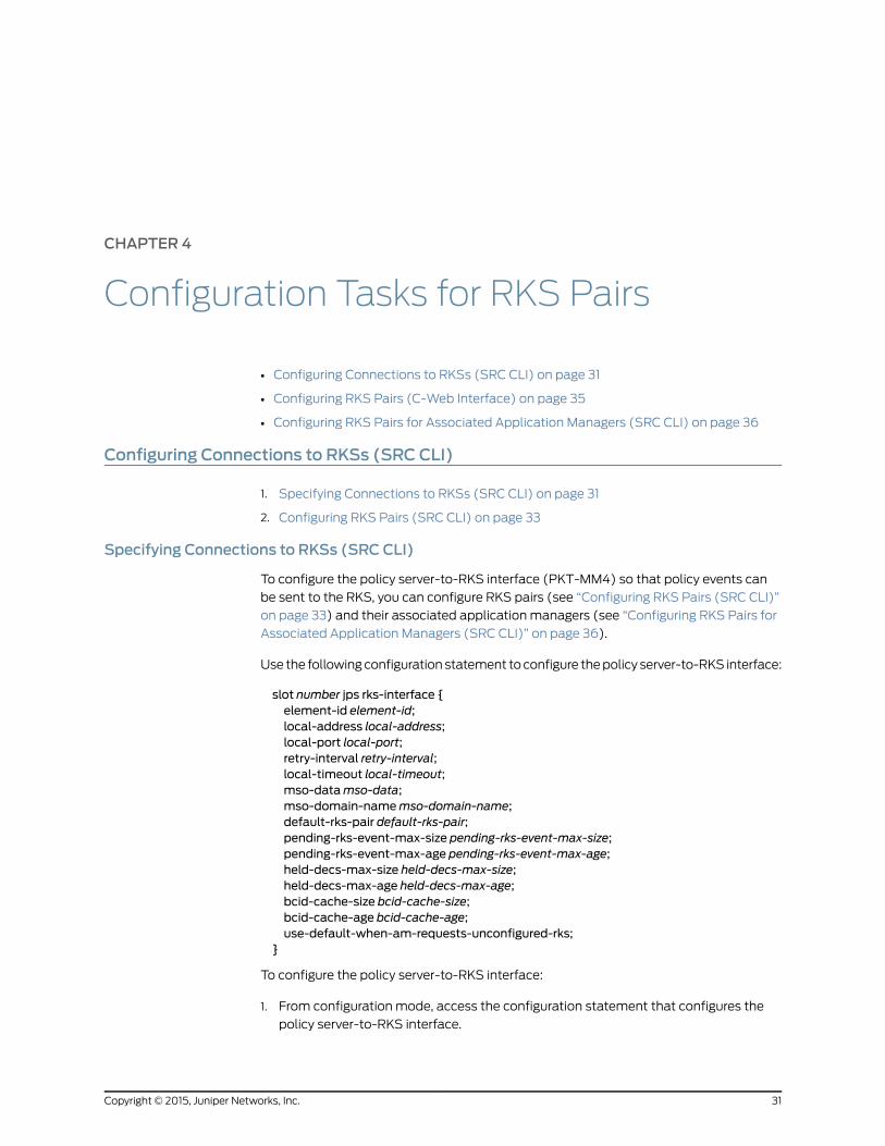
Use the following configuration statement to configure the policy server-to-RKS interface:
slot number jps rks-interface {element-id element-id;local-address local-address;local-port local-port;retry-interval retry-interval;local-timeout local-timeout;mso-datamso-data;mso-domain-namemso-domain-name;default-rks-pair default-rks-pair;pending-rks-event-max-size pending-rks-event-max-size;pending-rks-event-max-age pending-rks-event-max-age;held-decs-max-size held-decs-max-size;held-decs-max-age held-decs-max-age;bcid-cache-size bcid-cache-size;bcid-cache-age bcid-cache-age;use-default-when-am-requests-unconfigured-rks;
}
To configure the policy server-to-RKS interface:
1. From configuration mode, access the configuration statement that configures the
policy server-to-RKS interface.
31Copyright © 2015, Juniper Networks, Inc.

user@host# edit slot 0 jps rks-interface
2. ier for RKS event origin.
[edit slot 0 jps rks-interface]user@host# set element-id element-id
3. (Optional) Specify the source IP address that the plug-in uses to communicate with
the RKS.
[edit slot 0 jps rks-interface]user@host# set local-address local-address
If no value is specified and there is more than one local address, the JPS randomly
selects a local address to be used as the source address.
4. (Optional) Specify the source UDP port or a pool of ports that the plug-in uses to
communicate with the RKS.
[edit slot 0 jps rks-interface]user@host# set local-port local-port
5. (Optional) Specify the time the JPS waits for a response from an RKS before it resends
the packet.
[edit slot 0 jps rks-interface]user@host# set retry-interval retry-interval
The JPS keeps sending packets until either the RKS acknowledges the packet or the
maximum timeout is reached.
6. (Optional) Specify the maximum time the JPS waits for a response from an RKS.
[edit slot 0 jps rks-interface]user@host# set local-timeout local-timeout
7. (Optional) Specify the MSO-defined data in the financial entity ID (FEID) attribute,
which is included in event messages.
[edit slot 0 jps rks-interface]user@host# setmso-datamso-data
8. (Optional) Specify the MSO domain name in the FEID attribute that uniquely identifies
the MSO for billing and settlement purposes.
[edit slot 0 jps rks-interface]user@host# setmso-domain-namemso-domain-name
9. (Optional) Specify the default RKS pair that the JPS uses unless an RKS pair is
configured for a given application manager.
[edit slot 0 jps rks-interface]user@host# set default-rks-pair default-rks-pair
Copyright © 2015, Juniper Networks, Inc.32
PCMM Devices in an SRC-Managed Network

10. (Optional) Specify the maximum number of RKS events waiting for Gate-Set-Ack,
Gate-Set-Err, Gate-Del-Ack, and Gate-Del-Err messages.
[edit slot 0 jps rks-interface]user@host# set pending-rks-event-max-size pending-rks-event-max-size
11. (Optional) Specify the oldest age of RKS events waiting for Gate-Set-Ack,
Gate-Set-Err, Gate-Del-Ack, and Gate-Del-Err messages.
[edit slot 0 jps rks-interface]user@host# set pending-rks-event-max-age pending-rks-event-max-age
The maximum age must be greater than sent-message-timeout of the corresponding
CMTS interface.
12. (Optional) Specify the maximum number of outstanding Gate-Info requests.
[edit slot 0 jps rks-interface]user@host# set held-decs-max-size held-decs-max-size
13. (Optional) Specify the oldest age of outstanding Gate-Info requests.
[edit slot 0 jps rks-interface]user@host# set held-decs-max-age held-decs-max-age
The maximum age must be greater than sent-message-timeout of the corresponding
CMTS interface.
14. (Optional) Specify the size of billing correlation ID (BCID) cache.
[edit slot 0 jps rks-interface]user@host# set bcid-cache-size bcid-cache-size
15. (Optional) Specify the oldest age of billing correlation ID (BCID) in cache.
[edit slot 0 jps rks-interface]user@host# set bcid-cache-age bcid-cache-age
16. (Optional) Specify whether the default RKS pair is used when an application manager
requests the use of an unconfigured RKS pair.
[edit slot 0 jps rks-interface]user@host# set use-default-when-am-requests-unconfigured-rks
17. (Optional) Verify your configuration.
[edit slot 0 jps rks-interface] user@host# show
Configuring RKS Pairs (SRC CLI)
By default, the JPS has four RKS pairs. All parameters that share the same RKS pair name
configure the connection to that RKS pair. Any configured RKS pair can be used as the
value for the default RKS pair or the RKS pair associated with a specific application
manager.
33Copyright © 2015, Juniper Networks, Inc.
Chapter 4: Configuration Tasks for RKS Pairs

NOTE: When runningmore than one JPS in a group to provide redundancy,all the JPSs in that groupmust have same RKS pair configuration (includingthe default RKS pair and any configured RKSpairs associatedwith a specificapplicationmanager).
Use the following configuration statement to configure the RKS pair:
slot number jps rks-interface rks-pair rks-pair-name {primary-address primary-address;primary-port primary-port;secondary-address secondary-address;secondary-port secondary-port;
}
To configure the RKS pair:
1. From configuration mode, access the configuration statement that configures the
RKS pair. In this sample procedure, the RKS pair called pair1 is configured.
user@host# edit slot 0 jps rks-interface rks-pair pair1
2. Specify the IP address of the primary RKS for this RKS pair.
[edit slot 0 jps rks-interface rks-pair pair1]user@host# set primary-address primary-address
If no value is specified, the RKS pair is not defined.
3. (Optional) Specify the UDP port on the primary RKS to which the JPS sends events.
[edit slot 0 jps rks-interface rks-pair pair1]user@host# set primary-port primary-port
4. (Optional) Specify the IP address of the secondary RKS for this RKS pair.
[edit slot 0 jps rks-interface rks-pair pair1]user@host# set secondary-address secondary-address
5. (Optional) Specify the UDP port on the secondary RKS to which the JPS sends events.
[edit slot 0 jps rks-interface rks-pair pair1]user@host# set secondary-port secondary-port
6. (Optional) Verify your configuration.
[edit slot 0 jps rks-interface rks-pair pair1] user@host# showprimary-address ;primary-port 1813;secondary-address ;secondary-port 1813;
RelatedDocumentation
Modifying the JPS Configuration (C-Web Interface) on page 15•
Copyright © 2015, Juniper Networks, Inc.34
PCMM Devices in an SRC-Managed Network

• Configuring RKS Pairs (C-Web Interface) on page 35
• Specifying Connections to the Application Managers (SRC CLI) on page 20
• Viewing JPS RKS Statistics (C-Web Interface) on page 63
Configuring RKS Pairs (C-Web Interface)
• Configuring Connections for RKS Pairs (C-Web Interface) on page 35
• Configuring RKS Pairs for Associated Application Managers (C-Web
Interface) on page 35
• Specifying Connections to CMTS Devices (C-Web Interface) on page 36
Configuring Connections for RKS Pairs (C-Web Interface)
By default, the JPS has four RKS pairs. All parameters that share the same RKS pair name
configure the connection to that RKS pair. Any configured RKS pair can be used as the
value for the default RKS pair or the RKS pair associated with a specific application
manager.
NOTE: When runningmore than one JPS in a group to provide redundancy,all the JPSs in that groupmust have the same RKS pair configuration(including thedefaultRKSpair andanyconfiguredRKSpairs associatedwitha specific applicationmanager).
To configure the RKS pair:
1. Click Configure, and expand Slot>Slot: 0>JPS>RKS Interface.
2. Click the specified RKS pair (for example, pair 1).
The RKS Pair:pair 1 pane appears.
3. Enter the information in the main pane as described in the Help text, and click Apply.
Configuring RKS Pairs for Associated ApplicationManagers (C-Web Interface)
By default, the JPS has four associated application managers. All parameters that share
the same application manager name configure the RKS pair to which events associated
with a specific application manager are sent.
To configure the associated application manager:
1. Click Configure, and expand Slot>Slot: 0>JPS>RKS Interface.
2. Click the specified AM (for example, AM:1).
The RKS Interface/AM:1 pane appears.
3. Enter the information in the main pane as described in the Help text, and click Apply.
35Copyright © 2015, Juniper Networks, Inc.
Chapter 4: Configuration Tasks for RKS Pairs

Specifying Connections to CMTSDevices (C-Web Interface)
To configure the policy server–to–CMTS interface (PKT-MM2) so that the policy server
can communicate with CMTS devices:
1. Click Configure, expand Slot>Slot: 0>JPS, and then click CMTS Interface.
The CMTS Interface pane appears.
2. Enter the information in the main pane as described in the Help text, and click Apply.
RelatedDocumentation
Configuring Connections to RKSs (SRC CLI) on page 31•
• Specifying Connections to CMTS Devices (SRC CLI) on page 22
• Modifying the JPS Configuration (C-Web Interface) on page 15
• Viewing JPS RKS Statistics (C-Web Interface) on page 63
• Viewing JPS CMTS Connections (C-Web Interface) on page 60
Configuring RKS Pairs for Associated ApplicationManagers (SRC CLI)
By default, the JPS has four associated application managers. All parameters that share
the same application manager name configure the RKS pair to which events associated
with a specific application manager are sent.
Use the following configuration statement to configure the associated application
manager:
slot number jps rks-interface am am-name {am-id am-id;rks-pair-name rks-pair-name;trusted;
}
To configure the associated application manager:
1. From configuration mode, access the configuration statement that configures the
RKS pair for the associated application manager. In this sample procedure, the
application manager name called 1 is configured.
user@host# edit slot 0 jps rks-interface am 1
2. Specify the identifier of the application manager.
[edit slot 0 jps rks-interface am 1]user@host# set am-id am-id
If no value is specified, the RKS pair configuration is not defined for this application
manager. If you must set trusted to true without defining the RKS pair configuration,
you must specify a value for am-id and not specify a value for rks-pair-name.
Copyright © 2015, Juniper Networks, Inc.36
PCMM Devices in an SRC-Managed Network

3. (Optional) Specify the RKS pair that the JPS will send events to when those events
are triggered by gate transitions associated with the application manager specified
by am-id with the same application manager name (am-name).
[edit slot 0 jps rks-interface am 1]user@host# set rks-pair rks-pair-name
If no value is specified, the RKS pair configuration is not defined for this application
manager. Use when you must set trusted to true without defining the RKS pair
configuration.
4. (Optional) Specify whether this application manager is a trusted network element to
the JPS.
[edit slot 0 jps rks-interface am 1]user@host# set trusted
5. (Optional) Verify your configuration.
[edit slot 0 jps rks-interface am 1] user@host# show
RelatedDocumentation
• Configuring RKS Pairs (C-Web Interface) on page 35
• Configuring Connections to RKSs (SRC CLI) on page 31
37Copyright © 2015, Juniper Networks, Inc.
Chapter 4: Configuration Tasks for RKS Pairs

Copyright © 2015, Juniper Networks, Inc.38
PCMM Devices in an SRC-Managed Network

CHAPTER 5
Configuration Tasks for Subscriber IPPools Managed by CMTS
• Modifying the Subscriber Configuration (SRC CLI) on page 39
• Modifying the Subscriber Configuration (C-Web Interface) on page 40
• Configuring Subscriber IP Pools as IP Address Ranges (SRC CLI) on page 40
• Configuring Subscriber IP Pools as IP Address Ranges (C-Web Interface) on page 41
• Configuring Subscriber IP Pools as IP Subnets (SRC CLI) on page 41
• Configuring Subscriber IP Pools as IP Subnets (C-Web Interface) on page 42
Modifying the Subscriber Configuration (SRC CLI)
To locate the CMTS device associated with a subscriber, the JPS maps the subscriber IP
address in a message to the CMTS IP address to which the message must be delivered.
This mapping specifies the subscriber IP pools associated with CMTS devices.
Use the following configuration statements to configure a CMTS device to which the JPS
can connect and the pools of subscriber IP addresses that are managed by the CMTS
device:
slot number jps cmts-registry cmts cmts-ip ...slot number jps cmts-registry cmts cmts-ip range-pool pool-index {low low;high high;
}slot number jps cmts-registry cmts cmts-ip subnet-pool subnet {exclude [exclude];
}
Tasks to modify subscriber configuration are:
1. “Configuring Subscriber IP Pools as IP Address Ranges (SRC CLI)” on page 40
2. “Configuring Subscriber IP Pools as IP Subnets (SRC CLI)” on page 41
RelatedDocumentation
Modifying the Subscriber Configuration (C-Web Interface) on page 40•
39Copyright © 2015, Juniper Networks, Inc.

• Specifying Connections to CMTS Devices (SRC CLI) on page 22
Modifying the Subscriber Configuration (C-Web Interface)
To locate the CMTS device associated with a subscriber, the JPS maps the subscriber IP
address in a message to the CMTS IP address to which the message must be delivered.
This mapping specifies the subscriber IP pools associated with CMTS devices.
The tasks to configure a CMTS device to which the JPS can connect and the pools of
subscriber IP addresses that are managed by that CMTS device are:
1. “Configuring Subscriber IP Pools as IP Address Ranges (C-Web Interface)” on page 41
2. “Configuring Subscriber IP Pools as IP Subnets (C-Web Interface)” on page 42
RelatedDocumentation
Modifying the Subscriber Configuration (SRC CLI) on page 39•
• Modifying the JPS Configuration (C-Web Interface) on page 15
• Configuring Subscriber IP Pools as IP Address Ranges (C-Web Interface) on page 41
• Configuring Subscriber IP Pools as IP Subnets (C-Web Interface) on page 42
Configuring Subscriber IP Pools as IP Address Ranges (SRC CLI)
To configure subscriber IP pools that are managed by the CMTS device as IP address
ranges:
1. From configuration mode, access the configuration statement that configures the
CMTS device to which the JPS can connect.
user@host# edit slot 0 jps cmts-registry cmts cmts-ip range-pool pool-index
Specify the IP address of the CMTS device and the address range pool index.
2. Specify the first IP address in the IP range for the pool of subscriber IP addresses that
are managed by the CMTS device.
[edit slot 0 jps cmts-registry cmts cmts-ip range-pool pool-index]user@host# set low low
3. Specify the last IP address in the IP range for the pool of subscriber IP addresses that
are managed by the CMTS device.
[edit slot 0 jps cmts-registry cmts cmts-ip range-pool pool-index]user@host# set high high
4. (Optional) Verify your configuration.
[edit slot 0 jps cmts-registry] user@host# show
Copyright © 2015, Juniper Networks, Inc.40
PCMM Devices in an SRC-Managed Network

RelatedDocumentation
Configuring Subscriber IP Pools as IP Address Ranges (C-Web Interface) on page 41•
• Modifying the Subscriber Configuration (SRC CLI) on page 39
• Configuring Subscriber IP Pools as IP Subnets (SRC CLI) on page 41
• Specifying Connections to CMTS Devices (SRC CLI) on page 22
Configuring Subscriber IP Pools as IP Address Ranges (C-Web Interface)
To configure subscriber IP pools that are managed by the CMTS device as IP address
ranges:
1. Click Configure, expand Slot>Slot: 0>JPS, and then click CMTS Registry.
The CMTS Registry pane appears.
2. From the Create new list, select CMTS.
3. In the dialog box, type an IPv4 or IPv6 address for the new CMTS, and click OK.
The CMTS:<ip address> pane appears.
4. From the Create new list, select Range Pool.
5. In the dialog box, enter a number for the new Range Pool, and click OK.
The Range Pool: <number> pane appears.
6. Enter the information in the main pane as described in the Help text, and click Apply.
RelatedDocumentation
Configuring Subscriber IP Pools as IP Address Ranges (SRC CLI) on page 40•
• Configuring Subscriber IP Pools as IP Subnets (C-Web Interface) on page 42
• Modifying the Subscriber Configuration (C-Web Interface) on page 40
Configuring Subscriber IP Pools as IP Subnets (SRC CLI)
To configure subscriber IP pools that are managed by the CMTS device as IP subnets:
1. From configuration mode, access the configuration statement that configures the
CMTS device to which the JPS can connect.
user@host# edit slot 0 jps cmts-registry cmts cmts-ip subnet-pool subnet
Specify the IP address of the CMTS device and the IP address and mask of the subnet
for the pool of subscriber IP addresses.
2. (Optional) Specify the IP addresses of the subnet that are excluded from the subscriber
IP pool managed by the CMTS device.
[edit slot 0 jps cmts-registry cmts cmts-ip subnet-pool subnet]user@host# set exclude [exclude...]
3. (Optional) Verify your configuration.
41Copyright © 2015, Juniper Networks, Inc.
Chapter 5: Configuration Tasks for Subscriber IP Pools Managed by CMTS

[edit slot 0 jps cmts-registry] user@host# show
RelatedDocumentation
Configuring Subscriber IP Pools as IP Subnets (C-Web Interface) on page 42•
• Modifying the Subscriber Configuration (SRC CLI) on page 39
• Configuring Subscriber IP Pools as IP Address Ranges (SRC CLI) on page 40
• Specifying Connections to CMTS Devices (SRC CLI) on page 22
Configuring Subscriber IP Pools as IP Subnets (C-Web Interface)
To configure subscriber IP pools that are managed by the CMTS device as IP subnets:
1. Click Configure, expand Slot>Slot: 0>JPS, and then click CMTS Registry.
The CMTS Registry pane appears.
2. From the Create new list, select CMTS.
3. In the dialog box, type an IPv4 or IPv6 address for the new CMTS, and click OK.
The CMTS:<ip address> pane appears.
4. From the Create new list, select Subnet Pool.
5. In the dialog box, enter a network IP address/mask for the new Subnet Pool, and click
OK.
The Subnet Pool: <ip address/mask> pane appears.
6. Enter the information in the main pane as described in the Help text, and click Apply.
RelatedDocumentation
• Configuring Subscriber IP Pools as IP Subnets (SRC CLI) on page 41
• Configuring Subscriber IP Pools as IP Address Ranges (C-Web Interface) on page 41
• Modifying the Subscriber Configuration (C-Web Interface) on page 40
Copyright © 2015, Juniper Networks, Inc.42
PCMM Devices in an SRC-Managed Network

CHAPTER 6
Configuration Tasks for ApplicationManagers for JPS
• Specifying Application Managers for the Policy Server (SRC CLI) on page 43
• Specifying Application Managers for the Policy Server (C-Web Interface) on page 45
• Specifying Application Manager Identifiers for Policy Servers (SRC CLI) on page 45
• Specifying Application Manager Identifiers for Policy Servers (C-Web
Interface) on page 46
Specifying ApplicationManagers for the Policy Server (SRC CLI)
To specify the SAE community that connects to a policy server group, you need to add
an application manager group object to the directory.
Use the following configuration statements to specify the application manager for the
policy server:
shared network application-manager-group name {description description;application-manager-id application-manager-id;connected-sae [connected-sae...];pdp-group pdp-group;local-address-pools [local-address-pools...];managing-sae-iormanaging-sae-ior;
}
To add an application manager group:
1. From configuration mode, access the configuration statement that specifies the
application managers.
user@host# edit shared network application-manager-group name
2. (Optional) Specify information about the SAE community.
[edit shared network application-manager-group name]user@host# set description description
43Copyright © 2015, Juniper Networks, Inc.

3. (Optional) Specify the unique identifier within the domain of the service provider for
the application manager that handles the service session (Application Manager Tag)
as a 2-byte unsigned integer.
[edit shared network application-manager-group name]user@host# set application-manager-id application-manager-id
4. (Optional) Specify the SAEs that are connected to the specified policy server group.
This list becomes the community of SAEs.
[edit shared network application-manager-group name]user@host# set connected-sae [connected-sae...]
When you modify a community, wait for passive session stores of the new community
members to be updated before you shut down the current active SAE. Otherwise, a
failover from the current active SAE to the new member is triggered immediately, and
the new member’s session store may not have received all data from the active SAE’s
session store.
5. (Optional) Specify the name of the policy server group associated with this SAE
community.
[edit shared network application-manager-group name]user@host# set pdp-group pdp-group
6. (Optional) Specify the list of IP address pools that the specified PDP group currently
manages and stores.
[edit shared network application-manager-group name]user@host# set local-address-pools local-address-pools
You must configure a local address pool if you are using the NIC so that the NIC can
resolve the IP-to-SAE mapping. See “Using the NIC Resolver” on page 9.
7. (Optional) Specify the Common Object Request Broker Architecture (CORBA)
reference for the SAE managing this policy server group.
[edit shared network application-manager-group name]user@host# setmanaging-sae-iormanaging-sae-ior
The amIorPublisher script provides this information when the SAE connects to the
policy server. If you do not select this script when configuring initialization scripts,
enter a value. For information about configuring initialization scripts, see “Configuring
Initialization Scripts (SRC CLI)” on page 27.
RelatedDocumentation
JPS Interfaces on page 8•
• Specifying Application Managers for the Policy Server (C-Web Interface) on page 45
• Specifying Application Manager Identifiers for Policy Servers (SRC CLI) on page 45
• Viewing JPS State on page 56
• Viewing JPS AM Statistics (C-Web Interface) on page 58
Copyright © 2015, Juniper Networks, Inc.44
PCMM Devices in an SRC-Managed Network

Specifying ApplicationManagers for the Policy Server (C-Web Interface)
To specify the SAE community that connects to a policy server group, you need to add
an application manager group object to the directory.
To specify the application manager for the policy server:
1. Click Configure, expand Shared, and then click Network.
The Network pane appears.
2. From the Create new list, select ApplicationManager Group.
3. In the dialog box, enter a name for the new Application Manager Group, and click OK.
The Application Manager Group:<name> pane appears.
4. Enter the information in the main pane as described in the Help text, and click Apply.
RelatedDocumentation
Adding Objects for Policy Servers to the Directory (C-Web Interface) on page 27•
• Configuring Initialization Scripts (C-Web Interface) on page 28.
• Specifying Application Managers for the Policy Server (SRC CLI) on page 43
• Configuring the SAE to Interact with the JPS (C-Web Interface) on page 25
• Specifying Application Manager Identifiers for Policy Servers (C-Web Interface) on
page 46
Specifying ApplicationManager Identifiers for Policy Servers (SRC CLI)
The application manager identifier (AMID) identifies the application manager (such as
the SAE) in messages sent to and from the policy server. The SAE constructs the AMID
value by concatenating two fields: Application Manager Tag and Application Type.
The Application Manager Tag value is obtained from the specification of application
managers for policy servers. See “Specifying Application Managers for the Policy Server
(SRC CLI)” on page 43.
The Application Type value is obtained during service activation from the specification
of the PCMM Application Type value when you configure normal services.
For more information about configuring services, see Adding a Normal Service (SRC CLI).
RelatedDocumentation
JPS Interfaces on page 8•
• Specifying Application Manager Identifiers for Policy Servers (C-Web Interface) on
page 46
• Specifying Policy Server Identifiers in Messages (SRC CLI) on page 18
• Adding Objects for Policy Servers to the Directory (SRC CLI) on page 26
• Viewing JPS State on page 56
45Copyright © 2015, Juniper Networks, Inc.
Chapter 6: Configuration Tasks for Application Managers for JPS

Specifying ApplicationManager Identifiers for Policy Servers (C-Web Interface)
The application manager identifier (AMID) identifies the application manager (such as
the SAE) in messages sent to and from the policy server. The SAE constructs the AMID
value by concatenating two fields: Application Manager Tag and Application Type.
The Application Manager Tag value is obtained from the specification of application
managers for policy servers.
The Application Type value is obtained during service activation from the specification
of the PCMM Application Type value when you configure normal services.
RelatedDocumentation
• Specifying Application Manager Identifiers for Policy Servers (SRC CLI) on page 45
• Specifying Application Managers for the Policy Server (C-Web Interface) on page 45
• Adding Objects for Policy Servers to the Directory (C-Web Interface) on page 27
• Configuring Initialization Scripts (C-Web Interface) on page 28
Copyright © 2015, Juniper Networks, Inc.46
PCMM Devices in an SRC-Managed Network

CHAPTER 7
Configuration Statements
• Configuration Statements for the JPS on page 47
Configuration Statements for the JPS
Use the following configuration statements to configure the JPS at the [edit] hierarchy
level.
slot number jps {java-heap-size java-heap-size;snmp-agent;policy-server-id policy-server-id;use-psid-in-gate-commands;cmts-message-buffer-size cmts-message-buffer-size;am-message-buffer-size am-message-buffer-size;
}slot number jps am-interface {pep-id pep-id;listening-address listening-address;validate-pcmm-objects;message-max-lengthmessage-max-length;message-read-buffer-sizemessage-read-buffer-size;message-write-buffer-sizemessage-write-buffer-size;open-connection-timeout open-connection-timeout;
}slot number jps cmts-interface {cmts-addresses [cmts-addresses...];keepalive-interval keepalive-interval;synch-despite-unreachable-pep;synch-despite-pre-i03-pep;use-ssq-ssc-with-pre-i03-pep;local-address local-address;message-max-lengthmessage-max-length;message-read-buffer-sizemessage-read-buffer-size;message-write-buffer-sizemessage-write-buffer-size;open-connection-timeout open-connection-timeout;connection-open-retry-interval connection-open-retry-interval;sent-message-timeout sent-message-timeout;validate-pcmm-objects;
}slot number jps cmts-registry cmts cmts-ip ...slot number jps cmts-registry cmts cmts-ip range-pool pool-index {
47Copyright © 2015, Juniper Networks, Inc.

low low;high high;
}slot number jps cmts-registry cmts cmts-ip subnet-pool subnet {exclude [exclude];
}slot number jps logger name ...slot number jps logger name file {filter filter;filename filename;rollover-filename rollover-filename;maximum-file-sizemaximum-file-size;
}slot number jps logger name syslog {filter filter;host host;facility facility;format format;
}slot number jps rks-interface {element-id element-id;local-address local-address;local-port local-port;retry-interval retry-interval;local-timeout local-timeout;mso-datamso-data;mso-domain-namemso-domain-name;default-rks-pair default-rks-pair;pending-rks-event-max-size pending-rks-event-max-size;pending-rks-event-max-age pending-rks-event-max-age;held-decs-max-size held-decs-max-size;held-decs-max-age held-decs-max-age;bcid-cache-size bcid-cache-size;bcid-cache-age bcid-cache-age;use-default-when-am-requests-unconfigured-rks;
}slot number jps rks-interface am am-name {am-id am-id;rks-pair-name rks-pair-name;trusted;
}slot number jps rks-interface rks-pair rks-pair-name {primary-address primary-address;primary-port primary-port;secondary-address secondary-address;secondary-port secondary-port;
}
For detailed information about each configuration statement, see the SRC PE CLI
Command Reference.
RelatedDocumentation
• JPS Overview on page 7
• JPS Interfaces on page 8
• Configuring the JPS (SRC CLI) on page 13
Copyright © 2015, Juniper Networks, Inc.48
PCMM Devices in an SRC-Managed Network

PART 3
Administration
• Managing the JPS on page 51
• Routine Monitoring on page 55
49Copyright © 2015, Juniper Networks, Inc.

Copyright © 2015, Juniper Networks, Inc.50
PCMM Devices in an SRC-Managed Network

CHAPTER 8
Managing the JPS
• Starting the JPS (SRC CLI) on page 51
• Starting the JPS (C-Web Interface) on page 51
• Restarting the JPS (SRC CLI) on page 52
• Restarting the JPS (C-Web Interface) on page 52
• Stopping the JPS (SRC CLI) on page 53
• Stopping the JPS (C-Web Interface) on page 53
• Displaying JPS Status (SRC CLI) on page 53
• Displaying JPS Status (C-Web Interface) on page 54
Starting the JPS (SRC CLI)
You must start the JPS when you install the JPS without rebooting the JPS host.
To start the JPS:
user@host> enable component jps
The system responds with a start message. If the JPS is already running, the system
responds with a warning message.
RelatedDocumentation
Starting the JPS (C-Web Interface) on page 51•
• Stopping the JPS (SRC CLI) on page 53
• Configuring the JPS (SRC CLI) on page 13
• Monitoring the JPS on page 55
• JPS Overview on page 7
Starting the JPS (C-Web Interface)
You must start the JPS when you install the JPS without rebooting the JPS host.
To start the JPS:
1. Click Manage>Enable.
The Enable pane appears.
51Copyright © 2015, Juniper Networks, Inc.

2. From the Component list, select JPS, and click OK.
The system responds with a start message. If the JPS is already running, the system
responds with a warning message.
RelatedDocumentation
Restarting the JPS (C-Web Interface) on page 52•
• Stopping the JPS (C-Web Interface) on page 53
• Monitoring the SRC SNMP Agent (C-Web Interface)
• Displaying JPS Status (C-Web Interface) on page 54
• Configuring the JPS (C-Web Interface) on page 14
• JPS Overview on page 7
Restarting the JPS (SRC CLI)
To restart the JPS:
user@host> restart component jps
The system responds with a start message. If the JPS is already running, the system
responds with a shutdown message and then a start message.
RelatedDocumentation
Restarting the JPS (C-Web Interface) on page 52•
• Stopping the JPS (SRC CLI) on page 53
• Configuring the JPS (SRC CLI) on page 13
• Monitoring the JPS on page 55
• JPS Overview on page 7
Restarting the JPS (C-Web Interface)
To restart the JPS:
1. Click Manage>Restart.
The Restart pane appears.
2. From the Component list, select JPS, and click OK.
The system responds with a start message. If the JPS is already running, the system
responds with a shutdown message and then a start message.
RelatedDocumentation
Starting the JPS (C-Web Interface) on page 51•
• Stopping the JPS (C-Web Interface) on page 53
• Displaying JPS Status (C-Web Interface) on page 54
• Configuring the JPS (C-Web Interface) on page 14
Copyright © 2015, Juniper Networks, Inc.52
PCMM Devices in an SRC-Managed Network

Stopping the JPS (SRC CLI)
To stop the JPS:
user@host> disable component jps
The system responds with a shutdown message. If the JPS is not running when you issue
the command, the system responds with the command prompt.
To start the JPS, see “Starting the JPS (SRC CLI)” on page 51.
RelatedDocumentation
Stopping the JPS (C-Web Interface) on page 53•
• Restarting the JPS (SRC CLI) on page 52
• Monitoring the JPS on page 55
• JPS Overview on page 7
Stopping the JPS (C-Web Interface)
To stop the JPS:
1. Click Manage>Disable.
The Disable pane appears.
2. From the Component list, select JPS, and click OK.
The system responds with a shutdown message. If the JPS is not running when you issue
the command, the system responds with a status message.
RelatedDocumentation
Starting the JPS (C-Web Interface) on page 51•
• Restarting the JPS (C-Web Interface) on page 52
• Monitoring the SRC SNMP Agent (C-Web Interface)
Displaying JPS Status (SRC CLI)
Purpose Display the JPS status.
Action user@host> show component
The system responds with a status message.
RelatedDocumentation
Displaying JPS Status (C-Web Interface) on page 54•
• Monitoring the JPS on page 55
• Viewing JPS State on page 56
53Copyright © 2015, Juniper Networks, Inc.
Chapter 8: Managing the JPS

Displaying JPS Status (C-Web Interface)
To display the JPS status:
1. Click Monitor>Component.
The Installed Components pane appears.
2. Locate jps in the Name column. The Version and Status columns display the JPS
status.
RelatedDocumentation
• Starting the JPS (C-Web Interface) on page 51
• Restarting the JPS (C-Web Interface) on page 52
• Stopping the JPS (C-Web Interface) on page 53
• Modifying the JPS Configuration (C-Web Interface) on page 15
Copyright © 2015, Juniper Networks, Inc.54
PCMM Devices in an SRC-Managed Network

CHAPTER 9
Routine Monitoring
• Monitoring the JPS on page 55
• Viewing Server Process Information on page 56
• Viewing JPS State on page 56
• Viewing Information About the JPS Server Process (C-Web Interface) on page 57
• Viewing JPS AM Statistics (C-Web Interface) on page 58
• Viewing JPS AM Connections (C-Web Interface) on page 59
• Viewing JPS CMTS Statistics (C-Web Interface) on page 59
• Viewing JPS CMTS Connections (C-Web Interface) on page 60
• Viewing JPS CMTS Locator Statistics (C-Web Interface) on page 61
• Viewing JPS Message Handler Statistics (C-Web Interface) on page 61
• Viewing JPS Message Flow Statistics (C-Web Interface) on page 62
• Viewing JPS RKS Statistics (C-Web Interface) on page 63
Monitoring the JPS
Purpose Monitor the following JPS information:
• The basic health indicators for the server process
• The current state of the JPS, such as the current network connections or recent
performance statistics
Action user@host> show jps statistics
RelatedDocumentation
Displaying JPS Status (SRC CLI) on page 53•
• Viewing JPS State on page 56
• Viewing Server Process Information on page 56
• Configuring the JPS (SRC CLI) on page 13
• JPS Overview on page 7
55Copyright © 2015, Juniper Networks, Inc.

Viewing Server Process Information
Purpose View information about the server process.
Action user@host> show jps statistics process
RelatedDocumentation
Viewing Information About the JPS Server Process (C-Web Interface) on page 57•
• Monitoring the JPS on page 55
• Viewing JPS State on page 56
• JPS Overview on page 7
Viewing JPS State
You can monitor the current state of the JPS by:
1. Viewing Performance Statistics for the JPS Interfaces on page 56
2. Viewing Network Connections for the Application Manager on page 56
3. Viewing Network Connections for the CMTS Device on page 57
4. Viewing Performance Statistics for the CMTS Locator on page 57
5. Viewing Message Handler Information on page 57
Viewing Performance Statistics for the JPS Interfaces
Purpose View performance statistics for JPS interfaces.
Action To view recent performance statistics for the application manager-to-policy server
interface:
user@host> show jps statistics am
To view recent performance statistics for the policy server-to-CMTS interface:
user@host> show jps statistics cmts
To view recent performance statistics for the policy server-to-RKS interface:
user@host> show jps statistics rks
Viewing Network Connections for the ApplicationManager
Purpose View network connections for the application manager.
Action To view information about the current JPS network connections for all the application
managers:
user@host> show jps statistics am connections
To view information about the current JPS network connections for a specific application
manager:
user@host> show jps statistics am connections ip-address ip-address
Copyright © 2015, Juniper Networks, Inc.56
PCMM Devices in an SRC-Managed Network

Enter all or part of the IP address to list connections for all matching addresses.
Viewing Network Connections for the CMTSDevice
Purpose View network connections for the CMTS Device.
Action To view information about the current JPS connections for all the CMTS devices:
user@host> show jps statistics cmts connections
To view information about the current JPS connections for a specific CMTS device:
user@host> show jps statistics cmts connections ip-address ip-address
Enter all or part of the IP address to list connections for all matching addresses.
Viewing Performance Statistics for the CMTS Locator
Purpose View information about the recent performance statistics for the CMTS locator.
Action user@host> show jps statistics cmts-locator
ViewingMessage Handler Information
Purpose View message handler information.
Action To view information about the JPS message handler and message flows:
user@host> show jps statisticsmessage-handleruser@host> show jps statisticsmessage-handler message-flow
To view information about specific JPS message flows:
user@host> show jps statisticsmessage-handler message-flow id id
Enter all or part of the message flow identifier to list all matching message flows.
RelatedDocumentation
Displaying JPS Status (SRC CLI) on page 53•
• Monitoring the JPS on page 55
• Viewing Server Process Information on page 56
• JPS Overview on page 7
Viewing Information About the JPS Server Process (C-Web Interface)
Purpose View information about the JPS server process.
Action Click JPS >Statistics>Process.
The Statistics/Process pane displays the JPS server process information.
57Copyright © 2015, Juniper Networks, Inc.
Chapter 9: Routine Monitoring

RelatedDocumentation
Viewing Server Process Information on page 56•
• Configuring the JPS (C-Web Interface) on page 14
• JPS Overview on page 7
Viewing JPS AMStatistics (C-Web Interface)
Purpose View information about recent performance statistics for the application
manager–to–policy server interface.
Action Click JPS>Statistics>AM.
The Statistics/AM pane displays performance statistics for the application
manager–to–policy server interface.
RelatedDocumentation
Viewing JPS State on page 56•
• Modifying the JPS Configuration (C-Web Interface) on page 15
• Viewing JPS AM Connections (C-Web Interface) on page 59
• JPS Overview on page 7
Copyright © 2015, Juniper Networks, Inc.58
PCMM Devices in an SRC-Managed Network

Viewing JPS AMConnections (C-Web Interface)
Purpose View information about the current JPS network connections for the application manager.
Action Click JPS>Statistics>AM>Connections.1.
The Statistics/AM/Connections pane appears.
2. In the IP Address box, enter the IP address, or leave the box blank to display all AM
connections.
3. Click OK.
The Statistics/AM/Connections pane displays the AM connection statistics.
RelatedDocumentation
Viewing JPS State on page 56•
• Modifying the JPS Configuration (C-Web Interface) on page 15
• Viewing JPS AM Statistics (C-Web Interface) on page 58
• JPS Overview on page 7
Viewing JPS CMTS Statistics (C-Web Interface)
Purpose View information about recent performance statistics for the policy server–to–CMTS
interface.
Action Click JPS>Statistics>CMTS.
The Statistics/CMTS pane displays statistics for the policy server–to–CMTS interface.
59Copyright © 2015, Juniper Networks, Inc.
Chapter 9: Routine Monitoring

RelatedDocumentation
Viewing JPS State on page 56•
• Specifying Connections to CMTS Devices (C-Web Interface) on page 24
• Viewing JPS CMTS Connections (C-Web Interface) on page 60
• Viewing JPS CMTS Locator Statistics (C-Web Interface) on page 61
• JPS Overview on page 7
Viewing JPS CMTS Connections (C-Web Interface)
Purpose View information about the current JPS network connections for the CMTS device.
Action Click JPS>Statistics>CMTS>Connections.1.
The Statistics/CMTS/Connections pane appears.
2. In the IP Address box, enter the IP address, or leave the box blank to display all CMTS
connections.
3. Click OK.
The Statistics/CMTS/Connections pane displays the CMTS connection statistics.
Copyright © 2015, Juniper Networks, Inc.60
PCMM Devices in an SRC-Managed Network

RelatedDocumentation
Viewing JPS State on page 56•
• Specifying Connections to CMTS Devices (C-Web Interface) on page 24
• Viewing JPS CMTS Statistics (C-Web Interface) on page 59
• Viewing JPS CMTS Locator Statistics (C-Web Interface) on page 61
• JPS Overview on page 7
Viewing JPS CMTS Locator Statistics (C-Web Interface)
Purpose View information about the recent performance statistics for the CMTS locator.
Action Click JPS>Statistics>CMTS Locator.
The Statistics/CMTS Locator pane displays the CMTS locator statistics.
RelatedDocumentation
Viewing JPS State on page 56•
• Specifying Connections to CMTS Devices (C-Web Interface) on page 24
• Viewing JPS CMTS Statistics (C-Web Interface) on page 59
• Viewing JPS CMTS Connections (C-Web Interface) on page 60
• JPS Overview on page 7
Viewing JPSMessage Handler Statistics (C-Web Interface)
Purpose View information about the JPS message handler.
Action Click JPS>Statistics>Message Handler.
The Statistics/Message Handler pane displays the JPS message handler statistics.
61Copyright © 2015, Juniper Networks, Inc.
Chapter 9: Routine Monitoring

RelatedDocumentation
Viewing JPS State on page 56•
• Viewing JPS Message Flow Statistics (C-Web Interface) on page 62
• JPS Overview on page 7
Viewing JPSMessage Flow Statistics (C-Web Interface)
Purpose View information about JPS message flows.
Action Click JPS>Statistics>Message Handler>Message Flows.1.
The Statistics/Message Handler/Message Flow pane appears.
2. In the ID box, enter a message flow ID, or leave the box blank to display statistics for
all message flows.
3. Click OK.
The Statistics/Message Handler/Message Flow pane displays the message flow
statistics.
Copyright © 2015, Juniper Networks, Inc.62
PCMM Devices in an SRC-Managed Network

RelatedDocumentation
Viewing JPS State on page 56•
• Viewing JPS Message Handler Statistics (C-Web Interface) on page 61
• JPS Overview on page 7
Viewing JPS RKS Statistics (C-Web Interface)
Purpose View recent performance statistics for the policy server–to–record keeping server (RKS)
interface.
Action Click JPS>Statistics>RKS.
The Statistics/RKS pane displays statistics for the policy server–to–RKS interface.
RelatedDocumentation
• Viewing JPS AM Statistics (C-Web Interface) on page 58
• Viewing JPS CMTS Statistics (C-Web Interface) on page 59
• Configuring RKS Pairs (C-Web Interface) on page 35
• Modifying the JPS Configuration (C-Web Interface) on page 15
• JPS Overview on page 7
63Copyright © 2015, Juniper Networks, Inc.
Chapter 9: Routine Monitoring

Copyright © 2015, Juniper Networks, Inc.64
PCMM Devices in an SRC-Managed Network

PART 4
Index
• Index on page 67
65Copyright © 2015, Juniper Networks, Inc.

Copyright © 2015, Juniper Networks, Inc.66
PCMM Devices in an SRC-Managed Network

Index
Aaddress pools
assigned IP subscribers
configuring...............................................................43
assigned IP subscribers
PCMM network
address pools.........................................................43
CCMTS locator
monitoring
C-Web interface.....................................................61
SRC CLI......................................................................57
conventions
notice icons.......................................................................xii
text........................................................................................xii
customer support...................................................................xiv
contacting JTAC..............................................................xiv
Ddirectory
description..........................................................................4
directory server...........................................................................4
documentation
comments on..................................................................xiv
JJPS (Juniper Policy Server)
application manager-to-policy server interface,
configuring...................................................................20
C-Web interface.....................................................16
application manager-to-policy server interface,
monitoring
C-Web interface.............................................58, 59
SRC CLI.....................................................................56
architecture.........................................................................8
CMTS devices, monitoring
C-Web interface....................................................60
CMTS locator, monitoring
C-Web interface.....................................................61
SRC CLI......................................................................57
JPS state, monitoring...................................................56
logging, configuring........................................................18
logging, modifying..........................................................18
message flows, monitoring
C-Web interface....................................................62
SRC CLI......................................................................57
message handler, monitoring
C-Web interface.....................................................61
SRC CLI......................................................................57
monitoring
C-Web interface..............................................54, 57
SRC CLI..............................................................53, 55
operational status..................................................53, 54
overview................................................................................7
policy server-to-CMTS interface,
configuring....................................................................22
C-Web interface.............................................24, 36
policy server-to-CMTS interface, monitoring
C-Web interface............................................59, 60
SRC CLI.....................................................................56
policy server-to-RKS interface, configuring..........31
policy server-to-RKS interface, monitoring
C-Web interface....................................................63
SRC CLI.....................................................................56
server process, monitoring
C-Web interface.....................................................57
SRC CLI.....................................................................56
starting
C-Web interface......................................................51
SRC CLI......................................................................51
stopping
C-Web interface.....................................................53
SRC CLI.....................................................................53
subscriber address mappings, configuring..........39
C-Web interface....................................................40
subscriber configuration, modifying.......................39
C-Web interface....................................................40
Juniper Policy Server. See JPS
LLDAP (Lightweight Directory Access Protocol).See
directory; directory server
Mmanuals
comments on..................................................................xiv
Nnotice icons................................................................................xii
67Copyright © 2015, Juniper Networks, Inc.

Ppolicy servers
adding application manager groups
C-Web interface....................................................45
SRC CLI.....................................................................43
adding objects to directory
C-Web interface.....................................................27
SRC CLI.....................................................................26
specifying application managers
C-Web interface....................................................45
SRC CLI.....................................................................43
specifying SAE communities
C-Web interface....................................................45
SRC CLI.....................................................................43
SSAE (service activation engine)
configuring as an application manager
C-Web interface.....................................................25
SRC CLI......................................................................25
SRC components
description...........................................................................3
support, technical See technical support
Ttechnical support
contacting JTAC..............................................................xiv
text conventions.......................................................................xii
Copyright © 2015, Juniper Networks, Inc.68
PCMM Devices in an SRC-Managed Network
Related Documents