PCM-4335 All-in-one 486DX-66 with Flat Panel/CRT PC/104 Module

Welcome message from author
This document is posted to help you gain knowledge. Please leave a comment to let me know what you think about it! Share it to your friends and learn new things together.
Transcript

PCM-4335All-in-one 486DX-66with Flat Panel/CRTPC/104 Module

FCC STATEMENTTHIS DEVICE COMPLIES WITH PART 15 FCC RULES. OPERA-TION IS SUBJECT TO THE FOLLOWING TWO CONDITIONS:(1) THIS DEVICE MAY NOT CAUSE HARMFUL INTERFER-ENCE. (2) THIS DEVICE MUST ACCEPT ANY INTERFERENCERECEIVED INCLUDING INTERFERENCE THAT MAY CAUSEUNDESIRED OPERATION.
THIS EQUIPMENT HAS BEEN TESTED AND FOUND TOCOMPLY WITH THE LIMITS FOR A CLASS "A" DIGITALDEVICE, PURSUANT TO PART 15 OF THE FCC RULES.THESE LIMITS ARE DESIGNED TO PROVIDE REASON-ABLE PROTECTION AGAINTST HARMFUL INTERFER-ENCE WHEN THE EQUIPMENT IS OPERATED IN ACOMMERCIAL ENVIRONMENT. THIS EQUIPMENT GENER-ATES, USES, AND CAN RADIATE RADIO FREQUENCYENERGY AND , IF NOT INSTATLLED AND USED IN ACCOR-DANCE WITH THE INSTRUCTION MANUAL, MAY CAUSEHARMFUL INTERFERENCE TO RADIO COMMUNICA-TIONS. OPERATION OF THIS EQUIPMENT IN A RESIDEN-TIAL AREA IS LIKELY TO CAUSE HARMFUL INTERFER-ENCE IN WHICH CASE THE USER WILL BE REQUIREDTO CORRECT THE INTERFERENCE AT HIS OWN EX-PENSE.

Copyright Notice
This document is copyrighted, 1997, 1998, by AAEON TechnologyInc. All rights are reserved. AAEON Technology Inc. reserves theright to make improvements to the products described in thismanual at any time without notice.
No part of this manual may be reproduced, copied, translated ortransmitted in any form or by any means without the prior writtenpermission of AAEON Technology Inc. Information provided inthis manual is intended to be accurate and reliable. However,AAEON Technology Inc. assumes no responsibility for its use, norfor any infringements upon the rights of third parties which mayresult from its use.
Acknowledgements
ALI is a trademark of Acer Laboratories, Inc.AMI is a trademark of American Megatrends, Inc.Cyrix is a trademark of Cyrix Corporation.IBM, PC/AT, PS/2 and VGA are trademarks of InternationalBusiness Machines Corporation.Intel and Pentium are trademarks of Intel Corporation.Microsoft Windows® and MS-DOS are registered trademarks ofMicrosoft Corp.C&T is a trademark of Chips and Technologies, Inc.
Part No. 2007433502 PCM-4335 A1 3rd EditionPrepared in Taiwan May 1999

Packing listBefore you begin installing your card, please make sure that thefollowing materials have been shipped:
• 1 Supporting CD-ROM
• 1 PCM-4335 CPU card
• 1 Quick Installation Guide
• 1 6-pin mini(crimp) dual outlet adapter for keyboard and PS/2mouse
• 1 Hard disk drive (IDE) interface cable (40 pin)
• 1 Floppy disk drive interface cable (34 pin)
• PC/104 module mounting supports
• 1 SVGA adapter (16 pin)
• 1 parallel port adapter (26-pin and COM2 adapter (for RS-232/422/485) kit )
• 1 Serial port adapter (10-pin)
If any of these items are missing or damaged, contact your distribu-tor or sales representative immediately.
NoticeDear Customer,
Thank you for purchasing the SBC-456/456E board. The usermanual is designed to help you to get the most out of the SBC-456/456E, please read it thoroughly before you install and use theboard. The product that you have purchased comes with two-yearlimited warranty, but AAEON cannot be responsible for misuse ofthe product. Therefore, we strongly urge you first read the manualbefore using the product.
To receive the lastest version of the user manual, please visit ourWeb site at:
http://www.aaeon.com.tw
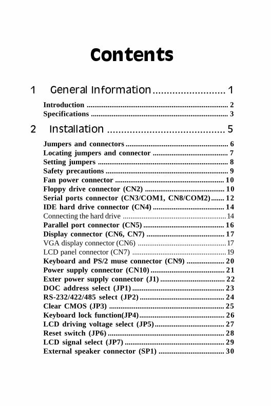
Contents
1 General Information.......................... 1Introduction ........................................................................... 2Specifications......................................................................... 3
2 Installation .......................................... 5Jumpers and connectors ...................................................... 6Locating jumpers and connector ........................................ 7Setting jumpers ..................................................................... 8Safety precautions ................................................................. 9Fan power connector .......................................................... 10Floppy drive connector (CN2) .......................................... 10Serial ports connector (CN3/COM1, CN8/COM2)....... 12IDE hard drive connector (CN4) ...................................... 14Connecting the hard drive .......................................................14Parallel port connector (CN5) ........................................... 16Display connector (CN6, CN7) ......................................... 17VGA display connector (CN6) ...............................................17LCD panel connector (CN7) ..................................................19Keyboard and PS/2 muse connector (CN9) .................... 20Power supply connector (CN10) ....................................... 21Exter power supply connector (J1) .................................. 22DOC address select (JP1)................................................. 23RS-232/422/485 select (JP2)............................................. 24Clear CMOS (JP3) ............................................................. 25Keyboard lock function(JP4)............................................. 26LCD driving voltage select (JP5)..................................... 27Reset switch (JP6).............................................................. 28LCD signal select (JP7)..................................................... 29External speaker connector (SP1)................................... 30

3 AMIBIOS Setup................................... 31General information ............................................................ 32Starting AMIBIOS setup ........................................................32AMIBIOS main menu .............................................................32Using a mouse with AMIBIOS setup .....................................33Using the keyboard with AMIBIOS setup ..............................33Standard CMOS setup ....................................................... 34Advanced CMOS setup..................................................... 36Advanced chipset setup..................................................... 42Power management setup .................................................. 43PCI/PLUG and play setup .................................................. 46Peripheral setup .................................................................. 49Change supervisor password............................................ 51Auto configuration with optimal settings ......................... 52Auto configruation wth fail safe settings ......................... 53Save settings and exit......................................................... 54Exit without saving ............................................................. 55
4 Flat Panel/CRT Controller DisplayDrviers and Utilities ........................... 57Software drivers .................................................................. 58Hardware configuration ..........................................................58Necessary prerequisites ..........................................................59Before you begin .....................................................................59Windows 95 .......................................................................... 60Driver installation....................................................................60Windows 3.1 ......................................................................... 68Driver installation....................................................................68OS/2....................................................................................... 69Windows NT 3.51 ................................................................ 71Driver installation....................................................................71Windows NT 4.0 .....................................................................72

A Watchdog Timer.............................. 73Watchdog Timer .................................................................. 73Example................................................................................ 75SetWatchDog_timer ENDP................................................ 76
B Installing PC/104 Modules ............... 79Installing PC/104 modules................................................. 80


Chapter 1 General Information 1
1GeneralInformation
This chapter provides backgroundinformation for the PCM-4335.
Sections include:
• Card specifications
CH
AP
TE
R

2 PCM-4335 User's Manual
IntroductionThe PCM-4335 comes equipped with an embedded microcontrollerwhich is STPC 486 DX-66. In addition, it comes with one RS-232and one RS-232/422/485 serial port. One bi-directional printer portsupporting SPP, ECP and EPP modes, an IDE HDD interface and afloppy disk controller. With its industrial grade reliability, the PCM-4335 can operate continuously at temperatures up to 140º F (60º C).
The PCM-4335 is specially designed as a compact all-in-one CPUcard which incorporates a PC/104 connector into its design, makingwithout backplane SBC applications possible. The numerous featuresprovide an ideal price/performance solution for high-end commercialand industrial applications where stability and reliability are essential.
The PCM-4335 features an SVGA interface which supports CRT andFlat Panel (TFT, STN, Mono and EL displays) both , with 2MBSDRAM (built in chip) display memory.
Chapter 1 General Information 3
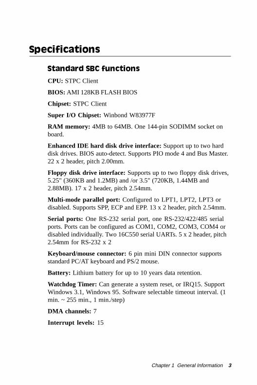
Specifications
Standard SBC functions
CPU: STPC Client
BIOS: AMI 128KB FLASH BIOS
Chipset: STPC Client
Super I/O Chipset: Winbond W83977F
RAM memory: 4MB to 64MB. One 144-pin SODIMM socket onboard.
Enhanced IDE hard disk drive interface: Support up to two harddisk drives. BIOS auto-detect. Supports PIO mode 4 and Bus Master.22 x 2 header, pitch 2.00mm.
Floppy disk drive interface: Supports up to two floppy disk drives,5.25" (360KB and 1.2MB) and /or 3.5" (720KB, 1.44MB and2.88MB). 17 x 2 header, pitch 2.54mm.
Multi-mode parallel port: Configured to LPT1, LPT2, LPT3 ordisabled. Supports SPP, ECP and EPP. 13 x 2 header, pitch 2.54mm.
Serial ports: One RS-232 serial port, one RS-232/422/485 serialports. Ports can be configured as COM1, COM2, COM3, COM4 ordisabled individually. Two 16C550 serial UARTs. 5 x 2 header, pitch2.54mm for RS-232 x 2
Keyboard/mouse connector: 6 pin mini DIN connector supportsstandard PC/AT keyboard and PS/2 mouse.
Battery: Lithium battery for up to 10 years data retention.
Watchdog Timer: Can generate a system reset, or IRQ15. SupportWindows 3.1, Windows 95. Software selectable timeout interval. (1min. ~ 255 min., 1 min./step)
DMA channels: 7
Interrupt levels: 15

4 PCM-4335 User's Manual
Power connector: 4 pin 3 1/2” FDD power connector.
Power management: I/O peripheral devices support power savingand doze/standby/suspend modes. APM 1.2 compliant.
Flat panel VGA interface
Chipset: C&T 69000
Display memory: 2MB SDRAM built in chip.
Display type: Supports CRT and flat panel (TFT, DSTN, and mono)displays. Can display both CRT and flat panel simultaneously.
Resolution: Up to 1024x768@64K colors.
SSD interface
One 32-pin DIP socket supports M-systems DiskOnChip 2000series, memory capacity from 2MB to 144MB.
Mechanical and environmental
Power supply voltage: +5V (4.75V to 5.25V)
Max. power requirements: +5V @ 2A
Operating temperature: 32 to 140ºF (0 to 60ºC)
Board Size: 96mm x 90mm
Weight: 0.2 Kg

Chapter 2 Installation 5
2Installation
This chapter explains set up proceduresfor the PCM-4335 hardware, includinginstructions on setting jumpers andconnecting peripherals, switches andindicators. Be sure to read all safetyprecautions before you begin the installa-tion procedure.
CH
AP
TE
R
6 PCM-4335 User's Manual
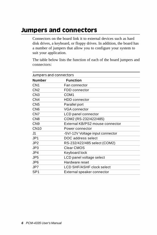
Jumpers and connectorsConnectors on the board link it to external devices such as harddisk drives, a keyboard, or floppy drives. In addition, the board hasa number of jumpers that allow you to configure your system tosuit your application.
The table below lists the function of each of the board jumpers andconnectors:
Jumpers and connectors
Number FunctionCN1 Fan connectorCN2 FDD connectorCN3 COM1CN4 HDD connectorCN5 Parallel portCN6 VGA connectorCN7 LCD panel connectorCN8 COM2 (RS-232/422/485)CN9 External KB/PS2 mouse connectorCN10 Power connectorJ1 -5V/-12V Voltage input connectorJP1 DOC address selectJP2 RS-232/422/485 select (COM2)JP3 Clear CMOSJP4 Keyboard lockJP5 LCD panel voltage selectJP6 Hardware resetJP7 LCD SHF/ASHF clock selectSP1 External speaker connector
Chapter 2 Installation 7
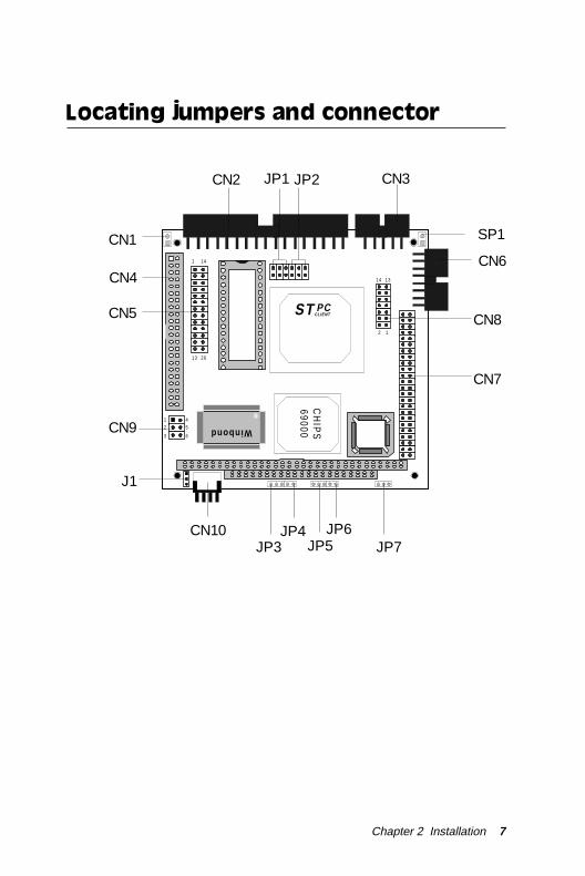
Locating jumpers and connector
Winbond
ST PCCLIENT
CH
IPS
6900014 13
2 1
1 14
13 26
1 42 5
3 6
JP1 JP2CN2 CN3
CN4
CN1CN6
CN7
CN8CN5
J1
CN10JP5
JP6JP7JP3
JP4
CN9
SP1

8 PCM-4335 User's Manual
Setting jumpersYou configure your card to match the needs of your application bysetting jumpers. A jumper is the simplest kind of electric switch.It consists of two metal pins and a small metal clip (oftenprotected by a plastic cover) that slides over the pins to connectthem. To “close” a jumper you connect the pins with the clip. To“open” a jumper you remove the clip. Sometimes a jumper willhave three pins, labeled 1, 2 and 3. In this case you would connecteither pins 1 and 2 or 2 and 3.
The jumper settings are schematically depicted in this manual asfollows:
A pair of needle-nose pliers may be helpful when working withjumpers.
If you have any doubts about the best hardware configuration foryour application, contact your local distributor or sales represen-tative before you make any changes.
Generally, you simply need a standard cable to make mostconnections.
132
Open Closed Closed 2-3
Open Closed Closed 2-3
1 2 3

Chapter 2 Installation 9
Safety precautions
Warning! Always completely disconnect the power cordfrom your chassis whenever you are working onit. Do not make connections while the power ison because sensitive electronic components canbe damaged by the sudden rush of power. Onlyexperienced electronics personnel should openthe PC chassis.
Caution! Always ground yourself to remove any staticcharge before touching the CPU card. Modernelectronic devices are very sensitive to staticelectric charges. Use a grounding wrist strap atall times. Place all electronic components on astatic-dissipative surface or in a static-shieldedbag when they are not in the chassis.
10 PCM-4335 User's Manual
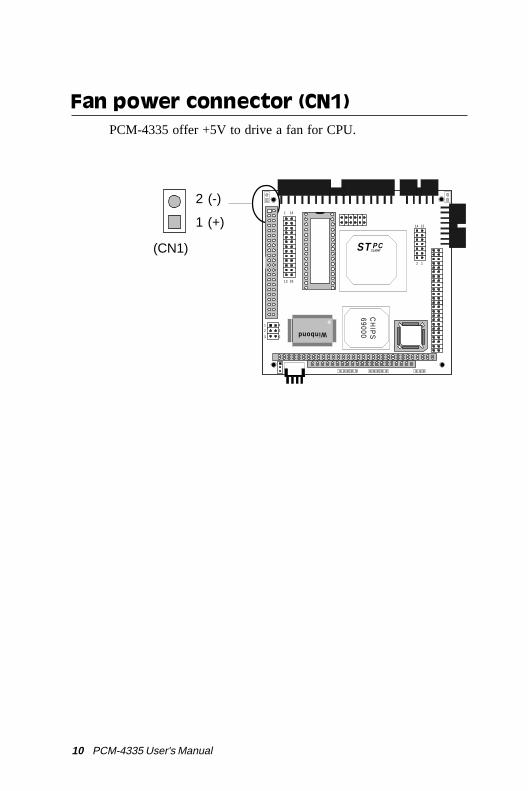
Fan power connector (CN1)PCM-4335 offer +5V to drive a fan for CPU.
2 (-)
1 (+)
(CN1)
Winbond
ST PCCLIENT
CH
IPS
69000
14 13
2 1
1 14
13 26
1 42 5
3 6

Chapter 2 Installation 11
Floppy drive connector (CN2)You can attach up to two floppy disks to the PCM-4335's on-board controller. You can use any combination of 5¼" (360 KBand 1.2 MB) and/or 3½" (720 KB, 1.44 MB, and 2.88 MB) drives.
The PCM-4335 CPU card comes with a 34-pin daisy-chain driveconnector cable. On one end of the cable is a 34-pin flat-cableconnector. There are two sets of floppy disk drive connectors,one in the middle, and one on the other end. Each set consists of a34-pin flat-cable connector (usually used for 3.5" drives) and aprinted-circuit board connector (usually used for 5.25" drives).
Connecting the floppy drive
1. Plug the 34-pin flat-cable connector into the floppy diskconnector.
2. Attach the appropriate connector on the other end of the cableto the floppy drive(s). You can use only one connector in theset. The set on the end (after the twist in the cable) connectsto the A: floppy. The set in the middle connects to the B:floppy.
Pin assignmentsThe following table lists the pin assignments for the floppy diskconnector:
Floppy drive connector (CN2)
Pin Signal Pin Signal1~33 (odd)GND 2 High density4, 6 Unused 8 Index10 Motor enable A 12 Driver select B14 Driver select A 16 Motor enable B18 Direction 20 Step pulse22 Write data 24 Write enable26 Track 0 28 Write protect30 Read data 32 Select head34 Disk Change
12 PCM-4335 User's Manual
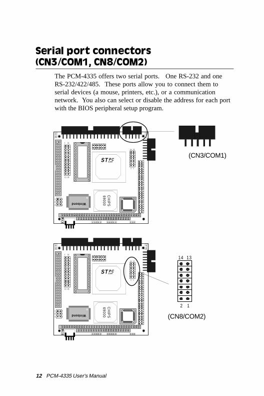
Serial port connectors(CN3/COM1, CN8/COM2)
The PCM-4335 offers two serial ports. One RS-232 and oneRS-232/422/485. These ports allow you to connect them toserial devices (a mouse, printers, etc.), or a communicationnetwork. You also can select or disable the address for each portwith the BIOS peripheral setup program.
(CN3/COM1)
14 13
2 1
(CN8/COM2)
Winbond
ST PCCLIENT
CH
IPS
69000
14 13
2 1
1 14
13 26
1 42 5
3 6
Winbond
ST PCCLIENT
CH
IPS
69000
14 13
2 1
1 14
13 26
1 42 5
3 6

Chapter 2 Installation 13
RS-232 connector (CN3/COM1)
The following table shows the pin assignments for the card's RS-232 port:
RS-232 connector (CN3/COM1)
Pin Signal1 DCD2 RX3 TX4 DTR5 GND6 DSR7 RTS8 CTS9 RI10 NC
RS-232/422/485 connector (CN8/COM2)
RS-232/422/485 connector (CN8/COM2)
Pin Signal1 DCD2 RX3 TX4 DTR5 GND6 DSR7 RTS8 CTS9 RI10 NC11 B485TXD+12 B485TXD-13 B422RXD+14 B422RXD-

14 PCM-4335 User's Manual
IDE hard drive connector (CN4)You can attach one or two Enhanced Integrated Device Electron-ics hard disk drives to the mainboard's internal controller. Themainboard's IDE controller uses a PCI local-bus interface. Thisadvanced interface supports faster data transfer and allows theIDE hard drive to exceed 528 MB.
Connecting the hard drive
Connecting drives is done in a daisy-chain fashion and requiresone of two cables, depending on the drive size. 1.8" and 2.5"drives need a 1 x 44-pin to 2 x 44-pin flat-cable connector. 3.5"drives use a 1 x 44-pin to 2 x 40-pin connect.
Wire number 1 on the cable is red or blue, and the other wires aregray.
1. Connect one end of the cable to CN4. Make sure that the red(or blue) wire corresponds to pin 1 on the connector, which islabeled on the board (on the right side).
2. Plug the other end of the cable to the Enhanced IDE harddrive, with pin 1on the cable corresponding to pin 1 on thehard drives. (see your hard drive's documentation for thelocation of the connector).
Connect a second drive as described above.
Unlike floppy drives, IDE hard drives can connect to eitherend of the cable. If you install two drives, you will need to setone as the master and one as the slave by using jumpers on thedrives. If you install just one drive, set it as the master.

Chapter 2 Installation 15
Pin assignments
The following table lists the pin numbers and their respectivesignals:
IDE hard drive connector (CN4)
IDE hard drive connector (CN4)
Pin Signal Pin Signal1 IDE RESET 2 GND3 DATA 7 4 DATA 85 DATA 6 6 DATA 97 DATA 5 8 DATA 109 DATA 4 10 DATA 1111 DATA 3 12 DATA 1213 DATA 2 14 DATA 1315 DATA 1 16 DATA 1417 DATA 0 18 DATA 1519 SIGNAL GND 20 N/C21 N/C 22 GND23 IO WRITE 24 GND25 IO READ 26 GND27 IO CHANNEL READY 28 ALE29 N/C 30 GND31 IRQ14 32 IOCS1633 ADDR 1 34 N/C35 ADDR 0 36 ADDR 237 HARD DISK SELECT 0 38 HARD DISK SELECT 139 IDE ACTIVE 40 MGND41 VCC 42 MVCC43 GND 44 N/C

16 PCM-4335 User's Manual
Winbond
ST PCCLIENT
CH
IPS
69000
14 13
2 1
1 14
13 26
1 42 5
3 6
Parallel port connector (CN5)Normally, the parallel port is used to connect the card to aprinter. The PCM-4335 includes an onboard parallel port,accessed through CN5, a 26-pin flat-cable connector. Youneed an adapter cable if you use a traditional DB-25connector. The cable has a 26-pin connector on one end anda DB-25 connector on the other.
Pin assignments
Parallel port connector (CN5)
Pin Signal Pin Signal1 /STROBE 2 \AUTOFD3 DO 4 ERR5 D1 6 \INIT7 D2 8 \SLCTINI9 D3 10 GND11 D4 12 GND13 D5 14 GND15 D6 16 GND17 D7 18 GND19 \ACK 20 GND21 BUST 22 GND23 PE 24 GND25 SLCT 26 N/C
(CN5)
1 14
13 26

Chapter 2 Installation 17
Display connectors (CN6, CN7)The PCM-4335 PCI SVGA interface can drive conventional CRTdisplays and is capable of driving a wide range of flat paneldisplays, including electroluminescent (EL), gas plasma, passiveLCD, and active LCD displays. The card has two connectors tosupport these displays, one for standard CRT VGA monitors andone for flat panel displays.
VGA display connector (CN6)
CN6 is a 16-pin, dual-in-line header used for conventional CRTdisplays. A simple one-to-one adapter can be used to match CN6to a standard 15-pin D-SUB connector commonly used for VGA.
VGA display connector (CN6)
Pin Signal Pin Signal1 RED 9 SIGNAL GND2 N/C 10 H-SYNC3 GREEN 11 CHASSIS GND4 SIGNAL GND 12 V-SYNC5 BLUE 13 CHASSIS GND6 N/C 14 N/C7 N/C 15 CHASSIS GND8 N/C 16 N/C
When the PCM-4335's power is applied, the control signal is lowuntil just after the relevant flat panel signals are present.
Configuration of the VGA interface is done completely via thesoftware utility. You don't have to set any jumpers.

18 PCM-4335 User's Manual
Winbond
ST PCCLIENT
CH
IPS
69000
14 13
2 1
1 14
13 26
1 42 5
3 6
(CN7)
1 2
49 50

Chapter 2 Installation 19
LCD panel connector (CN7)
LCD panel connector (CN7)
Pin Signal Pin Signal1 +12 VDC 2 +12 VDC
3 GND 4 GND5 +5 VDC 6 +5 VDC
7 ENAVEE 8 GND9 P0 10 P111 P2 12 P313 P4 14 P515 P6 16 P717 P8 18 P919 P10 20 P1121 P12 22 P1323 P14 24 P1525 P16 26 P1727 P18 28 P1929 P20 30 P2131 P22 32 P2333 P24 34 P2535 SHF CLK 36 FLM (V SYS)37 M 38 LP (H SYS)39 GND 40 ENABKL41 P26 42 P2743 P28 44 P2945 P30 46 P3147 P32 48 P3349 P34 50 P35

20 PCM-4335 User's Manual
Keyboard and PS/2 mouse connector(CN9)
The mainboard provides a keyboard connector which supportsboth a keyboard and a PS/2 style mouse. In most cases, especiallyin embedded applications, a keyboard is not used. The standardPC/AT BIOS will report an error or fail during power-on self-test(POST) after a reset if the keyboard is not present. The mainboardBIOS Advanced setup menu allows you to select "System Key-board" under the "Present" or "Absent" selection. This allows no-keyboard operation in embedded system applications without thesystem halting under POST (power-on-self-test).
Keyboard and PS/2 mouse connector (CN9)
Pin Signal1 KB_Data2 GND3 MS_Data4 KB_CLK5 Vcc
6 MS_CLK
1 4
2 5
3 6
(CN9)
Winbond
ST PCCLIENT
CH
IPS
69000
14 13
2 1
1 14
13 26
1 42 5
3 6

Chapter 2 Installation 21
Winbond
ST PCCLIENT
CH
IPS
69000
14 13
2 1
1 14
13 26
1 42 5
3 6
Power supply connector (CN10)In single board computer without backplane applications, you willneed to connect power directly to the PCM-4335 board usingCN10. This connector is fully compatible with the standard PCpower supply connectors(mini 4-pin). See the following table forits pin assignments:
Power supply connector (CN10)
Pin Function1 +12 V2 GND3 GND4 +5 V
+ 1 2 3 4
(CN10)

22 PCM-4335 User's Manual
Winbond
ST PCCLIENT
CH
IPS
69000
14 13
2 1
1 14
13 26
1 42 5
3 6
Exter power supply connector (J1)The PCM-4335 cna offer -5V & -12V voltages by input from the(J1) connector for expansion PC/104 application cards.
External power supply connector (J1)
Pin Function1 -5V2 -12V3 GND
1
2
3
(J1)

Chapter 2 Installation 23
Winbond
ST PCCLIENT
CH
IPS
69000
14 13
2 1
1 14
13 26
1 42 5
3 6
DOC address select (JP1)The DiskOnChip 2000 occupies a 8 KB window in the uppermemory address range of CC00 to DC00. You should ensure thisdoes not conflict with any other device's memory address. JP1controls the memory address of the Flash disk.
DOC address setting (JP1)
Address CC00 D000* D400
D800 DC00 Disable DOC
*default
2 4 6
1 3 5
(JP1)
1 3 5
2 4 6
1 3 5
2 4 6
1 3 5
2 4 6
1 3 5
2 4 6
1 3 5
2 4 6
1 3 5
2 4 6

24 PCM-4335 User's Manual
Winbond
ST PCCLIENT
CH
IPS
69000
14 13
2 1
1 14
13 26
1 42 5
3 6
RS-232/422/485 select (JP2)The PCM-4335 offers two serial ports. One RS-232 and one RS-232/422/485.
The follwing charts show the available options:
RS-232/422/485 select (JP2)
*RS-232 RS-422 RS-485
* default
(JP2)
2 4 6
1 3 5
2 4 6
1 3 5
2 4 6
1 3 5
2 4 6
1 3 5

Chapter 2 Installation 25
Winbond
ST PCCLIENT
CH
IPS
69000
14 13
2 1
1 14
13 26
1 42 5
3 6
Clear CMOS (JP3)You can connect an external switch to clear CMOS. This switchcloses CLEAR CMOS and turns on the power, at which time theCMOS setup can be cleared.
Clear CMOS (JP3)
Protect* Clear CMOS
*default
1 2 3 1 2 3
1 2 3(JP3)
26 PCM-4335 User's Manual
Winbond
ST PCCLIENT
CH
IPS
69000
14 13
2 1
1 14
13 26
1 42 5
3 6
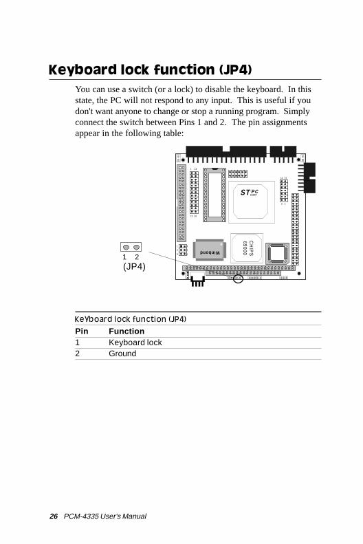
Keyboard lock function (JP4)You can use a switch (or a lock) to disable the keyboard. In thisstate, the PC will not respond to any input. This is useful if youdon't want anyone to change or stop a running program. Simplyconnect the switch between Pins 1 and 2. The pin assignmentsappear in the following table:
Keyboard lock function (JP4)
Pin Function1 Keyboard lock2 Ground
1 2(JP4)
Chapter 2 Installation 27
Winbond
ST PCCLIENT
CH
IPS
69000
14 13
2 1
1 14
13 26
1 42 5
3 6
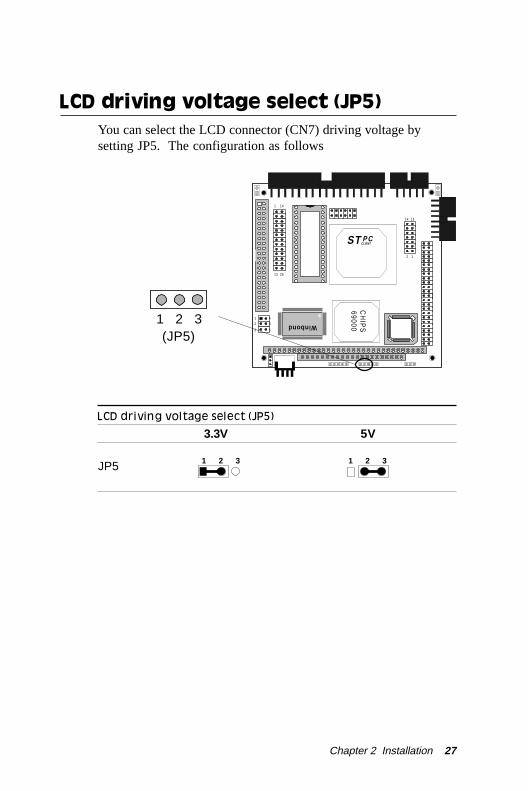
LCD driving voltage select (JP5)You can select the LCD connector (CN7) driving voltage bysetting JP5. The configuration as follows
LCD driving voltage select (JP5)
3.3V 5V
JP5 1 2 3 1 2 3
1 2 3(JP5)
28 PCM-4335 User's Manual
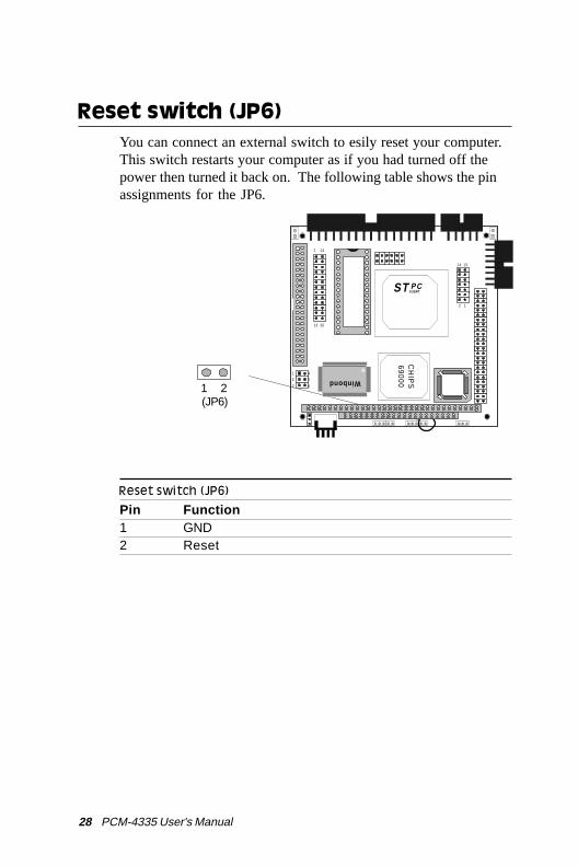
Reset switch (JP6)You can connect an external switch to esily reset your computer.This switch restarts your computer as if you had turned off thepower then turned it back on. The following table shows the pinassignments for the JP6.
Reset switch (JP6)
Pin Function1 GND2 Reset
1 2(JP6)
Winbond
ST PCCLIENT
CH
IPS
69000
14 13
2 1
1 14
13 26
1 42 5
3 6

Chapter 2 Installation 29
3 2 1
(JP7)
Winbond
ST PCCLIENT
CH
IPS
69000
14 13
2 1
1 14
13 26
1 42 5
3 6
LCD signal select (JP7)You can select the LCD control signal by setting (JP7). Thefollowing charts show the available option:
LCD signal select (JP7)
ASHF CLK SHF CLK
JP73 2 1 3 2 1
30 PCM-4335 User's Manual
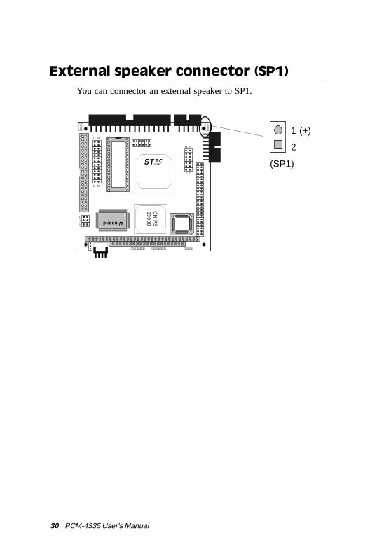
1 (+)
2
(SP1)
External speaker connector (SP1)You can connector an external speaker to SP1.
Winbond
ST PCCLIENT
CH
IPS
69000
14 13
2 1
1 14
13 26
1 42 5
3 6

CH
AP
TE
R
3AMIBIOS Setup
This chapter describes how to set theBIOS configuration data.

32 PCM-4335 User Manual
General informationAMIBIOS Setup configures system information that is stored inCMOS RAM.
Starting AMIBIOS setup
As POST executes, the following appears;
Hit <DEL> if you want to run SETUP
Press <DEL> to run AMIBIOS setup.
AMIBIOS main menu
The AMIBIOS setup screen appears as follows:
AMIBIOS SETUP — BIOS SETUP UTILITIES(C) 1995 American Megatrends, Inc. All Rights Reserved
Standard CMOS SetupAdvanced CMOS Setup
Advanced Chipset Setup Power Management Setup PCI/Plug and Play Setup
Peripheral SetupChange Supervisor Password
Auto Configuration with Optimal SettingsAuto Configuration with Fail Safe Settings
Save Settings and ExitExit Without Saving
Standard CMOS setup for changing time, date, hard disk type, etc.ESC: Exit :Sel F2/F3: Color F10: Save & Exit -

Chapter 3 AMIBIOS Setup 33
Using a mouse with AMIBIOS setup
AMIBIOS Setup can be accessed via keyboard, mouse. The mouseclick functions are:
• single click to change or select both global and current fields
• double click to perform an operation in the selected field
Using the keyboard with AMIBIOS setup
AMIBIOS Setup has a built-in keyboard driver that uses simplekeystroke combinations:
Keystroke Function<tab> Move to the next window or field.è, ç, é, ê Move to the next field to the right,
left, above, or below.<ENTER> Select the current field.+ Increments a value.- Decrements a value.<ESC> Close the current operation and return to
the previous level.<PgUp> Return to the previous page.<PgDn> Advance to the next page.<Home> Return to the beginning of the text.<End> Advance to the end of the text.<ALT>+H Access a help window.<ALT>+<Spacebar> Exit AMIBIOS Setup.Alphabetic keys A to Z are used in the Virtual keyboard, and
are not case sensitive.Numeric keys 0 to 9 are in the Virtual keyboard and
Numeric keypad.
34 PCM-4335 User Manual
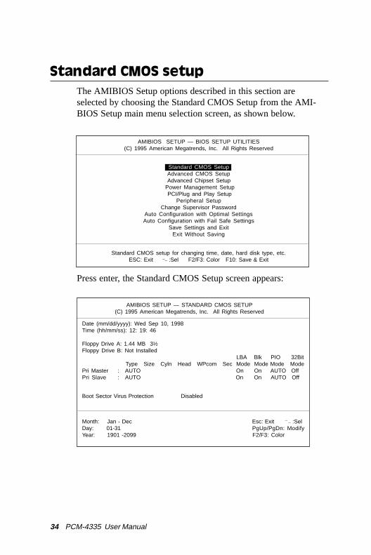
Standard CMOS setupThe AMIBIOS Setup options described in this section areselected by choosing the Standard CMOS Setup from the AMI-BIOS Setup main menu selection screen, as shown below.
Press enter, the Standard CMOS Setup screen appears:
AMIBIOS SETUP — STANDARD CMOS SETUP(C) 1995 American Megatrends, Inc. All Rights Reserved
Date (mm/dd/yyyy): Wed Sep 10, 1998Time (hh/mm/ss): 12: 19: 46
Floppy Drive A: 1.44 MB 3½Floppy Drive B: Not Installed
LBA Blk PIO 32Bit Type Size Cyln Head WPcom Sec Mode Mode Mode Mode
Pri Master : AUTO On On AUTO OffPri Slave : AUTO On On AUTO Off
Boot Sector Virus Protection Disabled
Month: Jan - Dec Esc: Exit :SelDay: 01-31 PgUp/PgDn: ModifyYear: 1901 -2099 F2/F3: Color
¯-
AMIBIOS SETUP — BIOS SETUP UTILITIES(C) 1995 American Megatrends, Inc. All Rights Reserved
Standard CMOS SetupAdvanced CMOS Setup
Advanced Chipset Setup Power Management Setup PCI/Plug and Play Setup
Peripheral SetupChange Supervisor Password
Auto Configuration with Optimal SettingsAuto Configuration with Fail Safe Settings
Save Settings and ExitExit Without Saving
Standard CMOS setup for changing time, date, hard disk type, etc.ESC: Exit :Sel F2/F3: Color F10: Save & Exit -

Chapter 3 AMIBIOS Setup 35
Date and Time ConfigurationSelect the Date and Time icon in the Standard CMOS setup. Thecurrent values for each category are displayed. Enter new valuesthrough the keyboard or hit the "+" or "-" key to change values.
Floppy A, Floppy BSelect the appropriate specifications to configure the type offloppy drive that is attached to the system: 360 KB 5¼", 1.2 MB5¼", 720 KB 3½", and/or 1.44 MB 3½". The settings have notbeen pre-installed.
Master Disk, Slave DiskSelect the appropriate values to configure the hard disk type youare using for the master and the slave. Available types are 1~46,USER, AUTO, Not Installed, and CDROM. The settings have notbeen preinstalled.
Boot Sector Virus ProtectionEnabling this option allows the system to issue a warning whenany program (or virus) issues a disk format command or attemptsto write to the boot sector of the hard disk drive. Further confir-mation is required before accessing this particular section of thehard disk drive.

36 PCM-4335 User Manual
Advanced CMOS setupSelect the Advanced CMOS Setup icon from the AMIBIOS Setupmain menu to enter Advanced CMOS setup.
The "Advanced CMOS Setup" options described in this section arethe standard options as shown on the following screen.
AMIBIOS SETUP — BIOS SETUP UTILITIES(C) 1995 American Megatrends, Inc. All Rights Reserved
Standard CMOS SetupAdvanced CMOS Setup
Advanced Chipset Setup Power Management Setup PCI/Plug and Play Setup
Peripheral SetupChange Supervisor Password
Auto Configuration with Optimal SettingsAuto Configuration with Fail Safe Settings
Save Settings and ExitExit Without Saving
Standard CMOS setup for changing time, date, hard disk type, etc.ESC: Exit :Sel F2/F3: Color F10: Save & Exit -

Chapter 3 AMIBIOS Setup 37
AMIBIOS SETUP — ADVANCED CMOS SETUP (C) 1995 American Megatrends, Inc. All Rights Reserved
Quick Boot : Enabled1st Boot Device : IDE-02nd Boot Device : Floppy3rd Boot Device : ReservedTry Other Boot Devices : YesInitial Display Mode : BIOSDisplay Mode at Add-On ROM Init : Force BIOSFloppy Access Control : Read-WriteHard Disk Access Control : Read-WriteS.M.A.R.T. For Hard Disks : DisabledBootUp Num-Lock : OnFloppy Drive Swap : DisabledFloppy Drive Seek : DisabledPrimary Display : VGA/EGADisplay Device : BothLCD Type : 640 18B-TFTPS/2 Mouse Support : EnabledSystem Keyboard : PresentPassword Check : SetupBoot To OS/2 : NOInternal Cache : Write BackSystem BIOS Cacheable : EnabledC000, 16K Shadow : CachedC400, 16K Shadow : CachedC800, 16K Shadow : DisabledCC00, 16K Shadow : DisabledD000, 16K Shadow : DisabledD400, 16K Shadow : DisabledD800, 16K Shadow : DisabledDC00, 16K Shadow : Disabled
Available Options:DisabledEnabled
Press enter, the Advanced CMOS Setup screen appears:
-ESC: Exit :SelPgUp/PgDn: ModifyF2/F3: Color
38 PCM-4335 User Manual
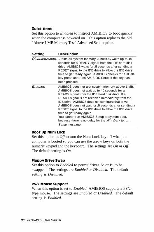
Quick BootSet this option to Enabled to instruct AMIBIOS to boot quicklywhen the computer is powered on. This option replaces the old"Above 1 MB Memory Test" Advanced Setup option.
Setting DescriptionDisabledAMIBIOS tests all system memory. AMIBIOS waits up to 40
seconds for a READY signal from the IDE hard diskdrive. AMIBIOS waits for .5 seconds after sending aRESET signal to the IDE drive to allow the IDE drivetime to get ready again. AMIBIOS checks for a <Del>key press and runs AMIBIOS Setup if the key hasbeen pressed.
Enabled AMIBIOS does not test system memory above 1 MB.AMIBIOS does not wait up to 40 seconds for aREADY signal from the IDE hard disk drive. If aREADY signal is not received immediately from theIDE drive, AMIBIOS does not configure that drive.AMIBIOS does not wait for .5 seconds after sending aRESET signal to the IDE drive to allow the IDE drivetime to get ready again.You cannot run AMIBIOS Setup at system boot,because there is no delay for the Hit <Del> to runSetup message.
Boot Up Num LockSet this option to Off to turn the Num Lock key off when thecomputer is booted so you can use the arrow keys on both thenumeric keypad and the keyboard. The settings are On or Off.The default setting is On.
Floppy Drive SwapSet this option to Enabled to permit drives A: or B: to beswapped. The settings are Enabled or Disabled. The defaultsetting is Disabled.
PS/2 Mouse SupportWhen this option is set to Enabled, AMIBIOS supports a PS/2-type mouse. The settings are Enabled or Disabled. The defaultsetting is Enabled.

Chapter 3 AMIBIOS Setup 39
System KeyboardThis option specifies that a keyboard is attached to the computer.The settings are Present or Absent. The default setting isPresent.
Primary DisplayThis option specifies the type of display monitor and adapterin the computer. The settings are Mono, CGA40x25, CGA80x25,VGA/EGA, or Absent. The default setting is EGA/VGA.
Display DeviceThis option allows user to select the display device. The settingsare CRT, LCD, and Both. The default setting is Both.
LCD typeThis option allows the user to select the LCD type.
The PCM-4335 supports the following LCD types:
dnarBeman emanledoM tamroF 5334-MCP
CEN 01-33CA8446LN )stib21(TFT084x046 seY
abihsoT A902C01MTL TFT)stib81(084x046 seY
CEN 40-62CA0608LN TFT006x008 seY
prahS 30x41 )stib63(TFT867x4201 seY

40 PCM-4335 User Manual
Password CheckThis option enables password checking every time the computeris powered on or every time AMIBIOS Setup is executed. IfAlways is chosen, a user password prompt appears every time thecomputer is turned on. If Setup is chosen, the password promptappears as AMIBIOS is executed. The default is Setup.
OS/2 Compatible ModeSet this option to Enabled to permit AMIBIOS to run with IBMOS/2. The settings are Enabled or Disabled. The default settingis Disabled.
System BIOS cacheable
When this option is set to Enabled, the contents of the F0000hsystem memory segment can be read from or written to L2 cachememory. The contents of the F0000h memory segment arealways copied from the BIOS ROM to system RAM for fasterexecution.
The settings are Enabled or Disabled. The default setting isDisabled.

Chapter 3 AMIBIOS Setup 41
ROM Location Setting
C000, 16K Shadow C400, 16K ShadowC800, 16K Shadow CC00, 16K ShadowD000, 16K Shadow D400, 16K ShadowD800, 16K Shadow DC00, 16K Shadow
These options control the location of the contents of the 16KB ofROM beginning at the specified memory location. If no adapterROM is using the named ROM area, this area is made available tothe local bus. The settings are:
Setting DescriptionShadow The contents of C0000h - C3FFFh are written to the
same address in system memory (RAM) for fasterexecution.
Enabled If an adapter ROM will be using the named ROMarea, ROM area are written to the same address insystem memory (RAM) for faster execution. Also,the contents of the RAM area can be read from andwritten to cache memory.
Disabled The video ROM is not copied to RAM. The contents ofthe video ROM cannot be read from or written to cachememory.

42 PCM-4335 User Manual
Advanced chipset setupSelect the Advanced Chipset Setup from the AMIBIOS Setupmain menu to enter the Chipset Setup. The following configura-tions are based on the manufacturer's default settings.
This section allows you to configure the system based on thespecific features of the installed chipset. This chipset managesbus speeds and access to system memory resources, such asDRAM and the external cache. It also coordinates communica-tions between the conventional ISA bus and the PCI bus. It mustbe stated that these items should never need to be altered. Thedefault settings have been chosen, because they provide the bestoperating conditions for your system.
AMIBIOS SETUP — ADVANCED CHIPSET SETUP(C) 1995 American Megatrends, Inc. All Rights Reserved
ISA CLK :14MHz/2DRAM Type/Timing :User SetupDRAM Bank 0 :EDO 60usDRAM Bank 1 :EDO 60usMemory Hole :DisabledPCI to Host Read Prefetch :DisabledPCI to Host write posting :DisabledWatchdog Timer Support :Enablled
AMIBIOS SETUP — BIOS SETUP UTILITIES(C) 1995 American Megatrends, Inc. All Rights Reserved
Standard CMOS SetupAdvanced CMOS Setup
Advanced Chipset Setup Power Management Setup PCI/Plug and Play Setup
Peripheral SetupChange Supervisor Password
Auto Configuration with Optimal SettingsAuto Configuration with Fail Safe Settings
Save Settings and ExitExit Without Saving
Standard CMOS setup for changing time, date, hard disk type, etc.ESC: Exit :Sel F2/F3: Color F10: Save & Exit -
Available Options:14MHz/2PCICLK/4
¯-ESC: Exit :SelPgUp/PgDn: ModifyF2/F3: Color

Chapter 3 AMIBIOS Setup 43
Power management setupThe Power management setup offers options to help reducepower consumption. To see the options in this group, choose thePower management setup icon from the AMIBIOS setup mainmenu.
AMIBIOS SETUP — BIOS SETUP UTILITIES(C) 1995 American Megatrends, Inc. All Rights Reserved
Standard CMOS SetupAdvanced CMOS Setup
Advanced Chipset Setup Power Management Setup PCI/Plug and Play Setup
Peripheral SetupChange Supervisor Password
Auto Configuration with Optimal SettingsAuto Configuration with Fail Safe Settings
Save Settings and ExitExit Without Saving
Standard CMOS setup for changing time, date, hard disk type, etc.ESC: Exit :Sel F2/F3: Color F10: Save & Exit -
AMIBIOS SETUP — ADVANCED CHIPSET SETUP(C) 1995 American Megatrends, Inc. All Rights Reserved
Power Management/APM :Disabled :EnabledHardware Auto Power Saving :DisabledGreen PC Monitor Power State :Stand ByVideo Power Down Mode :DisabledHard Disk Power Down Mode :DsiabledHard Disk Time Out (Minute) :DisabledDoze Time Out (Miunte) :DisabledStandby Time Out (Miunte) :DisabledSuspend Time Out (Miunte) :DisabledFull-On Clock Throttle Ratio :Normal ClockPower-Down Clock Throttle Ratio :Normal ClockSTPCLK# Modulation Period :64 usDisplay Activity :IgnoreDMA Activity :IgnorePCI Master Activity :IgnoreParallel IO Activity :IgnoreSerial IO Activity :IgnoreKeyboard Activity :MonitorFloppy disk Activity :IgnoreHard Disk Activity :IgnoreIRQ 1-15 Interrupt :IgnoreSystem Timer Interrupt :IgnoreNMI Interrupt :Ignore
Available Options:DisabledEnabled
¯-ESC: Exit :SelPgUp/PgDn: ModifyF2/F3: Color

44 PCM-4335 User Manual
Power management/APMPower management lets you set up your computer to saveelectricity when it is not actively in use by putting the system intoprogressively greater power saving modes. In the power manage-ment scheme there are four system states which proceed in thefollowing sequence:
Disabled à SMI
There are two selections for Power Management (Mode):
Disabled Turns off PM
SMI Maximized power saving by activatingmaximum power saving settings after oneminute of system inactivity.
With the exception of Disabled, SMI selections have "fixed-mode" settings. Therefore, when PM is set to Disabled, someitems which are predefined will become unmodifiable.
Power down HDD modeWhen enabled and after the selected time of system inactivity, thehard disk drive will be powered down while all other devices willremain active.
Doze mode timeoutThis sets the period of system inactivity after which the systemgoes into Doze mode, the most limited power saving state. Thesettings range from 10 seconds to 2 hours and can be set manual-ly when power management is in SMI. The default setting isDisabled. When the system goes into power saving mode, powermanagement will skip to the next mode in the sequence if this isdisabled.

Chapter 3 AMIBIOS Setup 45
Standby mode timeoutThis sets the period of system inactivity after which the systemgoes into Standby mode, the intermediate power saving state.The settings range from 10 seconds to 2 hours and can be setmanually when power management is in SMI. The default settingis Disabled. When the system goes into power saving mode,power management will skip to the next mode in the sequence ifthis is disabled.
Suspend mode timeoutThis sets the period of system inactivity after which the systemgoes into Suspend mode, the maximum power saving state. Thesettings range from 10 seconds to 2 hours and can be set manual-ly when power management is in SMI. The default setting isDisabled. When the system goes into power saving mode, powermanagement will skip to the next mode in the sequence if this isdisabled.

46 PCM-4335 User Manual
PCI/PLUG and play setupPCI/PnP setup options are displayed by choosing the PCI/PnPsetup icon from the AMIBIOS setup main. All PCI/PnP setupoptions are described in this section.
Plug and Play Aware OSSet this option to Yes if the operAZting ssytem installed in thecomputer is Plug and Play aware. AMIBIOS only detects andenables PnP ISA adapter cards that Are required for system boot.The Windows 95 operating systems detects and enables all otherPnP-aware adapter cards. Set this option to No if the operatingsystem (such as DOS, OS/2, Windows 3.x) does not use PnP.
You must set this option correctly or PnP-aware adapter cardsinstalled in your computer will not be configured properly.
The settings are Yes or No default settings is no.
AMIBIOS SETUP — BIOS SETUP UTILITIES(C) 1995 American Megatrends, Inc. All Rights Reserved
Standard CMOS SetupAdvanced CMOS Setup
Advanced Chipset Setup Power Management Setup PCI/Plug and Play Setup
Peripheral SetupChange Supervisor Password
Auto Configuration with Optimal SettingsAuto Configuration with Fail Safe Settings
Save Settings and ExitExit Without Saving
Standard CMOS setup for changing time, date, hard disk type, etc.ESC: Exit :Sel F2/F3: Color F10: Save & Exit -

Chapter 3 AMIBIOS Setup 47
AMIBIOS SETUP — ADVANCED CHIPSET SETUP(C) 1995 American Megatrends, Inc. All Rights Reserved
Plug and Play Aware O/S : No :EnabledPCI Latency Timer (PCI Clocks) : 64PCI VGA Palette Snoop : DisplayPCI IDE Bos Master : DisplayOff Board PCI IDE Card : AutoOff Board PCI IDE Primary IRQ : DisabledOff Board PCI IDE Secondary IRQ : DisabledDMA Channel 0 : PnPDMA Channel 1 : PnPDMA Channel 3 : PnPDMA Channel 5 : PnPDMA Channel 7 : PnPIRQ3 : PCI/PnPIRQ4 : PCI/PnPIRQ5 : PCI/PnPIRQ7 : PCI/PnPIRQ9 : PCI/PnPIRQ10 : PCI/PnPIRQ11 : PCI/PnP
Available Options:NoYes
¯-ESC: Exit :SelPgUp/PgDn: ModifyF2/F3: Color
PCI latency Timer (in PCI Clocks)This option sets the latency of all PCI devices on the PCI bus.The settings are in units equal to PCI clocks. The settings are 32,64, 96, 128, 160, 192, 224, or 248.
PCI IDE BusMasterSet this option to Enabled to specify that the IDE controller onthe PCI local bus has bus masteering capability. The settings areDisabled or Enabled. The default setting is Disabled.
Offboard PCI IDE CardThis option specifies if an offboard PCI IDE controller adaptercard is used in the computer. You must also specify the PCIexpansion slot on the motherboard where the offboard PCI IDEcontroller card is installed. If an offboard PCI IDE controller isused, the onboard IDE controller on the motherboard is automati-cally disabled.
If Auto is selected, AMIBIOS automatically determines thecorrect setting for this option.

48 PCM-4335 User Manual
IRQ3IRQ4IRQ5IRQ7IRQ9IRQ10IRQ11
These options specify bus that the named interrupt request lines(IRQs) are sued on. These options allow you to specify IRQs foruse by legacy ISA adapter cards.
These options determine if AMIBIOS should remove an IRQ fromthe pool of available IRQs passed to BIOS configurable devices.The available IRQ pool is determined by reading the ESCDNVRAM. If more IRQs must be removed from the pool, the enduser can use these PCI/PnP Setup options to remove the IRQ byassigning the option to the ISA/EISA setting. Onboard I/O isconfigurable by AMIBIOS. The IRQs used by onboard I/O areconfigurable by AMIBIOS. The IRQs used by onboard I/O areconfigured as PCI/PnP.
The settings are PCI/PnP or ISA/EISA. The default settings arePCI/PnP.

Chapter 3 AMIBIOS Setup 49
Peripheral setupPeripheral Setup options are displayed by choosing the PeripheralSetup icon from the AMIBIOS Setup main menu. All PeripheralSetup options are described in this section:
Onboard FDCThis option enables the floppy drive controller on the mother-board. The settings are Enabled, or Disabled.
Onboard Parallel PortThis option enables the parallel port on the motherboard andspecifies the parallel port base I/O port address. The settings areDisabled, 278, 378, and 3BC. The default setting is Enabled.
AMIBIOS SETUP — BIOS SETUP UTILITIES(C) 1995 American Megatrends, Inc. All Rights Reserved
Standard CMOS SetupAdvanced CMOS Setup
Advanced Chipset Setup Power Management Setup PCI/Plug and Play Setup
Peripheral SetupChange Supervisor Password
Auto Configuration with Optimal SettingsAuto Configuration with Fail Safe Settings
Save Settings and ExitExit Without Saving
Standard CMOS setup for changing time, date, hard disk type, etc.ESC: Exit :Sel F2/F3: Color F10: Save & Exit -
ESC: Exit :SelPgUp/PgDn: ModifyF2/F3: Color
AMIBIOS SETUP — PERIPHERAL SETUP(C) 1995 American Megatrends, Inc. All Rights Reserved
Onboard FDC :AutoOnboard Serial PortA :AutoOnboard Serial PortB :AutoOnboard Parallel Port :Auto Parallel Port Mode :ECP EPP Version :N/A Parallel Port IRQ :Auto Parallel Port DMA Channel :Auto
Onboard SID1 PCI IDE :Enabled
Available Options:DisabledEnabledAuto
¯-
50 PCM-4335 User Manual
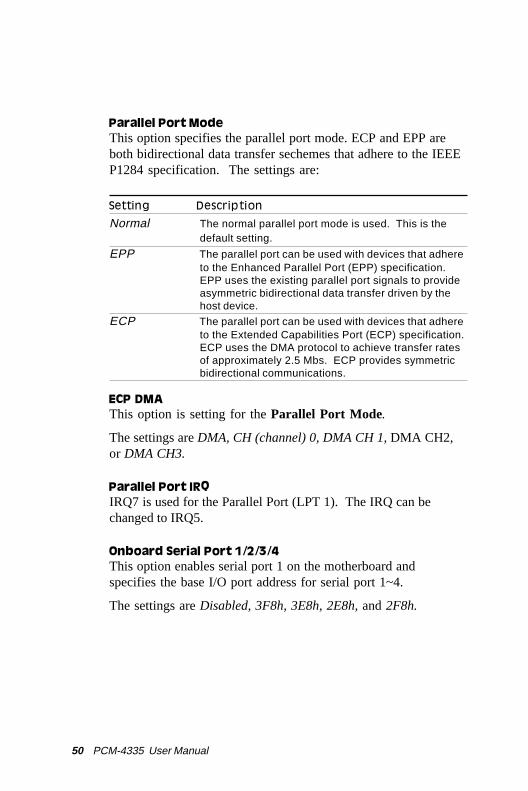
Parallel Port ModeThis option specifies the parallel port mode. ECP and EPP areboth bidirectional data transfer sechemes that adhere to the IEEEP1284 specification. The settings are:
Setting Description
Normal The normal parallel port mode is used. This is thedefault setting.
EPP The parallel port can be used with devices that adhereto the Enhanced Parallel Port (EPP) specification.EPP uses the existing parallel port signals to provideasymmetric bidirectional data transfer driven by thehost device.
ECP The parallel port can be used with devices that adhereto the Extended Capabilities Port (ECP) specification.ECP uses the DMA protocol to achieve transfer ratesof approximately 2.5 Mbs. ECP provides symmetricbidirectional communications.
ECP DMAThis option is setting for the Parallel Port Mode.
The settings are DMA, CH (channel) 0, DMA CH 1, DMA CH2,or DMA CH3.
Parallel Port IRQIRQ7 is used for the Parallel Port (LPT 1). The IRQ can bechanged to IRQ5.
Onboard Serial Port 1/2/3/4This option enables serial port 1 on the motherboard andspecifies the base I/O port address for serial port 1~4.
The settings are Disabled, 3F8h, 3E8h, 2E8h, and 2F8h.

Chapter 3 AMIBIOS Setup 51
Change supervisor password1) Select this option from the main menu
2) Enter the Password and Press <Enter>
3) Retype the Password and Press <Enter>
If you forget the password, please contact your distributor foranother password which you can use to enter the AMIBIOS setupand change your own password.
AMIBIOS SETUP — BIOS SETUP UTILITIES(C) 1995 American Megatrends, Inc. All Rights Reserved
Standard CMOS SetupAdvanced CMOS Setup
Advanced Chipset Setup Power Management Setup PCI/Plug and Play Setup
Peripheral SetupChange Supervisor Password
Auto Configuration with Optimal SettingsAuto Configuration with Fail Safe Settings
Save Settings and ExitExit Without Saving
Standard CMOS setup for changing time, date, hard disk type, etc.ESC: Exit :Sel F2/F3: Color F10: Save & Exit -

52 PCM-4335 User Manual
Auto configuration with optimalsettings
You can load the optimal default settings for the AMIBOIS setupoptions by selecting it from the main menu. The optimal defaultsettings are best case values that should optimize system perfor-mance. If CMOS RAM is corrupted, the optimal settings areloaded automatically.
AMIBIOS SETUP — BIOS SETUP UTILITIES(C) 1995 American Megatrends, Inc. All Rights Reserved
Standard CMOS SetupAdvanced CMOS Setup
Advanced Chipset Setup Power Management Setup PCI/Plug and Play Setup
Peripheral SetupChange Supervisor Password
Auto Configuration with Optimal SettingsAuto Configuration with Fail Safe Settings
Save Settings and ExitExit Without Saving
Standard CMOS setup for changing time, date, hard disk type, etc.ESC: Exit :Sel F2/F3: Color F10: Save & Exit -

Chapter 3 AMIBIOS Setup 53
Auto configuration with fail safesettings
You can load the Fail Safe settings for the AMIBOIS setupoptions by selecting it from the main menu. The Fail Safesettings provide the most stable settings, though they may notprovide optimal performance. Use this option as a diagnostic aidif the system is behaving erratically.
AMIBIOS SETUP — BIOS SETUP UTILITIES(C) 1995 American Megatrends, Inc. All Rights Reserved
Standard CMOS SetupAdvanced CMOS Setup
Advanced Chipset Setup Power Management Setup PCI/Plug and Play Setup
Peripheral SetupChange Supervisor Password
Auto Configuration with Optimal SettingsAuto Configuration with Fail Safe Settings
Save Settings and ExitExit Without Saving
Standard CMOS setup for changing time, date, hard disk type, etc.ESC: Exit :Sel F2/F3: Color F10: Save & Exit -

54 PCM-4335 User Manual
Save settings and exitIf you select this option and press <Enter>, the values entered inthe setup utilities will be recorded in the chipset's CMOSmemory. The microprocessor will check this every time you turnyour system on and compare this to what it finds as it checks thesystem. This record is required for the system to operate.
AMIBIOS SETUP — BIOS SETUP UTILITIES(C) 1995 American Megatrends, Inc. All Rights Reserved
Standard CMOS SetupAdvanced CMOS Setup
Advanced Chipset Setup Power Management Setup PCI/Plug and Play Setup
Peripheral SetupChange Supervisor Password
Auto Configuration with Optimal SettingsAuto Configuration with Fail Safe Settings
Save Settings and ExitExit Without Saving
Standard CMOS setup for changing time, date, hard disk type, etc.ESC: Exit :Sel F2/F3: Color F10: Save & Exit -

Chapter 3 AMIBIOS Setup 55
Exit without savingSelecting this option and pressing <Enter> lets you exit the Setupprogram, without recording any new values or changing old ones.
AMIBIOS SETUP — BIOS SETUP UTILITIES(C) 1995 American Megatrends, Inc. All Rights Reserved
Standard CMOS SetupAdvanced CMOS Setup
Advanced Chipset Setup Power Management Setup PCI/Plug and Play Setup
Peripheral SetupChange Supervisor Password
Auto Configuration with Optimal SettingsAuto Configuration with Fail Safe Settings
Save Settings and ExitExit Without Saving
Standard CMOS setup for changing time, date, hard disk type, etc.ESC: Exit :Sel F2/F3: Color F10: Save & Exit -

56 PCM-4335 User Manual
Chapter 4 Driver Installation 57
4Flat Panel/CRTController DisplayDrivers and Utilities
This chapter provides information about:
• Driver types and installation
CH
AP
TE
R
58 PCM-4335 User Manual
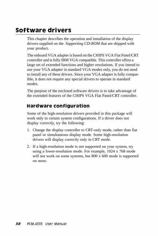
Software driversThis chapter describes the operation and installation of the displaydrivers supplied on the Supporting CD-ROM that are shipped withyour product.
The onboard VGA adapter is based on the CHIPS VGA Flat Panel/CRTcontroller and is fully IBM VGA compatible. This controller offers alarge set of extended functions and higher resolutions. If you intend touse your VGA adapter in standard VGA modes only, you do not needto install any of these drivers. Since your VGA adapter is fully compat-ible, it does not require any special drivers to operate in standardmodes.
The purpose of the enclosed software drivers is to take advantage ofthe extended features of the CHIPS VGA Flat Panel/CRT controller.
Hardware configuration
Some of the high-resolution drivers provided in this package willwork only in certain system configurations. If a driver does notdisplay correctly, try the following:
1. Change the display controller to CRT-only mode, rather than flatpanel or simultaneous display mode. Some high-resolutiondrivers will display correctly only in CRT mode.
2. If a high-resolution mode is not supported on your system, tryusing a lower-resolution mode. For example, 1024 x 768 modewill not work on some systems, but 800 x 600 mode is supportedon most.

Chapter 4 Driver Installation 59
Necessary prerequisites
The instructions in this manual assume that you understand elementa-ry concepts of MS-DOS and the IBM Personal Computer. Before youattempt to install any driver from the Supporting CD-ROM, youshould:
• Know how to copy files from a CD-ROM to a directory on the harddisk
• Understand the MS-DOS directory structure
If you are uncertain about any of these concepts, please refer to theDOS or OS/2 user reference guides for more information before youproceed with the installation.
Before you begin
Make sure you know the version of the application for which you areinstalling drivers. The Supporting CD-ROM contain drivers for severalversions of certain applications. For your driver to operate properly,you must install the driver for your version of the application program.

60 PCM-4335 User Manual
Windows® 95These drivers are designed to work with MicrosoftÒ WindowsÒ. Youjust install these drivers through the WindowsÒ operating system.
Driver installation
1. Install WindowsÒ 95 as you normally would for a VGA display.Click the Start button, go to Settings and click on ControlPanel. Choose the Display icon and double click on the icon.In the Display Properties window, show as figure 1:
figure 1

Chapter 4 Driver Installation 61
Click the setting buttom, then click the Advanced Properties iconinto the Advanced Display properties windows, show as figure2:
figure 2

62 PCM-4335 User Manual
click on Change Display Type. In the Change Display Typewindow, click on the Change button under Adapter Type into theselect Device window show as figure(3):This will bring up theSelect Device window.
figure 3
Chapter 4 Driver Installation 63
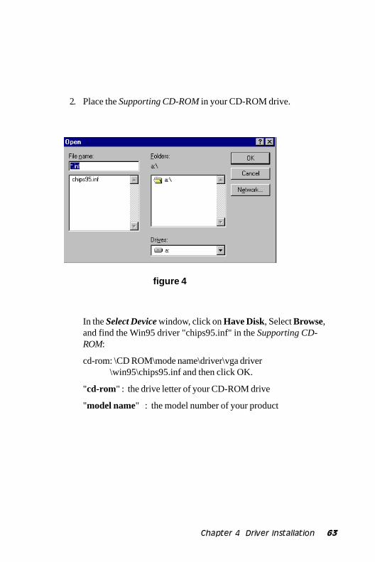
2. Place the Supporting CD-ROM in your CD-ROM drive.
In the Select Device window, click on Have Disk, Select Browse,and find the Win95 driver "chips95.inf" in the Supporting CD-ROM:
cd-rom: \CD ROM\mode name\driver\vga driver \win95\chips95.inf and then click OK.
"cd-rom" : the drive letter of your CD-ROM drive
"model name" : the model number of your product
figure 4
64 PCM-4335 User Manual
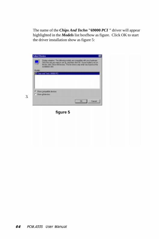
The name of the Chips And Techn "69000 PCI " driver will appearhighlighted in the Models list boxfhow as figure. Click OK to startthe driver installation show as figure 5:
3.
figure 5

Chapter 4 Driver Installation 65
Once the installation is complete, the Advanced display Propertieswindow will reappear. Show as figure 6:
figure 6

66 PCM-4335 User Manual
Click on close to close the window. Then the Display Propertieswindow will reappear. Show as figure 7:
figure 7

Chapter 4 Driver Installation 67
Click on Apply. Restart the system for the new settings to takeeffect, show as figure 8:
figure 8
68 PCM-4335 User Manual
Windows® 3.1These drivers are designed to work with Microsoft Windows Version3.1. You should install these drivers through Windows.
Driver installation
1. Install Windows as you normally would for a VGA display. RunWindows to make sure that it is working correctly.
2. Place the Supporting CD-ROM into your CD-ROM drive. InWindows Program Manager, choose File from the Options Menu.Then from the pull-down menu, choose Run. At the Command Lineprompt, type.
cd-rom:\CD ROM\model name\driver\vga driver\win31\setup.exe
Press the <ENTER> key or click OK to begin the installation.
"cd-rom" : the drive letter of your CD-ROM drive
"model name" : the model number of your product
At this point the setup program locates the directory where Windowsis installed. For proper operation, the drivers must be installed in theWindows subdirectory.
3. Press <ENTER> to complete the installation. Once completed, youcan find the icon Chips CPL under the Control Panel. The iconallows you to select and load the installed drivers.

Chapter 4 Driver Installation 69
OS/2These drivers are designed to function with the OS/2 Version 4.0, 3.0and 2.11 operating systems.
To install this driver, do the following steps:
1. Open an OS/2 full screen or windowed session.
2. Place the Supporting CD-ROM into your CD-ROM drive.
3. At the OS/2 command prompt, type the following commands tocopy the files to the OS/2 drive:
Type cd-rom drive:\CD ROM\model name\driver\vga driver\os2\
When the Setup Program is completed, you will need to perform ashutdown and then restart the system in order for changes to takeeffect.
"cd-rom" : the drive letter of your CD-ROM drive
"model name" : the model number of your product
A log of the information output during the install can be found
in <root>:\OS2\INSTALL\DISPLAY.LOG
4. After restarting the system, perform the following steps:
1. Open the OS/2 System folder.
2. Open the System Setup folder.
3. Open the Display Driver Install Object.
This step will execute the Display Driver Installation (DSPINSTL)utility program to finish installation of the new drivers.
4. When the Display Driver Install window appears, select Primary Display and then select OK.
5. When the Primary Display Driver List window appears, select "Chips and Technologies 69000" from the list of adapter types, then select OK or install the video driver.

70 PCM-4335 User Manual
6. When the installation is complete, you will need to shut down and then restart the system for the changes to take effect. Make sure to remove the installation diskette before restarting the system.

Chapter 4 Driver Installation 71
Windows® NT 3.51These drivers are designed to work with MicrosoftÒ WindowsÒ.
Driver installation
1. Install WindowsÒ NT 3.51 as you normally would for a VGAdisplay. Run WindowsÒ NT Control Panel from the Main Group.Choose the Display option. In the Display Settings dialog box,click on Change Display Type. Click on Change from theAdapter Type in the Display Type dialog box. Click on Other inthe Select Device dialog box.
2. Place the Supporting CD-ROM into your CD-ROM drive.
and type:
cd-rom: \CD ROM\model name\drive\vga drive\ win98 nt\windows.nt\nt351\Oemsetup.inf
"cd-rom" : the drive letter of your CD-ROM drive
"model name" : the model number of your product
Select the adapter "Chips and Tech 69000PCI" and click OK.
Click on Install to install the selected driver. Once the installation iscomplete, shut down and restart the system.

72 PCM-4335 User Manual
Windows® NT 4.0
Driver installation
1. Install WindowsÒ NT 4.0 as you normally would for a VGA display.First click the Start button, go to Settings and click on ControlPanel. Choose the Display icon and click on the icon. In theDisplay Properties window, click on the Settings tab. Then clickon Change Display Type. In the Change Display Type window,click on the Change button under Adapter Type. This will bring upthe Select Device window.
2. Place the Supporting CD-ROM into your CD-ROM dirve. In theSelect Device window, click on Have Disk, select "Browse" andfind the NT 4.0 driver from:
cd-rom : \CD ROM\model name\dirver\vga driver\ win98 nt\windows.nt\nt40\Oemsetup.inf
"cd-rom" : the drive letter of your CD-ROM drive
"model name" : the model number of your product
and then click OK. The name of the Chips and Technologies, Inc.Video Controller driver will appear highlighted in the Modules listbox. Select Chips and Tech. 69000 and Click OK . Click OK to startthe driver installation.
3. Once the installation is complete, the Change Display Type windowwill reappear. Click on close to close the window. Then theDisplay Properties window will reappear. Click on Apply . Restartthe system for the new settings to take effect.

AWatchdog Timer
AP
PE
ND
IX

74 PCM-4335 User's Manual
Watchdog TimerYou have to set Watching Dog Function is Enable in BIOS CMOSSetup before use this function.
Set Watching Dog Timer Output Function Active or Inactive.
Logical Device 7 : Register number 30 (CR30)
00h : Function inactive
01h : Function active
Write Watching Dog Timer Time-out value.
Logicel Device 8 : Register number F2 (CRF2)
00h : Time-out Disable
01h : Time-out occurs after 16 seconds
02h : Time-out occurs after 46 seconds
03h : Time-out occurs after 1 minute 16 seconds
04h : Time-out occurs after 1 minute 46 seconds
05h : Time-out occurs after 2 minutes 16 seconds
...........................
FFh : Time-out occurs after 127 minutes 16 seconds
program chip basic procedure is :
1. Enter configuration mode.
2. Select Logical Device.
3. Select register number.
4. write/read data to/from register.
5. exit configuration mode.
watch-dog function program procedure is :
1. Active Watching-Dog Timer output Function.
2. Write Watching Dog Timer Time-out value.

Appendix A Watchdog Timer 75
Example :
Following is an Example of programming 16 seconds period forwatchdog timer in assembly language. When timer times out, itwill generate system reset.
.model small
.code
CONFIG_PORT dw 3f0h
DATA_PORT dw 3f1H
SetWatchDog_Time PROC
push bx
push cx
push dx
mov bl,7 ;; Select Logical Device Number 7
mov ax,0130h ;; Register 30h write 01h to Active Function
call W977Write ;;
mov bl,8 ;; Select logical Device Number 8
mov ax,01f2h ;; Register F2h write Time-out value (01h)
call W977Write ;; watchdog time-out value is 16 sec
pop dx
pop cx
pop bx
mov ah,4ch
int 21h
ret

76 PCM-4335 User's Manual
SetWatchDog_Time ENDP
;; Enter to I/O Chip Program Configuration Register Mode
EnterConfig proc
cli
push ax
push dx
mov al,87h ;; Specific Value to Enter Config Mode
mov dx,cs:CONFIG_PORT ;;
out dx,al ;; Write to Config Port Twice!
out dx,al ;;
jmp $+2 ;; Delay
jmp $+2 ;;
pop dx
pop ax
ret
EnterConfig endp
;; Exit to I/O Chip Program Configuration Register Mode
ExitConfig proc
push ax
push dx
mov al,0aah ;; Specific Value to Exit Config Mode
mov dx,cs:CONFIG_PORT ;;
out dx,al ;; Write to Config Port
pop dx
pop ax
ret
ExitConfig endp

Appendix A Watchdog Timer 77
;; Select The I/O Chip Program Configuration Register Logical Device
;; Input : bl = logical device number
SelectDevice proc
push ax
push dx
mov al,07h ;; Select Control Register 7 (CR07)
mov dx,cs:CONFIG_PORT ;;
out dx,al ;; Write to Config Port
jmp $+2
mov al,bl ;; Write Logical Device Number
mov dx,cs:DATA_PORT ;; to Data Port
out dx,al
pop dx
pop ax
ret
SelectDevice endp
78 PCM-4335 User's Manual
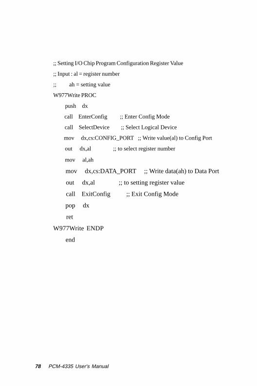
;; Setting I/O Chip Program Configuration Register Value
;; Input : al = register number
;; ah = setting value
W977Write PROC
push dx
call EnterConfig ;; Enter Config Mode
call SelectDevice ;; Select Logical Device
mov dx,cs:CONFIG_PORT ;; Write value(al) to Config Port
out dx,al ;; to select register number
mov al,ah
mov dx,cs:DATA_PORT ;; Write data(ah) to Data Port
out dx,al ;; to setting register value
call ExitConfig ;; Exit Config Mode
pop dx
ret
W977Write ENDP
end

BInstalling PC/104Modules
This appendix gives instructions forinstalling PC/104 modules.
AP
PE
ND
IX
80 PCM-4335 User's Manual
Installing PC/104 modulesThe PCM-4335's PC/104 connectors give you the flexibility toattach PC/104 expansion modules. These modules perform thefunctions of traditional plug-in expansion cards, but save spaceand valuable slots. Modules include:
• PCM-3110B PCMCIA Module (one-slot)• PCM-3115B PCMCIA Module (two-slot)• PCM-3200 PC/104 Sound Module• PCM-3420 PC/104 Fast SCSI Module• PCM-3521 Advanced Flat-Panel/CRT VGA Module• PCM-3522 LCD Panel Adapter• PCM-3600 PC/104 Fax/Modem Module• PCM-3610 Isolated RS-232 and RS-422/485 Module• PCM-3640 PC/104 4-port RS-232 Module• PCM-P50 PC/104 Vehicle Power Supply• PCM-3660 Ethernet Module• PCM-3718 30 KHz A/D Module• PCM-3724 48-channel DIO Module• PCM-3910 Breadboard Module• PCM-3810 Solid State Disk Module• PCM-3820 High Density Flash Solid State Disk Module
Appendix B Installing PC/104 Modules 81
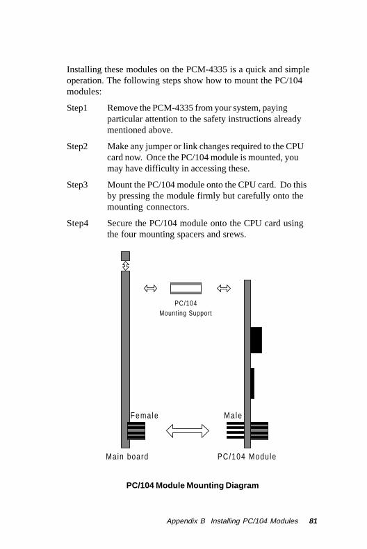
Installing these modules on the PCM-4335 is a quick and simpleoperation. The following steps show how to mount the PC/104modules:
Step1 Remove the PCM-4335 from your system, payingparticular attention to the safety instructions alreadymentioned above.
Step2 Make any jumper or link changes required to the CPUcard now. Once the PC/104 module is mounted, youmay have difficulty in accessing these.
Step3 Mount the PC/104 module onto the CPU card. Do thisby pressing the module firmly but carefully onto themounting connectors.
Step4 Secure the PC/104 module onto the CPU card usingthe four mounting spacers and srews.
PC/104 Module Mounting Diagram
PC/104 Mounting Support
Fema le Ma le
PC/104 Modu leMain board
82 PCM-4335 User's Manual
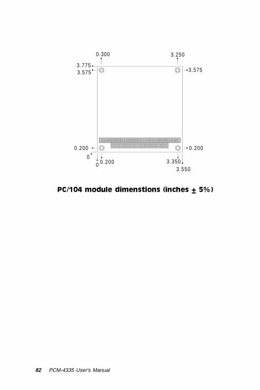
0.200
0 0 0.200 3.350
3.550
0.200
3.575
3.250 0.300
3.775 3.575
PC/104 module dimenstions (inches ±5%)
Related Documents