Welcome message from author
This document is posted to help you gain knowledge. Please leave a comment to let me know what you think about it! Share it to your friends and learn new things together.
Transcript

Inhaltsverzeichnis
PCI-951 Board – Benutzerhandbuch 1
Inhaltsverzeichnis
Einleitung ............................................................................................................. 4Verwendete Zeichen und ihre Bedeutung.............................................................. 5
Wichtige Hinweise ............................................................................................... 6Hinweis zur Garantie ............................................................................................. 6
Ausschluss der Unfallhaftungspflicht ..................................................................... 6
Haftungsbegrenzung / Gewährleistungspflicht....................................................... 6
Sicherheitshinweise ............................................................................................ 7Hinweise zur Lithium-Batterie ................................................................................ 8
Elektrostatisch gefährdete Bauelementen (EGB) .................................................. 8
Elektromagnetische Verträglichkeit........................................................................ 9
FCC Statement...................................................................................................... 9
Lieferumfang...................................................................................................... 10Optionale Teile..................................................................................................... 10
Produktidentifikation ............................................................................................ 10
Produktbeschreibung........................................................................................ 11Eigenschaften...................................................................................................... 12
Erweiterte Funktionen.......................................................................................... 14
Blockschaltbild ..................................................................................................... 15
Konfiguration ..................................................................................................... 16CPU Installation................................................................................................... 16
Hauptspeicher Installation ................................................................................... 17
Jumpers auf dem PCI-951 Board ........................................................................ 18
Jumper - Positionierung auf dem PCI-951 Board............................................ 19
Anschlüsse des PCI-951 Boards ......................................................................... 23
Externe Schnittstellen (am Boardslot ausgeführt) ........................................... 24
Onboard Anschlüsse....................................................................................... 26
Watchdog Timer Konfiguration ............................................................................ 44
Award BIOS Konfiguration ............................................................................... 45BIOS Setup.......................................................................................................... 45
Standard CMOS Setup ........................................................................................ 47
Advanced BIOS Features .................................................................................... 52
Advanced Chipset Features ................................................................................ 58
Integrated Peripherals ......................................................................................... 62
Power Management Setup .................................................................................. 67
Inhaltsverzeichnis
2 PCI-951 Board – Benutzerhandbuch
PNP/PCI Configuration ........................................................................................71
PC Health Status..................................................................................................73
Frequency/ Voltage Control..................................................................................74
Load Fail-Safe Defaults........................................................................................75
Load Optimized Defaults......................................................................................76
Set Supervisor / User Password ..........................................................................77
Save & Exit Setup ................................................................................................78
Exit Without Saving ..............................................................................................79
AMI BIOS Configuration ....................................................................................80BIOS Setup ..........................................................................................................80
Navigation........................................................................................................81
Main .....................................................................................................................82
System Time / System Date ............................................................................82
Advanced .............................................................................................................83
CPU Configuration...........................................................................................84
IDE Configuration ............................................................................................85
Floppy Configuration........................................................................................92
Super IO Configuration ....................................................................................93
Hardware Health Configuration........................................................................96
ACPI Settings ..................................................................................................97
Event Log Configuration ................................................................................100
Remote Access Configuration .......................................................................101
USB Configuration.........................................................................................103
PCIPnP ..............................................................................................................105
Boot....................................................................................................................109
Boot Settings Configuration ...........................................................................109
Boot Device Priority .......................................................................................113
Hard Disk Drivers ..........................................................................................114
Removable Drives .........................................................................................114
CD/DVD Drives..............................................................................................115
Security ..............................................................................................................116
Supervisor Password.....................................................................................117
User Password ..............................................................................................117
Boot Sector Virus Protection..........................................................................119
Hard Disk Security.........................................................................................120
Chipset...............................................................................................................121
Intel Brookdale-G NorthBridge Configuration ................................................121
Intel ICH4 SouthBridge Configuration............................................................123
Inhaltsverzeichnis
PCI-951 Board – Benutzerhandbuch 3
Exit..................................................................................................................... 127
Save Changes and Exit................................................................................. 127
Discard Changes and Exit............................................................................. 127
Discard Changes........................................................................................... 127
Load Optimal Defaults................................................................................... 127
Load Failsafe Defaults................................................................................... 128
Resources ........................................................................................................129I/O Port Address Map ........................................................................................ 129
Interrupt Request Lines (IRQ)............................................................................ 130
Intel® 845GV Chipsatz Treiberinstallation..................................................... 131Intel® 845GV Chipsatz-Treiberinstallation für Windows 2000 und XP............... 131
VGA-Treiberinstallation................................................................................... 132VGA-Treiberinstallation für Windows 2000 und XP ........................................... 132
Audio-Treiberinstallation ................................................................................ 133Audio-Treiberinstallation für Windows 2000....................................................... 134
Audio-Treiberinstallation für Windows XP.......................................................... 137
LAN-Treiberinstallation ................................................................................... 138LAN-Treiberinstallation für Windows 2000......................................................... 139
LAN-Treiberinstallation für Windows XP............................................................ 144
USB 2.0 - Treiberinstallation........................................................................... 145USB 2.0 – Treiberinstallation für Windows 2000................................................ 145
USB 2.0 – Treiberinstallation für Windows XP................................................... 149
Technische Daten............................................................................................ 151Elektrische Angaben.......................................................................................... 152
Leistungsspezifikationen.................................................................................... 153
CE-Richtlinien, Standards und Zulassungen ..................................................... 153
Technischer Support....................................................................................... 154Rücksendungen................................................................................................. 155

Einleitung
4 PCI-951 Board – Benutzerhandbuch
EinleitungKontron Embedded Computers weist darauf hin, dass die in diesen Unterlagenenthaltenen Informationen und Hinweise technischen Änderungen, insbesondereauch aufgrund einer ständigen Weiterentwicklung der Produkte von KontronEmbedded Computers, unterliegen können. Die beigefügten Unterlagen enthaltenkeine Zusicherungen von Kontron Embedded Computers im Hinblick auf imHandbuch beschriebene technische Vorgänge oder bestimmte im Handbuchwiedergegebene Produkteigenschaften. Kontron Embedded Computersübernimmt keine Haftung für die in dem vorliegenden Handbuch enthaltenenDruckfehler oder sonstige Ungenauigkeiten, es sei denn, dass KontronEmbedded Computers solche Fehler oder Ungenauigkeiten nachweislich bekanntsind oder diese Kontron Embedded Computers aufgrund grober Fahrlässigkeitunbekannt sind und Kontron Embedded Computers von einer entsprechendenBehebung der Fehler oder Ungenauigkeiten aus diesen Gründen abgesehen hat.Kontron Embedded Computers weist den Anwender ausdrücklich darauf hin, dassdieses Handbuch nur eine allgemeine Beschreibung technischer Vorgänge undHinweise enthält, deren Umsetzung nicht in jedem Einzelfall in der vorliegendenForm sinnvoll sein kann. In Zweifelsfällen ist daher unbedingt mit KontronEmbedded Computers Rücksprache zu nehmen.Dieses Handbuch ist urheberrechtlich geschützt. Kontron Embedded Computershat sich hieran alle Rechte vorbehalten. Ohne die vorherige schriftlicheZustimmung von Kontron Embedded Computers ist die Anfertigung von Kopienoder Teilkopien sowie die Übersetzung dieses Handbuchs in eine andereSprache nicht zulässig. Kontron Embedded Computers weist darauf hin, dass diein diesem Handbuch enthaltenen Informationen gemäß den von KontronEmbedded Computers an den Produkten vorgenommenen technischenÄnderungen und Ergänzungen laufend angepasst werden und dieses Handbuchsomit nur den bei Drucklegung wiedergegebenen technischen Stand der Produktevon Kontron Embedded Computers wiedergibt. Aktualisierte Versionen sind überdie Kontron Webseite: www.kontron.com verfügbar.
© 2005 by Kontron Embedded Computers
Nachdruck und Vervielfältigung, auch auszugsweise, nur mit ausdrücklicherGenehmigung durch
Kontron Embedded Computers GmbHOskar-von-Miller-Str. 1
85385 Eching bei München

Einleitung
PCI-951 Board – Benutzerhandbuch 5
Verwendete Zeichen und ihre Bedeutung
Symbol Bedeutung
Dieses Symbol weist darauf hin, dass bei Nichtbeachtung desWarnhinweises der Benutzer verletzt werden kann oder dasGerät beschädigt wird.
Dieses Symbol weist darauf hin, dass bei Nichtbeachtung desWarnhinweises das Gerät oder Teile des Geräts Schadennehmen können.
Dieses Symbol weist auf allgemeine Informationen zu Gerätund Handbuch hin.
Dieses Symbol ist nützlichen Anweisungen und Tips für dietägliche Arbeit vorangestellt.
SYSM Programm-Namen sind kursiv gedruckt.
format a: Befehle sind in Courier gedruckt.
® Microsoft, MS-DOS, Windows und Windows NT sind eingetragene Warenzeichen der MicrosoftCorporation.
® IBM, PC-AT, OS/2 und PS/2 sind eingetragene Warenzeichen der International Business MachinesCorporation.
® Intel und Pentium sind eingetragene Warenzeichen der Intel Corporation.
® Award ist ein eingetragenes Warenzeichen der Phoenix Technologies, Ltd..
Andere Produktnamen, die in diesem Handbuch erwähnt werden, können ebenfalls Warenzeichensein und werden hier nur zu Identifikationszwecken benutzt.

Wichtige Hinweise
6 PCI-951 Board – Benutzerhandbuch
Wichtige HinweiseIn diesem Kapitel finden Sie Hinweise, die Sie beim Umgang mit dem PCI-951Board unbedingt beachten müssen. Die Hinweise des Herstellers liefern Ihnennützliche Informationen zum PCI-951 Board.
Hinweis zur GarantieAufgrund ihrer begrenzten Lebensdauer sind Teile, die naturgemäß einer beson-deren Abnutzung ausgesetzt sind (Verschleißteile) von der über die gesetzlichenBestimmungen hinausgehenden Gewährleistung ausgenommen. Dies gilt z. B. fürdie Batterien.
Ausschluss der UnfallhaftungspflichtKontron Embedded Computers wird bei Nichtbeachtung der Hinweise (imspeziellen die Sicherheitshinweise) in diesem Handbuch und eventuell am Boarddurch den Benutzer von der gesetzlichen Unfallhaftungspflicht entbunden.
Haftungsbegrenzung / GewährleistungspflichtBei Boardschäden, die durch Nichtbeachten der Hinweise (im speziellen dieSicherheitshinweise) in diesem Handbuch und eventuell am Gerät verursachtwerden, übernimmt Kontron Embedded Computers auch während derGewährleistungspflicht keine Gewährleistung und ist von der gesetzlichenUnfallhaftungspflicht befreit.

Sicherheitshinweise
PCI-951 Board – Benutzerhandbuch 7
Sicherheitshinweise
Lesen Sie diesen Abschnitt sorgfältig, und beachten Sie die entsprechendenHinweise zu Ihrer Sicherheit und für einen bestimmungsgemäßen Gebrauch.Beachten Sie die Warnungen und Hinweise auf dem Board und im Handbuch.
Das Board ist von Kontron Embedded Computers gemäß IEC / EN60950 gebautund geprüft worden und hat das Werk in sicherheitstechnisch einwandfreiemZustand verlassen.Um diesen Zustand zu erhalten und einen gefahrlosen Betrieb sicherzustellen,muss der Anwender die Hinweise und die Warnvermerke beachten, die in diesemHandbuch enthalten sind.Kontron Embedded Computers gewährleistet nur dann die Sicherheit,Zuverlässigkeit und Leistung des Boards, wenn alle folgendenSicherheitshinweise beachtet werden.
� Das PCI-951 Board muss in Übereinstimmung mit der Gebrauchsanleitungverwendet werden.
� Das PCI-951 Bord wird in ein übergeordnetes System integriert.Die IEC / EN 60950 Sicherheitsrichtlinien müssen bei der Integration desPCI-951 Boards in das übergeordnete System gewährleistet werden.
� Beim Einbau des Boards, muss das übergeordnete System und das Board ineinem spannungsloser Zustand sein. Das System muss ausgeschaltet undvon der Stromquelle getrennt sein. Die Anschlusskabel der Peripheriegerätemüssen vom System getrennt werden.
� Beachten Sie, dass die verwendete DC-Spannungen mit denen im Abschnitt“Elektrische Angaben” spezifiziert, übereinstimmen.
� An die Schnittstellen des PCI-951 Boards dürfen nur Geräte oder Teile ange-schlossen werden, die die Anforderungen eines SELV-Kreises (Sicherheits-Kleinspannungs-Ausgang) nach IEC/EN60950 erfüllen.
� Es ist darauf zu achten, dass alle ans PCI-951Board angeschlossene Kabelordnungsgemäß verlegt und fixiert sind.
� Bei Erweiterung des Boards muss auf die Einhaltung der gesetzlichenVorschriften sowie auf die technischen Daten geachtet werden.

Sicherheitshinweise
8 PCI-951 Board – Benutzerhandbuch
� Reparaturen dürfen nur durch von Kontron Embedded Computers ermächtigtePersonen durchgeführt werden.
� Es ist anzunehmen, dass ein gefahrloser Betrieb nicht mehr möglich ist,� wenn das Board/System sichtbare Beschädigungen aufweist oder� wenn das Board/System nicht mehr arbeitet.In diesen Fällen ist das Board/System abzuschalten und gegenunabsichtlichen Betrieb zu sichern.
Hinweise zur Lithium-BatterieDas PCI - 951 Board ist mit einer Lithium-Batterie ausgestattet. Der Austauschder Lithium-Baterie kann nur werkseitig durchgeführt werden.
Achtung
Explosionsgefahr bei falschem Batteriewechsel.
Elektrostatischgefährdete Bauelemente (EGB)
Um die Komponenten des PCI-951 Boards von Beschädigung durchelektrostatische Aufladung zu schützen, müssen Sie bei allen Tätigkeiten mit demBoard folgende Vorsichtsmaßnahmen beachten:
� Bewahren Sie das Board in der antistatischen Verpackung auf, solange Siedas Board nicht installieren.
� Packen Sie dieses Produkt aus der antistatischen Verpackung aus undinstallieren es nur in ESD gesicherte Arbeitsplätze. Wenn kein ESDgesicherter Arbeitsplatz vorhanden ist, sollten Sie, bevor Sie das Boardanfassen, mögliche elektrostatische Ladung abbauen. Berühren Sie dafürwiederholt einen geerdeten metallischen Gegenstand.
� Fassen Sie das Board nur an den Außenkanten an.
� Berühren Sie keine Komponenten oder Leiterbahnen des Boards.

Sicherheitshinweise
PCI-951 Board – Benutzerhandbuch 9
Elektromagnetische VerträglichkeitDieses Gerät wurde für den Einsatz im Industriebereich und für Geschäfts- undGewerbebereiche sowie Kleinbetriebe entwickelt. Es gilt die EMV-Richtlinie89/336/EWG in der letztgültigen Version bzw. das deutsche EMV-Gesetz. Sofernder Anwender Änderungen bzw. Erweiterungen am Gerät vornimmt (z. B. Einbauvon Erweiterungskarten), sind ggf. die Voraussetzungen für die CE-Konformitäts-erklärung (Schutzanforderungen) nicht mehr gegeben.
FCC StatementThis equipment has been tested and found to comply with the limits for a Class Adigital device, pursuant to Part 15 of the FCC Rules. These limits are designed toprovide reasonable protection against harmful interference when the equipment isoperated in commercial environment. This equipment generates, uses, and canradiate radio frequency energy and, if not installed and used in accordance withthe instruction manual, may cause harmful interference to radio communications.Operation of this equipment in residential area is likely to cause harmfulinterference in which case the user will be required to correct the interference athis own expense.

Lieferumfang
10 PCI-951 Board – Benutzerhandbuch
LieferumfangPrüfen Sie bitte, ob die Lieferung komplett ist, und die unten aufgeführten Teileenthält (entsprechend der bestellten Board-Konfiguration). Wenn Sie beschädigteoder fehlende Teile feststellen, setzen Sie sich bitte mit Ihrem Händler inVerbindung.
� 1x PCI-951 Board PICMG (volle Länge), entsprechend der bestelltenKonfiguration
� 1x Sicherheitshinweise
Optionale Teile� DVI-Adapterkarte mit Slotblende (Bestellnummer: 0-0074-2334)
� Zubehörset: (Bestellnummer: 9-9900-0011)
Produktidentifikation Auf der Rückseite des Boards befindet sich ein Aufkleber mit der KontronProdukt-Identifikationsnummer.
Bezeichnung Produkt Identifikation
2-AXXX-XXXX PCI-951 Board
Die \"XXXX"\ Gruppe definiert die bestellte Board-Konfiguration.
Produktbeschreibung
PCI-951 Board – Benutzerhandbuch 11
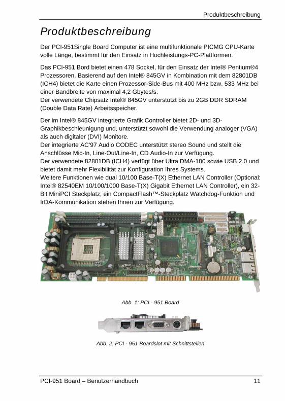
ProduktbeschreibungDer PCI-951Single Board Computer ist eine multifunktionale PICMG CPU-Kartevolle Länge, bestimmt für den Einsatz in Hochleistungs-PC-Plattformen.
Das PCI-951 Bord bietet einen 478 Sockel, für den Einsatz der Intel® Pentium®4Prozessoren. Basierend auf den Intel® 845GV in Kombination mit dem 82801DB(ICH4) bietet die Karte einen Prozessor-Side-Bus mit 400 MHz bzw. 533 MHz beieiner Bandbreite von maximal 4,2 Gbytes/s.Der verwendete Chipsatz Intel® 845GV unterstützt bis zu 2GB DDR SDRAM(Double Data Rate) Arbeitsspeicher.
Der im Intel® 845GV integrierte Grafik Controller bietet 2D- und 3D-Graphikbeschleunigung und, unterstützt sowohl die Verwendung analoger (VGA)als auch digitaler (DVI) Monitore.Der integrierte AC’97 Audio CODEC unterstützt stereo Sound und stellt dieAnschlüsse Mic-In, Line-Out/Line-In, CD Audio-In zur Verfügung.Der verwendete 82801DB (ICH4) verfügt über Ultra DMA-100 sowie USB 2.0 undbietet damit mehr Flexibilität zur Konfiguration Ihres Systems.Weitere Funktionen wie dual 10/100 Base-T(X) Ethernet LAN Controller (Optional:Intel® 82540EM 10/100/1000 Base-T(X) Gigabit Ethernet LAN Controller), ein 32-Bit MiniPCI Steckplatz, ein CompactFlash™-Steckplatz Watchdog-Funktion undIrDA-Kommunikation stehen Ihnen zur Verfügung.
Abb. 1: PCI - 951 Board
Abb. 2: PCI - 951 Boardslot mit Schnittstellen

Produktbeschreibung
12 PCI-951 Board – Benutzerhandbuch
Eigenschaften
Prozessor Sockel: Intel® Socket 478.
Prozessor: Intel® Pentium® 4 und / oder Celeron® CPU. Die interne CPU-Temperatur wird über einen I2C Sensor überwacht.
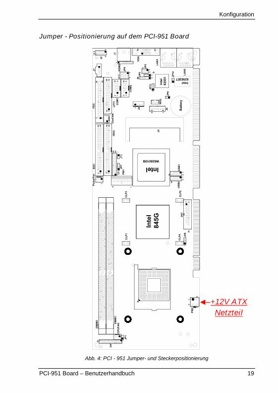
Der Intel® Pentium® 4 verwendet eine Versorgungsspannung(Vcore), welche aus der 12V gewonnen wird. Um den Betriebzu gewährleisten, ist es deshalb erforderlich den 4-poligenStecker vom Netzteil am Stecker (PW2) anzuschließen. (Siehe
Abb. 4: PCI - 951 Jumper- und Steckerpositionierung )
Processor Side Bus Speed (FSB): 400 / 533MHz.
Chipsatz: Intel® 845GV mit Intel® 82801DB (ICH4) Chipsatz.
Speicher:
� Zwei 184-polig ungepufferte-ECC DDR DIMMs, einseitig und/ oderdoppelseitig bestückt, bis zu 2GB als DDR200, DDR266 oder DDR333.
BIOS: Award BIOS.
� Das BIOS unterstützt “Plug &Play”. Es erkennt und installiert eingebaute PnP-fähige Peripheriegeräte und Erweiterungskarten automatisch.
� ACPI Power Management
DMI BIOS Support:
� Desktop Management Interface (DMI) ermöglicht dem AnwenderKonfigurationsinformationen, wie CPU-Typ, CPU-Geschwindigkeit, CPU-Temperatur, Frequenzen und Speichergröße abzufragen.
LPC I/O: Winbond W83627HF
PCI to ISA Bridge: ITE IT8888F
Parallele Port: Eine high-speed parallele Schnittstelle, die SPP/EPP/ECP Modus unterstützt.
Serielle Schnittstelle: Zwei 16550 UART kompatible Schnittstellen:
� COM1 konfigurierbar als RS-232 und
� COM2 konfigurierbar als RS-232 / RS-422 / RS-485 (wählbar durchJumpereinstellung)

Produktbeschreibung
PCI-951 Board – Benutzerhandbuch 13
Enhanced IDE: Der IDE -Controller stellt zwei Kanäle zur Verfügung, an denenbis zu vier IDE-Geräte angeschlossen werden können. Die IDE-Schnittstellenunterstützen PIO Modus bis 5 oder Ultra DMA 33/66/100 für IDE Hard Disk undATAPI CD-ROM.
FDD Interface: unterstützt zwei Floppy-Laufwerke (1.44MB, 2.88MB).
USB Interface: zwei USB Stecker (die vier USB Schnittstellen unterstützen),konform zur USB Spezifikation Rev. 2.0.
Audio: AC’97 (AD1881A) CODEC stellt stereo Sound Funktion mit Mic-In, AudioLine-In / Line-Out zur Verfügung.
Watchdog Timer: mit einstellbare Zeitstufen: ca. 1Sek. bis 256 Sek.
PICMG Compliance: entsprechend dem PICMG Standard 1.0.
VGA: Intel® 845GV mit integriertem VGA Controller
� Simultane Bildschirmanzeige (VGA und DVI)
� 64-bits Speicherbus im 2/4/8/16/32 MB DDR SDRAM
� LCD Flachbildschirme die DVI unterstützen
� Auflösung der CRT Bildschirmanzeige: 1920 x 1440 bei 85 Hz.
� Auflösung der LCD Bildschirmanzeige: bis zu 1280 x 1024 bei 60 Hz.
� Unterstützt anspruchsvolle 2D und 3D Grafiken; Verfügt über verbesserte 3DEigenschaften; Integrierte Beschleunigung für DVD- und Videowiedergabe.
Ethernet: Intel® 82562ET / 82801DB
� Der Intel® 82801DB ICH4 bietet einen integrierten LAN Contoller für fastEthernet (10/100 Mbit/s). Die Kombination mit dem Intel® 82562ET bieteteinen 10/100 Base-T Anschluss.
� Der Intel® 82551QM liefert eine eine standard-IEEE 802.3 Ethernet-Schnittstelle für 10/100 T Base Anwendungen (802.3, 802.3u, 802.3ab).
Keyboard und Maus Schnittstellen:� Kombinierte PS/2 Keyboard und Maus Buchse an der Boardslot-Blende.
� Eine onboard 7-polige Stiftleiste, die den Anschluss eines externen Keyboardsund einer Maus unterstützt.

Produktbeschreibung
14 PCI-951 Board – Benutzerhandbuch
IrDA Interface: eine onboard Stiftleiste ermöglicht den Anschluss eines externen IrDA Modul.
CompactFlash™ Socket (IDE compatible): erlaubt den Einsatz einer ComapctFlashTM-Karte (Typ I, II).
MiniPCI Socket: ermöglicht die Erweiterung durch eine MiniPCI-Karte.
Erweiterte Funktionen
� Temperatur Überwachung und Warnsignale: Die interne CPU-Temperaturwird mittels eines auf dem PCI-951Board I2C Sensors überwacht. Beimerreichen einer einstellbaren Temperaturgrenze, kann eine akustischeMeldung erfolgen oder das System abgeschaltet werden.
� ATX-Power Control: Bietet Funktionen wie Ausschalten beim Beenden desBetriebssystem oder Wake-up on LAN.
� Modem Ring-On: Erlaubt das selbstständige Hochfahren des Systems beieingehendem Anruf über einem externen Modem. Der Rechner darf hierfürnicht per Schalter vom Stromnetz getrennt sein.
� Wake On LAN: Erlaubt es den Rechner per Netzwerk einzuschalten. DerRechner darf hierfür nicht per Schalter vom Stromnetz getrennt sein. Wake-on-LAN arbeitet nur mit einem ATX –Netzteil.
Produktbeschreibung
PCI-951 Board – Benutzerhandbuch 15
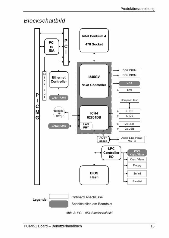
Blockschaltbild
Intel Pentium 4
478 Socket
PICMG
PCI
PCIzu
ISA
DDR DIMM
DDR DIMM
EthernetController
LAN1 RJ45
Mini
PCI
LAN2 RJ45
BIOSFlash
i845GV
VGA Controller
ICH482801DB
LANPHY
LPCController
I/O
DVI
VGA
2x USB
2x USB
1. IDE
2. IDE
Audio Line In/OutMik. In
CompactFlash
Parallel
Seriell
Floppy
PS/2Keyb./Maus
AC'97codec
Keyb./Maus
Schnittstellen am BoardslotLegende:
Onboard Anschlüsse
Batterie für
RTC
Abb. 3: PCI - 951 Blockschaltbild
Konfiguration
16 PCI-951 Board – Benutzerhandbuch
KonfigurationIn diesem Kapitel erhalten Sie Informationen über die Jumper und Anschlüsse aufdem PCI-951 Board, über Jumper-Einstellungen, um ihr System entsprechendIhrer Anforderungen zu konfigurieren.
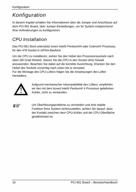
CPU InstallationDas PCI-951 Bord unterstützt einen Intel® Pentium®4 oder Celeron® Prozessor,für den 478 Sockel in mPGA-Bauform.
Um die CPU zu installieren, ziehen Sie den Hebel des Prozessorssockels nachoben (90 Grad Winkel). Setzen Sie die CPU in den Sockel ohne Gewaltanzuwenden. Beachten Sie dabei auf die korrekte Ausrichtung. Drücken Sie denHebel des Sockels vorsichtig nach unten bis er einrastet.Für die Montage des CPU-Lüfters folgen Sie die Anweisungen des Lüfter-Herstellers.
Aufgrund mechanischer Inkompatibilität des Lüfters, empfehlenwir den mit dem boxed Intel® Pentium® 4 Prozessor geliefertenKühler, nicht zu verwenden.
Um Überhitzungsprobleme zu vermeiden und eine stabileFunktion Ihres System sicherzustellen, achten Sie darauf, dassder Kontakt zwischen dem CPU-Kühler und der CPU-Oberflächegewährleistet ist.
Konfiguration
PCI-951 Board – Benutzerhandbuch 17
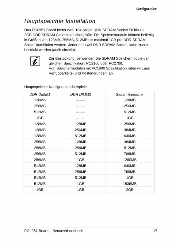
Hauptspeicher InstallationDas PCI-951 Board bietet zwei 184-polige DDR SDRAM Sockel für bis zu2GB DDR SDRAM Gesamtspeichergröße. Die Speichermodule können beliebigin Größen von 128MB, 256MB, 512MB bis maximal 1GB pro DDR SDRAMSockel kombiniert werden. Jeder der zwei DDR SDRAM Sockel, kann zuerstbestückt werden (auch einzeln).
Zur Bestückung, verwenden Sie SDRAM Speichermodule dergleichen Spezifikation: PC2100 oder PC2700.Von Speichermodulen mit PC1600 Spezifikation raten wir, ausVerfügbarkeits- und Kostengründen, ab.
Hauptspeicher Konfigurationsbeispiele:
DDR DIMM1 DDR DIMM2 Gesamtspeicher
128MB -------- 128MB
256MB -------- 256MB
512MB -------- 512MB
1GB -------- 1GB
128MB 128MB 256MB
128MB 256MB 384MB
128MB 512MB 640MB
256MB 128MB 384MB
256MB 256MB 512MB
256MB 512MB 768MB
256MB 1GB 1280MB
512MB 128MB 640MB
512MB 256MB 768MB
512MB 512MB 1GB
512MB 1GB 1536MB
1GB 1GB 2GB
Konfiguration
18 PCI-951 Board – Benutzerhandbuch
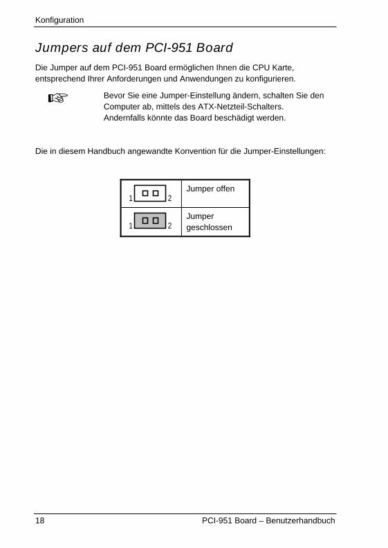
Jumpers auf dem PCI-951 BoardDie Jumper auf dem PCI-951 Board ermöglichen Ihnen die CPU Karte,entsprechend Ihrer Anforderungen und Anwendungen zu konfigurieren.
Bevor Sie eine Jumper-Einstellung ändern, schalten Sie denComputer ab, mittels des ATX-Netzteil-Schalters.Andernfalls könnte das Board beschädigt werden.
Die in diesem Handbuch angewandte Konvention für die Jumper-Einstellungen:
21Jumper offen
21Jumpergeschlossen
Konfiguration
PCI-951 Board – Benutzerhandbuch 19
Jumper - Positionierung auf dem PCI-951 Board
CLP
4
CLP
1
114
Inte
l82
551
Intel 82562ET
LAN2
JP12
JP6
Bat
tery
J6
IRVG
AJP
5
LAN1
11
JP3
1
5
2
J41
JP4
13
KB
MS
1211
J8
1JP
11
WO
L
2 2 11
9
CO
M2
1010 9
1
CO
M1
LPT1
13261
2
J2
910
J1
3334FD
C
620
Chs
FAN
1 210PW1 U
SB1
1
6 1
J5
IDE2
Intel W82801DB
19
JP2
JP7
J31
CLP
2U
SB2
12
10
21
DVI
20
JP8
1
CLP
3
Inte
l84
5G
Pow
erFa
n44
1
1434443
22 2 11
IDE1
1
1
2
1
PW2 4
3
DIM
M1
CPU
FAN
JP1
1
DIM
M2
ITP
25
Abb. 4: PCI - 951 Jumper- und Steckerpositionierung
+12V ATXNetzteil
Konfiguration
20 PCI-951 Board – Benutzerhandbuch
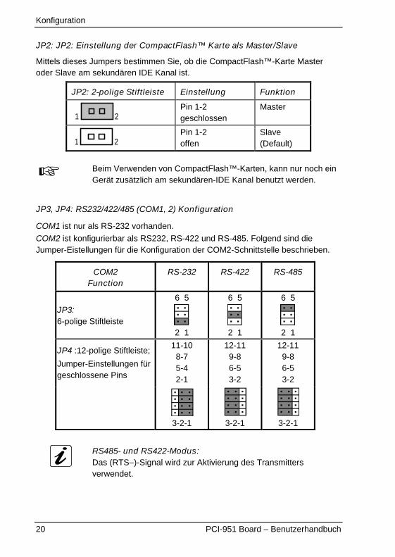
JP2: JP2: Einstellung der CompactFlash™ Karte als Master/Slave
Mittels dieses Jumpers bestimmen Sie, ob die CompactFlash™-Karte Masteroder Slave am sekundären IDE Kanal ist.
JP2: 2-polige Stiftleiste Einstellung Funktion
21Pin 1-2geschlossen
Master
21Pin 1-2offen
Slave(Default)
Beim Verwenden von CompactFlash™-Karten, kann nur noch einGerät zusätzlich am sekundären-IDE Kanal benutzt werden.
JP3, JP4: RS232/422/485 (COM1, 2) Konfiguration
COM1 ist nur als RS-232 vorhanden.
COM2 ist konfigurierbar als RS232, RS-422 und RS-485. Folgend sind dieJumper-Eistellungen für die Konfiguration der COM2-Schnittstelle beschrieben.
COM2Function
RS-232 RS-422 RS-485
JP3:6-polige Stiftleiste
6 5
2 1
6 5
2 1
6 5
2 1
JP4 :12-polige Stiftleiste;
Jumper-Einstellungen fürgeschlossene Pins
11-108-75-42-1
12-119-86-53-2
12-119-86-53-2
3-2-1 3-2-1 3-2-1
RS485- und RS422-Modus:Das (RTS–)-Signal wird zur Aktivierung des Transmittersverwendet.
Konfiguration
PCI-951 Board – Benutzerhandbuch 21
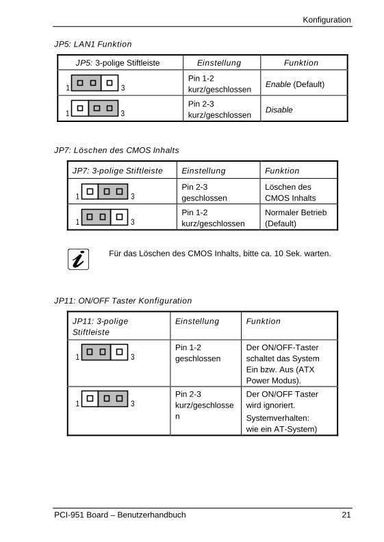
JP5: LAN1 Funktion
JP5: 3-polige Stiftleiste Einstellung Funktion
31Pin 1-2kurz/geschlossen
Enable (Default)
31Pin 2-3kurz/geschlossen
Disable
JP7: Löschen des CMOS Inhalts
JP7: 3-polige Stiftleiste Einstellung Funktion
31Pin 2-3geschlossen
Löschen desCMOS Inhalts
31Pin 1-2kurz/geschlossen
Normaler Betrieb(Default)
Für das Löschen des CMOS Inhalts, bitte ca. 10 Sek. warten.
JP11: ON/OFF Taster Konfiguration
JP11: 3-poligeStiftleiste
Einstellung Funktion
31Pin 1-2geschlossen
Der ON/OFF-Tasterschaltet das SystemEin bzw. Aus (ATXPower Modus).
31Pin 2-3kurz/geschlossen
Der ON/OFF Tasterwird ignoriert.
Systemverhalten:wie ein AT-System)
Konfiguration
22 PCI-951 Board – Benutzerhandbuch
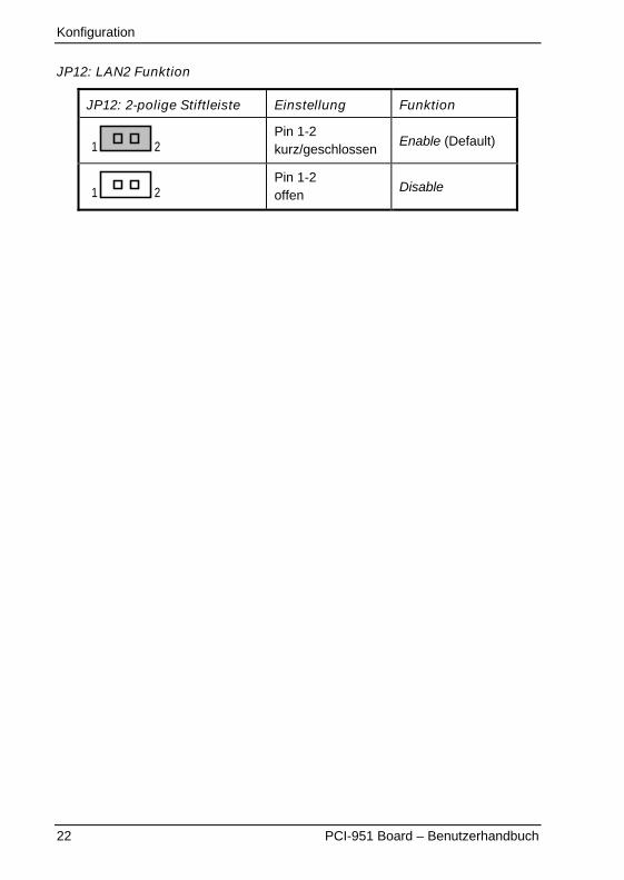
JP12: LAN2 Funktion
JP12: 2-polige Stiftleiste Einstellung Funktion
21Pin 1-2kurz/geschlossen
Enable (Default)
21Pin 1-2offen
Disable
Konfiguration
PCI-951 Board – Benutzerhandbuch 23
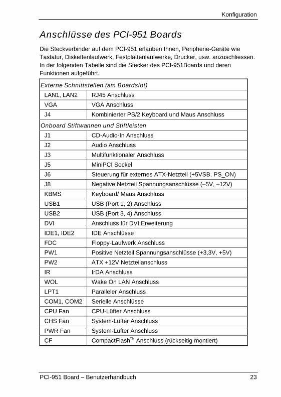
Anschlüsse des PCI-951 BoardsDie Steckverbinder auf dem PCI-951 erlauben Ihnen, Peripherie-Geräte wieTastatur, Diskettenlaufwerk, Festplattenlaufwerke, Drucker, usw. anzuschliessen.In der folgenden Tabelle sind die Stecker des PCI-951Boards und derenFunktionen aufgeführt.
Externe Schnittstellen (am Boardslot)
LAN1, LAN2 RJ45 Anschluss
VGA VGA Anschluss
J4 Kombinierter PS/2 Keyboard und Maus Anschluss
Onboard Stiftwannen und Stiftleisten
J1 CD-Audio-In Anschluss
J2 Audio Anschluss
J3 Multifunktionaler Anschluss
J5 MiniPCI Sockel
J6 Steuerung für externes ATX-Netzteil (+5VSB, PS_ON)
J8 Negative Netzteil Spannungsanschlüsse (–5V, –12V)
KBMS Keyboard/ Maus Anschluss
USB1 USB (Port 1, 2) Anschluss
USB2 USB (Port 3, 4) Anschluss
DVI Anschluss für DVI Erweiterung
IDE1, IDE2 IDE Anschlüsse
FDC Floppy-Laufwerk Anschluss
PW1 Positive Netzteil Spannungsanschlüsse (+3,3V, +5V)
PW2 ATX +12V Netzteilanschluss
IR IrDA Anschluss
WOL Wake On LAN Anschluss
LPT1 Paralleler Anschluss
COM1, COM2 Serielle Anschlüsse
CPU Fan CPU-Lüfter Anschluss
CHS Fan System-Lüfter Anschluss
PWR Fan System-Lüfter Anschluss
CF CompactFlashTM Anschluss (rückseitig montiert)
Konfiguration
24 PCI-951 Board – Benutzerhandbuch
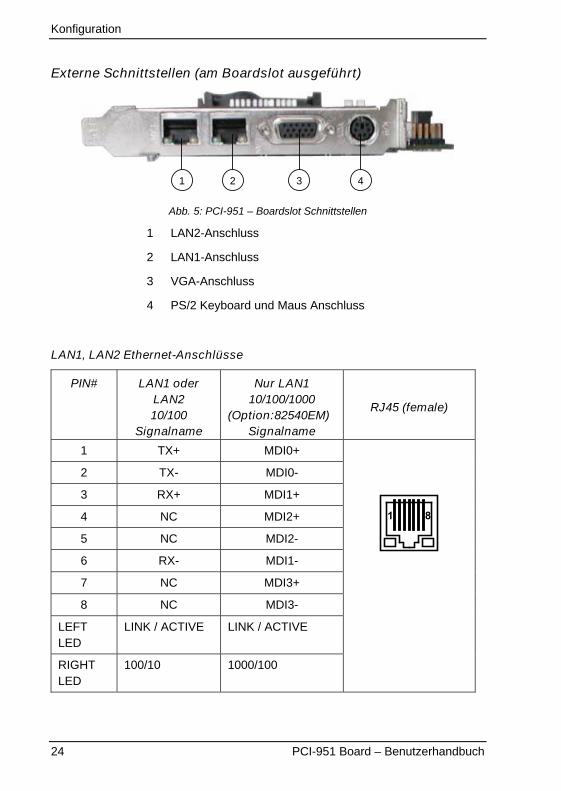
Externe Schnittstellen (am Boardslot ausgeführt)
42 31
Abb. 5: PCI-951 – Boardslot Schnittstellen
1 LAN2-Anschluss
2 LAN1-Anschluss
3 VGA-Anschluss
4 PS/2 Keyboard und Maus Anschluss
LAN1, LAN2 Ethernet-Anschlüsse
PIN# LAN1 oderLAN210/100
Signalname
Nur LAN110/100/1000
(Option:82540EM)Signalname
RJ45 (female)
1 TX+ MDI0+
2 TX- MDI0-
3 RX+ MDI1+
4 NC MDI2+
5 NC MDI2-
6 RX- MDI1-
7 NC MDI3+
8 NC MDI3-
LEFTLED
LINK / ACTIVE LINK / ACTIVE
RIGHTLED
100/10 1000/100
1 8
Konfiguration
PCI-951 Board – Benutzerhandbuch 25
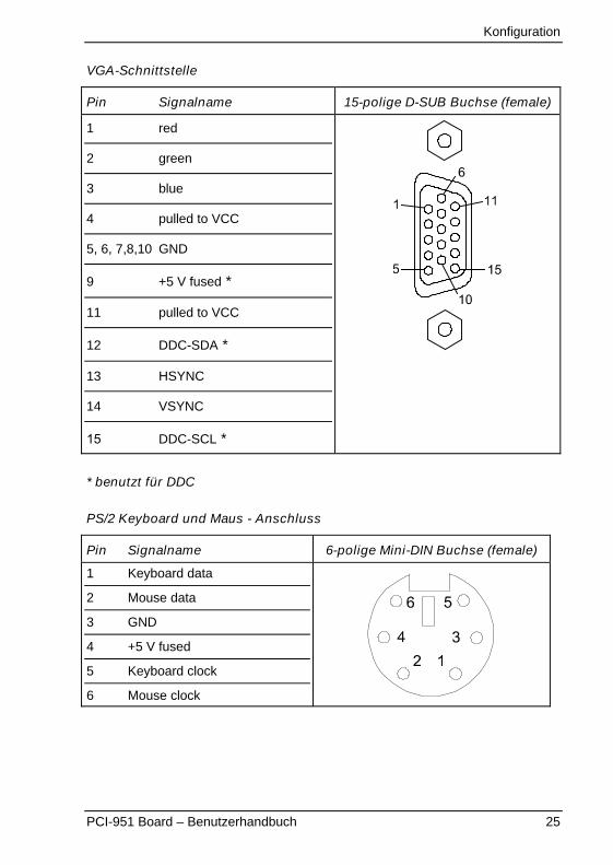
VGA-Schnittstelle
Pin Signalname 15-polige D-SUB Buchse (female)
1 red
2 green
3 blue
4 pulled to VCC
5, 6, 7,8,10 GND
9 +5 V fused *
11 pulled to VCC
12 DDC-SDA *
13 HSYNC
14 VSYNC
15 DDC-SCL *
* benutzt für DDC
PS/2 Keyboard und Maus - Anschluss
Pin Signalname 6-polige Mini-DIN Buchse (female)
1 Keyboard data
2 Mouse data
3 GND
4 +5 V fused
5 Keyboard clock
6 Mouse clock
Konfiguration
26 PCI-951 Board – Benutzerhandbuch
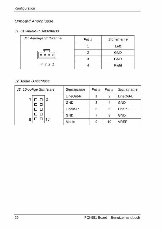
Onboard Anschlüsse
J1: CD-Audio-In Anschluss
J1: 4-polige Stiftwanne Pin # Signalname
1 Left
2 GND
3 GND
4 3 2 1 4 Right
J2: Audio -Anschluss
J2: 10-polige Stiftleiste Signalname Pin # Pin # Signalname
LineOut-R 1 2 LineOut-L
GND 3 4 GND
LineIn-R 5 6 LineIn-L
GND 7 8 GND
Mic-In 9 10 VREF
Konfiguration
PCI-951 Board – Benutzerhandbuch 27
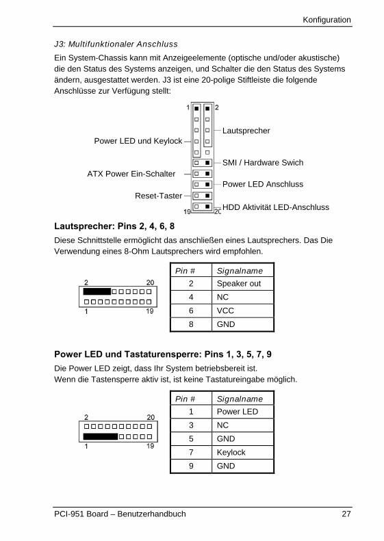
J3: Multifunktionaler Anschluss
Ein System-Chassis kann mit Anzeigeelemente (optische und/oder akustische)die den Status des Systems anzeigen, und Schalter die den Status des Systemsändern, ausgestattet werden. J3 ist eine 20-polige Stiftleiste die folgendeAnschlüsse zur Verfügung stellt:
Lautsprecher: Pins 2, 4, 6, 8Diese Schnittstelle ermöglicht das anschließen eines Lautsprechers. Das DieVerwendung eines 8-Ohm Lautsprechers wird empfohlen.
Pin # Signalname
2 Speaker out
4 NC
6 VCC
8 GND
Power LED und Tastaturensperre: Pins 1, 3, 5, 7, 9Die Power LED zeigt, dass Ihr System betriebsbereit ist.Wenn die Tastensperre aktiv ist, ist keine Tastatureingabe möglich.
Pin # Signalname
1 Power LED
3 NC
5 GND
7 Keylock
9 GND
Lautsprecher
SMI / Hardware Swich
Power LED Anschluss
HDD Aktivität LED-Anschluss
Power LED und Keylock
ATX Power Ein-Schalter
Reset-Taster

Konfiguration
28 PCI-951 Board – Benutzerhandbuch
SMI/Hardware Switch: Pins 11 und 12Diese Schnittstelle unterstützt den "Green Schalter" eines Systems. Wenn derSchalterer betätigt wird, wird das System sofort in den Energiespar-Modusumgeschaltet (gezwungen).
Pin # Signalname
12 Ext. SMI (depending onBIOS settings)
11 GND
Power Taster: Pins 14 und 13Dieser 2-polige Anschluss ermöglicht den Anschluss des “ATX Netzteil Ein/AusTasters”. Bei Betätigung dieses Tasters wird das System eingeschaltet. Bei einernachfolgenden Betätigung wird das System, je nach BIOS-Einstellung undBetriebssystems ausgeschaltet oder in einen Energiesparzustand versetzt.
Pin # Signalname
14 PWRBTN
13 Pulled up to VSB
Wird nur bei Verwendung der ATX-Funktion und einesentsprechenden Netzteils unterstützt.
Alternativer Anschluss für Power LED: Pins 15 und 16Diese Pins können zum alternativen Anschluss einer Power-LED verwendetwerden.
Pin # Signalname
16 Power LED
15 GND
Konfiguration
PCI-951 Board – Benutzerhandbuch 29
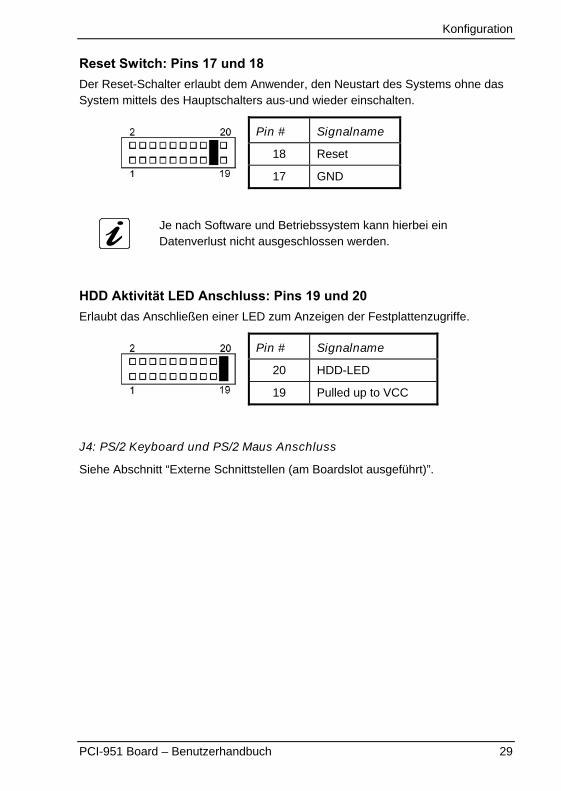
Reset Switch: Pins 17 und 18Der Reset-Schalter erlaubt dem Anwender, den Neustart des Systems ohne dasSystem mittels des Hauptschalters aus-und wieder einschalten.
Pin # Signalname
18 Reset
17 GND
Je nach Software und Betriebssystem kann hierbei einDatenverlust nicht ausgeschlossen werden.
HDD Aktivität LED Anschluss: Pins 19 und 20Erlaubt das Anschließen einer LED zum Anzeigen der Festplattenzugriffe.
Pin # Signalname
20 HDD-LED
19 Pulled up to VCC
J4: PS/2 Keyboard und PS/2 Maus Anschluss
Siehe Abschnitt “Externe Schnittstellen (am Boardslot ausgeführt)”.

Konfiguration
30 PCI-951 Board – Benutzerhandbuch
J5: MiniPCI Steckplatz
Pin-Belegung des J5 MiniPCI-Steckplatzes:
SMD PCI Steckplatz, 124-polig, Pin-BelegungPin Funktion Pin Funktion Pin Funktion
1 X 51 AD21 101 GND
2 X 52 AD22 102 GND
3 X 53 AD19 103 X
4 X 54 AD20 104 X
5 X 55 GND 105 X
6 X 56 PAR 106 X
7 X 57 AD17 107 X
8 X 58 AD18 108 X
9 X 59 -CEB2 109 X
10 X 60 AD16 110 X
11 X 61 -IRDY 111 X
12 X 62 GND 112 X
13 X 63 VCC3 113 X
14 X 64 -FRAME 114 GND
15 X 65 -CLKRUN 115 X
16 X 66 -TRDY 116 X
17 -INTB 67 -SERR 117 X
18 VCC 68 -STOP 118 X
19 VCC3 69 GND 119 X
20 -INTA 70 VCC3 120 X
21 X 71 -PERR 121 X
22 X 72 -DEVSEL 122 -MPCIACT
23 GND 73 -CBE1 123 X
24 V3.3Aux 74 GND 124 3.3VAUX
25 CLK 75 AD14
26 -RST 76 AD15
27 GND 77 GND
28 VCC3 78 AD13
29 -REQ 79 AD12
30 -GNT 80 AD11
31 VCC3 81 AD10
32 GND 82 GND
Die Tabelle wird auf der nächsten Seite fortgeführt.
Konfiguration
PCI-951 Board – Benutzerhandbuch 31
33 AD31 83 GND
34 -PME 84 AD9
35 AD29 85 AD8
36 X 86 -CBE0
37 GND 87 AD7
38 AD30 88 ACC3
39 AD27 89 ACC3
40 VCC3 90 AD6
41 AD25 91 AD5
42 AD28 92 AD4
43 RESV 93 X
44 AD26 94 AD2
45 -CBE3 95 AD3
46 AD24 96 AD0
47 AD23 97 VCC
48 IDSEL 98 X
49 GND 99 AD1
50 GND 100 R-WIP
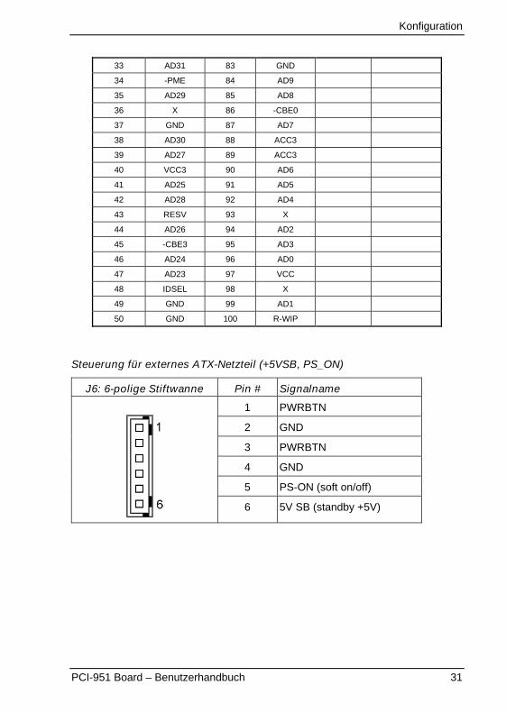
Steuerung für externes ATX-Netzteil (+5VSB, PS_ON)
J6: 6-polige Stiftwanne Pin # Signalname
1 PWRBTN
2 GND
3 PWRBTN
4 GND
5 PS-ON (soft on/off)
6 5V SB (standby +5V)
Konfiguration
32 PCI-951 Board – Benutzerhandbuch
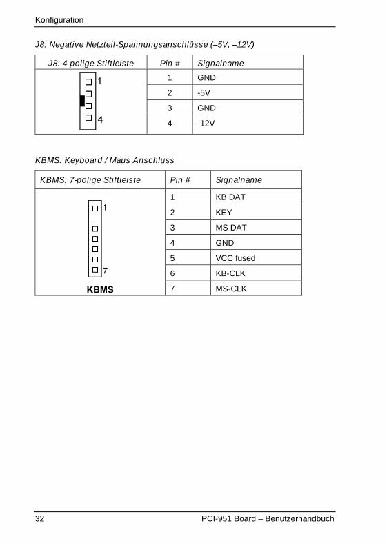
J8: Negative Netzteil-Spannungsanschlüsse (–5V, –12V)
J8: 4-polige Stiftleiste Pin # Signalname
1 GND
2 -5V
3 GND
4 -12V
KBMS: Keyboard / Maus Anschluss
KBMS: 7-polige Stiftleiste Pin # Signalname
1 KB DAT
2 KEY
3 MS DAT
4 GND
5 VCC fused
6 KB-CLK
KBMS 7 MS-CLK
Konfiguration
PCI-951 Board – Benutzerhandbuch 33
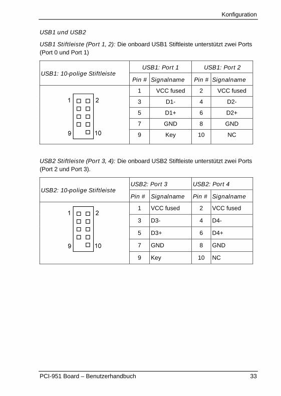
USB1 und USB2
USB1 Stiftleiste (Port 1, 2): Die onboard USB1 Stiftleiste unterstützt zwei Ports(Port 0 und Port 1)
USB1: Port 1 USB1: Port 2USB1: 10-polige Stiftleiste
Pin # Signalname Pin # Signalname
1 VCC fused 2 VCC fused
3 D1- 4 D2-
5 D1+ 6 D2+
7 GND 8 GND
9 Key 10 NC
USB2 Stiftleiste (Port 3, 4): Die onboard USB2 Stiftleiste unterstützt zwei Ports(Port 2 und Port 3).
USB2: Port 3 USB2: Port 4USB2: 10-polige Stiftleiste
Pin # Signalname Pin # Signalname
1 VCC fused 2 VCC fused
3 D3- 4 D4-
5 D3+ 6 D4+
7 GND 8 GND
9 Key 10 NC
Konfiguration
34 PCI-951 Board – Benutzerhandbuch
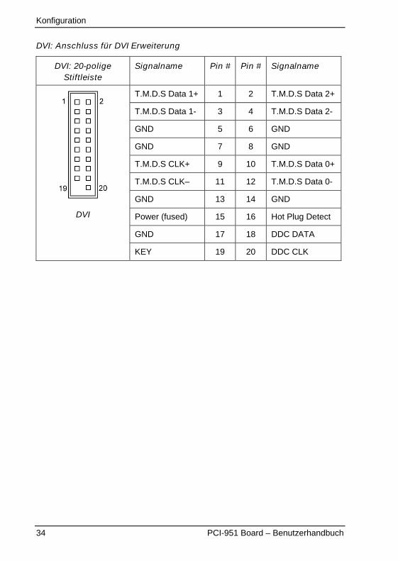
DVI: Anschluss für DVI Erweiterung
DVI: 20-poligeStiftleiste
Signalname Pin # Pin # Signalname
T.M.D.S Data 1+ 1 2 T.M.D.S Data 2+
T.M.D.S Data 1- 3 4 T.M.D.S Data 2-
GND 5 6 GND
GND 7 8 GND
T.M.D.S CLK+ 9 10 T.M.D.S Data 0+
T.M.D.S CLK– 11 12 T.M.D.S Data 0-
GND 13 14 GND
Power (fused) 15 16 Hot Plug Detect
GND 17 18 DDC DATA
DVI
KEY 19 20 DDC CLK
Konfiguration
PCI-951 Board – Benutzerhandbuch 35
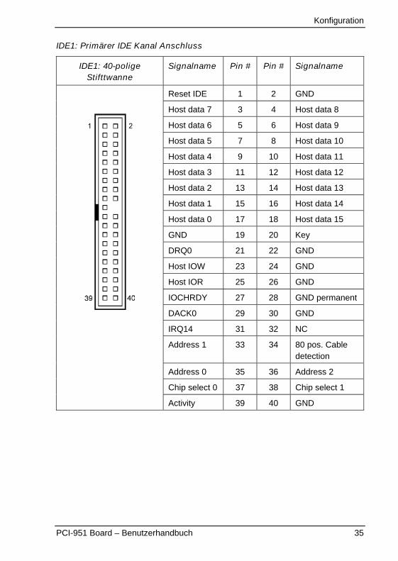
IDE1: Primärer IDE Kanal Anschluss
IDE1: 40-poligeStifttwanne
Signalname Pin # Pin # Signalname
Reset IDE 1 2 GND
Host data 7 3 4 Host data 8
Host data 6 5 6 Host data 9
Host data 5 7 8 Host data 10
Host data 4 9 10 Host data 11
Host data 3 11 12 Host data 12
Host data 2 13 14 Host data 13
Host data 1 15 16 Host data 14
Host data 0 17 18 Host data 15
GND 19 20 Key
DRQ0 21 22 GND
Host IOW 23 24 GND
Host IOR 25 26 GND
IOCHRDY 27 28 GND permanent
DACK0 29 30 GND
IRQ14 31 32 NC
Address 1 33 34 80 pos. Cabledetection
Address 0 35 36 Address 2
Chip select 0 37 38 Chip select 1
Activity 39 40 GND
Konfiguration
36 PCI-951 Board – Benutzerhandbuch
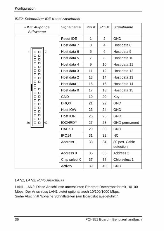
IDE2: Sekundärer IDE-Kanal Anschluss
IDE2: 40-poligeStiftwanne
Signalname Pin # Pin # Signalname
Reset IDE 1 2 GND
Host data 7 3 4 Host data 8
Host data 6 5 6 Host data 9
Host data 5 7 8 Host data 10
Host data 4 9 10 Host data 11
Host data 3 11 12 Host data 12
Host data 2 13 14 Host data 13
Host data 1 15 16 Host data 14
Host data 0 17 18 Host data 15
GND 19 20 Key
DRQ0 21 22 GND
Host IOW 23 24 GND
Host IOR 25 26 GND
IOCHRDY 27 28 GND permanent
DACK0 29 30 GND
IRQ14 31 32 NC
Address 1 33 34 80 pos. Cabledetection
Address 0 35 36 Address 2
Chip select 0 37 38 Chip select 1
Activity 39 40 GND
LAN1, LAN2: RJ45 Anschluss
LAN1, LAN2: Diese Anschlüsse unterstützen Ethernet Datentransfer mit 10/100Mbps. Der Anschluss LAN1 bietet optional auch 10/100/1000 Mbps.Siehe Abschnitt “Externe Schnittstellen (am Boardslot ausgeführt)”.
Konfiguration
PCI-951 Board – Benutzerhandbuch 37
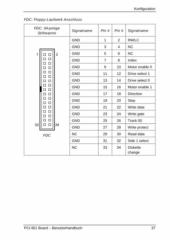
FDC: Floppy-Laufwerk Anschluss
FDC: 34-poligeStiftwanne
Signalname Pin # Pin # Signalname
GND 1 2 RM/LC
GND 3 4 NC
GND 5 6 NC
GND 7 8 Index
GND 9 10 Motor enable 0
GND 11 12 Drive select 1
GND 13 14 Drive select 0
GND 15 16 Motor enable 1
GND 17 18 Direction
GND 19 20 Step
GND 21 22 Write data
GND 23 24 Write gate
GND 25 26 Track 00
GND 27 28 Write protect
NC 29 30 Read data
GND 31 32 Side 1 select
FDC
NC 33 34 Diskettechange
Konfiguration
38 PCI-951 Board – Benutzerhandbuch
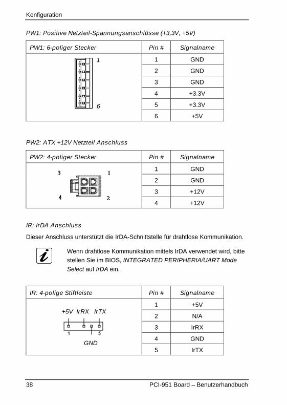
PW1: Positive Netzteil-Spannungsanschlüsse (+3,3V, +5V)
PW1: 6-poliger Stecker Pin # Signalname
1 GND
2 GND
3 GND
4 +3.3V
5 +3.3V
6 +5V
PW2: ATX +12V Netzteil Anschluss
PW2: 4-poliger Stecker Pin # Signalname
1 GND
2 GND
3 +12V
4 +12V
IR: IrDA Anschluss
Dieser Anschluss unterstützt die IrDA-Schnittstelle für drahtlose Kommunikation.
Wenn drahtlose Kommunikation mittels IrDA verwendet wird, bitte
stellen Sie im BIOS, INTEGRATED PERIPHERIA/UART Mode
Select auf IrDA ein.
IR: 4-polige Stiftleiste Pin # Signalname
1 +5V
2 N/A
3 IrRX
4 GND
+5V IrRX IrTX
GND5 IrTX
1
6
Konfiguration
PCI-951 Board – Benutzerhandbuch 39
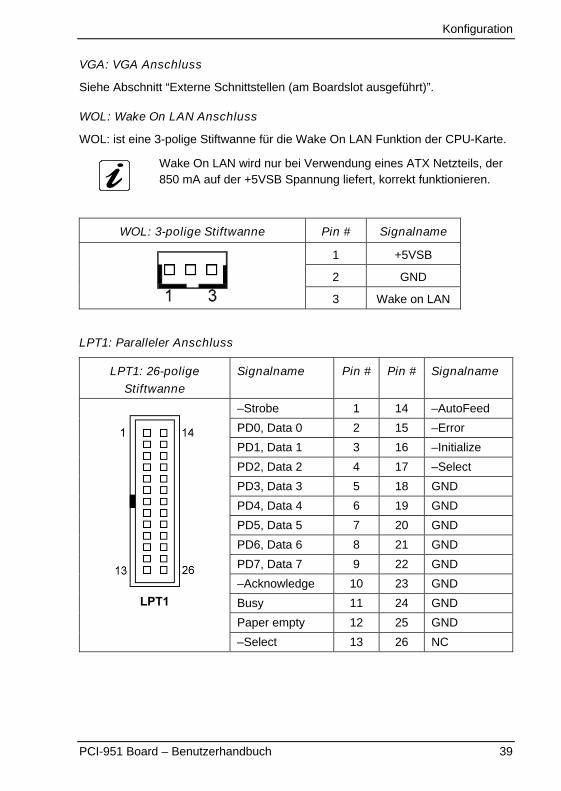
VGA: VGA Anschluss
Siehe Abschnitt “Externe Schnittstellen (am Boardslot ausgeführt)”.
WOL: Wake On LAN Anschluss
WOL: ist eine 3-polige Stiftwanne für die Wake On LAN Funktion der CPU-Karte.
Wake On LAN wird nur bei Verwendung eines ATX Netzteils, der850 mA auf der +5VSB Spannung liefert, korrekt funktionieren.
WOL: 3-polige Stiftwanne Pin # Signalname
1 +5VSB
2 GND
3 Wake on LAN
LPT1: Paralleler Anschluss
LPT1: 26-poligeStiftwanne
Signalname Pin # Pin # Signalname
–Strobe 1 14 –AutoFeed
PD0, Data 0 2 15 –Error
PD1, Data 1 3 16 –Initialize
PD2, Data 2 4 17 –Select
PD3, Data 3 5 18 GND
PD4, Data 4 6 19 GND
PD5, Data 5 7 20 GND
PD6, Data 6 8 21 GND
PD7, Data 7 9 22 GND
–Acknowledge 10 23 GND
Busy 11 24 GND
Paper empty 12 25 GND
LPT1
–Select 13 26 NC
Konfiguration
40 PCI-951 Board – Benutzerhandbuch
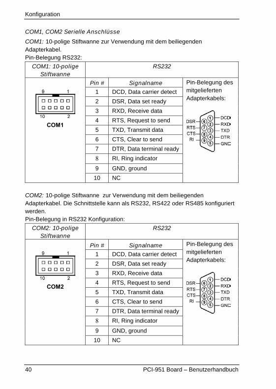
COM1, COM2 Serielle Anschlüsse
COM1: 10-polige Stiftwanne zur Verwendung mit dem beiliegendenAdapterkabel.Pin-Belegung RS232:
COM1: 10-poligeStiftwanne
RS232
Pin # Signalname
1 DCD, Data carrier detect
2 DSR, Data set ready
3 RXD, Receive data
4 RTS, Request to send
5 TXD, Transmit data
6 CTS, Clear to send
7 DTR, Data terminal ready
8 RI, Ring indicator
9 GND, ground
COM1
10 NC
Pin-Belegung desmitgeliefertenAdapterkabels:
COM2: 10-polige Stiftwanne zur Verwendung mit dem beiliegendenAdapterkabel. Die Schnittstelle kann als RS232, RS422 oder RS485 konfiguriertwerden.Pin-Belegung in RS232 Konfiguration:
COM2: 10-poligeStiftwanne
RS232
Pin # Signalname
1 DCD, Data carrier detect
2 DSR, Data set ready
3 RXD, Receive data
4 RTS, Request to send
5 TXD, Transmit data
6 CTS, Clear to send
7 DTR, Data terminal ready
8 RI, Ring indicator
9 GND, ground
COM2
10 NC
Pin-Belegung desmitgeliefertenAdapterkabels:
Konfiguration
PCI-951 Board – Benutzerhandbuch 41
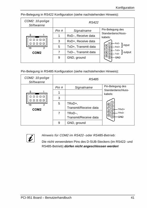
Pin-Belegung in RS422 Konfiguration (siehe nachstehenden Hinweis):
COM2: 10-poligeStiftwanne
RS422
Pin # Signalname
1 RxD–, Receive data
3 RxD+, Receive data
5 TxD+, Transmit data
7 TxD–, Transmit dataCOM29 GND, ground
Pin-Belegung desStandardanschluss-kabels:
RxD-
RxD+
TxD+
TxD-
�
�
input
output
Pin-Belegung in RS485 Konfiguration (siehe nachstehenden Hinweis):
COM2: 10-poligeStiftwanne
RS485
Pin # Signalname
1
3
5 TRxD+,Transmit/Receive data
7 TRxD–,Transmit/Receive data
COM2
9 GND, ground
Pin-Belegung desStandardanschluss-kabels:
TRxD+
TRxD-
Hinweis für COM2 im RS422- oder RS485-Betrieb:
Die nicht verwendeten Pins des D-SUB-Steckers (im RS422- und
RS485-Betrieb) dürfen nicht angeschlossen werden!
Konfiguration
42 PCI-951 Board – Benutzerhandbuch
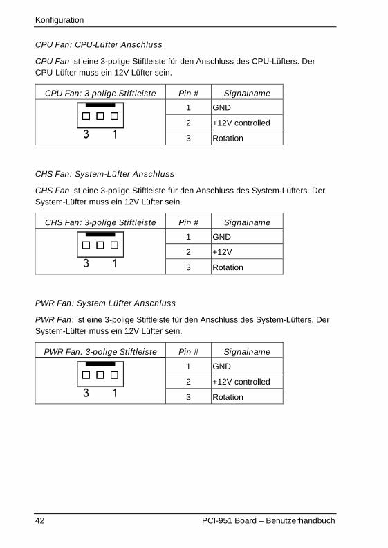
CPU Fan: CPU-Lüfter Anschluss
CPU Fan ist eine 3-polige Stiftleiste für den Anschluss des CPU-Lüfters. DerCPU-Lüfter muss ein 12V Lüfter sein.
CPU Fan: 3-polige Stiftleiste Pin # Signalname
1 GND
2 +12V controlled
3 Rotation
CHS Fan: System-Lüfter Anschluss
CHS Fan ist eine 3-polige Stiftleiste für den Anschluss des System-Lüfters. DerSystem-Lüfter muss ein 12V Lüfter sein.
CHS Fan: 3-polige Stiftleiste Pin # Signalname
1 GND
2 +12V
3 Rotation
PWR Fan: System Lüfter Anschluss
PWR Fan: ist eine 3-polige Stiftleiste für den Anschluss des System-Lüfters. DerSystem-Lüfter muss ein 12V Lüfter sein.
PWR Fan: 3-polige Stiftleiste Pin # Signalname
1 GND
2 +12V controlled
3 Rotation
Konfiguration
PCI-951 Board – Benutzerhandbuch 43
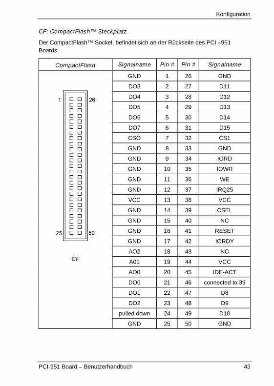
CF: CompactFlash™ Steckplatz
Der CompactFlash™ Sockel, befindet sich an der Rückseite des PCI –951Boards.
CompactFlash Signalname Pin # Pin # Signalname
GND 1 26 GND
DO3 2 27 D11
DO4 3 28 D12
DO5 4 29 D13
DO6 5 30 D14
DO7 6 31 D15
CSO 7 32 CS1
GND 8 33 GND
GND 9 34 IORD
GND 10 35 IOWR
GND 11 36 WE
GND 12 37 IRQ25
VCC 13 38 VCC
GND 14 39 CSEL
GND 15 40 NC
GND 16 41 RESET
GND 17 42 IORDY
AO2 18 43 NC
A01 19 44 VCC
AO0 20 45 IDE-ACT
DO0 21 46 connected to 39
DO1 22 47 D8
DO2 23 48 D9
pulled down 24 49 D10
CF
GND 25 50 GND

Konfiguration
44 PCI-951 Board – Benutzerhandbuch
Watchdog Timer KonfigurationDie Funktion des Wachdog Timers ist das System automatisch zurückzusetzen.Die Funktionsweise des Wachdog-Timers wird im Winbond W83627HF Chipfestgelegt. Wenn der Wachdog-Timer aktiviert ist, wird das System neugestartet,falls der Watchdog nicht innerhalb der eingestellten Zeitspanne zurückgesetztwird.
Bitte beachten: die Genauigkeit des Timers beträgt 20%.
Für genauere Informationen zur Programmierung des WatchdogTimers, verweisen wir auf das online Manual des Winbond chipsW83627HF (www.winbond.com).

Award BIOS Konfiguration
PCI-951 Board – Benutzerhandbuch 45
Award BIOS KonfigurationDieses Kapitel beschreibt die Award BIOS-Einstellungen für das PCI-951 Board.
Das PCI-951 Board verwendet ein Award BIOS (Basic Input/Output System),dass sowohl Intel® Pentium® 4 als auch Celeron® Prozessoren in einemStandard-IBM-AT kompatiblen I/O System unterstützt.
BIOS SetupDas Award BIOS verfügt über ein “Setup Utility Programm” für die Festlegung derKonfiguration und der Einstellungen Ihres Systems. Das “Setup Utility Programm”ist im BIOS-ROM integriert. Wenn Sie den Computer einschalten, wird das AwardBIOS gestartet. Beim Hochfahren des Computers, während des (POST) (PowerOn Self Test) erscheint eine Meldung:Press <DEL> to Enter Setup Drücken der Taste <Del> (auf deutschen Tastaturen mit <Entf> beschriftet)ermöglicht Ihnen den Aufruf des “Setup Utility Programm”.
Wenn Sie zu spät die Taste <Del> betätigt haben, können Sie das “Setup UtilityProgramm” nicht aufrufen.Um das “Setup Utility“ Programm dennoch aufzurufen zu können, ist ein Neustarterforderlich. Drücken Sie dafür den Reset Knopf des Computers bzw. drücken Siegleichzeitig die Tasten <Ctrl/Strg>, <Alt> and <Del/Entf>. Den Neustart könnenSie auch durch Aus- und Einschalten des Computers durchführen. Beachten Siedabei die Meldung:Press <DEL> to Enter Setup
Im allgemeinen betätigen Sie die Pfeiltasten, um die Felder hervorzuheben:Taste <Enter> zur Feldauswahl, die <PgUp> und <PgDn> Tasten, dieFeldauswahl zu ändern, <F1> für Hilfe und <ESC> für das Menü zu verlassen.
Wenn Sie das “Setup Utility“ Programm aufrufen, erscheint das Hauptmenü„CMOS Setup Utility ”. Das Hauptmenü erlaubt Ihnen verschiedene SetupFunktionen und die Auswahl zum Verlassen des Menüs zu wählen.
Die Änderungen werden nur übernommen, wenn zum Verlassen„SAVE & EXIT“ gewählt wird.
Award BIOS Konfiguration
46 PCI-951 Board – Benutzerhandbuch
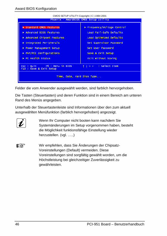
CMOS SETUP UTILITY-Copyright ( C ) 1984-2001
Felder die vom Anwender ausgewählt werden, sind farblich hervorgehoben.
Die Tasten (Steuertasten) und deren Funktion sind in einem Bereich am unterenRand des Menüs angegeben.
Unterhalb der Steuertastenleiste sind Informationen über den zum aktuellausgewählten Menüfunktion (farblich hervorgehoben) angezeigt.
Wenn Ihr Computer nicht booten kann nachdem SieSystemänderungen im Setup vorgenommen haben, bestehtdie Möglichkeit funktionsfähige Einstellung wiederherzustellen. (vgl. …..)
Wir empfehlen, dass Sie Änderungen der Chipsatz-Voreinstellungen (Default) vermeiden. DieseVoreinstellungen sind sorgfältig gewählt worden, um dieHöchstleistung bei gleichzeitiger Zuverlässigkeit zugewährleisten.
Award BIOS Konfiguration
PCI-951 Board – Benutzerhandbuch 47
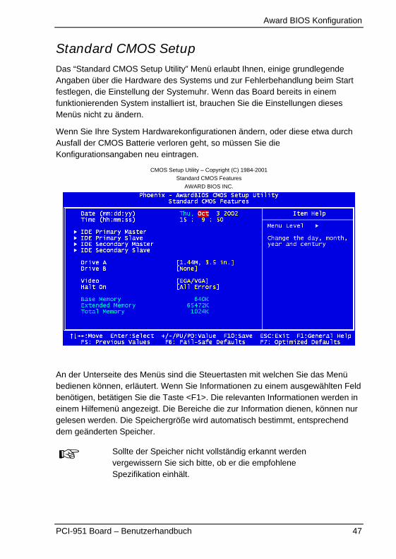
Standard CMOS SetupDas “Standard CMOS Setup Utility” Menü erlaubt Ihnen, einige grundlegendeAngaben über die Hardware des Systems und zur Fehlerbehandlung beim Startfestlegen, die Einstellung der Systemuhr. Wenn das Board bereits in einemfunktionierenden System installiert ist, brauchen Sie die Einstellungen diesesMenüs nicht zu ändern.
Wenn Sie Ihre System Hardwarekonfigurationen ändern, oder diese etwa durchAusfall der CMOS Batterie verloren geht, so müssen Sie dieKonfigurationsangaben neu eintragen.
CMOS Setup Utility – Copyright (C) 1984-2001
Standard CMOS Features
AWARD BIOS INC.
An der Unterseite des Menüs sind die Steuertasten mit welchen Sie das Menübedienen können, erläutert. Wenn Sie Informationen zu einem ausgewählten Feldbenötigen, betätigen Sie die Taste <F1>. Die relevanten Informationen werden ineinem Hilfemenü angezeigt. Die Bereiche die zur Information dienen, können nurgelesen werden. Die Speichergröße wird automatisch bestimmt, entsprechenddem geänderten Speicher.
Sollte der Speicher nicht vollständig erkannt werdenvergewissern Sie sich bitte, ob er die empfohleneSpezifikation einhält.
Award BIOS Konfiguration
48 PCI-951 Board – Benutzerhandbuch
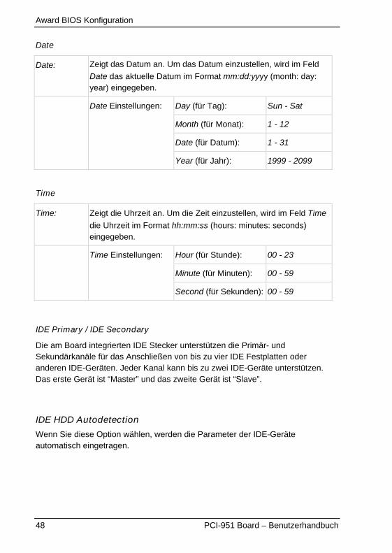
Date
Date: Zeigt das Datum an. Um das Datum einzustellen, wird im Feld
Date das aktuelle Datum im Format mm:dd:yyyy (month: day:year) eingegeben.
Day (für Tag): Sun - Sat
Month (für Monat): 1 - 12
Date (für Datum): 1 - 31
Date Einstellungen:
Year (für Jahr): 1999 - 2099
Time
Time: Zeigt die Uhrzeit an. Um die Zeit einzustellen, wird im Feld Time
die Uhrzeit im Format hh:mm:ss (hours: minutes: seconds)eingegeben.
Hour (für Stunde): 00 - 23
Minute (für Minuten): 00 - 59
Time Einstellungen:
Second (für Sekunden): 00 - 59
IDE Primary / IDE Secondary
Die am Board integrierten IDE Stecker unterstützen die Primär- undSekundärkanäle für das Anschließen von bis zu vier IDE Festplatten oderanderen IDE-Geräten. Jeder Kanal kann bis zu zwei IDE-Geräte unterstützen.Das erste Gerät ist “Master” und das zweite Gerät ist “Slave”.
IDE HDD Autodetection
Wenn Sie diese Option wählen, werden die Parameter der IDE-Geräteautomatisch eingetragen.
Award BIOS Konfiguration
PCI-951 Board – Benutzerhandbuch 49
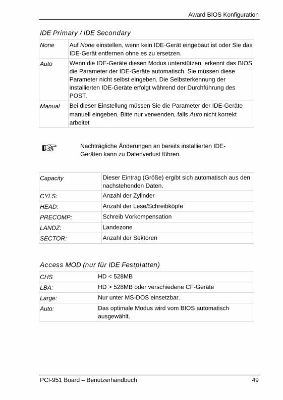
IDE Primary / IDE Secondary
None Auf None einstellen, wenn kein IDE-Gerät eingebaut ist oder Sie dasIDE-Gerät entfernen ohne es zu ersetzen.
Auto Wenn die IDE-Geräte diesen Modus unterstützen, erkennt das BIOSdie Parameter der IDE-Geräte automatisch. Sie müssen dieseParameter nicht selbst eingeben. Die Selbsterkennung derinstallierten IDE-Geräte erfolgt während der Durchführung desPOST.
Manual Bei dieser Einstellung müssen Sie die Parameter der IDE-Geräte
manuell eingeben. Bitte nur verwenden, falls Auto nicht korrektarbeitet
Nachträgliche Änderungen an bereits installierten IDE-Geräten kann zu Datenverlust führen.
Capacity Dieser Eintrag (Größe) ergibt sich automatisch aus dennachstehenden Daten.
CYLS: Anzahl der Zylinder
HEAD: Anzahl der Lese/Schreibköpfe
PRECOMP: Schreib Vorkompensation
LANDZ: Landezone
SECTOR: Anzahl der Sektoren
Access MOD (nur für IDE Festplatten)
CHS HD < 528MB
LBA: HD > 528MB oder verschiedene CF-Geräte
Large: Nur unter MS-DOS einsetzbar.
Auto: Das optimale Modus wird vom BIOS automatischausgewählt.
Award BIOS Konfiguration
50 PCI-951 Board – Benutzerhandbuch
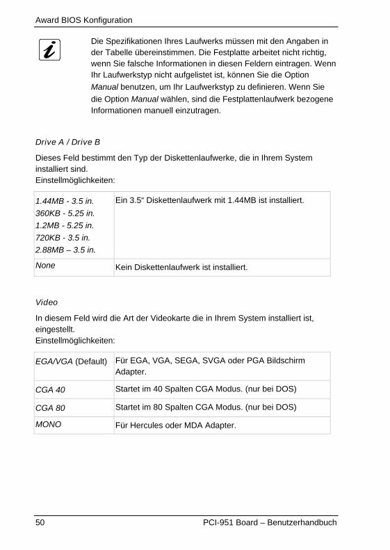
Die Spezifikationen Ihres Laufwerks müssen mit den Angaben inder Tabelle übereinstimmen. Die Festplatte arbeitet nicht richtig,wenn Sie falsche Informationen in diesen Feldern eintragen. WennIhr Laufwerkstyp nicht aufgelistet ist, können Sie die Option
Manual benutzen, um Ihr Laufwerkstyp zu definieren. Wenn Sie
die Option Manual wählen, sind die Festplattenlaufwerk bezogeneInformationen manuell einzutragen.
Drive A / Drive B
Dieses Feld bestimmt den Typ der Diskettenlaufwerke, die in Ihrem Systeminstalliert sind.Einstellmöglichkeiten:
1.44MB - 3.5 in.
360KB - 5.25 in.
1.2MB - 5.25 in.
720KB - 3.5 in.
2.88MB – 3.5 in.
Ein 3.5“ Diskettenlaufwerk mit 1.44MB ist installiert.
None Kein Diskettenlaufwerk ist installiert.
Video
In diesem Feld wird die Art der Videokarte die in Ihrem System installiert ist,eingestellt.Einstellmöglichkeiten:
EGA/VGA (Default) Für EGA, VGA, SEGA, SVGA oder PGA BildschirmAdapter.
CGA 40 Startet im 40 Spalten CGA Modus. (nur bei DOS)
CGA 80 Startet im 80 Spalten CGA Modus. (nur bei DOS)
MONO Für Hercules oder MDA Adapter.

Award BIOS Konfiguration
PCI-951 Board – Benutzerhandbuch 51
Halt On
Dieses Feld legt fest, bei welchen Fehlern der Bootvorgang abgebrochen wird.
All errors (Default) Wenn das BIOS ein Fehler ermittelt, stoppt derBootvorgang.
No errors Der Bootvorgang des Systems wird für Fehler dieermittelt werden können, nicht angehalten.
All, But Keyboard Tastaturfehler werden während des Bootvorgangsdes Systems ignoriert.
All, But Diskette Diskettenfehler werden während des Bootvorgangsdes Systems ignoriert.
All, But Disk/Key Tastatur- und Diskettenfehler werden während desBootvorgangs ignoriert, alle andere Fehler nicht.
Wenn das System wegen eines Fehlers stoppt, so ist zumFortführen des Bootvorgangs das Betätigen der F1-Taste nötig.Das System startet in einem solchen Fall nicht eigenständig.
Award BIOS Konfiguration
52 PCI-951 Board – Benutzerhandbuch
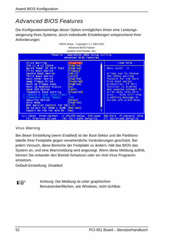
Advanced BIOS FeaturesDie Konfigurationseinträge dieser Option ermöglichen Ihnen eine Leistungs-steigerung Ihres Systems, durch individuelle Einstellungen entsprechend IhrerAnforderungen.
CMOS Setup – Copyright ( C ) 1984-2001
Advanced BIOS Feature
AWARD SOFTWARE, INC.
Virus Warning
Bei dieser Einstellung (wenn Enabled) ist der Boot-Sektor und die Partitions-tabelle Ihrer Festplatte gegen versehentliche Veränderungen geschützt. Beijedem Versuch, diese Bereiche der Festplatte zu ändern, hält das BIOS dasSystem an, und eine Warnmeldung wird angezeigt. Wenn diese Meldung auftritt,können Sie entweder den Betrieb fortsetzen oder ein Anti-Virus Programmeinsetzen.
Default-Einstellung: Disabled.
Achtung: Die Meldung ist unter graphischenBenutzeroberflächen, wie Windows, nicht sichtbar.
Award BIOS Konfiguration
PCI-951 Board – Benutzerhandbuch 53
CPU L1 & L2 Cache
Diese Einstellung ermöglicht den Level-1 und Level-2 der CPU ein- oderausschalten.
Enabled (Default): L1 und L2 Cash ist eingeschaltet.
Disabled L1 und L2 Cash ist ausgeschaltet.
Quick Power On Self Test
Diese Einstellung (bei Enabled) ermöglicht eine Beschleunigung des Selbsttestsbeim Einschalten des Systems.
Enabled (Default): Das Booten wird verkürzt, indem während des POSTeinige Tests nicht durchgeführt werden.
Disabled Der komplette POST wird durchgeführt.
First/ Second/ Third Boot Device
Diese Einstellungen legen die Reihenfolge der Laufwerke fest, von welchengebootet werden soll.
Einstellmöglichkeiten: Floppy, LS120, HDD-0, SCSI, CDROM, HDD-1, HDD-2,
HDD-3, ZIP 100, USB-FDD, USB-ZIP, USB- CDROM, USB- HDD, LAN und
Disabled.
Default-Einstellungen:
First Boot Device Floppy Default
Second Boot Device HDD-0 Default
Third Boot Device LS120 Default
Boot Other Device
Diese Einstellung ermöglicht Ihnen das Booten von einem anderen Laufwerk, alsdie im First/ Second/ Third Boot Device festgelegt.
Default-Einstellung: Enabled.
Award BIOS Konfiguration
54 PCI-951 Board – Benutzerhandbuch
Swap Floppy Drive
Die Einstellungen in diesem Feld ermöglichen Ihnen die Laufwerksbuchstabender Diskettenlaufwerke zu tauschen.
Enabled (Default): Das Laufwerk A: wird zu B: und das Laufwerk B: wird zu A:
Disabled Die Laufswerkbuchstaben werden nicht geändert.
Boot Up Floppy Seek
Wenn Enabled, wird das BIOS die Anzahl der Spuren des installiertenDiskettenlaufwerkes (40 oder 80 Spuren) checken.360kB Disketten haben 40 Spuren, während die 760kB Disketten (1.2M und1.44M) alle 80 Spuren haben.
Default-Einstellung: Enabled.
Boot Up NumLock Status
Diese Einstellung legt den Status der Num-Lock-Taste beim Systemstart fest.
On (Default): Das Nummernpad der Tastatur fungiert als Zahleneingabe.
Off: Das Nummernpad der Tastatur kann als Cursor verwendetwerden.
Gate A20 Option
Mit dieser Einstellung wird die Art, wie die Adressleitung A20 auf den Speicheroberhalb 1MB zugreift, festgelegt.
Fast (Default): Der Zugriff erfolgt über den Chipsatz.
Normal: Der Zugriff erfolgt er über den Tastatur-Controller.

Award BIOS Konfiguration
PCI-951 Board – Benutzerhandbuch 55
Typematic Rate Setting
Mit dieser Einstellung legen Sie die Wiederholungsrate der Tastatur fest.
Enabled: Es erscheint eine Zeichenfolge auf dem Bildschirm, solangeSie die Taste gedrückt halten.
Disabled (Default): Es erscheint pro Tastendruck immer nur ein Zeichen.
Typematic Rate (Chars/Sec)
Mit dieser Einstellung können Sie einstellen, wie schnell (Zeichen/Sekunde) dieTastatureingabe (Zeichenwiederholung) erfolgen soll.
6 (Default): Sechs (6) Zeichen/Sekunde
6 bis 30 6, 8, 10, 12, 15, 20, 24, 30 Zeichen/Sekunde
Typematic Delay (Msec)
Mit diesen Einstellungen legen Sie die Zeit fest, ab wann eine Taste alsdauergedrückt gilt und somit wiederholt wird.
250 (Default): 250 Msek. Wartezeit bis zum Erscheinen des Zeichen aufdem Bildschirm.
250-1000 250, 500, 750, 1000 Msek. Wartezeit.
Award BIOS Konfiguration
56 PCI-951 Board – Benutzerhandbuch
CMOS Setup – Copyright ( C ) 1984-2001
Advanced Chipset Feature Setup
AWARD SOFTWARE, INC.
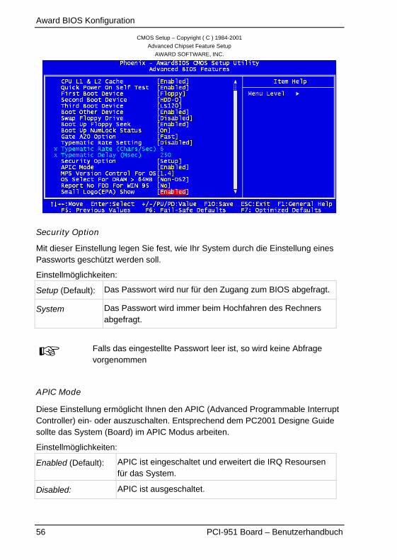
Security Option
Mit dieser Einstellung legen Sie fest, wie Ihr System durch die Einstellung einesPassworts geschützt werden soll.
Einstellmöglichkeiten:
Setup (Default): Das Passwort wird nur für den Zugang zum BIOS abgefragt.
System Das Passwort wird immer beim Hochfahren des Rechnersabgefragt.
Falls das eingestellte Passwort leer ist, so wird keine Abfragevorgenommen
APIC Mode
Diese Einstellung ermöglicht Ihnen den APIC (Advanced Programmable InterruptController) ein- oder auszuschalten. Entsprechend dem PC2001 Designe Guidesollte das System (Board) im APIC Modus arbeiten.
Einstellmöglichkeiten:
Enabled (Default): APIC ist eingeschaltet und erweitert die IRQ Resoursenfür das System.
Disabled: APIC ist ausgeschaltet.
Award BIOS Konfiguration
PCI-951 Board – Benutzerhandbuch 57
MPS Version Control For OS
Diese Einstellung legt fest, welche MPS-Version (Multi-Processor Specification)dieses Board anwendet. Sie müssen die MPS Version einstellen, welche Ihr
Betriebssystem unterstützt. Einstellmöglichkeiten: 1.1 und 1.4.
Default-Einstellung: 1.4
OS Select for DRAM > 64MB
Diese Einstellung legt fest, ob der Speicherbereich über 64 MByte vom Betriebs-system OS/2 verwaltet werden soll. Wenn Sie das Betriebssystem OS/2
verwenden, wählen Sie hier die Option OS2, sonst Non-OS2.
Default-Einstellung: Non-OS2
Report No FDD For WIN 95
Dieses Feld legt fest, ob das BIOS dem Betriebssystem Windows 95 mitteilensoll, ob ein Diskettenlaufwerk vorhanden ist oder nicht. Diese Funktion vermeidetunnötige Wartezeiten unter Windows 95.
Einstellmöglichkeiten: Yes und No.
Yes: Windows 95 soll nicht nach einem Diskettenlaufwerk suchen,da keines vorhanden ist.
No (Default): Windows 95 soll selber feststellen, ob ein Diskettenlaufwerkvorhanden ist.
Small Logo (EPA) Show
Mit dieser Einstellung bestimmen Sie, ob das EPA Logo auf dem Bildschirmwährend des Hochfahrens angezeigt werden soll.
Einstellmöglichkeiten:
Enabled (Default): Das EPA-Logo wird während des Hochfahrens angezeigt.
Disabled: Das EPA Logo wird während des Hochfahrens nichtangezeigt.
Award BIOS Konfiguration
58 PCI-951 Board – Benutzerhandbuch
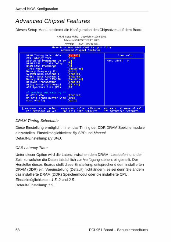
Advanced Chipset FeaturesDieses Setup-Menü bestimmt die Konfiguration des Chipsatzes auf dem Board.
CMOS Setup Utility – Copyright © 1984-2001
Advanced CHIPSET FEATURES
AWARD SOFTWARE INC.
DRAM Timing Selectable
Diese Einstellung ermöglicht Ihnen das Timing der DDR DRAM Speichermodule
einzustellen. Einstellmöglichkeiten: By SPD und Manual.
Default-Einstellung: By SPD.
CAS Latency Time
Unter dieser Option wird die Latenz zwischen dem DRAM -Lesebefehl und derZeit, zu welcher die Daten tatsächlich zur Verfügung stehen, eingestellt. DerHersteller dieses Boards stellt diese Einstellung, entsprechend dem installiertenDRAM (DDR) ein. Voreinstellung (Default) nicht ändern, es sei denn Sie änderndas installierte DRAM (DDR) Speichermodul oder die installierte CPU.
Einstellmöglichkeiten: 1.5, 2 und 2.5.
Default-Einstellung: 1.5.

Award BIOS Konfiguration
PCI-951 Board – Benutzerhandbuch 59
Activity to Precharge Delay
Diese Einstellung steuert die Anzahl der DRAM-Taktzyklen für SDRAM (DDR)
Parameter. Die Einstellmöglichkeiten sind 7, 6 und 5.
Default-Einstellung: 7. �Voreinstellung (Default) nicht ändern�.
DRAM RAS# to CAS# Delay
Hier wird die Zeitspanne zwischen dem RAS und CAS-Signal festgelegt. Siekönnen hier, je Speichertyp, 2/2 oder 3/3CLKs einstellen. Der Hersteller diesesBoards stellt diese Einstellung entsprechend dem installierten DRAM (DDR) ein.Voreinstellung (Default) nicht ändern; es sei denn, Sie ändern das installierteDRAM (DDR) Speichermodul oder die installierte CPU.
Einstellmöglichkeiten sind 2 und 3.
Default-Einstellung: 3.
DRAM RAS# Precharge
Mit dieser Einstellung wird festgelegt, wie viel Zeit zwischen zwei
Speicherzugriffen vergeht. Einstellmöglichkeiten sind 2 und 3.
Default-Einstellung: 3.
Turbo Mode
Diese Einstellung bestimmt die DRAM Zugriffsgeschwindigkeit.
Einstellmöglichkeiten sind Disabled (Default) und Enabled.
Memory Frequency For
Diese Einstellung bestimmt, wie der Speichertakt des installierten SDRAM (DDR)konfiguriert werden soll.
Einstellmöglichkeiten: Auto (Default), DDR 200, DDR 266, DDR 333.
System BIOS Cacheable
Das Award-BIOS spiegelt sich immer ins RAM F000h-FFFFFh. DieserSpeicherbereich kann gepuffert werden (im CPU internen Cache), wodurchZugriffe auf das BIOS schneller werden.
Einstellmöglichkeiten sind Enabled (Default) und Disabled.

Award BIOS Konfiguration
60 PCI-951 Board – Benutzerhandbuch
Video BIOS Cacheable
Das Video-BIOS belegt den Bereich von C000:0 bis maximal DFFF:0. DieserBereich kann gepuffert werden (im CPU internen Cache), wodurch Zugriffe aufdas Video-BIOS schneller werden.
Einstellmöglichkeiten sind: Enabled (Default) und Disabled.
Die Einstellungen Video BIOS Cacheable und System BIOSCacheable bieten praktisch nur unter DOS eine Beschleunigung,da moderne Betriebssysteme das BIOS nicht nutzten
Memory Hole At 15M-16M
Einige ältere ISA-Karten belegen einen Speicherbereich bei 15-16 MB imHauptspeicher. Um diesen, normalerweise belegten Bereich verwenden zu
können, kann dieser für ISA reserviert werden (Enabled).
Einstellmöglichkeiten sind Enabled und Disabled (Default).
Delayed Transaction
Der Chipsatz verfügt über einen integrierten 32-bit Schreibpuffers der alsZwischenspeicher genutzt wird, um die Datenübertragungsrate zu erhöhen.
Einstellmöglichkeiten sind Enabled (Default) und Disabled.Die Kompatibilität zur PCI Spezifikation Version 2.1 ist nur gewährleistet, falls der
Buffer aktiviert ist (Enabled).
Delay Prior to Thermal
Wenn die CPU den voreingestellten Grenzwert erreicht, wird erst nach der indiesem Feld eingestellten Verzögerungszeit die thermische Überwachungaktiviert. Dabei wird die Prozessorinterne Taktsteuerung benutzt, um denProzessor in den vorgegebenen Temperaturgrenzen zu halten.
Einstellmöglichkeiten: 4 Min, 8 Min, 16 Min (Default), 32 Min.

Award BIOS Konfiguration
PCI-951 Board – Benutzerhandbuch 61
AGP Aperture Size (MB)
Mit dieser Einstellung wird die Größe an Arbeitsspeicher, der für die AGPGrafikkarte zusätzlich zum lokalen Speicher zur Verfügung steht, bestimmt. Host-Zyklen, die auf den Apertur-Bereich zugreifen, werden direkt auf den AGPumgeleitet.
Einstellmöglichkeiten: 4MB, 8MB, 16MB, 32MB, 64MB, 128MB, 256MB.
Default-Einstellung: 64MB.
On-Chip VGA
Die Einstellmöglichkeiten für On-Chip VGA sind Enabled und Disabled.
Default-Einstellung: Enabled.
On-Chip Frame Buffer Size
Die Einstellmöglichkeiten für den internen Frame Buffer Size sind 8MB und 1MB.
Default-Einstellung: 8MB.
Boot Display
Die Einstellmöglichkeiten für Boot Display sind Auto, CRT, TV und EFP.
Default-Einstellung: Auto.
Award BIOS Konfiguration
62 PCI-951 Board – Benutzerhandbuch
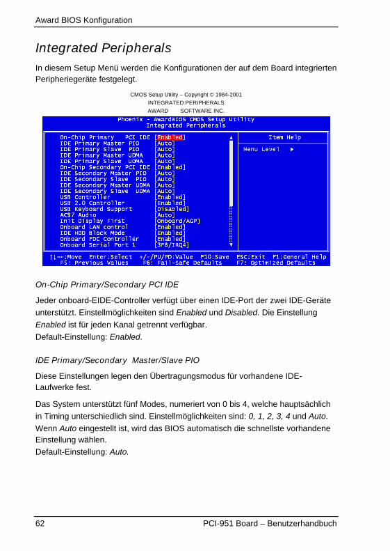
Integrated PeripheralsIn diesem Setup Menü werden die Konfigurationen der auf dem Board integriertenPeripheriegeräte festgelegt.
CMOS Setup Utility – Copyright © 1984-2001
INTEGRATED PERIPHERALS
AWARD SOFTWARE INC.
On-Chip Primary/Secondary PCI IDE
Jeder onboard-EIDE-Controller verfügt über einen IDE-Port der zwei IDE-Geräte
unterstützt. Einstellmöglichkeiten sind Enabled und Disabled. Die Einstellung
Enabled ist für jeden Kanal getrennt verfügbar.
Default-Einstellung: Enabled.
IDE Primary/Secondary Master/Slave PIO
Diese Einstellungen legen den Übertragungsmodus für vorhandene IDE-Laufwerke fest.
Das System unterstützt fünf Modes, numeriert von 0 bis 4, welche hauptsächlich
in Timing unterschiedlich sind. Einstellmöglichkeiten sind: 0, 1, 2, 3, 4 und Auto.
Wenn Auto eingestellt ist, wird das BIOS automatisch die schnellste vorhandeneEinstellung wählen.
Default-Einstellung: Auto.
Award BIOS Konfiguration
PCI-951 Board – Benutzerhandbuch 63
IDE Primary/Secondary Master/Slave UDMA
Unter dieser Option nehmen Sie die Einstellungen für den Ultra-DMA Modus Ihrer
IDE-Laufwerke vor. Einstellmöglichkeiten sind Auto und Disabled.
Default-Einstellung: Auto.
USB Controller
Die Einstellmöglichkeiten für dieses Feld sind Enabled und Disabled.
Default-Einstellung: Enabled.
USB 2.0 Controller
Die Einstellmöglichkeiten für dieses Feld sind Enabled und Disabled.
Default-Einstellung: Enabled.
USB Keyboard Support
Dieses Feld legt fest, ob die Unterstützung für USB-Tastaturen in Betriebs-systemen, die keine eigene USB-Unterstützung bieten, ein- oder ausgeschaltet
wird. Mit Enabled wird die USB-Unterstützung eingeschaltet, mit Disabled wird sieausgeschaltet.
Default-Einstellung: Disabled.
Für Betriebssysteme mit USB-Unterstützung sollte dieseFunktion nicht aktiviert werden.
AC97 Audio
Die Einstellmöglichkeiten für dieses Feld sind Auto und Disabled.
Default-Einstellung: Auto.
Init Display First
Unter dieser Option können Sie einstellen, welche Grafikkarte zuerst initialisiertwerden soll. Zur Auswahl stehen: PCI-Slot oder AGP Karte.
Einstellmöglichkeiten: Onboard/AGP und PCI Slot
Default-Einstellung: Onboard/AGP.
Onboard LAN Controller
Diese Einstellungen ermöglichen Ihnen den Onboard LAN Controller ein- oder
auszuschalten. Einstellmöglichkeiten: Enabled und Disabled.
Default-Einstellung: Enabled.
Award BIOS Konfiguration
64 PCI-951 Board – Benutzerhandbuch
IDE HDD Block Mode
Falls Ihre Festplatte den Block-Modus unterstützt, wählen Sie Enabled für dieautomatische Ermittlung der Zahl der Blöcke pro Aufforderung. Es könnenmehrere Sektoren gleichzeitig gelesen/geschrieben werden und damit wird die
Datentransferrate erhöht. Einstellmöglichkeiten: Enabled und Disabled.
Default-Einstellung: Enabled.
Onboard FDC Controller
Hiermit wird der auf dem Board integrierte Floppy Disk Controller (FDC) aktiviertbzw. deaktiviert.
Enabled (Default): Der Diskettencontroller des Boards wird verwendet.
Disabled Wenn Sie einen zusätzlichen Controller verwendenoder kein Diskettenlaufwerk einsetzen.
Onboard Serial Port 1&2
Diese Felder legen die Resourcen (I/O Adresse und IRQ) für die seriellenSchnittstellen fest.
Default Einstellmöglichkeiten (ohne Default-Einstellung)
Serial Port 1 3F8/IRQ4 2F8/IRQ3 / 3E8/IRQ4 / 2E8/IRQ3 / Disabled / Auto
Serial Port 2 2F8/IRQ3 3F8/IRQ4 / 3E8/IRQ4 / 2E8/IRQ3 / Disabled / Auto
Award BIOS Konfiguration
PCI-951 Board – Benutzerhandbuch 65
CMOS Setup Utility – Copyright © 1984-2001
INTEGRATED PERIPHERIAL
AWARD SOFTWARE INC.
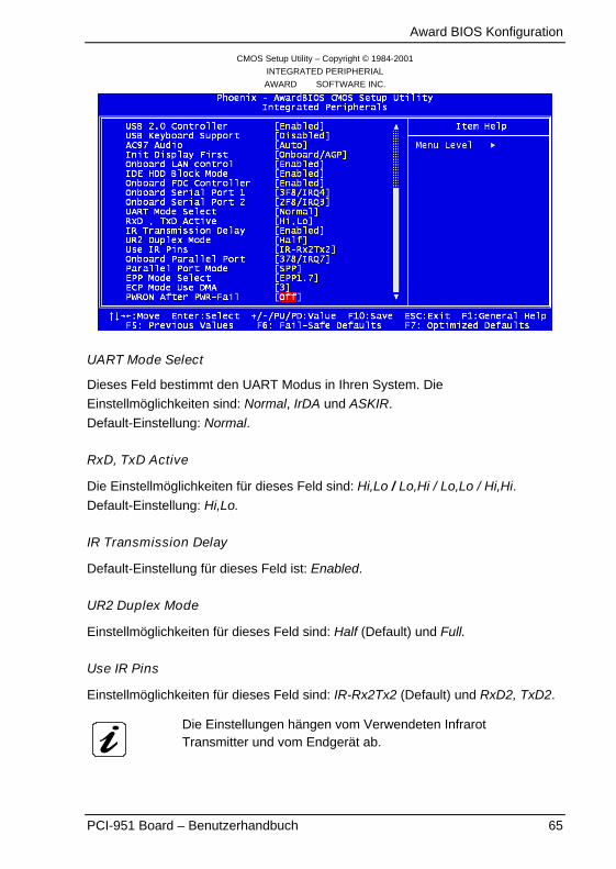
UART Mode Select
Dieses Feld bestimmt den UART Modus in Ihren System. Die
Einstellmöglichkeiten sind: Normal, IrDA und ASKIR.
Default-Einstellung: Normal.
RxD, TxD Active
Die Einstellmöglichkeiten für dieses Feld sind: Hi,Lo / Lo,Hi / Lo,Lo / Hi,Hi.
Default-Einstellung: Hi,Lo.
IR Transmission Delay
Default-Einstellung für dieses Feld ist: Enabled.
UR2 Duplex Mode
Einstellmöglichkeiten für dieses Feld sind: Half (Default) und Full.
Use IR Pins
Einstellmöglichkeiten für dieses Feld sind: IR-Rx2Tx2 (Default) und RxD2, TxD2.
Die Einstellungen hängen vom Verwendeten InfrarotTransmitter und vom Endgerät ab.
Award BIOS Konfiguration
66 PCI-951 Board – Benutzerhandbuch
Onboard Parallel Port
Dieses Feld legt die Resourcen (I/O-Adresse und IRQ) für die paralleleSchnittstelle fest.Einstellmöglichkeiten:
Default Einstellmöglichkeiten (ohne Default-Einstellung)
Parallel Port 378/IRQ7 278/IRQ5 / 3BC/IRQ7 / Disabled
Die Verwendung von ECP oder EPP ist bei Auswahl 3BC nichtunterstützt.
Parallel Port Mode
Dieses Feld legt fest, in welchen Modi die parallele Schnittstelle betrieben wird.Einstellmöglichkeiten:
SPP Standard Printer Port
EPP Enhanced Parallel Port
ECP Extended Capabilities Port
ECP+EPP (Default) Enhanced Parallel und Extended Capabilities Port
Normal Standard Parallel Port
ECP Mode Select
Einstellmöglichkeiten für dieses Feld sind: EPP 1.7 und EPP 1.9.
Default-Einstellung: EPP 1.7.
ECP Mode Use DMA
Einstellmöglichkeiten für dieses Feld sind: 3 und 1.
Default-Einstellung: 3.
PWRON After PWR-Fail
Je nach Einstellung verhält sich das System unterschiedlich bei Rückkehr derausgefallenen Netzspannung.
Einstellmöglichkeiten für dieses Feld sind: Off, On und Former-Sts.
Default-Einstellung: Off.
Award BIOS Konfiguration
PCI-951 Board – Benutzerhandbuch 67
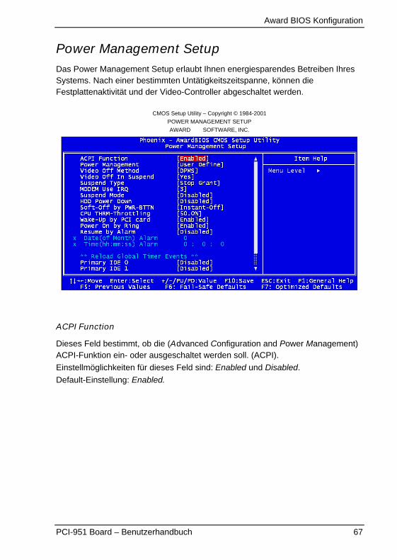
Power Management SetupDas Power Management Setup erlaubt Ihnen energiesparendes Betreiben IhresSystems. Nach einer bestimmten Untätigkeitszeitspanne, können dieFestplattenaktivität und der Video-Controller abgeschaltet werden.
CMOS Setup Utility – Copyright © 1984-2001
POWER MANAGEMENT SETUP
AWARD SOFTWARE, INC.
ACPI Function
Dieses Feld bestimmt, ob die (Advanced Configuration and Power Management)ACPI-Funktion ein- oder ausgeschaltet werden soll. (ACPI).
Einstellmöglichkeiten für dieses Feld sind: Enabled und Disabled.
Default-Einstellung: Enabled.
Award BIOS Konfiguration
68 PCI-951 Board – Benutzerhandbuch
Power Management
Dieses Feld bestimmt, wie die (Advanced Power Management) APM-Funktion(Stromsparmodi) eingesetzt wird.Einstellmöglichkeiten:
User Define(Default)
Jeder Bereich kann von 1 Min. bis 1h. eingestellt werden.Ausnahme: für die HDD kann der Bereich von 1 Min. bis 15 Min.eingestellt werden.
Min. Saving Minimum Power Management.
Max. Saving Maximum Power Management.
Um den Überhitzungsschutz der CPU sicherzustellen, kann
die Power Management Einstellung nicht auf Disabled
eingestellt werden; (Disabled-Einstellmöglichkeit ist nichtvorhanden).
Video Off Method
Dieses Feld legt die Methode zum Abschalten der Bildschirmanzeige fest.Einstellmöglichkeiten:
DPMS (Default) Das BIOS steuert den Energiesparmodus über DPMS-fähige Graphikkarten.
Blank Screen Bei dieser Option werden nur Leerzeichen in den VideoBuffer geschrieben.
V/H SYNC+Blank H-SYNC & V-SYNC Signale werden abgeschaltet.
Video Off In Suspend
Diese s Feld legt fest ob der Monitor im Stromsparmodus ausgeschaltet wird.
Einstellmöglichkeiten für dieses Feld sind: Yes (Default) und No.
Suspend Type
Einstellmöglichkeiten für dieses Feld sind: Stop Grant und PwrOn Suspend.
Default-Einstellung: Stop Grant.
Modem Use IRQ
Mit dieser Einstellung kann die Interrupt-Leitung (IRQ) eines eventuell vorhandenModems angeben werden. Durch Aktivitäten auf dieser Leitung, wird das System
geweckt. Einstellmöglichkeiten: NA, 3 (Default), 4, 5, 7, 9, 10, 11.

Award BIOS Konfiguration
PCI-951 Board – Benutzerhandbuch 69
Suspend Mode
Enabled, bewirkt dass, nach einer bestimmten Zeit ohne Systemaktivität alleFunktionseinheiten, außer der CPU, abgeschaltet werden.
Einstellmöglichkeiten: Enabled und Disabled (Default).
HDD Power Down
Dieses Feld legt fest, wann die Festplatte abgeschaltet werden soll.
Einstellmöglichkeiten: Disabled (Default), 1Min, 2Min, 3Min, 4Min, 5Min, 6Min,
7Min.Nach der eingestellten Zeit (Min = Minuten) ohne Systemaktivität schaltet dasSystem die Festplatte ab.
Disabled: Das System schaltet die Festplatte nicht ab.
Soft-Off by PWR-BTTN
Dieses Feld bestimmt das Auschalt-Verhalten, wenn ein ATX-Netzteil verwendet
wird. Einstellmöglichkeiten für dieses Feld sind: Instant Off und Delay 4 sec.
Default-Einstellung: Instant Off.
Wenn Sie Instant Off einstellen, schaltet sich der PC sofort nach der Betätigungdes ATX Power-Buttons aus.
Bei der Delay 4 sec .-Einstellung, muss der ATX Power-Button zum Ausschaltenlänger als 4 Sekunden gedrückt werden. Drücken Sie kürzer kommt der Rechnernur in den Soft-Aus-Zustand.
CPU THRM-Throttling
Mit diesen Einstellungen bestimmen Sie mit welchem Verhältnis der Chipsatz denProzessor stoppen soll.
Einstellmöglichkeiten: 12,5 %, 25%, 37,5%, 50%, 62,5%, 75%, 87,5%.(z.B bei 12,5%-Einstellungswert wird der Prozessor zu 12,5% gestoppt).
Default-Einstellung: 50%.
Wake-Up by PCI Card & Power On by Ring
Dieses Feld legt fest, ob das System aus dem Sparmodus geweckt werden sollwenn eine Aktivität oder Eingangssignale einer spezifischen Hardware-Peripherieoder Hardware-Funktion festgestellt wird.
Einstellmöglichkeiten: Enabled und Disabled.
Default-Einstellung: Enabled.
Um die Funktion “Wake Up On Ring“ oder “Wake Up On LAN” zunützen, müssen Sie ein Modem/ eine LAN-Netzwerkkarte das/die diePower ON-Funktion unterstützt, installieren.
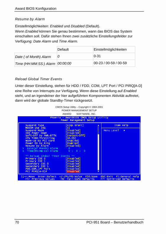
Award BIOS Konfiguration
70 PCI-951 Board – Benutzerhandbuch
Resume by Alarm
Einstellmöglichkeiten: Enabled und Disabled (Default).
Wenn Enabled können Sie genau bestimmen, wann das BIOS das Systemeinschalten soll. Dafür stehen Ihnen zwei zusätzliche Einstellungsfelder zur
Verfügung: Date Alarm und Time Alarm.
Default Einstellmöglichkeiten
Date ( of Month) Alarm 0 0-31
Time (HH:MM:SS:) Alarm 00:00:00 00-23 / 00-59 / 00-59
Reload Global Timer Events
Unter dieser Einstellung, stehen für HDD / FDD, COM, LPT Port / PCI PIRQ[A-D]
eine Reihe von Interrupts zur Verfügung. Wenn diese Einstellung auf Enabledsteht, und an irgendeiner der hier aufgeführten Komponenten Aktivität auftretet,dann wird der globale Standby-Timer rückgesetzt.
CMOS Setup Utility – Copyright © 1984-2001
POWER MANAGEMENT SETUP
AWARD SOFTWARE, INC.
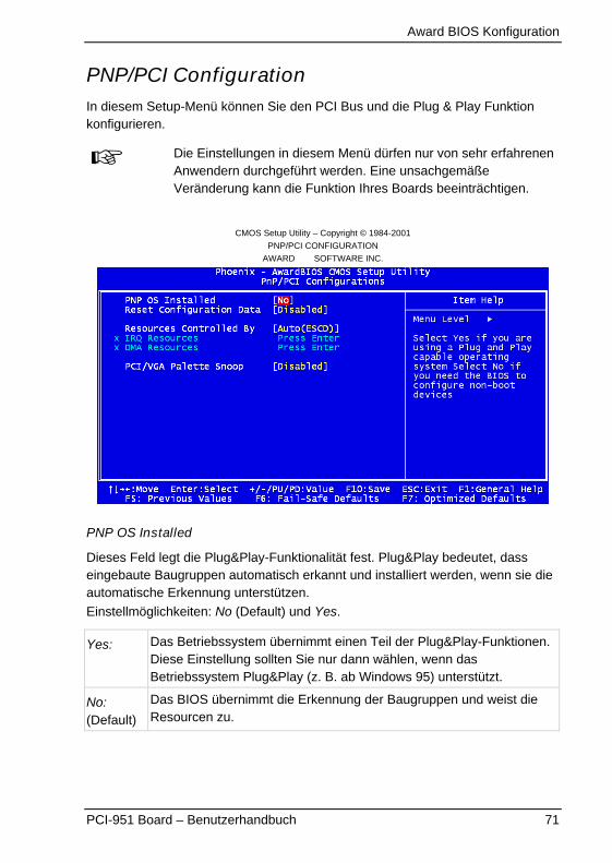
Award BIOS Konfiguration
PCI-951 Board – Benutzerhandbuch 71
PNP/PCI ConfigurationIn diesem Setup-Menü können Sie den PCI Bus und die Plug & Play Funktionkonfigurieren.
Die Einstellungen in diesem Menü dürfen nur von sehr erfahrenenAnwendern durchgeführt werden. Eine unsachgemäßeVeränderung kann die Funktion Ihres Boards beeinträchtigen.
CMOS Setup Utility – Copyright © 1984-2001
PNP/PCI CONFIGURATION
AWARD SOFTWARE INC.
PNP OS Installed
Dieses Feld legt die Plug&Play-Funktionalität fest. Plug&Play bedeutet, dasseingebaute Baugruppen automatisch erkannt und installiert werden, wenn sie dieautomatische Erkennung unterstützen.
Einstellmöglichkeiten: No (Default) und Yes.
Yes: Das Betriebssystem übernimmt einen Teil der Plug&Play-Funktionen.Diese Einstellung sollten Sie nur dann wählen, wenn dasBetriebssystem Plug&Play (z. B. ab Windows 95) unterstützt.
No:(Default)
Das BIOS übernimmt die Erkennung der Baugruppen und weist dieResourcen zu.
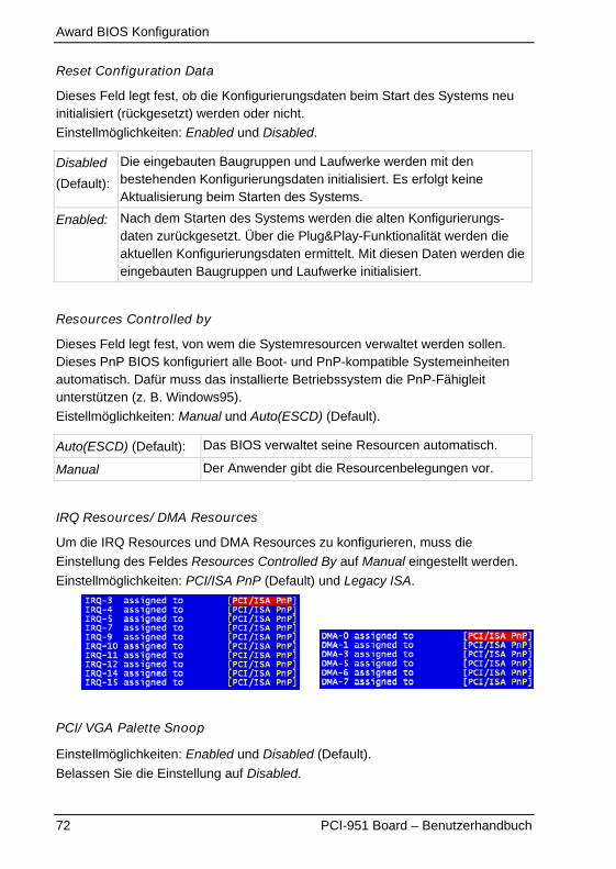
Award BIOS Konfiguration
72 PCI-951 Board – Benutzerhandbuch
Reset Configuration Data
Dieses Feld legt fest, ob die Konfigurierungsdaten beim Start des Systems neuinitialisiert (rückgesetzt) werden oder nicht.
Einstellmöglichkeiten: Enabled und Disabled.
Disabled
(Default):
Die eingebauten Baugruppen und Laufwerke werden mit denbestehenden Konfigurierungsdaten initialisiert. Es erfolgt keineAktualisierung beim Starten des Systems.
Enabled: Nach dem Starten des Systems werden die alten Konfigurierungs-daten zurückgesetzt. Über die Plug&Play-Funktionalität werden dieaktuellen Konfigurierungsdaten ermittelt. Mit diesen Daten werden dieeingebauten Baugruppen und Laufwerke initialisiert.
Resources Controlled by
Dieses Feld legt fest, von wem die Systemresourcen verwaltet werden sollen.Dieses PnP BIOS konfiguriert alle Boot- und PnP-kompatible Systemeinheitenautomatisch. Dafür muss das installierte Betriebssystem die PnP-Fähigleitunterstützen (z. B. Windows95).
Eistellmöglichkeiten: Manual und Auto(ESCD) (Default).
Auto(ESCD) (Default): Das BIOS verwaltet seine Resourcen automatisch.
Manual Der Anwender gibt die Resourcenbelegungen vor.
IRQ Resources/ DMA Resources
Um die IRQ Resources und DMA Resources zu konfigurieren, muss die
Einstellung des Feldes Resources Controlled By auf Manual eingestellt werden.
Einstellmöglichkeiten: PCI/ISA PnP (Default) und Legacy ISA.
PCI/ VGA Palette Snoop
Einstellmöglichkeiten: Enabled und Disabled (Default).
Belassen Sie die Einstellung auf Disabled.
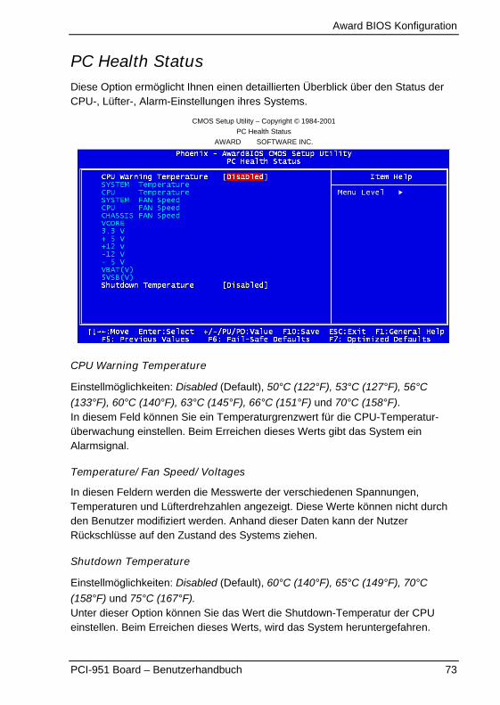
Award BIOS Konfiguration
PCI-951 Board – Benutzerhandbuch 73
PC Health StatusDiese Option ermöglicht Ihnen einen detaillierten Überblick über den Status derCPU-, Lüfter-, Alarm-Einstellungen ihres Systems.
CMOS Setup Utility – Copyright © 1984-2001
PC Health Status
AWARD SOFTWARE INC.
CPU Warning Temperature
Einstellmöglichkeiten: Disabled (Default), 50°C (122°F), 53°C (127°F), 56°C
(133°F), 60°C (140°F), 63°C (145°F), 66°C (151°F) und 70°C (158°F).In diesem Feld können Sie ein Temperaturgrenzwert für die CPU-Temperatur-überwachung einstellen. Beim Erreichen dieses Werts gibt das System einAlarmsignal.
Temperature/ Fan Speed/ Voltages
In diesen Feldern werden die Messwerte der verschiedenen Spannungen,Temperaturen und Lüfterdrehzahlen angezeigt. Diese Werte können nicht durchden Benutzer modifiziert werden. Anhand dieser Daten kann der NutzerRückschlüsse auf den Zustand des Systems ziehen.
Shutdown Temperature
Einstellmöglichkeiten: Disabled (Default), 60°C (140°F), 65°C (149°F), 70°C
(158°F) und 75°C (167°F).Unter dieser Option können Sie das Wert die Shutdown-Temperatur der CPUeinstellen. Beim Erreichen dieses Werts, wird das System heruntergefahren.
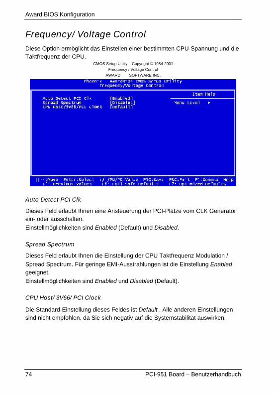
Award BIOS Konfiguration
74 PCI-951 Board – Benutzerhandbuch
Frequency/ Voltage ControlDiese Option ermöglicht das Einstellen einer bestimmten CPU-Spannung und dieTaktfrequenz der CPU.
CMOS Setup Utility – Copyright © 1984-2001
Frequency / Voltage Control
AWARD SOFTWARE INC.
Auto Detect PCI Clk
Dieses Feld erlaubt Ihnen eine Ansteuerung der PCI-Plätze vom CLK Generatorein- oder ausschalten.
Einstellmöglichkeiten sind Enabled (Default) und Disabled.
Spread Spectrum
Dieses Feld erlaubt Ihnen die Einstellung der CPU Taktfrequenz Modulation /
Spread Spectrum. Für geringe EMI-Ausstrahlungen ist die Einstellung Enabledgeeignet.
Einstellmöglichkeiten sind Enabled und Disabled (Default).
CPU Host/ 3V66/ PCI Clock
Die Standard-Einstellung dieses Feldes ist Default . Alle anderen Einstellungensind nicht empfohlen, da Sie sich negativ auf die Systemstabilität auswirken.
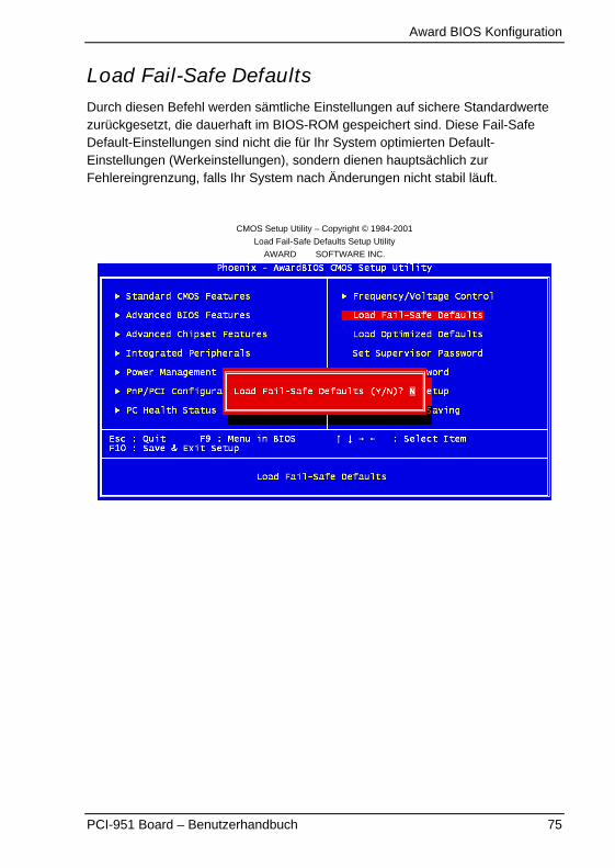
Award BIOS Konfiguration
PCI-951 Board – Benutzerhandbuch 75
Load Fail-Safe DefaultsDurch diesen Befehl werden sämtliche Einstellungen auf sichere Standardwertezurückgesetzt, die dauerhaft im BIOS-ROM gespeichert sind. Diese Fail-SafeDefault-Einstellungen sind nicht die für Ihr System optimierten Default-Einstellungen (Werkeinstellungen), sondern dienen hauptsächlich zurFehlereingrenzung, falls Ihr System nach Änderungen nicht stabil läuft.
CMOS Setup Utility – Copyright © 1984-2001
Load Fail-Safe Defaults Setup Utility
AWARD SOFTWARE INC.

Award BIOS Konfiguration
76 PCI-951 Board – Benutzerhandbuch
Load Optimized DefaultsDiese Option erlaubt Ihnen die Default-Einstellungen für Ihre Systemkonfigurationzu laden. Diese Default-Einstellungen sind die optimierten Werte(Werkeinstellungen), welche die optimalen Systemleistungen gewährleisten.
CMOS Setup Utility – Copyright © 1984-2001
Load Optimized Defaults Setup Utility
AWARD SOFTWARE INC.
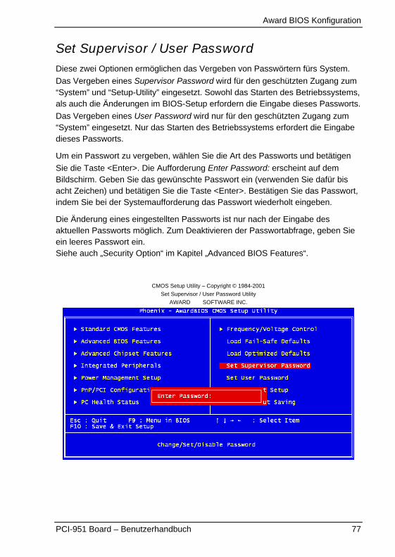
Award BIOS Konfiguration
PCI-951 Board – Benutzerhandbuch 77
Set Supervisor / User PasswordDiese zwei Optionen ermöglichen das Vergeben von Passwörtern fürs System.
Das Vergeben eines Supervisor Password wird für den geschützten Zugang zum“System” und “Setup-Utility” eingesetzt. Sowohl das Starten des Betriebssystems,als auch die Änderungen im BIOS-Setup erfordern die Eingabe dieses Passworts.
Das Vergeben eines User Password wird nur für den geschützten Zugang zum“System” eingesetzt. Nur das Starten des Betriebssystems erfordert die Eingabedieses Passworts.
Um ein Passwort zu vergeben, wählen Sie die Art des Passworts und betätigen
Sie die Taste <Enter>. Die Aufforderung Enter Password: erscheint auf demBildschirm. Geben Sie das gewünschte Passwort ein (verwenden Sie dafür bisacht Zeichen) und betätigen Sie die Taste <Enter>. Bestätigen Sie das Passwort,indem Sie bei der Systemaufforderung das Passwort wiederholt eingeben.
Die Änderung eines eingestellten Passworts ist nur nach der Eingabe desaktuellen Passworts möglich. Zum Deaktivieren der Passwortabfrage, geben Sieein leeres Passwort ein.Siehe auch „Security Option“ im Kapitel „Advanced BIOS Features“.
CMOS Setup Utility – Copyright © 1984-2001
Set Supervisor / User Password Utility
AWARD SOFTWARE INC.
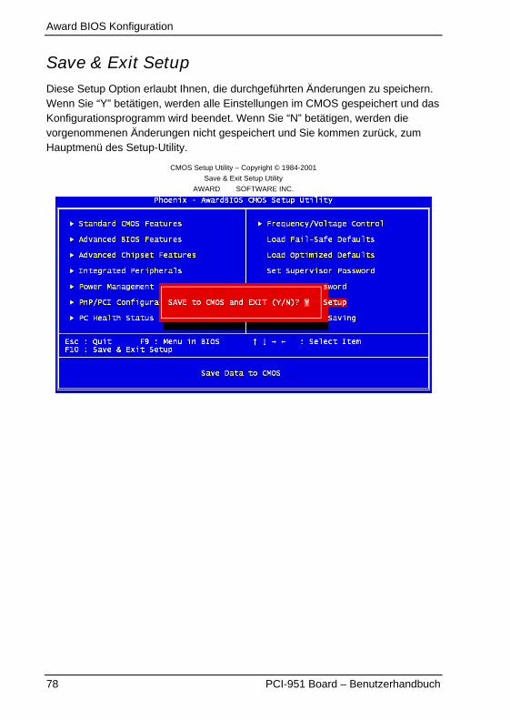
Award BIOS Konfiguration
78 PCI-951 Board – Benutzerhandbuch
Save & Exit SetupDiese Setup Option erlaubt Ihnen, die durchgeführten Änderungen zu speichern.Wenn Sie “Y” betätigen, werden alle Einstellungen im CMOS gespeichert und dasKonfigurationsprogramm wird beendet. Wenn Sie “N” betätigen, werden dievorgenommenen Änderungen nicht gespeichert und Sie kommen zurück, zumHauptmenü des Setup-Utility.
CMOS Setup Utility – Copyright © 1984-2001
Save & Exit Setup Utility
AWARD SOFTWARE INC.
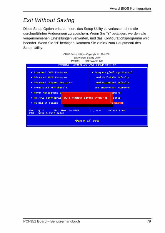
Award BIOS Konfiguration
PCI-951 Board – Benutzerhandbuch 79
Exit Without SavingDiese Setup Option erlaubt Ihnen, das Setup-Utility zu verlassen ohne diedurchgeführten Änderungen zu speichern. Wenn Sie “Y” betätigen, werden allevorgenommenen Einstellungen verworfen, und das Konfigurationsprogramm wirdbeendet. Wenn Sie “N” betätigen, kommen Sie zurück zum Hauptmenü desSetup-Utility.
CMOS Setup Utility – Copyright © 1984-2001
Exit Without Saving Utility
AWARD SOFTWARE INC.
AMI BIOS Configuration
80 PCI-951 Board – Benutzerhandbuch
AMI BIOS ConfigurationThis chapter describes the settings available in the optional AMI-BIOS for thePCI-951 board. The AMI-BIOS (Basic Input/Output System) pre- installed in yourcomputer system’s ROM supports Intel® Pentium® 4 and Celeron® processors ina standard IBM-AT compatible I/O system.
BIOS SetupThe AMI-BIOS provides a Setup utility program for specifying the systemconfigurations and settings. The BIOS ROM of the system stores the Setup utility.When you turn on the computer, the AMI-BIOS is activated.Pressing the <Del> key immediately allows you to enter the Setup utility. If youare a little bit late pressing the <Del> key, POST (Power On Self Test) willcontinue with its test routines, thus preventing you from invoking the Setup. If youstill wish to enter Setup, restart the system by pressing the ”Reset” button orsimultaneously pressing the <Ctrl>, <Alt> and <Delete> keys. You can alsorestart by turning the system Off and back On again. The following message willappear on the screen:Press <DEL> to Enter Setup
In general, you press the arrow keys to highlight items, <Enter> to select, the<PgUp> and <PgDn> keys to change entries, <F1> for help and <Esc> to quit.
When you enter the Setup utility, the Main Menu screen will appear on thescreen. The Main Menu allows you to select from various Setup functions and exitchoices.
The Main BIOS Setup menu screen has two main frames. The left frame displaysall the options that can be configured. “Grayed-out” options cannot be configured.Options is blue can be.
The right frame displays the key legend. Above the key legend is an areareserved for a text message. When an option is selected in the left frame, it ishighlighted in white. Often a text message will accompany it.
AMI BIOS Configuration
PCI-951 Board – Benutzerhandbuch 81
Navigation
Hot Key Description
�� Left/Right The Left and Right <Arrow> keys allow you to select a BIOSSetup screen.
For example: Main screen, Advanced screen, Chipsetscreen, and so on.
�� Up/Down The Up and Down <Arrow> keys allow you to select a BIOSSetup item or sub-screen.
+- Plus/Minus The Plus and Minus <Keys> keys allow you to change the fieldvalue of a particular BIOS Setup item.
For example: Date and Time.
Tab The <Tab> key allows you to select BIOS Setup fields.
The <F8> key on your keyboard is the Fail-Safe key. It is notdisplayed on the key legend by default. To set the Fail-Safesettings of the BIOS, press the <F8> key on your keyboard. TheFail-Safe settings allow the motherboard to boot up with the leastamount of options enabled. This can lessen the probability ofconflicting settings.
The <F9> key on your keyboard is the Optimal-Default key. To setthe Optimal-Default settings of the BIOS, press the <F9> key onyour keyboard.
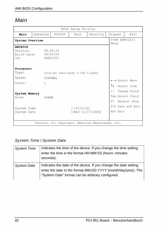
AMI BIOS Configuration
82 PCI-951 Board – Benutzerhandbuch
MainBIOS Setup Utility
Main Advanced PCIPnP Boot Security Chipset Exit
System Overview
AMIBIOSVersion:Build Date:ID:
ProcessorType:
Speed:
Count:
System MemorySize:
08.00.1008/02/040AAZI021
Intel(R) Pentium(R) 4 CPU 3.06GHz
3066MHz
1
248MB
System TimeSystem Date
[13:15:41][Wed 11/17/2004]
Item SpecificHelp
�� Select Menu
�� Select Item
+- Change Field
Tab Select Field
F1 General Help
F10 Save and Exit
ESC Exit
Version, (C) Copyright, American Megatrends, Inc.
System Time / System Date
System Time Indicates the time of the device. If you change the time setting,
enter the time in the format HH:MM:SS (hours: minutes:seconds).
System Date Indicates the date of the device. If you change the date setting,
enter the date in the format MM.DD.YYYY (month/day/year). The“System Date” format can be arbitrary configured.
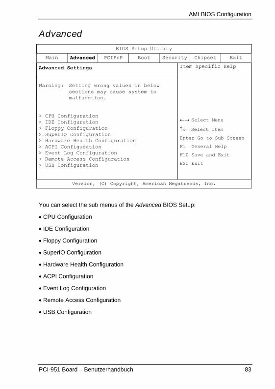
AMI BIOS Configuration
PCI-951 Board – Benutzerhandbuch 83
AdvancedBIOS Setup Utility
Main Advanced PCIPnP Boot Security Chipset Exit
Advanced Settings
Warning: Setting wrong values in belowsections may cause system tomalfunction.
> CPU Configuration> IDE Configuration> Floppy Configuration> SuperIO Configuration> Hardware Health Configuration> ACPI Configuration> Event Log Configuration> Remote Access Configuration> USB Configuration
Item Specific Help
�� Select Menu
�� Select Item
Enter Go to Sub Screen
F1 General Help
F10 Save and Exit
ESC Exit
Version, (C) Copyright, American Megatrends, Inc.
You can select the sub menus of the Advanced BIOS Setup:
� CPU Configuration
� IDE Configuration
� Floppy Configuration
� SuperIO Configuration
� Hardware Health Configuration
� ACPI Configuration
� Event Log Configuration
� Remote Access Configuration
� USB Configuration
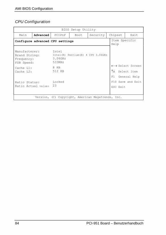
AMI BIOS Configuration
84 PCI-951 Board – Benutzerhandbuch
CPU Configuration
BIOS Setup Utility
Main Advanced PCIPnP Boot Security Chipset Exit
Configure advanced CPU settings
Manufacterer:Brand String:Frequency:FSB Speed:
Cache L1:Cache L2:
Ratio Status:Ratio Actual value:
IntelIntel(R) Pentium(R) 4 CPU 3.06GHz3.06GHz533MHz
8 KB512 KB
Locked23
Item SpecificHelp
�� Select Screen
�� Select Item
F1 General Help
F10 Save and Exit
ESC Exit
Version, (C) Copyright, American Megatrends, Inc.
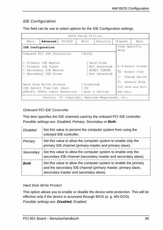
AMI BIOS Configuration
PCI-951 Board – Benutzerhandbuch 85
IDE Configuration
This field can be use to select options for the IDE Configuration settings.
BIOS Setup Utility
Main Advanced PCIPnP Boot Security Chipset Exit
IDE Configuration
Onboard PCI IDE Controller [Both]
> Primary IDE Master> Primary IDE Slave> Secondary IDE Master> Secondary IDE Slave
[Hard Disk][Not Detected][ATAPI CDROM][Not Detected]
Hard Disk Write ProtectIDE Detect Time Out (Sec)ATA(PI) 80Pin Cable Detection
[Disabled][35][Host & Device]
Item SpecificHelp
�� Select Screen
�� Select Item
+- Change Option
F1 General Help
F10 Save and Exit
ESC Exit
Version, (C) Copyright, American Megatrends, Inc.
Onboard PCI IDE Controller
This item specifies the IDE channels used by the onboard PCI IDE controller.
Possible settings are: Disabled, Primary, Secondary or Both.
Disabled Set this value to prevent the computer system from using theonboard IDE-controller.
Primary Set this value to allow the computer system to enable only theprimary IDE-channel (primary master and primary slave).
Secondary Set this value to allow the computer system to enable only thesecondary IDE-channel (secondary master and secondary slave).
Both Set this value to allow the computer system to enable the primaryand the secondary IDE-channel (primary master, primary slave,secondary master and secondary slave).
Hard Disk Write Protect
This option allows you to enable or disable the device write protection. This will beeffective only if the device is accessed through BIOS (e. g. MS-DOS).
Possible settings are: Disabled, Enabled.
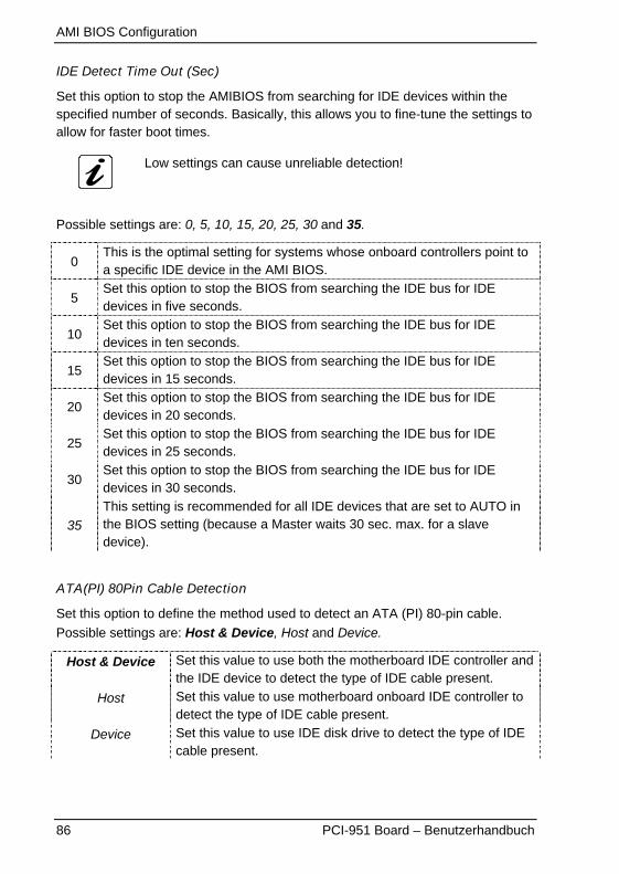
AMI BIOS Configuration
86 PCI-951 Board – Benutzerhandbuch
IDE Detect Time Out (Sec)
Set this option to stop the AMIBIOS from searching for IDE devices within thespecified number of seconds. Basically, this allows you to fine-tune the settings toallow for faster boot times.
Low settings can cause unreliable detection!
Possible settings are: 0, 5, 10, 15, 20, 25, 30 and 35.
0This is the optimal setting for systems whose onboard controllers point toa specific IDE device in the AMI BIOS.
5Set this option to stop the BIOS from searching the IDE bus for IDEdevices in five seconds.
10Set this option to stop the BIOS from searching the IDE bus for IDEdevices in ten seconds.
15Set this option to stop the BIOS from searching the IDE bus for IDEdevices in 15 seconds.
20Set this option to stop the BIOS from searching the IDE bus for IDEdevices in 20 seconds.
25Set this option to stop the BIOS from searching the IDE bus for IDEdevices in 25 seconds.
30Set this option to stop the BIOS from searching the IDE bus for IDEdevices in 30 seconds.
35This setting is recommended for all IDE devices that are set to AUTO inthe BIOS setting (because a Master waits 30 sec. max. for a slavedevice).
ATA(PI) 80Pin Cable Detection
Set this option to define the method used to detect an ATA (PI) 80-pin cable.
Possible settings are: Host & Device, Host and Device.
Host & Device Set this value to use both the motherboard IDE controller andthe IDE device to detect the type of IDE cable present.
Host Set this value to use motherboard onboard IDE controller todetect the type of IDE cable present.
Device Set this value to use IDE disk drive to detect the type of IDEcable present.
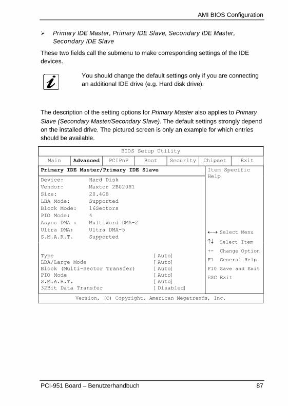
AMI BIOS Configuration
PCI-951 Board – Benutzerhandbuch 87
� Primary IDE Master, Primary IDE Slave, Secondary IDE Master,Secondary IDE Slave
These two fields call the submenu to make corresponding settings of the IDEdevices.
You should change the default settings only if you are connectingan additional IDE drive (e.g. Hard disk drive).
The description of the setting options for Primary Master also applies to Primary
Slave (Secondary Master/Secondary Slave). The default settings strongly dependon the installed drive. The pictured screen is only an example for which entriesshould be available.
BIOS Setup Utility
Main Advanced PCIPnP Boot Security Chipset Exit
Primary IDE Master/Primary IDE Slave
Device: Hard DiskVendor: Maxtor 2B020H1Size: 20.4GBLBA Mode: SupportedBlock Mode: 16SectorsPIO Mode: 4Async DMA : MultiWord DMA-2Ultra DMA: Ultra DMA-5S.M.A.R.T. Supported
TypeLBA/Large ModeBlock (Multi-Sector Transfer)PIO ModeS.M.A.R.T.32Bit Data Transfer
[Auto][Auto][Auto][Auto][Auto][Disabled]
Item SpecificHelp
�� Select Menu
�� Select Item
+- Change Option
F1 General Help
F10 Save and Exit
ESC Exit
Version, (C) Copyright, American Megatrends, Inc.
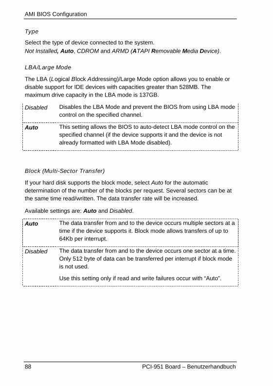
AMI BIOS Configuration
88 PCI-951 Board – Benutzerhandbuch
Type
Select the type of device connected to the system.
Not Installed, Auto, CDROM and ARMD (ATAPI Removable Media Device).
LBA/Large Mode
The LBA (Logical Block Addressing)/Large Mode option allows you to enable ordisable support for IDE devices with capacities greater than 528MB. Themaximum drive capacity in the LBA mode is 137GB.
Disabled Disables the LBA Mode and prevent the BIOS from using LBA modecontrol on the specified channel.
Auto This setting allows the BIOS to auto-detect LBA mode control on thespecified channel (if the device supports it and the device is notalready formatted with LBA Mode disabled).
Block (Multi-Sector Transfer)
If your hard disk supports the block mode, select Auto for the automaticdetermination of the number of the blocks per request. Several sectors can be atthe same time read/written. The data transfer rate will be increased.
Available settings are: Auto and Disabled.
Auto The data transfer from and to the device occurs multiple sectors at atime if the device supports it. Block mode allows transfers of up to64Kb per interrupt.
Disabled The data transfer from and to the device occurs one sector at a time.Only 512 byte of data can be transferred per interrupt if block modeis not used.
Use this setting only if read and write failures occur with “Auto”.

AMI BIOS Configuration
PCI-951 Board – Benutzerhandbuch 89
PIO Mode
These fields allow your system IDE controller to work faster. Rather than have theBIOS issue a series of commands that transfer to or from the IDE drive, PIO(Programmed Input/Output) allows the BIOS to communicate with the controllerand CPU directly.
The system supports five modes, numbered from 0 to 4, which primarily differ in
timing. Available settings are: 0, 1, 2, 3, 4 and Auto. When Auto is selected, theBIOS will select the best available mode.
Available settings are: Auto, 0, 1, 2, 3, 4.
Auto This setting allows the BIOS to auto-detect the PIO mode. This settingis to be used if the IDE disk drive cannot be determined.
0 This setting allows the BIOS to use the PIO mode 0. It has a datatransfer rate of 3.3MBs.
1 This setting allows the BIOS to use the PIO mode 1. It has a datatransfer rate of 5.2MBs.
2 This setting allows the BIOS to use the PIO mode 2. It has a datatransfer rate of 8.3MBs.
3 This setting allows the BIOS to use the PIO mode 3. It has a datatransfer rate of 11.1MBs.
4
This setting allows the BIOS to use the PIO mode 4. It has a datatransfer rate of 16.6MBs. This setting generally works with all harddisk drives manufactured after 1999. For other disk drive, such as IDECD-ROM drives, check the specification s of the drive.
Do not change the default setting “Auto”.If some read and write failures occur, check the length and qualityof the integrated device cable first or set this option to a setting witha lower data transfer rate as specified for your device.

AMI BIOS Configuration
90 PCI-951 Board – Benutzerhandbuch
DMA Mode
This option allows you to select the DMA mode option (depending on theintegrated device). Available settings are:
Auto, SWDMA0, SWDMA1, SWDMA2, MWDMA0, MWDMA1, MWDMA2,UDMA0, UDMA1, UDMA2, UDMA3, UDMA4, UDMA5 and UDMA6.
Auto If “Auto” is set, the BIOS auto-detects the DMA mode.This is the default setting.
SWDMA0 If “SWDMA0” is set the BIOS uses the Single Word DMA mode 0.It has a data transfer rate of 2.1MBs.
SWDMA1 If “SWDMA1” is set the BIOS uses the Single Word DMA mode 1.It has a data transfer rate of 4.2MBs.
SWDMA2 If “SWDMA2” is set the BIOS uses the Single Word DMA mode 2.It has a data transfer rate of 8.3MBs.
MWDMA0 If “MWDMA0” is set the BIOS uses the Multi Word DMA mode 0.It has a data transfer rate of 4.2MBs.
MWDMA1 If “MWDMA1” is set the BIOS uses the Multi Word DMA mode 1.It has a data transfer rate of 13.3MBs.
MWDMA2 If “MWDMA2” is set the BIOS uses the Multi Word DMA mode 2.It has a data transfer rate of 16.6MBs.
UDMA0 If “UDMA0” is set the BIOS uses the Ultra DMA mode 0.It has a data transfer rate of 16.6MBs (the same data transfer rateas PIO mode 4, and Multi Word DMA mode 2).
UDMA1 If “UDMA1” is set the BIOS uses the Ultra DMA mode 1.It has a data transfer rate of 25MBs.
UDMA2 If “UDMA2” is set the BIOS uses the Ultra DMA mode 2.It has a data transfer rate of 33.3MBs.
UDMA3 If “UDMA3” is set the BIOS uses the Ultra DMA mode 3.It has a data transfer rate of 44.4MBs. It is required to be used the80-conductor ATA cable for this data transfer rate.
UDMA4 If “UDMA4” is set the BIOS uses the Ultra DMA mode 4.It has a data transfer rate of 66.6MBs. It is required to be used the80-conductor ATA cable for this data transfer rate.
UDMA5 If “UDMA5” is set the BIOS uses the Ultra DMA mode 5.It has a data transfer rate of 99.9MBs. It is required to be used the80-conductor ATA cable for this data transfer rate.
UDMA6 If “UDMA6” is set the BIOS uses the Ultra DMA mode 6.It has a data transfer rate of 133.2MBs. It is required to be usedthe 80-conductor ATA cable for this data transfer rate.
AMI BIOS Configuration
PCI-951 Board – Benutzerhandbuch 91
S.M.A.R.T.
S. M. A. R. T. (Self-Monitoring, Analysis and Reporting Technology) is used topredict drive failures. (The integrated drive has to support this feature).
Available Settings are: Auto, Disabled and Enabled.
32Bit Data Transfer
This option allows you to enable or disable the 32bit data transfer rate for the IDE
devices. If this option is “Enabled” the date transfer is accelerated and the CPU(PCI Bus) is relieved.
Available settings are: Disabled and Enabled.
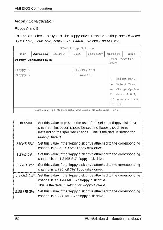
AMI BIOS Configuration
92 PCI-951 Board – Benutzerhandbuch
Floppy Configuration
Floppy A and B
This option selects the type of the floppy drive. Possible settings are: Disabled,
360KB 5¼“, 1.2MB 5¼“, 720KB 3½“; 1.44MB 3½“ and 2.88 MB 3½“.
BIOS Setup Utility
Main Advanced PCIPnP Boot Security Chipset Exit
Floppy Configuration
Floppy A
Floppy B
[1.44MB 3½“]
[Disabled]
Item SpecificHelp
�� Select Menu
�� Select Item
+- Change Option
F1 General Help
F10 Save and Exit
ESC Exit
Version, (C) Copyright, American Megatrends, Inc.
Disabled Set this value to prevent the use of the selected floppy disk drivechannel. This option should be set if no floppy disk drive isinstalled on the specified channel. This is the default setting for
Floppy Drive B.
360KB 5¼“ Set this value if the floppy disk drive attached to the correspondingchannel is a 360 KB 5¼“ floppy disk drive.
1.2MB 5¼“ Set this value if the floppy disk drive attached to the correspondingchannel is an 1.2 MB 5¼“ floppy disk drive.
720KB 3½“ Set this value if the floppy disk drive attached to the correspondingchannel is a 720 KB 3½“ floppy disk drive.
1.44MB 3½“ Set this value if the floppy disk drive attached to the correspondingchannel is an 1.44 MB 3½“ floppy disk drive.
This is the default setting for Floppy Drive A.
2.88 MB 3½“ Set this value if the floppy disk drive attached to the correspondingchannel is a 2.88 MB 3½“ floppy disk drive.
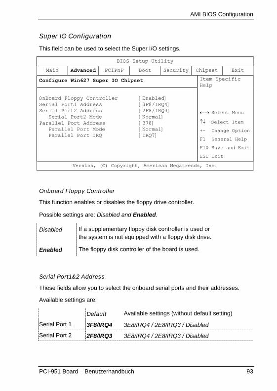
AMI BIOS Configuration
PCI-951 Board – Benutzerhandbuch 93
Super IO Configuration
This field can be used to select the Super I/O settings.
BIOS Setup Utility
Main Advanced PCIPnP Boot Security Chipset Exit
Configure Win627 Super IO Chipset
OnBoard Floppy ControllerSerial Port1 AddressSerial Port2 Address
Serial Port2 ModeParallel Port Address
Parallel Port ModeParallel Port IRQ
[Enabled][3F8/IRQ4][2F8/IRQ3][Normal][378][Normal][IRQ7]
Item SpecificHelp
�� Select Menu
�� Select Item
+- Change Option
F1 General Help
F10 Save and Exit
ESC Exit
Version, (C) Copyright, American Megatrends, Inc.
Onboard Floppy Controller
This function enables or disables the floppy drive controller.
Possible settings are: Disabled and Enabled.
Disabled If a supplementary floppy disk controller is used orthe system is not equipped with a floppy disk drive.
Enabled The floppy disk controller of the board is used.
Serial Port1&2 Address
These fields allow you to select the onboard serial ports and their addresses.
Available settings are:
Default Available settings (without default setting)
Serial Port 1 3F8/IRQ4 3E8/IRQ4 / 2E8/IRQ3 / Disabled
Serial Port 2 2F8/IRQ3 3E8/IRQ4 / 2E8/IRQ3 / Disabled
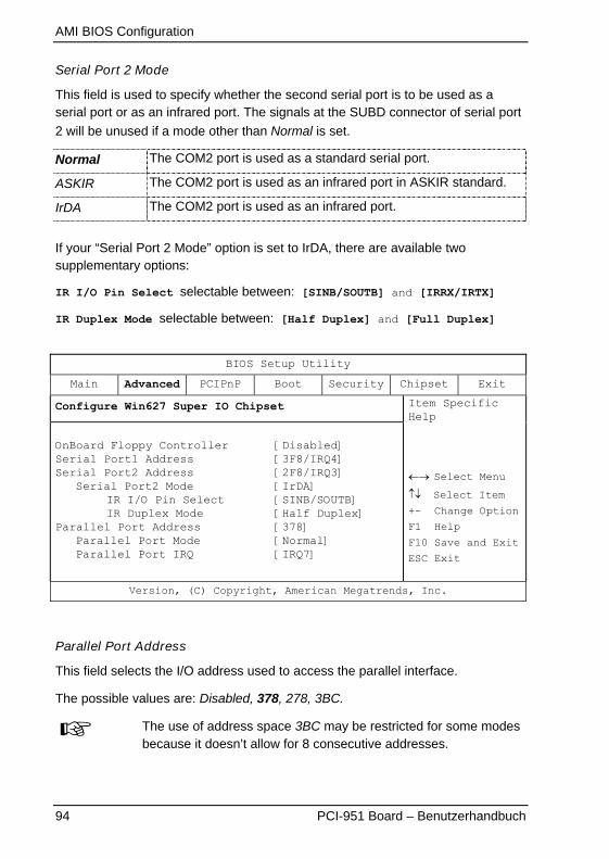
AMI BIOS Configuration
94 PCI-951 Board – Benutzerhandbuch
Serial Port 2 Mode
This field is used to specify whether the second serial port is to be used as aserial port or as an infrared port. The signals at the SUBD connector of serial port
2 will be unused if a mode other than Normal is set.
Normal The COM2 port is used as a standard serial port.
ASKIR The COM2 port is used as an infrared port in ASKIR standard.
IrDA The COM2 port is used as an infrared port.
If your “Serial Port 2 Mode” option is set to IrDA, there are available twosupplementary options:
IR I/O Pin Select selectable between: [SINB/SOUTB] and [IRRX/IRTX]
IR Duplex Mode selectable between: [Half Duplex] and [Full Duplex]
BIOS Setup Utility
Main Advanced PCIPnP Boot Security Chipset Exit
Configure Win627 Super IO Chipset
OnBoard Floppy ControllerSerial Port1 AddressSerial Port2 Address
Serial Port2 ModeIR I/O Pin SelectIR Duplex Mode
Parallel Port AddressParallel Port ModeParallel Port IRQ
[Disabled][3F8/IRQ4][2F8/IRQ3][IrDA][SINB/SOUTB][Half Duplex][378][Normal][IRQ7]
Item SpecificHelp
�� Select Menu
�� Select Item
+- Change Option
F1 Help
F10 Save and Exit
ESC Exit
Version, (C) Copyright, American Megatrends, Inc.
Parallel Port Address
This field selects the I/O address used to access the parallel interface.
The possible values are: Disabled, 378, 278, 3BC.
The use of address space 3BC may be restricted for some modesbecause it doesn’t allow for 8 consecutive addresses.
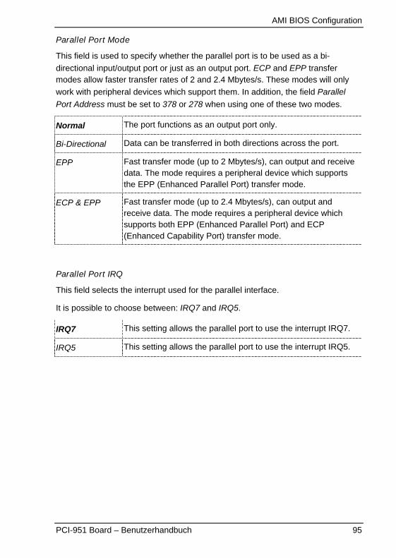
AMI BIOS Configuration
PCI-951 Board – Benutzerhandbuch 95
Parallel Port Mode
This field is used to specify whether the parallel port is to be used as a bi-
directional input/output port or just as an output port. ECP and EPP transfermodes allow faster transfer rates of 2 and 2.4 Mbytes/s. These modes will only
work with peripheral devices which support them. In addition, the field Parallel
Port Address must be set to 378 or 278 when using one of these two modes.
Normal The port functions as an output port only.
Bi-Directional Data can be transferred in both directions across the port.
EPP Fast transfer mode (up to 2 Mbytes/s), can output and receivedata. The mode requires a peripheral device which supportsthe EPP (Enhanced Parallel Port) transfer mode.
ECP & EPP Fast transfer mode (up to 2.4 Mbytes/s), can output andreceive data. The mode requires a peripheral device whichsupports both EPP (Enhanced Parallel Port) and ECP(Enhanced Capability Port) transfer mode.
Parallel Port IRQ
This field selects the interrupt used for the parallel interface.
It is possible to choose between: IRQ7 and IRQ5.
IRQ7 This setting allows the parallel port to use the interrupt IRQ7.
IRQ5 This setting allows the parallel port to use the interrupt IRQ5.
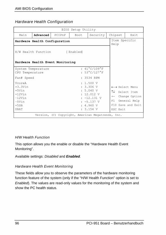
AMI BIOS Configuration
96 PCI-951 Board – Benutzerhandbuch
Hardware Health Configuration
BIOS Setup Utility
Main Advanced PCIPnP Boot Security Chipset Exit
Hardware Health Configuration
H/W Health Function [Enabled]
Hardware Health Event Monitoring
System TemperatureCPU Temperature
Fan# Speed
VcoreA+3.3Vin+5Vin+12Vin–12Vin–5Vin+5SBUBAT
: 41°C/109°F: 53°C/127°F
: 3534 RPM
: 1.500 V: 3.306 V: 5.040 V: 12.012 V: -12.131 V: -5.137 V: 4.960 V: 3.154 V
Item SpecificHelp
�� Select Menu
�� Select Item
+- Change Option
F1 General Help
F10 Save and Exit
ESC Exit
Version, (C) Copyright, American Megatrends, Inc.
H/W Health Function
This option allows you the enable or disable the “Hardware Health EventMonitoring”.
Available settings: Disabled and Enabled.
Hardware Health Event Monitoring
These fields allow you to observe the parameters of the hardware monitoringfunction feature of the system (only if the “H/W Health Function” option is set to
Enabled). The values are read-only values for the monitoring of the system andshow the PC health status.
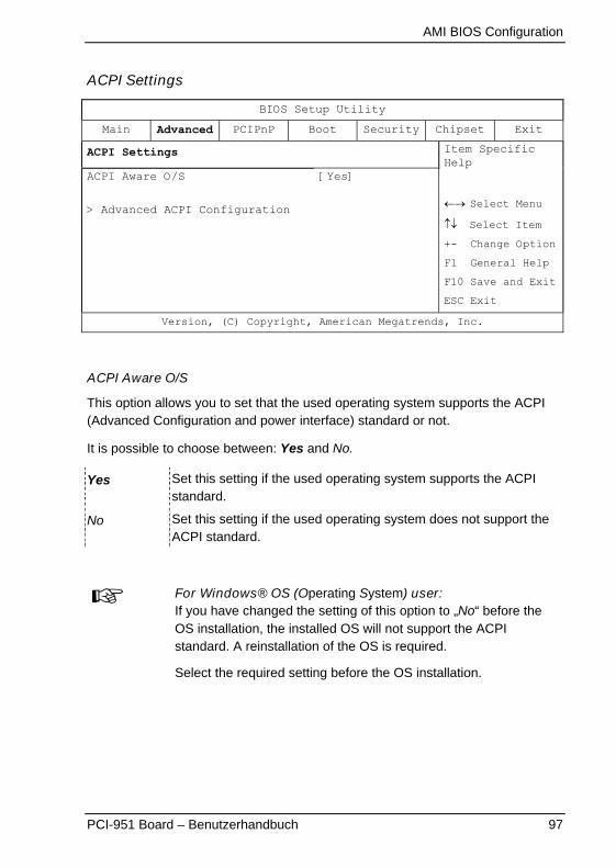
AMI BIOS Configuration
PCI-951 Board – Benutzerhandbuch 97
ACPI Settings
BIOS Setup Utility
Main Advanced PCIPnP Boot Security Chipset Exit
ACPI Settings
ACPI Aware O/S
> Advanced ACPI Configuration
[Yes]
Item SpecificHelp
�� Select Menu
�� Select Item
+- Change Option
F1 General Help
F10 Save and Exit
ESC Exit
Version, (C) Copyright, American Megatrends, Inc.
ACPI Aware O/S
This option allows you to set that the used operating system supports the ACPI(Advanced Configuration and power interface) standard or not.
It is possible to choose between: Yes and No.
Yes Set this setting if the used operating system supports the ACPIstandard.
No Set this setting if the used operating system does not support theACPI standard.
For Windows® OS (Operating System) user:If you have changed the setting of this option to „No“ before theOS installation, the installed OS will not support the ACPIstandard. A reinstallation of the OS is required.
Select the required setting before the OS installation.
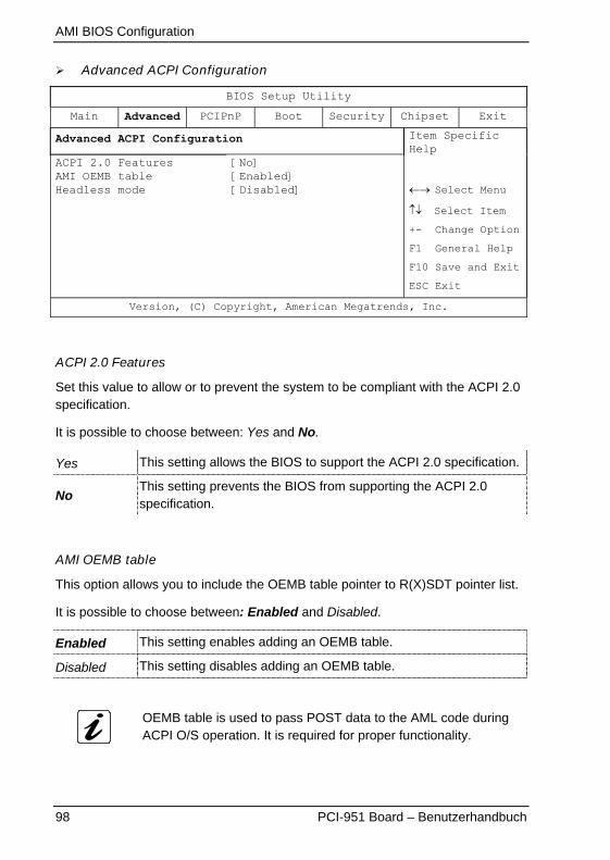
AMI BIOS Configuration
98 PCI-951 Board – Benutzerhandbuch
� Advanced ACPI Configuration
BIOS Setup Utility
Main Advanced PCIPnP Boot Security Chipset Exit
Advanced ACPI Configuration
ACPI 2.0 FeaturesAMI OEMB tableHeadless mode
[No][Enabled][Disabled]
Item SpecificHelp
�� Select Menu
�� Select Item
+- Change Option
F1 General Help
F10 Save and Exit
ESC Exit
Version, (C) Copyright, American Megatrends, Inc.
ACPI 2.0 Features
Set this value to allow or to prevent the system to be compliant with the ACPI 2.0specification.
It is possible to choose between: Yes and No.
Yes This setting allows the BIOS to support the ACPI 2.0 specification.
NoThis setting prevents the BIOS from supporting the ACPI 2.0specification.
AMI OEMB table
This option allows you to include the OEMB table pointer to R(X)SDT pointer list.
It is possible to choose between: Enabled and Disabled.
Enabled This setting enables adding an OEMB table.
Disabled This setting disables adding an OEMB table.
OEMB table is used to pass POST data to the AML code duringACPI O/S operation. It is required for proper functionality.
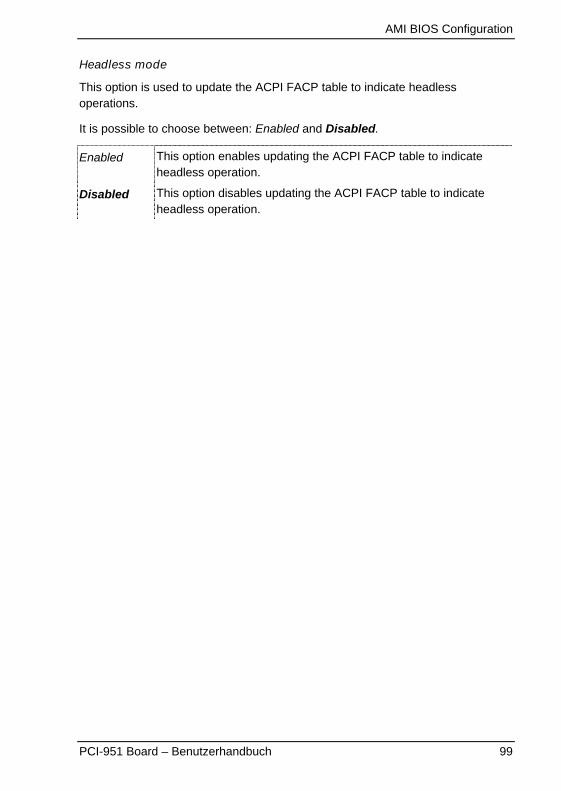
AMI BIOS Configuration
PCI-951 Board – Benutzerhandbuch 99
Headless mode
This option is used to update the ACPI FACP table to indicate headlessoperations.
It is possible to choose between: Enabled and Disabled.
Enabled This option enables updating the ACPI FACP table to indicateheadless operation.
Disabled This option disables updating the ACPI FACP table to indicateheadless operation.
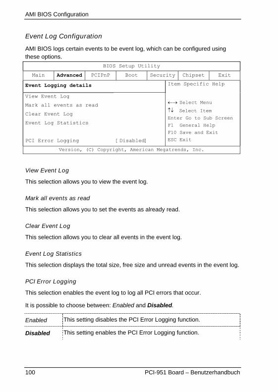
AMI BIOS Configuration
100 PCI-951 Board – Benutzerhandbuch
Event Log Configuration
AMI BIOS logs certain events to be event log, which can be configured usingthese options.
BIOS Setup Utility
Main Advanced PCIPnP Boot Security Chipset Exit
Event Logging details
View Event Log
Mark all events as read
Clear Event Log
Event Log Statistics
PCI Error Logging [Disabled]
Item Specific Help
�� Select Menu
�� Select Item
Enter Go to Sub Screen
F1 General Help
F10 Save and Exit
ESC Exit
Version, (C) Copyright, American Megatrends, Inc.
View Event Log
This selection allows you to view the event log.
Mark all events as read
This selection allows you to set the events as already read.
Clear Event Log
This selection allows you to clear all events in the event log.
Event Log Statistics
This selection displays the total size, free size and unread events in the event log.
PCI Error Logging
This selection enables the event log to log all PCI errors that occur.
It is possible to choose between: Enabled and Disabled.
Enabled This setting disables the PCI Error Logging function.
Disabled This setting enables the PCI Error Logging function.
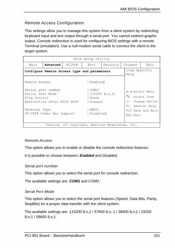
AMI BIOS Configuration
PCI-951 Board – Benutzerhandbuch 101
Remote Access Configuration
This settings allow you to manage this system from a client system by redirectingkeyboard input and text output through a serial port. You cannot redirect graphicoutput. Console redirection is used for configuring BIOS settings with a remoteTerminal (emulation). Use a null-modem serial cable to connect the client to thetarget system.
BIOS Setup Utility
Main Advanced PCIPnP Boot Security Chipset Exit
Configure Remote Access type and parameters
Remote Access
Serial port numberSerial Port ModeFlow ControlRedirection After BIOS POST
Terminal TypeVT-UTF8 Combo Key Support
[Enabled]
[COM1][115200 8,n,1][None][Always]
[ANSI][Disabled]
Item SpecificHelp
�� Select Menu
�� Select Item
+- Change Option
F1 General Help
F10 Save and Exit
ESC Exit
Version, (C) Copyright, American Megatrends, Inc.
Remote Access
This option allows you to enable or disable the console redirection features.
It is possible to choose between: Enabled and Disabled.
Serial port number
This option allows you to select the serial port for console redirection.
The available settings are: COM1 and COM2.
Serial Port Mode
This option allows you to select the serial port features (Speed, Data Bits, Parity,StopBits) for a proper data transfer with the client system.
The available settings are: 115200 8,n,1 / 57600 8,n, 1 / 38400 8,n,1 / 192008,n,1 / 09600 8,n,1.
AMI BIOS Configuration
102 PCI-951 Board – Benutzerhandbuch
Flow Control
Flow Control lets computers (host and client) tell each other when they canaccept more data for transmission and when to wait. This handshaking preventsdata from being lost because one computer was busy.
The available settings are: None, Hardware and Software.
Redirection After BIOS POST
This option allows you to select when the console redirection will be used.
Always Redirection is always active. (some OSs may not work if thissetting is chosen).
Boot Loader Redirection is active during POST and during Boot Loader.
Disabled Turns off the redirection after POST.
Terminal Type
This option allows you to select the target terminal type.
The available settings (industry standard terminal protocol) are:
ANSI, VT 100 and VT-UTF8.
VT-UTF8 Combo Key Support
This option allows you to enable or disable the VT-UTF8 Combo Key Support forANSI/VT 100 terminals.
It is possible to choose between: Enabled and Disabled.
Client and target systems must have the same settings for aworking communication.
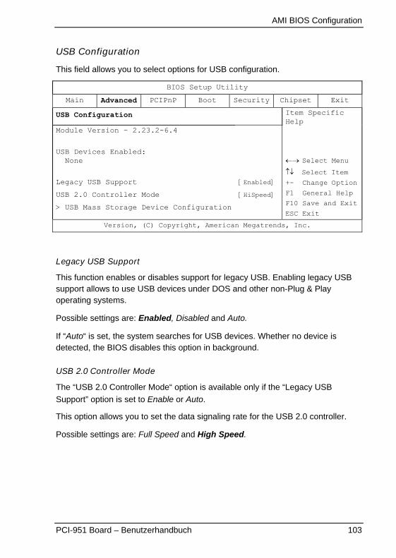
AMI BIOS Configuration
PCI-951 Board – Benutzerhandbuch 103
USB Configuration
This field allows you to select options for USB configuration.
BIOS Setup Utility
Main Advanced PCIPnP Boot Security Chipset Exit
USB Configuration
Module Version – 2.23.2-6.4
USB Devices Enabled: None
Legacy USB Support
USB 2.0 Controller Mode
> USB Mass Storage Device Configuration
[Enabled]
[HiSpeed]
Item SpecificHelp
�� Select Menu
�� Select Item
+- Change Option
F1 General Help
F10 Save and Exit
ESC Exit
Version, (C) Copyright, American Megatrends, Inc.
Legacy USB Support
This function enables or disables support for legacy USB. Enabling legacy USBsupport allows to use USB devices under DOS and other non-Plug & Playoperating systems.
Possible settings are: Enabled, Disabled and Auto.
If “Auto“ is set, the system searches for USB devices. Whether no device isdetected, the BIOS disables this option in background.
USB 2.0 Controller Mode
The “USB 2.0 Controller Mode“ option is available only if the “Legacy USB
Support” option is set to Enable or Auto.
This option allows you to set the data signaling rate for the USB 2.0 controller.
Possible settings are: Full Speed and High Speed.
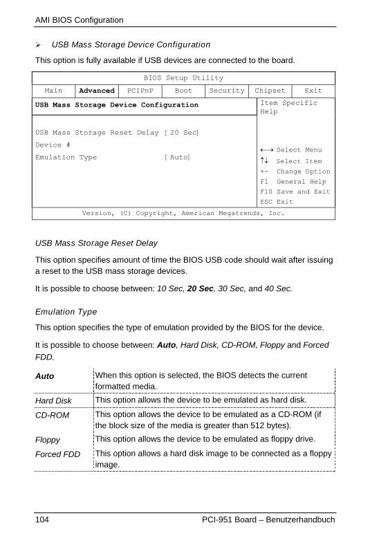
AMI BIOS Configuration
104 PCI-951 Board – Benutzerhandbuch
� USB Mass Storage Device Configuration
This option is fully available if USB devices are connected to the board.
BIOS Setup Utility
Main Advanced PCIPnP Boot Security Chipset Exit
USB Mass Storage Device Configuration
USB Mass Storage Reset Delay [20 Sec]
Device #
Emulation Type [Auto]
Item SpecificHelp
�� Select Menu
�� Select Item
+- Change Option
F1 General Help
F10 Save and Exit
ESC Exit
Version, (C) Copyright, American Megatrends, Inc.
USB Mass Storage Reset Delay
This option specifies amount of time the BIOS USB code should wait after issuinga reset to the USB mass storage devices.
It is possible to choose between: 10 Sec, 20 Sec, 30 Sec, and 40 Sec.
Emulation Type
This option specifies the type of emulation provided by the BIOS for the device.
It is possible to choose between: Auto, Hard Disk, CD-ROM, Floppy and Forced
FDD.
Auto When this option is selected, the BIOS detects the currentformatted media.
Hard Disk This option allows the device to be emulated as hard disk.
CD-ROM This option allows the device to be emulated as a CD-ROM (ifthe block size of the media is greater than 512 bytes).
Floppy This option allows the device to be emulated as floppy drive.
Forced FDD This option allows a hard disk image to be connected as a floppyimage.
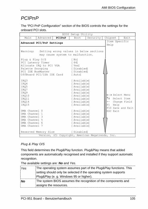
AMI BIOS Configuration
PCI-951 Board – Benutzerhandbuch 105
PCIPnPThe “PCI PnP Configuration” section of the BIOS controls the settings for theonboard PCI slots.
BIOS Setup UtilityMain Advanced PCIPnP Boot Security Chipset Exit
Advanced PCI/PnP Settings
Warning: Setting wrong values in below sectionsmay cause system to malfunction.
Plug & Play O/SPCI Latency TimerAllocate IRQ to PCI VGAPalette SnoopingPCI IDE BusMasterOffBoard PCI/ISA IDE Card
IRQ3IRQ4IRQ5IRQ7IRQ9IRQ10IRQ11IRQ14IRQ15
DMA Channel 0DMA Channel 1DMA Channel 3DMA Channel 5DMA Channel 6DMA Channel 7
Reserved Memory Size
[No][64][Yes][Disabled][Disabled][Auto]
[Available][Available][Available][Available][Available][Available][Available][Available][Available]
[Available][Available][Available][Available][Available][Available]
[Disabled]
Item SpecificHelp
�� Select Menu�� Select Item+- Change FieldF1 HelpF10 Save and ExitESC Exit
Version, (C) Copyright, American Megatrends, Inc.
Plug & Play O/S
This field determines the Plug&Play function. Plug&Play means that addedcomponents are automatically recognised and installed if they support automaticrecognition.
The available settings are: No and Yes.
Yes The operating system assumes part of the Plug&Play functions. Thissetting should only be selected if the operating system supportsPlug&Play (e. g. Windows 95 or higher).
No The system BIOS assumes the recognition of the components andassigns the resources.
AMI BIOS Configuration
106 PCI-951 Board – Benutzerhandbuch
PCI Latency Timer
This option allows you to set the latency timing (PCI clock) of all PCI devices onthe PCI bus.
The available settings are: 32, 64, 96, 128, 160, 192, 224 and 248.
Allocate IRQ to PCI VGA
This option allows or restricts the system to allocate an IRQ to a VGA adaptercard that uses the PCI bus.
The available settings are: No and Yes.
Palette Snooping
This option allows the compliance of older higher resolution video cards to theVGA standard. As presently all video boards are compliant to this standard, this
option must stay Disabled. This default setting should not be changed unless the
VGA card manufacturer requires Palette Snooping to be Enabled.
The available settings are: Enabled and Disabled.
PCI IDE BusMaster
This option allows you to specify if the IDE controller on the PCI bus shouldinclude a bus mastering capability or not.
The available settings are: Enabled and Disabled.
OffBoard PCI/ISA IDE Card
This option is to be used if an offboard PCI/ISA IDE controller adapter card isinstalled in the system. The settings of this option allow you to specify the PCIexpansion slot on the motherboard where the offboard PCI/ISA controller isinstalled.
The available settings are: PCI Slot1, PCI Slot2, PCI Slot3, PCI Slot4, PCI Slot5,
PCI Slot6, and Auto.

AMI BIOS Configuration
PCI-951 Board – Benutzerhandbuch 107
IRQ3, IRQ4, IRQ5, IRQ7, IRQ9, IRQ10, IRQ11, IRQ14, IRQ15
These options allow you to configure the IRQ Resources.
Available settings are: Available and Reserved.
Available This setting allows the specified IRQ to be used by PCI/PnP device.
Reserved This setting allows the specified IRQ to be used by a legacy ISAdevice.
DMA Channel 0, DMA Channel 1, DMA Channel 3, DMA Channel 5,DMA Channel 6, DMA Channel 7
These options allow you to configure the DMA Channels.
Available settings are: Available and Reserved.
Available This setting allows the specified DMA channel to be used byPCI/PnP device.
Reserved This setting allows the specified DMA channel to be used by alegacy ISA device.
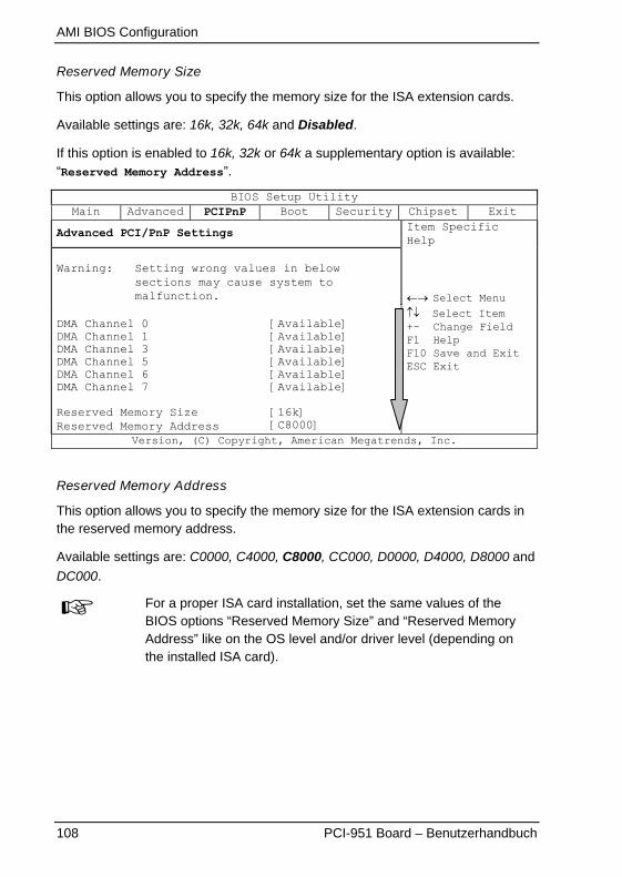
AMI BIOS Configuration
108 PCI-951 Board – Benutzerhandbuch
Reserved Memory Size
This option allows you to specify the memory size for the ISA extension cards.
Available settings are: 16k, 32k, 64k and Disabled.
If this option is enabled to 16k, 32k or 64k a supplementary option is available:“Reserved Memory Address”.
BIOS Setup UtilityMain Advanced PCIPnP Boot Security Chipset Exit
Advanced PCI/PnP Settings
Warning: Setting wrong values in belowsections may cause system tomalfunction.
DMA Channel 0DMA Channel 1DMA Channel 3DMA Channel 5DMA Channel 6DMA Channel 7
Reserved Memory SizeReserved Memory Address
[Available][Available][Available][Available][Available][Available]
[16k][C8000]
Item SpecificHelp
�� Select Menu�� Select Item+- Change FieldF1 HelpF10 Save and ExitESC Exit
Version, (C) Copyright, American Megatrends, Inc.
Reserved Memory Address
This option allows you to specify the memory size for the ISA extension cards inthe reserved memory address.
Available settings are: C0000, C4000, C8000, CC000, D0000, D4000, D8000 and
DC000.
For a proper ISA card installation, set the same values of theBIOS options “Reserved Memory Size” and “Reserved MemoryAddress” like on the OS level and/or driver level (depending onthe installed ISA card).
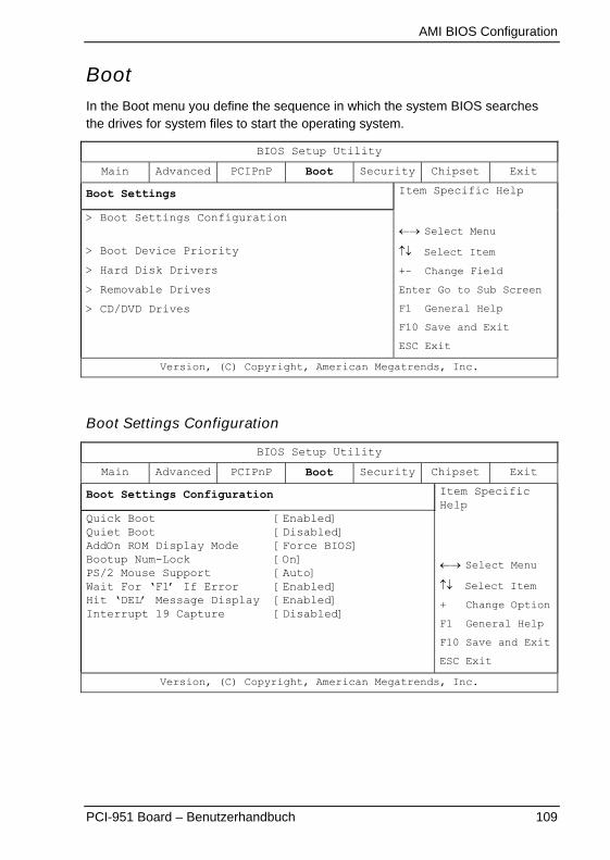
AMI BIOS Configuration
PCI-951 Board – Benutzerhandbuch 109
BootIn the Boot menu you define the sequence in which the system BIOS searchesthe drives for system files to start the operating system.
BIOS Setup Utility
Main Advanced PCIPnP Boot Security Chipset Exit
Boot Settings
> Boot Settings Configuration
> Boot Device Priority
> Hard Disk Drivers
> Removable Drives
> CD/DVD Drives
Item Specific Help
�� Select Menu
�� Select Item
+- Change Field
Enter Go to Sub Screen
F1 General Help
F10 Save and Exit
ESC Exit
Version, (C) Copyright, American Megatrends, Inc.
Boot Settings Configuration
BIOS Setup Utility
Main Advanced PCIPnP Boot Security Chipset Exit
Boot Settings Configuration
Quick BootQuiet BootAddOn ROM Display ModeBootup Num-LockPS/2 Mouse SupportWait For ‘F1’ If ErrorHit ‘DEL’ Message DisplayInterrupt 19 Capture
[Enabled][Disabled][Force BIOS][On][Auto][Enabled][Enabled][Disabled]
Item SpecificHelp
�� Select Menu
�� Select Item
+ Change Option
F1 General Help
F10 Save and Exit
ESC Exit
Version, (C) Copyright, American Megatrends, Inc.
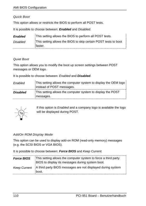
AMI BIOS Configuration
110 PCI-951 Board – Benutzerhandbuch
Quick Boot
This option allows or restricts the BIOS to perform all POST tests.
It is possible to choose between: Enabled and Disabled.
Enabled This setting allows the BIOS to perform all POST tests.
Disabled This setting allows the BIOS to skip certain POST tests to bootfaster.
Quiet Boot
This option allows you to modify the boot up screen settings between POSTmessages or OEM logo.
It is possible to choose between: Enabled and Disabled.
Enabled This setting allows the computer system to display the OEM logoinstead of POST messages.
Disabled This setting allows the computer system to display the POSTmessages.
If this option is Enabled and a company logo is available the logowill be displayed during POST.
AddOn ROM Display Mode
This option can be used to display add-on ROM (read-only memory) messages(e.g. the SCSI BIOS or VGA BIOS).
It is possible to choose between: Force BIOS and Keep Current.
Force BIOS This setting allows the computer system to force a third partyBIOS to display its messages during system boot.
Keep Current A third party BIOS messages are not displayed during systemboot.
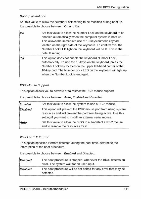
AMI BIOS Configuration
PCI-951 Board – Benutzerhandbuch 111
Bootup Num-Lock
Set this value to allow the Number Lock setting to be modified during boot up.
It is possible to choose between: On and Off.
On Set this value to allow the Number Lock on the keyboard to beenabled automatically when the computer system is boot up.This allows the immediate use of 10-keys numeric keypadlocated on the right side of the keyboard. To confirm this, theNumber Lock LED light on the keyboard will be lit. This is thedefault setting.
Off This option does not enable the keyboard Number Lockautomatically. To use the 10-keys on the keyboard, press theNumber Lock key located on the upper left-hand corner of the10-key pad. The Number Lock LED on the keyboard will light upwhen the Number Lock is engaged.
PS/2 Mouse Support
This option allows you to activate or to restrict the PS/2 mouse support.
It is possible to choose between: Auto, Enabled and Disabled.
Enabled Set this value to allow the system to use a PS/2 mouse.
Disabled This option will prevent the PS/2 mouse port from using systemresources and will prevent the port from being active. Use thissetting if you want to install an external serial mouse.
Auto Set this value to allow the BIOS to auto-detect a PS/2 mouseand to reserve the resources for it.
Wait For ‘F1’ If Error
This option specifies if errors detected during the boot time, determine theinterruption of the boot procedure.
It is possible to choose between: Enabled and Disabled.
Enabled The boot procedure is stopped, whenever the BIOS detects anerror. The system wait for an user input.
Disabled The boot procedure will be not halted for any error that may bedetected.
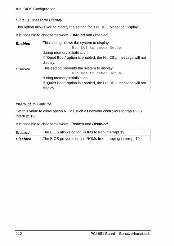
AMI BIOS Configuration
112 PCI-951 Board – Benutzerhandbuch
Hit ‘DEL’ Message Display
This option allows you to modify the setting for “Hit ‘DEL’ Message Display”.
It is possible to choose between: Enabled and Disabled.
Enabled This setting allows the system to display:Hit Del to enter Setup
during memory initialization.If “Quiet Boot” option is enabled, the Hit ‘DEL’ message will notdisplay.
Disabled This setting prevents the system to display:Hit Del to enter Setup
during memory initialization.If “Quiet Boot” option is enabled, the Hit ‘DEL’ message will notdisplay.
Interrupt 19 Capture
Set this value to allow option ROMs such as network controllers to trap BIOSinterrupt 19.
It is possible to choose between: Enabled and Disabled.
Enabled The BIOS allows option ROMs to trap interrupt 19.
Disabled The BIOS prevents option ROMs from trapping interrupt 19.
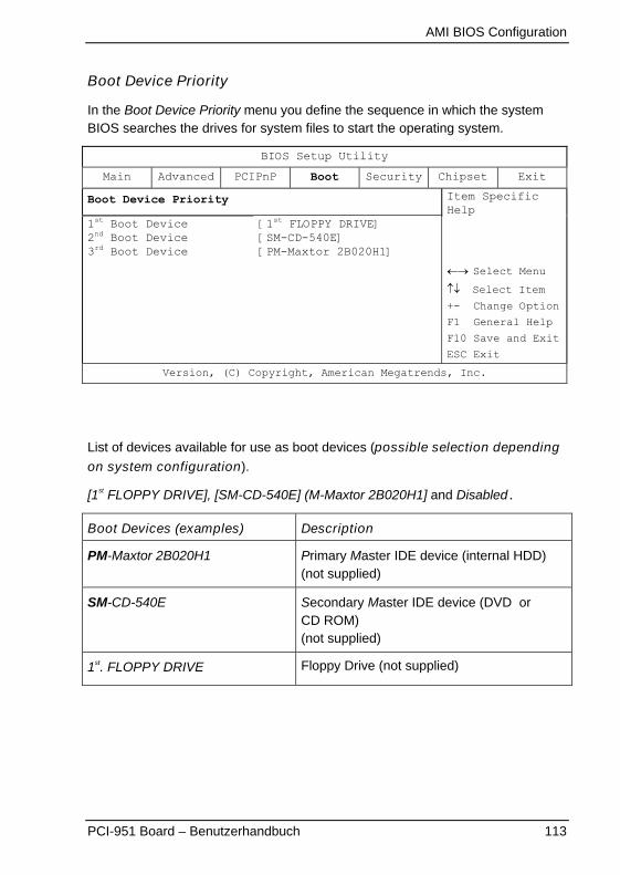
AMI BIOS Configuration
PCI-951 Board – Benutzerhandbuch 113
Boot Device Priority
In the Boot Device Priority menu you define the sequence in which the systemBIOS searches the drives for system files to start the operating system.
BIOS Setup Utility
Main Advanced PCIPnP Boot Security Chipset Exit
Boot Device Priority
1st Boot Device2nd Boot Device3rd Boot Device
[1st FLOPPY DRIVE][SM-CD-540E][PM-Maxtor 2B020H1]
Item SpecificHelp
�� Select Menu
�� Select Item
+- Change Option
F1 General Help
F10 Save and Exit
ESC Exit
Version, (C) Copyright, American Megatrends, Inc.
List of devices available for use as boot devices (possible selection dependingon system configuration).
[1st FLOPPY DRIVE], [SM-CD-540E] (M-Maxtor 2B020H1] and Disabled.
Boot Devices (examples) Description
PM-Maxtor 2B020H1 Primary Master IDE device (internal HDD)(not supplied)
SM-CD-540E Secondary Master IDE device (DVD orCD ROM)(not supplied)
1st. FLOPPY DRIVE Floppy Drive (not supplied)
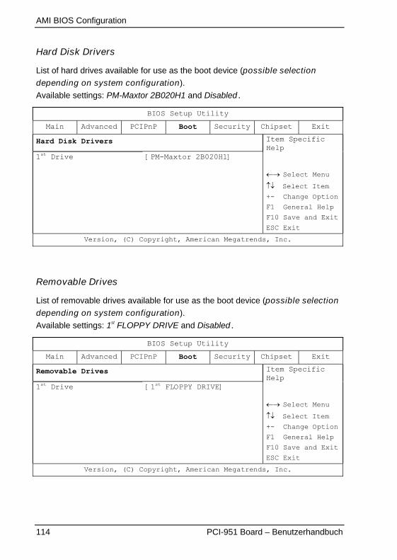
AMI BIOS Configuration
114 PCI-951 Board – Benutzerhandbuch
Hard Disk Drivers
List of hard drives available for use as the boot device (possible selectiondepending on system configuration).
Available settings: PM-Maxtor 2B020H1 and Disabled.
BIOS Setup Utility
Main Advanced PCIPnP Boot Security Chipset Exit
Hard Disk Drivers
1st Drive [PM-Maxtor 2B020H1]
Item SpecificHelp
�� Select Menu
�� Select Item
+- Change Option
F1 General Help
F10 Save and Exit
ESC Exit
Version, (C) Copyright, American Megatrends, Inc.
Removable Drives
List of removable drives available for use as the boot device (possible selectiondepending on system configuration).
Available settings: 1st FLOPPY DRIVE and Disabled.
BIOS Setup Utility
Main Advanced PCIPnP Boot Security Chipset Exit
Removable Drives
1st Drive [1st FLOPPY DRIVE]
Item SpecificHelp
�� Select Menu
�� Select Item
+- Change Option
F1 General Help
F10 Save and Exit
ESC Exit
Version, (C) Copyright, American Megatrends, Inc.

AMI BIOS Configuration
PCI-951 Board – Benutzerhandbuch 115
CD/DVD Drives
List of CD/DVD drives available for use as the boot device (possible selectiondepending on system configuration).
Available settings: SM-CD-540E and Disabled.
BIOS Setup Utility
Main Advanced PCIPnP Boot Security Chipset Exit
CD/DVD Drives
1st Drive [SM-CD-540E]
Item SpecificHelp
�� Select Menu
�� Select Item
+- Change Option
F1 General Help
F10 Save and Exit
ESC Exit
Version, (C) Copyright, American Megatrends, Inc.
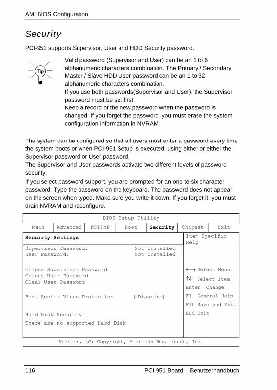
AMI BIOS Configuration
116 PCI-951 Board – Benutzerhandbuch
SecurityPCI-951 supports Supervisor, User and HDD Security password.
Valid password (Supervisor and User) can be an 1 to 6alphanumeric characters combination. The Primary / SecondaryMaster / Slave HDD User password can be an 1 to 32alphanumeric characters combination.If you use both passwords(Supervisor and User), the Supervisorpassword must be set first.Keep a record of the new password when the password ischanged. If you forget the password, you must erase the systemconfiguration information in NVRAM.
The system can be configured so that all users must enter a password every timethe system boots or when PCI-951 Setup is executed, using either or either theSupervisor password or User password.The Supervisor and User passwords activate two different levels of passwordsecurity.
If you select password support, you are prompted for an one to six characterpassword. Type the password on the keyboard. The password does not appearon the screen when typed. Make sure you write it down. If you forget it, you mustdrain NVRAM and reconfigure.
BIOS Setup Utility
Main Advanced PCIPnP Boot Security Chipset Exit
Security Settings
Supervisor Password:User Password:
Change Supervisor PasswordChange User PasswordClear User Password
Boot Sector Virus Protection
Hard Disk Security
There are no supported Hard Disk
Not InstalledNot Installed
[Disabled]
Item SpecificHelp
�� Select Menu
�� Select Item
Enter Change
F1 General Help
F10 Save and Exit
ESC Exit
Version, (C) Copyright, American Megatrends, Inc.
AMI BIOS Configuration
PCI-951 Board – Benutzerhandbuch 117
Supervisor Password
Indicates whether a supervisor password has been set.
If the password has been installed, Installed displays. If not, Not Installeddisplays.
User Password
Indicates whether an user password has been set. If the password has been
installed, Installed displays. If not, Not Installed displays.
Change Supervisor Password
Select this option and press <Enter> to access the sub menu.
You can use the sub menu to change the supervisor password. Select the“Change Supervisor Password” option from the Security Setup menu and press<Enter>.“Enter New Password:” input field appears. Valid password can be an 1 to 6alphanumeric characters combination. Type the password and press <Enter>.The screen does not display the characters entered. “Confirm New Password:”input field appears. Retype the password as prompted and press <Enter>. If thepassword confirmation is incorrect, an error message appears. The password isstored in NVRAM.
If a Supervisor Password is installed two options are available:
“User Access Level” with following settings: Full Access, Limited, View Only,
and No Access.
“Password Check” with following settings: Setup and Always.
AMI BIOS Configuration
118 PCI-951 Board – Benutzerhandbuch
Change User Password
Select this option and press <Enter> to access the sub menu.
You can use the sub menu to change the user password. Select Change UserPassword from the Security Setup menu and press <Enter>.
“Enter New Password:” input field appears. Valid password can be an 1 to 6alphanumeric characters combination. Type the password and press <Enter>.The screen does not display the characters entered. “Confirm New Password:”input field appears. Retype the password as prompted and press <Enter>. If thepassword confirmation is incorrect, an error message appears. The password isstored in NVRAM.
If an User Password is installed is available following option:
“Password Check” with following settings: Setup and Always.
Clear User Password
Select this option and press <Enter> to access the sub menu.
You can use the sub menu to clear the user password. Select “Clear UserPassword” from the Security Setup menu and press <Enter>.
“Clear User Password” � [Ok] [Cancel] Choose your selection.
AMI BIOS Configuration
PCI-951 Board – Benutzerhandbuch 119
Boot Sector Virus Protection
With this field you can protect the boot sector against virus.
It is possible to choose between: Enabled and Disabled.
Enabled
The boot sector cannot be changed. A virus that attacks the bootsector cannot infect the system.
Select “Enabled” to enable boot sector protection. The systemdisplays a warning when any program (or virus) issues a DiskFormat command or attempts to write to the boot sector of thehard disk drive.
If “Enabled”, the following appears when a write is attempted to
the boot sector. You may have to type N several times to preventthe boot sector write.
Boot Sector Write!
Possible VIRUS: Continue (Y/N)? _
The following appears after any attempt to format any cylinder,head, or sector of any hard disk drive via the BIOS INT 13 Harddisk drive Service:
Format!!!
Possible VIRUS: Continue (Y/N)? _
Disabled The boot sector could be changed. The protection is disabled.
Before installing an operating system you have to change this
selection to “Disabled”. During installation the first sector iswritten by the operating system. After the installation you can
enable the boot virus protection by set “Enabled”.
AMI BIOS Configuration
120 PCI-951 Board – Benutzerhandbuch
Hard Disk Security
Hard Disk Security uses the Security Mode Feature commandsdefined in the ATA specification.This option is available only if the installed HDD supportsSecurity Mode Feature commands defined in the ATA specification.
The option “Primary / Secondary Master / Slave HDD User Password” allows youto protect the data stored on the installed HDD/s (depending on the systemconfiguration).
Primary / Secondary Master / Slave HDD User Password
This option allows you to set drive-level password/s to protect your data stored onthe installed HDD/s (depending on the system configuration).
This password is kept within the drive and the data is protected even if the drive ismoved to another computer system.
This password can be an 1 to 32 alphanumeric characters combination.
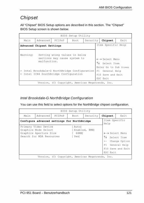
AMI BIOS Configuration
PCI-951 Board – Benutzerhandbuch 121
ChipsetAll “Chipset” BIOS Setup options are described in this section. The “Chipset”BIOS Setup screen is shown below.
BIOS Setup Utility
Main Advanced PCIPnP Boot Security Chipset Exit
Advanced Chipset Settings
Warning: Setting wrong values in belowsections may cause system tomalfunction.
> Intel Brookdale-G NorthBridge Configuration> Intel ICH4 SouthBridge Configuration
Item Specific Help
�� Select Menu
�� Select Item
Enter Go to Sub Screen
F1 General Help
F10 Save and Exit
ESC Exit
Version, (C) Copyright, American Megatrends, Inc.
Intel Brookdale-G NorthBridge Configuration
You can use this field to select options for the NorthBridge chipset configuration.
BIOS Setup Utility
Main Advanced PCIPnP Boot Security Chipset Exit
Configure advanced settings for NorthBridge
Primary Video DeviceGraphics Mode SelectGraphics Aperture SizeSearch for MDA Resources
[Auto][Enabled, 8MB][ 64MB][Yes]
Item SpecificHelp
�� Select Menu
�� Select Item
+- Change Option
F1 General Help
F10 Save and Exit
ESC Exit
Version, (C) Copyright, American Megatrends, Inc.

AMI BIOS Configuration
122 PCI-951 Board – Benutzerhandbuch
Primary Video Device
This option allows you to select which graphics controller to use as the primaryboot device.
Available settings are: Internal, External PCI, External AGP and Auto.
Graphics Mode Select
This option allows you to select the amount of system memory used by theinternal graphics device.
Available settings are: Enabled, 1MB, / Enabled, 8MB, / Disabled.
Graphics Aperture Size
The option allows you to set the aperture size of the graphics. The aperture is aportion of the PCI memory address range dedicated for graphics memory addressspace. Host cycles that hit the aperture range are forwarded to the AGP withoutany translation.
Available settings are 4MB, 8MB, 16MB, 32MB, 64MB, 128MB and 256MB.
Default setting: 64MB.
Search for MDA Resources
This option allows you to search for and Setup an MDA (Monochrome) videoadapter.
Available settings are: Yes and No.
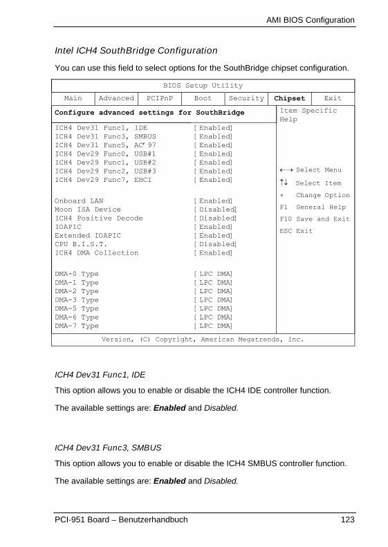
AMI BIOS Configuration
PCI-951 Board – Benutzerhandbuch 123
Intel ICH4 SouthBridge Configuration
You can use this field to select options for the SouthBridge chipset configuration.
BIOS Setup Utility
Main Advanced PCIPnP Boot Security Chipset Exit
Configure advanced settings for SouthBridge
ICH4 Dev31 Func1, IDEICH4 Dev31 Func3, SMBUSICH4 Dev31 Func5, AC’97ICH4 Dev29 Func0, USB#1ICH4 Dev29 Func1, USB#2ICH4 Dev29 Func2, USB#3ICH4 Dev29 Func7, EHCI
Onboard LANMoon ISA DeviceICH4 Positive DecodeIOAPICExtended IOAPICCPU B.I.S.T.ICH4 DMA Collection
DMA-0 TypeDMA-1 TypeDMA-2 TypeDMA-3 TypeDMA-5 TypeDMA-6 TypeDMA-7 Type
[Enabled][Enabled][Enabled][Enabled][Enabled][Enabled][Enabled]
[Enabled][Disabled][Disabled][Enabled][Enabled][Disabled][Enabled]
[LPC DMA][LPC DMA][LPC DMA][LPC DMA][LPC DMA][LPC DMA][LPC DMA]
Item SpecificHelp
�� Select Menu
�� Select Item
+ Change Option
F1 General Help
F10 Save and Exit
ESC Exit
Version, (C) Copyright, American Megatrends, Inc.
ICH4 Dev31 Func1, IDE
This option allows you to enable or disable the ICH4 IDE controller function.
The available settings are: Enabled and Disabled.
ICH4 Dev31 Func3, SMBUS
This option allows you to enable or disable the ICH4 SMBUS controller function.
The available settings are: Enabled and Disabled.
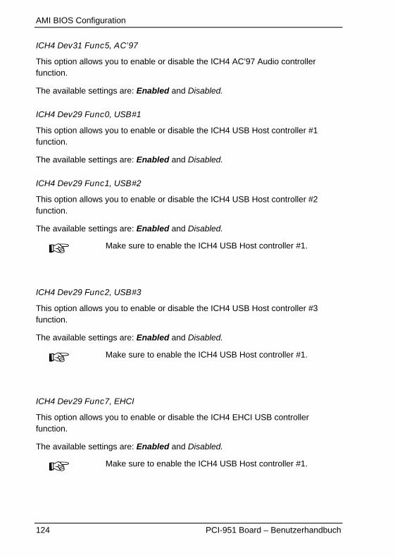
AMI BIOS Configuration
124 PCI-951 Board – Benutzerhandbuch
ICH4 Dev31 Func5, AC’97
This option allows you to enable or disable the ICH4 AC’97 Audio controllerfunction.
The available settings are: Enabled and Disabled.
ICH4 Dev29 Func0, USB#1
This option allows you to enable or disable the ICH4 USB Host controller #1function.
The available settings are: Enabled and Disabled.
ICH4 Dev29 Func1, USB#2
This option allows you to enable or disable the ICH4 USB Host controller #2function.
The available settings are: Enabled and Disabled.
Make sure to enable the ICH4 USB Host controller #1.
ICH4 Dev29 Func2, USB#3
This option allows you to enable or disable the ICH4 USB Host controller #3function.
The available settings are: Enabled and Disabled.
Make sure to enable the ICH4 USB Host controller #1.
ICH4 Dev29 Func7, EHCI
This option allows you to enable or disable the ICH4 EHCI USB controllerfunction.
The available settings are: Enabled and Disabled.
Make sure to enable the ICH4 USB Host controller #1.
AMI BIOS Configuration
PCI-951 Board – Benutzerhandbuch 125
Onboard LAN
This option allows you to enable or disable the onboard LAN.
The available settings are: Enabled and Disabled.
ICH4 Positive Decode
This option allows you to enable or disable the Positive Decode in ICH4.
The available settings are: Enabled and Disabled.
Set this option to Enable if the optional onboard PCI/ISA bridge is present.
IOAPIC
This option allows you to enable or disable the ICH4 IOAPIC (AdvancedProgrammable Interrupt Controller) function.
The available settings are: Enabled and Disabled.
Extended IOAPIC
This option allows you to enable or disable the extended mode of ICH4 IOAPIC. Ifenabled the APIC mode will expand available IRQ resources for the system.
The available settings are: Enabled and Disabled.
For Windows® XP OS (Operating System) user:Select the required setting before the OS installation.
CPU B.I.S.T.
This option allows you to enable or disable the CPU Built In Self Test.
The available settings are: Enabled and Disabled.
ICH4 DMA Collection
This option allows you to enable or disable the DMA collection buffer.
The available settings are: Enabled and Disabled.

AMI BIOS Configuration
126 PCI-951 Board – Benutzerhandbuch
DMA-0, 1, 2, 3, 4, 5, 6, 7 Type
This option allows you to select the type of DMA performed on the correspondingchannel.
The available settings are: LPC DMA and PC/PCI.
PC/PCIThe PCI bus is supported by the corresponding DMA (DirectMemory Access) channel.
LPC DMAThe LPC bus is supported by the corresponding DMA (DirectMemory Access) channel.
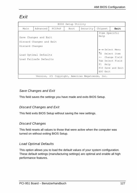
AMI BIOS Configuration
PCI-951 Board – Benutzerhandbuch 127
ExitBIOS Setup Utility
Main Advanced PCIPnP Boot Security Chipset Exit
Save Changes and Exit
Discard Changes and Exit
Discard Changes
Load Optimal Defaults
Load Failsafe Defaults
Item SpecificHelp
�� Select Menu
�� Select Item
+- Change Field
Tab Select Field
F1 Help
F10 Save and Exit
ESC Exit
Version, (C) Copyright, American Megatrends, Inc.
Save Changes and Exit
This field saves the settings you have made and exits BIOS Setup.
Discard Changes and Exit
This field exits BIOS Setup without saving the new settings.
Discard Changes
This field resets all values to those that were active when the computer wasturned on without exiting BIOS Setup.
Load Optimal Defaults
This option allows you to load the default values of your system configuration.These default settings (manufacturing settings) are optimal and enable all highperformance features.

AMI BIOS Configuration
128 PCI-951 Board – Benutzerhandbuch
Load Failsafe Defaults
By this option the system can reload all default settings, which are permanentlystored in the BIOS-ROM.These settings are not the optimised default settings (manufacturing defaults) foryour system, but can be used, if after changes, the system does not run reliably.The Fail-Safe settings are designed for maximum stability, but not maximumperformance.

Resources
PCI-951 Board – Benutzerhandbuch 129
Resources
I/O Port Address MapJedem Peripheriegerät im System wird eine I/O Portadresse zugewiesen, diedementsprechend auch die Identität des Geräts bekommt. Es steht eineGesamtmenge von 1K I/O Portadressbereich für ISA-Geräte zur Verfügung.In der folgenden Tabelle sind die I/O Portadressen, die für das PCI-951 Board beiStandard-Einstellung verwendet werden, aufgeführt.
Address Device Description
000h - 01Fh DMA Controller #1
020h - 03Fh Interrupt Controller #1
040h - 05Fh Timer
060h - 06Fh Keyboard Controller
070h - 07Fh Real Time Clock, NMI
080h - 09Fh DMA Page Register
0A0h - 0BFh Interrupt Controller #2
0C0h - 0DFh DMA Controller #2
0F0h Clear Math Coprocessor Busy Signal
0F1h Reset Math Coprocessor
1F0h - 1F7h IDE Interface
278 - 27F Parallel Port #2(LPT2)
2F8h - 2FFh Serial Port #2(COM2)
2B0 - 2DF Graphics adapter Controller
378h - 3FFh Parallel Port #1(LPT1)
360 - 36F Network Ports
3B0 - 3BF Monochrome & Printer adapter
3C0 - 3CF EGA adapter
3D0 - 3DF CGA adapter
3F0h - 3F7h Floppy Disk Controller
3F8h - 3FFh Serial Port #1(COM1)
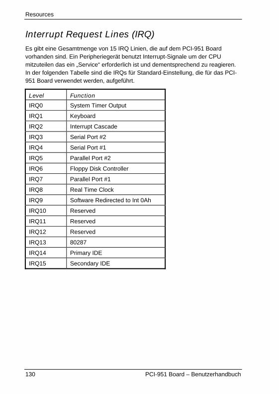
Resources
130 PCI-951 Board – Benutzerhandbuch
Interrupt Request Lines (IRQ)Es gibt eine Gesamtmenge von 15 IRQ Linien, die auf dem PCI-951 Boardvorhanden sind. Ein Peripheriegerät benutzt Interrupt-Signale um der CPUmitzuteilen das ein „Service“ erforderlich ist und dementsprechend zu reagieren.In der folgenden Tabelle sind die IRQs für Standard-Einstellung, die für das PCI-951 Board verwendet werden, aufgeführt.
Level Function
IRQ0 System Timer Output
IRQ1 Keyboard
IRQ2 Interrupt Cascade
IRQ3 Serial Port #2
IRQ4 Serial Port #1
IRQ5 Parallel Port #2
IRQ6 Floppy Disk Controller
IRQ7 Parallel Port #1
IRQ8 Real Time Clock
IRQ9 Software Redirected to Int 0Ah
IRQ10 Reserved
IRQ11 Reserved
IRQ12 Reserved
IRQ13 80287
IRQ14 Primary IDE
IRQ15 Secondary IDE

Intel® 845GV Chipsatz Treiberinstallation
PCI-951 Board – Benutzerhandbuch 131
Intel® 845GV Chipsatz TreiberinstallationDen Treiber für den Intel® 845GV Chipsatz finden Sie auf der mitgeliefertenTreiber-CD. In diesem Kapitel erhalten Sie Informationen für die Installation desTreibers für den Intel® 845GV Chipsatz. Bitte folgen Sie den Anweisungen die indiesem Kapitel beschrieben sind.
Bitte beachten Sie: Bevor Sie andere Treiber für Ihr Systeminstallieren, muss erst die Installation des Intel® 845GV Chipsatz-Treibers durchgeführt werden.
Dieses Kapitel beinhaltet:
� Intel® 845GV Chipsatz-Treiberinstallation für Windows 2000 und XP
Intel® 845GV Chipsatz-Treiberinstallation fürWindows 2000 und XPFühren Sie dieses Programm aus und befolgen Sie die Anweisungen auf demBildschirm.
Schritt 1: Legen Sie die Treiber-CD in das CD-ROM-Laufwerk.
Schritt 2: Wählen Sie Driver PCI-951 / Intel Chipset.
Schritt 3: Wählen Sie Intel Chipset Driver.
Schritt 4: Wählen Sie Next.
Schritt 5: Wählen Sie Yes.
Schritt 6: Wählen Sie Next.
Schritt 7: Wählen Sie Finish.

VGA-Treiberinstallation
132 PCI-951 Board – Benutzerhandbuch
VGA-TreiberinstallationDen VGA-Treiber finden Sie auf der mitgelieferten Treiber-CD. In diesem Kapitelerhalten Sie Informationen für die Installation des VGA-Treibers. Bitte folgen Sieden Anweisungen, die in diesem Kapitel beschrieben sind.
Bitte beachten Sie, dass für die Installation des VGA-Treibers,muss der Intel® 845GV Chipsatz-Treiber installiert sein.
Dieses Kapitel beinhaltet die Beschreibung für:
� VGA-Treiberinstallation für Windows 2000 und XP
VGA-Treiberinstallation für Windows 2000 undXPFühren Sie dieses Programm aus und befolgen Sie die Anweisungen auf demBildschirm.
Schritt 1: Legen Sie die Treiber-CD in das CD-ROM - Laufwerk.
Schritt 2: Wählen Sie Driver PCI-951 / Graphics Driver for 82845GV/ GL VGA Device.
Schritt 3: Wählen Sie Next.
Schritt 4: Wählen Sie Next.
Schritt 5: Wählen Sie Yes.
Schritt 6: Wählen Sie Finish. Sie müssen das System neu starten.

Audio-Treiberinstallation
PCI-951 Board – Benutzerhandbuch 133
Audio-TreiberinstallationDen AC’97 CODEC Audio-Treiber finden Sie auf der mitgelieferten Treiber-CD. Indiesem Kapitel erhalten Sie Informationen für die Installation des AC’97 CODECAudio-Treibers. Bitte folgen Sie den Anweisungen, die in diesem Kapitelbeschrieben sind.
Bitte beachten Sie, dass für die Installation des AC’97 CODECAudio-Treibers, muss der Intel® 845GV Chipsatz-Treiberinstalliert sein.
Dieses Kapitel beinhaltet die Beschreibung des für:
� Audio-Treiberinstallation für Windows 2000
� Audio-Treiberinstallation für Windows XP
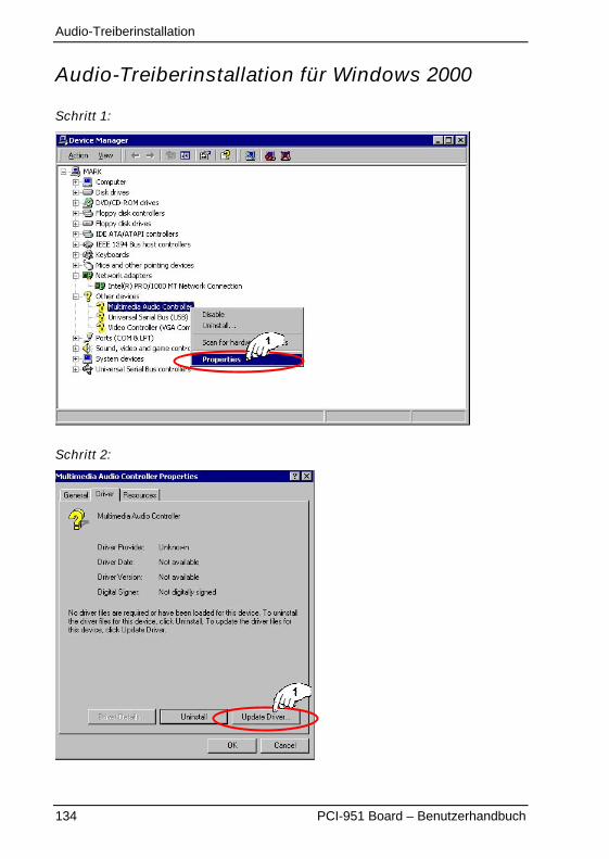
Audio-Treiberinstallation
134 PCI-951 Board – Benutzerhandbuch
Audio-Treiberinstallation für Windows 2000
Schritt 1:
Schritt 2:
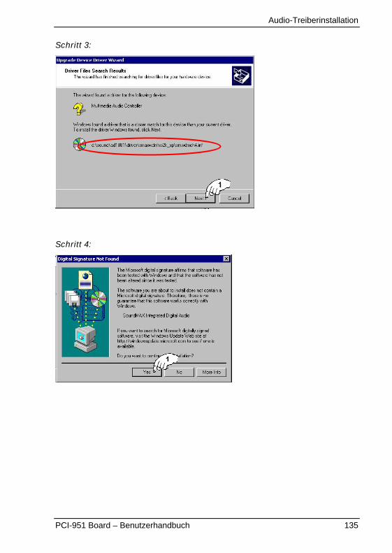
Audio-Treiberinstallation
PCI-951 Board – Benutzerhandbuch 135
Schritt 3:
Schritt 4:
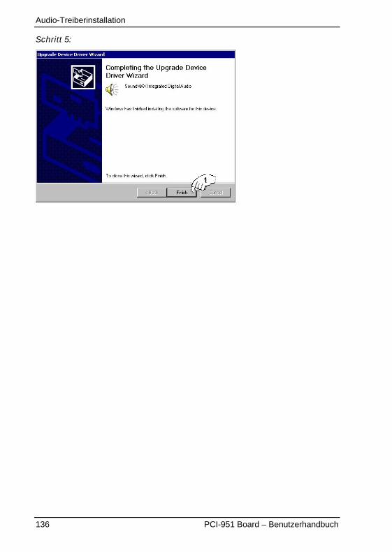
Audio-Treiberinstallation
136 PCI-951 Board – Benutzerhandbuch
Schritt 5:
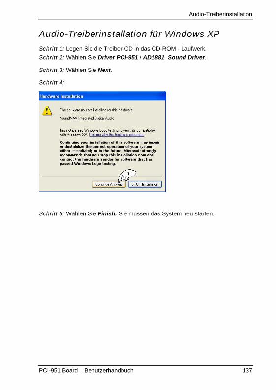
Audio-Treiberinstallation
PCI-951 Board – Benutzerhandbuch 137
Audio-Treiberinstallation für Windows XP
Schritt 1: Legen Sie die Treiber-CD in das CD-ROM - Laufwerk.
Schritt 2: Wählen Sie Driver PCI-951 / AD1881 Sound Driver.
Schritt 3: Wählen Sie Next.
Schritt 4:
Schritt 5: Wählen Sie Finish. Sie müssen das System neu starten.

LAN-Treiberinstallation
138 PCI-951 Board – Benutzerhandbuch
LAN-TreiberinstallationIn disem Kapitel ist das Verfahren für die Installation des LAN-Treibers desononboard Intel® 82551QM LAN-Controller beschrieben.
Dieses Kapitel beinhaltet die Beschreibung für:
� LAN-Treiberinstallation für Windows 2000
� LAN-Treiberinstallation für Windows XP
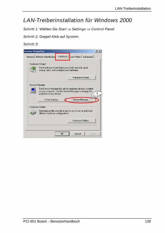
LAN-Treiberinstallation
PCI-951 Board – Benutzerhandbuch 139
LAN-Treiberinstallation für Windows 2000
Schritt 1: Wählen Sie Start � Settings � Control Panel.
Schritt 2: Doppel Klick auf System.
Schritt 3:
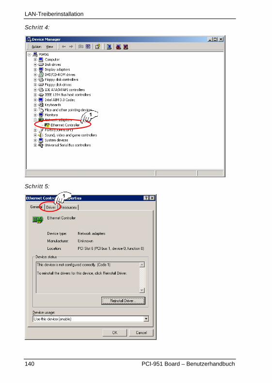
LAN-Treiberinstallation
140 PCI-951 Board – Benutzerhandbuch
Schritt 4:
Schritt 5:
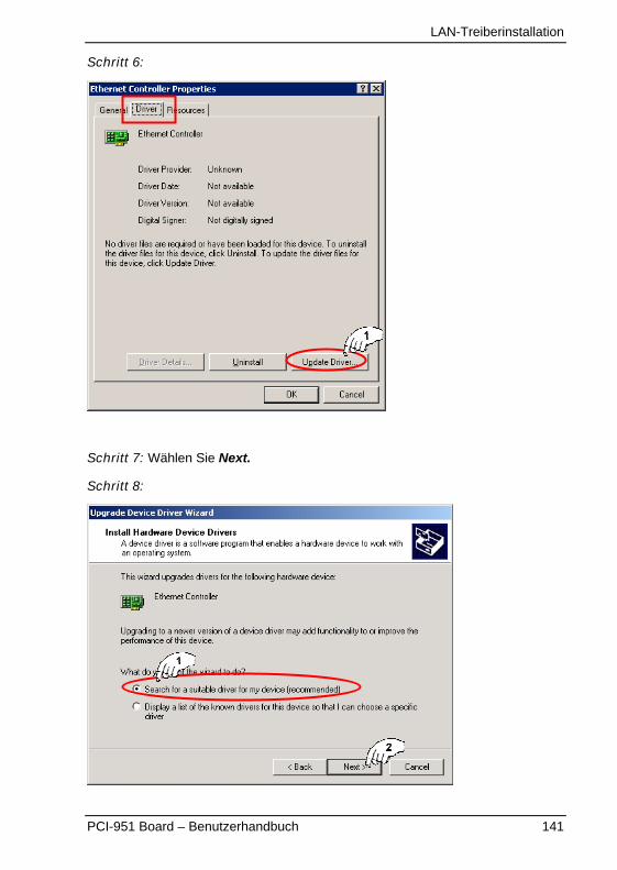
LAN-Treiberinstallation
PCI-951 Board – Benutzerhandbuch 141
Schritt 6:
Schritt 7: Wählen Sie Next.
Schritt 8:
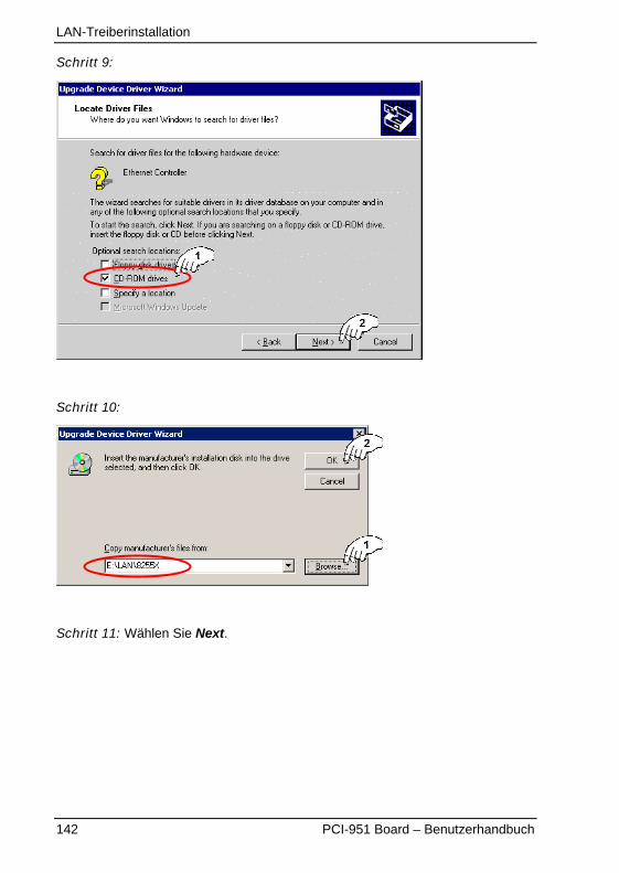
LAN-Treiberinstallation
142 PCI-951 Board – Benutzerhandbuch
Schritt 9:
Schritt 10:
Schritt 11: Wählen Sie Next.
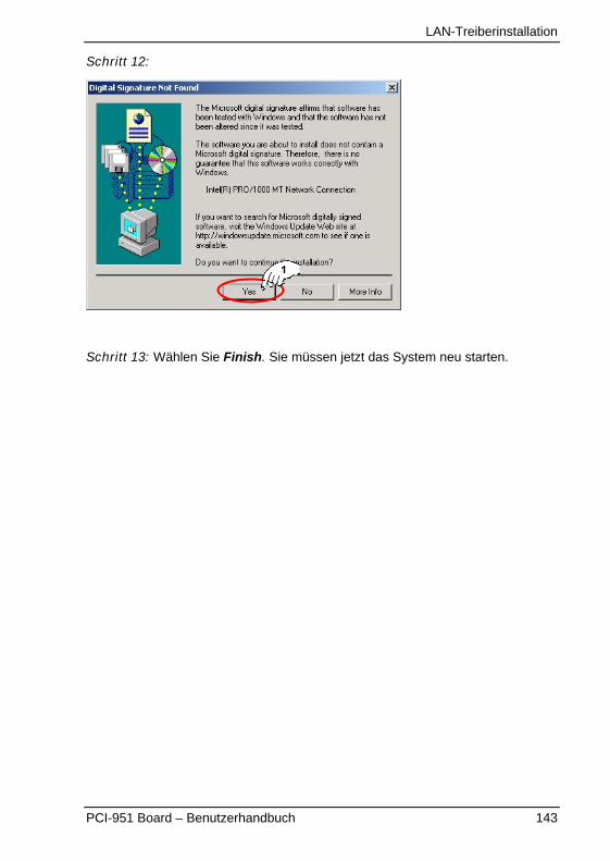
LAN-Treiberinstallation
PCI-951 Board – Benutzerhandbuch 143
Schritt 12:
Schritt 13: Wählen Sie Finish. Sie müssen jetzt das System neu starten.
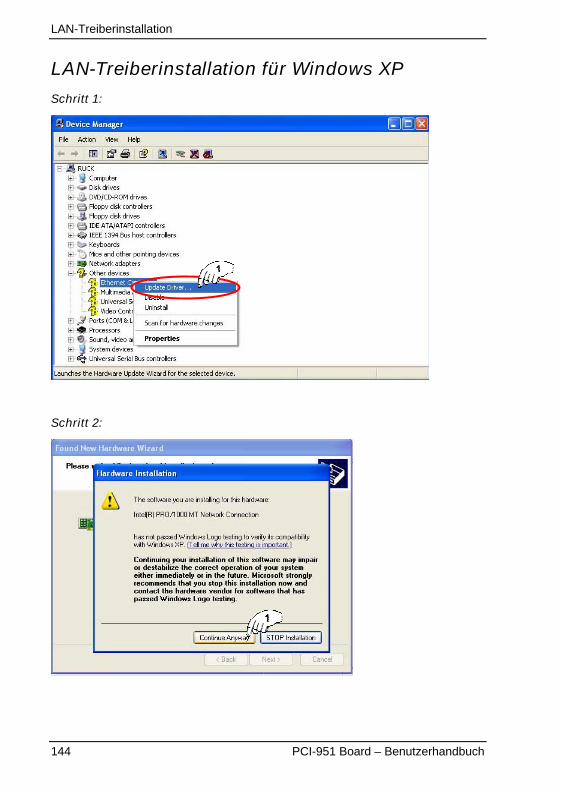
LAN-Treiberinstallation
144 PCI-951 Board – Benutzerhandbuch
LAN-Treiberinstallation für Windows XP
Schritt 1:
Schritt 2:
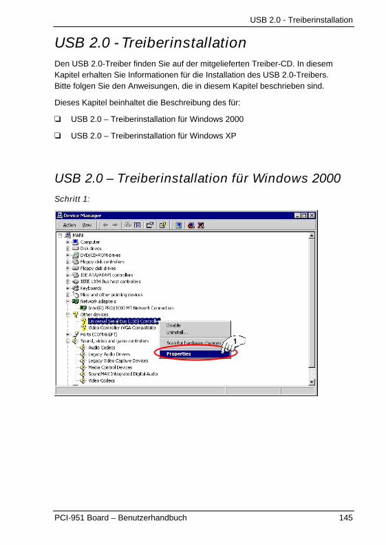
USB 2.0 - Treiberinstallation
PCI-951 Board – Benutzerhandbuch 145
USB 2.0 - TreiberinstallationDen USB 2.0-Treiber finden Sie auf der mitgelieferten Treiber-CD. In diesemKapitel erhalten Sie Informationen für die Installation des USB 2.0-Treibers.Bitte folgen Sie den Anweisungen, die in diesem Kapitel beschrieben sind.
Dieses Kapitel beinhaltet die Beschreibung des für:
� USB 2.0 – Treiberinstallation für Windows 2000
� USB 2.0 – Treiberinstallation für Windows XP
USB 2.0 – Treiberinstallation für Windows 2000
Schritt 1:
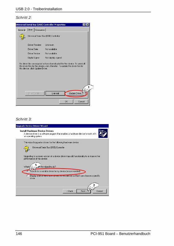
USB 2.0 - Treiberinstallation
146 PCI-951 Board – Benutzerhandbuch
Schritt 2:
Schritt 3:
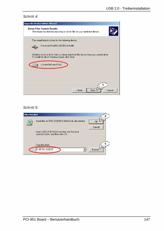
USB 2.0 - Treiberinstallation
PCI-951 Board – Benutzerhandbuch 147
Schritt 4:
Schritt 5:
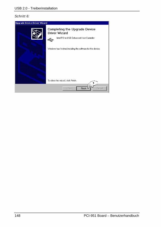
USB 2.0 - Treiberinstallation
148 PCI-951 Board – Benutzerhandbuch
Schritt 6:
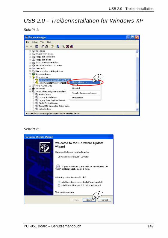
USB 2.0 - Treiberinstallation
PCI-951 Board – Benutzerhandbuch 149
USB 2.0 – Treiberinstallation für Windows XP
Schritt 1:
Schritt 2:
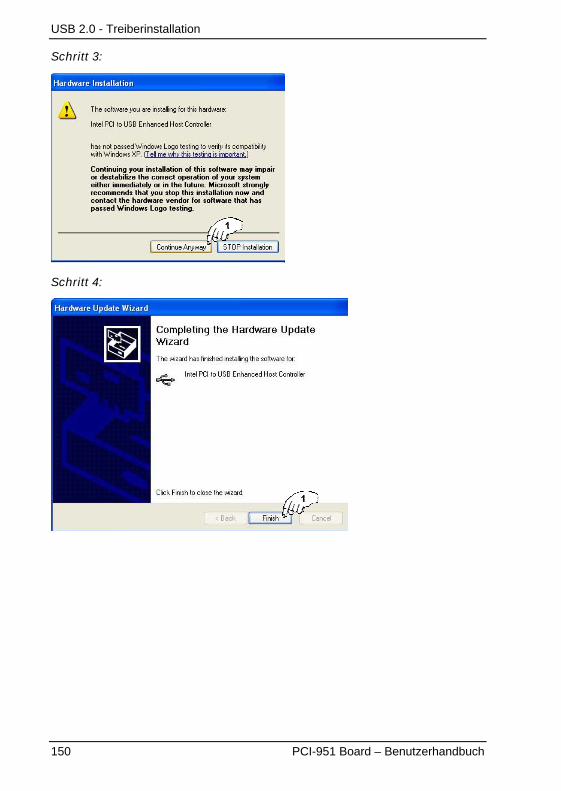
USB 2.0 - Treiberinstallation
150 PCI-951 Board – Benutzerhandbuch
Schritt 3:
Schritt 4:
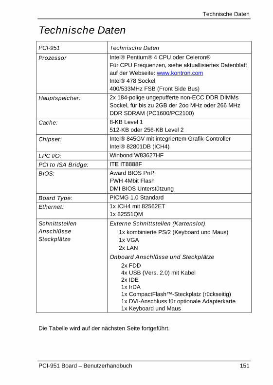
Technische Daten
PCI-951 Board – Benutzerhandbuch 151
Technische Daten
PCI-951 Technische Daten
Prozessor Intel® Pentium® 4 CPU oder Celeron®Für CPU Frequenzen, siehe aktuallisiertes Datenblattauf der Webseite: www.kontron.comIntel® 478 Sockel400/533MHz FSB (Front Side Bus)
Hauptspeicher: 2x 184-polige ungepufferte non-ECC DDR DIMMsSockel, für bis zu 2GB der 2oo MHz oder 266 MHzDDR SDRAM (PC1600/PC2100)
Cache: 8-KB Level 1512-KB oder 256-KB Level 2
Chipset: Intel® 845GV mit integriertem Grafik-ControllerIntel® 82801DB (ICH4)
LPC I/O: Winbond W83627HF
PCI to ISA Bridge: ITE IT8888F
BIOS: Award BIOS PnPFWH 4Mbit FlashDMI BIOS Unterstützung
Board Type: PICMG 1.0 Standard
Ethernet: 1x ICH4 mit 82562ET1x 82551QM
SchnittstellenAnschlüsseSteckplätze
Externe Schnittstellen (Kartenslot)1x kombinierte PS/2 (Keyboard und Maus)1x VGA2x LAN
Onboard Anschlüsse und Steckplätze2x FDD4x USB (Vers. 2.0) mit Kabel2x IDE1x IrDA1x CompactFlash™-Steckplatz (rückseitig)1x DVI-Anschluss für optionale Adapterkarte1x Keyboard und Maus
Die Tabelle wird auf der nächsten Seite fortgeführt.
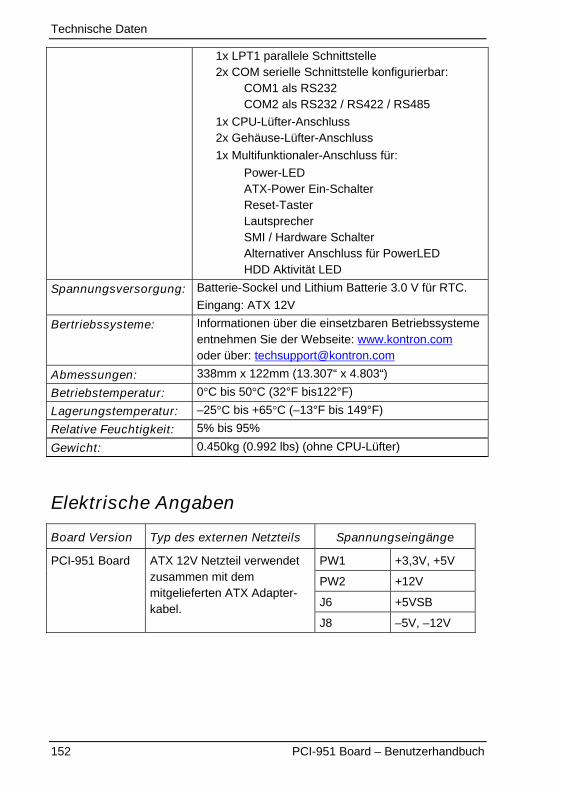
Technische Daten
152 PCI-951 Board – Benutzerhandbuch
1x LPT1 parallele Schnittstelle2x COM serielle Schnittstelle konfigurierbar:
COM1 als RS232COM2 als RS232 / RS422 / RS485
1x CPU-Lüfter-Anschluss2x Gehäuse-Lüfter-Anschluss
1x Multifunktionaler-Anschluss für:
Power-LEDATX-Power Ein-SchalterReset-TasterLautsprecherSMI / Hardware SchalterAlternativer Anschluss für PowerLEDHDD Aktivität LED
Spannungsversorgung: Batterie-Sockel und Lithium Batterie 3.0 V für RTC.
Eingang: ATX 12V
Bertriebssysteme: Informationen über die einsetzbaren Betriebssystemeentnehmen Sie der Webseite: www.kontron.comoder über: [email protected]
Abmessungen: 338mm x 122mm (13.307“ x 4.803“)
Betriebstemperatur: 0�C bis 50�C (32°F bis122°F)
Lagerungstemperatur: –25�C bis +65�C (–13°F bis 149°F)
Relative Feuchtigkeit: 5% bis 95%
Gewicht: 0.450kg (0.992 lbs) (ohne CPU-Lüfter)
Elektrische Angaben
Board Version Typ des externen Netzteils Spannungseingänge
PW1 +3,3V, +5V
PW2 +12V
J6 +5VSB
PCI-951 Board ATX 12V Netzteil verwendetzusammen mit demmitgelieferten ATX Adapter-kabel.
J8 –5V, –12V

Technische Daten
PCI-951 Board – Benutzerhandbuch 153
Leistungsspezifikationen
Eingang Eingangs Spitzenstrom
PW2: +12V 10A
PW1: +3V3 6A
PW1: +5V 1A
J6: +5VSB 1A
J8: –5V vernachlässigbar
J8: –12V vernachlässigbar
CE-Richtlinien, Standards und Zulassungen
CE -Richtlinien
Niederspannungsrichtlinie(Elektrische Sicherheit)
73/23/EWG
EMV – Richtlinie 89/336/EWG
Elektrische Sicherheit Standards
EUROPE EN 60 950:2000 / IEC 60950:1999 (Third Edition)
U.S.A. UL 60950-1:2003, First Edition
Canada CSA C22.2 No. 60950-1-03 1st Ed. April 1, 2003
EMV Standards
EUROPEEN 61000-6-4:2001 (Emission)EN 50082-1/ EN 61000-6-2 :2001 (Immunität)EN 55011: 1991 (CISPR11)
U.S.A. FCC 47 CFR Part 15, Class A
Zulassung Product Category CCN
UL Mark NWG2.E147705
cUL Mark NWG8.E147705

Technischer Support
154 PCI-951 Board – Benutzerhandbuch
Technischer SupportFür technische Fragen, setzen Sie sich bitte mit unserem technischen Support inVerbindung:
Tel: (+49) 816577-112Fax: (+49) 816577-110E-mail: [email protected]
Halten Sie Folgendes griffbereit:� die Artikelnummer des Boards (P/No #),� die Seriennummer des Boards (S/No #) (Die Seriennummer finden Sie aufden Aufkleber auf der Rückseite des Boards.
Schildern Sie unserem Mitarbeiter das Problem.
Falls Sie weitere Informationen über Kontron Embedded Computers, unsereProdukte oder Dienstleistungen wünschen, können Sie uns über die obengenannten Telefon-, Faxnummern, und über: www.kontron.com erreichen oderschreiben Sie uns:
Kontron Embedded Computers GmbHOskar-von-Miller-Str. 1
85386 Eching bei MünchenDeutschland

Technischer Support
PCI-951 Board – Benutzerhandbuch 155
RücksendungenBevor Sie ein nicht ordnungsgemäß funktionierendes Board an KontronEmbedded Computers zurückschicken, befolgen Sie bitte die unten aufgelistetenPunkte:
1. Kontaktieren Sie unseren Kundendienst in Deutschlandund lassen Sie sich eine RMA # geben.
Fax: (+49) 8165-77 311E-mail: [email protected]
2. Vergewissern Sie sich, dass Sie die RMA # von Kontron Kundendiensterhalten haben, bevor Sie das Board zurückschicken. Schreiben Sie dieseNummer gut lesbar auf das Paket, dass Sie uns zuschicken.
3. Beschreiben Sie, möglichst präzise, den Fehler den das Board aufweist.
4. Geben Sie einen Namen und eine Telefonnummer eines Ansprechpartnersan, für weitere Informationen wenn nötig.Wenn möglich fügen Sie alle notwendigen Zollpapiere und Rechnungen bei.
5. Wenn Sie ein Kontron-Board an uns zurückschicken:� Verpacken Sie das Board EDS sicher in den Originalkarton.� Fügen Sie eine Kopie des RMA Formulars der Lieferung bei.
Related Documents