CASSETTE FAN COIL COOLING/HEATING TERMINAL UNIT COOLING CAPACITY: 2,5 kW - 10,5 kW HEATING CAPACITY: 5,7 kW - 17,2 KW Features Stylish. Compact and lightweight. Ideal for standardized false ceilings. Low noise. Variable air flow distribution patterns. Infrared remote control. (standard) or wired controller availability. Master-Slave control capability. RS-485 Port, for BMS communication. Built-in condensate pump. Easy access to all the components for maintenance Standard filter for clean air. Fresh air and branch ducting capability. Self diagnosis. Interklima Hydronic Cassette Fan Coils are the ideal solution for cooling/heating applications. They are available in eight models with nominal capacities ranging from 2,5kW to 10,5 kW in cooling and 5,7kW up to 17,2kW in heating. This series is ideal in combination with Interklima air cooled water chillers or heat pumps for air conditioning offices, shops or any other commercial application, where floor and wall space is needed for fittings and furniture, by being installed flush into every ceilling with various air flow pattern flexibility according to the room shape and layout. PCE 03-04-06-08-09-10-12-16

Welcome message from author
This document is posted to help you gain knowledge. Please leave a comment to let me know what you think about it! Share it to your friends and learn new things together.
Transcript

CASSETTE FAN COILCOOLING/HEATINGTERMINAL UNIT
COOLING CAPACITY: 2,5 kW - 10,5 kWHEATING CAPACITY: 5,7 kW - 17,2 KW
Features
Stylish.
Compact and lightweight.
Ideal for standardized false ceilings.
Low noise.
Variable air flow distribution patterns.
Infrared remote control. (standard) or wired controller availability.
Master-Slave control capability.
RS-485 Port, for BMS communication.
Built-in condensate pump.
Easy access to all the components for maintenance
Standard filter for clean air.
Fresh air and branch ducting capability.
Self diagnosis.
Interklima Hydronic Cassette Fan Coils are theideal solution for cooling/heating applications.They are available in eight models withnominal capacities ranging from 2,5kW to10,5 kW in cooling and 5,7kW up to 17,2kWin heating.
This series is ideal in combination withInterklima air cooled water chillers or heatpumps for air conditioning offices, shops orany other commercial application, where floorand wall space is needed for fittings andfurniture, by being installed flush into everyceilling with various air flow pattern flexibilityaccording to the room shape and layout.
PCE 03-04-06-08-09-10-12-16

NOMENCLATURE
1 Interklima Hydronic cassette
2 Model numbers03=2kW04=3kW06=4kW08=6kW09=6,5kW10=7,5kW12=9kW16=10,5kW
3 TypeV- 2 pipe P- 4 pipe
4 Electrical CharacteristicS- 230V 1ph / 50Hz

Interklima Terminal UnitsPCE -VS ñ Hydronic cassette 3
1. Technical Specifications
2. Capacity Tables- Cooling - Heating
3. Outlook Drawings
4. Wiring Diagrams
5. Installation
6. Controller Instruction and Specifications
7. Service
Contents

Interklima Terminal UnitsPCE -VS ñ Hydronic cassette4
Technical specifications1.
PCE -03
Single
7.5
6.6
5.6
2.5
2.25
2.1
2.03
1.79
1.67
5.7
5.15
4.8
3
2.71
2.52
30/35/38
33.5
0.149
0.34
480
7.0
1.3
570
570
250
31
Model
Numbers of fan blowers
Nomimal airflow
Nominal cooling capacity*
Nominal sensible
cooling capacity*
Nominal heating capacity**
Nominal sensible
heating capacity**
Noise level@1M (L/M/H)
Power supply (V/Ph/Hz)
Fan motor power
Fan motor running current
Fan motor starting current
Operation control & thermostat
Water flow rate
Water pressure drop
Water content
Cond. drain connection I.D.
Casing dimentions
Panel dimentions
Cross weight
Connection method
Water Connection
PCE -04
Single
8.5
7
5.8
3
2.6
2.21
2.17
1.92
1.67
6
5.45
4.7
3.3
2.84
2.5
30/36/39
36.7
0.168
0.438
587
10.2
1.3
570
570
250
31
PCE -06
Single
10.4
9.4
7.8
4
3.4
2.9
2.84
2.51
2.19
6.9
6
5.2
4.2
3.65
3.17
35/41/43
54.2
0.241
0.759
765
9.6
1.79
570
570
290
33
PCE -08
Single
12.8
10.4
8.6
5
4.2
3.52
3.17
2.84
2.47
9
7.6
6.52
5.2
4.4
3.8
37/43/46
70.7
0.32
0.886
940
13.9
1.79
570
570
290
33
PCE -09
Twin
17
14
11.5
6.5
5.67
4.8
4.7
4.04
3.48
11.5
10
8.6
7.2
6.22
5.36
34/39/40
33.5x2
0.149x2
0.876
1.265
22.5
1.47
1.100
570
290
57
PCE -10
Twin
19.3
16
13
7.5
6.48
5.34
5.2
4.48
3.9
13
11.3
9.7
8.3
7.18
6.17
36/40/43
54.2x2
0.241x2
1.518
1.450
24.9
2.84
1.100
570
290
57
PCE -12
Twin
21.4
18.5
15.5
9
7.6
6.4
5.38
4.73
4.2
14.6
12.5
11.1
9.9
8.5
7.6
38/45/49
60.2x2
0.315x2
1.518
1.500
12.3
2.84
1.100
570
290
57
PCE -16
Twin
25
21
17.5
10.5
9
7.5
6.3
5.6
4.92
17.2
15.04
13.2
11
9.76
8.6
40/47/50
70.7x2
0.32x2
1.77
1.770
15.4
2.84
1.100
570
290
57
H
M
L
H
M
L
H
M
L
H
M
L
H
M
L
L
W
D
In
Out
kW
kW
kW
kW
kW
kW
kW
kW
kW
kW
kW
kW
kW
kW
kW
dB(A)
Watt
Amp
Amp
L/h
KPa
L
mm(in)
mm
mm
mm
mm
kgs
mm(in)
mm(in)
230/1/50
Remote control handset & wired wall pad
19.05(3/4)
Socket (threaded female)
19.05 (3/4)
19.05 (3/4)
PCE-VS
NOTESAll capacities are based on: cooling: indoor 27oC DB, 19.5oC WB, outdoor: 35oC DB, 24oC WB
heating: indoor 20oC DB, outdoor: 7oC DB, 6oC WB
Interklima Terminal UnitsPCE -VS ñ Hydronic cassette 5
Capacity Tables2.
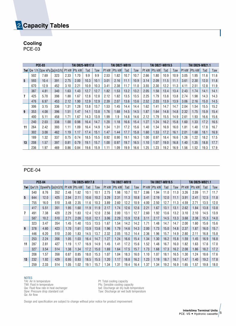
Qw 1/h
502
593
670
387
425
476
306
353
400
240
264
302
189
208
236
Pf kW
2.33
2.75
3.10
1.63
1.88
2.12
1.31
1.51
1.71
1.00
1.11
1.19
0.75
0.81
0.86
Pfs kW
1.70
2.00
2.21
1.43
1.67
1.90
1.28
1.47
1.67
0.98
1.09
1.17
0.74
0.79
0.84
Tad
9.9
10.3
10.9
12.7
12.8
12.9
13.8
14.1
14.3
16.4
16.4
17.4
18.5
19.1
19.6
Taw
9.9
10.1
10.3
12.7
12.8
12.9
13.7
13.8
13.9
14.7
14.9
15.1
15.5
15.7
15.9
Pf kW
2.53
3.01
3.41
1.82
2.12
2.39
1.53
1.76
1.99
1.20
1.34
1.47
0.92
1.00
1.11
Pfs kW
1.82
2.16
2.38
1.53
1.82
2.07
1.45
1.68
1.9
1.18
1.31
1.44
0.90
0.97
1.09
Tad
10.7
11.1
11.7
13.2
13.5
13.6
14.4
14.5
14.8
16.6
17.2
17.7
19.1
19.7
19.9
Taw
10.7
10.9
11.0
13.2
13.5
13.6
14.4
14.5
14.6
15.4
15.6
15.8
16.3
16.5
16.6
Pf kW
2.66
3.14
3.55
2.05
2.25
2.52
1.62
1.87
2.12
1.27
1.40
1.60
1.00
1.10
1.25
Pfs kW
1.80
2.09
2.30
1.58
1.79
2.03
1.41
1.64
1.79
1.24
1.34
1.53
0.97
1.07
1.23
Tad
10.9
11.5
12.2
13.4
13.8
13.9
14.7
14.8
15.5
16.2
16.9
17.2
18.4
19.0
19.2
Taw
10.9
11.1
11.3
13.4
13.8
13.9
14.7
14.8
14.9
15.8
16.0
16.1
16.6
16.8
16.9
Pf kW
3.05
3.61
4.11
2.43
2.74
3.06
2.04
2.32
2.61
1.60
1.81
2.01
1.26
1.40
1.56
Pfs kW
1.95
2.30
2.51
1.74
1.98
2.16
1.54
1.75
1.93
1.33
1.40
1.68
1.22
1.35
1.52
Tad
11.6
12.0
12.8
14.1
14.3
15.0
15.5
15.9
16.6
17.2
17.8
18.1
18.2
18.8
19.3
Taw
11.6
11.8
11.9
14.1
14.3
14.5
15.2
15.4
15.6
16.5
16.7
16.9
17.5
17.7
17.9
Dpw kPa
7.69
10.4
12.9
4.81
5.70
6.97
3.15
4.08
5.11
2.03
2.42
3.08
1.32
1.57
1.97
Qa[m3/h]
323
391
452
340
398
453
336
396
458
338
393
462
337
397
469
PCE-03
Twi
5
7
9
11
13
TAI DB25-WB17.8 TAI DB27-WB19 TAI DB27-WB19.5 TAI DB29-WB21.1
CoolingPCE-03
Qw1/h
540
644
755
417
491
587
323
378
446
253
287
327
208
232
259
Pf kW
2.48
2.94
3.48
1.95
2.29
2.71
1.45
1.70
2.00
1.05
1.19
1.38
0.87
0.95
1.05
Pfs kW
1.82
2.11
2.35
1.60
1.83
2.09
1.40
1.61
1.83
1.03
1.17
1.34
0.85
0.93
1.02
Tad
10.1
10.6
11.6
11.9
12.4
13.0
13.5
13.9
14.5
16.4
16.9
17.2
18.0
18.5
19.1
Taw
10.1
10.2
10.3
11.9
12.0
12.1
13.5
13.6
13.7
14.7
14.9
15.0
15.3
15.5
15.7
Pf kW
2.75
3.29
3.89
2.17
2.56
3.06
1.67
1.96
2.32
1.27
1.45
1.69
1.07
1.20
1.34
Pfs kW
1.98
2.31
2.60
1.74
2.00
2.29
1.54
1.79
2.05
1.24
1.41
1.64
1.04
1.17
1.31
Tad
10.7
11.3
12.2
12.6
13.1
13.9
14.2
14.6
15.2
16.6
17.2
17.5
18.3
18.8
19.4
Taw
10.7
10.8
10.9
12.6
12.7
12.8
14.2
14.3
14.4
15.4
15.6
15.7
16.0
16.2
16.4
Pf kW
2.86
3.41
4.00
2.21
2.60
3.11
1.71
2.00
2.36
1.34
1.52
1.73
1.10
1.23
1.37
Pfs kW
1.94
2.19
2.50
1.67
1.92
2.17
1.48
1.73
1.96
1.30
1.48
1.68
1.07
1.19
1.34
Tad
11.0
12.0
12.7
13.1
13.6
14.5
14.7
15.0
15.7
16.2
16.7
17.3
18.1
18.7
19.2
Taw
11.0
11.1
11.3
13.1
13.2
13.3
14.7
14.8
14.9
15.8
16.0
16.2
16.5
16.7
16.9
Pf kW
3.26
3.91
4.59
2.62
3.10
3.68
2.00
2.37
2.80
1.59
1.82
2.08
1.30
1.47
1.65
Pfs kW
2.09
2.41
2.71
1.84
2.10
2.38
1.60
1.87
2.11
1.45
1.63
1.86
1.24
1.40
1.57
Tad
11.7
12.5
13.5
13.8
14.5
15.3
15.6
16.0
16.8
16.9
17.6
18.2
18.6
19.2
19.8
Taw
11.7
11.8
12.0
13.8
13.9
14.0
15.6
15.7
15.8
16.8
17.0
17.2
17.6
17.8
18.0
DpwkPa
8.76
12.0
16.0
5.51
7.38
10.2
3.47
4.60
6.20
2.24
2.81
3.54
1.57
1.92
2.33
Qa[m3/h]
352
425
510
351
420
510
354
423
510
356
427
514
358
429
514
PCE-04
Twi
5
7
9
11
13
TAI DB25-WB17.8 TAI DB27-WB19 TAI DB27-WB19.5 TAI DB29-WB21.1
PCE-04
NOTESTAI: Air in temperature Pf: Total cooling capacityTWI: Fluid in temperature Pfs: Sensible cooling capacityQw: Fluid flow rate in heat exchanger tad: Discharge air dry bulb temperatureDpw: Pressure drop standard coil Taw: Discharge air wet bulb temperatureQa: Air flow
Design and specification are subject to change without prior notice for product improvement

Interklima Terminal UnitsPCE -VS ñ Hydronic cassette6
Qw1/h
816
974
1146
665
793
940
506
591
695
329
385
449
251
291
336
Pf kW
3.80
4.51
5.30
3.01
3.59
4.25
2.20
2.61
3.07
1.44
1.69
1.96
1.10
1.27
1.46
Pfs kW
2.62
2.97
3.36
2.3
2.64
2.98
2.03
2.3
2.61
1.41
1.65
1.9
1.07
1.23
1.43
Tad
10.4
11.2
12.0
12.0
12.7
13.4
13.5
14.2
14.8
16.9
17.2
17.5
18.8
19.1
19.3
Taw
9.7
9.8
10.0
11.5
11.6
11.7
13.3
13.4
13.5
14.9
15.0
15.1
15.6
15.7
15.8
Pf kW
4.20
5.02
5.96
3.41
4.06
4.83
2.59
3.06
3.55
1.70
2.00
2.33
1.25
1.45
1.67
Pfs kW
2.85
3.25
3.66
2.55
2.90
3.26
2.24
2.55
2.88
1.68
1.96
2.30
1.23
1.42
1.63
Tad
11.0
11.9
12.8
12.6
13.4
14.3
14.3
15.0
15.7
17.4
17.7
17.9
19.9
20.2
20.5
Taw
10.3
10.4
10.5
12.1
12.2
12.3
13.9
14.0
14.2
15.7
15.8
15.9
16.6
16.7
16.8
Pf kW
4.32
5.16
6.07
3.52
4.20
4.98
2.68
3.13
3.68
1.74
2.04
2.38
1.33
1.54
1.78
Pfs kW
2.78
3.15
3.58
2.47
2.84
3.17
2.16
2.46
2.77
1.69
2.00
2.33
1.30
1.50
1.73
Tad
11.4
12.3
13.1
13.0
13.7
14.6
14.7
15.4
16.1
17.3
17.5
17.8
19.5
19.8
20.1
Taw
10.7
10.8
11.0
12.5
12.6
12.7
14.3
14.5
14.6
16.2
16.3
16.4
17.0
17.1
17.2
Pf kW
5.00
5.93
7.05
4.10
4.88
5.80
3.18
3.72
4.40
2.15
2.54
2.98
1.73
2.02
2.35
Pfs kW
3.02
3.42
3.82
2.68
3.06
3.42
2.35
2.68
3.02
2.03
2.33
2.62
1.68
1.90
2.13
Tad
12.0
13.0
14.1
13.8
14.6
15.6
15.6
16.3
17.1
17.3
17.9
18.6
19.3
19.9
20.5
Taw
11.2
11.4
11.5
13.2
13.3
13.4
15.1
15.3
15.4
17.1
17.2
17.3
17.9
18.0
18.1
DpwkPa
10.79
14.83
19.88
7.46
10.25
13.92
4.56
6.04
8.08
2.10
2.79
3.68
1.29
1.69
2.18
Qa[m3/h]
516
624
750
516
624
750
516
626
751
517
625
752
518
624
752
PCE-08
Twi
5
7
9
11
13
TAI DB25-WB17.8 TAI DB27-WB19 TAI DB27-WB19.5 TAI DB29-WB21.1
PCE-08
Qw1/h
1100
1300
1550
906
1070
1265
695
827
972
493
585
672
429
506
576
Pf kW
5.13
6.16
7.41
4.12
4.92
5.80
3.02
3.68
4.37
2.07
2.45
2.86
1.75
2.05
2.38
Pfs kW
3.69
4.37
4.95
3.26
3.83
4.39
2.80
3.32
3.85
2.02
2.38
2.76
1.71
2.00
2.31
Tad
9.6
10.0
11.0
11.4
11.8
12.5
13.2
13.5
14.0
16.4
16.7
17.0
17.7
18.0
18.3
Taw
9.6
9.7
9.8
11.4
11.5
11.7
13.2
13.2
13.3
14.7
14.8
14.9
15.2
15.3
15.4
Pf kW
5.71
6.85
8.15
4.65
5.56
6.60
3.53
4.21
5.03
2.56
3.04
3.56
2.16
2.55
2.98
Pfs kW
4.03
4.77
5.47
3.58
4.15
4.81
3.12
3.73
4.26
2.52
2.98
3.48
2.11
2.54
2.92
Tad
10.2
10.6
11.5
12.0
12.6
13.3
13.8
14.0
14.8
16.3
16.6
16.9
18.0
18.1
18.5
Taw
10.2
10.3
10.5
12.0
12.1
12.3
13.8
13.9
14.0
15.3
15.4
15.5
15.9
16.0
16.1
Pf kW
5.80
6.90
8.20
4.80
5.67
6.70
3.68
4.38
5.15
2.61
3.10
3.56
2.27
2.68
3.05
Pfs kW
3.90
4.58
5.27
3.48
4.04
4.70
3.04
3.59
4.10
2.54
3.03
3.57
2.22
2.53
2.97
Tad
10.7
11.2
12.0
12.4
13.0
13.6
14.2
14.5
15.3
16.2
16.4
16.7
17.5
18.1
18.4
Taw
10.7
10.9
11.1
12.4
12.6
12.8
14.2
14.3
14.5
15.8
15.9
16.1
16.3
16.4
16.6
Pf kW
6.85
8.16
9.71
5.63
6.70
8.00
4.40
5.28
6.30
3.10
3.78
4.37
2.47
2.90
3.42
Pfs kW
4.31
5.01
5.68
3.80
4.47
5.05
3.32
3.96
4.51
2.85
3.45
3.89
2.38
2.82
3.30
Tad
11.0
11.7
12.8
13.0
13.5
14.5
14.9
15.2
16.0
16.8
16.9
17.7
18.8
19.0
19.4
Taw
11.0
11.2
11.4
13.0
13.2
13.3
14.9
15.0
15.1
16.8
16.8
17.0
17.7
17.8
17.9
DpwkPa
17.3
23.7
32.3
12.3
16.6
22.5
7.64
10.5
14.0
4.1
5.6
7.2
3.2
4.3
5.45
Qa[m3/h]
691
840
1022
694
841
1022
695
843
1029
694
846
1028
695
846
1027
PCE-09
Twi
5
7
9
11
13
TAI DB25-WB17.8 TAI DB27-WB19 TAI DB27-WB19.5 TAI DB29-WB21.1
PCE-09
NOTESTAI: Air in temperature Pf: Total cooling capacityTWI: Fluid in temperature Pfs: Sensible cooling capacityQw: Fluid flow rate in heat exchanger tad: Discharge air dry bulb temperatureDpw: Pressure drop standard coil Taw: Discharge air wet bulb temperatureQa: Air flow
Design and specification are subject to change without prior notice for product improvement

Interklima Terminal UnitsPCE -VS ñ Hydronic cassette 7
Qw1/h
1227
1472
1755
1010
1223
1450
793
961
1148
527
631
746
425
504
569
Pf kW
5.80
6.97
8.28
4.64
5.61
6.74
3.48
4.20
5.01
2.19
2.60
3.06
1.52
1.78
2.06
Pfs kW
4.19
4.76
5.45
3.64
4.19
4.83
3.19
3.69
4.29
2.15
2.53
2.97
1.49
1.74
2.00
Tad
9.7
10.7
11.5
11.5
12.3
13.0
13.1
13.8
14.3
16.9
17.2
17.5
19.3
19.6
19.9
Taw
9.7
9.8
10.0
11.4
11.5
11.6
13.1
13.2
13.3
14.9
15.0
15.1
15.8
15.9
16.0
Pf kW
6.42
7.73
9.21
5.24
6.35
7.54
4.06
4.90
5.86
2.73
3.27
3.87
2.15
2.57
2.96
Pfs kW
4.54
5.20
5.96
4.03
4.64
5.34
3.55
4.13
4.70
2.67
3.18
3.80
2.10
2.45
2.91
Tad
10.2
11.3
12.2
12.0
12.9
13.7
13.7
14.4
15.2
16.9
17.2
17.4
19.1
19.4
19.6
Taw
10.2
10.4
10.6
12.0
12.1
12.3
13.7
13.8
13.9
15.5
15.6
15.7
16.3
16.4
16.5
Pf kW
6.50
7.80
9.30
5.35
6.48
7.68
4.20
5.09
6.08
2.79
3.34
3.95
2.25
2.67
3.01
Pfs kW
4.38
5.13
5.84
3.90
4.48
5.20
3.43
4.00
4.58
2.72
3.25
3.84
2.18
2.59
2.94
Tad
10.8
11.5
12.5
12.5
13.4
14.0
14.1
14.8
15.5
16.7
17.0
17.3
18.7
19.0
19.5
Taw
10.8
11.0
11.2
12.5
12.6
12.8
14.1
14.2
14.3
16.0
16.1
16.2
16.7
16.8
17.0
Pf kW
7.65
9.21
11.03
6.37
7.63
9.18
4.99
6.03
7.20
3.43
4.12
4.90
2.78
3.32
3.8
Pfs kW
4.74
5.44
6.18
4.26
4.86
5.59
3.76
4.35
4.95
3.20
3.73
4.30
2.73
3.16
3.57
Tad
11.4
12.5
13.6
13.3
14.2
15.0
14.9
15.7
16.5
16.9
17.5
18.1
18.6
19.2
19.9
Taw
11.1
11.3
11.5
13.1
13.2
13.3
14.9
15.0
15.1
16.9
17.0
17.1
17.7
17.8
18.0
DpwkPa
21.3
29.5
40.5
15.0
21.2
24.9
9.7
13.7
18.9
4.64
6.4
8.7
3.2
4.3
5.3
Qa[m3/h]
783
961
1172
783
963
1172
781
963
1173
783
964
1174
784
964
1173
PCE-10
Twi
5
7
9
11
13
TAI DB25-WB17.8 TAI DB27-WB19 TAI DB27-WB19.5 TAI DB29-WB21.1
PCE-10
Qw1/h
1365
1610
1912
1089
1280
1510
814
952
1108
593
685
784
487
561
631
Pf kW
6.29
7.41
8.90
4.96
5.82
6.84
3.56
4.15
4.91
2.52
2.90
3.27
1.90
2.16
2.38
Pfs kW
4.47
5.05
5.72
3.93
4.42
5.04
3.47
3.91
4.41
2.46
2.81
3.19
1.84
2.16
2.32
Tad
11.1
11.8
12.7
12.7
13.4
14.1
14.1
14.7
15.4
17.2
17.5
18.0
19.1
19.3
19.9
Taw
10.4
10.5
10.6
12.1
12.2
12.4
13.8
13.9
14.0
15.0
15.1
15.3
15.7
15.8
16.0
Pf kW
7.03
8.30
9.95
5.60
6.55
7.73
4.15
4.83
5.62
3.08
3.56
4.08
2.53
2.91
3.27
Pfs kW
4.84
5.51
6.25
4.31
4.93
5.52
3.87
4.33
4.9
3.02
3.48
3.92
2.47
2.83
3.21
Tad
11.9
12.6
13.5
13.5
14.0
15.0
14.8
15.5
16.3
17.4
17.7
18.4
19.1
19.4
19.9
Taw
11.0
11.1
11.2
12.8
12.9
13.1
14.5
14.6
14.8
15.7
15.8
16.0
16.3
16.4
16.6
Pf kW
7.23
8.53
10.13
5.77
6.78
8.00
4.31
5.04
5.87
3.14
3.63
4.15
2.58
2.97
3.34
Pfs kW
4.70
5.33
6.05
4.20
4.73
5.38
3.70
4.19
4.76
3.05
3.56
4.05
2.50
2.91
3.26
Tad
12.3
13.0
13.9
13.8
14.5
15.3
15.3
15.9
16.6
17.3
17.5
18.1
19.0
19.2
19.8
Taw
11.4
11.5
11.7
13.2
13.3
13.5
14.9
15.0
15.2
16.2
16.3
16.5
16.8
16.9
17.1
Pf kW
8.30
9.78
11.65
6.70
7.90
9.45
5.11
5.98
7.00
3.70
4.30
4.95
3.12
3.60
4.10
Pfs kW
5.04
5.77
6.54
4.53
5.14
5.86
4.01
4.51
5.15
3.51
3.96
4.54
2.90
3.23
3.70
Tad
13.2
13.8
14.8
14.7
15.4
16.2
16.3
17.0
17.7
17.8
18.4
19.0
19.7
20.3
20.8
Taw
12.1
12.2
12.4
14.0
14.1
14.2
15.8
15.9
16.1
17.3
17.4
17.6
17.9
18.0
18.2
DpwkPa
10.30
13.90
18.90
6.90
9.20
12.40
4.10
5.40
7.10
2.30
2.99
3.80
1.60
2.10
2.60
Qa[m3/h]
930
1111
1352
931
1111
1353
932
1112
1354
933
1112
1354
932
1113
1354
PCE-12
Twi
5
7
9
11
13
TAI DB25-WB17.8 TAI DB27-WB19 TAI DB27-WB19.5 TAI DB29-WB21.1
PCE-12
NOTESTAI: Air in temperature Pf: Total cooling capacityTWI: Fluid in temperature Pfs: Sensible cooling capacityQw: Fluid flow rate in heat exchanger tad: Discharge air dry bulb temperatureDpw: Pressure drop standard coil Taw: Discharge air wet bulb temperatureQa: Air flow
Design and specification are subject to change without prior notice for product improvement
Interklima Terminal UnitsPCE -VS ñ Hydronic cassette8
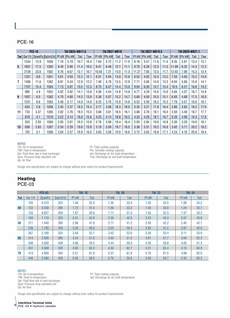
Qw1/h
1544
1831
2128
1231
1456
1707
900
1057
1231
633
733
818
553
638
702
Pf kW
7.10
8.40
9.76
5.61
6.61
7.73
4.02
4.70
5.46
2.45
2.82
3.22
2.05
2.34
2.64
Pfs kW
5.19
5.90
6.67
4.63
5.24
5.91
3.92
4.60
5.17
2.37
2.76
3.14
2.01
2.29
2.57
Tad
10.7
11.4
12.1
12.2
12.9
13.5
14.1
14.3
14.9
18.3
18.5
18.8
19.3
19.6
19.9
Taw
10.4
10.5
10.7
12.1
12.2
12.3
13.8
13.9
14.0
15.4
15.5
15.6
15.8
15.9
16.0
Pf kW
7.94
9.41
10.93
6.31
7.40
8.75
4.58
5.38
6.25
3.17
3.68
4.23
2.76
3.19
3.65
Pfs kW
5.72
6.46
7.21
5.04
5.78
6.47
4.44
5.07
5.70
3.08
3.61
4.14
2.69
3.09
3.58
Tad
11.2
12.1
13.0
13.0
13.5
14.4
14.6
15.2
15.8
18.3
18.5
18.8
19.4
19.7
19.9
Taw
11.0
11.1
11.3
12.8
12.9
13.0
14.6
14.7
14.8
16.0
16.1
16.2
16.4
16.5
16.6
Pf kW
8.18
9.70
11.27
6.52
7.71
9.04
4.77
5.60
6.52
3.35
3.88
4.33
2.93
3.38
3.72
Pfs kW
5.57
6.28
7.05
4.92
5.60
6.30
4.29
4.93
5.50
3.27
3.78
4.20
2.84
3.31
3.63
Tad
11.6
12.5
13.3
13.3
14.0
14.7
15.0
15.5
16.2
17.8
18.1
18.7
19.0
19.2
19.8
Taw
11.4
11.5
11.7
13.2
13.3
13.4
15.0
15.1
15.2
16.4
16.5
16.7
16.8
16.9
17.1
Pf kW
9.35
11.09
12.93
7.55
8.94
10.5
5.65
6.65
7.78
3.86
4.50
5.20
3.30
3.82
4.23
Pfs kW
5.61
6.32
7.00
4.93
5.60
6.31
4.37
4.89
5.57
3.83
4.40
4.90
3.20
3.71
4.10
Tad
13.4
14.3
15.3
15.2
15.9
16.6
16.7
17.5
18.0
18.2
18.7
19.3
19.9
20.2
20.8
Taw
12.1
12.2
12.4
14.0
14.1
14.2
15.9
16.0
16.1
17.6
17.7
17.8
18.1
18.2
18.4
DpwkPa
12.9
17.5
23.0
8.6
11.6
15.4
4.9
6.5
8.6
2.6
3.37
4.1
2.03
2.63
3.1
Qa[m3/h]
1050
1262
1502
1051
1262
1504
1052
1262
1503
1058
1265
1510
1059
1267
1508
PCE-16
Twi
5
7
9
11
13
TAI DB25-WB17.8 TAI DB27-WB19 TAI DB27-WB19.5 TAI DB29-WB21.1
PCE-16
NOTESTAI: Air in temperature Pf: Total cooling capacityTWI: Fluid in temperature Pfs: Sensible cooling capacityQw: Fluid flow rate in heat exchanger tad: Discharge air dry bulb temperatureDpw: Pressure drop standard coil Taw: Discharge air wet bulb temperatureQa: Air flow
Design and specification are subject to change without prior notice for product improvement
Qw 1/h
105
122
133
183
211
236
267
314
346
351
413
449
Pf kW
1.46
1.72
1.87
2.51
2.96
3.26
3.58
4.24
4.66
4.65
5.51
6.00
Tad
32.0
31.4
30.6
42.0
41.0
40.0
52.1
51.0
49.5
62.3
61.0
58.5
Pf kW
1.35
1.56
1.71
2.35
2.71
3.03
3.42
4.03
4.44
4.50
5.31
5.76
Tad
32.9
32.2
31.5
42.5
41.2
40.4
52.6
51.5
50.0
62.7
61.6
58.8
Pf kW
1.20
1.40
1.53
2.23
2.58
2.85
3.28
3.81
4.26
4.31
5.10
5.59
Tad
33.5
33.0
32.3
43.3
42.2
41.2
53.4
51.7
50.8
63.4
61.5
59.7
Pf kW
1.06
1.24
1.37
2.07
2.40
2.67
3.11
3.64
4.05
4.15
4.88
5.35
Tad
34.2
33.7
33.2
43.8
42.7
42.0
53.9
52.3
51.3
63.9
62.0
60.2
DpwkPa
0.410
0.530
0.627
1.110
1.440
1.760
2.180
2.930
3.500
3.580
4.800
5.580
Qa[m3/h]
323
395
459
323
395
459
324
395
458
326
394
458
PCE-03
Twi
40
50
60
70
TAI 18 TAI 20 TAI 22 TAI 24
HeatingPCE-03
NOTESTAI: Air in temperature Pf: Total cooling capacityTWI: Fluid in temperature tad: Discharge air dry bulb temperatureQw: Fluid flow rate in heat exchangerDpw: Pressure drop standard coilQa: Air flow
Design and specification are subject to change without prior notice for product improvement
Interklima Terminal UnitsPCE -VS ñ Hydronic cassette 9
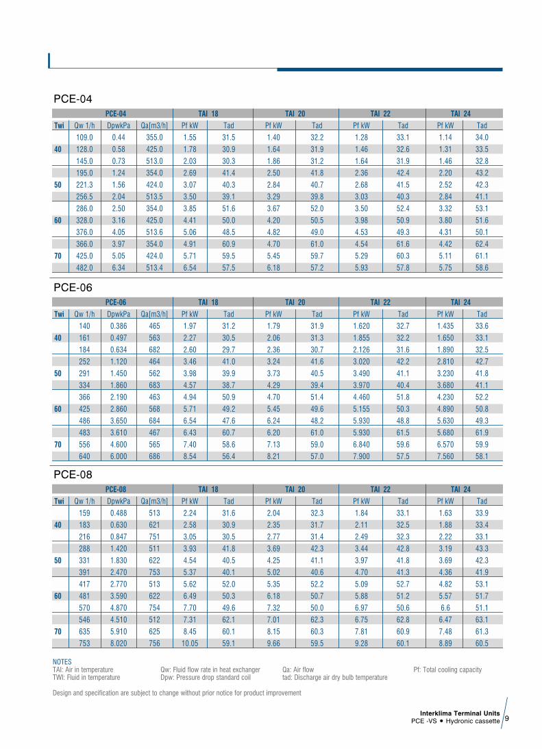
Qw 1/h
109.0
128.0
145.0
195.0
221.3
256.5
286.0
328.0
376.0
366.0
425.0
482.0
Pf kW
1.55
1.78
2.03
2.69
3.07
3.50
3.85
4.41
5.06
4.91
5.71
6.54
Tad
31.5
30.9
30.3
41.4
40.3
39.1
51.6
50.0
48.5
60.9
59.5
57.5
Pf kW
1.40
1.64
1.86
2.50
2.84
3.29
3.67
4.20
4.82
4.70
5.45
6.18
Tad
32.2
31.9
31.2
41.8
40.7
39.8
52.0
50.5
49.0
61.0
59.7
57.2
Pf kW
1.28
1.46
1.64
2.36
2.68
3.03
3.50
3.98
4.53
4.54
5.29
5.93
Tad
33.1
32.6
31.9
42.4
41.5
40.3
52.4
50.9
49.3
61.6
60.3
57.8
Pf kW
1.14
1.31
1.46
2.20
2.52
2.84
3.32
3.80
4.31
4.42
5.11
5.75
Tad
34.0
33.5
32.8
43.2
42.3
41.1
53.1
51.6
50.1
62.4
61.1
58.6
DpwkPa
0.44
0.58
0.73
1.24
1.56
2.04
2.50
3.16
4.05
3.97
5.05
6.34
Qa[m3/h]
355.0
425.0
513.0
354.0
424.0
513.5
354.0
425.0
513.6
354.0
424.0
513.4
PCE-04
Twi
40
50
60
70
TAI 18 TAI 20 TAI 22 TAI 24
PCE-04
Qw 1/h
140
161
184
252
291
334
366
425
486
483
556
640
Pf kW
1.97
2.27
2.60
3.46
3.98
4.57
4.94
5.71
6.54
6.43
7.40
8.54
Tad
31.2
30.5
29.7
41.0
39.9
38.7
50.9
49.2
47.6
60.7
58.6
56.4
Pf kW
1.79
2.06
2.36
3.24
3.73
4.29
4.70
5.45
6.24
6.20
7.13
8.21
Tad
31.9
31.3
30.7
41.6
40.5
39.4
51.4
49.6
48.2
61.0
59.0
57.0
Pf kW
1.620
1.855
2.126
3.020
3.490
3.970
4.460
5.155
5.930
5.930
6.840
7.900
Tad
32.7
32.2
31.6
42.2
41.1
40.4
51.8
50.3
48.8
61.5
59.6
57.5
Pf kW
1.435
1.650
1.890
2.810
3.230
3.680
4.230
4.890
5.630
5.680
6.570
7.560
Tad
33.6
33.1
32.5
42.7
41.8
41.1
52.2
50.8
49.3
61.9
59.9
58.1
DpwkPa
0.386
0.497
0.634
1.120
1.450
1.860
2.190
2.860
3.650
3.610
4.600
6.000
Qa[m3/h]
465
563
682
464
562
683
463
568
684
467
565
686
PCE-06
Twi
40
50
60
70
TAI 18 TAI 20 TAI 22 TAI 24
PCE-06
Qw 1/h
159
183
216
288
331
391
417
481
570
546
635
753
Pf kW
2.24
2.58
3.05
3.93
4.54
5.37
5.62
6.49
7.70
7.31
8.45
10.05
Tad
31.6
30.9
30.5
41.8
40.5
40.1
52.0
50.3
49.6
62.1
60.1
59.1
Pf kW
2.04
2.35
2.77
3.69
4.25
5.02
5.35
6.18
7.32
7.01
8.15
9.66
Tad
32.3
31.7
31.4
42.3
41.1
40.6
52.2
50.7
50.0
62.3
60.3
59.5
Pf kW
1.84
2.11
2.49
3.44
3.97
4.70
5.09
5.88
6.97
6.75
7.81
9.28
Tad
33.1
32.5
32.3
42.8
41.8
41.3
52.7
51.2
50.6
62.8
60.9
60.1
Pf kW
1.63
1.88
2.22
3.19
3.69
4.36
4.82
5.57
6.6
6.47
7.48
8.89
Tad
33.9
33.4
33.1
43.3
42.3
41.9
53.1
51.7
51.1
63.1
61.3
60.5
DpwkPa
0.488
0.630
0.847
1.420
1.830
2.470
2.770
3.590
4.870
4.510
5.910
8.020
Qa[m3/h]
513
621
751
511
622
753
513
622
754
512
625
756
PCE-08
Twi
40
50
60
70
TAI 18 TAI 20 TAI 22 TAI 24
PCE-08
NOTESTAI: Air in temperature Qw: Fluid flow rate in heat exchanger Qa: Air flow Pf: Total cooling capacityTWI: Fluid in temperature Dpw: Pressure drop standard coil tad: Discharge air dry bulb temperature
Design and specification are subject to change without prior notice for product improvement

Interklima Terminal UnitsPCE -VS ñ Hydronic cassette10
Qw 1/h
232
270
312
409
475
549
591
686
790
768
895
1028
Pf kW
3.29
3.82
4.39
5.60
6.52
7.53
7.95
9.20
10.62
10.30
11.95
13.79
Tad
32.7
32.0
31.3
43.0
41.9
40.8
53.4
51.8
50.1
63.9
61.9
59.7
Pf kW
2.98
3.46
4.00
5.25
6.10
7.05
7.59
8.80
10.14
9.85
11.48
13.20
Tad
33.3
32.7
32.1
43.5
42.4
41.3
53.9
52.3
50.6
64.0
62.0
59.9
Pf kW
2.69
3.11
3.57
4.92
5.71
6.59
7.21
8.35
9.59
9.51
11.03
12.73
Tad
34.0
33.4
32.8
44.0
43.0
41.9
54.2
52.7
51.0
64.5
62.5
60.5
Pf kW
2.39
2.77
3.17
4.57
5.30
6.12
6.82
7.92
9.12
9.10
10.57
12.20
Tad
34.7
34.2
33.6
44.4
43.5
42.5
54.5
53.1
51.5
64.7
62.8
60.9
DpwkPa
0.914
1.200
1.550
2.530
3.320
4.310
4.920
6.420
8.300
7.870
10.400
13.300
Qa[m3/h]
692
842
1022
690
841
1023
692
842
1024
692
845
1022
PCE-09
Twi
40
50
60
70
TAI 18 TAI 20 TAI 22 TAI 24
PCE-09
Qw 1/h
256
298
343
452
526
608
650
757
875
848
988
1142
Pf kW
3.62
4.21
4.84
6.19
7.21
8.32
8.75
10.21
11.78
11.32
13.18
15.26
Tad
32.3
31.5
30.78
42.4
41.2
39.9
52.6
50.8
49.1
62.7
60.4
58.2
Pf kW
3.29
3.83
44.00
5.80
6.75
7.80
8.34
9.72
11.23
10.98
12.68
14.66
Tad
33.0
32.3
31.6
42.9
41.7
40.6
53.0
51.2
49.6
63.0
60.8
58.7
Pf kW
2.96
3.45
3.97
5.41
6.31
7.28
7.92
9.23
10.67
10.44
12.18
14.07
Tad
33.7
33.1
32.5
43.4
42.3
41.2
53.3
51.7
50.1
63.3
61.2
59.1
Pf kW
2.63
3.06
3.53
5.03
5.87
6.76
7.50
8.74
10.10
10.00
11.67
13.47
Tad
34.4
33.8
33.3
43.9
42.7
41.8
53.7
52.1
50.6
63.6
61.5
59.6
DpwkPa
1.09
1.44
1.84
3.03
3.98
5.17
5.83
7.68
9.96
9.41
12.30
16.10
Qa[m3/h]
782
962
1172
783
962
1170
781
963
1172
782
960
1171
PCE-10
Twi
40
50
60
70
TAI 18 TAI 20 TAI 22 TAI 24
PCE-10
NOTESTAI: Air in temperature Qw: Fluid flow rate in heat exchanger Qa: Air flow Pf: Total cooling capacityTWI: Fluid in temperature Dpw: Pressure drop standard coil tad: Discharge air dry bulb temperature
Design and specification are subject to change without prior notice for product improvement
Interklima Terminal UnitsPCE -VS ñ Hydronic cassette 11
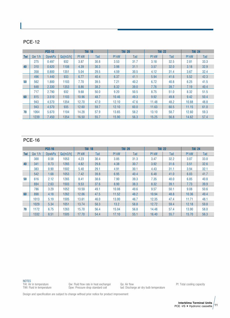
Qw 1/h
275
310
358
496
562
648
717
815
943
943
1064
1239
Pf kW
3.87
4.39
5.04
6.77
7.70
8.86
9.68
10.96
12.70
12.60
14.28
16.50
Tad
30.8
30.3
29.5
40.4
39.5
38.2
50.0
48.7
47.0
59.7
57.9
55.7
Pf kW
3.53
3.98
4.59
6.37
7.21
8.32
9.20
10.46
12.10
12.10
13.65
15.90
Tad
31.7
31.1
30.5
41.1
40.2
39.0
50.5
49.3
47.6
60.0
58.2
56.3
Pf kW
3.18
3.57
4.12
5.94
6.72
7.76
8.75
9.92
11.48
11.63
13.10
15.25
Tad
32.5
32.0
31.4
41.6
40.8
39.7
51.0
49.8
48.2
60.5
58.7
56.8
Pf kW
2.81
3.18
3.67
5.52
6.25
7.19
8.32
9.42
10.88
11.15
12.60
14.62
Tad
33.3
32.9
32.4
42.3
41.5
40.4
51.5
50.4
48.8
61.0
59.3
57.4
DpwkPa
0.497
0.620
0.800
1.440
1.800
2.330
2.790
3.510
4.570
4.570
5.670
7.450
Qa[m3/h]
932
1108
1351
933
1103
1353
932
1103
1354
935
1104
1354
PCE-12
Twi
40
50
60
70
TAI 18 TAI 20 TAI 22 TAI 24
PCE-12
Qw 1/h
300
341
383
542
616
694
786
898
1013
1029
1172
1332
Pf kW
4.23
4.82
5.40
7.42
8.41
9.53
10.59
12.06
13.61
13.74
15.70
17.70
Tad
30.4
29.8
29.1
39.8
38.6
37.6
49.1
47.5
46.0
58.3
56.4
54.4
Pf kW
3.85
4.38
4.91
6.95
7.90
8.90
10.08
11.52
13.00
13.2
15.04
17.10
Tad
31.3
30.7
30.1
40.4
39.3
38.3
49.6
48.2
46.7
58.8
56.8
55.1
Pf kW
3.47
3.92
4.43
6.48
7.35
8.32
9.57
10.94
12.35
12.72
14.48
16.40
Tad
32.2
31.6
31.1
41.0
40.0
39.1
50.1
48.8
47.4
59.4
57.4
55.7
Pf kW
3.07
3.51
3.94
6.03
6.85
7.73
9.08
10.36
11.71
12.18
13.90
15.70
Tad
33.0
32.6
32.1
41.7
40.8
39.9
50.6
49.4
48.1
59.8
58.0
56.3
DpwkPa
0.58
0.73
0.90
1.68
2.12
2.63
3.29
4.18
5.19
5.34
6.75
8.51
Qa[m3/h]
1053
1265
1502
1053
1265
1503
1052
1262
1505
1051
1263
1505
PCE-16
Twi
40
50
60
70
TAI 18 TAI 20 TAI 22 TAI 24
PCE-16
NOTESTAI: Air in temperature Qw: Fluid flow rate in heat exchanger Qa: Air flow Pf: Total cooling capacityTWI: Fluid in temperature Dpw: Pressure drop standard coil tad: Discharge air dry bulb temperature
Design and specification are subject to change without prior notice for product improvement

Interklima Terminal UnitsPCE -VS ñ Hydronic cassette12
Outlook drawings3.
PCE-03/04-VS PCE-06/08-VS
Interklima Terminal UnitsPCE -VS ñ Hydronic cassette 13
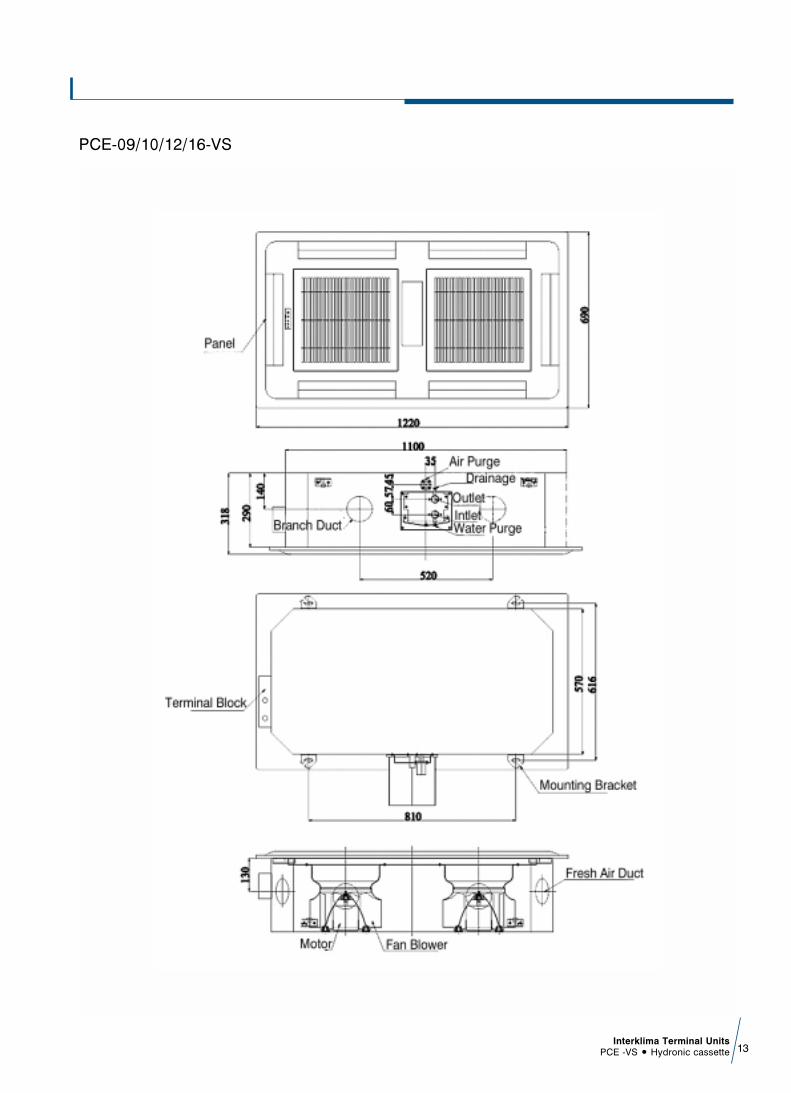
PCE-09/10/12/16-VS
Interklima Terminal UnitsPCE -VS ñ Hydronic cassette14
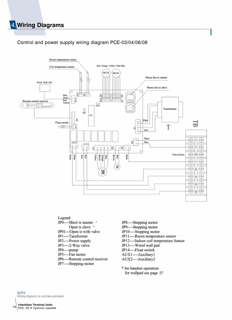
Wiring Diagrams4.
Control and power supply wiring diagram PCE-03/04/06/08
NOTESWirring diagrams on unit take precidents.

Interklima Terminal UnitsPCE -VS ñ Hydronic cassette 15
Control and power supply wiring diagram PCE-09/10/12/16
NOTESWirring diagrams on unit take precidents.
Master - Slave control wiring diagram
Factory supplied accessoriesCheck to ensure all factory supplied accessories are supplied withthe unit.
The appliance should be installed in accordance withnational wiring regulation.
Safety considerationsñ When working on air conditioning equipment, observe
precautions in this manual, and on plates and tables attachedto the unit. Follow all safety codes and other safetyprecautions that may apply.
ñ Installing and servicing air conditioning equipment should bedone by trained and qualified service personnel only.Untrained personnel can perform only basic maintenancefunctions such as cleaning coils, filters and replacing filters.
ñ Ensure that the electrical supply and frequency are adequatefor the operating current required for this specific installation.
WarningBefore any service or maintenance operations turn off the mainpower switch.ñ The manufacturer denies any responsibility and warranty shall
be void if these installation instructions are not observed. ñ Never switch off the power main supply when unit is operating
in the cooling cycle.To switch off the fan coil unit use only the ON-OFF button.
ñ This avoids over-flow in the drain pan, by allowing the pumpto drain any condensate water due to regulating valve losseswhen chiller is working.
Operation limitsñ Power supply
ñ Water circuit- Minimum entering water temperature: +2ÆC- Maximum entering water temperature: +80ÆC- Water side maximum pressure: 1400 kPa (142 m.w.c)
Before installationThe installation site must be established by the system designeror other qualified professional, taking account of the technicalrequisites and current standards and legislation.PCE fan coils must be installed by an authorized company only.PCE fan coils are designed for installation in a false ceiling, forintake of fresh air from outside and for deviation of a small part ofthe treated air for discharge in a neighboring room.They must be installed in such a way as to enable treated air tocirculate throughout the room and in respect of the minimumdistances required for technical maintenance operations.
ñ It is advisable to place the unit close to the installation sitewithout removing it from the packaging.Do not put heavy tools or weights on the packaging.
ñ Upon receipt, the unit and the packaging must be checked fordamage sustained in transit and if necessary, a damage claimmust be filed with the shipping company.
ñ Check immediately for installation accessories inside thepackaging.
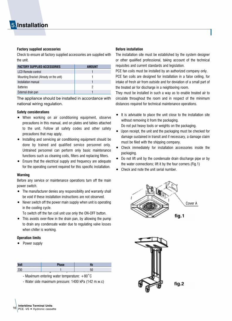
ñ Do not lift unit by the condensate drain discharge pipe or bythe water connections; lift it by the four corners.(Fig.1)
ñ Check and note the unit serial number.
Interklima Terminal UnitsPCE -VS ñ Hydronic cassette16
Installation5.
FACTORY SUPPLIED ACCESSORIES AMOUNT
LCD Remote control 1
Mounting Bracket (Already on the unit) 1
Installation manual 1
Batteries 2
External drain pan 1
Volt Phase Hz
230 1 50
fig.1
fig.2
Cover A

Selection locationñ Do not install the unit in rooms where flammable gas or
alkaline acid substances are present.Aluminum/copper coils and/or internal plastic componentscan be damaged irreparably.
ñ Do not install in workshops or kitchens; oil vapors drawn in bytreated air might deposit on the coils and alter theirperformance or damage the internal plastic parts of the unit.
ñ Installation of the unit will be facilitated by using a stacker andinserting a plywood sheet between the unit and the elevatedstacker.(Fig.2)
ñ It is recommended to position the unit as centrally as possiblein the room to ensure optimum air distribution. (Fig.3)Generally the best louver position is the one which allows airdiffusion along the ceiling. Alternatively intermediate positions can be selected.
ñ Check that it is possible to remove panels from ceiling in theselected position, to allow enough clearance for maintenanceand servicing operations.
Installation locationInstall the unit in a position:ñ Having sufficient strength to carry the weight of the unit.ñ Where the inlet and outlet grilles are not obstructed and the
conditioned air is able to blow all over the room.ñ From where condensate can be easily run to drain.ñ Check the distance between the upper slab and false ceiling to
ensure the unit will suit the distance. See Fig.4
ñ Ensure there is sufficient space around the unit to service it.See Fig.5
Interklima Terminal UnitsPCE -VS ñ Hydronic cassette 17
Model A (mm.) B (mm.)
PCE-03/04 250 10 or more
PCE-06/08/09/10/12/16 290 10 or more
fig.3
fig.5
Fig.4

Interklima Terminal UnitsPCE -VS ñ Hydronic cassette18
Installation method
Cassette Unitñ Using the installation template open ceiling panels and install
the suspension bolts as in Fig.6 below
590 x 590: Dimensions for opening616 x 280: Suspension BoltsMODELS PCE-03/04/06/08
590 x 1120: Dimensions for opening517.5 x 1047.5: Suspension BoltsMODELS PCE-09/10/12/16
Opening Dimensions and Positions for Suspension Bolts
ñ Mark position of suspension rods, water lines andcondensate drain pipe, power supply cables and remotecontrol cable.Supporting rods can be fixed, depending on the type ofceiling, as shown in Fig. 7 and Fig.8.
ñ Fit suspension brackets supplied with the unit to the threadedrods (Fig.9).Do not tighten nuts and counter nuts; this operation has tobe done only after final leveling of the unit, when all theconnections have been completed.
Fig. 6
Fig. 7
Fig.9
Fig. 8

ñ Ensure the ceiling is horizontally level, otherwise condensatewater cannot drain.
ñ The casing is fixed to the slab with 4 drop rods. The rodsshould have two nuts and washers to lock the unit in position.The Cassette brackets will then hook over the washers.
ñ When lifting the Cassette into position care should be takennot to lift the unit by the drip tray, which could be damaged.
ñ Lift unit (without the air panel) with care by its four cornersonly. Do not lift unit by the condensate drain discharge pipeor by the piping connections.
ñ Incline unit (Fig.10, Fig.11, Fig.13, Fig.14) and insert it into
the false ceiling. Insert the rods into the bracket slot.With minimum height (see table) false ceilings, it might benecessary to remove some T brackets of the false ceilingtemporarily.
ñ Using a level guide, line up the unit with a spirit level, andkeep dimension between the body and the lower part of thefalse ceiling (Fig.12 Fig.15).
ñ Line up the unit to the supporting bars of the false ceilingtightening the nuts and counter nuts of the threaded rods.
ñ After connection of the condensate drain piping and pipingconnections, check again that the unit is level.
Interklima Terminal UnitsPCE -VS ñ Hydronic cassette 19
Fig. 10
Fig.12
Fig. 11
Fig. 13
Fig.15
Fig. 14
MODEL PCE/03/04/06/08
A (mm.) 3
MODEL PCE/09/10/12/16
A (mm.) 3
Interklima Terminal UnitsPCE -VS ñ Hydronic cassette20
ñ The spaces between the unit and ceiling can now be adjusted.Use the drop rods to make the adjustment.
ñ Check to ensure the unit is level. The drain will thenautomatically be lower than the rest of the drip tray.
ñ Tighten the nuts on the suspended rods.
Drain pipe workIndoor Unitñ The unit is fitted with a condensate pump with a 500 mm. lift.ñ The unit is provided with 22 mm. bore flexible hose 300 mm.
long.ñ The flexible hose should be fitted into a 22 mm O/S º.
polyvinyl tube and sealed. The drain must be installed with adownward slope.
ñ On completion the drain line should be insulated
Water connectionsñ Water connections are fixed to the unit body to avoid breaks
when pipes are connected to valve assemblies; it is advisableto tighten the connection with a spanner.
ñ The upper coil connection is supplied with air purge screw, thelower connection with water purge screw, suitable for 8mm.wrench or screw-driver.
ñ Coil is partially drainable; it is advisable to blow air into the coilfor complete drainage.
Pipe connection kit (Option)
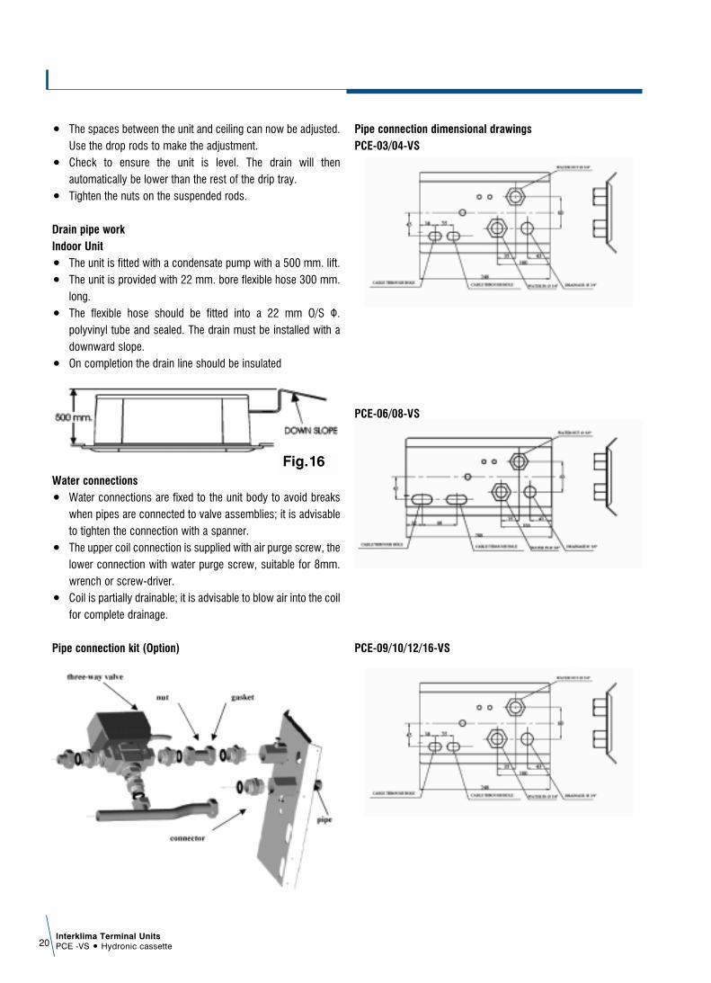
Pipe connection dimensional drawingsPCE-03/04-VS
PCE-06/08-VS
PCE-09/10/12/16-VS
Fig.16
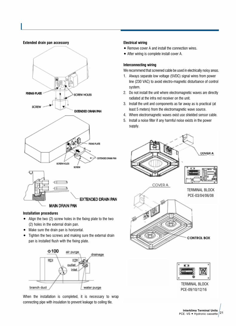
Extended drain pan accessory
Installation proceduresñ Align the two (2) screw holes in the fixing plate to the two
(2) holes in the external drain pan.ñ Make sure the drain pan is horizontal.ñ Tighten the two screws and making sure the external drain
pan is installed flush with the fixing plate.
When the installation is completed, it is necessary to wrapconnecting pipe with insulation to prevent leakage to ceiling tile.
Electrical wiringñ Remove cover A and install the connection wires.ñ After wiring is complete install cover A.
Interconnecting wiringWe recommend that screened cable be used in electrically noisy areas.1. Always separate low voltage (5VDC) signal wires from power
line (230 VAC) to avoid electro-magnetic disturbance of controlsystem.
2. Do not install the unit where electromagnetic waves are directlyradiated at the infra red receiver on the unit.
3. Install the unit and components as far away as is practical (atleast 5 meters) from the electromagnetic wave source.
4. Where electromagnetic waves exist use shielded sensor cable.5. Install a noise filter if any harmful noise exists in the power
supply.
Interklima Terminal UnitsPCE -VS ñ Hydronic cassette 21
TERMINAL BLOCKPCE-09/10/12/16
TERMINAL BLOCKPCE-03/04/06/08

Mounting front Panel assembly ñ Remove return grille from front panel.ñ Move the front panel to casing.ñ Tighten 4 screws as shown in Fig 17,18
Preliminary checks before start-upñ The unit should not be started up until the system piping has
been cleaned and all the air has been purged.ñ Check condensate drain pipe slope.ñ Make sure that air filter is clean and properly installed.ñ Ensure that voltage and current values correspond with the
unit nameplate values; check electrical connections.ñ Verify that air outlets are not closed.
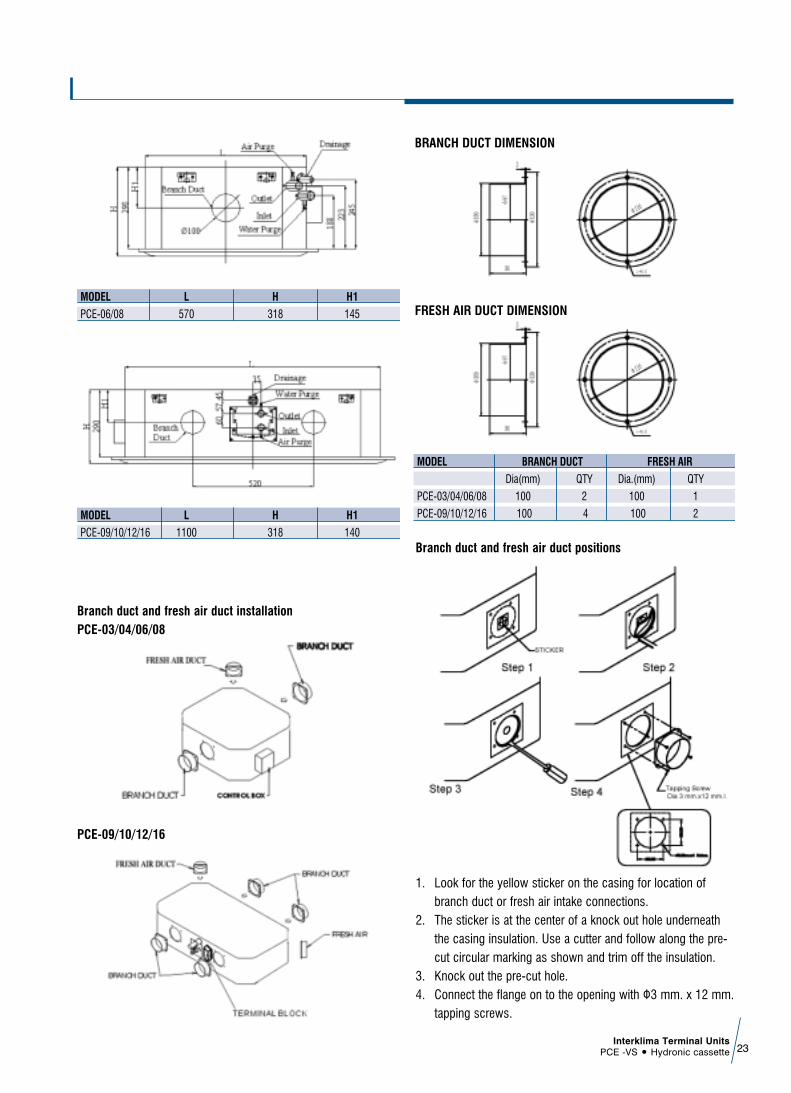
Fresh air renewal and branch ducting.ñ The side opening allows separate ductwork to be installed for
outside air intake and branch ducting. See Fig.26ñ Cut and remove anti-condensate insulating material.ñ Install your flanges and conduits to casing. Conduit can be
flexible polyester with spring core or corrugated aluminiumexternally coated (dia.4 in.) with anti-condensate material(fiberglass 12-25 mm thickness).
Fresh air - There is one (1) opening for connecting a fresh air duct for PCE-03-04-06-08,There are two (2) openings for connecting fresh air ducts for PCE-09-10-12-16.
Branch air- PCE-03-04-06-08 : Two(2) openings each.PCE-09-10-12-16 : Four (4) openings each.Order flanges (spigots) and blanking plates as accessories separately.
NOTE:- Branch duct flange (Optional part)- Fresh air duct flange (Optional part)- Blanking plate (Optional part)
MODEL L H H1
PCE-03/04 570 278 125
Interklima Terminal UnitsPCE -VS ñ Hydronic cassette22
Fig.17
Fig.18
Fig.26
Branch duct and fresh air duct positions
1. Look for the yellow sticker on the casing for location ofbranch duct or fresh air intake connections.
2. The sticker is at the center of a knock out hole underneaththe casing insulation. Use a cutter and follow along the pre-cut circular marking as shown and trim off the insulation.
3. Knock out the pre-cut hole.4. Connect the flange on to the opening with º3 mm. x 12 mm.
tapping screws.
Interklima Terminal UnitsPCE -VS ñ Hydronic cassette 23
Branch duct and fresh air duct installationPCE-03/04/06/08
PCE-09/10/12/16
BRANCH DUCT DIMENSION
FRESH AIR DUCT DIMENSIONMODEL L H H1
PCE-06/08 570 318 145
MODEL L H H1
PCE-09/10/12/16 1100 318 140
MODEL BRANCH DUCT FRESH AIR
Dia(mm) QTY Dia.(mm) QTY
PCE-03/04/06/08 100 2 100 1
PCE-09/10/12/16 100 4 100 2
Interklima Terminal UnitsPCE -VS ñ Hydronic cassette24
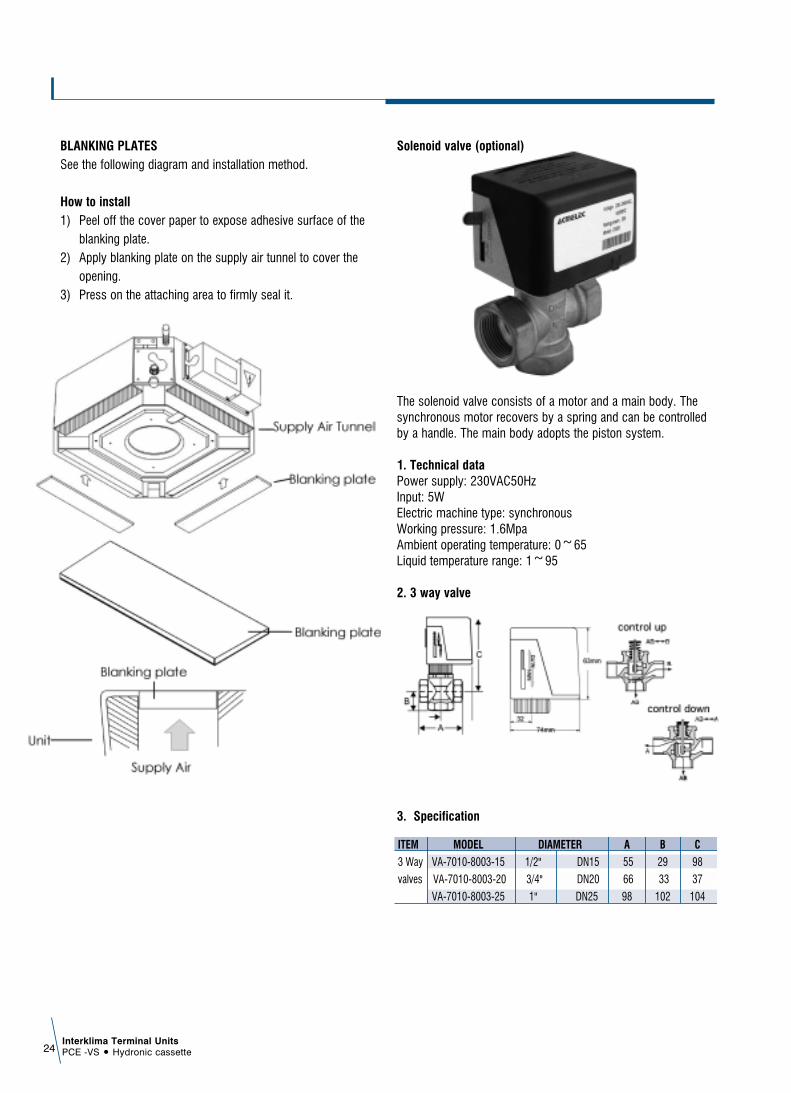
BLANKING PLATESSee the following diagram and installation method.
How to install1) Peel off the cover paper to expose adhesive surface of the
blanking plate.2) Apply blanking plate on the supply air tunnel to cover the
opening.3) Press on the attaching area to firmly seal it.
Solenoid valve (optional)
The solenoid valve consists of a motor and a main body. Thesynchronous motor recovers by a spring and can be controlledby a handle. The main body adopts the piston system.
1. Technical dataPower supply: 230VAC50HzInput: 5WElectric machine type: synchronousWorking pressure: 1.6MpaAmbient operating temperature: 0~65Liquid temperature range: 1~95
2. 3 way valve
3. Specification
ITEM MODEL DIAMETER A B C
3 Way VA-7010-8003-15 1/2" DN15 55 29 98
valves VA-7010-8003-20 3/4" DN20 66 33 37
VA-7010-8003-25 1" DN25 98 102 104
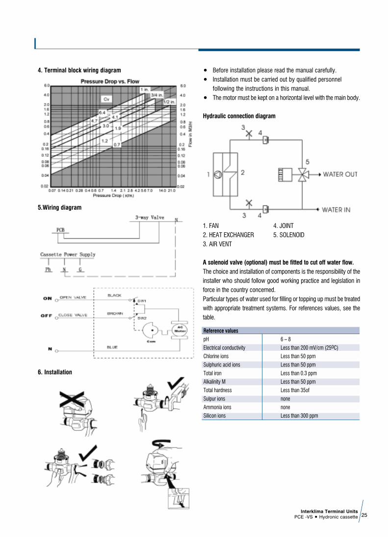
4. Terminal block wiring diagram
5.Wiring diagram
6. Installation
ñ Before installation please read the manual carefully. ñ Installation must be carried out by qualified personnel
following the instructions in this manual.ñ The motor must be kept on a horizontal level with the main body.
Hydraulic connection diagram
1. FAN 4. JOINT 2. HEAT EXCHANGER 5. SOLENOID3. AIR VENT
A solenoid valve (optional) must be fitted to cut off water flow.The choice and installation of components is the responsibility of theinstaller who should follow good working practice and legislation inforce in the country concerned.Particular types of water used for filling or topping up must be treatedwith appropriate treatment systems. For references values, see thetable.
Interklima Terminal UnitsPCE -VS ñ Hydronic cassette 25
Reference values
pH 6 – 8
Electrical conductivity Less than 200 mV/cm (25oC)
Chlorine ions Less than 50 ppm
Sulphuric acid ions Less than 50 ppm
Total iron Less than 0.3 ppm
Alkalinity M Less than 50 ppm
Total hardness Less than 35of
Sulpur ions none
Ammonia ions none
Silicon ions Less than 300 ppm

Interklima Terminal UnitsPCE -VS ñ Hydronic cassette26
Controller 6.
Instruction and SpecificationsRemote control handset
Interklima Terminal UnitsPCE -VS ñ Hydronic cassette 27
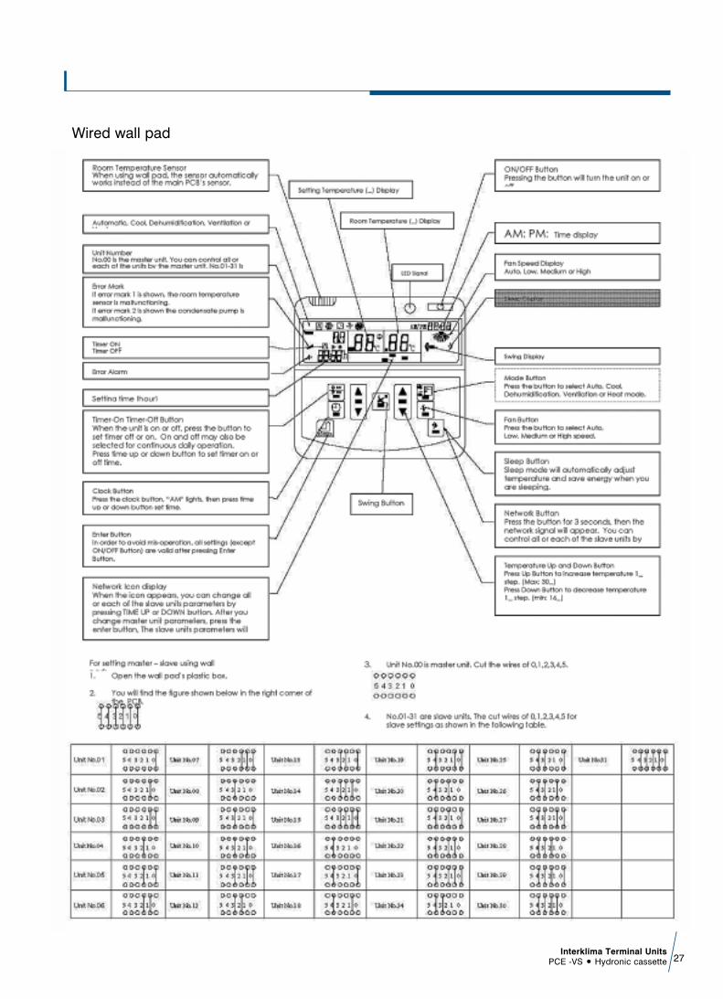
Wired wall pad

Interklima Terminal UnitsPCE -VS ñ Hydronic cassette28
Controls specification2 pipe hot and chilled hydronic cassetteWith motorized valve, Master - Slave control motorized valve,Master - Slave control & computer management system control
1.0 AbbeviationsTs = Setting temperature Tr = Room air temperature sensorTi = Indoor coil temperature sensorAUX = Auxiliary contactMTV = Motorized valve
2.0 Control system operation2.A Master and Slave unit function ñ The control board can be set either as a master unit or slave unit.
2.A.1 Master unit function ñ The master unit sends data on its setting to the slave unit.ñ The master unit settings are Unit ON/OFF, Mode,
Fan Speed, Set Temperature, Swing Function, and Sleep Function (by wall pad only).
2.A.2 Slave unit functionñ The slave unit receives data on its settings from the master unit.ñ The slave unit is allowed to change to a locally desired
setting as long as there are no subsequent changes to the settings of the master unit.
ñ The slave units can be set individually for sleep, timer on and off function.
2.A.3 Master and Slave Installationñ When using remote handset, for the master unit ensure
the JP0 jumper is shorted and for the slave units JP0 is opened before turning ON the main power supply.
ñ When using wired wall pad, JP0 jumper will not function. Use the wall pad to set master and slave units. The wall pad screen will show unit number 00 for master unit, and unit number 01-31 for slave units. See wired wall pad function guide to see how to set master and slave unit.
ñ Connect master to slave units with telephone wire. NOTE: Use 4-core cable and one-to-one configuration.
ñ When MAIN POWER SUPPLY is ON: With motorized valve: The master unit will respond with 3 beeps. The slave unit will respond with 1 beep.If there are beeping sounds from both master and slave the JP0 on both units is shorted. So, there will be no communication.If there is no beep sound, no board is set as the master unit. So, no communication will occur.
ñ Once the master unit receives the signal from the handset, the master unit will send the data.
ñ The slave unit will respond after receiving the data.
2.B Computer management systemñ You can connect the control PCB to your computer
management system through the RS-485 port direct to your computer telephone port with a telephone line.
ñ Master-slave can also be operated through the CMS.ñ The communication protocol is ASM. You can use your
CMS to check all units’ status, and control each unit On/Off, Mode, Set Temperature, Valve open or close, Swing function and Fan speed. You cannot control timer.
ñ The master unit can be connected with 31 slave units with maximum distance of 1 KM.
2.C Air conditioner ON/OFFThere are 3 ways to turn the system on or off:ñ By ON/OFF button on the handset or wired wall pad.ñ By programmable timer on the handset or wired wall pad.ñ By manual control button on the air conditioner.
2.D Power on settingñ When power on signal is received by the air conditioner,
the Mode, Fan Speed, Set Temperature and Swing settings will be the same as the last handset settings before the last power off.
2.E. Cool modeñ If Tr≥Ts+1oC, cool operation is activated. MTV is turned on.
AUX2 is closed. Indoor fan runs at set speed.ñ If Tr≤Ts, cool operation is terminated. MTV is turned off.
AUX2 is opened. Indoor fan runs at set speed.ñ The range of Ts is 16 to 30oC.ñ Indoor fan speed can be adjusted for low, medium,
high and auto.ñ When turned on, MTV requires 30 seconds before it is
fully open.ñ When turned off, MTV requires 120 seconds before it is
fully closed.ñ When the unit is turned off, indoor fan will delay for 5 seconds
before it is turned off.
2.E.1 Low temperature protection of indoor coil ñ If Ti≤2oC for 2 minutes, MTV is turned off. AUX2 is opened.
If indoor fan is set for low speed, it will run at medium speed. If it set at medium or high speed, it will keep running at the same speed.
ñ If Ti≥5oC for 2 minutes, MTV is turned on. AUX 2 is closed. Indoor fan runs at set speed.

Interklima Terminal UnitsPCE -VS ñ Hydronic cassette 29
2.F Fan modeñ Indoor fan runs at the set speed while MTV is turned off. AUX1
and AUX2 are opened.ñ Indoor fan speed can be adjusted for low, medium,
high and auto.
2.G Heat modeñ If Tr≤Ts-1oC, heat operation is activated. MTV is turned on.
AUX1 is closed. Indoor fan runs at set speed.ñ If Tr>Ts, heat operation is terminated. MTV is turned off.
AUX1 is opened. Indoor fan runs according to POST HEAT condition.
ñ The range of Ts is 16 to 30oC.ñ Indoor fan speed can be adjusted for low, medium, high and
auto.ñ When turned on, MTV requires 30 seconds before it is fully
open.ñ When turned off, MTV requires 120 seconds before it is fully
closed.ñ When the unit is turned off, indoor fan will delay for 5 seconds
before it is turned off.
2.G.1 Pre-Heat ñ If Ti<38oC, when MTV is on, AUX1 is closed and indoor fan
remains off.ñ If Ti>38oC, when MTV is on, AUX1 is closed and Indoor fan
runs at set speed.ñ If indoor coil temperature sensor is damaged, pre-heat time is
set for 2 minutes and indoor fan runs at set speed.
2.G.2 Post-Heat ñ If Ti>38oC, when MTV is off, AUX1 is opened and indoor fan
continues to run at set speed.ñ If Ti<38oC, when MTV is off, AUX1 is opened. Indoor fan runs
30 seconds and stops 3 minutes repeatedly.ñ If indoor coil temperature sensor is damaged, post-heat time
is set for 3 minutes with indoor fan running at set speed.
2.G.3 Over heat protection of indoor coilñ If Ti≥75oC, MTV is turned off, AUX1 is opened and indoor fan
remains on and runs at set speed.ñ If Ti<70oC, MTV is turned on. AUX1 is closed and indoor fan
remains on and runs at set speed. ñ If indoor coil temperature sensor is damaged, the protection
mode will become obsolete and the unit will work as the Pre-heat and Post-heat set times.
2.H Dehumidification modeñ If Tr≥25oC, MTV will be ON for 3 minutes and OFF for 4
minutes.ñ If 16oC≤Tr<25oC, MTV will be ON for 3 minutes and OFF for
6 minutes. ñ If Tr<16oC, MTV will be turned off.
2.I Auto heat-Dehumidification-Cool modeñ In auto mode, the set temperature of the system is 24oC and
the indoor fan runs in auto fan mode.ñ If Tr<21oC, the unit will operate in heat mode.ñ If Tr>25oC, the unit will operate in cool mode.ñ If 21oC≤Tr≤25oC, the unit will operate in dehumidification
mode.ñ Once the unit is turned on in auto mode, it will operate in that
mode and will not changeover.ñ If the unit has been turned off for 2 hours, when turning on the
unit, it will select the operating mode depending on the room temperature.
2.J Auxiliary contacts2.J.1 Cool mode (AUX 2) ñ AUX 2 is closed when MTV is on (in normal operation). ñ AUX 2 is opened when MTV is off or protection of indoor
coil is operating.
2.J.2 Fan mode (AUX 1 AND AUX 2) ñ AUX 1 and AUX 2 are opened when indoor fan is on.
2.J.3 Heat mode (AUX 1) ñ AUX 1 is closed when MTV is on (in normal operation). ñ AUX 1 is opened when MTV is off or protection of indoor coil
is operating.
2.K Sleep modeñ Sleep mode can only be set in cool or heat modes.ñ In cool mode, after sleep mode is set, the indoor fan will run
at low speed and Ts will increase 2oC during 2 hours.ñ In heat mode, after sleep mode is set, the indoor fan will run
at auto fan mode and Ts will decrease 2oC during 2 hours.ñ Changing of operation mode will cancel sleep mode.

Interklima Terminal UnitsPCE -VS ñ Hydronic cassette30
The COOL mode SLEEP profile is as follow:
The HEAT mode SLEEP profile is as follows:
2.L Auto fan speedñ In COOL mode, if Tr<Ts+2oC, indoor fan runs at low speed.
If Ts+2oC≤Tr<Ts+3oC, indoor fan runs at medium speed.If Tr≥Ts+3oC, indoor fan runs at high speed.
ñ In COOL mode, the fan speed cannot change until it has run at this speed over 30 seconds.
ñ In HEAT mode, if Tr≤Ts-1oC, indoor fan runs at low speed.If Ts-3oC≤Tr<Ts-1oC, indoor fan runs at medium speed.If Tr<Ts-3oC, indoor fan runs at high speed.
ñ In HEAT mode, the fan speed cannot change until it has run at this speed over 30 seconds.
2.M Louverñ When the unit is connection to power supply, the louver will
swing 100 degrees to close condition.ñ When the unit is turned on, the louver will swing 87 degrees
from close condition to set mode.ñ When the unit is turned off, the louver will swing 100
degrees back to close condition.ñ At swing mode, louver swings between 59-87 degrees range
and can be set within.
2.N Buzzerñ If a command is received by the air conditioner, the system
will respond with a beep.
2.P Auto restartñ The system uses non-volatile memory to save the present
operation parameters when system is turned off or in case ofsystem failure or cessation of power supply. Operationparameters are mode, set temperature, swing, and the fanspeed. When power supply resumes or the system isswitched on again, the same operations as previously setwill function.
2.Q Reset buttonñ On the unit front panel next to the LED lights is the reset button.
Press it once and unit will operate according to auto mode.
2.R Drain pump2.R.1 The unit is offñ If the float switch opens, the drain pump will work. When the
float switch closes, the drain pump will run continuously for5miniutes.
2.R.2 The unit is onñ In cool or dehumidify mode, the drain pump will be turned
on when valve is on, and will remain on for 5 minutes afterthe valve is turned off.
ñ When the mode is changed, the drain pump will remain onfor 5 minutes.
ñ If the float switch opens for 5 seconds after the 5minuteshas finished, the drain pump is turned on again and the valvecloses. After 10 minutes, if the float switch is continuallyopen, the red, yellow and green LEDs will blink to show thedrain pump does not work or there is a leak in the system.
ñ If the float switch closes, the drain pump will turn off after 5minutes.
Interklima Terminal UnitsPCE -VS ñ Hydronic cassette 31
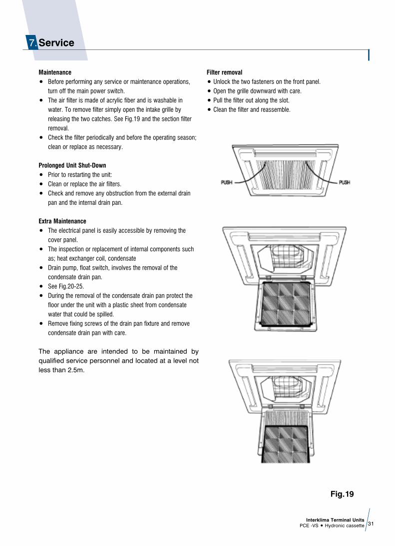
Service7.
Maintenanceñ Before performing any service or maintenance operations,
turn off the main power switch.ñ The air filter is made of acrylic fiber and is washable in
water. To remove filter simply open the intake grille byreleasing the two catches. See Fig.19 and the section filterremoval.
ñ Check the filter periodically and before the operating season;clean or replace as necessary.
Prolonged Unit Shut-Downñ Prior to restarting the unit:ñ Clean or replace the air filters.ñ Check and remove any obstruction from the external drain
pan and the internal drain pan.
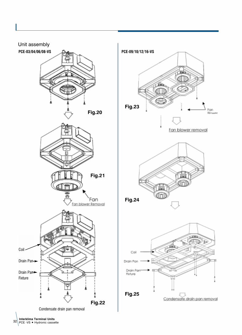
Extra Maintenanceñ The electrical panel is easily accessible by removing the
cover panel.ñ The inspection or replacement of internal components such
as; heat exchanger coil, condensate ñ Drain pump, float switch, involves the removal of the
condensate drain pan. ñ See Fig.20-25.ñ During the removal of the condensate drain pan protect the
floor under the unit with a plastic sheet from condensatewater that could be spilled.
ñ Remove fixing screws of the drain pan fixture and removecondensate drain pan with care.
The appliance are intended to be maintained byqualified service personnel and located at a level notless than 2.5m.
Filter removalñ Unlock the two fasteners on the front panel.ñ Open the grille downward with care.ñ Pull the filter out along the slot.ñ Clean the filter and reassemble.
Fig.19
Interklima Terminal UnitsPCE -VS ñ Hydronic cassette32
Coil
Drain Pan
Drain PanFixture
Fig.20
Fig.21
Fig.22Condensate drain pan removal
Fig.23
Fig.24
Fig.25
Unit assemblyPCE-03/04/06/08-VS PCE-09/10/12/16-VS

Air code display on unit panel
ñ If the drain pump malfunctions, the red , yellow and green LEDs will blink with beeping sound.
Press reset button or any of the remote handset buttons, and thebeeping will stop.
ITEM RED LED YELLOW LED GREEN LED
High speed ON OFF OFF
Medium speed OFF ON OFF
Low speed OFF OFF ON
Pre-heat OFF BLINK OFF
Post-heat OFF OFF BLINK
Low temperature BLINK OFF OFFprotection of indoor coil
Over heat protection OFF BLINK BLINKof indoor coil
Coil temperature ON BLINK BLINKsensor damaged
Room temperature BLINK OFF BLINKsensor damaged
Condensate pump damaged BLINK BLINK BLINK
Interklima Terminal UnitsPCE -VS ñ Hydronic cassette 33
Troubleshooting
Error code display on wall pad definition table
The fan coil does not start up
Malfunction
No voltage
Cause Remedy
- Check for presence of voltage- Check fuse on board
Mains switch in the "OFF position - Place in the "ON" position
Faulty room control - Check the room control
Faulty fan - Check fan motor
Air flow obstructed - Remove obstacles
Room control regulation - Check
Incorrect water temperature - Check
Air present - Vent
Insufficient output Filter clogged - Clean the filter
Loose screws - Tighten screws
Noise and vibrations Contact between metal parts - Check
CODE NO.
CODE NO.
CODE NO.
01
ROOM TEMPERATURE
SENSOR DAMAGED
06
CONDENSED WATER
OVER FLOW &
INDOOR COIL
TEMPERATURE
SENSOR DAMAGED
11
ROOM TEMPERATURE
SENSOR DAMAGED &
CONDENSED
WATER OVER FLOW &
AUTO RESTART FAILURE
02
CONDENSED WATER
OVER FLOW
07
ROOM TEMPERATURE
SENSOR DAMAGED &
CONDENSED WATER
OVER FLOW & INDOOR
COIL TEMPERATURE
SENSOR DAMAGED
12
INDOOR COIL
TEMPERATURE
SENSOR DAMAGED &
AUTO RESTART
FAILURE
03
ROOM TEMPERATURE SENSOR
DAMAGED & CONDENSED
WATER OVER FLOW
08
AUTO RESTART FAILURE
13
ROOM TEMPERATURE
SENSOR DAMAGED & INDOOR
COIL TEMPERATURE SENSOR
DAMAGED & AUTO RESTART
FAILURE
04
INDOOR COIL
TEMPERATURE
SENSOR DAMAGED
09
ROOM TEMPERATURE
SENSOR DAMAGED &
AUTO RESTART FAILURE
14
CONDENSED WATER OVER
FLOW & INDOOR COIL
TEMPERATURE SENSOR
DAMAGED & AUTO
RESTART FAILURE
05
ROOM TEMPERATURE SENSOR
DAMAGED & INDOOR COIL
TEMPERATURE SENSOR DAMAGED
10
CONDENSED WATER
OVER FLOW &
AUTO RESTART FAILURE
15
ROOM TEMPERATURE SENSOR
DAMAGED & CONDENSED WATER
OVER FLOW & INDOOR COIL
TEMPERATURE SENSOR DAMAGED
& AUTO RESTART FAILURE

Interklima Terminal UnitsPCE -VS ñ Hydronic cassette34
Exploded view drawing PCE-03/04/06/08-VS
1- Mounting brackets2- External drain pan3- Casing4- Control box
4-1- Main PCB4-2- Transformer4-3- Terminal block4-4- Remote handset4-5- Wire clip
5- Branch duct6- Fan motor (for PCE-03-04)6- Fan motor (for PCE-06)6- Fan motor (for PCE-08)
6-1- Motor capacitor (for PCE-03-04)6-1- Motor capacitor (for PCE-06-08)
7- Fresh air outlet8- Fan blower9- Drain pump assembly
9-1- Drain pump fixture9-2- Drain pump9-3- Drainage tube9-4- Float switch10- Coil (PCE-03-04)10- Coil (PCE-06-08)11- Drain pan12- Drain pan fixture13- Venturi14- Air filter15- Cover panel assembly
15-0- Receiver display15-1- Receiver label sticker15-2- Grille15-3- Bolt (Left)15-4- Bolt (Right)15-5- Swing Louver15-6- Stepping motor15-7- Fan bearing
16- Wired wall pad

Interklima Terminal UnitsPCE -VS ñ Hydronic cassette 35
Exploded view drawing PCE-09/10/12/16-VS
1 Mounting brackets2 Outside wiring box
2-1 Terminal block2-2 Invert Board2-3 Wire clip
3 Branch duct 4 External drain pan5 Casing6 Fresh air outlet7 Fan Motor ( for PCE-09 )7 Fan Motor ( for PCE-10-12 )7 Fan Motor ( for PCE-16 )
7-1 Fan Motor Capacitor ( for PCE-09 )7-1 Fan Motor Capacitor ( for PCE-10-12-16 )
8 Fan blower9 Coil
10 Drain Pump assembly10-1 Pump fixture10-2 Drain Pump10-3 Drainage tube10-4 Float switch
11 Drain pan12 Inside control box
12-1 Transformer12-2 Main PCB12-3 Remote handset
13 Venturi14 Drain pan fixture15 Air filter16 Cover Panel assembly
16-1 Grille16-2 Receiver label sticker16-3 Swing Louver16-4 Bolt (Right)16-5 Bolt (Left)16-6 Stepping motor16-7 Fan bearing
17 Wired wall pad

Products are manufactured in ISO 9001:2000certified factories. ISO 9001:2000 pertains to quality
assurance regarding design, development,manufacturing and installation of products
as well as to services related to the product.
INTERKLIMA PRODUCTS ARE DISTRIBUTED BY:
EG
B-2
-2-1
1/06
Specifications subject to change without notice
Interklima units comply with the European regulations thatguarantee the safety of the product
Engineering Data 2007
Related Documents


