NEW YORK STATE DEPARTMENT OF TRANSPORTATION STRUCTURES DESIGN AND CONSTRUCTION DIVISION PRESTRESSED CONCRETE CONSTRUCTION MANUAL SEPTEMBER 2000 GEORGE E. PATAKI GOVERNOR JOSEPH H. BOARDMAN COMMISSIONER

Welcome message from author
This document is posted to help you gain knowledge. Please leave a comment to let me know what you think about it! Share it to your friends and learn new things together.
Transcript

NEW YORK STATE
DEPARTMENT OF TRANSPORTATIONSTRUCTURES DESIGN AND CONSTRUCTION DIVISION
PRESTRESSED CONCRETECONSTRUCTION MANUAL
SEPTEMBER 2000
GEORGE E. PATAKIGOVERNOR
JOSEPH H. BOARDMANCOMMISSIONER

Prestressed Concrete
Construction Manual
New York State Department of Transportation
Structures Design and Construction Division
2nd Edition
About the Cover: September 2000
Hicks Road Bridge over the Northern State Parkway
The prestressed beams in this bridge were constructed
with curved soffits to match the shape of the arch
of the original Hicks Road Bridge.
iSeptember 21, 2000
New York State Department of Transportation
Prestressed Concrete Construction Manual
Table of Contents
FOREWORD . . . . . . . . . . . . . . . . . . . . . . . . . . . . . . . . . . . . . . . . . . . . . . . . . . . . . . . . xi
ACKNOWLEDGMENT . . . . . . . . . . . . . . . . . . . . . . . . . . . . . . . . . . . . . . . . . . . . . . . . xii
SECTION 1 INTRODUCTION . . . . . . . . . . . . . . . . . . . . . . . . . . . . . . . . . . . . . . . . . . 1-1
1.1 PURPOSE . . . . . . . . . . . . . . . . . . . . . . . . . . . . . . . . . . . . . . . . . . . . . . . 1-1
1.2 APPLICABILITY . . . . . . . . . . . . . . . . . . . . . . . . . . . . . . . . . . . . . . . . . . 1-1
1.3 REFERENCES TO PREVIOUS EDITIONS OF THE PCCM . . . . . . . . . 1-1
SECTION 2 DRAWINGS . . . . . . . . . . . . . . . . . . . . . . . . . . . . . . . . . . . . . . . . . . . . . 2-1
2.1 CONTRACT DRAWINGS . . . . . . . . . . . . . . . . . . . . . . . . . . . . . . . . . . . 2-1
2.1.1 Definition . . . . . . . . . . . . . . . . . . . . . . . . . . . . . . . . . . . . . . . . . . 2-1
2.1.2 Requests for Clarification . . . . . . . . . . . . . . . . . . . . . . . . . . . . . . 2-1
2.1.3 Dimensions . . . . . . . . . . . . . . . . . . . . . . . . . . . . . . . . . . . . . . . . . 2-1
2.1.4 Errors . . . . . . . . . . . . . . . . . . . . . . . . . . . . . . . . . . . . . . . . . . . . . 2-1
2.1.5 Principal Controlling Design Data and Material Properties . . . . . 2-1
2.1.6 Fabricating Dimensions . . . . . . . . . . . . . . . . . . . . . . . . . . . . . . . 2-2
2.2 SHOP DRAWINGS . . . . . . . . . . . . . . . . . . . . . . . . . . . . . . . . . . . . . . . . 2-2
2.2.1 Preparation . . . . . . . . . . . . . . . . . . . . . . . . . . . . . . . . . . . . . . . . . 2-2
2.2.2 Size and Type . . . . . . . . . . . . . . . . . . . . . . . . . . . . . . . . . . . . . . 2-2
2.2.2.1 Standard Size . . . . . . . . . . . . . . . . . . . . . . . . . . . . 2-2
2.2.2.2 Neatness and Clarity . . . . . . . . . . . . . . . . . . . . . . . 2-3
2.2.2.3 Title Block . . . . . . . . . . . . . . . . . . . . . . . . . . . . . . . 2-3
2.2.3 Return Without Examination . . . . . . . . . . . . . . . . . . . . . . . . . . . . 2-3
2.2.4 Digital Format . . . . . . . . . . . . . . . . . . . . . . . . . . . . . . . . . . . . . . 2-3
2.2.5 Information Required on Shop Drawings . . . . . . . . . . . . . . . . . . 2-3
2.2.5.1 Production Note Sheet . . . . . . . . . . . . . . . . . . . . . 2-3
iiSeptember 21, 2000
2.2.5.2 Additional Required Information for Pretensioned
Elements. . . . . . . . . . . . . . . . . . . . . . . . . . . . . . . . 2-4
2.2.5.3 Layout Sheet: . . . . . . . . . . . . . . . . . . . . . . . . . . . . 2-4
2.2.5.4 Unit Detail Sheets, Indicating: . . . . . . . . . . . . . . . . 2-5
2.2.5.5 Additional Required Information for Precast Concrete
Bridge Structural Units. . . . . . . . . . . . . . . . . . . . . . 2-5
2.2.5.6 Additional Required Information for Structures with
Post-Tensioning. . . . . . . . . . . . . . . . . . . . . . . . . . . 2-5
2.2.5.7 Additional Information Required for Precast
Segmental Bridges with Match Cast Joints. . . . . . 2-6
2.2.5.7.1 Geometry Control . . . . . . . . . . . . . . . . . . . . 2-6
2.2.5.7.2 Layout Sheets . . . . . . . . . . . . . . . . . . . . . . 2-7
2.2.5.7.3 Segment Detail . . . . . . . . . . . . . . . . . . . . . . 2-7
2.2.5.7.4 Reinforcing Steel . . . . . . . . . . . . . . . . . . . . 2-7
2.2.5.7.5 Tendon Ducts . . . . . . . . . . . . . . . . . . . . . . . 2-7
2.2.5.7.6 Inserts . . . . . . . . . . . . . . . . . . . . . . . . . . . . 2-7
2.2.5.7.7 Casting Curves . . . . . . . . . . . . . . . . . . . . . . 2-8
2.2.5.8 Forms for Precast Segmental Bridges with Match
Cast Joints . . . . . . . . . . . . . . . . . . . . . . . . . . . . . . 2-8
2.3 INSTALLATION DRAWINGS AND SUPPORTING DOCUMENTS . . . 2-9
2.3.1 Installation Note Sheets . . . . . . . . . . . . . . . . . . . . . . . . . . . . . . 2-10
2.3.2 Revised Installation Note Sheets . . . . . . . . . . . . . . . . . . . . . . . 2-10
2.3.3 Temporary Structures and Equipment Sheets . . . . . . . . . . . . . 2-10
2.3.4 Post-Tensioning Sheets . . . . . . . . . . . . . . . . . . . . . . . . . . . . . . 2-11
2.3.5 Checks and Modifications of Permanent Structural Components for
Erection Loads . . . . . . . . . . . . . . . . . . . . . . . . . . . . . . . . . . . . . 2-11
2.4 SUBMISSION OF SHOP DRAWINGS . . . . . . . . . . . . . . . . . . . . . . . 2-12
2.4.1 Check Prints . . . . . . . . . . . . . . . . . . . . . . . . . . . . . . . . . . . . . . . 2-13
2.5 EXAMINATION OF SHOP DRAWINGS . . . . . . . . . . . . . . . . . . . . . . . 2-13
2.5.1 Recording Receipt of Drawings . . . . . . . . . . . . . . . . . . . . . . . . 2-13
iiiSeptember 21, 2000
2.5.2 Examination Time . . . . . . . . . . . . . . . . . . . . . . . . . . . . . . . . . 2-13
2.5.3 Special Circumstances . . . . . . . . . . . . . . . . . . . . . . . . . . . . . . . 2-14
2.5.3.1 Large Sets of Drawings . . . . . . . . . . . . . . . . . . . . 2-14
2.5.3.2 Design Calculations . . . . . . . . . . . . . . . . . . . . . . 2-14
2.5.3.3 Contract Changes . . . . . . . . . . . . . . . . . . . . . . . . 2-14
2.5.4 Concrete Mix Design . . . . . . . . . . . . . . . . . . . . . . . . . . . . . . . . 2-14
2.5.5 Approved as Noted . . . . . . . . . . . . . . . . . . . . . . . . . . . . . . . . . . 2-14
2.5.6 Major Revisions . . . . . . . . . . . . . . . . . . . . . . . . . . . . . . . . . . . . 2-15
2.5.7 Distribution of Approved Shop Drawings . . . . . . . . . . . . . . . . . 2-15
2.5.7.1 Distribution List . . . . . . . . . . . . . . . . . . . . . . . . . . 2-15
2.5.7.2 Notification of DCES . . . . . . . . . . . . . . . . . . . . . . 2-16
2.6 ERECTION DRAWINGS . . . . . . . . . . . . . . . . . . . . . . . . . . . . . . . . . . . 2-16
2.6.1 General . . . . . . . . . . . . . . . . . . . . . . . . . . . . . . . . . . . . . . . . . . 2-16
2.6.2 Required Information . . . . . . . . . . . . . . . . . . . . . . . . . . . . . . . . 2-16
SECTION 3 INSPECTION . . . . . . . . . . . . . . . . . . . . . . . . . . . . . . . . . . . . . . . . . . . . 3-1
3.1 QUALITY . . . . . . . . . . . . . . . . . . . . . . . . . . . . . . . . . . . . . . . . . . . . . . . 3-1
3.1.1 Quality Control . . . . . . . . . . . . . . . . . . . . . . . . . . . . . . . . . . . . . . 3-1
3.1.2 Quality Assurance . . . . . . . . . . . . . . . . . . . . . . . . . . . . . . . . . . . 3-1
3.2 QUALIFICATIONS OF INSPECTORS . . . . . . . . . . . . . . . . . . . . . . . . 3-1
3.2.1 QA Inspectors . . . . . . . . . . . . . . . . . . . . . . . . . . . . . . . . . . . . . . 3-1
3.2.2 QC Inspectors . . . . . . . . . . . . . . . . . . . . . . . . . . . . . . . . . . . . . . 3-2
3.2.3 QC Tests . . . . . . . . . . . . . . . . . . . . . . . . . . . . . . . . . . . . . . . . . . 3-2
3.3 RESPONSIBILITIES OF INSPECTORS . . . . . . . . . . . . . . . . . . . . . . . . 3-2
3.3.1 Quality Control Inspector . . . . . . . . . . . . . . . . . . . . . . . . . . . . . 3-2
3.3.2 Quality Assurance Inspector . . . . . . . . . . . . . . . . . . . . . . . . . . . . 3-2
3.4 INSPECTOR’S MARK OF ACCEPTANCE FOR SHIPMENT . . . . . . . 3-3
3.5 REPORT OF ACCEPTANCE OF STRUCTURAL CONCRETE . . . . . 3-3
3.6 FACILITIES FOR INSPECTION . . . . . . . . . . . . . . . . . . . . . . . . . . . . . . 3-3
3.7 OBLIGATIONS OF THE CONTRACTOR . . . . . . . . . . . . . . . . . . . . . . 3-4
ivSeptember 21, 2000
3.7.1 Informing the DCES of Work Schedule . . . . . . . . . . . . . . . . . . 3-4
3.7.2 Informing the QA Inspector of Work Schedule . . . . . . . . . . . . . . 3-4
SECTION 4 MATERIAL REQUIREMENTS . . . . . . . . . . . . . . . . . . . . . . . . . . . . . . . 4-1
4.1 MATERIALS FOR CONCRETE . . . . . . . . . . . . . . . . . . . . . . . . . . . . . . 4-1
4.2 STEEL . . . . . . . . . . . . . . . . . . . . . . . . . . . . . . . . . . . . . . . . . . . . . . . . . . 4-2
4.3 MATERIALS FOR CURING . . . . . . . . . . . . . . . . . . . . . . . . . . . . . . . . . 4-3
4.4 MATERIALS FOR FINISHING . . . . . . . . . . . . . . . . . . . . . . . . . . . . . . . 4-3
4.4.1 Concrete Repair Materials . . . . . . . . . . . . . . . . . . . . . . . . . . . . . 4-3
4.4.2 Penetrating Sealers . . . . . . . . . . . . . . . . . . . . . . . . . . . . . . . . . . 4-3
4.5 MATERIALS FOR INSTALLATION . . . . . . . . . . . . . . . . . . . . . . . . . . . . 4-4
4.5.1 Transverse Post-Tensioning Steel . . . . . . . . . . . . . . . . . . . . . . . 4-4
4.5.2 Shear Key Material . . . . . . . . . . . . . . . . . . . . . . . . . . . . . . . . . . . 4-4
4.5.3 Anchorage Block-Out Grout . . . . . . . . . . . . . . . . . . . . . . . . . . . . 4-4
4.5.4 Anchor Dowel Fill Material . . . . . . . . . . . . . . . . . . . . . . . . . . . . . 4-5
4.5.4.1 Expansion End Material Option . . . . . . . . . . . . . . . 4-5
4.5.4.2 Fixed End Material Option . . . . . . . . . . . . . . . . . . . 4-5
4.6 MATERIALS FOR POST-TENSIONING . . . . . . . . . . . . . . . . . . . . . . . . 4-5
4.6.1 Post-Tensioning Anchorages and Couplers . . . . . . . . . . . . . . . . 4-5
4.6.2 Ducts . . . . . . . . . . . . . . . . . . . . . . . . . . . . . . . . . . . . . . . . . . . . . 4-6
4.6.2.1 Metal Ducts . . . . . . . . . . . . . . . . . . . . . . . . . . . . . . 4-6
4.6.2.2 Polyethylene Duct . . . . . . . . . . . . . . . . . . . . . . . . . 4-6
4.6.2.3 Duct Area . . . . . . . . . . . . . . . . . . . . . . . . . . . . . . . 4-7
4.6.2.4 Duct Fittings . . . . . . . . . . . . . . . . . . . . . . . . . . . . . 4-7
4.6.3 Grout . . . . . . . . . . . . . . . . . . . . . . . . . . . . . . . . . . . . . . . . . . . . . 4-8
4.6.3.1 Portland Cement . . . . . . . . . . . . . . . . . . . . . . . . . . 4-8
4.6.3.2 Water . . . . . . . . . . . . . . . . . . . . . . . . . . . . . . . . . . 4-8
4.6.3.3 Admixtures . . . . . . . . . . . . . . . . . . . . . . . . . . . . . . 4-8
SECTION 5 FABRICATION REQUIREMENTS . . . . . . . . . . . . . . . . . . . . . . . . . . . . 5-1
5.1 PLANT FACILITY . . . . . . . . . . . . . . . . . . . . . . . . . . . . . . . . . . . . . . . . . 5-1
vSeptember 21, 2000
5.2 ORDERING OF MATERIALS . . . . . . . . . . . . . . . . . . . . . . . . . . . . . . . . 5-1
5.3 DATA FOR QA INSPECTOR . . . . . . . . . . . . . . . . . . . . . . . . . . . . . . . . 5-1
5.4 CONCRETE FORMS . . . . . . . . . . . . . . . . . . . . . . . . . . . . . . . . . . . . . . 5-2
5.4.1 General . . . . . . . . . . . . . . . . . . . . . . . . . . . . . . . . . . . . . . . . . . . . 5-2
5.4.2 Void Producing Forms . . . . . . . . . . . . . . . . . . . . . . . . . . . . . . . 5-2
5.5 EMBEDDED STEEL . . . . . . . . . . . . . . . . . . . . . . . . . . . . . . . . . . . . . . . 5-2
5.5.1 Reinforcing and Prestressing Steel . . . . . . . . . . . . . . . . . . . . . . 5-2
5.5.2 Welded Wire Fabric . . . . . . . . . . . . . . . . . . . . . . . . . . . . . . . . . . 5-3
5.5.3 Inserts . . . . . . . . . . . . . . . . . . . . . . . . . . . . . . . . . . . . . . . . . . . . . 5-3
5.6 STRESSING REQUIREMENTS FOR PRETENSIONING . . . . . . . . . . 5-3
5.6.1 General . . . . . . . . . . . . . . . . . . . . . . . . . . . . . . . . . . . . . . . . . . . . 5-3
5.6.2 Tensioning of Tendons . . . . . . . . . . . . . . . . . . . . . . . . . . . . . . . . 5-4
5.6.3 Methods of Force Measurement . . . . . . . . . . . . . . . . . . . . . . . . . 5-4
5.6.3.1 Initial Tensioning . . . . . . . . . . . . . . . . . . . . . . . . . . 5-4
5.6.3.2 Final Tensioning . . . . . . . . . . . . . . . . . . . . . . . . . . 5-4
5.6.3.3 Gauging System . . . . . . . . . . . . . . . . . . . . . . . . . . 5-5
5.6.4 Prestressing Strands . . . . . . . . . . . . . . . . . . . . . . . . . . . . . . . . . 5-5
5.6.5 Control of Jacking Force . . . . . . . . . . . . . . . . . . . . . . . . . . . . . . . 5-5
5.6.6 Wire Failure in Tendons . . . . . . . . . . . . . . . . . . . . . . . . . . . . . . . 5-5
5.7 MATCH CAST SEGMENTS . . . . . . . . . . . . . . . . . . . . . . . . . . . . . . . . . 5-6
5.8 CONCRETE MIX DESIGN AND PROPORTIONING . . . . . . . . . . . . . . 5-6
5.9 PLACING CONCRETE . . . . . . . . . . . . . . . . . . . . . . . . . . . . . . . . . . . . . 5-7
5.9.1 Preparation . . . . . . . . . . . . . . . . . . . . . . . . . . . . . . . . . . . . . . . . . 5-7
5.9.2 Cold Weather . . . . . . . . . . . . . . . . . . . . . . . . . . . . . . . . . . . . . . . 5-7
5.9.3 Hot Weather . . . . . . . . . . . . . . . . . . . . . . . . . . . . . . . . . . . . . . . . 5-7
5.9.4 No Segregation . . . . . . . . . . . . . . . . . . . . . . . . . . . . . . . . . . . . . . 5-7
5.9.5 Placing . . . . . . . . . . . . . . . . . . . . . . . . . . . . . . . . . . . . . . . . . . . . 5-8
5.9.6 Consolidation . . . . . . . . . . . . . . . . . . . . . . . . . . . . . . . . . . . . . . . 5-8
5.10 FINISHING . . . . . . . . . . . . . . . . . . . . . . . . . . . . . . . . . . . . . . . . . . . . . . 5-8
5.10.1 Surfaces . . . . . . . . . . . . . . . . . . . . . . . . . . . . . . . . . . . . . 5-8
viSeptember 21, 2000
5.10.2 Top Surfaces . . . . . . . . . . . . . . . . . . . . . . . . . . . . . . . . . . 5-8
5.10.3 Exposed Surfaces . . . . . . . . . . . . . . . . . . . . . . . . . . . . . . 5-8
5.11 CURING . . . . . . . . . . . . . . . . . . . . . . . . . . . . . . . . . . . . . . . . . . . . . . . . 5-9
5.11.1 General . . . . . . . . . . . . . . . . . . . . . . . . . . . . . . . . . . . . . . 5-9
5.11.2 Initial Curing Phase . . . . . . . . . . . . . . . . . . . . . . . . . . . . 5-9
5.11.3 Final Curing Phase . . . . . . . . . . . . . . . . . . . . . . . . . . . . . 5-9
5.11.3.1 Saturated Cover . . . . . . . . . . . . . . . . . . . . . . . . . . 5-9
5.11.3.2 Steam Curing . . . . . . . . . . . . . . . . . . . . . . . . . . . 5-10
5.11.4 Record of Curing Time and Temperature . . . . . . . . . . 5-10
5.11.5 Transfer of Prestress . . . . . . . . . . . . . . . . . . . . . . . . . . 5-11
5.12 REMOVAL OF FORMS . . . . . . . . . . . . . . . . . . . . . . . . . . . . . . . . . . . . 5-11
5.13 TESTING CONCRETE . . . . . . . . . . . . . . . . . . . . . . . . . . . . . . . . . . . 5-11
5.13.1 Testing Cylinders For Strength . . . . . . . . . . . . . . . . . . . 5-11
5.13.1.1 Casting Test Cylinders . . . . . . . . . . . . . . . . . . . . 5-11
5.13.1.2 Curing Test Cylinders . . . . . . . . . . . . . . . . . . . . . 5-11
5.13.1.3 Testing for Concrete Strength . . . . . . . . . . . . . . 5-12
5.13.2 Testing Slump . . . . . . . . . . . . . . . . . . . . . . . . . . . . . . . . 5-12
5.13.3 Testing Air Content . . . . . . . . . . . . . . . . . . . . . . . . . . . . 5-12
5.13.4 Temperature . . . . . . . . . . . . . . . . . . . . . . . . . . . . . . . . . 5-12
5.13.5 Water/Cementitious Materials Ratio . . . . . . . . . . . . . . . 5-12
5.14 GEOMETRY CONTROL OF MATCH CAST SEGMENTS . . . . . . . . . 5-13
5.14.1 General . . . . . . . . . . . . . . . . . . . . . . . . . . . . . . . . . . . . . 5-13
5.14.2 Geometry Control Method . . . . . . . . . . . . . . . . . . . . . . . 5-13
5.14.3 Reference Points and Bench Marks . . . . . . . . . . . . . . . 5-14
5.15 POST-TENSIONING . . . . . . . . . . . . . . . . . . . . . . . . . . . . . . . . . . . . . . 5-14
SECTION 6 HANDLING, FINISHING AND ACCEPTANCE . . . . . . . . . . . . . . . . . . . 6-1
6.1 HANDLING . . . . . . . . . . . . . . . . . . . . . . . . . . . . . . . . . . . . . . . . . . . . . . 6-1
6.2 FINISHING . . . . . . . . . . . . . . . . . . . . . . . . . . . . . . . . . . . . . . . . . . . . . . 6-1
6.2.1 Shear Key Joints - Keyway Surface Cleaning . . . . . . . . . . . . . . 6-1

viiSeptember 21, 2000
6.2.2 Exposed Steel . . . . . . . . . . . . . . . . . . . . . . . . . . . . . . . . . . . . . . 6-1
6.2.3 Coating of Concrete Units . . . . . . . . . . . . . . . . . . . . . . . . . . . . . 6-1
6.2.3.1 Weather Limitations . . . . . . . . . . . . . . . . . . . . . . . 6-2
6.2.3.2 Sealer Application . . . . . . . . . . . . . . . . . . . . . . . . . 6-2
6.2.4 Finishing Surfaces . . . . . . . . . . . . . . . . . . . . . . . . . . . . . . . . . . . 6-2
6.3 ACCEPTANCE OF UNITS . . . . . . . . . . . . . . . . . . . . . . . . . . . . . . . . . . 6-2
6.3.1 Strength Requirement . . . . . . . . . . . . . . . . . . . . . . . . . . . . . . . . 6-3
6.3.2 Performance Criteria . . . . . . . . . . . . . . . . . . . . . . . . . . . . . . . . . 6-3
6.3.3 Durability . . . . . . . . . . . . . . . . . . . . . . . . . . . . . . . . . . . . . . . . . . . 6-3
6.3.4 Injurious Materials . . . . . . . . . . . . . . . . . . . . . . . . . . . . . . . . . . . 6-3
6.3.5 Tolerances . . . . . . . . . . . . . . . . . . . . . . . . . . . . . . . . . . . . . . . . . 6-3
6.4 DEFECTIVE UNITS . . . . . . . . . . . . . . . . . . . . . . . . . . . . . . . . . . . . . . . 6-3
6.4.1 Cosmetic Defects . . . . . . . . . . . . . . . . . . . . . . . . . . . . . . . . . . . . 6-3
6.4.2 Structural Defect . . . . . . . . . . . . . . . . . . . . . . . . . . . . . . . . . . . . . 6-4
6.4.3 Repairs of Structural Defects . . . . . . . . . . . . . . . . . . . . . . . . . . . 6-4
6.4.3.1 Documentation of Defects . . . . . . . . . . . . . . . . . . . 6-4
6.4.3.2 Description of Repairs . . . . . . . . . . . . . . . . . . . . . . 6-5
6.4.3.3 Supporting Material . . . . . . . . . . . . . . . . . . . . . . . . 6-5
6.4.3.4 Engineering Calculations . . . . . . . . . . . . . . . . . . . 6-5
6.5 STORAGE . . . . . . . . . . . . . . . . . . . . . . . . . . . . . . . . . . . . . . . . . . . . . . . 6-5
6.6 SHIPPING OF UNITS . . . . . . . . . . . . . . . . . . . . . . . . . . . . . . . . . . . . . . 6-5
SECTION 7 TOLERANCES . . . . . . . . . . . . . . . . . . . . . . . . . . . . . . . . . . . . . . . . . . . 7-1
7.1 GENERAL . . . . . . . . . . . . . . . . . . . . . . . . . . . . . . . . . . . . . . . . . . . . . . 7-1
7.2 PRESTRESSED CONCRETE I-BEAM UNITS AND BULB-TEE UNITS
. . . . . . . . . . . . . . . . . . . . . . . . . . . . . . . . . . . . . . . . . . . . . . . . . . . . . . . 7-1
7.2.1 Precasting . . . . . . . . . . . . . . . . . . . . . . . . . . . . . . . . . . . . . . . . . 7-1
7.2.2 Tolerance Check . . . . . . . . . . . . . . . . . . . . . . . . . . . . . . . . . . . . 7-2
7.3 PRESTRESSED CONCRETE BOX BEAM UNITS . . . . . . . . . . . . . . . . 7-2
7.3.1 Precasting . . . . . . . . . . . . . . . . . . . . . . . . . . . . . . . . . . . . . . . . . 7-2
viiiSeptember 21, 2000
7.3.2 Tolerance Check . . . . . . . . . . . . . . . . . . . . . . . . . . . . . . . . . . . . 7-3
7.4 PRESTRESSED CONCRETE HOLLOW SLAB UNITS . . . . . . . . . . . . 7-3
7.5 PRESTRESSED CONCRETE SOLID SLAB UNITS . . . . . . . . . . . . . . 7-4
7.6 PRESTRESSED CONCRETE PILE UNITS . . . . . . . . . . . . . . . . . . . . . 7-4
7.6.1 Precasting . . . . . . . . . . . . . . . . . . . . . . . . . . . . . . . . . . . . . . . . . 7-4
7.6.2 Tolerance Check . . . . . . . . . . . . . . . . . . . . . . . . . . . . . . . . . . . 7-4
7.7 PRECAST CONCRETE STRUCTURAL UNITS . . . . . . . . . . . . . . . . . . 7-5
7.7.1 Precasting . . . . . . . . . . . . . . . . . . . . . . . . . . . . . . . . . . . . . . . . . 7-5
7.8 MATCH CAST SEGMENTS . . . . . . . . . . . . . . . . . . . . . . . . . . . . . . . . . 7-5
7.8.1 Precasting . . . . . . . . . . . . . . . . . . . . . . . . . . . . . . . . . . . . . . . . . 7-5
SECTION 8 CONSTRUCTION DETAILS . . . . . . . . . . . . . . . . . . . . . . . . . . . . . . . . . 8-1
8.1 INSPECTION, STORAGE AND HANDLING . . . . . . . . . . . . . . . . . . . . 8-1
8.2 ACCEPTANCE . . . . . . . . . . . . . . . . . . . . . . . . . . . . . . . . . . . . . . . . . . . 8-1
8.3 REPAIR OF DAMAGED UNITS . . . . . . . . . . . . . . . . . . . . . . . . . . . . . . 8-1
8.4 ERECTION . . . . . . . . . . . . . . . . . . . . . . . . . . . . . . . . . . . . . . . . . . . . . . 8-1
8.4.1 Field Inspection . . . . . . . . . . . . . . . . . . . . . . . . . . . . . . . . . . . . 8-1
8.4.2 Procedure and Equipment . . . . . . . . . . . . . . . . . . . . . . . . . . . . 8-1
8.4.3 Bearing Surfaces . . . . . . . . . . . . . . . . . . . . . . . . . . . . . . . . . . . 8-2
8.4.4 Transverse Tie Rods, Strands and Anchor Rods . . . . . . . . . . . 8-2
8.4.5 Shear Key Joints . . . . . . . . . . . . . . . . . . . . . . . . . . . . . . . . . . . . 8-2
8.4.5.1 Loading . . . . . . . . . . . . . . . . . . . . . . . . . . . . . . . . 8-2
8.4.5.2 Preparation for Placement . . . . . . . . . . . . . . . . . . 8-2
8.4.5.3 Mixing - General . . . . . . . . . . . . . . . . . . . . . . . . . 8-2
8.4.5.4 Placement of Cement Based Grout Material for Shear
Keys . . . . . . . . . . . . . . . . . . . . . . . . . . . . . . . . . . . 8-3
8.4.5.5 Tensioning of Transverse Ties . . . . . . . . . . . . . . 8-3
8.5 POST-TENSIONING . . . . . . . . . . . . . . . . . . . . . . . . . . . . . . . . . . . . . . . 8-4
8.5.1 Post-Tensioning System Requirements . . . . . . . . . . . . . . . . . . . 8-4
8.5.2 Protection of Prestressing Steel . . . . . . . . . . . . . . . . . . . . . . . . 8-5

ixSeptember 21, 2000
8.5.2.1 Packaging . . . . . . . . . . . . . . . . . . . . . . . . . . . . . . . 8-5
8.5.2.2 Storage . . . . . . . . . . . . . . . . . . . . . . . . . . . . . . . . . 8-6
8.5.2.3 Installation . . . . . . . . . . . . . . . . . . . . . . . . . . . . . . . 8-6
8.5.2.4 Protection After Installation . . . . . . . . . . . . . . . . . . 8-6
8.5.3 Post-Tensioning Operations . . . . . . . . . . . . . . . . . . . . . . . . . . . . 8-7
8.5.3.1 Tensioning . . . . . . . . . . . . . . . . . . . . . . . . . . . . . . 8-7
8.5.3.2 Friction . . . . . . . . . . . . . . . . . . . . . . . . . . . . . . . . . 8-7
8.5.3.3 Stressing Jacks . . . . . . . . . . . . . . . . . . . . . . . . . . . 8-7
8.5.3.4 Calibration . . . . . . . . . . . . . . . . . . . . . . . . . . . . . . . 8-8
8.5.3.5 Recalibration . . . . . . . . . . . . . . . . . . . . . . . . . . . . . 8-8
8.5.3.6 Stressing of Tendons . . . . . . . . . . . . . . . . . . . . . . 8-8
8.6 GROUTING OF DUCTS . . . . . . . . . . . . . . . . . . . . . . . . . . . . . . . . . . . . 8-9
8.6.1 Batching Equipment . . . . . . . . . . . . . . . . . . . . . . . . . . . . . . . . 8-10
8.6.2 Mixer . . . . . . . . . . . . . . . . . . . . . . . . . . . . . . . . . . . . . . . . . . . . . 8-10
8.6.3 Screen . . . . . . . . . . . . . . . . . . . . . . . . . . . . . . . . . . . . . . . . . . . 8-10
8.6.4 Grout Pump . . . . . . . . . . . . . . . . . . . . . . . . . . . . . . . . . . . . . . . 8-10
8.6.5 Pressure Gauge . . . . . . . . . . . . . . . . . . . . . . . . . . . . . . . . . . . . 8-10
8.6.6 Pipes and Other Fittings . . . . . . . . . . . . . . . . . . . . . . . . . . . . . . 8-10
8.6.7 Mixing Grout . . . . . . . . . . . . . . . . . . . . . . . . . . . . . . . . . . . . . . . 8-11
8.6.8 Cleaning and Flushing Tendons . . . . . . . . . . . . . . . . . . . . . . . 8-11
8.6.9 Placing Grout . . . . . . . . . . . . . . . . . . . . . . . . . . . . . . . . . . . . . 8-12
8.6.9.1 Pressure . . . . . . . . . . . . . . . . . . . . . . . . . . . . . . . 8-12
8.6.9.2 Temperature . . . . . . . . . . . . . . . . . . . . . . . . . . . 8-12
8.6.10 Protection of Prestress Anchorages . . . . . . . . . . . . . . . 8-13
8.7 INSTALLATION OF PRECAST CONCRETE UNITS (Match Cast) . . 8-13
8.7.1 Installation Tolerances . . . . . . . . . . . . . . . . . . . . . . . . . . . . . . . 8-13
SECTION 9 CONTRACTOR’S DESIGN CALCULATIONS . . . . . . . . . . . . . . . . . . . 9-1
9.1 COVER SHEET . . . . . . . . . . . . . . . . . . . . . . . . . . . . . . . . . . . . . . . . . . 9-1
9.2 DESIGN / ANALYSIS SUMMARY . . . . . . . . . . . . . . . . . . . . . . . . . . . . . 9-2
xSeptember 21, 2000
9.3 CALCULATION SHEETS . . . . . . . . . . . . . . . . . . . . . . . . . . . . . . . . . . . 9-2
9.4 DESIGN SKETCHES . . . . . . . . . . . . . . . . . . . . . . . . . . . . . . . . . . . . . . 9-3
9.5 USE OF COMPUTER PROGRAMS . . . . . . . . . . . . . . . . . . . . . . . . . . . 9-3
9.6 STRUCTURES DIVISION REVIEW OF COMPUTER PROGRAMS . . 9-4
9.7 VERIFICATION OF THE COMPUTER PROGRAMS . . . . . . . . . . . . . . 9-4
9.8 ACCEPTANCE . . . . . . . . . . . . . . . . . . . . . . . . . . . . . . . . . . . . . . . . . . . 9-5
APPENDIX A DEFINITIONS . . . . . . . . . . . . . . . . . . . . . . . . . . . . . . . . . . . . . . A-1
APPENDIX B STRESSING REPORTS . . . . . . . . . . . . . . . . . . . . . . . . . . . . . B-1
APPENDIX C ACCEPTANCE /SHIPPING REPORT AND NOTICE OF DEFECT
. . . . . . . . . . . . . . . . . . . . . . . . . . . . . . . . . . . . . . . . . . . . . . . . . C-1

xiSeptember 21, 2000
FOREWORD
We are pleased to present this Second Edition of the “Prestressed Concrete
Construction Manual” as part of our continuing effort to advance the use of
prestressed concrete components in New York State bridges.
This new edition keeps the New York State Department of Transportation
specifications current with industry advances in design practice, materials,
fabrication methods and construction techniques. Implementation of the Manual
should result in wider applicability and greater economy in the use of prestressed
concrete bridge components.
James M. O’Connell, P.E.
Deputy Chief Engineer (Structures)
xiiSeptember 21, 2000
ACKNOWLEDGMENT
The Prestressed Concrete Construction Manual was first published in 1987, and hasbeen used since then virtually unchanged. This document has successfully functionedas the controlling construction specification for hundreds of prestressed concrete bridgesuperstructures.
This rewrite of the manual was necessitated by the Departments move from Englishunits to Metric units, and the addition of various new precast concrete components inbridge construction, increasing usage of match-cast segmental construction andchanges in precast concrete industry practices.
This manual is the result of the teamwork of the Concrete Engineering Unit, whosemembers cooperated to provide the additional efforts required by this special projectand also completing their current work assignments. Duane Carpenter, who did anexcellent job in compiling this document, deserves special recognition. My specialthanks to the other members of this unit who shared their experience and insight in thedevelopment of this manual: Eugene Di Cocco, Jerry Fasoldt and Irina Gerchikov.
Appreciation is given to the leadership and members of the Precast ConcreteAssociation of New York, who sat through many meetings discussing various issuesrelated to this manual and carefully read and commented on the first and second draftsof the manual. Appreciation is also given to the many individuals in the StructuresDivision, the Materials Bureau, the Construction Division and the Regions who reviewedthis manual. Their many insightful comments have contributed to the quality of the finaldocument. Final thanks is given to Kathleen Sabbag for typing and preparing thismanual.
Mathew C. Royce, P.E.Editor
September, 2000
1-1September 21, 2000
SECTION 1
INTRODUCTION
1.1 PURPOSE
The New York State Prestressed Concrete Construction Manual (PCCM) has been
prepared to be part of the specifications for structural precast concrete items fabricated
under the authority of the Deputy Chief Engineer of Structures (DCES).
1.2 APPLICABILITY
This manual applies when the item specification refers to this manual. Standard items that
refer to the PCCM are prestressed concrete beams, such as box beams, voided slabs,
solid slabs, bulb- tees and I-beams. Some special items that refer to the PCCM are arches,
precast frames, their associated wingwalls and invert slabs, and various other precast
concrete elements for bridges and highway applications.
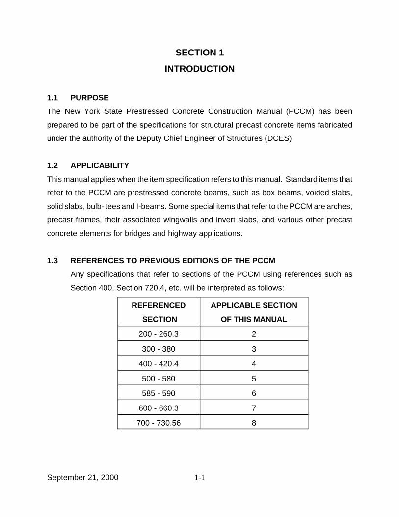
1.3 REFERENCES TO PREVIOUS EDITIONS OF THE PCCM
Any specifications that refer to sections of the PCCM using references such as
Section 400, Section 720.4, etc. will be interpreted as follows:
REFERENCED
SECTION
APPLICABLE SECTION
OF THIS MANUAL
200 - 260.3 2
300 - 380 3
400 - 420.4 4
500 - 580 5
585 - 590 6
600 - 660.3 7
700 - 730.56 8

2-1September 21, 2000
SECTION 2
DRAWINGS
2.1 CONTRACT DRAWINGS
2.1.1 Definition
The drawings that are part of the contract documents are hereinafter referred to as the
“plans.” The plans are not intended to be used as “shop drawings,” "installation drawings"
or “erection drawings.”
2.1.2 Requests for Clarification
Requests for clarification of the contract requirements for items covered by this
specification should be directed to the DCES. The DCES will furnish the clarification to the
Contractor.
2.1.3 Dimensions
In case of a difference on the plans between scaled dimensions and numbers, the
numbers shall be followed.
2.1.4 Errors
The Contractor shall call to the attention of the DCES any errors or discrepancies that may
be discovered within the contract documents.
2.1.5 Principal Controlling Design Data and Material Properties
The following will be considered principal controlling design data and material properties.
Any change requires pre-authorization by the DCES.
1 The horizontal distance between bearing centerlines, or other points of
support.
2 Length of the member, out-to-out.
3 Width of the member.
2-2September 21, 2000
4 Depth of the member.
5 Jacking force.
6 Concrete strengths.
7 Thickness of flanges and webs.
2.1.6 Fabricating Dimensions
The Contractor shall be responsible for modifying the dimensions of units to compensate
for elastic shortening, shrinkage, grade correction, and other phenomena that make
in-process fabricating dimensions different from those shown on the plans.
2.2 SHOP DRAWINGS
2.2.1 Preparation
Complete and accurate drawings shall be made by the Contractor, showing how each
concrete unit is to be fabricated. These drawings shall be made as soon as possible after
the contract award and shall be designated as shop drawings. Shop drawing approval by
the DCES shall not relieve the Contractor of the responsibility for the correctness of all
dimensions shown. When a shop drawing submittal includes calculations meeting the
requirements of Section 9 Contractor’s Design Calculations, the drawings must be
stamped and signed by the same engineer of record that stamped and signed the
calculations.
2.2.2 Size and Type
2.2.2.1 Standard Size
Shop drawings shall be cut to a standard size of 560 mm x 865 mm and arranged to
conform to the plans. The margin line shall be drawn 13 mm from the top, bottom, and
right-hand edges and 50 mm from the left-hand edge to permit binding.
2-3September 21, 2000
2.2.2.2 Neatness and Clarity
Shop drawings shall be complete, neatly drawn and clearly legible. Letters and numbers
shall be a minimum size of 3 mm.
2.2.2.3 Title Block
Each shop drawing shall have a top right corner box (a title block) identical to the one
shown on the plans. The title block shall show the contract number, the project
identification number (PIN), the project name, the structure name, the Bridge Identification
Number (BIN), and the name of the county. The sheets shall be arranged so that the notes
appear above each other near the right edge of the sheet. A space 75 mm by 280 mm, and
parallel to the length of the sheet, shall be reserved in the lower right hand corner for a title
and approval signature. There shall be a space 50 mm x 50 mm reserved within this title
block for each required stamp, i.e., "approved" stamp, engineer’s stamp, etc.
2.2.3 Return Without Examination
Sets of drawings not meeting the requirements of Section 2.2.2 will be returned without
examination.
2.2.4 Digital Format
Contractors who wish to submit drawings in a digital format should contact the Concrete
Engineering Unit for information on compatibility requirements.
2.2.5 Information Required on Shop Drawings
The shop drawings shall include the following information:
2.2.5.1 Production Note Sheet
1 Fabricating plant production schedule. If the work is not yet scheduled,
indicate “not yet scheduled” on the drawing.
2 Description of the fabricating plant, including any backup concrete mixing

2-4September 21, 2000
facilities, and proposed method of placement.
3 Design mix, including all admixtures and mixing operations including the
quantity and timing of introduction of water and admixtures. Modifications or
deviations from the original mix at any time after the shop drawings have been
approved will be subject to the acceptance of the DCES.
4 Quality control tests and procedures.
5 Unit and cylinder curing procedures, as required by Section 5.11 CURING.
6 Required compressive strength for each phase of fabrication.
7 Proposed method of handling and transporting precast concrete units.
8 Cold weather or hot weather concreting procedures, if need is anticipated.
9 Material and manner of applying Penetrating Sealer as required by Section
6.2.3 Coating of Concrete Units.
2.2.5.2 Additional Required Information for Pretensioned Elements.
1 The name of the NYSDOT approved manufacturer of the prestressing steel,
including any alternate source.
2 Calculations of strand elongation for each unique casting length (grip to grip).
Actual data shall be used in this calculation whenever available.
3 Tensioning force (initial and final).
4 Transfer of prestressing force procedure for all unit types to be fabricated.
5 Strand cutting sequence and material and manner of protecting the exposed
portions of the prestressing steel.
6 Camber at release.
7 Camber at shipping.
2.2.5.3 Layout Sheet:
1 North arrow.
2 Plan layout of structure.
3 General cross section views looking “up station.”
2-5September 21, 2000
4 Piece mark and its location on each unit.
5 Bridge begin, end, and pier stations as needed.
6 Center to center of bearings, all spans.
7 Necessary section details.
2.2.5.4 Unit Detail Sheets, Indicating:
1 Unit plan dimensions.
2 Unit elevation.
3 Unit cross section dimensions.
4 Reinforcing layout, including plan, elevation and cross section views.
5 Bar list including bar sizes, bend dimensions etc. shall be shown on the same
drawing on which reinforcing details are shown.
6 Railing anchorage layout and details.
7 Miscellaneous details, including diaphragm, required daps, special beam end
requirements, and special surface finishes.
8 Type and location of lifting device for all concrete units to be fabricated.
9 A complete bill of materials.
2.2.5.5 Additional Required Information for Precast Concrete Bridge Structural
Units.
(Non-Match Cast Joints)
The following minimum information shall be shown on the shop drawings at appropriate
locations.
1 All joints and connection details.
2 When required, preparation of keyway surfaces and specific grout proposed,
following the requirements of Section 8.4.5 Shear Key Joints.
2.2.5.6 Additional Required Information for Structures with Post-Tensioning.
(Match Cast and Non-Match Cast Segments)
The following minimum information shall be shown on the shop drawings at appropriate
2-6September 21, 2000
locations. These provisions do not apply to transverse post-tensioning of adjacent box
beam and adjacent voided slab units.
1 Complete details of the anchorage system for post-tensioning meeting the
requirements of Section 9.21.2.2 of Standard Specifications of Highway
Bridges. Details for reinforcing steel required due to stresses imposed in the
concrete by anchorage systems. Certified copies of the reports covering tests
performed on prestress anchorage devices as required by the above
specification shall be included in the shop drawing submittal as a part of the
supporting documents.
2 The orientation of the bearing plate, usually by providing offsets to a horizontal
and vertical plane. These planes usually coincide with the plane of the form.
3 Shop drawings shall be integrated and show all reinforcing steel tendons and
hardware within each unit. All conflicts between tendons and reinforcing steel
shall be resolved. The Contractor (supplier of post-tensioning hardware) is
responsible for designing and furnishing local zone anchorage reinforcement.
4 When any post-tensioning work is to be performed in the casting facility, all
relevant information meeting the requirements of Section 8.5 POST-
TENSIONING shall be shown on the installation drawing. The shop drawings
shall contain appropriate references to those details on the installation
drawings.
2.2.5.7 Additional Information Required for Precast Segmental Bridges with
Match Cast Joints.
The following minimum information shall be shown on the shop drawings at appropriate
locations.
2.2.5.7.1 Geometry Control
A description of the Contractor’s proposed geometry control procedure shall be provided.
This information shall include, but shall not be limited to, the following items:
2-7September 21, 2000
1 A detailed description of the theoretical principles underlying the geometry
control procedure.
2 A detailed narrative of the step-by-step geometry control procedure.
3 Detailed calculation forms.
4 A set of sample calculations.
5 A description of all measuring equipment and procedures.
6 The location of the control points to be established on each segment.
7 The qualifications of personnel who will carry out the geometry control.
2.2.5.7.2 Layout Sheets
Erection marks for each segment, indicating the location and order in the erection
sequence of each segment, shall be included.
2.2.5.7.3 Segment Detail
Fully and accurately dimensioned views of precast segments shall show clearly the three
dimensional relationship of all embedded items. These views shall show all projections,
recesses, notches, openings, blockouts, and other pertinent details.
2.2.5.7.4 Reinforcing Steel
Details of reinforcing steel shall clearly show the size, spacing, cover, and location of bars,
including any special reinforcing required but not shown on the contract plans.
2.2.5.7.5 Tendon Ducts
Size and type of duct for all post-tensioning tendons with horizontal and vertical profiles
clearly detailed and mathematically defined. Details of duct supports, grout tubes, vents,
and drains shall be shown including type, size, and location.
2.2.5.7.6 Inserts
Details and locations of all other items to be embedded in the segments such as inserts,
lifting devices, and post-tensioning hardware, etc. shall be clearly detailed.

2-8September 21, 2000
2.2.5.7.7 Casting Curves
Casting curves shall include the following information:
Casting curves shall correspond to the casting and installation methods, the installation
schedule, loads, and material properties proposed by the Contractor. Casting curves shall
be sufficiently accurate to allow the determination of control point settings for accurately
casting the segments to meet the profile and the alignment shown on the plans. The
preparation of casting curves shall recognize all deviations from straight line and
deformations due to the final required alignment and due to dead load, and superimposed
dead loads, erection loads, post-tensioning stresses including secondary moments, creep,
shrinkage, and installation schedule.
The preparation of casting curves shall be done at no additional cost and shall be
considered incidental to the contract. Because the casting curves are dependent on the
Contractor’s erection sequence schedule, the Contractor shall produce new casting curves
whenever there is a change in the erection sequence and/or schedule.
Casting curves shall be prepared, signed, and sealed by a Professional Engineer licensed
to practice in New York State and experienced in concrete segmental bridge design and
construction.
2.2.5.8 Forms for Precast Segmental Bridges with Match Cast Joints
Shop drawings shall be submitted for forms and form travelers. The forms used to cast the
concrete segments shall be capable of:
1 Match casting.
2 Producing the segments within the tolerances permitted.
3 Accommodating blockouts, openings and protrusions.
4 Adjusting to changes in segment geometry as shown in the plans, or for
correcting previous minor casting errors to prevent accumulation.
2-9September 21, 2000
5 Stripping without damage to the concrete.
6 The form design must provide a tight, leak proof joining to the previous
segment. The bulkhead must be capable of connecting the ducts in a manner
to hold their position and prevent intrusion of grout.
7 Where sections of forms are to be joined, on the exterior face of the segment,
an offset exceeding 1 mm for flat surfaces and 3 mm for corners and bends
will not be permitted.
8 All side, bottom, inside, and header forms for precast segmental construction
shall be constructed of steel unless use of other materials is approved by the
DCES.
9 Forms shall be of sufficient thickness, with adequate external bracing and
stiffeners, and shall be sufficiently anchored to withstand the forces due to
placement and vibration of concrete.
10 Internal bracing and holding devices in forms shall be limited to stay bolts in
webs which can be removed from the concrete surface to permit patching
following form removal.
11 Joints shall be designed and maintained for mortar tightness.
12 All form surfaces for casting members shall be constructed and maintained to
provide segment tolerances.
2.3 INSTALLATION DRAWINGS AND SUPPORTING DOCUMENTS
For work involving segmental construction a separate set of drawings hereinafter referred
to as "installation drawings" shall be required. These drawings shall be submitted together
with the shop drawings for the approval of the DCES and shall meet the requirements of
Sections 2.2.1, 2.2.2, 2.2.3, and 2.2.4. Submission, examination, approval and distribution
of these drawings shall be as per Sections 2.4 and 2.5, except that "shop drawing" shall
be interpreted to mean "installation drawing". The reviewing authority for installation
drawings and supporting materials will be the DCES or the designated representative. This
requirement will be waived when the contract plans contain sufficient installation details.
2-10September 21, 2000
Calculations required as supporting materials to installation drawings shall be prepared by,
signed, and sealed by a Professional Engineer licensed to practice in New York State and
experienced in concrete segmental bridge design and construction. These calculations
shall meet the requirements of Section 9 Contractor’s Design Calculations of this
manual.
Installation drawings shall include:
2.3.1 Installation Note Sheets
These sheets shall include the following information:
1 A detailed step-by-step description of the Contractor’s proposed installation
procedure.
2 The Contractor’s proposed installation schedule.
3 For each segment, a table of theoretical elevations and alignment of the
geometry control points established during casting. This information shall be
shown for each stage of erection.
4 The proposed method for measuring and recording the elevation and
alignment of all control points at each stage of installation.
2.3.2 Revised Installation Note Sheets
Revised sheets shall be resubmitted each time the Contractor proposes to deviate from
the sequence or schedule of erection contained in previously approved installation note
sheets.
2.3.3 Temporary Structures and Equipment Sheets
These sheets shall include complete details and design calculations for falsework, erection
equipment, formwork, and other temporary construction which may be required and which
will be subject to calculated stresses. This shall include complete information covering the
design and details for the scheme to be used to align and secure segments during erection
of the superstructure.

2-11September 21, 2000
2.3.4 Post-Tensioning Sheets
These sheets shall contain the following information meeting the requirements of
Section 8.5 POST-TENSIONING.
2.3.4.1 Calculations of theoretical elevations and alignment shall include the following
factors:
1 The effect of as-cast geometry established from surveys during casting of
segments.
2 Effects of construction dead and live loads.
3 Effects of post-tensioning.
4 Effects of creep and shrinkage.
5 Effect of the final profile of the roadway as shown on the plans.
2.3.4.2 Calculations to substantiate the post-tensioning system and procedures to be
used including stress strain curves typical of the prestressing steel to be
furnished, required jacking forces, elongation of tendons during tensioning,
seating losses, short term prestress losses, temporary overstress, stresses
in prestress anchorages including distribution plates and reinforcing steel
needed in the concrete to resist stresses imposed by prestress anchorages.
These calculations shall show a typical tendon force after applying the
expected friction coefficient and anticipated losses for the stressing system to
be used including anchor set losses. The modulus of elasticity used in
elongation calculations shall be that of the prestressing steel shown in the
plans. Adjustments to the calculations shall be made based on the strand
area and modulus of elasticity furnished by the Manufacturer.
2.3.5 Checks and Modifications of Permanent Structural Components for Erection
Loads
These documents shall include:

2-12September 21, 2000
1 Calculations showing that loads imposed on permanent structural components
by construction equipment, erection equipment, and temporary falsework will
not adversely affect the structural integrity of the bridge and that the allowable
stresses as shown on the plans are not exceeded during construction.
2 Complete detail drawings of any modifications to permanent structural
components proposed by the Contractor, with supporting calculations
demonstrating that the modifications are both necessary and adequate to
accommodate loads due to the proposed erection sequence.
3 A complete description of and details covering each of the post-tensioning
systems to be used for permanent and temporary tendons.
4 Designation of the specific prestressing steel, anchorage devices, bar
couplers, duct material and accessory items to be used, including the
manufacturer.
5 Properties of each of the components of the post-tensioning system.
6 Details covering assembly of each type of post-tensioning tendon.
7 Equipment to be used in the post-tensioning operation.
8 Procedure and sequence of operations for post-tensioning.
9 Parameters to be used to calculate the typical tendon force such as expected
friction coefficients and anchor set.
10 A table detailing the post-tensioning jacking sequence, jacking forces and
initial elongation of each tendon at each stage of erection for all post-
tensioning.
11 The operation of grouting post-tensioning tendons, the mix design for the
grout, details of equipment for mixing and placing grout, for flushing, backup
equipment, and methods of mixing and placing grout.
2.4 SUBMISSION OF SHOP DRAWINGS
When the shop drawings, prepared by the Contractor or the authorized agent, as specified,
are completed and checked, check prints shall be submitted to the DCES in accordance
with the requirements of the contract documents.

2-13September 21, 2000
2.4.1 Check Prints
The Contractor shall submit:
1 Two sets of check prints to the DCES.
2 One set of check prints to the Engineer-In-Charge.
3 Two sets of check prints to each Railroad or other Agency involved with the
contract.
2.5 EXAMINATION OF SHOP DRAWINGS
2.5.1 Recording Receipt of Drawings
All shop drawings are date stamped as they are received and recorded in a log at the office
of the DCES. The transmittal letter is also date stamped, and then faxed back to the
sender. Failure to receive this fax is an indication that the drawings have not been
received, and that the sender should attempt to find out what has become of the drawings.
2.5.2 Examination Time
The DCES will normally take two work days for the examination of each drawing in a
complete set of shop drawings, with a minimum of ten work days per one complete set.
A set of shop drawings is defined as all drawings received by the DCES from any
Contractor for a particular item in a contract on any day. A set of drawings will be
considered complete only if it contains the information necessary to correctly fabricate and
fully document the precast member(s) for which the drawings are prepared. If the shop
drawings are detained for examination for a period longer than that previously stated, such
detention will be taken into account when considering application by the Contractor for an
extension of time for the completion of the contract, changed conditions, schedule
revisions, etc.

2-14September 21, 2000
2.5.3 Special Circumstances
2.5.3.1 Large Sets of Drawings
When a set of shop drawings contains more than 20 sheets, the DCES will make every
effort to limit the total examination time to 40 working days.
2.5.3.2 Design Calculations
When a shop drawing submittal includes calculations meeting the requirements of Section
9 CONTRACTORS DESIGN CALCULATIONS, the examination time for the show
drawings will begin on the date of acceptance of the submitted design. The Contractor will
be informed of the date of the design acceptance.
2.5.3.3 Contract Changes
If shop drawings are submitted while the Department is considering changes to the
contract, evaluating Value Engineering proposals, etc., the DCES will not start the
examination of the drawings until a final resolution has been reached and all necessary
field change sheets and specifications have been approved.
2.5.4 Concrete Mix Design
Approval of the shop drawings alone does not constitute approval of the concrete produced
using the mix design shown on the shop drawings.
2.5.5 Approved as Noted
The DCES will review the drawings and indicate thereon such changes as may be
necessary to fulfill the needs of the State. If, in the opinion of the DCES, the revisions are
minor, one set of drawings with required changes indicated will be marked with “Approved
as Noted” and will be returned. The Contractor may then use that set of drawings to begin
fabrication of the units. The Contractor shall then submit two sets of the revised drawing
for final approval as soon as possible. No approval for shipment and/or payment will be
made until the final approval of the drawings. When the DCES is satisfied that the
2-15September 21, 2000
drawings are acceptable, both sets of drawings will be stamped “Approved”. One set will
remain the property of the State. The other set will be returned to the Contractor for
distribution as per Section 2.5.7.1.
2.5.6 Major Revisions
If the noted required changes are not minor, then the returned set of prints will not be
marked “Approved as Noted.” When the revisions have been completed, two sets of
drawings shall be forwarded to the DCES for approval. When the DCES is satisfied that
the drawings are acceptable, both sets of drawings will be stamped "Approved". One set
will remain the property of the State. The other set will be returned to the contractor for
distribution as per Section 2.5.7.1.
2.5.7 Distribution of Approved Shop Drawings
2.5.7.1 Distribution List
The Contractor or the authorized agent shall send copies of the approved shop drawings
as soon as possible in accordance with the distribution listed below:
1 One (1) set of approved drawings to the Fabricator of the precast and/or
prestressed concrete units.
2 Two (2) sets of approved drawings to the State’s quality assurance Inspector
at the fabrication plant.
3 One (1) set of approved drawings to the Regional Construction Engineer
through the Regional Director of Transportation.
4 One (1) set of approved drawings to the office of the State’s quality assurance
inspection firm.
5 One (1) set of approved drawings to every Railroad Company or Public
Agency involved in the contract and one (1) set of approved reproducibles.
6 One (1) set of approved drawings to the Engineer-In-Charge of the contract.

2-16September 21, 2000
2.5.7.2 Notification of DCES
One copy of the transmittal letter distributing the drawings shall be sent to the DCES.
2.6 ERECTION DRAWINGS
2.6.1 General
The Contractor shall submit erection drawings, signed and stamped by a Professional
Engineer registered to practice in New York State, to the Regional Director for each
structure in the contract. The number of sets of drawings required will be determined by
each Regional Director. These shall meet all the requirements of Section 2.2.2 Size and
Type. Copies shall also be sent for comments to any Railroad Company or other Agency
affected by the proposed erection procedure.
These drawings must be submitted at least 30 calendar days prior to the proposed
beginning of erection. The Regional Director will review and approve or reject the erection
procedure based upon its structural adequacy and the requirements given in Section 2.6.2
- Required Information. This review will consider, but not be limited to, effects on the
maintenance of traffic, modifications to existing pavement, the flow of water, etc. The
Regional Director’s Office will forward all of the comments to the Contractor for
incorporation into the erection procedure.
2.6.2 Required Information
The following minimum information shall be placed on the erection drawings for each
structure. Erection procedures for similar structures or twin bridges may be shown on the
same sheet:
1 Plan of the work area showing support structures, roads, railroad tracks,
canals or streams, utilities or any other information pertinent to erection.
2 Erection sequence for units, noting use of holding cranes or temporary
supports, false work and bents.

2-17September 21, 2000
3 Delivery location of each unit and storage location, if applicable.
4 Location and range for each pick.
5 A capacity chart for each crane and boom length used in the work. Cranes
lifting over active railroad facilities shall have a minimum lifting capacity of 150
percent of the lift weight.
6 Pick point location(s) on each member.
7 Lifting weight of each member (including clamps, spreader beams, etc.).
8 Lift and setting radius for each pick (or maximum lift radius).
9 Description of lifting devices or other connecting equipment, including capacity.
10 Beam tie down details or other method of stabilizing erected beam units, if
required.
11 Blocking details, if required, for stabilizing members supported on expansion
bearings and on bearings that do not limit movement in the transverse
direction.
12 Crane outriggers or their bearing mats, if used, shall be located no closer to
the back of the substructure than a distance defined by a line projected
upward from the top of the footing at a one vertical to one horizontal slope. For
crane positions located inside this line the Contractor shall submit calculations
signed and stamped by the engineer of record to the Regional Director for
review and approval or rejection.
3-1September 21, 2000
SECTION 3
INSPECTION
The assignment of quality assurance inspectors will be strictly based on the schedule of
production shown on the production note sheet. If the Fabricator needs any changes in the
approved schedule, a request for such changes shall be received by the DCES (Concrete
Engineering Unit) a minimum of three working days before the beginning date of schedule
change, with copies to the quality assurance Inspector and the quality assurance firm.
3.1 QUALITY
3.1.1 Quality Control
Quality control shall be performed by the Contractor to insure that materials and
workmanship meet the requirements of the contract documents. Quality control is the
responsibility of the Contractor. The quality control (QC) Inspector is the duly designated
person who acts for and on behalf of the Contractor on all inspection and quality matters
within the scope of the contract documents.
3.1.2 Quality Assurance
Quality assurance (QA) is the responsibility of the State. The quality assurance Inspector
is the duly designated person who acts for and on behalf of the State on all inspection and
quality matters within the scope of the contract documents. When the term Inspector(s)
is used without further qualification, it applies to QA within the limits of responsibility
designated in this manual.
3.2 QUALIFICATIONS OF INSPECTORS
3.2.1 QA Inspectors
QA Inspectors shall possess a current ACI Certification for Concrete Field Testing
Technician - Grade 1, or approved equal, as determined by the DCES.
3-2September 21, 2000
3.2.2 QC Inspectors
QC Inspectors shall be adequately qualified as per the accepted industry standards to
perform all tests in accordance with specified procedures.
3.2.3 QC Tests
Tests required by the contract shall be performed in the presence of the QA Inspector.
3.3 RESPONSIBILITIES OF INSPECTORS
3.3.1 Quality Control Inspector
QC Inspectors shall be furnished by the Contractor (Fabricator) with complete set(s) of
approved shop drawings and those portions of the contract documents that describe
material and quality requirements for the products to be fabricated.
The QC Inspector shall ascertain that all fabrication, handling, transportation and erection
is performed in accordance with the provisions of the contract documents and the
approved shop drawings. The QC Inspector shall make certain that only materials
conforming to the requirements of the contract documents are used. All materials used
shall be approved by the Materials Bureau in accordance with their procedures and
directives.
3.3.2 Quality Assurance Inspector
The QA Inspector shall witness that the fabrication of each unit meets the requirements of
the contract documents and the approved shop drawings. All fabrication related activity
shall only be performed in the presence of the QA Inspector. Any fabrication related
activity that is easy to inspect after the completion of that activity can be performed by the
Contractor at the Contractor’s risk without the presence of the QA Inspector. These
activities shall be preauthorized by the DCES. The QA Inspector shall have the authority
to inspect all materials and fabrication procedures to determine whether they conform to
the contract documents. Copies of all certifications shall be given to the QA Inspector.

3-3September 21, 2000
3.4 INSPECTOR’S MARK OF ACCEPTANCE FOR SHIPMENT
When the QA Inspector agrees that a precast concrete unit is ready for shipment from the
plant, the QA Inspector shall affix the acceptance stamp and shall complete and sign Part
A of the Report of Acceptance/Shipping of Structural Concrete, as indicated in Section 3.5.
This acceptance mark shall be made by paint or indelible ink stamp and placed near the
erection mark on the piece. The concrete unit may then be shipped or may be stored prior
to shipping.
The Inspector's acceptance stamp indicates that, at the time of acceptance, it was the
opinion of the Inspector that the concrete unit was fabricated from accepted materials and
in accordance with the contract documents and the approved shop drawings. However,
the Inspector’s stamp of acceptance does not imply that the concrete unit will not be
subject to rejection by the State if subsequently found to be defective.
3.5 REPORT OF ACCEPTANCE OF STRUCTURAL CONCRETE
The acceptance document for all structural concrete products subject to plant inspection
is the Report of Acceptance/Shipping of Structural Concrete (See Section 6.6 SHIPPING
OF UNITS and Appendix C ACCEPTANCE /SHIPPING REPORT AND NOTICE OF
DEFECT ). Prior to product shipment from the plant to the project site, the QA Inspector
shall complete and sign Part A of the Report of Acceptance/Shipping of Structural
Concrete to cover concrete units subject to inspection. The QC Inspector or other
authorized agent of the Contractor shall sign Part B of the Report of Acceptance/Shipping
of Structural Concrete at the time of shipping. The completion of Part A of this document
shall indicate to the Engineer that the structural concrete product may be paid for under
the payment rules established by the Department.
3.6 FACILITIES FOR INSPECTION
The Contractor shall provide all facilities for inspection of material and workmanship at the
fabrication plant. The QA Inspector shall have sole access to a work station which includes
the following minimum requirements:

3-4September 21, 2000
1 A desk with a chair.
2 File cabinet with lock.
3 Telephone access in plant.
4 A computer with a modem and an operating system that is compatible with the
operating system currently used by NYSDOT. The system shall also include
a printer and scanner of acceptable quality. Contact the Concrete Engineering
Unit for more information.
3.7 OBLIGATIONS OF THE CONTRACTOR
The Contractor shall be responsible for the acceptability of the fabricated units. The QC
Inspector shall take all necessary steps to assure that all materials, fabrication procedures
and the final product meet all the requirements of the contract documents and the
approved shop drawings.
3.7.1 Informing the DCES of Work Schedule
The Contractor shall inform the Concrete Engineering Unit three work days prior to:
1 Commencement of work.
2 Commencement of work after a work suspension of two work days or more.
3 Unit shipping.
3.7.2 Informing the QA Inspector of Work Schedule
The Contractor shall keep the QA Inspector informed of the day-to-day scheduling of
operations. The Inspector shall have free access throughout the fabrication plant to see
that the work being done is in conformance with the contract documents. If the Inspector
is not present to witness the work, the fabricator shall stop the work and immediately notify
the DCES (Concrete Engineering Unit).
4-1September 21, 2000
SECTION 4
MATERIAL REQUIREMENTS
4.1 MATERIALS FOR CONCRETE
The concrete shall meet the requirement of §501-2 Materials, under §501, Portland
Cement Concrete, General (§ Indicates Section in NYSDOT Standard Specifications,
Construction and Materials) with the following modifications:
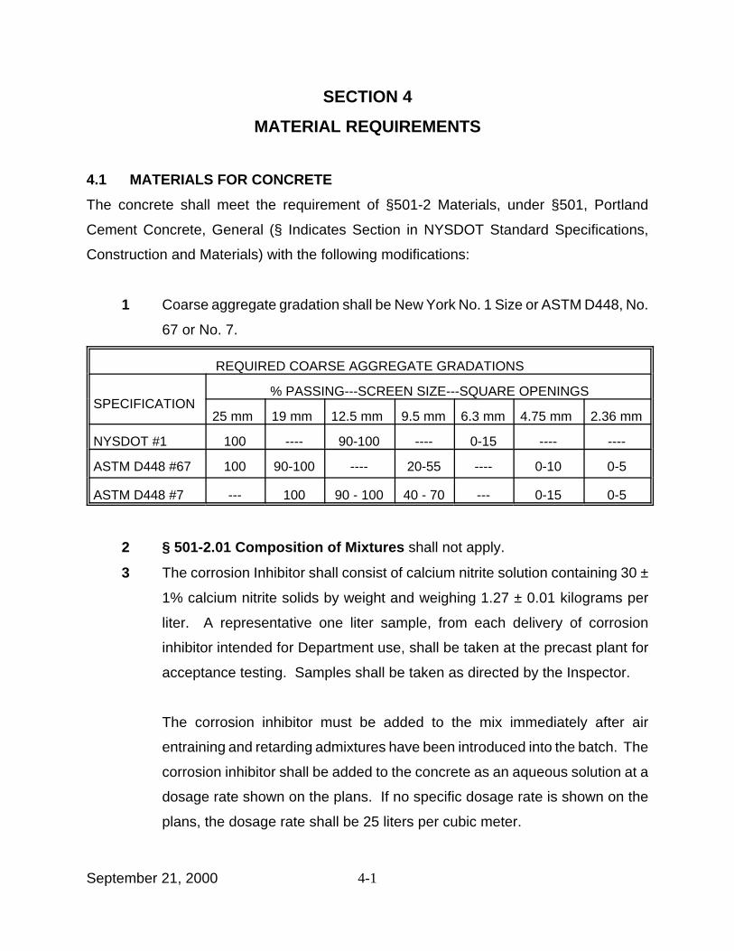
1 Coarse aggregate gradation shall be New York No. 1 Size or ASTM D448, No.
67 or No. 7.
REQUIRED COARSE AGGREGATE GRADATIONS
SPECIFICATION% PASSING---SCREEN SIZE---SQUARE OPENINGS
25 mm 19 mm 12.5 mm 9.5 mm 6.3 mm 4.75 mm 2.36 mm
NYSDOT #1 100 ---- 90-100 ---- 0-15 ---- ----
ASTM D448 #67 100 90-100 ---- 20-55 ---- 0-10 0-5
ASTM D448 #7 --- 100 90 - 100 40 - 70 --- 0-15 0-5
2 § 501-2.01 Composition of Mixtures shall not apply.
3 The corrosion Inhibitor shall consist of calcium nitrite solution containing 30 ±
1% calcium nitrite solids by weight and weighing 1.27 ± 0.01 kilograms per
liter. A representative one liter sample, from each delivery of corrosion
inhibitor intended for Department use, shall be taken at the precast plant for
acceptance testing. Samples shall be taken as directed by the Inspector.
The corrosion inhibitor must be added to the mix immediately after air
entraining and retarding admixtures have been introduced into the batch. The
corrosion inhibitor shall be added to the concrete as an aqueous solution at a
dosage rate shown on the plans. If no specific dosage rate is shown on the
plans, the dosage rate shall be 25 liters per cubic meter.
4-2September 21, 2000
An automatic corrosion inhibitor dispensing system shall be required. The
dispensing system shall meet the following requirements:
Delivery accuracy of ± 3% (by weight or volume)
Program Quantity (liters, nearest tenth)
System interlocks
Print requirements:
Project number and/or batch number
Date and time
Delivered quantity (liters, nearest tenth)
The calibration shall be in accordance with procedures approved by the
Director, Materials Bureau.
4 Blended cement meeting the requirements of §701-03 may be used subject
to approval by the DCES.
5 Air content shall be 7 percent ± 2 percent. A minimum air content of 3% will
be accepted, provided that the fabricator has previously demonstrated that
concrete from an identical mix meets the requirements of AASHTO T161 (80%
< x, where x = the relative dynamic modulus of elasticity after 300 cycles).
6 The use of calcium chloride, or an admixture containing calcium chloride, will
not be permitted.
7 The water/cementitious material ratio shall not exceed 0.40, as measured by
AASHTO TP-23-93. The AASHTO TP23 test measures the free water
available for hydration of the cement plus the bound water in the saturated
aggregate. The bound water may amount to 1-2% of the mass of the
aggregate.
4.2 STEEL
1 Bar reinforcement shall meet the requirements of §709-01.
2 Wire fabric shall meet the requirements of Standard Specifications §709-02.
4-3September 21, 2000
3 Chairs or other devices necessary to ensure the proper placement of steel
items shall meet the requirements of §556-2.02.
4 Prestressing steel shall meet the requirements of §709-06.
5 Chairs and other metal devices, shall be equipped with snug fitting, high
density polyethylene tips which provide six millimeters (6 mm) minimum
clearance between the metal of the chair and any exposed surface. Chairs
may be made of a dielectric material or stainless steel without polyethylene
tips and shall meet the requirements of ASTM A493, and AISI Type 430.
6 Bearing Plates (if required) shall meet the requirements of §715-01.
4.3 MATERIALS FOR CURING
1 Quilted covers (for curing) shall meet the requirements of §711-02.
2 Plastic Coated Burlap Blankets (for curing) shall meet the requirements of
§711-03.
3 Other materials may be used if approved by the DCES.
4.4 MATERIALS FOR FINISHING
4.4.1 Concrete Repair Materials
These materials shall meet the requirements of §701-06, §701-08 or §701-09
except the water demand shall be as the Manufacturer suggests for the needed
application. Fine aggregate shall meet the requirements of §703-03, Mortar Sand;
or §703-04, Grout Sand. Fine aggregate shall be absolutely dry. Concrete repair
material used shall meet the performance criteria of the concrete used in the unit.
4.4.2 Penetrating Sealers
The protective sealer used on concrete surfaces shall appear on the Department’s
Approved List, except that water based products shall not be used. Sealers shall
meet the requirements of Section § 717-03 Penetrating Type Protective Sealers.
4-4September 21, 2000
4.5 MATERIALS FOR INSTALLATION
4.5.1 Transverse Post-Tensioning Steel
Transverse strands or tie rods shall meet the material requirements shown on the
plans.
4.5.2 Shear Key Material
Shear Key material for box beam units, hollow slab units and solid slab units shall
meet the requirements of § 701-06, Cement Based Grout Materials for Shear Keys.
Rapid setting concrete Repair Material meeting the requirements of § 701-09 may
be used when approved by DCES.
4.5.3 Anchorage Block-Out Grout
The mortar shall consist of one of the following materials:
1 § 701-05, Concrete Grouting Material.
2 § 701-06, Cement Based Grout Material for Shear Keys.
3 § 701-08, Vertical and Overhead Patching Material.
4 A two-Component epoxy system and fine aggregate, using a combination of
one epoxy and one fine aggregate chosen from the list below: The fine
aggregate shall be completely dry.
a § 721-01, Epoxy Resin.
b § 721-03, Epoxy Polysulfide Grout.
c § 721-05, Epoxy Repair Paste.
d § 703-03, Mortar Sand.
e § 703-04, Grout Sand.
f § 703-07, Concrete Sand.
4-5September 21, 2000
4.5.4 Anchor Dowel Fill Material
4.5.4.1 Expansion End Material Option
1 NYS Mat. Spec. § 702-0700 - Asphalt Filler.
2 Fed. Mat. Spec. SS-S-00195B - Elastomeric Polymer Type, Two-Component
Cold Applied.
3 Fed. Mat. Spec. SS-S-00200D -Elastomeric Polymer Type, Two-Component
Jet Fuel Resistant, Cold Applied.
4.5.4.2 Fixed End Material Option
1 NYS Mat. Spec. § 721-01 - Epoxy Resin System with Sand. Bone-dry,
sandblast sand shall be added in the ratio of (1) part epoxy to (2) parts sand
by volume.
2 NYS Mat. Spec. § 721-03 - Epoxy Polysulfide Grout with Sand. Bone-dry,
sandblast sand shall be added in the ratio of (1) part epoxy to (2) parts sand
by volume.
3 NYS Mat. Spec. § 701-05 - Concrete Grouting Material.
4 NYS Mat. Spec. § 701-06 - Cement Based Grout Materials for Shear Keys.
4.6 MATERIALS FOR POST-TENSIONING
4.6.1 Post-Tensioning Anchorages and Couplers
All anchorages and couplers shall develop at least 95 percent of the actual ultimate
strength of the pre-stressing steel, when tested in an unbonded state, without
exceeding anticipated set. The coupling of tendons shall not reduce the elongation
at rupture below the requirements of the tendon itself. Couplers and/or coupler
components shall be enclosed in housings long enough to permit the necessary
movements. Couplers for tendons shall be used only at locations specifically
4-6September 21, 2000
indicated and/or approved by the Inspector/Engineer. Couplers shall not be used
at points of sharp tendon curvature.
4.6.2 Ducts
Ducts used to provide holes or voids in the concrete for the placement of post-
tensioned bonded tendons may be either formed with removable cores or may
consist of rigid or semi rigid ducts which are cast into the concrete.
Ducts formed with removable cores shall be formed with no constrictions which
would tend to block the passage of grout. All coring materials shall be removed.
Ducts formed by sheath left in place shall be a type that will not permit the intrusion
of any material. They shall transfer bond stresses to the member as required, shall
retain shape under the weight of the plastic concrete and shall have sufficient
strength to maintain their correct alignment and prevent wobble during placement
of concrete.
4.6.2.1 Metal Ducts
Sheathing for ducts shall be metal, except as provided below. Such ducts shall be
galvanized ferrous metal and shall be fabricated with either welded or water tight
interlocked seams. Galvanizing of welded seams will not be required. Rigid ducts shall
have smooth inner walls and shall be capable of being curved to the proper configuration
without crimping or flattening. Semi rigid ducts shall be corrugated and when tendons are
to be inserted after the concrete has been placed their minimum wall thickness shall be as
follows: 0.5 mm for ducts less than or equal to 65 mm diameter, 0.6 mm for ducts greater
than 65 mm diameter. When bar tendons are preassembled with such ducts, the duct
thickness shall not be less than 0.35 mm.
4.6.2.2 Polyethylene Duct
As an alternative to metal ducts, ducts for transverse tendons in deck slabs and at other
4-7September 21, 2000
locations where shown on the plans or approved by the DCES may be of high density
polyethylene, conforming to the material requirements of ASTM D3350.
Polyethylene ducts shall not be used when the radius of curvature of the tendon is less
than 10 meters.
Semi rigid polyethylene ducts for use where completely embedded in concrete shall be
corrugated with minimum material thickness of 1.25 ± 0.25 mm. Such ducts shall have a
white coating on the outside, or shall be of white material with ultraviolet stabilizers added.
Rigid polyethylene ducts for use where the tendon is not embedded in concrete shall be
rigid pipe manufactured in accordance with ASTM D2447, grades P33 or P34; F714 or
D3350 with a cell classification of PE345433C. For external applications, such duct shall
have an external diameter to wall thickness ratio of 21 or less.
For applications where polyethylene duct is exposed to sunlight or ultraviolet light, carbon
black shall be incorporated into the polyethylene pipe resin in such amounts as to provide
resistance to ultraviolet degradation in accordance with ASTM D1248.
4.6.2.3 Duct Area
The inside diameter of ducts shall be at least 6 mm larger than the nominal diameter of
single wire, bar, or strand tendons. In the case of multiple wire, bar or strand tendons, the
inside cross-sectional area of the sheathing shall be at least two times the net area of the
prestressing steel. When tendons are to be placed by the pull through method, the duct
area shall be at least 2-1/2 times the net area of the prestressing steel.
4.6.2.4 Duct Fittings
Coupling and transition fittings for ducts formed by sheathing shall be of either ferrous
metal or polyethylene, and shall be cement paste intrusion proof and of sufficient strength
to prevent distortion or displacement of the ducts during concrete placement.
4-8September 21, 2000
All ducts or anchorage assemblies shall be provided with pipes or other suitable
connections at each end of the duct for the injection of grout after prestressing. Ducts shall
also be provided with ports for venting or grouting at high points and for draining at
intermediate low points.
Vent and drain pipes shall be 13 mm minimum diameter standard pipe or suitable plastic
pipe. Connection to ducts shall be made with metallic or plastic structural fasteners. The
vents and drains shall be mortar tight, taped as necessary, and shall provide means for
injection of grout through the vents and for sealing to prevent leakage of grout.
4.6.3 Grout
Materials for grout which is to be placed in the ducts after tendons have been post-
tensioned shall conform to the following:
4.6.3.1 Portland Cement
Portland cement shall meet the requirements of § 701-01.
4.6.3.2 Water
The water used in the grout shall meet the requirements of §712-01.
4.6.3.3 Admixtures
Admixtures, if used, shall impart the properties of low water content, good flowability,
minimum bleed, and expansion, if desired. Admixtures which contain fluorides, sulphites,
or nitrates, or which, at the dosage used, contain chlorides in excess of 0.001 percent of
the weight of the concrete, shall not be used.
When a grout expanding admixture is required, or is used at the Contractor’s option, it shall
be well dispersed throughout the other admixtures and shall produce between a 2 to 6
percent unrestrained expansion of the grout.

4-9September 21, 2000
The amount of admixture to obtain a desired amount of expansion shall be determined by
tests. Anytime the manufacture location of either admixture or cement changes after
testing, new tests shall be conducted to determine proper proportions.
All admixtures shall be used in accordance with the instructions of the manufacturer.
5-1September 21, 2000
SECTION 5
FABRICATION REQUIREMENTS
5.1 PLANT FACILITY
Fabrication plants shall meet the following minimum requirements as a prerequisite for
shop drawing approval:
1 Business office with telephone facilities and fax machine.
2 Inspector facility as required by Section 3.6 FACILITIES FOR INSPECTION.
3 Sufficient area for concrete batch plant and raw material storage if the plant
produces concrete.
4 Sufficient area for storage.
5 Prestressing equipment and beds, if necessary.
6 Necessary concrete forms.
7 Required quality control equipment.
8 Required equipment for proper curing of concrete units.
5.2 ORDERING OF MATERIALS
The Contractor shall bear all costs for damages and unacceptable material which may
result from the ordering of materials prior to the approval of the shop drawings.
5.3 DATA FOR QA INSPECTOR
1 Certificates of acceptance for all materials shall be provided to the QA
Inspector.
2 A calibration certificate attesting to the fact that the concrete cylinder testing
machine to be used has been calibrated within the 12 month period
immediately prior to use.
3 A calibration certificate indicating the load calibration of each gauge and
hydraulic jack combination used for tensioning. The gauge shall be calibrated
from zero, throughout its entire load range. The gauge shall have clearly
marked divisions that are easily readable at the initial and final tensioning
5-2September 21, 2000
force. The calibration date of each combination of a gauge and hydraulic jack
shall be within the 12 month period immediately prior to use. More than one
gauge can be calibrated for one jacking system.
5.4 CONCRETE FORMS
5.4.1 General
Forms shall be well constructed, carefully aligned, clean, substantial and firm, securely
braced and fastened together and sufficiently tight to prevent leakage of mortar. They shall
be strong enough to withstand the action of mechanical vibrators. All forms for each unit
shall be approved by the Inspector prior to placing concrete.
All form surfaces that come in contact with the concrete shall be thoroughly treated with
an approved form coating in the manner and at the rate specified by the Manufacturer.
Forms so treated shall be protected against damage and other contamination prior to
placing the concrete. Any form coating material that sticks to or discolors concrete shall
not be used.
5.4.2 Void Producing Forms
Void forms shall be waterproof or be coated with a waterproofing material on the outside
and shall have a twenty millimeter minimum drain placed at each end of each void.
All voids shall be vented during curing unless waived by the DCES. The vents shall be
plugged with approved material after curing.
5.5 EMBEDDED STEEL
5.5.1 Reinforcing and Prestressing Steel
Prior to installation in the units, reinforcing steel and prestressing steel shall be free of
frost, dirt, oil, paint, mill scale, corrosion or any foreign material that may prevent a bond
5-3September 21, 2000
between the steel and the concrete. Some rust on steel is acceptable provided the rust is
not loose and the steel is not pitted. Tack welding of design bar reinforcement shall not be
permitted. Tack welding of redundant steel may be allowed to provide extra rigidity to the
steel cage. Reinforcing steel shall be adequately secured by chairs or blocking to forms
or by ties to tendons so it maintains its position during the casting of the concrete.
5.5.2 Welded Wire Fabric
Welded wire fabric, plain or deformed, may be substituted for the bar reinforcement
provided that:
1 The required cover is maintained.
2 The design steel area of the fabric equals or exceeds that of the bar
reinforcement.
3 Splices to the fabric are made in accordance with the requirements of the
NYSDOT Standard Specifications for Highway Bridges, §8.32.5 and §8.32.6,
as applicable.
4 The details shall be indicated on the shop drawings.
5.5.3 Inserts
All inserts shall be placed according to the plans and held firmly in position during the
placing of the concrete. All inserts, including those that are for the convenience of the
Contractor, shall be shown on the working drawings for approval by the DCES. Steel
inserts shall be stainless steel or shall be galvanized. All inserts shall be recessed 25 mm
unless otherwise shown on the drawings. The adequacy and location of the inserts is the
responsibility of the Contractor.
5.6 STRESSING REQUIREMENTS FOR PRETENSIONING
5.6.1 General
Two stages shall be followed in tensioning all prestress strands:
5-4September 21, 2000
1 Initial Tension Force - Application of a force of 10% to 15% of the required
jacking force to straighten the strand, eliminate slack and provide a reference
point for measuring elongation.
2 Final Tension Force - This is the total force required for each strand as shown
on the plans. This force shall be measured by a properly calibrated gauge and
verified by strand elongation, unless an alternate procedure is allowed by the
DCES. For straight strands, the agreement between the two methods shall be
3 percent and for draped strands, 5 percent.
5.6.2 Tensioning of Tendons
In all methods of tensioning, the force induced in the tendons shall be measured by gauge.
The exact initial tensioning force will be shown on the Production Note Sheet of the shop
drawings.
After the initial force has been applied to the tendon, reference points for measuring
elongation due to additional tensioning forces shall be established. Calculations for
elongations shall include allowances for friction, strand slippage and movement of
abutments. The final tensioning force shall be measured by properly calibrated gauges
and verified by measuring strand elongation.
5.6.3 Methods of Force Measurement
5.6.3.1 Initial Tensioning
Initial force shall be determined by one of the following:
1 Pressure gauges.
2 Dynamometers.
3 Load Cells.
5.6.3.2 Final Tensioning
Tendon elongation shall be computed using the modulus of elasticity of the tendon shown
5-5September 21, 2000
on the stress-strain curves furnished by the manufacturer. The actual elongation shall
agree with the computed elongation, with appropriate tolerance.
5.6.3.3 Gauging System
1 Pressure gauges shall be used on loads which are not less than one fourth
and not more than three fourths of the total graduated capacity.
2 Gauges shall have indicating dials of at least 150 mm diameter.
3 Gauges shall be mounted at or near working eye level and within 2 meters of
the Operator and positioned so that readings can be obtained without parallax.
4 Gauging systems shall be calibrated by a registered Professional Engineer.
5 Gauges for single strand jacks shall be calibrated by means of an approved
and calibrated load cell.
6 Gauges for large multiple strand jacks acting singularly or in multiple shall be
calibrated by proving rings or by load cells placed on either side of the movable
end carriage.
7 In multiple strand tensioning, use of a master gauge system to monitor
accuracy of hydraulic gauges is acceptable as an ongoing calibration method.
5.6.4 Prestressing Strands
Prestressing strand shall meet the requirements of §709-06.
5.6.5 Control of Jacking Force
Manual or automatic pressure cutoff valves shall be used for stopping the jack at the
required load. When manual cutoffs are used, the rate of loading shall be such that the
jack can be stopped at the specified load of the strand. If automatic pressure cutoff valves
are used, it shall be capable of adjustment to assure that the proper force is induced into
the strand.
5.6.6 Wire Failure in Tendons
Failure of wires in pretensioned strand is allowed, providing the total area of wire failure is
5-6September 21, 2000
not more than 2 percent of the total area of tendons in any member. When a prestressing
strand fails during tensioning, the gauge that is connected to the tensioning system shall
be recalibrated before it is reused. The recalibration may be waived if the gauge is
adequately protected by snubbers.
5.7 MATCH CAST SEGMENTS
5.7.1 Care shall be exercised in setting up forms for casting segments. All materials to
be embedded in concrete shall be properly positioned and supported. Provisions
for all projections, recesses, notches, openings, blockouts and other pertinent items
shall be made in accordance with the plans. Extreme care shall be taken in
positioning the match cast segment in relation to the segment to be cast. The
match cast segment shall not be torsionally distorted (twisted).
5.7.2 The abutting surface of the bulkhead segment shall be covered with a thin film of
bond breaker consisting of flax soap and talc, or other material approved by the
Engineer. The soap and talc mixture shall be appropriately five parts flax soap to
one part talc. The mixture may be varied based on job experience and results. The
acceptability of a material other than flax soap and talc shall be determined prior to
use in casting of segments by demonstration on a specimen with a facial area of at
least 0.4 square meters.
5.7.3 Prior to each use, the interior surfaces of forms shall be cleaned of all dirt, mortar,
and foreign material. Before placing reinforcing steel and other embedded items,
forms shall be thoroughly coated with an approved form oil or other equivalent
coating that permit the ready release of the forms and that do not discolor the
concrete.
5.8 CONCRETE MIX DESIGN AND PROPORTIONING
The Contractor shall be responsible for designing a concrete mix to produce the strength
5-7September 21, 2000
and other requirements specified on the plans. If no strength is indicated, the required
minimum strength shall be 45 MPa at 28 days. When water is added in stages, details
regarding measuring of water and the mixing operation after such addition shall be clearly
stated.
The mixing operation shall exactly follow the approved procedure on the Production Note
Sheet. The QA Inspector shall be provided with the batch ticket.
5.9 PLACING CONCRETE
5.9.1 Preparation
No concrete shall be placed without the QA Inspector’s approval. Compliance with the
precasting tolerances listed under Sections 7.1 GENERAL through 7.8 MATCH CAST
SEGMENTS of this manual is a prerequisite for approval by the QA Inspector.
5.9.2 Cold Weather
When the ambient temperature is below 4° C, the fabrication of the units shall be in
accordance with the cold weather concreting procedures, as approved on the approved
shop drawings.
5.9.3 Hot Weather
When the ambient temperature is above 32° C, the fabrication of the units shall be in
accordance with the hot weather concreting procedures, as approved on the approved
shop drawings.
5.9.4 No Segregation
Suitable means shall be used for placing concrete without segregation. The concrete
mixture shall not be dropped from a height greater than 300 mm above the top of the
forms.
5-8September 21, 2000
5.9.5 Placing
Special care shall be taken to deposit the concrete in its final position in each part of the
form. Vibrators shall be used only to consolidate the concrete after it has been properly
placed. Vibrators shall not be used to distribute the concrete in forms.
5.9.6 Consolidation
The plastic concrete shall be consolidated in place by either external or internal vibration
methods, or both, if necessary. The vibrators shall be of a type and design approved by
the Inspector and the size of the vibrating head shall be governed by the spacing of the
prestressing steel and reinforcement. When reinforcement is epoxy coated, vibrators shall
be rubber tipped.
5.10 FINISHING
5.10.1 Surfaces
Surfaces of concrete shall be true and even, free from rough, open or honeycombed areas,
and with no visible depressions or projections. The Fabricator shall produce well formed
matching units with overall pleasing appearance.
5.10.2 Top Surfaces
After all the concrete has been placed and thoroughly consolidated as required under
Section 5.9.6 Consolidation, the tops of units shall receive a finish as shown on the plans,
unless otherwise directed by the QA Inspector.
5.10.3 Exposed Surfaces
All surfaces which will be exposed in their installed condition shall be finished using a
procedure approved by the DCES.
5-9September 21, 2000
5.11 CURING
5.11.1 General
The Contractor shall indicate on the shop drawings, for approval, the method of cure and
complete outline of the proposed procedure under each of the phases of the curing cycle.
The Contractor may choose any one of the following acceptable curing methods.
Acceptable methods are:
a. Saturated Cover
b. Low Pressure Steam
Immediately upon the completion of concrete placement for each unit, an enclosure shall
be placed over the casting bed. For match cast segments the enclosure shall totally
enclose both the segment being cast ("wet cast segment") and the segment being cast
against ("match cast segment"). The Contractor shall submit all covers to the QA Inspector
for approval prior to the commencement of work.
5.11.2 Initial Curing Phase
Each method of cure shall have an initial curing phase as follows:
To prevent moisture loss on exposed surfaces during the initial curing phase, units shall
be covered as soon as the concrete can be covered without marring the surface, or the
exposed surfaces shall be kept wet by fog spray or wet blankets.
5.11.3 Final Curing Phase
During the initial curing phase, temperature in the enclosure shall not be less than 10° C.
The final curing phase may be initiated when the last portion of concrete placed has
reached a compressive strength of 3.5 MPa as indicated by a penetrometer test meeting
the requirements of ASTM C403.
5.11.3.1 Saturated Cover
The final curing phase may begin at any time after commencement of the initial curing
phase.
5-10September 21, 2000
Each unit shall be covered with heavy, water saturated burlap, or other material acceptable
to the Inspector. The burlap shall be kept saturated, and the concrete surface temperature
shall not drop below 20° C. These conditions shall be maintained for three days or until
the concrete has reached 70% of the specified 28 day strength.
5.11.3.2 Steam Curing
The steam curing cycle shall include a gradual heating and cooling period during which the
rate of change in temperature shall not exceed 22° C per hour. The maximum temperature
inside the enclosure shall not exceed 70° C. After the concrete has reached 70% of its
specified 28 day compressive strength the temperature within the curing enclosure shall
be decreased at an average rate not exceeding 22° C per hour until the temperature within
the curing enclosure is within 11° C of the ambient temperature of the storage area.
5.11.4 Record of Curing Time and Temperature
The Contractor shall provide one (1) automatic temperature recorder for every 30 meters
of product. The recorder shall continuously record curing temperatures for the initial and
final curing phases. The sensors shall be carefully placed within the curing enclosure to
ensure that ambient conditions are measured at the designated locations. Recorder
accuracy shall be certified once every 12 months and the certificate displayed with each
recorder. In addition, random temperature checks of each recorder shall be made by the
Inspector.
Each chart shall indicate the casting bed, date of casting, time of commencing, graphic plot
and the units that are represented by chart. The start of artificial heat and the transfer of
prestress shall be indicated on each graphic record.
After completion of the final curing phase, the charts shall be properly marked and given
to the QA Inspector. Temperatures recorded on the charts shall be considered as
verification of whether the units have been cured in accordance with the approved shop
drawings.
5-11September 21, 2000
5.11.5 Transfer of Prestress
Transfer of prestress shall be accomplished as soon as the final curing phase is complete
and in the manner approved on the shop drawings.
5.12 REMOVAL OF FORMS
Forms shall remain in place until the concrete has reached the compressive strength
specified on the shop drawings. Care shall be exercised in removing the forms to prevent
spalling and chipping of the concrete. For match cast units, prior to moving a unit from its
as-cast position, erection marks shall be affixed identifying its location in the structure and
order in the erection sequence, and match marks indicating its orientation relative to the
adjacent segment.
5.13 TESTING CONCRETE
5.13.1 Testing Cylinders For Strength
5.13.1.1 Casting Test Cylinders
The concrete strength shall be determined from concrete test cylinders made in
conformance with ASTM C31. All cylinders shall be made by the Contractor in the
presence of the QA Inspector. The Contractor shall cast a sufficient number of concrete
test cylinders to fulfill the concrete strength test requirements as stated in Section 5.13.1.3.
The expected number of test cylinders to be cast for each unit shall be shown on the shop
drawings.
The cylinders shall be made from the same batch of concrete actually placed in the precast
units. The QA Inspector shall be the sole judge of which cylinders are defective or
damaged and are not to be included in the determination of the strength class.
5.13.1.2 Curing Test Cylinders
All cylinders used to test for concrete strength shall be cured in the same manner as the
5-12September 21, 2000
units they represent unless otherwise indicated on the shop drawings. Match curing
systems may be submitted for approval.
5.13.1.3 Testing for Concrete Strength
A minimum of two cylinders representing each unit shall be tested in immediate succession
to verify the strength of the concrete. Cylinders shall be tested according to the
requirements of ASTM C39, except that the use of 100 mm X 200 mm cylinders is
acceptable. Use of neoprene caps shall follow the procedural directives of the Materials
Bureau. A minimum of four cylinders shall be tested for units weighing over 50 metric tons.
Each cylinder shall have a strength of at least 95 percent of the required strength. The
average strength of the cylinders tested must be equal to or greater than the required
strength. If this requirement is not met, another pair of cylinders may be tested at a later
time.
5.13.2 Testing Slump
Slump shall be tested on each batch of concrete according to ASTM C143.
5.13.3 Testing Air Content
Air content shall be tested on each batch of concrete according to Pressure Method ASTM
C231.
5.13.4 Temperature
The concrete temperature shall be measured as directed by the Inspector.
5.13.5 Water/Cementitious Materials Ratio
The water/cementitious materials ratio shall be measured according to AASHTO TP-23-93.
The water/cementitious ratio shall be measured by the Fabricator for the first batch of
concrete in a days placement and monitored by slump tests throughout production.
Additional water/cementitious ratio tests may be ordered by the Inspector if slump indicates
5-13September 21, 2000
the maximum water-to-total-cementitious material ratio may be exceeded. For initial slumps
less than 100 mm, a slump increase greater than 25 mm will be considered cause to
suspect an increase in water/cementitious materials ratio. For slumps greater than
100 mm, an increase greater than 40 mm will be considered cause to suspect an increase
in water/cementitious materials ratio.
5.14 GEOMETRY CONTROL OF MATCH CAST SEGMENTS
5.14.1 General
After a given segment is cast and before separating it from the adjacent matchcast
segment, the positions of the two adjoining segments shall be checked from established
control points. If the positions do not agree within a specified tolerance with the control
point settings from the approved casting curve, corrections to the geometry shall be made
in the next segment cast using the established control points.
5.14.2 Geometry Control Method
A suggested method of geometry control is as follows:
The instruments used to measure elevations should be precision levels equipped with
parallel plate micrometers capable of obtaining first order control and one piece Invar rods
with centering point bases. The instruments used for horizontal control measurements
should be one-second theodolites. A micrometer on either the theodolite or the foresight
target should be used for horizontal control measurements on segment control points.
Instruments should be mounted on a permanent platform independent of any other
structure. Provisions should be made to protect instruments from construction activities
and to minimize the effects of wind and temperature variations on the accuracy of
readings.
The position of two adjacent segments should be independently determined by two parties.
Casting should not begin until these surveys agree to within the following tolerances:
Elevations: 0.3 mm on any control point
Horizontal: 0.3 mm and 2 seconds of arc on any control point
5-14September 21, 2000
5.14.3 Reference Points and Bench Marks
A minimum of two permanent horizontal reference points shall be established in line with
the instrument mounting point. A permanent bench mark shall be established at a location
where it will not be disturbed by construction activities. The horizontal reference points and
bench mark shall be located so as to be continuously visible from the instruments.
5.15 POST-TENSIONING
All post-tensioning work done at the precasting facility shall be done according to DCES
approved installation drawings and as per Section 8.5 POST-TENSIONING of this manual.
6-1September 21, 2000
SECTION 6
HANDLING, FINISHING AND ACCEPTANCE
6.1 HANDLING
Segments shall be handled with care to prevent damage. Handling shall be done only by
using the devices shown on the approved drawings for this purpose.
The Contractor shall inspect each segment visually for evidence of damage or defects
before, during, and after critical operations and as often as necessary to ensure adequate
quality control. The Contractor shall immediately bring all evidence of damage or defects
to the attention of the QA Inspector.
6.2 FINISHING
6.2.1 Shear Key Joints - Keyway Surface Cleaning
The keyway surface shall be sandblast cleaned of any material which may prevent bonding
(i.e., - oil, grease, dirt, etc.) Sandblasting must be completed prior to coating with a
penetrating sealer.
6.2.2 Exposed Steel
All exposed steel shall be protected from rusting prior to placement in the storage area.
6.2.3 Coating of Concrete Units
All concrete units shall be coated on all surfaces with a penetrating sealer meeting the
requirements of Section 4.4.2 Penetrating Sealers. The surfaces must be prepared by
blast cleaning, removing all laitance, loose particles, etc. The surface shall be allowed to
dry for 24 hours after wetting for any reason. All surface preparation work shall be
completed and approved by the Inspector, before sealer application can commence. The
coating of the units shall take place prior to shipping the units unless otherwise approved
by the DCES.

6-2September 21, 2000
6.2.3.1 Weather Limitations
Sealer materials shall not be applied during wet weather conditions. Any unit exposed to
wetting within 12 hours of completion shall be recoated. Ambient and surface
temperatures shall be a minimum of 4° C during application and until the sealed concrete
is dry to the touch. Application by spray methods shall not be used during windy
conditions.
6.2.3.2 Sealer Application
The sealer shall be used as supplied by the manufacturer without thinning or alterations,
unless specifically required in the manufacturer’s instructions. Thorough mixing of the
sealer before and during its use shall be accomplished as recommended by the
manufacturer. Equipment for sealer application shall be clean of foreign materials.
A minimum of two (2) coats of sealer shall be applied. The total quantity of sealer applied
by each coat shall be equal to the quantity required at the application rate specified in the
Approved List. Each coat shall be allowed to dry before the next coat is applied. On
sloping and vertical surfaces, sealer application shall progress from bottom to top. Care
shall be taken to ensure that the entire surface of the concrete is covered and all pores
filled.
6.2.4 Finishing Surfaces
All surfaces which will be visible in their installed position shall be finished as approved by
DCES.
6.3 ACCEPTANCE OF UNITS
All units which are complete in all aspects and are fabricated in accordance with the
contract documents and meeting each of the following criteria will be accepted in
accordance with Section 3.4 INSPECTOR’S MARK OF ACCEPTANCE FOR SHIPMENT
of this manual.
6-3September 21, 2000
6.3.1 Strength Requirement
The unit meeting the required strength, when tested as per Section 5.13 TESTING
CONCRETE. A concrete element which has reached strength will be accepted even if the
time for reaching that strength exceeded the specified number of days.
6.3.2 Performance Criteria
The unit meeting the performance criteria established in the contract documents.
6.3.3 Durability
The unit is free of defects such as cracks, honeycombed areas, cold joints, exposed steel,
inadequate cover over steel, and any other defect which may reduce the durability of the
completed structure.
6.3.4 Injurious Materials
The unit is free of material injurious to concrete or steel within concrete. Concentrations
of total chloride ions in excess of 0.06% by weight of cement are considered injurious.
Other materials with injury potential will be determined by the DCES.
6.3.5 Tolerances
The unit meets the tolerances of Section 7 TOLERANCES. Note that pretensioned
concrete products have additional tolerances that must be met within 24 hours of transfer
of prestressing force.
6.4 DEFECTIVE UNITS
A unit which does not meet the requirements of Section 6.3 is a defective unit. The
Contractor will be issued a Notice of Defect as soon as the defect is discovered. (See
Appendix C).
6.4.1 Cosmetic Defects
Cosmetic defects are those that do not affect the ability of the unit to resist construction or

6-4September 21, 2000
service loads or reduce the life expectancy of the structure. This category of defect
includes superficial discontinuities such as minor cracks, small spalls, small honeycombed
areas, or any defect that does not extend beyond the centerline of any reinforcing steel.
Repair of cosmetic defects shall be made in such a manner that the aesthetics and
structural integrity of the unit is restored. The repairs shall be done in the presence of the
QA inspector using a written procedure approved by the DCES.
6.4.2 Structural Defect
Defects of structural significance are defects that will impair the ability of any unit to
adequately resist construction or service loads or that will reduce the life expectancy of the
structure. Examples of such defects include significant cracks, large spalls and
honeycombed areas, major segregation or breakage of concrete, etc. Determination by the
DCES that a defect is structural or cosmetic will be final. Repair of units with defects of
structural significance shall be according to the provisions of Section 6.4.3.
6.4.3 Repairs of Structural Defects
Drawings shall be prepared by the Contractor to completely document the defect(s) on the
unit and to describe and document the proposed repair procedure. The drawings shall
meet the requirements of Section 2.2.2 Size and Type of this manual. These drawings
shall be prepared, stamped and signed by a Professional Engineer registered in New York
State.
6.4.3.1 Documentation of Defects
The drawings shall completely document the defect(s) by showing appropriate views of the
units with all pertinent information about the defect. All information shown shall be verified
by the Inspector. If the unit concerned has spalled, honeycombed or heavily cracked
(disintegrated) areas, concrete from such areas shall be removed as approved by the
Inspector before documenting the defect.

6-5September 21, 2000
6.4.3.2 Description of Repairs
The drawing shall show a detailed description of the proposed repair procedure including
all preparatory work, and materials to be used. A post repair inspection procedure shall
be shown.
6.4.3.3 Supporting Material
The submittal shall include supporting material such as photographs of the defect, data
sheets for materials to be used, etc.
6.4.3.4 Engineering Calculations
The submittal shall include all necessary engineering calculations to substantiate the
soundness of the proposed repair. The calculations shall meet the requirements of Section
9 Contractor’s Design Calculations of this manual.
6.5 STORAGE
Units shall be stored on good hardwood dunnage and in a manner that prevents racking.
The units should be spaced far enough apart so that visual inspection along the length is
possible. No stacking of units will be allowed, unless approved by the DCES. Anchor
dowel holes shall be open at the bottom at all times to allow for drainage. The storage
area shall have proper drainage.
6.6 SHIPPING OF UNITS
6.6.1 The QC Inspector shall verify the following prior to shipping:
1 All units bear the stamp of the QA Inspector, and the QA Inspector has signed
Part A of the Report of Acceptance/Shipping of Structural Concrete for each
unit.
2 All units are properly supported and adequately tied to prevent movement
during shipping.
3 Plastic guards or other devices shall be used to protect the concrete where
6-6September 21, 2000
anchor chains would otherwise be in direct contact with the concrete.
4 The units shipped are free of any defect.
6.6.2 The QC Inspector shall sign Part B of the Report of Acceptance/Shipping of
Structural Concrete (see Section 3.5 REPORT OF ACCEPTANCE OF
STRUCTURAL CONCRETE and Appendix C ACCEPTANCE /SHIPPING
REPORT AND NOTICE OF DEFECT ), give the report to the transporter, and direct
the transporter to give the report to the EIC at the project site.
6.6.3 The QC Inspector shall fax the Report of Acceptance/Shipping of Structural
Concrete to the Concrete Engineering Unit and send a separate copy by mail.
7-1September 21, 2000
SECTION 7
TOLERANCES
7.1 GENERAL
The provisions of this Section shall apply to the unit types listed in Sections 7.2, 7.3, 7.4,
7.5, 7.6 and 7.7. If a different unit type is used, its tolerances will be indicated in the
specification for that particular unit type.
7.2 PRESTRESSED CONCRETE I-BEAM UNITS AND BULB-TEE UNITS
7.2.1 Precasting
In accordance with the provisions of Section 5.9 PLACING CONCRETE, all forms,
reinforcing and prestressing steel, etc., shall be inspected for compliance with the
tolerances listed below:
Width (flanges and fillets): +20 mm, -5 mm
Depth (overall): + 15 mm, -5 mm
Width (web): + 20 mm, -5 mm
Depth (flanges and fillets): ± 5 mm
Stirrup Bars (projection above top of the beam): ± 20 mm
Reinforcement Cover -0, + 5 mm
Tendon Position: ± 5 mm
Position of Deflection Points for Deflected Strands: ± 300 mm
Location of Inserts for Structural Connections: ± 15 mm
Side Inserts: ± 15 mm
Stirrup Bars (longitudinal spacing): ± 50 mm
Bulkhead (deviation from square or designated skew):
Horizontal: 6 mm Vertical: 1%
Overall length: ± 25 mm
7-2September 21, 2000
7.2.2 Tolerance Check
All units shall be checked for compliance with the following tolerances within 24 hours after
detensioning, except that shipping camber shall be checked within three days of shipping.
Sweep - (Horizontal misalignment of the outside surface, measured as a deviation
from straight line parallel to the centerline of the unit).
12 mm up to 12 m lengths
0.1% of length but no more than 25 millimeters for lengths greater than 12 m.
Bearing area deviation from plane: 3 mm
Camber deviation from release camber on the shop drawing: + 0.1%, -0.05% of unit
length.
Camber deviation from shipping camber on the shop drawing: + 0.1% - 0.05% of
unit length.
7.3 PRESTRESSED CONCRETE BOX BEAM UNITS
7.3.1 Precasting
In accordance with the provisions of Section 5.9 PLACING CONCRETE, all forms,
reinforcing and prestressing steel, etc. shall be inspected for compliance with the
tolerances listed below.
Width (overall): ± 6 mm
Depth (overall): + 15 mm - 6 mm
Width (web): ± 10 mm
Depth (top slab): ± 15 mm
Depth (bottom slab): + 15 mm - 3 mm
Position of Pretensioning Strands: ± 6 mm
Reinforcement Cover -0, + 5 mm
Composite Bar Projection: + 0 mm, - 10 mm
Void Position: ± 25 mm from the end of the void to the center of the
transverse tendon hole
7-3September 21, 2000
Tendon Tubes (distance between the tube centers and distance between the
centers of tubes and the unit ends): ± 20 mm
Tendon Tubes (distance between the centers of tubes and the bottom of the unit):
± 10 mm
Position of Reinforcement: Longitudinally: ± 50 mm (non-cumulative)
Bulkhead (deviation from square or designated skew):
Horizontal: 13 mm
Vertical: 13 mm
Dowel Tubes (spacing between the centers of tubes and from centers of tubes to
the ends of the unit): ± 15 mm
Position of Side Inserts: ± 15 mm
Length: ± 25 mm.
Bearing area (deviation from plane surface when tested with a straight edge
through middle half of unit): ± 3 mm.
7.3.2 Tolerance Check
All units shall be checked for compliance with the following tolerances within 24 hours after
detensioning, except that shipping camber shall be checked within three days of shipping.
Sweep - (Horizontal misalignment of the outside surface, measured as a deviation
from straight line parallel to the centerline of the unit).
12 mm up to 12 m lengths
0.1% of length but no more than 25 millimeters for lengths greater than 12 m.
Camber deviation from release camber shown on the shop drawing: ± 0.1% of unit
length, but not greater than ± 15 mm.
Camber deviation from shipping camber on the shop drawing: + 0.1% - 0.05% of
unit length.
7.4 PRESTRESSED CONCRETE HOLLOW SLAB UNITS
The requirements of Section 7.3 PRESTRESSED CONCRETE BOX BEAM UNITS apply.
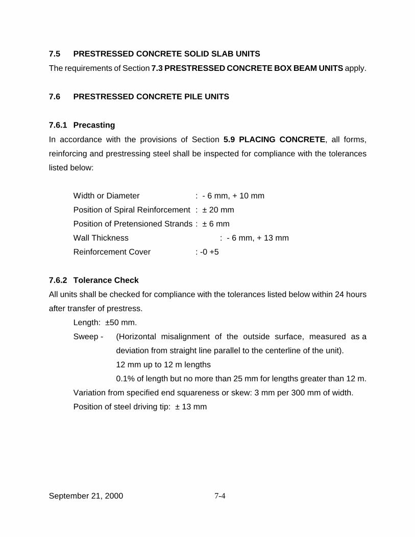
7-4September 21, 2000
7.5 PRESTRESSED CONCRETE SOLID SLAB UNITS
The requirements of Section 7.3 PRESTRESSED CONCRETE BOX BEAM UNITS apply.
7.6 PRESTRESSED CONCRETE PILE UNITS
7.6.1 Precasting
In accordance with the provisions of Section 5.9 PLACING CONCRETE, all forms,
reinforcing and prestressing steel shall be inspected for compliance with the tolerances
listed below:
Width or Diameter : - 6 mm, + 10 mm
Position of Spiral Reinforcement : ± 20 mm
Position of Pretensioned Strands : ± 6 mm
Wall Thickness : - 6 mm, + 13 mm
Reinforcement Cover : -0 +5
7.6.2 Tolerance Check
All units shall be checked for compliance with the tolerances listed below within 24 hours
after transfer of prestress.
Length: ±50 mm.
Sweep - (Horizontal misalignment of the outside surface, measured as a
deviation from straight line parallel to the centerline of the unit).
12 mm up to 12 m lengths
0.1% of length but no more than 25 mm for lengths greater than 12 m.
Variation from specified end squareness or skew: 3 mm per 300 mm of width.
Position of steel driving tip: ± 13 mm
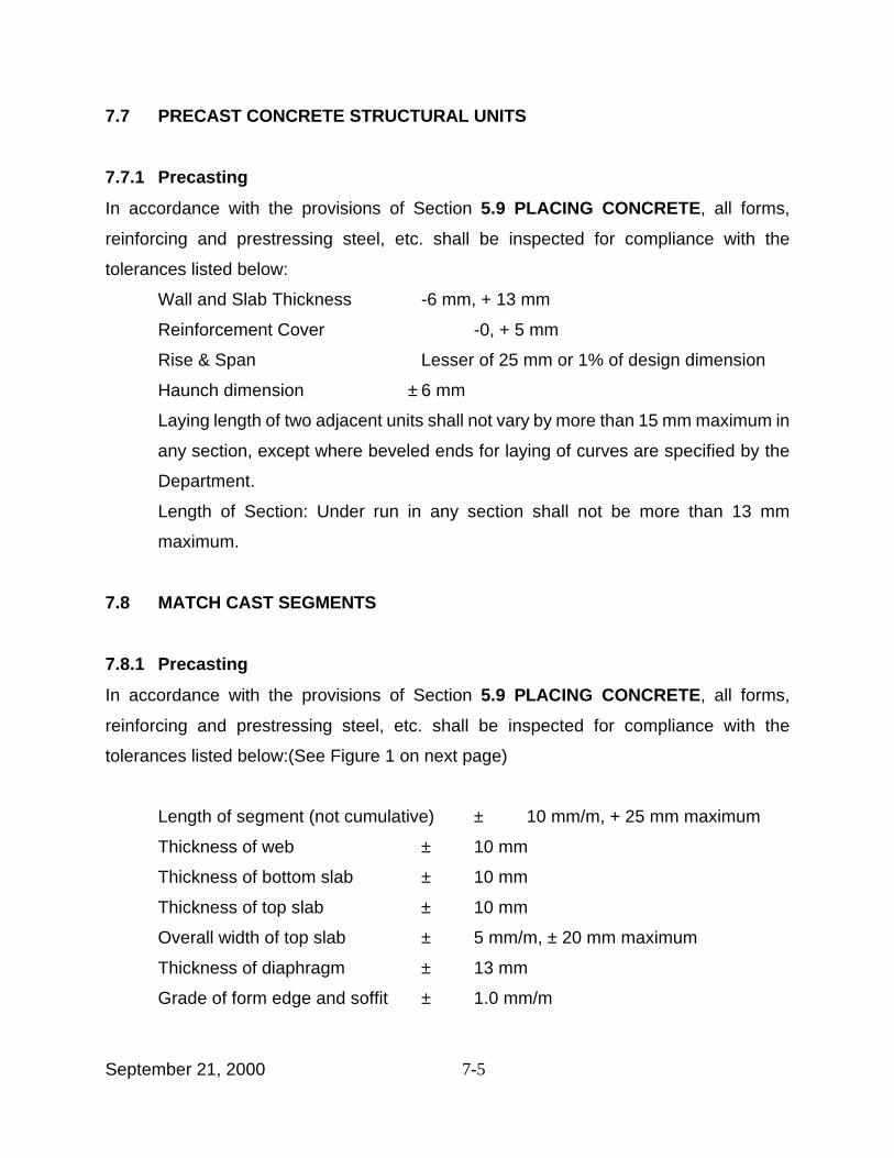
7-5September 21, 2000
7.7 PRECAST CONCRETE STRUCTURAL UNITS
7.7.1 Precasting
In accordance with the provisions of Section 5.9 PLACING CONCRETE, all forms,
reinforcing and prestressing steel, etc. shall be inspected for compliance with the
tolerances listed below:
Wall and Slab Thickness -6 mm, + 13 mm
Reinforcement Cover -0, + 5 mm
Rise & Span Lesser of 25 mm or 1% of design dimension
Haunch dimension ± 6 mm
Laying length of two adjacent units shall not vary by more than 15 mm maximum in
any section, except where beveled ends for laying of curves are specified by the
Department.
Length of Section: Under run in any section shall not be more than 13 mm
maximum.
7.8 MATCH CAST SEGMENTS
7.8.1 Precasting
In accordance with the provisions of Section 5.9 PLACING CONCRETE, all forms,
reinforcing and prestressing steel, etc. shall be inspected for compliance with the
tolerances listed below:(See Figure 1 on next page)
Length of segment (not cumulative) ± 10 mm/m, + 25 mm maximum
Thickness of web ± 10 mm
Thickness of bottom slab ± 10 mm
Thickness of top slab ± 10 mm
Overall width of top slab ± 5 mm/m, ± 20 mm maximum
Thickness of diaphragm ± 13 mm
Grade of form edge and soffit ± 1.0 mm/m
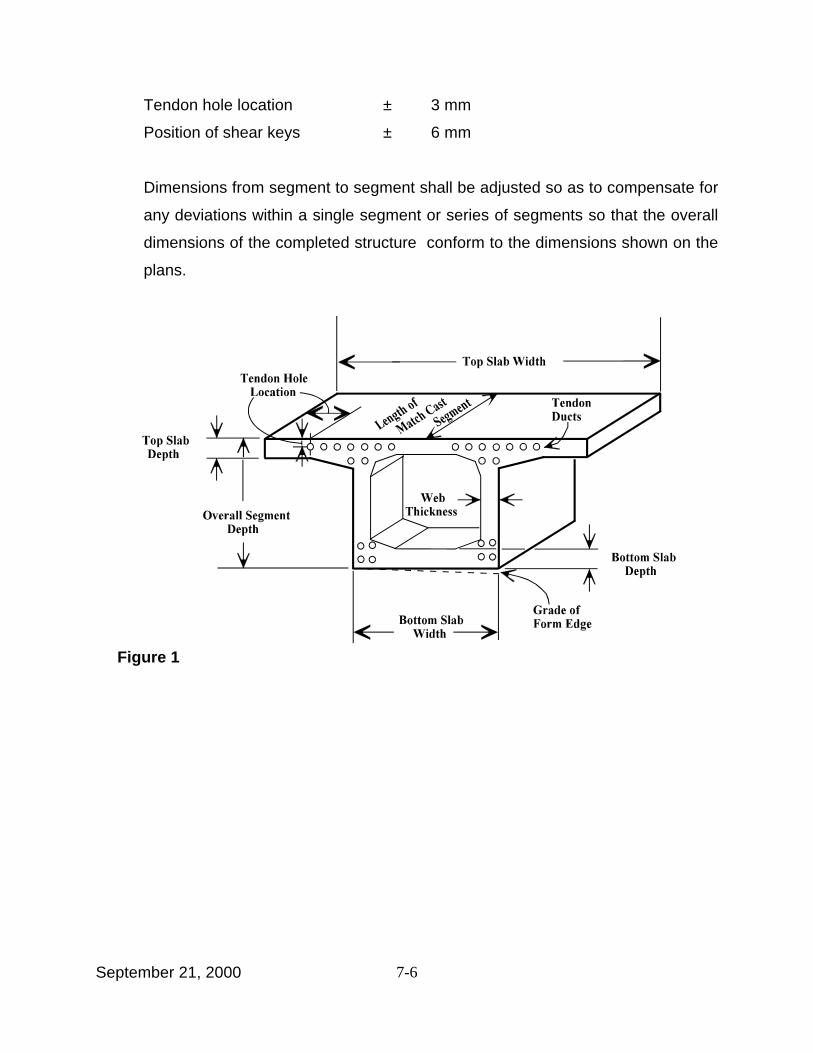
7-6September 21, 2000
Figure 1
Tendon hole location ± 3 mm
Position of shear keys ± 6 mm
Dimensions from segment to segment shall be adjusted so as to compensate for
any deviations within a single segment or series of segments so that the overall
dimensions of the completed structure conform to the dimensions shown on the
plans.
8-1September 21, 2000
SECTION 8
CONSTRUCTION DETAILS
8.1 INSPECTION, STORAGE AND HANDLING
Units will be inspected by the Engineer upon arrival at the construction site to determine
any damage and for conformance to dimensional tolerances. An additional inspection will
be made prior to erection to determine any damage during storage. The Contractor shall
handle and store the concrete units with extreme care to prevent damage to the units.
8.2 ACCEPTANCE
All Units meeting the requirements of Section 6.3 ACCEPTANCE OF UNITS will be
accepted.
8.3 REPAIR OF DAMAGED UNITS
Repairs of damaged units shall be according to Section 6.4 DEFECTIVE UNITS except
that the approval authority will be the Engineer instead of the DCES.
8.4 ERECTION
8.4.1 Field Inspection
The Contractor shall provide the Engineer with all facilities necessary to conduct a
thorough inspection of all the erection work.
8.4.2 Procedure and Equipment
Prior to erection of the units, the Contractor shall furnish to the Regional Director, the
erection procedure as required by Section 2.6 ERECTION DRAWINGS, with detailed
information concerning the proposed method of construction and the construction
equipment required. NO WORK SHALL BE DONE WITHOUT THE ENGINEER’S
APPROVAL.
8-2September 21, 2000
8.4.3 Bearing Surfaces
Bearing surfaces shall be properly finished and formed to provide full and even supporting
surfaces for bearings, bearing plates and concrete units.
8.4.4 Transverse Tie Rods, Strands and Anchor Rods
The installation of the tie rods, strands and anchor bolts shall comply with the requirements
shown on the plans.
8.4.5 Shear Key Joints
8.4.5.1 Loading
No loading of any span will be permitted until the following events have occurred:
1 All of the longitudinal shear keys of the span have been filled with shear key
material.
2 At least 24 hours have elapsed from the time the last keyway was filled.
8.4.5.2 Preparation for Placement
Prior to placing shear key material, there shall be no force in the transverse tie rods or
strands.
All shear key surfaces shall be thoroughly cleaned using a high pressure wash. The ends
and bottoms of the keyway shall be tightly sealed prior to placing shear key material to
prevent grout loss during shear key placement. The work shall be done in such a manner
that the sealing material shall be within 75mm of the bottoms and ends of the beams.
Shear keys that have not been coated with a penetrating sealer shall be continuously pre-
wetted over all shear key surfaces for a minimum of 24 hours.
8.4.5.3 Mixing - General
The following mixing requirements shall be adhered to:

8-3September 21, 2000
1 Mixing shall be done as close as possible to the keyway to be filled.
2 All necessary equipment for mixing and placing shall be present at the work
site prior to the start of mixing. All equipment shall be in good working order
as determined by the Engineer.
3 Material which, in the Engineer’s opinion is not pourable, exhibits signs of
setting or hardening, prior to placement, shall not be incorporated in the work.
It shall be removed from the work site.
8.4.5.4 Placement of Cement Based Grout Material for Shear Keys
8.4.5.4.1 The Grout manufacturer's instructions regarding mixing and placing shall be
followed, except that:
1 No aggregate shall be added to the grout.
2 The actual water to cement (W/C) ratio used shall comply exactly with the
value given for the specific product as published in the Department’s approved
list titled: Cement Based Grout Materials for Shear Keys, §701-06.
3 Grout shall not be placed during rainfalls.
4 Grout shall not be placed if the ambient temperature is outside the range of
7° C to 35° C.
8.4.5.4.2 No placement interruptions will be permitted. Grout shall be thoroughly rodded
as it is placed in the keyway. Grout shall be finished flush with the top of
keyway. When a camber differential exists between beams at the shear key
joint, the grout shall be filled to the highest beam and trowel finished at a 1 to
4 slope to the lower beam.
8.4.5.4.3 Curing shall be in accordance with the Grout Manufacturer’s instructions
unless otherwise required by the Engineer.
8.4.5.5 Tensioning of Transverse Ties
Tensioning shall be completed prior to performing any further work on the superstructure.
Transverse ties shall be tensioned to the force shown on the plans. Tensioning shall not
8-4September 21, 2000
be done until the requirements of Section 8.4.5.4 have been accomplished. No separate
installation drawings will be necessary for the tensioning of ties of adjacent prestress
box/slab unit superstructures.
Grouting of transverse ties, when required by the plans, shall be done as per Section 8.6.
The anchorage block-outs of fascia units shall be filled with anchorage block-out grout.
Grout meeting the requirements of §701-05 or §701-06 shall be prepared and applied in
accordance with the Manufacturer’s instructions. Epoxy grout systems shall be prepared
and applied in accordance with the Manufacturer's instructions. Epoxy grout systems shall
be mixed and placed in accordance with the requirements of Section 502-3.15 of the
Standard Specifications.
The temperature of the surface against which the grout is to be placed shall be at least
7° C. No placement of grout shall be permitted if the ambient temperature is less than
7° C, or if the ambient temperature is expected, or predicted, to become lower than 7° C
for a period of 12 to 15 hours after placement. After the grout has been placed, it shall be
dusted with the same brand and type of cement used in the production of the concrete
units. The color shall match the surrounding concrete surface.
8.5 POST-TENSIONING
This work shall consist of furnishing, installing, stressing and grouting post-tensioned
prestressing steel in accordance with the details shown on the installation drawings
approved by the DCES and the requirements of these specifications.
It shall also include the furnishing and installing of any appurtenant items necessary for the
particular post-tensioning system and pressure grouting of ducts.
8.5.1 Post-Tensioning System Requirements
1 Materials and devices used in the post-tensioning system shall conform to the
8-5September 21, 2000
requirements of Section 4.2 STEEL of this manual.
2 The net compressive stress in the concrete after all losses shall meet the
minimum required by the plans.
3 The distribution of individual tendons at each section shall conform to the
distribution shown on the plans.
4 The ultimate strength of the structure with the proposed post-tensioning
system shall meet the requirements of the plans.
5 Stresses in the concrete and prestressing steel at all sections and at all stages
of construction shall meet the requirements of the design criteria noted on the
plans.
6 All provisions of the design criteria, as noted on the plans, shall be satisfied.
8.5.2 Protection of Prestressing Steel
All prestressing steel shall be protected against physical damage at all times from
manufacture to grouting or encasing in concrete. Prestressing steel that has sustained
physical damage at any time shall be rejected. Any reel of prestressing steel that is found
to contain broken wires shall be rejected and the reel replaced.
8.5.2.1 Packaging
Prestressing steel shall be packaged in containers or shipping forms for protection of the
steel against physical damage and corrosion during shipping and storage. A corrosion
inhibitor, which prevents rust or other results of corrosion, shall be placed in the package
or form, or shall be incorporated in a corrosion inhibitor carrier type packaging material, or
when permitted by the Inspector, a corrosion inhibitor may be applied directly to the steel.
The corrosion inhibitor shall have no deleterious effect on the steel or concrete or bond
strength of steel to concrete. Inhibitor carrier type packaging material shall conform to the
provisions of Federal Specification MIL-P-3420. Packaging or forms damaged from any
cause shall be immediately replaced or restored to original condition.
8-6September 21, 2000
8.5.2.2 Storage
The prestressing steel shall be stored in a manner which at all times prevents the
packaging material from becoming saturated with water and allows a free flow of air around
the packages. If the useful life of the corrosion inhibitor in the package expires, it shall
immediately be rejuvenated or replaced.
8.5.2.3 Installation
At the time the prestressing steel is installed in the work, it shall be free from loose rust,
loose mill scale, dirt, paint, oil, grease or other deleterious material. Removal of tightly
adhering rust or mill scale will not be required. Prestressing steel which has experienced
rusting to the extent that it exhibits pits visible to the naked eye shall not be used in the
work. The shipping package or form shall be clearly marked with the heat number and with
a statement that the package contains high strength prestressing steel, and care is to be
used in handling. The type and amount of corrosion inhibitor used, the date when placed,
safety orders and instructions for use shall also be marked on the package or form.
8.5.2.4 Protection After Installation
If the period of time between installation of prestressing steel and grouting of the duct will
exceed 10 calendar days, the prestressing steel shall be protected from corrosion during
the entire period it is in place but ungrouted as provided below.
When corrosion protection of in-place prestressing steel is required, a corrosion inhibitor
which prevents rust or other results of corrosion shall be applied directly to the prestressing
steel. The corrosion inhibitor shall have no deleterious effect on the prestressing steel or
grout or bonding of the prestressing steel to the grout. The inhibitor shall be water soluble.
The corrosion inhibitor, the amount and time of initial application, and the frequency of
reapplication shall be approved by the DCES.

8-7September 21, 2000
8.5.3 Post-Tensioning Operations
8.5.3.1 Tensioning
All post-tensioning steel shall be tensioned by means of hydraulic jacks so that the force
of the prestressing steel shall not be less than the value shown on the approved installation
drawings. The maximum temporary tensile stress (jacking stress) in prestressing steel
shall not exceed 80 percent of the specified minimum ultimate tensile strength of the
prestressing steel. The prestressing steel shall be anchored at initial stresses in a way that
will result in the ultimate retention of permanent forces, not less than those shown on the
approved installation drawings, but in no case shall the initial stress at the anchors, after
anchor set, exceed 70 percent of the specified minimum ultimate tensile strength of the
prestressing steel. Permanent force and permanent stress will be considered as the force
and stress remaining in the prestressing steel after all losses, including creep and
shrinkage of concrete, elastic shortening of concrete, relaxation of steel, losses in post-
tensioned prestressing steel due to sequence of stressing, friction and take-up of
anchorages, and all other losses peculiar to the method or system of prestressing have
taken place or have been provided for.
8.5.3.2 Friction
When friction must be reduced, water soluble oil or graphite with no corrosive agents may
be used as a lubricant subject to the approval of the DCES. Lubricants shall be flushed
from the duct as soon as possible after stressing is completed by use of water pressure.
These ducts shall be flushed again just prior to the grouting operations. Each time the
ducts are flushed, they shall be immediately blown dry with oil-free air. The Contractor
shall submit a plan for capturing all fluids generated by the flushing method for approval
by the Engineer. No lubricants or flushing water will be allowed to enter any waterways or
environmentally sensitive areas.
8.5.3.3 Stressing Jacks
Each jack used to stress tendons shall be equipped with a pressure gauge having an

8-8September 21, 2000
accurately reading dial at least 150 mm in diameter for determining the jack pressure or
jack force.
8.5.3.4 Calibration
Prior to use for stressing on the project, each jack and its gauge shall be calibrated as a
unit by a testing laboratory approved by the DCES. Calibration shall be done with the
cylinder extension approximately in the position that it will be when applying the final
jacking force and with the jacking assembly in an identical configuration to that which will
be used at the job site (i.e., same length hydraulic lines). Certified calibration calculations
and a calibration chart shall be furnished to the Engineer/Inspector for each jack.
8.5.3.5 Recalibration
Recalibration of each jack shall be done at six-month intervals and at other times when
requested by the Engineer/Inspector. At the option of the Contractor, calibrations
subsequent to the initial laboratory calibration may be accomplished by the use of a master
gauge. The master gauge shall be supplied by the Contractor in a protective waterproof
container capable of protecting the calibration of the master gauge during shipment to a
laboratory. The Contractor shall provide a quick-attach coupler next to the permanent
gauge in the hydraulic lines which enables the quick and easy installation of the master
gauge to verify the permanent gauge readings. If any repair to, or modification of, a jack
is accomplished, such as replacing the seals or changing the length of the hydraulic lines,
the jack shall be recalibrated by the approved testing laboratory. No extra compensation
will be allowed for the initial or subsequent jack calibrations or for the use and required
calibration of a master gauge.
8.5.3.6 Stressing of Tendons
Post-tensioning forces shall not be applied until the concrete has attained the specified
compressive strength as evidenced by tests on representative samples of the concrete.
8.5.3.6.1 The tensioning process shall be conducted so that the tension being applied

8-9September 21, 2000
and the elongation of the prestressing steel may be measured at all times. A
permanent record shall be kept of gauge pressures and elongations at all
times and shall be submitted to the Inspector. The Stressing Report from
Appendix B of this manual shall be completed by the Contractor and presented
to the QA Inspector. The post-tensioning force may be verified as deemed
necessary by the DCES. The tendon force measured by gauge pressure shall
agree within five percent of the theoretical elongation or the entire operation
shall be checked and the source of error determined and remedied to the
satisfaction of the Inspector before proceeding with the work. Elongations
shall be measured to the nearest millimeter. Equipment for tensioning the
tendons must be furnished by the manufacturer of the system. Should
agreement between gauge readings and measured elongations fall outside the
acceptable tolerance, the Inspector may require, without additional
compensation to the Contractor, additional in-place friction tests in accordance
with this specification.
8.5.3.6.2 In the event that more than two percent of the individual strand wires in a
tendon break during the tensioning operation, the strand (or strands) shall be
removed and replaced. Previously tensioned strands shall not be allowed
unless approved by the Inspector.
8.5.3.6.3 Post-tensioning bars used to apply temporary post-tensioning may be reused
if they are undamaged.
8.5.3.6.4 Prestressing steel shall be cut using an abrasive saw between 20 to 40 mm
from the anchoring device, or as shown on the installation drawing.
8.6 GROUTING OF DUCTS
After post-tensioning and anchoring has been completed and accepted, the duct shall be
grouted in accordance with this specification. In the interval between the post-tensioning
and grouting operations, the prestressing steel shall be protected. Immediately after post-
tensioning, all grout vents of each duct shall be temporarily sealed with plugs to prevent
entrance of air or water. The plugs shall be left in place until just prior to duct grouting.
8-10September 21, 2000
8.6.1 Batching Equipment
Equipment for batching component materials shall be capable of accurately measuring and
dispensing the materials.
8.6.2 Mixer
The mixer shall be capable of continuous mechanical mixing of the ingredients to produce
a grout which is free of lumps and in which the ingredients are thoroughly dispersed.
8.6.3 Screen
The grouting equipment shall contain a screen having clear openings of 3 mm maximum
size to screen the grout prior to its introduction into the grout pump. If a grout with a
thixotropic additive is used, a screen opening of 5 mm is satisfactory. This screen shall be
easily accessible for inspection and cleaning.
8.6.4 Grout Pump
Grout pumps shall be capable of pumping the grout in a manner which complies with the
provisions of this specification. Pumps shall be a positive displacement type capable of
producing an outlet pressure of not less than 1 MPa and shall have seals which are
adequate to prevent introduction of oil, air or other foreign substance into the grout and to
prevent loss of grout or water. Backup pumps shall be available.
8.6.5 Pressure Gauge
A pressure gauge having a full scale reading of no greater than 2 MPa shall be placed at
some point in the grout line between the pumping outlet and the duct inlet. The grouting
equipment shall utilize gravity feed to the pump inlet from a hopper attached to and directly
above it. The hopper must be kept at least partially full of grout at all times during the
pumping operation to prevent air from being drawn into the post-tensioning duct.
8.6.6 Pipes and Other Fittings
Pipes or other suitable devices shall be provided for injection of grout and to serve as vent
8-11September 21, 2000
holes during grouting. The material for these pipes shall be at least 13 mm inside diameter
and may be either metal or a suitable plastic which will not react with the concrete or
enhance corrosion of the prestressing steel and is free of water soluble chlorides. These
pipes shall be fitted with positive mechanical shut off valves capable of withstanding
grouting pressures. All connections between a grout pipe and a duct shall be made with
metal or plastic structural fasteners and taped with a waterproof tape as necessary to
assure a water tight connection.
8.6.7 Mixing Grout
The sequence for charging the mixer shall be to add water, start the mixer and then add
cement. When cement and water are reasonably well mixed, admixtures shall be
introduced in accordance with written instructions of the manufacturer of each admixture.
The mixing procedures shall avoid having the admixture catch on the blades or the sides
of the mixing drum and from forming gel globules. The mixing procedure may be varied
in accordance with the written recommendations of the manufacturer of the admixtures.
The grout shall be mixed until a uniformly blended mixture is obtained and shall be
continuously agitated until it is introduced into the grout pump. Batches of grout shall be
placed within 30 minutes of completion of mixing. No water shall be added to the grout to
modify its consistency after the initial mixing operation is completed.
8.6.8 Cleaning and Flushing Tendons
If a water soluble lubricating oil or corrosion inhibiting oil is applied to the prestressing steel
or an embedded tendon is discontinuous through a joint between segments, the tendon
shall be flushed as provided below.
Immediately prior to grouting operations, the inside of the tendon shall be flushed with
water meeting the requirements of this specification (under pressure) to remove all traces
of the corrosion inhibitors used to protect the prestressing steel. Flushing operations shall
continue until the discharge water is free of any traces of the corrosion inhibitor. All water
containing corrosion inhibitor chemicals shall be collected in containers and disposed of
8-12September 21, 2000
as required by governmental regulations. Following the cleaning operations, water shall
be totally drained from within the tendon and it shall be blown out with compressed oil-free
air to the extent necessary to dry the prestressing steel and the inside surfaces of the pipe.
8.6.9 Placing Grout
Grouting shall start at the lowest injection point with all vent holes open. The pumping
pressure through the pipe shall be maintained until grout is continuously wasted at the next
vent hole and no visible slugs or other evidence of water or air are ejected and the grout
being ejected has the same consistency as the grout being injected. The vent valve shall
then be closed, the pumping pressure held momentarily and the valve at the injection port
closed.
8.6.9.1 Pressure
The pumping pressure at the tendon inlet shall not exceed 1.75 MPa, however, normal
operations shall be performed at 0.50 MPa. If the actual grouting pressure exceeds the
maximum recommended pumping pressure, grout may be injected at any vent hole which
has been or is ready to be closed as long as a one-way flow of grout is maintained. When
one-way flow of grout cannot be maintained, the grout shall be immediately flushed out of
the duct with water. The shut-off valves on the pipes serving as injection ports or vent ports
shall not be opened until the grout has taken its final set.
8.6.9.2 Temperature
When it is anticipated that the air temperature will fall below 0° C, ducts shall be kept free
of water so as to avoid freeze damage to ducts. No grouting shall be done when the
temperature of the grout is below 7° C. The temperature of the concrete or air surrounding
the tendon shall be maintained at 2° C or above from the time grout is placed until the
compressive strength of the grout, as determined from tests on 50 mm cubes cured under
the same conditions as the in-place grout, exceeds 5.5 MPa.
Under hot weather conditions, grouting shall take place early in the morning when daily
8-13September 21, 2000
temperatures are lowest. No grouting shall be done when the temperature of the grout
exceeds 32° C. It may be necessary to chill mixing water or take other special measures
to lower the temperature of the grout. After the grout has set, pipes used as injection or
vent ports shall be cut off. Metal pipes shall be cut off 25 mm below the surface of the
concrete. Plastic pipes shall be cut off flush with the surface of the concrete.
8.6.10 Protection of Prestress Anchorages
As soon as possible after tensioning and grouting is completed, but not exceeding 14 days,
exposed end anchorages, strands, and other metal accessories shall be cleaned of rust,
misplaced mortar, grout, and other such materials. Immediately following the cleaning
operation, the entire surface of the anchorage recess (all metal and concrete) shall be
thoroughly dried and uniformly coated with an epoxy bonding compound conforming to
AASHTO Specification M235, Class III in accordance with the manufacturer’s
recommendations.
Immediately following application of the epoxy bonding compound, tight fitting forms shall
be installed and the anchorage recess shall be filled with a non-shrink cement based grout.
The grout shall meet the requirements of § 701-05 or 701-06.
8.7 INSTALLATION OF PRECAST CONCRETE UNITS (Match Cast)
Installation of match cast units shall be according to the installation drawings approved by
the DCES and meeting the requirements of this specification and erection drawing
approved by the Regional Director.
8.7.1 Installation Tolerances
1 The maximum differential between outside faces of adjacent segments in the
erected position shall not exceed 5 mm.
2 Transversely, the angular deviation from the theoretical slope difference
between two successive segment joints shall not exceed 0.05 degrees.
8-14September 21, 2000
3 Longitudinally, the angular deviation from the theoretical slope between two
successive segments shall not exceed 0.2 degrees.
4 The horizontal and vertical position of a pier segment (superstructure segment
which rests on a pier) shall be within 3 mm of the longitudinal alignment, grade
and cross-slope required by the approved erection plans. These tolerances are
for relative location of control points, not absolute location.

9-1September 21, 2000
SECTION 9
CONTRACTOR’S DESIGN CALCULATIONS
Three sets of design calculations meeting the requirements of this section shall be
submitted when specified. Design calculations are required under the following
circumstances:
! When required by specification.
! When changes of structural significance are submitted for review and approval of
the DCES.
! When Value Engineering or substitution involving precast concrete items are
submitted for review and approval of the DCES.
! When repair procedures of structural significance involving precast concrete items
are submitted for review and approval of the DCES.
The DCES will take one work day for the examination of every four sheets in a complete
set of design calculations, with a minimum of ten work days per set. A set of design
calculations is defined as all calculation sheets received by the DCES for a particular item
in a contract. Calculations which include output from computer programs which have not
been previously reviewed and accepted by the DCES will take considerably more time to
review.
9.1 COVER SHEET
The cover sheet shall include:
1 Names of the designer and checker including the designer’s address and
phone and fax numbers.
2 Total number of sheets included in the package.
3 Name of the bridge, Bridge Identification Number (BIN), Project Identification
Number (PIN), and contract number.
9-2September 21, 2000
4 Design specification.
5 Design loadings.
6 Original signature with stamp of a Professional Engineer registered to practice
in New York State.
9.2 DESIGN / ANALYSIS SUMMARY
The summary shall include:
1 Names of components designed/analyzed and references to all controlling
specifications.
2 Materials to be used in the design along with minimum strength requirements
and/or allowable stresses under various loading combinations.
3 Soil parameters to be used in the design as well as assumptions related to soil
structure interaction.
4 Assumptions related to the geometry of the component.
5 Assumptions related to boundary conditions of the component designed.
6 Principles related to distribution of loads, computation of impact factors, etc.
7 Explanation of analysis of various loading conditions during critical construction
phases, including fabrication, transportation and erection of components
designed.
8 Method of analysis of long term performance of the structure including creep,
shrinkage and temperature effects.
9 Design assumptions related to crack control.
9.3 CALCULATION SHEETS
Calculation sheet requirements:
1 All sheets shall be sequentially numbered, dated with a common date and
shall clearly show the initials of the designer and the checker.
2 Note reference to the appropriate sections of the design specifications.
9-3September 21, 2000
3 When information outside of the design specification is used, the source
should be documented. Include relevant information from the source in an
Appendix, if appropriate. An explanation justifying its use shall be included.
4 Any corrections on the calculation sheets shall be initialed and dated by both
the designer and the checker. Any set of calculations is not expected to have
a significant number of corrections.
9.4 DESIGN SKETCHES
The submitted package should include design sketches showing the following:
1 Geometry of the component designed.
2 Critical sections considered in the design.
3 Required type and quantity of reinforcement at various locations.
4 Cover requirements.
5 Table of controlling shears and moments at critical sections.
6 Limitations on loading during construction and necessary precautionary
measures during shipping, handling, transportation and installation. Limitations
shall be clearly stated on these sketches, and shall be carried over to detail
drawings/installation drawings, and erection drawings.
9.5 USE OF COMPUTER PROGRAMS
Computer generated output included in any calculation package shall be from a computer
program acceptable to the NYSDOT - Structures Division. Commercially available general
structural analysis programs may be used after confirming the acceptability of these
programs with the DCES.
1 State the name of the programs, with reference to the NYSDOT - Structures
Division’s communications expressing the acceptability of the program.
2 Input data sheets shall precede each run of the program.
3 All hand calculations and sketches used for developing the input data shall be
included.

9-4September 21, 2000
4 All input data sheets, hand calculations, sketches, computer outputs, etc. shall
be numbered, dated and initialed by both designer and checker.
5 All critical information on the output data shall be highlighted. If any such data
is used for other calculations or development of design sketches, show the
page number on which such use is being made.
9.6 STRUCTURES DIVISION REVIEW OF COMPUTER PROGRAMS
Computer programs submitted for review and acceptance by the Structures Division shall
include:
1 The name of the program, version number, developer, owner, date of most
recent update, and operating system(s) on which the program will run.
2 The type of structural elements to be designed and/or analyzed by the
submitted program including the range of sizes of these elements.
3 Name(s) of other governmental agencies that have approved or accepted this
program.
4 Explanation of limitations of the program.
5 Explanation of the logic the program uses to produce the design/analysis.
This explanation shall include:
a The design specification on which the program is based.
b Significant assumptions used in the design.
c Equations, including identification of constants and variables.
d An explanation of input required to produce a correct design/analysis.
e An explanation of the output of the program, including identification of all
critical values, reinforcement requirements, and all other design output.
9.7 VERIFICATION OF THE COMPUTER PROGRAMS
9.7.1 The verification of the computer program shall be established by providing a number
of sample designs ranging from the smallest to the largest size of the element to be

9-5September 21, 2000
designed by the program. The submitted sample designs shall be independently
verified by the Submitter using one of the following methods:
1 Using hand calculations prepared by a Professional Engineer registered in
New York State.
2 Using another design/analysis program accepted by NYSDOT Structures
Division for design/analysis of similar structural elements.
3 Using calculations in a design example from a published textbook, or other
verification acceptable to the DCES.
9.7.2 This submitted information shall be stamped and signed by a Professional Engineer
registered in New York State.
9.7.3 The submitted set shall have a minimum of five independently verified sample
designs evenly distributed in the size range. The DCES may request additional
sample designs when deemed necessary.
9.8 ACCEPTANCE
9.8.1 When the DCES is satisfied that the program is capable of consistently producing
designs and/or conducting analysis meeting the design criteria, a letter stating the
acceptance of the program will be issued to the submitter of the program. All design
calculation submissions utilizing the program shall include a copy of this letter.
9.8.2 Changes made to a computer program subsequent to the Structures Division’s
determination of acceptability shall void that determination.
9.8.3 Acceptance of a computer program by NYSDOT in no way implies that the
Department assumes responsibility for the accuracy the internal logic or the
output of that program.
A-1September 21, 2000
APPENDIX A
DEFINITIONS
A
Admixture
A material other than water, aggregates or cement used as an ingredient of concrete or
grout to impart special characteristics.
Ambient Temperature
The temperature of the surrounding air and of the forms into which concrete is to be
cast.
Anchorage
The assembly of various hardware components that transfer tension in a tendon to
compression in concrete. Anchorages differ according to the particular prestressing
system (strands or bar), manufacturer, size of the tendon and the tendon force to be
carried.
Anchorage Bursting (Splitting) Force
Tensile force in the anchorage zone acting ahead of an anchorage device and is
orthogonal to the axis of the tendons. Bursting forces are typically resisted by special
reinforcement (spirals, closed hoops, anchored transverse ties, etc.) provided in the
anchorage zone.
Anchorage Zone
The region of the concrete containing the anchorages. This region is heavily reinforced
in order to withstand the localized bursting effects caused by anchorage of the stressed
tendon.
A-2September 21, 2000
B
Bar - Post-Tensioning
High strength steel bars with a typical tensile strength of 1035 MPa. Available sizes
range from 15 to 36 millimeter diameter for deformed bars and 19 to 35 millimeters for
plain bars, both with very coarse thread along their length. Bars are very versatile for
both temporary and permanent post-tensioning applications.
Bar Anchorages and Couplers
Bar anchorages are simple devices based on the principle of a threaded rod secured
against a distribution plate by a nut. These anchorages have a small anchor set (two to
three millimeters) that makes the bar tendon very suitable for short lengths. The anchor
set can be reduced or even eliminated by giving special attention to tightening of the
nut.
Blister
A concrete buildup, normally attached to a slab, in which one or more anchorages are
located.
C
Camber
The upward deflection which occurs in prestressed concrete members due to the net
bending resulting from stressing forces and dead load. It specifically does not include
dimensional inaccuracies due to errors in manufacturing, improper bearings or other
deficiencies in construction.
Casting Cell
Refers to a special formwork arrangement usually consisting of a fixed vertical bulkhead
of the cross-section shape at one end and adjustable soffit, side, and core forms all
designed and assembled into a machine for making a single precast unit.
A-3September 21, 2000
Casting Curve
The curve of casting geometry that shall be followed at the casting bed to achieve the
theoretical profile after final deformations have taken place.
Concrete Engineering Unit
A unit in the Department’s Structures Division responsible for structural precast,
prestressed and post-tensioned concrete units.
Contract Documents
The contract documents shall include the advertisement for proposals, the Contractor's
proposal, the agreement, Standard Specifications, the plans, any addenda and/or
amendments to specifications and all provisions required by law to be inserted in the
contract, whether actually inserted or not.
Whenever separate publications and the NYSDOT Standard Specifications are
referenced in the contract documents, it is understood to mean the publication and
specifications, as amended, which are current on the date of advertisement for bids.
Contractor
The individual, firm or corporation undertaking the execution of the work under the
terms of the contract and acting directly or through agents or employees.
Couplers for Strand Tendons
Couplers for strand tendons are normally formed by two special types of anchorages.
The wedge plate of each anchorage assembly has the holes and wedges for the
strands located along the outside in a circular pattern.
D
DCES
Deputy Chief Engineer (Structures), New York State Department of Transportation.
A-4September 21, 2000
DCETS
Deputy Chief Engineer (Technical Services), New York State Department of
Transportation.
Department
The New York State Department of Transportation, a word commonly used to mean the
Commissioner of Transportation or the authorized representative.
Detensioning of Strand
Transfer of Prestress - The release of tension from the strand. The prestressing force is
transferred from the bed anchorage to the individual pieces cast in the bed.
Detensioning Strength
The strength of the individual concrete pieces at the time the prestressing force is
transferred to them (See also Transfer Strength).
Deviation Saddle
A concrete block designed to attach external tendons to a concrete structure. This
block handles a change of alignment of the external tendon. The duct inside the
deviation block will normally be a galvanized steel pipe.
Ducts
Post-tensioning ducts (see also Sheathing) are pipes embedded inside the concrete
that ensure that the tendons placed in them can move freely inside the concrete. Ducts
are available in several diameters and types. See Flexible Ducts, Rigid Ducts,
Polyethylene Ducts.
Dynamometer
A device which will measure the tension applied to it when it is connected between two
tensile forces.
A-5September 21, 2000
E
Engineer (EIC) or Engineer-In-Charge
The Engineer representing the NYS Department of Transportation having direct
supervision of the execution of the contract under the direction of the Regional Director.
F
Fabricator
Any firm or corporation whom the Contractor retains to fabricate the precast and/or
prestressed concrete units.
Final Prestress
The prestressing force in the concrete after substantially all losses have occurred.
Flexible Ducts
Flexible duct must be made of corrugated metal for greater flexibility. Flexible duct is
made of a much thinner material that can be damaged easily during the casting of
concrete units. Therefore, it should be stiffened by mandrels, the tendons themselves,
or other methods to prevent crushing during the casting. Flexible duct must be
supported at intervals of 400 mm. Larger intervals are possible depending on the
material used for stiffening the ducts.
Form Release Agent
A substance applied to the forms for the purpose of preventing bond between the form
and the concrete cast in it.
fpu
Specified tensile strength of pre-stressing steel (for prestressing strand this is typically
1860 MPa and for prestressing bars 1035 MPa).
A-6September 21, 2000
G
Grips
The parts of a strand vise which actually contact or grip the wires or strands.
Grout
A mixture of Portland Cement and water and admixtures. The ratio normally used is
one bag of cement and up to nineteen liters of water with appropriate quantity of an
admixture as approved by DCES. The water/cement ratio shall not exceed 0.40, and
shall meet all the specified requirements in the contract document.
Grouting
Filling the space inside a duct and around the post-tensioned tendons with a mixture of
Portland cement, admixture(s) and water. The grout protects the tendon from corrosion
and also establishes a firm bond between tendon and concrete.
I
Initial Prestress
The prestressing force applied to the concrete at the time of tensioning or when post-
tensioned concrete tendons are stressed and anchored.
Inspector
Person designated by the Fabricator or the State to determine the compliance of the
fabricated item with the contract requirements.
L
Load Cell
A sensitive electrically operated strain gauge attached to a calibrated cell to provide
direct readings of loads applied to the cell.
A-7September 21, 2000
Loss of Prestress
The reduction of the prestressing force resulting from the combined effects of relaxation
in the tendons, creep and shrinkage in the concrete and elastic deformation of the
concrete.
M
Match-cast
A precast concrete fabrication procedure whereby a segment is cast against the
preceding segment, thereby producing a matching interface that for superstructure
segments will permit re-establishment of the cast geometry at the time of erection.
Materials Bureau
The Department’s Materials Bureau is responsible for the quality assurance program
for materials to be used on the contract and maintains a testing facility in Albany, New
York.
P
Plans
The official contract drawings and applicable Standard Sheets that show the location,
character, dimensions and details of the work to be performed.
Polyethylene Ducts
Polyethylene ducts are available for most applications. The most common one is for the
transverse post-tensioning of a bridge deck. It is often specified for this purpose, since it
cannot corrode. This type of duct, like most other types, is available corrugated,
circular, or flat. Polyethylene ducts are not suitable when curvature of the tendon is less
than 9.0 m, since the material cannot withstand the high contact pressures.
Post-Tensioning
A method of prestressing concrete whereby the tendon is kept from bonding to the

A-8September 21, 2000
concrete, then elongated and anchored directly against the hardened concrete,
imparting stresses through end bearing.
Prestressing Steel
The element of a tendon which is elongated and anchored to provide the necessary
permanent prestressing force.
Pretensioning
A method of prestressing concrete whereby the tendons are elongated, anchored while
the concrete in the member is cast, and released when the concrete is strong enough
to receive the stresses from the tendon through bond.
Proposal
The offer of the bidder for the work, when executed and submitted on the prescribed
form.
Proving Ring
An elastic alloy steel ring used to calibrate or measure loads. A dial indicator inside the
ring measures deflection under load and calibration curves enable direct determination
of load. Standard high capacity rings, certified by the National Bureau of Standards,
and accurate to 0.1 of 1%, are used to calibrate mechanical force measuring systems.
R
Regional Director
The Director, acting through the Commissioner, who is delegated the authority and
responsibility to execute the total Department prescribed work plans for the respective
Region.

A-9September 21, 2000
Retempering
The addition of water and remixing of concrete which has started to stiffen in order to
make it more workable.
Rigid Ducts
The most common type is the rigid metal duct. This may be a smooth or corrugated
duct that is flexible enough to allow it to be bent to 3.0 m minimum radius, but stiff
enough to prevent it from sagging between supports. Rigid ducts can be placed in the
concrete without using any inside stiffeners, provided they are tied firmly at intervals of
approximately 750 mm to the rebar cage in order to maintain their positions.
S
§
Symbol indicating particular sections referred to in the Standard Specifications,
Construction and Materials.
Segment
A modular section of the superstructure consisting of a certain cross-section shape and
length as detailed in the plans.
Segmental Construction
Construction of a superstructure using modular sections of a certain cross-section
shape and length as detailed in the plans.
Sheathing
Enclosure around the prestressing steel which forms the void for an embedded tendon
or provides protection for an external tendon.
Short Line Casting
The method of casting segments one at a time on a casting bed utilizing a fixed or
A-10September 21, 2000
movable bulkhead. The first segment is cast between bulkheads and successive
segments are cast, one at a time, against the bulkhead on one end and the
repositioned, previously poured segment on the other end.
Strand
An assembly of several steel wires (normally seven wires) wound together. Strands
usually have six outer wires helically wound around a single straight central wire.
Strand Vise
A device for holding a strand under tension.
Stressing
The process of tensioning tendons by attaching one or both ends to hydraulic jacks.
The jacks are hydraulically extended using high pressure pumps until a predetermined
force is applied to the tendon.
T
Tendon
A tensioned element, generally high-strength steel wires, strands or bars, used to
impart prestress to the concrete. In post-tensioned concrete, the complete assembly of
prestressing steel, anchorages and sheathing, when required, is also called a tendon.
Transfer Strength
The strength of the individual concrete pieces at the time the prestressing force is
transferred to them (see also Detensioning Strength).
W
Wedge set
The length by which a wedge is pulled into the wedge plate when the strand is released
from the jack at the end of stressing operation. Typically, this is about 6 mm to 10 mm

A-11September 21, 2000
depending upon the post-tensioning system. The lower set occurs when power seating
is used. This effect causes a loss of prestressing force in the strand that has to be
considered in the design and stressing of the tendon. Wedge set is also referred to as
“anchor set”.
Wedges
A small conically shaped steel component to be placed around a strand to grip and
secure it by wedge action in a tapered hole through the wedge plate.
Wet-Mix Concrete
Concrete mixtures designed for typical water-cement ratios, slumps and handling and
consolidation methods.
Wire
The basic component of a strand, although some proprietary post-tensioning systems
are made up of individual wires or groups of straight wires. Wire for strand typically has
an ultimate strength of 1860 MPa. Low relaxation wire is now standard for NYSDOT
work.

B-1September 21, 2000
APPENDIX B
STRESSING REPORTS
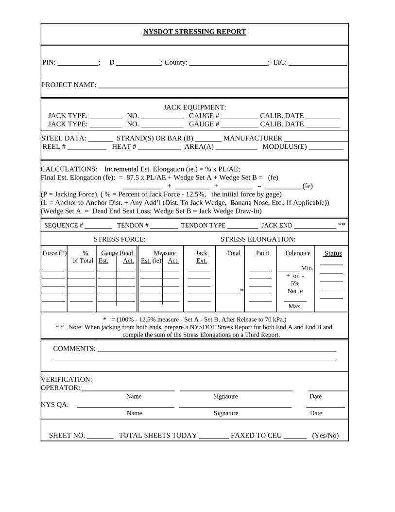
NYSDOT STRESSING REPORT
PIN: ; D ; County: ; EIC:
PROJECT NAME:
JACK EQUIPMENT:JACK TYPE: NO. GAUGE # CALIB. DATE JACK TYPE: NO. GAUGE # CALIB. DATE
STEEL DATA: STRAND(S) OR BAR (B) MANUFACTURER REEL # HEAT # AREA(A) MODULUS(E)
CALCULATIONS: Incremental Est. Elongation (ie.) = % x PL/AE; Final Est. Elongation (fe): = 87.5 x PL/AE + Wedge Set A + Wedge Set B = (fe) + + = (fe)(P = Jacking Force), ( % = Percent of Jack Force - 12.5%, the initial force by gage)(L = Anchor to Anchor Dist. + Any Add’l (Dist. To Jack Wedge, Banana Nose, Etc., If Applicable))(Wedge Set A = Dead End Seat Loss; Wedge Set B = Jack Wedge Draw-In)
SEQUENCE # TENDON # TENDON TYPE JACK END **
STRESS FORCE: STRESS ELONGATION:
Force (P)
% of Total
Gauge Read Est. Act.
MeasureEst. (ie) Act.
Jack Ext.
Total
*
Paint
Tolerance
Min.+ or -
5%Net e
Max.
Status
* = (100% - 12.5% measure - Set A - Set B, After Release to 70 kPa.)* * Note: When jacking from both ends, prepare a NYSDOT Stress Report for both End A and End B and
compile the sum of the Stress Elongations on a Third Report.
COMMENTS:
VERIFICATION:OPERATOR: Name Signature DateNYS QA: Name Signature Date
SHEET NO. TOTAL SHEETS TODAY FAXED TO CEU (Yes/No)

C-3September 21, 2000
APPENDIX CACCEPTANCE /SHIPPING REPORT AND NOTICE OF DEFECT
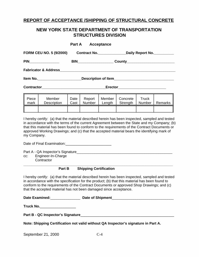
C-4September 21, 2000
REPORT OF ACCEPTANCE /SHIPPING OF STRUCTURAL CONCRETE
NEW YORK STATE DEPARTMENT OF TRANSPORTATION STRUCTURES DIVISION
Part A Acceptance
FORM CEU NO. 5 (9/2000) Contract No.______________Daily Report No.__________
PIN_______________ BIN__________________ County________________________
Fabricator & Address__________________________________________________________
Item No.______________________Description of Item______________________________
Contractor________________________________Erector________________________
Piecemark
MemberDescription
DateCast
ReportNumber
MemberLength
ConcreteStrength
TruckNumber Remarks
I hereby certify: (a) that the material described herein has been inspected, sampled and testedin accordance with the terms of the current Agreement between the State and my Company; (b)that this material has been found to conform to the requirements of the Contract Documents orapproved Working Drawings; and (c) that the accepted material bears the identifying mark ofmy Company.
Date of Final Examination:_______________________
Part A - QA Inspector’s Signature________________________________________________cc: Engineer-In-Charge
Contractor___________________________________________________________________________
Part B Shipping Certification
I hereby certify: (a) that the material described herein has been inspected, sampled and testedin accordance with the specification for the product; (b) that this material has been found toconform to the requirements of the Contract Documents or approved Shop Drawings; and (c)that the accepted material has not been damaged since acceptance.
Date Examined:_______________ Date of Shipment_______________________________
Truck No.__________________
Part B - QC Inspector’s Signature_______________________________________________
Note: Shipping Certification not valid without QA Inspector’s signature in Part A.
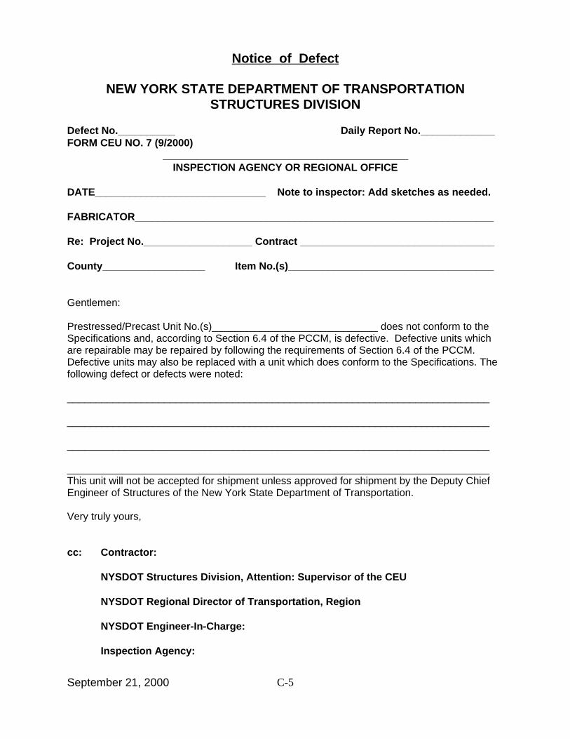
C-5September 21, 2000
Notice of Defect
NEW YORK STATE DEPARTMENT OF TRANSPORTATIONSTRUCTURES DIVISION
Defect No.__________ Daily Report No._____________ FORM CEU NO. 7 (9/2000)
___________________________________________INSPECTION AGENCY OR REGIONAL OFFICE
DATE______________________________ Note to inspector: Add sketches as needed.
FABRICATOR_______________________________________________________________
Re: Project No.___________________ Contract __________________________________
County__________________ Item No.(s)____________________________________
Gentlemen:
Prestressed/Precast Unit No.(s)_____________________________ does not conform to theSpecifications and, according to Section 6.4 of the PCCM, is defective. Defective units whichare repairable may be repaired by following the requirements of Section 6.4 of the PCCM.Defective units may also be replaced with a unit which does conform to the Specifications. Thefollowing defect or defects were noted:
__________________________________________________________________________
__________________________________________________________________________
__________________________________________________________________________
__________________________________________________________________________This unit will not be accepted for shipment unless approved for shipment by the Deputy ChiefEngineer of Structures of the New York State Department of Transportation.
Very truly yours,
cc: Contractor:
NYSDOT Structures Division, Attention: Supervisor of the CEU
NYSDOT Regional Director of Transportation, Region
NYSDOT Engineer-In-Charge:
Inspection Agency:
Related Documents


![NASHVILLE^ TENN] SATURDAY, DECEMBE 17R 1859,media2.sbhla.org.s3.amazonaws.com/tbarchive/1859/TB_1859_Dec_17.pdf... g tmr. Vasa kq^fa pccM »Me»i '.ttOm ... » ibr Fi-rcr sad. -i^ae.](https://static.cupdf.com/doc/110x72/5b1ab6587f8b9a46258dd16f/nashville-tenn-saturday-decembe-17r-1859-g-tmr-vasa-kqfa-pccm-mei.jpg)


