Revision: 1.04

Welcome message from author
This document is posted to help you gain knowledge. Please leave a comment to let me know what you think about it! Share it to your friends and learn new things together.
Transcript
Revision: 1.04

i
TABLE OF CONTENTS
REVISION HISTORY ................................................................................................2 REASONS USING DEVELOPMENT KIT...............................................................3
Ordering Options - Standard Configurations*.......................................................3 BLOCK DIAGRAM ....................................................................................................4 KEY FEATURES ........................................................................................................5
GENERAL INFORMATION.....................................................................................5 INFORMATION ON POWER...................................................................................6
CONFIGURATION AND INSTALLATION............................................................7 GPIO BIT MAPPING ....................................................................................................7 INTERFACE CONNECTORS ...........................................................................................8 LED LABEL AND INDICATOR ......................................................................................8 (SERIAL PORT HEADER ...............................................................................................9 SERIAL CONSOLE SETTINGS......................................................................................10
Precaution when using Serial Converter...................................................10 SERIAL CONVERTER PIN LAYOUTS ...........................................................................11 JTAG PORT HEADER ................................................................................................12 ETHERNET CONNECTORS ..........................................................................................13 HOW TO EXTEND ANTENNA ALIGNMENT TO CASE LED...........................................14
JTAG PROCESS .......................................................................................................15 BUILD AND INSTALL PROCESS (FOR OPENWRT FIRMWARE ON COMPEX MYLO LOADER)...................................................................................18 BUILD AND INSTALL PROCESS (FOR REDBOOT LOADER).......................21
STANDARD PLATFORM..............................................................................................21 Requirements....................................................................................................21 Unpacking and Build Process.......................................................................21 Installation..........................................................................................................24
APPENDIX I ..............................................................................................................28 BOARD FEATURES.....................................................................................................28 TOP SIDE OF BOARD............................................................................................29

WP543 2
REVISION HISTORY
Revision Information / Changes
Rev 1.0
First release for WP543 BareBoard
Rev 1.01 Added Build and Install Process (For OpenWRT Firmware On Compex Mylo Loader)
Rev 1.02
1. Change some information under Build and Install Process (For OpenWRT Firmware On Compex Mylo Loader)
- Compiling OpenWRT suitable for use on WP543 - Default Configurations
2. Change default miniPCI-slot
Rev 1.03 Added “How to JTAG Compex Loader”
Rev 1.04 Modify for WP543HV board
WP543 3
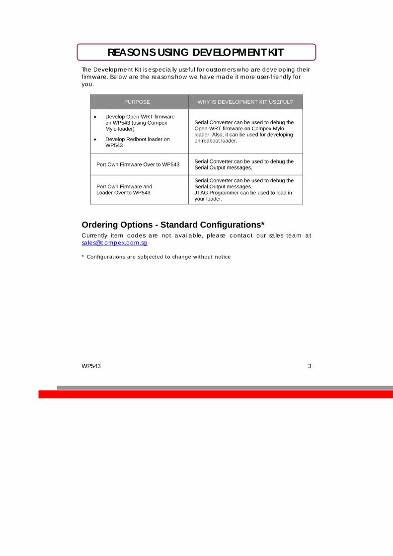
REASONS USING DEVELOPMENT KIT The Development Kit is especially useful for customers who are developing their firmware. Below are the reasons how we have made it more user-friendly for you.
PURPOSE WHY IS DEVELOPMENT KIT USEFUL?
• Develop Open-WRT firmware on WP543 (using Compex Mylo loader)
• Develop Redboot loader on WP543
Serial Converter can be used to debug the Open-WRT firmware on Compex Mylo loader. Also, it can be used for developing on redboot loader.
Port Own Firmware Over to WP543 Serial Converter can be used to debug the Serial Output messages.
Port Own Firmware and Loader Over to WP543
Serial Converter can be used to debug the Serial Output messages. JTAG Programmer can be used to load in your loader.
Ordering Options - Standard Configurations* Currently item codes are not available, please contact our sales team at [email protected] * Configurations are subjected to change without notice

WP543 4
BLOCK DIAGRAM

WP543 5
KEY FEATURES GENERAL INFORMATION
PROCESSOR Atheros AR71XX
MEMORY 32MB SDRAM (Up to 128MB max.)
NOR FLASH SPI Flash 4MB (Up to 16MB max.)
NAND FLASH NAND Flash 32MB (optional)
PHYSICAL PORTS
1 or 2 x Type III Mini-PCI Slots*
1 X 10/100 Base-TX Ethernet Port
(with Auto MDI/MDIX)
RADIO SUPPORTED 802.11b/g, 803.11a/b/g, 802.11nx
DEBUG INTERFACE
Serial (TTL) / JTAG (ARM-standard 20 pin )
Optional JTAG Programmer** available
Optional Serial Converter*** available
OPERATING TEMPERATURE -22°C to 55°C
LED INDICATORS 6 LEDs total:
• Power, Diagnostic, Connection, WLAN, LAN
OTHER FEATURES Push-Button Reset
Surge Arrestors (Optional)
DIMENSIONS 132mm x 130mm x 1.6mm
ENCLOSURE Directly mountable into Compex’s recommended WP, WPM or WPMA enclosure, with the need to separate mounting plates.
WP543 6
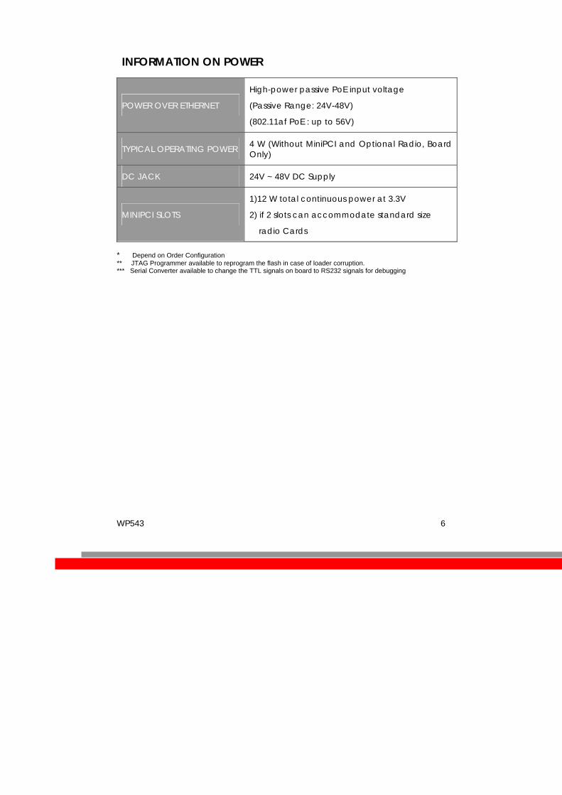
INFORMATION ON POWER
POWER OVER ETHERNET
High-power passive PoE input voltage
(Passive Range: 24V-48V)
(802.11af PoE : up to 56V)
TYPICAL OPERATING POWER 4 W (Without MiniPCI and Optional Radio, Board Only)
DC JACK 24V ~ 48V DC Supply
MINIPCI SLOTS
1)12 W total continuous power at 3.3V
2) if 2 slots can accommodate standard size
radio Cards
* Depend on Order Configuration ** JTAG Programmer available to reprogram the flash in case of loader corruption. *** Serial Converter available to change the TTL signals on board to RS232 signals for debugging
WP543 7
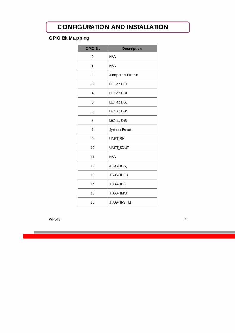
CONFIGURATION AND INSTALLATION GPIO Bit Mapping
GPIO Bit Description
0 N/A
1 N/A
2 Jumpstart Button
3 LED at DE1
4 LED at DS1
5 LED at DS3
6 LED at DS4
7 LED at DS5
8 System Reset
9 UART_SIN
10 UART_SOUT
11 N/A
12 JTAG(TCK)
13 JTAG(TDO)
14 JTAG(TDI)
15 JTAG(TMS)
16 JTAG(TRST_L)

WP543 8
Interface Connectors
The board interface connector pin assignments and signal descriptions are included in the following sections. The connectors are listed in the section below and the connector locations are shown in the following diagrams.
Connector Function
J5 Power Jack
P2 Ethernet Ports
J11 JTAG Port
J29/J30 MiniPCI Slot
J31 Serial Port
SW4 Reset Button
LED Label and Indicator
LED Label / Function
DS6 Power (Blue)
D24 Ethernet (Green)
DE1 Signal Strength Low (Red)
DS4 Signal Strength Higher-Low (Yellow)
DS3 Signal Strength Lower-High (Green)
DS5 Signal Strength High (Green)
DS5 Diagnostic (green)
DS1,DS2,DS7 Not Used
** based on Compex firmware

WP543 9
(Serial Port Header
The Serial Port (J31) Header signaling is shown in the following table.
Pin Signal
1 VCC – 3.3V
2 UART 0 Transmit Data
3 UART 0 Receive Data
4 GND
Note:
Our Serial port Implementation requires an external high-impedance serial port not usually available with the serial ports of the notebooks/computers. You will need a Serial Converter available in the market. For our customers’ convenience, it is bundled together with the board Development Kit.

WP543 10
Serial Console Settings
The serial console settings used together with the serial port is given below. This serial port uses TTL signals, and therefore you have to use serial converter using MAX-211 IC (or other IC in the market that convert TTL signals to RS232 signals) in order to use it with the PC.
Baud Rate 115200
Data 8 Bit
Parity None
Stop 1 Bit
Flow Control None
Precaution when using Serial Converter
Please attach the serial converter first on the board serial header, before attaching the power supply. This is to ensure that there is no surge of power to the serial converter, and prevent any damage the chipset on the serial converter.

WP543 11
Serial Converter Pin Layouts
Cables on the serial converters are provided. You can use the 6 Pin (Fixed) to 4 Pin (Fixed) provided. The pin layouts of the serial converters for use with the board are as follows:
Pin Assignment (Serial Converters)
Signal (Serial Converters)
Connected to Pin on WP543
Signal (WP543)
Pin 1 VCC(3.3V) – Red Pin 1 VCC (3.3V)
Pin 2 TX – Blue Pin 3 RX
Pin 4 RX - Green Pin 2 TX
Pin 6 GND – Black Pin 4 GND
Arrangement of Cables on Serial Converter to the board
Arrangement of Cables on the board itself
WP543 12
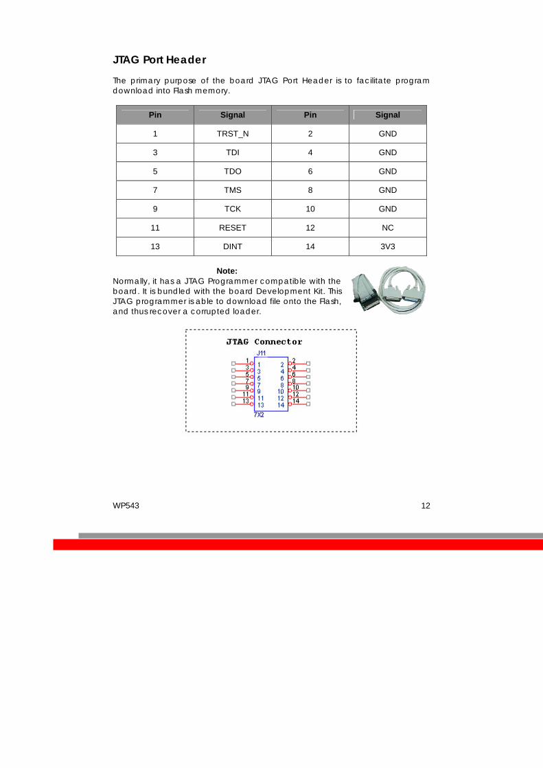
JTAG Port Header
The primary purpose of the board JTAG Port Header is to facilitate program download into Flash memory.
Pin Signal Pin Signal
1 TRST_N 2 GND
3 TDI 4 GND
5 TDO 6 GND
7 TMS 8 GND
9 TCK 10 GND
11 RESET 12 NC
13 DINT 14 3V3
Note:
Normally, it has a JTAG Programmer compatible with the board. It is bundled with the board Development Kit. This JTAG programmer is able to download file onto the Flash, and thus recover a corrupted loader.

WP543 13
Ethernet Connectors
The board contains 1 X 10/100 Base-TX Ethernet Channels. The Ethernet Channels are available through standard 8-pin RJ45 connectors. Ethernet Connectors(J6) signaling is shown below.
Pin Signal
1 TX+
2 TX-
3 RX+
4 PoE+V
5 PoE+V
6 RX-
7 GND
8 GND
WP543 14
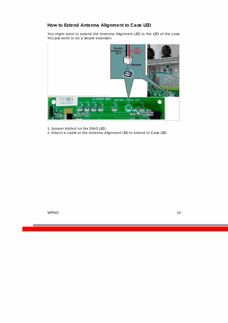
How to Extend Antenna Alignment to Case LED
You might want to extend the Antenna Alignment LED to the LED of the case. You just need to do a simple extension.
1. Jumper Added on the DIAG LED. 2. Attach a cable to the Antenna Alignment LED to extend to Case LED

WP543 15
JTAG Process Instructions reference writing a Compex loader Minimum Requirement 1. OCD Commander ver2.5.4 2. upbios.tst file (same for all Compex device) 3. zMylo.bin file(different device have different zMylo.bin) 4. JTAG cable Steps 1. Install the OCD Commander to your PC 2. Plug the JTAG cable to the JTAG port of the device 3. Run OCD Commander Program Set "Target Processor" for the particular device eg. WP543 boards select MIPS, Click "OK" 4.If there is this error message “Error Response from INITIALIZE....”, please check
the JTAG cable connection. Close the OCD Commander Program and go back to Step 3.
WP543 16
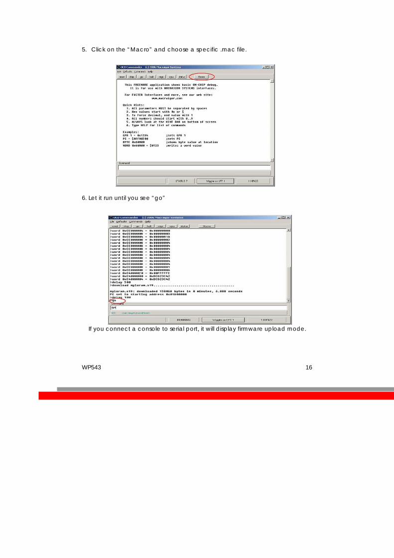
5. Click on the “Macro” and choose a specific .mac file.
6. Let it run until you see “go”
If you connect a console to serial port, it will display firmware upload mode.

WP543 17
7. From a computer, open a DOS command prompt 8. run, tftp upbios.tst
9. then run, tftp zMylo.bin (please observe the DIAG LED is off)
10. If either step 9 or step 10 fail, please start from step 3 again.
11. Power off the device and unplug JTAG cable
12. Power on the device and tftp the firmware into the device.
13. Reboot when done.
WP543 18
Build and Install Process (For OpenWRT firmware on Compex Mylo Loader)
Minimun Requirement 1. Compex loader version 2.54 or above. 2. OpenWRT will only be supported on WP543 with 4MB NOR flash and above. 3. Please ensure that the Ethernet connection is able to ping address =
192.168.168.1 4. If there is a USB NAND flash available on board, you would need to change
the loader configuration. Please refer to “what to do if there is a onboard NAND Flash”.
Compiling OpenWRT suitable for use on WP543 1. Getting source codes
>svn co –r 12448 https://snv.openwrt.org/openwrt/trunk
2. Apply patches from the files mod-wp543.tgz >tar zxvf mod-wp543.tgz >cp –a mod-wp543/* trunk/
3. Compile >cd trunk >cp wp543.config .config >make
OpenWRT Firmware will be in bin/openwrt-ar71xx-wp543.bin Uploading the OpenWRT firmware to WP543 running MyLoader v2.54.0717 a. Via Compex Firmware
- Put the AP in Firmware Upgrade mode and upload the file. - This file is for WP543 with 4MB or 8MB NOR flash.
b. Via TFTP - Go to the firmware upgrade mode (By pressing and hold the Reset
button and plug-in the power adapter). - Upload the OpenWRT image to the device (tftp –i 192.168.168.1 put
openwrt-ar71xx-wp543.bin) First run of OpenWRT • For customers with Serial console

WP543 19
During first run after flashing the firmware, do not power off the AP until the following messages appear: jffs2_scan_eraseblock(): End of filesystem marker found at 0x0 jffs2_build_filesystem(): unlocking the mtd device… done. jffs2_build_filesystem(): erasing all blocks after the end marker… done.
• For customers without Serial console If you do not have console, just wait for 5 minutes.
Completion Reboot the AP. Start using OpenWRT by telnet to default IP and you will see the picture shows below. > Telnet 192.168.1.1 > The picture shows below will appear if you are successful.
What to do if there is a onboard USB Flash If there is onboard USB flash, you would need to use the serial converter, enter the loader mode, by pressing, please configure the Loader to use NOR-Flash, i.e. “9 – USB Flash” “3 – Boot Device” “2 – Onboard NOR-Flash” Default Configurations LAN (bridge eth0+ath0): IP Address: 192.168.1.1 Wireless (ath0): Driver: madwifi Mode: ap ESSID: OpenWRT IP Address: 192.168.2.1

WP543 20
Please refer to http://madwifi.org/ for more information. Use of Compex Patches 1. MAC Address from loader 2. Can detect that it is a Compex board 3. Enable USB

WP543 21
Build and Install Process (For Redboot Loader)
Note: Wireless drivers NOT in SDK Note that in Compex WP543 SDK, redboot loader binaries are provided as part of the
SDK, which is only given to customers who have signed NDA/TLA with Compex
Standard Platform
Requirements
The main requirement for building the standard distribution is having a Linux based development platform with at least 1 GByte of free disk space, and a working GCC compiler tool chain. These procedures have been tested on a Fedora Core 8 machine, and on older machines with Fedora Core 4. The distribution contains all tools required to build the bootloader, kernel, and jffs2 image to be loaded onto the flash. Further, a tftp server is required, preferably on the development platform. This server is used by the reference platform to download all file images required.
Unpacking and Build Process
For WP543(NOR) Flash only, WP543-sdk-NOR-rel.tar is provided., where “rel” is the combination of board and release, such as “WP543-sdk-NOR-V1.0.tar”. The SDK file contains all of the files associated with the BSP, Kernel distribution, applications provided, build tool source, and the build system. This file can be used if the user is building for another system, and is not interested in the BSP, build tools, etc. for the WP543. Select a directory to open the build into, and use the following procedure. This procedure assumes that “athbuild” is the directory to unpack into, and that the SDK files are located in the directory immediately above. Modify the procedure according to your configuration:
#cd athbuild #tar –xzvf ../ WP543-sdk-NOR-V1.0.tar (large number of files unpack) #tar –xzvf ../ WP543-sdk-NOR-V1.0.tar (smaller number of files unpack).

WP543 22
When the source files are unpacked, the build process can begin. The build directory contains the make file for building all components required. The source distribution will contain the required files for the build of your choice. The build system will create two new directories: images and rootfs.build. The images directory will receive the final output of the build process that is used to update the platform board. The redboot images, the Linux kernel image in compressed format, and the jffs2 filesystem are all copied into this directory, under the subdirectory for the specific reference platform. The rootfs.build directory is used as an install target to create the jffs2 filesystem. All components that are build are installed into this directory, and the final step is to run mkfs.jffs2 on this directory to create the filesystem image. To do a full system build, use the following procedure:
#cd build # make BOARD_TYPE=board
where board is the specific board type of your reference platform, WP543. This will generate a full build of all components, and the cross tools required to build for the reference platform. Note that on subsequent builds the tools will NOT be rebuilt (this is a long process, the first build can take well over an hour). After a full build is performed, components can be rebuild as required. To build a specific component, you will use the command:
# make target BOARD_TYPE=board
where target is the specific target of choice. If you are unsure if the rootfs.build directory is properly populated, run the full build to erase and recreate the image. The following table outlines the main targets available.

WP543 23
Target Builds
fusion_build Rebuilds all driver files, and regenerates the module .ko files. Copies new files into the rootfs.build directory. This will also rebuild the jffs2 filesystem.
busybox_build Rebuilds the busybox component, and installs into the rootfs.build directory.
hostapd_fus Rebuilds the hostapd application provided to support WPA encryption. Installs into rootfs.build directory.
toolchain_build Rebuilds the gcc cross build tools provided. These are left in the build area, and are not put into the rootfs.build system
redboot_fusion Rebuilds the redboot bootloader, and copies the image into the images directory.
enet_build Rebuilds the Ethernet driver, and copies the ar7100.ko module into the rootfs.build directory.
kernel_build Rebuilds the Linux kernel. The result is copied to the images directory
fus_supplicant Rebuilds the WPA supplicant application provided, and installs into the rootfs.build.

WP543 24
Installation
To perform a software update on the system, the following are required • WP543 board • A serial converter • A server system with a tftp server • A terminal system with terminal emulation software, such as hyperterm or
Minicom • An Ethernet cable between the server system and the WP543 Connect the Ethernet ports on the server system and the Ethernet port. Connect the serial cable between the Terminal system and the AP, using the serial converter. (Refer to “Serial Port Header” section, pg 8)
A) Boot Monitor Update (with Compex Bootloader)
This procedure is provided to update the Compex loader to redboot loader. The source code for redboot is included. Redboot.rom is also included in the SDK.
WARNING Incorrect implementation of this procedure can cause board failure due to erasing the boot monitor from the Flash. If
this occurs, the board will have to be reloaded via download from an EJTAG
emulator. (Please refer to JTAG Port Header Section)
WP543 25
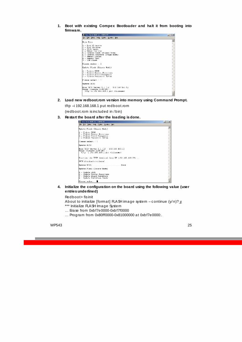
1. Boot with existing Compex Bootloader and halt it from booting into firmware.
2. Load new redboot.rom version into memory using Command Prompt.
tftp –i 192.168.168.1 put redboot.rom (redboot.rom is included in /bin)
3. Restart the board after the loading is done.
4. Initialize the configuration on the board using the following value (user
entries underlined) Redboot> fis init About to initialize [format] FLASH image system – continue (y/n)? y *** Initialize FLASH Image System … Erase from 0xbf7e0000-0xbf7f0000 … Program from 0x80ff0000-0x81000000 at 0xbf7e0000:.

WP543 26
B) i)Boot Monitor Update (with Existing Redboot)
This procedure is provided to update the boot monitor with a newer version that is generated. Note that the source code for the boot monitor is included in your distribution.
WARNING Incorrect implementation of this procedure can cause board failure due to erasing the boot monitor from the Flash. If
this occurs, the board will have to be reloaded via download from an EJTAG
emulator. (Please refer to JTAG Port Header Section)
1. Boot with existing Redboot and halt it from booting into Linux.
2. Load new redboot.rom version into memory.
RedBoot> load -r -v -b 0x80500000 redboot.rom -h <tftp server ip addr>
3. Write redboot to flash
Redboot> fis write -b 0x80500000 -f 0xbf000000 -l 0x40000
4. Reboot the board with new Redboot and break into the monitor with <ctrl-c> before booting Linux
Redboot> reset
5. Now reformat the flash with new redboot running.
Redboot> fis init -f
6. Initialize the configuration on the board using the following values (user entries underlined)
RedBoot> fconfig –i Initialize non-volatile configuration - continue (y/n)? y Run script at boot: true Boot script: Enter script, terminate with empty line >> fis load -d vmlinux >> exec >> Boot script timeout (1000ms resolution): 3 Use BOOTP for network configuration: false Gateway IP address: Local IP address: <Your IP address>

WP543 27
Local IP address mask: <Your required netmask> Default server IP address: <TFTP server IP address> Console baud rate: 115200 GDB connection port: 9000 Force console for special debug messages: false Network debug at boot time: false Update RedBoot non-volatile configuration - continue (y/n)? y ... Erase from 0xbf7e0000-0xbf7f0000: . ... Program from 0x80ff0000-0x81000000 at 0xbf7e0000: .
Since this procedure erases the flash device, you will also have to perform the software update process in the following section. This is the normal process used to update the driver or kernel when changes are made.
ii) Kernel/Driver Update
The Kernel and Driver image update is performed using the Red Boot boot monitor, commands through the serial console, and tftp file transfers. This procedure must be performed after doing a redboot update as described in the preceding section.
1. Power up the board, and hit <ctrl-c> to break into monitor
2. Load with new linux image.
Redboot> load -r -v -b 0x80500000 vmlinux.bin.gz -h <tftp server ip> Redboot> fis create -b 0x80500000 -e 0x80256000 -r 0x80060000 -l 0x100000 vmlinux
3. Load new jffs2 filesystem
Redboot> load -r -v -b 0x80500000 pb42fus-jffs2 -h <tftp server ip> Redboot> fis create -b 0x80500000 -e 0x0 -l 0x600000 filesystem
4. Reset the board. Board will now boot up into Linux.
iii) Board Startup
Once the redboot is loaded.
1. Power on the board and wait for Linux to boot.
Note that Redboot is configured to automatically boot into Linux.
2. Log into the board
User: root Password: 5up

WP543 28
Appendix I
Board Features

WP543 29
TOP SIDE OF BOARD
No: Feature Descriptions
1 Ethernet cum PoE port 10/100Mbps Ethernet port and 803.11af PoE (48V)
2 DC Jack 24V – 48V DC Supply
3 Reset button For board reset and startup mode control
4 JTAG port JTAG jumper header for programming
5 Serial port Serial port connection header
6 mini-PCI slot 1 9.2mm high Type IIIB mini-PCI slots
- -
Related Documents