12MM OPERATION MANUAL | SPARE PARTS LIST PC1000 POLYCHEM CORPORATION 6277 HEISLEY ROAD, MENTOR, OHIO 44060 PHONE: 440.357.1500, FAX: 440.352.9553 WWW.POLYCHEM.COM

Welcome message from author
This document is posted to help you gain knowledge. Please leave a comment to let me know what you think about it! Share it to your friends and learn new things together.
Transcript
12MM
OPERATION MANUAL | SPARE PARTS LISTPC1000
POLYCHEM CORPORATION6277 HEISLEY ROAD, MENTOR, OHIO 44060
PHONE: 440.357.1500, FAX: 440.352.9553WWW.POLYCHEM.COM
CONTENTS
PART I
1 General Safety Instructions ................................................................ A1
1.1 Basic Operation......................................................................... A1
1.2 Basic Safety Precautions ........................................................... A1
1.3 Safety Instructions Governing Specific Operational Phases..... A2
1.4 Warning of Electrical Dangers .................................................. A3
1.5 Grounding Instructions Shall Include the Following ................ A3
1.6 Before Operating....................................................................... A4
1.7 During Operation ...................................................................... A4
1.8 After Operating ......................................................................... A4
1.9 Signs and Symbols .................................................................... A5
2 Machine Information ......................................................................... A6
2.1 Areas of Application ................................................................. A6
2.2 Environment Information.......................................................... A6
2.3 Storage ...................................................................................... A7
2.4 Machine Description ................................................................. A7
2.5 Safety Devices........................................................................... A8
2.6 Technical Specification ............................................................. A9 3 Preparation Before Operating the Machine.......................................A11
3.1 Shipping ...................................................................................A11
3.2 Transportation & Centre of Gravity .........................................A11
3.3 Construction Layout................................................................ A12
3.4 Installation............................................................................... A13
3.5 Operation Space ...................................................................... A14
3.6 Operating Elements................................................................. A15
3.7 Instructions for Loading PP Strap ........................................... A17
3.8 Auto Strap Feeding Process .................................................... A19 4. Operating the Machine..................................................................... A21
4.1 Soft Tension Operation ........................................................... A21
4.2 High Tension Operation.......................................................... A21
4.3 Function Encoder .................................................................... A22
5. Adjustments ..................................................................................... A23
5.1 Strap Amount in the Accumulator Box ................................... A23
5.2 Adjustment for Feeding Pressure to the Accumulator Box..... A24
5.3 Adjustment for Heater Temperature........................................ A25
5.4 Some adjustments for straps ................................................... A25
5.5 Adjustment for Feeding/Reversing Pressure........................... A27
5.6 Adjustment on Tensioning Rollers for High Tension.............. A29
6. Troubleshooting ............................................................................... A30
6.1 LCD Display ........................................................................... A30
7. Maintenance ..................................................................................... A32
PART II
1. Wiring Diagram ……………………………………………………..B1
PART III
1. Strapping Head Unit ………………………...………………………C1
2. Bandway Unit ……………………………………………..……….C43
3. Accumulator Unit ………………………………………………….C63
4. Reel Control Group ………………………………………………..C85
5. Body Frame Unit …………………………………………………..C95
6. Electric Control Unit …………………………………………..….C133

PART I
-A1-
1 General Safety Instructions
1.1 Basic Operation
Read the operation and safety manual prior to using the strapping machine.
The operation and safety manual should remain attached to the machine at all times.
The machine may only be operated in accordance with its designated use.
The strapping machine was built in accordance with state-of-the-art standards and recognized safety rules. Nevertheless, improper use can still result in injury to personnel or damage to the machine and other material property.
Machine shall only be operated by trained personnel. Perform inspections and maintenance at regular intervals. Refer to the Maintenance
section of the manual. The machine may not be put in operation before checking the respective devices. Safety devices must never be bridged or eliminated by any means. To transport the equipment only use lifting apparatus and loading devices with sufficient
capacity. Always disconnect from external power supply when changing the location of the
machine, even if the location should only be slightly changed. Connect power supply properly before returning to service.
Do not alter or bypass protective interlocks. Do not alter circuits and machine unless authorized to do so by the manufacturer.
1.2 Basic Safety Precautions
In addition to the instructions for operation, the user is to be instructed in all generally applicable legal or mandatory regulations relevant to safety or the environment.
Long hair, loose-fitting garments, or jewelry can be a safety hazard. These items must be secured prior to equipment operation.
Use protective equipment whenever appropriate or when required by law.
Carefully observe all safety instructions and warnings attached to the machine. Keep safety labels clean and legible.
People that are being trained to operate or service the equipment must be supervised by experienced personnel.
Any electrical work performed on the equipment must be conducted by a skilled electrician or under the supervision of a skilled electrician. All work must be observed good electrical engineering practice and follow safety rules and local wiring standards.
-A2-
1.3 Safety Instructions Governing Specific Operational Phases
Avoid unsafe operation of the equipment.
The machine is only to be operated when it is in good running order. Only operate the equipment in a safe manner; all protective and safety devices must be in place and fully functional. This includes removable safety devices, emergency shut-off equipment, noise-protection devices and exhaust fans.
The machine is to be checked for damage and defects at least once each work shift. Any changes, including the working behavior of the machine, are to be reported immediately. If necessary, the machine is to be stopped and locked-out immediately.
In case of a malfunction, the strapping machine is to be immediately stopped and locked-out until the fault has been eliminated.
Before starting the strapping machine, make sure that the area is clear and safe.
Do not place any tools or parts onto the machine.
Operating personnel needs to be well trained before executing special operations and maintenance work; this work needs to be done with the proper supervision.
Always check and tighten connections after maintenance or repair.
After completing maintenance or repair, all safety devices must be replaced and checked for functionality before operating the equipment.
To minimize the environmental impact, all consumables and replaced parts must be disposed of safely.
Before starting the machine, check that the accessories have been stowed away safely.
Avoid operating the machine in a fashion that could upset its stability.
-A3-
1.4 Warning of Electrical Dangers
Immediately remove power to the machine in case of trouble in the electrical system. Replace a fuse with one with the same style and ratings; pay particular attention to matching the specified current.
Any electrical work performed on the equipment must be conducted by a skilled electrician or under the supervision of a skilled electrician. All work must be observed good electrical engineering practice and follow safety rules and local wiring standards.
Inspect the electrical equipment of the machine at regular intervals. Tighten any loose connections. Check wiring for scorch marks; replace scorched wiring and determine and correct the reason for the overheating.
When working on live equipment, ensure that a second person is available to cut power in case of an emergency. When appropriate, secure the working area with safety tape and a warning sign. Use insulated tools for electrical work.
Before working on high-voltage assemblies, turn off the power supply. Carefully discharge the supply cable and short-circuit any energy-storage components such as capacitors.
If the equipment was moved, carefully refit and refasten all parts removed for transport before reapplying power.
Before moving the machine, remember to disconnect the power cable.
1.5 Grounding Instructions Shall Include the Following
This product must be grounded. In the event of an electrical short circuit, grounding reduces the risk of electric shock. This product is equipped with a cord that has a grounding wire and an appropriate grounding plug. The plug must be plugged into an outlet that is properly installed and grounded in accordance with all local codes and ordinances.
If repair or replacement of the cord or plug is necessary, connect the ground wire to the ground terminal of the plug. The wire with green insulation (with or without yellow stripes) is the grounding wire.
Check with a qualified electrician or service person if the grounding instructions are not clear or if in doubt about the proper grounding of the machine. Do not modify the plug provided; if it will not fit the power outlet, have the proper outlet installed by a qualified electrician.
DANGER!
Improper installation of the grounding can result in electrocution.
-A4-
1.6 Before Operating
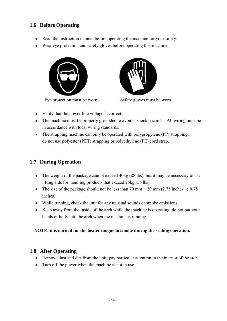
Read the instruction manual before operating the machine for your safety. Wear eye protection and safety gloves before operating this machine.
Eye protection must be worn Safety gloves must be worn
Verify that the power line voltage is correct. The machine must be properly grounded to avoid a shock hazard. All wiring must be
in accordance with local wiring standards. The strapping machine can only be operated with polypropylene (PP) strapping;
do not use polyester (PET) strapping or polyethylene (PE) cord strap. 1.7 During Operation
The weight of the package cannot exceed 40kg (88 lbs), but it may be necessary to use
lifting aids for handling products that exceed 25kg (55 lbs). The size of the package should not be less than 70 mm × 20 mm (2.75 inches × 0.75
inches). While running, check the unit for any unusual sounds or smoke emissions. Keep away from the inside of the arch while the machine is operating; do not put your
hands or body into the arch when the machine is running.
NOTE: it is normal for the heater tongue to smoke during the sealing operation.
1.8 After Operating
Remove dust and dirt from the unit; pay particular attention to the interior of the arch. Turn off the power when the machine is not in use.
-A5-
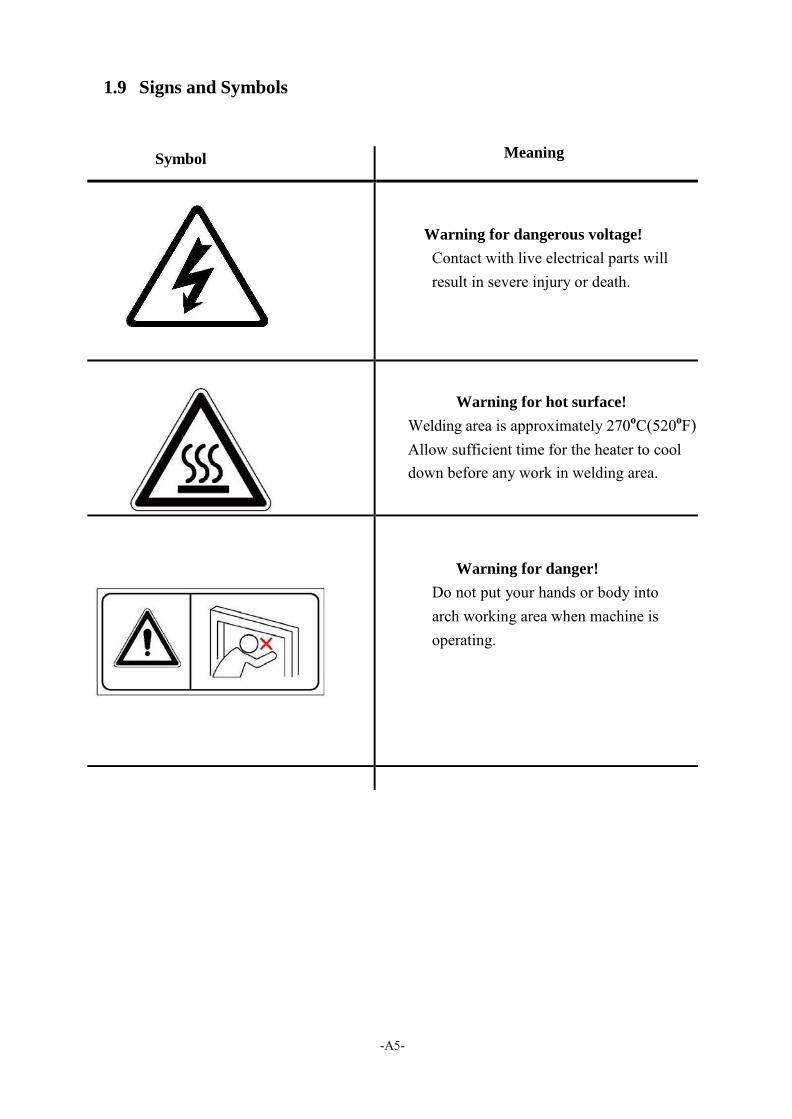
1.9 Signs and Symbols
Symbol Meaning
Warning for dangerous voltage!
Contact with live electrical parts will result in severe injury or death.
Warning for hot surface!
Welding area is approximately 270oC(520oF) Allow sufficient time for the heater to cool down before any work in welding area.
Warning for danger!
Do not put your hands or body into arch working area when machine is operating.
-A6-
2 Machine Information
2.1 Areas of Application
The strapping machine is to be used for strapping packages, cartons, paper boxes, newspapers, magazines and those materials using a polypropylene (PP) strapping for stabilizing purposes when in transportation. Be careful for rigidity of working materials, and don‟t try to pack agri-foodstuffs or other such material.
This machine was designed for certain applications only. We strongly recommend that this machine NOT be modified and/or used for any application other than for which it was designed. If you have any questions relative to its application DO NOT use the machine until you have had detail instruction from your dealer.
2.2 Environment Information
The strapping machine shall be installed in the following conditions:
Supply voltage: 0.9 - 1.1 nominal supply voltage Source frequency: 0.99 - 1.01 nominal frequency Ambient temperature: 5°C - 40°C (41℉-104℉).
Altitude: shall be at altitudes up to 1000m above mean sea level. Relative humidity: not exceed 50% at 40°C. Atmosphere: Free from excessive dust, acid fume, corrosive gases and salt. Avoid exposing to abnormal vibration. Don't use machine in dangerous environment. Don't use machines in damp or wet locations, or expose them to rain. Please provide a suitable illumination around the machine for safety operation. Work place of user should have a fire extinguisher or other devices that meet their local
safety regulations, and always be careful. Internal parts requiring frequent inspection and adjustment, and maintenance areas must
be provided with a suitable illumination around the machine.
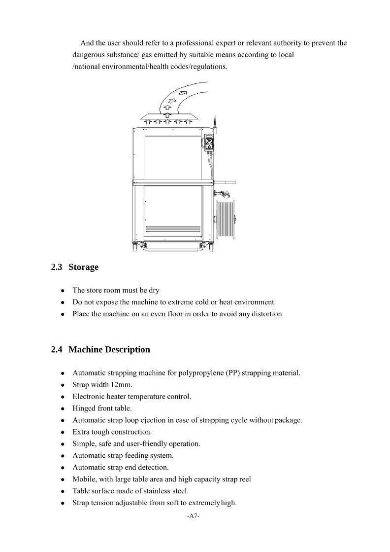
If there may be harmful gases, fumes or dust generated during heating, user or system integrator must install exhaust system for the extraction of harmful substances.
The exhaust system shall be positioned according to the vent location. Please refer to the figure.
-A7-
And the user should refer to a professional expert or relevant authority to prevent the dangerous substance/ gas emitted by suitable means according to local /national environmental/health codes/regulations.
2.3 Storage
The store room must be dry Do not expose the machine to extreme cold or heat environment Place the machine on an even floor in order to avoid any distortion
2.4 Machine Description
Automatic strapping machine for polypropylene (PP) strapping material. Strap width 12mm. Electronic heater temperature control. Hinged front table. Automatic strap loop ejection in case of strapping cycle without package. Extra tough construction. Simple, safe and user-friendly operation. Automatic strap feeding system. Automatic strap end detection. Mobile, with large table area and high capacity strap reel Table surface made of stainless steel. Strap tension adjustable from soft to extremely high.
-A8-
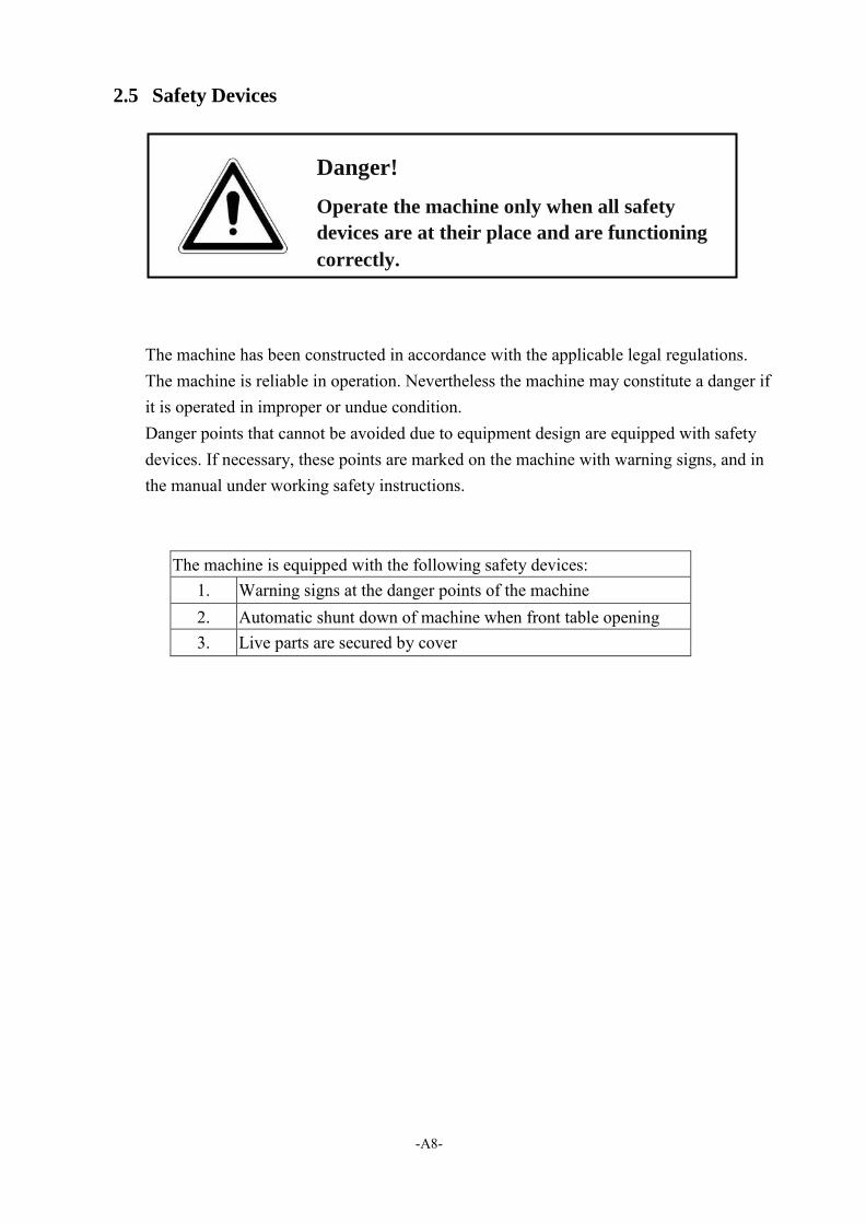
2.5 Safety Devices
The machine has been constructed in accordance with the applicable legal regulations. The machine is reliable in operation. Nevertheless the machine may constitute a danger if it is operated in improper or undue condition. Danger points that cannot be avoided due to equipment design are equipped with safety devices. If necessary, these points are marked on the machine with warning signs, and in the manual under working safety instructions.
The machine is equipped with the following safety devices: 1. Warning signs at the danger points of the machine 2. Automatic shunt down of machine when front table opening 3. Live parts are secured by cover
Danger!
Operate the machine only when all safety
devices are at their place and are functioning
correctly.
-A9-
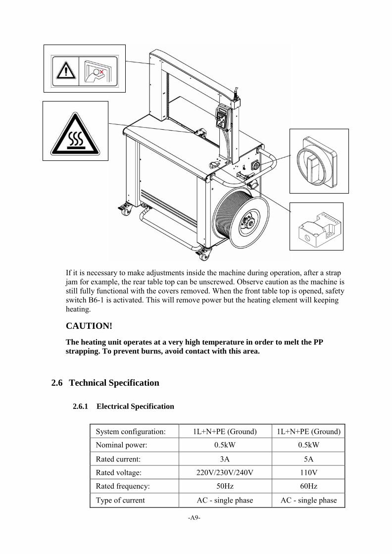
If it is necessary to make adjustments inside the machine during operation, after a strap jam for example, the rear table top can be unscrewed. Observe caution as the machine is still fully functional with the covers removed. When the front table top is opened, safety switch B6-1 is activated. This will remove power but the heating element will keeping heating.
CAUTION!
The heating unit operates at a very high temperature in order to melt the PP
strapping. To prevent burns, avoid contact with this area.
2.6 Technical Specification
2.6.1 Electrical Specification
System configuration: 1L+N+PE (Ground) 1L+N+PE (Ground)
Nominal power: 0.5kW 0.5kW
Rated current: 3A 5A
Rated voltage: 220V/230V/240V 110V
Rated frequency: 50Hz 60Hz
Type of current AC - single phase AC - single phase
-A10-
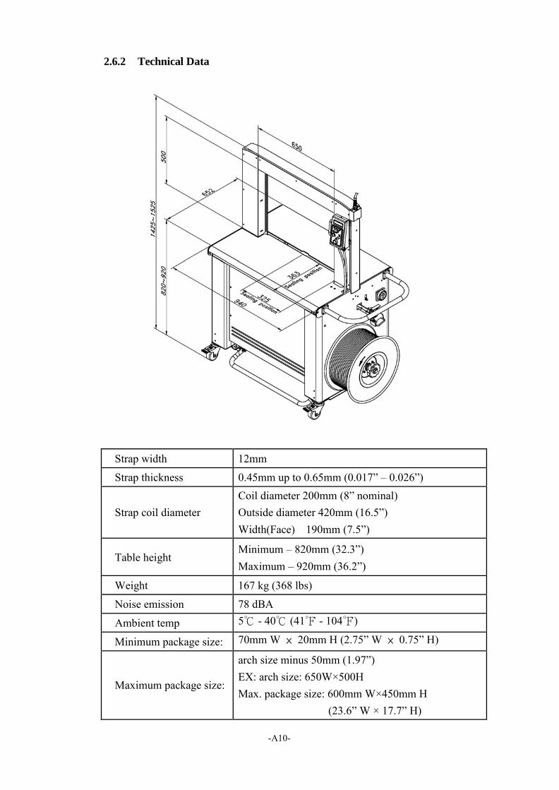
2.6.2 Technical Data
Strap width 12mm
Strap thickness 0.45mm up to 0.65mm (0.017” – 0.026”)
Strap coil diameter
Coil diameter 200mm (8” nominal) Outside diameter 420mm (16.5”) Width(Face) 190mm (7.5”)
Table height Minimum – 820mm (32.3”) Maximum – 920mm (36.2”)
Weight 167 kg (368 lbs)
Noise emission 78 dBA
Ambient temp 5℃ - 40℃ (41℉ - 104℉)
Minimum package size: 70mm W × 20mm H (2.75” W × 0.75” H)
Maximum package size:
arch size minus 50mm (1.97”) EX: arch size: 650W×500H Max. package size: 600mm W×450mm H
(23.6” W × 17.7” H)
-A11-
3 Preparation Before Operating the Machine
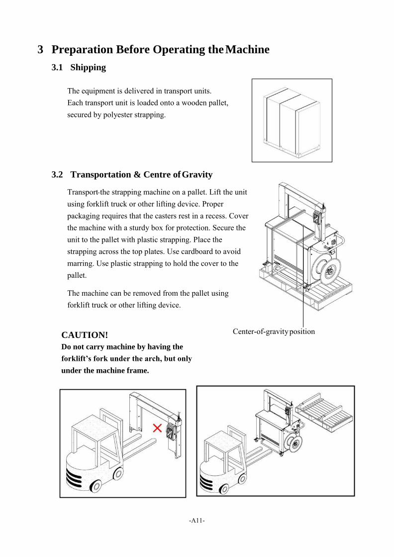
3.1 Shipping
The equipment is delivered in transport units. Each transport unit is loaded onto a wooden pallet, secured by polyester strapping.
3.2 Transportation & Centre of Gravity
Transport the strapping machine on a pallet. Lift the unit using forklift truck or other lifting device. Proper packaging requires that the casters rest in a recess. Cover the machine with a sturdy box for protection. Secure the unit to the pallet with plastic strapping. Place the strapping across the top plates. Use cardboard to avoid marring. Use plastic strapping to hold the cover to the pallet.
The machine can be removed from the pallet using forklift truck or other lifting device.
CAUTION! Center-of-gravity position
Do not carry machine by having the
forklift’s fork under the arch, but only
under the machine frame.
-A12-
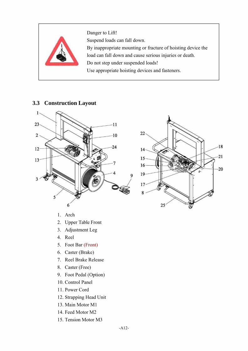
3.3 Construction Layout
1. Arch 2. Upper Table Front 3. Adjustment Leg 4. Reel 5. Foot Bar (Front) 6. Caster (Brake) 7. Reel Brake Release 8. Caster (Free) 9. Foot Pedal (Option) 10. Control Panel 11. Power Cord 12. Strapping Head Unit 13. Main Motor M1 14. Feed Motor M2 15. Tension Motor M3
Danger to Lift! Suspend loads can fall down. By inappropriate mounting or fracture of hoisting device the load can fall down and cause serious injuries or death. Do not step under suspended loads! Use appropriate hoisting devices and fasteners.
-A13-
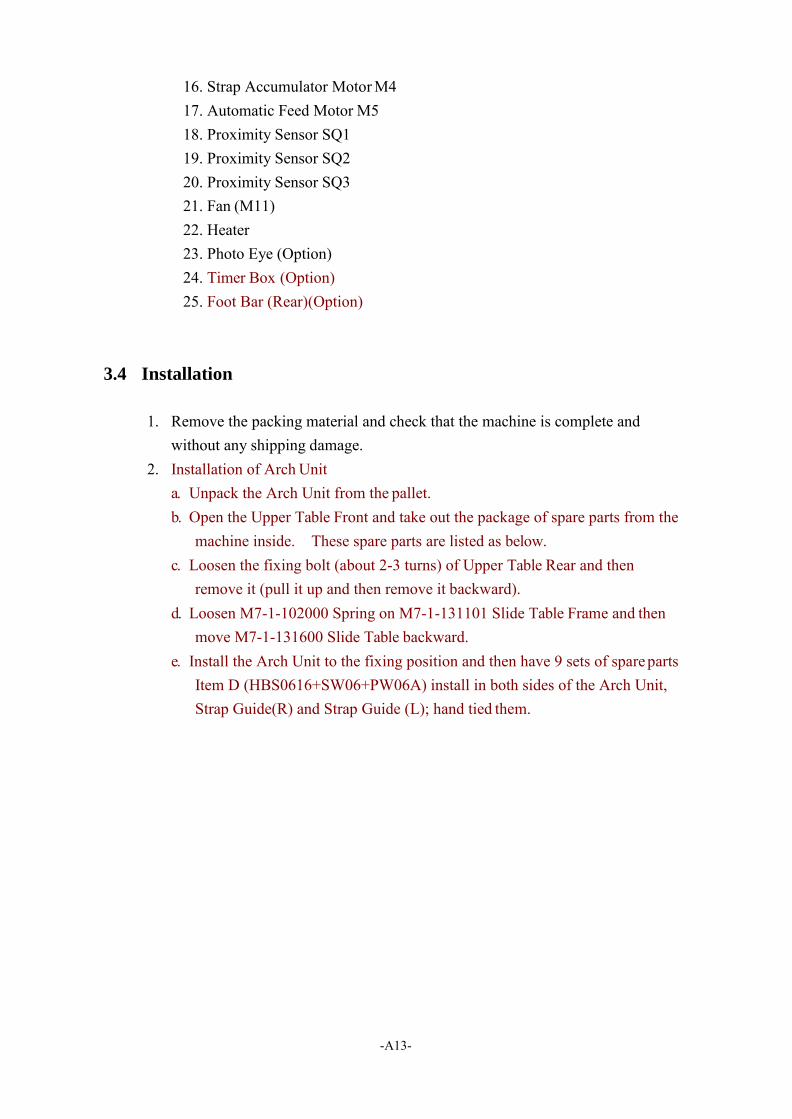
16. Strap Accumulator Motor M4 17. Automatic Feed Motor M5 18. Proximity Sensor SQ1 19. Proximity Sensor SQ2 20. Proximity Sensor SQ3 21. Fan (M11) 22. Heater 23. Photo Eye (Option) 24. Timer Box (Option) 25. Foot Bar (Rear)(Option)
3.4 Installation
1. Remove the packing material and check that the machine is complete and
without any shipping damage. 2. Installation of Arch Unit
a. Unpack the Arch Unit from the pallet. b. Open the Upper Table Front and take out the package of spare parts from the
machine inside. These spare parts are listed as below. c. Loosen the fixing bolt (about 2-3 turns) of Upper Table Rear and then
remove it (pull it up and then remove it backward). d. Loosen M7-1-102000 Spring on M7-1-131101 Slide Table Frame and then
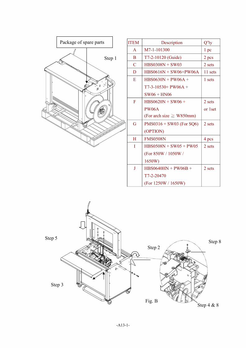
move M7-1-131600 Slide Table backward. e. Install the Arch Unit to the fixing position and then have 9 sets of spare parts
Item D (HBS0616+SW06+PW06A) install in both sides of the Arch Unit, Strap Guide(R) and Strap Guide (L); hand tied them.
-A13-1-
Step 5
Step 2
Step 8
Step 3
Fig. B Step 4 & 8
Step 1
Package of spare parts ITEM Description Q‟ty M7-1-101300 1 pc
T7-2-10120 (Guide) 2 pcs HBS0308N + SW03 2 sets HBS0616N + SW06+PW06A 11 sets
HBS0630N + PW06A + T7-3-10530+ PW06A + SW06 + HN06
1 sets
HBS0620N + SW06 + PW06A (For arch size ≧ W850mm)
2 sets or 1set
PMS0316 + SW03 (For SQ6) (OPTION)
2 sets
FMS0508N 4 pcs HBS0508N + SW05 + PW05
(For 850W / 1050W /
1650W)
2 sets
HBS0640HN + PW06B + T7-2-20470 (For 1250W / 1650W)
2 sets
-A13-2-
For 1250W/1650W
Step 9
Step 11
Step 10 Fig. D
For 1050W/1650W
Fig. E Fig. F
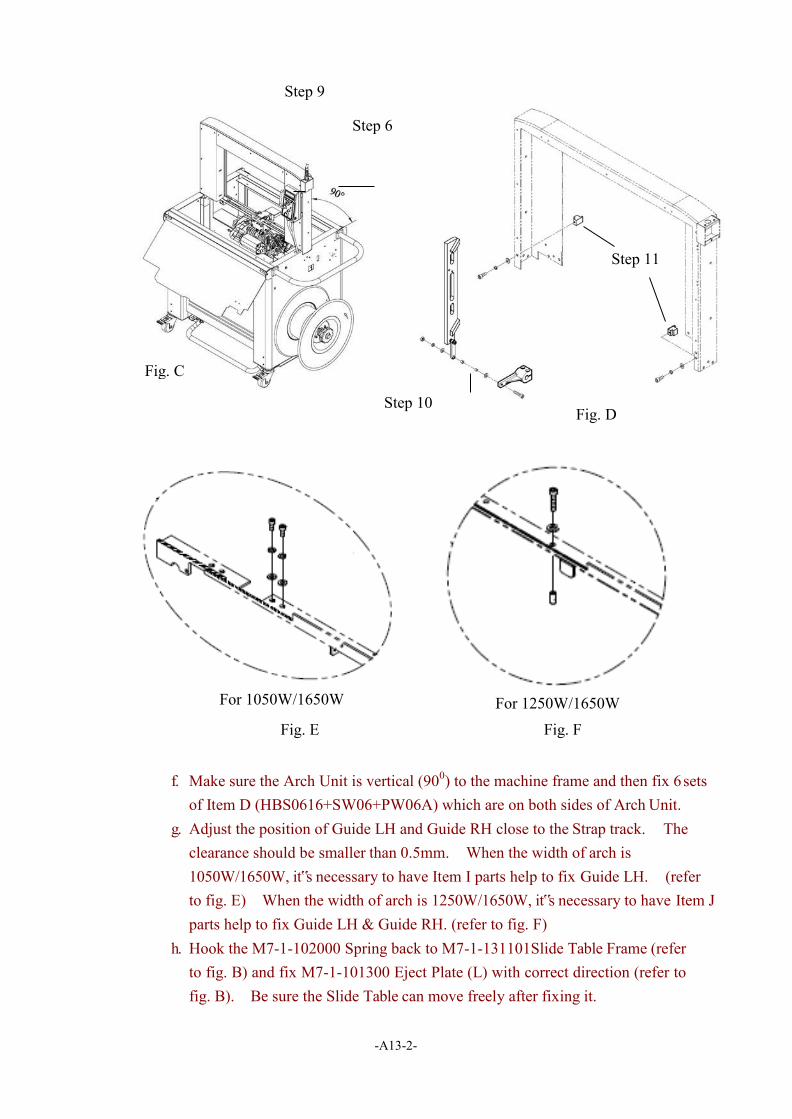
f. Make sure the Arch Unit is vertical (900) to the machine frame and then fix 6 sets of Item D (HBS0616+SW06+PW06A) which are on both sides of Arch Unit.
g. Adjust the position of Guide LH and Guide RH close to the Strap track. The clearance should be smaller than 0.5mm. When the width of arch is 1050W/1650W, it‟s necessary to have Item I parts help to fix Guide LH. (refer to fig. E) When the width of arch is 1250W/1650W, it‟s necessary to have Item J parts help to fix Guide LH & Guide RH. (refer to fig. F)
h. Hook the M7-1-102000 Spring back to M7-1-131101Slide Table Frame (refer to fig. B) and fix M7-1-101300 Eject Plate (L) with correct direction (refer to fig. B). Be sure the Slide Table can move freely after fixing it.
Step 6
Fig. C
-A13-3-
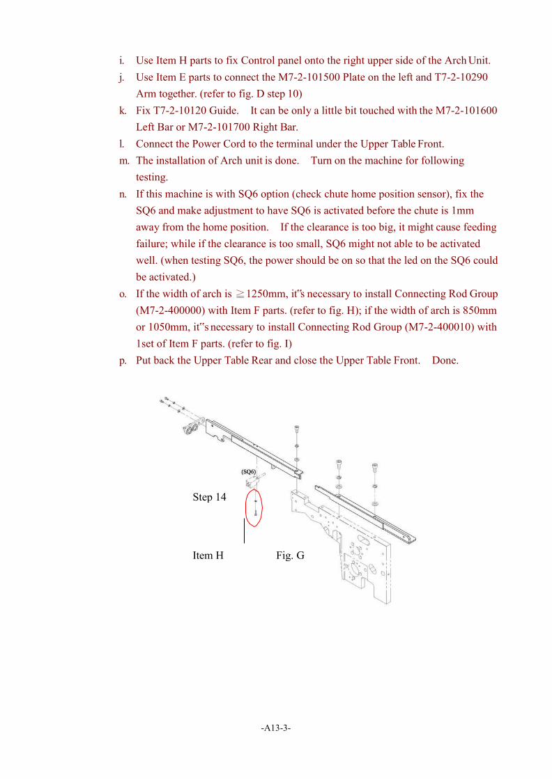
i. Use Item H parts to fix Control panel onto the right upper side of the Arch Unit. j. Use Item E parts to connect the M7-2-101500 Plate on the left and T7-2-10290
Arm together. (refer to fig. D step 10) k. Fix T7-2-10120 Guide. It can be only a little bit touched with the M7-2-101600
Left Bar or M7-2-101700 Right Bar. l. Connect the Power Cord to the terminal under the Upper Table Front. m. The installation of Arch unit is done. Turn on the machine for following
testing. n. If this machine is with SQ6 option (check chute home position sensor), fix the
SQ6 and make adjustment to have SQ6 is activated before the chute is 1mm away from the home position. If the clearance is too big, it might cause feeding failure; while if the clearance is too small, SQ6 might not able to be activated well. (when testing SQ6, the power should be on so that the led on the SQ6 could be activated.)
o. If the width of arch is ≧1250mm, it‟s necessary to install Connecting Rod Group (M7-2-400000) with Item F parts. (refer to fig. H); if the width of arch is 850mm or 1050mm, it‟s necessary to install Connecting Rod Group (M7-2-400010) with 1set of Item F parts. (refer to fig. I)
p. Put back the Upper Table Rear and close the Upper Table Front. Done.
Step 14
Item H Fig. G

-A13-4-
3. Adjust the table height by repositioning the screws underneath the machine frame (refer to below drawing). After adjustments, be sure to tighten all the fixing screws. Caution!
Be sure to take out the wire for the proximity switch underneath the left side of
machine to avoid any damage before adjusting the table height.
Step 15
Fig. H Item F
Fig. I Item F
-A13-5-
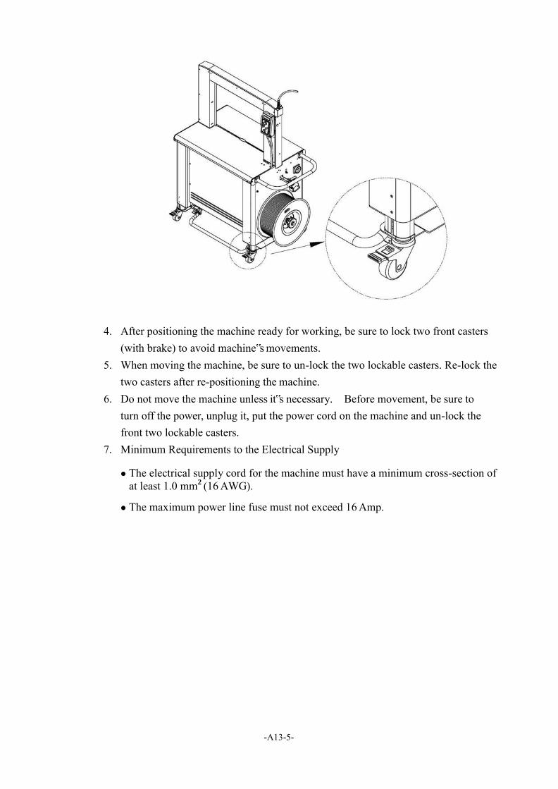
4. After positioning the machine ready for working, be sure to lock two front casters (with brake) to avoid machine‟s movements.
5. When moving the machine, be sure to un-lock the two lockable casters. Re-lock the two casters after re-positioning the machine.
6. Do not move the machine unless it‟s necessary. Before movement, be sure to turn off the power, unplug it, put the power cord on the machine and un-lock the front two lockable casters.
7. Minimum Requirements to the Electrical Supply
The electrical supply cord for the machine must have a minimum cross-section of at least 1.0 mm2 (16 AWG).
The maximum power line fuse must not exceed 16 Amp.
-A14-
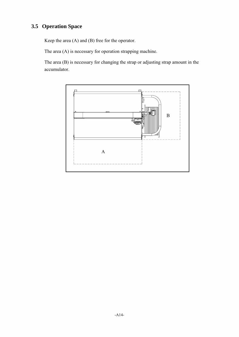
3.5 Operation Space
Keep the area (A) and (B) free for the operator.
The area (A) is necessary for operation strapping machine.
The area (B) is necessary for changing the strap or adjusting strap amount in the accumulator.
B
-A15-
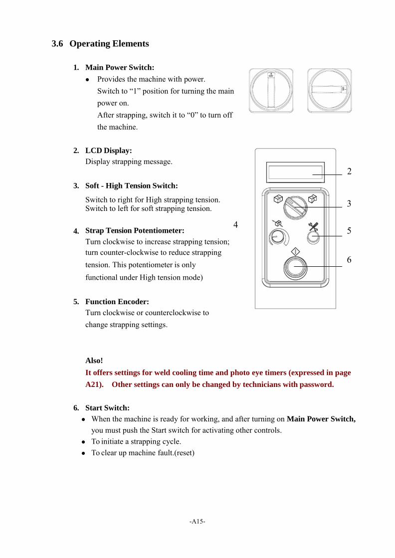
3.6 Operating Elements
1. Main Power Switch:
Provides the machine with power. Switch to “1” position for turning the main power on. After strapping, switch it to “0” to turn off the machine.
2. LCD Display:
Display strapping message. 2
3. Soft - High Tension Switch:
Switch to right for High strapping tension. 3 Switch to left for soft strapping tension.
4. Strap Tension Potentiometer: 4 5
Turn clockwise to increase strapping tension; turn counter-clockwise to reduce strapping tension. This potentiometer is only 6 functional under High tension mode)
5. Function Encoder:
Turn clockwise or counterclockwise to change strapping settings.
Also!
It offers settings for weld cooling time and photo eye timers (expressed in page
A21). Other settings can only be changed by technicians with password.
6. Start Switch:
When the machine is ready for working, and after turning on Main Power Switch,
you must push the Start switch for activating other controls. To initiate a strapping cycle. To clear up machine fault.(reset)
-A16-
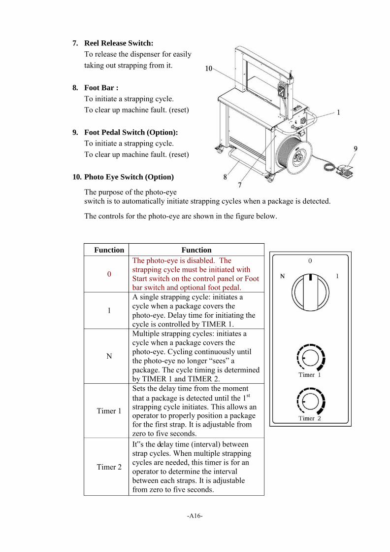
7. Reel Release Switch:
To release the dispenser for easily taking out strapping from it.
8. Foot Bar :
To initiate a strapping cycle. To clear up machine fault. (reset)
9. Foot Pedal Switch (Option):
To initiate a strapping cycle. To clear up machine fault. (reset)
10. Photo Eye Switch (Option)
The purpose of the photo-eye switch is to automatically initiate strapping cycles when a package is detected.
The controls for the photo-eye are shown in the figure below.
Function Function
0
The photo-eye is disabled. The strapping cycle must be initiated with Start switch on the control panel or Foot bar switch and optional foot pedal.
1
A single strapping cycle: initiates a cycle when a package covers the photo-eye. Delay time for initiating the cycle is controlled by TIMER 1.
Multiple strapping cycles: initiates a cycle when a package covers the photo-eye. Cycling continuously until the photo-eye no longer “sees” a package. The cycle timing is determined by TIMER 1 and TIMER 2.
Timer 1
Sets the delay time from the moment that a package is detected until the 1st
strapping cycle initiates. This allows an operator to properly position a package for the first strap. It is adjustable from zero to five seconds.
Timer 2
It‟s the delay time (interval) between strap cycles. When multiple strapping cycles are needed, this timer is for an operator to determine the interval between each straps. It is adjustable from zero to five seconds.
-A17-
11. Foot Bar (Rear)(Option):
To initiate a strapping cycle. To clear up machine fault. (reset)
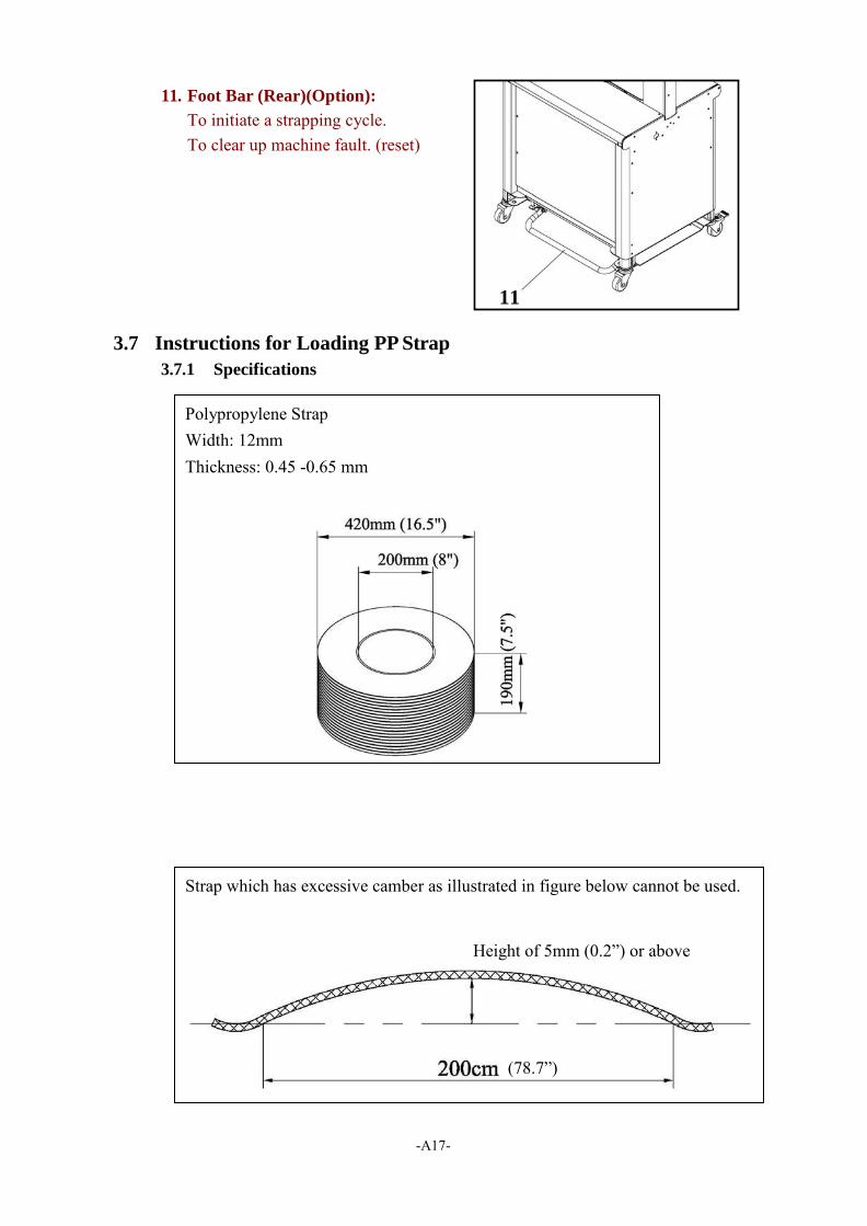
3.7 Instructions for Loading PP Strap
3.7.1 Specifications
Polypropylene Strap Width: 12mm Thickness: 0.45 -0.65 mm
Strap which has excessive camber as illustrated in figure below cannot be used.
Height of 5mm (0.2”) or above
(78.7”)
11
-A18-
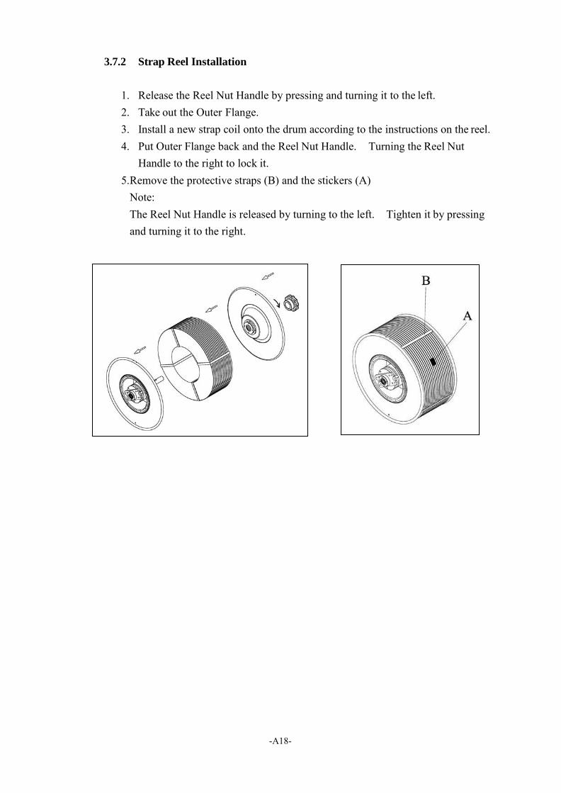
3.7.2 Strap Reel Installation
1. Release the Reel Nut Handle by pressing and turning it to the left. 2. Take out the Outer Flange. 3. Install a new strap coil onto the drum according to the instructions on the reel. 4. Put Outer Flange back and the Reel Nut Handle. Turning the Reel Nut
Handle to the right to lock it. 5. Remove the protective straps (B) and the stickers (A)
Note: The Reel Nut Handle is released by turning to the left. Tighten it by pressing and turning it to the right.
-A19-
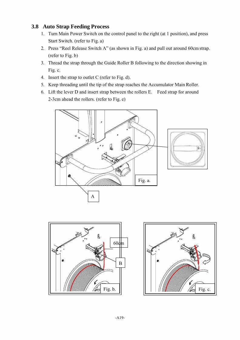
3.8 Auto Strap Feeding Process
1. Turn Main Power Switch on the control panel to the right (at 1 position), and press Start Switch. (refer to Fig. a)
2. Press “Reel Release Switch A” (as shown in Fig. a) and pull out around 60cm strap. (refer to Fig. b)
3. Thread the strap through the Guide Roller B following to the direction showing in Fig. c.
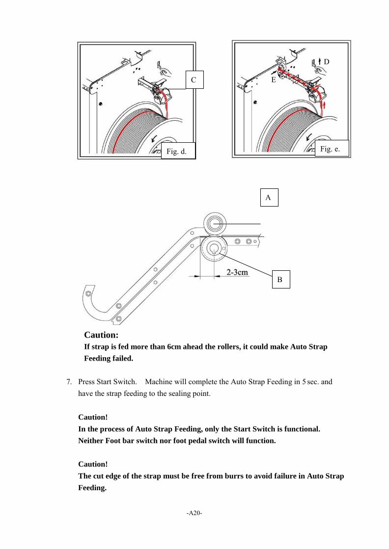
4. Insert the strap to outlet C (refer to Fig. d). 5. Keep threading until the tip of the strap reaches the Accumulator Main Roller. 6. Lift the lever D and insert strap between the rollers E. Feed strap for around
2-3cm ahead the rollers. (refer to Fig. e)
Fig. a.
60cm
B
Fig. b. Fig. c.
-A20-
Caution:
If strap is fed more than 6cm ahead the rollers, it could make Auto Strap
Feeding failed.
7. Press Start Switch. Machine will complete the Auto Strap Feeding in 5 sec. and
have the strap feeding to the sealing point.
Caution!
In the process of Auto Strap Feeding, only the Start Switch is functional.
Neither Foot bar switch nor foot pedal switch will function.
Caution!
The cut edge of the strap must be free from burrs to avoid failure in Auto Strap
Feeding.
C
Fig. d.
E
Fig. e.
B
-A21-
4. Operating the Machine
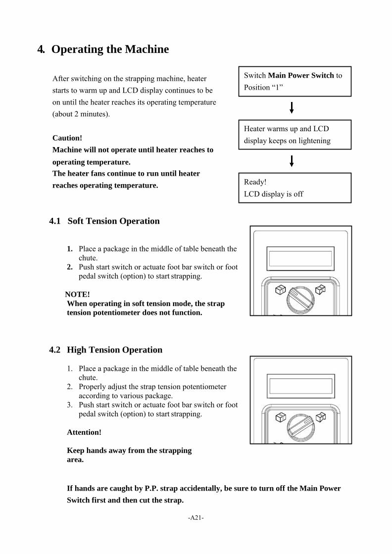
After switching on the strapping machine, heater starts to warm up and LCD display continues to be on until the heater reaches its operating temperature (about 2 minutes).
Caution!
Machine will not operate until heater reaches to
operating temperature.
The heater fans continue to run until heater
reaches operating temperature.
4.1 Soft Tension Operation
1. Place a package in the middle of table beneath the chute.
2. Push start switch or actuate foot bar switch or foot pedal switch (option) to start strapping.
NOTE!
When operating in soft tension mode, the strap
tension potentiometer does not function.
4.2 High Tension Operation
1. Place a package in the middle of table beneath the chute.
2. Properly adjust the strap tension potentiometer according to various package.
3. Push start switch or actuate foot bar switch or foot pedal switch (option) to start strapping.
Attention!
Keep hands away from the strapping
area.
If hands are caught by P.P. strap accidentally, be sure to turn off the Main Power
Switch first and then cut the strap.
Switch Main Power Switch to Position “1”
Heater warms up and LCD display keeps on lightening
Ready! LCD display is off
-A22-
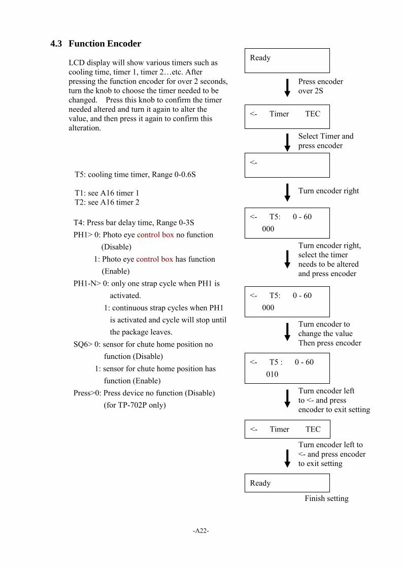
4.3 Function Encoder
LCD display will show various timers such as cooling time, timer 1, timer 2…etc. After pressing the function encoder for over 2 seconds, turn the knob to choose the timer needed to be changed. Press this knob to confirm the timer needed altered and turn it again to alter the value, and then press it again to confirm this alteration.
T5: cooling time timer, Range 0-0.6S
T1: see A16 timer 1 T2: see A16 timer 2
T4: Press bar delay time, Range 0-3S PH1> 0: Photo eye control box no function
(Disable) 1: Photo eye control box has function
(Enable) PH1-N> 0: only one strap cycle when PH1 is
activated. 1: continuous strap cycles when PH1
is activated and cycle will stop until the package leaves.
SQ6> 0: sensor for chute home position no function (Disable)
1: sensor for chute home position has function (Enable)
Press>0: Press device no function (Disable) (for TP-702P only)
Press encoder over 2S
Select Timer and press encoder
Turn encoder right
<- T5: 0 - 60 000
Turn encoder right, select the timer needs to be altered and press encoder
<- T5: 0 - 60
000
Turn encoder to change the value Then press encoder
<- T5 : 0 - 60
010
Turn encoder left to <- and press encoder to exit setting
Turn encoder left to <- and press encoder to exit setting
Finish setting
<- Timer TEC
Ready
Ready
<- Timer TEC
<-
-A23-
5. Adjustments
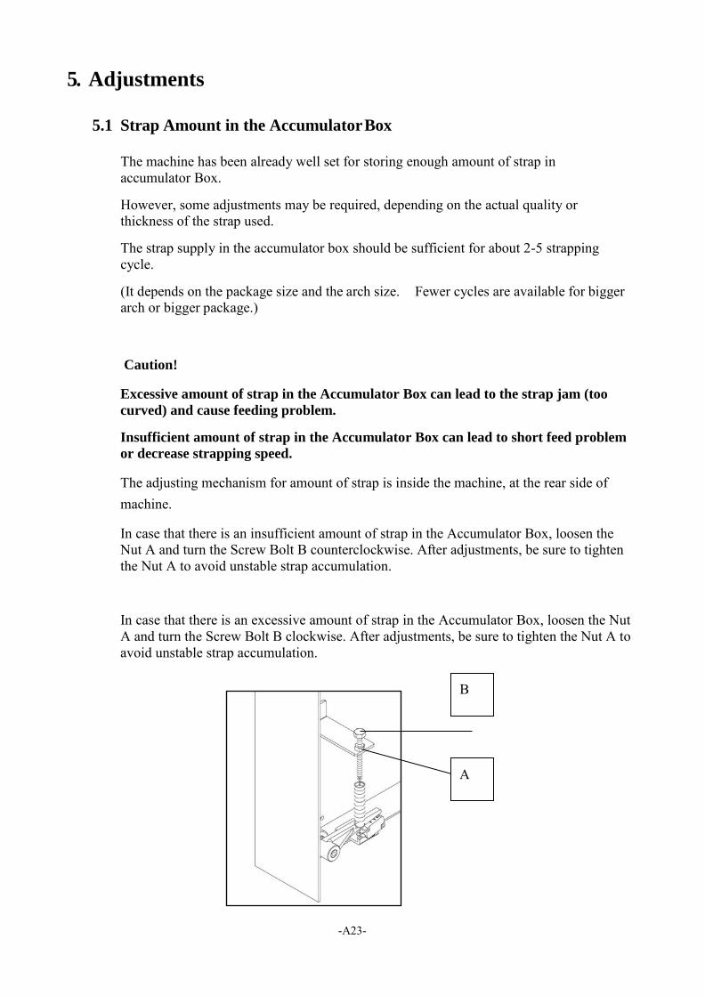
5.1 Strap Amount in the Accumulator Box
The machine has been already well set for storing enough amount of strap in accumulator Box.
However, some adjustments may be required, depending on the actual quality or thickness of the strap used.
The strap supply in the accumulator box should be sufficient for about 2-5 strapping cycle.
(It depends on the package size and the arch size. Fewer cycles are available for bigger arch or bigger package.)
Caution!
Excessive amount of strap in the Accumulator Box can lead to the strap jam (too
curved) and cause feeding problem.
Insufficient amount of strap in the Accumulator Box can lead to short feed problem
or decrease strapping speed.
The adjusting mechanism for amount of strap is inside the machine, at the rear side of machine.
In case that there is an insufficient amount of strap in the Accumulator Box, loosen the Nut A and turn the Screw Bolt B counterclockwise. After adjustments, be sure to tighten the Nut A to avoid unstable strap accumulation.
In case that there is an excessive amount of strap in the Accumulator Box, loosen the Nut A and turn the Screw Bolt B clockwise. After adjustments, be sure to tighten the Nut A to avoid unstable strap accumulation.
B
-A24-
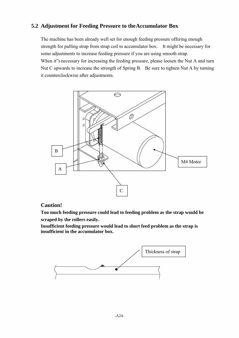
5.2 Adjustment for Feeding Pressure to the Accumulator Box
The machine has been already well set for enough feeding pressure offering enough strength for pulling strap from strap coil to accumulator box. It might be necessary for some adjustments to increase feeding pressure if you are using smooth strap. When it‟s necessary for increasing the feeding pressure, please loosen the Nut A and turn Nut C upwards to increase the strength of Spring B. Be sure to tighten Nut A by turning it counterclockwise after adjustments.
Caution!
Too much feeding pressure could lead to feeding problem as the strap would be
scraped by the rollers easily.
Insufficient feeding pressure would lead to short feed problem as the strap is
insufficient in the accumulator box.
B
M4 Motor
C
Thickness of strap

-A25-
5.3 Adjustment for Heater Temperature
The machine has been already well set for proper heater temperature. It might be necessary to do some adjustments according to temperature in working environment, and the quality of PP strap to ensure better sealing efficiency. Turn „‟A‟‟ clockwise to increase the heater temperature and turn it counterclockwise to decrease the heater temperature.
5.4 Some adjustments for straps
1. Adjusting “Strap Guide”
Adjusting the A (Strap Guide) according to the strap and make sure the width B is around 0.5mm (0.02”) wider than the strap.
Caution:
If B is too wide, it would lead to sealing problem. However, if it’s too narrow, it
would lead to feeding problem.
-A26-
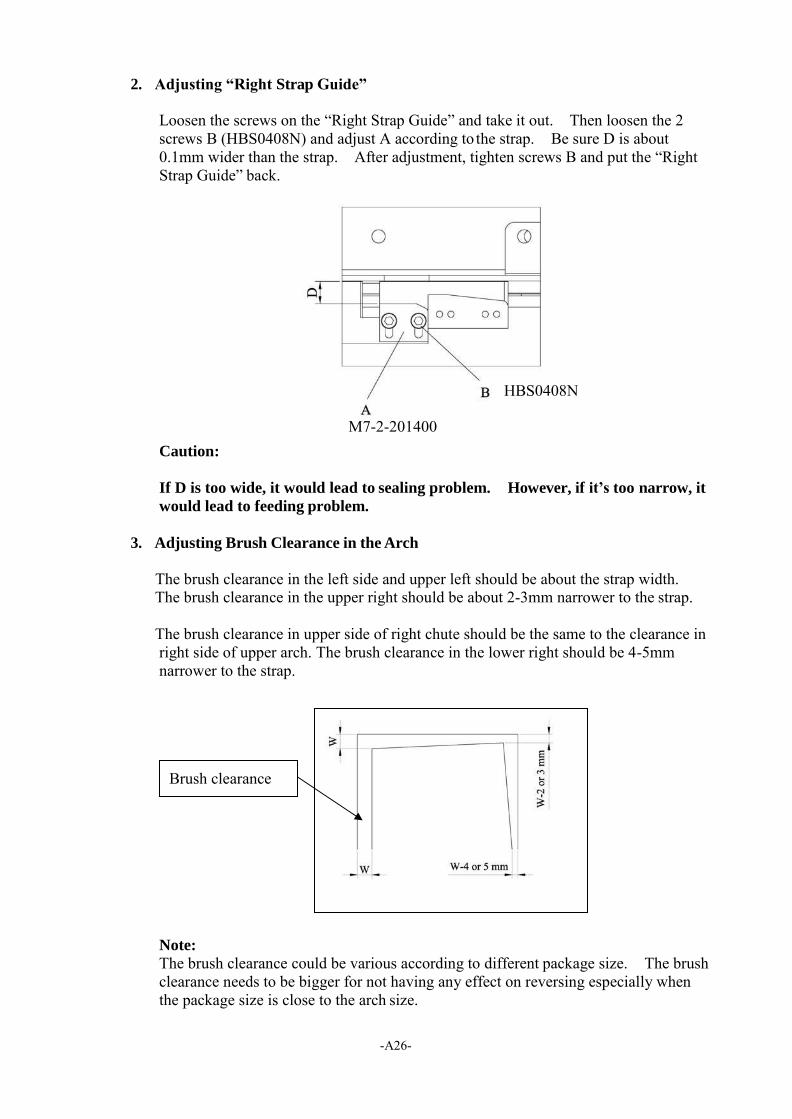
2. Adjusting “Right Strap Guide”
Loosen the screws on the “Right Strap Guide” and take it out. Then loosen the 2 screws B (HBS0408N) and adjust A according to the strap. Be sure D is about 0.1mm wider than the strap. After adjustment, tighten screws B and put the “Right Strap Guide” back.
HBS0408N
M7-2-201400 Caution:
If D is too wide, it would lead to sealing problem. However, if it’s too narrow, it
would lead to feeding problem.
3. Adjusting Brush Clearance in the Arch
The brush clearance in the left side and upper left should be about the strap width. The brush clearance in the upper right should be about 2-3mm narrower to the strap.
The brush clearance in upper side of right chute should be the same to the clearance in right side of upper arch. The brush clearance in the lower right should be 4-5mm narrower to the strap.
Note:
The brush clearance could be various according to different package size. The brush clearance needs to be bigger for not having any effect on reversing especially when the package size is close to the arch size.
Brush clearance
-A27-
4. Adjusting Strap Amount in the Accumulator Box
Different strap widths might have effects on the strap amount in the accumulator box. Please do the adjustment according to 5.1 if necessary.
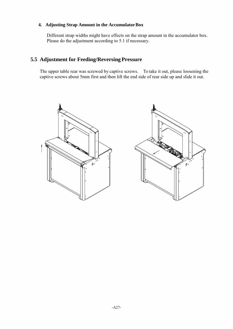
5.5 Adjustment for Feeding/Reversing Pressure
The upper table rear was screwed by captive screws. To take it out, please loosening the captive screws about 5mm first and then lift the end side of rear side up and slide it out.
-A28-
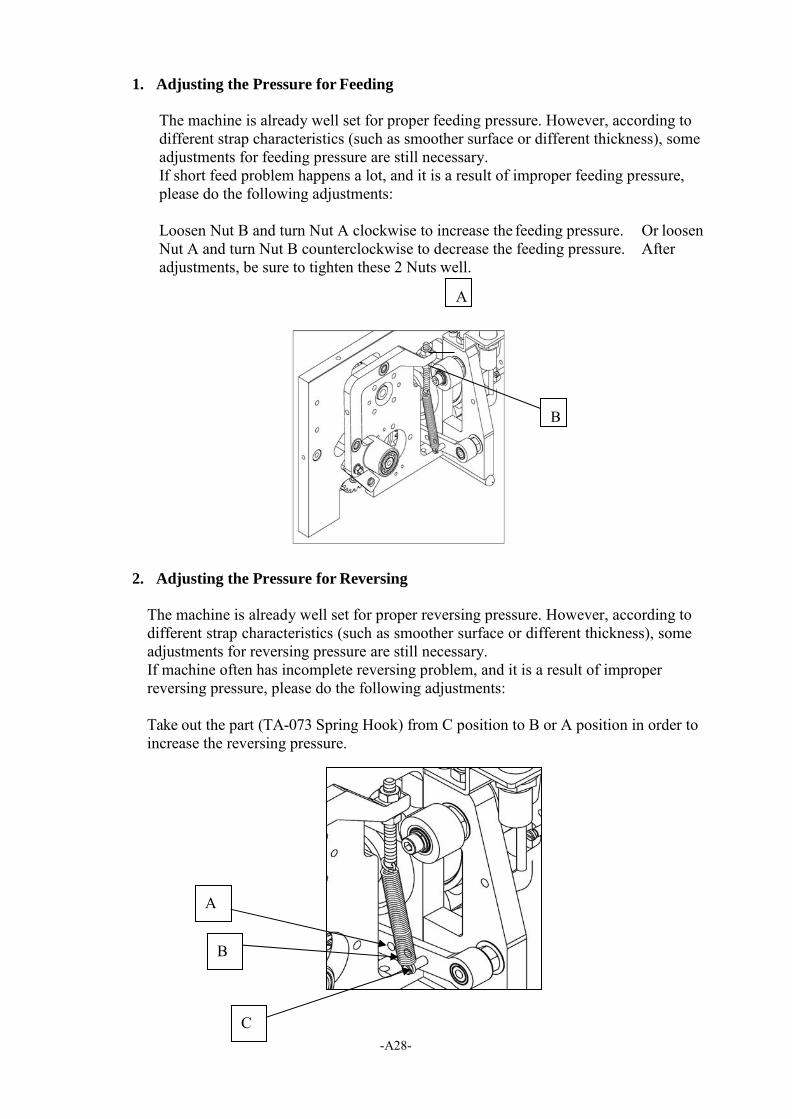
1. Adjusting the Pressure for Feeding
The machine is already well set for proper feeding pressure. However, according to different strap characteristics (such as smoother surface or different thickness), some adjustments for feeding pressure are still necessary. If short feed problem happens a lot, and it is a result of improper feeding pressure, please do the following adjustments:
Loosen Nut B and turn Nut A clockwise to increase the feeding pressure. Or loosen Nut A and turn Nut B counterclockwise to decrease the feeding pressure. After adjustments, be sure to tighten these 2 Nuts well.
2. Adjusting the Pressure for Reversing
The machine is already well set for proper reversing pressure. However, according to different strap characteristics (such as smoother surface or different thickness), some adjustments for reversing pressure are still necessary. If machine often has incomplete reversing problem, and it is a result of improper reversing pressure, please do the following adjustments:
Take out the part (TA-073 Spring Hook) from C position to B or A position in order to increase the reversing pressure.
B
B
C
-A29-
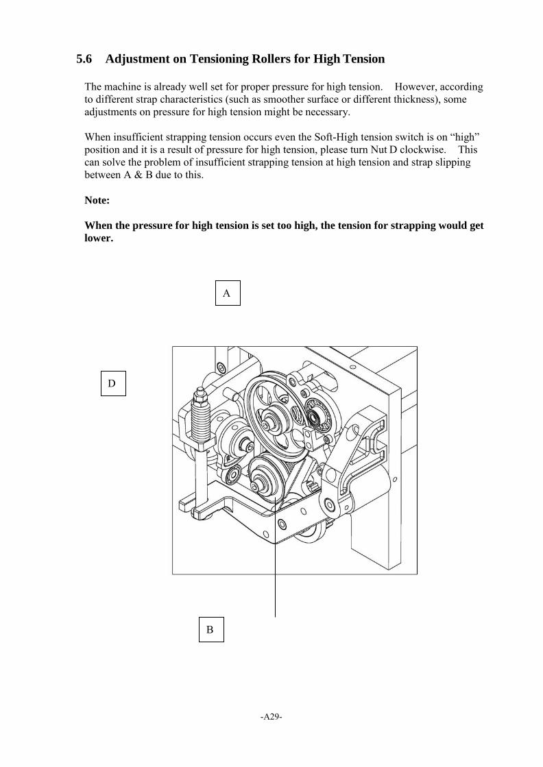
5.6 Adjustment on Tensioning Rollers for High Tension
The machine is already well set for proper pressure for high tension. However, according to different strap characteristics (such as smoother surface or different thickness), some adjustments on pressure for high tension might be necessary.
When insufficient strapping tension occurs even the Soft-High tension switch is on “high” position and it is a result of pressure for high tension, please turn Nut D clockwise. This can solve the problem of insufficient strapping tension at high tension and strap slipping between A & B due to this.
Note:
When the pressure for high tension is set too high, the tension for strapping would get
lower.
B
-A30-
6. Troubleshooting
6.1 LCD Display
When the machine has a malfunction, the LCD will flash and display a failure message. Message shown on the LCD could be as follows:
1. Reminder message: a. Push Start: Please press the Start Switch to make machine function. This is
especially necessary after the Safety Switch is released or after you just turn on the machine.
b. Load Strap: Load a new roll of strap or re-do the Auto Strap feeding again. c. B6 open; K1 open: When it shows this message after you press the Start
Switch, it means the Safety Switch might not be closed or the K1 in the control box is abnormal.
2. Malfunction from switches:
a. S1 Error: This means the Start Switch or the Foot Pedal is continuously triggered before activating them. Please check if any of these 2 Switches is defective.
b. S5 Error: This means the Reel Release Switch is continuously triggered before activating it. Try to press it by hand to see if it‟s defective.
c. SQ1 on Error: The SQ1 is triggered when doing Auto Strap Feeding. Check if the SQ1 or the Switch lever is defective.
d. SQ9 failure: Foot bar is not able to function properly and cause it not able to go back to home position.
3. Malfunction from procedures:
a. ASF failed: Auto Strap Feeding failed. It might be caused by wrong inserting direction or inserting strap too much. Please re-do the Auto Strap Feeding.
b. Feed jam: Resulting from not being able to feed strap to the sealing position. When Feed jam occurs, solve it by pressing the Start Switch or Foot bar. If this does not solve the problem, please take out the jammed strap by following steps:
-A31-
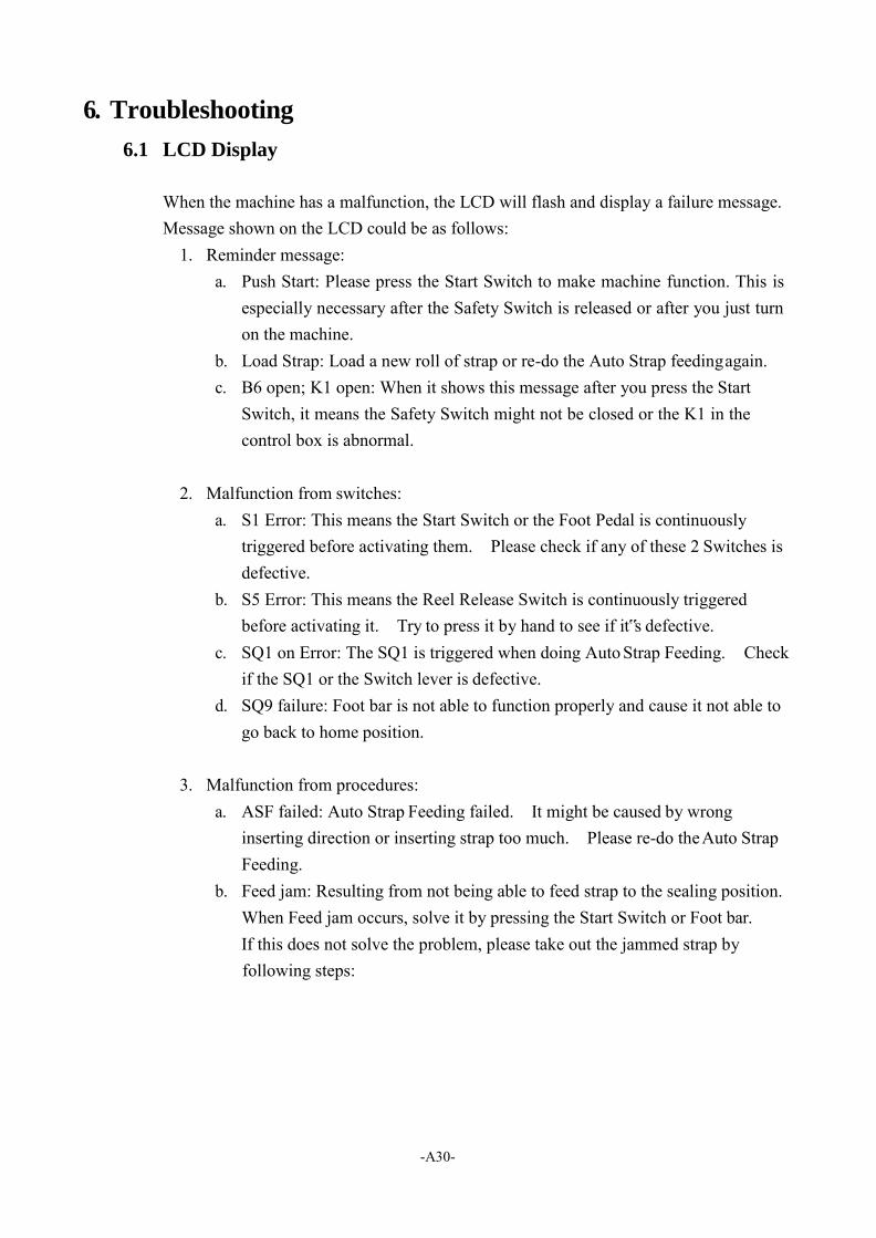
b-1. Open Upper Table Front Ass'y M7-5-210020. b-2. Lift up the Lever (M7-2-101400/M7-2-101410) with left hand and take
out the Cover (M7-1-311220) for the Upper Guide with right hand at the same time.
b-3. Take out the jammed strap and cut it. b-4. Put the cover (M7-1-311220) for the Upper Guide back to its position
and put the Upper Table Front Ass'y back as well. Push START switch in the control panel to RESTART machine.
If this does not solve the problem, the following causes have to be checked as well:
Fault Cause Remedy
1. Feed jam
Strap is too curved Change strap Insufficient feeding pressure Adjust feeding pressure according to
5.5 Too much strap amount in the accumulator box and has caused strap to be curved
Adjust to proper strap amount in the accumulator box according to 5.1
Other malfunctions
1. Sealing failure
Too much debris on both sides of heater plate
Clean both sides of the heater plate by fine sandpaper
Insufficient heater temperature
Increase the heater temperature according to 5.3
Insufficient cooling time Increase cooling time according to 4.3 2. Insufficient strap tension
Soft-High tension switch is at “soft” position
Turn it to “high” position
Lubricant drops into tension roller incautious
Clean the lubricant
Too much debris in the gear of tension roller
Clean the debris
-A32-
7. Maintenance
Warning:
Before any maintenance or repairs on the machine, set the Main Power
Switch to "O" (OFF). Wait about 5 minutes for cooling down the heater to
avoid burns with this area.
1. Cleaning and Lubrication
The high reliability and long service life of the strapping machine will depend on regular cleaning and maintenance.
ATTENTION!
All the important strap transport components, such as the drive rollers and the strap
guides, must be kept free from oil and grease. (lubricant)
The lubricant has to be non-resinous.
The lubricant is SAE 30
2. Maintenance
Only use original spare parts supplied by manufacturer.
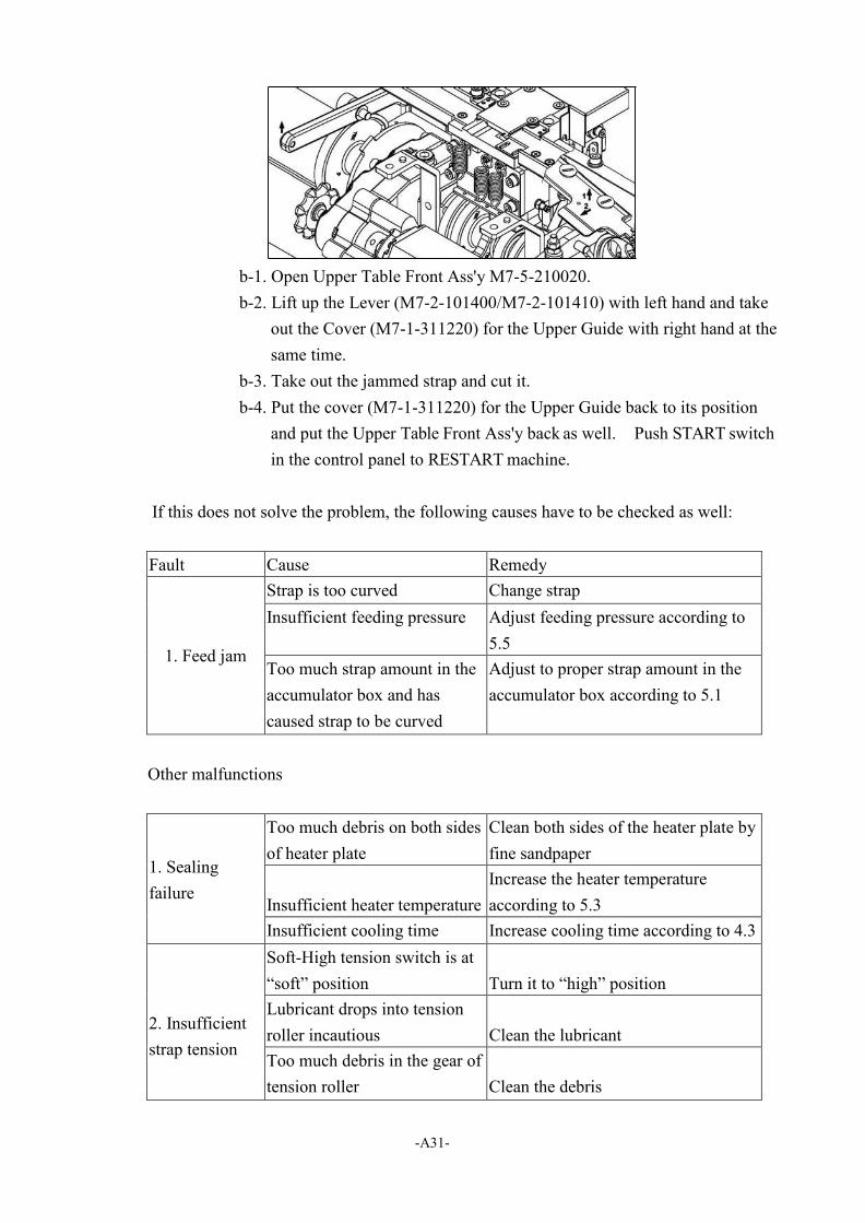
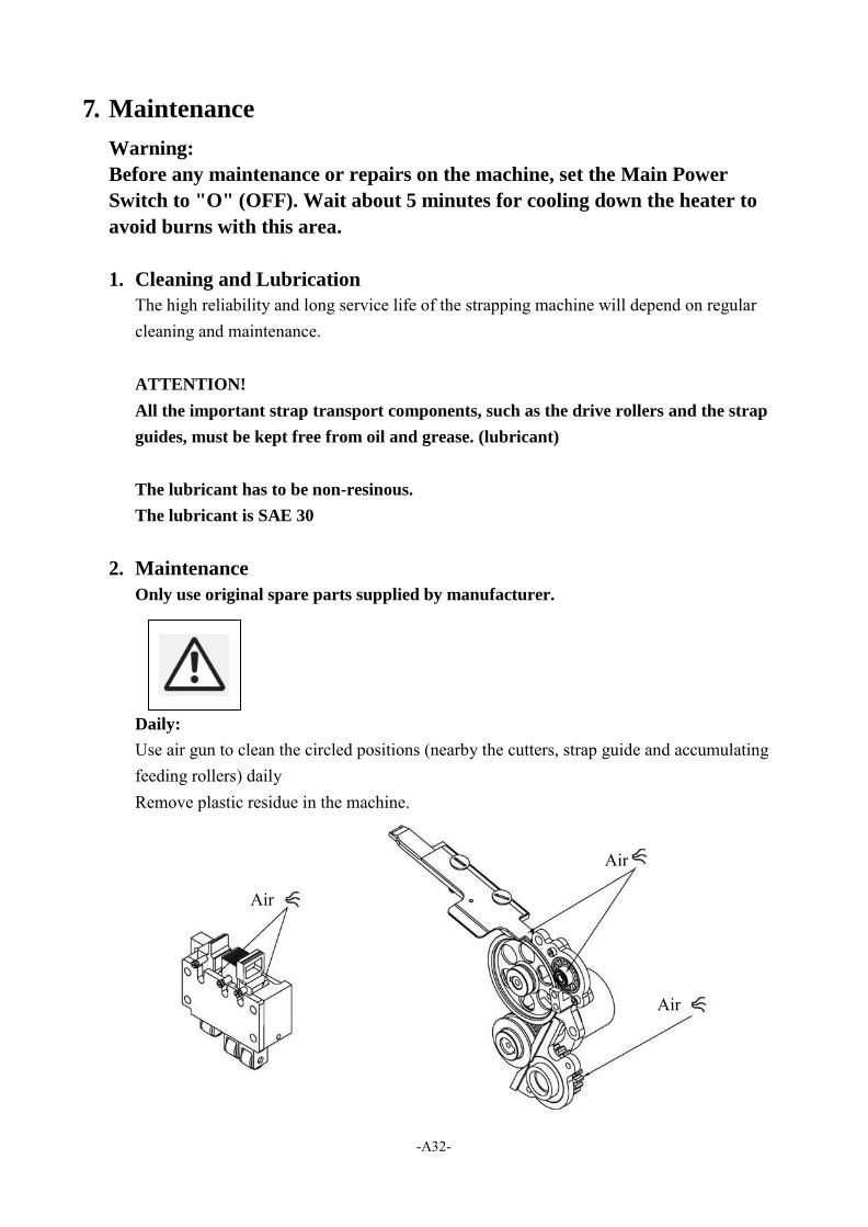
Daily:
Use air gun to clean the circled positions (nearby the cutters, strap guide and accumulating feeding rollers) daily Remove plastic residue in the machine.
Air
Air
Air
-A33-
Air
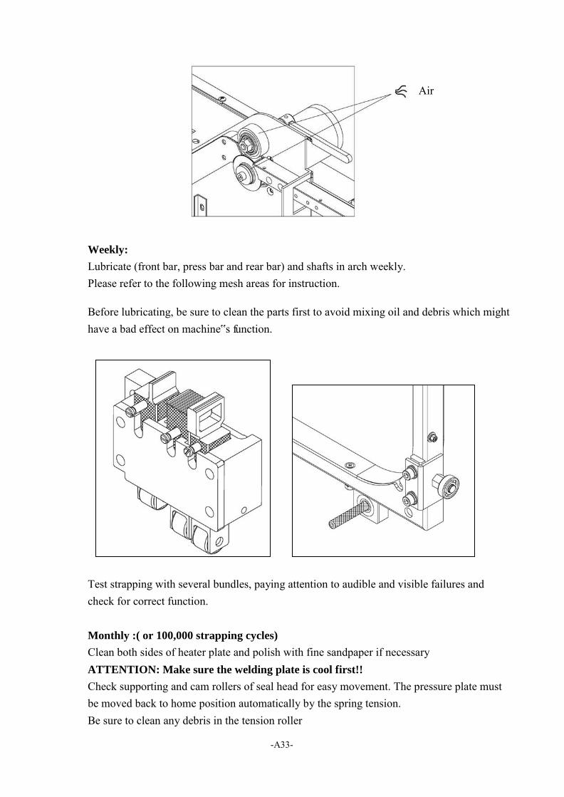
Weekly:
Lubricate (front bar, press bar and rear bar) and shafts in arch weekly. Please refer to the following mesh areas for instruction.
Before lubricating, be sure to clean the parts first to avoid mixing oil and debris which might have a bad effect on machine‟s function.
Test strapping with several bundles, paying attention to audible and visible failures and check for correct function.
Monthly :( or 100,000 strapping cycles)
Clean both sides of heater plate and polish with fine sandpaper if necessary ATTENTION: Make sure the welding plate is cool first!!
Check supporting and cam rollers of seal head for easy movement. The pressure plate must be moved back to home position automatically by the spring tension. Be sure to clean any debris in the tension roller

-A34-
6 Months:(or 500,000 strapping cycles)
Check heating element, replace and re-adjust it if necessary. Check strap cutter in sealing head, replace it if necessary. Check if the connector at wiring housing to printed circuit board is firmly fixed. Check if the safety switch on front table or right door functions well. Make machine ready for operation. Strap one bundle manually several times, paying attention to mal-functions, repeat procedure. Initiating several cyclings with package manually for testing and pay attention to any mal-functions. Make sure the strap accumulating function is well. If necessary, replace the assistant rollers, do proper adjustments to accumulating feeding pressure or to the clearance in the reel brake. Slightly lubricate the sealing head (bearing points) with light lubricant if necessary.
1 year :( or 1,000,000 strapping)
Replace deflection roller if it shows visible changes. In case of loud noise at bearings: locate them, replace the bearings. Get machine ready for operation again, strap one bundle manually several times, paying attention to malfunctions.

PART II
-B1-
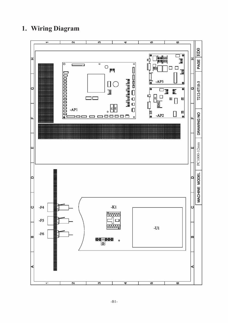
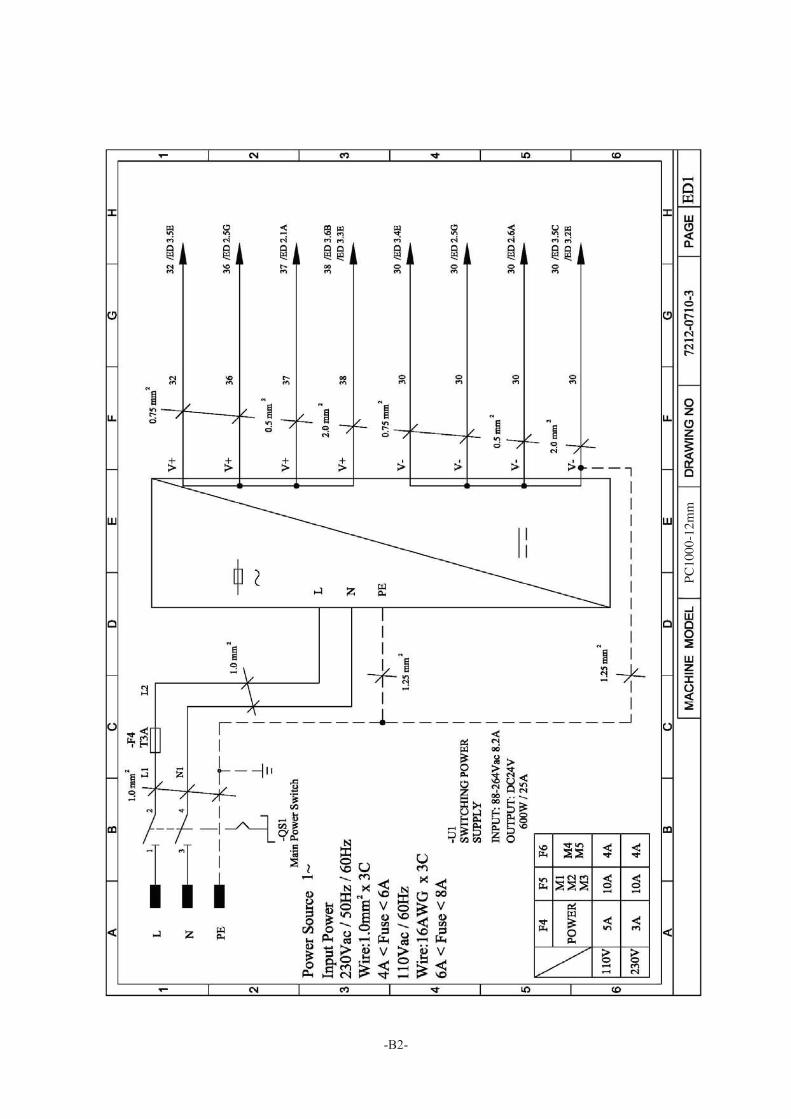
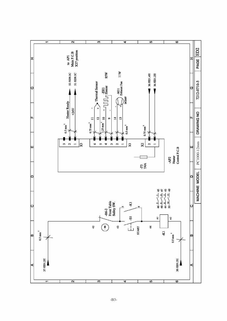
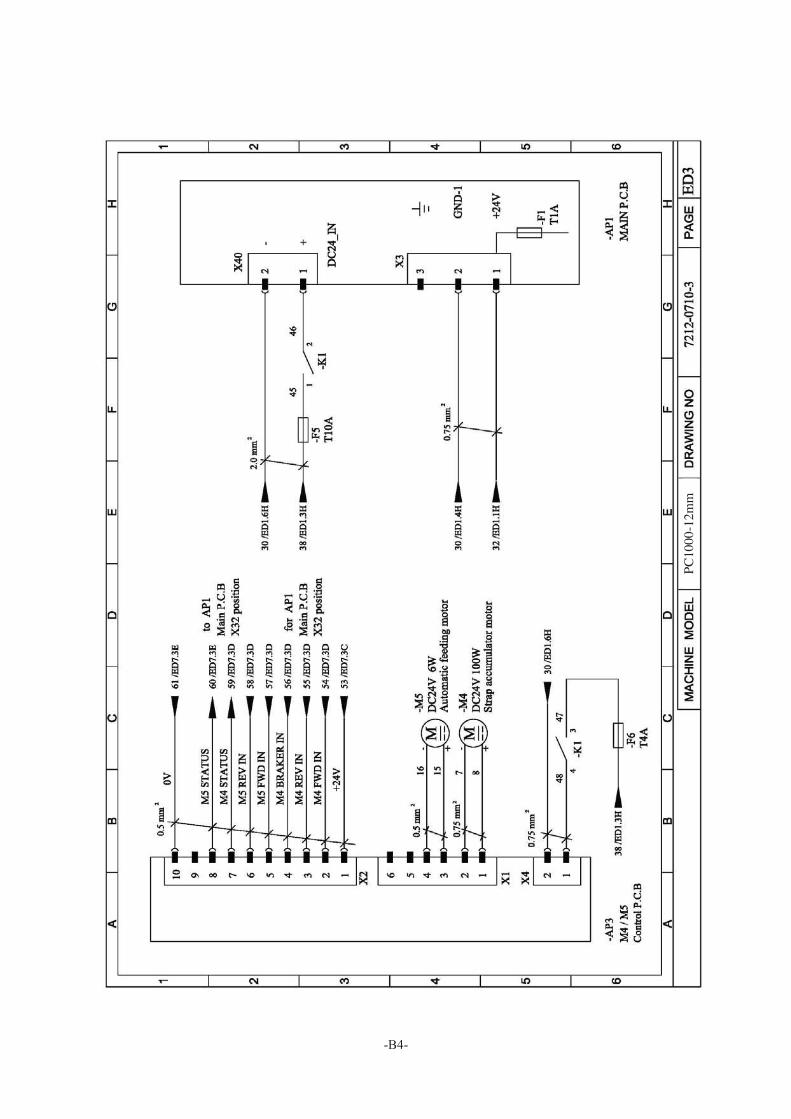
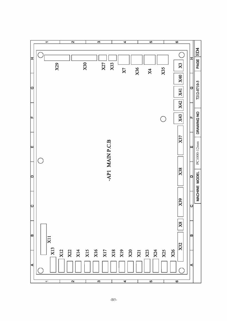
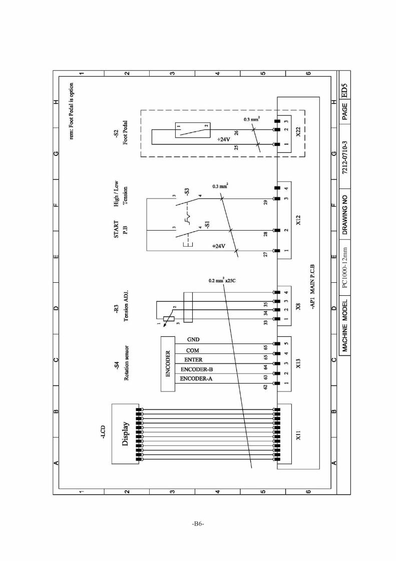
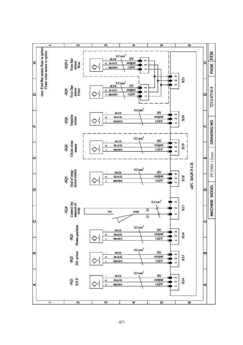
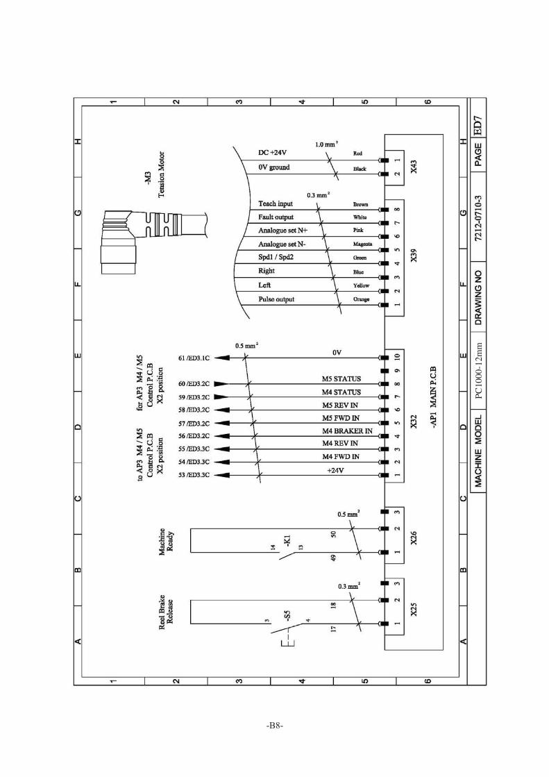
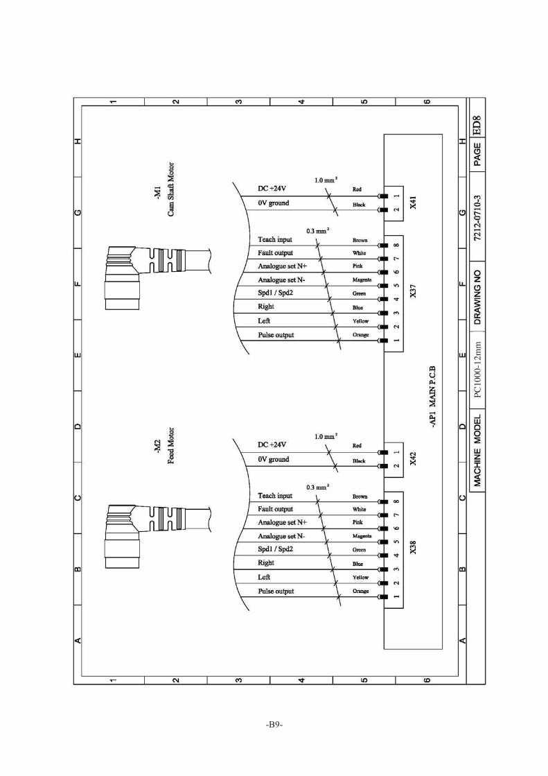
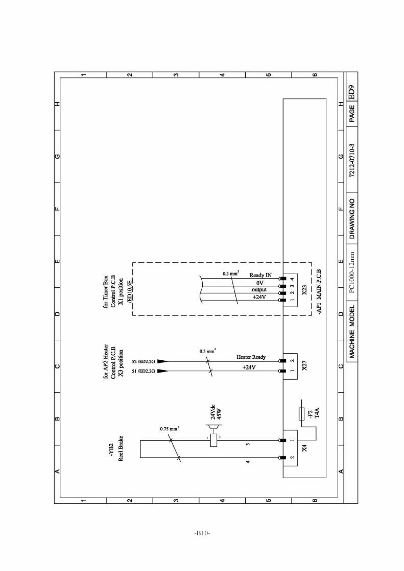
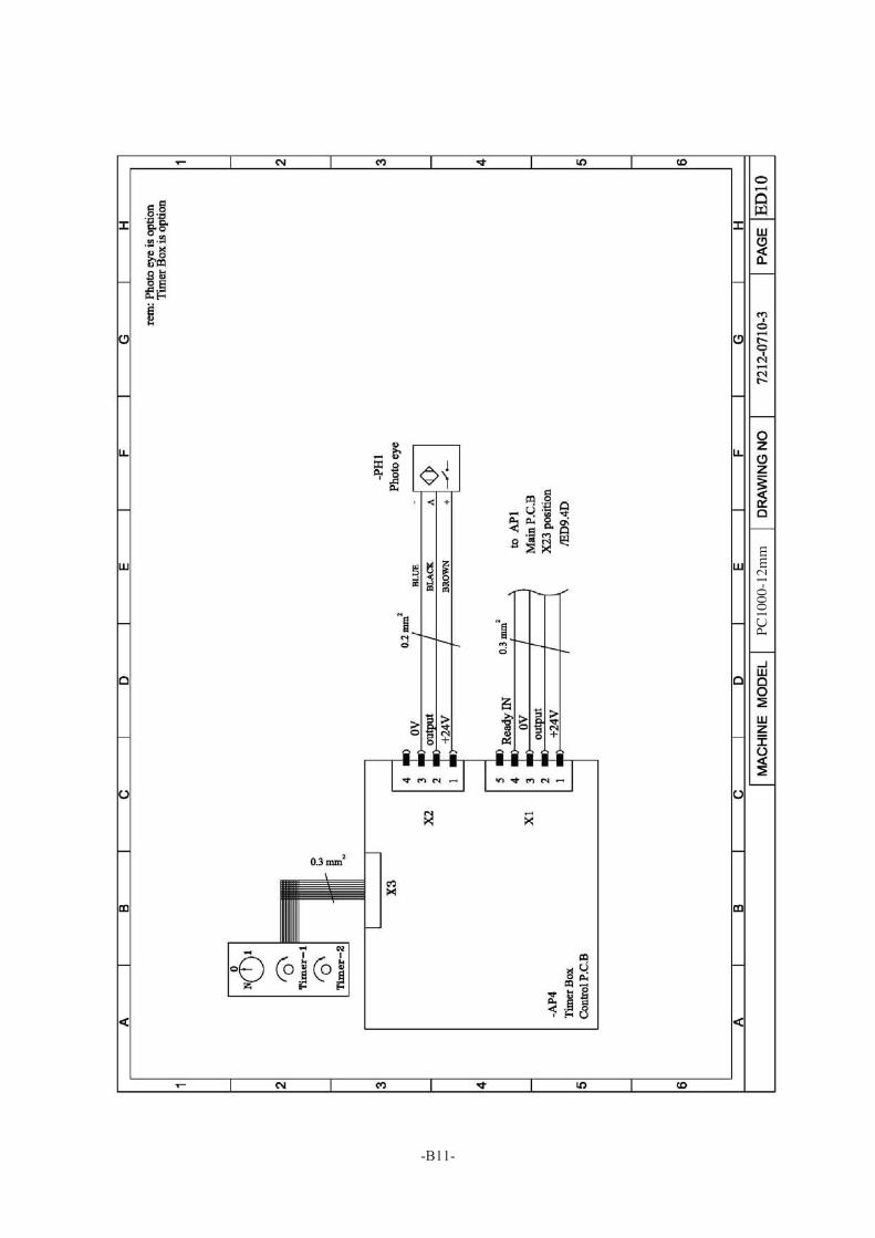
1. Wiring Diagram
PC10
00-1
2mm
-B2-
PC10
00-1
2mm
-B3-
PC10
00-1
2mm
-B4-
PC10
00-1
2mm
-B5-
PC10
00-1
2mm
-B6-
PC10
00-1
2mm
-B7-
PC10
00-1
2mm
-B8-
PC10
00-1
2mm
-B9-
PC10
00-1
2mm
-B10-
PC10
00-1
2mm
-B11-
PC10
00-1
2mm

PART III
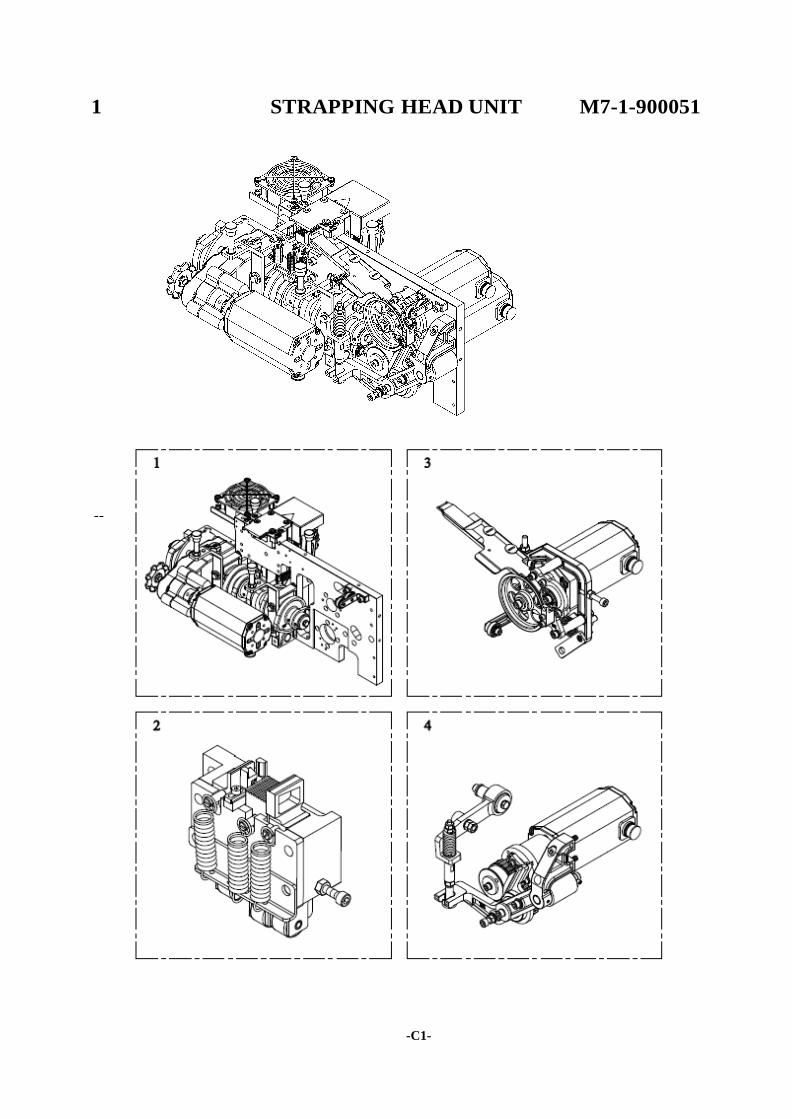
1 STRAPPING HEAD UNIT M7-1-900051
--
Cl-
-C1-
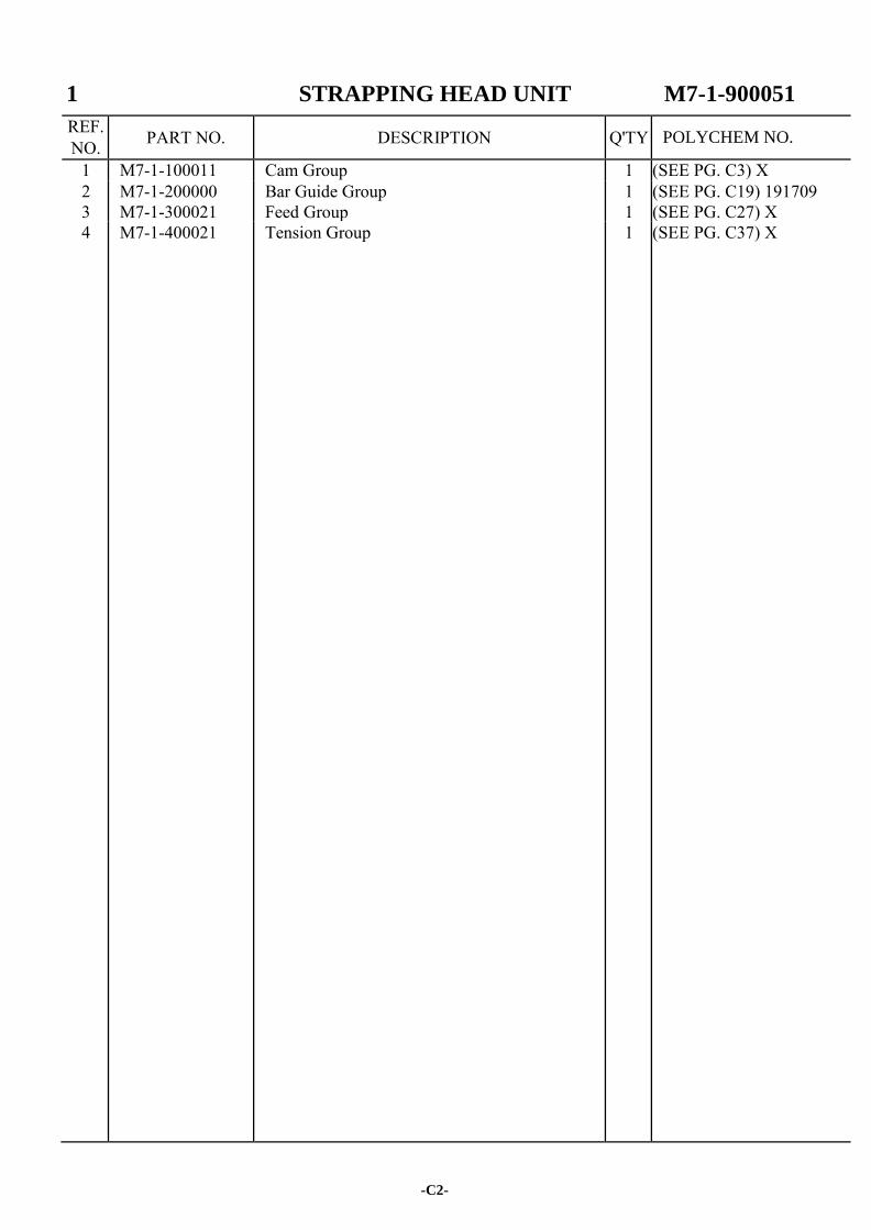
1 STRAPPING HEAD UNIT M7-1-900051
REF. NO. PART NO. DESCRIPTION Q'TY
1 M7-1-100011 Cam Group 1 (SEE PG. C3) X 2 M7-1-200000 Bar Guide Group 1 (SEE PG. C19) 191709 3 M7-1-300021 Feed Group 1 (SEE PG. C27) X 4 M7-1-400021 Tension Group 1 (SEE PG. C37) X
-C2-
POLYCHEM NO.
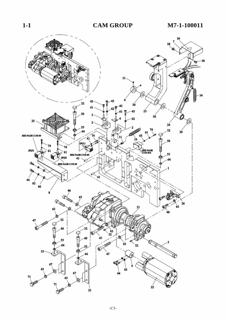
1-1 CAM GROUP M7-1-100011
-C3-
-C4-
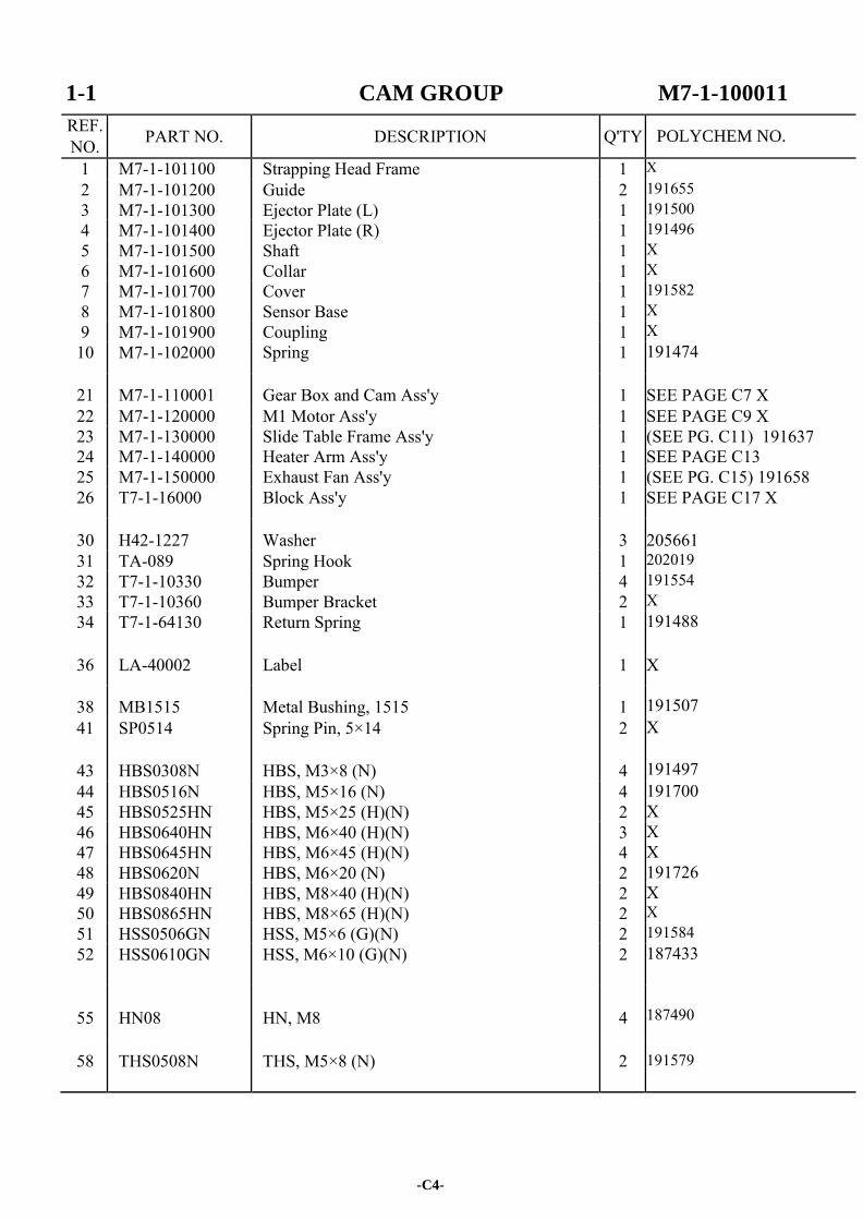
1-1 CAM GROUP M7-1-100011
REF. NO. PART NO. DESCRIPTION Q'TY
1 M7-1-101100 Strapping Head Frame 1 X 2 M7-1-101200 Guide 2 191655 3 M7-1-101300 Ejector Plate (L) 1 191500 4 M7-1-101400 Ejector Plate (R) 1 191496 5 M7-1-101500 Shaft 1 X 6 M7-1-101600 Collar 1 X 7 M7-1-101700 Cover 1 191582 8 M7-1-101800 Sensor Base 1 X 9 M7-1-101900 Coupling 1 X 10 M7-1-102000 Spring 1 191474
21 M7-1-110001 Gear Box and Cam Ass'y 1 SEE PAGE C7 X 22 M7-1-120000 M1 Motor Ass'y 1 SEE PAGE C9 X 23 M7-1-130000 Slide Table Frame Ass'y 1 (SEE PG. C11) 191637 24 M7-1-140000 Heater Arm Ass'y 1 SEE PAGE C13 25 M7-1-150000 Exhaust Fan Ass'y 1 (SEE PG. C15) 191658 26 T7-1-16000 Block Ass'y 1 SEE PAGE C17 X
30 H42-1227 Washer 3
205661 31 TA-089 Spring Hook 1 202019 32 T7-1-10330 Bumper 4 191554 33 T7-1-10360 Bumper Bracket 2 X 34 T7-1-64130 Return Spring 1 191488
36 LA-40002 Label 1
X
38 MB1515 Metal Bushing, 1515 1
191507 41 SP0514 Spring Pin, 5×14 2 X
43 HBS0308N HBS, M3×8 (N) 4
191497 44 HBS0516N HBS, M5×16 (N) 4 191700 45 HBS0525HN HBS, M5×25 (H)(N) 2 X 46 HBS0640HN HBS, M6×40 (H)(N) 3 X 47 HBS0645HN HBS, M6×45 (H)(N) 4 X 48 HBS0620N HBS, M6×20 (N) 2 191726 49 HBS0840HN HBS, M8×40 (H)(N) 2 X 50 HBS0865HN HBS, M8×65 (H)(N) 2 X 51 HSS0506GN HSS, M5×6 (G)(N) 2 191584 52 HSS0610GN HSS, M6×10 (G)(N) 2 187433
55
HN08
HN, M8
4
187490
58 THS0508N THS, M5×8 (N) 2
191579
POLYCHEM NO.
-C5-
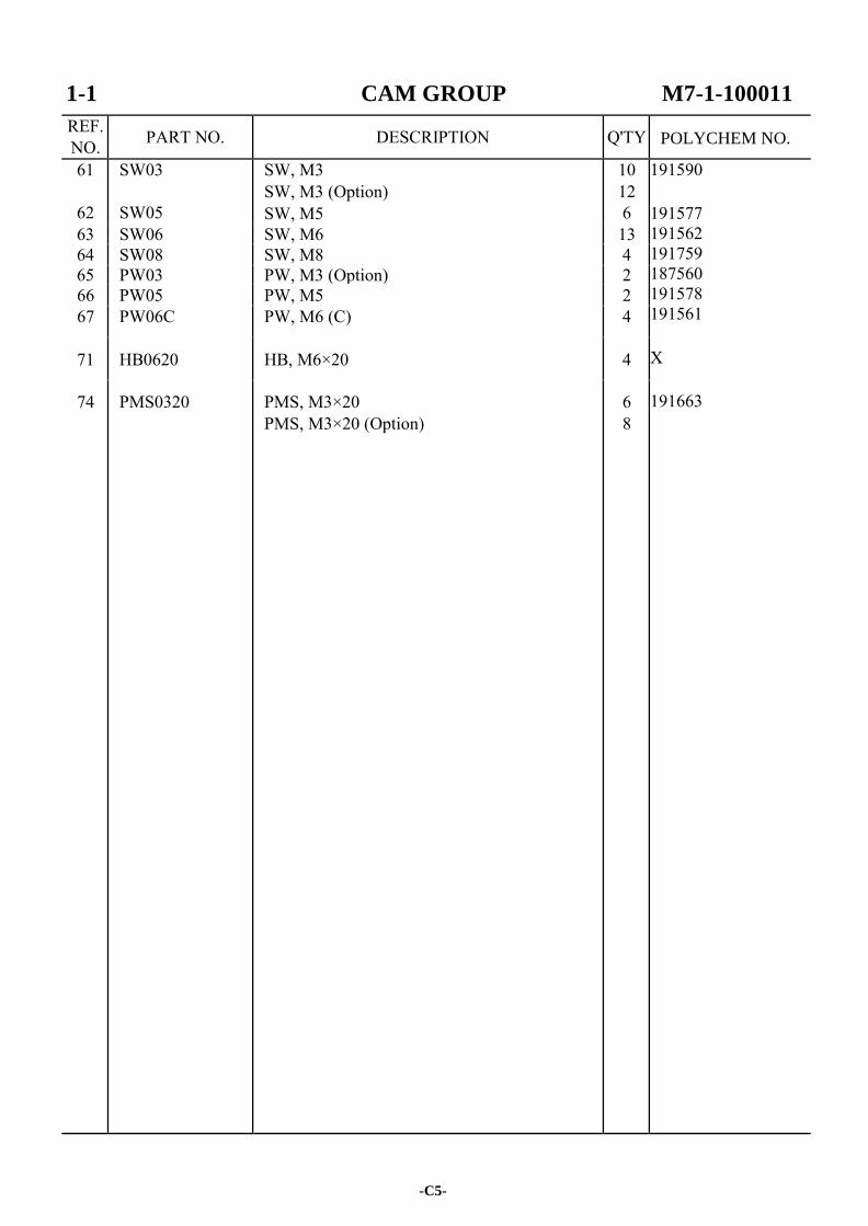
1-1 CAM GROUP M7-1-100011
REF. NO. PART NO. DESCRIPTION Q'TY
61
62
SW03
SW05
SW, M3 SW, M3 (Option) SW, M5
10 12 6
191590 191577 191562 191759 187560 191578 191561 X 191663
63 SW06 SW, M6 13 64 SW08 SW, M8 4 65 PW03 PW, M3 (Option) 2 66 PW05 PW, M5 2 67 PW06C PW, M6 (C) 4
71 HB0620 HB, M6×20 4
74 PMS0320 PMS, M3×20 PMS, M3×20 (Option)
6 8
POLYCHEM NO.

-C6-
1-1-1 GEAR BOX AND CAM ASS'Y M7-1-110001
-C7-
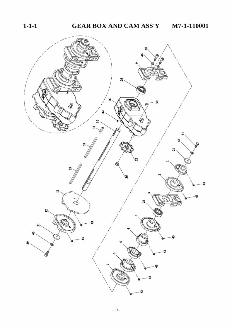
1-1-1 GEAR BOX AND CAM ASS'Y M7-1-110001
REF. NO. PART NO. DESCRIPTION Q'TY
1 M7-1-111100 Retracting Cam 1 X X X X X X X X X X X X X X 187830 X X
X
X 191544 X X 187305
191562 191612
2 M7-1-111200 Tension Cam 1 3 M7-1-111300 Heater Cam 1 4 M7-1-111400 Front Bar Cam 1 5 M7-1-111500 Press Bar Cam 1 6 M7-1-111600 Rear Bar Cam 1 7 M7-1-111701 Slide Table Cam 1
9 M7-1-111900 Support 2 10 M7-1-112001 Cam Shaft 1 11 M7-1-112100 Position Cam 1 12 M7-1-112201 Arch Cam 1
16 M7-1-110100 Gear Box 1
21 TB-223 Washer 2 22 T7-1-11240 Handle 1
26 BR6003ZZ Bearing, 6003ZZ 2
30 KYA020210 Key, 2×2×10 1 31 KYA050530 Key, 5×5×30 1
33 KYA0505101 Key, 5×5×101 2
36
CAP06
CAP, M6
1
39 HBS0616N HBS, M6×16 (N) 1 40 HBS0625N HBS, M6×25 (N) 4
42 HSS0505GN HSS, M5×5 (G)(N) 1 43 HSS0606GN HSS, M6×6 (G)(N) 9
46 SW06 SW, M6 6
51
HB0616
HB, M6×16
1
-C8-
POLYCHEM NO.
1-1-2 M1 MOTOR ASS'Y M7-1-120000
-C9-
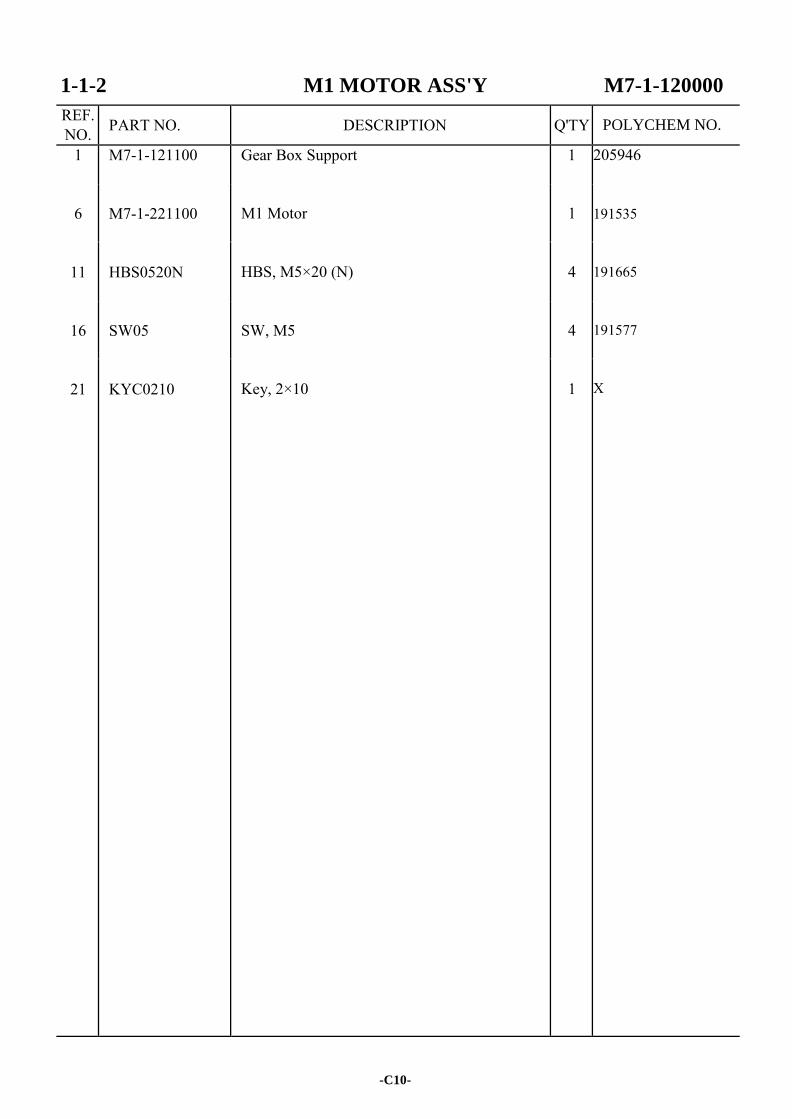
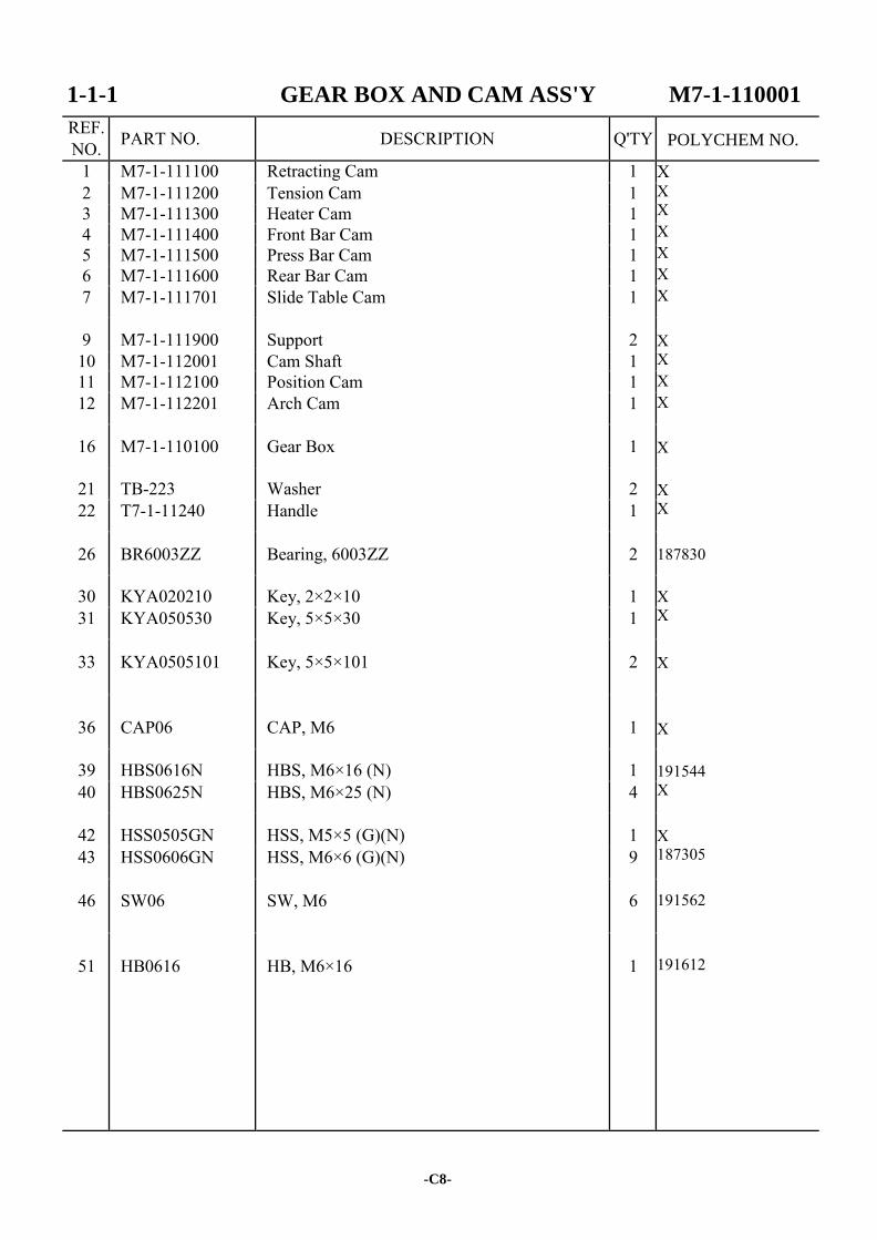
1-1-2 M1 MOTOR ASS'Y M7-1-120000
REF. NO. PART NO. DESCRIPTION Q'TY
1 M7-1-121100 Gear Box Support 1 205946 191535 191665 191577 X
6
M7-1-221100
M1 Motor
1
11
HBS0520N
HBS, M5×20 (N)
4
16
SW05
SW, M5
4
21
KYC0210
Key, 2×10
1
-C10-
POLYCHEM NO.
1-1-3 SLIDE TABLE FRAME ASS'Y M7-1-130000
-C11-
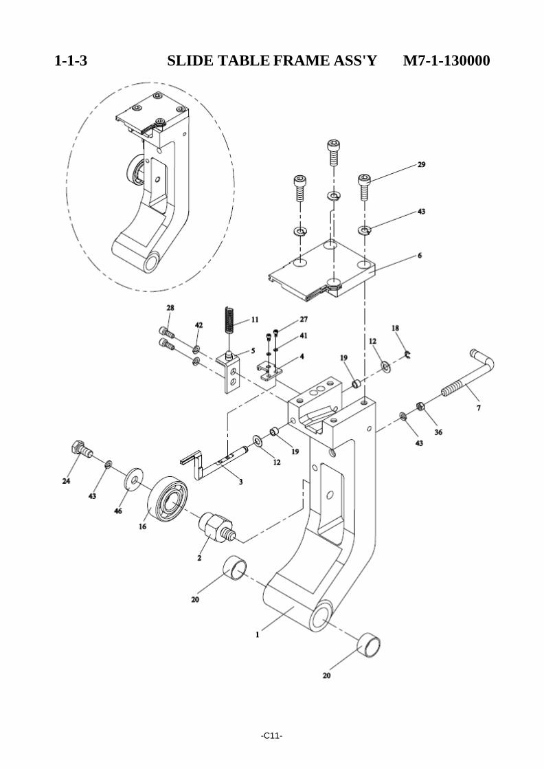
1-1-3 SLIDE TABLE FRAME ASS'Y M7-1-130000
REF. NO. PART NO. DESCRIPTION Q'TY
1 M7-1-131101 Slide Table Frame 1 191543 X 191542 191528 191545 191490 191721 X 191492 191504
191283 191505 191506
191507
205333
191589 190848 191544 191611
191590 191577 191562
191561
2 M7-1-131200 Shaft 1 3 M7-1-131300 Switch Lever 1 4 M7-1-131400 Sensor Plate 1 5 M7-1-131500 Spring Base 1 6
7
M7-1-131600 M7-1-131600S M7-1-131700
Slide Table Slide Table (Stainless Steel Model)(Option) Spring Hook
1 1 1
11
T7-1-10140
Spring
1
12 T7-3-40470 Washer 2
16 BR6202ZZ Bearing, 6202ZZ 1
18 ER04 Snap Ring, E-4 1 19 MB0508 Metal Bushing, 0508 2 20 MB1515 Metal Bushing, 1515 2
24 HB0612 HB, M6×12 1
27
HBS0306N
HBS, M3×6 (N)
2
28 HBS0512N HBS, M5×12 (N) 2 29 HBS0616N HBS, M6×16 (N) 4
36
HN06
HN, M6
1
41
SW03
SW, M3
2
42 SW05 SW, M5 2 43 SW06 SW, M6 6
46
PW06C
PW, M6 (C)
1
-C12-
POLYCHEM NO.
1-1-4 HEATER ARM ASS'Y M7-1-140000
-C13-
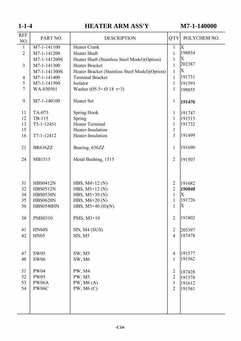
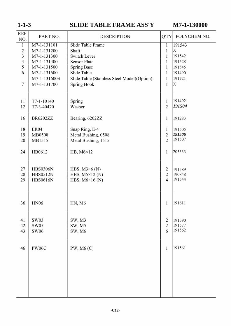
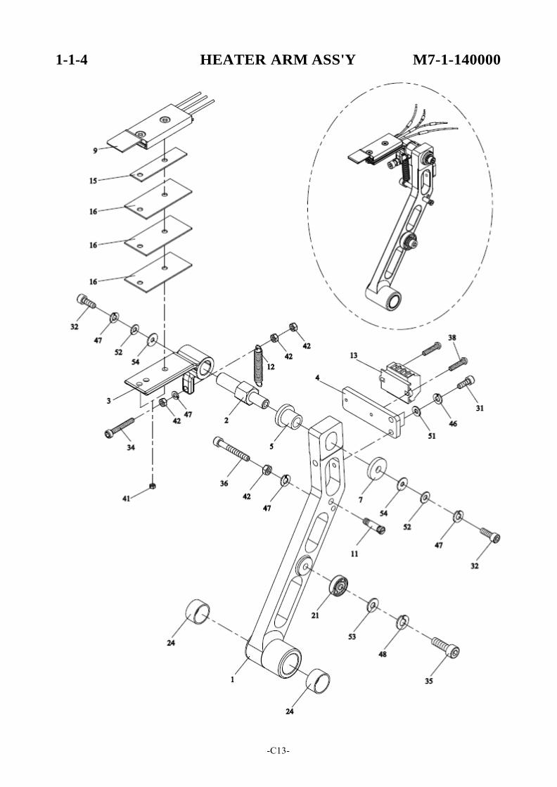
1-1-4 HEATER ARM ASS'Y M7-1-140000
REF. NO. PART NO. DESCRIPTION Q'TY
1 M7-1-141100 Heater Crank 1 X 198854 X 202387 X 191731 191593 198855 191476
191747 191515 191732 191499 191690 191507 191682 190848
X 191726 X 191802 205397 187478 191577 191562 187428 191578 191612 191561
2
3
4
M7-1-141200 M7-1-141200S M7-1-141300 M7-1-141300S M7-1-141400
Heater Shaft Heater Shaft (Stainless Steel Model)(Option) Heater Bracket Heater Bracket (Stainless Steel Model)(Option) Terminal Bracket
1 1 1 1 1
5 M7-1-141500 Isolator 1 7 WA-030501 Washer (Ø5.5× Ø 18 t=3) 1
9 M7-1-140100 Heater Set 1
11 TA-073 Spring Hook 1 12 TB-115 Spring 1 13 T5-1-12451 Heater Terminal 1 15 Heater-Insulation 1 16 T7-1-12412 Heater-Insulation 3
21 BR636ZZ Bearing, 636ZZ 1
24 MB1515 Metal Bushing, 1515 2
31
HBS0412N
HBS, M4×12 (N)
2
32 HBS0512N HBS, M5×12 (N) 2 34 HBS0530N HBS, M5×30 (N) 1 35 HBS0620N HBS, M6×20 (N) 1 36 HBS0540HN HBS, M5×40 (H)(N) 1
38 PMS0310 PMS, M3×10 2
41 HN04S HN, M4 (SUS) 2 42 HN05 HN, M5 4
47
SW05
SW, M5
4
48 SW06 SW, M6 1
51 PW04 PW, M4 2 52 PW05 PW, M5 2 53 PW06A PW, M6 (A) 1 54 PW06C PW, M6 (C) 2
-C14-
POLYCHEM NO.
1-1-5 EXHAUST FAN ASS'Y M7-1-150000
-C15-
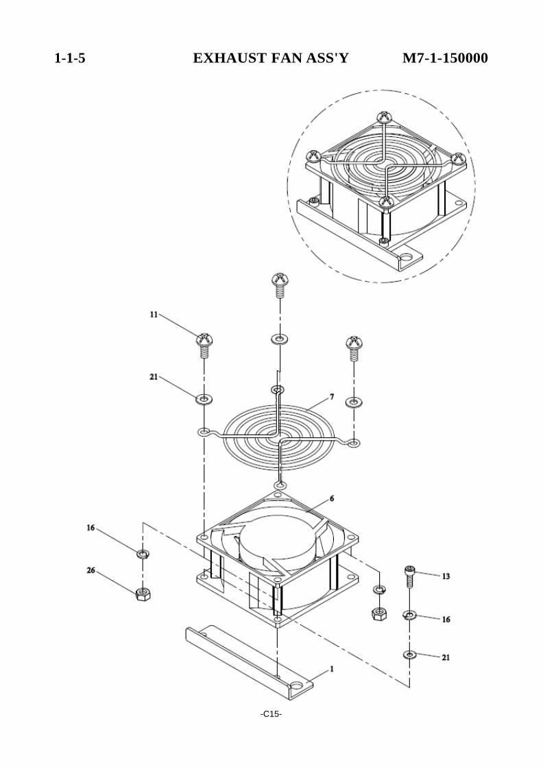
1-1-5 EXHAUST FAN ASS'Y M7-1-150000
REF. NO. PART NO. DESCRIPTION Q'TY
1 M7-1-151100 Fan Bracket 1 X 191765 204021
X
X X
187428 191604
6
T5-1-12370
Fan
1
7 T7-6-10930 Fan Cover 1
11
TMS0412
TMS, M4×12
4
13 HBS0410N HBS, M4×10 (N) 2
16 SW04 SW, M4 6
21
PW04
PW, M4
6
26
HN04
HN, M4
4
-C16-
POLYCHEM NO.
1-1-6 BLOCKASS'Y T7-1-16000
-C17-
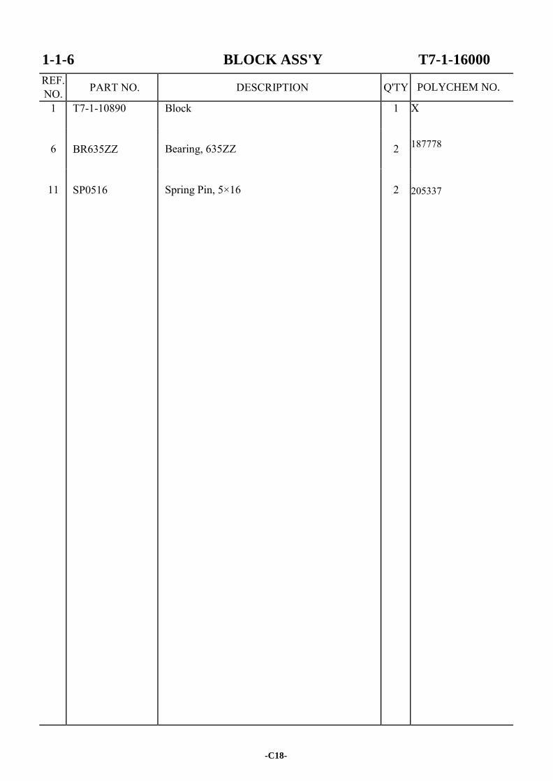
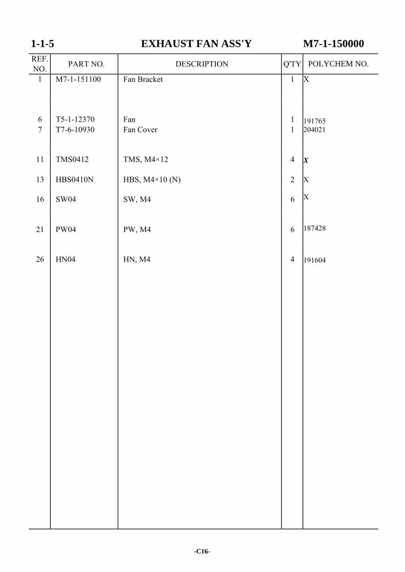
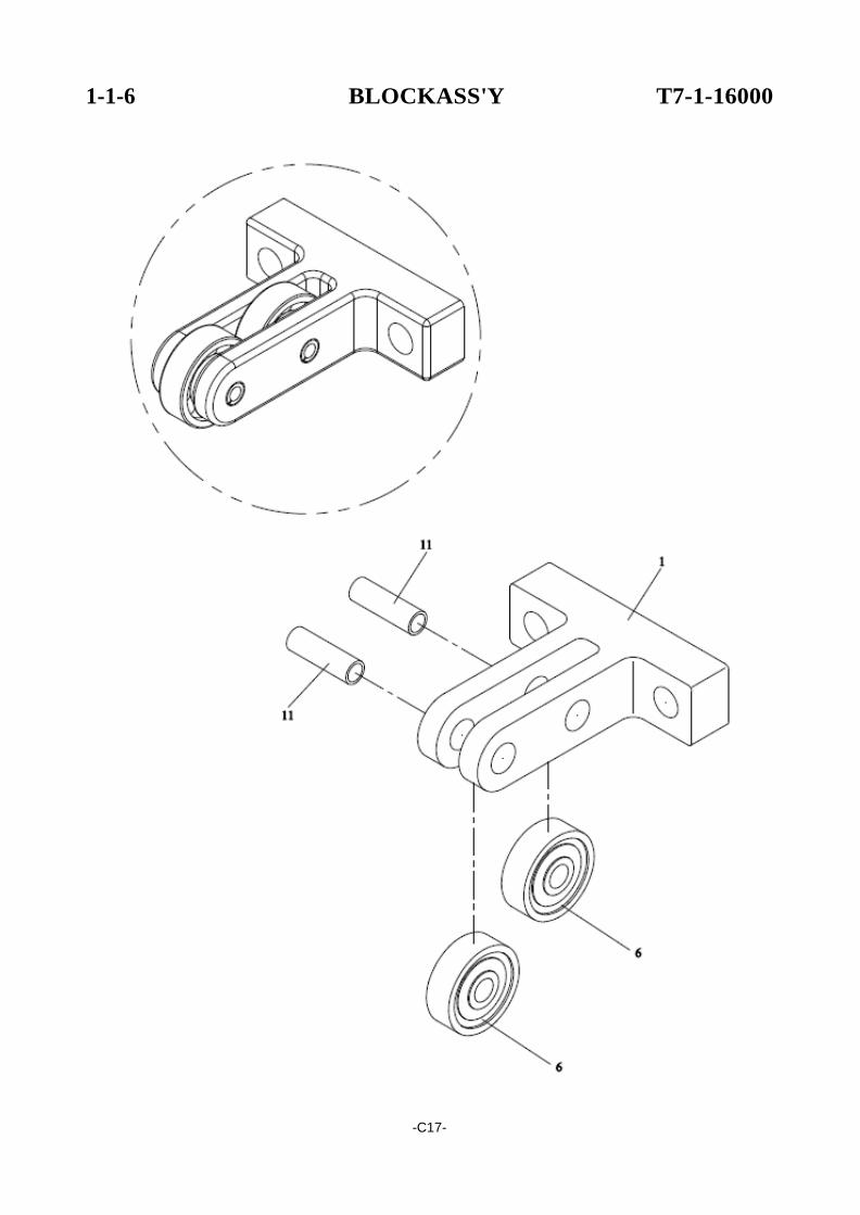
1-1-6 BLOCK ASS'Y T7-1-16000
REF. NO. PART NO. DESCRIPTION Q'TY
1 T7-1-10890 Block 1 X 187778 205337
6
BR635ZZ
Bearing, 635ZZ
2
11
SP0516
Spring Pin, 5×16
2
-C18-
POLYCHEM NO.
1-2 BAR GUIDE GROUP M7-1-200000
25
11
-C19-
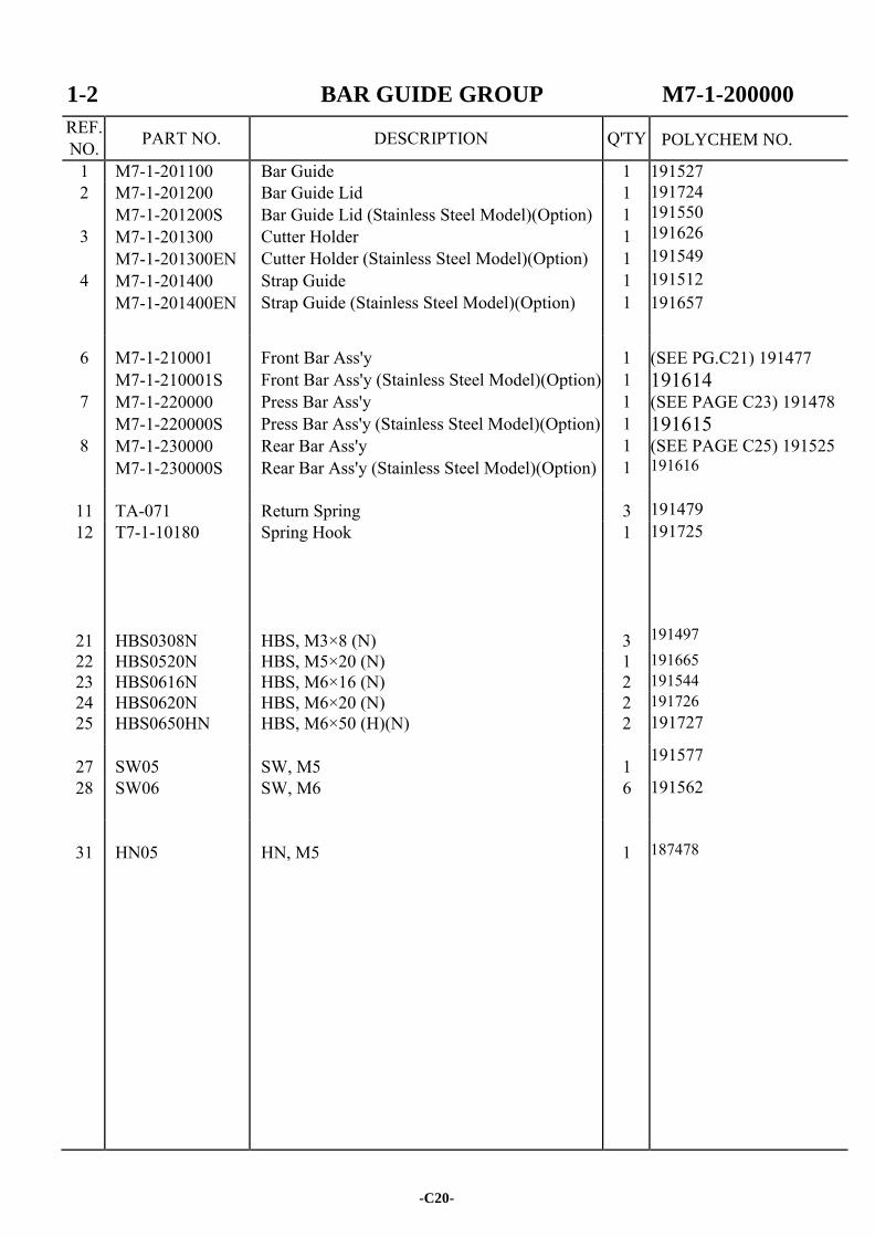
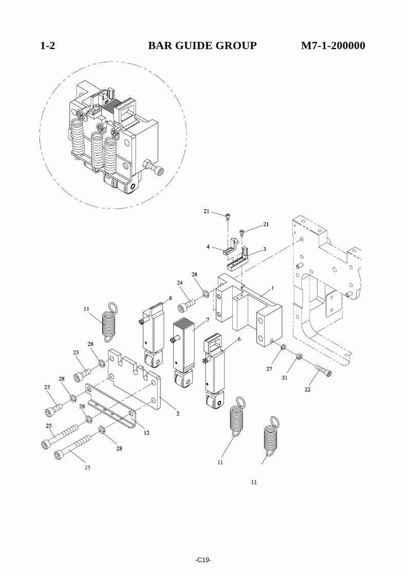
1-2 BAR GUIDE GROUP M7-1-200000
REF. NO. PART NO. DESCRIPTION Q'TY
1 M7-1-201100 Bar Guide 1 191527 2
3
4
M7-1-201200 M7-1-201200S M7-1-201300 M7-1-201300EN M7-1-201400 M7-1-201400EN
Bar Guide Lid Bar Guide Lid (Stainless Steel Model)(Option) Cutter Holder Cutter Holder (Stainless Steel Model)(Option) Strap Guide Strap Guide (Stainless Steel Model)(Option)
1 1 1 1 1 1
191724 191550 191626 191549 191512 191657
6
7
8
M7-1-210001 M7-1-210001S M7-1-220000 M7-1-220000S M7-1-230000 M7-1-230000S
Front Bar Ass'y Front Bar Ass'y (Stainless Steel Model)(Option) Press Bar Ass'y Press Bar Ass'y (Stainless Steel Model)(Option) Rear Bar Ass'y Rear Bar Ass'y (Stainless Steel Model)(Option)
1 1 1 1 1 1
(SEE PG.C21) 191477 191614 (SEE PAGE C23) 191478 191615 (SEE PAGE C25) 191525 191616
11 TA-071 Return Spring 3
191479 12 T7-1-10180 Spring Hook 1 191725
21
HBS0308N
HBS, M3×8 (N)
3
191497
22 HBS0520N HBS, M5×20 (N) 1 191665 23 HBS0616N HBS, M6×16 (N) 2 191544 24 HBS0620N HBS, M6×20 (N) 2 191726 25 HBS0650HN HBS, M6×50 (H)(N) 2 191727
27 SW05 SW, M5 1 191577
28 SW06 SW, M6 6 191562
31
HN05
HN, M5
1
187478
-C20-
POLYCHEM NO.
1-2-1 FRONT BAR ASS'Y M7-1-210001
-C21-
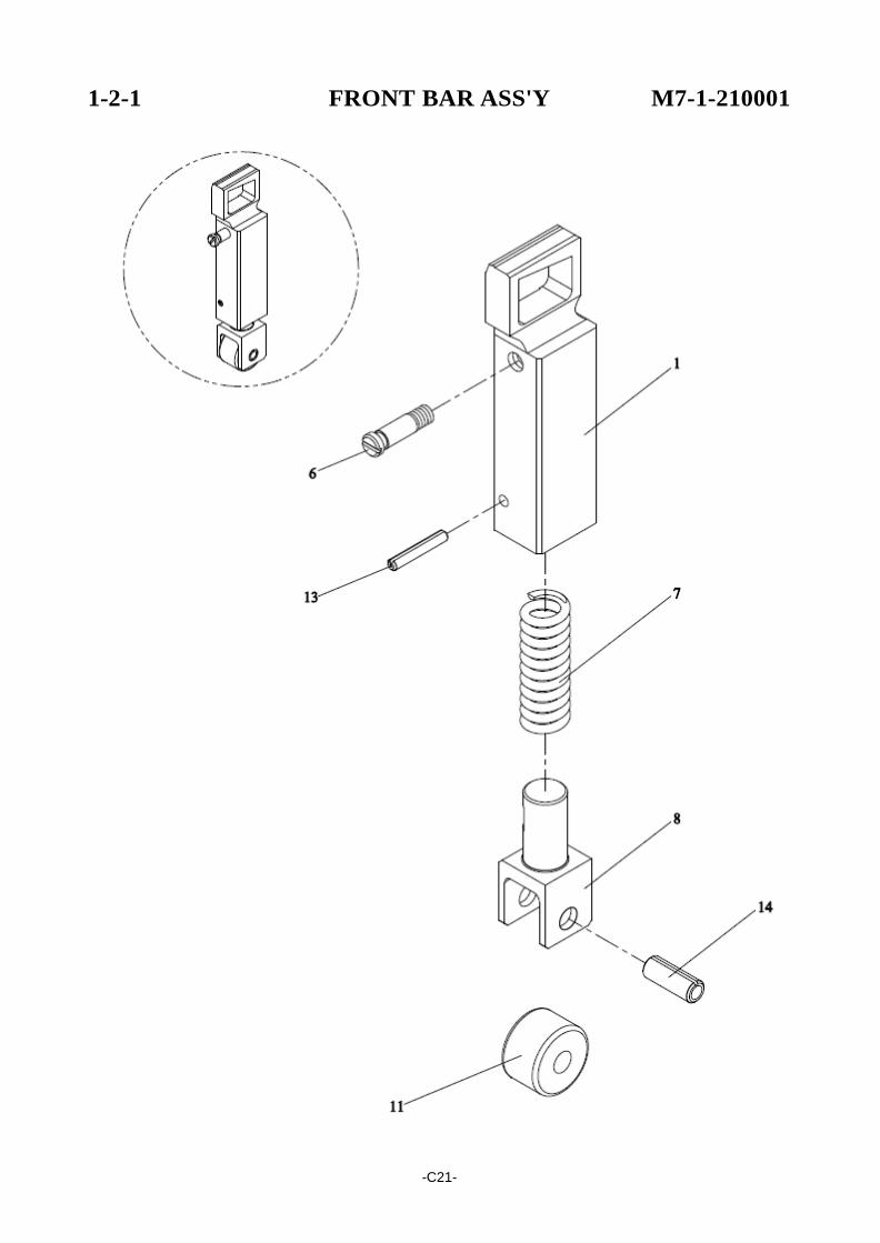
1-2-1 FRONT BAR ASS'Y M7-1-210001
REF. NO. PART NO. DESCRIPTION Q'TY
M7-1-210001 Front Bar Ass'y 1 191477 191614 191602 X 191747 191516 191654 191644 190797 191698
1
M7-1-210001S M7-1-211101 M7-1-211101S
Front Bar Ass'y (Stainless Steel Model)(Option) Front Bar Front Bar (Stainless Steel Model)(Option)
1 1 1
6 TA-073 Spring Hook 1 7 TA-078 Spring 1 8 T7-1-13121 Plunger 1
11
BRNART6VR
Bearing, NART6VR
1
13 SP0318 Spring Pin, 3×18 1 14 SP0616 Spring Pin, 6×16 1
-C22-
POLYCHEM NO.

1-2-2 PRESS BAR ASS'Y M7-1-220000
-C23-
1-2-2 PRESS BAR ASS'Y M7-1-220000
REF. NO. PART NO. DESCRIPTION Q'TY
M7-1-220000 Press Bar Ass'y 1 191478 191615 191633 X 191747 191516 191654 191644 190797 191698
1
M7-1-220000S M7-1-221200 M7-1-221200S
Press Bar Ass'y (Stainless Steel Model)(Option) Press Bar Press Bar (Stainless Steel Model)(Option)
1 1 1
6 TA-073 Spring Hook 1 7 TA-078 Spring 1 8 T7-1-13121 Plunger 1
11
BRNART6VR
Bearing, NART6VR
1
13 SP0318 Spring Pin, 3×18 1 14 SP0616 Spring Pin, 6×16 1
-C24-
POLYCHEM NO.
1-2-3 REAR BAR ASS'Y M7-1-230000
-C25-
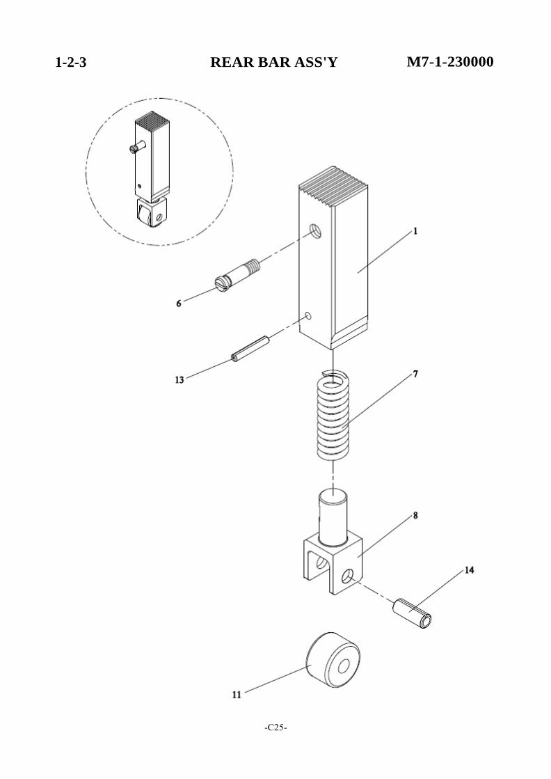
1-2-3 REAR BAR ASS'Y M7-1-230000
REF. NO. PART NO. DESCRIPTION Q'TY
M7-1-230000 Rear Bar Ass'y 1 191525 191616 191685 X
191747 191516 191654 191644 190797 191698
1
M7-1-230000S M7-1-231100 M7-1-231100S
Rear Bar Ass'y (Stainless Steel Model)(Option) Rear Bar Rear Bar (Stainless Steel Model)(Option)
1 1 1
6 TA-073 Spring Hook 1 7 TA-078 Spring 1 8 T7-1-13121 Plunger 1
11
BRNART6VR
Bearing, NART6VR
1
13 SP0318 Spring Pin, 3×18 1 14 SP0616 Spring Pin, 6×16 1
-C26-
POLYCHEM NO.
1-3 FEED GROUP M7-1-300021
-C27-
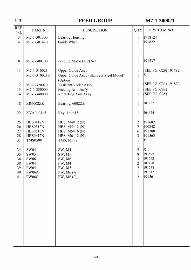
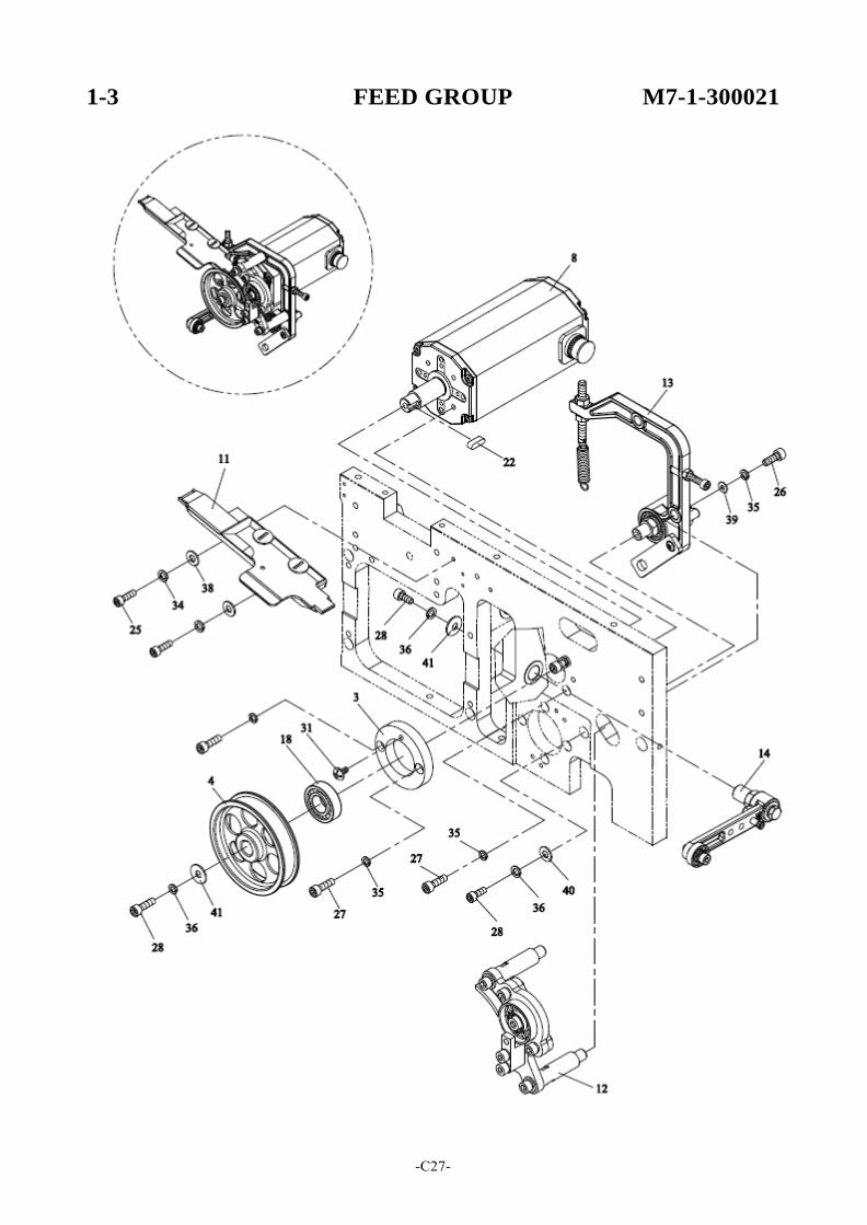
1-3 FEED GROUP M7-1-300021
REF. NO. PART NO. DESCRIPTION Q'TY
3 M7-1-301300 Bearing Housing 1 1918124 4 M7-1-301420 Guide Wheel 1 191822
8
M7-1-300100
Feeding Motor (M2) Set
1
191537
11
12
M7-1-310021 M7-1-310021S
M7-1-320020
Upper Guide Ass'y Upper Guide Ass'y (Stainless Steel Model) (Option) Assistant Roller Ass'y
1 1
1
(SEE PG. C29) 191792 X (SEE PG. C31) 191820
13 M7-1-330000 Feeding Arm Ass'y 1 (SEE PG. C33) 14 M7-1-340000 Retracting Arm Ass'y 1 (SEE PG. C35)
18 BR6002ZZ Bearing, 6002ZZ 1
187782
22 KYA040415 Key, 4×4×15 1
204624
25 HBS0412N HBS, M4×12 (N) 2
191682 26 HBS0512N HBS, M5×12 (N) 2 190848 27 HBS0516N HBS, M5×16 (N) 6 191700 28 HBS0612N HBS, M6×12 (N) 3 191563 31 TMS0508 TMS, M5×8 1 X
34 SW04 SW, M4 2
X 35 SW05 SW, M5 8 191577 36 SW06 SW, M6 3 191562 38 PW04 PW, M4 2 187428 39 PW05 PW, M5 2 191578 40 PW06A PW, M6 (A) 1 191612 41 PW06C PW, M6 (C) 2 191561
-C28-
POLYCHEM NO.
1-3-1 UPPER GUIDE ASS'Y M7-1-310021
-C29-
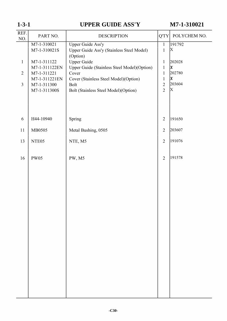
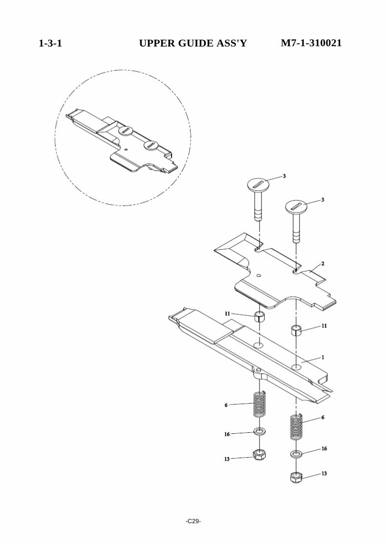
1-3-1 UPPER GUIDE ASS'Y M7-1-310021
REF. NO. PART NO. DESCRIPTION Q'TY
M7-1-310021 Upper Guide Ass'y 1 191792 X
202028 X 202780 X
203604 X 191650 203607 191076 191578
1
2
3
M7-1-310021S
M7-1-311122 M7-1-311122EN M7-1-311221 M7-1-311221EN M7-1-311300 M7-1-311300S
Upper Guide Ass'y (Stainless Steel Model) (Option) Upper Guide Upper Guide (Stainless Steel Model)(Option) Cover Cover (Stainless Steel Model)(Option) Bolt Bolt (Stainless Steel Model)(Option)
1
1 1 1 1 2 2
6
H44-10940
Spring
2
11 MB0505 Metal Bushing, 0505 2
13 NTE05 NTE, M5 2
16
PW05
PW, M5
2
-C30-
POLYCHEM NO.
1-3-2 ASSISTANT ROLLER ASS'Y M7-1-320020
/
-C31-
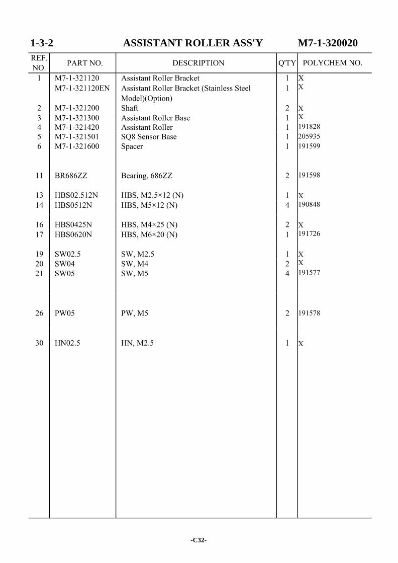
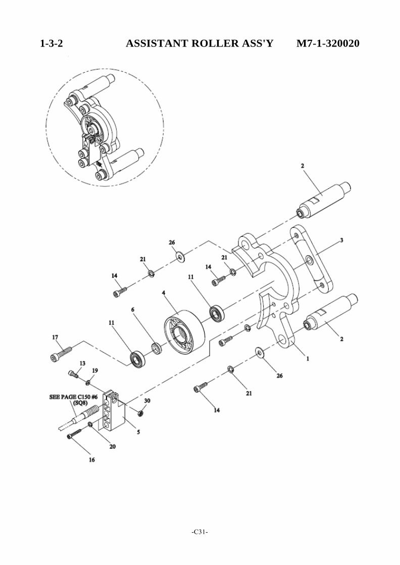
1-3-2 ASSISTANT ROLLER ASS'Y M7-1-320020
REF. NO. PART NO. DESCRIPTION Q'TY
1
2
M7-1-321120 M7-1-321120EN
M7-1-321200
Assistant Roller Bracket Assistant Roller Bracket (Stainless Steel Model)(Option) Shaft
1 1
2
X X
X X 191828 205935 191599 191598 X 190848 X 191726 X X 191577
191578
X
3 M7-1-321300 Assistant Roller Base 1 4 M7-1-321420 Assistant Roller 1 5 M7-1-321501 SQ8 Sensor Base 1 6 M7-1-321600 Spacer 1
11
BR686ZZ
Bearing, 686ZZ
2
13 HBS02.512N HBS, M2.5×12 (N) 1 14 HBS0512N HBS, M5×12 (N) 4
16 HBS0425N HBS, M4×25 (N) 2 17 HBS0620N HBS, M6×20 (N) 1
19 SW02.5 SW, M2.5 1 20 SW04 SW, M4 2 21 SW05 SW, M5 4
26
PW05
PW, M5
2
30
HN02.5
HN, M2.5
1
-C32-
POLYCHEM NO.
1-3-3 FEEDING ARM ASS'Y M7-1-330000
-C33-
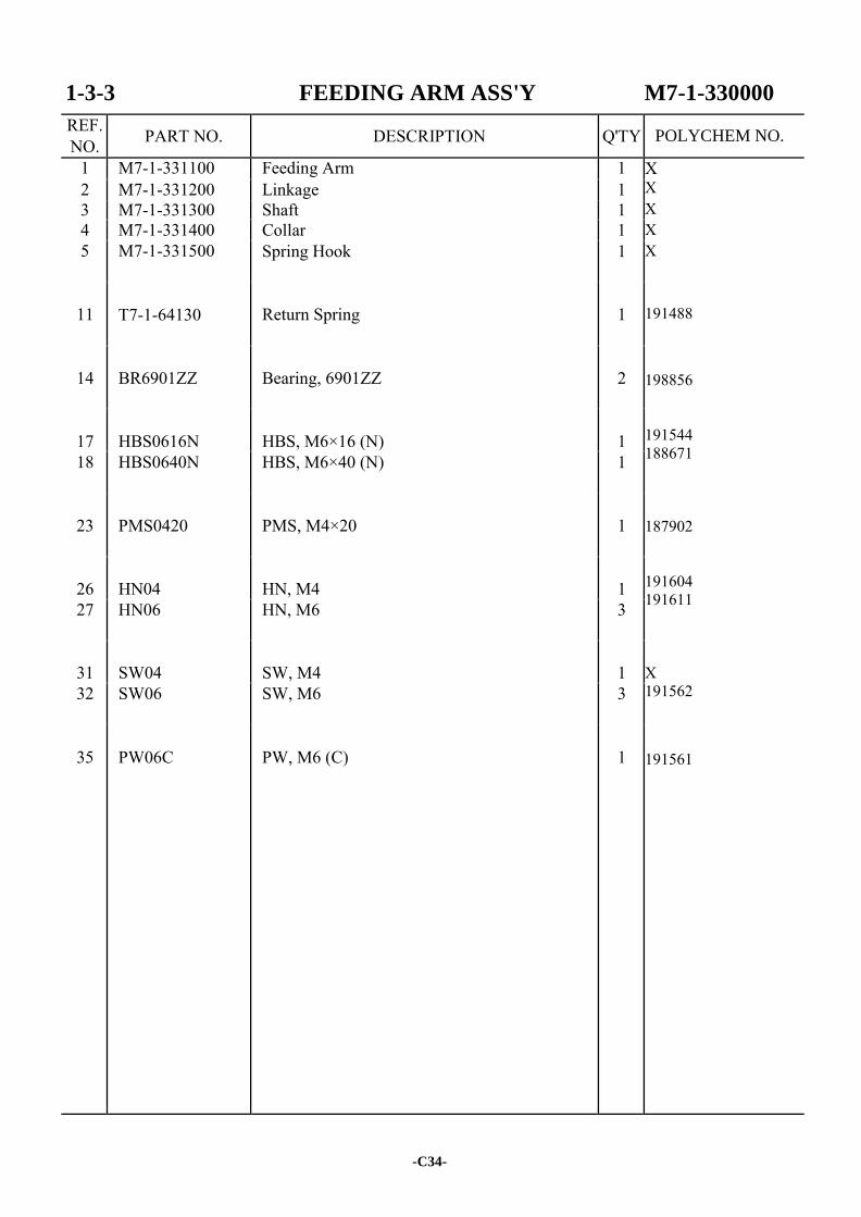
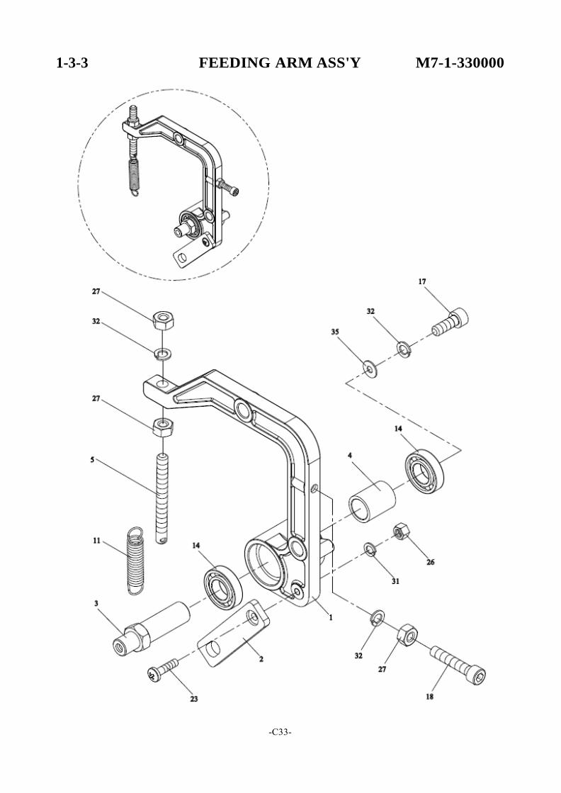
1-3-3 FEEDING ARM ASS'Y M7-1-330000
REF. NO. PART NO. DESCRIPTION Q'TY
1 M7-1-331100 Feeding Arm 1 X X X X X 191488
198856 191544 188671 187902 191604 191611 X 191562 191561
2 M7-1-331200 Linkage 1 3 M7-1-331300 Shaft 1 4 M7-1-331400 Collar 1 5 M7-1-331500 Spring Hook 1
11
T7-1-64130
Return Spring
1
14
BR6901ZZ
Bearing, 6901ZZ
2
17
HBS0616N
HBS, M6×16 (N)
1
18 HBS0640N HBS, M6×40 (N) 1
23
PMS0420
PMS, M4×20
1
26
HN04
HN, M4
1
27 HN06 HN, M6 3
31
SW04
SW, M4
1
32 SW06 SW, M6 3
35
PW06C
PW, M6 (C)
1
-C34-
POLYCHEM NO.
1-3-4 RETRACTING ARM ASS'Y M7-1-340000 \
I
-C35-

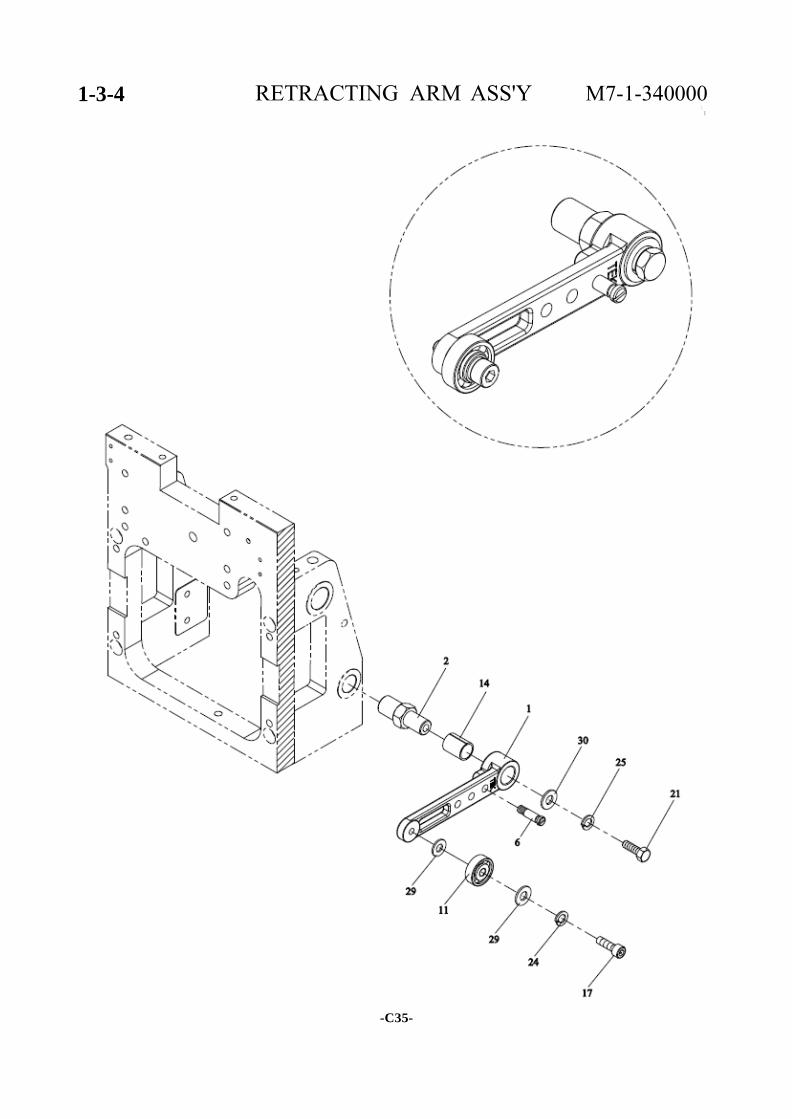
1-3-4 RETRACTING ARM ASS'Y M7-1-340000
REF. NO. PART NO. DESCRIPTION Q'TY
1 M7-1-341100 Retracting Arm 1 X X
191747 187778 X
191700
205333
191577 191562 191578 X
2 M7-1-341200 Shaft 1
6
TA-073
Spring Hook
1
11
BR635ZZ
Bearing, 635ZZ
1
14
MB1015
Metal Bushing, 1015
1
17
HBS0516N
HBS, M5×16 (N)
1
21
HB0612
HB, M6×12
1
24
SW05
SW, M5
1
25 SW06 SW, M6 1
29
PW05
PW, M5
2
30 PW06B PW, M6 (B) 1
-C36-
POLYCHEM NO.
1-4 TENSION GROUP M7-1-400021
-C37-
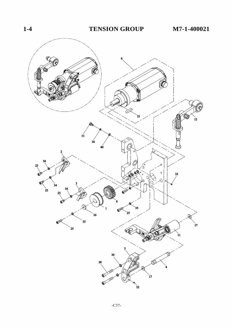
1-4 TENSION GROUP M7-1-400021
REF. NO. PART NO. DESCRIPTION Q'TY
1 M7-1-401120 Tension Guide Wheel 1 198851 M7-1-401120S Tension Guide Wheel (Stainless Steel Model) 1 X (Option)
2 M7-1-401220 Guide 1 191825 M7-1-401220EN Guide (Stainless Steel Model)(Option) 1 X
3 M7-1-401320 Tension Guide 1 191857
M7-1-401320EN Tension Guide (Stainless Steel Model)(Option) 1 X
4 M7-1-401400 Shaft 1 191818 5 M7-1-401500 Bracket 1 191819 6 M7-1-401600 Gear 1 191856
9 M7-1-301110 M3 Motor 1
191571
11 M7-1-410020 Tension Crank Ass'y 1
(SEE PG. C39) X
12 M7-1-420011 Tension Arm Ass'y 1 (SEE PG. C41) X
16 TB-223 Washer 1
X 17 AD-2-20181 Washer 2 191821
21
KYA050527
Key, 5×5×27
1
X
23 HBS0412N HBS, M4×12 (N) 4
191682
25 HBS0516N HBS, M5×16 (N) 5
191700
28 HBS0640HN HBS, M6×40 (H)(N) 2
188671
31 HB0612 HB, M6×12 1
205333 32 HSS0506GN HSS, M5×6 (G)(N) 2 191584
34 SW04 SW, M4 4
X 35 SW05 SW, M5 5 191577 36 SW06 SW, M6 3 191562
40
PW06C
PW, M6 (C)
1 191561
-C38-
POLYCHEM NO.
1-4-1 TENSION CRANK ASS'Y M7-1-410020
-C39-
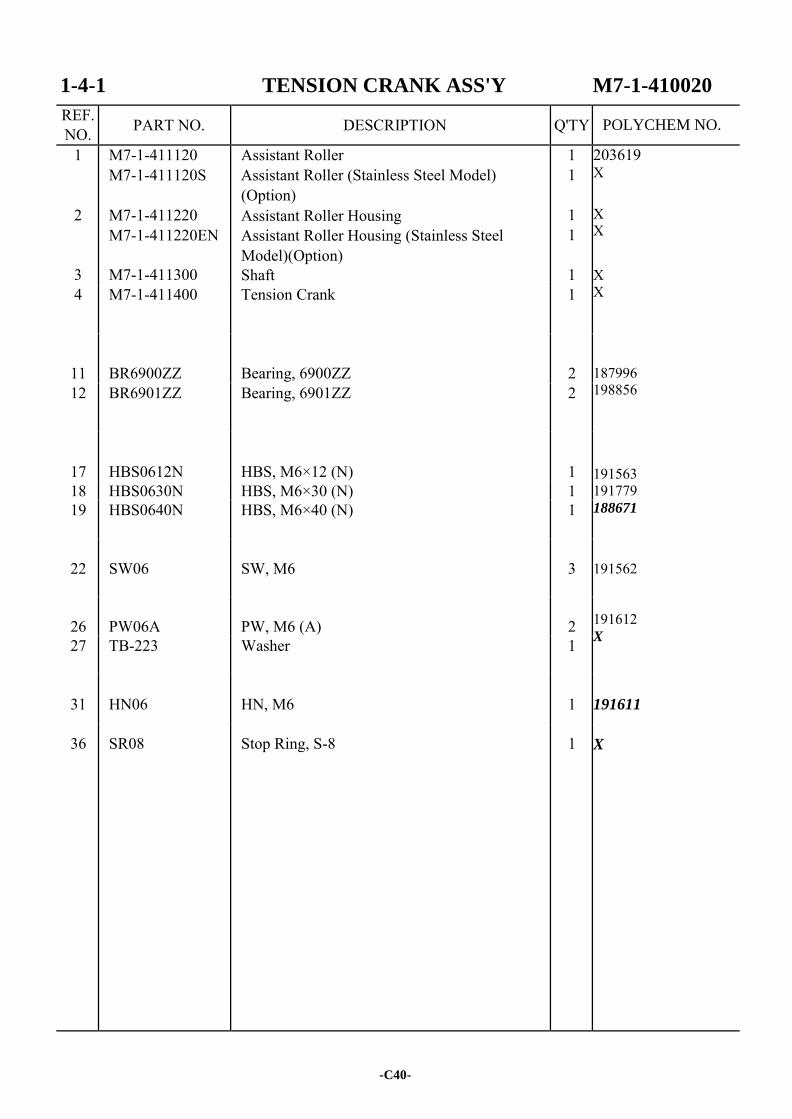
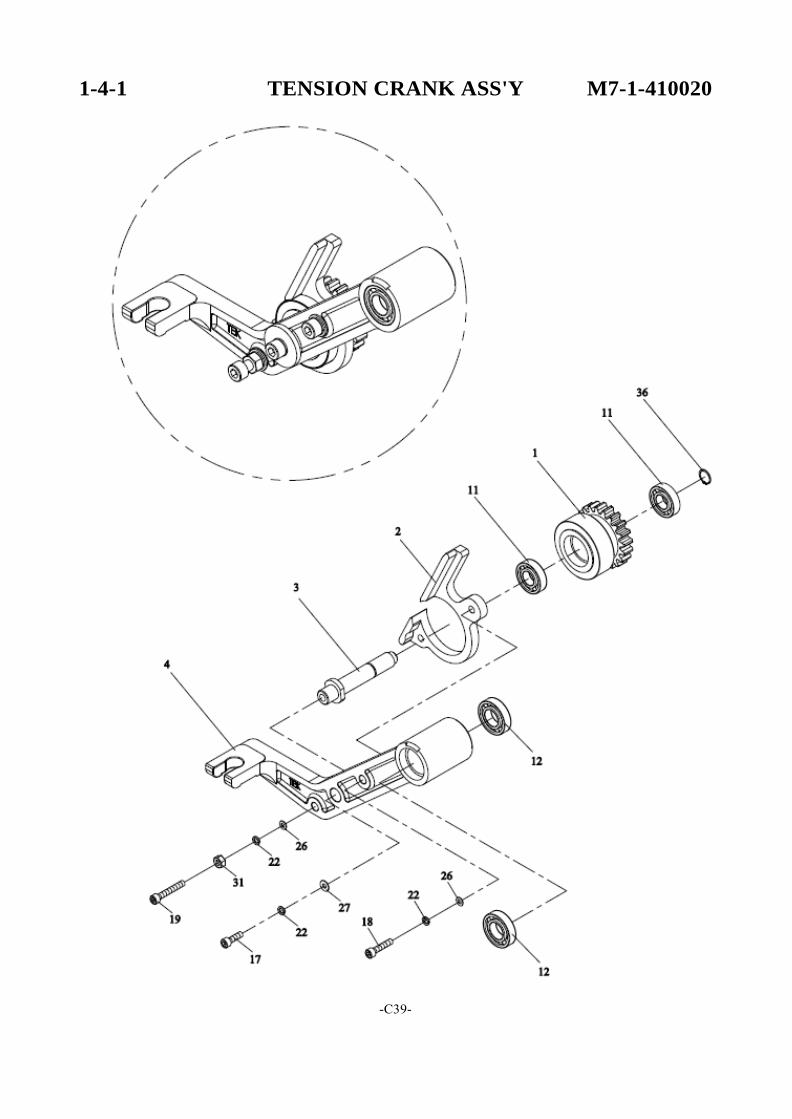
1-4-1 TENSION CRANK ASS'Y M7-1-410020
REF. NO. PART NO. DESCRIPTION Q'TY
1
2
3
M7-1-411120 M7-1-411120S
M7-1-411220 M7-1-411220EN
M7-1-411300
Assistant Roller Assistant Roller (Stainless Steel Model) (Option) Assistant Roller Housing Assistant Roller Housing (Stainless Steel Model)(Option) Shaft
1 1
1 1
1
203619 X X X
X X 187996 198856 191563 191779 188671
191562 191612 X
191611
X
4 M7-1-411400 Tension Crank 1
11
BR6900ZZ
Bearing, 6900ZZ
2
12 BR6901ZZ Bearing, 6901ZZ 2
17
HBS0612N
HBS, M6×12 (N)
1
18 HBS0630N HBS, M6×30 (N) 1 19 HBS0640N HBS, M6×40 (N) 1
22
SW06
SW, M6
3
26
PW06A
PW, M6 (A)
2
27 TB-223 Washer 1
31
HN06
HN, M6
1
36 SR08 Stop Ring, S-8 1
-C40-
POLYCHEM NO.
1-4-2 TENSION ARM ASS'Y M7-1-420011
-C41-
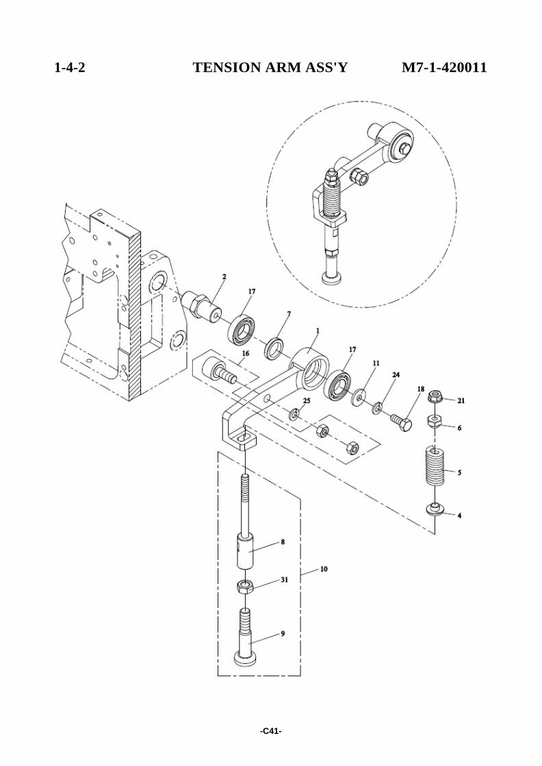
1-4-2 TENSION ARM ASS'Y M7-1-420011
REF. NO. PART NO. DESCRIPTION Q'TY
1 M7-1-421101 Tension Arm 1 X X
205490 191729 205491 X 203918 X 204692 X 191643 X
205333 205492 191562 191759
191612 187490
2 M7-1-421200 Shaft 1
4 M7-1-421400 Spring Support 1 5 M7-1-421520 Spring 1 6 M7-1-421600 Nut 1 7 M7-1-421700 Collar 1 8 M7-1-421800 Connecting Rod (Upper) 1 9 M7-1-421900 Connecting Rod (Lower) 1 10 M7-1-420100 Connecting Rod Set 1 11 TB-223 Washer 1
16
BRCF8
Bearing, CF8
1
17 BR6902ZZ Bearing, 6902ZZ 2
18 HB0612 HB, M6×12 1
21 FLG06 FLG, M6 1
24
SW06
SW, M6
1
25 SW08 SW, M8 1
28
PW06A
PW, M6 (A)
1
31
HN08
HN, M8
1
-C42-
POLYCHEM NO.
BANDWAY UNIT M7-2-900021
-C43-
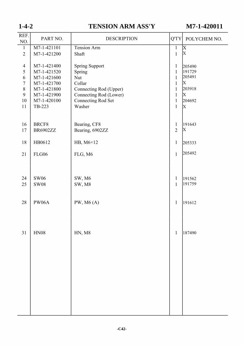
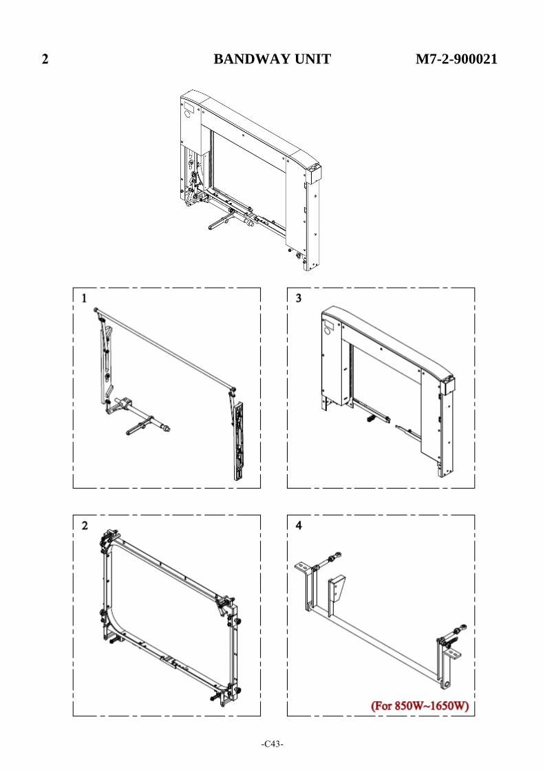
BANDWAY UNIT M7-2-900021
REF. NO. PART NO. DESCRIPTION Q'TY
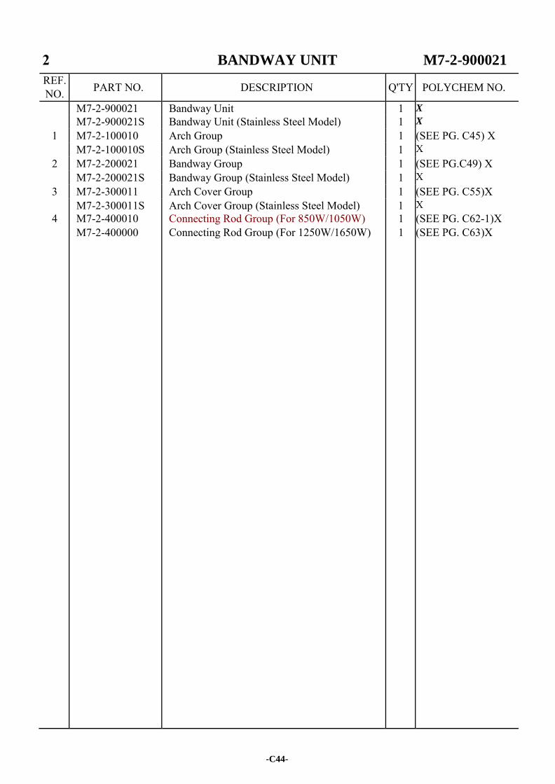
M7-2-900021 Bandway Unit 1 X
M7-2-900021S Bandway Unit (Stainless Steel Model) 1 X
1 M7-2-100010 Arch Group 1 (SEE PG. C45) X M7-2-100010S Arch Group (Stainless Steel Model) 1 X
2 M7-2-200021 Bandway Group 1 (SEE PG.C49) X M7-2-200021S Bandway Group (Stainless Steel Model) 1 X
3 M7-2-300011 Arch Cover Group 1 (SEE PG. C55)X M7-2-300011S Arch Cover Group (Stainless Steel Model) 1 X
4 M7-2-400010 Connecting Rod Group (For 850W/1050W) 1 (SEE PG. C62-1)X M7-2-400000 Connecting Rod Group (For 1250W/1650W) 1 (SEE PG. C63)X
-C44-
POLYCHEM NO.
2-1 ARCH GROUP M7-2-100010
-C45-
2-1 ARCH GROUP M7-2-100010
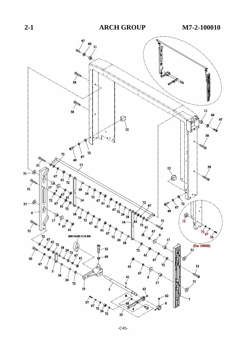
REF. NO. PART NO. DESCRIPTION Q'TY
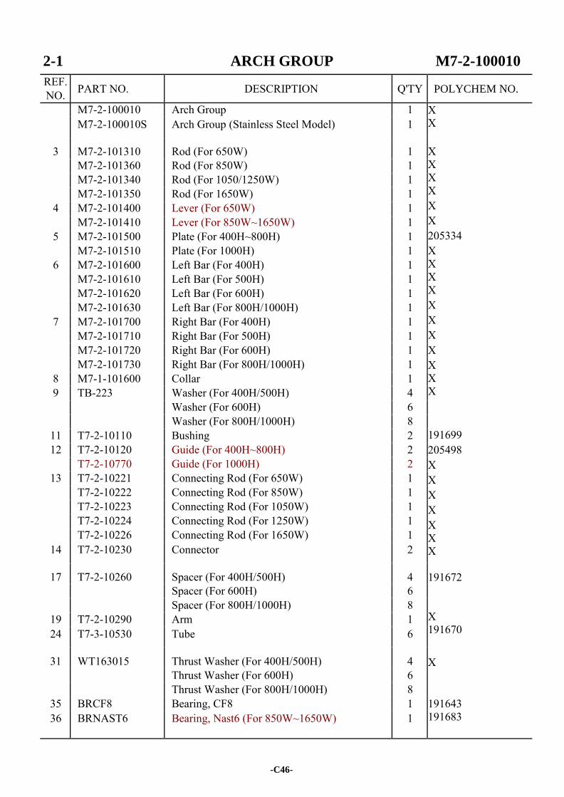
M7-2-100010 Arch Group 1 X X X X X X X X 205334 X X X X X X X X X X X 191699 205498 X X X X X X X 191672 X 191670 X 191643 191683
M7-2-100010S Arch Group (Stainless Steel Model) 1
3 M7-2-101310 Rod (For 650W) 1 M7-2-101360 Rod (For 850W) 1 M7-2-101340 Rod (For 1050/1250W) 1 M7-2-101350 Rod (For 1650W) 1
4 M7-2-101400 Lever (For 650W) 1 M7-2-101410 Lever (For 850W~1650W) 1
5 M7-2-101500 Plate (For 400H~800H) 1 M7-2-101510 Plate (For 1000H) 1
6 M7-2-101600 Left Bar (For 400H) 1 M7-2-101610 Left Bar (For 500H) 1 M7-2-101620 Left Bar (For 600H) 1 M7-2-101630 Left Bar (For 800H/1000H) 1
7 M7-2-101700 Right Bar (For 400H) 1 M7-2-101710 Right Bar (For 500H) 1 M7-2-101720 Right Bar (For 600H) 1 M7-2-101730 Right Bar (For 800H/1000H) 1
8 M7-1-101600 Collar 1 9 TB-223 Washer (For 400H/500H) 4
Washer (For 600H) 6 Washer (For 800H/1000H) 8
11 T7-2-10110 Bushing 2 12 T7-2-10120 Guide (For 400H~800H) 2
T7-2-10770 Guide (For 1000H) 2 13 T7-2-10221 Connecting Rod (For 650W) 1
T7-2-10222 Connecting Rod (For 850W) 1 T7-2-10223 Connecting Rod (For 1050W) 1 T7-2-10224 Connecting Rod (For 1250W) 1 T7-2-10226 Connecting Rod (For 1650W) 1
14 T7-2-10230 Connector 2
17 T7-2-10260 Spacer (For 400H/500H) 4 Spacer (For 600H) 6 Spacer (For 800H/1000H) 8
19 T7-2-10290 Arm 1 24 T7-3-10530 Tube 6
31 WT163015 Thrust Washer (For 400H/500H) 4 Thrust Washer (For 600H) 6 Thrust Washer (For 800H/1000H) 8
35 BRCF8 Bearing, CF8 1 36 BRNAST6 Bearing, Nast6 (For 850W~1650W) 1
-C46-
POLYCHEM NO.
2-1 ARCH GROUP M7-2-100010
REF. NO. PART NO. DESCRIPTION Q'TY
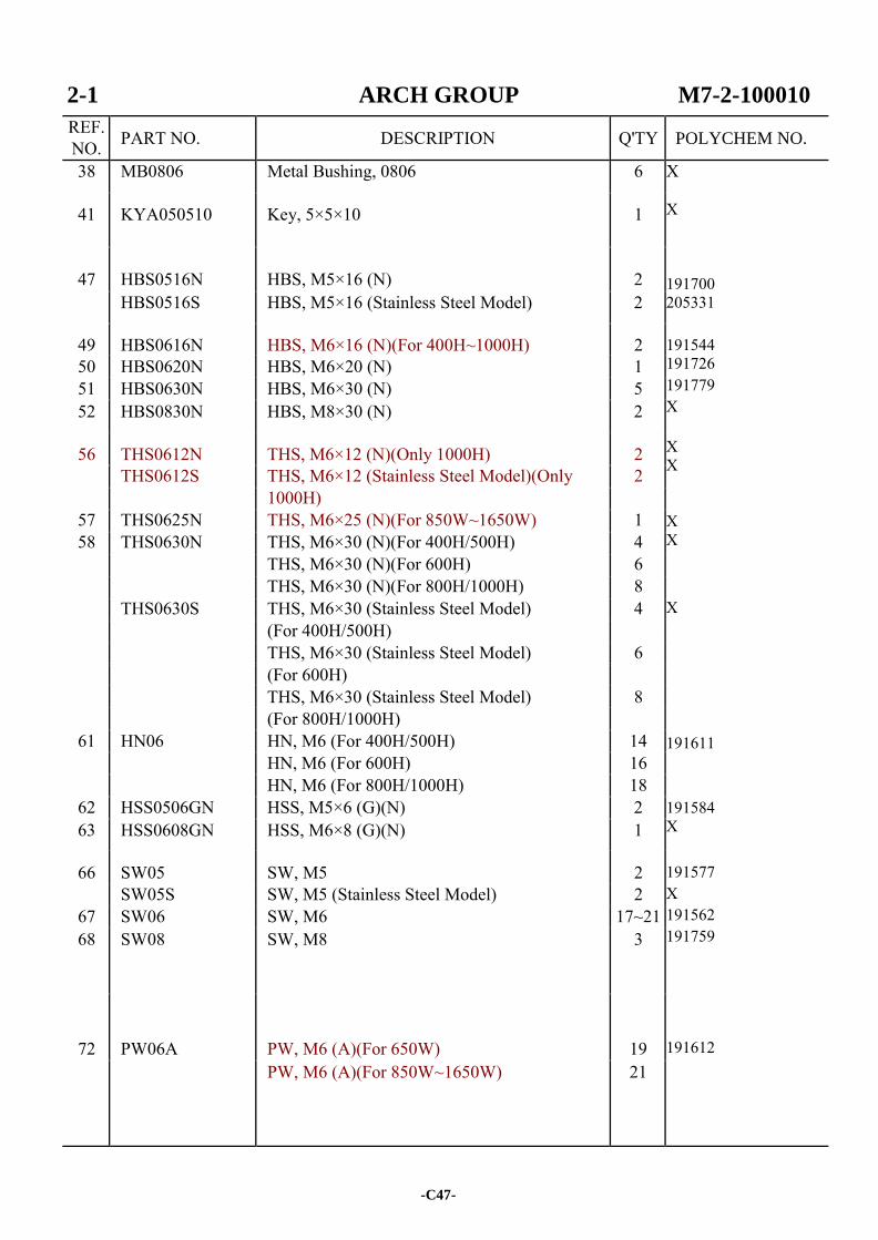
38 MB0806 Metal Bushing, 0806 6 X X 191700 205331 191544 191726 191779 X X X X X
X 191611 191584 X 191577 X 191562 191759 191612
41 KYA050510 Key, 5×5×10 1
47
HBS0516N
HBS, M5×16 (N)
2
HBS0516S HBS, M5×16 (Stainless Steel Model) 2
49 HBS0616N HBS, M6×16 (N)(For 400H~1000H) 2 50 HBS0620N HBS, M6×20 (N) 1 51 HBS0630N HBS, M6×30 (N) 5 52 HBS0830N HBS, M8×30 (N) 2
56 THS0612N THS, M6×12 (N)(Only 1000H) 2 THS0612S THS, M6×12 (Stainless Steel Model)(Only 2 1000H)
57 THS0625N THS, M6×25 (N)(For 850W~1650W) 1 58 THS0630N THS, M6×30 (N)(For 400H/500H) 4
THS, M6×30 (N)(For 600H) 6 THS, M6×30 (N)(For 800H/1000H) 8 THS0630S THS, M6×30 (Stainless Steel Model) 4 (For 400H/500H) THS, M6×30 (Stainless Steel Model) 6 (For 600H) THS, M6×30 (Stainless Steel Model) 8 (For 800H/1000H)
61 HN06 HN, M6 (For 400H/500H) 14 HN, M6 (For 600H) 16 HN, M6 (For 800H/1000H) 18
62 HSS0506GN HSS, M5×6 (G)(N) 2 63 HSS0608GN HSS, M6×8 (G)(N) 1
66 SW05 SW, M5 2 SW05S SW, M5 (Stainless Steel Model) 2
67 SW06 SW, M6 17~21 68 SW08 SW, M8 3
72
PW06A
PW, M6 (A)(For 650W)
19
PW, M6 (A)(For 850W~1650W) 21
-C47-
POLYCHEM NO.

-C48-
2-2 BANDWAY GROUP M7-2-200021
-C49-
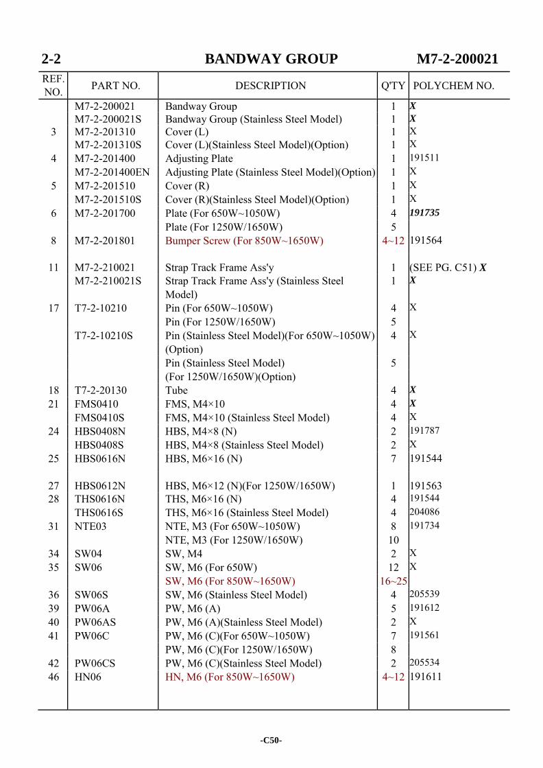
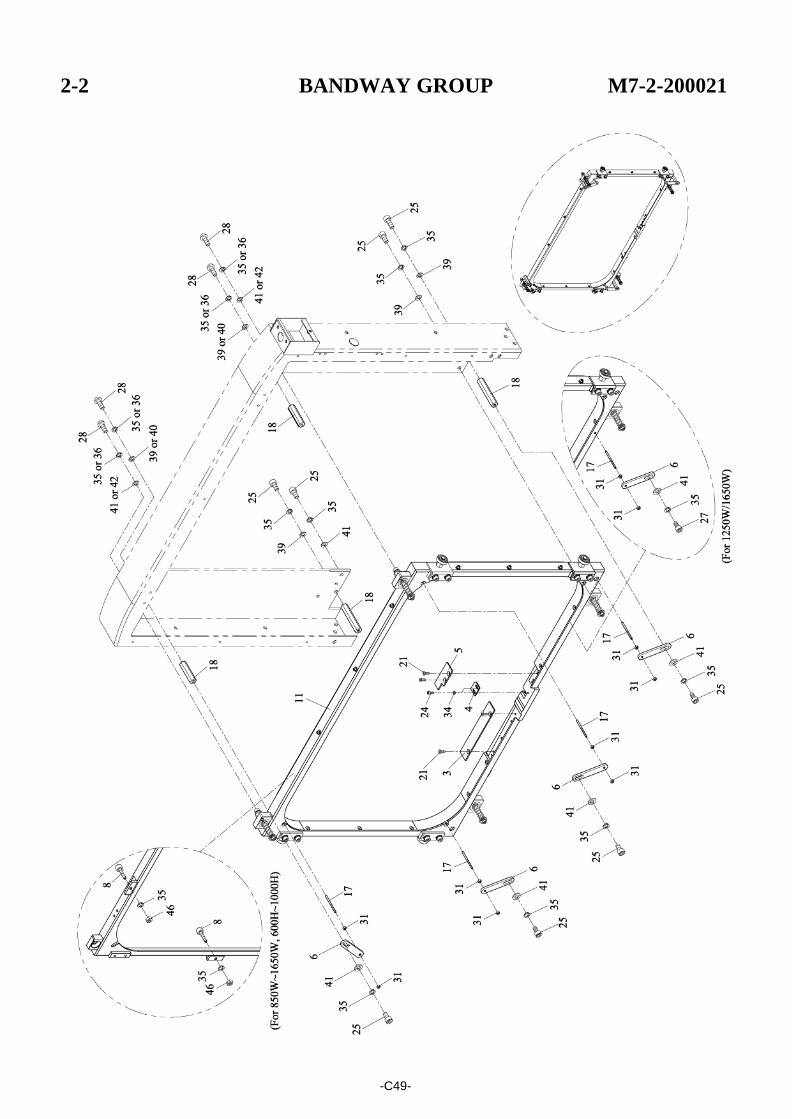
2-2 BANDWAY GROUP M7-2-200021
REF. NO. PART NO. DESCRIPTION Q'TY
M7-2-200021 Bandway Group 1 X
M7-2-200021S Bandway Group (Stainless Steel Model) 1 X
3 M7-2-201310 Cover (L) 1 X M7-2-201310S Cover (L)(Stainless Steel Model)(Option) 1 X
4 M7-2-201400 Adjusting Plate 1 191511 M7-2-201400EN Adjusting Plate (Stainless Steel Model)(Option) 1 X
5 M7-2-201510 Cover (R) 1 X M7-2-201510S Cover (R)(Stainless Steel Model)(Option) 1 X
6 M7-2-201700 Plate (For 650W~1050W) 4 191735
Plate (For 1250W/1650W) 5 8 M7-2-201801 Bumper Screw (For 850W~1650W) 4~12 191564
11 M7-2-210021 Strap Track Frame Ass'y 1 (SEE PG. C51) X M7-2-210021S Strap Track Frame Ass'y (Stainless Steel 1 X
Model) 17 T7-2-10210 Pin (For 650W~1050W) 4 X
Pin (For 1250W/1650W) 5 T7-2-10210S Pin (Stainless Steel Model)(For 650W~1050W) 4 X (Option) Pin (Stainless Steel Model) 5 (For 1250W/1650W)(Option)
18 T7-2-20130 Tube 4 X
21 FMS0410 FMS, M4×10 4 X
FMS0410S FMS, M4×10 (Stainless Steel Model) 4 X 24 HBS0408N HBS, M4×8 (N) 2 191787
HBS0408S HBS, M4×8 (Stainless Steel Model) 2 X 25 HBS0616N HBS, M6×16 (N) 7 191544
27 HBS0612N HBS, M6×12 (N)(For 1250W/1650W) 1
191563 28 THS0616N THS, M6×16 (N) 4 191544
THS0616S THS, M6×16 (Stainless Steel Model) 4 204086 31 NTE03 NTE, M3 (For 650W~1050W) 8 191734
NTE, M3 (For 1250W/1650W) 10 34 SW04 SW, M4 2 X 35 SW06 SW, M6 (For 650W) 12 X
SW, M6 (For 850W~1650W) 16~25 36 SW06S SW, M6 (Stainless Steel Model) 4 205539 39 PW06A PW, M6 (A) 5 191612 40 PW06AS PW, M6 (A)(Stainless Steel Model) 2 X 41 PW06C PW, M6 (C)(For 650W~1050W) 7 191561
PW, M6 (C)(For 1250W/1650W) 8 42 PW06CS PW, M6 (C)(Stainless Steel Model) 2 205534 46 HN06 HN, M6 (For 850W~1650W) 4~12 191611
-C50-
POLYCHEM NO.
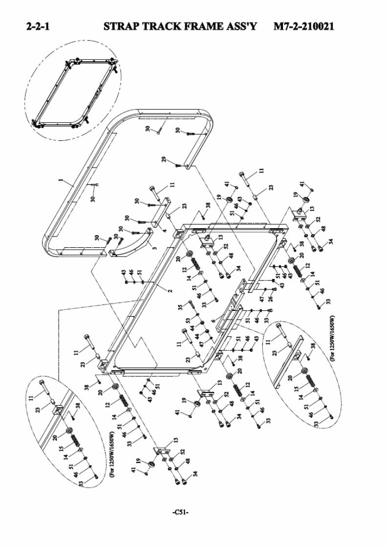
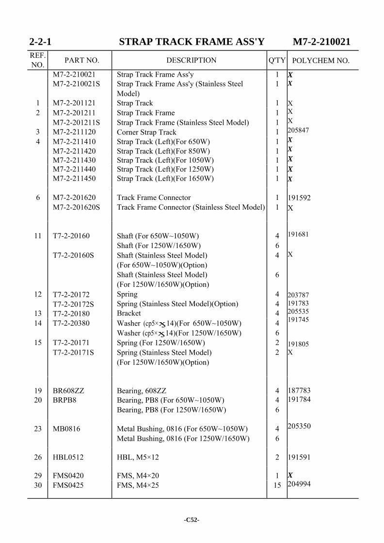
2-2-1 STRAP TRACK FRAME ASS'Y M7-2-210021
REF. NO. PART NO. DESCRIPTION Q'TY
M7-2-210021 Strap Track Frame Ass'y 1 X X
X X X 205847 X
X
X
X
X
191592 X 191681 X 203787 191783 205535 191745 191805 X
187783 191784 205350 191591 X
204994
1
M7-2-210021S
M7-2-201121
Strap Track Frame Ass'y (Stainless Steel Model) Strap Track
1
1 2
3
M7-2-201211 M7-2-201211S M7-2-211120
Strap Track Frame Strap Track Frame (Stainless Steel Model) Corner Strap Track
1 1 1
4 M7-2-211410 M7-2-211420
Strap Track (Left)(For 650W) Strap Track (Left)(For 850W)
1 1
M7-2-211430 Strap Track (Left)(For 1050W) 1 M7-2-211440 Strap Track (Left)(For 1250W) 1 M7-2-211450 Strap Track (Left)(For 1650W) 1
6 M7-2-201620 M7-2-201620S
Track Frame Connector Track Frame Connector (Stainless Steel Model)
1 1
11
12
13
T7-2-20160
T7-2-20160S
T7-2-20172 T7-2-20172S T7-2-20180
Shaft (For 650W~1050W) Shaft (For 1250W/1650W) Shaft (Stainless Steel Model) (For 650W~1050W)(Option) Shaft (Stainless Steel Model) (For 1250W/1650W)(Option) Spring Spring (Stainless Steel Model)(Option) Bracket
4 6 4
6
4 4 4
14
15
T7-2-20380
T7-2-20171 T7-2-20171S
Washer (cp5×ӽ14)(For 650W~1050W) Washer (cp5×ӽ14)(For 1250W/1650W) Spring (For 1250W/1650W) Spring (Stainless Steel Model) (For 1250W/1650W)(Option)
4 6 2 2
19
BR608ZZ
Bearing, 608ZZ
4 20 BRPB8 Bearing, PB8 (For 650W~1050W)
Bearing, PB8 (For 1250W/1650W) 4 6
23 MB0816 Metal Bushing, 0816 (For 650W~1050W) Metal Bushing, 0816 (For 1250W/1650W)
4 6
26 HBL0512 HBL, M5×12 2
29 FMS0420 FMS, M4×20 1 30 FMS0425 FMS, M4×25 15
-C52-
POLYCHEM NO.
2-2-1 STRAP TRACK FRAME ASS'Y M7-2-210021
REF. NO. PART NO. DESCRIPTION Q'TY
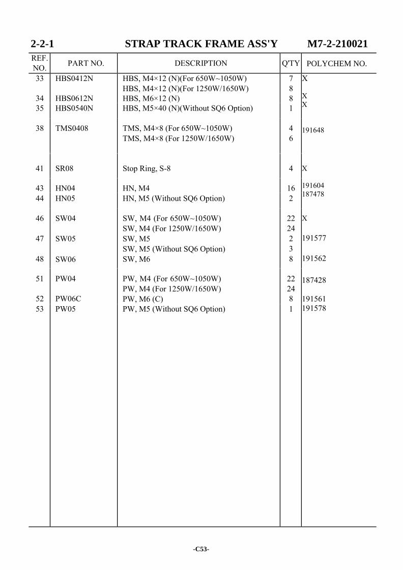
33
34
HBS0412N
HBS0612N
HBS, M4×12 (N)(For 650W~1050W) HBS, M4×12 (N)(For 1250W/1650W) HBS, M6×12 (N)
7 8 8
X X X 191648 X 191604 187478 X 191577 191562
187428 191561 191578
35 HBS0540N HBS, M5×40 (N)(Without SQ6 Option) 1
38 TMS0408 TMS, M4×8 (For 650W~1050W) TMS, M4×8 (For 1250W/1650W)
4 6
41
SR08
Stop Ring, S-8
4
43 HN04 HN, M4 16 44 HN05 HN, M5 (Without SQ6 Option) 2
46
47
48
SW04
SW05
SW06
SW, M4 (For 650W~1050W) SW, M4 (For 1250W/1650W) SW, M5 SW, M5 (Without SQ6 Option) SW, M6
22 24 2 3 8
51
52
PW04
PW06C
PW, M4 (For 650W~1050W) PW, M4 (For 1250W/1650W) PW, M6 (C)
22 24 8
53 PW05 PW, M5 (Without SQ6 Option) 1
-C53-
POLYCHEM NO.

-C54-
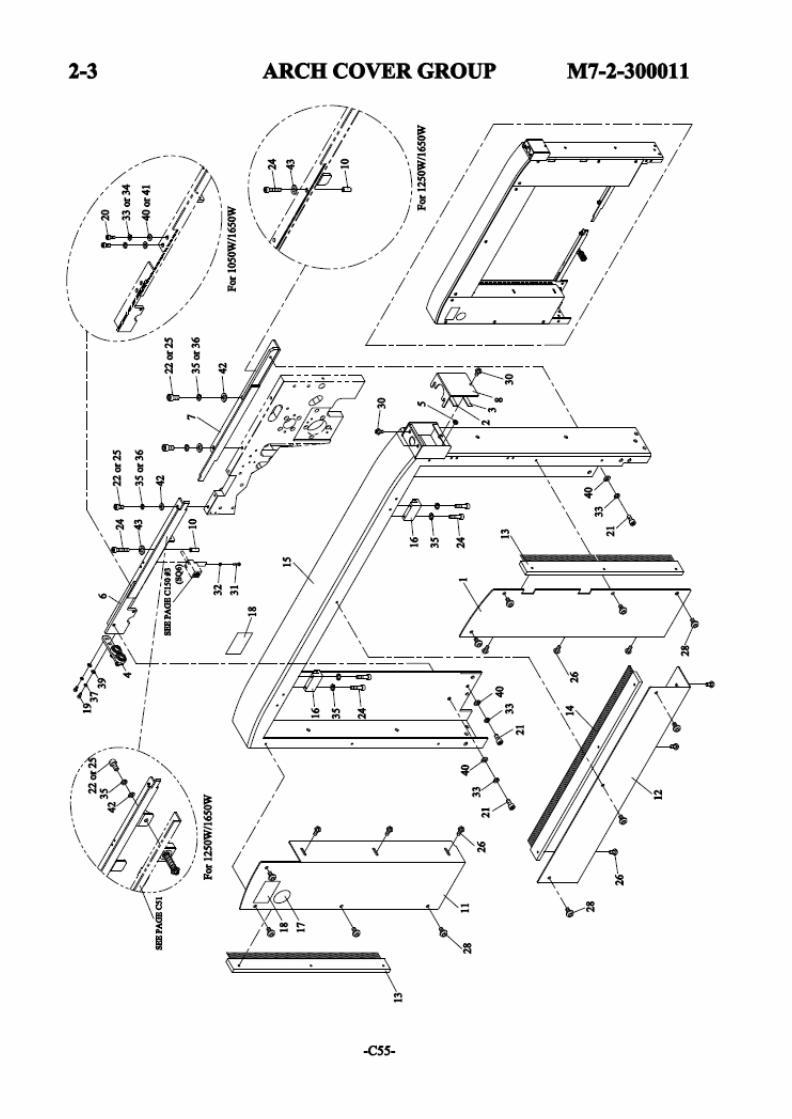
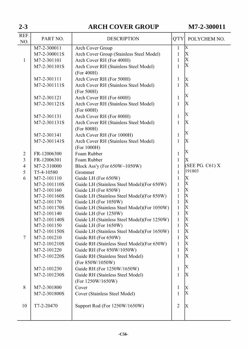
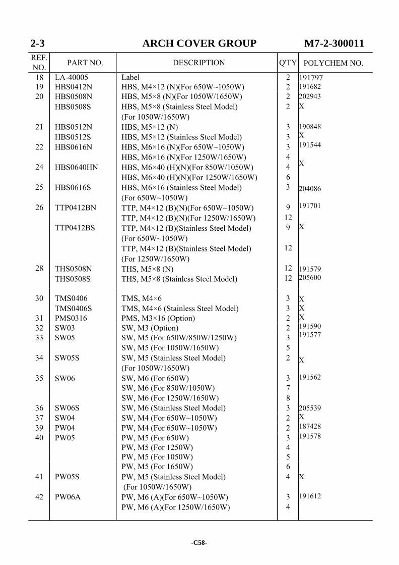
2-3 ARCH COVER GROUP M7-2-300011
REF. NO. PART NO. DESCRIPTION Q'TY
M7-2-300011 Arch Cover Group 1 X
1
M7-2-300011S M7-2-301101 M7-2-301101S
M7-2-301111
Arch Cover Group (Stainless Steel Model) Arch Cover RH (For 400H) Arch Cover RH (Stainless Steel Model) (For 400H) Arch Cover RH (For 500H)
1 1 1
1
X X X X
M7-2-301111S
M7-2-301121
Arch Cover RH (Stainless Steel Model) (For 500H) Arch Cover RH (For 600H)
1
1
X X
M7-2-301121S
M7-2-301131
Arch Cover RH (Stainless Steel Model) (For 600H) Arch Cover RH (For 800H)
1
1
X X
M7-2-301131S
M7-2-301141
Arch Cover RH (Stainless Steel Model) (For 800H) Arch Cover RH (For 1000H)
1
1
X X
2
M7-2-301141S
FR-12006300
Arch Cover RH (Stainless Steel Model) (For 1000H) Foam Rubber
1
1
X X
3 4 5
FR-12006301 M7-2-310000 T5-4-10580
Foam Rubber Block Ass'y (For 650W~1050W) Grommet
1 1 1
X (SEE PG. C61) X 191803
6 M7-2-101110 M7-2-101110S
Guide LH (For 650W) Guide LH (Stainless Steel Model)(For 650W)
1 1
X X
M7-2-101160 Guide LH (For 850W) 1 X M7-2-101160S Guide LH (Stainless Steel Model)(For 850W) 1 X M7-2-101170 Guide LH (For 1050W) 1 X M7-2-101170S Guide LH (Stainless Steel Model)(For 1050W) 1 X M7-2-101140 Guide LH (For 1250W) 1 X M7-2-101140S Guide LH (Stainless Steel Model)(For 1250W) 1 X M7-2-101150 Guide LH (For 1650W) 1 X
7 M7-2-101150S M7-2-101210 M7-2-101210S
Guide LH (Stainless Steel Model)(For 1650W) Guide RH (For 650W) Guide RH (Stainless Steel Model)(For 650W)
1 1 1
X X X
M7-2-101220 Guide RH (For 850W/1050W) 1 X M7-2-101220S
M7-2-101230
Guide RH (Stainless Steel Model) (For 850W/1050W) Guide RH (For 1250W/1650W)
1
1
X X
8
M7-2-101230S
M7-2-301800 M7-2-301800S
Guide RH (Stainless Steel Model) (For 1250W/1650W) Cover Cover (Stainless Steel Model)
1
1 1
X X X
10 T7-2-20470 Support Rod (For 1250W/1650W) 2 X
-C56-
POLYCHEM NO.
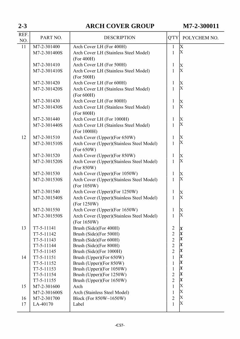
2-3 ARCH COVER GROUP M7-2-300011
REF. NO. PART NO. DESCRIPTION Q'TY
11 M7-2-301400 M7-2-301400S
M7-2-301410
Arch Cover LH (For 400H) Arch Cover LH (Stainless Steel Model) (For 400H) Arch Cover LH (For 500H)
1 1
1
X X
X X X X
X X X X
X X
X X
X X
X X
X X
X
X
X
X
X
X
X
X
X
X
X X X X
M7-2-301410S
M7-2-301420
Arch Cover LH (Stainless Steel Model) (For 500H) Arch Cover LH (For 600H)
1
1 M7-2-301420S
M7-2-301430
Arch Cover LH (Stainless Steel Model) (For 600H) Arch Cover LH (For 800H)
1
1 M7-2-301430S
M7-2-301440
Arch Cover LH (Stainless Steel Model) (For 800H) Arch Cover LH (For 1000H)
1
1
12
M7-2-301440S
M7-2-301510 M7-2-301510S
M7-2-301520
Arch Cover LH (Stainless Steel Model) (For 1000H) Arch Cover (Upper)(For 650W) Arch Cover (Upper)(Stainless Steel Model) (For 650W) Arch Cover (Upper)(For 850W)
1
1 1
1
M7-2-301520S
M7-2-301530
Arch Cover (Upper)(Stainless Steel Model) (For 850W) Arch Cover (Upper)(For 1050W)
1
1 M7-2-301530S
M7-2-301540
Arch Cover (Upper)(Stainless Steel Model) (For 1050W) Arch Cover (Upper)(For 1250W)
1
1 M7-2-301540S
M7-2-301550
Arch Cover (Upper)(Stainless Steel Model) (For 1250W) Arch Cover (Upper)(For 1650W)
1
1
13
M7-2-301550S
T7-5-11141 T7-5-11142
Arch Cover (Upper)(Stainless Steel Model) (For 1650W) Brush (Side)(For 400H) Brush (Side)(For 500H)
1
2 2
T7-5-11143 Brush (Side)(For 600H) 2 T7-5-11144 Brush (Side)(For 800H) 2
14 T7-5-11145 T7-5-11151 T7-5-11152
Brush (Side)(For 1000H) Brush (Upper)(For 650W) Brush (Upper)(For 850W)
2 1 1
T7-5-11153 Brush (Upper)(For 1050W) 1 T7-5-11154 Brush (Upper)(For 1250W) 2
15
16
T7-5-11155 M7-2-301600 M7-2-301600S M7-2-301700
Brush (Upper)(For 1650W) Arch Arch (Stainless Steel Model) Block (For 850W~1650W)
2 1 1 2
17 LA-40170 Label 1
-C57-
POLYCHEM NO.
2-3 ARCH COVER GROUP M7-2-300011
REF. NO. PART NO. DESCRIPTION Q'TY
18 LA-40005 Label 2 191797 191682 202943 X 190848 X 191544 X 204086 191701 X 191579 205600
X X X 191590 191577 X 191562
205539 X 187428 191578
X 191612
19 HBS0412N HBS, M4×12 (N)(For 650W~1050W) 2 20
21
22
24
25
26
28
HBS0508N HBS0508S
HBS0512N HBS0512S HBS0616N
HBS0640HN
HBS0616S
TTP0412BN
TTP0412BS
THS0508N THS0508S
HBS, M5×8 (N)(For 1050W/1650W) HBS, M5×8 (Stainless Steel Model) (For 1050W/1650W) HBS, M5×12 (N) HBS, M5×12 (Stainless Steel Model) HBS, M6×16 (N)(For 650W~1050W) HBS, M6×16 (N)(For 1250W/1650W) HBS, M6×40 (H)(N)(For 850W/1050W) HBS, M6×40 (H)(N)(For 1250W/1650W) HBS, M6×16 (Stainless Steel Model) (For 650W~1050W) TTP, M4×12 (B)(N)(For 650W~1050W) TTP, M4×12 (B)(N)(For 1250W/1650W) TTP, M4×12 (B)(Stainless Steel Model) (For 650W~1050W) TTP, M4×12 (B)(Stainless Steel Model) (For 1250W/1650W) THS, M5×8 (N) THS, M5×8 (Stainless Steel Model)
2 2
3 3 3 4 4 6 3
9 12 9
12
12 12
30
31
TMS0406 TMS0406S PMS0316
TMS, M4×6 TMS, M4×6 (Stainless Steel Model) PMS, M3×16 (Option)
3 3 2
32 SW03 SW, M3 (Option) 2 33
34
35
SW05
SW05S
SW06
SW, M5 (For 650W/850W/1250W) SW, M5 (For 1050W/1650W) SW, M5 (Stainless Steel Model) (For 1050W/1650W) SW, M6 (For 650W) SW, M6 (For 850W/1050W)
3 5 2
3 7
36
SW06S
SW, M6 (For 1250W/1650W) SW, M6 (Stainless Steel Model)
8 3
37 SW04 SW, M4 (For 650W~1050W) 2 39 PW04 PW, M4 (For 650W~1050W) 2 40 PW05 PW, M5 (For 650W)
PW, M5 (For 1250W) 3 4
PW, M5 (For 1050W) 5
41
42
PW05S
PW06A
PW, M5 (For 1650W) PW, M5 (Stainless Steel Model) (For 1050W/1650W) PW, M6 (A)(For 650W~1050W) PW, M6 (A)(For 1250W/1650W)
6 4
3 4
-C58-
POLYCHEM NO.

2-3 ARCH COVER GROUP M7-2-300011
REF. NO. PART NO. DESCRIPTION Q'TY
43 PW06B PW06BS
PW, M6 (B)(For 1250W/1650W) PW, M6 (B)(Stainless Steel Model) (For 1250W/1650W)
2 2
X 205540
-C59-
POLYCHEM NO.

-C60-
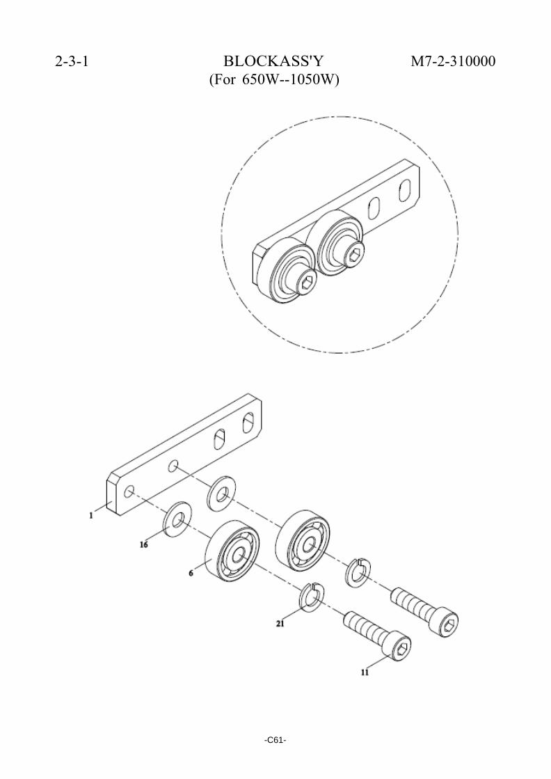
2-3-1 BLOCKASS'Y (For 650W--1050W)
M7-2-310000
-C61-

2-3-1 BLOCK ASS'Y M7-2-310000 (For 650W~1050W)
REF. NO. PART NO. DESCRIPTION Q'TY
1 M7-2-301200 Block 1 X 187778 191700 191578 191577
6
BR635ZZ
Bearing, 635ZZ
2
11
HBS0516N
HBS, M5×16 (N)
2
16
PW05
PW, M5
2
21
SW05
SW, M5
2
-C62-
POLYCHEM NO.
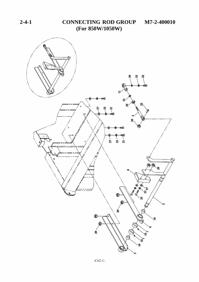
2-4-1 CONNECTING ROD GROUP M7-2-400010
(For 850W/1050W)
-C62-1-
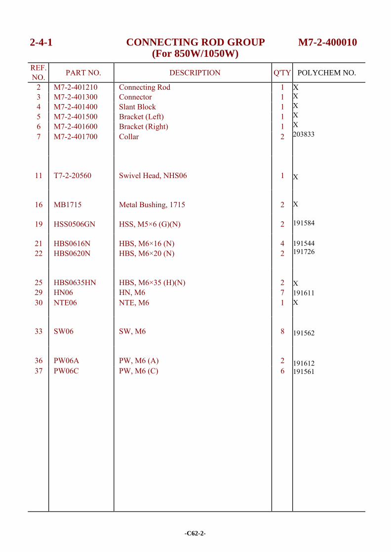
2-4-1 CONNECTING ROD GROUP (For 850W/1050W)
M7-2-400010
REF. NO. PART NO. DESCRIPTION Q'TY
2 M7-2-401210 Connecting Rod 1 X X X X X 203833 X X 191584 191544 191726 X 191611 X
191562
191612 191561
3 M7-2-401300 Connector 1 4 M7-2-401400 Slant Block 1 5 M7-2-401500 Bracket (Left) 1 6 M7-2-401600 Bracket (Right) 1 7 M7-2-401700 Collar 2
11
T7-2-20560
Swivel Head, NHS06
1
16
MB1715
Metal Bushing, 1715
2
19 HSS0506GN HSS, M5×6 (G)(N) 2
21 HBS0616N HBS, M6×16 (N) 4 22 HBS0620N HBS, M6×20 (N) 2
25
HBS0635HN
HBS, M6×35 (H)(N)
2
29 HN06 HN, M6 7 30 NTE06 NTE, M6 1
33
SW06
SW, M6
8
36
PW06A
PW, M6 (A)
2
37 PW06C PW, M6 (C) 6
-C62-2-
POLYCHEM NO.
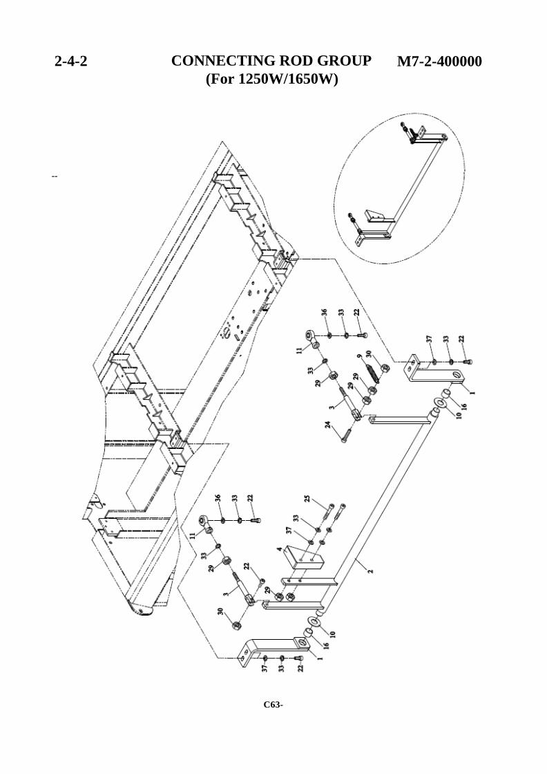
2-4-2 CONNECTING ROD GROUP
(For 1250W/1650W)
M7-2-400000
--
C63-

2-4-2 CONNECTING ROD GROUP M7-2-400000 (For 1250W/1650W)
REF. NO. PART NO. DESCRIPTION Q'TY
1 M7-2-401100 Bracket 2 X X X X
191524 205661 X X 191726 191779 X 191611 X 191562 191612 191561
2 M7-2-401200 Connecting Rod 1 3 M7-2-401300 Connector 2 4 M7-2-401400 Slant Block 1
9 TC-025 Spring 1 10 H42-1227 Washer 2 11 T7-2-20560 Swivel Head, NHS06 2
16
MB1512
Metal Bushing, 1512
2
22
HBS0620N
HBS, M6×20 (N)
7
24 HBS0630N HBS, M6×30 (N) 1 25 HBS0635HN HBS, M6×35 (H)(N) 2 29 HN06 HN, M6 6 30 NTE06 NTE, M6 2
33
SW06
SW, M6
10
36
PW06A
PW, M6 (A)
2
37 PW06C PW, M6 (C) 6
-C64-
POLYCHEM NO.
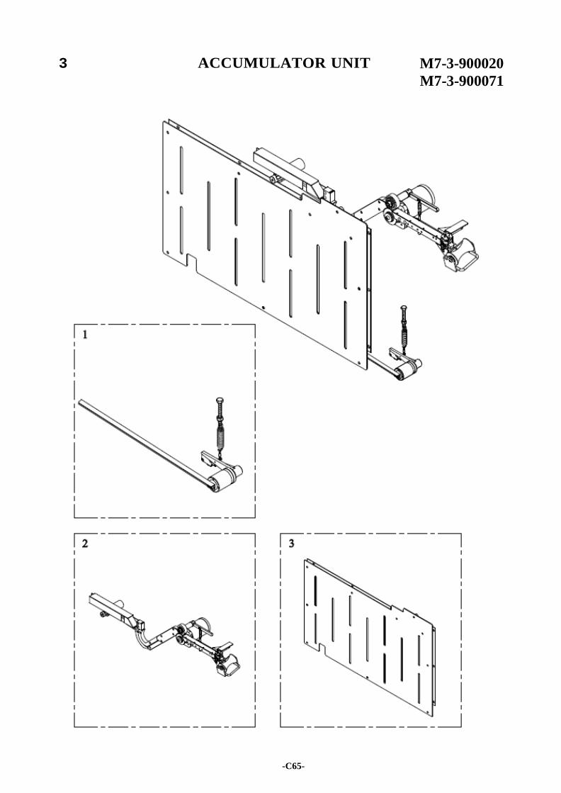
3 ACCUMULATOR UNIT M7-3-900020
M7-3-900071
-C65-
3 ACCUMULATOR UNIT M7-3-900020 M7-3-900071
REF. NO. PART NO. DESCRIPTION Q'TY
M7-3-900020 Accumulator Unit (For 650W) 1 X
M7-3-900020S
M7-3-900071
Accumulator Unit (Stainless Steel Model) (For 650W) Accumulator Unit (For 850W/1050W)
1
1
X
X
M7-3-900071S
M7-3-900081
Accumulator Unit (Stainless Steel Model) (For 850W/1050W) Accumulator Unit (For 1250W/1650W)
1
1
X
X
1
M7-3-900081S
M7-3-100020
Accumulator Unit (Stainless Steel Model) (For 1250W/1650W) Strap Amount Control Group
1
1
X
(SEE PG.C67) X 2
3
M7-3-200020 M7-3-200020S
M7-3-300020 M7-3-300020S
M7-3-300071
Auto Strap Feeding Group Auto Strap Feeding Group (Stainless Steel Model) Accumulator Box Group (For 650W) Accumulator Box Group (Stainless Steel Model)(For 650W) Accumulator Box Group (For 850W/1050W)
1 1
1 1
1
(SEE PG.C69) X X
(SEE PG. C85) X X
X
M7-3-300071S
M7-3-300081 M7-3-300081S
Accumulator Box Group (Stainless Steel Model)(For 850W/1050W) Accumulator Box Group (For 1250W/1650W) Accumulator Box Group (Stainless Steel Model)(For 1250W/1650W)
1
1 1
X
(SEE PG.C87) X X
-C66-
POLYCHEM NO.
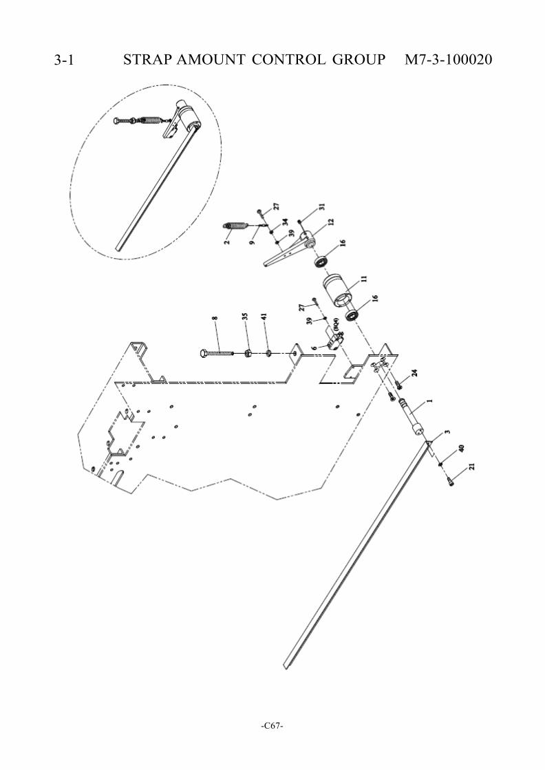
3-1 STRAP AMOUNT CONTROL GROUP M7-3-100020
-C67-
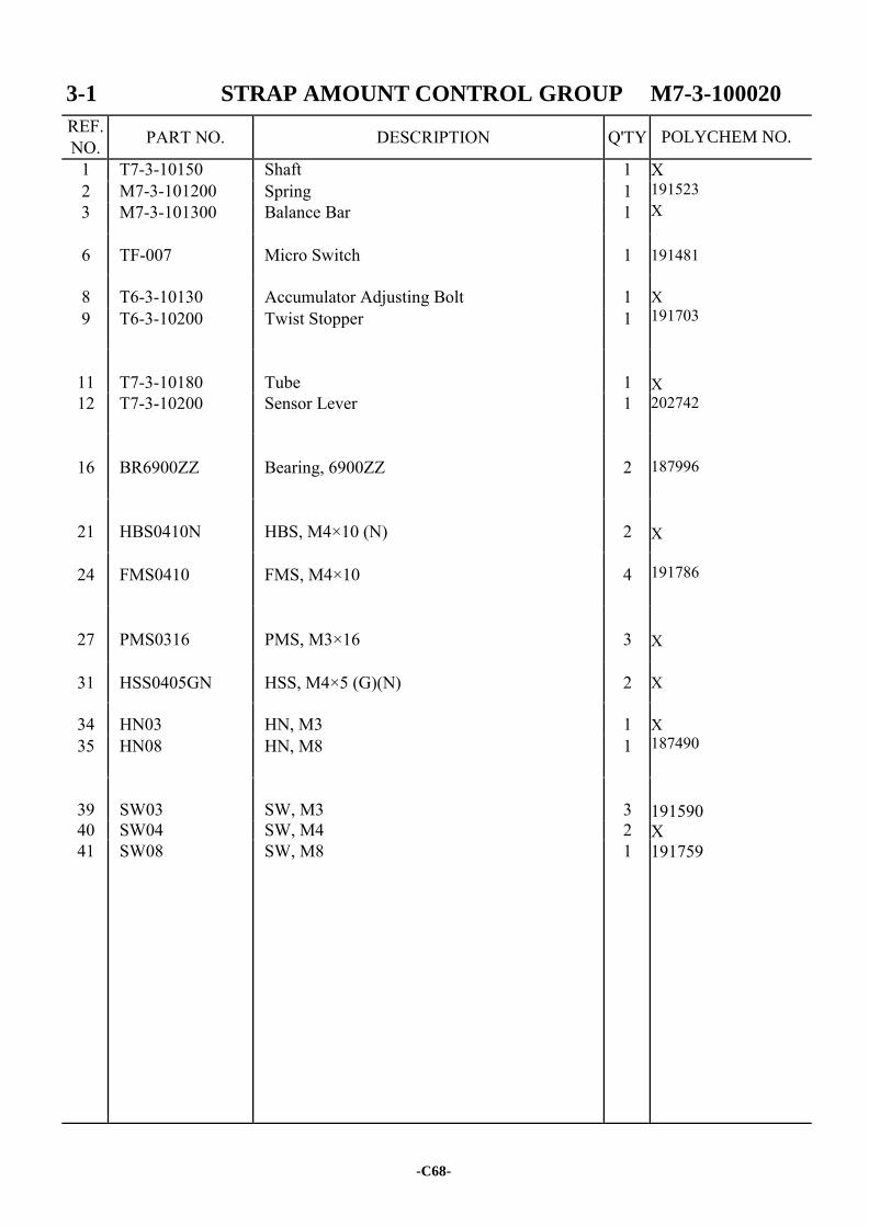
3-1 STRAP AMOUNT CONTROL GROUP M7-3-100020
REF. NO. PART NO. DESCRIPTION Q'TY
1 T7-3-10150 Shaft 1 X 191523 X 191481 X 191703 X 202742 187996 X 191786 X X
X 187490
191590 X 191759
2 M7-3-101200 Spring 1 3 M7-3-101300 Balance Bar 1
6 TF-007 Micro Switch 1
8 T6-3-10130 Accumulator Adjusting Bolt 1 9 T6-3-10200 Twist Stopper 1
11
T7-3-10180
Tube
1
12 T7-3-10200 Sensor Lever 1
16
BR6900ZZ
Bearing, 6900ZZ
2
21
HBS0410N
HBS, M4×10 (N)
2
24 FMS0410 FMS, M4×10 4
27
PMS0316
PMS, M3×16
3
31 HSS0405GN HSS, M4×5 (G)(N) 2
34 HN03 HN, M3 1 35 HN08 HN, M8 1
39
SW03
SW, M3
3
40 SW04 SW, M4 2 41 SW08 SW, M8 1
-C68-
POLYCHEM NO.
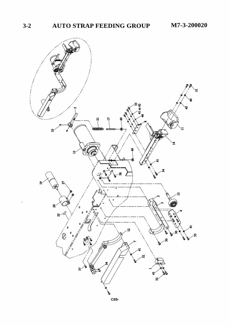
3-2 AUTO STRAP FEEDING GROUP M7-3-200020
-
C69-
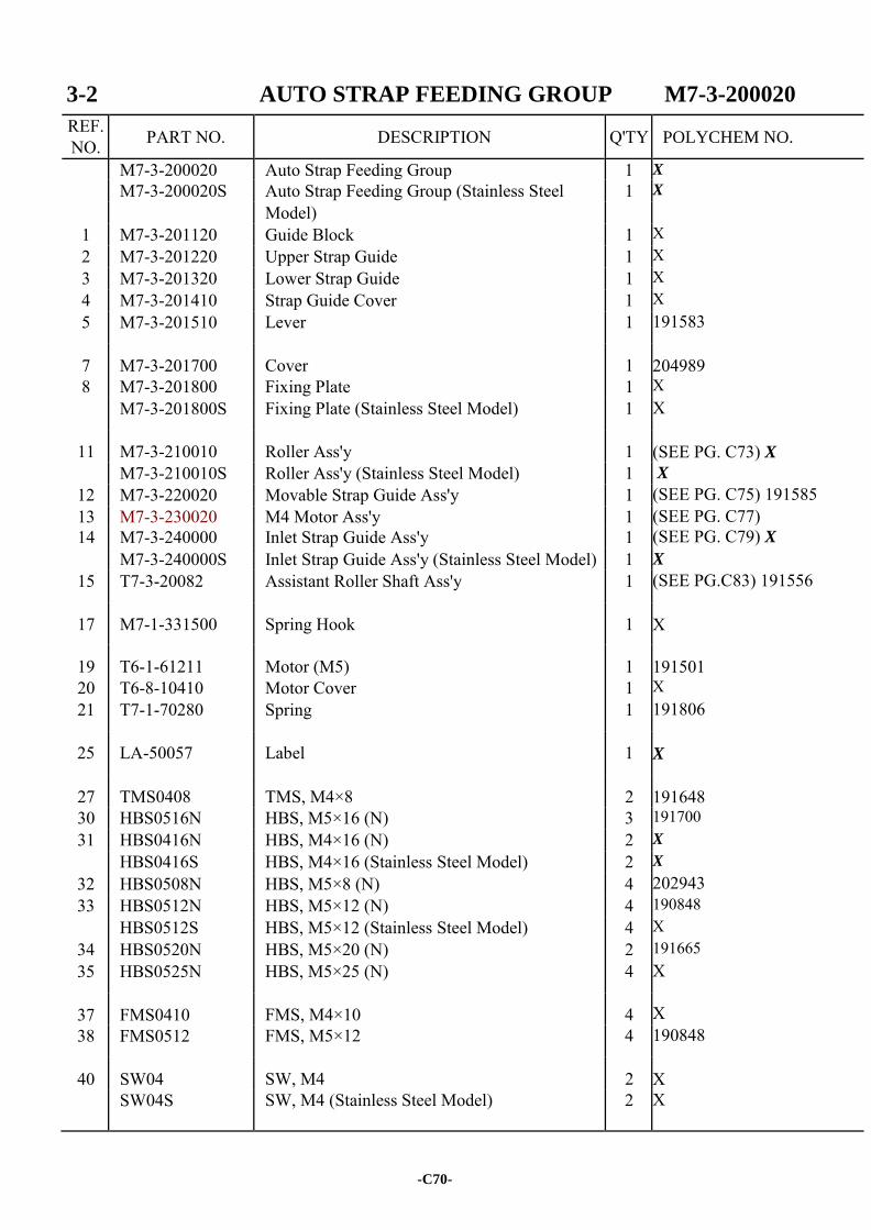
3-2 AUTO STRAP FEEDING GROUP M7-3-200020
REF. NO. PART NO. DESCRIPTION Q'TY
M7-3-200020 Auto Strap Feeding Group 1 X
M7-3-200020S Auto Strap Feeding Group (Stainless Steel 1 X
Model) 1 M7-3-201120 Guide Block 1 X 2 M7-3-201220 Upper Strap Guide 1 X 3 M7-3-201320 Lower Strap Guide 1 X 4 M7-3-201410 Strap Guide Cover 1 X 5 M7-3-201510 Lever 1 191583
7 M7-3-201700 Cover 1
204989 8 M7-3-201800 Fixing Plate 1 X
M7-3-201800S Fixing Plate (Stainless Steel Model) 1 X
11 M7-3-210010 Roller Ass'y 1
(SEE PG. C73) X M7-3-210010S Roller Ass'y (Stainless Steel Model) 1 X
12 M7-3-220020 Movable Strap Guide Ass'y 1 (SEE PG. C75) 191585 13 M7-3-230020 M4 Motor Ass'y 1 (SEE PG. C77) 14 M7-3-240000 Inlet Strap Guide Ass'y 1 (SEE PG. C79) X
M7-3-240000S Inlet Strap Guide Ass'y (Stainless Steel Model) 1 X
15 T7-3-20082 Assistant Roller Shaft Ass'y 1 (SEE PG.C83) 191556
17 M7-1-331500 Spring Hook 1
X
19 T6-1-61211 Motor (M5) 1
191501 20 T6-8-10410 Motor Cover 1 X 21 T7-1-70280 Spring 1 191806
25 LA-50057 Label 1
X
27 TMS0408 TMS, M4×8 2
191648 30 HBS0516N HBS, M5×16 (N) 3 191700 31 HBS0416N HBS, M4×16 (N) 2 X
HBS0416S HBS, M4×16 (Stainless Steel Model) 2 X
32 HBS0508N HBS, M5×8 (N) 4 202943 33 HBS0512N HBS, M5×12 (N) 4 190848
HBS0512S HBS, M5×12 (Stainless Steel Model) 4 X 34 HBS0520N HBS, M5×20 (N) 2 191665 35 HBS0525N HBS, M5×25 (N) 4 X
37 FMS0410 FMS, M4×10 4
X 38 FMS0512 FMS, M5×12 4 190848
40 SW04 SW, M4 2
X SW04S SW, M4 (Stainless Steel Model) 2 X
-C70-
POLYCHEM NO.
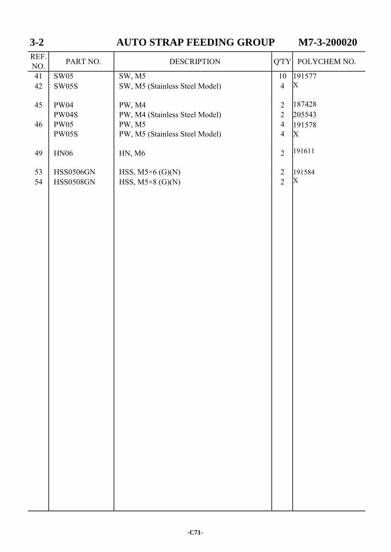
3-2 AUTO STRAP FEEDING GROUP M7-3-200020
REF. NO. PART NO. DESCRIPTION Q'TY
41 SW05 SW, M5 10 191577 X 187428 205543 191578 X 191611
191584 X
42 SW05S SW, M5 (Stainless Steel Model) 4
45 PW04 PW, M4 2 PW04S PW, M4 (Stainless Steel Model) 2
46 PW05 PW, M5 4 PW05S PW, M5 (Stainless Steel Model) 4
49 HN06 HN, M6 2
53 HSS0506GN HSS, M5×6 (G)(N) 2 54 HSS0508GN HSS, M5×8 (G)(N) 2
-C71-
POLYCHEM NO.

-C72-
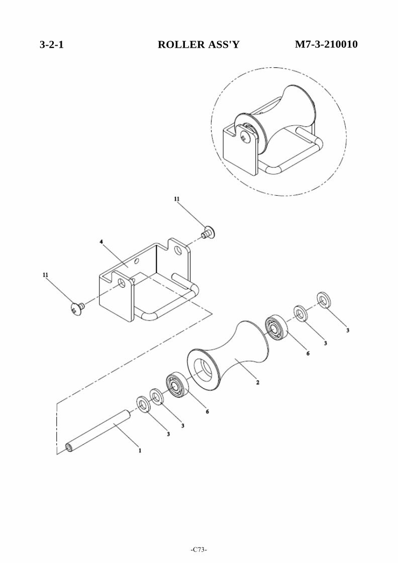
3-2-1 ROLLER ASS'Y M7-3-210010
-C73-
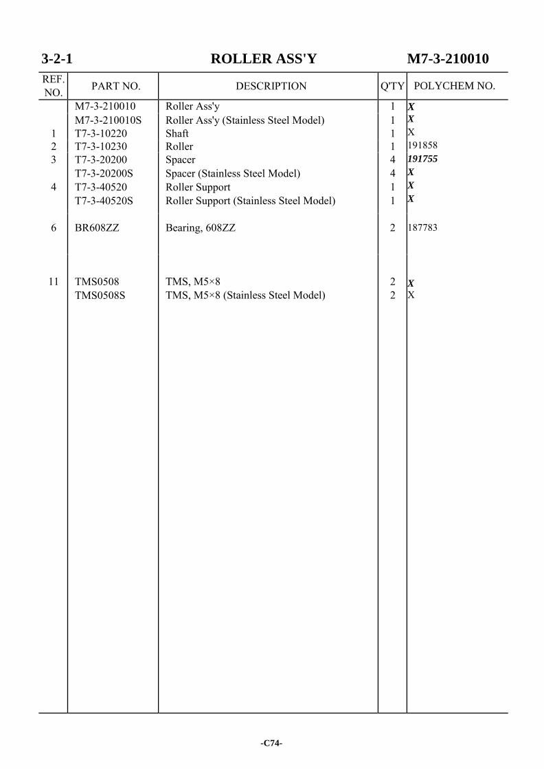
3-2-1 ROLLER ASS'Y M7-3-210010
REF. NO. PART NO. DESCRIPTION Q'TY
M7-3-210010 Roller Ass'y 1 X X X 191858 191755
X
X
X 187783
X
X
1
M7-3-210010S T7-3-10220
Roller Ass'y (Stainless Steel Model) Shaft
1 1
2 T7-3-10230 Roller 1 3
4
T7-3-20200 T7-3-20200S T7-3-40520 T7-3-40520S
Spacer Spacer (Stainless Steel Model) Roller Support Roller Support (Stainless Steel Model)
4 4 1 1
6 BR608ZZ Bearing, 608ZZ 2
11
TMS0508 TMS0508S
TMS, M5×8 TMS, M5×8 (Stainless Steel Model)
2 2
-C74-
POLYCHEM NO.
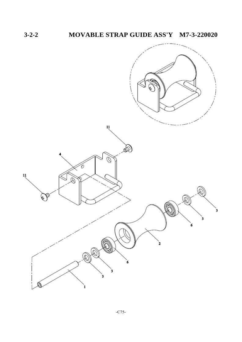
3-2-2 MOVABLE STRAP GUIDE ASS'Y M7-3-220020
-C75-
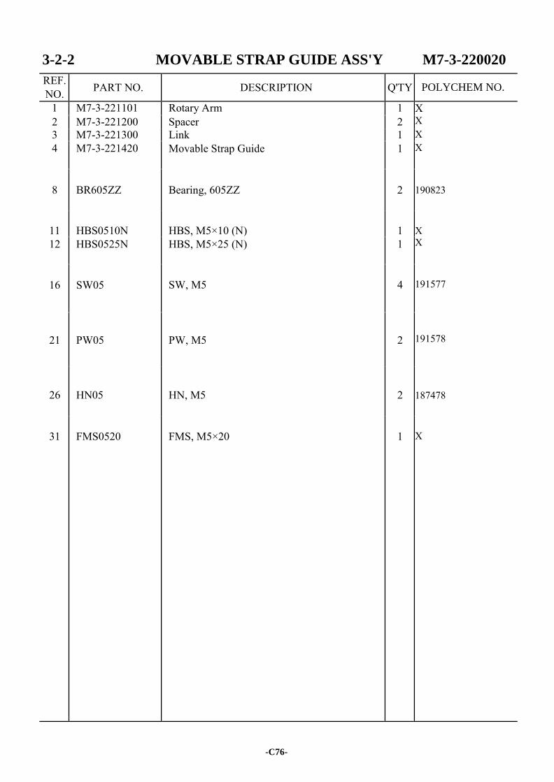
3-2-2 MOVABLE STRAP GUIDE ASS'Y M7-3-220020
REF. NO. PART NO. DESCRIPTION Q'TY
1 M7-3-221101 Rotary Arm 1 X X X X
190823 X X
191577
191578 187478 X
2 M7-3-221200 Spacer 2 3 M7-3-221300 Link 1 4 M7-3-221420 Movable Strap Guide 1
8
BR605ZZ
Bearing, 605ZZ
2
11
HBS0510N
HBS, M5×10 (N)
1
12 HBS0525N HBS, M5×25 (N) 1
16
SW05
SW, M5
4
21
PW05
PW, M5
2
26
HN05
HN, M5
2
31
FMS0520
FMS, M5×20
1
-C76-
POLYCHEM NO.
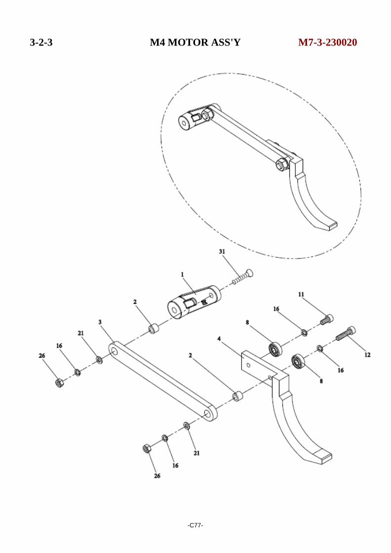
3-2-3 M4 MOTOR ASS'Y M7-3-230020
-C77-
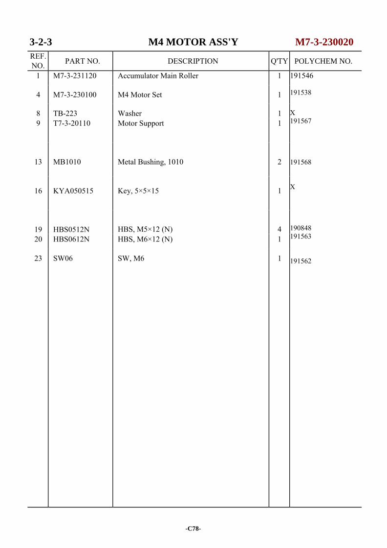
3-2-3 M4 MOTOR ASS'Y M7-3-230020
REF. NO. PART NO. DESCRIPTION Q'TY
1 M7-3-231120 Accumulator Main Roller 1 191546 191538 X 191567 191568 X 190848 191563 191562
4 M7-3-230100 M4 Motor Set 1
8 TB-223 Washer 1 9 T7-3-20110 Motor Support 1
13
MB1010
Metal Bushing, 1010
2
16
KYA050515
Key, 5×5×15
1
19
HBS0512N
HBS, M5×12 (N)
4
20 HBS0612N HBS, M6×12 (N) 1
23 SW06 SW, M6 1
-C78-
POLYCHEM NO.
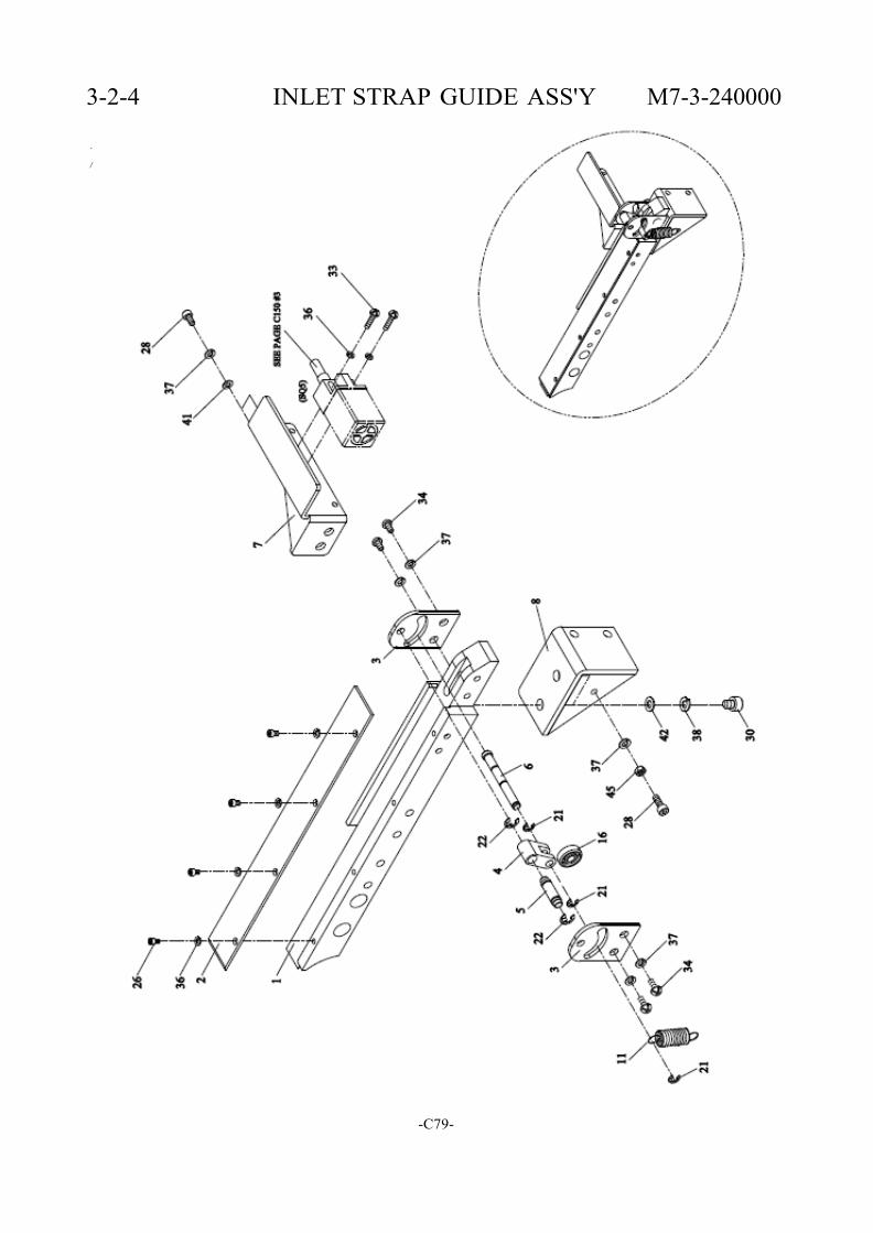
3-2-4 INLET STRAP GUIDE ASS'Y M7-3-240000
. /
-C79-
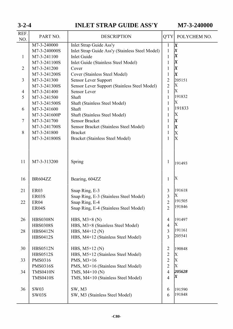
3-2-4 INLET STRAP GUIDE ASS'Y M7-3-240000
REF. NO. PART NO. DESCRIPTION Q'TY
M7-3-240000 Inlet Strap Guide Ass'y 1 X X X
X
X
X
205151 X X 191832 X 191833 X X
X X X 191493 X 191618 X 191505 191846
191497 X 191161 205541
190848 X X X 205628
X
191590 191848
1
2
3
4
M7-3-240000S M7-3-241100 M7-3-241100S M7-3-241200 M7-3-241200S M7-3-241300 M7-3-241300S M7-3-241400
Inlet Strap Guide Ass'y (Stainless Steel Model) Inlet Guide Inlet Guide (Stainless Steel Model) Cover Cover (Stainless Steel Model) Sensor Lever Support Sensor Lever Support (Stainless Steel Model) Sensor Lever
1 1 1 1 1 2 2 1
5
6
7
8
M7-3-241500 M7-3-241500S M7-3-241600 M7-3-241600P M7-3-241700 M7-3-241700S M7-3-241800 M7-3-241800S
Shaft Shaft (Stainless Steel Model) Shaft Shaft (Stainless Steel Model) Sensor Bracket Sensor Bracket (Stainless Steel Model) Bracket Bracket (Stainless Steel Model)
1 1 1 1 1 1 1 1
11
M7-3-313200
Spring
1
16
BR604ZZ
Bearing, 604ZZ
1
21
22
ER03 ER03S ER04 ER04S
Snap Ring, E-3 Snap Ring, E-3 (Stainless Steel Model) Snap Ring, E-4 Snap Ring, E-4 (Stainless Steel Model)
3 3 2 2
26
28
HBS0308N HBS0308S HBS0412N HBS0412S
HBS, M3×8 (N) HBS, M3×8 (Stainless Steel Model) HBS, M4×12 (N) HBS, M4×12 (Stainless Steel Model)
4 4 3 3
30
33
34
HBS0512N HBS0512S PMS0316 PMS0316S TMS0410N TMS0410S
HBS, M5×12 (N) HBS, M5×12 (Stainless Steel Model) PMS, M3×16 PMS, M3×16 (Stainless Steel Model) TMS, M4×10 (N) TMS, M4×10 (Stainless Steel Model)
2 2 2 2 4 4
36 SW03 SW03S
SW, M3 SW, M3 (Stainless Steel Model)
6 6
-C80-
POLYCHEM NO.
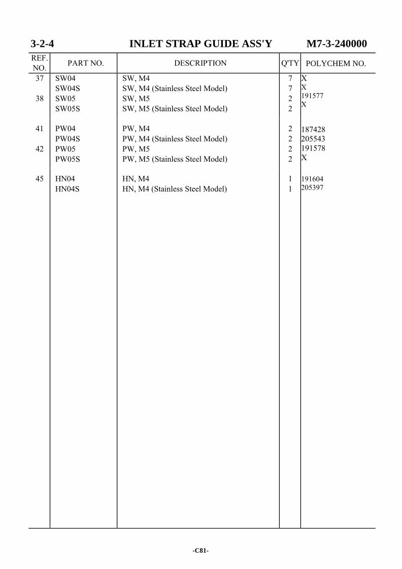
3-2-4 INLET STRAP GUIDE ASS'Y M7-3-240000
REF. NO. PART NO. DESCRIPTION Q'TY
37
38
SW04 SW04S SW05 SW05S
SW, M4 SW, M4 (Stainless Steel Model) SW, M5 SW, M5 (Stainless Steel Model)
7 7 2 2
X X 191577 X 187428 205543 191578 X 191604 205397
41
42
PW04 PW04S PW05 PW05S
PW, M4 PW, M4 (Stainless Steel Model) PW, M5 PW, M5 (Stainless Steel Model)
2 2 2 2
45 HN04 HN04S
HN, M4 HN, M4 (Stainless Steel Model)
1 1
-C81-
POLYCHEM NO.

-C82-
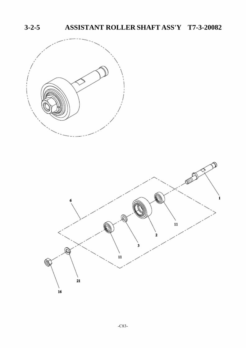
3-2-5 ASSISTANT ROLLER SHAFT ASS'Y T7-3-20082
-C83-
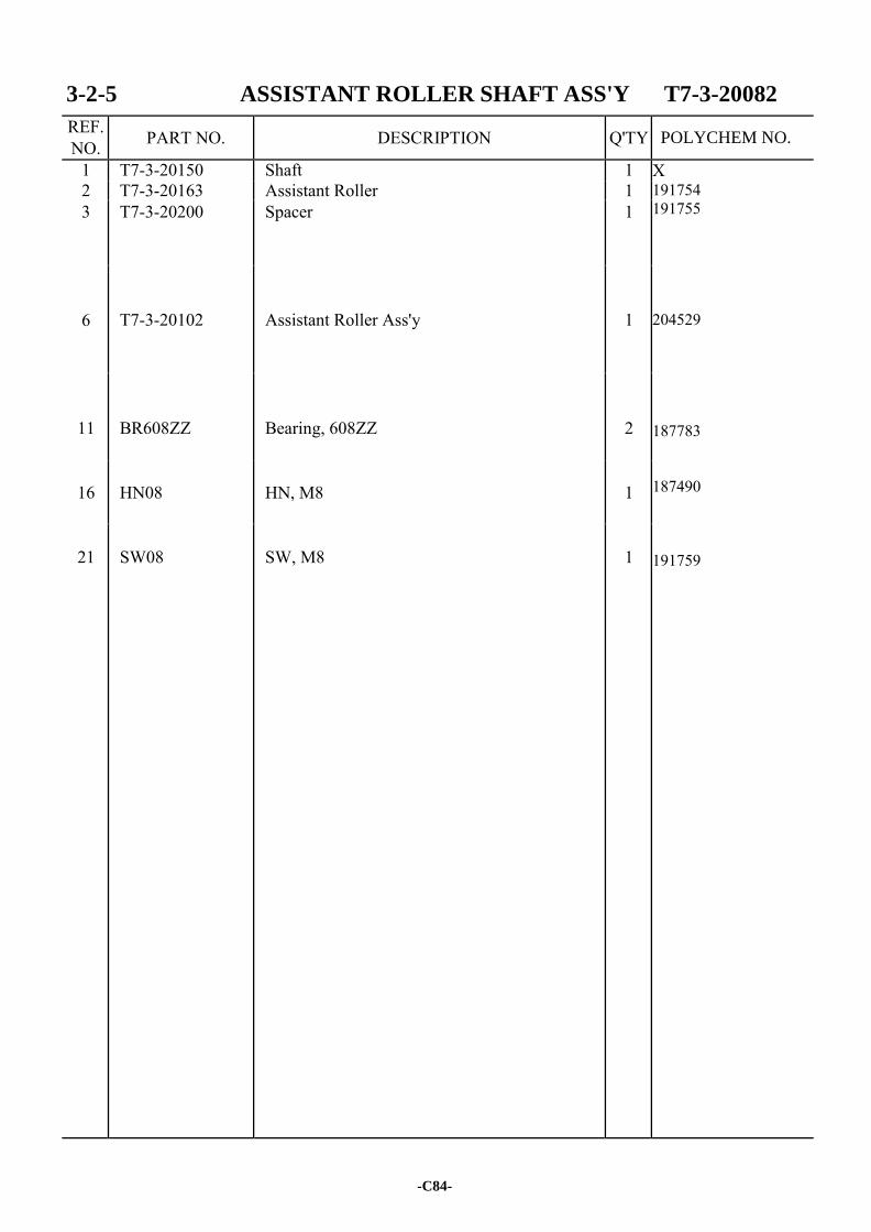
3-2-5 ASSISTANT ROLLER SHAFT ASS'Y T7-3-20082
REF. NO. PART NO. DESCRIPTION Q'TY
1 T7-3-20150 Shaft 1 X 191754 191755 204529 187783 187490 191759
2 T7-3-20163 Assistant Roller 1 3 T7-3-20200 Spacer 1
6
T7-3-20102
Assistant Roller Ass'y
1
11
BR608ZZ
Bearing, 608ZZ
2
16
HN08
HN, M8
1
21
SW08
SW, M8
1
-C84-
POLYCHEM NO.
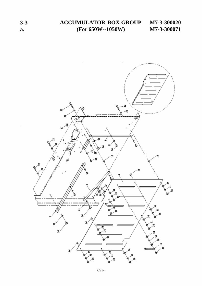
3-3
a.
ACCUMULATOR BOX GROUP M7-3-300020
(For 650W--1050W) M7-3-300071
-
C85-
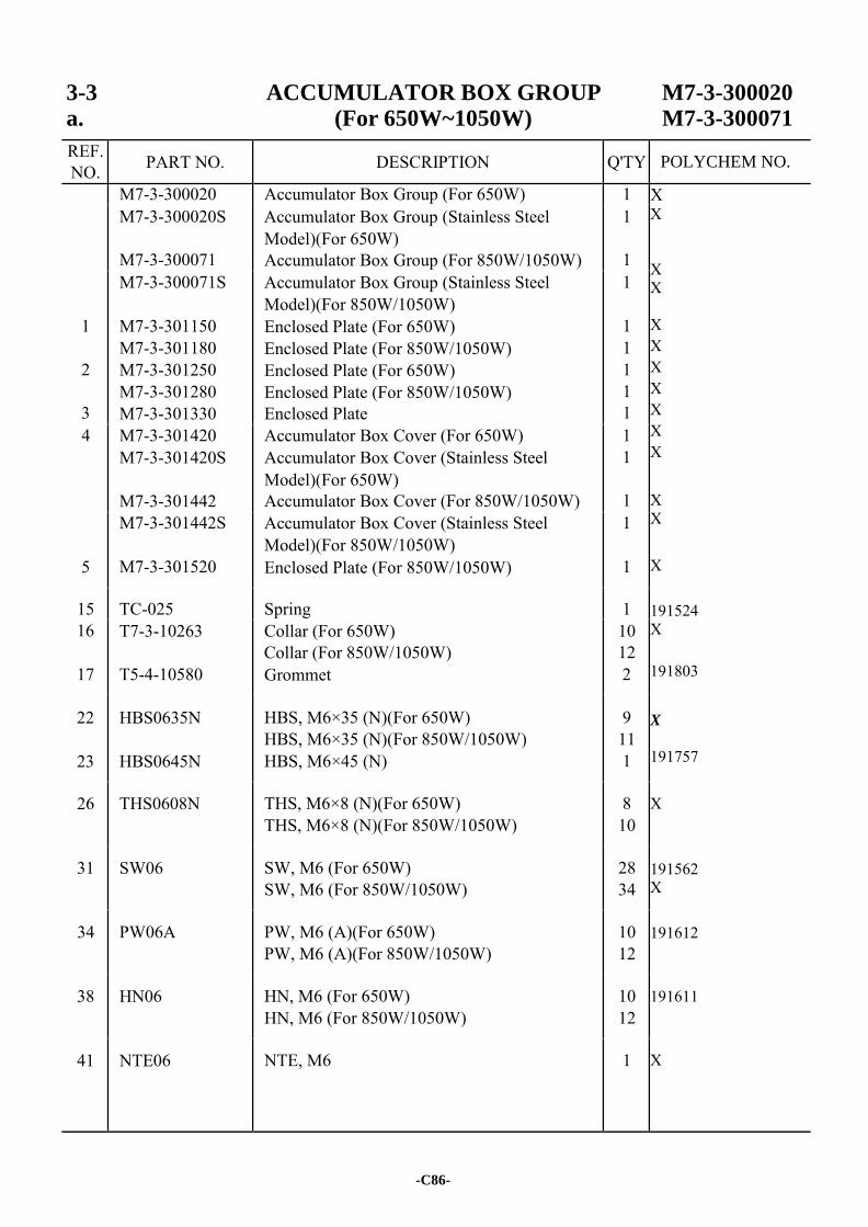
3-3 ACCUMULATOR BOX GROUP M7-3-300020 a. (For 650W~1050W) M7-3-300071
REF. NO. PART NO. DESCRIPTION Q'TY
M7-3-300020 Accumulator Box Group (For 650W) 1 X X X X X X X X X X X
X X
X 191524 X 191803
X
191757
X
191562 X
191612 191611 X
M7-3-300020S
M7-3-300071
Accumulator Box Group (Stainless Steel Model)(For 650W) Accumulator Box Group (For 850W/1050W)
1
1
1
2
3
M7-3-300071S
M7-3-301150 M7-3-301180 M7-3-301250 M7-3-301280 M7-3-301330
Accumulator Box Group (Stainless Steel Model)(For 850W/1050W) Enclosed Plate (For 650W) Enclosed Plate (For 850W/1050W) Enclosed Plate (For 650W) Enclosed Plate (For 850W/1050W) Enclosed Plate
1
1 1 1 1 1
4 M7-3-301420 M7-3-301420S
M7-3-301442
Accumulator Box Cover (For 650W) Accumulator Box Cover (Stainless Steel Model)(For 650W) Accumulator Box Cover (For 850W/1050W)
1 1
1
5
M7-3-301442S
M7-3-301520
Accumulator Box Cover (Stainless Steel Model)(For 850W/1050W) Enclosed Plate (For 850W/1050W)
1
1
15 TC-025 Spring 1 16
17
T7-3-10263
T5-4-10580
Collar (For 650W) Collar (For 850W/1050W) Grommet
10 12 2
22
23
HBS0635N
HBS0645N
HBS, M6×35 (N)(For 650W) HBS, M6×35 (N)(For 850W/1050W) HBS, M6×45 (N)
9 11 1
26 THS0608N THS, M6×8 (N)(For 650W) THS, M6×8 (N)(For 850W/1050W)
8 10
31 SW06 SW, M6 (For 650W) SW, M6 (For 850W/1050W)
28 34
34 PW06A PW, M6 (A)(For 650W) PW, M6 (A)(For 850W/1050W)
10 12
38 HN06 HN, M6 (For 650W) HN, M6 (For 850W/1050W)
10 12
41 NTE06 NTE, M6 1
-C86-
POLYCHEM NO.
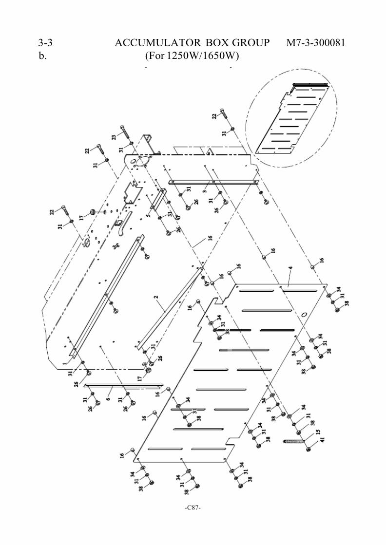
3-3 ACCUMULATOR BOX GROUP M7-3-300081 b. (For 1250W/1650W)
-C87-
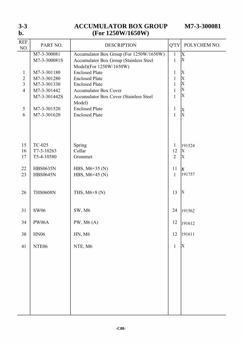
3-3 ACCUMULATOR BOX GROUP M7-3-300081 b. (For 1250W/1650W)
REF. NO. PART NO. DESCRIPTION Q'TY
M7-3-300081 Accumulator Box Group (For 1250W/1650W) 1 X X X
X X X X
X X 191524 X X
X
191757
X
191562 191612
191611 X
1
M7-3-300081S
M7-3-301180
Accumulator Box Group (Stainless Steel Model)(For 1250W/1650W) Enclosed Plate
1
1 2 M7-3-301280 Enclosed Plate 1 3 M7-3-301330 Enclosed Plate 1 4
5
M7-3-301442 M7-3-301442S
M7-3-301520
Accumulator Box Cover Accumulator Box Cover (Stainless Steel Model) Enclosed Plate
1 1
1
6 M7-3-301620 Enclosed Plate 1
15
TC-025
Spring
1 16 T7-3-10263 Collar 12 17 T5-4-10580 Grommet 2
22 HBS0635N HBS, M6×35 (N) 11 23 HBS0645N HBS, M6×45 (N) 1
26
THS0608N
THS, M6×8 (N)
13
31
SW06
SW, M6
24
34 PW06A PW, M6 (A) 12
38 HN06 HN, M6 12
41 NTE06 NTE, M6 1
-C88-
POLYCHEM NO.
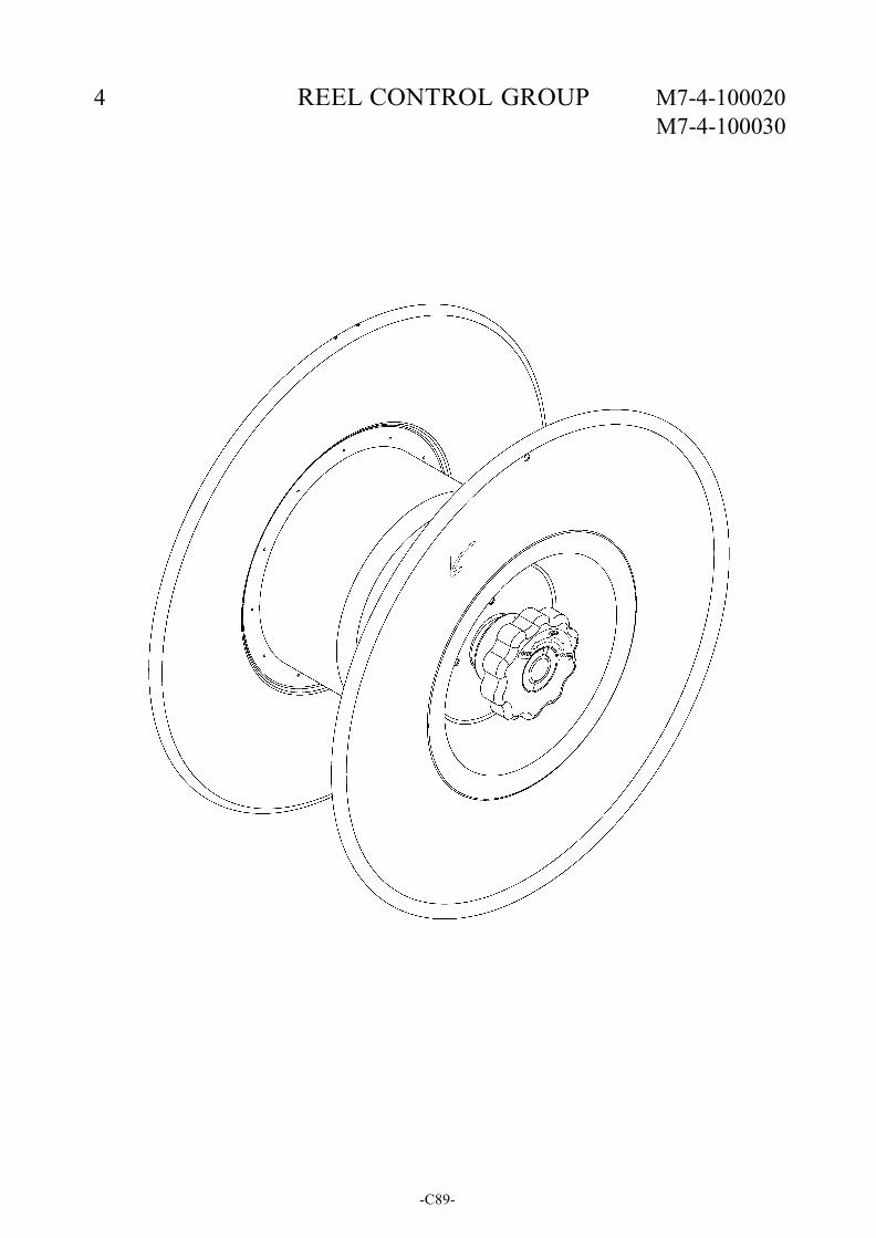
4 REEL CONTROL GROUP M7-4-100020 M7-4-100030
-C89-
4 REEL CONTROL GROUP M7-4-100020 M7-4-100030
REF. NO. PART NO. DESCRIPTION Q'TY
M7-4-100020 M7-4-100020S
M7-4-100030 M7-4-100030S
Reel Control Group (For 200mm) Reel Control Group (Stainless Steel Model) (For 200mm) Reel Control Group (For 150mm)(Option) Reel Control Group (Stainless Steel Model) (For 150mm)(Option)
1 1
1 1
(SEE PG. C91) X X
X
X
-C90-
POLYCHEM NO.
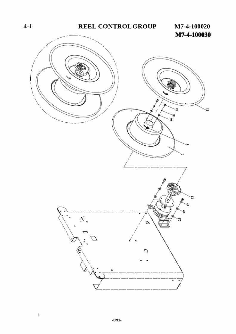
4-1
I
REEL CONTROL GROUP M7-4-100020
-C91-
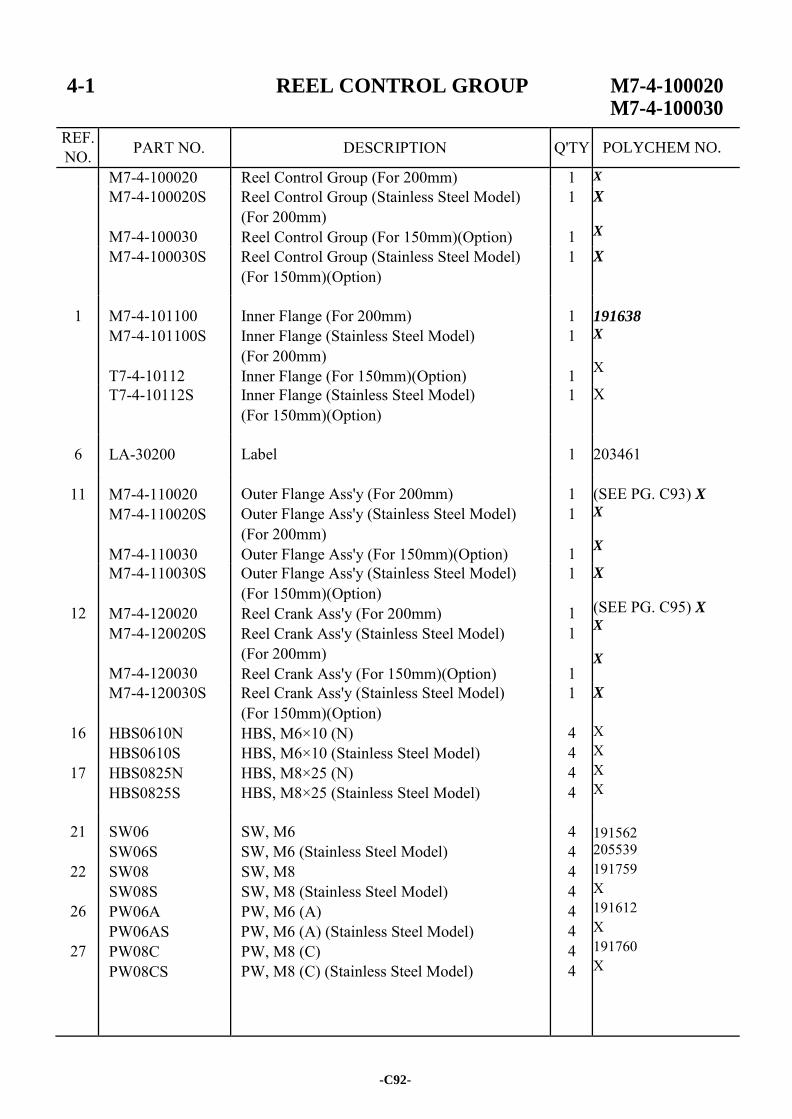
4-1 REEL CONTROL GROUP M7-4-100020 M7-4-100030
REF. NO. PART NO. DESCRIPTION Q'TY
M7-4-100020 Reel Control Group (For 200mm) 1 X
M7-4-100020S
M7-4-100030
Reel Control Group (Stainless Steel Model) (For 200mm) Reel Control Group (For 150mm)(Option)
1
1
X
X
M7-4-100030S Reel Control Group (Stainless Steel Model) (For 150mm)(Option)
1 X
1 M7-4-101100 M7-4-101100S
T7-4-10112
Inner Flange (For 200mm) Inner Flange (Stainless Steel Model) (For 200mm) Inner Flange (For 150mm)(Option)
1 1
1
191638 X
X
T7-4-10112S Inner Flange (Stainless Steel Model) (For 150mm)(Option)
1 X
6 LA-30200 Label 1
203461
11 M7-4-110020 M7-4-110020S
M7-4-110030
Outer Flange Ass'y (For 200mm) Outer Flange Ass'y (Stainless Steel Model) (For 200mm) Outer Flange Ass'y (For 150mm)(Option)
1 1
1
(SEE PG. C93) X X
X
12
M7-4-110030S
M7-4-120020 M7-4-120020S
M7-4-120030
Outer Flange Ass'y (Stainless Steel Model) (For 150mm)(Option) Reel Crank Ass'y (For 200mm) Reel Crank Ass'y (Stainless Steel Model) (For 200mm) Reel Crank Ass'y (For 150mm)(Option)
1
1 1
1
X
(SEE PG. C95) X X
X
16
17
M7-4-120030S
HBS0610N HBS0610S HBS0825N HBS0825S
Reel Crank Ass'y (Stainless Steel Model) (For 150mm)(Option) HBS, M6×10 (N) HBS, M6×10 (Stainless Steel Model) HBS, M8×25 (N) HBS, M8×25 (Stainless Steel Model)
1
4 4 4 4
X
X X X X
21
22
26
27
SW06 SW06S SW08 SW08S PW06A PW06AS PW08C PW08CS
SW, M6 SW, M6 (Stainless Steel Model) SW, M8 SW, M8 (Stainless Steel Model) PW, M6 (A) PW, M6 (A) (Stainless Steel Model) PW, M8 (C) PW, M8 (C) (Stainless Steel Model)
4 4 4 4 4 4 4 4
191562 205539 191759 X 191612 X 191760 X
-C92-
POLYCHEM NO.
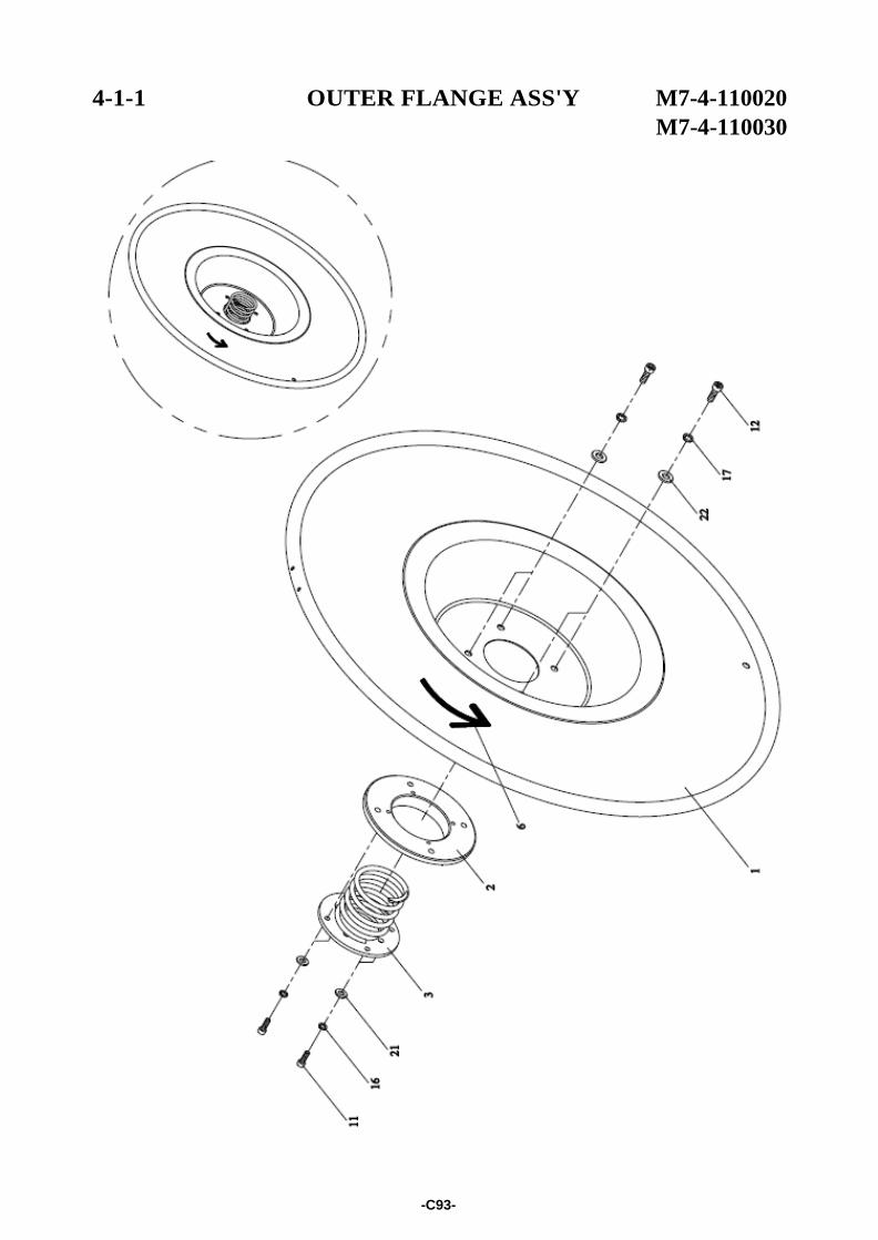
4-1-1 OUTER FLANGE ASS'Y M7-4-110020
M7-4-110030
-C93-
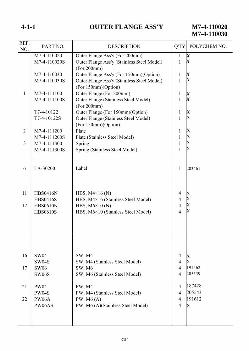
4-1-1 OUTER FLANGE ASS'Y M7-4-110020 M7-4-110030
REF. NO. PART NO. DESCRIPTION Q'TY
M7-4-110020 Outer Flange Ass'y (For 200mm) 1 X X
X
X X
X X X X X X X
203461 X X X X X X 191562 205539 187428 205543 191612 X
M7-4-110020S
M7-4-110030
Outer Flange Ass'y (Stainless Steel Model) (For 200mm) Outer Flange Ass'y (For 150mm)(Option)
1
1
1
M7-4-110030S
M7-4-111100 M7-4-111100S
T7-4-10122
Outer Flange Ass'y (Stainless Steel Model) (For 150mm)(Option) Outer Flange (For 200mm) Outer Flange (Stainless Steel Model) (For 200mm) Outer Flange (For 150mm)(Option)
1
1 1
1
2
3
T7-4-10122S
M7-4-111200 M7-4-111200S M7-4-111300 M7-4-111300S
Outer Flange (Stainless Steel Model) (For 150mm)(Option) Plate Plate (Stainless Steel Model) Spring Spring (Stainless Steel Model)
1
1 1 1 1
6
LA-30200
Label
1
11
12
HBS0416N HBS0416S HBS0610N HBS0610S
HBS, M4×16 (N) HBS, M4×16 (Stainless Steel Model) HBS, M6×10 (N) HBS, M6×10 (Stainless Steel Model)
4 4 4 4
16
17
SW04 SW04S SW06 SW06S
SW, M4 SW, M4 (Stainless Steel Model) SW, M6 SW, M6 (Stainless Steel Model)
4 4 4 4
21
22
PW04 PW04S PW06A PW06AS
PW, M4 PW, M4 (Stainless Steel Model) PW, M6 (A) PW, M6 (A)(Stainless Steel Model)
4 4 4 4
-C94
POLYCHEM NO.
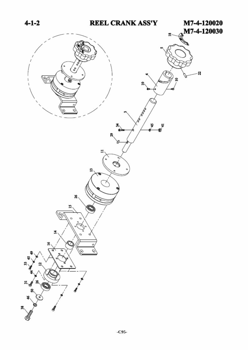
-C95-
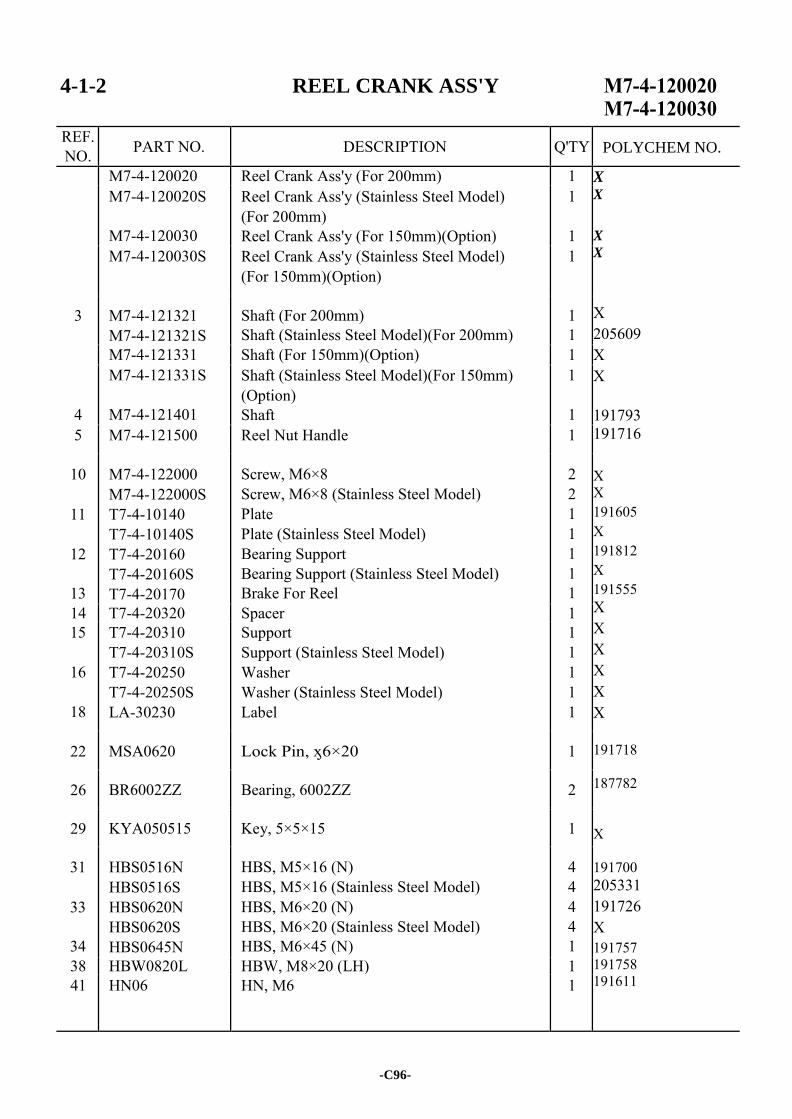
4-1-2 REEL CRANK ASS'Y
REF. NO. PART NO. DESCRIPTION Q'TY
M7-4-120020 Reel Crank Ass'y (For 200mm) 1 X X
X
X
X 205609 X X 191793 191716 X X 191605 X 191812 X 191555 X X X X X X 191718 187782 X 191700 205331 191726 X 191757 191758 191611
M7-4-120020S
M7-4-120030
Reel Crank Ass'y (Stainless Steel Model) (For 200mm) Reel Crank Ass'y (For 150mm)(Option)
1
1 M7-4-120030S Reel Crank Ass'y (Stainless Steel Model)
(For 150mm)(Option) 1
3 M7-4-121321 M7-4-121321S
Shaft (For 200mm) Shaft (Stainless Steel Model)(For 200mm)
1 1
M7-4-121331 Shaft (For 150mm)(Option) 1
4
M7-4-121331S
M7-4-121401
Shaft (Stainless Steel Model)(For 150mm) (Option) Shaft
1
1 5 M7-4-121500 Reel Nut Handle 1
10
11
12
13
M7-4-122000 M7-4-122000S T7-4-10140 T7-4-10140S T7-4-20160 T7-4-20160S T7-4-20170
Screw, M6×8 Screw, M6×8 (Stainless Steel Model) Plate Plate (Stainless Steel Model) Bearing Support Bearing Support (Stainless Steel Model) Brake For Reel
2 2 1 1 1 1 1
14 T7-4-20320 Spacer 1 15
16
18
T7-4-20310 T7-4-20310S T7-4-20250 T7-4-20250S LA-30230
Support Support (Stainless Steel Model) Washer Washer (Stainless Steel Model) Label
1 1 1 1 1
22 MSA0620 Lock Pin, ӽ6×20 1
26 BR6002ZZ Bearing, 6002ZZ 2
29 KYA050515 Key, 5×5×15 1
31
33
34
HBS0516N HBS0516S HBS0620N HBS0620S HBS0645N
HBS, M5×16 (N) HBS, M5×16 (Stainless Steel Model) HBS, M6×20 (N) HBS, M6×20 (Stainless Steel Model) HBS, M6×45 (N)
4 4 4 4 1
38 HBW0820L HBW, M8×20 (LH) 1 41 HN06 HN, M6 1
-C96-
POLYCHEM NO.

4-1-2 REEL CRANK ASS'Y
REF. NO. PART NO. DESCRIPTION Q'TY
44
45
46
49
50
SW05 SW05S SW06 SW06S SW08 SW08S PW06C PW06CS PW08C PW08CS
SW, M5 SW, M5 (Stainless Steel Model) SW, M6 SW, M6 (Stainless Steel Model) SW, M8 SW, M8 (Stainless Steel Model) PW, M6 (C) PW, M6 (C)(Stainless Steel Model) PW, M8 (C) PW, M8 (C)(Stainless Steel Model)
4 4 5 5 1 1 4 4 1 1
191577 X 191562 205539 191759 X 191561 205534 191760 X
-C97-
POLYCHEM NO.

-C98-
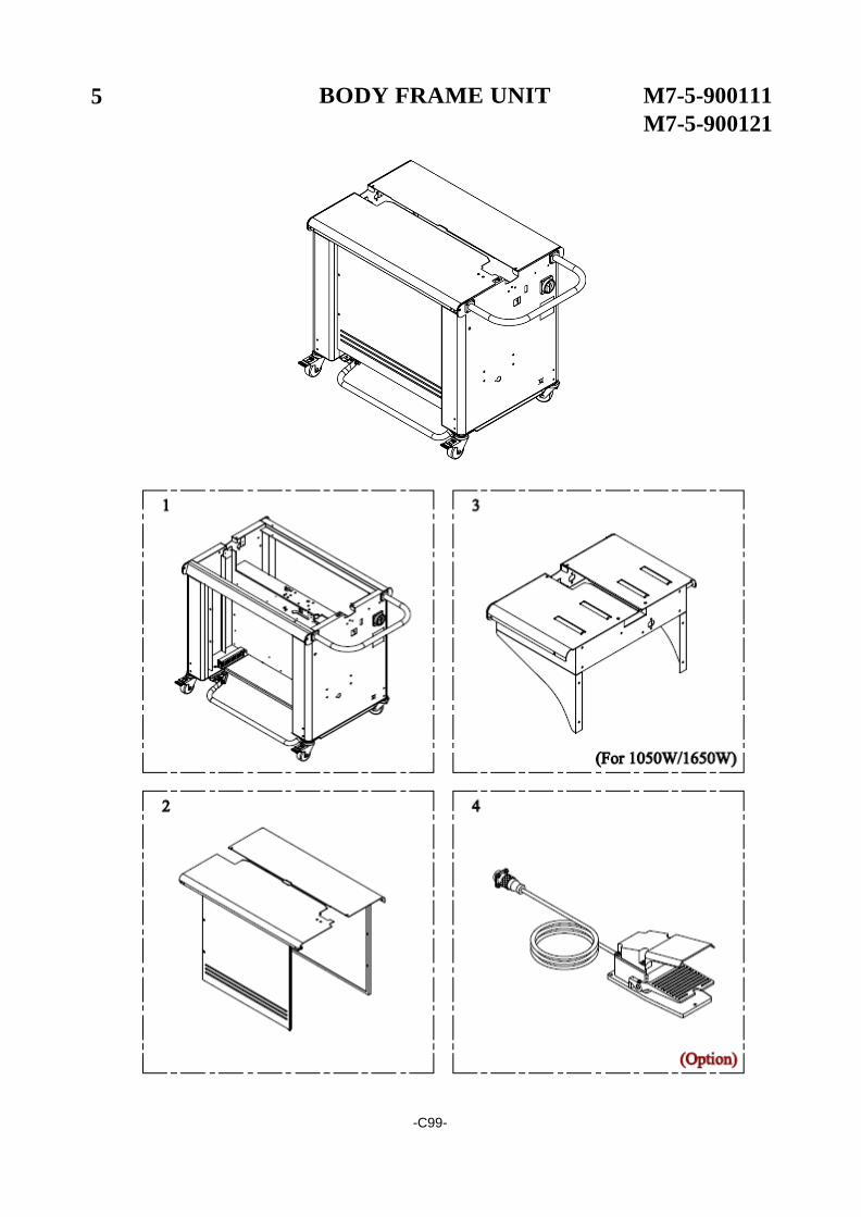
5 BODY FRAME UNIT M7-5-900111
M7-5-900121
-C99-
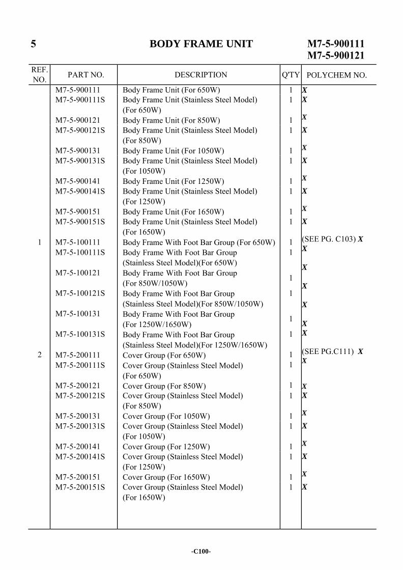
BODY FRAME UNIT
REF. NO. PART NO. DESCRIPTION Q'TY
M7-5-900111 Body Frame Unit (For 650W) 1 X
M7-5-900111S
M7-5-900121
Body Frame Unit (Stainless Steel Model) (For 650W) Body Frame Unit (For 850W)
1
1
X
X
M7-5-900121S
M7-5-900131
Body Frame Unit (Stainless Steel Model) (For 850W) Body Frame Unit (For 1050W)
1
1
X
X
M7-5-900131S
M7-5-900141
Body Frame Unit (Stainless Steel Model) (For 1050W) Body Frame Unit (For 1250W)
1
1
X
X
M7-5-900141S
M7-5-900151
Body Frame Unit (Stainless Steel Model) (For 1250W) Body Frame Unit (For 1650W)
1
1
X X
1
2
M7-5-900151S
M7-5-100111 M7-5-100111S
M7-5-100121
M7-5-100121S
M7-5-100131
M7-5-100131S
M7-5-200111 M7-5-200111S
M7-5-200121
Body Frame Unit (Stainless Steel Model) (For 1650W) Body Frame With Foot Bar Group (For 650W) Body Frame With Foot Bar Group (Stainless Steel Model)(For 650W) Body Frame With Foot Bar Group (For 850W/1050W) Body Frame With Foot Bar Group (Stainless Steel Model)(For 850W/1050W) Body Frame With Foot Bar Group (For 1250W/1650W) Body Frame With Foot Bar Group (Stainless Steel Model)(For 1250W/1650W) Cover Group (For 650W) Cover Group (Stainless Steel Model) (For 650W) Cover Group (For 850W)
1
1 1
1
1
1
1
1 1
1
X
(SEE PG. C103) X
X
X
X
X
X
X
(SEE PG.C111) X X
X
M7-5-200121S
M7-5-200131
Cover Group (Stainless Steel Model) (For 850W) Cover Group (For 1050W)
1
1
X X
M7-5-200131S
M7-5-200141
Cover Group (Stainless Steel Model) (For 1050W) Cover Group (For 1250W)
1
1
X X
M7-5-200141S
M7-5-200151
Cover Group (Stainless Steel Model) (For 1250W) Cover Group (For 1650W)
1
1
X X
M7-5-200151S Cover Group (Stainless Steel Model) (For 1650W)
1 X
-C100-
POLYCHEM NO.
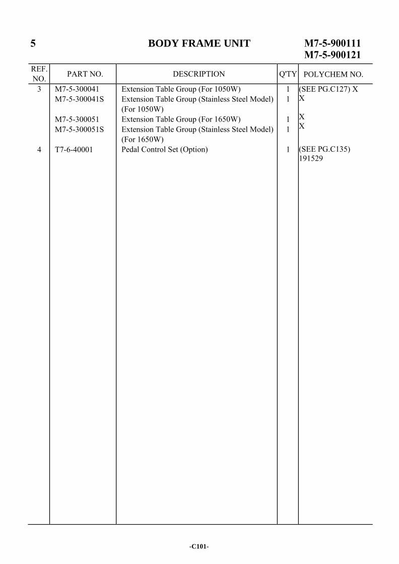
BODY FRAME UNIT
REF. NO. PART NO. DESCRIPTION Q'TY
3
4
M7-5-300041 M7-5-300041S
M7-5-300051 M7-5-300051S
T7-6-40001
Extension Table Group (For 1050W) Extension Table Group (Stainless Steel Model) (For 1050W) Extension Table Group (For 1650W) Extension Table Group (Stainless Steel Model) (For 1650W) Pedal Control Set (Option)
1 1
1 1
1
(SEE PG.C127) X X X X (SEE PG.C135) 191529
-C101-
POLYCHEM NO.

-C102-
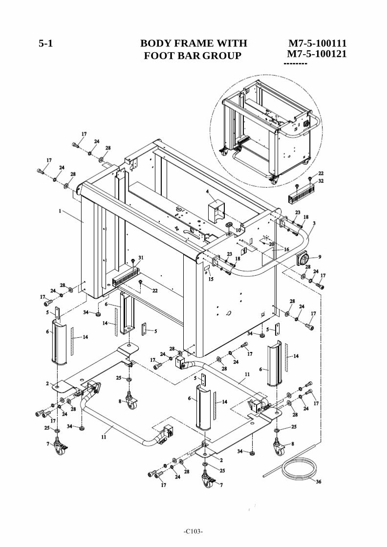
5-1 BODY FRAME WITH
FOOT BAR GROUP
/ //
M7-5-100111
--M---7----5-100121
-C103-
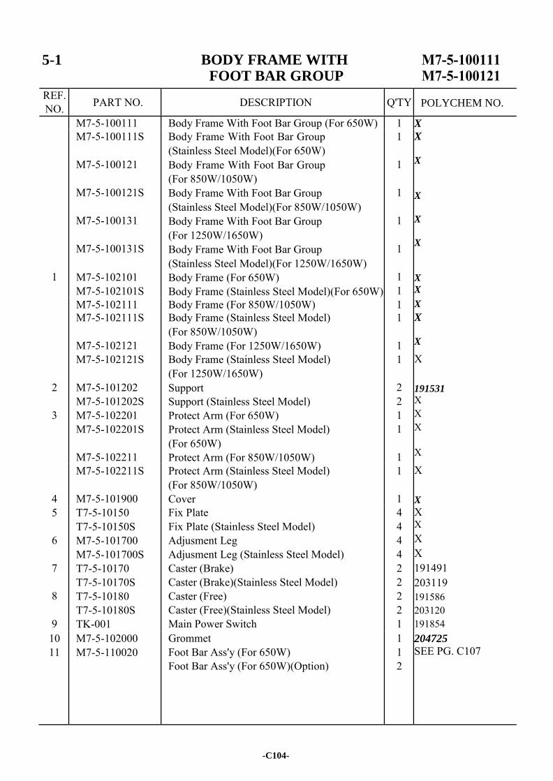
5-1 BODY FRAME WITH FOOT BAR GROUP
REF. NO. PART NO. DESCRIPTION Q'TY
M7-5-100111 Body Frame With Foot Bar Group (For 650W) 1 X
1
M7-5-100111S
M7-5-100121
M7-5-100121S
M7-5-100131
M7-5-100131S
M7-5-102101 M7-5-102101S
Body Frame With Foot Bar Group (Stainless Steel Model)(For 650W) Body Frame With Foot Bar Group (For 850W/1050W) Body Frame With Foot Bar Group (Stainless Steel Model)(For 850W/1050W) Body Frame With Foot Bar Group (For 1250W/1650W) Body Frame With Foot Bar Group (Stainless Steel Model)(For 1250W/1650W) Body Frame (For 650W) Body Frame (Stainless Steel Model)(For 650W)
1
1
1
1
1
1 1
X
X
X
X
X
X
X
M7-5-102111 Body Frame (For 850W/1050W) 1 X
M7-5-102111S
M7-5-102121
Body Frame (Stainless Steel Model) (For 850W/1050W) Body Frame (For 1250W/1650W)
1
1
X
X
2
3
M7-5-102121S
M7-5-101202 M7-5-101202S M7-5-102201 M7-5-102201S
M7-5-102211
Body Frame (Stainless Steel Model) (For 1250W/1650W) Support Support (Stainless Steel Model) Protect Arm (For 650W) Protect Arm (Stainless Steel Model) (For 650W) Protect Arm (For 850W/1050W)
1
2 2 1 1
1
X 191531
X X X X
4
M7-5-102211S
M7-5-101900
Protect Arm (Stainless Steel Model) (For 850W/1050W) Cover
1
1
X X
5
6
7
8
9
T7-5-10150 T7-5-10150S M7-5-101700 M7-5-101700S T7-5-10170 T7-5-10170S T7-5-10180 T7-5-10180S TK-001
Fix Plate Fix Plate (Stainless Steel Model) Adjusment Leg Adjusment Leg (Stainless Steel Model) Caster (Brake) Caster (Brake)(Stainless Steel Model) Caster (Free) Caster (Free)(Stainless Steel Model) Main Power Switch
4 4 4 4 2 2 2 2 1
X X X X 191491 203119 191586 203120 191854
10 11
M7-5-102000 M7-5-110020
Grommet Foot Bar Ass'y (For 650W) Foot Bar Ass'y (For 650W)(Option)
1 1 2
204725
SEE PG. C107
-C104-
POLYCHEM NO.
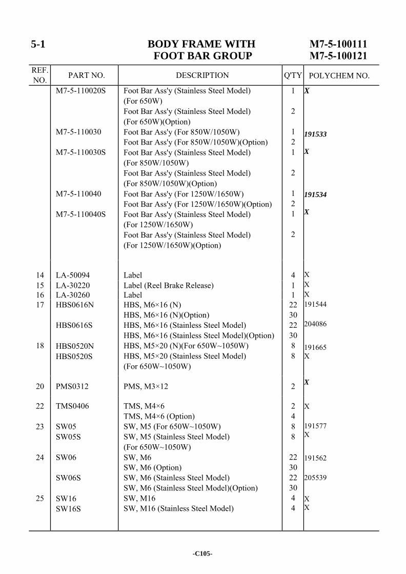
5-1 BODY FRAME WITH FOOT BAR GROUP
REF. NO. PART NO. DESCRIPTION Q'TY
M7-5-110020S
M7-5-110030
M7-5-110030S
M7-5-110040
M7-5-110040S
Foot Bar Ass'y (Stainless Steel Model) (For 650W) Foot Bar Ass'y (Stainless Steel Model) (For 650W)(Option) Foot Bar Ass'y (For 850W/1050W) Foot Bar Ass'y (For 850W/1050W)(Option) Foot Bar Ass'y (Stainless Steel Model) (For 850W/1050W) Foot Bar Ass'y (Stainless Steel Model) (For 850W/1050W)(Option) Foot Bar Ass'y (For 1250W/1650W) Foot Bar Ass'y (For 1250W/1650W)(Option) Foot Bar Ass'y (Stainless Steel Model) (For 1250W/1650W) Foot Bar Ass'y (Stainless Steel Model) (For 1250W/1650W)(Option)
1
2
1 2 1
2
1 2 1
2
X
191533
X 191534
X
X X X 191544 204086 191665 X X
X 191577 X 191562 205539 X X
14
LA-50094
Label
4
15 LA-30220 Label (Reel Brake Release) 1 16 LA-30260 Label 1 17
18
HBS0616N
HBS0616S
HBS0520N HBS0520S
HBS, M6×16 (N) HBS, M6×16 (N)(Option) HBS, M6×16 (Stainless Steel Model) HBS, M6×16 (Stainless Steel Model)(Option) HBS, M5×20 (N)(For 650W~1050W) HBS, M5×20 (Stainless Steel Model) (For 650W~1050W)
22 30 22 30 8 8
20 PMS0312 PMS, M3×12 2
22
23
24
25
TMS0406
SW05 SW05S
SW06
SW06S
SW16 SW16S
TMS, M4×6 TMS, M4×6 (Option) SW, M5 (For 650W~1050W) SW, M5 (Stainless Steel Model) (For 650W~1050W) SW, M6 SW, M6 (Option) SW, M6 (Stainless Steel Model) SW, M6 (Stainless Steel Model)(Option) SW, M16 SW, M16 (Stainless Steel Model)
2 4 8 8
22 30 22 30 4 4
-C105-
POLYCHEM NO.
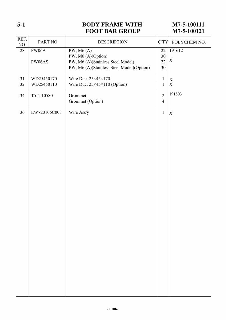
5-1 BODY FRAME WITH FOOT BAR GROUP
REF. NO. PART NO. DESCRIPTION Q'TY
28 PW06A
PW06AS
PW, M6 (A) PW, M6 (A)(Option) PW, M6 (A)(Stainless Steel Model) PW, M6 (A)(Stainless Steel Model)(Option)
22 30 22 30
191612 X X X 191803 X
31 WD25450170 Wire Duct 25×45×170 1 32 WD25450110 Wire Duct 25×45×110 (Option) 1
34 T5-4-10580 Grommet Grommet (Option)
2 4
36 EW720106C003 Wire Ass'y 1
-C106-
POLYCHEM NO.
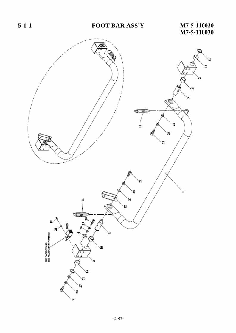
5-1-1 FOOT BAR ASS'Y
-C107-
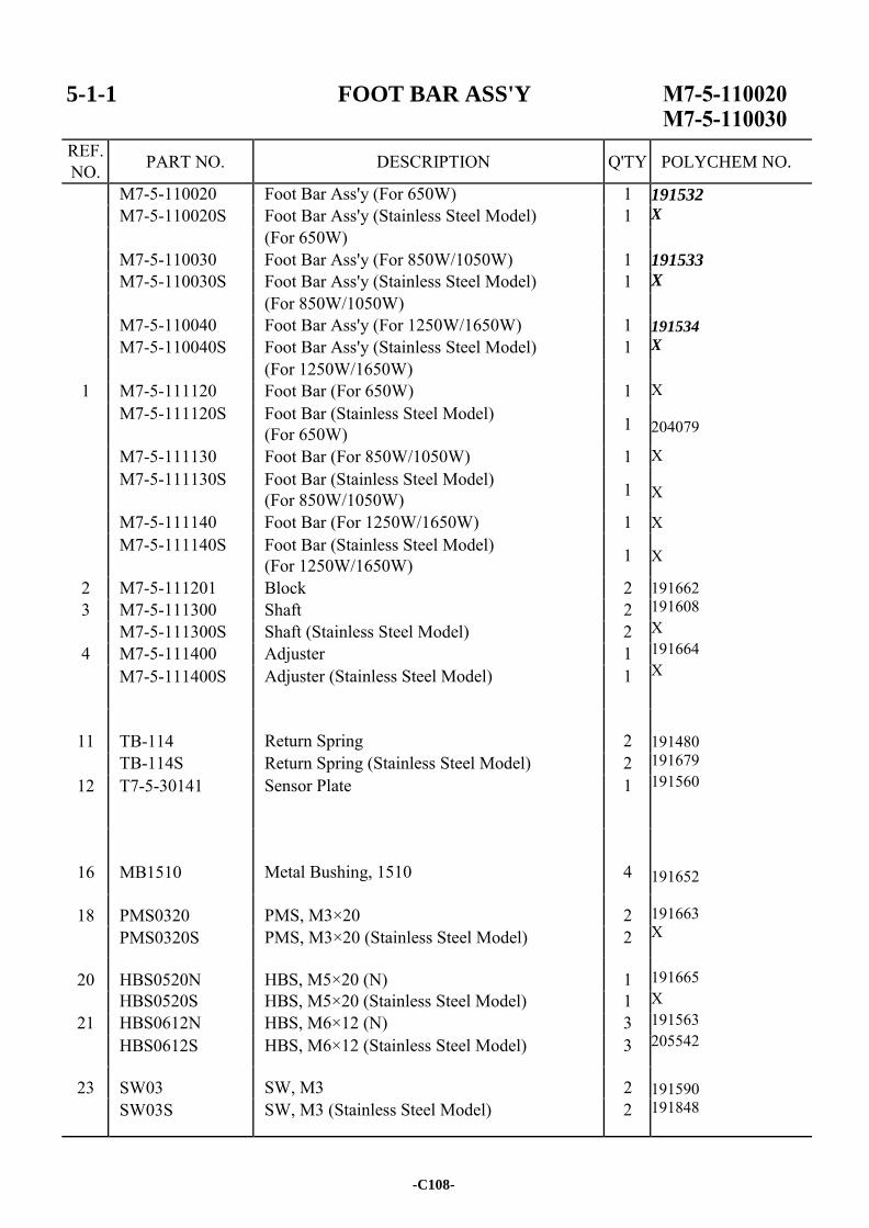
5-1-1 FOOT BAR ASS'Y
REF. NO. PART NO. DESCRIPTION Q'TY
M7-5-110020 Foot Bar Ass'y (For 650W) 1 191532 X
191533
X
191534
X
X 204079
X X
X X 191662 191608 X 191664 X 191480 191679 191560 191652 191663 X 191665 X 191563 205542
191590 191848
M7-5-110020S Foot Bar Ass'y (Stainless Steel Model) 1 (For 650W) M7-5-110030 Foot Bar Ass'y (For 850W/1050W) 1 M7-5-110030S Foot Bar Ass'y (Stainless Steel Model) 1 (For 850W/1050W) M7-5-110040 Foot Bar Ass'y (For 1250W/1650W) 1 M7-5-110040S Foot Bar Ass'y (Stainless Steel Model) 1 (For 1250W/1650W)
1 M7-5-111120 Foot Bar (For 650W) 1 M7-5-111120S Foot Bar (Stainless Steel Model)
(For 650W) 1
M7-5-111130 Foot Bar (For 850W/1050W) 1 M7-5-111130S Foot Bar (Stainless Steel Model)
(For 850W/1050W) 1
M7-5-111140 Foot Bar (For 1250W/1650W) 1 M7-5-111140S Foot Bar (Stainless Steel Model)
(For 1250W/1650W) 1
2 M7-5-111201 Block 2 3 M7-5-111300 Shaft 2
M7-5-111300S Shaft (Stainless Steel Model) 2 4 M7-5-111400 Adjuster 1
M7-5-111400S Adjuster (Stainless Steel Model) 1
11
TB-114
Return Spring
2
TB-114S Return Spring (Stainless Steel Model) 2 12 T7-5-30141 Sensor Plate 1
16
MB1510
Metal Bushing, 1510
4
18 PMS0320 PMS, M3×20 2 PMS0320S PMS, M3×20 (Stainless Steel Model) 2
20 HBS0520N HBS, M5×20 (N) 1 HBS0520S HBS, M5×20 (Stainless Steel Model) 1
21 HBS0612N HBS, M6×12 (N) 3 HBS0612S HBS, M6×12 (Stainless Steel Model) 3
23 SW03 SW, M3 2 SW03S SW, M3 (Stainless Steel Model) 2
-C108-
POLYCHEM NO.
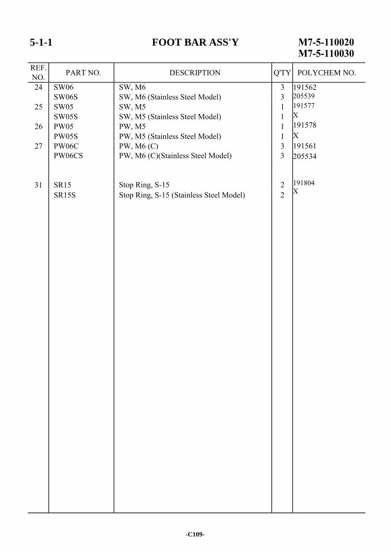
5-1-1 FOOT BAR ASS'Y
REF. NO. PART NO. DESCRIPTION Q'TY
24 SW06 SW, M6 3 191562 205539 191577 X 191578 X 191561 205534 191804 X
SW06S SW, M6 (Stainless Steel Model) 3 25 SW05 SW, M5 1
SW05S SW, M5 (Stainless Steel Model) 1 26 PW05 PW, M5 1
PW05S PW, M5 (Stainless Steel Model) 1 27 PW06C PW, M6 (C) 3
PW06CS PW, M6 (C)(Stainless Steel Model) 3
31
SR15
Stop Ring, S-15
2
SR15S Stop Ring, S-15 (Stainless Steel Model) 2
-C109-
POLYCHEM NO.

-C110-
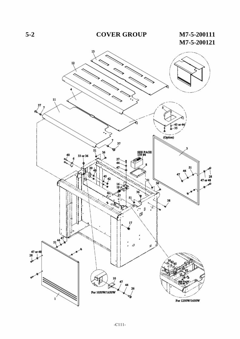
5-2 COVER GROUP M7-5-200111
M7-5-200121
-C111-
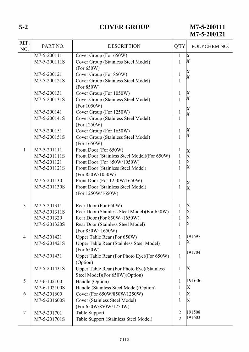
5-2 COVER GROUP
REF. NO. PART NO. DESCRIPTION Q'TY
M7-5-200111 Cover Group (For 650W) 1 X X
X
X
X
X
X
X
X
X X X X X X X X X X X 191697 X 191704 X 191606 X X X 191508 191603
M7-5-200111S
M7-5-200121
Cover Group (Stainless Steel Model) (For 650W) Cover Group (For 850W)
1
1 M7-5-200121S
M7-5-200131
Cover Group (Stainless Steel Model) (For 850W) Cover Group (For 1050W)
1
1 M7-5-200131S
M7-5-200141
Cover Group (Stainless Steel Model) (For 1050W) Cover Group (For 1250W)
1
1 M7-5-200141S
M7-5-200151
Cover Group (Stainless Steel Model) (For 1250W) Cover Group (For 1650W)
1
1
1
M7-5-200151S
M7-5-201111 M7-5-201111S
Cover Group (Stainless Steel Model) (For 1650W) Front Door (For 650W) Front Door (Stainless Steel Model)(For 650W)
1
1 1
M7-5-201121 Front Door (For 850W/1050W) 1 M7-5-201121S
M7-5-201130
Front Door (Stainless Steel Model) (For 850W/1050W) Front Door (For 1250W/1650W)
1
1 M7-5-201130S Front Door (Stainless Steel Model)
(For 1250W/1650W) 1
3 M7-5-201311 M7-5-201311S
Rear Door (For 650W) Rear Door (Stainless Steel Model)(For 650W)
1 1
M7-5-201320 Rear Door (For 850W~1650W) 1
4
5
6
7
M7-5-201320S
M7-5-201421 M7-5-201421S
M7-5-201431
M7-5-201431S
M7-6-102100 M7-6-102100S M7-5-201600 M7-5-201600S
M7-5-201701 M7-5-201701S
Rear Door (Stainless Steel Model) (For 850W~1650W) Upper Table Rear (For 650W) Upper Table Rear (Stainless Steel Model) (For 650W) Upper Table Rear (For Photo Eye)(For 650W) (Option) Upper Table Rear (For Photo Eye)(Stainless Steel Model)(For 650W)(Option) Handle (Option) Handle (Stainless Steel Model)(Option) Cover (For 650W/850W/1250W) Cover (Stainless Steel Model) (For 650W/850W/1250W) Table Support Table Support (Stainless Steel Model)
1
1 1
1
1
1 1 1 1
2 2
-C112-
POLYCHEM NO.
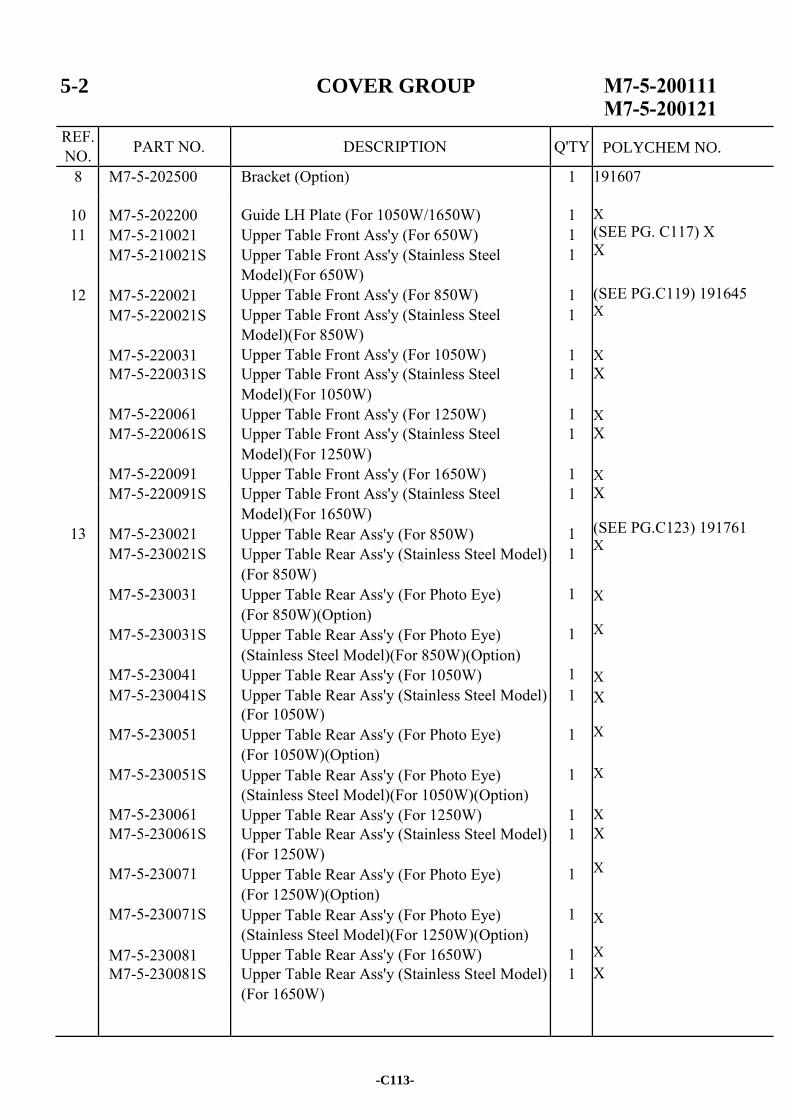
5-2 COVER GROUP
REF. NO. PART NO. DESCRIPTION Q'TY
8 M7-5-202500 Bracket (Option) 1 191607
10 11
12
M7-5-202200 M7-5-210021 M7-5-210021S
M7-5-220021 M7-5-220021S
M7-5-220031
Guide LH Plate (For 1050W/1650W) Upper Table Front Ass'y (For 650W) Upper Table Front Ass'y (Stainless Steel Model)(For 650W) Upper Table Front Ass'y (For 850W) Upper Table Front Ass'y (Stainless Steel Model)(For 850W) Upper Table Front Ass'y (For 1050W)
1 1 1
1 1
1
X (SEE PG. C117) X X
(SEE PG.C119) 191645 X
X
M7-5-220031S
M7-5-220061
Upper Table Front Ass'y (Stainless Steel Model)(For 1050W) Upper Table Front Ass'y (For 1250W)
1
1
X X
M7-5-220061S
M7-5-220091
Upper Table Front Ass'y (Stainless Steel Model)(For 1250W) Upper Table Front Ass'y (For 1650W)
1
1
X X
13
M7-5-220091S
M7-5-230021 M7-5-230021S
M7-5-230031
M7-5-230031S
M7-5-230041
Upper Table Front Ass'y (Stainless Steel Model)(For 1650W) Upper Table Rear Ass'y (For 850W) Upper Table Rear Ass'y (Stainless Steel Model) (For 850W) Upper Table Rear Ass'y (For Photo Eye) (For 850W)(Option) Upper Table Rear Ass'y (For Photo Eye) (Stainless Steel Model)(For 850W)(Option) Upper Table Rear Ass'y (For 1050W)
1
1 1
1
1
1
X (SEE PG.C123) 191761 X X X
X
M7-5-230041S
M7-5-230051
M7-5-230051S
M7-5-230061
Upper Table Rear Ass'y (Stainless Steel Model) (For 1050W) Upper Table Rear Ass'y (For Photo Eye) (For 1050W)(Option) Upper Table Rear Ass'y (For Photo Eye) (Stainless Steel Model)(For 1050W)(Option) Upper Table Rear Ass'y (For 1250W)
1
1
1
1
X X X X
M7-5-230061S
M7-5-230071
M7-5-230071S
M7-5-230081
Upper Table Rear Ass'y (Stainless Steel Model) (For 1250W) Upper Table Rear Ass'y (For Photo Eye) (For 1250W)(Option) Upper Table Rear Ass'y (For Photo Eye) (Stainless Steel Model)(For 1250W)(Option) Upper Table Rear Ass'y (For 1650W)
1
1
1
1
X X X X
M7-5-230081S Upper Table Rear Ass'y (Stainless Steel Model) (For 1650W)
1 X
-C113-
POLYCHEM NO.
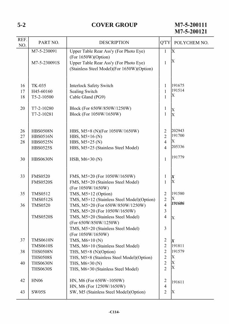
5-2 COVER GROUP
REF. NO. PART NO. DESCRIPTION Q'TY
M7-5-230091
M7-5-230091S
Upper Table Rear Ass'y (For Photo Eye) (For 1650W)(Option) Upper Table Rear Ass'y (For Photo Eye) (Stainless Steel Model)(For 1650W)(Option)
1
1
X X 191675 191514 X X X 202943 191700 X 205336 191779 X
X 191580 X 191686
X X
191811 191579 X X X 191611 X
16
TK-035
Interlock Safety Switch
1
17 H45-60160 Sealing Switch 1 18 T5-2-10500 Cable Gland (PG9) 1
20 T7-2-10280 T7-2-10281
Block (For 650W/850W/1250W) Block (For 1050W/1650W)
1 1
26
HBS0508N
HBS, M5×8 (N)(For 1050W/1650W)
2
27 HBS0516N HBS, M5×16 (N) 2 28 HBS0525N
HBS0525S HBS, M5×25 (N) HBS, M5×25 (Stainless Steel Model)
4 4
30 HBS0630N HSB, M6×30 (N) 1
33
35
36
37
38
40
FMS0520 FMS0520S
TMS0512 TMS0512S TMS0520
TMS0520S
TMS0610N TMS0610S THS0508N THS0508S THS0630N THS0630S
FMS, M5×20 (For 1050W/1650W) FMS, M5×20 (Stainless Steel Model) (For 1050W/1650W) TMS, M5×12 (Option) TMS, M5×12 (Stainless Steel Model)(Option) TMS, M5×20 (For 650W/850W/1250W) TMS, M5×20 (For 1050W/1650W) TMS, M5×20 (Stainless Steel Model) (For 650W/850W/1250W) TMS, M5×20 (Stainless Steel Model) (For 1050W/1650W) TMS, M6×10 (N) TMS, M6×10 (Stainless Steel Model) THS, M5×8 (N)(Option) THS, M5×8 (Stainless Steel Model)(Option) THS, M6×30 (N) THS, M6×30 (Stainless Steel Model)
1 1
2 2 4 3 4
3
2 2 2 2 2 2
42
43
HN06
SW05S
HN, M6 (For 650W~1050W) HN, M6 (For 1250W/1650W) SW, M5 (Stainless Steel Model)(Option)
2 4 2
-C114-
POLYCHEM NO.
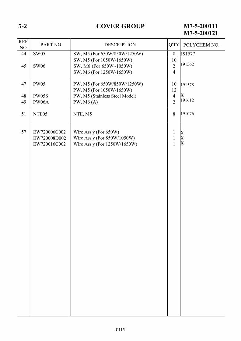
5-2 COVER GROUP
REF. NO. PART NO. DESCRIPTION Q'TY
44 SW05 SW, M5 (For 650W/850W/1250W) 8 191577 191562 191578 X 191612
191076 X X X
45
SW06
SW, M5 (For 1050W/1650W) SW, M6 (For 650W~1050W) SW, M6 (For 1250W/1650W)
10 2 4
47
48
PW05
PW05S
PW, M5 (For 650W/850W/1250W) PW, M5 (For 1050W/1650W) PW, M5 (Stainless Steel Model)
10 12 4
49 PW06A PW, M6 (A) 2
51 NTE05 NTE, M5 8
57 EW720006C002
EW720008D002
Wire Ass'y (For 650W) Wire Ass'y (For 850W/1050W)
1 1
EW720016C002 Wire Ass'y (For 1250W/1650W) 1
-C115-
POLYCHEM NO.

-C116-
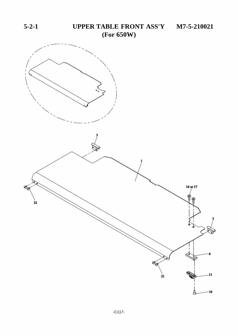
5-2-1 UPPER TABLE FRONT ASS'Y M7-5-210021
(For 650W)
-C117-
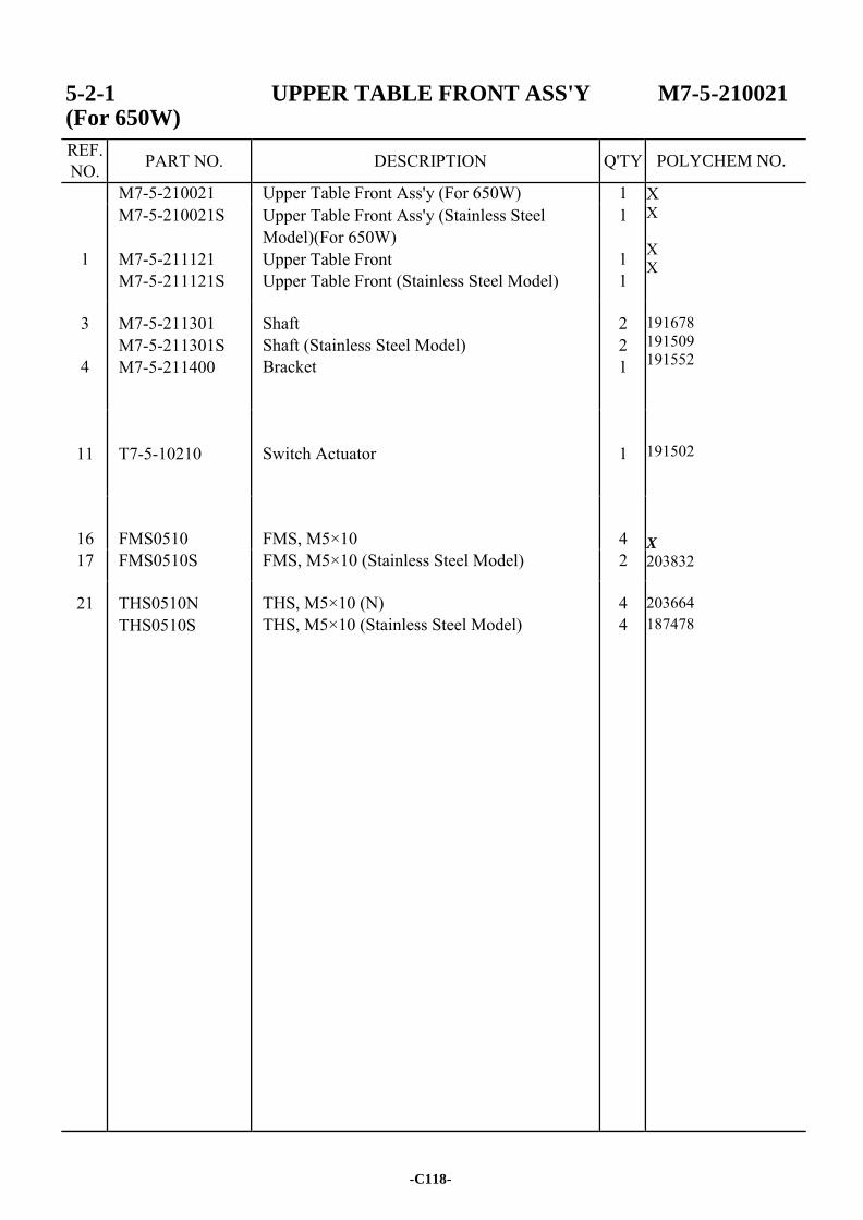
5-2-1 UPPER TABLE FRONT ASS'Y M7-5-210021 (For 650W)
REF. NO. PART NO. DESCRIPTION Q'TY
M7-5-210021 Upper Table Front Ass'y (For 650W) 1 X X X X 191678 191509 191552 191502 X
203832 203664 187478
1
M7-5-210021S
M7-5-211121 M7-5-211121S
Upper Table Front Ass'y (Stainless Steel Model)(For 650W) Upper Table Front Upper Table Front (Stainless Steel Model)
1
1 1
3
4
M7-5-211301 M7-5-211301S M7-5-211400
Shaft Shaft (Stainless Steel Model) Bracket
2 2 1
11
T7-5-10210
Switch Actuator
1
16
FMS0510
FMS, M5×10
4
17 FMS0510S FMS, M5×10 (Stainless Steel Model) 2
21 THS0510N THS0510S
THS, M5×10 (N) THS, M5×10 (Stainless Steel Model)
4 4
-C118-
POLYCHEM NO.
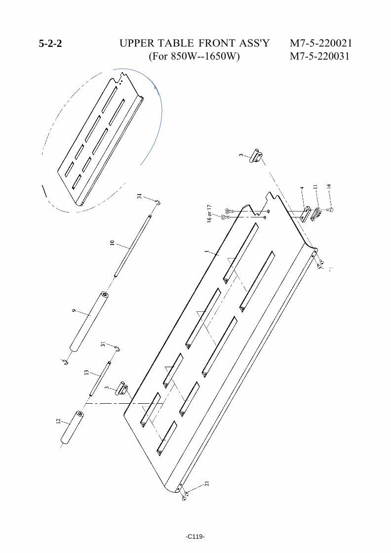
5-2-2 UPPER TABLE FRONT ASS'Y M7-5-220021 (For 850W--1650W) M7-5-220031
\ I
I
I
\
...... N
-C119-
5-2-2 UPPER TABLE FRONT ASS'Y (For 850W~1650W)
REF. NO. PART NO. DESCRIPTION Q'TY
M7-5-220021 Upper Table Front Ass'y (For 850W) 1 191645 X X X X X
X X 191646 X
X X
X X
X X 191678 191509 191552 191673 X
M7-5-220021S
M7-5-220031
Upper Table Front Ass'y (Stainless Steel Model)(For 850W) Upper Table Front Ass'y (For 1050W)
1
1 M7-5-220031S
M7-5-220061
Upper Table Front Ass'y (Stainless Steel Model)(For 1050W) Upper Table Front Ass'y (For 1250W)
1
1 M7-5-220061S
M7-5-220091
Upper Table Front Ass'y (Stainless Steel Model)(For 1250W) Upper Table Front Ass'y (For 1650W)
1
1
1
M7-5-220091S
M7-5-221121 M7-5-221121S
M7-5-221131
Upper Table Front Ass'y (Stainless Steel Model)(For 1650W) Upper Table Front (For 850W) Upper Table Front (Stainless Steel Model) (For 850W) Upper Table Front (For 1050W)
1
1 1
1
M7-5-221131S
M7-5-221161
Upper Table Front (Stainless Steel Model) (For 1050W) Upper Table Front (For 1250W)
1
1 M7-5-221161S
M7-5-221191
Upper Table Front (Stainless Steel Model) (For 1250W) Upper Table Front (For 1650W)
1
1 M7-5-221191S Upper Table Front (Stainless Steel Model)
(For 1650W) 1
3
4
M7-5-211301 M7-5-211301S M7-5-211400
Shaft Shaft (Stainless Steel Model) Bracket
2 2 1
9
T6-5-11120
Table Roller (250mm)(For 850W) Table Roller (250mm)(For 1050W)
6 4
T6-5-11121
Table Roller (250mm)(For 1250W/1650W) Table Roller (250mm)(Stainless Steel Model) (For 850W) Table Roller (250mm)(Stainless Steel Model) (For 1050W) Table Roller (250mm)(Stainless Steel Model) (For 1250W/1650W)
8 6
4
8
-C120-
POLYCHEM NO.
5-2-2 UPPER TABLE FRONT ASS'Y (For 850W~1650W)
REF. NO. PART NO. DESCRIPTION Q'TY
10 T6-5-11130 Table Roller Shaft (For 850W) Table Roller Shaft (For 1050W)
6 4
191674 X 191502 191751 X 191752 X X
203832 191559
203312
191649 203502
11
T6-5-11131
T7-5-10210
Table Roller Shaft (For 1250W/1650W) Table Roller Shaft (Stainless Steel Model) (For 850W) Table Roller Shaft (Stainless Steel Model) (For 1050W) Table Roller Shaft (Stainless Steel Model) (For 1250W/1650W) Switch Actuator
8 6
4
8
1
12
13
T7-5-40410 T7-5-40411
T7-5-40420 T7-5-40420S
Table Roller (130mm)(For 1050W) Table Roller (130mm)(Stainless Steel Model) (For 1050W) Table Roller Shaft (For 1050W) Table Roller Shaft (Stainless Steel Model) (For 1050W)
4 4
4 4
16
FMS0510
FMS, M5×10
4
17 FMS0510S FMS, M5×10 (Stainless Steel Model) 2
21
THS0510N THS0510S
THS, M5×10 (N) THS, M5×10 (Stainless Steel Model)
4 4
31
ER07
ER07S
Snap Ring, E-7 (For 850W) Snap Ring, E-7 (For 1050W~1650W) Snap Ring, E-7 (Stainless Steel Model) (For 850W) Snap Ring, E-7 (Stainless Steel Model) (For 1050W~1650W)
12 16 12
16
-C121-
POLYCHEM NO.

-C122-
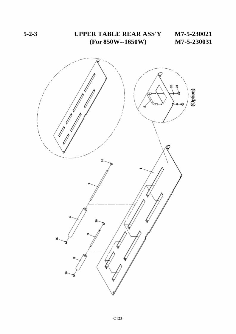
5-2-3 UPPER TABLE REAR ASS'Y M7-5-230021
(For 850W--1650W) M7-5-230031
-C123-
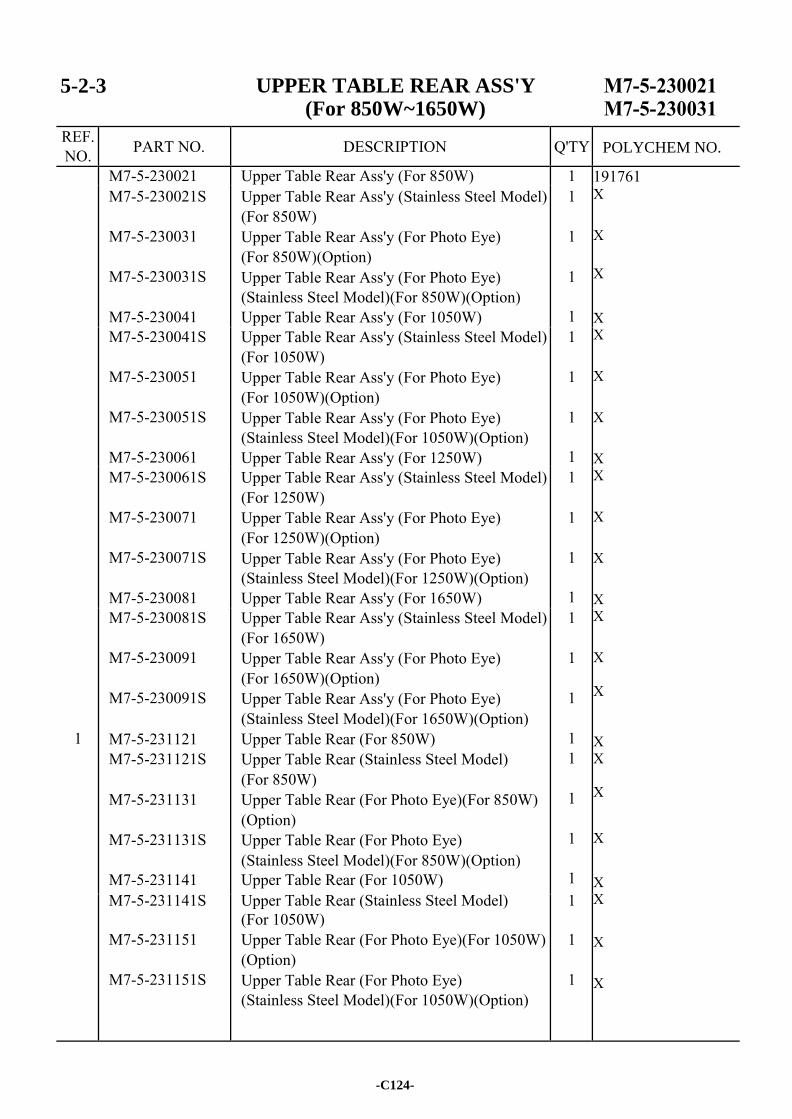
5-2-3 UPPER TABLE REAR ASS'Y (For 850W~1650W)
REF. NO. PART NO. DESCRIPTION Q'TY
M7-5-230021 Upper Table Rear Ass'y (For 850W) 1 191761 X X X
X X X X X X X X X X X X X X X X
X X
X X
M7-5-230021S
M7-5-230031
M7-5-230031S
M7-5-230041
Upper Table Rear Ass'y (Stainless Steel Model) (For 850W) Upper Table Rear Ass'y (For Photo Eye) (For 850W)(Option) Upper Table Rear Ass'y (For Photo Eye) (Stainless Steel Model)(For 850W)(Option) Upper Table Rear Ass'y (For 1050W)
1
1
1
1 M7-5-230041S
M7-5-230051
M7-5-230051S
M7-5-230061
Upper Table Rear Ass'y (Stainless Steel Model) (For 1050W) Upper Table Rear Ass'y (For Photo Eye) (For 1050W)(Option) Upper Table Rear Ass'y (For Photo Eye) (Stainless Steel Model)(For 1050W)(Option) Upper Table Rear Ass'y (For 1250W)
1
1
1
1 M7-5-230061S
M7-5-230071
M7-5-230071S
M7-5-230081
Upper Table Rear Ass'y (Stainless Steel Model) (For 1250W) Upper Table Rear Ass'y (For Photo Eye) (For 1250W)(Option) Upper Table Rear Ass'y (For Photo Eye) (Stainless Steel Model)(For 1250W)(Option) Upper Table Rear Ass'y (For 1650W)
1
1
1
1
1
M7-5-230081S
M7-5-230091
M7-5-230091S
M7-5-231121 M7-5-231121S
M7-5-231131
M7-5-231131S
M7-5-231141
Upper Table Rear Ass'y (Stainless Steel Model) (For 1650W) Upper Table Rear Ass'y (For Photo Eye) (For 1650W)(Option) Upper Table Rear Ass'y (For Photo Eye) (Stainless Steel Model)(For 1650W)(Option) Upper Table Rear (For 850W) Upper Table Rear (Stainless Steel Model) (For 850W) Upper Table Rear (For Photo Eye)(For 850W) (Option) Upper Table Rear (For Photo Eye) (Stainless Steel Model)(For 850W)(Option) Upper Table Rear (For 1050W)
1
1
1
1 1
1
1
1
M7-5-231141S
M7-5-231151
M7-5-231151S
Upper Table Rear (Stainless Steel Model) (For 1050W) Upper Table Rear (For Photo Eye)(For 1050W) (Option) Upper Table Rear (For Photo Eye) (Stainless Steel Model)(For 1050W)(Option)
1
1
1
-C124-
POLYCHEM NO.
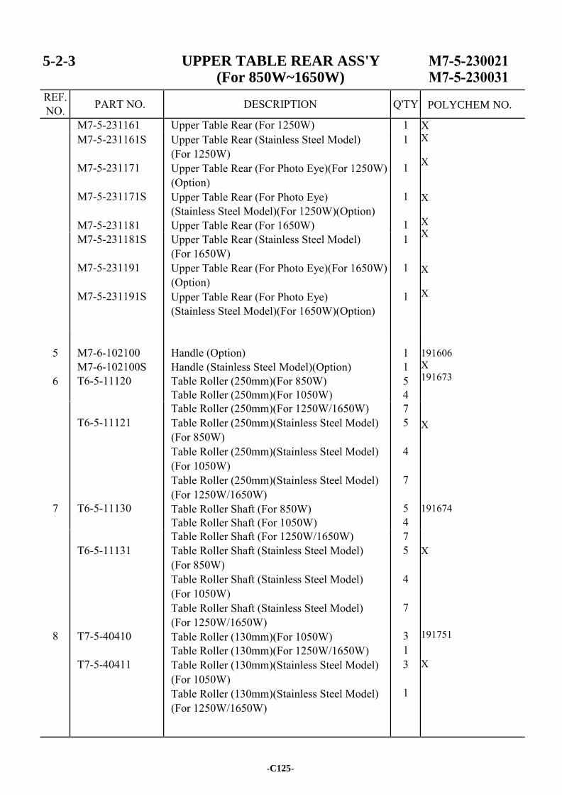
5-2-3 UPPER TABLE REAR ASS'Y (For 850W~1650W)
REF. NO. PART NO. DESCRIPTION Q'TY
M7-5-231161 Upper Table Rear (For 1250W) 1 X X X X X X X X 191606 X 191673 X 191674
X 191751 X
M7-5-231161S
M7-5-231171
M7-5-231171S
M7-5-231181
Upper Table Rear (Stainless Steel Model) (For 1250W) Upper Table Rear (For Photo Eye)(For 1250W) (Option) Upper Table Rear (For Photo Eye) (Stainless Steel Model)(For 1250W)(Option) Upper Table Rear (For 1650W)
1
1
1
1 M7-5-231181S
M7-5-231191
M7-5-231191S
Upper Table Rear (Stainless Steel Model) (For 1650W) Upper Table Rear (For Photo Eye)(For 1650W) (Option) Upper Table Rear (For Photo Eye) (Stainless Steel Model)(For 1650W)(Option)
1
1
1
5
6
M7-6-102100 M7-6-102100S T6-5-11120
Handle (Option) Handle (Stainless Steel Model)(Option) Table Roller (250mm)(For 850W) Table Roller (250mm)(For 1050W)
1 1 5 4
7
T6-5-11121
T6-5-11130
Table Roller (250mm)(For 1250W/1650W) Table Roller (250mm)(Stainless Steel Model) (For 850W) Table Roller (250mm)(Stainless Steel Model) (For 1050W) Table Roller (250mm)(Stainless Steel Model) (For 1250W/1650W) Table Roller Shaft (For 850W) Table Roller Shaft (For 1050W)
7 5
4
7
5 4
8
T6-5-11131
T7-5-40410
T7-5-40411
Table Roller Shaft (For 1250W/1650W) Table Roller Shaft (Stainless Steel Model) (For 850W) Table Roller Shaft (Stainless Steel Model) (For 1050W) Table Roller Shaft (Stainless Steel Model) (For 1250W/1650W) Table Roller (130mm)(For 1050W) Table Roller (130mm)(For 1250W/1650W) Table Roller (130mm)(Stainless Steel Model) (For 1050W) Table Roller (130mm)(Stainless Steel Model) (For 1250W/1650W)
7 5
4
7
3 1 3
1
-C125-
POLYCHEM NO.
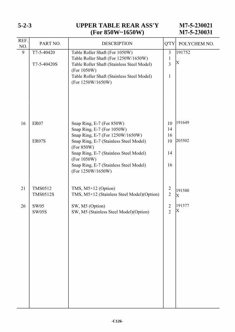
5-2-3 UPPER TABLE REAR ASS'Y (For 850W~1650W)
REF. NO. PART NO. DESCRIPTION Q'TY
9 T7-5-40420
T7-5-40420S
Table Roller Shaft (For 1050W) Table Roller Shaft (For 1250W/1650W) Table Roller Shaft (Stainless Steel Model) (For 1050W) Table Roller Shaft (Stainless Steel Model) (For 1250W/1650W)
3 1 3
1
191752 X 191649
203502 191580 X 191577 X
16
ER07
Snap Ring, E-7 (For 850W) Snap Ring, E-7 (For 1050W)
10 14
ER07S
Snap Ring, E-7 (For 1250W/1650W) Snap Ring, E-7 (Stainless Steel Model) (For 850W) Snap Ring, E-7 (Stainless Steel Model) (For 1050W) Snap Ring, E-7 (Stainless Steel Model) (For 1250W/1650W)
16 10
14
16
21
TMS0512 TMS0512S
TMS, M5×12 (Option) TMS, M5×12 (Stainless Steel Model)(Option)
2 2
26 SW05 SW05S
SW, M5 (Option) SW, M5 (Stainless Steel Model)(Option)
2 2
-C126-
POLYCHEM NO.
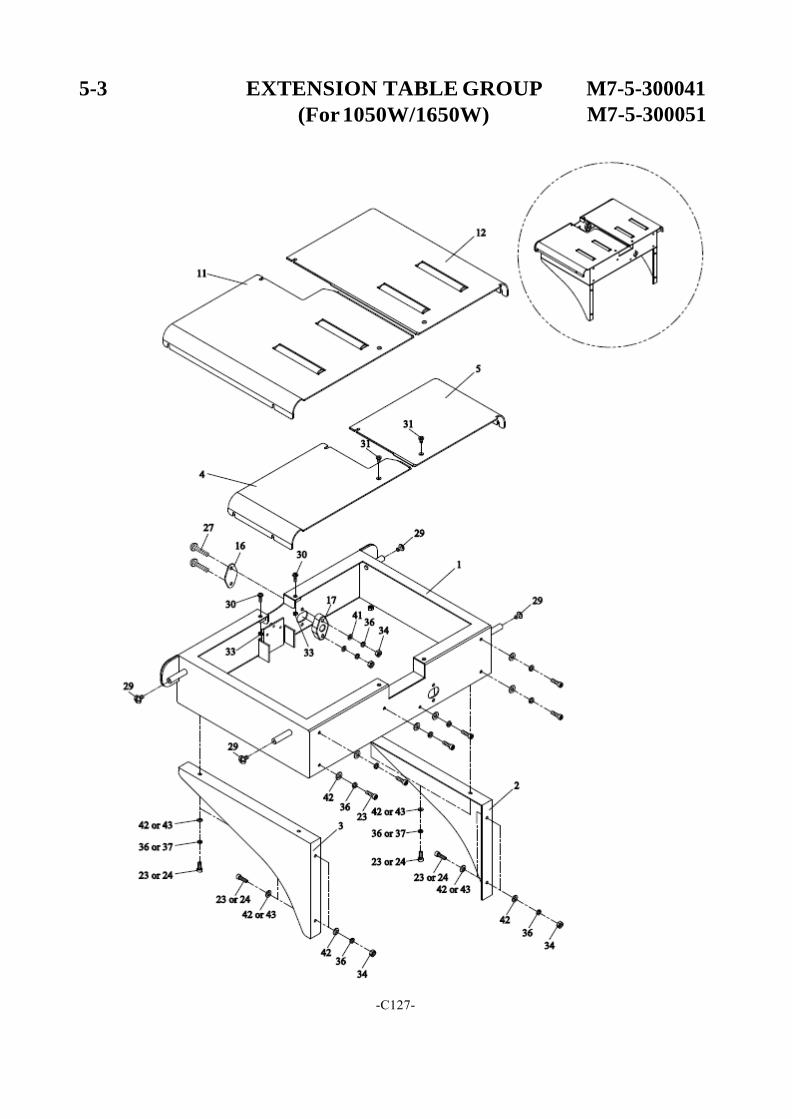
5-3 EXTENSION TABLE GROUP
(For 1050W/1650W)
M7-5-300041
M7-5-300051
-C127-
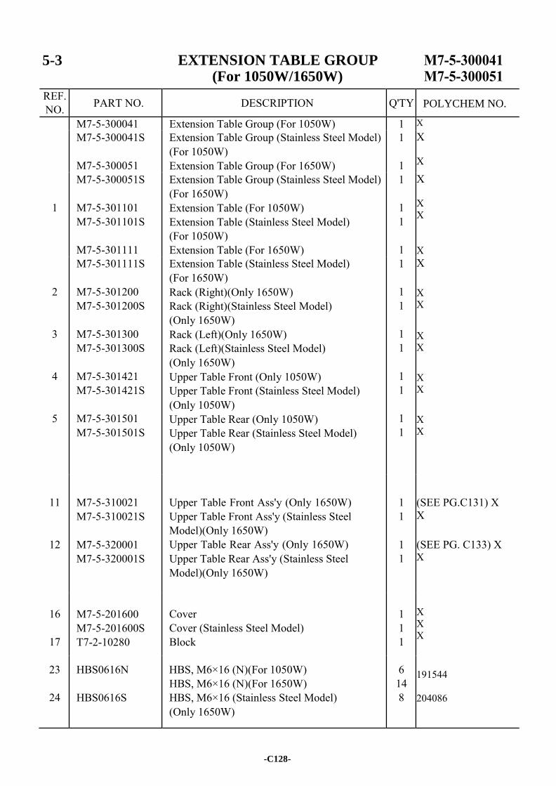
5-3 EXTENSION TABLE GROUP (For 1050W/1650W)
REF. NO. PART NO. DESCRIPTION Q'TY
M7-5-300041 Extension Table Group (For 1050W) 1 X M7-5-300041S
M7-5-300051
Extension Table Group (Stainless Steel Model) (For 1050W) Extension Table Group (For 1650W)
1
1
X X
1
M7-5-300051S
M7-5-301101 M7-5-301101S
M7-5-301111
Extension Table Group (Stainless Steel Model) (For 1650W) Extension Table (For 1050W) Extension Table (Stainless Steel Model) (For 1050W) Extension Table (For 1650W)
1
1 1
1
X X X X
2
3
4
5
M7-5-301111S
M7-5-301200 M7-5-301200S
M7-5-301300 M7-5-301300S
M7-5-301421 M7-5-301421S
M7-5-301501 M7-5-301501S
Extension Table (Stainless Steel Model) (For 1650W) Rack (Right)(Only 1650W) Rack (Right)(Stainless Steel Model) (Only 1650W) Rack (Left)(Only 1650W) Rack (Left)(Stainless Steel Model) (Only 1650W) Upper Table Front (Only 1050W) Upper Table Front (Stainless Steel Model) (Only 1050W) Upper Table Rear (Only 1050W) Upper Table Rear (Stainless Steel Model) (Only 1050W)
1
1 1
1 1
1 1
1 1
X X X
X X
X X
X X
11
12
M7-5-310021 M7-5-310021S
M7-5-320001 M7-5-320001S
Upper Table Front Ass'y (Only 1650W) Upper Table Front Ass'y (Stainless Steel Model)(Only 1650W) Upper Table Rear Ass'y (Only 1650W) Upper Table Rear Ass'y (Stainless Steel Model)(Only 1650W)
1 1
1 1
(SEE PG.C131) X X
(SEE PG. C133) X X
16
17
M7-5-201600 M7-5-201600S T7-2-10280
Cover Cover (Stainless Steel Model) Block
1 1 1
X X X
23
24
HBS0616N
HBS0616S
HBS, M6×16 (N)(For 1050W) HBS, M6×16 (N)(For 1650W) HBS, M6×16 (Stainless Steel Model) (Only 1650W)
6 14 8
191544 204086
-C128-
POLYCHEM NO.
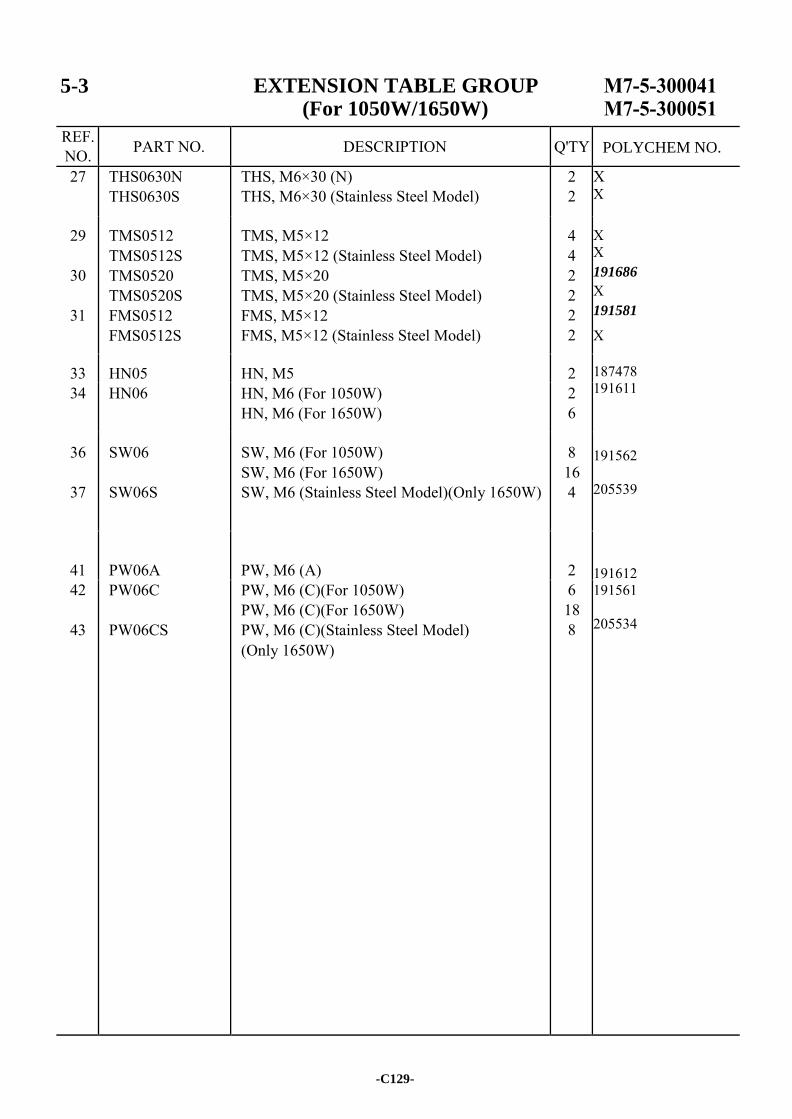
5-3 EXTENSION TABLE GROUP (For 1050W/1650W)
REF. NO. PART NO. DESCRIPTION Q'TY
27 THS0630N THS0630S
THS, M6×30 (N) THS, M6×30 (Stainless Steel Model)
2 2
X X X X 191686
X 191581
X
187478 191611 191562 205539 191612 191561 205534
29
30
31
TMS0512 TMS0512S TMS0520 TMS0520S FMS0512 FMS0512S
TMS, M5×12 TMS, M5×12 (Stainless Steel Model) TMS, M5×20 TMS, M5×20 (Stainless Steel Model) FMS, M5×12 FMS, M5×12 (Stainless Steel Model)
4 4 2 2 2 2
33 HN05 HN, M5 2 34 HN06 HN, M6 (For 1050W)
HN, M6 (For 1650W) 2 6
36
37
SW06
SW06S
SW, M6 (For 1050W) SW, M6 (For 1650W) SW, M6 (Stainless Steel Model)(Only 1650W)
8 16 4
41
PW06A
PW, M6 (A)
2
42
43
PW06C
PW06CS
PW, M6 (C)(For 1050W) PW, M6 (C)(For 1650W) PW, M6 (C)(Stainless Steel Model) (Only 1650W)
6 18 8
-C129-
POLYCHEM NO.

-C130-
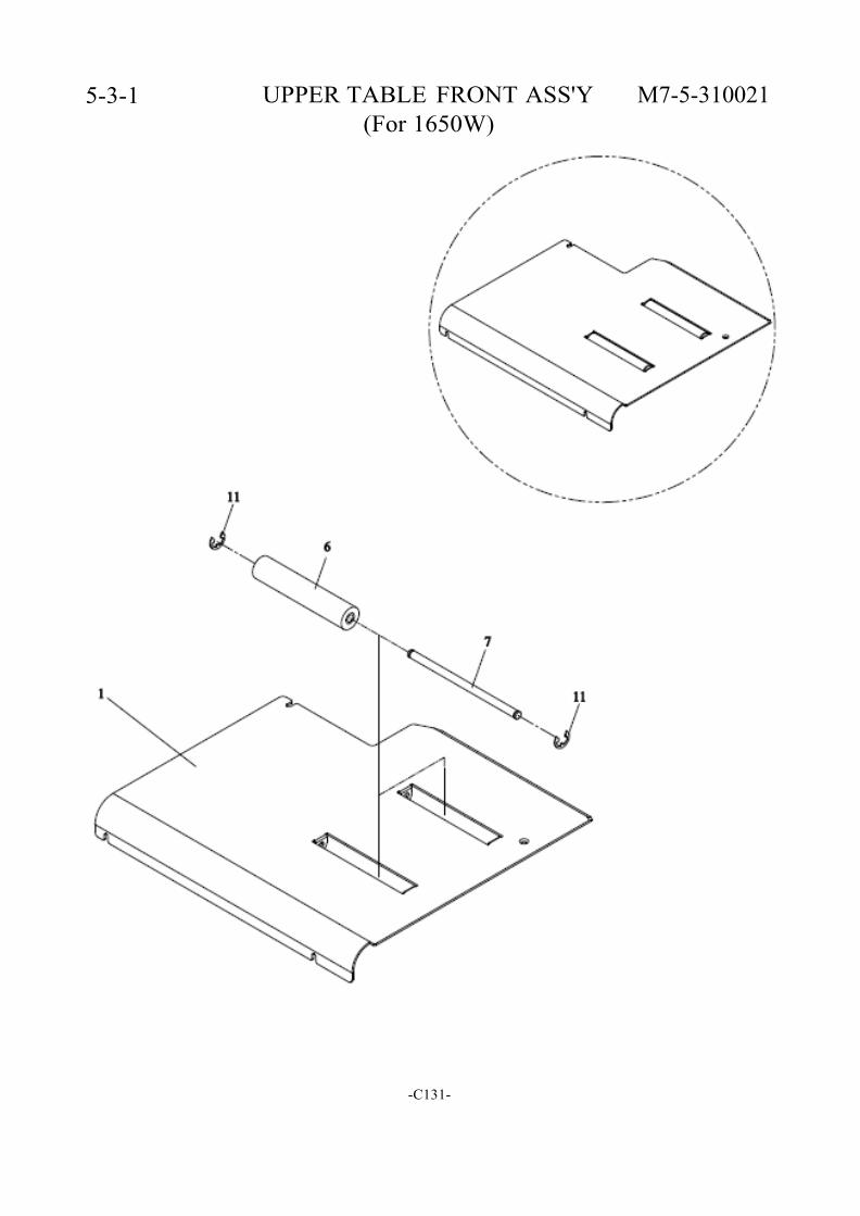
5-3-1 UPPER TABLE FRONT ASS'Y M7-5-310021 (For 1650W)
-C131-
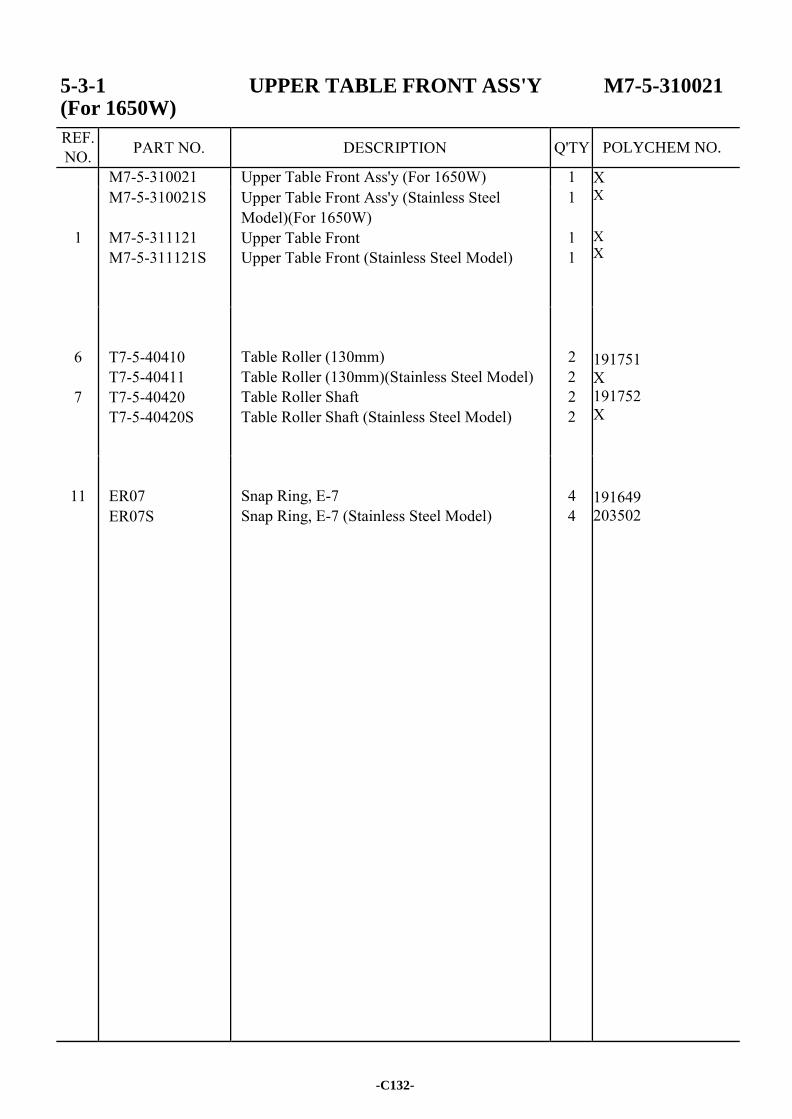
5-3-1 UPPER TABLE FRONT ASS'Y M7-5-310021 (For 1650W)
REF. NO. PART NO. DESCRIPTION Q'TY
M7-5-310021 Upper Table Front Ass'y (For 1650W) 1 X X X X 191751 X 191752 X 191649 203502
1
M7-5-310021S
M7-5-311121 M7-5-311121S
Upper Table Front Ass'y (Stainless Steel Model)(For 1650W) Upper Table Front Upper Table Front (Stainless Steel Model)
1
1 1
6
7
T7-5-40410 T7-5-40411 T7-5-40420 T7-5-40420S
Table Roller (130mm) Table Roller (130mm)(Stainless Steel Model) Table Roller Shaft Table Roller Shaft (Stainless Steel Model)
2 2 2 2
11
ER07 ER07S
Snap Ring, E-7 Snap Ring, E-7 (Stainless Steel Model)
4 4
-C132-
POLYCHEM NO.
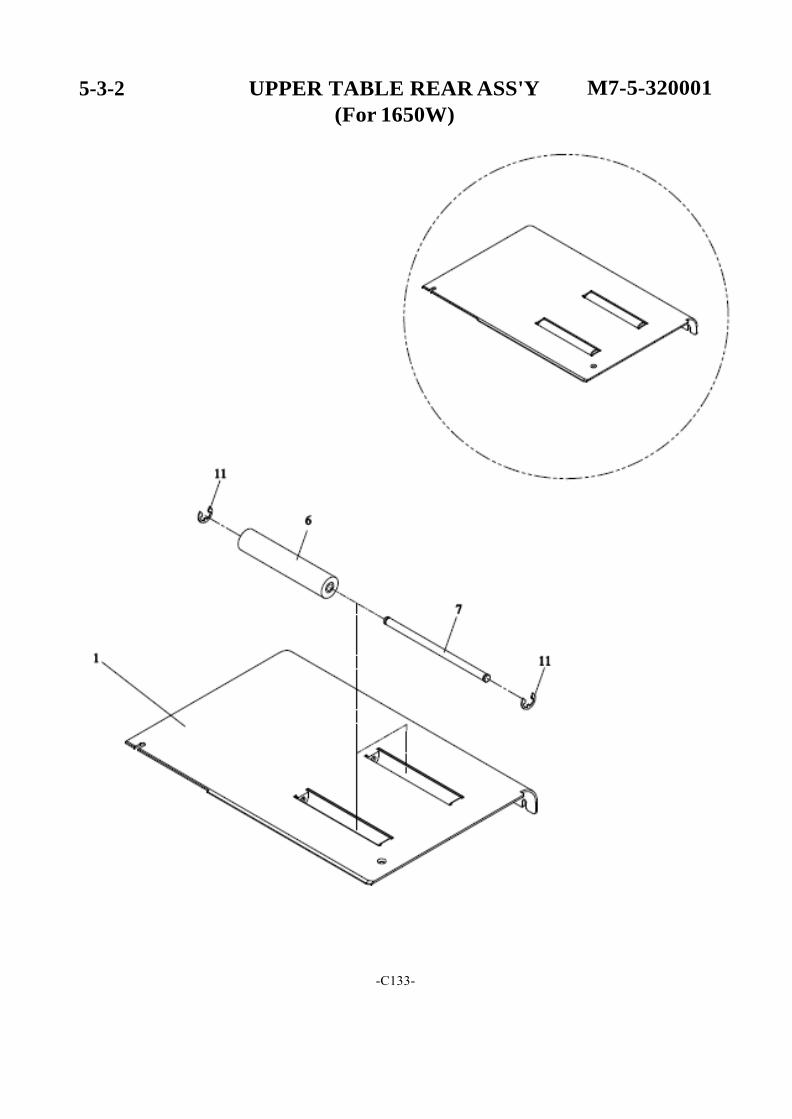
5-3-2 UPPER TABLE REAR ASS'Y
(For 1650W)
M7-5-320001
-C133-
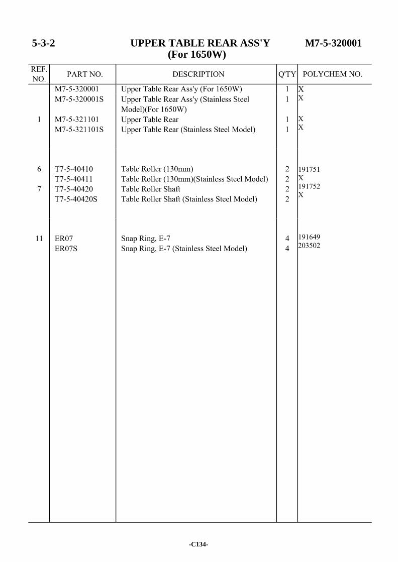
5-3-2 UPPER TABLE REAR ASS'Y M7-5-320001 (For 1650W)
REF. NO. PART NO. DESCRIPTION Q'TY
M7-5-320001 Upper Table Rear Ass'y (For 1650W) 1 X X X X 191751 X 191752 X 191649 203502
1
M7-5-320001S
M7-5-321101 M7-5-321101S
Upper Table Rear Ass'y (Stainless Steel Model)(For 1650W) Upper Table Rear Upper Table Rear (Stainless Steel Model)
1
1 1
6
7
T7-5-40410 T7-5-40411 T7-5-40420 T7-5-40420S
Table Roller (130mm) Table Roller (130mm)(Stainless Steel Model) Table Roller Shaft Table Roller Shaft (Stainless Steel Model)
2 2 2 2
11
ER07 ER07S
Snap Ring, E-7 Snap Ring, E-7 (Stainless Steel Model)
4 4
-C134-
POLYCHEM NO.
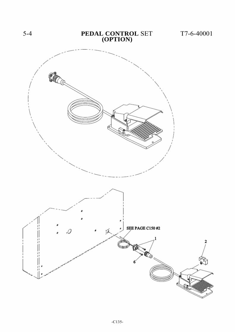
5-4 PEDAL CONTROL SET T7-6-40001
(OPTION)
-C135-
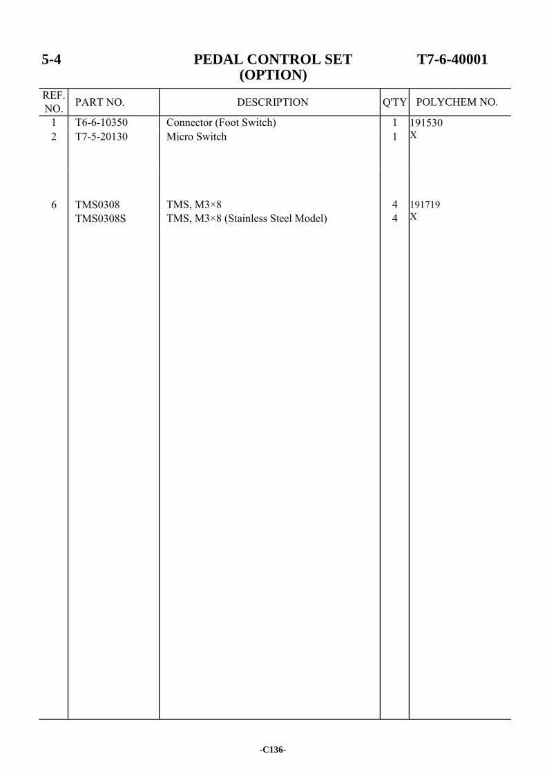
5-4 PEDAL CONTROL SET T7-6-40001 (OPTION)
REF. NO. PART NO. DESCRIPTION Q'TY
1 T6-6-10350 Connector (Foot Switch) 1 191530 X 191719 X
2 T7-5-20130 Micro Switch 1
6
TMS0308 TMS0308S
TMS, M3×8 TMS, M3×8 (Stainless Steel Model)
4 4
-C136-
POLYCHEM NO.
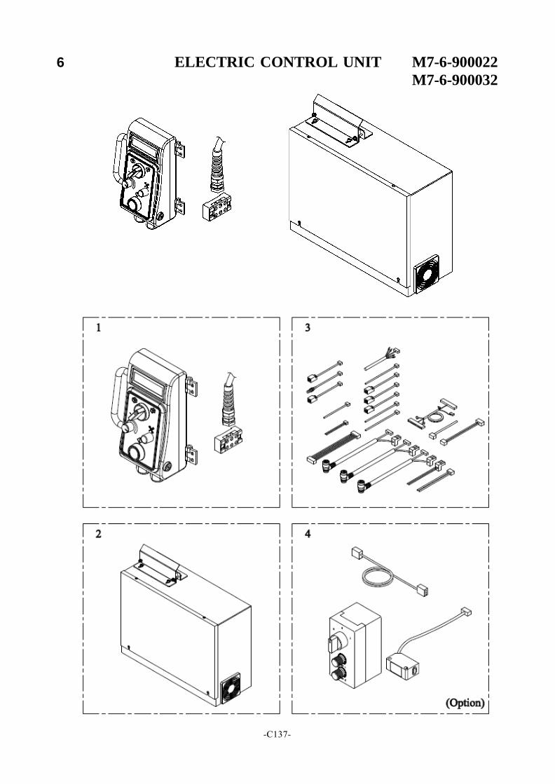
6 ELECTRIC CONTROL UNIT M7-6-900022
M7-6-900032
-C137-
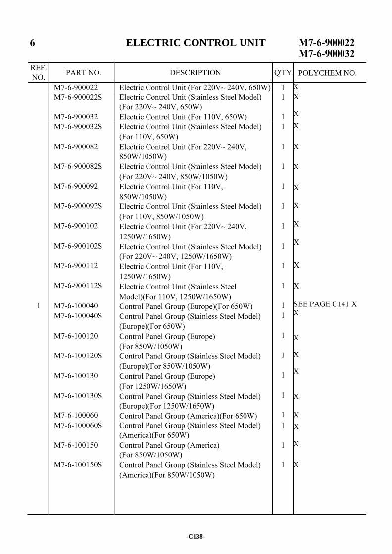
ELECTRIC CONTROL UNIT
REF. NO. PART NO. DESCRIPTION Q'TY
M7-6-900022 Electric Control Unit (For 220V~ 240V, 650W) 1 X M7-6-900022S
M7-6-900032
Electric Control Unit (Stainless Steel Model) (For 220V~ 240V, 650W) Electric Control Unit (For 110V, 650W)
1
1
X X
1
M7-6-900032S
M7-6-900082
M7-6-900082S
M7-6-900092
M7-6-900092S
M7-6-900102
M7-6-900102S
M7-6-900112
M7-6-900112S
M7-6-100040 M7-6-100040S
M7-6-100120
M7-6-100120S
M7-6-100130
M7-6-100130S
M7-6-100060
Electric Control Unit (Stainless Steel Model) (For 110V, 650W) Electric Control Unit (For 220V~ 240V, 850W/1050W) Electric Control Unit (Stainless Steel Model) (For 220V~ 240V, 850W/1050W) Electric Control Unit (For 110V, 850W/1050W) Electric Control Unit (Stainless Steel Model) (For 110V, 850W/1050W) Electric Control Unit (For 220V~ 240V, 1250W/1650W) Electric Control Unit (Stainless Steel Model) (For 220V~ 240V, 1250W/1650W) Electric Control Unit (For 110V, 1250W/1650W) Electric Control Unit (Stainless Steel Model)(For 110V, 1250W/1650W) Control Panel Group (Europe)(For 650W) Control Panel Group (Stainless Steel Model) (Europe)(For 650W) Control Panel Group (Europe) (For 850W/1050W) Control Panel Group (Stainless Steel Model) (Europe)(For 850W/1050W) Control Panel Group (Europe) (For 1250W/1650W) Control Panel Group (Stainless Steel Model) (Europe)(For 1250W/1650W) Control Panel Group (America)(For 650W)
1
1
1
1
1
1
1
1
1
1 1
1
1
1
1
1
X X X X X X X X
X SEE PAGE C141 X X X X X X X
M7-6-100060S
M7-6-100150
M7-6-100150S
Control Panel Group (Stainless Steel Model) (America)(For 650W) Control Panel Group (America) (For 850W/1050W) Control Panel Group (Stainless Steel Model) (America)(For 850W/1050W)
1
1
1
X X
X
-C138-
POLYCHEM NO.
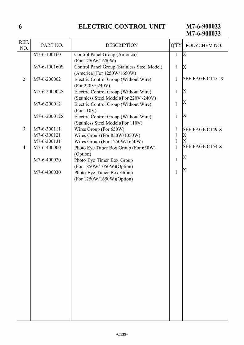
ELECTRIC CONTROL UNIT
REF. NO. PART NO. DESCRIPTION Q'TY
2
3
4
M7-6-100160
M7-6-100160S
M7-6-200002
M7-6-200002S
M7-6-200012
M7-6-200012S
M7-6-300111 M7-6-300121 M7-6-300131 M7-6-400000
M7-6-400020
M7-6-400030
Control Panel Group (America) (For 1250W/1650W) Control Panel Group (Stainless Steel Model) (America)(For 1250W/1650W) Electric Control Group (Without Wire) (For 220V~240V) Electric Control Group (Without Wire) (Stainless Steel Model)(For 220V~240V) Electric Control Group (Without Wire) (For 110V) Electric Control Group (Without Wire) (Stainless Steel Model)(For 110V) Wires Group (For 650W) Wires Group (For 850W/1050W) Wires Group (For 1250W/1650W) Photo Eye Timer Box Group (For 650W) (Option) Photo Eye Timer Box Group (For 850W/1050W)(Option) Photo Eye Timer Box Group (For 1250W/1650W)(Option)
1
1
1
1
1
1
1 1 1 1
1
1
X X SEE PAGE C145 X X X X SEE PAGE C149 X X X SEE PAGE C154 X X X
-C139-
POLYCHEM NO.

-C140-
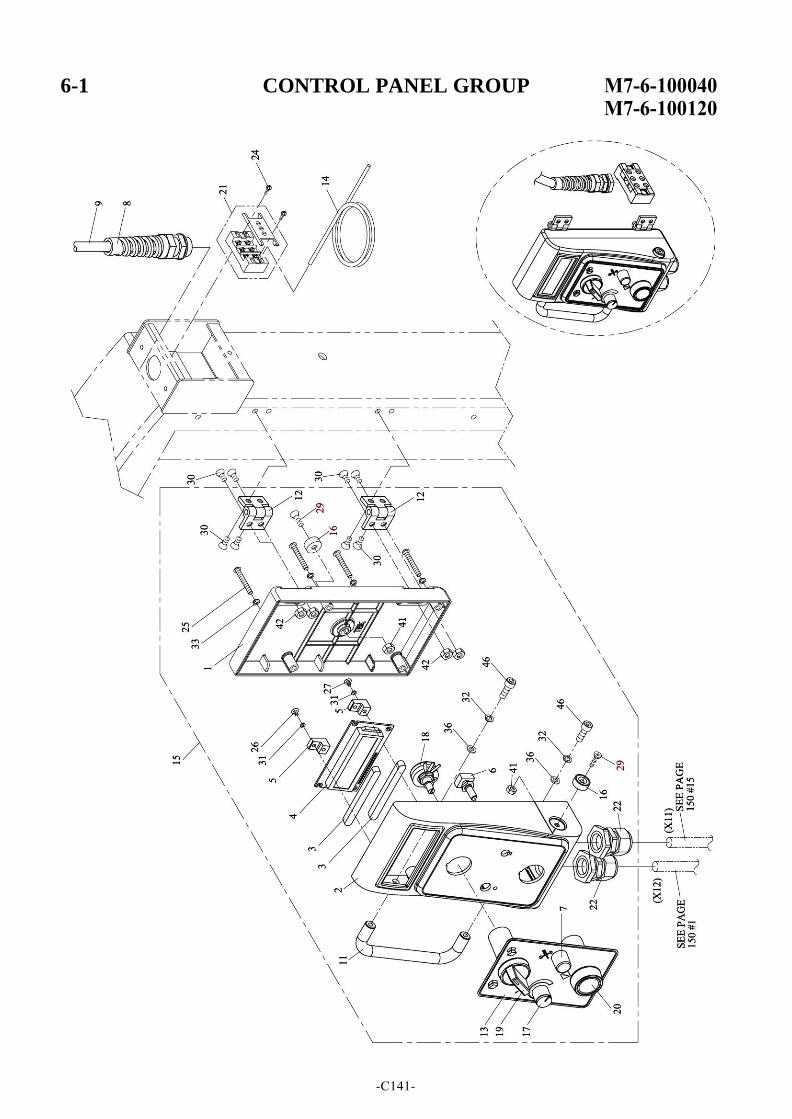
6-1 CONTROL PANEL GROUP
-C141-
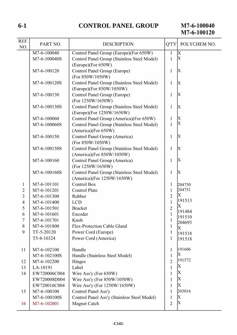
6-1 CONTROL PANEL GROUP
REF. NO. PART NO. DESCRIPTION Q'TY
M7-6-100040 Control Panel Group (Europe)(For 650W) 1 X X
X X X X
X X
X X X X 204750 204751 X 191513 X 191484 191510 204693 X 191518 191518 191606 X 191572 X X X X 203016 X X
M7-6-100040S Control Panel Group (Stainless Steel Model) 1 (Europe)(For 650W) M7-6-100120 Control Panel Group (Europe) 1 (For 850W/1050W) M7-6-100120S Control Panel Group (Stainless Steel Model) 1 (Europe)(For 850W/1050W) M7-6-100130 Control Panel Group (Europe) 1 (For 1250W/1650W) M7-6-100130S Control Panel Group (Stainless Steel Model) 1 (Europe)(For 1250W/1650W) M7-6-100060 Control Panel Group (America)(For 650W) 1 M7-6-100060S Control Panel Group (Stainless Steel Model) 1 (America)(For 650W) M7-6-100150 Control Panel Group (America) 1 (For 850W/1050W) M7-6-100150S Control Panel Group (Stainless Steel Model) 1 (America)(For 850W/1050W) M7-6-100160 Control Panel Group (America) 1 (For 1250W/1650W) M7-6-100160S Control Panel Group (Stainless Steel Model) 1 (America)(For 1250W/1650W)
1 M7-6-101101 Control Box 1 2 M7-6-101201 Control Plate 1 3 M7-6-101300 Rubber 2 4 M7-6-101400 LCD 1 5 M7-6-101501 Bracket 2 6 M7-6-101601 Encoder 1 7 M7-6-101701 Knob 1 8 M7-6-101800 Flex-Protection Cable Gland 1 9 TT-5-20120 Power Cord (Europe) 1
T5-4-10324 Power Cord (America) 1
11 M7-6-102100 Handle 1 M7-6-102100S Handle (Stainless Steel Model) 1
12 M7-6-102200 Hinges 2 13 LA-10191 Label 1 14 EW720006C004 Wire Ass'y (For 650W) 1
EW720008D004 Wire Ass'y (For 850W/1050W) 1 EW720016C004 Wire Ass'y (For 1250W/1650W) 1
15 M7-6-100100 Control Panel Ass'y 1 M7-6-100100S Control Panel Ass'y (Stainless Steel Model) 1
16 M7-6-102001 Magnet Catch 2
-C142-
POLYCHEM NO.
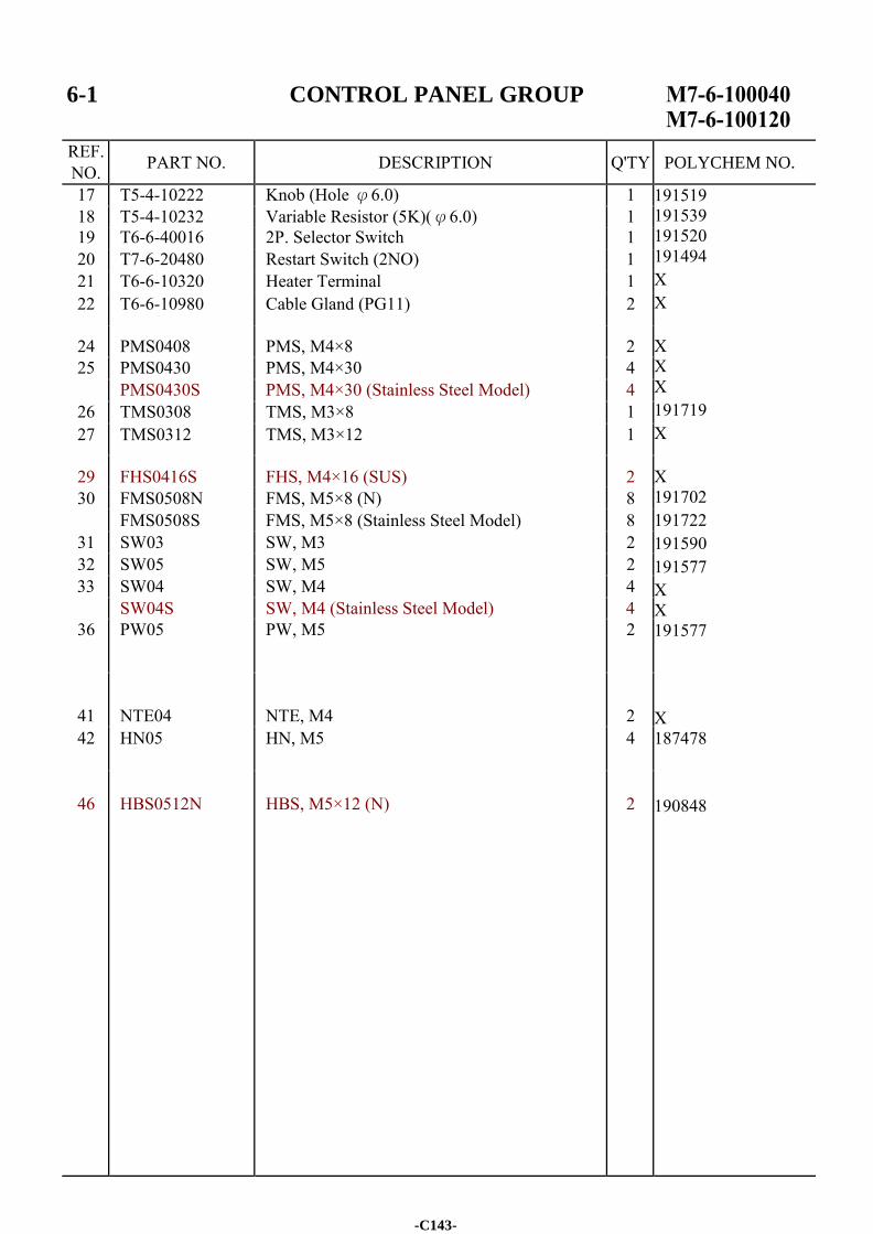
6-1 CONTROL PANEL GROUP
REF. NO. PART NO. DESCRIPTION Q'TY
17 T5-4-10222 Knob (Hole φ6.0) 1 191519 191539 191520 191494 X X X X X 191719 X X 191702 191722 191590 191577 X X 191577 X 187478
190848
18 T5-4-10232 Variable Resistor (5K)(φ6.0) 1 19 T6-6-40016 2P. Selector Switch 1 20 T7-6-20480 Restart Switch (2NO) 1 21 T6-6-10320 Heater Terminal 1 22 T6-6-10980 Cable Gland (PG11) 2
24 PMS0408 PMS, M4×8 2 25 PMS0430 PMS, M4×30 4
PMS0430S PMS, M4×30 (Stainless Steel Model) 4 26 TMS0308 TMS, M3×8 1 27 TMS0312 TMS, M3×12 1
29 FHS0416S FHS, M4×16 (SUS) 2 30 FMS0508N FMS, M5×8 (N) 8
FMS0508S FMS, M5×8 (Stainless Steel Model) 8 31 SW03 SW, M3 2 32 SW05 SW, M5 2 33 SW04 SW, M4 4
SW04S SW, M4 (Stainless Steel Model) 4 36 PW05 PW, M5 2
41
NTE04
NTE, M4
2
42 HN05 HN, M5 4
46
HBS0512N
HBS, M5×12 (N)
2
-C143-
POLYCHEM NO.

-C144-
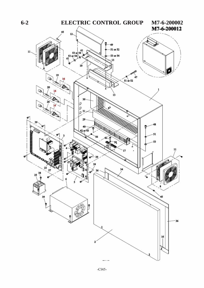
6-2 ELECTRIC CONTROL GROUP M7-6-200002
-Cl45-
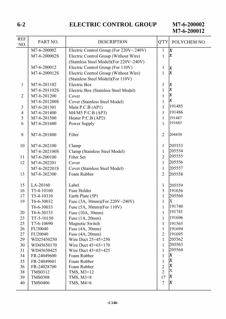
6-2 ELECTRIC CONTROL GROUP
REF. NO. PART NO. DESCRIPTION Q'TY
M7-6-200002 Electric Control Group (For 220V~ 240V) 1 X X
X
X X
X X
X
191485 191486 191487 191683 204430 205553 205554 205555 205556 205557 205558 205559 191656 205560 X 191740 191741 191696 191565 191694 191695 205562 205563 205564 X
X
X X X
X
M7-6-200002S
M7-6-200012
Electric Control Group (Without Wire) (Stainless Steel Model)(For 220V~240V) Electric Control Group (For 110V)
1
1
1
2
3
M7-6-200012S
M7-6-201102 M7-6-201102S M7-6-201200 M7-6-201200S M7-6-201301
Electric Control Group (Without Wire) (Stainless Steel Model)(For 110V) Electric Box Electric Box (Stainless Steel Model) Cover Cover (Stainless Steel Model) Main P.C.B (AP1)
1
1 1 1 1 1
4 M7-6-201400 M4/M5 P.C.B (AP3) 1 5 M7-6-201500 Heater P.C.B (AP2) 1 6 M7-6-201600 Power Supply 1
8 M7-6-201800 Filter 2
10
11
M7-6-202100 M7-6-202100S M7-6-200100
Clamp Clamp (Stainless Steel Model) Filter Set
1 1 2
12
13
M7-6-202201 M7-6-202201S M7-6-202300
Cover Cover (Stainless Steel Model) Foam Rubber
1 1 2
15 LA-20160 Label 1 16 T5-4-10160 Fuse Holder 3 17 T5-4-10310 Earth Plate (5P) 1 19
20
T6-6-30032 T6-6-30033 T6-6-30133
Fuse (3A, 30mm)(For 220V~240V) Fuse (5A, 30mm)(For 110V) Fuse (10A, 30mm)
1 1 1
23 TT-5-10150 Fuse (1A, 20mm) 1 25 T7-6-10690 Magnetic Switch 1 26 FU30040 Fuse (4A, 30mm) 1 27 FU20040 Fuse (4A, 20mm) 2 29 WD25450250 Wire Duct 25×45×250 1 30 WD45650170 Wire Duct 45×65×170 1 31 WD45650425 Wire Duct 45×65×425 1 34 FR-24049600 Foam Rubber 1 35 FR-24049601 Foam Rubber 1 36 FR-24028700 Foam Rubber 2 38 TMS0312 TMS, M3×12 2 39 TMS0308 TMS, M3×8 17 40 TMS0406 TMS, M4×6 7
-C146-
POLYCHEM NO.
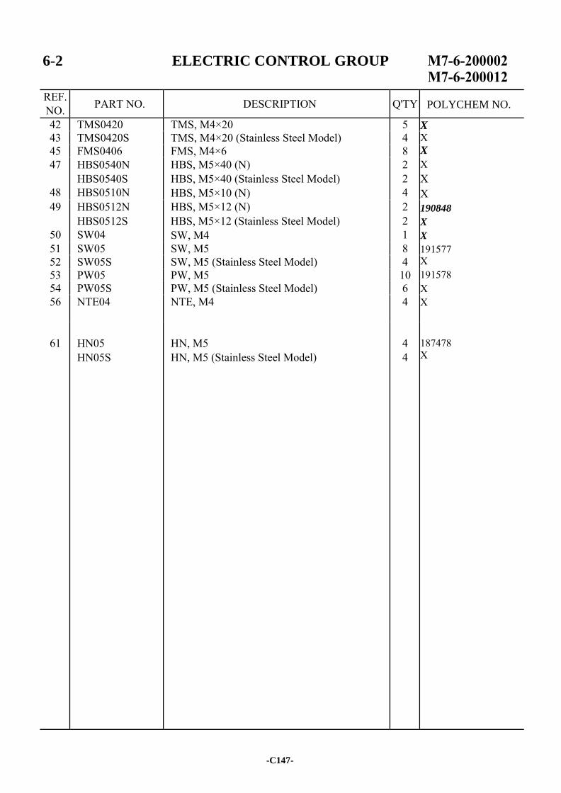
6-2 ELECTRIC CONTROL GROUP
REF. NO. PART NO. DESCRIPTION Q'TY
42 TMS0420 TMS, M4×20 5 X X X
X X X 190848
X
X
191577 X 191578 X X 187478 X
43 TMS0420S TMS, M4×20 (Stainless Steel Model) 4 45 FMS0406 FMS, M4×6 8 47
48
HBS0540N HBS0540S HBS0510N
HBS, M5×40 (N) HBS, M5×40 (Stainless Steel Model) HBS, M5×10 (N)
2 2 4
49
50
HBS0512N HBS0512S SW04
HBS, M5×12 (N) HBS, M5×12 (Stainless Steel Model) SW, M4
2 2 1
51 SW05 SW, M5 8 52 SW05S SW, M5 (Stainless Steel Model) 4 53 PW05 PW, M5 10 54 PW05S PW, M5 (Stainless Steel Model) 6 56 NTE04 NTE, M4 4
61
HN05 HN05S
HN, M5 HN, M5 (Stainless Steel Model)
4 4
-C147-
POLYCHEM NO.

-C148-
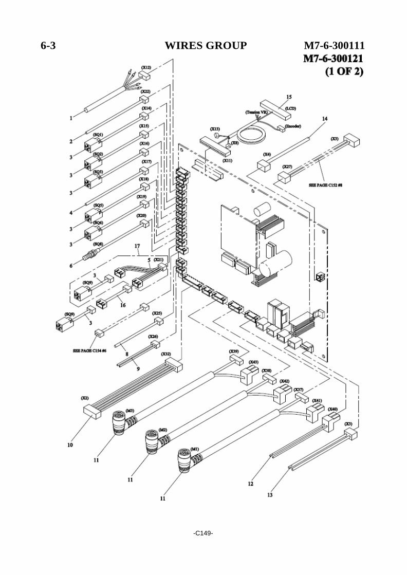
6-3
WIRES GROUP M7-6-300111
-C149-
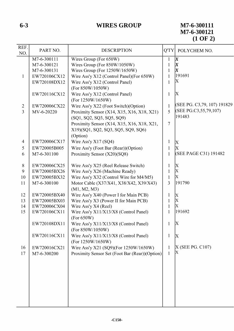
6-3 WIRES GROUP M7-6-300111 M7-6-300121
(1 OF 2)
REF. NO. PART NO. DESCRIPTION Q'TY
M7-6-300111 Wires Group (For 650W) 1 X M7-6-300121 Wires Group (For 850W/1050W) 1 X
1
2 3
4
M7-6-300131 EW720106CX12 EW720108DX12
EW720116CX12
EW720006CX22 MV-6-20220
EW720006CX17
Wires Group (For 1250W/1650W) Wire Ass'y X12 (Control Panel)(For 650W) Wire Ass'y X12 (Control Panel) (For 850W/1050W) Wire Ass'y X12 (Control Panel) (For 1250W/1650W) Wire Ass'y X22 (Foot Switch)(Option) Proximity Sensor (X14, X15, X16, X18, X21) (SQ1, SQ2, SQ3, SQ5, SQ9) Proximity Sensor (X14, X15, X16, X18, X21, X19)(SQ1, SQ2, SQ3, SQ5, SQ9, SQ6) (Option) Wire Ass'y X17 (SQ4)
1 1 1
1
1 5
7
1
X
191691 X X
(SEE PG. C3,79, 107) 191829 (SEE PG.C3,55,79,107) 191483 X
5 6
EW720005B005 M7-6-301100
Wire Ass'y (Foot Bar (Rear))(Option) Proximity Sensor (X20)(SQ8)
1 1
X (SEE PAGE C31) 191482
8 EW720006CX25 Wire Ass'y X25 (Reel Release Switch) 1
X 9 EW720005BX26 Wire Ass'y X26 (Machine Ready) 1 X
10 EW720005BX32 Wire Ass'y X32 (Control Wire for M4/M5) 1 X 11
12
M7-6-300100
EW720005BX40
Motor Cable (X37/X41, X38/X42, X39/X43) (M1, M2, M3) Wire Ass'y X40 (Power I for Main PCB)
3
1
191790 X
13 EW720005BX03 Wire Ass'y X3 (Power II for Main PCB) 1 X 14 EW720006CX04 Wire Ass'y X4 (Reel) 1 X 15
16 17
EW720106CX11
EW720108DX11
EW720116CX11
EW720016CX21 M7-6-300200
Wire Ass'y X11/X13/X8 (Control Panel) (For 650W) Wire Ass'y X11/X13/X8 (Control Panel) (For 850W/1050W) Wire Ass'y X11/X13/X8 (Control Panel) (For 1250W/1650W) Wire Ass'y X21 (SQ9)(For 1250W/1650W) Proximity Sensor Set (Foot Bar (Rear))(Option)
1
1
1
1 1
191692 X X
X (SEE PG. C107) X
-C150-
POLYCHEM NO.
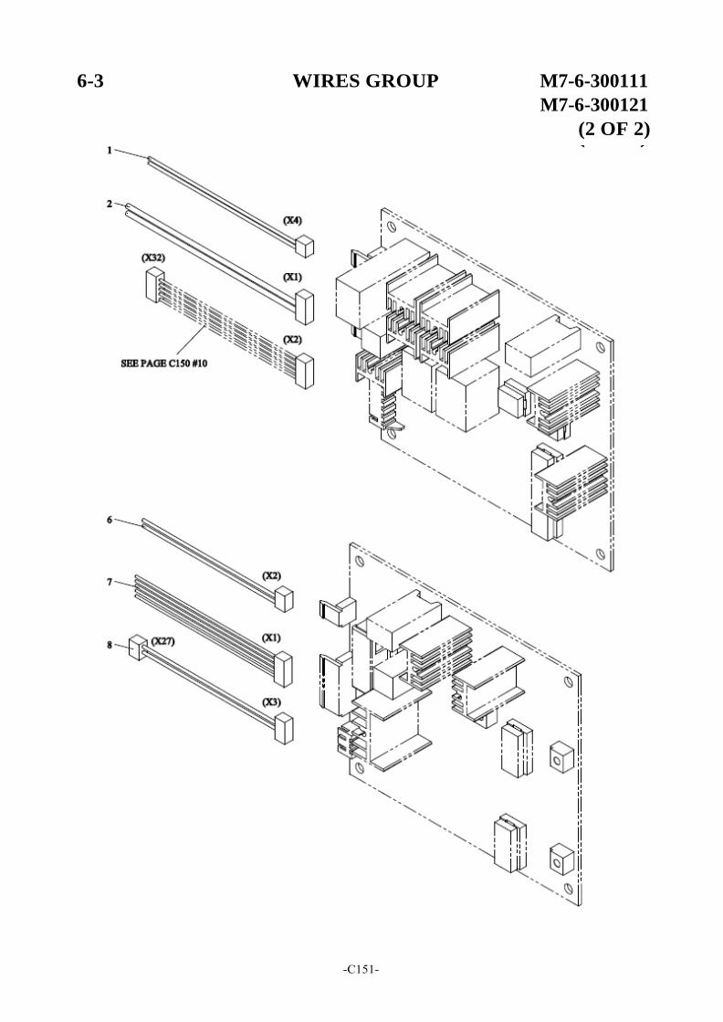
6-3 WIRES GROUP M7-6-300111
M7-6-300121
(2 OF 2)
-C151-
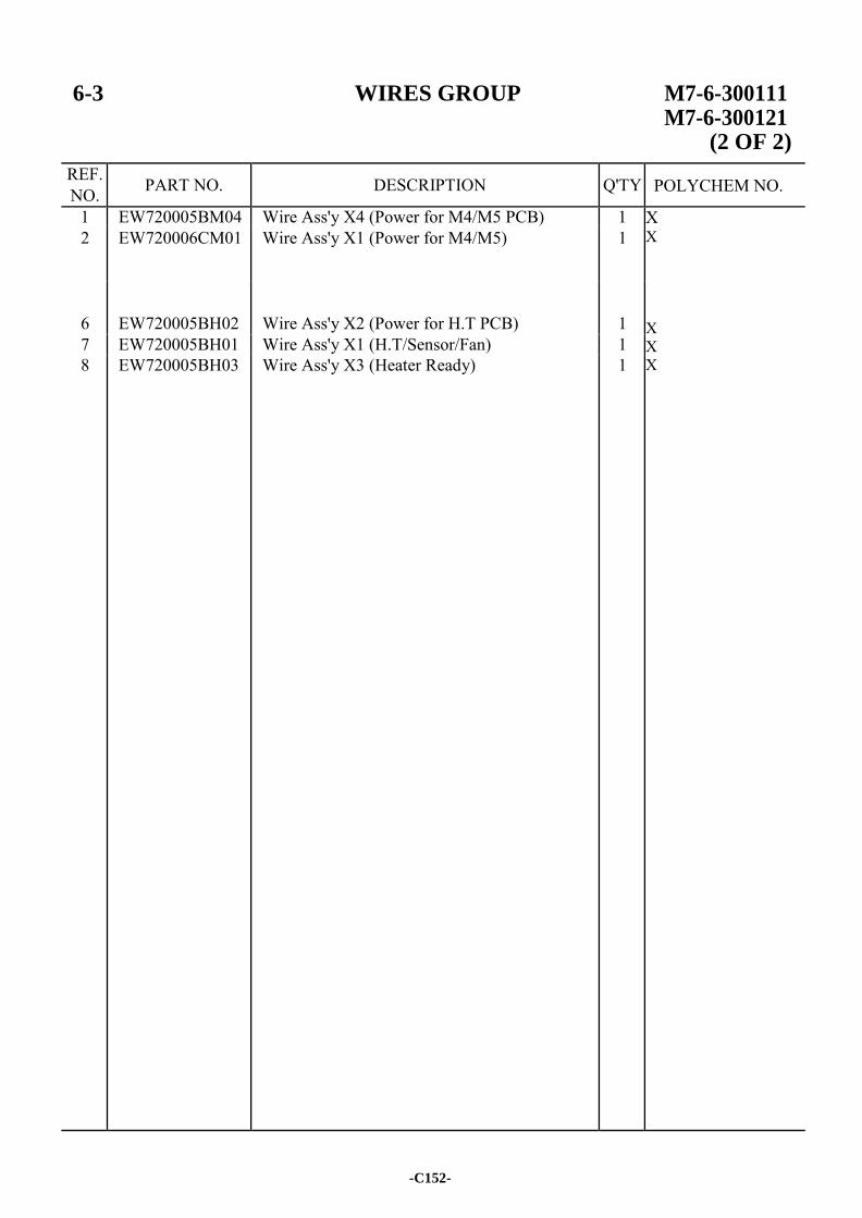
6-3 WIRES GROUP M7-6-300111 M7-6-300121
(2 OF 2)
REF. NO. PART NO. DESCRIPTION Q'TY
1 EW720005BM04 Wire Ass'y X4 (Power for M4/M5 PCB) 1 X X X X X
2 EW720006CM01 Wire Ass'y X1 (Power for M4/M5) 1
6
EW720005BH02
Wire Ass'y X2 (Power for H.T PCB)
1
7 EW720005BH01 Wire Ass'y X1 (H.T/Sensor/Fan) 1 8 EW720005BH03 Wire Ass'y X3 (Heater Ready) 1
-C152-
POLYCHEM NO.
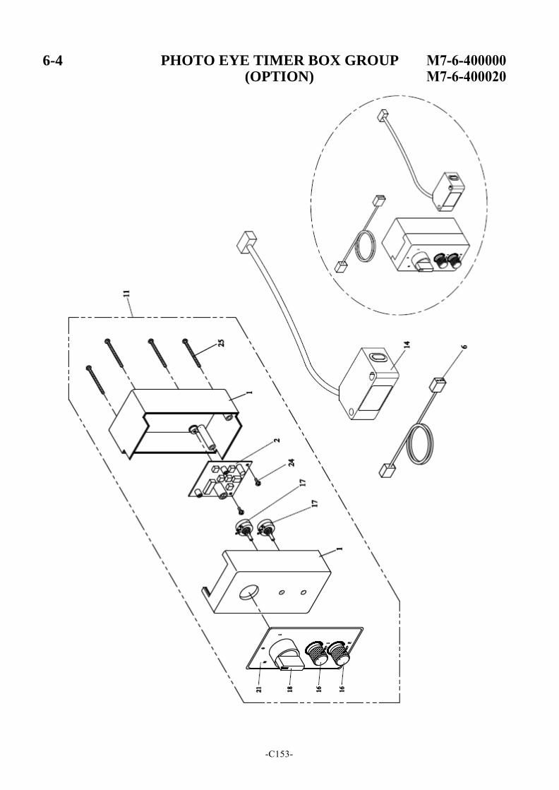
6-4 PHOTO EYE TIMER BOX GROUP (OPTION)
-C153-
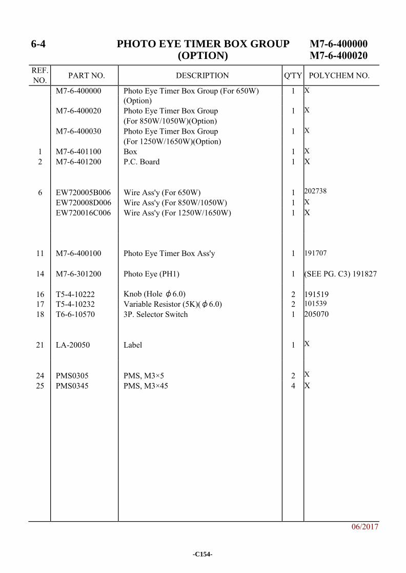
6-4 PHOTO EYE TIMER BOX GROUP (OPTION)
REF. NO. PART NO. DESCRIPTION Q'TY POLYCHEM NO.
M7-6-400000 Photo Eye Timer Box Group (For 650W) 1 X (Option) M7-6-400020 Photo Eye Timer Box Group 1 X (For 850W/1050W)(Option) M7-6-400030 Photo Eye Timer Box Group 1 X (For 1250W/1650W)(Option)
1 M7-6-401100 Box 1 X 2 M7-6-401200 P.C. Board 1 X
6
EW720005B006
Wire Ass'y (For 650W)
1
202738
EW720008D006 Wire Ass'y (For 850W/1050W) 1 X EW720016C006 Wire Ass'y (For 1250W/1650W) 1 X
11
M7-6-400100
Photo Eye Timer Box Ass'y
1
191707
14 M7-6-301200 Photo Eye (PH1) 1 (SEE PG. C3) 191827
16 T5-4-10222 Knob (Hole φ6.0) 2
191519 17 T5-4-10232 Variable Resistor (5K)(φ6.0) 2 101539 18 T6-6-10570 3P. Selector Switch 1 205070
21
LA-20050
Label
1
X
24
PMS0305
PMS, M3×5
2
X
25 PMS0345 PMS, M3×45 4 X
06/2017
-C154-
Related Documents