PbLi Thermofluid Analysis (Session 1 – ITER TBM and blanket design and analysis) Sergey Smolentsev, Siegfried Malang, and Clement Wong FNST MEETING August 12-14, 2008 UCLA

PbLi Thermofluid Analysis (Session 1 – ITER TBM and blanket design and analysis) Sergey Smolentsev, Siegfried Malang, and Clement Wong FNST MEETING August.
Dec 19, 2015
Welcome message from author
This document is posted to help you gain knowledge. Please leave a comment to let me know what you think about it! Share it to your friends and learn new things together.
Transcript

PbLi Thermofluid Analysis(Session 1 – ITER TBM and blanket design and analysis)
Sergey Smolentsev,
Siegfried Malang, and Clement Wong
FNST MEETING
August 12-14, 2008
UCLA

Current accomplishments
• First assessment of MHD pressure drop for the IB blanket - Clement Wong
• Double-Layer Flow Channel Insert for Electric and Thermal Insulation in the Dual-Coolant Lead-Lithium Blanket - this presentation

Double-layer FCI…..Will be presented at TOFE-18
Sept. 28 – Oct. 2, 2008San Francisco, USA

AbstractAbstractAbstract
A new modification of the Flow Channel Insert (FCI) called “double-layer” or “nested” FCI (nFCI) is proposed and assessed via numerical simulations for the poloidal duct flows in the Dual-Coolant Lead-Lithium (DCLL) blanket under the US DEMO OB blanket conditions. The proposed nFCI mitigates the thermal stress while providing sufficient thermal insulation and reducing the MHD pressure drop.
1

US DCLL DEMO OB blanketUS DCLL DEMO OB blanketUS DCLL DEMO OB blanket
Sketch of the US DCLL DEMO blanket with the FCI
350/450He inlet/outlet temperature, ˚C
500/700PbLi inlet/outlet temperature, ˚C
3.08Neutron wall loading (peak), MW/m2
0.55Surface heat flux, MW/m2
DEMO OBParameter
The DCLL blanket is considered in the US for testing in ITER and as a primary candidate for a DEMO reactor [1, 2]
In the DCLL blanket, the steel structure is cooled by high pressure He and PbLicirculates slowly (~ 10 cm/s) as a breeder and coolant
A key element of the DCLL concept is the SiCFlow Channel Insert (FCI), which serves as electric and thermal insulator
2
StiffeningPlate
Back Plate
He Inlet/OutletPipe
PbLi Inlet/OutletPipe
PbLi InletManifold
PbLi OutletManifold
First Wall
PbLi PoloidalDucts
FCI
PbLiHe
( )pol x
( )rad y
( )tor z
Flow Channel Insert (FCI)Flow Channel Insert (FCI)Flow Channel Insert (FCI) 3
Upper cap FCI
Front duct FCI
Lower cap FCI
Return duct FCI
Inlet manifold FCI
Outlet manifold FCI
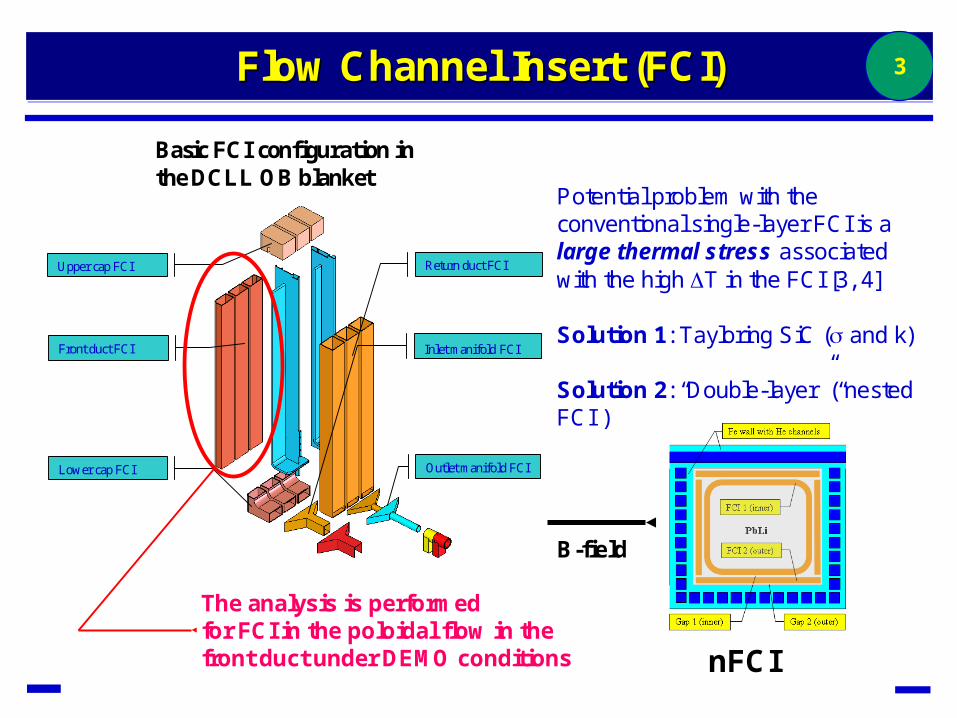
Basic FCI configuration in the DCLL OB blanket
The analysis is performedfor FCI in the poloidal flow in thefront duct under DEMO conditions
Potential problem with theconventional single-layer FCI is a large thermal stress associated with the high T in the FCI [3, 4]
Solution 1: Tayloring SiC ( and k)
Solution 2: “Double-layer” (“nested FCI”)
nFCI
B-field

Nested FCI (nFCI)Nested FCI (Nested FCI (nFCInFCI)) 4
(a) (b)
(a) nFCI (basic sketch)(b) nFCI with all plates
atached (model)(c) nFCI with 4 detached
plates (model)(d) nFCI with 1 detached
plate (model)(e) nFCI with one outer
plate (model)
(c) (d) (e)

Mathematical modelMathematical modelMathematical model 5
0
0
1( ) ( ) 0
xxz
tz ty
BBU U dP
z z y y d z
0
0 0
1 1 1 10x x
zy z
B B UB
z z y y z
Momentum equation:
Induction equation:
Energy equation:
p x y z T
T T T TC U k k k q
x x x y y z z

Computational mesh andnFCI flow parameters
Computational mesh andComputational mesh andnFCInFCI flow parametersflow parameters
6
z / b
y/b
-1.5 -1 -0.5 0 0.5 1 1.5-1.5
-1
-0.5
0
0.5
1
1.5
z / b
y/b
-1.5 -1 -0.5 0 0.5 1 1.5-1.5
-1
-0.5
0
0.5
1
1.5
Location of nFCI in thepoloidal duct
Computational mesh concentratesmore points within the nFCI and MHDboundary layers
Gap 1: 1 mmGap 2: 1 mm
FCI 1: 2.5 mm, 10 S/m,1 W/m·KFCI 2: 2.5 mm, 10 S/m,1 W/m·K
Flow velocity = 6.4 cm/sPoloidal length = 2 mToroidal width = 0.207 mRadial depth = 0.211 mMagnetic field = 4 T
Ha=12,000Re=60,000

Velocity (4 detached plates)Velocity (4 detached plates)Velocity (4 detached plates) 7

Induced currentInduced currentInduced current 8
z / b
y/b
-1.5 -1 -0.5 0 0.5 1 1.5-1.5
-1
-0.5
0
0.5
1
1.5
z / b
y/b
-0.5 0 0.5
1
z / b
y/b
-1.5 -1 -0.5 0 0.5 1 1.5-1.5
-1
-0.5
0
0.5
1
1.5
z / b
y/b
-0.5 0 0.5
1
4 detached plates All plates are attached
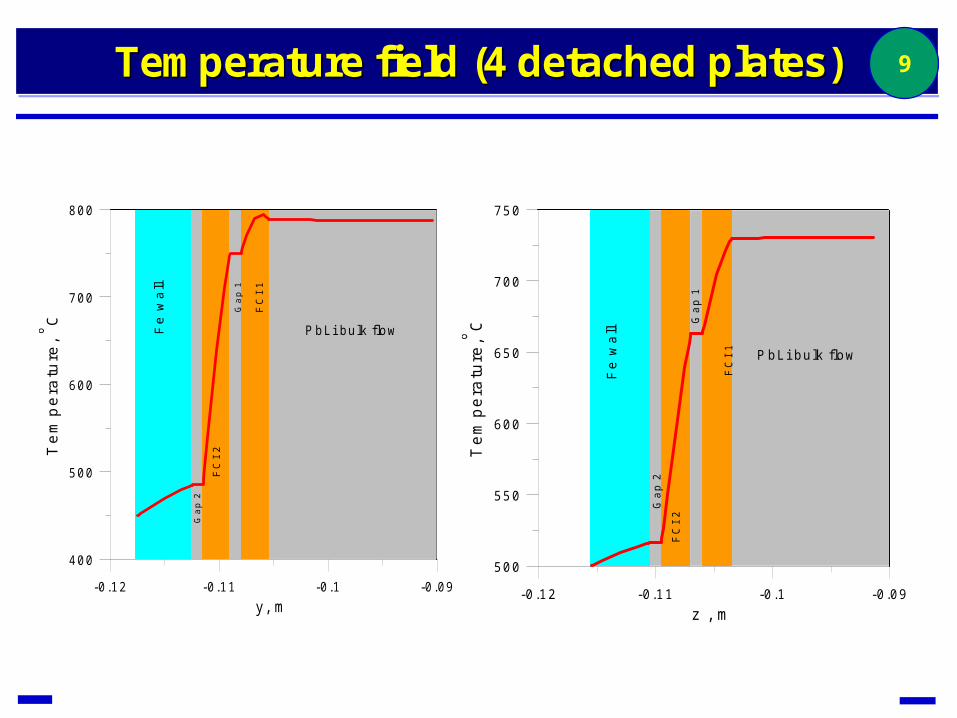
Temperature field (4 detached plates)Temperature field (4 detached plates)Temperature field (4 detached plates) 9
-0 .12 -0.11 -0.1 -0.09y, m
400
500
600
700
800
Tem
pera
ture
, C
PbLi bu lk flow
FC
I 1
FC
I 2
Gap
1
Gap
2
Fe
wal
l
-0 .12 -0.11 -0.1 -0.09z , m
500
550
600
650
700
750
Tem
pera
ture
,C
PbLi bu lk flow
FC
I 1
FC
I 2
Gap
1
Gap
2
Fe
wal
l

Summary of computationsSummary of computationsSummary of computations 10
0.45E-030.59E-030.38E-03dP/dx, MPa/m
~260 K~260 K~260 KOuter FCI (T)y
~150 K~150 K~150 KOuter FCI (T)z
~70 K~70 K~70 KInner FCI (T)z
~50 K~50 K~50 KInner FCI (T)y
126 97 150R
nFCI with 1 detached plate
nFCI with 4 detached plates
nFCI with all plates attached
R is the pressure drop reduction factor = P without FCI / P with FCI

ConclusionsConclusionsConclusions 11
• The new nFCI design provides an engineering solution to mitigate a high thermal stress, which is usually typical to the single-layer FCI. In this design, the thermal insulation is shared between the inner and outer FCI, while the inner FCI provides most of electric insulation.
•The thickness of the FCI layers can easily be adjusted and the choice between one or four detached plates can be made to meet concrete design requirements and heating conditions and, for example, to distinguish between flows in the front and return ducts.
• Compared to the single-layer FCI, electrical conductivity of the outer FCI is of minor importance, and a degradation of its electrical insulation due to cracks or LM filled pores is of no concern.
• Although the present analysis shows significant reduction of the MHD pressure drop in the poloidal ducts of the OB blanket (even in the case of four detached plates), further nFCI optimizations and more analysis may be needed in the IB blanket conditions where the electric insulation requirements are much more demanding.

References:References:References:
[1] C.P.C. Wong, S. Malang, M. Sawan, M. Dagher, S. Smolentsev, B. Merrill, M. Youssef, S. Reyes, D.K. Sze, N.B. Morley, S. Sharafat, P. Calderoni, G. Sviatoslavsky, R. Kurtz, P. Fogarty, S. Zinkle, M. Abdou, An overview of dual coolant Pb-17Li breeder first wall and blanket concept development for the US ITER-TBM design, Fusion Eng. Des. 81 (2006) 461-467.
[2] C. P. C. Wong, S. Malang, M. Sawan, S. Smolentsev, S. Majumdar, B. Merrill, D. K. Sze, N. Morley, S. Sharafat, M. Dagher, P. Peterson, H. Zhao, S. J. Zinkle, M. Abdou, M. Youssef, Assessment of first wall and blanket options with the use of liquid breeder, Fusion Sci. Technol. 47 (2005) 502-509.
[3] S. Smolentsev, N. B. Morley, M. Abdou, MHD and thermal issues of the SiCf/SiC flow channel insert, Fusion Sci. Technol. 50 (2006) 107-119.
[4] S. Smolentsev, N.B. Morley, C. Wong, M. Abdou, MHD and heat transfer considerations for the US DCLL blanket for DEMO and ITER TBM, Fusion Eng. Des., in press (2008).
[5] Y. Katoh, S. Kondo, L.L. Snead, DC electrical conductivity of silicon carbide ceramics and composites for flow channel insert applications, J. Nuclear Materials, in press (2008).
[6] S. Smolentsev, R. Moreau, M. Abdou, Characterization of key magnetohydrodynamic phenomena in PbLiflows for the US DCLL blanket, Fusion Eng. Des., in press (2008).
[7] S. Smolentsev, N. B. Morley, M. Abdou, Code development for analysis of MHD pressure drop reduction in a liquid metal blanket using insulation technique based on a fully developed flow model, Fusion Eng. Des. 73 (2005) 83-93.
12
Related Documents