May 2015 NASA/TM2015-218760 Payload Performance Analysis for a Reusable Two-Stage-to-Orbit Vehicle Paul V. Tartabini, James R. Beaty, Roger A. Lepsch, and Michael G. Gilbert Langley Research Center, Hampton, Virginia https://ntrs.nasa.gov/search.jsp?R=20150008958 2018-07-22T10:03:53+00:00Z

Welcome message from author
This document is posted to help you gain knowledge. Please leave a comment to let me know what you think about it! Share it to your friends and learn new things together.
Transcript

May 2015
NASA/TM 2015-218760
Payload Performance Analysis for a Reusable Two-Stage-to-Orbit Vehicle Paul V. Tartabini, James R. Beaty, Roger A. Lepsch, and Michael G. Gilbert Langley Research Center, Hampton, Virginia
https://ntrs.nasa.gov/search.jsp?R=20150008958 2018-07-22T10:03:53+00:00Z
NASA STI Program . . . in Profile
Since its founding, NASA has been dedicated to the advancement of aeronautics and space science. The NASA scientific and technical information (STI) program plays a key part in helping NASA maintain this important role.
The NASA STI program operates under the auspices of the Agency Chief Information Officer. It collects, organizes, provides for archiving, and disseminates NASA’s STI. The NASA STI program provides access to the NTRS Registered and its public interface, the NASA Technical Reports Server, thus providing one of the largest collections of aeronautical and space science STI in the world. Results are published in both non-NASA channels and by NASA in the NASA STI Report Series, which includes the following report types:
TECHNICAL PUBLICATION. Reports of
completed research or a major significant phase of research that present the results of NASA Programs and include extensive data or theoretical analysis. Includes compilations of significant scientific and technical data and information deemed to be of continuing reference value. NASA counter-part of peer-reviewed formal professional papers but has less stringent limitations on manuscript length and extent of graphic presentations.
TECHNICAL MEMORANDUM. Scientific
and technical findings that are preliminary or of specialized interest, e.g., quick release reports, working papers, and bibliographies that contain minimal annotation. Does not contain extensive analysis.
CONTRACTOR REPORT. Scientific and
technical findings by NASA-sponsored contractors and grantees.
CONFERENCE PUBLICATION.
Collected papers from scientific and technical conferences, symposia, seminars, or other meetings sponsored or co-sponsored by NASA.
SPECIAL PUBLICATION. Scientific,
technical, or historical information from NASA programs, projects, and missions, often concerned with subjects having substantial public interest.
TECHNICAL TRANSLATION.
English-language translations of foreign scientific and technical material pertinent to NASA’s mission.
Specialized services also include organizing and publishing research results, distributing specialized research announcements and feeds, providing information desk and personal search support, and enabling data exchange services. For more information about the NASA STI program, see the following: Access the NASA STI program home page
at http://www.sti.nasa.gov E-mail your question to [email protected]
Phone the NASA STI Information Desk at
757-864-9658 Write to:
NASA STI Information Desk Mail Stop 148 NASA Langley Research Center
Hampton, VA 23681-2199

National Aeronautics and Space Administration Langley Research Center Hampton, Virginia 23681-2199
May 2015
NASA/TM 2015-218760
Payload Performance Analysis for a Reusable Two-Stage-to-Orbit Vehicle Paul V. Tartabini, James R. Beaty, Roger A. Lepsch, and Michael G. Gilbert Langley Research Center, Hampton, Virginia

Available from:
NASA STI Program / Mail Stop 148 NASA Langley Research Center
Hampton, VA 23681-2199 Fax: 757-864-6500
The use of trademarks or names of manufacturers in the report is for accurate reporting and does not constitute an official endorsement, either expressed or implied, of such products or manufacturers by the National Aeronautics and Space Administration.
iii
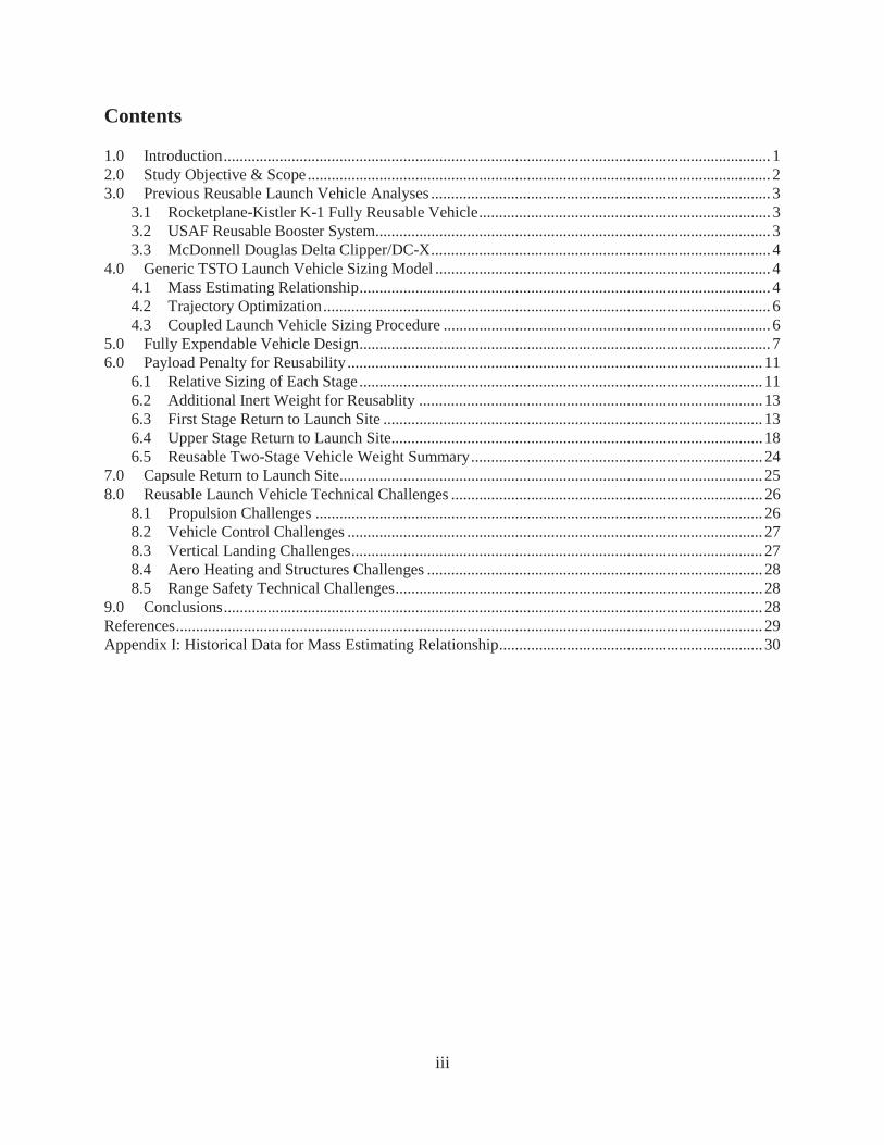
Contents
1.0 Introduction ......................................................................................................................................... 1 2.0 Study Objective & Scope .................................................................................................................... 2 3.0 Previous Reusable Launch Vehicle Analyses ..................................................................................... 3
3.1 Rocketplane-Kistler K-1 Fully Reusable Vehicle ......................................................................... 3 3.2 USAF Reusable Booster System ................................................................................................... 3 3.3 McDonnell Douglas Delta Clipper/DC-X ..................................................................................... 4
4.0 Generic TSTO Launch Vehicle Sizing Model .................................................................................... 4 4.1 Mass Estimating Relationship ....................................................................................................... 4 4.2 Trajectory Optimization ................................................................................................................ 6 4.3 Coupled Launch Vehicle Sizing Procedure .................................................................................. 6
5.0 Fully Expendable Vehicle Design ....................................................................................................... 7 6.0 Payload Penalty for Reusability ........................................................................................................ 11
6.1 Relative Sizing of Each Stage ..................................................................................................... 11 6.2 Additional Inert Weight for Reusablity ...................................................................................... 13 6.3 First Stage Return to Launch Site ............................................................................................... 13 6.4 Upper Stage Return to Launch Site ............................................................................................. 18 6.5 Reusable Two-Stage Vehicle Weight Summary ......................................................................... 24
7.0 Capsule Return to Launch Site .......................................................................................................... 25 8.0 Reusable Launch Vehicle Technical Challenges .............................................................................. 26
8.1 Propulsion Challenges ................................................................................................................ 26 8.2 Vehicle Control Challenges ........................................................................................................ 27 8.3 Vertical Landing Challenges ....................................................................................................... 27 8.4 Aero Heating and Structures Challenges .................................................................................... 28 8.5 Range Safety Technical Challenges ............................................................................................ 28
9.0 Conclusions ....................................................................................................................................... 28 References ................................................................................................................................................... 29 Appendix I: Historical Data for Mass Estimating Relationship .................................................................. 30

iv
List of Acronyms
ACS Attitude control system
Al-Li Aluminum-Lithium
BTU British thermal unit
GLOW Gross lift off weight, pounds
Isp Specific impulse, lb (force)-second per lb (mass), or seconds
ISS International space station
klbm Thousand pounds mass
L/D Lift to drag ratio
lbf Pounds force
LEO Low Earth orbit
LH2 Liquid Hydrogen
LOX Liquid oxygen
MER Mass estimating relationship
Mlbm Million pounds mass
POST2 Program to Optimize Simulated Trajectories II
psf pounds of force per square foot
Qbar Dynamic pressure, lb/sqft
RBS Reusable Booster System
RP Rocket propellant (hydrocarbon fuel)
T/W Thrust-to-Weight Ratio
TPS Thermal Protection System
TSTO Two Stage to Orbit
USAF United States Air Force
VTOL Vertical takeoff & landing

1
Abstract
This paper investigates a unique approach in the development of a reusable launch vehicle where, instead of designing the vehicle to be reusable from its inception, as was done for the Space Shuttle, an expendable two stage launch vehicle is evolved over time into a reusable launch vehicle. To accomplish this objective, each stage is made reusable by adding the systems necessary to perform functions such as thermal protection and landing, without significantly altering the primary subsystems and outer mold line of the original expendable vehicle. In addition, some of the propellant normally used for ascent is used instead for additional propulsive maneuvers after staging in order to return both stages to the launch site, keep loads within acceptable limits and perform a soft landing. This paper presents a performance analysis that was performed to investigate the feasibility of this approach by quantifying the reduction in payload capability of the original expendable launch vehicle after accounting for the mass additions, trajectory changes and increased propellant requirements necessary for reusability. Results show that it is feasible to return both stages to the launch site with a positive payload capability equal to approximately 50% of an equivalent expendable launch vehicle. Further discussion examines the ability to return a crew/cargo capsule to the launch site and presents technical challenges that would have to be overcome.
1.0 Introduction
Since nearly the beginning of space flight, the concept of a reusable launch vehicle has been contemplated and studied. Reusability can offer significant reductions in unit payload launch cost as compared to expendable. One unique approach that has been discussed recently within the aerospace community is the idea of beginning with an expendable two-stage-to-orbit (TSTO) launch vehicle and evolving it over time into a reusable launch vehicle. This approach differs from the way that the space shuttle was designed as well as the approach taken in many reusable concept studies where part or all of the launch vehicle is designed to be reusable from its inception. Typically these designs have been quite complex when compared to expendable vehicles, often including wings or other aerodynamic surfaces to enable the launch vehicle stages to return to the launch site. Such systems require significant up-front development funding rendering decisions to commit very difficult.
The idea investigated in this paper is to make each stage reusable with minimal changes to the original expendable vehicle. Thus, although each stage would require additional systems (e.g., landing gear, thermal protection, etc.), the primary subsystems and outer mold lines would remain largely unchanged. To return to the launch site after staging, the first stage would have to adjust its attitude and reignite the main engines to arrest its forward motion and place it on a return trajectory headed towards the launch site with acceptable deceleration loads. The upper stage, after delivering the payload to the target orbit, would remain in orbit until its orbital ground track approached the launch site, and then perform a deorbit maneuver placing it on a reentry trajectory that intercepted the launch site while satisfying vehicle heating and deceleration limits. Without wings or aerodynamic surfaces, both stages would have minimal maneuvering capability, and would have to be placed on trajectories that brought them close to the launch site. Both stages would require landing systems and the upper stage would require a heat shield for thermal protection during reentry.
2
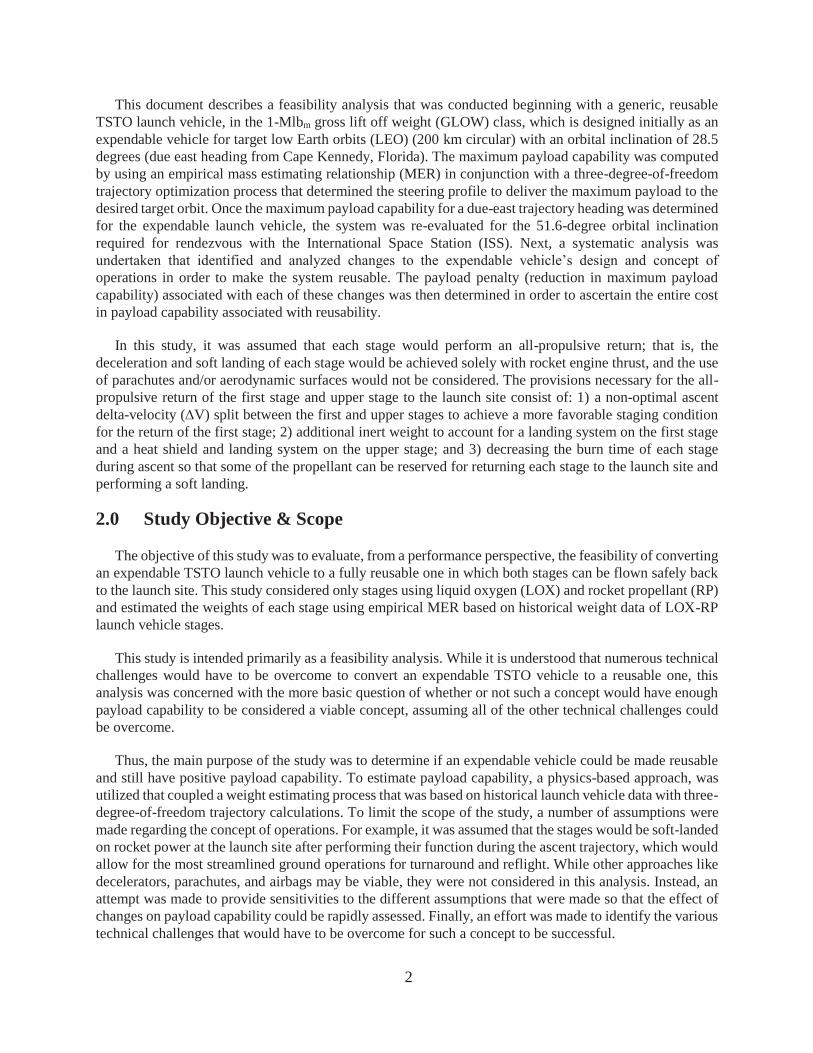
This document describes a feasibility analysis that was conducted beginning with a generic, reusable TSTO launch vehicle, in the 1-Mlbm gross lift off weight (GLOW) class, which is designed initially as an expendable vehicle for target low Earth orbits (LEO) (200 km circular) with an orbital inclination of 28.5 degrees (due east heading from Cape Kennedy, Florida). The maximum payload capability was computed by using an empirical mass estimating relationship (MER) in conjunction with a three-degree-of-freedom trajectory optimization process that determined the steering profile to deliver the maximum payload to the desired target orbit. Once the maximum payload capability for a due-east trajectory heading was determined for the expendable launch vehicle, the system was re-evaluated for the 51.6-degree orbital inclination required for rendezvous with the International Space Station (ISS). Next, a systematic analysis was undertaken that identified and analyzed changes to the expendable vehicle’s design and concept of operations in order to make the system reusable. The payload penalty (reduction in maximum payload capability) associated with each of these changes was then determined in order to ascertain the entire cost in payload capability associated with reusability.
In this study, it was assumed that each stage would perform an all-propulsive return; that is, the deceleration and soft landing of each stage would be achieved solely with rocket engine thrust, and the use of parachutes and/or aerodynamic surfaces would not be considered. The provisions necessary for the all-propulsive return of the first stage and upper stage to the launch site consist of: 1) a non-optimal ascent delta-velocity ( V) split between the first and upper stages to achieve a more favorable staging condition for the return of the first stage; 2) additional inert weight to account for a landing system on the first stage and a heat shield and landing system on the upper stage; and 3) decreasing the burn time of each stage during ascent so that some of the propellant can be reserved for returning each stage to the launch site and performing a soft landing.
2.0 Study Objective & Scope
The objective of this study was to evaluate, from a performance perspective, the feasibility of converting an expendable TSTO launch vehicle to a fully reusable one in which both stages can be flown safely back to the launch site. This study considered only stages using liquid oxygen (LOX) and rocket propellant (RP) and estimated the weights of each stage using empirical MER based on historical weight data of LOX-RP launch vehicle stages.
This study is intended primarily as a feasibility analysis. While it is understood that numerous technical challenges would have to be overcome to convert an expendable TSTO vehicle to a reusable one, this analysis was concerned with the more basic question of whether or not such a concept would have enough payload capability to be considered a viable concept, assuming all of the other technical challenges could be overcome.
Thus, the main purpose of the study was to determine if an expendable vehicle could be made reusable and still have positive payload capability. To estimate payload capability, a physics-based approach, was utilized that coupled a weight estimating process that was based on historical launch vehicle data with three-degree-of-freedom trajectory calculations. To limit the scope of the study, a number of assumptions were made regarding the concept of operations. For example, it was assumed that the stages would be soft-landed on rocket power at the launch site after performing their function during the ascent trajectory, which would allow for the most streamlined ground operations for turnaround and reflight. While other approaches like decelerators, parachutes, and airbags may be viable, they were not considered in this analysis. Instead, an attempt was made to provide sensitivities to the different assumptions that were made so that the effect of changes on payload capability could be rapidly assessed. Finally, an effort was made to identify the various technical challenges that would have to be overcome for such a concept to be successful.
3
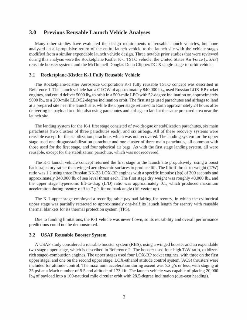
3.0 Previous Reusable Launch Vehicle Analyses
Many other studies have evaluated the design requirements of reusable launch vehicles, but none analyzed an all-propulsive return of the entire launch vehicle to the launch site with the vehicle stages modified from a similar expendable launch vehicle design. Three notable prior studies that were reviewed during this analysis were the Rocketplane Kistler K-1 TSTO vehicle, the United States Air Force (USAF) reusable booster system, and the McDonnell Douglas Delta Clipper/DC-X single-stage-to-orbit vehicle.
3.1 Rocketplane-Kistler K-1 Fully Reusable Vehicle
The Rocketplane-Kistler Aerospace Corporation K-1 fully reusable TSTO concept was described in Reference 1. The launch vehicle had a GLOW of approximately 840,000 lbm, used Russian LOX-RP rocket engines, and could deliver 5000 lbm to orbit in a 500-mile LEO with 52-degree inclination or, approximately 9000 lbm to a 200-mile LEO/52-degree inclination orbit. The first stage used parachutes and airbags to land at a prepared site near the launch site, while the upper stage returned to Earth approximately 24 hours after delivering its payload to orbit, also using parachutes and airbags to land at the same prepared area near the launch site.
The landing system for the K-1 first stage consisted of two drogue or stabilization parachutes, six main parachutes (two clusters of three parachutes each), and six airbags. All of these recovery systems were reusable except for the stabilization parachute, which was not recovered. The landing system for the upper stage used one drogue/stabilization parachute and one cluster of three main parachutes, all common with those used for the first stage, and four spherical air bags. As with the first stage landing system, all were reusable, except for the stabilization parachute, which was not recovered.
The K-1 launch vehicle concept returned the first stage to the launch site propulsively, using a boost back trajectory rather than winged aerodynamic surfaces to produce lift. The liftoff thrust-to-weight (T/W) ratio was 1.2 using three Russian NK-33 LOX-RP engines with a specific impulse (Isp) of 300 seconds and approximately 340,000 lbf of sea level thrust each. The first stage dry weight was roughly 40,000 lbm and the upper stage hypersonic lift-to-drag (L/D) ratio was approximately 0.1, which produced maximum acceleration during reentry of 5 to 7 g’s for no bank angle (lift vector up).
The K-1 upper stage employed a reconfigurable payload fairing for reentry, in which the cylindrical upper stage was partially retracted to approximately one-half its launch length for reentry with reusable thermal blankets for its thermal protection system (TPS).
Due to funding limitations, the K-1 vehicle was never flown, so its reusability and overall performance predictions could not be demonstrated.
3.2 USAF Reusable Booster System
A USAF study considered a reusable booster system (RBS), using a winged booster and an expendable two stage upper stage, which is described in Reference 2. The booster used four high T/W ratio, oxidizer-rich staged-combustion engines. The upper stages used four LOX-RP rocket engines, with three on the first upper stage, and one on the second upper stage. LOX-ethanol attitude control system (ACS) thrusters were included for attitude control. The maximum acceleration during ascent was 5.5 g’s or less, with staging at 25 psf at a Mach number of 5.5 and altitude of 173 kft. The launch vehicle was capable of placing 20,000 lbm of payload into a 100-nautical mile circular orbit with 28.5-degree inclination (due-east heading).
4
The USAF identified several performance trades necessary for returning the booster to its launch site, such as the need to limit the staging Mach number to allow its return using reasonable amounts of propellant, to eliminate the need for TPS on the booster, and also to use a lofted boost trajectory to lower the dynamic pressure at staging. These tradeoffs placed additional V performance requirements on the upper stage(s) of the launch vehicle, which tends to reduce the overall cost effectiveness for a system with higher performance expendable upper stage(s) such as the USAF concept.
3.3 McDonnell Douglas Delta Clipper/DC-X
The McDonnell Douglas Delta Clipper/DC-X concept was a single-stage-to-orbit vertical takeoff and landing (VTOL) launch vehicle that utilized all-propulsive vertical landing after its return from orbit. The concept was capable of delivering two crew members and up to 10 tons of payload to LEO, or two crew members and up to 5 tons of payload to polar orbit. The flight test vehicle (designated DC-X), a one-third-scale model of the Delta Clipper concept, flew eight test missions between 1993 and 1995 at low altitude to demonstrate the vertical landing capability. Its follow-on version, DC-XA, made use of advanced lightweight materials to save weight and included an Aluminum-lithium LOX tank and graphite-epoxy liquid hydrogen (LH2) tank. The DC-XA flew three successful missions between May and June 1996 and was destroyed on its fourth test flight on July 31, 1996 due to a failure of one of its landing struts, which caused the vehicle to tip over on its landing pad.
4.0 Generic TSTO Launch Vehicle Sizing Model
The starting point for the reusable feasibility study was an expendable TSTO LOX-RP launch vehicle. To size the expendable vehicle, a coupled two-step process was implemented that made use of an existing empirical MER and a three-degree-of-freedom trajectory optimization program. Once defined, this expendable vehicle became the baseline that was modified to make each stage reusable, and the payload capability of the expendable concept became the figure of merit used to assess the performance penalty due to reusability.
4.1 Mass Estimating Relationship
An empirical MER was developed that was based on historical weight data from fourteen different LOX-RP launch vehicle stages. These vehicles had a range in gross weight from 55,000 lbm (Soyuz ST-2) to 6.2 Mlbm (Saturn S-IC). The data used to develop this MER are listed in Appendix I.
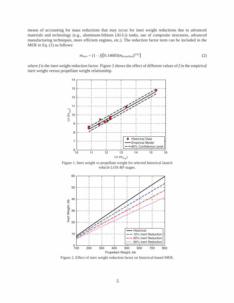
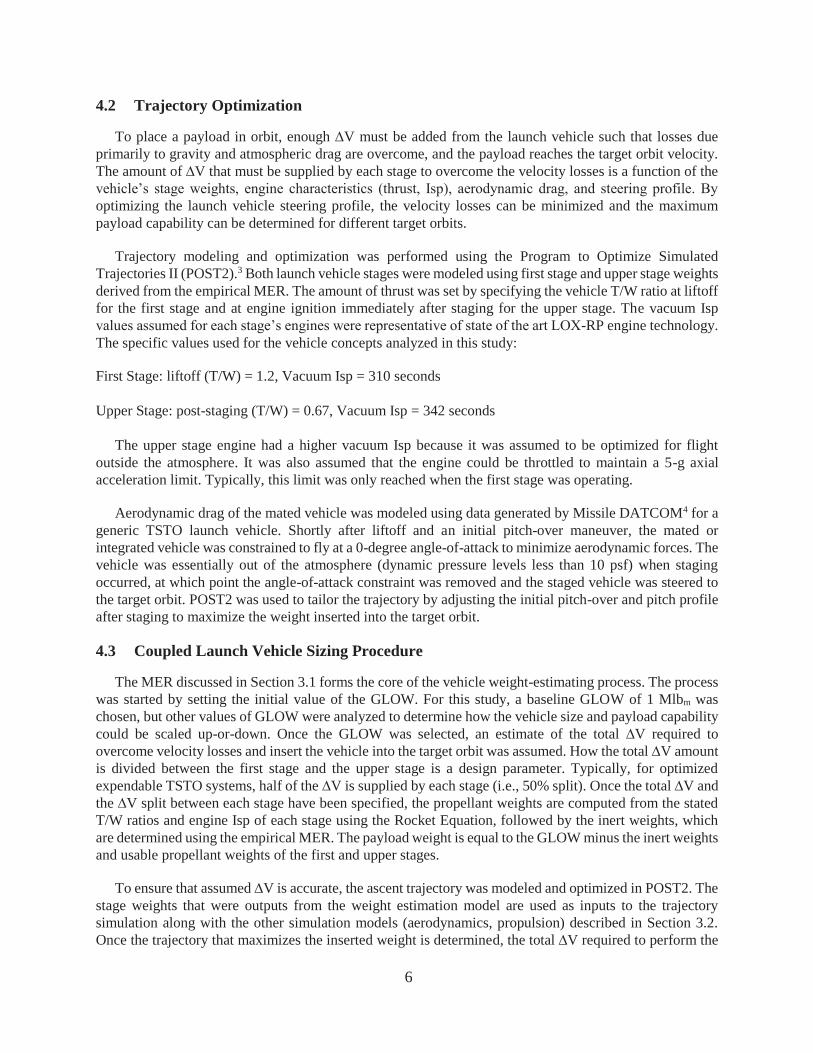
The empirical MER that was utilized is an exponential equation that relates each stage’s inert weight to its propellant weight:
minert = 0.14683(mpropellant)0.95 (1)
The propellant weight is the weight of the usable propellant (what is expended during ascent) and the inert weight includes everything else except the payload (vehicle dry weight plus unusable propellant not burned during ascent). A plot showing the log-log relationship of these two variables is shown in Fig. 1. The exponential equation for LOX-RP stages was derived from a linear regression analysis of the data in the figure. The plot shows a strong linear trend in the historical data, and the corresponding coefficient of determination (R2) of the linear fit is 0.965. The dashed lines show the uncertainty of the empirical MER at an 80% confidence level based upon an error analysis with the historical data points.
Because many of the existing vehicle stages used to define the empirical MER were developed a number of years ago, the equation was modified to include an inert weight reduction factor. This factor provides a
5
means of accounting for mass reductions that may occur for inert weight reductions due to advanced materials and technology (e.g., aluminum-lithium (Al-Li) tanks, use of composite structures, advanced manufacturing techniques, more efficient engines, etc.). The reduction factor term can be included in the MER in Eq. (1) as follows:
minert = (1 – f)[0.14683(mpropellant)0.95] (2)
where f is the inert weight reduction factor. Figure 2 shows the effect of different values of f in the empirical inert weight versus propellant weight relationship.
Figure 1. Inert weight vs propellant weight for selected historical launch
vehicle LOX-RP stages.
Figure 2. Effect of inert weight reduction factor on historical-based MER.
6
4.2 Trajectory Optimization
To place a payload in orbit, enough V must be added from the launch vehicle such that losses due primarily to gravity and atmospheric drag are overcome, and the payload reaches the target orbit velocity. The amount of V that must be supplied by each stage to overcome the velocity losses is a function of the vehicle’s stage weights, engine characteristics (thrust, Isp), aerodynamic drag, and steering profile. By optimizing the launch vehicle steering profile, the velocity losses can be minimized and the maximum payload capability can be determined for different target orbits.
Trajectory modeling and optimization was performed using the Program to Optimize Simulated Trajectories II (POST2).3 Both launch vehicle stages were modeled using first stage and upper stage weights derived from the empirical MER. The amount of thrust was set by specifying the vehicle T/W ratio at liftoff for the first stage and at engine ignition immediately after staging for the upper stage. The vacuum Isp values assumed for each stage’s engines were representative of state of the art LOX-RP engine technology. The specific values used for the vehicle concepts analyzed in this study:
First Stage: liftoff (T/W) = 1.2, Vacuum Isp = 310 seconds
Upper Stage: post-staging (T/W) = 0.67, Vacuum Isp = 342 seconds
The upper stage engine had a higher vacuum Isp because it was assumed to be optimized for flight outside the atmosphere. It was also assumed that the engine could be throttled to maintain a 5-g axial acceleration limit. Typically, this limit was only reached when the first stage was operating.
Aerodynamic drag of the mated vehicle was modeled using data generated by Missile DATCOM4 for a generic TSTO launch vehicle. Shortly after liftoff and an initial pitch-over maneuver, the mated or integrated vehicle was constrained to fly at a 0-degree angle-of-attack to minimize aerodynamic forces. The vehicle was essentially out of the atmosphere (dynamic pressure levels less than 10 psf) when staging occurred, at which point the angle-of-attack constraint was removed and the staged vehicle was steered to the target orbit. POST2 was used to tailor the trajectory by adjusting the initial pitch-over and pitch profile after staging to maximize the weight inserted into the target orbit.
4.3 Coupled Launch Vehicle Sizing Procedure
The MER discussed in Section 3.1 forms the core of the vehicle weight-estimating process. The process was started by setting the initial value of the GLOW. For this study, a baseline GLOW of 1 Mlbm was chosen, but other values of GLOW were analyzed to determine how the vehicle size and payload capability could be scaled up-or-down. Once the GLOW was selected, an estimate of the total V required to overcome velocity losses and insert the vehicle into the target orbit was assumed. How the total V amount is divided between the first stage and the upper stage is a design parameter. Typically, for optimized expendable TSTO systems, half of the V is supplied by each stage (i.e., 50% split). Once the total V and the V split between each stage have been specified, the propellant weights are computed from the stated T/W ratios and engine Isp of each stage using the Rocket Equation, followed by the inert weights, which are determined using the empirical MER. The payload weight is equal to the GLOW minus the inert weights and usable propellant weights of the first and upper stages.
To ensure that assumed V is accurate, the ascent trajectory was modeled and optimized in POST2. The stage weights that were outputs from the weight estimation model are used as inputs to the trajectory simulation along with the other simulation models (aerodynamics, propulsion) described in Section 3.2. Once the trajectory that maximizes the inserted weight is determined, the total V required to perform the
7
mission, which is an output from the trajectory, must match the value that was input into the weight estimation model. If there is a difference, this weight model is updated with the V computed by trajectory program and the process is continued iteratively until trajectory output V matches the weight model input
V.
This process was used to determine the payload capability for a range of expendable TSTO launch vehicles with gross liftoff weights varying from 600 klbm to 1.1 Mlbm. For this study, the process was repeated assuming both 0% and 20% inert weight reduction factors.
A 50% V split between the first and upper stages was assumed, but the sensitivity of this parameter was determined for the baseline 1-Mlbm GLOW vehicle. Once this process was completed for the expendable vehicle, a systematic approach was undertaken to determine the various payload capability penalties associated with converting the expendable concept to a reusable one.
5.0 Fully Expendable Vehicle Design
Using the process outlined in the previous section, the stage weights and trajectory were defined for a two-stage expendable LOX-RP launch vehicle with a gross liftoff weight of 1.0 Mlbm. The weights for this vehicle were derived using the MER given in Eq. 2 with an inert weight reduction factor of 0.2 (i.e., 20%).
This vehicle had a maximum payload capability of slightly more than 36 klbm when launched due east from KSC into a circular 200-km LEO with an inclination of 28.5 degrees. The weight breakdown of the vehicle is shown in Table 1. To perform the mission, the vehicle had to carry sufficient propellant to supply a total V of 30,050 ft/s, half of which was provided by the first stage and the other half by the upper stage. Velocity losses (predominantly gravity and drag losses) accounted for the difference between the V imparted to the vehicle and the required orbital velocity of roughly 25,560 ft/s. The 1:1 ratio (50% split) between the V that was delivered by the first stage and upper stage was near optimal. The importance of this ratio and its sensitivity to payload capability will be discussed in the next section.
Table 1. Weight breakdown for 1.0 Mlbm expendable TSTO vehicle.
Expendable TSTO Concept Stage 1 inert, lbm 46,396 Stage 1 propellant, lbm 778,266 Stage 2 inert, lbm 8,511 Stage 2 propellant, lbm 130,576 Payload, lbm 36,251 GLOW, lbm 1,000,000
The propellant weights listed in Table 1 give the amount of usable propellant for each stage; that is, the
amount of propellant actually expended by each stage during its engine burn, excluding reserves and residuals. The inert weight is the vehicle dry weight plus the weight of the reserve and residual propellants. For this study, it was assumed that the unused propellant was 1% of the total propellant for the stage. Thus, for example, the corresponding total propellant weight of stage 1 was 786,127 lbm and its corresponding dry weight was 38,535 lbm.
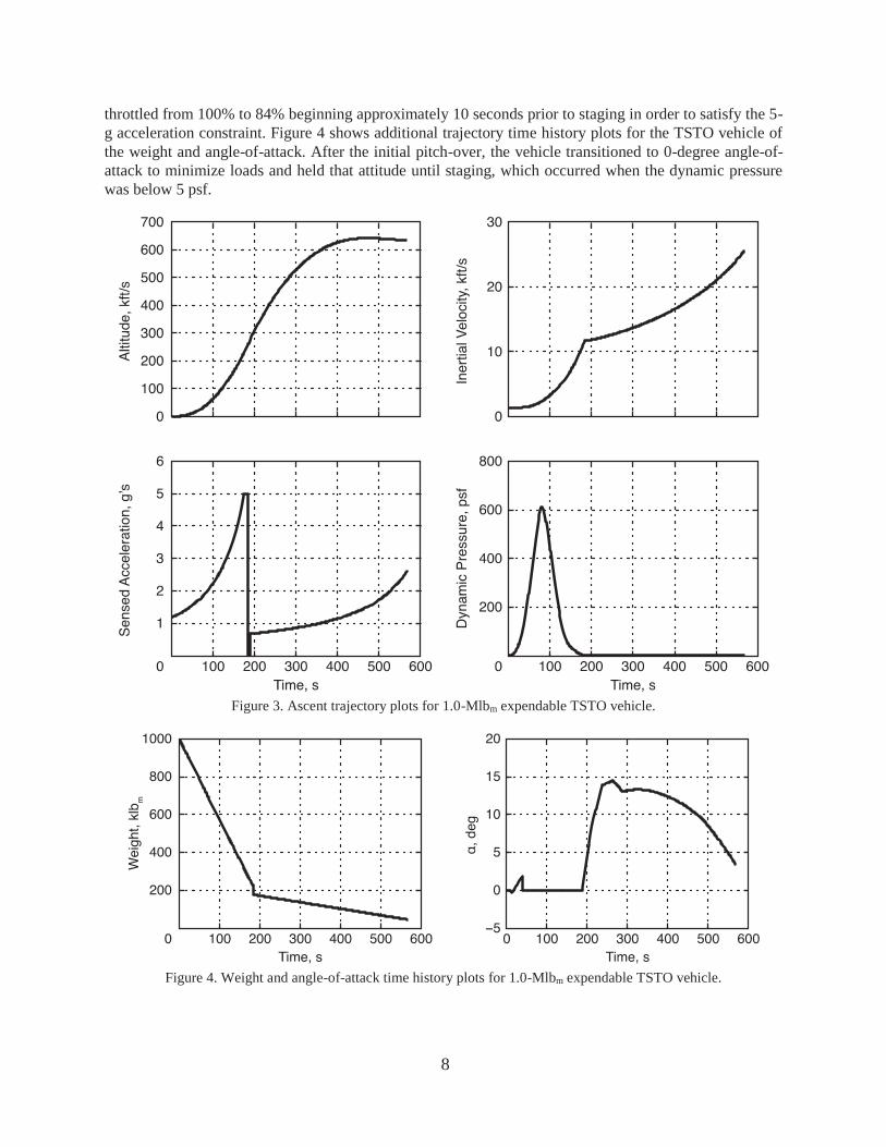
Using the stage weights from Table 1, the ascent trajectory was modeled in POST2 and the steering profile that maximized weight inserted into orbit was determined. Figure 3 shows time history plots from the optimized TSTO ascent trajectory of altitude, velocity, sensed acceleration and dynamic pressure. Staging occurred 184 seconds after liftoff at Mach 11.2 and an altitude of 260,000 ft. The engines were
8
throttled from 100% to 84% beginning approximately 10 seconds prior to staging in order to satisfy the 5-g acceleration constraint. Figure 4 shows additional trajectory time history plots for the TSTO vehicle of the weight and angle-of-attack. After the initial pitch-over, the vehicle transitioned to 0-degree angle-of-attack to minimize loads and held that attitude until staging, which occurred when the dynamic pressure was below 5 psf.
Figure 3. Ascent trajectory plots for 1.0-Mlbm expendable TSTO vehicle.
Figure 4. Weight and angle-of-attack time history plots for 1.0-Mlbm expendable TSTO vehicle.
9
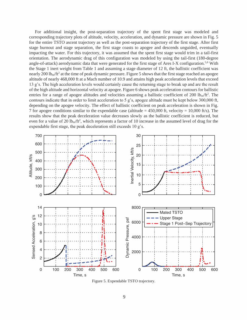
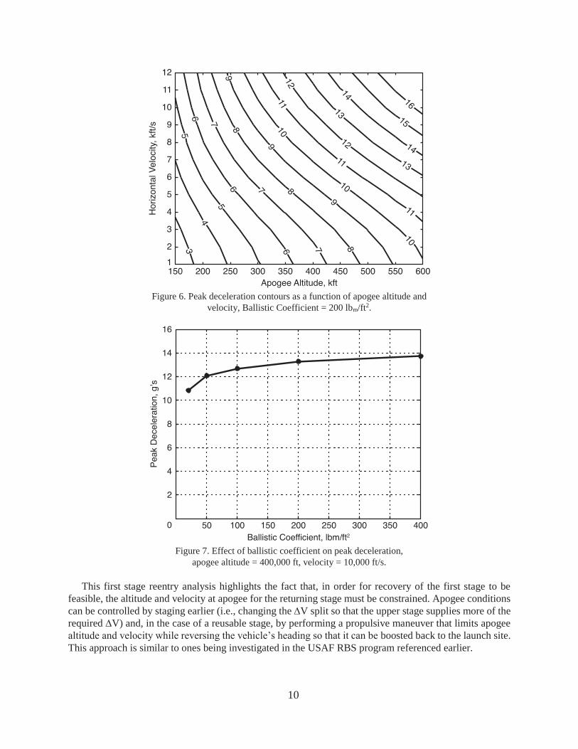
For additional insight, the post-separation trajectory of the spent first stage was modeled and corresponding trajectory plots of altitude, velocity, acceleration, and dynamic pressure are shown in Fig. 5 for the entire TSTO ascent trajectory as well as the post-separation trajectory of the first stage. After first stage burnout and stage separation, the first stage coasts to apogee and descends unguided, eventually impacting the water. For this trajectory, it was assumed that the spent first stage would trim in a tail-first orientation. The aerodynamic drag of this configuration was modeled by using the tail-first (180-degree angle-of-attack) aerodynamic data that were generated for the first stage of Ares I-X configuration.5,6 With the Stage 1 inert weight from Table 1 and assuming a stage diameter of 12 ft, the ballistic coefficient was nearly 200 lbm/ft2 at the time of peak dynamic pressure. Figure 5 shows that the first stage reached an apogee altitude of nearly 468,000 ft at a Mach number of 10.9 and attains high peak acceleration levels that exceed 13 g’s. The high acceleration levels would certainly cause the returning stage to break up and are the result of the high altitude and horizontal velocity at apogee. Figure 6 shows peak acceleration contours for ballistic entries for a range of apogee altitudes and velocities assuming a ballistic coefficient of 200 lbm/ft2. The contours indicate that in order to limit acceleration to 5 g’s, apogee altitude must be kept below 300,000 ft, depending on the apogee velocity. The effect of ballistic coefficient on peak acceleration is shown in Fig. 7 for apogee conditions similar to the expendable case (altitude = 450,000 ft, velocity = 10,000 ft/s). The results show that the peak deceleration value decreases slowly as the ballistic coefficient is reduced, but even for a value of 20 lbm/ft2, which represents a factor of 10 increase in the assumed level of drag for the expendable first stage, the peak deceleration still exceeds 10 g’s.
Figure 5. Expendable TSTO trajectory.
10
Figure 6. Peak deceleration contours as a function of apogee altitude and
velocity, Ballistic Coefficient = 200 lbm/ft2.
Figure 7. Effect of ballistic coefficient on peak deceleration,
apogee altitude = 400,000 ft, velocity = 10,000 ft/s.
This first stage reentry analysis highlights the fact that, in order for recovery of the first stage to be feasible, the altitude and velocity at apogee for the returning stage must be constrained. Apogee conditions can be controlled by staging earlier (i.e., changing the V split so that the upper stage supplies more of the required V) and, in the case of a reusable stage, by performing a propulsive maneuver that limits apogee altitude and velocity while reversing the vehicle’s heading so that it can be boosted back to the launch site. This approach is similar to ones being investigated in the USAF RBS program referenced earlier.
11
6.0 Payload Penalty for Reusability
An analysis was performed to estimate the amount of payload capability that would be lost by altering the expendable TSTO design described in the previous section so that both stages were reusable and could be propulsively returned and soft landed at the launch site after delivering the payload to orbit. Initially, the expendable vehicle design was modified by adjusting the V split (ratio of total V delivered by each stage) to force staging to occur at a lower velocity, closer to the launch site, and the payload capability of the resulting expendable vehicle was reevaluated for a mission to a 51.6-degree inclination LEO required for delivery of a hypothetical crew/cargo capsule to the ISS. Next, a systematic analysis of the performance ramifications of each step required to make the system reusable was undertaken, and the penalties in payload capability due to the additional inert weight and the propellant that must be reserved for returning the stages to the launch site (which cannot be used during the ascent) were determined. Additional analyses were performed to understand the effect of launch vehicle scaling and the impact of requiring the capsule to be soft-landed.
6.1 Relative Sizing of Each Stage
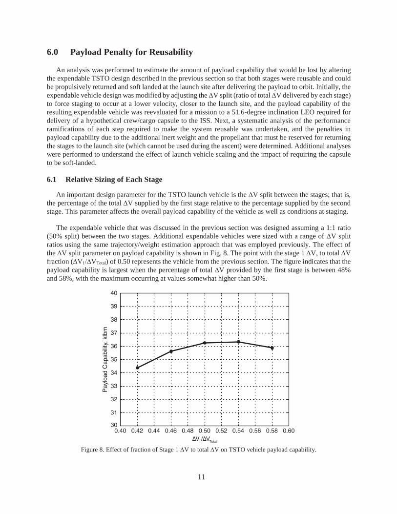
An important design parameter for the TSTO launch vehicle is the V split between the stages; that is, the percentage of the total V supplied by the first stage relative to the percentage supplied by the second stage. This parameter affects the overall payload capability of the vehicle as well as conditions at staging.
The expendable vehicle that was discussed in the previous section was designed assuming a 1:1 ratio (50% split) between the two stages. Additional expendable vehicles were sized with a range of V split ratios using the same trajectory/weight estimation approach that was employed previously. The effect of the V split parameter on payload capability is shown in Fig. 8. The point with the stage 1 V, to total V fraction ( V1 VTotal) of 0.50 represents the vehicle from the previous section. The figure indicates that the payload capability is largest when the percentage of total V provided by the first stage is between 48% and 58%, with the maximum occurring at values somewhat higher than 50%.
Figure 8. Effect of fraction of Stage 1 V to total V on TSTO vehicle payload capability.

12
The ratio of V between stages also has a large effect on the staging condition. While decreasing the percentage of V provided by the first stage necessarily requires a larger upper stage, it also lowers the staging Mach number and forces staging to occur closer to the launch site, both of which are favorable for enabling the return of a reusable first stage. As shown in Fig. 9, the effect of the V1 VTotal fraction on the staging Mach number is linear. For values of this fraction that optimize payload capability (near 0.50), staging occurs at Mach numbers greater than 10.
Staging must occur at a sufficiently low Mach number in order to make it feasible to propulsively reverse the heading of a reusable first stage and return it to the launch site. Consequently, an expendable vehicle with a 42%/58% split between V1 and V2 was defined as the baseline to which reusable concepts would be compared. This V split resulted in a payload reduction of nearly 5% compared to the near-optimal 50% split vehicle that was discussed previously. In addition, for the remainder of the study, the payload capability was determined for an ISS mission that targeted 51.6-degree LEO (200-km altitude phasing orbit). Because there is less benefit from the Earth’s rotational velocity, the payload capability to a 51.6-degree LEO is roughly 6% less than for a due east LEO mission. The weight breakdown of the two expendable vehicles and the effect of changing to the ISS mission is presented in Table 2. Note that the stage sizes were assumed to remain fixed for the change to the baseline ISS mission. The decreased GLOW for this case is due to the lower payload relative to the due-east mission.
Figure 9. Effect of fraction of Stage 1 V to total V on TSTO vehicle staging
Mach number.
Table 2. Comparison of expendable concepts with different V split fractions.
Expendable 50/50 split, due East LEO
Baseline 42/58 split, due East LEO
Baseline 42/58 split, 51.6-degree LEO
Stage 1 inert, l lbm 46,396 43,342 43,342 Stage 1 propellant, lbm 778,266 724,436 724,436 Stage 2 inert, lbm 8,511 11,909 11,909 Stage 2 propellant, lbm 130,576 185,962 185,962 Payload, lbm 36,251 34,351 32,334 GLOW, lbm 1,000,000 1,000,000 997,983

13
6.2 Additional Inert Weight for Reusablity
Clearly, additional subsystems will be required for each stage in order to make them reusable. For this study, it was assumed that an additional 10% of the inert weight would be required for the booster to enable it to fly back to the launch site and perform a soft landing. Most of this weight would be needed for a landing system and perhaps attitude control thrusters. Likewise, it was assumed that an additional 20% of the upper stage inert weight would be required to return it to the landing site. As with the booster, the upper stage would require a landing system along with dedicated landing engines, since it is likely that the upper stage engine used during ascent would be optimized for vacuum conditions. In addition, the upper stage will also need to have a heat shield to protect it from aeroheating during reentry.
The effect of adding inert weight on payload capability was determined and the results are shown in Table 3 where the changes from the baseline have been highlighted. Since the vehicle must carry additional inert weight, the payload capability is reduced by 9.6%. The sensitivity of payload capability to additional inert weight can be computed from the table when you consider that the sensitivity for the upper stage is 1:1 (1 lbm of additional inert reduces payload by 1 lbm). The sensitivity for the first stage is more favorable: 6.1 lbm of inert to 1 lbm of payload.
Table 3. Effect of additional inert weight (highlighted) on payload capability.
Baseline expendable 42/58 split, ISS
Additional Inert Weight
Stage 1 inert, lbm 43,342 43,342 Stage 1 extra inert, lbm 0 4,334.2 Stage 1 propellant, lbm 724,436 724,436 Stage 2 inert, lbm 11,909 11,909 Stage 2 extra inert, lbm 0 2381.8 Stage 2 propellant, lbm 185,962 185,962 Payload, lbm 32,334 29,242 GLOW, lbm 997,983 1,001,607 Payload change, % –9.6
6.3 First Stage Return to Launch Site
To make the expendable TSTO launch vehicle’s first stage reusable, it was assumed that some of the ascent propellant would be reserved for two post-stage separation maneuvers required to return the stage to the launch site: 1) a boost-back maneuver in which a subset of the main engines are re-ignited after stage separation to reverse the stage’s heading and loft it sufficiently to return to the launch site; and 2) a braking and descent maneuver occurring near the end of flight using at least one main engine fired in a direction opposing the descending stage’s motion to reduce its velocity and bring it to a safe, soft landing at the launch pad. Since the propellant required for these two return maneuvers is no longer available for ascent, the payload capability will decrease. A trajectory analysis was performed to model these return maneuvers and determine the penalty in payload capability for the integrated TSTO vehicle.
6.3.1 First Stage Boost Back
The first stage boost-back maneuver was initiated immediately after stage separation with brief coast period prior to the engine restart. During this time, the upper stage engine was ignited and the ascent mission continued, and the first stage was oriented to an angle-of-attack near 180 degrees so that the engine thrust force would oppose its forward motion. Note that the dynamic pressure at staging was below 5 lbf/ft2 and the first stage remained effectively outside the atmosphere for the duration of the boost-back maneuver. No
14
effort was made to model rotational vehicle dynamics and it was assumed that the vehicle had adequate control provisions to properly orient and steer the vehicle. Once oriented, a subset of the first stage engines were restarted and remained lit until the vehicle had sufficient energy to return to the launch site. The steering profile that minimized boost-back propellant was determined using POST2 for a return trajectory that reached the launch site while remaining below the 5-g acceleration limit. The degree of aerodynamic heating encountered during the first stage return was evaluated using Chapman’s reference heat rate with an effective nose radius of 1 foot. The reference heat rate remained below 7 BTU/ft2 for the entire return trajectory; thus it was assumed that only a minimal amount of TPS would be required to protect the first stage.
The acceleration limit was approached twice, near the end of the boost-back engine burn when one engine was shut down to satisfy the constraint, and during the subsequent coast when the stage reentered the sensible atmosphere. Thus, the boost -back maneuver had to be designed to return the first stage to the launch site as well as limit apogee altitude and velocity to satisfy the acceleration constraint during the coast phase. To achieve these objectives, a 75-second boost-back maneuver was required that expended approximately 70,000 lbm of first stage propellant. If the acceleration constraint was lifted, it was possible to return to the launch site with as little as 55,000 lbm of propellant and a peak acceleration of 8 g’s.
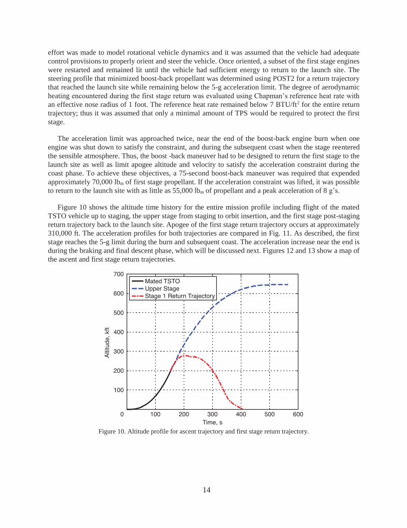
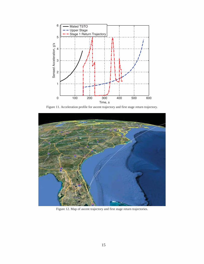
Figure 10 shows the altitude time history for the entire mission profile including flight of the mated TSTO vehicle up to staging, the upper stage from staging to orbit insertion, and the first stage post-staging return trajectory back to the launch site. Apogee of the first stage return trajectory occurs at approximately 310,000 ft. The acceleration profiles for both trajectories are compared in Fig. 11. As described, the first stage reaches the 5-g limit during the burn and subsequent coast. The acceleration increase near the end is during the braking and final descent phase, which will be discussed next. Figures 12 and 13 show a map of the ascent and first stage return trajectories.
Figure 10. Altitude profile for ascent trajectory and first stage return trajectory.
15
Figure 11. Acceleration profile for ascent trajectory and first stage return trajectory.
Figure 12. Map of ascent trajectory and first stage return trajectories.
16
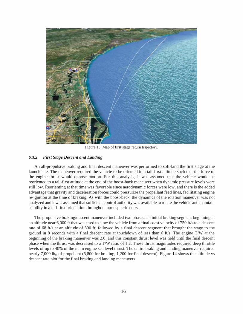
Figure 13. Map of first stage return trajectory.
6.3.2 First Stage Descent and Landing
An all-propulsive braking and final descent maneuver was performed to soft-land the first stage at the launch site. The maneuver required the vehicle to be oriented in a tail-first attitude such that the force of the engine thrust would oppose motion. For this analysis, it was assumed that the vehicle would be reoriented to a tail-first attitude at the end of the boost-back maneuver when dynamic pressure levels were still low. Reorienting at that time was favorable since aerodynamic forces were low, and there is the added advantage that gravity and deceleration forces could pressurize the propellant feed lines, facilitating engine re-ignition at the time of braking. As with the boost-back, the dynamics of the rotation maneuver was not analyzed and it was assumed that sufficient control authority was available to rotate the vehicle and maintain stability in a tail-first orientation throughout atmospheric entry.
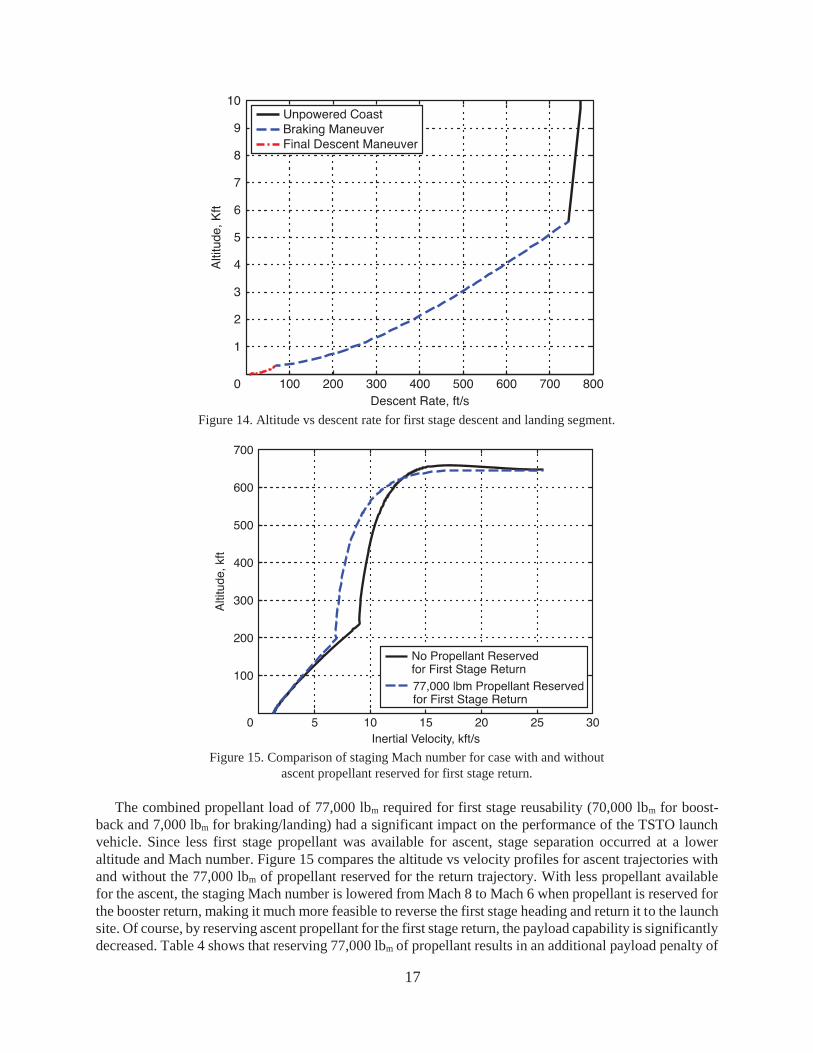
The propulsive braking/descent maneuver included two phases: an initial braking segment beginning at an altitude near 6,000 ft that was used to slow the vehicle from a final coast velocity of 750 ft/s to a descent rate of 68 ft/s at an altitude of 300 ft; followed by a final descent segment that brought the stage to the ground in 8 seconds with a final descent rate at touchdown of less than 6 ft/s. The engine T/W at the beginning of the braking maneuver was 2.0, and this constant thrust level was held until the final descent phase when the thrust was decreased to a T/W ratio of 1.2. These thrust magnitudes required deep throttle levels of up to 40% of the main engine sea level thrust. The entire braking and landing maneuver required nearly 7,000 lbm of propellant (5,800 for braking, 1,200 for final descent). Figure 14 shows the altitude vs descent rate plot for the final braking and landing maneuvers.
17
Figure 14. Altitude vs descent rate for first stage descent and landing segment.
Figure 15. Comparison of staging Mach number for case with and without
ascent propellant reserved for first stage return.
The combined propellant load of 77,000 lbm required for first stage reusability (70,000 lbm for boost-back and 7,000 lbm for braking/landing) had a significant impact on the performance of the TSTO launch vehicle. Since less first stage propellant was available for ascent, stage separation occurred at a lower altitude and Mach number. Figure 15 compares the altitude vs velocity profiles for ascent trajectories with and without the 77,000 lbm of propellant reserved for the return trajectory. With less propellant available for the ascent, the staging Mach number is lowered from Mach 8 to Mach 6 when propellant is reserved for the booster return, making it much more feasible to reverse the first stage heading and return it to the launch site. Of course, by reserving ascent propellant for the first stage return, the payload capability is significantly decreased. Table 4 shows that reserving 77,000 lbm of propellant results in an additional payload penalty of
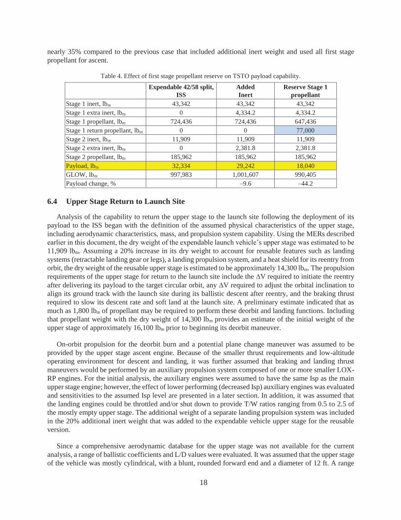
18
nearly 35% compared to the previous case that included additional inert weight and used all first stage propellant for ascent.
Table 4. Effect of first stage propellant reserve on TSTO payload capability.
Expendable 42/58 split, ISS
Added Inert
Reserve Stage 1 propellant
Stage 1 inert, lbm 43,342 43,342 43,342 Stage 1 extra inert, lbm 0 4,334.2 4,334.2 Stage 1 propellant, lbm 724,436 724,436 647,436 Stage 1 return propellant, lbm 0 0 77,000 Stage 2 inert, lbm 11,909 11,909 11,909 Stage 2 extra inert, lbm 0 2,381.8 2,381.8 Stage 2 propellant, lbm 185,962 185,962 185,962 Payload, lbm 32,334 29,242 18,040 GLOW, lbm 997,983 1,001,607 990,405 Payload change, % –9.6 –44.2
6.4 Upper Stage Return to Launch Site
Analysis of the capability to return the upper stage to the launch site following the deployment of its payload to the ISS began with the definition of the assumed physical characteristics of the upper stage, including aerodynamic characteristics, mass, and propulsion system capability. Using the MERs described earlier in this document, the dry weight of the expendable launch vehicle’s upper stage was estimated to be 11,909 lbm. Assuming a 20% increase in its dry weight to account for reusable features such as landing systems (retractable landing gear or legs), a landing propulsion system, and a heat shield for its reentry from orbit, the dry weight of the reusable upper stage is estimated to be approximately 14,300 lbm. The propulsion requirements of the upper stage for return to the launch site include the V required to initiate the reentry after delivering its payload to the target circular orbit, any V required to adjust the orbital inclination to align its ground track with the launch site during its ballistic descent after reentry, and the braking thrust required to slow its descent rate and soft land at the launch site. A preliminary estimate indicated that as much as 1,800 lbm of propellant may be required to perform these deorbit and landing functions. Including that propellant weight with the dry weight of 14,300 lbm provides an estimate of the initial weight of the upper stage of approximately 16,100 lbm prior to beginning its deorbit maneuver.
On-orbit propulsion for the deorbit burn and a potential plane change maneuver was assumed to be provided by the upper stage ascent engine. Because of the smaller thrust requirements and low-altitude operating environment for descent and landing, it was further assumed that braking and landing thrust maneuvers would be performed by an auxiliary propulsion system composed of one or more smaller LOX-RP engines. For the initial analysis, the auxiliary engines were assumed to have the same Isp as the main upper stage engine; however, the effect of lower performing (decreased Isp) auxiliary engines was evaluated and sensitivities to the assumed Isp level are presented in a later section. In addition, it was assumed that the landing engines could be throttled and/or shut down to provide T/W ratios ranging from 0.5 to 2.5 of the mostly empty upper stage. The additional weight of a separate landing propulsion system was included in the 20% additional inert weight that was added to the expendable vehicle upper stage for the reusable version.
Since a comprehensive aerodynamic database for the upper stage was not available for the current analysis, a range of ballistic coefficients and L/D values were evaluated. It was assumed that the upper stage of the vehicle was mostly cylindrical, with a blunt, rounded forward end and a diameter of 12 ft. A range

19
of drag coefficients (from 1.2 to 2.8) were considered, assuming a low angle of attack reentry. These assumptions were combined with the estimated weight from above to yield a range of ballistic coefficients from 50 to 120 lbf/ft2. It was further assumed that the upper stage was sufficiently ballasted (perhaps through location of the descent propellant supply) to produce a nose-first trim condition with a low L/D ratio in the range of 0.1 to 0.2. The relatively low L/D ratios assumed for the analysis is the result of the upper stage being a cylinder lacking any wings or other aerodynamic lift producing devices. Using these assumed ranges of ballistic coefficient and L/D ratio, the reentry dynamics (maximum acceleration and reference heating) can be estimated, as well as the flight characteristics of a ballistic trajectory for the return to the launch area.
The maximum acceleration and aerodynamic heating during the ballistic reentry of the upper stage is dependent on its velocity and vertical flight path angle as it reaches the upper limits of the Earth’s atmosphere and begins to experience aerodynamic drag. By adjusting the amount of V provided by the upper stage rocket engine during the deorbit burn, which is dependent on the T/W ratio and the duration of the burn, the velocity and entry flight path angle of the upper stage can be controlled to determine the minimum value of the peak acceleration and aerodynamic heating during reentry. The smallest maximum acceleration during the upper stage reentry is shown in Figure 16 for a T/W ratio of 0.55, a range of ballistic coefficients and a range of L/D ratios. The data show that maximum acceleration levels greater than 6 g’s are possible for small L/D ratios (0.1 or smaller), and can be further decreased to less than 5 g’s for L/D values of 0.2 or higher. The aerodynamic heating during the reentry was evaluated using Chapman’s reference heat rate with an effective nose radius of 1 ft for the range of ballistic coefficients and L/D ratios considered. The heat rate during upper stage reentry is shown in Figure 17 for a range of ballistic coefficients and a range of L/D ratios. Again, the small L/D ratios (0.1 or smaller) produce the largest heat rates of 110 to 170 BTU/ft2/s over the range of ballistic coefficients evaluated, whereas the larger L/D ratios reduce the heat rates to 75 to 140, depending on the ballistic coefficient and L/D ratio. The actual heat rate scales inversely with the square root of the effective nose radius of the upper stage heat shield, as the Chapman’s reference heat rate assumed an effective nose radius of 1 ft, so that the actual upper stage heat rate should be less than shown in the figure. However, the heat rates shown are not beyond the capability of traditional TPS materials, and may not require more elaborate TPS solutions.
Figure 16. Maximum acceleration during reentry versus ballistic coefficient and
L/D ratio.

20
Figure 17. Maximum heat rate during reentry versus ballistic coefficient and L/D ratio.
For the remaining analysis of the upper stage reentry and soft landing at the launch site, an L/D of 0.1 and a ballistic coefficient of were assumed. It was determined that a 7-second deorbit burn (0.55-T/W, Isp of 342 seconds) consuming 180 lbm of deorbit propellant was required to provide an entry trajectory with a peak acceleration of 6.5 g’s and a peak heat rate of 155 BTU/ft2/s. For the remaining analysis of the propellant required to return the upper stage to the launch site, it was assumed that the propellant required for the deorbit burn is fixed at 180 lbm. If the final design of such a reusable launch vehicle required different values of the upper stage physical characteristics within the ranges evaluated, the amount of propellant required for the deorbit burn may change slightly, but should not be significantly different from the 180-lbm estimated.
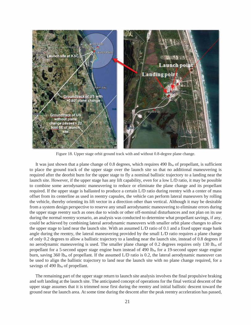
Because of the assumed low L/D capability of the upper stage, the upper stage lacks the cross-range maneuvering capability to return to the launch site after a single orbit. For a 200-km circular orbit with 51.6-degree inclination, one orbit (with a period of approximately 88.3 minutes) places the ground track of the upper stage approximately 700 nautical miles northwest of the launch site, which is beyond the cross-range aerodynamic capability of the upper stage to maneuver to the launch site. The propellant required to change the inclination of its orbit for a single orbit reentry to the launch site would be prohibitive (nearly 9000 lbm for 19-degree plane change). However, if it were possible to delay the return of the upper stage for roughly 24 hours, the ground track of its orbit would pass approximately 22 nautical miles southeast of the launch site. By including a small orbital plane change prior to the deorbit burn, the orbital inclination can be increased slightly to place the ground track of the upper stage over the launch site, so that a ballistic entry could be used. The amount of plane change required is 0.8 degrees, which increases the orbital plane inclination from 51.6 degrees to 52.4 degrees, and if performed at the point where the orbit passes through the line of nodes on the descending side, the plane change would require a 19-second burn of the upper stage engine at a T/W ratio of 0.55, using an additional 490 lbm of propellant. Figure 18 shows the upper stage ground track with and without the 0.8-degree plane change, and the resultant ballistic trajectory landing point within 0.07 nautical miles (425 ft) of the launch site. The portion of the figure to the right is zoomed in around the launch complex, showing the launch site and the landing point of the upper stage.
21
Figure 18. Upper stage orbit ground track with and without 0.8-degree plane change.
It was just shown that a plane change of 0.8 degrees, which requires 490 lbm of propellant, is sufficient to place the ground track of the upper stage over the launch site so that no additional maneuvering is required after the deorbit burn for the upper stage to fly a nominal ballistic trajectory to a landing near the launch site. However, if the upper stage has any lift capability, even for a low L/D ratio, it may be possible to combine some aerodynamic maneuvering to reduce or eliminate the plane change and its propellant required. If the upper stage is ballasted to produce a certain L/D ratio during reentry with a center of mass offset from its centerline as used in reentry capsules, the vehicle can perform lateral maneuvers by rolling the vehicle, thereby orienting its lift vector in a direction other than vertical. Although it may be desirable from a system design perspective to reserve any small aerodynamic maneuvering to eliminate errors during the upper stage reentry such as ones due to winds or other off-nominal disturbances and not plan on its use during the normal reentry scenario, an analysis was conducted to determine what propellant savings, if any, could be achieved by combining lateral aerodynamic maneuvers with smaller orbit plane changes to allow the upper stage to land near the launch site. With an assumed L/D ratio of 0.1 and a fixed upper stage bank angle during the reentry, the lateral maneuvering provided by the small L/D ratio requires a plane change of only 0.2 degrees to allow a ballistic trajectory to a landing near the launch site, instead of 0.8 degrees if no aerodynamic maneuvering is used. The smaller plane change of 0.2 degrees requires only 130 lbm of propellant for a 5-second upper stage engine burn instead of 490 lbm for a 19-second upper stage engine burn, saving 360 lbm of propellant. If the assumed L/D ratio is 0.2, the lateral aerodynamic maneuver can be used to align the ballistic trajectory to land near the launch site with no plane change required, for a savings of 490 lbm of propellant.
The remaining part of the upper stage return to launch site analysis involves the final propulsive braking and soft landing at the launch site. The anticipated concept of operations for the final vertical descent of the upper stage assumes that it is trimmed nose first during the reentry and initial ballistic descent toward the ground near the launch area. At some time during the descent after the peak reentry acceleration has passed,

22
the upper stage reorients itself to a vertical orientation with the rocket engines pointing downward and maintains that orientation until soft landing. Such rotational maneuvers of the upper stage would require systems such as ACS jets or thrust vector control of the descent rocket engine, which were not considered in this analysis. A variety of final descent scenarios were evaluated, from aggressive ones in which the rocket engine braking from the ballistic descent rate did not occur until very close to ground impact (mere seconds before impact) with a brief, relatively large T/W ratio engine burn leading to a final soft landing, to more conservative ones in which the rocket engine braking thrust was applied at higher altitudes until a minimum descent rate was achieved at some lower altitude, followed by a final slow descent at a different T/W ratio to a soft landing. The aggressive scenarios use the least amount of propellant compared with more conservative ones, but assume higher risk. For the purposes of this document, only one of the conservative landing scenarios is described, which still used less total upper stage propellant than the 1,800-lbm that was reserved for the upper stage return to launch site analysis.
The final landing scenario was based on the 0.8-degree plane change to align the upper orbital ground track with the launch site on the 15th orbit, and a deorbit burn to begin the reentry trajectory. The plane change maneuver requires 490 lbm of propellant and the deorbit burn requires 180 lbm of propellant, for a total of 670 lbm of propellant plus the propellant to achieve launch site area return. For the chosen landing scenario, the soft landing begins with a 0.5-T/W rocket engine burn (with an assumed Isp of 342 seconds) at an altitude of 5,000 ft, which continues at that thrust level for 19.2 seconds until the upper stage altitude is 415 ft with a descent rate of 205 ft/s. Then, the rocket engine T/W is increased to 2.3 until soft landing with a descent rate of 3.1 ft/s is achieved 3.9 seconds later. Figure 19 presents the altitude versus descent rate for the final descent phase of the trajectory, and Figure 20 presents the acceleration during the final descent phase of the trajectory.
Figure 19. Upper stage altitude and descent rate during landing.

23
Figure 20. Upper stage acceleration during landing.
The amount of propellant required for the initial 19.2-second propulsive braking maneuver is 445 lbm, and the amount of propellant required for the final 3.9-second descent to the soft landing is 415 lbm, for a total of 860 lbm for the propulsive braking and final descent, and total return propellant consumption of 1,530 lbm, including the 670 lbm of propellant used during the 0.8-degree orbital plane change and deorbit burn. This maintains a reserve of 270 lbm of propellant, or 15% of the original allocation of 1,800 lbm of propellant reserved for the upper stage return to launch site.
As stated, the braking and soft-landing analysis assumed that the upper stage engine has a throttle capability to deliver a T/W ratio from 0.5 to 2.5 with an Isp of 342 seconds (the same Isp as delivered at high altitudes in near vacuum). An analysis was performed to determine the sensitivity of the retro rocket engine Isp on the propellant usage in the event that a different rocket engine is used during the low-altitude braking and soft-landing phase, or if the high-altitude nozzle design of the upper stage engine were to deliver a smaller Isp at low altitude than is optimum value at high altitude. Reduction of the Isp from 342 seconds to 300 seconds increases the propellant required for the final braking and soft-landing phase by approximately 12%, and reducing it from 342 seconds to 275 seconds increases the propellant required by nearly 21%. With an Isp of 275, a soft landing requires 1,040 lbm of propellant. Combining this with the 670-lbm of propellant required on orbit to perform the 0.8-degree plane change and the deorbit burn, the total propellant usage of the reusable upper stage would be 1,710 lbm, still less than the 1,800-lbm reserved in the vehicle sizing analysis.
The analysis described in this section shows that it is possible to return the upper stage of a reusable vehicle to the launch site using less than 1,800 lbm of propellant while allowing for a 20% increase in upper stage dry mass to account for additional modifications required for reusability (e.g., heat shield, descent and/or attitude control propulsion, landing gear, etc.). The payload penalty for upper stage reusability was 4,182 lbm, or approximately 20% (a one-for-one tradeoff of payload to extra inert weight and propellant reserved for the upper stage return to launch site). Up to 500 lbm of additional payload capability could be achieved by using the limited lateral aerodynamic maneuvering capability of the upper stage to reduce or eliminate the need for an orbital plane change, assuming that such an aerodynamic capability is available.
24
Likewise, further increases of up to 170 lbm in payload capability could also be attained by performing a higher risk, more aggressive landing maneuver.
6.5 Reusable Two-Stage Vehicle Weight Summary
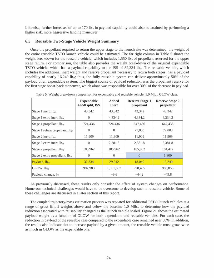
Once the propellant required to return the upper stage to the launch site was determined, the weight of the entire reusable TSTO launch vehicle could be estimated. The far right column in Table 5 shows the weight breakdown for the reusable vehicle, which includes 1,550 lbm of propellant reserved for the upper stage return. For comparison, the table also provides the weight breakdown of the original expendable TSTO vehicle, which had a payload capability to the ISS of 32,334 lbm. The reusable vehicle, which includes the additional inert weight and reserve propellant necessary to return both stages, has a payload capability of nearly 16,240 lbm; thus, the fully reusable system can deliver approximately 50% of the payload of an expendable system. The biggest source of payload reduction was the propellant reserve for the first stage boost-back maneuver, which alone was responsible for over 30% of the decrease in payload.
Table 5. Weight breakdown comparison for expendable and reusable vehicle, 1.0 Mlbm GLOW class.
Expendable 42/58 split, ISS
Added Inert
Reserve Stage 1 propellant
Reserve Stage 2 propellant
Stage 1 inert, lbm 43,342 43,342 43,342 43,342
Stage 1 extra inert, lbm 0 4,334.2 4,334.2 4,334.2
Stage 1 propellant, lbm 724,436 724,436 647,436 647,436
Stage 1 return propellant, lbm 0 0 77,000 77,000
Stage 2 inert, lbm 11,909 11,909 11,909 11,909
Stage 2 extra inert, lbm 0 2,381.8 2,381.8 2,381.8
Stage 2 propellant, lbm 185,962 185,962 185,962 184,412
Stage 2 extra propellant, lbm 0 0 0 1,800
Payload, lbm 32,334 29,242 18,040 16,240
GLOW, lbm 997,983 1,001,607 990,405 988,855
Payload change, % –9.6 –44.2 –49.8
As previously discussed, these results only consider the effect of system changes on performance. Numerous technical challenges would have to be overcome to develop such a reusable vehicle. Some of these challenges are discussed in a later section of this report.
The coupled trajectory/mass estimation process was repeated for additional TSTO launch vehicles at a range of gross liftoff weights above and below the baseline 1.0 Mlbm to determine how the payload reduction associated with reusability changed as the launch vehicle scaled. Figure 21 shows the estimated payload weight as a function of GLOW for both expendable and reusable vehicles. For each case, the reduction in payload of the reusable case compared to the expendable case remained near 50%. In addition, the results also indicate that to increase payload by a given amount, the reusable vehicle must grow twice as much in GLOW as the expendable one.
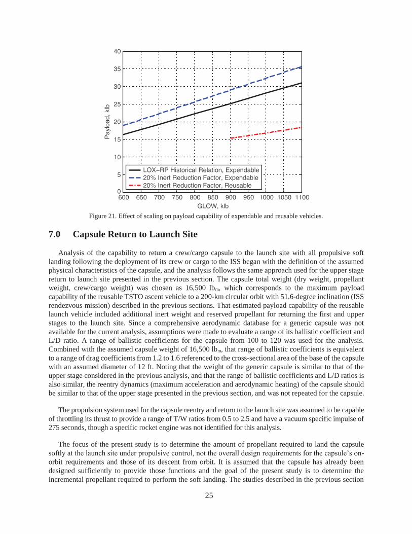
25
Figure 21. Effect of scaling on payload capability of expendable and reusable vehicles.
7.0 Capsule Return to Launch Site
Analysis of the capability to return a crew/cargo capsule to the launch site with all propulsive soft landing following the deployment of its crew or cargo to the ISS began with the definition of the assumed physical characteristics of the capsule, and the analysis follows the same approach used for the upper stage return to launch site presented in the previous section. The capsule total weight (dry weight, propellant weight, crew/cargo weight) was chosen as 16,500 lbm, which corresponds to the maximum payload capability of the reusable TSTO ascent vehicle to a 200-km circular orbit with 51.6-degree inclination (ISS rendezvous mission) described in the previous sections. That estimated payload capability of the reusable launch vehicle included additional inert weight and reserved propellant for returning the first and upper stages to the launch site. Since a comprehensive aerodynamic database for a generic capsule was not available for the current analysis, assumptions were made to evaluate a range of its ballistic coefficient and L/D ratio. A range of ballistic coefficients for the capsule from 100 to 120 was used for the analysis. Combined with the assumed capsule weight of 16,500 lbm, that range of ballistic coefficients is equivalent to a range of drag coefficients from 1.2 to 1.6 referenced to the cross-sectional area of the base of the capsule with an assumed diameter of 12 ft. Noting that the weight of the generic capsule is similar to that of the upper stage considered in the previous analysis, and that the range of ballistic coefficients and L/D ratios is also similar, the reentry dynamics (maximum acceleration and aerodynamic heating) of the capsule should be similar to that of the upper stage presented in the previous section, and was not repeated for the capsule.
The propulsion system used for the capsule reentry and return to the launch site was assumed to be capable of throttling its thrust to provide a range of T/W ratios from 0.5 to 2.5 and have a vacuum specific impulse of 275 seconds, though a specific rocket engine was not identified for this analysis.
The focus of the present study is to determine the amount of propellant required to land the capsule softly at the launch site under propulsive control, not the overall design requirements for the capsule’s on-orbit requirements and those of its descent from orbit. It is assumed that the capsule has already been designed sufficiently to provide those functions and the goal of the present study is to determine the incremental propellant required to perform the soft landing. The studies described in the previous section

26
for returning the upper stage to the launch site that dealt with orbital plane changes required to align the orbital ground track with the launch site and the deorbit burn required to begin its descent from orbit will not be addressed here for the capsule return to launch site analysis. Only the final descent phase of the capsule trajectory will be considered.
As was the case with the upper stage descent, the amount of propellant required for the capsule soft landing at the launch site is dependent on how aggressively the final braking and soft landing is accomplished. Waiting until later in the trajectory (at a lower altitude) to begin the braking, and doing so with a higher T/W ratio consumes less propellant, but assumes more risk for landing the capsule safely. Beginning the braking maneuver earlier (at a higher altitude) reduces the risk to the mission at the expense of using more propellant. During the present study, different scenarios were evaluated, but only one of the more conservative approaches will be described.
In the more conservative scenario, the capsule soft landing begins with a 2.0-T/W rocket engine burn (with an assumed Isp of 275 seconds) at an altitude of 1000 ft, and continues that thrust level for 5 seconds until the altitude reaches 230 ft with a descent rate of 70 ft/s. Then, the rocket engine T/W is decreased to 1.27 until soft landing with a descent rate of 5.1 ft/s is achieved 6 seconds later. The amount of propellant required for the initial 5-second propulsive braking maneuver is 590 lbm, and the amount of propellant required for the final 6-second descent to the soft landing is 440 lbm, for a total of 1030 lbm for the propulsive braking and final descent. More aggressive braking and landing scenarios were developed that can reduce the amount of propellant used to 730 lbm by assuming more risk in the final descent.
The analysis described in this section shows that it is possible to return the capsule to the launch site and to land softly under propulsive control using approximately 1030 lbm of propellant. The weight savings of parachute systems that would otherwise be used to provide the soft landing could possibly offset the extra weight of the propellant and other landing systems (landing gear, struts, etc.) required for the capsule soft landing at the launch site, or perhaps the existing propellant reserve of the capsule would be sufficient to provide the additional propellant in addition to its on-orbit propellant requirements.
8.0 Reusable Launch Vehicle Technical Challenges
During the current analysis which investigated the potential for evolving an existing expendable launch vehicle into a reusable one in which the two stages and crew/cargo module return to the launch site via propulsive VTOL technology, many technical challenges were identified which must be considered before a viable operational reusable launch vehicle design could be completed. The solutions of those technical challenges were considered to be beyond the scope of the current analysis and were not considered. However, those technical challenges are significant enough that the inability to find adequate design solutions could reduce or eliminate the viability of the reusable launch vehicle concept. In general, the technical challenges can loosely be grouped into categories of propulsion, vehicle control, vertical landing, aero heating and structures, and range safety.
8.1 Propulsion Challenges
A major assumption made during the current analysis is that the rocket engines used for the propulsive braking and landing have multiple restart capability, have the ability for in-flight ignition with the engine nozzle pointed into the airflow with significant dynamic pressure, and that they have deep throttle capability to provide T/W ratios of 0.5 to 2.5 with nearly empty vehicle stages. The ability of prior and current technology rocket engines to achieve these capabilities has not been demonstrated.
27
In addition, suitable mechanisms for controlling propellant slosh and providing ullage management could require complex tank, feed system, and pressurization systems and may have to control propellant bubbles which could lead to pump cavitation during engine restarts after significant vehicle orientation changes during the reentry and return portions of the trajectory.
Return of the upper stage requires approximately 24-hour return time to allow its ground track to pass close enough to the launch site for a landing attempt. Propellant conditioning to mitigate boil off of the cryogenic LOX would have to be considered.
8.2 Vehicle Control Challenges
The complex vehicle orientation maneuvers that are required for the reentry, braking during descent, and rotation to vertical orientations prior to landing will require robust vehicle attitude control and the need for large control moments. The precise mechanism for producing such control moments was not considered in the current analysis, but could include ACS jets or thrust vector control of the rocket engines used for landing. Additional weight and complexity of such systems could further erode the payload to orbit capability of a reusable launch vehicle.
The design of an ACS would also have to address the challenges of the aerodynamic trim characteristics of the returning vehicle wherein the center of mass location may be significantly aft in the vehicle stage because of the weight of its rocket engine in the aft, with mostly empty propellant tanks forward. In addition, during the reentry phase of the upper stage trajectory, the ACS will have to provide an orientation to maintain a small angle of attack to produce sufficient lift to minimize aero heating and acceleration during reentry, yet small enough to maintain structural loads at manageable levels. The braking maneuver also requires a precise vehicle rotation maneuver to point the engines and their thrust into the velocity vector, and to maintain the proper vehicle orientation during the braking.
8.3 Vertical Landing Challenges
The soft landing scenarios described earlier in this document alluded to the tradeoff of propellant required to perform the braking and landing functions versus the risk in a shorter timeline. The most efficient braking and landing scenario from the standpoint of propellant use is a high “last seconds” rocket engine burn, but the time available to mitigate any risks with delayed engine start, thrust stabilization, etc. may not be sufficient for a safe and successful recovery of the vehicle stages.
The McDonnell Douglas Delta Clipper DC-X flight test vehicle demonstrated technical issues with rocket plume/ground effects interaction causing a “fountain effect” where the vehicle floated atop high-pressure gases during attempted landings. This effect caused high heating loads on the vehicle and reduced the controllability of the final descent and landing as the vehicle tended to skid laterally on the plume of exhaust gas near touchdown. One attempt that the project used to mitigate this effect was to land over a landing pit covered with a metal grate that would allow the rocket engine exhaust to pass through and reduce the fountain effect. Another approach that could be used involves canting the engine nozzles outward relative to the vehicle vertical axis so that the thrust from the rocket engines is not directly downward, but that would only work if multiple engines or nozzles are used, and would reduce the amount of net thrust directed in the downward direction. Similar measures would likely have to be investigated with the current vertical landing concept.
The lateral velocity at landing must be minimized to prevent the vertical landing vehicle from tipping over once its landing gear/legs touched down. The design of the landing gear/legs was not considered in the present analysis, but the number of legs and their orientation would have to be studied. In addition,

28
cross winds at the landing site would present similar issues of lateral stability of the vehicle during a vertical landing, and would have to be considered carefully in a final concept design.
8.4 Aero Heating and Structures Challenges
Although considered briefly at a high level in this analysis, the effects of aero heating during reentry and the ensuing TPS requirements would have to be analyzed in detail for an operational reusable launch vehicle concept. The placement of TPS features on the vehicle would have to be carefully integrated with the vehicle flight mechanics and trajectory design and its aerodynamic trim characteristics during reentry. Though it was felt that the levels of aero heating estimated in this analysis were manageable, a more thorough aero heating analysis and TPS design would have to be performed for any final concept design.
No structural design criteria were considered in the current analysis, other than application of preliminary design constraints such as reducing the first stage separation Mach/Qbar conditions to reasonably survivable limits. This required a tradeoff of the optimal V split for the first and upper stages for a consideration of maximum payload to orbit capability with that of managing the first stage separation Mach/Qbar conditions and for providing the capability of returning the first stage to the launch site. The structural design requirements necessary for the first stage boost back trajectory to the launch site and the upper stage reentry would need to be developed and implemented in an operational reusable launch vehicle concept.
The landing systems for the first and second stages and the crew/cargo module would have to be considered, including the type of landing struts, their number, physical arrangement, compression (shock) mechanisms, etc. The landing systems design would be complex for the first and second stages to avoid interference with the rocket nozzles used during the ascent and the boost back/reentry and landing, and for the crew/cargo module to avoid interference with its reentry heat shield. A retractable, or deployable, mechanism may be required, which could increase the weight, cost, and complexity of the reusable launch vehicle.
8.5 Range Safety Technical Challenges
Not considered in the current analysis were challenges related to range safety issues for returning the vehicle stages and crew/cargo module to the vicinity of populated regions around the launch site, particularly in light of those high-speed objects returning in a ballistic trajectory with minimal maneuvering capability. The effects of engine-out failure scenarios during braking/landing and for long/short trajectory deviations was not considered, but would be a major concern for certifying an operational reusable launch vehicle concept. In contrast, existing expendable launch vehicles are designed so that the expendable stages fall harmlessly into the ocean, away from populated land areas.
9.0 Conclusions
An initial performance analysis of a reusable TSTO launch vehicle indicates that it is feasible to return both stages to the launch site, landing vertically under propulsive control only, with a positive payload capability equal to approximately 50% of an equivalent expendable launch vehicle. It also was shown that it is feasible to return a crew/cargo capsule to the launch site, also landing vertically under propulsive control with propellant usage within the capability of typical capsule designs without degrading its crew or cargo carrying capability. However, a number of technical challenges were identified that would have to be overcome to design an operationally feasible reusable TSTO launch vehicle concept.
29
References
1. Kohrs, R. and Petersen, R., “Development of the K-1 Two-stage, fully Reusable Launch Vehicle,” AIAA-98-1540, 1998.
2. Bradford, J. and Hellman, B., “Return to Launch Site Trajectory Options for a Reusable Booster without a Secondary Propulsion System,” AIAA-2009-6439, September 2009.
3. Striepe, S. A., Powell, R. W., Desai, P. N., Queen, E. M., Brauer, G. L., Cornick, D. E., Olson, D. W., Petersen, F. M., Ste-venson, R., Engle, M. C., Marsh, S. M., and Gromko, A. M., “Program To Optimize Simulated Trajectories (POST II), Utilization Manual, Version 1.1. 6,” Jan. 2004.
4. Blake, W. B., “Missile DATCOM: User’s Manual – 1997 FORTRAN 90 Version,” Air Force Research Laboratories, Document AFRL-VA-WP-TR-1998-3009, Feb. 1998.
5. Bauer, S. X., and Krist, S. E., “Aerodynamic Assessment of the Ares I-X Flight Test Vehicle,” 58th JANNAF Propulsion Meeting, April 2011.
6. Purinton, D. C., Blevins, J. A., Pritchett, V., Haynes, D., and Carpenter, M., “Aerodynamic Characterization and Simulation of a Solid Rocket Booster During Reentry Flight,” AIAA 2011-0014, January 2011.
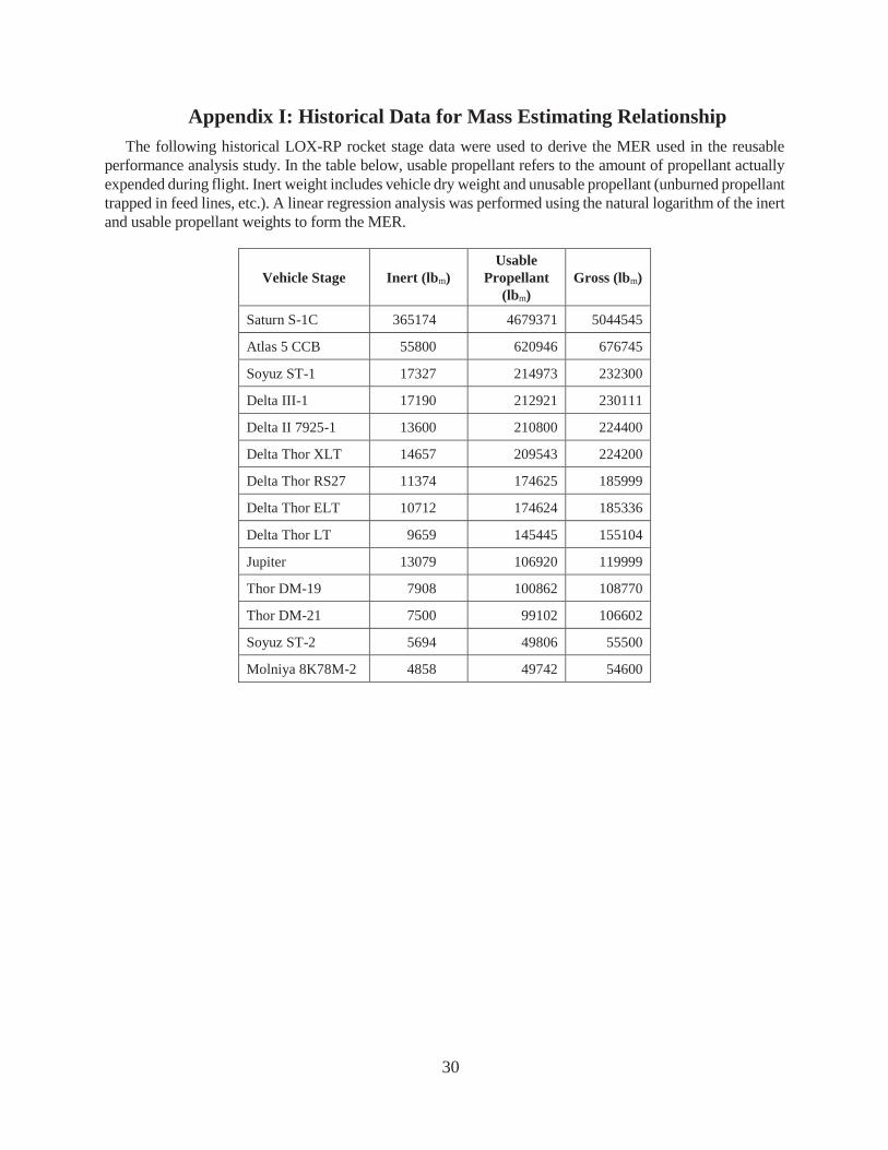
30
Appendix I: Historical Data for Mass Estimating Relationship The following historical LOX-RP rocket stage data were used to derive the MER used in the reusable
performance analysis study. In the table below, usable propellant refers to the amount of propellant actually expended during flight. Inert weight includes vehicle dry weight and unusable propellant (unburned propellant trapped in feed lines, etc.). A linear regression analysis was performed using the natural logarithm of the inert and usable propellant weights to form the MER.
Vehicle Stage Inert (lbm) Usable
Propellant (lbm)
Gross (lbm)
Saturn S-1C 365174 4679371 5044545
Atlas 5 CCB 55800 620946 676745
Soyuz ST-1 17327 214973 232300
Delta III-1 17190 212921 230111
Delta II 7925-1 13600 210800 224400
Delta Thor XLT 14657 209543 224200
Delta Thor RS27 11374 174625 185999
Delta Thor ELT 10712 174624 185336
Delta Thor LT 9659 145445 155104
Jupiter 13079 106920 119999
Thor DM-19 7908 100862 108770
Thor DM-21 7500 99102 106602
Soyuz ST-2 5694 49806 55500
Molniya 8K78M-2 4858 49742 54600
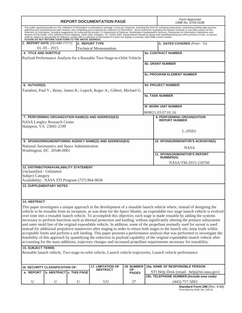
REPORT DOCUMENTATION PAGE Form ApprovedOMB No. 0704-0188
2. REPORT TYPE Technical Memorandum
4. TITLE AND SUBTITLEPayload Performance Analysis for a Reusable Two-Stage-to-Orbit Vehicle
5a. CONTRACT NUMBER
6. AUTHOR(S)
Tartabini, Paul V.; Beaty, James R.; Lepsch, Roger A.; Gilbert, Michael G.
7. PERFORMING ORGANIZATION NAME(S) AND ADDRESS(ES)NASA Langley Research CenterHampton, VA 23681-2199
9. SPONSORING/MONITORING AGENCY NAME(S) AND ADDRESS(ES)National Aeronautics and Space AdministrationWashington, DC 20546-0001
8. PERFORMING ORGANIZATION REPORT NUMBER
L-20563
10. SPONSOR/MONITOR'S ACRONYM(S)
NASA
13. SUPPLEMENTARY NOTES
12. DISTRIBUTION/AVAILABILITY STATEMENTUnclassified - UnlimitedSubject Category Availability: NASA STI Program (757) 864-9658
19a. NAME OF RESPONSIBLE PERSON
STI Help Desk (email: [email protected])
14. ABSTRACT
This paper investigates a unique approach in the development of a reusable launch vehicle where, instead of designing the vehicle to be reusable from its inception, as was done for the Space Shuttle, an expendable two stage launch vehicle is evolvedover time into a reusable launch vehicle. To accomplish this objective, each stage is made reusable by adding the systems necessary to perform functions such as thermal protection and landing, without significantly altering the primary subsystems and outer mold line of the original expendable vehicle. In addition, some of the propellant normally used for ascent is used instead for additional propulsive maneuvers after staging in order to return both stages to the launch site, keep loads within acceptable limits and perform a soft landing. This paper presents a performance analysis that was performed to investigate the feasibility of this approach by quantifying the reduction in payload capability of the original expendable launch vehicle afteraccounting for the mass additions, trajectory changes and increased propellant requirements necessary for reusability.15. SUBJECT TERMSReusable launch vehicle, Two-stage-to-orbit vehicle, Launch vehicle trajectories, Launch vehicle performance
18. NUMBER OF PAGES
3719b. TELEPHONE NUMBER (Include area code)
(443) 757-5802
a. REPORT
U
c. THIS PAGE
U
b. ABSTRACT
U
17. LIMITATION OF ABSTRACT
UU
Prescribed by ANSI Std. Z39.18Standard Form 298 (Rev. 8-98)
3. DATES COVERED (From - To)
5b. GRANT NUMBER
5c. PROGRAM ELEMENT NUMBER
5d. PROJECT NUMBER
5e. TASK NUMBER
5f. WORK UNIT NUMBER
869021.03.07.01.16
11. SPONSOR/MONITOR'S REPORT NUMBER(S)
NASA/TM-2015-218760
16. SECURITY CLASSIFICATION OF:
The public reporting burden for this collection of information is estimated to average 1 hour per response, including the time for reviewing instructions, searching existing data sources, gathering and maintaining the data needed, and completing and reviewing the collection of information. Send comments regarding this burden estimate or any other aspect of this collection of information, including suggestions for reducing this burden, to Department of Defense, Washington Headquarters Services, Directorate for Information Operations and Reports (0704-0188), 1215 Jefferson Davis Highway, Suite 1204, Arlington, VA 22202-4302. Respondents should be aware that notwithstanding any other provision of law, no person shall be subject to any penalty for failing to comply with a collection of information if it does not display a currently valid OMB control number.PLEASE DO NOT RETURN YOUR FORM TO THE ABOVE ADDRESS.
1. REPORT DATE (DD-MM-YYYY)05 - 201501-
Related Documents