UK ROADS LIAISON GROUP PAVEMENT DESIGN AND MAINTENANCE 2018 FOOTWAY AND CYCLETRACK MANAGEMENT GROUP ASSET MANAGEMENT GUIDANCE FOR FOOTWAYS AND CYCLE ROUTES: VOLUME 1

Welcome message from author
This document is posted to help you gain knowledge. Please leave a comment to let me know what you think about it! Share it to your friends and learn new things together.
Transcript
UK ROADS LIAISON GROUP
PAVEMENT DESIGN AND MAINTENANCE
2018
FOOTWAY AND CYCLETRACK MANAGEMENT GROUP
ASSET MANAGEMENT GUIDANCE FOR FOOTWAYS AND CYCLE ROUTES:
VOLUME 1
Asset Management Guidance for Footways and Cycle Routes:Pavement Design and MaintenanceVolume 1
FOREWORD
This document has been developed under a commission from the Footway and Cycletrack Management Group (FCMG), a sub-group of the UK Roads Board (UKRB) under the UK Roads Liaison Group (UKRLG).
This document forms part of suite of three documents commissioned by the FCMG, which have been developed to align with and support the implementation of the UKRLG Code of Practice Well-managed highway infrastructure: a code of practice (1) for footways and cycle routes.
The purpose of this document is to provide information on the design and maintenance of paved assets for walking and cycling.
This document has been endorsed by CIHT.
Asset Management Guidance for Footways and Cycle Routes:Pavement Design and MaintenanceVolume 1
ACKNOWLEDGEMENTS
This document has been developed from existing guidance sponsored by FCMG:
Application Guide AG26 (Version 2). Footway and Cycle Route Design Construction and Maintenance Guide (2)
and retains and re-presents some of the information and content from that document.
This document has been prepared under the overall purview of FCMG’s project steering group comprising:
• Mr Herbert Micallef, TfL
• Mr Peter McCready, London borough of Bromley
• Mr Dan Bond, Rhondda Cynon Taff
and the direct management, with extensive contribution and advice, of Mr Herbert Micallef as FCMG’s Project Manager.
The project was commissioned and managed by TfL on behalf of FCMG with funding from DfT via UKRLG, and was delivered by CH2M supported by Hyperion Infrastructure Consultancy and Accent MR.
Permission to reproduce extracts from British Standards is granted by BSI. British Standards can be obtained in PDF or hard copy formats from the BSI online shop: www.bsigroup.com/Shop or by contacting BSI Customer Services for hardcopies only: Tel: +44 (0)20 8996 9001, Email: [email protected].
Asset Management Guidance for Footways and Cycle Routes:Pavement Design and MaintenanceVolume 1
CONTENTS
INTRODUCTION 1Objective 1
Definitions 1
What is the scope of this guidance? 2
Who is this guidance for? 2
Context for this guidance 2
HOW TO USE THIS GUIDANCE 4
STEP 1: DISCOVER 6Confirm required outcomes 6
Establish further requirements 7
Users and uses 7
Planning, heritage, conservation and streetscape 7
Stakeholder engagement and control of third parties 8
Site information 8
STEP 2: DEFINE 9General guidance for provision of walking and cycling facilities 9
Considerations for pavement solutions 11
Develop outline solution 15
Further investigation 15
STEP 3: DEVELOP 20Footway and cycle route pavement construction 21
Pavement design 22
Pavement materials 23
Monolithic pavements 25
Elemental pavements 27
Maintenance treatments and operations 36
STEP 4: DELIVER 39Clarity of requirements 39
Construction 39
REFERENCES 41
APPENDIX A GUIDANCE: INITIAL SITE APPRAISAL 46
APPENDIX B DRAINAGE INVESTIGATION SAMPLE SPECIFICATION 49
APPENDIX C TOPOGRAPHIC SURVEY SAMPLE SPECIFICATION 52
APPENDIX D CARRIAGEWAY CORING SAMPLE SPECIFICATION 54
Asset Management Guidance for Footways and Cycle Routes:Pavement Design and MaintenanceVolume 1
1 INTRODUCTION
OBJECTIVEThere are extensive existing resources and guidance on the development of walking and cycling facilities, incorporating planning, design, construction and maintenance. The objective of this document is to present a process for the design and maintenance of the pavement for footways and cycle routes that:
• Highlights the factors for consideration during the design and maintenance of footways and cycle routes;
• Sign posts existing relevant information such as legislation, standards, Codes of Practice and guidance; and
• Provides further guidance and clarification where appropriate.
DEFINITIONSDefinitions used are consistent with those presented in Well-managed highway infrastructure: a code of practice (1), i.e.
• The term ‘footway’ is used for that part of a highway over which the public have a right of way on foot only, e.g. segregated surfaced paths used by pedestrians.
• The term ‘cycle route’ is used as the collective term for facilities used by cyclists. These include:
- cycle tracks adjacent to or away from carriageways
- cycle lanes on carriageways
- on carriageway provision with cycle symbols and shared use facilities.
• The term pavement is used as the collective term for all hardened surfaces within the highway, including carriageways, footways and cycle routes.
Asset Management Guidance for Footways and Cycle Routes:Pavement Design and MaintenanceVolume 1
2 WHAT IS THE SCOPE OF THIS GUIDANCE?This guidance is intended principally for footways and cycle routes with bound surface construction that are the responsibility of a local highway authority.
Cycle lanes that form part of the carriageway will, in general, be designed, constructed and maintained with the requirements and procedures for the carriageway asset and so are not specifically addressed within this guidance. Similarly, unsurfaced tracks, leisure trails and public rights of way (PROW) are not directly included within the scope however some of the advice presented may be relevant and of value.
The guidance covers the following types of works:
New provision – Highway Authority or Developer funded projects to create new walking and/or cycling facilities
Renewals – planned works to restore, maintain or enhance asset performance as part of a planned programme of works
Maintenance - rehabilitation of an existing asset to restore level of service and/or rectify deterioration in condition either as:
• Planned maintenance, or
• Routine maintenance
Note that reactive maintenance to address defects that require an immediate or short term response, e.g. fixing of potholes, is not explicitly covered within this document. A designed and planned solution is generally not feasible or appropriate for such works, which are often temporary holding solutions until a more permanent treatment can be effected.
WHO IS THIS GUIDANCE FOR?While this document is aimed primarily at engineers within local highways authorities with responsibility for design and maintenance of walking and cycling facilities. It is also intended to assist anyone who is involved in the development, design, specification and/or delivery of works for the design and maintenance of paved footways and cycle routes.
The term ‘designer’ is used throughout this guidance since the Construction Design and Management (CDM) regulations (3) define a designer as “an organisation or individual who is involved preparing or modifying designs for construction projects, or arranging for, or instructing others to do this. Designs include drawings, design details, specification, bills of quality and design calculations”.
CONTEXT FOR THIS GUIDANCEThe process of developing a works solution for a footway or cycle route will generally be initiated by a rational procedure that has identified and prioritised the need for investment. This procedure should, ideally, conform to established asset management principles, such those as described in:
• Well-managed highway infrastructure: a code of practice (1) and
• Highway infrastructure asset management: guidance document (4)
3
Asset Management Guidance for Footways and Cycle Routes:Pavement Design and MaintenanceVolume 1
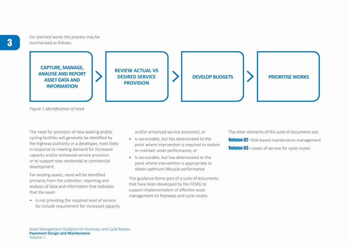
For planned works the process may be summarised as follows:
Figure 1 Identification of need
CAPTURE, MANAGE, ANALYSE AND REPORT
ASSET DATA AND INFORMATION
REVIEW ACTUAL VS DESIRED SERVICE
PROVISIONDEVELOP BUDGETS PRIORITISE WORKS
and/or enhanced service provision), or
• Is serviceable, but has deteriorated to the point where intervention is required to restore or maintain asset performance, or
• Is serviceable, but has deteriorated to the point where intervention is appropriate to obtain optimum lifecycle performance
This guidance forms part of a suite of documents that have been developed by the FCMG to support implementation of effective asset management on footways and cycle routes.
The need for provision of new walking and/or cycling facilities will generally be identified by the highway authority or a developer, most likely in response to meeting demand for increased capacity and/or enhanced service provision, or to support new residential or commercial development.
For existing assets, need will be identified primarily from the collection, reporting and analysis of data and information that indicates that the asset:
• Is not providing the required level of service (to include requirement for increased capacity
The other elements of this suite of documents are:
Volume 02 - Risk-based maintenance management
Volume 03 - Levels of service for cycle routes
Asset Management Guidance for Footways and Cycle Routes:Pavement Design and MaintenanceVolume 1
4 HOW TO USE THIS GUIDANCE
This document guides the reader through the steps that should be considered when developing a solution that meets the required outcomes, for example
• Provision of a safe and comfortable facility for all users
• Minimisation of whole life cost
• Enhanced durability and service life
• Improved aesthetics or environmental impact.
The guidance identifies issues to be considered and provides references to other sources of relevant existing information where appropriate, for instance
• Guidance and best practice advice
• Standards
• Legislation
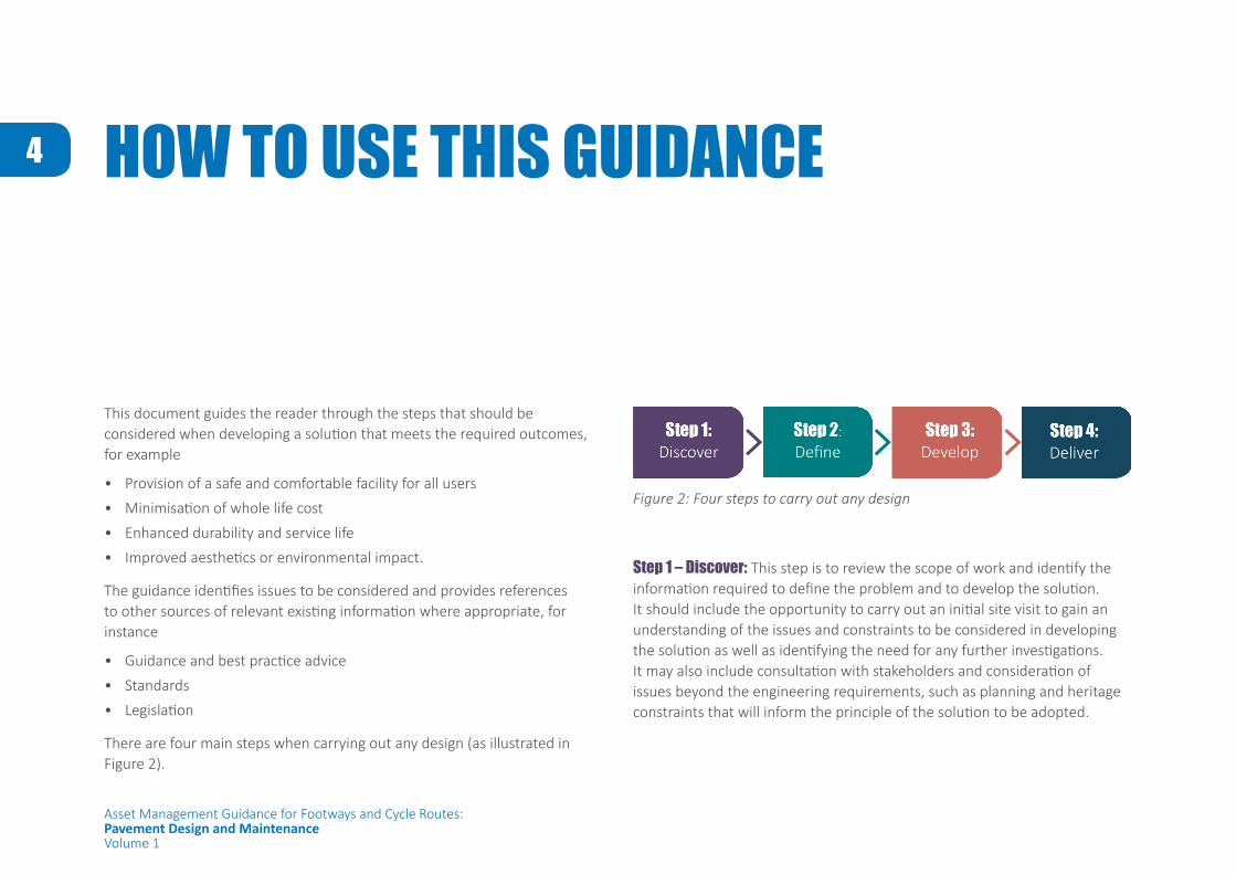
There are four main steps when carrying out any design (as illustrated in Figure 2).
Figure 2: Four steps to carry out any design
Step 1 – Discover: This step is to review the scope of work and identify the information required to define the problem and to develop the solution. It should include the opportunity to carry out an initial site visit to gain an understanding of the issues and constraints to be considered in developing the solution as well as identifying the need for any further investigations. It may also include consultation with stakeholders and consideration of issues beyond the engineering requirements, such as planning and heritage constraints that will inform the principle of the solution to be adopted.
5
Asset Management Guidance for Footways and Cycle Routes:Pavement Design and MaintenanceVolume 1
Step 2 – Define: This step is to review the information that has been gathered in Step 1 together with the required outcomes from the initial identification of need in order to define the problem to be addressed. This leads to development of the design case and establishing the design parameters and/or criteria for the pavement solution. Depending on the nature and scale of the works it may be appropriate to consider further investigation to support the solution development and design.
Step 3 – Develop: This step is to take the design parameters that have been established in Step 2 and to develop a solution that is appropriate for the circumstances and requirements of the particular site, e.g. what form of construction should be adopted to suit the anticipated users, what form of treatment would restore serviceability most cost effectively. There may be other factors that influence the design such as different stakeholder requirements or architectural requirements for particular materials. This stage is, therefore, about the development of the ideas, ensuring that the construction and material selection is appropriate to meet the needs of the community and provides a solution that is safe, sustainable, environmentally sound and value for money over the whole life of the asset.
Step 4 – Deliver: This step is about making it happen through the detailed design and specification of the solution and the execution of the works on site. Not every design will be straightforward to deliver and the designer is expected to maintain engagement throughout the process to ensure that the required outcomes are delivered.
6
Asset Management Guidance for Footways and Cycle Routes:Pavement Design and MaintenanceVolume 1
STEP 1: DISCOVER
This step is to review the scope of work and identify the information required to define the problem and develop the solution. It should include the opportunity to carry out an initial site visit to gain an understanding of the issues and constraints to be considered as well as identifying the need for any further investigations. It may also include consultation with stakeholders and consideration of issues beyond the engineering requirements, such as planning and heritage constraints that will inform the principle of the solution to be adopted.
CONFIRM REQUIRED OUTCOMESOnce the need for intervention at a particular location has been confirmed and approved, the required outcomes from the works investment should be established. These will generally be largely defined from the original identification of need and the subsequent asset management processes for justification and prioritisation of the scheme. Typically these may include:
• Increase in capacity
• Restore or enhance level of service
• Improve access for a wider range of users, e.g. Cyclists
• Improvement of asset condition
7
Asset Management Guidance for Footways and Cycle Routes:Pavement Design and MaintenanceVolume 1
ESTABLISH FURTHER REQUIREMENTSConsideration should also be given to the requirement and/or opportunity to address other drivers such as the highway authority’s wider policy objectives and legal obligations. Many highway authorities will, for example, have aims around minimising environmental impact and/or sustainable development which could influence the choice of solution that is adopted.
A useful guide to the relevant legal framework that may bear upon the choice of solution is presented in: Well-managed highway infrastructure: a code of practice (1)
Further guidance on the recommended approach to planning networks of walking and cycling routes is available in Local Cycling and Walking Infrastructure Plan Guidance (5)
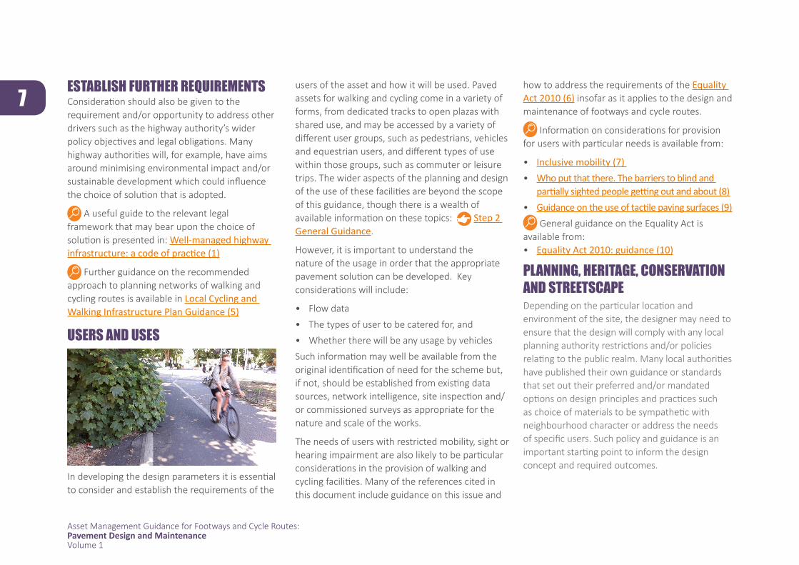
USERS AND USES
In developing the design parameters it is essential to consider and establish the requirements of the
users of the asset and how it will be used. Paved assets for walking and cycling come in a variety of forms, from dedicated tracks to open plazas with shared use, and may be accessed by a variety of different user groups, such as pedestrians, vehicles and equestrian users, and different types of use within those groups, such as commuter or leisure trips. The wider aspects of the planning and design of the use of these facilities are beyond the scope of this guidance, though there is a wealth of available information on these topics: Step 2 General Guidance.
However, it is important to understand the nature of the usage in order that the appropriate pavement solution can be developed. Key considerations will include:
• Flow data
• The types of user to be catered for, and
• Whether there will be any usage by vehicles
Such information may well be available from the original identification of need for the scheme but, if not, should be established from existing data sources, network intelligence, site inspection and/or commissioned surveys as appropriate for the nature and scale of the works.
The needs of users with restricted mobility, sight or hearing impairment are also likely to be particular considerations in the provision of walking and cycling facilities. Many of the references cited in this document include guidance on this issue and
how to address the requirements of the Equality Act 2010 (6) insofar as it applies to the design and maintenance of footways and cycle routes.
Information on considerations for provision for users with particular needs is available from:
• Inclusive mobility (7) • Who put that there. The barriers to blind and
partially sighted people getting out and about (8) • Guidance on the use of tactile paving surfaces (9)
General guidance on the Equality Act is available from:• Equality Act 2010: guidance (10)
PLANNING, HERITAGE, CONSERVATION AND STREETSCAPE Depending on the particular location and environment of the site, the designer may need to ensure that the design will comply with any local planning authority restrictions and/or policies relating to the public realm. Many local authorities have published their own guidance or standards that set out their preferred and/or mandated options on design principles and practices such as choice of materials to be sympathetic with neighbourhood character or address the needs of specific users. Such policy and guidance is an important starting point to inform the design concept and required outcomes.

8
Asset Management Guidance for Footways and Cycle Routes:Pavement Design and MaintenanceVolume 1
affecting both service and durability if not properly executed. It is therefore important to understand the framework for dealing with third parties. The Highways Authorities & Utilities Committee (HAUC) has produced a specification for reinstatements to utility works which is a widely acknowledged and accepted standard: Specification for the reinstatement of openings in highways (SROH) (18)
For further information on powers of enforcement, liability or permits the designer should refer to:
• Local road maintenance, repairs, and street works in england (19)
• The traffic management permit scheme (england) regulations (2007) (20)
Additional information on good practice, guidance and legislation for street works is available from the HAUC website.
SITE INFORMATIONWhile policy and the required outcomes will ultimately inform the choice of solution, the particular features and condition of the site will bear directly upon the engineering of the pavement design or maintenance solution. It is therefore essential to obtain the appropriate information, commensurate with the nature and scale of the works, on layout, construction and condition at an early stage.
There is a range of guidance and advice on these issues, published by a number of organisations: examples are given below.
• Manual for streets (11)• Manual for streets 2 (12) • Ltn 1/08 traffic management and streetscape
(13)
• Local Cycling and Walking Infrastructure Plan Guidance (5)
• Street design for all, 2014 (14) • Tfl streetscape guidance (15) • Better streets delivered (16)• Better streets delivered 2 (17)
STAKEHOLDER ENGAGEMENT AND CONTROL OF THIRD PARTIESThe designer should consider if any stakeholder or third party, such as a utility company or owner of adjacent land or premises, needs to be consulted if the proposed works are likely to affect, or be affected by, their existing asset or interest. It is important to identify such issues at an early stage since disruption or damage caused by poor design and/or works planning and execution that does not meet stakeholder standards or requirements may give rise to claims, repairs and/or reputational damage.
Similarly, intervention by third parties – typically utility companies – can cause damage and disruption to footways and cycle routes
Existing InformationAn early action on the client should be to identify and assimilate existing information particularly with regard to:
• Site layout and topography
• Presence of utilities and other assets
• Construction and condition of existing paved assets
• User type and flow data
Much of this, and possibly further relevant information, may be available from the evidence and data used to identify the need for works at the location. The completeness, quality and currency of the existing information will inform the scope and extent of any further site investigation. Further Investigation
Site appraisalIt is good practice for the designer to make an initial familiarisation visit to the site to better understand the environment, condition, constraints and other site-specific factors that will influence the choice of solution and/or, depending on the nature and scale of the works, inform the need for further more detailed investigation.
Guidance on the information that should, typically, be sought both in the interrogation of existing information and through the initial �ite appraisal is presented in Appendix A.
9
Asset Management Guidance for Footways and Cycle Routes:Pavement Design and MaintenanceVolume 1
STEP 2: DEFINE
This step is to review the information that has been gathered in Step 1 together with the required outcomes from the initial identification of need in order to define the problem to be addressed. This leads to the developing the design case and establishing the design parameters and/or criteria for the pavement solution. Depending on the nature and scale of the works it may be appropriate to consider further investigation to support the solution development and design.
The following sections present a number of factors that may be appropriate to consider in developing the design and/or identifying the need for further information.
GENERAL GUIDANCE FOR PROVISION OF WALKING AND CYCLING FACILITIESWhere the scheme entails new provision or significant improvement then the wider aspects of provision of walking and or cycling facilities, beyond the form of pavement construction, will need to be considered. However, there is merit in considering how the overall provision of walking and cycling can be improved in any planned pavement works including those focused principally on rehabilitation and repair.
While these aspects of design are beyond the scope of this guidance, there is extensive published information on the design of footways and cycle routes which may have a bearing on the pavement design and materials options. A number of sources that address general design and/or the considerations for footways and cycle routes are presented in the table below. This list is by no means exhaustive but is intended to give the designer an indication of the range of material and sources available.
10
Asset Management Guidance for Footways and Cycle Routes:Pavement Design and MaintenanceVolume 1
General Footways Cycle RoutesManual for Streets (11) Manual for Streets 2 (12)Local Cycling and Walking Infrastructure Plan Guidance (5)
LTN 1/11 Shared space (21)LTN 1/12 Shared use routes for pedestrians and cyclists (22) TA 90/05 The Geometric Design of Pedestrian, Cycle and Equestrian Routes (140)TA 91/05 Provision for Non-motorised Users (23) Design Guidance. Active Travel (Wales) Act 2013 (24) Street Design for All (14) Inclusive mobility (6) Traffic free routes: conceptual design (25)
Planning for Walking (26)Providing for Journeys on Foot (27)
LTN 2/08 Cycle Infrastructure Design (28) Cycling by design (29)London cycling design standards (30) Design manual for bicycle traffic (31) Handbook for cycle friendly design (32) Greater Manchester Cycling Design Guidance (33) IAN 195/16 Cycle Traffic And The Strategic Road Network (34) Planning for cycling (35)
Site LayoutDetail of the site layout is important to enable the designer to ensure that the proposed solution can be constructed within the site constraints while meeting minimum design requirements and offering acceptable levels of user service and comfort. Ideally the layout information should include:
• Plan location and dimensions• Levels and vertical dimensions• Location of other assets, e.g. structures,
lighting, signs etc• Location of utilities• Location of street furniture
From this the designer should seek to ensure that:
• there is adequate depth of construction/natural ground to accommodate the pavement construction/treatment
• there is adequate surface profile for efficient drainage
• there is adequate clearance to other assets/furniture
• the gradients and radii are appropriate for safe and comfortable use
• the works don’t impact subsurface utilitiesInformation on the site layout may be available from existing records or may be gained from the initial site appraisal Site Appraisal, Appendix A
For projects of significant scale and value, and where the existing information is not adequate, it may be appropriate to commission a topographic survey to obtain the necessary information on site geometry and the location of features and assets. Further Investigation, Topographic Survey, Appendix C
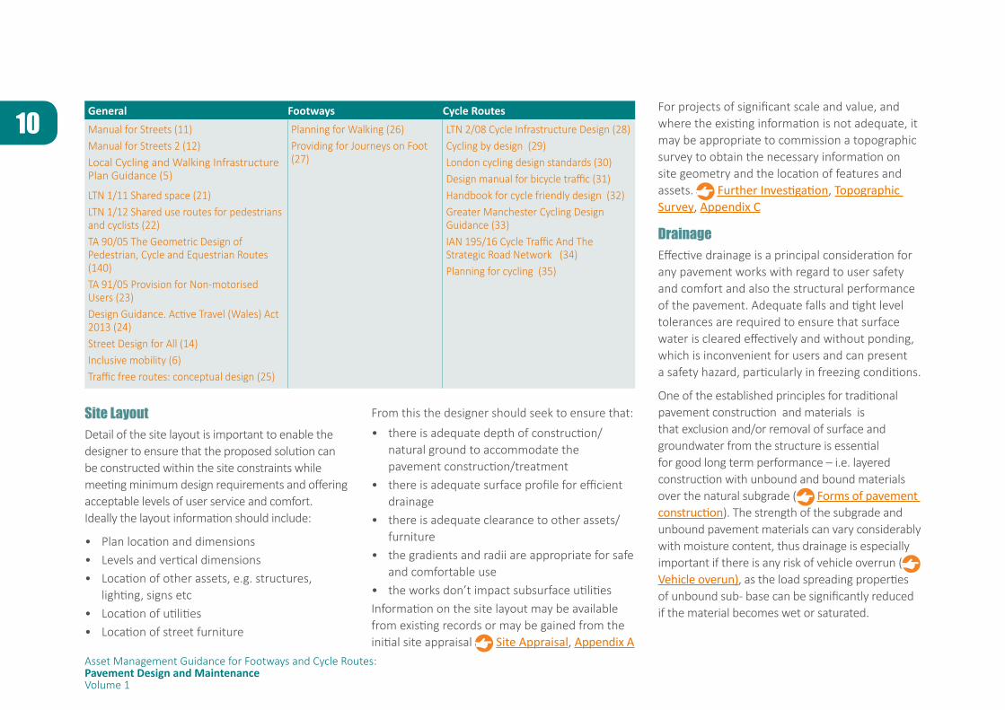
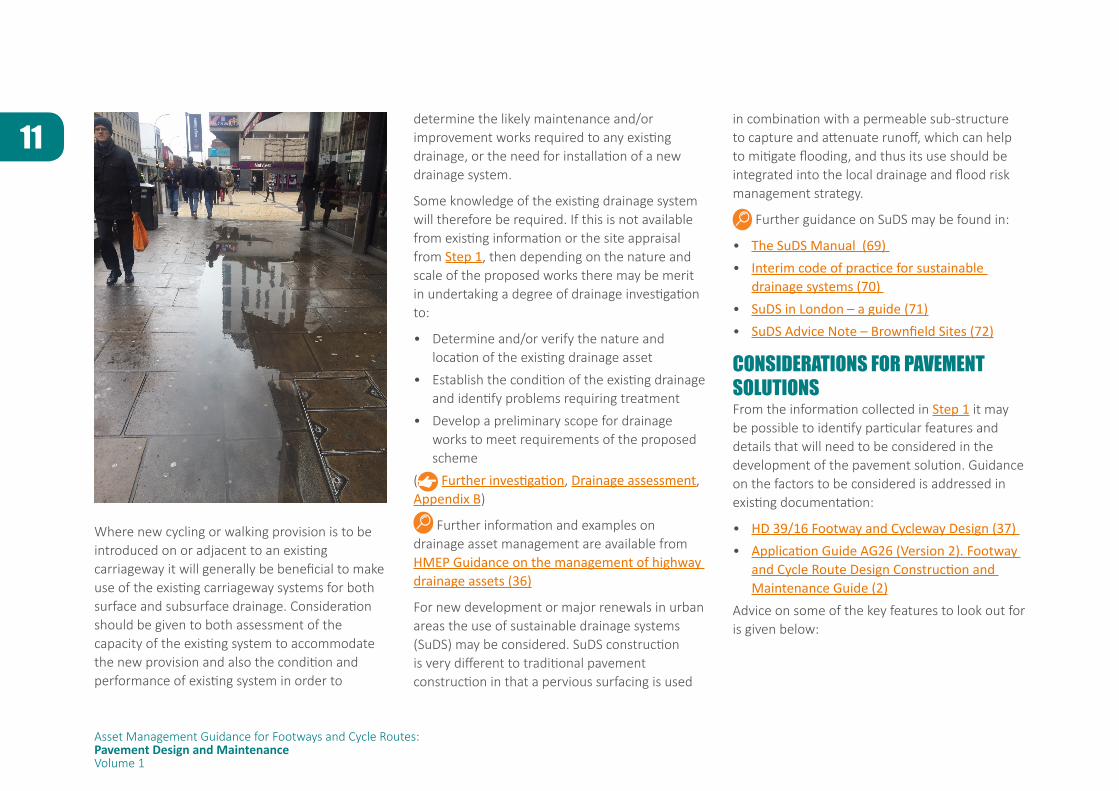
DrainageEffective drainage is a principal consideration for any pavement works with regard to user safety and comfort and also the structural performance of the pavement. Adequate falls and tight level tolerances are required to ensure that surface water is cleared effectively and without ponding, which is inconvenient for users and can present a safety hazard, particularly in freezing conditions.
One of the established principles for traditional pavement construction and materials is that exclusion and/or removal of surface and groundwater from the structure is essential for good long term performance – i.e. layered construction with unbound and bound materials over the natural subgrade ( Forms of pavement construction). The strength of the subgrade and unbound pavement materials can vary considerably with moisture content, thus drainage is especially important if there is any risk of vehicle overrun ( Vehicle overun), as the load spreading properties of unbound sub- base can be significantly reduced if the material becomes wet or saturated.
11
Asset Management Guidance for Footways and Cycle Routes:Pavement Design and MaintenanceVolume 1
Where new cycling or walking provision is to be introduced on or adjacent to an existing carriageway it will generally be beneficial to make use of the existing carriageway systems for both surface and subsurface drainage. Consideration should be given to both assessment of the capacity of the existing system to accommodate the new provision and also the condition and performance of existing system in order to
determine the likely maintenance and/or improvement works required to any existing drainage, or the need for installation of a new drainage system.
Some knowledge of the existing drainage system will therefore be required. If this is not available from existing information or the site appraisal from Step 1, then depending on the nature and scale of the proposed works there may be merit in undertaking a degree of drainage investigation to:
• Determine and/or verify the nature and location of the existing drainage asset
• Establish the condition of the existing drainage and identify problems requiring treatment
• Develop a preliminary scope for drainage works to meet requirements of the proposed scheme
( Further investigation, Drainage assessment, Appendix B)
Further information and examples on drainage asset management are available from HMEP Guidance on the management of highway drainage assets (36)
For new development or major renewals in urban areas the use of sustainable drainage systems (SuDS) may be considered. SuDS construction is very different to traditional pavement construction in that a pervious surfacing is used
in combination with a permeable sub-structure to capture and attenuate runoff, which can help to mitigate flooding, and thus its use should be integrated into the local drainage and flood risk management strategy.
Further guidance on SuDS may be found in:
• The SuDS Manual (69) • Interim code of practice for sustainable
drainage systems (70) • SuDS in London – a guide (71)• SuDS Advice Note – Brownfield Sites (72)
CONSIDERATIONS FOR PAVEMENT SOLUTIONSFrom the information collected in Step 1 it may be possible to identify particular features and details that will need to be considered in the development of the pavement solution. Guidance on the factors to be considered is addressed in existing documentation:
• HD 39/16 Footway and Cycleway Design (37) • Application Guide AG26 (Version 2). Footway
and Cycle Route Design Construction and Maintenance Guide (2)
Advice on some of the key features to look out for is given below:
12
Asset Management Guidance for Footways and Cycle Routes:Pavement Design and MaintenanceVolume 1
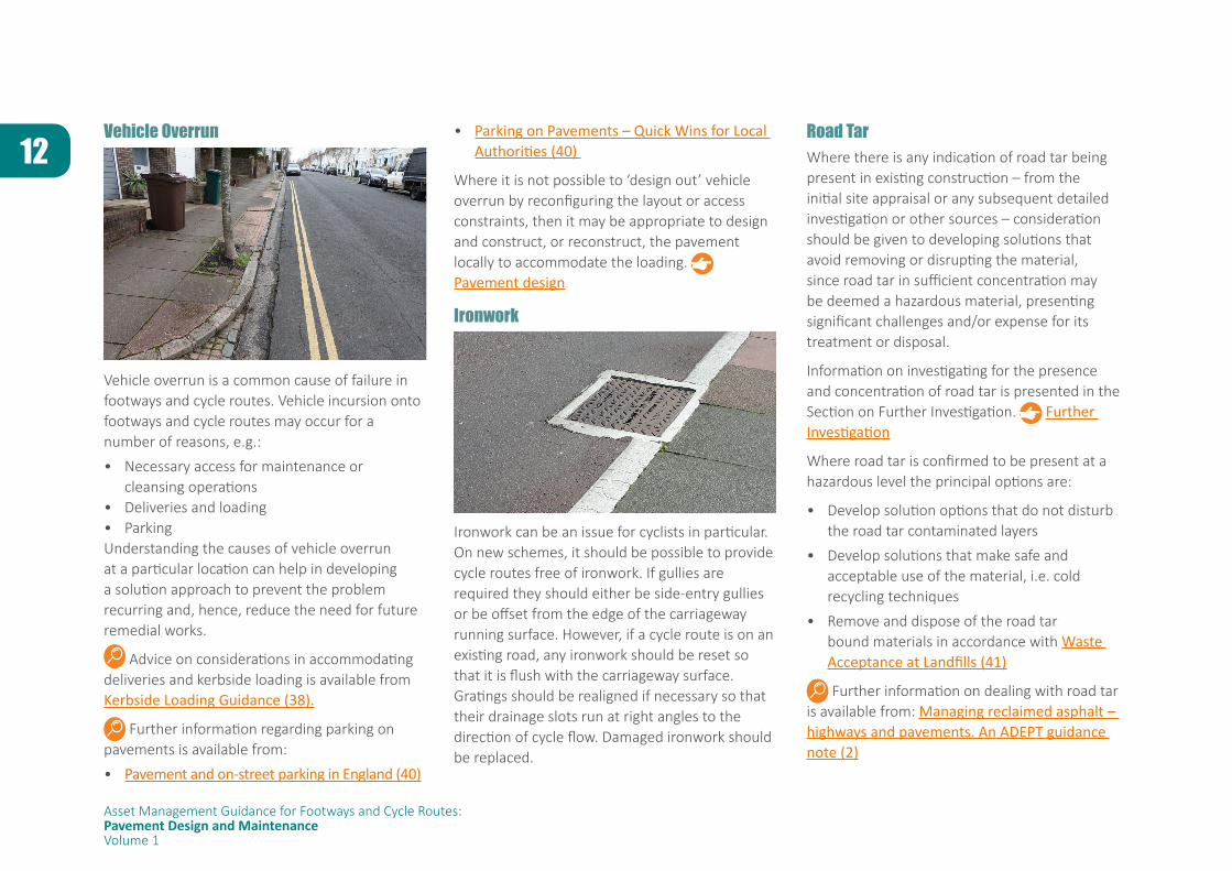
Vehicle Overrun
Vehicle overrun is a common cause of failure in footways and cycle routes. Vehicle incursion onto footways and cycle routes may occur for a number of reasons, e.g.:
• Necessary access for maintenance or cleansing operations
• Deliveries and loading• ParkingUnderstanding the causes of vehicle overrun at a particular location can help in developing a solution approach to prevent the problem recurring and, hence, reduce the need for future remedial works.
Advice on considerations in accommodating deliveries and kerbside loading is available from Kerbside Loading Guidance (38).
Further information regarding parking on pavements is available from:
• Pavement and on-street parking in England (40)
• Parking on Pavements – Quick Wins for Local Authorities (40)
Where it is not possible to ‘design out’ vehicle overrun by reconfiguring the layout or access constraints, then it may be appropriate to design and construct, or reconstruct, the pavement locally to accommodate the loading. Pavement design
Ironwork
Ironwork can be an issue for cyclists in particular. On new schemes, it should be possible to provide cycle routes free of ironwork. If gullies are required they should either be side-entry gullies or be offset from the edge of the carriageway running surface. However, if a cycle route is on an existing road, any ironwork should be reset so that it is flush with the carriageway surface. Gratings should be realigned if necessary so that their drainage slots run at right angles to the direction of cycle flow. Damaged ironwork should be replaced.
Road TarWhere there is any indication of road tar being present in existing construction – from the initial site appraisal or any subsequent detailed investigation or other sources – consideration should be given to developing solutions that avoid removing or disrupting the material, since road tar in sufficient concentration may be deemed a hazardous material, presenting significant challenges and/or expense for its treatment or disposal.
Information on investigating for the presence and concentration of road tar is presented in the Section on Further Investigation. Further Investigation
Where road tar is confirmed to be present at a hazardous level the principal options are:
• Develop solution options that do not disturb the road tar contaminated layers
• Develop solutions that make safe and acceptable use of the material, i.e. cold recycling techniques
• Remove and dispose of the road tar bound materials in accordance with Waste Acceptance at Landfills (41)
Further information on dealing with road tar is available from: Managing reclaimed asphalt – highways and pavements. An ADEPT guidance note (2)
13
Asset Management Guidance for Footways and Cycle Routes:Pavement Design and MaintenanceVolume 1
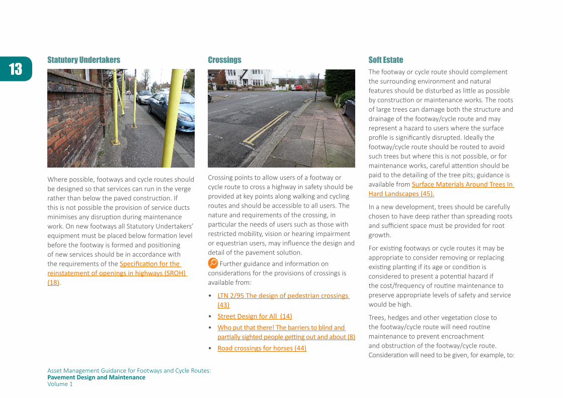
Statutory Undertakers
Where possible, footways and cycle routes should be designed so that services can run in the verge rather than below the paved construction. If this is not possible the provision of service ducts minimises any disruption during maintenance work. On new footways all Statutory Undertakers’ equipment must be placed below formation level before the footway is formed and positioning of new services should be in accordance with the requirements of the Specification for the reinstatement of openings in highways (SROH) (18).
Crossings
Crossing points to allow users of a footway or cycle route to cross a highway in safety should be provided at key points along walking and cycling routes and should be accessible to all users. The nature and requirements of the crossing, in particular the needs of users such as those with restricted mobility, vision or hearing impairment or equestrian users, may influence the design and detail of the pavement solution.
Further guidance and information on considerations for the provisions of crossings is available from:
• LTN 2/95 The design of pedestrian crossings (43)
• Street Design for All (14) • Who put that there! The barriers to blind and
partially sighted people getting out and about (8)• Road crossings for horses (44)
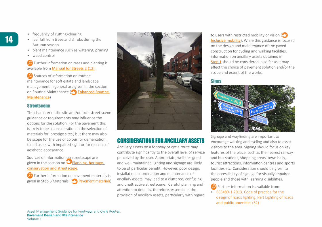
Soft Estate The footway or cycle route should complement the surrounding environment and natural features should be disturbed as little as possible by construction or maintenance works. The roots of large trees can damage both the structure and drainage of the footway/cycle route and may represent a hazard to users where the surface profile is significantly disrupted. Ideally the footway/cycle route should be routed to avoid such trees but where this is not possible, or for maintenance works, careful attention should be paid to the detailing of the tree pits; guidance is available from Surface Materials Around Trees In Hard Landscapes (45).
In a new development, trees should be carefully chosen to have deep rather than spreading roots and sufficient space must be provided for root growth.
For existing footways or cycle routes it may be appropriate to consider removing or replacing existing planting if its age or condition is considered to present a potential hazard if the cost/frequency of routine maintenance to preserve appropriate levels of safety and service would be high.
Trees, hedges and other vegetation close to the footway/cycle route will need routine maintenance to prevent encroachment and obstruction of the footway/cycle route. Consideration will need to be given, for example, to:
14
Asset Management Guidance for Footways and Cycle Routes:Pavement Design and MaintenanceVolume 1
• frequency of cutting/clearing• leaf fall from trees and shrubs during the
Autumn season• plant maintenance such as watering, pruning• weed control
Further information on trees and planting is available from Manual for Streets 2 (12).
Sources of information on routine maintenance for soft estate and landscape management in general are given in the section on Routine Maintenance ( Enhanced Routine Maintenance)
StreetsceneThe character of the site and/or local street-scene guidance or requirements may influence the options for the solution. For the pavement this is likely to be a consideration in the selection of materials for ‘prestige sites’, but there may also be scope for the use of colour for demarcation, to aid users with impaired sight or for reasons of aesthetic appearance.
Sources of information on streetscape are given in the section on Planning, heritage, conservation and streetscape.
Further information on pavement materials is given in Step 3 Materials. ( Pavement materials)
CONSIDERATIONS FOR ANCILLARY ASSETSAncillary assets on a footway or cycle route may contribute significantly to the overall level of service perceived by the user. Appropriate, well-designed and well-maintained lighting and signage are likely to be of particular benefit. However, poor design, installation, coordination and maintenance of ancillary assets, may lead to a cluttered, confusing and unattractive streetscene. Careful planning and attention to detail is, therefore, essential in the provision of ancillary assets, particularly with regard
to users with restricted mobility or vision ( Inclusive mobility). While this guidance is focused on the design and maintenance of the paved construction for cycling and walking facilities, information on ancillary assets obtained in Step 1 should be considered in so far as it may affect the choice of pavement solution and/or the scope and extent of the works.
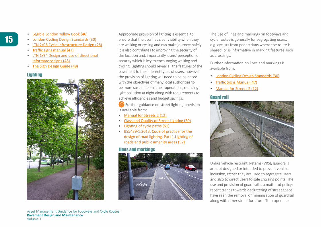
Signs
Signage and wayfinding are important to encourage walking and cycling and also to assist visitors to the area. Signing should focus on key features of the place, such as the nearest railway and bus stations, shopping areas, town halls, tourist attractions, information centres and sports facilities etc. Consideration should be given to the accessibility of signage for visually impaired people and those with learning disabilities.
Further information is available from:• BS5489-1:2013. Code of practice for the
design of roads lighting. Part Lighting of roads and public amenities (52)
15
Asset Management Guidance for Footways and Cycle Routes:Pavement Design and MaintenanceVolume 1
• Legible London Yellow Book (46) • London Cycling Design Standards (30) • LTN 2/08 Cycle Infrastructure Design (28)• Traffic signs manual (47)• LTN 1/94 Design and use of directional
informatory signs (48)• The Sign Design Guide (49)
Lighting
Appropriate provision of lighting is essential to ensure that the user has clear visibility when they are walking or cycling and can make journeys safely. It is also contributes to improving the security of the location and, importantly, users’ perception of security which is key to encouraging walking and cycling. Lighting should reveal all the features of the pavement to the different types of users, however the provision of lighting will need to be balanced with the objectives of many local authorities to be more sustainable in their operations, reducing light pollution at night along with requirements to achieve efficiencies and budget savings.
Further guidance on street lighting provision is available from: • Manual for Streets 2 (12)• Class and Quality of Street Lighting (50)• Lighting of cycle paths (51)• BS5489-1:2013. Code of practice for the
design of road lighting. Part 1.Lighting of roads and public amenity areas (52)
Lines and markings
The use of lines and markings on footways and cycle routes is generally for segregating users, e.g. cyclists from pedestrians where the route is shared, or is informative in marking features such as crossings.
Further information on lines and markings is available from:
• London Cycling Design Standards (30)• Traffic Signs Manual (47)• Manual for Streets 2 (12)
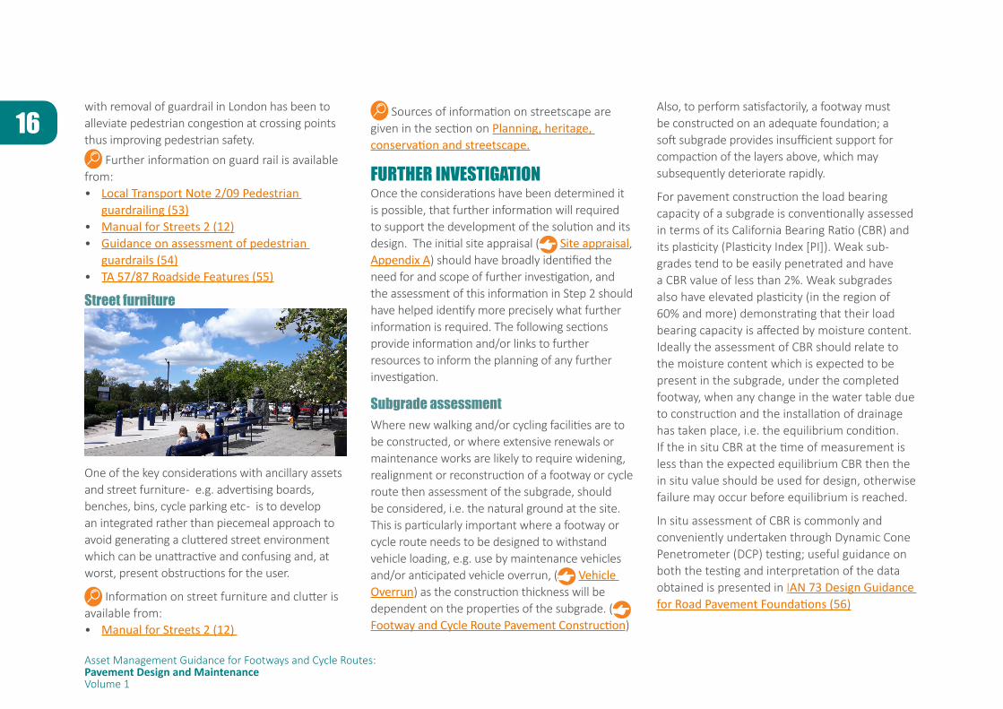
Guard rail
Unlike vehicle restraint systems (VRS), guardrails are not designed or intended to prevent vehicle incursion, rather they are used to segregate users and also to direct users to safe crossing points. The use and provision of guardrail is a matter of policy; recent trends towards decluttering of street space have seen the removal or minimisation of guardrail along with other street furniture. The experience
16
Asset Management Guidance for Footways and Cycle Routes:Pavement Design and MaintenanceVolume 1
with removal of guardrail in London has been to alleviate pedestrian congestion at crossing points thus improving pedestrian safety.
Further information on guard rail is available from:• Local Transport Note 2/09 Pedestrian
guardrailing (53)• Manual for Streets 2 (12) • Guidance on assessment of pedestrian
guardrails (54)• TA 57/87 Roadside Features (55)
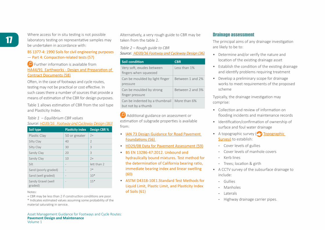
Street furniture
One of the key considerations with ancillary assets and street furniture - e.g. advertising boards, benches, bins, cycle parking etc - is to develop an integrated rather than piecemeal approach to avoid generating a cluttered street environment which can be unattractive and confusing and, at worst, present obstructions for the user.
Information on street furniture and clutter is available from:• Manual for Streets 2 (12)
Sources of information on streetscape are given in the section on Planning, heritage, conservation and streetscape.
FURTHER INVESTIGATIONOnce the considerations have been determined it is possible, that further information will required to support the development of the solution and its design. The initial site appraisal ( Site appraisal, Appendix A) should have broadly identified the need for and scope of further investigation, and the assessment of this information in Step 2 should have helped identify more precisely what further information is required. The following sections provide information and/or links to further resources to inform the planning of any further investigation.
Subgrade assessment Where new walking and/or cycling facilities are to be constructed, or where extensive renewals or maintenance works are likely to require widening, realignment or reconstruction of a footway or cycle route then assessment of the subgrade, should be considered, i.e. the natural ground at the site. This is particularly important where a footway or cycle route needs to be designed to withstand vehicle loading, e.g. use by maintenance vehicles and/or anticipated vehicle overrun, ( Vehicle Overrun) as the construction thickness will be dependent on the properties of the subgrade. ( Footway and Cycle Route Pavement Construction)
Also, to perform satisfactorily, a footway must be constructed on an adequate foundation; a soft subgrade provides insufficient support for compaction of the layers above, which may subsequently deteriorate rapidly.
For pavement construction the load bearing capacity of a subgrade is conventionally assessed in terms of its California Bearing Ratio (CBR) and its plasticity (Plasticity Index [PI]). Weak sub-grades tend to be easily penetrated and have a CBR value of less than 2%. Weak subgrades also have elevated plasticity (in the region of 60% and more) demonstrating that their load bearing capacity is affected by moisture content. Ideally the assessment of CBR should relate to the moisture content which is expected to be present in the subgrade, under the completed footway, when any change in the water table due to construction and the installation of drainage has taken place, i.e. the equilibrium condition. If the in situ CBR at the time of measurement is less than the expected equilibrium CBR then the in situ value should be used for design, otherwise failure may occur before equilibrium is reached.
In situ assessment of CBR is commonly and conveniently undertaken through Dynamic Cone Penetrometer (DCP) testing; useful guidance on both the testing and interpretation of the data obtained is presented in IAN 73 Design Guidance for Road Pavement Foundations (56)
17
Asset Management Guidance for Footways and Cycle Routes:Pavement Design and MaintenanceVolume 1
Where access for in situ testing is not possible laboratory testing on representative samples may be undertaken in accordance with:
BS 1377-4: 1990 Soils for civil engineering purposes — Part 4: Compaction-related tests (57)
Further information is available from HA44/91 Earthworks - Design and Preparation of Contract Documents (58) Often, in the case of footways and cycle routes, testing may not be practical or cost effective. In such cases there a number of sources that provide a means of estimation of the CBR for design purposes.
Table 1 allows estimation of CBR from the soil type and Plasticity Index.
Table 1 – Equilibrium CBR valuesSource: HD39/16 Footway and Cycleway Design (36)l
Soil type Plasticity index Design CBR %Plastic Clay 50 or greater 2+
Silty Clay 40 2
Silty Clay 30 3
Sandy Clay 20 3
Sandy Clay 10 2+
Silt - lett than 2
Sand (poorly graded) - 7*
Sand (well graded) - 10*
Sandy Gravel (well graded)
- 15*
Notes: + CBR may be less than 2 if construction conditions are poor.* Indicates estimated values assuming some probability of the material saturating in service.
Alternatively, a very rough guide to CBR may be taken from the table 2.
Table 2 – Rough guide to CBRSource: HD39/16 Footway and Cycleway Design (36)
Soil condition CBRVery soft, exudes between fingers when squeezed
Less than 1%
Can be moulded by light finger pressure
Between 1 and 2%
Can be moulded by strong finger pressure
Between 2 and 3%
Can be indented by a thumbnail but not by a thumb
More than 6%
Additional guidance on assessment or estimation of subgrade properties is available from:
• IAN 73 Design Guidance for Road Pavement Foundations (56)
• HD29/08 Data for Pavement Assessment (59) • BS EN 13286-47:2012. Unbound and
hydraulically bound mixtures. Test method for the determination of California bearing ratio, immediate bearing index and linear swelling (60)
• ASTM D4318-10E1.Standard Test Methods for Liquid Limit, Plastic Limit, and Plasticity Index of Soils (61)
Drainage assessmentThe principal aims of any drainage investigation are likely to be to:
• Determine and/or verify the nature and location of the existing drainage asset
• Establish the condition of the existing drainage and identify problems requiring treatment
• Develop a preliminary scope for drainage works to meet requirements of the proposed scheme
Typically, the drainage investigation may comprise:
• Collection and review of information on flooding incidents and maintenance records
• Identification/confirmation of ownership of surface and foul water drainage
• A topographic survey ( Topographic Survey) to establish:
- Cover levels of gullies - Cover levels of manhole covers - Kerb lines - Trees; location & girth
• A CCTV survey of the subsurface drainage to include:
- Gullies - Manholes - Laterals - Highway drainage carrier pipes.
18
Asset Management Guidance for Footways and Cycle Routes:Pavement Design and MaintenanceVolume 1
A sample brief for a drainage investigation is presented in Appendix B. ( Appendix B)
Further information on assessment of existing drainage assets is available from IAN 147/12 Drainage surveys and data (62).
Where new walking or cycling facilities are being constructed, or significant renewals or maintenance works being undertaken, it may be appropriate to undertake an assessment of likely flows to be accommodated and/or flood risk to inform the design of a new or enhanced drainage system to support the long term serviceability and performance of the footway or cycle route.
Information on assessment of drainage requirements is available from:
• Rainfall runoff management for developments (63)
• Designing for exceedance in urban areas – good practice (64)
• Managing urban flooding from heavy rainfall (65)
• Greenfield runoff rate estimation (66)
General information on drainage design is available from:
• HD 49/16 Highway drainage design principle requirements (67)
• HD33/16 Design of highway drainage systems (68)
Topographic surveyThe principal aims of a topographic survey are to:
• Establish the geometry of the existing site:
- horizontal carriageway/footway/cycle route alignment
- vertical carriageway/footway/cycle route alignment
• Identify and record pavement construction in the carriageway/footway/cycle route
• Identify and record drainage runs and falls
• Identify and record principal highway assets e.g.
- lighting
- signs & bollards (illuminated & non-illuminated)
- vehicle restraint systems
• Identify and record highway features
A sample brief for a topographic survey is presented in Appendix C. ( Appendix C)
Further information is available from The Survey Association
Condition assessment of existing footway or cycle route pavementVisual SurveyIn the majority of cases the sole or principal means of assessing condition of the existing footway/cycle route pavement will be a visual
survey. The purpose of the visual survey is to:
• Identify existing construction type(s) & materials
• identify pavement features and defects
and, hence, assist in both diagnosing the causes of pavement distress and developing appropriate design and treatment solutions.
Guidance on visual surveys is available from Overview of Visual Data Collection (73)
Information on existing visual surveys is available from:
• Coarse Visual Inspection (CVI) (74) • Detailed Visual Inspection (DVI) (75) • Footway Network Survey (FNS) (76)• Walking Route Audit Tool (77)
Testing and analysis of pavement materialsOn occasion, perhaps for major upgrade works, it may be appropriate to carry out more detailed investigation and analysis of the existing construction and materials. Some of the available techniques and their application are listed in Table 3.
19
Asset Management Guidance for Footways and Cycle Routes:Pavement Design and MaintenanceVolume 1
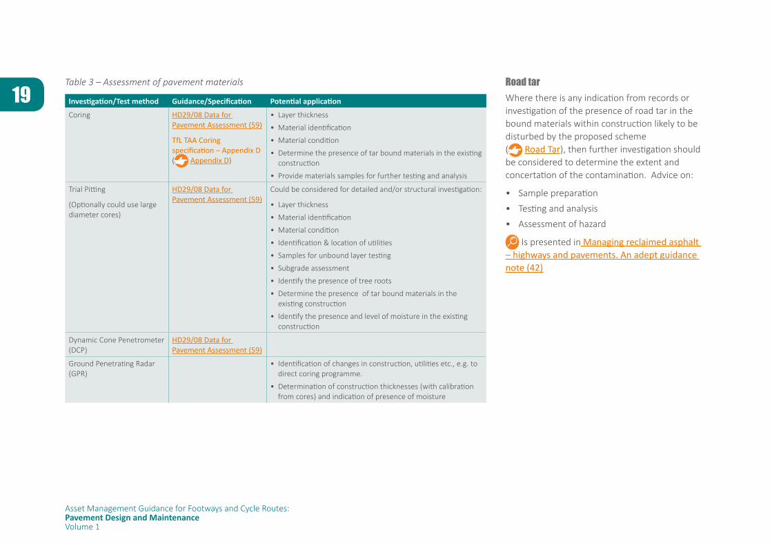
Table 3 – Assessment of pavement materials
Investigation/Test method Guidance/Specification Potential application
Coring HD29/08 Data for Pavement Assessment (59)
TfL TAA Coring specification – Appendix D ( Appendix D)
• Layer thickness
• Material identification
• Material condition
• Determine the presence of tar bound materials in the existing construction
• Provide materials samples for further testing and analysis
Trial Pitting
(Optionally could use large diameter cores)
HD29/08 Data for Pavement Assessment (59)
Could be considered for detailed and/or structural investigation:
• Layer thickness
• Material identification
• Material condition
• Identification & location of utilities
• Samples for unbound layer testing
• Subgrade assessment
• Identify the presence of tree roots
• Determine the presence of tar bound materials in the existing construction
• Identify the presence and level of moisture in the existing construction
Dynamic Cone Penetrometer (DCP)
HD29/08 Data for Pavement Assessment (59)
Ground Penetrating Radar (GPR)
• Identification of changes in construction, utilities etc., e.g. to direct coring programme.
• Determination of construction thicknesses (with calibration from cores) and indication of presence of moisture
Road tar Where there is any indication from records or investigation of the presence of road tar in the bound materials within construction likely to be disturbed by the proposed scheme ( Road Tar), then further investigation should be considered to determine the extent and concertation of the contamination. Advice on:
• Sample preparation
• Testing and analysis
• Assessment of hazard
Is presented in Managing reclaimed asphalt – highways and pavements. An adept guidance note (42)
20
Asset Management Guidance for Footways and Cycle Routes:Pavement Design and MaintenanceVolume 1
STEP 3: DEVELOP
Step 3 – Develop: This step is to take the design parameters that have been established in Step 2 and to develop a solution that is appropriate for the circumstances and requirements of the particular site, e.g. what form of construction should be adopted to suit the anticipated users, what form of treatment would restore serviceability most cost effectively. There may be other factors that influence the design such as different stakeholder requirements, or architectural requirements for particular materials. This stage is, therefore, about the development of the ideas, ensuring that the construction and material selection is appropriate to meet the needs of the community and provides a solution that is safe, sustainable, environmentally sound and value for money over the whole life of the asset.
Overall in developing appropriate solutions it is important to consider both the principle and detail of the approach to:
• ensure that that the solution addresses the original drivers that led to the identification of need
• determine whether there is opportunity or requirement to address legislative/statutory obligations and/or the organisation’s policy objectives in the design and delivery of the scheme
• provide appropriate levels of service for all users
• assess both initial affordability and also whole life cost over the lifecycle of the pavement
• assess future maintenance requirements, e.g. frequency, cost, ease of intervention, disruption,
• manage the impact on the existing environment and natural features
21
Asset Management Guidance for Footways and Cycle Routes:Pavement Design and MaintenanceVolume 1
The basic principle of the proposed pavement works will have been largely established from the information obtained in Step 1 and its assessment in Step 2.
The following sections provide further information on:
• Forms of construction
• Design
• Materials
• Maintenance treatments and operations
FOOTWAY AND CYCLE ROUTE PAVEMENT CONSTRUCTIONForms of pavement constructionThere are a various options for the general form of construction and constituent materials for footway and cycle route pavements which, for the purposes of this guidance, are categorized as follows:
MonolithicA monolithic pavement is a pavement made up of constituent materials that bind together to form a single, coherent material. Examples of monolithic materials include concrete, asphalt or thermoplastic materials.
ElementalAn elemental pavement is a pavement made up of individual units placed adjacent to each other. Examples of elemental pavements include blocks, setts and flags.
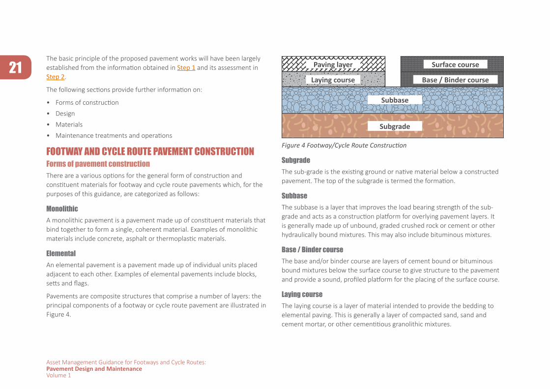
Pavements are composite structures that comprise a number of layers: the principal components of a footway or cycle route pavement are illustrated in Figure 4.
Subgrade
Subbase
Laying course
Paving layer Surface course
Base / Binder course
Figure 4 Footway/Cycle Route Construction
SubgradeThe sub-grade is the existing ground or native material below a constructed pavement. The top of the subgrade is termed the formation.
SubbaseThe subbase is a layer that improves the load bearing strength of the sub-grade and acts as a construction platform for overlying pavement layers. It is generally made up of unbound, graded crushed rock or cement or other hydraulically bound mixtures. This may also include bituminous mixtures.
Base / Binder courseThe base and/or binder course are layers of cement bound or bituminous bound mixtures below the surface course to give structure to the pavement and provide a sound, profiled platform for the placing of the surface course.
Laying courseThe laying course is a layer of material intended to provide the bedding to elemental paving. This is generally a layer of compacted sand, sand and cement mortar, or other cementitious granolithic mixtures.
22
Asset Management Guidance for Footways and Cycle Routes:Pavement Design and MaintenanceVolume 1
Surface courseSurface course is the surface layer of a monolithic pavement. It is generally a smooth, slightly textured bituminous or thermoplastic material intended to provide comfort and slip resistance.
Paving layerThe paving layer is the surface layer of an elemental pavement. This comprises modules, i.e.
• Concrete / stone flags,
• Concrete / stone blocks,
• Clay pavers or
• Stone setts
made from concrete, clay or natural stone.
PAVEMENT DESIGNThickness designThe function of the pavement is to provide a structure that protects the underlying natural ground, or subgrade, from both the environment and the loads applied in usage of the footway and/or cycle route, while maintaining a form and profile that provides users with a safe and comfortable surface. For value and efficiency this should be achieved without need for frequent and/or significant repair, so the use of a rational design approach for the dimensioning of the pavement layers, in conjunction with careful selection and specification of materials, is advised.
Design methodologies for the thickness design of footway and cycle route pavements are available from.
• HD39/16 Footway and cycleway design (36) • Construction and surfacing of footways and
cycleways using asphalt (78)• Application Guide AG26 (Version 2). Footway
and Cycle Route Design Construction and Maintenance Guide (2)
• BS7533 Pavements constructed with clay, natural stone or concrete pavers - Part 1: Guide for the structural design of
heavy duty pavements constructed of clay pavers or precast concrete paving blocks (79)
- Part 2: Guide for the structural design of lightly trafficked pavements constructed of clay pavers or precast concrete paving blocks (80)
- Part 8: Guide for the structural design of lightly trafficked pavements of precast concrete flags and natural stone flags (81)
- Part 10: Guide for the structural design of trafficked pavements constructed of natural stone setts and bound construction with concrete paving blocks (82)
- Part 12: Guide to the structural design of trafficked pavements constructed on a bound base using concrete paving flags and natural stone slabs (83)
- Part 13: Guide for the design of permeable pavements constructed with concrete paving blocks and flags, natural stone slabs and setts and clay pavers (84)
Guidance on typical footway and cycle route construction is available from:
• Traffic free routes: detailed design (85) • Cycling by design (29) In practice the loads presented by pedestrians and/or cyclists are minimal in comparison with vehicular traffic and the role of the pavement structure is largely to maintain a safe and durable surface and to protect the subgrade from the environmental effects of, in particular, water and frost. Where any vehicular use is anticipated, such as for:
• Access• Loading• Use by maintenance and/or cleansing vehicles• Localised vehicle overrun
then attention must be paid to the design of the structure to accommodate this loading.
Rational design methodologies for pavement thickness design are generally based on consideration of:
• The properties of the existing subgrade
• Assessment of the anticipated loading
• Protection of frost susceptible materials
• Choice of the form of construction and materials
23
Asset Management Guidance for Footways and Cycle Routes:Pavement Design and MaintenanceVolume 1
Given the light nature of the loading on many footways and cycle routes, with consequent minimal requirement for a load bearing structure, a key consideration in the design can be the provision of an appropriate depth of non-frost susceptible materials to protect the underlying subgrade from the effects of frost penetration. Frost damage occurs in very cold conditions where water, that has either seeped into the pavement or is present due to a high water table, freezes and expands causing the pavement to heave. In the UK it is recommended that no frost susceptible material should be within 450 mm of the pavement surface unless the regional frost index is less than 50, in which case the depth can be reduced to 350mm. Where the natural subgrade is frost susceptible this minimum thickness requirement is usually addressed through the provision of an appropriate thickness of non-frost susceptible subbase in combination with the bound construction layers.
Footways and cycle routes not subject to vehicle loading are generally low risk applications in terms of pavement materials and performance. It may be, therefore, that where the likelihood and/or consequence of frost heave are deemed to be low the option of reducing this minimum thickness and/or utilising lower specification materials could be considered if these offer benefits in terms of cost or sustainability.
Advice on the frost index can be obtained from meteorological advisory services.
Edge detailsThe detailing of the edge of a footway or cycle route is important to ensure both provision of adequate lateral restraint to the pavement construction and proper functioning of the drainage ( Drainage, Drainage assessment).
Further information on edge details is available from:
• HA39/98 Edge of pavement details (86) • Application Guide AG26 (Version 2). Footway
and Cycle Route Design Construction and Maintenance Guide (2)
• Cycling by design
PAVEMENT MATERIALSFactors for consideration when selecting the materials for construction or maintenance of a footway or cycle route include:
• Safety; typically slip/skid resistance
• Structural adequacy; ability to support the anticipated loading and use
• Lifecycle performance:
- Initial cost
- Expected service life
- Maintenance requirements, frequency and costs
• Appropriateness for the local environment; style, character, colour
• Sustainability; sourcing, availability, transportation and placing of materials
The following sections provide guidance on typical footway and cycle route materials.
Subgrade( Further Investigation).
The subgrade of a pavement is the native material of the location, upon which the pavement construction is founded. Hence the top of the subgrade, termed the formation, is the level from which the pavement construction is built up. As the role of the pavement is both to enable the subgrade to support the anticipated loading and to protect it from environmental effects, the properties of the subgrade govern the pavement construction that is required. ( Subgrade assessment).
For new construction the existing ground will require:
• Removal of the top layer (topsoil) in order to reduce the organic content in the sub-grade which will decay and create voids, compromising its strength. An acceptable subgrade must be free of organic material, soft spots and it must be parallel to the plane of construction.
24
Asset Management Guidance for Footways and Cycle Routes:Pavement Design and MaintenanceVolume 1
• The subgrade will also be required to be trimmed or filled to the required level to accommodate the finished levels of the new pavement.
The existing subgrade may need to be improved by the use of a capping layer which essentially reduces the susceptibility of moisture of the subgrade and enhances its CBR. Capping layers are selected fill material, often comprising compacted crushed rock, as specified in Table 6/1 of Volume 1 of Series 600 of the Manual for Contracts for Highway Works (MCHW; Volume 1; Series 600; Table 6/1) (87). Capping layers should only be considered in areas of very high load and are generally not needed for footways and cycleways.
Subbase The subbase acts as a key structural layer for transferring applied loading to the subgrade in the completed pavement and also as a construction platform for the placing and compaction of the overlying layers. There are two principal types of subbase:
• Unbound granular material
• Cement or hydraulically bound material
Bitumen, typically in the form bitumen emulsion, may also be used to produce a bound subbase.
Unbound subbaseUnbound subbase in the UK can be classified as one of 5 types. These materials most commonly compromise of crushed stone, crushed slag or, crushed concrete.
• Type 1, Type 4 and Category B
A well graded material produced from aggregate complying to BS EN 13242:2013 Aggregates for unbound and hydraulically bound materials for use in civil engineering work and road construction (88) which provides, inter alia, specification of requirements for
- particle shape
- resistance to fragmentation
- resistance to freeze / thaw deterioration
The aggregate grading has a nominal maximum size of 32mm. Type 1 allows for 25% oversize to a limit of 63mm and must have a fines content of less than 9%. The material is designed to enhance aggregate interlocking and therefore create a relatively high stiffness material without the need for binding (with bitumen or cement). If the material has more than 50% asphalt arisings then the material is described as Type 4. Category B material is effectively a Type 1 with a more defined grading allowing for only 20% oversize.
• Type 2
A material similar to Type 1 but with a less tightly controlled grading, which generally leads to a finer material than Type 1. The degree of aggregate interlock tends to be lower than Type 1 due to the wider range on grading limits, and as a result Type 2 generally has a lower stiffness than Type 1.
• Type 3
A gap graded material with fines below 5% allowing for voiding to be created within the mixture. It is used for Sustainable Urban Drainage Systems (SuDS) ( SuDS) as it allows water percolation into the sub-grade. Due to its open skeleton it tends to not be suitable to sustain heavy loads.
Compaction of unbound sub-base materials is dependent on optimum moisture content.
Specifications for these subbase materials are available from:
• Specification for Highway Works. Series 800 (Clauses 803-806) (89)
• BS EN 13285: 2010. Unbound mixtures. Specifications (90)
Further information is available from:
• Notes for Guidance on the Specification for Highway Works. Series 800 (Clauses NG803-806 ) (91)
25
Asset Management Guidance for Footways and Cycle Routes:Pavement Design and MaintenanceVolume 1
Hydraulically bound subbaseHydraulically Bound Materials (HBMs) are soils or aggregates that have a binder such as cement, lime-based binders, gypsum or fly ash added, which then cure through hydration when mixed with water.
Due to the relatively quick curing time of cement, most HBMs used in carriageway, footway or cycle route construction are made using aggregates, often recycled, and cement to produce a Cement Bound Granular Material (CBGM). Depending on the cement content used, CBGMs have equivalent or greater strength than a traditional unbound subbase with a consequent potential for overall thickness reduction. This, together with the facility to make use of recycled and/or secondary materials – particularly for the lower risk applications presented by the majority of footway and cycle route construction - can present both a cost effective and sustainable option for the subbase or base.
For slower curing HBM appropriate measures must be taken to prevent damage by trafficking and/or weather while exposed during construction.
Further guidance is provided in:
• Specification for Highway Works. Series 800 (Clause 813) (89)
• Notes for Guidance on the Specification for Highway Works. Series 800 (Clause NG813) (91)
Specifications for hydraulically bound materials are available from:
• Specification for Highway Works. Series 800 (Clauses 821 - 840) (89)
• BS EN 14227 (Parts 1-5) Hydraulically Bound Mixtures. Specifications. (92)
Lean mix concretes can also be used as sub-base and should:
• be designed in line with BS 8500:2-2015 “Concrete – Complementary British Standard to BS EN 206 Part 2: Specification for constituent materials and concrete” (93)
• and have a slump class of S1 as specified in BS8500:1-2015 – “Concrete – Complementary British Standard to BS EN 206 Part 1: Method of specifying and guidance for the specifier” (94)
The loading on footways and cycle routes that are not subject to overrun or occasional vehicle use is very light. This offers the opportunity to adopt lower specification materials, particularly in the underlying layers of the construction such as the subbase, with commensurately low risk of failure. This can lead to benefits in terms of reduced cost and also sustainability and environmental impact where local and/or recycled materials can be utilised.
Further information on the use of recycled and secondary materials is available from:
• Quality protocols: converting waste into non-waste products (95)
• Application Guide AG26 (Version 2). Footway and Cycle Route Design Construction and Maintenance Guide (2)
Bitumen bound subbaseBitumen bound subbases are soils and aggregates that have a bituminous binder, typically bitumen or bitumen emulsion, and may be laid as hot mixes or cold mixes. Bituminous materials are further described in the Monolithic pavements section of this document, below.
MONOLITHIC PAVEMENTSAsphalt materialsSurface CourseThe principal functions of the surface course are to provide a safe and comfortable surface for the user and, depending on the environment, contribute to the overall streetscene. Asphalt surfaces are generally the preferred option for cycle routes since, if well designed, specified and constructed, they provide a smooth profile and skid resistant surface. For this reason, asphalt surface courses for cycle routes should be laid by paving machine wherever possible as this enables good surface regularity, and hence ride quality, to be achieved. ( Construction tolerances) Access for paving equipment is, therefore, an important consideration in the solution development and design.
26
Asset Management Guidance for Footways and Cycle Routes:Pavement Design and MaintenanceVolume 1
Suitable asphalt surface course materials for footways and cycle routes include the following which are detailed in the Specification for Highway Works. 900 Series (96)
• 6mm Dense asphalt surface course: AC 6 dense surf to Clause 909
• 10mm Close graded asphalt surface course: AC 10 close surf Clause 912
• Hot Rolled Asphalt surface course: HRA 15/10 F surf to Clause 910
Mastic Asphalts, specified in accordance with BS EN 13108-6:2006 (99) may provide an aesthetically suitable solution for footways and cycle routes in conservation areas.
Base / Binder courseThe base and binder course are structural layers which contribute to the overall strength of the finished pavement and provide a substrate for the placing of the surface course (or the paving layer in elemental pavements). For the majority of footway and cycle route pavements, depending on the pavement design ( Pavement design), a separate base layer will not be required; a single binder course or base/binder course layer will suffice.
A 20mm Dense base/binder course asphalt concrete, as specified in Clause 906 of Specification for Highway Works (94) , is commonly used, for footways or cycle routes construction. This material may also be used as a base below a bound setts paving layer as detailed in BS7533-10: Pavements constructed with clay, natural stone or concrete pavers. Part 10: Guide for the structural design of trafficked pavements constructed of natural stone setts and bound construction with concrete paving blocks (82)
All asphalt materials must be specified in accordance with the relevant parts of BS EN 13108 Bituminous mixtures. Material specifications. Principally these will be:
• BS EN 13108-1:2016. Bituminous mixtures. Material specifications. Part 1. Asphalt Concrete (98)
• BS EN 13108-2:2016 Bituminous mixtures. Material specifications. Part 2. Asphalt Concrete for Very Thin Layers (99)
• BS EN 13108-4:2016 Bituminous mixtures. Material specifications. Part 4. Hot Rolled Asphalt (100)
• BS EN 13108-5:2016 Bituminous mixtures. Material specifications. Part 5. Stone Mastic Asphalt (101)
All asphalt materials should be laid in accordance with BS 594987:2015 Asphalt for roads and other paved areas. Specification for transport, laying, compaction and product-type testing protocols (102)
Guidance on the specification of asphalt surface courses and base/binder courses is available from PD 6691 Guidance on the use of BS EN 13108, Bituminous mixtures. Material specifications (103).
Further information on the range of suitable asphalt surface course and base/binder course materials is available from:
• Construction and surfacing of footways and cycleways using asphalt (78)
• HD39/16 Footway and cycleway design (36)• Cycle path surface options (104)
Surface dressingSurface dressing is a cheap and effective way of sealing the surface, prevent further deterioration to the surface and enhance skid resistance. For footways and cycletracks this may be an ideal way to maintain service levels for rural and remote sections.
27
Asset Management Guidance for Footways and Cycle Routes:Pavement Design and MaintenanceVolume 1
RetreadRetread is a process that recycles in situ materials recovered from damaged footways and cycletracks, maximising use of existing materials and reducing to a minimum the amount of new materials imported onto site. The existing surface is planed off, to a depth of 50-75mm, and scarified. The scarified material is then graded to the required falls and levels, any excess material removed or any additional material required imported. The material is sprayed with emulsion and harrowed to thoroughly mix the emulsion with the stone. This process is repeated and the material is then rolled and compacted.
Slurry seals & micro asphalt Slurry sealing is a cold-mix paving treatment containing specially graded aggregate, asphalt emulsion, water and other additives. It is a cost effective way of sealing and refreshing the surface properties of a footway or cycletrack. It is a manual process with a curing time of generally around 24 hours. For footways and cycletracks this is typically a 6mm treatment.
Microasphalting is a cold-mix expansion of slurry seal with a higher polymer and asphalt residual content, better quality aggregate and fast-setting chemicals. It is a machine process whereby a continuous flow of material is supplied to the spreader box. Microasphalt technology
is improving significantly and in recent times microasphalts suitable for heavy loading are available in the market. For footways and cycletracks this is typically a 15mm treatment.
Foamed mix asphalts The basic principle of foamed asphalt mixes is to expand bitumen by contact with water under carefully controlled conditions, then mix the foamed bitumen with cold, moist aggregates. Foamed bitumen provides a strong binder that enables the use of a wide range of new and recycled aggregates.
Cold mixes, under the right conditions, can be as strong after curing as hot mixes and tend to have very quick curing times. Foamed asphalt mixtures will generally be less expensive than either hot mix or emulsion-based mixtures and cure sufficiently quickly to be open to traffic on the same day as laid.
RecyclingAsphalts used on footways and cycle routes open up the opportunity of recycling. Since the aggregate properties for use on footways and cycle routes are not essential as they are not loaded with heavy vehicles that abrade and degrade the aggregate; therefore the recycling opportunities are maximised.
Hot mix asphalt recyclingThis is the process by which asphalt planings are incorporated into a new hot mix material. BS EN 13108-8:2016. Bituminous mixtures. Material specifications. Reclaimed asphalt (105) states that the level of homogeneity of the material in practice determines the maximum amount of reclaimed asphalt that may be used. This opens up opportunities to use increased amounts of recycled asphalt planings (RAP) particularly for applications which do not require high levels of structural pperformance, which is often the case for footways and cycle routes
Further information on hot mix recycling is available from Asphalt the 100% recyclable construction product (106).
Imprinted thermoplasticsImprinted thermoplastics provide a robust coloured surfacing at relatively low cost and relatively easy to maintain. The process is to use hot thermoplastic paint and imprinting a pattern into the surface of the thermoplastic. This gives an artificial look of block or flag paving without the aggravation of reconstructing asphalt roads. It is also relatively easy to maintain since thermoplastic can be fixed by cutting, re-heating and relaying albeit it may suffer from discolouring and may not exactly match the repair in tone and intensity.
28
Asset Management Guidance for Footways and Cycle Routes:Pavement Design and MaintenanceVolume 1
ELEMENTAL PAVEMENTSLaying courseThere are two types of laying courses; bound and unbound. The bound materials are generally hydraulically bound fine aggregates, such as cement bound sand mortars, while the unbound mixtures are loose aggregate, such as sand.
Each of the systems has its own advantages and disadvantages.
Unbound laying courseUnbound laying course is most suitable for use with small element paving – i.e. units smaller than 400mm x 400mm, such as clay pavers, concrete blocks, stone blocks and stone setts – placed on an unbound or bound base or subbase. Generally the material used will comply with grading designation Gf85 0/4 and Gf85 0/6 of BS EN 12620:2013 Aggregates for concrete (107), and typically sharp sands or grits should be used that are free of deleterious salts or contaminants. Other sand products, such as building sand or plastering sand, should not be used since the particles of these materials are rounded and tend to be fine and, hence, they may be susceptible to loss of stiffness and mechanical properties in the presence of moisture, with consequent potential for movement and pumping of the material.
Unbound bedding layers have an unlimited working life meaning that they can be continuously adjusted even after the work is finished. They also tend to be inexpensive.
Bound laying courseBound laying courses are generally cement and sand mixtures. Bound laying courses can be used over a base/subbase and are recommended for use with larger flags and for deeper installations, such as setts. These materials have a limited working time during construction but provide strong and durable bedding to elemental paving. Bound laying courses are generally more expensive than unbound materials, particularly the proprietary bedding mortars.
Sand and cement mortarsThese are relatively weak laying courses and should not be used in areas subject to vehicular traffic. Sand and cement mortars must comply with BS EN 998-2:2016 – Specification for mortar for masonry (108). BS 7533-4: Code of practice for the construction of pavements of precast concrete flags or natural stone slabs (107) requires that the designation of sand cement mortar for use in highways applications should be Class M12 as specified in Table 1 of BS EN 998-2: 2016 Specification for mortar for masonry. Masonry mortar (110). This generally means a sand to cement ratio of 3:1. It is also recommended to add a plasticiser to the mixture to increase its workability in use. Lower proportions of cement to sand content are allowable for lightly used footways and cycle routes. It is not recommended to reduce the sand to cement ratio to less than 6:1 sand:cement.
For construction the material should be supplied to Slump Class S3 , which is between 100mm and 150, as specified in BS8500-1: 2015, Concrete – Complementary British Standard to BS EN 206 Part 1: Method of specifying and guidance for the specifier (111).
Proprietary mortars BS7533 compliant In BS7533 Part 7 “Code of practice for the construction of pavements of natural stone paving units and cobbles (setts), and rigid construction with concrete block paving” (113) the requirement for cement bound laying course is expressed under two options for “fine bedding concrete”) namely; Type A and Type B. Type B is the stronger of the two with a minimum compressive strength of 35MPa and a flexural strength of 4.5MPa. The requirements for Type A are of a compressive strength of 25MPa and a flexural strength of 3.5MPa.
Paving LayerThe paving layer is the surface layer of an elemental pavement. In the UK these are generally clay, natural stone or concrete products; the following sections provide further information on each of these.
Clay products Clay paversClay pavers generally come in 2:1 or 3:1 aspect ratio (length:width) and tend to be marked for use in flexible (ie over an unbound or asphalt
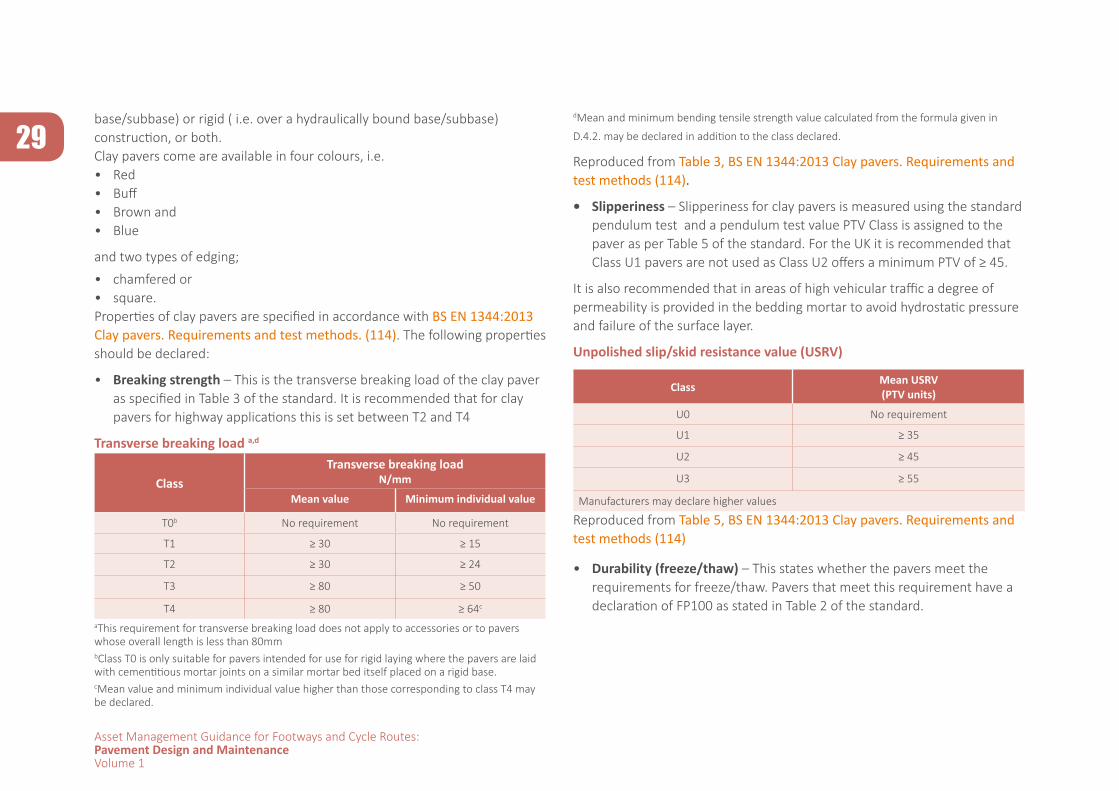
29
Asset Management Guidance for Footways and Cycle Routes:Pavement Design and MaintenanceVolume 1
base/subbase) or rigid ( i.e. over a hydraulically bound base/subbase) construction, or both. Clay pavers come are available in four colours, i.e.• Red• Buff• Brown and• Blue
and two types of edging;
• chamfered or• square.Properties of clay pavers are specified in accordance with BS EN 1344:2013 Clay pavers. Requirements and test methods. (114). The following properties should be declared:
• Breaking strength – This is the transverse breaking load of the clay paver as specified in Table 3 of the standard. It is recommended that for clay pavers for highway applications this is set between T2 and T4
Transverse breaking load a,d
ClassTransverse breaking load
N/mm
Mean value Minimum individual value
T0b No requirement No requirement
T1 ≥ 30 ≥ 15
T2 ≥ 30 ≥ 24
T3 ≥ 80 ≥ 50
T4 ≥ 80 ≥ 64c
aThis requirement for transverse breaking load does not apply to accessories or to pavers whose overall length is less than 80mmbClass T0 is only suitable for pavers intended for use for rigid laying where the pavers are laid with cementitious mortar joints on a similar mortar bed itself placed on a rigid base.cMean value and minimum individual value higher than those corresponding to class T4 may be declared.
dMean and minimum bending tensile strength value calculated from the formula given in
D.4.2. may be declared in addition to the class declared.
Reproduced from Table 3, BS EN 1344:2013 Clay pavers. Requirements and test methods (114).
• Slipperiness – Slipperiness for clay pavers is measured using the standard pendulum test and a pendulum test value PTV Class is assigned to the paver as per Table 5 of the standard. For the UK it is recommended that Class U1 pavers are not used as Class U2 offers a minimum PTV of ≥ 45.
It is also recommended that in areas of high vehicular traffic a degree of permeability is provided in the bedding mortar to avoid hydrostatic pressure and failure of the surface layer.
Unpolished slip/skid resistance value (USRV)
Class Mean USRV(PTV units)
U0 No requirement
U1 ≥ 35
U2 ≥ 45
U3 ≥ 55
Manufacturers may declare higher values
Reproduced from Table 5, BS EN 1344:2013 Clay pavers. Requirements and test methods (114)
• Durability (freeze/thaw) – This states whether the pavers meet the requirements for freeze/thaw. Pavers that meet this requirement have a declaration of FP100 as stated in Table 2 of the standard.
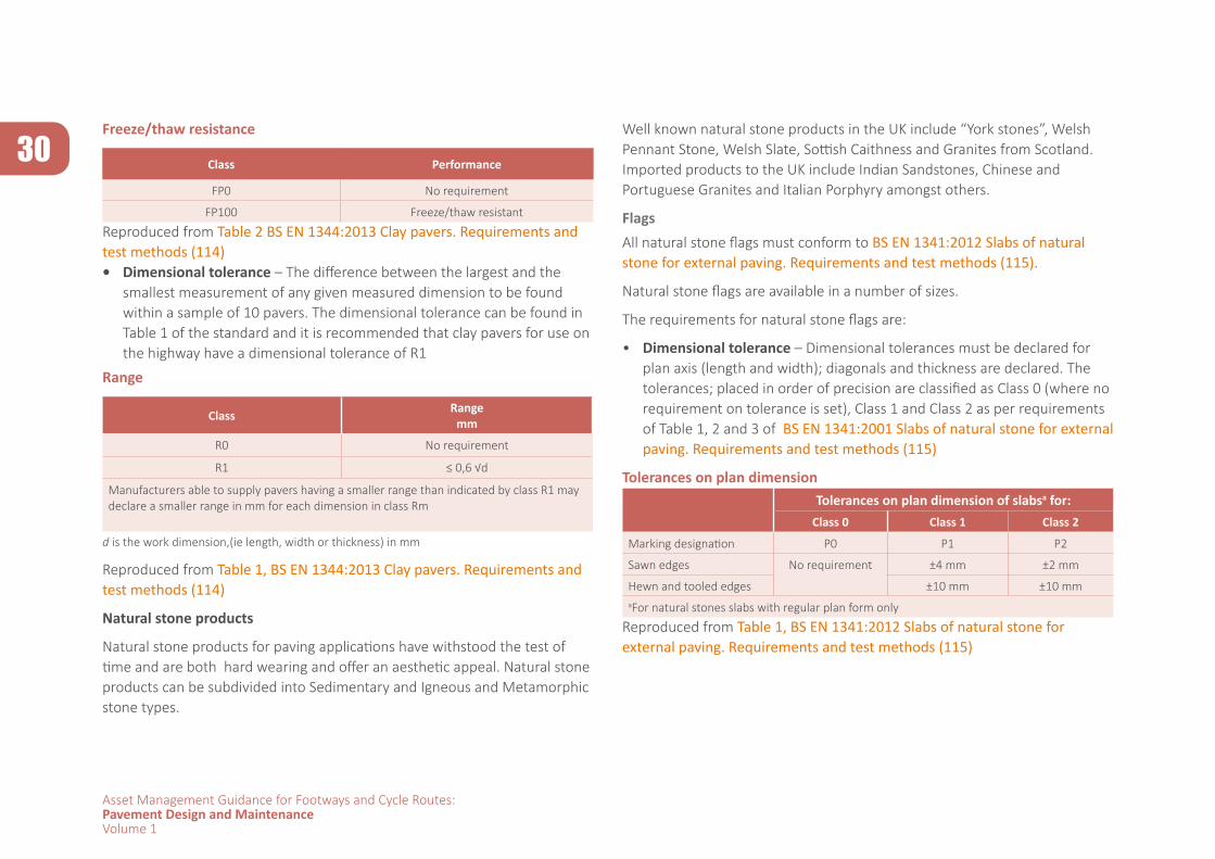
30
Asset Management Guidance for Footways and Cycle Routes:Pavement Design and MaintenanceVolume 1
Freeze/thaw resistance
Class Performance
FP0 No requirement
FP100 Freeze/thaw resistant
Reproduced from Table 2 BS EN 1344:2013 Clay pavers. Requirements and test methods (114)• Dimensional tolerance – The difference between the largest and the
smallest measurement of any given measured dimension to be found within a sample of 10 pavers. The dimensional tolerance can be found in Table 1 of the standard and it is recommended that clay pavers for use on the highway have a dimensional tolerance of R1
Range
Class Rangemm
R0 No requirement
R1 ≤ 0,6 √d
Manufacturers able to supply pavers having a smaller range than indicated by class R1 may declare a smaller range in mm for each dimension in class Rm
d is the work dimension,(ie length, width or thickness) in mm
Reproduced from Table 1, BS EN 1344:2013 Clay pavers. Requirements and test methods (114)
Natural stone products
Natural stone products for paving applications have withstood the test of time and are both hard wearing and offer an aesthetic appeal. Natural stone products can be subdivided into Sedimentary and Igneous and Metamorphic stone types.
Well known natural stone products in the UK include “York stones”, Welsh Pennant Stone, Welsh Slate, Sottish Caithness and Granites from Scotland. Imported products to the UK include Indian Sandstones, Chinese and Portuguese Granites and Italian Porphyry amongst others.
FlagsAll natural stone flags must conform to BS EN 1341:2012 Slabs of natural stone for external paving. Requirements and test methods (115).
Natural stone flags are available in a number of sizes.
The requirements for natural stone flags are:
• Dimensional tolerance – Dimensional tolerances must be declared for plan axis (length and width); diagonals and thickness are declared. The tolerances; placed in order of precision are classified as Class 0 (where no requirement on tolerance is set), Class 1 and Class 2 as per requirements of Table 1, 2 and 3 of BS EN 1341:2001 Slabs of natural stone for external paving. Requirements and test methods (115)
Tolerances on plan dimensionTolerances on plan dimension of slabsa for:
Class 0 Class 1 Class 2
Marking designation P0 P1 P2
Sawn edges No requirement ±4 mm ±2 mm
Hewn and tooled edges ±10 mm ±10 mmaFor natural stones slabs with regular plan form only
Reproduced from Table 1, BS EN 1341:2012 Slabs of natural stone for external paving. Requirements and test methods (115)
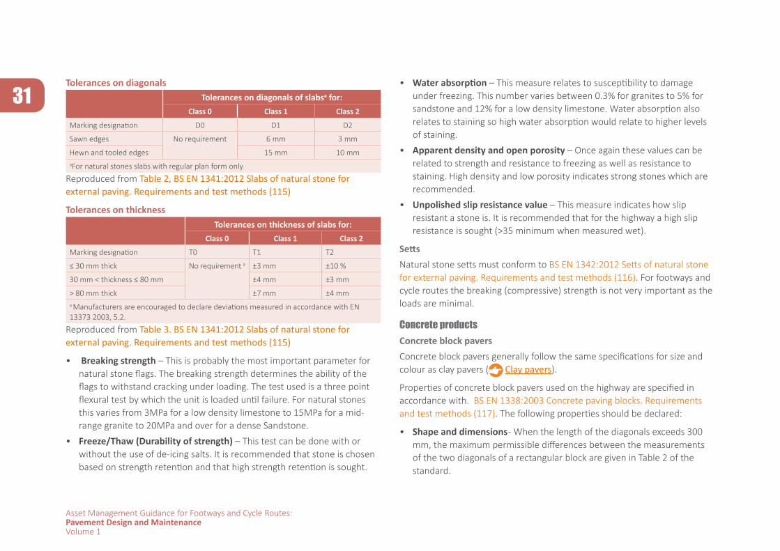
31
Asset Management Guidance for Footways and Cycle Routes:Pavement Design and MaintenanceVolume 1
Tolerances on diagonalsTolerances on diagonals of slabsa for:
Class 0 Class 1 Class 2
Marking designation D0 D1 D2
Sawn edges No requirement 6 mm 3 mm
Hewn and tooled edges 15 mm 10 mmaFor natural stones slabs with regular plan form only
Reproduced from Table 2, BS EN 1341:2012 Slabs of natural stone for external paving. Requirements and test methods (115)
Tolerances on thicknessTolerances on thickness of slabs for:
Class 0 Class 1 Class 2
Marking designation T0 T1 T2
≤ 30 mm thick No requirement a ±3 mm ±10 %
30 mm < thickness ≤ 80 mm ±4 mm ±3 mm
> 80 mm thick ±7 mm ±4 mma Manufacturers are encouraged to declare deviations measured in accordance with EN 13373 2003, 5.2.
Reproduced from Table 3. BS EN 1341:2012 Slabs of natural stone for external paving. Requirements and test methods (115)
• Breaking strength – This is probably the most important parameter for natural stone flags. The breaking strength determines the ability of the flags to withstand cracking under loading. The test used is a three point flexural test by which the unit is loaded until failure. For natural stones this varies from 3MPa for a low density limestone to 15MPa for a mid-range granite to 20MPa and over for a dense Sandstone.
• Freeze/Thaw (Durability of strength) – This test can be done with or without the use of de-icing salts. It is recommended that stone is chosen based on strength retention and that high strength retention is sought.
• Water absorption – This measure relates to susceptibility to damage under freezing. This number varies between 0.3% for granites to 5% for sandstone and 12% for a low density limestone. Water absorption also relates to staining so high water absorption would relate to higher levels of staining.
• Apparent density and open porosity – Once again these values can be related to strength and resistance to freezing as well as resistance to staining. High density and low porosity indicates strong stones which are recommended.
• Unpolished slip resistance value – This measure indicates how slip resistant a stone is. It is recommended that for the highway a high slip resistance is sought (>35 minimum when measured wet).
SettsNatural stone setts must conform to BS EN 1342:2012 Setts of natural stone for external paving. Requirements and test methods (116). For footways and cycle routes the breaking (compressive) strength is not very important as the loads are minimal.
Concrete productsConcrete block paversConcrete block pavers generally follow the same specifications for size and colour as clay pavers ( Clay pavers).
Properties of concrete block pavers used on the highway are specified in accordance with. BS EN 1338:2003 Concrete paving blocks. Requirements and test methods (117). The following properties should be declared:
• Shape and dimensions - When the length of the diagonals exceeds 300 mm, the maximum permissible differences between the measurements of the two diagonals of a rectangular block are given in Table 2 of the standard.
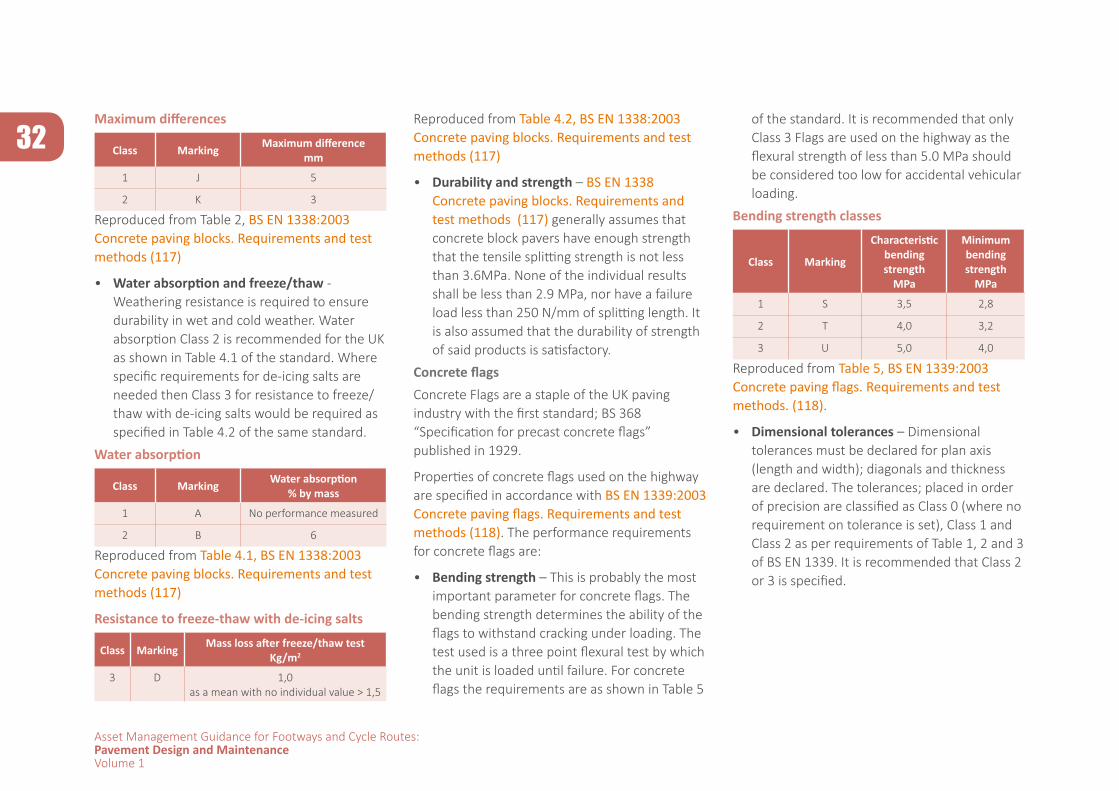
32
Asset Management Guidance for Footways and Cycle Routes:Pavement Design and MaintenanceVolume 1
Maximum differences
Class Marking Maximum differencemm
1 J 5
2 K 3
Reproduced from Table 2, BS EN 1338:2003 Concrete paving blocks. Requirements and test methods (117)
• Water absorption and freeze/thaw - Weathering resistance is required to ensure durability in wet and cold weather. Water absorption Class 2 is recommended for the UK as shown in Table 4.1 of the standard. Where specific requirements for de-icing salts are needed then Class 3 for resistance to freeze/thaw with de-icing salts would be required as specified in Table 4.2 of the same standard.
Water absorption
Class Marking Water absorption% by mass
1 A No performance measured
2 B 6
Reproduced from Table 4.1, BS EN 1338:2003 Concrete paving blocks. Requirements and test methods (117)
Resistance to freeze-thaw with de-icing salts
Class Marking Mass loss after freeze/thaw testKg/m2
3 D 1,0as a mean with no individual value > 1,5
Reproduced from Table 4.2, BS EN 1338:2003 Concrete paving blocks. Requirements and test methods (117)
• Durability and strength – BS EN 1338 Concrete paving blocks. Requirements and test methods (117) generally assumes that concrete block pavers have enough strength that the tensile splitting strength is not less than 3.6MPa. None of the individual results shall be less than 2.9 MPa, nor have a failure load less than 250 N/mm of splitting length. It is also assumed that the durability of strength of said products is satisfactory.
Concrete flagsConcrete Flags are a staple of the UK paving industry with the first standard; BS 368 “Specification for precast concrete flags” published in 1929.
Properties of concrete flags used on the highway are specified in accordance with BS EN 1339:2003 Concrete paving flags. Requirements and test methods (118). The performance requirements for concrete flags are:
• Bending strength – This is probably the most important parameter for concrete flags. The bending strength determines the ability of the flags to withstand cracking under loading. The test used is a three point flexural test by which the unit is loaded until failure. For concrete flags the requirements are as shown in Table 5
of the standard. It is recommended that only Class 3 Flags are used on the highway as the flexural strength of less than 5.0 MPa should be considered too low for accidental vehicular loading.
Bending strength classes
Class Marking
Characteristic bending strength
MPa
Minimum bending strength
MPa
1 S 3,5 2,8
2 T 4,0 3,2
3 U 5,0 4,0
Reproduced from Table 5, BS EN 1339:2003 Concrete paving flags. Requirements and test methods. (118).
• Dimensional tolerances – Dimensional tolerances must be declared for plan axis (length and width); diagonals and thickness are declared. The tolerances; placed in order of precision are classified as Class 0 (where no requirement on tolerance is set), Class 1 and Class 2 as per requirements of Table 1, 2 and 3 of BS EN 1339. It is recommended that Class 2 or 3 is specified.
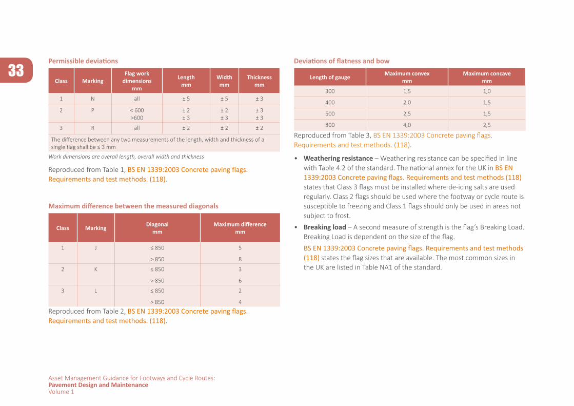
33
Asset Management Guidance for Footways and Cycle Routes:Pavement Design and MaintenanceVolume 1
Permissible deviations
Class MarkingFlag work
dimensionsmm
Lengthmm
Widthmm
Thicknessmm
1 N all ± 5 ± 5 ± 3
2 P < 600>600
± 2± 3
± 2± 3
± 3± 3
3 R all ± 2 ± 2 ± 2
The difference between any two measurements of the length, width and thickness of a single flag shall be ≤ 3 mm
Work dimensions are overall length, overall width and thickness
Reproduced from Table 1, BS EN 1339:2003 Concrete paving flags. Requirements and test methods. (118).
Maximum difference between the measured diagonals
Class Marking Diagonalmm
Maximum differencemm
1 J ≤ 850
> 850
5
8
2 K ≤ 850
> 850
3
6
3 L ≤ 850
> 850
2
4
Reproduced from Table 2, BS EN 1339:2003 Concrete paving flags. Requirements and test methods. (118).
Deviations of flatness and bow
Length of gauge Maximum convex mm
Maximum concavemm
300 1,5 1,0
400 2,0 1,5
500 2,5 1,5
800 4,0 2,5
Reproduced from Table 3, BS EN 1339:2003 Concrete paving flags. Requirements and test methods. (118).
• Weathering resistance – Weathering resistance can be specified in line with Table 4.2 of the standard. The national annex for the UK in BS EN 1339:2003 Concrete paving flags. Requirements and test methods (118) states that Class 3 flags must be installed where de-icing salts are used regularly. Class 2 flags should be used where the footway or cycle route is susceptible to freezing and Class 1 flags should only be used in areas not subject to frost.
• Breaking load – A second measure of strength is the flag’s Breaking Load. Breaking Load is dependent on the size of the flag.
BS EN 1339:2003 Concrete paving flags. Requirements and test methods (118) states the flag sizes that are available. The most common sizes in the UK are listed in Table NA1 of the standard.
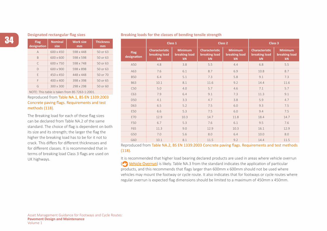
34
Asset Management Guidance for Footways and Cycle Routes:Pavement Design and MaintenanceVolume 1
Designated rectangular flag sizes
Flag designation
Nominal size
Work sizemm
Thicknessmm
A 600 x 450 598 x 448 50 or 63
B 600 x 600 598 x 598 50 or 63
C 600 x 750 598 x 748 50 or 63
D 600 x 900 598 x 898 50 or 63
E 450 x 450 448 x 448 50 or 70
F 400 x 400 398 x 398 50 or 65
G 300 x 300 298 x 298 50 or 60
NOTE: This table is taken from BS 7263-1:2001.
Reproduced from Table NA.1, BS EN 1339:2003 Concrete paving flags. Requirements and test methods (118).
The Breaking load for each of these flag sizes can be declared from Table NA.2 of the same standard. The choice of flag is dependent on both its size and its strength; the larger the flag the higher the breaking load has to be for it not to crack. This differs for different thicknesses and for different classes. It is recommended that in terms of breaking load Class 3 flags are used on UK highways.
Breaking loads for the classes of bending tensile strength
Class 1 Class 2 Class 3
Flag designation
Characteristic breaking load
kN
Minimum breaking load
kN
Characteristic breaking load
kN
Minimum breaking load
kN
Characteristic breaking load
kN
Minimum breaking load
kN
A50 4.8 3.8 5.5 4.4 6.8 5.5
A63 7.6 6.1 8.7 6.9 10.8 8.7
B50 6.4 5.1 7.3 5.8 9.1 7.3
B63 10.1 8.1 11.6 9.2 14.4 11.6
C50 5.0 4.0 5.7 4.6 7.1 5.7
C63 7.9 6.4 9.1 7.3 11.3 9.1
D50 4.1 3.3 4.7 3.8 5.9 4.7
D63 6.5 5.2 7.5 6.0 9.3 7.5
E50 6.6 5.3 7.5 6.0 9.4 7.5
E70 12.9 10.3 14.7 11.8 18.4 14.7
F50 6.7 5.3 7.6 6.1 9.5 7.6
F65 11.3 9.0 12.9 10.3 16.1 12.9
G50 7.0 5.6 8.0 6.4 10.0 8.0
G60 10.1 8.1 11.5 9.2 14.4 11.5
Reproduced from Table NA.2, BS EN 1339:2003 Concrete paving flags. Requirements and test methods (118).
It is recommended that higher load bearing declared products are used in areas where vehicle overrun ( Vehicle Overrun) is likely. Table NA.3 from the standard indicates the application of particular products, and this recommends that flags larger than 600mm x 600mm should not be used where vehicles may mount the footway or cycle route. It also indicates that for footways or cycle routes where regular overrun is expected flag dimensions should be limited to a maximum of 450mm x 450mm.
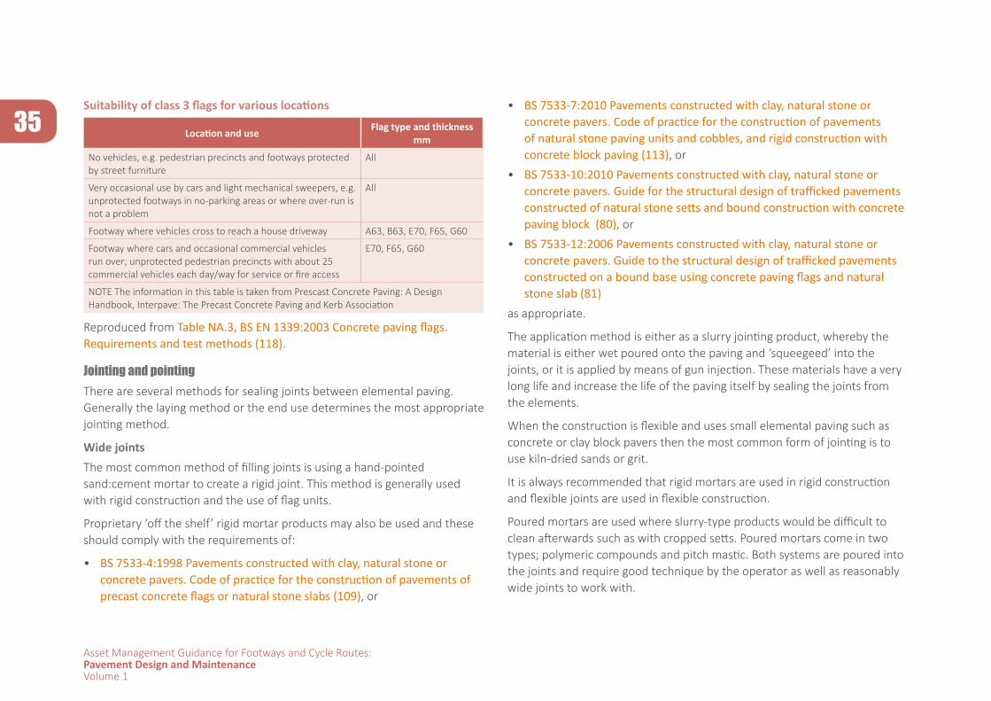
35
Asset Management Guidance for Footways and Cycle Routes:Pavement Design and MaintenanceVolume 1
Suitability of class 3 flags for various locations
Location and use Flag type and thickness mm
No vehicles, e.g. pedestrian precincts and footways protected by street furniture
All
Very occasional use by cars and light mechanical sweepers, e.g. unprotected footways in no-parking areas or where over-run is not a problem
All
Footway where vehicles cross to reach a house driveway A63, B63, E70, F65, G60
Footway where cars and occasional commercial vehicles run over; unprotected pedestrian precincts with about 25 commercial vehicles each day/way for service or fire access
E70, F65, G60
NOTE The information in this table is taken from Prescast Concrete Paving: A Design Handbook, Interpave: The Precast Concrete Paving and Kerb Association
Reproduced from Table NA.3, BS EN 1339:2003 Concrete paving flags. Requirements and test methods (118).
Jointing and pointingThere are several methods for sealing joints between elemental paving. Generally the laying method or the end use determines the most appropriate jointing method.
Wide jointsThe most common method of filling joints is using a hand-pointed sand:cement mortar to create a rigid joint. This method is generally used with rigid construction and the use of flag units.
Proprietary ‘off the shelf’ rigid mortar products may also be used and these should comply with the requirements of:
• BS 7533-4:1998 Pavements constructed with clay, natural stone or concrete pavers. Code of practice for the construction of pavements of precast concrete flags or natural stone slabs (109), or
• BS 7533-7:2010 Pavements constructed with clay, natural stone or concrete pavers. Code of practice for the construction of pavements of natural stone paving units and cobbles, and rigid construction with concrete block paving (113), or
• BS 7533-10:2010 Pavements constructed with clay, natural stone or concrete pavers. Guide for the structural design of trafficked pavements constructed of natural stone setts and bound construction with concrete paving block (80), or
• BS 7533-12:2006 Pavements constructed with clay, natural stone or concrete pavers. Guide to the structural design of trafficked pavements constructed on a bound base using concrete paving flags and natural stone slab (81)
as appropriate.
The application method is either as a slurry jointing product, whereby the material is either wet poured onto the paving and ‘squeegeed’ into the joints, or it is applied by means of gun injection. These materials have a very long life and increase the life of the paving itself by sealing the joints from the elements.
When the construction is flexible and uses small elemental paving such as concrete or clay block pavers then the most common form of jointing is to use kiln-dried sands or grit.
It is always recommended that rigid mortars are used in rigid construction and flexible joints are used in flexible construction.
Poured mortars are used where slurry-type products would be difficult to clean afterwards such as with cropped setts. Poured mortars come in two types; polymeric compounds and pitch mastic. Both systems are poured into the joints and require good technique by the operator as well as reasonably wide joints to work with.
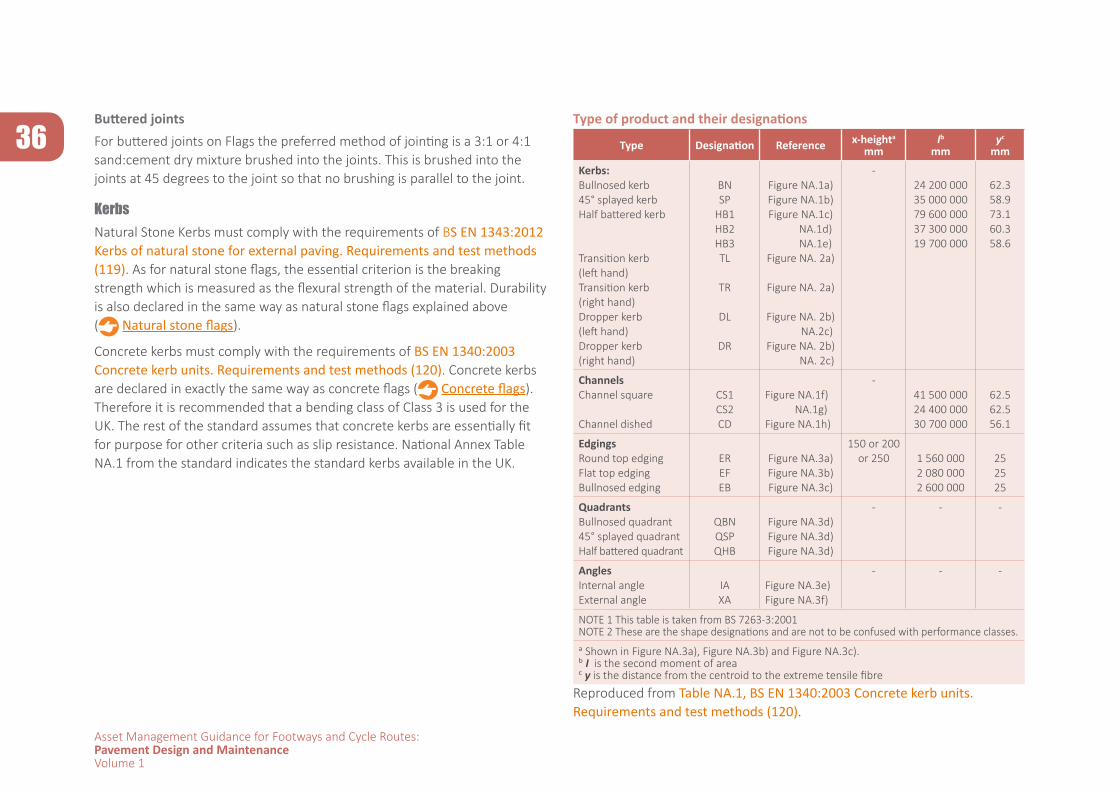
36
Asset Management Guidance for Footways and Cycle Routes:Pavement Design and MaintenanceVolume 1
Buttered jointsFor buttered joints on Flags the preferred method of jointing is a 3:1 or 4:1 sand:cement dry mixture brushed into the joints. This is brushed into the joints at 45 degrees to the joint so that no brushing is parallel to the joint.
KerbsNatural Stone Kerbs must comply with the requirements of BS EN 1343:2012 Kerbs of natural stone for external paving. Requirements and test methods (119). As for natural stone flags, the essential criterion is the breaking strength which is measured as the flexural strength of the material. Durability is also declared in the same way as natural stone flags explained above ( Natural stone flags).
Concrete kerbs must comply with the requirements of BS EN 1340:2003 Concrete kerb units. Requirements and test methods (120). Concrete kerbs are declared in exactly the same way as concrete flags ( Concrete flags). Therefore it is recommended that a bending class of Class 3 is used for the UK. The rest of the standard assumes that concrete kerbs are essentially fit for purpose for other criteria such as slip resistance. National Annex Table NA.1 from the standard indicates the standard kerbs available in the UK.
Type of product and their designations
Type Designation Reference x-heighta
mmIb
mmyc
mm
Kerbs:Bullnosed kerb45° splayed kerbHalf battered kerb
Transition kerb (left hand)Transition kerb (right hand)Dropper kerb (left hand)Dropper kerb (right hand)
BNSP
HB1 HB2 HB3TL
TR
DL
DR
Figure NA.1a)Figure NA.1b)Figure NA.1c) NA.1d) NA.1e)Figure NA. 2a)
Figure NA. 2a)
Figure NA. 2b) NA.2c)Figure NA. 2b) NA. 2c)
-24 200 00035 000 00079 600 000 37 300 000 19 700 000
62.358.973.1 60.3 58.6
ChannelsChannel square
Channel dished
CS1 CS2CD
Figure NA.1f) NA.1g)Figure NA.1h)
-41 500 000 24 400 00030 700 000
62.5 62.556.1
EdgingsRound top edgingFlat top edgingBullnosed edging
EREFEB
Figure NA.3a)Figure NA.3b)Figure NA.3c)
150 or 200 or 250 1 560 000
2 080 0002 600 000
252525
QuadrantsBullnosed quadrant45° splayed quadrantHalf battered quadrant
QBNQSPQHB
Figure NA.3d)Figure NA.3d)Figure NA.3d)
- - -
AnglesInternal angleExternal angle
IAXA
Figure NA.3e)Figure NA.3f)
- - -
NOTE 1 This table is taken from BS 7263-3:2001NOTE 2 These are the shape designations and are not to be confused with performance classes.
a Shown in Figure NA.3a), Figure NA.3b) and Figure NA.3c).b I is the second moment of areac y is the distance from the centroid to the extreme tensile fibre
Reproduced from Table NA.1, BS EN 1340:2003 Concrete kerb units. Requirements and test methods (120).
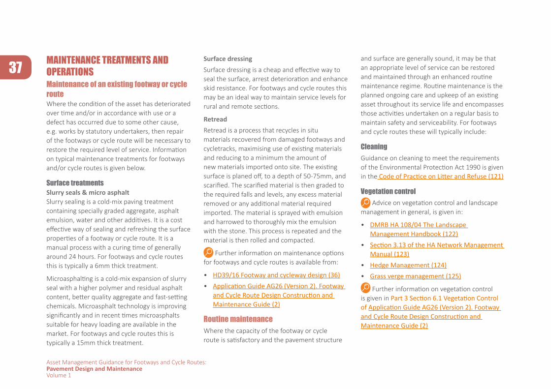
37
Asset Management Guidance for Footways and Cycle Routes:Pavement Design and MaintenanceVolume 1
MAINTENANCE TREATMENTS AND OPERATIONSMaintenance of an existing footway or cycle route Where the condition of the asset has deteriorated over time and/or in accordance with use or a defect has occurred due to some other cause, e.g. works by statutory undertakers, then repair of the footways or cycle route will be necessary to restore the required level of service. Information on typical maintenance treatments for footways and/or cycle routes is given below.
Surface treatmentsSlurry seals & micro asphaltSlurry sealing is a cold-mix paving treatment containing specially graded aggregate, asphalt emulsion, water and other additives. It is a cost effective way of sealing and refreshing the surface properties of a footway or cycle route. It is a manual process with a curing time of generally around 24 hours. For footways and cycle routes this is typically a 6mm thick treatment.
Microasphalting is a cold-mix expansion of slurry seal with a higher polymer and residual asphalt content, better quality aggregate and fast-setting chemicals. Microasphalt technology is improving significantly and in recent times microasphalts suitable for heavy loading are available in the market. For footways and cycle routes this is typically a 15mm thick treatment.
Surface dressingSurface dressing is a cheap and effective way to seal the surface, arrest deterioration and enhance skid resistance. For footways and cycle routes this may be an ideal way to maintain service levels for rural and remote sections.
RetreadRetread is a process that recycles in situ materials recovered from damaged footways and cycletracks, maximising use of existing materials and reducing to a minimum the amount of new materials imported onto site. The existing surface is planed off, to a depth of 50-75mm, and scarified. The scarified material is then graded to the required falls and levels, any excess material removed or any additional material required imported. The material is sprayed with emulsion and harrowed to thoroughly mix the emulsion with the stone. This process is repeated and the material is then rolled and compacted.
Further information on maintenance options for footways and cycle routes is available from:
• HD39/16 Footway and cycleway design (36)• Application Guide AG26 (Version 2). Footway
and Cycle Route Design Construction and Maintenance Guide (2)
Routine maintenanceWhere the capacity of the footway or cycle route is satisfactory and the pavement structure
and surface are generally sound, it may be that an appropriate level of service can be restored and maintained through an enhanced routine maintenance regime. Routine maintenance is the planned ongoing care and upkeep of an existing asset throughout its service life and encompasses those activities undertaken on a regular basis to maintain safety and serviceability. For footways and cycle routes these will typically include:
CleaningGuidance on cleaning to meet the requirements of the Environmental Protection Act 1990 is given in the Code of Practice on Litter and Refuse (121)
Vegetation control Advice on vegetation control and landscape
management in general, is given in:
• DMRB HA 108/04 The Landscape Management Handbook (122)
• Section 3.13 of the HA Network Management Manual (123)
• Hedge Management (124) • Grass verge management (125)
Further information on vegetation control is given in Part 3 Section 6.1 Vegetation Control of Application Guide AG26 (Version 2). Footway and Cycle Route Design Construction and Maintenance Guide (2)

38
Asset Management Guidance for Footways and Cycle Routes:Pavement Design and MaintenanceVolume 1
See also: Fitting landscapes - securing more sustainable landscapes (126)
Minor patching Information on minor patching is available from:
• Potholes and Repair Techniques for Local Roads (127) • HMEP Pothole Review. Appendix B (128) • HD31/94. Maintenance of Bituminous Roads. (129) • Clause 946 of the Specification for Highway Works. 900 Series (96) • IAN 90/07 Guidance for the use of emergency patching materials (130)
39
Asset Management Guidance for Footways and Cycle Routes:Pavement Design and MaintenanceVolume 1
STEP 4: DELIVER
This step is about making it happen through the detailed design and specification of the solution and the execution of the works on site. Not every design will be straightforward to deliver and the designer is expected to maintain engagement throughout the process to ensure that the required outcomes are delivered.
CLARITY OF REQUIREMENTSOnce the solution has been developed it is essential that the requirements are clearly stated by the designer and communicated to the organisation that will be carrying out he works. The nature of this communication is likely to depend upon the contractual arrangement between the parties and also the scale of the works. For significant planned works this would typically entail the designer preparing:
• detailed design drawings showing the layout, dimensions and materials• a specification detailing the specific requirements for the materials to be
used (as discussed in Step 3) and also requirements for the transportation and placing of the materials during the construction process
Materials specifications should make reference to recognised standards, i.e. the British implementation of European Standards (BS EN) or, in the absence of an appropriate BS EN, simply the relevant British Standard (BS). For certain product groups, such as asphalt, the use of ‘harmonised’ European Standards is effectively mandatory to comply with the EU Construction Products Regulation.
Information on harmonised standards and the Construction Products Regulation is available from:
• Harmonised standards • Construction Products Regulation
CONSTRUCTION The construction process is the point at which the outcome from investment planning and works development is realised. It is, therefore, important that construction is carefully controlled and executed so that planned service and performance from the pavement and, hence, value from the investment are obtained.
40
Asset Management Guidance for Footways and Cycle Routes:Pavement Design and MaintenanceVolume 1
In terms of serviceability for the user, one of the key parameters is surface regularity which affects smoothness of ride, so it is recommended that this is controlled through specification of surface tolerances. Asphalt is generally the preferred surface for cycle routes as it can provide a smooth, as well as skid resistant surface. For this reason it is recommended that asphalt should be laid to the tolerances specified in Table 4.3 of HD 39/16 Footway and Cycleway Design (36) i.e. the maximum deviation under a 1m straight edge must not exceed 3mm. In practice this means that asphalt surface courses for cycle routes should be laid by paving machine which, in turn, means that access for paving plant should be considered in the both the solution design and construction planning.
It will generally be necessary to consider level tolerances for the underlying layers in the pavement construction to ensure an adequate platform is provided to enable the final surface to be constructed to the required tolerance.
Further information on level tolerances is available from:
• Specification for Highway Works. Series 700: Road Pavements – General (131)
• HD 39/16 Footway and Cycleway Design (36)
For works of significant scale with substantial supply of paving materials it may appropriate
to monitor the quality and conformance of the materials through testing either in situ or on representative samples.
Testing of asphalt materials should be undertaken in accordance with the appropriate part(s) of BS EN 12697. Bituminous mixtures. Test methods for hot mix asphalt (132). Guidance on the use of these tests is given in PD 6692: 2006 Asphalt. Guidance on the use of BS EN 12697 “Bituminous mixtures. Test methods for hot mix asphalt" (133).
Further information on testing of materials and workmanship for footways and cycle routes is available from HD 39/16 Footway and Cycleway Design (37).
Further information on the construction of asphalt pavements is available from:
• BS 594987:2015. Asphalt for roads and other paved areas. Specification for transport, laying, compaction and product-type testing protocols (100)
• Resurfacing of roads and other paved areas using asphalt (134)
Information on the construction of elemental pavements is available from:
• BS7533 Pavements constructed with clay, natural stone or concrete pavers - Part 3: Code of practice for laying precast
concrete paving blocks and clay pavers for flexible pavements (135);
- Part 4: Code of practice for the construction of pavements of precast concrete flags or natural stone slabs (107);
- Part 6: Code of practice for laying natural stone, precast concrete and clay kerb units (136);
- Part 7: Code of practice for the construction of pavements of natural stone paving units and cobbles, and rigid construction with concrete block paving (111);
- Part 9: Code of practice for the construction of rigid pavements of clay pavers (137)
Information on repair and reinstatement is available from:
• Practical Guide to Street Works (138) • Specification for the reinstatement of
openings in highways (18) • BS7533 Pavements constructed with clay,
natural stone or concrete pavers: Part 11: Code of practice for the opening, maintenance and reinstatement of pavements of concrete, clay and natural stone (139)
41
Asset Management Guidance for Footways and Cycle Routes:Pavement Design and MaintenanceVolume 1
REFERENCES
1 Well-managed highway infrastructure: a code of practice. UK Roads Liaison Group. 2016
2 Application Guide AG26 (Version 2). Footway and Cycle Route Design Construction and Maintenance Guide . TRL Ltd. 2003
3 Construction Design and Management (CDM) Regulations. Health and Safety Executive. 2015.
4 Highway infrastructure asset management: guidance document”. DfT. Highways Maintenance Efficiency Programme. 2013
5 Local Cycling and Walking Infrastructure Plan Guidance
6 Equality Act 2010 c15.
7 Inclusive mobility. Accessible transport and local transport. DfT. 2015..
8 Who put that there. The barriers to blind and partially sighted people getting out and about. RNIB 2015
9 Guidance on the use of Tactile Paving Surfaces . DETR 1998
10 Equality Act 2010: guidance Equality Act 2010: how it might affect you. March 2013.
11 Manual for Streets. Thomas Telford Publishing. 2007
12 Manual for Streets 2. CIHT. 2010
13 LTN 1/08 Traffic Management and Streetscape. DfT. 2008
14 Street Design for All, 2014. DfT, Civic Voice, CIHT, PRIAN. 2014.
15 TfL Streetscape Guidance Revision 1. TfL 2017.
16 Better Streets Delivered . Tfl 2013
17 Better Streets Delivered 2 . Tfl. 2017.
18 Specification for the reinstatement of openings in highways (SROH). DfT. 2010.
CLIC
K TO OPEN A LINK
Text
42
Asset Management Guidance for Footways and Cycle Routes:Pavement Design and MaintenanceVolume 1
19 Local road maintenance, repairs, and street works in England . House of Commons Library December 28. 2106.. www.parliament.co.uk.
20 The Traffic Management Permit Scheme (England) Regulations (2007)
21 LTN 1/11 Shared space . DfT 2011 l
22 LTN 1/12 Shared use routes for pedestrians and cyclists . DfT 2012
23 TA 91/05 Provision for Non-motorised Users . Highways England. Design Manual for Roads and Bridges. 5.2.4 2005.
24 Design Guidance. Active Travel (Wales) Act 2013 . Welsh Government. 2013.
25 Traffic free routes: conceptual design . Sustrans. Design Manual Chapter 5. 2014.
26 Planning for Walking . CIHT.2015
27 Providing for Journeys on Foot . CIHT. 2000.
28 LTN 2/08 Cycle Infrastructure Design . DfT. 2008
29 Cycling by design. Transport Scotland. 2010.
30 London cycling design standards. Streets Toolkit. TfL . 2014.
31 Design manual for bicycle traffic. Centrum voor Regelgeving en Onderzoek in de Grond-, Water- en Wegenbouw en de Verkeerstechniek (CROW) . ISBN 9789066286597 . 2017
32 Handbook for cycle friendly design. Sustrans Design Manual. 2014.
33 Greater Manchester Cycling Design Guidance. Transport for Greater Manchester. 2014.
34 IAN 195/16 Cycle Traffic And The Strategic Road Network Highways England. Design Manual for Roads and Bridges. Interim Advice Notes. 2016.
35 Planning for cycling . CIHT. 2014.
36 HMEP Guidance on the management of highway drainage assets . DfT. Highways Maintenance Efficiency Programme. 2012
37 HD 39/16 Footway and Cycleway Design . Highways England. Design Manual for Roads and Bridges. 7.2.5 2016
38 Kerbside Loading Guidance. TfL. 2017.
39 Pavement and on-street parking in England. House of Commons Library. Briefing Paper No. SN01170. 2016.
40 Parking on Pavements – Quick Wins for Local Authorities . RNIB Briefing. 2012.
41 Waste Acceptance at Landfills. Environment Agency. 2010
42 Managing reclaimed asphalt – highways and pavements. An adept guidance note. ADEPT. 2016.
43 LTN 2/95 The design of pedestrian crossings. DfT. 1995
44 Road crossings for horses. The British Horse Society. 2016
45 Surface Materials Around Trees In Hard Landscapes. London Tree Officers Association. 2017
46 Legible London Yellow Book. A prototype wayfinding system for London. TfL. 2007.
47 Traffic signs manual. DfT. 2006, updated 2017.
48 LTN 1/94 Design and use of directional informatory signs. DfT. 1994
49 The Sign Design Guide. Sign Design Society & RNIB. ISBN-13: 978-1858784120
50 Class and Quality of Street Lighting . Institution of Lighting Professionals. 2012.
51 Lighting of cycle paths . Sustrans,. Technical Information Note No, 29. 2012.
52 BS5489-1:2013. Code of practice for the design of road lighting. Part 1.Lighting of roads and public amenity areas. BSI 2012.
53 Local Transport Note 2/09 Pedestrian guardrailing. DfT 2009.
54 Guidance on assessment of pedestrian guardrails. Tfl .2012
55 TA 57/87 Roadside Features. . Highways England. Design Manual for Roads and Bridges. 6.3.3 1995.
56 IAN 73/06 Design Guidance for Road Pavement Foundations. Highways England. Design Manual for Roads and Bridges. Interim Advice Notes, 2006
43
Asset Management Guidance for Footways and Cycle Routes:Pavement Design and MaintenanceVolume 1
57 BS 1377-4:1990. Soils for civil engineering purposes — Part 4: Compaction-related tests. BSI. 1990.
58 HA44/91 Earthworks - Design and Preparation of Contract Documents. Highways England. Design Manual for Roads and Bridges. 4.1.1 1995
59 HD29/08 Data for Pavement Assessment. Highways England. Design Manual for Roads and Bridges. 7.3.2 2008
60 BS EN 13286-47:2012 – Unbound and hydraulically bound mixtures. Test method for the determination of California bearing ratio, immediate bearing index and linear swelling. BSI.2012
61 ASTM D4318-10E1 – Standard Test Methods for Liquid Limit, Plastic Limit, and Plasticity Index of Soils. ASTM. 2010
62 IAN 147/12 Drainage surveys and data. Highways England. Design Manual for Roads and Bridges. Interim Advice Notes. 2012
63 Rainfall runoff management for developments. Environment Agency. 2013
64 Designing for exceedance in urban areas – good practice. CIRIA C635.2006.
65 Managing urban flooding from heavy rainfall. CIRIA Report 738a. 2013
66 Greenfield runoff rate estimation. HR Wallingford.
67 HD 49/16 Highway drainage design principle requirements. Highways England. Design Manual for Roads and Bridges. 4.2.1. 2016
68 HD33/16 Design of highway drainage systems. Highways England. Design Manual for Roads and Bridges. 4.2.3. 2016
69 The SuDS Manual . CIRIA Report C753. 2015
70 Interim code of practice for sustainable drainage systems. National SUDS Working Group. 2004
71 SuDS in London – a guide . TfL 2016
72 SuDS Advice Note – Brownfield Sites . Scottish Environment Protection Agency. 2003
73 Visual Data Collection .UKPMS User Manual. Volume 2, Chapter 1. UK Roads Liaison Group. 2009.
74 Coarse Visual Inspection (CVI) UKPMS User Manual. Volume 2, Chapter 7. UK Roads Liaison Group. 2009
75 Detailed Visual Inspection (DVI) UKPMS User Manual. Volume 2, Chapter 8. UK Roads Liaison Group. 2009
76 Footway Network Survey (FNS) UKPMS User Manual. Volume 2, Chapter 9. UK Roads Liaison Group. 2010
77 Walking Route Audit Tool
78 Construction and surfacing of footways and cycleways using asphalt . Mineral Products Association. 2009.
79 BS7533-1:2001 Pavements constructed with clay, natural stone or concrete pavers Part 1: Guide for the structural design of heavy duty pavements constructed of clay pavers or precast concrete paving blocks . BSI. 2001
80 BS7533-2:2001 Pavements constructed with clay, natural stone or concrete pavers Part 2: Guide for the structural design of lightly trafficked pavements constructed of clay pavers or precast concrete paving blocks . BSI.2001
81 BS7533-8: 2003. Pavements constructed with clay, natural stone or concrete pavers Part 8: Guide for the structural design of lightly trafficked pavements of precast concrete flags and natural stone flags. BSI.2003
82 BS7533-10:2010 Pavements constructed with clay, natural stone or concrete pavers Part 10: Guide for the structural design of trafficked pavements constructed of natural stone setts and bound construction with concrete paving blocks .BSI 2010.
83 BS7533 – 12.2006 Pavements constructed with clay, natural stone or concrete pavers Part 12: Guide to the structural design of trafficked pavements constructed on a bound base using concrete paving flags and natural stone slabs. BSI. 2006
44
Asset Management Guidance for Footways and Cycle Routes:Pavement Design and MaintenanceVolume 1
84 BS7533 – 13: 2009. Pavements constructed with clay, natural stone or concrete pavers Part 13: Guide for the design of permeable pavements constructed with concrete paving blocks and flags, natural stone slabs and setts and clay pavers. BSI. 2009.
85 Traffic free routes: detailed design. Sustrans. Design Manual Chapter 6. 2014.
86 HA39/98 Edge of pavement details. Highways England. Design Manual for Roads and Bridges. 4.2.1. 1998
87 Highways England. Manual for Contracts for Highway Works. Volume 1; Series 600. 2016.
88 BS EN 13242: 2013 Aggregates for unbound and hydraulically bound materials for use in civil engineering work and road construction. BSI. 213
89 Highways England. Manual for Contracts for Highway Works. Volume 1; Series 800.2016
90 BS EN 13285:2010 Unbound mixtures. Specifications. BSI. 2010
91 Highways England. Manual for Contracts for Highway Works. Volume 2; Series 800. 2016
92 BS EN 14227 (Parts 1 – 5). Hydraulically Bound Mixtures. Specifications. BSI. 2013
93 BS 8500:2-2015 “Concrete – Complementary British Standard to BS EN 206 Part 2: Specification for constituent materials and concrete”. BSI.2015
94 BS8500:1-2015 – “Concrete – Complementary British Standard to BS EN 206 Part 1: Method of specifying and guidance for the specifier”. BSI.2015
95 Quality protocols: converting waste into non-waste products. Environment Agency. 2014
96 Highways England. Manual for Contracts for Highway Works. Volume 1; Series 900. 2008
97 BS EN 13108-6:2006. Bituminous mixtures. Material specifications. Part 6. Mastic Asphalt. BSI.2006
98 BS EN 13108-1:2016. Bituminous mixtures. Material specifications. Part 1. Asphalt Concrete . BSI.2016
99 BS EN 13108-2:2016 Bituminous mixtures. Material specifications. Part 2. Asphalt Concrete for Very Thin Layers . BSI.2016
100 BS EN 13108-4:2016 Bituminous mixtures. Material specifications. Part 4. Hot Rolled Asphalt. BSI.2016
101 BS EN 13108-5:2016 Bituminous mixtures. Material specifications. Part 5. Stone Mastic Asphalt. BSI.2016
102 BS 594987:2015 Asphalt for roads and other paved areas. Specification for transport, laying, compaction and product-type testing protocols. BSI. 2015
103 PD 6691 Guidance on the use of BS EN 13108, Bituminous mixtures. Material specifications. BSI.2015
104 Cycle path surface options. Sustrans. Technical Information Note No. 8. 2012
105 BS EN 13108-8:2016. Bituminous mixtures. Material specifications. Reclaimed asphalt. BSI. 2016
106 Asphalt the 100% recyclable construction product. EAPA Position Paper. EAPA. 2014.
107 BS EN 12620:2013 Aggregates for concrete . BSI.2013
108 BS EN 998-2:2016 – Specification for mortar for masonry. BSI. 2016.
109 BS 7533-4:1998. Pavements constructed with clay, natural stone or concrete pavers. Code of practice for the construction of pavements of precast concrete flags or natural stone slab. BSI.1998.
110 BS EN 998-2: 2016 Specification for mortar for masonry. Masonry mortar. BSI.2016
111 BS8500-1: 2015, Concrete – Complementary British Standard to BS EN 206 Part 1: Method of specifying and guidance for the specifier. BSI. 2015
112 Proprietary BS7533 compliant laying mortar – BS EN 13813 – heavy duty trafficked footways in elemental paving
45
Asset Management Guidance for Footways and Cycle Routes:Pavement Design and MaintenanceVolume 1
113 BS 7533-7:2010 Pavements constructed with clay, natural stone or concrete pavers. Code of practice for the construction of pavements of natural stone paving units and cobbles, and rigid construction with concrete block paving. BSI. 2010
114 BS EN 1344:2013 Clay pavers. Requirements and test methods, BSI. 2013
115 BS EN 1341:2012 Slabs of natural stone for external paving. Requirements and test methods. BSI. 2012
116 BS EN 1342:2012 Setts of natural stone for external paving. Requirements and test methods. BSI. 2012.
117 BS EN 1338:2003 Concrete paving blocks. Requirements and test methods. BSI. 2003.
118 BS EN 1339:2003 Concrete paving flags. Requirements and test methods. BSI. 2003
119 BS EN 1343:2012 Kerbs of natural stone for external paving. Requirements and test methods. BSI. 2012
120 BS EN 1340:2003 Concrete kerb units. Requirements and test methods. BSI. 2003
121 Guidance on cleaning to meet the requirements of the Environmental Protection Act 1990 is given in the Code of Practice on Litter and Refuse. DEFRA.2006.
122 HA 108/04 Landscape Management Handbook. Highways England. Design Manual for Roads and Bridges 10.3.2. 2004.
123 Network Management Manual. Part 3. Routine Service. Highways Agency. 2009.
124 Hedge Management. Sustrans. Ecology Technical Information Note No. 01. 2011.
125 Grass verge management . Sustrans. Ecology Technical Information Note No. 02. 2011
126 Fitting landscapes - securing more sustainable landscapes. Transport Scotland 2014.
127 Potholes and Repair Techniques for Local Roads. ADEPT Report CSS79-05. 2010
128 Potholes Review. Prevention and a Better Cure. Appendix B. DfT. Highways Maintenance Efficiency Programme. 2012.
129 HD31/94. Maintenance of Bituminous Roads. Highways England. Design Manual for Roads and Bridges 7.4.1. 1994.
130 IAN 90/07 Guidance for the use of emergency patching materials Highways England. Design Manual for Roads and Bridges. Interim Advice Notes. 2007.
131 Highways England. Manual for Contracts for Highway Works. Volume 1; Series 700. Road Pavements – General 2016.
132 BS EN 12697. Bituminous mixtures. Test methods for hot mix asphalt. Various parts. Published by BSI.
133 PD 6692 Asphalt. Guidance on the use of BS EN 12697 Bituminous mixtures. Test methods for hot mix asphalt. BSI. 2006
134 Resurfacing of roads and other paved areas using asphalt. Mineral Products Association. 2009
135 BS7533-3: 2005 Pavements constructed with clay, natural stone or concrete pavers. Part 3: Code of practice for laying precast concrete paving blocks and clay pavers for flexible pavements BSI. 2005
136 BS7533-6:1999. Pavements constructed with clay, natural stone or concrete pavers. Part 6: Code of practice for laying natural stone, precast concrete and clay kerb units. BSI. 1999
137 BS7533 - 9: 2010. Pavements constructed with clay, natural stone or concrete pavers Part 9: Code of practice for the construction of rigid pavements of clay pavers. BSI. 2010
138 Practical Guide to Street Works. DfT. HAUC(UK). 2006
139 BS7533 – 11: 2003. Pavements constructed with clay, natural stone or concrete pavers: Part 11: Code of practice for the opening, maintenance and reinstatement of pavements of concrete, clay and natural stone. BSI. 2003
140 The Geometric Design of Pedestrian, Cycle and Equestrian Routes. Highways England. Design Manual for Roads and Bridges. 6.3.5 2005.
46
Asset Management Guidance for Footways and Cycle Routes:Pavement Design and MaintenanceVolume 1
APPENDIX A - GUIDANCE: INITIAL SITE APPRAISAL
at the location. The completeness, quality and currency of the existing information will inform the scope and extent of further site investigation.
A) Existing footways and/or cycle routes (including change of use)Existing data to be collated and assimilated is likely to include:
• Inventory data for both the paved and ancillary assets, eg
- Paved asset
� Widths
� Surface type
� Construction
- Ancillary assets
� Drainage/SUDS
� Lighting
GUIDANCE: INITIAL SITE APPRAISAL Once the location for investment to provide, improve or restore a footway and/or cycle route has been confirmed, an initial appraisal of the site will be required to identify and assess features and characteristics that may influence the choice of solution and the works design.
The application of this guidance should be scaled to be commensurate with the likely nature and scale of the works, i.e. major planned capital improvements will require more detailed assessment than, say, a routine or reactive repair of localised defects.
1 EXISTING INFORMATIONThe first action will generally be to identify and assimilate existing information. Much of this, and possibly further relevant information, may be available from the evidence and data used to identify the need for works
47
Asset Management Guidance for Footways and Cycle Routes:Pavement Design and MaintenanceVolume 1
� Signs
� Guard rails
� Soft estate
• Usage data
- Flows
- User categories
� Pedestrians
� Cyclists
� Equestrian
� Vehicles
• Maintenance
• Light/occasional use/access
• Overrun
• Condition data
- Surveys
- Maintenance history
- Defect reports
- Response/repair records
• Utilities data search results
• Topographic data
• Environment data:
- Noise
- Air quality
- User comfort survey
- Streetscence/aesthetics
B) Provision of new footway and/or cycle route Where a new cycle route or footway is being proposed unless, for example, use is being made of an existing paved area, such as where a cycle lane is being introduced on an existing carriageway or where a footway or cycle route is being developed for shared use, there will evidently be no existing asset information. However there may be:
• usage information
• topgraphic data
• information on the environment
available from the studies, forecasts and/or design proposals prepared to support the original identification of need.
2 PRELIMINARY INSPECTIONOnce all relevant existing information has been collated and assimilated it is recommended that a preliminary inspection of the site should be carried out by representatives from:
• Sponsor/Promoter
• Designer
• Asset owner
• Maintenance service provider
as appropriate.
The purpose of the inspection is to obtain an
understanding of, and information on, features and factors that may influence the choice or feasibility of solution options to deliver the required outcomes from the works
A) Existing footways and/or cycle routes (including change of use)For existing footways and cycle routes the inspection should generally look to identify and assess features and factors relating to:
• Safety & asset condition
• Amenity/user comfort
• Environment
• Usage drivers
• Design and construction
An indication of the features to assess under each of these categories is given below.
a) Safety & asset condition
Overall assessment of condition and identification of defects and forms of distress that impact on safety and serviceability, e.g.
1. Footway and/or cycle route
• Trips
• Potholes
• Slip/skid resistance
• Ponding
• Kerb, channel condition
48
Asset Management Guidance for Footways and Cycle Routes:Pavement Design and MaintenanceVolume 1
• Evidence of vehicle overrun
• Significant defects
2. Ancillary assets
• Missing/faulty lights
• Missing/damaged signs
• Missing/damaged guard rail
• Damaged street furniture – shelters, benches, planters, waste bins etc
b) Amenity/user comfort
Overall identification and assessment factors that affect ease of use and user comfort
• Shape
• Roughness
• Lighting levels
• Signage and information
• Overgrown trees/vegetation
• Obstructions, street clutter
• Pinch points
• Delivery or parking bays
• Transitions
• Crossings
• Ironwork
c) Environment
Overall identification and assessment factors relating to the local environment that may have a
bearing on the choice of solution
• Neighbourhood character
• Streetscene
• Trees and planting
• Noise
• Air quality
d) Usage drivers
Factors affecting the volume and types of users and, hence, considerations in solution e.g. for persons with restricted mobility
• schools, hospitals etc
• parks, sports pitches, leisure facilities
• railway, bus stations, transport hubs
• museums, galleries, tourist & cultural attractions
• residential development
• commercial development
• retail development
e) Design and Construction
Local factors that may influence the works design and or buildability
• Confirmation of scheme extents
• Level constraints
• Likely traffic management constraints
• Drainage – type, condition
• Adjacent land/premises
• Cellars, basements, coal chutes etc
• Statutory undertakers’ apparatus
B) Provision of new footway and/or cycle route While a preliminary inspection is primarily applicable to existing assets it may still be of value for new provision to identify, for example, environmental factors and usage drivers and also the likely nature and scope of further investigations.
3 OUTCOMEThe outcome from the initial site appraisal should be the collation and analysis of information, most likely presented in a report, that identifies the nature and scale of the issues to be addressed and, hence, informs the selection and development of appropriate solution option(s).
Where possible, the inspection should aim to identify the causes of observed defects. However, particularly for significant works further investigation may be justified and the preliminary inspection should form the basis for determining the nature and extent of those investigations.
49
Asset Management Guidance for Footways and Cycle Routes:Pavement Design and MaintenanceVolume 1
APPENDIX B - DRAINAGE INVESTIGATION SPECIFICATION
1 PURPOSEThe purpose of this specification is to provide the requirements for undertaking investigations to drainage assets.
2 BACKGROUND / SCOPEThe outcomes from the drainage investigation are to:
• Determine and/or verify the types and location of the existing drainage assets
• Establish the condition of the existing drainage assets and identify problems requiring attention to rectify
• Determine the need for any further investigations
• Develop a preliminary scope for drainage works, ensuring that they meet the requirements of the proposed works
3 GUIDANCE DESCRIPTIONDesktop study and site familiarisation visitA desktop study must be undertaken to interrogate the Authorities’ Flood Risk Database for the area of the scheme. Additionally, information may be obtained from the local authorities surface water management plans with regard to the flood/drainage characteristics within the extents of the scheme.
Existing drainage assets details and locations must be obtained from asset management systems and existing records must be used to obtain sewer records to enable asset investigations to be planned and carried out.
CCTV drainage investigationA CCTV survey of the subsurface highway drainage assets shall be carried out. The survey must as a minimum include the location of:
• Gullies
50
Asset Management Guidance for Footways and Cycle Routes:Pavement Design and MaintenanceVolume 1
• Manholes
• Laterals
• Highway drainage carrier pipes
As part of the CCTV Investigation work, the contractor must:
• Ensure camera access is possible e.g. sewer cleaning and lifting ‘stuck’ gully and manhole covers. This should be carried out prior to the main investigation. All blockages found during the survey must be cleared by the contractor.
• Lift manhole covers to inspect levels of flow / silt within the highway drainage system and add to the defects report.
• Confirm direction of pipe connectivity between highway drainage gully and main sewer.
• Carry out CCTV of highway drainage: gully laterals to main sewer and also main sewer (if owned by authority).
• Provide a structural condition report, along with the CCTV video footage from the survey.
In line with IAN 147/12, the drainage structural condition must be reported based upon the categories of defects found.
The following tables (1, 2 and 3) indicate the grading criteria, example service condition and the suggested actions required.
Table 1: Drain hydraulic/structural condition - service condition
Grade Existing Performance (Hydraulic/Structural)
Service Condition Action Required
1 80- 100 No defects. Clear None
2 80 Superficial defects. Superficial deposits with no loss of performance
None but monitoring required
3 70 Intervention Minor defects. Performance is slightly reduced
Consider repairs/replacement as part of scheme works.
4* 50 Major defects. Performance severely reduced
Repair/replace
5* 0 Not fit for purpose.
Blocked or unsafe condition
Repair/replace
Table 2: Highway drainage intervention levels (Gullies)
Location/Type Condition Grade Comment/Action
Road/Footway Functioning normally 1 None – check suitability if in a cycle superhighway
Damaged/missing cover 5 Replace
Cracked frame/cover 3 Replace
Frame/cover set too low/ high
3 If boxes, frames and covers are found to be > 20mm lower than the surrounding carriageway they should be re-set.
Settled – too low 3/4 Hazard for cyclists
No rodding access 3 Include replacement in revenue programme
Blocked with concrete etc. 3/4 Include replacement in revenue programme
Poorly located e.g. not at low point
3 Install additional gullies
Insufficient no. gullies 3 Install additional gullies
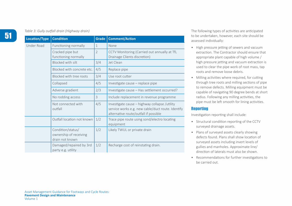
51
Asset Management Guidance for Footways and Cycle Routes:Pavement Design and MaintenanceVolume 1
Table 3: Gully outfall drain (Highway drain)
Location/Type Condition Grade Comment/Action
Under Road Functioning normally 1 None
Cracked pipe but functioning normally
2 CCTV Monitoring (Carried out annually at TfL Drainage Clients discretion)
Blocked with silt 3/4 Jet Clean
Blocked with concrete etc. 4/5 Replace pipe
Blocked with tree roots 3/4 Use root cutter
Collapsed 4/5 Investigate cause – replace pipe
Adverse gradient 2/3 Investigate cause – Has settlement occurred?
No rodding access 3 Include replacement in revenue programme
Not connected with outfall
4/5 Investigate cause – highway collapse /utility service works e.g. new cable/duct route. Identify alternative route/outfall if possible
Outfall location not known 1/2 Trace pipe route using sond/electro locating equipment
Condition/status/ownership of receiving drain not known
1/2 Likely TWUL or private drain
Damaged/repaired by 3rd party e.g. utility
1/2 Recharge cost of reinstating drain.
The following types of activities are anticipated to be undertaken, however, each site should be assessed individually:
• High pressure jetting of sewers and vacuum extraction. The Contractor should ensure that appropriate plant capable of high volume / high pressure jetting and vacuum extraction is used to clear the pipe work of root mass, tap roots and remove loose debris.
• Milling activities where required, for cutting through tree roots and milling sections of pipe to remove defects. Milling equipment must be capable of navigating 90 degree bends at short radius. Following any milling activities, the pipe must be left smooth for lining activities.
ReportingInvestigation reporting shall include:
• Structural condition reporting of the CCTV surveyed drainage assets.
• Plans of surveyed assets clearly showing defects found. Plans shall show location of surveyed assets including invert levels of gullies and manholes. Approximate line/direction of laterals must also be shown.
• Recommendations for further investigations to be carried out.
52
Asset Management Guidance for Footways and Cycle Routes:Pavement Design and MaintenanceVolume 1
APPENDIX C - TOPOGRAPHIC SURVEY SPECIFICATION
1 PURPOSEThe purpose of this specification is to define the requirements of a Topographic Survey.
2 BACKGROUND / SCOPEThe outcomes of carrying out a Topographic survey are to:
• Identify and record all highway features within the proposed site of the scheme.
• Establish the geometry of the existing site:
- Horizontal alignment of carriageway, footway and any cycle tracks
- Vertical alignment of carriageway, footway and any cycle tracks
• Identify and record the pavement construction
• Identify and record the drainage runs and falls including location of channels and gullies etc
• Identify and record principle highway assets including:
- Lighting
- Signs and bollards (both illuminated and non-illuminated)
- Vehicle restraint systems
• Compliment a LiDAR survey where LiDAR is carried out.
53
Asset Management Guidance for Footways and Cycle Routes:Pavement Design and MaintenanceVolume 1
3 GUIDANCE
DESCRIPTIONExisting informationPrior to undertaking any survey works the designer must, in consultation with the authority, determine whether any existing survey information is available and, if so, assess its suitability for the scheme in terms of the objectives stated above, including consideration of:
• Scope
• Coverage
• Currency (age of information)
• Accuracy
Information provided to the designerInformation provided to the designer in advance of the survey will include:
• Base plan(s) showing the scheme extents and boundaries for the survey
• Details of any site access and/or working restrictions
In advance of the survey, information provided to the contactor may also include:
• Specific features and details to be recorded
• Levels
• Presentation of collected data
Features and details to be recorded The designer must determine all of the features which lie within the site boundaries that must be recorded in the Topographic Survey.
LevelsLevel information shall be collected at 5.0m intervals. This spacing shall be decreased to 2.0m chainage intervals within 20m of a junction. All levels shall be recorded in metres, relative to Ordanance Datum (Newlyn) to 2 decimal places at:
• Back of the footway
• Top of the kerb
• Bottom of the kerb
• Channels
• Gullies
• Man-hole covers
• Changes in directions of falls
• Carriageway crown (if it is not along centre line road markings)
• Carriageway centre line within area shown by attached drawings
Additionally, the following situations need to be considered:
• For footways and cycletracks over 4m in width or footways which incorporate a drainage channel as part of the construction, an
additional longititudinal line of levels must be taken along the centre line of the footway or cycletrack or on the drainage channel.
• If a drainage channel is present on a footway of a width less than 4m, then intermediate levels must be taken on the drainage channel.
• If the footway or cycletrack is greater than 12m in width, levels should be provided on a 4m grid basis.
The designer shall take further levels as required:
• To ensure the nature of the highway layout and topography within the highway where there are unsual changes in profile is accurately reflected.
• At central reserves and Islands.
• At road humps or where there is a large area of carriageway or paved area.
Accuracy• 3D information is to be given to a tolerance of
(to be set by designer)
• 2D information is to be given to tolerance of (to be set by designer)
• If the topographical survey undertaken is an extension of a previous survey, the new survey must be linked with the existing survey.
Photographs, in JPG format, of the faces of existing traffic signs must be provided and the picture reference numbers placed in a separate layer of the drawing.
54
Asset Management Guidance for Footways and Cycle Routes:Pavement Design and MaintenanceVolume 1
APPENDIX D - CARRIAGEWAY CORING SPECIFICATION
1 PURPOSEThe purpose of this specification is to provide the requirements for undertaking and reporting coring activities.
2 BACKGROUND / SCOPEThe objectives of carrying out carriageway coring activities are to:
• Determine the presence of Road Tar bound materials in the existing construction to enable appropriate actions to be taken where necessary;
• Identify the layer thicknesses and material types in the existing construction;
• Provide visual indication of material condition;
• Identify delamination between construction layers;
• Determine depth of cracking;
• Investigate condition of joints and/or cracks in underlying hydraulically bound material;
• Determine propagation of major rutting to structural layers of the carriageway;
• Optionally, provide materials samples for further testing and analysis.
Number and location of coresThe designer must make use of the conducted visual condition survey information in order to determine location of cores. Additionally Ground Penetrating Radar (GPR) survey may be used to plan the number and location of cores in advance of works taking place in accordance with the following requirements:
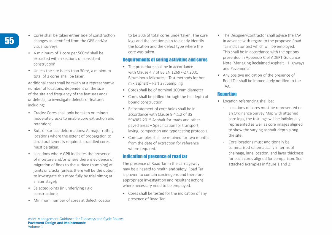
55
Asset Management Guidance for Footways and Cycle Routes:Pavement Design and MaintenanceVolume 1
• Cores shall be taken either side of construction changes as identified from the GPR and/or visual surveys.
• A minimum of 1 core per 500m2 shall be extracted within sections of consistent construction
• Unless the site is less than 30m2, a minimum total of 3 cores shall be taken.
Additional cores shall be taken at a representative number of locations, dependent on the size of the site and frequency of the features and/or defects, to investigate defects or features including:
• Cracks: Cores shall only be taken on minor/moderate cracks to enable core extraction and retention;
• Ruts or surface deformations: At major rutting locations where the extent of propagation to structural layers is required, straddled cores must be taken;
• Locations where GPR indicates the presence of moisture and/or where there is evidence of migration of fines to the surface (pumping) at joints or cracks (unless there will be the option to investigate this more fully by trial pitting at a later stage);
• Selected joints (in underlying rigid construction);
• Minimum number of cores at defect location
to be 30% of total cores undertaken. The core logs and the location plan to clearly identify the location and the defect type where the core was taken.
Requirements of coring activities and cores• The procedure shall be in accordance
with Clause 4.7 of BS EN 12697-27:2001 Bituminous Mixtures – Test methods for hot mix asphalt – Part 27: Sampling
• Cores shall be of nominal 100mm diameter
• Cores shall be drilled through the full depth of bound construction
• Reinstatement of core holes shall be in accordance with Clause 9.4.1.2 of BS 594987:2015 Asphalt for roads and other paved areas – Specification for transport, laying, compaction and type testing protocols
• Core samples shall be retained for two months from the date of extraction for reference where required.
Indication of presence of road tarThe presence of Road Tar in the carriageway may be a hazard to health and safety. Road Tar is proven to contain carcinogens and therefore appropriate investigation and resultant actions where necessary need to be employed.
• Cores shall be tested for the indication of any presence of Road Tar.
• The Designer/Contractor shall advise the TAA in advance with regard to the proposed Road Tar indicator test which will be employed. This shall be in accordance with the options presented in Appendix C of ADEPT Guidance Note ‘Managing Reclaimed Asphalt – Highways and Pavements’
• Any positive indication of the presence of Road Tar shall be immediately notified to the TAA.
Reporting• Location referencing shall be:
- Locations of cores must be represented on an Ordinance Survey Map with attached core logs, the test logs will be individually represented as well as core images aligned to show the varying asphalt depth along the site.
- Core locations must additionally be summarised schematically in terms of chainage, lane location, and layer thickness for each cores aligned for comparison. See attached examples in figure 1 and 2:
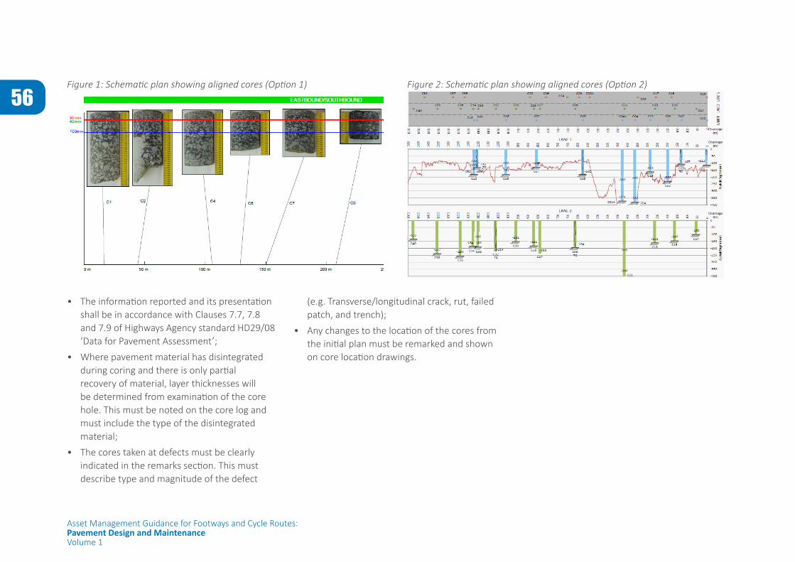
56
Asset Management Guidance for Footways and Cycle Routes:Pavement Design and MaintenanceVolume 1
Figure 1: Schematic plan showing aligned cores (Option 1) Figure 2: Schematic plan showing aligned cores (Option 2)
• The information reported and its presentation shall be in accordance with Clauses 7.7, 7.8 and 7.9 of Highways Agency standard HD29/08 ‘Data for Pavement Assessment’;
• Where pavement material has disintegrated during coring and there is only partial recovery of material, layer thicknesses will be determined from examination of the core hole. This must be noted on the core log and must include the type of the disintegrated material;
• The cores taken at defects must be clearly indicated in the remarks section. This must describe type and magnitude of the defect
(e.g. Transverse/longitudinal crack, rut, failed patch, and trench);
• Any changes to the location of the cores from the initial plan must be remarked and shown on core location drawings.
Related Documents