Geotechnical Engineering Environmental Engineering Hydrogeology Geological Engineering Materials Testing Building Science Paterson Group Inc. Consulting Engineers 154 Colonnade Road South Ottawa (Nepean), Ontario Canada K2E 7J5 Tel: (613) 226-7381 Fax: (613) 226-6344 www.patersongroup.ca patersongroup Geotechnical Investigation Proposed Residential Development Trails Edge - Phase 2 Renaud Road Ottawa, Ontario Prepared For Minto Communities March 12, 2012 Report: PG2392-1

Welcome message from author
This document is posted to help you gain knowledge. Please leave a comment to let me know what you think about it! Share it to your friends and learn new things together.
Transcript
GeotechnicalEngineering
EnvironmentalEngineering
Hydrogeology
GeologicalEngineering
Materials Testing
Building Science
Paterson Group Inc.Consulting Engineers154 Colonnade Road SouthOttawa (Nepean), OntarioCanada K2E 7J5
Tel: (613) 226-7381Fax: (613) 226-6344www.patersongroup.ca
patersongroup
Geotechnical InvestigationProposed Residential Development
Trails Edge - Phase 2Renaud Road
Ottawa, Ontario
Prepared For
Minto Communities
March 12, 2012
Report: PG2392-1
patersongroup Geotechnical Investigation
Ottawa Kingston North Bay Proposed Residential DevelopmentRenaud Road - Ottawa
Report: PG2392-1
March 12, 2012 Page i
Table of ContentsPage
1.0 INTRODUCTION. . . . . . . . . . . . . . . . . . . . . . . . . . . . . . . . . . . . . . . . . . . . . . . . . . . . 1
2.0 PROPOSED DEVELOPMENT. . . . . . . . . . . . . . . . . . . . . . . . . . . . . . . . . . . . . . . . . 1
3.0 METHOD OF INVESTIGATION
3.1 Field Investigation. . . . . . . . . . . . . . . . . . . . . . . . . . . . . . . . . . . . . . . . . . . . . . 2
3.2 Field Survey. . . . . . . . . . . . . . . . . . . . . . . . . . . . . . . . . . . . . . . . . . . . . . . . . . 3
3.3 Laboratory Testing. . . . . . . . . . . . . . . . . . . . . . . . . . . . . . . . . . . . . . . . . . . . . 3
3.4 Analytical Testing. . . . . . . . . . . . . . . . . . . . . . . . . . . . . . . . . . . . . . . . . . . . . . 4
4.0 OBSERVATIONS
4.1 Surface Conditions. . . . . . . . . . . . . . . . . . . . . . . . . . . . . . . . . . . . . . . . . . . . . 5
4.2 Subsurface Profile.. . . . . . . . . . . . . . . . . . . . . . . . . . . . . . . . . . . . . . . . . . . . . 5
4.3 Groundwater. . . . . . . . . . . . . . . . . . . . . . . . . . . . . . . . . . . . . . . . . . . . . . . . . . 6
5.0 DISCUSSION
5.1 Geotechnical Assessment.. . . . . . . . . . . . . . . . . . . . . . . . . . . . . . . . . . . . . . . 7
5.2 Site Grading and Preparation. . . . . . . . . . . . . . . . . . . . . . . . . . . . . . . . . . . . . 7
5.3 Foundation Design. . . . . . . . . . . . . . . . . . . . . . . . . . . . . . . . . . . . . . . . . . . . . 8
5.4 Design of Earthquakes. . . . . . . . . . . . . . . . . . . . . . . . . . . . . . . . . . . . . . . . . 13
5.5 Basement Slab. . . . . . . . . . . . . . . . . . . . . . . . . . . . . . . . . . . . . . . . . . . . . . . 13
5.6 Pavement Structure. . . . . . . . . . . . . . . . . . . . . . . . . . . . . . . . . . . . . . . . . . . 13
6.0 DESIGN AND CONSTRUCTION PRECAUTIONS
6.1 Foundation Drainage and Backfill. . . . . . . . . . . . . . . . . . . . . . . . . . . . . . . . . 16
6.2 Protection Against Frost Action. . . . . . . . . . . . . . . . . . . . . . . . . . . . . . . . . . . 16
6.3 Excavation Side Slopes. . . . . . . . . . . . . . . . . . . . . . . . . . . . . . . . . . . . . . . . 16
6.4 Pipe Bedding and Backfill. . . . . . . . . . . . . . . . . . . . . . . . . . . . . . . . . . . . . . . 17
6.5 Thrust Blocks. . . . . . . . . . . . . . . . . . . . . . . . . . . . . . . . . . . . . . . . . . . . . . . . 18
6.6 Groundwater Control. . . . . . . . . . . . . . . . . . . . . . . . . . . . . . . . . . . . . . . . . . . 18
6.7 Winter Construction. . . . . . . . . . . . . . . . . . . . . . . . . . . . . . . . . . . . . . . . . . . 19
6.8 Landscaping Considerations. . . . . . . . . . . . . . . . . . . . . . . . . . . . . . . . . . . . . 19
6.9 Corrosion Potential and Sulphate. . . . . . . . . . . . . . . . . . . . . . . . . . . . . . . . . 20
7.0 RECOMMENDATIONS. . . . . . . . . . . . . . . . . . . . . . . . . . . . . . . . . . . . . . . . . . . . . . 21
8.0 STATEMENT OF LIMITATIONS. . . . . . . . . . . . . . . . . . . . . . . . . . . . . . . . . . . . . . . 22
patersongroup Geotechnical Investigation
Ottawa Kingston North Bay Proposed Residential DevelopmentRenaud Road - Ottawa
Report: PG2392-1
March 12, 2012 Page ii
Appendices
Appendix 1 Soil Profile and Test Data Sheets
Symbols and Terms
Unidimensional Consolidation Test Results
Atterberg Limits’ Results
Analytical Testing Results
Appendix 2 Figure 1 - Key Plan
Drawing PG2392-1 - Test Hole Location Plan
Drawing PG2392-2 - Permissible Grade Raise Areas - Housing

patersongroup Geotechnical Investigation
Ottawa Kingston North Bay Proposed Residential DevelopmentRenaud Road - Ottawa
Report: PG2392-1March 12, 2012 Page 1
1.0 INTRODUCTION
Paterson Group (Paterson) was commissioned by Minto Communities (Minto) to
conduct a geotechnical investigation for Phase 2 of the Trails Edge residential
development located on the north side of Renaud Road between Page Road and
Mer Bleue Road, in the City of Ottawa (refer to Figure 1 - Key Plan presented in
Appendix 2).
The following report has been prepared specifically and solely for the aforementioned
project which is described herein. It contains our findings and includes geotechnical
recommendations pertaining to the design and construction of the proposed
development as it is understood at the time of writing this report.
A previous geotechnical investigation was completed by Paterson Group (Paterson)
at the subject site and surrounding areas. The relevant Soil Profile and Test Data
sheets and Unidimensional Consolidation Testing Results Sheets and Atterberg Limits
from the previous geotechnical investigation is presented in Appendix 1.
Investigating the presence or potential presence of contamination on the subject
property was not part of the scope of work of the present investigation. Therefore, the
present report does not address environmental issues.
2.0 PROPOSED DEVELOPMENT
Specific details of the current phase of the proposed development have not been
provided to Paterson. However, it is expected that the current phase of the proposed
residential development will consist of townhouses, single family residential dwellings
with associated roadways, local access lanes and driveways. It is also expected that
the proposed development will be municipally serviced.

patersongroup Geotechnical Investigation
Ottawa Kingston North Bay Proposed Residential DevelopmentRenaud Road - Ottawa
Report: PG2392-1March 12, 2012 Page 2
3.0 METHOD OF INVESTIGATION
3.1 Field Investigation
Field Program
The field program for the current geotechnical investigation was carried out on
August 16 and 17, 2011 and February 9 and 10, 2012. A previous geotechnical field
investigation was also completed by Paterson on May 11 and 12, 2009. The locations
of all the test holes completed during the geotechnical investigations are illustrated on
Drawing PG2392-1 - Test Hole Location Plan included in Appendix 2.
The boreholes were drilled using a track-mounted auger drill rig operated by a two
person crew. All fieldwork was conducted under the full-time supervision of personnel
from Paterson’s geotechnical division under the direction of a senior engineer. The
drilling procedure consisted of augering to the required depths at the selected locations
and sampling the overburden soils.
Sampling and In Situ Testing
Soil samples were collected from the boreholes using a 50 mm diameter split-spoon
(SS) sampler, or using 73 mm diameter thin walled (TW) Shelby tubes in conjunction
with a piston sampler. All soil samples were visually inspected and initially classified
on site. The split-spoon samples were placed in sealed plastic bags and the Shelby
tubes were sealed at both ends on site. All samples were transported to our laboratory
for further examination and classification. The depths at which the split-spoon and
Shelby tube samples were recovered from the boreholes are shown as SS and TW,
respectively, on the Soil Profile and Test Data sheets presented in Appendix 1.
Standard Penetration Testing (SPT) was conducted in conjunction with the recovery
of the split-spoon samples. The SPT results are recorded as “N” values on the Soil
Profile and Test Data sheets. The “N” value is the number of blows required to drive
the split-spoon sampler 300 mm into the soil after a 150 mm initial penetration using
a 63.5 kg hammer falling from a height of 760 mm. Undrained shear strength testing
was carried out in cohesive soils using a field vane apparatus.
The thickness of the silty clay layer was evaluated during the course of the current
investigation by dynamic cone penetration testing (DCPT) at all test hole locations.

patersongroup Geotechnical Investigation
Ottawa Kingston North Bay Proposed Residential DevelopmentRenaud Road - Ottawa
Report: PG2392-1March 12, 2012 Page 3
The DCPT consists of driving a steel drill rod, equipped with a 50 mm diameter cone
at its tip, using a 63.5 kg hammer falling from a height of 760 mm. The number of
blows required to drive the cone into the soil is recorded for each 300 mm increment.
Due to the low resistance exerted by the silty clay, the cone was pushed using the
hydraulic head of the drill rig until resistance to penetration was encountered. The drop
hammer was then used to further advance the cone.
The subsurface conditions observed in the test holes were recorded in detail in the
field. The soil profiles are presented on the Soil Profile and Test Data sheets in
Appendix 1 of this report.
Groundwater
Flexible polyethylene standpipes were installed in all boreholes to permit monitoring of
the groundwater levels subsequent to the completion of the sampling program.
3.2 Field Survey
The test hole locations along with ground surface elevations at the test hole locations
were determined in the field by Annis O’Sullivan Vollebekk Limited. It is understood
that the elevations are referenced to a geodetic datum. Due to existing densely tree
covered areas within the subject site, BH 4 and BH 5 were relocated to the adjacent
property boundaries. BH 4, BH 5 and BH 6 were relocated and surveyed by Paterson’s
personnel due to access issues.
The locations of the boreholes and the ground surface elevations at the test hole
locations are presented on Drawing PG2392-1 - Test Hole Location Plan in Appendix 2.
3.3 Laboratory Testing
Soil samples were collected from the subject site and were visually examined in our
laboratory to review the results of the field logging. A total of twelve (12) Shelby tube
samples were submitted during the current and previous geotechnical investigations
for unidimensional consolidation testing. The results of the testing are shown on the
Consolidation Test sheets in Appendix 1. The results of the geotechnical laboratory
testing program are discussed in Subsections 4.2 and 5.3 of this report.

patersongroup Geotechnical Investigation
Ottawa Kingston North Bay Proposed Residential DevelopmentRenaud Road - Ottawa
Report: PG2392-1March 12, 2012 Page 4
3.4 Analytical Testing
One (1) soil sample was submitted for analytical testing to assess the corrosion
potential for exposed ferrous metals and the potential of sulphate attacks against
subsurface concrete structures. The sample was submitted to determine the
concentration of sulphate and chloride, the resistivity and the pH of the sample. The
results are presented in Appendix 1 and are discussed further in Subsection 6.9.

patersongroup Geotechnical Investigation
Ottawa Kingston North Bay Proposed Residential DevelopmentRenaud Road - Ottawa
Report: PG2392-1March 12, 2012 Page 5
4.0 OBSERVATIONS
4.1 Surface Conditions
The subject site is undeveloped and is relatively flat. Treed areas were noted within
the north portion of the subject site and the south portion of the site has recently been
cleared and is currently occupied by several fill piles. A shallow ditch runs in a east-
west direction within the south central portion of the subject site.
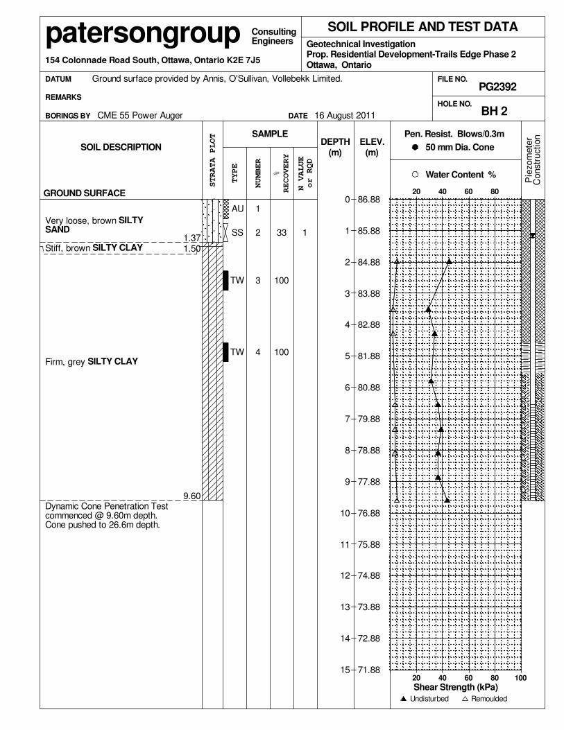
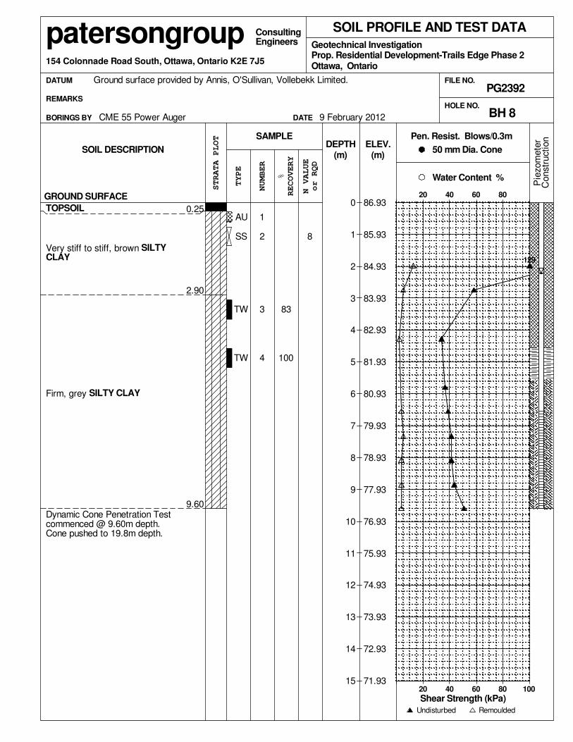
4.2 Subsurface Profile
Generally, the soil profile encountered at the test hole locations, consists of a thin
topsoil layer underlain by a deep silty clay layer to depths varying between 25 to 28 m
below existing ground surface. A silty sand deposit was noted at the borehole locations
within the south portion of the subject site.
Reference should be made to the Soil Profile and Test Data sheets presented in
Appendix 1 for details of the soil profiles encountered during the current and previous
geotechnical investigations.
Six (6) silty clay samples during the current geotechnical investigation and six (6) silty
clay samples during the previous geotechnical investigation were subjected to
unidimensional consolidation (oedometer) testing. The test results are presented in
Subsection 5.3 and on the Consolidation Test sheets in Appendix 1. The consolidation
test results indicate that the silty clay is overconsolidated with overconsolidation ratios
(OCR) for the tested samples varying between 1.2 and 2.2. The OCR is the ratio of the
preconsolidation pressure to the effective pressure at the sample depth. This is further
discussed in Subsection 5.3.
Two (2) silty clay samples were submitted for Atterberg Limits testing from the subject
site. The tested materials were classified as Inorganic Clays of High Plasticity (CH) in
accordance with the Unified Soil Classification System. The results are summarized
in Table 1 and presented on the Atterberg Limits Results sheet in Appendix 1.
Table 1 - Summary of Atterberg Limits Tests
SampleDepth
(m)
Moisture
Content
%
Liquid
Limit
%
Plastic
Limit
%
Plasticity
Index
%
Classification
BH 3 - TW 3 2.79 27.9 67 28 39 CH
BH 3-09 - TW 4 7.29 30.8 72 31 41 CH
CH: Inorganic Clays of high plasticity

patersongroup Geotechnical Investigation
Ottawa Kingston North Bay Proposed Residential DevelopmentRenaud Road - Ottawa
Report: PG2392-1March 12, 2012 Page 6
4.3 Groundwater
The long-term groundwater level can be estimated based on moisture levels and colour
of the recovered soil samples. Based on these observations combined with the field
observations at the borehole locations, the groundwater table is expected between 1.5
to 2.5 m depth below original ground surface. It should be noted that groundwater
levels are subject to seasonal fluctuations. Therefore, the groundwater levels could be
different at the time of construction.

patersongroup Geotechnical Investigation
Ottawa Kingston North Bay Proposed Residential DevelopmentRenaud Road - Ottawa
Report: PG2392-1March 12, 2012 Page 7
5.0 DISCUSSION
5.1 Geotechnical Assessment
The subject site is considered adequate for the proposed development. Based on the
subsurface profile encountered, it is expected that stiff silty clay and/or compact silty
sand will be encountered at the founding levels of the proposed structures.
Due to the presence of the sensitive silty clay layer, the subject site will be subjected
to grade raise restrictions. Permissible grade raise areas are detailed in Drawing
PG2392-2 - Permissible Grade Raise Areas - Housing. Where exceedances of the
permissible grade raise occur, lightweight fill (LWF) can be utilized below garage and
porch floor slabs, as well as, around the perimeter of the buildings, where required.
LWF dimensions, if required, will be determined on a lot by lot basis for the current
phase. Alternatively, a surcharging program could be implemented where grade raise
exceedances occur.
The above and other considerations are further discussed in the following sections.
5.2 Site Grading and Preparation
Stripping Depth
Topsoil and deleterious fill, such as those containing organics, should be stripped from
under any buildings, paved areas, pipe bedding and other settlement sensitive
structures.
Fill Placement
Fill used for grading beneath the buildings should consist, unless otherwise specified,
of clean imported granular fill, such as Ontario Provincial Standard Specifications
(OPSS) Granular A or Granular B Type II. This material should be tested and
approved prior to delivery to the site. The fill should be placed in lifts no greater than
300 mm thick and compacted using suitable compaction equipment for the lift
thickness. Fill placed beneath the building areas should be compacted to at least 98%
of its standard Proctor maximum dry density (SPMDD).

patersongroup Geotechnical Investigation
Ottawa Kingston North Bay Proposed Residential DevelopmentRenaud Road - Ottawa
Report: PG2392-1March 12, 2012 Page 8
Non-specified existing fill along with site-excavated soil can be used as general
landscaping fill and beneath parking areas where settlement of the ground surface is
of minor concern. In landscaped areas, these materials should be spread in thin lifts
and at least compacted by the tracks of the spreading equipment to minimize voids.
If these materials are to be used to build up the subgrade level for areas to be paved,
they should be compacted in thin lifts to a minimum density of 95% of their respective
SPMDD. Non-specified existing fill and site-excavated soils are not suitable for use as
backfill against foundation walls unless a composite drainage blanket connected to a
perimeter drainage system is provided.
5.3 Foundation Design
Bearing Resistance Values
Footings, up to 2 m wide, placed on an undisturbed, stiff silty clay can be designed
using a bearing resistance value at serviceability limit states (SLS) of 90 kPa and
factored bearing resistance values at ultimate limit states (ULS) of 150 kPa.
Strip and pad footings placed on an undisturbed, compact silty sand bearing surface
can be designed using a bearing resistance value at serviceability limit states (SLS) of
60 kPa and a factored bearing resistance value at ultimate limit states (ULS)
of 120 kPa. Where the silty sand bearing surface is found to be in a loose state of
compactness, the area should be proof-rolled under dry conditions using a vibratory
compactor and approved by the geotechnical consultant prior to placing footings.
A geotechnical resistance factor of 0.5 was applied to the bearing resistance values at
ULS.
The bearing resistance values at SLS will be subjected to potential post-construction
total and differential settlements of 25 and 15 mm, respectively.
An undisturbed soil bearing surface consists of one from which all topsoil and
deleterious materials, such as loose, frozen or disturbed soil, whether in situ or not,
have been removed, in the dry, prior to the placement of concrete for footings.
Lateral Support
The bearing medium under footing-supported structures is required to be provided with
adequate lateral support with respect to excavations and different foundation levels.
Adequate lateral support is provided to a stiff to firm silty clay above the groundwater
table when a plane extending down and out from the bottom edge of the footing at a
minimum of 1.5H:1V passes only through in situ soil of the same or higher capacity as
the bearing medium soil.

patersongroup Geotechnical Investigation
Ottawa Kingston North Bay Proposed Residential DevelopmentRenaud Road - Ottawa
Report: PG2392-1March 12, 2012 Page 9
Settlement/Grade Raise
Consideration must be given to potential settlements which could occur due to the
presence of the silty clay deposit and the combined loads from the proposed footings,
any groundwater lowering effects, and grade raise fill. The foundation loads to be
considered for the settlement case are the continuously applied loads which consist of
the unfactored dead loads and the portion of the unfactored live load that is considered
to be continuously applied. For dwellings, a minimum value of 50% of the live load is
often recommended by Paterson.
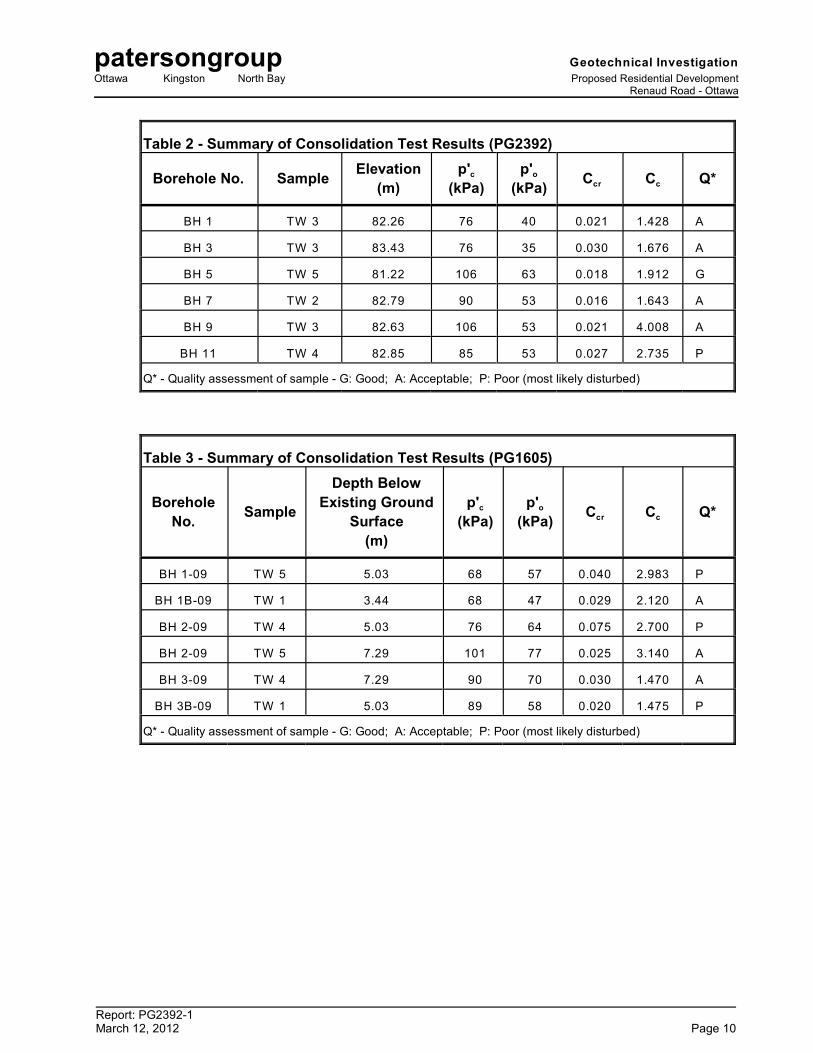
Generally, the potential long term settlement is evaluated based on the compressibility
characteristics of the silty clay. These characteristics are estimated in the laboratory
by conducting unidimensional consolidation tests on undisturbed soil samples collected
using Shelby tubes in conjunction with a piston sampler. Twelve (12) site specific
consolidation tests were carried out for the subject phase. The results of the
consolidation tests are presented in Table 2 and 3 on the following page and in
Appendix 1.
c oValue p' is the preconsolidation pressure of the sample and p' is the effective
overburden pressure. It should be noted that the effective overburden pressure has
been calculated from original ground surface for borehole locations, which were
completed after the fill program had been initiated. The difference between these
values is the available preconsolidation. The increase in stress on the soil due to the
cumulative effects of the fill surcharge, the footing pressures, the slab loadings and the
lowering of the groundwater should not exceed the available preconsolidation if
unacceptable settlements are to be avoided.
cr cThe values C and C are the recompression and compression indices, respectively,
and are a measure of the compressibility of the soil due to stress increases below and
cabove the preconsolidation pressures. The higher values for the C , as compared to
crthe C , illustrate the increased settlement potential above, as compared to below, the
preconsolidation pressure.
patersongroup Geotechnical Investigation
Ottawa Kingston North Bay Proposed Residential DevelopmentRenaud Road - Ottawa
Report: PG2392-1March 12, 2012 Page 10
Table 2 - Summary of Consolidation Test Results (PG2392)
Borehole No. SampleElevation
(m)cp'
(kPa)op'
(kPa) cr cC C Q*
BH 1 TW 3 82.26 76 40 0.021 1.428 A
BH 3 TW 3 83.43 76 35 0.030 1.676 A
BH 5 TW 5 81.22 106 63 0.018 1.912 G
BH 7 TW 2 82.79 90 53 0.016 1.643 A
BH 9 TW 3 82.63 106 53 0.021 4.008 A
BH 11 TW 4 82.85 85 53 0.027 2.735 P
Q* - Quality assessment of sample - G: Good; A: Acceptable; P: Poor (most likely disturbed)
Table 3 - Summary of Consolidation Test Results (PG1605)
Borehole
No.Sample
Depth Below
Existing Ground
Surface
(m)
cp'
(kPa)op'
(kPa) cr cC C Q*
BH 1-09 TW 5 5.03 68 57 0.040 2.983 P
BH 1B-09 TW 1 3.44 68 47 0.029 2.120 A
BH 2-09 TW 4 5.03 76 64 0.075 2.700 P
BH 2-09 TW 5 7.29 101 77 0.025 3.140 A
BH 3-09 TW 4 7.29 90 70 0.030 1.470 A
BH 3B-09 TW 1 5.03 89 58 0.020 1.475 P
Q* - Quality assessment of sample - G: Good; A: Acceptable; P: Poor (most likely disturbed)

patersongroup Geotechnical Investigation
Ottawa Kingston North Bay Proposed Residential DevelopmentRenaud Road - Ottawa
Report: PG2392-1March 12, 2012 Page 11
c o cr cIt should be noted that the values of p' , p' , C and C are determined using standard
engineering practices and are estimates only. In addition, natural variations within the
o soil deposit would also affect the results. Furthermore, the p' parameter is directly
influenced by the groundwater level. While the groundwater levels were measured at
the time of the fieldwork, the levels vary with time and this has an impact on the
oavailable preconsolidation. Lowering the groundwater level increases the p' and
therefore reduces the available preconsolidation. Unacceptable settlements could be
oinduced by a significant lowering of the groundwater level. The p' values for the
consolidation tests carried out for the present investigation are based on the long term
groundwater level observed at each borehole location. The groundwater level is based
on the colour and undrained shear strength profile of the silty clay.
The total and differential settlements will be dependent of the characteristics of the
buildings. For design purposes, the total and differential settlements associated with
the combination of proposed grade raises and design footing loading conditions are
estimated to be 25 mm and 20 mm, respectively. A post-development groundwater
lowering of 0.5 m was assumed.
The potential post construction total and differential settlements are dependent on the
position of the long term groundwater level when building over deposits of
compressible silty clay. While efforts can be made to reduce the impacts of the
development on the long term level of the groundwater by placing clay dykes in the
service trenches, reducing the sizes of paved areas, leaving green spaces to allow for
groundwater recharge, limiting planting of trees to areas away from the buildings, it is
not economically possible to control the level of the groundwater.
The permissible grade raise recommendations for the proposed residential dwellings
are presented in Drawing PG2392-2 - Permissible Grade Raise Areas - Housing in
Appendix 2. An average grade raise fill unit weight of 18 kN/m for houses was used3
for grade raise estimate purposes.
To reduce potential long term liabilities, consideration should be given to accounting
for a larger groundwater lowering and to providing means to reduce long term
groundwater lowering (e.g. clay dykes, restriction on planting around the stores, etc).
It should be noted that building on silty clay deposits increases the likelihood of building
movements and therefore of cracking. The use of steel reinforcement in foundations
placed at key structural locations will tend to reduce foundation cracking as compared
to unreinforced foundations.

patersongroup Geotechnical Investigation
Ottawa Kingston North Bay Proposed Residential DevelopmentRenaud Road - Ottawa
Report: PG2392-1March 12, 2012 Page 12
Where the grade raise restrictions can be accommodated, the design of the footings
can be carried out based on the values provided in Subsection 5.3. Where the grade
raise is close to, but below, the maximum permissible grade raise, consideration should
be given to using more reinforcement in the design of the foundation (footings and
walls) to reduce the risks of cracking in the concrete foundation. The use of control
joints within the brick work between the garage and basement area should also be
considered.
Where permissible grade raise exceedances occur at the buildings, LWF should be
utilized below garage and porch floor slabs, as well as, around the perimeter of the
buildings, where required. LWF dimensions will be determined on a lot by lot basis for
the current phase.
It is also possible to preload or surcharge the subject site in localized areas provided
sufficient time is available to achieve the desired settlements based on theoretical
values from the settlement analysis. If this option is considered, a monitoring program
using settlement plates and electronic piezometers will have to be implemented. This
program will determine the amount of settlement in the preloaded or surcharged areas.
Obviously, preloading to proposed finished grades will allow for consolidation of the
underlying clays over a longer time period. Surcharging the site with additional fill
above the proposed finished grade will add additional load to the underlying clays
accelerating the consolidation process and allowing for earlier settlements. Once the
desired settlements are achieved, the site can be unloaded and the fill can be used
elsewhere on site.
With both the preloading and surcharging methods, the loading period can be reduced
by installing vertical wick drains or sand drains in the silty clay layer to promote the
movement of groundwater towards the ground surface.
It should be noted that the underground services may be subjected to unacceptable
total or differential settlements. In particular, the joints at the interface building/soil may
be subjected to excessive stress if the differential settlements between the building and
the services are excessive. This should be considered in the design of the
underground services.
Once the required grade raises are established, the above options could be further
discussed along with further recommendations on specific requirements.

patersongroup Geotechnical Investigation
Ottawa Kingston North Bay Proposed Residential DevelopmentRenaud Road - Ottawa
Report: PG2392-1March 12, 2012 Page 13
5.4 Design for Earthquakes
Based on existing subsoils information, a seismic site response Class E is applicable
for the proposed buildings to be located within the subject site according to the
OBC 2006. However, based on bedrock depth and general knowledge of the seismic
shear wave velocities for the subsoils observed, a seismic Site Class D may be
applicable for the north and central portions of the subject site. However, a site specific
shear wave velocity test should be completed to confirm our assumptions. The soils
underlying the site are not susceptible to liquefaction.
5.5 Basement Slab
With the removal of all topsoil and fill, containing organic matter, within the footprints
of the proposed buildings, the native soil surface will be considered to be an acceptable
subgrade surface on which to commence backfilling for floor slab construction. Any
soft areas should be removed and backfilled with appropriate backfill material. OPSS
Granular B Type II is recommended for backfilling below the floor slab. It is
recommended that the upper 200 mm of sub-slab fill consist of 19 mm clear crushed
stone.
5.6 Pavement Structure
For design purposes, the pavement structure presented in the following tables could
be used for the design of car parking areas, local roadways and roadways with bus
traffic.
Table 4 - Recommended Pavement Structure - Driveways
Thickness(mm)
Material Description
50 Wear Course - HL 3 or Superpave 12.5 Asphaltic Concrete
150 BASE - OPSS Granular A Crushed Stone
300 SUBBASE - OPSS Granular B Type II
SUBGRADE - Either in situ soil or OPSS Granular B Type II material placed over in situ soil

patersongroup Geotechnical Investigation
Ottawa Kingston North Bay Proposed Residential DevelopmentRenaud Road - Ottawa
Report: PG2392-1March 12, 2012 Page 14
Table 5 - Recommended Pavement Structure - Local Residential Roadways (No Bus Traffic)
Thickness(mm)
Material Description
40 Wear Course - Superpave 12.5 Asphaltic Concrete
50 Binder Course - Superpave 19.0 Asphaltic Concrete
150 BASE - OPSS Granular A Crushed Stone
400 SUBBASE - OPSS Granular B Type II
SUBGRADE - Either in situ soil or OPSS Granular B Type II material placed over in situ soil
Table 6 - Recommended Pavement Structure - Roadways with Bus Traffic
Thickness
mm
Material Description
40 Wear Course - Superpave 12.5 Asphaltic Concrete
50 Upper Binder Course - Superpave 19.0 Asphaltic Concrete
50 Lower Binder Course - Superpave 19.0 Asphaltic Concrete
150 BASE - OPSS Granular A Crushed Stone
600 SUBBASE - OPSS Granular B Type II
SUBGRADE - Either in situ soil or OPSS Granular B Type II material placed
over in situ soil
Minimum Performance Graded (PG) 58-34 asphalt cement should be used for this
project.
If soft spots develop in the subgrade during compaction or due to construction traffic,
the affected areas should be excavated and replaced with OPSS Granular B Type I
or II material. Weak subgrade conditions may be experienced over service trench fill
materials. This may require the use of a geotextile, such as Terratrack 200 or
equivalent, thicker subbase or other measures that can be recommended at the time
of construction as part of the field observation program.
The pavement granular base and subbase should be placed in maximum 300 mm thick
lifts and compacted to a minimum of 100% of the material’s SPMDD using suitable
vibratory equipment.
patersongroup Geotechnical Investigation
Ottawa Kingston North Bay Proposed Residential DevelopmentRenaud Road - Ottawa
Report: PG2392-1March 12, 2012 Page 15
Pavement Structure Drainage
Satisfactory performance of the pavement structure is largely dependent on keeping
the contact zone between the subgrade material and the base stone in a dry condition.
Failure to provide adequate drainage under conditions of heavy wheel loading can
result in the fine subgrade soil being pumped into the voids in the stone subbase,
thereby reducing its load carrying capacity.
Due to the impervious nature of the subgrade materials consideration should be given
to installing subdrains during the pavement construction. These drains installed at
catch basins should be at least 3 m long and should extend in four orthogonal
directions or longitudinally when placed along a curb. Along local streets, the drains
should be placed along the edges of the pavement. The subdrain inverts should be
approximately 300 mm below subgrade level. The subgrade surface should be
crowned to promote water flow to the drainage lines.

patersongroup Geotechnical Investigation
Ottawa Kingston North Bay Proposed Residential DevelopmentRenaud Road - Ottawa
Report: PG2392-1March 12, 2012 Page 16
6.0 DESIGN AND CONSTRUCTION PRECAUTIONS
6.1 Foundation Drainage and Backfill
It is recommended that a perimeter foundation drainage system be provided for
proposed structures. The system should consist of a 100 to 150 mm diameter,
geotextile-wrapped, perforated, corrugated, plastic pipe, surrounded on all sides by
150 mm of 10 mm clear crushed stone, placed at the footing level around the exterior
perimeter of the structure. The pipe should have a positive outlet, such as a gravity
connection to the storm sewer.
Backfill against the exterior sides of the foundation walls should consist of free-
draining, non frost susceptible granular materials. The site materials will be frost
susceptible and, as such, are not recommended for re-use as backfill unless a
composite drainage system (such as system Platon or Miradrain G100N) connected
to a drainage system is provided.
6.2 Protection Against Frost Action
Perimeter footings of heated structures are required to be insulated against the
deleterious effect of frost action. A minimum 1.5 m thick soil cover (or equivalent)
should be provided in this regard.
A minimum of 2.1 m thick soil cover (or equivalent) should be provided for other
exterior unheated footings.
6.3 Excavation Side Slopes
The excavation for the proposed development will be mostly through silty clay. Above
the groundwater level, for excavations to depths of approximately 3 m, the excavation
side slopes should be stable in the short term at 1H:1V. The lowermost 1.2 m can be
vertical provided the material consists of stiff in situ silty clay. Flatter slopes could be
required for deeper excavations or for excavation below the groundwater level. Where
such side slopes are not permissible or practical, temporary shoring should be used.
The subsoil at this site is considered to be mainly a Type 2 and 3 soil according to the
Occupational Health and Safety Act and Regulations for Construction Projects.
The slope cross-sections recommended above are for temporary slopes. Excavated
soil should not be stockpiled directly at the top of excavations and heavy equipment
should be kept away from the excavation sides.
patersongroup Geotechnical Investigation
Ottawa Kingston North Bay Proposed Residential DevelopmentRenaud Road - Ottawa
Report: PG2392-1March 12, 2012 Page 17
Slopes in excess of 3 m in height should be periodically inspected by the geotechnical
consultant in order to detect if the slopes are exhibiting signs of distress.
It is recommended that a trench box be used at all times to protect personnel working
in trenches with steep or vertical sides. It is expected that services will be installed by
“cut and cover” methods and excavations will not be left open for extended periods of
time.
6.4 Pipe Bedding and Backfill
Bedding and backfill materials should be in accordance with City of Ottawa standards
and specifications.
The pipe bedding for sewer and water pipes should consist of at least 150 mm of
OPSS Granular A material. Where the bedding is located within the soft to firm grey
silty clay, the thickness of the bedding material should be increased to a minimum of
300 mm. The material should be placed in maximum 300 mm thick lifts and
compacted to a minimum of 95% of its SPMDD. The bedding material should extent
at least to the spring line of the pipe.
The cover material, which should consist of OPSS Granular A, should extend from the
spring line of the pipe to at least 300 mm above the obvert of the pipe. The material
should be placed in maximum 300 mm thick lifts and compacted to a minimum of 95%
of its SPMDD.
It should generally be possible to re-use the moist (not wet) brown silty clay above the
cover material if the excavation and filling operations are carried out in dry weather
conditions. Wet silty clay materials will be difficult to re-use, as the high water contents
make compacting impractical without an extensive drying period.
Where hard surface areas are considered above the trench backfill, the trench backfill
material within the frost zone (about 1.8 m below finished grade) should match the soils
exposed at the trench walls to minimize differential frost heaving. The trench backfill
should be placed in maximum 300 mm thick loose lifts and compacted to a minimum
of 95% of the material’s SPMDD.

patersongroup Geotechnical Investigation
Ottawa Kingston North Bay Proposed Residential DevelopmentRenaud Road - Ottawa
Report: PG2392-1March 12, 2012 Page 18
To reduce long-term lowering of the groundwater level at this site, clay seals should be
provided in the service trenches. The seals should be at least 1.5 m long (in the trench
direction) and should extend from trench wall to trench wall. Generally, the seals
should extend from the frost line and fully penetrate the bedding, sub-bedding and
cover material. The barriers should consist of relatively dry and compactable brown
silty clay placed in maximum 225 mm thick loose layers and compacted to a minimum
of 95% of the material’s SPMDD. The clay seals should be placed at the site
boundaries and at strategic locations at no more than 60 m intervals in the service
trenches.
6.5 Thrust Blocks
The thrust blocks will be located within the silty clay deposit. Thrust blocks resisting
lateral loads should be sized based on allowable passive earth pressure at the pipe
depth. Those resisting (downward) vertical loads should be sized based on the
allowable bearing capacity.
Where the thrust block is placed within the silty clay, the allowable earth pressure and
horizontal bearing pressure will be dependent on the depth of the pipe invert. An
allowable lateral earth pressure of 100 kPa and an allowable vertical soil bearing
capacity of 75 kPa can be used provided that invert of the pipe is placed at a minimum
depth of 2.4 m.
The above values are provided on the assumptions that the thrust blocks are placed
against undisturbed soil bearing surfaces.
An undisturbed soil bearing surface consists of one from which all topsoil and
deleterious materials, such as loose, frozen or disturbed soil have been removed in the
dry prior to the placement of concrete.
6.6 Groundwater Control
Due to the relatively impervious nature of the silty clay materials, it is anticipated that
groundwater infiltration into the excavations should be low and controllable using open
sumps. A perched groundwater condition may be encountered within the silty sand
deposit which may produce significant temporary groundwater infiltration levels.
Pumping from open sumps should be sufficient to control the groundwater influx
through the sides of shallow excavations.

patersongroup Geotechnical Investigation
Ottawa Kingston North Bay Proposed Residential DevelopmentRenaud Road - Ottawa
Report: PG2392-1March 12, 2012 Page 19
A temporary MOE permit to take water (PTTW) will be required for this project if more
than 50,000 L/day are to be pumped during the construction phase. At least 3 to
4 months should be allowed for completion of the application and issuance of the
permit by the MOE.
The contractor should be prepared to direct water away from all bearing surfaces and
subgrades, regardless of the source, to prevent disturbance to the founding medium.
6.7 Winter Construction
The subsoil conditions at this site mostly consist of frost susceptible materials. In
presence of water and freezing conditions ice could form within the soil mass. Heaving
and settlement upon thawing could occur. Precautions should be taken if winter
construction is considered for this project.
In the event of construction during below zero temperatures, the founding stratum
should be protected from freezing temperatures by the use of straw, propane heaters
and tarpaulins or other suitable means. In this regard, the base of the excavations
should be insulated from sub-zero temperatures immediately upon exposure and until
such time as heat is adequately supplied to the building and the footings are protected
with sufficient soil cover to prevent freezing at founding level.
The trench excavations should be carried out in a manner that will avoid the
introduction of frozen materials into the trenches. As well, pavement construction is
difficult during winter. The subgrade consists of frost susceptible soils which will
experience total and differential frost heaving as the work takes place. In addition, the
introduction of frost, snow or ice into the pavement materials, which is difficult to avoid,
could adversely affect the performance of the pavement structure. Additional
information could be provided, if required.
6.8 Landscaping Considerations
Tree Planting Restrictions
The current phase of the proposed development is located in an area of highly
sensitive silty clay deposits for tree planting. It is expected that the combination of the
proposed finished grades and the thickness of the underlying weathered clay crust will
provide approximately 3 to 4 m thick buffer to the underlying firm silty clay deposit.

patersongroup Geotechnical Investigation
Ottawa Kingston North Bay Proposed Residential DevelopmentRenaud Road - Ottawa
Report: PG2392-1March 12, 2012 Page 20
Tree planting for this subject development should be limited to low water demand trees.
The minimum permissible distance from the foundation will depend on the nature of the
tree, the depth of the clay crust and the final grade raise in relation to the permissible
grade raise. A minimum permissible distance of 5 m from the foundation wall is
recommended for a tree planting setback.
It is well documented in the literature, and is our experience, that fast-growing trees
located near buildings founded on cohesive soils that shrink on drying can result in
long-term differential settlements of the structures. Tree varieties that have the most
pronounced effect on foundations are seen to consist of poplars, willows and some
maples (i.e. Manitoba Maples) and, as such, they should not be considered in the
landscaping design.
Swimming Pools
The in-situ soils are considered to be acceptable for swimming pools. Above ground
swimming pools must be placed at least 4 m away from the residence foundation and
neighbouring foundations. Otherwise, pool construction is considered routine, and can
be constructed in accordance with the manufacturer`s requirements.
Aboveground Hot Tubs
If consideration is given to construction of an aboveground hot tub, a geotechnical
consultant should be retained by the homeowner to review the site conditions.
Additional grading around the hot tub should not exceed permissible grade raises.
Otherwise, hot tub construction is considered routine, and can be constructed in
accordance with the manufacturer’s specifications.
Installation of Decks or Additions
If consideration is given to construction of a deck or addition, a geotechnical consultant
should be retained by the homeowner to review the site conditions. Additional grading
around proposed deck or addition should not exceed permissible grade raises.
Otherwise, standard construction practices are considered acceptable.
6.9 Corrosion Potential and Sulphate
The results of analytical testing show that the sulphate content is less than 0.1%.
These results are indicative that Type 10 Portland cement (normal cement) would be
appropriate for this site. The results of the chloride content, pH and resistivity indicate
the presence of a non-aggressive to slightly aggressive environment for exposed
ferrous metals at this site.

patersongroup Geotechnical Investigation
Ottawa Kingston North Bay Proposed Residential DevelopmentRenaud Road - Ottawa
Report: PG2392-1March 12, 2012 Page 21
7.0 RECOMMENDATIONS
It is recommended that the following be completed once the master plan and site
development are determined:
� Review detailed grading plan(s) from a geotechnical perspective.
� Observation of all bearing surfaces prior to the placement of concrete.
� Periodic observation of the condition of unsupported excavation side slopes in
excess of 3 m in height, if applicable.
� Observation of all subgrades prior to backfilling.
� Field density tests to ensure that the specified level of compaction has been
achieved.
� Sampling and testing of the bituminous concrete including mix design reviews.
A report confirming that the above program has been conducted in general accordance
with our recommendations could be issued upon request, following the completion of
a satisfactory material testing and observation program by the geotechnical consultant.

patersongroup Geotechnical Investigation
Ottawa Kingston North Bay Proposed Residential DevelopmentRenaud Road - Ottawa
Report: PG2392-1March 12, 2012 Page 22
8.0 STATEMENT OF LIMITATIONS
The recommendations made in this report are in accordance with our present
understanding of the project. We request that we be permitted to review the grading
plan once available and our recommendations when the drawings and specifications
are complete.
A geotechnical investigation of this nature is a limited sampling of a site. The
recommendations are based on information gathered at the specific test locations and
can only be extrapolated to an undefined limited area around the test locations. The
extent of the limited area depends on the soil, bedrock and groundwater conditions, as
well the history of the site reflecting natural, construction, and other activities. Should
any conditions at the site be encountered which differ from those at the test locations,
we request notification immediately in order to permit reassessment of our
recommendations.
The present report applies only to the project described in this document. Use of this
report for purposes other than those described herein or by person(s) other than Minto
Communities (Minto) or their agent(s) is not authorized without review by Paterson
Group for the applicability of our recommendations to the altered use of the report.
Paterson Group Inc.
Richard Groniger, Technologist. David J. Gilbert, P.Eng.
Report Distribution:
� Minto Communities (3 copies)
� Paterson Group (1 copy)

APPENDIX 1
SOIL PROFILE AND TEST DATA SHEETS
SYMBOLS AND TERMS
UNIDIMENSIONAL CONSOLIDATION TEST RESULTS
ATTERBERG LIMITS’ RESULTS
ANALYTICAL TESTING RESULTS

0
1
2
3
4
5
6
7
8
9
10
11
12
13
14
15
GROUND SURFACE
%
TYPE
2
1
100
83
100
67
3
4
SS 2
Dynamic Cone Penetration Testcommenced @ 9.60m depth.Cone pushed to 27.7m depth.
3
STRATA PLOT
Firm, grey SILTY CLAY
Stiff to firm, brown SILTYCLAY
Very loose, brown SILTYSAND
9.60
2.10
0.20
TW
TW
SS
DATUM
SOIL DESCRIPTION
CME 55 Power Auger
Ground surface provided by Annis, O'Sullivan, Vollebekk Limited.
REMARKS
BORINGS BY
Consulting
HOLE NO.
Pen. Resist. Blows/0.3m
85.87
84.87
83.87
82.87
81.87
80.87
79.87
78.87
77.87
76.87
75.87
74.87
73.87
72.87
71.87
70.87
Water Content %
Remoulded
patersongroup154 Colonnade Road South, Ottawa, Ontario K2E 7J5
Pie
zom
ete
r
50 mm Dia. Cone
Prop. Residential Development-Trails Edge Phase 2
SOIL PROFILE AND TEST DATA
(m)
PG2392
20 40 60 80
Engineers
(m)
or RQD
Undisturbed
Shear Strength (kPa)
BH 1
ELEV.
Constr
uction
NUMBER
Ottawa, Ontario
SAMPLEDEPTH
20 40 60 80 100
RECOVERY
DATE
FILE NO.
Geotechnical Investigation
N VALUE
16 August 2011

NUMBER
Ottawa, Ontario
ELEV.
BH 1
Undisturbed
or RQD
Constr
uction
28.45
(GWL @ 1.6m depth based onfield observations)
End of Borehole
Practical cone refusal @28.45m depth
SAMPLEDEPTH
TYPE
%
STRATA PLOT
15
16
17
18
19
20
21
22
23
24
25
26
27
28
SOIL PROFILE AND TEST DATA
16 August 2011
Ground surface provided by Annis, O'Sullivan, Vollebekk Limited.
CME 55 Power Auger
Consulting
(m)
Engineers
20 40 60 80
BORINGS BY
(m)50 mm Dia. Cone
Pie
zom
ete
r
154 Colonnade Road South, Ottawa, Ontario K2E 7J5
patersongroup
Remoulded
Water Content %
PG2392
SOIL DESCRIPTION
Geotechnical Investigation
DATE
20 40 60 80 100
N VALUE
RECOVERY
REMARKS
Shear Strength (kPa)
DATUM FILE NO.
GROUND SURFACE
Prop. Residential Development-Trails Edge Phase 2
HOLE NO.
Pen. Resist. Blows/0.3m
70.87
69.87
68.87
67.87
66.87
65.87
64.87
63.87
62.87
61.87
60.87
59.87
58.87
57.87
DEPTH
TYPE
0
1
2
3
4
5
6
7
8
9
10
11
12
13
14
15
GROUND SURFACE
%
4
3
2
1
100
100
33 1
TW
AU
SS
Dynamic Cone Penetration Testcommenced @ 9.60m depth.Cone pushed to 26.6m depth.
Firm, grey SILTY CLAY
Stiff, brown SILTY CLAY
Very loose, brown SILTYSAND
9.60
1.501.37
TW
DATUM
CME 55 Power Auger
Ground surface provided by Annis, O'Sullivan, Vollebekk Limited.
REMARKS
BORINGS BY
(m)
STRATA PLOT SAMPLE
Prop. Residential Development-Trails Edge Phase 2
HOLE NO.
Pen. Resist. Blows/0.3m
86.88
85.88
84.88
83.88
82.88
81.88
80.88
79.88
78.88
77.88
76.88
75.88
74.88
73.88
72.88
71.88
Water Content %
Remoulded
patersongroup154 Colonnade Road South, Ottawa, Ontario K2E 7J5
Pie
zom
ete
r
50 mm Dia. Cone
Consulting SOIL PROFILE AND TEST DATA
(m)
PG2392
20 40 60 80
Engineers
Constr
uction
SOIL DESCRIPTION
Undisturbed
BH 2
or RQD
Ottawa, Ontario
ELEV.
N VALUE
20 40 60 80 100
FILE NO.
NUMBER
Shear Strength (kPa)
RECOVERY
DATE 16 August 2011
Geotechnical Investigation

DEPTH50 mm Dia. Cone
26.69End of Borehole
Practical cone refusal @26.69m depth
(GWL @ 1.21m-Feb. 29/12)
SOIL PROFILE AND TEST DATA
TYPE
%
STRATA PLOT
15
16
17
18
19
20
21
22
23
24
25
26
HOLE NO.
CME 55 Power Auger
Prop. Residential Development-Trails Edge Phase 2
DATUM
BORINGS BY
Ground surface provided by Annis, O'Sullivan, Vollebekk Limited.
SAMPLE
Consulting
(m)
Engineers
20 40 60 80
PG2392
(m)
REMARKS
Shear Strength (kPa)
Geotechnical Investigation
DATE
20 40 60 80 100
N VALUE
RECOVERY
FILE NO.
SOIL DESCRIPTION
71.88
70.88
69.88
68.88
67.88
66.88
65.88
64.88
63.88
62.88
61.88
60.88
Pen. Resist. Blows/0.3m
Pie
zom
ete
r
154 Colonnade Road South, Ottawa, Ontario K2E 7J5
patersongroup
Remoulded
Water Content %
NUMBER
Ottawa, Ontario
ELEV.
BH 216 August 2011
Undisturbed
or RQD
Constr
uction
GROUND SURFACE

0
1
2
3
4
5
6
7
8
9
10
11
12
13
14
15
GROUND SURFACE
%
TYPE
4
3
2
1
100
100
92SS
TW
1
AUSTRATA PLOT
Dynamic Cone Penetration Testcommenced @ 9.60m depth.Cone pushed to 26.2m depth.
Firm, grey SILTY CLAY
Stiff to firm, brown SILTYCLAY
Very loose, brown SILTYSAND
9.60
2.10
0.69
TW
DATUM
SOIL DESCRIPTION
CME 55 Power Auger
Ground surface provided by Annis, O'Sullivan, Vollebekk Limited.
REMARKS
BORINGS BY
Consulting
HOLE NO.
Pen. Resist. Blows/0.3m
86.22
85.22
84.22
83.22
82.22
81.22
80.22
79.22
78.22
77.22
76.22
75.22
74.22
73.22
72.22
71.22
Water Content %
Remoulded
patersongroup154 Colonnade Road South, Ottawa, Ontario K2E 7J5
Pie
zom
ete
r
50 mm Dia. Cone
Prop. Residential Development-Trails Edge Phase 2
SOIL PROFILE AND TEST DATA
(m)
PG2392
20 40 60 80
Engineers
(m)
or RQD
Undisturbed
Shear Strength (kPa)
BH 3
ELEV.
Constr
uction
NUMBER
Ottawa, Ontario
SAMPLEDEPTH
20 40 60 80 100
RECOVERY
DATE
FILE NO.
Geotechnical Investigation
N VALUE
16 August 2011

BH 3
DEPTHSAMPLE
Ottawa, Ontario
16 August 2011
NUMBER
Undisturbed
or RQD
Constr
uction
ELEV.
27.56End of Borehole
Practical cone refusal @27.56m depth
(GWL @ 1.6m depth based onfield observations)
15
16
17
18
19
20
21
22
23
24
25
26
27
TYPE
%
STRATA PLOT
SOIL PROFILE AND TEST DATA
Ground surface provided by Annis, O'Sullivan, Vollebekk Limited.
CME 55 Power Auger
Consulting
(m)
Engineers
20 40 60 80
BORINGS BY
(m)50 mm Dia. Cone
Pie
zom
ete
r
154 Colonnade Road South, Ottawa, Ontario K2E 7J5
patersongroup
Remoulded
Water Content %
PG2392
SOIL DESCRIPTION
Geotechnical Investigation
DATE
20 40 60 80 100
N VALUE
RECOVERY
REMARKS
Shear Strength (kPa)
DATUM FILE NO.
GROUND SURFACE
Prop. Residential Development-Trails Edge Phase 2
HOLE NO.
Pen. Resist. Blows/0.3m
71.22
70.22
69.22
68.22
67.22
66.22
65.22
64.22
63.22
62.22
61.22
60.22
59.22

Ottawa, Ontario
TYPE
139
GROUND SURFACE
SAMPLE
0
1
2
3
4
5
6
7
8
9
10
11
12
13
14
15
STRATA PLOT
%
10.400.25
TW
TW
SS
AU
8.38
2
TOPSOIL
3
139
2.90
Inferred SILTY CLAY
Dynamic Cone Penetration Testcommenced @ 8.38m depth.Cone pushed to 22.5m depth.
Firm, grey SILTY CLAY
Very stiff to stiff, brown SILTYCLAY
Brown SILTY SAND
Consulting
CME 55 Power Auger
Ground surface provided by Annis, O'Sullivan, Vollebekk Limited.
REMARKS
Prop. Residential Development-Trails Edge Phase 2
DEPTH
DATUM
BORINGS BY
50 mm Dia. Cone
Water Content %
Remoulded
patersongroup154 Colonnade Road South, Ottawa, Ontario K2E 7J5
Pie
zom
ete
r
(m)
SOIL PROFILE AND TEST DATA
(m)
PG2392
20 40 60 80
Engineers
or RQD
HOLE NO.
14 February 2012
Undisturbed
NUMBER
BH 4
ELEV.Pen. Resist. Blows/0.3m
Shear Strength (kPa)
FILE NO.
Constr
uction
86.60
85.60
84.60
83.60
82.60
81.60
80.60
79.60
78.60
77.60
76.60
75.60
74.60
73.60
72.60
71.60
SOIL DESCRIPTION
RECOVERY
N VALUE
20 40 60 80 100
DATE
Geotechnical Investigation

Constr
uction
ELEV.
BH 4
NUMBER
Undisturbed
or RQD
14 February 2012
STRATA PLOT
22.50End of Borehole
Practical DCPT refusal @22.50m depth
(GWL @ 2.2m depth based onfield observations)
TYPE
%
Ottawa, Ontario
15
16
17
18
19
20
21
22
DEPTHSAMPLE
Consulting
(m)
Engineers
20 40 60 80
PG2392Ground surface provided by Annis, O'Sullivan, Vollebekk Limited.
SOIL PROFILE AND TEST DATA
REMARKS
50 mm Dia. Cone
Pie
zom
ete
r
154 Colonnade Road South, Ottawa, Ontario K2E 7J5
patersongroup
Remoulded
Water Content %
(m)
Pen. Resist. Blows/0.3m
Geotechnical Investigation
DATE
20 40 60 80 100
N VALUE
RECOVERY
FILE NO.
Shear Strength (kPa)
SOIL DESCRIPTION
CME 55 Power Auger
71.60
70.60
69.60
68.60
67.60
66.60
65.60
64.60
GROUND SURFACE
HOLE NO.
Prop. Residential Development-Trails Edge Phase 2
DATUM
BORINGS BY

120
0
1
2
3
4
5
6
7
8
9
10
11
12
13
14
15
GROUND SURFACE
%
TYPE
83SS
AU
AU
5
4
3
2
TW 100
0.20
7
1
120
TW
STRATA PLOT
Dynamic Cone Penetration Testcommenced @ 9.60m depth.Cone pushed to 21.6m depth.
Firm, grey SILTY CLAY
Very stiff to stiff, brown SILTYCLAY
TOPSOIL
9.60
2.90
DATUM
SOIL DESCRIPTION
CME 55 Power Auger
Ground surface provided by Annis, O'Sullivan, Vollebekk Limited.
REMARKS
BORINGS BY
Consulting
HOLE NO.
Pen. Resist. Blows/0.3m
87.07
86.07
85.07
84.07
83.07
82.07
81.07
80.07
79.07
78.07
77.07
76.07
75.07
74.07
73.07
72.07
Water Content %
Remoulded
patersongroup154 Colonnade Road South, Ottawa, Ontario K2E 7J5
Pie
zom
ete
r
50 mm Dia. Cone
Prop. Residential Development-Trails Edge Phase 2
SOIL PROFILE AND TEST DATA
(m)
PG2392
20 40 60 80
Engineers
(m)
or RQD
Undisturbed
Shear Strength (kPa)
BH 5
ELEV.
Constr
uction
NUMBER
Ottawa, Ontario
SAMPLEDEPTH
20 40 60 80 100
N VALUE
RECOVERY
DATE
Geotechnical Investigation
FILE NO.
10 February 2012

NUMBER
Ottawa, Ontario
ELEV.DEPTH
BH 5
Undisturbed
or RQD
Constr
uction
22.78End of Borehole
Practical DCPT refusal @22.78m depth.
(GWL @ 2.2m depth based onfield observations)
SAMPLE
TYPE
%
STRATA PLOT
15
16
17
18
19
20
21
22
SOIL PROFILE AND TEST DATA
10 February 2012
Ground surface provided by Annis, O'Sullivan, Vollebekk Limited.
CME 55 Power Auger
Consulting
(m)
Engineers
20 40 60 80
BORINGS BY
(m)50 mm Dia. Cone
Pie
zom
ete
r
154 Colonnade Road South, Ottawa, Ontario K2E 7J5
patersongroup
Remoulded
Water Content %
PG2392
SOIL DESCRIPTION
Geotechnical Investigation
DATE
20 40 60 80 100
N VALUE
RECOVERY
REMARKS
Shear Strength (kPa)
DATUM FILE NO.
GROUND SURFACE
Prop. Residential Development-Trails Edge Phase 2
HOLE NO.
Pen. Resist. Blows/0.3m
72.07
71.07
70.07
69.07
68.07
67.07
66.07
65.07

116
159
0
1
2
3
4
5
6
7
8
9
10
11
12
13
14
15
GROUND SURFACE
STRATA PLOT
TYPE
%
75
SS
AUAU
5
4
3
2
TW 100
0.25
6
1
116
159
TW
Dynamic Cone Penetration Testcommenced @ 9.60m depth.Cone pushed to 22.9m depth.
Stiff to firm, grey SILTY CLAY
Very stiff to stiff, brown SILTYCLAY
TOPSOIL
9.60
2.90
DATUM
CME 55 Power Auger
Ground surface provided by Annis, O'Sullivan, Vollebekk Limited.
REMARKS
BORINGS BY
(m)DEPTH
Prop. Residential Development-Trails Edge Phase 2
HOLE NO.
Pen. Resist. Blows/0.3m
86.91
85.91
84.91
83.91
82.91
81.91
80.91
79.91
78.91
77.91
76.91
75.91
74.91
73.91
72.91
71.91
Water Content %
Remoulded
patersongroup154 Colonnade Road South, Ottawa, Ontario K2E 7J5
Pie
zom
ete
r
50 mm Dia. Cone
Consulting SOIL PROFILE AND TEST DATA
(m)
PG2392
20 40 60 80
Engineers
Constr
uction
or RQD
SOIL DESCRIPTION
NUMBER
Undisturbed
Ottawa, Ontario
SAMPLEELEV.
Geotechnical Investigation
N VALUE
RECOVERY
20 40 60 80 100
FILE NO.
BH 6
Shear Strength (kPa)
DATE 13 February 2012

Constr
uction
ELEV.
BH 6
NUMBER
Undisturbed
or RQD
13 February 2012
STRATA PLOT
23.11End of Borehole
Practical DCPT refusal @23.11m depth
(GWL @ 2.2m depth based onfield observations)
TYPE
%
Ottawa, Ontario
15
16
17
18
19
20
21
22
23
DEPTHSAMPLE
Consulting
(m)
Engineers
20 40 60 80
PG2392Ground surface provided by Annis, O'Sullivan, Vollebekk Limited.
SOIL PROFILE AND TEST DATA
REMARKS
50 mm Dia. Cone
Pie
zom
ete
r
154 Colonnade Road South, Ottawa, Ontario K2E 7J5
patersongroup
Remoulded
Water Content %
(m)
Pen. Resist. Blows/0.3m
Geotechnical Investigation
DATE
20 40 60 80 100
N VALUE
RECOVERY
FILE NO.
Shear Strength (kPa)
SOIL DESCRIPTION
CME 55 Power Auger
71.91
70.91
69.91
68.91
67.91
66.91
65.91
64.91
63.91
GROUND SURFACE
HOLE NO.
Prop. Residential Development-Trails Edge Phase 2
DATUM
BORINGS BY

179
129
STRATA PLOT
GROUND SURFACE
%
3
2
1
100
100
100
67 7
TW
Very stiff to stiff, brown SILTYCLAY
129
4
Firm, grey SILTY CLAY
SS
Loose, brown SILTY SAND
TOPSOIL
9.60
3.30
0.300.20
TW
TW
179
Dynamic Cone Penetration Testcommenced @ 9.60m depth.Cone pushed to 23.5m depth.
CME 55 Power Auger
Ground surface provided by Annis, O'Sullivan, Vollebekk Limited.
REMARKS
BORINGS BY
Shear Strength (kPa)
DATUM
Consulting
TYPE
Prop. Residential Development-Trails Edge Phase 2
Pen. Resist. Blows/0.3m
87.15
86.15
85.15
84.15
83.15
82.15
81.15
80.15
79.15
78.15
77.15
76.15
75.15
74.15
73.15
72.15
SOIL DESCRIPTION
Water Content %
Remoulded
patersongroup154 Colonnade Road South, Ottawa, Ontario K2E 7J5
Pie
zom
ete
r
SOIL PROFILE AND TEST DATA
(m)
PG2392
20 40 60 80
Engineers
(m)
HOLE NO.
50 mm Dia. Cone
Ottawa, Ontario
or RQD
Undisturbed
NUMBER
BH 7
FILE NO.
ELEV.SAMPLE
DEPTH
0
1
2
3
4
5
6
7
8
9
10
11
12
13
14
1520 40 60 80 100
N VALUE
Geotechnical Investigation
RECOVERY
DATE 17 August 2011
Constr
uction

BH 7
DEPTHSAMPLE
Ottawa, Ontario
17 August 2011
NUMBER
Undisturbed
or RQD
Constr
uction
ELEV.
24.84End of Borehole
Practical cone refusal @24.84m depth
(GWL @ 2.3m depth based onfield observations)
15
16
17
18
19
20
21
22
23
24
TYPE
%
STRATA PLOT
SOIL PROFILE AND TEST DATA
Ground surface provided by Annis, O'Sullivan, Vollebekk Limited.
CME 55 Power Auger
Consulting
(m)
Engineers
20 40 60 80
BORINGS BY
(m)50 mm Dia. Cone
Pie
zom
ete
r
154 Colonnade Road South, Ottawa, Ontario K2E 7J5
patersongroup
Remoulded
Water Content %
PG2392
SOIL DESCRIPTION
Geotechnical Investigation
DATE
20 40 60 80 100
N VALUE
RECOVERY
REMARKS
Shear Strength (kPa)
DATUM FILE NO.
GROUND SURFACE
Prop. Residential Development-Trails Edge Phase 2
HOLE NO.
Pen. Resist. Blows/0.3m
72.15
71.15
70.15
69.15
68.15
67.15
66.15
65.15
64.15
63.15
129
0
1
2
3
4
5
6
7
8
9
10
11
12
13
14
15
GROUND SURFACE
STRATA PLOT
%
TYPE
AU
4
3
2
1
100
83TW
TW
8
129
SS
Dynamic Cone Penetration Testcommenced @ 9.60m depth.Cone pushed to 19.8m depth.
Firm, grey SILTY CLAY
Very stiff to stiff, brown SILTYCLAY
TOPSOIL
9.60
2.90
0.25
DATUM
SOIL DESCRIPTION
CME 55 Power Auger
Ground surface provided by Annis, O'Sullivan, Vollebekk Limited.
REMARKS
BORINGS BY
Consulting
HOLE NO.
Pen. Resist. Blows/0.3m
86.93
85.93
84.93
83.93
82.93
81.93
80.93
79.93
78.93
77.93
76.93
75.93
74.93
73.93
72.93
71.93
Water Content %
Remoulded
patersongroup154 Colonnade Road South, Ottawa, Ontario K2E 7J5
Pie
zom
ete
r
50 mm Dia. Cone
Prop. Residential Development-Trails Edge Phase 2
SOIL PROFILE AND TEST DATA
(m)
PG2392
20 40 60 80
Engineers
(m)
or RQD
Undisturbed
Shear Strength (kPa)
BH 8
ELEV.
Constr
uction
NUMBER
Ottawa, Ontario
SAMPLEDEPTH
20 40 60 80 100
RECOVERY
DATE
FILE NO.
Geotechnical Investigation
N VALUE
9 February 2012

15
16
17
18
19
20
21
22
23
24
SAMPLE
STRATA PLOT
%
TYPE
Undisturbed
NUMBER
BH 8
ELEV.DEPTH
Ottawa, Ontario
End of Borehole
Practical DCPT refusal @24.00m depth.
(GWL @ 2.2m depth based onfield observations)
24.00
Ground surface provided by Annis, O'Sullivan, Vollebekk Limited.DATUM
(m)
ConsultingEngineers
CME 55 Power Auger
20 40 60 80
REMARKS
BORINGS BY
or RQD
Water Content %
Remoulded
patersongroup154 Colonnade Road South, Ottawa, Ontario K2E 7J5
50 mm Dia. Cone
SOIL PROFILE AND TEST DATA
(m)
PG2392
Pie
zom
ete
r
9 February 2012DATE
Constr
uction
Prop. Residential Development-Trails Edge Phase 2
HOLE NO.
Geotechnical Investigation
71.93
70.93
69.93
68.93
67.93
66.93
65.93
64.93
63.93
62.93
GROUND SURFACE
SOIL DESCRIPTION
Shear Strength (kPa)
FILE NO.
RECOVERY
N VALUE
20 40 60 80 100
Pen. Resist. Blows/0.3m

110
STRATA PLOT
GROUND SURFACE
%
AU
4
3
2
1
100
100
100
TW
8
110
SS
TW
Dynamic Cone Penetration Testcommenced at 9.60m depth.Cone pushed to 19.8m depth.
Firm, grey SILTY CLAY
Very stiff to stiff, brown SILTYCLAY
TOPSOIL
9.60
2.90
0.23
CME 55 Power Auger
Ground surface provided by Annis, O'Sullivan, Vollebekk Limited.
REMARKS
BORINGS BY
Shear Strength (kPa)
DATUM
Consulting
TYPE
Prop. Residential Development-Trails Edge Phase 2
Pen. Resist. Blows/0.3m
86.96
85.96
84.96
83.96
82.96
81.96
80.96
79.96
78.96
77.96
76.96
75.96
74.96
73.96
72.96
71.96
SOIL DESCRIPTION
Water Content %
Remoulded
patersongroup154 Colonnade Road South, Ottawa, Ontario K2E 7J5
Pie
zom
ete
r
SOIL PROFILE AND TEST DATA
(m)
PG2392
20 40 60 80
Engineers
(m)
HOLE NO.
50 mm Dia. Cone
Ottawa, Ontario
or RQD
Undisturbed
NUMBER
FILE NO.
BH 9
SAMPLEDEPTH
0
1
2
3
4
5
6
7
8
9
10
11
12
13
14
15
DATE
N VALUE
RECOVERY
ELEV.
20 40 60 80 100
Geotechnical Investigation
10 February 2012
Constr
uction

%
TYPE
SAMPLE
Ottawa, Ontario
STRATA PLOT
DEPTH
15
16
17
18
19
20
21
22
23
24
25
26End of Borehole
Practical DCPT refusal @26.16m depth.
(GWL @ 2.2m depth based onfield observations)
26.16
ELEV.
BORINGS BY
(m)
Consulting
CME 55 Power Auger
REMARKS
Engineers
DATUM Ground surface provided by Annis, O'Sullivan, Vollebekk Limited.
50 mm Dia. Cone
Water Content %
Remoulded
patersongroup154 Colonnade Road South, Ottawa, Ontario K2E 7J5
Pie
zom
ete
r
SOIL PROFILE AND TEST DATA
(m)
PG2392
20 40 60 80
Constr
uction
10 February 2012
or RQD
Undisturbed
NUMBER
BH 9
Prop. Residential Development-Trails Edge Phase 2
HOLE NO.
Pen. Resist. Blows/0.3m
71.96
70.96
69.96
68.96
67.96
66.96
65.96
64.96
63.96
62.96
61.96
60.96
SOIL DESCRIPTION
FILE NO.
GROUND SURFACE RECOVERY
N VALUE
20 40 60 80 100
DATE
Geotechnical Investigation
Shear Strength (kPa)

179
139
STRATA PLOT
GROUND SURFACE
%
SS
AU
3
2
2
1
92 7
0.20
179
139
TW
TW
Dynamic Cone Penetration Testcommenced @ 25.27m depth.Cone pushed to 22.7m depth.
Firm, grey SILTY CLAY
Very stiff to stiff, brown SILTYCLAY
Brown SILTY CLAY withsand, trace gravel
TOPSOIL
9.60
3.30
0.69
CME 55 Power Auger
Ground surface provided by Annis, O'Sullivan, Vollebekk Limited.
REMARKS
BORINGS BY
Shear Strength (kPa)
DATUM
Consulting
TYPE
Prop. Residential Development-Trails Edge Phase 2
Pen. Resist. Blows/0.3m
86.97
85.97
84.97
83.97
82.97
81.97
80.97
79.97
78.97
77.97
76.97
75.97
74.97
73.97
72.97
71.97
SOIL DESCRIPTION
Water Content %
Remoulded
patersongroup154 Colonnade Road South, Ottawa, Ontario K2E 7J5
Pie
zom
ete
r
SOIL PROFILE AND TEST DATA
(m)
PG2392
20 40 60 80
Engineers
(m)
HOLE NO.
50 mm Dia. Cone
Ottawa, Ontario
or RQD
Undisturbed
NUMBER
BH10
FILE NO.
ELEV.SAMPLE
DEPTH
0
1
2
3
4
5
6
7
8
9
10
11
12
13
14
1520 40 60 80 100
N VALUE
Geotechnical Investigation
RECOVERY
DATE 17 August 2011
Constr
uction

15
16
17
18
19
20
21
22
23
24
25
DEPTHSAMPLE
NUMBER
Constr
uction
Ottawa, Ontario
Undisturbed
BH10
ELEV.
or RQD
STRATA PLOT
End of Borehole
Practical cone refusal @25.27m depth
(GWL @ 2.3m depth based onfield observations)
25.27
%
TYPE
(m)
BORINGS BY
REMARKS
Ground surface provided by Annis, O'Sullivan, Vollebekk Limited.
CME 55 Power Auger
Consulting
(m)
Engineers
Water Content %
Remoulded
patersongroup
20 40 60 80
Pie
zom
ete
r
PG2392
50 mm Dia. Cone
SOIL PROFILE AND TEST DATA
154 Colonnade Road South, Ottawa, Ontario K2E 7J5
20 40 60 80 100
DATE
Geotechnical Investigation
RECOVERY
17 August 2011
HOLE NO.
DATUM
N VALUE
Prop. Residential Development-Trails Edge Phase 2
GROUND SURFACE
Pen. Resist. Blows/0.3m
71.97
70.97
69.97
68.97
67.97
66.97
65.97
64.97
63.97
62.97
61.97
SOIL DESCRIPTION
Shear Strength (kPa)
FILE NO.

169
0
1
2
3
4
5
6
7
8
9
10
11
12
13
14
15
GROUND SURFACE
%
TYPE
3
21
100
100
83 12
5
AU
Firm, grey SILTY CLAY
STRATA PLOT
169
4
Dynamic Cone Penetration Testcommenced @ 9.60m depth.Cone pushed to 20.4m depth.
Very stiff to stiff, brown SILTYCLAY
TOPSOIL
9.60
2.90
0.25
TW
TW
SS
AU
DATUM
SOIL DESCRIPTION
CME 55 Power Auger
Ground surface provided by Annis, O'Sullivan, Vollebekk Limited.
REMARKS
BORINGS BY
Consulting
Prop. Residential Development-Trails Edge Phase 2
HOLE NO.
Pen. Resist. Blows/0.3m
87.17
86.17
85.17
84.17
83.17
82.17
81.17
80.17
79.17
78.17
77.17
76.17
75.17
74.17
73.17
72.17
Water Content %
Remoulded
patersongroup154 Colonnade Road South, Ottawa, Ontario K2E 7J5
Pie
zom
ete
r
50 mm Dia. Cone
SOIL PROFILE AND TEST DATA
(m)
PG2392
20 40 60 80
Engineers
(m)
or RQD
Undisturbed
NUMBER
Shear Strength (kPa)
Constr
uction
BH11
Ottawa, Ontario
SAMPLEDEPTH
N VALUE
DATE
RECOVERY
ELEV.
Geotechnical Investigation
20 40 60 80 100
9 February 2012
FILE NO.

Undisturbed
Ottawa, Ontario
ELEV.
NUMBER
DEPTH
or RQD
Constr
uction
9 February 2012 BH11
21.28End of Borehole
Practical DCPT refusal @21.28m depth.
(GWL @ 2.3m depth based onfield observations)
SAMPLE
TYPE
%
STRATA PLOT
15
16
17
18
19
20
21
SOIL PROFILE AND TEST DATA
CME 55 Power Auger
Consulting
(m)
Engineers
20 40 60 80
REMARKS
(m)
BORINGS BY
50 mm Dia. Cone
Pie
zom
ete
r
154 Colonnade Road South, Ottawa, Ontario K2E 7J5
patersongroup
Remoulded
Water Content %
PG2392
Geotechnical Investigation
DATE
20 40 60 80 100
N VALUE
RECOVERY
FILE NO.Ground surface provided by Annis, O'Sullivan, Vollebekk Limited.
SOIL DESCRIPTION
Shear Strength (kPa)
GROUND SURFACE
Prop. Residential Development-Trails Edge Phase 2
HOLE NO.
Pen. Resist. Blows/0.3m
72.17
71.17
70.17
69.17
68.17
67.17
66.17
DATUM

SAMPLEDEPTH
0
1
2
3
4
5
6
7
8
9
GROUND SURFACE
STRATA PLOT
%
TYPE
1
100
100
100
1
23
4
3
TW
End of Borehole
(Based on soil sampleobservations, GWL @ 2.3mdepth)
Firm, brown SILTY CLAY
- soft to firm and grey by 2.8mdepth
Very loose, light brown SILTYSAND
9.60
2
TW
TW
SS
SS
SS
AU
7
6
5
1.37
Pen. Resist. Blows/0.3m
CME 850 Power Auger
REMARKS
BORINGS BY
(m)
Proposed Residential Development-Renaud Road
HOLE NO.
50 mm Dia. Cone
Water Content %
Remoulded
patersongroup154 Colonnade Road South, Ottawa, Ontario K2E 7J5
Pie
zom
ete
r
Consulting
DATUM
SOIL PROFILE AND TEST DATA
(m)
PG1605
20 40 60 80
Engineers
BH 1-09
Constr
uction
Undisturbed
NUMBER
or RQD
ELEV.
Ottawa, Ontario
SOIL DESCRIPTION
RECOVERY
FILE NO.
N VALUE
Shear Strength (kPa)
DATE
20 40 60 80 100
Geotechnical Investigation
12 May 2009

BH 1B-09
SAMPLE
Ottawa, Ontario
12 May 2009
0
1
2
3
NUMBER
Undisturbed
or RQD
Constr
uction
GROUND SURFACE
ELEV.
1TW
3.05
3.66
OVERBURDEN
Grey SILTY CLAY
End of Borehole
DEPTH
TYPE
%
STRATA PLOT
SOIL PROFILE AND TEST DATA
REMARKS
Consulting
(m)
Engineers
20 40 60 80
(m)
BORINGS BY
50 mm Dia. Cone
Pie
zom
ete
r
154 Colonnade Road South, Ottawa, Ontario K2E 7J5
patersongroup
Remoulded
Water Content %
PG1605FILE NO.
Geotechnical Investigation
DATE
20 40 60 80 100
N VALUE
CME 850 Power Auger
RECOVERY
Shear Strength (kPa)
Proposed Residential Development-Renaud Road
HOLE NO.
Pen. Resist. Blows/0.3m
SOIL DESCRIPTION
DATUM

0
1
2
3
4
5
6
7
8
9
GROUND SURFACE
%
TYPE
4
TW
SS
SS
AU
5
4
3
2 50
1.52
10
1STRATA PLOT
TW
0.10
End of Borehole
(Based on soil sampleobservations, GWL @ 2.3mdepth)
Firm, brown SILTY CLAY
- grey by 2.8m depth
Loose, brown to red-brownSILTY SAND
TOPSOIL
9.60
CME 850 Power Auger
REMARKS
BORINGS BY
Shear Strength (kPa)
DATUM
(m)
HOLE NO.
Pen. Resist. Blows/0.3m
SOIL DESCRIPTION
Water Content %
Remoulded
patersongroup154 Colonnade Road South, Ottawa, Ontario K2E 7J5
Pie
zom
ete
r
50 mm Dia. Cone
Consulting SOIL PROFILE AND TEST DATA
(m)
PG1605
20 40 60 80
Engineers
Proposed Residential Development-Renaud Road
or RQD
Undisturbed
NUMBER
FILE NO.
BH 2-09
Ottawa, Ontario
SAMPLEDEPTH
N VALUE
DATE
RECOVERY
ELEV.
Constr
uction
20 40 60 80 100
Geotechnical Investigation
12 May 2009

104
STRATA PLOT
GROUND SURFACE
%4SS
SS
AU
4
3
2
10.08
75
0.60
4
100
104
TW
End of Borehole
(Based on soil sampleobservations, GWL @ 3.6mdepth)
- grey by 4.1m depth
- firm by 4.6m depth
Very stiff to stiff, brown SILTYCLAY
Loose, brown SILTY SANDTOPSOIL
9.60
FILE NO.
CME 850 Power Auger
REMARKS
BORINGS BY
DATUM
Consulting
TYPE
Proposed Residential Development-Renaud Road
Pen. Resist. Blows/0.3m
SOIL DESCRIPTION
Shear Strength (kPa)
Water Content %
Remoulded
patersongroup154 Colonnade Road South, Ottawa, Ontario K2E 7J5
Pie
zom
ete
r
50 mm Dia. Cone
HOLE NO.
SOIL PROFILE AND TEST DATA
(m)
PG1605
20 40 60 80
Engineers
(m)
Ottawa, Ontario
or RQD
Undisturbed
NUMBER
BH 3-09
ELEV.SAMPLE
DEPTH
0
1
2
3
4
5
6
7
8
9
DATE
20 40 60 80 100
N VALUE
RECOVERY
Geotechnical Investigation
12 May 2009
Constr
uction

BH 3B-09
SAMPLE
Ottawa, Ontario
12 May 2009
0
1
2
3
4
5
NUMBER
Undisturbed
or RQD
Constr
uction
GROUND SURFACE
ELEV.
1TW
4.57
5.18
OVERBURDEN
Grey SILTY CLAY
End of Borehole
DEPTH
TYPE
%
STRATA PLOT
SOIL PROFILE AND TEST DATA
REMARKS
Consulting
(m)
Engineers
20 40 60 80
(m)
BORINGS BY
50 mm Dia. Cone
Pie
zom
ete
r
154 Colonnade Road South, Ottawa, Ontario K2E 7J5
patersongroup
Remoulded
Water Content %
PG1605FILE NO.
Geotechnical Investigation
DATE
20 40 60 80 100
N VALUE
CME 850 Power Auger
RECOVERY
Shear Strength (kPa)
Proposed Residential Development-Renaud Road
HOLE NO.
Pen. Resist. Blows/0.3m
SOIL DESCRIPTION
DATUM

GROUND SURFACE0
1
DEPTHSAMPLE
STRATA PLOT
ELEV.
HA 1-09
NUMBER
Undisturbed
or RQD
Constr
uction
Ottawa, Ontario
128
0.28
0.71
1.50
TOPSOIL
Brown SILTY fine SAND
Very stiff, brown SILTY CLAY
End of Hand Auger Hole
137
128
137
TYPE
%
(m)
REMARKS
Hand Auger
Consulting
(m)
Engineers
PG1605
SOIL PROFILE AND TEST DATA
50 mm Dia. Cone
Pie
zom
ete
r
154 Colonnade Road South, Ottawa, Ontario K2E 7J5
patersongroup
Remoulded
Water Content %
20 40 60 80N VALUE
11 May 2009
Geotechnical Investigation
BORINGS BY
20 40 60 80 100
Proposed Residential Development-Renaud Road
DATUM
DATE
RECOVERY
HOLE NO.
Pen. Resist. Blows/0.3m
SOIL DESCRIPTION
Shear Strength (kPa)
FILE NO.

GROUND SURFACE0
1
DEPTHSAMPLE
STRATA PLOT
ELEV.
HA 2-09
NUMBER
Undisturbed
or RQD
Constr
uction
Ottawa, Ontario
128
0.30
0.40
1.60
TOPSOIL
Brown SILTY fine SAND
Very stiff, brown SILTY CLAY
End of Hand Auger Hole
128
128
128
TYPE
%
(m)
REMARKS
Hand Auger
Consulting
(m)
Engineers
PG1605
SOIL PROFILE AND TEST DATA
50 mm Dia. Cone
Pie
zom
ete
r
154 Colonnade Road South, Ottawa, Ontario K2E 7J5
patersongroup
Remoulded
Water Content %
20 40 60 80N VALUE
11 May 2009
Geotechnical Investigation
BORINGS BY
20 40 60 80 100
Proposed Residential Development-Renaud Road
DATUM
DATE
RECOVERY
HOLE NO.
Pen. Resist. Blows/0.3m
SOIL DESCRIPTION
Shear Strength (kPa)
FILE NO.

ELEV.DEPTHSAMPLE
Ottawa, Ontario
HA 3-09
NUMBER
Undisturbed
or RQD
Constr
uction
0.25
1.60
TOPSOIL
Very stiff, brown SILTY CLAY
End of Hand Auger Hole
128
0
1128
128
TYPE
%
STRATA PLOT
128
SOIL PROFILE AND TEST DATA
REMARKS
Hand Auger
Consulting
(m)
Engineers
20 40 60 80
(m)50 mm Dia. Cone
Pie
zom
ete
r
154 Colonnade Road South, Ottawa, Ontario K2E 7J5
patersongroup
Remoulded
Water Content %
PG1605
11 May 2009
Geotechnical Investigation
DATE
20 40 60 80 100
BORINGS BY
RECOVERY
GROUND SURFACE
DATUM
N VALUE
FILE NO.
Proposed Residential Development-Renaud Road
HOLE NO.
Pen. Resist. Blows/0.3m
SOIL DESCRIPTION
Shear Strength (kPa)

GROUND SURFACE0
1
DEPTHSAMPLE
STRATA PLOT
ELEV.
HA 4-09
NUMBER
Undisturbed
or RQD
Constr
uction
Ottawa, Ontario
128
0.25
0.35
1.56
TOPSOIL
Brown SILTY fine SAND
Very stiff, brown SILTY CLAY
End of Hand Auger Hole
128
128
128
TYPE
%
(m)
REMARKS
Hand Auger
Consulting
(m)
Engineers
PG1605
SOIL PROFILE AND TEST DATA
50 mm Dia. Cone
Pie
zom
ete
r
154 Colonnade Road South, Ottawa, Ontario K2E 7J5
patersongroup
Remoulded
Water Content %
20 40 60 80N VALUE
11 May 2009
Geotechnical Investigation
BORINGS BY
20 40 60 80 100
Proposed Residential Development-Renaud Road
DATUM
DATE
RECOVERY
HOLE NO.
Pen. Resist. Blows/0.3m
SOIL DESCRIPTION
Shear Strength (kPa)
FILE NO.

0.30
1.60
TOPSOIL
Very stiff, brown SILTY CLAY
End of Hand Auger Hole
128
128
128
128
TYPE
%
STRATA PLOT
0
1
DEPTHSAMPLE
Ottawa, Ontario
ELEV.
HA 5-09
NUMBER
Undisturbed
or RQD
Constr
uction
(m)
BORINGS BY
REMARKS
Hand Auger
Consulting
(m)
Engineers
PG1605
SOIL PROFILE AND TEST DATA
50 mm Dia. Cone
Pie
zom
ete
r
154 Colonnade Road South, Ottawa, Ontario K2E 7J5
patersongroup
Remoulded
Water Content %
20 40 60 80
Shear Strength (kPa)
11 May 2009
Geotechnical Investigation
DATE
20 40 60 80 100
N VALUE
RECOVERY
FILE NO.
GROUND SURFACE
DATUM
Proposed Residential Development-Renaud Road
HOLE NO.
Pen. Resist. Blows/0.3m
SOIL DESCRIPTION

GROUND SURFACE0
1
DEPTHSAMPLE
STRATA PLOT
ELEV.
HA 6-09
NUMBER
Undisturbed
or RQD
Constr
uction
Ottawa, Ontario
128
0.30
0.50
1.60
TOPSOIL
Brown SILTY CLAY withsand
Very stiff, brown SILTY CLAY
End of Hand Auger Hole
128
128
128
TYPE
%
(m)
REMARKS
Hand Auger
Consulting
(m)
Engineers
PG1605
SOIL PROFILE AND TEST DATA
50 mm Dia. Cone
Pie
zom
ete
r
154 Colonnade Road South, Ottawa, Ontario K2E 7J5
patersongroup
Remoulded
Water Content %
20 40 60 80N VALUE
11 May 2009
Geotechnical Investigation
BORINGS BY
20 40 60 80 100
Proposed Residential Development-Renaud Road
DATUM
DATE
RECOVERY
HOLE NO.
Pen. Resist. Blows/0.3m
SOIL DESCRIPTION
Shear Strength (kPa)
FILE NO.

ELEV.DEPTHSAMPLE
Ottawa, Ontario
HA 7-09
NUMBER
Undisturbed
or RQD
Constr
uction
0.25
1.60
TOPSOIL
Very stiff, brown SILTY CLAY
End of Hand Auger Hole
128
0
1128
128
TYPE
%
STRATA PLOT
128
SOIL PROFILE AND TEST DATA
REMARKS
Hand Auger
Consulting
(m)
Engineers
20 40 60 80
(m)50 mm Dia. Cone
Pie
zom
ete
r
154 Colonnade Road South, Ottawa, Ontario K2E 7J5
patersongroup
Remoulded
Water Content %
PG1605
11 May 2009
Geotechnical Investigation
DATE
20 40 60 80 100
BORINGS BY
RECOVERY
GROUND SURFACE
DATUM
N VALUE
FILE NO.
Proposed Residential Development-Renaud Road
HOLE NO.
Pen. Resist. Blows/0.3m
SOIL DESCRIPTION
Shear Strength (kPa)

SYMBOLS AND TERMS
SOIL DESCRIPTION Behavioural properties, such as structure and strength, take precedence over particle gradation in
describing soils. Terminology describing soil structure are as follows:
Desiccated - having visible signs of weathering by oxidation of clay
minerals, shrinkage cracks, etc.
Fissured - having cracks, and hence a blocky structure.
Varved - composed of regular alternating layers of silt and clay.
Stratified - composed of alternating layers of different soil types, e.g. silt
and sand or silt and clay.
Well-Graded - Having wide range in grain sizes and substantial amounts of
all intermediate particle sizes (see Grain Size Distribution).
Uniformly-Graded - Predominantly of one grain size (see Grain Size Distribution).
The standard terminology to describe the strength of cohesionless soils is the relative density, usually
inferred from the results of the Standard Penetration Test (SPT) ‘N’ value. The SPT N value is the
number of blows of a 63.5 kg hammer, falling 760 mm, required to drive a 51 mm O.D. split spoon
sampler 300 mm into the soil after an initial penetration of 150 mm.
Relative Density ‘N’ Value Relative Density %
Very Loose <4 <15
Loose 4-10 15-35
Compact 10-30 35-65
Dense 30-50 65-85
Very Dense >50 >85
The standard terminology to describe the strength of cohesive soils is the consistency, which is based on
the undisturbed undrained shear strength as measured by the in situ or laboratory vane tests,
penetrometer tests, unconfined compression tests, or occasionally by Standard Penetration Tests.
Consistency Undrained Shear Strength (kPa) ‘N’ Value
Very Soft <12 <2
Soft 12-25 2-4
Firm 25-50 4-8
Stiff
Very Stiff
50-100
100-200
8-15
15-30
Hard >200 >30

SYMBOLS AND TERMS (continued)
SOIL DESCRIPTION (continued) Cohesive soils can also be classified according to their “sensitivity”. The sensitivity is the ratio between
the undisturbed undrained shear strength and the remoulded undrained shear strength of the soil.
Terminology used for describing soil strata based upon texture, or the proportion of individual particle
sizes present is provided on the Textural Soil Classification Chart at the end of this information package.
ROCK DESCRIPTION The structural description of the bedrock mass is based on the Rock Quality Designation (RQD).
The RQD classification is based on a modified core recovery percentage in which all pieces of sound core
over 100 mm long are counted as recovery. The smaller pieces are considered to be a result of closely-
spaced discontinuities (resulting from shearing, jointing, faulting, or weathering) in the rock mass and are
not counted. RQD is ideally determined from NXL size core. However, it can be used on smaller core
sizes, such as BX, if the bulk of the fractures caused by drilling stresses (called “mechanical breaks”) are
easily distinguishable from the normal in situ fractures.
RQD % ROCK QUALITY
90-100 Excellent, intact, very sound
75-90 Good, massive, moderately jointed or sound
50-75 Fair, blocky and seamy, fractured
25-50 Poor, shattered and very seamy or blocky, severely fractured
0-25 Very poor, crushed, very severely fractured
SAMPLE TYPES
SS - Split spoon sample (obtained in conjunction with the performing of the Standard
Penetration Test (SPT))
TW - Thin wall tube or Shelby tube
PS - Piston sample
AU - Auger sample or bulk sample
WS - Wash sample
RC - Rock core sample (Core bit size AXT, BXL, etc.). Rock core samples are
obtained with the use of standard diamond drilling bits.

SYMBOLS AND TERMS (continued)
GRAIN SIZE DISTRIBUTION
MC% - Natural moisture content or water content of sample, %
LL - Liquid Limit, % (water content above which soil behaves as a liquid)
PL - Plastic limit, % (water content above which soil behaves plastically)
PI - Plasticity index, % (difference between LL and PL)
Dxx - Grain size which xx% of the soil, by weight, is of finer grain sizes
These grain size descriptions are not used below 0.075 mm grain size
D10 - Grain size at which 10% of the soil is finer (effective grain size)
D60 - Grain size at which 60% of the soil is finer
Cc - Concavity coefficient = (D30)2 / (D10 x D60)
Cu - Uniformity coefficient = D60 / D10
Cc and Cu are used to assess the grading of sands and gravels:
Well-graded gravels have: 1 < Cc < 3 and Cu > 4
Well-graded sands have: 1 < Cc < 3 and Cu > 6
Sands and gravels not meeting the above requirements are poorly-graded or uniformly-graded.
Cc and Cu are not applicable for the description of soils with more than 10% silt and clay
(more than 10% finer than 0.075 mm or the #200 sieve)
CONSOLIDATION TEST
p’o - Present effective overburden pressure at sample depth
p’c - Preconsolidation pressure of (maximum past pressure on) sample
Ccr - Recompression index (in effect at pressures below p’c)
Cc - Compression index (in effect at pressures above p’c)
OC Ratio Overconsolidaton ratio = p’c / p’o
Void Ratio Initial sample void ratio = volume of voids / volume of solids
Wo - Initial water content (at start of consolidation test)
PERMEABILITY TEST
k - Coefficient of permeability or hydraulic conductivity is a measure of the ability of
water to flow through the sample. The value of k is measured at a specified unit
weight for (remoulded) cohesionless soil samples, because its value will vary
with the unit weight or density of the sample during the test.


2
1.80
2.15
2.20
2.05
2.00
1.95
1.90
1.85
1.70
1.75
5 10 2 5 100
2.10
Sample Depth
3
3.61
82.26 mSample Elev.
Sample No.
Borehole No.
CONSOLIDATION TEST DATA SUMMARY
STRESS, kPa
VOID
RATIO
p'
Geotechnical Investigation - Prop. Residential
Development-Trails Edge Phase 2
EngineersConsultingpatersongroup
PG2392
2.184
Minto Communities Inc.
DATE
FILE NO.
PROJECT
CLIENT
p'
08/23/2011
Cc
Ccr
Void Ratio
OC Ratio
Unit Wt.
cTW 3
oBH 1
15.5
TESTCONSOLIDATION
kN/m
%
kPa
Wom
154 Colonnade Road South, Ottawa, Ontario K2E 7J5
79.4
1.428
0.021
1.9
76
40 kPa

5
1.95
2.35
2.40
2.25
2.20
2.15
2.10
2
2.00
100
1.90
1.85
1.805 10 2
2.30
2.05
Sample No.
2.79
83.43 m
p'
2.406
Sample Depth
Borehole No.
CONSOLIDATION TEST DATA SUMMARY
STRESS, kPa
VOID
RATIO
08/23/2011
Sample Elev.
Minto Communities Inc.
EngineersConsultingpatersongroup
Geotechnical Investigation - Prop. Residential
Development-Trails Edge Phase 2
DATE
FILE NO.
PROJECT
CLIENT
TEST
PG2392
Ccr
Void Ratio
OC Ratio
BH 3
c
3
o
Unit Wt.
p' 1.676
CONSOLIDATION
kN/m
%
kPa
kPa
m
Cc
87.5Wo
0.030
2.2
76
35
TW 3
154 Colonnade Road South, Ottawa, Ontario K2E 7J5
15.2

1005
2.00
2.30
2.35
2.40
2.45
2.20
2.15
2.10
2
2.05
2.25
1.95
1.905 10 2
Sample No.
5.85
81.22 m
p'
2.46
Sample Depth
Borehole No.
CONSOLIDATION TEST DATA SUMMARY
STRESS, kPa
VOID
RATIO
02/19/2012
Sample Elev.
Minto Communities Inc.
EngineersConsultingpatersongroup
Geotechnical Investigation - Prop. Residential
Development-Trails Edge Phase 2
DATE
FILE NO.
PROJECT
CLIENT
TEST
PG2392
Ccr
Void Ratio
OC Ratio
BH 5
c
3
o
Unit Wt.
p' 1.912
CONSOLIDATION
kN/m
%
kPa
kPa
m
Cc
89.5Wo
0.018
1.7
106
63
TW 5
154 Colonnade Road South, Ottawa, Ontario K2E 7J5
15.0

22
1.60
1.95
2.00
2.05
1.85
1.80
1.75
100
1.65
5
1.55
1.50
1.455 10
1.90
1.70
Sample No.
4.36
82.79 m
p'
Sample Depth
Borehole No.
CONSOLIDATION TEST DATA SUMMARY
STRESS, kPa
VOID
RATIO
08/23/2011
3Sample Elev.
Minto Communities Inc.
EngineersConsultingpatersongroup
Geotechnical Investigation - Prop. Residential
Development-Trails Edge Phase 2
DATE
FILE NO.
PROJECT
CLIENT
CONSOLIDATION
PG2392
2.043Void Ratio
OC Ratio
BH 7
cp' Cc
Wo
154 Colonnade Road South, Ottawa, Ontario K2E 7J5
o
1.643
kN/m
%
kPa
kPa
m
Ccr
74.3
TEST
0.016
1.7
90
53
TW 2
Unit Wt. 15.7

22
2.20
2.55
2.60
2.65
2.45
2.40
2.35
100
2.25
5
2.15
2.10
2.055 10
2.50
2.30
Sample No.
4.33
82.63 m
p'
Sample Depth
Borehole No.
CONSOLIDATION TEST DATA SUMMARY
STRESS, kPa
VOID
RATIO
02/19/2012
3Sample Elev.
Minto Communities Inc.
EngineersConsultingpatersongroup
Geotechnical Investigation - Prop. Residential
Development-Trails Edge Phase 2
DATE
FILE NO.
PROJECT
CLIENT
CONSOLIDATION
PG2392
2.634Void Ratio
OC Ratio
BH 9
cp' Cc
Wo
154 Colonnade Road South, Ottawa, Ontario K2E 7J5
o
4.008
kN/m
%
kPa
kPa
m
Ccr
95.8
TEST
0.021
2.0
106
53
TW 3
Unit Wt. 15.0

5
2.00
2.40
2.45
2.30
2.25
2.20
2.15
2
2.05
100
1.95
1.90
1.855 10 2
2.35
2.10
Sample No.
4.32
82.85 m
p'
2.472
Sample Depth
Borehole No.
CONSOLIDATION TEST DATA SUMMARY
STRESS, kPa
VOID
RATIO
02/17/2012
Sample Elev.
Minto Communities Inc.
EngineersConsultingpatersongroup
Geotechnical Investigation - Prop. Residential
Development-Trails Edge Phase 2
DATE
FILE NO.
PROJECT
CLIENT
TEST
PG2392
Ccr
Void Ratio
OC Ratio
BH11
c
3
o
Unit Wt.
p' 2.735
CONSOLIDATION
kN/m
%
kPa
kPa
m
Cc
89.9Wo
0.027
1.6
85
53
TW 4
154 Colonnade Road South, Ottawa, Ontario K2E 7J5
15.1

Minto Communities Inc.
2.40
2.45
2.50
EngineersConsultingpatersongroup
2.30
Geotechnical Investigation - Proposed Residential
Development-Renaud Road
2.25
DATE
FILE NO.
PROJECT
CLIENT
5 10 2 5 100 2
PG1605
2.35
1.80
1.85
1.90
1.95
2.00
2.05
2.10
2.15
2.20
2.983
BH 1-09
OC Ratio
Void Ratio
Ccr
Cc
Wo
Unit Wt.
TW 5
57
68
0.040o
90.8
14.8
m
kPa
kPa
%
kN/m
CONSOLIDATIONTEST
2.497 3
1.2
VOID
RATIO
05/29/09
5.03
m
p'
Sample Elev.
Sample Depth
Sample No.
Borehole No.
CONSOLIDATION TEST DATA SUMMARY
cp'
154 Colonnade Road South, Ottawa, Ontario K2E 7J5
STRESS, kPa

1005
1.95
2.35
2.40
2.25
2.20
2.15
2.10
2
2.00
2.30
1.90
1.85
1.805 10 2
2.05
Borehole No.
3.44
m
p'
Sample Elev.
TEST
Sample No.
CONSOLIDATION TEST DATA SUMMARY
STRESS, kPa
VOID
RATIO
05/19/09
3
Sample Depth
Minto Communities Inc.
EngineersConsultingpatersongroup
Geotechnical Investigation - Proposed Residential
Development-Renaud Road
DATE
FILE NO.
PROJECT
CLIENT
CONSOLIDATION
PG1605
Void Ratio
OC Ratio
BH 1B-09
cp'
2.404
Wo
154 Colonnade Road South, Ottawa, Ontario K2E 7J5
o 0.029
kN/m
%
kPa
kPa
m
16.0
Ccr
2.120Cc
1.4
68
47
TW 1
Unit Wt.
87.4

5
1.9
2.4
2.5
2.6
2.7
2.2
2.1
2
2.0
100
1.8
1.75 10 2
2.3
Sample No.
5.03
m
p'
Sample Depth
Borehole No.
CONSOLIDATION TEST DATA SUMMARY
STRESS, kPa
VOID
RATIO
05/20/09
3Sample Elev.
Geotechnical Investigation - Proposed Residential
Development-Renaud Road
EngineersConsultingpatersongroup
PG1605
CONSOLIDATION
Minto Communities Inc.
DATE
FILE NO.
PROJECT
CLIENT
Ccr
Void Ratio
OC Ratio
BH 2-09
c
2.691
o
Unit Wt.
154 Colonnade Road South, Ottawa, Ontario K2E 7J5
p' 2.700
kN/m
%
kPa
kPa
m
Cc
97.9Wo
0.075
1.2
76
64
TW 4
TEST
14.5

21.7
2.2
2.3
2.4
2.5
2.0
1.9
5 10 2 5 100
2.1
1.8
05/29/09
VOID
RATIO
STRESS, kPa
CONSOLIDATION TEST DATA SUMMARY
Borehole No.
Sample No.
Sample Depth
Sample Elev.
p'
m
7.29
Geotechnical Investigation - Proposed Residential
Development-Renaud Road
EngineersConsultingpatersongroup
PG1605Minto Communities Inc.
DATE
FILE NO.
PROJECT
CLIENT
TEST
p'
3
Cc
Ccr
Void Ratio
OC Ratio
Unit Wt.
cTW 5
o
154 Colonnade Road South, Ottawa, Ontario K2E 7J5
BH 2-09
14.7
CONSOLIDATION
kN/m
%
kPa
Wom
2.464
89.6
3.140
0.025
1.3
101
77 kPa

5
1.90
2.25
2.30
2.35
2.15
2.10
2.05
2
1.95
100
1.85
1.805 10 2
2.20
2.00
Sample No.
7.29
m
p'
Sample Depth
Borehole No.
CONSOLIDATION TEST DATA SUMMARY
STRESS, kPa
VOID
RATIO
05/31/09
3Sample Elev.
Geotechnical Investigation - Proposed Residential
Development-Renaud Road
EngineersConsultingpatersongroup
PG1605
CONSOLIDATION
Minto Communities Inc.
DATE
FILE NO.
PROJECT
CLIENT
Ccr
Void Ratio
OC Ratio
BH 3-09
c
2.339
o
Unit Wt.
p' 1.470
154 Colonnade Road South, Ottawa, Ontario K2E 7J5
kN/m
%
kPa
kPa
m
Cc
85.1Wo
0.030
1.3
90
70
TW 4
TEST
14.7

100
1.50
1.80
1.85
1.90
1.70
1.65
1.60
1.55
2
1.45
1.405 10 2 5
1.75
Sample No.
1.901
5.03
m
p'
Sample Depth
Borehole No.
CONSOLIDATION TEST DATA SUMMARY
STRESS, kPa
VOID
RATIO
05/19/09
Sample Elev.
Geotechnical Investigation - Proposed Residential
Development-Renaud Road
EngineersConsultingpatersongroup
PG1605
TEST
Minto Communities Inc.
DATE
FILE NO.
PROJECT
CLIENT
o
3
Ccr
Void Ratio
OC Ratio
BH 3B-09
Wo
p'
Unit Wt.
c
69.1
CONSOLIDATION
kN/m
%
kPa
kPa
Cc
16.5
154 Colonnade Road South, Ottawa, Ontario K2E 7J5
1.475
0.020
1.5
89
58
TW 1
m

30
60
50
40
0 20 40 60 100
20
10
080
PROJECT
BH 3 28 39 Inorganic clays of high plasticity67TW 3
RESULTS
CLIENT
ATTERBERG LIMITS'
FILE NO.
DATE
Minto Communities Inc.
Geotechnical Investigation - Prop. Residential
Development-Trails Edge Phase 2
PG2392
16 Aug 11
patersongroup ConsultingEngineers
Specimen Identification
154 Colonnade Road South, Ottawa, Ontario K2E 7J5
LL PL PI Fines Classification
PLASTICITY
INDEX
CL-ML
CL
ML
CH
MH
LIQUID LIMIT (LL)
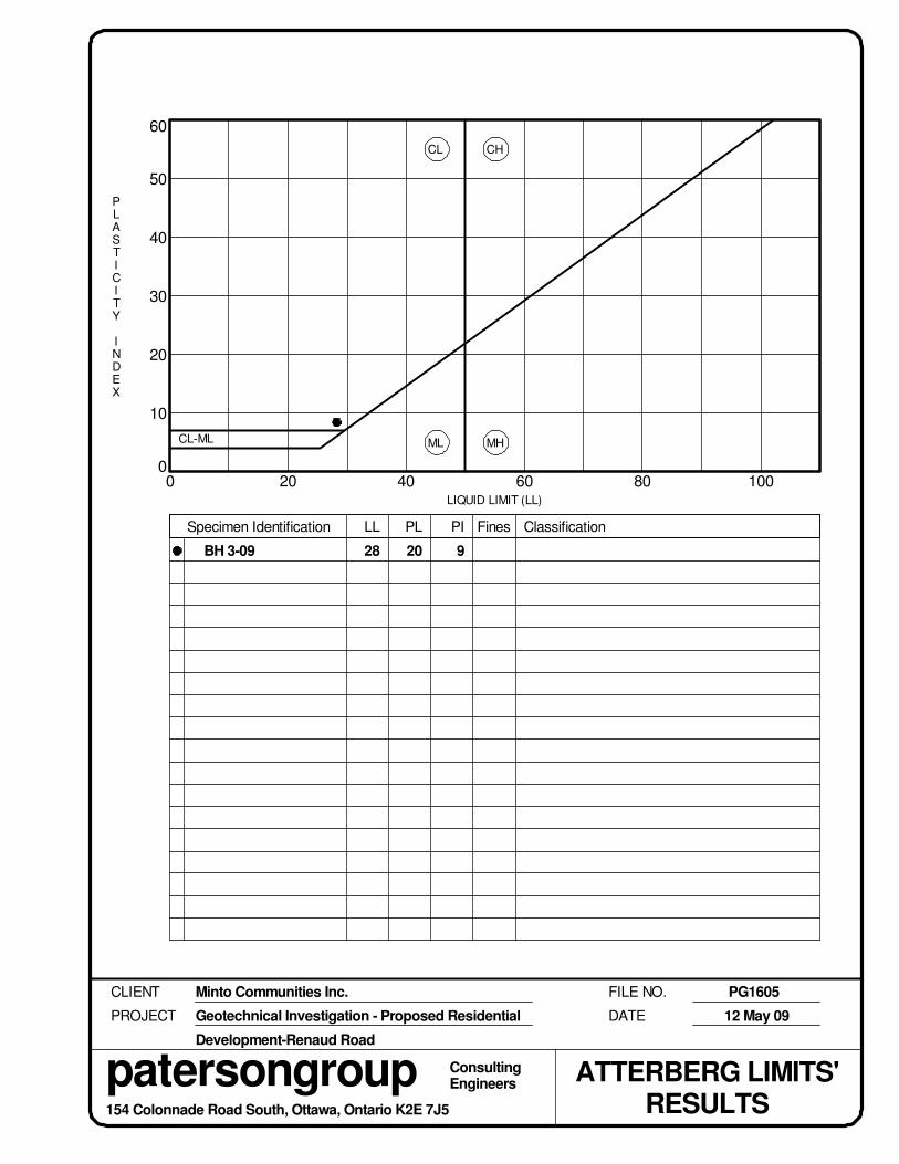
30
60
50
40
0 20 40 60 100
20
10
080
FILE NO.
RESULTS
BH 3-09 20 928
PROJECT
MH
DATE
Minto Communities Inc.
Geotechnical Investigation - Proposed Residential
Development-Renaud Road
PG1605
12 May 09
patersongroup ConsultingEngineers
CLIENT
ATTERBERG LIMITS'
LIQUID LIMIT (LL)
Specimen Identification LL PL PI Fines Classification
PLASTICITY
INDEX
CL-ML
CL
ML
CH
154 Colonnade Road South, Ottawa, Ontario K2E 7J5

Certificate of AnalysisClient:
Report Date: 24-Aug-2011Order Date:17-Aug-2011
Client PO: 11693 Project Description: PG2392Paterson Group Consulting Engineers
Order #: 1134171
Client ID: BH3-SS2 - - -Sample Date: ---17-Aug-11
1134171-01 - - -Sample ID:MDL/Units Soil - - -
Physical Characteristics
% Solids ---65.50.1 % by Wt.
General Inorganics
pH ---6.60.1 pH Units
Resistivity ---96.30.10 Ohm.m
Anions
Chloride ---185 ug/g dry
Sulphate ---235 ug/g dry
Page 3 of 7

APPENDIX 2
FIGURE 1 - KEY PLAN
DRAWING PG2392-1 - TEST HOLE LOCATION PLAN
DRAWING PG2392-2 - PERMISSIBLE GRADE RAISE AREAS - HOUSING

FIGURE 1
KEY PLAN
SITE
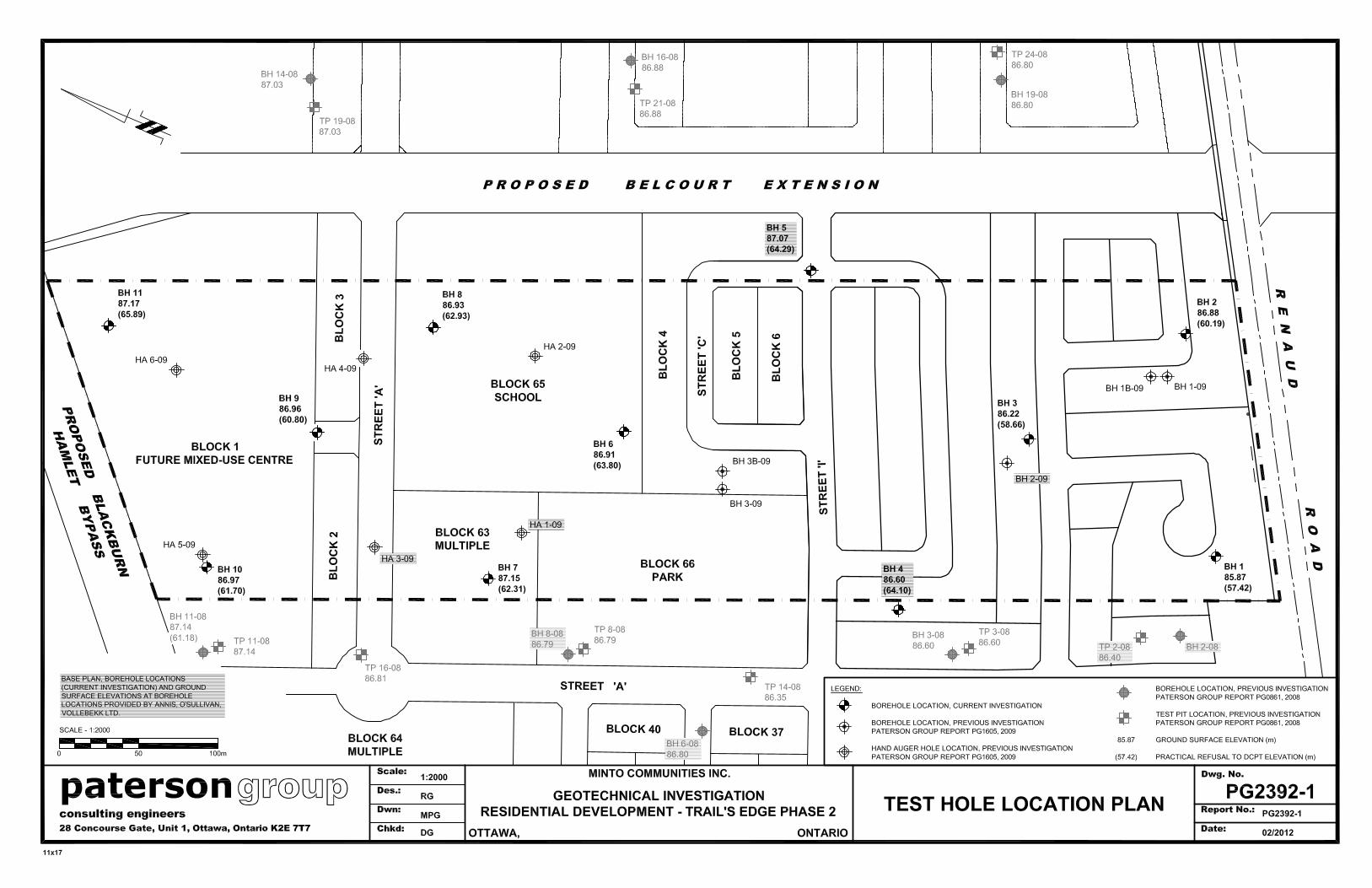

Related Documents


