This guide describes one of five models available in the VNX Series, the EMC ® VNX5100™. This guide is a parts location guide and provides illustrations of the part number label locations of orderable parts for the EMC VNX5100 platform. Included in this parts location guide are also tables describing individual VNX5100 parts or components and how these components are identified as either customer replaceable units (CRUs) or field replaceable units (FRUs). This guide is available online at https://mydocs.emc.com/VNX/relatedDocs.jsp. From the VNX Hardware Parts heading, click on the desired guide. The guide will appear in your browser. Topics include: ◆ Product software and hardware release revisions ...................................................... 2 ◆ Revision history ........................................................................................................ 2 ◆ Where to get help...................................................................................................... 2 ◆ How this document is organized ............................................................................... 3 ◆ Related documentation ............................................................................................. 3 ◆ VNX5100 Block platform stackup .............................................................................. 4 ◆ VNX5100 components .............................................................................................. 6 ◆ Standby power supply (SPS) ..................................................................................... 6 ◆ Disk processor enclosure (DPE) ................................................................................. 7 ◆ Small form-factor pluggable (SFP+) ......................................................................... 13 ◆ DIMMs .................................................................................................................... 14 ◆ Disk-array enclosure (DAE) ...................................................................................... 16 EMC ® VNX ™ Family VNX5100 ™ Parts Location Guide P/N 300-013-312 Rev 01 June 26, 2012

Welcome message from author
This document is posted to help you gain knowledge. Please leave a comment to let me know what you think about it! Share it to your friends and learn new things together.
Transcript

This guide describes one of five models available in the VNX Series, the EMC® VNX5100™. This guide is a parts location guide and provides illustrations of the part number label locations of orderable parts for the EMC VNX5100 platform. Included in this parts location guide are also tables describing individual VNX5100 parts or components and how these components are identified as either customer replaceable units (CRUs) or field replaceable units (FRUs).
This guide is available online at https://mydocs.emc.com/VNX/relatedDocs.jsp. From the VNX Hardware Parts heading, click on the desired guide. The guide will appear in your browser.
Topics include:
◆ Product software and hardware release revisions ...................................................... 2◆ Revision history ........................................................................................................ 2◆ Where to get help...................................................................................................... 2◆ How this document is organized ............................................................................... 3◆ Related documentation............................................................................................. 3◆ VNX5100 Block platform stackup .............................................................................. 4◆ VNX5100 components .............................................................................................. 6◆ Standby power supply (SPS) ..................................................................................... 6◆ Disk processor enclosure (DPE) ................................................................................. 7◆ Small form-factor pluggable (SFP+) ......................................................................... 13◆ DIMMs .................................................................................................................... 14◆ Disk-array enclosure (DAE) ...................................................................................... 16
EMC® VNX™ FamilyVNX5100™
Parts Location GuideP/N 300-013-312Rev 01
June 26, 2012

Product software and hardware release revisions
IMPORTANT
The part numbers listed in this guide are for reference only. Part numbers can change over time, and this document does not keep pace with those changes. The EMC parts inventory will automatically substitute for the latest part numbers as required.
Product software and hardware release revisions
As part of an effort to improve its product lines, EMC periodically releases revisions of its software and hardware. Therefore, some functions described in this document might not be supported by all versions of the software or hardware currently in use. The product release notes provide the most up-to-date information on product features.
Contact your EMC representative if a product does not function properly or does not function as described in this document.
Note: This document was accurate at publication time. New versions of this document might be released on the EMC online support website. Check the EMC online support website to ensure that you are using the latest version of this document.
Revision history
The following table presents the revision history of this document:
Where to get help
EMC support, product, and licensing information can be obtained as follows:
Product information — For documentation, release notes, software updates, or information about EMC products, licensing, and service, go to the EMC online support website (registration required) at:
https://Support.EMC.com
Technical support — For technical support, go to EMC online support and select Support. On the Support page, you will see several options, including one to create a service request. Note that to open a service request, you must have a valid support agreement. Contact your EMC sales representative for details about obtaining a valid support agreement or with questions about your account.
Revision Date Description
A01 June 26, 2012 First release of the VNX5100 Parts Location Guide with document part number
2 EMC VNX5100 Parts Location Guide

How this document is organized
How this document is organized
The major sections of this guide are listed in the following table.
Related documentation
EMC provides the ability to create step-by-step planning, installation, and maintenance instructions tailored to your environment. To create VNX customized documentation, go to: https://mydocs.emc.com/VNX/.
To download a PDF copy of the desired publication, go to the following sections:
◆ For hardware-related books, go to the About VNX section, and then select Learn about VNX. Next, follow the steps in the wizard.
◆ For technical specifications, go to the About VNX section, and then select View technical specifications. Next, follow the steps in the wizard.
◆ For installation, adding, or replacing tasks, go to the VNX tasks section, and then select the appropriate heading. For example, to download a PDF copy of the VNX5100 Block Installation Guide, go to Install VNX and follow the steps in the wizard.
◆ For server-related tasks, go to the Server tasks for the VNX5100 section, and then select the appropriate heading. For example, to download a PDF copy of Adding or replacing hardware, go to Add or replace hardware and follow the steps in the wizard.
Title Description
“VNX5100 Block platform stackup” on page 4
Describes and shows the front and rear views of a typical VNX5100.
“VNX5100 components” on page 6
Provides a description of the components that comprise a VNX5100. Along with a description, illustrations of each component are also shown.
“Standby power supply (SPS)” on page 6
Describes and illustrates the part number label locations of the SPS.
“Disk processor enclosure (DPE)” on page 7
Describes and illustrates the part number label locations of the DPE and the components that comprise the DPE.
“Small form-factor pluggable (SFP+)” on page 13
Describes and illustrates the part number label locations of the SFP transceiver modules used in the DME.
“DIMMs” on page 14 Describes and illustrates the part number label locations of the memory module or dual-inline memory modules (DIMMs) used in the DPE.
“Disk-array enclosure (DAE)” on page 16
Describes and illustrates the part number label locations of the two types of DAEs available for the VNX5100.
EMC VNX5100 Parts Location Guide 3

VNX5100 Block platform stackup
VNX5100 Block platform stackup
The VNX5100 Block platform comprises a disk processor enclosure (DPE), and a standby power supply (SPS).
Note: Throughout this guide, figure references are placed in the Part number label location heading of tables because some of the tables have part number locations, as described in Table 4 on page 10 and some do not, as described in Table 1 on page 7, for example. This format is used throughout this guide.
Front view
On the front, viewing from top to bottom, a VNX5100 Block platform includes the following hardware:
◆ One 3U DPE chassis with either a:
• 15 (3.5-inch) disk drives (hot-swappable)
or,
• 25 (2.5-inch) disk drives (hot-swappable)
◆ One 1U SPS
Figure 1 and Figure 2 on page 5 show two examples of the front of a VNX5100 Block platform 3U DPE with a 1U SPS.
Figure 1 Example of the VNX5100 Block platform with 3U, 15 disk drives (front view)
3U, 15 (3.5-inch) disk processor enclosure (DPE)
Standby power supply (SPS)VNX-000604
4 EMC VNX5100 Parts Location Guide

VNX5100 Block platform stackup
Figure 2 Example of the VNX5100 Block platform with 3U, 25 disk drives (front view)
Note: A typical VNX5100 Block platform has only a 3U DPE and a 1U SPS. In the following sections, the illustrations and corresponding tables describe these individual components. These descriptions are for illustrative purposes only.
Rear view
On the rear, viewing from top to bottom, a VNX5100 Block platform includes the following hardware components:
◆ One 3U DPE with two storage processors (SP A and B); each has one CPU module and one power supply/cooling module
◆ One 1U SPS
Figure 3 shows an example of the rear of a VNX5100 Block platform having a dual SPS and a DPE with two storage processors (SP A and B).
Figure 3 Example of VNX5100 Block platform (rear view)
240
1 2 3 4 5 6 7 8 9 10 11 12 13 14 15 16 17 18 19 20 21 22 23 240
3U, 25 (2.5-inch) disk processor enclosure (DPE)
Standby power supply (SPS) VNX-000684
SPS B (optional)
X42 3 4 5
6GbSAS
8Gbfibre 1
0 X46Gb SAS
B
X42 3 4 5
6GbSAS
8Gbfibre 1
0 X46Gb SAS
A
Cover
Do not remove
Cover
Do not remove
Cover
Do not remove
Cover
Do not remove
SP B SP A
SPS AVNX-000288
EMC VNX5100 Parts Location Guide 5

VNX5100 components
VNX5100 components
Viewing from bottom to top, the VNX5100 Block platform includes two components. The following sections discuss each component in an illustration and table. The illustration will show or point out the location of the part number label on the component. The table will list the part number, describe the component or part, and tell you if it is a FRU or CRU or both.
◆ A 1U Standby power supply (SPS)
◆ Disk processor enclosures (DPE)
• 3U, 15 (3.5-inch) disk drive
• 3U, 25 (2.5-inch) disk drive
• Storage processor (SP) power supply/cooling module
• Storage processor
◆ Small form-factor pluggable (SFP) transceiver modules
◆ Dual in-line memory modules (DIMMs)
◆ Disk-array enclosures (DAEs)
• 3U, 15 (3.5-inch) disk drive
• 2U, 25 (2.5-inch) disk drive
Standby power supply (SPS)
The VNX5100 Block platform can support up to a dual 1U standby power supply (SPS) to provide temporary emergency power to the VNX5100 Block platform.
Rear view
Figure 4 shows the part number label location on a dual 1U SPS.
Figure 4 Example of a dual 1U SPS
900-XXX-0014 0082
A00REV
S/N900-XXX-0014 0082
A00REV
S/N
Part Number (P/N) labelCNS-001545
6 EMC VNX5100 Parts Location Guide

Disk processor enclosure (DPE)
Table 1 lists the part number label location, part number, description, and whether it is a FRU or CRU.
Disk processor enclosure (DPE)
The 3U DPE has part numbers visible on both the front and rear.
Front view
The DPE has two types of disk drive carriers:
◆ 3U, 15 (3.5-inch) disk drives
◆ 3U, 25 (2.5-inch) disk drives
DPE 3U, 15 (3.5-inch) disk drive
Figure 5 shows the front view of the DPE 3U, 15 (3.5-inch) disk drives.
Note: You can visually distinguish disk module kinds by their type, capacity, and speed labels, and by the design of the latch and handle on each disk module (Figure 5).
Figure 5 Example of the DPE 3U, 15 (3.5-inch) disk drive (front view)
Note: Figure 5 is for illustrative purposes only. The front of the disk modules may be a little different than the ones in your particular cabinet.
Table 1 SPS part number
Part number label location (Figure 4 on page 6) Part number Description FRU CRU
078-000-084078-000-085
DC standby power supply (SPS) 1200W
Part Number Label
VNX-000607
EMC VNX5100 Parts Location Guide 7
Disk processor enclosure (DPE)
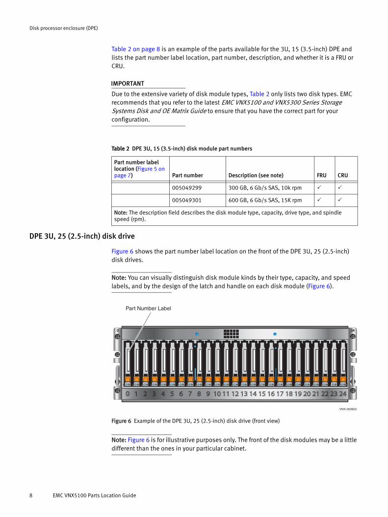
Table 2 on page 8 is an example of the parts available for the 3U, 15 (3.5-inch) DPE and lists the part number label location, part number, description, and whether it is a FRU or CRU.
IMPORTANT
Due to the extensive variety of disk module types, Table 2 only lists two disk types. EMC recommends that you refer to the latest EMC VNX5100 and VNX5300 Series Storage Systems Disk and OE Matrix Guide to ensure that you have the correct part for your configuration.
DPE 3U, 25 (2.5-inch) disk drive
Figure 6 shows the part number label location on the front of the DPE 3U, 25 (2.5-inch) disk drives.
Note: You can visually distinguish disk module kinds by their type, capacity, and speed labels, and by the design of the latch and handle on each disk module (Figure 6).
Figure 6 Example of the DPE 3U, 25 (2.5-inch) disk drive (front view)
Note: Figure 6 is for illustrative purposes only. The front of the disk modules may be a little different than the ones in your particular cabinet.
Table 2 DPE 3U, 15 (3.5-inch) disk module part numbers
Part number label location (Figure 5 on page 7) Part number Description (see note) FRU CRU
005049299 300 GB, 6 Gb/s SAS, 10k rpm
005049301 600 GB, 6 Gb/s SAS, 15K rpm
Note: The description field describes the disk module type, capacity, drive type, and spindle speed (rpm).
240
1 2 3 4 5 6 7 8 9 10 11 12 13 14 15 16 17 18 19 20 21 22 23 240
Part Number Label
VNX-000603
8 EMC VNX5100 Parts Location Guide
Disk processor enclosure (DPE)
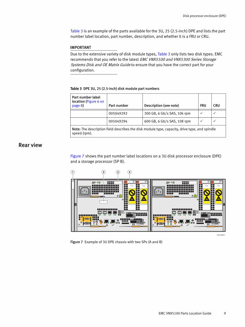
Table 3 is an example of the parts available for the 3U, 25 (2.5-inch) DPE and lists the part number label location, part number, description, and whether it is a FRU or CRU.
IMPORTANT
Due to the extensive variety of disk module types, Table 3 only lists two disk types. EMC recommends that you refer to the latest EMC VNX5100 and VNX5300 Series Storage Systems Disk and OE Matrix Guide to ensure that you have the correct part for your configuration.
Rear view
Figure 7 shows the part number label locations on a 3U disk processor enclosure (DPE) and a storage processor (SP B).
Figure 7 Example of 3U DPE chassis with two SPs (A and B)
Table 3 DPE 3U, 25 (2.5-inch) disk module part numbers
Part number label location (Figure 6 on page 8) Part number Description (see note) FRU CRU
005049292 300 GB, 6 Gb/s SAS, 10k rpm
005049294 600 GB, 6 Gb/s SAS, 10K rpm
Note: The description field describes the disk module type, capacity, drive type, and spindle speed (rpm).
X42 3 4 5
6GbSAS
8Gbfibre 1
0 X46Gb SAS
B
X42 3 4 5
6GbSAS
8Gbfibre 1
0 X46Gb SAS
A
Cover
Do not remove
Cover
Do not remove
Cover
Do not remove
Cover
Do not remove
1
VNX-000611
432
EMC VNX5100 Parts Location Guide 9

Disk processor enclosure (DPE)
Table 4 lists the part number label location, part number, description, and whether it is a FRU or CRU.
SP power supply/cooling module
Figure 8 shows the part number label location on a power supply/cooling module used in the VNX5100 Block platform SPs (A and B).
Figure 8 Example of a power supply/cooling module
Table 5 lists the part number label location, part number, description, and whether it is a FRU or CRU.
Table 4 DPE chassis and SP part numbers
Part number label location (Figure 7 on page 9) Part number Description FRU CRU
1 100-562-503100-563-138
3U, 15 disk drive chassis and midplane3U, 25 disk drive chassis and midplane
2 110-140-404B SP, 1.6-GHz GHZ QC CPU, with 4-GB RAM DIMMs (for a closer view, see Figure 9 on page 11)
110-140-400B SP, 1.6-GHz GHZ QC CPU, DIMMs (for a closer view, see Figure 9 on page 11)
3 071-000-529 1U AC/DC, 875W, dual power supply (for a closer view, see Figure 8 on page 10)
4 150-001-819 I/O module filler panel includes a Do Not Remove label
— —
Part number (P/N) label
VNX-000608
Table 5 Power supply/cooling module part number
Part number label location (Figure 8) Part number Description FRU CRU
071-000-529 1U AC/DC, 875W, dual power supply
10 EMC VNX5100 Parts Location Guide

Disk processor enclosure (DPE)
SP
Figure 9 shows the part number label location on a SP without the power supply/cooling module.
Figure 9 Example of the SP
Table 6 lists the part number label location, part number, description, and whether it is a FRU or CRU.
To access the SP CPU, you must first remove the SP from the 3U DPE (Figure 10 on page 12). Then, you must remove the power supply/cooling fan modules (Figure 11 on page 12).
X42 3 4 5
6GbSAS
8Gbfibre 1
0 X46Gb SAS
B
SP (P/N) label
Cover
Do not remove
Cover
Do not remove
VNX-000609
Table 6 SP part number
Part number label location (Figure 9) Part number Description FRU CRU
110-140-404B SP 1.6-GHZ CPU, with 4GB of memory
110-140-400B SP 1.6-GHZ CPU, without memory
EMC VNX5100 Parts Location Guide 11

Disk processor enclosure (DPE)
Figure 10 shows the SP partially removed from the front of the DPE.
Figure 10 Example of removing the SP from the 3U DPE
Figure 11 shows the power supply/cooling module being removed from the SP.
Figure 11 Example of removing the SP power supply/cooling module from the SP
CL4594
CL4595
12 EMC VNX5100 Parts Location Guide

Small form-factor pluggable (SFP+)
The part number labels for the SP and the SP CPU module in Figure 12 are listed in Table 6 on page 11.
Figure 12 Example of the SP CPU with power supply/cooling module set aside
The SP CPU part number label is located on the motherboard of the SP CPU (Figure 12).
Small form-factor pluggable (SFP+)
Small form-factor (SFP+) modules are compact, hot-pluggable transceivers inserted into the SFP+ slot of an 8-Gb/s SP Fibre Channel (FC) port in a VNX5100 platform. This transceiver module provides uplink optical interfaces, laser send or transmit (TX) and laser receive (RX). An SFP+ transceiver module is hot-swappable. You can replace an SFP+ from the rear of the SP while the platform is powered up.
Note: The SFP+ part number is visible only when the SFP+ is removed from the SP 8-Gb/s FC port.
Only one type of SFP+ transceiver module that is used in 8-Gb/s port of the VNX5100 platform.
SP CPU part number (P/N) label
VNX-000665
SP part number (P/N) label
SP Power supply/cooling module
EMC VNX5100 Parts Location Guide 13

DIMMs
Figure 13 shows an example of an SFP+ with a part number label.
Figure 13 Example of an SFP or SFP+
Table 7 lists the part number label location, part number, description, and whether it is a FRU or CRU.
DIMMs
The SP uses SDRAM DIMMs1. Each SP uses two 2-GB unbuffered Double-Data-Rate 3 (DDR3) type memory for a total of 4 GB. Figure 14 on page 15 shows an example of the location of the SP DIMM slot location.
Figure 14 on page 15 shows an example of the SP DIMM with a part number label. Table 8 on page 16 lists the part number, description, and whether it is a FRU or CRU.
IMPORTANT
The DIMM part numbers are visible only when you remove the DIMM from the DIMM slot. You must first take the SP out of service, disconnect any SP cables, remove the SP from the DPE, then remove the SP power supply/cooling module from the SP (see Figure 10 on page 12, Figure 11 on page 12, and Figure 12 on page 13). With the SP CPU laying on an antistatic mat, lift the DIMM cover up in the SP CPU, and then remove the DIMM from the
CNS-001347
P/N: 000-XXX-000
Part Number (P/N) label
Table 7 SFP and SFP+ module part numbers
Part number label location (Figure 13) Part number Description FRU CRU
019-078-042 (SFP+)
Used in the SP 8-Gb/s Fibre Channel (FC) ports
1. The term DIMM is used throughout this guide. The term DIMM is also referred to as a memory module. These terms are interchangeable and mean the same thing.
14 EMC VNX5100 Parts Location Guide
DIMMs
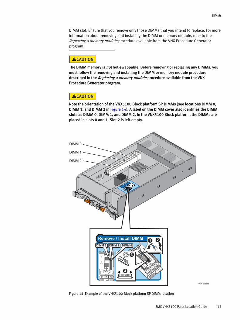
DIMM slot. Ensure that you remove only those DIMMs that you intend to replace. For more information about removing and installing the DIMM or memory module, refer to the Replacing a memory module procedure available from the VNX Procedure Generator program.
The DIMM memory is not hot-swappable. Before removing or replacing any DIMMs, you must follow the removing and installing the DIMM or memory module procedure described in the Replacing a memory module procedure available from the VNX Procedure Generator program.
Note the orientation of the VNX5100 Block platform SP DIMMs (see locations DIMM 0, DIMM 1, and DIMM 2 in Figure 14). A label on the DIMM cover also identifies the DIMM slots as DIMM 0, DIMM 1, and DIMM 2. In the VNX5100 Block platform, the DIMMs are placed in slots 0 and 1. Slot 2 is left empty.
Figure 14 Example of the VNX5100 Block platform SP DIMM location
DIMM 0
DIMM 1
DIMM 2
Remove / Install DIMM
3
4
21DIMM 2 DIMM 0DIMM 1
31
23
4
VNX-000610
EMC VNX5100 Parts Location Guide 15
Disk-array enclosure (DAE)
Figure 15 Example of the VNX5100 Block platform SP DIMM location
Disk-array enclosure (DAE)
The expansion disk-array enclosures (DAEs) have part numbers visible on both the front and rear.
Front view
The DAE has two types of disk drive carriers:
◆ 3U, 15 (3.5-inch) disk drives
◆ 3U, 25 (2.5-inch) disk drives
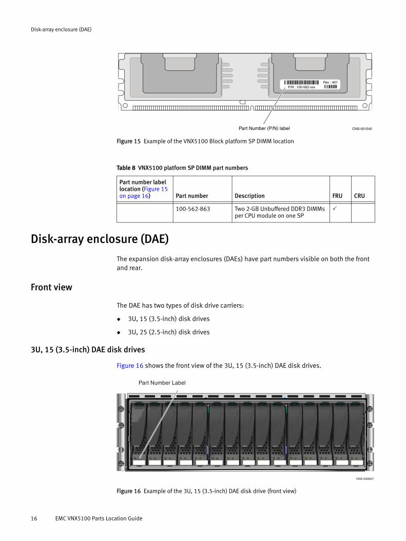
3U, 15 (3.5-inch) DAE disk drives
Figure 16 shows the front view of the 3U, 15 (3.5-inch) DAE disk drives.
Figure 16 Example of the 3U, 15 (3.5-inch) DAE disk drive (front view)
P/N : 100-562-xxx
Part Number (P/N) label CNS-001540
Rev : A01ÊA01.Š
Ê100-562-264vŠ
Table 8 VNX5100 platform SP DIMM part numbers
Part number label location (Figure 15 on page 16) Part number Description FRU CRU
100-562-863 Two 2-GB Unbuffered DDR3 DIMMs per CPU module on one SP
Part Number Label
VNX-000607
16 EMC VNX5100 Parts Location Guide

Disk-array enclosure (DAE)
Note: You can visually distinguish disk module kinds by their type, capacity, and speed labels, and by the design of the latch and handle on each disk module (Figure 16 on page 16).
Table 9 is an example of the parts available for the 3U, 15 (3.5-inch) DAE and lists the part number label location, part number, description, and whether it is a FRU or CRU.
IMPORTANT
Due to the extensive variety of disk module types, Table 9 lists only two disk types. EMC recommends that you refer to the latest EMC VNX5100 and VNX5300 Series Storage Systems Disk and OE Matrix Guide to ensure that you have the correct part for your configuration.
2U, 25 (2.5-inch) DAE disk drive
Figure 17 shows the front view of the 2U, 25 (2.5-inch) DAE disk drives.
Figure 17 Example of the 2U, 25 (2.5-inch) DAE disk drive (front view)
Note: You can visually distinguish disk module kinds by type, capacity, and speed labels, and by the design of the latch and handle on each disk module (Figure 17).
Table 9 3U, 15 (3.5-inch) DAE disk module part numbers
Part number label location (Figure 16 on page 16) Part number Description (see note) FRU CRU
005049299 300 GB, 6 Gb/s SAS, 10k rpm
005049301 600 GB, 6 Gb/s SAS, 15K rpm
Note: The description field describes the disk module type, capacity, drive type, and spindle speed (rpm).
Part number label
VNX-000602
EMC VNX5100 Parts Location Guide 17

Disk-array enclosure (DAE)
Table 10 is an example of the parts available for the 2U, 25 (2.5-inch) DAE and lists the part number label location, part number, description, and whether it is a FRU or CRU.
IMPORTANT
Due to the extensive variety of disk module types, Table 10 only lists two disk types. EMC recommends that you refer to the latest EMC VNX5100 and VNX5300 Series Storage Systems Disk and OE Matrix Guide to ensure that you have the correct part for your configuration.
Rear view
The DAE has two types of LCC modules and power supplies:
◆ 3U, 15 DAE LCC and power supply
◆ 2U, 25 DAE LCC and power supply
3U, 15 (3.5-inch) DAE LCC and power supply
Figure 18 shows the part number label location on the rear of the 3U, 15 (3.5-inch) DAE for the LCC and power supply.
Figure 18 Example of 3U, 15 (3.5-inch) DAE LCC and power supply
Table 10 2U, 25 (2.5-inch) DAE disk module part numbers
Part number label location (Figure 17 on page 17) Part number Description (see note) FRU CRU
005049292 300 GB, 6 Gb/s SAS, 10k rpm
005049294 600 GB, 6 Gb/s SAS, 10K rpm
Note: The description field describes the disk module type, capacity, drive type, and spindle speed (rpm).
1 2
A
B #
X4
6Gb
SA
S
#
X4
6Gb
SAS
LCC B
LCC AVNX-000605
18 EMC VNX5100 Parts Location Guide

Disk-array enclosure (DAE)
Table 11 lists the part number label location, part number, description, and whether it is a FRU or CRU.
2U, 25 (2.5-inch) DAE LCC and power supply
Figure 19 shows the part number label location on the rear of the 2U, 25 (2.5-inch) DAE for the LCC and the power supply.
Figure 19 Example of 2U, 25 (2.5-inch) DAE LCC and power supply
Table 12 lists the part number label location, part number, description, and whether it is a FRU or CRU.
Table 11 3U, 15 (3.5-inch) LCC and power supply part numbers
Part number label location (Figure 18 on page 18) Part number Description FRU CRU
1 071-000-518 LCC B 400 W dual 12 V power supply1
2 303-108-000E LCC B
1. The rear of the 3U, 15 (3.5-inch) DAE has the LCC power supply and LCC inverted or on top of each other. In other words, the LCC B power supply is located on the top of LCC B. While LCC A is located on the bottom of the DAE with LCC A on top of the LCC A power supply (Figure 18 on page 18).
6 G
bSA
S
X4
#
6 Gb
SAS
X4
#
1 2
VNX-000606
Table 12 2U, 25 (2.5-inch) DAE LCC and power supply part numbers
Part number label location (Figure 19) Part number Description FRU CRU
1 071-000-541 LCC B power 400 W 12 V supply1
2 303-104-001E LCC B2
1. The rear of the 2U, 25 (2.5-inch) DAE has the LCC power supplies inverted or on opposite sides. In other words, LCC B power supply is located on the left of the DAE and LCC A power supply is located on the right (Figure 19).
2. The rear of the 2U, 25 (2.5-inch) DAE has the LCCs inverted or on top of each other. In other words, LCC B is located on the top and LCC A is located on the bottom (Figure 19).
EMC VNX5100 Parts Location Guide 19

Disk-array enclosure (DAE)
Copyright © 2012 EMC Corporation. All rights reserved. Published in the USA.
Published June 26, 2012
EMC believes the information in this publication is accurate as of its publication date. The information is subject to change without notice.
The information in this publication is provided as is. EMC Corporation makes no representations or warranties of any kind with respect to the information in this publication, and specifically disclaims implied warranties of merchantability or fitness for a particular purpose. Use, copying, and distribution of any EMC software described in this publication requires an applicable software license.
EMC2, EMC, and the EMC logo are registered trademarks or trademarks of EMC Corporation in the United States and other countries. All other trademarks used herein are the property of their respective owners.
For the most up-to-date regulatory document for your product line, go to the technical documentation and advisories section on EMC Online Support.
20 EMC VNX5100 Parts Location Guide
Related Documents