PARTS FEEDER R CAT. No. 7018-)#/E

Welcome message from author
This document is posted to help you gain knowledge. Please leave a comment to let me know what you think about it! Share it to your friends and learn new things together.
Transcript

PA
RT
S F
EE
DE
R
PARTSFEEDERR
CAT. No. 7018-)#/E
PARTS FEEDER
corporation
corp
oratio
n

6
7
8
8
9
Bowl Feeder Series
4~5Standard Series
Bowl Series
Linear Feeder Series
Hopper Series
Controller Series
44~45
46~55
56~57
Ordering Parts Feeders
Bowl Feeder
Linear Feeder
70~76
78
Spare Part and Peripheral Dimensions / Light grip and Sunline belt Part Nos.
Estimate Requests
58~59
60~61
62~63
Non-slip Composite Feeder
Monodrive 2-way FeederTM
SMD Feeder・High Speed Linear Feeder
Spring Untangling FeederMonodrive Two-way Feeder with The Separation Mechanism for Tangled Springs 64~65
66~67Globalized Parts Feeder Series
68~69Flexible Feeder・One-touch Bowl Clamp
10
11~21
22~29
30~33
34~36
Selection of Vibratory Driving Unit
Bowl Feeder
Bowl
Isolated Bottom/Fixed BottomAuxiliary Hopper in the Bowl
Auxiliary Vibrator
Hopper
37
ControllerI/O Controller Unit 38~42
Control Functions andTiming Chart 43
Vibratory Drive Unit / Vibratory Trough / ControllerVibratory Drive Unit / Bowl / Controller
Outline and Features
Parts Feeders for Special Applications
Standard Series Combination Table
Standard Series Dimensions and Specifications
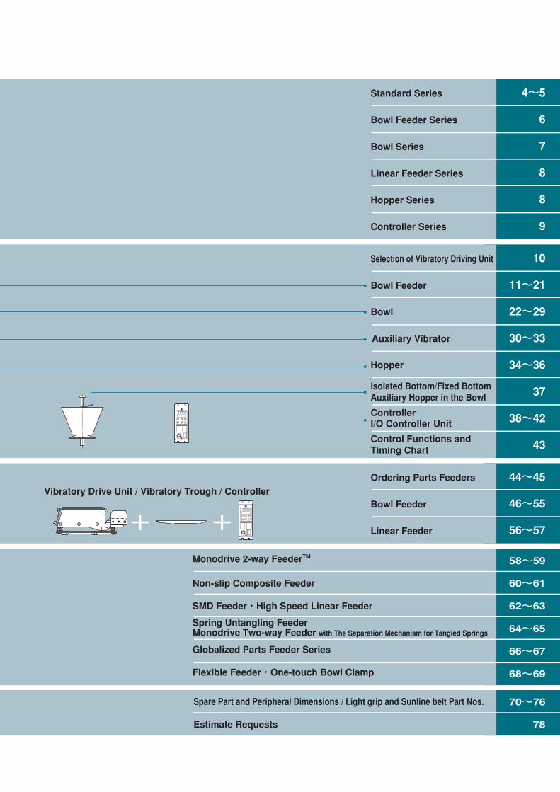
CONTENTS
+ + + +
K-ECG25
O
AC100-115/200-230V 50/60Hz 2A
V.F. CONTROLLER JAPAN
FUN C
RESET
DATA
EN TER
J OG
R U N
STOP
SPEED
RoHSVib.ARUN Fre.A L IMI T
K-ECG25
O
AC100-115/200-230V 50/60Hz 2A
V.F. CONTROLLER JAPAN
FUN C
RESET
DATA
EN TER
J OG
R U N
STOP
SPEED
RoHSVib.ARUN Fre.A L IMI T
K-ECG25
O
AC100-115/200-230V 50/60Hz 2A
V.F. CONTROLLER JAPAN
FUN C
RESET
DATA
EN TER
J OG
R U N
STOP
SPEED
RoHSVib.ARUN Fre.A L IMI T
*前見返/E_*前後/見返/E 13/01/30 10:34 ページ 1
6
7
8
8
9
Bowl Feeder Series
4~5Standard Series
Bowl Series
Linear Feeder Series
Hopper Series
Controller Series
44~45
46~55
56~57
Ordering Parts Feeders
Bowl Feeder
Linear Feeder
70~76
78
Spare Part and Peripheral Dimensions / Light grip and Sunline belt Part Nos.
Estimate Requests
58~59
60~61
62~63
Non-slip Composite Feeder
Monodrive 2-way FeederTM
SMD Feeder・High Speed Linear Feeder
Spring Untangling FeederMonodrive Two-way Feeder with The Separation Mechanism for Tangled Springs 64~65
66~67Globalized Parts Feeder Series
68~69Flexible Feeder・One-touch Bowl Clamp
10
11~21
22~29
30~33
34~36
Selection of Vibratory Driving Unit
Bowl Feeder
Bowl
Isolated Bottom/Fixed BottomAuxiliary Hopper in the Bowl
Auxiliary Vibrator
Hopper
37
ControllerI/O Controller Unit 38~42
Control Functions andTiming Chart 43
Vibratory Drive Unit / Vibratory Trough / ControllerVibratory Drive Unit / Bowl / Controller
Outline and Features
Parts Feeders for Special Applications
Standard Series Combination Table
Standard Series Dimensions and Specifications
CONTENTS
+ + + +
K-ECG25
O
AC100-115/200-230V 50/60Hz 2A
V.F. CONTROLLER JAPAN
FUN C
RESET
DATA
EN TER
J OG
R U N
STOP
SPEED
RoHSVib.ARUN Fre.A L IMI T
K-ECG25
O
AC100-115/200-230V 50/60Hz 2A
V.F. CONTROLLER JAPAN
FUN C
RESET
DATA
EN TER
J OG
R U N
STOP
SPEED
RoHSVib.ARUN Fre.A L IMI T
K-ECG25
O
AC100-115/200-230V 50/60Hz 2A
V.F. CONTROLLER JAPAN
FUN C
RESET
DATA
EN TER
J OG
R U N
STOP
SPEED
RoHSVib.ARUN Fre.A L IMI T
*前見返/E_*前後/見返/E 13/01/30 10:34 ページ 1

Warranty
NTN warrants, to the original purchaser only, that the delivered product which is the subject of this sale (a)will conform to drawings and specifications mutually established in writing as applicable to the contract, and (b)be free from defects in material or fabrication. The duration of this warranty is one year from date of delivery.If the buyer discovers within this period a failure of the product to conform to drawings or specifications, or adefect in material or fabrication, it must promptly notify NTN in writing. In no event shall such notification bereceived by NTN later than 13 months from the date of delivery. Within a reasonable time after suchnotification, NTN will, at its option, (a) correct any failure of the product to conform to drawings, specificationsor any defect in material or workmanship, with either replacement or repair of the product, or (b) refund, in partor in whole, the purchase price. Such replacement and repair, excluding charges for labor, is at NTN'sexpense. All warranty service will be performed at service centers designated by NTN. These remedies arethe purchaser's exclusive remedies for breach of warranty.
NTN does not warrant (a) any product, components or parts not manufactured by NTN, (b) defects causedby failure to provide a suitable installation environment for the product, (c) damage caused by use of theproduct for purposes other than those for which it was designed, (d) damage caused by disasters such as fire,flood, wind, and lightning, (e) damage caused by unauthorized attachments or modification, (f) damage duringshipment, or (g) any other abuse or misuse by the purchaser.
THE FOREGOING WARRANTIES ARE IN LIEU OF ALL OTHER WARRANTIES, EXPRESS OR IMPLIED,INCLUDING BUT NOT LIMITED TO THE IMPLIED WARRANTIES OF MERCHANTABILITY AND FITNESSFOR A PARTICULAR PURPOSE.
In no case shall NTN be liable for any special, incidental, or consequential damages based upon breach ofwarranty, breach of contract, negligence, strict tort, or any other legal theory,and in no case shall total liabilityof NTN exceed the purchase price of the part upon which such liability is based. Such damages include, butare not limited to, loss of profits, loss of savings or revenue, loss of use of the product or any associatedequipment, cost of capital, cost of any substitute equipment, facilities or services, downtime, the claims of thirdparties including customers, and injury to property. Some states do not allow limits on warranties, or onremedies for breach in certain transactions. In such states, the limits in this paragraph and in paragraph (2)shall apply to the extent allowable under case law and statutes in such states.
Any action for breach of warranty or any other legal theory must be commenced within 15 months followingdelivery of the goods.
Unless modified in a writing signed by both parties, this agreement is understood to be the complete andexclusive agreement between the parties, superceding all prior agreements, oral or written, and all othercommunications between the parties relating to the subject matter of this agreement. No employee of NTN orany other party is authorized to make any warranty in addition to those made in this agreement.
This agreement allocates the risks of product failure between NTN and the purchaser. This allocation isrecognized by both parties and is reflected in the price of the goods. The purchaser acknowledges that it hasread this agreement, understands it, and is bound by its terms.
© NTN Corporation. 2013Although care has been taken to assure the accuracy of the data compiled in this catalog, NTN does notassume any liability to any company or person for errors or omissions.
*前見返/E_*前後/見返/E 13/01/30 10:34 ページ 2

PARTS FEEDER
*編集1-17-E_ *編集1-17/E 13/01/30 10:21 ページ 1
2
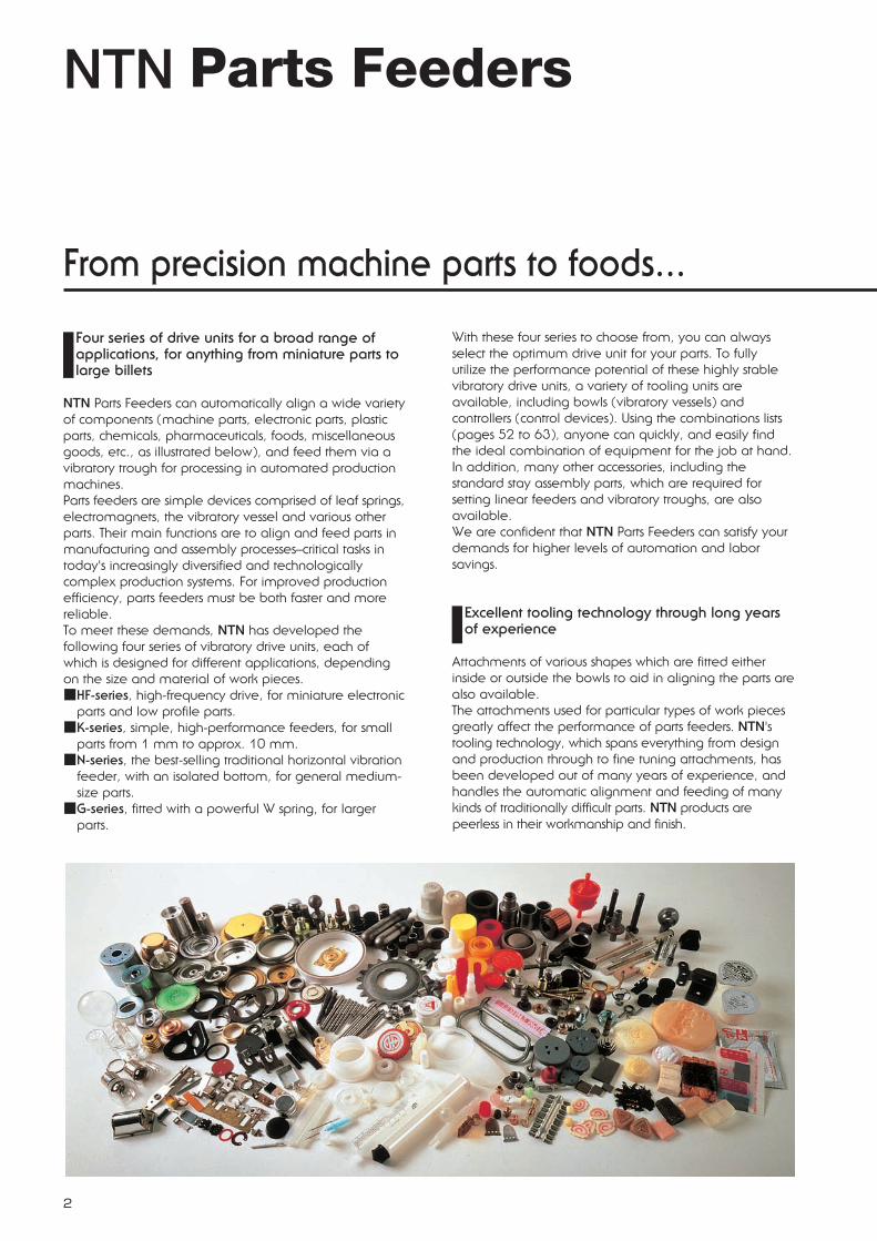
NTN Parts Feeders
From precision machine parts to foods...
Four series of drive units for a broad range ofapplications, for anything from miniature parts tolarge billets
NTN Parts Feeders can automatically align a wide varietyof components (machine parts, electronic parts, plasticparts, chemicals, pharmaceuticals, foods, miscellaneousgoods, etc., as illustrated below), and feed them via avibratory trough for processing in automated productionmachines.Parts feeders are simple devices comprised of leaf springs,electromagnets, the vibratory vessel and various otherparts. Their main functions are to align and feed parts inmanufacturing and assembly processes–critical tasks intoday's increasingly diversified and technologicallycomplex production systems. For improved productionefficiency, parts feeders must be both faster and morereliable.To meet these demands, NTN has developed thefollowing four series of vibratory drive units, each ofwhich is designed for different applications, dependingon the size and material of work pieces.■HF-series, high-frequency drive, for miniature electronic
parts and low profile parts.■K-series, simple, high-performance feeders, for small
parts from 1 mm to approx. 10 mm.■N-series, the best-selling traditional horizontal vibration
feeder, with an isolated bottom, for general medium-size parts.
■G-series, fitted with a powerful W spring, for largerparts.
With these four series to choose from, you can alwaysselect the optimum drive unit for your parts. To fullyutilize the performance potential of these highly stablevibratory drive units, a variety of tooling units areavailable, including bowls (vibratory vessels) andcontrollers (control devices). Using the combinations lists(pages 52 to 63), anyone can quickly, and easily findthe ideal combination of equipment for the job at hand.In addition, many other accessories, including thestandard stay assembly parts, which are required forsetting linear feeders and vibratory troughs, are alsoavailable.We are confident that NTN Parts Feeders can satisfy yourdemands for higher levels of automation and laborsavings.
Excellent tooling technology through long yearsof experience
Attachments of various shapes which are fitted eitherinside or outside the bowls to aid in aligning the parts arealso available.The attachments used for particular types of work piecesgreatly affect the performance of parts feeders. NTN'stooling technology, which spans everything from designand production through to fine tuning attachments, hasbeen developed out of many years of experience, andhandles the automatic alignment and feeding of manykinds of traditionally difficult parts. NTN products arepeerless in their workmanship and finish.
*編集1-17-E_ *編集1-17/E 13/01/30 10:21 ページ 2

3
*編集1-17-E_ *編集1-17/E 13/01/30 10:21 ページ 3

4
Outline, features, and applications
Standard series
Bowl feeder series (Refer to page 6)
Bowl series (Refer to page 7)
Precision machined bowl Cascade bowl Stainless steel cascade bowl
Straight wall bowl Cone bowl Dish bowl
HF-series K-series
N-series G-series
*編集1-17-E_ *編集1-17/E 13/01/30 10:21 ページ 4

5
Outline, features, and applications
Linear feeder series (Refer to page 8)
Controller series (Refer to page 9)
Hopper series (Refer to page 8)
S-seriesHS-series L-series
Detached hopper Space-saving hopper Rotary hopper
Variable frequency controller SMD controller I/O controller unit
*編集1-17-E_ *編集1-17/E 13/01/30 10:21 ページ 5

6
Outline, features, and applications
Bowl feeder seriesBowl feeder series Numbers in shaded area
indicate reference pages.
K-series
K-series bowl feeders are intended for small parts, including electronic components.Simple, open construction and well thought out spring mechanism design allow precise and stablevibration for long periods of time.
(1) Precise full wave drive(2) Height adjustment mechanism(3) Attractive coverless construction
HF-series
HF-series bowl feeders can smoothly feed miniature and low profile parts at high speed through an F-serieshorizontal drive running at high-frequency via a variable frequency controller.Use in conjunction with HS-series.
(1) High-speed, stable feeding(2) Highly rigid isolating vibration(3) Height adjustment mechanism
N-series (See exploded view below.)
The N-series are NTN's most representative bowl feeders featuring stable operation and high durability by incorporating a traditional isolated bottom and horizontal drive. The new N32 model has been added to expand the N-series range.
(1) Low noise(2) No adjustment required(3) High-speed, stable feeding(4) Auxiliary hopper can be fitted.(5) Fastening base plate fitted as standard.
G-series
G-series are powerful bowl feeders for large andheavy work pieces. This series of feeders includesthe G50 and the more powerful G63.
(1) Powerful leaf spring(2) Enhanced drive system(3) Reduced vibration transmission(4) Isolated bottom can be installed.
Isolated bottom constructionSince the bottom is isolated from the bowl, it does not vibrate.Only the tracks around the bowl are vibrated during operation. This design generates less noise, and keeps the vibrating massunchanged. Thus, feed speed is always constant. In addition,an auxiliary hopper can be installed in the bowl.
Vibration systemUnlike conventional vertical drive feeders, which have high-capacityelectromagnets, a horizontal drive is employed in N-series bowlfeeders by evenly distributing several weaker electromagnetsaround the circumference so that force is distributed evenly andsmoothly in the direction of vibration. Good balance in vibrationalamplitude allows high-speed feeding without the need for frequent adjustments.
Exploded view of N25 type
Auxiliaryhopper
Bowl
w/Isolatedbottom
Uppervibrator
Electro-magnet
11
12・13
14 to 19
20・21
*編集1-17-E_ *編集1-17/E 13/01/30 10:21 ページ 6
7
Outline, features, and applications
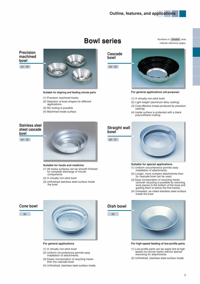
Bowl seriesBowl series
Cone bowl
For general applications
(1) A virtually non-stick bowl(2) Uniform circumference permits easy installation of attachments.(3) Easier incorporation of recycling tracks than the cascade bowl(4) Unfinished, stainless steel surface inside
28
Dish bowl
For high-speed feeding of low-profile parts.
(1) Low-profile parts can be easily fed at high speed via narrow tracks without special reworking for attachments.(2) Unfinished, stainless steel surface inside
29
Stainless steelsheet cascadebowl
Suitable for foods and medicine(1) All tracks surfaces can be smooth-finished for complete discharge of minute components. (2) A virtually non-stick bowl(3) Unfinished stainless steel surface inside the bowl
24・25
Straight wallbowl
Suitable for special applications(1) Uniform circumference permits easy installation of attachments.(2) Longer, more complex attachments than for cascade bowl can be used. (3) Easy incorporation of recycling tracks (smooth recycling is possible by returning work pieces to the bottom of the bowl and guiding them to below the first tracks)(4) Untreated, as-rolled stainless steel surface inside the bowl
26・27
Precisionmachinedbowl
Suitable for aligning and feeding minute parts
(1) Precision machined tracks(2) Selection of bowl shapes for different applications(3) NC tooling is possible(4) Machined inside surface
22・29
Cascadebowl
For general applications (all-purpose)
(1) A virtually non-stick bowl(2) Light weight (aluminum alloy casting)(3) Cost-effective (mass-produced by precision casting)(4) Inside surface is protected with a black polyurethane coating.
22・23
Numbers in shaded area
indicate reference pages.
*編集1-17-E_ *編集1-17/E 13/01/30 10:21 ページ 7
8
Outline, features, and applications
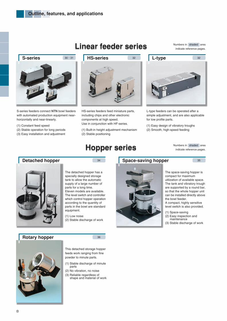
Linear feeder seriesLinear feeder series
S-series feeders connect NTN bowl feederswith automated production equipment near-horizontally and near-linearly.
(1) Constant feed speed(2) Stable operation for long periods(3) Easy installation and adjustment
Detached hopper 34
HS-series feeders feed miniature parts,including chips and other electroniccomponents at high speed.Use in conjunction with HF-series.
(1) Built-in height adjustment mechanism(2) Stable positioning
L-type feeders can be operated after asimple adjustment, and are also applicablefor low profile parts.
(1) Easy design of vibratory troughs(2) Smooth, high-speed feeding
Hopper seriesHopper series
The detached hopper has aspecially designed storagetank to allow the automaticsupply of a large number ofparts for a long time.Eleven models are available.The level switch and controllerwhich control hopper operationaccording to the quantity ofparts in the bowl are standardequipment.
(1) Low noise(2) Stable discharge of work
Space-saving hopper 35
The space-saving hopper iscompact for maximumutilization of available space.The tank and vibratory troughare supported by a round bar,so that the whole hopper unitcan be installed directly abovethe bowl feeder.A compact, highly sensitivelevel switch is also provided.
(1) Space-saving(2) Easy inspection and maintenance(3) Stable discharge of work
Rotary hopper 36
This detached storage hopperfeeds work ranging from finepowder to minute parts.
(1) Stable discharge of minute parts(2) No vibration, no noise(3) Reliable regardless of shape and material of work
Numbers in shaded area
indicate reference pages.
Numbers in shaded area
indicate reference pages.
S-series 30・31 HS-series 32 L-type 32
*編集1-17-E_ *編集1-17/E 13/01/30 10:21 ページ 8
9
Controller seriesController series Numbers in shaded area
indicate reference pages.
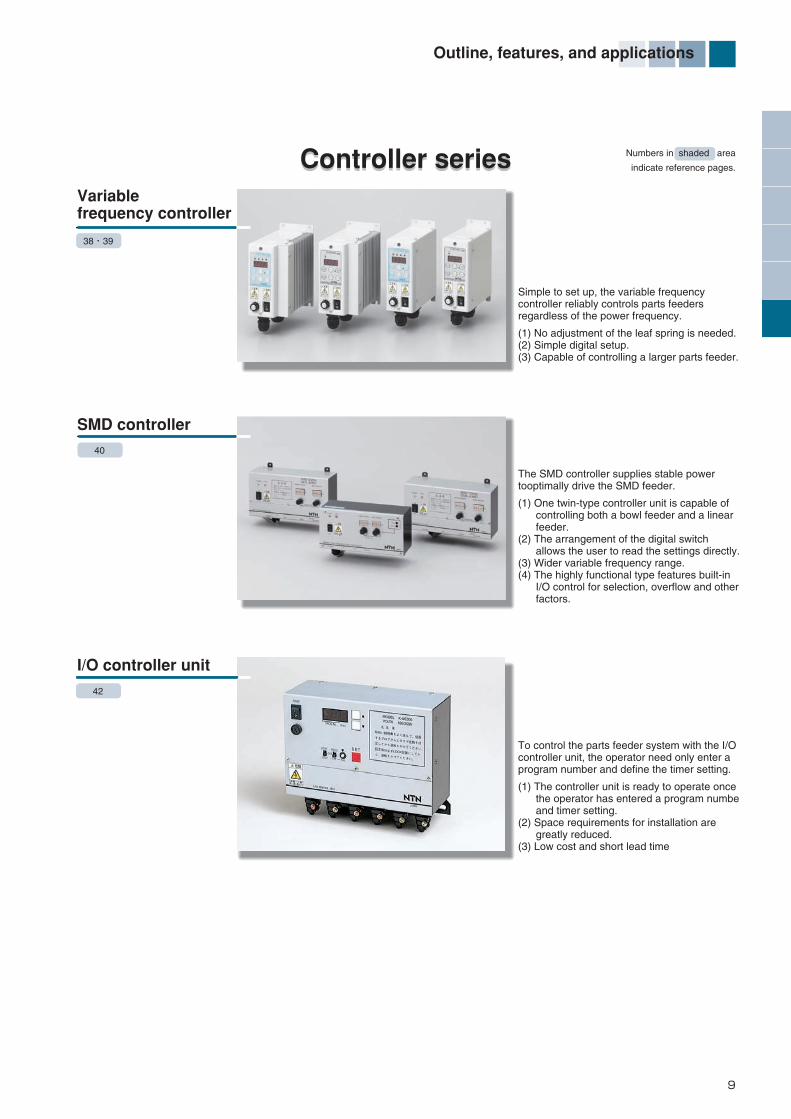
To control the parts feeder system with the I/Ocontroller unit, the operator need only enter aprogram number and define the timer setting.
(1) The controller unit is ready to operate once the operator has entered a program numbe and timer setting.(2) Space requirements for installation are greatly reduced.(3) Low cost and short lead time
Simple to set up, the variable frequencycontroller reliably controls parts feedersregardless of the power frequency.
(1) No adjustment of the leaf spring is needed.(2) Simple digital setup.(3) Capable of controlling a larger parts feeder.
Variablefrequency controller
I/O controller unit
SMD controller
The SMD controller supplies stable powertooptimally drive the SMD feeder.
(1) One twin-type controller unit is capable of controlling both a bowl feeder and a linear feeder.(2) The arrangement of the digital switch allows the user to read the settings directly.(3) Wider variable frequency range.(4) The highly functional type features built-in I/O control for selection, overflow and other factors.
42
38・39
40
Outline, features, and applications
*編集1-17-E_ *編集1-17/E 13/01/30 10:21 ページ 9

10
Selection of Vibratory Driving Unit
Once the outer diameter of the bowl and vibratory trough length are determined, suitable vibratory drives can be selected from the graphs below.
For details, refer to pages 6 and 7 in the "Parts Feeder Guide Book" (CAT.No.7019/E).
500
20 35 55 751051.5
1 000
500
15420.3
1 000
Vibratorytrough length(mm)
Vibratorytrough mass(kg)
Bowl outerdiameter(mm)
Bowl mass(kg)
Bowl outer diameter and mass figures include attachments.
Appropriatebowl sizes forbowl feeders
Appropriatevibratory troughsizes for linearfeeders
K 10
K 14
K 16
K 20
N 25
N 32
N 40
G 50
G 63
S 05
L 20
S 20
HS 05
S 10
S 08
S 30
HS 07
HF 10
HF 14
HF 16
*編集1-17-E_ *編集1-17/E 13/01/30 10:21 ページ 10
11
Bowl feeder dimensions and specifications
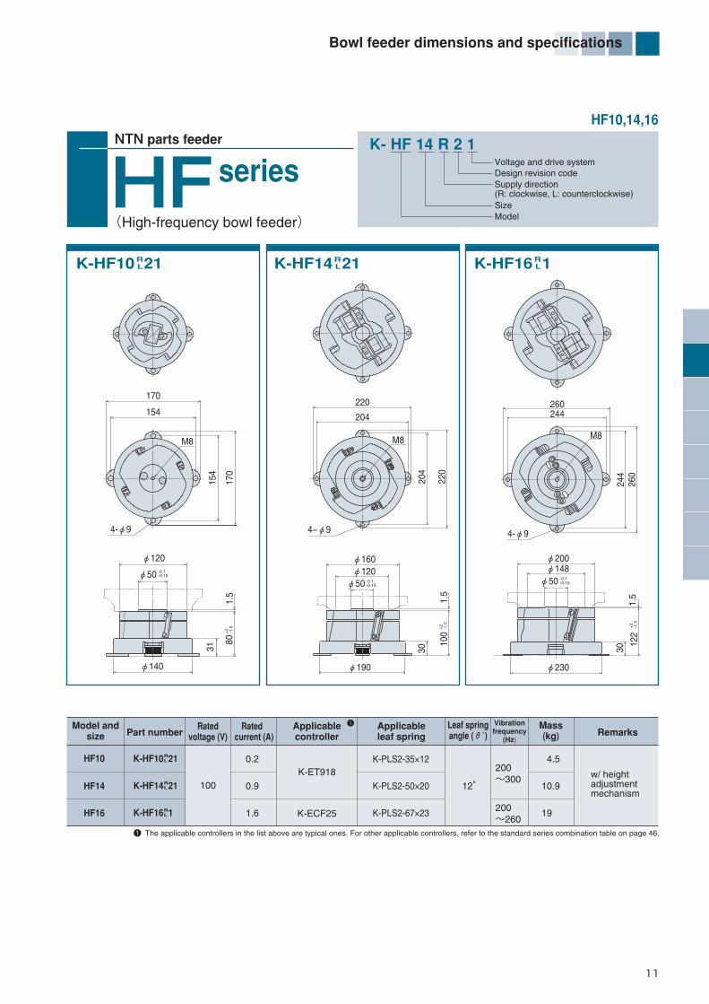
K- HF 14 R 2 1Voltage and drive systemDesign revision codeSupply direction(R: clockwise, L: counterclockwise)SizeModel
NTN parts feeder
seriesHFHF10,14,16
(High-frequency bowl feeder)
Model andsize
HF10
HF14
HF16
Part numberApplicablecontroller
Applicableleaf spring Remarks
Ratedvoltage (V)
Rated current (A)
Leaf springangle (θ˚)
Vibrationfrequency
(Hz)
Mass(kg)
K-HF10 21
K-HF14 21
K-HF16 1
100 10.9
19
4.50.2
0.9
1.6
K-ET918
K-ECF25
K-PLS2-50×20
K-PLS2-67×23
K-PLS2-35×12200~300
200~260
12°
RL
RL
RL
K-HF10 21 RL K-HF14 21 R
L K-HF16 1 RL
4−φ9
220
-0.1-0.15
-0.1-0.15
M822
0
φ190
100
φ160φ120
204
φ50
30204
-0.1-0.15
+2
-1.5
φ50
80
φ120
1.5
+2
-1.5
+2
-1.5
1.5
φ140
31
170
170
M8
4-φ9
154
154
1 The applicable controllers in the list above are typical ones. For other applicable controllers, refer to the standard series combination table on page 46.
1
M8
244
260
260244
4-φ9
φ200
φ230
φ148φ50
1.5
122
30
w/ heightadjustmentmechanism
*編集1-17-E_ *編集1-17/E 13/01/30 10:21 ページ 11

12
Bowl feeder dimensions and specifications
NTN parts feeder
seriesK- K 10 R 1
Voltage and drive systemDesign revision codeSupply direction(R: clockwise, L: counterclockwise)SizeModel
KK10,14
K-K14 RL 12
4-φ10
□150
□12
6
M8 Tapped×14
φ150
θ φ50φ120
1.5
Bowlmounting face
144
10
Model andsize
K10
K14
Part numberApplicablecontroller
Applicableleaf spring Remarks
Ratedvoltage (V)
Rated current (A)
Leaf spring angle (θ˚)
Vibrationfrequency
(Hz)
Mass(kg)
K-K10 1K-K10 2K-K14 1K-K14 2
100200100200
10.0
90~1303.6
0.30.150.70.35
K-ECF25
K-PLS2-50×9
K-PLS2-35×520˚
1 The applicable controllers in the list above are typical ones. For other applicable controllers, refer to the standard series combination table in page 47.
K-K10 R1L2
1
□84
4-φ9Mounting hole
□100
M8 Tapped×12
θ
φ100
1.5
Bowlmounting face
φ50
100
RL
RL
RL
RL
*編集1-17-E_ *編集1-17/E 13/01/30 10:21 ページ 12

13
Bowl feeder dimensions and specifications
K-K20 , RL
12 K-K20 RL 3
4
Bowlmounting face
NTN parts feeder
seriesK- K 16 R 3 1
Voltage and drive systemDesign revision codeSupply direction(R: clockwise, L: counterclockwise)SizeModel
KK16,20
Model andsize
K16
K20
Part numberApplicablecontroller
Applicableleaf spring Remarks
Ratedvoltage (V)
Rated current (A)
Leaf spring angle (θ˚)
Vibrationfrequency
(Hz)
Mass(kg)
K-K16 31K-K16 32K-K20 1K-K20 2K-K20 3K-K20 4
100200100200100200
20
3545~65
90~130 Full wave
Half wave
1.80.32.51.52.01.0
K-ECF25K-ECH45
K-PLS2-67×12-1
K-PLS2-116×35-1
K-PLS2-116×20-2
20˚
15˚
25˚
1 The applicable controllers in the list above are typical ones. For other applicable controllers, refer to the standard series combination table in page 47.
1
θ
RL
RLRL
RL
RL
RL
□250
φ250
189
2
φ200
□20
0
4-M10 Tapped Thru
M12 Tapped×18
K-K16 3RL
12
Bowlmounting face
10
θ
φ200
φ150
M8 Tapped×14
4-φ10
164
□16
0
□200 8
*編集1-17-E_ *編集1-17/E 13/01/30 10:21 ページ 13
14
Bowl feeder dimensions and specifications
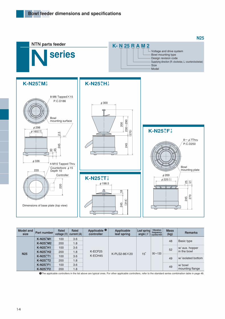
Model andsize
N25
Part numberApplicablecontroller
Applicableleaf spring Remarks
Ratedvoltage (V)
Rated current (A)
Leaf spring angle (θ˚)
Vibrationfrequencycycles/min
Mass(kg)
K-N25 M1K-N25 M2K-N25 H1K-N25 H2K-N25 T1K-N25 T2K-N25 F1K-N25 F2
100200100200100200100200
49
49
52
48
w/ isolated bottom
w/ bowlmounting flange
w/ aux. hopperin the bowl
Basic type3.61.83.61.83.61.83.61.8
K-PLS2-86×20 90~13015°
RL
RL
RL
RL
RL
RL
RL
RL
1The applicable controllers in the list above are typical ones. For other applicable controllers, refer to the standard series combination table in page 48.
1
K- N 25 R A M 2Voltage and drive systemBowl mounting typeDesign revision codeSupplying direction (R: clockwise, L: counterclockwise)SizeModel
NTN parts feeder
seriesNK-N25 MR
L12
K-N25 TRL
12
K-N25 HRL
12
12K-N25 FR
L
K-ECF25K-ECH45
4-M10 Tapped Thru
Controller
Counterbore φ15Depth 10
Dimensions of base plate (top view)
Bowlmounting surface
P.C.D186
8-M6 Tapped×15
2.5
245
220
φ165
45
φ336
φ298
30
-0.05-0.15
220
φ300
200
245
(57
0)230~
290
φ198.5
245
(31
4)
18
245
8-φ7Thru
φ269-0.1-0.3φ225
P.C.D250
25(
2)27
0
Bowlmounting plate
N25
*編集1-17-E_ *編集1-17/E 13/01/30 10:21 ページ 14

15
Bowl feeder dimensions and specifications
Model andsize
N25・A
Part numberApplicablecontroller
Applicableleaf spring Remarks
Ratedvoltage (V)
Rated current (A)
Leaf spring angle (θ˚)
Vibrationfrequencycycles/min
Mass(kg)
K-N25 AM1K-N25 AM2K-N25 AH1K-N25 AH2K-N25 AT1K-N25 AT2K-N25 AF1K-N25 AF2
100200100200100200100200
45
45
48
44
w/ isolated bottom
w/ bowlmounting flange
w/ aux. hopperin the bowl
basic type3.61.83.61.83.61.83.61.8
K-PLS2-86×20 90~13015°
RL
RL
RL
RL
RL
RL
RL
RL
1 The applicable controllers in the list above are typical ones. For other applicable controllers, refer to the standard series combination table in page 48.2 25.A will be supplied with three height adjusting bolts (M10×80) and three clamps (K-P0800).
1
2
K-N25 AMRL
12
K-N25 ATRL
12
K-N25 AHRL
12
12K-N25 AFR
L
w/ free set base
K-ECF25K-ECH45
Rubberinsulatorfitting hole
3-φ9
2.5
P.C.D186
25
±1
5
-0.05-0.15
211
φ298
K-PB-N251
8-M6 Tapped×15
3-Hex.bolt M10R75
(R43)
Free set base dimensions (top view)
256
±1
545
φ165
φ336
P.C.D 220
P.C.D
315
-0.1-0.3
P.C.D250
φ269
281±
15
A-part
Bowlmounting surface
8-φ7 Thru
φ225
225
Details of A-part
(37.5)45±
15
K-P0800
Hex.bolt M10×80
±1
5(5
80
)
±1
5
φ300
±1
525
6 ±1
5
φ198.5
256
1820
0
(325
)
230~
290
N25・A
*編集1-17-E_ *編集1-17/E 13/01/30 10:21 ページ 15

16
Bowl feeder dimensions and specifications
90~130or
45~65
1 The applicable controllers in the list above are typical ones. For other applicable controllers, refer to the standard series combination table in page 49 to 50.
K- N 32 R 2 M 2Voltage and drive system (2: Full wave, 4: Half wave)Bowl mounting typeDesign revision codeSupplying direction (R: clockwise, L: counterclockwise)SizeModel
NTN parts feeder
seriesNN32
Counterbore φ15 Depth 10
P.C.D250
Base plate dimensions (top view)
6-M8 Tapped×15
P.C.D2506-M8 Tapped×15
P.C.D280
Bowl mounting faceBowl mounting face 6-φ9 Thru
Controller
Drain oil chute (L rotation)
Drain oil chute (R rotation)
1
K-N32 2MRL
24 K-N32 2TR
L
K-N32 2HRL
24
K-N32 2FRL
24
24
N32・2
K-N32 2M2K-N32 2M4K-N32 2H2K-N32 2H4K-N32 2T2K-N32 2T4K-N32 2F2K-N32 2F4
200
2.83.52.83.52.83.52.83.5
K-ECH45
K-PLS2-116×40K-PLS2-116×20K-PLS2-116×40K-PLS2-116×20K-PLS2-116×40K-PLS2-116×20K-PLS2-116×40K-PLS2-116×20
68
76
72
69
15˚
RL
RL
RL
RL
RL
RL
RL
RL
4-M10 Tapped Thru
Model andsize Part number
Applicablecontroller
Applicableleaf spring Remarks
Ratedvoltage(V)
Rated current(A)
Leaf spring angle(θ°)
Vibrationfrequency
(Hz)
Mass(kg)
basic type
w/ aux. hopper in the bowl
w/ bowlmounting flange
w/ isolated bottom
φ230 -0.05-0.15
φ410
φ386
2826
647
250
2.5
266
φ300
250
(35)φ230 -0.05
-0.15
285
2
250
φ268
Controller
(21)
(35
1)
290~
340
230
φ345
250
(63
0)
*編集1-17-E_ *編集1-17/E 13/01/30 10:21 ページ 16

17
Bowl feeder dimensions and specifications
1 The applicable controllers in the list above are typical ones. For other applicable controllers, refer to the standard series combination table in page 49 to 50.2 N32.A will be supplied with three height adjusting bolts (M16×100) and three clamps (K-P0801).
K- N 32 R AM 2Voltage and drive system (2: Full wave, 4: Half wave)Bowl mounting typeDesign revision codeSupplying direction (R: clockwise, L: counterclockwise)SizeModel
Free set base dimensions (top view)
6-M8 Tapped×15
6-M8 Tapped×15
Bowlmounting face
Bowlmounting face6-φ9 Thru
Controller
Drain oil chute (L rotation)
Drain oil chute (R rotation)
90~130or
45~65
w/ free set base
P.C.D280φ300
321±
20
(35)φ230
-0.05-0.15
286±
202
290~
340
230
φ345
286±
20 (66
5±20)
P.C.D250
Rubber insulatormounting thread
φ230 -0.05-0.15
φ386
2.5
27φ450P.C.D300
286±
20
64±2
022
2
K-P0801
K-PB-N323
P.C.D250
φ268
(21)
286±
20
(38
7±20)
15°
P.C.D
420
100
1
2
K-N32 AMRL
24 K-N32 ATR
L
K-N32 AHRL
24
K-N32 AFRL
24
24
N32・A
K-N32 AM2K-N32 AM4K-N32 AH2K-N32 AH4K-N32 AT2K-N32 AT4K-N32 AF2K-N32 AF4
200
2.83.52.83.52.83.52.83.5
K-ECH45
K-PLS2-116×40K-PLS2-116×20K-PLS2-116×40K-PLS2-116×20K-PLS2-116×40K-PLS2-116×20K-PLS2-116×40K-PLS2-116×20
64
72
68
65
15˚
RL
RL
RL
RL
RL
RL
RL
RL
N32・ANTN parts feeder
seriesN
3-Hex.bolt M16×100
2-M6 Tapped
3-M10 Tapped
Model andsize Part number
Applicablecontroller
Applicableleaf spring
RemarksRatedvoltage (V)
Rated current (A)
Leaf spring angle (θ˚)
Vibrationfrequency
(Hz)
Mass(kg)
basic type
w/ aux. hopper in the bowl
w/ bowlmounting flange
w/ isolated bottom
3-Hex.bolt M16
*編集1-17-E_ *編集1-17/E 13/01/30 10:21 ページ 17
18
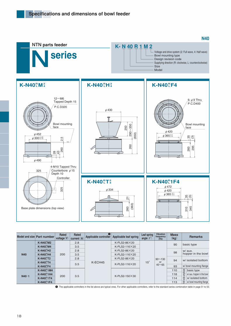
Specifications and dimensions of bowl feeder
K-N40 MRL
24
K-N40 1F4RL
K-N40 F4RL
K-N40 TRL
24
K-N40 HRL
24
N40 w
ide am
plitud
e
Model and size
N40
N40・1
Part number Applicable controller Applicable leaf spring RemarksRated
voltage(V)Rated
current(A)Leaf spring angle(θ°)
Vibrationfrequency
(Hz)
Mass(kg)
K-N40 M2K-N40 M4K-N40 H2K-N40 H4K-N40 T2K-N40 T4K-N40 F4K-N40 1M4K-N40 1H4K-N40 1T4K-N40 1F4
200
200
90
98
94
93110118114113
w/ isolated bottom
w/ aux.hopper in the bowl
basic type2.83.52.83.52.8
3.5
3.5
K-ECH45
K-PLS2-86×20K-PLS2-116×20K-PLS2-86×20K-PLS2-116×20K-PLS2-86×20
K-PLS2-116×20
K-PLS2-150×30
15°
RL
RL
RL
RL
RL
RL
RL
RL
RL
RL
RL
1 The applicable controllers in the list above are typical ones. For other applicable controllers, refer to the standard series combination table in page 51 to 53.
1
90~130or
45~65 w/ bowl mounting flange
basic typew/ aux. hopper in the bowlw/ isolated bottomw/ bowl mounting flange
-0.05-0.15
12-M6Tapped Depth 15
φ452
Bowl mountingface
φ490
260
432.
5
28
φ300
325
P.C.D320
325
4-M10 Tapped ThruCounterbore φ15Depth 10
Controller
Base plate dimensions (top view)
φ334
(363
)
250
2126
0
φ430
290~
350
260
(650
)
6-φ9 Thru
φ420-0.1-0.5
295
(3)
Bowl mounting face
260
φ365
35
P.C.D400
φ420
310
35 (3)
345
φ365
φ472
-0.1-0.5
N40
K- N 40 R 1 M 2Voltage and drive system (2: Full wave, 4: Half wave)Bowl mounting typeDesign revision codeSupplying direction (R: clockwise, L: counterclockwise)SizeModel
NTN parts feeder
seriesN
*編集18-45-E_ *編集18-51/E 13/01/30 10:22 ページ 18

19
N40・A
Model and size
N40・A
Part number Applicable controller Applicable leaf spring RemarksRated
voltage (V)Rated
current (A)Leaf spring angle (θ˚)
Vibrationfrequency
(Hz)
Mass(kg)
K-N40 AM2K-N40 AM4K-N40 AH2K-N40 AH4K-N40 AT2K-N40 AT4K-N40 AF4
200
88
96
92
91
w/ isolatedbottom
w/ aux. hopperin the bowl
basic type2.83.52.83.52.8
3.5
K-ECH45
K-PLS2-86×20K-PLS2-116×20K-PLS2-86×20K-PLS2-116×20K-PLS2-86×20
K-PLS2-116×20
15°
RL
RL
RL
RL
RL
RL
RL
1 The applicable controllers in the list above are typical ones. For other applicable controllers, refer to the standard series combination table in page 51 to 52.2 40.A will be supplied with three height adjusting bolts (M16×100) and three clamps (K-P0801).
1
2
K - N 40 R A M 2Voltage and drive system (2: Full wave, 4: Half wave)Bowl mounting typeDesign revision codeSupplying direction (R: clockwise, L: counterclockwise)SizeModel
NTN parts feeder
seriesNK-N40 AMR
L24
K-N40 ATRL
24
K-N40 AHRL K-N40 AF4R
L24
90~130or
45~65
w/ bowl mounting flange
w/ f
ree
set b
ase
Controller
Rubber insulator hole
2-M6 Tapped
K-PB-N401
-0.05-0.15φ300
Bowl mounting face
45
φ452
+4
0
0
2.5
+4
0
027
2227
4-M10 Tapped
21+
40
0
+4
0
0
+4
0
0
+4
0
045
φ334
(662
)
227
φ430
(375
)27
2+
40
0
+4
0 0
227
4525
029
0~35
027
2
P.C.D400
Details of area A
45
Hex.bolt M16×100
K-P0801
Bowl mountingface
+4
0
0
48
-0.1-0.5
45(3
)35
Area A +4
0
0
+4
0
030
7227
φ420φ365
6-φ9 Thru
100
φ530P.C.D500
Free set base dimensions (top view)
12-M6Tapped×15
25R90
3-Hex.bolt M16
R45
P.C.D320
P.C.D350
15˚30˚ 15˚
60˚
Specifications and dimensions of bowl feeder
*編集18-45-E_ *編集18-51/E 13/01/30 10:22 ページ 19
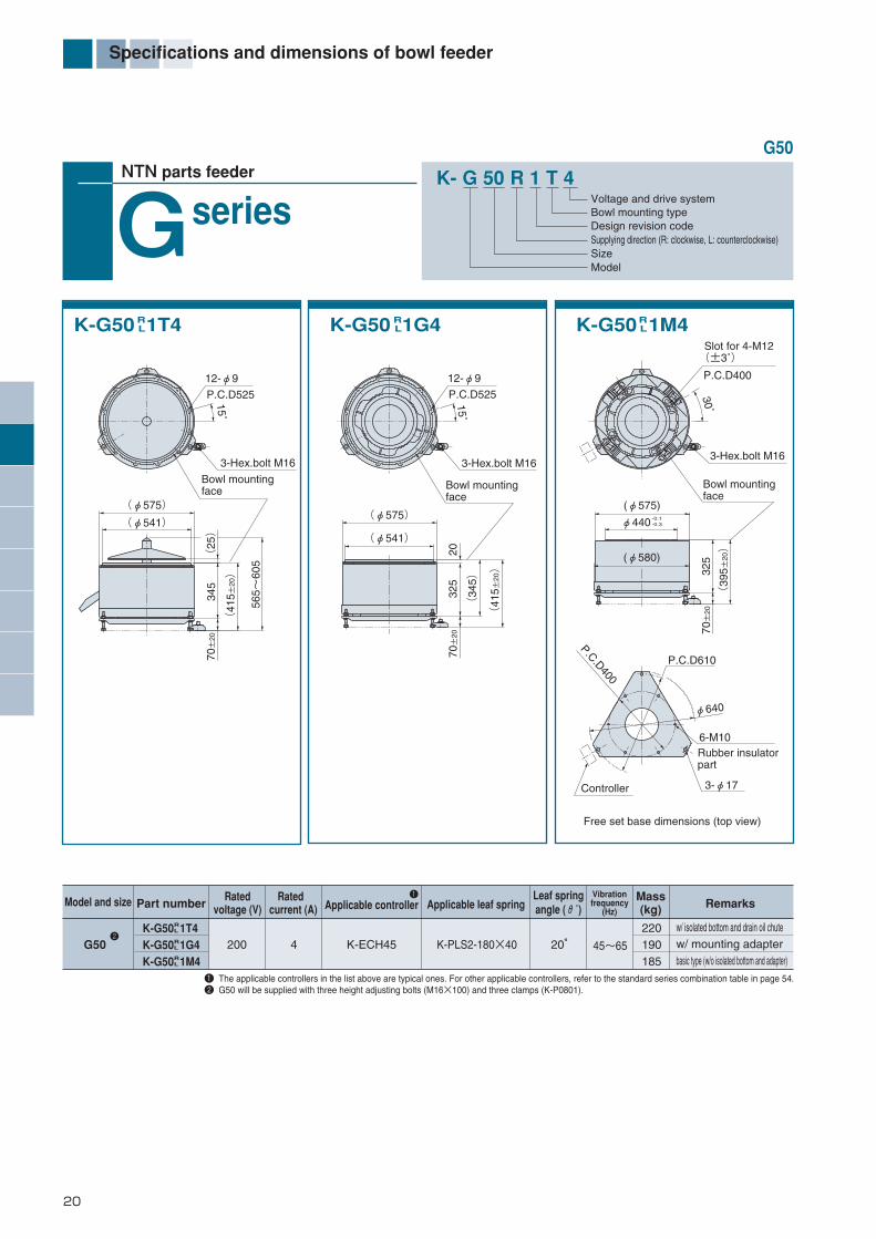
20
Specifications and dimensions of bowl feeder
Model and size
G50
Part number Applicable controller Applicable leaf spring RemarksRated
voltage (V)Rated
current (A)Leaf springangle (θ˚)
Vibrationfrequency
(Hz)
Mass(kg)
K-G50 1T4K-G50 1G4K-G50 1M4
200220190185
w/ isolated bottom and drain oil chutew/ mounting adapterbasic type (w/o isolated bottom and adapter)
4 K-ECH45 K-PLS2-180×40 20°
RL
RL
RL
1 The applicable controllers in the list above are typical ones. For other applicable controllers, refer to the standard series combination table in page 54.2 G50 will be supplied with three height adjusting bolts (M16×100) and three clamps (K-P0801).
1
2
K- G 50 R 1 T 4Voltage and drive systemBowl mounting typeDesign revision codeSupplying direction (R: clockwise, L: counterclockwise)Size Model
NTN parts feeder
seriesGK-G50 1T4R
L K-G50 1G4RL K-G50 1M4R
L
45~65
G50
P.C.D525
3-Hex.bolt M16
12-φ9
15˚
70±
20
(φ575)
345
(41
5 ±20)
Bowl mountingface
(φ541)
565~
605
(25)
P.C.D525
3-Hex.bolt M16
12-φ9
15˚
70±
2032
520
(41
5 ±20)
(34
5)Bowl mountingface
(φ575)
(φ541)
Free set base dimensions (top view)
P.C.D400
Slot for 4-M12(±3˚)
30˚
Rubber insulatorpart
Controller 3-φ17
6-M10
P.C.D400
φ64070±
2032
5
(39
5 ±20)
(φ575)
φ440 -0.1-0.3
Bowl mountingface
3-Hex.bolt M16
P.C.D610
(φ580)
*編集18-45-E_ *編集18-51/E 13/01/30 10:22 ページ 20

21
Model and size
G63・2
Part number Applicable controller Applicable leaf spring RemarksRated
voltage (V)Rated
current (A)Leaf springangle (θ˚)
Vibrationfrequency
(Hz)
Mass(kg)
K-G63 2T4K-G63 2G4K-G63 2M4
200400370360
w/ isolated bottom and drain oil chutew/ mounting adapterbasic type (w/o isolated bottom and adapter)
10 K-ECK96 K-PLS2-250×70 20°
RL
RL
RL
K- G 63 R 2 T 4Voltage and drive systemBowl mounting typeDesign revision codeSupplying direction (R: clockwise, L: counterclockwise)Size Model
NTN parts feeder
seriesGK-G63 2T4R
L K-G63 2G4RL K-G63 2M4R
L
45~65
φ475
428
(25)
560~
570
φ25
Drain oil chute
12-φ9ThruP.C.D 525
(225
)
12-φ9ThruP.C.D 525
Mounting face ofbowl mountingadapter
Controller
388
488
488
4-M10 Tapped thru
φ780
Mounting face of bowl mountingadapter
416
8-Hex.bolt M10
16
Bowlfixture
Baseplate dimensions (top view)
G63
1 The applicable controllers in the list above are typical ones. For other applicable controllers, refer to the standard series combination table in page 55.
1
φ534
1638
8
428
780
(32
4)
780(10
3)
Specifications and dimensions of bowl feeder
*編集18-45-E_ *編集18-51/E 13/01/30 10:22 ページ 21

22
Bowl dimensions and specifications
NTN parts feeder
Cascadebowl (1)
Part numberDimensions (mm)Specifications
Turns Material Mass(kg) Applicable unit, remarks
Standardcapacity(R)
K-B10 C1201 1
K-B10 C1401 12
K-B10 C1403 12
K-B10 C1501 1
K-B10 C1502 12
K-B10 C1701 12
K-B14 C1801 1
K-B14 C2001 1
K-B16RC2101 2
K-B16 C2301K-B16 C2601
120140145150150175188200225230260
3040353434403265568077
8.811.011.09.39.2
13.612.018.018.020.030.0
4.06.06.04.33.27.86.0
10.04.3
11.019.0
120100100116116138120120170162202
3.03.03.03.03.02.31.53.02.03.01.5
AR alloyAR alloyAR alloyAR alloyAR alloyAR alloyAR alloyAR alloyAR castingAR castingAR casting
0.470.380.480.550.521.001.201.801.100.901.70
0.070.100.100.090.090.120.150.220.220.300.40
w/ outer apron
2-tracksFor conventional Part No. K10·AFor high-frequency
2-tracks
RL
RL
RL
RL
RL
RL
RL
RL
RL
RL
1 The Al alloy bowl is precision machined.2 Part Nos. C1401, C1403, C1502, C1701 and C2101 are manufactured on special order.
A B C D E
K10
HF14K14
K16
K-B10 C1201RL
K-B10 C1403,1501,1502,1701K-B14 C1801,2001
RL
RL
K-B10 C1401RL
K-B16RC2101K-B16 C2301K-B16 C2601
RL
RL
K- B 10 R C 14 01
Bowl type codeSizeSupply direction (R: clockwise, L: counterclockwise)
Bowl type (C: cascade, D: dish, Z: straight wall, K: cone)
Bowl outer dia.Bowl suffix
BD
φ50
C
φA
φ8.5
E
φ50
C
D
φA
B
φ8.5
D
C B
φA
E
φ50
φ8.5
φ120
E
D
φ150
C
φA
φ9B
*編集18-45-E_ *編集18-51/E 13/01/30 10:22 ページ 22

23
Specifications and dimensions of bowls
NTN parts feeder
Cascadebowl (2)
K-B25 CD・・・K-B40 CD・・・
RL
RL
K-B25 CB・・・K-B40 CB・・・
RL
RL
K-B63 CD83RL
K-B63 CB83RL
※Height of outlet
K- B 25 R C D 39 1
Bowl unit codeSizeSupply direction (R: clockwise, L: counterclockwise)
Bowl type (C: cascade, D: dish, Z: straight wall, K: cone)
Bowl bottom type (D: no-bottom(isolated bottom type), F: integrated bottom, B: w/ fixed bottom)
Bowl outer dia. (rounded off to cm)Design revision code
Part numberDimensions (mm)Specifications
Turns Material Mass(kg)
Applicable unit, remarksApprox. capacity upto the first step (R)
K-B25 C 33K-B25 C 39K-B25 C 391K-B40 C 54K-B40 C 58K-B40 C 64K-B40 C 641K-B63 C 83
330396396540588640640830
105129151162210203241230
3240
50
64
90
2032323240505068
738992
111130139141140
8298
121120160148186160
2.02.02.02.02.02.02.01.5
AR castingAR castingAR castingAR castingAR castingAR castingAR castingAR casting
1.62.52.54.58.0
10.010.022.0
1.52.52.55 7 9 9
20
Steep steps
Steep steps
Steep steps
RL
RL
RL
RL
RL
RL
RL
RL
DB
DB
DB
DB
DB
DB
DB
DB
1 The lead of the last turn of the track.
A B C D E F
N25
N40
G50, G63・2
67140
87160
112164
P. C. D 320(B40)
P. C. D 186(B25)
φA
8-φ7(B25)
12-φ7(B40)
C
D M12 Tapped
B
※E
F
P.C.D 320(B40)
P.C.D 186(B25)
φA
8-φ7(B25)
12-φ7(B40)
C
D
F ※E B
12-M8 Tapped×15
C
D
P. C. D 52512-M8 Tapped×15
φA
F ※E B
C
D
P. C. D 525
φA
F ※E B
*編集18-45-E_ *編集18-51/E 13/01/30 10:22 ページ 23

24
Bowl specifications and dimensions
NTN parts feeder
Cascadebowl (3)
P.C.D 320(B40)
P.C.D 186(B25)
φA
8-φ7(B25)
12-φ7(B40)
C
D
F ※E B
C
D
P.C.D 250
6-φ9
φA
※E B
F
K-B25 SD・・・K-B40 SD・・・
RL
RL
K-B32 SD491RL
K-B63 SD83RL
※Height of outlet
K- B 25 R S D 39 1
Bowl CodeSizeSupply direction (R: clockwise, L: counterclockwise)
Bowl type (C: cascade, D: dish, Z: straight wall, K: cone, S: stainless steel cascade)
Bowl bottom type (D: no-bottom (isolated bottom), F: integrated bottom, B: w/ fixed bottom)
Bowl outer dia. (to nearest cm)Design revision code
Part numberDimensions (mm)Specifications
Turns Material Mass(kg)
Applicable unit, remarksApprox. capacity upto the first step (R)
K-B25 SD39K-B25 SD391K-B32 SD491K-B40 SD54K-B40 SD58K-B40 SD64K-B40 SD6412
K-B63 SD832
390390496538582636636828
137157182168217210246227
40
5550
64
90
3232363240505068
- 97
127 -
137 -
146 -
99119136121161149185160
2.02.02.02.02.02.02.01.5
SUSSUSSUSSUSSUSSUSSUSSUS
4.34.4
10.210.012.014.015.230.1
2.52.53.25 7 9 9
20
Steep steps
Steep steps
Steep steps
RL
RL
RL
RL
RL
RL
RL
RL
1 The lead of the last turn of the track.2 Part Nos. SD641 and SD83 are manufactured on special order.
A B C D E F
N25
N32
N40
G63・2
67140
87160
112164
C
D
P.C.D 525
12-M8 Tapped ×15
φA
F ※E B
*編集18-45-E_ *編集18-51/E 13/01/30 10:22 ページ 24

25
Bowl specifications and dimensions
NTN parts feeder
Cascadebowl (4)
K-B25 SF・・・K-B40 SF・・・
RL
RL
K-B32 SF491RLK-B20 S3201R
L
K-B63 SF83RL
K- B 25 R S F 39 1
Bowl codeSizeSupply direction (R: clockwise, L: counterclockwise)
Bowl type (C: cascade, D: dish, Z: straight wall, K: cone, S: stainless steel cascade)
Bowl bottom type (D: no-bottom (isolated bottom type), F: integrated bottom, B: w/ fixed bottom)
Bowl outer dia. (to nearest cm)Design revision code
※Height of outlet
1 The lead of the last turn of the track.2 Part Nos. SF641 and SF83 are manufactured on special order.
ECφ231
P.C.D 2806-M8 Tapped×20
D
φA
B
※F
φ13 M12
φ298
C
φ226(B25)
D
B
F
φ13
8-M6(B25)
※E
φA
M12
φ366(B40) 6-M8(B40)
P.C.D250(B25)P.C.D400(B40)
φ18
15
C
※E B
φ566
M16
φ536φ504
φAD
φA
φ13
φ130
φ190
D
C
※E B
Specifications Dimensions (mm)Part number
Turns Material Mass(kg)
Applicable unit, remarksApprox. capacity upto the first step (R)
K-B20 S3201K-B25 SF39K-B25 SF391K-B32 SF491K-B40 SF54K-B40 SF58K-B40 SF64K-B40 SF641K-B63 SF83
320390390496538582636636828
108131151150165212207243277
3440
4750
64
90
253232363240505068
- - 91- - 132- 135-
7393
113106118156146182210
2.02.02.02.02.02.02.02.01.5
SUSSUSSUSSUSSUSSUSSUSSUSSUS
3.14.74.8
12.012.514.516.017.042.1
1.32.52.53.25 7 9 9
20
Steep steps
Steep steps
Steep steps
RL
RL
RL
RL
RL
RL
RL
RL
RL
A B C D E F
N25
K20
N32
N40
G63・2
67140
87160
112164
*編集18-45-E_ *編集18-51/E 13/01/30 10:22 ページ 25

26
Bowl specifications and dimensions
NTN parts feeder
Straightwall bowl (1)
K-B10 Z1201K-B14 Z2001K-B16 Z・・・K-B20 Z・・・
RL
RL
RL
RL
K-B32 ZF401RL
K-B25 ZF・・・RL
K-B25 ZD・・・K-B32 ZD401
RL
RL
K- B 25 R Z F 30 1
Bowl size codeSizeSupply direction (R: clockwise, L: counter-clockwise)Bowl type (C: cascade, D: dish, Z: straight wall, K: cone)
Bowl bottom (D: no-bottom (isolated bottom type), F: integrated bottom, B: w/ fixed bottom)
Bowl outer dia. (to nearest cm)Design revision code
1 Part Nos. Z2302, Z 30, Z 301, Z 302, Z 351 and ZD354 are manufactured on special order.DF
DF
DF
DF
φA
D
φE
φF
BC
φ9
φ298
P. C. D 280
6-M8 Tapped×10
B E
φA
D
C
φ13M12
φ231
M12φ13
FC
G B
φ275Hex. bolt
φA
P. C. D250
D
8-M6×15
E
φ298(B32)φ220(B25)
C
B
φA
D
8-φ7(B25)
6-φ9.5(B32)
φ166(B25)
φ13(B20)
φ200(B25)φ270(B32)
φ231(B32)
P.C.D186(B25)P.C.D250(B32)
Specifications Dimensions (mm)
Part numberTurns Material
Mass(kg) Applicable unit, remarks
Standardcapacity
(R)
K-B10 Z1201K-B14 Z2001K-B16 Z2301K-B16 Z23021
K-B16 Z2501K-B20 Z2801K-B20 Z3003K-B25 Z 301
K-B25 Z 3011
K-B25 Z 3021
K-B25 Z 35K-B25 Z 3511
K-B25 Z 352K-B25 ZD3541
K-B32 ZD401K-B32 ZF401
120200234234250280300304304304354354354354
400
455565556575858585
110100100125135
140
1323282030333636303642354242
48
1020201520252525202530303030
40
5080808080
1301309595
120106106131141148143
2.01.51.52.01.51.51.51.52.02.01.52.02.02.5
2.0
100130150150150190200116116141128128153-
-
SUSSUS
SUS
SUS
SUS
SUS
(0.7)1.62.22.02.33.13.94.84.95.46.06.16.76.2
10.0
0.070.350.450.400.601.201.701.801.601.802.802.202.802.80
4.00
Low lead, 2-tracks
Standard lead, 2-tracks
Low lead, 2-tracksStandard lead, 2-tracksStandard lead, 2.5-tracks
RL
RL
RL
RL
RL
RL
RL
RL
RL
RL
RL
RL
RL
RL
RL
RL
DF
DF
DF
DF
DF
DF
A B C D E F
- - - - - - - 9191
116103103128-
-
G
K10K14
K16
K20
N32
N25
*編集18-45-E_ *編集18-51/E 13/01/30 10:22 ページ 26

27
Bowl specifications and dimensions
NTN parts feeder
Straightwall bowl (2)
Part number
Dimensions (mm)SpecificationsTurns Material
Mass(kg) Applicable unit, remarks
Standardcapacity
(R)
K-B40 Z 45K-B40 ZF4511
K-B40 ZF4521
K-B40 Z 50K-B40 ZF5011
K-B40 ZF5021
K-B40 ZD5031
K-B40 ZF55K-B40 ZF601
K-B50 ZF6511
K-B63 ZF751
454454454504504504504554604655755
130130160140140175195150170193220
5646566252626268748085
4040404545454550556570
139 - -
145 - -
200 - - - -
1.52.02.01.52.02.02.51.51.51.51.5
175 175 205 182 182 217 -
188 204 -
270
SUSSUSSUSSUSSUSSUSSUSSUSSUSSUSSUS
12.012.213.013.013.214.013.014.016.030.048.0
5.04.05.07.06.07.07.0
10.013.017.025.0
Low lead, 2-tracks
Standard lead, 2-tracks
Low lead, 2-tracksStandard lead, 2-tracksStandard lead, 2.5-tracks
RL
RL
RL
RL
DF
DF
RL
RL
RL
RL
RL
RL
RL
A B C D E F
140 140 170 147 147 182 -
153 169 190 -
G
N40
G50・1G63・2
K-B40 ZF・・・RL
K-B50 ZF651RL
K-B40 ZD・・・RL
K-B63 ZF75RL
K- B 40 R Z F 45 2
Bowl codeSizeSupply direction (R: clockwise, L: counterclockwise)Bowl type (C: cascade, D: dish, Z: straight wall, K: cone)
Bowl bottom (D: no-bottom (isolated bottom type), F: integrated bottom, B: w/fixed bottom)
Bowl outer dia. (to nearest cm)Design revision code
φ420
B
F
φ13
P. C. D400
P. C. D400
φA
M12
Hex.bolt
6-M8×20
D
C
G E
φ336
φ360
P. C. D320
φ301
φA
12-φ7C
D
B17
B
C
F
15 φ536
D
φ566
φA
BC
G
φA
D
8-M12 Tapped×22φ440.5
φ448
Bowl mountingface
1 Part Nos. ZF451, ZF452, ZF501, ZF502, ZD503, ZF60, ZF651 and ZF75 are manufactured on special order.
*編集18-45-E_ *編集18-51/E 13/01/30 10:22 ページ 27
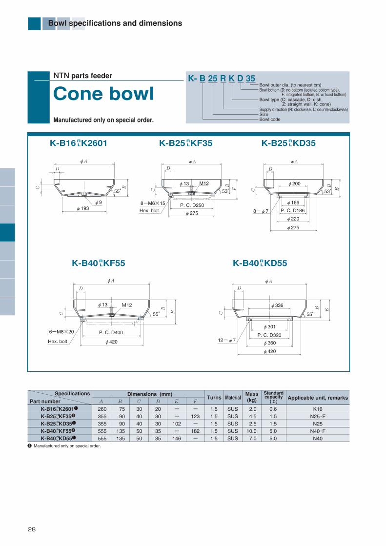
28
Bowl specifications and dimensions
NTN parts feeder
Manufactured only on special order.
Cone bowl
Part number Dimensions (mm)Specifications
Turns MaterialMass(kg) Applicable unit, remarks
Standardcapacity
(R)
K-B16 K26011
K-B25 KF351
K-B25 KD351
K-B40 KF551
K-B40 KD551
260355355555555
759090
135135
3040405050
2030303535
- -
102 -
146
1.51.51.51.51.5
- 123 -
182 -
SUSSUSSUSSUSSUS
2.04.52.5
10.07.0
0.61.51.55.05.0
RL
RL
RL
RL
RL
A B C D E F
K16N25・FN25
N40・FN40
K-B16 K2601RL K-B25 KF35R
L
K-B40 KF55RL
K-B25 KD35RL
K-B40 KD55RL
K- B 25 R K D 35
Bowl codeSizeSupply direction (R: clockwise, L: counterclockwise)
Bowl type (C: cascade, D: dish, Z: straight wall, K: cone)
Bowl bottom (D: no-bottom (isolated bottom type), F: integrated bottom, B: w/ fixed bottom)
Bowl outer dia. (to nearest cm)
1 Manufactured only on special order.
8-φ7 P. C. D186
φ220
φ200
53°
φ275
D
C
φ166
φA
E
BM12
P. C. D250
53° F
φ275Hex. bolt
8-M6×15
C
φ13
φAD
BB
55°
D
φA
φ193
C
φ9
12-φ7
C
φ336
φ301
P. C. D320
φ360
φ420
55°
EB
φA
D
Hex. bolt
55°
φ420
P. C. D400
C
D
6-M8×20
B
φA
φ13 M12
F
*編集18-45-E_ *編集18-51/E 13/01/30 10:22 ページ 28

29
Bowl specifications and dimensions
NTN parts feeder
Dish bowl
Specifications Dimensions (mm)Part number
Turns MaterialMass(kg) Applicable unit, remarks
Standardcapacity
(R)
K-B10 D1301 1
K-B10 D1402 12
K-B10 D1701 12
K-B10 D2001 12
K-B14 D2002 1
K-B16D2801K-B25DF42 2
K-B40DF64 2
K-B40DF641 2
134148178204204280420640640
3238606060718097
150
10 12 14 30 31 - - - -
1.01.03.71.51.5- - - -
100110100124127150281446466
3.02.75.02.12.0- - - -
- - - - - -
113 142 195
AR alloyAR alloyAR alloyAR alloyAR alloySUS
SUS SUS SUS
0.440.490.841.31.51.74.0
13.018.0
0.060.080.200.200.200.351.203.505.00
w/ overhang
For K-10・A
RL
RL
RL
RL
RL
A B C D E F
K10
K14K16
N25・F
N40・F
K-B10 D1301,1402,1701RL
K-B10 D2001K-B14 D2002
RL
RL
K-B16D2801
K-B25DF42K-B40DF64,641
K- B 40 D F 64 1
Bowl codeSizeSupply direction (R: clockwise, L: counterclockwise)Bowl type (C: cascade, D: dish, Z: straight wall, K: cone)
Bowl bottom (D: no-bottom (isolated bottom type), F: integrated bottom, B: w/ fixed bottom)
Bowl outer dia. (to nearest cm)Design revision code
1 Aluminum alloy bowl is precision machined. Since the standard stainless steel dish bowl does not have any tracks, the R/L code is not required.2 Part Nos. D1402, D1701, D2001, D2901, DF42 , DF64 and DF641 are manufactured on special order.
D
φE
φ50 (φ80)
C
φ8.5
B
φA
φ50
CD
B
φE
φ8.5
P. C. D250(B25) P. C. D400(B40)
φE
φA
45°
F
B
φA
φA
φ9
φE
B
45°
*編集18-45-E_ *編集18-51/E 13/01/30 10:22 ページ 29
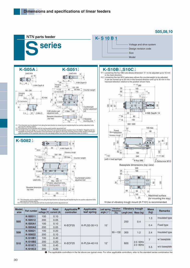
30
Dimensions and specifications of linear feeders
4-Nut M6
※1 Loosening the four M6 nuts allows dimension ※1 to be adjusted up to 10 mm in the feed direction.※2 Loosening the two M10 setscrews allows the counterweight to be adjusted. It can be moved up to 20 mm in the forward direction and up to 30 mm in the rearward direction relative to the position shown here.
Vibratory trough
(with 4 leaf springs)
(for mounting the stay)Machined surface
w/ baseplate
Insulated type
Insulated type
Fixed type
w/o baseplate
1 The applicable controllers in the list above are typical ones. For other applicable controllers, refer to the standard series combination list.
K- S 10 B 1Voltage and drive system
Design revision code
Size
Model
NTN parts feeder
seriesS
90~130
S05,08,10
※Use of vibratory trough mount (K-T101) is recommended.
S05
S08
S10
K-S0511K-S0512K-S05A1K-S05A2K-S0821K-S0822K-S10B1K-S10B2K-S10C1K-S10C2
100200100200100200100200100200
1.3
0.4
2.4
7
5.5
250
300
600
0.4
1.2
2.5:50Hz2.0:60Hz
0.100.050.100.050.200.100.400.200.400.20
K-ECF25
K-ECF25
K-PLS2-35×5
K-PLS4-40×6
15˚
12˚
1
※1: This dimension can be adjusted 2 mm along the feed direction by loosening and retightening the two position adjustment bolts securing the vibrating section.※2: This dimension can be adjusted with the counterweight position adjustment bolt.※3: The height of the new design is 4 mm less than that of the conventional optional insulated mount (K-UH001). Regarding the two baseplate mounting slots, the position of the downstream slot relative to the chute mounting screws (4-M4) remains unchanged while the position of the upstream side slot in the new design differs from that of the conventional mount (K-UH001).
※1: This dimension can be adjusted 2 mm along the feed direction by loosening and retightening the two position adjustment bolts securing the vibrating section.※2: This dimension can be adjusted with the counterweight position adjustment bolt.
4-M6 Depth 14
2 Position adjustment boltsfor vibrating section
Baseplate dimensions (top view)
Counterweight positionadjustment bolt
Counter-weight
Model,size Part number
Applicableleaf spring Remarks
Ratedvoltage (V)
Ratedcurrent (A)
Leaf springangle (θ˚)
Vibrationfrequency
(Hz)
Mass(kg)
Applicablecontroller
Vibratory trough
Length (mm) Mass (kg)
K-S10B ,S10C12
12K-S0511
2K-S05A 12
K-S082 12
※1
※1
※2 280
11
※1
※1
54(
93)
20
113
14
25
Feeddirection
40
80
150
140 max.
90
12 58
(40)
(40)
2-Setscrew M10
110
300~600
※1
140110
120
90 67 64
5065
1111
12゜
Counter-weight
※1
※1
※1
※1
※2
※2
240
190
240190
60 120
15
25
6465
14023
20
6.5
34
(13)
Baseplate dimensions (top view)
67 40
Lead wire
40
100~250
250~300
4-M4 Depth 8
2 Baseplatemounting slots
10
15°
(29)※1
(17) 37※1
※2
(19)
11.4
※1
※3
※3
3
※3
※1
※1
Vibratorytrough
Vibratory trough
15
25
60
120
20 80
(25)
4 (slot)
96
50
50(
46)
80 max.
100 max.
2-M6 vibration partadjustment bolts
123Max.(138)
※2Max.(224)
4512
258
Counterweightposition adjustmentbolt
Counter-weightFeed direction
7
44 50115
15°
4-M5 Depth 15
20 32
Feed direction
(33.5)
(13.5)
Baseplate dimensions (top view)
9650
10 (slot)
75
4512
199Lead wire
7
328
50190
120
Lead wire
404-M4 Depth 8
2-M6×10
10
Vibratorytrough
15 25
60
100~250
45 max.
11.4 37
13.4
15°
Feed direction
*編集18-45-E_ *編集18-51/E 13/01/30 10:22 ページ 30
31
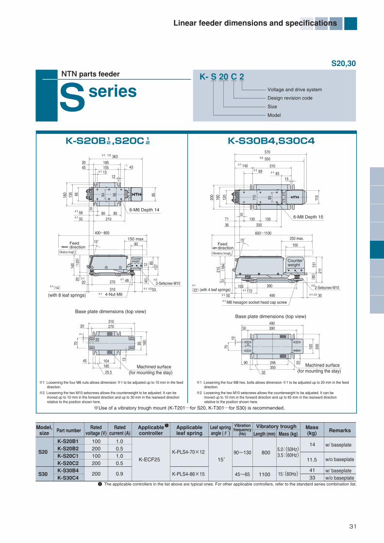
Linear feeder dimensions and specifications
K- S 20 C 2Voltage and drive system
Design revision code
Size
Model
NTN parts feeder
seriesS
Feeddirection
Vibratory troughVibratory trough
Feeddirection
(with 8 leaf springs)(with 4 leaf springs)
2-Setscrew M10
S20,30
Model,size
S20
S30
Part numberApplicableleaf spring Remarks
Ratedvoltage (V)
Ratedcurrent (A)
Leaf springangle (θ˚)
Vibrationfrequency
(Hz)
Vibratory troughLength (mm) Mass (kg)
Mass(kg)
K-S20B1K-S20B2K-S20C1K-S20C2K-S30B4K-S30C4
100200100200
200
11.5
33
41
14
80090~130
45~65 1100 15:(60Hz)
5.0:(50Hz)3.5:(60Hz)
w/ baseplate
w/ baseplate
w/o baseplate
w/o baseplate
1.00.51.00.5
0.9
K-PLS4-70×12
K-PLS4-86×15
15˚
Applicablecontroller
1
※1 Loosening the four M6 nuts allows dimension ※1 to be adjusted up to 10 mm in the feed direction.
※2 Loosening the two M10 setscrews allows the counterweight to be adjusted. It can be moved up to 10 mm in the forward direction and up to 30 mm in the rearward direction relative to the position shown here.
※1 Loosening the four M8 hex. bolts allows dimension ※1 to be adjusted up to 20 mm in the feed direction.
※2 Loosening the two M10 setscrews allows the counterweight to be adjusted. It can be moved up to 10 mm in the forward direction and up to 65 mm in the rearward direction relative to the position shown here.
4-Nut M6
6-M6 Depth 14
Machined surface (for mounting the stay)
Machined surface (for mounting the stay)
※1
250 max.
2-Setscrew M10
M8 hexagon socket head cap screw
6-M8 Depth 15
1 The applicable controllers in the list above are typical ones. For other applicable controllers, refer to the standard series combination list.
K-ECF25
※Use of a vibratory trough mount (K-T201…for S20, K-T301…for S30) is recommended.
K-S30B4,S30C4K-S20B ,S20C12
12
※1
※1
※2 363
13
※1 58※1
※1
※2
※2
33
※1
※1 ※1
※1(14)20
150 max.400~800
! 1 43185155
160
135 95 95
12
3045
Base plate dimensions (top view)
2580
21080
90
12(
40)
13785
15゜
140(
120)
2070
7
13
95 160
310
270
310
20
45 104185
25.5
27020
48
53
64 95
※1
※2
570
550
310
15
3571 130 130
330
600~1100
36
110
120
160
200
215
(18
4)31
69
※1 50※1 172
490
390
49039050
30(22)
※1 83
※1 140
15゜
※1
※2
※2※1
Base plate dimensions (top view)
150
131
211
(80)
10
70
40
90 246350
32
20
120
200
100
115
80
Counterweight Counter
weight
*編集18-45-E_ *編集18-51/E 13/01/30 10:22 ページ 31

32
Linear feeder dimensions and specifications
Model,size
HS05HS07
L20
Part numberApplicableleaf spring Remarks
Ratedvoltage (V)
Ratedcurrent (A)
Leaf springangle (θ˚)
Vibrationfrequency
(Hz)
Vibratory troughLength (mm) Mass (kg)
Mass(kg)
K-HS0521K-HS0711K-L201K-L202
100100100200
250300
600
0.30.6
1.12.5
8.05.0:(50Hz)4.0:(60Hz)
Rubber insulator
w/ isolation mountusing leaf springs
0.160.51.00.5
K-ECF25
K-PLS2-35×9K-PLS4-40×6
K-PLS2-67×15
200 ~300
90 ~130
10˚
0˚
1 The applicable controllers in the list above are typical examples. For other applicable controllers, refer to the standard series combination table.
Applicablecontroller
1
K- HS 05 2 1Voltage and drive system
Design revision code
Size
Model
NTN parts feeder
seriesHSK-HS0711(high-frequency)K-HS0521(high-frequency)
K-L2012
L
HS05,07,L20
type
Vibratorytrough
Feed direction
88±
2
Height adjustment screw
100
15
112
8020.820
14.86
40
100~25045 max.
282215
4-M3 Tapped
3-φ5
100
70
105
160 160
50 10
C/G ofvibratorytrough
Vibratorytrough
Feeddirection
600 max.
400
100 100 10010
378-M6×10
70
50(50Hz)
×612.5
36(60Hz)320
85
275
M6285
200~300
Feed direction
Vibratorytrough
110±
2
Height adjustment screw
123
45
32
1056-M5 Tapped
70
3-φ8
60 max.
24 42
9025
9169
25
47.2
*編集18-45-E_ *編集18-51/E 13/01/30 10:22 ページ 32

33
Vibratory trough mount, auxiliary vibrator
Vibratorytrough mount
K- T 10 1Vibratory troughtypeSizeVibratory troughcode
Auxiliaryvibrator
K- M 05 1
Type codeSizeVoltage/drive system
An auxiliary vibrator, to be installed on the back of the vibratorytrough, generates minute vibrations to help those pieces that areprone to jam on the vibratory trough to feed smoothly.The auxiliary vibrator is also handy for various other vibrationapplications.
Specifications
Part numberDimensions (mm) Approx. mass of
vibratory trough(kg)
Rated voltage(V)
Rated current(A)
K-M05K-M10
7290
6892
93120
2730
2260
9
60
2-M6×102-M8×15
2-M8×15
1.23.7
200(100)
0.2(0.4)0.5(1.0)
1 Does not include dimensions of cover mounting screws.
12
12
K-T081Mass: 0.07 kgMaterial:Aluminum casting
K-T101Mass: 0.3 kgMaterial:Aluminum casting
K-T201Mass: 0.85 kgMaterial:Aluminum casting
K-T301Mass: 3.0 kgMaterial: Aluminum casting
A B 1 C 1 D E F G H IApplicablecontroller
73
4
14 240
12
4-3.5 Drill Thru
25
20
164
708010
70
12060
80
2-5.5 Drill Thru
40 80
120 150
40 55
100 110
10
4-4 Drill Thru
4-7 Drill Thru
100
33020
10
255
15
407
4206190
42
6-7 Drill Thru
500
429 9364
808025210190
128 158 158(8)
1055
25A B A
A B A
7
128120
9850
65
8
B-B
24
657
6-9.5 Drill Thru
9880
850330370
130 13035A-A
Cord outlet
Tapped mountinghole I
Vibrationdirection
Tapped mounting hole H
K-EGA57
B 1
F
C1
A G
D
E
*編集18-45-E_ *編集18-51/E 13/01/30 10:22 ページ 33

34
Hopper dimensions and specifications
NTN parts feeder
Detachedhopper
1 The code "4" of the voltage/drive system in the part number means 200 V, full wave, and "3" means 100 V, half wave. The 100 V variants of V03 through V08 are available by special order.2 The dimension D is corresponds to the vibratory trough set to horizontal position.3 The dimension E will vary according to the adjusted angle of the vibratory trough. The quoted dimension is the minimum value.4 Polyurethane-coated tanks and vibratory troughs are available upon request.5 Part Nos. V04, V08 and V12 are manufactured on special order.6 Applicable controllers: K-EGA57, variable voltage variable frequency small controller (installed separately)
K-V7S234 K-V01S ~V12S43
4
K- V 01 S 4
Type code
Storage capacity
Tank material (S: stainless steel)
Voltage and drive system 1
Vibratory trough
I
BH
4-φ10
L30×30×3.2
FG
D 2
C
E 3
A
Vibratory trough
I
E 3
D 2
C
Level switch
L40×40×5(V01~08)L50×50×6(V12)
A
G F
H B4-φ12(mounting hole)
V7,V01~12
※θ※θ
※The tilt angle of the vibratory trough is adjustable within the range 0˚-10˚. ※The tilt angle of the vibratory trough is adjustable within the range 0˚-10˚ (V03, 04, 06, 08) or 5˚-15˚ (V01, 12).
Specifications Dimensions(mm)Part number
Ratedvoltage(V)
Approx.mass(kg)
Max.workinput mass
(kg)
Tankcapacity(R)
Tankmaterial
Vibratorytrough
material
Ratedcurrent(A)
K-V7S2K-V01SK-V03SK-V03S1K-V04S 5
K-V04S1 5
K-V06SK-V06S1K-V08S 5
K-V08S1 5
K-V12S4 5
220350400400400400500500500500640
260385435435435435505505505505635
514735735735860860
1 0171 0171 1271 1271 186
286435418417418417574574574574596
333542570670570670721771721771852
2040505050505050505070
180270300300300300400400400400500
240350400400400400470470470470590
100185225225225225270270270270380
7153030454560608080
120
12556570687380858490
200
2050
100100100100120120120120120 200
200(100) 1.0
(3.2)SUS4
SUS
AR 4
casting(as cast)
0.2(0.4)
2.0
34
3434
34
34
34
34
34
34
34
A B C D 2 E 3 F G H I
*編集18-45-E_ *編集18-51/E 13/01/30 10:22 ページ 34

35
Hopper dimensions and specifications
NTN parts feeder
Space-savinghopper
K- SV 01 S 4
Type code
Storage capacity
Tank material (S: stainless steel)
Voltage/drive system
SV1,3,01,03,06
1 The dimensions in the diagram correspond to a vibratory trough tilt angle of 10˚.2 Polyurethane-coated tanks and vibratory troughs are available upon request.3 The stay of Model SV06 does not protrude from the top of the frame.4 Applicable controllers: K-EGA57, K-ECF25 (cannot be installed to the support section)
K-SV01S ~SV06S434
Dimensions (mm)Part number
760
810
905~975
340
390
510
500
600
720
380
480
585
300
400
480
315
365
430
180
218
270
335~
465
520~590
305
315
445
φ40
φ50
A B C 1 D E F 1 G H 1 I 1 J
K-SV01S3K-SV01S4K-SV03S3K-SV03S4K-SV06S4
15
30
60
SUS2 SUS2
100200100200200
1.70.91.70.91.5
34
40
68
40
80
160
Dimensions (mm)Part number
310~400400~490
233323
155~245
A B C 1Rated
voltage(V)
Tankcapacity
(R)
Tankcapacity
(R)
Max.workinput mass
(kg)
Max.workinput mass
(kg)
Ratedcurrent
(mA)
Ratedvoltage
(V)
Ratedcurrent
(A)
Mass(kg)
Mass(kg)
K-SV1S4K-SV3S4
1.53
Tankmaterial
Tankmaterial
SUS2 SUS2 K-EGA57
Vibratorytrough
material
Vibratorytrough
material
Applicable controller(variable frequency)
200 805.66.5
68
K-SV01,SV03Base part dimensions (top view)
K-SV06Base part dimensions (top view)
※1
3-φ14
K-SV1S4,SV3S4
E
A(
SV
01,
03)
A(
SV
06)3
5 ~ 15˚
Tank
FrameHS 55~65
Vibratorytrough
D
Max.(C)1
Levelswitch
Base
SupporterBowl
(F)
1O
utle
t hei
ght o
fvi
brat
ory
troug
h H
JI 1
B
360˚ rotatable
Out
let w
idth
of
vibr
ator
y tro
ugh
G
4-φ14 Thru180
130
30
130
180
(for M12)
(for M12)
90
(218
)
90
90
R25
(25)
(R172)
(21)
83
0~10˚
Tank
Vibratorytrough
Frame
(167) 36
(298)
(124
)
Supporter
Out
let w
idth
of
vibr
ator
y tro
ugh
55
219
110
192
φ25
4-φ9
75
36
60
100
Out
let h
eigh
t of
vibr
ator
y tr
ough
C
360˚
rota
tabl
e
A
B
(for M8)
Base part dimensions (top view)
1
Level switchK-UE017(sold separately)
*編集18-45-E_ *編集18-51/E 13/01/30 10:22 ページ 35

36
Hopper dimensions and specifications
NTN parts feeder
Rotary hopper
1
Part number
■ Dimensions
K-UV001
Dimensions(mm)
1 Discharge rate values in the list above are measured dy discharging river sand at a drum angle of 45˚. Some parts cannot be discharged, depending on shape.
Remark 1) Using a level switch (K-UE010) (optional) that can be operated by a slight pressure together with a proximity switch enables more effective control.
A
B
C
D
E
F
G
H
Mounting stay I
118
130
170
75
290
220
55
118
K-PZ0509
Part number
■ Specifications
Max. drum capacity (P)
Max. load (kg)
Drum speed (rpm)
Power consumption (W)
Rated voltage (V)
Discharge rate (P /min)
Max. allowable work piece size (mm)
Material (as machined)
K-UV001
300
1
6.7
8
3
3
2~3
100
5
A2024
50Hz
60Hz
50Hz
60Hz
(E)
C
45°
φ
D
(G)
Mounting stay I
Depth H
(F)
BA
*編集18-45-E_ *編集18-51/E 13/01/30 10:22 ページ 36

Isolatedbottom
K- PS - 25 LLength of shaft 1
Size Isolatedbottom code
An isolated bottom means a bottom that is vibrationallyisolated forming the central, bottom section of thecascade bowl. Although these bottoms rotate as pieces in the bowl are rotated, they have a vibration-freeconstruction. As a result, noise is kept very low, the rateof damaged parts fed is reduced, and feed speed ismore stable. The adoption of various damping materials,such as laminated damping steel sheet, has resulted in adramatic drop in noise level for hoppers loaded with parts.
If a hopper with a particularly narrow clearance isrequired, please consult NTN Engineering.
Part number
Specifications A(mm)
Standardmaterial
Applicableunit
Bottom angleθ°
Standardclearance
(mm)
K-PS-25
K-PS-32
K-PS-40
K-PS-63S
198.5
268
334
475
1.6
2.0
2.0
4.0
15°
20°
N25
N32
N40
G50/G63 Al casting
1 S : short shaft, L: long shaft (for aux. hopper in the bowl)
SL
SL
SL
15°
K- H 25
Size
Aux. hopper code
K- PBB - 25
Size
Fixed bottomcode
An auxiliary hopper in the bowl is a small hopper forstoring parts for feeding; it can be fitted in the bowl using the shaft of the isolated bottom.This helps to make the feeding system more compact,since extra bench or floor space is not required, unlikeconventional separate hoppers.The run-off of parts fed can be adjusted by turning theupper knob to adjust the lower clearance.Note that the auxiliary hopper is not suitable for partsthat can be easily tangled or that do not slide well.For such work pieces, use the NTN hopper series.
AStandard material
Approx. capacity
(R)Applicable
unitDimensions (mm)
K-H25
K-H32
K-H40
300
340
430
B
200
230
250
N25
N32
N40
7
12
20
SUS
AStandard material
Applicableunit
Dimensions (mm)
K-PBB-25
K-PBB-40
200
336
C
186
320
B
64
74
N25
N40
Polyurethane-coated Al casting
If an isolated bottom cannot be used together with abottomless bowl, use a fixed bottom. The handlingquality of the fixed bottom is the same as that ofintegrated bottom bowls.
Fixedbottom
Mild steel w/ stainlesssteel lamination
Stainless steelw/ damping material
Auxiliaryhopperin the bowl
Part number
Specifications
Part number
Specifications
ClearanceφA
Approx. 30 mm
In cases w/o hopper shaft aux. hopper in the bowl not used
In a case w/ hopper shaft (aux. hopper in the bowls used)
Approx. 200 mm
θ
B
Clearance
Knob
φA
Hole for M6 Hex. socket boltP. C. D. C
B
φA
4 pos. (for 25)6 pos. (for 40)
Isolated bottom / Auxiliary hopper in the bowl / Fixed bottom
37
*編集18-45-E_ *編集18-51/E 13/01/30 10:22 ページ 37

38
Controller dimensions and specifications
Controller code
Control function (application)
Control capacity
Voltage and drive system
Control functionsPart numberSupplyvoltage
(V)Applicable drive unit
Controlcapacity
(A)
K-ECF25
K-ECG25
K-ECH45
K-ECJ45
K-ECK96
K-UE083
2A
4.5A
12A
4.5A
100/200V
100V
200V
K10~K16, K20 (200V), K25 (200V)S-series, V-series (200V)
N32, N40, G50・1, K20 (100V) , N25 (100V), V-series (200V)
G63
K-ECF25, K-ECG25, K-ECH45, K-ECJ45
2-φ3.5Model nameplate
K- E CF 2 5NTN parts feeder
Small variablefrequency controller
External control + ON/OFF control with sensor + operation instructions
Boosting from 100 V to 200 V
External control + ON-OFF control with sensor + operation instructions+ resonance point tracing and constant amplitude
External control + ON-OFF control with sensor + operation instructions+ resonance point tracing and constant amplitude
External control + ON-OFF control with sensor + operation instructions+ constant amplitude
External control + ON/OFF control with sensor + operation instructions
K-ECF25, K-ECG25 K-ECH45, K-ECJ45
K-UE083
K-P1398Attached to K-ECG25 and K-ECJ45
K-ECK96
�The separate vibration sensor (K-P1398) is required when using the constant amplitude function.
� There is no attachment hole as the controller is fixed from the side.
Standard type, Multifunction type
K-ECG25
O
AC100-115/200-230V 50/60Hz 2A
V.F. CONTROLLER JAPAN
FUN C
RESET
DATA
EN TER
J OG
R U N
STOP
SPEED
RoHSVib.ARUN Fre.A L IMI T
14215
(9)
(35)
3015
5
2-φ5
170
140
160
560
1
K-ECJ45RUN Vib.A Fra.A LIMIT
60 142
15
9.33.25
2-φ5
170
140
160
52
(9)
(35)
82
RUMFUNC
DATA
ENTER
V.F. CONTROLLER JAPAN
SPEED
AC100-115/200-230V 50/60Hz 4.5A
RESET
STOP
JOG
R0HS
2000
10
415
13 P13
98
NT
N
18
26
2 40
MODEL
AV100V UNIT
Warning
Attaching this unitwill change thecontroller powersupply to AC 100Vonly.Connecting AC200 V may causea fire.
K-UE083
98
129
R0HS
NAC100-115V50/60HzOUT AC200VMAX AX4.5A
JAPAN
POWERON
OFF
K - E C K 9 6 RoHS
RUN Vib.A LIMIT
FUNC
DATAENTER
STOP
RUN
MIN MAX
SPEED ADJ.JOG
RESET
JAPANV.F. CONTROLLER
AC200-230V 50/60Hz 12A
162
7
180 17
015
6
142
2-φ7
116
116
6.5
(2)
(2) 141
Cooling fan
180
37
23
*編集18-45-E_ *編集18-51/E 13/01/30 10:22 ページ 38

39
Controller dimensions and specifications
1 This unit is exclusively for the Variable Voltage Variable Frequency Small Controller. Always purchase it as a pair with a controller, as it cannot be attached later. This model comes with booster unit, so for details, contact NTN Engineering2 When rated load is connected to ECH45/ECJ45, the maximum output voltage of the controller is about 190 V.
Controller code
Control function (application)
Control capacity
Voltage and drive system
K- E CF 2 5NTN parts feeder
Small variablefrequency controller
K-UE083Part number
Power supply
Output
Input voltage range, frequency
Output voltage, rated current
1
2
Single-phase 100 to 115 V AC (-5 to +10%), 50 to 60 Hz 10%
280 V DC (Input voltage 100 V AC, under no load ), 4.5 A
Small variable frequency controller
K-ECF25 K-ECH45 K-ECG25 K-ECK96K-ECJ45
2.0A 4.5A 2.0A 12.0A
DC 24V, 100mA
30~200Hz0~200V
Single-phase AC/200 to 230 V ±10%
4.5A
Single-phase 100 to 115 V AC/200 to 230 V AC ±10% 50/60 Hz common
Single-phase AC 0 to 100/0 to 200 V (1 V units), switches automatically to suit the power supply voltage
Sine wave PWM
Microcomputer based1 point (NPN/PNP transistor control available, inversion of signal available)
Yes (0.0 to 5.0 sec each variable)
2 points (for NPN open collector), inversion of signal available 2 points each (ON: 0.0 to 60.0 sec variable, OFF: 0.0 to 30.0 sec variable)
Panel lock, panel control and data monitoring according to 7-segment LED0 to 40˚C
Overload, short circuit and F-V curve
1 In the event of 200 V output for 100 V AC input, a booster unit (optional) is required separately.2 Minimum setting time indicated is 0.0 sec. But, the minimum operating time on the soft timer is about 50 msec.3 This applies when the output voltage is set to a value within the range of 30 to 80 V (100 V) or 60 to 170 V (200 V).4 Application is disapproved or operational restriction may be imposed depending on the applicable vibratory drive unit or operating conditions.5 The ECK96 vibration sensor is optional.
1
2
3
4
4
5
■Features¡Reduced size and extended functions Drastic miniaturization and weight saving realized Convenient functions added to those of conventional machines such as multiple-speed control, short work alarm, air blow control and jog operation
¡Constant amplitude and resonance point tracing functions provided Constant amplitude and resonance point tracing functions realized through feedback control using vibration sensors
Booster unit
■FeaturesThis booster unit exclusive for small controller series products is so designed as to drive 200 V AC load on a 100 V AC power supply.
Output voltage remains within 3% in the event of a 10% variation in supply voltage.
30 to 500 Hz (in 0.1 Hz increment)
DC 24V, 200mA
About 1.1 kg About 1.7 kg About 1.2 kg About 1.7 kgVibration sensor (K-P1398), 1 piece
NoNo No
SingleSingle for each
1a×1
About 3.5 kgNo
YesYes
Part numberRated voltageFrequencyVoltageFrequencyRated currentDrive systemService power supply
ControlExternal control inputSoftware start / stopConstant voltage functionConstant amplitude functionResonance point tracing functionSensor inputON/OFF delay time Other functionsOperating temperature rangeProtectionAccessoriesMass
1a×2(AC250V/0.1A)1a×4(DC 30V/0.1A)
Ou
tpu
tP
ow
ersu
pp
ly
Controloutput
Relay contactTr signal
Run signal: 1 point, fault signal: 1 pointSolenoid valve control: 3 points, alarm: 1 point)
*編集18-45-E_ *編集18-51/E 13/01/30 10:22 ページ 39

40
Controller dimensions and specifications
2
NTN parts feeder
SMD controllerK- E T9 1 8
Controller codeControl function (application)Control capacityVoltage and drive system
1 For details of control functions, refer to page 43.
Control functionsPart number Supply voltage(V) Applicable drive unit
K-ET918
Control capacity(A)0.51.80.51.0
100
100
HS05, HS07, S05, S08, S10HF10, HF14, K-seriesHS05, HS07HF10, HF14
1
K-UE410 (highly functional twin type)
K-UE450 (highly functional twin type)
K-ET918 (standard twin type, with metal connectors)
+
- -
+
-
+
-
+
I0
+
- -
+
-
+
-
+
137
4635
1120
128
150
100
220
2-φ62.3
80
(94)
1 9 9 9 1 9 9 9
! Caution・Always read the instruction manual before starting work such as wiring, operations or adjustments.・Always connect the ground to prevent accidents involving electrocution or earth leakage.
MODELVOLTS
K-UE400AC100V
LINEAR FEEDER BOWL FEEDER
Hz
POWER TRIP
SPEED ADJ.
SMD FEEDER CONTROLLER JAPAN
POWERL. F. SPARE
B. F. VALVE SENSOR
ON
OFF
Hz
123
135
150
(17
0)
9073
3.2
175
2-φ7
7.5
31.5
190
. .
JAPAN
.1 9 9 9 .1 9 9 9
MODEL K-UE450VOLTS AC100V
2-φ5238
16
78
123
POWERL.F.
B.F. VALVE SENSORSPARE
175
2-φ7
3.2(95)
190
(170
)
SMD FEEDER CONTROLLER
OFF
ON
SPEED ADJ.
Hz Hz
POWER
LINEAR FEEDER BOWL FEEDERTRIP
135
150
31.5
2-φ523817531.5
6
69
9
17531.5 7.5
K-UE410K-UE450
K-ET918 K-UE410 K-UE450
Maximum frequency varies within 0.2% in the event of a ±10% variation in supply voltage±1% of the max. frequency
PWM
Analog system
0~40˚C
1 Depending on the measuring instrument used, the output voltage may exceed the 0–95 V range. Also, the maximum output voltage can vary depending on the frequency setting.2 With a special programming tool, you can vary the timer constant and the number of inputs and outputs used. The maximum numbers of controllable inputs and outputs are seven inputs and five outputs for Model K-UE410 and 10 inputs and eight outputs for Model K-UE450.3 This is the driving frequency. The frequency of the parts feeder is approximately twice as high and within the range of 40.0–399.8 Hz.4 The supply voltage is applied to the solenoid valve.5 Do not use the controller in the presence of corrosive gas or in a very dusty environment; or where substances capable of damaging the electrical components, resins, or sheet metal can contact the controller.
50/60 Hz common
Open-collector connectable (Run at close, and stop when opened)
Connections with metal connector (Connections with terminal block)
2.9kg
6 points, 24 VDC solenoid valve3 points, 24 VDC solenoid valve
Variable 0.2 - 2.0 sec
2 points: Open-collector transistor output (run, bowl feeder synchronization)
ON 0.1 - 10 sec OFF 0.1 - 10 sec. Timer settings are predetermined by the internal program.
1.8 A for bowl feeder, 0.5 A for linear feeder 1.0 A for bowl feeder, 0.5 A for linear feeder
DC 12V 80mA DC 24V 250mA
AC 100V~115V ±10%
0~95V 1
Maximum output voltage varies within 3% in the event of a ±10% variation in supply voltage when the output voltage is 85 V or lower.
20.0~199.9Hz
External control + sequence control
External control + ON/OFF controlwith sensor + operation instructions
Caution・Always read the instruction manual before starting work such as wiring, operations or adjustments.・Always connect the ground to prevent accidents involving electrocution or earth leakage.
!
Model
Ou
tpu
tPo
wer
supp
ly Rated voltage
Frequency
Voltage
Voltage stability
Frequency 3
Frequency stability
Frequency setting accuracy
Max. allowable current
Service power supply
Drive system
Control input(for timer)
Wiring of connection systemto vibratory driving unit
Control
Control input (S1-S2)
Sequence input
Timer setting
Control output
Valve control output
Software start
Operating temperature range
Mass
Control input (S3-S4)Open-collector connectable (Switch-selectable
between linear feeder input and “unused.”)
Open-collector connectable(2-wire sensor connectable) (polarity reversible)
22
4 points (Requirements are the same as those for control inputs [S1, S2].)
1 point: No-voltage relay output (synchronous with bowl feeder)
1 point: 100 VAC solenoid valve (synchronized with bowl feeder)
9 points (Requirements are the same as those for control inputs [S1, S2].)2
4
2
*編集18-45-E_ *編集18-51/E 13/01/30 10:22 ページ 40

41
Controller dimensions and specifications
NTN parts feeder
Constant voltagecontroller
DiameterDN40:490mm
2-M6
N25:336mm
+50
+20
0
-20
-50
170(-15%)
230(+15%)
200Supply voltage(V)
Standard controller
Constant voltage controller
Constantvoltagecharacteristics
Out
put v
olta
ge fl
uctu
atio
n(%) Model K-N25RM2/CD39
Power supply frequency 60(Hz)Output voltage 140(V)
Measuring conditions
K-EGA17, K-EGA57 Mounting dimensions
K - E G A 5 7
ModelSingle-phase, 100~115/200~230V AC, ±10%
50 Hz/60 Hz switch-selectable
Full wave / half wave switch-selectablePossible (variable in eight increments of 0.1 to 1 second)
±3% or less of output voltage fluctuation against ±10% of supply voltage fluctuation 2
0~40˚C 3
K-EGA17
0.3A
K-EGA57
5.0A
Approx. 0.5 kg
Single-phase AC 0 to 95/0 to 190 Vmax 1 (linked to switching between power supply voltage.The lower value and upper value differ depending the usage conditions.)
Control function1Part number Applicable unitControl capacity(A)
K-EGA17
K-EGA57External contro + lON/OFF control with level switch
0.3
5.0 K-series, N-series, G50・1, S-series, L20, V-series, SV-series
S05, S08
1 For details of control functions, refer to page 43. For details, contact NTN Engineering.
1 There may be differences in measured values depending on measuring instruments, because output voltage is adjusted via a phase control technique.2 The values of the constant voltage characteristics are based on an output voltage set from 30 V to 85 V (for 100 V power supply) or from 60 V to 170 V (for 200 V power supply).3 Do not use the controller in the presence of corrosive gas or in a very dusty environment; or where substances such as water, oil, and solvents capable of damaging the electrical components, resins, or sheet metal can contact the controller.
Rated voltage characteristics
Software start / stopConstant voltage functionOperating temperature rangeMass
※Flat attachment foot (optional: K-PZ0465)
View of standard attachment foot from the bottom
POWER
ON
RoHS JAPAN
STABILIZED VOLTAGE CONTROLLER
AC100-115/200-230V 50/60Hz
01
2
34 5 6
7
8
910
OFF
SPEED ADJ.
POWER
ON
RoHS JAPAN
STABILIZED VOLTAGE CONTROLLER
AC100-115/200-230V 50/60Hz
01
2
34 5 6
7
8
910
OFF
SPEED ADJ.
Bowl feeder base
90
Mounting pitch
130±2
(67)(38)
33.5
(157) 2-Slot 7×8
170
130
8
33.5(38)90
7010
105
705 5 2.3
Flat attachment plate (optional)K-PZ0465
170
160 13
0
Controller codeControl function (application)Control capacityVoltage, drive system
Ou
tpu
tP
ow
ersu
pp
ly Rated voltage
Rated currentDrive system
Voltage
Frequency
*編集18-45-E_ *編集18-51/E 13/01/30 10:22 ページ 41
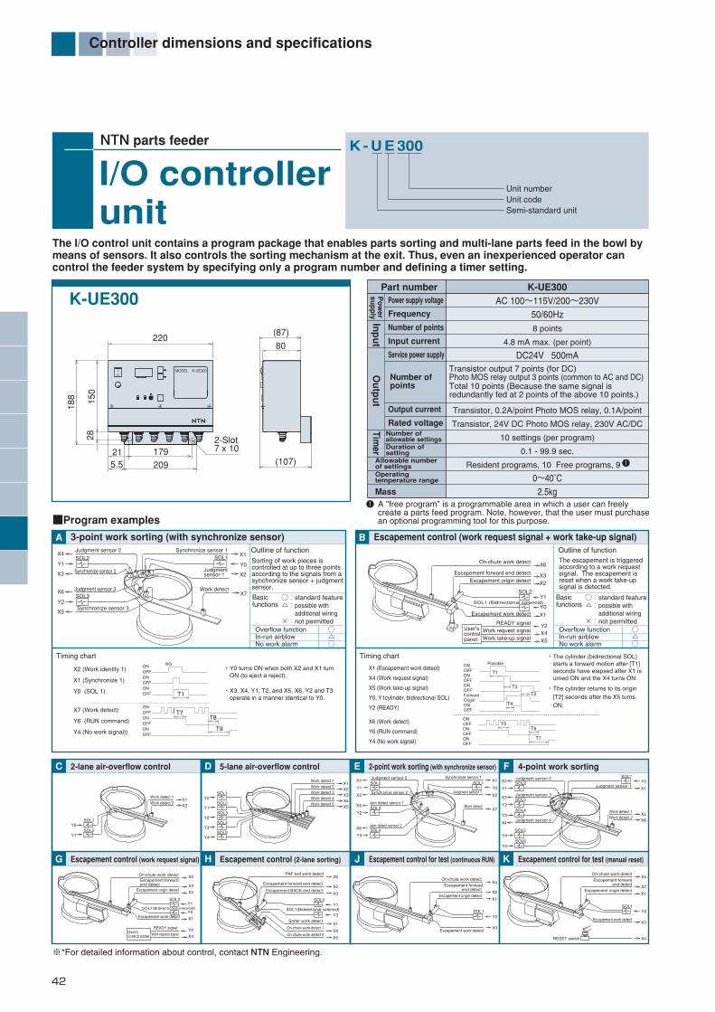
42
Controller dimensions and specifications
NTN parts feeder
I/O controllerunit
Part number K-UE300Power supply voltage
Frequency
Number of points
Input current
Service power supply
Output current
Rated voltage
AC 100~115V/200~230V50/60Hz8 points
4.8 mA max. (per point)
DC24V 500mA
Transistor, 0.2A/point Photo MOS relay, 0.1A/point
Transistor, 24V DC Photo MOS relay, 230V AC/DC
10 settings (per program)
0.1 - 99.9 sec.
Resident programs, 10 Free programs, 9 0~40˚C
2.5kg
Operatingtemperature range
Allowable numberof settings
Mass
1 A "free program" is a programmable area in which a user can freely create a parts feed program. Note, however, that the user must purchase an optional programming tool for this purpose.
A 3-point work sorting (with synchronize sensor)Outline of function
Timing chart
Basicfunctions
Sorting of work pieces iscontrolled at up to three pointsaccording to the signals from asynchronize sensor + judgmentsensor.
◯:standard feature△:possible with additional wiring×:not permitted
Overflow function ◯In-run airblow △No work alarm ◯
Basicfunctions
◯:standard feature△:possible with additional wiring×:not permitted
Overflow function ◯In-run airblow △No work alarm ◯
B Escapement control (work request signal + work take-up signal)Outline of function
Timing chart
The escapement is triggeredaccording to a work requestsignal. The escapement isreset when a work take-upsignal is detected.
■Program examples
Y2
X5
X4
X3
Y1
X6SOL3
SOL2
Synchronize sensor 3
Judgment sensor 2
Judgmentsensor 1
Synchronize sensor 2
Judgment sensor 3X7
X1
Y0
X2
SOL1Synchronize sensor 1
Work detect
C 2-lane air-overflow control
G Escapement control (work request signal)
D 5-lane air-overflow control
H Escapement control (2-lane sorting)
E 2-point work sorting (with synchronize sensor)
J Escapement control for test (continuous RUN)
4-point work sorting
K Escapement control for test (manual reset)
F
X3X4X5
X2X1
Work detect 3Work detect 4Work detect 5
Work detect 1Work detect 2
Y3
Y4
Y0
Y1
Y2SOL3
SOL4
SOL5
SOL1
SOL2X2
Work detect 1Work detect 2
X1
Y1
Y0SOL2
SOL1
X7
X1
Y0
X2
Synchronize sensor 1
Judgment sensor 1
SOL1
Work detect
Y3
Y2
X6
X5
X3
Y1
X4
Jam detect sensor 1
Jam detect sensor 2
Judgment sensor 2
Synchronize sensor 2
SOL4
SOL3
SOL2
Y5
Y4
X4
Y3
Y1
Y2
X2
X3
SOL2
SOL3
SOL4
SOL5
SOL6
Judgment sensor 2
Judgment sensor 3
Judgment sensor 4
Work detect 1Work detect 2
Judgment sensor 1
X6X5
Y0
X1
SOL1
SOL1(Bidirectional solenoid)
SOL2
X5
X4
X1
Y1
Y0
X2
X3
X6
On-chute work detect 2
Sorter work detect
PAF exit work detect
Escapement forward end detect
Escapement BACK end detect
On-chute work detect 1Escapement work detect
Escapement origin detect
On-chute work detect Escapement forward
end detect
X3
X2
Y0
X1
SOL1
X4
Escapement work detect
On-chute work detect
Escapement origin detect
Escapement forwardend detect
SOL1
X4
X3
Y0
X1
X2
X5
RESET switch
1
Number ofpoints
Duration ofsetting
Number ofallowable settings
K-UE300
K - U E 300
Semi-standard unitUnit codeUnit number
The I/O control unit contains a program package that enables parts sorting and multi-lane parts feed in the bowl bymeans of sensors. It also controls the sorting mechanism at the exit. Thus, even an inexperienced operator cancontrol the feeder system by specifying only a program number and defining a timer setting.
※*For detailed information about control, contact NTN Engineering.
MODEL K-UE300
215.5
28
209
2-Slot7 x 10179
188 150
6
1
220
(107)
(87)80
IO
X2 (Work identify 1)
Y0 (SOL 1)
X7 (Work detect)
Y6 (RUN command)
Y4 (No work signal))
X1 (Synchronize 1)
OFF
OFF
OFF
OFFON
ON
ON
ONOFF
ONOFFON
T1
T7
NG・Y0 turns ON when both X2 and X1 turn ON (to eject a reject).
・X3, X4, Y1, T2, and X5, X6, Y2 and T3 operate in a manner identical to Y0.
T8
T9
Work take-up signal X5
Escapement origin detect
Work request signalREADY signal
Escapement work detect
SOL1 (Bidirectional solenoid)
SOL2
Escapement forward end detect
User’scontrolpanel
X1
X4Y2
X2
Y1
Y0
X3
X6On-chute work detect
OFF
OFF
OFFON
ON
OFFON
ForwardOrigin
ON Possible
Y0, Y1cylinder, bidirectional SOL)
Y2 (READY)
X6 (Work detect)
Y6 (RUN command)
T1
T3
T2
T4
T5T6
T7
X1 (Escapement work detect)
X4 (Work request signal)
X5 (Work take-up signal)
Y4 (No work signal)
・The cylinder (bidirectional SOL) starts a forward motion after [T1] seconds have elapsed after X1 is urned ON and the X4 turns ON.
・The cylinder returns to its origin [T2] seconds after the X5 turns ON.
OFF
OFFON
ON
OFFON
SOL1(Bidirectional solenoid)
READY signal
Work request signal
SOL2
Escapement work detect
User’scontrol panel
Escapement origin detect
On-chute work detect Escapement forwardend detect
X4
Y2
X1
Y0
Y1
X5
X3
X2
Po
wer
sup
ply
Inp
ut
Ou
tpu
tTim
er
Transistor output 7 points (for DC)Photo MOS relay output 3 points (common to AC and DC)Total 10 points (Because the same signal isredundantly fed at 2 points of the above 10 points.)
*編集18-45-E_ *編集18-51/E 13/01/30 10:22 ページ 42

43
Control functions and timing chart of controllers
Control functions and timing chart
External control
Timing chart
External control+ON/OFF control with level switch
Timing chart
External control+ON/OFF control with sensor+operation instruction
Timing chart
External control+ON/OFF control+logiccircuit with 2 sensors+operation instruction
Timing chart
External control+ON/OFF control with sensor+no-work alarm+operation instruction
Timing chart
1 Use a relay contact to open the external control input for the EGA. Use an open collector transistor to control other controllers. The input logic can be reversed for variable frequency controllers other than SMD controllers.
¡Note: Choose a relay with a minimum applicable load that does not exceed 1 V and 1 mA and with a minimum permissible contact voltage of 250 V to control the EGA mode. If the leakage current is 100µA or less, a MOSFET relay for alternating open/close can also be used for control.
2 The controller settings vary depending on whether the Variable Voltage Variable Frequency Small Controller is turned ON with a closed contact (Low) or open contact (High).
3 Assumes that work sensor 1 and 2 operates on the controller service power supply. For details, refer to the specifications of the controller service power supply. Use an NPN open collector output sensor. The input logic of the sensor signal can be reversed at the controller side.
4 The run instruction output is a signal for controlling standalone hoppers. It can also be used as a run signal for controllers.
5 When using an external transformer, calculate its capacity using the formula below.
( )Full wave: × ≦ transformer capacityparts feeder
supply voltage ( )parts feederrated current
( )Half wave: × ×2≦ transformer capacityparts feeder
supply voltage ( )parts feederrated current
OFF delay
OFF delay ON delay
ON delay
2
Note: For details, refer to the controller manual or contact NTN Engineering.
OFF delay ON delay
ON delay
External controlcontact Close (Lo)input Open (Hi)
Parts ONfeeder OFF
External control Closecontact input Open
Part Detectsensor 1 Not detect
Parts ONfeeder OFF
Operation instruction Closecontact output Open
External control Closecontact input Open
Part Detectsensor 1 Not detect
Part Detectsensor 2 Not detect
Parts ONfeeder OFF
Operation instruction Closecontact output Open
●The parts feeder is turned ON/OFF with an external signal.●Detached hopper is automatically turned ON/OFF by the level switch which detects the quantity of any pieces in the parts feeder bowl.
External control Closecontact input Open
Part Detectsensor 1 Not detect
Parts ONfeeder OFF
Alarm signal Closeoutput Open
Operation instruction Closecontact output Open
●If the sensor has failed to detect any parts for a predetermined duration (max. 60 sec.), the contact signal is output for alarm.
●Parts feeder is turned OFF if the sensor does not detect any pieces during a predetermined time period . (Built-in ON/OFF delay timer)
●Parts feeder is turned OFF if neither sensors detect any pieces, or when either sensor no longer detects any pieces. (Built-in ON/OFF delay timer)
External controlcontact Closeinput Open
Detached ONhopper OFF
Level ON (No parts)switch OFF
*編集18-45-E_ *編集18-51/E 13/01/30 10:22 ページ 43
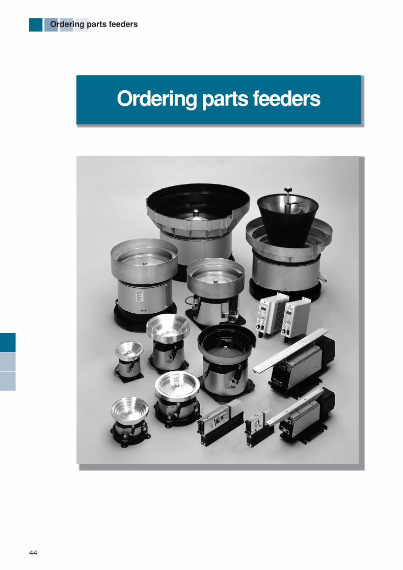
44
Ordering parts feeders
Ordering parts feeders
*編集18-45-E_ *編集18-51/E 13/01/30 10:22 ページ 44

45
Ordering parts feeders
¡NTN parts feeder series can be optimized for a specific application by combining various units. The combination of the three standard unit types-the vibratory drive units, bowls (vibratory trough mount), and controllers-provides for many different variations, allowing users to select the optimum configuration for aligning and feeding.
¡Functions can be further expanded by incorporating peripheral accessories, such as auxiliary weights.
¡Any combination of units not identified by blue lines may pose certain technical problems. If such a combination is required, consult NTN Engineering for guidance. To purchase such a combination, units must be ordered individually. Remember however, that NTN cannot guarantee the performance and proper functioning of such combinations.
Notes for ordering parts feeders
■Part number categoriesNTN parts feeders can be designated and ordered using any of the three part number categories given below.1) Unit part number: Units, such as vibratory drive units, bowls, and controllers (pages 11 through 43), and special-purpose
parts feeders (pages 58 through 69).2) Combination part numbers: Combinations of units as described in the standard series combination lists (pages 46 through
57).3) Component part numbers: Specific parts such as leaf springs, mounting brackets, and optional parts (pages 69 through
76).
■Part number notation1) Unit part number notation
¡Simply write the unit part number of the vibratory driving unit, bowl, or controller, etc. that you wish to order.2) Combination item number notation
¡As shown in the standard series combination lists (pages 46 to 57): □Specify a part number (blue characters in the table) after K-, and connect them with slash marks (/) in the order of K-!
(vibratory drive unit) /@(bowls) .□Possible combinations are: K-!/@ only.□Combination such as K-!/#, K-@/@,K-@/# are not acceptable. If such a combination is required, itemize the unit part
numbers.¡Controllers cannot be included in a combination part number, so order separately specifying unit part numbers.¡An optional part cannot be included in a combination part number. Instead, order separately specifying its component
number.3) Component part number notation
¡When ordering a component, such as a spring or stay mounting part, order by component number (pages 69 through 75).
Part number categories and notation
*編集18-45-E_ *編集18-51/E 13/01/30 10:22 ページ 45

46
Bowl Feeder Series Combination Table
Standard Series Combination Table
HF10,14,16
K- HF 14 R 2 1 / C 18 01
Vibratory drive unit BowlD
rive unit model
Bow
l type
Bow
l suffix
Unit size
Bow
l outer dia.
Supply direction
Design revision code
Voltage and drive system
■Examples of combination part numbers
Mod
elsi
ze ! Vibratory drive unit @ Bowl # Controller
! @
(High-frequency bowl feeder)
C1201C1403 1
C1501C1701 1
Z1201
D1301D1402 1
Cascade
Straightwall bowl
T91 SMD twin
K-ECF25Variablefrequency
Dish
K-HF10 21RL
C1801 CascadeK-HF14 21RL
1 Manufactured only on special order.
HF
10H
F14
K-HF16 1RL
φ188
φ190
100
30
HF
16
K-ECF25Variablefrequency
¡Any combinations of units identified by blue lines are available for order. ¡Any combinations of units not identified by blue lines may pose certain technical problems. If such a combination is required, consult NTN Engineering for technical advice.
*編集46-74-E_ *編集46-74/E 13/01/30 10:23 ページ 46
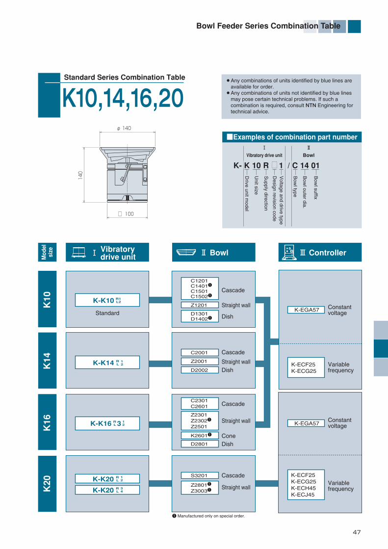
47
Bowl Feeder Series Combination Table
K- K 10 R 1 / C 14 01Vibratory drive unit Bowl
Drive unit m
odel
Bow
l type
Bow
l suffix
Unit size
Bow
l outer dia.
Supply direction
Design revision code
Voltage and drive type
■Examples of combination part number
! Vibratory drive unit @ Bowl # Controller
! @
Standard Series Combination Table
K10,14,16,20
C1201C14011
C1501C15021
Z1201
D1301D14021
Cascade
StandardStraight wall
Straight wall
Straight wall
Cone
Dish
K-K10 R1L2
C2001
C2301C2601
S3201
Z28011
Z30031
K26011
D2801
Z2301Z23021
Z2501
Z2001
D2002
Cascade
Cascade
Cascade
Dish
Dish
Straight wall
K-K14 RL 12
K-K16 3RL
12
K-K20 RL 12
K-K20 RL 34
1 Manufactured only on special order.
K-EGA57
K-ECF25K-ECG25
K-ECF25K-ECG25K-ECH45K-ECJ45
Constantvoltage
Constantvoltage
Variable frequency
Variable frequency
K10
K14
K16
K20
Mod
elsi
ze
¡Any combinations of units identified by blue lines are available for order. ¡Any combinations of units not identified by blue lines may pose certain technical problems. If such a combination is required, consult NTN Engineering for technical advice.
φ 140
□ 100
140
K-EGA57
*編集46-74-E_ *編集46-74/E 13/01/30 10:23 ページ 47

48
Bowl Feeder Series Combination Table
Standard Series Combination Table
N25
K- N 25 R A H 2 / C D 39
Vibratory drive unit BowlD
rive unit model
Bow
l type
Bow
l outer dia.
Design revision code
Unit size
Bow
l bottom type
Supply direction
Design revision code
※
Bow
l mounting type
Voltage and drive system
■Examples of combination part number
! Vibratory drive unit @ Bowl # Controller
470~
530
570
φ396φ305
φ336
374
※Designs revision code A means free set base.
! @
CD33CD39CD391
ZD301
ZD3011
ZD3021
ZD35ZD3511
ZD352
Cascade
w/ Aux. hopper in the bowl
Straight wall
Cone
K-N25 H RL
KD35w/ Isolated bottom
K-N25 TRL
12
12
K-N25 AH RL
12
K-N25 AT RL
12
ZF301
ZF3011
ZF3021
ZF35ZF3511
ZF352
w/ Flange
Straight wall
Cone
w/ FixedbottomCascade
K-N25 F RL
KF351
DishDF42
CB33CB39CB391
Basic type
K-N25 MRL
12
12
K-N25 AF RL
12
K-N25 AM RL
12
SD39SD391
Stainlesssteel cascade
SF39SF391
Stainless steelcascadeIntegratedbottom
1 Manufactured only on special order.
K-EGA57 Constantvoltage
Variablefrequency
K-ECF25K-ECG25K-ECH45K-ECJ45
N25・H
N25・T
N25・F
N25・M
Mod
elsi
ze
¡Any combinations of units identified by blue lines are available for order. ¡Any combinations of units not identified by blue lines may pose certain technical problems. If such a combination is required, consult NTN Engineering for technical advice.
*編集46-74-E_ *編集46-74/E 13/01/30 10:23 ページ 48

49
Bowl Feeder Series Combination Table
Standard Series Combination Table
N32(Full wave)
K- N 32 R 2 H 2 / S D 49 1
Vibratory drive unit Bowl
Drive unit m
odel
Bow
l type
Design revision code
Unit size
Bow
l outer dia.
Bow
l bottom type
Supply direction
Design revision code
Bow
l mounting type
Voltage and drive system
■Examples of combination part numbers
! Vibratory drive unit @ Bowl # Controller
φ496φ340
φ410
430 53
0~59
064
0
! @
w/ Aux. hopper in the bowl
K-N32 2H2 RL
K-N32 AH2 RL
w/ Isolated bottom
K-N32 AT2 RL
K-N32 2T2 RL
w/ Flange
K-N32 AF2 RL
K-N32 2F2 RL
Stainless steelcascadeIntegratedbottom
Straight wallIntegratedbottom
Stainlesssteel cascade
Straight wall
SD491
ZD401
SF491
ZF401
Basic type
K-N32 AM2 RL
K-N32 2M2 RL
Constantvoltage
N32・H
(Fu
ll w
ave)
N32・T
(Fu
ll w
ave)
N32・F
(Fu
ll w
ave)
N32・M
(Fu
ll w
ave)
K-EGA57
Mod
elsi
ze
¡Any combinations of units identified by blue lines are available for order. ¡Any combinations of units not identified by blue lines may pose certain technical problems. If such a combination is required, consult NTN Engineering for technical advice.
Variablefrequency
K-ECH45K-ECJ45
*編集46-74-E_ *編集46-74/E 13/01/30 10:23 ページ 49

50
Bowl Feeder Series Combination Table
Standard Series Combination Table
K- N 32 R 2 H 4 / S D 49 1
Vibratory drive unit BowlD
rive unit model
Bow
l type
Design revision code
Design revision code
Unit size
Bow
l outer dia.
Bow
l bottom type
Supply direction
Bow
l mounting type
Voltage and drive system
■Examples of combination part numbers
! Vibratory drive unit @ Bowl # Controller
! @
N32(Half wave)
w/ Aux. hopper in the bowl
K-N32 AH4 RL
K-N32 2H4 RL
w/ Isolated bottom
K-N32 AT4 RL
K-N32 2T4 RL
w/ Flange
K-N32 AF4 RL
K-N32 2F4 RL
Basic type
K-N32 AM4 RL
K-N32 2M4 RL
φ496φ345
φ410
406530~590
630
Stainlesssteel cascade
Straight wall
SD491
ZD401
SF491
ZF401
Stainless steelcascadeIntegratedbottom
Straight wallIntegratedbottom
Constantvoltage
Variablefrequency
K-ECH45K-ECJ45
N32・H
(Hal
f w
ave)
N32・T
(Hal
f w
ave)
N32・F
(Hal
f w
ave)
N32・M
(Hal
f w
ave)
K-EGA57
Mod
elsi
ze
¡Any combinations of units identified by blue lines are available for order. ¡Any combinations of units not identified by blue lines may pose certain technical problems. If such a combination is required, consult NTN Engineering for technical advice.
*編集46-74-E_ *編集46-74/E 13/01/30 10:23 ページ 50
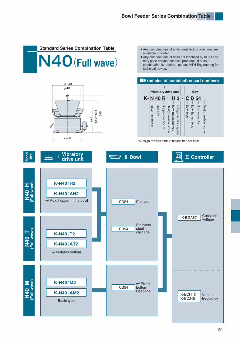
51
Bowl Feeder Series Combination Table
K- N 40 R H 2 / C D 54 Vibratory drive unit Bowl
Drive unit m
odel
Bow
l type
Design revision code
Unit size
Bow
l outer dia.
Bow
l bottom type
Supply direction
※
Design revision code
Bow
l mounting type
Voltage and drive system
■Examples of combination part numbers
! Vibratory drive unit @ Bowl # Controller
φ540φ435
φ490
421
550~
615
650
※Design revision code A means free set base.
! @
Standard Series Combination Table
N40(Full wave)
w/ Aux. hopper in the bowl
K-N40 AH2 RL
K-N40 H2 RL
w/ Isolated bottom
K-N40 AT2 RL
K-N40 T2RL
w/ Fixedbottom Cascade
CB54
Basic type
K-N40 AM2 RL
K-N40 M2 RL
CascadeCD54
Stainlesssteelcascade
SD54
Constant voltage
Variablefrequency
K-ECH45K-ECJ45
N40・H
(Fu
ll w
ave)
N40・T
(Fu
ll w
ave)
N40・M
(Fu
ll w
ave)
K-EGA57
Mod
elsi
ze
¡Any combinations of units identified by blue lines are available for order. ¡Any combinations of units not identified by blue lines may pose certain technical problems. If such a combination is required, consult NTN Engineering for technical advice.
*編集46-74-E_ *編集46-74/E 13/01/30 10:23 ページ 51
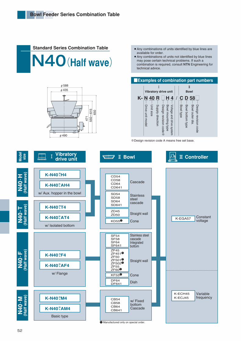
52
Bowl Feeder Series Combination Table
K- N 40 R H 4 / C D 58 Vibratory drive unit Bowl
Drive unit m
odel
Bow
l type
Design revision code
Unit size
Bow
l outer dia.
Bow
l bottom type
Supply direction
Design revision code
※
Bow
l mounting type
Voltage and drive system
■Examples of combination part numbers
! Vibratory drive unit @ Bowl # Controller
φ490
φ435
φ58847
155
0~61
565
0
※Design revision code A means free set base.
! @
Standard Series Combination Table
N40(Half wave)
Cascade
Straight wall
Cone
w/ Aux. hopper in the bowl
K-N40 AH4 RL
K-N40 H4
w/ Isolated bottom
K-N40 AT4
K-N40 T4
RL
RL
RL
w/ Flange
K-N40 AF4 RL
K-N40 F4 RL
CD54CD58CD64CD641
Stainlesssteelcascade
SD54SD58SD64SD641
ZD45ZD50
KD551
ZF45ZF4511
ZF50ZF5011
ZF5021
ZF55ZF601
CB54CB58CB64CB641
KF551
w/ FixedbottomCascade
SF54SF58SF64SF641
Stainless steelcascadeIntegratedbottom
Straight wall
Cone
Dish
Basic type
K-N40 AM4 RL
K-N40 M4 RL
DF64DF641
1 Manufactured only on special order.
N40・H
(Hal
f w
ave)
N40・T
(Hal
f w
ave)
N40・F
(Hal
f w
ave)
N40・M
(Hal
f w
ave)
Constantvoltage
Variablefrequency
K-ECH45K-ECJ45
K-EGA57
Mod
elsi
ze
¡Any combinations of units identified by blue lines are available for order. ¡Any combinations of units not identified by blue lines may pose certain technical problems. If such a combination is required, consult NTN Engineering for technical advice.
*編集46-74-E_ *編集46-74/E 13/01/30 10:23 ページ 52
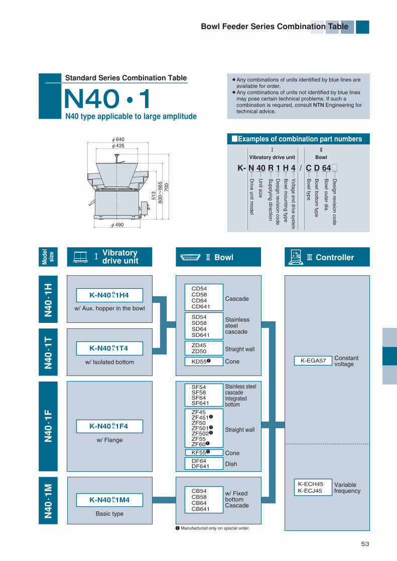
53
Bowl Feeder Series Combination Table
Standard Series Combination Table
N40・1
Vibratory drive unit Bowl
Bow
l type
Design revision code
Bow
l outer dia.
Bow
l bottom type
■Examples of combination part numbers
K- N 40 R 1 H 4 / C D 64
Drive unit m
odel
Unit size
Supplying direction
Design revision code
Bow
l mounting type
Voltage and drive system
! Vibratory drive unit @ Bowl # Controller
φ640φ435
φ490
513
600~
665
700
N40 type applicable to large amplitude
! @
Cascade
Straight wall
Cone
w/ Aux. hopper in the bowl
K-N40 1H4
w/ Isolated bottom
K-N40 1T4
RL
RL
w/ Flange
K-N40 1F4 RL
CD54CD58CD64CD641
Stainlesssteelcascade
SD54SD58SD64SD641
ZD45ZD50
KD551
ZF45ZF4511
ZF50ZF5011
ZF5021
ZF55ZF601
CB54CB58CB64CB641
KF551
DF64DF641
w/ FixedbottomCascade
SF54SF58SF64SF641
Stainless steel cascadeIntegratedbottom
Straight wall
Cone
Dish
Basic type
K-N40 1M4 RL
1 Manufactured only on special order.
N40・1H
N40・1T
N40・1F
N40・1M
Constantvoltage
Variablefrequency
K-ECH45K-ECJ45
K-EGA57
Mod
elsi
ze
¡Any combinations of units identified by blue lines are available for order. ¡Any combinations of units not identified by blue lines may pose certain technical problems. If such a combination is required, consult NTN Engineering for technical advice.
*編集46-74-E_ *編集46-74/E 13/01/30 10:23 ページ 53

54
Bowl Feeder Series Combination Table
Standard Series Combination Table
G50
K- G 50 R 1 T 4 / C D 83 Vibratory drive unit Bowl
Drive unit m
odel
Bowl type
Design revision code
Unit size
Bow
l outer dia.
Bow
l bottom type
Supply direction
Bow
l mounting type
Design revision code
Voltage and drive system
■Examples of combination part numbers
! Vibratory drive unit @ Bowl # Controller
! @70±
2034
0
(41
0±20) 64
0
φ580
φ830
CascadeK-G50 1T4
w/ Adapter
w/ Isolated bottom
K-G50 1G4
RL
RL
Basic type
CD83
w/ FixedbottomCascade
CB83
Straight wall ZF6511K-G50 1M4 R
L
1 Manufactured only on special order.
G50・T
G50・G
G50・M
Constantvoltage
Variablefrequency
K-ECH45K-ECJ45
K-EGA57
Mod
elsi
ze
¡Any combinations of units identified by blue lines are available for order. ¡Any combinations of units not identified by blue lines may pose certain technical problems. If such a combination is required, consult NTN Engineering for technical advice.
*編集46-74-E_ *編集46-74/E 13/01/30 10:23 ページ 54
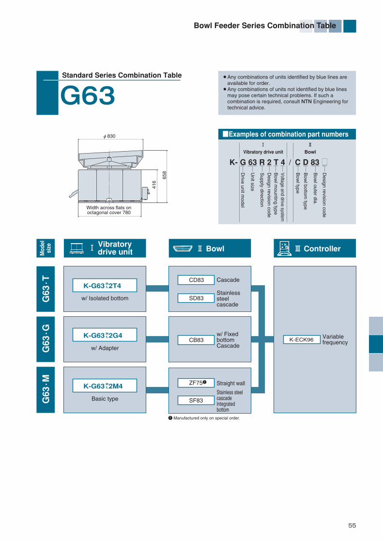
55
Bowl Feeder Series Combination Table
Standard Series Combination Table
G63
K- G 63 R 2 T 4 / C D 83 Vibratory drive unit Bowl
Drive unit m
odel
Bow
l type
Design revision code
Unit size
Bow
l outer dia.
Bow
l bottom type
Supply direction
Bow
l mounting type
Design revision code
Voltage and drive system
■Examples of combination part numbers
416
Width across flats onoctagonal cover 780
658
φ830
! Vibratory drive unit @ Bowl # Controller
! @
CascadeK-G63 2T4
w/ Adapter
w/ Isolated bottom
K-G63 2G4
RL
RL
Basic type
CD83
Stainlesssteelcascade
SD83
w/ FixedbottomCascade
CB83
Straight wallZF751
Stainless steelcascadeIntegratedbottom
SF83
K-G63 2M4 RL
1 Manufactured only on special order.
G63・T
G63・G
G63・M
K-ECK96 Variablefrequency
K
Mod
elsi
ze
¡Any combinations of units identified by blue lines are available for order. ¡Any combinations of units not identified by blue lines may pose certain technical problems. If such a combination is required, consult NTN Engineering for technical advice.
*編集46-74-E_ *編集46-74/E 13/01/30 10:23 ページ 55
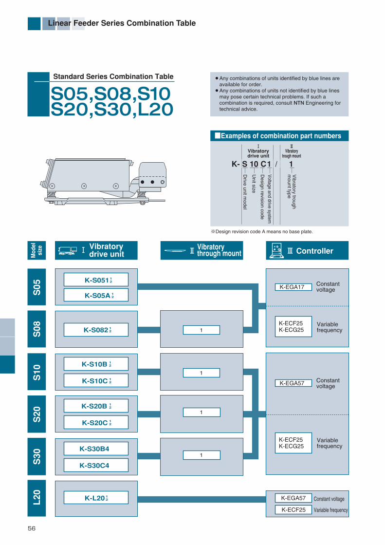
56
Linear Feeder Series Combination Table
Standard Series Combination Table
S05,S08,S10S20,S30,L20
K- S 10 C1 / 1
Vibratorytrough mount
Drive unit m
odel
Vibratory trough
mount type
Unit size
Design revision code
Voltage and drive system
■Examples of combination part numbers
Vibratorydrive unit
! Vibratory drive unit @ # Controller
! @
※Design revision code A means no base plate.
Vibratorythrough mount
1
1
1
1
K-S05A 12
K-S051 12
K-S082
K-S10B
K-L20 12
12
12
K-S20B 12
K-S10C 12
K-S20C 12
K-S30B4
K-S30C4
S05
S08
S10
S20
L20
S30
Mod
elsi
ze
¡Any combinations of units identified by blue lines are available for order. ¡Any combinations of units not identified by blue lines may pose certain technical problems. If such a combination is required, consult NTN Engineering for technical advice.
K-EGA17
K-ECF25K-ECG25
K-ECF25K-ECG25
K-ECF25
K-EGA57
K-EGA57
Constantvoltage
Constantvoltage
Variablefrequency
Variablefrequency
Constant voltage
Variable frequency
*編集46-74-E_ *編集46-74/E 13/01/30 10:23 ページ 56

57
Linear Feeder Series Combination Table
Standard Series Combination Table
HS05,07
! Vibratory drive unit # Controller
(High-frequency linear feeder)
K-HS0521
K-HS0711
Height adjustment screw
HS
05H
S07
K-ECF25K-ECG25
Variablefrequency
Mod
elsi
ze
¡Any combinations of units identified by blue lines are available for order. ¡Any combinations of units not identified by blue lines may pose certain technical problems. If such a combination is required, consult NTN Engineering for technical advice.
88±
2
*編集46-74-E_ *編集46-74/E 13/01/30 10:23 ページ 57

58
Monodrive 2-way feeder
Monodrive2-Way FeederTM
Features
Specifications
¡Handles a diversity of parts types ranging from miniature to medium-sized.
¡Accommodates machine parts, electronic components, plastic parts, and the like.
Applications and compatible work pieces
Conventionalbowl feeder
Plan view
Monodrivetwo-way feeder
This revolutionary two-way feeder comprises only one linear feeder. It is capable of storing, aligning/orienting, and feeding parts.
1. One linear feeder drives two chutes in different directions — one for the aligning/orienting side and one for the returning side.
This novel return feeder comprises a conventional linear feeder and an innovative leaf spring unit mounted above the linear feeder. The linear feeder and leaf spring unit generate mutually counteracting vibrations in two different planes in order to align/orient and feed parts. (Patent pending)
2. Compact, light and energy-efficient Compared to bowl feeder designs, this liner aligning/orienting
parts feeder is simpler, more compact, and requires roughly half the installation space. Furthermore, since one linear feeder can store, align/orient and feed parts, the entire production system can be made lighter and more energy-efficient.
3. This simplified design is the ideal choice for multi-product, small-lot production.
The simplified construction ensures easier maintenance. This unique feeder handles a diversity of parts types and can be fitted with a chute suitable for a particular part type.
1 Two main feeder body types are available: R (clockwise) and L (counterclockwise). Also, feeder models are available with a baseplate (identified by suffix B) and without a baseplate (identified by suffix C).2 The mass of the mounted chute is the mass value of a chute that can be added.
Mass (kg)
MD10 100/0.4200/0.2 450~600 0.3
0.7 K-ECF 25
10.5
9
19
15.5
54
461.6
2
5
15
550~800
850~1100
200/0.5100/1.0 Standard: 7.5˚
(±1˚)
200/0.9
MD20
MD30
K-MD10 BRL
12
12
K-MD10 CK-PLS4-40×6K-PLS4-41×7
K-PLS4-70×12K-PLS4-62×12
K-PLS4-86×15K-PLS4-100×20
RL
12
12
RLK-MD20 B
K-MD20 CRL
RLK-MD30 B4
K-MD30 C4RL
Model Part No.1 Applicable
leaf springApplicablecontroller
Inclination angleof return trough(possible range)
Mounted chute Maximum volume ofwork pieces loaded
(R)(Max. on solo basis)Length (mm) Mass (kg)
Powersupply(V/A)
2
*編集46-74-E_ *編集46-74/E 13/01/30 10:23 ページ 58

59
Monodrive 2-way feeder
4-Nut M6
4-Nut M6
AT mounting portion
AT mounting portion
AT mountingportion
AT mountingportion
AT mountingportion
Parts delivery
Parts delivery
AT mounting portion
Parts delivery
Return trough
Return trough
Return trough
198.
5 (2
05 m
ax.)
244
(251
max
.)35
1 (3
61 m
ax.)
Baseplate
Baseplate
Baseplate
6-M5Depth 15
7-M6Depth 18
7-M6Depth 24
4-Hex. sockethead bolt M6
AT mounting dimensions
AT mounting dimensions
Structure and dimensions
Baseplate dimensions(top view)
Baseplate dimensions(top view)
Baseplate dimensions(top view)
(standard inclination: 7.5˚±1˚)
(standard inclination: 7.5˚±1˚)
(standard inclination: 7.5˚±1˚)
For specific dimensions of a linear feeder, see the specifications/dimensions page in this catalog.
K-MD10 B (with baseplate) K-MD10 C (without baseplate)
K-MD20 B (with baseplate) K-MD20 C (without baseplate)
K-MD30 B4 (with baseplate) K-MD30 C4 (without baseplate)
RL
12
RL
12
RL
12
RL
12
RL
RL
20
240
380
370
140
19025
20
65 6423
11
6.5
60
28
97
40
18
120
15
34
110
310
104
185 25.5
27015512
20
45
770
490
390
90
50
40 15310
246
35032
10
20
70 120
200
45
95160
13
25(
20~
30)
20
29
54 10.5
4.5
113
(170)
450~600
(300)
129
190
110
335
75
10 45
50 51.5
80 80 55 40
2015
73
15
140
270
155
10 55
73 12
80 80
410
911818
31
215
51
580
15 60 60 60120
10497
120 120
310
390
129
80 35 50
69 28
34
90
75
29
130
51
36
29(
28~
35)
43.5(
34~
53)
(Linear travel S20)
(Linear travel S30)
(370)
550~800
(170)
(232)
(156)
666
160
70
117 50
(217)
650
135
529 129
850~1100
70
95
472460 90 39
66
38
168
15
(Linear travel S10)
*編集46-74-E_ *編集46-74/E 13/01/30 10:23 ページ 59

60
Non-slip composite feeder
This unique feeder combines a rotary disk with a vibratory bowl feeder. It offers the orientating/aligning capabilities of a vibratory bowl feeder as well as the feed stability to handle even oiled work pieces. What's more, it's designed for low noise operation.
1. Stable parts feeding The special rotary disk reliably delivers problem parts (oiled
pins and bolts) that conventional vibrator systems cannot handle easily. Parts are delivered to the outer circumference of the bowl's vibratory section.
2. Low-noise operation The vibratory section is limited to the circumferential portion of
the bowl, which orients or aligns the parts. This design contributes to low-noise operation.
3. Versatility Because the orientating/aligning section is a vibratory type, it can
handle complex parts as easily as conventional parts feeders.4. High-speed parts feeding The speed of the rotary disk can be adjusted as desired to
accommodate specific types of work pieces. What's more, the vibration angle of the vibratory section on the circumference can be adjusted to a near-horizontal orientation with the installation of an appropriate leaf spring. As a result, the work pieces can be oriented/aligned at higher speeds.
Non-slipcomposite feeder
Features
Specifications
¡Metal parts such as oiled pins and bolts
¡General mechanical components (metal or plastic) and automotive components
◆Accommodates the same maximum allowable work piece size as the conventional Model N25 and N40.
◆Does not accommodate miniature work pieces (those measuring less than 4 mm in general) or thin work pieces (those measuring less than 3 mm in thickness in general)
Applications and compatible work pieces
Model and sizeK-UP050A K-UP051A K-UP052A
N25 N40K-UP053A K-UP071 K-UP072
Clockwise Counterclockwise Clockwise ClockwiseCounterclockwise CounterclockwiseK-N25RM1 K-N25LM1 K-N25RM2 K-N40RM4
6000 pieces/min / 7200 pieces/min 3000 pieces/min / 3600 pieces/min1 to 20 rpm variable 3.75 to 18 rpm variable
52kg 110kgφ357/3kg φ509/7kg
1.5L 4L
Motor overload protection and others
K-ECH45 K-ECF25
K-UE251 K-UE261
K-ECH45
K-UE270
K-N25LM2 K-N40LM4
AC100V / 4.5A AC200V / 2.4A AC200V /3.8APart No.Power supply/rated currentDirection of rotationVibratory drive unitVibration frequency (for ref.)Disk rotation speedMass (including bowl)Bowl outer diameter/massStandard capacity of bowl
Protection
Vibratory sectionRotary section
Applicablecontroller
*編集46-74-E_ *編集46-74/E 13/01/30 10:23 ページ 60
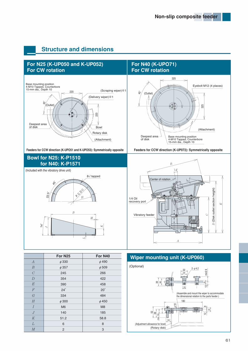
61
Non-slip composite feeder
(Assemble and mount the wiper to accommodatethe dimensional relation to the parts feeder.)
(Adjustment allowance for bowl)(Rotary disk)
B
8-I tapped
M
HP. C. D
G
14˚
45˚
22.5
˚
L
J K
For N25 (K-UP050 and K-UP052)For CW rotation
Bowl for N25: K-P1510 for N40: K-P1571
For N40 (K-UPO71)For CW rotation
Wiper mounting unit (K-UP060)
(Optional)
Feeders for CCW direction (K-UPO51 and K-UPO53): Symmetrically opposite
(Included with the vibratory drive unit)
Feeders for CCW direction (K-UP072): Symmetrically opposite
14°
F˚
A
C
D (
Dis
k ou
tlet s
ectio
n he
ight
)
E
1/4 Oilrecovery port
Vibratory feeder
B
2-φ4.2
min
2 632
180
812
52
min
1939
φ10
20
(24)
15
39 2013
30
24
For N25
A
B
C
D
E
F
G
H
I
J
K
L
M
For N40
φ330
φ357
245
354
390
24°
334
φ300
M6
140
51.2
6
2
φ490
φ509
266
422
458
20°
484
φ450
M8
185
58.8
8
3
220
45°
220
45°
325
325
Center of rotation
Structure and dimensions
(Scraping wiper)※1
(Outlet)
(Outlet)(Delivery wiper)※1
Bowl
Rotary disk
(Attachment)
(Attachment)
Deepest areaof disk
Deepest areaof disk
Eyebolt M12 (4 places)Base mounting position4-M10 Tapped, Counterbore15-mm dia., Depth 10
Base mounting position4-M10 Tapped, Counterbore15-mm dia., Depth 10
*編集46-74-E_ *編集46-74/E 13/01/30 10:23 ページ 61

62
SMD feeder
Configured with an HF Series High-Frequency Bowl Feeder and an HS series Linear Feeder, the SMD Feeder rapidly orients/aligns standard chip components and feeds them to an inspection device, taping machine or the like.
The linear feeder section has been improved and now incorporates an innovative super-high-speed feeding device.
1. A new design eliminates the possibility of work pieces jamming at the relay point between the bowl and the chute, significantly improving equipment availability.
2. Provides super-high-speed and high-precision parts feeding (up to 3,500 units of R1005 chips per minute, or 5,500 units of C0603 chips per minute).
3. More compact design - The floor space requirement is no more than 70% that of NTN's conventional equipment for feeding chip resistors.
4. The unique system for orienting/aligning parts does not use compressed air (for feeding chip capacitors), thus helping to prevent possible damage to chip components.
SMD feeder
Features
Typical applicable work pieces and specifications
Chip resistor specifications Chip capacitor specifications
Applicable work pieces
Power supply
Feeder dimensions
Compressed air supply
Typical orientation/alignment capabilities
Chip resistor (involving head/tail orientation)R0603,R1005
Chip capacitor C0603, C1005 (not involving head/tail or front/back orientation)Chip inductor L0603, L1005 (not involving head/tail or front/back orientation)
Max. 5,500 chips/min (C0603)Max. 5,000 chips/min (C1005)
Max. 3,000 chips/min (R0603)Max. 3,500 chips/min (R1005)
0.1MPa(1kg/cm2)Single-phase 100 V, 50/60 Hz
400mm×160mm×190mm 300mm×165mm×150mm※The above data reflect typical applications. The equipment is capable of feeding other miniature work pieces. For details, refer to CAT. Nos. 7020-@/E.
*編集46-74-E_ *編集46-74/E 13/01/30 10:23 ページ 62

63
High Speed Linear Feeder
The use of a “High Amplitude Spring Mechanism ” to increase amplitude higher over standard linear feeders allows transportation of various types of foodstuff or work pieces that absorb vibrations, complete with an energy-saving design.
1. Large amplitudeThe High Amplitude Spring Mechanism allows high speed transportation of foodstuff or work pieces that absorb vibrations.
2. Energy savingsThe use of the High Amplitude Spring Mechanism mean magnets with high magnetic forces are no longer needed, while also retaining the same low power consumption as standard models.
3. StabilityChanging both the front and rear side amplitude springs individually limits variations in transportation of the entire chute for more stable supply.
High SpeedLinear Feeder
Features
Applicable work, specification examples
550
400
670
800
Chute
Vibrating body (upper, lower)
Operating philosophy
The upper vibrating body and chute vibrate in thesame phase by adjusting the frequency
Chute
Upper vibrating body
Lower vibrating body
Applicable work Various kinds of foods, such as pasted food, side dishes of lunch box, ingredients ofhodgepodges, etc.
3~4mm
Single-phase 200 V, 50/60 Hz
Overall length 800×width 250×height 400 mm
Approximately 30 kg
Maximum amplitude
Power source
Product dimensions
Product weight
※This product is individually designed, so for details contact NTN Engineering .
*編集46-74-E_ *編集46-74/E 13/01/30 10:23 ページ 63
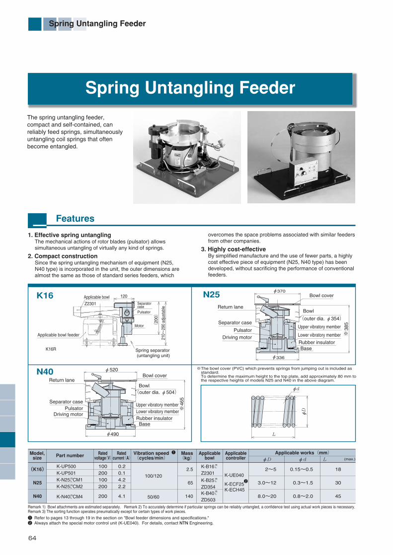
64
Spring Untangling Feeder
1. Effective spring untanglingThe mechanical actions of rotor blades (pulsator) allows simultaneous untangling of virtually any kind of springs.
2. Compact constructionSince the spring untangling mechanism of equipment (N25, N40 type) is incorporated in the unit, the outer dimensions are almost the same as those of standard series feeders, which
overcomes the space problems associated with similar feeders from other companies.
3. Highly cost-effectiveBy simplified manufacture and the use of fewer parts, a highly cost effective piece of equipment (N25, N40 type) has been developed, without sacrificing the performance of conventional feeders.
Features
Remark 1) Bowl attachments are estimated separately. Remark 2) To accurately determine if particular springs can be reliably untangled, a confidence test using actual work pieces is necessary.Remark 3) The sorting function operates pneumatically except for certain types of work pieces.
※The bowl cover (PVC) which prevents springs from jumping out is included as standard. To determine the maximum height to the top plate, add approximately 80 mm to the respective heights of models N25 and N40 in the above diagram.
Bowl
Bowl cover
Upper vibratory memberLower vibratory memberRubber insulator
Base
Upper vibratory member
Lower vibratory member
Rubber insulatorBase
(outer dia. φ354)
Return lane
Separator case
Separator case
Pulsator
Driving motor
Bowl
Bowl cover
Driving motorPulsator
(outer dia. φ504)
Return lane
The spring untangling feeder, compact and self-contained, can reliably feed springs, simultaneously untangling coil springs that often become entangled.
Spring Untangling Feeder
Model,size
Rated voltage(V)
Rated current(A)
Mass(kg)
Applicablecontroller
Applicablebowl
Vibration speed(cycles/min)Part number
Applicable works(mm)φD φd L (max.)
(K16)
N25
N40
K-UP500K-UP501K-N25 CM1K-N25 CM2
K-N40 CM4
100/120
50/60
100200100200
200
0.20.14.22.2
4.1
2.5
65
140
2~5
3.0~12
8.0~20
0.15~0.5
0.3~1.5
0.8~2.0
18
30
45
K-ECF25K-ECH45
K-UE040
K-B16Z2301
K-B25ZD354K-B40ZD503
1 Refer to pages 13 through 19 in the section on "Bowl feeder dimensions and specifications."2 Always attach the special motor control unit (K-UE040). For details, contact NTN Engineering.
N25
N40
K16
RL
RL
RL
RL
RL
RL
1
2
φ336
φ370
385
※
φ520
φ490
※46
5
L
φd
φD
Applicable bowlSeparatorcasePulsator
Motor
Spring separator (untangling unit)
Applicable bowl feeder
Z2301
120
(20
0)
210~
290
adju
stab
le
K16R
*編集46-74-E_ *編集46-74/E 13/01/30 10:23 ページ 64

65
Monodrive Two-way Feeder with The Separation Mechanism for Tangled Springs
1. Space-savingThe combination of the MD2 feeder and spring separator gives the entire device a more compact design.
2. Stable feedingThe spring separator disassembles tangled work pieces, and can arrange work into the same orientation with subsequent attachments for more stable feeding.
3. Ideal for small lot, high variety productionThe use of the MD2 feeder allows work pieces within the feeder to be checked easily by eye, and is compatible with high variety production by simply replacing the final output block.
4. Additional functionsA photoelectric sensor uses the controller service power supply (DC 24 V, 200 mA) to detect work pieces and operate a solenoid valve.
・Full detection for air-overflow ⇒ surplus parts transported into the feeder・Reverse spray with air with block detection ⇒ blocked work pieces transported into the feeder
Adding the Separation Mechanism for Tangled Springs to NTN’s proprietary Monodrive Two-way Feeder helps save space for more stable feeding!
Monodrive Two-way Feederwith The Separation Mechanism for Tangled Springs
Features
Applicable work
Used bodyApplicable work
Wire diameterOuter diameter Length (maximum)
φ2.0~5.0mm
φ5.0~10.0mm
φ0.15~0.5mm
φ0.5~1.0mm
20mm
30mm
MD10
MD20
※This product is individually designed, so for details contact NTN Engineering.
*編集46-74-E_ *編集46-74/E 13/01/30 10:23 ページ 65

66
Globalized parts feeder series
1. Globalized products for use outside JapanNTN strongly supports its clients' efforts to export to European and North American markets. Consequently, these products conform to European CE marking and have acquired NRTL certification from the U.S.A. (which also conforms to the corresponding Canadian certification through the U.S.A.-Canada reciprocal-certification system).
2. A diverse product lineNTN globalized products feature a wide-ranging product line encompassing bowl feeders, linear feeders and standalone auxiliary hoppers.
Globalized parts feeder series
Features
Table of globalized products (as of October 2012)
K-K16R(L)Y2
K-N25R(L)ZM2
K-N25R(L)ZF2
K-N25R(L)ZT2
K-N25R(L)ZH2
K-N25R(L)YM2
K-N25R(L)YF2
K-N25R(L)YT2
K-N25R(L)YH2
K-N25R(L)WM4
K-N25R(L)WF4
K-N25R(L)WT4
K-N25R(L)WH4
K-N40R(L)ZM2
K-N40R(L)ZT2
K-N40R(L)ZH2
K-N40R(L)ZM4
K-N40R(L)ZF4
K-N40R(L)ZT4
K-N40R(L)ZH4
K-N40R(L)YM2
K-N40R(L)YT2
K-N40R(L)YH2
K-N40R(L)YM4
K-N40R(L)YF4
K-N40R(L)YT4
K-N40R(L)YH4
K16
N25
N40
K-K16R(L)32
K-N25R(L)M2
K-N25R(L)F2
K-N25R(L)T2
K-N25R(L)H2
K-N25R(L)AM2
K-N25R(L)AF2
K-N25R(L)AT2
K-N25R(L)AH2
K-N25R(L)M4
K-N25R(L)F4
K-N25R(L)T4
K-N25R(L)H4
K-N40R(L)M2
K-N40R(L)T2
K-N40R(L)H2
K-N40R(L)M4
K-N40R(L)F4
K-N40R(L)T4
K-N40R(L)H4
K-N40R(L)AM2
K-N40R(L)AT2
K-N40R(L)AH2
K-N40R(L)AM4
K-N40R(L)AF4
K-N40R(L)AT4
K-N40R(L)AH4
Globalized product part No.Part No. of product dedicated
to Japanese market Globalized product part No.Part No. of product dedicated
to Japanese market
K-N40R(L)WM4
K-N40R(L)WF4
K-N40R(L)WT4
K-N40R(L)WH4
K-G50R(L)ZM4
K-G50R(L)ZG4
K-G50R(L)ZT4
K-S10Z2
K-S10Y2
K-S20Z2
K-S20Y2
K-S20W4
K-S20V4
K-S30Z4
K-S30Y4
K-V01SZ4
K-V03SZ4
K-V06SZ4
N40・1
G50・1
S10
S20
S30
V01
V03
V06
K-N40R(L)1M4
K-N40R(L)1F4
K-N40R(L)1T4
K-N40R(L)1H4
K-G50R(L)1M4
K-G50R(L)1G4
K-G50R(L)1T4
K-S10B2
K-S10C2
K-S20B2
K-S20C2
K-S20B4
K-S20C4
K-S30B4
K-S30C4
K-V01S4
K-V03S4
K-V06S4
Bo
wl f
eed
er
Bo
wl f
eed
erL
inea
r fe
eder
Ho
pp
er
Notes1. The specifications for vibratory driving units for globalized products (rated voltage, current, leaf spring, mass, external dimensions, mounting dimensions, etc.) are the same as those of units intended for the Japanese market. For the specifications of a particular globalized product, see the specifications for the part No. intended for the Japanese market.
2. For applicable controllers, see page 67.
Notes1. The CE marking acquisition process for a particular product includes a review of the final product and requires the submission of a self-declaration of conformity. If the
specifications or appearance of the NTN parts feeder differs from that of the original parts feeder shipped from NTN because the unit has been incorporated into a system or has been modified by tooling, the client who has modified or is intending to export the system that has incorporated the parts feeder must submit a self-declaration of conformity for the entire system to be exported.
2. Controllers and vibratory driving units are tested in combination as a set (particularly for the EMC test). Conformity with CE marking and NRTL certification becomes invalid if the NTN globalized product is combined with an NTN product intended for the Japanese market or with a product from another manufacturer.
3. Post-processed products including bowls, tooling (aligning/orienting mechanisms) and the like are outside the scope of NTN's responsibility. A client who intends to export such products is responsible for undertaking the review and submitting a self-declaration for these products.
Important: Conformity with CE marking and NRTL certification can be rendered invalid if the NTN globalized product is used in certain environments. For further information, contact NTN Engineering. The products listed on this page do not conform to the RoHS Directives.
*編集46-74-E_ *編集46-74/E 13/01/30 10:23 ページ 66
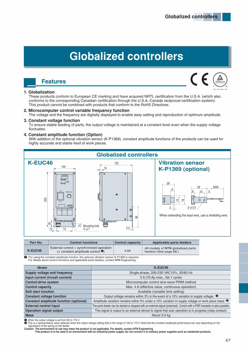
67
Globalized controllers
1. GlobalizationThese products conform to European CE marking and have acquired NRTL certification from the U.S.A. (which also conforms to the corresponding Canadian certification through the U.S.A.-Canada reciprocal-certification system).This product cannot be combined with products that conform to the RoHS Directives.
2. Microcomputer control variable frequency functionThe voltage and the frequency are digitally displayed to enable easy setting and reproduction of optimum amplitude.
3. Constant voltage functionTo ensure stable feeding of parts, the output voltage is maintained at a constant level even when the supply voltage fluctuates.
4. Constant amplitude function (Option)With addition of the optional vibration sensor (K-P1369), constant amplitude functions of the products can be used for highly accurate and stable feed of work pieces.
Globalized controllers
Features
2-φ7
1 For using the constant amplitude function, the optional vibration sensor K-P1369 is required. For details about control functions and applicable parts feeders, contact NTN Engineering.
1 When the output voltage is set from 60 to 170 V.2 This is a representative value obtained when the output voltage setting falls in the range of 100 to 170 V. Note that the constant amplitude performance can vary depending on the adjustment of the spring on the feeder.Caution: The environment of use may mean the product is not applicable. For details, contact NTN Engineering. This product is to be used in an environment with an industrial power supply. Do not connect it to ordinary power supplies such as residential products.
Mounting hole
100152
10
13 74 2.3
255
96
30
Globalized controllers
K-EUC46 4.0AExternal control + synchronized operation
(+ constant amplitude control 1)All models of NTN globalized partsfeeders (See page 66.)
654
1
0
3
2
9
10
7
8
K-EUC46
ONSPEED ADJ.
OFF
JAPAN
RESET
ENTERDATA
FUNC
STOPRUN
15
NTN2-φ3.5
2633 2000
12 18
88 10 5
2
NTN
K-EUC46 Vibration sensorK-P1369 (optional)
Part No. Control functions Control capacity Applicable parts feeders
Supply voltage and frequencyInput current (inrush current)Control-drive systemControl capacitySoft start functionConstant voltage functionConstant amplitude function (optional)External control inputOperation signal outputMass
Single-phase, 200-230 VAC10%, 50/60 Hz5 A (70 Ap max., fist 1 cycle)
Microcomputer control sine wave PWM methodMax. 4 A (effective value, continuous operation)
Available (variable time setting)Output voltage remains within 3% in the event of a 10% variation in supply voltage. 1
Amplitude variation remains within 3% under a 10% variation in supply voltage or work piece mass. 2
The parts feeder can be started or stopped with an external signal (polarized). Control with a PNP transistor is also possible.This signal is output to an external device to signal that auto operation is in progress (relay contact).
About 3.5 kg
Model K-EUC46
When extending the lead wire, use a shielding wire.
*編集46-74-E_ *編集46-74/E 13/01/30 10:23 ページ 67

Flexible feeder outline, features, and specifications
68
Flexible feeder
θ1θ2
θ3
Adoption of the Z spring in place of the standard spring on NTN parts feeder can provide optimum vibratory characteristics that are ideally suited to the physical properties of specific product parts and further expanded applications.The Z springs are fully compatible with the vibratory drive units in the list below. Thus, the standard springs in your parts feeder can be replaced with the Z springs without any change in spring setting dimensions.
To set the feeder for a high speed application, fit the spacer on the upper end of the Z spring fitting part, as shown in Fig.1.When feeding oil-contaminated pieces, or when parts feeding is sluggish due to a steep track slope, reverse the Z springs, and fit the spacer at the lower end of the Z spring fitting part as shown in Fig.3.In this manner, any of three kinds of vibratory angles including the standard angle can be selected.
¡For high-speed feeding
Feeding state
If the parts feeder can be adjusted to a lower spring setting angle, the jump stroke of the parts fed will be smaller, and consequently, feeding can be made smoother and faster.
¡(Standard)
Feeding state
If the parts feeder is adjusted for a standard spring setting angle, its behavior will be intermediate between high-speed feeding and grade feeding. This setting will be suitable for virtually any standard product.
¡For grade feeding
Feeding state
If the parts feeder is adjusted for a larger spring setting angle, the friction between the parts fed and the feeding surface will be greater. Consequently, grading will tend to be more stable, even at low speed.
A
Z spring
θ1
Spacer
B
Z spring
θ1
Use 2 spacers
θ2
Standardspring
A
Spacer
θ3
Z spring
B
Use 2 spacers
θ3
Z spring
Fig.1 Fig.2 Fig.3
Model and sizeof parts feeder θ1 (θ2) θ3
Part number of Z spring Part number of spacer Spring setting angle(°)
Z spring (pcs.) Spacer (pcs.)
Standard number per unit.
K14K16N25N40(Full wave)K20(Half wave)N40(Half wave)G63S20S30
121588※1
※1
13139
(20)(22)(15)(15)(15)(15)(20)(20)(15)
282922222525272721
K-PLS2-50×9-1K-PLS2-67×12-2K-PLS2-86×20-1K-PLS2-86×20-1K-PLS2-116×20-2K-PLS2-116×20-2K-PLS2-250×70-1K-PLS4-70×12-1K-PLS4-86×15-1
K-P0430K-P0427K-P0426K-P0426K-P0408,K-P0426K-P0408,K-P0426K-P0423K-P0411K-P0431
20201824924161610
44343 Each4 Each1622
※1 High-speed type (θ=5) of K20(Half wave) and N40 (Half wave) are unavailable. ※2 For K20(Half wave) and N40 (Half wave), fit two spacers of different thickness on the Z spring fitting part shown in Fig.1B and 3B.※3 For G63, fit two spacers of same thickness on the Z spring fitting as shown in Fig.1B and 3B.
※2
※2
※3
*編集46-74-E_ *編集46-74/E 13/01/30 10:23 ページ 68
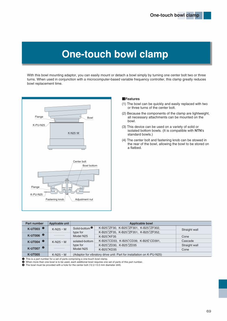
■Features(1) The bowl can be quickly and easily replaced with two
or three turns of the center bolt.
(2) Because the components of the clamp are lightweight, all necessary attachments can be mounted on the bowl.
(3) This device can be used on a variety of solid or isolated bottom bowls. (It is compatible with NTN's standard bowls.)
(4) The center bolt and fastening knob can be stowed in the rear of the bowl, allowing the bowl to be stored on a flatbed.
One-touch bowl clamp
With this bowl mounting adaptor, you can easily mount or detach a bowl simply by turning one center bolt two or threeturns. When used in conjunction with a microcomputer-based variable frequency controller, this clamp greatly reducesbowl replacement time.
K-PU-N25
K-PU-N25
K-N25・M
Flange
Flange
Center bolt
Bowl bottom
Adjustment nutFastening knob
Bowl
Part number Applicable unit Applicable bowl
K-UT003
K-UT006
K-UT004
K-UT007
K-UT005
K-N25・M
K-N25・M
K-N25・M
K-B25 ZF30, K-B25 ZF301, K-B25 ZF302,RL
RL
RL
K-B25 ZF35, K-B25 ZF351, K-B25 ZF352,RL
RL
RL
K-B25 KF35RL
K-B25 CD33, K-B25 CD39, K-B25 CD391,RL
RL
RL
K-B25 ZD30, K-B25 ZD35RL
RL
K-B25 KD35RL
Solid-bottomtype forModel N25
solated-bottomtype forModel N25
(Adaptor for vibratory drive unit: Part for installation on K-PU-N25)
Straight wall
ConeCascadeStraight wallCone
1 This is a part number for a set of parts comprising a one-touch bowl clamp. 2 When more than one bowl is to be used, each additional bowl requires one set of parts of this part number. 3 The bowl must be provided with a hole for the center bolt (12.2-13.0 mm diameter drill).
1 3
2
1
2
One-touch bowl clamp
69
*編集46-74-E_ *編集46-74/E 13/01/30 10:23 ページ 69
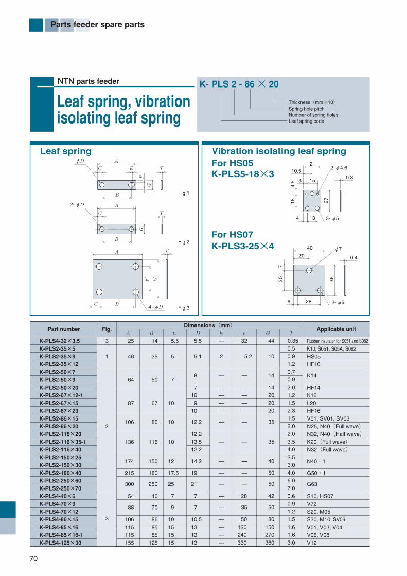
70
Parts feeder spare parts
NTN parts feeder
Leaf spring, vibrationisolating leaf spring
K- PLS 2 - 86 × 20
Leaf spring code Number of spring holesSpring hole pitchThickness(mm×10)
Leaf spring Vibration isolating leaf springFor HS05K-PLS5-18×3
For HS07K-PLS3-25×4
13 3-φ5
18 27
0.3
2-φ4.610.5
3 15
21
4
4.5
2-φ6
0.4
6 28
38
φ7
725
20
40
F
B
A T
G
4-φDC
B
C
G
T
2-φD A
A
F
EC
B
G
T
φD
Fig.1
Fig.2
Fig.3
Part number Fig. Applicable unitA B C D E F G T
Dimensions(mm)
K-PLS4-32×3.5K-PLS2-35×5K-PLS2-35×9K-PLS2-35×12K-PLS2-50×7K-PLS2-50×9K-PLS2-50×20K-PLS2-67×12-1K-PLS2-67×15K-PLS2-67×23K-PLS2-86×15K-PLS2-86×20K-PLS2-116×20K-PLS2-116×35-1K-PLS2-116×40K-PLS2-150×25K-PLS2-150×30K-PLS2-180×40K-PLS2-250×60K-PLS2-250×70K-PLS4-40×6K-PLS4-70×9K-PLS4-70×12K-PLS4-86×15K-PLS4-85×16K-PLS4-85×16-1K-PLS4-125×30
3
1
2
3
25
46
64
87
106
136
174
215
300
54
88
106115115155
14
35
50
67
86
116
150
180
250
40
70
868585
125
5.5
5
7 10
10
10
12
17.5
25
7
9
10151515
5.5
5.1
8
710 910
12.2
12.213.512.2
14.2
19
21
7 7 10.5131313
—
2
—
————
—
—
—
—
—
—
—
————
32
5.2
—
— — — —
—
—
—
—
—
28
35
50120240330
44
10
14
14202020
35
35
40
50
50
42
50
80150270360
0.350.50.91.20.70.92.01.21.52.31.52.02.03.54.02.53.04.06.07.00.60.91.21.51.61.63.0
Rubber insulator for S051 and S082K10, S051, S05A, S082HS05HF10
K14
HF14K16L20HF16V01, SV01, SV03N25, N40(Full wave)N32, N40(Half wave)K20(Full wave)N32(Full wave)
N40・1
G50・1
G63
S10, HS07V72S20, M05S30, M10, SV06V01, V03, V04V06, V08V12
*編集46-74-E_ *編集46-74/E 13/01/30 10:24 ページ 70

71
Parts feeder spare parts
NTN parts feeder
MagnetK- PMG - 2 1 3
Magnet codeMagnet sizeVoltage (1: For 100 V, 2: For 200 V)Number of bundled pieces
33
28124
21
28 22
1211
.512
6
40.52-φ5.8
24.5
35
20
28
31
8
921
102-φ 3.5
2-M5×12
A
K
H
EF
G
C
L
B2-D Tapped
I J
3-M12
A
F
B
C
3-φ9
E
Fig.1 Fig.3Fig.2
Fig.6Fig.5 Fig.7
Fig.4
A
F
B
C2-φ9
E
20
3.5
2-φ4.8
22 15
B
D
G
A
CEFPart number Fig. Dimensions(mm)
Mass(kg)
Dimensions(mm)A B C D E F G H I J K L
K-PMG-011-5
K-PMG-021-2
K-PMG-017-3
K-PMG-027
K-PMG-011-4
K-PMG-017-1
K-PMG-017-2
K-PMG-027-1
K-PMG-217-2
K-PMG-1 1-1
K-PMG-2 1
K-PMG-2 1-1
K-PMG-2 3
K-PMG-311-1
K-PMG-321
K-PMG-311-3
K-PMG-321-4
K-PMG-323
K-PMG-323-1
K-PMG-324
K-PMG-411-1
K-PMG-411-2
K-PMG-421-1
K-PMG-421-2
K-PMG-521
K-PMG-521-1
1
2
3
4
5
6
7
—
—
—
—
—
41
41
41
54
58
78
78
78
90
90
90
90
90
90
90
110
144
—
—
—
—
—
39
39
39
48
50
75
75
75
87
87
87
87
87
87
87
70
82
—
—
—
—
—
31.5
31.5
31.5
40.5
43
48
48
48
60
60
60
60
60
60
60
75
75
—
—
—
—
—
36
36
36
48
—
—
M6×12
—
—
—
M6×13
M6×13
—
—
—
—
—
—
—
—
—
—
16
16
16
25
—
—
22
—
—
—
28
28
28
28
—
80
128
—
—
—
—
—
13
13
13
20.5
6.5
7
7
7
8.5
8.5
8.5
8.5
8.5
8.5
8.5
56
60
—
—
—
—
—
20
20
20
28
0
4
4
4
5
5
5
5
5
5
5
—
—
—
—
—
—
—
M5×12
M5×12
M5×12
M6×12
6
10
10
10
11
11
11
11
11
11
11
—
—
—
—
—
—
—
—
—
—
—
24
37
37
37
44
44
44
44
44
44
44
—
—
—
—
—
—
—
—
—
—
—
36
54
54
54
66
66
66
66
66
66
66
—
—
—
—
—
—
—
—
—
—
—
16
22
22
22
33
33
33
33
33
33
33
—
—
—
—
—
—
—
—
—
—
—
12
10
10
10
11
11
11
11
11
11
11
—
—
0.1
0.1
0.2
0.2
0.1
0.3
0.4
0.3
1.0
0.4
1.0
0.9
3.0
1.7
1.9
1.5
1.7
5.7
5.7
7.5
2.3
2.4
2.3
2.4
4.5
4.3
S0511, S05A1
S0512, S05A2
S0821
S0822
HS05
HS07
HF14
SV1, SV3
HF16
K10, S10, M05, V71
S20, L20, M10, SV01, SV03
K14
N25 3 pcs. bundled
V01~V08
S30, V01~V12, SV06
K16
K16
N32·2, half wave, 3 pcs. bundled
N32·2, full wave, 3 pcs. bundled
N40, N40・1(4 pcs. bundled)
K20 100V, full wave
K20 100V, half wave
K20 200V, full wave
K20 200V, half wave
G63・2
G50・1
12
12
12
12
*編集46-74-E_ *編集46-74/E 13/01/30 10:24 ページ 71

72
Parts feeder spare parts
NTN parts feeder
F-shape magnet, rubberinsulator, armature
Armature
2-D Tapped
C
G
F A
B
E
2-F75
A
E
DG
B12
C
Fig.1 Fig.2 Fig.3 Fig.4 Fig.5
4.5
1696
50
60 80
2-φ9φ20
28
2-M5 Tapped Thru
Slot hole (6.5×8)
1416
4113
6
6 12
18
Partnumber Fig. Applicable magnet Applicable unit
A B C E F ID
Dimensions(mm)
K-P0300K-P0301
K-P0302
K-P0303K-P0317K-P0310K-P0311K-P0320K-P0315K-P0314K-P0316K-P0318K-P0319
3654
66
5466
105—
20.528
105———
1620
22
202260—94
60———
1622
33
2233
17.5—548
17.5———
——
—
M5×10M6×13
100—211370———
——
—
303440—252240———
6.57
8.5
78.5φ12
—2611
M10———
G
44
5
45
15—422035———
H
——
—
————63————
——
—
————
M6×15M3×12
————
K-PMG-1 1-1K-PMG-2K-PMG-311-1K-PMG-321K-PMG-32 ,K-PMG-323-1K-PMG-2 1-1K-PMG-311-3,K-PMG-321-4K-PMG-521K-PMG-017-K-PMG-217-2K-PMG-011-3K-PMG-521-1K-PMG-411- ,K-PMG-421-K-PMG-011-5,K-PMG-021-2K-PMG-017-3,K-PMG-027
K10, S10, M05, V71N25, S20, L20, M10, SV01, SV03
N32, N40, S30, V01~V12, SV06
K14K16G63・2HF14, HS07, SV1, SV3HF16HS05G50・1K20S05S08
1
234425——
12
1123
12
34
12
12
12
D
A
B
H
E
10
CFG
2-J
Part number ApplicableunitA B C D E F G H
Dimensions(mm)
K-PMG-119-1 58 34 34 M4 16.6 24 39 22 HF10
K - PIR - 40
Rubber insulatorcode
Rubber insulatorouter dia.
Partnumber Fig. Applicable unit
A B C D E Dimensions(mm)
K-PIR-15K-PIR-25K-PIR-302K-PIR-40K-PIR-50
15254050
11322
15203040
15 81317
M5M6M8M10
1518
K14K16, S10, S20, V72, SV01, SV03, SV1, SV3HF10, HF14, HF16N25, S30, V01~V08, K20N32, N40, N40・1, G50, G63・2, V12
C
B
H
2-D Tapped
F
G
E
A
D
B
φA
D
CE
C
D nut
D
φA
B
φ9
1823
30
12
32
24
40
M8 Fine thread
Fig.3Fig.2Fig.1
F-shape magnet Rubber insulator
*編集46-74-E_ *編集46-74/E 13/01/30 10:24 ページ 72
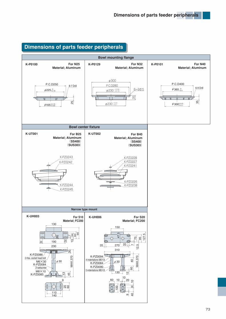
73
Dimensions of parts feeder peripherals
Dimensions of parts feeder peripherals
For B25Material; Aluminum
(SS400)(SUS303)
For B40Material; Aluminum
(SS400)(SUS303)
25
P.C.D250
φ225
+0.15+0.05φ165
8-7 Drill 0-0.15
φ365
35
6-9 Drill 0-0.5
φ300+0.5+0.1
P.C.D400
Bowl mounting flange
K-P0100 For N25 Material; Aluminum
K-P0129 For N32 Material; Aluminum
K-P0101 For N40 Material; Aluminum
Bowl center fixture
K-UT001 K-UT002
K-PZ0228K-PZ0227
K-PZ0226K-PZ0238
K-PZ0241K-PZ0242
K-PZ0244
K-PZ0245
K-PZ0243
Narrow type mount
φ300
P.C.D280
φ230
φ230
35
ー0.05ー0.15
+0.3+0.1
6ー9きり
140110
6020
9
M8×10
230
φ30
13 4530
MA
X.3
70
M6×30
2-setscrew
K-PZ00862-Hex. socket head bolt
K-PZ0085
20 190
30
130
20
90
60
34
137
K-PZ0084
K-UH006 For S20Material; FC200
K-UH003 For S10Material; FC200
7040
6012
9 4010
30
100
7
12.5
95 127.
5
K-PZ0094
K-PZ0084K-PZ0090 M
AX
.370
150
270
310
130
60
4-indentations M8×8
2-indentations M8×8
1010 20
φ30
20 20
47.5
*編集46-74-E_ *編集46-74/E 13/01/30 10:24 ページ 73

74
Dimensions of parts feeder peripherals
For S10, 20Material; SS400
Unit(mm)
K-PZ0530 For S30Material; FC200
Fixed type mount
Stay mounting parts
Stay mounting parts
K-PZ0501 For N25Material; FC200
Component part number
K-PZ9513
K-PZ9514
K-PZ9515
K-PZ9516
K-PZ9517
K-PZ9518
100
150
200
70
110
150
110
110
110
155
155
155
90
90
90
135
135
135
120
120
120
160
160
160
140
140
140
185
185
185
S10
S10
S10
S20
S20
S20
H A B C DApplicable
to
H4
4
4-M10 NutD
±1
±1
CB
A
350
310
160
200
70
4-M1240
11
15
150
152-M6
φ20
φ20
2-φ7(W/ M6 bolt) 2-φ7
(W/ M6 bolt)
40°10° 5°
302-M6 30
(120)
K-PZ0511 For N40Material; FC200
25
23
(24)
25(2
4)
9 15
34 41 50
(66)
28°7° 3.5°
(64)
φ20
(122)
23
9 1534 41 50
2540
(25)
( )25
25
φ2025
R168 (18)
(10)
K-PZ0568 For N32Material; FC200
2-M6
φ20
2-φ7(W/ M6 bolt)30
(122)
23
25(2
4)
9 1534 41 50
33°8° 4°
(65)
32
( )25
φ2025
R205
(18)
(10)
R245
(18)
(10)
( )25
4-φ9
K-P1153 K-P1152For φ15Material; Aluminum
For φ15Material; FC200
K-PZ0509 For φ15Material; ZDC2
4254
26
2- φ7
105026
2-set screw
17
M6×8
φ15
φ25
25
2-Socket head bolt
M6×18
54
2-φ15
25
17
58
4515
3420
φ15
φ26
2-φ7
15
35
3010
Set screw M6×8
*編集46-74-E_ *編集46-74/E 13/01/30 10:24 ページ 74
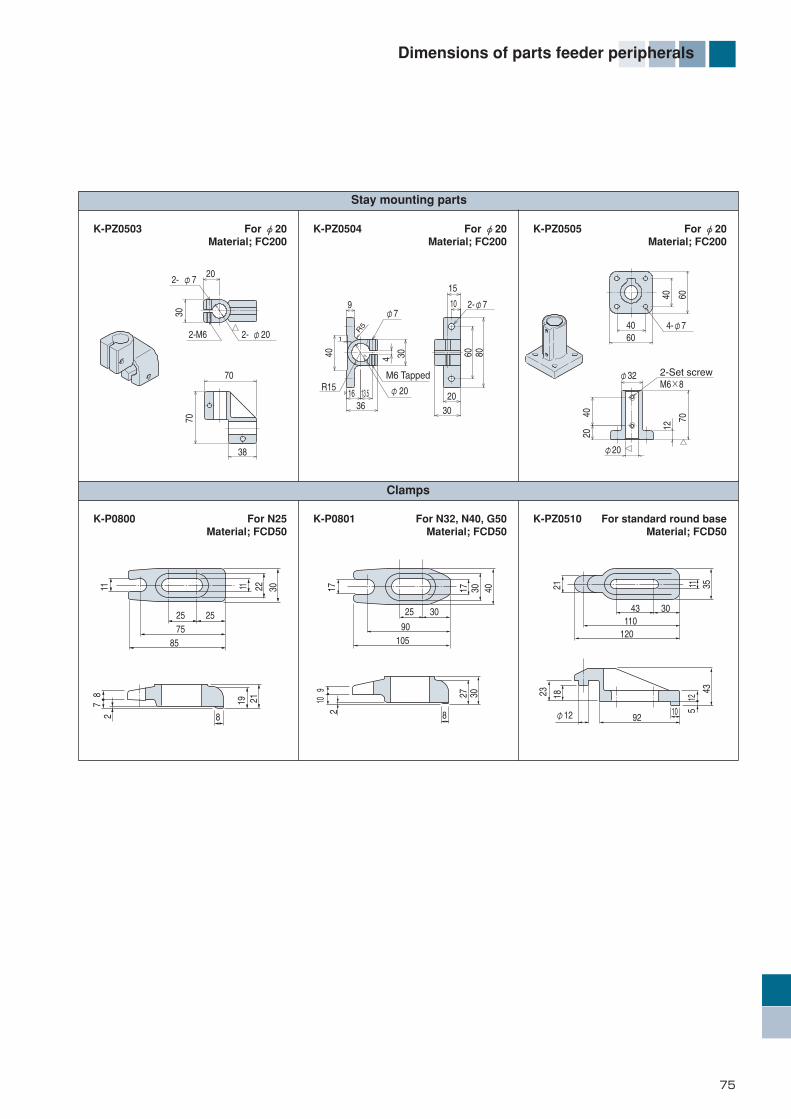
75
Dimensions of parts feeder peripherals
Stay mounting parts
Clamps
K-PZ0510 For standard round baseMaterial; FCD50
K-P0800 For N25Material; FCD50
K-P0801 For N32, N40, G50Material; FCD50
4-φ760
40 60
40
12
2-Set screwM6×8
4020
φ32
70
φ20
15
60
10
80
2030
2-φ7
3616
R15M6 Tapped
R5
1
φ20
9
40 3013.5
4
φ730
2- φ20
202- φ7
2-M6
70
70
38
K-PZ0503 K-PZ0504For φ20Material; FC200
For φ20Material; FC200
K-PZ0505 For φ20Material; FC200
117
28
19 2111 22 30 17
910
2
17 3027 30
40 21 11 35
23 18 125
43
2575
85
8
25 25 43 30110
120
9210
90105
30
8 φ12
*編集46-74-E_ *編集46-74/E 13/01/30 10:24 ページ 75

76
Light grip and Sunline belt Part Nos.
Applicable bowl Light grip Part No.
Light grip and Sunline belt Part Nos.
Sunline belt Part No.
B16RC2601
B16LC2601
B20RC3201
B20LC3201
B20RS3201
B20LS3201
B25RC 33
B25LC 33
B25RC 39
B25RC 391
B25LC 39
B25LC 391
B25RSD39
B25RSD391
B25LSD39
B25LSD391
B32RSD491
B32LSD491
B32RSF491
B32LSF491
B40RC 54
B40LC 54
B40RC 58
B40LC 58
B40RC 64
B40RC 641
B40LC 64
B40LC 641
B40RSD54
B40LSD54
B40RSD58
B40LSD58
B40RSD64
B40RSD641
B40LSD64
B40LSD641
B63RC 83
B63LC 83
B63RSD83
B63LSD83
K-PZ0335
K-PZ0336
K-PZ8516
K-PZ8518
K-PZ8516
K-PZ8518
K-PZ0200
K-PZ0201
K-PZ0202
K-PZ0202
K-PZ0203
K-PZ0203
K-PZ0202
K-PZ0202
K-PZ0203
K-PZ0203
K-PZ8500
K-PZ8502
K-PZ8501
K-PZ8503
K-PZ0204
K-PZ0205
K-PZ0206
K-PZ0207
K-PZ0208
K-PZ0208
K-PZ0209
K-PZ0209
K-PZ0204
K-PZ0205
K-PZ0206
K-PZ0207
K-PZ0208
K-PZ0208
K-PZ0209
K-PZ0209
K-PZ0337
K-PZ0338
K-PZ0337
K-PZ0338
K-PZ0351
K-PZ0352
K-PZ8515
K-PZ8517
K-PZ8515
K-PZ8517
K-PZ0353
K-PZ0354
K-PZ0355
K-PZ0355
K-PZ0356
K-PZ0356
K-PZ0355
K-PZ0355
K-PZ0356
K-PZ0356
K-PZ8504
K-PZ8506
K-PZ8505
K-PZ8507
K-PZ0357
K-PZ0358
K-PZ0359
K-PZ0360
K-PZ0361
K-PZ0361
K-PZ0362
K-PZ0362
K-PZ0357
K-PZ0358
K-PZ0359
K-PZ0360
K-PZ0361
K-PZ0361
K-PZ0362
K-PZ0362
K-PZ0363
K-PZ0364
K-PZ0363
K-PZ0364
Cascade bowl
B16
B20
B25
B32
B40
B63
DB
DB
DB
DB
DB
DB
DB
DB
DB
DB
DB
DB
DB
DB
DB
DB
Applicable bowl Light grip Part No. Sunline belt Part No.
B14RZ2001
B14LZ2001
B16RZ2301
B16LZ2301
B16RZ2302
B16LZ2302
B16RZ2501
B16LZ2501
B20RZ2801
B20LZ2801
B20RZ3003
B20LZ3003
B25RZ 30
B25LZ 30
B25RZ 301
B25LZ 301
B25RZ 302
B25LZ 302
B25RZ 35
B25LZ 35
B25RZ 35
B25LZ 35
B32RZ 401
B32LZ 401
B40RZ 45
B40LZ 45
B40RZF45
B40LZF45
B40RZ 50
B40LZ 50
B40RZ 50
B40LZ 50
B40RZF55
B40LZF55
B40RZF60
B40LZF60
K-PZ0348K-PZ0349
K-PZ0365K-PZ0366
K-PZ0350K-PZ0349
K-PZ0367K-PZ0366
K-PZ0296K-PZ0297
K-PZ0368K-PZ0369
K-PZ0298K-PZ0297
K-PZ0370K-PZ0269
K-PZ0299K-PZ0300
K-PZ0374K-PZ0375
K-PZ0301K-PZ0300
K-PZ0376K-PZ0375
K-PZ8519K-PZ8520
K-PZ8522K-PZ8523
K-PZ8521K-PZ8520
K-PZ8524K-PZ8523
K-PZ8508K-PZ8509
K-PZ8511K-PZ8512
K-PZ8510K-PZ8509
K-PZ8513K-PZ8512
K-PZ0302K-PZ0303
K-PZ0377K-PZ0378
K-PZ0308K-PZ0309
K-PZ0386K-PZ0387
K-PZ0310K-PZ0309
K-PZ0388K-PZ0387
K-PZ0311K-PZ0312
K-PZ0389K-PZ0390
K-PZ0313K-PZ0312
K-PZ0391K-PZ0390
K-PZ0311K-PZ0312
K-PZ0389K-PZ0390
K-PZ0313K-PZ0312
K-PZ0391K-PZ0390
K-PZ0308K-PZ0309×2
K-PZ0386K-PZ0387×2
K-PZ0249K-PZ0250×2
K-PZ0380K-PZ0381×2
K-PZ0251K-PZ0250×2
K-PZ0382K-PZ0381×2
K-PZ0302K-PZ0303×2
K-PZ0377K-PZ0378×2
K-PZ0304K-PZ0303×2
K-PZ0379K-PZ0378×2
K-PZ0305K-PZ0306×2
K-PZ0383K-PZ0384×2
K-PZ0307K-PZ0306×2
K-PZ0385K-PZ0384×2
K-PZ0310K-PZ0309×2
K-PZ0388K-PZ0387×2
K-PZ0314K-PZ0315×2
K-PZ0392K-PZ0393×2
K-PZ0316K-PZ0315×2
K-PZ0394K-PZ0393×2
K-PZ0317K-PZ0318×2
K-PZ0395K-PZ0396×2
K-PZ0319K-PZ0318×2
K-PZ0397K-PZ0396×2
K-PZ0304K-PZ0303
K-PZ0379K-PZ0378
K-PZ0302K-PZ0303
K-PZ0377K-PZ0378
K-PZ0304K-PZ0303
K-PZ0379K-PZ0378
K-PZ0305K-PZ0306
K-PZ0383K-PZ0384
K-PZ0307K-PZ0306
K-PZ0385K-PZ0384
K-PZ0246K-PZ0247×2
K-PZ0371K-PZ0372×2
K-PZ0248K-PZ0247×2
K-PZ0373K-PZ0372×2
Straight wall bowl Upper stage: For bowl bottomLower stage: For bowl track
B14
B16
B20
B32
B25
B40
DF
DF
DF
DF
DF
DF
DF
DF
DF
DF
DF
DF
DF
DF
DF
DF
DF
12
12
12
12
12
DF
12
*編集46-74-E_ *編集46-74/E 13/01/30 10:24 ページ 76

HEADQUARTERSNTN Corporation URL http://www.ntn.co.jp1-3-17, Kyomachibori, Nishi-ku, Osaka-shi, Osaka 550-0003 Japan Phone: +81-6-6443-5001
NTN USA Corporation URL http://www.ntnamerica.com1600 E. Bishop Court, P.O. Box 7604, Mount Prospect, IL 60056-7604, U.S.A. Phone: +1-847-298-7500 Fax: +1-847-294-1209
SALES NETWORKNTN Bearing Corp. of AmericaHead Office / 1600 E. Bishop Court, P.O. Box 7604, Mount Prospect, IL 60056-7604, U.S.A. Phone: +1-847-298-7500 Fax: +1-847-699-9744Central Sales Office / 2413 North Main Street, East Peoria, Illinois 61611 Phone: +1-309-699-8600 Fax: +1-309-699-8670NTN Automotive Center / 39255 W. 12 Mile Road, Farmington Hills, MI 48331-2975, U.S.A. Phone: +1-248-324-4700 Fax: +1-248-324-1103
NTN Bearing Corp. of Canada Ltd. URL http://www.ntn.caHead Office / 305 Courtneypark Drive West, Mississauga, Ontario, L5W 1Y2, Canada Phone: +1-905-564-2700 Fax: +1-905-564-7749Vancouver Branch / 106B - 3680 Bonneville Place Burnaby, B.C. V3N 4T6, Canada Phone: +1-604-444-2007 Fax: +1-604-444-2665Edmonton Branch / 4608-97th Street, Edmonton, Alberta T6E 5N9, Canada Phone: +1-780-435-6200 Fax: +1-780-435-3600Toronto Branch / 305 Courtneypark Drive West, Mississauga, Ontario L5W 1Y4, Canada Phone: +1-905-564-9600 Fax: +1-905-564-9609Montreal Branch / 4973 Levy Street, Ville, St-Laurent, Quebec, H4R 2N9, Canada Phone: +1-514-333-8054 Fax: +1-514-333-1078
NTN Wälzlager (Europa) GmbH. URL http://www.ntn-snr.comHead Office / Max-Planck-Str. 23, 40699 Erkrath, F.R.Germany Phone: +49-211-2508-0 Fax: +49-211-2508-400Stuttgart Branch / Plieninger Str. 63B, 70794 Filderstadt F.R.Germany Phone: +49-711-123901-0 Fax: +49-711-123901-660
NTN Bearings (UK) Ltd. URL http://www.ntn-snr.comWellington Crescent, Fradley Park, Lichfield, Staffordshire, WS13 8RZ, U.K. Phone: +44-1543-445000 Fax: +44-1543-445035
NTN-SNR ROULEMENTS. URL http://www.ntn-snr.comHead Office / 1, rue des Usines B.P. 2017 74010 Annecy Cedex, France Phone: +33-4-50-65-30-00 Fax: +33-4-50-65-32-91Lyon Branch / Le Florentin, 71, Chemin du Moulin Carron, BP8-69570 DARDILLY, France Phone: +33-4-78-66-68-00 Fax: +33-4-78-66-68-20Paris Branch / 6, rue Auguste Comte, BP49, 92174 Vanves Cedex, France Phone: +33-1-40-93-66-00 Fax: +33-1-40-93-66-10Cran Gevrier Branch / 6 route de la Salle, 74960, Cran Gevrier, France Phone: +33-4-50-65-93-00 Fax: +33-4-50-65-93-46
SNR Wälzlager GmbH. Duesseldorf Branch / Max-Planck-Str. 23, 40699 Erkrath, F.R.Germany Phone: +49-211-2508-0 Fax: +49-211-2508-400 Bielefeld Branch / Friedrich-Hagemann-Straße 66, 33719 Bielefeld, F.R.Germany Phone: +49-521-9-24-00-0 Fax: +49-521-9-24-00-90 Stuttgart Branch / Plieninger Str. 63B, 70794 Filderstadt F.R.Germany Phone: +49-711-123901-0 Fax: +49-711-123901-660
NTN-SNR ITALIA S.P.A. / Via Riccardo Lombardi, 19/4, 20153 Milan, Italy Phone: +39-02-47-99-86-00 Fax: +39-02-33-50-06-56NTN-SNR IBERICA SA / Calle Barberán n˚6, 28035 Madrid, Spain Phone: +34-916-71-89-13 Fax: +34-916-73-65-48NTN-SNR RULMENTI S.R.L. / Zona Industriala-Vest, 6 Strada Salzburg, 24 00 SIBIU, Romania Phone: +40-269-20-35-00 Fax: +40-269-20-35-25NTN-SNR Marocco / 73, boulevard Moulay Slimane, Ain Sebaâ Casablanca, BP 15873 Casa-Principal, Marocco Phone: +212-522-66-76-80 Fax: +212-522-66-5166
NTN Bearing-Singapore (Pte) Ltd. URL http://www.ntn.com.sgHead Office / No.9 Clementi Loop Singapore 129812 Phone: + 65-64698066 Fax: +65-64695400Philippine Representative Office / Unit 1002 Philippine Axa Life Centre Condominium Corporation Sen. Gil Puyat Ave Corner Tindalo Street Makati City, Philippines Phone: +63-2-759-4407 Fax: +63-2-759-4409Vietnam Representative Office / 303, 3rd of Thanh Dong Building 132 - 138 Kim Ma Str., Ba Dinh Dist., Ha Noi, Viet Nam Phone: +84-4-37347661 Fax: +84-4-37347662
NTN Bearing India PVT. Ltd.Head Office / SPIC Annexe Building, 2nd Floor No.86, Mount Road, Guindy Chennai 600032, India Phone: +91-0-44-33707700 Fax: +91-0-44-33707701Delhi Branch / 715-716, International Trade Tower, Nehru Place, New Delhi - 1100019, India Phone: +91-0-11-40520406 Fax: +91-0-11-40520407
NTN (China) Investment Corp. URL http://www.ntn.com.cnShanghai Head Office / No.6 building No.1666 Nanle Road, Songjiang Industrial Zone, Songjiang, Shanghai 201611, China Phone: +86-21-5774-5500 Fax: +86-21-5778-2898Beijing Branch / Unit 3018, South Tower, Beijing Kerry Centre, 1 Guanghua Road, Chaoyang District, Beijing 100020, China Phone: +86-10-6568-3069 Fax: +86-10-6568-2278Guangzhou Branch / Room 3606, Onelink Center, No.230-232 Tianhe Road, Tianhe District, Guangzhou 510620, China Phone: +86-20-3877-2943 Fax: +86-20-3877-2942Nanjing Branch / Room 18A, Nanjing IFC, No.1 Hanzhong Rd, Baixia District, Nanjing 210029, China Phone: +86-25-8477-5355 Fax: +86-25-8477-5360Chongqing Branch / Room 15-6, Carnival mansion, No.9 Guanyingqiao Street, Jiangbei District, Chongqing 400020, China Phone: +86-23-6796-0812 Fax: +86-23-6796-0878Shenyang Branch / Room 2606, China Resources Building, No.286 Qingnian Street, Heping District, Shenyang 110004, China Phone: +86-24-3137-9186 Fax: +86-24-3137-9185
NTN China Ltd. URL http://www.ntnchina.comHong Kong Office / Room 1914-15, Park-In Commercial Centre, 56 Dundas Street, Mongkok, Kowloon, Hong Kong Phone: +852-2385-5097 (4 lines) Fax: +852-2385-2138
NTN Bearing-Thailand Co., Ltd.Head Office / 12th Floor, Panjathani Tower, 127/15 Nonsee Road, Chongnonsee Yannawa, Bangkok 10120, Thailand Phone: +66-2-681-0401 Fax: +66-2-681-0408Khon Kaen Branch / 189-191 Ruen Rom Road Tambon Nai-Muang, Amphur Muang, Kohn Kaen, 40000, Thailand Phone: +66-43-223679 Fax: +66-43-223061Haad Yai Branch / 198-198/1 Nipat U-Thid 2 Road, Amphur Haad Yai, Songkhla, 90110, Thailand Phone: +66-74-236568 Fax: +66-74-231520Bangna Branch / 35/35 Bangna-Trad Road, KM11 Bangplee, Samutprakarn, 10540, Thailand Phone: +66-2-7501732 Fax: +66-2-7501731Chiangmai Branch / 46/8-10 Thy wang Rd. Changmoi sub.district, Munag district, Chiangmai province, 50300 Thailand Phone: +66-53-874328 Fax: +66-53-874330
NTN Bearing-Malaysia Sdn. Bhd.Head Office / No.2, Jalan Arkitek U 1/22, Hicom Glenmarie Industrial Park, 40150 Shah Alam, Selangor, Malaysia Phone: +60-3-55696088 Fax: +60-3-55690200Butterworth Branch / 4700, Jalan Permatang Pauh, 13400 Butterworth, Malaysia Phone: +60-4-3328312 Fax: +60-4-3324407Ipoh Branch Office /65, Medan Kidd, Kinta Mansion, 30200 Ipoh, Malaysia Phone: +60-5-2547743 Fax: +60-5-2538077Kuantan Branch / B-72, Ground Floor, Jalan Beserah 25300 Kuantan, Malaysia Phone: +60-9-5141132 Fax: +60-9-5141164Johor Bahru Branch / 51 Jalan, Sri Bahagia 5, Taman Sri Bahagia, Tampoi, 81200 Johor Bahru, Malaysia Phone: +60-7-2364929 Fax: +60-7-2370897
PT. NTN Bearing IndonesiaC-21, 22 MM2100 Industrial Town, Cikarang Barat, BEKASI 17520 West Jave Indonesia Phone : +62-21-252-2081 Fax : +62-21-252-2082
NTN-CBC (Australia) Pty. Ltd.3, The Crescent, Kingsgrove, NSW 2008, Australia Phone: +61-2-99479200 Fax: +61-2-95543311
NTN de Mexico, S.A. URL http://www.ntnmexico.com.mxMexico Head Office / Emilio Cárdenas No.158 Apdo.124, C.P.54030, Tlalnepantla, Edo.deMéxico, Mexico Phone: +52-55-5390-1133 Fax: +52-55-5565-8545Guadalajara Branch / Calle 22 No.2465, Zona Industrial, C.P.44940, Guadalajara, Jalisco, Mexico Phone: +52-33-3145-1448 Fax: +52-33-3145-1594Monterrey Branch / Av. Ruiz Cortines No.1336 Ote, Col. La Purisima, C.P.67120, Cd. Guadalupe, Nuevo Leon, Mexico Phone: +52-818-334-9931 Fax: +52-818-334-9932Mexicali Branch / Blvd. Benito Juárez No.3293 Esq. Ayuntamiento, C.P.21360, Mexicali, BCN, Mexico Phone: +52-686-563-3632 Fax: +52-686-582-2057Veracruz Branch / María Auxiliadora No.687 Esq. J.F.Molina, C.P.91870, Col. Los Pinos, Veracruz, Mexico Phone: 52-229-934-4757 Fax: +52-229-938-0457
NTN Sudamericana, S.A. URL http://www.ntnsudamericana.comWorld Trade Center Panama Calle 53 Este, Urbanización Marbella Piso NO.16, Oficina 1601 Apartado Postal 832-0487, Panamá, Rep.de Panamá Phone: +507-269-4777 Fax: +507-264-5592
NTN do Brasil Ltda. URL http://www.ntn.com.brAv. Moema, 94-9˚ Andar-conj, 92a94 CEP 04077-020-Indianópolis-São Paulo-SP, -Brasil Phone: +55-11-5051-0600 Fax: +55-11-5051-2807
NTN Korea Co., Ltd.Head Office / 10th Floor, Press Center, 25, Taepyeong-Ro 1-GA, Jung-Gu, Seoul 100-745, Korea Phone: +82-2-720-3665 Fax: +82-2-720-3669Busan Branch / Rm.707, 7th Floor, Daerim Bldg., 341-5 Bujeon 1-Dong, Busanjin- Gu, Busan, Korea, 614-843 Phone: +82-51-811-1351 Fax: +82-51-811-1353
NOTE : The appearance and specifications may be changed without prior notice if required to improve performance. Although care has been taken to assure the accuracy of the data compiled in this catalog, NTN does not assume any liability to any company or person for errors or omissions.
IE07 CAT. No. 7018-)#/E 2013
CompanyName
Address
Person incharge
End user
Requiredquantity
Operation
Customer
End user
Requesteddelivery date
Postal code
(Department)
(Name)
Tel No.
Fax No.
Name Code Contact person Code
Wo
rkA
lign
ing
requ
iremen
ts
Description/Material
Feed rate
No. of Feeding lines
Allowable noise level
Voltage
Frequency
Types
Work capacity
Atmosphere
FrequencyconversionYes・No
Weight/BurrForeign matter/Residual liquid Yes・No( )
Max. pcs./min/line m/min/line
Normal pcs./min/line m/min/line
Min pcs./min/line m/min/line
g/Yes・No
/
/YesNo
Water-baseOil-base
Rust prevention oilCutting fluid
Rinsing liquid
Po
wer su
pp
lyC
on
nected
mach
ines
Lines %Success rate
dB(A scale)
100V・200V・ V
Your site 50・60Hz User's site 50・60Hz
Work site
Workresponsibility You・User・NTN
Your site・User's site・NTN
Cycle time sec. pcs .m/min
(Dust, mist)present(temperature, humidity)high
Assembling machine・Processing machine( )
Parts feed
er specificatio
ns
Intended unit type K- Commissioned to NTN
Bowl
Control offeeding
over
Attachmentopening
NTNYour company
Type
Supplying direction
Material
Inside treatment
System
Sensor
Cascade・Straight wall・Cone・Dish・Commissioned to NTN
Polished・Urethane rubber coated・Commissioned to NTN
CW・CCW・Decided later
Al・Ss・Commissioned to NTN
aControl in the bowl
bPhotosensor or proximity sensor
Purchase
Installation
Control
Your company・NTN
Your company・NTN
Your company・NTN
aHorizontal discharge
bDownward ˚discharge
A mm required
〔Remarks〕
Projectedbudget
Attachm
ents, etc.
Linear feederRequired・
Not required・Commissioned to NTN
HopperRequired・
Not required・Commissioned to NTN
EscapementRequired・Not required
Vibratorytrough length
Type
Type
Tank material
Input amount
Type
Control
K-series
N-series
Base plate, etc.
Base plate
Rack
Carrier
K-
mm
Steel・SS・Commissioned to NTN
pcs./time hour/time
aFeeding works w/ enough intervals
Gray(Munsell N-6.0)Black
Works outlet height mm
Slide handle
Bowl inside type・Detached type・Commissioned to NTN
bAbove requirement+ keeping a specific position
Your company・NTN (Control VAC DC V)AvailableUnavailable kg/cm2 or more
NTN standard
Silver and black
Required・Not required
Paint color
Mount plateRequired・Not required
Repeat order
Similar item has been shipped
Original inquiry No.(serial No.)
Yes(Inquiry No. - )No
Contact person
Particularcolor
a Horizontal top
b Downward ˚ required
c Vertical fall
A mm required
Connectingchute
Part shape and alignment posture
(top view) Aligning direction is commissioned to NTN(CW)
(CCW)
(side view)
Up
Down
Estim
ation
classification
1. Formal estimation
2. Rough estimation
3. Alignment judgment capability
Requested reply date /
Receipt date
Inquiry <
Jobdescription
Date Month Year
/ /
Compressed air
Commissioned to NTN
Required・Not required
Date Month Year/ /
(Send to:)NTN CORPORATIONHead Office/3-17, 1-chome, Kyomachibori, Nishi-ku, Osaka, 550 Japan Phone: 81-6-443-5001 Telex: J63750, NTN CORP. Fax: 81-6-445-8581
a
b
A
a
A
b
c
NTN Parts Feeder Estimate Request SheetFor correct design and estimates, please complete the bold outlined sections, and supply three or more
specimens of the work pieces you intend to feed, along with associated drawings for reference.
78
*後見返/E_*前後/見返/E 13/01/30 10:38 ページ 2
Related Documents

![Empower – Operational Manual USER’S MANUAL · Empower – Operational Manual TRINITY [2] Warranty statement Trinity warrants to the original retail purchaser of the Trinity product](https://static.cupdf.com/doc/110x72/5b88e0037f8b9abf5c8c6fab/empower-operational-manual-users-empower-operational-manual-trinity.jpg)