Cleveland State University EngagedScholarship@CSU Physics Faculty Publications Physics Department 5-20-1999 Particle Sizing in Strongly Turbid Suspensions with the One-Beam Cross-Correlation Dynamic Light- Scaering Technique Anthony J. Adorjan James A. Lock Cleveland State University, [email protected] omas W. Taylor Cleveland State University, [email protected] Padetha Tin William V. Meyer See next page for additional authors Publisher's Statement is paper was published in Applied Optics and is made available as an electronic reprint with the permission of OSA. e paper can be found at the following URL on the OSA website: hp://www.opticsinfobase.org/ao/ abstract.cfm?URI=ao-38-15-3409. Systematic or multiple reproduction or distribution to multiple locations via electronic or other means is prohibited and is subject to penalties under law. Repository Citation Adorjan, Anthony J.; Lock, James A.; Taylor, omas W.; Tin, Padetha; Meyer, William V.; and Smart, Anthony E., "Particle Sizing in Strongly Turbid Suspensions with the One-Beam Cross-Correlation Dynamic Light-Scaering Technique" (1999). Physics Faculty Publications. Paper 88. hp://engagedscholarship.csuohio.edu/sciphysics_facpub/88 is Article is brought to you for free and open access by the Physics Department at EngagedScholarship@CSU. It has been accepted for inclusion in Physics Faculty Publications by an authorized administrator of EngagedScholarship@CSU. For more information, please contact [email protected]. Original Citation Adorjan, Anthony J., James A. Lock, omas W. Taylor, Padetha Tin, William V. Meyer, and Anthony E. Smart. "Particle Sizing in Strongly Turbid Suspensions with the One-Beam Cross-Correlation Dynamic Light-Scaering Technique." Applied Optics 38 (1999): 3409-3416.

Welcome message from author
This document is posted to help you gain knowledge. Please leave a comment to let me know what you think about it! Share it to your friends and learn new things together.
Transcript
Cleveland State UniversityEngagedScholarship@CSU
Physics Faculty Publications Physics Department
5-20-1999
Particle Sizing in Strongly Turbid Suspensions withthe One-Beam Cross-Correlation Dynamic Light-Scattering TechniqueAnthony J. Adorjan
James A. LockCleveland State University, [email protected]
Thomas W. TaylorCleveland State University, [email protected]
Padetha Tin
William V. Meyer
See next page for additional authors
Publisher's StatementThis paper was published in Applied Optics and is made available as an electronic reprint with the permission of OSA.The paper can be found at the following URL on the OSA website: http://www.opticsinfobase.org/ao/abstract.cfm?URI=ao-38-15-3409. Systematic or multiple reproduction or distribution to multiple locations viaelectronic or other means is prohibited and is subject to penalties under law.
Repository CitationAdorjan, Anthony J.; Lock, James A.; Taylor, Thomas W.; Tin, Padetha; Meyer, William V.; and Smart, Anthony E., "Particle Sizing in Strongly TurbidSuspensions with the One-Beam Cross-Correlation Dynamic Light-Scattering Technique" (1999). Physics Faculty Publications. Paper 88.http://engagedscholarship.csuohio.edu/sciphysics_facpub/88
This Article is brought to you for free and open access by the Physics Department at EngagedScholarship@CSU. It has been accepted for inclusion inPhysics Faculty Publications by an authorized administrator of EngagedScholarship@CSU. For more information, please [email protected].
Original CitationAdorjan, Anthony J., James A. Lock, Thomas W. Taylor, Padetha Tin, William V. Meyer, and Anthony E. Smart. "Particle Sizing inStrongly Turbid Suspensions with the One-Beam Cross-Correlation Dynamic Light-Scattering Technique." Applied Optics 38 (1999):3409-3416.
AuthorsAnthony J. Adorjan, James A. Lock, Thomas W. Taylor, Padetha Tin, William V. Meyer, and Anthony E. Smart
This article is available at EngagedScholarship@CSU: http://engagedscholarship.csuohio.edu/sciphysics_facpub/88
Particle sizing in strongly turbid suspensionswith the one-beam cross-correlation dynamiclight-scattering technique
Anthony J. Adorjan, James A. Lock, Thomas W. Taylor, Padetha Tin, William V. Meyer,and Anthony E. Smart
The utility of the one-beam cross-correlation dynamic light-scattering system for sizing small particles insuspension was previously limited by its small-intensity signal-to-baseline ratio for strongly turbidsuspensions. We describe three improvements in the optical system and sample cell that raise the ratioto a value comparable with that of other cross-correlation dynamic light-scattering systems. Theseimprovements are ~i! using a square cross-sectional sample cell to minimize the attenuation of theincident beam and singly scattered light, ~ii! placing a 200-mm-wide slit between the sample cell and thedetector fibers to mask off the region of weak single scattering and strong multiple scattering from thedetectors’ field of view, and ~iii! aligning the center of the detectors’ field of view with the region ofstrongest single scattering. We analyze a number of suspensions of polystyrene latex spheres with adiameter between 65 and 562 nm in water using this improved one-beam instrument and find that themeasured radius is determined in a 2-min data collection time to better than 610% for volume fractionsof the suspended polystyrene latex spheres up to a few percent. © 1999 Optical Society of America
OCIS codes: 120.4640, 290.5820, 290.7050.
1. Introduction
One of the many applications of dynamic light scat-tering is measuring the size of small noninteractingparticles suspended in a liquid and undergoingBrownian motion. In dilute suspensions where thevolume fraction of the suspended particles is f &1025 and only single scattering occurs, the intensitycorrelation function C~t! for both autocorrelation sys-tems and cross-correlation systems consists of a con-stant baseline plus a decaying exponential in thedelay time t. The decay rate is proportional to the
diffusion coefficient of the particles in the liquid,which in turn is inversely proportional to the particleradius.1 Larger volume fractions of either verysmall particles ~e.g., a diameter of ;10 nm! or nearlyindex-matched particles give rise to negligible multi-ple scattering because of their very small scatteringcross section and may also be analyzed relativelystraightforwardly with dynamic light-scatteringtechniques. But a laser beam passing through a tur-bid suspension ~e.g., f . 1023! of particles, whose sizeis comparable to the wavelength of light and whoserefractive index differs significantly from that of theliquid in which the particles are suspended ~i.e.,large, optically hard particles!, undergoes significantmultiple scattering. This produces a complicatednonexponential correlation function.2 To use dy-namic light-scattering techniques as a nonintrusivemethod for sizing optically hard particles in stronglyturbid suspensions ~e.g., f ' 1022!, the contributionof multiple scattering to the measured intensity cor-relogram must either be suppressed or modeled andcompensated for.
Many optical particle sizing instruments that usedynamic light scattering and that largely avoid con-tamination of the measured correlogram by multiplescattering have been demonstrated successfully.
A. J. Adorjan is with the Department of Physics, Kent StateUniversity, Kent, Ohio 44242-0001. J. A. Lock and T. W. Taylorare with the Department of Physics, Cleveland State University,Cleveland, Ohio 44115-2440. J. A. Lock’s e-mail address [email protected]. P. Tin is with the Ohio Aerospace In-stitute, NASA Lewis Research Center, Cleveland, Ohio 44135-3191. W. V. Meyer is with the National Center for MicrogravityResearch, NASA Lewis Research Center, Cleveland, Ohio 44135-3191. A. E. Smart is at 2857 Europa Drive, Costa Mesa, Califor-nia 92626-3525.
Received 2 October 1998; revised manuscript received 3 Febru-ary 1999.
0003-6935y99y153409-08$15.00y0© 1999 Optical Society of America
20 May 1999 y Vol. 38, No. 15 y APPLIED OPTICS 3409
These include ~1! autocorrelation systems using atightly focused beam and a narrow field-of-view de-tector either in ~a! side scattering3 or ~b!backscattering,4–6 ~2! cross-correlation systems usingtwo counterpropagating laser beams of the samewavelength and two oppositely placed detectorswhose narrow field of view is perpendicular to thebeam paths,7–9 ~3! the planar two-color cross-correlation system10–12 that uses two different laserwavelengths and a scattering angle u Þ 90°, ~4!the three-dimensional two-color cross-correlationsystem,13–15 and ~5! the one-beam cross-correlationsystem either ~a! with16 or ~b! without17 a gradient-index lens attached to the end of each of the twodetector fibers. Systems ~1a!, ~2!–~4!, and ~5a! pos-sess the advantage of obtaining a large-intensitysignal-to-baseline ratio b ~typically 0.80 & b & 0.95for autocorrelation systems and 0.05 & b & 0.30 forcross-correlation systems! when analyzing stronglyturbid suspensions of optically hard particles. Butthese systems have the disadvantage of requiringsensitive and careful alignment because of the needto overlap the narrow field of view of the detector~s!with the tightly focused beam~s! in the sample cell.System ~1b!, on the other hand, enjoys the advan-tages of both a large b and ease of alignment. Sys-tem ~5b!, which is described in Section 2, has theadvantages of a long depth of field and being easy toalign because the field of view of the detectors iscomparable to the width of the sample cell. But thusfar it has had the disadvantage that, although theintensity signal-to-baseline ratio is b ' 0.2 for poly-styrene latex ~PSL! spheres in water with f ' 1024,the ratio falls to less than b ' 1023 for these particleswhen f ' 1022, thus requiring long run times andcareful baseline fitting procedures when examiningstrongly turbid suspensions.
Our purpose in this paper is to describe three im-provements to the one-beam cross-correlation systemthat increase its intensity signal-to-baseline ratio to b' 0.1 for volume fractions of the suspended particlesup to a few percent, while retaining its ease of align-ment. These improvements make the one-beamcross-correlation system comparable in signal strengthwith other cross-correlation systems and greatly re-duce the run time required to obtain a low-noise cor-relation function for strongly turbid suspensions.These improvements represent a necessary first stepin making this instrument sufficiently robust to take itfrom the research laboratory to less forgiving indus-trial settings.
The body of this paper is organized as follows. InSection 2 we briefly review the one-beam system anddescribe the improvements in the optical system andsample cell. In Section 3 we present particle sizingresults for a number of strongly turbid, nearly mono-disperse suspensions of PSL spheres of diameter 65nm # d # 562 nm and volume fraction 0.001 # f #0.05 in water. Last, in Section 4 we discuss ourresults and comment on some of the fundamentallimitations of dynamic light-scattering systems for
sizing optically hard particles in strongly turbid sus-pensions.
2. One-Beam Cross-Correlation System
A. Overview of the Instrument
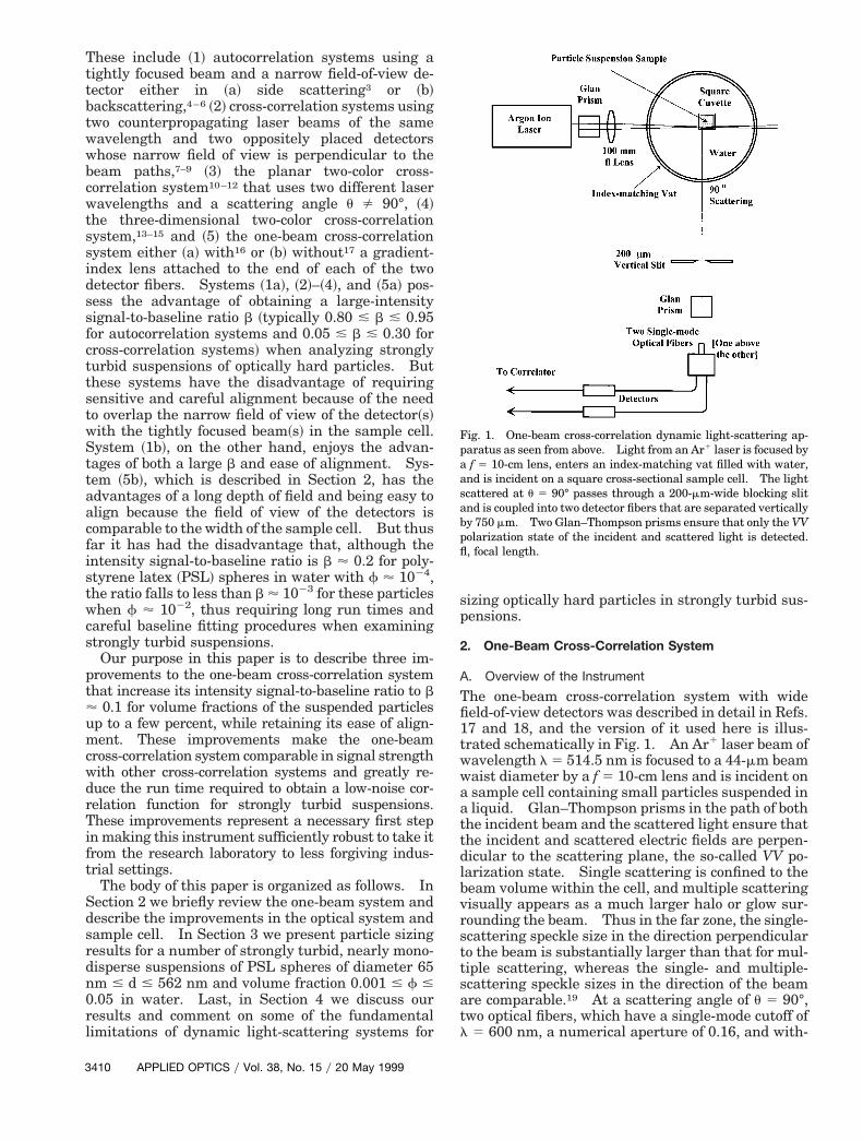
The one-beam cross-correlation system with widefield-of-view detectors was described in detail in Refs.17 and 18, and the version of it used here is illus-trated schematically in Fig. 1. An Ar1 laser beam ofwavelength l 5 514.5 nm is focused to a 44-mm beamwaist diameter by a f 5 10-cm lens and is incident ona sample cell containing small particles suspended ina liquid. Glan–Thompson prisms in the path of boththe incident beam and the scattered light ensure thatthe incident and scattered electric fields are perpen-dicular to the scattering plane, the so-called VV po-larization state. Single scattering is confined to thebeam volume within the cell, and multiple scatteringvisually appears as a much larger halo or glow sur-rounding the beam. Thus in the far zone, the single-scattering speckle size in the direction perpendicularto the beam is substantially larger than that for mul-tiple scattering, whereas the single- and multiple-scattering speckle sizes in the direction of the beamare comparable.19 At a scattering angle of u 5 90°,two optical fibers, which have a single-mode cutoff ofl 5 600 nm, a numerical aperture of 0.16, and with-
Fig. 1. One-beam cross-correlation dynamic light-scattering ap-paratus as seen from above. Light from an Ar1 laser is focused bya f 5 10-cm lens, enters an index-matching vat filled with water,and is incident on a square cross-sectional sample cell. The lightscattered at u 5 90° passes through a 200-mm-wide blocking slitand is coupled into two detector fibers that are separated verticallyby 750 mm. Two Glan–Thompson prisms ensure that only the VVpolarization state of the incident and scattered light is detected.fl, focal length.
3410 APPLIED OPTICS y Vol. 38, No. 15 y 20 May 1999
out gradient-index lenses attached are connected todetectors and provide the wide field of view describedabove. They are stacked perpendicular to the beamdirection so that their separation is greater than themultiple-scattering speckle size but less than thesingle-scattering speckle size. As a result, the sin-gly scattered light cross correlates whereas all but afew percent13,18 of the multiply scattered light doesnot, producing the desired multiple-scattering sup-pression. To reduce flare produced by scatteringfrom the surfaces of the sample cell and to preventthe q broadening of the measured correlogram thatwould have otherwise occurred because of the widefield of view of the detectors, the sample cell wasplaced in a water-filled glass-wall cylindrical index-matching vat of 8.0-cm inner diameter and 8.5 cmouter diameter. The detectors were placed just be-yond the vat’s paraxial focal line, 17.0 cm from thescattering volume to focus the light scattered at 90°onto the detector fibers. The detector fibers wereraised a few degrees above the horizontal until thebest signal-to-noise ratio was obtained, further re-ducing flare.
The particles’ hydrodynamic radius a was obtainedin Ref. 17 by fitting the measured intensity correlo-gram to the formula appropriate for monodispersenoninteracting particles in the infinite-dilution limit:
C~t! 5 ^Itotal&2@1 1 b exp~2kB Tq2ty3pha!#, (1)
where ^Itotal& is the time average of the scattered lightintensity coupled into each of the detector fibers, thescattered momentum transfer is q 5 4pn sin~uy2!yl,n is the refractive index of the liquid ~n 5 1.333 forthe experiments described both here and in Ref. ~17!,kB is Boltzmann’s constant, T is the temperature ofthe sample in degrees Kelvin, and h is the viscosity ofthe liquid. The intensity signal-to-baseline ratio bfor autocorrelation or cross-correlation systems canbe written as14
b 5 bgeometricbbeams~^Isingle&y^Itotal&!2, (2)
where ^Isingle& is the time-averaged single-scatteredlight intensity recorded by the detectors, ^Imultiple& isthe time-averaged multiple-scattered light intensityrecorded, and ^Itotal& 5 ^Isingle& 1 ^Imultiple&. The fac-tor bgeometric in Eq. ~2! is the only contribution to b foran autocorrelation system. It depends on geometricconsiderations such as the degree of overlap of thebeam~s! with the field of view of the detector~s! andthe ratio of the detector cross-sectional area dividedby the spatial coherence area of the scattered light.The factor bbeams depends on the intensity differenceof the two illuminating beams in two-beam cross-correlation systems. The factor ~^Isingle&y^Itotal&!
2
pertains to both one-beam and two-beam cross-correlation systems. In addition, the intensitysignal-to-baseline ratio is further reduced by noise inthe laser and the detector~s!.
B. Improvements in the Optical System and Sample Cell
The refractive index of PSL spheres relative to wateris nrel 5 1.2. Thus f ' 0.01 suspensions of theseparticles whose size is comparable with the wave-length of light produce much multiple scattering. InRef. 17 we found that, although the intensity signal-to-baseline ratio was b ' 0.2 for a f 5 2.0 3 1024
concentration of d 5 107-nm PSL spheres, it fell to b5 0.7 3 1023 for f 5 0.01, and no cross-correlationsignal was detected for f . 0.01. The reason for thesmall value of b when f ' 0.01 was because thedetectors’ wide field of view received an overwhelm-ingly large amount of multiply scattered light withrespect to the amount of singly scattered lightreceived. This occurred for three reasons: ~i! Theexperiments described in Ref. 17 used a 1.01-cm-diameter circular cross-sectional glass test tube asthe sample cell, and the focused laser beam traversedthe cell diameter. In moderately turbid suspen-sions, for singly scattered light to exit the sample celland be detected, it had to travel of the order of a cellradius in the suspension and was attenuated alongthe way. ~ii! For strongly turbid suspensions, singlyscattered light was found to be strong near the frontsurface of the sample cell and rapidly diminishedalong the beam path because of the attenuation of thelaser beam as it penetrated into the cell. Themultiple-scattering halo, on the other hand, was vi-sually observed to be bright over the entire celllength. The wide field of view of the detectors en-compassed the region of strong single and multiplescattering near the front of the sample cell, as well asthe region of greatly attenuated single scattering andstrong multiple scattering near the middle and theback of the cell. ~iii! The coupling efficiency of scat-tered light into the detector fibers is greatest near thecenter of the fibers’ field of view.20 In the experi-ments described in Ref. 17, the index-matching vatand the cell were concentric. Thus the center of thedetectors’ field of view was aligned with the center ofthe sample cell where single scattering was stronglyattenuated and where most of the detected signal wasmultiply scattered light.
These three mechanisms conspired to produce thesmall value for the ratio ~^Isingle&y^Itotal&!
2 in Eq. ~2! forstrongly turbid suspensions and suggested the follow-ing changes in our experimental setup: ~i! We nowuse a 1.0 cm 3 1.0 cm square cross-sectional quartzcuvette as the sample cell within the index-matchingvat. The focused laser beam is now incident on thecuvette’s front wall approximately 0.5 mm from theside wall closest to the detector fibers as in Fig. 1.Thus singly scattered light travels only a short dis-tance on its way to the detectors in the sample cellwith much reduced attenuation. ~ii! We now place ablocking slit, 200 mm wide and 2 cm high, approxi-mately half way between the sample cell and thedetector fibers so as to obscure all but ;0.4 mm of thefibers’ field of view at the sample cell. The slit axisis perpendicular to the beam direction, and the slit ispositioned so that the unobscured portion of the fi-
20 May 1999 y Vol. 38, No. 15 y APPLIED OPTICS 3411
bers’ field of view contains only the region of strongsingle scattering near the front surface of the cuvette.The presence of the slit does not affect the single- andmultiple-scattering speckle sizes perpendicular to thelaser beam direction because the spatial extent of thesingle- and multiple-scattering effective sources19 inthat direction is unchanged by the presence of theslit. ~iii! We now align the center of the fibers’ fieldof view with the slit and the strong single-scatteringregion near the front of the cell so as to most effi-ciently couple singly scattered light into the opticalfibers. Each of these three improvements has beenused at various times in the past in various dynamiclight-scattering systems. But in the experimentsdescribed here we quantify the improvement thateach produces in the signal-to-baseline ratio of theone-beam cross-correlation instrument.
In Ref. 17 the two detector fibers were separated by250 mm perpendicular to the beam direction. Formost of the experiments described here, the fiber sep-aration was chosen as 750 mm for the following rea-son. Near the front of the sample cell where singlescattering is the strongest, the multiple-scatteringhalo quickly fans out around the laser beam, and thehalo radius increases as the beam propagates deeperinto the cell. The blocking slit is positioned so thatthe region just inside the front wall of the cell is theonly portion of the cell visible to the fibers. Thus themultiple-scattering speckle size perpendicular to thelaser beam, though still smaller than that of singlescattering, is larger than it was for the experiments ofRef. 17. This requires a larger detector separationso that the separation remains larger than themultiple-scattering speckle size.
3. Experimental Results
A. Improvement in the Signal-to-Baseline Ratio
The PSL suspensions analyzed in the present set ofexperiments were obtained from Bangs Laboratories.They were diluted with distilled water to the desiredconcentration and were interrogated by the instru-ment within a few minutes after preparation. Var-ious electrolytes, whose purpose would be to screenelectrostatic interactions, were not added to the sus-pensions. The fact that the particle size was mea-sured accurately for the lower-concentration sampleshere, and in the experiments described in Ref. 17where the same sample preparation method wasused, provides some evidence that long-range electro-static interactions did not strongly affect the diffusioncoefficient of the PSL spheres in suspension. In thepresent set of experiments, we examined volume frac-tions f 5 0.001, 0.002, 0.005, 0.01, 0.02, and 0.05 ofPSL spheres with diameter d 5 65, 120, 246, and 562nm. For all the experiments reported here, the scat-tering angle was u 5 90°, and the VV polarizationstate of the incident and scattered light was detected.The Ar1 laser power was 100 mW, except for the65-nm particles, where the power was increased to200 mW to compensate for the much lower light-scattering intensity at 90° of these particles. Specif-
ically, for the four particle sizes considered here, 65,120, 246, and 562 nm, the VV-polarized single-scattering intensity at 90° was calculated using Mietheory and is in the ratio 1:32:454:872. The datacollection time was 2 min. This led to correlogramspossessing a moderate amount of statistical noise.But this time period was used nonetheless becauselonger collection times are often impractical in indus-trial settings, and it is our purpose here to assess theone-beam instrument’s viability for such applica-tions.
We already mentioned that in the experiments de-scribed in Ref. 17, cross-correlated scattering by a f5 0.01 concentration of d 5 107-nm PSL spheres inwater produced an intensity signal-to-baseline ratioof b 5 0.7 3 1023. In the present experiments, wefirst determined the improvement in b obtained byusing the square cross-sectional cuvette, rather thanthe circular cross-sectional test tube, in the index-matching vat. The focused laser beam now enteredthe front wall of the cuvette near its side wall, and thecenter of the detectors’ field of view was aligned withthe portion of the sample cell just inside the front wallof the cuvette as in Fig. 1. Cross-correlated scatter-ing with this experimental arrangement by a f 50.01 concentration of d 5 120-nm PSL spheres inwater, but without the blocking slit, produced an in-tensity signal-to-baseline ratio of b 5 0.020. Thisrepresents an increase by a factor of approximately30 over the value of b for the circular cross-sectionalsample cell, corresponding to a decrease in theamount of multiple scattering detected relative tosingle scattering by a factor of approximately 30.The increase in b and the resulting decrease in theratio of multiple scattering relative to single scatter-ing are actually somewhat greater than these values.This is because the PSL spheres of Ref. 17 had adiameter of 107 nm, whereas the spheres of this ex-periment have a diameter of 120 nm, and themultiple-scattering intensity increases as the size ofthe particles increases for a given volume fraction ofparticles in suspension.
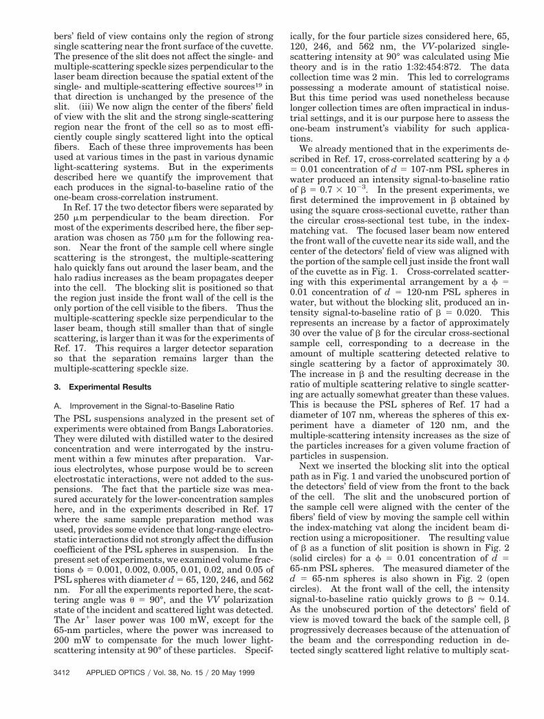
Next we inserted the blocking slit into the opticalpath as in Fig. 1 and varied the unobscured portion ofthe detectors’ field of view from the front to the backof the cell. The slit and the unobscured portion ofthe sample cell were aligned with the center of thefibers’ field of view by moving the sample cell withinthe index-matching vat along the incident beam di-rection using a micropositioner. The resulting valueof b as a function of slit position is shown in Fig. 2~solid circles! for a f 5 0.01 concentration of d 565-nm PSL spheres. The measured diameter of thed 5 65-nm spheres is also shown in Fig. 2 ~opencircles!. At the front wall of the cell, the intensitysignal-to-baseline ratio quickly grows to b ' 0.14.As the unobscured portion of the detectors’ field ofview is moved toward the back of the sample cell, bprogressively decreases because of the attenuation ofthe beam and the corresponding reduction in de-tected singly scattered light relative to multiply scat-
3412 APPLIED OPTICS y Vol. 38, No. 15 y 20 May 1999
tered light. The single-scattering mean free path oflight in the suspension is
Ls 5 4ay3fescatt, (3)
where escatt is the scattering efficiency of a singleparticle. For d 5 65-nm PSL spheres at f 5 0.01 inwater, escatt was calculated using Mie theory yieldingLs 5 1.35 mm. The intensity-to-baseline ratio inFig. 2 was fit approximately by a decaying exponen-tial with the decay distance Ls ; 1.7 mm, in roughagreement with the calculated single-scatteringmean free path.
The measured particle diameter was also found tobe much less accurate deeper in the sample cell be-cause of the poorer single-scattering statistics of theintensity cross-correlation function. But just pastthe front wall of the cuvette inside the cell is a regionapproximately 0.6 mm long where the measured di-ameter was found to be quite accurate and where b '0.10 indicating the region of relatively strong singlescattering. This region is wider than the ;0.4 mmlength of the sample cell unobscured by the blockingslit and provides the optimal placement of the slit forthe particle sizing experiments described below.Qualitatively similar results for b as a function of slitposition were obtained for a f 5 0.01 concentration ofd 5 246-nm PSL spheres. No effort was made, how-ever, to optimize b by varying the width of the slit orits placement between the sample cell and the detec-tor fibers.
As a final measurement of the improvement of b forour one-beam system, we again considered the f 50.01 concentration of d 5 120-nm PSL spheres. In-sertion of the blocking slit and positioning the unob-scured portion of the detectors’ field of view justinside the sample cell near its front wall produced anintensity signal-to-baseline ratio of b 5 0.116. Thisrepresents an increase in b by a factor of approxi-mately 6 from the value without the blocking slit and
a factor of approximately 170 from that of the exper-iment of Ref. 17 using the circular cross-sectionalsample cell. Similar improvements in b that weredue to the blocking slit were obtained for all particlesizes and volume fractions examined, with the im-provement being somewhat larger for smaller con-centrations.
B. Particle Sizing Results
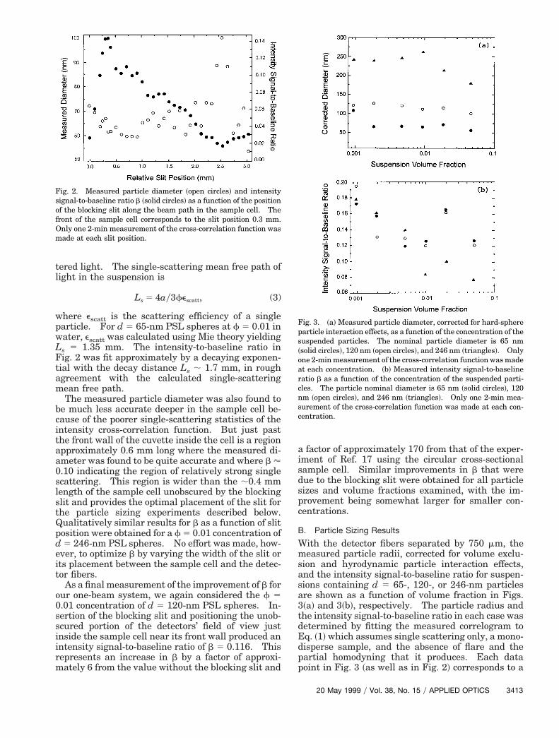
With the detector fibers separated by 750 mm, themeasured particle radii, corrected for volume exclu-sion and hyrodynamic particle interaction effects,and the intensity signal-to-baseline ratio for suspen-sions containing d 5 65-, 120-, or 246-nm particlesare shown as a function of volume fraction in Figs.3~a! and 3~b!, respectively. The particle radius andthe intensity signal-to-baseline ratio in each case wasdetermined by fitting the measured correlogram toEq. ~1! which assumes single scattering only, a mono-disperse sample, and the absence of flare and thepartial homodyning that it produces. Each datapoint in Fig. 3 ~as well as in Fig. 2! corresponds to a
Fig. 2. Measured particle diameter ~open circles! and intensitysignal-to-baseline ratio b ~solid circles! as a function of the positionof the blocking slit along the beam path in the sample cell. Thefront of the sample cell corresponds to the slit position 0.3 mm.Only one 2-min measurement of the cross-correlation function wasmade at each slit position.
Fig. 3. ~a! Measured particle diameter, corrected for hard-sphereparticle interaction effects, as a function of the concentration of thesuspended particles. The nominal particle diameter is 65 nm~solid circles!, 120 nm ~open circles!, and 246 nm ~triangles!. Onlyone 2-min measurement of the cross-correlation function was madeat each concentration. ~b! Measured intensity signal-to-baselineratio b as a function of the concentration of the suspended parti-cles. The particle nominal diameter is 65 nm ~solid circles!, 120nm ~open circles!, and 246 nm ~triangles!. Only one 2-min mea-surement of the cross-correlation function was made at each con-centration.
20 May 1999 y Vol. 38, No. 15 y APPLIED OPTICS 3413
single 2-min measurement of the cross-correlationfunction, as is characteristic of single-shot particlesizing measurements.
Presuming for the moment that multiple scatteringhas been completely suppressed and flare has beencompletely eliminated so that all the detected lightcorresponds to single scattering, particle interactionsbegin to affect the measured PSL sphere radius in-ferred from Eq. ~1! at volume fractions larger than f* 0.01. The four particle sizes used in the presentexperiments correspond to the argument qa of thestatic structure factor having the value 0.75, 1.38,2.83, and 6.46. These values span the region fromqa & 2 where particle interactions are dominated bycollective diffusion mechanisms to qa * 2 where par-ticle interactions are dominated by self-diffusionmechanisms.4,21–23 We assumed that the PSLspheres suspended in water are adequately modeledas hard spheres, and we corrected the measuredparticle radius obtained from Eq. ~1! for volume ex-clusion and hydrodynamic effects using the hydrody-namic model of Eqs. ~92a!–~92e! of Ref. 23 ~which isaccurate for volume fractions of a few percent or less!and the Percus–Yevick hard-sphere structure func-tion and pair correlation function.24 Figure 3~a! in-dicates that the corrected hydrodynamic radius of thePSL spheres was generally determined by our one-beam cross-correlation instrument to better than610% for f # 0.05.
The larger than expected measured size of the65-nm particles at f 5 0.001 is probably due in partto their relatively weak single-scattering intensity at90° and the resulting relatively large statistical noisein the correlogram measured in a single 2-min inter-val. For the 562-nm particles, the detector fiberswere spaced by 500 mm because we could not obtaina clean, low-noise correlogram using a 750-mm sepa-ration. The measured radii of the 562-nm particlesfollowed the same trends as for the 246-nm particles.But they are not plotted in Fig. 3 because we desiredall the data shown in the figure to be obtained withthe same instrumental geometry.
As can be seen in Fig. 3~a!, the one-beam cross-correlation technique somewhat undersized the 120-and 246-nm particles for f $ 0.02. One likelyreason for this is the residual few-percent cross-correlation of the detected multiply scatteredlight.13,18 Residual cross-correlated multiple scat-tering causes the correlation function to decay fast-er2,4 as a function of t than if single scattering alonewere present. As a result, the measured particleradius obtained using Eq. ~1! in the presence ofweakly cross-correlated multiple scattering is under-estimated. Other possible reasons for undersizingthe larger particles at the higher concentrations in-clude the effects of incoherent and coherent flare.The former adds noise to the correlogram and thelatter acts as a local oscillator, which also effectivelyundersizes the particles if Eq. ~1! is used for the anal-ysis. Experiments whose purpose is to assess theimportance of flare and partial homodyning are now
in progress, and preliminary results for autocorrela-tion systems have been published in Ref. 25.
One measure of the amount of multiply scatteredlight present is given by a comparison between thesize of the sample cell and the single-scattering meanfree path. The longest single-scattering mean freepath for the suspensions examined here is Ls 5 13.5mm corresponding to the d 5 65 nm and f 5 0.001sample, which is comparable with the length of thesample cell. As a result, all the suspensions exam-ined here visually appear milky white to the nakedeye. The noticeably low measured sizes in Fig. 3~a!for d 5 120 nm and f 5 0.05, d 5 246 nm and f 50.02, and d 5 246 nm and f 5 0.05 correspond to Ls5 51, 34, and 14 mm, respectively. Thus the im-provements to the one-beam instrument describedhere permit the sizing of PSL spheres in water in a2-min time interval to ;10% accuracy until Ls is anorder of magnitude less than the 400 mm length of thesample cell unobscured by the blocking slit. Al-though a 10% error is not sufficiently accurate forresearch purposes, it may often be acceptable for var-ious industrial applications.
Another measure of the contamination of the cor-relogram by multiple scattering is a comparison ofthe single-scattered intensity at 90° with the single-scattering cross section:
sscatt 5 pa2escatt. (4)
This is because multiple scattering is initiated bylight that scatters for the first time in any directionwhereas only the light scattered for the first time at90° arrives at the detectors as singly scattered light.As mentioned above, Isingle ~90°! is in the ratio 1:32:454:872 for the 65, 120, 246, and 562-nm PSL spheresconsidered here. But the single-scattering cross sec-tion is in the ratio 1:33:1075:35240. This indicatesthat multiple scattering is increasingly strong for the246- and 562-nm PSL spheres, and a residual few-percent cross-correlation of this amount of multiplescattering can be sizable.
Because the 200-mm blocking slit itself should pre-vent q broadening of the measured correlogram, one-beam cross-correlation experiments were alsoperformed with the index-matching vat absent, butwith the remainder of the optical system as in Fig. 1,and with a data collection time of 2 min. The mea-sured sphere radii for this system were found to begenerally similar to the results of Fig. 3~a!. But thecorrelograms contained a noticeably larger amount ofstatistical noise than with the vat present. We be-lieve that the higher noise level is due to lower scat-tered power coupled into the detector fibers becauseof the lack of focusing previously provided by the vat.
4. Discussion
In Ref. 17 it was found that the one-beam cross-correlation instrument gave accurate results for themeasured particle radius for dilute suspensions oflarge, optically hard particles. But for strongly tur-bid suspensions it required long run times and care-
3414 APPLIED OPTICS y Vol. 38, No. 15 y 20 May 1999
ful baseline fitting procedures because of the lowvalue of the measured intensity signal-to-baseline ra-tio. The instrument’s high degree of multiple-scattering suppression only roughly compensated forthe large amount of multiple-scattering intensity ad-mitted by the wide field-of-view detectors. With theimprovements in the optical system and sample celldescribed here, much less multiply scattered light iscoupled into the detector fibers, while the ease ofalignment of the instrument is retained. As can beseen by the results of Figs. 3~a! and 3~b!, data can beacquired much more quickly when working withstrongly turbid suspensions.
As a next step in moving the one-beam cross-correlation instrument toward industrial applica-tions, it should be tested on mixtures of spherical andnonspherical particles of different sizes to determineits particle sizing capability for less than ideal sam-ples. Also, a one-beam cross-correlation instrumentwith u ' 165° ~i.e., a cross-correlation backscatterprobe! should possess the versatility of autocorrela-tion backscatter probes4–6 while providing improvedmultiple-scattering suppression and a larger depth offield. The scattering angle u 5 90° for the instru-ment of Fig. 1, although experimentally convenient,represents a relatively unfavorable situation for de-tecting singly scattered light from large, opticallyhard particles. This is because as the particle ra-dius increases, the single-scattering light intensitydevelops a wide minimum centered at u ' 90°, whichis formed by the increasingly rapid falloff of the trans-mitted intensity for u , 90° and the increasingbuildup of the one-internal-reflection and two-internal-reflection intensity26 for u . 90°. As a re-sult, the single-scattering intensity at u 5 90°increases much more slowly and is more easily dom-inated by multiple scattering than is the case for u '165°. Preliminary results for the performance of theone-beam instrument for u up to 135° were given inRef. 17.
Both particle interaction effects and multiple scat-tering limit the concentrations of optically hard par-ticles in suspension for which accurate nonintrusiveparticle sizing measurements can be made using dy-namic light-scattering methods, presuming that poly-dispersity issues have been suitably handled and thatflare and optical noise have been eliminated. Whenf 5 0.01, hard-sphere particle interactions cause Eq.~1! to underestimate the radius of the 65-nm PSLspheres by only approximately 1% and to overesti-mate the radius of the 246- and 562-nm PSL spheresby approximately 2%. But when f 5 0.05, the un-derestimation and overestimation grow to approxi-mately 5% and 9%, respectively. Thus even ifmultiple scattering by the PSL spheres can be suit-ably suppressed, the volume fraction of the suspen-sion must be less than a few percent if few-percentsizing accuracy is acceptable when using conven-tional models, such as Eq. ~1!, for these determina-tions.
But dynamic light-scattering techniques do notcompletely eliminate multiple scattering from the
measured correlogram. In autocorrelation systems,multiple scattering correlates over the detector’s en-tire field of view, including the region that intersectsthe laser beam where single scattering greatly dom-inates, as well as the portion of the field of view thatpasses through the multiple-scattering halo. Incross-correlation techniques, multiple scatteringweakly cross correlates in the overlap region of thebeams and the detectors’ field of view. The limita-tion multiple scattering places on the ability of dy-namic light-scattering techniques to accurately sizeparticles in suspension depends on the particles’ re-fractive index relative to the liquid, their size, andtheir concentration as can be seen in Eq. ~3!, as wellas on the geometric configuration of the instrument.For the one-beam cross-correlation instrument de-scribed here, the dominant error for sizing PSLspheres in water with volume fraction in the range0.01 , f , 0.05 most likely arises from the few-percentresidual cross correlation of multiple scattering. Butthe instrument has succeeded, nonetheless, in extend-ing the utility of the one-beam method by several or-ders of magnitude.
This research was supported by NASA in the formsof a Summer Student Internship ~A. J. Adorjan!, anAmerican Society for Engineering Education Sum-mer Faculty Fellowship ~T. W. Taylor!, NASA grantNCC3-521 ~J. A. Lock!, and the NASA AdvancedTechnology Development Program YOF-2567 ~P. Tin,W. V. Meyer, and A. E. Smart!, and by the OhioAerospace Institute in the form of patent disclosuresconcerning the one-beam instrument.
References1. B. J. Berne and R. Pecora, Dynamic Light Scattering ~Wiley,
New York, 1976!, pp. 83–86.2. P. Stepanek, “Static and dynamic properties of multiple light
scattering,” J. Chem. Phys. 99, 6384–6393 ~1993!.3. T. Gisler, H. Ruger, S. U. Egelhaaf, J. Tschumi, P. Schurten-
berger, and J. Ricka, “Mode-selective light scattering: theoryversus experimental realization,” Appl. Opt. 34, 3546–3553~1995!.
4. H. Wiese and D. Horn, “Single-mode fibers in fiber-opticquasielastic light scattering: a study of the dynamics of con-centrated latex dispersions,” J. Chem. Phys. 94, 6429–6443~1991!.
5. H. S. Dhadwal, R. R. Ansari, and W. V. Meyer, “A fiber opticprobe for particle sizing in concentrated suspensions,” Rev. Sci.Instrum. 62, 2963–2968 ~1991!.
6. R. R. Ansari and K. I. Suh, “Dynamic light scattering particlesize measurements in turbid media,” in Coherence DomainOptical Methods in Biomedical Science and Clinical Applica-tions II, V. V. Tuchin and J. A. Izatt, eds., Proc. SPIE 3251,146–156 ~1998!.
7. G. D. J. Phillies, “Suppression of multiple scattering effects inquasielastic light scattering by homodyne cross-correlationtechniques,” J. Chem. Phys. 74, 260–262 ~1981!.
8. G. D. J. Phillies, “Experimental demonstration of multiplescattering suppression in quasielastic light scattering spec-troscopy by homodyne coincidence techniques,” Phys. Rev. A24, 1939–1943 ~1981!.
9. J. K. G. Dhont and C. G. de Kruif, “Scattered light intensitycross-correlation. I. Theory,” J. Chem. Phys. 79, 1658–1663~1983!.
20 May 1999 y Vol. 38, No. 15 y APPLIED OPTICS 3415
10. H. J. Mos, C. Pathmamanoharan, J. K. G. Dhont, and C. G. deKruif, “Scattered light intensity cross-correlation. II. Ex-perimental,” J. Chem. Phys. 84, 45–49 ~1986!.
11. M. Drewel, J. Ahrens, and U. Podschus, “Decorrelation of mul-tiple scattering for an arbitrary scattering angle,” J. Opt. Soc.Am. A 7, 206–210 ~1990!.
12. K. Schatzel, M. Drewel, and J. Ahrens, “Suppression of mul-tiple scattering in photon correlation spectroscopy,” J. Phys.Condens. Matter 2, SA393–SA398 ~1990!.
13. K. Schatzel, “Suppression of multiple scattering by photoncross-correlation techniques,” J. Mod. Opt. 38, 1849–1865~1991!.
14. L. B. Aberle, P. Hulstede, S. Wiegand, W. Schroer, and W.Staude, “Effective suppression of multiply scattered light instatic and dynamic light scattering,” Appl. Opt. 37, 6511–6524~1998!.
15. C. Urban and P. Schurtenberger, “Characterization of turbidcolloidal suspensions using light scattering techniques com-bined with cross-correlation methods,” J. Colloid Interface Sci.207, 150–158 ~1998!.
16. U. Nobbmann, S. W. Jones, and B. J. Ackerson, “Multiplescattering suppression: cross correlation with tilted single-mode fibers,” Appl. Opt. 36, 7571–7576 ~1997!.
17. W. V. Meyer, D. S. Cannell, A. E. Smart, T. W. Taylor, and P.Tin, “Multiple-scattering suppression by cross correlation,”Appl. Opt. 36, 7551–7558 ~1997!.
18. J. A. Lock, “Role of multiple scattering in cross-correlated light
scattering with a single laser beam,” Appl. Opt. 36, 7559–7570~1997!.
19. E. Hecht, Optics, 2nd ed. ~Addison-Wesley, Reading, Mass.,1987!, p. 532.
20. J. Ricka, “Dynamic light scattering with single-mode and mul-timode receivers,” Appl. Opt. 32, 2860–2875 ~1993!.
21. C. W. J. Beenakker and P. Mazur, “Diffusion of spheres inconcentrated suspension: resummation of many-body hydro-dynamic interactions,” Phys. Lett. A 98, 22–24 ~1983!.
22. C. W. J. Beenakker and P. Mazur, “Diffusion of spheres in aconcentrated suspension II,” Physica A 126, 349–370 ~1984!.
23. P. N. Pusey and R. J. A. Tough, “Particle interactions,” inDynamic Light Scattering: Applications of Photon Correla-tion Spectroscopy, R. Pecora, ed. ~Plenum, New York, 1985!,pp. 85–179.
24. N. W. Ashcroft and J. Lekner, “Structure and resistivity ofliquid metals,” Phys. Rev. 145, 83–90 ~1966!.
25. W. V. Meyer, A. E. Smart, D. S. Cannell, R. G. Brown, J. A.Lock, and T. W. Taylor, “Multiple scattering suppression withcross-correlation and flare rejection with fiber optic homodyn-ing,” paper AIAA 99-0962, presented at the Thirty-SeventhAerospace Sciences Meeting and Exhibit, Reno, Nev., 11–14January 1999 ~American Institute of Aeronautics and Astro-nautics, New York, 1999!.
26. J. A. Lock, “Contribution of high-order rainbows to the scat-tering of a Gaussian laser beam by a spherical particle,” J. Opt.Soc. Am. A 10, 693–706 ~1993!.
3416 APPLIED OPTICS y Vol. 38, No. 15 y 20 May 1999
Related Documents


