This is an electronic reprint of the original article. This reprint may differ from the original in pagination and typographic detail. Powered by TCPDF (www.tcpdf.org) This material is protected by copyright and other intellectual property rights, and duplication or sale of all or part of any of the repository collections is not permitted, except that material may be duplicated by you for your research use or educational purposes in electronic or print form. You must obtain permission for any other use. Electronic or print copies may not be offered, whether for sale or otherwise to anyone who is not an authorised user. Petsiuk, Aliaksei; Tanikella, Nagendra G.; Dertinger, Samantha; Pringle, Adam; Oberloier, Shane; Pearce, Joshua M. Partially RepRapable automated open source bag valve mask-based ventilator Published in: HardwareX DOI: 10.1016/j.ohx.2020.e00131 Published: 01/10/2020 Document Version Publisher's PDF, also known as Version of record Published under the following license: CC BY Please cite the original version: Petsiuk, A., Tanikella, N. G., Dertinger, S., Pringle, A., Oberloier, S., & Pearce, J. M. (2020). Partially RepRapable automated open source bag valve mask-based ventilator. HardwareX, 8, [e00131]. https://doi.org/10.1016/j.ohx.2020.e00131

Welcome message from author
This document is posted to help you gain knowledge. Please leave a comment to let me know what you think about it! Share it to your friends and learn new things together.
Transcript
This is an electronic reprint of the original article.This reprint may differ from the original in pagination and typographic detail.
Powered by TCPDF (www.tcpdf.org)
This material is protected by copyright and other intellectual property rights, and duplication or sale of all or part of any of the repository collections is not permitted, except that material may be duplicated by you for your research use or educational purposes in electronic or print form. You must obtain permission for any other use. Electronic or print copies may not be offered, whether for sale or otherwise to anyone who is not an authorised user.
Petsiuk, Aliaksei; Tanikella, Nagendra G.; Dertinger, Samantha; Pringle, Adam; Oberloier,Shane; Pearce, Joshua M.Partially RepRapable automated open source bag valve mask-based ventilator
Published in:HardwareX
DOI:10.1016/j.ohx.2020.e00131
Published: 01/10/2020
Document VersionPublisher's PDF, also known as Version of record
Published under the following license:CC BY
Please cite the original version:Petsiuk, A., Tanikella, N. G., Dertinger, S., Pringle, A., Oberloier, S., & Pearce, J. M. (2020). PartiallyRepRapable automated open source bag valve mask-based ventilator. HardwareX, 8, [e00131].https://doi.org/10.1016/j.ohx.2020.e00131
HardwareX 8 (2020) e00131
Contents lists available at ScienceDirect
HardwareX
journal homepage: www.elsevier .com/ locate /ohx
Partially RepRapable automated open source bag valvemask-based ventilator
https://doi.org/10.1016/j.ohx.2020.e001312468-0672/� 2020 The Authors. Published by Elsevier Ltd.This is an open access article under the CC BY license (http://creativecommons.org/licenses/by/4.0/).
⇑ Corresponding author.E-mail addresses: [email protected] (A. Petsiuk), [email protected] (N.G. Tanikella), [email protected] (S. Dertinger), [email protected] (A.
[email protected] (S. Oberloier), [email protected] (J.M. Pearce).
Aliaksei Petsiuk a, Nagendra G. Tanikella b, Samantha Dertinger c, Adam Pringle b,Shane Oberloier a, Joshua M. Pearce a,b,d,e,⇑aDepartment of Electrical & Computer Engineering, Michigan Technological University, USAbDepartment of Materials Science & Engineering, Michigan Technological University, USAcBiomedical Engineering, Michigan Technological University, USAd Équipe de Recherche sur les Processus Innovatifs (ERPI) , Université de Lorraine, Francee School of Electrical Engineering, Aalto University, Finland
a r t i c l e i n f o
Article history:Received 26 June 2020Received in revised form 23 July 2020Accepted 30 July 2020
Keywords:VentilatorPandemicVentilationInfluenza pandemicCoronavirusCoronavirus pandemicPandemic ventilatorSingle-limbOpen sourceOpen hardwareCOVID-19Medical hardwareRepRap3-D printingOpen source medical hardwareEmbedded systemsReal-time operating system
a b s t r a c t
This study describes the development of a simple and easy-to-build portable automatedbag valve mask (BVM) compression system, which, during acute shortages and supplychain disruptions can serve as a temporary emergency ventilator. The resuscitation systemis based on the Arduino controller with a real-time operating system installed on a largelyRepRap 3-D printable parametric component-based structure. The cost of the materials forthe system is under $170, which makes it affordable for replication by makers around theworld. The device provides a controlled breathing mode with tidal volumes from 100 to800 mL, breathing rates from 5 to 40 breaths/minute, and inspiratory-to-expiratory ratiofrom 1:1 to 1:4. The system is designed for reliability and scalability of measurement cir-cuits through the use of the serial peripheral interface and has the ability to connect addi-tional hardware due to the object-oriented algorithmic approach. Experimental resultsafter testing on an artificial lung for peak inspiratory pressure (PIP), respiratory rate(RR), positive end-expiratory pressure (PEEP), tidal volume, proximal pressure, and lungpressure demonstrate repeatability and accuracy exceeding human capabilities in BVM-based manual ventilation. Future work is necessary to further develop and test the systemto make it acceptable for deployment outside of emergencies such as with COVID-19 pan-demic in clinical environments, however, the nature of the design is such that desired fea-tures are relatively easy to add using protocols and parametric design files provided.� 2020 The Authors. Published by Elsevier Ltd. This is an open access article under the CCBY
license (http://creativecommons.org/licenses/by/4.0/).
Pringle),

2 A. Petsiuk et al. / HardwareX 8 (2020) e00131
1. Specifications table
Figinco
Hardware name
. 1. RepRapable Ventilator System: A) stflating bag, 3) motor setup, 4) compressiontrol system, 8) power supply with backu
RepRapable Automated Open Source BVM-based Ventilator
Subject area � Medical Hardware type � Medical hardware Open Source License GNU General Public License (GPL) v3.0 and CERN Open Hardware License (OHL) v1.2 Cost of Hardware < $170 Source File Repository https://osf.io/fjdwz/2. Hardware in context
Coronavirus disease 2019 (COVID-19) is increasing mortality rates by overwhelming medical infrastructure at the regio-nal level [1–4]. Mechanical ventilators, which are essential for treating both influenza and COVID-19 patients in severe acuterespiratory failure [5,6], are in critical short supply in some locations [7–10]. During pandemics intensive care units (ICUs) donot have sufficient ventilators to treat all the patients requiring them [11–13], which forces triage and rationing [14,15]. Thisis despite national stockpiles of proprietary, mass-manufactured ventilators, which are simply not numerous enough due toprohibitive costs to service society during an extreme pandemic [16–20].
Another approach to provide products uses the technically and economically-viable open source small-scale digital tech-nologies and off-the-shelf components for distributed manufacturing [21,22]. There has already been a concerted effort toapply open source hardware and 3-D printing during the COVID-19 pandemic [23–29]. In addition, challenges with supplychains during any type of pandemic can be partially offset by open source recyclebots [30–34] and direct recycling extrusion[35] to close the loop on material supplies with local waste converted into additive manufacturing feedstock [36–41]. Thedistributed manufacturing of scientific equipment has been shown to provide custom, high-quality scientific tools for sub-stantially lower costs than conventional proprietary products [42–46]. This is because a scientific tool can be developed onceand then digitally replicated for approximately the cost of the materials [47] creating enormous distributed value [48] a highreturn on investment [49], and the ability to focus investments for strategic national goals [50,51]. This same open sourcehardware design approach [52] can be applied to medical equipment [53–56] to overcome supply shortages [57–61].
There has already been some effort in developing low-cost ventilators in the literature [62–70] as well as in the makercommunity; however, the former failed to provide full source code and the latter (as of March 2020) was unvalidatedand largely untested [71]. To both fill the current critical need for ventilators as well as provide a basis for future pandemics,this article provides the full source code for a fully-functional low-cost 3-D printable open-source pandemic ventilator andincludes validation testing using an artificial lung.
3. Hardware description.
The open-source pandemic single-limb (with one hose for the respiratory circuit; exhalation occurs through a single ori-fice located at the distal end of the circuit) ventilator (Fig. 1) was designed to be highly reproducible, simple in fabrication,maintenance and use for epidemics, pandemics and in developing and under-resourced communities. The design of the
andalone automated BVM-based resuscitation system, B) testing procedure, 1) bag mounting system, 2) self-n mechanism (pusher), 5) Positive End Expiratory Pressure (PEEP) valve [85], 6) feedback pressure sensors, 7)p battery, 9) air mask, 10) mechanical lung, 11) airway pressure sensor.
A. Petsiuk et al. / HardwareX 8 (2020) e00131 3
device and software was governed by ISO standards [72], the British Medicines & Healthcare Products Regulatory Agency’srapidly manufactured ventilator system [73] and the Key Ventilation Specifications developed by the E-Vent project [74]along with consultation with health care professionals. The system can be fabricated from readily accessible components,open source Arduino microcontrollers [75,76] open source electronics that can be made with open source mills [77–79]and custom parts with a RepRap-class material extrusion-based 3-D printer [80–84]. Mechanical ventilation, which canbe easily controlled by a simple user input, was chosen to be most effective at treating the largest number of people.
The system implements two following modes: controlled mechanical ventilation (CMV) and inverse ratio ventilation(IRV). A user can control breathing rates (breaths per minute or BPM), tidal volume (VT, air volume pushed into the lungs),inspiratory/expiration time ratio (I/E ratio). All the mechanical components (Fig. 1: components 1, 4, 7) were developed inopen-source CAD systems. The use of a parametric OpenSCAD generator of 3-D printable components (junction boxes for thefeedback pressure sensors (Fig. 1) allows to fit any tubing system. A backup battery enables short-term patient mobility andsafety protocols in software provide alarm signals when the monitored proximal pressure exceeds the permissible range, orthe pressure sensors are disconnected.
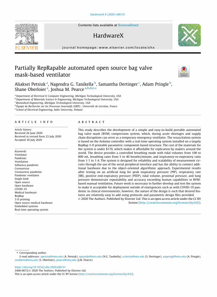
The electrical architecture is illustrated in Fig. 2. The development process of a medical device as an embedded real-timesystem can be divided into the main following steps:
1. System design2. Schematic development3. Fabrication and assembly4. Software development5. Testing
Each of the above steps undergoes numerous iterations, starting with a concept passing the basic and detailed engineer-ing stages, and ending with a finished product [86–91].
This study of ventilator systems is based on fundamental works [92–97]. In addition to the technical difficulties with thedevelopment of an embedded real-time system, there are also a significant number of details associated with the fabricationof parts that are used in contact with the patient.
The developed system has three control inputs for the variables: tidal volume (VT), breathing rate per minute (BPM), andinspiratory-to-expiratory ratio (I/E). BPM and I/E are controlled by rotary potentiometers, and BPM is controlled with arotary encoder. Having a rotary encoder with an additional button may allow developers to upgrade the system in the future(for example, add a menu to select another mode).
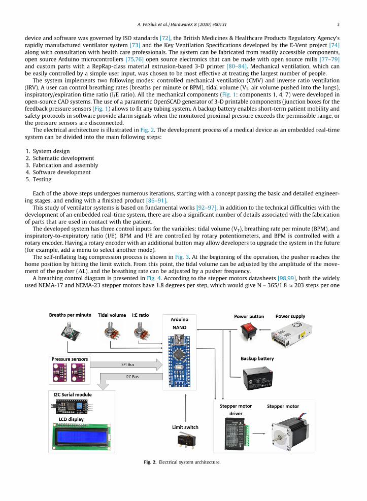
The self-inflating bag compression process is shown in Fig. 3. At the beginning of the operation, the pusher reaches thehome position by hitting the limit switch. From this point, the tidal volume can be adjusted by the amplitude of the move-ment of the pusher (DL), and the breathing rate can be adjusted by a pusher frequency.
A breathing control diagram is presented in Fig. 4. According to the stepper motors datasheets [98,99], both the widelyused NEMA-17 and NEMA-23 stepper motors have 1.8 degrees per step, which would give N = 365/1.8 � 203 steps per one
Fig. 2. Electrical system architecture.
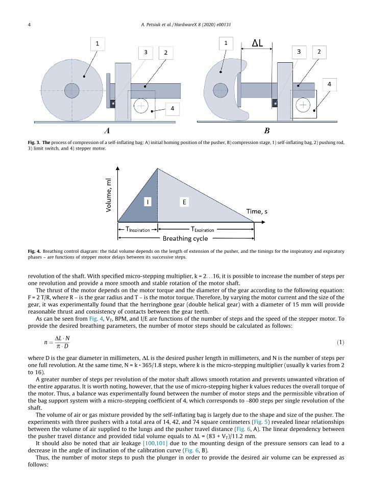
Fig. 3. The process of compression of a self-inflating bag: A) initial homing position of the pusher, B) compression stage, 1) self-inflating bag, 2) pushing rod,3) limit switch, and 4) stepper motor.
Fig. 4. Breathing control diagram: the tidal volume depends on the length of extension of the pusher, and the timings for the inspiratory and expiratoryphases – are functions of stepper motor delays between its successive steps.
4 A. Petsiuk et al. / HardwareX 8 (2020) e00131
revolution of the shaft. With specified micro-stepping multiplier, k = 2. . .16, it is possible to increase the number of steps perone revolution and provide a more smooth and stable rotation of the motor shaft.
The thrust of the motor depends on the motor torque and the diameter of the gear according to the following equation:F = 2 T/R, where R – is the gear radius and T – is the motor torque. Therefore, by varying the motor current and the size of thegear, it was experimentally found that the herringbone gear (double helical gear) with a diameter of 15 mm will providereasonable thrust and consistency of contacts between the gear teeth.
As can be seen from Fig. 4, VT, BPM, and I/E are functions of the number of steps and the speed of the stepper motor. Toprovide the desired breathing parameters, the number of motor steps should be calculated as follows:
n ¼ DL � Np � D ð1Þ
where D is the gear diameter in millimeters, DL is the desired pusher length in millimeters, and N is the number of steps perone full revolution. At the same time, N = k ∙ 365/1.8 steps, where k is the micro-stepping multiplier (usually k varies from 2to 16).
A greater number of steps per revolution of the motor shaft allows smooth rotation and prevents unwanted vibration ofthe entire apparatus. It is worth noting, however, that the use of micro-stepping higher k values reduces the overall torque ofthe motor. Thus, a balance was experimentally found between the number of motor steps and the permissible vibration ofthe bag support system with a micro-stepping coefficient of 4, which corresponds to ~800 steps per single revolution of theshaft.
The volume of air or gas mixture provided by the self-inflating bag is largely due to the shape and size of the pusher. Theexperiments with three pushers with a total area of 14, 42, and 74 square centimeters (Fig. 5) revealed linear relationshipsbetween the volume of air supplied to the lungs and the pusher travel distance (Fig. 6, A). The linear dependency betweenthe pusher travel distance and provided tidal volume equals to DL = (83 + VT)/11.2 mm.
It should also be noted that air leakage [100,101] due to the mounting design of the pressure sensors can lead to adecrease in the angle of inclination of the calibration curve (Fig. 6, B).
Thus, the number of motor steps to push the plunger in order to provide the desired air volume can be expressed asfollows:
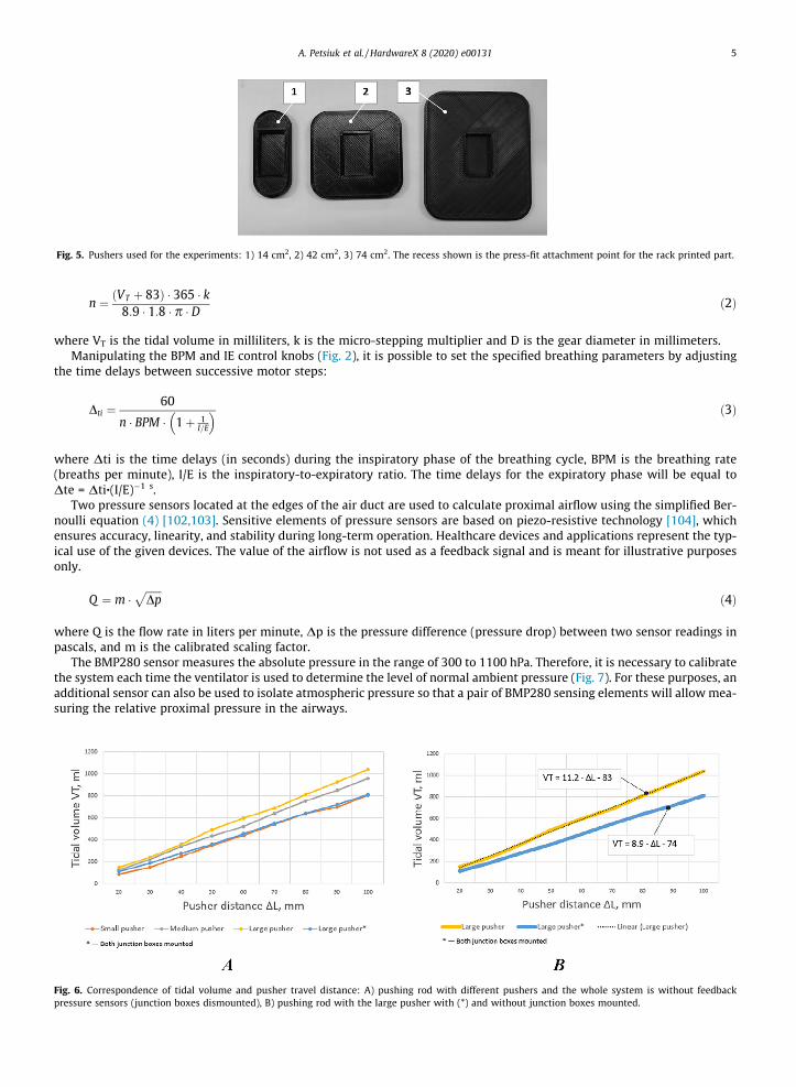
Fig. 5. Pushers used for the experiments: 1) 14 cm2, 2) 42 cm2, 3) 74 cm2. The recess shown is the press-fit attachment point for the rack printed part.
Fig. 6.pressur
A. Petsiuk et al. / HardwareX 8 (2020) e00131 5
n ¼ VT þ 83ð Þ � 365 � k8:9 � 1:8 � p � D ð2Þ
where VT is the tidal volume in milliliters, k is the micro-stepping multiplier and D is the gear diameter in millimeters.Manipulating the BPM and IE control knobs (Fig. 2), it is possible to set the specified breathing parameters by adjusting
the time delays between successive motor steps:
Dti ¼ 60
n � BPM � 1þ 1I=E
� � ð3Þ
where Dti is the time delays (in seconds) during the inspiratory phase of the breathing cycle, BPM is the breathing rate(breaths per minute), I/E is the inspiratory-to-expiratory ratio. The time delays for the expiratory phase will be equal toDte = Dti∙(I/E)�1 s.
Two pressure sensors located at the edges of the air duct are used to calculate proximal airflow using the simplified Ber-noulli equation (4) [102,103]. Sensitive elements of pressure sensors are based on piezo-resistive technology [104], whichensures accuracy, linearity, and stability during long-term operation. Healthcare devices and applications represent the typ-ical use of the given devices. The value of the airflow is not used as a feedback signal and is meant for illustrative purposesonly.
Q ¼ m �ffiffiffiffiffiffiDp
pð4Þ
where Q is the flow rate in liters per minute, Dp is the pressure difference (pressure drop) between two sensor readings inpascals, and m is the calibrated scaling factor.
The BMP280 sensor measures the absolute pressure in the range of 300 to 1100 hPa. Therefore, it is necessary to calibratethe system each time the ventilator is used to determine the level of normal ambient pressure (Fig. 7). For these purposes, anadditional sensor can also be used to isolate atmospheric pressure so that a pair of BMP280 sensing elements will allowmea-suring the relative proximal pressure in the airways.
Correspondence of tidal volume and pusher travel distance: A) pushing rod with different pushers and the whole system is without feedbacke sensors (junction boxes dismounted), B) pushing rod with the large pusher with (*) and without junction boxes mounted.

Fig. 7. Proximal pressure calibration: A) absolute pressure of the laboratory environment (zero-level for proximal pressure), B) BMP280 calibration curvefor proximal pressure.
6 A. Petsiuk et al. / HardwareX 8 (2020) e00131
To suppress the noise of the signal from the pressure sensors, an exponential filter is used [105]. This smooths the curvewithout using significant memory resources. When a new measured value pt is provided, the exponential filter updates asmoothed observation, St:
St ¼ a � pt þ 1� að Þ � St�1 ð5Þ
where St-1 is the previous output value of the filter in pascals, pt is the newmeasured value in pascals, and a is the smoothingconstant (0 < a < 1).
Since the BMP80 pressure sensors are located in the junction boxes (Fig. 1), and not directly in the airflow path, their read-ings must be brought to real proximal pressure values based on the results of experiments with the mechanical lung [106].
A calibration curve coerces the sensors values to proximal airway pressure can be described by the following equation:
Pproximal ¼ 0:144 � Pabsolute
100� 128:2
� �ð6Þ
where Pproximal – proximal pressure in cmH2O, Pabsolute – absolute BMP280 pressure in pascals.Thus, the signals from pressure sensors located at opposite ends of the airway can be interpreted as proximal pressure.
Based on the above Eq. (6), it is possible to determine the readings of the sensors corresponding to the minimum allowablePEEP pressure and the maximum critical pressure of 40 cmH2O (Fig. 8).
The control system is based on the Arduino controller and a stepper motor setup (NEMA-23 motor). The Arduino Nanoboard was chosen as a controller due to low relative expense while having sufficient digital and analog pins.
A significant number of medical software development standards contain information and requirements regarding soft-ware design, validation, and certification [107–112]. However, in the global pandemic, meeting all requirements can be dif-ficult. The main guidelines for emergency ventilation systems is the use of real-time operating systems and a serialperipheral interface for connecting sensing devices [113].
Fig. 8. Pressure sensors feedback.
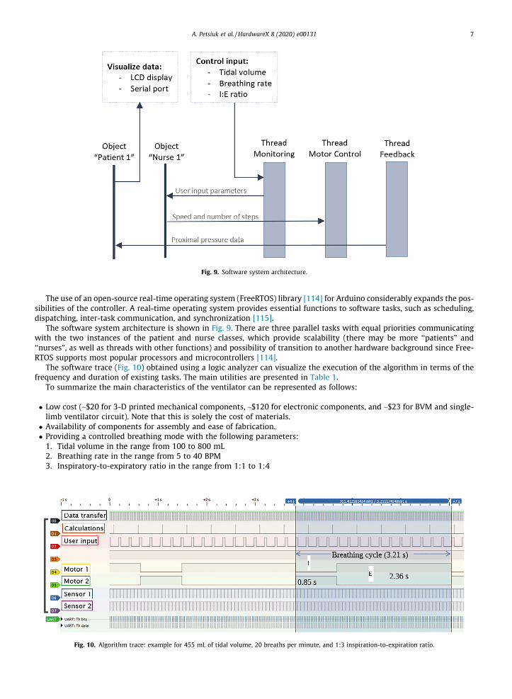
Fig. 9. Software system architecture.
A. Petsiuk et al. / HardwareX 8 (2020) e00131 7
The use of an open-source real-time operating system (FreeRTOS) library [114] for Arduino considerably expands the pos-sibilities of the controller. A real-time operating system provides essential functions to software tasks, such as scheduling,dispatching, inter-task communication, and synchronization [115].
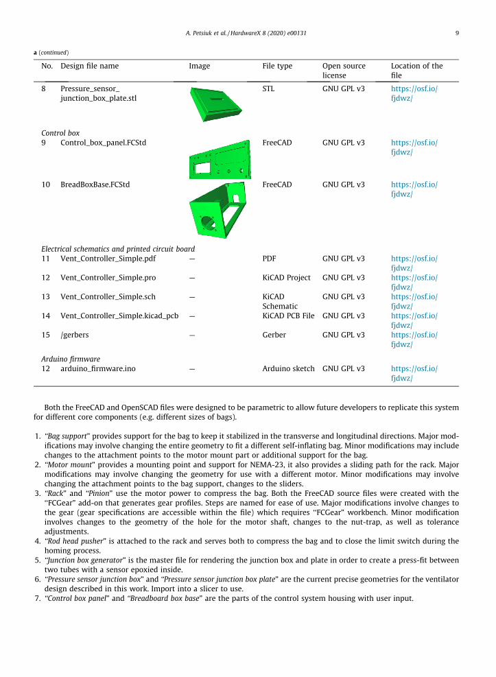
The software system architecture is shown in Fig. 9. There are three parallel tasks with equal priorities communicatingwith the two instances of the patient and nurse classes, which provide scalability (there may be more ‘‘patients” and‘‘nurses”, as well as threads with other functions) and possibility of transition to another hardware background since Free-RTOS supports most popular processors and microcontrollers [114].
The software trace (Fig. 10) obtained using a logic analyzer can visualize the execution of the algorithm in terms of thefrequency and duration of existing tasks. The main utilities are presented in Table 1.
To summarize the main characteristics of the ventilator can be represented as follows:
� Low cost (~$20 for 3-D printed mechanical components, ~$120 for electronic components, and ~$23 for BVM and single-limb ventilator circuit). Note that this is solely the cost of materials.
� Availability of components for assembly and ease of fabrication.� Providing a controlled breathing mode with the following parameters:1. Tidal volume in the range from 100 to 800 mL2. Breathing rate in the range from 5 to 40 BPM3. Inspiratory-to-expiratory ratio in the range from 1:1 to 1:4
Fig. 10. Algorithm trace: example for 455 mL of tidal volume, 20 breaths per minute, and 1:3 inspiration-to-expiration ratio.

Table 1Software tracing summary.
Utility Frequency, Hz Duration, ms
Serial data transfer 14 2.5Motor parameters recalculation 2 0.1Reading user input and LCD display update 4.5 50Two pressure sensors readings 14 1.5
8 A. Petsiuk et al. / HardwareX 8 (2020) e00131
� Software reliability through the use of the real-time operating system� Reliability and scalability of measurement circuits through the use of the serial peripheral interface (SPI)� Ability to connect additional hardware due to the object-oriented algorithmic approach
4. Design files
4.1. Design files summary
No.
Design file name Image File type Open sourcelicenseLocation of thefile
Bag mounting system
1 BagSupport.FCStd FreeCAD GNU GPL v3 https://osf.io/fjdwz/
2
MotorMount.FCStd FreeCAD GNU GPL v3 https://osf.io/fjdwz/3
Rack.FCStd FreeCAD GNU GPL v3 https://osf.io/fjdwz/4
Pinion.FCStd FreeCAD GNU GPL v3 https://osf.io/fjdwz/5
Rod_head_pusher.scad OpenSCAD GNU GPL v3 https://osf.io/fjdwz/Junction boxes for pressure sensors
6 Junction_box_generator.scad OpenSCAD https://osf.io/fjdwz/
7 Pressure_sensor_junction_box.stl STL GNU GPL v3 https://osf.io/fjdwz/
A. Petsiuk et al. / HardwareX 8 (2020) e00131 9
a (continued)
No.
Design file name Image File type Open sourcelicenseLocation of thefile
8
Pressure_sensor_junction_box_plate.stlSTL
GNU GPL v3 https://osf.io/fjdwz/Control box
9 Control_box_panel.FCStd FreeCAD GNU GPL v3 https://osf.io/fjdwz/
10
BreadBoxBase.FCStd FreeCAD GNU GPL v3 https://osf.io/fjdwz/Electrical schematics and printed circuit board
11 Vent_Controller_Simple.pdf — PDF GNU GPL v3 https://osf.io/fjdwz/
12 Vent_Controller_Simple.pro — KiCAD Project GNU GPL v3 https://osf.io/fjdwz/
13 Vent_Controller_Simple.sch — KiCADSchematic
GNU GPL v3 https://osf.io/fjdwz/
14 Vent_Controller_Simple.kicad_pcb — KiCAD PCB File GNU GPL v3 https://osf.io/fjdwz/
15 /gerbers — Gerber GNU GPL v3 https://osf.io/fjdwz/
Arduino firmware
12 arduino_firmware.ino — Arduino sketch GNU GPL v3 https://osf.io/fjdwz/
Both the FreeCAD and OpenSCAD files were designed to be parametric to allow future developers to replicate this systemfor different core components (e.g. different sizes of bags).
1. ‘‘Bag support” provides support for the bag to keep it stabilized in the transverse and longitudinal directions. Major mod-ifications may involve changing the entire geometry to fit a different self-inflating bag. Minor modifications may includechanges to the attachment points to the motor mount part or additional support for the bag.
2. ‘‘Motor mount” provides a mounting point and support for NEMA-23, it also provides a sliding path for the rack. Majormodifications may involve changing the geometry for use with a different motor. Minor modifications may involvechanging the attachment points to the bag support, changes to the sliders.
3. ‘‘Rack” and ‘‘Pinion” use the motor power to compress the bag. Both the FreeCAD source files were created with the‘‘FCGear” add-on that generates gear profiles. Steps are named for ease of use. Major modifications involve changes tothe gear (gear specifications are accessible within the file) which requires ‘‘FCGear” workbench. Minor modificationinvolves changes to the geometry of the hole for the motor shaft, changes to the nut-trap, as well as toleranceadjustments.
4. ‘‘Rod head pusher” is attached to the rack and serves both to compress the bag and to close the limit switch during thehoming process.
5. ‘‘Junction box generator” is the master file for rendering the junction box and plate in order to create a press-fit betweentwo tubes with a sensor epoxied inside.
6. ‘‘Pressure sensor junction box” and ‘‘Pressure sensor junction box plate” are the current precise geometries for the ventilatordesign described in this work. Import into a slicer to use.
7. ‘‘Control box panel” and ‘‘Breadboard box base” are the parts of the control system housing with user input.

10 A. Petsiuk et al. / HardwareX 8 (2020) e00131
8. ‘‘Schematic” is a control system wiring diagram that can be implemented using both a breadboard and a printed circuitboard.
9. ‘‘Arduino firmware” is a program that reads user input and implements motor control in accordance with user-definedbreathing parameters.
5. Bill of materials
The complete Bill of Materials is available in the OSF repository (https://osf.io/ugt3e/).
5.1. Breathing system Bill of materials
Designator
Number Cost perunit –USDTotalcost –USD
Source of materials
Adult Bag-Valve-Mask AmbuSPUR II
1
15.95 15.95 https://www.heartsmart.com/ambu-adult-spur-ii-adult-bvm-pSingle-limbventilatorcircuit
1
6.71 6.71 https://www.saveritemedical.com/products/adult-single-limb-portable-ventilator-circuit?variant=32484935052&gclid=EAIaIQobChMIzsvWlbye6gIVDtbACh2DswWiEAQYAiABEgL0FPD_BwE5.2. Mechanical system Bill of materials
Designator
Component MassingramsCost perunit –USD
Totalcost –USD
Source of materials
Material typePLA – 3-Dprinterfilament
BagSupport.stl,MotorMount.stl, Rack.stl,Pinion.stl,BreadBoardBase.stl,BreadBoardCover.stl
700
$25/kg $17.50 https://us.polymaker.com/product/polylite-pla/Hardthermoplastic
Ninjaflex – 3-Dprinterfilament
Junction_box and plateSTLs
40
$85/kg $3.40 https://www.fennerdrives.com/product-lines/_/3d/Flexiblepolymer
5.3. Control system Bill of materials
Component
Number Cost perunit – USDTotalcost –USD
Source of materials
Power supply, 12 V
1 18.95 18.95 https://www.amazon.com/eTopxizu-Universal-Regulated-Switching-Computer/dp/B00D7CWSCGBattery 12 V 7A
1 17.5 17.5 https://www.amazon.com/ExpertPower-EXP1270-Rechargeable-Lead-Battery/dp/B003S1RQ2SBreadboard
1 7.9 7.9 https://www.amazon.com/BB830-Solderless-Plug-BreadBoard-tie-Points/dp/B0040Z4QN8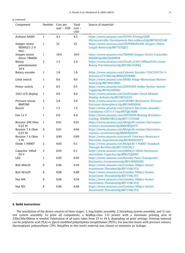
A. Petsiuk et al. / HardwareX 8 (2020) e00131 11
a (continued)
Component
Number Cost perunit – USDTotalcost –USD
Source of materials
Arduino NANO
1 4.3 4.3 https://www.amazon.com/WYPH-ATmega328P-Microcontroller-Development-Not-soldered/dp/B07KCH534KStepper motorNEMA23 (1.9Nm)
1
32 32 https://www.amazon.com/STEPPERONLINE-Stepper-269oz-Length-Router/dp/B077Z5QJCLStepper motordriver TB6600
1
10.9 10.9 https://www.amazon.com/TB6600-Stepper-Driver-Controller-tb6600/dp/B07S64MBTRRotarypotentiometer10 K
2
1.2 2.4 https://www.amazon.com/Uxcell-a15011600ux0235-Linear-Rotary-Potentiometer/dp/B01DKCUVMQRotary encoder
1 1.8 1.8 https://www.amazon.com/Cylewet-Encoder-15%C3%9716–5-Arduino-CYT1062/dp/B06XQTHDRR/Limit switch
1 0.6 0.6 https://www.amazon.com/MXRS-Hinge-Momentary-Button-Switch/dp/B07MW2RPJYPower switch
1 0.5 0.5 https://www.amazon.com/ZUPAYIPA-Solder-Rocker-Switch-Toggle/dp/B01N2U8PK0/16x2 LCD display
1 9.0 9.0 https://www.amazon.com/SunFounder-Serial-Module-Display-Arduino/dp/B019K5X53OPressure sensorBMP280
2
2.8 5.6 https://www.amazon.com/CHENBO-Barometric-Pressure-Precision-Atmospheric/dp/B01N4EHIW6Buzzer
1 1.5 1.5 https://www.amazon.com/Cylewet-Electronic-Sounder-Continuous-CYT1117/dp/B07QJG46B8Fan 12 V
1 6.0 6.0 https://www.amazon.com/ANVISION-Bearing-Brushless-Cooling-YDM4010B12/dp/B0711FVD48Resistor 200 Ohm0.25 W
1
0.01 0.01 https://www.amazon.com/McIgIcM-resistor-Electronics-resistors-assortment/dp/B06WRQS97CResistor 1 k Ohm0.25 W
4
0.01 0.04 https://www.amazon.com/McIgIcM-resistor-Electronics-resistors-assortment/dp/B06WRQS97CResistor 1 k Ohm5 W
1
0.89 0.89 https://www.amazon.com/uxcell-Tolerance-Resistance-Electronic-Experiments/dp/B07RWRVWYYDiode 1 N4007
2 0.05 0.1 https://www.amazon.com/McIgIcM-1 N4007-Standard-Through-Rectifier/dp/B071DXGHL7Capacitor 100uF50 V
2
0.05 0.1 https://www.amazon.com/JABINCO-100uf-Aluminum-electrolytic-Capacitor/dp/B082TQRDKTLED
1 0.05 0.05 https://www.amazon.com/Novelty-Place-Transparent-Electronics-Components/dp/B01AKM9ODGBolt M4x20
9 0.06 0.54 https://www.amazon.com/Comdox-500pcs-Socket-Assortment-Threaded/dp/B071VBL355/Bolt M3x20
8 0.06 0.48 https://www.amazon.com/Comdox-500pcs-Socket-Assortment-Threaded/dp/B071VBL355Nut M4
9 0.06 0.54 https://www.amazon.com/Comdox-500pcs-Socket-Assortment-Threaded/dp/B071VBL355/Nut M3
8 0.06 0.48 https://www.amazon.com/Comdox-500pcs-Socket-Assortment-Threaded/dp/B071VBL355/6. Build instructions
The installation of the device consists of three stages: 1) bag holder assembly, 2) breathing system assembly, and 3) con-trol system assembly. To print all components, a RepRap-class 3-D printer with a minimum printing area of230x230x100mm is needed. Fabrication of all parts takes from 25 to 34 h, depending on print settings. Printing materialcan be polylactic acid (PLA) or glycol modified polyethylene terephthalate (PETG). For junction boxes with pressure sensors,thermoplastic polyurethane (TPU, NinjaFlex in this work) material was chosen to minimize air leakage.
12 A. Petsiuk et al. / HardwareX 8 (2020) e00131
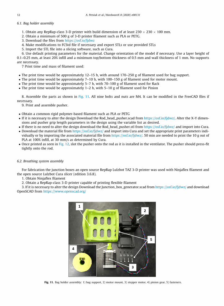
6.1. Bag holder assembly
1. Obtain any RepRap-class 3-D printer with build dimension of at least 230 � 230 � 100 mm.2. Obtain a minimum of 500 g of 3-D printer filament such as PLA or PETG.3. Download the files from https://osf.io/fjdwz4. Make modifications to FCStd file if necessary and export STLs or use provided STLs5. Import the STL file into a slicing software, such as Cura.6. Use default printing parameters for the material. Change orientation of the model if necessary. Use a layer height of
0.1–0.25 mm, at least 20% infill and a minimum top/bottom thickness of 0.5 mm and wall thickness of 1 mm. No supportsare necessary.
7 Print time and mass of filament used:
� The print time would be approximately 12–15 h, with around 170–250 g of filament used for bag support.� The print time would be approximately 7–10 h, with 100–150 g of filament used for motor mount.� The print time would be approximately 5–7 h, with 70–100 g of filament used for Rack� The print time would be approximately 1–2 h, with 5–10 g of filament used for Pinion
8. Assemble the parts as shown in Fig. 11. All nine bolts and nuts are M4. It can be modified in the FreeCAD files ifnecessary.
9. Print and assemble pusher.
� Obtain a common rigid polymer-based filament such as PLA or PETG� If it is necessary to alter the design Download the Rod_head_pusher.scad from https://osf.io/fjdwz/. Alter the X-Y dimen-sions and pusher grip length parameters in the design using the variable list as desired.
� If there is no need to alter the design download the Rod_head_pusher.stl from https://osf.io/fjdwz/ and import into Cura.� Download the material file from https://osf.io/fjdwz/ and import into Cura and set the appropriate print parameters indi-vidually or by importing the associated material file from https://osf.io/fjdwz/. 50 min are needed to print the 10 g out ofPLA at 100% infill, at 30 mm/s as determined by Cura.
� Once printed as seen in Fig. 12, slot the pusher onto the rod as it is installed in the ventilator. The pusher should press-fittightly onto the rod.
6.2. Breathing system assembly
For fabrication the junction boxes an open source RepRap Lulzbot TAZ 3-D printer was used with Ninjaflex filament andthe open source Lulzbot Cura slicer (edition 3.6.8).
1. Obtain Ninjaflex filament2. Obtain a RepRap-class 3-D printer capable of printing flexible filament3. If it is necessary to alter the design Download the Junction_box_generator.scad from https://osf.io/fjdwz/ and download
OpenSCAD from https://www.openscad.org/
Fig. 11. Bag holder assembly: 1) bag support, 2) motor mount, 3) stepper motor, 4) pinion gear, 5) fasteners.
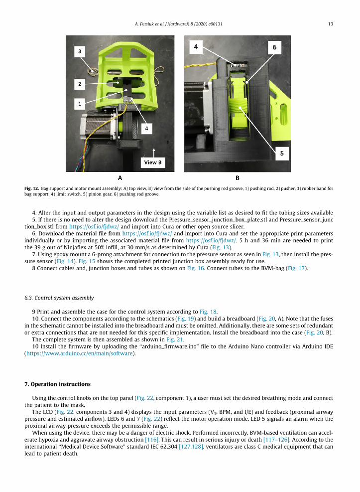
Fig. 12. Bag support and motor mount assembly: A) top view, B) view from the side of the pushing rod groove, 1) pushing rod, 2) pusher, 3) rubber band forbag support, 4) limit switch, 5) pinion gear, 6) pushing rod groove.
A. Petsiuk et al. / HardwareX 8 (2020) e00131 13
4. Alter the input and output parameters in the design using the variable list as desired to fit the tubing sizes available5. If there is no need to alter the design download the Pressure_sensor_junction_box_plate.stl and Pressure_sensor_junc
tion_box.stl from https://osf.io/fjdwz/ and import into Cura or other open source slicer.6. Download the material file from https://osf.io/fjdwz/ and import into Cura and set the appropriate print parameters
individually or by importing the associated material file from https://osf.io/fjdwz/. 5 h and 36 min are needed to printthe 39 g out of Ninjaflex at 50% infill, at 30 mm/s as determined by Cura (Fig. 13).
7. Using epoxy mount a 6-prong attachment for connection to the pressure sensor as seen in Fig. 13, then install the pres-sure sensor (Fig. 14). Fig. 15 shows the completed printed junction box assembly ready for use.
8 Connect cables and, junction boxes and tubes as shown on Fig. 16. Connect tubes to the BVM-bag (Fig. 17).
6.3. Control system assembly
9 Print and assemble the case for the control system according to Fig. 18.10. Connect the components according to the schematics (Fig. 19) and build a breadboard (Fig. 20, A). Note that the fuses
in the schematic cannot be installed into the breadboard and must be omitted. Additionally, there are some sets of redundantor extra connections that are not needed for this specific implementation. Install the breadboard into the case (Fig. 20, B).
The complete system is then assembled as shown in Fig. 21.10 Install the firmware by uploading the ‘‘arduino_firmware.ino” file to the Arduino Nano controller via Arduino IDE
(https://www.arduino.cc/en/main/software).
7. Operation instructions
Using the control knobs on the top panel (Fig. 22, component 1), a user must set the desired breathing mode and connectthe patient to the mask.
The LCD (Fig. 22, components 3 and 4) displays the input parameters (VT, BPM, and I/E) and feedback (proximal airwaypressure and estimated airflow). LEDs 6 and 7 (Fig. 22) reflect the motor operation mode. LED 5 signals an alarm when theproximal airway pressure exceeds the permissible range.
When using the device, there may be a danger of electric shock. Performed incorrectly, BVM-based ventilation can accel-erate hypoxia and aggravate airway obstruction [116]. This can result in serious injury or death [117–126]. According to theinternational ‘‘Medical Device Software” standard IEC 62,304 [127,128], ventilators are class C medical equipment that canlead to patient death.
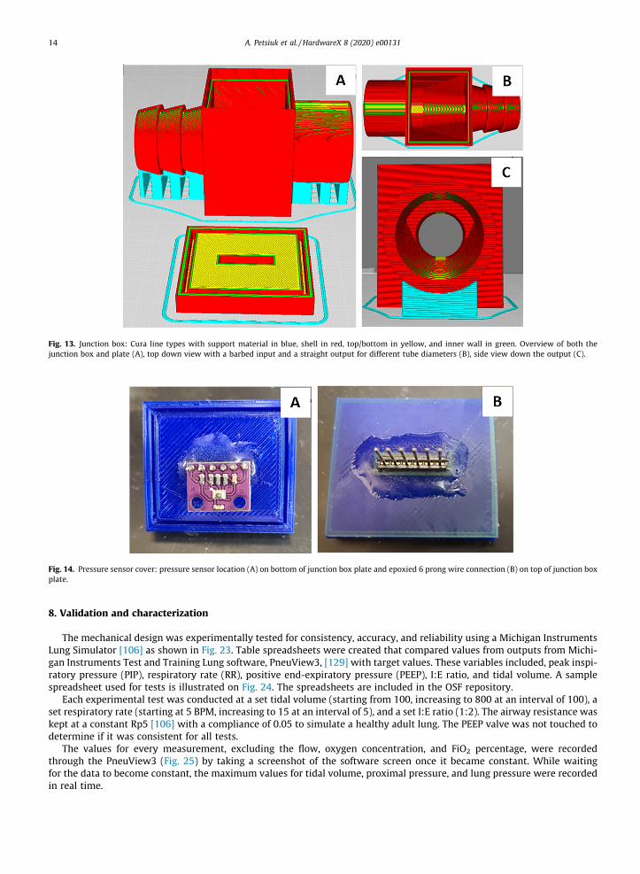
Fig. 13. Junction box: Cura line types with support material in blue, shell in red, top/bottom in yellow, and inner wall in green. Overview of both thejunction box and plate (A), top down view with a barbed input and a straight output for different tube diameters (B), side view down the output (C).
Fig. 14. Pressure sensor cover: pressure sensor location (A) on bottom of junction box plate and epoxied 6 prong wire connection (B) on top of junction boxplate.
14 A. Petsiuk et al. / HardwareX 8 (2020) e00131
8. Validation and characterization
The mechanical design was experimentally tested for consistency, accuracy, and reliability using a Michigan InstrumentsLung Simulator [106] as shown in Fig. 23. Table spreadsheets were created that compared values from outputs from Michi-gan Instruments Test and Training Lung software, PneuView3, [129] with target values. These variables included, peak inspi-ratory pressure (PIP), respiratory rate (RR), positive end-expiratory pressure (PEEP), I:E ratio, and tidal volume. A samplespreadsheet used for tests is illustrated on Fig. 24. The spreadsheets are included in the OSF repository.
Each experimental test was conducted at a set tidal volume (starting from 100, increasing to 800 at an interval of 100), aset respiratory rate (starting at 5 BPM, increasing to 15 at an interval of 5), and a set I:E ratio (1:2). The airway resistance waskept at a constant Rp5 [106] with a compliance of 0.05 to simulate a healthy adult lung. The PEEP valve was not touched todetermine if it was consistent for all tests.
The values for every measurement, excluding the flow, oxygen concentration, and FiO2 percentage, were recordedthrough the PneuView3 (Fig. 25) by taking a screenshot of the software screen once it became constant. While waitingfor the data to become constant, the maximum values for tidal volume, proximal pressure, and lung pressure were recordedin real time.
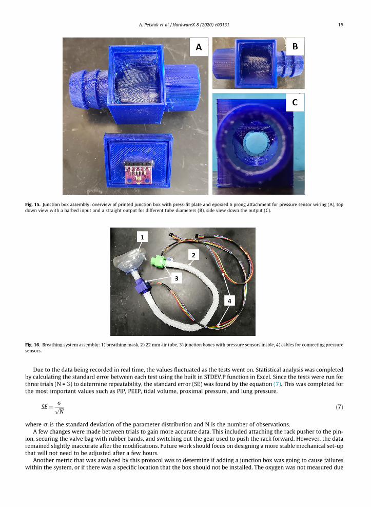
Fig. 15. Junction box assembly: overview of printed junction box with press-fit plate and epoxied 6 prong attachment for pressure sensor wiring (A), topdown view with a barbed input and a straight output for different tube diameters (B), side view down the output (C).
Fig. 16. Breathing system assembly: 1) breathing mask, 2) 22 mm air tube, 3) junction boxes with pressure sensors inside, 4) cables for connecting pressuresensors.
A. Petsiuk et al. / HardwareX 8 (2020) e00131 15
Due to the data being recorded in real time, the values fluctuated as the tests went on. Statistical analysis was completedby calculating the standard error between each test using the built in STDEV.P function in Excel. Since the tests were run forthree trials (N = 3) to determine repeatability, the standard error (SE) was found by the equation (7). This was completed forthe most important values such as PIP, PEEP, tidal volume, proximal pressure, and lung pressure.
SE ¼ rffiffiffiffiN
p ð7Þ
where r is the standard deviation of the parameter distribution and N is the number of observations.A few changes were made between trials to gain more accurate data. This included attaching the rack pusher to the pin-
ion, securing the valve bag with rubber bands, and switching out the gear used to push the rack forward. However, the dataremained slightly inaccurate after the modifications. Future work should focus on designing a more stable mechanical set-upthat will not need to be adjusted after a few hours.
Another metric that was analyzed by this protocol was to determine if adding a junction box was going to cause failureswithin the system, or if there was a specific location that the box should not be installed. The oxygen was not measured due
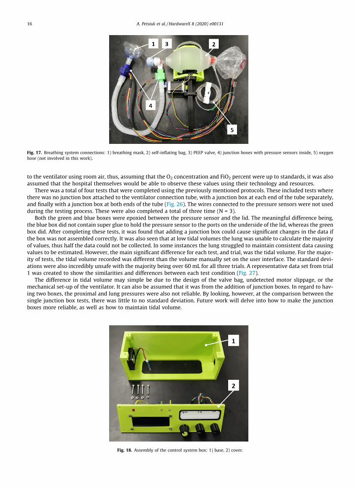
Fig. 17. Breathing system connections: 1) breathing mask, 2) self-inflating bag, 3) PEEP valve, 4) junction boxes with pressure sensors inside, 5) oxygenhose (not involved in this work).
16 A. Petsiuk et al. / HardwareX 8 (2020) e00131
to the ventilator using room air, thus, assuming that the O2 concentration and FiO2 percent were up to standards, it was alsoassumed that the hospital themselves would be able to observe these values using their technology and resources.
There was a total of four tests that were completed using the previously mentioned protocols. These included tests wherethere was no junction box attached to the ventilator connection tube, with a junction box at each end of the tube separately,and finally with a junction box at both ends of the tube (Fig. 26). The wires connected to the pressure sensors were not usedduring the testing process. These were also completed a total of three time (N = 3).
Both the green and blue boxes were epoxied between the pressure sensor and the lid. The meaningful difference being,the blue box did not contain super glue to hold the pressure sensor to the ports on the underside of the lid, whereas the greenbox did. After completing these tests, it was found that adding a junction box could cause significant changes in the data ifthe box was not assembled correctly. It was also seen that at low tidal volumes the lung was unable to calculate the majorityof values, thus half the data could not be collected. In some instances the lung struggled to maintain consistent data causingvalues to be estimated. However, the main significant difference for each test, and trial, was the tidal volume. For the major-ity of tests, the tidal volume recorded was different than the volume manually set on the user interface. The standard devi-ations were also incredibly unsafe with the majority being over 60 mL for all three trials. A representative data set from trial1 was created to show the similarities and differences between each test condition (Fig. 27).
The difference in tidal volume may simple be due to the design of the valve bag, undetected motor slippage, or themechanical set-up of the ventilator. It can also be assumed that it was from the addition of junction boxes. In regard to hav-ing two boxes, the proximal and lung pressures were also not reliable. By looking, however, at the comparison between thesingle junction box tests, there was little to no standard deviation. Future work will delve into how to make the junctionboxes more reliable, as well as how to maintain tidal volume.
Fig. 18. Assembly of the control system box: 1) base, 2) cover.
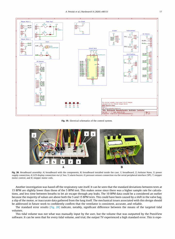
Fig. 19. Electrical schematics of the control system.
Fig. 20. Breadboard assembly: A) breadboard with the components, B) breadboard installed inside the case, 1) breadboard, 2) Arduino Nano, 3) powersupply connection, 4) LCD display connection via I2C bus, 5) alarm buzzer, 6) pressure sensors connection via the serial peripheral interface (SPI), 7) steppermotor control, and 8) stepper motor coils.
A. Petsiuk et al. / HardwareX 8 (2020) e00131 17
Another investigation was based off the respiratory rate itself. It can be seen that the standard deviations between tests at15 BPM are slightly lower than those of the 5 BPM test. This makes sense since there was a higher sample rate for calcula-tions, and less time between breaths to let air escape through any leaks. The 10 BPM data could be a considered an outlierbecause the majority of values are above both the 5 and 15 BPM tests. This could have been caused by a shift in the valve bag,a slip of the motor, or inaccurate data gathered from the lung itself. The mechanical issues associated with this design shouldbe addressed in future work to confidently confirm that the ventilator is consistent, accurate, and reliable.
The standard error results (Fig. 28) indicate, notably, significant difference between the means of the targeted tidalvolumes.
This tidal volume was not what was manually input by the user, but the volume that was outputted by the PneuViewsoftware. It can be seen that for every tidal volume, and trial, the output TV experienced a high standard error. This is espe-
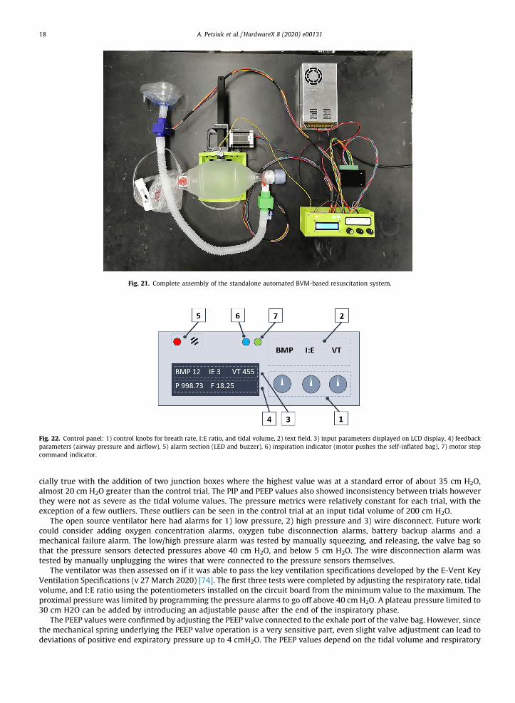
Fig. 21. Complete assembly of the standalone automated BVM-based resuscitation system.
Fig. 22. Control panel: 1) control knobs for breath rate, I:E ratio, and tidal volume, 2) text field, 3) input parameters displayed on LCD display, 4) feedbackparameters (airway pressure and airflow), 5) alarm section (LED and buzzer), 6) inspiration indicator (motor pushes the self-inflated bag), 7) motor stepcommand indicator.
18 A. Petsiuk et al. / HardwareX 8 (2020) e00131
cially true with the addition of two junction boxes where the highest value was at a standard error of about 35 cm H2O,almost 20 cm H2O greater than the control trial. The PIP and PEEP values also showed inconsistency between trials howeverthey were not as severe as the tidal volume values. The pressure metrics were relatively constant for each trial, with theexception of a few outliers. These outliers can be seen in the control trial at an input tidal volume of 200 cm H2O.
The open source ventilator here had alarms for 1) low pressure, 2) high pressure and 3) wire disconnect. Future workcould consider adding oxygen concentration alarms, oxygen tube disconnection alarms, battery backup alarms and amechanical failure alarm. The low/high pressure alarm was tested by manually squeezing, and releasing, the valve bag sothat the pressure sensors detected pressures above 40 cm H2O, and below 5 cm H2O. The wire disconnection alarm wastested by manually unplugging the wires that were connected to the pressure sensors themselves.
The ventilator was then assessed on if it was able to pass the key ventilation specifications developed by the E-Vent KeyVentilation Specifications (v 27 March 2020) [74]. The first three tests were completed by adjusting the respiratory rate, tidalvolume, and I:E ratio using the potentiometers installed on the circuit board from the minimum value to the maximum. Theproximal pressure was limited by programming the pressure alarms to go off above 40 cm H2O. A plateau pressure limited to30 cm H2O can be added by introducing an adjustable pause after the end of the inspiratory phase.
The PEEP values were confirmed by adjusting the PEEP valve connected to the exhale port of the valve bag. However, sincethe mechanical spring underlying the PEEP valve operation is a very sensitive part, even slight valve adjustment can lead todeviations of positive end expiratory pressure up to 4 cmH2O. The PEEP values depend on the tidal volume and respiratory
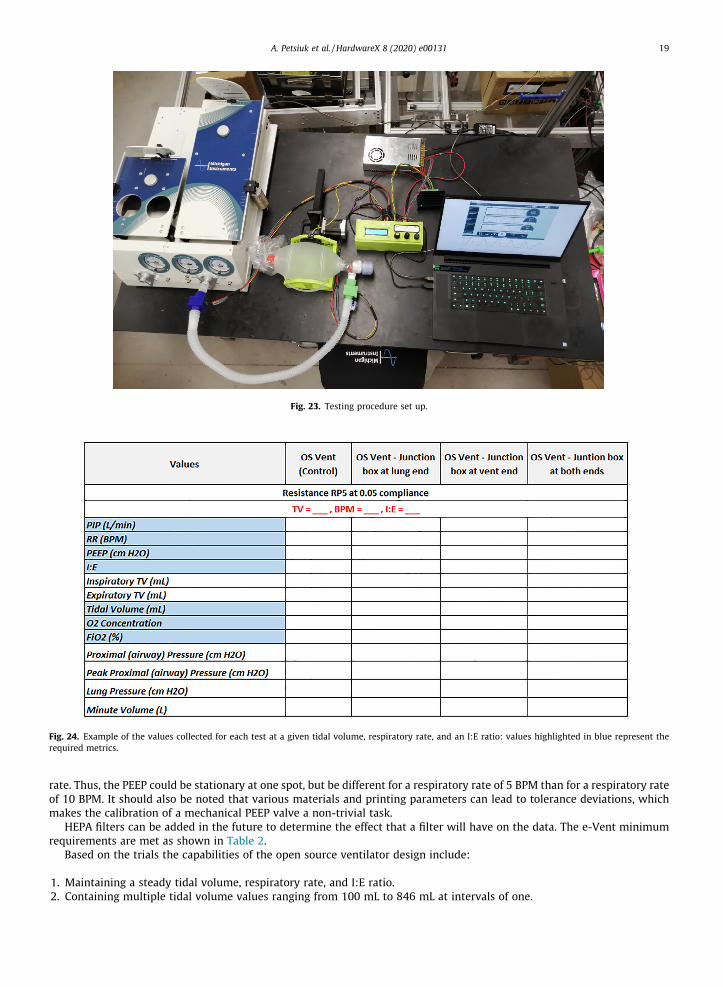
Fig. 23. Testing procedure set up.
Fig. 24. Example of the values collected for each test at a given tidal volume, respiratory rate, and an I:E ratio: values highlighted in blue represent therequired metrics.
A. Petsiuk et al. / HardwareX 8 (2020) e00131 19
rate. Thus, the PEEP could be stationary at one spot, but be different for a respiratory rate of 5 BPM than for a respiratory rateof 10 BPM. It should also be noted that various materials and printing parameters can lead to tolerance deviations, whichmakes the calibration of a mechanical PEEP valve a non-trivial task.
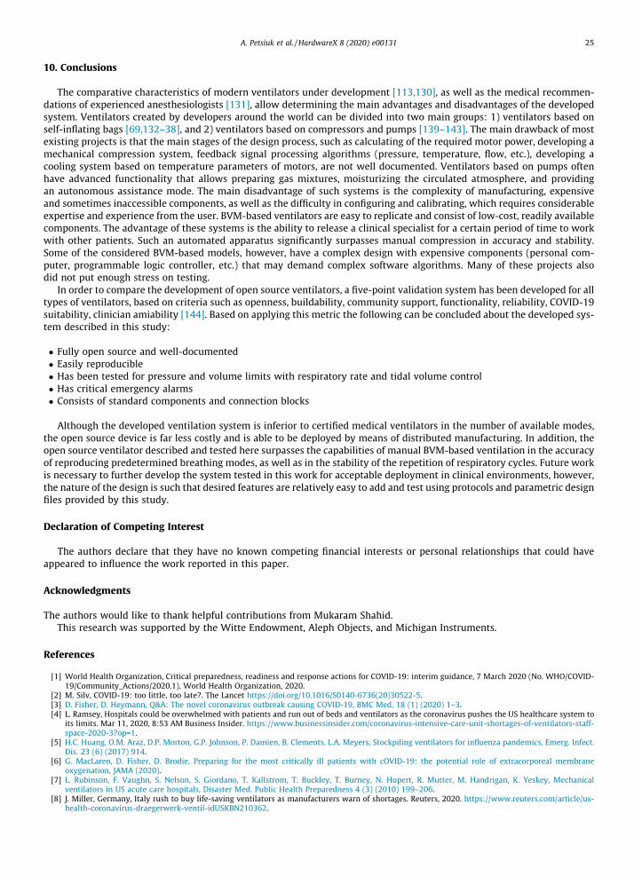
HEPA filters can be added in the future to determine the effect that a filter will have on the data. The e-Vent minimumrequirements are met as shown in Table 2.
Based on the trials the capabilities of the open source ventilator design include:
1. Maintaining a steady tidal volume, respiratory rate, and I:E ratio.2. Containing multiple tidal volume values ranging from 100 mL to 846 mL at intervals of one.
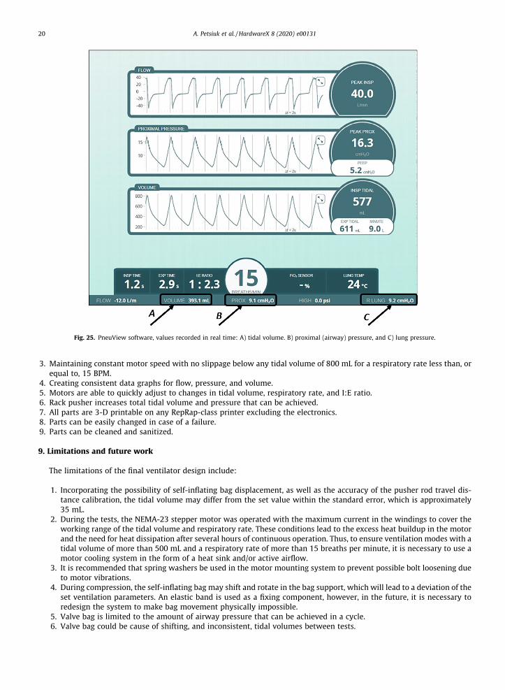
Fig. 25. PneuView software, values recorded in real time: A) tidal volume. B) proximal (airway) pressure, and C) lung pressure.
20 A. Petsiuk et al. / HardwareX 8 (2020) e00131
3. Maintaining constant motor speed with no slippage below any tidal volume of 800 mL for a respiratory rate less than, orequal to, 15 BPM.
4. Creating consistent data graphs for flow, pressure, and volume.5. Motors are able to quickly adjust to changes in tidal volume, respiratory rate, and I:E ratio.6. Rack pusher increases total tidal volume and pressure that can be achieved.7. All parts are 3-D printable on any RepRap-class printer excluding the electronics.8. Parts can be easily changed in case of a failure.9. Parts can be cleaned and sanitized.
9. Limitations and future work
The limitations of the final ventilator design include:
1. Incorporating the possibility of self-inflating bag displacement, as well as the accuracy of the pusher rod travel dis-tance calibration, the tidal volume may differ from the set value within the standard error, which is approximately35 mL.
2. During the tests, the NEMA-23 stepper motor was operated with the maximum current in the windings to cover theworking range of the tidal volume and respiratory rate. These conditions lead to the excess heat buildup in the motorand the need for heat dissipation after several hours of continuous operation. Thus, to ensure ventilation modes with atidal volume of more than 500 mL and a respiratory rate of more than 15 breaths per minute, it is necessary to use amotor cooling system in the form of a heat sink and/or active airflow.
3. It is recommended that spring washers be used in the motor mounting system to prevent possible bolt loosening dueto motor vibrations.
4. During compression, the self-inflating bag may shift and rotate in the bag support, which will lead to a deviation of theset ventilation parameters. An elastic band is used as a fixing component, however, in the future, it is necessary toredesign the system to make bag movement physically impossible.
5. Valve bag is limited to the amount of airway pressure that can be achieved in a cycle.6. Valve bag could be cause of shifting, and inconsistent, tidal volumes between tests.
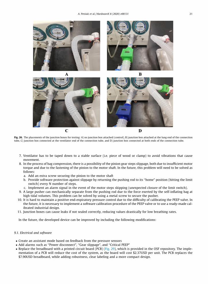
Fig. 26. The placements of the junction boxes for testing: A) no junction box attached (control), B) junction box attached at the lung end of the connectiontube, C) junction box connected at the ventilator end of the connection tube, and D) junction box connected at both ends of the connection tube.
A. Petsiuk et al. / HardwareX 8 (2020) e00131 21
7. Ventilator has to be taped down to a stable surface (i.e. piece of wood or clamp) to avoid vibrations that causemovement.
8. In the process of bag compression, there is a possibility of the pinion gear steps slippage, both due to insufficient motortorque and due to the fastening of the pinion to the motor shaft. In the future, this problem will need to be solved asfollows:a. Add an extra screw securing the pinion to the motor shaftb. Provide software protection against slippage by returning the pushing rod to its ‘‘home” position (hitting the limit
switch) every N number of steps.c. Implement an alarm signal in the event of the motor steps skipping (unexpected closure of the limit switch).
9. A large pusher can mechanically separate from the pushing rod due to the force exerted by the self-inflating bag athigh tidal volumes. This problem can be solved by using a metal screw to secure the pusher.
10. It is hard to maintain a positive end-expiratory pressure control due to the difficulty of calibrating the PEEP valve. Inthe future, it is necessary to implement a software calibration procedure of the PEEP valve or to use a ready-made cal-ibrated industrial design.
11. Junction boxes can cause leaks if not sealed correctly, reducing values drastically for low breathing rates.
In the future, the developed device can be improved by including the following modifications:
9.1. Electrical and software
� Create an assistant mode based on feedback from the pressure sensors� Add alarms such as ‘‘Power disconnect”, ‘‘Gear slippage”, and ‘‘Critical PEEP”� Replace the breadboard with a printed circuit board (PCB) (Fig. 29), which is provided in the OSF repository. The imple-mentation of a PCB will reduce the cost of the system, as the board will cost $2.37USD per unit. The PCB replaces the$7.90USD breadboard, while adding robustness, clear labeling and a more compact design.
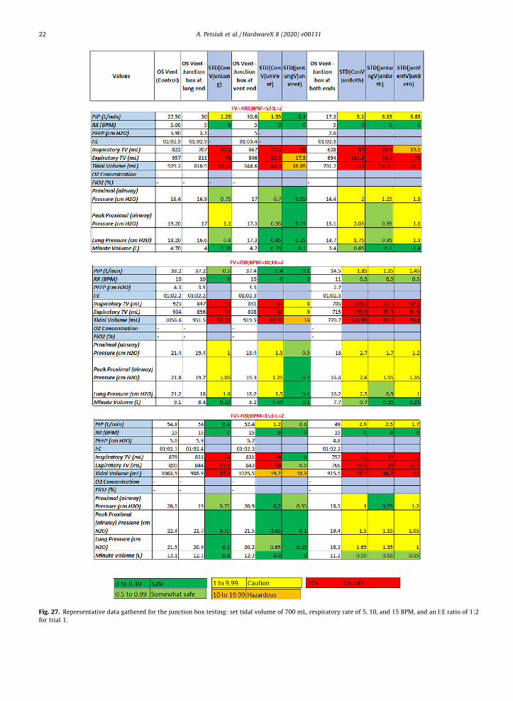
Fig. 27. Representative data gathered for the junction box testing: set tidal volume of 700 mL, respiratory rate of 5, 10, and 15 BPM, and an I:E ratio of 1:2for trial 1.
22 A. Petsiuk et al. / HardwareX 8 (2020) e00131
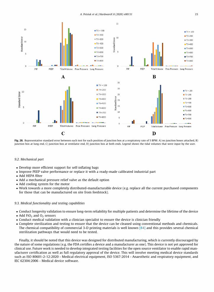
Fig. 28. Representative standard error between each test for each position of junction box at a respiratory rate of 5 BPM: A) no junction boxes attached, B)junction box at lung end, C) junction box at ventilator end, D) junction box at both ends. Legend shows the tidal volumes that were input by the user.
A. Petsiuk et al. / HardwareX 8 (2020) e00131 23
9.2. Mechanical part
� Develop more efficient support for self-inflating bags� Improve PEEP valve performance or replace it with a ready-made calibrated industrial part� Add HEPA filter� Add a mechanical pressure relief valve as the default option� Add cooling system for the motor� Work towards a more completely distributed-manufacturable device (e.g. replace all the current purchased componentsfor those that can be manufactured on site from feedstock).
9.3. Medical functionality and testing capabilities
� Conduct longevity validation to ensure long-term reliability for multiple patients and determine the lifetime of the device� Add FiO2 and O2 sensors� Conduct medical validation with a clinician specialist to ensure the device is clinician friendly� Complete sterilization and testing to ensure that the device can be cleaned using conventional methods and chemicals.The chemical compatibility of commercial 3-D printing materials is well known [84] and this provides several chemicalsterilization pathways that would need to be tested.
Finally, it should be noted that this device was designed for distributed manufacturing, which is currently discouraged bythe nature of some regulations (e.g. the FDA certifies a device and a manufacturer as one). This device is not yet approved forclinical use. Future work is needed to develop integrated testing facilities for the open source ventilator to enable rapid man-ufacturer certification as well as full regulatory approval of the device. This will involve meeting medical device standardssuch as ISO 80601-2-12:2020 - Medical electrical equipment, ISO 5367:2014 - Anaesthetic and respiratory equipment, andIEC 62304:2006 - Medical device software.
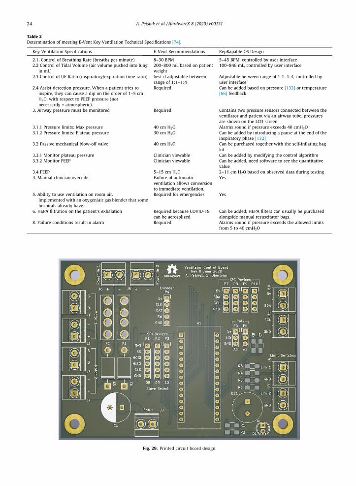
Table 2Determination of meeting E-Vent Key Ventilation Technical Specifications [74].
Key Ventilation Specifications E-Vent Recommendations RepRapable OS Design
2.1. Control of Breathing Rate (breaths per minute) 8–30 BPM 5–45 BPM, controlled by user interface2.2 Control of Tidal Volume (air volume pushed into lung
in mL)200–800 mL based on patientweight
100–846 mL, controlled by user interface
2.3 Control of I/E Ratio (inspiratory/expiration time ratio) best if adjustable betweenrange of 1:1–1:4
Adjustable between range of 1:1–1:4, controlled byuser interface
2.4 Assist detection pressure. When a patient tries toinspire, they can cause a dip on the order of 1–5 cmH2O, with respect to PEEP pressure (notnecessarily = atmospheric).
Required Can be added based on pressure [132] or temperature[66] feedback
3. Airway pressure must be monitored Required Contains two pressure sensors connected between theventilator and patient via an airway tube, pressuresare shown on the LCD screen
3.1.1 Pressure limits: Max pressure 40 cm H2O Alarms sound if pressure exceeds 40 cmH2O3.1.2 Pressure limits: Plateau pressure 30 cm H2O Can be added by introducing a pause at the end of the
inspiratory phase [132]3.2 Passive mechanical blow-off valve 40 cm H2O Can be purchased together with the self-inflating bag
kit3.3.1 Monitor plateau pressure Clinician viewable Can be added by modifying the control algorithm3.3.2 Monitor PEEP Clinician viewable Can be added, need software to see the quantitative
value3.4 PEEP 5–15 cm H2O 2–11 cm H2O based on observed data during testing4. Manual clinician override Failure of automatic
ventilation allows conversionto immediate ventilation.
Yes
5. Ability to use ventilation on room air.Implemented with an oxygen/air gas blender that somehospitals already have.
Required for emergencies Yes
6. HEPA filtration on the patient’s exhalation Required because COVID-19can be aerosolized
Can be added, HEPA filters can usually be purchasedalongside manual resuscitator bags.
8. Failure conditions result in alarm Required Alarms sound if pressure exceeds the allowed limitsfrom 5 to 40 cmH2O
Fig. 29. Printed circuit board design.
24 A. Petsiuk et al. / HardwareX 8 (2020) e00131
A. Petsiuk et al. / HardwareX 8 (2020) e00131 25
10. Conclusions
The comparative characteristics of modern ventilators under development [113,130], as well as the medical recommen-dations of experienced anesthesiologists [131], allow determining the main advantages and disadvantages of the developedsystem. Ventilators created by developers around the world can be divided into two main groups: 1) ventilators based onself-inflating bags [69,132–38], and 2) ventilators based on compressors and pumps [139–143]. The main drawback of mostexisting projects is that the main stages of the design process, such as calculating of the required motor power, developing amechanical compression system, feedback signal processing algorithms (pressure, temperature, flow, etc.), developing acooling system based on temperature parameters of motors, are not well documented. Ventilators based on pumps oftenhave advanced functionality that allows preparing gas mixtures, moisturizing the circulated atmosphere, and providingan autonomous assistance mode. The main disadvantage of such systems is the complexity of manufacturing, expensiveand sometimes inaccessible components, as well as the difficulty in configuring and calibrating, which requires considerableexpertise and experience from the user. BVM-based ventilators are easy to replicate and consist of low-cost, readily availablecomponents. The advantage of these systems is the ability to release a clinical specialist for a certain period of time to workwith other patients. Such an automated apparatus significantly surpasses manual compression in accuracy and stability.Some of the considered BVM-based models, however, have a complex design with expensive components (personal com-puter, programmable logic controller, etc.) that may demand complex software algorithms. Many of these projects alsodid not put enough stress on testing.
In order to compare the development of open source ventilators, a five-point validation system has been developed for alltypes of ventilators, based on criteria such as openness, buildability, community support, functionality, reliability, COVID-19suitability, clinician amiability [144]. Based on applying this metric the following can be concluded about the developed sys-tem described in this study:
� Fully open source and well-documented� Easily reproducible� Has been tested for pressure and volume limits with respiratory rate and tidal volume control� Has critical emergency alarms� Consists of standard components and connection blocks
Although the developed ventilation system is inferior to certified medical ventilators in the number of available modes,the open source device is far less costly and is able to be deployed by means of distributed manufacturing. In addition, theopen source ventilator described and tested here surpasses the capabilities of manual BVM-based ventilation in the accuracyof reproducing predetermined breathing modes, as well as in the stability of the repetition of respiratory cycles. Future workis necessary to further develop the system tested in this work for acceptable deployment in clinical environments, however,the nature of the design is such that desired features are relatively easy to add and test using protocols and parametric designfiles provided by this study.
Declaration of Competing Interest
The authors declare that they have no known competing financial interests or personal relationships that could haveappeared to influence the work reported in this paper.
Acknowledgments
The authors would like to thank helpful contributions from Mukaram Shahid.This research was supported by the Witte Endowment, Aleph Objects, and Michigan Instruments.
References
[1] World Health Organization, Critical preparedness, readiness and response actions for COVID-19: interim guidance, 7 March 2020 (No. WHO/COVID-19/Community_Actions/2020.1). World Health Organization, 2020.
[2] M. Silv, COVID-19: too little, too late?. The Lancet https://doi.org/10.1016/S0140-6736(20)30522-5.[3] D. Fisher, D. Heymann, Q&A: The novel coronavirus outbreak causing COVID-19, BMC Med. 18 (1) (2020) 1–3.[4] L. Ramsey, Hospitals could be overwhelmed with patients and run out of beds and ventilators as the coronavirus pushes the US healthcare system to
its limits. Mar 11, 2020, 8:53 AM Business Insider. https://www.businessinsider.com/coronavirus-intensive-care-unit-shortages-of-ventilators-staff-space-2020-3?op=1.
[5] H.C. Huang, O.M. Araz, D.P. Morton, G.P. Johnson, P. Damien, B. Clements, L.A. Meyers, Stockpiling ventilators for influenza pandemics, Emerg. Infect.Dis. 23 (6) (2017) 914.
[6] G. MacLaren, D. Fisher, D. Brodie, Preparing for the most critically ill patients with cOVID-19: the potential role of extracorporeal membraneoxygenation, JAMA (2020).
[7] L. Rubinson, F. Vaughn, S. Nelson, S. Giordano, T. Kallstrom, T. Buckley, T. Burney, N. Hupert, R. Mutter, M. Handrigan, K. Yeskey, Mechanicalventilators in US acute care hospitals, Disaster Med. Public Health Preparedness 4 (3) (2010) 199–206.
[8] J. Miller, Germany, Italy rush to buy life-saving ventilators as manufacturers warn of shortages. Reuters, 2020. https://www.reuters.com/article/us-health-coronavirus-draegerwerk-ventil-idUSKBN210362.
26 A. Petsiuk et al. / HardwareX 8 (2020) e00131
[9] P. Neighmond, As The Pandemic Spreads, Will There Be Enough Ventilators?,” 2020. NPR. https://www.npr.org/sections/health-shots/2020/03/14/815675678/as-the-pandemic-spreads-will-there-be-enough-ventilators.
[10] J. Lagasse, COVID-19: Ventilators are in short supply, but so are medications for ventilator patients [Internet]. Healthcare Finance News. [cited 2020Jun 4]. Available from: https://www.healthcarefinancenews.com/news/covid-19-ventilators-are-short-supply-so-are-medications-ventilator-patients.
[11] P. Smetanin, D. Stiff, A. Kumar, P. Kobak, R. Zarychanski, N. Simonsen, F. Plummer, Potential intensive care unit ventilator demand/capacity mismatchdue to novel swine-origin H1N1 in Canada, Can. J. Infect. Dis. Med. Microbiol. 20 (4) (2009) e115–e123.
[12] A. Ercole, B.L. Taylor, A. Rhodes, D.K. Menon, Modelling the impact of an influenza A/H1N1 pandemic on critical care demand from early pathogenicitydata: the case for sentinel reporting, Anaesthesia 64 (9) (2009) 937–941.
[13] D. Stiff, A. Kumar, N. Kissoon, R. Fowler, P. Jouvet, P. Skippen, P. Smetanin, M. Kesselman, S. Veroukis, Potential pediatric intensive care unitdemand/capacity mismatch due to novel pH1N1 in Canada, Pediatr. Crit. Care Med. 12 (2) (2011) e51–e57.
[14] K.M. Kim, S. Cinti, S. Gay, S. Goold, A. Barnosky, M. Lozon, Triage of mechanical ventilation for pediatric patients during a pandemic, Disaster Med.Public Health Preparedness 6 (2) (2012) 131–137.
[15] R.K. Kanter, Would triage predictors perform better than first-come, first-served in pandemic ventilator allocation?, Chest 147 (1) (2015) 102–108.[16] E.M. Malatino, Strategic national stockpile: overview and ventilator assets, Respir. Care 53 (1) (2008) 91–95.[17] M.I. Meltzer, A. Patel, A. Ajao, S.V. Nystrom, L.M. Koonin, Estimates of the demand for mechanical ventilation in the United States during an influenza
pandemic, Clin. Infect. Dis. 60 (suppl_1) (2015) S52–S57.[18] L. Crowder, Ventilator blues: infectious disease expert Tom Inglesby on the next major pandemic, Bull. Atom. Sci. 74 (5) (2018) 340–347.[19] K. Folmer, ’We’ll take them all’: Demand for ventilators spikes as coronavirus looms. ABC News March 14, 2020 https://abcnews.go.com/Health/
demand-ventilators-spikes-coronavirus-looms/story?id=69597233.[20] M. Heal, Ventilators for coronavirus patients are in short supply. How scientists might pivot [Internet]. Los Angeles Times. 2020 [cited 2020 Jun 4].
Available from: https://www.latimes.com/science/story/2020-04-07/researchers-look-for-ways-to-divert-patients-from-ventilators-as-shortage-looms.
[21] B.T. Wittbrodt, A.G. Glover, J. Laureto, G.C. Anzalone, D. Oppliger, J.L. Irwin, J.M. Pearce, Life-cycle economic analysis of distributed manufacturing withopen-source 3-D printers, Mechatronics 23 (6) (2013) 713–726.
[22] J.S. Srai, M. Kumar, G. Graham, W. Phillips, J. Tooze, S. Ford, P. Beecher, B. Raj, M. Gregory, M.K. Tiwari, B. Ravi, Distributed manufacturing: scope,challenges and opportunities, Int. J. Prod. Res. 54 (23) (2016) 6917–6935.
[23] H. Chesbrough, To recover faster from Covid-19, open up: managerial implications from an open innovation perspective, Ind. Market. Manage. (2020Apr 16).
[24] B.K. Lai, J.L. Erian, S.H. Pew, M.S. Eckmann, Emergency open-source three-dimensional printable ventilator circuit splitter and flow regulator duringthe COVID-19 pandemic, Anesthesiol.: J. Am. Soc. of Anesthesiol. (2020 Apr 13).
[25] L. Cavallo, A. Marcianò, M. Cicciù, G. Oteri, 3D printing beyond dentistry during COVID 19 epidemic: A technical note for producing connectors tobreathing devices, Prosthesis 2 (2) (2020 Jun) 46–52.
[26] M. Salmi, J.S. Akmal, E. Pei, J. Wolff, A. Jaribion, S.H. Khajavi, 3D Printing in COVID-19: productivity estimation of the most promising open sourcesolutions in emergency situations, Appl. Sci. 10 (11) (2020 Jan) 4004.
[27] J.M. Pearce, Distributed manufacturing of open source medical hardware for pandemics, J. Manuf. Mater. Process. 4 (2) (2020 Jun) 49.[28] A. Maia Chagas, J.C. Molloy, L.L. Prieto-Godino, T. Baden, Leveraging open hardware to alleviate the burden of COVID-19 on global health systems, Plos
Biol. 18 (4) (2020) e3000730.[29] M. Attaran, 3D printing role in filling the critical gap in the medical supply chain during COVID-19 pandemic, Am. J. Ind. Bus. Manage. 10 (05) (2020
May 26) 988.[30] C. Baechler, M. DeVuono, J.M. Pearce, Distributed recycling of waste polymer into RepRap feedstock, Rapid Prototyping J. 19 (2) (2013) 118–125.[31] F.A.C. Sanchez, S. Lanza, H. Boudaoud, S. Hoppe, M. Camargo, Polymer recycling and additive manufacturing in an open source context: optimization
of processes and methods, in: Annual International Solid Freeform Fabrication Symposium, ISSF, 2015, pp. 1591–1600.[32] F.A.C. Sanchez, H. Boudaoud, S. Hoppe, M. Camargo, Polymer recycling in an open-source additive manufacturing context: mechanical issues, Addit.
Manuf. 17 (2017) 87–105.[33] M.I. Mohammed, A. Das, E. Gomez-Kervin, D. Wilson, I. Gibson, EcoPrinting: investigating the use of 100% recycled acrylonitrile butadiene styrene
(ABS) for additive manufacturing, in: Proceedings of the 28th Annual International Solid Freeform Fabrication Symposium, 2017, pp. 532–542.[34] M.I. Mohammed, D. Wilson, E. Gomez-Kervin, L. Rosson, J. Long, EcoPrinting: investigation of solar powered plastic recycling and additive
manufacturing for enhanced waste management and sustainable manufacturing, in: 2018 IEEE Conference on Technologies for Sustainability(SusTech), IEEE, 2018, pp. 1–6.
[35] A.L. Woern, D.J. Byard, R.B. Oakley, M.J. Fiedler, S.L. Snabes, J.M. Pearce, Fused particle fabrication 3-D printing: recycled materials’ optimization andmechanical properties, Materials 11 (8) (2018) 1413.
[36] M.I. Mohammed, D. Wilson, E. Gomez-Kervin, B. Tang, J. Wang, Investigation of closed-loop manufacturing with acrylonitrile butadiene styrene overmultiple generations using additive manufacturing, ACS Sustainable Chem. Eng. 7 (16) (2019) 13955–13969.
[37] P. Santander, F.A.C. Sanchez, H. Boudaoud, M. Camargo, Closed loop supply chain network for local and distributed plastic recycling for 3D printing: aMILP-based optimization approach, Resour. Conserv. Recycl. 154 (2020) 104531.
[38] S.C. Dertinger, N. Gallup, N.G. Tanikella, M. Grasso, S. Vahid, P.J. Foot, J.M. Pearce, Technical pathways for distributed recycling of polymer compositesfor distributed manufacturing: Windshield wiper blades, Resour. Conserv. Recycl. 157 (2020) 104810.
[39] E.J. Hunt, C. Zhang, N. Anzalone, J.M. Pearce, Polymer recycling codes for distributed manufacturing with 3-D printers, Resour. Conserv. Recycl. 97(2015) 24–30.
[40] S. Pavlo, C. Fabio, B. Hakim, C. Mauricio, 3D-printing based distributed plastic recycling: a conceptual model for closed-loop supply chain design, in:2018 IEEE International Conference on Engineering, Technology and Innovation (ICE/ITMC), IEEE, 2018, pp. 1–8.
[41] S. Zhong, J.M. Pearce, Tightening the loop on the circular economy: Coupled distributed recycling and manufacturing with recyclebot and RepRap 3-Dprinting, Resour.Conserv. Recycl. 128 (2018) 48–58.
[42] K.F. Daniel, J.G. Peter, Open-source hardware is a low-cost alternative for scientific instrumentation and research, Mod. Instrum. (2012).[43] J.M. Pearce, Building research equipment with free, open-source hardware, Science 337 (6100) (2012) 1303–1304.[44] J.M. Pearce, Open-source lab: how to build your own hardware and reduce research costs, Elsevier, 2013.[45] A.M. Chagas, Haves and have nots must find a better way: The case for open scientific hardware, PLoS Biol. 16 (9) (2018) e3000014.[46] M.D. Dryden, R. Fobel, C. Fobel, A.R. Wheeler, Upon the shoulders of giants: open-source hardware and software in analytical chemistry, Anal. Chem.
89 (8) (2017) 4330–4338.[47] M. Coakley, D.E. Hurt, 3D printing in the laboratory: maximize time and funds with customized and open-source labware, J. Lab. Autom. 21 (4) (2016)
489–495.[48] J.M. Pearce, Quantifying the value of open source hardware development, Mod. Econ. 6 (2015) 1–11.[49] J.M. Pearce, Return on investment for open source scientific hardware development, Sci. Public Pol. 43 (2) (2016) 192–195.[50] I.T.S. Heikkinen, H. Savin, J. Partanen, J. Seppälä, J.M. Pearce, Towards national policy for open source hardware research: the case of Finland, Technol.
Forecasting Social Change 155 (2020) 119986.[51] J. Pearce, Impacts of open source hardware in science and engineering, Bridge (2017) 24–31.[52] S. Oberloier, J.M. Pearce, General design procedure for free and open-source hardware for scientific equipment, Designs 2 (1) (2018) 2.[53] C.L. Ventola, Medical applications for 3D printing: current and projected uses, Pharm. Ther. 39 (10) (2014) 704.
A. Petsiuk et al. / HardwareX 8 (2020) e00131 27
[54] G. Niezen, P. Eslambolchilar, H. Thimbleby, Open-source hardware for medical devices, BMJ Innov. 2 (2) (2016) 78–83.[55] R.E. Michaels, J.M. Pearce, 3-D printing open-source click-MUAC bands for identification of malnutrition, Public Health Nutr. 20 (11) (2017) 2063–
2066.[56] J.M. Pearce, Maximizing returns for public funding of medical research with opensource hardware, Health Policy Technol. 6 (4) (2017) 381–382.[57] P. Tatham, J. Loy, U. Peretti, Three dimensional printing–a key tool for the humanitarian logistician?, J. Humanitarian Logist. Supply Chain Manage.
(2015).[58] S. Saripalle, H. Maker, A. Bush, N. Lundman, 3D printing for disaster preparedness: Making life-saving supplies on-site, on-demand, on-time, in: 2016
IEEE Global Humanitarian Technology Conference (GHTC), IEEE, 2016, pp. 205–208.[59] E. James, L. James, 3D printing humanitarian supplies in the field, Humanit. Exch. 66 (2016) 43–45.[60] B.L. Savonen, T.J. Mahan, M.W. Curtis, J.W. Schreier, J.K. Gershenson, J.M. Pearce, Development of a resilient 3-D printer for humanitarian crisis
response, Technologies 6 (1) (2018) 30.[61] D. Kats, L. Spicher, B. Savonen, J. Gershenson, Paper 3D Printing to supplement rural healthcare supplies—What do healthcare facilities want?. In 2018
IEEE Global Humanitarian Technology Conference (GHTC), IEEE, 2018, pp. 1–8.[62] C.W. Kerechanin, P.N. Cytcgusm, J.A. Vincent, D.G. Smith, D.S. Wenstrand, Development of field portable ventilator systems for domestic and military
emergency medical response, John Hopkins Apl. Tech. Digest 25 (3) (2004).[63] H. Jürß, M. Degner, H. Ewald, A new compact and low-cost respirator concept for one way usage, IFAC-PapersOnLine 51 (27) (2018) 367–372.[64] P. Fuchs, J. Obermeier, S. Kamysek, M. Degner, H. Nierath, H. Jürß, H. Ewald, J. Schwarz, M. Becker, J.K. Schubert, Safety and applicability of a pre-stage
public access ventilator for trained laypersons: a proof of principle study, BMC Emerg. Med. 17 (1) (2017) 37.[65] M. Fogarty, J. Orr, D. Westenskow, L. Brewer, D. Sakata, Electric Blower Based Portable Emergency Ventilator, 2013. https://digitalcommons.usu.edu/
cgi/viewcontent.cgi?referer=https://www.google.com/&httpsredir=1&article=1016&context=spacegrant&fbclid=IwAR1EtJVcxXm82PjGWFCA0t7H_MxNVjuseAePRfxNORr9h4ZQLQ9sNdQjXhc.
[66] M. Shahid, Prototyping of Artificial Respiration Machine Using AMBU Bag Compression. In 2019 International Conference on Electronics, Information,and Communication (ICEIC), IEEE, 2019, pp. 1–6.
[67] A.M. Al Husseini, H.J. Lee, J. Negrete, S. Powelson, A.T. Servi, A.H. Slocum, J. Saukkonen, Design and prototyping of a low-cost portable mechanicalventilator, Trans. ASME-W-J. Med. Dev. 4 (2) (2010) 027514.
[68] S.K. Powelson, Design and prototyping of a low-cost portable mechanical ventilator (Doctoral dissertation, Massachusetts Institute of Technology),2010. https://dspace.mit.edu/handle/1721.1/59954.
[69] D. Williams, S. Flory, R. King, M. Thornton, J. Dingley, A low oxygen consumption pneumatic ventilator for emergency construction during arespiratory failure pandemic, Anaesthesia 65 (3) (2010) 235–242.
[70] B.A. Simon, W. Mitzner, Design and calibration of a high-frequency oscillatory ventilator, IEEE Trans. Biomed. Eng. 38 (2) (1991) 214–218.[71] J.M. Pearce, A review of open source ventilators for COVID-19 and future pandemics. F1000Res. 2020;9:218. https://f1000research.com/articles/9-
218.[72] ISO 80601-2-12:2020. Medical electrical equipment — Part 2-12: Particular requirements for basic safety and essential performance of critical care
ventilators. ISO. https://www.iso.org/standard/72069.html.[73] Medicines & Healthcare Products Regulatory Agency (MHRA), Rapidly Manufactured Ventilator System (RMVS) Document RMVS001 - Specification
Issued by MHRA v 3.1, 2020. https://assets.publishing.service.gov.uk/government/uploads/system/uploads/attachment_data/file/876167/RMVS001_v3.1.pdf
[74] MIT E-Vent. Key Ventilation Specifications. V 27 March 2020. https://e-vent.mit.edu/clinical/key-ventilation-specifications/ (visited 3-28-2020).[75] M. Banzi, M. Shiloh, Getting started with Arduino: the open source electronics prototyping platform. Maker Media, Inc., 2014.[76] A. D’Ausilio, Arduino: a low-cost multipurpose lab equipment, Behav. Res. Methods 44 (2) (2012) 305–313.[77] S. Oberloier, J.M. Pearce, Belt-driven open source circuit mill using low-cost 3-D printer components, Inventions 3 (3) (2018) 64.[78] G.C. Anzalone, B. Wijnen, J.M. Pearce, Multi-material additive and subtractive prosumer digital fabrication with a free and open-source convertible
delta RepRap 3-D printer, Rapid Prototyping J. 21 (5) (2015) 506–519, https://doi.org/10.1108/RPJ-09-2014-0113.[79] N. Sathyakumar, K.P. Balaji, R. Ganapathi, S.R. Pandian, A build-your-own three axis CNC PCB milling machine, Mater. Today: Proc 5 (11) (2018)
24404–24413.[80] R. Jones, P. Haufe, E. Sells, P. Iravani, V. Olliver, C. Palmer, A. Bowyer, RepRap–the replicating rapid prototyper, Robotica 29 (1) (2011) 177–191.[81] E. Sells, S. Bailard, Z. Smith, A. Bowyer, V. Olliver, RepRap: the replicating rapid prototyper: maximizing customizability by breeding the means of
production, in: Handbook of Research in Mass Customization and Personalization, In 2 Volumes, 2010, pp. 568–580.[82] A. Bowyer, 3D printing and humanity’s first imperfect replicator. 3D printing and additive manufacturing 1(1) (2014) 4–5.[83] J.V. Chen, A.B. Dang, C.S. Lee, A.B. Dang, 3D printed PLA Army-Navy retractors when used as linear retractors yield clinically acceptable tolerances, 3D
Printing Med. 5 (1) (2019) 1–9.[84] I.T. Heikkinen, C. Kauppinen, Z. Liu, S.M. Asikainen, S. Spoljaric, J.V. Seppälä, H. Savin, J.M. Pearce, Chemical compatibility of fused filament fabrication-
based 3-D printed components with solutions commonly used in semiconductor wet processing, Addit. Manuf. 23 (2018) 99–107.[85] PANDApeep Gen2 PEEP valve. https://www.thingiverse.com/thing:4250354, 2020 (accessed 06.09.20).[86] Elecia White, Making Embedded Systems: Design Patterns For Great Software. O’Reilly Media; 1st ed., 2011.[87] M.B. Weinger, M.E. Wiklund, D.J. Gardner-Bonneau (Eds.), Handbook of Human Factors in Medical Device Design, 1st ed., CRC Press, 2010.[88] Gavriel Salvendy (Ed.), Handbook of Human Factors and Ergonomics, 4th ed., Wiley , 2012.[89] J.D. Bronzino (Ed.), Medical Devices and Systems, 1st ed., CRC Press, 2006.[90] A.D. Lantada (Ed.), Handbook on Advanced Design and Manufacturing Technologies for Biomedical Devices. Springer, 2013.[91] P. Ogrodnik. Medical Device Design: Innovation from Concept to Market, 1st ed., Academic Press, 2012.[92] Hooman Poor, Basics of Mechanical Ventilation, 1st ed., Springer, 2018.[93] D.R. Hess, R.M. Kacmarek. Essentials of Mechanical Ventilation, 3rd ed., McGraw-Hill Education/Medical, 2014.[94] R.L. Chatburn. Fundamentals of Mechanical Ventilation: A Short Course on the Theory and Application of Mechanical Ventilators, 2003.[95] E. Correger et al., Interpretation of ventilator curves in patients with acute respiratory failure, Med. Intensiva, v. 36(4), pp. 294–306, 2012. doi
10.1016/j.medine.2012.06.001, https://www.medintensiva.org/en-interpretation-ventilator-curves-in-patients-articuloS2173572712000732.[96] J.-E. S. Kenny MD. ICU Physiology in 1000 Words, A series of articles, http://www.heart-lung.org/1000.html.[97] E.G. Daoud, H.L. Farag, R.L. Chatburn, Airway pressure release ventilation: what do we know?, Respir. Care 57 (2) (2012) 282–292, https://doi.org/
10.4187/respcare.01238. http://rc.rcjournal.com/content/57/2/282.[98] NEMA 17 Stepper motor. https://reprap.org/wiki/NEMA_17_Stepper_motor, 2020 (accessed 06.09.20).[99] NEMA-23 Stepper motor. https://www.cuidevices.com/product/resource/nema23-amt112s.pdf, 2020 (accessed 06.09.20).[100] Y. Ueno, N. Nakanishi, J. Oto, H. Imanaka, M. Nishimura. A bench study of the effects of leak on ventilator performance during noninvasive ventilation,
Respir. Care 56 (11) (2011) 1758–1764. doi:https://doi.org/10.4187/respcare.01145, http://rc.rcjournal.com/content/56/11/1758.[101] A. Berlinski, Pediatric Aerosol Therapy. Respiratory Care June 2017, 62 (6) 662-677; Doi:https://doi.org/10.4187/respcare.05298, http://rc.
rcjournal.com/content/62/6/662.[102] Flow Measurement. https://www.smar.com/en/technical-article/flow-measurement, (accessed 06.09.20).[103] Measuring Flow in Liquids with Pressure Transducers. https://www.validyne.com/blog/measuring-flow-rate-in-liquids-with-pressure-transducers,
(accessed 06.09.20).[104] BMP280 Digital Pressure Sensor. https://cdn-shop.adafruit.com/datasheets/BST-BMP280-DS001-11.pdf, 2015 (accessed 06.09.20).[105] NIST/SEMATECH e-Handbook of Statistical Methods, https://www.itl.nist.gov/div898/handbook//pmc/section4/pmc431.htm (accessed 06.09.20).
28 A. Petsiuk et al. / HardwareX 8 (2020) e00131
[106] Michigan Instruments: Adult Lung Simulators. https://www.michiganinstruments.com/lung-simulators/adult-test-lung-simulators, (accessed06.09.20).
[107] J. Jensen, I. Sandoval-Watt. Software in Medical Devices: Regulations, Guidance, and Standards (presentation), Advanced Medical TechnologyAssociation, https://www.advamed.org/sites/default/files/resource/software_in_medical_devices_-_module_1.pdf.
[108] K. Fu. Trustworthy Medical Device Software. National Academies Press (US), 2011. https://spqr.eecs.umich.edu/papers/fu-trustworthy-medical-device-software-IOM11.pdf.
[109] General Principles of Software Validation; Final Guidance for Industry and FDA Staff. U.S. Department Of Health and Human Services, Food and DrugAdministration, Center for Devices and Radiological Health, Center for Biologics Evaluation and Research, 2002. https://www.fda.gov/regulatory-information/search-fda-guidance-documents/general-principlessoftware-validation.
[110] Standards Guide to Design Validation and Safe Medical Device Software. Medical Design Briefs, 2019, https://www.medicaldesignbriefs.com/.[111] Developing Medical Device Software to be compliant with IEC 62304-Amendment 1:2015. Liverpool Data Research Associates (LDRA), 2015, https://
www.fuji-setsu.co.jp/files/EW_2018_62304Amd1_Paper.pdf.[112] Badr. A new approach to verifying and validating medical device development. IBM Software Group, 2009, https://www.softacus.com/images/files/
A_new_approach_to_verifying_and_validating_medical_device_development_EN_2009_1.pdf.[113] R.L. Read, COVID-19 Ventilator Projects and Resources with FAQs. https://github.com/PubInv/covid19-vent-list, 2020 (accessed 06.09.20).[114] FreeRTOS: Real-time operating system for microcontrollers, https://www.freertos.org/index.html (accessed 06.09.20).[115] Phillip A. Laplante, Seppo J. Ovaska. Real-Time Systems Design and Analysis: Tools for the Practitioner, 4th ed., Wiley-IEEE Press, 2012.[116] M. Rock, The Dos and Don’ts of Bag-Valve Mask Ventilation. JEMS, 2014 https://www.jems.com/2014/08/08/dos-and-don-ts-bag-valve-mask-
ventilatio (accessed 06.09.20).[117] J.C. Parker, L.A. Hernandez, K.J. Peevy, Mechanisms of ventilator-induced lung injury, Crit. Care Med. 21 (1) (1993) 131–143.[118] D. Dreyfuss, G. Saumon, Ventilator-induced lung injury: lessons from experimental studies, Am. J. Respir. Crit. Care Med. 157 (1) (1998) 294–323.[119] A.S. Slutsky, V.M. Ranieri, Ventilator-induced lung injury, N. Engl. J. Med. 369 (22) (2013) 2126–2136.[120] J.D. Ricard, D. Dreyfuss, G.J.I.C.M. Saumon, Ventilator-induced lung injury, Eur. Respir. J. 22 (42 suppl) (2003) 2s–9s.[121] C.C. Dos Santos, A.S. Slutsky, Invited review: mechanisms of ventilator-induced lung injury: a perspective, J. Appl. Physiol 89 (4) (2000) 1645–1655.[122] L.N. Tremblay, A.S. Slutsky, 2006. Ventilator-induced lung injury: from the bench to the bedside, in: Applied Physiology in Intensive Care Medicine,
Springer, Berlin, Heidelberg, 2006, pp. 357–366.[123] L. Gattinoni, A. Protti, P. Caironi, E. Carlesso, Ventilator-induced lung injury: the anatomical and physiological framework, Crit. Care Med. 38 (10)
(2010) S539–S548.[124] M. Cressoni, M. Gotti, C. Chiurazzi, D. Massari, I. Algieri, M. Amini, A. Cammaroto, M. Brioni, C. Montaruli, K. Nikolla, M. Guanziroli, Mechanical power
and development of ventilator-induced lung injury, Anesthesiol.: J. Am. Soc. Anesthesiol. 124 (5) (2016) 1100–1108.[125] L. Brochard, F. Roudot-Thoraval, E. Roupie, C. Delclaux, J. Chastre, E. Fernandez-Mondejar, E. Clementi, J. Mancebo, P. Factor, D. Matamis, M. Ranieri,
Tidal volume reduction for prevention of ventilator-induced lung injury in acute respiratory distress syndrome, Am. J. Respir. Crit. Care Med. 158 (6)(1998) 1831–1838.
[126] L. Gattinoni, E. Carlesso, P. Cadringher, F. Valenza, F. Vagginelli, D. Chiumello, Physical and biological triggers of ventilator-induced lung injury and itsprevention, Euro. Respir. J. 22 (47 suppl) (2003) 15s–25s.
[127] IEC 62304:2006 Medical device software – Software life cycle processes. https://www.iso.org/standard/38421.html, 2006 (accessed 06.09.20).[128] Developing Medical Device Software to be compliant with IEC 62304-Amendment 1:2015. https://www.fuji-setsu.co.jp/files/EW_2018_62304Amd1_
Paper.pdf (accessed 06.09.20).[129] Michigan Instruments: PNEUVIEW� SOFTWARE. https://www.michiganinstruments.com/lung-simulators/pneuview-software (accessed 06.09.20).[130] J. Ebin, MD. Global Ventilator Projects. https://www.ebcore.io/global-ventilator-projects, https://docs.google.com/document/d/
1FNRe2GS7ShhJAJu6Ogdl0OAjS0oLJZ-lkPjT1DSAhpI/edit?ts=5e79401f, 2020 (06.09.20).[131] E. Schulz, MBBS, FANZDA, A brief for engineers, by a doctor, on hacking a ventilator for surge capacity in Covid19 patients.
https://docs.google.com/document/d/1sdrKYQ0mDOu4bJum6Fx6piRutIJovo7UqFKYHHxUD5A/edit#heading=h.zfqx8qqil1g1, 2020 (accessed06.09.20).
[132] MIT Emergency Ventilator (E-Vent) Project. https://e-vent.mit.edu, 2020 (accessed 06.09.20).[133] Ad Hoc ventilator. https://20100.be/ad-hoc-ventilator/, 2020 (accessed 06.09.20).[134] VentilatorPAL Pro. https://freebreathing.org/ventilatorpal-pro, 2020 (accessed 06.09.20).[135] AmboVent 1690.108. https://members.smoove.io//view.ashx?message=h44741568O122392748O219654O122323322&r=1009, 2020 (accessed
06.09.20).[136] ApolloBVM - Emergency Use Ventilator. http://oedk.rice.edu/apollobvm, 2020 (accessed 06.09.20).[137] VentilatorPAL. https://freebreathing.org, 2020 (accessed 06.09.20).[138] OPENBREATH. https://www.openbreath.it/en, 2020 (accessed 06.09.20).[139] O. Garmendia, M.A. Rodríguez-Lazaro, J. Otero, P. Phan, A. Stoyanova, A.T. Dinh-Xuan, D. Gozal, D. Navajas, J.M. Montserrat, R. Farré. Low-cost, easy-
to-build non-invasive pressure support ventilator for under-resourced regions: open source hardware description, performance and feasibilitytesting, Eur Respir. J. (2020). doi:10.1183/13993003.00846-2020, https://erj.ersjournals.com/content/early/2020/04/16/13993003.00846-2020.short.
[140] The Pandemic Ventilator. https://www.instructables.com/id/The-Pandemic-Ventilator, 2020 (accessed 06.09.2020).[141] The Ventilator Rex (V-Rex). https://github.com/hackadayrex/ventilator, 2020 (accessed 06.09.20).[142] Zephyr Open Source Ventilator. https://github.com/Julhh/Zephyr, 2020 (accessed 06.09.20).[143] RespiraWorks: Pandemic Ventilator. https://docs.google.com/document/d/1Dz7eMgXowFBtBA_0PKzfAXweHnNMbGlIAXPshCbI2Vk/edit, 2020
(accessed 06.09.20).[144] Evaluating Open Source Ventilator Projects. https://docs.google.com/document/u/1/d/e/2PACX-1vRl9yZ27KvslftcNvweHgH1A81pO8gHL62TWpY_
VY-UELWdK9x-4-3hNw3DbkemClzExPsg8RfnxilP/pub, 2020 (accessed 06.09.20).
https://docs.google.com/document/d/1FNRe2GS7ShhJAJu6Ogdl0OAjS0oLJZ-lkPjT1DSAhpI/edit%3fts%3d5e79401f
Related Documents


