7.1 Part VII: Control Surveying _________________________________________________________________ Control Surveying consists of research, measurements, calculations and reports detailing the horizontal and vertical reference systems established for the survey. 7.1. Sources of Information 7.1.1 Federal Current National Spatial Data Infrastructure (NSDI) Geospatial Positioning Accuracy Standards published by the Federal Geodetic Control Subcommittee (FGCS) of the Federal Geographic Data Committee (FGDC) may be downloaded in .PDF or .WPD formats from the following Internet address: http://www.fgdc.gov/standards/documents/standards/accuracy A variety of programs are available from the National Geodetic Survey that will prove indispensable in the planning, conducting, processing and evaluation of high order control surveys. Software may be accessed at the following Internet site: http://www.ngs.noaa.gov/PC_PROD/pc_prod.shtml A brief description of those the surveyor may find especially helpful is reproduced in Annex C to this chapter for convenience. Data Sheets: NOAA/NGS Data Sheets are available on the Internet at the following address: http://www.ngs.noaa.gov/datasheet.html The data sheets provide location, elevation and descriptors of points included in the NSDI data base. Searches can be performed over an area or from a point and radius. This is the primary data source for anyone conducting high order vertical or horizontal control surveys. 7.1.2 MDOT The Michigan Department of Transportation maintains a substantial data base consisting of past survey records. These data should be obtained and checked. Particular attention should be paid to datums as many have been used throughout MDOT history.

Welcome message from author
This document is posted to help you gain knowledge. Please leave a comment to let me know what you think about it! Share it to your friends and learn new things together.
Transcript

7.1
Part VII: Control Surveying_________________________________________________________________
Control Surveying consists of research, measurements, calculations and reports detailing thehorizontal and vertical reference systems established for the survey.
7.1. Sources of Information
7.1.1 Federal
Current National Spatial Data Infrastructure (NSDI) Geospatial Positioning Accuracy Standardspublished by the Federal Geodetic Control Subcommittee (FGCS) of the Federal Geographic DataCommittee (FGDC) may be downloaded in .PDF or .WPD formats from the following Internetaddress: http://www.fgdc.gov/standards/documents/standards/accuracy
A variety of programs are available from the National Geodetic Survey that will prove indispensablein the planning, conducting, processing and evaluation of high order control surveys. Software maybe accessed at the following Internet site: http://www.ngs.noaa.gov/PC_PROD/pc_prod.shtml
A brief description of those the surveyor may find especially helpful is reproduced in Annex C to thischapter for convenience.
Data Sheets: NOAA/NGS Data Sheets are available on the Internet at the following address:http://www.ngs.noaa.gov/datasheet.html
The data sheets provide location, elevation and descriptors of points included in the NSDI data base.Searches can be performed over an area or from a point and radius. This is the primary data sourcefor anyone conducting high order vertical or horizontal control surveys.
7.1.2 MDOT
The Michigan Department of Transportation maintains a substantial data base consisting of pastsurvey records. These data should be obtained and checked. Particular attention should be paid todatums as many have been used throughout MDOT history.

7.2
MDOT maintains an office for an NGS National Geodetic Advisor. Telephone number is (517) 377-1510.
7.1.3 Local
Local records consisting of those acquired and maintained by public and private entities can serve asa valuable resource. It is the responsibility of the surveyor to evaluate and check data from all sourcesto ensure consistency and reliability.
7.2 Minimal Requirements for Horizontal and Vertical Primary Control
To establish primary horizontal control for the Michigan Department of Transportation, the GlobalPositioning System (GPS) is the method of choice.
7.2.1 Primary Horizontal Control Networks
Until further notice specifications found in “Geometric Geodetic Accuracy Standards andSpecifications for Using GPS Relative Positioning Techniques, Version 5.0”; Federal GeodeticControl Committee; Rockville, MD; 1988 should be used for MDOT primary control surveys,especially those whose points will be entered into the National Spatial Data Infrastructure. See PartV, “The Global Positioning System”.
Optimum results will occur when the following guidelines are adhered to.
1. Use control points that are of an accuracy standard equal to or better than that desired on thenew points.
2. Use a minimum of three known horizontal control points and four known vertical control welldisbursed throughout the network.
3. Datums are consistent.
a. The values of horizontal control points known in NAD83(19XX) are used withvertical control points known in NAVD 1988.

7.3
b. Definition of horizontal coordinate values may change when NGS performs areadjustment. This is reflected in the datum definition of the control point. Usersneed to make sure that all horizontal points used for control conform to the samedatum definition. Coordinates of a point defined on the NAD83(1994) datum maydiffer slightly from the same point defined on the NAD83(1996) datum. Be consistent.
4. Simultaneously observe points that are close together (less than 2 kilometers apart).
5. Independently observe all points two times and at least 10% of all points three times.
6. Keep new points within the perimeter of known control points.
7. Observe additional known horizontal and vertical control points to be used as check points.
8. When setting new points, keep the monumentation consistent with the accuracy of the desiredresults. This will insure repeatability at a later date.
9. Use the MDOT GPS Data sheet for observations on primary control networks. A sample formis included as Annex B to this chapter.
10. A minimally constrained least squares network adjustment is a measure of the quality of theobservations. It should be performed first. If results are not satisfactory, insure that blundershave been eliminated and that systematic errors have been accounted for.
11. A properly constrained least squares network adjustment is a measure of the quality of thecontrol. If results are unsatisfactory, observe additional control points.
12. Avoid using trivial vectors in the network adjustments. The estimated number of independentvectors available for a project can be estimated using the following formula (FGCC, 1988):
b = (r-1)s
Where:b = estimated number of independent vectors availabler = the number of GPS receivers used for each observing session

7.4
s = number of observing sessions scheduled for the project
Figure 7-1 shows the number of non-trivial vectors resulting from four receivers observingsimultaneously for a single session..
b = (r-1)s = (4-1)1
= 3 independent, non-trivial vectors
13. A minimum of two, independent three dimensional vectors must remain for each point in thenetwork after both minimally constrained and fully constrained adjustments are performed.Vectors between fixed control points should not be used in the constrained adjustment.
14. Keep baseline distances under40 kilometers for high accuracysurveys and adjust observationtimes accordingly. In a staticmode, best results will beachieved with an observationtime of one hour for the first 20kilometers, then an additionalthirty minutes for each tenkilometers of baseline lengththereafter.
15. GPS antenna heights should bemeasured and recorded in both English and metric units at three points along the perimeterof the antenna.
“An independent baseline measurement in an observing session isachieved when the data used are not simply different combinationsof the same data used in computaton of other baseline vectorsobserved in that session.” (ANSLIC, 1996)

7.5
7.2.2 Primary Vertical Control Networks
Primary Vertical control is that used to densify existing first and second order NGS control and toprovide a framework for further intermediate project control.
7.2.3 Standards of Accuracy
Primary vertical control shall meet Federal Geodetic Control Subcommittee (FGCS) Second Order,Class I standards. “Interim FGCS Specifications and Procedures to Incorporate Electronic Digital/Bar-Code Leveling Systems” FGCSVERT (ver. 4.0 7/15/94) should be consulted for standards andspecifications. Portions are reproduced in Tables 7-1 and 7-2 for convenience.
With bar-coded scale rods, the following observing sequence should be used:BacksightBacksight distance, standard errorForesightForesight distance, standard errorOff-level/re-levelForesight, standard errorBacksight, standard error.
Optimum results will be obtained when the following guidelines are adhered to.
1.1. Primary vertical control will be established by differential leveling using a digital level andcalibrated invar level rods.
2. A minimum of four vertical reference control points, spaced throughout the network, certifiedas meeting or exceeding accuracy standards greater than or equal to the desired end results ofthe control net will be used.
3. Instruments will be checked daily by running the collimation program and storing acceptableresults.
4. Leveling will begin and close on two of the benchmarks described above.

7.6
5. The distance from the leveling instrument to the backsight and to the foresight should be
balanced within 10% of each other.
6. Sight distance will be no greater than 60 meters nor less than 10 meters.
7. All observations will be direct readings taken at least 0.50 meters above the base of the levelrod.
8. Level rods will be held in a vertical position determined by the use of a level bubble. Levelbubbles will be checked and adjusted as needed and at intervals consistent with those for theinstrument.
9. Turning points shall be established on substantial objects to include marks on concrete or rockoutcroppings, driven turn pins, turning plates (turtles) weighing at least 7 kg, or similarobjects. Screw drivers, chaining pins or the like are not acceptable turning points.
10. New project benchmarks will be set at intervals not to exceed 500 meters.
Table 7-1.Level Network Geometry
Order First First Second Second Third
Class I II I II
Benchmark spacing not more than (km)
3 3 3 3 3
Average benchmark spacingnot more than (km)
1.6 1.6 1.6 3.0 3.0
Line length betweennetwork control points notmore than (km)
300a 100a 50a 50a 25b
Minimum benchmark ties 6 6 4 4 4

7.7
Table 7-2Field Procedures
Electronic Digital/Bar-Code Leveling Systems (Modified)
Order First First Second Second Third
Class I II I II
Section Running DR, or MDS DR, orMDS
DR DR DR
Difference of forward and backward sight lengths never to exceed: per setup (m) per section (m)
24
510
510
1010
1010
Maximum sight length (m)l 50 60 60 70 90
Minimum ground clearance of line of sight (m)
0.5 0.5 0.5 0.5 0.5
Even number of setups when not using leveling rods with detailed calibration
Yes Yes Yes Yes ...........
Determine temperature gradient for the vertical range of the line of sight at each setup
Yes Yes Yes .......... ..........
Maximum section misclosure (mm) 3 D 5 D 6 D 8 D 12 D
Maximum loop misclosures (mm) 4 E 5 E 6 E 8 E 12 E
for one setup not to∆ ∆h h1 2−exceed (mm) for MDS procedure
0.30 0.30 0.60 0.70 1.30
Use multiple reading option to obtaineach observation - minimum numberof readings
3 3 3 3 3
mm = millimetersm = metersD = Shortest one way length of section in kmE = Length of loop in km
DR = Double Run MDS = Modified, Double Simultaneous Procedure.
Note: 1. Maximum sight length permitted unless the manufacturer recommends a maximum sight length which isless.
7.8
Ellipsoid
Topography
Geoid
H
h
N
Line Normal to the Ellipsoid
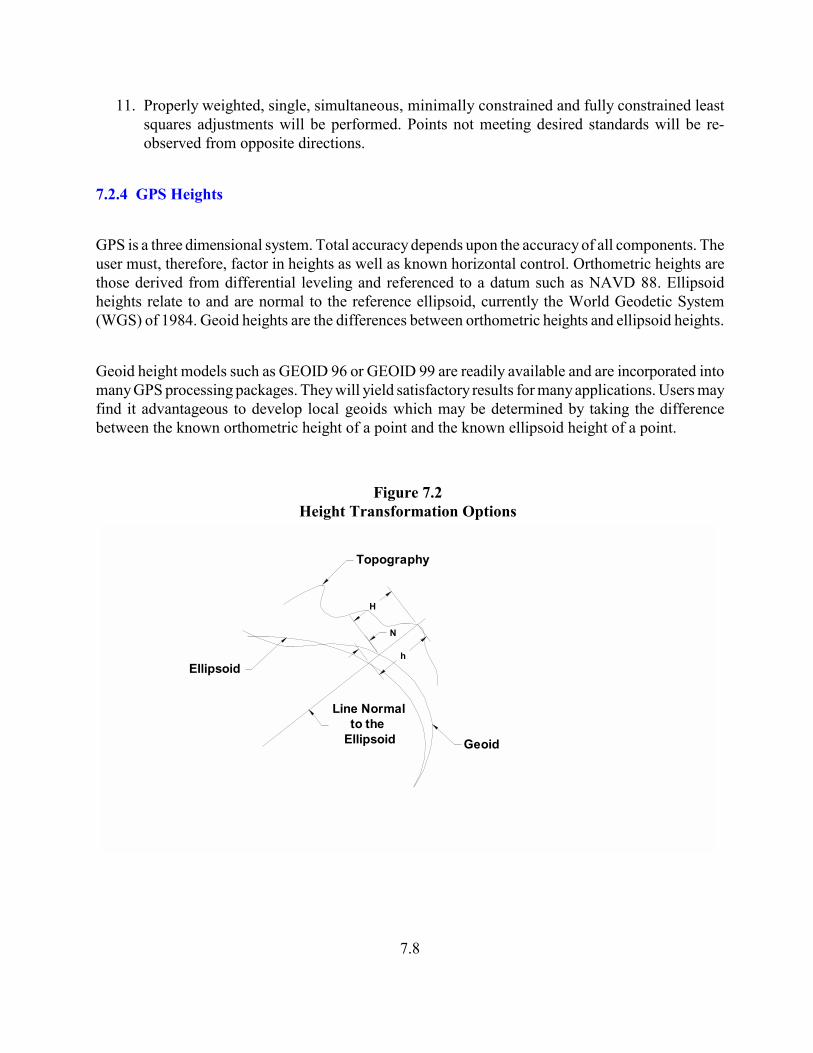
Figure 7.2Height Transformation Options
11. Properly weighted, single, simultaneous, minimally constrained and fully constrained leastsquares adjustments will be performed. Points not meeting desired standards will be re-observed from opposite directions.
7.2.4 GPS Heights
GPS is a three dimensional system. Total accuracy depends upon the accuracy of all components. Theuser must, therefore, factor in heights as well as known horizontal control. Orthometric heights arethose derived from differential leveling and referenced to a datum such as NAVD 88. Ellipsoidheights relate to and are normal to the reference ellipsoid, currently the World Geodetic System(WGS) of 1984. Geoid heights are the differences between orthometric heights and ellipsoid heights.
Geoid height models such as GEOID 96 or GEOID 99 are readily available and are incorporated intomany GPS processing packages. They will yield satisfactory results for many applications. Users mayfind it advantageous to develop local geoids which may be determined by taking the differencebetween the known orthometric height of a point and the known ellipsoid height of a point.

7.9
H = Height above the Geoid, also known as orthometric height derived from differential levelingoperations.
h = Height above the Ellipsoid, derived from GPS observations N = The difference between geiod height and ellipsoid height, approximated by modeling
packages such as GEOID 96/99 or derived from observations.
H = h - Nh = H + N
1. If the geoid is above the ellipsoid, N is positive2. If the geoid is below the ellipsoid, as in Michigan, N is negative.
7.3 Reconnaissance and Monumentation
7.3.1 Primary Control Stations
Preferred primary control stations, both horizontal and vertical, are those of the National SpatialReference System (NSRS). Recovery information documented in DDPROC*.HA data sheets shallbe submitted for all NSRS control stations for which a search was conducted whether these stationswere actually used in the survey or not. Knowing that a control station is erroneous or lost can be asvaluable to future operations as knowing a station’s current status.
7.3.2 Monumentation.Monuments set for NSRS densification or for primary project control shall be permanent in natureand removed from proposed construction activity. An ideal monument is a metal disk, oriented North,set in a large bridge abutment or substantial rock out cropping. An acceptable monument consists ofa metal disk, oriented North, set in poured concrete 1 foot in diameter, 5 feet deep, belled at thebottom.
7.3.3 Monument Pairs
Control monuments are typically set in pairs, monuments in the pair being intervisible and locatedfrom 0.5 to 1 mile apart. Monument pairs are set at intervals between 3 to 10 miles apart or as needed.

7.10
The concrete monument is normally poured in place in a hole dug in the ground, using a top form only. The hole has asquare or circular cross section depending upon the shape of the top form. It is dug to a depth of 5 feet (sufficient toextend below the frost line),then additional material is removed from the bottom to create the bell having a total diameterof about 18 inches.
Figure 7-3
Primary Control Monument
Concrete is poured and tamped in the hole until a level is reached where the top form is set. The form should be setbefore the last 1.0' of concrete is poured. The purpose of the form is to avoid shoulders on or mushrooming of themonument. The top of the monument shall be flush with the ground or protrude from 0.16' to 0.49' above the ground.The form is a simple device that can be fabricated from a cement bag with the top and bottom removed.
The top of the monument is smoothed and beveled with a trowel. The disk with the stamping oriented North ispressed into the center of the monument and recessed slightly.
7.3.4 Visibility Diagrams
Visibility diagrams shall be completed for each existing control point sought, found or set in theconduct of the control survey. Rubbings or detailed photographs shall be included. Standards shallconform to those used in DDPROC. A sample form is shown included as Annex A to thischapter.

7.11
7.3.5 Witnessing
Reference points will be established for all permanent monuments. Directions and a distancesfrom the monument to the reference point shall be measured. A minimum of four reference pointsshall be established for each monument. Reference points should be permanent in nature, readilyidentifiable and surround the monument. 7.4 Michigan High Accuracy Reference Network (HARN)
The High Accuracy Reference Network (HARN) provides a system of horizontal controlthroughout the State of Michigan. These specially designated points were established to A or Border accuracies. Subsequent to the establishment of HARN, other points in the NSDI wereadjusted to it. HARN datum (NAD83-1994) is the preferred datum for horizontal control forMDOT projects.
7.5 Documentation and Submission of Data to NOAA/NGS
Should it be necessary to submit primary control for inclusion into the NSDI coordination shall bemade with the Design Surveys Supervising Surveyor and the MDOT National Geodetic Advisor.7.6 Geodetic Network Accuracy Standards
7.6.1 Standards for Horizontal, Ellipsoid Height and Orthometric Height
Standards for geodetic control surveys shall conform to the model adapted from those developedby the Federal Geodetic Control Subcommittee/Federal Geographic Data Committee (FGDC-STD-007-1998) and reproduced in Table 7.3 below. These standards differ from the class andorder system formerly used. References in this manual to specifications to achieve class and orderstandards are meant to be consistant with desired accuracy standards.
“The reporting standard in the horizontal component is the radius of a circle of uncertainty, suchthat the true or theoretical location of the point falls within that circle 95% of the time. Thereporting standard in the vertical component is a linear uncertainty value, such that the true ortheoretical location of the point falls within +/- of that linear uncertainty value 95% of the time.”

7.12
Table 7.3 -- Accuracy Standards
Horizontal, Ellipsoid Height, and Orthometric Height
---------------------------------------------
Accuracy 95-Percent
Classification Confidence
---------------------------------------------
Less Than or
Equal to:
1-Millimeter 0.001 meters
2-Millimeter 0.002 "
5-Millimeter 0.005 "
1-Centimeter 0.010 "
2-Centimeter 0.020 "
5-Centimeter 0.050 "
1-Decimeter 0.100 "
2-Decimeter 0.200 "
5-Decimeter 0.500 "
1-Meter 1.000 "
2-Meter 2.000 "
5-Meter 5.000 "
10-Meter 10.000 "
A data set may contain one set of accuracy values for the horizontal component and a different setof accuracy values for the vertical component. Accuracy values must be expressed in the sameunit of measure (feet or meters) as the results of the survey proper. Table 7.4 relates the desiredaccuracy standard to the 95% confidence interval.

7.13
Table 7.4Relationship Between Accuracy Standards
and 95% Confidence Intervals
Accuracy Classification 95% ConfidenceInterval
Remarks
Less than or Equal to:
sub- millimeter Reserved for CORS
1 - millimeter 0.001 meters Accuracy between 0 and 1mm
2 - millimeters 0.002 meters Accuracy between 0 and 2mm
5 - millimeters 0.005 meters Accuracy between 0 and 5mm
1 - centimeter 0.010 meters Accuracy between 0 and 1cm
2 - centimeter 0.020 meters etc.
5 - centimeter 0.500 meters
1 - decimeter 0.100 meters
2 - decimeter 0.200 meters
5 - decimeter 0.500 meters
1 - meter 1.000 meters
2 - meter 2.000 meters
5 - meter 5.000 meters
10 - meter 10.000 meters
Source: “Draft Geospatial Positioning Accuracy Standards; Federal Geographic Data Committee; January, 1997.
Providers and users must both fully understand the desired results before the survey is begun.

7.14
7.6.2 Accuracy Classification
FGDC standards define four steps leading to accuracy classification.
1. Examination of survey measurements, field records, sketches and other documentation toverify compliance with the specifications for the intended accuracy of the survey.
2. Reviewing the results of a minimally constrained, least squares adjustment of the surveymeasurements to ensure correct weighting of the observations and freedom from blunders.
3. Computing accuracy measures by weighting datum values in accordance with the networkaccuracies of the existing network control. This is in contrast to a constrained adjustmentwhere coordinates are obtained by holding fixed the datum values in accordance with thenetwork accuracies of the existing network control.
4. Checking the survey accuracy by comparing minimally constrained adjustment results against established control. The result must meet a 95% confidence level. If thecomparison fails, then both the survey and network measurements must be scrutinized todetermine the source of the problem.
Unacceptable statistical results means that there is a problem with either the survey or with thenetwork control. Randomly dithering weights to pass statistical tests is a practice that will notbe accepted. Find the problem, then readjust. 7.6.3 Estimating Positional Accuracy
FGCC standards use a circle of uncertainty rather than the classical error ellipse in determiningthe quality of survey results. Statistical and testing methodology may be found in “GeospatialPositioning Accuracy Standards Part 3: National Standard for Spatial Data Accuracy”;Subcommittee for Base Cartographic Data, Federal Geographic Data Committee; Reston, VA;1998.
7.7 Intermediate Project Control
Intermediate project control is that established for property surveys, alignment, mapping, photocontrol and similar applications.

7.15
7.7.1 Methodology (Horizontal)
Responsibility of achieving required accuracies lies with the field surveyor. Techniques may vary.For intermediate project control, the Global Positioning System, classical traverse or acombination of the two may be used. In designing a survey it must be realized that intermediateproject control results can never be better than the primary control used and thus the surveyormust be certain that the primary control used must be of a quality better than or at least equal tothe desired results.
7.7.2 Standards of Accuracy
Alignment points and intermediate traverse points have a maximum radius of uncertainty of 0.07feet or below at the 95% confidence level.
7.7.3 Classical Traversing
When using the traverse method for establishing intermediate project control, the followingguidelines shall be adhered to.
1. Intermediate control traverses are to be closed and adjusted between two or more pairs ofprimary control points with known coordinates.
2. All intermediate control points are either part of the traverse (occupied) or measured fromat least two points that are part of the traverse. Open ended traverses are not acceptable.
3. Distances between traverse points should not be less that 300 feet.
4. No distance shall be adjusted by more than a ratio of 50 parts per million of that distancenor shall any angle be adjusted by more than 5 seconds.
5. Targets shall be attached to tribrachs and mounted on tripods.
6. Horizontal distances shall be measured twice, once in a forsight mode, once in a backsightmode.

7.16
7. Horizontal angles shall be measured twice in the direct position, twice in the reversedposition.
8. Zenith angles shall be measured once direct and once reversed.
9. Intermediate control traverses shall be analyzed and adjusted by a suitable least squaresadjustment program acceptable to the Supervising Land Surveyor, MDOT DesignDivision.
7.7.4 GPS
When using GPS to establish intermediate project control, the following guidelines shall beadhered to.
1. GPS observations shall conform to the specifications for intermediate control surveys andmeet standards consistent with intermediate control traverses.
2. GPS intermediate horizontal control surveys shall be tied into three known horizontal control points and four known vertical control points published by NGS or established byprimary horizontal/vertical control surveying methods.
3. GPS horizontal control shall form a network with at least 20% of all points being occupiedtwice. Points less than 1 mile apart shall be occupied simultaneously.
4. Minimally constrained and fully constrained least squares adjustments shall be performed.Vectors containing normalized residuals of 2 or higher in any component shall be removedand the network readjusted. Two vectors shall remain for each intermediate project controlpoint.
5. Maximum standard deviation for any coordinate shall not exceed +/-0.01 feet. The radiusof the circle of uncertainty at the 95% confidence region shall not exceed 0.07 feet.
6. Final coordinates shall be derived from a fully constrained least squares networkadjustment holding three primary control horizontal points and four vertical control pointsas fixed.

7.17
7.7.5 Combined Observations
Classical surveying observations may be combined with GPS vectors in performing intermediateproject control surveys. Further details may e found in Appendix H: “GPS/Classical Integration”.The software used in combining observations must be capable of rigorous least squaresadjustment and must be approved by the MDOT survey project manager.
7.7.6 Monumentation of Intermediate Control
When establishing alignment, no less that two intervisible horizontal control points no more thanone kilometer apart shall be established along each tangent. Sufficient control points shall beestablished to permit construction survey crews to stake out the alignment without furthertraverse. Control points should be established at all Points of Intersection, Points of Curvature,Points of Tangency at at intersections with U.S. Public Land Survey System (PLSS) control lines.
A 18 inch long #4 or larger reinforcing rod may be set in hard surface roads preferably protectedby a monument box with cover. The type of monument to be used off of a hard surface road shallbe 3 feet long #4 or larger reinforcing rod capped with a device identifying the surveyor. Achiseled “+” in a massive concrete structure or rock outcropping is acceptable. If points arecorners of the PLSS, requirements of P.A. 74 of 1970 as amended shall be adhered to. The settingof parallel offset points is permitted providing that such points are clearly identified in thesurveyor’s report.
No less than four witnesses will be established for all intermediate control points. A witness shallconsist of a direction observed to the dearest degree and distance measured to the nearesthundredth of a foot from the intermediate control point to the witness point.
7.8 Intermediate Vertical Control
7.8.1 Standard of Accuracy
Intermediate vertical project control networks shall meet an unadjusted error of closure not greaterthan 0.06 feet times the square root of the distance leveled in miles, unless otherwise directed.Benchmarks will be set at intervals not to exceed 1640 feet. Networks shall begin and end on atleast two NGS published benchmarks or benchmarks set to MDOT primary control standards.
Adjustments shall be made using rigorous, least squares methodology acceptable to the

7.18
Supervising Surveyor, Design Surveys and only when raw data meets standards. The maximumstandard deviation on any benchmark elevation shall not exceed +/- 0.07 feet. Portions ofnetworks not meeting standards shall be re-observed in an opposite direction and if no blunderscan be determined, additional known benchmarks shall be observed. All points in the networkshall be contained in a single, simultaneous, properly constrained adjustment.
7.8.2 Methodology
Surveys to establish intermediate vertical control will most likely meet minimum standards of thefollowing guidelines are adhered to.
1. Leveling instruments shall be tested at the beginning of each project and adjusted if necessary then at 20 day intervals for the duration of the project.
2. Leveling will begin and close on NGS first or second order vertical control points or onpoints established by MDOT standards for primary vertical control. Third order points orthe adjusted values on points meeting these standards combined with at least one higherorder point may be used if MDOT accuracy standards can still be met.
3. All project benchmarks must be part of the network. “Side shots” are not acceptable.
4. Turning points shall be established on substantial objects to include marks on concrete orrock outcroppings, driven turn pins, “turtles” or similar objects. Screw drivers, chainingpins or the like are not acceptable turning points.
5. Sight distances shall be no greater than 200 feet nor less than 30 feet. Backsights andforesights shall be ballanced to within 10% their respective distances.
6. Level rods must be held vertically. All observations shall be direct readings taken at a distance of no less than 1.5 feet from the base of the rod.
7. Benchmark descriptions shall include the type of monument, stampings or uniqueidentifying features, location by coordinates or station plus and out.
8. Photo targets lying within 300 feet of the level network shall be included in the level network.

7.19
7.9 Deliverables
As appropriate, the following documents will be submitted with all control surveys. Hard copiesor digital copies as identified below will be transmitted.
A. Surveyor’s Report (hard copy)Scope of WorkUncertainties in ControlUncertainties in ObservationsUncertainties in Final ResultsRecommendations
B. Instrument Test Results (hard copy)
C. Reconnaissance Results (hard copy and digital in form of DDPROC*.HA file )
D. Photographs or Rubbings or All Primary Control Monuments Found or Set (hard copy)
E. Control Used (hard copy)
F. Network Diagram(s) (hard copy)
G. Observation Schedules (hard copy)
H. Field Notes/Sketches (hard copy)
I. Un-edited Observation Electronic Data Files (digital)
J. Explanation of a-priori weighting scheme (hard copy)
K. Results of Minimally Constrained Least Squares Adjustment (hard copy, digital)
L. Results of Fully Constrained Least Squares Adjustment (hard copy, digital)

7.20
M Coordinate List with Standard Deviations and 95% Radii of Uncertainty (hard copy, digital)
N. Elevation List with Standard Deviations and 95% Confidence Intervals (hard copy, digital)
O. Point Descriptions and Witness Lists (hard copy, digital copy)

7.21
Annex A, Part VII, Visibility Diagram (A)

7.22
Annex A, Part VII, Visibility Diagram (B)

7.23
Annex B, Part VII, GPS Data Sheet

7.24
Annex C, Part VII, NGS Software______________________________________________________________________________ADJUST (Version 4.12) [ manual available ]
Performs a least squares adjustment on horizontal, vertical angle, and/or GPSobservations. The program comprises six data checking programs in addition to theadjustment software. This software package has numerous options, such as choice ofellipsoid, and includes sample input data. The source code is also available.
ADJUST UTILITIES Suite of programs that are used in conjunction with PC program ADJUST. This group ofprograms includes:
BBACCUR which provides a formatted listing of the external and internal accuracieswhich have been computed by program ADJUST-- sorted in numerical ascending order ofexternal accuracy. Output from program ADJUST, run with accuracies, is used as input.
CLUSTER used to identify geodetic stations which are common to two data sets withrespect to name or a given position tolerance.
ELEVUP creates a bfile which combines the bfile output from the constrained horizontal adjustment with the bfile output from the constrained vertical adjustment. This new bfile contains *80* records with adjusted positions from the horizontal and *86* records with the ellipsoidal heights from the horizontal adjustment and the orthometric heights and geoid heights from the vertical adjustment.
ELLACC which computes ellipsoidal height order and class for a project. Output fromprogram ADJUST, run with accuracies, is used as input.
MAKE86 which adds *86* records to the bfile. If the existing *80* records containorthometric heights, these are added to the new *86* records.
MODGEE scales the standard errors assigned to the observations in the gfile. Input is agfile and the scaling factor.

7.25
QQRECORD adds qq records to the Afile (used by program ADJUST) to computeaccuracies for all observed lines. Either the gfile (for GPS projects) or the bfile (forclassical terrestrial projects) can be used as input.
CALIBRAT (Version 1.0) This program is used to determine the scale and constant corrections for electronicdistance measuring instruments by making measurements over previously determinedbase lines. The formulas used in the program are found in NOAA TechnicalMemorandum NOS NGS-10, "Use of Calibration Base Lines."
COMPGB (Version 1.1) Tests the consistency and compatibility of the Blue Book B file (GPS project and stationoccupation data) and G file (GPS vector data transfer file).
CR8BB (Version 4.0) Reformats GPS project information to fit the requirements of the National GeodeticSurvey data base. The file created, which is called the B-file, contains projectinformation, station information, and survey measurements. The CR8BB softwarefunctions independently of the type of GPS receivers used in a project.
CR8G (Version 1.1) Formats reduced vector data to Blue Book specifications.
CR8SER (Version 1.1) Extracts data from GPS Blue Book G file to create a station serial number file (serfil) forGPS observations.
DDPROC (Version 3.00.01) The DDPROC Program organizes control point descriptions in accordance with theNational Geodetic Survey's new (description file (D-FILE) format. Users may still use DDPROC V2.33 [ manual available ] to submit descriptions in the unified descriptionformat to NGS, or they may use the programs contained in DDPROC V03.00.00 tosubmit descriptions in D-FILE format.

7.26
DEFLEC96 (Version 3.10) Computes deflections of the vertical and Laplace corrections for the conterminous UnitedStates, Alaska, Puerto Rico, Virgin Islands, and Hawaii.
DSPLOT (Version 1.4)
Digital Data Sheet (DSDATA) plot program. Used to plot DSX created index files on theterminal screen. DSX is the DSDATA extraction program. Although DSPLOT wasprimarily developed to work with DSDATA and DSX, the program will plot any filewhich is in the same format as a DSX created index file. The documentation fileDSPLOT.DOT contains a sample of this format. cost: Free with purchase of DSDATA
DSSELECT (Version 3.4) Digital Data Sheet (DSDATA) Data Item Selection program. Allows for extraction ofvarious data items from a DSDATA file into a separate file. Output is one record perstation with data items separated by a delimiter for easy database loading. cost: Free withpurchase of DSDATA
DSWIN (Version 1.8) DSWIN is windows based software for Data Sheet view and extraction. It displays a listof county names as found on your CD-ROM. Click on a county and a list of stationsappears. Click on a station from the list and a data sheet appears. You may save the datasheet to a file or print it. The search feature allows for filtering the station list by: PointRadius, Min/Max Box, Station Name, or PID. You may also filter by type of control, suchas 1st order bench marks only
DSX (Version 6.04) Digital Data Sheet (DSDATA) extraction program. Extracts individual of groups of datafrom a DSDATA file. Includes options to extract by Station Identifier, Station Name,Area, and more. Also includes utilities for manipulating the data such as joining two ofmore DSDATA files or splitting a DSDATA file into smaller files. cost: Free withpurchase of DSDATA
ENHANCEMENTS (Version 20) [ manual available ]Performs field check computations, such as tape standardization, eccentric reduction,datum transformation, triangle (plane, spherical, geodetic), special (three-point fix,intersection, resection), geodetic (traverse, inverse, direct) computations, solarobservation for azimuth, and State plane coordinate system computations on the NAD 27and NAD 83 datums.

7.27
GAPP (Version 2.1) The GPS-Assisted Phototriangulation Package (GAPP) performs aero- triangulationadjustments that incorporate observations of the position of a GPS antenna mounted onan aircraft. GAPP can also be used to adjust conventional aerotriangulation data.
GEOID96 (Version 3.10) Computes geoid height values for the conterminous United States, Alaska, Puerto Rico,Virgin Islands, and Hawaii. Suitable for conversion of NAD83 GPS ellipsoidal heightsinto NAVD88 orthometric heights.
G96SSS (Version 3.10) Computes geoid height values for the conterminous United States. Gravimetric geoid forscientific studies.
GPPCGP (Version 2.0) Converts NAD 27 State plane coordinates to NAD 27 geographic positions (latitudes andlongitudes) and conversely. Includes defining constants for all NAD 27 plane coordinatezones.
HTDP (Version 2.2) This horizontal time-dependent positioning software program allows users to predicthorizontal displacements and/or velocities at locations throughout the United States. Thissoftware also enables users to update geodetic coordinates and/or observations from onedate to another.
INTERORB (Version 1.0) Interpolates binary GPS orbit files with a record length of 52.
INVERSE/FORWARD3D (Version 1.0) Comprises four programs - Inverse (Version 2.0) which computes the geodetic azimuthand distance between two points, given their geographic positions; Forward (Version 2.0)which computes the geographic position of a point, given the geodetic azimuth anddistance from a point with known geographic position; and the three-dimensionalversions of these programs . INVERS3D (Version 1.0) and FORWRD3D (Version 1.0),which include the height component.

7.28
LOOP (Version 4.03) Determines the loop misclosures of GPS base lines using the delta x, delta y, delta zvector components computed from a group of observing sessions.
LVL_DH (Version 2.0) Estimates the leveled height difference between two bench marks by removing theorthometric correction from the differences of published heights.
MTEN4 (Version 20) [ manual available ]Computes and verifies classical horizontal field observations (angles and distances), andformats these data to conform to Blue Book specifications. MTEN4 does not adjust fieldobservations, but performs certain field check computations, but performs certain fieldcheck computations such as triangle computations, distance reductions, and trigonometricheight computations, distance reductions, and trigonometric height computations.MTEN4 allows four-digit station numbers and new position codes set forth in the BlueBook.
NADCON (Version 2.1) [ manual available ]Transforms geographic coordinates between the NAD 27, Old Hawaiian, Puerto Rico, orAlaska Island datums and NAD 83 values. Recommended for converting coordinate datafor mapping, low-accuracy surveying, or navigation.
PCVOBS (Version 2.10) Simplifies entering vertical observation data records into Blue Book format. The programformats the data onto a computer disk which can then be sent to NGS for furtherprocessing and incorporation of the data into the National Geodetic Reference System.
PROMPTER (Version 1.0) Creates horizontal control point records in Blue Book format with geodetic positions ingeographic coordinates, state plane coordinates, or Universal Transverse Mercatorcoordinates.
SPCS83 (Version 2.0) Converts NAD 83 state plane coordinates to NAD 83 geographic positions andconversely. Includes defining constants for NAD 83 coordinate zones. State planecoordinates are entered or computed to 1 mm accuracy, while the latitudes and longitudesentered or computed correspond to approximately 0.3 mm accuracy.

7.29
TOLADD (Version 1.0) Adds a user-specified shift in seconds to each input latitude and longitude.
UTMS (Version 1.1) Converts geographic coordinates (latitudes and longitudes) on the Clarke 1866, GRS80/WGS 84, International, WGS 72, or any user-defined reference ellipsoid to UniversalTransverse Mercator (UTM) coordinates, and vice-versa.
VERTCON (Version 2.0) Computes the modeled difference in orthometric height between the North AmericanVertical Datum of 1988 (NAVD 88) and the National Geodetic Vertical Datum of 1929(NGVD 29) for a given location specified by latitude and longitude. This conversion issufficient for many mapping purposes.
VFPROC (Version 3.33) [ manual available ]Computes and verifies vertical field observations(leveling data), and formats these data toconform to Blue Book specifications. VFPROC does not perform a least squaresadjustment, but checks the observational and descriptive data for completeness andconsistency.
Technical Manuals are available for the following programs:
• ADJUST• DDPROC• ENHANCEMENTS• MTEN4• NADCON• VFPROC
Contact NGS Information Services for prices

7.30
Part VII Bibliography______________________________________________________________________________
Geometric Geodetic Accuracy Standards and Specifications for Using GPS Relative PositioningTechniques, Version 5.0. Rockville. Maryland: Federal Geodetic Control Committee, 1988.
Hoffman-Wellenhof, B., H. Lichtenegger, and J. Collins. GPS Theory and Practice. 2nd ed. NewYork, New York: Springer-Verlag, 1993.
Interim FGCS Specifications and Procedures to Incorporate Electronic Digital/Bar CodeLeveling Systems. Silver Spring, Maryland: NOAA, National Geodetic Survey, 1994.
Leick, Alfred. GPS Satellite Surveying. New York, New York: John Wiley and Sons, 1990.
National Spatial Data Infrastructure Geospatial Positioning Accuracy Standards. Reston,Virginia: Federal Geodetic Control Subcommittee, Federal Geographic Data Committee, U.S.Geological Survey, 1998.
Standards and Practices for Control Surveys. Bruce, ACT: The Intergovernmental Committee onSurveying and Mapping, Australian Surveying and Land Information Group, 1997.
Van Sickle, Jan. GPS for Land Surveyors. Chelsea, Michigan: Ann Arbor Press, Inc.,1996.
Standards of Practice (Interim). Lansing, Michigan: Michigan Department of Transportation,1998.
Standards and Practices for Control Surveys.http://www.anzlic.org.au/icsm/publications/sp1/sp1.htm
Wells, David, Norman Beck, Demitris Delikaraoglou, Alfred Kleusberg, Edward J. Krakkiwski,Gerard Lachapelle, Richard B. Langley, Mete Nakiboglu, Klaus-Peter Schwarz, Hames M.Tranquilla, Petr Vanicek. Guide to GPS Positioning. Fredericton, New Brunswick, Canada:Canadian GPS Associates, 1987.
Related Documents


