OF 18 L101SFL003 PART NUMBER PART NUMBER: L101SFL003 DESCRIPTION: CROSSTREK TRAILER HITCH SUBARU OF AMERICA PAGE PLEASE READ THIS INSTRUCTIONS CAREFULLY, BEFORE YOU START INSTALLATION SAFETY PRECAUTION: When installing Trailer Hitch, the use of safety glasses is recommended. WARNING: 1. Always install the accessory following the instructions. Failure to do so may cause damage to the vehicle or the accessory. 2. Please also refer to SUBARU SERVICE MANUAL upon removing and re-assembling vehicle components. 3. Do not drill, cut, weld or otherwise modify the Trailer Hitch. 4. Do not lubricate the bolts and nuts with oil or grease. 5. If Trailer Hitch is removed, a bumper beam MUST be reinstalled. Failure to reinstall a bumper beam after removal of the trailer hitch will negatively affect vehicle rear crash performance. Please contact your SUBARU dealer. 6. When a Trailer Hitch is installed, it is not possible to install the rear towing hook. 7. Never exceed the maximum towing capacity and maximum tongue load. It could cause personal injury and/or vehicle damage. 8. When towing, total vehicle weight must not exceed the Gross Vehicle Weight Rating (GVWR). Also the load distribution on each axle must not exceed the Gross Axle Weight Rating (GAWR). The GVWR and GAWR for your vehicle can be found on the "Certification label" which is located on the left side center pillar of the vehicle. 9. For models equipped with RAB, refer to the part which indicated [RAB]. 10. Ensure all recyclable discarded vehicle accessory components and packaging are recycled following local recycling regulations. 11. It is always recommended that this accessory is fitted by a qualified SUBARU technician. 12. In the engine bay, disconnect the negative battery terminal. 13. Safely store and protect any removed vehicle components. 14. Ensure all bare metal surfaces are protected using Automotive Bare Metal Primer and touch-up paint. 15. Remove all metal swarf and dust from all vehicle surfaces if surface is used for accessory installation. 16. Tow hitch to be used with Subaru ball mounts L101SFL200 (all non-PHEV) and L101SFL201 (PHEV). Please see dealer for correct ball mount part # application. Warranty is granted only when installation is done correctly by your SUBARU dealer. SUBARU reserves the right to change the design of accessories and/or construction, illustration, and text of this manual at anytime without prior notice. ISSUE 3 DATE 2/23/2020 INSTALLATION INSTRUCTIONS 1

Welcome message from author
This document is posted to help you gain knowledge. Please leave a comment to let me know what you think about it! Share it to your friends and learn new things together.
Transcript

OF 18L101SFL003
PART NUMBER
PART NUMBER: L101SFL003
DESCRIPTION: CROSSTREK
TRAILER HITCH
SUBARU OF AMERICAPAGE
PLEASE READ THIS INSTRUCTIONS CAREFULLY, BEFORE YOU START
INSTALLATION
SAFETY PRECAUTION: When installing Trailer Hitch, the use of safety glasses is recommended.
WARNING:
1. Always install the accessory following the instructions. Failure to do so may cause damage to the
vehicle or the accessory.
2. Please also refer to SUBARU SERVICE MANUAL upon removing and re-assembling vehicle
components.
3. Do not drill, cut, weld or otherwise modify the Trailer Hitch.
4. Do not lubricate the bolts and nuts with oil or grease.
5. If Trailer Hitch is removed, a bumper beam MUST be reinstalled. Failure to reinstall a bumper beam
after removal of the trailer hitch will negatively affect vehicle rear crash performance. Please contact your
SUBARU dealer.
6. When a Trailer Hitch is installed, it is not possible to install the rear towing hook.
7. Never exceed the maximum towing capacity and maximum tongue load. It could cause personal injury
and/or vehicle damage.
8. When towing, total vehicle weight must not exceed the Gross Vehicle Weight Rating (GVWR). Also
the load distribution on each axle must not exceed the Gross Axle Weight Rating (GAWR). The GVWR
and GAWR for your vehicle can be found on the "Certification label" which is located on the left side
center pillar of the vehicle.
9. For models equipped with RAB, refer to the part which indicated [RAB].
10. Ensure all recyclable discarded vehicle accessory components and packaging are recycled following
local recycling regulations.
11. It is always recommended that this accessory is fitted by a qualified SUBARU technician.
12. In the engine bay, disconnect the negative battery terminal.
13. Safely store and protect any removed vehicle components.
14. Ensure all bare metal surfaces are protected using Automotive Bare Metal Primer and touch-up
paint.
15. Remove all metal swarf and dust from all vehicle surfaces if surface is used for accessory
installation.
16. Tow hitch to be used with Subaru ball mounts L101SFL200 (all non-PHEV) and L101SFL201
(PHEV). Please see dealer for correct ball mount part # application.
Warranty is granted only when installation is done correctly by your SUBARU dealer.
SUBARU reserves the right to change the design of accessories and/or construction, illustration, and text
of this manual at anytime without prior notice.
ISSUE
3
DATE
2/23/2020
INSTALLATION INSTRUCTIONS
1

0
LH
RH LH RH
M12 flange nut M10 flange nut
OFL101SFL003 3
x2 x1
18SUBARU OF AMERICA
PAGE
2/23/2020 2
x1
M
x1
O
x12 x6 x2
M12 hex flange bolt
x2x4
M12 flat washer M10 hex
flange bolt
x1hook & loop
J
x5foil tape
N
foam tape
KIT CONTENTS:
x5
K L
D
A B C
x1 x1 set x1 set
HE F G
I
cable tie - 11"
PART NUMBER ISSUE DATE
OF
18mm open end wrench
3
ISSUE DATESUBARU OF AMERICA
14mm open end wrench reamer
cutting tool
clip remover
7mm open end wrench
17mm deep well socket
14mm deep well socket
file
side cutter
PART NUMBER
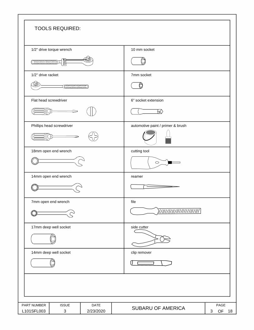
TOOLS REQUIRED:
1/2" drive torque wrench
1/2" drive racket
Flat head screwdriver
Phillips head screwdriver
10 mm socket
7mm socket
6" socket extension
automotive paint / primer & brush
L101SFL003
PAGE
183 2/23/2020

1
2
3
4
OF
PAGE
3 18L101SFL003
PART NUMBER ISSUE DATESUBARU OF AMERICA
2/23/2020 4
1 REMOVE REAR TAIL LIGHTS
Carefully set aside the fasteners and tail light assmeblies were they will not be
damaged
Carefully remove the tail light assembly from each side. Unplug the wire harness
connector.
Using a small Phiilips head screwdriver and rachet with 10 mm socket, remove (2)
screws from the rear tail light assembly on each side
Using a small flat head screwdriver, remove (2) tail light covers on each side.
LH tail light
1
1
2
2
LH tail light
LH rear corner of vehicle
3
flat head screwdriver
ratchet
10mm socket

1
2
3
4
(TOP OF
VEHICLE)
(TOP OF
VEHICLE)
OF
Starting at the LH side wheel well, using both hands, pull one side of the fascia out
from the vehicle.
With a screwdriver, release (1) small push pin fastener per side on the LH/RH fascia
wheel well. Use the tip of the screwdriver to push the center of the pin.
With a small flat head screwdriver, remove (8) large push pin fasteners across the
length of the bumper. Save push pins for later use.
2 REMOVE REAR BUMPER FASCIA
PART NUMBER ISSUE DATE
Continue around the rear LH side. At the rear corner, begin to pull rearward and work
across the vehicle from left to right to remove the entire bumper.
18SUBARU OF AMERICA
PAGE
5
6
7
Disconnect the RAB sensor harness.
Fully release the bumper from the vehicle body.
Lay fascia aside where it will not be damaged during hitch installation.
L101SFL003 3 2/23/2020 5
2
(x8)
1
3
4
4clip remover

1
2
3
4
1
2
OF 18
PAGE
6
Remove the LH & RH bumper brackets.
4 REMOVE REAM BUMPER BRACKETS
Disconnect the RAB harness connector from the top of the bumper beam.
Using 14 mm deep socket, remove (2) bolts and (1) nut from each side of the
bumper beam
Remove the bumper beam.
3 REMOVE REAR BUMPER BEAM
Remove (1) fastener from each LH/RH bumper bracket.
PART NUMBER ISSUE DATESUBARU OF AMERICA
2/23/2020L101SFL003 3
Discard (2) nuts and (2) bolts. Retain (2) bolts for installation of cover panel.
11
If Trailer Hitch is removed, a bumper beam MUST be reinstalled. Failure to reinstall a bumper beam after removal of the trailer hitch will negatively affect vehicle rear crash performance. Please contact your SUBARU dealer.
!
2 2
2 2
22
bumper beam
4
14mm deep socket
flat head screwdriver
ratchet
extension
1
OF
DATESUBARU OF AMERICA
PAGE
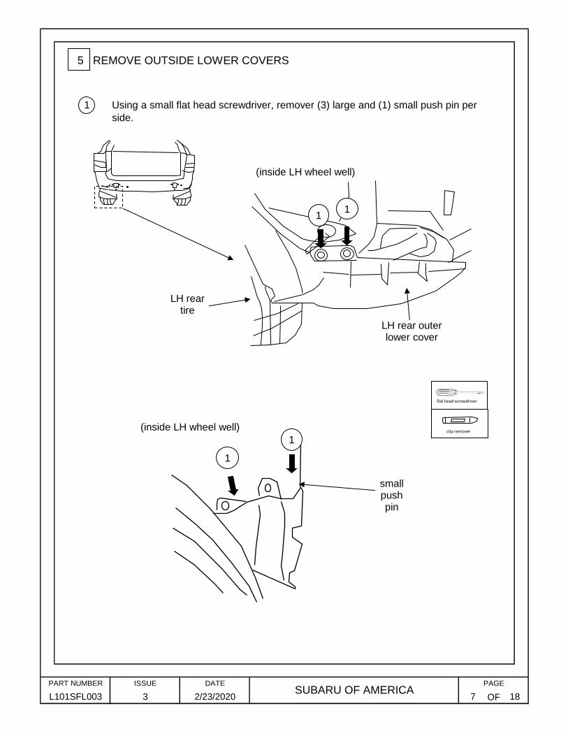
Using a small flat head screwdriver, remover (3) large and (1) small push pin per
side.
5 REMOVE OUTSIDE LOWER COVERS
L101SFL003 3 2/23/2020 7 18
PART NUMBER ISSUE
LH rear tire
LH rear outer lower cover
11
(inside LH wheel well)
1
1
small push pin
flat head screwdriver
clip remover(inside LH wheel well)

1
2
3
4
OF
6 INSTALL LH / RH FRAME BRACKET ASSEMBLIES - PART "B"
L101SFL003 3 2/23/2020 8 18
DATESUBARU OF AMERICA
PAGEPART NUMBER ISSUE
Place LH and RH welded bracket subassembly "B" into side frame hole opening.
Loosely install (1) M12 bolt "D" and washer "E" through the bottom of the frame into
ONLY the front hole.
Align the bracket holes with the holes in the frame rail.
Remove (3) rubber grommets per side from the bottom of the side frame.
B
D
E
2
11
(LH side)
(LH side)
3
3
3
4
1

1
2
3
1
2
3
4
OF
Loosely install (1) M10 nut "H" on each side onto the vehicle weld bolts.
Install the main hitch "A" between the LH and RH frame bracket subassemblies
and onto the vehicle rear panel weld bolts.
7 INSTALL MAIN HITCH MEMBER - PART "A"
Install (1) M12 bolt "D" and washer "E" into the bottom hole on each side, through
the frame, and into the weld nut of part "B".
Install (1) M12 bolt "D" and washer "E" into the side hole on each side, through
the frame, and into the weld nut of part "B".
Align the holes the frame holes of part "C" to the (1) bottom and (1) side hole in
the frame rail.
Install frame bracket subassembly "C" to the mounted hitch on the outside of part "B"
on each side.
Loosely install (1) M10 bolt "G" on each side into the vehicle weld nuts.
9 INSTALL LH / RH FRAME BRACKET ASSEMBLIES - PART "C"
L101SFL003SUBARU OF AMERICA
PAGE
9 18
PART NUMBER ISSUE DATE
3 2/23/2020
AB
B
H
H
GG
2
2
1
3 3
(LH side)
(LH side)C B
A
1
D
E 4
32
DE
1
1
2
3
OF
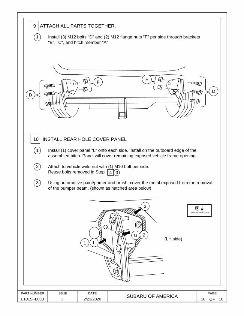
Attach to vehicle weld nut with (1) M10 bolt per side.
Reuse bolts removed in Step
Using automotive paint/primer and brush, cover the metal exposed from the removal
of the bumper beam. (shown as hatched area below)
9 ATTACH ALL PARTS TOGETHER.
Install (3) M12 bolts "D" and (2) M12 flange nuts "F" per side through brackets
"B", "C", and hitch member "A"
Install (1) cover panel "L" onto each side. Install on the outboard edge of the
assembled hitch. Panel will cover remaining exposed vehicle frame opening.
10 INSTALL REAR HOLE COVER PANEL
18L101SFL003SUBARU OF AMERICA
PAGEPART NUMBER DATEISSUE
3 2/23/2020 10
DD
FF
(LH side)
4 3
paint/primer & brush
L
G
1
2
3

1
LH SIDE
RH SIDE
REAR
OF
14
11 TORQUE FASTENERS
Torque all fasteners in the order and to the torque valuse as shown in the table
ORDERTORQUE
(Nm)
2 85 63 14
TORQUE
(ft-lb)socket size (mm)
1 85 63 14
3
17
4 85 63 14
5 85 63 17
85
7 85 63
6 85 63
63
17
8 85 63 17
9 85 63 17
10 85 63 17
85 63 17 & 18mm wrench
12 85 63 17
11
13 85 63 17
14 85 63 17 & 18mm wrench
16 85 63 17 & 18mm wrench
15 85 63 17 & 18mm wrench
17 70 52 14
18 70 52 14
L101SFL003 3
PAGE
11 18
PART NUMBER ISSUE DATESUBARU OF AMERICA
2/23/2020
(underneath)
(underneath)
!
1
2
4
3
1817
14
16
12
10
68
13
15
11
5 7
9
17mm deep well sockettorque wrench extension 14mm socket 18mm open end wrench

1
2
3
4
5
6
1
2
3
4
OF
12 MODIFYING REAR BUMPER FASCIA
Move the fascia to a flat area in order to cut the "U" shape for the trailer hitch.
Once the gasket is in place, trim the excess length so that it is even with the edge.
Make sure the starting end of the gasket has a 90° square cut end.
Starting at one end of the bumper opening, carefully slide the gasket "K" along the
edge.
Remove the paper template on the next page and prepare as shown on that page.
Remove all burrs and rough edges after the cut is made.
With the template in place, mark the "U" shape.
Align the holes in the template to the holes on the inside of the bumper fascia.
Move the fascia to a flat area in order to cut the "U" shape for the trailer hitch.
L101SFL003
Continue to wrap around the opening, being sure to create a smooth joint as you go.
2/23/2020
13 INSTALLING RUBBER BUMPER TRIM GASKET "K"
12 18
PART NUMBER ISSUE DATESUBARU OF AMERICA
3
PAGE
3
AFTER CUT
side cutter
filecutting tool
reamer
3
4
4
4
5
6
4
1
2
M
3
DRIVER'S SIDE

OF
PART NUMBER ISSUE DATESUBARU OF AMERICA
PAGE
L101SFL003 3 2/23/2020 13 18
REAR BUMPER FASCIA HITCH OPENING CUTTING TEMPLATE
1" SQUAREuse as
reference to verify correct
print scale
cut out all hatched area & holes
when complete, template should look like this:
DRIVER'S SIDE
INS
TA
LL
ON
INS
IDE
FA
CE
OF
BU
MP
ER
FA
SC
IA

1 Raise and remove the carpeted spare tire compartment cover.
2 Remove tool tray
3 Unscrew and remove tire thumbscrew.
4 Remove spare tire.
5 Remove (4) push pin fasteners from side foam trays.
6 Remove rear tailgate trim.Remove (2) push pin fasteners to remove the rear inside trunk panel.
7 Remove rear tailgage trim.
8 Remove rubber plug from rear skirt panel.
OF
14 WIRING HARNESS INSTALLATION
L101SFL003
ISSUEPART NUMBER
3
DATESUBARU OF AMERICA
PAGE
2/23/2020 14 18
1
2
3
4
5
5
6
6
clip remover
8
7

9
OF
10
11
12
13
14
Connect the tow hitch wiring harness to the vehicle side connector.
Route the wiring across the rear trunk panel as shown below.
Peel backing off the double sided tape on fuse holder and attach to the power
convertor (ECU). Peel the backing off the double sided tape of the ECU and attach in
the side of the spare tire area as shown. Make sure that the fuse is firmly pressed
onto the ECU and that the ECU is pressed firmly onto the flat inner wall of the spare
tire area. Be sure it will not interfere with the spare tire.
14 WIRING HARNESS INSTALLATION (CONT'D)
Locate the wiring harness pre-arranged connector at the LH side of the trunk.
Wrap the pre-arranged-to-tow hitch connection with foam tape "N". Wrap any
excess length with an 11" cable tie "L".
Install the 4-pin connector into the wiring harness mounting bracket on the tow hitch
using the clamp bracket and hardware included in the wiring harness kit "I". Tighten
the bolts to 5±1 in-lb.
SUBARU OF AMERICAL101SFL003 3 2/23/2020
ISSUE DATE PAGE
15 18
PART NUMBER
10
11
12
13
9

PAGE
OF 18L101SFL003 3
PART NUMBER ISSUE
Secure the wirining harness to the hitch member tube with (3) 11" cable ties "L" as
shown.17
19 Secure the connector to the bracket using an 11" cable tie "L" by wrapping the cable
tie through the [RAB] connector and around the bracket.
Attach the [RAB] connector to the hitch bracket using the piece of hook & loop "O".
Remove the adhesive liner and stick one side to the connector and the other to the
bracket.
2/23/2020 16
DATESUBARU OF AMERICA
14 WIRING HARNESS INSTALLATION (CONT'D)
18
Route the connector at the opposite end through the hole in the rear panel and into
the trunk area.15
16 Install the rubber grommet into the hole.
15
16
150m 150m
17
17
18
[RAB]
19

1
OF
14 WIRING HARNESS INSTALLATION (CONT'D)
20
Always use safety chains when towing.
Secure the wiring harness to the inside of the spare tire area using 5 pieces of foil
tape "M" in the locations as shown.
Inside the spare tire area, connect the 2 ends of the wiring harness connector. Wrap
the connection with foam tape "N"
21
DATESUBARU OF AMERICA
15 SAFETY CHAIN HOOK
L101SFL003 3
PART NUMBER
2/23/2020 17
PAGE
18
ISSUE
!
20
21
21
21

1
1
2
3
4
5
6
7
1
2
3
4
5
OF
These instructions are an official document and an integral part of the trailer hitch. It
should be stored in a glove box all the time and handed over with the vehicle if sold.
L101SFL003 3 2/23/2020 18 18
For further information, read vehicle's owners manual or consult your dealer or
dealer's service department.
SUBARU accepts no liability for product defects caused by the vehicle owner or
other persons and/or incorrect use.
After the first 600 miles, please consult with SUBARU dealer to re-check the
tightness of Trailer Hitch bolts and/or nuts.
Replace rear compartment cover.
18 CAUTION
For models equipped with BSD (Blind Spot Detection) and RCTA (Rear Cross
Traffic Alert) driving support systems, when towing a trailer, press BSD/RCTA
OFF switch to deactivate the systems. The system may not operate properly due
to the blocked rader waves. For details about BSD/RCTA OFF switch, refer to the
owners manual "BSD/RCTA OFF switch".
ISSUE DATESUBARU OF AMERICA
PAGE
For models equipped with RAB (Reverse Automatic Braking) system, please consult
with SUBARU dealer when towing a trailer.
16 INSTALLATION INSTRUCTIONS
17 REINSTALLATION OF COMPONENTS
Reinstall outside lower covers.
Reconnect RAB harness
Reinstall rear bumper fascia.
PART NUMBER
Note: attach fascia to hitch member brackets using 2 push-pins
Reinstall rear tail lamps. Remember to reconnect wiring harness.
Reinstall rear tail light covers.
Reinstall spare tire and related components.
!
Related Documents