Sales and Engineering Data Sheet ED 15118-2 Group: Controls Part Number: ED 15118 Date: February 2016 Daikin Magnitude ® Chiller Unit Controller Protocol Information Modbus ® Protocol Model WME Frictionless Centrifugal Chiller, Single-Compressor and Dual-Compressor

Welcome message from author
This document is posted to help you gain knowledge. Please leave a comment to let me know what you think about it! Share it to your friends and learn new things together.
Transcript

Sales and Engineering Data Sheet ED 15118-2Group: ControlsPart Number: ED 15118Date: February 2016
Daikin Magnitude® Chiller Unit Controller Protocol InformationModbus® Protocol
Model WME Frictionless Centrifugal Chiller, Single-Compressor and Dual-Compressor
ED 15118-2 • MAGNITUDE UNIT CONTROLLER 2 www.DaikinApplied.com
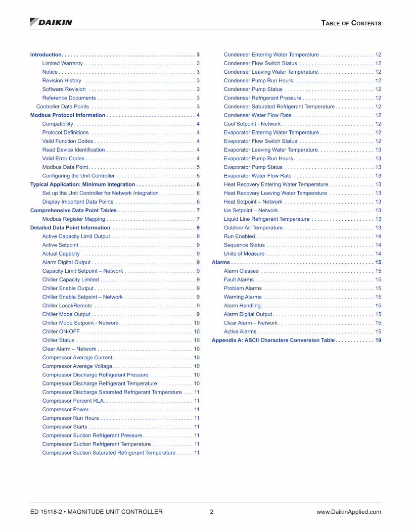
Table of ConTenTs
Table of ConTenTs
Introduction . . . . . . . . . . . . . . . . . . . . . . . . . . . . . . . . . . . . . . . . . . . . . 3Limited Warranty . . . . . . . . . . . . . . . . . . . . . . . . . . . . . . . . . . . . . 3Notice . . . . . . . . . . . . . . . . . . . . . . . . . . . . . . . . . . . . . . . . . . . . . . 3Revision History . . . . . . . . . . . . . . . . . . . . . . . . . . . . . . . . . . . . . 3Software Revision . . . . . . . . . . . . . . . . . . . . . . . . . . . . . . . . . . . . 3Reference Documents . . . . . . . . . . . . . . . . . . . . . . . . . . . . . . . . . 3
Controller Data Points . . . . . . . . . . . . . . . . . . . . . . . . . . . . . . . . . . . 3Modbus Protocol Information . . . . . . . . . . . . . . . . . . . . . . . . . . . . . . 4
Compatibility. . . . . . . . . . . . . . . . . . . . . . . . . . . . . . . . . . . . . . . . . 4Protocol Definitions . . . . . . . . . . . . . . . . . . . . . . . . . . . . . . . . . . . 4Valid Function Codes . . . . . . . . . . . . . . . . . . . . . . . . . . . . . . . . . . 4Read Device Identification . . . . . . . . . . . . . . . . . . . . . . . . . . . . . . 4Valid Error Codes . . . . . . . . . . . . . . . . . . . . . . . . . . . . . . . . . . . . . 4Modbus Data Point. . . . . . . . . . . . . . . . . . . . . . . . . . . . . . . . . . . . 5Configuring the Unit Controller . . . . . . . . . . . . . . . . . . . . . . . . . . . 5
Typical Application: Minimum Integration . . . . . . . . . . . . . . . . . . . . 6Set up the Unit Controller for Network Integration . . . . . . . . . . . . 6Display Important Data Points . . . . . . . . . . . . . . . . . . . . . . . . . . . 6
Comprehensive Data Point Tables . . . . . . . . . . . . . . . . . . . . . . . . . . 7Modbus Register Mapping . . . . . . . . . . . . . . . . . . . . . . . . . . . . . . 7
Detailed Data Point Information . . . . . . . . . . . . . . . . . . . . . . . . . . . . 9Active Capacity Limit Output . . . . . . . . . . . . . . . . . . . . . . . . . . . . 9Active Setpoint . . . . . . . . . . . . . . . . . . . . . . . . . . . . . . . . . . . . . . . 9Actual Capacity . . . . . . . . . . . . . . . . . . . . . . . . . . . . . . . . . . . . . . 9Alarm Digital Output . . . . . . . . . . . . . . . . . . . . . . . . . . . . . . . . . . . 9Capacity Limit Setpoint – Network . . . . . . . . . . . . . . . . . . . . . . . . 9Chiller Capacity Limited . . . . . . . . . . . . . . . . . . . . . . . . . . . . . . . . 9Chiller Enable Output . . . . . . . . . . . . . . . . . . . . . . . . . . . . . . . . . . 9Chiller Enable Setpoint – Network . . . . . . . . . . . . . . . . . . . . . . . . 9Chiller Local/Remote . . . . . . . . . . . . . . . . . . . . . . . . . . . . . . . . . . 9Chiller Mode Output . . . . . . . . . . . . . . . . . . . . . . . . . . . . . . . . . . . 9Chiller Mode Setpoint - Network. . . . . . . . . . . . . . . . . . . . . . . . . 10Chiller ON-OFF . . . . . . . . . . . . . . . . . . . . . . . . . . . . . . . . . . . . . 10Chiller Status . . . . . . . . . . . . . . . . . . . . . . . . . . . . . . . . . . . . . . . 10Clear Alarm – Network . . . . . . . . . . . . . . . . . . . . . . . . . . . . . . . . 10Compressor Average Current. . . . . . . . . . . . . . . . . . . . . . . . . . . 10Compressor Average Voltage. . . . . . . . . . . . . . . . . . . . . . . . . . . 10Compressor Discharge Refrigerant Pressure . . . . . . . . . . . . . . 10Compressor Discharge Refrigerant Temperature. . . . . . . . . . . . 10Compressor Discharge Saturated Refrigerant Temperature . . . 11Compressor Percent RLA. . . . . . . . . . . . . . . . . . . . . . . . . . . . . . 11Compressor Power. . . . . . . . . . . . . . . . . . . . . . . . . . . . . . . . . . . 11Compressor Run Hours . . . . . . . . . . . . . . . . . . . . . . . . . . . . . . . 11Compressor Starts . . . . . . . . . . . . . . . . . . . . . . . . . . . . . . . . . . . 11Compressor Suction Refrigerant Pressure. . . . . . . . . . . . . . . . . 11Compressor Suction Refrigerant Temperature . . . . . . . . . . . . . . 11Compressor Suction Saturated Refrigerant Temperature . . . . . 11
Condenser Entering Water Temperature . . . . . . . . . . . . . . . . . . 12Condenser Flow Switch Status . . . . . . . . . . . . . . . . . . . . . . . . . 12Condenser Leaving Water Temperature. . . . . . . . . . . . . . . . . . . 12Condenser Pump Run Hours . . . . . . . . . . . . . . . . . . . . . . . . . . . 12Condenser Pump Status . . . . . . . . . . . . . . . . . . . . . . . . . . . . . . 12Condenser Refrigerant Pressure . . . . . . . . . . . . . . . . . . . . . . . . 12Condenser Saturated Refrigerant Temperature . . . . . . . . . . . . . 12Condenser Water Flow Rate . . . . . . . . . . . . . . . . . . . . . . . . . . . 12Cool Setpoint - Network . . . . . . . . . . . . . . . . . . . . . . . . . . . . . . . 12Evaporator Entering Water Temperature . . . . . . . . . . . . . . . . . . 12Evaporator Flow Switch Status . . . . . . . . . . . . . . . . . . . . . . . . . 12Evaporator Leaving Water Temperature. . . . . . . . . . . . . . . . . . . 13Evaporator Pump Run Hours . . . . . . . . . . . . . . . . . . . . . . . . . . . 13Evaporator Pump Status . . . . . . . . . . . . . . . . . . . . . . . . . . . . . . 13Evaporator Water Flow Rate . . . . . . . . . . . . . . . . . . . . . . . . . . . 13Heat Recovery Entering Water Temperature . . . . . . . . . . . . . . . 13Heat Recovery Leaving Water Temperature . . . . . . . . . . . . . . . 13Heat Setpoint – Network . . . . . . . . . . . . . . . . . . . . . . . . . . . . . . 13Ice Setpoint – Network . . . . . . . . . . . . . . . . . . . . . . . . . . . . . . . . 13Liquid Line Refrigerant Temperature . . . . . . . . . . . . . . . . . . . . . 13Outdoor Air Temperature . . . . . . . . . . . . . . . . . . . . . . . . . . . . . . 13Run Enabled. . . . . . . . . . . . . . . . . . . . . . . . . . . . . . . . . . . . . . . . 14Sequence Status . . . . . . . . . . . . . . . . . . . . . . . . . . . . . . . . . . . . 14Units of Measure . . . . . . . . . . . . . . . . . . . . . . . . . . . . . . . . . . . . 14
Alarms . . . . . . . . . . . . . . . . . . . . . . . . . . . . . . . . . . . . . . . . . . . . . . . . 15Alarm Classes . . . . . . . . . . . . . . . . . . . . . . . . . . . . . . . . . . . . . . 15Fault Alarms . . . . . . . . . . . . . . . . . . . . . . . . . . . . . . . . . . . . . . . . 15Problem Alarms . . . . . . . . . . . . . . . . . . . . . . . . . . . . . . . . . . . . . 15Warning Alarms . . . . . . . . . . . . . . . . . . . . . . . . . . . . . . . . . . . . . 15Alarm Handling . . . . . . . . . . . . . . . . . . . . . . . . . . . . . . . . . . . . . . 15Alarm Digital Output . . . . . . . . . . . . . . . . . . . . . . . . . . . . . . . . . . 15Clear Alarm – Network . . . . . . . . . . . . . . . . . . . . . . . . . . . . . . . . 15Active Alarms . . . . . . . . . . . . . . . . . . . . . . . . . . . . . . . . . . . . . . . 15
Appendix A: ASCII Characters Conversion Table . . . . . . . . . . . . . 19

InTroduCTIon
www.DaikinApplied.com 3 ED 15118-2 • MAGNITUDE UNIT CONTROLLER
InTroduCTIon
This document contains the necessary information to incorporate a Magnitude Chiller Unit Controller from Daikin Applied into your Building Automation System (BAS). It includes all necessary Modbus variables and corresponding Magnitude Chiller Unit Controller data points. Modbus terms and principles are not defined. Refer to the appropriate specifications for definitions and details.
Limited WarrantyConsult your local Daikin Applied representative for warranty details. To find your local Daikin Applied representative, go to www.DaikinApplied.com.
Notice© 2016 Daikin Applied, Minneapolis MN. All rights reserved throughout the world. Daikin Applied reserves the right to change any information contained herein without prior notice. The user is responsible for determining whether this product is appropriate for his or her application.
™ ® The following are trademarks or registered trademarks of their respective companies. Modbus is a registered trademark of Gould, Inc. Windows is a registered trademark of Microsoft Corporation. Magnitude is a registered trademark of Daikin Applied.
Revision History ED 15118 April 2010 Preliminary release.
ED 15118-1 December 2011 1. Added scaling to Capacity Limit Setpoint – Network.
2. Changed Units of Measure in Table 2 to be Writable. It was incorrectly marked read only.
ED 15118-2 February 2016 Added compressor #2 data and modified the description for Compressor Percent RLA to show the value read via Modbus should be divided by 10.
Software RevisionThis edition documents all versions of the standard Magnitude Chiller Unit Controller software and all subsequent revisions until otherwise indicated. You can determine the revision of the application software from the unit controller keypad/display. The version is located on the Service screen. BACnet can also read the software revision by reading the Application_Software_Version property of the Device Object.
Reference DocumentsCompany Number Title Source
Daikin Applied IM 993
Magnitude Chiller Unit Controller, Modbus Communication Module Installation Manual
www.DaikinApplied.com
Daikin Applied OM 1034Magnitude Frictionless Centrifugal Chiller Operation and Maintenance Manual
www.DaikinApplied.com
Daikin Applied IOM 1209
Magnitude Frictionless Centrifugal Chiller Installation, Operation and Maintenance Manual 1000–1500 Tons
www.DaikinApplied.com
Gould, Inc. Modbus® Application Protocol www.Modbus.org
Gould, Inc. Modbus Over Serial Line www.Modbus.org
Controller Data PointsThe Magnitude Chiller Unit Controller contains data points or unit variables that are accessible from two different user interfaces: the unit controller OITS (Operator Interface Touch Screen) panel or a Modbus serial network. Not all points are accessible from both interfaces. This manual lists all important data points and the corresponding network path for each applicable interface. Refer to OM 1034 and IOM 1209 (available on www.DaikinApplied.com) for unit controller operation details.
ED 15118-2 • MAGNITUDE UNIT CONTROLLER 4 www.DaikinApplied.com
Modbus ProToCol InforMaTIon
Modbus ProToCol InforMaTIon
CompatibilityThe Magnitude Chiller Unit Controller can be configured in an interoperable Modbus network. The unit controller must have the corresponding Modbus Communication Module installed. The Magnitude Chiller Unit Controller is designed to meet the Modbus Standards published at www.Modbus.org (see the Reference Documents section).
Protocol DefinitionsThe Modbus protocol is a standardized Application Level (OSI Level 7) protocol used in interoperable Industrial Control networks. Modbus provides the communication infrastructure necessary to integrate products manufactured by different vendors and to integrate control services that are now independent.
It specifies how requests from the client are sent to a server and how servers reply. The client constructs a PDU (Protocol Data Unit) and sends it to a specific server or broadcasts it to all servers. The PDU contains a function code that defines the action the client is requesting from the server(s). The PDU also includes a data field that further defines the action to the server, for example, the location of the data to be read.
A normal reply from a server includes the same function code and a response data field. In the case of a read operation, the response data field contains the requested data. In the case of a write operation, the response data field contains an echo of the write data of the request command. If the server detects an error in the transmission, the reply to the client includes and exception function code and the response data field contains an exception code.
Controllers can communicate on standard Modbus networks using one of two transmission modes: ASCII or RTU. Users select the serial port communication parameters (baud rate, parity mode, etc), during configuration of the controller. The mode and serial parameters must be the same for all devices on a Modbus network. Transmission mode determines how information is packed into the message fields and decoded. In RTU mode, each byte contains two hexadecimal characters, and in ASCII mode, each byte contains one ASCII character. The Magnitude Chiller Unit Controller uses the RTU mode only.
The Modbus Communication Module uses the following data structure: 8 data bits, 1 stop bit, and no parity bit. It uses the following data transmission rates: 2400, 4800, 9600 and 19200 (default) bps. The baud rate can be configured through the unit controller OITS panel.
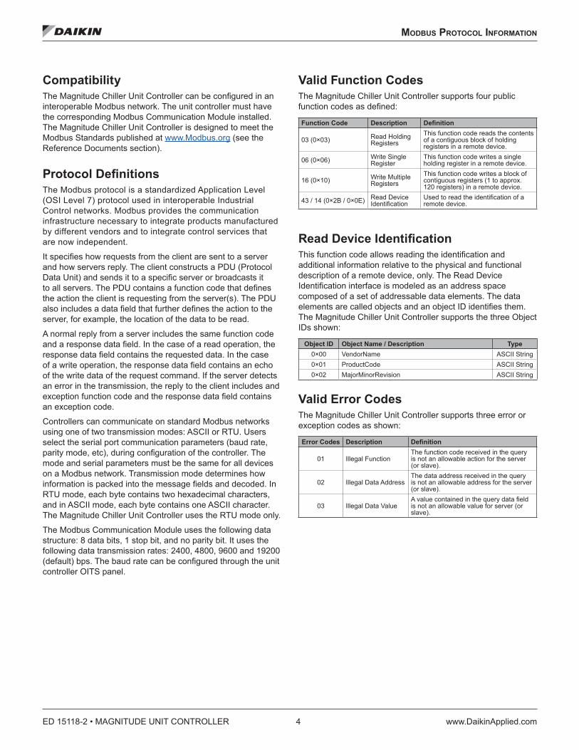
Valid Function CodesThe Magnitude Chiller Unit Controller supports four public function codes as defined:
Function Code Description Definition
03 (0×03) Read Holding Registers
This function code reads the contents of a contiguous block of holding registers in a remote device.
06 (0×06) Write Single Register
This function code writes a single holding register in a remote device.
16 (0×10) Write Multiple Registers
This function code writes a block of contiguous registers (1 to approx. 120 registers) in a remote device.
43 / 14 (0×2B / 0×0E) Read Device Identification
Used to read the identification of a remote device.
Read Device IdentificationThis function code allows reading the identification and additional information relative to the physical and functional description of a remote device, only. The Read Device Identification interface is modeled as an address space composed of a set of addressable data elements. The data elements are called objects and an object ID identifies them. The Magnitude Chiller Unit Controller supports the three Object IDs shown:
Object ID Object Name / Description Type0×00 VendorName ASCII String0×01 ProductCode ASCII String0×02 MajorMinorRevision ASCII String
Valid Error CodesThe Magnitude Chiller Unit Controller supports three error or exception codes as shown:
Error Codes Description Definition
01 Illegal FunctionThe function code received in the query is not an allowable action for the server (or slave).
02 Illegal Data AddressThe data address received in the query is not an allowable address for the server (or slave).
03 Illegal Data ValueA value contained in the query data field is not an allowable value for server (or slave).
Modbus ProToCol InforMaTIon
www.DaikinApplied.com 5 ED 15118-2 • MAGNITUDE UNIT CONTROLLER
Modbus Data PointEach data point accessible from a Modbus network is described with a table that gives the data type and index. If the data point represents an enumerated variable, the enumerations are also listed.
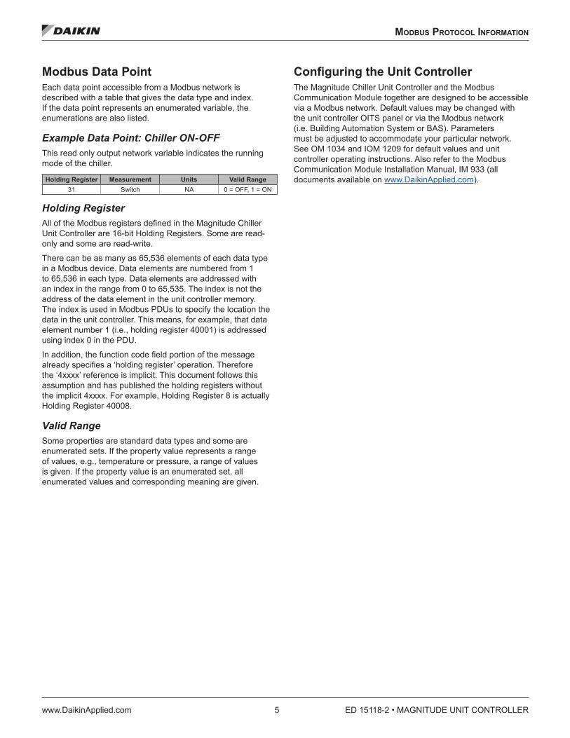
Example Data Point: Chiller ON-OFF This read only output network variable indicates the running mode of the chiller.
Holding Register Measurement Units Valid Range31 Switch NA 0 = OFF, 1 = ON
Holding RegisterAll of the Modbus registers defined in the Magnitude Chiller Unit Controller are 16-bit Holding Registers. Some are read-only and some are read-write.
There can be as many as 65,536 elements of each data type in a Modbus device. Data elements are numbered from 1 to 65,536 in each type. Data elements are addressed with an index in the range from 0 to 65,535. The index is not the address of the data element in the unit controller memory. The index is used in Modbus PDUs to specify the location the data in the unit controller. This means, for example, that data element number 1 (i.e., holding register 40001) is addressed using index 0 in the PDU.
In addition, the function code field portion of the message already specifies a ‘holding register’ operation. Therefore the ‘4xxxx’ reference is implicit. This document follows this assumption and has published the holding registers without the implicit 4xxxx. For example, Holding Register 8 is actually Holding Register 40008.
Valid RangeSome properties are standard data types and some are enumerated sets. If the property value represents a range of values, e.g., temperature or pressure, a range of values is given. If the property value is an enumerated set, all enumerated values and corresponding meaning are given.
Configuring the Unit ControllerThe Magnitude Chiller Unit Controller and the Modbus Communication Module together are designed to be accessible via a Modbus network. Default values may be changed with the unit controller OITS panel or via the Modbus network (i.e. Building Automation System or BAS). Parameters must be adjusted to accommodate your particular network. See OM 1034 and IOM 1209 for default values and unit controller operating instructions. Also refer to the Modbus Communication Module Installation Manual, IM 933 (all documents available on www.DaikinApplied.com).

ED 15118-2 • MAGNITUDE UNIT CONTROLLER 6 www.DaikinApplied.com
TyPICal aPPlICaTIon: MInIMuM InTegraTIon
TyPICal aPPlICaTIon: MInIMuM InTegraTIon
The following section describes how to set up the Magnitude Chiller Unit Controller, with an attached Modbus Communication Module, for network integration.
Set up the Unit Controller for Network IntegrationFrom the Magnitude Chiller Unit Controller OITS panel:
1. Set the Control Source on the SET/UNIT screen to USER.
2. Change the BAS Network Protocol default to the appropriate BAS Protocol on the SET/BAS screen.
3. Verify with the chiller/control company technician that the chiller is operational on the BAS.
4. Set the Control Source on the SET/UNIT screen to BAS.
Display Important Data PointsTypical BAS workstation display of Magnitude Unit Controller attributes include the following significant data points (page number of detailed description in parenthesis). Each data point is identified with a number that also identifies it in the corresponding Comprehensive Data Point Tables.
Table 1: Significant Data Points
No . Configuration1 Chiller Status (11)2 Chiller Mode Setpoint - Network (11)3 Actual Capacity (10)4 Chiller Enable Setpoint - Network (11)
Temperatures5 Condenser Entering Water Temperature (15)6 Condenser Leaving Water Temperature (15)7 Evaporator Entering Water Temperature (16)8 Evaporator Leaving Water Temperature (17)
Setpoints9 Cool Setpoint – Network (16)
10 Capacity Limit Setpoint - Network (10)Alarms
11 Alarm Digital Output (10)12 Clear Alarm - Network (12)13 Active Alarms (20)
You can display any number of additional data points based on job requirements or individual preference. See Modbus Data Points for all available Modbus Variables. For a detailed description of each data point, see the Detailed Data Point Information section.

CoMPrehensIve daTa PoInT Tables
www.DaikinApplied.com 7 ED 15118-2 • MAGNITUDE UNIT CONTROLLER
CoMPrehensIve daTa PoInT Tables
Modbus Register MappingThe Modbus Communication Module supports zero-based addressing. For example, holding register 40002 is addressed as 0001 in a Modbus message. The following tables assume 4xxxx addressing. For example, 1 is holding register 40001.
Table 2: General Data Points
Data Point Name Page R=Read W=Write Holding Register (4xxxx) DescriptionChiller Local/Remote 9 R 1 0=Remote, 1=Local(4) Chiller Enable Setpoint – Network 9 R/W 2 0=Disable (Default), 1=EnableChiller Enable Output 9 R 3 0=Disabled, 1=EnabledRun Enabled 14 R 4 0=OFF, 1=Run Allowed(2) Chiller Mode Setpoint - Network 10 R/W 5 1=Ice, 2=Cool (Default), 3=HeatChiller Mode Output 9 R 6 1=Ice, 2=Cool, 3=Heat(9) Cool Setpoint - Network 12 R/W 7 35 to 80°F (Default = 44°F) 1.7°C to 26.7°CIce Setpoint - Network 13 R/W 8 15 to 35°F (Default = 25°F) -9.5 to 1. 7°CHeat Setpoint - Network 13 R/W 9 100 to 150°F (Default = 135°F) 37.8 to 65.6°CActive Setpoint 9 R 10 15 to 150°F (-9.4 to 65.5°C)(3) Actual Capacity 9 R 11 0% to 100%(10) Capacity Limit Setpoint – Network 9 R/W 12 0% to 100% (Default = 100%)Active Capacity Limit Output 9 R 13 0% to 100%Chiller Capacity Limited 9 R 14 0=Not Limited, 1=Limited(1) Chiller Status 10 R 15 1=OFF, 2=Start, 3=Run, 4=Preshutdown, 5=Service(12) Clear Alarm – Network 10 R/W 16 0=Normal (Default), 1=Clear Alarm(11) Alarm Digital Output 9 R 17 0=No Alarm, 1=Alarm(7) Evaporator Entering Water Temp 12 R 18 -40 to 257°F (-40 to 125°C)(8) Evaporator Leaving Water Temp 13 R 19 -40 to 257°F (-40 to 125°C)Evaporator Water Flow Rate 13 R 20 0 to 10,000 GPM (0 to 631 L/s)Evaporator Flow Switch Status 12 R 21 0=No Flow, 1=Flow(5) Condenser Entering Water Temp 12 R 22 -40 to 257°F (-40 to 125°C)(6) Condenser Leaving Water Temp 12 R 23 -40 to 257°F (-40 to 125°C)Condenser Water Flow Rate 12 R 24 0 to 10,000 GPM (0 to 631 L/s)Condenser Flow Switch Status 12 R 25 0=No Flow, 1=FlowHeat Recovery Entering Water Temp 13 R 26 -40 to 257°F (-40 to 125°C)Heat Recovery Leaving Water Temp 13 R 27 -40 to 257°F (-40 to 125°C)Outdoor Air Temp 13 R 28 -40°F to 212°F (-40°C to 100°C)Liquid Line Refrigerant Temp 13 R 29 -40 to 257°F (-40 to 125°C)Chiller ON-OFF 10 R 31 0=OFF, 1=ON
Sequence Status 14 R 32
bit8 = Chiller at Full Load 0=Not at full load, 1=Full load
bit9 = Circuit/Comp 1 Availability 0=Not Available, 1=Available
All other bits are unused at this time.Condenser Refrigerant Pressure 12 R 53 0 to 410 PSI (0 to 2827 kPA)Condenser Saturated Refrigerant Temp 12 R 54 -15 to 185°F (-26.2 to 85°C)Units of Measure 14 W 321 0=English (Default), 1=MetricActive Alarms 15 R See Table 5
ED 15118-2 • MAGNITUDE UNIT CONTROLLER 8 www.DaikinApplied.com
CoMPrehensIve daTa PoInT Tables
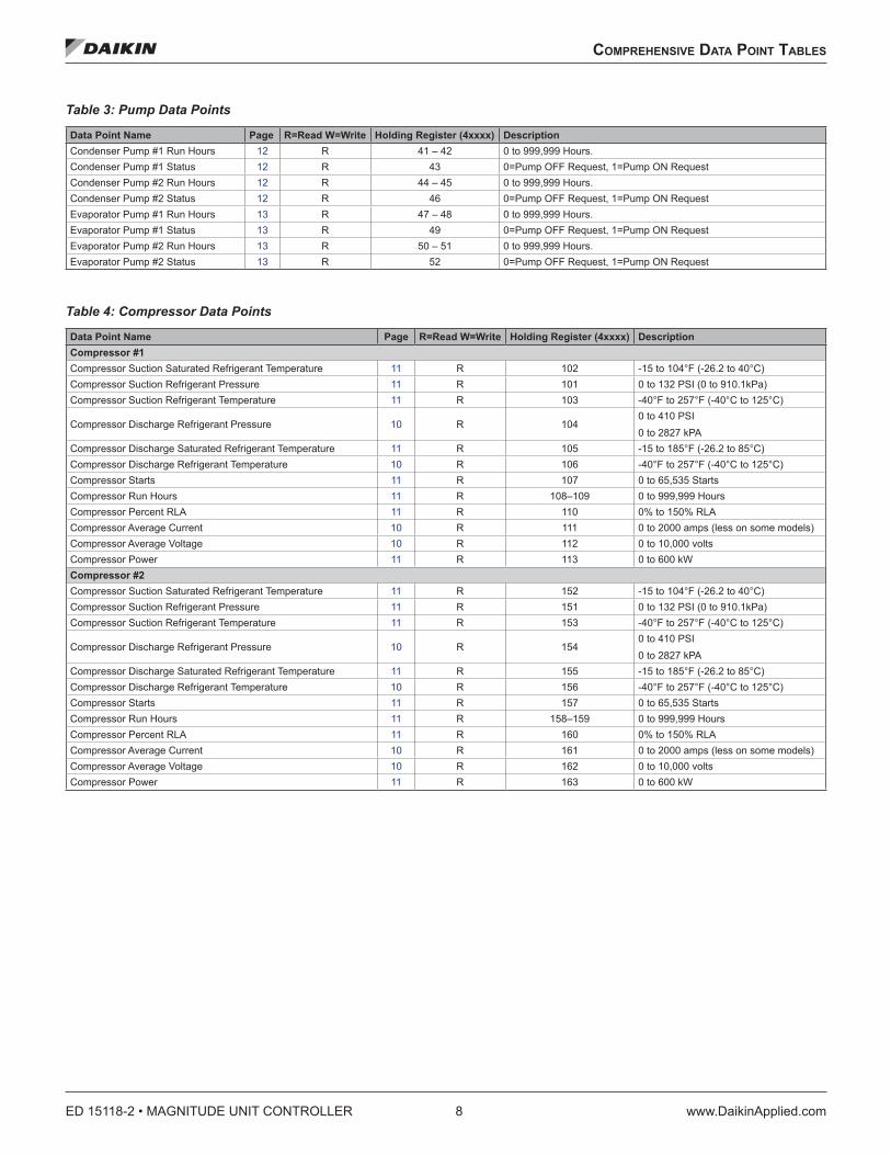
Table 3: Pump Data Points
Data Point Name Page R=Read W=Write Holding Register (4xxxx) DescriptionCondenser Pump #1 Run Hours 12 R 41 – 42 0 to 999,999 Hours. Condenser Pump #1 Status 12 R 43 0=Pump OFF Request, 1=Pump ON RequestCondenser Pump #2 Run Hours 12 R 44 – 45 0 to 999,999 Hours. Condenser Pump #2 Status 12 R 46 0=Pump OFF Request, 1=Pump ON RequestEvaporator Pump #1 Run Hours 13 R 47 – 48 0 to 999,999 Hours. Evaporator Pump #1 Status 13 R 49 0=Pump OFF Request, 1=Pump ON RequestEvaporator Pump #2 Run Hours 13 R 50 – 51 0 to 999,999 Hours. Evaporator Pump #2 Status 13 R 52 0=Pump OFF Request, 1=Pump ON Request
Table 4: Compressor Data Points
Data Point Name Page R=Read W=Write Holding Register (4xxxx) DescriptionCompressor #1Compressor Suction Saturated Refrigerant Temperature 11 R 102 -15 to 104°F (-26.2 to 40°C)Compressor Suction Refrigerant Pressure 11 R 101 0 to 132 PSI (0 to 910.1kPa)Compressor Suction Refrigerant Temperature 11 R 103 -40°F to 257°F (-40°C to 125°C)
Compressor Discharge Refrigerant Pressure 10 R 1040 to 410 PSI0 to 2827 kPA
Compressor Discharge Saturated Refrigerant Temperature 11 R 105 -15 to 185°F (-26.2 to 85°C)Compressor Discharge Refrigerant Temperature 10 R 106 -40°F to 257°F (-40°C to 125°C)Compressor Starts 11 R 107 0 to 65,535 StartsCompressor Run Hours 11 R 108–109 0 to 999,999 HoursCompressor Percent RLA 11 R 110 0% to 150% RLACompressor Average Current 10 R 111 0 to 2000 amps (less on some models)Compressor Average Voltage 10 R 112 0 to 10,000 voltsCompressor Power 11 R 113 0 to 600 kWCompressor #2Compressor Suction Saturated Refrigerant Temperature 11 R 152 -15 to 104°F (-26.2 to 40°C)Compressor Suction Refrigerant Pressure 11 R 151 0 to 132 PSI (0 to 910.1kPa)Compressor Suction Refrigerant Temperature 11 R 153 -40°F to 257°F (-40°C to 125°C)
Compressor Discharge Refrigerant Pressure 10 R 1540 to 410 PSI0 to 2827 kPA
Compressor Discharge Saturated Refrigerant Temperature 11 R 155 -15 to 185°F (-26.2 to 85°C)Compressor Discharge Refrigerant Temperature 10 R 156 -40°F to 257°F (-40°C to 125°C)Compressor Starts 11 R 157 0 to 65,535 StartsCompressor Run Hours 11 R 158–159 0 to 999,999 HoursCompressor Percent RLA 11 R 160 0% to 150% RLACompressor Average Current 10 R 161 0 to 2000 amps (less on some models)Compressor Average Voltage 10 R 162 0 to 10,000 voltsCompressor Power 11 R 163 0 to 600 kW

deTaIled daTa PoInT InforMaTIon
www.DaikinApplied.com 9 ED 15118-2 • MAGNITUDE UNIT CONTROLLER
deTaIled daTa PoInT InforMaTIon
This section describes the information (i.e. data) that is available to the BAS via Modbus.
Active Capacity Limit OutputThis read only variable is a measure of the ratio of operating capacity limit to full capacity expressed in percent. This value is the lowest of all limits specified by the operator, analog Demand Limit input, or Network Capacity Limit Setpoint.
Holding Register Measurement Units Valid Range
13 Percent of Chiller Capacity % 0% to 100%
Active SetpointThis read only variable indicates the current setpoint used to control the chiller. The setpoint that is used is based on the operating mode (Ice, Cool or Heat) of the chiller and any “LWT (Low Water Temperature) reset” functions that are in effect. See “Chiller Mode Output” and “Chiller Mode Setpoint – Network”. The default mode is Cool. There are three possible setpoints. See “Cool Setpoint – Network”, “Heat Setpoint – Network” and “Ice Setpoint – Network”.
Holding Register Measurement Units Valid Range
10 Temperature °F or °C 15 to 150°F / -9.4 to 65.5°C
Actual CapacityThis read only variable indicates the percent of maximum capacity the chiller is producing under the present operating conditions. At 100%, the chiller may be producing more or less than its nominal rating due to variations in operating conditions.
Holding Register Measurement Units Valid Range
11 Percent of Chiller Capacity % 0% to 100%
Alarm Digital OutputThis read only variable indicates whether an alarm condition has occurred. This variable must be polled for alarm notification.
Holding Register Measurement Units Valid Range
17 Switch NA 0 = No Alarm, 1 = Alarm
Capacity Limit Setpoint – NetworkThis read/write variable sets the maximum capacity level of the chiller. This level may be adjusted via the BAS or other network device, but cannot be adjusted above a factory-specified limit. The default is 100%. Values read should be divided by 10. For example, a value of 1000 should be interpreted as 100.0%. Likewise, to write a value of 100%, a value of 1000 should be written.
Holding Register Measurement Units Valid Range
12 Percent of Chiller Capacity × 10 % 0% to 100%
Chiller Capacity LimitedThis read only output network variable indicates whether conditions may exist that prevent the chiller from reaching full capacity.
Holding Register Measurement Units Valid Range
14 Switch NA 0 = Not Limited, 1 = Limited
Chiller Enable OutputThis read only variable indicates if operation of the chiller is disabled or enabled. If the chiller is disabled, it can not run. If it is enabled, the chiller is allowed to run.
Holding Register Measurement Units Valid Range
3 Switch NA 0 = Disabled, 1 = Enabled
Chiller Enable Setpoint – Network This read/write variable is used to disable or enable chiller operation over the network. The default is Disable.
Holding Register Measurement Units Valid Range
2 Switch NA 0 = Disable, 1 = Enable
Chiller Local/RemoteThis read only variable indicates whether the chiller is in local control or allowed to be controlled remotely via the Modbus network. The value can only be changed locally. The values from the following variables are ignored in the chiller application if this variable is set to Local (1):
• Chiller Enable Setpoint• Chiller Mode Setpoint – Network• Cool Setpoint Network• Ice Setpoint Network• Heat Setpoint Network• Capacity Limit Setpoint
Holding Register Measurement Units Valid Range
1 Switch NA 0 = Remote, 1 = Local
Chiller Mode OutputThis read only variable indicates the current operating mode of the chiller.
Holding Register Measurement Units Valid Range
6 Enumeration NA1 = Ice 2 = Cool 3 = Heat

ED 15118-2 • MAGNITUDE UNIT CONTROLLER 10 www.DaikinApplied.com
deTaIled daTa PoInT InforMaTIon
Chiller Mode Setpoint - NetworkThis read/write variable is used to change the operating mode of the chiller. The default is Cool.
Holding Register Measurement Units Valid Range
5 Enumeration NA1 = Ice 2 = Cool 3 = Heat
Chiller ON-OFF This read only variable indicates the running mode of the chiller.
Holding Register Measurement Units Valid Range31 Switch NA 0 = OFF, 1 = ON
Chiller StatusThis read only variable indicates the unit status of the chiller.
Holding Register Measurement Units Valid Range
15 Enumeration NA
1 = OFF 2 = Start 3 = Run 4 = Pre-shutdown 5 =Service
Clear Alarm – NetworkThis read/write network variable clears all active alarms. The following alarms cannot be cleared via the Modbus network. They can only be cleared at the chiller unit controller:
• Low Evaporator Pressure• High Condenser Pressure • Evaporator Freeze Protect• Condenser Freeze Protect• High Motor Temperature• High Motor Gap Temperature• Mechanical High Pressure
Holding Register Measurement Units Valid Range
16 Switch NA 0 = Normal, 1 = Clear Alarm
Compressor Average CurrentThis read only variable indicates the average input line current of the compressor VFD. Values read should be divided by 10. For example, a value of 2000 should be interpreted as 200.0.
Compressor #1Holding Register Measurement Units Valid Range
111 Electric Current × 10 Amperes 0 to 2,000 Amps
Compressor #2Holding Register Measurement Units Valid Range
161 Electric Current × 10 Amperes 0 to 2,000 Amps
Compressor Average VoltageThis read only variable indicates the average input line voltage of the compressor VFD. Values read should be divided by 10. For example, a value of 5000 should be interpreted as 500.0.
Compressor #1Holding Register Measurement Units Valid Range
112 Electric Voltage × 10 Volts 0 to 10,000 Volts
Compressor #2Holding Register Measurement Units Valid Range
162 Electric Voltage × 10 Volts 0 to 10,000 Volts
Compressor Discharge Refrigerant PressureThis read only variable indicates the current refrigerant pressure discharged from the compressor. Values read should be divided by 10. For example, a value of 1330 should be interpreted as 133.0.
Compressor #1Holding Register Measurement Units Valid Range
104 Pressure (gauge) × 10 PSI (kilopaskal) 0 to 410 PSI
(0 to 2827 kPA) Compressor #2Holding Register Measurement Units Valid Range
154 Pressure (gauge) × 10 PSI (kilopaskal) 0 to 410 PSI
(0 to 2827 kPA)
Compressor Discharge Refrigerant TemperatureThis read only variable indicates the current refrigerant temperature discharged from the compressor. Values read should be divided by 10. For example, a value of 1037 should be interpreted as 103.7.
Compressor #1Holding Register Measurement Units Valid Range
106 Temperature × 10 °F or °C -40°F to 257°F (-40°C to 125°C)
Compressor #2Holding Register Measurement Units Valid Range
156 Temperature × 10 °F or °C -40°F to 257°F (-40°C to 125°C)

deTaIled daTa PoInT InforMaTIon
www.DaikinApplied.com 11 ED 15118-2 • MAGNITUDE UNIT CONTROLLER
Compressor Discharge Saturated Refrigerant TemperatureThis read only variable indicates the current saturated refrigerant temperature discharged from the compressor. Values read should be divided by 10. For example, a value of 1037 should be interpreted as 103.7.
Compressor #1Holding Register Measurement Units Valid Range
105 Temperature × 10 °F or °C -15 to 185°F -26.2 to 85°C
Compressor #2Holding Register Measurement Units Valid Range
155 Temperature × 10 °F or °C -15 to 185°F -26.2 to 85°C
Compressor Percent RLAThis read only variable indicates the current percent RLA for the compressor motor of the compressor. Values read should be divided by 10. For example, a value of 810 should be interpreted as 81.0%.
Compressor #1Holding Register Measurement Units Valid Range
110 Percent RLA × 10 % RLA 0% to 150% RLACompressor #2Holding Register Measurement Units Valid Range
160 Percent RLA × 10 % RLA 0% to 150% RLA
Compressor PowerThis read only variable indicates the current power of the compressor motor. Values read should be divided by 10. For example, a value of 1000 should be interpreted as 100.0.
Compressor #1Holding Register Measurement Units Valid Range
113 Electric Power × 10 Kilowatts 0 to 600 kW
Compressor #2Holding Register Measurement Units Valid Range
163 Electric Power × 10 Kilowatts 0 to 600 kW
Compressor Run HoursThis read only variable indicates the number of hours that the compressor motor has been turned on.
Compressor #1Holding Register Measurement Units Valid Range
108 - 109 Elapsed Time Hours 0 to 999,999 Hours
Compressor #2Holding Register Measurement Units Valid Range
158 - 159 Elapsed Time Hours 0 to 999,999 Hours
Compressor StartsThis read only variable indicates the number of times the compressor motor has been started.
Compressor #1Holding Register Measurement Units Valid Range
107 Count Starts 0 to 65,535 StartsCompressor #2Holding Register Measurement Units Valid Range
157 Count Starts 0 to 65,535 Starts
Compressor Suction Refrigerant PressureThis read only variable indicates the current refrigerant pressure entering the compressor. Values read should be divided by 10. For example, a value of 400 should be interpreted as 40.0.
Compressor #1Holding Register Measurement Units Valid Range
101 Pressure (gauge) × 10 PSI or kPa 0 to 132 PSI
(0 to 910.1kPa)Compressor #2Holding Register Measurement Units Valid Range
151 Pressure (gauge) × 10 PSI or kPa 0 to 132 PSI
(0 to 910.1kPa)
Compressor Suction Refrigerant TemperatureThis read only variable indicates the current refrigerant temperature entering the compressor. Values read should be divided by 10. For example, a value of 850 should be interpreted as 85.0.
Compressor #1Holding Register Measurement Units Valid Range
103 Temperature × 10 °F or °C -40°F to 257°F (-40°C to 125°C)
Compressor #2Holding Register Measurement Units Valid Range
153 Temperature × 10 °F or °C -40°F to 257°F (-40°C to 125°C)
Compressor Suction Saturated Refrigerant TemperatureThis read only variable indicates the current saturated refrigerant temperature discharged from the compressor. Values read should be divided by 10. For example, a value of 850 should be interpreted as 85.0.
Compressor #1Holding Register Measurement Units Valid Range
102 Temperature × 10 °F or °C -15 to 104°F -26.2 to 40°C
Compressor #2Holding Register Measurement Units Valid Range
152 Temperature × 10 °F or °C -15 to 104°F -26.2 to 40°C

ED 15118-2 • MAGNITUDE UNIT CONTROLLER 12 www.DaikinApplied.com
deTaIled daTa PoInT InforMaTIon
Condenser Entering Water TemperatureThis read only variable indicates the current temperature of the water entering the condenser. Values read should be divided by 10. For example, a value of 688 should be interpreted as 68.8.
Holding Register Measurement Units Valid Range
22 Temperature × 10 °F or °C -40 to 257°F -40 to 125°C
Condenser Flow Switch StatusThis read only variable indicates the status of the water flowing through the condenser.
Holding Register Measurement Units Valid Range
25 Switch NA 0 = No Flow, 1 = Flow
Condenser Leaving Water TemperatureThis read only variable indicates the current temperature of the water leaving the condenser. Values read should be divided by 10. For example, a value of 688 should be interpreted as 68.8.
Holding Register Measurement Units Valid Range
23 Temperature × 10 °F or °C -40 to 257°F -40 to 125°C
Condenser Pump Run HoursThis read only variable indicates the number of hours that the pump motor has been turned ON.
Pump #1Holding Register Measurement Units Valid Range
41 - 42 Elapsed Time Hours 0 to 999,999 Hours
Pump #2Holding Register Measurement Units Valid Range
44 - 45 Elapsed Time Hours 0 to 999,999 Hours
Condenser Pump StatusThis read only variable indicates if the pump has been commanded ON or OFF.
Condenser #1Holding Register Measurement Units Valid Range
43 Switch NA 0 = Pump OFF
Request1 = Pump ON
RequestCondenser #2Holding Register Measurement Units Valid Range
46 Switch NA 0 = Pump OFF
Request1 = Pump ON
Request
Condenser Refrigerant PressureThis read only variable indicates refrigerant pressure of the condenser. Values read should be divided by 10. For example, a value of 1330 should be interpreted as 133.0.
Holding Register Measurement Units Valid Range
53 Pressure (gauge) × 10 PSI (kPa) 0 to 410 PSI
(0 to 2827 kPA)
Condenser Saturated Refrigerant TemperatureThis read only variable indicates the saturated refrigerant temperature of the condenser. Values read should be divided by 10. For example, a value of 688 should be interpreted as 68.8.
Holding Register Measurement Units Valid Range
54 Temperature × 10 °F or °C -15 to 185°F -26.2 to 85°C
Condenser Water Flow RateThis read only variable indicates the rate of water flow through the condenser.
Holding Register Measurement Units Valid Range
24 Flow Volume GPM (liters/second)
0 to 10,000 GPM (0 to 631 L/s)
Cool Setpoint - NetworkThis read/write variable is used to change the Cooling setpoint from the network. It sets the temperature of the Leaving Chilled Water when the chiller is operating in the Cooling Mode. It cannot be set below the local Cool Setpoint. The default is 44°F. Values read should be divided by 10. For example, a value of 410 should be interpreted as 41.0.
Holding Register Measurement Units Valid Range
7 Temperature × 10 °F or °C 35 to 80°F 1.7°C to 26.7°C
Evaporator Entering Water TemperatureThis read only variable indicates the temperature of the water entering the evaporator. Values read should be divided by 10. For example, a value of 688 should be interpreted as 68.8.
Holding Register Measurement Units Valid Range
18 Temperature × 10 °F or °C -40 to 257°F (-40 to 125°C)
Evaporator Flow Switch StatusThis read only indicates the status of the water flowing through the evaporator.
Holding Register Measurement Units Valid Range
21 Switch NA 0 = No Flow, 1 = Flow

deTaIled daTa PoInT InforMaTIon
www.DaikinApplied.com 13 ED 15118-2 • MAGNITUDE UNIT CONTROLLER
Evaporator Leaving Water TemperatureThis read only variable indicates the current temperature of the water leaving the evaporator. Values read should be divided by 10. For example, a value of 688 should be interpreted as 68.8.
Holding Register Measurement Units Valid Range
19 Temperature × 10 °F or °C -40 to 257°F (-40 to 125°C)
Evaporator Pump Run HoursThis read only variable indicates the number of hours that the pump motor has been turned ON.
Pump #1Holding Register Measurement Units Valid Range
47 - 48 Elapsed Time Hours 0 to 999,999 Hours
Pump #2Holding Register Measurement Units Valid Range
50 - 51 Elapsed Time Hours 0 to 999,999 Hours
Evaporator Pump StatusThis read only variable indicates if the pump has been commanded ON or OFF.
Pump #1Holding Register Measurement Units Valid Range
49 Switch NA 0 = Pump OFF
Request1 = Pump ON
RequestPump #2Holding Register Measurement Units Valid Range
52 Switch NA 0 = Pump OFF
Request1 = Pump ON
Request
Evaporator Water Flow RateThis read only variable indicates the rate of water flow through the evaporator.
Holding Register Measurement Units Valid Range
20 Flow Volume GPM (liters/second)
0 to 10,000 GPM (0 to 631 L/s)
Heat Recovery Entering Water TemperatureThis read only variable indicates the temperature of the water entering the heat recovery section of the condenser. Values read should be divided by 10. For example, a value of 688 should be interpreted as 68.8.
Holding Register Measurement Units Valid Range
26 Temperature × 10 °F or °C -40 to 257°F (-40 to 125°C)
Heat Recovery Leaving Water TemperatureThis read only variable indicates the current temperature of the water leaving the heat recovery section of the condenser. Values read should be divided by 10. For example, a value of 688 should be interpreted as 68.8.
Holding Register Measurement Units Valid Range
27 Temperature × 10 °F or °C -40 to 257°F (-40 to 125°C)
Heat Setpoint – NetworkThis read/write variable is used to change the Heating setpoint from the network. It sets the temperature of the Leaving Condenser Water when the chiller is operating in the Heating Mode. The default is 135°F. Values read should be divided by 10. For example, a value of 1350 should be interpreted as 135.0.
Holding Register Measurement Units Valid Range
9 Temperature × 10 °F or °C100 to 150°F
(Default = 135°F)37.8 to 65.6°C
Ice Setpoint – NetworkThis read/write variable is used to change the Ice setpoint from the network. It sets the temperature of the Leaving Chilled Water when the chiller is operating in the Ice Mode. The default is 25°F. Values read should be divided by 10. For example, a value of 250 should be interpreted as 25.0.
Holding Register Measurement Units Valid Range
8 Temperature × 10 °F or °C15 to 35°F
(Default = 25°F)-9.5 to 1. 7°C
Liquid Line Refrigerant TemperatureThis read only variable indicates the current, liquid line, refrigerant temperature.
Circuit #1Holding Register Measurement Units Valid Range
29 Temperature °F or °C -40 to 257°F (-40 to 125°C)
Outdoor Air TemperatureThis read only variable indicates the current outdoor air temperature. Values read should be divided by 10. For example, a value of 720 should be interpreted as 72.0.
Holding Register Measurement Units Valid Range
28 Temperature × 10 °F or °C -40°F to 212°F (-40°C to 100°F)
ED 15118-2 • MAGNITUDE UNIT CONTROLLER 14 www.DaikinApplied.com
deTaIled daTa PoInT InforMaTIon
Run EnabledThis read only variable indicates the running mode of the chiller. The Run Enabled variable indicates that the chiller can start if operating conditions are met.
Holding Register Measurement Units Valid Range
4 Switch NA 0 = Off, 1 = Run Allowed
Sequence Status This read only variable indicates the circuit/compressor availability of the chiller.
Holding Register Measurement Units Valid Range
32
Bit 8 – Chiller Full Load NA 0 = Not at Full Load
1 = Full Load Bit 9 – Circuit/Compressor 1
AvailabilityNA 0 = Not Available
1 = Available
Units of Measure This read/write holding register selects the units of measure that are passed through Modbus.
Holding Register Measurement Units Valid Range
321 Units of Measure NA0=English (Default),1=Metric

alarMs
www.DaikinApplied.com 15 ED 15118-2 • MAGNITUDE UNIT CONTROLLER
alarMs
Alarm ClassesModbus alarms in a Magnitude Chiller Unit Controller are divided into three classes: Faults, Problems, and Warnings. Fault alarms have the highest severity level. Problem alarms have medium severity level. Warning alarms have the lowest severity level.
Fault AlarmsFault alarms require an acknowledgment from the operator. These alarms indicate that the compressor is shut down.
Problem AlarmsProblem alarms do not cause compressor shutdown but limit operation of the chiller in some way.
Warning AlarmsA warning is enunciated whenever an abnormal condition exists which does not effect chiller operation.
Alarm HandlingOne Modbus network variable indicates an alarm condition and one network variable clears alarms.
Alarm Digital OutputThis read only output network variable indicates whether an alarm condition has occurred. This variable must be polled for alarm notification.
Holding Register Measurement Units Valid Range
17 Switch NA 0 = No Alarm 1 = Alarm
Clear Alarm – NetworkThis read/write variable clears all active alarms. The following alarms cannot be cleared via the network. They can only be cleared at the chiller unit controller.
• Low Evaporator Pressure• High Condenser Pressure • Evaporator Freeze Protect• Condenser Freeze Protect• High Motor Temperature• High Motor Gap Temperature• Mechanical High Pressure
Holding Register Measurement Units Valid Range
16 Switch NA 0 = Normal 1 = Clear Alarm
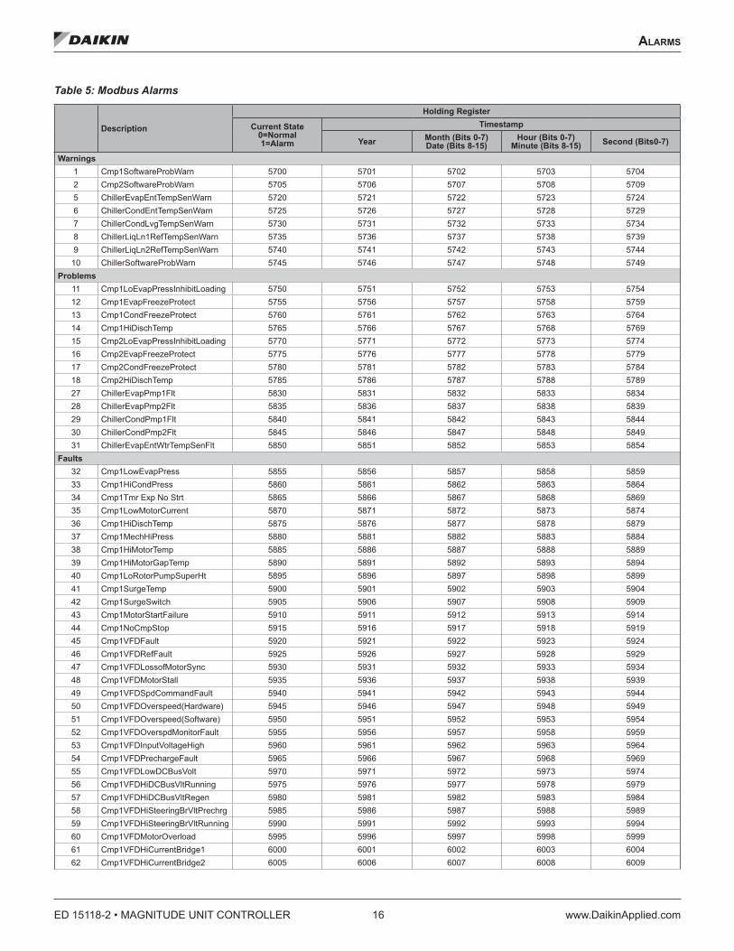
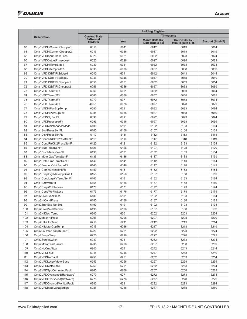
Active AlarmsThe Active Alarms Holding Registers are comprised of several holding registers. There is one holding register for each alarm that indicates the alarm condition, and there are four holding registers for the timestamp for each alarm. You must read the status of these registers to determine the particular alarm condition indicated by the Alarm Digital Output. Table 5 defines the holding registers for each alarm.
Holding Register Measurement Units Valid Range
5700-6819 Alarm Condition & Timestamp NA See Table 5
ED 15118-2 • MAGNITUDE UNIT CONTROLLER 16 www.DaikinApplied.com
alarMs
Table 5: Modbus Alarms
Description
Holding Register
Current State 0=Normal 1=Alarm
Timestamp
Year Month (Bits 0-7) Date (Bits 8-15)
Hour (Bits 0-7) Minute (Bits 8-15) Second (Bits0-7)
Warnings1 Cmp1SoftwareProbWarn 5700 5701 5702 5703 57042 Cmp2SoftwareProbWarn 5705 5706 5707 5708 57095 ChillerEvapEntTempSenWarn 5720 5721 5722 5723 57246 ChillerCondEntTempSenWarn 5725 5726 5727 5728 57297 ChillerCondLvgTempSenWarn 5730 5731 5732 5733 57348 ChillerLiqLn1RefTempSenWarn 5735 5736 5737 5738 57399 ChillerLiqLn2RefTempSenWarn 5740 5741 5742 5743 5744
10 ChillerSoftwareProbWarn 5745 5746 5747 5748 5749Problems
11 Cmp1LoEvapPressInhibitLoading 5750 5751 5752 5753 575412 Cmp1EvapFreezeProtect 5755 5756 5757 5758 575913 Cmp1CondFreezeProtect 5760 5761 5762 5763 576414 Cmp1HiDischTemp 5765 5766 5767 5768 576915 Cmp2LoEvapPressInhibitLoading 5770 5771 5772 5773 577416 Cmp2EvapFreezeProtect 5775 5776 5777 5778 577917 Cmp2CondFreezeProtect 5780 5781 5782 5783 578418 Cmp2HiDischTemp 5785 5786 5787 5788 578927 ChillerEvapPmp1Flt 5830 5831 5832 5833 583428 ChillerEvapPmp2Flt 5835 5836 5837 5838 583929 ChillerCondPmp1Flt 5840 5841 5842 5843 584430 ChillerCondPmp2Flt 5845 5846 5847 5848 584931 ChillerEvapEntWtrTempSenFlt 5850 5851 5852 5853 5854
Faults32 Cmp1LowEvapPress 5855 5856 5857 5858 585933 Cmp1HiCondPress 5860 5861 5862 5863 586434 Cmp1Tmr Exp No Strt 5865 5866 5867 5868 586935 Cmp1LowMotorCurrent 5870 5871 5872 5873 587436 Cmp1HiDischTemp 5875 5876 5877 5878 587937 Cmp1MechHiPress 5880 5881 5882 5883 588438 Cmp1HiMotorTemp 5885 5886 5887 5888 588939 Cmp1HiMotorGapTemp 5890 5891 5892 5893 589440 Cmp1LoRotorPumpSuperHt 5895 5896 5897 5898 589941 Cmp1SurgeTemp 5900 5901 5902 5903 590442 Cmp1SurgeSwitch 5905 5906 5907 5908 590943 Cmp1MotorStartFailure 5910 5911 5912 5913 591444 Cmp1NoCmpStop 5915 5916 5917 5918 591945 Cmp1VFDFault 5920 5921 5922 5923 592446 Cmp1VFDRefFault 5925 5926 5927 5928 592947 Cmp1VFDLossofMotorSync 5930 5931 5932 5933 593448 Cmp1VFDMotorStall 5935 5936 5937 5938 593949 Cmp1VFDSpdCommandFault 5940 5941 5942 5943 594450 Cmp1VFDOverspeed(Hardware) 5945 5946 5947 5948 594951 Cmp1VFDOverspeed(Software) 5950 5951 5952 5953 595452 Cmp1VFDOverspdMonitorFault 5955 5956 5957 5958 595953 Cmp1VFDInputVoltageHigh 5960 5961 5962 5963 596454 Cmp1VFDPrechargeFault 5965 5966 5967 5968 596955 Cmp1VFDLowDCBusVolt 5970 5971 5972 5973 597456 Cmp1VFDHiDCBusVltRunning 5975 5976 5977 5978 597957 Cmp1VFDHiDCBusVltRegen 5980 5981 5982 5983 598458 Cmp1VFDHiSteeringBrVltPrechrg 5985 5986 5987 5988 598959 Cmp1VFDHiSteeringBrVltRunning 5990 5991 5992 5993 599460 Cmp1VFDMotorOverload 5995 5996 5997 5998 599961 Cmp1VFDHiCurrentBridge1 6000 6001 6002 6003 600462 Cmp1VFDHiCurrentBridge2 6005 6006 6007 6008 6009
alarMs
www.DaikinApplied.com 17 ED 15118-2 • MAGNITUDE UNIT CONTROLLER
Description
Holding Register
Current State 0=Normal 1=Alarm
Timestamp
Year Month (Bits 0-7) Date (Bits 8-15)
Hour (Bits 0-7) Minute (Bits 8-15) Second (Bits0-7)
63 Cmp1VFDHiCurrentChopper1 6010 6011 6012 6013 601464 Cmp1VFDHiCurrentChopper2 6015 6016 6017 6018 601965 Cmp1VFDInputPhaseLoss 6020 6021 6022 6023 602466 Cmp1VFDOutputPhaseLoss 6025 6026 6027 6028 602967 Cmp1VFDHiTempSide1 6030 6031 6032 6033 603468 Cmp1VFDHiTempSide2 6035 6036 6037 6038 603969 Cmp1VFD IGBT FltBridge1 6040 6041 6042 6043 604470 Cmp1VFD IGBT FltBridge2 6045 6046 6047 6048 604971 Cmp1VFD IGBT FltChopper1 6050 6051 6052 6053 605472 Cmp1VFD IGBT FltChopper2 6055 6056 6057 6058 605973 Cmp1VFDTherm1Flt 6060 6061 6062 6063 606474 Cmp1VFDTherm2Flt 6065 6066 6067 6068 606975 Cmp1VFDTherm3Flt 6070 6071 6072 6073 607476 Cmp1VFDTherm4Flt 46075 6076 6077 6078 607977 Cmp1VFDHiPwrSupTemp 6080 6081 6082 6083 608478 Cmp1VFDHiPwrSupVolt 6085 6086 6087 6088 608979 Cmp1VFDClgFanFlt 6090 6091 6092 6093 609480 Cmp1VFDProcessorFlt 6095 6096 6097 6098 609981 Cmp1VFDMaintenanceMode 6100 6101 6102 6103 610482 Cmp1SuctPressSenFlt 6105 6106 6107 6108 610983 Cmp1DishPressSenFlt 6110 6111 6112 6113 611484 Cmp1CondRfrCkt1PressSenFlt 6115 6116 6117 6118 611985 Cmp1CondRfrCkt2PressSenFlt 6120 6121 6122 6123 612486 Cmp1SuctTempSenFlt 6125 6126 6127 6128 612987 Cmp1DischTempSenFlt 6130 6131 6132 6133 613488 Cmp1MotorGapTempSenFlt 6135 6136 6137 6138 613989 Cmp1RotorPmpTempSenFlt 6140 6141 6142 6143 614490 Cmp1BearingOrbitSurgeFlt 6145 6146 6147 6148 614991 Cmp1CommunicationsFlt 6150 6151 6152 6153 615492 Cmp1EvapLvgWtrTempSenFlt 6155 6156 6157 6158 615993 Cmp1CondLvgWtrTempSenFlt 6160 6161 6162 6163 616494 Cmp1SoftwareFlt 6165 6166 6167 6168 616995 Cmp1EvapWtrFlwLoss 6170 6171 6172 6173 617496 Cmp1CondWtrFlwLoss 6175 6176 6177 6178 617997 Cmp2LowEvapPress 6180 6181 6182 6183 618498 Cmp2HiCondPress 6185 6186 6187 6188 618999 Cmp2Tmr Exp No Strt 6190 6191 6192 6193 6194
100 Cmp2LowMotorCurrent 6195 6196 6197 6198 6199101 Cmp2HiDischTemp 6200 6201 6202 6203 6204102 Cmp2MechHiPress 6205 6206 6207 6208 6209103 Cmp2HiMotorTemp 6210 6211 6212 6213 6214104 Cmp2HiMotorGapTemp 6215 6216 6217 6218 6219105 Cmp2LoRotorPumpSuperHt 6220 6221 6222 6223 6224106 Cmp2SurgeTemp 6225 6226 6227 6228 6229107 Cmp2SurgeSwitch 6230 6231 6232 6233 6234108 Cmp2MotorStartFailure 6235 6236 6237 6238 6239109 Cmp2NoCmpStop 6240 6241 6242 6243 6244110 Cmp2VFDFault 6245 6246 6247 6248 6249111 Cmp2VFDRefFault 6250 6251 6252 6253 6254112 Cmp2VFDLossofMotorSync 6255 6256 6257 6258 6259113 Cmp2VFDMotorStall 6260 6261 6262 6263 6264114 Cmp2VFDSpdCommandFault 6265 6266 6267 6268 6269115 Cmp2VFDOverspeed(Hardware) 6270 6271 6272 6273 6274116 Cmp2VFDOverspeed(Software) 6275 6276 6277 6278 6279117 Cmp2VFDOverspdMonitorFault 6280 6281 6282 6283 6284118 Cmp2VFDInputVoltageHigh 6285 6286 6287 6288 6289

ED 15118-2 • MAGNITUDE UNIT CONTROLLER 18 www.DaikinApplied.com
alarMs
Description
Holding Register
Current State 0=Normal 1=Alarm
Timestamp
Year Month (Bits 0-7) Date (Bits 8-15)
Hour (Bits 0-7) Minute (Bits 8-15) Second (Bits0-7)
119 Cmp2VFDPrechargeFault 6290 6291 6292 6293 6294120 Cmp2VFDLowDCBusVolt 6295 6296 6297 6298 6299121 Cmp2VFDHiDCBusVltRunning 6300 6301 6302 6303 6304122 Cmp2VFDHiDCBusVltRegen 6305 6306 6307 6308 6309123 Cmp2VFDHiSteeringBrVltPrechrg 6310 6311 6312 6313 6314124 Cmp2VFDHiSteeringBrVltRunning 6315 6316 6317 6318 6319125 Cmp2VFDMotorOverload 6320 6321 6322 6323 6324126 Cmp2VFDHiCurrentBridge1 6325 6326 6327 6328 6329127 Cmp2VFDHiCurrentBridge2 6330 6331 6332 6333 6334128 Cmp2VFDHiCurrentChopper1 6335 6336 6337 6338 6339129 Cmp2VFDHiCurrentChopper2 6340 6341 6342 6343 6344130 Cmp2VFDInputPhaseLoss 6345 6346 6347 6348 6349131 Cmp2VFDOutputPhaseLoss 6350 6351 6352 6353 6354132 Cmp2VFDHiTempSide1 6355 6356 6357 6358 6359133 Cmp2VFDHiTempSide2 6360 6361 6362 6363 6364134 Cmp2VFD IGBT FltBridge1 6365 6366 6367 6368 6369135 Cmp2VFD IGBT FltBridge2 6370 6371 6372 6373 6374136 Cmp2VFD IGBT FltChopper1 6375 6376 6377 6378 6379137 Cmp2VFD IGBT FltChopper2 6380 6381 6382 6383 6384138 Cmp2VFDTherm1Flt 6385 6386 6387 6388 6389139 Cmp2VFDTherm2Flt 6390 6391 6392 6393 6394140 Cmp2VFDTherm3Flt 6395 6396 6397 6398 6399141 Cmp2VFDTherm4Flt 6400 6401 6402 6403 6404142 Cmp2VFDHiPwrSupTemp 6405 6406 6407 6408 6409143 Cmp2VFDHiPwrSupVolt 6410 6411 6412 6413 6414144 Cmp2VFDClgFanFlt 6415 6416 6417 6418 6419145 Cmp2VFDProcessorFlt 6420 6421 6422 6423 6424146 Cmp2VFDMaintenanceMode 6425 6426 6427 6428 6429147 Cmp2SuctPressSenFlt 6430 6431 6432 6433 6434148 Cmp2DishPressSenFlt 6435 6436 6437 6438 6439149 Cmp2CondRfrCkt1PressSenFlt 6440 6441 6442 6443 6444150 Cmp2CondRfrCkt2PressSenFlt 6445 6446 6447 6448 6449151 Cmp2SuctTempSenFlt 6450 6451 6452 6453 6454152 Cmp2DischTempSenFlt 6455 6456 6457 6458 6459153 Cmp2MotorGapTempSenFlt 6460 6461 6462 6463 6464154 Cmp2RotorPmpTempSenFlt 6465 6466 6467 6468 6469155 Cmp2BearingOrbitSurgeFlt 6470 6471 6472 6473 6474156 Cmp2CommunicationsFlt 6475 6476 6477 6478 6479157 Cmp2EvapLvgWtrTempSenFlt 6480 6481 6482 6483 6484158 Cmp2CondLvgWtrTempSenFlt 6485 6486 6487 6488 6489159 Cmp2SoftwareFlt 6490 6491 6492 6493 6494160 Cmp2EvapWtrFlwLoss 6495 6496 6497 6498 6499161 Cmp2CondWtrFlwLoss 6590 6591 6592 6593 6594
aPPendIx a: asCII CharaCTers ConversIon Table
www.DaikinApplied.com 19 ED 15118-2 • MAGNITUDE UNIT CONTROLLER
aPPendIx a: asCII CharaCTers ConversIon Table
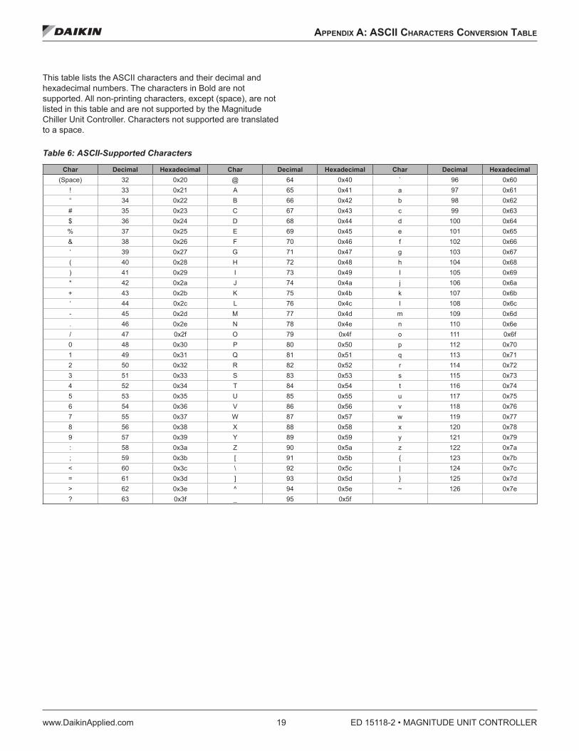
This table lists the ASCII characters and their decimal and hexadecimal numbers. The characters in Bold are not supported. All non-printing characters, except (space), are not listed in this table and are not supported by the Magnitude Chiller Unit Controller. Characters not supported are translated to a space.
Table 6: ASCII-Supported Characters
Char Decimal Hexadecimal Char Decimal Hexadecimal Char Decimal Hexadecimal(Space) 32 0x20 @ 64 0x40 ` 96 0x60
! 33 0x21 A 65 0x41 a 97 0x61“ 34 0x22 B 66 0x42 b 98 0x62# 35 0x23 C 67 0x43 c 99 0x63$ 36 0x24 D 68 0x44 d 100 0x64% 37 0x25 E 69 0x45 e 101 0x65& 38 0x26 F 70 0x46 f 102 0x66‘ 39 0x27 G 71 0x47 g 103 0x67( 40 0x28 H 72 0x48 h 104 0x68) 41 0x29 I 73 0x49 I 105 0x69* 42 0x2a J 74 0x4a j 106 0x6a+ 43 0x2b K 75 0x4b k 107 0x6b‘ 44 0x2c L 76 0x4c l 108 0x6c- 45 0x2d M 77 0x4d m 109 0x6d. 46 0x2e N 78 0x4e n 110 0x6e/ 47 0x2f O 79 0x4f o 111 0x6f0 48 0x30 P 80 0x50 p 112 0x701 49 0x31 Q 81 0x51 q 113 0x712 50 0x32 R 82 0x52 r 114 0x723 51 0x33 S 83 0x53 s 115 0x734 52 0x34 T 84 0x54 t 116 0x745 53 0x35 U 85 0x55 u 117 0x756 54 0x36 V 86 0x56 v 118 0x767 55 0x37 W 87 0x57 w 119 0x778 56 0x38 X 88 0x58 x 120 0x789 57 0x39 Y 89 0x59 y 121 0x79: 58 0x3a Z 90 0x5a z 122 0x7a; 59 0x3b [ 91 0x5b { 123 0x7b< 60 0x3c \ 92 0x5c | 124 0x7c= 61 0x3d ] 93 0x5d } 125 0x7d> 62 0x3e ^ 94 0x5e ~ 126 0x7e? 63 0x3f _ 95 0x5f

ED 15118-2 (02/16) ©2016 Daikin Applied | (800) 432–1342 | www.DaikinApplied.com
Daikin Applied Training and DevelopmentNow that you have made an investment in modern, efficient Daikin equipment, its care should be a high priority. For training information on all Daikin HVAC products, please visit us at www.DaikinApplied.com and click on Training, or call 540-248-9646 and ask for the Training Department.
Warranty
All Daikin equipment is sold pursuant to its standard terms and conditions of sale, including Limited Product Warranty. Consult your local Daikin Applied representative for warranty details. To find your local Daikin Applied representative, go to www.DaikinApplied.com.
Aftermarket Services
To find your local parts office, visit www.DaikinApplied.com or call 800-37PARTS (800-377-2787). To find your local service office, visit www.DaikinApplied.com or call 800-432-1342.
This document contains the most current product information as of this printing. For the most up-to-date product information, please go to www.DaikinApplied.com.
Products manufactured in an ISO Certified Facility.
Related Documents