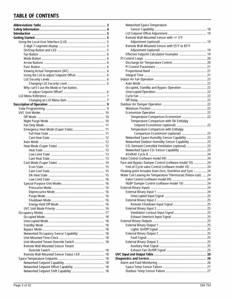
MicroTech II ™ Unit Ventilator Controls for AAF ® -HermanNelson ® Classroom Unit Ventilators Operation Maintenance Manual OM 754 Group: Unit Ventilator Part Number: 106506307 Date: August 2002 Supercedes: New ©2002 AAF ® -HermanNelson ® Used with AAF-HermanNelson Classroom Unit Ventilator Model AVS, AVV – Floor Mounted Model AHF, AHV – Ceiling Mounted Before unit commissioning, please read this publication in its entirety. Develop a thorough understanding before starting the commissioning procedure. This manual is to be used by the commissioner as a guide. Each installation is unique, only general topics are covered. The order in which topics are covered may not be those required for the actual commissioning. IMPORTANT 2-pipe Wet Heat Only – Software Model UV09 (Valve Control) Software Model UV10 (F&BP Damper Control)

Welcome message from author
This document is posted to help you gain knowledge. Please leave a comment to let me know what you think about it! Share it to your friends and learn new things together.
Transcript
MicroTech II™ Unit Ventilator Controlsfor AAF®-HermanNelson® Classroom Unit Ventilators
Operation Maintenance Manual OM 754
Group: Unit Ventilator
Part Number: 106506307
Date: August 2002
Supercedes: New
©2002 AAF®-HermanNelson®
Used with AAF-HermanNelson Classroom Unit VentilatorModel AVS, AVV – Floor Mounted
Model AHF, AHV – Ceiling Mounted
Before unit commissioning, please read this publication in its entirety.Develop a thorough understanding before starting the commissioning procedure.
This manual is to be used by the commissioner as a guide. Each installation is unique, only general topics are covered.The order in which topics are covered may not be those required for the actual commissioning.
IMPORTANT
2-pipe Wet Heat Only –Software Model UV09 (Valve Control)
Software Model UV10 (F&BP Damper Control)
Page 2 of 32 OM 754
TABLE OF CONTENTS
Abbreviations Table ......................................................... 3Safety Information ........................................................... 4Introduction .................................................................. 5Getting Started ............................................................... 5
Using the Local User Interface (LUI) ............................................. 52-digit 7-segment display ........................................................ 5On/Stop Button and LED ......................................................... 5Fan Button ............................................................................... 6Mode Button ............................................................................ 6Arrow Buttons ......................................................................... 6Func Button ............................................................................. 6Viewing Actual Temperature (IAT) ........................................... 6Using the LUI to adjust Setpoint Offset ................................... 6LUI Security Levels .................................................................. 6
Changing LUI Security Level .............................................. 6Why can’t I use the Mode or Fan button,
or adjust Setpoint Offset? .................................................. 6LUI Menu Reference ...................................................................... 7
Changing an LUI Menu Item .............................................. 7Description of Operation ................................................... 9
State Programming ....................................................................... 9UVC Unit Modes .......................................................................... 10
Off Mode ............................................................................... 10Night Purge Mode ................................................................. 10Fan Only Mode ....................................................................... 11Emergency Heat Mode (Super State) ..................................... 11
Full Heat State ................................................................. 11Cant Heat State ................................................................ 12
Auto Mode ............................................................................. 12Heat Mode (Super State) ....................................................... 12
Heat State ........................................................................ 13Low Limit State ............................................................... 13Cant Heat State ................................................................ 13
Cool Mode (Super State) ....................................................... 14Econ State ....................................................................... 15Cant Cool State ................................................................ 15DA Heat State .................................................................. 15Low Limit State ............................................................... 16
Special Purpose Unit Modes.................................................. 16Pressurize Mode .............................................................. 16Depressurize Mode .......................................................... 16Purge Mode ..................................................................... 16Shutdown Mode .............................................................. 16Energy Hold Off Mode ..................................................... 16
UVC Unit Mode Priority ......................................................... 16Occupancy Modes ....................................................................... 17
Occupied Mode...................................................................... 18Unoccupied Mode.................................................................. 18Standby Mode ....................................................................... 18Bypass Mode ......................................................................... 18Networked Occupancy Sensor Capability .............................. 18Unit-Mounted Time-Clock ...................................................... 18Unit-Mounted Tenant Override Switch ................................... 18Remote Wall-Mounted Sensor Tenant
Override Switch ............................................................... 18Remote Wall-Mounted Sensor Status LED ............................ 18
Space Temperature Setpoints ...................................................... 18Networked Setpoint Capability ............................................... 18Networked Setpoint Offset Capability .................................... 18Networked Setpoint Shift Capability ...................................... 18
Networked Space TemperatureSensor Capability ............................................................. 18
LUI Setpoint Offset Adjustment ............................................. 19Remote Wall-Mounted Sensor with +/- 3°F
Adjustment (optional) ...................................................... 19Remote Wall-Mounted Sensor with 55°F to 85°F
Adjustment (optional) ...................................................... 19Effective Setpoint Calculation Examples ................................ 19
PI Control Loops ......................................................................... 20Discharge Air Temperature Control ........................................ 20PI Control Parameters ........................................................... 21Proportional Band ................................................................. 21Integral Time ......................................................................... 21
Indoor Air Fan Operation ............................................................. 22Auto Mode ............................................................................. 22Occupied, Standby and Bypass Operation ............................. 22Unoccupied Operation ........................................................... 22Cycle Fan ............................................................................... 22Off Delay ................................................................................ 22
Outdoor Air Damper Operation .................................................... 22Minimum Position ................................................................. 22Economizer Operation ........................................................... 22
Temperature Comparison Economizer ............................. 22Temperature Comparison with OA Enthalpy
Setpoint Economizer (optional) ................................... 22Temperature Comparison with Enthalpy
Comparison Economizer (optional) ............................. 23Networked Space Humidity Sensor Capability ....................... 23Networked Outdoor Humidity Sensor Capability .................... 23CO2 Demand Controlled Ventilation (optional) ....................... 23Networked Space CO2 Sensor Capability ............................... 23ASHRAE Cycle II .................................................................... 24
Valve Control (software model 09) .............................................. 24Face and Bypass Damper Control (software model 10) ............... 24
End-of-Cycle valve Control (software model 10) ................... 24Floating-point Actuator Auto-Zero, Overdrive and Sync ............... 24Water Coil Leaving Air Temperature Thermostat (freeze-stat) ..... 24
Valve Control (software model 09) ........................................ 24F&BP Damper Control (software model 10) .......................... 24
External Binary Inputs ................................................................. 24External Binary Input 1 .......................................................... 24
Unoccupied Input Signal ................................................. 25External Binary Input 2 .......................................................... 25
Remote Shutdown Input Signal ....................................... 25External Binary Input 3 .......................................................... 25
Ventilation Lockout Input Signal ...................................... 25Exhaust Interlock Input Signal ......................................... 25
External Binary Outputs ............................................................... 25External Binary Output 1 ........................................................ 25
Lights On/Off Signal ........................................................ 25External Binary Output 2 ........................................................ 25
Fault Signal ...................................................................... 25External Binary Output 3 ........................................................ 25
Auxiliary Heat Signal ........................................................ 25Exhaust Fan On/Off Signal ............................................... 25
UVC Input and Output Table .............................................. 26Diagnostics and Service .................................................. 26
Alarm and Fault Monitoring ......................................................... 26Space Temp Sensor Failure ................................................... 27Outdoor Temp Sensor Failure ................................................ 27

OM 754 Page 3 of 32
Discharge Air Temp Sensor Failure ........................................ 27Space Humidity Sensor Failure (optional) ............................. 27Outdoor Humidity Sensor Failure (optional) .......................... 27Space CO2 Sensor Failure (optional) ...................................... 27Change Filter Indication ......................................................... 27
Index of Meaning of AbreviationsAbreviationsAHED Auxiliary Heat End DifferentialAHSD Auxiliary Heat Start DifferentialASCII American Standard Code for Information Interchange
ASHRAEAmerican Society of Heating, Refrigerating,
and Air Conditioning Engineers, IncCCLO Compressor Cooling Lockout SetpointCO2S CO2 SetpointCW Chilled Water
CWVP Chilled Water Valve PositionDA Discharge Air
DAHL Discharge Air High LimitDAT Discharge Air Temp
DATS Discharge Air Temp SetpointDCV Demand Controlled VentilationECD Economizer Compare DifferentialEED Economizer Enthalpy DifferentialEES Economizer Enthalpy SetpointEHS Emergency Heat Setpoint
EOAD Exhaust Outdoor Air DamperEOAT Outdoor Air Temperature OutputEOC End-of-Cycle
EOCS End-of-Cycle Low OAT SetpointEORH Outdoor Air Humidity OutputERH Space Humidity OutputETD Economizer Temperature DifferentialETS Economizer Temperature SetpointEWIT Source (Water-in) TemperatureFBDP Face and Bypass Damper PositionFCC Federal Communications Commission
F & BP Face & BypassHVACR Heating, Ventilating, Air Conditioning, Refrigerating
HW Hot WaterIA Indoor Air
IAF Indoor Air Fan
IAT Indoor Air Temperature
Table 1. Abbreviations
Index of Meaning of AbreviationsAbreviationsLED Light Emitting DiodeLUI Local User Interface
MCLL Mechanical Cooling Low LimitNEC National Electrical CodeOA Outdoor Air
OAD Outdoor Air DamperOADE Energize Exhaust Fan OAD SetpointOADH OAD Min Position High-Speed SetpointOADL OAD Min Position Low-Speed SetpointOADM OAD Min Position Medium-Speed SetpointOADP Outdoor Air Damper PositionOALS Outside Air Lockout PositionOAMX OAD Maximum Position SetpointOAT Outdoor Air TemperatureOCS Occupied Cooling SetpointOHS Occupied Heating Setpoint
PI Proportional IntegralPPM Parts Per MillionRH Relative Humidity
RHS Space Humidity SetpointRO Read OnlyRW Read WriteSCS Standby Cooling SetpointSHS Standby Heating SetpointTXV Thermal eXpansion ValueUCS Unoccupied Cooling SetpointUHS Unoccupied Heating SetpointUV Unit Ventilator
UVC Unit Ventilator ControllerUVCM UVC (Heat/Cool) Mode OutputUVCS UVC State OutputVALP Wet Heat Valve PositionVCLL Ventilation Cooling Low LimitWH Wet Heat
WITD Source (Water-in) Temperature Differential
Troubleshooting Temperature Sensors ........................................ 27Troubleshooting Humidity Sensors ............................................. 28Troubleshooting Carbon Dioxide (CO2) Sensors .......................... 28
UVC Configuration Parameters .......................................... 29
Page 4 of 32 OM 754
If the unit ventilator is to be used for temporary heating or cooling,the unit must first be properly commissioned. Failure to complywith this requirement will void the warranty.
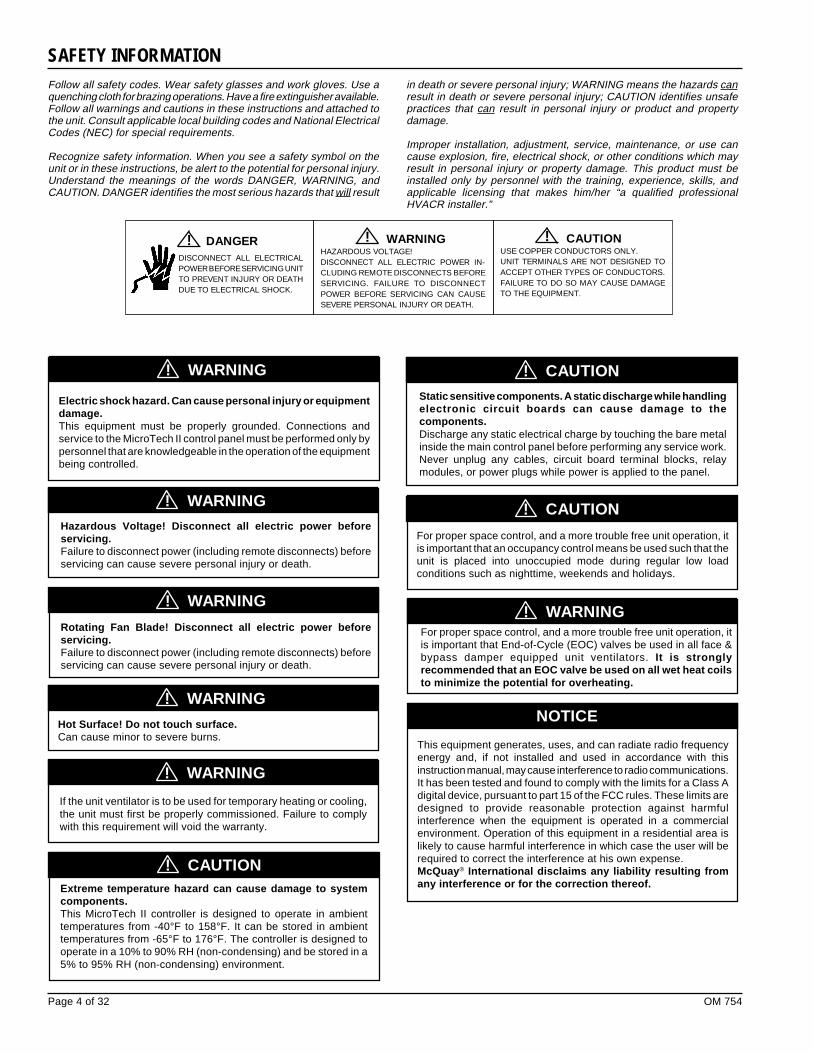
Follow all safety codes. Wear safety glasses and work gloves. Use aquenching cloth for brazing operations. Have a fire extinguisher available.Follow all warnings and cautions in these instructions and attached tothe unit. Consult applicable local building codes and National ElectricalCodes (NEC) for special requirements.
Recognize safety information. When you see a safety symbol on theunit or in these instructions, be alert to the potential for personal injury.Understand the meanings of the words DANGER, WARNING, andCAUTION. DANGER identifies the most serious hazards that will result
DISCONNECT ALL ELECTRICALPOWER BEFORE SERVICING UNITTO PREVENT INJURY OR DEATHDUE TO ELECTRICAL SHOCK.
WARNINGHAZARDOUS VOLTAGE!DISCONNECT ALL ELECTRIC POWER IN-CLUDING REMOTE DISCONNECTS BEFORESERVICING. FAILURE TO DISCONNECTPOWER BEFORE SERVICING CAN CAUSESEVERE PERSONAL INJURY OR DEATH.
! CAUTIONUSE COPPER CONDUCTORS ONLY.UNIT TERMINALS ARE NOT DESIGNED TOACCEPT OTHER TYPES OF CONDUCTORS.FAILURE TO DO SO MAY CAUSE DAMAGETO THE EQUIPMENT.
!! DANGER
NOTICE
WARNING!
WARNING!
CAUTION!
CAUTION!
Static sensitive components. A static discharge while handlingelectronic circuit boards can cause damage to thecomponents.Discharge any static electrical charge by touching the bare metalinside the main control panel before performing any service work.Never unplug any cables, circuit board terminal blocks, relaymodules, or power plugs while power is applied to the panel.
Extreme temperature hazard can cause damage to systemcomponents.This MicroTech II controller is designed to operate in ambienttemperatures from -40°F to 158°F. It can be stored in ambienttemperatures from -65°F to 176°F. The controller is designed tooperate in a 10% to 90% RH (non-condensing) and be stored in a5% to 95% RH (non-condensing) environment.
in death or severe personal injury; WARNING means the hazards canresult in death or severe personal injury; CAUTION identifies unsafepractices that can result in personal injury or product and propertydamage.
Improper installation, adjustment, service, maintenance, or use cancause explosion, fire, electrical shock, or other conditions which mayresult in personal injury or property damage. This product must beinstalled only by personnel with the training, experience, skills, andapplicable licensing that makes him/her “a qualified professionalHVACR installer.”
SAFETY INFORMATION
This equipment generates, uses, and can radiate radio frequencyenergy and, if not installed and used in accordance with thisinstruction manual, may cause interference to radio communications.It has been tested and found to comply with the limits for a Class Adigital device, pursuant to part 15 of the FCC rules. These limits aredesigned to provide reasonable protection against harmfulinterference when the equipment is operated in a commercialenvironment. Operation of this equipment in a residential area islikely to cause harmful interference in which case the user will berequired to correct the interference at his own expense.McQuay® International disclaims any liability resulting fromany interference or for the correction thereof.
Electric shock hazard. Can cause personal injury or equipmentdamage.This equipment must be properly grounded. Connections andservice to the MicroTech II control panel must be performed only bypersonnel that are knowledgeable in the operation of the equipmentbeing controlled.
CAUTION!
For proper space control, and a more trouble free unit operation, itis important that an occupancy control means be used such that theunit is placed into unoccupied mode during regular low loadconditions such as nighttime, weekends and holidays.
Hot Surface! Do not touch surface.Can cause minor to severe burns.
WARNING!Hazardous Voltage! Disconnect all electric power beforeservicing.Failure to disconnect power (including remote disconnects) beforeservicing can cause severe personal injury or death.
WARNING!
Rotating Fan Blade! Disconnect all electric power beforeservicing.Failure to disconnect power (including remote disconnects) beforeservicing can cause severe personal injury or death.
WARNING!
For proper space control, and a more trouble free unit operation, itis important that End-of-Cycle (EOC) valves be used in all face &bypass damper equipped unit ventilators. It is stronglyrecommended that an EOC valve be used on all wet heat coilsto minimize the potential for overheating.
WARNING!

OM 754 Page 5 of 32
Unit Ventilator Available Protocols Bulletin NumberUnit Ventilator Unit Controller LonWorks® Communications Module IM 729
Unit Ventilator Unit Controller JCI N2 Open® Communications Module IM 730
Unit Ventilator Unit Controller BACnet® Communications Module IM 731
Protocol Data Packet ED-15065
Unit Ventilator Installation
Model Designations Description Manual BulletinNumber
AED, AEQ Air Source Heat Pump IM 502
ARQ, ERQ Water Source Heat Pump IM UV-3-202
AZS, AZQ, AZV, AZU, AZR Self-contained IM 503
AVS, AVV, AVR, AVB Vertical Split-system
AHF, AHV, AHR, AHB Horizontal Split-systemIM 725
Unit Ventilator Control Configuration Bulletin NumberMicroTech II Unit Ventilator Controller IM 747
Many UVC parameters are accessible both through the LUI and thenetwork interface. The shared LUI and the network interfacevariables have a “last-change-wins” relationship.
2-DIGIT 7-SEGMENT DISPLAYThe LUI 2-digit 7-segment display normally will be displaying theeffective (current) heating or cooling setpoint (Effective SetpointOutput). The LUI display is also used to view and adjust many UVCparameters as explained in the following sections.
When the UVC is in the Off mode, the LUI will display the currentheating setpoint and all other LED’s will be switched off.
ON/STOP BUTTON AND LEDThe On/Stop button is used to toggle the UVC between Off mode andrunning (Application Mode Input). The On/Stop LED will be off whenthe UVC is in the off mode.
GETTING STARTED
This manual contains information regarding the MicroTech II™ controlsystem used in the AAF®-HermanNelson® Unit Ventilator productline. It describes the MicroTech II components, input/outputconfigurations, field wiring options and requirements, and serviceprocedures.For installation and general information on the MicroTech II UnitVentilator Controller, refer to the appropriate installation andmaintenance bulletin, see Table 2.
Table 3. Model-Specific Unit Ventilator Installation Literature
Table 2. MicroTech UVC Installation Literature
Using the Local User Interface (LUI)The MicroTech II UVC is a self-contained device that is capable ofcomplete, stand-alone operation. Information in the controller can bedisplayed and modified by using the Local User Interface (LUI). Thefollowing sections describe how to use the LUI.
Table 4. Protocol-Specific Communication Card Installation Literature and Protocol Data
Figure 1. Local User Interface (LUI)
NOTICE
INTRODUCTION
For installation, commissioning instructions and general informationon a particular unit ventilator model, refer to the appropriate model-specific installation manual, refer to Table 3.For installation and manual instructions on a particular plug-incommunications card, refer to the appropriate protocol-specificinstallation manual, see Table 4. For a description of supportednetwork variables for each protocol refer to Protocol Data Packetbulletin, see Table 4.
NOTICE
Page 6 of 32 OM 754
The UVC archives each change to the LUI Fan and Mode buttons.When the On/Stop button is used to bring the unit out of Off mode,the UVC will implement the last active fan and unit modes.
Each time the UVC power is cycled, the UVC will be in auto fan andauto unit modes when power is returned.
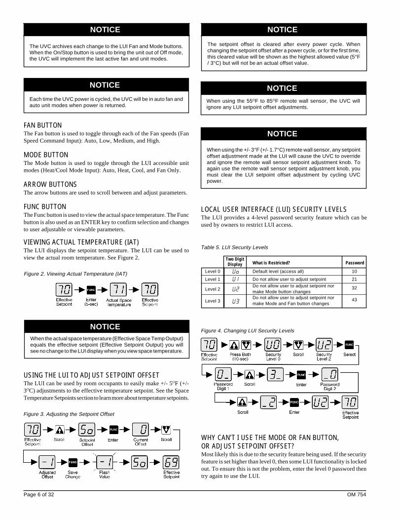
FAN BUTTONThe Fan button is used to toggle through each of the Fan speeds (FanSpeed Command Input): Auto, Low, Medium, and High.
MODE BUTTONThe Mode button is used to toggle through the LUI accessible unitmodes (Heat/Cool Mode Input): Auto, Heat, Cool, and Fan Only.
ARROW BUTTONSThe arrow buttons are used to scroll between and adjust parameters.
FUNC BUTTONThe Func button is used to view the actual space temperature. The Funcbutton is also used as an ENTER key to confirm selection and changesto user adjustable or viewable parameters.
VIEWING ACTUAL TEMPERATURE (IAT)The LUI displays the setpoint temperature. The LUI can be used toview the actual room temperature. See Figure 2. Two Digit
What is Restricted? PasswordDisplayLevel 0 Default level (access all) 10
Level 1 Do not allow user to adjust setpoint 21
Level 2Do not allow user to adjust setpoint normake Mode button changes
32
Level 3Do not allow user to adjust setpoint normake Mode and Fan button changes
43
Table 5. LUI Security Levels
Figure 4. Changing LUI Security Levels
WHY CAN’T I USE THE MODE OR FAN BUTTON,OR ADJUST SETPOINT OFFSET?Most likely this is due to the security feature being used. If the securityfeature is set higher than level 0, then some LUI functionality is lockedout. To ensure this is not the problem, enter the level 0 password thentry again to use the LUI.
When using the +/- 3°F (+/- 1.7°C) remote wall sensor, any setpointoffset adjustment made at the LUI will cause the UVC to overrideand ignore the remote wall sensor setpoint adjustment knob. Toagain use the remote wall sensor setpoint adjustment knob, youmust clear the LUI setpoint offset adjustment by cycling UVCpower.
Figure 3. Adjusting the Setpoint Offset
NOTICE
NOTICE
NOTICE
NOTICE
NOTICE
LOCAL USER INTERFACE (LUI) SECURITY LEVELSThe LUI provides a 4-level password security feature which can beused by owners to restrict LUI access.
The setpoint offset is cleared after every power cycle. Whenchanging the setpoint offset after a power cycle, or for the first time,this cleared value will be shown as the highest allowed value (5°F/ 3°C) but will not be an actual offset value.
Figure 2. Viewing Actual Temperature (IAT)
When the actual space temperature (Effective Space Temp Output)equals the effective setpoint (Effective Setpoint Output) you willsee no change to the LUI display when you view space temperature.
NOTICE
When using the 55OF to 85OF remote wall sensor, the UVC willignore any LUI setpoint offset adjustments.
USING THE LUI TO ADJUST SETPOINT OFFSETThe LUI can be used by room occupants to easily make +/- 5OF (+/-3OC) adjustments to the effective temperature setpoint. See the SpaceTemperature Setpoints section to learn more about temperature setpoints.
OM 754 Page 7 of 32
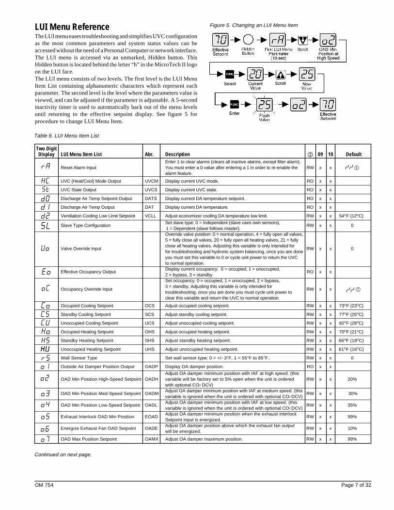
LUI Menu ReferenceThe LUI menu eases troubleshooting and simplifies UVC configurationas the most common parameters and system status values can beaccessed without the need of a Personal Computer or network interface.The LUI menu is accessed via an unmarked, Hidden button. ThisHidden button is located behind the letter “h” in the MicroTech II logoon the LUI face.The LUI menu consists of two levels. The first level is the LUI MenuItem List containing alphanumeric characters which represent eachparameter. The second level is the level where the parameters value isviewed, and can be adjusted if the parameter is adjustable. A 5-secondinactivity timer is used to automatically back out of the menu levelsuntil returning to the effective setpoint display. See figure 5 forprocedure to change LUI Menu Item.
Figure 5. Changing an LUI Menu Item
Table 6. LUI Menu Item List
Two DigitDisplay LUI Menu Item List Abr. Description � 09 10 Default
Enter 1 to clear alarms (clears all inactive alarms, except filter alarm).Reset Alarm Input You must enter a 0 value after entering a 1 in order to re-enable the RW x x �
alarm feature.
UVC (Heat/Cool) Mode Output UVCM Display current UVC mode. RO x x
UVC State Output UVCS Display current UVC state. RO x x
Discharge Air Temp Setpoint Output DATS Display current DA temperature setpoint. RO x x
Discharge Air Temp Output DAT Display current DA temperature. RO x x
Ventilation Cooling Low Limit Setpoint VCLL Adjust economizer cooling DA temperature low limit. RW x x 54OF (12OC)
Slave Type ConfigurationSet slave type: 0 = Independent (slave uses own sensors),
RW x x 01 = Dependent (slave follows master).Override valve position: 0 = normal operation, 4 = fully open all valves,5 = fully close all valves, 20 = fully open all heating valves, 21 = fully
Valve Override Inputclose all heating valves. Adjusting this variable is only intended for
RW x x 0for troubleshooting and hydronic system balancing, once you are doneyou must set this variable to 0 or cycle unit power to return the UVCto normal operation.
Effective Occupancy OutputDisplay current occupancy: 0 = occupied, 1 = unoccupied,
RO x x2 = bypass, 3 = standby.Set occupancy: 0 = occupied, 1 = unoccupied, 2 = bypass,
Occupancy Override Input3 = standby. Adjusting this variable is only intended for
RW x x �troubleshooting, once you are done you must cycle unit power toclear this variable and return the UVC to normal operation.
Occupied Cooling Setpoint OCS Adjust occupied cooling setpoint. RW x x 73OF (23OC)
Standby Cooling Setpoint SCS Adjust standby cooling setpoint. RW x x 77OF (25OC)
Unoccupied Cooling Setpoint UCS Adjust unoccupied cooling setpoint. RW x x 82OF (28OC)
Occupied Heating Setpoint OHS Adjust occupied heating setpoint. RW x x 70OF (21OC)
Standby Heating Setpoint SHS Adjust standby heating setpoint. RW x x 66OF (19OC)
Unoccupied Heating Setpoint UHS Adjust unoccupied heating setpoint. RW x x 61OF (16OC)
Wall Sensor Type Set wall sensor type: 0 = +/- 3°F, 1 = 55°F to 85°F. RW x x 0
Outside Air Damper Position Output OADP Display OA damper position. RO x x
Adjust OA damper minimum position with IAF at high speed. (thisOAD Min Position High-Speed Setpoint OADH variable will be factory set to 5% open when the unit is ordered RW x x 20%
with optional CO2 DCV)
OAD Min Position Med-Speed Setpoint OADMAdjust OA damper minimum position with IAF at medium speed. (this
RW x x 30%variable is ignored when the unit is ordered with optional CO2 DCV)
OAD Min Position Low-Speed Setpoint OADLAdjust OA damper minimum position with IAF at low speed. (this
RW x x 35%variable is ignored when the unit is ordered with optional CO2 DCV)
Exhaust Interlock OAD Min Position EOADAdjust OA damper minimum position when the exhaust interlock
RW x x 99%Setpoint input is energized.
Energize Exhaust Fan OAD Setpoint OADEAdjust OA damper position above which the exhaust fan output
RW x x 10%will be energized.
OAD Max Position Setpoint OAMX Adjust OA damper maximum position. RW x x 99%
Continued on next page.
Page 8 of 32 OM 754
Table 6. LUI Menu Item List (Continued)
Two DigitDisplay LUI Menu Item List Abr. Description � 09 10 Default
Set OA damper lockout feature status: 0 = disable, 1 = enable.OAD Lockout Enable (this variable will be factory set to 1 when the unit is ordered as a RW x x 0
recirc unit with no OAD)Adjust OA temperature below which the OA damper will be closed
OAD Lockout Setpoint OALS if the OA damper lockout is enabled. (this variable will be factory RW x x 36OF (2OC)set to –99OC when the unit is ordered as a recirc unit with no OAD)
Economizer Enable Set economizer status: 0 = disable, 1 = enable. RW x x 1
Economizer OA Temp Setpoint ETS Adjust economizer OA temperature setpoint. RW x x 68OF (20OC)
Economizer IA/OA Temp Differential ETD Adjust economizer IA/OA temperature differential. RW x x 2OF (1OC)
Adjust economizer IA/OA temperature differential. This variable isEconomizer Compare Differential ECD identical to Economizer IA/OA Temp Differential and therefore RW x x 0OF (0OC)
need not be used (do not change).
Economizer OA Enthalpy Setpoint EES Adjust economizer OA enthalpy setpoint. RW x x25 btu/lb(58 kJ/kg)
Economizer IA/OA Enthalpy Differential EED Adjust economizer IA/OA enthalpy differential. RW x x1 btu/lb
(3 kJ/kg)
Space Humidity Output ERH Display room humidity (optional). RO x x
Outdoor Air Humidity Output EORH Display OA humidity (optional). RO x x
Outdoor Air Temp Output EOAT Display OA temperature. RO x x
Emergency Heat Enable Set emergency heat status: 0 = disable, 1 = enable. RW x x 1
Emergency Heat Setpoint EHS Adjust emergency heat setpoint. RW x x 54OF (12OC)
Emergency Heat Shutdown Set emergency heat operation during shutdown, 0 = no emergencyConfiguration heat during shutdown: 1 = allow emergency heat during shutdown.
RW x x 0
Auxiliary Heat Start Differential AHSD Adjust auxiliary heat start differential. RW x x 2OF (1OC)
Auxiliary Heat End Differential AHED Adjust auxiliary heat stop differential. RW x x 2OF (1OC)
Auxiliary Heat Configuration Set auxiliary heat type: 0 = N.O. device, 1 = N.C. device RW x x 0
External BI-3 ConfigurationSet the function of external binary Input 3: 0 = ventilation lockout,
RW x x 01 = exhaust interlock.
External BO-3 ConfigurationSet the function of external binary output 3: 0 = auxiliary heat,
RW x x 01 = exhaust fan on/off signal.
Fan Cycling ConfigurationSet if IAF cycles (switches off) during occupied, bypass, and
RW x x 2standby mode: 2 = no cycling, 3 = cycle IAF.
Filter Alarm Enable Set filter alarm status: 0 = disable, 1 = enable. RW x x 0
Reset Filter Alarm InputEnter 1 to clear filter alarm. You must go back and enter a 0 value
RW x x �after entering a 1 to re-enable the filter alarm.Adjust EOC low OA temperature setpoint. When the OA
EOC Low OAT Setpoint EOCS temperature falls below this setpoint the heat or heat/cool EOC RW x 39OF (4OC)valve will remain open.
F&BP Damper Position Output FBDP Display F&BP damper position. RO x
WH Valve Position Output VALP Display WH valve position RO x
LUI Temperature Units Set LUI temperature display units in degrees F or degrees C. RW x x F
� If a menu item value is greater than 2-digits (higher than 99), then will be displayed by the LUI.
� RW = read and write capable, RO = read only. (All RO values displayed are snapshots and are not dynamically updated as the value is displayed.)� Additional UVC field configuration is required if the dewpoint/humidity binary input is used, consult the factory.

OM 754 Page 9 of 32
State ProgrammingThe MicroTech II UVC takes advantage of state machine programmingto define and control unit ventilator operation. State machines definespecific states, or modes of operation for each process within the unitventilator (i.e. heating, cooling, etc.) and contain the specific logic foreach state. This eliminates some of the most common problemsassociated with control sequences such as the possibility of simultaneousheating and cooling, rapid cycling, etc.State machine programming, and the unique nature of state diagrams,can be easily used to describe unit ventilator operation, and can vastlysimplify sequence verification during unit commissioning, as well assimplify troubleshooting. With the unique combination of state machineprogramming and the LUI’s ability to allow a technician to easilydetermine the active UVC state, troubleshooting the UVC can be verysimple.The state diagrams presented in the following sections consist ofseveral “elements” including Super States, States, Conditional Jumps(also called transitions) and a Transition Point. Super states are used asa means to group two or more related states into a single controlfunction such as cooling, or heating, etc. States are where all the actualwork takes place, within each state the UVC enables PI-loops and otherlogic sequences required to control unit ventilator operation within thatparticular state, while other functions and PI-loops not needed duringthat state may be disabled. Conditional jumps, or transitions, are the
Not all states or modes are available for all UV configurations, andsome states (such as Active Dehumidification) are optional.
DESCRIPTION OF OPERATION
Figure 6. Complete UVC - State Program
In the state descriptions below the terms saturated high andsaturated low indicate that the heating or cooling function beingdescribed has reached 100% or 0% respectively.
logic paths used by the UVC to determine which state should be madeactive, these are the “questions” the UVC will continually consider.The transition point is simply a point through which a number ofconditional jumps meet, you can think of it as a point where a numberof questions must be considered from which the UVC then determineswhich path is followed and which state is then made active.The UVC states and super states are used to define the “normal” unitmodes, such as Off, Night Purge, Fan Only, Emergency Heat, Auto,Cool, and Heat. The UVC also supports several “special purpose” unitmodes such as Purge, Pressurize, De-pressurize, and Shutdown, whichcan be forced via a network connection and override typical UVCoperation.
NOTICE
NOTICE

Page 10 of 32 OM 754
Table 7. UVC State Names and Numbers (see figure 6)
State StateNormal UVC Modes Numbers
Names (ASCII)
Off Off 9(57)
Night Purge Night Purge 8(56)
Fan Only Fan Only A(65)
Emergency Heat Full Heat 7(55)Super State Cant Heat D(68)
Heat 5(53)Heat Cant Heat B(66)
Super StateLow Limit E(69)
Auto Econ 3(51)
Cool DA Heat 4(52)Super State Cant Cool C(67)
Low Limit F(70)
UVC Unit ModesThe UVC provides several “normal” modes of unit operation, theseinclude Off, Night Purge, Fan Only, Cool, Emergency Heat, Auto,Heat and Cool.Normal UVC modes can contain a single state or several statesdependent upon the functionality required for each particular mode.Each UVC state has been assigned a number. This state number can bevery helpful when trying to understand which state is currently activewithin the UVC. The current UVC state number can be viewed usingthe LUI. See Figure 6 for Super State and State.
Transition(UVC Mode = Off)into State
Operation When Off mode becomes active, the UVC stops all
within State normal heating, cooling, ventilation (OA damper is
closed), and fan operation. The UVC will continue to
monitor space conditions, indicate faults, and provide
network communications (if connected to a network)
as long as power is maintained to the unit. If the space
temperature drops below EHS, and the Emergency
Heat function is enabled, the UVC will be forced into
the Emergency Heat mode (see Emergency Heat Mode).
The space lighting output will continue to operate
normally based upon the current UVC occupancy
mode.
Special purpose unit modes (i.e. Purge, Pressurize,
and De-pressurize modes) accessed via a network
connection can force the UVC to perform “special”
functions during which the UVC will appear to be in
the Off mode. See Special Purpose Unit Modes, and
the UVC Unit Mode Priority sections for more
information.
The UVC will remain in this state until one of the
transition out conditions become true.
Transition(UVC Mode ≠ Off)
out of State
Figure 7. Off State Diagram
OFF MODE (STATE NUMBER 9)Off mode is provided so that the UVC can be forced into a powered offcondition. The Off mode is a “stop” state for the unit ventilator, it is nota power off state. The LUI or a network connection can force the unitinto the Off mode. Off mode consists of a single UVC state: Off [9].
WARNING!
Off mode is a “stop” state for the unit ventilator. It is not a “poweroff” state. Power may still be provided to the unit.
NIGHT PURGE MODE (STATE NUMBER 8)Night Purge mode is provided as a means to more easily and quicklyventilate a space. Night purge can be useful in helping to remove odorbuild up at the end of each day, or after cleaning, painting, or other odorgenerating operations occur within the space. Night Purge is a fullventilation with exhaust mode, during which room comfort will verylikely be compromised, it is therefore strongly recommended thatNight Purge only be used when the space is unoccupied. The LUI or anetwork connection can force the unit into the Night Purge mode. NightPurge mode consists of a single UVC state: Night Purge [8].
Transition(UVC Mode = Night Purge)into State
Operation When Night Purge mode becomes active, the UVC
within State stops all normal heating and cooling as any new energy
used to treat the incoming air would be wasted in the
Figure 8. Night Purge State Diagram

OM 754 Page 11 of 32
FAN ONLY MODE (STATE NUMBER A)The Fan Only mode is provided so that the UVC can be forced into aFan Only operation. The LUI or a network connection can force the unitinto the Fan Only mode. Fan Only mode consists of a single UVC state:Fan Only [A].
Transition(UVC Mode = Fan Only)into State
Operation When Fan Only mode becomes active, the UVC stops
within State all normal heating and cooling. If the space temperature
drops below the EHS, and the Emergency Heat function
is enabled, the UVC will be forced into the Emergency
Heat mode (see the Emergency Heat Mode).
The UVC will remain in this state until one of the
transition out conditions become true.
Transition(UVC Mode ≠ Fan Only)out of State
Figure 9. Fan Only State Diagram
EMERGENCY HEAT MODE (SUPER STATE)The Emergency Heat mode is provided for situations where the UVCis in a mode that does not normally allow heating, such as Off, Cool,Night Purge, or Fan Only. If Emergency Heat mode is enabled, theUVC can automatically force itself into the Emergency Heat modefrom Off, Cool, Night Purge, Fan Only, Purge, Pressurize, De-pressurize,and Shutdown. Additionally, the LUI or a network connection can beused to force the unit into the Emergency Heat mode. Emergency Heatmode consists of two UVC states: Full Heat [7] and Cant Heat [D].
Transitioninto (UVC Mode = Emergency Heat)
Super State
Operation When the Emergency Heat mode super state becomes
within active, the UVC will automatically determine which
Super State which UVC state to make active, Full Heat [7] or Cant
Heat [D], based upon the transitions for each of those
states.
The UVC will remain in this super state until one of the
transition out conditions become true.
Transitionout of (UVC Mode ≠ Emergency Heat)
Super State
Figure 10. Emergency Heat State Diagram
Full Heat State (State Number 7)The Full Heat state is the “normal” state that the UVC will go into whenEmergency Heat mode is active.
TransitionHeat = Availableinto State
Operation When Emergency Heat mode becomes active, the
within State UVC will go into 100% heating until the space
temperature raises to the EHS plus a fixed differential
(9OF / 5OC). In the Emergency Heat mode the space fan
will be set to high speed, and the OA damper will
operate normally. If the UVC forces itself into the
Emergency Heat mode from another mode, then the
UVC will return to the appropriate unit mode once the
space temperature rises to the EHS plus the fixed
differential. The UVC will monitor the DAT to ensure
it does not exceed DAHL. If the DAT does exceed
DAHL (140OF / 60OC default), then heating will be set
to 0% for a minimum of 2-minutes (fixed) and until the
DAT drops 18OF (10OC) fixed differential below
DAHL.
The UVC will remain in this state until one of the
transition out conditions become true, or until one of
the superstate transition out conditions becomes true.
Transition(Heat ≠ Available)out of State
Notes:(Heat ≠ Available) is true when an IAT or DAT sensor fault exists (seeUnit Faults).
purging process. In the Night Purge mode the space
fan will be set to high speed, the OA damper will be set
to 100% open, and the Exhaust Fan binary output (see
External Binary Outputs) will be set to On. If not set to
another mode within 1-hour, the UVC will force itself
into the Fan Only mode (see Fan Only Mode). If the
space temperature drops below the EHS, and the
Emergency Heat function is enabled, the UVC will be
forced into the Emergency Heat mode (see Emergency
Heat Mode).
The UVC will remain in this state until one of the
transition out conditions become true.
Transition(UVC Mode ≠ Night Purge)out of State

Page 12 of 32 OM 754
AUTO MODEAuto mode is provided so that the UVC can be set to automaticallydetermine if heating, cooling or dehumidification is required. Automode is the default start-up UVC mode. Auto mode is made up of theHeat and Cool modes. When the UVC is set to auto mode, the UVC willdetermine which mode (Heat or Cool) to use.
Cant Heat State (state number D)The Cant Heat state is a “non-normal” state that the UVC can go intowhen Emergency Heat mode is active. Only an IAT or DAT sensorfault during Emergency Heat mode will cause the UVC to make thisstate active.
Transition(Heat ≠ Available)
into State
Operation When the Cant Heat state becomes active, the space
within State fan will remain at high speed.
The UVC will remain in this state until one of the
transition out conditions become true, or until one of
the super state transition out conditions becomes true.
Transition(Heat = Available)out of State
Notes:(Heat ≠ Available) is true when an IAT or DAT sensor fault exists (seeUnit Faults).
HEAT MODE (SUPER STATE)When in Heat mode the UVC will use primary heat (electric heat) asneeded to maintain the effective heating setpoint (see Space TemperatureSetpoints). The LUI or a network connection can be used to force theunit into the Heat mode. Additionally, the UVC when set to Auto modecan automatically force the unit into the Heat mode as needed. Whenthe UVC is in Auto mode, it is “normal” for the UVC to “idle” in Heatmode when there is no need to switch to another mode. The Heat modesuper state consists of three UVC states: Heat [5], Low Limit [E] andCant Heat [B].
Transition (UVC Mode = Heat)
into OR
Super State (UVC Mode = Auto AND Space Temperature ≠ Warm)
Operation When the Heat mode super state becomes active, the
within UVC will automatically determine which UVC state
Super State to make active, Heat [5], Low Limit [E], or Cant Heat
[B] based upon the transitions for each of those states.
The UVC will remain in this super state until one of the
transition out conditions become true.
Transition (UVC Mode ≠ Heat AND UVC Mode ≠ Auto)
out of OR
Super State (UVC Mode = Auto AND Space Temp = Warm AND
Heat PI = Saturated Low)
Figure 11. Heat Mode Super State Diagram
OM 754 Page 13 of 32
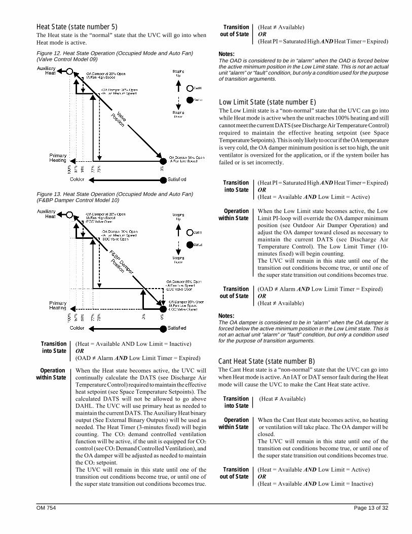
Figure 12. Heat State Operation (Occupied Mode and Auto Fan)(Valve Control Model 09)
Low Limit State (state number E)The Low Limit state is a “non-normal” state that the UVC can go intowhile Heat mode is active when the unit reaches 100% heating and stillcannot meet the current DATS (see Discharge Air Temperature Control)required to maintain the effective heating setpoint (see SpaceTemperature Setpoints). This is only likely to occur if the OA temperatureis very cold, the OA damper minimum position is set too high, the unitventilator is oversized for the application, or if the system boiler hasfailed or is set incorrectly.
Transition (Heat PI = Saturated High AND Heat Timer = Expired)
into State OR
(Heat = Available AND Low Limit = Active)
Operation When the Low Limit state becomes active, the Low
within State Limit PI-loop will override the OA damper minimum
position (see Outdoor Air Damper Operation) and
adjust the OA damper toward closed as necessary to
maintain the current DATS (see Discharge Air
Temperature Control). The Low Limit Timer (10-
minutes fixed) will begin counting.
The UVC will remain in this state until one of the
transition out conditions become true, or until one of
the super state transition out conditions becomes true.
Transition (OAD ≠ Alarm AND Low Limit Timer = Expired)
out of State OR
(Heat ≠ Available)
Notes:The OA damper is considered to be in “alarm” when the OA damper isforced below the active minimum position in the Low Limit state. This isnot an actual unit “alarm” or “fault” condition, but only a condition usedfor the purpose of transition arguments.
Cant Heat State (state number B)The Cant Heat state is a “non-normal” state that the UVC can go intowhen Heat mode is active. An IAT or DAT sensor fault during the Heatmode will cause the UVC to make the Cant Heat state active.
Transition (Heat ≠ Available)
into State
Operation When the Cant Heat state becomes active, no heating
within State or ventilation will take place. The OA damper will be
closed.
The UVC will remain in this state until one of the
transition out conditions become true, or until one of
the super state transition out conditions becomes true.
Transition (Heat = Available AND Low Limit = Active)
out of State OR
(Heat = Available AND Low Limit = Inactive)
Heat State (state number 5)The Heat state is the “normal” state that the UVC will go into whenHeat mode is active.
Transition (Heat = Available AND Low Limit = Inactive)
into State OR
(OAD ≠ Alarm AND Low Limit Timer = Expired)
Operation When the Heat state becomes active, the UVC will
within State continually calculate the DATS (see Discharge Air
Temperature Control) required to maintain the effective
heat setpoint (see Space Temperature Setpoints). The
calculated DATS will not be allowed to go above
DAHL. The UVC will use primary heat as needed to
maintain the current DATS. The Auxiliary Heat binary
output (See External Binary Outputs) will be used as
needed. The Heat Timer (3-minutes fixed) will begin
counting. The CO2 demand controlled ventilation
function will be active, if the unit is equipped for CO2
control (see CO2 Demand Controlled Ventilation), and
the OA damper will be adjusted as needed to maintain
the CO2 setpoint.
The UVC will remain in this state until one of the
transition out conditions become true, or until one of
the super state transition out conditions becomes true.
Figure 13. Heat State Operation (Occupied Mode and Auto Fan)(F&BP Damper Control Model 10)
Transition (Heat ≠ Available)
out of State OR
(Heat PI = Saturated High AND Heat Timer = Expired)
Notes:The OAD is considered to be in “alarm” when the OAD is forced belowthe active minimum position in the Low Limit state. This is not an actualunit “alarm” or “fault” condition, but only a condition used for the purposeof transition arguments.

Page 14 of 32 OM 754
Transition (UVC Mode = Cool)
into OR
Super State (UVC Mode = Auto AND Space Temperature = Warm)
Operation When the Cool mode super state becomes active, the
within UVC will automatically determine which UVC state
Super State to make active, Econ [3], DA Heat [4], Low Limit [F],
or Cant Cool [C] based upon the transitions for each of
those states. If the space temperature drops below
EHS, and the Emergency Heat function is enabled, the
UVC will be forced into the Emergency Heat mode
(see Emergency Heat Mode).
The UVC will remain in this super state until one of
the transition out conditions become true.
Transition (UVC Mode ≠ Cool AND UVC Mode ≠ Auto)
of out OR
Super State (UVC Mode = Auto AND Space Temp = Cold AND
Mech PI = Saturated Low AND Econ PI = Saturated
Low)
Figure 14. Cool Mode Super State Diagram
COOL MODE (SUPER STATE)When in Cool mode the UVC will use primary cooling (economizer)as needed to maintain the effective cooling setpoint (see SpaceTemperature Setpoints). The LUI or a network connection can be usedto force the unit into the Cool mode. Additionally, the UVC when setto Auto mode can automatically force the unit into the Cool mode.When the UVC is in Auto mode, it is “normal” for the UVC to “idle”in Cool mode when there is no need to switch to another mode. TheCool mode super state consists of up to four UVC states: Econ [3], DAHeat [4], Low Limit [F] and Cant Cool [C ].
OM 754 Page 15 of 32
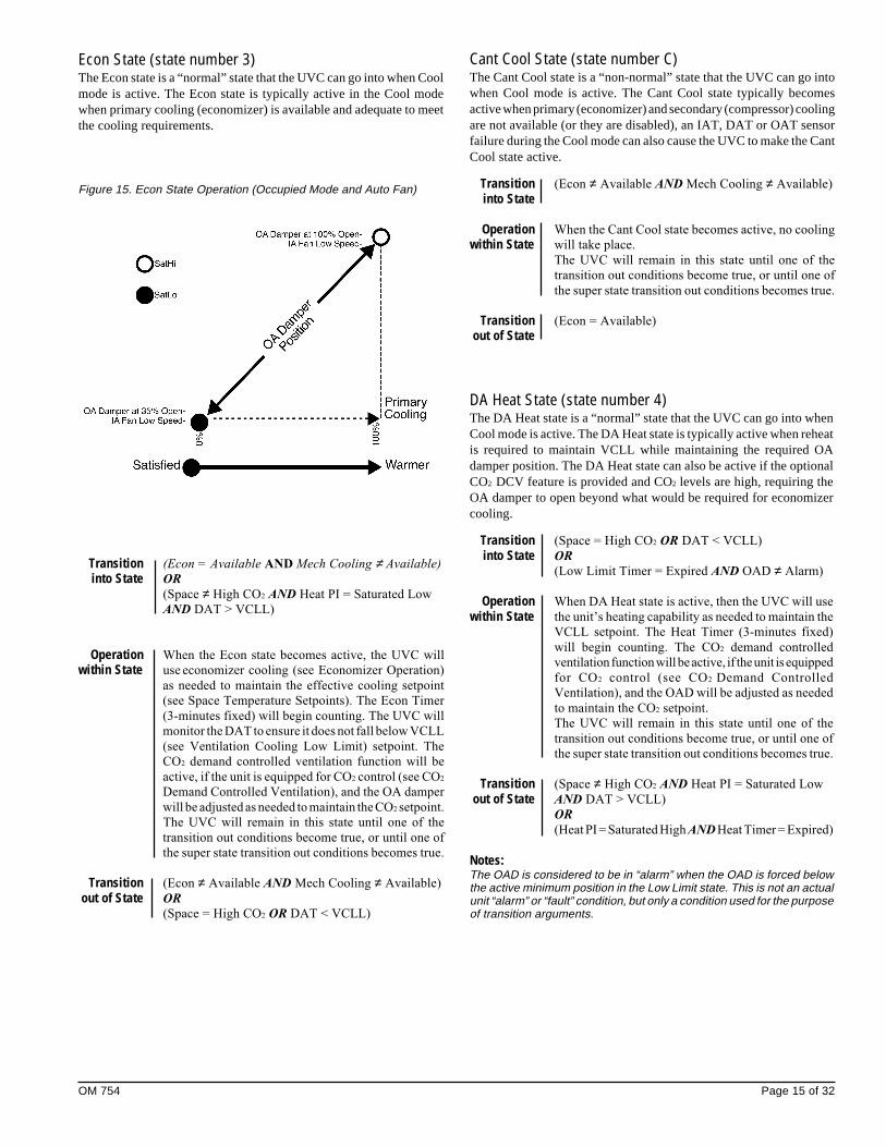
Econ State (state number 3)The Econ state is a “normal” state that the UVC can go into when Coolmode is active. The Econ state is typically active in the Cool modewhen primary cooling (economizer) is available and adequate to meetthe cooling requirements.
Transition (Econ = Available AND Mech Cooling ≠ Available)
into State OR
(Space ≠ High CO2 AND Heat PI = Saturated Low
AND DAT > VCLL)
Operation When the Econ state becomes active, the UVC will
within State use economizer cooling (see Economizer Operation)
as needed to maintain the effective cooling setpoint
(see Space Temperature Setpoints). The Econ Timer
(3-minutes fixed) will begin counting. The UVC will
monitor the DAT to ensure it does not fall below VCLL
(see Ventilation Cooling Low Limit) setpoint. The
CO2 demand controlled ventilation function will be
active, if the unit is equipped for CO2 control (see CO2
Demand Controlled Ventilation), and the OA damper
will be adjusted as needed to maintain the CO2 setpoint.
The UVC will remain in this state until one of the
transition out conditions become true, or until one of
the super state transition out conditions becomes true.
Transition (Econ ≠ Available AND Mech Cooling ≠ Available)
out of State OR
(Space = High CO2 OR DAT < VCLL)
Figure 15. Econ State Operation (Occupied Mode and Auto Fan)
Cant Cool State (state number C)The Cant Cool state is a “non-normal” state that the UVC can go intowhen Cool mode is active. The Cant Cool state typically becomesactive when primary (economizer) and secondary (compressor) coolingare not available (or they are disabled), an IAT, DAT or OAT sensorfailure during the Cool mode can also cause the UVC to make the CantCool state active.
Transition (Econ ≠ Available AND Mech Cooling ≠ Available)
into State
Operation When the Cant Cool state becomes active, no cooling
within State will take place.
The UVC will remain in this state until one of the
transition out conditions become true, or until one of
the super state transition out conditions becomes true.
Transition (Econ = Available)
out of State
DA Heat State (state number 4)The DA Heat state is a “normal” state that the UVC can go into whenCool mode is active. The DA Heat state is typically active when reheatis required to maintain VCLL while maintaining the required OAdamper position. The DA Heat state can also be active if the optionalCO2 DCV feature is provided and CO2 levels are high, requiring theOA damper to open beyond what would be required for economizercooling.
Transition (Space = High CO2 OR DAT < VCLL)
into State OR
(Low Limit Timer = Expired AND OAD ≠ Alarm)
Operation When DA Heat state is active, then the UVC will use
within State the unit’s heating capability as needed to maintain the
VCLL setpoint. The Heat Timer (3-minutes fixed)
will begin counting. The CO2 demand controlled
ventilation function will be active, if the unit is equipped
for CO2 control (see CO2 Demand Controlled
Ventilation), and the OAD will be adjusted as needed
to maintain the CO2 setpoint.
The UVC will remain in this state until one of the
transition out conditions become true, or until one of
the super state transition out conditions becomes true.
Transition (Space ≠ High CO2 AND Heat PI = Saturated Low
out of State AND DAT > VCLL)
OR
(Heat PI = Saturated High AND Heat Timer = Expired)
Notes:The OAD is considered to be in “alarm” when the OAD is forced belowthe active minimum position in the Low Limit state. This is not an actualunit “alarm” or “fault” condition, but only a condition used for the purposeof transition arguments.
Page 16 of 32 OM 754
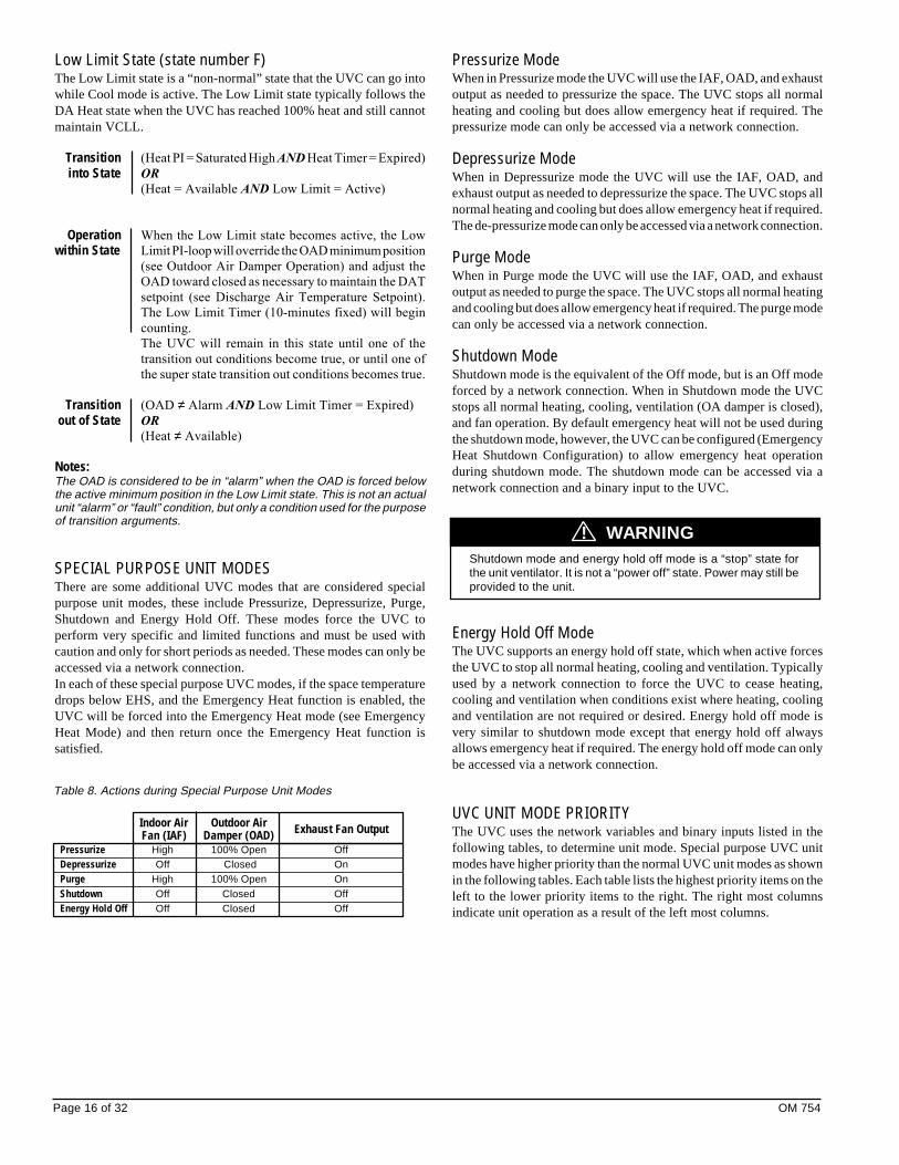
Table 8. Actions during Special Purpose Unit Modes
Indoor Air Outdoor Air Exhaust Fan Output Fan (IAF) Damper (OAD)Pressurize High 100% Open OffDepressurize Off Closed OnPurge High 100% Open OnShutdown Off Closed OffEnergy Hold Off Off Closed Off
Pressurize ModeWhen in Pressurize mode the UVC will use the IAF, OAD, and exhaustoutput as needed to pressurize the space. The UVC stops all normalheating and cooling but does allow emergency heat if required. Thepressurize mode can only be accessed via a network connection.
Depressurize ModeWhen in Depressurize mode the UVC will use the IAF, OAD, andexhaust output as needed to depressurize the space. The UVC stops allnormal heating and cooling but does allow emergency heat if required.The de-pressurize mode can only be accessed via a network connection.
Purge ModeWhen in Purge mode the UVC will use the IAF, OAD, and exhaustoutput as needed to purge the space. The UVC stops all normal heatingand cooling but does allow emergency heat if required. The purge modecan only be accessed via a network connection.
Shutdown ModeShutdown mode is the equivalent of the Off mode, but is an Off modeforced by a network connection. When in Shutdown mode the UVCstops all normal heating, cooling, ventilation (OA damper is closed),and fan operation. By default emergency heat will not be used duringthe shutdown mode, however, the UVC can be configured (EmergencyHeat Shutdown Configuration) to allow emergency heat operationduring shutdown mode. The shutdown mode can be accessed via anetwork connection and a binary input to the UVC.
Energy Hold Off ModeThe UVC supports an energy hold off state, which when active forcesthe UVC to stop all normal heating, cooling and ventilation. Typicallyused by a network connection to force the UVC to cease heating,cooling and ventilation when conditions exist where heating, coolingand ventilation are not required or desired. Energy hold off mode isvery similar to shutdown mode except that energy hold off alwaysallows emergency heat if required. The energy hold off mode can onlybe accessed via a network connection.
UVC UNIT MODE PRIORITYThe UVC uses the network variables and binary inputs listed in thefollowing tables, to determine unit mode. Special purpose UVC unitmodes have higher priority than the normal UVC unit modes as shownin the following tables. Each table lists the highest priority items on theleft to the lower priority items to the right. The right most columnsindicate unit operation as a result of the left most columns.
WARNING!Shutdown mode and energy hold off mode is a “stop” state forthe unit ventilator. It is not a “power off” state. Power may still beprovided to the unit.
Low Limit State (state number F)The Low Limit state is a “non-normal” state that the UVC can go intowhile Cool mode is active. The Low Limit state typically follows theDA Heat state when the UVC has reached 100% heat and still cannotmaintain VCLL.
Transition (Heat PI = Saturated High AND Heat Timer = Expired)
into State OR
(Heat = Available AND Low Limit = Active)
Operation When the Low Limit state becomes active, the Low
within State Limit PI-loop will override the OAD minimum position
(see Outdoor Air Damper Operation) and adjust the
OAD toward closed as necessary to maintain the DAT
setpoint (see Discharge Air Temperature Setpoint).
The Low Limit Timer (10-minutes fixed) will begin
counting.
The UVC will remain in this state until one of the
transition out conditions become true, or until one of
the super state transition out conditions becomes true.
Transition (OAD ≠ Alarm AND Low Limit Timer = Expired)
out of State OR
(Heat ≠ Available)
Notes:The OAD is considered to be in “alarm” when the OAD is forced belowthe active minimum position in the Low Limit state. This is not an actualunit “alarm” or “fault” condition, but only a condition used for the purposeof transition arguments.
SPECIAL PURPOSE UNIT MODESThere are some additional UVC modes that are considered specialpurpose unit modes, these include Pressurize, Depressurize, Purge,Shutdown and Energy Hold Off. These modes force the UVC toperform very specific and limited functions and must be used withcaution and only for short periods as needed. These modes can only beaccessed via a network connection.In each of these special purpose UVC modes, if the space temperaturedrops below EHS, and the Emergency Heat function is enabled, theUVC will be forced into the Emergency Heat mode (see EmergencyHeat Mode) and then return once the Emergency Heat function issatisfied.
OM 754 Page 17 of 32
Priority ResultApplication Override Input � Unit Mode Override Input � Unit Mode Output �
HeatNormal (Auto) � Cool
Emergency HeatHeat Heat
Normal (Auto) � Cool CoolNight Purge Night PurgeOff OffEmergency Heat Emergency HeatFan Only Fan Only
Heat Don’t Care HeatCool Don’t Care CoolNight Purge Don’t Care Night PurgeOff Don’t Care OffEmergency Heat Don’t Care Emergency HeatFan Only Don’t Care Fan Only
� Normal (Auto) is the normal UVC power-up state.� These are network variables.
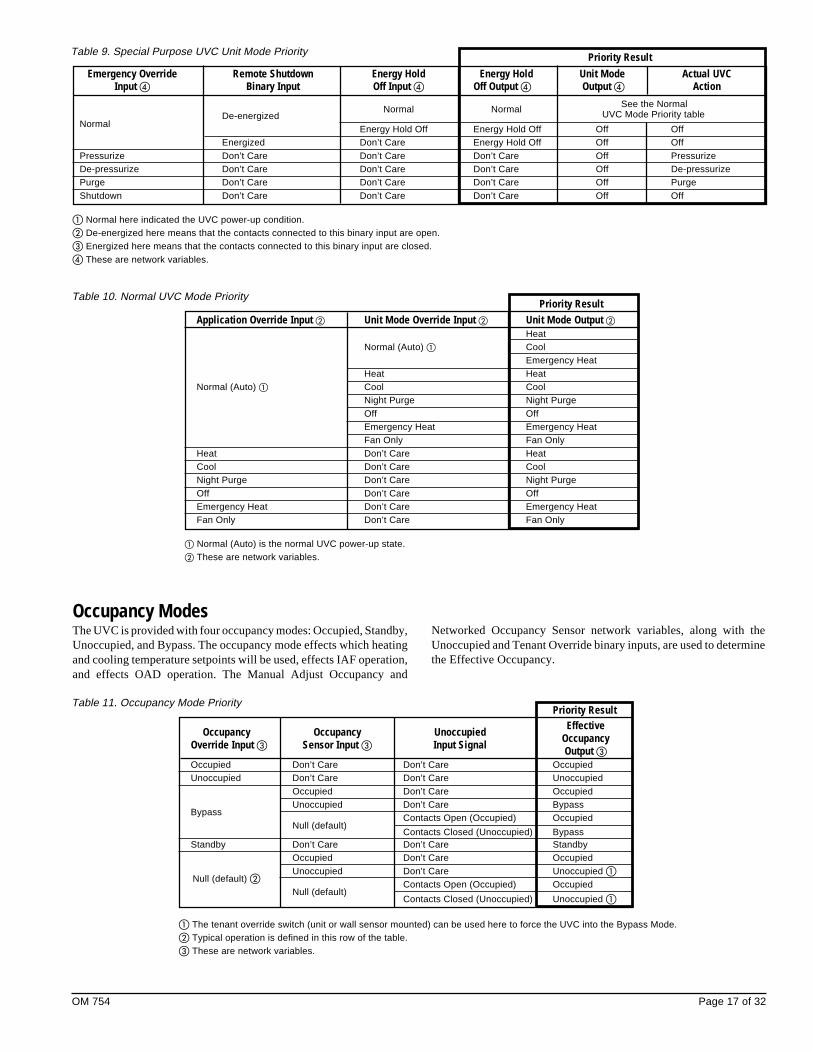
Table 10. Normal UVC Mode Priority
Occupancy ModesThe UVC is provided with four occupancy modes: Occupied, Standby,Unoccupied, and Bypass. The occupancy mode effects which heatingand cooling temperature setpoints will be used, effects IAF operation,and effects OAD operation. The Manual Adjust Occupancy and
Priority Result
Occupancy Occupancy Unoccupied Effective
Override Input � Sensor Input � Input Signal OccupancyOutput �
Occupied Don’t Care Don’t Care OccupiedUnoccupied Don’t Care Don’t Care Unoccupied
Occupied Don’t Care OccupiedUnoccupied Don’t Care Bypass
BypassContacts Open (Occupied) Occupied
Null (default)Contacts Closed (Unoccupied) Bypass
Standby Don’t Care Don’t Care StandbyOccupied Don’t Care OccupiedUnoccupied Don’t Care Unoccupied �
Null (default) �Contacts Open (Occupied) Occupied
Null (default)Contacts Closed (Unoccupied) Unoccupied �
Table 11. Occupancy Mode Priority
Networked Occupancy Sensor network variables, along with theUnoccupied and Tenant Override binary inputs, are used to determinethe Effective Occupancy.
Priority ResultEmergency Override Remote Shutdown Energy Hold Energy Hold Unit Mode Actual UVC
Input � Binary Input Off Input � Off Output � Output � Action
Normal Normal See the Normal
NormalDe-energized UVC Mode Priority table
Energy Hold Off Energy Hold Off Off OffEnergized Don’t Care Energy Hold Off Off Off
Pressurize Don’t Care Don’t Care Don’t Care Off PressurizeDe-pressurize Don’t Care Don’t Care Don’t Care Off De-pressurizePurge Don’t Care Don’t Care Don’t Care Off PurgeShutdown Don’t Care Don’t Care Don’t Care Off Off
� Normal here indicated the UVC power-up condition.� De-energized here means that the contacts connected to this binary input are open.� Energized here means that the contacts connected to this binary input are closed.� These are network variables.
Table 9. Special Purpose UVC Unit Mode Priority
� The tenant override switch (unit or wall sensor mounted) can be used here to force the UVC into the Bypass Mode.� Typical operation is defined in this row of the table.� These are network variables.

Page 18 of 32 OM 754
OCCUPIED MODEThe occupied mode is the normal day time mode of UVC operation.During occupied mode the UVC will use the occupied heating andcooling setpoints, the OAD will operate normally, and by default theIAF will remain on.
UNOCCUPIED MODEThe unoccupied occupancy mode is the normal night time mode ofUVC operation. During unoccupied mode the UVC will use theunoccupied heating and cooling setpoints, the OAD will remain closed,and the IAF will cycle as needed for heating or cooling. The IAF willremain off when there is no need for heating or cooling.
STANDBY MODEThe standby mode is a special purpose day time mode of UVCoperation. During standby mode the UVC will use the standby heatingand cooling setpoints, the OAD will remain closed, and by default theIAF will remain on.
BYPASS MODEThe bypass mode (also called Tenant Override) is the equivalent of atemporary occupied mode. Once the bypass mode is initiated it willremain in effect for a set period of time (120-minutes default). Duringthe bypass mode the UVC will use the occupied heating and coolingsetpoints, the OAD will operate normally, and by default the IAF willremain on.
NETWORKED OCCUPANCY SENSOR CAPABILITYA networked occupancy sensor can be interfaced with the OccupancySensor Input variable to select occupancy modes. When the OccupancySensor Input variable is used, it will automatically override any hard-wired unoccupied binary input signal.
UNIT-MOUNTED TIME-CLOCKAn optional unit-mounted factory-installed electronic 24-hour/7-daytime clock can be provided on some unit ventilator configurations. Thistime clock is factory wired to the UVC unoccupied binary input and canbe set to automatically place the unit into occupied and unoccupiedmodes based upon its user configured schedule.
UNIT-MOUNTED TENANT OVERRIDE SWITCHA tenant override switch is factory installed in all floor mounted units.This tenant override switch is located near the LUI on the unit. Thetenant override switch provides a momentary contact closure that canbe used by room occupants to temporarily force the UVC into thebypass occupancy mode from unoccupied mode.
REMOTE WALL-MOUNTED SENSOR TENANTOVERRIDE SWITCHThe optional remote wall-mounted sensors include a tenant overrideswitch. This tenant override switch provides a momentary contactclosure that can be used by room occupants to temporarily force theUVC into the bypass occupancy mode from unoccupied mode.
REMOTE WALL-MOUNTED SENSOR STATUS LEDThe optional remote wall-mounted sensors each include a UVC statusLED. This status LED aids is diagnostics by indicating the UVCoccupancy mode and fault condition.
Indication LED OperationOccupied On Continually
Unoccupied On 1-sec / Off 9-secBypass On ContinuallyStandby On 9-sec / Off 1-sec
Fault On 5-sec / Off 5-sec
Table 12. Remote Wall-Mount Sensor Status LED
Space Temperature SetpointsThe UVC uses the six occupancy-based temperature setpoints as thebasis to determine the Effective Setpoint Output. The UVC willcalculate the effective setpoint based upon the unit mode, the occupancymode, and the values of several network variables. The effectivesetpoint is then used as the temperature setpoint that the UVC willmaintain.
Temperature Setpoints Abr. DefaultsUnoccupied Cool UCS 82.4OF (28.0OC)
Standby Cool SCS 77.0OF (25.0OC)Occupied Cool OCS 73.4OF (23.0OC)Occupied Heat OHS 69.8OF (21.0OC)Standby Heat SHS 66.2OF (19.0OC)
Unoccupied Heat UHS 60.8OF (16.0OC)
Table 13. Default Occupancy-based Temp Setpoints
NETWORKED SETPOINT CAPABILITYThe Space Temp Setpoint Input variable is used to allow the temperaturesetpoints for the occupied and standby modes to be changed via thenetwork, the unoccupied setpoints are not effected by this variable.
NETWORKED SETPOINT OFFSET CAPABILITYThe Setpoint Offset Input variable is used to shift the effectiveoccupied and standby temperature setpoints by adding the value of theSetpoint Offset Input variable to the current setpoints, the unoccupiedsetpoints are not effected by this variable. This variable is typicallybound to a supervisory network controller (by others) or to a networkedwall module (by others) having a relative setpoint adjustment.
NETWORKED SETPOINT SHIFT CAPABILITYThe Setpoint Shift Input variable is used to shift the effective heat/coolsetpoints. It is typically bound to a networked supervisory controllerwhich provides functions such as outdoor air temperature compensation.All occupied, standby and unoccupied setpoints will be shifted upward(+) or downward (-) by the corresponding value of the Setpoint ShiftInput variable.
The Setpoint Shift Input capability is not available through theBACnet® interface.
NETWORKED SPACE TEMPERATURESENSOR CAPABILITYA networked space temperature sensor can be interfaced with theSpace Temp Input variable. When the Space Temp Input variable isused (valid value), it will automatically override the hard-wired spacetemperature sensor.
NOTICE
OM 754 Page 19 of 32
NOTICE
NOTICE
If it is intended that the LUI will be used by room occupants to adjustthe Setpoint Offset, then you must not use the optional remote wall-mounted sensor with 55OF to 85OF adjustment. When using theoptional remote wall-mounted sensor with 55OF to 85OF adjustment,the UVC will ignore any Setpoint Offset changes made at the LUI.
NOTICE
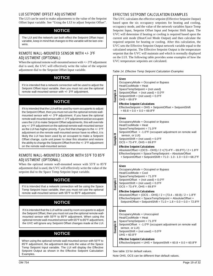
GivenOccupancyMode = Occupied or BypassHeat/CoolMode = HeatSpaceTempSetpoint = (not used)SetpointOffset = (not used) = 0.0OFSetpointShift = (not used) = 0.0OFOHS = 69.8°FEffective Setpoint CalculationsEffectiveSetpoint = OHS + SetpointOffset + SetpointShift
= 69.8 + 0.0 + 0.0 = 69.8OF
GivenOccupancyMode = Occupied or BypassHeat/CoolMode = HeatSpaceTempSetpoint = 71.0OFSetpointOffset = -1.0OF (occupant adjustment on remote wall
sensor, or LUI)SetpointShift = (not used) = 0.0OFOCS = 73.4°F, OHS = 69.8°FEffective Setpoint CalculationsAbsoluteOffset = (OCS – OHS) / 2 =(73.4OF – 69.8OF) / 2 = 1.8OFEffectiveSetpoint = SpaceTempSetpoint – AbsoluteOffset
+ SetpointOffset + SetpointShift = 71.0 - 1.0 - 1.0 + 0.0 = 68.2OF
GivenOccupancyMode = Occupied or BypassHeat/CoolMode = CoolSpaceTempSetpoint = 71.0OFSetpointOffset = (not used) = 0.0OFSetpointShift = (not used) = 0.0OFOCS = 73.4°F, OHS = 69.8°F
Effective Setpoint CalculationsAbsoluteOffset = (OCS – OHS) / 2 = (73.4 – 69.8) / 2 = 1.8OFEffectiveSetpoint = SpaceTempSetpoint + AbsoluteOffset +
SetpointOffset + SetpointShift = 71.0 + 1.8 + 0.0 + 0.0 = 72.8OF
GivenOccupancyMode = UnoccupiedHeat/CoolMode = HeatSpaceTempSetpoint = 71.0OFSetpointOffset = -1.0OF (occupant adjustment on remote wall
sensor, or LUI)SetpointShift = (not used) = 0.0OFUHS = 60.8°FEffective Setpoint CalculationsEffectiveSetpoint = UHS + SetpointShift = 60.8 + 0.0 = 60.8OF
See table 13 for default values.
Note OHS, OCS can be different than default values.
Table 14. Effective Temp Setpoint Calculation Examples
NOTICE
NOTICE
LUI SETPOINT OFFSET ADJUSTMENTThe LUI can be used to make adjustments to the value of the SetpointOffset Input variable. See “Using the LUI to adjust Setpoint Offset”.
The LUI and the network can both effect the Setpoint Offset Inputvariable, keep in mind that changes to this variable will be last-one-wins.
REMOTE WALL-MOUNTED SENSOR WITH +/- 3OFADJUSTMENT (OPTIONAL)When the optional remote wall-mounted sensor with +/- 3OF adjustmentdial is used, the UVC will effectively write the value of the setpointadjustment dial to the Setpoint Offset Input variable.
If it is intended that a network connection will be used to adjust theSetpoint Offset Input variable, then you must not use the optionalremote wall-mounted sensor with +/- 3OF adjustment.
If it is intended that the LUI will be used by room occupants to adjustthe Setpoint Offset, then you must not use the optional remote wall-mounted sensor with +/- 3OF adjustment. If you have the optionalremote wall-mounted sensor with +/- 3OF adjustment and an occupantuses the LUI to make Setpoint Offset adjustments, this will overrideany +/- 3OF adjustment on the optional remote wall-mounted sensoras the LUI has higher priority. If you find that changes to the +/- 3OFadjustment on the remote wall-mounted sensor have no effect, it islikely the LUI has been used by an occupant to make a SetpointOffset change, cycle unit power to clear this situation and restorethe ability to change the Setpoint Offset from the +/- 3OF adjustmenton the remote wall-mounted sensor.
REMOTE WALL-MOUNTED SENSOR WITH 55OF TO 85OFADJUSTMENT (OPTIONAL)When the optional remote wall-mounted sensor with 55OF to 85OFadjustment dial is used, the UVC will effectively write the value of thesetpoint dial to the Space Temp Setpoint Input variable.
If it is intended that a network connection will be using the SpaceTemp Setpoint Input variable, then you must not use the optionalremote wall-mounted sensor with 55OF to 85OF adjustment.
EFFECTIVE SETPOINT CALCULATION EXAMPLESThe UVC calculates the effective setpoint (Effective Setpoint Output)based upon the six occupancy setpoints for heating and cooling,occupancy mode, and the value of the network variables Space TempSetpoint Input, Setpoint Offset Input and Setpoint Shift Input. TheUVC will determine if heating or cooling is required based upon thecurrent unit mode (Heat/Cool Mode Output) and then calculate therequired setpoint for heating or cooling. After this calculation, theUVC sets the Effective Setpoint Output network variable equal to thecalculated setpoint. The Effective Setpoint Output is the temperaturesetpoint that the UVC will maintain and which is normally displayedon the LUI. The following table provides some examples of how theUVC temperature setpoints are calculated.
Exam
ple
DEx
ampl
e C
Exam
ple
BEx
ampl
e A
NOTICE
When using the optional remote wall-mounted sensor with 55OF to85OF adjustment, the adjustment dial sets the value of the SpaceTemp Setpoint Input variable. The LUI will display the EffectiveSetpoint Output as shown in the Effective Setpoint CalculationExamples.
Page 20 of 32 OM 754
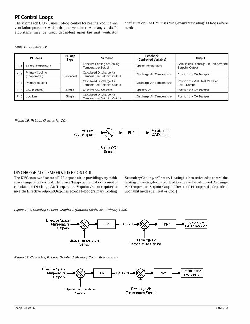
PI Loop FeedbackPI Loops Type Setpoint (Controlled Variable) Output
PI-1 SpaceTemperatureEffective Heating or Cooling
Space TemperatureCalculated Discharge Air Temperature
Temperature Setpoint Setpoint Output
PI-2Primary Cooling Calculated Discharge Air
Discharge Air Temperature Position the OA Damper(Economizer) Cascaded Temperature Setpoint Output
PI-3 Primary HeatingCalculated Discharge Air
Discharge Air TemperaturePosition the Wet Heat Valve or
Temperature Setpoint Output F&BP Damper
PI-4 CO2 (optional) Single Effective CO2 Setpoint Space CO2 Position the OA Damper
PI-5 Low Limit SingleCalculated Discharge Air
Discharge Air Temperature Position the OA DamperTemperature Setpoint Output
PI Control LoopsThe MicroTech II UVC uses PI-loop control for heating, cooling andventilation processes within the unit ventilator. As many as six PIalgorithms may be used, dependent upon the unit ventilator
Table 15. PI Loop List
Figure 16. PI Loop Graphic for CO2
Figure 17. Cascading PI Loop Graphic 1 (Sotware Model 10 – Primary Heat)
Figure 18. Cascading PI Loop Graphic 2 (Primary Cool – Economizer)
DISCHARGE AIR TEMPERATURE CONTROLThe UVC uses two “cascaded” PI loops to aid in providing very stablespace temperature control. The Space Temperature PI-loop is used tocalculate the Discharge Air Temperature Setpoint Output required tomeet the Effective Setpoint Output, a second PI-loop (Primary Cooling,
configuration. The UVC uses “single” and “cascading” PI loops whereneeded.
Secondary Cooling, or Primary Heating) is then activated to control theheating or cooling device required to achieve the calculated DischargeAir Temperature Setpoint Output. The second PI-loop used is dependentupon unit mode (i.e. Heat or Cool).
OM 754 Page 21 of 32
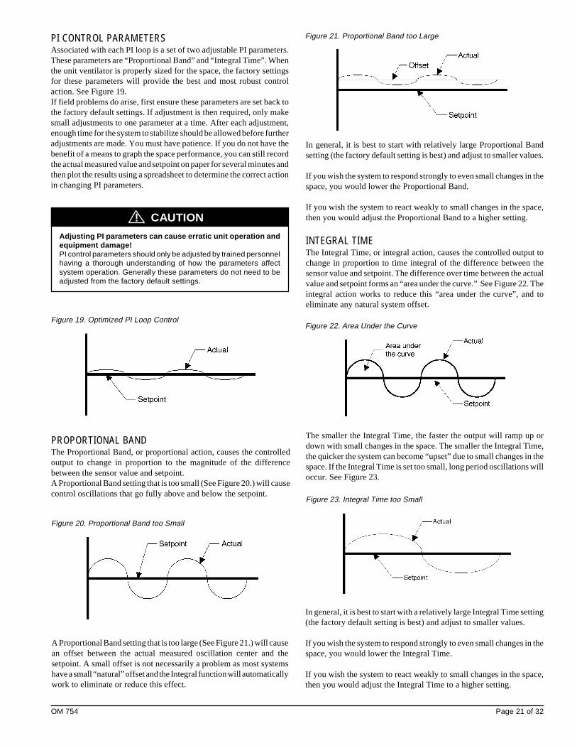
PI CONTROL PARAMETERSAssociated with each PI loop is a set of two adjustable PI parameters.These parameters are “Proportional Band” and “Integral Time”. Whenthe unit ventilator is properly sized for the space, the factory settingsfor these parameters will provide the best and most robust controlaction. See Figure 19.If field problems do arise, first ensure these parameters are set back tothe factory default settings. If adjustment is then required, only makesmall adjustments to one parameter at a time. After each adjustment,enough time for the system to stabilize should be allowed before furtheradjustments are made. You must have patience. If you do not have thebenefit of a means to graph the space performance, you can still recordthe actual measured value and setpoint on paper for several minutes andthen plot the results using a spreadsheet to determine the correct actionin changing PI parameters.
Adjusting PI parameters can cause erratic unit operation andequipment damage!PI control parameters should only be adjusted by trained personnelhaving a thorough understanding of how the parameters affectsystem operation. Generally these parameters do not need to beadjusted from the factory default settings.
CAUTION!
Figure 19. Optimized PI Loop Control
PROPORTIONAL BANDThe Proportional Band, or proportional action, causes the controlledoutput to change in proportion to the magnitude of the differencebetween the sensor value and setpoint.A Proportional Band setting that is too small (See Figure 20.) will causecontrol oscillations that go fully above and below the setpoint.
Figure 20. Proportional Band too Small
A Proportional Band setting that is too large (See Figure 21.) will causean offset between the actual measured oscillation center and thesetpoint. A small offset is not necessarily a problem as most systemshave a small “natural” offset and the Integral function will automaticallywork to eliminate or reduce this effect.
Figure 21. Proportional Band too Large
In general, it is best to start with relatively large Proportional Bandsetting (the factory default setting is best) and adjust to smaller values.
If you wish the system to respond strongly to even small changes in thespace, you would lower the Proportional Band.
If you wish the system to react weakly to small changes in the space,then you would adjust the Proportional Band to a higher setting.
INTEGRAL TIMEThe Integral Time, or integral action, causes the controlled output tochange in proportion to time integral of the difference between thesensor value and setpoint. The difference over time between the actualvalue and setpoint forms an “area under the curve.” See Figure 22. Theintegral action works to reduce this “area under the curve”, and toeliminate any natural system offset.
Figure 22. Area Under the Curve
Figure 23. Integral Time too Small
The smaller the Integral Time, the faster the output will ramp up ordown with small changes in the space. The smaller the Integral Time,the quicker the system can become “upset” due to small changes in thespace. If the Integral Time is set too small, long period oscillations willoccur. See Figure 23.
In general, it is best to start with a relatively large Integral Time setting(the factory default setting is best) and adjust to smaller values.
If you wish the system to respond strongly to even small changes in thespace, you would lower the Integral Time.
If you wish the system to react weakly to small changes in the space,then you would adjust the Integral Time to a higher setting.
Page 22 of 32 OM 754
Indoor Air Fan OperationThe UVC supports a 3-speed IA fan: Low, Medium, and High. TheUVC will calculate the effective fan speed and operation based uponthe unit mode, the occupancy mode, and the values of several networkvariables.
AUTO MODEThe UVC is provided with a user selectable auto fan mode feature.When in auto fan mode, the UVC uses the space temperature PI loopto automatically adjust the fan speed as needed to maintain spacetemperature. This ensures that the UVC will maintain the lowest andquietest fan speed whenever possible. When in auto fan mode, amaximum of 6 fan speed changes per hour is allowed (by default), thisprevents frequent automatic fan speed changes from disturbing roomoccupants.
OCCUPIED, STANDBY AND BYPASS OPERATIONDuring occupied, standby and bypass modes the IA fan will, by default,remain On.
UNOCCUPIED OPERATIONDuring unoccupied mode the IA fan will typically remain off and willcycle with calls for heating and cooling.
CYCLE FANThe UVC is provided with a Fan Cycling Configuration variable whichcan be used to force the IA fan to cycle with calls for heating andcooling during the occupied, standby and bypass occupancy modes.When the fan is off, the OA damper will be closed, therefore, it isrecommended that this feature only be used when it is acceptable thatnormal ventilation is not required.
OFF DELAYWhen the IA fan is set to cycle, or during the unoccupied mode, or whenthe UVC is placed into off mode, the UVC is configured to continue fanoperation for a time period (30-seconds default) after heating orcooling is complete.
Outdoor Air Damper OperationThe UVC is configured for an OA damper operated by a floating-pointactuator. The OA damper actuator contains a spring which will ensurethat the OA damper is closed upon loss of power. The floating-pointactuator is driven by the UVC using two binary (Triac) outputs. TheOA damper is typically open to the current minimum position duringthe occupied and bypass occupancy modes, and closed during theunoccupied and standby occupancy modes.
MINIMUM POSITIONThe UVC is configured to maintain three OA damper minimumpositions based upon the operation of the IAF. This allows the abilityfor each unit to be field configured to provide the amount of fresh airrequired to the space at each of the three IA fan speeds.
Table 16. Default OA Damper Minimum Positions
w/o CO2 w/ CO2
IAF High Speed 20% 5%
IAF Medium Speed 30% 5%
IAF Low Speed 35% 5%
NOTICE
If the CO2 Demand Controlled Ventilation (DCV) option is used,then the UVC will only use the IA fan high speed OA damperminimum position regardless of fan speed, the DCV function willadjust the OA damper above this minimum as needed to maintainCO2 setpoint.
ECONOMIZER OPERATIONThe economizer function is used by the UVC to determine if the OA isadequate for economizer (primary) cooling. When both the economizerand mechanical cooling are available, the economizer will be used asprimary cooling and the UVC will add mechanical cooling only if theeconomizer is not adequate to meet the current cooling load (i.e. the OAdamper reaches 100% and cooling is still required).The UVC is configured to support three economizer types:
• Temperature Comparison Economizer (default)• Temperature Comparison with OA Enthalpy Setpoint
Economizer (optional)• Temperature Comparison with Enthalpy Comparison
Economizer (optional)
Temperature Comparison EconomizerThe UVC uses two configuration variables to determine if theeconomizer can be used: Economizer OA Temp Setpoint andEconomizer Temp Differential. See Table 17.
EffectiveOutdoorTemp <
(EconomizerOATempSetpoint –
EconomizerTempDifferential)
Economizer Available OR
EffectiveOutdoorTemp <
(EffectiveSpaceTemp –
EconomizerTempDifferential)
Temperature Comparison with OA Enthalpy SetpointEconomizer (optional)The UVC uses three configuration variables to determine if theeconomizer can be used: Economizer OA Temp Setpoint, EconomizerTemp Differential and Economizer OA Enthalpy Setpoint. SeeTable 18.
Table 17. Economizer Available Calculation – Temperature Comparison
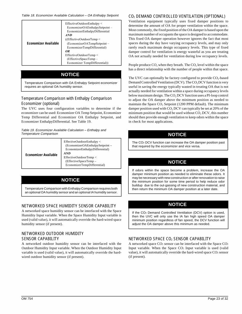
OM 754 Page 23 of 32
EffectiveOutdoorEnthalpy <
EconomizerOAEnthalpySetpoint –
EconomizerEnthalpyDifferential
AND
((EffectiveOutdoorTemp <
Economizer Available (EconomizerOATempSetpoint –
EconomizerTempDifferential)
OR
EffectiveOutdoorTemp <
(EffectiveSpaceTemp –
Economizer TempDifferential))
Temperature Comparison with OA Enthalpy Setpoint economizerrequires an optional OA humidity sensor.
NOTICE
Table 18. Economizer Available Calculation – OA Enthalpy Setpoint
Temperature Comparison with Enthalpy ComparisonEconomizer (optional)The UVC uses four configuration variables to determine if theeconomizer can be used: Economizer OA Temp Setpoint, EconomizerTemp Differential and Economizer OA Enthalpy Setpoint, andEconomizer EnthalpyDifferential. See Table 19.
Table 19. Economizer Available Calculation – Enthalpy andTemperature Comparison
EffectiveOutdoorEnthalpy <(EconomizerOAEnthalpySetpoint –EconomizerEnthalpyDifferential)
Economizer Available ANDEffectiveOutdoorTemp <
(EffectiveSpaceTemp –EconomizerTempDifferential)
Temperature Comparison with Enthalpy Comparison requires bothan optional OA humidity sensor and an optional IA humidity sensor.
NOTICE
NETWORKED SPACE HUMIDITY SENSOR CAPABILITYA networked space humidity sensor can be interfaced with the SpaceHumidity Input variable. When the Space Humidity Input variable isused (valid value), it will automatically override the hard-wired spacehumidity sensor (if present).
NETWORKED OUTDOOR HUMIDITYSENSOR CAPABILITYA networked outdoor humidity sensor can be interfaced with theOutdoor Humidity Input variable. When the Outdoor Humidity Inputvariable is used (valid value), it will automatically override the hard-wired outdoor humidity sensor (if present).
CO2 DEMAND CONTROLLED VENTILATION (OPTIONAL)Ventilation equipment typically uses fixed damper positions todetermine the amount of OA for proper ventilation within the space.Most commonly, the fixed position of the OA damper is based upon themaximum number of occupants the space is designed to accommodate.This fixed OA damper operation however ignores the fact that mostspaces during the day have varying occupancy levels, and may onlyrarely reach maximum design occupancy levels. This type of fixeddamper control for ventilation is energy wasteful as you are treatingOA not actually needed for ventilation during low occupancy levels.
People produce CO2 when they breath. The CO2 level within the spacehas a direct relationship with the number of people within that space.
The UVC can optionally be factory configured to provide CO2-basedDemand Controlled Ventilation (DCV). The CO2 DCV function is veryuseful in saving the energy typically wasted in treating OA that is notactually needed for ventilation within a space during occupancy levelsbelow maximum design. The CO2 DCV function uses a PI-loop controlto adjust the OA damper above the minimum position as needed tomaintain the Space CO2 Setpoint (1200 PPM default). The minimumdamper position used with CO2 DCV can typically be set at 20% of theminimum position that would be used without CO2 DCV, this numbershould then provide enough ventilation to keep odors within the spacein check for most applications.
The CO2 DCV function can increase the OA damper position pastthat required by the economizer and vice versa.
If odors within the space become a problem, increase the OAdamper minimum position as needed to eliminate these odors. Itmay be necessary with new construction or after renovation to raisethe minimum position for some time period to help reduce odorbuildup due to the out-gassing of new construction material, andthen return the minimum OA damper position at a later date.
If the CO2 Demand Controlled Ventilation (DCV) option is used,then the UVC will only use the IA fan high speed OA damperminimum position regardless of fan speed, the DCV function willadjust the OA damper above this minimum as needed.
NETWORKED SPACE CO2 SENSOR CAPABILITYA networked space CO2 sensor can be interfaced with the Space CO2
Input variable. When the Space CO2 Input variable is used (validvalue), it will automatically override the hard-wired space CO2 sensor(if present).
NOTICE
NOTICE
NOTICE
Page 24 of 32 OM 754
NOTICEAn End-of-Cycle (EOC) valve is strongly recommended. If an EOCvalve is not installed, it is very likely that overheating of thespace will occur.
Floating-point Actuator Auto-Zero,Overdrive and SyncThe UVC at power-up will auto-zero all floating-point actuators (OAdamper) before going into normal operation to ensure proper positioning,this can take as long as 150-seconds after power-up. During auto-zerothe unit will remain Off, the actuators will open approximately 30%and then be driven full closed, the overdrive feature is then used tocontinue forcing the actuators closed for one full stroke period. Oncethe zeroing process is complete normal unit operation will begin.The UVC is configured such that whenever a floating-point actuator iscommanded to go to 0% or 100%, the UVC will overdrive the actuatorone full stroke period past the 0% or 100% position to ensure properpositioning.
Additionally, the UVC is configured to sync all floating-point actuatorsonce every 12-hours of operation. To do this the UVC will force theactuator to the nearest rail position (0% or 100%), use the overdrivefeature, and then return to its normal position. For example, if theactuator is at 20% when the 12-hour limit is reached, then the UVC willforce the actuator to 0%, use overdrive, and then return to the 20%position.
Water Coil Leaving Air TemperatureThermostat (freeze-stat)A normally-closed low temperature thermostat is factory provided todetect low leaving air temperature conditions on the indoor air coil.This thermostat is mounted on the discharge air side of the unit’s watercoil. The low temperature thermostat cut-out is 38OF +/-2OF (3OC +/-1OC) and the cut-in is 45OF +/-2OF (7OC +/-1OC). When the lowtemperature thermostat detects low leaving air temperatures (contactsopen) the following will occur.
VALVE CONTROL (SOFTWARE MODEL 09)When freeze-stat cuts-out:1. OA damper closes immediately.2. Space fan stops.3. The wet heat valve is set to a minimum of 50%.4. If heating is required the valve modulates above 50% as needed,
auxiliary heat may be used as needed.When the freeze-stat cuts-in the UVC will return to normal operation.
F&BP DAMPER CONTROL (SOFTWARE MODEL 10)When the freeze-stat cuts-out:1. OA damper closes immediately.2. EOC valve opens immediately.3. If heating is required the F&BP damper modulates as needed,
otherwise the F&BP damper goes 100% bypass, auxiliary heat maybe used as needed.
When the freeze-stat cuts-in the UVC will return to normal operation.
External Binary InputsThe UVC is provided with three (3) binary inputs which can provide thefollowing functions. These inputs each allow a single set of dry-contacts (no voltage source) to be used as a signal to the UVC, multipleunits can be connected to a single set of dry-contacts. For wiring seeMicroTech II Unit Ventilator Controller IM747.
Notice
Not all of the functions listed can be used at the same time. TheUVC is provided with configuration parameters which can beadjusted to select which function will be used for these inputs whenmultiple functions are indicated below.
EXTERNAL BINARY INPUT 1This input can be configured as an unoccupied (default) or dewpoint/humidity signal.
ASHRAE CYCLE IIThe UVC supports ASHRAE Cycle II operation. The basis of ASHRAECycle II is to maintain the required minimum amount of ventilationwhenever possible, which can be increased during normal operationfor economizer cooling or CO2 DCV control, but can also be reducedto prevent excessively cold discharge air temperatures.A discharge air temperature sensor is installed in all unit ventilators. Ifnecessary, the ASHRAE II control algorithm will override roomcontrol and modify the heating, ventilating, and cooling functions (asavailable) to prevent the discharge air temperature from falling belowthe VCLL setpoint.
Valve Control (software model 09)The UVC is configured for a modulating heat/cool valve operated bya floating-point actuator. The modulating valve actuator contains aspring which will ensure that the heat/cool valve is open, upon loss ofpower. The floating-point actuator is driven by the UVC using twobinary (Triac) outputs.
Face & Bypass Damper Control(software model 10)The UVC is configured for a F&BP damper operated by a floating-point actuator. The floating-point actuator is driven by the UVC usingtwo binary (Triac) outputs.
END-OF-CYCLE VALVE CONTROL(SOFTWARE MODEL 10)The UVC is configured for a 2-position WH EOC valve. The 2-positionvalve actuator contains a spring which will ensure that the wet heatvalve is open upon loss of power. The 2-position actuator is driven bythe UVC using one binary (Triac) output.
NOTICE
OM 754 Page 25 of 32
NOTICE
Exhaust Fan On/Off SignalThis relay output provides one set of NO dry-contacts which can beused to signal the operation of an exhaust fan. When the OA damperopens more than the Energize Exhaust Fan OA Damper Setpoint thenthe relay output will signal the exhaust fan on (contacts closed), whenthe OA damper closes below this setpoint the relay output will signalthe exhaust fan off (contacts open).
Auxiliary Heat StartsPrimary Heat PI-loop = Saturated High
(100%) for more than 2-minutesANDEffectiveSpaceTemp ≤ EffectiveSetpointAuxiliary Heat – AuxiliaryHeatStartDifferential
Start/Stop Calculation
Auxiliary Heat StopsEffectiveSpaceTemp ≥ (EffectiveSetpoint
– AuxiliaryHeatStartDifferential) +AuxiliaryHeatStopDifferential
Table 20. Auxiliary Heat Calculation
Unoccupied Input SignalThis input allows a single set of dry-contacts to be used to signal theUVC to go into unoccupied or occupied mode. When the contacts close(unoccupied) the UVC will go into unoccupied mode, when thecontacts open (occupied) the UVC will go into occupied mode.Additional variables can effect occupancy mode and override thisbinary input. See Occupancy Modes.
EXTERNAL BINARY INPUT 2This input can only be used for remote shutdown.
Remote Shutdown Input SignalThis input allows a single set of dry-contacts to be used to signal theUVC to go into shutdown mode. When the contacts close (shutdown)the UVC will go into shutdown mode, when the contacts open the UVCwill return to normal operation. See Special Purpose Unit Modes.
EXTERNAL BINARY INPUT 3This input can be configured as an ventilation lockout (default) orexhaust interlock signal.
Ventilation Lockout Input SignalThis input allows a single set of dry-contacts to be used to signal theUVC to close the OA damper. When the contacts close (ventilationlockout signal) the UVC will close the OA damper, when the contactsopen the UVC will return to normal OA damper operation.
Exhaust Interlock Input SignalThis input allows a single set of dry-contacts to be used to signal theUVC that an exhaust fan within the space has been energized, the UVCwill reposition the OA damper to a user adjustable minimum position(Exhaust Interlock OA Damper Min Position Setpoint). When thecontacts close (exhaust fan on signal) the UVC will use the valuedefined by the Exhaust Interlock OA Damper Min Position Setpoint asthe minimum OA damper position regardless of IA fan speed, when thecontacts open the UVC will return to normal OA damper operation.
External Binary OutputsThe UVC is provided with three (3) binary outputs which can providethe following functions. These outputs are relay type outputs which areintended to be used with signal level voltages (24vac max) only. Forwiring see MicroTech II Unit Ventilator Controller IM739.
Notice
Not all of the functions listed can be used at the same time. TheUVC is provided with configuration parameters which can beadjusted to select which function will be used for these outputswhen multiple functions are indicated below.
EXTERNAL BINARY OUTPUT 1This output can only be used as a signal for space lights.
Lights On/Off SignalThis relay output provides one set of NO dry-contacts which can beused to signal the operation of the space lights. When the UVC is inoccupied, standby or bypass occupancy modes the relay output willsignal the lights on (contacts closed), when the UVC is in unoccupiedoccupancy mode the relay output will signal the lights off (contactsopen).
EXTERNAL BINARY OUTPUT 2This output can only be used as a fault signal.
Fault SignalThis relay output provides a NO, NC, and Common connections thatcan be used to signal a fault condition. When a fault exists, the UVCwill energize this relay output, when the fault or faults are cleared theUVC will de-energize this relay output.
EXTERNAL BINARY OUTPUT 3This output can only be used to operate an auxiliary heat device orsignal exhaust fan operation.
Auxiliary Heat SignalThis relay output provides one set of NO dry-contacts which can beused to operate an auxiliary heat device. The UVC by default isconfigured to operate a NO auxiliary heat device (de-energize whenheat is required) such as a wet heat valve actuator with a spring setupto open upon power failure. However, the Auxiliary Heat Configurationvariable can be used to set the UVC to use a NC auxiliary heat device(energize when heat is required) such as electric heat.

Page 26 of 32 OM 754
UVC INPUT AND OUTPUT TABLEAll UVC input and output connections and their corresponding unitventilator usage are shown in the following table.
Table 21. Inputs and Outputs for 2-pipe wet heat only SoftwareModels 09 and 10
Model 09 Model 102-pipe Wet Heat Only – 2-pipe Wet Heat Only –
Valve Control F&BP Damper ControlDescription
BO-1 Inside Fan High Inside Fan High
BO-2 Inside Fan Medium Inside Fan Medium
BO-3
BO-4
BO-5
BO-6 External Output Option 3: External Output Option 3:Fault Indication� Fault Indication�
BO-7 Wet Heat EOC Valve (NO)�
BO-8
BO-9
BI-1
BI-2
BI-3 Low Air Temperature Low Air TemperatureThermostat (NC)� Thermostat (NC)�
BI-4 External Input Option 1: External Input Option 1:Ventilation Lockout (default) Ventilation Lockout (default)or Exhaust Interlock� or Exhaust Interlock�
BI-5 External Input Option 2: External Input Option 2:Remote Shutdown � Remote Shutdown �
BI-6 External Input Option 3: External Input Option 3:Unoccupied� Unoccupied �
BI-7
BI-8
BI-9
BI-10
BI-11
The most important aspect of troubleshooting unit ventilator controlsis to isolate the source of the problem into one of two categories: 1) theproblem resides within the UVC, or 2) the problem is external to theUVC. Under most circumstances the problem will reside external to theUVC.
Alarm and Fault MonitoringThe UVC is programmed to monitor the unit for specific alarmconditions. If an alarm condition exists, a fault will occur. When a faultcondition occurs, the UVC will indicate the fault condition by displayingthe fault code on the LUI, the remote wall-mounted sensor (optional)LED will flash a pattern indicating that a fault condition exists, the faultsignal binary output will be energized, and the UVC will perform theappropriate control actions.Manual reset faults can be reset in one of three ways: 1) cycle unitpower, 2) LUI menu, or 3) via network interface.
DIAGNOSTICS AND SERVICE
LUIPriority Fault Description 09 10 Reset Fault
Codes1 Space Temp Sensor Failure x x Auto
2 Not Used
3 Not Used
4 Not Used
5 Not Used
6 Not Used
7 Outdoor Temp Sensor Failure x x Auto
8 Discharge Air Temp Sensor Failure x x Auto
9 Not Used
10 Not Used
11 Space Humidity Sensor Failure x x Auto
12 Outdoor Humidity Sensor Failure x x Auto
13 Space CO2 Sensor Failure x x Auto
14 Not Used
15 Not Used
16 Change Filter Indication x x Manual
Table 22. Alarm and Fault Code Summary
BI-12
AI-1 IA Temp. Sensor + T.O. IA Temp. Sensor + T.O.
AI-2 Remote Setpt. Adjust. Pot. Remote Setpt. Adjust. Pot.
AI-3 DA Temp Sensor DA Temp Sensor
AI-4 OA Temp Sensor OA Temp Sensor
AI-5
AI-6
Expansion BoardxBO-1 External Output Option 2: External Output Option 2:
Lights On/Off� Lights On/Off�
xBO-2 External Output Option 1: External Output Option 1:Exhaust Fan On/Off (default) Exhaust Fan On/Off (default)or Auxiliary Heat� or Auxiliary Heat�
xBO-3 OA Damper Open OA Damper Open
xBO-4 OA Damper Close OA Damper Close
xBO-5 Wet Heat Valve Open F&BP Damper Open Face
xBO-6 Wet Heat Valve Close F&BP Damper Close Face
xBO-7
xBO-8 Inside Fan Low Inside Fan Low
xAI-1 IA Humidity Sensor� IA Humidity Sensor�
xAI-2 OA Humidity Sensor� OA Humidity Sensor�
xAI-3 Indoor CO2 Sensor� Indoor CO2 Sensor�
xAI-4
� Optional.� Field selectable external output options (all possible options are shown).� Field selectable external input options (all possible options are shown).� This thermostat is not installled on units with steam coils, this input will then
be wired for constant no-fault condition.� End-of-Cycle (EOC) valve is strongly recommended for proper space control.

OM 754 Page 27 of 32
SPACE TEMP SENSOR FAILURE ( )The Space Temp Sensor Failure fault will occur when the UVC detectsan open or a short condition from the space temperature sensor.
Effect:• Space fan is de-energized (unless in emergency heat mode)• Outside air damper is forced closed• Heating valve is fully opened to the coil (software model 09)• F&BP damper positioned to 100% face (software model 10)• Heating EOC valve is opened (software model 10)• Fault is indicated
OUTDOOR TEMP SENSOR FAILURE ( )The Outdoor Temp Sensor Failure fault will occur when the UVCdetects an open or a short condition from the OA temperature sensor.
Effect:• Outside air damper is forced closed• EOC valve control due to OA temperature is disabled, EOC valve
will operate based upon space temperature only (software model 10)• Fault is indicated
DISCHARGE AIR TEMP SENSOR FAILURE ( )The Discharge Air Temp Sensor Failure fault will occur when the UVCdetects an open or a short condition from the DA temperature sensor.Emergency heat mode is available during this fault condition.
Effect:• Space fan is immediately de-energized (unless in emergency heat
mode)• Outside air damper is forced closed• Heating valve is fully opened to the coil (software model 09)• F&BP damper is positioned to 100% face (ssoftware model 10)• Heating EOC valve is opened (software model 10)• Fault is indicated
SPACE HUMIDITY SENSOR FAILURE (OPTIONAL) ( )The Space Humidity Sensor Failure fault will occur when the UVCdetects an open or a short condition from the IA space humidity sensor.
Effect:• IA/OA Enthalpy comparison economizer (if used) is disabled• Dehumidification function (optional) is disabled• Fault is indicated
OUTDOOR HUMIDITY SENSOR FAILURE (OPTIONAL) ( )The Outdoor Humidity Sensor Failure fault will occur when the UVCdetects an open or a short condition from the OA humidity sensor.
Effect:• IA/OA Enthalpy comparison or OA Enthalpy economizer (if used)
is disabled• Fault is indicated
SPACE CO2 SENSOR FAILURE (OPTIONAL) ( )The Space CO2 Sensor Failure fault will occur when the UVC detectsan open or a short condition from the Space CO2 sensor.
Effect:• CO2 Demand Controlled Ventilation function is disabled• Fault is indicated
CHANGE FILTER INDICATION ( )The Change Filter Indication will occur when the UVC calculates thatthe total fan run time has exceeded the allowed number of hours sincethe last filter change.
Effect:• Fault is indicated
Troubleshooting Temperature SensorsThe UVC is configured to use passive positive temperature coefficient(PTC) sensor whose resistance increases with increasing temperature.The element has a reference resistance of 1035 ohms at 77°F (25°C).Each element is calibrated according to the tables shown.
The following procedure can be used to troubleshoot a suspect sensor.1. Disconnect both sensor leads from the UVC.2. Take a temperature reading at the sensor location.3. Use the temperature reading from Step 2 to determine the expected
sensor resistance from the Temperature versus Resistance Table 23.4. Using an ohmmeter, measure the actual resistance across the two
sensor leads.5. Compare the expected resistance to the actual resistance.6. If the actual resistance value deviates substantially (more than
10%) from the expected resistance, replace the sensor.
Table 23. Temperature versus Resistance Table
OF (OC) Resistance OF (OC) Resistancein OhmsO in Ohms
-40 (-40) 613 113 (45) 1195-31 (-35) 640 122 (50) 1237-22 (-30) 668 131 (55) 1279-13 (-25) 697 140 (60) 1323-4 (-20) 727 149 (65) 13685 (-15) 758 158 (70) 141314 (-10) 789 167 (75) 145923 (-5) 822 176 (80) 150632 (0) 855 185 (85) 155441 (5) 889 194 (90) 160250 (10) 924 203 (95) 165259 (15) 960 212 (100) 170268 (20) 997 221 (105) 175377 (25) 1035 230 (110) 180486 (30) 1074 239 (115) 185695 (35) 1113 248 (120) 1908
104 (40) 1153
DIAGNOSTICS AND SERVICE (continued)
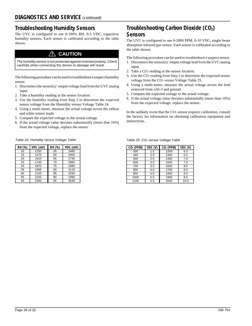
Page 28 of 32 OM 754
Troubleshooting Humidity SensorsThe UVC is configured to use 0-100% RH, 0-5 VDC, capacitivehumidity sensors. Each sensor is calibrated according to the tableshown.
/!\ CautionThe humidity sensor is not protected against reversed polarity. Checkcarefully when connecting the device or damage will result.
The following procedure can be used to troubleshoot a suspect humiditysensor.1. Disconnect the sensor(s)’ output voltage lead from the UVC analog
input.2. Take a humidity reading at the sensor location.3. Use the humidity reading from Step 2 to determine the expected
sensor voltage from the Humidity versus Voltage Table 24.4. Using a multi-meter, measure the actual voltage across the yellow
and white sensor leads.5. Compare the expected voltage to the actual voltage.6. If the actual voltage value deviates substantially (more than 10%)
from the expected voltage, replace the sensor.
Table 24. Humidity versus Voltage Table
RH (%) VDC (mV) RH (%) VDC (mV)10 1330 55 248015 1475 60 260020 1610 65 273025 1740 70 286030 1870 75 298035 1995 80 311540 2120 85 325045 2235 90 339050 2360 95 3530
Troubleshooting Carbon Dioxide (CO2)SensorsThe UVC is configured to use 0-2000 PPM, 0-10 VDC, single beamabsorption infrared gas sensor. Each sensor is calibrated according tothe table shown.
The following procedure can be used to troubleshoot a suspect sensor.1. Disconnect the sensor(s)’ output voltage lead from the UVC analog
input.2. Take a CO2 reading at the sensor location.3. Use the CO2 reading from Step 2 to determine the expected sensor
voltage from the CO2 versus Voltage Table 25.4. Using a multi-meter, measure the actual voltage across the lead
removed from xAI-3 and ground.5. Compare the expected voltage to the actual voltage.6. If the actual voltage value deviates substantially (more than 10%)
from the expected voltage, replace the sensor.
In the unlikely event that the CO2 sensor requires calibration, consultthe factory for information on obtaining calibration equipment andinstructions.
Table 25. CO2 versus Voltage Table
CO2 (PPM) VDC (V) CO2 (PPM) VDC (V)300 1.5 1200 6.0400 2.0 1300 6.5500 2.5 1400 7.0600 3.0 1500 7.5700 3.5 1600 8.0800 4.0 1700 8.5900 4.5 1800 9.01000 5.0 1900 9.51100 5.5 2000 10.0
DIAGNOSTICS AND SERVICE (continued)
CAUTION!
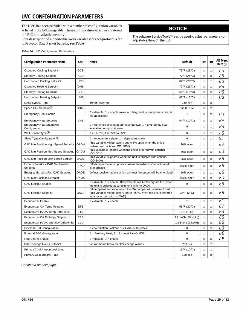
OM 754 Page 29 of 32
Table 26. UVC Configuration Parameters
Configuration Parameter Name Abr. Notes Default 09 10 LUI MenuItem �
Occupied Cooling Setpoint OCS 73OF (23OC) x x
Standby Cooling Setpoint SCS 77OF (25OC) x x
Unoccupied Cooling Setpoint UCS 82OF (28OC) x x
Occupied Heating Setpoint OHS 70OF (21OC) x x
Standby Heating Setpoint SHS 66OF (19OC) x x
Unoccupied Heating Setpoint UHS 61OF (16OC) x x
Local Bypass Time Tenant override 240 min x x
Space CO2 Setpoint� CO2S 1200 PPM x x
Emergency Heat Enable0 = disable, 1 = enable (uses auxiliary heat where primary heat is
1 x xnot applicable)
Emergency Heat Setpoint EHS 54OF (12OC) x x
Emergency Heat Shutdown 0 = no emergency heat during shutdown, 1 = emergency heat0 x x
Configuration available during shutdown
Wall Sensor Type� 0 = +/- 3°F, 1 = 55°F to 85°F 0 x x
Slave Type Configuration� 0 = independent slave, 1 = dependent slave 0 x x
OAD Min Position High-Speed Setpoint OADH(this variable will be factory set to 5% open when the unit is
20% open x xordered with optional CO2 DCV)
OAD Min Position Med-Speed Setpoint OADM(this variable is ignored when the unit is ordered with optional CO2
DCV)
30% open x x
OAD Min Position Low-Speed Setpoint OADL(this variable is ignored when the unit is ordered with optional CO2
DCV)
35% open x x
Exhaust Interlock OAD Min PositionEOAD
OA damper minimum position when the exhaust interlock input100% open x x
Setpoint is energized
Energize Exhaust Fan OAD Setpoint OADE defines position above which exhaust fan output will be energized 10% open x x
OAD Max Position Setpoint OAMX 100% open x x
OAD Lockout Enable0 = disable, 1 = enable (this variable will be factory set to 1 when
0 x xthe unit is ordered as a recirc unit with no OAD)OA temperature below which the OA damper will remain closed
OAD Lockout Setpoint OALS (this variable will be factory set to –99OC when the unit is ordered 36OF (2OC) x xas a recirc unit with no OAD)
Economizer Enable 0 = disable, 1 = enable 1 x x
Economizer OA Temp Setpoint ETS 68OF (20OC) x x
Economizer IA/OA Temp Differential ETD 2OF (1OC) x x
Economizer OA Enthalpy Setpoint EES 25 btu/lb (58 kJ/kg) x x
Economizer IA/OA Enthalpy Differential EED 1.3 btu/lb (3 kJ/kg) x x
External BI-3 Configuration 0 = Ventilation Lockout, 1 = Exhaust Interlock 0 x x
External B0-3 Configuration 0 = Auxiliary Heat, 1 = Exhaust Fan On/Off 0 x x
Filter Alarm Enable 0 = disable, 1 = enable 0 x x
Filter Change Hours Setpoint fan run hours between filter change alarms 700 hrs x x
Primary Cool Proportional Band 18OF (10OC) x x
Primary Cool Integral Time 180 sec x x
UVC CONFIGURATION PARAMETERS
Continued on next page.
The UVC has been provided with a number of configuration variablesas listed in the following table. These configuration variables are storedin UVC non-volatile memory.For a description of supported network variables for each protocol referto Protocol Data Packet bulletin, see Table 4.
The software ServiceTools™ can be used to adjust parameters notadjustable through the LUI.
NOTICE
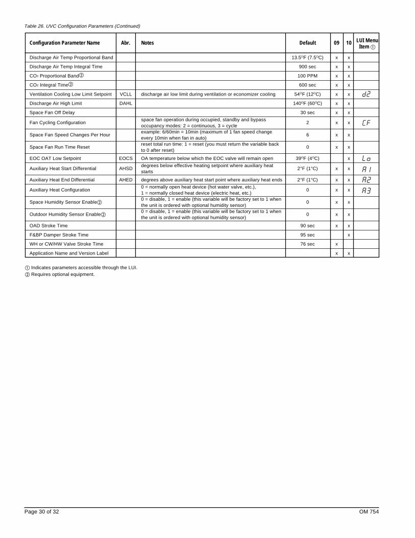
Page 30 of 32 OM 754
Configuration Parameter Name Abr. Notes Default 09 10 LUI MenuItem �
Discharge Air Temp Proportional Band 13.5OF (7.5OC) x x
Discharge Air Temp Integral Time 900 sec x x
CO2 Proportional Band� 100 PPM x x
CO2 Integral Time� 600 sec x x
Ventilation Cooling Low Limit Setpoint VCLL discharge air low limit during ventilation or economizer cooling 54OF (12OC) x x
Discharge Air High Limit DAHL 140OF (60OC) x x
Space Fan Off Delay 30 sec x x
Fan Cycling Configurationspace fan operation during occupied, standby and bypass
2 x xoccupancy modes: 2 = continuous, 3 = cycle
Space Fan Speed Changes Per Hourexample: 6/60min = 10min (maximum of 1 fan speed change
6 x xevery 10min when fan in auto)
Space Fan Run Time Resetreset total run time: 1 = reset (you must return the variable back
0 x xto 0 after reset)
EOC OAT Low Setpoint EOCS OA temperature below which the EOC valve will remain open 39OF (4OC) x
Auxiliary Heat Start Differential AHSDdegrees below effective heating setpoint where auxiliary heat
2°F (1°C) x xstarts
Auxiliary Heat End Differential AHED degrees above auxiliary heat start point where auxiliary heat ends 2°F (1°C) x x
Auxiliary Heat Configuration0 = normally open heat device (hot water valve, etc.),
0 x x1 = normally closed heat device (electric heat, etc.)
Space Humidity Sensor Enable�0 = disable, 1 = enable (this variable will be factory set to 1 when
0 x xthe unit is ordered with optional humidity sensor)
Outdoor Humidity Sensor Enable�0 = disable, 1 = enable (this variable will be factory set to 1 when
0 x xthe unit is ordered with optional humidity sensor)
OAD Stroke Time 90 sec x x
F&BP Damper Stroke Time 95 sec x
WH or CW/HW Valve Stroke Time 76 sec x
Application Name and Version Label x x
� Indicates parameters accessible through the LUI.� Requires optional equipment.
Table 26. UVC Configuration Parameters (Continued)

OM 754 Page 31 of 32
Notes

Page 32 of 32 OM 754
©2002 McQuay International • www.mcquay.com • 800-432-1342 OM 754 (8/02)
®
This document contains the most current product information as of this printing. For the most up-to-dateproduct information, please go to www.mcquay.com.
Related Documents