Part I Integration of Heat Transfer and Chemical Reactions Ch01.fm Page 1 Friday, February 25, 2005 7:01 PM

Welcome message from author
This document is posted to help you gain knowledge. Please leave a comment to let me know what you think about it! Share it to your friends and learn new things together.
Transcript

Part IIntegration of Heat Transfer and Chemical Reactions
Ch01.fm Page 1 Friday, February 25, 2005 7:01 PM

Ch01.fm Page 2 Friday, February 25, 2005 7:01 PM
3
1Enhancing Productivity and Thermal Efficiency of High-Temperature Endothermic Processes in Heat-Integrated Fixed-Bed Reactors
Grigorios Kolios, Achim Gritsch, Bernd Glöckler and Gerhart Eigenberger
Abstract
High-temperature endothermic processes (e.g., reforming of hydrocarbons) arewidely utilized in the production of basic chemicals and fuels from fossil feedstocks.These processes require large amounts of heat at temperatures up to 1000 ºC. Inconventional solutions, only about half of the high-temperature heat supplied istransferred into the endothermic reaction. Emerging applications such as decentral-ized hydrogen production for residential and mobile power generation require con-siderable improvement in specific productivity and thermal efficiency. Thus, thistopic is currently the subject of exciting research activities in industry and academia.This chapter provides an introduction to the fundamentals of heat-integrated pro-cesses, an overview on conceptual trends in process and apparatus design, and ananalysis of the state of the art, with emphasis on steam reforming of methane.
1.1Introduction
Endothermic high-temperature processes stand at the beginning of the chemical pro-duction chain – for example, syngas is produced mainly through steam reforming ofnaphtha or natural gas, ethylene and propylene through steam cracking, and styrenethrough dehydrogenation of ethylbenzene. These processes are usually conducted inlarge furnaces and belong naturally to the largest fuel consumers. At the same time,they have a significant heat surplus since typically only about 50 % of the heat genera-ted is consumed by the endothermic reaction. In large product- and energy-integratedchemical sites, waste heat can be utilized in subsequent processes. However, rigidthermal coupling throughout the plant imposes constraints regarding the heatbalance of individual processes and requires a considerable overhead in order toadjust plant-wide optimal operating conditions. This problem could be significantlyrelaxed by reducing the surplus of the heat exporters. This is one strong incentive forenhancing the thermal efficiency of endothermic high-temperature processes.
Integrated Chemical Processes. Edited by K. Sundmacher, A. Kienle and A. Seidel-MorgensternCopyright © 2005 WILEY-VCH Verlag GmbH & Co. KGaA, WeinheimISBN 3-527-30831-8
Ch01.fm Page 3 Friday, February 25, 2005 7:01 PM
1 Enhancing Productivity and Thermal Efficiency of High-Temperature Endothermic Processes 4
Two emerging trends endorse the concept of heat-integrated processes: first, theproduction of basic chemicals is moved close to oil and gas wells where crude oil ornatural gas is processed in large stand-alone units [1]. Second, fuel cell systemsrequire on-site and on-demand hydrogen production from primary fuels (i.e., natu-ral gas, liquid hydrocarbons or alcohols) [2]. Net heat generation in these processesis equivalent to raw material and energy loss, and is therefore undesirable.
While many publications in the field of heat-integrated processes focus on specificprocesses such as dehydrogenation of paraffins or hydrogen production [3–5], thischapter is more focused on general conceptual trends in process and apparatus design.
1.2Heat-Integrated Processes for Endothermic Reactions
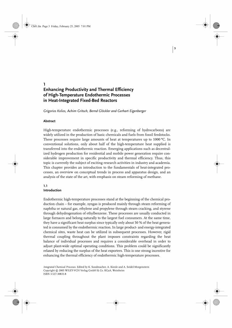
The intended purpose of heat-integrated processes for endothermic reactions isillustrated by the example of methane steam reforming for hydrogen generation,which is of high practical relevance [6] and features typical characteristics of the con-sidered process class. The reaction is given by the following stoichiometric equation:
Figure 1.1 shows the heat fluxes required at different process stages for the gener-ation of H2 equivalent to 1 kW combustion enthalpy based on the lower heatingvalue of hydrogen (LHV, H2). Typically, the feed composition of the technical processcorresponds to a steam-to-carbon molar ratio of S:C = 3:1. The reaction temperatureis determined by chemical equilibrium. The heat consumption of the steam-reform-ing reaction is equivalent to around 30 % of the lower heating value of the producedhydrogen. The amount of heat required for heating the gaseous feed to reaction tem-
( )o; ,+ + ∆ =4 2 23 950 20 235RkJCH H O H CO H C bar mol´
Fig. 1.1. Heat fluxes for hydrogen generation by steam reforming of methane.
Ch01.fm Page 4 Friday, February 25, 2005 7:01 PM

1.2 Heat-integrated Processes for Endothermic Reactions 5
perature corresponds to almost 20 % of the heat of combustion. On the other hand,a considerable amount of sensible heat contained in the product stream is usable forfeed preheating.
Heat-integrated processes comprise two additional functions besides the main(endothermic) reaction: process heat generation and heat recovery. As shown above,both aspects are equally important, since the heat of reaction and the heat requiredfor feed preheating are in the same range. Figure 1.2 shows, schematically, two dif-ferent configurations of heat-integrated processes. The process comprises two ther-mally interconnected reaction stages for the endothermic reaction and for thecombustion. Heat exchangers on both sides perform heat recovery by coupling feedpreheating with product cooling. In the first configuration (Fig. 1.2(a)) the endother-mic reaction mixture and the combustion gas flow countercurrently through all pro-cess stages such that the hot effluent from the exothermic reaction is used to heat upthe cold feed for the endothermic reaction, and vice versa. In the second configura-tion (Fig. 1.2(b)), thermal contact between the two process streams is limited to thereaction stage, while heat recovery is separated between the flows of the exothermicand the endothermic reactions.
Fig. 1.2. Schematic flow configurations of heat-integrated processes for coupling endothermic and exothermic reactions. (a) Countercurrent flow of process streams. (b) Cocurrent flow of the process streams in the reactor stages and heat recovery in separate circuits.
Ch01.fm Page 5 Friday, February 25, 2005 7:01 PM
1 Enhancing Productivity and Thermal Efficiency of High-Temperature Endothermic Processes 6
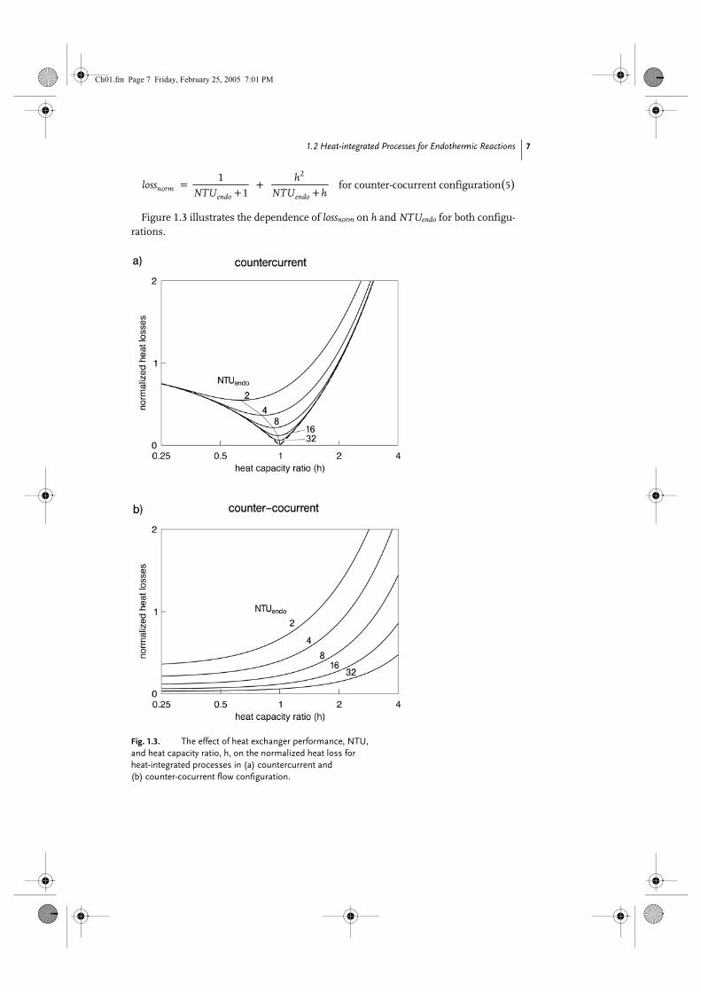
1.2.1Optimality Conditions
1.2.1.1 Efficiency of Heat RecoveryAnalysis of the overall heat balance yields basic conditions for optimal heat recovery.The optimizing condition is minimization of heat loss. The feed temperatures of thetwo process streams, T0, and the outlet temperature of the endothermic stage, Tequ,are fixed (Fig. 1.2) where Tequ is the temperature required for the desired conversionunder equilibrium conditions. Obviously, Tequ is also a lower limit of the tempera-ture in the combustion stage. The performance of the heat exchangers is given bythe mean heat transfer coefficient kh and the heat exchange area A. Both heatexchangers are assumed to be identical. The mass flow rate of the endothermic mix-
ture and the combustion gas is and , respectively. Crucial parameters forthe efficiency of heat recovery are the heat capacity ratio of the process streams (h)and the number of transfer units of the heat exchangers (NTU):
Taking the amount of heat required for bridging the temperature gap (Tequ – T0)for the endothermic mixture as a reference, the normalized heat loss is given by thefollowing expression:
A value of lossnorm = 1 indicates that the total heat loss via the exit streams of theexothermic and the endothermic stage is equal to the amount of heat required toheat up the feed of the endothermic stage about ∆T = Tequ – T0. lossnorm can beexpressed explicitly as a function of h and NTUendo taking into account the theory ofideal countercurrent heat exchangers [7].
At this point, a distinction is required between the two configurations shown inFig. 1.2. In the countercurrent configuration the heat capacity fluxes of the heatexchanging streams are generally differing, whereas in the counter-cocurrent config-uration they are equal to each other. Hence, we obtain:
⋅endoM
⋅exoM
( )1
⋅
⋅
=
pendo
pexo
M c
h
M c
( ); 2⋅ ⋅
= = =
h h endoendo exo
p pendo exo
k A k A NTUNTU NTU
hM c M c
( ) ( )( )0 0
03
− −− + −=
−endo exo
normequ
T T h T Tloss
T T
( ) ( )for countercurrent configuration
1
11 4
−
−−
+= −
−
endo
endo
hNTU
h
norm hNTU
h
h eloss h
h e
Ch01.fm Page 6 Friday, February 25, 2005 7:01 PM
1.2 Heat-integrated Processes for Endothermic Reactions 7
Figure 1.3 illustrates the dependence of lossnorm on h and NTUendo for both configu-rations.
( )for counter-cocurrent configuration2
51
1= +
+ +normendo endo
hloss
NTU NTU h
Fig. 1.3. The effect of heat exchanger performance, NTU, and heat capacity ratio, h, on the normalized heat loss for heat-integrated processes in (a) countercurrent and (b) counter-cocurrent flow configuration.
Ch01.fm Page 7 Friday, February 25, 2005 7:01 PM
1 Enhancing Productivity and Thermal Efficiency of High-Temperature Endothermic Processes 8
For the countercurrent configuration the optimal heat capacity ratio convergesasymptotically to h = 1 with increasing NTU values. Even for an ideal heat exchanger(NTU Æ �), small deviations from the optimal heat capacity ratio cause significantheat losses. On the other hand, heat losses could be minimized with decreasing heatcapacity ratio and increasing NTU values for the counter-cocurrent configuration. Inthis case the heat recovery becomes complete for an ideal heat exchanger(NTU Æ �) independent of the heat capacity ratio h.
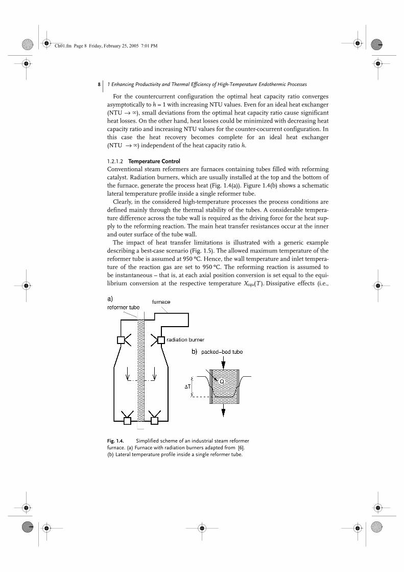
1.2.1.2 Temperature ControlConventional steam reformers are furnaces containing tubes filled with reformingcatalyst. Radiation burners, which are usually installed at the top and the bottom ofthe furnace, generate the process heat (Fig. 1.4(a)). Figure 1.4(b) shows a schematiclateral temperature profile inside a single reformer tube.
Clearly, in the considered high-temperature processes the process conditions aredefined mainly through the thermal stability of the tubes. A considerable tempera-ture difference across the tube wall is required as the driving force for the heat sup-ply to the reforming reaction. The main heat transfer resistances occur at the innerand outer surface of the tube wall.
The impact of heat transfer limitations is illustrated with a generic exampledescribing a best-case scenario (Fig. 1.5). The allowed maximum temperature of thereformer tube is assumed at 950 ºC. Hence, the wall temperature and inlet tempera-ture of the reaction gas are set to 950 ºC. The reforming reaction is assumed tobe instantaneous – that is, at each axial position conversion is set equal to the equi-librium conversion at the respective temperature Xequ(T ). Dissipative effects (i.e.,
Fig. 1.4. Simplified scheme of an industrial steam reformer furnace. (a) Furnace with radiation burners adapted from [6]. (b) Lateral temperature profile inside a single reformer tube.
Ch01.fm Page 8 Friday, February 25, 2005 7:01 PM

1.2 Heat-integrated Processes for Endothermic Reactions 9
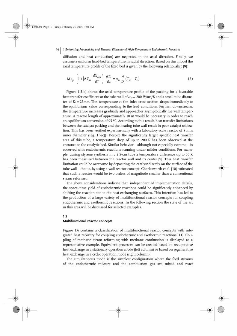
Fig. 1.5. Effect of heat transfer limitation in industrial steam reformers. (a) Scheme of a single catalytic fixed-bed reformer tube with typical heat transfer and operating parameters. (b) Computed temperature profile (solid line) and equilibrium conversion profile (dashed line) in flow direction for a tubular reformer. (c) Measured fixed-bed temperature profiles at different wall temperatures in a tubular reformer (Di = 8 mm) filled with spherical catalyst pellets (dp = 1.5 mm).
Ch01.fm Page 9 Friday, February 25, 2005 7:01 PM
1 Enhancing Productivity and Thermal Efficiency of High-Temperature Endothermic Processes 10
diffusion and heat conduction) are neglected in the axial direction. Finally, weassume a uniform fixed-bed temperature in radial direction. Based on this model theaxial temperature profile of the fixed bed is given by the following relationship [8]:
Figure 1.5(b) shows the axial temperature profile of the packing for a favorableheat transfer coefficient at the tube wall of αw = 200 W/m2/K and a small tube diame-ter of Di = 25mm. The temperature at the inlet cross-section drops immediately tothe equilibrium value corresponding to the feed conditions. Further downstream,the temperature increases gradually and approaches asymptotically the wall temper-ature. A reactor length of approximately 10 m would be necessary in order to reachan equilibrium conversion of 95 %. According to this result, heat transfer limitationsbetween the catalyst packing and the heating tube wall result in poor catalyst utiliza-tion. This has been verified experimentally with a laboratory-scale reactor of 8 mminner diameter (Fig. 1.5(c)). Despite the significantly larger specific heat transferarea of this tube, a temperature drop of up to 200 K has been observed at theentrance to the catalytic bed. Similar behavior – although not especially extreme – isobserved with endothermic reactions running under milder conditions. For exam-ple, during styrene synthesis in a 2.5-cm tube a temperature difference up to 30 Khas been measured between the reactor wall and its center [9]. This heat transferlimitation could be overcome by depositing the catalyst directly on the surface of thetube wall – that is, by using a wall reactor concept. Charlesworth et al. [10] estimatedthat such a reactor would be two orders of magnitude smaller than a conventionalsteam reformer.
The above considerations indicate that, independent of implementation details,the space–time yield of endothermic reactions could be significantly enhanced byshifting the reaction site to the heat-exchanging surfaces. This intention has led tothe production of a large variety of multifunctional reactor concepts for couplingendothermic and exothermic reactions. In the following section the state of the artin this area will be discussed for selected examples.
1.3Multifunctional Reactor Concepts
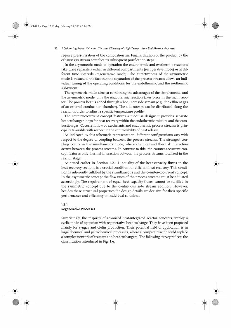
Figure 1.6 contains a classification of multifunctional reactor concepts with inte-grated heat recovery for coupling endothermic and exothermic reactions [11]. Cou-pling of methane steam reforming with methane combustion is displayed as arepresentative example. Equivalent processes can be created based on recuperativeheat exchange in a stationary operation mode (left column) or based on regenerativeheat exchange in a cyclic operation mode (right column).
The simultaneous mode is the simplest configuration where the feed streamsof the endothermic mixture and the combustion gas are mixed and react
( ) ( )4
1 6⋅
+ ∆ = α −
equ cp ad w w c
i
dX dTM c T T T
dT dz D
Ch01.fm Page 10 Friday, February 25, 2005 7:01 PM

1.3 Multifunctional Reactor Concepts 11
simultaneously in the same volume. The amount of oxygen is adjusted to generatesufficient excess heat, in order to compensate non-idealities of heat recovery. Thesimultaneous mode has been widely applied in technical processes, for example, inautothermal reforming or in oxidative dehydrogenation processes. However, mixingof the process streams imposes substantial constraints to the process conditions,since they must be compatible to the endothermic and to the exothermic subsystem.For example, high-pressure operation, often desirable for steam reforming, would
Fig. 1.6. Schematic classification of heat-integrated concepts for the representative example of coupling methane steam reform-ing and methane combustion.
Ch01.fm Page 11 Friday, February 25, 2005 7:01 PM
1 Enhancing Productivity and Thermal Efficiency of High-Temperature Endothermic Processes 12
require pressurization of the combustion air. Finally, dilution of the product by theexhaust gas stream complicates subsequent purification steps.
In the asymmetric mode of operation the endothermic and exothermic reactionstake place separately either in different compartments (recuperative mode) or at dif-ferent time intervals (regenerative mode). The attractiveness of the asymmetricmode is related to the fact that the separation of the process streams allows an indi-vidual tuning of the operating conditions for the endothermic and the exothermicsubsystem.
The symmetric mode aims at combining the advantages of the simultaneous andthe asymmetric mode: only the endothermic reaction takes place in the main reac-tor. The process heat is added through a hot, inert side stream (e.g., the effluent gasof an external combustion chamber). The side stream can be distributed along thereactor in order to adjust a specific temperature profile.
The counter-cocurrent concept features a modular design: it provides separateheat exchanger loops for heat recovery within the endothermic mixture and the com-bustion gas. Cocurrent flow of exothermic and endothermic process streams is prin-cipally favorable with respect to the controllability of heat release.
As indicated by this schematic representation, different configurations vary withrespect to the degree of coupling between the process streams. The strongest cou-pling occurs in the simultaneous mode, where chemical and thermal interactionoccurs between the process streams. In contrast to this, the counter-cocurrent con-cept features only thermal interaction between the process streams localized in thereactor stage.
As stated earlier in Section 1.2.1.1, equality of the heat capacity fluxes in theheat recovery sections is a crucial condition for efficient heat recovery. This condi-tion is inherently fulfilled by the simultaneous and the counter-cocurrent concept.In the asymmetric concept the flow rates of the process streams must be adjustedaccordingly. The requirement of equal heat capacity fluxes cannot be fulfilled inthe symmetric concept due to the continuous side stream addition. However,besides these structural properties the design details are decisive for their specificperformance and efficiency of individual solutions.
1.3.1Regenerative Processes
Surprisingly, the majority of advanced heat-integrated reactor concepts employ acyclic mode of operation with regenerative heat exchange. They have been proposedmainly for syngas and olefin production. Their potential field of application is inlarge chemical and petrochemical processes, where a compact reactor could replacea complex network of reactors and heat exchangers. The following survey reflects theclassification introduced in Fig. 1.6.
Ch01.fm Page 12 Friday, February 25, 2005 7:01 PM

1.3 Multifunctional Reactor Concepts 13
1.3.1.1 Simultaneous ModeA pioneering report on the simultaneous concept with integrated heat recovery pro-poses a reverse-flow mode of operation for syngas production from natural gas [12].The process is implemented in an adiabatic fixed-bed reactor with inert end zonesand a catalytically active section in the middle. The experiments confirm the feasibil-ity of the concept. The results of this investigation, together with those of subse-quent studies [13, 14], indicate that local excess temperatures up to 1500 ºC are themajor problem of this concept. One reason for this is the tendency for the reactionzones of combustion and reforming to separate from each other. Due to a preferen-tial adsorption of oxygen on the catalyst surface, total oxidation of hydrocarbons isfavored [15]. Steam reforming and the water-gas-shift reaction take off after com-plete depletion of oxygen. Additionally, ignition of homogeneous combustion isunavoidable if the temperature exceeds 600 ºC. Coke formation in the heat-exchangezones has been identified as an additional reason for the temperature runaway. DeGroote et al. [13] show that the major source of coke in the upstream section is meth-ane cracking and the Boudouard equilibrium in the downstream section. The sud-den ignition of accumulated coke may lead to extreme local temperature peaks.
1.3.1.2 Asymmetric ModeThe CATOFIN process developed by ABB-Lummus for dehydrogenation of C3–C4paraffins [16, 17] can be considered as the prototype process of coupling endother-mic and exothermic reactions. Figure 1.7 shows the process scheme in schematicform. Each cycle includes the production phase and two regeneration steps. Theheat consumption of the endothermic reaction during the production phase is takenfrom the heat stored in the fixed bed. The thermal reservoir is restored by a super-heated air purge during the second phase. In addition to convective heating, heat isgenerated through the combustion of carbonaceous deposits. Finally, hydrogen ispassed over the fixed bed in order to convert the catalyst back to its reduced, activeform, and this produces additional heat. A similar concept has been proposed for
Fig. 1.7. CATOFIN process: dehydrogenation of propane adapted from Ullmann [54]. (a) charge heater; (b) air heater; (c) purge step; (d) production step; (e) regeneration step.
Ch01.fm Page 13 Friday, February 25, 2005 7:01 PM

1 Enhancing Productivity and Thermal Efficiency of High-Temperature Endothermic Processes 14
styrene synthesis [18]. The attraction of this concept results from the simplicity ofthe reactor – a simple adiabatic fixed-bed type – and the process-integrated regenera-tion of the catalyst – that is, the removal of carbonaceous deposits. Both, cocurrentflow and countercurrent flow have been investigated. The authors concluded thatthe reverse-flow mode is superior with regard to selectivity because the endothermicreaction runs along an increasing temperature profile. However, at a low air-to-hydrocarbon ratio the yield of the cocurrent-flow mode is higher than in the reverse-flow mode. This is due to a wrong-way phenomenon caused by coupling the endoth-ermic reaction with countercurrent heat exchange.
Figure 1.8 illustrates the operating behavior of the reverse-flow CATOFIN processin the limit of equal heat capacities during reaction and regeneration cycle (h = 1).The inlet temperature of the regeneration gas is set approximately above theinlet temperature of the endothermic reaction feed. In the periodic steady state, onlytwo narrow zones close to both reactor ends contribute considerably to the conver-sion, while the major part of the fixed bed cools down to a temperature level well
Fig. 1.8. Reverse-flow CATOFIN process at equal heat capacity fluxes during production and regeneration cycle: periodic temp-erature profiles (top) and conversion profiles (bottom) at the end of the endothermic semicycle (t = tcyc/2) and the regeneration cycle (t = 0).
∆ adT
Ch01.fm Page 14 Friday, February 25, 2005 7:01 PM
1.3 Multifunctional Reactor Concepts 15
below the adiabatic temperature drop of the endothermic reaction. The accumula-tion of heat consumption of the endothermic reaction in the fixed bed is the reverseanalogy to the accumulation of heat of weakly exothermic reactions in autothermalreactors [19]. This counter-intuitive effect indicates the complexity of coupling chem-ical reactions with countercurrent heat exchange.
The asymmetric reverse-flow operation mode as proposed by Levenspiel [20] is astraightforward extension of the CATOFIN process in order to integrate heat genera-tion and heat recovery in the reactor. Its application in syngas production has beenstudied theoretically in a series of papers by Kulkarni and Dudukovi [21, 22]. Thisstudy demonstrates the feasibility of coupling methane steam reforming with meth-ane combustion, but it also reveals the susceptibility of the process to severe over-heating. Operation with preheated feed during the exothermic semicycle is proposedas a remedy.
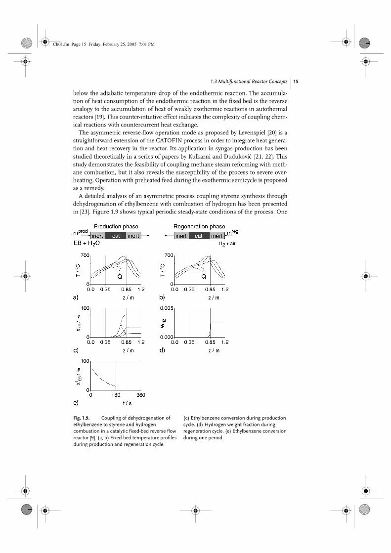
A detailed analysis of an asymmetric process coupling styrene synthesis throughdehydrogenation of ethylbenzene with combustion of hydrogen has been presentedin [23]. Figure 1.9 shows typical periodic steady-state conditions of the process. One
éc
Fig. 1.9. Coupling of dehydrogenation of ethylbenzene to styrene and hydrogen combustion in a catalytic fixed-bed reverse flow reactor [9]. (a, b) Fixed-bed temperature profiles during production and regeneration cycle.
(c) Ethylbenzene conversion during production cycle. (d) Hydrogen weight fraction during regeneration cycle. (e) Ethylbenzene conversion during one period.
Ch01.fm Page 15 Friday, February 25, 2005 7:01 PM

1 Enhancing Productivity and Thermal Efficiency of High-Temperature Endothermic Processes 16
finding of this study is the importance of structuring the fixed bed in catalytic andinert sections. In particular, a sufficient length of the right inert zone is decisive forthe establishment of a sufficient temperature level in the catalytic part. However,heat release within a narrow zone at the right end of the catalytic section impliesinefficient heat storage. The initial temperature profile of the endothermic semicycleenables indeed high conversion at a high selectivity, but subsequently the tempera-ture peak is shifted into the right inert section and becomes useless.
The major conclusions from the above-described studies are consistent: in theasymmetric mode of operation the reaction zones of the exothermic and endother-mic reactions inherently repel each other, leading either to an extreme maximumtemperature or to poor performance. A noncontinuous heat supply and productionduring every other semicycle cause obviously strong fluctuations of operation. More-over, reasonable states of operation are attainable only with an excess of gas duringthe exothermic semicycle. This contradicts the condition of equal heat capacities foroptimal heat recovery (see Section 1.2.1.1). For example, the heat loss in the case dis-played in Fig. 1.9 is equal to the heat demand of the endothermic reaction. Differentstrategies have been assessed with regard to their potential to reduce hotspots dur-ing the exothermic semicycle and to improve thermal efficiency.
Latent heat storageIt is clear that temperature oscillations during heating–cooling cycles depend on thefixed-bed heat capacity. Figure 1.10 shows a simplified picture of the effect of phasechange on the effective heat capacity of pure substances. Considerable amounts of
Fig. 1.10. Temperature plotted versus specific enthalpy of a pure substance undergoing phase changes (melting, solidifying).
Ch01.fm Page 16 Friday, February 25, 2005 7:01 PM
1.3 Multifunctional Reactor Concepts 17
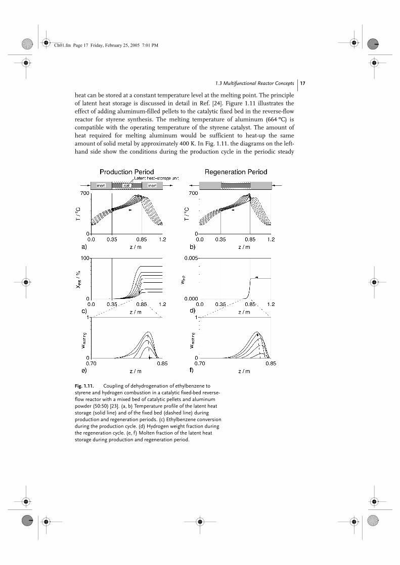
heat can be stored at a constant temperature level at the melting point. The principleof latent heat storage is discussed in detail in Ref. [24]. Figure 1.11 illustrates theeffect of adding aluminum-filled pellets to the catalytic fixed bed in the reverse-flowreactor for styrene synthesis. The melting temperature of aluminum (664 ºC) iscompatible with the operating temperature of the styrene catalyst. The amount ofheat required for melting aluminum would be sufficient to heat-up the sameamount of solid metal by approximately 400 K. In Fig. 1.11. the diagrams on the left-hand side show the conditions during the production cycle in the periodic steady
Fig. 1.11. Coupling of dehydrogenation of ethylbenzene to styrene and hydrogen combustion in a catalytic fixed-bed reverse- flow reactor with a mixed bed of catalytic pellets and aluminum powder (50:50) [23]. (a, b) Temperature profile of the latent heat storage (solid line) and of the fixed bed (dashed line) during production and regeneration periods. (c) Ethylbenzene conversion during the production cycle. (d) Hydrogen weight fraction during the regeneration cycle. (e, f) Molten fraction of the latent heat storage during production and regeneration period.
Ch01.fm Page 17 Friday, February 25, 2005 7:01 PM
1 Enhancing Productivity and Thermal Efficiency of High-Temperature Endothermic Processes 18
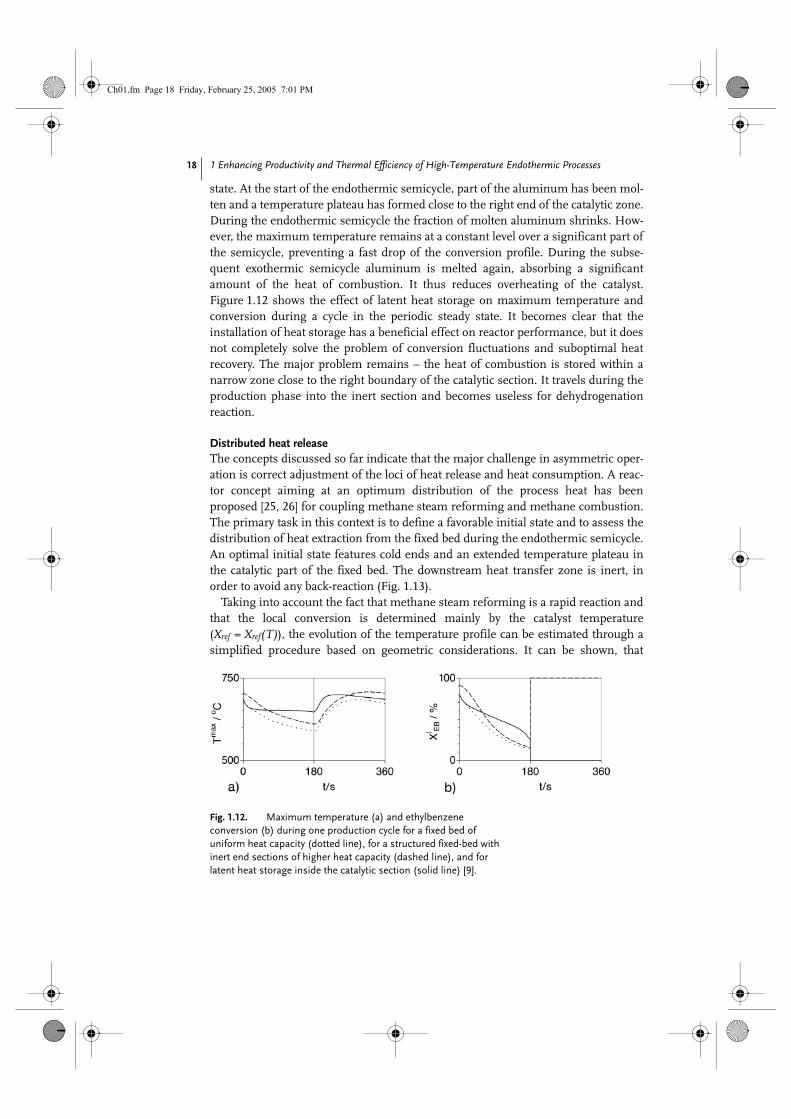
state. At the start of the endothermic semicycle, part of the aluminum has been mol-ten and a temperature plateau has formed close to the right end of the catalytic zone.During the endothermic semicycle the fraction of molten aluminum shrinks. How-ever, the maximum temperature remains at a constant level over a significant part ofthe semicycle, preventing a fast drop of the conversion profile. During the subse-quent exothermic semicycle aluminum is melted again, absorbing a significantamount of the heat of combustion. It thus reduces overheating of the catalyst.Figure 1.12 shows the effect of latent heat storage on maximum temperature andconversion during a cycle in the periodic steady state. It becomes clear that theinstallation of heat storage has a beneficial effect on reactor performance, but it doesnot completely solve the problem of conversion fluctuations and suboptimal heatrecovery. The major problem remains – the heat of combustion is stored within anarrow zone close to the right boundary of the catalytic section. It travels during theproduction phase into the inert section and becomes useless for dehydrogenationreaction.
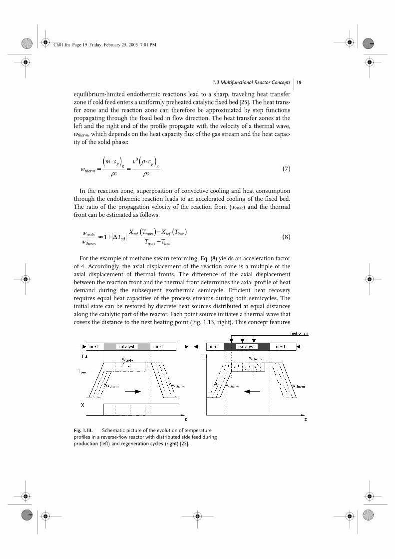
Distributed heat releaseThe concepts discussed so far indicate that the major challenge in asymmetric oper-ation is correct adjustment of the loci of heat release and heat consumption. A reac-tor concept aiming at an optimum distribution of the process heat has beenproposed [25, 26] for coupling methane steam reforming and methane combustion.The primary task in this context is to define a favorable initial state and to assess thedistribution of heat extraction from the fixed bed during the endothermic semicycle.An optimal initial state features cold ends and an extended temperature plateau inthe catalytic part of the fixed bed. The downstream heat transfer zone is inert, inorder to avoid any back-reaction (Fig. 1.13).
Taking into account the fact that methane steam reforming is a rapid reaction andthat the local conversion is determined mainly by the catalyst temperature(Xref = Xref(T)), the evolution of the temperature profile can be estimated through asimplified procedure based on geometric considerations. It can be shown, that
Fig. 1.12. Maximum temperature (a) and ethylbenzene conversion (b) during one production cycle for a fixed bed of uniform heat capacity (dotted line), for a structured fixed-bed with inert end sections of higher heat capacity (dashed line), and for latent heat storage inside the catalytic section (solid line) [9].
Ch01.fm Page 18 Friday, February 25, 2005 7:01 PM
1.3 Multifunctional Reactor Concepts 19
equilibrium-limited endothermic reactions lead to a sharp, traveling heat transferzone if cold feed enters a uniformly preheated catalytic fixed bed [25]. The heat trans-fer zone and the reaction zone can therefore be approximated by step functionspropagating through the fixed bed in flow direction. The heat transfer zones at theleft and the right end of the profile propagate with the velocity of a thermal wave,wtherm, which depends on the heat capacity flux of the gas stream and the heat capac-ity of the solid phase:
In the reaction zone, superposition of convective cooling and heat consumptionthrough the endothermic reaction leads to an accelerated cooling of the fixed bed.The ratio of the propagation velocity of the reaction front (wendo) and the thermalfront can be estimated as follows:
For the example of methane steam reforming, Eq. (8) yields an acceleration factorof 4. Accordingly, the axial displacement of the reaction zone is a multiple of theaxial displacement of thermal fronts. The difference of the axial displacementbetween the reaction front and the thermal front determines the axial profile of heatdemand during the subsequent exothermic semicycle. Efficient heat recoveryrequires equal heat capacities of the process streams during both semicycles. Theinitial state can be restored by discrete heat sources distributed at equal distancesalong the catalytic part of the reactor. Each point source initiates a thermal wave thatcovers the distance to the next heating point (Fig. 1.13, right). This concept features
Fig. 1.13. Schematic picture of the evolution of temperature profiles in a reverse-flow reactor with distributed side feed during production (left) and regeneration cycles (right) [25].
( ) ( )( )
ρ
ρ ρ
0
7⋅ ⋅
= =p pg g
therm
m c v cw
c c
( ) ( )( )max
max
1 8−
≈ + ∆−
ref ref lowendoad
therm low
X T X TwT
w T T
Ch01.fm Page 19 Friday, February 25, 2005 7:01 PM

1 Enhancing Productivity and Thermal Efficiency of High-Temperature Endothermic Processes 20
optimal characteristics in several respects: The conversion of the endothermic reac-tion is determined by the temperature plateau in the catalytic part and can be main-tained at a constant level throughout the complete endothermic semicycle. The heatcapacities of the process gases during the production and the regeneration step canbe adjusted properly in order to achieve optimal heat recovery.
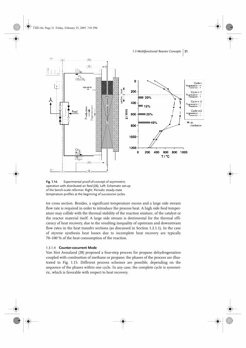
The concept has been implemented in a laboratory-scale set-up. A sketch of thereactor is shown in Fig. 1.14 (left). Point-wise heat generation at well-defined posi-tions along the fixed bed is accomplished with a special gas distributor which islocated in the central reactor axis and has openings at four axial positions. The dis-tributor is activated during the exothermic semicycle. Air is supplied to the reactorthrough the openings and burns part of the fuel contained in the main stream. Thecombustion reaction is almost instantaneous and represents approximately a pointheat source. This configuration prevents direct contact of oxygen with the catalyticfixed bed and protects the catalyst against oxidation. Moreover, uncontrolled com-bustion of carbonaceous deposits and its detrimental consequences can be excluded.Nevertheless, catalyst decoking is ensured by mild, endothermic reactions, for exam-ple, gasification or hydrogenation. The right-hand part of Fig. 1.14 shows the tem-perature profiles at the end of consecutive endothermic and exothermic semicyclesin periodic steady-state operation. The length of the production and regenerationcycle was set to 3 minutes. During the production cycle a mean methane conversionhigher than 98 % could be attained. Despite insufficient insulation and a high wall-to-volume ratio of the laboratory set-up, a production capacity of 1.5 kWLHV,H2 L–1
was achieved with a thermal efficiency of approximately 70 % – that is, the heat lossis in the order of 40 % of the heat uptake for the reforming reaction.
1.3.1.3 Symmetric Mode with Side Stream InjectionSide stream injection provides a flexible basis for new process variants. A derivate ofthis concept is the symmetric process: Shifting the combustion into an externalcombustion chamber and feeding the hot effluent gases to the main reactor enablesa continuous heat supply to the endothermic reaction, and continuous production.The endothermic reaction mixture is fed in periodically changing directions to thereactor, and this leads to symmetric conditions during both semicycles. The advan-tage over the simultaneous mode is the exclusion of direct contact and of undesir-able side reactions of the endothermic reaction mixture with oxygen. The symmetricprocess is particularly suitable for mole-number-increasing reactions since dilutionof the reaction mixture with inert gases may shift the chemical equilibrium towardshigher conversion. Accordingly, the symmetric process has been applied to styrenesynthesis [23, 27]. Side feed can be added either through a single or multiple ports.Distributed side feeding provides additional control variables, such as periodic acti-vation of the side ports [27]. This can be utilized for optimizing the shape of the tem-perature profile with respect to product selectivity. However, improved controllabilityand variability of the symmetric process goes along with a significantly increasedcomplexity of the reactor design. Fine-structured inlet manifolds and static mixersare required in order to achieve a uniform distribution of the side feed over the reac-
Ch01.fm Page 20 Friday, February 25, 2005 7:01 PM
1.3 Multifunctional Reactor Concepts 21
tor cross section. Besides, a significant temperature excess and a large side streamflow rate is required in order to introduce the process heat. A high side feed temper-ature may collide with the thermal stability of the reaction mixture, of the catalyst orthe reactor material itself. A large side stream is detrimental for the thermal effi-ciency of heat recovery, due to the resulting inequality of upstream and downstreamflow rates in the heat transfer sections (as discussed in Section 1.2.1.1). In the caseof styrene synthesis heat losses due to incomplete heat recovery are typically70–100 % of the heat consumption of the reaction.
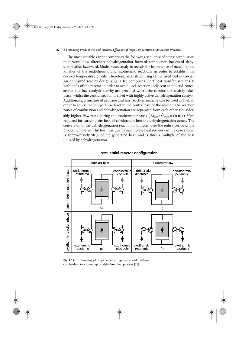
1.3.1.4 Counter-cocurrent ModeVan Sint Annaland [28] proposed a four-step process for propane dehydrogenationcoupled with combustion of methane or propane; the phases of the process are illus-trated in Fig. 1.15. Different process schemes are possible, depending on thesequence of the phases within one cycle. In any case, the complete cycle is symmet-ric, which is favorable with respect to heat recovery.
Fig. 1.14. Experimental proof-of-concept of asymmetric operation with distributed air feed [26]. Left: Schematic set-up of the bench-scale reformer. Right: Periodic steady-state temperature profiles at the beginning of successive cycles.
Ch01.fm Page 21 Friday, February 25, 2005 7:01 PM
1 Enhancing Productivity and Thermal Efficiency of High-Temperature Endothermic Processes 22
The most suitable variant comprises the following sequence of steps: combustionin forward flow direction–dehydrogenation forward–combustion backward–dehy-drogenation backward. Model-based analysis reveals the importance of matching thekinetics of the endothermic and exothermic reactions in order to establish thedesired temperature profile. Therefore, axial structuring of the fixed bed is crucial.An optimized reactor design (Fig. 1.16) comprises inert heat transfer sections atboth ends of the reactor in order to avoid back-reaction. Adjacent to the end zones,sections of low catalytic activity are provided where the combustion mainly takesplace, whilst the central section is filled with highly active dehydrogenation catalyst.Additionally, a mixture of propane and less reactive methane can be used as fuel, inorder to adjust the temperature level in the central part of the reactor. The reactionzones of combustion and dehydrogenation are separated from each other. Consider-
ably higher flow rates during the exothermic phases ( ) Marerequired for carrying the heat of combustion into the dehydrogenation zones. Theconversion of the dehydrogenation reaction is uniform over the entire period of theproduction cycles. The heat loss due to incomplete heat recovery in the case shownis approximately 90 % of the generated heat, and is thus a multiple of the heatutilized by dehydrogenation.
Fig. 1.15. Coupling of propane dehydrogenation and methane combustion in a four-step catalytic fixed-bed process [28].
( ): 10⋅ ⋅
=
exo endoM M O
Ch01.fm Page 22 Friday, February 25, 2005 7:01 PM

1.3 Multifunctional Reactor Concepts 23
This study also addresses the detrimental effect of carbonaceous deposits formedduring the dehydrogenation steps. The ignition of accumulated coke during the sub-sequent regeneration step can lead to extreme local temperature peaks that are ableto deactivate the catalyst or even to destroy the reactor. The phenomenon of temper-ature excursion during the exothermic gas–solid reactions has been analyzed byNieken and Watzenberger [29] and Salden [30], and will be discussed briefly in thefollowing section.
Fig. 1.16. Four-step propane dehydrogenation process [28]: Temperature profiles (top) and mass fraction profiles (bottom) at the end of the first two steps (1- exo, 2- endo). The end profiles of the subsequent steps are mirror images of the profiles shown.
Ch01.fm Page 23 Friday, February 25, 2005 7:01 PM
1 Enhancing Productivity and Thermal Efficiency of High-Temperature Endothermic Processes 24
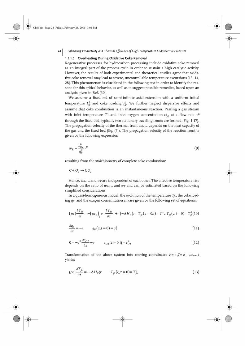
1.3.1.5 Overheating During Oxidative Coke RemovalRegenerative processes for hydrocarbon processing include oxidative coke removalas an integral part of the process cycle in order to sustain a high catalytic activity.However, the results of both experimental and theoretical studies agree that oxida-tive coke removal may lead to severe, uncontrollable temperature excursions [13, 14,28]. This phenomenon is elucidated in the following text in order to identify the rea-sons for this critical behavior, as well as to suggest possible remedies, based upon ananalysis given in Ref. [30].
We assume a fixed-bed of semi-infinite axial extension with a uniform initial
temperature T2fb and coke loading q0
B. We further neglect dispersive effects and
assume that coke combustion is an instantaneous reaction. Passing a gas stream
with inlet temperature T+ and inlet oxygen concentration c+O2 at a flow rate v0
through the fixed-bed, typically two stationary traveling fronts are formed (Fig. 1.17).The propagation velocity of the thermal front wtherm depends on the heat capacity ofthe gas and the fixed bed (Eq. (7)). The propagation velocity of the reaction front isgiven by the following expression
resulting from the stoichiometry of complete coke combustion:
Hence, wtherm and wR are independent of each other. The effective temperature risedepends on the ratio of wtherm and wR and can be estimated based on the followingsimplified considerations.
In a quasi-homogeneous model, the evolution of the temperature Tfb, the coke load-ing qB, and the oxygen concentration cO2 are given by the following set of equations:
Transformation of the above system into moving coordinates τ = t; ζ = z – wtherm tyields:
( )0
020 9= O
RB
cw v
q
+ 2 2C O COÆ
( ) ( ) ( ) ( ) ( ) ( ), ; , 00 0 10+∂ ∂ρ =− ρ + −∆ = = = =
∂ ∂fb fb
p R fb fb fbg
T Tc c v H r T z t T T z t T
t z
( ) ( ), 00 11∂
=− = =∂
BB B
qr q z t q
t
( )( , )0 22 20 0 12+∂
=− − = =∂
OO O
cv r c z t c
z
( ) ( )( ) ( ) , 00 13∂
ρ = −∆ ζ τ = =∂τ
fbR fb fb
Tc H r T T
Ch01.fm Page 24 Friday, February 25, 2005 7:01 PM
1.3 Multifunctional Reactor Concepts 25
Additionally, the constant pattern assumption implies the following conditions:
Eq. (17) inserted in Eq. (14) yields:
Combining Eqs. (13), (16), and (19) leads to:
Here, we must discriminate between two cases:1. Reaction front faster than thermal front (wR > wtherm):
This case, displayed in Fig. 1.17(c), occurs at high inlet oxygen concentrations orsmall initial coke loading – that is, the combustion is limited by the amount ofcoke. The heat generation by reaction exceeds the heat consumption for heating
( )( , ) ; ( , )00 14∞∂ ∂= − ζ τ = = ζ ∞ τ =
∂τ ∂ζB B
therm B B B Bq q
w r q q q qÆ
( )( , )0 22 20 0 15+∂
=− − ζ = τ =∂ζ
OO O
cv r c c
( ) ( )16∂ ∂
=− −∂τ ∂ζ
fb fbR therm
T Tw w
( ) ( )17∂ ∂
=− −∂τ ∂ζ
B BR therm
q qw w
( ) ( )18∂ ∂
− − = −∂ζ ∂ζ
B BR therm therm
q qw w w r
( )19∂
=∂ζ
BR
qr wfi
( ) ( ) ( ) ( )20∂ ∂
− ρ − = −∆∂ζ ∂ζ
fb BR therm R R
T qc w w H w
( )( )
( )21−∆
=− ⋅− ρ
fb RR
B R therm
dT Hw
dq w w cfi
( )( )
( )( )
( )max0 0
2 22+−∆ −∆∆ = − =− ⋅ ⋅ =− ⋅ ⋅
− ρ − ρR RR therm
fb B OR therm R therm P g
H Hw wT T T q c
w w c w w c
( ) ( )( ) ( )
02
123
+
∆ = ⋅ −∆ρρ
−
eff RP g
B O
T Hcc
q c
fi
Ch01.fm Page 25 Friday, February 25, 2005 7:01 PM

1 Enhancing Productivity and Thermal Efficiency of High-Temperature Endothermic Processes 26
up the cold gas stream. For wR >> wtherm the effective temperature riseapproaches asymptotically the value
that can be interpreted as the adiabatic temperature rise of the solid phase.2. Reaction front slower than thermal front (wR < wtherm):
This case, displayed in Fig. 1.17(d), occurs at a low inlet oxygen concentration or ahigh initial coke loading – that is, the combustion is oxygen-limited. The heat ofcombustion is carried away downstream by convection. For wR << wtherm theeffective temperature rise approaches asymptotically the value
which can be interpreted as the adiabatic temperature rise of the gas phase.Figure 1.18 displays the effective temperature rise during oxidative coke removal
as a function of the oxygen molar fraction of the regeneration gas according toEqs. (23) and (25), respectively. The adiabatic temperature rise of the shown case is38 K. However, ∆Teff can be much higher and tends to infinity at the limit ofwR Æ wtherm. This can be explained as follows: when the velocities of the thermalfront and the reaction front are equal, the heat of combustion accumulates in a nar-row zone which may lead to extremely high local temperatures. This conclusion hasbeen verified theoretically through detailed simulations [30].
The above considerations hold under the condition that the ignition temperature
of coke combustion is lower than T0fb in the coke-limited regime, or lower than T+ in
the oxygen-limited regime. However, in the considered heat-integrated processes thefeed temperature T+ is generally far below the ignition temperature. The fatal aspectin this scenario is that coke regeneration is carried out “carefully” – that is, with alow oxygen concentration. Oxygen deficiency leads to incomplete coke removalaccording to the following condition:
In this way, the reaction front is synchronized inevitably with the thermal front,leading to the observed temperature excursions (Fig. 1.19).
( )0 −∆∆ =
ρs
adB Rq H
Tc
( )( )
( )( )
( )max0
2 24+ +−∆ −∆∆ = − = ⋅ ⋅ = ⋅ ⋅
− ρ − ρR RR therm
B OR therm R therm P g
H Hw wT T T q c
w w c w w c
( ) ( )( ) ( )
02
125
+
∆ = ⋅ −∆ρ ρ
−
eff RP g
O B
T Hc c
c q
fi
( )( )2
+ −∆∆ =
ρ
g O Rad
p g
c HT
c
( )020 26
+
= = ⋅− rO
R thermB B
cw w v
q q
Ch01.fm Page 26 Friday, February 25, 2005 7:01 PM

1.3 Multifunctional Reactor Concepts 27
Hence, in order to prevent overheating it is not simply the amount of coke thatmatters; rather, it is also necessary to avoid synchronization of the thermal and com-bustion fronts. This can be achieved by correctly adjusting the oxygen inlet concen-tration, in order to carry out regeneration in the coke-limited regime.
1.3.2Recuperative Processes
The activities of heat-integrated processes with recuperative heat exchange aremainly devoted to the conversion of primary fuels (hydrocarbons or alcohols) tohydrogen, with few exceptions – for example, investigations on the dehydrogenationof light alkanes in Schmidt’s group [3]. The practical relevance and vitality of
Fig. 1.17. Schematic picture of front propagation during oxidative coke removal. (a) Oxygen concentration in the regeneration gas, e.g., air. (b) Coke loading of the solid phase. (c) Front propagation of the thermal front (velocity wtherm) and the reaction front (wR) with preceding reaction front. (d) Front propagation with preceding thermal front
(special case: T+ = T0fb ).
Ch01.fm Page 27 Friday, February 25, 2005 7:01 PM

1 Enhancing Productivity and Thermal Efficiency of High-Temperature Endothermic Processes 28
research on heat-integrated fuel processors can be estimated from the numberof established companies and start-ups active in this area [31]. Two major trendsprevail: One focusing on optimization of existing concepts and one aiming at novelconcepts based on micro-reactors.
Fig. 1.18. Effective temperature rise during oxidative coke removal as a function of the oxygen mole fraction of the regeneration feed gas.
Fig. 1.19. Front propagation during oxidative coke removal with low inlet temperature. (a) Oxygen concentration in the regeneration gas. (b) Coke loading of the solid phase. (c) Development of temperature excursion in the propagating reaction zone.
Ch01.fm Page 28 Friday, February 25, 2005 7:01 PM
1.3 Multifunctional Reactor Concepts 29
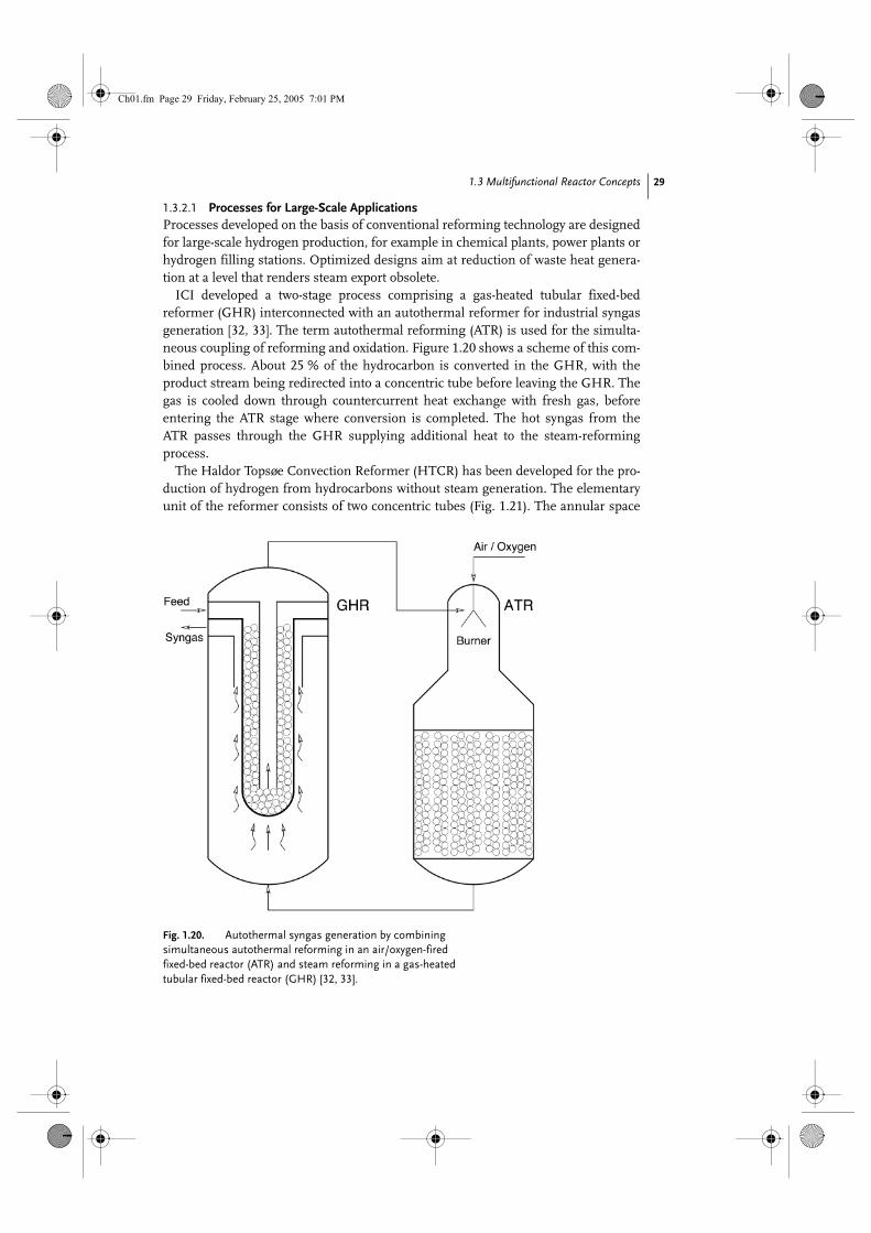
1.3.2.1 Processes for Large-Scale ApplicationsProcesses developed on the basis of conventional reforming technology are designedfor large-scale hydrogen production, for example in chemical plants, power plants orhydrogen filling stations. Optimized designs aim at reduction of waste heat genera-tion at a level that renders steam export obsolete.
ICI developed a two-stage process comprising a gas-heated tubular fixed-bedreformer (GHR) interconnected with an autothermal reformer for industrial syngasgeneration [32, 33]. The term autothermal reforming (ATR) is used for the simulta-neous coupling of reforming and oxidation. Figure 1.20 shows a scheme of this com-bined process. About 25 % of the hydrocarbon is converted in the GHR, with theproduct stream being redirected into a concentric tube before leaving the GHR. Thegas is cooled down through countercurrent heat exchange with fresh gas, beforeentering the ATR stage where conversion is completed. The hot syngas from theATR passes through the GHR supplying additional heat to the steam-reformingprocess.
The Haldor Topsøe Convection Reformer (HTCR) has been developed for the pro-duction of hydrogen from hydrocarbons without steam generation. The elementaryunit of the reformer consists of two concentric tubes (Fig. 1.21). The annular space
Fig. 1.20. Autothermal syngas generation by combining simultaneous autothermal reforming in an air/oxygen-fired fixed-bed reactor (ATR) and steam reforming in a gas-heated tubular fixed-bed reactor (GHR) [32, 33].
Ch01.fm Page 29 Friday, February 25, 2005 7:01 PM
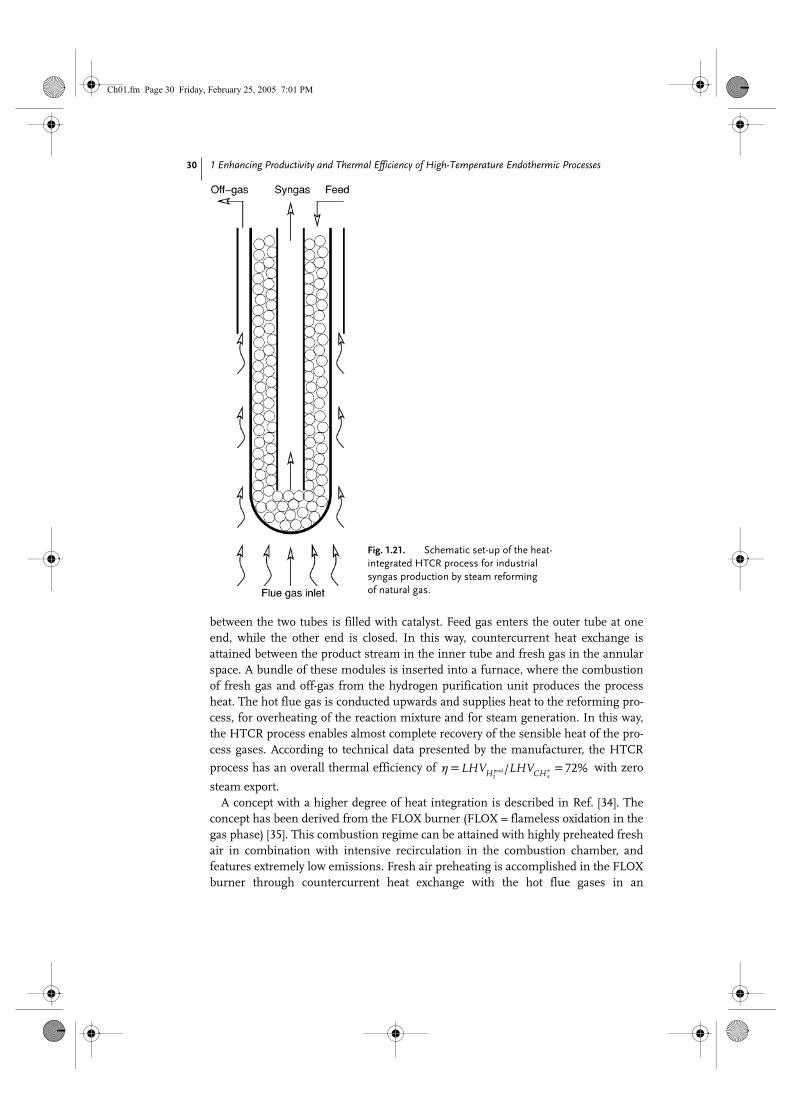
1 Enhancing Productivity and Thermal Efficiency of High-Temperature Endothermic Processes 30
between the two tubes is filled with catalyst. Feed gas enters the outer tube at oneend, while the other end is closed. In this way, countercurrent heat exchange isattained between the product stream in the inner tube and fresh gas in the annularspace. A bundle of these modules is inserted into a furnace, where the combustionof fresh gas and off-gas from the hydrogen purification unit produces the processheat. The hot flue gas is conducted upwards and supplies heat to the reforming pro-cess, for overheating of the reaction mixture and for steam generation. In this way,the HTCR process enables almost complete recovery of the sensible heat of the pro-cess gases. According to technical data presented by the manufacturer, the HTCR
process has an overall thermal efficiency of with zero
steam export.A concept with a higher degree of heat integration is described in Ref. [34]. The
concept has been derived from the FLOX burner (FLOX = flameless oxidation in thegas phase) [35]. This combustion regime can be attained with highly preheated freshair in combination with intensive recirculation in the combustion chamber, andfeatures extremely low emissions. Fresh air preheating is accomplished in the FLOXburner through countercurrent heat exchange with the hot flue gases in an
Fig. 1.21. Schematic set-up of the heat-integrated HTCR process for industrial syngas production by steam reforming of natural gas.
/ %2 4
72+η= =prodH CHLHV LHV
Ch01.fm Page 30 Friday, February 25, 2005 7:01 PM

1.3 Multifunctional Reactor Concepts 31
integrated heat exchanger. Thus, heat recovery is inherently included in the FLOXburner. In the FLOX reformer the reforming modules consisting of two concentrictubes, similar to those of the HTCR- and ICI-GHR design, which hang in thecombustion chamber. Steam generation, reforming and water-gas-shift reaction areintegrated in every module. Figure 1.22 shows a scheme of the heat management ofthis concept. The two heat recovery loops of the reforming and combustion gas arealmost completely separated from each other. The heat content of the reforming gasis utilized for vaporizing the liquid water and the water-gas shift stage for CO-removal is cooled by the produced steam. The sensible heat of the flue gas is utilizedfor preheating the fresh air superheating the methane/steam mixture. The FLOX-reformer design is modular with a capacity of 50–250 Nm3 H2 h–1. Thermalefficiency exceeds 80 %.
1.3.2.2 Processes for Small-scale ApplicationsNowadays, the most common small-scale application of hydrogen is the use inresidential or mobile fuel cell systems. Special requirements of this application arecompact design, integrated CO-removal, high energetic efficiency, quick start-upand fast transient behavior. The proposed solutions comprise unit-operation-basedconcepts as well as multifunctional, micro-structured reactors.
A gasoline processing system has been developed by Daimler Chrysler [36] basedon ATR. Catalytic ATR is extremely rapid, and provides the potential for a very com-pact process. The specific productivity of the ATR is about 15 kWLHV,gasoline L–1. Thefuel is sprayed into a preheated air stream. The ATR-product stream enters a high-temperature shift reactor (HTS), in order to convert CO. Both ATR and HTS aredesigned as adiabatic metallic monolith reactors, which are coated with differentnoble metal catalysts for reforming and water-gas shift reactions. The operation tem-perature of the ATR is above 750 ºC, while the HTS operates at about 450 ºC. There-fore, it is recommended that the two units are interconnected with a heat exchanger,in order to recover the heat of the ATR product stream for preheating the ATR feed(Fig. 1.23). The behavior of the coupled system has been analyzed in Ref. [37].
Fig. 1.22. Flowsheet of the FLOX-reformer. The triangles indicate the exchanged heat fluxes between different stages of the process [34].
Ch01.fm Page 31 Friday, February 25, 2005 7:01 PM
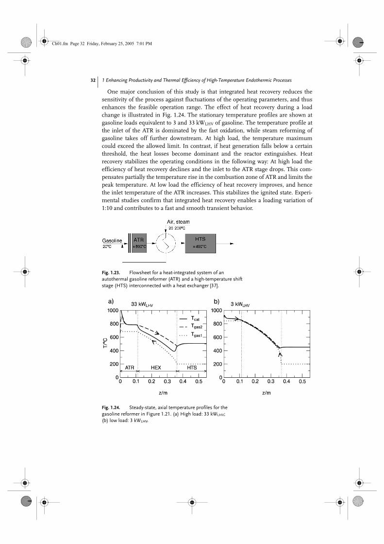
1 Enhancing Productivity and Thermal Efficiency of High-Temperature Endothermic Processes 32
One major conclusion of this study is that integrated heat recovery reduces thesensitivity of the process against fluctuations of the operating parameters, and thusenhances the feasible operation range. The effect of heat recovery during a loadchange is illustrated in Fig. 1.24. The stationary temperature profiles are shown atgasoline loads equivalent to 3 and 33 kWLHV of gasoline. The temperature profile atthe inlet of the ATR is dominated by the fast oxidation, while steam reforming ofgasoline takes off further downstream. At high load, the temperature maximumcould exceed the allowed limit. In contrast, if heat generation falls below a certainthreshold, the heat losses become dominant and the reactor extinguishes. Heatrecovery stabilizes the operating conditions in the following way: At high load theefficiency of heat recovery declines and the inlet to the ATR stage drops. This com-pensates partially the temperature rise in the combustion zone of ATR and limits thepeak temperature. At low load the efficiency of heat recovery improves, and hencethe inlet temperature of the ATR increases. This stabilizes the ignited state. Experi-mental studies confirm that integrated heat recovery enables a loading variation of1:10 and contributes to a fast and smooth transient behavior.
Fig. 1.23. Flowsheet for a heat-integrated system of an autothermal gasoline reformer (ATR) and a high-temperature shift stage (HTS) interconnected with a heat exchanger [37].
Fig. 1.24. Steady-state, axial temperature profiles for the gasoline reformer in Figure 1.21. (a) High load: 33 kWLHV; (b) low load: 3 kWLHV.
Ch01.fm Page 32 Friday, February 25, 2005 7:01 PM
1.3 Multifunctional Reactor Concepts 33
The progress in micro-reactor technology provides the background for the devel-opment of compact fuel processors and peripheral components of fuel cell systems.
Published performance data [38–42] indicate the high development status alreadyreached: Volume-specific productivity values up to 750 lNH2/lit./h ≡ 2,3 kWLHV,H2/lit. and overall thermal efficiency values from 80 to 90 % have been reported for gasgeneration processes including feed preheating, gas generation and purification.Unfortunately, no further details are available about reactor design and the processconditions except for very few of them.
The Integrated Fuel Processor (IFP)This was developed by Ballard Power [40], and is a multifunctional reactor includingthe evaporation of a methanol/water mixture, autothermal methanol reforming andpreferential oxidation (PrOx) for CO removal. The device consists of a stack of iden-tical, structured plates which divide its volume in two compartments with micro-structured rectangular channels. These plates are made from aluminum and copper,thus ensuring high thermal conductivity for a uniform temperature over the entirereactor volume. A schematic picture of a single plate is shown in Fig. 1.25. Liquidmethanol/water mixture enters the first compartment and evaporates when heatedby the exothermic PrOx reaction, which takes place on the other side of the plate.The reactants are mixed with air and enter the porous section of the plates where thereforming reaction takes place as the reaction gases cross the plates. In the secondchamber, secondary air is added and the reaction products pass over a PrOx-catalystwhile exchanging heat with the first chamber. The temperature of the reactor isadjusted to 280 ºC. Proof-of-concept experiments with the IFP gave an extremely
high productivity of 2.5 m3N H2/lit./h ≡ 7.5kWLHV,H2/lit. A special powder-metallur-
gical fabrication method allows for producing impermeable and porous areas on theplate as required for the flow distribution, embossing the surface structure andimpregnating with reforming catalyst (Cu/ZnO) in one step. The plates are piled to astack and joined by sintering. However, the IFP-design is not suitable for high-tem-perature applications such as gasoline or methane processors. Furthermore, theabove-mentioned autothermal reforming processes are charged with the inherentshortcomings of the simultaneous mode with regard to product dilution and pres-sure limitations. Therefore, the focus is set on high- temperature steam reforming.The potential of catalytic plate reactors with narrow channels regarding controllabil-ity, productivity and efficiency has been demonstrated in detailed theoretical studiesby Zanfir and Gavriilidis [43]. One crucial task in implementing the concept is thedevelopment of fabrication techniques for catalytic activation of the plates and forassembling a stack. The solution of choice would be to coat the plates before joiningthem to a stack. However, the conditions required by the common joint methods –soldering or diffusion bonding – would damage the catalyst, whilst the alternative oflaser welding is too expensive. Therefore, although coating the completely assem-bled reactor is often employed as the only viable solution, this is extremely difficultto control [44] and is a clear restriction of the adequacy of micro-fabricated reactorsfor specific applications. Moreover, the suggestion of “the smaller the better” is not
Ch01.fm Page 33 Friday, February 25, 2005 7:01 PM

1 Enhancing Productivity and Thermal Efficiency of High-Temperature Endothermic Processes 34
generally true in the context of processes with integrated heat recovery. Decreasingthe channel width allows a given heat transfer area to be installed in shorter devices.This enhances the influence of heat conductivity and tends to equalize temperaturegradients; thus, it is an advantage for temperature control in the reaction stage.However, the same effect considerably affects the efficiency of heat recovery in theheat exchanger sections [45]. Therefore, it is not recommended that attention befocused exclusively on minimization of the hydraulic diameter and the size of thedevices.
Another important aspect is optimization of the process parameters. The chal-lenge here is to control catalytic combustion, in order to attain overlapping of thecombustion and reforming reaction over a sufficient interval [46]. The operatingconditions are mainly determined by the fuel composition and the heat exchange
Fig. 1.25. Schematic diagram of a single plate of the Integrated Fuel Processor (IFP) [40]. Top = flow scheme; center = view to the front side; bottom = view to the reverse side.
Ch01.fm Page 34 Friday, February 25, 2005 7:01 PM
1.3 Multifunctional Reactor Concepts 35
mode between the process streams. In low-temperature processes (e.g., methanolreforming) or in processes without feed preheating, hydrogen is required to stabilizethe ignited state of the catalytic combustion [47, 48]. However, the presence of hydro-gen is extremely critical at high temperatures due to the ignition of homogeneouscombustion. The use of less-reactive pure methane is recommended in this case, inorder to avoid runaway [49]. Additionally, countercurrent flow of the reforming andthe combustion gas gives rise to separation of the reaction zones and to runaway ofthe combustion reaction. A considerable excess of the combustion gas flow rateagainst the reforming gas flow rate is required in order to stabilize reasonable oper-ating conditions at the cost of a lower thermal efficiency [45]. Overlapping of thereaction zones could be enforced either through distributed side-feeding of air orfuel or through cocurrent flow of combustion and reforming gas stream in the cata-lytic part of the reactor [50].
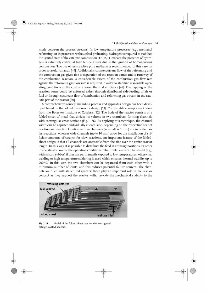
A comprehensive concept including process and apparatus design has been devel-oped based on the folded plate reactor design [51]. Comparable concepts are knownfrom the Boreskov Institute of Catalysis [52]. The body of the reactor consists of afolded sheet of metal that divides its volume in two chambers, forming channelswith rectangular cross-sections (Fig. 1.26). By applying this technique, the channelwidth can be adjusted individually at each side, depending on the respective heat ofreaction and reaction kinetics: narrow channels (as small as 1 mm) are indicated forfast reactions, whereas wide channels (up to 10 mm) allow for the installation of suf-ficient amounts of catalyst for slow reactions. An important feature of the folded-sheet design is that all channels are accessible from the side over the entire reactorlength. In this way, it is possible to distribute the feed at arbitrary positions, in orderto specifically control the operating conditions. The frontal ends can be sealed (e.g.,with silicon rubber) if they are permanently exposed to low temperatures; otherwise,welding or high-temperature soldering is used which ensures thermal stability up to900 ºC. In this way, the two chambers can be separated from each other with aminimum number of joints, and this reduces potential failure sources. The chan-nels are filled with structured spacers; these play an important role in the reactorconcept as they support the reactor walls, provide the mechanical stability to the
Fig. 1.26. Model of the folded sheet reactor with corrugated, catalyst-coated spacers.
Ch01.fm Page 35 Friday, February 25, 2005 7:01 PM

1 Enhancing Productivity and Thermal Efficiency of High-Temperature Endothermic Processes 36
reactor structure, and contribute to the improvement of the heat exchange throughplanar contact to the reactor wall. Spacers with crossing passages can be used asstatic mixers downstream of the injection ports in order to distribute the feeduniformly over the depth of each channel; finally, the spacers can be coated with cat-alyst. In this way, it is possible to adjust the axial structure of the channels in order toattain optimal implementation of multiple functions. The gas inlet and outlet portsare integrated in shells, forming the reactor casing. They are assembled together bytwo longitudinal weld seams, and the casing can also be reinforced to enhance therigidity of the device. Two prototype reactors have been developed – one for low-tem-perature methanol steam reforming, and one for high-temperature methane steamreforming based on the folded-sheet reactor concept.
Methanol steam reforming
The concept has been developed to the stage of a bench-scale prototype for 3m3N/h
hydrogen [53]. The complete hydrogen generation process including evaporation ofmethanol and water, superheating, reforming, water-gas shift combined with prod-uct cooling, are integrated in this device. Heat supply is controlled by distributedside-feeding of fuel (hydrogen) at five stages along the reactor. The experimentsshowed a good methanol conversion (X > 90 %) with moderate CO formation(yco ~ 2 %) and excellent dynamics upon load changes.
However, the distribution of the fuel in the depth of the channels required a com-plex capillary distributor with tiny exit nozzles. The particular device, although opti-mal with regard to the uniformity of gas distribution, seems not to be an adequatetechnical solution.
Methane steam reformingThe counter-cocurrent reformer concept including two countercurrent heatexchangers and a cocurrent reaction section (Fig. 1.27(a)) was considered in order toattain optimal conditions for kinetic control of the combustion [8]. It is well knownthat cocurrent cooling is generally favorable in preventing runaway of highlyexothermic reactions. In the particular case, chemical cooling is provided by thereforming reaction.
The conditions in the reaction section are of primary interest for the entire pro-cess. Experiments have been conducted with superheated feed streams using athree-channel model reactor in order to analyze the coupling of methane reformingand methane combustion in the cocurrent mode. Figure 1.27(c) shows a sketch ofthe configuration representing an elementary unit of the folded sheet reactor with acombustion channel of full-height in the middle and two reforming channels of halfof full- height, one on each side. Heat losses to the surroundings have been partiallycompensated by an electrically heated insulation. The diagrams show the tempera-ture profile (Fig. 1.27(b)) and the performance data of the reactor (Fig. 1.27(d))depending on the fuel concentration in the steady state. The most important resultis that the cooling effect of the reforming reaction effectively prevents runaway ofcombustion. Hence, it is possible to achieve complete conversion under moderate
Ch01.fm Page 36 Friday, February 25, 2005 7:01 PM

1.3 Multifunctional Reactor Concepts 37
Fig.
1.2
7.M
etha
ne s
team
ref
orm
er w
ith c
ocur
rent
flow
in th
e re
actio
n zo
ne.
(a)
Flow
sch
eme.
(b)
Sim
ulat
ed a
nd m
easu
red
tem
pera
ture
pro
files
in th
e re
acti
on z
one
of th
e th
ree-
chan
nel r
eact
or. (
c) S
ketc
h of
the
thre
e-ch
anne
l
reac
tor
for
coup
ling
of s
team
ref
orm
ing
and
com
bust
ion.
(d)
Sim
ulat
ed a
nd
mea
sure
d m
etha
ne c
onve
rsio
n de
pend
ing
on fu
el fe
ed c
once
ntra
tion
of th
e co
mbu
stio
n re
actio
n.
Ch01.fm Page 37 Friday, February 25, 2005 7:01 PM
1 Enhancing Productivity and Thermal Efficiency of High-Temperature Endothermic Processes 38
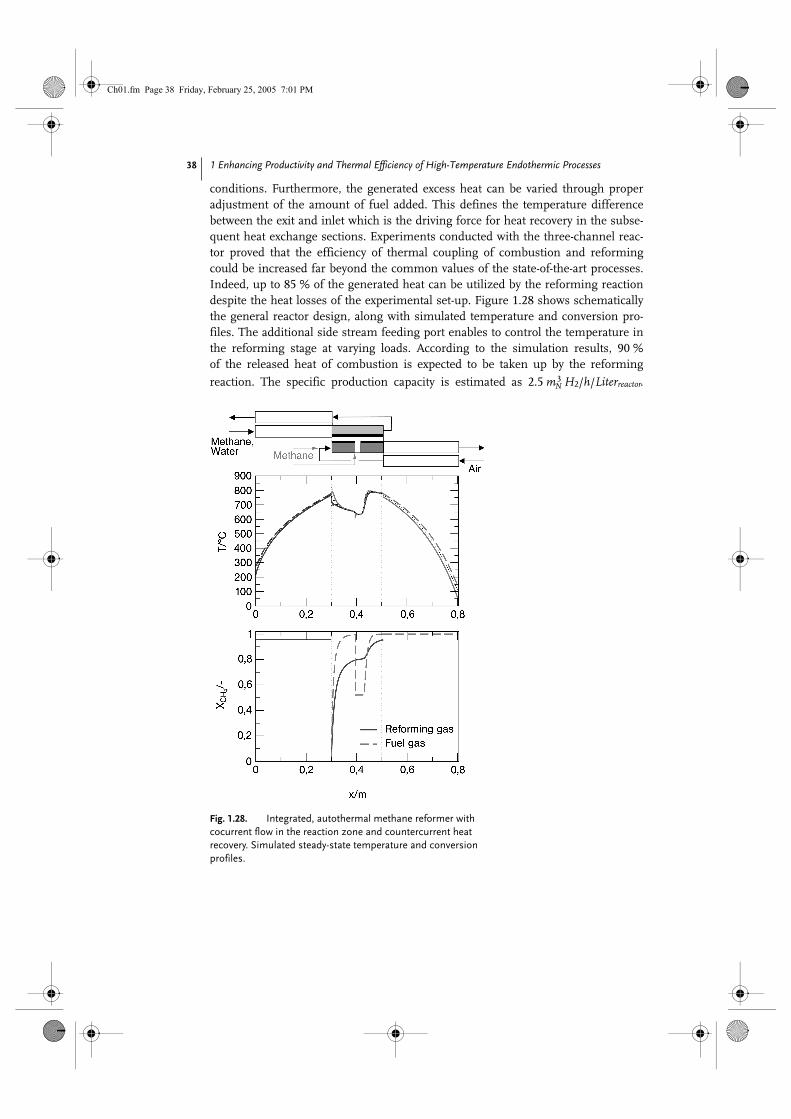
conditions. Furthermore, the generated excess heat can be varied through properadjustment of the amount of fuel added. This defines the temperature differencebetween the exit and inlet which is the driving force for heat recovery in the subse-quent heat exchange sections. Experiments conducted with the three-channel reac-tor proved that the efficiency of thermal coupling of combustion and reformingcould be increased far beyond the common values of the state-of-the-art processes.Indeed, up to 85 % of the generated heat can be utilized by the reforming reactiondespite the heat losses of the experimental set-up. Figure 1.28 shows schematicallythe general reactor design, along with simulated temperature and conversion pro-files. The additional side stream feeding port enables to control the temperature inthe reforming stage at varying loads. According to the simulation results, 90 %of the released heat of combustion is expected to be taken up by the reforming
reaction. The specific production capacity is estimated as 2.5 m3N H2/h/Literreactor.
Fig. 1.28. Integrated, autothermal methane reformer with cocurrent flow in the reaction zone and countercurrent heat recovery. Simulated steady-state temperature and conversion profiles.
Ch01.fm Page 38 Friday, February 25, 2005 7:01 PM
1.4 Conclusions 39
Experimental proof-of-concept with a bench-scale reactor (production capacity of
3.3 m3N H2/h) is the subject of ongoing investigations.
1.4Conclusions
The coupling of high-temperature endothermic and exothermic reactions in multi-functional devices with integrated heat recovery is gaining increasing interest,driven in particular by the developing hydrogen technology. Conventional conceptsare not suitable to meet the demands on specific performance, thermal efficiencyand autonomy of the process. Two routes are currently being pursued towards novelsolutions employing either regenerative or recuperative heat exchange for heat cou-pling and heat recovery.
Regenerative processes based on the reverse-flow reactor concept are preferred inlarge-scale applications due to their simple and scalable reactor design. Compactrecuperative concepts based on the wall reactor concept provide the best potential forsmall-scale applications. Apart from these general features, correct structuring of thecatalytic and fluid-dynamic properties of the reactor is essential for an optimaldesign. Distributed feeding of combustion air or fuel ensures optimal heat transferfrom the exothermic to the endothermic part. An integrated approach combiningapparatus design and process development is indicated for optimal implementationof novel solutions.
With regard to fuel processors for hydrogen production, autothermal reformingprocesses have initially approached the technological and economical targets fortechnical implementation, though their applicability is limited due to principalshortcomings of the concept. Properly designed steam reforming processes maypossibly compete with autothermal reformers with regard to space–time yield andheat recovery, while offering high flexibility in terms of operating conditions. Theymay, therefore, be utilized in a wide spectrum of applications.
Symbols and Abbreviations
A area, m2
c specific heat capacity of the solid phase, J kg–1 K–1
cp specific heat capacity of the gas phase, J kg–1 K–1
cj concentration of component j, mol m–3
Di inner diameter, m
h heat capacity ratio
h specific enthalpy, J mol–1
kh heat transfer coefficient, W m–2 K–1
lossnorm normalized heat losses
mass flux, kg s–1
molar flux, mol s–1
NTU number of transfer units
⋅M⋅N
Ch01.fm Page 39 Friday, February 25, 2005 7:01 PM

1 Enhancing Productivity and Thermal Efficiency of High-Temperature Endothermic Processes 40
Greek letters
Indices
p pressure, bar
qB coke loading, mol m–3
r reaction rate, mol m–3 s–1
t time, s
T temperature, K
v0 superficial gas velocity, m s–1
wtherm thermal front propagation velocity, m s–1
wendo/exo/R reaction front propagation velocity, m s–1
X conversion of reaction
yj molar fraction of the component j
z axial coordinate, m
αw heat transfer coefficient, W m–2 K–1
∆HR heat of reaction, kJ mol–1
∆T temperature difference, K
∆Tad adiabatic temperature rise, K
∆Teff effective temperature rise, K
λ axial heat conductivity, W m–1 K–1
ρ density, kg m–3
τ time in transformed system of coordinates, s
ζ spatial coordinate in transformed system, m
0, + inlet or initial conditions
– outlet conditions
c fixed-bed catalyst
cyc cycle
equ equilibrium conditions
endo endothermic reaction
exo exothermic reaction
fb fixed-bed
g gas phase
l liquid phase
lat latent heat storage
low lower value
max maximum value
prod production cycle
reg regeneration cycle
ref steam reforming
s solid phase
w separating wall
Ch01.fm Page 40 Friday, February 25, 2005 7:01 PM

References 41
Acronyms
References
ATR Autothermal Reformer
GHR Gas-Heated Reformer
HTS High-Temperature Shift Stage
LHV Lower Heating Value
PrOx Preferential Oxidation
1. Horizon 2015: Perspectives for the European Chemical Industry. A study by the European Chemical Industry Council (www.cefig.org), 2004.
2. J. Larminie, A. Dicks, Fuel Cell Systems Explained. 2nd edn., Wiley, 2003.
3. K. Venkataraman, J. M. Redenius, L. D. Schmidt, Millisecond Catalytic Wall Reactors: Dehydrogenation of Ethane. Chem. Eng. Sci., 2002, 57, 2335–2343.
4. K. Venkataraman, E. C. Wanat, L. D. Schmidt, Steam Reforming of Methane and Water Gas Shift in Short Contact Time Reactors. AIChE J., 2003, 49, 1277–1284.
5. M. Zanfir, A. Gavriilidis, Modeling of a catalytic plate reactor for dehydrogenation-combustion coupling. Chem. Eng. Sci., 2001, 56, 2671–2683.
6. P. Häussinger, Ullmann’s Encyclopedia of Industrial Chemistry. Hydrogen, 1989, Vol. A13, VCH Verlagsgesellschaft, Weinheim, 311 ff.
7. E. U. Schlünder, Introduction into heat transfer, Vieweg, Braunschweig, 3rd edn, 1981.
8. G. Kolios, B. Glöckler, A. Gritsch, et al., Heat-Integrated Reactor Concepts for Hydrogen Production by Methane Steam Reforming. Accepted for Publication in Fuel Cells. 2004.
9. G. Kolios, Zur autothermen Führung der Styrolsynthese mit periodischem Wechsel der Strömungsrichtung. Nr. 501, VDI-Fortschrittsberichte, Reihe 3, VDI-Verlag, Düsseldorf, 1997.
10. R. Charlesworth, A. Gough, C. Ramshaw, Combustion and steam reforming of methane on thin layer catalysts for use in catalytic plate reactors. Fourth UK/National Conference on Heat Transfer, Institution of Mechanical Engineers, 26–27 September 1995, pp. 85–89.
11. G. Kolios, J. Frauhammer, G. Eigenberger, Autothermal Fixed-Bed Reactor Concepts. Chem. Eng. Sci., 2000, 55, 5945–5967.
12. R. F. Blanks, T. S. Wittrig, D. A. Peterson, Bidirectional adiabatic synthesis gas generator. Chem. Eng. Sci., 1990, 45, 2407–2413.
13. A. M. De Groote, G. F. Froment, Synthesis Gas Production from Natural Gas in a Fixed-Bed Reactor with Reversed Flow. Can. J. Chem. Eng., 1996, 74, 735–742.
14. K. Gosiewski, Simulations of non-stationary reactors for the catalytic conversion of methane to synthesis gas. Chem. Eng. Sci., 2001, 56, 1501–1510.
15. G. Veser, J. Frauhammer, Modeling steady state and ignition during catalytic methane oxidation in a monolith reactor. Chem. Eng. Sci., 2000, 55, 2271–2286.
16. R. G. Craig, T. J. Delaney, J. M. Duffalo, Catalytic dehydrogenation performance of the catofin process. DeWitt Petro-chemical Review, Houston 1990.
17. C. Ercan, R. J. Gartside, Reactor Performance and Stability in an Alternating Reaction-Reheat Paraffin Dehydrogenation System. Can. J. Chem. Eng., 1996, 74, 626–637.
Ch01.fm Page 41 Friday, February 25, 2005 7:01 PM
1 Enhancing Productivity and Thermal Efficiency of High-Temperature Endothermic Processes 42
18. T. N. Haynes, C. Georgakis, H. S. Caram, The application of reverse flow reactors to endothermic reactions. Chem. Eng. Sci., 1992, 47, 2927–2932.
19. Yu. Sh. Matros, Catalytic processes under unsteady-state conditions. Studies in surface science and catalysis. 1989, vol. 43, Reversal of the reaction mixture flow in the fixed catalyst bed. Amsterdam: Elsevier.
20. O. Levenspiel, Chemical Engineer’s Grand Adventure. Chem. Eng. Sci., 1988, 43, 1427–1435.
21. M. S. Kulkarni, M. P. Dudukovi , A bidirectional fixed-bed reactor for coupling exothermic and endothermic reactions. AIChE J., 1996, 42, 2897–2910.
22. M. S. Kulkarni, M. P. Dudukovi , Periodic operation of asymmetric bidirectional fixed-bed reactors with temperature limitations. Ind. Eng. Chem. Res., 1998, 37, 770–781.
23. G. Kolios, G. Eigenberger, Styrene synthesis in a reverse-flow reactor. Chem. Eng. Sci., 1999, 54, 2637–2646.
24. W. R. Humphries, E. I. Griggs, A design handbook for phase change thermal control and energy storage devices. NASA Technical paper, 1074, Washington DC, 1977.
25. B. Glöckler, G. Kolios, G. Eigenberger, Analysis of a novel reverse-flow reactor concept for autothermal methane steam reforming. Chem. Eng. Sci., 2003, 58, 593–601.
26. B. Glöckler, A. Gritsch, A. Morillo, et al., Autothermal reactor concepts for endothermic fixed-bed reactions. Chem. Eng. Res. Des., 2004, 82 (A2), 148–159.
27. J. D. Snyder, B. Subramaniam, A novel flow strategy for ethylbenzene dehydrogenation in a packed-bed reactor. Chem. Eng. Sci., 1994, 49, 5585–5601.
28. M. van Sint Annaland, A novel reverse flow reactor coupling endothermic and exothermic reactions. PhD thesis, Twente
University, Enschede, The Netherlands, 2000.
29. U. Nieken, O. Watzenberger, Periodic operation of the Deacon process. Chem. Eng. Sci., 1999, 54, 2619–2626.
30. A. Salden, Adsorption/Incineration Process for Waste Gas Purification. Ph.D. thesis, University of Stuttgart, Germany. 2002, Logos Verlag Berlin.
31. www.fuelcelltoday.com: Knowledge Bank.
32. E. H. Stitt, P. E. J. Abbott, B. J. Cromarty, et al., Emerging Trends in Syngas and Hydrogen. Presented at CatCon2000, 12–13 June, 2000, Houston, TX, USA.
33. E. H. Stitt, Multifunctional Reactors? ‘Up to a Point Lord Copper’. Chem. Eng. Res. Des., 2004, 82 (A2), 129–139.
34. H. P. Schmidt, J. A. Wünning, FLOX• Steam Reforming for PEM Fuel Cell Systems. 59th “Congresso ATI”, Genua, 2004.
35. J. Wünning, Flammenlose Oxidation von Brennstoff mit hochvorgewärmter Luft Chem.-Ing.-Tech., 1991, 63, 1243–1245.
36. A. Docter, G. Konrad, A. Lamm, Reformer für Benzin und benzinähnliche Kraftstoffe. VDI – Berichte, 2000, 84, 399–411.
37. S. Springmann, Kinetische Grundlagen und dynamische Simulation der autothermen Kraftstoffreformierung. PhD thesis, University of Stuttgart, Germany. 2003, Logos Verlag Berlin.
38. P. S. Chintawar, B. Bowers, C. O’Brien, et al., Advanced High Efficiency Quick Start Fuel Processor for Transportation Applications. Progress Report for Hydrogen, Fuel Cells, and Infrastructure Technologies Program. U.S. Department of Energy; 2003.
39. N. Edwards, S. R. Ellis, J. C. Frost, et al., On-board hydrogen generation for transport applications: the HotSpot• methanol processor. J. Power Sources, 1998, 71, 123–128.
40. M. Schuessler, M. Portscher, U. Limbeck, Monolithic integrated fuel processor for the conversion of liquid methanol. Catalysis Today, 2003, 79–80, 511–520.
éc
éc
Ch01.fm Page 42 Friday, February 25, 2005 7:01 PM
References 43
41. M. Krumpelt, T. R. Krause, J. D. Carter, et al., Fuel processing for fuel cell systems in transportation and portable power applications. Catalysis Today, 2002, 77, 3–16.
42. S. Ahmed, R. Ahluwalia, S. H. D. Lee, Quick-Starting Fuel Processors – A Feasibility Study. Progress Report for Hydrogen, Fuel Cells, and Infrastructure Technologies Program. U.S. Department of Energy; 2003.
43. M. Zanfir, A. Gavriilidis, Catalytic combustion assisted methane steam reforming in a catalytic plate reactor. Chem. Eng. Sci., 2003, 58, 3947–3960.
44. A. L. Dicks, S. L. Jones, R. Judd, et al., Assessment of advanced catalyst performance and fabrication options for a compact steam reformer. Technical report: ETSU F/02/00180/REP, U.S. Department of Trade and Industry; 2001.
45. J. Frauhammer, Ein neues Gegenstrom-Reaktorkonzept für endotherme Hochtemperaturreaktionen. PhD thesis, University of Stuttgart, Germany. 2003, VDI Verlag, Düsseldorf.
46. G. Kolios, J. Frauhammer, G. Eigenberger, A simplified procedure for the optimal design of autothermal reactors for endothermic high-temperature reactions. Chem. Eng. Sci., 2001, 56, 351–357.
47. Z. R. Ismagilov, V. V. Pushkarev, O. Yu. Podyacheva, et al., A catalytic heat-exchanging tubular reactor for combining of high-temperature exothermic and endothermic reactions. Chem. Eng J., 2001, 82, 355–360.
48. F. A. Robbins, H. Zhu, G. S. Jackson, Transient modeling of combined catalytic combustion/CH4 steam reforming. Catalysis Today, 2003, 83, 141–156.
49. A. Gritsch, G. Kolios, G. Eigenberger, Reaktorkonzepte zur autothermen Führung endothermer Hochtempe-raturreaktionen. Chem.-Ing.-Tech., 2004, 76, 722–725.
50. G. Kolios, J. Frauhammer, G. Eigenberger, Efficient reactor concepts for coupling of endothermic and exothermic reactions. Chem. Eng. Sci., 2002, 57, 1505–1510.
51. G. Friedrich, G. Gaiser, G. Eigenberger, et al., Kompakter Reaktor für katalytische Reaktionen mit integriertem Wärmerücktausch. European Patent, EP 0 885 653 B1, 2003.
52. V. A. Kirillov, N. A. Kuzin,A. V. Kulikov, et al., Thermallycoupled catalytic reactor for steam reforming of methane and liquid hydrocarbons. Theor. Found. Chem. Eng., 2003, 37, 1–9.
53. A. Morillo, A. Freund, C. Merten, Concept and design of a novel compact reactor for autothermal steam reforming with integrated evaporation and CO cleanup. Ind. Eng. Chem. Res., 2004, 43, 4624–4634.
54. R. Killpack, Ullmann’sEncyclopedia of Industrial Chemistry. Propene, 1989, Vol. A22, VCH Verlagsgesellschaft, Weinheim, 217 ff.
Ch01.fm Page 43 Friday, February 25, 2005 7:01 PM

Ch01.fm Page 44 Friday, February 25, 2005 7:01 PM
Related Documents