Yours sincerely John Thompson Chief Executive, Robust Details Limited Edition 4 robustdetails ® Dear Colleague, Thank you for downloading the first update pack of 2019. This update includes Fusion’s Thermashield pre-insulated panels as an optional flanking construction to E-WS-1. Thermashield was added as a flanking option to E-FS-3 in June 2018, so this latest amendment now allows plots using this inner leaf construction to be registered for both the wall and the floor Robust Details. E-FS-3 also includes a new ceiling treatment option offering an alternative to using the HP30 resilient bars. This new treatment specifies a generic 16mm resilient bar, and also a second ceiling with a minimum 150mm void. Other amendments include clarifying the sheathing and panel spacings requirements for E-WT-2. Please see the Changes Sheet for full details of all updates. Please update your September 2018, 4th Edition Handbook as follows: 1. Remove and replace just last page 5/6 of E-WM-9. 2. Remove and replace just the first and last page of E-WT-2. 3. Remove and replace all pages of E-WS-1. 4. Remove and replace just page 9/10 of E-WS-5. 5. Remove and replace just last page 5/6 of E-FC-5. 6. Remove and replace all pages of E-FS-3. 7. Remove and replace just first page 1/2 of Appendix A2. January 2019 Update Pack Part E robustdetails ®

Welcome message from author
This document is posted to help you gain knowledge. Please leave a comment to let me know what you think about it! Share it to your friends and learn new things together.
Transcript
Yours sincerely
John Thompson
Chief Executive,Robust Details Limited
Edition 4 robustdetails®
Dear Colleague,
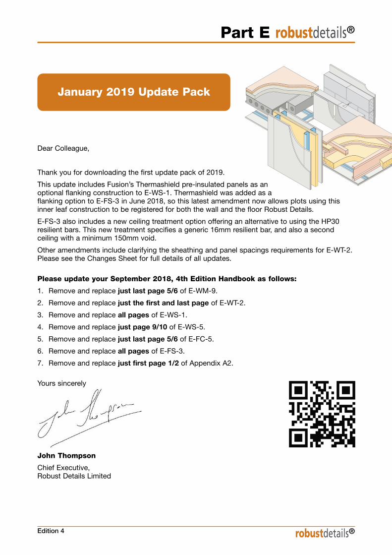
Thank you for downloading the first update pack of 2019.
This update includes Fusion’s Thermashield pre-insulated panels as an optional flanking construction to E-WS-1. Thermashield was added as a flanking option to E-FS-3 in June 2018, so this latest amendment now allows plots using thisinner leaf construction to be registered for both the wall and the floor Robust Details.
E-FS-3 also includes a new ceiling treatment option offering an alternative to using the HP30resilient bars. This new treatment specifies a generic 16mm resilient bar, and also a secondceiling with a minimum 150mm void.
Other amendments include clarifying the sheathing and panel spacings requirements for E-WT-2.Please see the Changes Sheet for full details of all updates.
Please update your September 2018, 4th Edition Handbook as follows:
1. Remove and replace just last page 5/6 of E-WM-9.
2. Remove and replace just the first and last page of E-WT-2.
3. Remove and replace all pages of E-WS-1.
4. Remove and replace just page 9/10 of E-WS-5.
5. Remove and replace just last page 5/6 of E-FC-5.
6. Remove and replace all pages of E-FS-3.
7. Remove and replace just first page 1/2 of Appendix A2.
January 2019 Update Pack
Part E robustdetails®

Edition 4January 2019 Update
robustdetails®
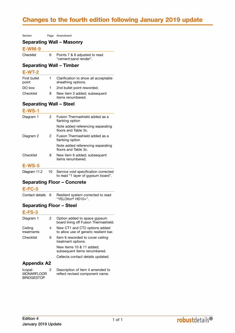
Changes to the fourth edition following January 2019 update
1 of 1
Section Page Amendment
Separating Wall – MasonryE-WM-9Checklist 6 Points 7 & 8 adjusted to read
“cement:sand render”.
Separating Wall – TimberE-WT-2First bullet 1 Clarification to show all acceptablepoint sheathing options.
DO box 1 2nd bullet point reworded.
Checklist 8 New item 3 added; subsequent items renumbered.
Separating Wall – SteelE-WS-1Diagram 1 2 Fusion Thermashield added as a
flanking option
Note added referencing separating floors and Table 3c.
Diagram 2 2 Fusion Thermashield added as a flanking option
Note added referencing separating floors and Table 3c.
Checklist 8 New item 6 added; subsequentitems renumbered.
E-WS-5Diagram 11.2 10 Service void specification corrected
to read “1 layer of gypsum board”.
Separating Floor – ConcreteE-FC-5Contact details 6 Resilient system corrected to read
“YELOfon® HD10+”.
Separating Floor – SteelE-FS-3Diagram 1 2 Option added to space gypsum
board lining off Fusion Thermashield.
Ceiling 4 New CT1 and CT2 options addedtreatments to allow use of generic resilient bar.
Checklist 6 Item 6 reworded to cover ceiling treatment options.
New items 10 & 11 added; subsequent items renumbered.
Cellecta contact details updated.
Appendix A2Icopal- 2 Description of item 4 amended to MONARFLOOR reflect revised component name.BRIDGESTOP

5 of 6
Separating Wall – Solid Dense Block Masonry
Edition 4January 2019 Update
E-WM-9
5 of 6 robustdetails®
blank page
See overleaf for checklist

6 of 6 Edition 4January 2019 Update
Separating Wall – Solid Dense Block Masonry E-WM-9
robustdetails® 6 of 6
Ref. Item
1. Are separating wall blocks dense aggregate(1850 to 2300 kg/m3) as featured on the list of acceptableblocks (www.robustdetails.com)?
2. Are blocks laid for the full 215mm width of the wall (i.e. 215mm blocks laid on side)?
3. Is blockwork laid single course stretcher bond?
4. Is separating wall breaking the continuity of the inner leaf? (i.e. is the face of the separating wall abutted and tied orbonded into the inner leaf)
5. Are cavity stops installed?
6. Are all joints fully filled?
7. Is cement:sand render applied to the whole wall face? (except where it may be omitted between floor joists/beams)
8. Is cement:sand render at least 13mm thick and scratchfinished?
9. Is mass per unit area of the gypsum based board at least 12.5 kg/m2?
10. Are all junctions of wall and ceiling boards sealed with tape or caulked with sealant?
11. Is separating wall satisfactorily complete?
Notes (include details of any corrective action)
CHECKLIST (to be completed by site manager/supervisor)
Company:
Site:
Plot: Site manager/supervisor:
Yes No Inspected(4) (4) (initials & date)
Site manager/supervisor signature . . . . . . . . . . . . . . . . . . . . . . . . . . .
®: UK registered trade mark no. 2291665
© Robust Details Limited 2011. All rights reserved. No part of this Handbook (other than the checklists) may be reproduced in any materialform or issued or communicated to the public (including photocopying or storing it in any medium by electronic means, and whether or nottransiently or incidentally to some other use of this Handbook) without the prior written permission of Robust Details Limited except inaccordance with the provisions of the Copyright, Designs and Patents Act 1988. Warning: the doing of an unauthorised act in relation to a copyright work may result in both a civil claim for damages and criminal prosecution.
1 of 8
Sep
arating W
all – Timber Frame
E-W
T-2
Separating Wall – Timber Frame
Edition 4January 2019 Update
E-WT-2
robustdetails®
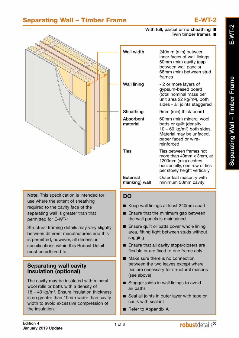
With full, partial or no sheathing nTwin timber frames n
Wall width 240mm (min) betweeninner faces of wall linings.50mm (min) cavity (gapbetween wall panels)68mm (min) between studframes
Wall lining - 2 or more layers ofgypsum-based board(total nominal mass perunit area 22 kg/m2), bothsides - all joints staggered
Sheathing 9mm (min) thick board
Absorbent 60mm (min) mineral woolmaterial batts or quilt (density
10 – 60 kg/m3) both sides.Material may be unfaced,paper faced or wire-reinforced
Ties Ties between frames notmore than 40mm x 3mm, at1200mm (min) centreshorizontally, one row of tiesper storey height vertically
External Outer leaf masonry with (flanking) wall minimum 50mm cavity
DO
n Keep wall linings at least 240mm apart
n Ensure that the minimum gap betweenthe wall panels is maintained
n Ensure quilt or batts cover whole liningarea, fitting tight between studs withoutsagging
n Ensure that all cavity stops/closers areflexible or are fixed to one frame only
n Make sure there is no connectionbetween the two leaves except whereties are necessary for structural reasons(see above)
n Stagger joints in wall linings to avoid air paths
n Seal all joints in outer layer with tape orcaulk with sealant
n Refer to Appendix A
Note: This specification is intended foruse where the extent of sheathingrequired to the cavity face of theseparating wall is greater than thatpermitted for E-WT-1
Structural framing details may vary slightlybetween different manufacturers and thisis permitted, however, all dimensionspecifications within this Robust Detailmust be adhered to.
Separating wall cavityinsulation (optional)
The cavity may be insulated with mineralwool rolls or batts with a density of 18 – 40 kg/m3. Ensure insulation thicknessis no greater than 10mm wider than cavitywidth to avoid excessive compression ofthe insulation.

2 of 8 Edition 4January 2019 Update
Separating Wall – Timber Frame E-WT-2
robustdetails®
1. External (flanking) wall junction
Plan
Plan
2. Staggered external (flanking) wall junction
Masonry outer leaf (min 100mm thick)
External wall cavity (min 50mm)
Inner leaf where there is no separating floore.g. for houses• one layer of gypsum-based board nominal 8 kg/m2
Inner leaf where there is a separating floor, e.g. for flats/apartments• if using robustdetails® for floor, refer to Table 3b in introduction to select anacceptable robustdetails® separating floor anduse two layers of gypsum-based boardnominal 8kg/m2 each layer
• if using floor requiring pre-completion testing,seek specialist advice
Seal all perimeter joints with tape or caulk with sealant
Close cavity with a cavity stop (see Appendix A)
Mineral wool insulation 10 kg/m3 (min);70mm (min) EPS or foil faced PIR with no gaps
Masonry outer leaf (min 100mm thick)
External wall cavity (min 50mm)
Sheathing board
Inner leaf where there is no separating floore.g. for houses• one layer of gypsum-based board nominal 8 kg/m2
Inner leaf where there is a separating floor, e.g. for flats/apartments• if using robustdetails® for floor, refer to Table 3bin introduction to select an acceptable robustdetails® separating floor and use twolayers of gypsum-based board nominal8kg/m2 each layer
• if using floor requiring pre-completion testing,seek specialist advice
Close cavity with a cavity stop (see Appendix A)
Seal all perimeter joints with tape or caulk with sealant
Mineral wool insulation 10 kg/m3 (min);70mm (min) EPS or foil faced PIR with no gaps

Separating Wall – Timber Frame
Edition 4January 2019 Update
E-WT-2
7 of 8 robustdetails®
10. Services and sockets in the separating wall
9.1 – electrical sockets, switches, etc.
Provide two or more layers of gypsum-basedboard (total nominal mass per unit area 22 kg/m2) to enclose electrical boxes
Stagger sockets, switches, etc. on each side of the wall such that they are not positioned inopposite bays
Alternatively provide a service void on surfaceof separating wall. This is the preferred methodwhere more than one socket, switch, etc. areclose together, e.g. in a kitchen.
Studs or battens used to create the servicezone should be securely fixed back to theseparating wall structure
Plan
Plan
Plan
9.2 – piped services
Service duct within separating wall
Provide two or more layers of gypsum-basedboard (total nominal mass per unit area 22 kg/m2) to enclose pipes
Stagger services on each side of wall such thatthey are not positioned in opposite bays
Note: this detail is not applicable for SVPs orgas pipes.
8 of 8 Edition 4January 2019 Update
Separating Wall – Timber Frame E-WT-2
robustdetails®
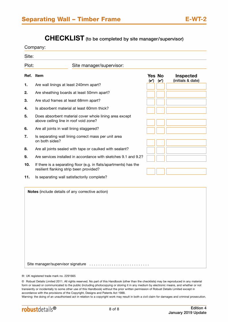
Ref. Item
1. Are wall linings at least 240mm apart?
2. Are sheathing boards at least 50mm apart?
3. Are stud frames at least 68mm apart?
4. Is absorbent material at least 60mm thick?
5. Does absorbent material cover whole lining area except above ceiling line in roof void zone?
6. Are all joints in wall lining staggered?
7. Is separating wall lining correct mass per unit areaon both sides?
8. Are all joints sealed with tape or caulked with sealant?
9. Are services installed in accordance with sketches 9.1 and 9.2?
10. If there is a separating floor (e.g. in flats/apartments) has theresilient flanking strip been provided?
11. Is separating wall satisfactorily complete?
Notes (include details of any corrective action)
CHECKLIST (to be completed by site manager/supervisor)
Company:
Site:
Plot: Site manager/supervisor:
Yes No Inspected(4) (4) (initials & date)
Site manager/supervisor signature . . . . . . . . . . . . . . . . . . . . . . . . . . .
®: UK registered trade mark no. 2291665
© Robust Details Limited 2011. All rights reserved. No part of this Handbook (other than the checklists) may be reproduced in any materialform or issued or communicated to the public (including photocopying or storing it in any medium by electronic means, and whether or nottransiently or incidentally to some other use of this Handbook) without the prior written permission of Robust Details Limited except inaccordance with the provisions of the Copyright, Designs and Patents Act 1988. Warning: the doing of an unauthorised act in relation to a copyright work may result in both a civil claim for damages and criminal prosecution.

1 of 8
Sep
arat
ing
Wal
l – S
teel
Fra
me
E-W
S-1
Separating Wall – Steel Frame
Edition 4January 2019 Update
E-WS-1
robustdetails®
Twin metal frames nFor use in lightweight steel frame houses and flats/apartments n
Wall lining - 2 or more layers of gypsum-based board (minimum totalnominal mass per unit area22 kg/m2) both sides
- all joints staggered
Wall width 200mm (min) between innerfaces of wall linings.
Absorbent - one layer 50mm (min)material unfaced mineral wool batts
(density 33-60 kg/m3), or- two layers 25mm (min)unfaced mineral wool batts(density 33-60 kg/m3), or- two layers 25mm (min)unfaced mineral wool quilt(density min 10 kg/m3)
External Outer leaf masonry with(flanking) wall minimum 50mm cavity
DOn Keep wall linings at least 200mm apart
n Ensure the batts or quilt cover whole wallarea and are fitted together tightly
n Make sure batts or quilt are not tightlycompressed by the twin frames
n Ensure that all cavity stops/closers areflexible or are fixed to one frame only
n Make sure there is no connectionbetween the two leaves except whereties are necessary for structural reasons
n Stagger joints in wall linings to avoid air paths
n Seal all joints in outer layer with tape orcaulk with sealant
n Refer to Appendix A
Notes: The steel frame profiles shown are indicative only. Other profiles areacceptable.
This Robust Detail is only suitable for usein lightweight steel frame houses andflats/apartments. When using this RobustDetail in flats/apartments please refer toTables 3 and 4 of the Introduction. Inrelation to separating floors the inner leafof external (flanking) walls may requirefurther treatments – seek specialist advice.
All sketches show one layer of mineralwool batts placed between the studs. It is also acceptable to place a layer ofmineral wool batts or quilt on both sides of the wall.

2 of 8 Edition 4January 2019 Update
Separating Wall – Steel Frame E-WS-1
robustdetails®
1. External (flanking) wall junction
2. Staggered external (flanking) wall junction
Masonry outer leaf (min 100mm thick)
External wall cavity (min 50mm)
Fill the void between between studs with mineralwool batt, 10 kg/m3 (min), for 600mm (min) fromseparating wall or use Fusion Thermashield
Inner leaf – one layer of gypsum-based boardnominal 8 kg/m2 or if using Fusion Thermashield,nominal 9.8 kg/m2 spaced off by min 38mmbattens or 25mm resilient bars
If using robustdetails® for floor, refer to Table 3c inIntroduction to select an acceptable robustdetails®separating floor. Then refer to separating floorRobust Detail to identify acceptable inner leafconstruction
Seal all perimeter joints with tape or caulk with sealant
Close cavity with a flexible cavity stop
Plan
Plan
Close cavity with a flexible cavity stop
Seal all perimeter joints with tape or caulk with sealant
Inner leaf – one layer of gypsum-based boardnominal 8 kg/m2 or if using Fusion Thermashield,nominal 9.8 kg/m2 spaced off by min 38mmbattens or 25mm resilient bars
If using robustdetails® for floor, refer to Table 3c inIntroduction to select an acceptable robustdetails®separating floor. Then refer to separating floorRobust Detail to identify acceptable inner leafconstruction
Masonry outer leaf (min 100mm thick)
External wall cavity (min 50mm)
Fill the void between between studs with mineralwool batt, 10 kg/m3 (min), for 600mm (min) fromseparating wall or use Fusion Thermashield
3 of 8
Separating Wall – Steel Frame
Edition 4January 2019 Update
E-WS-1
robustdetails®
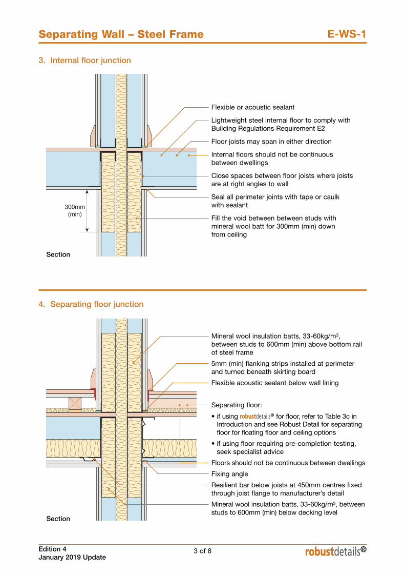
3. Internal floor junction
Flexible or acoustic sealant
Lightweight steel internal floor to comply withBuilding Regulations Requirement E2
Floor joists may span in either direction
Internal floors should not be continuousbetween dwellings
Close spaces between floor joists where joistsare at right angles to wall
Seal all perimeter joints with tape or caulk with sealant
Fill the void between between studs withmineral wool batt for 300mm (min) down from ceiling
Section
4. Separating floor junction
Section
Mineral wool insulation batts, 33-60kg/m3,between studs to 600mm (min) above bottom railof steel frame
5mm (min) flanking strips installed at perimeterand turned beneath skirting board
Flexible acoustic sealant below wall lining
Separating floor:
• if using robustdetails® for floor, refer to Table 3c inIntroduction and see Robust Detail for separatingfloor for floating floor and ceiling options
• if using floor requiring pre-completion testing,seek specialist advice
Floors should not be continuous between dwellings
Fixing angle
Resilient bar below joists at 450mm centres fixedthrough joist flange to manufacturer’s detail
Mineral wool insulation batts, 33-60kg/m3, betweenstuds to 600mm (min) below decking level
4 of 8 Edition 4January 2019 Update
Separating Wall – Steel Frame E-WS-1
robustdetails®
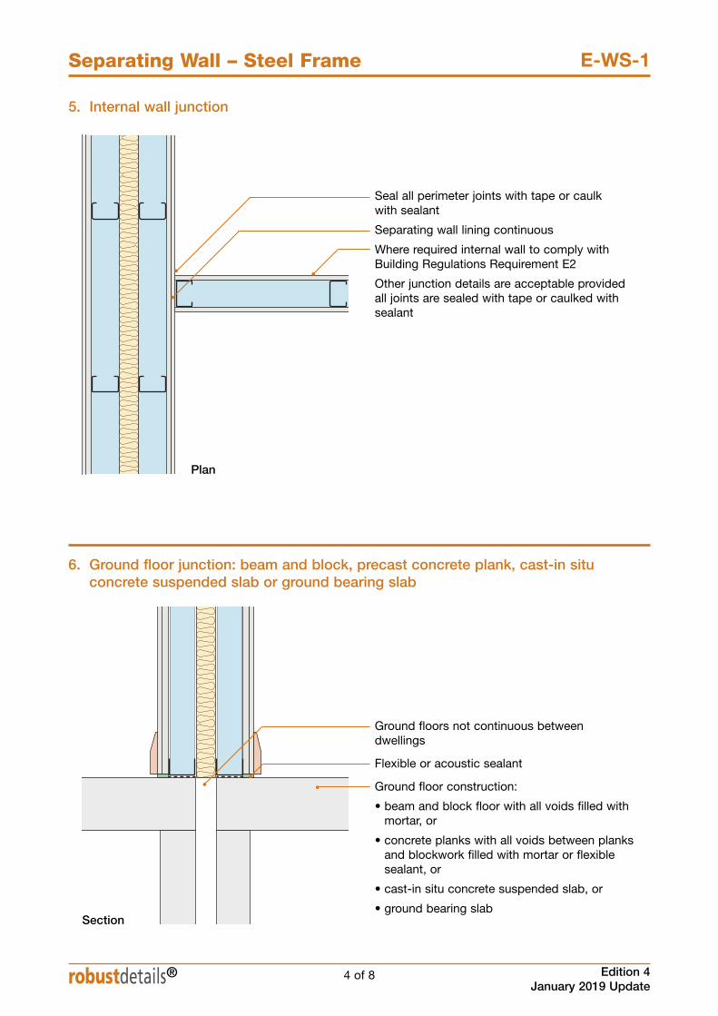
6. Ground floor junction: beam and block, precast concrete plank, cast-in situconcrete suspended slab or ground bearing slab
Ground floors not continuous betweendwellings
Flexible or acoustic sealant
Ground floor construction:
• beam and block floor with all voids filled withmortar, or
• concrete planks with all voids between planksand blockwork filled with mortar or flexiblesealant, or
• cast-in situ concrete suspended slab, or
• ground bearing slabSection
5. Internal wall junction
Seal all perimeter joints with tape or caulk with sealant
Separating wall lining continuous
Where required internal wall to comply withBuilding Regulations Requirement E2
Other junction details are acceptable providedall joints are sealed with tape or caulked withsealant
Plan
5 of 8
Separating Wall – Steel Frame
Edition 4January 2019 Update
E-WS-1
robustdetails®
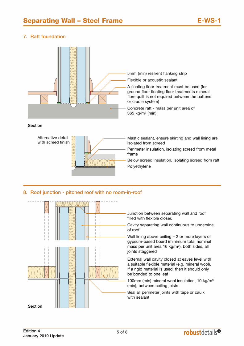
7. Raft foundation
Section
5mm (min) resilient flanking strip
Flexible or acoustic sealant
A floating floor treatment must be used (forground floor floating floor treatments mineralfibre quilt is not required between the battensor cradle system)
Concrete raft - mass per unit area of 365 kg/m2 (min)
8. Roof junction - pitched roof with no room-in-roof
Junction between separating wall and rooffilled with flexible closer.
Cavity separating wall continuous to undersideof roof
Wall lining above ceiling – 2 or more layers ofgypsum-based board (minimum total nominalmass per unit area 16 kg/m2), both sides, alljoints staggered
External wall cavity closed at eaves level with a suitable flexible material (e.g. mineral wool). If a rigid material is used, then it should only be bonded to one leaf
100mm (min) mineral wool insulation, 10 kg/m3
(min), between ceiling joists
Seal all perimeter joints with tape or caulk with sealant
Section
Alternative detailwith screed finish
Mastic sealant, ensure skirting and wall lining areisolated from screed
Perimeter insulation, isolating screed from metalframe
Below screed insulation, isolating screed from raft
Polyethylene
6 of 8 Edition 4January 2019 Update
Separating Wall – Steel Frame E-WS-1
robustdetails®
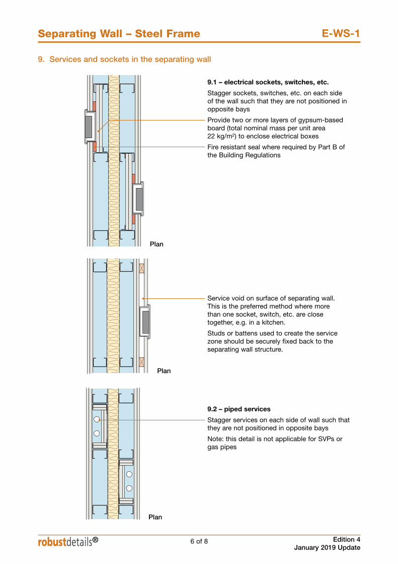
9. Services and sockets in the separating wall
9.1 – electrical sockets, switches, etc.
Stagger sockets, switches, etc. on each side of the wall such that they are not positioned inopposite bays
Provide two or more layers of gypsum-basedboard (total nominal mass per unit area 22 kg/m2) to enclose electrical boxes
Fire resistant seal where required by Part B ofthe Building Regulations
Service void on surface of separating wall. This is the preferred method where more than one socket, switch, etc. are close together, e.g. in a kitchen.
Studs or battens used to create the servicezone should be securely fixed back to theseparating wall structure.
Plan
Plan
Plan
9.2 – piped services
Stagger services on each side of wall such thatthey are not positioned in opposite bays
Note: this detail is not applicable for SVPs orgas pipes
7 of 8
Separating Wall – Steel Frame
Edition 4January 2019 Update
E-WS-1
robustdetails®
blank page
See overleaf for checklist

8 of 8 Edition 4January 2019 Update
Separating Wall – Steel Frame E-WS-1
robustdetails®
CHECKLIST (to be completed by site manager/supervisor)
Company:
Site:
Plot: Site manager/supervisor:
Ref. Item
1. Are wall linings at least 200mm apart?
2. Is the absorbent material unfaced mineral wool batts or quilt of appropriate density and thickness?
3. Are batts or quilt fitted together tightly ?
4. Are all joints in the wall lining staggered?
5. Is separating wall lining correct mass per unit area on both sides?
6. Where Fusion Thermashield is used, is the inner leaf gypsumboard 9.8 kg/m2 and spaced off by min 38mm battens or 25mmresilent bars?
7. Are all joints sealed with tape or caulked with sealant?
8. Are services installed in accordance with sketches 8.1 & 8.2?
9. Is separating wall satisfactorily complete?
Notes (include details of any corrective action)
Yes No Inspected(4) (4) (initials & date)
Site manager/supervisor signature . . . . . . . . . . . . . . . . . . . . . . . . . . .
®: UK registered trade mark no. 2291665
© Robust Details Limited 2011. All rights reserved. No part of this Handbook (other than the checklists) may be reproduced in any materialform or issued or communicated to the public (including photocopying or storing it in any medium by electronic means, and whether or nottransiently or incidentally to some other use of this Handbook) without the prior written permission of Robust Details Limited except inaccordance with the provisions of the Copyright, Designs and Patents Act 1988. Warning: the doing of an unauthorised act in relation to a copyright work may result in both a civil claim for damages and criminal prosecution.

9 of 12
Separating Wall – Steel Frame
Edition 4January 2019 Update
E-WS-5
robustdetails®
9. Ground floor junction
Mastic sealant, ensure skirting and wall lining areisolated from screed
Perimeter insulation, isolating screed from metalframe
Below screed insulation, isolating screed from slab
DPM (if required)
Section
Alternative detail withtimber floating floorfinish
10. Internal wall junction
Seal all perimeter joints with tape or caulk withsealant
Separating wall lining continuous
Where required internal wall to comply withBuilding Regulations Requirement E2
Plan
5mm (min) resilient flanking strip
Flexible or acoustic sealant
Insitu concrete, minimum mass per unit area 365 kg/m2
Ensure studs, top and bottom rails or gypsum boards do not bridge between the twin frames

10 of 12 Edition 4January 2019 Update
Separating Wall – Steel Frame E-WS-5
robustdetails®
330mm (min)
11. Services and sockets in the separating wall
Plan
Plan
11.1 Electrical sockets, switches etc
11.2 Electrical sockets and switches in service void
Plan
11.3 Piped services located within wall
Ensure studs, top and bottom rails or gypsum boards do not bridge between the twin frames
Service void using min 25mmbattens or steel studs with 1 layerof gypsum board
Service void on surface of separatingwall. This is the preferred methodwhere more than one socket, switch,etc. are close together, e.g. in akitchen
Studs or battens used to create theservice zone should be securelyfixed back to the separating wallstructure
Stagger sockets, switches, etc. oneach side of the wall such that theyare not positioned in opposite bays
Provide two or more layers ofgypsum-based board (total nominalmass per unit area 20 kg/m2) toenclose electrical boxes
Fire resistant seal where required byPart B of the Building Regulations
Stagger services on each side ofthe wall such that they are notpositioned in opposite bays
Note: this detail is not applicable forSVPs or gas pipes
Provide two or more layers ofgypsum-based board (total nominalmass per unit area 20 kg/m2) toenclose pipes
5 of 6
Separating Floor – Concrete
Edition 4January 2019 Update
E-FC-5
robustdetails®
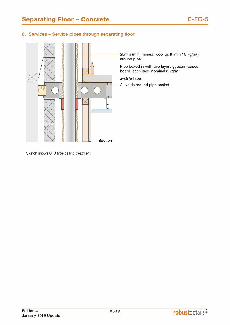
6. Services – Service pipes through separating floor
Section
25mm (min) mineral wool quilt (min 10 kg/m3)around pipe
Pipe boxed in with two layers gypsum-basedboard, each layer nominal 8 kg/m2
J-strip tape
All voids around pipe sealed
Sketch shows CT0 type ceiling treatment

®: UK registered trade mark no. 2291665
© Robust Details Limited 2011. All rights reserved. No part of this Handbook (other than the checklists) may be reproduced in any materialform or issued or communicated to the public (including photocopying or storing it in any medium by electronic means, and whether or nottransiently or incidentally to some other use of this Handbook) without the prior written permission of Robust Details Limited except inaccordance with the provisions of the Copyright, Designs and Patents Act 1988. Warning: the doing of an unauthorised act in relation to a copyright work may result in both a civil claim for damages and criminal prosecution.
Yes No Inspected(4) (4) (initials & date)
6 of 6 Edition 4January 2019 Update
Separating Floor – Concrete E-FC-5
CHECKLIST (to be completed by site manager/supervisor)
Company:
Site:
Plot: Site manager/supervisor:
Ref. Item
1. Has training been received from Cellecta®?
2. Are precast concrete planks 150mm (min) thick and of mass per unit area 300 kg/m2 (min)?
3. Are inner leaves to external (flanking) walls of the correct block density and appropriate for precast concrete plankthickness and ceiling treatment?
4. Are joints between precast concrete planks grouted and sealed?
5. Are precast concrete planks built into the masonry walls?
6. Is the E-strip perimeter edging installed around all roomperimeter walls (including door openings, cupboards, acrossthresholds and into wall recesses) and service pipes and jointssealed with J-strip tape?
7. Are YELOfon® HD10+ resilient layer joints formed asdescribed in Section 4 and sealed with J-strip tape?
8. Is YELOfon® HD10+ resilient layer overlapping the E-stripperimeter edging and joints sealed with J-strip tape?
9. Are the skirting boards isolated from the screed by the E-stripperimeter edging?
10. Is appropriate ceiling treatment used to suit wall block type?
11. Are all ceiling board joints sealed with tape or caulked withsealant?
12. Are service pipes wrapped in quilt and boxed in with two layersof nominal 8 kg/m2 gypsum-based board?
13. Is separating floor satisfactorily complete?
Site manager/supervisor signature . . . . . . . . . . . . . . . . . . . . . . . . . . .
Contact details for technical assistance from Cellecta®, manufacturer of YELOfon® HD10+ system:
Telephone: 01634 296677 Fax: 01634 226630 E-mail: [email protected]
Notes (include details of any corrective action)
robustdetails®

1 of 6
Separating Floor – Metal Joists
E-FS-2™
Separating Floor – Metal Joists
Edition 4January 2019 Update
E-FS-3
robustdetails®
Cellecta ScreedBoard® 28 on timber sub-floor nUse with lightweight metal frame walls only n
Floating floor Cellecta ScreedBoard® 28
Floor decking 18mm thick (min) woodbased board, density 600 kg/m3 (min)
Joists 254mm (min) deep metaljoists
Absorbent 100mm (min) mineral wool material quilt insulation (10-36 kg/m3)
between joists
Ceiling See section 4 for suitableceiling treatment
Separating Floor – Metal Joists
E-FS-3
DO
n Lay quilt (min 100mm thick) between alljoists, including doubled up joists,ensuring no gaps remain
n Apply Cellecta SB adhesive to allScreedBoard® 28 decking joints
n Install YELOfon® FS50 flanking anglearound the perimeter of the ScreedBoard® 28 to isolate floor fromwalls and skirtings
n Ensure resilient ceiling bars are fixed atright angles to the joists
n Ensure ceiling treatment is fixed correctly(see section 4)
n Stagger joints in ceiling layers
n Refer to Appendix A
2 of 6 Edition 4January 2019 Update
Separating Floor – Metal Joists E-FS-3
robustdetails®
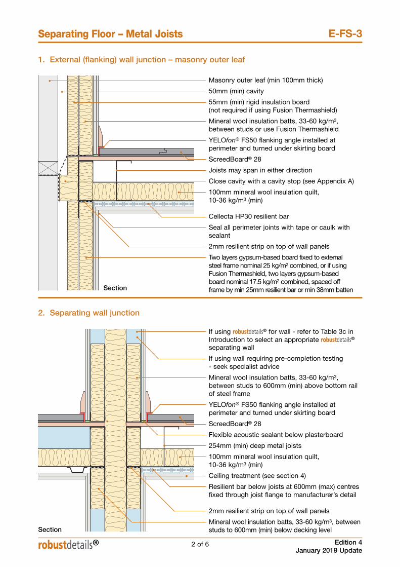
1. External (flanking) wall junction – masonry outer leaf
Masonry outer leaf (min 100mm thick)
50mm (min) cavity
55mm (min) rigid insulation board (not required if using Fusion Thermashield)
Mineral wool insulation batts, 33-60 kg/m3,between studs or use Fusion Thermashield
YELOfon® FS50 flanking angle installed atperimeter and turned under skirting board
ScreedBoard® 28
Joists may span in either direction
Close cavity with a cavity stop (see Appendix A)
100mm mineral wool insulation quilt, 10-36 kg/m3 (min)
Cellecta HP30 resilient bar
Seal all perimeter joints with tape or caulk withsealant
2mm resilient strip on top of wall panels
Two layers gypsum-based board fixed to externalsteel frame nominal 25 kg/m2 combined, or if usingFusion Thermashield, two layers gypsum-basedboard nominal 17.5 kg/m2 combined, spaced offframe by min 25mm resilient bar or min 38mm battenSection
2. Separating wall junction
Section
If using robustdetails® for wall - refer to Table 3c inIntroduction to select an appropriate robustdetails®separating wall
If using wall requiring pre-completion testing - seek specialist advice
Mineral wool insulation batts, 33-60 kg/m3,between studs to 600mm (min) above bottom railof steel frame
YELOfon® FS50 flanking angle installed atperimeter and turned under skirting board
ScreedBoard® 28
Flexible acoustic sealant below plasterboard
254mm (min) deep metal joists
100mm mineral wool insulation quilt, 10-36 kg/m3 (min)
Ceiling treatment (see section 4)
Resilient bar below joists at 600mm (max) centresfixed through joist flange to manufacturer’s detail
2mm resilient strip on top of wall panels
Mineral wool insulation batts, 33-60 kg/m3, betweenstuds to 600mm (min) below decking level

3 of 6
Separating Floor – Metal Joists
Edition 4January 2019 Update
E-FS-3
robustdetails®
3. Internal wall junction
Where required internal wall to comply withBuilding Regulations Requirement E2
YELOfon® FS50 flanking angle
ScreedBoard® 28
Joist stiffener if required
Cellecta HP30 resilient bar
Mineral wool insulation batts, 33-60 kg/m3,between studs to 600mm (min) below deckinglevel
Section

4. Ceiling treatment for E-FS-3
4 of 6 Edition 4January 2019 Update
Separating Floor – Metal Joists E-FS-3
robustdetails® 4 of 6
n The maximum load on resilient bars should not exceed that specified in the manufacturer’s instructions
n Ensure ceiling layers have staggered joints.
n Services must not puncture ceiling linings (except cables, which should be sealed around with flexible sealant)
CT1 and CT2 – Must include second ceiling CT3 – Optional second ceiling
CEILING BOARD FIXINGS MUST NOTPENETRATE OR TOUCH JOISTS
16mm (min) resilient bars with CT1 and CT216mm (min) metal resilient ceiling bars mounted atright angles to the joists at 400mm centres (bars must achieve a minimum laboratoryperformance of rd∆Rw+Ctr=17dB andrd∆Lw=16dB) – see Appendix E
Ceiling treatment CT1Two layers of gypsum-based board, composed of19mm (nominal 13.5 kg/m2) fixed with 32mmscrews, and 12.5mm (nominal 10 kg/m2) fixed with42 mm screws
Ceiling treatment CT2Two layers of gypsum-based boards composed of15mm (nominal 12.5 kg/m2) fixed with 25mmscrews and second layer of 15mm gypsum-basedboard (nominal 12.5 kg/m2) fixed with 42mm screws
Downlighters and recessed lighting
Downlighters or recessed lighting may be installedin the second ceiling in accordance with themanufacturer’s instructions
Particular attention should also be paid to BuildingRegulations Part B - Fire Safety
Downlighters and recessed lightingDownlighters or recessed lighting may be installedin the primary ceiling:• in accordance with the manufacturer’sinstructions
• at no more than one light per 2m2 of ceiling areain each room unless the use of a greater densityof light fittings is supported by testing undertakenin accordance with Appendix F
• at centres not less than 0.75m• into openings not exceeding 100mm diameter or100x100mm
Particular attention should also be paid to BuildingRegulations Part B - Fire Safety
Note: Only downlighters which have beensatisfactorily assessed in accordance with the procedure described in Appendix F“Determination of the acoustic performance ofdownlighters and recessed lighting inlightweight separating floors” are acceptable.
Cellecta® HP30 30mm deep metal resilient barfixed perpendicular to floor joists at 600mm (max) centres
Ceiling treatment CT3Two layers of gypsum-based boards composed of15mm (nominal 12.5 kg/m2) fixed with 25mm screwsand second layer of 15mm gypsum-based board(nominal 12.5 kg/m2) fixed with 42mm screws
150mm(min)
12.5mm ceiling boardnominal 8 kg/m2

5 of 6
Separating Floor – Metal Joists
Edition 4January 2019 Update
E-FS-3
5. Underfloor heating systems below ScreedBoard®
robustdetails®
6. Services – pipes through separating floor
Section
Service pipe
25mm mineral fibre quilt insulation (10-36 kg/m3)installed around the complete perimeter of theservice pipe. Where the service pipe penetratesthe separating floor, all voids are to be packedwith insulation quilt
YELOfon® FS50 flanking angle installed atperimeter and turned under skirting board
ScreedBoard® 28
Close cavity with a cavity stop (see Appendix A)
Proprietary fire collar fitted around pipe andfixed to underside of steel joists
Cellecta HP30 resilient bar
2 layers of gypsum-based board nominal 16 kg/m2 combined fixed to 45mm metal framestud forming duct. Joints to be staggered andtaped
Mineral wool insulation batts, 33-60 kg/m3,between studs
YELOfon® FS50 flanking angle
20mm ScreedBoard® 20
25mm (min) extruded or expanded polystyrenepanel with underfloor heating pipes
8mm FIBREfon® resilient layer
Cellecta HP30 resilient bar
Seal all perimeter joints with tape or caulk withsealant
2mm resilient strip on top of wall panels
Section

6 of 6 Edition 4January 2019 Update
Separating Floor – Metal Joists E-FS-3
robustdetails®
CHECKLIST (to be completed by site manager/supervisor)
Company:
Site:
Plot: Site manager/supervisor:
Ref. Item
1. Are metal joists minimum 254mm deep?
2. Is sub-deck minimum 18mm, 600 kg/m3?
3. Are YELOfon® FS50 flanking angles installed correctly?
4. Has the ScreedBoard® 28 floating floor treatment been fitted in accordance with the manufacturer’s instructions?
5. Where underfloor heating is used, is FIBREfon® 8 installed inaddition to the ScreedBoard® 20?
6. Are the correct type of resilient ceiling bars used and fitted, inaccordance with the manufacturer’s instructions, at rightangles to the joists (Cellecta® HP30 bars must be used ifsecond ceiling is not included)?
7. Has quilt (min 100mm thick) been fitted between the joists?
8. Has ceiling system been fitted in accordance with themanufacturer’s instructions?
9. Are the ceiling treatments fixed to the resilient bars with correct screws, such that the screws do not touch or penetrate the joists?
10. For CT1 or CT2 is secondary ceiling void minimum 150mm?
11. Where Fusion Thermashield is used, is the inner leaf lined with 2layers gypsum-based board nominal 17.5 kg/m2 combined, spacedoff inner leaf frame by min 25mm resilient bar or min 38mm batten?
12. Are all joints sealed with tape or caulked with sealant?
13. Are vertical service pipes wrapped in quilt and boxed in withtwo layers of gypsum-based board combined nominal massper unit area of 16 kg/m2?
14. Is separating floor satisfactorily complete?
Yes No Inspected(4) (4) (initials & date)
Site manager/supervisor signature . . . . . . . . . . . . . . . . . . . . . . . . . . .
Contact details for technical assistance from Cellecta, manufacturer of ScreedBoard® 28 system:
Telephone: 01634 296677 Fax: 01634 226630 E-mail: [email protected]
Notes (include details of any corrective action)
®: UK registered trade mark no. 2291665
© Robust Details Limited 2011. All rights reserved. No part of this Handbook (other than the checklists) may be reproduced in any materialform or issued or communicated to the public (including photocopying or storing it in any medium by electronic means, and whether or nottransiently or incidentally to some other use of this Handbook) without the prior written permission of Robust Details Limited except inaccordance with the provisions of the Copyright, Designs and Patents Act 1988. Warning: the doing of an unauthorised act in relation to a copyright work may result in both a civil claim for damages and criminal prosecution.

1
Appendix A2 – Specific Flanking Conditions
Edition 4January 2019 Update robustdetails®
Contents
Section Page
Icopal-MONARFLOOR® BRIDGESTOP® 2System for robustdetails® masonry cavity wallsSmartroof complete Interlocking 3“room-in-roof” panel system using robustdetails®timber or masonry cavity wallsKingspan TEK inner leaf flanking condition 4for robustdetails® timber separating wallsPrestoplan PresPeak 60 interlocking single 5spandrel panel system for robustdetails® timberseparating walls Icopal-MONARFLOOR® Wall Cap RDA2 6System for robustdetails® separating floors with cavity flanking wallsRoofSpace I-Roof™ “room-in-roof” panel 7system using robustdetails® timber or masonry cavity wallsSpace4 “room-in-roof” panel system using 8robustdetails® timber or masonry cavity wallsStewart Milne Timber Systems Sigma® Roof 9Spandrel Panel System for robustdetails®timber separating wallsNYTROOF RAPID FIT SYSTEM for robustdetails® 10masonry cavity wallsLightweight external cladding for robustdetails® 11timber separating wallsFlanking construction to robustdetails® precast 12concrete separating floors around privatestairs
2 Edition 4January 2019 Update
Appendix A2 – Specific Flanking Conditions
robustdetails®
Appendix A
1
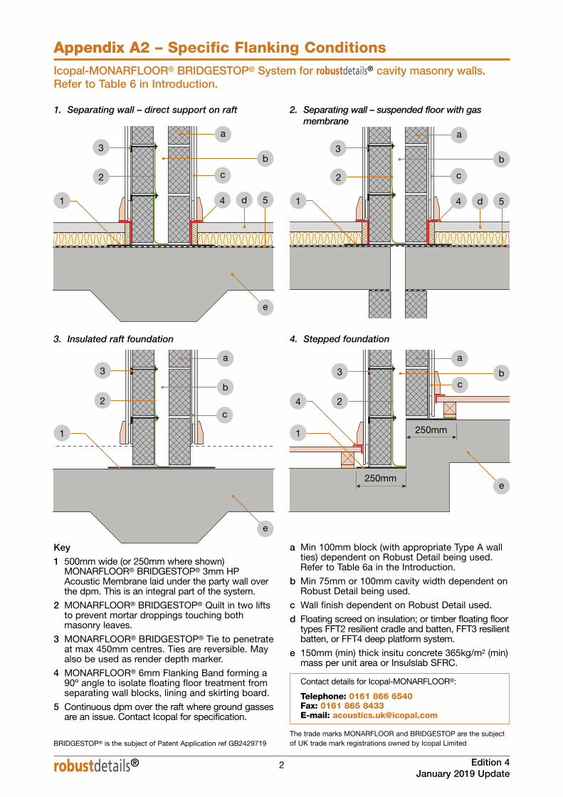
Key
1 500mm wide (or 250mm where shown)MONARFLOOR® BRIDGESTOP® 3mm HPAcoustic Membrane laid under the party wall overthe dpm. This is an integral part of the system.
2 MONARFLOOR® BRIDGESTOP® Quilt in two liftsto prevent mortar droppings touching bothmasonry leaves.
3 MONARFLOOR® BRIDGESTOP® Tie to penetrateat max 450mm centres. Ties are reversible. Mayalso be used as render depth marker.
4 MONARFLOOR® 6mm Flanking Band forming a90º angle to isolate floating floor treatment fromseparating wall blocks, lining and skirting board.
5 Continuous dpm over the raft where ground gassesare an issue. Contact Icopal for specification.
1. Separating wall – direct support on raft
Icopal-MONARFLOOR® BRIDGESTOP® System for robustdetails® cavity masonry walls.Refer to Table 6 in Introduction.
2
3
4
a
b
c
a Min 100mm block (with appropriate Type A wallties) dependent on Robust Detail being used.Refer to Table 6a in the Introduction.
b Min 75mm or 100mm cavity width dependent onRobust Detail being used.
c Wall finish dependent on Robust Detail used.
d Floating screed on insulation; or timber floating floortypes FFT2 resilient cradle and batten, FFT3 resilientbatten, or FFT4 deep platform system.
e 150mm (min) thick insitu concrete 365kg/m2 (min)mass per unit area or Insulslab SFRC.
1
1
2
3
a
b
c
a
b
2
3
a
b
5 5
2
3
250mm
250mm
4
4
1
2. Separating wall – suspended floor with gasmembrane
3. Insulated raft foundation 4. Stepped foundation
d d
c
c
Contact details for Icopal-MONARFLOOR®:
Telephone: 0161 866 6540Fax: 0161 865 8433E-mail: [email protected]
BRIDGESTOP® is the subject of Patent Application ref GB2429719The trade marks MONARFLOOR and BRIDGESTOP are the subjectof UK trade mark registrations owned by Icopal Limited
e
e
e
Related Documents