PART B:CHAPTER 8 Durability PART B Chapter 8 Durability This chapter provides the design requirements for movement joints in masonry to control cracking due to shrinkage of the wall, concrete slab shrinkage, foundation movement and thermal expansion or contraction. Contents 8.1 BASIS OF DESIGN 8.2 DESIGN REQUIREMENTS 8.3 STANDARD DESIGNS 8.4 WORKED EXAMPLE

Welcome message from author
This document is posted to help you gain knowledge. Please leave a comment to let me know what you think about it! Share it to your friends and learn new things together.
Transcript

PART B:CHAPTER 8Durability
PART B Chapter 8DurabilityThis chapter provides the design requirements for movement joints in masonry to control cracking due to shrinkage of the wall, concrete slab shrinkage, foundation movement and thermal expansion or contraction.
Contents8.1 BAsis of design
8.2 design RequiRemenTs
8.3 sTAndARd designs
8.4 woRked exAmPle

PART B:CHAPTER 8Durability
The durability of masonry and its components must be such that the required function can be performed throughout the entire design life of the structure. While some marginal deterioration of the units or mortar may be acceptable over a long period, any substantial deterioration of the masonry units, mortar, ties, connectors, lintels or reinforcement would be unacceptable.
Prevention of corrosion is of primary importance. Ties, connectors and lintels should be galvanised to the required thicknesses or, in extremely aggressive environments, be manufactured from non-corrosive materials such as stainless steel.
Concrete grout which protects reinforcement must have sufficient cement content to create an alkaline environment which lasts for the duration of the design life.
8.1 BAsis of design

PART B:CHAPTER 8Durability
8.2.1 geneRAl
AS 3700 Section 5 sets out the durability requirements for masonry units, mortar, built-in components and reinforcement or tendons throughout the design life of the structure.
AS 3700 Table 5.1 defines the required classifications for masonry units, mortar, built-in components and cover for reinforcement or tendons for the particular environments and positions within the structure.
The associated Clauses and Standards cited in Table 5.1 are:
■ AS/NZS 4456.10 provides a test and means of classifying the durability of masonry units. (See Glossary for Grades).
■ AS 3700 Table 11.1 provides suitable mortar mixes for particular classifications.
■ AS/NZS 2699 series provides performancerequirements for built-in components and deemed-to-comply corrosion resistance of galvanising and other treatments.
■ AS 3700 Clause 5.8 provides the requirements for grout to achieve the covers specified in Table 5.1.
8.2.2 RequiRemenTs foR sPeCifiC iTems
Exposure EnvironmentsAS 3700 Clause 5.3 defines the exposure environments for which the masonry and its components must be designed.
Concrete Masonry UnitsSalt resistance needs to be provided for masonry units that may be subject to salt attack. AS/NZS 4456.10 provides a test for resistance to salt attack.
MortarThe durability of the mortar is covered by the deemed-to-satisfy compositions in AS 3700 Table 11.1. Type M1 and Type M2 mortars are not recommended for concrete masonry and therefore the mortar choice is between Type M3 and Type M4.
Built-In ComponentsBuilding accessories are commonly manufactured from galvanised steel and durability will be satisfied by the prescriptive galvanising covered in AS 2699.1, AS 2699.2 or AS 2699.3.
The testing criteria for components in categories R0 to R4 are quite severe:
■ Maximum temperature of 55°C (or 40°C if the component is embedded).
■ Daily temperature cycles from ambient (say 18°C) to 40°C.
■ The medium surrounding the accessory being initially alkaline pH up to 10 but reducing over time to become not less than 10 (ie close to neutral).
■ Remaining wet for a 3 month period.
■ Aerosol penetration to an extent depending on distance from the coast: R0 – Nil R1 – 10 g/m2/day R2 – 20 g/m2/day R3 – 60 g/m2/day R4 – 300 g/m2/day
■ Exposure to UV radiation of 20 MJ/m2 for a period of up to 4 weeks corresponding to the period of construction.
GroutThe specified 300 kg/m3 cement content is to ensure that an alkaline environment surrounds embedded steel reinforcement and other items.
Reinforcement and TendonsWhere horizontal reinforcement is to be used, hollow concrete blocks should be of a type which allows the grout to surround the reinforcement throughout its length. `H’ blocks and `Double-U’ blocks are suitable types.
If flush-ended masonry units are used (which require the reinforcement to pass through the perpendicular joints) the reinforcement must be supported off the webs in such a way that the cover requirements can be achieved over the whole length of the reinforcement. This is difficult to achieve and would be unsuitable unless another form of corrosion protection is provided.
8.2 design RequiRemenTs

PART B:CHAPTER 8Durability
8.3 sTAndARd designs
140-mm leaf 190-mm leaf
REINFORCED MASONRY – Cover (c) and Effective Depths (d)
t
dr
2
ts c
Grout
rtt
Severe marineenvironments. Salineor contaminated waterand in tidal or splashzones. Within 1 km ofindustry producingchemical pollutants
Required grout cover, c (mm) 30
Core taper*, tt (mm) = 5
Face-shell thickness*, ts (mm) = 25
Block thickness, t (mm) = 140
Maximum possible effectivedepth, d (mm) for followingreinforcement diameter,r (mm): 12
16
20
747270
20
848280
15
898785
Interior environmentssubject to saline wettingand drying. Masonrybelow the damp-proofcourse or in contact withaggressive soils. Masonryin fresh water
(Note: 15 mm is consideredto be the practical minimumfor cover, giving considerationto the normal nominal sizeof aggregates)
* Note: Manufacturers may adopt variations from these values for core taper and face-shell thickness. If so, this will alter the effective depth, d, given in the Table above
SevereVery severe Other applications
EXPOSURE CONDITIONS
t
dr
2
ts c
Grout
rtt
Severe marineenvironments. Salineor contaminated waterand in tidal or splashzones. Within 1 km ofindustry producingchemical pollutants
Required grout cover, c (mm) 30
Core taper*, tt (mm) = 5
Face-shell thickness*, ts (mm) = 30
Block thickness, t (mm) = 190
Maximum possible effectivedepth, d (mm) for followingreinforcement diameter,r (mm): 12
16
20
119117115
20
129127125
15
134132130
Interior environmentssubject to saline wettingand drying. Masonrybelow the damp-proofcourse or in contact withaggressive soils. Masonryin fresh water
(Note: 15 mm is consideredto be the practical minimumfor cover, giving considerationto the normal nominal sizeof aggregates)
* Note: Manufacturers may adopt variations from these values for core taper and face-shell thickness. If so, this will alter the effective depth, d, given in the Table above
SevereVery severe Other applications
EXPOSURE CONDITIONS
This section sets out the required cover and resulting maximum effective depth of reinforcement for design purposes. For the specification of masonry units, mortars, built-in items and grout, refer to Part C:Chapter 2.

PART B:CHAPTER 8Durability
8.4 woRked exAmPle
Purpose of the worked exampleThe purpose of the following worked example is to demonstrate the steps to be followed when performing manual calculations or when preparing computer software for the analysis and design of masonry. The worked example also serves the purpose of demonstrating the origin of the Standard Designs which are based on similar masonry capacity considerations. Although comprehensive in its treatment of AS 3700, the worked example is not intended to analyze or design all parts of the particular structure. It deals only with enough to demonstrate the design method.
Design and detailingAll design and detailing shall comply with the requirements of AS 3700.
It is the designer’s responsibility to allow for the effects of control joints, chases, openings, strength and stiffness of ties and connectors, and strength and stiffness of supports, in addition to normal considerations of loads and masonry properties.
Masonry propertiesThe worked examples in this chapter are based on masonry properties complying with the General Specification set out in Part C:Chapter 2, modified as noted below.
Hollow concrete blocksWidth 90 mm, 110 mm, 140 mm and 190 mm
Height 190 mm
Length 390 mm
Face-shell bedded
Minimum face-shell thickness, ts = 25 mm for 90 mm, 110 mm and 140 mm units ts = 30 mm for 190 mm units
Minimum characteristic compressive strength, f ’uc =15 MPa
Minimum characteristic lateral modulus of rupture, f ’ut = 0.8 MPa
Solid or cored concrete bricksWidth 110 mm
Height 76 mm
Length 230 mm
Fully bedded
Minimum characteristic compressive strength, f ’uc =10 MPa
Minimum characteristic lateral modulus of rupture, f ’ut = 0.8 MPa
Mortar jointsMortar type M3 (or M4)
Joint thickness 10 mm
Concrete groutMinimum characteristic compressive strength, f ’c = 20 MPa
Minimum cement content 300 kg/m3
Steel reinforcementN12, N16 or N20 as noted.
GO TO WORKED EXAMPLE
PART B:CHAPTER 8Durability
Worked Example [Page 1 of 1]
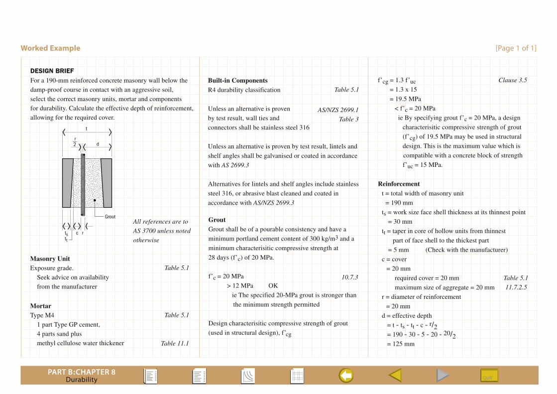
DESIGN BRIEFFor a 190-mm reinforced concrete masonry wall below the
damp-proof course in contact with an aggressive soil,
select the correct masonry units, mortar and components
for durability. Calculate the effective depth of reinforcement,
allowing for the required cover.
t
dr2
ts c
Grout
rtt
Table 5.1
All references are to
AS 3700 unless noted
otherwise
Table 5.1
Table 11.1
Masonry UnitExposure grade.
Seek advice on availability
from the manufacturer
MortarType M4
1 part Type GP cement,
4 parts sand plus
methyl cellulose water thickener
Table 5.1
AS/NZS 2699.1
Table 3
Built-in ComponentsR4 durability classification
Unless an alternative is proven
by test result, wall ties and
connectors shall be stainless steel 316
Unless an alternative is proven by test result, lintels and
shelf angles shall be galvanised or coated in accordance
with AS 2699.3
Alternatives for lintels and shelf angles include stainless
steel 316, or abrasive blast cleaned and coated in
accordance with AS/NZS 2699.3
GroutGrout shall be of a pourable consistency and have a
minimum portland cement content of 300 kg/m3 and a
minimum characterisitic compressive strength at
28 days (f’c) of 20 MPa.
f’c = 20 MPa
> 12 MPa OK
ie The specified 20-MPa grout is stronger than
the minimum strength permitted
Design characterisitic compressive strength of grout
(used in structural design), f’cg
10.7.3
f’cg = 1.3 f’uc Clause 3.5
= 1.3 x 15
= 19.5 MPa
< f’c = 20 MPa
ie By specifying grout f’c = 20 MPa, a design
characterisitic compressive strength of grout
(f’cg) of 19.5 MPa may be used in structural
design. This is the maximum value which is
compatible with a concrete block of strength
f’uc = 15 MPa.
Reinforcement t = total width of masonry unit
= 190 mm
ts = work size face shell thickness at its thinnest point
= 30 mm
tt = taper in core of hollow units from thinnest
part of face shell to the thickest part
= 5 mm (Check with the manufacturer)
c = cover
= 20 mm
required cover = 20 mm
maximum size of aggregate = 20 mm
r = diameter of reinforcement
= 20 mm
d = effective depth
= t - ts - tt - c - r/2 = 190 - 30 - 5 - 20 - 20/2 = 125 mm
Table 5.1
11.7.2.5
Related Documents