Concepts & Examples ScreenOS Reference Guide Voice-over-Internet Protocol Release 6.3.0, Rev. 02 Published: 2012-12-10 Revision 02 Copyright © 2012, Juniper Networks, Inc.

Welcome message from author
This document is posted to help you gain knowledge. Please leave a comment to let me know what you think about it! Share it to your friends and learn new things together.
Transcript

Concepts & ExamplesScreenOS Reference Guide
Voice-over-Internet Protocol
Release
6.3.0, Rev. 02
Published: 2012-12-10
Revision 02
Copyright © 2012, Juniper Networks, Inc.

Juniper Networks, Inc.1194 North Mathilda AvenueSunnyvale, California 94089USA408-745-2000www.juniper.net
Juniper Networks, Junos, Steel-Belted Radius, NetScreen, and ScreenOS are registered trademarks of Juniper Networks, Inc. in the UnitedStates and other countries. JunosE is a trademark of Juniper Networks, Inc. All other trademarks, service marks, registered trademarks, orregistered service marks are the property of their respective owners.Juniper Networks assumes no responsibility for any inaccuracies in this document. Juniper Networks reserves the right to change, modify,transfer, or otherwise revise this publication without notice.Products made or sold by Juniper Networks or components thereof might be covered by one or more of the following patents that areowned by or licensed to Juniper Networks: U.S. Patent Nos. 5,473,599, 5,905,725, 5,909,440, 6,192,051, 6,333,650, 6,359,479, 6,406,312,6,429,706, 6,459,579, 6,493,347, 6,538,518, 6,538,899, 6,552,918, 6,567,902, 6,578,186, and 6,590,785.Copyright © 2009, Juniper Networks, Inc.All rights reserved.
Revision HistoryDecember 2012—Revision 02
Content subject to change. The information in this document is current as of the date listed in the revision history.
SOFTWARE LICENSE
The terms and conditions for using this software are described in the software license contained in the acknowledgment to your purchaseorder or, to the extent applicable, to any reseller agreement or end-user purchase agreement executed between you and Juniper Networks.By using this software, you indicate that you understand and agree to be bound by those terms and conditions.
Generally speaking, the software license restricts the manner in which you are permitted to use the software and may contain prohibitionsagainst certain uses. The software license may state conditions under which the license is automatically terminated. You should consultthe license for further details.
For complete product documentation, please see the Juniper Networks Website at www.juniper.net/techpubs.
ENDUSER LICENSE AGREEMENT
The Juniper Networks product that is the subject of this technical documentation consists of (or is intended for use with) Juniper Networkssoftware. Use of such software is subject to the terms and conditions of the End User License Agreement (“EULA”) posted at
http://www.juniper.net/support/eula.html. By downloading, installing or using such software, you agree to the terms and conditionsof that EULA.
Copyright © 2012, Juniper Networks, Inc.ii
Abbreviated Table of Contents
About This Guide . . . . . . . . . . . . . . . . . . . . . . . . . . . . . . . . . . . . . . . . . . . . . . . . . xiii
Part 1 VOIP
Chapter 1 H.323 Application Layer Gateway . . . . . . . . . . . . . . . . . . . . . . . . . . . . . . . . . . . . 3
Chapter 2 Session Initiation Protocol Application Layer Gateway . . . . . . . . . . . . . . . . . 15
Chapter 3 Media Gateway Control Protocol Application Layer Gateway . . . . . . . . . . . 65
Chapter 4 Skinny Client Control Protocol Application Layer Gateway . . . . . . . . . . . . . 79
Chapter 5 Apple iChat Application Layer Gateway . . . . . . . . . . . . . . . . . . . . . . . . . . . . . 107
Part 2 Index
Index . . . . . . . . . . . . . . . . . . . . . . . . . . . . . . . . . . . . . . . . . . . . . . . . . . . . . . . . . . . . 123
iiiCopyright © 2012, Juniper Networks, Inc.

Copyright © 2012, Juniper Networks, Inc.iv
Voice-over-Internet Protocol

Table of Contents
About This Guide . . . . . . . . . . . . . . . . . . . . . . . . . . . . . . . . . . . . . . . . . . . . . . . . . xiii
Document Conventions . . . . . . . . . . . . . . . . . . . . . . . . . . . . . . . . . . . . . . . . . . . . . . xiii
Document Feedback . . . . . . . . . . . . . . . . . . . . . . . . . . . . . . . . . . . . . . . . . . . . . . . . xvi
Requesting Technical Support . . . . . . . . . . . . . . . . . . . . . . . . . . . . . . . . . . . . . . . . xvi
Part 1 VOIP
Chapter 1 H.323 Application Layer Gateway . . . . . . . . . . . . . . . . . . . . . . . . . . . . . . . . . . . . 3
Overview . . . . . . . . . . . . . . . . . . . . . . . . . . . . . . . . . . . . . . . . . . . . . . . . . . . . . . . . . . . 3
Alternate Gatekeeper . . . . . . . . . . . . . . . . . . . . . . . . . . . . . . . . . . . . . . . . . . . . . . . . . 3
Examples . . . . . . . . . . . . . . . . . . . . . . . . . . . . . . . . . . . . . . . . . . . . . . . . . . . . . . . . . . 4
Example: Gatekeeper in the Trust Zone . . . . . . . . . . . . . . . . . . . . . . . . . . . . . . . 4
WebUI . . . . . . . . . . . . . . . . . . . . . . . . . . . . . . . . . . . . . . . . . . . . . . . . . . . . . . 4
CLI . . . . . . . . . . . . . . . . . . . . . . . . . . . . . . . . . . . . . . . . . . . . . . . . . . . . . . . . . 5
Example: Gatekeeper in the Untrust Zone . . . . . . . . . . . . . . . . . . . . . . . . . . . . . 5
WebUI . . . . . . . . . . . . . . . . . . . . . . . . . . . . . . . . . . . . . . . . . . . . . . . . . . . . . . 6
CLI . . . . . . . . . . . . . . . . . . . . . . . . . . . . . . . . . . . . . . . . . . . . . . . . . . . . . . . . 6
Example: Outgoing Calls with NAT . . . . . . . . . . . . . . . . . . . . . . . . . . . . . . . . . . . 7
WebUI . . . . . . . . . . . . . . . . . . . . . . . . . . . . . . . . . . . . . . . . . . . . . . . . . . . . . . 7
CLI . . . . . . . . . . . . . . . . . . . . . . . . . . . . . . . . . . . . . . . . . . . . . . . . . . . . . . . . 9
Example: Incoming Calls with NAT . . . . . . . . . . . . . . . . . . . . . . . . . . . . . . . . . . 9
WebUI . . . . . . . . . . . . . . . . . . . . . . . . . . . . . . . . . . . . . . . . . . . . . . . . . . . . . 10
CLI . . . . . . . . . . . . . . . . . . . . . . . . . . . . . . . . . . . . . . . . . . . . . . . . . . . . . . . . 11
Example: Gatekeeper in the Untrust Zone with NAT . . . . . . . . . . . . . . . . . . . . 12
WebUI . . . . . . . . . . . . . . . . . . . . . . . . . . . . . . . . . . . . . . . . . . . . . . . . . . . . . 12
CLI . . . . . . . . . . . . . . . . . . . . . . . . . . . . . . . . . . . . . . . . . . . . . . . . . . . . . . . . 14
Chapter 2 Session Initiation Protocol Application Layer Gateway . . . . . . . . . . . . . . . . . 15
Overview . . . . . . . . . . . . . . . . . . . . . . . . . . . . . . . . . . . . . . . . . . . . . . . . . . . . . . . . . . 15
SIP Request Methods . . . . . . . . . . . . . . . . . . . . . . . . . . . . . . . . . . . . . . . . . . . . 16
Classes of SIP Responses . . . . . . . . . . . . . . . . . . . . . . . . . . . . . . . . . . . . . . . . . 17
SIP Application Layer Gateway . . . . . . . . . . . . . . . . . . . . . . . . . . . . . . . . . . . . . 18
Session Description Protocol Sessions . . . . . . . . . . . . . . . . . . . . . . . . . . . . . . 20
Pinhole Creation . . . . . . . . . . . . . . . . . . . . . . . . . . . . . . . . . . . . . . . . . . . . . . . . . 21
Session Inactivity Timeout . . . . . . . . . . . . . . . . . . . . . . . . . . . . . . . . . . . . . . . . 22
SIP Attack Protection . . . . . . . . . . . . . . . . . . . . . . . . . . . . . . . . . . . . . . . . . . . . 23
Example: SIP Protect Deny . . . . . . . . . . . . . . . . . . . . . . . . . . . . . . . . . . . . 23
Example: Signaling-Inactivity and Media-Inactivity Timeouts . . . . . . . . . 23
Example: UDP Flooding Protection . . . . . . . . . . . . . . . . . . . . . . . . . . . . . . 24
vCopyright © 2012, Juniper Networks, Inc.
Example: SIP Connection Maximum . . . . . . . . . . . . . . . . . . . . . . . . . . . . . 24
SIP with Network Address Translation . . . . . . . . . . . . . . . . . . . . . . . . . . . . . . . . . . 25
Outgoing Calls . . . . . . . . . . . . . . . . . . . . . . . . . . . . . . . . . . . . . . . . . . . . . . . . . . 26
Incoming Calls . . . . . . . . . . . . . . . . . . . . . . . . . . . . . . . . . . . . . . . . . . . . . . . . . . 26
Forwarded Calls . . . . . . . . . . . . . . . . . . . . . . . . . . . . . . . . . . . . . . . . . . . . . . . . 26
Call Termination . . . . . . . . . . . . . . . . . . . . . . . . . . . . . . . . . . . . . . . . . . . . . . . . 27
Call Re-INVITE Messages . . . . . . . . . . . . . . . . . . . . . . . . . . . . . . . . . . . . . . . . . 27
Call Session Timers . . . . . . . . . . . . . . . . . . . . . . . . . . . . . . . . . . . . . . . . . . . . . . 27
Call Cancellation . . . . . . . . . . . . . . . . . . . . . . . . . . . . . . . . . . . . . . . . . . . . . . . . 27
Forking . . . . . . . . . . . . . . . . . . . . . . . . . . . . . . . . . . . . . . . . . . . . . . . . . . . . . . . . 27
SIP Messages . . . . . . . . . . . . . . . . . . . . . . . . . . . . . . . . . . . . . . . . . . . . . . . . . . 28
SIP Headers . . . . . . . . . . . . . . . . . . . . . . . . . . . . . . . . . . . . . . . . . . . . . . . . . . . . 28
SIP Body . . . . . . . . . . . . . . . . . . . . . . . . . . . . . . . . . . . . . . . . . . . . . . . . . . . . . . 30
SIP NAT Scenario . . . . . . . . . . . . . . . . . . . . . . . . . . . . . . . . . . . . . . . . . . . . . . . 30
Examples . . . . . . . . . . . . . . . . . . . . . . . . . . . . . . . . . . . . . . . . . . . . . . . . . . . . . . . . . 32
Incoming SIP Call Support Using the SIP Registrar . . . . . . . . . . . . . . . . . . . . . 32
Example: Incoming Call (Interface DIP) . . . . . . . . . . . . . . . . . . . . . . . . . . 34
Example: Incoming Call (DIP Pool) . . . . . . . . . . . . . . . . . . . . . . . . . . . . . . 36
Example: Incoming Call with MIP . . . . . . . . . . . . . . . . . . . . . . . . . . . . . . . 38
Example: Proxy in the Private Zone . . . . . . . . . . . . . . . . . . . . . . . . . . . . . 40
Example: Proxy in the Public Zone . . . . . . . . . . . . . . . . . . . . . . . . . . . . . . 42
Example: Three-Zone, Proxy in the DMZ . . . . . . . . . . . . . . . . . . . . . . . . . 44
Example: Untrust Intrazone . . . . . . . . . . . . . . . . . . . . . . . . . . . . . . . . . . . 48
Example: Trust Intrazone . . . . . . . . . . . . . . . . . . . . . . . . . . . . . . . . . . . . . . 51
Example: Full-Mesh VPN for SIP . . . . . . . . . . . . . . . . . . . . . . . . . . . . . . . . 53
Bandwidth Management for VoIP Services . . . . . . . . . . . . . . . . . . . . . . . . . . . 61
Chapter 3 Media Gateway Control Protocol Application Layer Gateway . . . . . . . . . . . 65
Overview . . . . . . . . . . . . . . . . . . . . . . . . . . . . . . . . . . . . . . . . . . . . . . . . . . . . . . . . . . 65
MGCP Security . . . . . . . . . . . . . . . . . . . . . . . . . . . . . . . . . . . . . . . . . . . . . . . . . . . . . 66
About MGCP . . . . . . . . . . . . . . . . . . . . . . . . . . . . . . . . . . . . . . . . . . . . . . . . . . . . . . 66
Entities in MGCP . . . . . . . . . . . . . . . . . . . . . . . . . . . . . . . . . . . . . . . . . . . . . . . . 66
Endpoint . . . . . . . . . . . . . . . . . . . . . . . . . . . . . . . . . . . . . . . . . . . . . . . . . . 66
Connection . . . . . . . . . . . . . . . . . . . . . . . . . . . . . . . . . . . . . . . . . . . . . . . . . 67
Call . . . . . . . . . . . . . . . . . . . . . . . . . . . . . . . . . . . . . . . . . . . . . . . . . . . . . . . 67
Call Agent . . . . . . . . . . . . . . . . . . . . . . . . . . . . . . . . . . . . . . . . . . . . . . . . . . 67
Commands . . . . . . . . . . . . . . . . . . . . . . . . . . . . . . . . . . . . . . . . . . . . . . . . . . . . 68
Response Codes . . . . . . . . . . . . . . . . . . . . . . . . . . . . . . . . . . . . . . . . . . . . . . . . 70
Examples . . . . . . . . . . . . . . . . . . . . . . . . . . . . . . . . . . . . . . . . . . . . . . . . . . . . . . . . . . 71
Media Gateway in Subscribers’ Homes—Call Agent at the ISP . . . . . . . . . . . . 71
WebUI . . . . . . . . . . . . . . . . . . . . . . . . . . . . . . . . . . . . . . . . . . . . . . . . . . . . . 72
CLI . . . . . . . . . . . . . . . . . . . . . . . . . . . . . . . . . . . . . . . . . . . . . . . . . . . . . . . . 73
ISP-Hosted Service . . . . . . . . . . . . . . . . . . . . . . . . . . . . . . . . . . . . . . . . . . . . . . 74
WebUI . . . . . . . . . . . . . . . . . . . . . . . . . . . . . . . . . . . . . . . . . . . . . . . . . . . . . 74
CLI . . . . . . . . . . . . . . . . . . . . . . . . . . . . . . . . . . . . . . . . . . . . . . . . . . . . . . . . 76
Chapter 4 Skinny Client Control Protocol Application Layer Gateway . . . . . . . . . . . . . 79
Overview . . . . . . . . . . . . . . . . . . . . . . . . . . . . . . . . . . . . . . . . . . . . . . . . . . . . . . . . . . 79
SCCP Security . . . . . . . . . . . . . . . . . . . . . . . . . . . . . . . . . . . . . . . . . . . . . . . . . . . . . 80
Copyright © 2012, Juniper Networks, Inc.vi
Voice-over-Internet Protocol
About SCCP . . . . . . . . . . . . . . . . . . . . . . . . . . . . . . . . . . . . . . . . . . . . . . . . . . . . . . . 80
SCCP Components . . . . . . . . . . . . . . . . . . . . . . . . . . . . . . . . . . . . . . . . . . . . . 80
SCCP Client . . . . . . . . . . . . . . . . . . . . . . . . . . . . . . . . . . . . . . . . . . . . . . . . 81
Call Manager . . . . . . . . . . . . . . . . . . . . . . . . . . . . . . . . . . . . . . . . . . . . . . . . 81
Cluster . . . . . . . . . . . . . . . . . . . . . . . . . . . . . . . . . . . . . . . . . . . . . . . . . . . . . 81
SCCP Transactions . . . . . . . . . . . . . . . . . . . . . . . . . . . . . . . . . . . . . . . . . . . . . . 81
Client Initialization . . . . . . . . . . . . . . . . . . . . . . . . . . . . . . . . . . . . . . . . . . . 82
Client Registration . . . . . . . . . . . . . . . . . . . . . . . . . . . . . . . . . . . . . . . . . . . 82
Call Setup . . . . . . . . . . . . . . . . . . . . . . . . . . . . . . . . . . . . . . . . . . . . . . . . . 83
Media Setup . . . . . . . . . . . . . . . . . . . . . . . . . . . . . . . . . . . . . . . . . . . . . . . . 83
SCCP Control Messages and RTP Flow . . . . . . . . . . . . . . . . . . . . . . . . . . . . . . 83
SCCP Messages . . . . . . . . . . . . . . . . . . . . . . . . . . . . . . . . . . . . . . . . . . . . . . . . 84
Examples . . . . . . . . . . . . . . . . . . . . . . . . . . . . . . . . . . . . . . . . . . . . . . . . . . . . . . . . . 85
Example: Call Manager/TFTP Server in the Trust Zone . . . . . . . . . . . . . . . . . 86
WebUI . . . . . . . . . . . . . . . . . . . . . . . . . . . . . . . . . . . . . . . . . . . . . . . . . . . . 86
CLI . . . . . . . . . . . . . . . . . . . . . . . . . . . . . . . . . . . . . . . . . . . . . . . . . . . . . . . . 87
Example: Call Manager/TFTP Server in the Untrust Zone . . . . . . . . . . . . . . . 88
WebUI . . . . . . . . . . . . . . . . . . . . . . . . . . . . . . . . . . . . . . . . . . . . . . . . . . . . 88
CLI . . . . . . . . . . . . . . . . . . . . . . . . . . . . . . . . . . . . . . . . . . . . . . . . . . . . . . . 89
Example: Three-Zone, Call Manager/TFTP Server in the DMZ . . . . . . . . . . . . 90
WebUI . . . . . . . . . . . . . . . . . . . . . . . . . . . . . . . . . . . . . . . . . . . . . . . . . . . . 90
CLI . . . . . . . . . . . . . . . . . . . . . . . . . . . . . . . . . . . . . . . . . . . . . . . . . . . . . . . 92
Example: Intrazone, Call Manager/TFTP Server in Trust Zone . . . . . . . . . . . . 93
WebUI . . . . . . . . . . . . . . . . . . . . . . . . . . . . . . . . . . . . . . . . . . . . . . . . . . . . 93
CLI . . . . . . . . . . . . . . . . . . . . . . . . . . . . . . . . . . . . . . . . . . . . . . . . . . . . . . . 95
Example: Intrazone, Call Manager/TFTP Server in Untrust Zone . . . . . . . . . . 96
WebUI . . . . . . . . . . . . . . . . . . . . . . . . . . . . . . . . . . . . . . . . . . . . . . . . . . . . . 97
CLI . . . . . . . . . . . . . . . . . . . . . . . . . . . . . . . . . . . . . . . . . . . . . . . . . . . . . . . 98
Example: Full-Mesh VPN for SCCP . . . . . . . . . . . . . . . . . . . . . . . . . . . . . . . . . 98
WebUI (for Central) . . . . . . . . . . . . . . . . . . . . . . . . . . . . . . . . . . . . . . . . . . 99
CLI (for Central) . . . . . . . . . . . . . . . . . . . . . . . . . . . . . . . . . . . . . . . . . . . . 101
WebUI (for Branch Office 1) . . . . . . . . . . . . . . . . . . . . . . . . . . . . . . . . . . . 102
CLI (for Branch Office 1) . . . . . . . . . . . . . . . . . . . . . . . . . . . . . . . . . . . . . . 103
WebUI (for Branch Office 2) . . . . . . . . . . . . . . . . . . . . . . . . . . . . . . . . . . 104
CLI (for Branch Office 2) . . . . . . . . . . . . . . . . . . . . . . . . . . . . . . . . . . . . . 106
Chapter 5 Apple iChat Application Layer Gateway . . . . . . . . . . . . . . . . . . . . . . . . . . . . . 107
Overview . . . . . . . . . . . . . . . . . . . . . . . . . . . . . . . . . . . . . . . . . . . . . . . . . . . . . . . . . 107
Configuring the AppleiChat ALG . . . . . . . . . . . . . . . . . . . . . . . . . . . . . . . . . . . . . . 108
WebUI . . . . . . . . . . . . . . . . . . . . . . . . . . . . . . . . . . . . . . . . . . . . . . . . . . . . . . . 108
CLI . . . . . . . . . . . . . . . . . . . . . . . . . . . . . . . . . . . . . . . . . . . . . . . . . . . . . . . . . . 108
WebUI . . . . . . . . . . . . . . . . . . . . . . . . . . . . . . . . . . . . . . . . . . . . . . . . . . . . 109
CLI . . . . . . . . . . . . . . . . . . . . . . . . . . . . . . . . . . . . . . . . . . . . . . . . . . . . . . . 109
WebUI . . . . . . . . . . . . . . . . . . . . . . . . . . . . . . . . . . . . . . . . . . . . . . . . . . . . 109
CLI . . . . . . . . . . . . . . . . . . . . . . . . . . . . . . . . . . . . . . . . . . . . . . . . . . . . . . . 109
viiCopyright © 2012, Juniper Networks, Inc.
Table of Contents
Configuration Examples . . . . . . . . . . . . . . . . . . . . . . . . . . . . . . . . . . . . . . . . . . . . . 109
Scenario 1: Private–Public Network . . . . . . . . . . . . . . . . . . . . . . . . . . . . . . . . 109
WebUI . . . . . . . . . . . . . . . . . . . . . . . . . . . . . . . . . . . . . . . . . . . . . . . . . . . . 110
CLI . . . . . . . . . . . . . . . . . . . . . . . . . . . . . . . . . . . . . . . . . . . . . . . . . . . . . . . 112
Scenario 2: Intrazone Call Within Private Network . . . . . . . . . . . . . . . . . . . . . 114
WebUI . . . . . . . . . . . . . . . . . . . . . . . . . . . . . . . . . . . . . . . . . . . . . . . . . . . . 114
CLI . . . . . . . . . . . . . . . . . . . . . . . . . . . . . . . . . . . . . . . . . . . . . . . . . . . . . . . 116
Scenario 3: Users Across Different Networks . . . . . . . . . . . . . . . . . . . . . . . . . 116
WebUI . . . . . . . . . . . . . . . . . . . . . . . . . . . . . . . . . . . . . . . . . . . . . . . . . . . . . 117
CLI . . . . . . . . . . . . . . . . . . . . . . . . . . . . . . . . . . . . . . . . . . . . . . . . . . . . . . . 119
Part 2 Index
Index . . . . . . . . . . . . . . . . . . . . . . . . . . . . . . . . . . . . . . . . . . . . . . . . . . . . . . . . . . . . 123
Copyright © 2012, Juniper Networks, Inc.viii
Voice-over-Internet Protocol

List of Figures
About This Guide . . . . . . . . . . . . . . . . . . . . . . . . . . . . . . . . . . . . . . . . . . . . . . . . . xiii
Figure 1: Images in Illustrations . . . . . . . . . . . . . . . . . . . . . . . . . . . . . . . . . . . . . . . . xvi
Part 1 VOIP
Chapter 1 H.323 Application Layer Gateway . . . . . . . . . . . . . . . . . . . . . . . . . . . . . . . . . . . . 3
Figure 2: H.323 Protocol . . . . . . . . . . . . . . . . . . . . . . . . . . . . . . . . . . . . . . . . . . . . . . . 3
Figure 3: H.323 Gatekeeper in the Trust Zone . . . . . . . . . . . . . . . . . . . . . . . . . . . . . . 4
Figure 4: H.323 Gatekeeper in the Untrust Zone . . . . . . . . . . . . . . . . . . . . . . . . . . . . 5
Figure 5: Network Address Translation—Outgoing Calls . . . . . . . . . . . . . . . . . . . . . . 7
Figure 6: Network Address Translation—Incoming Calls . . . . . . . . . . . . . . . . . . . . . 10
Figure 7: Gatekeeper in the Untrust Zone . . . . . . . . . . . . . . . . . . . . . . . . . . . . . . . . . 12
Chapter 2 Session Initiation Protocol Application Layer Gateway . . . . . . . . . . . . . . . . . 15
Figure 8: SIP ALG Call Setup . . . . . . . . . . . . . . . . . . . . . . . . . . . . . . . . . . . . . . . . . . 22
Figure 9: SIP NAT Scenario 1 . . . . . . . . . . . . . . . . . . . . . . . . . . . . . . . . . . . . . . . . . . . 31
Figure 10: SIP NAT Scenario 2 . . . . . . . . . . . . . . . . . . . . . . . . . . . . . . . . . . . . . . . . . 32
Figure 11: Incoming SIP . . . . . . . . . . . . . . . . . . . . . . . . . . . . . . . . . . . . . . . . . . . . . . . 33
Figure 12: Incoming Call with Interface DIP on ethernet3 Interface . . . . . . . . . . . . 34
Figure 13: Incoming Call with DIP Pool . . . . . . . . . . . . . . . . . . . . . . . . . . . . . . . . . . 36
Figure 14: Incoming Call with MIP . . . . . . . . . . . . . . . . . . . . . . . . . . . . . . . . . . . . . . 38
Figure 15: Proxy in the Private Zone . . . . . . . . . . . . . . . . . . . . . . . . . . . . . . . . . . . . . 40
Figure 16: Proxy in the Public Zone . . . . . . . . . . . . . . . . . . . . . . . . . . . . . . . . . . . . . 42
Figure 17: Proxy in the DMZ . . . . . . . . . . . . . . . . . . . . . . . . . . . . . . . . . . . . . . . . . . . . 45
Figure 18: Untrust Intrazone . . . . . . . . . . . . . . . . . . . . . . . . . . . . . . . . . . . . . . . . . . . 48
Figure 19: Trust Intrazone . . . . . . . . . . . . . . . . . . . . . . . . . . . . . . . . . . . . . . . . . . . . . 51
Figure 20: Full-Mesh VPN for SIP . . . . . . . . . . . . . . . . . . . . . . . . . . . . . . . . . . . . . . 54
Figure 21: Priority-Level Settings . . . . . . . . . . . . . . . . . . . . . . . . . . . . . . . . . . . . . . . 63
Chapter 3 Media Gateway Control Protocol Application Layer Gateway . . . . . . . . . . . 65
Figure 22: Media Gateway in Subscribers’ Home . . . . . . . . . . . . . . . . . . . . . . . . . . . 72
Figure 23: ISP-Hosted Service . . . . . . . . . . . . . . . . . . . . . . . . . . . . . . . . . . . . . . . . . 74
Chapter 4 Skinny Client Control Protocol Application Layer Gateway . . . . . . . . . . . . . 79
Figure 24: Call Setup and Teardown . . . . . . . . . . . . . . . . . . . . . . . . . . . . . . . . . . . . 84
Figure 25: Call Manager/TFTP Server in the Private Zone . . . . . . . . . . . . . . . . . . . 86
Figure 26: Call Manager/TFTP Server in the Untrust Zone . . . . . . . . . . . . . . . . . . 88
Figure 27: Call Manager/TFTP Server in the DMZ . . . . . . . . . . . . . . . . . . . . . . . . . . 90
Figure 28: Intrazone, Call Manager/TFTP Server in Trust Zone . . . . . . . . . . . . . . . 93
Figure 29: Intrazone, Call Manager/TFTP Server in Trust Zone . . . . . . . . . . . . . . . 97
Figure 30: Full-Mesh VPN for SCCP . . . . . . . . . . . . . . . . . . . . . . . . . . . . . . . . . . . . 99
ixCopyright © 2012, Juniper Networks, Inc.

Chapter 5 Apple iChat Application Layer Gateway . . . . . . . . . . . . . . . . . . . . . . . . . . . . . 107
Figure 31: AppleiChat Scenario 1—Users on Public and Private Networks . . . . . . 109
Figure 32: AppleiChat Scenario 2—Intrazone Call Within a Private Network . . . . . 114
Figure 33: AppleiChat Scenario 3—Users Across Different Networks . . . . . . . . . . 117
Copyright © 2012, Juniper Networks, Inc.x
Voice-over-Internet Protocol

List of Tables
Part 1 VOIP
Chapter 2 Session Initiation Protocol Application Layer Gateway . . . . . . . . . . . . . . . . . 15
Table 1: Session Initiation Protocol Responses . . . . . . . . . . . . . . . . . . . . . . . . . . . . 18
Table 2: Requesting Messages with NAT . . . . . . . . . . . . . . . . . . . . . . . . . . . . . . . . . 29
Chapter 3 Media Gateway Control Protocol Application Layer Gateway . . . . . . . . . . . 65
Table 3: MGCP Commands . . . . . . . . . . . . . . . . . . . . . . . . . . . . . . . . . . . . . . . . . . . 68
Chapter 4 Skinny Client Control Protocol Application Layer Gateway . . . . . . . . . . . . . 79
Table 4: SCCP Registration Messages . . . . . . . . . . . . . . . . . . . . . . . . . . . . . . . . . . . 82
Table 5: Station to Call Manager Messages . . . . . . . . . . . . . . . . . . . . . . . . . . . . . . 84
Table 6: Call Manager to Station Messages . . . . . . . . . . . . . . . . . . . . . . . . . . . . . . 85
Table 7: Call Manager 4.0 Messages and Post Skinny 6.2 . . . . . . . . . . . . . . . . . . . 85
Table 8: Call Manager to Station . . . . . . . . . . . . . . . . . . . . . . . . . . . . . . . . . . . . . . . 85
Chapter 5 Apple iChat Application Layer Gateway . . . . . . . . . . . . . . . . . . . . . . . . . . . . . 107
Table 9: Standard iChat Service Ports . . . . . . . . . . . . . . . . . . . . . . . . . . . . . . . . . . 107
xiCopyright © 2012, Juniper Networks, Inc.

Copyright © 2012, Juniper Networks, Inc.xii
Voice-over-Internet Protocol

About This Guide
VOIP focuses on the various methods available in ScreenOS to perform address
translation. This guide contains the following chapters:
• “H.323 Application Layer Gateway” on page 3 describes the H.323 protocol and
provides examples of typical scenarios.
• “Session Initiation Protocol Application Layer Gateway” on page 15 describes the
Session Initiation Protocol (SIP) and shows how the SIP ALG processes calls in Route
and Network Address Translation (NAT) modes. Examples of typical scenarios follow
a summary of the SIP architecture.
• “Media Gateway Control Protocol Application Layer Gateway” on page 65 presents an
overview of the Media Gateway Control Protocol (MGCP) ALG and lists the firewall
security features of the implementation. Examples of typical scenarios follow a
summary of the MGCP architecture.
• “Skinny Client Control Protocol Application Layer Gateway” on page 79 presents an
overview of the Skinny Client Control Protocol (SCCP) ALG and lists the firewall security
features of the implementation. Examples of typical scenarios follow a summary of
the SCCP architecture.
• “Apple iChat Application Layer Gateway” on page 107 presents an overview of the
AppleiChat ALG and lists the firewall security features of the implementation. Examples
of typical scenarios follow a summary of the AppleiChat architecture.
• Document Conventions on page xiii
• Document Feedback on page xvi
• Requesting Technical Support on page xvi
Document Conventions
This document uses the conventions described in the following sections:
• Web User Interface Conventions on page xiii
• Command Line Interface Conventions on page xiv
• Naming Conventions and Character Types on page xiv
• Illustration Conventions on page xv
WebUser InterfaceConventions
The Web user interface (WebUI) contains a navigational path and configuration settings.
To enter configuration settings, begin by clicking a menu item in the navigation tree on
xiiiCopyright © 2012, Juniper Networks, Inc.
the left side of the screen. As you proceed, your navigation path appears at the top of
the screen, with each page separated by angle brackets.
The following example shows the WebUI path and parameters for defining an address:
Policy > Policy Elements > Addresses > List > New: Enter the following, then click OK:
Address Name: addr_1IP Address/Domain Name:IP/Netmask: (select), 10.2.2.5/32
Zone: Untrust
To open Online Help for configuration settings, click the question mark (?) in the upper
right of the screen.
The navigation tree also provides a Help > Config Guide configuration page to help you
configure security policies and Internet Protocol Security (IPSec). Select an option from
the list, and follow the instructions on the page. Click the ? character in the upper right
for Online Help on the Config Guide.
Command LineInterface Conventions
The following conventions are used to present the syntax of command line interface
(CLI) commands in text and examples.
In text, commands are in boldface type and variables are in italic type.
In examples:
• Variables are in italic type.
• Anything inside square brackets [ ] is optional.
• Anything inside braces { } is required.
• If there is more than one choice, each choice is separated by a pipe ( | ). For example,
the following command means “set the management options for the ethernet1, the
ethernet2, or the ethernet3 interface”:
set interface { ethernet1 | ethernet2 | ethernet3 }manage
NOTE: When entering a keyword, you only have to type enough letters toidentify the word uniquely. Typing set adm uwhee j12fmt54will enter thecommand set admin user wheezer j12fmt54. However, all the commandsdocumented in this guide are presented in their entirety.
Naming Conventionsand Character Types
ScreenOS employs the following conventions regarding the names of objects—such as
addresses, admin users, auth servers, IKE gateways, virtual systems, VPN tunnels, and
zones—defined in ScreenOS configurations:
• If a name string includes one or more spaces, the entire string must be enclosed within
double quotes; for example:
set address trust “local LAN” 10.1.1.0/24
Copyright © 2012, Juniper Networks, Inc.xiv
Voice-over-Internet Protocol
• Any leading spaces or trailing text within a set of double quotes are trimmed; for
example, “local LAN” becomes “local LAN”.
• Multiple consecutive spaces are treated as a single space.
• Name strings are case-sensitive, although many CLI keywords are case-insensitive.
For example, “local LAN” is different from “local lan”.
ScreenOS supports the following character types:
• Single-byte character sets (SBCS) and multiple-byte character sets (MBCS). Examples
of SBCS are ASCII, European, and Hebrew. Examples of MBCS—also referred to as
double-byte character sets (DBCS)—are Chinese, Korean, and Japanese.
• ASCII characters from 32 (0x20 in hexadecimals) to 255 (0xff), except double quotes
( “ ), which have special significance as an indicator of the beginning or end of a name
string that includes spaces.
NOTE: A console connection only supports SBCS. TheWebUI supportsboth SBCS andMBCS, depending on the character sets that your browsersupports.
IllustrationConventions
Figure 1 on page xvi shows the basic set of images used in illustrations throughout this
volume.
xvCopyright © 2012, Juniper Networks, Inc.
About This Guide

Figure 1: Images in Illustrations
Document Feedback
If you find any errors or omissions in this document, contact Juniper Networks at
Requesting Technical Support
Technical product support is available through the Juniper Networks Technical Assistance
Center (JTAC). If you are a customer with an active J-Care or JNASC support contract,
or are covered under warranty, and need postsales technical support, you can access
our tools and resources online or open a case with JTAC.
• JTAC policies—For a complete understanding of our JTAC procedures and policies,
review the JTAC User Guide located at
http://www.juniper.net/customers/support/downloads/710059.pdf.
• Product warranties—For product warranty information, visit
http://www.juniper.net/support/warranty/.
• JTAC hours of operation—The JTAC centers have resources available 24 hours a day,
7 days a week, 365 days a year.
Copyright © 2012, Juniper Networks, Inc.xvi
Voice-over-Internet Protocol
Self-HelpOnline Toolsand Resources
For quick and easy problem resolution, Juniper Networks has designed an online
self-service portal called the Customer Support Center (CSC) that provides you with the
following features:
• Find CSC offerings— http://www.juniper.net/customers/support/
• Search for known bugs—Find product documentation—
http://www.juniper.net/techpubs/
• Find solutions and answer questions using our Knowledge Base—http://kb.juniper.net/
• Download the latest versions of software and review your release
notes—http://www.juniper.net/customers/csc/software/
• Search technical bulletins for relevant hardware and software notifications—
http://www.juniper.net/alerts/
• Join and participate in the Juniper Networks Community Forum—
http://www.juniper.net/company/communities/
• Open a case online in the CSC Case Manager—
http://www.juniper.net/customers/cm/
• To verify service entitlement by product serial number, use our Serial Number
Entitlement (SNE) Tool—
https://tools.juniper.net/SerialNumberEntitlementSearch/
Opening a CasewithJTAC
You can open a case with JTAC on the Web or by telephone.
• Use the Case Manager tool in the CSC at http://www.juniper.net/customers/cm/.
• Call 1-888-314-JTAC (1-888-314-5822—toll free in USA, Canada, and Mexico).
For international or direct-dial options in countries without toll-free numbers, visit us at
http://www.juniper.net/customers/support/requesting-support/.
xviiCopyright © 2012, Juniper Networks, Inc.
About This Guide

Copyright © 2012, Juniper Networks, Inc.xviii
Voice-over-Internet Protocol
PART 1
VOIP
• H.323 Application Layer Gateway on page 3
• Session Initiation Protocol Application Layer Gateway on page 15
• Media Gateway Control Protocol Application Layer Gateway on page 65
• Skinny Client Control Protocol Application Layer Gateway on page 79
• Apple iChat Application Layer Gateway on page 107
1Copyright © 2012, Juniper Networks, Inc.

Copyright © 2012, Juniper Networks, Inc.2
Voice-over-Internet Protocol

CHAPTER 1
H.323 Application Layer Gateway
This chapter describes the H.323 protocol and provides examples for configuring the
H.323 Application Layer Gateway (ALG) on a Juniper Networks security device. This
chapter contains the following sections:
• Overview on page 3
• Alternate Gatekeeper on page 3
• Examples on page 4
Overview
The H.323 Application Layer Gateway (ALG) allows you secure voice over IP (VoIP)
communication between terminal endpoints such as IP phones and multimedia devices.
In such a telephony system, gatekeeper devices manage call registration, admission, and
call status for VoIP calls. Gatekeepers can reside in the two different zones or in the same
zone.
Figure 2: H.323 Protocol
NOTE: Illustrations in this chapter use IP phones for illustrative purposes,although it is possible tomake configurations for other hosts that use VoIP,such as NetMeetingmultimedia devices.
Alternate Gatekeeper
The H.323 ALG in ScreenOS supports the use of an alternate gatekeeper. All the IP end
points must register with a gatekeeper through the Registration, Admission, and Status
(RAS) protocol before they can attempt calls between them. During the registration
process, the primary gatekeeper sends Gatekeeper Confirm (GCF) and Registration
3Copyright © 2012, Juniper Networks, Inc.
Confirm (RCF) messages to the endpoint. These messages contain the list of available
alternate gatekeepers.
The alternate gatekeeper provides high availability, redundancy and scalability for the
IP end points. If the primary gatekeeper fails, IP-enabled phones and other multimedia
devices registered with that gatekeeper are registered with the alternate gatekeeper.
You can configure the primary and alternate gatekeepers in the Trust, Untrust, or DMZ
zones.
NOTE: Currently, the Juniper Networks H.323 ALG supports the gatekeeperand the alternate gatekeeper in the same zone.
To use the alternate gatekeeper feature, you need to configure a security policy that
allows the endpoint device to reach the alternate gatekeeper when the endpoint cannot
reach the primary gatekeeper.
Examples
This section contains the following configuration scenarios:
• Example: Gatekeeper in the Trust Zone on page 4
• Example: Gatekeeper in the Untrust Zone on page 5
• Example: Outgoing Calls with NAT on page 7
• Example: Incoming Calls with NAT on page 9
• Example: Gatekeeper in the Untrust Zone with NAT on page 12
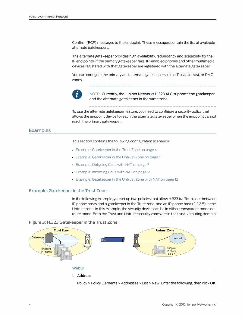
Example: Gatekeeper in the Trust Zone
In the following example, you set up two policies that allow H.323 traffic to pass between
IP phone hosts and a gatekeeper in the Trust zone, and an IP phone host (2.2.2.5) in the
Untrust zone. In this example, the security device can be in either transparent mode or
route mode. Both the Trust and Untrust security zones are in the trust-vr routing domain.
Figure 3: H.323 Gatekeeper in the Trust Zone
WebUI
1. Address
Policy > Policy Elements > Addresses > List > New: Enter the following, then clickOK:
Copyright © 2012, Juniper Networks, Inc.4
Voice-over-Internet Protocol

Address Name: IP_PhoneIP Address/Domain Name:IP/Netmask: (select), 2.2.2.5/32
Zone: Untrust
2. Policies
Policies > (From: Trust, To: Untrust) New: Enter the following, then click OK:
Source Address:Address Book Entry: (select), Any
Destination Address:Address Book Entry: (select), IP_Phone
Service: H.323Action: Permit
Policies > (From: Untrust, To: Trust) New: Enter the following, then click OK:
Source Address:Address Book Entry: (select), IP_Phone
Destination Address:Address Book Entry: (select), Any
Service: H.323Action: Permit
CLI
1. Address
set address untrust IP_Phone 2.2.2.5/32
2. Policies
set policy from trust to untrust any IP_Phone h.323 permitset policy from untrust to trust IP_Phone any h.323 permitsave
Example: Gatekeeper in the Untrust Zone
Because transparent and route modes do not require address mapping of any kind,
security device configuration for a gatekeeper in the Untrust zone is usually identical to
the configuration for a gatekeeper in the Trust zone.
In the following example, you set up two policies to allow H.323 traffic to pass between
IP phone hosts in the Trust zone, and the IP phone at IP address 2.2.2.5 (and the
gatekeeper) in the Untrust zone. The device can be in transparent or route mode. Both
the Trust and Untrust security zones are in the trust-vr routing domain.
Figure 4: H.323 Gatekeeper in the Untrust Zone
5Copyright © 2012, Juniper Networks, Inc.
Chapter 1: H.323 Application Layer Gateway

WebUI
1. Addresses
Policy > Policy Elements > Addresses > List > New: Enter the following, then clickOK:
Address Name: IP_PhoneIP Address/Domain Name:IP/Netmask: (select), 2.2.2.5/32
Zone: Untrust
Policy > Policy Elements > Addresses > List > New: Enter the following, then clickOK:
Address Name: GatekeeperIP Address/Domain Name:IP/Netmask: (select), 2.2.2.10/32
Zone: Untrust
2. Policies
Policies > (From: Trust, To: Untrust) New: Enter the following, then click OK:
Source Address:Address Book Entry: (select), Any
Destination Address:Address Book Entry: (select), IP_Phone
Service: H.323Action: Permit
Policies > (From: Untrust, To: Trust) New: Enter the following, then click OK:
Source Address:Address Book Entry: (select), IP_Phone
Destination Address:Address Book Entry: (select), Any
Service: H.323Action: Permit
Policies > (From: Trust, To: Untrust) New: Enter the following, then click OK:
Source Address:Address Book Entry: (select), Any
Destination Address:Address Book Entry: (select), Gatekeeper
Service: H.323Action: Permit
CLI
1. Addresses
set address untrust IP_Phone 2.2.2.5/32set address untrust gatekeeper 2.2.2.10/32
2. Policies
set policy from trust to untrust any IP_Phone h.323 permitset policy from trust to untrust any gatekeeper h.323 permitset policy from untrust to trust IP_Phone any h.323 permit
Copyright © 2012, Juniper Networks, Inc.6
Voice-over-Internet Protocol

set policy from untrust to trust gatekeeper any h.323 permitsave
Example: Outgoing Calls with NAT
When the security device uses NAT (Network Address Translation), a gatekeeper or
endpoint device in the Trust zone has a private address, and when it is in the Untrust zone
it has a public address. When you set a security device in NAT mode, you must map a
public IP address to each device that needs to receive incoming traffic with a private
address.
In this example, the devices in the Trust zone include the endpoint host (10.1.1.5) and the
gatekeeper device (10.1.1.25). IP_Phone2 (2.2.2.5) is in the Untrust zone. You configure
the security device to allow traffic between the endpoint host IP_Phone1 and the
gatekeeper in the Trust zone and the endpoint host IP_Phone2 in the Untrust zone. Both
the Trust and Untrust security zones are in the trust-vr routing domain.
Figure 5: Network Address Translation—Outgoing Calls
WebUI
1. Interfaces
Network > Interfaces > Edit (for ethernet1): Enter the following, then click Apply:
Zone Name: TrustStatic IP: (select this option when present)IP Address/Netmask: 10.1.1.1/24Select the following, then clickOK:Interface Mode: NAT
Network > Interfaces > Edit (for ethernet3): Enter the following, then click OK:
Zone Name: UntrustStatic IP: (select this option when present)IP Address/Netmask: 1.1.1.1/24
2. Addresses
Policy > Policy Elements > Addresses > List > New: Enter the following, then clickOK:
Address Name: IP_Phone1IP Address/Domain Name:IP/Netmask: (select), 10.1.1.5/32
Zone: Trust
Policy > Policy Elements > Addresses > List > New: Enter the following, then clickOK:
7Copyright © 2012, Juniper Networks, Inc.
Chapter 1: H.323 Application Layer Gateway

Address Name: GatekeeperIP Address/Domain Name:IP/Netmask: (select), 10.1.1.25/32
Zone: Trust
Policy > Policy Elements > Addresses > List > New: Enter the following, then clickOK:
Address Name: IP_Phone2IP Address/Domain Name:IP/Netmask: (select), 2.2.2.5/32
Zone: Untrust
3. Mapped IP Addresses
Network > Interfaces > Edit (for ethernet3) > MIP > New: Enter the following, then
click OK:
Mapped IP: 1.1.1.5Netmask: 255.255.255.255Host IP Address: 10.1.1.5Host Virtual Router Name: trust-vr
Network > Interfaces > Edit (for ethernet3) > MIP > New: Enter the following, then
click OK:
Mapped IP: 1.1.1.25Netmask: 255.255.255.255Host IP Address: 10.1.1.25Host Virtual Router Name: trust-vr
4. Route
Network > Routing > Destination > trust-vr New: Enter the following, then click OK:
Network Address/Netmask: 0.0.0.0/0Gateway: (select)Interface: ethernet3Gateway IP Address: 1.1.1.250
5. Policies
Policies > (From: Trust, To: Untrust) New: Enter the following, then click OK:
Source Address:Address Book Entry: (select), IP_Phone1
Destination Address:Address Book Entry: (select), IP_Phone2
Service: H.323Action: Permit
Policies > (From: Trust, To: Untrust) New: Enter the following, then click OK:
Source Address:Address Book Entry: (select), Gatekeeper
Destination Address:Address Book Entry: (select), IP_Phone2
Service: H.323Action: Permit
Policies > (From: Untrust, To: Trust) New: Enter the following, then click OK:
Copyright © 2012, Juniper Networks, Inc.8
Voice-over-Internet Protocol
Source Address:Address Book Entry: (select), IP_Phone2
Destination Address:Address Book Entry: (select), MIP(1.1.1.5)
Service: H.323Action: Permit
Policies 7gt; (From: Untrust, To: Trust) New: Enter the following, then click OK:
Source Address:Address Book Entry: (select), IP_Phone2
Destination Address:Address Book Entry: (select), MIP(1.1.1.25)
Service: H.323Action: Permit
CLI
1. Interfaces
set interface ethernet1 zone trustset interface ethernet1 ip 10.1.1.1/24set interface ethernet3 zone untrustset interface ethernet3 ip 1.1.1.1/24
2. Addresses
set address trust IP_Phone1 10.1.1.5/32set address trust gatekeeper 10.1.1.25/32set address untrust IP_Phone2 2.2.2.5/32
3. Mapped IP Addresses
set interface ethernet3mip 1.1.1.5 host 10.1.1.5set interface ethernet3mip 1.1.1.25 host 10.1.1.25
4. Route
set vrouter trust-vr route 0.0.0.0/0 interface ethernet3 gateway 1.1.1.250
5. Policies
set policy from trust to untrust IP_Phone1 IP_Phone2 h.323 permitset policy from trust to untrust gatekeeper IP_Phone2 h.323 permitset policy from untrust to trust IP_Phone2mip(1.1.1.5) h.323 permitset policy from untrust to trust IP_Phone2mip (1.1.1.25) h.323 permitsave
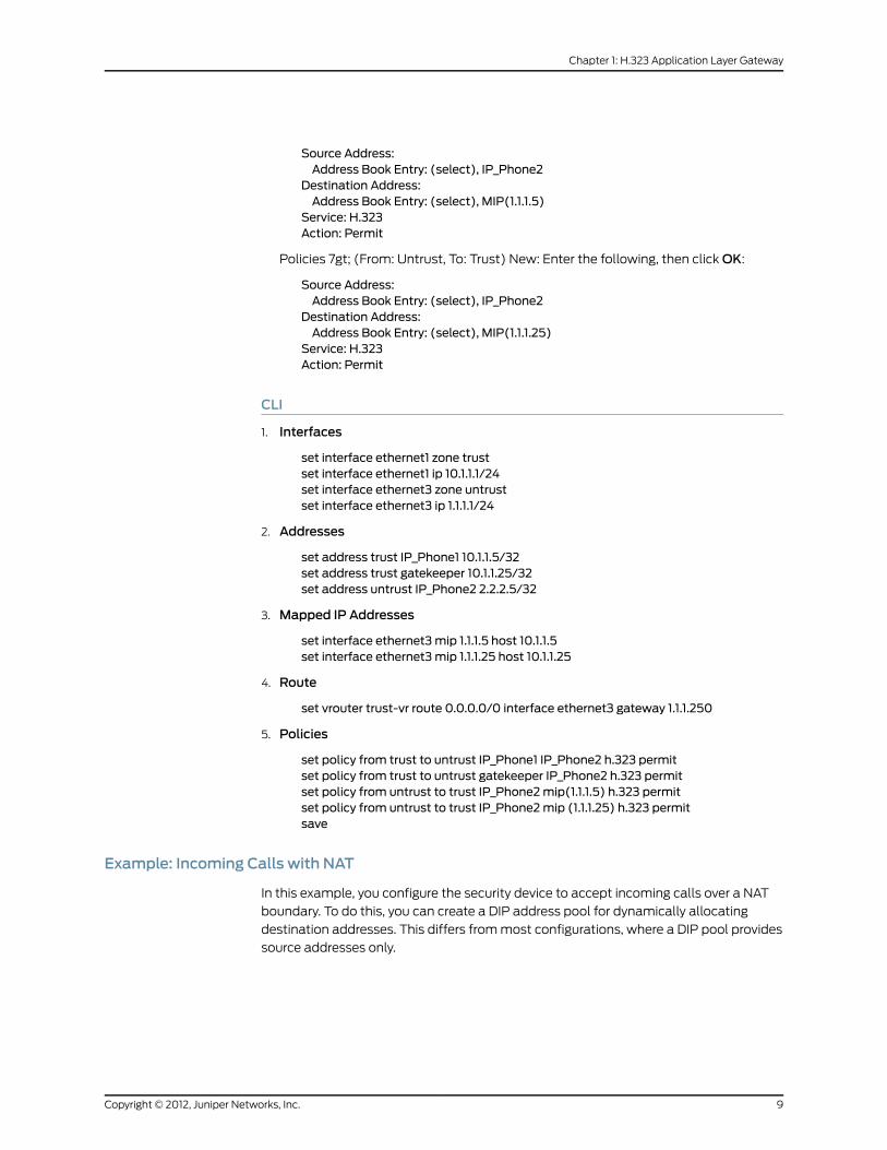
Example: Incoming Calls with NAT
In this example, you configure the security device to accept incoming calls over a NAT
boundary. To do this, you can create a DIP address pool for dynamically allocating
destination addresses. This differs from most configurations, where a DIP pool provides
source addresses only.
9Copyright © 2012, Juniper Networks, Inc.
Chapter 1: H.323 Application Layer Gateway

Figure 6: Network Address Translation—Incoming Calls
The name of the DIP pool can be DIP(id_num) for a user-defined DIP, or DIP(interface)
when the DIP pool uses the same address as an interface IP address. You can use such
address entries as destination addresses in policies, together with the services H.323,
SIP, or other VoIP (Voice-over-IP) protocols, to support incoming calls.
A single policy with a policy-based NAT (DIP ID 2) fails because of the twin-pair port
limitations on the DIP pool. The policy segments the traffic so that they do not have more
than 512 phones (the DIP limitation) on each DIP pool.
The following example uses DIP in an H.323 VoIP configuration. The keyword “ incoming”
instructs the device to add the DIP and interface addresses to the global zone.
WebUI
1. Interfaces
Network > Interfaces > Edit (for ethernet1): Enter the following, then click Apply:
Zone Name: TrustStatic IP: (select this option when present)IP Address/Netmask: 10.1.1.1/24Enter the following, then clickOK:Interface Mode: NAT
Network > Interfaces > Edit (for ethernet3): Enter the following, then click OK:
Zone Name: UntrustStatic IP: (select this option when present)IP Address/Netmask: 1.1.1.1/24
2. DIPwith Incoming NAT
Network > Interface > Edit (for ethernet3) > DIP > New: Enter the following, then click
OK:
ID: 5IP Address Range: (select), 1.1.1.12 ~ 1.1.1.150Port Translation: (select)
In the same subnet as the interface IP or its secondary IPs: (select)Incoming NAT: (select)
3. Addresses
Policy > Policy Elements > Addresses > List > New (for Trust): Enter the following,
then click OK:
Copyright © 2012, Juniper Networks, Inc.10
Voice-over-Internet Protocol

Address Name: IP_Phones1IP Address/Domain Name:IP/Netmask: (select), 10.1.1.5/24
Zone: Trust
Policy > Policy Elements > Addresses > List > New (for Untrust): Enter the following,
then click OK:
Address Name: IP_Phone2IP Address/Domain Name:IP/Netmask: (select), 2.2.2.5/32
Zone: Untrust
4. Policies
Policies > (From: Trust, To: Untrust) New: Enter the following, then click OK:
Source Address:Address Book Entry: (select), IP_Phones1
Destination Address:Address Book Entry: (select), Any
Service: H.323Action: Permit
Policies > (From: Untrust, To: Trust) New: Enter the following, then click OK:
Source Address:Address Book Entry: (select), IP_Phone2
Destination Address:Address Book Entry: (select), DIP(5)
Service: H.323Action: Permit
CLI
1. Interfaces
set interface ethernet1 zone trustset interface ethernet1 ip 10.1.1.1/24set interface ethernet3 zone untrustset interface ethernet3 ip 1.1.1.1/24
2. DIPwith Incoming NAT
set interface ethernet3 dip 5 1.1.1.12 1.1.1.150 incoming
3. Addresses
set address trust IP_Phones1 10.1.1.5/24set address untrust IP_Phone2 2.2.2.5/32
4. Policies
set policy from trust to untrust IP_Phones1 any h.323 nat src dip 5 permitset policy from untrust to trust IP_Phone2 dip(5) h.323 permitsave
11Copyright © 2012, Juniper Networks, Inc.
Chapter 1: H.323 Application Layer Gateway

Example: Gatekeeper in the Untrust Zonewith NAT
In this example, the gatekeeper device (2.2.2.25) and host IP_Phone2 (2.2.2.5) are in the
Untrust zone and host IP_Phone1 (10.1.1.5) is in the Trust zone. You configure the security
device to allow traffic between host IP_Phone1 in the Trust zone and host IP_Phone2
(and the gatekeeper) in the Untrust zone. Both the Trust and Untrust security zones are
in the trust-vr routing domain.
Figure 7: Gatekeeper in the Untrust Zone
WebUI
1. Interfaces
Network > Interfaces > Edit (for ethernet1): Enter the following, then click Apply:
Zone Name: TrustStatic IP: (select this option when present)IP Address/Netmask: 10.1.1.1/24Enter the following, then clickOK:Interface Mode: NAT
Network > Interfaces > Edit (for ethernet3): Enter the following, then click OK:
Zone Name: UntrustStatic IP: (select this option when present)IP Address/Netmask: 1.1.1.1/24
2. Addresses
Policy > Policy Elements > Addresses > List > New: Enter the following, then clickOK:
Address Name: IP_Phone1IP Address/Domain Name:IP/Netmask: (select), 10.1.1.5/32
Zone: Trust
Policy > Policy Elements > Addresses > List > New: Enter the following, then clickOK:
Address Name: GatekeeperIP Address/Domain Name:IP/Netmask: (select), 2.2.2.25/32
Zone: Untrust
Policy > Policy Elements > Addresses > List > New: Enter the following, then clickOK:
Address Name: IP_Phone2IP Address/Domain Name:
Copyright © 2012, Juniper Networks, Inc.12
Voice-over-Internet Protocol
IP/Netmask: (select), 2.2.2.5/32Zone: Untrust
3. Mapped IP Address
Network > Interfaces > Edit (for ethernet3) > MIP > New: Enter the following, then
click OK:
Mapped IP: 1.1.1.5Netmask: 255.255.255.255Host IP Address: 10.1.1.5
4. Route
Network > Routing > Destination > trust-vr New: Enter the following, then click OK:
Network Address/Netmask: 0.0.0.0/0Gateway: (select)Interface: ethernet3Gateway IP Address: 1.1.1.250
5. Policies
Policies > (From: Trust, To: Untrust) New: Enter the following, then click OK:
Source Address:Address Book Entry: (select), IP_Phone1
Destination Address:Address Book Entry: (select), IP_Phone2
Service: H.323Action: Permit
Policies > (From: Trust, To: Untrust) New: Enter the following, then click OK:
Source Address:Address Book Entry: (select), IP_Phone1
Destination Address:Address Book Entry: (select), Gatekeeper
Service: H.323Action: Permit
Policies > (From: Untrust, To: Trust) New: Enter the following, then click OK:
Source Address:Address Book Entry: (select), IP_Phone2
Destination Address:Address Book Entry: (select), MIP(1.1.1.5)
Service: H.323Action: Permit
Policies > (From: Untrust, To: Trust) New: Enter the following, then click OK:
Source Address:Address Book Entry: (select), GatekeeperDestination Address:Address Book Entry: (select), MIP(1.1.1.5)Service: H.323Action: Permit
13Copyright © 2012, Juniper Networks, Inc.
Chapter 1: H.323 Application Layer Gateway
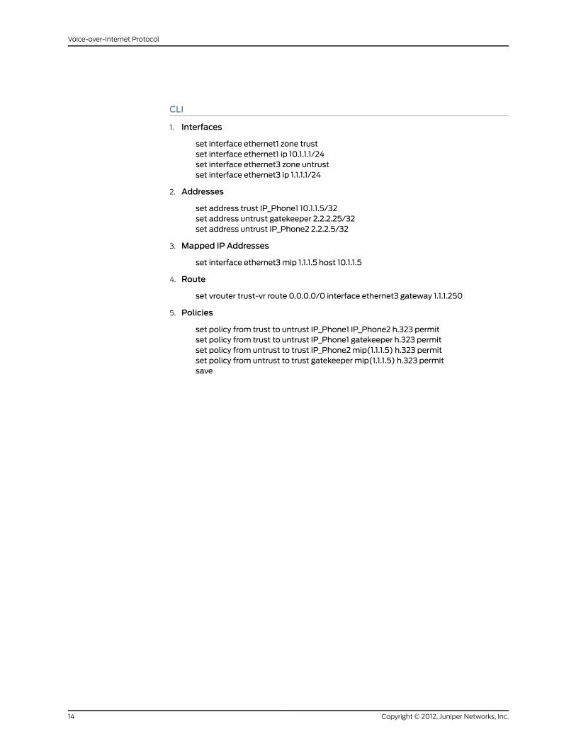
CLI
1. Interfaces
set interface ethernet1 zone trustset interface ethernet1 ip 10.1.1.1/24set interface ethernet3 zone untrustset interface ethernet3 ip 1.1.1.1/24
2. Addresses
set address trust IP_Phone1 10.1.1.5/32set address untrust gatekeeper 2.2.2.25/32set address untrust IP_Phone2 2.2.2.5/32
3. Mapped IP Addresses
set interface ethernet3mip 1.1.1.5 host 10.1.1.5
4. Route
set vrouter trust-vr route 0.0.0.0/0 interface ethernet3 gateway 1.1.1.250
5. Policies
set policy from trust to untrust IP_Phone1 IP_Phone2 h.323 permitset policy from trust to untrust IP_Phone1 gatekeeper h.323 permitset policy from untrust to trust IP_Phone2mip(1.1.1.5) h.323 permitset policy from untrust to trust gatekeeper mip(1.1.1.5) h.323 permitsave
Copyright © 2012, Juniper Networks, Inc.14
Voice-over-Internet Protocol

CHAPTER 2
Session Initiation ProtocolApplication Layer Gateway
This chapter describes the Session Initiation Protocol (SIP) Application Layer Gateway
(ALG) and contains the following sections:
• Overview on page 15
• SIP with Network Address Translation on page 25
• Examples on page 32
Overview
Session Initiation Protocol (SIP) is an Internet Engineering Task Force (IETF)-standard
protocol for initiating, modifying, and terminating multimedia sessions over the Internet.
Such sessions might include conferencing, telephony, or multimedia, with features such
as instant messaging and application-level mobility in network environments.
Juniper Networks security devices support SIP as a service and can screen SIP traffic,
allowing and denying it based on a policy that you configure. SIP is a predefined service
in ScreenOS and uses port 5060 as the destination port.
SIP’s primary function is to distribute session-description information and, during the
session, to negotiate and modify the parameters of the session. SIP is also used to
terminate a multimedia session.
Session-description information is included in INVITE and ACK messages and indicates
the multimedia type of the session, for example, voice or video. Although SIP can use
different description protocols to describe the session, the Juniper Networks SIP ALG
supports only Session Description Protocol (SDP).
SDP provides information that a system can use to join a multimedia session. SDP might
include information such as IP addresses, port numbers, times, and dates. Note that the
IP address and port number in the SDP header (the “ c=” and “ m=” fields, respectively)
are the address and port where the client wants to receive the media streams and not
the IP address and port number from which the SIP request originates (although they
can be the same). See “Session Description Protocol Sessions” on page 20 for more
information.
15Copyright © 2012, Juniper Networks, Inc.
SIP messages consist of requests from a client to a server and responses to the requests
from a server to a client with the purpose of establishing a session (or a call). A User
Agent (UA) is an application that runs at the endpoints of the call and consists of two
parts: the User Agent Client (UAC), which sends SIP requests on behalf of the user; and
a User Agent Server (UAS), which listens to the responses and notifies the user when
they arrive. Examples of UAs are SIP proxy servers and phones.
SIP Request Methods
The SIP transaction model includes a number of request and response messages, each
of which contains a method field that denotes the purpose of the message. ScreenOS
supports the following method types and response codes:
• INVITE—A user sends an INVITE request to invite another user to participate in a session.
The body of an INVITE request may contain the description of the session. In NAT
mode, the IP addresses in the Via:, From:, To:, Call-ID:, Contact:, Route:, and
Record-Route: header fields are modified as shown in Table 2 on page 29.
• ACK—The user from whom the INVITE originated sends an ACK request to confirm
reception of the final response to the INVITE request. If the original INVITE request did
not contain the session description, the ACK request must include it. In NAT mode, the
IP addresses in the Via:, From:, To:, Call-ID:, Contact:, Route:, and Record-Route: header
fields are modified as shown in Table 2 on page 29.
• OPTIONS—Used by the User Agent (UA) to obtain information about the capabilities
of the SIP proxy. A server responds with information about what methods, session
description protocols, and message encoding it supports. In NAT mode, when the
OPTIONS request is sent from a UA outside NAT to a proxy inside NAT, the SIP ALG
translates the address in the Request-URI and the IP address in the To: field to the
appropriate IP address of the internal client. When the UA is inside NAT and the proxy
is outside NAT, the SIP ALG translates the From:, Via:, and Call-ID: fields as shown in
Table 2 on page 29.
• BYE—A user sends a BYE request to abandon a session. A BYE request from either user
automatically terminates the session. In NAT mode, the IP addresses in the Via:, From:,
To:, Call-ID:, Contact:, Route:, and Record-Route: header fields are modified as shown
in Table 2 on page 29.
• CANCEL—A user can send a CANCEL request to cancel a pending INVITE request. A
CANCEL request has no effect if the SIP server processing the INVITE had sent a final
response for the INVITE before it received the CANCEL. In NAT mode, the IP addresses
in the Via:, From:, To:, Call-ID:, Contact:, Route:, and Record-Route: header fields are
modified as shown in Table 2 on page 29.
• REGISTER—A user sends a REGISTER request to a SIP registrar server to inform it of
the current location of the user. A SIP registrar server records all the information it
receives in REGISTER requests and makes this information available to any SIP server
attempting to locate a user. In NAT mode, REGISTER requests are handled as follows:
• REGISTER requests from an external client to an internal registrar—When the SIP
ALG receives the incoming REGISTER request it translates the IP address, if any, in
the Request-URI. Incoming REGISTER messages are allowed only to a MIP or VIP
address. No translation is needed for the outgoing response.
Copyright © 2012, Juniper Networks, Inc.16
Voice-over-Internet Protocol
• REGISTER requests from an internal client to an external registrar—When the SIP
ALG receives the outgoing REGISTER request it translates the IP addresses in the
To:, From:, Via:, Call-ID:, and Contact: header fields. A backward translation is
performed for the incoming response.
• Info—Used to communicate mid-session signaling information along the signaling path
for the call. In NAT mode, the IP addresses in the Via:, From:, To:, Call-ID:, Contact:,
Route:, and Record-Route: header fields are modified as shown in Table 2 on page 29.
• Subscribe—Used to request current state and state updates from a remote node. In
NAT mode, the address in the Request-URI is changed to a private IP address if the
messages is coming from the external network into the internal network. The IP
addresses in Via:, From:, To:, Call-ID:, Contact:, Route:, and Record-Route: header fields
are modified as shown in the table in Table 2 on page 29.
• Notify—Sent to inform subscribers of changes in state to which the subscriber has a
subscription. In NAT mode, the IP address in the Request-URI: header field is changed
to a private IP address if the message is coming from the external network into the
internal network. The IP address in the Via:, From:, To:, Call-ID:, Contact:, Route:, and
Record-Route: header fields are modified as shown in Table 2 on page 29.
• Refer—Used to refer the recipient (identified by the Request-URI) to a third party by
the contact information provided in the request. In NAT mode, the IP address in the
Request-URI is changed to a private IP address if the message is coming from the
external network into the internal network. The IP addresses in the Via:, From:, To:,
Call-ID:, Contact:, Route:, and Record-Route: header fields are modified as shown in
Table 2 on page 29.
For example, if user A in a private network refers user B, in a public network, to user C,
who is also in the private network, the SIP ALG allocates a new IP address and port
number for user C so that user C can be contacted by user B. If user C is registered with
a registrar, however, its port mapping is stored in the ALG NAT table and is reused to
perform the translation.
• Update—Used to open pinhole for new or updated SDP information. The Via:, From:,
To:, Call-ID:, Contact:, Route:, and Record-Route: header fields are modified as shown
in Table 2 on page 29.
• 1xx, 202, 2xx, 3xx, 4xx, 5xx, 6xx Response Codes—Used to indicate the status of a
transaction. Header fields are modified as shown in Table 2 on page 29.
Classes of SIP Responses
SIP responses provide status information about SIP transactions and include a response
code and a reason phrase. SIP responses are grouped into the following classes:
• Informational (100 to 199)—Request received, continuing to process the request.
• Success (200 to 299)—Action successfully received, understood, and accepted.
• Redirection (300 to 399)—Further action required to complete the request.
• Client Error (400 to 499)—Request contains bad syntax or cannot be fulfilled at this
server.
17Copyright © 2012, Juniper Networks, Inc.
Chapter 2: Session Initiation Protocol Application Layer Gateway

• Server Error (500 to 599)—Server failed to fulfill an apparently valid request.
• Global Failure (600 to 699)—Request cannot be fulfilled at any server.
Table 1 on page 18 provides a complete list of current SIP responses, all of which are
supported on Juniper Networks security devices.
Table 1: Session Initiation Protocol Responses
ResponseCode-ReasonPhraseResponseCode-ReasonPhraseResponseCode-ReasonPhraseClass
181 Call is being forwarded180 Ringing100 TryingInformational
183 Session progress182 Queued
202 Accepted200 OKSuccess
302 Moved temporarily301 Moved permanently300 Multiple choicesRedirection
380 Alternative service305 Use proxy
402 Payment required401 Unauthorized400 Bad requestClient Error
405 Method not allowed404 Not found403 Forbidden
408 Request time-out407 Proxy authentication required406 Not acceptable
411 Length required410 Gone409 Conflict
415 Unsupported media type414 Request-URL too large413 Request entity too large
481 Call leg/transaction does notexist
480 Temporarily not available420 Bad extension
484 Address incomplete483 Too many hops482 Loop detected
487 Request canceled486 Busy here485 Ambiguous
488 Not acceptable here
502 Bad gateway501 Not implemented500 Server internal errorServer Error
505 SIP version not supported504 Gateway time-out502 Service unavailable
604 Does not exist anywhere603 Decline600 Busy everywhereGlobal Failure
606 Not acceptable
SIP Application Layer Gateway
There are two types of SIP traffic, the signaling and the media stream. SIP signaling traffic
consists of request and response messages between client and server and uses transport
Copyright © 2012, Juniper Networks, Inc.18
Voice-over-Internet Protocol
protocols such as User Datagram Protocol (UDP) or Transmission Control Protocol
(TCP). The media stream carries the data (audio data, for example) and uses Application
Layer protocols such as Real Time Protocol (RTP) over UDP.
Juniper Networks security devices support SIP signaling messages on port 5060. You
can simply create a policy that permits SIP service, and the security device filters SIP
signaling traffic like any other type of traffic, permitting or denying it. The media stream,
however, uses dynamically assigned port numbers that can change several times during
the course of a call. Without fixed ports, it is impossible to create a static policy to control
media traffic. In this case, the security device invokes the SIP ALG. The SIP ALG reads
SIP messages and their SDP content and extracts the port-number information it needs
to dynamically open pinholes and let the media stream traverse the security device.
NOTE: Werefer toapinholeas the limitedopeningofaport toallowexclusivetraffic.
The SIP ALG monitors SIP transactions and dynamically creates and manages pinholes
based on the information it extracts from these transactions. The Juniper Networks SIP
ALG supports all SIP methods and responses (see “SIP Request Methods” on page 16
and “Classes of SIP Responses” on page 17). You can allow SIP transactions to traverse
the Juniper Networks firewall by creating a static policy that permits SIP service. This
policy enables the security device to intercept SIP traffic and do one of the following
actions: permit or deny the traffic or enable the SIP ALG to open pinholes to pass the
media stream. The SIP ALG needs to open pinholes only for the SIP requests and
responses that contain media information (SDP). For SIP messages that do not contain
SDP, the security device simply lets them through.
The SIP ALG intercepts SIP messages that contain SDP and, using a parser, extracts the
information it requires to create pinholes. The SIP ALG examines the SDP portion of the
packet, and a parser extracts information such as IP addresses and port numbers, which
the SIP ALG records in a pinhole table. The SIP ALG uses the IP addresses and port
numbers recorded in the pinhole table to open pinholes and allow media streams to
traverse the security device.
The SIP ALG for IPv6 supports Netscreen Redundancy Protocol (NSRP).
NOTE: Juniper Networks security devices do not support encrypted SDP. Ifa security device receives a SIPmessage in which SDP is encrypted, the SIPALG permits it through the firewall but generates a logmessage informingthe user that it cannot process the packet. If SDP is encrypted, the SIP ALGcannot extract the information it needs from SDP to open pinholes. As aresult, themedia content that SDP describes cannot traverse the securitydevice.
19Copyright © 2012, Juniper Networks, Inc.
Chapter 2: Session Initiation Protocol Application Layer Gateway

Session Description Protocol Sessions
An SDP session description is text-based and consists of a set of lines. It can contain
session-level and media-level information. The session-level information applies to the
whole session, while the media-level information applies to a particular media stream.
An SDP session description always contains session-level information, which appears
at the beginning of the description, and might contain media-level information, which
comes after.
NOTE: In the SDP session description, themedia-level information beginswith them= field.
Of the many fields in the SDP description, two are particularly useful to the SIP ALG
because they contain Transport Layer information. The two fields are the following:
• c= for connection information
This field can appear at the session or media level. It displays in this format:
• c=<network type><address type><connection address>
Currently, the security device supports "IN" (for Internet) as the network type, "IP4 and
IP6" as address types, and a unicast IP address or domain name as the destination
(connection) IP address.
NOTE: Generally, the destination IP address can also be amulticast IPaddress, but ScreenOS does not currently support multicast with SIP.
If the destination IP address is a unicast IP address, the SIP ALG creates pinholes using
the IP address and port numbers specified in the media description field m=.
• m= for media announcement
This field appears at the media level and contains the description of the media. It
displays in this format:
m=<media><port><transport><fmt list>
Currently, the security device supports only “ audio” as the media and “ RTP” as the
Application Layer transport protocol. The port number indicates the destination (not
the origin) of the media stream. The format list (fmt list) provides information about
the Application Layer protocol that the media uses.
In this release of ScreenOS, the security device opens ports only for RTP and RTCP.
Every RTP session has a corresponding Real Time Control Protocol (RTCP) session.
Therefore, whenever a media stream uses RTP, the SIP ALG must reserve ports (create
pinholes) for both RTP and RTCP traffic. By default, the port number for RTCP is one
higher than the RTP port number.
Copyright © 2012, Juniper Networks, Inc.20
Voice-over-Internet Protocol
NOTE: Generally, the destination IP address can also be amulticast IPaddress, but ScreenOS does not currently support multicast with SIP.
Pinhole Creation
Both pinholes for the RTP and RTCP traffic share the same destination IP address. The
IP address comes from the c= field in the SDP session description. Because the c= field
can appear in either the session-level or media-level portion of the SDP session
description, the parser determines the IP address based on the following rules (in
accordance with SDP conventions):
• First, the SIP ALG parser verifies if there is a c= field containing an IP address in the
media level. If there is one, the parser extracts that IP address, and the SIP ALG uses
it to create a pinhole for the media.
• If there is no c= field in the media level, the SIP ALG parser extracts the IP address from
the c= field in the session level, and the SIP ALG uses it to create a pinhole for the
media. If the session description does not contain a c= field in either level, this indicates
an error in the protocol stack, and the security device drops the packet and logs the
event.
The following lists the information the SIP ALG needs to create a pinhole. This information
comes from the SDP session description and parameters on the security device:
• Protocol: UDP.
• Source IP: Unknown.
• Source port: Unknown.
• Destination IP: The parser extracts the destination IP address from the c= field in the
media or session level.
• Destination port: The parser extracts the destination port number for RTP from the
m= field in the media level and calculates the destination port number for RTCP using
the following formula:
RTP port number + one
• Lifetime: This value indicates the length of time (in seconds) during which a pinhole
is open to allow a packet through. A packet must go through the pinhole before the
lifetime expires. When the lifetime expires, the SIP ALG removes the pinhole.
When a packet goes through the pinhole within the lifetime period, immediately
afterwards the SIP ALG removes the pinhole for the direction from which the packet
came.
Figure 8 on page 22 describes a call setup between two SIP clients and how the SIP
ALG creates pinholes to allow RTP and RTCP traffic. The illustration assumes that the
security device has a policy that permits SIP, thus opening port 5060 for SIP signaling
messages.
21Copyright © 2012, Juniper Networks, Inc.
Chapter 2: Session Initiation Protocol Application Layer Gateway
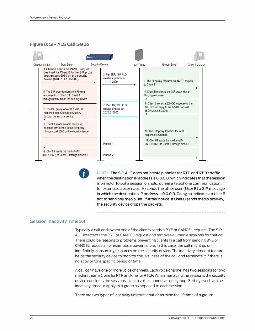
Figure 8: SIP ALG Call Setup
NOTE: The SIP ALG does not create pinholes for RTP and RTCP trafficwhenthedestination IPaddress is0.0.0.0,which indicates that thesessionis on hold. To put a session on hold, during a telephone communication,for example, a user (User A) sends the other user (User B) a SIPmessagein which the destination IP address is 0.0.0.0. Doing so indicates to User Bnot to send anymedia until further notice. If User B sendsmedia anyway,the security device drops the packets.
Session Inactivity Timeout
Typically a call ends when one of the clients sends a BYE or CANCEL request. The SIP
ALG intercepts the BYE or CANCEL request and removes all media sessions for that call.
There could be reasons or problems preventing clients in a call from sending BYE or
CANCEL requests, for example, a power failure. In this case, the call might go on
indefinitely, consuming resources on the security device. The inactivity-timeout feature
helps the security device to monitor the liveliness of the call and terminate it if there is
no activity for a specific period of time.
A call can have one or more voice channels. Each voice channel has two sessions (or two
media streams), one for RTP and one for RTCP. When managing the sessions, the security
device considers the sessions in each voice channel as one group. Settings such as the
inactivity timeout apply to a group as opposed to each session.
There are two types of inactivity timeouts that determine the lifetime of a group:
Copyright © 2012, Juniper Networks, Inc.22
Voice-over-Internet Protocol

• Signaling-inactivity timeout: This parameter indicates the maximum length of time (in
seconds) a call can remain active without any SIP-signaling traffic. Each time a
SIP-signaling message occurs within a call, this timeout resets. The default setting is
43200 seconds (12 hours).
• Media-inactivity timeout: This parameter indicates the maximum length of time (in
seconds) a call can remain active without any media (RTP or RTCP) traffic within a
group. Each time an RTP or RTCP packet occurs within a call, this timeout resets. The
default setting is 120 seconds.
If either of these timeouts expires, the security device removes all sessions for this call
from its table, thus terminating the call.
SIP Attack Protection
The ability of the SIP proxy server to process calls can be affected by repeat SIP INVITE
requests, whether malicious or through client or server error, that it initially denied. To
prevent the SIP proxy server from being overwhelmed by such requests, you can use the
sip protect deny command to configure the security device to monitor INVITE requests
and proxy server replies to them. The sip protect deny command supports both IPv4
and IPv6 addresses. If a reply contains a 3xx, 4xx, or 5xx response code (see “Classes of
SIP Responses” on page 17), the ALG stores the source IP address of the request and
the IP address of the proxy server in a table. Subsequently, the security device checks all
INVITE requests against this table and, for a configurable number of seconds (the default
is 3), discards any packets that match entries in the table. You can also configure the
security device to monitor INVITE request to a specific proxy server by specifying the
destination IP address. SIP attack protection is configured globally.
Example: SIP Protect Deny
In this example, you configure the security device to protect a single SIP proxy server
(1.1.1.3/24) from repeat SIP requests to which it has already denied service. Packets are
dropped for a period of 5 seconds, after which the security device resumes forwarding
INVITE requests from those sources.
WebUI
You must use the CLI to protect SIP proxy servers from being inundated by SIP messages.
CLI
set alg sip app-screen protect deny dst-ip 1.1.1.3/24set alg sip protect deny timeout 5save
Example: Signaling-Inactivity andMedia-Inactivity Timeouts
In this example, you configure the signaling-inactivity timeout to 30,000 seconds and
the media-inactivity timeout to 90 seconds.
23Copyright © 2012, Juniper Networks, Inc.
Chapter 2: Session Initiation Protocol Application Layer Gateway
WebUI
NOTE: Youmust use the CLI to set SIP-signaling andmedia-inactivitytimeouts.
CLI
set alg sip signaling-inactivity-timeout 30000set alg sip media-inactivity-timeout 90save
Example: UDP Flooding Protection
You can protect the security device against UDP flooding by zone and destination address.
In this example, you set a threshold of 80,000 per second for the number of UDP packets
that can be received on IP address 1.1.1.5, in the Untrust zone, before the security device
generates an alarm and drops subsequent packets for the remainder of that second.
NOTE: This example uses a general ScreenOS command and is notnecessarily SIP-specific. For more information about UDP flood protectionand how to determine effective settings, see UDP Flood.
WebUI
Security > Screening > Screen: Enter the following, then click Apply:
Zone: UntrustUDP Flood Protection (select)
> Destination IP: Enter the following, then click the Back arrow in your browser to return
to the Screen configuration page:
Destination IP: 1.1.1.5Threshold: 80000Add: (select)
CLI
set zone untrust screen udp-flood dst-ip 1.1.1.5 threshold 80000save
Example: SIP ConnectionMaximum
In this example, you prevent flood attacks on the SIP network from attackers in the
Untrust zone by setting a maximum of 20 concurrent sessions from a single IP address.
If the security device detects more than 20 connection attempts from the same IP address,
it begins dropping subsequent attempts until the number of sessions drops below the
specified maximum.
Copyright © 2012, Juniper Networks, Inc.24
Voice-over-Internet Protocol
NOTE: This example uses a general ScreenOS command and is notnecessarily SIP-specific. For more information about source-based sessionlimits and how to determine effective settings, see Source Based andDestination Based Session
WebUI
Screening > Screen (Zone: Untrust): Enter the following, then click OK:
Source IP Based Session Limit: (select)Threshold: 20 Sessions
CLI
set zone untrust screen limit-session source-ip-based 20save
SIPwith Network Address Translation
The Network Address Translation (NAT) protocol enables multiple hosts in a private
subnet to share a single public IP address to access the Internet. For outgoing traffic,
NAT replaces the private IP address of the host in the private subnet with the public IP
address. For incoming traffic, the public IP address is converted back into the private
address, and the message is routed to the appropriate host in the private subnet.
Using NAT with the SIP service is more complicated because SIP messages contain IP
addresses in the SIP headers as well as in the SIP body. The SIP headers contain
information about the caller and the receiver, and the security device translates this
information to hide it from the outside network. The SIP body contains the Session
Description Protocol (SDP) information, which includes IP addresses and port numbers
for transmission of the media. The security device translates SDP information for allocating
resources to send and receive the media.
How IP addresses and port numbers in SIP messages are replaced depends on the
direction of the message. For an outgoing message, the private IP address and port
number of the client are replaced with the public IP address and port number of the
Juniper Networks firewall. For an incoming message, the public address of the firewall is
replaced with the private address of the client.
When an INVITE message is sent out across the firewall, the SIP ALG collects information
from the message header into a call table, which it uses to forward subsequent messages
to the correct end point. When a new message arrives, for example an ACK or 200 OK,
the ALG compares the From:, To:, and Call-ID: fields against the call table to identify the
call context of the message. If a new INVITE message arrives that matches the existing
call, the ALG processes it as a REINVITE.
When a message containing SDP information arrives, the ALG allocates ports and creates
a NAT mapping between them and the ports in the SDP. Because the SDP requires
sequential ports for the Real Time Protocol (RTP) and Real Time Control Protocol (RTCP)
channels, the ALG provides consecutive even-odd ports. If it is unable to find a pair of
ports it discards the SIP message.
25Copyright © 2012, Juniper Networks, Inc.
Chapter 2: Session Initiation Protocol Application Layer Gateway

Outgoing Calls
When a SIP call is initiated with a SIP request message from the internal to the external
network, NAT replaces the IP addresses and port numbers in the SDP and creates a
binding to map the IP addresses and port numbers to the Juniper Networks firewall. Via:,
Contact:, Route:, and Record-Route: SIP header fields, if present, are also bound to the
firewall IP address. The ALG stores these mappings for use in retransmissions and for
SIP response messages.
The SIP ALG then opens pinholes in the firewall to allow media through the security
device on the dynamically assigned ports negotiated based on information in the SDP
and the Via:, Contact:, and Record-Route: header fields. The pinholes also allow incoming
packets to reach the Contact:, Via:, and Record-Route: IP addresses and ports. When
processing return traffic, the ALG inserts the original Contact:, Via:, Route:, and
Record-Route: SIP fields back into the packets.
Incoming Calls
Incoming calls are initiated from the public network to public Mapped IP (MIP) addresses
or to interface IP addresses on the security device. MIPs are statically configured IP
addresses that point to internal hosts; interface IP addresses are dynamically recorded
by the ALG as it monitors REGISTER messages sent by internal hosts to the SIP registrar.
(For more information, see “Examples” on page 32.) When the security device receives
an incoming SIP packet, it sets up a session and forwards the payload of the packet to
the SIP ALG.
The ALG examines the SIP request message (initially an INVITE) and, based on information
in the SDP, opens gates for outgoing media. When a 200 OK response message arrives,
the SIP ALG performs NAT on the IP addresses and ports and opens pinholes in the
outbound direction. (The opened gates have a short time-to-live, and time out if a 200
OK response message is not received quickly.)
When a 200 OK response arrives, the SIP proxy examines the SDP information and reads
the IP addresses and port numbers for each media session. The SIP ALG on the security
device performs NAT on the addresses and port numbers, opens pinholes for outbound
traffic, and refreshes the timeout for gates in the inbound direction.
When the ACK arrives for the 200 OK, it also passes through the SIP ALG. If the message
contains SDP information, the SIP ALG ensures that the IP addresses and port numbers
are not changed from the previous INVITE—if they are, the ALG deletes old pinholes and
creates new pinholes to allow media to pass through. The ALG also monitors the Via:,
Contact:, and Record-Route: SIP fields and opens new pinholes if it determines that these
fields have changed.
Forwarded Calls
A forwarded call is when, for example, user A outside the network calls user B inside the
network, and user B forwards the call to user C outside the network. The SIP ALG
processes the INVITE from user A as a normal incoming call. But when the ALG examines
the forwarded call from B to C outside the network and notices that B and C are reached
Copyright © 2012, Juniper Networks, Inc.26
Voice-over-Internet Protocol
using the same interface, it does not open pinholes in the firewall, because media will
flow directly between user A and user C.
Call Termination
The BYE message is used to terminate a call. When the security device receives a BYE
message, it translates the header fields just as it does for any other message, But because
a BYE message must be acknowledged by the receiver with a 200 OK, the ALG delays
call teardown for five seconds to allow time for transmission of the 200 OK.
Call Re-INVITEMessages
Re-INVITE messages are used to add new media sessions to a call, and to removing
existing media sessions. When new media sessions are added to a call, new pinholes are
opened in the firewall and new address bindings created. The process is identical to the
original call setup. When one or more media sessions are removed from a call, pinholes
are closed and bindings released just as with a BYE message.
Call Session Timers
The SIP ALG uses the Session-Expires value to time out a session if a Re-INVITE or
UPDATE message is not received. The ALG gets the Session-Expires value, if present,
from the 200 OK response to the INVITE and uses this value for signaling timeout. If the
ALG receives another INVITE before the session times out, it resets all timeout values to
this new INVITE or to default values, and the process is repeated.
As a precautionary measure, the SIP ALG uses hard timeout values to set the maximum
amount of time a call can exist. This ensures that the security device is protected in the
event of the following:
• End systems crash during a call and a BYE message is not received.
• Malicious users never send a BYE in an attempt to attack a SIP ALG.
• Poor implementations of sip proxy fail to process Record-Route and never send a BYE
message.
• Network failures prevent a BYE message from being received.
Call Cancellation
Either party can cancel a call by sending a CANCEL message. Upon receiving a CANCEL
message, the SIP ALG closes pinholes through the firewall—if any have been opened—and
releases address bindings. Before releasing the resources, the ALG delays the control
channel age-out for approximately five seconds to allow time for the final 200 OK to
pass through. The call is terminated when the five second timeout expires, regardless of
whether a 487 or non-200 response arrives.
Forking
Forking enables a SIP proxy to send a single INVITE message to multiple destinations
simultaneously. When the multiple 200 OK response messages arrive for the single call,
the SIP ALG parses but updates call information with the first 200 OK message it receives.
27Copyright © 2012, Juniper Networks, Inc.
Chapter 2: Session Initiation Protocol Application Layer Gateway

SIPMessages
The SIP message format consists of a SIP header section, and the SIP body. In request
messages, the first line of the header section is the request line, which includes the method
type, Request-URI, and protocol version. In response messages, the first line is the status
line, which contains a status code. SIP headers contain IP addresses and port numbers
used for signaling. The SIP body, separated from the header section by a blank line, is
reserved for session description information, which is optional. Juniper Networks security
devices currently support the Session Description Protocol (SDP) only. The SIP body
contains IP addresses and port numbers used to transport the media.
In NAT mode, the security device translates information in the SIP headers to hide the
information from the outside network. NAT is performed on SIP body information to
allocate resources, that is, port numbers where the media is to be received.
SIP Headers
In the following sample SIP request message, NAT replaces the IP addresses in the header
fields—shown in bold font—to hide them from the outside network.
INVITE [email protected] SIP/2.0Via: SIP/2.0/UDP 10.150.20.3:5434From: [email protected]: [email protected]: [email protected]: [email protected]:5434Route: <sip:[email protected]:5060>Record-Route: <sip:[email protected]:5060>
How IP address translation is performed depends on the type and direction of the
message, which can be any of the following:
• Inbound request
• Outbound response
• Outbound request
• Inbound response
Table 2 on page 29 shows how NAT is performed in each of these cases. Note that for
several of the header fields the ALG must know more than just whether the messages
comes from inside or outside the network. It must also know what client initiated the
call, and whether the message is a request or response.
Copyright © 2012, Juniper Networks, Inc.28
Voice-over-Internet Protocol

Table 2: RequestingMessages with NAT
ActionFieldsMessage Type
Replace ALG address with local addressTo:Inbound Request
(from public to private)NoneFrom:
NoneCall-ID:
NoneVia:
Replace ALG address with local addressRequest-URI:
NoneContact:
NoneRecord-Route:
NoneRoute:
Replace ALG address with local addressTo:Outbound Response
(from private to public)NoneFrom:
NoneCall-ID:
NoneVia:
N/ARequest-URI:
Replace local address with ALG addressContact:
Replace local address with ALG addressRecord-Route:
NoneRoute:
NoneTo:Outbound Request
(from private to public)Replace local address with ALG addressFrom:
Replace local address with ALG addressCall-ID:
Replace local address with ALG addressVia:
NoneRequest-URI:
Replace local address with ALG addressContact:
Replace local address with ALG addressRecord-Route:
Replace ALG address with local addressRoute:
29Copyright © 2012, Juniper Networks, Inc.
Chapter 2: Session Initiation Protocol Application Layer Gateway

Table 2: RequestingMessages with NAT (continued)
ActionFieldsMessage Type
NoneTo:Outbound Response
(from public to private)Replace ALG address with local addressFrom:
Replace ALG address with local addressCall-ID:
Replace ALG address with local addressVia:
N/ARequest-URI:
NoneContact:
Replace ALG address with local addressRecord-Route:
Replace ALG address with local addressRoute:
SIP Body
The SDP information in the SIP body includes IP addresses the ALG uses to create
channels for the media stream. Translation of the SDP section also allocates resources,
that is, port numbers to send and receive the media.
The following except from a sample SDP section shows the fields that are translated for
resource allocation.
o=user 2344234 55234434 IN IP4 10.150.20.3c=IN IP4 10.150.20.3m=audio 43249 RTP/AVP 0
SIP messages can contain more than one media stream. The concept is similar to
attaching multiple files to an email message. For example, an INVITE message sent from
a SIP client to a SIP server might have the following fields:
c=IN IP4 10.123.33.4m=audio 33445 RTP/AVP 0c=IN IP4 10.123.33.4m=audio 33447 RTP/AVP 0c=IN IP4 10.123.33.4m=audio 33449 RTP/AVP 0
Juniper Networks security devices support up to 6 SDP channels negotiated for each
direction, for a total of 12 channels per call. For more information, see “Session Description
Protocol Sessions” on page 20.
SIP NAT Scenario
In Figure 9 on page 31, ph1 sends a SIP INVITE message to ph2. Note how the IP addresses
in the header fields—shown in bold font—are translated by the security device.
Copyright © 2012, Juniper Networks, Inc.30
Voice-over-Internet Protocol
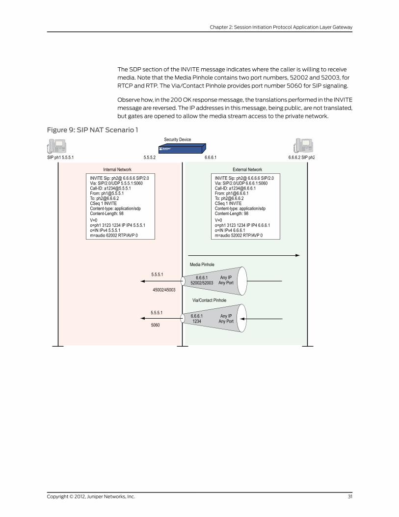
The SDP section of the INVITE message indicates where the caller is willing to receive
media. Note that the Media Pinhole contains two port numbers, 52002 and 52003, for
RTCP and RTP. The Via/Contact Pinhole provides port number 5060 for SIP signaling.
Observe how, in the 200 OK response message, the translations performed in the INVITE
message are reversed. The IP addresses in this message, being public, are not translated,
but gates are opened to allow the media stream access to the private network.
Figure 9: SIP NAT Scenario 1
31Copyright © 2012, Juniper Networks, Inc.
Chapter 2: Session Initiation Protocol Application Layer Gateway

Figure 10: SIP NAT Scenario 2
Examples
This section contains the following sample scenarios:
• Incoming SIP Call Support Using the SIP Registrar on page 32
• Example: Incoming Call with MIP on page 38
• Example: Proxy in the Private Zone on page 40
• Example: Proxy in the Public Zone on page 42
• Example: Three-Zone, Proxy in the DMZ on page 44
• Example: Untrust Intrazone on page 48
• Example: Trust Intrazone on page 51
• Example: Full-Mesh VPN for SIP on page 53
Incoming SIP Call Support Using the SIP Registrar
SIP registration provides a discovery capability by which SIP proxies and location servers
are able to identify the location or locations where users want to be contacted. A user
registers one or more contact locations by sending a REGISTER message to the registrar.
Copyright © 2012, Juniper Networks, Inc.32
Voice-over-Internet Protocol
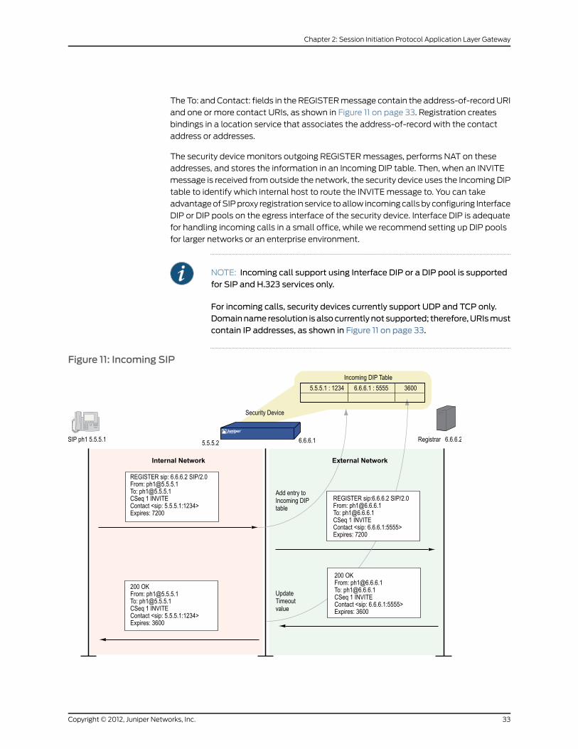
The To: and Contact: fields in the REGISTER message contain the address-of-record URI
and one or more contact URIs, as shown in Figure 11 on page 33. Registration creates
bindings in a location service that associates the address-of-record with the contact
address or addresses.
The security device monitors outgoing REGISTER messages, performs NAT on these
addresses, and stores the information in an Incoming DIP table. Then, when an INVITE
message is received from outside the network, the security device uses the Incoming DIP
table to identify which internal host to route the INVITE message to. You can take
advantage of SIP proxy registration service to allow incoming calls by configuring Interface
DIP or DIP pools on the egress interface of the security device. Interface DIP is adequate
for handling incoming calls in a small office, while we recommend setting up DIP pools
for larger networks or an enterprise environment.
NOTE: Incoming call support using Interface DIP or a DIP pool is supportedfor SIP and H.323 services only.
For incoming calls, security devices currently support UDP and TCP only.Domainname resolution isalsocurrentlynot supported; therefore,URIsmustcontain IP addresses, as shown in Figure 11 on page 33.
Figure 11: Incoming SIP
33Copyright © 2012, Juniper Networks, Inc.
Chapter 2: Session Initiation Protocol Application Layer Gateway

Example: Incoming Call (Interface DIP)
In this example, phone1 is on the ethernet1 interface in the Trust zone, and phone2 and
the proxy server are on the ethernet3 interface in the Untrust zone. You set Interface DIP
on the ethernet3 interface to do NAT on incoming calls, then create a policy permitting
SIP traffic from the Untrust zone to the Trust zone and reference that DIP in the policy.
You also create a policy that permits SIP traffic from the Trust to the Untrust zone using
NAT Source. This enables phone1 in the Trust zone to register with the proxy in the Untrust
zone. For an explanation of how incoming DIP works with the SIP registration service,
see “Examples” on page 32.
Figure 12: Incoming Call with Interface DIP on ethernet3 Interface
WebUI
1. Interfaces
Network > Interfaces > Edit (for ethernet1): Enter the following, then click Apply:
Zone Name: TrustStatic IP: (select this option when present)IP Address/Netmask: 10.1.1.1/24Enter the following, then clickOK:Interface Mode: NAT
Network > Interfaces > Edit (for ethernet3): Enter the following, then click OK:
Zone Name: UntrustStatic IP: (select this option when present)IP Address/Netmask: 1.1.1.1/24Interface Mode: Route
2. Addresses
Policy > Policy Elements > Addresses > List > New: Enter the following, then clickOK:
Address Name: phone1IP Address/Domain Name:IP/Netmask: (select), 10.1.1.3/24
Zone: Trust
Policy > Policy Elements > Addresses > List > New: Enter the following, then clickOK:
Address Name: phone2IP Address/Domain Name:
Copyright © 2012, Juniper Networks, Inc.34
Voice-over-Internet Protocol
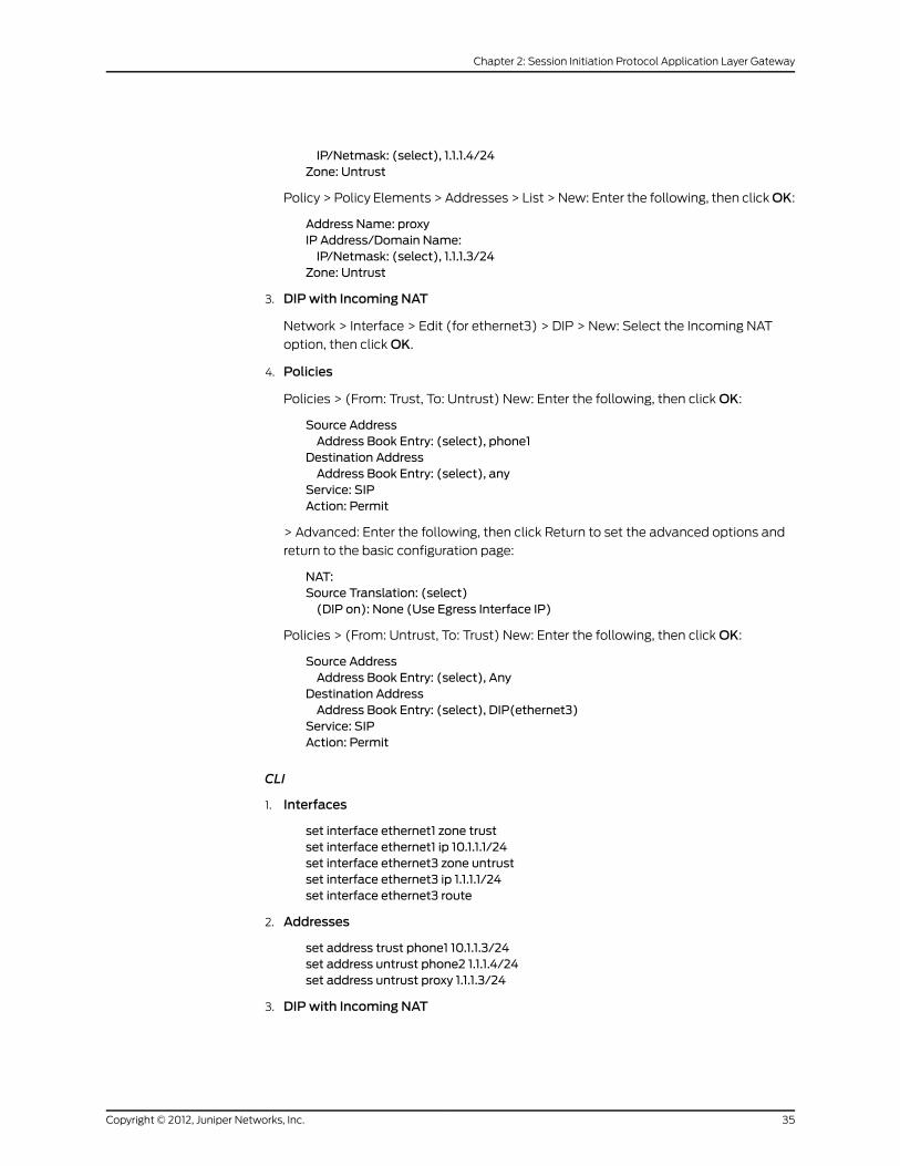
IP/Netmask: (select), 1.1.1.4/24Zone: Untrust
Policy > Policy Elements > Addresses > List > New: Enter the following, then clickOK:
Address Name: proxyIP Address/Domain Name:IP/Netmask: (select), 1.1.1.3/24
Zone: Untrust
3. DIPwith Incoming NAT
Network > Interface > Edit (for ethernet3) > DIP > New: Select the Incoming NAT
option, then click OK.
4. Policies
Policies > (From: Trust, To: Untrust) New: Enter the following, then click OK:
Source AddressAddress Book Entry: (select), phone1
Destination AddressAddress Book Entry: (select), any
Service: SIPAction: Permit
> Advanced: Enter the following, then click Return to set the advanced options and
return to the basic configuration page:
NAT:Source Translation: (select)(DIP on): None (Use Egress Interface IP)
Policies > (From: Untrust, To: Trust) New: Enter the following, then click OK:
Source AddressAddress Book Entry: (select), Any
Destination AddressAddress Book Entry: (select), DIP(ethernet3)
Service: SIPAction: Permit
CLI
1. Interfaces
set interface ethernet1 zone trustset interface ethernet1 ip 10.1.1.1/24set interface ethernet3 zone untrustset interface ethernet3 ip 1.1.1.1/24set interface ethernet3 route
2. Addresses
set address trust phone1 10.1.1.3/24set address untrust phone2 1.1.1.4/24set address untrust proxy 1.1.1.3/24
3. DIPwith Incoming NAT
35Copyright © 2012, Juniper Networks, Inc.
Chapter 2: Session Initiation Protocol Application Layer Gateway
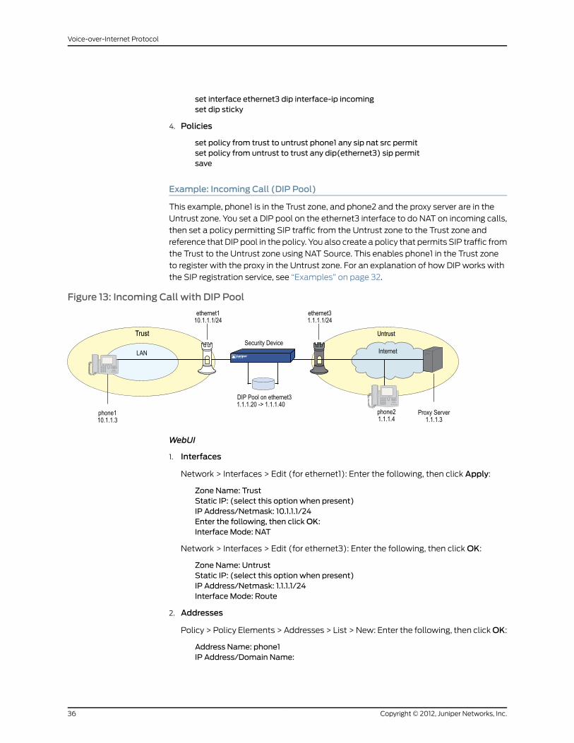
set interface ethernet3 dip interface-ip incomingset dip sticky
4. Policies
set policy from trust to untrust phone1 any sip nat src permitset policy from untrust to trust any dip(ethernet3) sip permitsave
Example: Incoming Call (DIP Pool)
This example, phone1 is in the Trust zone, and phone2 and the proxy server are in the
Untrust zone. You set a DIP pool on the ethernet3 interface to do NAT on incoming calls,
then set a policy permitting SIP traffic from the Untrust zone to the Trust zone and
reference that DIP pool in the policy. You also create a policy that permits SIP traffic from
the Trust to the Untrust zone using NAT Source. This enables phone1 in the Trust zone
to register with the proxy in the Untrust zone. For an explanation of how DIP works with
the SIP registration service, see “Examples” on page 32.
Figure 13: Incoming Call with DIP Pool
WebUI
1. Interfaces
Network > Interfaces > Edit (for ethernet1): Enter the following, then click Apply:
Zone Name: TrustStatic IP: (select this option when present)IP Address/Netmask: 10.1.1.1/24Enter the following, then clickOK:Interface Mode: NAT
Network > Interfaces > Edit (for ethernet3): Enter the following, then click OK:
Zone Name: UntrustStatic IP: (select this option when present)IP Address/Netmask: 1.1.1.1/24Interface Mode: Route
2. Addresses
Policy > Policy Elements > Addresses > List > New: Enter the following, then clickOK:
Address Name: phone1IP Address/Domain Name:
Copyright © 2012, Juniper Networks, Inc.36
Voice-over-Internet Protocol
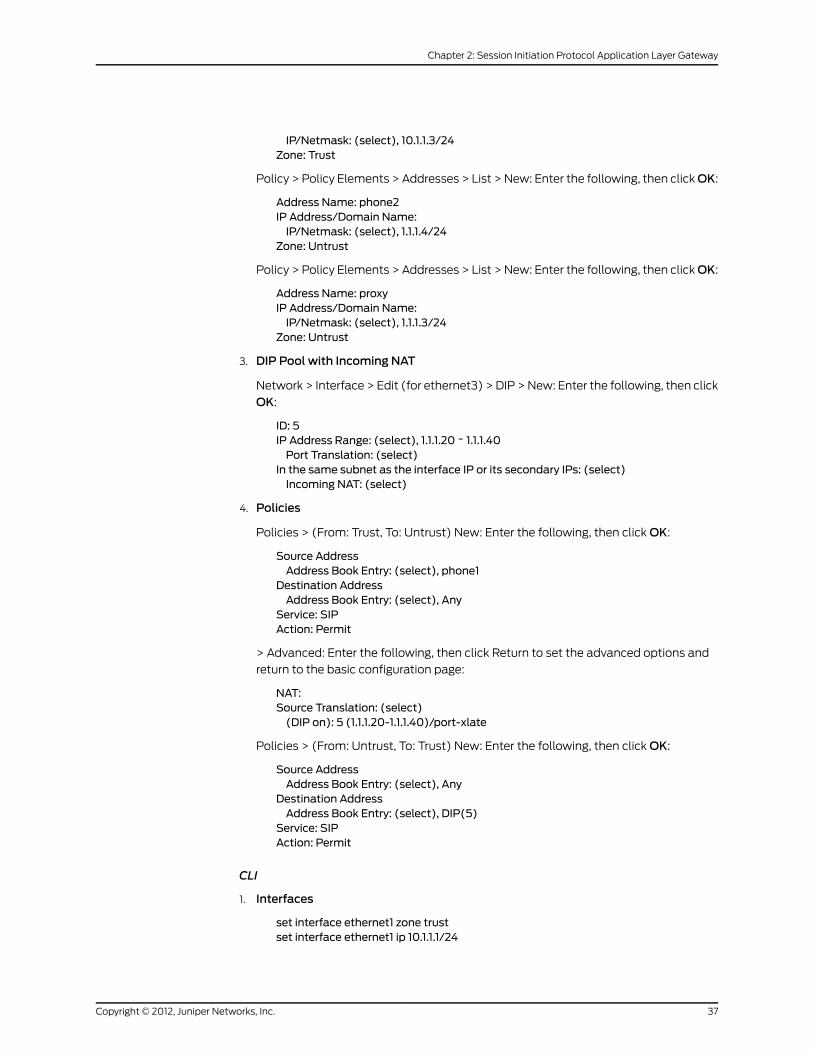
IP/Netmask: (select), 10.1.1.3/24Zone: Trust
Policy > Policy Elements > Addresses > List > New: Enter the following, then clickOK:
Address Name: phone2IP Address/Domain Name:IP/Netmask: (select), 1.1.1.4/24
Zone: Untrust
Policy > Policy Elements > Addresses > List > New: Enter the following, then clickOK:
Address Name: proxyIP Address/Domain Name:IP/Netmask: (select), 1.1.1.3/24
Zone: Untrust
3. DIP Pool with Incoming NAT
Network > Interface > Edit (for ethernet3) > DIP > New: Enter the following, then click
OK:
ID: 5IP Address Range: (select), 1.1.1.20 ~ 1.1.1.40Port Translation: (select)
In the same subnet as the interface IP or its secondary IPs: (select)Incoming NAT: (select)
4. Policies
Policies > (From: Trust, To: Untrust) New: Enter the following, then click OK:
Source AddressAddress Book Entry: (select), phone1
Destination AddressAddress Book Entry: (select), Any
Service: SIPAction: Permit
> Advanced: Enter the following, then click Return to set the advanced options and
return to the basic configuration page:
NAT:Source Translation: (select)(DIP on): 5 (1.1.1.20-1.1.1.40)/port-xlate
Policies > (From: Untrust, To: Trust) New: Enter the following, then click OK:
Source AddressAddress Book Entry: (select), Any
Destination AddressAddress Book Entry: (select), DIP(5)
Service: SIPAction: Permit
CLI
1. Interfaces
set interface ethernet1 zone trustset interface ethernet1 ip 10.1.1.1/24
37Copyright © 2012, Juniper Networks, Inc.
Chapter 2: Session Initiation Protocol Application Layer Gateway
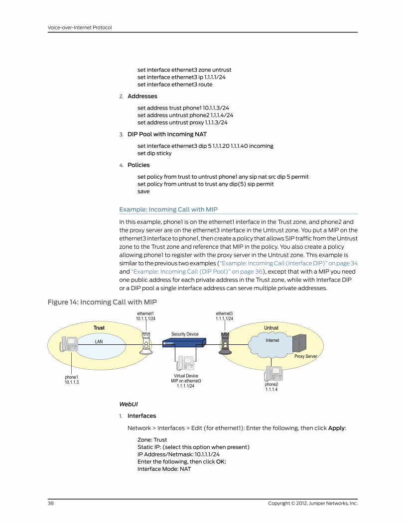
set interface ethernet3 zone untrustset interface ethernet3 ip 1.1.1.1/24set interface ethernet3 route
2. Addresses
set address trust phone1 10.1.1.3/24set address untrust phone2 1.1.1.4/24set address untrust proxy 1.1.1.3/24
3. DIP Pool with Incoming NAT
set interface ethernet3 dip 5 1.1.1.20 1.1.1.40 incomingset dip sticky
4. Policies
set policy from trust to untrust phone1 any sip nat src dip 5 permitset policy from untrust to trust any dip(5) sip permitsave
Example: Incoming Call with MIP
In this example, phone1 is on the ethernet1 interface in the Trust zone, and phone2 and
the proxy server are on the ethernet3 interface in the Untrust zone. You put a MIP on the
ethernet3 interface to phone1, then create a policy that allows SIP traffic from the Untrust
zone to the Trust zone and reference that MIP in the policy. You also create a policy
allowing phone1 to register with the proxy server in the Untrust zone. This example is
similar to the previous two examples (“Example: Incoming Call (Interface DIP)” on page 34
and “Example: Incoming Call (DIP Pool)” on page 36), except that with a MIP you need
one public address for each private address in the Trust zone, while with Interface DIP
or a DIP pool a single interface address can serve multiple private addresses.
Figure 14: Incoming Call with MIP
WebUI
1. Interfaces
Network > Interfaces > Edit (for ethernet1): Enter the following, then click Apply:
Zone: TrustStatic IP: (select this option when present)IP Address/Netmask: 10.1.1.1/24Enter the following, then clickOK:Interface Mode: NAT
Copyright © 2012, Juniper Networks, Inc.38
Voice-over-Internet Protocol
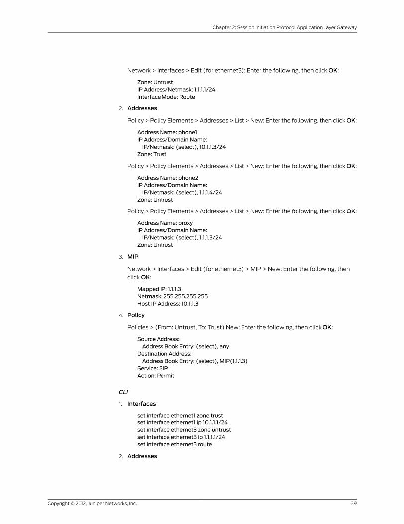
Network > Interfaces > Edit (for ethernet3): Enter the following, then click OK:
Zone: UntrustIP Address/Netmask: 1.1.1.1/24Interface Mode: Route
2. Addresses
Policy > Policy Elements > Addresses > List > New: Enter the following, then clickOK:
Address Name: phone1IP Address/Domain Name:IP/Netmask: (select), 10.1.1.3/24
Zone: Trust
Policy > Policy Elements > Addresses > List > New: Enter the following, then clickOK:
Address Name: phone2IP Address/Domain Name:IP/Netmask: (select), 1.1.1.4/24
Zone: Untrust
Policy > Policy Elements > Addresses > List > New: Enter the following, then clickOK:
Address Name: proxyIP Address/Domain Name:IP/Netmask: (select), 1.1.1.3/24
Zone: Untrust
3. MIP
Network > Interfaces > Edit (for ethernet3) > MIP > New: Enter the following, then
click OK:
Mapped IP: 1.1.1.3Netmask: 255.255.255.255Host IP Address: 10.1.1.3
4. Policy
Policies > (From: Untrust, To: Trust) New: Enter the following, then click OK:
Source Address:Address Book Entry: (select), any
Destination Address:Address Book Entry: (select), MIP(1.1.1.3)
Service: SIPAction: Permit
CLI
1. Interfaces
set interface ethernet1 zone trustset interface ethernet1 ip 10.1.1.1/24set interface ethernet3 zone untrustset interface ethernet3 ip 1.1.1.1/24set interface ethernet3 route
2. Addresses
39Copyright © 2012, Juniper Networks, Inc.
Chapter 2: Session Initiation Protocol Application Layer Gateway

set address trust phone1 10.1.1.3/24set address untrust phone2 1.1.1.4/24set address untrust proxy 1.1.1.3/24
3. MIP
set interface ethernet3mip 1.1.1.3 host 10.1.1.3
4. Policy
set policy from untrust to trust anymip(1.1.1.3) sip permitsave
Example: Proxy in the Private Zone
In this example, phone1 and the SIP proxy server are on the ethernet1 interface in the
Trust (private) zone, and phone2 is on the ethernet3 interface in the Untrust zone. You
put a MIP on the ethernet3 interface to the proxy server to allow phone2 to register with
the proxy, then create a policy allowing SIP traffic from the Untrust to the Trust zone and
reference that MIP in the policy. You also create a policy from the Trust to the Untrust
zone to allow phone1 to call out.
Figure 15: Proxy in the Private Zone
WebUI
1. Interfaces
Network > Interfaces > Edit (for ethernet1): Enter the following, then click OK:
Zone: TrustStatic IP: (select this option when present)IP Address/Netmask: 10.1.1.1/24Enter the following, then click OK:Interface Mode: NAT
Network > Interfaces > Edit (for ethernet3): Enter the following, then click OK:
Zone: UntrustIP Address/Netmask: 1.1.1.1/24Interface Mode: Route
2. Addresses
Policy > Policy Elements > Addresses > List > New: Enter the following, then clickOK:
Address Name: phone1IP Address/Domain Name:
Copyright © 2012, Juniper Networks, Inc.40
Voice-over-Internet Protocol

IP/Netmask: (select), 10.1.1.3/24Zone: Trust
Policy > Policy Elements > Addresses > List > New: Enter the following, then clickOK:
Address Name: phone2IP Address/Domain Name:IP/Netmask: (select), 1.1.1.4/24
Zone: Untrust
Policy > Policy Elements > Addresses > List > New: Enter the following, then clickOK:
Address Name: proxyIP Address/Domain Name:IP/Netmask: (select), 10.1.1.4/24
Zone: Trust
3. MIP
Network > Interfaces > Edit (for loopback.3) > MIP > New: Enter the following, then
click OK:
Mapped IP: 1.1.1.2Netmask: 255.255.255.255Host IP Address: 10.1.1.4Host Virtual Router Name: trust-vr
4. Policies
Policies > (From: Trust, To: Untrust) New: Enter the following, then click OK:
Source Address:Address Book Entry: (select) any
Destination Address:Address Book Entry: (select) phone2
Service: SIPAction: Permit
> Advanced: Enter the following, then click Return to set the advanced options and
return to the basic configuration page:
NAT:Source Translation: (select)(DIP on): None (Use Egress Interface IP)
Policies > (From: Untrust, To: Trust) New: Enter the following, then click OK:
Source Address:Address Book Entry: (select), phone2
Destination Address:Address Book Entry: (select), MIP(1.1.1.2)
Service: SIPAction: Permit
CLI
1. Interfaces
set interface ethernet1 zone trustset interface ethernet1 ip 10.1.1.1/24set interface ethernet3 zone untrust
41Copyright © 2012, Juniper Networks, Inc.
Chapter 2: Session Initiation Protocol Application Layer Gateway
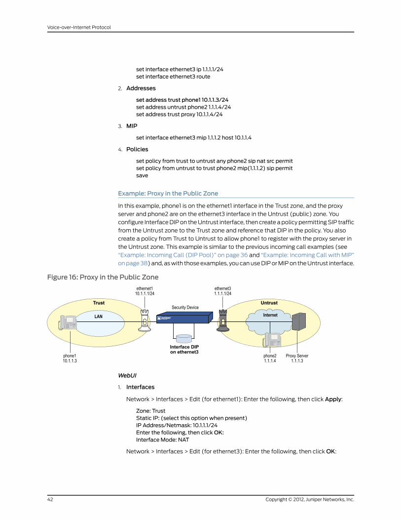
set interface ethernet3 ip 1.1.1.1/24set interface ethernet3 route
2. Addresses
set address trust phone1 10.1.1.3/24set address untrust phone2 1.1.1.4/24set address trust proxy 10.1.1.4/24
3. MIP
set interface ethernet3mip 1.1.1.2 host 10.1.1.4
4. Policies
set policy from trust to untrust any phone2 sip nat src permitset policy from untrust to trust phone2mip(1.1.1.2) sip permitsave
Example: Proxy in the Public Zone
In this example, phone1 is on the ethernet1 interface in the Trust zone, and the proxy
server and phone2 are on the ethernet3 interface in the Untrust (public) zone. You
configure Interface DIP on the Untrust interface, then create a policy permitting SIP traffic
from the Untrust zone to the Trust zone and reference that DIP in the policy. You also
create a policy from Trust to Untrust to allow phone1 to register with the proxy server in
the Untrust zone. This example is similar to the previous incoming call examples (see
“Example: Incoming Call (DIP Pool)” on page 36 and “Example: Incoming Call with MIP”
on page 38) and, as with those examples, you can use DIP or MIP on the Untrust interface.
Figure 16: Proxy in the Public Zone
WebUI
1. Interfaces
Network > Interfaces > Edit (for ethernet1): Enter the following, then click Apply:
Zone: TrustStatic IP: (select this option when present)IP Address/Netmask: 10.1.1.1/24Enter the following, then clickOK:Interface Mode: NAT
Network > Interfaces > Edit (for ethernet3): Enter the following, then click OK:
Copyright © 2012, Juniper Networks, Inc.42
Voice-over-Internet Protocol

Zone: UntrustIP Address/Netmask: 1.1.1.1/24Interface Mode: Route
2. Addresses
Policy > Policy Elements > Addresses > List > New: Enter the following, then clickOK:
Address Name: phone1IP Address/Domain Name:IP/Netmask: (select), 10.1.1.3/24
Zone: Trust
Policy > Policy Elements > Addresses > List > New: Enter the following, then clickOK:
Address Name: phone2IP Address/Domain Name:IP/Netmask: (select), 1.1.1.4/24
Zone: Untrust
Policy > Policy Elements > Addresses > List > New: Enter the following, then clickOK:
Address Name: proxyIP Address/Domain Name:IP/Netmask: (select), 1.1.1.3/24
Zone: Untrust
3. Interface DIP
Network > Interface > Edit (for ethernet3) > DIP: Select the Incoming NAT check box.
4. Policies
Policies > (From: Trust, To: Untrust) New: Enter the following, then click OK:
Source Address:Address Book Entry: (select) phone1
Destination Address:Address Book Entry: (select) Any
Service: SIPAction: Permit
> Advanced: Enter the following, then click Return to set the advanced options and
return to the basic configuration page:
NAT:Source Translation: (select)(DIP on): None (Use Egress Interface IP)
Policies > (From: Untrust, To: Trust) New: Enter the following, then click OK:
Source Address:Address Book Entry: (select), Any
Destination Address:Address Book Entry: (select), DIP(ethernet3)
Service: SIPAction: Permit
CLI
1. Interfaces
43Copyright © 2012, Juniper Networks, Inc.
Chapter 2: Session Initiation Protocol Application Layer Gateway
set interface ethernet1 zone trustset interface ethernet1 ip 10.1.1.1/24set interface ethernet3 zone untrustset interface ethernet3 ip 1.1.1.1/24
2. Addresses
set address trust phone1 10.1.1.3/24set address untrust phone2 1.1.1.4/24set address untrust proxy 1.1.1.3/24
3. Interface DIP
set interface ethernet3 dip interface-ip incoming
4. Policies
set policy from trust to untrust phone1 any sip nat src permitset policy from untrust to trust any dip(ethernet3) sip permitsave
Example: Three-Zone, Proxy in the DMZ
In this example, phone1 is on the ethernet1 interface in the Trust zone, phone2 is on the
ethernet3 interface in the Untrust zone, and the proxy server is on the ethernet2 interface
in the DMZ. You put a MIP on the ethernet2 interface to phone1 in the Trust zone, and
create a policy from the DMZ to the Trust zone and reference that MIP in the policy. In
fact, with three zones, you need to create bidirectional policies between each of the
zones. The arrows in Figure 17 on page 45 show the flow of SIP signaling traffic when
phone2 in the Untrust zone places a call to phone1 in the Trust zone. After the session is
initiated, the media flows directly between phone1 and phone2.
Copyright © 2012, Juniper Networks, Inc.44
Voice-over-Internet Protocol
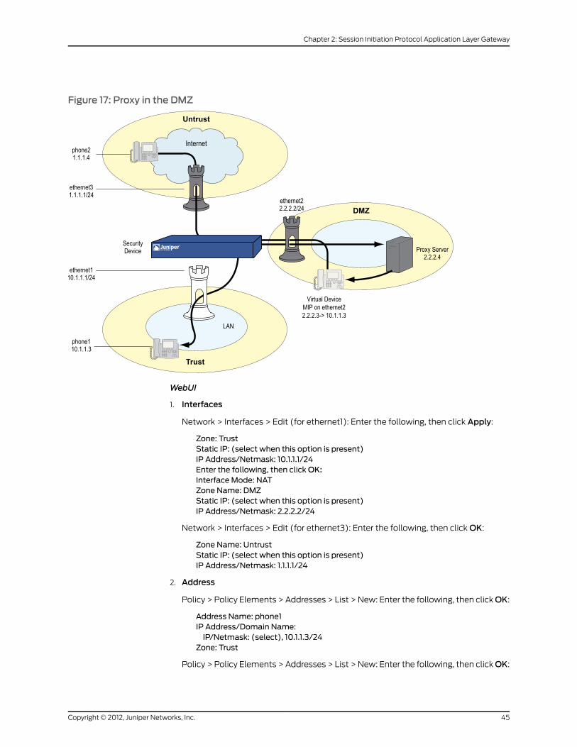
Figure 17: Proxy in the DMZ
WebUI
1. Interfaces
Network > Interfaces > Edit (for ethernet1): Enter the following, then click Apply:
Zone: TrustStatic IP: (select when this option is present)IP Address/Netmask: 10.1.1.1/24Enter the following, then clickOK:Interface Mode: NATZone Name: DMZStatic IP: (select when this option is present)IP Address/Netmask: 2.2.2.2/24
Network > Interfaces > Edit (for ethernet3): Enter the following, then click OK:
Zone Name: UntrustStatic IP: (select when this option is present)IP Address/Netmask: 1.1.1.1/24
2. Address
Policy > Policy Elements > Addresses > List > New: Enter the following, then clickOK:
Address Name: phone1IP Address/Domain Name:IP/Netmask: (select), 10.1.1.3/24
Zone: Trust
Policy > Policy Elements > Addresses > List > New: Enter the following, then clickOK:
45Copyright © 2012, Juniper Networks, Inc.
Chapter 2: Session Initiation Protocol Application Layer Gateway

Address Name: phone2IP Address/Domain Name:IP/Netmask: (select), 1.1.1.4/24
Zone: Untrust
Policy > Policy Elements > Addresses > List > New: Enter the following, then clickOK:
Address Name: proxyIP Address/Domain Name:IP/Netmask: (select), 2.2.2.4/24
Zone: DMZ
3. MIP
Network > Interfaces > Edit (for ethernet2) > MIP > New: Enter the following, then
click OK:
Mapped IP: 2.2.2.3Netmask: 255.255.255.255Host IP Address: 10.1.1.3
4. Policies
Policies > (From: Trust, To: DMZ) New: Enter the following, then click OK:
Source Address:Address Book Entry: (select), phone1
Destination Address:Address Book Entry: (select), proxy
Service: SIPAction: Permit
> Advanced: Enter the following, then click Return to set the advanced options and
return to the basic configuration page:
NAT:Source Translation: Enable(DIP on): None (Use Egress Interface IP)
Policies > (From: DMZ, To: Untrust) New: Enter the following, then click OK:
Source Address:Address Book Entry: (select), proxy
Destination Address:Address Book Entry: (select), phone2
Service: SIPAction: Permit
Policies > (From: Untrust, To: Trust) New: Enter the following, then click OK:
Source Address:Address Book Entry: (select), phone2
Destination Address:Address Book Entry: (select), phone1
Service: SIPAction: Permit
Policies > (From: Untrust, To: DMZ) New: Enter the following, then click OK:
Source Address:Address Book Entry: (select), phone2
Copyright © 2012, Juniper Networks, Inc.46
Voice-over-Internet Protocol

Destination Address:Address Book Entry: (select), proxy
Service: SIPAction: Permit
Policies > (From: DMZ, To: Trust) New: Enter the following, then click OK:
Source Address:Address Book Entry: (select), proxy
Destination Address:Address Book Entry: (select), MIP(2.2.2.3)
Service: SIPAction: Permit
Policies > (From: Trust, To: Untrust) New: Enter the following, then click OK:
Source Address:Address Book Entry: (select), phone1
Destination Address:Address Book Entry: (select), phone2
Service: SIPAction: Permit
> Advanced: Enter the following, then click Return to set the advanced options and
return to the basic configuration page:
NAT:Source Translation: Enable(DIP on): None (Use Egress Interface IP)
CLI
1. Interfaces
set interface ethernet1 zone trustset interface ethernet1 ip 10.1.1.1/24set interface ethernet3 zone untrustset interface ethernet3 ip 1.1.1.1/24set interface ethernet3 routeset interface ethernet2 zone dmzset interface ethernet2 ip 2.2.2.2/24set interface ethernet2 route
2. Addresses
set address trust phone1 10.1.1.3/24set address untrust phone2 1.1.1.4/24set address dmz proxy 2.2.2.4
3. MIP
set interface2mip 2.2.2.3 host 10.1.1.3
4. Policies
set policy from trust to dmz phone1 proxy sip nat src permitset policy from dmz to untrust proxy phone2 sip permitset policy from untrust to trust phone2 phone1 sip permitset policy from untrust to dmz phone2 proxy sip permitset policy from dmz to trust proxymip(2.2.2.3) sip permit
47Copyright © 2012, Juniper Networks, Inc.
Chapter 2: Session Initiation Protocol Application Layer Gateway

set policy from trust to untrust phone1 phone2 sip nat src permitsave
Example: Untrust Intrazone
In this example, phone1 is on the ethernet4 interface in the Untrust zone, phone2 is in a
subnet on the ethernet3 interface in the Untrust zone, and the proxy server is on the
ethernet1 interface in the Trust zone. To allow intrazone SIP traffic between the two
phones in the Untrust zone, you create a loopback interface, add ethernet3 and ethernet4
to a loopback group, then put a MIP on the loopback interface to the IP address of the
proxy server. Creating a loopback interface enables you to use a single MIP for the proxy
server in the Trust zone. Because blocking is on by default in the Untrust zone, you must
also turn off blocking to allow intrazone communication. For more information about
using loopback interfaces, see MIP and Loopback Interface.
Figure 18: Untrust Intrazone
WebUI
1. Interfaces
Network > Interfaces > Edit (for ethernet1): Enter the following, then click Apply:
Copyright © 2012, Juniper Networks, Inc.48
Voice-over-Internet Protocol

Zone: TrustStatic IP: (select when this option is present)IP Address/Netmask: 10.1.1.1/24
Enter the following, then click OK:
Interface Mode: NAT
Network > Interfaces > Edit (for ethernet4): Enter the following, then click OK:
Zone: UntrustStatic IP: (select when this option is present)IP Address/Netmask: 1.1.1.1/24
Network > Interfaces > Edit (for ethernet3): Enter the following, then click OK:
Zone: UntrustStatic IP: (select when this option is present)IP Address/Netmask: 1.1.2.1/24
Network > Interfaces > New Loopback IF: Enter the following, then click OK:
Interface Name: loopback.1Zone: Untrust (trust-vr)IP Address/Netmask: 1.1.4.1/24
2. Addresses
Policy > Policy Elements > Addresses > List > New: Enter the following, then clickOK:
Address Name: proxyIP Address/Domain Name:IP/Netmask: (select), 10.1.1.5/32
Zone: Trust
Policy > Policy Elements > Addresses > List > New: Enter the following, then clickOK:
Address Name: phone1IP Address/Domain Name:IP/Netmask: (select), 1.1.1.4/32
Zone: Untrust
Policy > Policy Elements > Addresses > List > New: Enter the following, then clickOK:
Address Name: phone2IP Address/Domain Name:IP/Netmask: (select), 1.1.2.4/32
Zone: Untrust
3. Loopback Group
Network > Interfaces > Edit (for ethernet3): Enter the following, then click OK:
Asmember of loopback group: (select) loopback.1Zone Name: Untrust
Network > Interfaces > Edit (for ethernet4): Enter the following, then click OK:
Asmember of loopback group: (select) loopback.1Zone Name: Untrust
4. MIP
49Copyright © 2012, Juniper Networks, Inc.
Chapter 2: Session Initiation Protocol Application Layer Gateway

Network > Interfaces > Edit (for loopback.1) > MIP > New: Enter the following, then
click OK:
Mapped IP: 1.1.4.5Netmask: 255.255.255.255Host IP Address: 10.1.1.5Host Virtual Router Name: trust-vr
5. Blocking
Network > Zones > Edit (for Untrust): Enter the following, then click OK:
Block Intra-Zone Traffic: (clear)
6. Policies
Policies > (From: Trust, To: Untrust) New: Enter the following, then click OK:
Source Address:Address Book Entry: (select), proxy
Destination Address:Address Book Entry: (select), Any
Service: SIPAction: Permit
> Advanced: Enter the following, then click Return to set the advanced options and
return to the basic configuration page:
NAT:Source Translation: Enable(DIP on): None (Use Egress Interface IP)
Policies > (From: Untrust, To: Trust) New: Enter the following, then click OK:
Source Address:Address Book Entry: (select), Any
Destination Address:Address Book Entry: (select), MIP(1.1.4.5)
Service: SIPAction: Permit
CLI
1. Interfaces
set interface ethernet1 zone trustset interface ethernet1 ip 10.1.1.1/24set interface ethernet3 zone untrustset interface ethernet3 ip 1.1.2.1/24set interface ethernet3 routeset interface ethernet4 zone untrustset interface ethernet4 ip 1.1.1.1/24set interface ethernet4 routeset interface loopback.1 zone untrustset interface loopback.1 ip 1.1.4.1/24set interface loopback.1 route
2. Addresses
Copyright © 2012, Juniper Networks, Inc.50
Voice-over-Internet Protocol

set address trust proxy 10.1.1.5/32set address untrust phone1 1.1.1.4/32set address untrust phone2 1.1.2.4/32
3. Loopback Group
set interface ethernet3 loopback-group loopback.1set interface ethernet4 loopback-group loopback.1
4. MIP
set interface loopback.1 mip 1.1.4.5 host 10.1.1.5
5. Blocking
unset zone untrust block
6. Policies
set policy from trust to untrust proxy any sip nat src permitset policy from untrust to trust anymip(1.1.4.5) sip permitsave
Example: Trust Intrazone
In this example, phone1 is on the ethernet1 interface in the Trust zone, phone 2 is on the
ethernet2 interface in a subnet in the Trust zone, and the proxy server is on the ethernet3
interface in the Untrust zone. To allow both phones in the Trust zone to communicate
with each other, you configure Interface DIP on the ethernet3 interface to allow them to
contact the proxy server, then set policies to allow bidirectional SIP traffic between the
Trust and the Untrust zones. Blocking is off by default in the Trust zone (as it is in custom
zones you define).
Figure 19: Trust Intrazone
WebUI
1. Interfaces
Network > Interfaces > Edit (for ethernet1): Enter the following, then click Apply:
Zone: TrustStatic IP: (select when this option is present)IP Address/Netmask: 10.1.1.1/24Enter the following, then clickOK:Interface Mode: NAT
Network > Interfaces > Edit (for ethernet2): Enter the following, then click Apply:
51Copyright © 2012, Juniper Networks, Inc.
Chapter 2: Session Initiation Protocol Application Layer Gateway
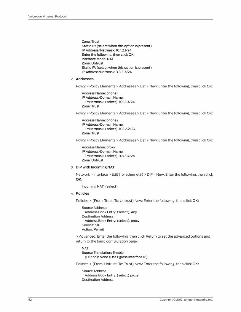
Zone: TrustStatic IP: (select when this option is present)IP Address/Netmask: 10.1.2.1/24Enter the following, then clickOK:Interface Mode: NATZone: UntrustStatic IP: (select when this option is present)IP Address/Netmask: 3.3.3.3/24
2. Addresses
Policy > Policy Elements > Addresses > List > New: Enter the following, then clickOK:
Address Name: phone1IP Address/Domain Name:IP/Netmask: (select), 10.1.1.3/24
Zone: Trust
Policy > Policy Elements > Addresses > List > New: Enter the following, then clickOK:
Address Name: phone2IP Address/Domain Name:IP/Netmask: (select), 10.1.2.2/24
Zone: Trust
Policy > Policy Elements > Addresses > List > New: Enter the following, then clickOK:
Address Name: proxyIP Address/Domain Name:IP/Netmask: (select), 3.3.3.4/24
Zone: Untrust
3. DIPwith Incoming NAT
Network > Interface > Edit (for ethernet3) > DIP > New: Enter the following, then click
OK:
Incoming NAT: (select)
4. Policies
Policies > (From: Trust, To: Untrust) New: Enter the following, then click OK:
Source Address:Address Book Entry: (select), Any
Destination Address:Address Book Entry: (select), proxy
Service: SIPAction: Permit
> Advanced: Enter the following, then click Return to set the advanced options and
return to the basic configuration page:
NAT:Source Translation: Enable(DIP on): None (Use Egress Interface IP)
Policies > (From: Untrust, To: Trust) New: Enter the following, then click OK:
Source AddressAddress Book Entry: (select) proxy
Destination Address
Copyright © 2012, Juniper Networks, Inc.52
Voice-over-Internet Protocol

Address Book Entry: (select) AnyService: SIPAction: Permit
> Advanced: Enter the following, then click Return to set the advanced options:
NAT:Source Translation: (select)(DIP on): None (Use Egress Interface IP)
CLI
1. Interfaces
set interface ethernet1 zone trustset interface ethernet1 ip 10.1.1.1/24set interface ethernet2 zone trustset interface ethernet2 ip 10.1.2.1/24set interface ethernet2 natset interface ethernet3 zone untrustset interface ethernet3 ip 3.3.3.3/24set interface ethernet3 route
2. Addresses
set address trust phone1 10.1.1.3/24set address trust phone2 10.1.2.2/24set address untrust proxy 3.3.3.4/24
3. Interface DIP
set interface ethernet3 dip interface-ip incoming
4. Policies
set policy from trust to untrust any proxy sip nat src permitset policy from untrust to trust proxy dip(ethernet3) sip permitsave
Example: Full-Mesh VPN for SIP
In this example, the central office and two branch offices are linked by a full-mesh VPN.
Each site has a single security device. The proxy server is in the Trust zone at the Central
Office, phone1 is in the Trust zone at Branch Office One, and phone2 is in the Trust zone
at Branch Office Two. All interfaces connecting the devices are in their respective Untrust
zones. On each device, you configure two tunnels, one to each of the other devices, to
create a fully meshed network.
NOTE: The security devices used in this examplemust have at least threeindependently configurable interfaces available.
53Copyright © 2012, Juniper Networks, Inc.
Chapter 2: Session Initiation Protocol Application Layer Gateway

Figure 20: Full-Mesh VPN for SIP
WebUI (for Central)
1. Interfaces
Network > Interfaces > Edit (for ethernet2/1): Enter the following, then click Apply:
Zone: UntrustStatic IP: (select when this option is present)IP Address/Netmask: 1.1.1.1/24
Network > Interfaces > Edit (for ethernet2/2): Enter the following, then click Apply:
Zone: UntrustStatic IP: (select when this option is present)IP Address/Netmask: 1.1.2.1/24
Network > Interfaces > Edit (for ethernet2/8): Enter the following, then click Apply:
Zone: TrustStatic IP: (select when this option is present)IP Address/Netmask: 10.1.3.1/24Enter the following, then click OK:Interfacemode: route
Network > Interfaces > New Tunnel IF: Enter the following, then click Apply:
Copyright © 2012, Juniper Networks, Inc.54
Voice-over-Internet Protocol
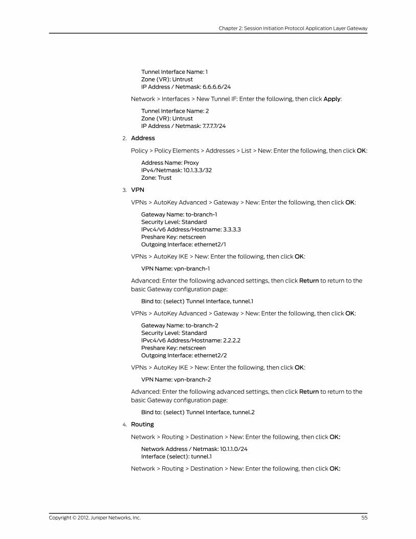
Tunnel Interface Name: 1Zone (VR): UntrustIP Address / Netmask: 6.6.6.6/24
Network > Interfaces > New Tunnel IF: Enter the following, then click Apply:
Tunnel Interface Name: 2Zone (VR): UntrustIP Address / Netmask: 7.7.7.7/24
2. Address
Policy > Policy Elements > Addresses > List > New: Enter the following, then clickOK:
Address Name: ProxyIPv4/Netmask: 10.1.3.3/32Zone: Trust
3. VPN
VPNs > AutoKey Advanced > Gateway > New: Enter the following, then click OK:
Gateway Name: to-branch-1Security Level: StandardIPvc4/v6 Address/Hostname: 3.3.3.3Preshare Key: netscreenOutgoing Interface: ethernet2/1
VPNs > AutoKey IKE > New: Enter the following, then click OK:
VPNName: vpn-branch-1
Advanced: Enter the following advanced settings, then click Return to return to the
basic Gateway configuration page:
Bind to: (select) Tunnel Interface, tunnel.1
VPNs > AutoKey Advanced > Gateway > New: Enter the following, then click OK:
Gateway Name: to-branch-2Security Level: StandardIPvc4/v6 Address/Hostname: 2.2.2.2Preshare Key: netscreenOutgoing Interface: ethernet2/2
VPNs > AutoKey IKE > New: Enter the following, then click OK:
VPNName: vpn-branch-2
Advanced: Enter the following advanced settings, then click Return to return to the
basic Gateway configuration page:
Bind to: (select) Tunnel Interface, tunnel.2
4. Routing
Network > Routing > Destination > New: Enter the following, then click OK:
Network Address / Netmask: 10.1.1.0/24Interface (select): tunnel.1
Network > Routing > Destination > New: Enter the following, then click OK:
55Copyright © 2012, Juniper Networks, Inc.
Chapter 2: Session Initiation Protocol Application Layer Gateway

Network Address / Netmask: 10.1.2.0/24Interface (select): tunnel.2
5. Policies
Policies > (From: Trust, To: Untrust) New Enter the following, then click OK:
Source Address (select) Address Book Entry: ProxyDestination Address (select) Address Book Entry: Any-IPv4Service: SIPAction: Permit
Policies > (From: Untrust, To: Trust) > New: Enter the following, then click OK:
Source Address (select) Address Book Entry: Any-IPv4Destination Address (select) Address Book Entry: ProxyService: SIPAction: Permit
CLI (for Central)
1. Interfaces
set interface ethernet2/1 zone untrustset interface ethernet2/1 ip 1.1.1.1/24set interface ethernet2/2 zone untrustset interface ethernet2/2 ip 1.1.2.1/24set interface ethernet2/8 zone trustset interface ethernet2/8 ip 10.1.3.1/24set interface ethernet2/8 routeset interface tunnel.1 zone untrustset interface tunnel.1 ip 6.6.6.6/24set interface tunnel.2 zone untrustset interface tunnel.2 ip 7.7.7.7/24
2. Address
set address trust proxy 10.1.3.3/32
3. VPN
set ike gateway to-branch-1 address 3.3.3.3 main outgoing-interface ethernet2/1preshare netscreen sec-level standardset ike gateway to-branch-2 address 2.2.2.2 main outgoing-interface ethernet2/2preshare netscreen sec-level standardset vpn vpn_branch-1 gateway to-branch-1 no-reply tunnel idletime 0 sec-levelstandardset vpn vpn-branch-1 id 1 bind interface tunnel.1set vpn vpn-branch-2 gateway to-branch-2 no-reply tunnel idletime 0 sec-levelstandardset vpn vpn-branch-2 id 2 bind interface tunnel.2
4. Routing
set route 10.1.2.0/24 interface tunnel.2set route 10.1.1.0/24 interface tunnel.1
5. Policies
Copyright © 2012, Juniper Networks, Inc.56
Voice-over-Internet Protocol

set policy from untrust to trust any proxy sip permitset policy from trust to untrust proxy any sip permitsave
WebUI (for Branch Office 1)
1. Interfaces
Network > Interfaces > Edit (for ethernet1): Enter the following, then click Apply:
Zone: TrustStatic IP: (select when this option is present)IP Address/Netmask: 10.1.1.1/24Interfacemode: NAT
Network > Interfaces > Edit (for ethernet3): Enter the following, then click Apply:
Zone: UntrustStatic IP: (select when this option is present)IP Address/Netmask: 3.3.3.3/24
Network > Interfaces > Edit (for ethernet4): Enter the following, then click Apply:
Zone: UntrustStatic IP: (select when this option is present)IP Address/Netmask: 4.4.4.4/24
Network > Interfaces > New Tunnel IF: Enter the following, then click Apply:
Tunnel Interface Name: 2Zone (VR): UntrustUnnumbered (select) Interface: ethernet3
Network > Interfaces > New Tunnel IF: Enter the following, then click Apply:
Tunnel Interface Name: 3Zone (VR): UntrustUnnumbered (select) Interface: ethernet4
2. Address
Policy > Policy Elements > Addresses > List > New: Enter the following, then clickOK:
Address Name: phone1IPv4/Netmask: 10.1.1.3/32Zone: V1-Trust
3. VPN
VPNs > AutoKey Advanced > Gateway > New: Enter the following, then click OK:
Gateway Name: to-centralSecurity Level: StandardIPvc4/v6 Address/Hostname: 1.1.2.1Preshare Key: netscreenOutgoing Interface: ethernet3
VPNs > AutoKey IKE > New: Enter the following, then click OK:
VPNName: vpn-central
Advanced: Enter the following advanced settings, then click Return to return to the
basic Gateway configuration page:
57Copyright © 2012, Juniper Networks, Inc.
Chapter 2: Session Initiation Protocol Application Layer Gateway

Bind to (select): Tunnel Interface, tunnel.1
VPNs > AutoKey Advanced > Gateway > New: Enter the following, then click OK:
Gateway Name: to-ns50Security Level: StandardIPvc4/v6 Address/Hostname: 5.5.5.5Preshare Key: netscreenOutgoing Interface: ethernet4
VPNs > AutoKey IKE > New: Enter the following, then click OK:
VPNName: vpn-ns50
Advanced: Enter the following advanced settings, then click Return to return to the
basic Gateway configuration page:
Bind to (select): Tunnel Interface, tunnel.3
4. Routing
Network > Routing > Destination > New: Enter the following, then click OK:
Network Address / Netmask: 10.1.2.0/24Interface (select): tunnel.3
Network > Routing > Destination > New: Enter the following, then click OK:
Network Address / Netmask: 10.1.3.0/24Interface (select): tunnel.1
5. Policies
Policies > (From: Trust, To: Untrust) > New: Enter the following, then click OK:
Source Address (select) Address Book Entry: phone2Destination Address (select) Address Book Entry: Any-IPv4Service: SIPAction: Permit
Policies > (From: Untrust, To: Trust) > New: Enter the following, then click OK:
Source Address (select) Address Book Entry: Any-IPv4Destination Address (select) Address Book Entry: phone2Service: SIPAction: Permit
CLI (for Branch Office 1)
1. Interfaces
set interface ethernet1 zone trustset interface ethernet1 ip 10.1.1.1/24set interface ethernet1 routeset interface ethernet3 zone untrustset interface ethernet3 ip 3.3.3.3/24set interface ethernet4 zone untrustset interface ethernet4 ip 4.4.4.4/24set interface tunnel.2 zone untrustset interface tunnel.2 ip unnumbered interface ethernet3set interface tunnel.3 zone untrustset interface tunnel.3 ip unnumbered interface ethernet4
Copyright © 2012, Juniper Networks, Inc.58
Voice-over-Internet Protocol

2. Address
set address trust phone1 10.1.1.3/32
3. VPN
set ike gateway to-central address 1.1.1.1 main outgoing-interface ethernet3 presharenetscreen sec-level standardset ike gateway to-ns50 address 5.5.5.5 main outgoing-interface ethernet4 presharenetscreen sec-level standardset vpn vpncentral gateway to-central no-replay tunnel idletime0 sec-level standardset vpn vpncentral bind interface tunnel.1set vpn vpn-ns50 gateway to-ns50 no-replay tunnel idletime 0 sec-level standardset vpn vpn-ns50 bind interface tunnel.3
4. Routes
set route 10.1.2.0/24 interface tunnel.3set route 10.1.3.0/24 interface tunnel.1
5. Policies
set policy from trust to untrust phone1 any sip permitset policy from untrust to trust any phone1 sip permitsave
WebUI (for Branch Office 2)
1. Interfaces
Network > Interfaces > Edit (for ethernet1): Enter the following, then click Apply:
Zone: TrustStatic IP: (select when this option is present)IP Address/Netmask: 10.1.2.1/24Enter the following, then clickOK:Interfacemode: NAT
Network > Interfaces > Edit (for ethernet3): Enter the following, then click Apply:
Zone: UntrustStatic IP: (select when this option is present)IP Address/Netmask: 2.2.2.2/24
Network > Interfaces > Edit (for ethernet4): Enter the following, then click Apply:
Zone: UntrustStatic IP: (select when this option is present)IP Address/Netmask: 4.4.4.4/24
Network > Interfaces > New Tunnel IF: Enter the following, then click Apply:
Tunnel Interface Name: 2Zone (VR): UntrustUnnumbered (select) Interface: ethernet3
Network > Interfaces > New Tunnel IF: Enter the following, then click Apply:
Tunnel Interface Name: 3Zone (VR): Untrust
Unnumbered (select) Interface: ethernet4
59Copyright © 2012, Juniper Networks, Inc.
Chapter 2: Session Initiation Protocol Application Layer Gateway

2. Address
Policy > Policy Elements > Addresses > List > New: Enter the following, then clickOK:
Address Name: phone2IPv4/Netmask: 10.1.2.3/32Zone: Trust
3. VPN
VPNs > AutoKey Advanced > Gateway > New: Enter the following, then click OK:
Gateway Name: to-centralSecurity Level: StandardIPvc4/v6 Address/Hostname: 1.1.2.1Preshare Key: netscreenOutgoing Interface: ethernet3
VPNs > AutoKey IKE > New: Enter the following, then click OK:
VPNName: vpn-central
Advanced: Enter the following advanced settings, then click Return to return to the
basic Gateway configuration page:
Bind to (select): Tunnel Interface, tunnel.2
VPNs > AutoKey Advanced > Gateway > New: Enter the following, then click OK:
Gateway Name: to-ns50Security Level: StandardIPvc4/v6 Address/Hostname: 4.4.4.4Preshare Key: netscreenOutgoing Interface: ethernet4
VPNs > AutoKey IKE > New: Enter the following, then click OK:
VPNName: vpn-ns50
Advanced: Enter the following advanced settings, then click Return to return to the
basic Gateway configuration page:
Bind to (select): Tunnel Interface, tunnel.3
4. Routing
Network > Routing > Destination > New: Enter the following, then click OK:
Network Address / Netmask: 10.1.3.0/24Interface (select): tunnel.2
Network > Routing > Destination > New: Enter the following, then click OK:
Network Address / Netmask: 10.1.1.0/24Interface (select): tunnel.3
5. Policies
Policies > (From: Trust, To: Untrust) New Enter the following, then click OK:
Source Address (select) Address Book Entry: phone2Destination Address (select) Address Book Entry: Any-IPv4Service: SIPAction: Permit
Copyright © 2012, Juniper Networks, Inc.60
Voice-over-Internet Protocol

Policies > (From: Untrust, To: Trust) > New: Enter the following, then click OK:
Source Address (select) Address Book Entry: Any-IPv4Destination Address (select) Address Book Entry: phone2Service: SIPAction: Permit
CLI (for Branch Office 2)
1. Interfaces
set interface ethernet1 zone trustset interface ethernet1 ip 10.1.2.1/24set interface ethernet3 zone untrustset interface ethernet3 ip 2.2.2.2/24set interface ethernet4 zone untrustset interface ethernet4 ip 4.4.4.4/24set interface tunnel.2 zone untrustset interface tunnel.2 ip unnumbered interface ethernet3set interface tunnel.3 zone untrustset interface tunnel.3 ip unnumbered interface ethernet4
2. Address
set address trust phone2 10.1.2.3/32
3. VPN
set ike gateway to-central address 1.1.2.1 Main outgoing-interface ethernet3 presharenetscreen sec-level standardset ike gateway to-ns50 address 4.4.4.4Main outgoing-interface ethernet4 presharenetscreen sec-level standardset vpn vpncentral gateway to-central no-replay tunnel idletime0 sec-level standardset vpn vpncentral id 4 bind interface tunnel.2set vpn vpn-ns50 gateway to-ns50 no-replay tunnel idletime 0 sec-level standardset vpn vpn-ns50 id 5 bind interface tunnel.3
4. Routes
set route 10.1.3.0/24 interface tunnel.2set route 10.1.1.0/24 interface tunnel.3
5. Policies
set policy from trust to untrust phone2 any sip permitset policy from untrust to trust any phone2 sip permitsave
BandwidthManagement for VoIP Services
We recommend the following ways to manage bandwidth for VoIP services, using the
standard ScreenOS traffic shaping mechanisms:
• Guarantee bandwidth for VoIP traffic—The most effective way to ensure quality VoIP
service, and still allow other types of traffic on the interface, is to create a policy
guaranteeing the minimum bandwidth necessary for the amount of VoIP traffic you
expect on the interface and set priority queuing to the highest level. The advantage of
this strategy is that VoIP traffic can use additional bandwidth when it is available, and
61Copyright © 2012, Juniper Networks, Inc.
Chapter 2: Session Initiation Protocol Application Layer Gateway

other types of traffic can use bandwidth not guaranteed for VoIP when VoIP traffic is
not using it.
• Limit bandwidth for non-VoIP traffic—By setting a maximum bandwidth for non-VoIP
traffic, you make the remaining bandwidth available to VoIP traffic. You would also
set priority queuing to the highest level for VoIP traffic. The disadvantage of this method
is that non-VoIP traffic cannot use additional bandwidth even when VoIP traffic is not
using it.
• Use priority queuing and Differentiated Services Codepoint (DSCP)
marking—Guaranteeing bandwidth for VoIP traffic and limiting bandwidth for non-VoIP
traffic both govern throughput on the security device. DSCP marking enables you to
preserve your priority-queuing settings downstream and to keep or change the received
DSCP value set by the originating networking device upstream so that the next-hop
router, typically the LAN or WAN edge router, can enforce Quality of Service (QoS) in
its DiffServ domain. In VPN configurations, the security device marks the outer header
of the IP packet (if the policy is configured to do so), or leaves the TOS byte as 0 so
that the next-hop router can enforce the correct QoS on the encrypted traffic. For
information about how DSCP works with priority levels in policies, see Traffic Shaping.
Figure 21 on page 63 shows how priority-level settings can affect guaranteed bandwidth
(gbw) and maximum bandwidth (mbw) usage on an ethernet1 (2 Mbps) interface. The
illustration assumes you have determined you need to support at least eight VoIP calls
(8 x 64 Kbps bandwidth per call, for a total of 512 Kbps) and occasionally as many as 16
calls. You have guaranteed the remaining bandwidth to general office traffic and have
set maximum bandwidth for your office traffic to include bandwidth not guaranteed to
VoIP. This creates a 512 Kbps overlap of maximum bandwidth for VoIP and office-traffic
services, shown by the dashed lines.
The left side of Figure 21 on page 63 shows what bandwidth usage with these settings
looks like with high office-traffic usage and low VoIP traffic usage on the interface. If
VoIP traffic suddenly needs more bandwidth, it cannot get it unless it has a higher priority
than the office-traffic services. The right side of Figure 21 on page 63 shows what
bandwidth usage looks like in the same circumstance when you give VoIP traffic a higher
priority and set office traffic to a lower priority. For more information about configuring
bandwidth and priority levels, see Traffic Shaping.
Copyright © 2012, Juniper Networks, Inc.62
Voice-over-Internet Protocol
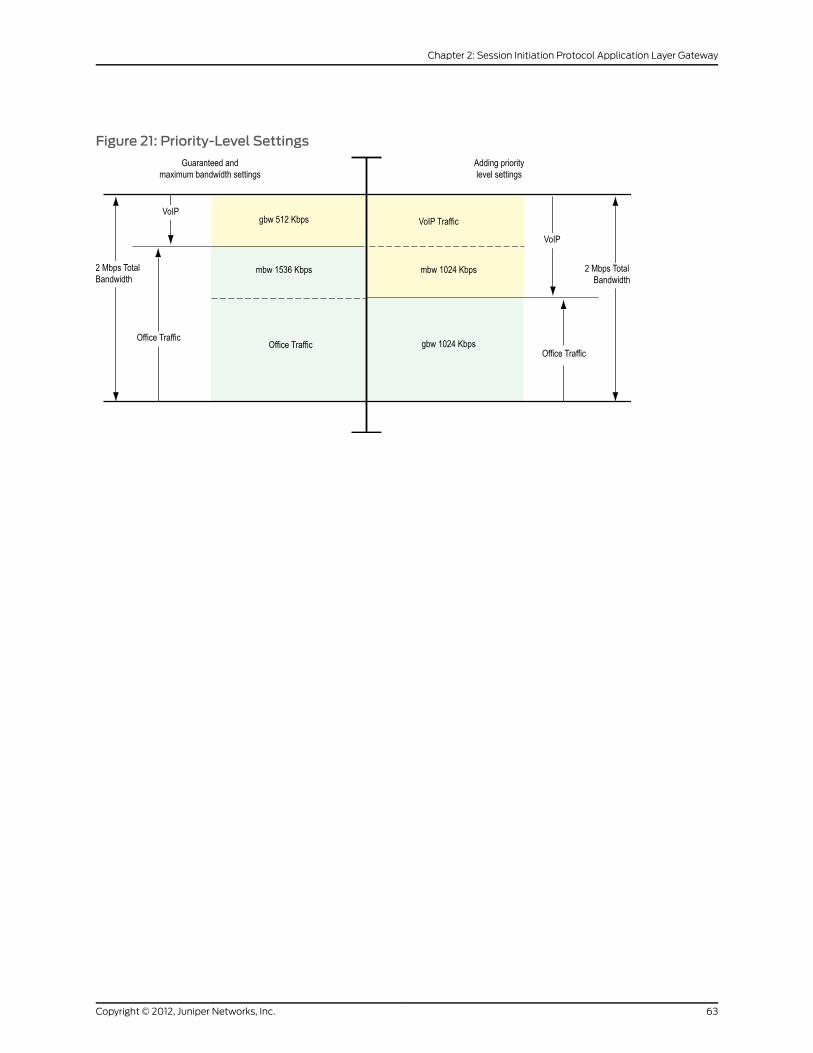
Figure 21: Priority-Level Settings
63Copyright © 2012, Juniper Networks, Inc.
Chapter 2: Session Initiation Protocol Application Layer Gateway

Copyright © 2012, Juniper Networks, Inc.64
Voice-over-Internet Protocol

CHAPTER 3
Media Gateway Control ProtocolApplication Layer Gateway
This chapter presents an overview of the Media Gateway Control Protocol (MGCP)
Application Layer Gateway (ALG) and lists the firewall security features of the
implementation. Examples of typical scenarios follow a summary of the MGCP
architecture. This chapter includes the following sections:
• Overview on page 65
• MGCP Security on page 66
• About MGCP on page 66
• Examples on page 71
Overview
The Media Gateway Control Protocol (MGCP) is supported on security devices in Route,
transparent, and Network Address Translation (NAT) mode. MGCP is a text-based
Application Layer protocol used for call setup and control. MGCP is based on a
master-slave call control architecture in which the media gateway controller, via the call
agent, maintains call control intelligence, while the media gateways carry out the
instructions of the call agent.
The MGCP ALG performs the following procedures:
• Conducts VoIP signaling payload inspection. The payload of the incoming VoIP signaling
packet is fully inspected based on related RFCs and proprietary standards. Any
malformed packet attack is blocked by the ALG.
• Conducts MGCP signaling payload inspection. The payload of the incoming MGCP
signaling packet is fully inspected in accordance with RFC 3435. Any malformed-packet
attack is blocked by the ALG.
• Provides stateful processing. The corresponding VoIP-based state machines are invoked
to process the parsed information. Any out-of-state or out-of-transaction packet is
identified and properly handled.
• Performs Network Address Translation (NAT). Any embedded IP address and port
information in the payload is properly translated based on the existing routing
65Copyright © 2012, Juniper Networks, Inc.

information and network topology, and is replaced with the translated IP address and
port number, if necessary.
• Manages pinholes for VoIP traffic. To keep the VoIP network secure, the IP address
and port information used for media or signaling is identified by the ALG, and any
needed pinhole is dynamically created and closed during call setup.
MGCP Security
The MGCP ALG includes the following security features:
• Denial of Service (DoS) attack protection—the ALG performs stateful inspection at
the UDP packet level, the transaction level, and at the call level. MGCP packets
matching the RFC 3435 message format, transaction state, and call state, are
processed. All other messages are dropped.
• Firewall policy enforcement between gateway and gateway controller (signaling
policy).
• Firewall policy enforcement between gateways (media policy).
• Per-gateway MGCP message flooding control. Any malfunctioning or hacked gateway
will not disrupt the whole VoIP network. Combined with per-gateway flooding control,
damage is contained within the impacted gateway.
• Per-gateway MGCP connection flooding control.
• Seamless switchover/failover if calls, including calls in progress, are switched to the
standby firewall in case of system failure.
About MGCP
MGCP is a text-based, application layer protocol that can be used for call setup and
control. The protocol is based on a master/slave call control architecture: the media
gateway controller (call agent) maintains call control intelligence, and media gateways
carry out the instructions from the call agent.
Entities in MGCP
There are four basic entities in MGCP:
• Endpoint on page 66
• Connection on page 67
• Call on page 67
• Call Agent on page 67
Endpoint
A media gateway (MG) is a collection of endpoints. An endpoint can be an analog line,
trunk, or any other access point. An endpoint is named as below:
local-endpoint-name@domain-name
Copyright © 2012, Juniper Networks, Inc.66
Voice-over-Internet Protocol

The following are some valid endpoint IDs:
group1/[email protected]/Trk1/*@[192.168.10.8] (wild-carding)[email protected] (any endpoint within the MG)*@voiptel.net (all endpoints within the MG)
Connection
Connections are created on each endpoint by a MG during call setup. A typical VoIP call
involves two connections. A complex call, for example a three-party call or conference
call, might require more connections. The media gateway controller (MGC) can instruct
media gateways to create, modify, delete and audit a connection.
A connection is identified by its connection ID which is created by the MG when it is
requested to create a connection. Connection ID is presented as a hexadecimal string,
and its maximum length is 32 characters.
Call
A call is identified by its call ID, which is created by the MGC when establishing a new
call. Call ID is a hexadecimal string with a maximum length of 32 characters. Call ID is
unique within the MGC. Two or more connections can have the same call ID if they belong
to the same call.
Call Agent
One or more call agents (also called media gateway controllers) are supported in MGCP
to enhance reliability in VoIP network. The following are two examples of call agent
names:
Several network addresses can be associated under one domain name in the Domain
Name System (DNS). By keeping track of the time to live (TTL) of DNS query/response
data and implementing retransmission using other alternative network addresses,
switchover and failover is achieved in MGCP.
The concept of notified entity is essential in MGCP. The notified entity for an endpoint is
the call agent currently controlling that endpoint. An endpoint should send any MGCP
command to its notified entity. However, different call agents might send MGCP
commands to this endpoint.
The notified entity is set to a provisioned value upon startup, but could be changed by a
call agent through the use of a Notified Entity parameter contained in a MGCP message.
If the notified entity for an endpoint is empty or has not been set explicitly, its value
defaults to the source address of the last successful non-audit MGCP command received
for that endpoint.
67Copyright © 2012, Juniper Networks, Inc.
Chapter 3: Media Gateway Control Protocol Application Layer Gateway
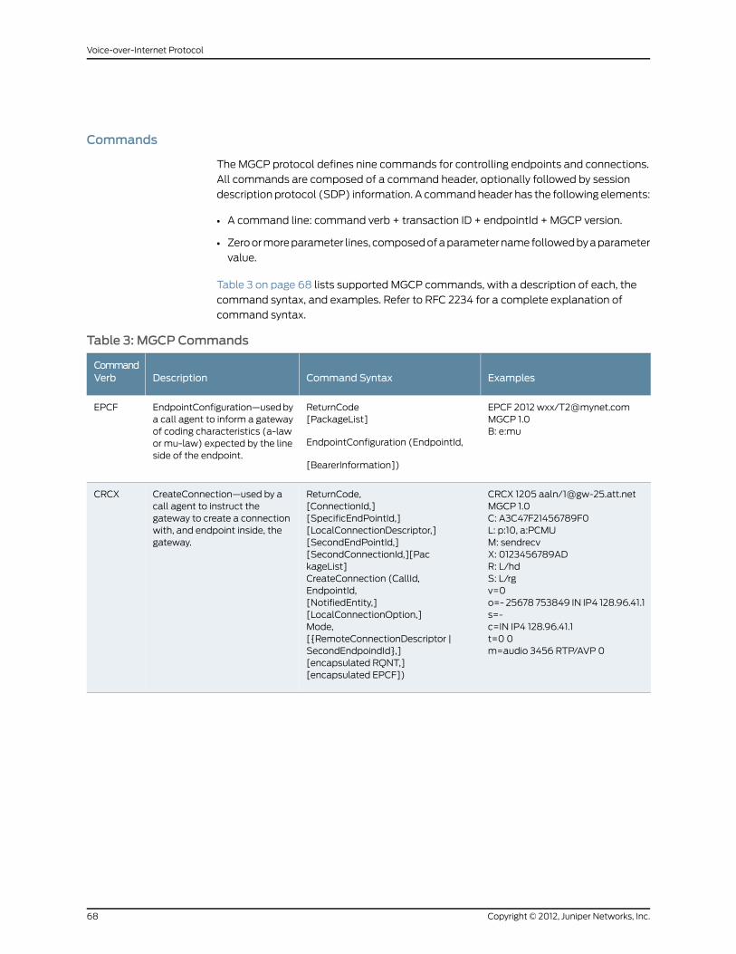
Commands
The MGCP protocol defines nine commands for controlling endpoints and connections.
All commands are composed of a command header, optionally followed by session
description protocol (SDP) information. A command header has the following elements:
• A command line: command verb + transaction ID + endpointId + MGCP version.
• Zero or more parameter lines, composed of a parameter name followed by a parameter
value.
Table 3 on page 68 lists supported MGCP commands, with a description of each, the
command syntax, and examples. Refer to RFC 2234 for a complete explanation of
command syntax.
Table 3: MGCP Commands
ExamplesCommand SyntaxDescriptionCommandVerb
EPCF 2012 wxx/[email protected] 1.0B: e:mu
ReturnCode[PackageList]
EndpointConfiguration (EndpointId,
[BearerInformation])
EndpointConfiguration—used bya call agent to inform a gatewayof coding characteristics (a-lawor mu-law) expected by the lineside of the endpoint.
EPCF
CRCX 1205 aaln/[email protected] 1.0C: A3C47F21456789F0L: p:10, a:PCMUM: sendrecvX: 0123456789ADR: L/hdS: L/rgv=0o=- 25678 753849 IN IP4 128.96.41.1s=-c=IN IP4 128.96.41.1t=0 0m=audio 3456 RTP/AVP 0
ReturnCode,[ConnectionId,][SpecificEndPointId,][LocalConnectionDescriptor,][SecondEndPointId,][SecondConnectionId,][PackageList]CreateConnection (CallId,EndpointId,[NotifiedEntity,][LocalConnectionOption,]Mode,[{RemoteConnectionDescriptor |SecondEndpoindId},][encapsulated RQNT,][encapsulated EPCF])
CreateConnection—used by acall agent to instruct thegateway to create a connectionwith, and endpoint inside, thegateway.
CRCX
Copyright © 2012, Juniper Networks, Inc.68
Voice-over-Internet Protocol
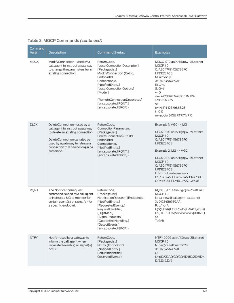
Table 3: MGCP Commands (continued)
ExamplesCommand SyntaxDescriptionCommandVerb
MDCX 1210 aaln/[email protected] 1.0C: A3C47F21456789F0I: FDE234C8M: recvonlyX: 0123456789AER: L/huS: G/rtv=0o=- 4723891 7428910 IN IP4128.96.63.25s=-c=IN IP4 128.96.63.25t=0 0m=audio 3456 RTP/AVP 0
ReturnCode,[LocalConnectionDescriptor,][PackageList]ModifyConnection (CallId,EndpointId,ConnectionId,[NotifiedEntity,][LocalConnectionOption,][Mode,]
[RemoteConnectionDescriptor,][encapsulated RQNT,][encapsulated EPCF])
ModifyConnection—used by acall agent to instruct a gatewayto change the parameters for anexisting connection.
MDCX
Example 1: MGC -> MG
DLCX 9210 aaln/[email protected] 1.0C: A3C47F21456789F0I: FDE234C8
Example 2: MG -> MGC
DLCX 9310 aaln/[email protected] 1.0C: A3C47F21456789F0I: FDE234C8E: 900 - Hardware errorP: PS=1245, OS=62345, PR=780,OR=45123, PL=10, JI=27, LA=48
ReturnCode,ConnectionParameters,[PackageList]DeleteConnection (CallId,EndpointId,ConnectionId,[NotifiedEntity,][encapsulated RQNT,][encapsulated EPCF])
DeleteConnection—used by acall agent to instruct a gatewayto delete an existing connection.
DeleteConnection can also beused by a gateway to release aconnection that can no longer besustained.
DLCX
RQNT 1205 aaln/[email protected] 1.0N: [email protected]: 0123456789AAR: L/hd(A,E(S(L/dl),R(L/oc,L/hu,D/[0-9#*T](D))))D: (0T|00T|xx|91xxxxxxxxxx|9011x.T)S:T: G/ft
ReturnCode,[PackageList]NotificationRequest[(EndpointId,[NotifiedEntity,][RequestedEvents,]RequestIdentifier,[DigitMap,][SignalRequests,][QuarantineHandling,][DetectEvents,][encapsulated EPCF])
The NotificationRequestcommand is used by a call agentto instruct a MG to monitor forcertain event(s) or signal(s) fora specific endpoint.
RQNT
NTFY 2002 aaln/[email protected] 1.0N: [email protected]:5678X: 0123456789ACO:L/hd,D/9,D/1,D/2,D/0,D/1,D/8,D/2,D/9,D/4,D/2,D/6,D/6
ReturnCode,[PackageList]Notify (EndpointID,[NotifiedEntity,]RequestIdentifier,ObservedEvents)
Notify—used by a gateway toinform the call agent whenrequested event(s) or signal(s)occur.
NTFY
69Copyright © 2012, Juniper Networks, Inc.
Chapter 3: Media Gateway Control Protocol Application Layer Gateway

Table 3: MGCP Commands (continued)
ExamplesCommand SyntaxDescriptionCommandVerb
Example 1:
AUEP 1201 aaln/[email protected] 1.0F: A, R,D,S,X,N,I,T,OExample 2:AUEP 1200 *@rgw-25.att.net MGCP1.0
ReturnCode,EndPointIdList, | {[RequestedEvents,][QuarantineHandling,][DigitMap,][SignalRequests,][RequestedIdentifier,][NotifiedEntity,][ConnectionIdentifier,][DetectEvents,][ObservedEvents,][EventStats,][BearerInformation,][BearerMethod,][RestartDelay,][ReasonCode,][MaxMGCPDatagram,][Capabilities]}[PackageList]
AuditEndpoint (EndpointId,
[RequestedInfo])
AuditEndpoint—used by a callagent to audit the status of theendpoint.
AUEP
AUCX 3003 aaln/[email protected] 1.0I: 32F345E2F: C,N,L,M,LC,P
ReturnCode,[CallId,][NotifiedEntity,][LocalConnectionOptions,][Mode,][RemoteConnectionDescriptor,][LocalConnectionDescriptor,][ConnectionParameters,][PackageList]AuditConnection (EndpointId,ConnectionId,RequestedInfo)
AuditConnection—used by a callagent to collect the parametersapplied to a connection.
AUCX
RSIP 5200 aaln/[email protected] 1.0RM: gracefulRD: 300
ReturnCode,[NotifiedEntity,][PackageList]RestartInProgress (EndpointId,RestartMethod,[RestartDelay,][ReasonCode])
RestartInProgress—used by agateway to notify a call agentthat one or more endpoints arebeing taken out of service orplaced back in service.
RSIP
Response Codes
Every command sent by the calling agent or gateway, whether successful or not, requires
a response code. The response code is in the header of the response message, and
optionally is followed by session description information.
The response header is composed of a response line, followed by zero or more parameter
lines, each containing a parameter name letter followed by its value. The response header
Copyright © 2012, Juniper Networks, Inc.70
Voice-over-Internet Protocol
is composed of a 3-digit response code, transaction ID, and optionally followed by
commentary. The response header in the following response message shows the response
code 200 (successful completion), followed by ID 1204, and the comment: OK:
200 1204 OKI: FDE234C8v=0o=- 25678 753849 IN IP4 128.96.41.1s=-c=IN IP4 128.96.41.1t=0 0m=audio 3456 RTP/AVP 96a=rtpmap:96 G726-32/8000
The ranges of response codes are defined as follows:
• 000 – 099: indicate a response acknowledgement.
• 100 – 199: indicate a provisional response.
• 200 – 299: indicate a successful completion (final response).
• 400 – 499: indicate a transient error (final response).
• 500 – 599: indicate a permanent error (final response).
Refer to RFC 3661 for detailed information about response codes.
A response to a command is sent to the source address of the command, not to the
current notified entity. A media gateway can receive MGCP commands from various
network addresses simultaneously, and send back responses to corresponding network
addresses. However, it sends all MGCP commands to its current notified entity.
Examples
This section includes the following configuration scenarios:
• Media Gateway in Subscribers’ Homes—Call Agent at the ISP on page 71
• ISP-Hosted Service on page 74
Media Gateway in Subscribers’ Homes—Call Agent at the ISP
In this example (see Figure 22 on page 72) you configure a security device at a Cable
Service Provider to support MGCP for their network of residential subscribers. The security
device and the call agent are on the cable service provider’s premises. An integrated
Access Device (IAD), or set-top box, is in each subscriber’s home, acting as a
gateway—each IAD represents a separate residence. The call agent is in the trust_ca
zone; residential customers are in the res_cust zone.
After creating zones—untrust_subscriber for the customers and trust_ca for the service
provider, you configure addresses, and then policies. Although gateways frequently reside
in different zones, requiring policies for media traffic, in this example both gateways are
in the same subnet. RTP traffic between the gateways never passes through the firewall,
therefore no policy is needed for media.
71Copyright © 2012, Juniper Networks, Inc.
Chapter 3: Media Gateway Control Protocol Application Layer Gateway

Figure 22: Media Gateway in Subscribers’ Home
WebUI
1. Zones
Network > Zones > New: Enter the following, then click OK:
Zone Name: untrust_subscriber
Network > Zones > New: Enter the following, then click OK:
Zone Name: trust_ca
2. Addresses
Policy > Policy Elements > Addresses > List > New: Enter the following, then clickOK:
Address Name: SubscriberSubNetComment: Our subscribers’ networkIP Address/Domain Name:IP/Netmask: (select), 2.2.2.0/24
Zone: untrust-subscriber
Policy > Policy Elements > Addresses > List > New: Enter the following, then clickOK:
Address Name: call_agent1Comment: Our No. 1 call agentIP Address/Domain Name:IP/Netmask: (select), 10.1.1.101/32
Zone: trust_ca
3. Interfaces
Network > Interfaces > Edit (for ethernet3): Enter the following, then click Apply:
Copyright © 2012, Juniper Networks, Inc.72
Voice-over-Internet Protocol
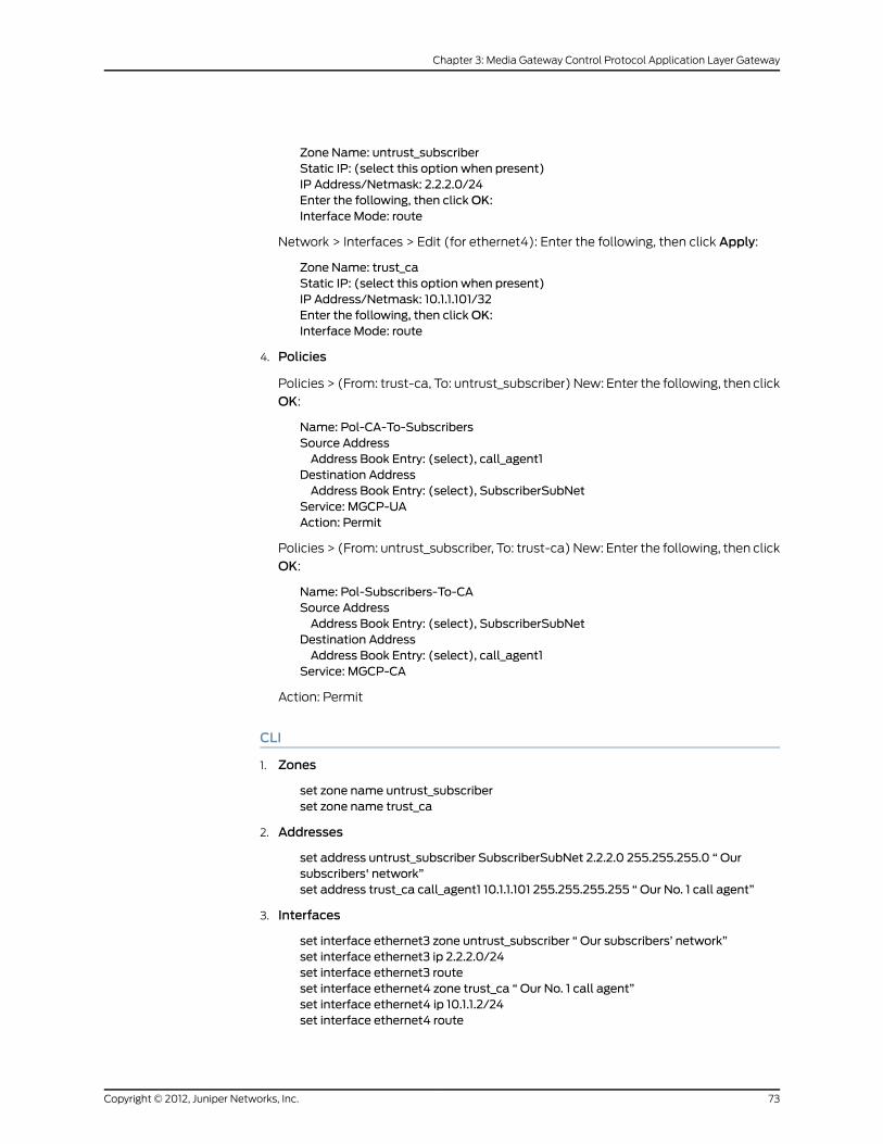
Zone Name: untrust_subscriberStatic IP: (select this option when present)IP Address/Netmask: 2.2.2.0/24Enter the following, then clickOK:Interface Mode: route
Network > Interfaces > Edit (for ethernet4): Enter the following, then click Apply:
Zone Name: trust_caStatic IP: (select this option when present)IP Address/Netmask: 10.1.1.101/32Enter the following, then clickOK:Interface Mode: route
4. Policies
Policies > (From: trust-ca, To: untrust_subscriber) New: Enter the following, then click
OK:
Name: Pol-CA-To-SubscribersSource AddressAddress Book Entry: (select), call_agent1
Destination AddressAddress Book Entry: (select), SubscriberSubNet
Service: MGCP-UAAction: Permit
Policies > (From: untrust_subscriber, To: trust-ca) New: Enter the following, then click
OK:
Name: Pol-Subscribers-To-CASource AddressAddress Book Entry: (select), SubscriberSubNet
Destination AddressAddress Book Entry: (select), call_agent1
Service: MGCP-CA
Action: Permit
CLI
1. Zones
set zone name untrust_subscriberset zone name trust_ca
2. Addresses
set address untrust_subscriber SubscriberSubNet 2.2.2.0 255.255.255.0 “ Oursubscribers' network”set address trust_ca call_agent1 10.1.1.101 255.255.255.255 “ Our No. 1 call agent”
3. Interfaces
set interface ethernet3 zone untrust_subscriber “ Our subscribers’ network”set interface ethernet3 ip 2.2.2.0/24set interface ethernet3 routeset interface ethernet4 zone trust_ca “ Our No. 1 call agent”set interface ethernet4 ip 10.1.1.2/24set interface ethernet4 route
73Copyright © 2012, Juniper Networks, Inc.
Chapter 3: Media Gateway Control Protocol Application Layer Gateway

4. Policies
setpolicynamePol-CA-TO-Subscribers fromtrust_catountrust_subscribercall_agent1SubscriberSubNetmgcp-ua permitset policy name Pol-Subscribers-To-CA from untrust_subscriber to trust_caSubscriberSubNet call_agent1 mgcp-ca permit
ISP-Hosted Service
In this example, (see Figure 23 on page 74) an ISP located on the American west coast
provides MGCP service to customers in Asia and San Francisco. Asia customers are in
the Untrust zone, and supported by the gateway: asia_gw (3.3.3.110); San Francisco
customers are in the Trust zone, and supported by the gateway: sf_gw (2.2.2.201). The
call agent: west_ca (10.1.1.101) is in the DMZ.
After setting addresses for the gateways and the call agent, you configure the interfaces,
putting ethernet4 and ethernet5, which are trusted, in route mode to allow them to
stream media directly after call setup. To protect the IP address of the call agent in the
DMZ from exposure, you place a MIP on ethernet6, that is, you map the IP address of the
call agent (10.1.1.101) to an IP address from the pool of addresses on the ethernet6
interface, in this case: 3.3.3.101.
Finally, you create policies. To allow MGCP signaling between the call agent in the DMZ
and the gateway in the Untrust zone, you create one policy for each direction, referencing
the MIP that protects the call agent. You create another pair of policies to allow signaling
between the call agent and the gateway in the Trust zone. A single policy is sufficient to
allow bidirectional communication between gateways in the Trust and Untrust zones.
Figure 23: ISP-Hosted Service
WebUI
1. Addresses
Policy > Policy Elements > Addresses > List > New: Enter the following, then clickOK:
Address Name: sf_gwComment: gateway in asiaIP Address/Domain Name:
Copyright © 2012, Juniper Networks, Inc.74
Voice-over-Internet Protocol
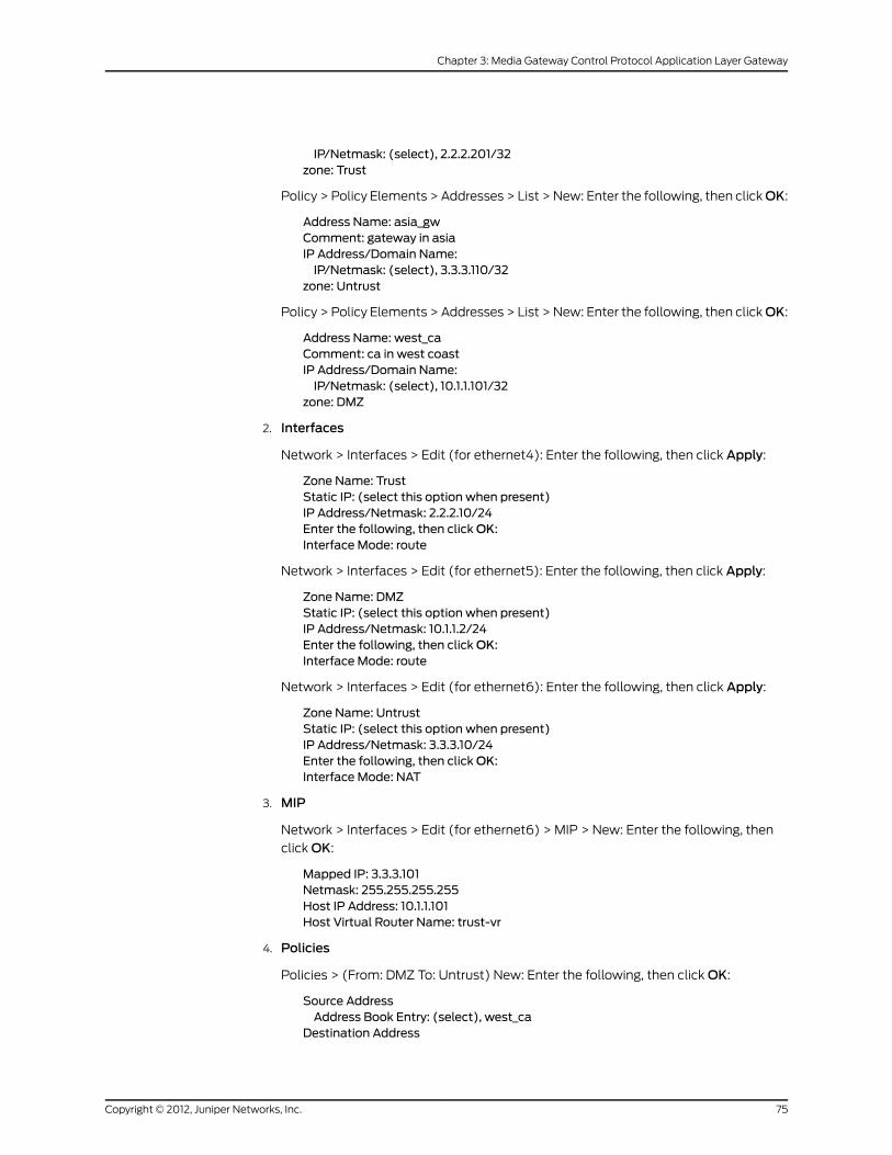
IP/Netmask: (select), 2.2.2.201/32zone: Trust
Policy > Policy Elements > Addresses > List > New: Enter the following, then clickOK:
Address Name: asia_gwComment: gateway in asiaIP Address/Domain Name:IP/Netmask: (select), 3.3.3.110/32
zone: Untrust
Policy > Policy Elements > Addresses > List > New: Enter the following, then clickOK:
Address Name: west_caComment: ca in west coastIP Address/Domain Name:IP/Netmask: (select), 10.1.1.101/32
zone: DMZ
2. Interfaces
Network > Interfaces > Edit (for ethernet4): Enter the following, then click Apply:
Zone Name: TrustStatic IP: (select this option when present)IP Address/Netmask: 2.2.2.10/24Enter the following, then clickOK:Interface Mode: route
Network > Interfaces > Edit (for ethernet5): Enter the following, then click Apply:
Zone Name: DMZStatic IP: (select this option when present)IP Address/Netmask: 10.1.1.2/24Enter the following, then clickOK:Interface Mode: route
Network > Interfaces > Edit (for ethernet6): Enter the following, then click Apply:
Zone Name: UntrustStatic IP: (select this option when present)IP Address/Netmask: 3.3.3.10/24Enter the following, then clickOK:Interface Mode: NAT
3. MIP
Network > Interfaces > Edit (for ethernet6) > MIP > New: Enter the following, then
click OK:
Mapped IP: 3.3.3.101Netmask: 255.255.255.255Host IP Address: 10.1.1.101Host Virtual Router Name: trust-vr
4. Policies
Policies > (From: DMZ To: Untrust) New: Enter the following, then click OK:
Source AddressAddress Book Entry: (select), west_ca
Destination Address
75Copyright © 2012, Juniper Networks, Inc.
Chapter 3: Media Gateway Control Protocol Application Layer Gateway

Address Book Entry: (select), asia_gwService: MGCP-UAAction: Permit
Policies > (From: Untrust To: DMZ) New: Enter the following, then click OK:
Source AddressAddress Book Entry: (select), asia_gw
Destination AddressAddress Book Entry: (select), west_ca
Service: MGCP-CAAction: Permit
Policies > (From: Trust To: DMZ) New: Enter the following, then click OK:
Source AddressAddress Book Entry: (select), sf_gw
Destination AddressAddress Book Entry: (select), west_ca
Service: MGCP-CAAction: Permit
Policies > (From: DMZ To: Trust) New: Enter the following, then click OK:
Source AddressAddress Book Entry: (select), west_ca
Destination AddressAddress Book Entry: (select), sf_gw
Service: MGCP-UAAction: Permit
Policies > (From: Trust To: Untrust) New: Enter the following, then click OK:
Source AddressAddress Book Entry: (select), sf_gw
Destination AddressAddress Book Entry: (select), asia_gw
Service: MGCP-UAAction: Permit
> Advanced: Enter the following, then click Return to set the advanced options and
return to the basic configuration page:
NAT:Source Translation: (select)DIP on: None (Use Egress Interface IP)
CLI
1. Addresses
set address trust sf_gw 2.2.2.201/32 “ gateway in s.f.”set address untrust asia_gw 3.3.3.110/32 “ gateway in asia”set address dmzwest_ca 10.1.1.101/32 “ ca in west coast”
2. Interfaces
set interface ethernet4 ip 2.2.2.10/24set interface ethernet4 routeset interface ethernet4 zone trust
Copyright © 2012, Juniper Networks, Inc.76
Voice-over-Internet Protocol
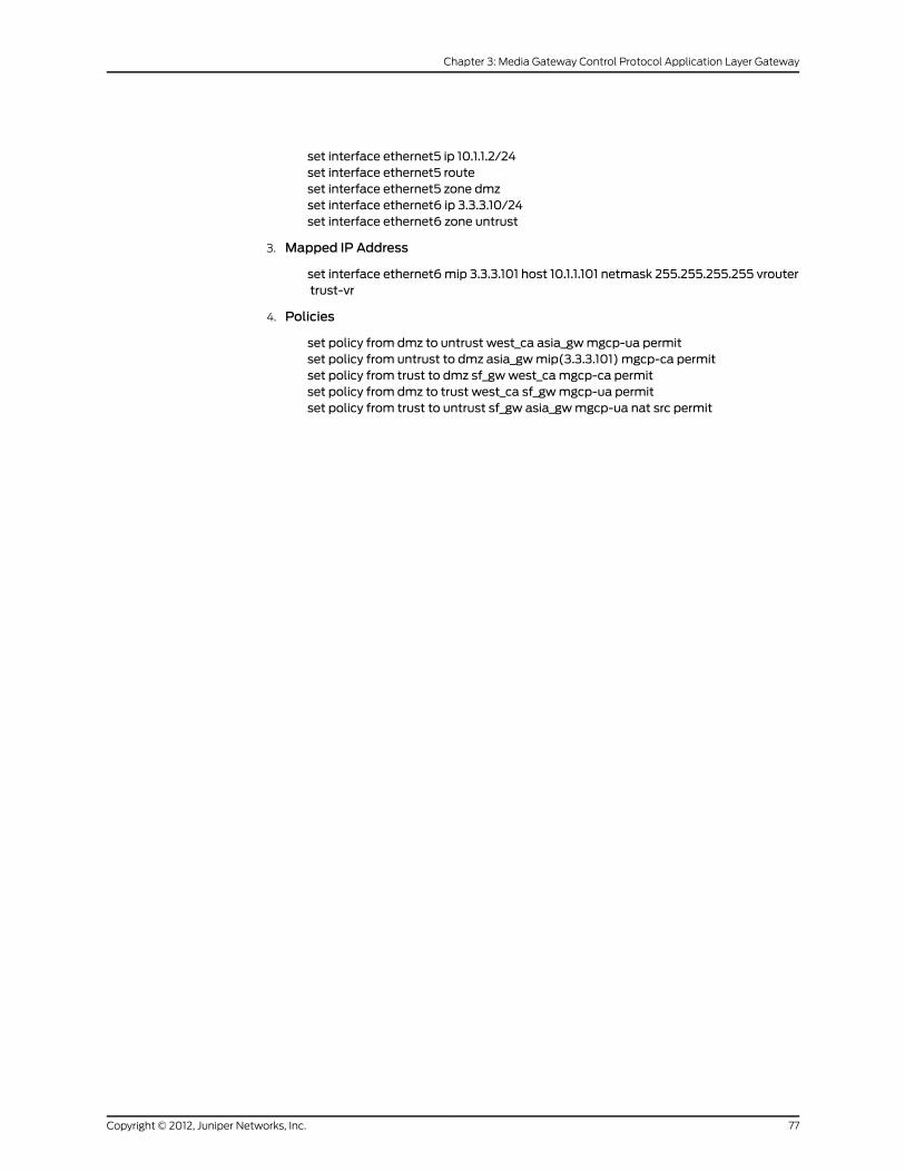
set interface ethernet5 ip 10.1.1.2/24set interface ethernet5 routeset interface ethernet5 zone dmzset interface ethernet6 ip 3.3.3.10/24set interface ethernet6 zone untrust
3. Mapped IP Address
set interface ethernet6mip 3.3.3.101 host 10.1.1.101 netmask 255.255.255.255 vroutertrust-vr
4. Policies
set policy from dmz to untrust west_ca asia_gwmgcp-ua permitset policy from untrust to dmz asia_gwmip(3.3.3.101) mgcp-ca permitset policy from trust to dmz sf_gwwest_camgcp-ca permitset policy from dmz to trust west_ca sf_gwmgcp-ua permitset policy from trust to untrust sf_gw asia_gwmgcp-ua nat src permit
77Copyright © 2012, Juniper Networks, Inc.
Chapter 3: Media Gateway Control Protocol Application Layer Gateway

Copyright © 2012, Juniper Networks, Inc.78
Voice-over-Internet Protocol

CHAPTER 4
SkinnyClientControl Protocol ApplicationLayer Gateway
This chapter presents an overview of the Skinny Client Control Protocol (SCCP)
Application Layer Gateway (ALG) and lists the firewall security features of the
implementation. Examples of typical scenarios follow a summary of the SCCP
architecture. This chapter includes the following sections:
• Overview on page 79
• SCCP Security on page 80
• About SCCP on page 80
• Examples on page 85
Overview
Skinny Client Control Protocol (SCCP) is supported on security devices in Route,
transparent, and Network Address Translation (NAT) modes. SCCP is a binary-based
Application Layer protocol used for Voice-over-Internet Protocol (VoIP) call setup and
control. In the SCCP architecture, a Cisco H.323 proxy, known as the Call Manager, does
most of the processing. IP phones, also called End Stations, run the Skinny client and
connect to a primary (and, if available, a secondary) Call Manager over TCP on port 2000
and register with the primary Call Manager. This connection is then used to establish
calls coming to or from the client.
The SCCP ALG supports the following:
• Call flow from a Skinny client, through the Call Manager, to another Skinny client.
• Seamless failover—switches over all calls in process to the standby firewall during
failure of the primary.
• VoIP signaling payload inspection—fully inspects the payload of incoming VoIP signaling
packets based on related RFCs and proprietary standards. Any malformed packet
attack is blocked by the ALG.
• SCCP signaling payload inspection—fully inspects the payload of incoming SCCP
signaling packets in accordance with RFC 3435. Any malformed-packet attack is
blocked by the ALG.
79Copyright © 2012, Juniper Networks, Inc.

• Stateful processing—invokes the corresponding VoIP-based state machines to process
the parsed information. Any out-of-state or out-of-transaction packet is identified and
properly handled.
• Network Address Translation (NAT)—translates any embedded IP address and port
information in the payload, based on the existing routing information and network
topology, with the translated IP address and port number, if necessary.
• Pinhole creation and management for VoIP traffic—identifies IP address and port
information used for media or signaling and dynamically opens (and closes) pinholes
to securely stream the media.
SCCP Security
The SCCP ALG includes the following security features:
• Denial of Service (DoS) attack protection—The ALG performs stateful inspection at
the UDP packet level, the transaction level, and the call level. Packets matching the
SCCP message format, transaction state, and call state are processed. All other
messages are dropped.
• Firewall policy enforcement between Cisco IP phones and the Call Manager
(Intra-Cluster).
• Firewall policy enforcement between Call Managers (Inter-Cluster).
• Call Manager flood control—Protects the Call Manager from being flooded with new
calls either by an already compromised connected client or by a faulty device.
• Firewall policy enforcement between gateways (media policy).
• Per-gateway SCCP connection flooding control.
• Seamless switchover/failover if calls, including calls in progress, are switched to the
standby firewall in case of system failure.
About SCCP
The following sections give a brief overview of SCCP and how it works:
• SCCP Components on page 80
• SCCP Transactions on page 81
• SCCP Messages on page 84
SCCP Components
The principle components of the SCCP VoIP architecture include the following:
• SCCP Client on page 81
• Call Manager on page 81
• Cluster on page 81
Copyright © 2012, Juniper Networks, Inc.80
Voice-over-Internet Protocol
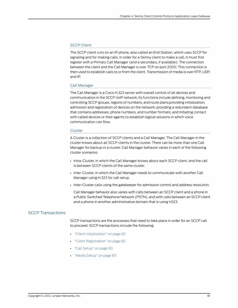
SCCP Client
The SCCP client runs on an IP phone, also called an End Station, which uses SCCP for
signaling and for making calls. In order for a Skinny client to make a call, it must first
register with a Primary Call Manager (and a secondary, if available). The connection
between the client and the Call Manager is over TCP on port 2000. This connection is
then used to establish calls to or from the client. Transmission of media is over RTP, UDP,
and IP.
Call Manager
The Call Manager is a Cisco H.323 server with overall control of all devices and
communication in the SCCP VoIP network. Its functions include defining, monitoring and
controlling SCCP groups, regions of numbers, and route plans;providing initialization,
admission and registration of devices on the network; providing a redundant database
that contains addresses, phone numbers, and number formats; and initiating contact
with called devices or their agents to establish logical sessions in which voice
communication can flow.
Cluster
A Cluster is a collection of SCCP clients and a Call Manager. The Call Manager in the
cluster knows about all SCCP clients in the cluster. There can be more than one Call
Manager for backup in a cluster. Call Manager behavior varies in each of the following
cluster scenarios:
• Intra-Cluster, in which the Call Manager knows about each SCCP client, and the call
is between SCCP clients of the same cluster.
• Inter-Cluster, in which the Call Manager needs to communicate with another Call
Manager using H.323 for call setup.
• Inter-Cluster calls using the gatekeeper for admission control and address resolution.
Call Manager behavior also varies with calls between an SCCP client and a phone in
a Public Switched Telephone Network (PSTN), and with calls between an SCCP client
and a phone in another administrative domain that is using H323.
SCCP Transactions
SCCP transactions are the processes that need to take place in order for an SCCP call
to proceed. SCCP transactions include the following:
• “Client Initialization” on page 82
• “Client Registration” on page 82
• “Call Setup” on page 83
• “Media Setup” on page 83
81Copyright © 2012, Juniper Networks, Inc.
Chapter 4: Skinny Client Control Protocol Application Layer Gateway

Client Initialization
To initialize, the SCCP client needs to know the IP address of the Call Manager, its own
IP address, and other information about the IP gateway and DNS servers. Initialization
takes place on the local LAN. The client sends a Dynamic Host Control Protocol (DHCP)
request to get an IP address, the DNS server address, and the TFTP server name and
address. The client needs the TFTP server name to download the configuration file:
sepmacaddr.cnf. If the TFTP name is not given, the client uses the default filename in
the IP phone. The client then downloads the configuration file .cnf (xml) from TFTP
server. CNF files contain the IP address or addresses of the primary and secondary Cisco
Call Manager. With this information, the client contacts the Call Manager to register.
Client Registration
The SCCP client, after initialization, registers with the Call Manager over a TCP connection
on well-known default port 2000. The client registers by providing the Call Manager with
its IP address, the MAC address of the phone, and other information, such as protocol
and version. The client cannot initiate or receive calls until it is registered. Keepalive
messages keep this TCP connection open between the client and Call Manager so that
the client can initiate or receive calls at any time, provided that a policy on the security
device allows this.
Table 4 on page 82 lists SCCP messages and indicates messages that are of interest to
the security device.
Table 4: SCCP RegistrationMessages
Of Interest to Security DeviceFrom Call ManagerFrom Client
bRegisterMessage
bIPortMessage
bRegisterAckMessage
CapabilititsRequest
CapabilitiesResMessage
ButtonTemplateReqMessage
ButtonTemplateResMessage
SoftKeyTemplateReqMessage
SoftKeyTemplateResMessage
bLineStatReqMessage
bLineStatMessage
Copyright © 2012, Juniper Networks, Inc.82
Voice-over-Internet Protocol

Call Setup
IP phone-to-IP phone call-setup using SCCP is always handled by the Call Manager.
Messages for call setup are sent to the Call Manager, which returns messages appropriate
to the status of the call. If call setup is successful, and a policy on the security device
allows the call, the Call Manager sends the media setup messages to the client.
Media Setup
The Call Manager sends the IP address and port number of the called party to the calling
party. The Call Manager also sends the media IP address and port number of the calling
party to the called party. After media setup, media is transmitted directly between clients.
When the call ends, the Call Manager is informed and terminates the media streams. At
no time during this process does the Call Manager hand over call-setup function to the
client. Media is streamed directly between clients through RTP/UDP/IP.
SCCP Control Messages and RTP Flow
Figure 24 on page 84 shows the SCCP control messages used to set up and tear down
a simple call betweenPhone1 andPhone2. Except for the OffHook message initiating the
call from Phone1 and the OnHook message signaling the end of the call, all aspects of
the call are controlled by the Call Manager.
83Copyright © 2012, Juniper Networks, Inc.
Chapter 4: Skinny Client Control Protocol Application Layer Gateway
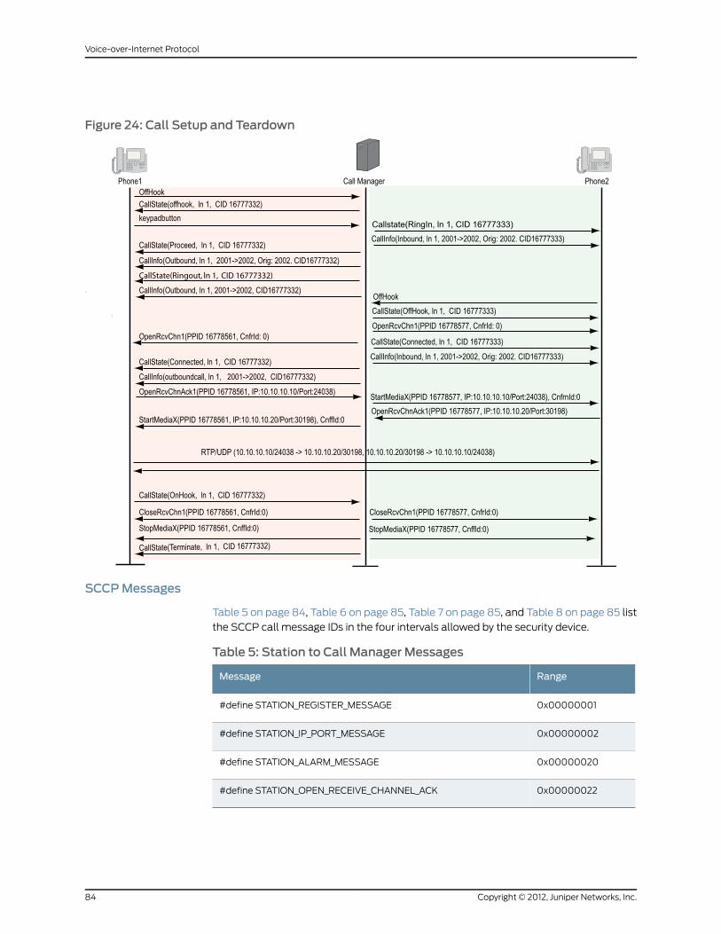
Figure 24: Call Setup and Teardown
SCCPMessages
Table 5 on page 84, Table 6 on page 85, Table 7 on page 85, and Table 8 on page 85 list
the SCCP call message IDs in the four intervals allowed by the security device.
Table 5: Station to Call Manager Messages
RangeMessage
0x00000001#define STATION_REGISTER_MESSAGE
0x00000002#define STATION_IP_PORT_MESSAGE
0x00000020#define STATION_ALARM_MESSAGE
0x00000022#define STATION_OPEN_RECEIVE_CHANNEL_ACK
Copyright © 2012, Juniper Networks, Inc.84
Voice-over-Internet Protocol
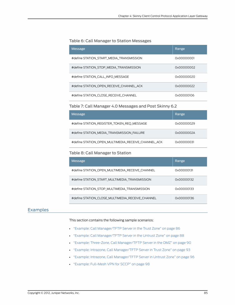
Table 6: Call Manager to StationMessages
RangeMessage
0x00000001#define STATION_START_MEDIA_TRANSMISSION
0x00000002#define STATION_STOP_MEDIA_TRANSMISSION
0x00000020#define STATION_CALL_INFO_MESSAGE
0x00000022#define STATION_OPEN_RECEIVE_CHANNEL_ACK
0x00000106#define STATION_CLOSE_RECEIVE_CHANNEL
Table 7: Call Manager 4.0Messages and Post Skinny 6.2
RangeMessage
0x00000029#define STATION_REGISTER_TOKEN_REQ_MESSAGE
0x0000002A#define STATION_MEDIA_TRANSMISSION_FAILURE
0x00000031#define STATION_OPEN_MULTIMEDIA_RECEIVE_CHANNEL_ACK
Table 8: Call Manager to Station
RangeMessage
0x00000131#define STATION_OPEN_MULTIMEDIA_RECEIVE_CHANNEL
0x00000132#define STATION_START_MULTIMEDIA_TRANSMISSION
0x00000133#define STATION_STOP_MULTIMEDIA_TRANSMISSION
0x00000136#define STATION_CLOSE_MULTIMEDIA_RECEIVE_CHANNEL
Examples
This section contains the following sample scenarios:
• “Example: Call Manager/TFTP Server in the Trust Zone” on page 86
• “Example: Call Manager/TFTP Server in the Untrust Zone” on page 88
• “Example: Three-Zone, Call Manager/TFTP Server in the DMZ” on page 90
• “Example: Intrazone, Call Manager/TFTP Server in Trust Zone” on page 93
• “Example: Intrazone, Call Manager/TFTP Server in Untrust Zone” on page 96
• “Example: Full-Mesh VPN for SCCP” on page 98
85Copyright © 2012, Juniper Networks, Inc.
Chapter 4: Skinny Client Control Protocol Application Layer Gateway

Example: Call Manager/TFTP Server in the Trust Zone
In this example, phone1 and the Call Manager/TFTP Server are on the ethernet1 interface
in the Trust (private) zone, and phone2 is on the ethernet3 interface in the Untrust zone.
You put a MIP for the Call Manager/TFTP Server on the ethernet3 interface, so that when
phone2 boots up it can contact the TFTP Server and obtain the IP address of the Call
Manager. (We recommend that you change the IP address of the Call Manager in the
TFTP Server config file (sep <mac_addr>.cnf) to the MIP IP address of the Call Manager.)
You then create a policy allowing SCCP traffic from the Untrust to the Trust zone and
reference that MIP in the policy. You also create a policy from the Trust to the Untrust
zone to allow phone1 to call out.
Figure 25: Call Manager/TFTP Server in the Private Zone
WebUI
1. Interfaces
Network > Interfaces > Edit (for ethernet1): Enter the following, then click OK:
Zone: TrustStatic IP: (select this option when present)IP Address/Netmask: 10.1.1.1/24Enter the following, then clickOK:Interface Mode: route
Network > Interfaces > Edit (for ethernet3): Enter the following, then click OK:
Zone: UntrustIP Address/Netmask: 1.1.1.1/24Interface Mode: Route
2. Addresses
Policy > Policy Elements > Addresses > List > New: Enter the following, then clickOK:
Address Name: phone1IP Address/Domain Name:IP/Netmask: (select), 10.1.1.3/24
Zone: Trust
Policy > Policy Elements > Addresses > List > New: Enter the following, then clickOK:
Address Name: phone2IP Address/Domain Name:
Copyright © 2012, Juniper Networks, Inc.86
Voice-over-Internet Protocol

IP/Netmask: (select), 1.1.1.4/24Zone: Untrust
Policy > Policy Elements > Addresses > List > New: Enter the following, then clickOK:
Address Name: CM-TFTP_ServerIP Address/Domain Name:IP/Netmask: (select), 10.1.1.4/24
Zone: Trust
3. MIP
Network > Interfaces > Edit (for loopback.3) > MIP > New: Enter the following, then
click OK:
Mapped IP: 1.1.1.2Netmask: 255.255.255.255Host IP Address: 10.1.1.4Host Virtual Router Name: trust-vr
4. Policies
Policies > (From: Trust, To: Untrust) New: Enter the following, then click OK:
Source Address:Address Book Entry: (select) any
Destination Address:Address Book Entry: (select) phone2
Service: SCCPAction: Permit
> Advanced: Enter the following, then click Return to set the advanced options and
return to the basic configuration page:
NAT:Source Translation: (select)(DIP on): None (Use Egress Interface IP)
Policies > (From: Untrust, To: Trust) New: Enter the following, then click OK:
Source Address:Address Book Entry: (select), phone2
Destination Address:Address Book Entry: (select), MIP(1.1.1.2)
Service: SCCPAction: Permit
CLI
1. Interfaces
set interface ethernet1 zone trustset interface ethernet1 ip 10.1.1.1/24set interface ethernet1 routeset interface ethernet3 zone untrustset interface ethernet3 ip 1.1.1.1/24set interface ethernet3 route
2. Addresses
87Copyright © 2012, Juniper Networks, Inc.
Chapter 4: Skinny Client Control Protocol Application Layer Gateway

set address trust phone1 10.1.1.3/24set address untrust phone2 1.1.1.4/24set address trust cm-tftp_server 10.1.1.4/24
3. MIP
set interface ethernet3mip 1.1.1.2 host 10.1.1.4
4. Policies
set policy from trust to untrust any phone2 sccp nat src permitset policy from untrust to trust phone2mip(1.1.1.2) sccp permitsave
NOTE: It is alwaysmore secure to specify a service explicitly, as shown inthis example configuration, than to use the keyword any.
Example: Call Manager/TFTP Server in the Untrust Zone
In this example, phone1 is on the ethernet1 interface in the Trust zone, and phone2 and
the Call Manager/TFTP Server are on the ethernet3 interface in the Untrust zone. After
configuring interfaces and addresses, you create policy from the Trust zone to the Untrust.
This allows phone1 to register with the Call Manager/TFTP Server in the Untrust zone.
Figure 26: Call Manager/TFTP Server in the Untrust Zone
WebUI
1. Interfaces
Network > Interfaces > Edit (for ethernet1): Enter the following, then click Apply:
Zone Name: TrustStatic IP: (select this option when present)IP Address/Netmask: 10.1.1.1/24
Enter the following, then click OK:
Interface Mode: route
Network > Interfaces > Edit (for ethernet3): Enter the following, then click OK:
Zone Name: UntrustStatic IP: (select this option when present)
Copyright © 2012, Juniper Networks, Inc.88
Voice-over-Internet Protocol
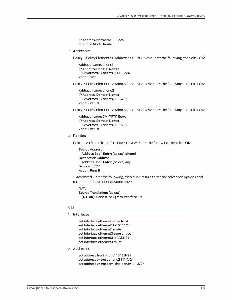
IP Address/Netmask: 1.1.1.1/24Interface Mode: Route
2. Addresses
Policy > Policy Elements > Addresses > List > New: Enter the following, then clickOK:
Address Name: phone1IP Address/Domain Name:IP/Netmask: (select), 10.1.1.3/24
Zone: Trust
Policy > Policy Elements > Addresses > List > New: Enter the following, then clickOK:
Address Name: phone2IP Address/Domain Name:IP/Netmask: (select), 1.1.1.4/24
Zone: Untrust
Policy > Policy Elements > Addresses > List > New: Enter the following, then clickOK:
Address Name: CM/TFTP ServerIP Address/Domain Name:IP/Netmask: (select), 1.1.1.3/24
Zone: Untrust
3. Policies
Policies > (From: Trust, To: Untrust) New: Enter the following, then click OK:
Source AddressAddress Book Entry: (select) phone1
Destination AddressAddress Book Entry: (select) any
Service: SCCPAction: Permit
> Advanced: Enter the following, then click Return to set the advanced options and
return to the basic configuration page:
NAT:Source Translation: (select)(DIP on): None (Use Egress Interface IP)
CLI
1. Interfaces
set interface ethernet1 zone trustset interface ethernet1 ip 10.1.1.1/24set interface ethernet1 routeset interface ethernet3 zone untrustset interface ethernet3 ip 1.1.1.1/24set interface ethernet3 route
2. Addresses
set address trust phone1 10.1.1.3/24set address untrust phone2 1.1.1.4/24set address untrust cm-tftp_server 1.1.1.3/24
89Copyright © 2012, Juniper Networks, Inc.
Chapter 4: Skinny Client Control Protocol Application Layer Gateway

3. Policies
set policy from trust to untrust phone1 any sccp nat src permitsave
NOTE: It is alwaysmore secure to specify a service explicitly, as shown inthis example configuration, than to use the keyword any.
Example: Three-Zone, Call Manager/TFTP Server in the DMZ
In this example, phone1 is on the ethernet1 interface in the Trust zone, phone2 is on the
ethernet3 interface in the Untrust zone, and the Call Manager/TFTP Server is on the
ethernet2 interface in the DMZ. For signaling, you create a policy from the Trust zone to
the DMZ to allow phone1 to communicate with the Call Manager/TFTP Server, and you
create a policy from the Untrust zone to the DMZ to allow phone2 to communicate with
the Call Manager/TFTP Server. For transmission of media, you create a policy from Trust
to Untrust to allow phone1 and phone2 to communicate directly. The arrows in Figure 27
on page 90 show the flow of SCCP signaling traffic when phone2 in the Untrust zone
places a call to phone1 in the Trust zone. After the session is initiated, the media flows
directly between phone1 and phone2.
Figure 27: Call Manager/TFTP Server in the DMZ
WebUI
1. Interfaces
Copyright © 2012, Juniper Networks, Inc.90
Voice-over-Internet Protocol

Network > Interfaces > Edit (for ethernet1): Enter the following, then click Apply:
Zone: TrustStatic IP: (select when this option is present)IP Address/Netmask: 10.1.1.1/24Enter the following, then click OK:Interface Mode: NAT
Network > Interfaces > Edit (for ethernet2): Enter the following, then click OK:
Zone Name: DMZStatic IP: (select when this option is present)IP Address/Netmask: 2.2.2.2/24
Network > Interfaces > Edit (for ethernet3): Enter the following, then click OK:
Zone Name: UntrustStatic IP: (select when this option is present)IP Address/Netmask: 1.1.1.1/24
2. Address
Policy > Policy Elements > Addresses > List > New: Enter the following, then clickOK:
Address Name: phone1IP Address/Domain Name:IP/Netmask: (select), 10.1.1.3/24
Zone: Trust
Policy > Policy Elements > Addresses > List > New: Enter the following, then clickOK:
Address Name: phone2IP Address/Domain Name:IP/Netmask: (select), 1.1.1.4/24
Zone: Untrust
Policy > Policy Elements > Addresses > List > New: Enter the following, then clickOK:
Address Name: CM-TFTP_ServerIP Address/Domain Name:IP/Netmask: (select), 2.2.2.4/24
Zone: DMZ
3. Policies
Policies > (From: Trust, To: DMZ) New: Enter the following, then click OK:
Source Address:Address Book Entry: (select), phone1
Destination Address:Address Book Entry: (select), CM-TFTP_Server
Service: SCCPAction: Permit
> Advanced: Enter the following, then click Return to set the advanced options and
return to the basic configuration page:
NAT:Source Translation: Enable(DIP on): None (Use Egress Interface IP)
Policies > (From: Untrust, To: DMZ) New: Enter the following, then click OK:
91Copyright © 2012, Juniper Networks, Inc.
Chapter 4: Skinny Client Control Protocol Application Layer Gateway
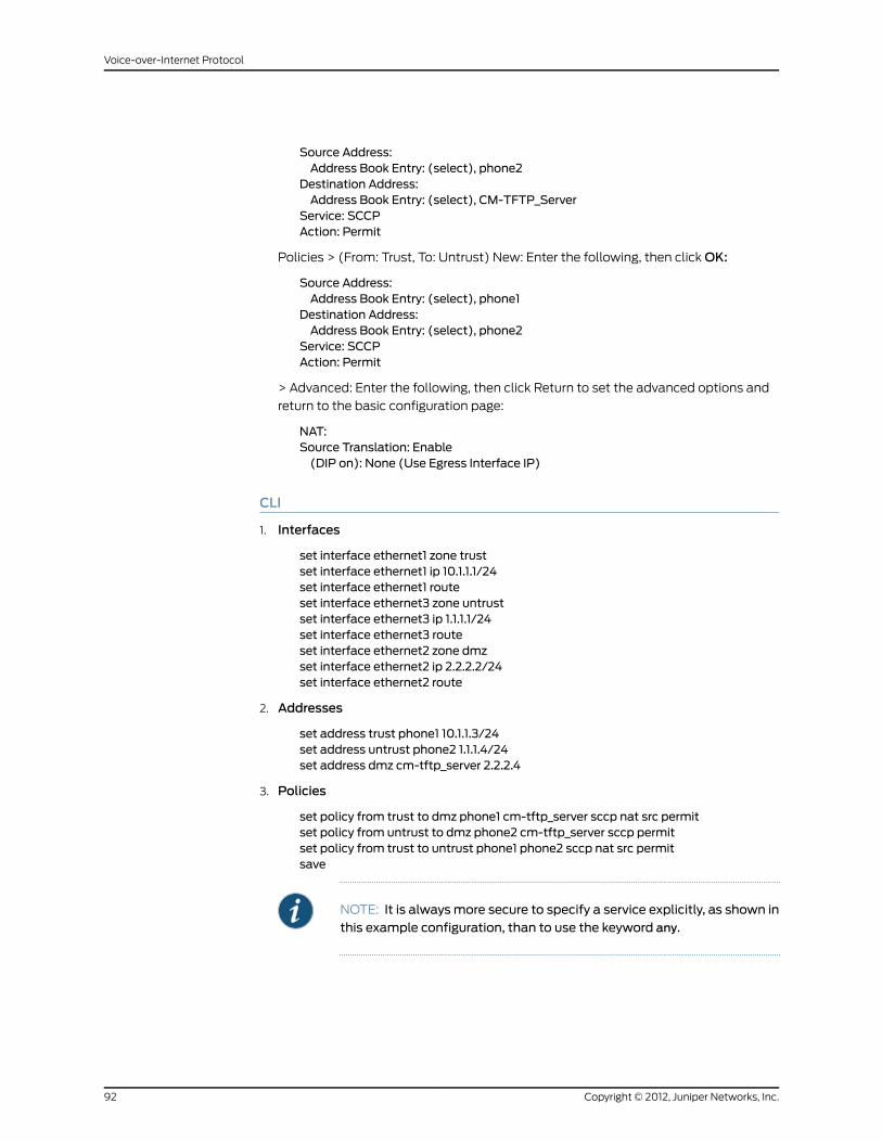
Source Address:Address Book Entry: (select), phone2
Destination Address:Address Book Entry: (select), CM-TFTP_Server
Service: SCCPAction: Permit
Policies > (From: Trust, To: Untrust) New: Enter the following, then click OK:
Source Address:Address Book Entry: (select), phone1
Destination Address:Address Book Entry: (select), phone2
Service: SCCPAction: Permit
> Advanced: Enter the following, then click Return to set the advanced options and
return to the basic configuration page:
NAT:Source Translation: Enable(DIP on): None (Use Egress Interface IP)
CLI
1. Interfaces
set interface ethernet1 zone trustset interface ethernet1 ip 10.1.1.1/24set interface ethernet1 routeset interface ethernet3 zone untrustset interface ethernet3 ip 1.1.1.1/24set interface ethernet3 routeset interface ethernet2 zone dmzset interface ethernet2 ip 2.2.2.2/24set interface ethernet2 route
2. Addresses
set address trust phone1 10.1.1.3/24set address untrust phone2 1.1.1.4/24set address dmz cm-tftp_server 2.2.2.4
3. Policies
set policy from trust to dmz phone1 cm-tftp_server sccp nat src permitset policy from untrust to dmz phone2 cm-tftp_server sccp permitset policy from trust to untrust phone1 phone2 sccp nat src permitsave
NOTE: It is alwaysmore secure to specify a service explicitly, as shown inthis example configuration, than to use the keyword any.
Copyright © 2012, Juniper Networks, Inc.92
Voice-over-Internet Protocol

Example: Intrazone, Call Manager/TFTP Server in Trust Zone
In this example, phone1 is on the ethernet4 interface in the Untrust zone, phone2 is in a
subnet on the ethernet3 interface in the Untrust zone, and the Call Manager/TFTP Server
is on the ethernet1 interface in the Trust zone. To allow intrazone SCCP traffic between
the two phones in the Untrust zone, you create a loopback interface, add ethernet3 and
ethernet4 to a loopback group, then put a MIP on the loopback interface to the IP address
of the Call Manager/TFTP Server. Creating a loopback interface enables you to use a
single MIP for the Call Manager/TFTP Server in the Trust zone. (For more information
about using loopback interfaces, see MIP and Loopback Interface .) And finally, because
intrazone blocking is on by default, you unset blocking in the Untrust zone to allow
intrazone communication.
Figure 28: Intrazone, Call Manager/TFTP Server in Trust Zone
WebUI
1. Interfaces
Network > Interfaces > Edit (for ethernet1): Enter the following, then click Apply:
93Copyright © 2012, Juniper Networks, Inc.
Chapter 4: Skinny Client Control Protocol Application Layer Gateway
Zone: TrustStatic IP: (select when this option is present)IP Address/Netmask: 10.1.1.1/24
Enter the following, then click OK:
Interface Mode: NAT
Network > Interfaces > Edit (for ethernet4): Enter the following, then click OK:
Zone: UntrustStatic IP: (select when this option is present)IP Address/Netmask: 1.1.1.1/24
Network > Interfaces > Edit (for ethernet3): Enter the following, then click OK:
Zone: UntrustStatic IP: (select when this option is present)IP Address/Netmask: 1.1.2.1/24
Network > Interfaces > New Loopback IF: Enter the following, then click OK:
Interface Name: loopback.1Zone: Untrust (trust-vr)IP Address/Netmask: 1.1.4.1/24
2. Addresses
Policy > Policy Elements > Addresses > List > New: Enter the following, then clickOK:
Address Name: CM-TFTP_ServerIP Address/Domain Name:IP/Netmask: (select), 10.1.1.5/32
Zone: Trust
Policy > Policy Elements > Addresses > List > New: Enter the following, then clickOK:
Address Name: phone1IP Address/Domain Name:IP/Netmask: (select), 1.1.1.4/32
Zone: Untrust
Policy > Policy Elements > Addresses > List > New: Enter the following, then clickOK:
Address Name: phone2IP Address/Domain Name:IP/Netmask: (select), 1.1.2.4/32
Zone: Untrust
3. Loopback Group
Network > Interfaces > Edit (for ethernet3): Enter the following, then click OK:
Asmember of loopback group: (select) loopback.1Zone Name: Untrust
Network > Interfaces > Edit (for ethernet4): Enter the following, then click OK:
Asmember of loopback group: (select) loopback.1Zone Name: Untrust
4. MIP
Copyright © 2012, Juniper Networks, Inc.94
Voice-over-Internet Protocol

Network > Interfaces > Edit (for loopback.1) > MIP > New: Enter the following, then
click OK:
Mapped IP: 1.1.4.5Netmask: 255.255.255.255Host IP Address: 10.1.1.5Host Virtual Router Name: trust-vr
5. Blocking
Network > Zones > Edit (for Untrust): Enter the following, then click OK:
Block Intra-Zone Traffic: (clear)
6. Policies
Policies > (From: Trust, To: Untrust) New: Enter the following, then click OK:
Source Address:Address Book Entry: (select), CM-TFTP_Server
Destination Address:Address Book Entry: (select), Any
Service: SCCPAction: Permit
> Advanced: Enter the following, then click Return to set the advanced options and
return to the basic configuration page:
NAT:Source Translation: Enable(DIP on): None (Use Egress Interface IP)
Policies > (From: Untrust, To: Trust) New: Enter the following, then click OK:
Source Address:Address Book Entry: (select), Any
Destination Address:Address Book Entry: (select), MIP(1.1.4.5)
Service: SCCPAction: Permit
CLI
1. Interfaces
set interface ethernet1 zone trustset interface ethernet1 ip 10.1.1.1/24set interface ethernet1 routeset interface ethernet3 zone untrustset interface ethernet3 ip 1.1.2.1/24set interface ethernet3 routeset interface ethernet4 zone untrustset interface ethernet4 ip 1.1.1.1/24set interface ethernet4 routeset interface loopback.1 zone untrustset interface loopback.1 ip 1.1.4.1/24set interface loopback.1 route
2. Addresses
95Copyright © 2012, Juniper Networks, Inc.
Chapter 4: Skinny Client Control Protocol Application Layer Gateway
set address trust cm-tftp_server 10.1.1.5/32set address untrust phone1 1.1.1.4/32set address untrust phone2 1.1.2.4/32
3. Loopback Group
set interface ethernet3 loopback-group loopback.1set interface ethernet4 loopback-group loopback.1
4. MIP
set interface loopback.1 mip 1.1.4.5 host 10.1.1.5
5. Blocking
unset zone untrust block
6. Policies
set policy from trust to untrust cm/tftp_server any sccp nat src permitset policy from untrust to trust anymip(1.1.4.5) sccp permitsave
NOTE: Although, in this example, you unset blocking in the Untrust zoneto allow intrazone communication, you can accomplish the same thingby creating the following policy:
set policy from untrust to untrust any any sccp permit
Note, also, that it is alwaysmore secure to specify a service explicitly, asshown in this example configuration, than to use the keyword any.
Example: Intrazone, Call Manager/TFTP Server in Untrust Zone
In this example, phone1 is on the ethernet1 interface in the Trust zone, phone 2 is on the
ethernet2 interface in a subnet in the Trust zone, and the Call Manager/TFTP Server is
on the ethernet3 interface in the Untrust zone. After configuring interfaces and addresses,
you create a policy from Trust to Untrust to allow phone1 and phone2 to register with
the Call Manager/TFTP Server in the Untrust zone. Blocking is off by default in the Trust
zone (as it is in custom zones you define), so it is not necessary to create. However, for
greater security, you could optionally turn blocking off, and create a policy from Trust to
Trust. This would allow you to specify the SCCP service, and restrict intrazone calls to
phone1 and phone2.
Copyright © 2012, Juniper Networks, Inc.96
Voice-over-Internet Protocol

Figure 29: Intrazone, Call Manager/TFTP Server in Trust Zone
WebUI
1. Interfaces
Network > Interfaces > Edit (for ethernet1): Enter the following, then click Apply:
Zone: TrustStatic IP: (select when this option is present)IP Address/Netmask: 10.1.1.1/24Enter the following, then click OK:Interface Mode: route
Network > Interfaces > Edit (for ethernet2): Enter the following, then click Apply:
Zone: TrustStatic IP: (select when this option is present)IP Address/Netmask: 10.1.2.1/24Enter the following, then clickOK:Interface Mode: routeZone: UntrustStatic IP: (select when this option is present)IP Address/Netmask: 3.3.3.3/24
2. Addresses
Policy > Policy Elements > Addresses > List > New: Enter the following, then clickOK:
Address Name: phone1IP Address/Domain Name:IP/Netmask: (select), 10.1.1.3/24
Zone: Trust
Policy > Policy Elements > Addresses > List > New: Enter the following, then clickOK:
Address Name: phone2IP Address/Domain Name:IP/Netmask: (select), 10.1.2.2/24
Zone: Trust
Policy > Policy Elements > Addresses > List > New: Enter the following, then clickOK:
Address Name: CM/TFTP ServerIP Address/Domain Name:IP/Netmask: (select), 3.3.3.4/24
Zone: Untrust
3. Policies
97Copyright © 2012, Juniper Networks, Inc.
Chapter 4: Skinny Client Control Protocol Application Layer Gateway
Policies > (From: Trust, To: Untrust) New: Enter the following, then click OK:
Source Address:Address Book Entry: (select), Any
Destination Address:Address Book Entry: (select), CM/TFTP Server
Service: SCCPAction: Permit
> Advanced: Enter the following, then click Return to set the advanced options and
return to the basic configuration page:
NAT:Source Translation: Enable(DIP on): None (Use Egress Interface IP)
CLI
1. Interfaces
set interface ethernet1 zone trustset interface ethernet1 ip 10.1.1.1/24set interface ethernet2 zone trustset interface ethernet2 ip 10.1.2.1/24set interface ethernet3 zone untrustset interface ethernet3 ip 3.3.3.3/24set interface ethernet3 route
2. Addresses
set address trust phone1 10.1.1.3/24set address trust phone2 10.1.2.2/24set address untrust cm-tftp_server 3.3.3.4/24
3. Policies
set policy from trust to untrust any cm-tftp_server sccp nat src permitsave
NOTE: It is alwaysmore secure to specify a service explicitly, as shown inthis example configuration, than to use the keyword any.
Example: Full-Mesh VPN for SCCP
In this example, the central office and two branch offices are linked by a full-mesh VPN.
Each site has a single security device. The Call Manager/TFTP Server is in the Trust zone
at the Central Office, phone1 is in the Trust zone at Branch Office One, and phone2 is in
the Trust zone at Branch Office Two. All interfaces connecting the devices are in their
respective Untrust zones. On each device, you configure two tunnels, one to each of the
other devices, to create a fully meshed network.
NOTE: The security devices used in this examplemust have at least threeindependently configurable interfaces available.
Copyright © 2012, Juniper Networks, Inc.98
Voice-over-Internet Protocol

Figure 30: Full-Mesh VPN for SCCP
NOTE: It is alwaysmore secure to explicitly specify a service, as shown inthis example configuration, than to use the keyword any.
WebUI (for Central)
1. Interfaces
Network > Interfaces > Edit (for ethernet2/1): Enter the following, then click Apply:
Zone: UntrustStatic IP: (select when this option is present)IP Address/Netmask: 1.1.1.1/24
Network > Interfaces > Edit (for ethernet2/2): Enter the following, then click Apply:
Zone: UntrustStatic IP: (select when this option is present)IP Address/Netmask: 1.1.2.1/24
Network > Interfaces > Edit (for ethernet2/8): Enter the following, then click Apply:
Zone: TrustStatic IP: (select when this option is present)IP Address/Netmask: 10.1.3.1/24
99Copyright © 2012, Juniper Networks, Inc.
Chapter 4: Skinny Client Control Protocol Application Layer Gateway

Enter the following, then click OK:Interfacemode: route
Network > Interfaces > New Tunnel IF: Enter the following, then click Apply:
Tunnel Interface Name: 1Zone (VR): UntrustIP Address / Netmask: 6.6.6.6/24
Network > Interfaces > New Tunnel IF: Enter the following, then click Apply:
Tunnel Interface Name: 2Zone (VR): UntrustIP Address / Netmask: 7.7.7.7/24
2. Address
Policy > Policy Elements > Addresses > List > New: Enter the following, then clickOK:
Address Name: CM/TFTP ServerIPv4/Netmask: 10.1.3.3/32Zone: Trust
3. VPN
VPNs > AutoKey Advanced > Gateway > New: Enter the following, then click OK:
Gateway Name: to-branch-1Security Level: StandardIPvc4/v6 Address/Hostname: 3.3.3.3Preshare Key: netscreenOutgoing Interface: ethernet2/1
VPNs > AutoKey IKE > New: Enter the following, then click OK:
VPNName: vpn-branch-1
Advanced: Enter the following advanced settings, then click Return to return to the
basic Gateway configuration page:
Bind to: (select) Tunnel Interface, tunnel.1
VPNs > AutoKey Advanced > Gateway > New: Enter the following, then click OK:
Gateway Name: to-branch-2Security Level: StandardIPvc4/v6 Address/Hostname: 2.2.2.2Preshare Key: netscreenOutgoing Interface: ethernet2/2
VPNs > AutoKey IKE > New: Enter the following, then click OK:
VPNName: vpn-branch-2
Advanced: Enter the following advanced settings, then click Return to return to the
basic Gateway configuration page:
4. Routing
Network > Routing > Destination > New: Enter the following, then click OK:
Network Address / Netmask: 10.1.1.0/24Interface (select): tunnel.1
Copyright © 2012, Juniper Networks, Inc.100
Voice-over-Internet Protocol

Network > Routing > Destination> New: Enter the following, then click OK:
Network Address / Netmask: 10.1.2.0/24Interface (select): tunnel.2
5. Policies
Policies > (From: Trust, To: Untrust) New Enter the following, then click OK:
Source Address (select) Address Book Entry: CM/TFTP ServerDestination Address (select) Address Book Entry: Any-IPv4Service: SCCPAction: Permit
Policies > (From: Untrust, To: Trust) > New: Enter the following, then click OK:
Source Address (select) Address Book Entry: Any-IPv4Destination Address (select) Address Book Entry: CM/TFTP ServerService: SCCPAction: Permit
CLI (for Central)
1. Interfaces
set interface ethernet2/1 zone untrustset interface ethernet2/1 ip 1.1.1.1/24set interface ethernet2/2 zone untrustset interface ethernet2/2 ip 1.1.2.1/24set interface ethernet2/8 zone trustset interface ethernet2/8 ip 10.1.3.1/24set interface ethernet2/8 routeset interface tunnel.1 zone untrustset interface tunnel.1 ip 6.6.6.6/24set interface tunnel.2 zone untrustset interface tunnel.2 ip 7.7.7.7/24
2. Address
set address trust cm-tftp_server 10.1.3.3/32
3. VPN
set ike gateway to-branch-1 address 3.3.3.3 main outgoing-interface ethernet2/1preshare netscreen sec-level standardset ike gateway to-branch-2 address 2.2.2.2 main outgoing-interface ethernet2/2preshare netscreen sec-level standardset vpn vpn_branch-1 gateway to-branch-1 no-reply tunnel idletime 0 sec-levelstandardset vpn vpn-branch-1 id 1 bind interface tunnel.1set vpn vpn-branch-2 gateway to-branch-2 no-reply tunnel idletime 0 sec-levelstandardset vpn vpn-branch-2 id 2 bind interface tunnel.2
4. Routing
set route 10.1.2.0/24 interface tunnel.2set route 10.1.1.0/24 interface tunnel.1
5. Policies
101Copyright © 2012, Juniper Networks, Inc.
Chapter 4: Skinny Client Control Protocol Application Layer Gateway

set policy from trust to untrust cm-tftp_server any sccp permitset policy from untrust to trust any cm-tftp_server sccp permitsave
WebUI (for Branch Office 1)
1. Interfaces
Network > Interfaces > Edit (for ethernet1): Enter the following, then click Apply:
Zone: TrustStatic IP: (select when this option is present)IP Address/Netmask: 10.1.1.1/24Interfacemode: route
Network > Interfaces > Edit (for ethernet3): Enter the following, then click Apply:
Zone: UntrustStatic IP: (select when this option is present)IP Address/Netmask: 3.3.3.3/24
Network > Interfaces > Edit (for ethernet4): Enter the following, then click Apply:
Zone: UntrustStatic IP: (select when this option is present)IP Address/Netmask: 4.4.4.4/24
Network > Interfaces > New Tunnel IF: Enter the following, then click Apply:
Tunnel Interface Name: 2Zone (VR): UntrustUnnumbered (select) Interface: ethernet3
Network > Interfaces > New Tunnel IF: Enter the following, then click Apply:
Tunnel Interface Name: 3Zone (VR): UntrustUnnumbered (select) Interface: ethernet4
2. Address
Policy > Policy Elements > Addresses > List > New: Enter the following, then clickOK:
Address Name: phone1IPv4/Netmask: 10.1.1.3/32Zone: V1-Trust
3. VPN
VPNs > AutoKey Advanced > Gateway > New: Enter the following, then click OK:
Gateway Name: to-centralSecurity Level: StandardIPvc4/v6 Address/Hostname: 1.1.2.1Preshare Key: netscreenOutgoing Interface: ethernet3
VPNs > AutoKey IKE > New: Enter the following, then click OK:
VPNName: vpn-central
Copyright © 2012, Juniper Networks, Inc.102
Voice-over-Internet Protocol

Advanced: Enter the following advanced settings, then click Return to return to the
basic Gateway configuration page:
Bind to (select): Tunnel Interface, tunnel.1
VPNs > AutoKey Advanced > Gateway > New: Enter the following, then click OK:
Gateway Name: to-ns50Security Level: StandardIPvc4/v6 Address/Hostname: 5.5.5.5Preshare Key: netscreenOutgoing Interface: ethernet4
VPNs > AutoKey IKE > New: Enter the following, then click OK:
VPNName: vpn-ns50
Advanced: Enter the following advanced settings, then click Return to return to the
basic Gateway configuration page:
Bind to (select): Tunnel Interface, tunnel.3
4. Routing
Network > Routing > Destination> New: Enter the following, then click OK:
Network Address / Netmask: 10.1.2.0/24Interface (select): tunnel.3
Network > Routing > Destination > New: Enter the following, then click OK:
Network Address / Netmask: 10.1.3.0/24Interface (select): tunnel.1
5. Policies
Policies > (From: Trust, To: Untrust) > New: Enter the following, then click OK:
Source Address (select) Address Book Entry: phone2Destination Address (select) Address Book Entry: Any-IPv4Service: SCCPAction: Permit
Policies > (From: Untrust, To: Trust) > New: Enter the following, then click OK:
Source Address (select) Address Book Entry: Any-IPv4Destination Address (select) Address Book Entry: phone2Service: SCCPAction: Permit
CLI (for Branch Office 1)
1. Interfaces
set interface ethernet1 zone trustset interface ethernet1 ip 10.1.1.1/24set interface ethernet1 routeset interface ethernet3 zone untrustset interface ethernet3 ip 3.3.3.3/24set interface ethernet4 zone untrustset interface ethernet4 ip 4.4.4.4/24set interface tunnel.2 zone untrust
103Copyright © 2012, Juniper Networks, Inc.
Chapter 4: Skinny Client Control Protocol Application Layer Gateway
set interface tunnel.2 ip unnumbered interface ethernet3set interface tunnel.3 zone untrustset interface tunnel.3 ip unnumbered interface ethernet4
2. Address
set address trust phone1 10.1.1.3/32
3. VPN
set ike gateway to-central address 1.1.1.1 main outgoing-interface ethernet3 presharenetscreen sec-level standardset ike gateway to-ns50 address 5.5.5.5 main outgoing-interface ethernet4 presharenetscreen sec-level standardset vpn vpncentral gateway to-central no-replay tunnel idletime0 sec-level standardset vpn vpncentral bind interface tunnel.1set vpn vpn-ns50 gateway to-ns50 no-replay tunnel idletime 0 sec-level standardset vpn vpn-ns50 bind interface tunnel.3
4. Routes
set route 10.1.2.0/24 interface tunnel.3set route 10.1.3.0/24 interface tunnel.1
5. Policies
set policy from trust to untrust phone1 any sccp permitset policy from untrust to trust any phone1 sccp permitsave
WebUI (for Branch Office 2)
1. Interfaces
Network > Interfaces > Edit (for ethernet1): Enter the following, then click Apply:
Zone: TrustStatic IP: (select when this option is present)IP Address/Netmask: 10.1.2.1/24Enter the following, then click OK:Interfacemode: route
Network > Interfaces > Edit (for ethernet3): Enter the following, then click Apply:
Zone: UntrustStatic IP: (select when this option is present)IP Address/Netmask: 2.2.2.2/24
Network > Interfaces > Edit (for ethernet4): Enter the following, then click Apply:
Zone: UntrustStatic IP: (select when this option is present)IP Address/Netmask: 4.4.4.4/24
Network > Interfaces > New Tunnel IF: Enter the following, then click Apply:
Tunnel Interface Name: 2Zone (VR): UntrustUnnumbered (select) Interface: ethernet3
Network > Interfaces > New Tunnel IF: Enter the following, then click Apply:
Copyright © 2012, Juniper Networks, Inc.104
Voice-over-Internet Protocol
Tunnel Interface Name: 3Zone (VR): UntrustUnnumbered (select) Interface: ethernet4
2. Address
Policy > Policy Elements > Addresses > List > New: Enter the following, then clickOK:
Address Name: phone2IPv4/Netmask: 10.1.2.3/32Zone: Trust
3. VPN
VPNs > AutoKey Advanced > Gateway > New: Enter the following, then click OK:
Gateway Name: to-centralSecurity Level: StandardIPvc4/v6 Address/Hostname: 1.1.2.1Preshare Key: netscreenOutgoing Interface: ethernet3
VPNs > AutoKey IKE > New: Enter the following, then click OK:
VPNName: vpn-central
Advanced: Enter the following advanced settings, then click Return to return to the
basic Gateway configuration page:
Bind to (select): Tunnel Interface, tunnel.2
VPNs > AutoKey Advanced > Gateway > New: Enter the following, then click OK:
Gateway Name: to-ns50Security Level: StandardIPvc4/v6 Address/Hostname: 4.4.4.4Preshare Key: netscreenOutgoing Interface: ethernet4
VPNs > AutoKey IKE > New: Enter the following, then click OK:
VPNName: vpn-ns50
Advanced: Enter the following advanced settings, then click Return to return to the
basic Gateway configuration page:
Bind to (select): Tunnel Interface, tunnel.3
4. Routing
Network > Routing > Destination > New: Enter the following, then click OK:
Network Address / Netmask: 10.1.3.0/24Interface (select): tunnel.2
Network > Routing > Destination > New: Enter the following, then click OK:
Network Address / Netmask: 10.1.1.0/24Interface (select): tunnel.3
5. Policies
Policies > (From: Trust, To: Untrust) New Enter the following, then click OK:
105Copyright © 2012, Juniper Networks, Inc.
Chapter 4: Skinny Client Control Protocol Application Layer Gateway

Source Address (select) Address Book Entry: phone2Destination Address (select) Address Book Entry: Any-IPv4Service: SCCPAction: Permit
Policies > (From: Untrust, To: Trust) > New: Enter the following, then click OK:
Source Address (select) Address Book Entry: Any-IPv4Destination Address (select) Address Book Entry: phone2Service: SCCPAction: Permit
CLI (for Branch Office 2)
1. Interfaces
set interface ethernet1 zone trustset interface ethernet1 ip 10.1.2.1/24set interface ethernet1 routeset interface ethernet3 zone untrustset interface ethernet3 ip 2.2.2.2/24set interface ethernet4 zone untrustset interface ethernet4 ip 4.4.4.4/24set interface tunnel.2 zone untrustset interface tunnel.2 ip unnumbered interface ethernet3set interface tunnel.3 zone untrustset interface tunnel.3 ip unnumbered interface ethernet4
2. Address
set address trust phone1 10.1.2.3/32
3. VPN
set ike gateway to-central address 1.1.1.1 Main outgoing-interface ethernet3 presharenetscreen sec-level standardset ike gateway to-ns50 address 4.4.4.4 Main outgoing-interface ethernet4 presharenetscreen sec-level standardset vpn vpncentral gateway to-central no-replay tunnel idletime0 sec-level standardset vpn vpncentral id 4 bind interface tunnel.2set vpn vpn-ns50 gateway to-ns50 no-replay tunnel idletime 0 sec-level standardset vpn vpn-ns50 id 5 bind interface tunnel.3
4. Routes
set route 10.1.3.0/24 interface tunnel.1set route 10.1.2.0/24 interface tunnel.3
5. Policies
set policy from trust to untrust phone2 any sccp permitset policy from untrust to trust any phone2 sccp permitsave
Copyright © 2012, Juniper Networks, Inc.106
Voice-over-Internet Protocol
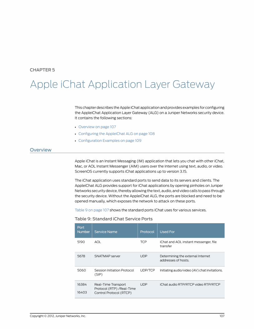
CHAPTER 5
Apple iChat Application Layer Gateway
This chapter describes the Apple iChat application and provides examples for configuring
the AppleiChat Application Layer Gateway (ALG) on a Juniper Networks security device.
It contains the following sections:
• Overview on page 107
• Configuring the AppleiChat ALG on page 108
• Configuration Examples on page 109
Overview
Apple iChat is an Instant Messaging (IM) application that lets you chat with other iChat,
Mac, or AOL Instant Messenger (AIM) users over the Internet using text, audio, or video.
ScreenOS currently supports iChat applications up to version 3.15.
The iChat application uses standard ports to send data to its servers and clients. The
AppleiChat ALG provides support for iChat applications by opening pinholes on Juniper
Networks security device, thereby allowing the text, audio, and video calls to pass through
the security device. Without the AppleiChat ALG, the ports are blocked and need to be
opened manually, which exposes the network to attack on these ports.
Table 9 on page 107 shows the standard ports iChat uses for various services.
Table 9: Standard iChat Service Ports
Used ForProtocolService NamePortNumber
iChat and AOL instant messenger, filetransfer
TCPAOL5190
Determining the external Internetaddresses of hosts.
UDPSNATMAP server5678
Initiating audio/video (AV) chat invitations.UDP/TCPSession Initiation Protocol(SIP)
5060
iChat audio RTP/RTCP video RTP/RTCPUDPReal-Time TransportProtocol (RTP) /Real-TimeControl Protocol (RTCP)
16384
16403
107Copyright © 2012, Juniper Networks, Inc.

For a list of well-known ports, seehttp://docs.info.apple.com/article.html?artnum=106439
The iChat service uses the AOL and SIP protocols for its audio/video operations. It uses
the AIM protocol to connect to servers. SIP is used for setting audio/video sessions
between IM clients after they successfully negotiate ports. The SIP ALG creates pinholes
for audio/video sessions. SIP is a predefined service in ScreenOS and uses port 5060 as
the destination port. During iChat operation, the security device creates separate sessions
for AOL and SIP.
NOTE: The ALG does not open all ports when you enable the AppleiChatALG on the security device. ALG opens pinholes only for the ports that areexchanged during iChat signalingmessages.
The number of iChat sessions that the security device can handle is limited to the
maximum number of Network Address Translation (NAT) cookies available for that
particular security device.
NOTE: The NAT cookies available for a security device are shared by otherALGs like H.323 and P2P ALG.
You can view the maximum number of NAT cookies available for a particular device using
the following CLI command:
get nat cookie
For information about running iChat in NAT mode, see
http://docs.info.apple.com/article.html?artnum=93208
Configuring the AppleiChat ALG
You configure the AppleiChat ALG with the WebUI or the CLI.
WebUI
Security>ALG>Apple iChat. Select the following, then click Apply:AppleiChat Enable (select)
CLI
set alg appleichat enable
When you enable the AppleiChat ALG functionality, the security device opens pinholes
for the configured call-answer-time to establish the iChat audio/video session. The
call-answer-time is the duration of time for which the security device opens the pinholes
for establishing iChat audio/video session. The default value of call-answer-time is 32
seconds. When this timer expires, the device closes the pinholes. The range for configuring
the call-answer-time is 20 to 90 seconds.
To configure a call-answer-time of 30 seconds:
Copyright © 2012, Juniper Networks, Inc.108
Voice-over-Internet Protocol
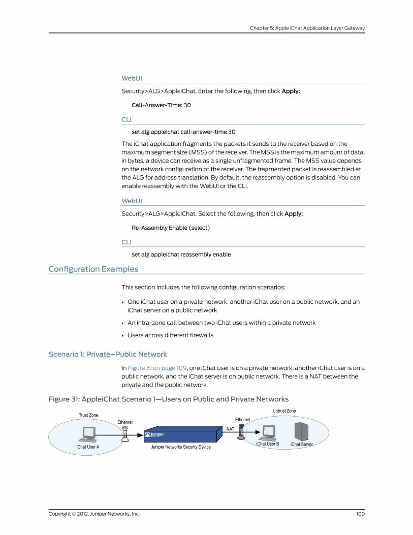
WebUI
Security>ALG>AppleiChat. Enter the following, then click Apply:
Call-Answer-Time: 30
CLI
set alg appleichat call-answer-time 30
The iChat application fragments the packets it sends to the receiver based on the
maximum segment size (MSS) of the receiver. The MSS is the maximum amount of data,
in bytes, a device can receive as a single unfragmented frame. The MSS value depends
on the network configuration of the receiver. The fragmented packet is reassembled at
the ALG for address translation. By default, the reassembly option is disabled. You can
enable reassembly with the WebUI or the CLI.
WebUI
Security>ALG>AppleiChat. Select the following, then click Apply:
Re-Assembly Enable (select)
CLI
set alg appleichat reassembly enable
Configuration Examples
This section includes the following configuration scenarios:
• One iChat user on a private network, another iChat user on a public network, and an
iChat server on a public network
• An intra-zone call between two iChat users within a private network
• Users across different firewalls
Scenario 1: Private–Public Network
In Figure 31 on page 109, one iChat user is on a private network, another iChat user is on a
public network, and the iChat server is on public network. There is a NAT between the
private and the public network.
Figure 31: AppleiChat Scenario 1—Users on Public and Private Networks
109Copyright © 2012, Juniper Networks, Inc.
Chapter 5: Apple iChat Application Layer Gateway
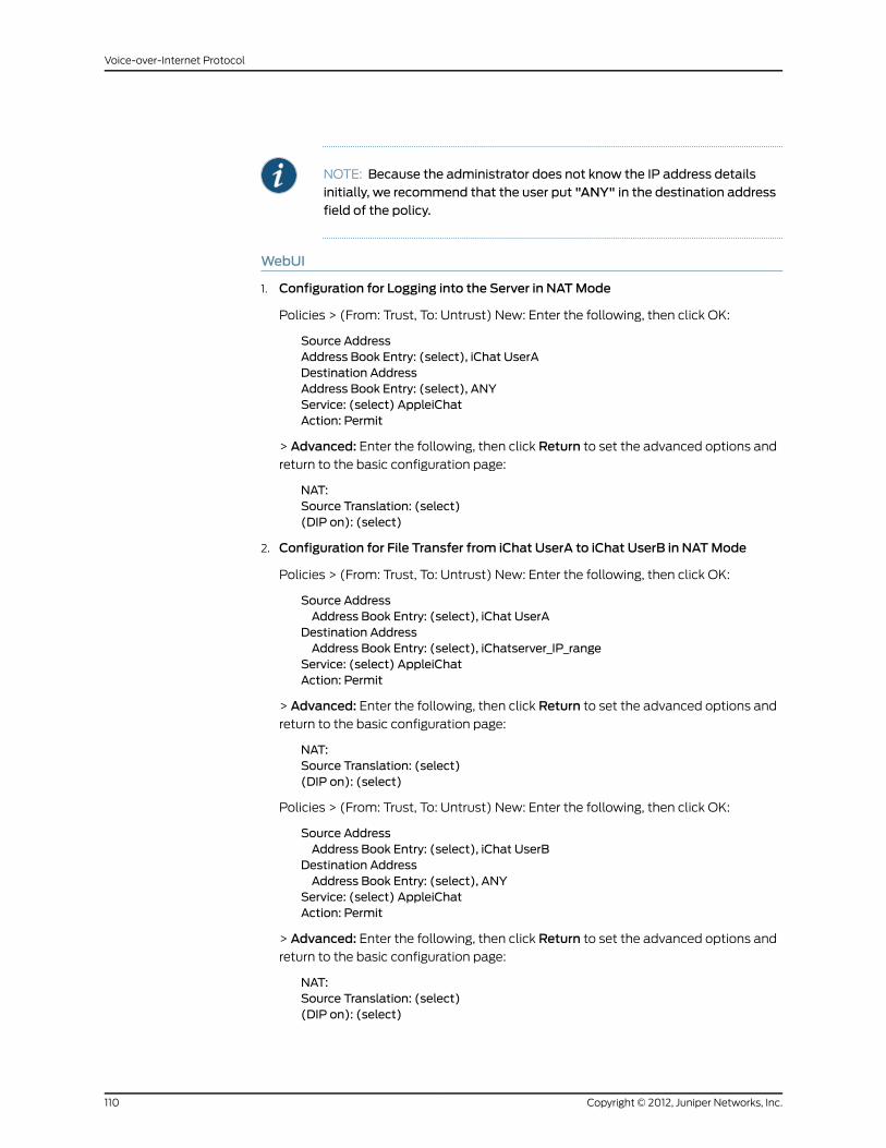
NOTE: Because the administrator does not know the IP address detailsinitially, we recommend that the user put "ANY" in the destination addressfield of the policy.
WebUI
1. Configuration for Logging into the Server in NATMode
Policies > (From: Trust, To: Untrust) New: Enter the following, then click OK:
Source AddressAddress Book Entry: (select), iChat UserADestination AddressAddress Book Entry: (select), ANYService: (select) AppleiChatAction: Permit
> Advanced: Enter the following, then click Return to set the advanced options and
return to the basic configuration page:
NAT:Source Translation: (select)(DIP on): (select)
2. Configuration for File Transfer from iChat UserA to iChat UserB in NATMode
Policies > (From: Trust, To: Untrust) New: Enter the following, then click OK:
Source AddressAddress Book Entry: (select), iChat UserA
Destination AddressAddress Book Entry: (select), iChatserver_IP_range
Service: (select) AppleiChatAction: Permit
> Advanced: Enter the following, then click Return to set the advanced options and
return to the basic configuration page:
NAT:Source Translation: (select)(DIP on): (select)
Policies > (From: Trust, To: Untrust) New: Enter the following, then click OK:
Source AddressAddress Book Entry: (select), iChat UserB
Destination AddressAddress Book Entry: (select), ANY
Service: (select) AppleiChatAction: Permit
> Advanced: Enter the following, then click Return to set the advanced options and
return to the basic configuration page:
NAT:Source Translation: (select)(DIP on): (select)
Copyright © 2012, Juniper Networks, Inc.110
Voice-over-Internet Protocol
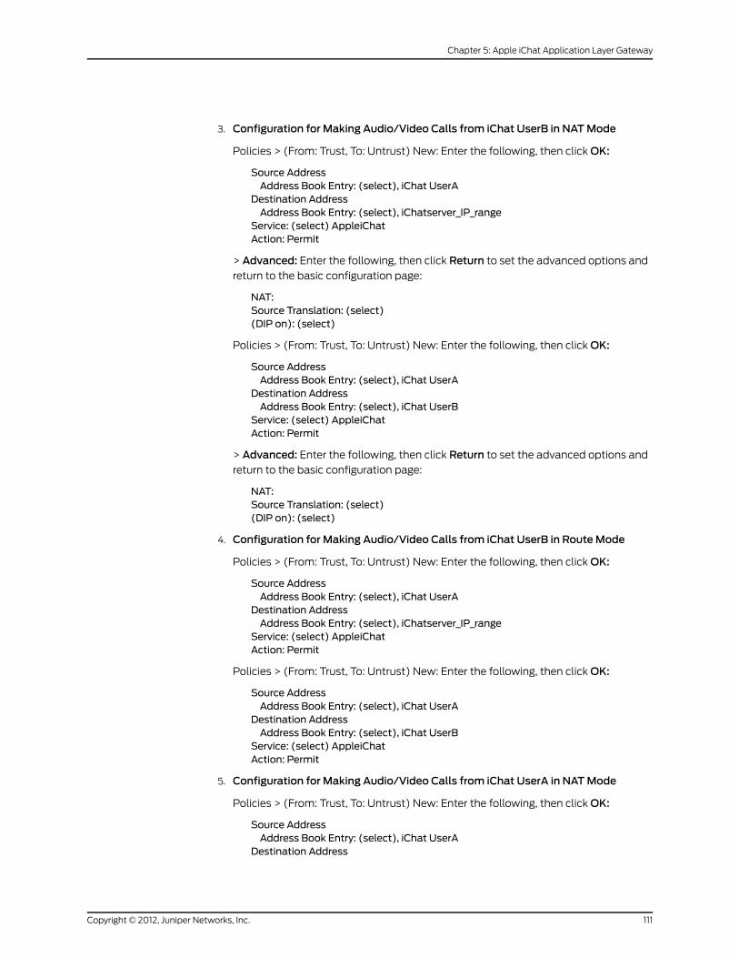
3. Configuration for Making Audio/Video Calls from iChat UserB in NATMode
Policies > (From: Trust, To: Untrust) New: Enter the following, then click OK:
Source AddressAddress Book Entry: (select), iChat UserA
Destination AddressAddress Book Entry: (select), iChatserver_IP_range
Service: (select) AppleiChatAction: Permit
> Advanced: Enter the following, then click Return to set the advanced options and
return to the basic configuration page:
NAT:Source Translation: (select)(DIP on): (select)
Policies > (From: Trust, To: Untrust) New: Enter the following, then click OK:
Source AddressAddress Book Entry: (select), iChat UserA
Destination AddressAddress Book Entry: (select), iChat UserB
Service: (select) AppleiChatAction: Permit
> Advanced: Enter the following, then click Return to set the advanced options and
return to the basic configuration page:
NAT:Source Translation: (select)(DIP on): (select)
4. Configuration for Making Audio/Video Calls from iChat UserB in RouteMode
Policies > (From: Trust, To: Untrust) New: Enter the following, then click OK:
Source AddressAddress Book Entry: (select), iChat UserA
Destination AddressAddress Book Entry: (select), iChatserver_IP_range
Service: (select) AppleiChatAction: Permit
Policies > (From: Trust, To: Untrust) New: Enter the following, then click OK:
Source AddressAddress Book Entry: (select), iChat UserA
Destination AddressAddress Book Entry: (select), iChat UserB
Service: (select) AppleiChatAction: Permit
5. Configuration for Making Audio/Video Calls from iChat UserA in NATMode
Policies > (From: Trust, To: Untrust) New: Enter the following, then click OK:
Source AddressAddress Book Entry: (select), iChat UserA
Destination Address
111Copyright © 2012, Juniper Networks, Inc.
Chapter 5: Apple iChat Application Layer Gateway

Address Book Entry: (select), iChatserver_IP_rangeService: (select) AppleiChatAction: Permit
> Advanced: Enter the following, then click Return to set the advanced options and
return to the basic configuration page:
NAT:Source Translation: (select)(DIP on): (select)
Policies > (From: Trust, To: Untrust) New: Enter the following, then click OK:
Source AddressAddress Book Entry: (select), iChat UserA
Destination AddressAddress Book Entry: (select), iChat UserB
Service: (select) AppleiChatAction: Permit
> Advanced: Enter the following, then click Return to set the advanced options and
return to the basic configuration page:
NAT:Source Translation: (select)(DIP on): (select)
6. Configuration for Making Audio/Video Calls from iChat UserA in RouteMode
Policies > (From: Trust, To: Untrust) New: Enter the following, then click OK:
Source AddressAddress Book Entry: (select), iChat UserA
Destination AddressAddress Book Entry: (select), iChatserver_IP_range
Service: (select) AppleiChatAction: Permit
Policies > (From: Trust, To: Untrust) New: Enter the following, then click OK:
Source AddressAddress Book Entry: (select), iChat UserA
Destination AddressAddress Book Entry: (select), iChat UserB
Service: (select) AppleiChatAction: Permit
CLI
1. Configuration for Logging into the Server in NATMode
set policy from trust to untrust "ichatUserA" "ANY" apple-ichat nat src permit
OR
set policy from trust to untrust "ichatUserA" "iChatserver_IP_range" apple-ichat natsrc permit
Copyright © 2012, Juniper Networks, Inc.112
Voice-over-Internet Protocol
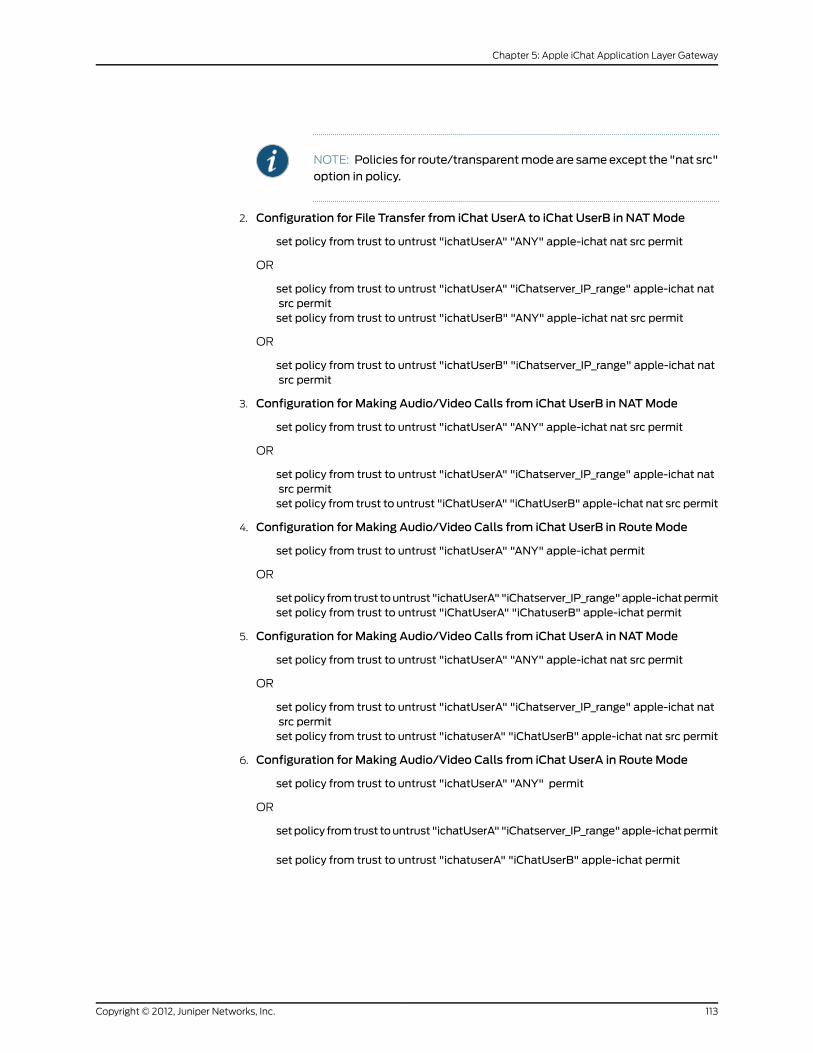
NOTE: Policies for route/transparentmodeare sameexcept the "nat src"option in policy.
2. Configuration for File Transfer from iChat UserA to iChat UserB in NATMode
set policy from trust to untrust "ichatUserA" "ANY" apple-ichat nat src permit
OR
set policy from trust to untrust "ichatUserA" "iChatserver_IP_range" apple-ichat natsrc permitset policy from trust to untrust "ichatUserB" "ANY" apple-ichat nat src permit
OR
set policy from trust to untrust "ichatUserB" "iChatserver_IP_range" apple-ichat natsrc permit
3. Configuration for Making Audio/Video Calls from iChat UserB in NATMode
set policy from trust to untrust "ichatUserA" "ANY" apple-ichat nat src permit
OR
set policy from trust to untrust "ichatUserA" "iChatserver_IP_range" apple-ichat natsrc permitset policy from trust to untrust "iChatUserA" "iChatUserB" apple-ichat nat src permit
4. Configuration for Making Audio/Video Calls from iChat UserB in RouteMode
set policy from trust to untrust "ichatUserA" "ANY" apple-ichat permit
OR
setpolicy fromtrust tountrust "ichatUserA""iChatserver_IP_range"apple-ichatpermitset policy from trust to untrust "iChatUserA" "iChatuserB" apple-ichat permit
5. Configuration for Making Audio/Video Calls from iChat UserA in NATMode
set policy from trust to untrust "ichatUserA" "ANY" apple-ichat nat src permit
OR
set policy from trust to untrust "ichatUserA" "iChatserver_IP_range" apple-ichat natsrc permitset policy from trust to untrust "ichatuserA" "iChatUserB" apple-ichat nat src permit
6. Configuration for Making Audio/Video Calls from iChat UserA in RouteMode
set policy from trust to untrust "ichatUserA" "ANY" permit
OR
setpolicy fromtrust tountrust "ichatUserA""iChatserver_IP_range"apple-ichatpermit
set policy from trust to untrust "ichatuserA" "iChatUserB" apple-ichat permit
113Copyright © 2012, Juniper Networks, Inc.
Chapter 5: Apple iChat Application Layer Gateway
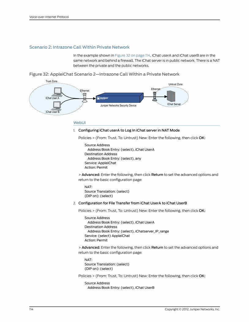
Scenario 2: Intrazone Call Within Private Network
In the example shown in Figure 32 on page 114, iChat userA and iChat userB are in the
same network and behind a firewall. The iChat server is in public network. There is a NAT
between the private and the public networks.
Figure 32: AppleiChat Scenario 2—Intrazone Call Within a Private Network
WebUI
1. Configuring iChat userA to Log In iChat server in NATMode
Policies > (From: Trust, To: Untrust) New: Enter the following, then click OK:
Source AddressAddress Book Entry: (select), iChat UserA
Destination AddressAddress Book Entry: (select), any
Service: AppleiChatAction: Permit
> Advanced: Enter the following, then click Return to set the advanced options and
return to the basic configuration page:
NAT:Source Translation: (select)(DIP on): (select)
2. Configuration for File Transfer from iChat UserA to iChat UserB
Policies > (From: Trust, To: Untrust) New: Enter the following, then click OK:
Source AddressAddress Book Entry: (select), iChat UserA
Destination AddressAddress Book Entry: (select), iChatserver_IP_range
Service: (select) AppleiChatAction: Permit
> Advanced: Enter the following, then click Return to set the advanced options and
return to the basic configuration page:
NAT:Source Translation: (select)(DIP on): (select)
Policies > (From: Trust, To: Untrust) New: Enter the following, then click OK:
Source AddressAddress Book Entry: (select), iChat UserB
Copyright © 2012, Juniper Networks, Inc.114
Voice-over-Internet Protocol

Destination AddressAddress Book Entry: (select), ANY
Service: (select) AppleiChatAction: Permit
> Advanced: Enter the following, then click Return to set the advanced options and
return to the basic configuration page:
NAT:Source Translation: (select)(DIP on): (select)
3. Configuration for Making Audio/Video Calls from iChat UserA in NATMode
Policies > (From: Trust, To: Untrust) New: Enter the following, then click OK:
Source AddressAddress Book Entry: (select), iChat UserA
Destination AddressAddress Book Entry: (select), ANY
Service: (select) AppleiChatAction: Permit
> Advanced: Enter the following, then click Return to set the advanced options and
return to the basic configuration page:
NAT:Source Translation: (select)(DIP on): (select)
4. Configuration for Making Audio/Video Calls from iChat UserA in RouteMode
Policies > (From: Trust, To: Untrust) New: Enter the following, then click OK:
Source AddressAddress Book Entry: (select), iChat UserA
Destination AddressAddress Book Entry: (select), ichatServer
Service: (select) AppleiChatAction: Permit
5. Configuration for Making Audio/Video Calls from iChat UserB in NATMode
Policies > (From: Trust, To: Untrust) New: Enter the following, then click OK:
Source AddressAddress Book Entry: (select), iChat UserB
Destination AddressAddress Book Entry: (select), iChatServer
Service: (select) AppleiChatAction: Permit
> Advanced: Enter the following, then click Return to set the advanced options and
return to the basic configuration page:
NAT:Source Translation: (select)(DIP on): (select)
6. Configuration for Making Audio/Video Calls from iChat UserB in RouteMode
115Copyright © 2012, Juniper Networks, Inc.
Chapter 5: Apple iChat Application Layer Gateway

Policies > (From: Trust, To: Untrust) New: Enter the following, then click OK:
Source AddressAddress Book Entry: (select), iChat UserB
Destination AddressAddress Book Entry: (select), iChatServer
Service: (select) AppleiChatAction: Permit
CLI
1. Configuring iChat UserA to Log Into iChat Server in NATMode
set policy from trust to untrust "ichatUserA" "ANY" apple-ichat nat src permit
OR
set policy from trust to untrust "ichatUserA" "iChatServer_IP_range" apple-ichat natsrc permit
2. Configuration for File Transfer Between UserA and UserB
set policy from trust to untrust "ichatUserA" "ANY" apple-ichat nat src permit
OR
set policy from trust to untrust "ichatUserA" "iChatServer_IP_range" apple-ichat natsrc permitset policy from trust to untrust "ichatUserB" "ANY" apple-ichat nat src permit
OR
set policy from trust to untrust "ichatUserB" "iChatServer_IP_range" apple-ichat natsrc permit
3. Configuration for Making Audio/Video Calls from iChat UserA in NATMode
set policy from trust to untrust "ichatUserA" "ANY" apple-ichat nat src permit
OR
set policy from trust to untrust "ichatUserA" "iChatserver_IP_range" apple-ichat natsrc permit
4. Configuration for Making Audio/Video Calls from iChat UserA in RouteMode
setpolicy fromtrust tountrust "ichatUserA""iChatserver_IP_range"apple-ichatpermit
5. Configuration for Making Audio/Video Calls from iChat UserB in NATMode
set policy from trust to untrust "ichatUserB" "iChatserver_IP_range" apple-ichat natsrc permit
6. Configuration for Making Audio/Video Calls from iChat UserB in RouteMode
setpolicy fromtrust tountrust "ichatUserB""iChatserver_IP_range"apple-ichatpermit
Scenario 3: Users Across Different Networks
In Figure 33 on page 117, iChat userA is on a private network and iChat userB and userC
are on another private network. The iChat server is on a public network. There is NAT
between private networks and the public network.
Copyright © 2012, Juniper Networks, Inc.116
Voice-over-Internet Protocol

Figure 33: AppleiChat Scenario 3—Users Across Different Networks
WebUI
1. Configuration on Firewall 1 for Login from iChat UserA in NATMode
Policies > (From: Trust, To: Untrust) New: Enter the following, then click OK:
Source AddressAddress Book Entry: (select), iChat UserA
Destination AddressAddress Book Entry: (select), any
Service: (select) AppleiChatAction: Permit
> Advanced: Enter the following, then click Return to set the advanced options and
return to the basic configuration page:
NAT:Source Translation: (select)(DIP on): (select)
2. Configuration on Firewall 1 for File Transfer from iChat UserA to iChat UserB in NATMode
Policies > (From: Trust, To: Untrust) New: Enter the following, then click OK:
Source AddressAddress Book Entry: (select), iChat UserA
Destination AddressAddress Book Entry: (select), iChatserver_IP_range
Service: (select) AppleiChatAction: Permit
> Advanced: Enter the following, then click Return to set the advanced options and
return to the basic configuration page:
NAT:Source Translation: (select)(DIP on): (select)
117Copyright © 2012, Juniper Networks, Inc.
Chapter 5: Apple iChat Application Layer Gateway

3. Configuration on Firewall 1 for Making Audio/Video Calls from iChat UserA in NATMode
Policies > (From: Trust, To: Untrust) New: Enter the following, then click OK:
Source AddressAddress Book Entry: (select), iChat UserA
Destination AddressAddress Book Entry: (select), iChatserver_IP_range
Service: (select) AppleiChatAction: Permit
> Advanced: Enter the following, then click Return to set the advanced options and
return to the basic configuration page:
NAT:Source Translation: (select)(DIP on): (select)
Policies > (From: Trust, To: Untrust) New: Enter the following, then click OK:
Source AddressAddress Book Entry: (select), iChat UserA
Destination AddressAddress Book Entry: (select), iChat UserB
Service: (select) AppleiChatAction: Permit
> Advanced: Enter the following, then click Return to set the advanced options and
return to the basic configuration page:
NAT:Source Translation: (select)(DIP on): (select)
4. ConfigurationonFirewall 1 forMakingAudio/VideoCalls from iChatUserA inRouteMode
Policies > (From: Trust, To: Untrust) New: Enter the following, then click OK:
Source AddressAddress Book Entry: (select), iChat UserA
Destination AddressAddress Book Entry: (select), iChatserver_IP_range
Service:(select) AppleiChatAction: Permit
5. Configuration on Firewall 2 for Making Audio/Video Calls from iChat UserB in NATMode
Policies > (From: Trust, To: Untrust) New: Enter the following, then click OK:
Source AddressAddress Book Entry: (select), iChat UserB
Destination AddressAddress Book Entry: (select), iChat server
Service: (select) AppleiChatAction: Permit
Copyright © 2012, Juniper Networks, Inc.118
Voice-over-Internet Protocol

> Advanced: Enter the following, then click Return to set the advanced options and
return to the basic configuration page:
NAT:Source Translation: (select)(DIP on): (select)
Policies > (From: Trust, To: Untrust) New: Enter the following, then click OK:
Source AddressAddress Book Entry: (select), iChat UserB
Destination AddressAddress Book Entry: (select), ichatUserA_public
Service: (select) AppleiChatAction: Permit
> Advanced: Enter the following, then click Return to set the advanced options and
return to the basic configuration page:
NAT:Source Translation: (select)(DIP on): (select)
6. ConfigurationonFirewall 2 forMakingAudio/VideoCalls from iChatUserB inRouteMode
Policies > (From: Trust, To: Untrust) New: Enter the following, then click OK:
Source AddressAddress Book Entry: (select), iChat UserB
Destination AddressAddress Book Entry: (select), iChatserver_IP_range
Service:(select) AppleiChatAction: Permit
Policies > (From: Trust, To: Untrust) New: Enter the following, then click OK:
Source AddressAddress Book Entry: (select), iChat UserB
Destination AddressAddress Book Entry: (select), iChatserver_IP_range
Service:(select) AppleiChatAction: Permit
CLI
1. Configuration on Firewall 1 for Login from iChat UserA in NATMode
set policy from trust to untrust "ichatUserA" "ANY" apple-ichat nat src permit
OR
set policy from trust to untrust "ichatUserA" "iChatServer_IP_range" apple-ichat natsrc permit
2. Configuration on Firewall 1 for File Transfer from iChat UserA to iChat UserB in NATMode
set policy from trust to untrust "ichatUserA" "ANY" apple-ichat nat src permit
OR
119Copyright © 2012, Juniper Networks, Inc.
Chapter 5: Apple iChat Application Layer Gateway

set policy from trust to untrust "ichatUserA" "iChatServer_IP_range" apple-ichat natsrc permit
3. Configuration on Firewall 1 for Making Audio/Video calls from iChat UserA in NATmode
set policy from trust to untrust "ichatUserA" "ANY" apple-ichat nat src permit
OR
set policy from trust to untrust "ichatUserA" "iChatserver_IP_range" apple-ichat natsrc permitset policy from trust to untrust "iChatuserA" "iChatuserB_public" apple-ichat nat srcpermit
4. Configuration on Firewall 1 forMakingAudio/Video calls from iChatUserA inRouteMode
set policy from trust to untrust "ichatUserA" "ANY" apple-ichat permit
OR
setpolicy fromtrust tountrust "ichatUserA""iChatserver_IP_range"apple-ichatpermitset policy from trust to untrust "iChatUserA" "iChatuserB_public" apple-ichat permit
5. Configuration on Firewall 2 for Making Audio/Video Calls from iChat UserB in NATMode
set policy from trust to untrust "ichatUserB" "ANY" apple-ichat nat src permit
OR
set policy from trust to untrust "ichatUserB" "iChatserver_IP_range" apple-ichat natsrc permitset policy from trust to untrust "iChatUserB" "ichatUserA_public" apple-ichat nat srcpermit
6. ConfigurationonFirewall 2 forMakingAudio/VideoCalls from iChatUserB inRouteMode
set policy from trust to untrust "ichatUserB" "ANY" apple-ichat permit
OR
setpolicy fromtrust tountrust "ichatUserB""iChatserver_IP_range"apple-ichatpermitset policy from trust to untrust ""iChatUserB" ichatUserA_public" apple-ichat permit
Copyright © 2012, Juniper Networks, Inc.120
Voice-over-Internet Protocol

PART 2
Index
• Index on page 123
121Copyright © 2012, Juniper Networks, Inc.

Copyright © 2012, Juniper Networks, Inc.122
Voice-over-Internet Protocol

Index
AALGs..............................................................................................18
Apple iChat.....................................................................107
SIP.........................................................................................15
SIP NAT..............................................................................25
alternate gatekeepers..............................................................3
Apple iChat ALG.....................................................................107
call-answer-time.........................................................108
reassembly.....................................................................108
Ccall-answer-time, Apple iChat ALG...............................108
GGatekeeper Confirm (GCF) messages..............................3
IiChat ALG..................................................................................107
Mmessages
GCF.........................................................................................3
RCF.........................................................................................3
multimedia sessions, SIP......................................................15
Ppinholes........................................................................................21
Rreassembly, Apple iChat ALG...........................................108
Registration Confirm (RCF) messages.............................3
SSDP...............................................................................................18
service book, service groups (WebUI)............................63
SIP
ALG................................................................................18, 22
connection information...............................................20
defined................................................................................15
media announcements...............................................20
messages...........................................................................15
multimedia sessions......................................................15
pinholes..............................................................................18
request methods.............................................................16
response codes................................................................17
RTCP...................................................................................20
RTP......................................................................................20
SDP......................................................................................18
signaling.............................................................................18
SIP NAT
call setup....................................................................25, 29
defined...............................................................................25
DIP pool, using a.............................................................36
DIP, using incoming........................................................32
DIP, using interface........................................................34
incoming, with MIP.................................................36, 38
proxy in DMZ....................................................................44
proxy in private zone.............................................40, 86
proxy in public zone.......................................................42
Trust intrazone.................................................................51
untrust intrazone....................................................48, 93
VPN, using full-mesh............................................53, 98
SIP timeouts
session inactivity.............................................................22
Vvoice-over IP
bandwidth management.............................................61
123Copyright © 2012, Juniper Networks, Inc.

Copyright © 2012, Juniper Networks, Inc.124
Voice-over-Internet Protocol
Related Documents