Rules Guidance 2012 Rules for the Classification of Steel Ships Part 4 Hull Equipment 2012 Guidance Relating to the Rules for the Classification of Steel ships Part 4 Hull Equipment

Welcome message from author
This document is posted to help you gain knowledge. Please leave a comment to let me know what you think about it! Share it to your friends and learn new things together.
Transcript

Rule
sG
uid
ance
2012Rules for the Classification of Steel Ships
Part 4 Hull Equipment
2012Guidance Relating to the Rules for the Classification of Steel ships
Part 4 Hull Equipment
2012
Rules for the Classification of Steel Ships
Part 4
Hull Equipment
RA-04-E KOREAN REGISTER OF SHIPPING
- i -
APPLICATION OF PART 4 "HULL EQUIPMENT"
1. Unless expressly specified otherwise, the requirements in these Rules apply to ships for which contracts for construction are signed on or after 1 July 2012.
2. The amendments to the Rules for 2011 edition and their effective date are as follows;
Effective Date : 4 July 2011
Chapter 8 EQUIPMENT NUMBER AND EQUIPMENT
Section 4 Chains
- Table 4.8.8 has been amended.
Effective Date : 1 Jan. 2012
Chapter 3 BOW DOORS, SIDE AND STERN DOORS
Section 1 Bow Doors and Inner Doors
- 108. 1 (1) (B) has been amended.
Effective Date : 1 July 2012
Chapter 1 RUDDERS
Section 11 Propeller Nozzles
- 1103. (1) and (2) have been amended.
Chapter 4 BULWARKS, FREEING PORTS, SIDE SCUTTLES, RECTANGULAR
WINDOWS, SKYLIGHTS VENTILATORS AND PERMANENT
GANGWAYS
Section 3 Side Scuttles, Rectangular Windows and Skylights
- Words have been amended.
Chapter 8 EQUIPMENT NUMBER AND EQUIPMENT
Section 1 General
- Table 4.8.1 has been amended.
Section 8 Side Scuttles
- Words have been amended.
Section 9 Rectangular Windows
- Words have been amended.
- iii -
CONTENTS
CHAPTER 1 RUDDERS ······································································································· 1
Section 1 General ············································································································· 1Section 2 Rudder Force ···································································································· 3Section 3 Rudder Torque ································································································· 4Section 4 Rudder Strength Calculation ··········································································· 7Section 5 Rudder Stocks ·································································································· 7Section 6 Rudder Plates, Rudder Frames and Rudder Main Pieces ····························· 8Section 7 Couplings between Rudder Stocks and Main Pieces ·································· 10Section 8 Pintles ············································································································· 12Section 9 Bearings of Rudder Stocks and Pintles ······················································· 12Section 10 Rudder Accessories ························································································ 14Section 11 Propeller Nozzles ··························································································· 14
CHAPTER 2 HATCHWAYS AND OTHER DECK OPENINGS ································ 17
Section 1 General ··········································································································· 17Section 2 Arrangements ·································································································· 19Section 3 Width of Attached Plating ············································································ 20Section 4 Load Model ···································································································· 21Section 5 Strength Check ······························································································· 22Section 6 Hatch Coamings ····························································································· 30Section 7 Weathertightness, Closing Arrangement, Securing Devices and Stoppers · 32Section 8 Additional Requirements ················································································ 35Section 9 Drainage ·········································································································· 36Section 10 Miscellaneous Openings ················································································· 36
CHAPTER 3 BOW DOORS, SIDE AND STERN DOORS ······································· 39
Section 1 Bow Doors and Inner Doors ········································································ 39Section 2 Side and Stern Doors ···················································································· 48
CHAPTER 4 BULWARKS, FREEING PORTS, SIDE SCUTTLES, RECTANGULAR
WINDOWS, SKYLIGHTS, VENTILATORS AND PERMANENT
GANGWAYS ································································································· 55
Section 1 Bulwarks and Guardrails ··············································································· 55Section 2 Freeing Ports ·································································································· 56Section 3 Side Scuttles, Rectangular Windows and Skylights ···································· 57Section 4 Ventilators ······································································································· 60Section 5 Permanent Gangways ····················································································· 62
CHAPTER 5 MASTS AND DERRICK POSTS ····························································· 63
Section 1 Masts without Cargo Gear ············································································ 63Section 2 Derrick Posts ·································································································· 63
- iv -
CHAPTER 6 CEILINGS AND SPARRINGS ·································································· 65
Section 1 Bottom Ceilings ····························································································· 65Section 2 Sparrings ········································································································· 65
CHAPTER 7 CEMENTING AND PAINTING ································································· 67
Section 1 Cementing ········································································································· 67Section 2 Painting ············································································································· 67
CHAPTER 8 EQUIPMENT NUMBER AND EQUIPMENT ········································· 69
Section 1 General ············································································································· 69Section 2 Equipment Number ·························································································· 70Section 3 Anchors ············································································································· 74Section 4 Chains ··············································································································· 80Section 5 Steel Wire Ropes ····························································································· 90Section 6 Fibre Ropes ······································································································ 96Section 7 Hatch Tarpaulins ······························································································ 98Section 8 Side Scuttles ····································································································· 99Section 9 Rectangular Windows ···················································································· 103
CHAPTER 9 STRENGTH AND SECURING OF SMALL HATCHES,
FITTINGS AND EQUIPMENT ON THE FORE DECK ···················· 109
Section 1 Application and Implementation ··································································· 109Section 2 Strength and Securing of Small Hatches on the Exposed Fore Deck ······ 109Section 3 Strength Requirements for Fore Deck Fittings and Equipment ················· 112
CHAPTER 10 SHIPBOARD EQUIPMENT, FITTINGS AND SUPPORTING HULL
STRUCTURES ASSOCIATED WITH TOWING AND
MOORING ······························································································ 117
Section 1 Definitions and Scope of Application ·························································· 117Section 2 Towing and Mooring ····················································································· 117
CHAPTER 11 ACCESS TO AND WITHIN SPACES IN, AND FORWARD
OF, THE CARGO AREA OF OIL TANKERS AND BULK
CARRIERS ······························································································· 121
Section 1 General ··········································································································· 121Section 2 Technical Provisions for Means of Access for Inspections ······················· 122
Pt 4 Hull Equipment
Ch 1 Rudders Pt 4, Ch 1
Rules for the Classification of Steel Ships 2012 1
CHAPTER 1 RUDDERS
Section 1 General
101. Application
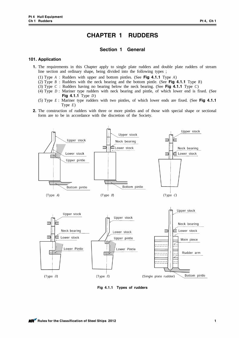
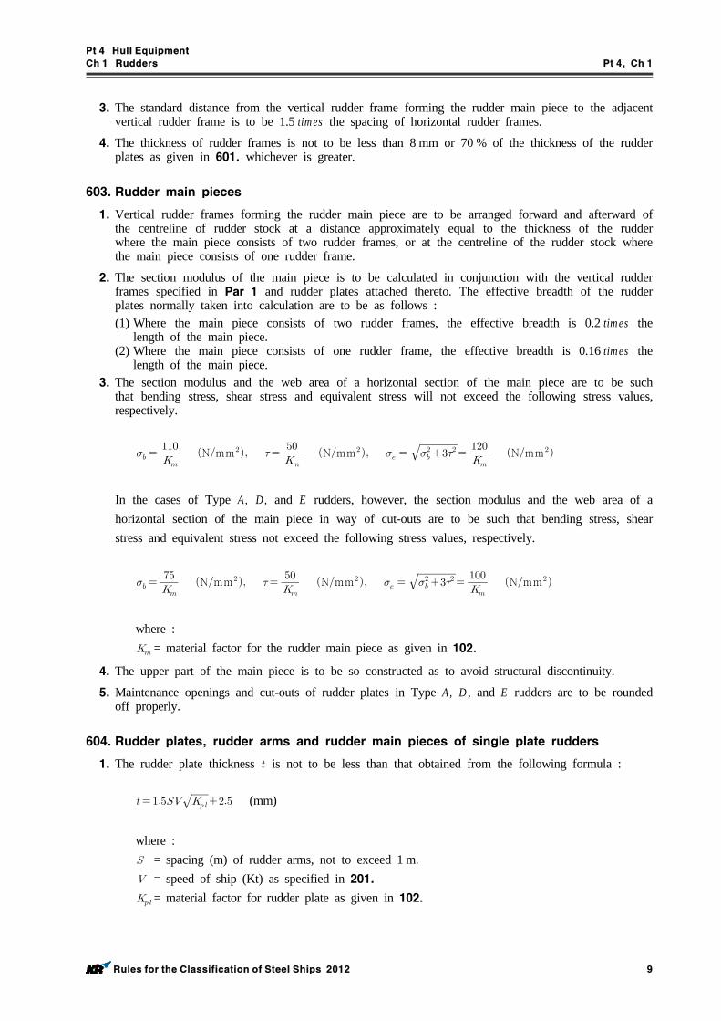
1. The requirements in this Chapter apply to single plate rudders and double plate rudders of stream line section and ordinary shape, being divided into the following types ;(1) Type A : Rudders with upper and bottom pintles. (See Fig 4.1.1 Type A)(2) Type B : Rudders with the neck bearing and the bottom pintle. (See Fig 4.1.1 Type B)(3) Type C : Rudders having no bearing below the neck bearing. (See Fig 4.1.1 Type C)(4) Type D : Mariner type rudders with neck bearing and pintle, of which lower end is fixed. (See
Fig 4.1.1 Type D )(5) Type E : Mariner type rudders with two pintles, of which lower ends are fixed. (See Fig 4.1.1
Type E)2. The construction of rudders with three or more pintles and of those with special shape or sectional
form are to be in accordance with the discretion of the Society.
Fig 4.1.1 Types of rudders
Pt 4 Hull Equipment
Ch 1 Rudders Pt 4, Ch 1
2 Rules for the Classification of Steel Ships 2012
3. The construction of rudders designed to move more than 35 degrees on one side is to be in ac-cordance with the discretion of the Society.
102. Materials
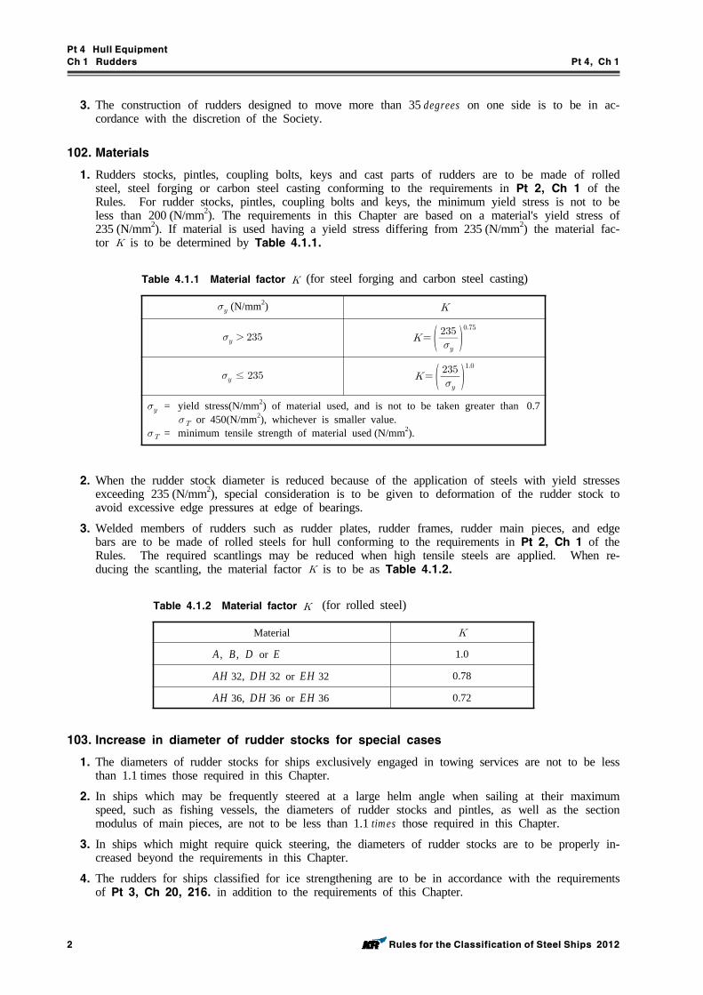
1. Rudders stocks, pintles, coupling bolts, keys and cast parts of rudders are to be made of rolled steel, steel forging or carbon steel casting conforming to the requirements in Pt 2, Ch 1 of the Rules. For rudder stocks, pintles, coupling bolts and keys, the minimum yield stress is not to be less than 200 (N/mm2). The requirements in this Chapter are based on a material's yield stress of 235 (N/mm2). If material is used having a yield stress differing from 235 (N/mm2) the material fac-tor is to be determined by Table 4.1.1.
(N/mm2)
≤
= yield stress(N/mm2) of material used, and is not to be taken greater than 0.7 or 450(N/mm2), whichever is smaller value.
= minimum tensile strength of material used (N/mm2).
Table 4.1.1 Material factor (for steel forging and carbon steel casting)
2. When the rudder stock diameter is reduced because of the application of steels with yield stresses exceeding 235 (N/mm2), special consideration is to be given to deformation of the rudder stock to avoid excessive edge pressures at edge of bearings.
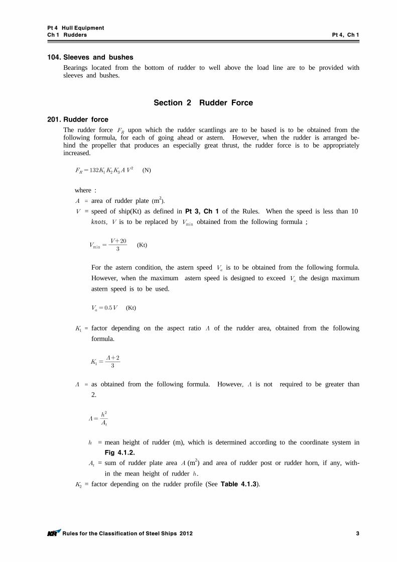
3. Welded members of rudders such as rudder plates, rudder frames, rudder main pieces, and edge bars are to be made of rolled steels for hull conforming to the requirements in Pt 2, Ch 1 of the Rules. The required scantlings may be reduced when high tensile steels are applied. When re-ducing the scantling, the material factor is to be as Table 4.1.2.
Material
A, B, D or E 1.0
AH 32, DH 32 or EH 32 0.78
AH 36, DH 36 or EH 36 0.72
Table 4.1.2 Material factor (for rolled steel)
103. Increase in diameter of rudder stocks for special cases
1. The diameters of rudder stocks for ships exclusively engaged in towing services are not to be less than 1.1 times those required in this Chapter.
2. In ships which may be frequently steered at a large helm angle when sailing at their maximum speed, such as fishing vessels, the diameters of rudder stocks and pintles, as well as the section modulus of main pieces, are not to be less than 1.1 times those required in this Chapter.
3. In ships which might require quick steering, the diameters of rudder stocks are to be properly in-creased beyond the requirements in this Chapter.
4. The rudders for ships classified for ice strengthening are to be in accordance with the requirements of Pt 3, Ch 20, 216. in addition to the requirements of this Chapter.
Pt 4 Hull Equipment
Ch 1 Rudders Pt 4, Ch 1
Rules for the Classification of Steel Ships 2012 3
104. Sleeves and bushes
Bearings located from the bottom of rudder to well above the load line are to be provided with sleeves and bushes.
Section 2 Rudder Force
201. Rudder force
The rudder force upon which the rudder scantlings are to be based is to be obtained from the following formula, for each of going ahead or astern. However, when the rudder is arranged be-hind the propeller that produces an especially great thrust, the rudder force is to be appropriately increased.
(N)
where : = area of rudder plate (m2).
= speed of ship(Kt) as defined in Pt 3, Ch 1 of the Rules. When the speed is less than 10knots, is to be replaced by min obtained from the following formula ;
min
(Kt)
For the astern condition, the astern speed is to be obtained from the following formula. However, when the maximum astern speed is designed to exceed the design maximum astern speed is to be used.
(Kt)
= factor depending on the aspect ratio of the rudder area, obtained from the following formula.
= as obtained from the following formula. However, is not required to be greater than 2.
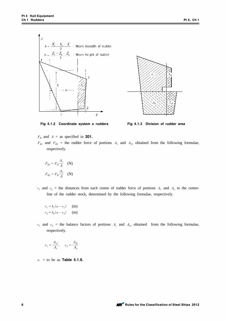
= mean height of rudder (m), which is determined according to the coordinate system in Fig 4.1.2.
= sum of rudder plate area (m2) and area of rudder post or rudder horn, if any, with-in the mean height of rudder .
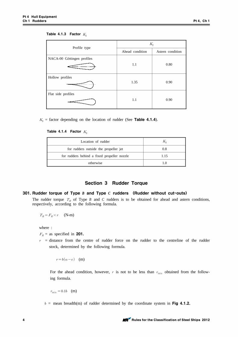
= factor depending on the rudder profile (See Table 4.1.3).
Pt 4 Hull Equipment
Ch 1 Rudders Pt 4, Ch 1
4 Rules for the Classification of Steel Ships 2012
Profile type
Ahead condition Astern condition
NACA-00 Gӧttingen profiles1.1 0.80
Hollow profiles1.35 0.90
Flat side profiles1.1 0.90
Table 4.1.3 Factor
= factor depending on the location of rudder (See Table 4.1.4).
Location of rudder
for rudders outside the propeller jet 0.8
for rudders behind a fixed propeller nozzle 1.15
otherwise 1.0
Table 4.1.4 Factor
Section 3 Rudder Torque
301. Rudder torque of Type B and Type C rudders (Rudder without cut-outs)The rudder torque of Type B and C rudders is to be obtained for ahead and astern conditions, respectively, according to the following formula.
× (N-m)
where : = as specified in 201. = distance from the centre of rudder force on the rudder to the centreline of the rudder
stock, determined by the following formula.
(m)
For the ahead condition, however, is not to be less than min obtained from the follow-ing formula.
min (m)
= mean breadth(m) of rudder determined by the coordinate system in Fig 4.1.2.
Pt 4 Hull Equipment
Ch 1 Rudders Pt 4, Ch 1
Rules for the Classification of Steel Ships 2012 5
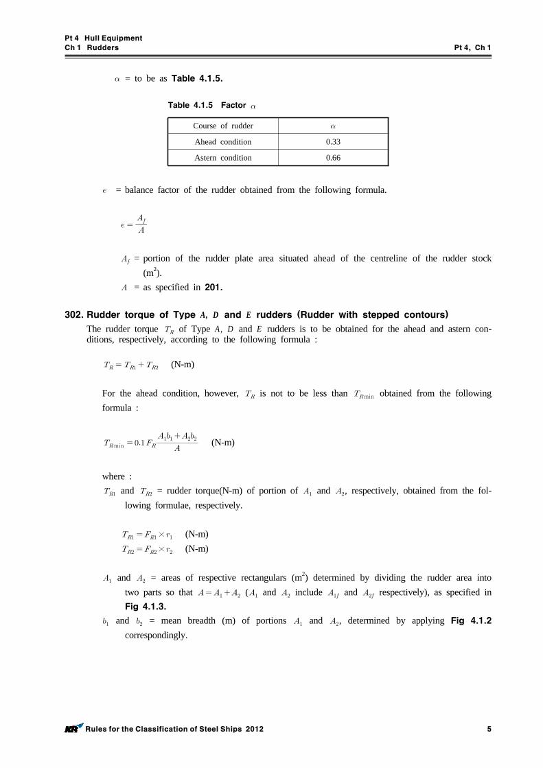
= to be as Table 4.1.5.
Course of rudder
Ahead condition 0.33
Astern condition 0.66
Table 4.1.5 Factor
= balance factor of the rudder obtained from the following formula.
= portion of the rudder plate area situated ahead of the centreline of the rudder stock (m2).
= as specified in 201.
302. Rudder torque of Type A, D and E rudders (Rudder with stepped contours)The rudder torque of Type A, D and E rudders is to be obtained for the ahead and astern con-ditions, respectively, according to the following formula :
(N-m)
For the ahead condition, however, is not to be less than min obtained from the following formula :
min (N-m)
where : and = rudder torque(N-m) of portion of and , respectively, obtained from the fol-
lowing formulae, respectively.
× (N-m) × (N-m)
and = areas of respective rectangulars (m2) determined by dividing the rudder area into two parts so that ( and include and respectively), as specified in Fig 4.1.3.
and = mean breadth (m) of portions and , determined by applying Fig 4.1.2 correspondingly.
Pt 4 Hull Equipment
Ch 1 Rudders Pt 4, Ch 1
6 Rules for the Classification of Steel Ships 2012
Fig 4.1.2 Coordinate system o rudders Fig 4.1.3 Division of rudder area
and = as specified in 201. and = the rudder force of portions and , obtained from the following formulae,
respectively.
(N)
(N)
and = the distances from each centre of rudder force of portions and to the centre-line of the rudder stock, determined by the following formulae, respectively.
(m) (m)
and = the balance factors of portions and , obtained from the following formulae, respectively.
= to be as Table 4.1.6.
Pt 4 Hull Equipment
Ch 1 Rudders Pt 4, Ch 1
Rules for the Classification of Steel Ships 2012 7
Locations of rudder parts
For parts of a rudder not behind a fixed structure such as rudder horn
for ahead condition 0.33
for astern condition 0.66
For parts of a rudder behind a fixed structure such as rudder horn
for ahead condition 0.25
for astern condition 0.55
Table 4.1.6 Factor
Section 4 Rudder Strength Calculation
401.Rudder strength calculation
1. The rudder strength is to be sufficient against the rudder force and rudder torque as given in Sec 2 and Sec 3. When the scantling of each part of a rudder is determined, the following moments and forces are to be considered.
For rudder body : bending moment and shear force
For rudder stock : bending moment and torque
For pintle bearing and rudder stock bearing : supporting force
2. The bending moments, shear forces and supporting forces to be considered are to be determined by a direct calculation or an approximate simplified method as deemed appropriate by the Society.
Section 5 Rudder Stocks
501. Upper stocks
The upper stock diameter required for the transmission of the rudder torque is to be determined so that the torsional stress not exceed 68/Kg(N/mm2). In dimensioning, the upper stock diameter may be determined by the following formula:
(mm)
= as specified in 301. and 302. = material factor for rudder stock, as given in 102.
502. Lower stocks
The diameter of the lower stock subjected to combined forces of torque and bending moment is to be determined so that the equivalent stress in the rudder stock not exceed 118 Ks (N/mm2). The equivalent stress is to be obtained from the following formula :
(N/mm2)
where : and = the bending stress and torsional stress acting on the lower stock, determined as fol-
lows respectively :
Pt 4 Hull Equipment
Ch 1 Rudders Pt 4, Ch 1
8 Rules for the Classification of Steel Ships 2012
× (N/mm2)
× (N/mm2)
= bending moment(N-m) at the section of the rudder stock considered. = as specified in 301. and 302.
When the horizontal section of the lower stock forms a circle, the lower stock diameter may be determined by the following formula :
(mm)
where : = upper stock diameter(mm) as given in 501.
Section 6 Rudder Plates, Rudder Frames and Rudder Main Pieces
601. Rudder plate
The rudder plate thickness is not to be less than that obtained from the following formula :
×
(mm)
where : and = as specified in 201. = material factor for the rudder plate as given in 102. = as specified in Pt 3, Ch 1, 111. = to be obtained from the following formula :
max : if ≥
= spacing of horizontal or vertical rudder frames, whichever is smaller (m). = spacing of horizontal or vertical rudder frames, whichever is greater (m).
602. Rudder frames
1. The rudder body is to be stiffened by horizontal and vertical rudder frames enabling it to act as bending girder.
2. The standard spacing of horizontal rudder frames, is to be obtained from the following formula :
(m)
Pt 4 Hull Equipment
Ch 1 Rudders Pt 4, Ch 1
Rules for the Classification of Steel Ships 2012 9
3. The standard distance from the vertical rudder frame forming the rudder main piece to the adjacent vertical rudder frame is to be 1.5 times the spacing of horizontal rudder frames.
4. The thickness of rudder frames is not to be less than 8 mm or 70 % of the thickness of the rudder plates as given in 601. whichever is greater.
603. Rudder main pieces
1. Vertical rudder frames forming the rudder main piece are to be arranged forward and afterward of the centreline of rudder stock at a distance approximately equal to the thickness of the rudder where the main piece consists of two rudder frames, or at the centreline of the rudder stock where the main piece consists of one rudder frame.
2. The section modulus of the main piece is to be calculated in conjunction with the vertical rudder frames specified in Par 1 and rudder plates attached thereto. The effective breadth of the rudder plates normally taken into calculation are to be as follows :(1) Where the main piece consists of two rudder frames, the effective breadth is 0.2 times the
length of the main piece.(2) Where the main piece consists of one rudder frame, the effective breadth is 0.16 times the
length of the main piece.3. The section modulus and the web area of a horizontal section of the main piece are to be such
that bending stress, shear stress and equivalent stress will not exceed the following stress values, respectively.
Nmm
Nmm
Nmm
In the cases of Type A, D , and E rudders, however, the section modulus and the web area of a horizontal section of the main piece in way of cut-outs are to be such that bending stress, shear stress and equivalent stress not exceed the following stress values, respectively.
Nmm
Nmm
Nmm
where : = material factor for the rudder main piece as given in 102.
4. The upper part of the main piece is to be so constructed as to avoid structural discontinuity.
5. Maintenance openings and cut-outs of rudder plates in Type A, D , and E rudders are to be rounded off properly.
604. Rudder plates, rudder arms and rudder main pieces of single plate rudders
1. The rudder plate thickness is not to be less than that obtained from the following formula :
(mm)
where : = spacing (m) of rudder arms, not to exceed 1 m. = speed of ship (Kt) as specified in 201. = material factor for rudder plate as given in 102.
Pt 4 Hull Equipment
Ch 1 Rudders Pt 4, Ch 1
10 Rules for the Classification of Steel Ships 2012
2. Rudder arms are to comply with the following requirements.(1) The thickness of rudder arms is not to be less than that of rudder plates.(2) The section modulus of rudder arms is not to be less than the value obtained from the follow-
ing formula. This section modulus, however, may be reduced gradually toward the edge of the rudder plate.
(cm3)
where : = horizontal distance (m) from the aft edge of the rudder plate to the centre of the rud-
der stock. = material factor for the rudder arm as given in 102. and = as specified in Par 1.
3. The diameters of main pieces are not to be less than those of lower rudder stocks. In rudders having no bearing below the neck bearing, however, the main piece diameter may be reduced grad-ually within the lower 1/3 area of the rudder, and may be 75 % of the specified diameter at the bottom part.
605. Connections
Rudder plates and frames are to be effectively connected and free from defects, cautions being tak-en to the workmanship.
606. Paintings and drainings
The internal surface of rudder is to be coated with effective paint, and means for draining are to be provided at the bottom of rudder.
Section 7 Couplings between Rudder Stocks and Main Pieces
701. Horizontal flange couplings
1. Coupling bolts are to be reamer bolts and at least 6 reamer bolts are to be used in each coupling.
2. Couplings are to comply with the requirements in Table 4.1.7.
702. Vertical flange couplings
1. Coupling bolts are to be reamer bolts and at least 8 reamer bolts are to be used in each coupling.
2. Couplings are to comply with the requirements in Table 4.1.7.
703. Cone couplings
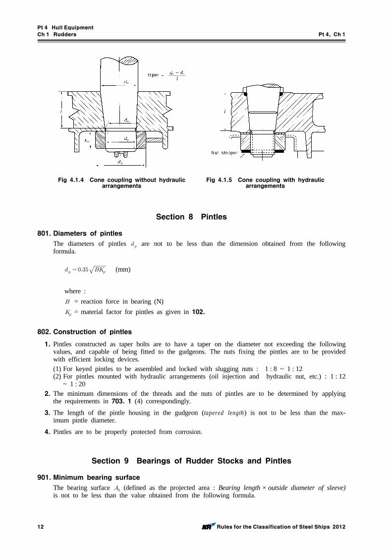
1. Cone couplings without hydraulic arrangements (oil injection and hydraulic nut, etc.) for mounting and dismounting the coupling are to comply with the following requirements.(1) The couplings are to have a taper on diameters of 1 : 8 ~ 1 : 12 and be secured by the slug-
ging nut. (See Fig 4.1.4)(2) The taper length of rudder stocks fitted into the rudder plate is generally not to be less than
1.5 times the rudder stock diameter at the top of the rudder.(3) For the couplings between stock and rudder, a key is to be provided. And the scantling of the
key is to be to the discretion of the Society.(4) The dimensions of the slugging nut as specified in the preceding (1) are to be as follows (See Fig 4.1.4) :
Pt 4 Hull Equipment
Ch 1 Rudders Pt 4, Ch 1
Rules for the Classification of Steel Ships 2012 11
≥ (mm) ≥ (mm) ≥ or 1.5 (mm), whichever is greater.
where : = external thread diameter(mm). = length of nut(mm). = outer diameter of nut(mm).
(5) The nuts fixing the rudder stocks are to be provided with efficient locking devices such as lock nut, nut stopper, etc.
(6) Couplings of rudder stocks are to be properly protected from corrosion.
ParameterRequirement
Horizontal flange coupling Vertical flange coupling
×
- 0.00043
(not less than 0.9)(1)
0.67 0.67
= total number of bolts. = bolt diameter (mm). = stock diameter (mm), the greater of the diameters or according to 501. and 502. = the first moment of area of the bolts about the centreline of the coupling flange (cm3) = mean distance (mm) of the bolt axes from the centre of the bolt system. = material factor for the rudder stock as given in 102. = material factor for the bolts as given in 102. = material factor for the coupling flange as given in 102. = the thickness (mm) of the coupling flanges. = the width (mm) of the material outside the bolt holes of the coupling flanges.
NOTE :(1) In way horizontal flange couplings, is to be calculated from determined by a number of bolts not ex-
ceeding 8.
Table 4.1.7 The minimum requirements for rudder couplings to stock
2. Cone couplings with hydraulic arrangements (oil injection and hydraulic nut, etc.) for mounting and dismounting the coupling are to comply with the following requirements.(1) Couplings are to have a taper on diameters of 1 : 12 ~ 1 : 20. The push-up force and push-up
length are to be at the discretion of the Society.(2) The nuts fixing the rudder stocks are to be provided with efficient locking devices. However, a
securing plate for securing nut against the rudder body is not to be provided.(3) Couplings of rudder stocks are to be properly protected from corrosion.(4) The dimensions of the securing nuts are to be as specified Par 1, (4).
Pt 4 Hull Equipment
Ch 1 Rudders Pt 4, Ch 1
12 Rules for the Classification of Steel Ships 2012
Fig 4.1.4 Cone coupling without hydraulic arrangements
Fig 4.1.5 Cone coupling with hydraulic arrangements
Section 8 Pintles
801. Diameters of pintles
The diameters of pintles are not to be less than the dimension obtained from the following formula.
(mm)
where : = reaction force in bearing (N) = material factor for pintles as given in 102.
802. Construction of pintles
1. Pintles constructed as taper bolts are to have a taper on the diameter not exceeding the following values, and capable of being fitted to the gudgeons. The nuts fixing the pintles are to be provided with efficient locking devices.(1) For keyed pintles to be assembled and locked with slugging nuts : 1 : 8 ~ 1 : 12(2) For pintles mounted with hydraulic arrangements (oil injection and hydraulic nut, etc.) : 1 : 12
~ 1 : 202. The minimum dimensions of the threads and the nuts of pintles are to be determined by applying
the requirements in 703. 1 (4) correspondingly.
3. The length of the pintle housing in the gudgeon (tapered length) is not to be less than the max-imum pintle diameter.
4. Pintles are to be properly protected from corrosion.
Section 9 Bearings of Rudder Stocks and Pintles
901. Minimum bearing surface
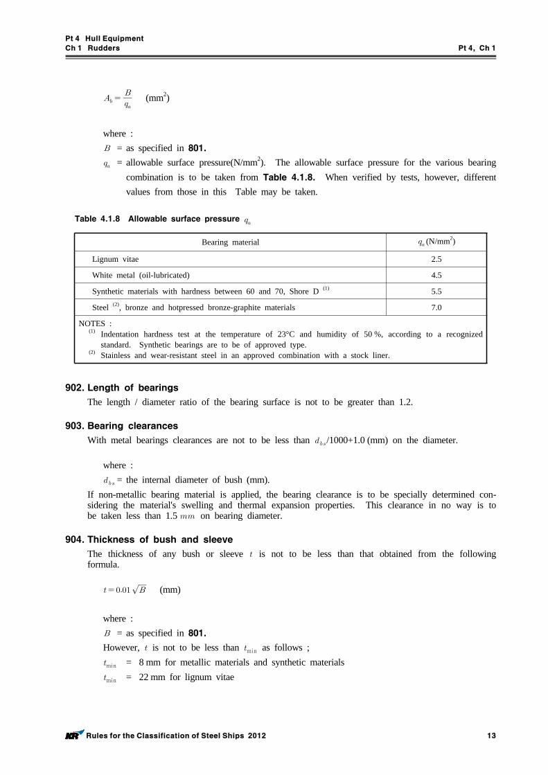
The bearing surface (defined as the projected area : Bearing length × outside diameter of sleeve) is not to be less than the value obtained from the following formula.
Pt 4 Hull Equipment
Ch 1 Rudders Pt 4, Ch 1
Rules for the Classification of Steel Ships 2012 13
(mm2)
where : = as specified in 801. = allowable surface pressure(N/mm2). The allowable surface pressure for the various bearing
combination is to be taken from Table 4.1.8. When verified by tests, however, different values from those in this Table may be taken.
Bearing material (N/mm2)
Lignum vitae 2.5
White metal (oil-lubricated) 4.5
Synthetic materials with hardness between 60 and 70, Shore D (1) 5.5
Steel (2), bronze and hotpressed bronze-graphite materials 7.0
NOTES :(1) Indentation hardness test at the temperature of 23°C and humidity of 50 %, according to a recognized
standard. Synthetic bearings are to be of approved type.(2) Stainless and wear-resistant steel in an approved combination with a stock liner.
Table 4.1.8 Allowable surface pressure
902. Length of bearings
The length / diameter ratio of the bearing surface is not to be greater than 1.2.
903. Bearing clearances
With metal bearings clearances are not to be less than /1000+1.0 (mm) on the diameter.
where : = the internal diameter of bush (mm).
If non-metallic bearing material is applied, the bearing clearance is to be specially determined con-sidering the material's swelling and thermal expansion properties. This clearance in no way is to be taken less than 1.5 on bearing diameter.
904. Thickness of bush and sleeve
The thickness of any bush or sleeve is not to be less than that obtained from the following formula.
(mm)
where : = as specified in 801.However, is not to be less than min as follows ;min = 8 mm for metallic materials and synthetic materialsmin = 22 mm for lignum vitae
Pt 4 Hull Equipment
Ch 1 Rudders Pt 4, Ch 1
14 Rules for the Classification of Steel Ships 2012
Section 10 Rudder Accessories
1001. Rudder carriers
Suitable rudder carriers are to be provided for supporting the weight of rudder according to the form and the weight of the rudder, and care is to be taken to provide efficient lubrication at the support.
1002. Jumping stoppers
Suitable arrangements are to be provided to prevent the rudder from jumping due to wave shocks.
Section 11 Propeller Nozzles
1101. Application
1. The following requirements are applicable to propeller nozzles having an inner diameter of up to 5m. Nozzles with larger diameters will be specially considered.
2. Special attention is to be given to the support of fixed nozzles at the hull structures.
1102. Design pressure
1. The design pressure for propeller nozzles is to be determined by the following formula:
(kN/m2)
(kN/m2)
= maximum shaft power in (kW) = propeller disc area in (m2)
= propeller diameter in (m) = factor according to the following formula:
×
min = 1.0 in zone 2 (propeller zone) = 0.5 in zone 1 & 3 = 0.35 in zone 4
1103. Plate thickness
(1) The thickness of the nozzle shell plating is not to be less than the greater of the following val-ues and 7.5 mm :
(mm) (mm)
= spacing of ring stiffeners in (m) = corrosion allowance (mm)
Pt 4 Hull Equipment
Ch 1 Rudders Pt 4, Ch 1
Rules for the Classification of Steel Ships 2012 15
≤ for 5.1=kt
≻ for min
(2) The web thickness of the internal stiffening rings shall not be less than the nozzles plating for zone 3, however, in no case be less than 7.5 mm.
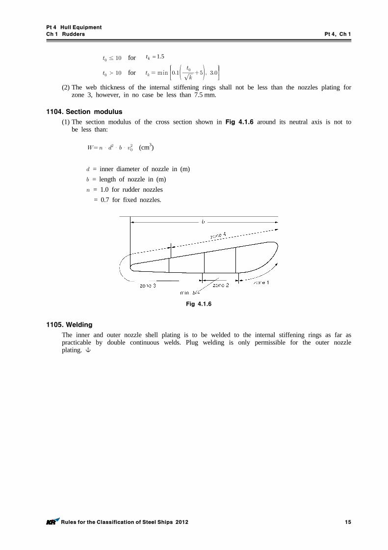
1104. Section modulus
(1) The section modulus of the cross section shown in Fig 4.1.6 around its neutral axis is not to be less than:
・・・ (cm3)
= inner diameter of nozzle in (m) = length of nozzle in (m) = 1.0 for rudder nozzles = 0.7 for fixed nozzles.
Fig 4.1.6
1105. Welding
The inner and outer nozzle shell plating is to be welded to the internal stiffening rings as far as practicable by double continuous welds. Plug welding is only permissible for the outer nozzle plating.
Pt 4 Hull Equipment
Ch 2 Hatchways and Other Deck Openings Pt 4, Ch 2
Rules for the Classification of Steel Ships 2012 17
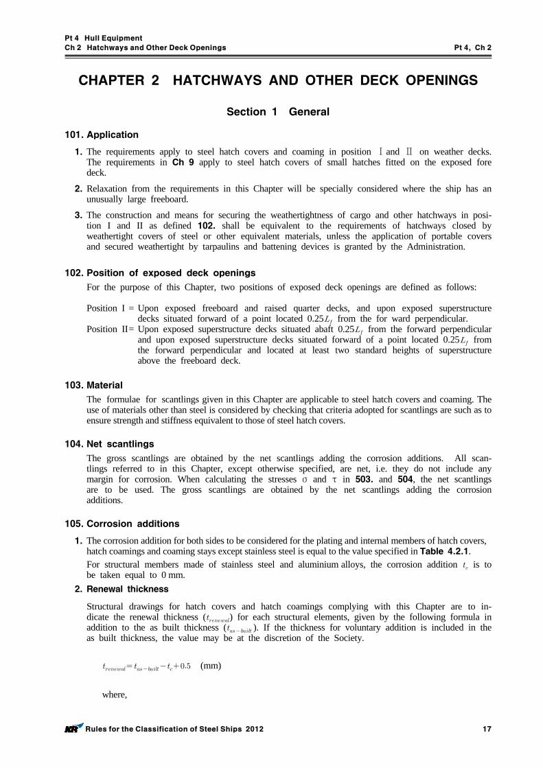
CHAPTER 2 HATCHWAYS AND OTHER DECK OPENINGS
Section 1 General
101. Application
1. The requirements apply to steel hatch covers and coaming in position Ⅰand Ⅱ on weather decks. The requirements in Ch 9 apply to steel hatch covers of small hatches fitted on the exposed fore deck.
2. Relaxation from the requirements in this Chapter will be specially considered where the ship has an unusually large freeboard.
3. The construction and means for securing the weathertightness of cargo and other hatchways in posi-tion I and II as defined 102. shall be equivalent to the requirements of hatchways closed by weathertight covers of steel or other equivalent materials, unless the application of portable covers and secured weathertight by tarpaulins and battening devices is granted by the Administration.
102. Position of exposed deck openings
For the purpose of this Chapter, two positions of exposed deck openings are defined as follows:
Position I = Upon exposed freeboard and raised quarter decks, and upon exposed superstructure decks situated forward of a point located 0.25 from the for ward perpendicular.
Position II= Upon exposed superstructure decks situated abaft 0.25 from the forward perpendicular and upon exposed superstructure decks situated forward of a point located 0.25 from the forward perpendicular and located at least two standard heights of superstructure above the freeboard deck.
103. Material
The formulae for scantlings given in this Chapter are applicable to steel hatch covers and coaming. The use of materials other than steel is considered by checking that criteria adopted for scantlings are such as to ensure strength and stiffness equivalent to those of steel hatch covers.
104. Net scantlings
The gross scantlings are obtained by the net scantlings adding the corrosion additions. All scan-tlings referred to in this Chapter, except otherwise specified, are net, i.e. they do not include any margin for corrosion. When calculating the stresses σ and τ in 503. and 504, the net scantlings are to be used. The gross scantlings are obtained by the net scantlings adding the corrosion additions.
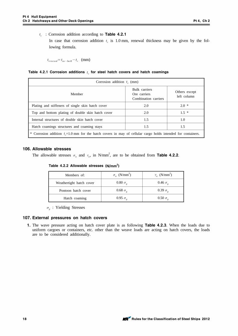
105. Corrosion additions
1. The corrosion addition for both sides to be considered for the plating and internal members of hatch covers, hatch coamings and coaming stays except stainless steel is equal to the value specified in Table 4.2.1.For structural members made of stainless steel and aluminium alloys, the corrosion addition is to be taken equal to 0 mm.
2. Renewal thickness
Structural drawings for hatch covers and hatch coamings complying with this Chapter are to in-dicate the renewal thickness () for each structural elements, given by the following formula in addition to the as built thickness ( ). If the thickness for voluntary addition is included in the as built thickness, the value may be at the discretion of the Society.
(mm)
where,
Pt 4 Hull Equipment
Ch 2 Hatchways and Other Deck Openings Pt 4, Ch 2
18 Rules for the Classification of Steel Ships 2012
: Corrosion addition according to Table 4.2.1 In case that corrosion addition is 1.0 mm, renewal thickness may be given by the fol-lowing formula.
(mm)
Corrosion addition (mm)
MemberBulk carriersOre carriersCombination carriers
Others exceptleft column
Plating and stiffeners of single skin hatch cover 2.0 2.0 *
Top and bottom plating of double skin hatch cover 2.0 1.5 *
Internal structures of double skin hatch cover 1.5 1.0
Hatch coamings structures and coaming stays 1.5 1.5
* Corrosion addition =1.0 mm for the hatch covers in may of cellular cargo holds intended for containers.
Table 4.2.1 Corrosion additions for steel hatch covers and hatch coamings
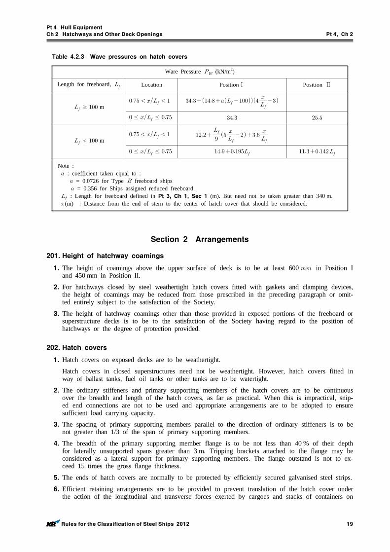
106. Allowable stresses
The allowable stresses and , in N/mm2, are to be obtained from Table 4.2.2.
Members of: (N/mm2) (N/mm2)
Weathertight hatch cover 0.80 0.46
Pontoon hatch cover 0.68 0.39
Hatch coaming 0.95 0.50
Table 4.2.2 Allowable stresses (N/mm2)
: Yielding Stresses
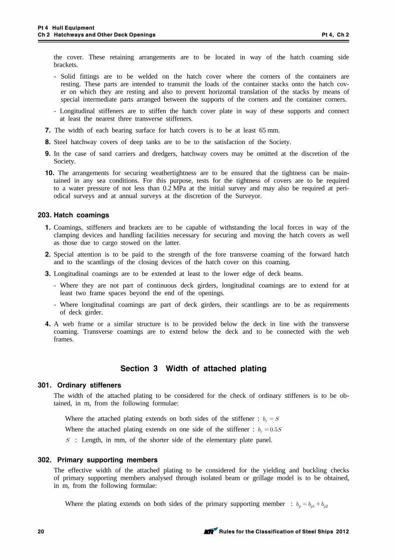
107. External pressures on hatch covers
1. The wave pressure acting on hatch cover plate is as following Table 4.2.3. When the loads due to uniform cargoes or containers, etc. other than the weave loads are acting on hatch covers, the loads are to be considered additionally.
Pt 4 Hull Equipment
Ch 2 Hatchways and Other Deck Openings Pt 4, Ch 2
Rules for the Classification of Steel Ships 2012 19
Ware Pressure (kN/m2)
Length for freeboard, Location PositionⅠ Position Ⅱ
≥ m
≤ ≤
≺ m
≤ ≤
Note : : coefficient taken equal to : = 0.0726 for Type freeboard ships
= 0.356 for Ships assigned reduced freeboard. : Length for freeboard defined in Pt 3, Ch 1, Sec 1 (m). But need not be taken greater than 340 m. (m) : Distance from the end of stern to the center of hatch cover that should be considered.
Table 4.2.3 Wave pressures on hatch covers
Section 2 Arrangements
201. Height of hatchway coamings
1. The height of coamings above the upper surface of deck is to be at least 600 in Position I and 450 mm in Position II.
2. For hatchways closed by steel weathertight hatch covers fitted with gaskets and clamping devices, the height of coamings may be reduced from those prescribed in the preceding paragraph or omit-ted entirely subject to the satisfaction of the Society.
3. The height of hatchway coamings other than those provided in exposed portions of the freeboard or superstructure decks is to be to the satisfaction of the Society having regard to the position of hatchways or the degree of protection provided.
202. Hatch covers
1. Hatch covers on exposed decks are to be weathertight.
Hatch covers in closed superstructures need not be weathertight. However, hatch covers fitted in way of ballast tanks, fuel oil tanks or other tanks are to be watertight.
2. The ordinary stiffeners and primary supporting members of the hatch covers are to be continuous over the breadth and length of the hatch covers, as far as practical. When this is impractical, snip-ed end connections are not to be used and appropriate arrangements are to be adopted to ensure sufficient load carrying capacity.
3. The spacing of primary supporting members parallel to the direction of ordinary stiffeners is to be not greater than 1/3 of the span of primary supporting members.
4. The breadth of the primary supporting member flange is to be not less than 40 % of their depth for laterally unsupported spans greater than 3 m. Tripping brackets attached to the flange may be considered as a lateral support for primary supporting members. The flange outstand is not to ex-ceed 15 times the gross flange thickness.
5. The ends of hatch covers are normally to be protected by efficiently secured galvanised steel strips.
6. Efficient retaining arrangements are to be provided to prevent translation of the hatch cover under the action of the longitudinal and transverse forces exerted by cargoes and stacks of containers on
Pt 4 Hull Equipment
Ch 2 Hatchways and Other Deck Openings Pt 4, Ch 2
20 Rules for the Classification of Steel Ships 2012
the cover. These retaining arrangements are to be located in way of the hatch coaming side brackets.
- Solid fittings are to be welded on the hatch cover where the corners of the containers are resting. These parts are intended to transmit the loads of the container stacks onto the hatch cov-er on which they are resting and also to prevent horizontal translation of the stacks by means of special intermediate parts arranged between the supports of the corners and the container corners.
- Longitudinal stiffeners are to stiffen the hatch cover plate in way of these supports and connect at least the nearest three transverse stiffeners.
7. The width of each bearing surface for hatch covers is to be at least 65 mm.
8. Steel hatchway covers of deep tanks are to be to the satisfaction of the Society.
9. In the case of sand carriers and dredgers, hatchway covers may be omitted at the discretion of the Society.
10. The arrangements for securing weathertightness are to be ensured that the tightness can be main-tained in any sea conditions. For this purpose, tests for the tightness of covers are to be required to a water pressure of not less than 0.2 MPa at the initial survey and may also be required at peri-odical surveys and at annual surveys at the discretion of the Surveyor.
203. Hatch coamings
1. Coamings, stiffeners and brackets are to be capable of withstanding the local forces in way of the clamping devices and handling facilities necessary for securing and moving the hatch covers as well as those due to cargo stowed on the latter.
2. Special attention is to be paid to the strength of the fore transverse coaming of the forward hatch and to the scantlings of the closing devices of the hatch cover on this coaming.
3. Longitudinal coamings are to be extended at least to the lower edge of deck beams.
- Where they are not part of continuous deck girders, longitudinal coamings are to extend for at least two frame spaces beyond the end of the openings.
- Where longitudinal coamings are part of deck girders, their scantlings are to be as requirements of deck girder.
4. A web frame or a similar structure is to be provided below the deck in line with the transverse coaming. Transverse coamings are to extend below the deck and to be connected with the web frames.
Section 3 Width of attached plating
301. Ordinary stiffeners
The width of the attached plating to be considered for the check of ordinary stiffeners is to be ob-tained, in m, from the following formulae:
Where the attached plating extends on both sides of the stiffener : Where the attached plating extends on one side of the stiffener : : Length, in mm, of the shorter side of the elementary plate panel.
302. Primary supporting members
The effective width of the attached plating to be considered for the yielding and buckling checks of primary supporting members analysed through isolated beam or grillage model is to be obtained, in m, from the following formulae:
Where the plating extends on both sides of the primary supporting member :
Pt 4 Hull Equipment
Ch 2 Hatchways and Other Deck Openings Pt 4, Ch 2
Rules for the Classification of Steel Ships 2012 21
Where the plating extends on one side of the primary supporting member :
where : min (m) min (m) : Span, in , of the considered primary supporting member, : Half distance, in m, between the considered primary supporting member and the ad-
jacent ones, for one side, for the other side.When a isolated beam or a grillage analysis is used, the ordinary stiffeners are not to be included in the attached flange area of the primary members.
Section 4 Load Model
401. Lateral pressures and concentrated loads
1. General
The lateral pressures and concentrated loads to be considered as acting on hatch covers are in-dicated in 2. to 6. When two or more panels are connected by hinges, each individual panel is to be considered separately. In any case, the sea pressures defined in 2. are to be considered for hatch covers located on exposed decks. Additionally, when the hatch cover is intended to carry uni-form cargoes, special cargoes or containers, the pressures and forces defined in 3. to 6. are to be considered independently from the sea pressures.
2. Sea pressures
The still water and wave lateral pressures are to be considered and are to be taken equal to:still water pressure : wave pressure is equal to the value specified in Table 4.2.3.
3. Internal pressures due to liquid cargo or ballast tanks
If applicable, the still water and wave lateral pressures are to be considered and to comply with the applicable provisions of the Society.
4. Pressures due to uniform cargoes
If applicable, the still water and wave lateral pressures are to be considered and to comply with the applicable provisions of the Society.
5. Pressures due to special cargoes
In the case of carriage on the hatch covers of special cargoes (e.g. pipes, etc.) which may tempo-rarily retain water during navigation, the lateral pressure to be applied is considered by the Society on a case by case basis.
6. Forces due to containers
In the case of carriage of containers on the hatch covers, the concentrated forces under the contain-ers corners are to be determined in accordance with the applicable requirements of the Society.
402. Load point
1. Wave lateral pressure for hatch covers on exposed decks
The wave lateral pressure to be considered as acting on each hatch cover is to be calculated at a point located :
longitudinally, at the hatch cover mid-length
Pt 4 Hull Equipment
Ch 2 Hatchways and Other Deck Openings Pt 4, Ch 2
22 Rules for the Classification of Steel Ships 2012
transversely, on the longitudinal plane of symmetry of the shipvertically, at the top of the hatch coaming.
2. Lateral pressures other than the wave pressure
The lateral pressure is to be calculated :- in way of the geometrical centre of gravity of the plate panel, for plating- at mid-span, for ordinary stiffeners and primary supporting members.
Section 5 Strength Check
501. General
1. Application
The strength check is applicable to rectangular hatch covers subjected to a uniform pressure, de-signed with primary supporting members arranged in one direction or as a grillage of longitudinal and transverse primary supporting members. In the latter case, the stresses in the primary support-ing members are to be determined by a grillage or a finite element analysis. It is to be checked that stresses induced by concentrated loads are in accordance with the criteria in 504. 4.
2. Hatch covers supporting containers
The scantlings of hatch covers supporting container stacks are to comply with the applicable provi-sions of the Society.
3. Hatch covers subjected to concentrated loads
For hatch covers supporting concentrated loads, ordinary stiffeners and primary supporting members are generally to be checked by direct calculations, taking into account the stiffener arrangements and their relative inertia. It is to be checked that stresses induced by concentrated loads are in ac-cordance with the criteria in 503. & 504.
4. Covers of small hatchways
The gross thickness of covers is to be not less than 8 mm. This thickness is to be increased or an efficient stiffening fitted to the Society's satisfaction where the greatest horizontal dimension of the cover exceeds 0.6 m.
502. Plating
1. Net thickness
The net thickness of steel hatch cover top plating, in mm, is to be not less than the value ob-tained from the following formula :
(mm)
: Factor for combined membrane and bending response, equal to :
= 1.5 in general, for , for the attached plating of primary supporting members
= , for
≥ , for the attached plating of primary supporting members
: Spacing of stiffeners. (m) : Still water pressure. (kN/m2) : Wave pressure. (kN/m2)
Pt 4 Hull Equipment
Ch 2 Hatchways and Other Deck Openings Pt 4, Ch 2
Rules for the Classification of Steel Ships 2012 23
: Normal stress (N/mm2) in the attached plating of primary supporting members, calculated according to 504. 3 or determined through a grillage analysis or a finite element analysis, as the case may be.
: Allowable stress (N/mm2) : The yield stress of material (N/mm2)
2. Minimum net thickness
The net thickness, in mm, of hatch cover plating is to be not less than the greater of the follow-ing values : = 0.01 = 6
3. Critical buckling stress check
The compressive stress in the hatch cover plating, induced by the bending of primary supporting members, either parallel or perpendicular to the direction of ordinary stiffeners, calculated according to 504. 3 or determined through a grillage analysis or a finite element analysis, as the case may be, is to comply with the following formula:(1) The compressive stress, , in the hatch cover plate panels, induced by the bending of primary
supporting members parallel to the direction of secondary stiffeners, and the critical buckling stress, , are to be evaluated as defined below :
≤
when ≤
when
: Minimum upper yield stress or proof stress of the material (N/mm2)
: Modulus of elasticity of the material to be assumed equal to for steel ×
(N/mm2) : Net thickness of plate panel (mm) : Spacing of secondary stiffeners (m)
(2) The mean compressive stress, σ, in each of the hatch cover plate panels, induced by the bend-ing of primary supporting members perpendicular to the direction of secondary stiffeners, and the critical buckling stress, , to be evaluated as defined below :
≤
when ≤
when
: Minimum upper yield stress or proof stress of the material (N/mm2)
Pt 4 Hull Equipment
Ch 2 Hatchways and Other Deck Openings Pt 4, Ch 2
24 Rules for the Classification of Steel Ships 2012
: Modulus of elasticity of the material to be assumed equal to for steel ×
(N/mm2), : Net thickness of plate panel (mm) : Length of the shorter side of the plate panel (m) : Length of the longer side of the plate panel (m) : Ratio between smallest and largest compressive stress : Coefficients obtained according to the kind of stiffeners at compressive side, which are
given by the followings : 1.30 when plating is stiffened by primary supporting members 1.21 when plating is stiffened by secondary stiffeners of angle or T type 1.10 when plating is stiffened by secondary stiffeners of bulb type 1.05 when plating is stiffened by flat bar
(3) The biaxial compressive stress in the hatch cover panels, when calculated by means of FEM shell element model, is to be at the Society's discretion.
503. Ordinary stiffeners
1. For flat bar ordinary stiffeners, the ratio is to comply with the following formula :
≤
where: : Web height, in mm, of the ordinary stiffener.
: Net thickness, in mm, of the ordinary stiffener.
2. Net section modulus and net shear sectional area
The net section modulus , in cm3, and the net shear sectional area , in cm2, of an ordinary stiffener subject to lateral pressure are to be not less than the values obtained from the following formulae :
(cm3)
(cm2)
where: : Boundary coefficient for ordinary stiffeners and primary supporting members, taken equal to : - = 8 in the case of ordinary stiffeners and primary supporting members simply sup-
ported at both ends or supported at one end and clamped at the other end - = 12 in the case of ordinary stiffeners and primary supporting members clamped at
Pt 4 Hull Equipment
Ch 2 Hatchways and Other Deck Openings Pt 4, Ch 2
Rules for the Classification of Steel Ships 2012 25
both ends : Ordinary stiffener span, in m, to be taken as the spacing, in m, of primary supporting
members or the distance between a primary supporting member and the edge support, as applicable. When brackets are fitted at both ends of all ordinary stiffener spans, the ordinary stiffener span may be reduced by an amount equal to 2/3 of the minimum brackets arm length, but not greater than 10 % of the gross span, for each bracket.
3. Critical buckling stress check
(1) The compressive stress in the top flange of secondary stiffeners, induced by the bending of primary supporting members parallel to the direction of secondary stiffeners, and the critical buckling stress , to be evaluated as defined below :
≤
= when ≤
=
when ≻
where, = minimum upper yield stress, in N/mm2, of the material = ideal elastic buckling stress, in N/mm2, of the secondary stiffener
= minimum between and
=
= modulus of elasticity, in N/mm2
= × for steel = moment of inertia, in cm4, of the secondary stiffener, including a top flange equal
to the spacing of secondary stiffeners = cross-sectional area, in cm2, of the secondary stiffener, including a top flange
equal to the spacing of secondary stiffeners = span, in m, of the secondary stiffener
=
=
×
= number of half waves, given by the following table :
≤ ≤ ≤ ≤
1 2 3
= sectorial moment of inertia, in cm6, of the secondary stiffener about its con-nection with the plating
Pt 4 Hull Equipment
Ch 2 Hatchways and Other Deck Openings Pt 4, Ch 2
26 Rules for the Classification of Steel Ships 2012
=
× for flat bar secondary stiffeners
=
× for "Tee" secondary stiffeners
=
× for angles and bulb secon-
dary stiffener = polar moment of inertia, in cm4, of the secondary stiffener about its connection
with the plating
=
× for flat bar secondary stiffeners
=
× for flanged secondary stiffeners
= St Venant's moment of inertia, in cm4, of the secondary stiffener without top flange
=
× for flat bar secondary stiffeners
=
× for flanged secondary stiffeners
= height and net thickness, in mm, of the secondary stiffener, respectively = width and net thickness, in mm, of the secondary stiffener bottom flange,
respectively = spring stiffness exerted by the hatch cover top plating
=
×
= , to be taken not less than zero for flanged secondary stiffeners, need not be taken less than 0.1
=
= as defined in 502. 1= as defined in 502. 3 (1)
= net thickness, in mm, of the hatch cover plate panel(2) For flat bar secondary stiffeners and buckling stiffeners, the ratio is to be not greater than ,
where: = height and net thickness of the stiffener, respectively = = minimum upper yield stress, in N/mm2, of the material.
504. Primary supporting members
1. Application
The requirements in 3 to 5 apply to primary supporting members which may be analysed through
Pt 4 Hull Equipment
Ch 2 Hatchways and Other Deck Openings Pt 4, Ch 2
Rules for the Classification of Steel Ships 2012 27
isolated beam models. Primary supporting members whose arrangement is of a grillage type and which cannot be analysed through isolated beam models are to be checked by direct calculations, using the checking criteria in 4.
2. Normal and shear stress for isolated beam
In case that grillage analysis or finite element analysis are not carried out, according to the require-ments in 1, the maximum normal stress and shear stress in the primary supporting members are to be obtained, in N/mm2, from the following formulae:
(N/mm2)
(N/mm2)
: Boundary coefficient for ordinary stiffeners and primary supporting members, taken equal to : - = 8 in the case of ordinary stiffeners and primary supporting members simply sup-
ported at both ends or supported at one end and clamped at the other end - = 12 in the case of ordinary stiffeners and primary supporting members clamped at
both ends : Span of the primary supporting member, in m : Spacing of secondary stiffener, in m : Net shear sectional area, in cm2
: Net section modulus, in cm3
3. Checking criteria
The normal stress and the shear stress , calculated according to 3. or determined through a grillage analysis or finite element analysis, as the case may be, are to comply with the following formulae :
≤
≤
4. Deflection limit
The net moment of inertia of a primary supporting member is to be such that the deflection does not exceed
max
where: : Coefficient taken equal to :
max for weathertight hatch covers max for pontoon hatch covers
max : Greatest span, in m, of primary supporting members.
5. Critical buckling stress check of the web panels of the primary supporting members.
(1) This check is to be carried out for the web panels of primary supporting members, formed by web stiffeners or by the crossing with other primary supporting members, the face plate (or the bottom cover plate) or the attached top cover plate.
Pt 4 Hull Equipment
Ch 2 Hatchways and Other Deck Openings Pt 4, Ch 2
28 Rules for the Classification of Steel Ships 2012
(2) The shear stress τ in the web panels of the primary supporting members, calculated according to [5.4.3] or determined through a grillage analysis or a finite element analysis, as the case may be, is to comply with the following formulae :
≤
when ≤
when ≻
where,
=
= minimum upper yield stress, in N/mm2, of the material
=
= modules of elasticity, in N/mm2
= 2.06 × 10⁵ for steel = net thickness, in mm, of primary supporting member
=
= greater dimension, in m, of web panel of primary supporting member = smaller dimension, in m, of web panel of primary supporting member.
(3) For primary supporting members parallel to the direction of secondary stiffeners, the actual di-mensions of the panels are to be considered.
(4) For primary supporting members perpendicular to the direction of secondary stiffeners or for hatch covers built without secondary stiffeners, a presumed square panel of dimension is to be taken for the determination of the stress . In such a case, the average shear stress be-tween the values calculated at the ends of this panel is to be considered.
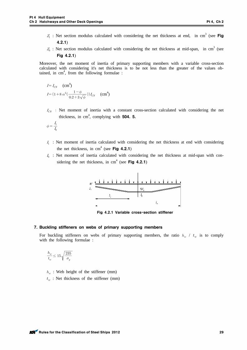
6. Primary supporting members of variable cross-section
The net section modulus of primary supporting members with a variable cross-section is to be not less than the greater of the value obtained from the following formulae and the use of these formulae is limited to the determination of the strength of primary supporting members in which abrupt changes in the cross-section do not occur along their length. :
(cm3)
(cm3)
Net section modules calculated with considering the net thickness, in cm3, for a constant cross-section, complying with the checking criteria in 504. 4.
: Length of the variable section part, in m (see Fig 4.2.1) : Span measured, in m, between end supports (see Fig 4.2.1)
Pt 4 Hull Equipment
Ch 2 Hatchways and Other Deck Openings Pt 4, Ch 2
Rules for the Classification of Steel Ships 2012 29
: Net section modulus calculated with considering the net thickness at end, in cm3 (see Fig 4.2.1)
: Net section modulus calculated with considering the net thickness at mid-span, in cm3 (see Fig 4.2.1)
Moreover, the net moment of inertia of primary supporting members with a variable cross-section calculated with considering it's net thickness is to be not less than the greater of the values ob-tained, in cm4, from the following formulae :
(cm4)
(cm4)
Net moment of inertia with a constant cross-section calculated with considering the net thickness, in cm4, complying with 504. 5.
: Net moment of inertia calculated with considering the net thickness at end with considering the net thickness, in cm4 (see Fig 4.2.1)
: Net moment of inertia calculated with considering the net thickness at mid-span with con-sidering the net thickness, in cm4 (see Fig 4.2.1)
Fig 4.2.1 Variable cross-section stiffener
7. Buckling stiffeners on webs of primary supporting members
For buckling stiffeners on webs of primary supporting members, the ratio / is to comply with the following formulae :
≤
: Web height of the stiffener (mm) : Net thickness of the stiffener (mm)
Pt 4 Hull Equipment
Ch 2 Hatchways and Other Deck Openings Pt 4, Ch 2
30 Rules for the Classification of Steel Ships 2012
Section 6 Hatch Coamings
601. Stiffening
1. The ordinary stiffeners of the hatch coamings are to be continuous over the breadth and length of the hatch coamings.
2. Coamings are to be stiffened on their upper edges with a stiffener suitably shaped to fit the hatch cover closing appliances. Moreover, when covers are fitted with tarpaulins, an angle or a bulb sec-tion is to be fitted all around coamings of more than 3 m in length or 600 mm in height; this stiffener is to be fitted at approximately 250 mm below the upper edge. The width of the horizon-tal flange of the angle is not to be less than 180 mm.
3. Where hatch covers are fitted with tarpaulins, coamings are to be strengthened by brackets or stays with a spacing not greater than 3 m. Where the height of the coaming exceeds 900 mm, additional strengthening may be required. However, reductions may be granted for transverse coamings in pro-tected areas.
4. When two hatches are close to each other, underdeck stiffeners are to be fitted to connect the lon-gitudinal coamings with a view to maintaining the continuity of their strength. Similar stiffening is to be provided over 2 frame spacings at ends of hatches exceeding 9 frame spacings in length. In some cases, the Society may require the continuity of coamings to be maintained above the deck.
5. Where watertight metallic hatch covers are fitted, other arrangements of equivalent strength may be adopted.
602. Load model
1. The lateral pressure to be considered as acting on the hatch coamings are as follows.(1) The pressure on the forward transverse hatch coaming of the foremost cargo hold is given by = 290 (kN/m2)
Where a forecastle deemed appropriate by the Society is fitted, however, this pressure may be reduced to 220 (kN/m2).
(2) The pressure on the other coamings is given by = 220 (kN/m2)(3) For cargo holds intended for the carriage of liquid cargoes, the liquid internal pressures applied
on hatch coaming is also to be determined.2. Where forward transverse hatch coaming of ships other than Bulk Carrier is protected by the ad-
jacent forward cargo hold hatch or other structures effectively against the green sea forces the pres-sure may be suitably reduced in accordance with the discretion of the Society.
603. Scantlings
1. Plating
(1) The net thickness of the forward and side hatch coaming plate is not to be less than that ob-tained from the following formulae. The net thickness is not to be less than 9.5 mm .
: The spacing of ordinary stiffener (m)(2) For aft hatch coamings - Where is 100 m and under : (mm) - Where is greater than 100 m : (mm)
2. Ordinary stiffeners
The net section modulus of the longitudinal or transverse ordinary stiffeners of hatch coamings is to be not less than the value obtained, in cm3, from the following formulae :
Pt 4 Hull Equipment
Ch 2 Hatchways and Other Deck Openings Pt 4, Ch 2
Rules for the Classification of Steel Ships 2012 31
= span, in m = 16 in general = 12 for the end span of stiffeners sniped at the coaming corners = Ratio of the plastic section modulus to the elastic section modulus of the ordinary stiff-
eners with an attached plate breadth, in mm, equal to 40 , where t is the plate net thickness.
= 1,16 in the absence of more precise evaluation.
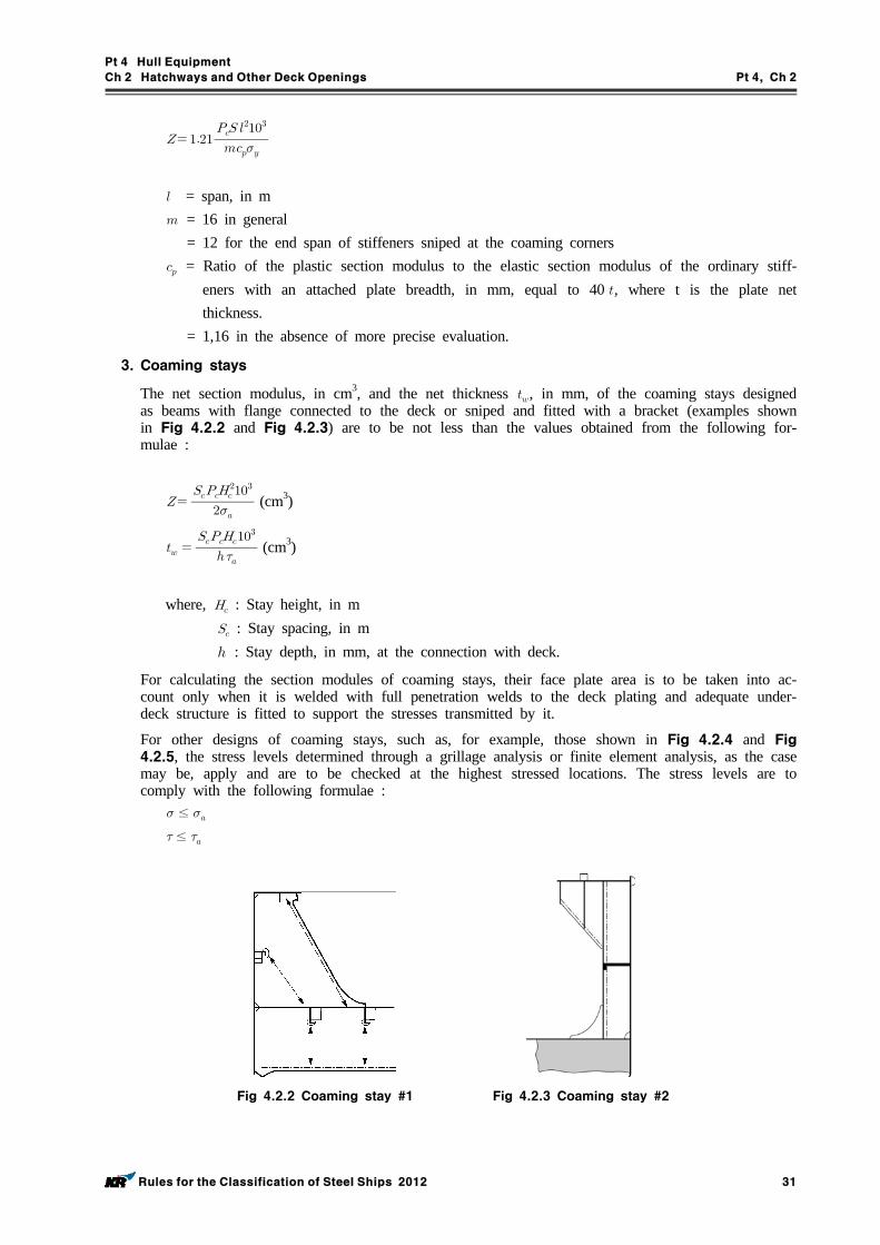
3. Coaming stays
The net section modulus, in cm3, and the net thickness , in mm, of the coaming stays designed as beams with flange connected to the deck or sniped and fitted with a bracket (examples shown in Fig 4.2.2 and Fig 4.2.3) are to be not less than the values obtained from the following for-mulae :
(cm3)
(cm3)
where, : Stay height, in m : Stay spacing, in m : Stay depth, in mm, at the connection with deck.
For calculating the section modules of coaming stays, their face plate area is to be taken into ac-count only when it is welded with full penetration welds to the deck plating and adequate under-deck structure is fitted to support the stresses transmitted by it.
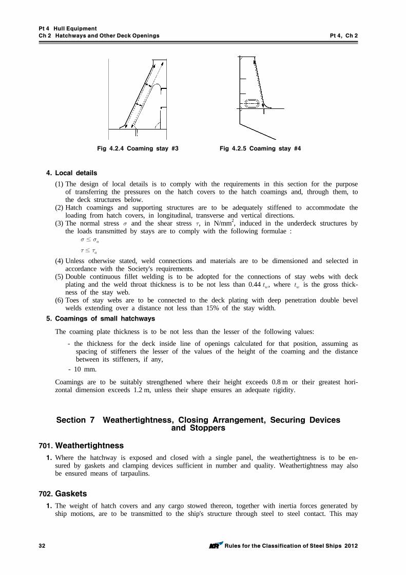
For other designs of coaming stays, such as, for example, those shown in Fig 4.2.4 and Fig 4.2.5, the stress levels determined through a grillage analysis or finite element analysis, as the case may be, apply and are to be checked at the highest stressed locations. The stress levels are to comply with the following formulae :≤
≤
Fig 4.2.2 Coaming stay #1 Fig 4.2.3 Coaming stay #2
Pt 4 Hull Equipment
Ch 2 Hatchways and Other Deck Openings Pt 4, Ch 2
32 Rules for the Classification of Steel Ships 2012
Fig 4.2.4 Coaming stay #3 Fig 4.2.5 Coaming stay #4
4. Local details
(1) The design of local details is to comply with the requirements in this section for the purpose of transferring the pressures on the hatch covers to the hatch coamings and, through them, to the deck structures below.
(2) Hatch coamings and supporting structures are to be adequately stiffened to accommodate the loading from hatch covers, in longitudinal, transverse and vertical directions.
(3) The normal stress and the shear stress , in N/mm2, induced in the underdeck structures by the loads transmitted by stays are to comply with the following formulae :
≤
≤
(4) Unless otherwise stated, weld connections and materials are to be dimensioned and selected in accordance with the Society's requirements.
(5) Double continuous fillet welding is to be adopted for the connections of stay webs with deck plating and the weld throat thickness is to be not less than 0.44 , where is the gross thick-ness of the stay web.
(6) Toes of stay webs are to be connected to the deck plating with deep penetration double bevel welds extending over a distance not less than 15% of the stay width.
5. Coamings of small hatchways
The coaming plate thickness is to be not less than the lesser of the following values:
- the thickness for the deck inside line of openings calculated for that position, assuming as spacing of stiffeners the lesser of the values of the height of the coaming and the distance between its stiffeners, if any,
- 10 mm.
Coamings are to be suitably strengthened where their height exceeds 0.8 m or their greatest hori-zontal dimension exceeds 1.2 m, unless their shape ensures an adequate rigidity.
Section 7 Weathertightness, Closing Arrangement, Securing Devices and Stoppers
701. Weathertightness
1. Where the hatchway is exposed and closed with a single panel, the weathertightness is to be en-sured by gaskets and clamping devices sufficient in number and quality. Weathertightness may also be ensured means of tarpaulins.
702. Gaskets
1. The weight of hatch covers and any cargo stowed thereon, together with inertia forces generated by ship motions, are to be transmitted to the ship's structure through steel to steel contact. This may
Pt 4 Hull Equipment
Ch 2 Hatchways and Other Deck Openings Pt 4, Ch 2
Rules for the Classification of Steel Ships 2012 33
be achieved by continuous steel to steel contact of the hatch cover skirt plate with the ship's struc-ture or by means of defined bearing pads.
2. The sealing is to be obtained by a continuous gasket of relatively soft elastic material compressed to achieve the necessary weathertightness. Similar sealing is to be arranged between cross-joint elements. Where fitted, compression flat bars or angles are to be well rounded where in contact with the gasket and to be made of a corrosion-resistant material.
3. The gasket and the securing arrangements are to maintain their efficiency when subjected to large relative movements between the hatch cover and the ship's structure or between hatch cover elements. If necessary, suitable devices are to be fitted to limit such movements.
4. The gasket material is to be of a quality suitable for all environmental conditions likely to be en-countered by the ship, and is to be compatible with the cargoes transported. The material and form of gasket selected are to be considered in conjunction with the type of hatch cover, the securing arrangement and the expected relative movement between the hatch cover and the ship's structure. The gasket is to be effectively secured to the hatch cover.
5. Coamings and steel parts of hatch covers in contact with gaskets are to have no sharp edges.
6. Metallic contact is required for an earthing connection between the hatch cover and the hull structures. If necessary, this is to be achieved by means of a special connection for the purpose.
7. In case of container ship with unusually large freeboard, gaskets may be omitted and clamping de-vices for steel hatchway covers may be suitably dispensed with at the discretion of the Society.
703. Closing arrangement, securing devices and stoppers
1. General
Panel hatch covers are to be secured by appropriate devices (bolts, wedges or similar) suitably spaced alongside the coamings and between cover elements. The securing and stop arrangements are to be fitted using appropriate means which cannot be easily removed. In addition to the require-ments above, all hatch covers, and in particular those carrying deck cargo, are to be effectively se-cured against horizontal shifting due to the horizontal forces resulting from ship motions. Towards the ends of the ship, vertical acceleration forces may exceed the gravity force. The resulting lifting forces are to be considered when dimensioning the securing devices according to 5. to 7. Lifting forces from cargo secured on the hatch cover during rolling are also to be taken into account. Hatch coamings and supporting structure are to be adequately stiffened to accommodate the loading from hatch covers. Hatch covers provided with special sealing devices, insulated hatch covers, flush hatch covers and those having coamings of a reduced height (see 201) are considered by the Society on a case by case basis. In the case of hatch covers carrying containers, the scantlings of the closing devices are to take into account the possible upward vertical forces transmitted by the containers.
2. Arrangements
The securing and stopping devices are to be arranged so as to ensure sufficient compression on gaskets between hatch covers and coamings and between adjacent hatch covers. Arrangement and spacing are to be determined with due attention to the effectiveness for weathertightness, depending on the type and the size of the hatch cover, as well as on the stiffness of the hatch cover edges between the securing devices. At cross-joints of multipanel covers, (male/female) vertical guides are to be fitted to prevent excessive relative vertical deflections between loaded/unloaded panels. The location of stoppers is to be compatible with the relative movements between hatch covers and the ship's structure in order to prevent damage to them. The number of stoppers is to be as small as possible.
3. Spacing
The spacing of the securing arrangements is to be generally not greater than 6 m.
Pt 4 Hull Equipment
Ch 2 Hatchways and Other Deck Openings Pt 4, Ch 2
34 Rules for the Classification of Steel Ships 2012
4. Construction
Securing arrangements with reduced scantlings may be accepted provided it can be demonstrated that the possibility of water reaching the deck is negligible. Securing devices are to be of reliable construction and securely attached to the hatchway coamings, decks or hatch covers. Individual se-curing devices on each hatch cover are to have approximately the same stiffness characteristics.
5. Area of securing devices
The gross cross area of each securing device is not to be less than the value obtained, in cm2, from the following formula :
where, : Spacing, in , of securing devices : Coefficient taken equal to: (0.75 for > 235 N/mm2, 1.00 for ≤ 235 N/mm2)In the above calculations, may not be taken greater than 0.7.
Between hatch cover and coaming and at cross-joints, a packing line pressure sufficient to obtain weathertightness is to be maintained by securing devices. For packing line pressures exceeding 5 N/mm, the net cross area A is to be increased in direct proportion. The packing line pressure is to be specified. In the case of securing arrangements which are particularly stressed due to the un-usual width of the hatchway, the net cross area A of the above securing arrangements is to be de-termined through direct calculations.
6. Inertia of edges elements
The hatch cover edge stiffness is to be sufficient to maintain adequate sealing pressure between se-curing devices. The moment of inertia of edge elements is to be not less than the value obtained, in cm4, from the following formula :
where: : Packing line pressure, in N/mm, to be taken not less than 5 N/mm : Spacing, in m, of securing devices
7. Diameter of rods or bolts
Rods or bolts are to have a gross diameter not less than 19 mm for hatchways exceeding 5 m2 in area.
8. Stoppers
Hatch covers are to be effectively secured, by means of stoppers, against the transverse forces aris-ing from a pressure 175 kN/m2. With the exclusion of No.1 hatch cover, hatch covers are to be ef-fectively secured, by means of stoppers, against the longitudinal forces acting on the forward end arising from a pressure of 175 kN/m2.
No.1 hatch cover is to be effectively secured, by means of stoppers, against the longitudinal forces acting on the forward end arising from a pressure of 230 kN/m2. This pressure may be reduced to 175 kN/m2 when a forecastle is fitted.
The equivalent stress in stoppers, their supporting structures and calculated in the throat of the stopper welds is to be equal to or less than the allowable value, equal to 0.8 .
Pt 4 Hull Equipment
Ch 2 Hatchways and Other Deck Openings Pt 4, Ch 2
Rules for the Classification of Steel Ships 2012 35
704. Tarpaulins
1. Where weathertightness of hatch covers is ensured by means of tarpaulins, at least two layers of tarpaulins are to be fitted. Tarpaulins are to be free from jute and waterproof and are to have ad-equate characteristics of strength and resistance to atmospheric agents and high and low temperatures. The mass per unit surface of tarpaulins made of vegetable fibres, before the water-proofing treatment, is to be not less than :
- for waterproofing by tarring : 0.65 kg/m2
- for waterproofing by chemical dressing : 0.60 kg/m2
- for waterproofing by dressing with black oil : 0.55 kg/m2
In addition to tarpaulins made of vegetable fibres, those of synthetic fabrics or plastic laminates may be accepted by the Society provided their qualities, as regards strength, waterproofing and re-sistance to high and low temperatures, are equivalent to those of tarpaulins made of vegetable fibres.
705. Cleats
1. Where rod cleats are fitted, resilient washers or cushions are to be incorporated.
2. Where hydraulic cleating is adopted, a positive means is to be provided to ensure that it remains mechanically locked in the closed position in the event of failure of the hydraulic system.
706. Wedges, battens and locking bars
1. Wedges
Wedges are to be of tough wood, generally not more than 200 mm in length and 50 mm in width. They are generally to be tapered not more than 1 in 6 and their thickness is to be not less than 13 mm.
2. Battens and locking bars
For all hatches steel bars or equivalent means shall be provided in order efficiently and in-dependently to secure each section of hatch covers after tarpaulins are battened down. Hatch covers of more than 1.5 m in length shall be secured by at least two securing appliances. Acceptable equivalent means to steel bars shall consist of devices and materials which will provide strength equivalent to, and elasticity not greater than that of, steel. Steel wire rope cannot be regarded as satisfactory equivalent means.
Section 8 Additional Requirements
801. Portable beams
1. Carriers and sockets for portable beams are to be of substantial construction, having a minimum beaming surface of 75 mm, and are to be provided with means for efficient fitting and securing of the beams.
2. Coamings are to be stiffened in way of carriers and sockets by providing stiffeners from these fit-tings to the deck or equivalent strengthening.
3. Where sliding type of beams is used, the arrangement is to ensure that the beams remain properly in position where the hatchway is closed.
4. The depth of portable beams and the width of their face plates are to be suitable to ensure lateral stability of the beams. The depth of beams at their ends is not to be less than 0.4 times the depth at mid-span or 150 mm, whichever is greater.
5. The upper face plates of portable beams are to extend to the extreme ends of the beams. The web plates, for at least 180 mm at each ends, are to be increased in thickness to at least twice that at
Pt 4 Hull Equipment
Ch 2 Hatchways and Other Deck Openings Pt 4, Ch 2
36 Rules for the Classification of Steel Ships 2012
mid-span or to be reinforced with doubling plates.
6. Portable beams are to be provided with suitable gear for lifting on and off without getting upon them.
7. Portable beams are to be clearly marked to indicate the deck, hatchway and position to which they belong.
802. Steel pontoon cover
1. The depth of steel pontoon covers at supports is not to be less than one-third the depth at mid-span or 150 mm, whichever is greater.
2. The width of bearing surface for steel pontoon covers is not to be less than 75 mm.
3. Steel pontoon covers are to be clearly marked to indicate the deck, hatchway and position to which they belong.
803. Tarpaulins and securing arrangements for hatchway closed by portable covers
1. Battens are to be efficient for securing the tarpaulins and not to be less than 65 mm in width and 9 mm in thickness.
2. Wedges are to be fit the regulations of 706. 1.
3. Cleats are to be set to fit the taper of the wedges. They are to be at least 65 mm wide and to be spaced not more than 600 mm from centre to centre. The cleats along each side are to be arranged not more than 150 mm apart from the hatch corners.
Section 9 Drainage
901. Arrangement
1. Drainage is to be arranged inside the line of gaskets by means of a gutter bar or vertical extension of the hatch side and end coaming.
2. Drain openings are to be arranged at the ends of drain channels and are to be provided with effi-cient means for preventing ingress of water from outside, such as non-return valves or equivalent.
3. Cross-joints of multi-panel hatch covers are to be arranged with drainage of water from the space above the gasket and a drainage channel below the gasket.
4. If a continuous outer steel contact is arranged between the cover and the ship's structure, drainage from the space between the steel contact and the gasket is also to be provided.
Section 10 Miscellaneous Openings
1001. Companionways
1. All openings in freeboard decks other than hatchways are to be protected by an enclosed super-structure, or by a deckhouse or companionway of equivalent strength.
2. In Position I the height above the deck of sills at the doorways in companionways is to be at least 600 mm. In Position II it is to be at least 380 mm.
1002. Protection of machinery space openings
Machinery space openings are to be efficiently enclosed by steel casings of ample strength. Machinery openings provided on freeboard deck are to be placed in superstructures or deckhouses as far as possible. Where the casings are not protected by other structures, the sills of access openings are not to be less than 600 mm in height above the deck in Position I and not to be less
Pt 4 Hull Equipment
Ch 2 Hatchways and Other Deck Openings Pt 4, Ch 2
Rules for the Classification of Steel Ships 2012 37
than 380 mm in Position II. The access openings are to be provided with permanent closures.
1003. Closures for access openings or openings
1. Annular spaces around funnels and all other openings in the machinery casings are to be provided with closing means capable of being operated from outside the machinery space in case of fire.
2. Access openings in the machinery spaces are to be provided with steel doors and to be located in enclosed positions as far as possible. Access openings above freeboard deck not within an en-closed superstructure are to be provided with doors capable of being closed and secured from both sides. Doors to exposed access openings on freeboard and sunken poop decks are to be of the outward opening type.
3. Exposed openings on tops of machinery casings are to be provided with covers capable of being readily closed and secured.
Pt 4 Hull Equipment
Ch 3 Bow Doors, Side and Stern Doors Pt 4, Ch 3
Rules for the Classification of Steel Ships 2012 39
CHAPTER 3 BOW DOORS, SIDE AND STERN DOORS
Section 1 Bow Doors and Inner Doors
101. General
1. Application
(1) These requirements apply to the arrangement, strength and securing of bow doors and inner doors leading to a complete or long forward enclosed superstructure or to a long non-enclosed superstructure, where fitted to attain minimum bow height equivalence.
(2) The requirements apply to all ro-ro passenger ships and ro-ro cargo ships engaged on interna-tional voyages and also to ro-ro passenger ships and ro-ro cargo ships engaged only in domestic (noninternational) voyages, except where specifically indicated otherwise herein.
(3) The requirements are not applicable to high speed, light displacement craft as defined in the IMO Code of Safety for High Speed Craft.
(4) The bow door and inner door of all existing ro-ro passenger ships constructed before or on 30 June 1996 are to be deemed appropriate by the Society.
2. Kinds of bow doors
The kinds of bow doors which are applied by this Chapter are generally two types as follows. However, other types of bow doors will be specially considered in association with the applicable requirements of these rules by the Society, except for following (1) and (2).(1) Visor door
Visor doors opened by rotating upwards and outwards about a horizontal axis through two or more hinges located near the top of the door and connected to the primary structure of the door by longitudinally arranged lifting arms.
(2) Side-opening doorSide-opening doors opened either by rotating outwards about a vertical axis through two or more hinges located near the outboard edges or by horizontal translation by means of linking arms arranged with pivoted attachments to the door and the ship. It is anticipated the side-open-ing bow doors are arranged in pairs.
3. Arrangement
Arrangements for the bow door and inner door are to comply with the following (1) to (5)(1) Bow doors are to be situated above the freeboard deck except that where a watertight recess
fitted for arrangement of ramps or other related mechanical devices is located forward of the collision bulkhead and above the deepest waterline, the bow doors may be situated above the recess.
(2) An inner door which is to be part of the collision bulkhead is to be fitted. The inner door does not need to be fitted directly above the bulkhead. Where the vehicle ramp is arranged as a part of collision bulkhead, and its position complies with requirements of Pt 3, Ch 14, 201., the vehicle ramp may be regarded as an inner door. If this is not possible, a separate inner weather door is to be installed.
(3) Bow doors and inner doors are to be arranged so as to preclude the possibility of the bow door causing structural damage to the inner door or to the collision bulkhead in the case of damage to or detachment of the bow door. If this is not possible, a separate inner weathertight door is to be installed, as indicated in Pt 3, Ch 14, 201.
(4) Bow doors are to be so fitted as to ensure tightness consistent with operational conditions and to give effective protection to inner doors. Inner doors forming part of the collision bulkhead are to be weathertight over the full height of the cargo space and arranged with fixed sealing supports on the aft side of the doors.
(5) The requirements for inner doors are based on the assumption that vehicle are effectively lashed and secured against movement in stowed position.
4. Definitions
The definitions which are used in this Chapter are as follows.(1) Securing device
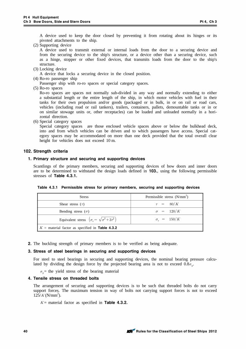
Pt 4 Hull Equipment
Ch 3 Bow Doors, Side and Stern Doors Pt 4, Ch 3
40 Rules for the Classification of Steel Ships 2012
A device used to keep the door closed by preventing it from rotating about its hinges or its pivoted attachments to the ship.
(2) Supporting deviceA device used to transmit external or internal loads from the door to a securing device and from the securing device to the ship's structure, or a device other than a securing device, such as a hinge, stopper or other fixed devices, that transmits loads from the door to the ship's structure.
(3) Locking deviceA device that locks a securing device in the closed position.
(4) Ro-ro passenger ship Passenger ship with ro-ro spaces or special category spaces.
(5) Ro-ro spacesRo-ro spaces are spaces not normally sub-divided in any way and normally extending to either a substantial length or the entire length of the ship, in which motor vehicles with fuel in their tanks for their own propulsion and/or goods (packaged or in bulk, in or on rail or road cars, vehicles (including road or rail tankers), trailers, containers, pallets, demountable tanks or in or on similar stowage units or, other receptacles) can be loaded and unloaded normally in a hori-zontal direction.
(6) Special category spacesSpecial category spaces are those enclosed vehicle spaces above or below the bulkhead deck, into and from which vehicles can be driven and to which passengers have access. Special cat-egory spaces may be accommodated on more than one deck provided that the total overall clear height for vehicles does not exceed 10 m.
102. Strength criteria
1. Primary structure and securing and supporting devices
Scantlings of the primary members, securing and supporting devices of bow doors and inner doors are to be determined to withstand the design loads defined in 103., using the following permissible stresses of Table 4.3.1.
Stress Permissible stress (N/mm2)
Shear stress ()
Bending stress ()
Equivalent stress
= material factor as specified in Table 4.3.2
Table 4.3.1 Permissible stress for primary members, securing and supporting devices
2. The buckling strength of primary members is to be verified as being adequate.
3. Stress of steel bearings in securing and supporting devices
For steel to steel bearings in securing and supporting devices, the nominal bearing pressure calcu-lated by dividing the design force by the projected bearing area is not to exceed 0.8.
= the yield stress of the bearing material4. Tensile stress on threaded bolts
The arrangement of securing and supporting devices is to be such that threaded bolts do not carry support forces. The maximum tension in way of bolts not carrying support forces is not to exceed 125/ (N/mm2).
= material factor as specified in Table 4.3.2.
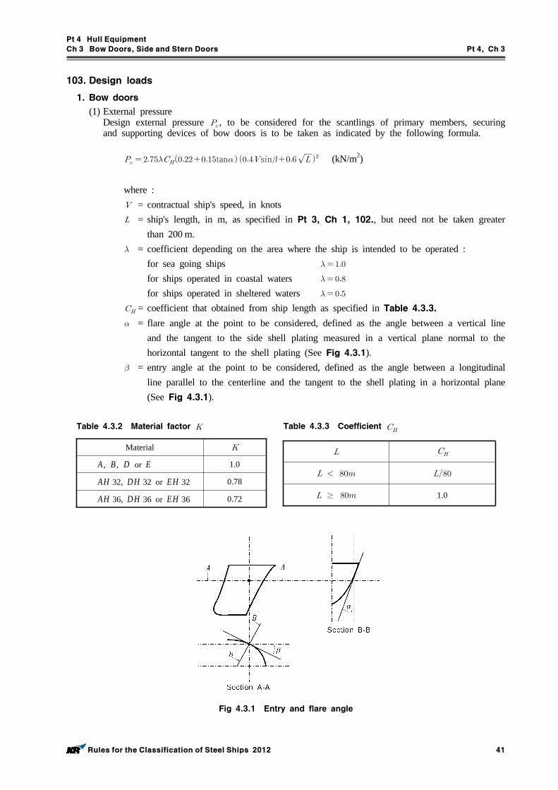
Pt 4 Hull Equipment
Ch 3 Bow Doors, Side and Stern Doors Pt 4, Ch 3
Rules for the Classification of Steel Ships 2012 41
103. Design loads
1. Bow doors
(1) External pressureDesign external pressure , to be considered for the scantlings of primary members, securing and supporting devices of bow doors is to be taken as indicated by the following formula.
tan sin (kN/m2)
where : = contractual ship's speed, in knots = ship's length, in m, as specified in Pt 3, Ch 1, 102., but need not be taken greater
than 200 m. = coefficient depending on the area where the ship is intended to be operated :
for sea going ships
for ships operated in coastal waters
for ships operated in sheltered waters
= coefficient that obtained from ship length as specified in Table 4.3.3. = flare angle at the point to be considered, defined as the angle between a vertical line
and the tangent to the side shell plating measured in a vertical plane normal to the horizontal tangent to the shell plating (See Fig 4.3.1).
= entry angle at the point to be considered, defined as the angle between a longitudinal line parallel to the centerline and the tangent to the shell plating in a horizontal plane (See Fig 4.3.1).
Material
A, B, D or E 1.0
AH 32, DH 32 or EH 32 0.78
AH 36, DH 36 or EH 36 0.72
Table 4.3.2 Material factor
≥ 1.0
Table 4.3.3 Coefficient
Fig 4.3.1 Entry and flare angle
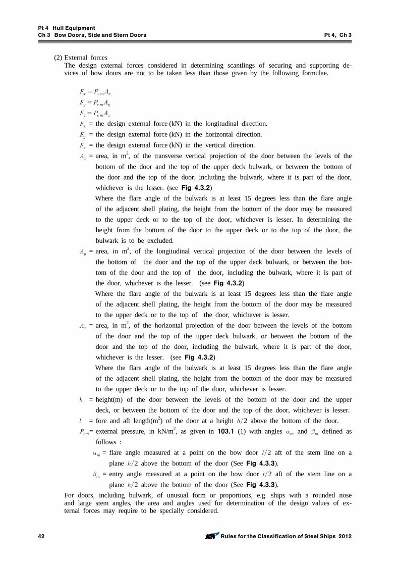
Pt 4 Hull Equipment
Ch 3 Bow Doors, Side and Stern Doors Pt 4, Ch 3
42 Rules for the Classification of Steel Ships 2012
(2) External forcesThe design external forces considered in determining scantlings of securing and supporting de-vices of bow doors are not to be taken less than those given by the following formulae.
= the design external force (kN) in the longitudinal direction. = the design external force (kN) in the horizontal direction. = the design external force (kN) in the vertical direction. = area, in m2, of the transverse vertical projection of the door between the levels of the
bottom of the door and the top of the upper deck bulwark, or between the bottom of the door and the top of the door, including the bulwark, where it is part of the door, whichever is the lesser. (see Fig 4.3.2)
Where the flare angle of the bulwark is at least 15 degrees less than the flare angle of the adjacent shell plating, the height from the bottom of the door may be measured to the upper deck or to the top of the door, whichever is lesser. In determining the height from the bottom of the door to the upper deck or to the top of the door, the bulwark is to be excluded.
= area, in m2, of the longitudinal vertical projection of the door between the levels of the bottom of the door and the top of the upper deck bulwark, or between the bot-tom of the door and the top of the door, including the bulwark, where it is part of the door, whichever is the lesser. (see Fig 4.3.2)
Where the flare angle of the bulwark is at least 15 degrees less than the flare angle of the adjacent shell plating, the height from the bottom of the door may be measured to the upper deck or to the top of the door, whichever is lesser.
= area, in m2, of the horizontal projection of the door between the levels of the bottom of the door and the top of the upper deck bulwark, or between the bottom of the door and the top of the door, including the bulwark, where it is part of the door, whichever is the lesser. (see Fig 4.3.2)
Where the flare angle of the bulwark is at least 15 degrees less than the flare angle of the adjacent shell plating, the height from the bottom of the door may be measured to the upper deck or to the top of the door, whichever is lesser.
= height(m) of the door between the levels of the bottom of the door and the upper deck, or between the bottom of the door and the top of the door, whichever is lesser.
= fore and aft length(m2) of the door at a height 2 above the bottom of the door.= external pressure, in kN/m2, as given in 103.1 (1) with angles and defined as
follows : = flare angle measured at a point on the bow door 2 aft of the stem line on a
plane 2 above the bottom of the door (See Fig 4.3.3). = entry angle measured at a point on the bow door 2 aft of the stem line on a
plane 2 above the bottom of the door (See Fig 4.3.3).For doors, including bulwark, of unusual form or proportions, e.g. ships with a rounded nose and large stem angles, the area and angles used for determination of the design values of ex-ternal forces may require to be specially considered.
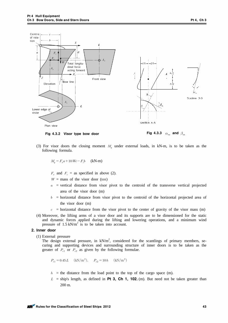
Pt 4 Hull Equipment
Ch 3 Bow Doors, Side and Stern Doors Pt 4, Ch 3
Rules for the Classification of Steel Ships 2012 43
Fig 4.3.2 Visor type bow door Fig 4.3.3 and
(3) For visor doors the closing moment under external loads, in kN-m, is to be taken as the following formula.
(kN-m)
and = as specified in above (2). = mass of the visor door (ton) = vertical distance from visor pivot to the centroid of the transverse vertical projected
area of the visor door (m) = horizontal distance from visor pivot to the centroid of the horizontal projected area of
the visor door (m) = horizontal distance from the visor pivot to the center of gravity of the visor mass (m)
(4) Moreover, the lifting arms of a visor door and its supports are to be dimensioned for the static and dynamic forces applied during the lifting and lowering operations, and a minimum wind pressure of 1.5 kN/m2 is to be taken into account.
2. Inner door
(1) External pressureThe design external pressure, in kN/m2, considered for the scantlings of primary members, se-curing and supporting devices and surrounding structure of inner doors is to be taken as the greater of or as given by the following formulae.
kNm kNm
= the distance from the load point to the top of the cargo space (m). = ship's length, as defined in Pt 3, Ch 1, 102. (m). But need not be taken greater than
200 m.
Pt 4 Hull Equipment
Ch 3 Bow Doors, Side and Stern Doors Pt 4, Ch 3
44 Rules for the Classification of Steel Ships 2012
(2) Internal pressureThe design internal pressure, , considered for the scantlings of securing devices of inner doors is not to be less than 25 kN/m2.
104. Scantlings of bow doors
1. General
(1) The strength of bow doors is to be commensurate with that of the surrounding structure.(2) Bow doors are to be adequately stiffened and means are to be provided to prevent lateral or
vertical movement of the doors when closed. For visor doors adequate strength for the opening and closing operations is to be provided in the connections of the lifting arms to the door structure and to the ship structure.
2. Primary structure
Scantlings of the primary members are generally to be supported by direct strength calculations in association with the external pressure given in 103. 1 (1) and permissible stresses given in Table 4.3.1. Normally, formulae for simple beam theory may be applied to determine the bending stress. Members are to be considered to have simply supported end connections.
3. Secondary stiffeners
Secondary stiffeners are to be supported by primary members constituting the main stiffening of the door. The section modulus of secondary stiffeners is not to be less than that required for end framing. Consideration is to be given, where necessary, to differences in fixity between ship's frames and bow doors stiffeners. In addition, stiffener webs are to have a net sectional area, A , not less than that obtained from the following formula.
(cm2)
= shear force (kN) in the stiffener calculated by using uniformly distributed external pressure
= as specified in 103. 1 (1) = material factor as specified in Table 4.3.2
4. Plating
The thickness of bow door plating is to be not less than that required for the side shell plating, using bow door stiffener spacing, but in no case less than the minimum required thickness of fore end shell plating.
105. Scantlings of inner doors
1. General
(1) Scantlings of the primary members are generally to be supported by direct strength calculations in association with the external pressure given in 103. 2 (1) and permissible stresses given in Table 4.3.1. Normally, formulate for simple beam theory may be applied.
(2) Where inner doors also serve as a vehicle ramps, the scantlings are not to be less than those required for vehicle decks.
106. Securing and supporting of bow doors
1. General
(1) Bow doors are to be fitted with adequate means of securing and supporting so as to be com-mensurate with the strength and stiffness of the surrounding structure.
(2) The hull supporting structure in way of the bow doors is to be suitable for the same design loads and design stresses as the securing and supporting devices.
(3) Where packing is required, the packing material is to be of a comparatively soft type, and the
Pt 4 Hull Equipment
Ch 3 Bow Doors, Side and Stern Doors Pt 4, Ch 3
Rules for the Classification of Steel Ships 2012 45
supporting forces are to be carried by the steel structure only. Other types of packing may be considered.
(4) Maximum design clearance between securing and supporting devices is not generally to exceed 3 mm.
(5) A means is to be provided for mechanically fixing the door in the open position.(6) Only the active supporting and securing devices having an effective stiffness in the relevant di-
rection are to be included and considered to calculate the reaction forces acting on the devices.(7) Small and/or flexible devices such as cleats intended to provide load compression of the pack-
ing material are not generally to be included in the calculations.(8) The number of securing and supporting devices are generally to be the minimum practical
whilst taking into account the requirements for redundant provision given in Par 2 (6), (7) and the available space for adequate support in the hull structure.
(9) For opening outwards visor doors, the pivot arrangement is generally to be such that the visor is self closing under external loads, that . Moreover, the closing moment as given in 103. 1, (3) (A) is to be not less than:
× (kN-m)
, , , , and = as specified in 103.
2. Scantlings
(1) Securing and supporting devices are to be adequately designed so that they can withstand the reaction forces within the permissible stresses given in Table 4.3.1.
(2) For visor doors the reaction forces applied on the effective securing and supporting devices as-suming the door as a rigid body are determined for the following combination of external loads acting simultaneously together with the self weight of the door :(A) Case 1 and (B) Case 2 0.7 acting on each side separately together with 0.7 and 0.7
where , and are determined as indicated in 103. 1 (2) and applied at the centroid of projected areas.
(3) For side-opening doors the reaction forces applied on the effective securing and supporting de-vices assuming the door as a rigid body are determined for the following combination of ex-ternal loads acting simultaneously together with the self weight of the door:(A) Case 1 , and (B) Case 2 0.7 and 0.7 acting on both doors and 0.7 acting on each door separately.
where , and are determined as indicated in 103. 1 (2) and applied at the centroid of projected areas.
(4) The support forces as determined according to above (2) (A) and (3) (A) shall generally give rise to a zero moment about the transverse axis through the centroid of the area . For visor doors, longitudinal reaction forces of pin and/or wedge supports at the door base contributing to this moment are not to be of the forward direction.
(5) The distribution of the reaction forces acting on the securing and supporting devices may re-quire to be supported by direct calculations taking into account the flexibility of the hull struc-ture and the actual position and stiffness of the supports.
(6) The arrangement of securing and supporting devices in way of these securing devices is to be designed with redundancy so that in the event of failure of any single securing or supporting device the remaining devices are capable to withstand the reaction forces without exceeding by more than 20 percent the permissible stresses as given in Table 4.3.1.
(7) For visor doors, two securing devices are to be provided at the lower part of the door, each capable of providing the full reaction force required to prevent opening of the door within the permissible stresses given in Table 4.3.1. The opening moment , in kN-m, to be balanced by this reaction force, is not to be taken less than:
(kN-m)
where :
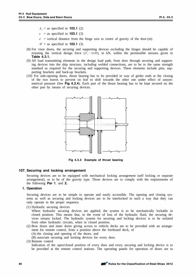
Pt 4 Hull Equipment
Ch 3 Bow Doors, Side and Stern Doors Pt 4, Ch 3
46 Rules for the Classification of Steel Ships 2012
= as specified in 103.1 (2) = as specified in 103.1 (3) = vertical distance from the hinge axis to centre of gravity of the door (m) = as specified in 103.1 (3)
(8) For visor doors, the securing and supporting devices excluding the hinges should be capable of resisting the vertical design force ( ), in kN, within the permissible stresses given in Table 4.3.1.
(9) All load transmitting elements in the design load path, from door through securing and support-ing devices into the ship structure, including welded connections, are to be to the same strength standard as required for the securing and supporting devices. These elements include pins, sup-porting brackets and back-up brackets.
(10) For side-opening doors, thrust bearing has to be provided in way of girder ends at the closing of the two leaves to prevent on leaf to shift towards the other one under effect of unsym-metrical pressure (See Fig 4.3.4). Each part of the thrust bearing has to be kept secured on the other part by means of securing devices.
Fig 4.3.4 Example of thrust bearing
107. Securing and locking arrangement
Securing devices are to be equipped with mechanical locking arrangement (self locking or separate arrangement), or to be of the gravity type. Those devices are to comply with the requirements of the following Par 1. and 2.
1. Operation
Securing devices are to be simple to operate and easily accessible. The opening and closing sys-tems as well as securing and locking devices are to be interlocked in such a way that they can only operate in the proper sequence.(1) Hydraulic securing devices
Where hydraulic securing devices are applied, the system is to be mechanically lockable in closed position. This means that, in the event of loss of the hydraulic fluid, the securing de-vices remain locked. The hydraulic system for securing and locking devices is to be isolated from other hydraulic circuits, when in closed position.
(2) Bow doors and inner doors giving access to vehicle decks are to be provided with an arrange-ment for remote control, from a position above the freeboard deck, of(A) the closing and opening of the doors, and(B) associate securing and locking devices for every door.
(3) Remote controlIndication of the open/closed position of every door and every securing and locking device is to be provided at the remote control stations. The operating panels for operation of doors are to
Pt 4 Hull Equipment
Ch 3 Bow Doors, Side and Stern Doors Pt 4, Ch 3
Rules for the Classification of Steel Ships 2012 47
be inaccessible to unauthorized persons. A notice plate, giving instructions to the effect that all securing devices are to be closed and locked before leaving harbour, is to be placed at each operating panel and is to be supplemented by warning indicator lights.
2. Indication and monitoring
(1) Separate indicator lights and audible alarms are to be provided on the navigation bridge and on the operating panel to show that the bow door and inner door are closed and that their securing and locking devices are properly positioned. The indication panel is to be provided with a lamp test function. It shall not be possible to turn off the indicator light.
(2) The indicator system is to be designed on the fail safe principle and is to show by visual alarms if the door is not fully closed and not fully locked and by audible alarms if securing devices become open or locking devices become unsecured. The power supply for the indicator system for operating and closing doors is to be independent of the power supply for operating and closing the doors and is to be provided with a back-up power supply from the emergency source of power or other secure power supply e.g. UPS. The sensors of the indicator system are to be protected from water, ice formation and mechanical damage.
(3) The indication panel on the navigation bridge is to be equipped with a mode selection function “harbour/sea voyage”, so arranged that audible alarm is given on the navigation bridge if the vessel leaves harbour with the bow door or inner door not closed or with any of the securing devices not in the correct position.
(4) A water leakage detection system with audible alarm and television surveillance is to be ar-ranged to provide an indication to the navigation bridge and to the engine control room of leakage through the inner door.
(5) Between the bow door and the inner door a television surveillance system is to be fitted with a monitor on the navigation bridge and in the engine control room. The system is to monitor the position of the doors and a sufficient number of their securing devices. Special consideration is to be given for the lighting and contrasting colour of objects under surveillance.
(6) A drainage system is to be arranged in the area between bow door and ramp or where no ramp is fitted between the bow door and inner door. The system is to be equipped with an au-dible alarm function to the navigation bridge being set off when the water levels in these areas exceed 0.5m or the high water level alarm, whichever is lesser.
(7) The indicator system is considered designed on the fail - safe principal in above (2) to (6) when:(A) The indication panel is provided with:
- a power failure alarm- an earth failure alarm- a lamp test- separate indication for door closed, door locked, door not closed and door not locked.
(B) Limit switches electrically closed when the door is closed (when more limit switches are provided they may be connected in series).
(C) Limit switches electrically closed when securing arrangements are in place (when more limit switches are provided they may be connected in series).
(D) Two electrical circuits (also in one multicore cable), one for the indication of door closed / not closed and the other for door locked / not locked.
(E) In case of dislocation of limit switches, indication to show : not closed / not locked / se-curing arrangement not in place - as appropriate.
(8) For ro-ro passenger ships on international voyages, the special category spaces and ro-ro spaces are to be continuously patrolled or monitored by effective means, such as television suveillance, so that any movement of vehicles in adverse weather conditions or unauthorized access by pas-sengers thereto, can be detected whilst the ship is underway.
108. Operating and maintenance manual
1. An Operating and Maintenance Manual for the bow door and inner door is to be provided on board and is to contain necessary information after approval of this society. (1) main particulars and design drawings
(A) special safety precautions(B) details of vessel(C) equipment and design loading (for ramps)
Pt 4 Hull Equipment
Ch 3 Bow Doors, Side and Stern Doors Pt 4, Ch 3
48 Rules for the Classification of Steel Ships 2012
(D) key plan of equipment (doors and ramps)(E) manufacturer’s recommended testing for equipment(F) description of equipment for
(a) bow doors(b) inner bow doors(c) bow ramp/doors(d) side doors(e) stern doors(f) central power pack(g) bridge panel(h) engine control room panel
(2) service conditions(A) limiting heel and trim of ship for loading/unloading(B) limiting heel and trim for door operations(C) doors/ramps operating instructions(D) doors/ramps emergency operating instructions
(3) maintenance(A) schedule and extent of maintenance(B) trouble shooting and acceptable clearances(C) maufacturer’s maintenance procedures
(4) register of inspections, including inspection of locking, securing and supporting devices, repairs and renewals.
This Manual has is to be submitted for approval that the above mentioned items are contained in the OMM and that the maintenance part includes the necessary information with regard to in-spections, trouble-shooting and acceptance / rejection criteria.
2. Documented operating procedures for closing and securing the bow door and inner door are to be kept on board and posted in appropriate place.
Section 2 Side and Stern Doors
201. General
1. Application
(1) These rules give requirements for the arrangement, strength and securing of side shell doors, abaft the collision bulkhead, and stern doors leading into enclosed spaces.
(2) The side shell door and stern door of all existing ro-ro passenger ships constructed before or on 30 June 1997 are to be as deemed appropriate by the Society.
2. Arrangement
(1) Stern doors for passenger vessels are to be situated above the freeboard deck. Stern doors for ro-ro cargo ships and side shell doors may be either below or above the freeboard deck.
(2) The side and stern doors are to be so fitted as to ensure tightness and structural integrity com-mensurate with their location and the surrounding structure.
(3) In general, the lower edge of door openings is not to be below a line drawn parallel to the freeboard deck at side, which has at its lowest point the upper edge of the uppermost load line.
(4) Where side door and stern door are unavoidably provided below the line as stipulated in above (3), the following conditions are to be satisfied.(A) Compartment being equivalent to watertight-bulkhead in strength and watertightness is to be
provided and the second door is to be fitted for the compartment.(B) Detecting device for sea water leakage is to be provided in the compartment and drainage
means of the compartment with a screw-down stop valve capable of being controlled from easily accessible position is to be provided.
(5) Doors are generally to be arranged to open outwards.3. Definitions
The definitions specified in this Section are to be in accordance with 101.4.
Pt 4 Hull Equipment
Ch 3 Bow Doors, Side and Stern Doors Pt 4, Ch 3
Rules for the Classification of Steel Ships 2012 49
202. Strength criteria
1. Primary structure and securing and supporting devices
Scantlings of the primary members, securing and supporting devices of doors are to be determined to withstand the design loads defined in 203., using the following permissible stresses of Table 4.3.1.
2. The bucking strength of primary members is to be verified as being adequate.3. Steel of steel bearings in securing and supporting devices
For steel to steel bearings in securing and supporting devices, the nominal bearing pressure calcu-lated by dividing the design force by the projected bearing area is not to exceed 0.8.
= the yield stress of the bearing material.4. Tensile stress on threaded bolts
The arrangements of securing and supporting devices is to be such that threaded bolts do not carry support forces. The maximum tension in way of threads bolts not carrying support forces is not to exceed 125 (N/mm2). = material factor as specified in Table 4.3.2.
203. Design Loads
The design forces considered for the scantlings of primary members, securing and supporting de-vices are not to be less than the following Par 1 to 3.
1. Design forces for securing or supporting devices of doors opening inwards :External force : (kN)Internal force : (kN)
2. Design forces for securing or supporting devices of doors opening outwards :External force : (kN)Internal force : (kN)
3. Design forces for primary members is to be taken as the greater of the following two formulae :External force : (kN)Internal force : (kN)
where : = area, in , of the door opening = mass of the door (ton) = total paking force in kN, packing line pressure is normally not to be taken less than 5
N/mm. = the greater of and (kN) = accidental force, in kN, due to loose of cargo etc., to be uniformly distributed over the
area and not to be taken less than 300 kN. For small doors such as bunker doors and pilot doors, the value of may be appropriately reduced. However, the value of may be taken as zero, provided an additional structure such as an inner ramp is fitted, which is capable of protecting the door from accidental forces due to loose cargoes.
= external design pressure, in kN/m2, determined at the centre of gravity of the door opening and not taken less than the value obtained from the following formulae.
for ,
Pt 4 Hull Equipment
Ch 3 Bow Doors, Side and Stern Doors Pt 4, Ch 3
50 Rules for the Classification of Steel Ships 2012
for ≥ ,
However, for stern doors of ships fitted with bow doors, is not to be taken less than:
(kN/m2)
where : = coefficient that obtained from ship's length as specified in Table 4.3.3. = ship's length, in m, as specified in Pt 3, Ch 1, 102. but need not be taken greater than
200 m = height of the center of area of the door, in m, above the baseline = coefficient depending on the area where the ship is intended to be operated :
for sea going ships = 1for ships operated in coastal waters = 0.8for ships operated in sheltered waters = 0.5
= draught, in m, at the highest subdivision load line
204. Scantlings
1. General
(1) In general the strength of side and stern doors is to be equivalent to the strength of the sur-rounding structure.
(2) Side and stern door openings in the side shell are to have well rounded corners and adequate compensation is to be arranged with web frames at sides and stringers or equivalent above and below.
(3) Side and stern doors are to be adequately stiffened, and means are to be provided to prevent movement of the doors when closed. Adequate strength is to be provided in the connections of the lifting/maneuvering arms and hinges to the door structure and to the ship structure.
(4) Where side and stern doors also serve as vehicle ramps, the design of the hinges should take into account the ship angle of trim which may result in uneven loading on the hinges.
2. Plating
(1) The thickness of the side and stern door plating is not to be less than the side shell plating calculated with the door stiffener spacing, and in no case to be less than the minimum shell plate thickness.
(2) Where side and stern doors also serve as vehicle ramps, the plating is not to be less than re-quired for vehicle decks.
3. Stiffeners
(1) The section modulus of horizontal or vertical stiffeners is not to be less than required for side framing. Consideration is to be given, where necessary, to differences in fixity between ship's frame and door stiffeners.
(2) Where side and stern doors also serve as vehicle ramps, the stiffener scantlings are not to be less than required for vehicle decks.
(3) Where necessary, side and stern door stiffeners are to be supported by girders or stringers.4. Primary members
(1) Scantlings of primary members are generally to be supported by direct calculations in associa-tion with the design forces given in 203. 3 and permissible stresses given in Table 4.3.1. Normally, formulae for simple beam theory may be applied to determine the bending stress. Members are to be considered to have simply supported end connections.
(2) The webs of girders and stringers are to be adequately stiffened, preferably in a direction per-pendicular to the shell plating.
(3) The girder system is to be given sufficient stiffness to ensure integrity of the boundary support
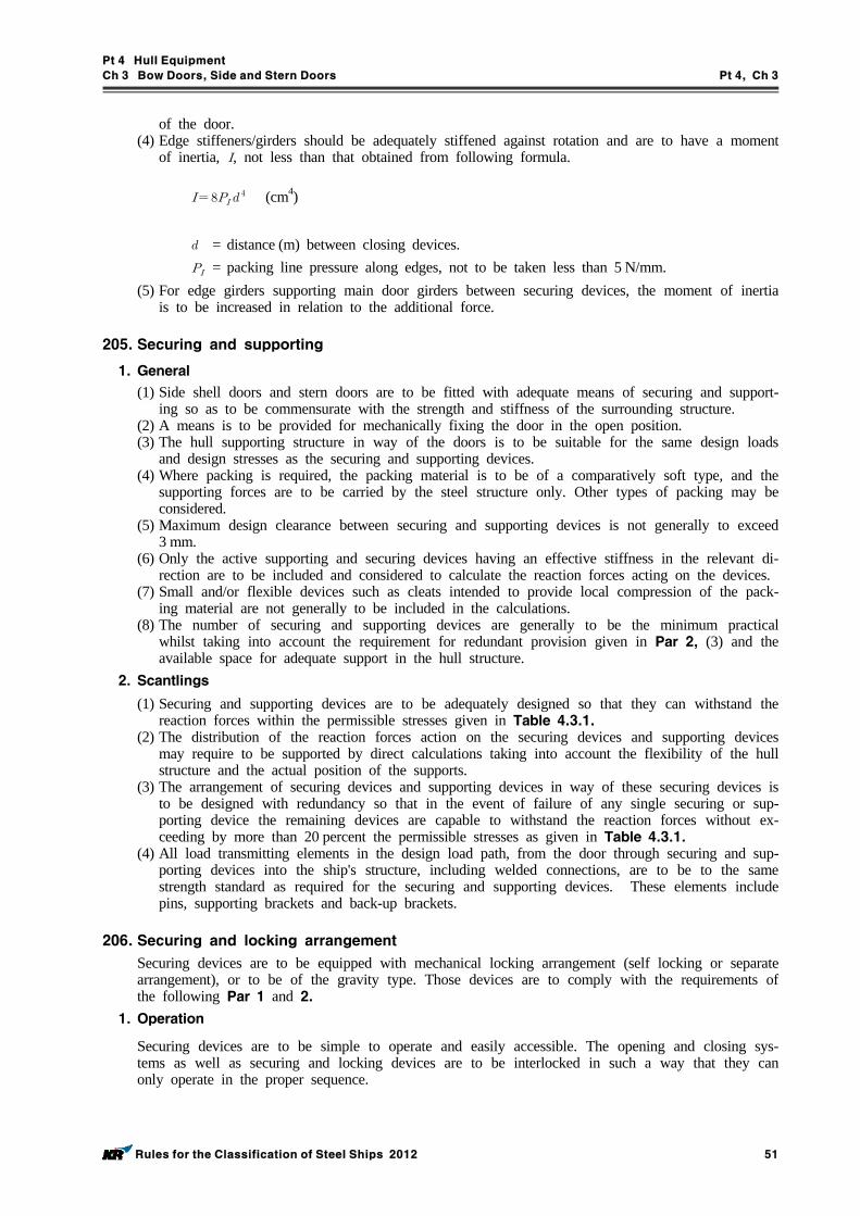
Pt 4 Hull Equipment
Ch 3 Bow Doors, Side and Stern Doors Pt 4, Ch 3
Rules for the Classification of Steel Ships 2012 51
of the door.(4) Edge stiffeners/girders should be adequately stiffened against rotation and are to have a moment
of inertia, , not less than that obtained from following formula.
(cm4)
= distance (m) between closing devices. = packing line pressure along edges, not to be taken less than 5 N/mm.
(5) For edge girders supporting main door girders between securing devices, the moment of inertia is to be increased in relation to the additional force.
205. Securing and supporting
1. General
(1) Side shell doors and stern doors are to be fitted with adequate means of securing and support-ing so as to be commensurate with the strength and stiffness of the surrounding structure.
(2) A means is to be provided for mechanically fixing the door in the open position.(3) The hull supporting structure in way of the doors is to be suitable for the same design loads
and design stresses as the securing and supporting devices.(4) Where packing is required, the packing material is to be of a comparatively soft type, and the
supporting forces are to be carried by the steel structure only. Other types of packing may be considered.
(5) Maximum design clearance between securing and supporting devices is not generally to exceed 3 mm.
(6) Only the active supporting and securing devices having an effective stiffness in the relevant di-rection are to be included and considered to calculate the reaction forces acting on the devices.
(7) Small and/or flexible devices such as cleats intended to provide local compression of the pack-ing material are not generally to be included in the calculations.
(8) The number of securing and supporting devices are generally to be the minimum practical whilst taking into account the requirement for redundant provision given in Par 2, (3) and the available space for adequate support in the hull structure.
2. Scantlings
(1) Securing and supporting devices are to be adequately designed so that they can withstand the reaction forces within the permissible stresses given in Table 4.3.1.
(2) The distribution of the reaction forces action on the securing devices and supporting devices may require to be supported by direct calculations taking into account the flexibility of the hull structure and the actual position of the supports.
(3) The arrangement of securing devices and supporting devices in way of these securing devices is to be designed with redundancy so that in the event of failure of any single securing or sup-porting device the remaining devices are capable to withstand the reaction forces without ex-ceeding by more than 20 percent the permissible stresses as given in Table 4.3.1.
(4) All load transmitting elements in the design load path, from the door through securing and sup-porting devices into the ship's structure, including welded connections, are to be to the same strength standard as required for the securing and supporting devices. These elements include pins, supporting brackets and back-up brackets.
206. Securing and locking arrangement
Securing devices are to be equipped with mechanical locking arrangement (self locking or separate arrangement), or to be of the gravity type. Those devices are to comply with the requirements of the following Par 1 and 2.
1. Operation
Securing devices are to be simple to operate and easily accessible. The opening and closing sys-tems as well as securing and locking devices are to be interlocked in such a way that they can only operate in the proper sequence.
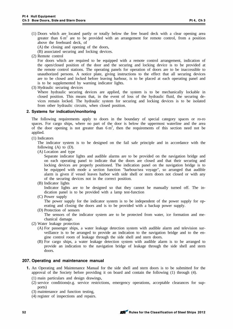
Pt 4 Hull Equipment
Ch 3 Bow Doors, Side and Stern Doors Pt 4, Ch 3
52 Rules for the Classification of Steel Ships 2012
(1) Doors which are located partly or totally below the free board deck with a clear opening area greater than 6 m2 are to be provided with an arrangement for remote control, from a position above the freeboard deck, of(A) the closing and opening of the doors,(B) associated securing and locking devices.
(2) Remote controlFor doors which are required to be equipped with a remote control arrangement, indication of the open/closed position of the door and the securing and locking device is to be provided at the remote control stations. The operating panels for operation of doors are to be inaccessible to unauthorized persons. A notice plate, giving instructions to the effect that all securing devices are to be closed and locked before leaving harbour, is to be placed at each operating panel and is to be supplemented by warning indicator lights.
(3) Hydraulic securing devicesWhere hydraulic securing devices are applied, the system is to be mechanically lockable in closed position. This means that, in the event of loss of the hydraulic fluid, the securing de-vices remain locked. The hydraulic system for securing and locking devices is to be isolated from other hydraulic circuits, when closed position.
2. Systems for indication/monitoring
The following requirements apply to doors in the boundary of special category spaces or ro-ro spaces. For cargo ships, where no part of the door is below the uppermost waterline and the area of the door opening is not greater than 6 m2, then the requirements of this section need not be applied.(1) Indicators
The indicator system is to be designed on the fail safe principle and in accordance with the following (A) to (D).(A) Location and type
Separate indicator lights and audible alarms are to be provided on the navigation bridge and on each operating panel to indicate that the doors are closed and that their securing and locking devices are properly positioned. The indication panel on the navigation bridge is to be equipped with mode a section function "harbour/sea voyage", so arranged that audible alarm is given if vessel leaves harbor with side shell or stern doors not closed or with any of the securing devices not in the correct position.
(B) Indicator lightsIndicator lights are to be designed so that they cannot be manually turned off. The in-dication panel is to be provided with a lamp test-function
(C) Power supplyThe power supply for the indicator system is to be independent of the power supply for op-erating and closing the doors and is to be provided with a backup power supply.
(D) Protection of sensorsThe sensors of the indicator system are to be protected from water, ice formation and me-chanical damage.
(2) Water leakage protection(A) For passenger ships, a water leakage detection system with audible alarm and television sur-
veillance is to be arranged to provide an indication to the navigation bridge and to the en-gine control room of leakage through the side shell and stern doors.
(B) For cargo ships, a water leakage detection system with audible alarm is to be arranged to provide an indication to the navigation bridge of leakage through the side shell and stern doors.
207. Operating and maintenance manual
1. An Operating and Maintenance Manual for the side shell and stern doors is to be submitted for the approval of the Society before providing it on board and contain the following (1) through (4).(1) main particulars and design drawings,(2) service conditions(e.g. service restrictions, emergency operations, acceptable clearances for sup-
ports)(3) maintenance and function testing,(4) register of inspections and repairs.

Pt 4 Hull Equipment
Ch 3 Bow Doors, Side and Stern Doors Pt 4, Ch 3
Rules for the Classification of Steel Ships 2012 53
2. Documented operating procedures for closing and securing side shell and stern doors are to be kept on board and posted at the appropriate places.
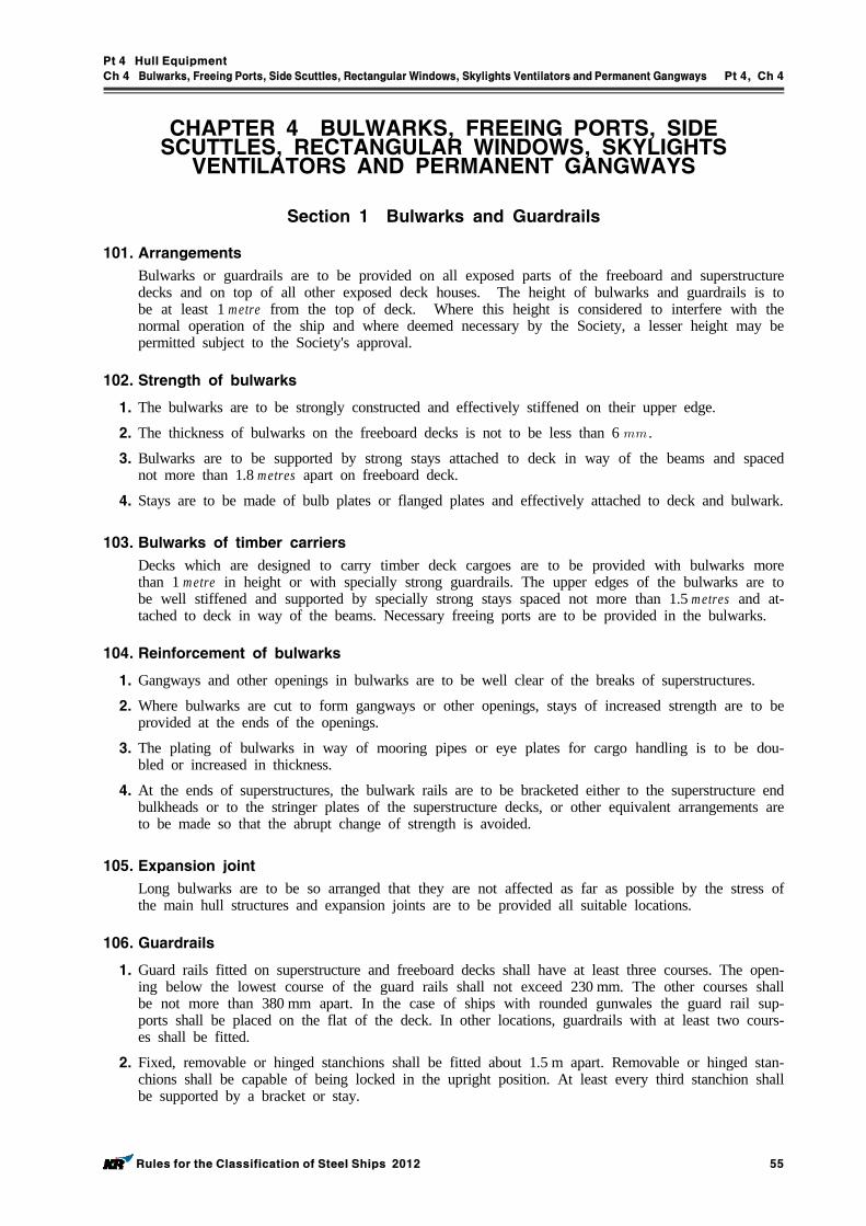
Pt 4 Hull Equipment
Ch 4 Bulwarks, Freeing Ports, Side Scuttles, RectangularWindows, Skylights Ventilators andPermanent Gangways Pt 4, Ch 4
Rules for the Classification of Steel Ships 2012 55
CHAPTER 4 BULWARKS, FREEING PORTS, SIDE SCUTTLES, RECTANGULAR WINDOWS, SKYLIGHTS VENTILATORS AND PERMANENT GANGWAYS
Section 1 Bulwarks and Guardrails
101. Arrangements
Bulwarks or guardrails are to be provided on all exposed parts of the freeboard and superstructure decks and on top of all other exposed deck houses. The height of bulwarks and guardrails is to be at least 1 metre from the top of deck. Where this height is considered to interfere with the normal operation of the ship and where deemed necessary by the Society, a lesser height may be permitted subject to the Society's approval.
102. Strength of bulwarks
1. The bulwarks are to be strongly constructed and effectively stiffened on their upper edge.
2. The thickness of bulwarks on the freeboard decks is not to be less than 6 .
3. Bulwarks are to be supported by strong stays attached to deck in way of the beams and spaced not more than 1.8 metres apart on freeboard deck.
4. Stays are to be made of bulb plates or flanged plates and effectively attached to deck and bulwark.
103. Bulwarks of timber carriers
Decks which are designed to carry timber deck cargoes are to be provided with bulwarks more than 1 metre in height or with specially strong guardrails. The upper edges of the bulwarks are to be well stiffened and supported by specially strong stays spaced not more than 1.5 metres and at-tached to deck in way of the beams. Necessary freeing ports are to be provided in the bulwarks.
104. Reinforcement of bulwarks
1. Gangways and other openings in bulwarks are to be well clear of the breaks of superstructures.
2. Where bulwarks are cut to form gangways or other openings, stays of increased strength are to be provided at the ends of the openings.
3. The plating of bulwarks in way of mooring pipes or eye plates for cargo handling is to be dou-bled or increased in thickness.
4. At the ends of superstructures, the bulwark rails are to be bracketed either to the superstructure end bulkheads or to the stringer plates of the superstructure decks, or other equivalent arrangements are to be made so that the abrupt change of strength is avoided.
105. Expansion joint
Long bulwarks are to be so arranged that they are not affected as far as possible by the stress of the main hull structures and expansion joints are to be provided all suitable locations.
106. Guardrails
1. Guard rails fitted on superstructure and freeboard decks shall have at least three courses. The open-ing below the lowest course of the guard rails shall not exceed 230 mm. The other courses shall be not more than 380 mm apart. In the case of ships with rounded gunwales the guard rail sup-ports shall be placed on the flat of the deck. In other locations, guardrails with at least two cours-es shall be fitted.
2. Fixed, removable or hinged stanchions shall be fitted about 1.5 m apart. Removable or hinged stan-chions shall be capable of being locked in the upright position. At least every third stanchion shall be supported by a bracket or stay.
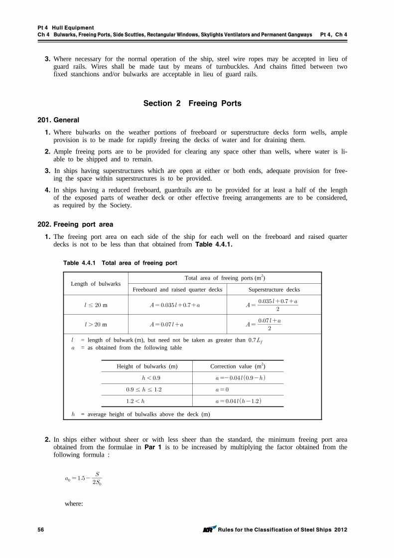
Pt 4 Hull Equipment
Ch 4 Bulwarks, Freeing Ports, Side Scuttles, RectangularWindows, Skylights Ventilators andPermanent Gangways Pt 4, Ch 4
56 Rules for the Classification of Steel Ships 2012
3. Where necessary for the normal operation of the ship, steel wire ropes may be accepted in lieu of guard rails. Wires shall be made taut by means of turnbuckles. And chains fitted between two fixed stanchions and/or bulwarks are acceptable in lieu of guard rails.
Section 2 Freeing Ports
201. General
1. Where bulwarks on the weather portions of freeboard or superstructure decks form wells, ample provision is to be made for rapidly freeing the decks of water and for draining them.
2. Ample freeing ports are to be provided for clearing any space other than wells, where water is li-able to be shipped and to remain.
3. In ships having superstructures which are open at either or both ends, adequate provision for free-ing the space within superstructures is to be provided.
4. In ships having a reduced freeboard, guardrails are to be provided for at least a half of the length of the exposed parts of weather deck or other effective freeing arrangements are to be considered, as required by the Society.
202. Freeing port area
1. The freeing port area on each side of the ship for each well on the freeboard and raised quarter decks is not to be less than that obtained from Table 4.4.1.
Length of bulwarksTotal area of freeing ports (m2)
Freeboard and raised quarter decks Superstructure decks
≤ m
m
= length of bulwark (m), but need not be taken as greater than 0.7 = as obtained from the following table
Height of bulwarks (m) Correction value (m2)
≤ ≤
= average height of bulwalks above the deck (m)
Table 4.4.1 Total area of freeing port
2. In ships either without sheer or with less sheer than the standard, the minimum freeing port area obtained from the formulae in Par 1 is to be increased by multiplying the factor obtained from the following formula :
where:
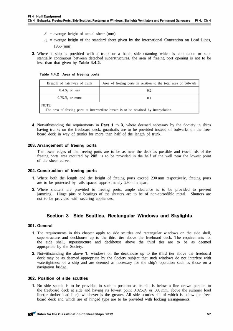
Pt 4 Hull Equipment
Ch 4 Bulwarks, Freeing Ports, Side Scuttles, RectangularWindows, Skylights Ventilators andPermanent Gangways Pt 4, Ch 4
Rules for the Classification of Steel Ships 2012 57
= average height of actual sheer (mm) = average height of the standard sheer given by the International Convention on Load Lines,
1966 (mm)
3. Where a ship is provided with a trunk or a hatch side coaming which is continuous or sub-stantially continuous between detached superstructures, the area of freeing port opening is not to be less than that given by Table 4.4.2.
Breadth of hatchway of trunk Area of freeing ports in relation to the total area of bulwark
0.4 or less 0.2
0.75 or more 0.1
NOTE :The area of freeing ports at intermediate breath is to be obtained by interpolation.
Table 4.4.2 Area of freeing ports
4. Notwithstanding the requirements in Pars 1 to 3, where deemed necessary by the Society in ships having trunks on the freeboard deck, guardrails are to be provided instead of bulwarks on the free-board deck in way of trunks for more than half of the length of trunk.
203. Arrangement of freeing ports
The lower edges of the freeing ports are to be as near the deck as possible and two-thirds of the freeing ports area required by 202. is to be provided in the half of the well near the lowest point of the sheer curve.
204. Construction of freeing ports
1. Where both the length and the height of freeing ports exceed 230 mm respectively, freeing ports are to be protected by rails spaced approximately 230 mm apart.
2. Where shutters are provided to freeing ports, ample clearance is to be provided to prevent jamming. Hinge pins or bearings of the shutters are to be of non-corrodible metal. Shutters are not to be provided with securing appliances.
Section 3 Side Scuttles, Rectangular Windows and Skylights
301. General
1. The requirements in this chapter apply to side scuttles and rectangular windows on the side shell, superstructure and deckhouse up to the third tier above the freeboard deck. The requirements for the side shell, superstructure and deckhouse above the third tier are to be as deemed appropriate by the Society.
2. Notwithstanding the above 1. windows on the deckhouse up to the third tier above the freeboard deck may be as deemed appropriate by the Society subject that such windows do not interfere with watertightness of a ship and are deemed as necessary for the ship's operation such as those on a navigation bridge.
302. Position of side scuttles
1. No side scuttle is to be provided in such a position as its sill is below a line drawn parallel to the freeboard deck at side and having its lowest point 0.025 or 500 mm, above the summer load line(or timber load line), whichever is the greater. All side scuttles sill of which is below the free-board deck and which are of hinged type are to be provided with locking arrangements.

Pt 4 Hull Equipment
Ch 4 Bulwarks, Freeing Ports, Side Scuttles, RectangularWindows, Skylights Ventilators andPermanent Gangways Pt 4, Ch 4
58 Rules for the Classification of Steel Ships 2012
2. No side scuttle is to be provided to any space solely engaged in carriage of cargoes.
303. Application of side scuttles
1. Side scuttle inboard are to be type A, type B, type C side scuttles complying with the require-ments in Ch 8, Sec. 8.
2. Type A, type B and type C side scuttles are to be so arranged that their design pressure is less than the maximum allowable pressure determined to their grades and nominal diameters.
3. Side scuttle to spaces below the freeboard deck and those provided to sunken poop are to be type A side scuttle, type B side scuttle or equivalent thereto.
4. Side scuttles to spaces below freeboard deck, within the first tier of superstructure, those fitted up to the first tier of the deckhouse on the freeboard deck which have unprotected deck openings leading to spaces below the freeboard deck inside, deckhouses considered buoyant in stability calcu-lations and those exposed to direct blow of seas are to be type A, type B side scuttle with dead light or equivalent thereto.
5. Side scuttles fitted in spaces which give direct access to an open stairway and provided in deck-house and companion which protect the openings specified in below, are to be type A, type B side scuttle with dead light or equivalent thereto. Where cabin bulkhead or doors separate side scuttles from a direct access leading below the freeboard deck, application of side scuttle is to be as deemed appropriate by the Society.
6. Side scuttles to the spaces in the second tier on the freeboard deck, protecting direct access below or considered buoyant in stability calculations, are to be type A, type B side scuttles or equivalent thereto.
7. In ships with specially reduced freeboard, side scuttles located below the waterline after flooding into compartments are to be of fixed type.
8. Side scuttles shall be of non-opening type in ships subject to damage stability regulations, if calcu-lations indicate that they would become immersed by any intermediate stage of flooding or the fi-nal equilibrium waterplane in any required damage case.
9. Deckhouses situated on a raised quarter deck or on the deck of a superstructure of less than stand-ard height or on the deck of a deckhouse of less than standard height, may be regarded as being in the second tier as far as the provision of deadlights is concerned, provided the height of the raised quarter deck, superstructure or deckhouse is equal to, or greater than, the standard quarter deck height.
304. Protection of side scuttles
All side scuttles in way of the anchor housing and other similar places where they are liable to be damaged are to be protected by strong gratings.
305. Design pressure and maximum allowable pressure of side scuttles.
1. The design pressure of side scuttle is to be less than the maximum allowable pressure determined to their nominal diameters and classes. The design pressure P is to be determined using the follow-ing equation.
, , and : As specified Pt 3, Ch 17, 201. : Vertical distance from summer load line to sill of side scuttle(m). Where timber
load line is given, vertical distance from timber load line to sill of side scuttle.
2. Notwithstanding the provision of 1. above, the design pressure is not to be less than minimum de-sign pressure as given in Table 4.4.4.
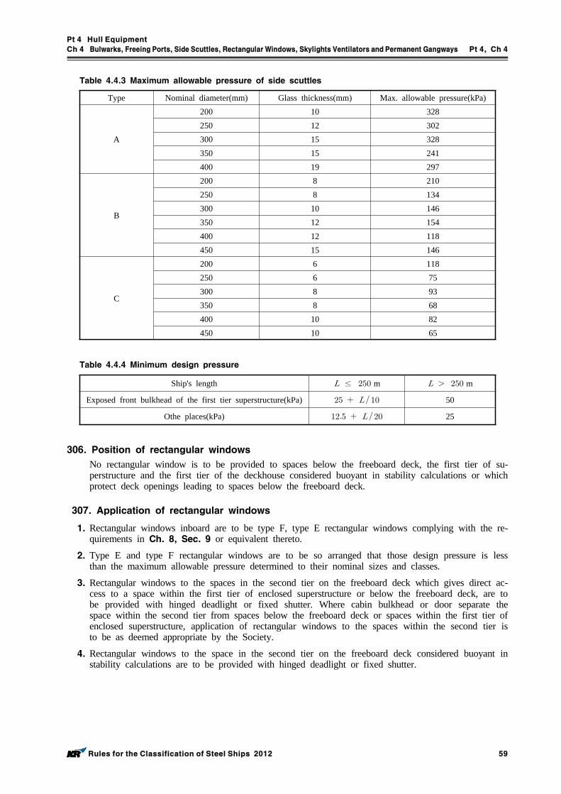
Pt 4 Hull Equipment
Ch 4 Bulwarks, Freeing Ports, Side Scuttles, RectangularWindows, Skylights Ventilators andPermanent Gangways Pt 4, Ch 4
Rules for the Classification of Steel Ships 2012 59
Type Nominal diameter(mm) Glass thickness(mm) Max. allowable pressure(kPa)
A
200 10 328250 12 302300 15 328350 15 241400 19 297
B
200 8 210250 8 134300 10 146350 12 154400 12 118450 15 146
C
200 6 118250 6 75300 8 93350 8 68400 10 82450 10 65
Table 4.4.3 Maximum allowable pressure of side scuttles
Ship's length ≤ m m
Exposed front bulkhead of the first tier superstructure(kPa) 50
Othe places(kPa) 25
Table 4.4.4 Minimum design pressure
306. Position of rectangular windows
No rectangular window is to be provided to spaces below the freeboard deck, the first tier of su-perstructure and the first tier of the deckhouse considered buoyant in stability calculations or which protect deck openings leading to spaces below the freeboard deck.
307. Application of rectangular windows
1. Rectangular windows inboard are to be type F, type E rectangular windows complying with the re-quirements in Ch. 8, Sec. 9 or equivalent thereto.
2. Type E and type F rectangular windows are to be so arranged that those design pressure is less than the maximum allowable pressure determined to their nominal sizes and classes.
3. Rectangular windows to the spaces in the second tier on the freeboard deck which gives direct ac-cess to a space within the first tier of enclosed superstructure or below the freeboard deck, are to be provided with hinged deadlight or fixed shutter. Where cabin bulkhead or door separate the space within the second tier from spaces below the freeboard deck or spaces within the first tier of enclosed superstructure, application of rectangular windows to the spaces within the second tier is to be as deemed appropriate by the Society.
4. Rectangular windows to the space in the second tier on the freeboard deck considered buoyant in stability calculations are to be provided with hinged deadlight or fixed shutter.
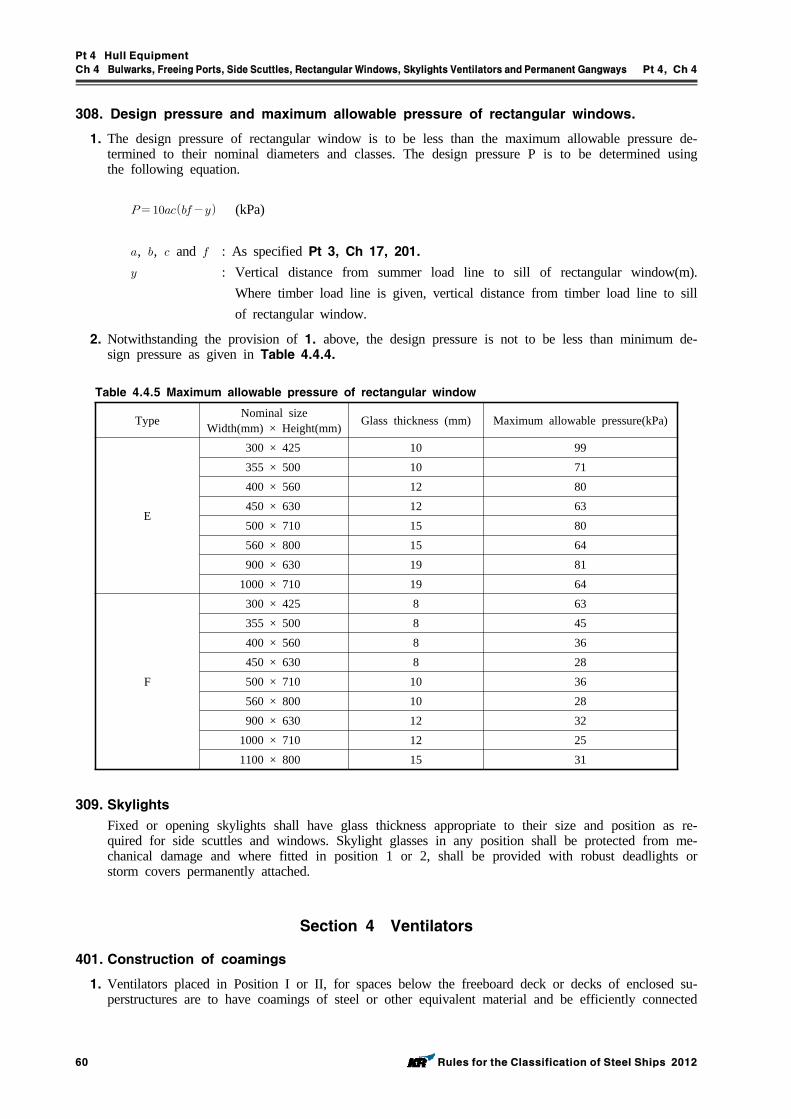
Pt 4 Hull Equipment
Ch 4 Bulwarks, Freeing Ports, Side Scuttles, RectangularWindows, Skylights Ventilators andPermanent Gangways Pt 4, Ch 4
60 Rules for the Classification of Steel Ships 2012
308. Design pressure and maximum allowable pressure of rectangular windows.
1. The design pressure of rectangular window is to be less than the maximum allowable pressure de-termined to their nominal diameters and classes. The design pressure P is to be determined using the following equation.
(kPa)
, , and : As specified Pt 3, Ch 17, 201. : Vertical distance from summer load line to sill of rectangular window(m).
Where timber load line is given, vertical distance from timber load line to sill of rectangular window.
2. Notwithstanding the provision of 1. above, the design pressure is not to be less than minimum de-sign pressure as given in Table 4.4.4.
Type Nominal sizeWidth(mm) × Height(mm) Glass thickness (mm) Maximum allowable pressure(kPa)
E
300 × 425 10 99355 × 500 10 71400 × 560 12 80450 × 630 12 63500 × 710 15 80560 × 800 15 64900 × 630 19 81
1000 × 710 19 64
F
300 × 425 8 63355 × 500 8 45400 × 560 8 36450 × 630 8 28500 × 710 10 36560 × 800 10 28900 × 630 12 32
1000 × 710 12 251100 × 800 15 31
Table 4.4.5 Maximum allowable pressure of rectangular window
309. Skylights
Fixed or opening skylights shall have glass thickness appropriate to their size and position as re-quired for side scuttles and windows. Skylight glasses in any position shall be protected from me-chanical damage and where fitted in position 1 or 2, shall be provided with robust deadlights or storm covers permanently attached.
Section 4 Ventilators
401. Construction of coamings
1. Ventilators placed in Position I or II, for spaces below the freeboard deck or decks of enclosed su-perstructures are to have coamings of steel or other equivalent material and be efficiently connected
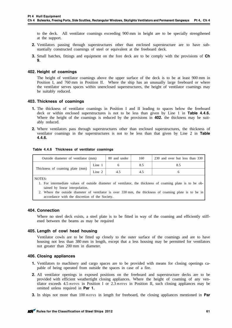
Pt 4 Hull Equipment
Ch 4 Bulwarks, Freeing Ports, Side Scuttles, RectangularWindows, Skylights Ventilators andPermanent Gangways Pt 4, Ch 4
Rules for the Classification of Steel Ships 2012 61
to the deck. All ventilator coamings exceeding 900 mm in height are to be specially strengthened at the support.
2. Ventilators passing through superstructures other than enclosed superstructure are to have sub-stantially constructed coamings of steel or equivalent at the freeboard deck.
3. Small hatches, fittings and equipment on the fore deck are to be comply with the provisions of Ch 9.
402. Height of coamings
The height of ventilator coamings above the upper surface of the deck is to be at least 900 mm in Position I, and 760 mm in Position II. Where the ship has an unusually large freeboard or where the ventilator serves spaces within unenclosed superstructures, the height of ventilator coamings may be suitably reduced.
403. Thickness of coamings
1. The thickness of ventilator coamings in Position I and II leading to spaces below the freeboard deck or within enclosed superstructures is not to be less than given by Line 1 in Table 4.4.6. Where the height of the coamings is reduced by the provisions in 402. the thickness may be suit-ably reduced.
2. Where ventilators pass through superstructures other than enclosed superstructures, the thickness of ventilator coamings in the superstructures is not to be less than that given by Line 2 in Table 4.4.6.
Outside diameter of ventilator (mm) 80 and under 160 230 and over but less than 330
Thickness of coaming plate (mm)Line 1 6 8.5 8.5
Line 2 4.5 4.5 6
NOTES:1. For intermediate values of outside diameter of ventilator, the thickness of coaming plate is to be ob-
tained by linear interpolation.2. Where the outside diameter of ventilator is over 330 mm, the thickness of coaming plate is to be in
accordance with the discretion of the Society.
Table 4.4.6 Thickness of ventilator coamings
404. Connection
Where no steel deck exists, a steel plate is to be fitted in way of the coaming and efficiently stiff-ened between the beams as may be required
405. Length of cowl head housing
Ventilator cowls are to be fitted up closely to the outer surface of the coamings and are to have housing not less than 380 mm in length, except that a less housing may be permitted for ventilators not greater than 200 mm in diameter.
406. Closing appliances
1. Ventilators to machinery and cargo spaces are to be provided with means for closing openings ca-pable of being operated from outside the spaces in case of a fire.
2. All ventilator openings in exposed positions on the freeboard and superstructure decks are to be provided with efficient weathertight closing appliances. Where the height of coaming of any ven-tilator exceeds 4.5 metres in Position I or 2.3 metres in Position II, such closing appliances may be omitted unless required in Par 1.
3. In ships not more than 100 metres in length for freeboard, the closing appliances mentioned in Par
Pt 4 Hull Equipment
Ch 4 Bulwarks, Freeing Ports, Side Scuttles, RectangularWindows, Skylights Ventilators andPermanent Gangways Pt 4, Ch 4
62 Rules for the Classification of Steel Ships 2012
2 are to be permanently provided; where not so provided in other ships, they are to be con-veniently stowed near the ventilators to which they are to be fitted up.
407. Ventilators for deckhouses
The ventilators for the deckhouses which protect the companionways leading to spaces below the freeboard deck are to be equivalent to those for the enclosed superstructures.
Section 5 Permanent Gangways
501. General
Satisfactory means (in the form of guardrails, life lines, gangways or under deck passages, etc.) are to be provided for the protection of the crew in getting to and from their quarters, the machinery space and all other parts used in the necessary work of the ship.
502. Ships having reduced freeboard
In ships having a reduced freeboard, a fore and after permanent gangway is to be provided at the level of the Superstructure deck between the poop or after deckhouse and the midship bridge or deckhouse, or equivalent means of access is to be provided to carry out the purpose of gangway, such as a passage below deck. Safe and satisfactory access from the gangway level is to be avail-able between separate crew accommodations and the machinery space.
503. Construction of gangways
The gangway specified in 502. is to be efficiently constructed and situated as near the centre line of ship as practicable. The gangways are to be in general at least 600 mm wide and to be pro-vided on their both sides with guardrails which are at least 1 meter high and comply with the re-quirements in 106. 1.
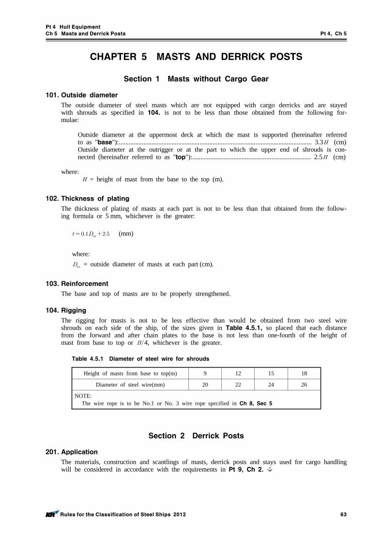
Pt 4 Hull Equipment
Ch 5 Masts and Derrick Posts Pt 4, Ch 5
Rules for the Classification of Steel Ships 2012 63
CHAPTER 5 MASTS AND DERRICK POSTS
Section 1 Masts without Cargo Gear
101. Outside diameter
The outside diameter of steel masts which are not equipped with cargo derricks and are stayed with shrouds as specified in 104. is not to be less than those obtained from the following for-mulae:
Outside diameter at the uppermost deck at which the mast is supported (hereinafter referred to as "base"):..................................................................................................................... 3.3 (cm)Outside diameter at the outrigger or at the part to which the upper end of shrouds is con-nected (hereinafter referred to as "top"):........................................................................ 2.5 (cm)
where: = height of mast from the base to the top (m).
102. Thickness of plating
The thickness of plating of masts at each part is not to be less than that obtained from the follow-ing formula or 5 mm, whichever is the greater:
(mm)
where: = outside diameter of masts at each part (cm).
103. Reinforcement
The base and top of masts are to be properly strengthened.
104. Rigging
The rigging for masts is not to be less effective than would be obtained from two steel wire shrouds on each side of the ship, of the sizes given in Table 4.5.1, so placed that each distance from the forward and after chain plates to the base is not less than one-fourth of the height of mast from base to top or 4, whichever is the greater.
Height of masts from base to top(m) 9 12 15 18
Diameter of steel wire(mm) 20 22 24 26
NOTE:The wire rope is to be No.1 or No. 3 wire rope specified in Ch 8, Sec 5
Table 4.5.1 Diameter of steel wire for shrouds
Section 2 Derrick Posts
201. Application
The materials, construction and scantlings of masts, derrick posts and stays used for cargo handling will be considered in accordance with the requirements in Pt 9, Ch 2.
Pt 4 Hull Equipment
Ch 6 Ceilings and Sparrings Pt 4, Ch 6
Rules for the Classification of Steel Ships 2012 65
CHAPTER 6 CEILINGS AND SPARRINGS
Section 1 Bottom Ceilings
101. Ships with single bottoms
1. In ships with single bottoms, close ceilings are to be provided on the floors up to the upper turn of bilge.
2. The thickness of ceilings is to be as Table 4.6.1.
3. The ceilings on the flat on the floors are to be laid in portable sections, or other convenient ar-rangements are to be made for easy removal where required for cleaning, painting or inspection of the bottom.
Thickness of ceiling(mm)
m 50
61 m≤≤ 76 m 57
m 63
Table 4.6.1 Thickness of ceiling
102. Ships with double bottoms
1. In ships with double bottoms, close ceilings are to be laid from the margin plate to the upper turn of bilge so arranged as to be readily removable for inspection of the limbers.
2. Ceilings are to be laid on the inner bottoms under hatchways, unless the requirements in Pt 3, Ch 7, 501. 3 or Pt 7, Ch 3, 204. 2 are applied.
3. Ceilings on the top of double bottom are to be laid on battens not less than 13 mm in thickness, or to be bedded on the covering required in Ch 7, 104.
4. The thickness of ceilings is to be as required in 101. 2.
Section 2 Sparrings
201. Arrangements
In all cargo spaces where it is intended to carry general cargo, sparrings not less than 50 mm in thickness and 150 mm in breadth are to be provided not more than 230 mm apart above the bilge ceiling, or equivalent arrangements are to be provided for the protection of framing.
202. Special protections
Where it is intended normally to carry such cargoes as timbers which are liable to cause damage to the hull, special protection arrangements are to be provided.
203. Exemptions
1. Sparring may be omitted in cargo holds of ships such as coal carriers, bulk carriers, ore carriers and similar ships.
2. General cargo ships may omit sparring only subject to the approval of the Society at the request of Owner, in which case the ship is distinguished with the notation "n.s." in the Register Book.
Pt 4 Hull Equipment
Ch 7 Cementing and Painting Pt 4, Ch 7
Rules for the Classification of Steel Ships 2012 67
CHAPTER 7 CEMENTING AND PAINTING
Section 1 Cementing
101. General
The bottom in ships with single bottoms, the bilges in all ships and the double bottoms in the boiler spaces of all ships are to be efficiently protected by Portland cement or other equivalent ma-terials which cover the plates and frames as far as the upper turn of bilge. However, cement pro-tection may be dispensed with in the bottom of the space solely used for carriage of oil.
102. Portland cement
Portland cement is to be mixed with fresh water and sand or other satisfactory substances, in the proportion of about one part of cement to two of sand.
103. Thickness of cement
The thickness of cement is not to be less than 20 mm at the edges.
104. Special consideration
The top plating of tanks, where ceiled directly, is to be covered with good tar put on hot and well sprinkled with cement powder, or with other equally effective coatings.
Section 2 Painting
201. General
1. All steel works are to be coated with a suitable paint. Special requirements may be additionally made by the Society in accordance with the kind of ships, purpose of spaces, etc.
2. Notwithstanding the requirements in Par 1, where it is recognized by the Society that the spaces are effectively protected against corrosion of steel works by the means other than painting or due to quality of cargoes, etc., painting may be omitted.
202. Wash cement
Steelworks in tanks intended for water may be coated with wash cement in lieu of paint.
203. Cleaning before painting
The surface of steelworks is to be thoroughly cleaned and loose rust, oil and other injurious adhe-sives are to be removed before being painted. At least the outer surface of shell plating below the load line is to be sufficiently free from rust and mill scale before painting.
Pt 4 Hull Equipment
Ch 8 Equipment Number and Equipment Pt 4, Ch 8
Rules for the Classification of Steel Ships 2012 69
CHAPTER 8 EQUIPMENT NUMBER AND EQUIPMENT
Section 1 General
101. General and application
1. All ships, according to their equipment number of provisions in Sec 2, are to be provided with anchors, chain cables, ropes, etc. which are not less than given in Table 4.8.1.
2. Anchors, chain cables, ropes, etc. for ships having equipment number not more than 205 or more than 16,000 are to be as determined by the Society.
3. The bower anchors given in Table 4.8.1 are to be connected to their cables and stored on board ready for use.
4. The anchors, chain cables and ropes (hereinafter referred to as "equipment") which are required to be tested and inspected to be used for ships classed with the Society are to comply with the re-quirements of this Chapter.
5. The equipment other than those prescribed in this Chapter may be used where specially approved in connection with the design and use. In such case, the detailed data relating to the process of manufacture of the equipment are to be submitted for approval.
6. All ships are to be provided with suitable appliances for handling of anchors
7. The inboard end of chain cable is to be secured to the hull through a strong eye plate by means of shackle or by other equivalent means.
102. Materials
1. The materials for equipment specified in this Chapter are to comply with the requirements in each Section and Pt 2, Ch 1.
2. The test pieces and testing procedures for materials of equipment are to comply with the require-ments in each Section and Pt 2, Ch 1.
103. Process of manufacture
The process of manufactures for equipment specified in this Chapter is to comply with the require-ments in each Section.
104. Tests and inspections
1. All equipment prescribed in this Chapter are to be tested and inspected in the presence of the Society's Surveyor in accordance with the requirements of this Chapter and are to comply with the requirements for the tests and inspections.
2. Where equipment having characteristics differing from those prescribed in this Chapter are to be tested and inspected according to the approved specification for the testing.
3. The tests and inspections for equipment may be dispensed with, where these equipment have appro-priate certificates accepted by the Society.
105. Execution of tests and inspections
1. The manufacturers shall afford the Surveyor all necessary facilities and access to all relevant parts of the works to enable him to verify that the approved process is adhered to.
2. All tests and inspections of equipment are to be carried out at the place of manufacturer prior to delivery.
Pt 4 Hull Equipment
Ch 8 Equipment Number and Equipment Pt 4, Ch 8
70 Rules for the Classification of Steel Ships 2012
106. Marking for accepted equipments
Equipment which have satisfactory complied with the required in this Chapter are to be stamped in accordance with the provisions in each Section.
Section 2 Equipment Number
201. Equipment number
Equipment number is the value obtained from the following formula:
where: = molded displacement in tonnes to the summer load waterline., = values specified in the following (1), (2) and (3).
(1) is the value obtained from the following formula:
′ (m)
where: = vertical distance, at the midship, from the load line to the top of uppermost con-
tinuous deck beam at side (m).′ = height from the uppermost continuous deck to the top of uppermost superstructures or
deckhouses having a breadth greater than 4 (m), In the calculation of ′ , sheer and trim may be ignored. Where a deckhouse having a breadth greater than 4 is located above a deckhouse with a breadth of 4 or less, the narrow deckhouse may be ignored.
(2) is the value obtained from the following formula:
∑″ (m2)
where: = value specified in (1)∑″ = summing up of the products of the height ″ (m) and length (m) of super-
structures, deckhouses or trunks which are located above the uppermost continuous deck within the length of ship and also have a breadth greater than 4 and a height greater than 1.5 metres.
(3) In the application of (1) and (2), screens and bulwarks more than 1.5 metres in height are to be regarded as parts of superstructure or deckhouses.
202. Mass of anchors
1. The mass of individual bower anchors may vary by ±7 % of the mass given in Table 4.8.1 pro-vided that the total mass of stipulated number of bower anchors is not less than obtained from multiplying the mass per anchor by the number given in Table 4.8.1. Where, however, an appro-val by the Society is obtained, the anchors which are increased in mass by more than 7 % may be used.
Pt 4 Hull Equipment
Ch 8 Equipment Number and Equipment Pt 4, Ch 8
Rules for the Classification of Steel Ships 2012 71
2. Where stock anchors are used, the mass excluding the stock, is not to be less than 0.80 times the mass specified in Table 4.8.1 for ordinary stockless bower anchors.
3. Where high holding power anchors are used, the mass of each anchor may be 0.75 times the mass specified in Table 4.8.1.
4. Where super high holding power anchors are used, the mass of each anchor may be 0.5 times the mass specified in Table 4.8.1. However, the mass of super high holding anchor is generally not to exceed 1500 kg.
203. Chain cables and stream lines
1. Chain cables for bower anchors are to be stud link chains of Grade 1, 2 or 3 specified in Sec 4. However, Grade 1 chains made of Class 1 chain bars (RSBC 31) are not to be used in association with high holding power anchors.
2. As for chain cables or wire ropes for stream lines, the breaking test load specified in Sec 4 or 5 is not to be less than the breaking load given in Table 4.8.1 respectively.
3. Steel wire rope instead of stud link chain cable are to be in accordance with the Guidance relating to the Rules specified by the Society for vessels of special design or operation such as crane barges.
204. Tow lines and mooring lines
1. As for wire ropes and hemp ropes used as tow lines and mooring lines, the breaking test load specified in Sec 5 or 6 is not to be less than the breaking load given Table 4.8.1 respectively.
2. For ships having the ratio above 0.9, the following number of ropes should be added to the number required by Table 4.8.1 for mooring lines.
Number of mooring line
≤ 1
≤ 2
3
NOTES:A = value specified in 201. (2)E = equipment number.
3. For individual mooring lines with required breaking load above 490 kN according to Table 4.8.1 the required strength may be reduced by the corresponding increase of the number of mooring lines and vice versa, provided that the total breaking load of all mooring lines aboard the ship is not less than the value obtained from multiplying the required breaking load in Table 4.8.1 by the sum of number required in Table 4.8.1 and Par 1, irrespective of the requirements in Par 1. However, the number of mooring lines is not to be less than 6 in any case, and any one of the lines is not to have a breaking load less than 490 kN.
4. The requirements for synthetic fibre ropes used as tow lines or mooring lines are to be as stipu-lated elsewhere.
5. The length of individual mooring lines may be reduced up to 7 % of the length given in Table 4.8.1 provided that total length of the stipulated number of mooring lines is not less than obtained from multiplying the length by the number given in Table 4.8.1.
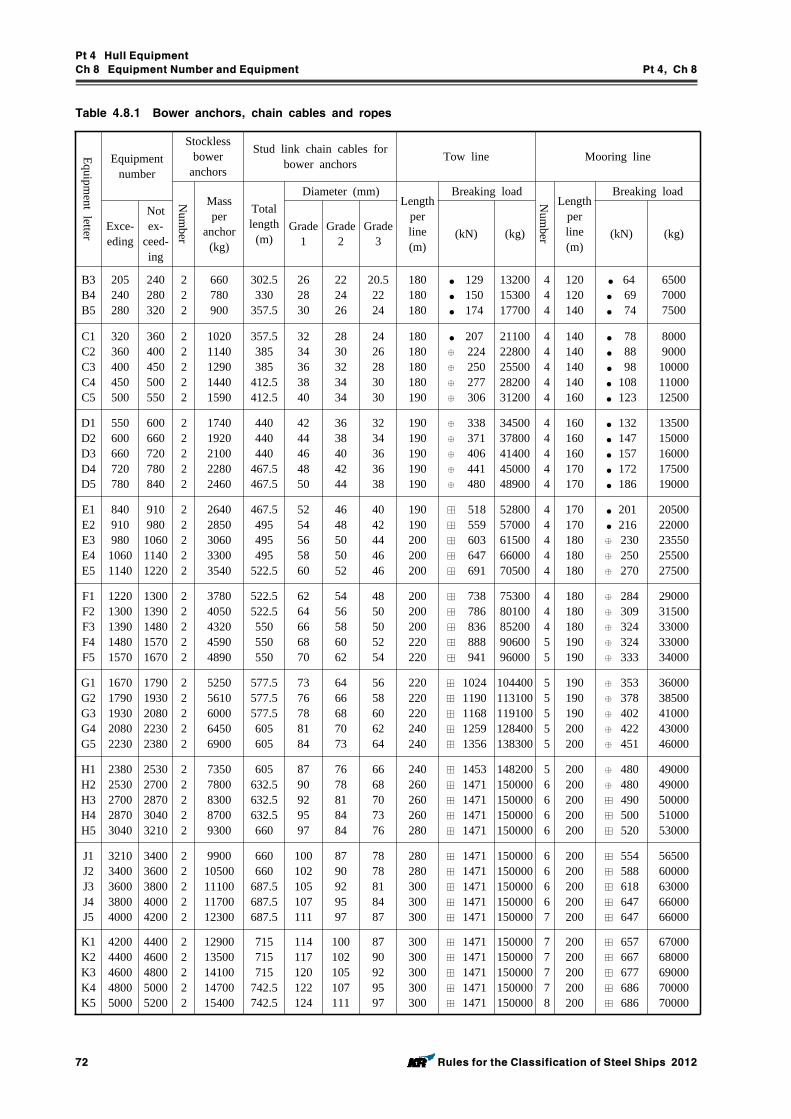
Pt 4 Hull Equipment
Ch 8 Equipment Number and Equipment Pt 4, Ch 8
72 Rules for the Classification of Steel Ships 2012
Equipment letter
Equipment number
Stockless bower
anchors
Stud link chain cables for bower anchors Tow line Mooring line
Num
ber
Mass per
anchor (kg)
Total length
(m)
Diameter (mm)Length
per line (m)
Breaking load
Num
ber
Length per line (m)
Breaking load
Exce-eding
Not ex-
ceed-ing
Grade 1
Grade 2
Grade 3 (kN) (kg) (kN) (kg)
B3B4B5
205240280
240280320
222
660780900
302.5330
357.5
262830
222426
20.52224
180180180
● 129● 150● 174
132001530017700
444
120120140
● 64● 69● 74
650070007500
C1C2C3C4C5
320360400450500
360400450500550
22222
10201140129014401590
357.5385385
412.5412.5
3234363840
2830323434
2426283030
180180180180190
● 207⊕ 224⊕ 250⊕ 277⊕ 306
2110022800255002820031200
44444
140140140140160
● 78● 88● 98● 108● 123
80009000100001100012500
D1D2D3D4D5
550600660720780
600660720780840
22222
17401920210022802460
440440440
467.5467.5
4244464850
3638404244
3234363638
190190190190190
⊕ 338⊕ 371⊕ 406⊕ 441⊕ 480
3450037800414004500048900
44444
160160160170170
● 132● 147● 157● 172● 186
1350015000160001750019000
E1E2E3E4E5
84091098010601140
910980106011401220
22222
26402850306033003540
467.5495495495
522.5
5254565860
4648505052
4042444646
190190200200200
⊞ 518⊞ 559⊞ 603⊞ 647⊞ 691
5280057000615006600070500
44444
170170180180180
● 201● 216⊕ 230⊕ 250⊕ 270
2050022000235502550027500
F1F2F3F4F5
12201300139014801570
13001390148015701670
22222
37804050432045904890
522.5522.5550550550
6264666870
5456586062
4850505254
200200200220220
⊞ 738⊞ 786⊞ 836⊞ 888⊞ 941
7530080100852009060096000
44455
180180180190190
⊕ 284⊕ 309⊕ 324⊕ 324⊕ 333
2900031500330003300034000
G1G2G3G4G5
16701790193020802230
17901930208022302380
22222
52505610600064506900
577.5577.5577.5605605
7376788184
6466687073
5658606264
220220220240240
⊞ 1024⊞ 1190⊞ 1168⊞ 1259⊞ 1356
104400113100119100128400138300
55555
190190190200200
⊕ 353⊕ 378⊕ 402⊕ 422⊕ 451
3600038500410004300046000
H1H2H3H4H5
23802530270028703040
25302700287030403210
22222
73507800830087009300
605632.5632.5632.5660
8790929597
7678818484
6668707376
240260260260280
⊞ 1453⊞ 1471⊞ 1471⊞ 1471⊞ 1471
148200150000150000150000150000
56666
200200200200200
⊕ 480⊕ 480⊞ 490⊞ 500⊞ 520
4900049000500005100053000
J1J2J3J4J5
32103400360038004000
34003600380040004200
22222
990010500111001170012300
660660
687.5687.5687.5
100102105107111
8790929597
7878818487
280280300300300
⊞ 1471⊞ 1471⊞ 1471⊞ 1471⊞ 1471
150000150000150000150000150000
66667
200200200200200
⊞ 554⊞ 588⊞ 618⊞ 647⊞ 647
5650060000630006600066000
K1K2K3K4K5
42004400460048005000
44004600480050005200
22222
1290013500141001470015400
715715715
742.5742.5
114117120122124
100102105107111
8790929597
300300300300300
⊞ 1471⊞ 1471⊞ 1471⊞ 1471⊞ 1471
150000150000150000150000150000
77778
200200200200200
⊞ 657⊞ 667⊞ 677⊞ 686⊞ 686
6700068000690007000070000
Table 4.8.1 Bower anchors, chain cables and ropes
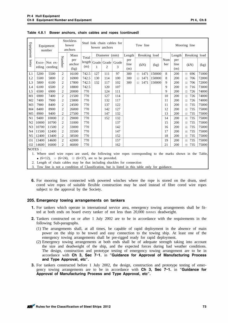
Pt 4 Hull Equipment
Ch 8 Equipment Number and Equipment Pt 4, Ch 8
Rules for the Classification of Steel Ships 2012 73
Equipment letter
Equipment number
Stockless bower
anchors
Stud link chain cables for bower anchors Tow line Mooring line
Num
ber
Mass per
anchor (kg)
Total length
(m)
Diameter (mm) Length per line (m)
Breaking loadNumber
Length per line (m)
Breaking load
Exce-eding
Not ex-ceeding
Grade 1
Grade 2
Grade 3 (kN) (kg) (kN) (kg)
L1L2L3L4L5
52005500580061006500
55005800610065006900
22222
1610016900178001880020000
742.5742.5742.5742.5770
127130132
111114117120124
97100102107111
300300300
⊞ 1471⊞ 1471⊞ 1471
150000150000150000
88999
200200200200200
⊞ 696⊞ 706⊞ 706⊞ 716⊞ 726
7100072000720007300074000
M1M2M3M4M5
69007400790084008900
74007900840089009400
22222
2150023000245002600027500
770770770770770
127132137142147
114117122127132
1011111213
200200200200200
⊞ 726⊞ 726⊞ 735⊞ 735⊞ 735
7400074000750007500075000
N1N2N3N4N5
940010000107001150012400
1000010700115001240013400
22222
2900031000330003550038500
770770770770770
152 132137142147152
1415161718
200200200200200
⊞ 735⊞ 735⊞ 735⊞ 735⊞ 735
7500075000750007500075000
O1O2
1340014600
1460016000
22
4200046000
770770
157162
1921
200200
⊞ 735⊞ 735
7500075000
NOTES :1. Where steel wire ropes are used, the following wire ropes corresponding to the marks shown in the Table,
● (6×12), ⊕ (6×24), ⊞ (6×37), are to be provided.2. Length of chain cables may be that including shackles for connection3. Tow line is not a condition of Classification, but is listed in this table only for guidance.
Table 4.8.1 Bower anchors, chain cables and ropes (continued)
6. For mooring lines connected with powered winches where the rope is stored on the drum, steel cored wire ropes of suitable flexible construction may be used instead of fibre cored wire ropes subject to the approval by the Society.
205. Emergency towing arrangements on tankers
1. For tankers which operate in international service area, emergency towing arrangements shall be fit-ted at both ends on board every tanker of not less than 20,000 tonnes deadweight.
2. Tankers constructed on or after 1 July 2002 are to be in accordance with the requirements in the following Sub-paragraphs.(1) The arrangements shall, at all times, be capable of rapid deployment in the absence of main
power on the ship to be towed and easy connection to the towing ship. At least one of the emergency towing arrangements shall be pre-rigged ready for rapid deployment.
(2) Emergency towing arrangements at both ends shall be of adequate strength taking into account the size and deadweight of the ship, and the expected forces during bad weather conditions. The design, construction and prototype testing of emergency towing arrangement are to be in accordance with Ch 3, Sec 7-1. in "Guidance for Approval of Manufacturing Process and Type Approval, etc".
3. For tankers constructed before 1 July 2002, the design, construction and prototype testing of emer-gency towing arrangements are to be in accordance with Ch 3, Sec 7-1. in "Guidance for Approval of Manufacturing Process and Type Approval, etc".
Pt 4 Hull Equipment
Ch 8 Equipment Number and Equipment Pt 4, Ch 8
74 Rules for the Classification of Steel Ships 2012
Section 3 Anchors
301. Application
Anchors to be equipped on ships in accordance with the provisions in this Chapter are to be in compliance with the requirements in this Section or to be of equivalent quality.
302. Kinds
The kinds of anchors are as follows:(1) Ordinary anchors
(A) Stocked anchors(B) Stockless anchors
(2) HHP anchors(3) SHHP anchors, not exceeding 1,500kg in mass
303. Materials
1. Cast steel anchor flukes, shanks, swivels and shackles are to be manufactured and tested in accord-ance with the requirements in PT 2, Ch 1, 501. of the Rules and comply with the requirements for castings for welded construction. The steel is to be fine grain treated with Aluminium. If test programme B is selected in 309. 1 then Charpy V notch (CVN) impact testing of cast material is required.
2. Forged steel anchor pins, shanks, swivels and shackles are to be manufactured and tested in accord-ance with the requirements in PT 2, Ch 1, 601. of the Rules. Shanks, swivels and shackles are to comply with the requirements for carbon and carbon-manganese steels for welded construction.
3. Rolled billets, plate and bar for fabricated steel anchors are to be manufactured and tested in ac-cordance with the requirements in PT 2, Ch 1, 301. of the Rules.
4. Rolled bar intended for pins, swivels and shackles are to be manufactured and tested in accordance with the requirements in PT 2, Ch 1, 301. and 601. of the Rules.
5. Cast steels for super high holding power anchor are to be subjected to the impact test according to the followings.(1) One set of three V notch impact test specimens specified in Pt 2, Ch 1 are to be taken. (2) The average absorbed energy is not to be less than 27 J at 0 °C. However, when the average
absorbed energy of two or more test specimens among a set of test specimens is less than 27 J or when the average absorbed energy of a single test specimen is less than 19 J, the test is to be considered to have failed.
(3) Anchor rings of super high holding power anchor are to comply with the requirements of im-pact test for Grade 3 chain in Ch 8, Table 4.8.10.
304. Constructions and dimensions
1. The construction and form of anchors are to comply with the KS V 3311 (Anchors) or equivalent to this, the special forms of anchors are to be approved by the Society.
2. The high holding power anchors and super high holding anchors, except in accordance with the provision in the above Par 1, are to be tested by the holding power indicated by the Society and are to comply with the test requirements.
3. Welded construction of fabricated anchors is to be done in accordance with procedures approved by the Society. Welding is to be carried out by qualified welders, following the approved welding pro-cedures, using approved welding consumables.
4. Assembly and fitting are to be done in accordance with the design details. Securing of the anchor pin, shackle pin or swivel nut by welding is to be done in accordance with an approved procedure.
305. Heat Treatment
1. Components for cast of forged anchors are to properly heat treated in accordance with the require-
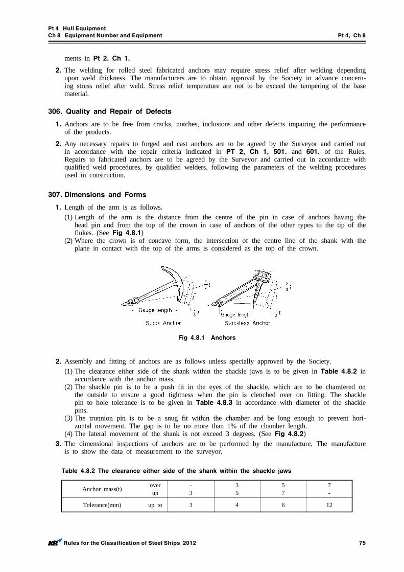
Pt 4 Hull Equipment
Ch 8 Equipment Number and Equipment Pt 4, Ch 8
Rules for the Classification of Steel Ships 2012 75
ments in Pt 2. Ch 1.
2. The welding for rolled steel fabricated anchors may require stress relief after welding depending upon weld thickness. The manufacturers are to obtain approval by the Society in advance concern-ing stress relief after weld. Stress relief temperature are not to be exceed the tempering of the base material.
306. Quality and Repair of Defects
1. Anchors are to be free from cracks, notches, inclusions and other defects impairing the performance of the products.
2. Any necessary repairs to forged and cast anchors are to be agreed by the Surveyor and carried out in accordance with the repair criteria indicated in PT 2, Ch 1, 501. and 601. of the Rules. Repairs to fabricated anchors are to be agreed by the Surveyor and carried out in accordance with qualified weld procedures, by qualified welders, following the parameters of the welding procedures used in construction.
307. Dimensions and Forms
1. Length of the arm is as follows. (1) Length of the arm is the distance from the centre of the pin in case of anchors having the
head pin and from the top of the crown in case of anchors of the other types to the tip of the flukes. (See Fig 4.8.1)
(2) Where the crown is of concave form, the intersection of the centre line of the shank with the plane in contact with the top of the arms is considered as the top of the crown.
Fig 4.8.1 Anchors
2. Assembly and fitting of anchors are as follows unless specially approved by the Society.(1) The clearance either side of the shank within the shackle jaws is to be given in Table 4.8.2 in
accordance with the anchor mass.(2) The shackle pin is to be a push fit in the eyes of the shackle, which are to be chamfered on
the outside to ensure a good tightness when the pin is clenched over on fitting. The shackle pin to hole tolerance is to be given in Table 4.8.3 in accordance with diameter of the shackle pins.
(3) The trunnion pin is to be a snug fit within the chamber and be long enough to prevent hori-zontal movement. The gap is to be no more than 1% of the chamber length.
(4) The lateral movement of the shank is not exceed 3 degrees. (See Fig 4.8.2)3. The dimensional inspections of anchors are to be performed by the manufacture. The manufacture
is to show the data of measurement to the surveyor.
Anchor mass(t) overup
-3
35
57
7-
Tolerance(mm) up to 3 4 6 12
Table 4.8.2 The clearance either side of the shank within the shackle jaws
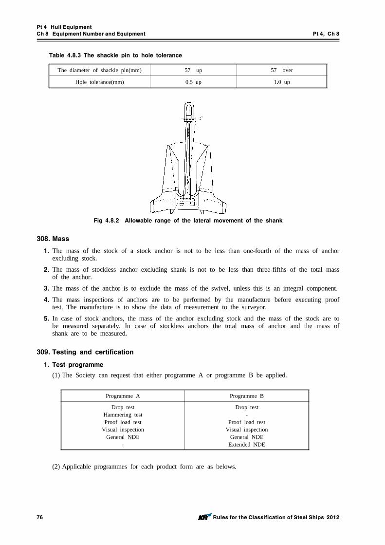
Pt 4 Hull Equipment
Ch 8 Equipment Number and Equipment Pt 4, Ch 8
76 Rules for the Classification of Steel Ships 2012
The diameter of shackle pin(mm) 57 up 57 over
Hole tolerance(mm) 0.5 up 1.0 up
Table 4.8.3 The shackle pin to hole tolerance
Fig 4.8.2 Allowable range of the lateral movement of the shank
308. Mass
1. The mass of the stock of a stock anchor is not to be less than one-fourth of the mass of anchor excluding stock.
2. The mass of stockless anchor excluding shank is not to be less than three-fifths of the total mass of the anchor.
3. The mass of the anchor is to exclude the mass of the swivel, unless this is an integral component.
4. The mass inspections of anchors are to be performed by the manufacture before executing proof test. The manufacture is to show the data of measurement to the surveyor.
5. In case of stock anchors, the mass of the anchor excluding stock and the mass of the stock are to be measured separately. In case of stockless anchors the total mass of anchor and the mass of shank are to be measured.
309. Testing and certification
1. Test programme
(1) The Society can request that either programme A or programme B be applied.
Programme A Programme B
Drop testHammering testProof load test
Visual inspectionGeneral NDE
-
Drop test-
Proof load testVisual inspection
General NDEExtended NDE
(2) Applicable programmes for each product form are as belows.
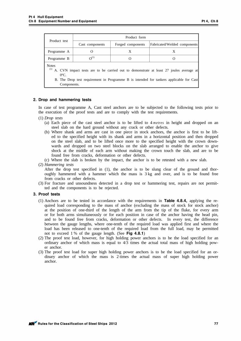
Pt 4 Hull Equipment
Ch 8 Equipment Number and Equipment Pt 4, Ch 8
Rules for the Classification of Steel Ships 2012 77
Product testProduct form
Cast components Forged components Fabricated/Welded components
Programme A O X X
Programme B O(1) O O
Notes (1) A. CVN impact tests are to be carried out to demonstrate at least 27 joules average at
0ºC.B. The Drop test requirement in Programme B is intended for tankers applicable for Cast
Components.
2. Drop and hammering tests
In case of test programme A, Cast steel anchors are to be subjected to the following tests prior to the execution of the proof tests and are to comply with the test requirements.(1) Drop tests
(a) Each piece of the cast steel anchor is to be lifted to 4 metres in height and dropped on an steel slab on the hard ground without any crack or other defects.
(b) Where shank and arms are cast in one piece in stock anchors, the anchor is first to be lift-ed to the specified height with its shank and arms in a horizontal position and then dropped on the steel slab, and to be lifted once more to the specified height with the crown down-wards and dropped on two steel blocks on the slab arranged to enable the anchor to give shock at the middle of each arm without making the crown touch the slab, and are to be found free from cracks, deformation or other defects.
(c) Where the slab is broken by the impact, the anchor is to be retested with a new slab.(2) Hammering tests
After the drop test specified in (1), the anchor is to be slung clear of the ground and thor-oughly hammered with a hammer which the mass is 3 kg and over, and is to be found free from cracks or other defects.
(3) For fracture and unsoundness detected in a drop test or hammering test, repairs are not permit-ted and the components is to be rejected.
3. Proof tests
(1) Anchors are to be tested in accordance with the requirements in Table 4.8.4, applying the re-quired load corresponding to the mass of anchor (excluding the mass of stock for stock anchor) at the position of one-third of the length of the arm from the tip of the fluke, for every arm or for both arms simultaneously or for each position in case of the anchor having the head pin, and to be found free from cracks, deformation or other defects. In every test, the difference between the gauge lengths, where one-tenth of the required load was applied first and where the load has been released to one-tenth of the required load from the full load, may be permitted not to exceed 1 % of the gauge length. (See Fig 4.8.1)
(2) The proof test load, however, for high holding power anchors is to be the load specified for an ordinary anchor of which mass is equal to 4/3 times the actual total mass of high holding pow-er anchor.
(3) The proof test load for super high holding power anchors is to be the load specified for an or-dinary anchor of which the mass is 2 times the actual mass of super high holding power anchor.
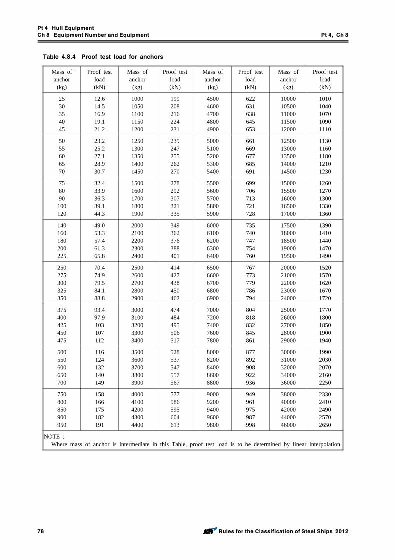
Pt 4 Hull Equipment
Ch 8 Equipment Number and Equipment Pt 4, Ch 8
78 Rules for the Classification of Steel Ships 2012
Mass of anchor
(kg)
Proof test load(kN)
Mass of anchor
(kg)
Proof test load(kN)
Mass of anchor
(kg)
Proof test load(kN)
Mass of anchor
(kg)
Proof test load(kN)
2530354045
12.614.516.919.121.2
10001050110011501200
199208216224231
45004600470048004900
622631638645653
1000010500110001150012000
10101040107010901110
5055606570
23.225.227.128.930.7
12501300135014001450
239247255262270
50005100520053005400
661669677685691
1250013000135001400014500
11301160118012101230
758090100120
32.433.936.339.144.3
15001600170018001900
278292307321335
55005600570058005900
699706713721728
1500015500160001650017000
12601270130013301360
140160180200225
49.053.357.461.365.8
20002100220023002400
349362376388401
60006100620063006400
735740747754760
1750018000185001900019500
13901410144014701490
250275300325350
70.474.979.584.188.8
25002600270028002900
414427438450462
65006600670068006900
767773779786794
2000021000220002300024000
15201570162016701720
375400425450475
93.497.9103107112
30003100320033003400
474484495506517
70007200740076007800
804818832845861
2500026000270002800029000
17701800185019001940
500550600650700
116124132140149
35003600370038003900
528537547557567
80008200840086008800
877892908922936
3000031000320003400036000
19902030207021602250
750800850900950
158166175182191
40004100420043004400
577586595604613
90009200940096009800
949961975987998
3800040000420004400046000
23302410249025702650
NOTE ;Where mass of anchor is intermediate in this Table, proof test load is to be determined by linear interpolation
Table 4.8.4 Proof test load for anchors
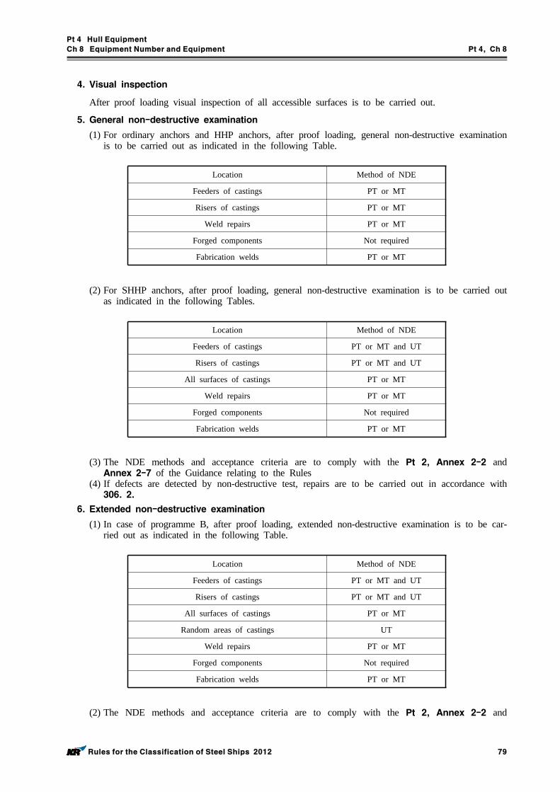
Pt 4 Hull Equipment
Ch 8 Equipment Number and Equipment Pt 4, Ch 8
Rules for the Classification of Steel Ships 2012 79
4. Visual inspection
After proof loading visual inspection of all accessible surfaces is to be carried out.
5. General non-destructive examination
(1) For ordinary anchors and HHP anchors, after proof loading, general non-destructive examination is to be carried out as indicated in the following Table.
Location Method of NDE
Feeders of castings PT or MT
Risers of castings PT or MT
Weld repairs PT or MT
Forged components Not required
Fabrication welds PT or MT
(2) For SHHP anchors, after proof loading, general non-destructive examination is to be carried out as indicated in the following Tables.
Location Method of NDE
Feeders of castings PT or MT and UT
Risers of castings PT or MT and UT
All surfaces of castings PT or MT
Weld repairs PT or MT
Forged components Not required
Fabrication welds PT or MT
(3) The NDE methods and acceptance criteria are to comply with the Pt 2, Annex 2-2 and Annex 2-7 of the Guidance relating to the Rules
(4) If defects are detected by non-destructive test, repairs are to be carried out in accordance with 306. 2.
6. Extended non-destructive examination
(1) In case of programme B, after proof loading, extended non-destructive examination is to be car-ried out as indicated in the following Table.
Location Method of NDE
Feeders of castings PT or MT and UT
Risers of castings PT or MT and UT
All surfaces of castings PT or MT
Random areas of castings UT
Weld repairs PT or MT
Forged components Not required
Fabrication welds PT or MT
(2) The NDE methods and acceptance criteria are to comply with the Pt 2, Annex 2-2 and
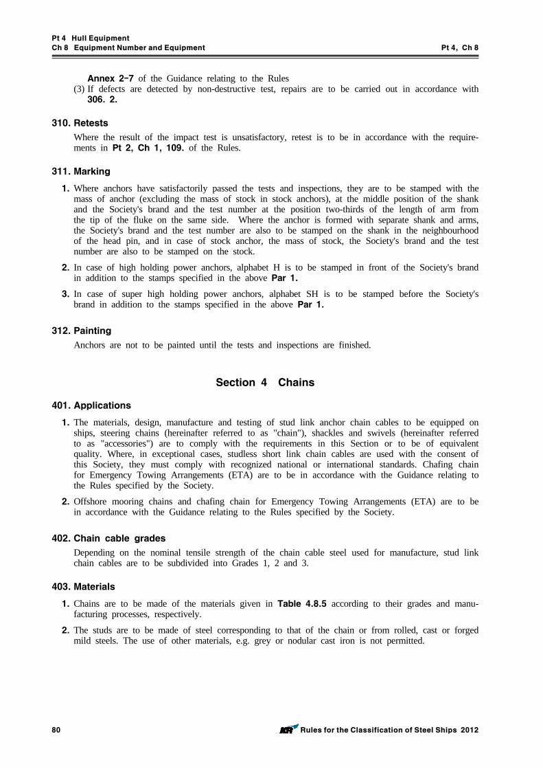
Pt 4 Hull Equipment
Ch 8 Equipment Number and Equipment Pt 4, Ch 8
80 Rules for the Classification of Steel Ships 2012
Annex 2-7 of the Guidance relating to the Rules(3) If defects are detected by non-destructive test, repairs are to be carried out in accordance with 306. 2.
310. Retests
Where the result of the impact test is unsatisfactory, retest is to be in accordance with the require-ments in Pt 2, Ch 1, 109. of the Rules.
311. Marking
1. Where anchors have satisfactorily passed the tests and inspections, they are to be stamped with the mass of anchor (excluding the mass of stock in stock anchors), at the middle position of the shank and the Society's brand and the test number at the position two-thirds of the length of arm from the tip of the fluke on the same side. Where the anchor is formed with separate shank and arms, the Society's brand and the test number are also to be stamped on the shank in the neighbourhood of the head pin, and in case of stock anchor, the mass of stock, the Society's brand and the test number are also to be stamped on the stock.
2. In case of high holding power anchors, alphabet H is to be stamped in front of the Society's brand in addition to the stamps specified in the above Par 1.
3. In case of super high holding power anchors, alphabet SH is to be stamped before the Society's brand in addition to the stamps specified in the above Par 1.
312. Painting
Anchors are not to be painted until the tests and inspections are finished.
Section 4 Chains
401. Applications
1. The materials, design, manufacture and testing of stud link anchor chain cables to be equipped on ships, steering chains (hereinafter referred to as "chain"), shackles and swivels (hereinafter referred to as "accessories") are to comply with the requirements in this Section or to be of equivalent quality. Where, in exceptional cases, studless short link chain cables are used with the consent of this Society, they must comply with recognized national or international standards. Chafing chain for Emergency Towing Arrangements (ETA) are to be in accordance with the Guidance relating to the Rules specified by the Society.
2. Offshore mooring chains and chafing chain for Emergency Towing Arrangements (ETA) are to be in accordance with the Guidance relating to the Rules specified by the Society.
402. Chain cable grades
Depending on the nominal tensile strength of the chain cable steel used for manufacture, stud link chain cables are to be subdivided into Grades 1, 2 and 3.
403. Materials
1. Chains are to be made of the materials given in Table 4.8.5 according to their grades and manu-facturing processes, respectively.
2. The studs are to be made of steel corresponding to that of the chain or from rolled, cast or forged mild steels. The use of other materials, e.g. grey or nodular cast iron is not permitted.
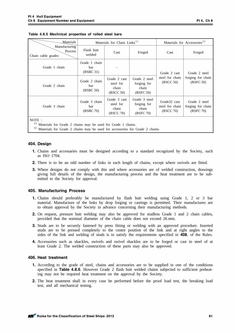
Pt 4 Hull Equipment
Ch 8 Equipment Number and Equipment Pt 4, Ch 8
Rules for the Classification of Steel Ships 2012 81
Table 4.8.5 Mechnical properties of rolled steel bars
Materials Manufacturing
ProcessChain cable grades
Materials for Chain Links Materials for Accessories
Flash butt welded Cast Forged Cast Forged
Grade 1 chainGrade 1 chain
bar(RSBC 31)
-Grade 2 cast
steel for chain(RSCC 50)
Grade 2 steel forging for chain
(RSFC 50) Grade 2 chain
Grade 2 chain bar
(RSBC 50)
Grade 2 cast steel for
chain(RSCC 50)
Grade 2 steel forging for
chain (RSFC 50)
Grade 3 chainGrade 3 chain
bar(RSBC 70)
Grade 3 cast steel for
chain(RSCC 70)
Grade 3 steel forging for
chain (RSFC 70)
Grade32 cast steel for chain
(RSCC 70)
Grade 2 steel forging for chain
(RSFC 70)
NOTE : (1) Materials for Grade 2 chains may be used for Grade 1 chains. (2) Materials for Grade 2 chains may be used for accessories for Grade 2 chains.
404. Design
1. Chains and accessaries must be designed according to a standard recognized by the Society, such as ISO 1704.
2. There is to be an odd number of links in each length of chains, except where swivels are fitted.
3. Where designs do not comply with this and where accessories are of welded construction, drawings giving full details of the design, the manufacturing process and the heat treatment are to be sub-mitted to the Society for approval.
405. Manufacturing Process
1. Chains should preferably be manufactured by flash butt welding using Grade 1, 2 or 3 bar material. Manufacture of the links by drop forging or castings is permitted. Their manufactures are to obtain approval by the Society in advance concerning their manufacturing methods.
2. On request, pressure butt welding may also be approved for studless Grade 1 and 2 chain cables, provided that the nominal diameter of the chain cable does not exceed 26 mm.
3. Studs are to be securely fastened by press fitting or welding with an approved procedure. Inserted studs are to be pressed completely to the centre position of the link and at right angles to the sides of the link and welding of studs is to satisfy the requirements specified in 408. of the Rules.
4. Accessories such as shackles, swivels and swivel shackles are to be forged or cast in steel of at least Grade 2. The welded construction of these parts may also be approved.
406. Heat treatment
1. According to the grade of steel, chains and accessories are to be supplied in one of the conditions specified in Table 4.8.6. However Grade 2 flash butt welded chains subjected to sufficient preheat-ing may not be required heat treatment on the approval by the Society.
2. The heat treatment shall in every case be performed before the proof load test, the breaking load test, and all mechanical testing.
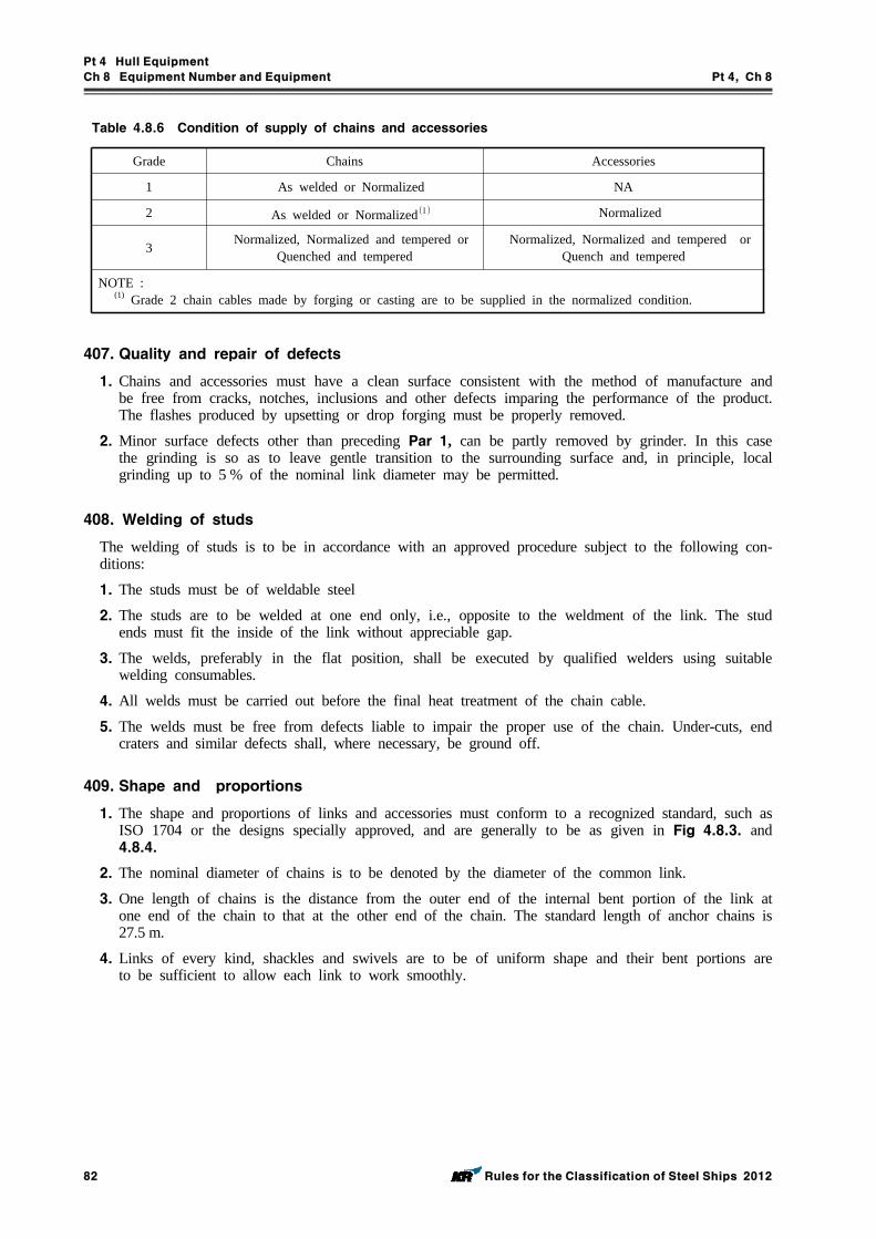
Pt 4 Hull Equipment
Ch 8 Equipment Number and Equipment Pt 4, Ch 8
82 Rules for the Classification of Steel Ships 2012
Grade Chains Accessories
1 As welded or Normalized NA
2 As welded or Normalized Normalized
3 Normalized, Normalized and tempered or Quenched and tempered
Normalized, Normalized and tempered or Quench and tempered
NOTE :(1) Grade 2 chain cables made by forging or casting are to be supplied in the normalized condition.
Table 4.8.6 Condition of supply of chains and accessories
407. Quality and repair of defects
1. Chains and accessories must have a clean surface consistent with the method of manufacture and be free from cracks, notches, inclusions and other defects imparing the performance of the product. The flashes produced by upsetting or drop forging must be properly removed.
2. Minor surface defects other than preceding Par 1, can be partly removed by grinder. In this case the grinding is so as to leave gentle transition to the surrounding surface and, in principle, local grinding up to 5 % of the nominal link diameter may be permitted.
408. Welding of studs
The welding of studs is to be in accordance with an approved procedure subject to the following con-ditions:
1. The studs must be of weldable steel
2. The studs are to be welded at one end only, i.e., opposite to the weldment of the link. The stud ends must fit the inside of the link without appreciable gap.
3. The welds, preferably in the flat position, shall be executed by qualified welders using suitable welding consumables.
4. All welds must be carried out before the final heat treatment of the chain cable.
5. The welds must be free from defects liable to impair the proper use of the chain. Under-cuts, end craters and similar defects shall, where necessary, be ground off.
409. Shape and proportions
1. The shape and proportions of links and accessories must conform to a recognized standard, such as ISO 1704 or the designs specially approved, and are generally to be as given in Fig 4.8.3. and 4.8.4.
2. The nominal diameter of chains is to be denoted by the diameter of the common link.
3. One length of chains is the distance from the outer end of the internal bent portion of the link at one end of the chain to that at the other end of the chain. The standard length of anchor chains is 27.5 m.
4. Links of every kind, shackles and swivels are to be of uniform shape and their bent portions are to be sufficient to allow each link to work smoothly.
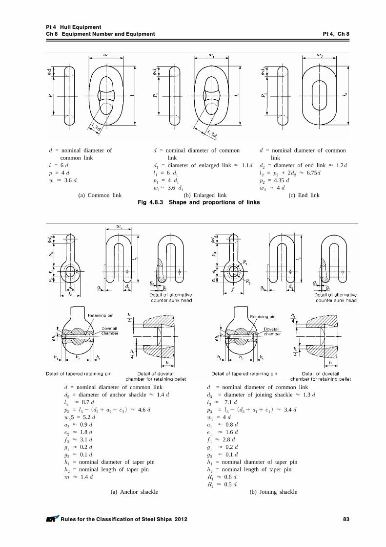
Pt 4 Hull Equipment
Ch 8 Equipment Number and Equipment Pt 4, Ch 8
Rules for the Classification of Steel Ships 2012 83
= nominal diameter of common link = 6 = 4 ≈ 3.6
(a) Common link
= nominal diameter of common link = diameter of enlarged link ≈ 1.1 = 6 = 4 ≈ 3.6
(b) Enlarged link
= nominal diameter of common link = diameter of end link ≈ 1.2 = + 2 ≈ 6.75 = 4.35 ≈ 4
(c) End linkFig 4.8.3 Shape and proportions of links
= nominal diameter of common link = diameter of anchor shackle ≈ 1.4 ≈ 8.7 = ≈ 4.6 5 = 5.2 ≈ 0.9 ≈ 1.8 ≈ 3.1 ≈ 0.2 ≈ 0.1 = nominal diameter of taper pin = nominal length of taper pin ≈ 1.4
(a) Anchor shackle
= nominal diameter of common link = diameter of joining shackle ≈ 1.3 ≈ 7.1 = ≈ 3.4 = 4 ≈ 0.8 ≈ 1.6 ≈ 2.8 ≈ 0.2 ≈ 0.1 = nominal diameter of taper pin = nominal length of taper pin ≈ 0.6 ≈ 0.5
(b) Joining shackle
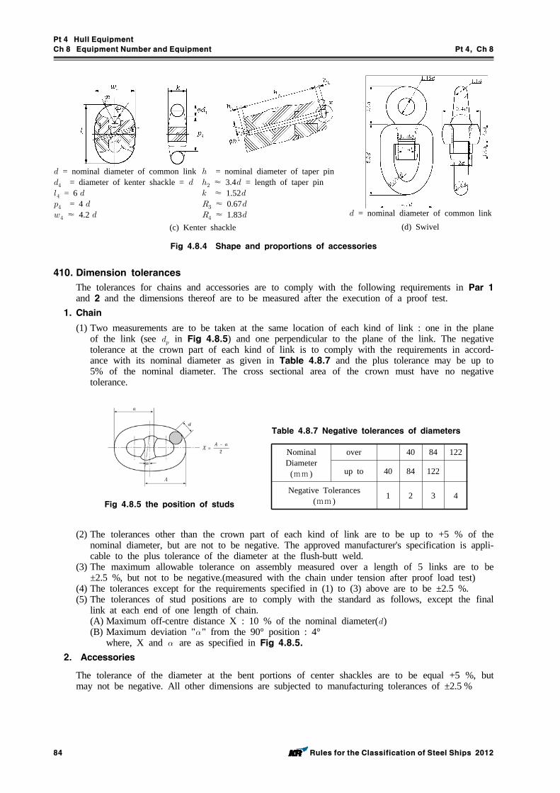
Pt 4 Hull Equipment
Ch 8 Equipment Number and Equipment Pt 4, Ch 8
84 Rules for the Classification of Steel Ships 2012
= nominal diameter of common link = diameter of kenter shackle = = 6 = 4 ≈ 4.2
= nominal diameter of taper pin ≈ 3.4 = length of taper pin ≈ 1.52 ≈ 0.67 ≈ 1.83
(c) Kenter shackle
= nominal diameter of common link(d) Swivel
Fig 4.8.4 Shape and proportions of accessories
410. Dimension tolerances
The tolerances for chains and accessories are to comply with the following requirements in Par 1 and 2 and the dimensions thereof are to be measured after the execution of a proof test.
1. Chain
(1) Two measurements are to be taken at the same location of each kind of link : one in the plane of the link (see in Fig 4.8.5) and one perpendicular to the plane of the link. The negative tolerance at the crown part of each kind of link is to comply with the requirements in accord-ance with its nominal diameter as given in Table 4.8.7 and the plus tolerance may be up to 5% of the nominal diameter. The cross sectional area of the crown must have no negative tolerance.
Fig 4.8.5 the position of studs
Nominal Diameter
(mm )
over 40 84 122
up to 40 84 122
Negative Tolerances (mm ) 1 2 3 4
Table 4.8.7 Negative tolerances of diameters
(2) The tolerances other than the crown part of each kind of link are to be up to +5 % of the nominal diameter, but are not to be negative. The approved manufacturer's specification is appli-cable to the plus tolerance of the diameter at the flush-butt weld.
(3) The maximum allowable tolerance on assembly measured over a length of 5 links are to be ±2.5 %, but not to be negative.(measured with the chain under tension after proof load test)
(4) The tolerances except for the requirements specified in (1) to (3) above are to be ±2.5 %.(5) The tolerances of stud positions are to comply with the standard as follows, except the final
link at each end of one length of chain.(A) Maximum off-centre distance X : 10 % of the nominal diameter()(B) Maximum deviation "" from the 90° position : 4°
where, X and are as specified in Fig 4.8.5.2. Accessories
The tolerance of the diameter at the bent portions of center shackles are to be equal +5 %, but may not be negative. All other dimensions are subjected to manufacturing tolerances of ±2.5 %
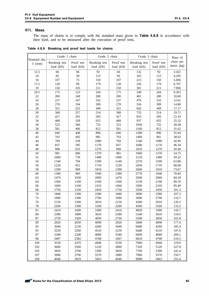
Pt 4 Hull Equipment
Ch 8 Equipment Number and Equipment Pt 4, Ch 8
Rules for the Classification of Steel Ships 2012 85
411. Mass
The mass of chains is to comply with the standard mass given in Table 4.8.8 in accordance with their kind, and to be measured after the execution of proof tests.
Nominal dia. (mm)
Grade 1 chain Grade 2 chain Grade 3 chain Mass of chain per metre (kg)
Breaking test load (kN)
Proof test load (kN)
Breaking test load (kN)
Proof test load (kN)
Breaking test load (kN)
Proof test load (kN)
12.51416
17.519
6682107128150
46587589
105
92115150179211
6682
107128150
132165215256301
92115150179211
3.4224.2925.6066.7077.906
20.522242628
175200237278321
123140167194225
244280332389449
175200237278321
349401476556642
244280332389449
9.20310.6012.6114.8017.17
3032343638
368417468523581
257291328366406
514583655732812
368417468523581
735833937
10501160
514583655732812
19.7122.4325.3228.3831.62
4042444648
640703769837908
448492538585635
896981
108011701270
640703769837908
12801400154016801810
896981
108011701270
35.0438.6342.4046.3450.46
5052545658
9811060114012201290
686739794851909
13701480159017101810
9811060114012201290
19602110227024302600
13701480159017101810
54.7559.2263.8668.6873.67
6062646668
13801470156016601750
9691030110011601230
19402060219023102450
13801470156016601750
27702940313033003500
19402060219023102450
78.8484.1889.7095.40101.3
70737678
1840199021502260
1290139015001580
2580279030103160
1840199021502260
3690399043004500
2580279030103160
107.3116.7126.5133.2
818487
241025802750
169018001920
338036103850
241025802750
482051605500
338036103850
143.7154.5165.8
9092959798
29203040323033403407
20502130226023402382
40904260451046804768
29203040323033403407
58406080644066906810
40904260451046804768
177.4185.4197.6206.1210.3
100102105107108
35303660385039804046
24702560270027902829
49405120539055705663
35303660385039804046
70607320770079608088
49405120539055705663
219.0227.8241.4250.7255.4
Table 4.8.8 Breaking and proof test loads for chains
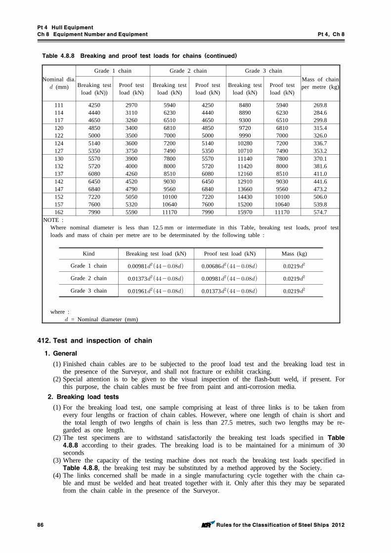
Pt 4 Hull Equipment
Ch 8 Equipment Number and Equipment Pt 4, Ch 8
86 Rules for the Classification of Steel Ships 2012
Nominal dia. (mm)
Grade 1 chain Grade 2 chain Grade 3 chainMass of chain per metre (kg)Breaking test
load (kN))Proof test load (kN)
Breaking test load (kN)
Proof test load (kN)
Breaking test load (kN)
Proof test load (kN)
111114117
425044404650
297031103260
594062306510
425044404650
848088909300
594062306510
269.8284.6299.8
120122
48505000
34003500
68107000
48505000
97209990
68107000
315.4326.0
124127
51405350
36003750
72007490
51405350
1028010710
72007490
336.7353.2
130132137
557057206080
390040004260
780080008510
557057206080
111401142012160
780080008510
370.1381.6411.0
142147
64506840
45204790
90309560
64506840
1291013660
90309560
441.6473.2
152157
72207600
50505320
1010010640
72207600
1443015200
1010010640
506.0539.8
162 7990 5590 11170 7990 15970 11170 574.7NOTE :
Where nominal diameter is less than 12.5 mm or intermediate in this Table, breaking test loads, proof test loads and mass of chain per metre are to be determinated by the following table :
Kind Breaking test load (kN) Proof test load (kN) Mass (kg)
Grade 1 chain 0.00981 0.00686 0.0219
Grade 2 chain 0.01373 0.00981 0.0219
Grade 3 chain 0.01961 0.01373 0.0219
where : = Nominal diameter (mm)
Table 4.8.8 Breaking and proof test loads for chains (continued)
412. Test and inspection of chain
1. General
(1) Finished chain cables are to be subjected to the proof load test and the breaking load test in the presence of the Surveyor, and shall not fracture or exhibit cracking.
(2) Special attention is to be given to the visual inspection of the flash-butt weld, if present. For this purpose, the chain cables must be free from paint and anti-corrosion media.
2. Breaking load tests
(1) For the breaking load test, one sample comprising at least of three links is to be taken from every four lengths or fraction of chain cables. However, where one length of chain is short and the total length of two lengths of chain is less than 27.5 metres, such two lengths may be re-garded as one length.
(2) The test specimens are to withstand satisfactorily the breaking test loads specified in Table 4.8.8 according to their grades. The breaking load is to be maintained for a minimum of 30 seconds
(3) Where the capacity of the testing machine does not reach the breaking test loads specified in Table 4.8.8, the breaking test may be substituted by a method approved by the Society.
(4) The links concerned shall be made in a single manufacturing cycle together with the chain ca-ble and must be welded and heat treated together with it. Only after this they may be separated from the chain cable in the presence of the Surveyor.
Pt 4 Hull Equipment
Ch 8 Equipment Number and Equipment Pt 4, Ch 8
Rules for the Classification of Steel Ships 2012 87
3. Proof load tests
The proof tests are to be carried out for each length of the chains which satisfactorily complied with the breaking tests, and the chains are to withstand the proof test loads specified in Table 4.8.8 without cracking, breakage or any other defects. The test is to be carried out after the chains were heat treated where necessary.
4. Retest
(1) Breaking load tests (A) Where the test is not satisfactory, the chain may be retested by taking out another set of
test specimens from the same length of chain, and where the test specimens comply with the requirements, the remaining three lengths of chain may be accepted. Where the retest fails, the length of chain from which the test specimen have been taken is rejected, and the remaining three chains are to be subjected to the breaking tests individually. If one of such test fails to meet the requirements, all the remaining three lengths of the chain are rejected.
(B) Where the missing chain links due to the preparation of the retest of Par 5 above are re-placed by new chain links, the test specimens manufactured by the same procedure are to be subjected to the breaking test, and are to comply with the requirements.
(2) Proof load testsWhere the test is not satisfactory, the chain may be retested only once more by link of same manufacturing process after replacing the defective link. Where, however, more than 5 % of the total links are found defective, the retest is not permitted. In addition, an investigation is to be made to identify the cause of the failure.
5. Mechanical tests on grade 2 and 3 chain cable
(1) Grade 2 and grade 3 chain cables are to be subjected to the mechanical tests, and are to com-ply with the requirements.
(2) Mechanical test specimens are to be taken from every four lengths in accordance with Table 4.8.9. For forged or cast chain cables where the batch size is less than four lengths, the sam-pling frequency will be by heat and heat treatment charge.
(3) An additional link (or where the links are small, several links) for mechanical test specimen re-moval is (are) to be provided in a length of chain cable not containing the specimen for the breaking test. The specimen link must be manufactured and heat treated together with the length of chain cable. Mechanical tests are to be carried out in the presence of the Surveyor. Mechanical properties of chain links are to comply with requirements given in Table 4.8.10.
(4) Test procedure and forms of test specimens are to comply with the requirements in Pt 2, Ch 1, Sec 2.
(5) Where the test results of mechanical properties of chain links do not conform to the require-ments, additional tests are to be carried out in accordance with the requirements specified in Pt 2, Ch 1, 306. 9.
413. Test and inspection of accessories
1. Proof load test
Each kind of accessory is to be tested to the proof test loads specified in Table 4.8.8, in accord-ance with the kinds and diameters of the chains to be connected therewith, and they are to with-stand the test without crack, breakage or any other defect. This test may be carried out simulta-neously with the proof test for the chains or together with any chains of the same diameter with which shackles and swivels are connected.
2. Breaking load test
(1) From each manufacturing batch (same accessory type, grade, size and heat treatment charge, but not necessarily representative of each heat of steel or individual purchase order) of 25 units or less of detachable links, shackles, swivels, swivel shackles, enlarged links, and end links, and from each manufacturing batch of 50 units or less of kenter shackles, one unit is to be sub-jected to the breaking load test at the break load specified for the corresponding chain given by Table 4.8.8. Enlarged links and end links need not be tested provided that they are manufac-tured and heat treated together with the chain cable.
(2) Where the test of Par (1) above is not satisfactory, the accessories may be retested by taking
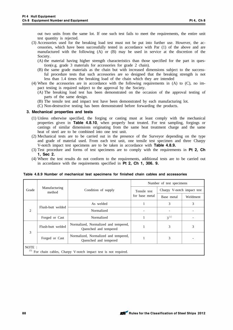
Pt 4 Hull Equipment
Ch 8 Equipment Number and Equipment Pt 4, Ch 8
88 Rules for the Classification of Steel Ships 2012
out two units from the same lot. If one such test fails to meet the requirements, the entire unit test quantity is rejected.
(3) Accessories used for the breaking load test must not be put into further use. However, the ac-cessories, which have been successfully tested in accordance with Par (1) of the above and are manufactured with the following (A) or (B) may be used in service at the discretion of the Society. (A) the material having higher strength characteristics than those specified for the part in ques-
tion(e.g. grade 3 materials for accessories for grade 2 chain).(B) the same grade materials as the chain but with increased dimensions subject to the success-
ful procedure tests that such accessories are so designed that the breaking strength is not less than 1.4 times the breaking load of the chain which they are intended
(4) When the accessories are in accordance with the following requirements in (A) to (C), no im-pact testing is required subject to the approval by the Society.(A) The breaking load test has been demonstrated on the occasion of the approval testing of
parts of the same design.(B) The tensile test and impact test have been demonstrated by each manufacturing lot.(C) Non-destructive testing has been demonstrated before forwarding the products.
3. Mechanical properties and tests
(1) Unless otherwise specified, the forging or casting must at least comply with the mechanical properties given in Table 4.8.10, when properly heat treated. For test sampling, forgings or castings of similar dimensions originating from the same heat treatment charge and the same heat of steel are to be combined into one test unit.
(2) Mechanical tests are to be carried out in the presence of the Surveyor depending on the type and grade of material used. From each test unit, one tensile test specimen and three Charpy V-notch impact test specimens are to be taken in accordance with Table 4.8.9.
(3) Test procedure and forms of test specimens are to comply with the requirements in Pt 2, Ch 1, Sec 2.
(4) Where the test results do not conform to the requirements, additional tests are to be carried out in accordance with the requirements specified in Pt 2, Ch 1, 306. 9.
Grade Manufacturingmethod Condition of supply
Number of test specimens
Tensile testfor base metal
Charpy V-notch impact test
Base metal Weldment
2Flush-butt welded
As welded 1 3 3
Normalized - - -
Forged or Cast Normalized 1 3 -
3Flush-butt welded Normalized, Normalized and tempered,
Quenched and tempered 1 3 3
Forged or Cast Normalized, Normalized and tempered, Quenched and tempered 1 3 -
NOTE : (1) For chain cables, Charpy V-notch impact test is not required.
Table 4.8.9 Number of mechanical test specimens for finished chain cables and accessories
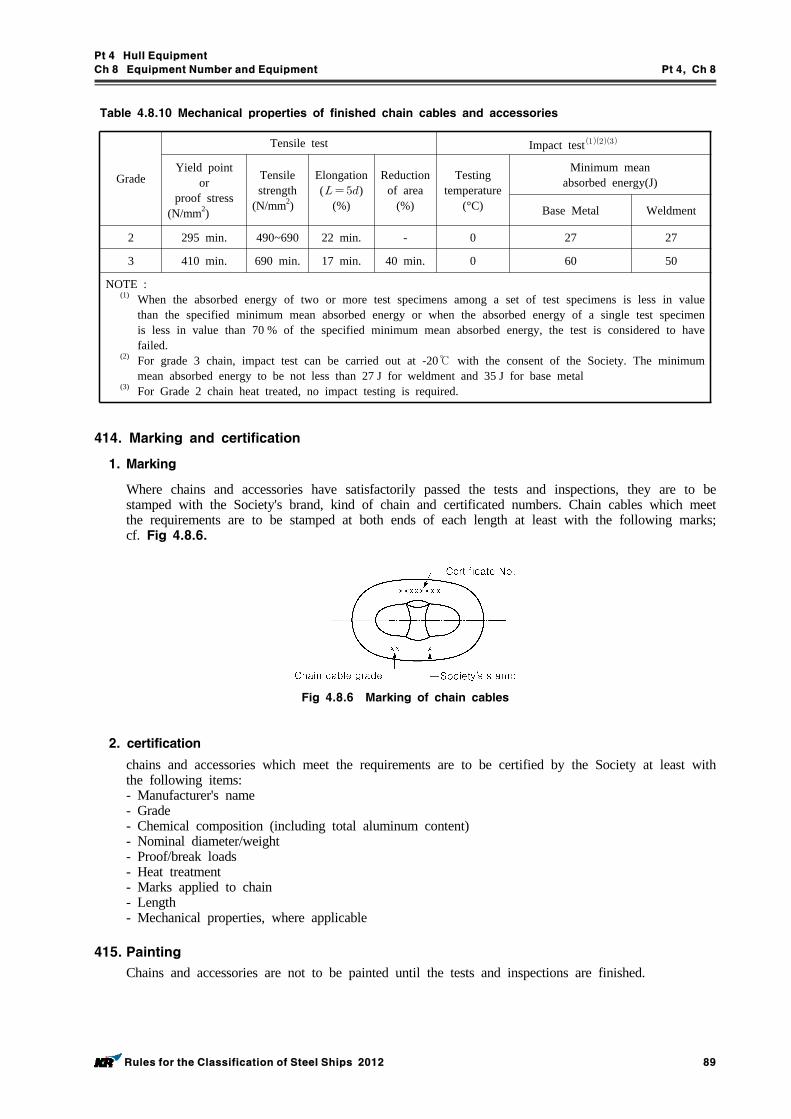
Pt 4 Hull Equipment
Ch 8 Equipment Number and Equipment Pt 4, Ch 8
Rules for the Classification of Steel Ships 2012 89
Grade
Tensile test Impact test
Yield point or
proof stress(N/mm2)
Tensilestrength
(N/mm2)
Elongation( )
(%)
Reductionof area
(%)
Testingtemperature
(°C)
Minimum meanabsorbed energy(J)
Base Metal Weldment
2 295 min. 490~690 22 min. - 0 27 27
3 410 min. 690 min. 17 min. 40 min. 0 60 50
NOTE : (1) When the absorbed energy of two or more test specimens among a set of test specimens is less in value
than the specified minimum mean absorbed energy or when the absorbed energy of a single test specimen is less in value than 70 % of the specified minimum mean absorbed energy, the test is considered to have failed.
(2) For grade 3 chain, impact test can be carried out at -20℃ with the consent of the Society. The minimum mean absorbed energy to be not less than 27 J for weldment and 35 J for base metal
(3) For Grade 2 chain heat treated, no impact testing is required.
Table 4.8.10 Mechanical properties of finished chain cables and accessories
414. Marking and certification
1. Marking
Where chains and accessories have satisfactorily passed the tests and inspections, they are to be stamped with the Society's brand, kind of chain and certificated numbers. Chain cables which meet the requirements are to be stamped at both ends of each length at least with the following marks; cf. Fig 4.8.6.
Fig 4.8.6 Marking of chain cables
2. certification
chains and accessories which meet the requirements are to be certified by the Society at least with the following items:- Manufacturer's name- Grade- Chemical composition (including total aluminum content)- Nominal diameter/weight- Proof/break loads- Heat treatment- Marks applied to chain- Length- Mechanical properties, where applicable
415. Painting
Chains and accessories are not to be painted until the tests and inspections are finished.
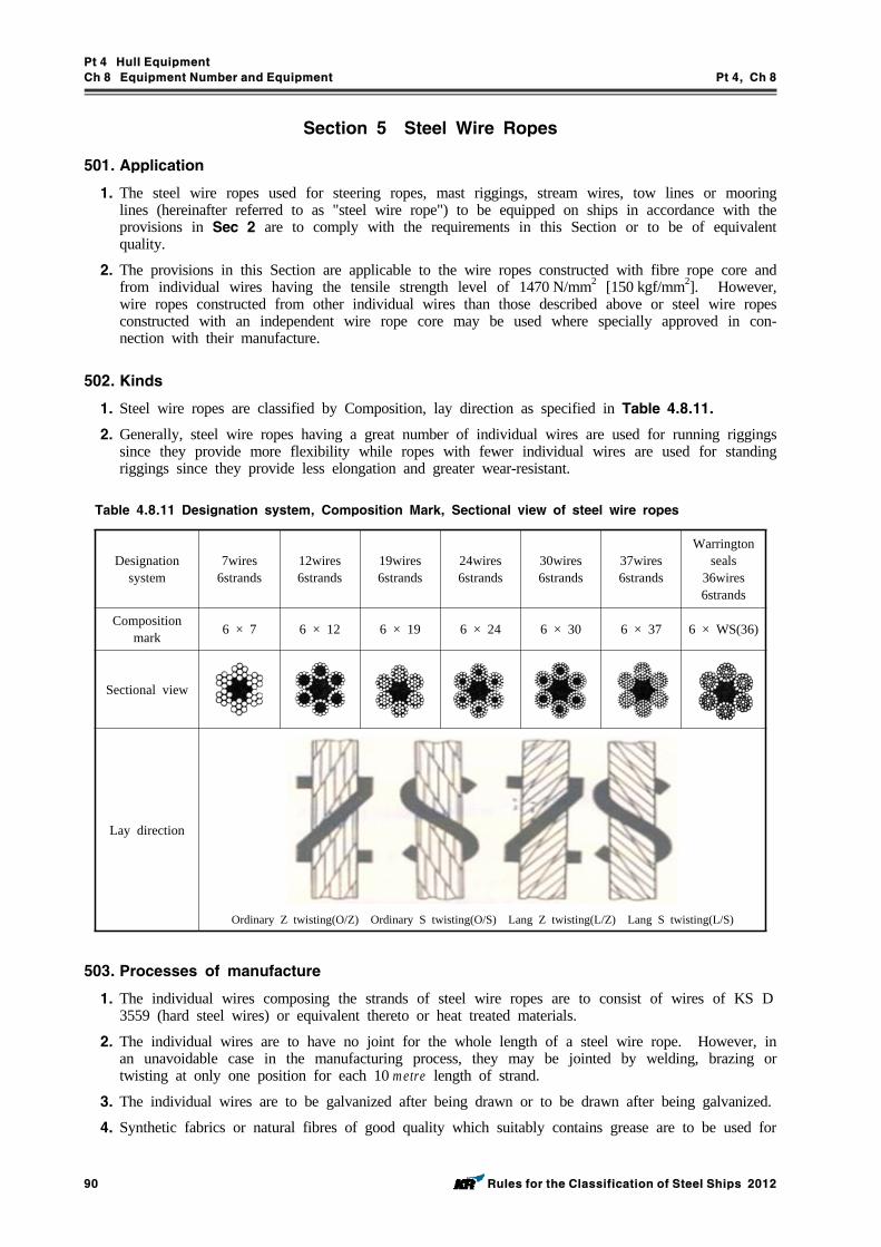
Pt 4 Hull Equipment
Ch 8 Equipment Number and Equipment Pt 4, Ch 8
90 Rules for the Classification of Steel Ships 2012
Section 5 Steel Wire Ropes
501. Application
1. The steel wire ropes used for steering ropes, mast riggings, stream wires, tow lines or mooring lines (hereinafter referred to as "steel wire rope") to be equipped on ships in accordance with the provisions in Sec 2 are to comply with the requirements in this Section or to be of equivalent quality.
2. The provisions in this Section are applicable to the wire ropes constructed with fibre rope core and from individual wires having the tensile strength level of 1470 N/mm2 [150 kgf/mm2]. However, wire ropes constructed from other individual wires than those described above or steel wire ropes constructed with an independent wire rope core may be used where specially approved in con-nection with their manufacture.
502. Kinds
1. Steel wire ropes are classified by Composition, lay direction as specified in Table 4.8.11.
2. Generally, steel wire ropes having a great number of individual wires are used for running riggings since they provide more flexibility while ropes with fewer individual wires are used for standing riggings since they provide less elongation and greater wear-resistant.
Designation system
7wires6strands
12wires6strands
19wires6strands
24wires6strands
30wires6strands
37wires6strands
Warrington seals
36wires6strands
Composition mark 6 × 7 6 × 12 6 × 19 6 × 24 6 × 30 6 × 37 6 × WS(36)
Sectional view
Lay direction
Ordinary Z twisting(O/Z) Ordinary S twisting(O/S) Lang Z twisting(L/Z) Lang S twisting(L/S)
Table 4.8.11 Designation system, Composition Mark, Sectional view of steel wire ropes
503. Processes of manufacture
1. The individual wires composing the strands of steel wire ropes are to consist of wires of KS D3559 (hard steel wires) or equivalent thereto or heat treated materials.
2. The individual wires are to have no joint for the whole length of a steel wire rope. However, in an unavoidable case in the manufacturing process, they may be jointed by welding, brazing or twisting at only one position for each 10 metre length of strand.
3. The individual wires are to be galvanized after being drawn or to be drawn after being galvanized.
4. Synthetic fabrics or natural fibres of good quality which suitably contains grease are to be used for
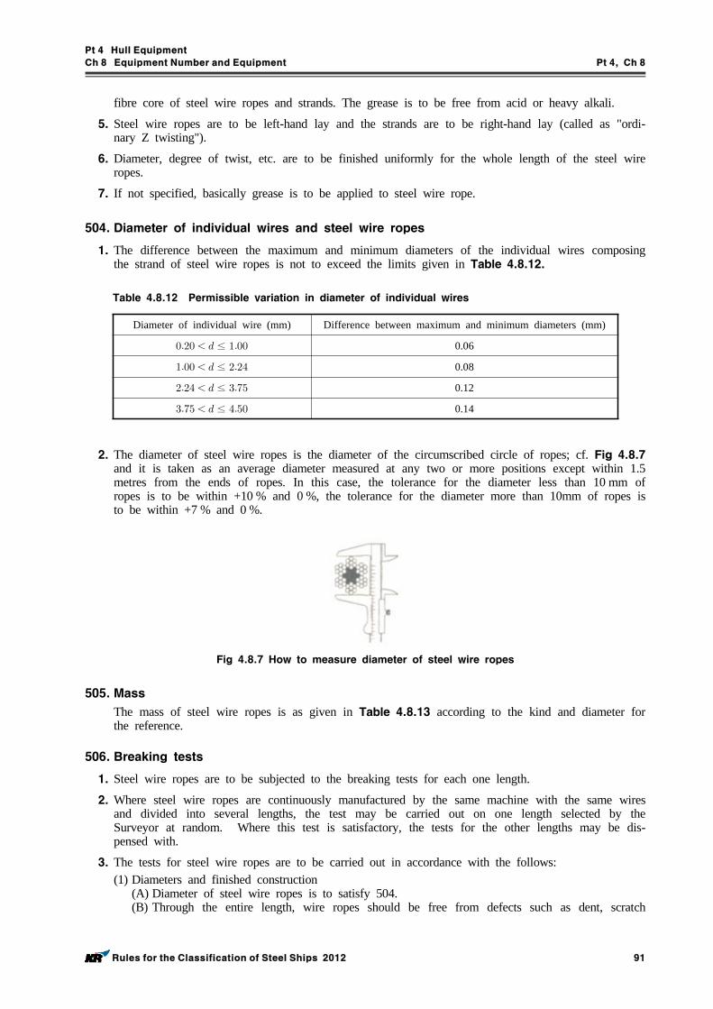
Pt 4 Hull Equipment
Ch 8 Equipment Number and Equipment Pt 4, Ch 8
Rules for the Classification of Steel Ships 2012 91
fibre core of steel wire ropes and strands. The grease is to be free from acid or heavy alkali.
5. Steel wire ropes are to be left-hand lay and the strands are to be right-hand lay (called as "ordi-nary Z twisting").
6. Diameter, degree of twist, etc. are to be finished uniformly for the whole length of the steel wire ropes.
7. If not specified, basically grease is to be applied to steel wire rope.
504. Diameter of individual wires and steel wire ropes
1. The difference between the maximum and minimum diameters of the individual wires composing the strand of steel wire ropes is not to exceed the limits given in Table 4.8.12.
Diameter of individual wire (mm) Difference between maximum and minimum diameters (mm)
≤ 0.06
≤ 0.08
≤ 0.12
≤ 0.14
Table 4.8.12 Permissible variation in diameter of individual wires
2. The diameter of steel wire ropes is the diameter of the circumscribed circle of ropes; cf. Fig 4.8.7 and it is taken as an average diameter measured at any two or more positions except within 1.5 metres from the ends of ropes. In this case, the tolerance for the diameter less than 10 mm of ropes is to be within +10 % and 0 %, the tolerance for the diameter more than 10mm of ropes is to be within +7 % and 0 %.
Fig 4.8.7 How to measure diameter of steel wire ropes
505. Mass
The mass of steel wire ropes is as given in Table 4.8.13 according to the kind and diameter for the reference.
506. Breaking tests
1. Steel wire ropes are to be subjected to the breaking tests for each one length.
2. Where steel wire ropes are continuously manufactured by the same machine with the same wires and divided into several lengths, the test may be carried out on one length selected by the Surveyor at random. Where this test is satisfactory, the tests for the other lengths may be dis-pensed with.
3. The tests for steel wire ropes are to be carried out in accordance with the follows:(1) Diameters and finished construction
(A) Diameter of steel wire ropes is to satisfy 504.(B) Through the entire length, wire ropes should be free from defects such as dent, scratch
Pt 4 Hull Equipment
Ch 8 Equipment Number and Equipment Pt 4, Ch 8
92 Rules for the Classification of Steel Ships 2012
which are detrimental to practical use.(2) Breaking load tests
(A) The test piece of which both ends are either loosened and solidified to cone with suitable metal alloy or gripped by other suitable methods, is to be set to the testing machine and gradually pulled until breaks down.
(B) One test piece is to be taken from each length of steel wire ropes.(C) The distance between the grips is taken table below. However, in case of exceeding 2 me-
tres, the distance between the grips should be 2 metres.
Diameter of steel wire ropes The distance between the grips
up to 6 mm not less than 300 mm
over 6 mm 20 mm or less not less than 600 mm
20 mm over not less than 30 times of diameter of steel wire ropes
(D) The test pieces are to withstand the breaking test loads specified in Table 4.8.13 according to the grade and diameter of steel wire rope.
(E) Where the test piece has broken down at the parts of the grips before reaching the required breaking load, one more test piece taken from the steel wire rope may be retested.
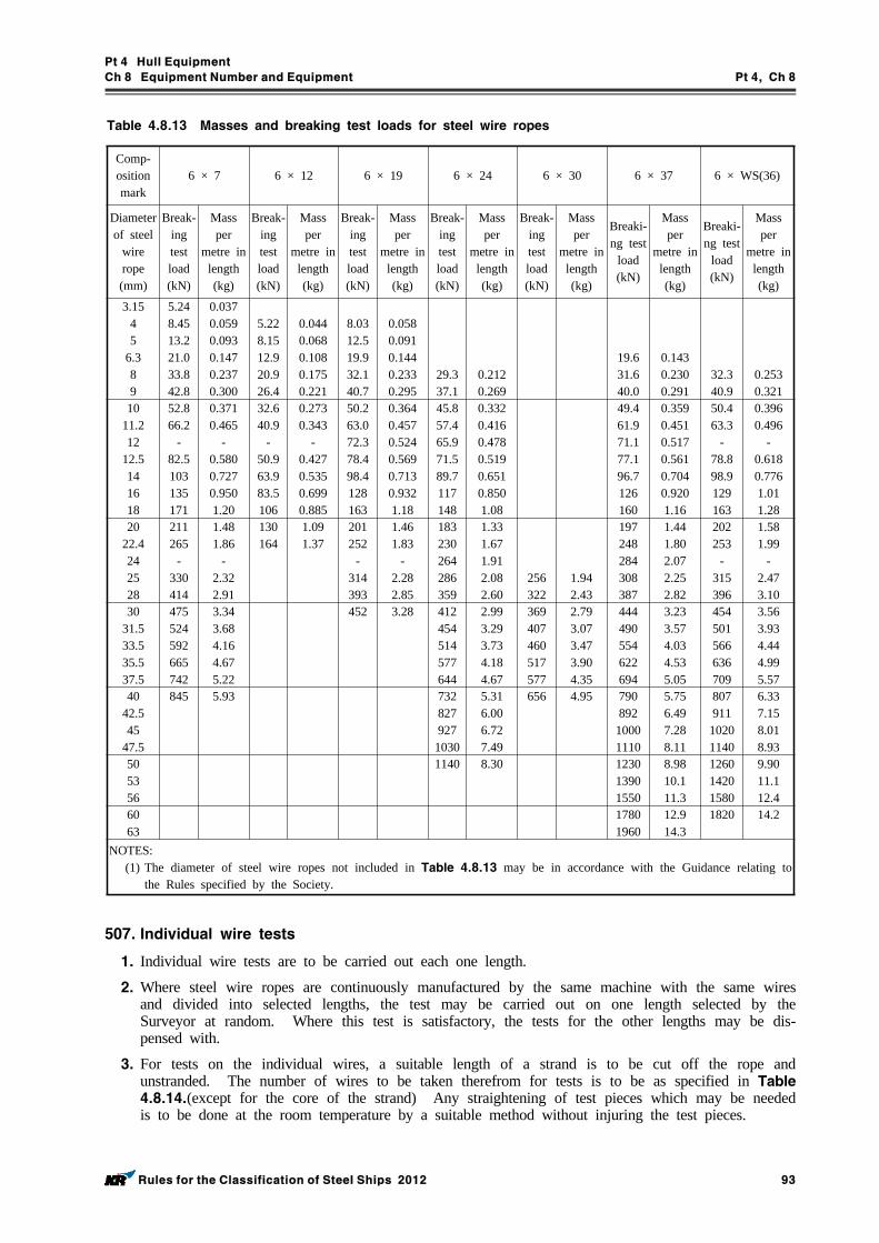
Pt 4 Hull Equipment
Ch 8 Equipment Number and Equipment Pt 4, Ch 8
Rules for the Classification of Steel Ships 2012 93
Comp-osition mark
6 × 7 6 × 12 6 × 19 6 × 24 6 × 30 6 × 37 6 × WS(36)
Diameter of steel
wire rope(mm)
Break-ing test load(kN)
Mass per
metre in length(kg)
Break-ing test load(kN)
Mass per
metre in length(kg)
Break-ing test load(kN)
Mass per
metre in length(kg)
Break-ing test load(kN)
Mass per
metre in length(kg)
Break-ing test load(kN)
Mass per
metre in length(kg)
Breaki-ng test
load(kN)
Mass per
metre in length(kg)
Breaki-ng test
load(kN)
Mass per
metre in length(kg)
3.1545
6.389
5.248.4513.221.033.842.8
0.0370.0590.0930.1470.2370.300
5.228.1512.920.926.4
0.0440.0680.1080.1750.221
8.0312.519.932.140.7
0.0580.0910.1440.2330.295
29.337.1
0.2120.269
19.631.640.0
0.1430.2300.291
32.340.9
0.2530.321
1011.212
12.5141618
52.866.2
-82.5103135171
0.3710.465
-0.5800.7270.9501.20
32.640.9
-50.963.983.5106
0.2730.343
-0.4270.5350.6990.885
50.263.072.378.498.4128163
0.3640.4570.5240.5690.7130.9321.18
45.857.465.971.589.7117148
0.3320.4160.4780.5190.6510.8501.08
49.461.971.177.196.7126160
0.3590.4510.5170.5610.7040.9201.16
50.463.3
-78.898.9129163
0.3960.496
-0.6180.7761.011.28
2022.4242528
211265
-330414
1.481.86
-2.322.91
130164
1.091.37
201252
-314393
1.461.83
-2.282.85
183230264286359
1.331.671.912.082.60
256322
1.942.43
197248284308387
1.441.802.072.252.82
202253
-315396
1.581.99
-2.473.10
3031.533.535.537.5
475524592665742
3.343.684.164.675.22
452 3.28 412454514577644
2.993.293.734.184.67
369407460517577
2.793.073.473.904.35
444490554622694
3.233.574.034.535.05
454501566636709
3.563.934.444.995.57
4042.545
47.5
845 5.93 732827927
1030
5.316.006.727.49
656 4.95 790892
10001110
5.756.497.288.11
807911
10201140
6.337.158.018.93
505356
1140 8.30 123013901550
8.9810.111.3
126014201580
9.9011.112.4
6063
17801960
12.914.3
1820 14.2
NOTES:(1) The diameter of steel wire ropes not included in Table 4.8.13 may be in accordance with the Guidance relating to
the Rules specified by the Society.
Table 4.8.13 Masses and breaking test loads for steel wire ropes
507. Individual wire tests
1. Individual wire tests are to be carried out each one length.
2. Where steel wire ropes are continuously manufactured by the same machine with the same wires and divided into selected lengths, the test may be carried out on one length selected by the Surveyor at random. Where this test is satisfactory, the tests for the other lengths may be dis-pensed with.
3. For tests on the individual wires, a suitable length of a strand is to be cut off the rope and unstranded. The number of wires to be taken therefrom for tests is to be as specified in Table 4.8.14.(except for the core of the strand) Any straightening of test pieces which may be needed is to be done at the room temperature by a suitable method without injuring the test pieces.
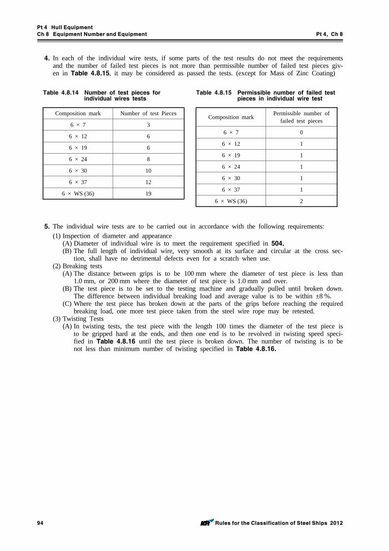
Pt 4 Hull Equipment
Ch 8 Equipment Number and Equipment Pt 4, Ch 8
94 Rules for the Classification of Steel Ships 2012
4. In each of the individual wire tests, if some parts of the test results do not meet the requirements and the number of failed test pieces is not more than permissible number of failed test pieces giv-en in Table 4.8.15, it may be considered as passed the tests. (except for Mass of Zinc Coating)
Composition mark Number of test Pieces
6 × 7 3
6 × 12 6
6 × 19 6
6 × 24 8
6 × 30 10
6 × 37 12
6 × WS (36) 19
Table 4.8.14 Number of test pieces for individual wires tests
Composition mark Permissible number of failed test pieces
6 × 7 0
6 × 12 1
6 × 19 1
6 × 24 1
6 × 30 1
6 × 37 1
6 × WS (36) 2
Table 4.8.15 Permissible number of failed test pieces in individual wire test
5. The individual wire tests are to be carried out in accordance with the following requirements:(1) Inspection of diameter and appearance
(A) Diameter of individual wire is to meet the requirement specified in 504.(B) The full length of individual wire, very smooth at its surface and circular at the cross sec-
tion, shall have no detrimental defects even for a scratch when use.(2) Breaking tests
(A) The distance between grips is to be 100 mm where the diameter of test piece is less than 1.0 mm, or 200 mm where the diameter of test piece is 1.0 mm and over.
(B) The test piece is to be set to the testing machine and gradually pulled until broken down. The difference between individual breaking load and average value is to be within ±8 %.
(C) Where the test piece has broken down at the parts of the grips before reaching the required breaking load, one more test piece taken from the steel wire rope may be retested.
(3) Twisting Tests(A) In twisting tests, the test piece with the length 100 times the diameter of the test piece is
to be gripped hard at the ends, and then one end is to be revolved in twisting speed speci-fied in Table 4.8.16 until the test piece is broken down. The number of twisting is to be not less than minimum number of twisting specified in Table 4.8.16.
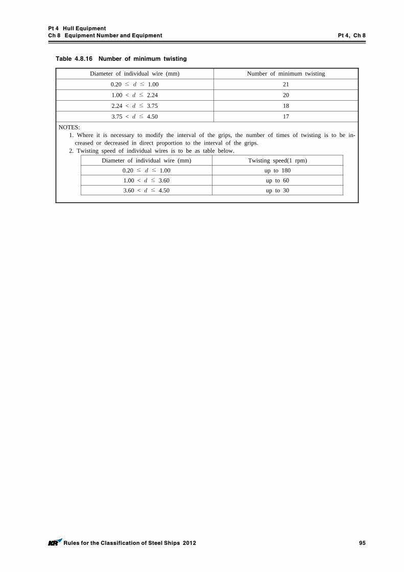
Pt 4 Hull Equipment
Ch 8 Equipment Number and Equipment Pt 4, Ch 8
Rules for the Classification of Steel Ships 2012 95
Diameter of individual wire (mm) Number of minimum twisting
0.20 ≤ ≤ 1.00 21
1.00 < ≤ 2.24 20
2.24 < ≤ 3.75 18
3.75 < ≤ 4.50 17
NOTES: 1. Where it is necessary to modify the interval of the grips, the number of times of twisting is to be in-
creased or decreased in direct proportion to the interval of the grips. 2. Twisting speed of individual wires is to be as table below.
Diameter of individual wire (mm) Twisting speed(1 rpm)0.20 ≤ ≤ 1.00 up to 180
1.00 < ≤ 3.60 up to 60
3.60 < ≤ 4.50 up to 30
Table 4.8.16 Number of minimum twisting
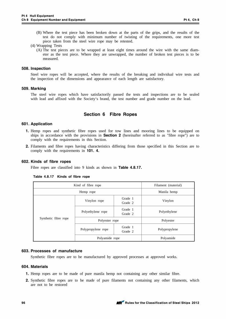
Pt 4 Hull Equipment
Ch 8 Equipment Number and Equipment Pt 4, Ch 8
96 Rules for the Classification of Steel Ships 2012
(B) Where the test piece has been broken down at the parts of the grips, and the results of the test do not comply with minimum number of twisting of the requirements, one more test piece taken from the steel wire rope may be retested.
(4) Wrapping Tests(A) The test pieces are to be wrapped at least eight times around the wire with the same diam-
eter as the test piece. Where they are unwrapped, the number of broken test pieces is to be measured.
508. Inspection
Steel wire ropes will be accepted, where the results of the breaking and individual wire tests and the inspection of the dimensions and appearance of each length are satisfactory.
509. Marking
The steel wire ropes which have satisfactorily passed the tests and inspections are to be sealed with lead and affixed with the Society‘s brand, the test number and grade number on the lead.
Section 6 Fibre Ropes
601. Application
1. Hemp ropes and synthetic fibre ropes used for tow lines and mooring lines to be equipped on ships in accordance with the provisions in Section 2 (hereinafter referred to as "fibre rope") are to comply with the requirements in this Section.
2. Filaments and fibre ropes having characteristics differing from those specified in this Section are to comply with the requirements in 101. 4.
602. Kinds of fibre ropes
Fibre ropes are classified into 9 kinds as shown in Table 4.8.17.
Kind of fibre rope Filament (material)
Hemp rope Manila hemp
Synthetic fibre rope
Vinylon rope Grade 1Grade 2 Vinylon
Polyethylene rope Grade 1Grade 2 Polyethylene
Polyester rope Polyester
Polypropylene rope Grade 1Grade 2 Polypropylene
Polyamide rope Polyamide
Table 4.8.17 Kinds of fibre rope
603. Processes of manufacture
Synthetic fibre ropes are to be manufactured by approved processes at approved works.
604. Materials
1. Hemp ropes are to be made of pure manila hemp not containing any other similar fibre.
2. Synthetic fibre ropes are to be made of pure filaments not containing any other filaments, which are not to be restored
Pt 4 Hull Equipment
Ch 8 Equipment Number and Equipment Pt 4, Ch 8
Rules for the Classification of Steel Ships 2012 97
605. Construction of fibre ropes and others
1. Hemp ropes are, in general, to be composed of three strands and synthetic fibre ropes are to be composed of three or eight strands.
2. Three strand ropes are, in general, to be made of strands twisted together with a Z lay, these strands themselves being made with an S lay. Eight strand ropes are, in general, to be formed of four pairs of strands, the pairs being constituted successively of two strands twisted in the S direc-tion and than of two strands twisted in the Z direction.
3. The number of the yarns of a strand is to be same, and the dimensions and laying of the yarns composing ropes are to be uniform for the whole length of the rope.
4. The lead for the strand is, in general, to be below 3.2 times the nominal diameter for three strand rope and below 3.5 times the nominal diameter for eight strand rope.
5. Polyamide ropes are to be suitably heat treated by induction furnace or others to set the lay and obtain dimensional stability. Vinylon and polypropylene ropes may be subjected to suitable heat treatment, if necessary.
6. Synthetic fibre ropes may be subjected to resin treatment and dye treatment subject to the approval by the Society.
7. Oil of good quality is to be used in manufacturing hemp ropes. Ropes are not to contain excessive quantity of oil.
606. Diameter
The diameter of fibre ropes is to be measured on circumscribed circle of the ropes under the load equal to 5 % of the breaking test load specified in Table 4.8.18 Its tolerance is to be ±3 % of its nominal diameter.
607. Breaking tests
Breaking tests for fibre ropes are to be carried out in accordance with the following requirements:(1) One specimen is to be taken from each coil of the fibre ropes. Where fibre ropes are con-
tinuously manufactured by the same machine with the yarns of the same type and divided into several coils, one specimen may be taken from one coil of the ropes selected by the Surveyor at random.
(2) The length of the specimen is not to be less than 30 times the diameter of the hemp rope, but need not exceed one metre.
(3) Specimens for polyethylene and polypropylene ropes are to be subjected to breaking tests in as wet condition immediately after having been immersed in warm water at 35 ± 2 °C for more than 30 minutes. For other fibre ropes than the above ropes, specimens are to be subjected to breaking tests in as dry condition at room temperature.
(4) The load at the time of breaking is not to be less than given in Table 4.8.18.
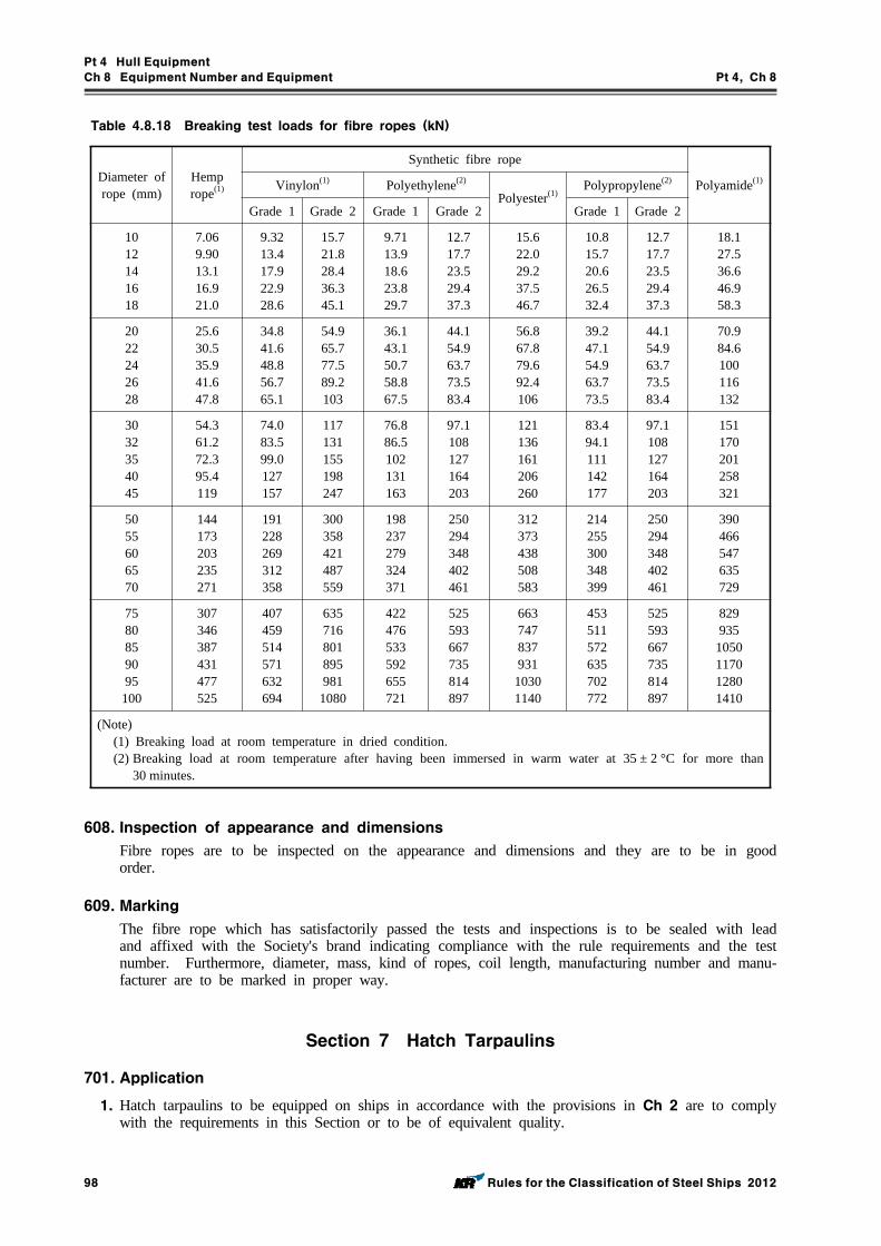
Pt 4 Hull Equipment
Ch 8 Equipment Number and Equipment Pt 4, Ch 8
98 Rules for the Classification of Steel Ships 2012
Diameter of rope (mm)
Hemp rope(1)
Synthetic fibre rope
Polyamide(1)Vinylon(1) Polyethylene(2)
Polyester(1)Polypropylene(2)
Grade 1 Grade 2 Grade 1 Grade 2 Grade 1 Grade 2
1012141618
7.069.9013.116.921.0
9.3213.417.922.928.6
15.721.828.436.345.1
9.7113.918.623.829.7
12.717.723.529.437.3
15.622.029.237.546.7
10.815.720.626.532.4
12.717.723.529.437.3
18.127.536.646.958.3
2022242628
25.630.535.941.647.8
34.841.648.856.765.1
54.965.777.589.2103
36.143.150.758.867.5
44.154.963.773.583.4
56.867.879.692.4106
39.247.154.963.773.5
44.154.963.773.583.4
70.984.6100116132
3032354045
54.361.272.395.4119
74.083.599.0127157
117131155198247
76.886.5102131163
97.1108127164203
121136161206260
83.494.1111142177
97.1108127164203
151170201258321
5055606570
144173203235271
191228269312358
300358421487559
198237279324371
250294348402461
312373438508583
214255300348399
250294348402461
390466547635729
7580859095100
307346387431477525
407459514571632694
635716801895981
1080
422476533592655721
525593667735814897
66374783793110301140
453511572635702772
525593667735814897
829935
1050117012801410
(Note)(1) Breaking load at room temperature in dried condition.(2) Breaking load at room temperature after having been immersed in warm water at 35 ± 2 °C for more than
30 minutes.
Table 4.8.18 Breaking test loads for fibre ropes (kN)
608. Inspection of appearance and dimensions
Fibre ropes are to be inspected on the appearance and dimensions and they are to be in good order.
609. Marking
The fibre rope which has satisfactorily passed the tests and inspections is to be sealed with lead and affixed with the Society's brand indicating compliance with the rule requirements and the test number. Furthermore, diameter, mass, kind of ropes, coil length, manufacturing number and manu-facturer are to be marked in proper way.
Section 7 Hatch Tarpaulins
701. Application
1. Hatch tarpaulins to be equipped on ships in accordance with the provisions in Ch 2 are to comply with the requirements in this Section or to be of equivalent quality.
Pt 4 Hull Equipment
Ch 8 Equipment Number and Equipment Pt 4, Ch 8
Rules for the Classification of Steel Ships 2012 99
2. The tests and inspections for hatch tarpaulins made of synthetic materials are to be to the dis-cretion of the Society.
702. Grades
The grades of tarpaulins are as follows:Grade A tarpaulins (Mark, TA)Grade B tarpaulins (Mark, TB)
703. Materials
Tarpaulins are to be made from cloths woven with flax yarn or cotton yarn of good quality.
704. Sewing
The overlapping, sewing threads and method of sewing for the purpose of joining the cloths used for tarpaulins are to be to the satisfaction of the Surveyor.
705. Mass
The mass of cloths used for tarpaulins before waterproof treatment is not to be less than 650 g/m2 for Grade A tarpaulins and 490 g/m2 for Grade B tarpaulins. Where, however, the waterproof me-diums other than tar are used, the minimum mass may be reduced to 85 % of the above mass ac-cording to the characteristics of the mediums.
706. Tensile Tests
The strength of cloths used for tarpaulins before the waterproof treatment is not to be less than 80kg for Grade A tarpaulins and 60 kg for Grade B tarpaulins in warp and woof, being tested with test pieces 30 mm wide and 200 mm long. Where, however, the waterproof mediums other than tar are used, the minimum strength may be reduced to 85 % of the above value according to the char-acteristics of the mediums.
707. Waterproof treatments
1. Waterproof mediums are to be made of suitable tar, grease or chemicals.
2. Tarpaulins are to pass the waterproofness tests which the Surveyor considers appropriate.
3. The waterproof medium applied to the tarpaulin is to prove free from adhesion, cracking or any other defect on its surface where it is folded at the temperature which is appropriate to this society.
708. Making
For the hatch tarpaulins which have been satisfactorily tested and inspected, the Society‘s brand, manufacturer, test number and grade identification of the hatch tarpaulins are to be marked on suit-able places of the hatch tarpaulins.
Section 8 Side Scuttles
801. Application
The side scuttles to be fitted up on ships according to the requirements in Ch 4 (hereinafter re-ferred to as side scuttle) are to comply with the requirements in this Section or to be of equivalent quality.
802. Types
Side scuttles are classified into following three types and divided into "fixed type" and "hinged type" according to the types of glass holders of the scuttles, and divided into "bolted type" and
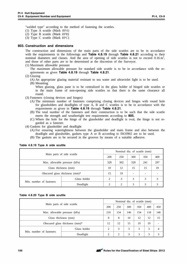
Pt 4 Hull Equipment
Ch 8 Equipment Number and Equipment Pt 4, Ch 8
100 Rules for the Classification of Steel Ships 2012
"welded type" according to the method of fastening the scuttles.(1) Type A scuttle (Mark RPA)(2) Type B scuttle (Mark RPB) (3) Type C scuttle (Mark RPC)
803. Construction and dimensions
The construction and dimensions of the main parts of the side scuttles are to be in accordance with the requirements in the followings and Table 4.8.19 through Table 4.8.21 according to their nominal diameters and classes. And the area of opening of side scuttles is not to exceed 0.16 m2, and those of other parts are to be determined at the discretion of the Surveyor.(1) Maximum allowable pressure
The maximum allowable pressure for standard side scuttle is to be in accordance with the re-quirements as given Table 4.8.19 through Table 4.8.21.
(2) Glazing (A) An appropriate glazing material resistant to sea water and ultraviolet light is to be used.(B) Mounting
When glazing, glass pane is to be centralized in the glass holder of hinged side scuttles or in the main frame of non-opening side scuttles so that there is the same clearance all round.
(3) Fasteners (closing devices and hinges)(A) The minimum number of fasteners comprising closing devices and hinges with round hole
for glassholders and deadlights of type A, B and C scuttles is to be in accordance with the requirements as given in Table 4.8.19 through Table 4.8.21.
(B) The total number of the fasteners and their construction is to be such that the side scuttle meets the strength and weathertight test requirements according to 805.
(C) Where the hole for the hinge of the glassholder and deadlight is oval, the hinge is not re-garded as a fastener.
(4) Gaskets for glassholder and deadlight (A) For ensuring watertightness between the glassholder and main frame and also between the
deadlight and glassholder, gaskets type A or B according to ISO3902 are to be used. (B) The gaskets are to be secured in the grooves by means of a suitable adhesive.
Main parts of side scuttleNominal dia. of scuttle (mm)
200 250 300 350 400
Max. allowable pressure (kPa) 328 302 328 241 297
Glass thickness (mm) 10 12 15 15 19
Obscured glass thickness (mm)* 15 19 - - -
Min. number of fastenersGlass holder 2 3 3 3 3
Deadlight 2 2 3 3 3
Table 4.8.19 Type A side scuttle
Main parts of side scuttleNominal dia. of scuttle (mm)
200 250 300 350 400 450
Max. allowable pressure (kPa) 210 134 146 154 118 146
Glass thickness (mm) 8 8 10 12 12 15
Obscured glass thickness (mm)* 12 12 15 19 19 -
Min. number of fastenersGlass holder 2 3 3 3 3 4
Deadlight 2 2 3 3 3 3
Table 4.8.20 Type B side scuttle
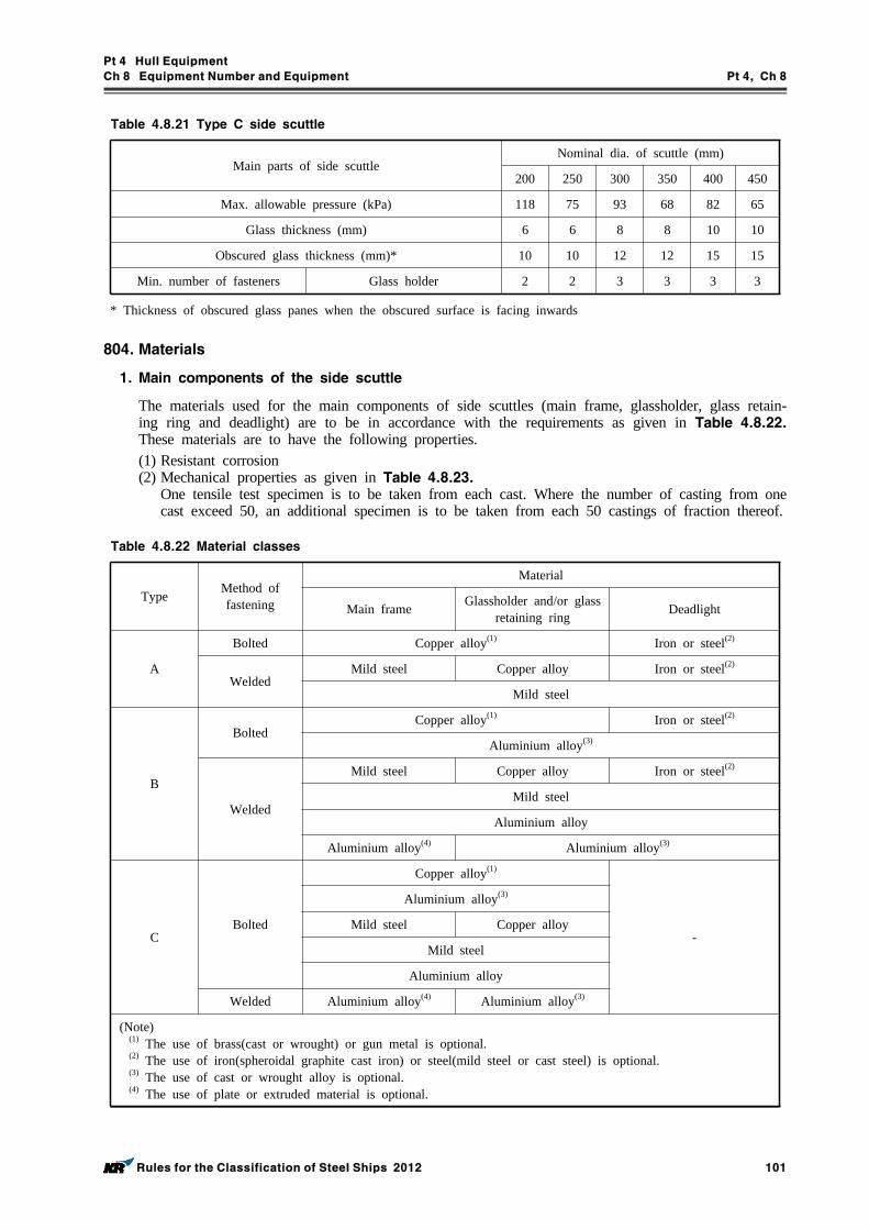
Pt 4 Hull Equipment
Ch 8 Equipment Number and Equipment Pt 4, Ch 8
Rules for the Classification of Steel Ships 2012 101
Main parts of side scuttleNominal dia. of scuttle (mm)
200 250 300 350 400 450
Max. allowable pressure (kPa) 118 75 93 68 82 65
Glass thickness (mm) 6 6 8 8 10 10
Obscured glass thickness (mm)* 10 10 12 12 15 15
Min. number of fasteners Glass holder 2 2 3 3 3 3
Table 4.8.21 Type C side scuttle
* Thickness of obscured glass panes when the obscured surface is facing inwards
804. Materials
1. Main components of the side scuttle
The materials used for the main components of side scuttles (main frame, glassholder, glass retain-ing ring and deadlight) are to be in accordance with the requirements as given in Table 4.8.22. These materials are to have the following properties. (1) Resistant corrosion (2) Mechanical properties as given in Table 4.8.23.
One tensile test specimen is to be taken from each cast. Where the number of casting from one cast exceed 50, an additional specimen is to be taken from each 50 castings of fraction thereof.
Type Method of fastening
Material
Main frame Glassholder and/or glass retaining ring Deadlight
A
Bolted Copper alloy(1) Iron or steel(2)
WeldedMild steel Copper alloy Iron or steel(2)
Mild steel
B
BoltedCopper alloy(1) Iron or steel(2)
Aluminium alloy(3)
Welded
Mild steel Copper alloy Iron or steel(2)
Mild steel
Aluminium alloy
Aluminium alloy(4) Aluminium alloy(3)
CBolted
Copper alloy(1)
-
Aluminium alloy(3)
Mild steel Copper alloy
Mild steel
Aluminium alloy
Welded Aluminium alloy(4) Aluminium alloy(3)
(Note)(1) The use of brass(cast or wrought) or gun metal is optional. (2) The use of iron(spheroidal graphite cast iron) or steel(mild steel or cast steel) is optional. (3) The use of cast or wrought alloy is optional. (4) The use of plate or extruded material is optional.
Table 4.8.22 Material classes
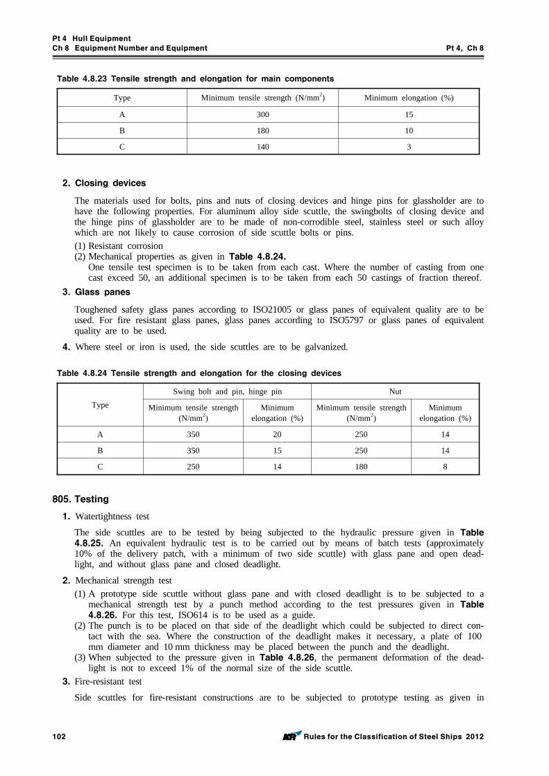
Pt 4 Hull Equipment
Ch 8 Equipment Number and Equipment Pt 4, Ch 8
102 Rules for the Classification of Steel Ships 2012
Type Minimum tensile strength (N/mm2) Minimum elongation (%)
A 300 15
B 180 10
C 140 3
Table 4.8.23 Tensile strength and elongation for main components
2. Closing devices
The materials used for bolts, pins and nuts of closing devices and hinge pins for glassholder are to have the following properties. For aluminum alloy side scuttle, the swingbolts of closing device and the hinge pins of glassholder are to be made of non-corrodible steel, stainless steel or such alloy which are not likely to cause corrosion of side scuttle bolts or pins.(1) Resistant corrosion (2) Mechanical properties as given in Table 4.8.24.
One tensile test specimen is to be taken from each cast. Where the number of casting from one cast exceed 50, an additional specimen is to be taken from each 50 castings of fraction thereof.
3. Glass panes
Toughened safety glass panes according to ISO21005 or glass panes of equivalent quality are to be used. For fire resistant glass panes, glass panes according to ISO5797 or glass panes of equivalent quality are to be used.
4. Where steel or iron is used, the side scuttles are to be galvanized.
TypeSwing bolt and pin, hinge pin Nut
Minimum tensile strength (N/mm2)
Minimum elongation (%)
Minimum tensile strength (N/mm2)
Minimum elongation (%)
A 350 20 250 14
B 350 15 250 14
C 250 14 180 8
Table 4.8.24 Tensile strength and elongation for the closing devices
805. Testing
1. Watertightness test
The side scuttles are to be tested by being subjected to the hydraulic pressure given in Table 4.8.25. An equivalent hydraulic test is to be carried out by means of batch tests (approximately 10% of the delivery patch, with a minimum of two side scuttle) with glass pane and open dead-light, and without glass pane and closed deadlight.
2. Mechanical strength test (1) A prototype side scuttle without glass pane and with closed deadlight is to be subjected to a
mechanical strength test by a punch method according to the test pressures given in Table 4.8.26. For this test, ISO614 is to be used as a guide.
(2) The punch is to be placed on that side of the deadlight which could be subjected to direct con-tact with the sea. Where the construction of the deadlight makes it necessary, a plate of 100mm diameter and 10 mm thickness may be placed between the punch and the deadlight.
(3) When subjected to the pressure given in Table 4.8.26, the permanent deformation of the dead-light is not to exceed 1% of the normal size of the side scuttle.
3. Fire-resistant test
Side scuttles for fire-resistant constructions are to be subjected to prototype testing as given in
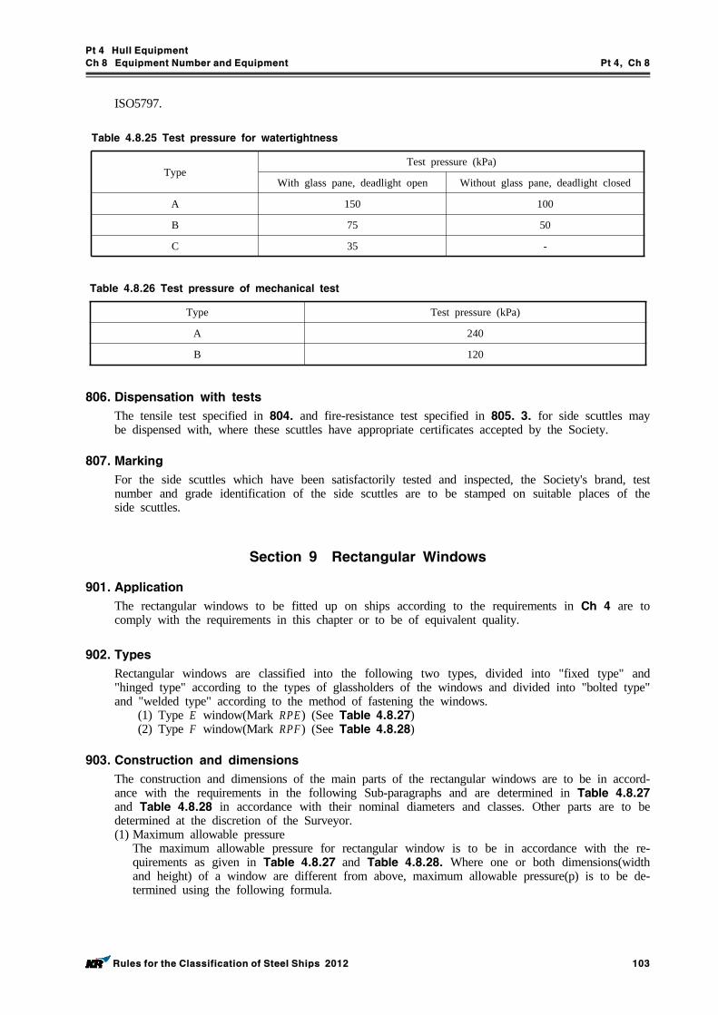
Pt 4 Hull Equipment
Ch 8 Equipment Number and Equipment Pt 4, Ch 8
Rules for the Classification of Steel Ships 2012 103
ISO5797.
TypeTest pressure (kPa)
With glass pane, deadlight open Without glass pane, deadlight closed
A 150 100
B 75 50
C 35 -
Table 4.8.25 Test pressure for watertightness
Type Test pressure (kPa)
A 240
B 120
Table 4.8.26 Test pressure of mechanical test
806. Dispensation with tests
The tensile test specified in 804. and fire-resistance test specified in 805. 3. for side scuttles may be dispensed with, where these scuttles have appropriate certificates accepted by the Society.
807. Marking
For the side scuttles which have been satisfactorily tested and inspected, the Society's brand, test number and grade identification of the side scuttles are to be stamped on suitable places of the side scuttles.
Section 9 Rectangular Windows
901. Application
The rectangular windows to be fitted up on ships according to the requirements in Ch 4 are to comply with the requirements in this chapter or to be of equivalent quality.
902. Types
Rectangular windows are classified into the following two types, divided into "fixed type" and "hinged type" according to the types of glassholders of the windows and divided into "bolted type" and "welded type" according to the method of fastening the windows.
(1) Type E window(Mark RPE) (See Table 4.8.27)(2) Type F window(Mark RPF) (See Table 4.8.28)
903. Construction and dimensions
The construction and dimensions of the main parts of the rectangular windows are to be in accord-ance with the requirements in the following Sub-paragraphs and are determined in Table 4.8.27 and Table 4.8.28 in accordance with their nominal diameters and classes. Other parts are to be determined at the discretion of the Surveyor.(1) Maximum allowable pressure
The maximum allowable pressure for rectangular window is to be in accordance with the re-quirements as given in Table 4.8.27 and Table 4.8.28. Where one or both dimensions(width and height) of a window are different from above, maximum allowable pressure(p) is to be de-termined using the following formula.
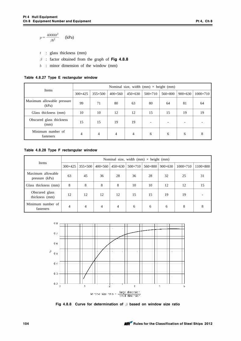
Pt 4 Hull Equipment
Ch 8 Equipment Number and Equipment Pt 4, Ch 8
104 Rules for the Classification of Steel Ships 2012
(kPa)
: glass thickness (mm) : factor obtained from the graph of Fig 4.8.8 : minor dimension of the window (mm)
ItemsNominal size, width (mm) × height (mm)
300×425 355×500 400×560 450×630 500×710 560×800 900×630 1000×710
Maximum allowable pressure (kPa) 99 71 80 63 80 64 81 64
Glass thickness (mm) 10 10 12 12 15 15 19 19
Obscured glass thickness (mm) 15 15 19 19 - - - -
Minimum number of fasteners 4 4 4 4 6 6 6 8
Table 4.8.27 Type E rectangular window
ItemsNominal size, width (mm) × height (mm)
300×425 355×500 400×560 450×630 500×710 560×800 900×630 1000×710 1100×800
Maximum allowable pressure (kPa) 63 45 36 28 36 28 32 25 31
Glass thickness (mm) 8 8 8 8 10 10 12 12 15
Obscured glass thickness (mm) 12 12 12 12 15 15 19 19 -
Minimum number of fasteners 4 4 4 4 6 6 6 8 8
Table 4.8.28 Type F rectangular window
Fig 4.8.8 Curve for determination of based on window size ratio
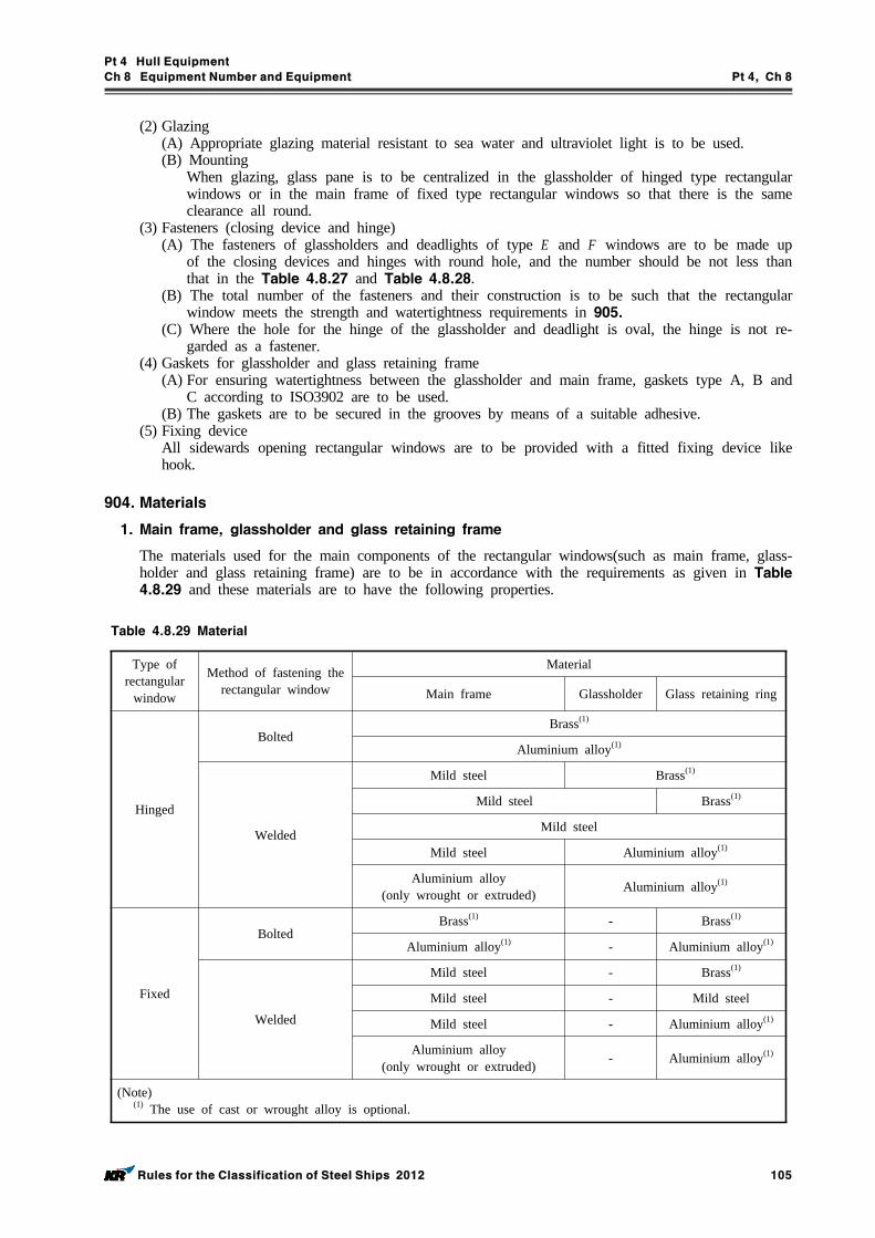
Pt 4 Hull Equipment
Ch 8 Equipment Number and Equipment Pt 4, Ch 8
Rules for the Classification of Steel Ships 2012 105
(2) Glazing(A) Appropriate glazing material resistant to sea water and ultraviolet light is to be used.(B) Mounting
When glazing, glass pane is to be centralized in the glassholder of hinged type rectangular windows or in the main frame of fixed type rectangular windows so that there is the same clearance all round.
(3) Fasteners (closing device and hinge)(A) The fasteners of glassholders and deadlights of type E and F windows are to be made up
of the closing devices and hinges with round hole, and the number should be not less than that in the Table 4.8.27 and Table 4.8.28.
(B) The total number of the fasteners and their construction is to be such that the rectangular window meets the strength and watertightness requirements in 905.
(C) Where the hole for the hinge of the glassholder and deadlight is oval, the hinge is not re-garded as a fastener.
(4) Gaskets for glassholder and glass retaining frame(A) For ensuring watertightness between the glassholder and main frame, gaskets type A, B and
C according to ISO3902 are to be used. (B) The gaskets are to be secured in the grooves by means of a suitable adhesive.
(5) Fixing deviceAll sidewards opening rectangular windows are to be provided with a fitted fixing device like hook.
904. Materials
1. Main frame, glassholder and glass retaining frame
The materials used for the main components of the rectangular windows(such as main frame, glass-holder and glass retaining frame) are to be in accordance with the requirements as given in Table 4.8.29 and these materials are to have the following properties.
Type of rectangular
window
Method of fastening the rectangular window
Material
Main frame Glassholder Glass retaining ring
Hinged
BoltedBrass(1)
Aluminium alloy(1)
Welded
Mild steel Brass(1)
Mild steel Brass(1)
Mild steel
Mild steel Aluminium alloy(1)
Aluminium alloy(only wrought or extruded) Aluminium alloy(1)
Fixed
BoltedBrass(1) - Brass(1)
Aluminium alloy(1) - Aluminium alloy(1)
Welded
Mild steel - Brass(1)
Mild steel - Mild steel
Mild steel - Aluminium alloy(1)
Aluminium alloy(only wrought or extruded) - Aluminium alloy(1)
(Note)(1) The use of cast or wrought alloy is optional.
Table 4.8.29 Material
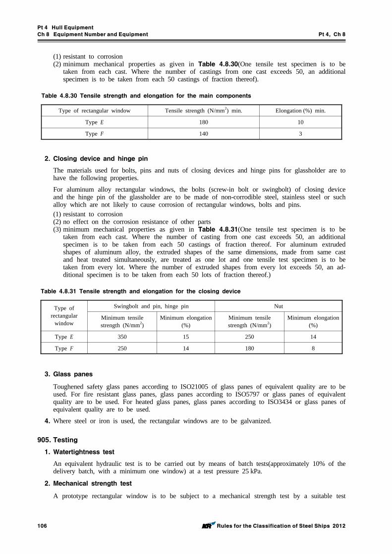
Pt 4 Hull Equipment
Ch 8 Equipment Number and Equipment Pt 4, Ch 8
106 Rules for the Classification of Steel Ships 2012
(1) resistant to corrosion(2) minimum mechanical properties as given in Table 4.8.30(One tensile test specimen is to be
taken from each cast. Where the number of castings from one cast exceeds 50, an additional specimen is to be taken from each 50 castings of fraction thereof).
Type of rectangular window Tensile strength (N/mm2) min. Elongation (%) min.
Type E 180 10
Type F 140 3
Table 4.8.30 Tensile strength and elongation for the main components
2. Closing device and hinge pin
The materials used for bolts, pins and nuts of closing devices and hinge pins for glassholder are to have the following properties.
For aluminum alloy rectangular windows, the bolts (screw-in bolt or swingbolt) of closing device and the hinge pin of the glassholder are to be made of non-corrodible steel, stainless steel or such alloy which are not likely to cause corrosion of rectangular windows, bolts and pins. (1) resistant to corrosion(2) no effect on the corrosion resistance of other parts(3) minimum mechanical properties as given in Table 4.8.31(One tensile test specimen is to be
taken from each cast. Where the number of casting from one cast exceeds 50, an additional specimen is to be taken from each 50 castings of fraction thereof. For aluminum extruded shapes of aluminum alloy, the extruded shapes of the same dimensions, made from same cast and heat treated simultaneously, are treated as one lot and one tensile test specimen is to be taken from every lot. Where the number of extruded shapes from every lot exceeds 50, an ad-ditional specimen is to be taken from each 50 lots of fraction thereof.)
Type of rectangular
window
Swingbolt and pin, hinge pin Nut
Minimum tensile strength (N/mm2)
Minimum elongation (%)
Minimum tensile strength (N/mm2)
Minimum elongation (%)
Type E 350 15 250 14
Type F 250 14 180 8
Table 4.8.31 Tensile strength and elongation for the closing device
3. Glass panes
Toughened safety glass panes according to ISO21005 of glass panes of equivalent quality are to be used. For fire resistant glass panes, glass panes according to ISO5797 or glass panes of equivalent quality are to be used. For heated glass panes, glass panes according to ISO3434 or glass panes of equivalent quality are to be used.
4. Where steel or iron is used, the rectangular windows are to be galvanized.
905. Testing
1. Watertightness test
An equivalent hydraulic test is to be carried out by means of batch tests(approximately 10% of the delivery batch, with a minimum one window) at a test pressure 25 kPa.
2. Mechanical strength test
A prototype rectangular window is to be subject to a mechanical strength test by a suitable test
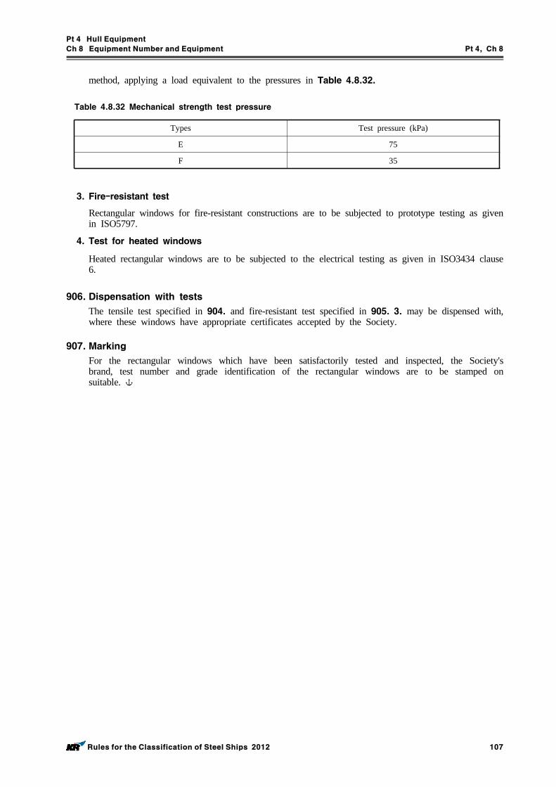
Pt 4 Hull Equipment
Ch 8 Equipment Number and Equipment Pt 4, Ch 8
Rules for the Classification of Steel Ships 2012 107
method, applying a load equivalent to the pressures in Table 4.8.32.
Types Test pressure (kPa)
E 75
F 35
Table 4.8.32 Mechanical strength test pressure
3. Fire-resistant test
Rectangular windows for fire-resistant constructions are to be subjected to prototype testing as given in ISO5797.
4. Test for heated windows
Heated rectangular windows are to be subjected to the electrical testing as given in ISO3434 clause 6.
906. Dispensation with tests
The tensile test specified in 904. and fire-resistant test specified in 905. 3. may be dispensed with, where these windows have appropriate certificates accepted by the Society.
907. Marking
For the rectangular windows which have been satisfactorily tested and inspected, the Society's brand, test number and grade identification of the rectangular windows are to be stamped on suitable.
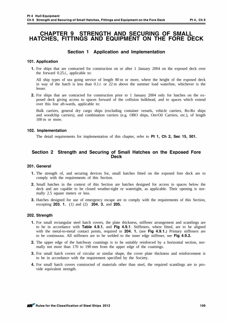
Pt 4 Hull Equipment
Ch 9 Strength and Securing of Small Hatches, Fittings and Equipment on the Fore Deck Pt 4, Ch 9
Rules for the Classification of Steel Ships 2012 109
CHAPTER 9 STRENGTH AND SECURING OF SMALL HATCHES, FITTINGS AND EQUIPMENT ON THE FORE DECK
Section 1 Application and Implementation
101. Application
1. For ships that are contracted for construction on or after 1 January 2004 on the exposed deck over the forward 0.25 , applicable to:
All ship types of sea going service of length 80 m or more, where the height of the exposed deck in way of the hatch is less than 0.1 or 22 m above the summer load waterline, whichever is the lesser.
2. For ships that are contracted for construction prior to 1 January 2004 only for hatches on the ex-posed deck giving access to spaces forward of the collision bulkhead, and to spaces which extend over this line aft-wards, applicable to:
Bulk carriers, general dry cargo ships (excluding container vessels, vehicle carriers, Ro-Ro ships and woodchip carriers), and combination carriers (e.g. OBO ships, Ore/Oil Carriers, etc.), of length 100 m or more.
102. Implementation
The detail requirements for implementation of this chapter, refer to Pt 1, Ch 2, Sec 15, 501.
Section 2 Strength and Securing of Small Hatches on the Exposed Fore Deck
201. General
1. The strength of, and securing devices for, small hatches fitted on the exposed fore deck are to comply with the requirements of this Section.
2. Small hatches in the context of this Section are hatches designed for access to spaces below the deck and are capable to be closed weather-tight or watertight, as applicable. Their opening is nor-mally 2.5 square meters or less.
3. Hatches designed for use of emergency escape are to comply with the requirements of this Section, excepting 203. 1. (1) and (2) 204. 3. and 205.
202. Strength
1. For small rectangular steel hatch covers, the plate thickness, stiffener arrangement and scantlings are to be in accordance with Table 4.9.1, and Fig 4.9.1. Stiffeners, where fitted, are to be aligned with the metal-to-metal contact points, required in 204. 1. (see Fig 4.9.1.) Primary stiffeners are to be continuous. All stiffeners are to be welded to the inner edge stiffener, see Fig 4.9.2.
2. The upper edge of the hatchway coamings is to be suitably reinforced by a horizontal section, nor-mally not more than 170 to 190 mm from the upper edge of the coamings.
3. For small hatch covers of circular or similar shape, the cover plate thickness and reinforcement is to be in accordance with the requirement specified by the Society.
4. For small hatch covers constructed of materials other than steel, the required scantlings are to pro-vide equivalent strength.
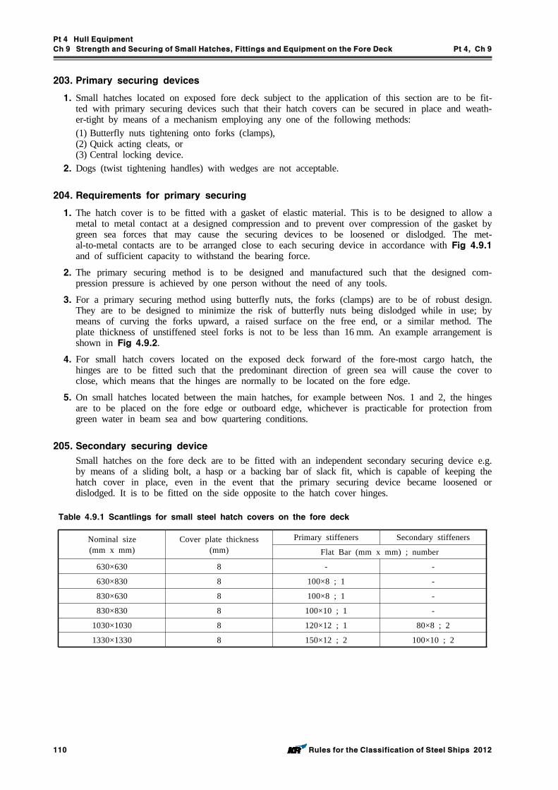
Pt 4 Hull Equipment
Ch 9 Strength and Securing of Small Hatches, Fittings and Equipment on the Fore Deck Pt 4, Ch 9
110 Rules for the Classification of Steel Ships 2012
203. Primary securing devices
1. Small hatches located on exposed fore deck subject to the application of this section are to be fit-ted with primary securing devices such that their hatch covers can be secured in place and weath-er-tight by means of a mechanism employing any one of the following methods:(1) Butterfly nuts tightening onto forks (clamps),(2) Quick acting cleats, or(3) Central locking device.
2. Dogs (twist tightening handles) with wedges are not acceptable.
204. Requirements for primary securing
1. The hatch cover is to be fitted with a gasket of elastic material. This is to be designed to allow a metal to metal contact at a designed compression and to prevent over compression of the gasket by green sea forces that may cause the securing devices to be loosened or dislodged. The met-al-to-metal contacts are to be arranged close to each securing device in accordance with Fig 4.9.1 and of sufficient capacity to withstand the bearing force.
2. The primary securing method is to be designed and manufactured such that the designed com-pression pressure is achieved by one person without the need of any tools.
3. For a primary securing method using butterfly nuts, the forks (clamps) are to be of robust design. They are to be designed to minimize the risk of butterfly nuts being dislodged while in use; by means of curving the forks upward, a raised surface on the free end, or a similar method. The plate thickness of unstiffened steel forks is not to be less than 16 mm. An example arrangement is shown in Fig 4.9.2.
4. For small hatch covers located on the exposed deck forward of the fore-most cargo hatch, the hinges are to be fitted such that the predominant direction of green sea will cause the cover to close, which means that the hinges are normally to be located on the fore edge.
5. On small hatches located between the main hatches, for example between Nos. 1 and 2, the hinges are to be placed on the fore edge or outboard edge, whichever is practicable for protection from green water in beam sea and bow quartering conditions.
205. Secondary securing device
Small hatches on the fore deck are to be fitted with an independent secondary securing device e.g. by means of a sliding bolt, a hasp or a backing bar of slack fit, which is capable of keeping the hatch cover in place, even in the event that the primary securing device became loosened or dislodged. It is to be fitted on the side opposite to the hatch cover hinges.
Nominal size(mm x mm)
Cover plate thickness(mm)
Primary stiffeners Secondary stiffeners
Flat Bar (mm x mm) ; number
630×630 8 - -
630×830 8 100×8 ; 1 -
830×630 8 100×8 ; 1 -
830×830 8 100×10 ; 1 -
1030×1030 8 120×12 ; 1 80×8 ; 2
1330×1330 8 150×12 ; 2 100×10 ; 2
Table 4.9.1 Scantlings for small steel hatch covers on the fore deck
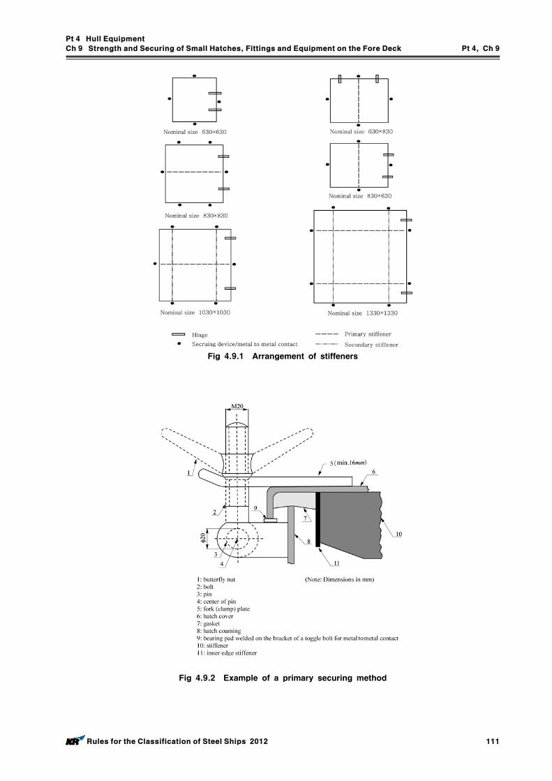
Pt 4 Hull Equipment
Ch 9 Strength and Securing of Small Hatches, Fittings and Equipment on the Fore Deck Pt 4, Ch 9
Rules for the Classification of Steel Ships 2012 111
Fig 4.9.1 Arrangement of stiffeners
Fig 4.9.2 Example of a primary securing method
Pt 4 Hull Equipment
Ch 9 Strength and Securing of Small Hatches, Fittings and Equipment on the Fore Deck Pt 4, Ch 9
112 Rules for the Classification of Steel Ships 2012
Section 3 Strength Requirements for Fore Deck Fittings and Equipment
301. General
1. This section provides strength requirements to resist green sea forces for the following items :
air pipes, ventilator pipes and their closing devices, the securing of windlasses.
2. For windlasses, these requirements are additional to those appertaining to the anchor and chain per-formance criteria of Pt 5, Ch 8.
3. Where mooring winches are integral with the anchor windlass, they are to be considered as part of the windlass.
302. Applied loading
1. Air pipes, ventilator pipes and their closing devices(1) The pressures , in kN/m2 acting on air pipes, ventilator pipes and their closing devices may
be calculated from:
(kN/m2)
where : = density of sea water (1.025 t/m3) = velocity of water over the fore deck (13.5 m/sec) = shape coefficient
= 0.5 for pipes, = 1.3 for air pipe or ventilator heads in general, = 0.8 for an air pipe or ventilator head of cylinderical form with its axis in the vertical
direction. = slamming coefficient (3.2) = protection coefficient:
= 0.7 for pipes and ventilator heads located immediately behind a breakwater or fore-castle,
= 1.0 elsewhere and immediately behind a bulwark.(2) Forces acting in the horizontal direction on the pipe and its closing device may be calculated
from (1) using the largest projected area of each component.2. Windlasses
(1) The following pressures and associated areas are to be applied (see Fig 4.9.3):- 200 kN/m2 normal to the shaft axis and away from the forward perpendicular, over the pro-
jected area in this direction,- 150 kN/m2 parallel to the shaft axis and acting both inboard and outboard separately, over
the multiple of times the projected area in this direction,
where is defined as: , but not greater than 2.5
where: = width of windlass measured parallel to the shaft axis, = overall height of windlass.
(2) Forces in the bolts, chocks and stoppers securing the windlass to the deck are to be calculated. The windlass is supported by bolt groups, each containing one or more bolts, see Fig 4.9.4.
(3) The axial force in bolt group (or bolt) , positive in tension, may be calculated from:
Pt 4 Hull Equipment
Ch 9 Strength and Securing of Small Hatches, Fittings and Equipment on the Fore Deck Pt 4, Ch 9
Rules for the Classification of Steel Ships 2012 113
where: = force (kN) acting normal to the shaft axis = force (kN) acting parallel to the shaft axis, either inboard or outboard whichever gives
the greater force in bolt group = shaft height above the windlass mounting (cm), = and coordinates of bolt group from the centroid of all bolt groups, pos-
itive in the direction opposite to that of the applied force (cm) = cross sectional area of all bolts in group (cm2) ∑ for bolt groups
∑ for bolt groups = static reaction at bolt group , due to weight of windlass.
(4) Shear forces , applied to the bolt group , and the resultant combined force may be calculated from:
= coefficient of friction (0.5) = mass of windlass (tonnes) = gravity acceleration (9.81 m/s2) = number of bolt groups.
(5) Axial tensile and compressive forces in (3) and lateral forces in (4) are also to be considered in the design of the supporting structure.
303. Strength Requirements
1. Air pipes, ventilator pipes and their closing devices
(1) These requirements are additional to Pt 5, Ch 6, Sec 2.(2) Bending moments and stresses in air and ventilator pipes are to be calculated at critical posi-
tions: at penetration pieces, at weld or flange connections, at toes of supporting brackets. Bending stresses in the net section are not to exceed 0.8, where is the specified minimum yield stress or 0.2% proof stress of the steel at room temperature. Irrespective of corrosion pro-tection, a corrosion addition to the net section of 2.0 mm is then to be applied.
(3) For standard air pipes of 760 mm height closed by heads of not more than the tabulated pro-jected area, pipe thicknesses and bracket heights are specified in Table 4.9.2 Where brackets are required, three or more radial brackets are to be fitted. Brackets are to be of gross thick-ness 8 mm or more, of minimum length 100 mm, and height according to Table 4.9.2 but need not extend over the joint flange for the head. Bracket toes at the deck are to be suitably supported.
(4) For other configurations, loads according to 302. are to be applied, and means of support de-termined in order to comply with the requirements of (2). Brackets, where fitted, are to be of suitable thickness and length according to their height. Pipe thickness is not to be taken less than as indicated in Pt 5, Ch 6, 102.
(5) For standard ventilators of 900 mm height closed by heads of not more than the tabulated pro-jected area, pipe thicknesses and bracket heights are specified in Table 4.9.3 Brackets, where required are to be as specified in (3).
(6) For ventilators of height greater than 900 mm, brackets or alternative means of support are to be fitted according to the requirements of each Society. Pipe thickness is not to be taken less
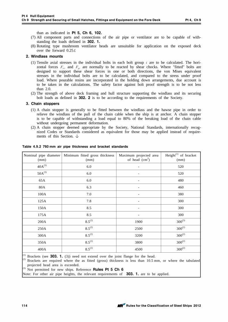
Pt 4 Hull Equipment
Ch 9 Strength and Securing of Small Hatches, Fittings and Equipment on the Fore Deck Pt 4, Ch 9
114 Rules for the Classification of Steel Ships 2012
than as indicated in Pt 5, Ch 6, 102.(7) All component parts and connections of the air pipe or ventilator are to be capable of with-
standing the loads defined in 302. 1.(8) Rotating type mushroom ventilator heads are unsuitable for application on the exposed deck
over the forward 0.252. Windlass mounts
(1) Tensile axial stresses in the individual bolts in each bolt group are to be calculated. The hori-zontal forces and are normally to be reacted by shear chocks. Where "fitted" bolts are designed to support these shear forces in one or both directions, the von Mises equivalent stresses in the individual bolts are to be calculated, and compared to the stress under proof load. Where pourable resins are incorporated in the holding down arrangements, due account is to be taken in the calculations. The safety factor against bolt proof strength is to be not less than 2.0.
(2) The strength of above deck framing and hull structure supporting the windlass and its securing bolt loads as defined in 302. 2 is to be according to the requirements of the Society.
3. Chain stoppers
(1) A chain stopper is generally to be fitted between the windlass and the hawse pipe in order to relieve the windlass of the pull of the chain cable when the ship is at anchor. A chain stopper is to be capable of withstanding a load equal to 80% of the breaking load of the chain cable without undergoing permanent deformation.
(2) A chain stopper deemed appropriate by the Society, National Standards, internationally recog-nized Codes or Standards considered as equivalent for those may be applied instead of require-ments of this Section.
Nominal pipe diameter (mm)
Minimum fitted gross thickness (mm)
Maximum projected area of head (cm2)
Height(1) of bracket (mm)
40A(3) 6.0 - 520
50A(3) 6.0 - 520
65A 6.0 - 480
80A 6.3 - 460
100A 7.0 - 380
125A 7.8 - 300
150A 8.5 - 300
175A 8.5 - 300
200A 8.5(2) 1900 300(3)
250A 8.5(2) 2500 300(2)
300A 8.5(2) 3200 300(2)
350A 8.5(2) 3800 300(2)
400A 8.5(2) 4500 300(2)
(1) Brackets (see 303. 1. (3)) need not extend over the joint flange for the head.(2) Brackets are required where the as fitted (gross) thickness is less than 10.5 mm, or where the tabulated
projected head area is exceeded.(3) Not permitted for new ships. Reference Rules Pt 5 Ch 6Note: For other air pipe heights, the relevant requirements of 303. 1. are to be applied.
Table 4.9.2 760 mm air pipe thickness and bracket standards
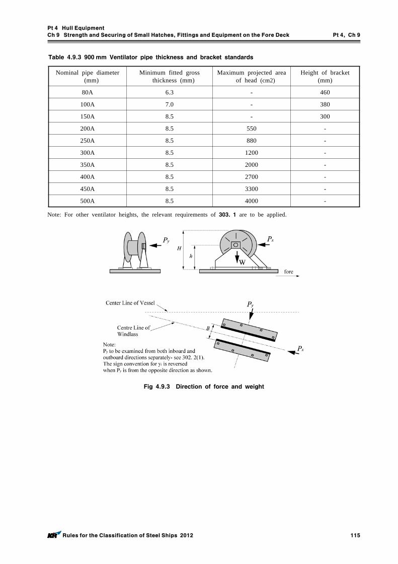
Pt 4 Hull Equipment
Ch 9 Strength and Securing of Small Hatches, Fittings and Equipment on the Fore Deck Pt 4, Ch 9
Rules for the Classification of Steel Ships 2012 115
Nominal pipe diameter (mm)
Minimum fitted gross thickness (mm)
Maximum projected area of head (cm2)
Height of bracket (mm)
80A 6.3 - 460
100A 7.0 - 380
150A 8.5 - 300
200A 8.5 550 -
250A 8.5 880 -
300A 8.5 1200 -
350A 8.5 2000 -
400A 8.5 2700 -
450A 8.5 3300 -
500A 8.5 4000 -
Table 4.9.3 900 mm Ventilator pipe thickness and bracket standards
Note: For other ventilator heights, the relevant requirements of 303. 1 are to be applied.
Fig 4.9.3 Direction of force and weight
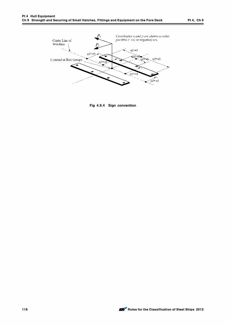
Pt 4 Hull Equipment
Ch 9 Strength and Securing of Small Hatches, Fittings and Equipment on the Fore Deck Pt 4, Ch 9
116 Rules for the Classification of Steel Ships 2012
Fig 4.9.4 Sign convention
Pt 4 Hull Equipment
Ch 10 Shipboard Equipment, Fittings and Supporting Hull Structures Associated with Towing and Mooring Pt 4, Ch 10
Rules for the Classification of Steel Ships 2012 117
CHAPTER 10 SHIPBOARD EQUIPMENT, FITTINGS AND SUPPORTING HULL STRUCTURES ASSOCIATED WITH
TOWING AND MOORING
Section 1 Definitions and Scope of Application
101. Application
1. This Chapter is to be applied to new displacement ships of 500GT and above, except high speed craft, special purpose vessels and offshore units, which were keeling after 1 Jan. 2007.
2. This Chapter is to be applied to shipboard fittings and supporting hull structures used for the nor-mal towing and mooring operations. For the emergency towing arrangements, ships subject to Ch 8, 205. are to comply with that regulation and Resolution MSC.35 (63) as may be amended.
3. The mooring equipment of single point moorings which fitted on ships such as oil tanker the deliv-ery of which is after 1 January 2009 are to be in accordance with the Guidance relating to the Rules specified by the Society.
102. Definitions
1. Shipboard fittings mean bollards and bitts, fairleads, stand rollers and chocks used for the normal mooring of the ship and similar components used for the normal towing of the ship.
2. Other components such as capstans, winches, etc. are not covered by this requirement.
3. Any weld or bolt or other fastening connecting the shipboard fitting to the supporting hull structure is part of the shipboard fitting and subject to the industry standard applicable to such fitting.
4. Supporting hull structures means that part of the ship structure on/in which the shipboard fitting is placed and which is directly submitted to the forces exerted on the shipboard fitting.
The net minimum scantlings of the supporting hull structure are to comply with the requirements given 201. 5 and 202. 5. The required gross thickness is obtained by adding the total corrosion additions given in 201. 6 and 202. 6. And the hull structure supporting capstans, winches, etc. used for the normal towing and mooring operations mentioned above should be also be subjected to this chapter.
5. Industry standard means international standard(ISO etc.) or standards issued by national associa-tion(KS, DIN, JMSA etc.) which are recognized in the country where the ship is built.
Section 2 Towing and Mooring
201. Towing
1. Strength
The strength of shipboard fittings used for normal towing operations at bow, sides and stern and their supporting hull structures are to comply with the requirements of this chapter.
2. Arrangement
Shipboard fittings for towing are to be located on longitudinals, beams and/or girders, which are part of the deck construction so as to facilitate efficient distribution of the towing load. Other equivalent arrangements may be accepted (for Panama chocks, etc.) provided the strength is con-firmed adequate for the intended service.
3. Load considerations
Shipboard fittings and supporting hull structures for towing are to be complied with the following requirements.
Pt 4 Hull Equipment
Ch 10 Shipboard Equipment, Fittings and Supporting Hull Structures Associated with Towing and Mooring Pt 4, Ch 10
118 Rules for the Classification of Steel Ships 2012
(1) Unless greater safe working load (SWL) of shipboard fittings is specified, the minimum design load to be used is the following value of (A) or (B), whichever is applicable. (A) For normal towing operation (e.g. harbour/manoeuvring)
1.25 times the intended maximum towing load (e.g. static bollard pull) as indicated on the towing and mooring arrangement plan.
(B) For other towing service (e.g. escort)The normal breaking strength of the tow line based on the equipment number. Side pro-jected area including maximum stacks of deck cargoes is to be taken into account for calcu-lation of equipment number.
(2) The design load should be applied through the tow line according to the arrangements shown on the towing and mooring arrangements plan, the method of application of the design load to the fittings and supporting hull structure should be taken into account such that the total load need not be more than twice the design load specified in (A), (B), i.e. no more than one turn of one line. (See Fig 4.10.1)
(3) When a specific SWL is applied for a shipboard fitting at the request of the applicant, by which the design load will be greater than the above minimum values, the strength of the fit-ting is to be designed using this specific design load.
4. Shipboard fittings
The selection of shipboard fittings is to be made by the shipyard in accordance with an Industry standard (e.g. ISO 3913: 1977 Shipbuilding-Welded steel bollards) accepted by the society. When the shipboard fitting is not selected from an accepted Industry standard, the design load used to as-sess its strength and its attachment to the ship should be in accordance with 3.
5. Supporting hull structure
(1) Arrangement Arrangement of the reinforced members (carling) beneath shipboard fittings should consider any
variation of direction (laterally and vertically) of the towing forces (which should be not less than the design load as per 3.) acting through the arrangement of connection to the shipboard fittings.
(2) Acting point of towing forceThe acting point of towing force on shipboard fittings should be taken at the attachment point of a towing line or at a change in its direction.
(3) Allowable stressesAllowable stresses under the design load conditions are as follows, and no stress concentration factors being taken into account. Normal stress : 100 % of the specified minimum yield point of the material;
Shearing stress : 60 % of the specified minimum yield point of the material;6. Corrosion addition of supporting hull structures
The scantling of supporting hull structures is not to be less than the value of net thickness plus the following values (1) through (3).(1) For bulk carriers specified in Pt. 11, corrosion addition specified in Pt 11, Ch 3, Sec 3(2) For double hull oil tankers specified in Pt. 12, corrosion addition specified in Pt 12, Ch 6, Sec 3
(3) For other ships, the value will be considered by the Society, but not to be less than 2 mm.7. Safe Working Load (SWL)
(1) The SWL used for nomal towing operations (harbour/manoeuvring) should not exceed 80 % of the design load as given in 3 (1) and the SWL used for other towing operations (e.g. escort) should not exceed the design load as given in 3 (2).
For fittings used for both harbour and escort purposes, the greater of the design loads of 3 (1) and 3 (2) should be used.
(2) The SWL of each shipboard fitting should be marked (by weld bead or equivalent) on the deck fittings used for towing.
(3) The above provisions on SWL apply for a single post basis (no more than one turn of one line).
(4) The towing and mooring arrangements plan described in 203. should define the method of use of towing lines.
Pt 4 Hull Equipment
Ch 10 Shipboard Equipment, Fittings and Supporting Hull Structures Associated with Towing and Mooring Pt 4, Ch 10
Rules for the Classification of Steel Ships 2012 119
202. Mooring
1. Strength
The strength of shipboard fittings used for mooring operations and their supporting hull structures are to comply with the requirement of this Chapter.
2. Arrangements
Shipboard fittings for mooring should be located on longitudinals, beams and/or girders, which are part of the deck construction so as to facilitate efficient distribution of the mooring load. Other equivalent arrangements may be accepted (for Panama chocks, etc.) provided the strength is con-firmed adequate for the service.
3. Load considerations
Shipboard fittings and supporting hull structures for mooring are to be complied with the following requirements. (1) Unless greater safe working load(SWL) of shipboard fittings is specified, the design load applied
to shipboard fittings and supporting hull structures should be 1.25 times the breaking strength of the mooring line based on the equipment number.Side projected area including maximum stacks of deck cargoes is to be taken into account for calculation of equipment number.
(2) According to the requirements of Ch 8, 204. 8, above (1) breaking strength may be reduced with corresponding increase of number of the mooring lines. But the number of mooring lines is not to be less than 6 and no one line is to have a strength less than 490 kN.
(3) The design load applied to supporting hull structures for winches, etc. is to be 1.25 times the intended maximum brake holding load and, for capstans, 1.25 times the maximum hauling force.
(4) The design load should be applied through the mooring line according to the arrangement shown on the towing and mooring arrangement plan. The method of application of the design load to the fittings and supporting hull structures should be taken into account such that the to-tal load need not be more than twice the design load specified in (1), i.e. no more than one line. (See Fig 4.10.1)
(5) When a specific SWL is applied for a shipboard fitting at the request of the applicant, by which the design load will be greater than the above minimum values, the strength of the fit-ting is to be designed using this specific design load.
4. Shipboard fittings
The selection of shipboard fittings is in accordance with 201. 4.
5. Supporting hull structures
(1) Arrangements Arrangement of the reinforced members (carling) beneath shipboard fittings should consider any variation of direction (laterally and vertically) of the towing forces (which should be not less than the Design Load as per 3.) acting through the arrangement of connection to the shipboard fittings.
(2) Acting point of mooring forceThe acting point of the mooring force on shipboard fittings should be taken at the attachment point of a mooring line or a change in its direction.
(3) Allowable stresses Allowable stresses under the design load conditions are as follows, and no stress concentration
factors being taken into account. Normal stress : 100 % of the specified minimum yield point of the material;
Shearing stress : 60 % of the specified minimum yield point of the material;6. Corrosion addition of supporting hull structures
Corrosion addition are to be followed 201. 6.
7. Safe working load (SWL)
(1) The SWL should not exceed 80 % of the design load given in 3. (2) The SWL of each shipboard fitting should be marked (by weld bead or equivalent) on the deck
fittings used for mooring.
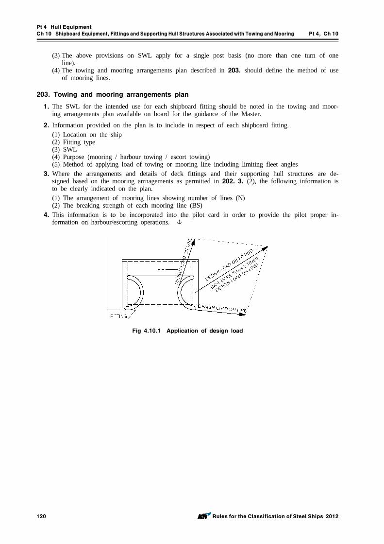
Pt 4 Hull Equipment
Ch 10 Shipboard Equipment, Fittings and Supporting Hull Structures Associated with Towing and Mooring Pt 4, Ch 10
120 Rules for the Classification of Steel Ships 2012
(3) The above provisions on SWL apply for a single post basis (no more than one turn of one line).
(4) The towing and mooring arrangements plan described in 203. should define the method of use of mooring lines.
203. Towing and mooring arrangements plan
1. The SWL for the intended use for each shipboard fitting should be noted in the towing and moor-ing arrangements plan available on board for the guidance of the Master.
2. Information provided on the plan is to include in respect of each shipboard fitting. (1) Location on the ship (2) Fitting type (3) SWL (4) Purpose (mooring / harbour towing / escort towing)(5) Method of applying load of towing or mooring line including limiting fleet angles
3. Where the arrangements and details of deck fittings and their supporting hull structures are de-signed based on the mooring arrnagements as permitted in 202. 3. (2), the following information is to be clearly indicated on the plan. (1) The arrangement of mooring lines showing number of lines (N)(2) The breaking strength of each mooring line (BS)
4. This information is to be incorporated into the pilot card in order to provide the pilot proper in-formation on harbour/escorting operations.
Fig 4.10.1 Application of design load
Pt 4 Hull Equipment
Ch 11 Access to and Within Spaces in, and Forward of, the Cargo Area of Oil Tankers and Bulk Carriers Pt 4, Ch 11
Rules for the Classification of Steel Ships 2012 121
CHAPTER 11 ACCESS TO AND WITHIN SPACES IN, AND FORWARD OF, THE CARGO AREA OF OIL TANKERS
AND BULK CARRIERS
Section 1 General
101. Application
1. This applies to oil tankers of 500 gross tonnage and over and bulk carriers, as defined in SOLAS Reg. II/1, of 20,000 gross tonnage and over, constructed on or after 1 January 2005.
2. This do not apply to the cargo tanks of combined chemical/oil tankers complying with the provi-sions of the IBC Code.
102. Means of access to cargo and other spaces
1. Each space shall be provided with means of access to enable, throughout the life of a ship, overall and close-up inspections and thickness measurements of the ship's structures to be carried out by this Society as necessary. Such means of access shall comply with the requirements of paragraph 105. and section 2.
2. Where a permanent means of access may be susceptible to damage during normal cargo loading and unloading operations or where it is impracticable to fit permanent means of access, this Society may allow, in lieu thereof, the provision of movable or portable means of access, as specified in the section 2, provided that the means of attaching, rigging, suspending or supporting the portable means of access forms a permanent part of the ship's structure. All portable equipment shall be ca-pable of being readily erected or deployed by ship's personnel.
3. The construction and materials of all means of access and their attachment to the ship’s structure shall be to the satisfaction of this Society. The means of access shall be subject to survey prior to, or in conjunction with, its use in carrying out surveys in accordance with SOLAS I/10.
103. Safe access to cargo holds, cargo tanks, ballast tanks and other spaces
1. Safe access to cargo holds, cofferdams, ballast tanks, cargo tanks and other spaces in the cargo area shall be direct from the open deck and such as to ensure their complete inspection. Safe ac-cess to double bottom spaces or to foreward ballast tanks may be from a pump-room, deep coffer-dam, pipe tunnel, cargo hold, double hull space or similar compartment not intended for the car-riage of oil or hazardous cargoes.
2. Tanks, and subdivisions of tanks, having a length of 35 m or more, shall be fitted with at least two access hatchways and ladders, as far apart as practicable. Tanks less than 35 m in length shall be served by at least one access hatchway and ladder. When a tank is subdivided by one or more swash bulkheads or similar obstructions which do not allow ready means of access to the other parts of the tank, at least two hatchways and ladders shall be fitted.
3. Each cargo hold shall be provided with at least two means of access as far apart as practicable. In general, these accesses should be arranged diagonally, for example one access near the forward bulkhead on the port side, the other one near the aft bulkhead on the starboard side.
104. Ship structure access manual
1. A ship's means of access to carry out overall and close-up inspections and thickness measurements shall be described in a Ship structure access manual approved by this Society, an updated copy of which shall be kept on board. The Ship structure access manual shall include the following for each space ;(1) plans showing the means of access to the space, with appropriate technical specifications and di-
mensions (2) plans showing the means of access within each space to enable an overall inspection to be car-
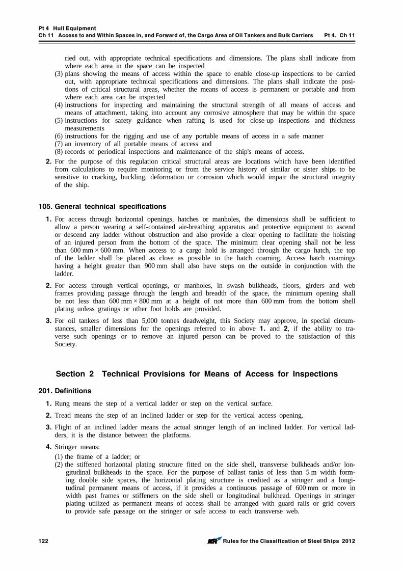
Pt 4 Hull Equipment
Ch 11 Access to and Within Spaces in, and Forward of, the Cargo Area of Oil Tankers and Bulk Carriers Pt 4, Ch 11
122 Rules for the Classification of Steel Ships 2012
ried out, with appropriate technical specifications and dimensions. The plans shall indicate from where each area in the space can be inspected
(3) plans showing the means of access within the space to enable close-up inspections to be carried out, with appropriate technical specifications and dimensions. The plans shall indicate the posi-tions of critical structural areas, whether the means of access is permanent or portable and from where each area can be inspected
(4) instructions for inspecting and maintaining the structural strength of all means of access and means of attachment, taking into account any corrosive atmosphere that may be within the space
(5) instructions for safety guidance when rafting is used for close-up inspections and thickness measurements
(6) instructions for the rigging and use of any portable means of access in a safe manner(7) an inventory of all portable means of access and(8) records of periodical inspections and maintenance of the ship's means of access.
2. For the purpose of this regulation critical structural areas are locations which have been identified from calculations to require monitoring or from the service history of similar or sister ships to be sensitive to cracking, buckling, deformation or corrosion which would impair the structural integrity of the ship.
105. General technical specifications
1. For access through horizontal openings, hatches or manholes, the dimensions shall be sufficient to allow a person wearing a self-contained air-breathing apparatus and protective equipment to ascend or descend any ladder without obstruction and also provide a clear opening to facilitate the hoisting of an injured person from the bottom of the space. The minimum clear opening shall not be less than 600 mm × 600 mm. When access to a cargo hold is arranged through the cargo hatch, the top of the ladder shall be placed as close as possible to the hatch coaming. Access hatch coamings having a height greater than 900 mm shall also have steps on the outside in conjunction with the ladder.
2. For access through vertical openings, or manholes, in swash bulkheads, floors, girders and web frames providing passage through the length and breadth of the space, the minimum opening shall be not less than 600 mm × 800 mm at a height of not more than 600 mm from the bottom shell plating unless gratings or other foot holds are provided.
3. For oil tankers of less than 5,000 tonnes deadweight, this Society may approve, in special circum-stances, smaller dimensions for the openings referred to in above 1. and 2, if the ability to tra-verse such openings or to remove an injured person can be proved to the satisfaction of this Society.
Section 2 Technical Provisions for Means of Access for Inspections
201. Definitions
1. Rung means the step of a vertical ladder or step on the vertical surface.
2. Tread means the step of an inclined ladder or step for the vertical access opening.
3. Flight of an inclined ladder means the actual stringer length of an inclined ladder. For vertical lad-ders, it is the distance between the platforms.
4. Stringer means:(1) the frame of a ladder; or(2) the stiffened horizontal plating structure fitted on the side shell, transverse bulkheads and/or lon-
gitudinal bulkheads in the space. For the purpose of ballast tanks of less than 5 m width form-ing double side spaces, the horizontal plating structure is credited as a stringer and a longi-tudinal permanent means of access, if it provides a continuous passage of 600 mm or more in width past frames or stiffeners on the side shell or longitudinal bulkhead. Openings in stringer plating utilized as permanent means of access shall be arranged with guard rails or grid covers to provide safe passage on the stringer or safe access to each transverse web.
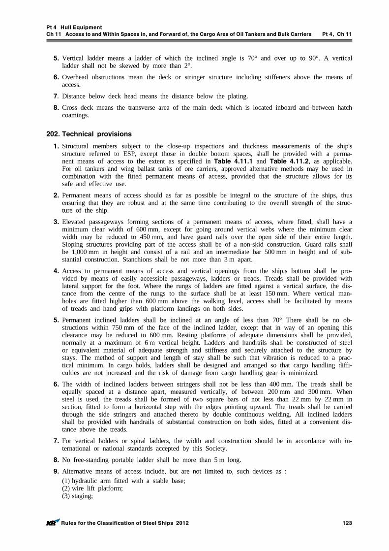
Pt 4 Hull Equipment
Ch 11 Access to and Within Spaces in, and Forward of, the Cargo Area of Oil Tankers and Bulk Carriers Pt 4, Ch 11
Rules for the Classification of Steel Ships 2012 123
5. Vertical ladder means a ladder of which the inclined angle is 70° and over up to 90°. A vertical ladder shall not be skewed by more than 2°.
6. Overhead obstructions mean the deck or stringer structure including stiffeners above the means of access.
7. Distance below deck head means the distance below the plating.
8. Cross deck means the transverse area of the main deck which is located inboard and between hatch coamings.
202. Technical provisions
1. Structural members subject to the close-up inspections and thickness measurements of the ship's structure referred to ESP, except those in double bottom spaces, shall be provided with a perma-nent means of access to the extent as specified in Table 4.11.1 and Table 4.11.2, as applicable. For oil tankers and wing ballast tanks of ore carriers, approved alternative methods may be used in combination with the fitted permanent means of access, provided that the structure allows for its safe and effective use.
2. Permanent means of access should as far as possible be integral to the structure of the ships, thus ensuring that they are robust and at the same time contributing to the overall strength of the struc-ture of the ship.
3. Elevated passageways forming sections of a permanent means of access, where fitted, shall have a minimum clear width of 600 mm, except for going around vertical webs where the minimum clear width may be reduced to 450 mm, and have guard rails over the open side of their entire length. Sloping structures providing part of the access shall be of a non-skid construction. Guard rails shall be 1,000 mm in height and consist of a rail and an intermediate bar 500 mm in height and of sub-stantial construction. Stanchions shall be not more than 3 m apart.
4. Access to permanent means of access and vertical openings from the ship.s bottom shall be pro-vided by means of easily accessible passageways, ladders or treads. Treads shall be provided with lateral support for the foot. Where the rungs of ladders are fitted against a vertical surface, the dis-tance from the centre of the rungs to the surface shall be at least 150 mm. Where vertical man-holes are fitted higher than 600 mm above the walking level, access shall be facilitated by means of treads and hand grips with platform landings on both sides.
5. Permanent inclined ladders shall be inclined at an angle of less than 70° There shall be no ob-structions within 750 mm of the face of the inclined ladder, except that in way of an opening this clearance may be reduced to 600 mm. Resting platforms of adequate dimensions shall be provided, normally at a maximum of 6 m vertical height. Ladders and handrails shall be constructed of steel or equivalent material of adequate strength and stiffness and securely attached to the structure by stays. The method of support and length of stay shall be such that vibration is reduced to a prac-tical minimum. In cargo holds, ladders shall be designed and arranged so that cargo handling diffi-culties are not increased and the risk of damage from cargo handling gear is minimized.
6. The width of inclined ladders between stringers shall not be less than 400 mm. The treads shall be equally spaced at a distance apart, measured vertically, of between 200 mm and 300 mm. When steel is used, the treads shall be formed of two square bars of not less than 22 mm by 22 mm in section, fitted to form a horizontal step with the edges pointing upward. The treads shall be carried through the side stringers and attached thereto by double continuous welding. All inclined ladders shall be provided with handrails of substantial construction on both sides, fitted at a convenient dis-tance above the treads.
7. For vertical ladders or spiral ladders, the width and construction should be in accordance with in-ternational or national standards accepted by this Society.
8. No free-standing portable ladder shall be more than 5 m long.
9. Alternative means of access include, but are not limited to, such devices as :(1) hydraulic arm fitted with a stable base;(2) wire lift platform;(3) staging;
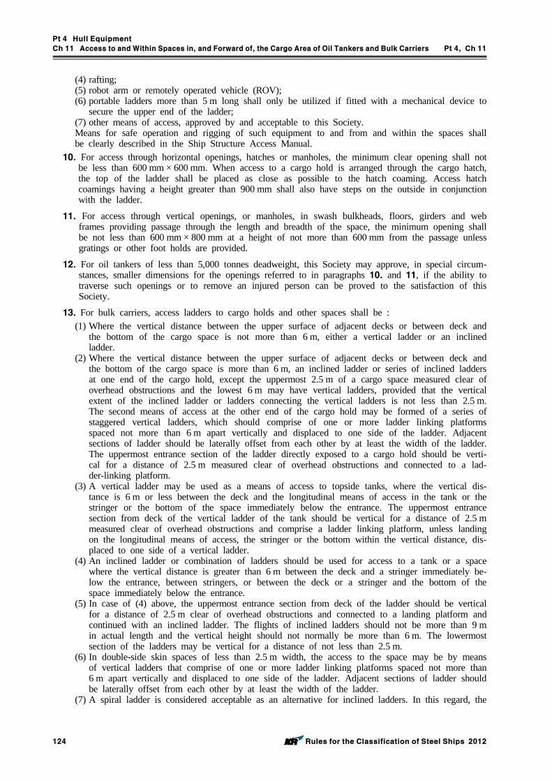
Pt 4 Hull Equipment
Ch 11 Access to and Within Spaces in, and Forward of, the Cargo Area of Oil Tankers and Bulk Carriers Pt 4, Ch 11
124 Rules for the Classification of Steel Ships 2012
(4) rafting;(5) robot arm or remotely operated vehicle (ROV);(6) portable ladders more than 5 m long shall only be utilized if fitted with a mechanical device to
secure the upper end of the ladder; (7) other means of access, approved by and acceptable to this Society. Means for safe operation and rigging of such equipment to and from and within the spaces shall be clearly described in the Ship Structure Access Manual.
10. For access through horizontal openings, hatches or manholes, the minimum clear opening shall not be less than 600 mm × 600 mm. When access to a cargo hold is arranged through the cargo hatch, the top of the ladder shall be placed as close as possible to the hatch coaming. Access hatch coamings having a height greater than 900 mm shall also have steps on the outside in conjunction with the ladder.
11. For access through vertical openings, or manholes, in swash bulkheads, floors, girders and web frames providing passage through the length and breadth of the space, the minimum opening shall be not less than 600 mm × 800 mm at a height of not more than 600 mm from the passage unless gratings or other foot holds are provided.
12. For oil tankers of less than 5,000 tonnes deadweight, this Society may approve, in special circum-stances, smaller dimensions for the openings referred to in paragraphs 10. and 11, if the ability to traverse such openings or to remove an injured person can be proved to the satisfaction of this Society.
13. For bulk carriers, access ladders to cargo holds and other spaces shall be :(1) Where the vertical distance between the upper surface of adjacent decks or between deck and
the bottom of the cargo space is not more than 6 m, either a vertical ladder or an inclined ladder.
(2) Where the vertical distance between the upper surface of adjacent decks or between deck and the bottom of the cargo space is more than 6 m, an inclined ladder or series of inclined ladders at one end of the cargo hold, except the uppermost 2.5 m of a cargo space measured clear of overhead obstructions and the lowest 6 m may have vertical ladders, provided that the vertical extent of the inclined ladder or ladders connecting the vertical ladders is not less than 2.5 m. The second means of access at the other end of the cargo hold may be formed of a series of staggered vertical ladders, which should comprise of one or more ladder linking platforms spaced not more than 6 m apart vertically and displaced to one side of the ladder. Adjacent sections of ladder should be laterally offset from each other by at least the width of the ladder. The uppermost entrance section of the ladder directly exposed to a cargo hold should be verti-cal for a distance of 2.5 m measured clear of overhead obstructions and connected to a lad-der-linking platform.
(3) A vertical ladder may be used as a means of access to topside tanks, where the vertical dis-tance is 6 m or less between the deck and the longitudinal means of access in the tank or the stringer or the bottom of the space immediately below the entrance. The uppermost entrance section from deck of the vertical ladder of the tank should be vertical for a distance of 2.5 m measured clear of overhead obstructions and comprise a ladder linking platform, unless landing on the longitudinal means of access, the stringer or the bottom within the vertical distance, dis-placed to one side of a vertical ladder.
(4) An inclined ladder or combination of ladders should be used for access to a tank or a space where the vertical distance is greater than 6 m between the deck and a stringer immediately be-low the entrance, between stringers, or between the deck or a stringer and the bottom of the space immediately below the entrance.
(5) In case of (4) above, the uppermost entrance section from deck of the ladder should be vertical for a distance of 2.5 m clear of overhead obstructions and connected to a landing platform and continued with an inclined ladder. The flights of inclined ladders should not be more than 9 m in actual length and the vertical height should not normally be more than 6 m. The lowermost section of the ladders may be vertical for a distance of not less than 2.5 m.
(6) In double-side skin spaces of less than 2.5 m width, the access to the space may be by means of vertical ladders that comprise of one or more ladder linking platforms spaced not more than 6 m apart vertically and displaced to one side of the ladder. Adjacent sections of ladder should be laterally offset from each other by at least the width of the ladder.
(7) A spiral ladder is considered acceptable as an alternative for inclined ladders. In this regard, the

Pt 4 Hull Equipment
Ch 11 Access to and Within Spaces in, and Forward of, the Cargo Area of Oil Tankers and Bulk Carriers Pt 4, Ch 11
Rules for the Classification of Steel Ships 2012 125
uppermost 2.5 m can continue to be comprised of the spiral ladder and need not change over to vertical ladders.
14. The uppermost entrance section from deck of the vertical ladder providing access to a tank should be vertical for a distance of 2.5 m measured clear of overhead obstructions and comprise a ladder linking platform, displaced to one side of a vertical ladder. The vertical ladder can be between 1.6m and 3 m below deck structure if it lands on a longitudinal or athwartship permanent means of access fitted within that range.
203. Protective coating
Permanent means of access in dedicated seawater ballast tanks in all types of ships and double-side skin spaces of bulk carriers shall be coated in accordance with the Guidance relating to the Rules specified by the Society.
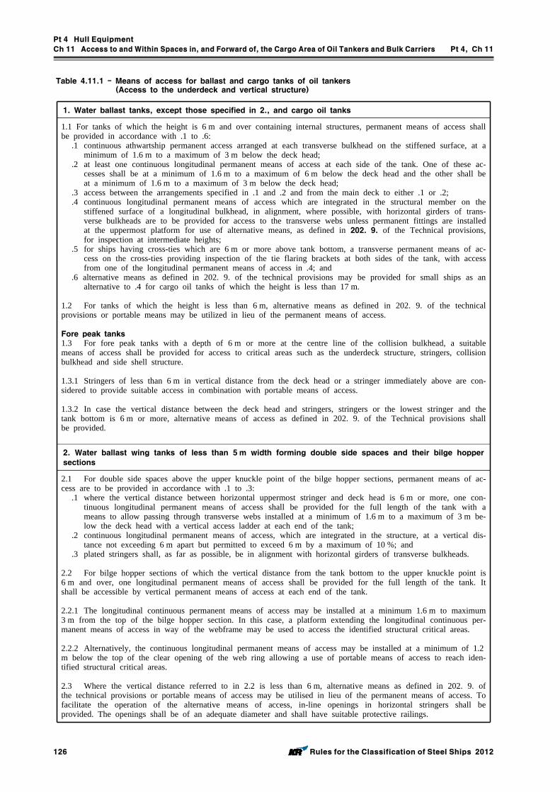
Pt 4 Hull Equipment
Ch 11 Access to and Within Spaces in, and Forward of, the Cargo Area of Oil Tankers and Bulk Carriers Pt 4, Ch 11
126 Rules for the Classification of Steel Ships 2012
1. Water ballast tanks, except those specified in 2., and cargo oil tanks
1.1 For tanks of which the height is 6 m and over containing internal structures, permanent means of access shall be provided in accordance with .1 to .6:
.1 continuous athwartship permanent access arranged at each transverse bulkhead on the stiffened surface, at a minimum of 1.6 m to a maximum of 3 m below the deck head;
.2 at least one continuous longitudinal permanent means of access at each side of the tank. One of these ac-cesses shall be at a minimum of 1.6 m to a maximum of 6 m below the deck head and the other shall be at a minimum of 1.6 m to a maximum of 3 m below the deck head;
.3 access between the arrangements specified in .1 and .2 and from the main deck to either .1 or .2;
.4 continuous longitudinal permanent means of access which are integrated in the structural member on the stiffened surface of a longitudinal bulkhead, in alignment, where possible, with horizontal girders of trans-verse bulkheads are to be provided for access to the transverse webs unless permanent fittings are installed at the uppermost platform for use of alternative means, as defined in 202. 9. of the Technical provisions, for inspection at intermediate heights;
.5 for ships having cross-ties which are 6 m or more above tank bottom, a transverse permanent means of ac-cess on the cross-ties providing inspection of the tie flaring brackets at both sides of the tank, with access from one of the longitudinal permanent means of access in .4; and
.6 alternative means as defined in 202. 9. of the technical provisions may be provided for small ships as an alternative to .4 for cargo oil tanks of which the height is less than 17 m.
1.2 For tanks of which the height is less than 6 m, alternative means as defined in 202. 9. of the technical provisions or portable means may be utilized in lieu of the permanent means of access.
Fore peak tanks1.3 For fore peak tanks with a depth of 6 m or more at the centre line of the collision bulkhead, a suitable means of access shall be provided for access to critical areas such as the underdeck structure, stringers, collision bulkhead and side shell structure.
1.3.1 Stringers of less than 6 m in vertical distance from the deck head or a stringer immediately above are con-sidered to provide suitable access in combination with portable means of access.
1.3.2 In case the vertical distance between the deck head and stringers, stringers or the lowest stringer and the tank bottom is 6 m or more, alternative means of access as defined in 202. 9. of the Technical provisions shall be provided.
2. Water ballast wing tanks of less than 5m width forming double side spaces and their bilge hopper sections
2.1 For double side spaces above the upper knuckle point of the bilge hopper sections, permanent means of ac-cess are to be provided in accordance with .1 to .3:
.1 where the vertical distance between horizontal uppermost stringer and deck head is 6 m or more, one con-tinuous longitudinal permanent means of access shall be provided for the full length of the tank with a means to allow passing through transverse webs installed at a minimum of 1.6 m to a maximum of 3 m be-low the deck head with a vertical access ladder at each end of the tank;
.2 continuous longitudinal permanent means of access, which are integrated in the structure, at a vertical dis-tance not exceeding 6 m apart but permitted to exceed 6 m by a maximum of 10 %; and
.3 plated stringers shall, as far as possible, be in alignment with horizontal girders of transverse bulkheads.
2.2 For bilge hopper sections of which the vertical distance from the tank bottom to the upper knuckle point is 6 m and over, one longitudinal permanent means of access shall be provided for the full length of the tank. It shall be accessible by vertical permanent means of access at each end of the tank.
2.2.1 The longitudinal continuous permanent means of access may be installed at a minimum 1.6 m to maximum 3 m from the top of the bilge hopper section. In this case, a platform extending the longitudinal continuous per-manent means of access in way of the webframe may be used to access the identified structural critical areas.
2.2.2 Alternatively, the continuous longitudinal permanent means of access may be installed at a minimum of 1.2m below the top of the clear opening of the web ring allowing a use of portable means of access to reach iden-tified structural critical areas.
2.3 Where the vertical distance referred to in 2.2 is less than 6 m, alternative means as defined in 202. 9. of the technical provisions or portable means of access may be utilised in lieu of the permanent means of access. To facilitate the operation of the alternative means of access, in-line openings in horizontal stringers shall be provided. The openings shall be of an adequate diameter and shall have suitable protective railings.
Table 4.11.1 - Means of access for ballast and cargo tanks of oil tankers (Access to the underdeck and vertical structure)
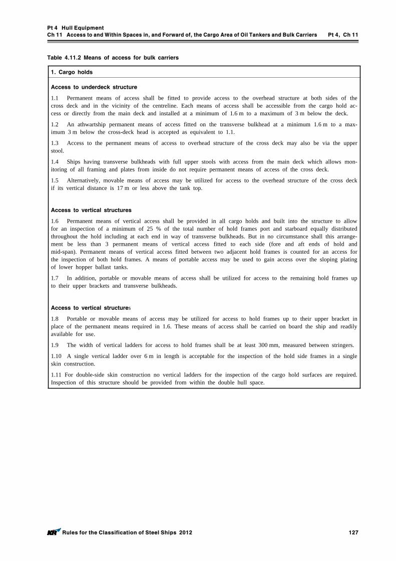
Pt 4 Hull Equipment
Ch 11 Access to and Within Spaces in, and Forward of, the Cargo Area of Oil Tankers and Bulk Carriers Pt 4, Ch 11
Rules for the Classification of Steel Ships 2012 127
1. Cargo holds
Access to underdeck structure
1.1 Permanent means of access shall be fitted to provide access to the overhead structure at both sides of the cross deck and in the vicinity of the centreline. Each means of access shall be accessible from the cargo hold ac-cess or directly from the main deck and installed at a minimum of 1.6 m to a maximum of 3 m below the deck.
1.2 An athwartship permanent means of access fitted on the transverse bulkhead at a minimum 1.6 m to a max-imum 3 m below the cross-deck head is accepted as equivalent to 1.1.
1.3 Access to the permanent means of access to overhead structure of the cross deck may also be via the upper stool.
1.4 Ships having transverse bulkheads with full upper stools with access from the main deck which allows mon-itoring of all framing and plates from inside do not require permanent means of access of the cross deck.
1.5 Alternatively, movable means of access may be utilized for access to the overhead structure of the cross deck if its vertical distance is 17 m or less above the tank top.
Access to vertical structures
1.6 Permanent means of vertical access shall be provided in all cargo holds and built into the structure to allow for an inspection of a minimum of 25 % of the total number of hold frames port and starboard equally distributed throughout the hold including at each end in way of transverse bulkheads. But in no circumstance shall this arrange-ment be less than 3 permanent means of vertical access fitted to each side (fore and aft ends of hold and mid-span). Permanent means of vertical access fitted between two adjacent hold frames is counted for an access for the inspection of both hold frames. A means of portable access may be used to gain access over the sloping plating of lower hopper ballast tanks.
1.7 In addition, portable or movable means of access shall be utilized for access to the remaining hold frames up to their upper brackets and transverse bulkheads.
Access to vertical structures
1.8 Portable or movable means of access may be utilized for access to hold frames up to their upper bracket in place of the permanent means required in 1.6. These means of access shall be carried on board the ship and readily available for use.
1.9 The width of vertical ladders for access to hold frames shall be at least 300 mm, measured between stringers.
1.10 A single vertical ladder over 6 m in length is acceptable for the inspection of the hold side frames in a single skin construction.
1.11 For double-side skin construction no vertical ladders for the inspection of the cargo hold surfaces are required. Inspection of this structure should be provided from within the double hull space.
Table 4.11.2 Means of access for bulk carriers
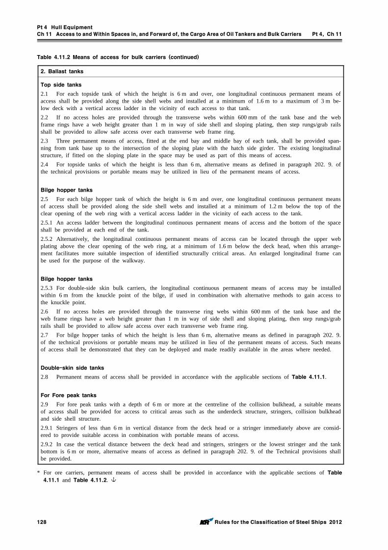
Pt 4 Hull Equipment
Ch 11 Access to and Within Spaces in, and Forward of, the Cargo Area of Oil Tankers and Bulk Carriers Pt 4, Ch 11
128 Rules for the Classification of Steel Ships 2012
2. Ballast tanks
Top side tanks
2.1 For each topside tank of which the height is 6 m and over, one longitudinal continuous permanent means of access shall be provided along the side shell webs and installed at a minimum of 1.6 m to a maximum of 3 m be-low deck with a vertical access ladder in the vicinity of each access to that tank. 2.2 If no access holes are provided through the transverse webs within 600 mm of the tank base and the web frame rings have a web height greater than 1 m in way of side shell and sloping plating, then step rungs/grab rails shall be provided to allow safe access over each transverse web frame ring. 2.3 Three permanent means of access, fitted at the end bay and middle bay of each tank, shall be provided span-ning from tank base up to the intersection of the sloping plate with the hatch side girder. The existing longitudinal structure, if fitted on the sloping plate in the space may be used as part of this means of access. 2.4 For topside tanks of which the height is less than 6 m, alternative means as defined in paragraph 202. 9. of the technical provisions or portable means may be utilized in lieu of the permanent means of access.
Bilge hopper tanks
2.5 For each bilge hopper tank of which the height is 6 m and over, one longitudinal continuous permanent means of access shall be provided along the side shell webs and installed at a minimum of 1.2 m below the top of the clear opening of the web ring with a vertical access ladder in the vicinity of each access to the tank. 2.5.1 An access ladder between the longitudinal continuous permanent means of access and the bottom of the space shall be provided at each end of the tank. 2.5.2 Alternatively, the longitudinal continuous permanent means of access can be located through the upper web plating above the clear opening of the web ring, at a minimum of 1.6 m below the deck head, when this arrange-ment facilitates more suitable inspection of identified structurally critical areas. An enlarged longitudinal frame can be used for the purpose of the walkway.
Bilge hopper tanks
2.5.3 For double-side skin bulk carriers, the longitudinal continuous permanent means of access may be installed within 6 m from the knuckle point of the bilge, if used in combination with alternative methods to gain access to the knuckle point. 2.6 If no access holes are provided through the transverse ring webs within 600 mm of the tank base and the web frame rings have a web height greater than 1 m in way of side shell and sloping plating, then step rungs/grab rails shall be provided to allow safe access over each transverse web frame ring. 2.7 For bilge hopper tanks of which the height is less than 6 m, alternative means as defined in paragraph 202. 9. of the technical provisions or portable means may be utilized in lieu of the permanent means of access. Such means of access shall be demonstrated that they can be deployed and made readily available in the areas where needed.
Double-skin side tanks 2.8 Permanent means of access shall be provided in accordance with the applicable sections of Table 4.11.1.
For Fore peak tanks
2.9 For fore peak tanks with a depth of 6 m or more at the centreline of the collision bulkhead, a suitable means of access shall be provided for access to critical areas such as the underdeck structure, stringers, collision bulkhead and side shell structure. 2.9.1 Stringers of less than 6 m in vertical distance from the deck head or a stringer immediately above are consid-ered to provide suitable access in combination with portable means of access. 2.9.2 In case the vertical distance between the deck head and stringers, stringers or the lowest stringer and the tank bottom is 6 m or more, alternative means of access as defined in paragraph 202. 9. of the Technical provisions shall be provided.
Table 4.11.2 Means of access for bulk carriers (continued)
* For ore carriers, permanent means of access shall be provided in accordance with the applicable sections of Table 4.11.1 and Table 4.11.2.
2012
Guidance Relating to the Rules for the Classification of Steel Ships
Part 4
Hull Equipment
GA-04-E KOREAN REGISTER OF SHIPPING

APPLICATION OF THE GUIDANCE
This "Guidance Relating to the Rules for the Classification of Steel Ships" (hereafter called as the Guidance) is prepared with the intent of giving guidelines as to the treatment of the various provisions for items required the unified interpretations and items not specified in details in the Rules, and the requirements specified in the Guidance are to be ap-plied, in principle, in addition to the various provisions in the Rules.As to any technical modifications which can be regarded as equivalent to any requirements in the Guidance, their flexible application will be prop-erly considered.
- i -
APPLICATION OF PART 4 "HULL EQUIPMENT"
1. Unless expressly specified otherwise, the requirements in the Guidance apply to ships for which contracts for construction are signed on or after 1 July 2012.
2. The amendments to the Guidance for 2011 edition and their effective date are as follows;
Effective Date : 1 July 2012
Chapter 4 BULWARKS, FREEING PORTS, SIDE SCUTTLES, RECTANGULAR
WINDOWS, VENTILATORS AND PERMANENT GANGWAYS
Section 1 Bulwarks and Guardrails
- 101. 2 has been newly added.
Section 2 Freeing Ports
- 202. 8 has been newly added.
Section 3 Side Scuttles, Rectangular Windows and Skylights
- Words have been amended.- 303. 2 has been newly added.- Table 4.4.1 and Table 4.4.2 have been newly added.
Section 4 Ventilators
- 402. has been newly added.
Chapter 11 ACCESS TO AND WITHIN SPACES IN, AND FORWARD OF, THE
CARGO AREA OF OIL TANKERS AND BULK CARRIERS
Section 1 General
- 102. 1 has been newly added.
Section 2 Technical Provisions for Means of Access for Inspections
- 202. 2 (2) has been amended.- 202. 5 (1) has been amended.- 202. 8 has been amended.
Annex 4-2 Means of Access for Ballast and Cargo Tanks of Oil Tankers
- 1.1.4 has been amended.
Annex 4-3 Means of Access for Bulk Carriers
- 1.8 has been newly added.- 2.5.2 has been amended.
- iii -
CONTENTS
CHAPTER 1 RUDDERS ·····································································································1
Section 1 General ················································································································· 1
101. Application ···················································································································· 1102. Materials ························································································································ 2
Section 4 Rudder Strength Calculation ··········································································· 2
401. Rudder strength calculation ·························································································· 2
Section 5 Rudder Stocks ···································································································· 8
501. Upper stocks ················································································································· 8
Section 6 Rudder Plates, Rudder Frames and Rudder Main Pieces ···················· 8
603. Rudder main pieces ······································································································ 8605. Connections ··················································································································· 8
Section 7 Couplings between Rudder Stocks and Main Pieces ····························· 9
701. Horizontal flange coupling ··························································································· 9702. Vertical flange couplings ····························································································· 9703. Cone coupling ··············································································································· 9704. Coupling flange ·········································································································· 11
Section 8 Pintles ················································································································· 11
802. Construction of pintles ······························································································· 11
Section 9 Bearings of Rudders Stock and Pintles ···················································· 12
901. Minimum bearing surface ·························································································· 12902. Bearing clearances ······································································································ 12
Section 10 Rudder Accessories ······················································································ 12
1001. Rudder carriers ········································································································· 121002. Jumping stoppers ······································································································ 13
CHAPTER 2 HATCHWAYS AND OTHER DECK OPENINGS ···························15
Section 1 General ··············································································································· 15
101. Application ·················································································································· 15102. Position of exposed deck openings ··········································································· 15
Section 2 Arrangements ···································································································· 15
201. Height of hatchway coamings ··················································································· 15202. Hatch covers ··············································································································· 15
Section 4 Load Model ········································································································ 18
401. Lateral pressure and concentrated loads ··································································· 18
Section 5 Strength Check ································································································· 19
501. General ························································································································ 19
- iv -
Section 6 Hatch Coamings ······························································································· 21
602. Load models ··············································································································· 21
Section 7 Weathertightness, Closing Arrangement, Securing Devices and
Stopper ··············································································································· 22
702. Gaskets ························································································································ 22703. Closing arrangement, securing device and stoppers ················································· 22
Section 8 Additional Requirements ················································································ 23
801. Portable beam ············································································································· 23
Section 10 Miscellaneous Openings ·············································································· 23
1001. Companionways ········································································································ 23
CHAPTER 3 BOW DOORS, SIDE AND STERN DOORS ···································25
Section 1 Bow Doors and Inner Doors ········································································ 25
101. General ························································································································ 25
Section 2 Side Shell Doors and Stern Doors ····························································· 25
201. General ························································································································ 25
CHAPTER 4 BULWARKS, FREEING PORTS, SIDE SCUTTLES,
RECTANGULAR WINDOWS, SKYLIGHTS, VENTILATORS
AND PERMANENT GANGWAYS ························································27
Section 1 Bulwarks and Guardrails ················································································ 27
101. Arrangements ·············································································································· 27106. Guardrails ···················································································································· 27
Section 2 Freeing Ports ···································································································· 28
201. General ························································································································ 28202. Freeing port area ········································································································ 28204. Arrangement of freeing ports ···················································································· 29205. Structure ······················································································································ 29
Section 3 Side Scuttles, Rectangular Windows and Skylights ······························· 30
301. General application ····································································································· 30303. Application of side scuttle ························································································· 30305. Design pressure and maximum allowable pressure of side scuttle ························ 32307. Application of rectangular window ··········································································· 32
Section 4 Ventilators ·········································································································· 32
402. Height of coamings ···································································································· 32
Section 5 Permanent Gangways ····················································································· 33
501. General ························································································································ 33
- v -
CHAPTER 7 CEMENTING AND PAINTING ·····························································37
Section 2 Painting ··············································································································· 37
201. General ························································································································ 37
CHAPTER 8 EQUIPMENT NUMBER AND EQUIPMENT ·····································39
Section 1 General ··············································································································· 39
101. General and application ····························································································· 39
Section 2 Equipment Number ·························································································· 39
201. Equipment number ······································································································ 39203. Chain cables and stream lines ·················································································· 42
Section 3 Anchors ··············································································································· 43
304. Constructions and dimensions ···················································································· 43
Section 4 Chains ················································································································· 43
401. Application ·················································································································· 43409. Dimensions and forms ······························································································· 54412. Breaking test of chains ······························································································ 54
Section 5 Steel Wire Ropes ····························································································· 54
506. Rope test ····················································································································· 54
Section 7 Hatch Tarpaulins ······························································································ 55
701. Application ·················································································································· 55
CHAPTER 9 STRENGTH AND SECURING OF SMALL HATCHES,
FITTINGS AND EQUIPMENT ON THE FORE DECK ·················57
Section 2 Strength and Securing of Small Hatches on the Exposed Fore Deck ······ 57
201. General ························································································································ 57
CHAPTER 10 SHIPBOARD EQUIPMENT, FITTINGS AND SUPPORTING
HULL STRUCTURES ASSOCIATED WITH TOWING AND
MOORING ···································································································59
Section 1 Definitions and Scope of Application ························································· 59
101. Application ·················································································································· 59
Section 2 Towing and Mooring ······················································································· 63
204. Survey after construction ··························································································· 63
CHAPTER 11 ACCESS TO AND WIHIN SPACES IN, AND FORWARD OF,
THE CARGO AREA OF OIL TANKERS AND
BULK CARRIERS ····················································································65
Section 1 General ··············································································································· 65
101. Application ·················································································································· 65
- vi -
102. Means of access to cargo and other spaces ···························································· 65103. Safe access to cargo holds, cargo tanks, ballast tanks and other spaces ············· 66104. Ship structure access manual ····················································································· 66105. General technical specifications ················································································· 67
Section 2 Technical Provisions for Means of Access for Inspections ················ 68
201. Definitions ··················································································································· 68202. Technical provisions ··································································································· 70203. Corrosion protection ··································································································· 76
<ANNEX>
Annex 4-1 Cone Couplings of Rudder Stocks and Rudder Main Pieces ············ 77
Annex 4-2 Means of Access for Ballast and Cargo Tanks of Oil Tankers ········ 79
Annex 4-3 Means of Access for Bulk Carriers ···························································· 83
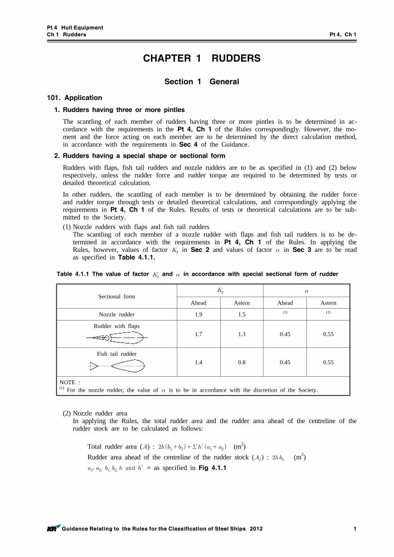
Pt 4 Hull Equipment
Ch 1 Rudders Pt 4, Ch 1
Guidance Relating to the Rules for the Classification of Steel Ships 2012 1
CHAPTER 1 RUDDERS
Section 1 General
101. Application
1. Rudders having three or more pintles
The scantling of each member of rudders having three or more pintles is to be determined in ac-cordance with the requirements in the Pt 4, Ch 1 of the Rules correspondingly. However, the mo-ment and the force acting on each member are to be determined by the direct calculation method, in accordance with the requirements in Sec 4 of the Guidance.
2. Rudders having a special shape or sectional form
Rudders with flaps, fish tail rudders and nozzle rudders are to be as specified in (1) and (2) below respectively, unless the rudder force and rudder torque are required to be determined by tests or detailed theoretical calculation.
In other rudders, the scantling of each member is to be determined by obtaining the rudder force and rudder torque through tests or detailed theoretical calculations, and correspondingly applying the requirements in Pt 4, Ch 1 of the Rules. Results of tests or theoretical calculations are to be sub-mitted to the Society.(1) Nozzle rudders with flaps and fish tail rudders
The scantling of each member of a nozzle rudder with flaps and fish tail rudders is to be de-termined in accordance with the requirements in Pt 4, Ch 1 of the Rules. In applying the Rules, however, values of factor in Sec 2 and values of factor in Sec 3 are to be read as specified in Table 4.1.1.
Sectional form
Ahead Astern Ahead Astern
Nozzle rudder 1.9 1.5 (1) (1)
Rudder with flaps1.7 1.3 0.45 0.55
Fish tail rudder1.4 0.8 0.45 0.55
NOTE :(1) For the nozzle rudder, the value of is to be in accordance with the discretion of the Society.
Table 4.1.1 The value of factor and in accordance with special sectional form of rudder
(2) Nozzle rudder areaIn applying the Rules, the total rudder area and the rudder area ahead of the centreline of the rudder stock are to be calculated as follows:
Total rudder area () : ′ (m2)Rudder area ahead of the centreline of the rudder stock () : (m2) and ′ = as specified in Fig 4.1.1
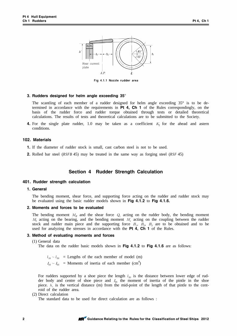
Pt 4 Hull Equipment
Ch 1 Rudders Pt 4, Ch 1
2 Guidance Relating to the Rules for the Classification of Steel Ships 2012
3. Rudders designed for helm angle exceeding 35°
The scantling of each member of a rudder designed for helm angle exceeding 35° is to be de-termined in accordance with the requirements in Pt 4, Ch 1 of the Rules correspondingly, on the basis of the rudder force and rudder torque obtained through tests or detailed theoretical calculations. The results of tests and theoretical calculations are to be submitted to the Society.
4. For the single plate rudder, 1.0 may be taken as a coefficient for the ahead and astern conditions.
102. Materials
1. If the diameter of rudder stock is small, cast carbon steel is not to be used.
2. Rolled bar steel (RSFB 45) may be treated in the same way as forging steel (RSF 45)
Section 4 Rudder Strength Calculation
401. Rudder strength calculation
1. General
The bending moment, shear force, and supporting force acting on the rudder and rudder stock may be evaluated using the basic rudder models shown in Fig 4.1.2 to Fig 4.1.6.
2. Moments and forces to be evaluated
The bending moment and the shear force acting on the rudder body, the bending moment acting on the bearing, and the bending moment acting on the coupling between the rudder stock and rudder main piece and the supporting force , , are to be obtained and to be used for analyzing the stresses in accordance with the Pt 4, Ch 1 of the Rules.
3. Method of evaluating moments and forces
(1) General dataThe data on the rudder basic models shown in Fig 4.1.2 to Fig 4.1.6 are as follows:
∼ = Lengths of the each member of model (m)∼ = Moments of inertia of each member (cm4)
For rudders supported by a shoe piece the length is the distance between lower edge of rud-der body and centre of shoe piece and the moment of inertia of the pintle in the shoe piece. is the vertical distance (m) from the mid-point of the length of that pintle to the cent-roid of the rudder area.
(2) Direct calculationThe standard data to be used for direct calculation are as follows :
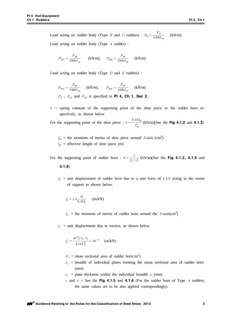
Pt 4 Hull Equipment
Ch 1 Rudders Pt 4, Ch 1
Guidance Relating to the Rules for the Classification of Steel Ships 2012 3
Load acting on rudder body (Type and rudders) : (kN/m)
Load acting on rudder body (Type rudder) :
(kN/m), (kN/m)
Load acting on rudder body (Type and rudders) :
(kN/m), (kN/m)
, and is specified in Pt 4, Ch 1, Sec 2.
= spring constant of the supporting point of the shoe piece or the rudder horn re-spectively, as shown below
For the supporting point of the shoe piece :
(kN/m)(See the Fig 4.1.2 and 4.1.3)
= the moments of inertia of shoe piece around -axis (cm4) = effective length of shoe piece (m)
For the supporting point of rudder horn : (kN/m)(See the Fig 4.1.2, 4.1.5 and
4.1.6)
= unit displacement of rudder horn due to a unit force of 1 acting in the centre of support as shown below.
(m/kN)
= the moments of inertia of rudder horn around the -axis(cm4)
= unit displacement due to torsion, as shown below
× (m/kN)
= mean sectional area of rudder horn (m2) = breadth of individual plates forming the mean sectional area of rudder horn
(mm) = plate thickness within the individual breadth (mm) and = See the Fig 4.1.5 and 4.1.6 (For the rudder horn of Type rudders,
the same values are to be also applied correspondingly)
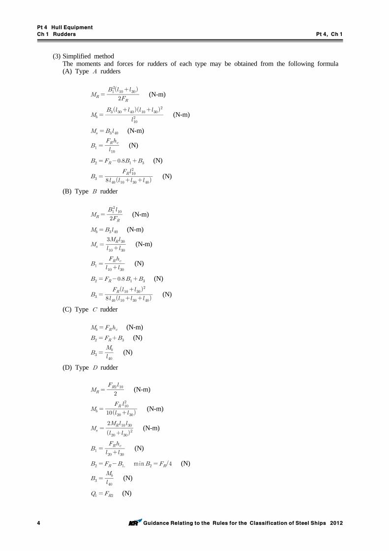
Pt 4 Hull Equipment
Ch 1 Rudders Pt 4, Ch 1
4 Guidance Relating to the Rules for the Classification of Steel Ships 2012
(3) Simplified methodThe moments and forces for rudders of each type may be obtained from the following formula(A) Type rudders
(N-m)
(N-m)
(N-m)
(N)
(N)
(N)
(B) Type rudder
(N-m)
(N-m)
(N-m)
(N)
(N)
(N)
(C) Type rudder
(N-m) (N)
(N)
(D) Type rudder
(N-m)
(N-m)
(N-m)
(N)
min (N)
(N)
(N)
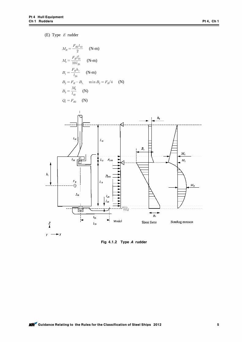
Pt 4 Hull Equipment
Ch 1 Rudders Pt 4, Ch 1
Guidance Relating to the Rules for the Classification of Steel Ships 2012 5
(E) Type rudder
(N-m)
(N-m)
(N-m)
min (N)
(N)
(N)
Fig 4.1.2 Type A rudder
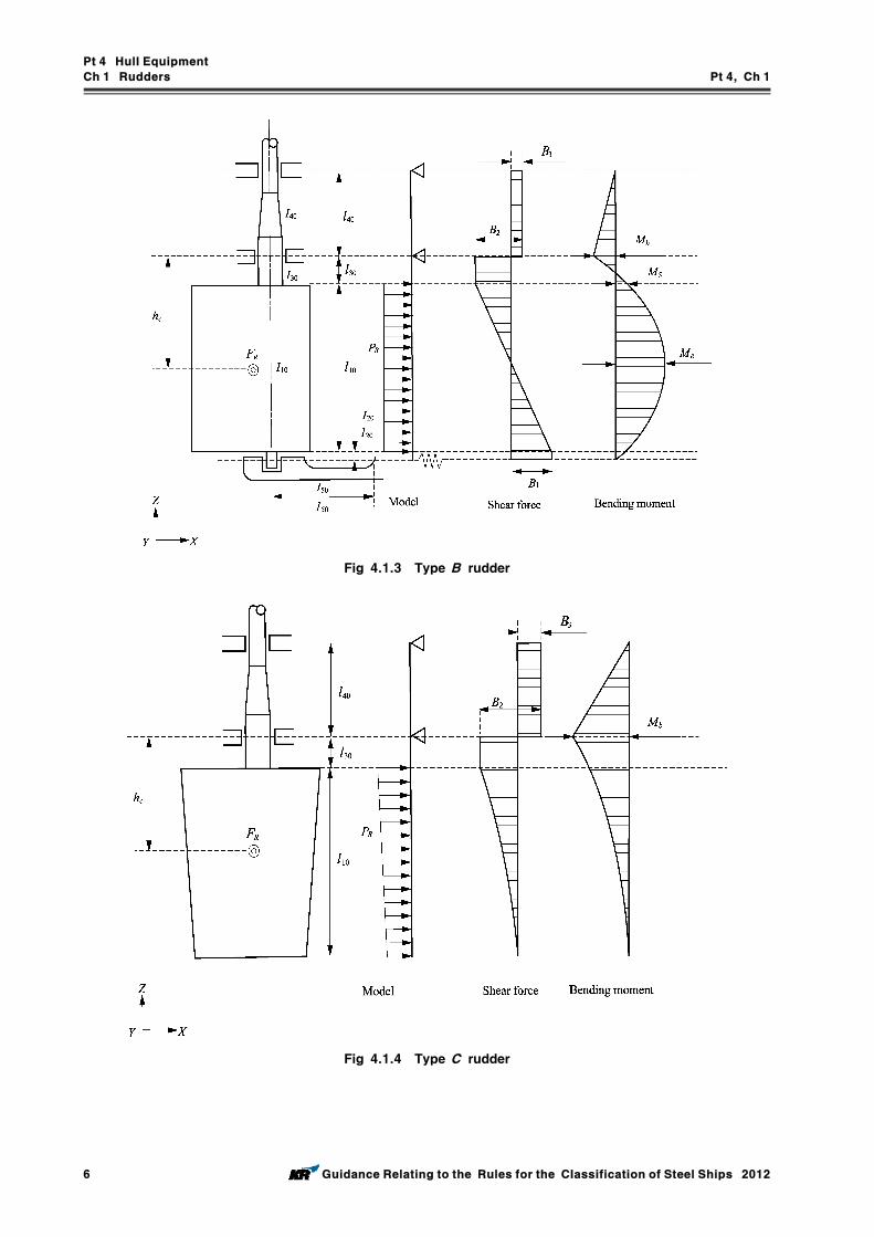
Pt 4 Hull Equipment
Ch 1 Rudders Pt 4, Ch 1
6 Guidance Relating to the Rules for the Classification of Steel Ships 2012
Fig 4.1.3 Type B rudder
Fig 4.1.4 Type C rudder
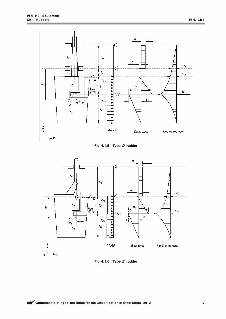
Pt 4 Hull Equipment
Ch 1 Rudders Pt 4, Ch 1
Guidance Relating to the Rules for the Classification of Steel Ships 2012 7
Fig 4.1.5 Type D rudder
Fig 4.1.6 Type E rudder
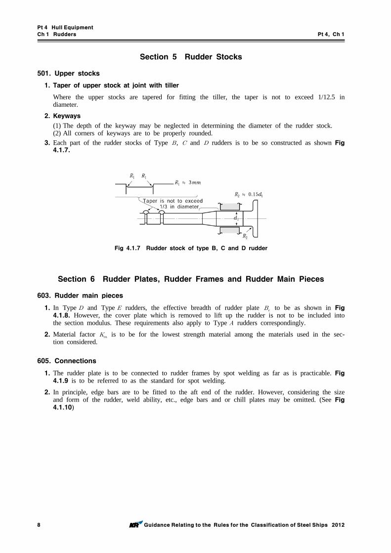
Pt 4 Hull Equipment
Ch 1 Rudders Pt 4, Ch 1
8 Guidance Relating to the Rules for the Classification of Steel Ships 2012
Section 5 Rudder Stocks
501. Upper stocks
1. Taper of upper stock at joint with tiller
Where the upper stocks are tapered for fitting the tiller, the taper is not to exceed 1/12.5 in diameter.
2. Keyways
(1) The depth of the keyway may be neglected in determining the diameter of the rudder stock.(2) All corners of keyways are to be properly rounded.
3. Each part of the rudder stocks of Type , and rudders is to be so constructed as shown Fig 4.1.7.
Fig 4.1.7 Rudder stock of type B, C and D rudder
Section 6 Rudder Plates, Rudder Frames and Rudder Main Pieces
603. Rudder main pieces
1. In Type and Type rudders, the effective breadth of rudder plate to be as shown in Fig 4.1.8. However, the cover plate which is removed to lift up the rudder is not to be included into the section modulus. These requirements also apply to Type rudders correspondingly.
2. Material factor is to be for the lowest strength material among the materials used in the sec-tion considered.
605. Connections
1. The rudder plate is to be connected to rudder frames by spot welding as far as is practicable. Fig 4.1.9 is to be referred to as the standard for spot welding.
2. In principle, edge bars are to be fitted to the aft end of the rudder. However, considering the size and form of the rudder, weld ability, etc., edge bars and or chill plates may be omitted. (See Fig 4.1.10)
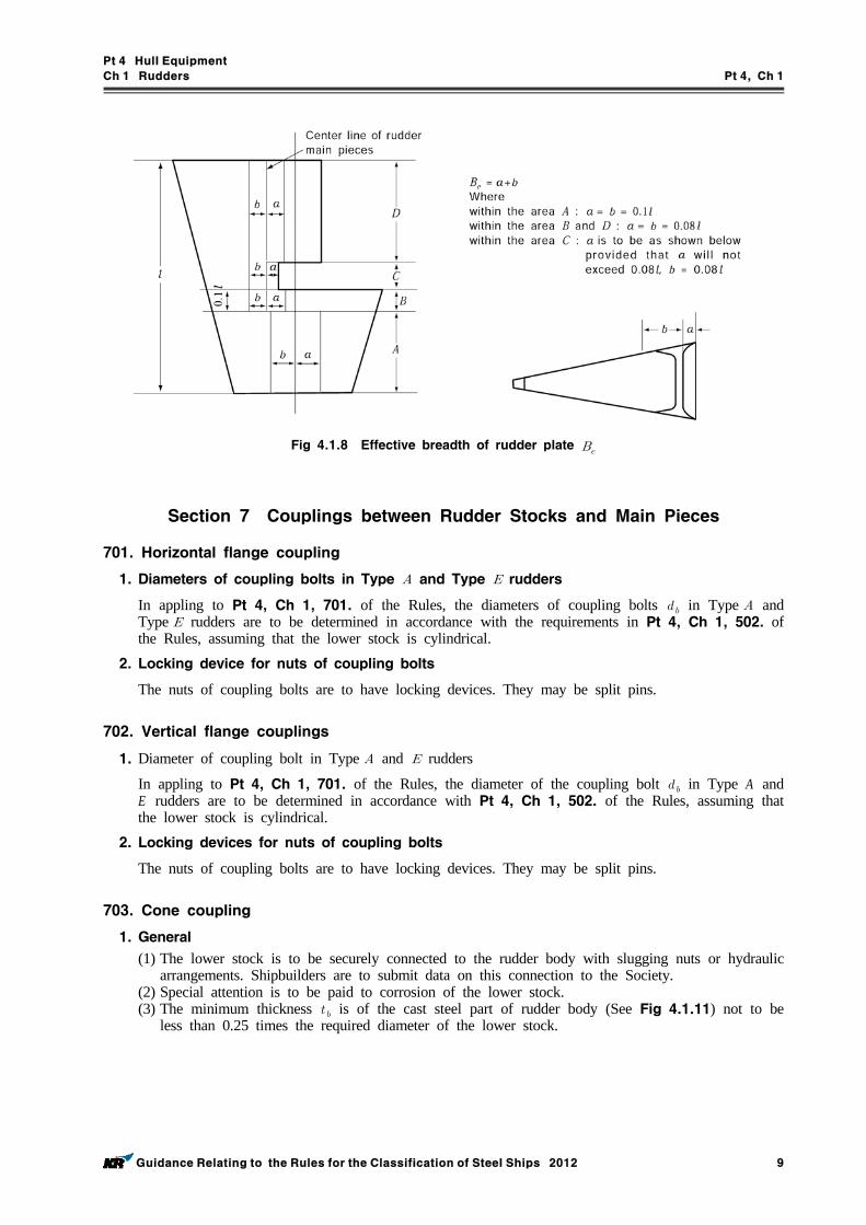
Pt 4 Hull Equipment
Ch 1 Rudders Pt 4, Ch 1
Guidance Relating to the Rules for the Classification of Steel Ships 2012 9
Fig 4.1.8 Effective breadth of rudder plate
Section 7 Couplings between Rudder Stocks and Main Pieces
701. Horizontal flange coupling
1. Diameters of coupling bolts in Type and Type rudders
In appling to Pt 4, Ch 1, 701. of the Rules, the diameters of coupling bolts in Type and Type rudders are to be determined in accordance with the requirements in Pt 4, Ch 1, 502. of the Rules, assuming that the lower stock is cylindrical.
2. Locking device for nuts of coupling bolts
The nuts of coupling bolts are to have locking devices. They may be split pins.
702. Vertical flange couplings
1. Diameter of coupling bolt in Type and rudders
In appling to Pt 4, Ch 1, 701. of the Rules, the diameter of the coupling bolt in Type A and E rudders are to be determined in accordance with Pt 4, Ch 1, 502. of the Rules, assuming that the lower stock is cylindrical.
2. Locking devices for nuts of coupling bolts
The nuts of coupling bolts are to have locking devices. They may be split pins.
703. Cone coupling
1. General
(1) The lower stock is to be securely connected to the rudder body with slugging nuts or hydraulic arrangements. Shipbuilders are to submit data on this connection to the Society.
(2) Special attention is to be paid to corrosion of the lower stock.(3) The minimum thickness is of the cast steel part of rudder body (See Fig 4.1.11) not to be
less than 0.25 times the required diameter of the lower stock.
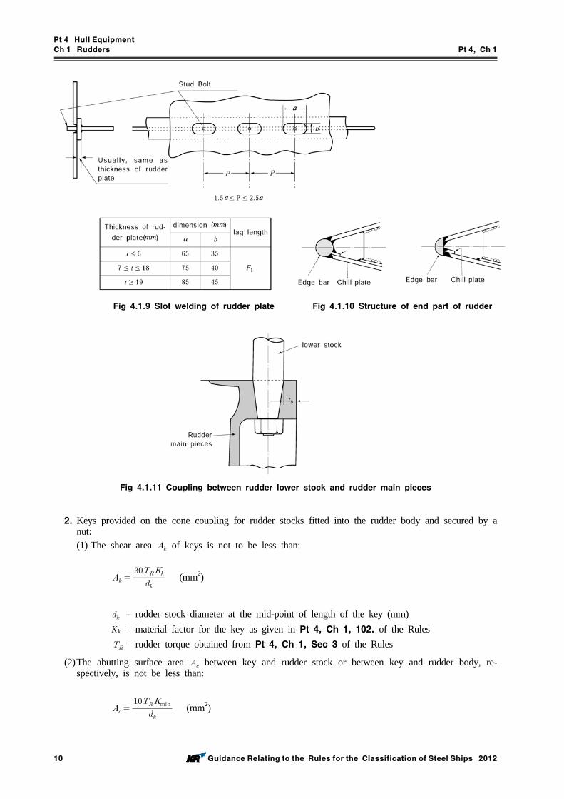
Pt 4 Hull Equipment
Ch 1 Rudders Pt 4, Ch 1
10 Guidance Relating to the Rules for the Classification of Steel Ships 2012
Fig 4.1.9 Slot welding of rudder plate Fig 4.1.10 Structure of end part of rudder
Fig 4.1.11 Coupling between rudder lower stock and rudder main pieces
2. Keys provided on the cone coupling for rudder stocks fitted into the rudder body and secured by a nut:(1) The shear area of keys is not to be less than:
(mm2)
= rudder stock diameter at the mid-point of length of the key (mm)K k = material factor for the key as given in Pt 4, Ch 1, 102. of the Rules = rudder torque obtained from Pt 4, Ch 1, Sec 3 of the Rules
(2)The abutting surface area between key and rudder stock or between key and rudder body, re-spectively, is not be less than:
min (mm2)
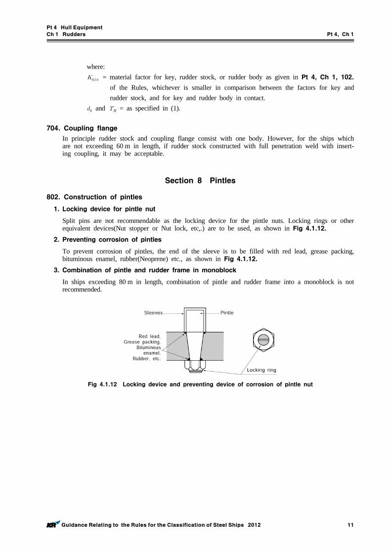
Pt 4 Hull Equipment
Ch 1 Rudders Pt 4, Ch 1
Guidance Relating to the Rules for the Classification of Steel Ships 2012 11
where:min = material factor for key, rudder stock, or rudder body as given in Pt 4, Ch 1, 102.
of the Rules, whichever is smaller in comparison between the factors for key and rudder stock, and for key and rudder body in contact.
and = as specified in (1).
704. Coupling flange
In principle rudder stock and coupling flange consist with one body. However, for the ships which are not exceeding 60 m in length, if rudder stock constructed with full penetration weld with insert-ing coupling, it may be acceptable.
Section 8 Pintles
802. Construction of pintles
1. Locking device for pintle nut
Split pins are not recommendable as the locking device for the pintle nuts. Locking rings or other equivalent devices(Nut stopper or Nut lock, etc,.) are to be used, as shown in Fig 4.1.12.
2. Preventing corrosion of pintles
To prevent corrosion of pintles, the end of the sleeve is to be filled with red lead, grease packing, bituminous enamel, rubber(Neoprene) etc., as shown in Fig 4.1.12.
3. Combination of pintle and rudder frame in monoblock
In ships exceeding 80 m in length, combination of pintle and rudder frame into a monoblock is not recommended.
Fig 4.1.12 Locking device and preventing device of corrosion of pintle nut
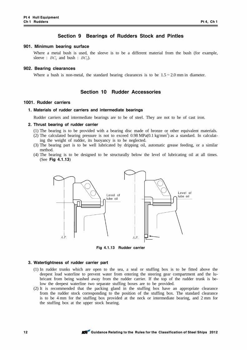
Pt 4 Hull Equipment
Ch 1 Rudders Pt 4, Ch 1
12 Guidance Relating to the Rules for the Classification of Steel Ships 2012
Section 9 Bearings of Rudders Stock and Pintles
901. Minimum bearing surface
Where a metal bush is used, the sleeve is to be a different material from the bush (for example, sleeve : and bush : ).
902. Bearing clearances
Where a bush is non-metal, the standard bearing clearances is to be 1.5 ~ 2.0 mm in diameter.
Section 10 Rudder Accessories
1001. Rudder carriers
1. Materials of rudder carriers and intermediate bearings
Rudder carriers and intermediate bearings are to be of steel. They are not to be of cast iron.2. Thrust bearing of rudder carrier
(1) The bearing is to be provided with a bearing disc made of bronze or other equivalent materials.(2) The calculated bearing pressure is not to exceed 0.98 MPa(0.1 kg/mm2) as a standard. In calculat-
ing the weight of rudder, its buoyancy is to be neglected.(3) The bearing part is to be well lubricated by dripping oil, automatic grease feeding, or a similar
method.(4) The bearing is to be designed to be structurally below the level of lubricating oil at all times.
(See Fig 4.1.13)
Fig 4.1.13 Rudder carrier
3. Watertightness of rudder carrier part
(1) In rudder trunks which are open to the sea, a seal or stuffing box is to be fitted above the deepest load waterline to prevent water from entering the steering gear compartment and the lu-bricant from being washed away from the rudder carrier. If the top of the rudder trunk is be-low the deepest waterline two separate stuffing boxes are to be provided.
(2) It is recommended that the packing gland in the stuffing box have an appropriate clearance from the rudder stock corresponding to the position of the stuffing box. The standard clearance is to be 4 mm for the stuffing box provided at the neck or intermediate bearing, and 2 mm for the stuffing box at the upper stock bearing.
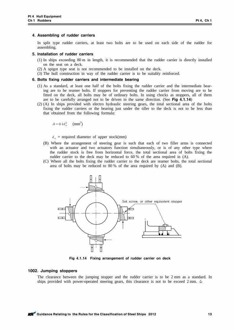
Pt 4 Hull Equipment
Ch 1 Rudders Pt 4, Ch 1
Guidance Relating to the Rules for the Classification of Steel Ships 2012 13
4. Assembling of rudder carriers
In split type rudder carriers, at least two bolts are to be used on each side of the rudder for assembling.
5. Installation of rudder carriers
(1) In ships exceeding 80 m in length, it is recommended that the rudder carrier is directly installed on the seat on a deck.
(2) A spigot type seat is not recommended to be installed on the deck.(3) The hull construction in way of the rudder carrier is to be suitably reinforced.
6. Bolts fixing rudder carriers and intermediate bearing
(1) As a standard, at least one half of the bolts fixing the rudder carrier and the intermediate bear-ing are to be reamer bolts. If stoppers for preventing the rudder carrier from moving are to be fitted on the deck, all bolts may be of ordinary bolts. In using chocks as stoppers, all of them are to be carefully arranged not to be driven in the same direction. (See Fig 4.1.14)
(2) (A) In ships provided with electro hydraulic steering gears, the total sectional area of the bolts fixing the rudder carriers or the bearing just under the tiller to the deck is not to be less than that obtained from the following formula:
(mm2)
= required diameter of upper stock(mm)(B) Where the arrangement of steering gear is such that each of two filler arms is connected
with an actuator and two actuators function simultaneously, or is of any other type where the rudder stock is free from horizontal force, the total sectional area of bolts fixing the rudder carrier to the deck may be reduced to 60 % of the area required in (A).
(C) Where all the bolts fixing the rudder carrier to the deck are reamer bolts, the total sectional area of bolts may be reduced to 80 % of the area required by (A) and (B).
Fig 4.1.14 Fixing arrangement of rudder carrier on deck
1002. Jumping stoppers
The clearance between the jumping stopper and the rudder carrier is to be 2 mm as a standard. In ships provided with power-operated steering gears, this clearance is not to be exceed 2 mm.
Pt 4 Hull Equipment
Ch 2 Hatchways and Other Deck Openings Pt 4, Ch 2
Guidance Relating to the Rules for the Classification of Steel Ships 2012 15
CHAPTER 2 HATCHWAYS AND OTHER DECK OPENINGS
Section 1 General
101. Application
1. The regulation of 101.3 of the Rules is not to be applied to the vessel which engaged in domestic service only.
102. Position of exposed deck openings
1. Exposed superstructure deck of the Rules is in general exposed deck up to superstructure of second tier above freeboard deck. However, where actual deck height is less than standard height of super-structure(), it is to be of exposed deck of nearest superstructure from the point above freeboard deck by 2 .
2. Exposed deck of superstructure above the deck defined in 1. may be regarded as deckhouse or its exposed deck.
Section 2 Arrangements
201. Height of hatchway coamings
1. Where the openings of hatchways are comparatively small and weathertight steel hatch covers are provided with, height and thickness of their coamings are to be as follows.(1) Coamings height is to be not less than the value given in Table 4.2.1 according to the loca-
tion and opening area of the hatchways. (2) Thickness of coamings is to be not less than the value calculated in following formula.
m : (mm) ≧ m : (mm)
Table 4.2.1 Height of small hatchway coamings (mm)
Hatch Area (m2)
Position of Hatchway
Other type than stated in
column of right side
, Which are fitted with hinge type closing means capable of
opening and closing
Position I 450 mm 380 mm
Position II 380 mm 230 mm
2. Construction and scantlings of hatchway coamings for deep tanks are also to comply with the re-quirements of Ch 2 of the Rules as well as Pt 3, Ch 15 of the Rules.
202. Hatch covers
1. Steel hatchway covers provided on exposed upper deck in way of cargo holds used as deep water ballast tanks for bulk carrier, etc, and similar ones are to comply with the following requirements in addition Ch 2 of the Rules.(1) The thickness of top plating is not to be less than the obtained from the following formula.
However, in case of double plating type hatch covers, the plates actually loaded are only to comply with.
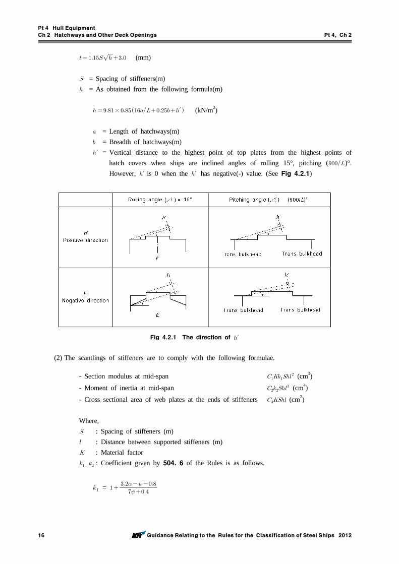
Pt 4 Hull Equipment
Ch 2 Hatchways and Other Deck Openings Pt 4, Ch 2
16 Guidance Relating to the Rules for the Classification of Steel Ships 2012
(mm)
= Spacing of stiffeners(m) = As obtained from the following formula(m)
×′ (kN/m2)
= Length of hatchways(m) = Breadth of hatchways(m)′ = Vertical distance to the highest point of top plates from the highest points of
hatch covers when ships are inclined angles of rolling 15°, pitching ()°. However, ′ is 0 when the ′ has negative(-) value. (See Fig 4.2.1)
Fig 4.2.1 The direction of ′
(2) The scantlings of stiffeners are to comply with the following formulae.
- Section modulus at mid-span (cm3)
- Moment of inertia at mid-span (cm4)
- Cross sectional area of web plates at the ends of stiffeners (cm2)
Where, : Spacing of stiffeners (m) : Distance between supported stiffeners (m) : Material factor : Coefficient given by 504. 6 of the Rules is as follows.
=
Pt 4 Hull Equipment
Ch 2 Hatchways and Other Deck Openings Pt 4, Ch 2
Guidance Relating to the Rules for the Classification of Steel Ships 2012 17
=
and : Coefficients given by Table 4.2.2 : As given by the following formulae according to the arranged direction of stiffeners,
and , , ′ are to be followed by (1)
- Transverse direction (in case hatch covers are opened/closed in the longitudinal direc-tion) × ′ (kN/m2)
- Longitudinal direction (in case hatch covers are opened/closed in the transverse direc-tion) × ′ (kN/m2)
1.07 1.81 0.064
Table 4.2.2 Coefficient
(3) Thickness and depth of web of girders are not to be less than 7 mm and /25. The girders are to be provided with tripping brackets at the intervals of about 3 m.
(4) The section modulus of stiffeners supported by girders and subjected to a uniformly distributed loads may be obtained from the direct strength calculations, or obtained from the following for-mulae in accordance with the type of covers as considered.
(cm3)
Where, and : As specified in the preceding (2) : Coefficient given below according to the type of end connections of stiffeners
In case of lug at both ends : 1.0 In case of snip at both ends or one end snip and another end lug : 1.5
2. Steel hatch covers in way of tanks loading cargo oil of flash point below 60 °C are to be paid enough attention in order to keep oil-tightness and air-tightness and to prevent occurring sparks due to striking of the surrounding metal fittings. And their gaskets are to be of materials certified as oilproof and fireproof by the relative standard.
3. In principle, double plating hatch covers are not to be used in way of oil tanks. However, if they are to be used, their construction is to be easily drained out and vented by air.
4. In this article sand carrier and dredger mean that the ships are be engaged in gathering, trans-porting, dredging or reclamation etc. for sand, soil, gravel etc. and are to be as follows(1) For the ship which operates in domestic-costal service area, the requirement for exemption of
hatchway covers of sand carrier and dredger is as follows.(A) Barge and Ship having hopper door
Ships which is fitted with a buoyancy tank in each side and hopper door in bottom should have sufficient reserved buoyancy and stability in assumed the worst flooded condition of cargo hold.
(B) Barge not having a hopper door
Pt 4 Hull Equipment
Ch 2 Hatchways and Other Deck Openings Pt 4, Ch 2
18 Guidance Relating to the Rules for the Classification of Steel Ships 2012
Barge which is fitted with a buoyancy tank in each side and operates within 20 nautical miles out of the Korean peninsula(excluding those intend to sail to Che-ju Island) should have sufficient reserved buoyancy and stability in assumed the worst flooded condition of cargo hold.
(C) For the exemption of hatchway cover installation, it should be met with the following con-ditions in assumed the worst flooded condition.(a) The upper deck side line should be not flooded(b) For self-propelled ship : ≥ m
For non self-propelled ship : ≥ m(where, = Breadth)
(2) For the ship which operates in international service area and is fitted with door or valve in bot-tom, the requirement for exemption of hatchway cover installation of sand carrier and dredger is as follows.(A) The intact stability is to be met with the requirement of Pt 1, Annex 1-2 of the Guidance.
In this case, the calculation is to include the homogeneous full load condition of cargo in each cargo hold loaded up to the top of the hatchway coaming.
(B) When the wetted cargo with the design bulk density of minimum 2.2 ton/m 3 is homoge-neously loaded to the assigned freeboard in each hold and assuming that the void space of the cargo hold above the cargo surface is filled with the sea water induced by the flooding, the stability of the above (A) is to be satisfied.
(C) The damage stability is to be met with SOLAS Ch. II-1, B-1(D) The doors or valves on bottom area are to be met with following requirements.
(a) The opening of the bottom dump doors should be effective in less than one(1) minute.(b) In the case of bottom door not to be opened by gravity, the opening should be possible
even after the main power source or the ram mechanism actuating the bottom dump doors have been put out of order. In this case, it should be possible to operate both systems from bridge, and the cargo releasing arrangements should be such that asymmetrical jettisoning of the cargo should not be possible even partially.
(E) Draft indicator is to be fitted on the bridge.(F) Where the additional requirements other than described above are necessary, the ship is to
be met with those requirements also.
Section 4 Load Model
401. Lateral pressure and concentrated loads
1. In addition to the above provisions, hatch covers for ships carrying deck cargoes are to be in ac-cordance with the following (1) to (5)(1) Hatch covers carrying deck cargo are to be effectively secured against the horizontal and verti-
cal forces arising from ship motion.(2) To prevent damage to hatch covers and ship structure, the location of stoppers is to be compat-
ible with the relative movements between hatch cover and ship structure. The number should be as small as practically possible.
(3) Hatchway coamings and supporting structure are to be adequately stiffened to accommodate the loading from hatch covers.
(4) It is to be designed for preventing excessive relative vertical deflection between loaded/ un-loaded panel.
(5) When the cargoes loaded on hatch covers of exposed parts and lower deck, the construction and scantlings are to be applied in the following requirements in addition to Ch 2 of the Rules.(A) The loading height, loading condition, etc, is to be clearly shown in the drawings for
approval. In case of loading freight containers, the kind of them and loading position are to be additionally described.
(B) Girders or stiffeners are to be provided for reinforcement beneath the corner fittings of freight containers.
(C) Top plates of hatch covers, upon which wheeled vehicles are loaded, are to comply with Pt 7, Ch 7 of the Rules.
(D) For the construction of hatch covers, stress and deflection of planed loading is to be calcu-
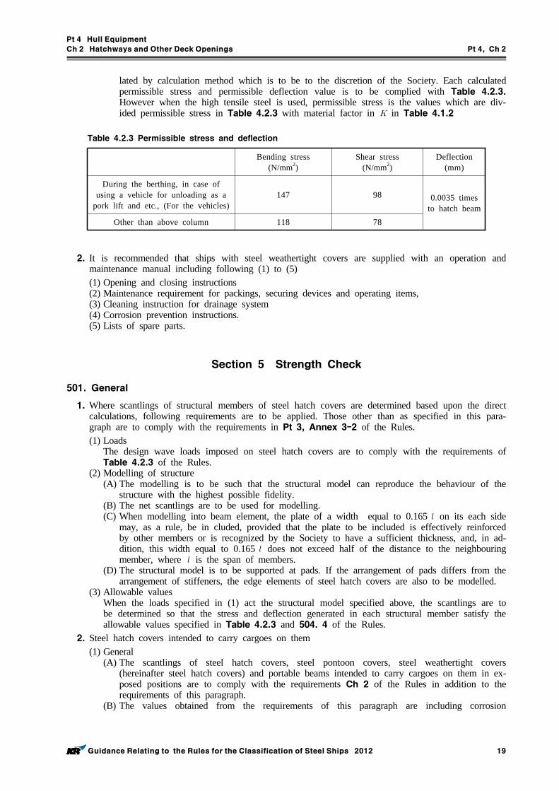
Pt 4 Hull Equipment
Ch 2 Hatchways and Other Deck Openings Pt 4, Ch 2
Guidance Relating to the Rules for the Classification of Steel Ships 2012 19
lated by calculation method which is to be to the discretion of the Society. Each calculated permissible stress and permissible deflection value is to be complied with Table 4.2.3. However when the high tensile steel is used, permissible stress is the values which are div-ided permissible stress in Table 4.2.3 with material factor in in Table 4.1.2
Table 4.2.3 Permissible stress and deflection
Bending stress (N/mm2)
Shear stress (N/mm2)
Deflection (mm)
During the berthing, in case of using a vehicle for unloading as a
pork lift and etc., (For the vehicles)147 98 0.0035 times
to hatch beamOther than above column 118 78
2. It is recommended that ships with steel weathertight covers are supplied with an operation and maintenance manual including following (1) to (5)(1) Opening and closing instructions(2) Maintenance requirement for packings, securing devices and operating items,(3) Cleaning instruction for drainage system(4) Corrosion prevention instructions.(5) Lists of spare parts.
Section 5 Strength Check
501. General
1. Where scantlings of structural members of steel hatch covers are determined based upon the direct calculations, following requirements are to be applied. Those other than as specified in this para-graph are to comply with the requirements in Pt 3, Annex 3-2 of the Rules. (1) Loads
The design wave loads imposed on steel hatch covers are to comply with the requirements of Table 4.2.3 of the Rules.
(2) Modelling of structure (A) The modelling is to be such that the structural model can reproduce the behaviour of the
structure with the highest possible fidelity. (B) The net scantlings are to be used for modelling. (C) When modelling into beam element, the plate of a width equal to 0.165 on its each side
may, as a rule, be in cluded, provided that the plate to be included is effectively reinforced by other members or is recognized by the Society to have a sufficient thickness, and, in ad-dition, this width equal to 0.165 does not exceed half of the distance to the neighbouring member, where is the span of members.
(D) The structural model is to be supported at pads. If the arrangement of pads differs from the arrangement of stiffeners, the edge elements of steel hatch covers are also to be modelled.
(3) Allowable values When the loads specified in (1) act the structural model specified above, the scantlings are to be determined so that the stress and deflection generated in each structural member satisfy the allowable values specified in Table 4.2.3 and 504. 4 of the Rules.
2. Steel hatch covers intended to carry cargoes on them (1) General
(A) The scantlings of steel hatch covers, steel pontoon covers, steel weathertight covers (hereinafter steel hatch covers) and portable beams intended to carry cargoes on them in ex-posed positions are to comply with the requirements Ch 2 of the Rules in addition to the requirements of this paragraph.
(B) The values obtained from the requirements of this paragraph are including corrosion
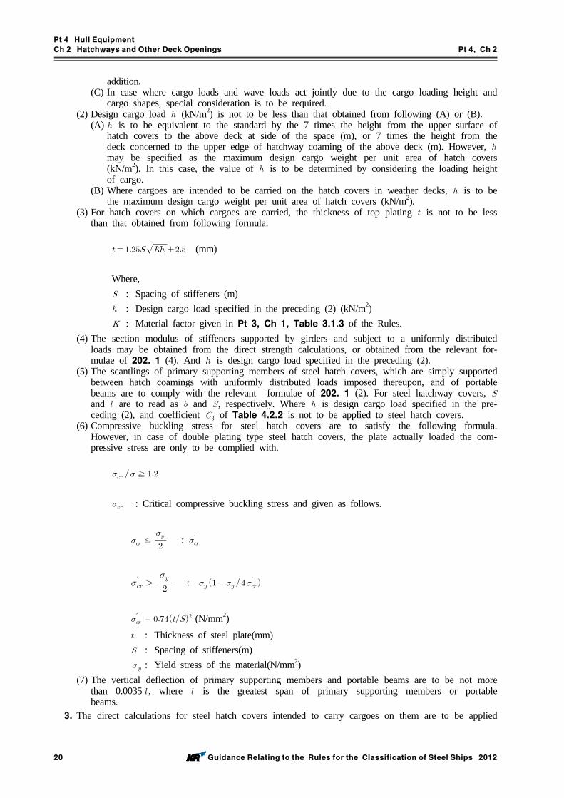
Pt 4 Hull Equipment
Ch 2 Hatchways and Other Deck Openings Pt 4, Ch 2
20 Guidance Relating to the Rules for the Classification of Steel Ships 2012
addition. (C) In case where cargo loads and wave loads act jointly due to the cargo loading height and
cargo shapes, special consideration is to be required. (2) Design cargo load (kN/m2) is not to be less than that obtained from following (A) or (B).
(A) is to be equivalent to the standard by the 7 times the height from the upper surface of hatch covers to the above deck at side of the space (m), or 7 times the height from the deck concerned to the upper edge of hatchway coaming of the above deck (m). However, may be specified as the maximum design cargo weight per unit area of hatch covers (kN/m2). In this case, the value of is to be determined by considering the loading height of cargo.
(B) Where cargoes are intended to be carried on the hatch covers in weather decks, is to be the maximum design cargo weight per unit area of hatch covers (kN/m2).
(3) For hatch covers on which cargoes are carried, the thickness of top plating is not to be less than that obtained from following formula.
(mm)
Where, : Spacing of stiffeners (m) : Design cargo load specified in the preceding (2) (kN/m2) : Material factor given in Pt 3, Ch 1, Table 3.1.3 of the Rules.
(4) The section modulus of stiffeners supported by girders and subject to a uniformly distributed loads may be obtained from the direct strength calculations, or obtained from the relevant for-mulae of 202. 1 (4). And is design cargo load specified in the preceding (2).
(5) The scantlings of primary supporting members of steel hatch covers, which are simply supported between hatch coamings with uniformly distributed loads imposed thereupon, and of portable beams are to comply with the relevant formulae of 202. 1 (2). For steel hatchway covers, and are to read as and , respectively. Where is design cargo load specified in the pre-ceding (2), and coefficient of Table 4.2.2 is not to be applied to steel hatch covers.
(6) Compressive buckling stress for steel hatch covers are to satisfy the following formula. However, in case of double plating type steel hatch covers, the plate actually loaded the com-pressive stress are only to be complied with.
≧
: Critical compressive buckling stress and given as follows.
≦
: ′
′
: ′
′ (N/mm2) : Thickness of steel plate(mm) : Spacing of stiffeners(m) : Yield stress of the material(N/mm2)
(7) The vertical deflection of primary supporting members and portable beams are to be not more than 0.0035 , where is the greatest span of primary supporting members or portable beams.
3. The direct calculations for steel hatch covers intended to carry cargoes on them are to be applied
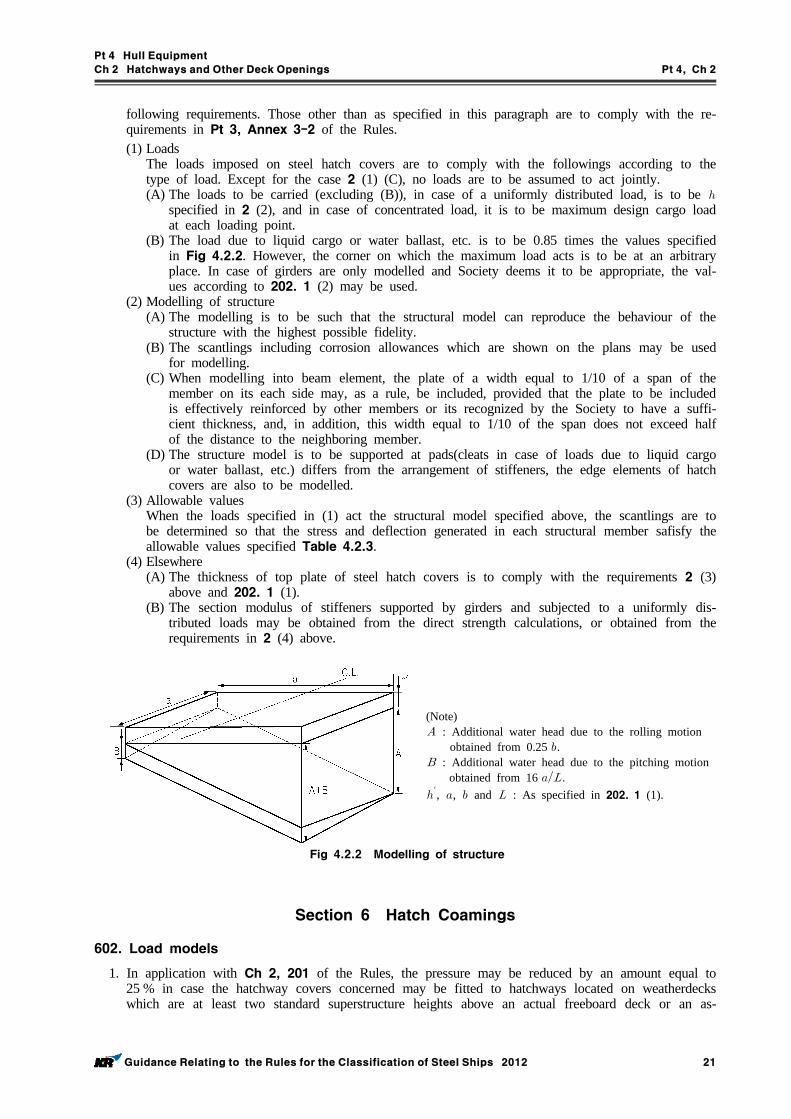
Pt 4 Hull Equipment
Ch 2 Hatchways and Other Deck Openings Pt 4, Ch 2
Guidance Relating to the Rules for the Classification of Steel Ships 2012 21
following requirements. Those other than as specified in this paragraph are to comply with the re-quirements in Pt 3, Annex 3-2 of the Rules. (1) Loads
The loads imposed on steel hatch covers are to comply with the followings according to the type of load. Except for the case 2 (1) (C), no loads are to be assumed to act jointly. (A) The loads to be carried (excluding (B)), in case of a uniformly distributed load, is to be
specified in 2 (2), and in case of concentrated load, it is to be maximum design cargo load at each loading point.
(B) The load due to liquid cargo or water ballast, etc. is to be 0.85 times the values specified in Fig 4.2.2. However, the corner on which the maximum load acts is to be at an arbitrary place. In case of girders are only modelled and Society deems it to be appropriate, the val-ues according to 202. 1 (2) may be used.
(2) Modelling of structure (A) The modelling is to be such that the structural model can reproduce the behaviour of the
structure with the highest possible fidelity. (B) The scantlings including corrosion allowances which are shown on the plans may be used
for modelling. (C) When modelling into beam element, the plate of a width equal to 1/10 of a span of the
member on its each side may, as a rule, be included, provided that the plate to be included is effectively reinforced by other members or its recognized by the Society to have a suffi-cient thickness, and, in addition, this width equal to 1/10 of the span does not exceed half of the distance to the neighboring member.
(D) The structure model is to be supported at pads(cleats in case of loads due to liquid cargo or water ballast, etc.) differs from the arrangement of stiffeners, the edge elements of hatch covers are also to be modelled.
(3) Allowable values When the loads specified in (1) act the structural model specified above, the scantlings are to be determined so that the stress and deflection generated in each structural member safisfy the allowable values specified Table 4.2.3.
(4) Elsewhere(A) The thickness of top plate of steel hatch covers is to comply with the requirements 2 (3)
above and 202. 1 (1). (B) The section modulus of stiffeners supported by girders and subjected to a uniformly dis-
tributed loads may be obtained from the direct strength calculations, or obtained from the requirements in 2 (4) above.
(Note) : Additional water head due to the rolling motion
obtained from 0.25 . : Additional water head due to the pitching motion
obtained from 16 . ′, , and : As specified in 202. 1 (1).
Fig 4.2.2 Modelling of structure
Section 6 Hatch Coamings
602. Load models
1. In application with Ch 2, 201 of the Rules, the pressure may be reduced by an amount equal to 25 % in case the hatchway covers concerned may be fitted to hatchways located on weatherdecks which are at least two standard superstructure heights above an actual freeboard deck or an as-
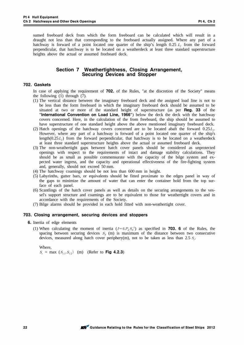
Pt 4 Hull Equipment
Ch 2 Hatchways and Other Deck Openings Pt 4, Ch 2
22 Guidance Relating to the Rules for the Classification of Steel Ships 2012
sumed freeboard deck from which the form freeboard can be calculated which will result in a draught not less than that corresponding to the freeboard actually assigned. Where any part of a hatchway is forward of a point located one quarter of the ship’s length 0.25 from the forward perpendicular, that hatchway is to be located on a weatherdeck at least three standard superstructure heights above the actual or assumed freeboard deck.
Section 7 Weathertightness, Closing Arrangement, Securing Devices and Stopper
702. Gaskets
In case of applying the requirement of 702. of the Rules, "at the discretion of the Society" means the following (1) through (7).(1) The vertical distance between the imaginary freeboard deck and the assigned load line is not to
be less than the form freeboard in which the imaginary freeboard deck should be assumed to be situated at two or more of the standard height of superstructure (as per Reg. 33 of the "International Convention on Load Line, 1966") below the deck the deck with the hatchway covers concerned. Here, in the calculation of the from freeboard, the ship should be assumed to have superstructure of one standard height above the above mentioned imaginary freeboard deck.
(2) Hatch openings of the hatchway covers concerned are to be located abaft the forward 0.25. However, where any part of a hatchway is forward of a point located one quarter of the ship's length(0.25) from the forward perpendicular, that hatchway is to be located on a weatherdeck at least three standard superstructure heights above the actual or assumed freeboard deck.
(3) The non-weathertight gaps between hatch cover panels should be considered as unprotected openings with respect to the requirements of intact and damage stability calculations. They should be as small as possible commensurate with the capacity of the bilge system and ex-pected water ingress, and the capacity and operational effectiveness of the fire-fighting system and, generally, should not exceed 50 mm.
(4) The hatchway coamings should be not less than 600 mm in height.(5) Labyrinths, gutter bars, or equivalents should be fitted proximate to the edges panel in way of
the gaps to minimize the amount of water that can enter the container hold from the top sur-face of each panel.
(6) Scantlings of the hatch cover panels as well as details on the securing arrangements to the ves-sel's support structure and coamings are to be equivalent to those for weathertight covers and in accordance with the requirements of the Society.
(7) Bilge alarms should be provided in each hold fitted with non-weathertight cover.
703. Closing arrangement, securing devices and stoppers
6. Inertia of edge elements (1) When calculating the moment of inertia ( ) as specified in 703. 6 of the Rules, the
spacing between securing devices (m) is maximum of the distance between two consecutive devices, measured along hatch cover periphery(m), not to be taken as less than 2.5 .
Where, = max ( (m) (Refer to Fig 4.2.3)
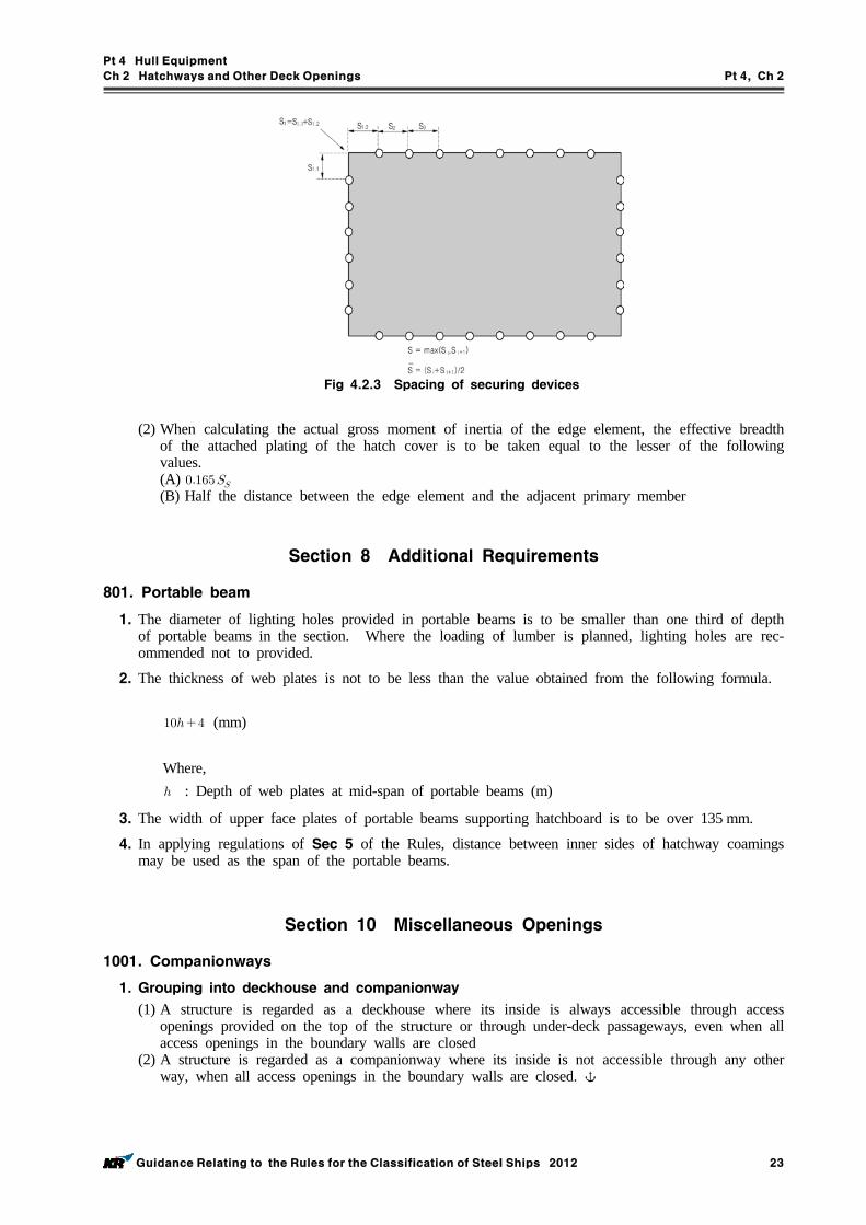
Pt 4 Hull Equipment
Ch 2 Hatchways and Other Deck Openings Pt 4, Ch 2
Guidance Relating to the Rules for the Classification of Steel Ships 2012 23
Fig 4.2.3 Spacing of securing devices
(2) When calculating the actual gross moment of inertia of the edge element, the effective breadth of the attached plating of the hatch cover is to be taken equal to the lesser of the following values. (A) (B) Half the distance between the edge element and the adjacent primary member
Section 8 Additional Requirements
801. Portable beam
1. The diameter of lighting holes provided in portable beams is to be smaller than one third of depth of portable beams in the section. Where the loading of lumber is planned, lighting holes are rec-ommended not to provided.
2. The thickness of web plates is not to be less than the value obtained from the following formula.
(mm)
Where, : Depth of web plates at mid-span of portable beams (m)
3. The width of upper face plates of portable beams supporting hatchboard is to be over 135 mm.
4. In applying regulations of Sec 5 of the Rules, distance between inner sides of hatchway coamings may be used as the span of the portable beams.
Section 10 Miscellaneous Openings
1001. Companionways
1. Grouping into deckhouse and companionway
(1) A structure is regarded as a deckhouse where its inside is always accessible through access openings provided on the top of the structure or through under-deck passageways, even when all access openings in the boundary walls are closed
(2) A structure is regarded as a companionway where its inside is not accessible through any other way, when all access openings in the boundary walls are closed.
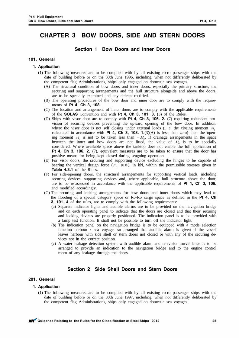
Pt 4 Hull Equipment
Ch 3 Bow Doors, Side and Stern Doors Pt 4, Ch 3
Guidance Relating to the Rules for the Classification of Steel Ships 2012 25
CHAPTER 3 BOW DOORS, SIDE AND STERN DOORS
Section 1 Bow Doors and Inner Doors
101. General
1. Application
(1) The following measures are to be complied with by all existing ro-ro passenger ships with the date of building before or on the 30th June 1996, including, when not differently deliberated by the competent flag Administrations, ships only engaged on domestic sea voyages.(A) The structural condition of bow doors and inner doors, especially the primary structure, the
securing and supporting arrangements and the hull structure alongside and above the doors, are to be specially examined and any defects rectified.
(B) The operating procedures of the bow door and inner door are to comply with the require-ments of Pt 4, Ch 3, 108.
(C) The location and arrangement of inner doors are to comply with the applicable requirements of the SOLAS Convention and with Pt 4, Ch 3, 101. 3. (3) of the Rules.
(D) Ships with visor door are to comply with Pt 4, Ch 3, 106. 2. (7) requiring redundant pro-vision of securing devices preventing the upward opening of the bow door. In addition, where the visor door is not self closing under external loads (i. e. the closing moment calculated in accordance with Pt 4, Ch 3, 103. 1.(3)(A) is less than zero) then the open-ing moment is not to be taken less than . If drainage arrangements in the space between the inner and bow doors are not fitted, the value of is to be specially considered. Where available space above the tanktop does not enable the full application of Pt 4, Ch 3, 106. 2. (7), equivalent measures are to be taken to ensure that the door has positive means for being kept closed during seagoing operation.
(E) For visor doors, the securing and supporting device excluding the hinges to be capable of bearing the vertical design force ( ), in kN, within the permissible stresses given in Table 4.3.1 of the Rules.
(F) For side-opening doors, the structural arrangements for supporting vertical loads, including securing devices, supporting devices and, where applicable, hull structure above the door, are to be re-assessed in accordance with the applicable requirements of Pt 4, Ch 3, 106. and modified accordingly.
(G) The securing and locking arrangements for bow doors and inner doors which may lead to the flooding of a special category space or Ro-Ro cargo space as defined in the Pt 4, Ch 3, 101. 4 of the rules, are to comply with the following requirements:(a) Separate indicator lights and audible alarms are to be provided on the navigation bridge
and on each operating panel to indicate that the doors are closed and that their securing and locking devices are properly positioned. The indication panel is to be provided with a lamp test function. It shall not be possible to turn off the indicator light.
(b) The indication panel on the navigation bridge is to be equipped with a mode selection function harbour / sea voyage, so arranged that audible alarm is given if the vessel leaves harbour with side shell or stern doors not closed or with any of the securing de-vices not in the correct position.
(c) A water leakage detection system with audible alarm and television surveillance is to be arranged to provide an indication to the navigation bridge and to the engine control room of any leakage through the doors.
Section 2 Side Shell Doors and Stern Doors
201. General
1. Application
(1) The following measures are to be complied with by all existing ro-ro passenger ships with the date of building before or on the 30th June 1997, including, when not differently deliberated by the competent flag Administrations, ships only engaged on domestic sea voyages.
Pt 4 Hull Equipment
Ch 3 Bow Doors, Side and Stern Doors Pt 4, Ch 3
26 Guidance Relating to the Rules for the Classification of Steel Ships 2012
(A) The structural condition of side shell doors and stern doors, especially the primary structure, the securing and supporting arrangements and the hull structure alongside and above the doors, are to be specially examined and any defects rectified.
(B) The structural arrangement of securing devices and supporting devices of inwards opening doors in way of these securing devices and, where applicable, of the surrounding hull struc-ture is to be reassessed in accordance with the applicable requirements of Pt 4, Ch 3, 205. and modified accordingly.
(C) The securing and locking arrangements for side and stern doors which may lead to the flooding of a special category space or Ro-Ro cargo space as defined in the Pt 4, Ch 3, 101. 4 of the rules, are to comply with the following requirements:(a) Separate indicator lights and audible alarms are to be provided on the navigation bridge
and on each operating panel to indicate that the doors are closed and that their securing and locking devices are properly positioned. The indication panel is to be provided with a lamp test function. It shall not be possible to turn off the indicator light.
(b) The indication panel on the navigation bridge is to be equipped with a mode selection function harbour / sea voyage, so arranged that audible alarm is given if the vessel leaves harbour with side shell or stern doors not closed or with any of the securing de-vices not in the correct position.
(c) A water leakage detection system with audible alarm and television surveillance is to be arranged to provide an indication to the navigation bridge and to the engine control room of any leakage through the doors.
(D) Documented operating procedures for closing and securing side shell and stern doors are to be kept on board and posted at the appropriate places.
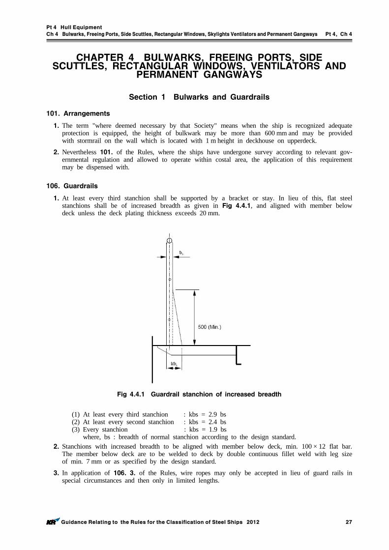
Pt 4 Hull Equipment
Ch 4 Bulwarks, FreeingPorts, Side Scuttles, RectangularWindows, Skylights Ventilators andPermanent Gangways Pt 4, Ch 4
Guidance Relating to the Rules for the Classification of Steel Ships 2012 27
CHAPTER 4 BULWARKS, FREEING PORTS, SIDE SCUTTLES, RECTANGULAR WINDOWS, VENTILATORS AND
PERMANENT GANGWAYS
Section 1 Bulwarks and Guardrails
101. Arrangements
1. The term "where deemed necessary by that Society" means when the ship is recognized adequate protection is equipped, the height of bulkwark may be more than 600 mm and may be provided with stormrail on the wall which is located with 1 m height in deckhouse on upperdeck.
2. Nevertheless 101. of the Rules, where the ships have undergone survey according to relevant gov-ernmental regulation and allowed to operate within costal area, the application of this requirement may be dispensed with.
106. Guardrails
1. At least every third stanchion shall be supported by a bracket or stay. In lieu of this, flat steel stanchions shall be of increased breadth as given in Fig 4.4.1, and aligned with member below deck unless the deck plating thickness exceeds 20 mm.
Fig 4.4.1 Guardrail stanchion of increased breadth
(1) At least every third stanchion : kbs = 2.9 bs (2) At least every second stanchion : kbs = 2.4 bs (3) Every stanchion : kbs = 1.9 bs
where, bs : breadth of normal stanchion according to the design standard. 2. Stanchions with increased breadth to be aligned with member below deck, min. 100 × 12 flat bar.
The member below deck are to be welded to deck by double continuous fillet weld with leg size of min. 7 mm or as specified by the design standard.
3. In application of 106. 3. of the Rules, wire ropes may only be accepted in lieu of guard rails in special circumstances and then only in limited lengths.
Pt 4 Hull Equipment
Ch 4 Bulwarks, FreeingPorts, Side Scuttles, RectangularWindows, Skylights Ventilators andPermanent Gangways Pt 4, Ch 4
28 Guidance Relating to the Rules for the Classification of Steel Ships 2012
Section 2 Freeing Ports
201. General
1. The adequate provision for freeing the spaces which are open at either or both ends within super-structure referred to in Ch 4, 201. 3 of the Rules is subject to the (1) through (3).(1) The minimum freeing port area on each side of the ship for the open superstructure is not less
than that obtained from the following formula.
(m2)
Where, = (m2) is not more than 20 m = (m2) is more than 20 m : (m) : Where bulwark forms a well, the length of bulwark in well(m) : Length of the common space within the open superstructure(m) : Breadth of the openings in the end bulkhead of the enclosed superstructure(m) : One standard superstructue height(m) : The distance of the well deck above the freeboard deck(m)
(2) The minimum freeing port area on each side of the ship for the open well is not less than that obtaibed fron the following formula.
(m2)
Where, = (m2) is not more than 20 m = (m2) is more than 20 m = (m2) is moe than 1.2 m = 0 is not more than 1.2 m, but not less than 0.9 m = (m2) is less than 0.9 m : Average height of bulwark above the deck (m)
(3) In ships either without sheer or with less sheer than the standard, the minimum freeing port area obtained from the above (1) and (2), is increased by multiply the factor obtained from 202. 2 of the Rules.
2. The requirements in 201. 4 of the Rules are applied to type A or B-100 ships with specially re-duced freeboards.
3. The requirements in 202. 4 of the Rules are applied to type A or B-100 ships with specially re-duced freeboard having trunks.
202. Freeing port area
1. A flush-decker having an effective deckhouse is to be considered to have two wells afore and abaft the deckhouse, and each of these wells is required to have freeing port area as prescribed in 202. of the Rules. The term "effective deckhouse" means a structure having a breadth not less than 80% of the breadth of ship and the width of passageways at its sides does not exceed 1.5 m.
2. Where a divisional bulkhead extending from side to side is provided at the forward end of deck-
Pt 4 Hull Equipment
Ch 4 Bulwarks, FreeingPorts, Side Scuttles, RectangularWindows, Skylights Ventilators andPermanent Gangways Pt 4, Ch 4
Guidance Relating to the Rules for the Classification of Steel Ships 2012 29
house, the ship is to be considered to have two wells afore and abaft the bulkhead, irrespective of the breadth of deckhouse, and each of these wells is required to have the freeing port area as pre-scribed in 202. of the Rules.
3. In ships which correspond to the requirements 201. 2, the guardrails installed at both sides for more than half of the length of the exposed parts of the freeboard deck, and in ships which corre-spond to the requirements in 201. 3, the guardrails installed at both sides for more than half of the length of trunks on the freeboard deck may be replaced by freeing ports of a total area not less than 33 % of the total area of bulwark in the lower parts of bulwarks.
4. In type B-60 ships, freeing ports in the lower parts of bulwarks are to have an area not less than 25 % of the total area of bulwark.
5. Where freeing ports are fitted with rails, etc., projected area of them is to be excluded from actual freeing port area in calculations.
6. Where set-in structure of side shell or superstructure from a well in pure car carrier, etc., adequate freeing ports are to be provided in accordance with the requirements of 202. 3 of the Rules.
7.
(1) The case where a ship is provided with a trunk or a hatch side coaming which is continuous or substantially continuous between detached superstructure specified in 202. 3 of the Rules means the case where is equal to, or less than , where and are shown in the following.
: Free flow area through which water runs across the deck given by the following for-mula(m2)
Where, : Distance between hatchways, and between hatchways and superstructures and
deckhouse(m) : Height of bulwarks(m) : Projected area of structure which prevent free flow in .
: As specified in 202. 1 and 2 of the Rules.(m2)(2) Where is greater than , but not greater than , freeing port area ( ) is increased by the
following formula with the value obtained from 202. 1 and 2 of the Rules. and are shown in the above (1), is specified in 202. 3 of the Rules.
(m2)
(3) Where is greater than , is equal to . 8. Nevertheless 101. 1 thou. 3 of the Rules, where the ships operate within costal area which the
ship could go and return from smooth water within 2 hours by the maximum speed, the freeing port area could be deducted to the half area of the required freeing port area.
204. Arrangement of freeing ports
1. In ships having very small shear or without shear, the area of freeing ports is to be distributed throughout the whole length of the well.
2. Specially, for the ships having reduces freeboard, freeing ports having not less than 25 % of total area of bulwarks is to be provided in lower part of bulwarks.
Pt 4 Hull Equipment
Ch 4 Bulwarks, FreeingPorts, Side Scuttles, RectangularWindows, Skylights Ventilators andPermanent Gangways Pt 4, Ch 4
30 Guidance Relating to the Rules for the Classification of Steel Ships 2012
205. Structure
In case fishing vessels etc. which are accepted to this Society are fitted securing and locking de-vices, its structure are to be of an approved one.
Section 3 Side Scuttles, Rectangular Windows and Skylights
301. General Application
1. With respect to the provisions of Ch 4, 301. of the rules, the term as deemed as appropriate by the Society means that the side scuttles and rectangular windows is to be in conformity correspond-ing to the position and to have appropriate weathertightness.
2. With respect to the provisions of Ch 4, 301. and 302. of the rules, windows on a navigation bridge within the third tiers above the freeboard deck, which is granted to be of rectangular win-dow in accordance with the provisions of 306. of the rules, may be of rectangular window other than of class E or F subject to the following (1) and (2) (1) The navigation bridge is to be separated from spaces below the freeboard deck and spaces with-
in superstructures by the following (A) Weathertightness closing devices (B) Two or more cabin bulkheads or doors. In such case, the height of sills of the doorway to
the navigation bridge are not to be less than those required for closing devices at the posi-tion of such doorway.
(2) The design pressure of such windows is not to be less than the value specified in 308. of the rules and construction of frames, etc. for such windows is to be in conformity to those required for the class E, F rectangular window corresponding to the position of such windows and to have appropriate weathertightness.
303. Application of side scuttle
1. The wording as deemed as appropriate by the Society in 303. 5 of the rules means that the side scuttles may be class A or class B side scuttles without deadlight.
2. Nevertheless 101. 1 thou. 3 of the Rules, the side scuttles of the ship which operates in the costal and smooth water service could be accepted as the followings(1) The side scuttles of the ship which operates in the costal service to be in accordance with Table 4.4.1 or equivalent thereto.
(2) The side scuttles of the ship which operates in the smooth water service to be in accordance with Table 4.4.2 or equivalent thereto.
(3) The side scuttles of the superstructures and deckhouses above main deck not to be installed be-low seal height of the superstructures and deckhouses. However, where it is not practicable, the side scuttles with deadlight could be accepted.
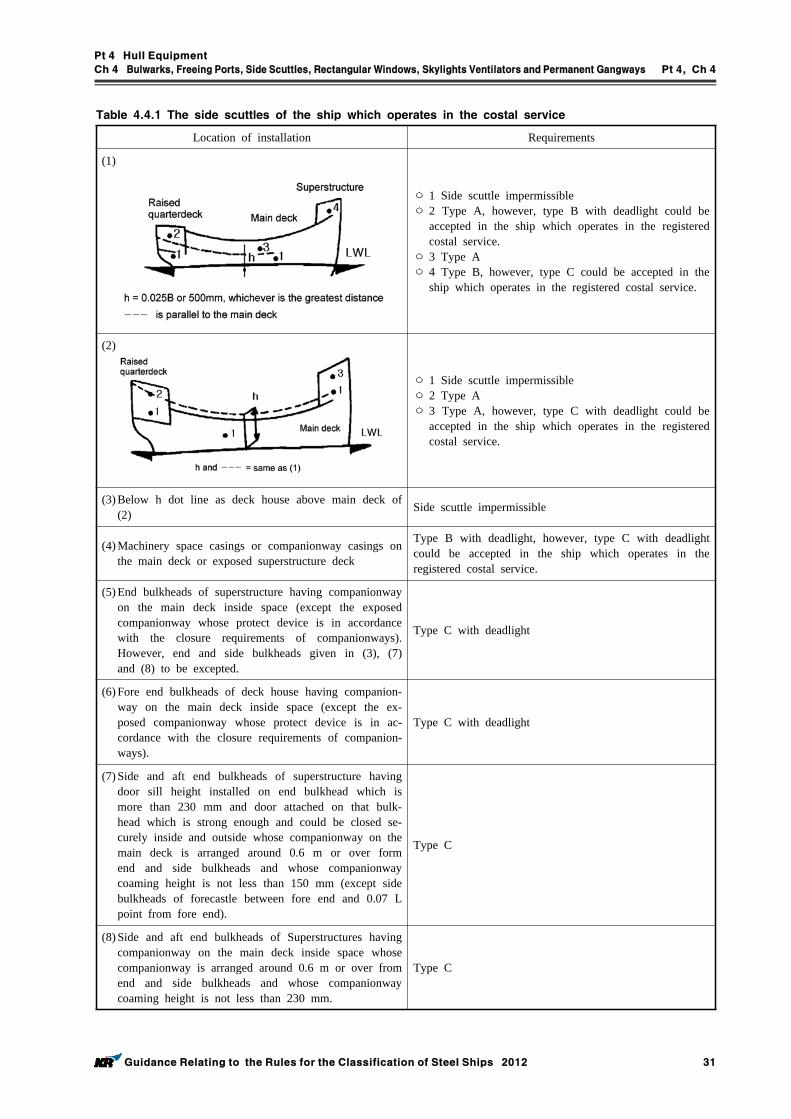
Pt 4 Hull Equipment
Ch 4 Bulwarks, FreeingPorts, Side Scuttles, RectangularWindows, Skylights Ventilators andPermanent Gangways Pt 4, Ch 4
Guidance Relating to the Rules for the Classification of Steel Ships 2012 31
Location of installation Requirements
(1)
ㅇ 1 Side scuttle impermissibleㅇ 2 Type A, however, type B with deadlight could be
accepted in the ship which operates in the registered costal service.
ㅇ 3 Type Aㅇ 4 Type B, however, type C could be accepted in the
ship which operates in the registered costal service.
(2)
ㅇ 1 Side scuttle impermissibleㅇ 2 Type Aㅇ 3 Type A, however, type C with deadlight could be
accepted in the ship which operates in the registered costal service.
(3) Below h dot line as deck house above main deck of (2) Side scuttle impermissible
(4) Machinery space casings or companionway casings on the main deck or exposed superstructure deck
Type B with deadlight, however, type C with deadlight could be accepted in the ship which operates in the registered costal service.
(5) End bulkheads of superstructure having companionway on the main deck inside space (except the exposed companionway whose protect device is in accordance with the closure requirements of companionways). However, end and side bulkheads given in (3), (7) and (8) to be excepted.
Type C with deadlight
(6) Fore end bulkheads of deck house having companion-way on the main deck inside space (except the ex-posed companionway whose protect device is in ac-cordance with the closure requirements of companion-ways).
Type C with deadlight
(7) Side and aft end bulkheads of superstructure having door sill height installed on end bulkhead which is more than 230 mm and door attached on that bulk-head which is strong enough and could be closed se-curely inside and outside whose companionway on the main deck is arranged around 0.6 m or over form end and side bulkheads and whose companionway coaming height is not less than 150 mm (except side bulkheads of forecastle between fore end and 0.07 L point from fore end).
Type C
(8) Side and aft end bulkheads of Superstructures having companionway on the main deck inside space whose companionway is arranged around 0.6 m or over from end and side bulkheads and whose companionway coaming height is not less than 230 mm.
Type C
Table 4.4.1 The side scuttles of the ship which operates in the costal service
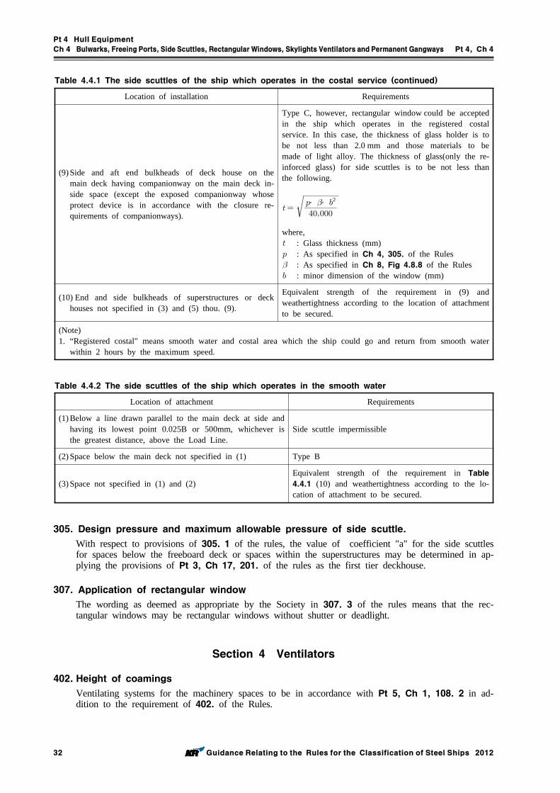
Pt 4 Hull Equipment
Ch 4 Bulwarks, FreeingPorts, Side Scuttles, RectangularWindows, Skylights Ventilators andPermanent Gangways Pt 4, Ch 4
32 Guidance Relating to the Rules for the Classification of Steel Ships 2012
Location of installation Requirements
(9) Side and aft end bulkheads of deck house on the main deck having companionway on the main deck in-side space (except the exposed companionway whose protect device is in accordance with the closure re-quirements of companionways).
Type C, however, rectangular window could be accepted in the ship which operates in the registered costal service. In this case, the thickness of glass holder is to be not less than 2.0 mm and those materials to be made of light alloy. The thickness of glass(only the re-inforced glass) for side scuttles is to be not less than the following.
․ ․
where, : Glass thickness (mm) : As specified in Ch 4, 305. of the Rules : As specified in Ch 8, Fig 4.8.8 of the Rules : minor dimension of the window (mm)
(10) End and side bulkheads of superstructures or deck houses not specified in (3) and (5) thou. (9).
Equivalent strength of the requirement in (9) and weathertightness according to the location of attachment to be secured.
(Note)1. “Registered costal" means smooth water and costal area which the ship could go and return from smooth water
within 2 hours by the maximum speed.
Table 4.4.1 The side scuttles of the ship which operates in the costal service (continued)
Location of attachment Requirements
(1) Below a line drawn parallel to the main deck at side and having its lowest point 0.025B or 500mm, whichever is the greatest distance, above the Load Line.
Side scuttle impermissible
(2) Space below the main deck not specified in (1) Type B
(3) Space not specified in (1) and (2)Equivalent strength of the requirement in Table 4.4.1 (10) and weathertightness according to the lo-cation of attachment to be secured.
Table 4.4.2 The side scuttles of the ship which operates in the smooth water
305. Design pressure and maximum allowable pressure of side scuttle.
With respect to provisions of 305. 1 of the rules, the value of coefficient "a" for the side scuttles for spaces below the freeboard deck or spaces within the superstructures may be determined in ap-plying the provisions of Pt 3, Ch 17, 201. of the rules as the first tier deckhouse.
307. Application of rectangular window
The wording as deemed as appropriate by the Society in 307. 3 of the rules means that the rec-tangular windows may be rectangular windows without shutter or deadlight.
Section 4 Ventilators
402. Height of coamings
Ventilating systems for the machinery spaces to be in accordance with Pt 5, Ch 1, 108. 2 in ad-dition to the requirement of 402. of the Rules.
Pt 4 Hull Equipment
Ch 4 Bulwarks, FreeingPorts, Side Scuttles, RectangularWindows, Skylights Ventilators andPermanent Gangways Pt 4, Ch 4
Guidance Relating to the Rules for the Classification of Steel Ships 2012 33
Section 5 Permanent Gangways
501. General
1. Protection of crew provided in exposed freeboard deck, superstructure deck, crew accommodation area and machinery space and other area locations in question is to be in accordance with Table 4.4.1.
2. Where the access way(gangway, walkway may be included in access way) is provided, it is to be complied with the followings.(1) Wire rope may only be accepted in lieu of guard rails in special circumstances and then only
in limited length.(2) In all cases where wire ropes are fitted, adequate devices are to be provided to ensure their
tautness.(3) Lengths of chain may only be accepted in lieu of guard rails if fitted between two fixed
stanchions.(4) Where stanchions are fitted, every 3rd stanchion is to be supported by a bracket or stay.(5) Removable or hinged stanchions shall be capable of being locked in the upright position.(6) A means of passage over obstructions. if any, such as pipes or other fittings of permanent na-
ture should be provided.(7) Generally, the width of gangway or deck-level walkway should not exceed 1.5 m.
3. For oil tankers, chemical tankers and gas carriers constructed before 1st July 1998, existing arrange-ments which complied with (b) or (c) may be accepted in lieu of (e) or (f) provided such existing arrangements are fitted with shelters and means of access to and from the deck as required for the arrangements (e) or (f) as defined in Table 4.4.1.
4. For tankers less than 100 m in length (), the minimum width of the gangway platform or deck level walkway fitted in accordance with arrangements (e) or (f), respectively, may be reduced to 0.6m.
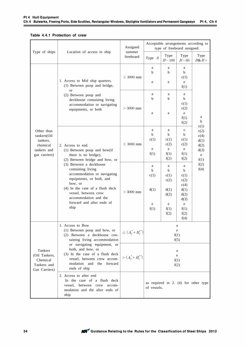
Pt 4 Hull Equipment
Ch 4 Bulwarks, FreeingPorts, Side Scuttles, RectangularWindows, Skylights Ventilators andPermanent Gangways Pt 4, Ch 4
34 Guidance Relating to the Rules for the Classification of Steel Ships 2012
Table 4.4.1 Protection of crew
Type of ships Location of access in shipAssigned summer
freeboard
Acceptable arrangements according to type of freeboard assigned:
Type Type
Type
Type &
Other than tankers(Oil
tankers, chemical
tankers and gas carriers)
1. Access to Mid ship quarters.(1) Between poop and bridge,
or(2) Between poop and
deckhouse containing living accommodation or navigating equipments, or both
≤ mm
ab
e
ab
e
ab
c(1)e
f(1)
ab
c(1)c(2)c(4)d(1)d(2)d(3)
ef(1)f(2)f(4)
mm
ab
e
ab
e
ab
c(1)c(2)
ef(1)f(2)
2. Access to end. (1) Between poop and bow(if
there is no bridge), (2) Between bridge and bow, or(3) Between a deckhouse
containing living accommodation or navigating equipments, or both, and bow, or
(4) In the case of a flush deck vessel, between crew accommodation and the forward and after ends of ship
≤ mm
ab
c(1)
ef(1)
ab
c(1)c(2)
ef(1)f(2)
b
c(1)c(2)
ef(1)f(2)
mm
ab
c(1)
d(1)
ef(1)
ab
c(1)c(2)
d(1)d(2)
ef(1)f(2)
ab
c(1)c(2)c(4)d(1)d(2)d(3)
ef(1)f(2)f(4)
Tankers(Oil Tankers,
Chemical Tankers and Gas Carriers)
1. Access to Bow(1) Between poop and bow, or(2) Between a deckhouse con-
taining living accommodation or navigating equipment, or both, and bow, or
(3) In the case of a flush deck vessel, between crew accom-modation and the forward ends of ship
≤
ae
f(1)f(5)
ae
f(1)f(2)
2. Access to after end In the case of a flush deck
vessel, between crew accom-modation and the after ends of ship
as required in 2. (4) for other type of vessels.
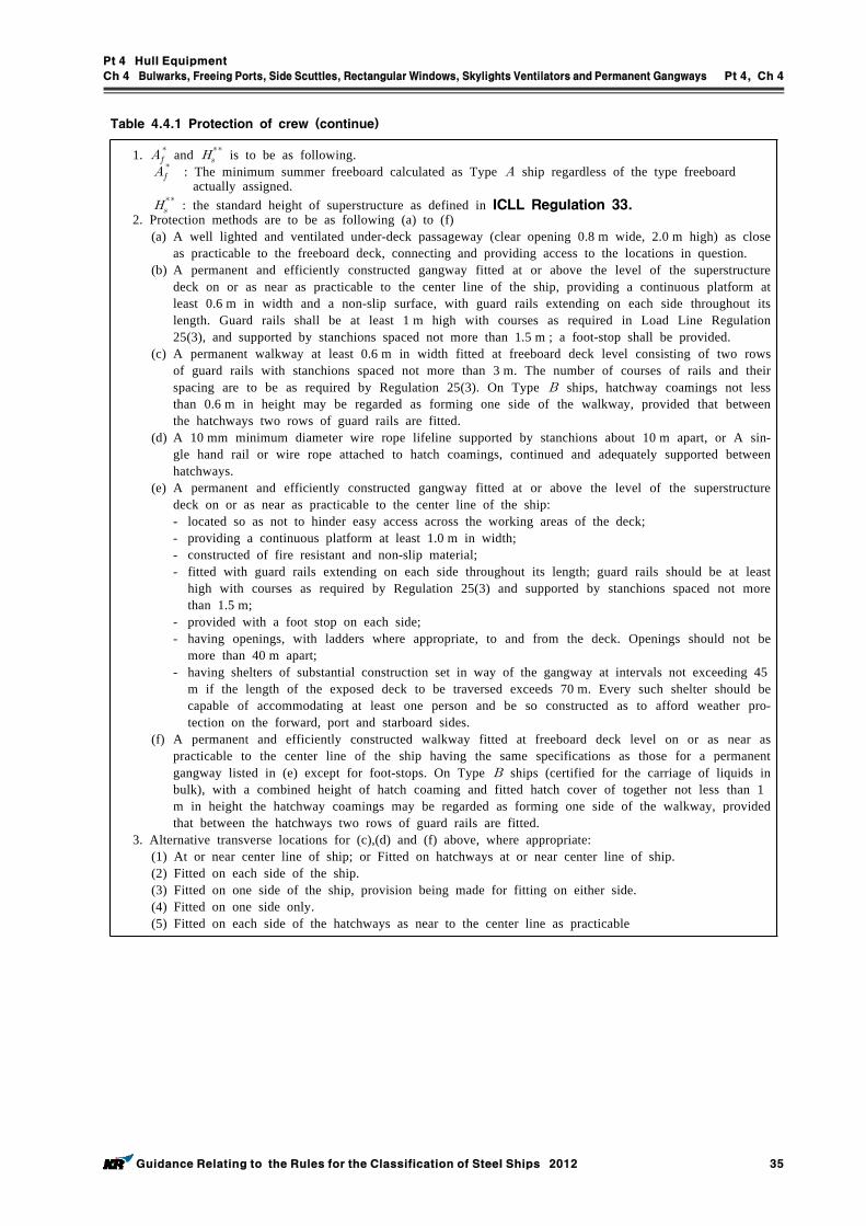
Pt 4 Hull Equipment
Ch 4 Bulwarks, FreeingPorts, Side Scuttles, RectangularWindows, Skylights Ventilators andPermanent Gangways Pt 4, Ch 4
Guidance Relating to the Rules for the Classification of Steel Ships 2012 35
Table 4.4.1 Protection of crew (continue)
1. and
is to be as following.
: The minimum summer freeboard calculated as Type ship regardless of the type freeboard actually assigned.
: the standard height of superstructure as defined in ICLL Regulation 33.2. Protection methods are to be as following (a) to (f)
(a) A well lighted and ventilated under-deck passageway (clear opening 0.8 m wide, 2.0 m high) as close as practicable to the freeboard deck, connecting and providing access to the locations in question.
(b) A permanent and efficiently constructed gangway fitted at or above the level of the superstructure deck on or as near as practicable to the center line of the ship, providing a continuous platform at least 0.6 m in width and a non-slip surface, with guard rails extending on each side throughout its length. Guard rails shall be at least 1 m high with courses as required in Load Line Regulation 25(3), and supported by stanchions spaced not more than 1.5 m ; a foot-stop shall be provided.
(c) A permanent walkway at least 0.6 m in width fitted at freeboard deck level consisting of two rows of guard rails with stanchions spaced not more than 3 m. The number of courses of rails and their spacing are to be as required by Regulation 25(3). On Type ships, hatchway coamings not less than 0.6 m in height may be regarded as forming one side of the walkway, provided that between the hatchways two rows of guard rails are fitted.
(d) A 10 mm minimum diameter wire rope lifeline supported by stanchions about 10 m apart, or A sin-gle hand rail or wire rope attached to hatch coamings, continued and adequately supported between hatchways.
(e) A permanent and efficiently constructed gangway fitted at or above the level of the superstructure deck on or as near as practicable to the center line of the ship:- located so as not to hinder easy access across the working areas of the deck;- providing a continuous platform at least 1.0 m in width;- constructed of fire resistant and non-slip material;- fitted with guard rails extending on each side throughout its length; guard rails should be at least
high with courses as required by Regulation 25(3) and supported by stanchions spaced not more than 1.5 m;
- provided with a foot stop on each side;- having openings, with ladders where appropriate, to and from the deck. Openings should not be
more than 40 m apart;- having shelters of substantial construction set in way of the gangway at intervals not exceeding 45
m if the length of the exposed deck to be traversed exceeds 70 m. Every such shelter should be capable of accommodating at least one person and be so constructed as to afford weather pro-tection on the forward, port and starboard sides.
(f) A permanent and efficiently constructed walkway fitted at freeboard deck level on or as near as practicable to the center line of the ship having the same specifications as those for a permanent gangway listed in (e) except for foot-stops. On Type ships (certified for the carriage of liquids in bulk), with a combined height of hatch coaming and fitted hatch cover of together not less than 1m in height the hatchway coamings may be regarded as forming one side of the walkway, provided that between the hatchways two rows of guard rails are fitted.
3. Alternative transverse locations for (c),(d) and (f) above, where appropriate:(1) At or near center line of ship; or Fitted on hatchways at or near center line of ship.(2) Fitted on each side of the ship.(3) Fitted on one side of the ship, provision being made for fitting on either side.(4) Fitted on one side only.(5) Fitted on each side of the hatchways as near to the center line as practicable
Pt 4 Hull Equipment
Ch 7 Cementing and Painting Pt 4, Ch 7
Guidance Relating to the Rules for the Classification of Steel Ships 2012 37
CHAPTER 7 CEMENTING AND PAINTING
Section 2 Painting
201. General
1. Limitation of using aluminium paint
In ships carrying oil of a flash point not exceeding 60°C chemical carrier, paints containing alumi-nium must not be used in cargo oil tanks, pump rooms, cofferdams, cargo tank deck area, or any other area where cargo vapour may accumulate, except that the paint concerned have been proven by tests to have no nature of increasing the danger of ignition which may lead to explosions.
Aluminized pipes may be permitted in hazardous areas on open deck provided they are protected from accidental impact, and in inerted cargo tanks and ballast tanks.
2. Special requirements
The cases that "Special requirements may be additionally made by the Society" stated in Pt 4, Ch 7, 201. of the Rules are as follows.(1) The requirements Pt 7, Ch 3, 107. of the Rules(2) The requirements Pt 3, Ch 1, 803. of the Rules
3. Omission of painting
In accordance with Pt 4, Ch 7, 201. of the Rules, the cases that painting may be omitted are as follows.(1) Where ships are applied the requirements Pt 7, Ch 3 of the Rules and their cargoes are in-
tended to be regularly handled by grabs or similar mechanical appliances, painting for cargo holds may be omitted subject to the following (A) and (B)(A) Omission of painting is to be limited to those members such as inner bottom plates, slant
plates of bilge hoper tanks and slant plates of lower stool transverse bulkheads whose thick-ness is increased in accordance with the requirements Pt 7, Ch 3, 304. 2 and 3, 302. 2 or 502. 1 of the Rules. However, omission of painting is not accepted for areas within the ex-tent of painting prescribed in above mentioned 2.
(B) The reason and area of omission of painting are to be prescribed in the plans submitted for the approval (for example : Midship Section, etc.)
(2) Where ships are specified in (1) above and intended to carry exclusively chips of wood, the area which are expected to be effectively protected against corrosion of steel by the secretion of chips of wood(the area except where has normally no touch with the cargoes such as inside of upper deck) may be added to the area of omission of painting specified in above item (1) (B) notwithstanding the requirements of the above item 2 (1). The salt beaten structural members in cargo holds used as ballast water tanks is to be thicker by 1.0 mm than the requirements of Pt 7, Ch 3 of the Rules. However, those which are in cargo holds used as ballast water tanks on-ly in port need not be thicker.
(3) Where tanks are exclusively loaded oils, painting for inside of them may be omitted in spite of kind of ships.
Pt 4 Hull Equipment
Ch 8 Equipment Number and Equipment Pt 4, Ch 8
Guidance Relating to the Rules for the Classification of Steel Ships 2012 39
CHAPTER 8 EQUIPMENT NUMBER AND EQUIPMENT
Section 1 General
101. General and application
1. Consideration for restricted navigation area
(1) Ships assigned with class notation "Smooth water service" may be provided the equipment in accordance with the equipment letter of equipment number which is one grade lower class of equipment letter.
(2) In case of the above (1), the provisions of the used material may not be considered.2. Due to be assigned scantling draft(), if draft() for designed ship and draft assigning is smaller
than designed draft(), equipment number and equipment are to be as follows:(1) For scantling draft(), equipment number and equipment corresponded with scantling draft ()
is to be equipped. In this case, if is not less than 300 mm, ship length () corresponded with is to be used.
(2) If is not less than (for ship assigned , > ), equipment number and equipment are to be decided by the scantling which is corresponded with . If is not less than 300mm, equipment number is to be calculated with ship length which is corresponded with
3. Superstructure which is not regarded as a deckhouse due to strength
Even though superstructure is not regarded as a deckhouse due to strength, if side wall is extended to side shell and deck is provided, it may be regarded as a superstructure. However, for the super-structure having unusually short end parts of deckhouse may be regarded as a deckhouse.
Section 2 Equipment Number
201. Equipment number
1. The equipment number of tug boat is to be following formula;
×
= maximum breadth of superstructure or deck house at each floor(m) = each height of superstructure having breadth greater than or each deckhouse(m).
2. Significant figures
(1) The scantling unit(m) of length, height, breadth has two significant figures and third figure is raised to a unit.
(2) has a only positive number.(3) Each item of formula
(
) has a only positive number with raising to unit from first figure.
3. ,
(1) The values of , is to be in accordance with designed summer load line. However, ships assigned scantling draft use the value .
(2) When the principle dimensions( , and ) is changed (for example, is changed when is greater than 300 mm), equipment number may be recalculated.
(3) When draft is changed, it is in accordance with the regulation 101. 2 of this chapter.4. Extents of structures to be included in the second term (2.0 ) of formula
(1) The following items are to be included into the calculation of ′ .(A) superstructures
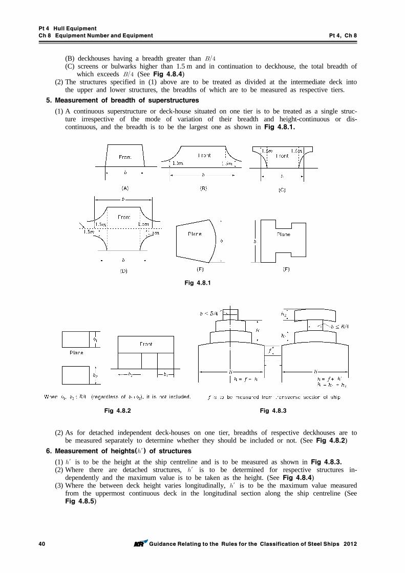
Pt 4 Hull Equipment
Ch 8 Equipment Number and Equipment Pt 4, Ch 8
40 Guidance Relating to the Rules for the Classification of Steel Ships 2012
(B) deckhouses having a breadth greater than (C) screens or bulwarks higher than 1.5 m and in continuation to deckhouse, the total breadth of
which exceeds (See Fig 4.8.4)(2) The structures specified in (1) above are to be treated as divided at the intermediate deck into
the upper and lower structures, the breadths of which are to be measured as respective tiers.5. Measurement of breadth of superstructures
(1) A continuous superstructure or deck-house situated on one tier is to be treated as a single struc-ture irrespective of the mode of variation of their breadth and height-continuous or dis-continuous, and the breadth is to be the largest one as shown in Fig 4.8.1.
Fig 4.8.1
Fig 4.8.2 Fig 4.8.3
(2) As for detached independent deck-houses on one tier, breadths of respective deckhouses are to be measured separately to determine whether they should be included or not. (See Fig 4.8.2)
6. Measurement of heights(′) of structures(1) ′ is to be the height at the ship centreline and is to be measured as shown in Fig 4.8.3.(2) Where there are detached structures, ′ is to be determined for respective structures in-
dependently and the maximum value is to be taken as the height. (See Fig 4.8.4)(3) Where the between deck height varies longitudinally, ′ is to be the maximum value measured
from the uppermost continuous deck in the longitudinal section along the ship centreline (See Fig 4.8.5)
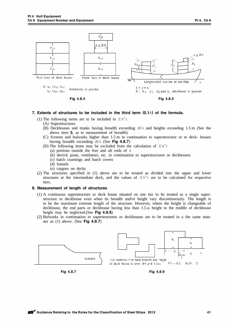
Pt 4 Hull Equipment
Ch 8 Equipment Number and Equipment Pt 4, Ch 8
Guidance Relating to the Rules for the Classification of Steel Ships 2012 41
Fig 4.8.4 Fig 4.8.5
7. Extents of structures to be included in the third term (0.1A) of the formula.(1) The following items are to be included in ″ .
(A) Superstructures(B) Deckhouses and trunks having breadth exceeding and heights exceeding 1.5 m (See the
above item 5, as to measurement of breadth)(C) Screens and bulwarks higher than 1.5 m in continuation to superstructure or to deck- houses
having breadth exceeding (See Fig 4.8.7)(D) The following items may be excluded from the calculation of ″
(a) portions outside the fore and aft ends of (b) derrick posts, ventilators, etc. in continuation to superstructures or deckhouses(c) hatch coamings and hatch covers(d) funnels(e) cargoes on decks
(2) The structures specified in (1) above are to be treated as divided into the upper and lower structures at the intermediate deck, and the values of ″ are to be calculated for respective tiers.
8. Measurement of length of structures
(1) A continuous superstructure or deck house situated on one tier to be treated as a single super-structure or deckhouse even when its breadth and/or height vary discontinuously. The length is to be the maximum extreme length of the structure. However, where the height is changeable of deckhouse, the end parts or deckhouse having less than 1.5 m height to the middle of deckhouse height may be neglected.(See Fig 4.8.6)
(2) Bulwarks in continuation to superstructures or deckhouses are to be treated in a the same man-ner as (1) above. (See Fig 4.8.7)
Fig 4.8.7
Fig 4.8.9
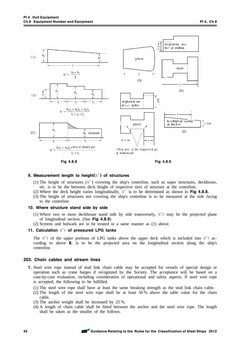
Pt 4 Hull Equipment
Ch 8 Equipment Number and Equipment Pt 4, Ch 8
42 Guidance Relating to the Rules for the Classification of Steel Ships 2012
Fig 4.8.8
Fig 4.8.6
9. Measurement length to height(″ ) of structures(1) The height of structures (″ ) covering the ship's centreline, such as super structures, deckhouse,
etc. is to be the between deck height of respective tiers of structure at the centreline.(2) Where the deck height varies longitudinally, ″ is to be determined as shown in Fig 4.8.8.(3) The height of structures not covering the ship's centreline is to be measured at the side facing
to the centreline.10. Where structure stand side by side
(1) Where two or more deckhouse stand side by side transversely, ″ may be the projected plane of longitudinal section. (See Fig 4.8.9)
(2) Screens and bulwark are to be treated in a same manner as (1) above.11. Calculation ″ of pressured LPG tanks
The ″ of the upper portions of LPG tanks above the upper deck which is included into ″ ac-cording to above 8. is to be the projected area on the longitudinal section along the ship's centreline.
203. Chain cables and stream lines
1. Steel wire rope instead of stud link chain cable may be accepted for vessels of special design or operation such as crane barges if recognized by the Society. The acceptance will be based on a case-by-case evaluation, including consideration of operational and safety aspects. If steel wire rope is accepted, the following to be fulfilled.(1) The steel wire rope shall have at least the same breaking strength as the stud link chain cable.(2) The length of the steel wire rope shall be at least 50 % above the table value for the chain
cable.(3) The anchor weight shall be increased by 25 %.(4) A length of chain cable shall be fitted between the anchor and the steel wire rope. The length
shall be taken as the smaller of the follows.
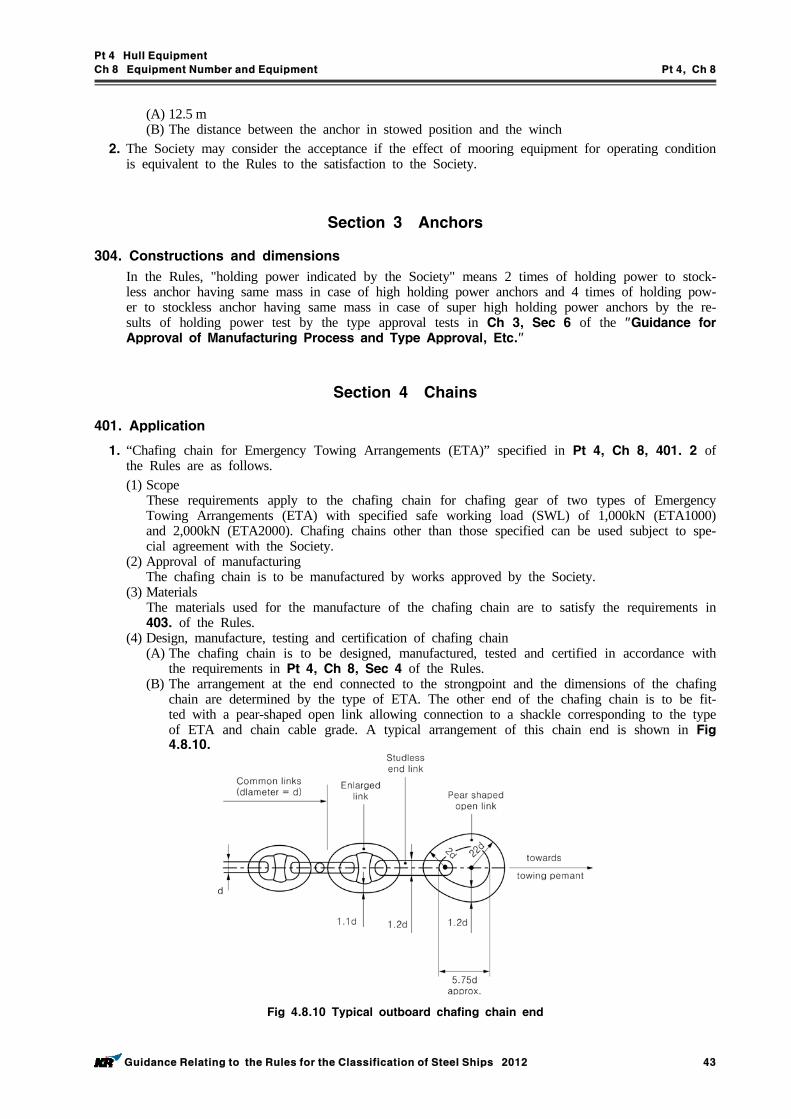
Pt 4 Hull Equipment
Ch 8 Equipment Number and Equipment Pt 4, Ch 8
Guidance Relating to the Rules for the Classification of Steel Ships 2012 43
(A) 12.5 m(B) The distance between the anchor in stowed position and the winch
2. The Society may consider the acceptance if the effect of mooring equipment for operating condition is equivalent to the Rules to the satisfaction to the Society.
Section 3 Anchors
304. Constructions and dimensions
In the Rules, "holding power indicated by the Society" means 2 times of holding power to stock-less anchor having same mass in case of high holding power anchors and 4 times of holding pow-er to stockless anchor having same mass in case of super high holding power anchors by the re-sults of holding power test by the type approval tests in Ch 3, Sec 6 of the "Guidance for Approval of Manufacturing Process and Type Approval, Etc."
Section 4 Chains
401. Application
1. “Chafing chain for Emergency Towing Arrangements (ETA)” specified in Pt 4, Ch 8, 401. 2 of the Rules are as follows.(1) Scope These requirements apply to the chafing chain for chafing gear of two types of Emergency
Towing Arrangements (ETA) with specified safe working load (SWL) of 1,000kN (ETA1000) and 2,000kN (ETA2000). Chafing chains other than those specified can be used subject to spe-cial agreement with the Society.
(2) Approval of manufacturingThe chafing chain is to be manufactured by works approved by the Society.
(3) Materials The materials used for the manufacture of the chafing chain are to satisfy the requirements in 403. of the Rules.
(4) Design, manufacture, testing and certification of chafing chain(A) The chafing chain is to be designed, manufactured, tested and certified in accordance with
the requirements in Pt 4, Ch 8, Sec 4 of the Rules.(B) The arrangement at the end connected to the strongpoint and the dimensions of the chafing
chain are determined by the type of ETA. The other end of the chafing chain is to be fit-ted with a pear-shaped open link allowing connection to a shackle corresponding to the type of ETA and chain cable grade. A typical arrangement of this chain end is shown in Fig 4.8.10.
Fig 4.8.10 Typical outboard chafing chain end
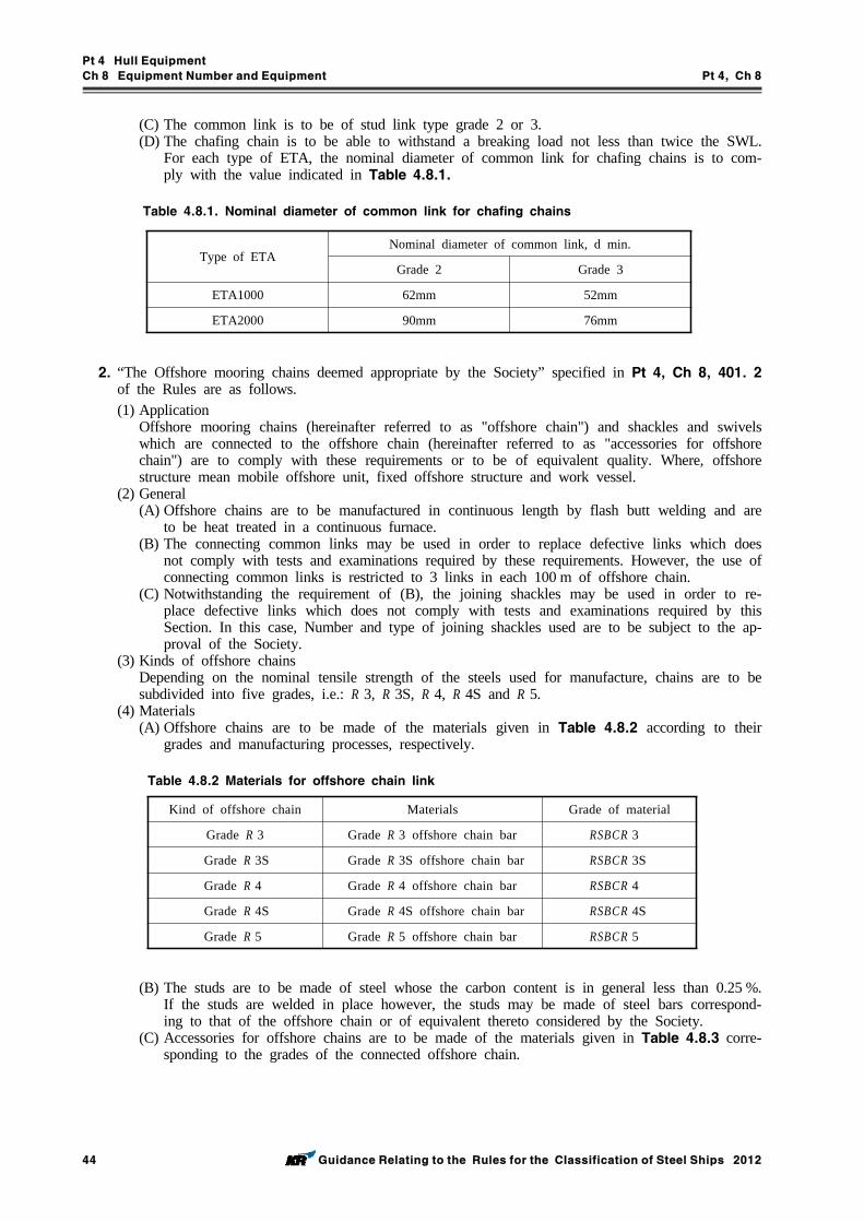
Pt 4 Hull Equipment
Ch 8 Equipment Number and Equipment Pt 4, Ch 8
44 Guidance Relating to the Rules for the Classification of Steel Ships 2012
(C) The common link is to be of stud link type grade 2 or 3.(D) The chafing chain is to be able to withstand a breaking load not less than twice the SWL.
For each type of ETA, the nominal diameter of common link for chafing chains is to com-ply with the value indicated in Table 4.8.1.
Type of ETANominal diameter of common link, d min.
Grade 2 Grade 3
ETA1000 62mm 52mm
ETA2000 90mm 76mm
Table 4.8.1. Nominal diameter of common link for chafing chains
2. “The Offshore mooring chains deemed appropriate by the Society” specified in Pt 4, Ch 8, 401. 2 of the Rules are as follows.(1) Application
Offshore mooring chains (hereinafter referred to as "offshore chain") and shackles and swivels which are connected to the offshore chain (hereinafter referred to as "accessories for offshore chain") are to comply with these requirements or to be of equivalent quality. Where, offshore structure mean mobile offshore unit, fixed offshore structure and work vessel.
(2) General(A) Offshore chains are to be manufactured in continuous length by flash butt welding and are
to be heat treated in a continuous furnace.(B) The connecting common links may be used in order to replace defective links which does
not comply with tests and examinations required by these requirements. However, the use of connecting common links is restricted to 3 links in each 100 m of offshore chain.
(C) Notwithstanding the requirement of (B), the joining shackles may be used in order to re-place defective links which does not comply with tests and examinations required by this Section. In this case, Number and type of joining shackles used are to be subject to the ap-proval of the Society.
(3) Kinds of offshore chainsDepending on the nominal tensile strength of the steels used for manufacture, chains are to be subdivided into five grades, i.e.: R 3, R 3S, R 4, R 4S and R 5.
(4) Materials(A) Offshore chains are to be made of the materials given in Table 4.8.2 according to their
grades and manufacturing processes, respectively.
Table 4.8.2 Materials for offshore chain link
Kind of offshore chain Materials Grade of material
Grade R 3 Grade R 3 offshore chain bar RSBCR 3
Grade R 3S Grade R 3S offshore chain bar RSBCR 3S
Grade R 4 Grade R 4 offshore chain bar RSBCR 4
Grade R 4S Grade R 4S offshore chain bar RSBCR 4S
Grade R 5 Grade R 5 offshore chain bar RSBCR 5
(B) The studs are to be made of steel whose the carbon content is in general less than 0.25 %. If the studs are welded in place however, the studs may be made of steel bars correspond-ing to that of the offshore chain or of equivalent thereto considered by the Society.
(C) Accessories for offshore chains are to be made of the materials given in Table 4.8.3 corre-sponding to the grades of the connected offshore chain.
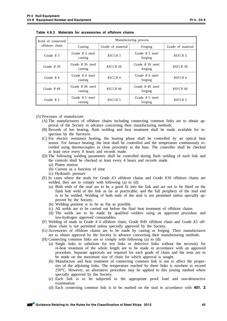
Pt 4 Hull Equipment
Ch 8 Equipment Number and Equipment Pt 4, Ch 8
Guidance Relating to the Rules for the Classification of Steel Ships 2012 45
Table 4.8.3 Materials for accessories of offshore chains
Kind of connected offshore chain
Manufacturing process
Casting Grade of material Forging Grade of material
Grade R 3 Grade R 3 steel casting RSCCR 3 Grade R 3 steel
forging RSFCR 3
Grade R 3S Grade R 3S steel casting RSCCR 3S Grade R 3S steel
forging RSFCR 3S
Grade R 4 Grade R 4 steel casting RSCCR 4 Grade R 4 steel
forging RSFCR 4
Grade R 4S Grade R 4S steel casting RSCCR 4S Grade R 4S steel
forging RSFCR 4S
Grade R 5 Grade R 5 steel casting RSCCR 5 Grade R 5 steel
forging RSFCR 5
(5) Processes of manufacture(A) The manufacturers of offshore chains including connecting common links are to obtain ap-
proval of the Society in advance concerning their manufacturing methods.(B) Records of bar heating, flash welding and heat treatment shall be made available for in-
spection by the Surveyor.(C) For electric resistance heating, the heating phase shall be controlled by an optical heat
sensor. For furnace heating, the heat shall be controlled and the temperature continuously re-corded using thermocouples in close proximity to the bars. The controller shall be checked at least once every 8 hours and records made.
(D) The following welding parameters shall be controlled during flash welding of each link and the controls shall be checked at least every 4 hours and records made.(a) Platen motion(b) Current as a function of time(c) Hydraulic pressure
(E) In cases where the studs for Grade R3 offshore chains and Grade R3S offshore chains are welded, they are to comply with following (a) to (d):(a) Both ends of the stud are to be a good fit into the link and are not to be fitted on the
flash butt weld of the link as far as practicable, and the full periphery of the stud end is to be welded. Welding of both ends of the stud is not permitted unless specially ap-proved by the Society.
(b) Welding position is to be as flat as possible.(c) All welds are to be carried out before the final heat treatment of offshore chains(d) The welds are to be made by qualified welders using an approved procedure and
low-hydrogen approved consumables.(F) Welding of studs in Grade R 4 offshore chain, Grade R4S offshore chain and Grade R5 off-
shore chain is not permitted unless specially approved by the Society.(G) Accessories of offshore chains are to be made by casting or forging. Their manufacturers
are to obtain approval by the Society in advance concerning their manufacturing methods.(H) Connecting common links are to comply with following (a) to (d):
(a) Single links to substitute for test links or defective links without the necessity for re-heat treatment of the whole length are to be made in accordance with an approved procedure. Separate approvals are required for each grade of chain and the tests are to be made on the maximum size of chain for which approval is sought.
(b) Manufacture and heat treatment of connecting common link is not to affect the proper-ties of the adjoining links. The temperature reached by these links is nowhere to exceed 250°C. However, an alternative procedure may be applied to this joining method where specially approved by the Society.
(c) Each link is to be subjected to the appropriate proof load and non-destructive examination.
(d) Each connecting common link is to be marked on the stud in accordance with 401. 2
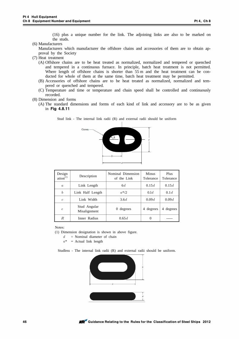
Pt 4 Hull Equipment
Ch 8 Equipment Number and Equipment Pt 4, Ch 8
46 Guidance Relating to the Rules for the Classification of Steel Ships 2012
(16) plus a unique number for the link. The adjoining links are also to be marked on the studs.
(6) ManufacturersManufacturers which manufacturer the offshore chains and accessories of them are to obtain ap-proval by the Society
(7) Heat treatment(A) Offshore chains are to be heat treated as normalized, normalized and tempered or quenched
and tempered in a continuous furnace. In principle, batch heat treatment is not permitted. Where length of offshore chains is shorter than 55 m and the heat treatment can be con-ducted for whole of them at the same time, batch heat treatment may be permitted.
(B) Accessories of offshore chains are to be heat treated as normalized, normalized and tem-pered or quenched and tempered.
(C) Temperature and time or temperature and chain speed shall be controlled and continuously recorded.
(8) Dimension and forms(A) The standard dimensions and forms of each kind of link and accessory are to be as given
in Fig 4.8.11
Stud link - The internal link radii (R) and external radii should be uniform
Designation(1) Description Nominal Dimension
of the LinkMinus
TolerancePlus
Tolerance
Link Length 6 0.15 0.15
Link Half Length */2 0.l 0.1
Link Width 3.6 0.09 0.09
Stud Angular Misalignment 0 degrees 4 degrees 4 degrees
Inner Radius 0.65 0 -----
Notes:(1) Dimension designation is shown in above figure.
= Nominal diameter of chain * = Actual link length
Studless - The internal link radii (R) and external radii should be uniform.
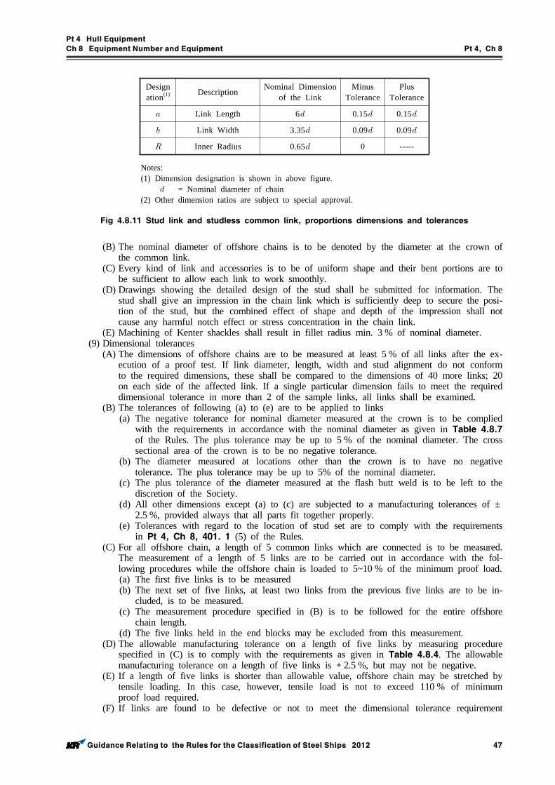
Pt 4 Hull Equipment
Ch 8 Equipment Number and Equipment Pt 4, Ch 8
Guidance Relating to the Rules for the Classification of Steel Ships 2012 47
Designation(1) Description Nominal Dimension
of the LinkMinus
TolerancePlus
Tolerance
Link Length 6 0.15 0.15
Link Width 3.35 0.09 0.09
Inner Radius 0.65 0 -----
Notes:(1) Dimension designation is shown in above figure.
= Nominal diameter of chain(2) Other dimension ratios are subject to special approval.
Fig 4.8.11 Stud link and studless common link, proportions dimensions and tolerances
(B) The nominal diameter of offshore chains is to be denoted by the diameter at the crown of the common link.
(C) Every kind of link and accessories is to be of uniform shape and their bent portions are to be sufficient to allow each link to work smoothly.
(D) Drawings showing the detailed design of the stud shall be submitted for information. The stud shall give an impression in the chain link which is sufficiently deep to secure the posi-tion of the stud, but the combined effect of shape and depth of the impression shall not cause any harmful notch effect or stress concentration in the chain link.
(E) Machining of Kenter shackles shall result in fillet radius min. 3 % of nominal diameter.(9) Dimensional tolerances
(A) The dimensions of offshore chains are to be measured at least 5 % of all links after the ex-ecution of a proof test. If link diameter, length, width and stud alignment do not conform to the required dimensions, these shall be compared to the dimensions of 40 more links; 20 on each side of the affected link. If a single particular dimension fails to meet the required dimensional tolerance in more than 2 of the sample links, all links shall be examined.
(B) The tolerances of following (a) to (e) are to be applied to links(a) The negative tolerance for nominal diameter measured at the crown is to be complied
with the requirements in accordance with the nominal diameter as given in Table 4.8.7 of the Rules. The plus tolerance may be up to 5 % of the nominal diameter. The cross sectional area of the crown is to be no negative tolerance.
(b) The diameter measured at locations other than the crown is to have no negative tolerance. The plus tolerance may be up to 5% of the nominal diameter.
(c) The plus tolerance of the diameter measured at the flash butt weld is to be left to the discretion of the Society.
(d) All other dimensions except (a) to (c) are subjected to a manufacturing tolerances of ±2.5 %, provided always that all parts fit together properly.
(e) Tolerances with regard to the location of stud set are to comply with the requirements in Pt 4, Ch 8, 401. 1 (5) of the Rules.
(C) For all offshore chain, a length of 5 common links which are connected is to be measured. The measurement of a length of 5 links are to be carried out in accordance with the fol-lowing procedures while the offshore chain is loaded to 5~10 % of the minimum proof load. (a) The first five links is to be measured(b) The next set of five links, at least two links from the previous five links are to be in-
cluded, is to be measured.(c) The measurement procedure specified in (B) is to be followed for the entire offshore
chain length.(d) The five links held in the end blocks may be excluded from this measurement.
(D) The allowable manufacturing tolerance on a length of five links by measuring procedure specified in (C) is to comply with the requirements as given in Table 4.8.4. The allowable manufacturing tolerance on a length of five links is + 2.5 %, but may not be negative.
(E) If a length of five links is shorter than allowable value, offshore chain may be stretched by tensile loading. In this case, however, tensile load is not to exceed 110 % of minimum proof load required.
(F) If links are found to be defective or not to meet the dimensional tolerance requirement
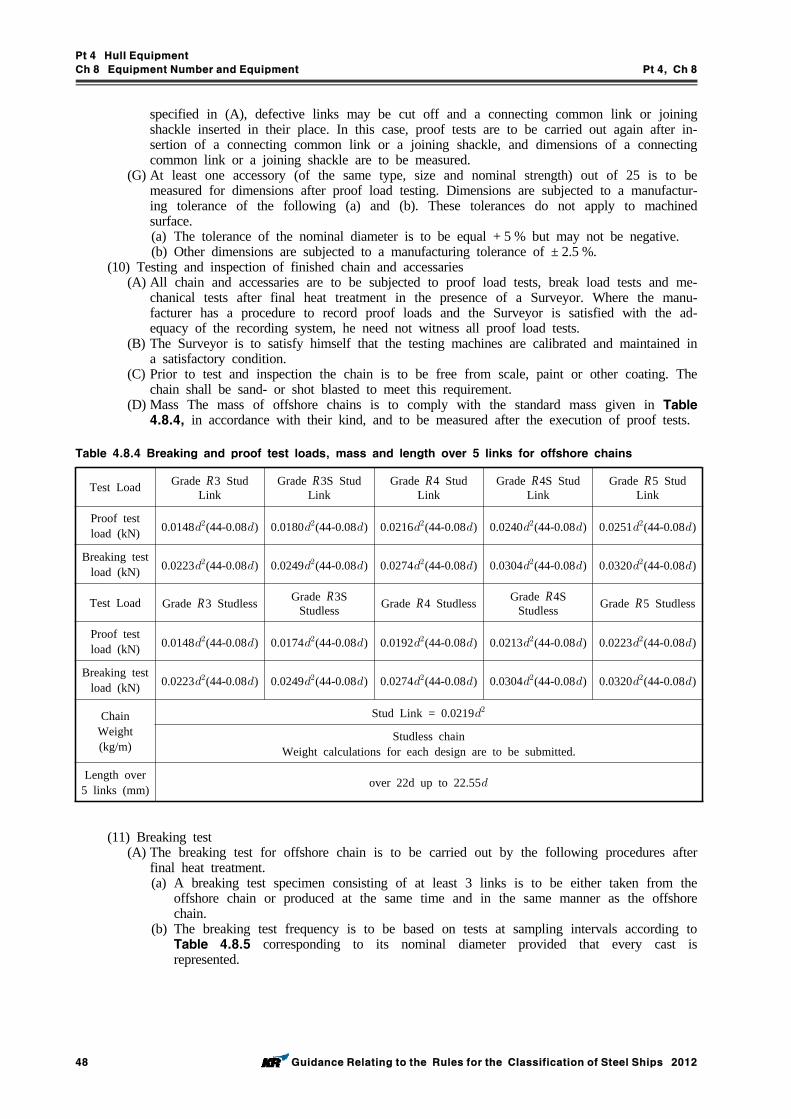
Pt 4 Hull Equipment
Ch 8 Equipment Number and Equipment Pt 4, Ch 8
48 Guidance Relating to the Rules for the Classification of Steel Ships 2012
specified in (A), defective links may be cut off and a connecting common link or joining shackle inserted in their place. In this case, proof tests are to be carried out again after in-sertion of a connecting common link or a joining shackle, and dimensions of a connecting common link or a joining shackle are to be measured.
(G) At least one accessory (of the same type, size and nominal strength) out of 25 is to be measured for dimensions after proof load testing. Dimensions are subjected to a manufactur-ing tolerance of the following (a) and (b). These tolerances do not apply to machined surface.(a) The tolerance of the nominal diameter is to be equal + 5 % but may not be negative.(b) Other dimensions are subjected to a manufacturing tolerance of ± 2.5 %.
(10) Testing and inspection of finished chain and accessaries(A) All chain and accessaries are to be subjected to proof load tests, break load tests and me-
chanical tests after final heat treatment in the presence of a Surveyor. Where the manu-facturer has a procedure to record proof loads and the Surveyor is satisfied with the ad-equacy of the recording system, he need not witness all proof load tests.
(B) The Surveyor is to satisfy himself that the testing machines are calibrated and maintained in a satisfactory condition.
(C) Prior to test and inspection the chain is to be free from scale, paint or other coating. The chain shall be sand- or shot blasted to meet this requirement.
(D) Mass The mass of offshore chains is to comply with the standard mass given in Table 4.8.4, in accordance with their kind, and to be measured after the execution of proof tests.
Table 4.8.4 Breaking and proof test loads, mass and length over 5 links for offshore chains
Test Load Grade R3 Stud Link
Grade R3S Stud Link
Grade R4 Stud Link
Grade R4S Stud Link
Grade R5 Stud Link
Proof test load (kN) 0.0148(44-0.08) 0.0180(44-0.08) 0.0216(44-0.08) 0.0240(44-0.08) 0.0251(44-0.08)
Breaking test load (kN) 0.0223(44-0.08) 0.0249(44-0.08) 0.0274(44-0.08) 0.0304(44-0.08) 0.0320(44-0.08)
Test Load Grade R3 Studless Grade R3S Studless Grade R4 Studless Grade R4S
Studless Grade R5 Studless
Proof test load (kN) 0.0148(44-0.08) 0.0174(44-0.08) 0.0192(44-0.08) 0.0213(44-0.08) 0.0223(44-0.08)
Breaking test load (kN) 0.0223(44-0.08) 0.0249(44-0.08) 0.0274(44-0.08) 0.0304(44-0.08) 0.0320(44-0.08)
Chain Weight (kg/m)
Stud Link = 0.0219
Studless chainWeight calculations for each design are to be submitted.
Length over 5 links (mm) over 22d up to 22.55
(11) Breaking test(A) The breaking test for offshore chain is to be carried out by the following procedures after
final heat treatment.(a) A breaking test specimen consisting of at least 3 links is to be either taken from the
offshore chain or produced at the same time and in the same manner as the offshore chain.
(b) The breaking test frequency is to be based on tests at sampling intervals according to Table 4.8.5 corresponding to its nominal diameter provided that every cast is represented.
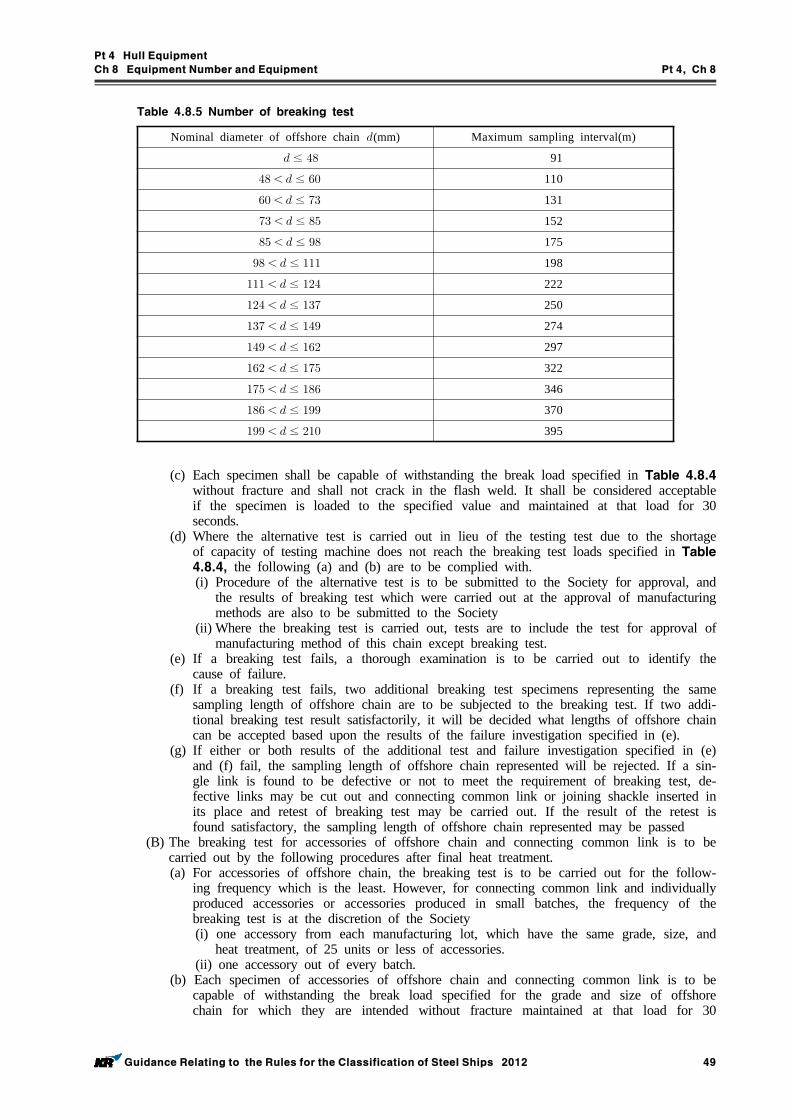
Pt 4 Hull Equipment
Ch 8 Equipment Number and Equipment Pt 4, Ch 8
Guidance Relating to the Rules for the Classification of Steel Ships 2012 49
Table 4.8.5 Number of breaking test
Nominal diameter of offshore chain (mm) Maximum sampling interval(m)
≤ 91
≤ 110
≤ 131
≤ 152
≤ 175
≤ 198
≤ 222
≤ 250
≤ 274
≤ 297
≤ 322
≤ 346
≤ 370
≤ 395
(c) Each specimen shall be capable of withstanding the break load specified in Table 4.8.4 without fracture and shall not crack in the flash weld. It shall be considered acceptable if the specimen is loaded to the specified value and maintained at that load for 30 seconds.
(d) Where the alternative test is carried out in lieu of the testing test due to the shortage of capacity of testing machine does not reach the breaking test loads specified in Table 4.8.4, the following (a) and (b) are to be complied with.(i) Procedure of the alternative test is to be submitted to the Society for approval, and
the results of breaking test which were carried out at the approval of manufacturing methods are also to be submitted to the Society
(ii) Where the breaking test is carried out, tests are to include the test for approval of manufacturing method of this chain except breaking test.
(e) If a breaking test fails, a thorough examination is to be carried out to identify the cause of failure.
(f) If a breaking test fails, two additional breaking test specimens representing the same sampling length of offshore chain are to be subjected to the breaking test. If two addi-tional breaking test result satisfactorily, it will be decided what lengths of offshore chain can be accepted based upon the results of the failure investigation specified in (e).
(g) If either or both results of the additional test and failure investigation specified in (e) and (f) fail, the sampling length of offshore chain represented will be rejected. If a sin-gle link is found to be defective or not to meet the requirement of breaking test, de-fective links may be cut out and connecting common link or joining shackle inserted in its place and retest of breaking test may be carried out. If the result of the retest is found satisfactory, the sampling length of offshore chain represented may be passed
(B) The breaking test for accessories of offshore chain and connecting common link is to be carried out by the following procedures after final heat treatment.(a) For accessories of offshore chain, the breaking test is to be carried out for the follow-
ing frequency which is the least. However, for connecting common link and individually produced accessories or accessories produced in small batches, the frequency of the breaking test is at the discretion of the Society(i) one accessory from each manufacturing lot, which have the same grade, size, and
heat treatment, of 25 units or less of accessories.(ii) one accessory out of every batch.
(b) Each specimen of accessories of offshore chain and connecting common link is to be capable of withstanding the break load specified for the grade and size of offshore chain for which they are intended without fracture maintained at that load for 30
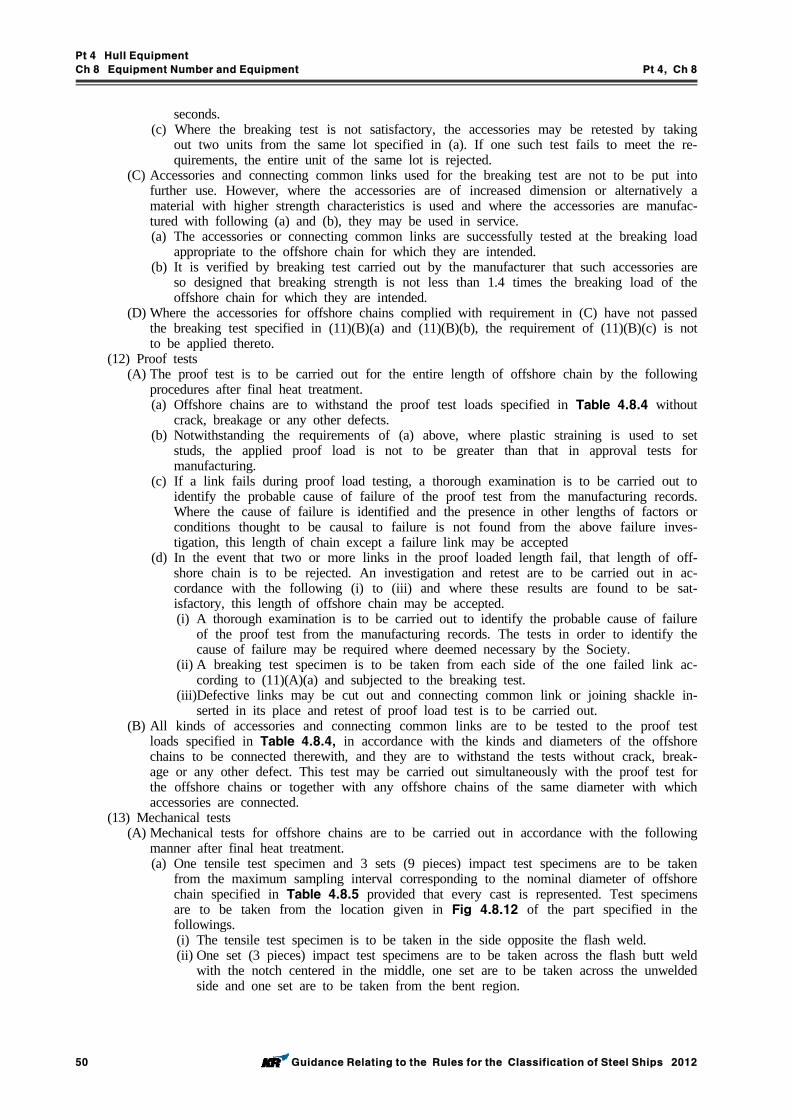
Pt 4 Hull Equipment
Ch 8 Equipment Number and Equipment Pt 4, Ch 8
50 Guidance Relating to the Rules for the Classification of Steel Ships 2012
seconds.(c) Where the breaking test is not satisfactory, the accessories may be retested by taking
out two units from the same lot specified in (a). If one such test fails to meet the re-quirements, the entire unit of the same lot is rejected.
(C) Accessories and connecting common links used for the breaking test are not to be put into further use. However, where the accessories are of increased dimension or alternatively a material with higher strength characteristics is used and where the accessories are manufac-tured with following (a) and (b), they may be used in service.(a) The accessories or connecting common links are successfully tested at the breaking load
appropriate to the offshore chain for which they are intended.(b) It is verified by breaking test carried out by the manufacturer that such accessories are
so designed that breaking strength is not less than 1.4 times the breaking load of the offshore chain for which they are intended.
(D) Where the accessories for offshore chains complied with requirement in (C) have not passed the breaking test specified in (11)(B)(a) and (11)(B)(b), the requirement of (11)(B)(c) is not to be applied thereto.
(12) Proof tests(A) The proof test is to be carried out for the entire length of offshore chain by the following
procedures after final heat treatment.(a) Offshore chains are to withstand the proof test loads specified in Table 4.8.4 without
crack, breakage or any other defects. (b) Notwithstanding the requirements of (a) above, where plastic straining is used to set
studs, the applied proof load is not to be greater than that in approval tests for manufacturing.
(c) If a link fails during proof load testing, a thorough examination is to be carried out to identify the probable cause of failure of the proof test from the manufacturing records. Where the cause of failure is identified and the presence in other lengths of factors or conditions thought to be causal to failure is not found from the above failure inves-tigation, this length of chain except a failure link may be accepted
(d) In the event that two or more links in the proof loaded length fail, that length of off-shore chain is to be rejected. An investigation and retest are to be carried out in ac-cordance with the following (i) to (iii) and where these results are found to be sat-isfactory, this length of offshore chain may be accepted.(i) A thorough examination is to be carried out to identify the probable cause of failure
of the proof test from the manufacturing records. The tests in order to identify the cause of failure may be required where deemed necessary by the Society.
(ii) A breaking test specimen is to be taken from each side of the one failed link ac-cording to (11)(A)(a) and subjected to the breaking test.
(iii)Defective links may be cut out and connecting common link or joining shackle in-serted in its place and retest of proof load test is to be carried out.
(B) All kinds of accessories and connecting common links are to be tested to the proof test loads specified in Table 4.8.4, in accordance with the kinds and diameters of the offshore chains to be connected therewith, and they are to withstand the tests without crack, break-age or any other defect. This test may be carried out simultaneously with the proof test for the offshore chains or together with any offshore chains of the same diameter with which accessories are connected.
(13) Mechanical tests(A) Mechanical tests for offshore chains are to be carried out in accordance with the following
manner after final heat treatment.(a) One tensile test specimen and 3 sets (9 pieces) impact test specimens are to be taken
from the maximum sampling interval corresponding to the nominal diameter of offshore chain specified in Table 4.8.5 provided that every cast is represented. Test specimens are to be taken from the location given in Fig 4.8.12 of the part specified in the followings.(i) The tensile test specimen is to be taken in the side opposite the flash weld.(ii) One set (3 pieces) impact test specimens are to be taken across the flash butt weld
with the notch centered in the middle, one set are to be taken across the unwelded side and one set are to be taken from the bent region.
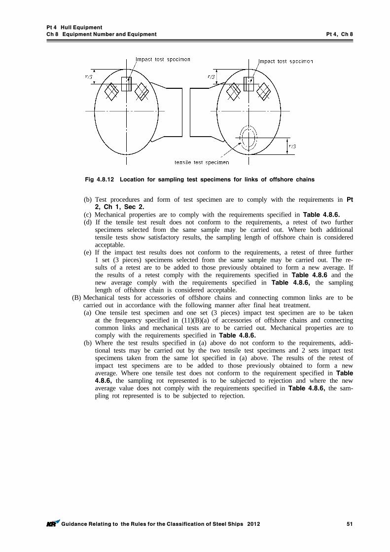
Pt 4 Hull Equipment
Ch 8 Equipment Number and Equipment Pt 4, Ch 8
Guidance Relating to the Rules for the Classification of Steel Ships 2012 51
Fig 4.8.12 Location for sampling test specimens for links of offshore chains
(b) Test procedures and form of test specimen are to comply with the requirements in Pt 2, Ch 1, Sec 2.
(c) Mechanical properties are to comply with the requirements specified in Table 4.8.6.(d) If the tensile test result does not conform to the requirements, a retest of two further
specimens selected from the same sample may be carried out. Where both additional tensile tests show satisfactory results, the sampling length of offshore chain is considered acceptable.
(e) If the impact test results does not conform to the requirements, a retest of three further 1 set (3 pieces) specimens selected from the same sample may be carried out. The re-sults of a retest are to be added to those previously obtained to form a new average. If the results of a retest comply with the requirements specified in Table 4.8.6 and the new average comply with the requirements specified in Table 4.8.6, the sampling length of offshore chain is considered acceptable.
(B) Mechanical tests for accessories of offshore chains and connecting common links are to be carried out in accordance with the following manner after final heat treatment.(a) One tensile test specimen and one set (3 pieces) impact test specimen are to be taken
at the frequency specified in (11)(B)(a) of accessories of offshore chains and connecting common links and mechanical tests are to be carried out. Mechanical properties are to comply with the requirements specified in Table 4.8.6.
(b) Where the test results specified in (a) above do not conform to the requirements, addi-tional tests may be carried out by the two tensile test specimens and 2 sets impact test specimens taken from the same lot specified in (a) above. The results of the retest of impact test specimens are to be added to those previously obtained to form a new average. Where one tensile test does not conform to the requirement specified in Table 4.8.6, the sampling rot represented is to be subjected to rejection and where the new average value does not comply with the requirements specified in Table 4.8.6, the sam-pling rot represented is to be subjected to rejection.
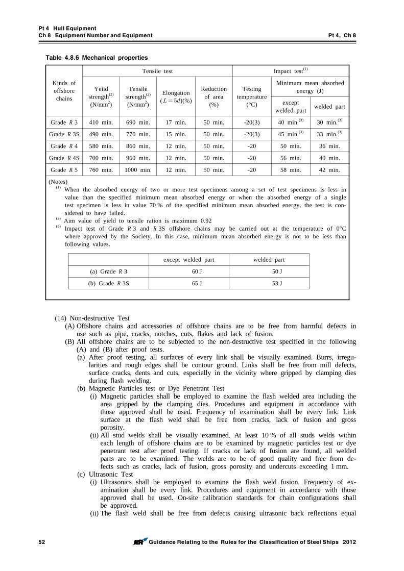
Pt 4 Hull Equipment
Ch 8 Equipment Number and Equipment Pt 4, Ch 8
52 Guidance Relating to the Rules for the Classification of Steel Ships 2012
Table 4.8.6 Mechanical properties
Kinds of offshore chains
Tensile test Impact test(1)
Yeild strength(2)
(N/mm2)
Tensile strength(2)
(N/mm2)
Elongation( )(%)
Reduction of area
(%)
Testing temperature
(°C)
Minimum mean absorbed energy (J)
except welded part welded part
Grade R 3 410 min. 690 min. 17 min. 50 min. -20(3) 40 min.(3) 30 min.(3)
Grade R 3S 490 min. 770 min. 15 min. 50 min. -20(3) 45 min.(3) 33 min.(3)
Grade R 4 580 min. 860 min. 12 min. 50 min. -20 50 min. 36 min.
Grade R 4S 700 min. 960 min. 12 min. 50 min. -20 56 min. 40 min.
Grade R 5 760 min. 1000 min. 12 min. 50 min. -20 58 min. 42 min.
except welded part welded part
(a) Grade R 3 60 J 50 J
(b) Grade R 3S 65 J 53 J
(Notes)(1) When the absorbed energy of two or more test specimens among a set of test specimens is less in
value than the specified minimum mean absorbed energy or when the absorbed energy of a single test specimen is less in value 70 % of the specified minimum mean absorbed energy, the test is con-sidered to have failed.
(2) Aim value of yield to tensile ration is maximum 0.92(3) Impact test of Grade R 3 and R 3S offshore chains may be carried out at the temperature of 0°C
where approved by the Society. In this case, minimum mean absorbed energy is not to be less than following values.
(14) Non-destructive Test(A) Offshore chains and accessories of offshore chains are to be free from harmful defects in
use such as pipe, cracks, notches, cuts, flakes and lack of fusion.(B) All offshore chains are to be subjected to the non-destructive test specified in the following
(A) and (B) after proof tests.(a) After proof testing, all surfaces of every link shall be visually examined. Burrs, irregu-
larities and rough edges shall be contour ground. Links shall be free from mill defects, surface cracks, dents and cuts, especially in the vicinity where gripped by clamping dies during flash welding.
(b) Magnetic Particles test or Dye Penetrant Test(i) Magnetic particles shall be employed to examine the flash welded area including the
area gripped by the clamping dies. Procedures and equipment in accordance with those approved shall be used. Frequency of examination shall be every link. Link surface at the flash weld shall be free from cracks, lack of fusion and gross porosity.
(ii) All stud welds shall be visually examined. At least 10 % of all studs welds within each length of offshore chains are to be examined by magnetic particles test or dye penetrant test after proof testing. If cracks or lack of fusion are found, all welded parts are to be examined. The welds are to be of good quality and free from de-fects such as cracks, lack of fusion, gross porosity and undercuts exceeding 1 mm.
(c) Ultrasonic Test(i) Ultrasonics shall be employed to examine the flash weld fusion. Frequency of ex-
amination shall be every link. Procedures and equipment in accordance with those approved shall be used. On-site calibration standards for chain configurations shall be approved.
(ii) The flash weld shall be free from defects causing ultrasonic back reflections equal
Pt 4 Hull Equipment
Ch 8 Equipment Number and Equipment Pt 4, Ch 8
Guidance Relating to the Rules for the Classification of Steel Ships 2012 53
to or greater than the calibration standard.(C) Magnetic particles test or dye penetrant test for all ac))ssories of offshore chain and con-
necting common link, is to be employed to examine after proof test.(15) Repair of Defects
(A) Where insignificant defects are found from non-destructive test specified in (14) above, they are to be repaired by grinding down no more than 5 % of the link diameter in depth and streamlined to provide no sharp contours, and where their final dimensions are to be within the dimensional tolerances required by (9), those offshore chains and their accessories are considered acceptable.
(B) Where harmful defects are found from non-destructive test specified if (14)(B), a defective link may be cut out and connecting common link or joining shackle inserted in its place. Retests specified in (11) to (13) are to be carried out, and where the results comply with the requirements, these offshore chains and their accessories are considered acceptable.
(16) Markings(A) Where offshore chains and accessories of offshore chains have satisfactorily passed the tests
and inspections required in Par 2, they are to be marked as follows.(a) Places of markings
- At stud of each end of offshore chains- At stud of each end at intervals not exceeding 100 m- On connecting common link- On stud of common links next to connecting common links or joining shackles- All kinds of accessories of offshore chains
(b) Kinds of markings- Society's stamp- The grade of offshore chains and accessories of offshore chains (e.g. KR-R 3, KR-R
3S, KR-R 4, KR-R 4S and KR-R 5)- The nominal diameter of offshore chains and accessories of offshore chains- Manufacturer's number
(B) The marking shall make it possible to recognize leading and tail end of the chain. The marking shall be permanent and legible throughout the expected lifetime of the chain.
(C) All marked links shall be stated on the certificate, and the chain certificate shall contain in-formation on number and location of connecting common links.
(17) PaintingOffshore chains and accessories of offshore chains are not to be painted until the tests and in-spections are finished.
(18) RecordManufacturers producing offshore chains and accessories of offshore chains are to make records with regard to the manufacturing processes tests and inspections required to offshore chains and accessories of offshore chains, and the results of them, and such records are to readily available to the Surrey or when requested.(A) Records of manufacturing processes such as heating of bar materials, flush butt welding,
heat treatment are to include the followings.(a) Checking records of bar materials by electric resistance heating and furnace heating
specified in 2 (5) (C)(b) Checking records of the welding parameters of flash butt welding process specified in 2
(5) (D)(c) Process of heat treatment
Temperature and time of temperature and offshore chains speed are to be controlled and continuously recorded.
(B) Records of testings and inspections are to indicates the following (a) to (d).(a) The results of dimension measurement required by 401. 2 (9) and (10).(b) The results of testing required by 401. 2 (11) to (13)(c) The results of non-destructive test required by 401. 2 (14)(d) If the testings and inspections do not meet the requirements specified in (a) to (c), pho-
tographs of the failure of offshore chains and accessories of offshore chains as well as nonconformity, corrective actions and repair works are included in records.
3. “Chafing Chain for Single Point Mooring arrangements” specified in Pt 4, Ch 8, 401. 2 of the Rules are as follows.(1) Scope
Pt 4 Hull Equipment
Ch 8 Equipment Number and Equipment Pt 4, Ch 8
54 Guidance Relating to the Rules for the Classification of Steel Ships 2012
These requirements apply to short lengths (approximately 8 m) of 76 mm diameter chain to be connected to hawsers for the tethering of oil carriers to single point moorings, FPSO's and sim-ilar uses.
(2) Approval of ManufacturingThe chafing chain is to be manufactured by works approved by the Society .
(3) MaterialsThe materials used for the manufacture of the chafing chain are to satisfy the requirements specified in 403. of the Rules
(4) Design, manufacturing, testing and certification(A) The chafing chain is to be designed, manufactured, tested and certified in accordance with
the requirements specified in 401. 2.(B) The arrangement of the end connections is to be of an approved type.(C) The common link is to be of the stud link type - Grade R3 or R4.(D) The chafing chain is to be capable of withstanding the breaking test loads of 4884 kN
(Grade R3) and 6001 kN (Grade R4). However documented evidence of satisfactory testing of similar diameter mooring chain in the prior six month period may be used in lieu of break testing subject to agreement with classification society.
(E) The chain lengths shall be proof load tested in accordance with 401. 2 (12). The test load for Grade R3 is 3242 kN and for Grade R4 is 4731 kN.
409. Dimensions and forms
1. In Pt 4, Ch 8, 409. 1 of the Rules, when manufacturer would make chains different from stand-ard dimensions, the dimension tables are to be approved by the Society except the case where the dimensions comply with KS or ISO.
2. For anchor chain cables for large anchor specified in Pt 4, Ch 8, 203. 1 of the Rules, the length of the shackle and accessories may be included in one length of chain.
412. Breaking test of chains
1. The omissions of breaking test of chains due to the shortage of capacity of testing machine speci-fied in Pt 4, Ch 8, 412. 2 of the Rules, is to be in accordance with the following requirements in (1) to (3). (1) Chains are to be comply with the requirements as follows.
(A) Chains are to be Grade 2 or Grade 3 chain.(B) Breaking loads specified in Table 4.8.7 of the Rules are to be above 6000 kN.(C) Chains are to be heat treated.(D) Breaking test had been demonstrated at approval test for manufacturing process for the nom-
inal diameter or more.(E) For welded chains specified in Pt 4, Ch 8, 413 of the Rules is to pass the mechanical test
of chain link.(2) Following tests are to be carried out as an alternative test. Manufacturers are to obtain approval
of the concrete testing plan by the Society in advance. The test is able to confirm the strength of welded part for welded chain.(A) Non-destructive inspection(B) Marco-structure inspection(C) Bend test(D) Tensile test(E) For Grade 3 chain impact test may be required for reference.
(3) Where the test had been performed as specified in (2) without breaking test, "Alternative break-ing test has been applied" is indicated in the certificate.
Section 5 Steel Wire Ropes
506. Rope test
1. The values not included in breaking loads of steel wire ropes in Table 4.8.13 specified in Pt 4,
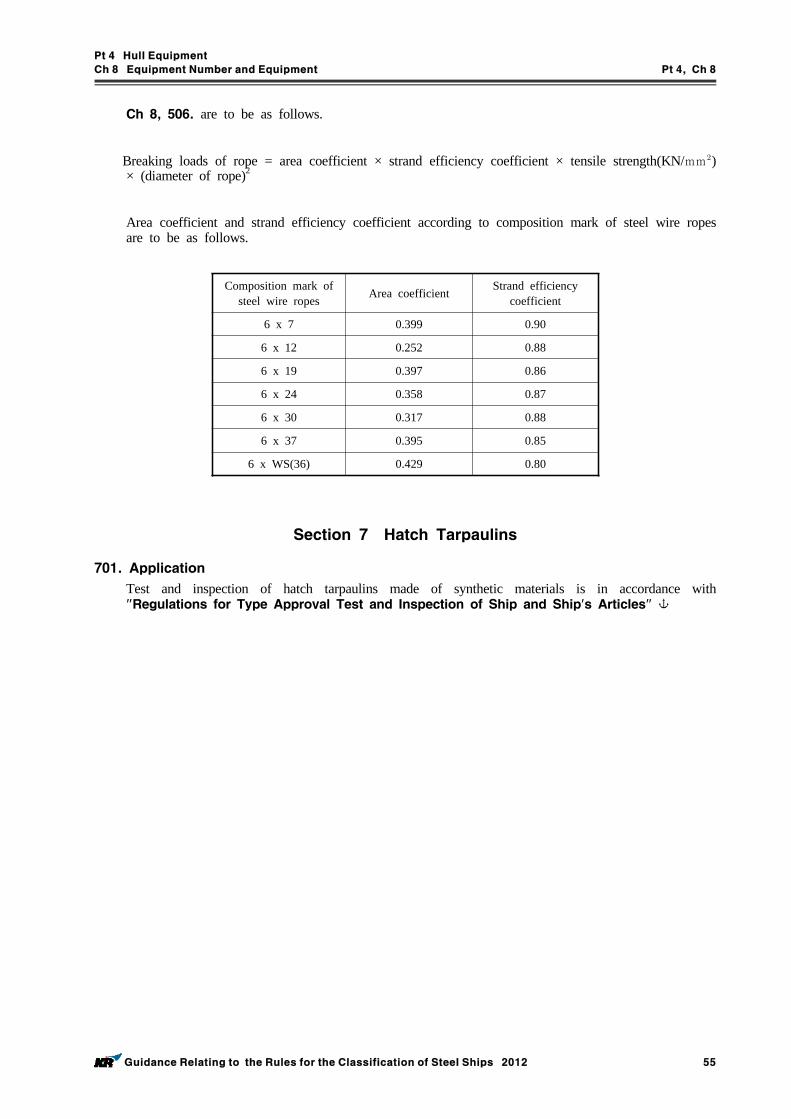
Pt 4 Hull Equipment
Ch 8 Equipment Number and Equipment Pt 4, Ch 8
Guidance Relating to the Rules for the Classification of Steel Ships 2012 55
Ch 8, 506. are to be as follows.
Breaking loads of rope = area coefficient × strand efficiency coefficient × tensile strength(KN/mm) × (diameter of rope)2
Area coefficient and strand efficiency coefficient according to composition mark of steel wire ropes are to be as follows.
Composition mark of steel wire ropes Area coefficient Strand efficiency
coefficient
6 x 7 0.399 0.90
6 x 12 0.252 0.88
6 x 19 0.397 0.86
6 x 24 0.358 0.87
6 x 30 0.317 0.88
6 x 37 0.395 0.85
6 x WS(36) 0.429 0.80
Section 7 Hatch Tarpaulins
701. Application
Test and inspection of hatch tarpaulins made of synthetic materials is in accordance with "Regulations for Type Approval Test and Inspection of Ship and Ship's Articles"
Pt 4 Hull Equipment
Ch 9 Strength and Securing of Small Hatches, Fittings and Equipment on the Fore Deck Pt 4, Ch 9
Guidance Relating to the Rules for the Classification of Steel Ships 2012 57
CHAPTER 9 STRENGTH AND SECURING OF SMALL HATCHES, FITTINGS AND EQUIPMENT ON THE FORE DECK
Section 2Strength and Securing of Small Hatches on the Exposed Fore Deck
201. General
In application of 201. 3. of the Rules, securing devices of hatches designed for emergency escape are to be of a quick-acting type(e.g., one action wheel handles are provided as central locking de-vices for latching/unlatching of hatch cover)operable from both sides of the hatch cover.
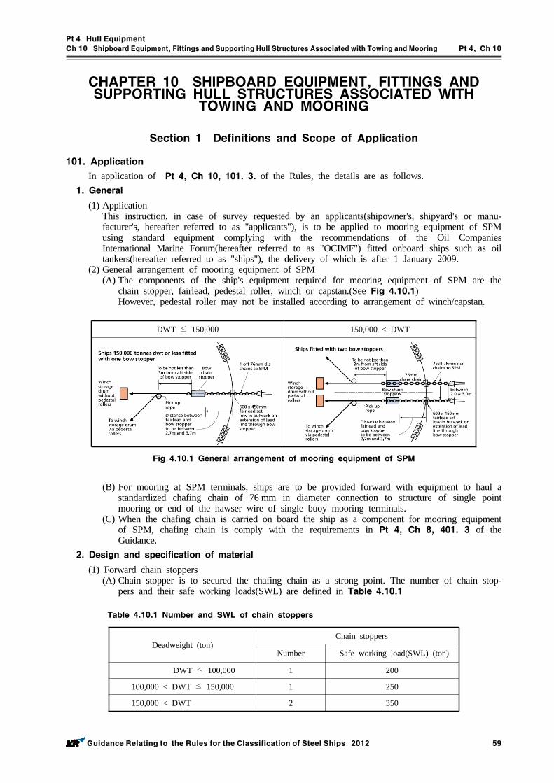
Pt 4 Hull Equipment
Ch 10 Shipboard Equipment, Fittings and Supporting Hull Structures Associated with Towing and Mooring Pt 4, Ch 10
Guidance Relating to the Rules for the Classification of Steel Ships 2012 59
CHAPTER 10 SHIPBOARD EQUIPMENT, FITTINGS AND SUPPORTING HULL STRUCTURES ASSOCIATED WITH
TOWING AND MOORING
Section 1 Definitions and Scope of Application
101. Application
In application of Pt 4, Ch 10, 101. 3. of the Rules, the details are as follows.1. General
(1) Application This instruction, in case of survey requested by an applicants(shipowner's, shipyard's or manu-facturer's, hereafter referred to as "applicants"), is to be applied to mooring equipment of SPM using standard equipment complying with the recommendations of the Oil Companies International Marine Forum(hereafter referred to as "OCIMF") fitted onboard ships such as oil tankers(hereafter referred to as "ships"), the delivery of which is after 1 January 2009.
(2) General arrangement of mooring equipment of SPM(A) The components of the ship's equipment required for mooring equipment of SPM are the
chain stopper, fairlead, pedestal roller, winch or capstan.(See Fig 4.10.1)However, pedestal roller may not be installed according to arrangement of winch/capstan.
DWT ≤ 150,000 150,000 < DWT
Fig 4.10.1 General arrangement of mooring equipment of SPM
(B) For mooring at SPM terminals, ships are to be provided forward with equipment to haul a standardized chafing chain of 76 mm in diameter connection to structure of single point mooring or end of the hawser wire of single buoy mooring terminals.
(C) When the chafing chain is carried on board the ship as a component for mooring equipment of SPM, chafing chain is comply with the requirements in Pt 4, Ch 8, 401. 3 of the Guidance.
2. Design and specification of material
(1) Forward chain stoppers (A) Chain stopper is to secured the chafing chain as a strong point. The number of chain stop-
pers and their safe working loads(SWL) are defined in Table 4.10.1
Deadweight (ton) Chain stoppers
Number Safe working load(SWL) (ton)
DWT ≤ 100,000 1 200
100,000 < DWT ≤ 150,000 1 250
150,000 < DWT 2 350
Table 4.10.1 Number and SWL of chain stoppers
Pt 4 Hull Equipment
Ch 10 Shipboard Equipment, Fittings and Supporting Hull Structures Associated with Towing and Mooring Pt 4, Ch 10
60 Guidance Relating to the Rules for the Classification of Steel Ships 2012
(B) Chain stoppers are to be capable of securing the 76 mm common stud links of the chafing chain when the stopping device is in the closed position, and capable of passing freely the chafing chain and its associated fittings when the stopping device is in the open position.
(C) Chain stoppers may be of the hinged bar or pawl type or of other equivalent design.(D) The stopping device of the chain stopper is to be arranged, when in the closed position, to
prevent it from gradually working to the open position, which would release the chafing chain and allow it to pay out. Stopping devices are to be easy and safe to operate and, in the open position, are to be properly secured.
(E) Chain stoppers are to be located between 2.7 m and 3.7 m inward of the hull from the bow fairlead. Fairlead and pedestal roller are to be located in line with each other.
(F) Stopper supporting structures are to be trimmed to compensate for any camber and/or sheer of the deck. The leading edge of the stopper base plate is to be faired to allow for the un-impeded entry of the chafing chain into the stopper.
(G) Where the chain stopper is bolted to a seating welded to the deck, the bolts are to be sat-isfied with the following strength criteria. However, in such condition, efficient thrust chocks capable of withstanding a horizontal force equal to 2.0 times the required working strength are to be installed.
≤
Where, : The equivalent stress in the equipment components(bolts, etc.) induced by the
loads. : Permissible stress, to be taken, in Nmm, as the lower of 0.67 and 0.4 : Minimum yield stress, in Nmm, of the material : Tensile strength, in Nmm, of the material
(H) The steel grade of bolts is to be not less than grade 8.8 as defined by KS B ISO898-1 (Grade 10.9 is recommended). Bolts are to be pre-stressed in compliance with appropriate standards and tightening is to be suitably checked.
(I) The chain stopper is to be made of rolled steel, steel forging or steel casting complying with the requirements of Pt 2, Ch 1 of the Rules. However, use of spheroidal graphite iron casting may be accepted for the main component of the chain stopper provided that:(a) the component concerned is not to be a welded part(b) the spheroidal graphite iron casting is of ferritic structure with an elongation not less
than 12%(c) the yield stress at 0.2% proof load is measured and surveyed(d) the internal structure of the component is inspected by means of non-destructive exami-
nations(J) The material used for the stopping device (pawl or hinged bar) of chain stoppers is to have
mechanical properties similar to Grade R3 chain cable. (2) Fairleads
(A) One fairlead is to be fitted for each chain stopper.(B) For ships of over 150,000 ton DWT, two fairleads are required and the fairleads are to be
spaced 2.0 m or more center to center apart, if practicable, and in no case more than 3.0 m apart. For ships of 150,000 ton DWT or less, only one fairlead is to be fitted on the centerline.
(C) Fairleads are normally of a closed type such as Panama chocks and are to have an opening large enough to pass the largest portion of the chafing chain, pick-up rope and associated fittings. For this purpose, the inner dimensions of the bow fairlead opening are to be at least 600 mm in width and 450 mm in height.
(D) Fairleads are to be oval or round in shape. The lips of the fairleads are to be suitably faired in order to prevent the chafing chain from fouling on the lower lip when heaving inboard. The bending ratio(bearing surface diameter of the fairlead to chafing chain diame-ter) is to be not less than 7 to 1.
(E) Fairleads are to be located as close as possible to the deck and, in any case, to be in such
Pt 4 Hull Equipment
Ch 10 Shipboard Equipment, Fittings and Supporting Hull Structures Associated with Towing and Mooring Pt 4, Ch 10
Guidance Relating to the Rules for the Classification of Steel Ships 2012 61
a position that the chafing chain is approximately parallel to the deck when it is pulled be-tween the chain stopper and the fairlead.
(F) Fairleads are to be made of rolled steel, steel forging or steel casting complying with the requirements of Pt 2, Ch 1 of the Rules.
(3) Pedestal roller(A) Pedestal rollers are to be positioned to enable a direct pull to be achieved on the con-
tinuation of the direct lead line between the fairlead and chain stopper. They are to be fit-ted not less than 3.0 m behind the chain stopper.
(B) Pedestal rollers are to be capable of withstanding a horizontal force equal to the greater of the following values. Stresses generated by this horizontal force are to comply with the strength criteria indicated in 2 (1) (G).(a) 22.5 ton (b) the resultant force due to an assumed pull of 22.5 ton in the pick-up rope
(C) It is recommended that the pedestal roller should have a diameter not less than 7 times the diameter of the pick-up rope. Where the diameter of the pick-up rope is unknown, the roller diameter should be at least 400 mm.
(4) Winches or capstans(A) Winches or capstans used to handle the mooring gear are to be capable of heaving inboard
a load of at least 15 ton. For this purpose winches or capstans are to be capable of exert-ing a continuous duty pull of not less than 15 ton and withstanding a braking pull of not less than 22.5 ton.
(B) If a winch storage drum is used to stow the pick-up rope, it is to be of sufficient size to accommodate 150 m of rope of 80 mm diameter.
3. Type approval
The prototype testing of mooring equipment of SPM is to be in accordance with Ch 3, Sec 7-2. in "Guidance for Approval of Manufacturing Process and Type Approval, Etc".
4. Certificate Etc.
(1) Issuing, valid term and renewal for the approval certificate are to be complied with Ch 3, Sec 1 in "Guidance for Approval of Manufacturing Process and Type Approval, Etc".
(2) Some components of mooring equipment of SPM may be also used for the bow emergency towing arrangements provided that the requirements of instruction are to be complied with and type approval of bow emergency towing arrangement complied with Ch 3, Sec 7-1. in "Guidance for Approval of Manufacturing Process and Type Approval, Etc".
5. Component's inspection of mooring equipment of SPM
Where components of mooring equipment of SPM have undergone the type approval of this Society and satisfactorily passed the tests and inspections required as followings, the certificate will be is-sued when applicants request the inspection of components.(1) Chain stoppers used to mooring equipment of SPM are according to the followings.
(A) The materials are to comply with the requirements in Pt 2, Ch 1 of the Rules and di-mensions are to comply with an approved drawings.
(B) Performance of chain stopper is to comply with the requirements in 101. 2 (1). (C) Chain stoppers are to be wholly examined by ultrasonic test in principle, but, if impracti-
cable, may be examined by effective non-destructive test such as magnetic particle test. (D) Where chain stoppers have satisfactorily passed the tests and inspections required in this
Society, safe working load and identification numbers are to be marked permanently.(2) Fairleads used to mooring equipment of SPM are to be in accordance with the following
requirements. (A) The materials are to comply with the requirements in Pt 2, Ch 1 of the Rules and di-
mensions are to comply with an approved drawings. (B) Performance of fairleads is to comply with the requirements in 101. 2 (2).(C) Fairleads are to be wholly examined by ultrasonic test in principle, but, if impracticable,
may be examined by effective non-destructive test such as magnetic particle test. (3) Pedestal roller and winches or capstans used to mooring equipment of SPM are to comply with
the requirements in 101. 2 (3), (4) and to be verified by means of certificate/report of in-spection issued by manufacturer.
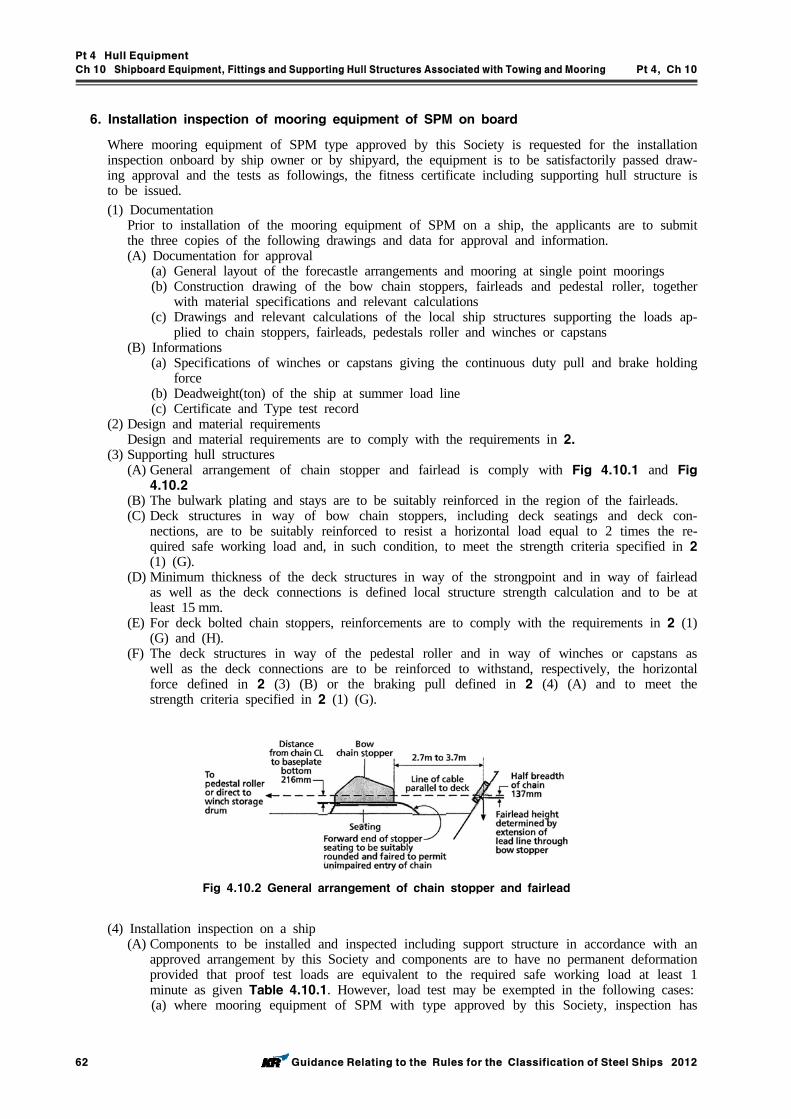
Pt 4 Hull Equipment
Ch 10 Shipboard Equipment, Fittings and Supporting Hull Structures Associated with Towing and Mooring Pt 4, Ch 10
62 Guidance Relating to the Rules for the Classification of Steel Ships 2012
6. Installation inspection of mooring equipment of SPM on board
Where mooring equipment of SPM type approved by this Society is requested for the installation inspection onboard by ship owner or by shipyard, the equipment is to be satisfactorily passed draw-ing approval and the tests as followings, the fitness certificate including supporting hull structure is to be issued.(1) Documentation
Prior to installation of the mooring equipment of SPM on a ship, the applicants are to submit the three copies of the following drawings and data for approval and information. (A) Documentation for approval
(a) General layout of the forecastle arrangements and mooring at single point moorings(b) Construction drawing of the bow chain stoppers, fairleads and pedestal roller, together
with material specifications and relevant calculations (c) Drawings and relevant calculations of the local ship structures supporting the loads ap-
plied to chain stoppers, fairleads, pedestals roller and winches or capstans(B) Informations
(a) Specifications of winches or capstans giving the continuous duty pull and brake holding force
(b) Deadweight(ton) of the ship at summer load line(c) Certificate and Type test record
(2) Design and material requirementsDesign and material requirements are to comply with the requirements in 2.
(3) Supporting hull structures (A) General arrangement of chain stopper and fairlead is comply with Fig 4.10.1 and Fig 4.10.2
(B) The bulwark plating and stays are to be suitably reinforced in the region of the fairleads.(C) Deck structures in way of bow chain stoppers, including deck seatings and deck con-
nections, are to be suitably reinforced to resist a horizontal load equal to 2 times the re-quired safe working load and, in such condition, to meet the strength criteria specified in 2 (1) (G).
(D) Minimum thickness of the deck structures in way of the strongpoint and in way of fairlead as well as the deck connections is defined local structure strength calculation and to be at least 15 mm.
(E) For deck bolted chain stoppers, reinforcements are to comply with the requirements in 2 (1) (G) and (H).
(F) The deck structures in way of the pedestal roller and in way of winches or capstans as well as the deck connections are to be reinforced to withstand, respectively, the horizontal force defined in 2 (3) (B) or the braking pull defined in 2 (4) (A) and to meet the strength criteria specified in 2 (1) (G).
Fig 4.10.2 General arrangement of chain stopper and fairlead
(4) Installation inspection on a ship (A) Components to be installed and inspected including support structure in accordance with an
approved arrangement by this Society and components are to have no permanent deformation provided that proof test loads are equivalent to the required safe working load at least 1 minute as given Table 4.10.1. However, load test may be exempted in the following cases:(a) where mooring equipment of SPM with type approved by this Society, inspection has
Pt 4 Hull Equipment
Ch 10 Shipboard Equipment, Fittings and Supporting Hull Structures Associated with Towing and Mooring Pt 4, Ch 10
Guidance Relating to the Rules for the Classification of Steel Ships 2012 63
been approved in accordance with the requirements in 5.(b) where mooring equipment of SPM without type approved by this Society, strength cal-
culation sheets provided that 2 times the required safety factor should be submitted and approved by this Society and inspection has been approved in accordance with the re-quirements in 5.. provided that proof test loads equivalent to safe working load.
(B) Supporting hull structures are to comply with the requirements in 6 (3).(C) Main welds of the chain stoppers with the hull structure are to be 100 % inspected by
means of non-destructive examinations.(D) Onboard status of an instruction manual and approved drawings are to be confirmed.
Section 2 Towing and Mooring
204. Survey after construction
The condition of deck fittings, their pedestals, if any, and the hull structures in the vicinity of the fittings are to comply with regulations specified in Pt 1, Ch 2, 202. of the Rules.
Pt 4 Hull Equipment
Ch 11 Access to and Within Spaces in, and Forward of, the Cargo Area of Oil Tankers and Bulk Carriers Pt 4, Ch 11
Guidance Relating to the Rules for the Classification of Steel Ships 2012 65
CHAPTER 11 ACCESS TO AND WITHIN SPACES IN,AND FORWARD OF, THE CARGO AREA OF OIL TANKERS
AND BULK CARRIERS
Section 1 General
101. Application
1. In application of 101. 1. of the Rules, the details are as follows.(1) The contents of Res. MSC.151/8(78) can be applied for ships which were keeling on and after
1 Jan. 2005 instead of Res. MSC.133/4(76).(2) Oil tankers:
The regulation is only applicable to oil tankers having integral tanks for carriage of oil in bulk, which is contained in the definition of oil in Annex 1 of MARPOL 73/78. Independent oil tanks can be excluded. SOLAS Regulation II‐1/3‐6 is not normally applied to FPSO or FSO un-less the Administration decides otherwise.
102. Means of access to cargo and other spaces
1. In application of 102. 1 of the Rules, the details are as follows.
Each space for which close-up inspection is not required such as fuel oil tanks and void spaces forward of cargo area, may be provided with a means of access necessary for overall survey in-tended to report on the overall conditions of the hull structure.
2. In application of 102. 2 of the Rules, the details are as follows.(1) Some possible alternative means of access are listed under paragraph 3.9 of TP. Always sub-
ject to acceptance as equivalent by the Administration, alternative means such as an unmanned robot arm, ROV’s and dirigibles with necessary equipment of the permanent means of access for overall and close‐up inspections and thickness measurements of the deck head structure such as deck transverses and deck longitudinals of cargo oil tanks and ballast tanks, are to be capa-ble of:- safe operation in ullage space in gas‐free environment;- introduction into the place directly from a deck access.
3. In application of 102. 3 of the Rules, the details are as follows.(1) Inspection
The MA arrangements, including portable equipment and attachments, are to be periodically in-spected by the crew or competent inspectors as and when it is going to be used to confirm that the MAs remain in serviceable condition.
(2) Procedures(A) Any company authorised person using the MA shall assume the role of inspector and check
for obvious damage prior to using the access arrangements. Whilst using the MA the in-spector is to verify the condition of the sections used by close up examination of those sec-tions and note any deterioration in the provisions. Should any damage or deterioration be found, the effect of such deterioration is to be assessed as to whether the damage or deteri-oration affects the safety for continued use of the access. Deterioration found that is consid-ered to affect safe use is to be determined as “substantial damage” and measures are to be put in place to ensure that the affected section(s) are not to be further used prior effective repair.
(B) Statutory survey of any space that contains MA shall include verification of the continued effectiveness of the MA in that space. Survey of the MA shall not be expected to exceed the scope and extent of the survey being undertaken. If the MA is found deficient the scope of survey should be extended if this is considered appropriate.
(C) Records of all inspections are to be established based on the requirements detailed in the ships Safety Management System. The records are to be readily available to persons using the MAs and a copy attached to the MA Manual. The latest record for the portion of the MA inspected should include as a minimum the date of the inspection, the name and title of the inspector, a confirmation signature, the sections of MA inspected, verification of con-
Pt 4 Hull Equipment
Ch 11 Access to and Within Spaces in, and Forward of, the Cargo Area of Oil Tankers and Bulk Carriers Pt 4, Ch 11
66 Guidance Relating to the Rules for the Classification of Steel Ships 2012
tinued serviceable condition or details of any deterioration or substantial damage found. A file of permits issued should be maintained for verification.
103. Safe access to cargo holds, cargo tanks, ballast tanks and other spaces
1. In application of 103. 1 of the Rules, the details are as follows.
Access to a double side skin space of bulk carriers may be either from a topside tank or double bottom tank or from both.
2. In application of 103. 2 of the Rules, the details are as follows.
A cargo oil tank of less than 35 m length without a swash bulkhead requires only one access hatch.
Where rafting is indicated in the ship structures access manual as the means to gain ready access to the under deck structure, the term "similar obstructions" referred to in the regulation includes in-ternal structures (e.g., webs >1.5 m deep) which restrict the ability to raft (at the maximum water level needed for rafting of under deck structure) directly to the nearest access ladder and hatchway to deck. When rafts or boats alone, as an alternative means of access, are allowed under the con-ditions specified in resolution A.744(18), permanent means of access are to be provided to allow safe entry and exit. This means:(1) access direct from the deck via a vertical ladder and small platform fitted approximately 2 m
below the deck in each bay; or(2) access to deck from a longitudinal permanent platform having ladders to deck in each end of
the tank. The platform shall, for the full length of the tank, be arranged in level with, or above, the maximum water level needed for rafting of under deck structure. For this purpose, the ullage corresponding to the maximum water level is to be assumed not more than 3 m from the deck plate measured at the midspan of deck transverses and in the middle length of the tank. (See Figure below). A permanent means of access from the longitudinal permanent plat-form to the water level indicated above is to be fitted in each bay (e.g., permanent rungs on one of the deck webs inboard of the longitudinal permanent platform).
104. Ship structure access manual
1. In application of 104. 1 of the Rules, the details are as follows.
Access manual should address spaces listed in paragraph 3 of SOLAS II‐1/3‐6.
As a minimum the English version should be provided
The ship structure access manual is to contain at least the following two parts:
Part 1: Plans, instructions and inventory required by paragraphs 4.1.1 to 4.1.7 of SOLAS II‐1/3‐6. This part is to be approved by the Administration or the organization recognised by the Administration
Part 2 : Form of record of inspections and maintenance, and change of inventory of portable equip-ment due to additions or replacement after construction. This part is be approved for its form only at new building.
The following matters are to be addressed in the ship structure access manual:(1) The access manual should clearly cover scope as specified in the regulations for use by crews,
surveyors and port state control officers.(2) Approval / re‐approval procedure for the manual, i.e. any changes of the permanent, portable,
movable or alternative means of access within the scope of the regulation and the Technical provisions are subject to review and approval by the Administration or by the organization rec-ognised by the Administration.
(3) Verification of MA is to be part of safety construction survey for continued effectiveness of the MA in that space which is subject to the statutory survey.
(4) Inspection of MA by the crew and/or a competent inspector of the company as a part of regu-lar inspection and maintenance.
(5) Actions to be taken if MA is found unsafe to use.(6) In case of use of portable equipment plans showing the means of access within each space in-
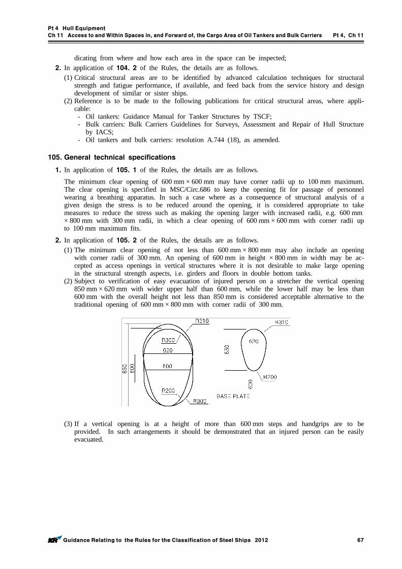
Pt 4 Hull Equipment
Ch 11 Access to and Within Spaces in, and Forward of, the Cargo Area of Oil Tankers and Bulk Carriers Pt 4, Ch 11
Guidance Relating to the Rules for the Classification of Steel Ships 2012 67
dicating from where and how each area in the space can be inspected;2. In application of 104. 2 of the Rules, the details are as follows.
(1) Critical structural areas are to be identified by advanced calculation techniques for structural strength and fatigue performance, if available, and feed back from the service history and design development of similar or sister ships.
(2) Reference is to be made to the following publications for critical structural areas, where appli-cable: - Oil tankers: Guidance Manual for Tanker Structures by TSCF; - Bulk carriers: Bulk Carriers Guidelines for Surveys, Assessment and Repair of Hull Structure
by IACS; - Oil tankers and bulk carriers: resolution A.744 (18), as amended.
105. General technical specifications
1. In application of 105. 1 of the Rules, the details are as follows.
The minimum clear opening of 600 mm × 600 mm may have corner radii up to 100 mm maximum. The clear opening is specified in MSC/Circ.686 to keep the opening fit for passage of personnel wearing a breathing apparatus. In such a case where as a consequence of structural analysis of a given design the stress is to be reduced around the opening, it is considered appropriate to take measures to reduce the stress such as making the opening larger with increased radii, e.g. 600 mm× 800 mm with 300 mm radii, in which a clear opening of 600 mm × 600 mm with corner radii up to 100 mm maximum fits.
2. In application of 105. 2 of the Rules, the details are as follows.(1) The minimum clear opening of not less than 600 mm × 800 mm may also include an opening
with corner radii of 300 mm. An opening of 600 mm in height × 800 mm in width may be ac-cepted as access openings in vertical structures where it is not desirable to make large opening in the structural strength aspects, i.e. girders and floors in double bottom tanks.
(2) Subject to verification of easy evacuation of injured person on a stretcher the vertical opening 850 mm × 620 mm with wider upper half than 600 mm, while the lower half may be less than 600 mm with the overall height not less than 850 mm is considered acceptable alternative to the traditional opening of 600 mm × 800 mm with corner radii of 300 mm.
(3) If a vertical opening is at a height of more than 600 mm steps and handgrips are to be provided. In such arrangements it should be demonstrated that an injured person can be easily evacuated.
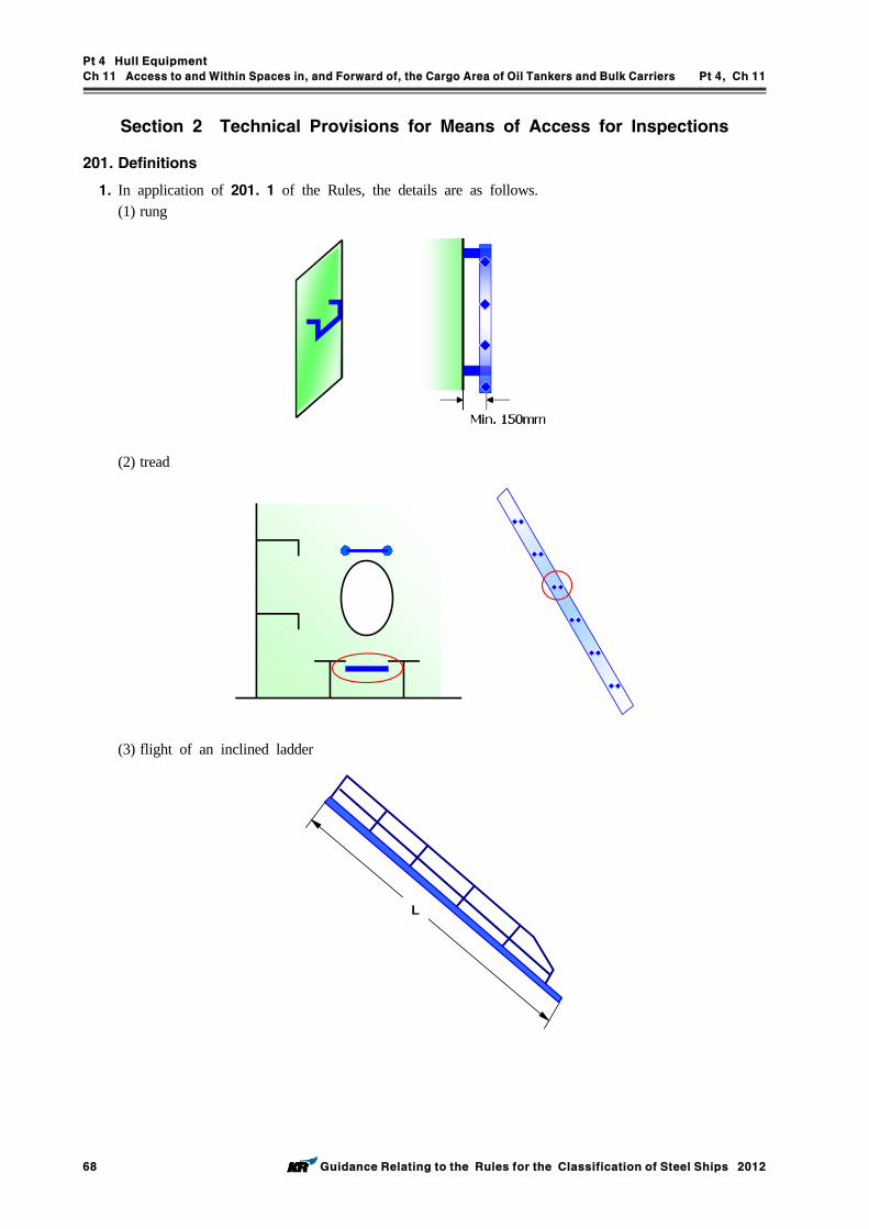
Pt 4 Hull Equipment
Ch 11 Access to and Within Spaces in, and Forward of, the Cargo Area of Oil Tankers and Bulk Carriers Pt 4, Ch 11
68 Guidance Relating to the Rules for the Classification of Steel Ships 2012
Section 2 Technical Provisions for Means of Access for Inspections
201. Definitions
1. In application of 201. 1 of the Rules, the details are as follows.(1) rung
(2) tread
(3) flight of an inclined ladder
L
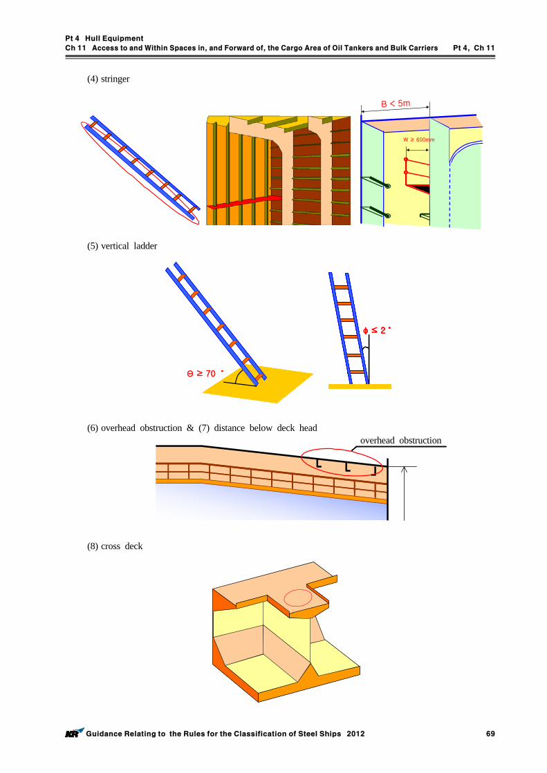
Pt 4 Hull Equipment
Ch 11 Access to and Within Spaces in, and Forward of, the Cargo Area of Oil Tankers and Bulk Carriers Pt 4, Ch 11
Guidance Relating to the Rules for the Classification of Steel Ships 2012 69
(4) stringer
B < 5m
W ≥ 600mm
(5) vertical ladder
Θ ≥ 70 ˚Θ ≥ 70 ˚
φ ≤ 2 ˚φ ≤ 2 ˚φ ≤ 2 ˚
(6) overhead obstruction & (7) distance below deck head
(8) cross deck
overhead obstruction
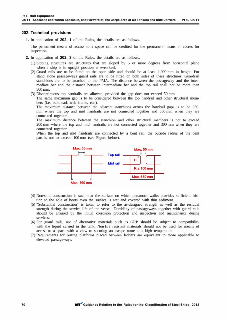
Pt 4 Hull Equipment
Ch 11 Access to and Within Spaces in, and Forward of, the Cargo Area of Oil Tankers and Bulk Carriers Pt 4, Ch 11
70 Guidance Relating to the Rules for the Classification of Steel Ships 2012
202. Technical provisions
1. In application of 202. 1 of the Rules, the details are as follows.
The permanent means of access to a space can be credited for the permanent means of access for inspection.
2. In application of 202. 3 of the Rules, the details are as follows.(1) Sloping structures are structures that are sloped by 5 or more degrees from horizontal plane
when a ship is in upright position at even‐keel. (2) Guard rails are to be fitted on the open side and should be at least 1,000 mm in height. For
stand alone passageways guard rails are to be fitted on both sides of these structures. Guardrail stanchions are to be attached to the PMA. The distance between the passageway and the inter-mediate bar and the distance between intermediate bar and the top rail shall not be more than 500 mm.
(3) Discontinuous top handrails are allowed, provided the gap does not exceed 50 mm.The same maximum gap is to be considered between the top handrail and other structural mem-bers (i.e. bulkhead, web frame, etc.).The maximum distance between the adjacent stanchions across the handrail gaps is to be 350mm where the top and mid handrails are not connected together and 550 mm when they are connected together.The maximum distance between the stanchion and other structural members is not to exceed 200 mm where the top and mid handrails are not connected together and 300 mm when they are connected together.When the top and mid handrails are connected by a bent rail, the outside radius of the bent part is not to exceed 100 mm (see Figure below).
(4) Non‐skid construction is such that the surface on which personnel walks provides sufficient fric-tion to the sole of boots even the surface is wet and covered with thin sediment.
(5) “Substantial construction” is taken to refer to the as-designed strength as well as the residual strength during the service life of the vessel. Durability of passageways together with guard rails should be ensured by the initial corrosion protection and inspection and maintenance during services.
(6) For guard rails, use of alternative materials such as GRP should be subject to compatibility with the liquid carried in the tank. Non‐fire resistant materials should not be used for means of access to a space with a view to securing an escape route at a high temperature.
(7) Requirements for resting platforms placed between ladders are equivalent to those applicable to elevated passageways.
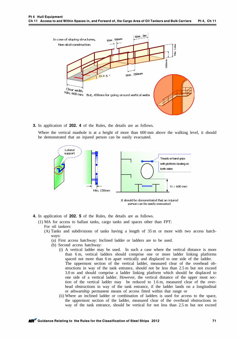
Pt 4 Hull Equipment
Ch 11 Access to and Within Spaces in, and Forward of, the Cargo Area of Oil Tankers and Bulk Carriers Pt 4, Ch 11
Guidance Relating to the Rules for the Classification of Steel Ships 2012 71
3. In application of 202. 4 of the Rules, the details are as follows.
Where the vertical manhole is at a height of more than 600 mm above the walking level, it should be demonstrated that an injured person can be easily evacuated.
4. In application of 202. 5 of the Rules, the details are as follows.(1) MA for access to ballast tanks, cargo tanks and spaces other than FPT:
For oil tankers:(A) Tanks and subdivisions of tanks having a length of 35 m or more with two access hatch-
ways:(a) First access hatchway: Inclined ladder or ladders are to be used.(b) Second access hatchway:
(i) A vertical ladder may be used. In such a case where the vertical distance is more than 6 m, vertical ladders should comprise one or more ladder linking platforms spaced not more than 6 m apart vertically and displaced to one side of the ladder.
The uppermost section of the vertical ladder, measured clear of the overhead ob-structions in way of the tank entrance, should not be less than 2.5 m but not exceed 3.0 m and should comprise a ladder linking platform which should be displaced to one side of a vertical ladder. However, the vertical distance of the upper most sec-tion of the vertical ladder may be reduced to 1.6 m, measured clear of the over-head obstructions in way of the tank entrance, if the ladder lands on a longitudinal or athwartship permanent means of access fitted within that range or
(ii) Where an inclined ladder or combination of ladders is used for access to the space, the uppermost section of the ladder, measured clear of the overhead obstructions in way of the tank entrance, should be vertical for not less than 2.5 m but not exceed
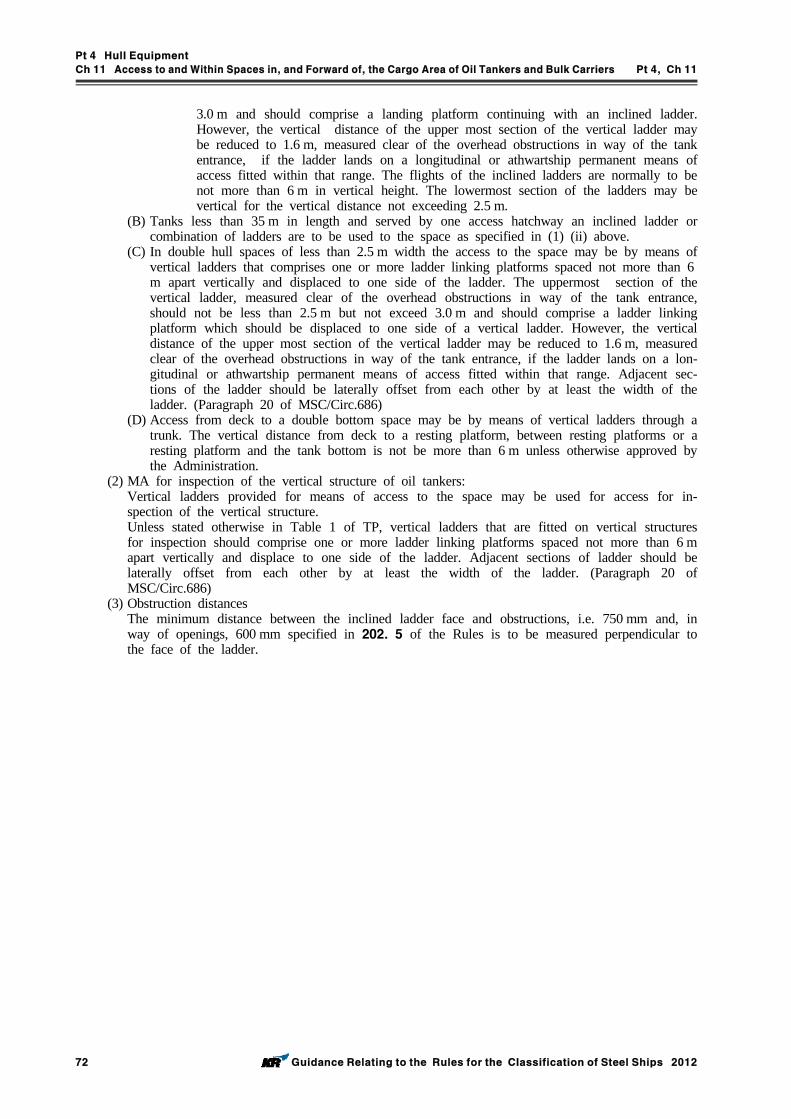
Pt 4 Hull Equipment
Ch 11 Access to and Within Spaces in, and Forward of, the Cargo Area of Oil Tankers and Bulk Carriers Pt 4, Ch 11
72 Guidance Relating to the Rules for the Classification of Steel Ships 2012
3.0 m and should comprise a landing platform continuing with an inclined ladder. However, the vertical distance of the upper most section of the vertical ladder may be reduced to 1.6 m, measured clear of the overhead obstructions in way of the tank entrance, if the ladder lands on a longitudinal or athwartship permanent means of access fitted within that range. The flights of the inclined ladders are normally to be not more than 6 m in vertical height. The lowermost section of the ladders may be vertical for the vertical distance not exceeding 2.5 m.
(B) Tanks less than 35 m in length and served by one access hatchway an inclined ladder or combination of ladders are to be used to the space as specified in (1) (ii) above.
(C) In double hull spaces of less than 2.5 m width the access to the space may be by means of vertical ladders that comprises one or more ladder linking platforms spaced not more than 6m apart vertically and displaced to one side of the ladder. The uppermost section of the vertical ladder, measured clear of the overhead obstructions in way of the tank entrance, should not be less than 2.5 m but not exceed 3.0 m and should comprise a ladder linking platform which should be displaced to one side of a vertical ladder. However, the vertical distance of the upper most section of the vertical ladder may be reduced to 1.6 m, measured clear of the overhead obstructions in way of the tank entrance, if the ladder lands on a lon-gitudinal or athwartship permanent means of access fitted within that range. Adjacent sec-tions of the ladder should be laterally offset from each other by at least the width of the ladder. (Paragraph 20 of MSC/Circ.686)
(D) Access from deck to a double bottom space may be by means of vertical ladders through a trunk. The vertical distance from deck to a resting platform, between resting platforms or a resting platform and the tank bottom is not be more than 6 m unless otherwise approved by the Administration.
(2) MA for inspection of the vertical structure of oil tankers:Vertical ladders provided for means of access to the space may be used for access for in-spection of the vertical structure.Unless stated otherwise in Table 1 of TP, vertical ladders that are fitted on vertical structures for inspection should comprise one or more ladder linking platforms spaced not more than 6 m apart vertically and displace to one side of the ladder. Adjacent sections of ladder should be laterally offset from each other by at least the width of the ladder. (Paragraph 20 of MSC/Circ.686)
(3) Obstruction distancesThe minimum distance between the inclined ladder face and obstructions, i.e. 750 mm and, in way of openings, 600 mm specified in 202. 5 of the Rules is to be measured perpendicular to the face of the ladder.
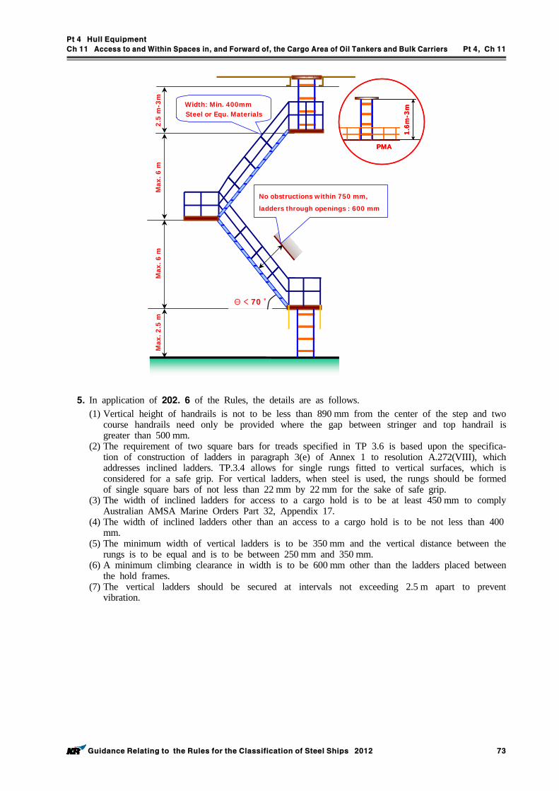
Pt 4 Hull Equipment
Ch 11 Access to and Within Spaces in, and Forward of, the Cargo Area of Oil Tankers and Bulk Carriers Pt 4, Ch 11
Guidance Relating to the Rules for the Classification of Steel Ships 2012 73
Max
. 6 m
Θ < 70 ˚
No obstructions within 750 mm,
ladders through openings : 600 mm
Max
. 2.5
m
Width: Min. 400mmSteel or Equ. Materials
Max
. 6 m
2.5
m-3
m
1.6m
-3m
PMA
1.6m
-3m
PMA
5. In application of 202. 6 of the Rules, the details are as follows.(1) Vertical height of handrails is not to be less than 890 mm from the center of the step and two
course handrails need only be provided where the gap between stringer and top handrail is greater than 500 mm.
(2) The requirement of two square bars for treads specified in TP 3.6 is based upon the specifica-tion of construction of ladders in paragraph 3(e) of Annex 1 to resolution A.272(VIII), which addresses inclined ladders. TP.3.4 allows for single rungs fitted to vertical surfaces, which is considered for a safe grip. For vertical ladders, when steel is used, the rungs should be formed of single square bars of not less than 22 mm by 22 mm for the sake of safe grip.
(3) The width of inclined ladders for access to a cargo hold is to be at least 450 mm to comply Australian AMSA Marine Orders Part 32, Appendix 17.
(4) The width of inclined ladders other than an access to a cargo hold is to be not less than 400mm.
(5) The minimum width of vertical ladders is to be 350 mm and the vertical distance between the rungs is to be equal and is to be between 250 mm and 350 mm.
(6) A minimum climbing clearance in width is to be 600 mm other than the ladders placed between the hold frames.
(7) The vertical ladders should be secured at intervals not exceeding 2.5 m apart to prevent vibration.
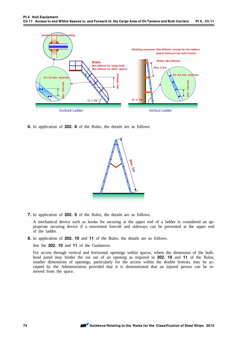
Pt 4 Hull Equipment
Ch 11 Access to and Within Spaces in, and Forward of, the Cargo Area of Oil Tankers and Bulk Carriers Pt 4, Ch 11
74 Guidance Relating to the Rules for the Classification of Steel Ships 2012
Θ ≥ 70 ˚
22×22 mm steel bar
20
0∼
300
mm
Min
. 890
mm
WidthMin.450mm for cargo holdMin.400mm for other spaces
Double continuous welding
Θ < 70 ˚
250∼
35
0m
m
Max. 2.5m
Width: Min.350mm
Inclined Ladder Vertical Ladder
Climbing clearance: Min.600mm, except for the laddersplaced between the hold frames
22×22 mm steel bar
6. In application of 202. 8 of the Rules, the details are as follows.
Max. 5m
7. In application of 202. 9 of the Rules, the details are as follows.
A mechanical device such as hooks for securing at the upper end of a ladder is considered an ap-propriate securing device if a movement fore/aft and sideways can be prevented at the upper end of the ladder.
8. In application of 202. 10 and 11 of the Rules, the details are as follows.
See the 202. 10 and 11 of the Guidances.
For access through vertical and horizontal openings within spaces, where the dimension of the bulk-head panel may hinder the cut out of an opening as required in 202. 10 and 11 of the Rules, smaller dimensions of openings, particularly for the access within the double bottom, may be ac-cepted by the Administration provided that it is demonstrated that an injured person can be re-moved from the space.
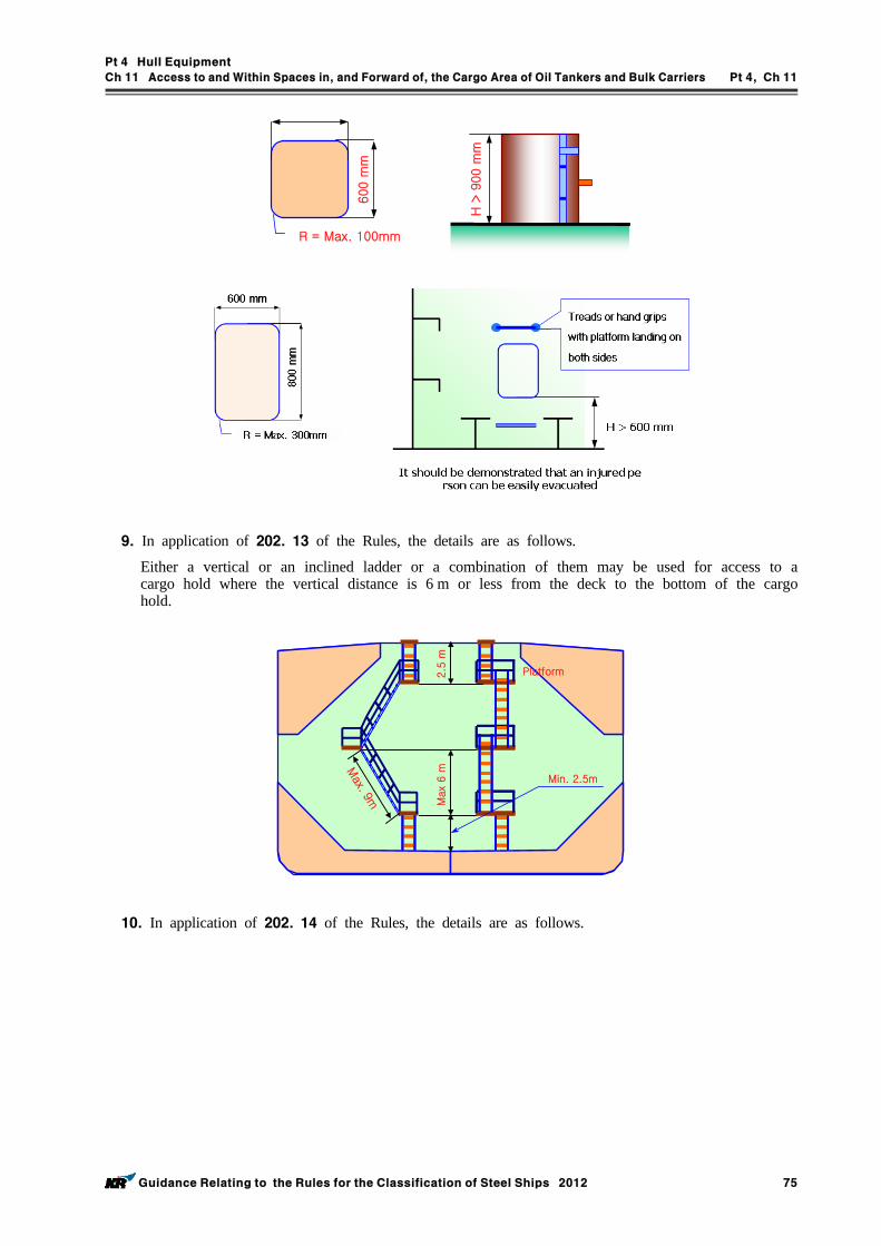
Pt 4 Hull Equipment
Ch 11 Access to and Within Spaces in, and Forward of, the Cargo Area of Oil Tankers and Bulk Carriers Pt 4, Ch 11
Guidance Relating to the Rules for the Classification of Steel Ships 2012 75
600 m
m
R = Max. 100mm
H >
900 m
m
9. In application of 202. 13 of the Rules, the details are as follows.
Either a vertical or an inclined ladder or a combination of them may be used for access to a cargo hold where the vertical distance is 6 m or less from the deck to the bottom of the cargo hold.
Platform
Max
6 m
2.5
m
Min. 2.5m
Max. 9m
10. In application of 202. 14 of the Rules, the details are as follows.
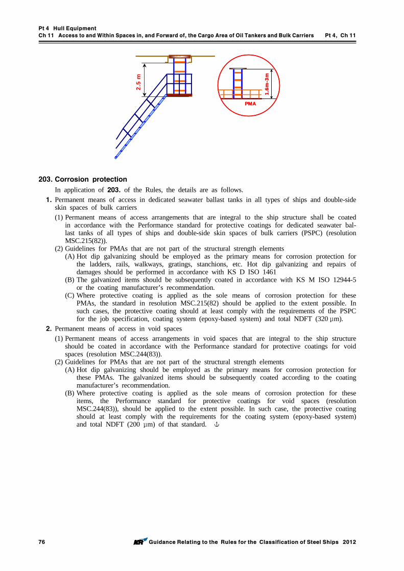
Pt 4 Hull Equipment
Ch 11 Access to and Within Spaces in, and Forward of, the Cargo Area of Oil Tankers and Bulk Carriers Pt 4, Ch 11
76 Guidance Relating to the Rules for the Classification of Steel Ships 2012
1.6m
-3m
PMA
1.6m
-3m
PMA
2.5
m
203. Corrosion protection
In application of 203. of the Rules, the details are as follows.1. Permanent means of access in dedicated seawater ballast tanks in all types of ships and double-side
skin spaces of bulk carriers(1) Permanent means of access arrangements that are integral to the ship structure shall be coated
in accordance with the Performance standard for protective coatings for dedicated seawater bal-last tanks of all types of ships and double-side skin spaces of bulk carriers (PSPC) (resolution MSC.215(82)).
(2) Guidelines for PMAs that are not part of the structural strength elements(A) Hot dip galvanizing should be employed as the primary means for corrosion protection for
the ladders, rails, walkways, gratings, stanchions, etc. Hot dip galvanizing and repairs of damages should be performed in accordance with KS D ISO 1461
(B) The galvanized items should be subsequently coated in accordance with KS M ISO 12944-5 or the coating manufacturer’s recommendation.
(C) Where protective coating is applied as the sole means of corrosion protection for these PMAs, the standard in resolution MSC.215(82) should be applied to the extent possible. In such cases, the protective coating should at least comply with the requirements of the PSPC for the job specification, coating system (epoxy-based system) and total NDFT (320 μm).
2. Permanent means of access in void spaces(1) Permanent means of access arrangements in void spaces that are integral to the ship structure
should be coated in accordance with the Performance standard for protective coatings for void spaces (resolution MSC.244(83)).
(2) Guidelines for PMAs that are not part of the structural strength elements(A) Hot dip galvanizing should be employed as the primary means for corrosion protection for
these PMAs. The galvanized items should be subsequently coated according to the coating manufacturer’s recommendation.
(B) Where protective coating is applied as the sole means of corrosion protection for these items, the Performance standard for protective coatings for void spaces (resolution MSC.244(83)), should be applied to the extent possible. In such case, the protective coating should at least comply with the requirements for the coating system (epoxy-based system) and total NDFT (200 μm) of that standard.
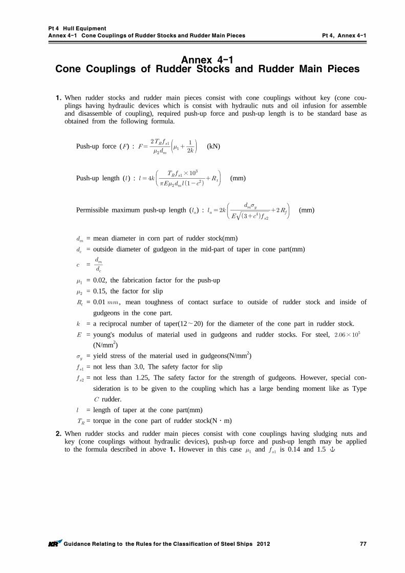
Pt 4 Hull Equipment
Annex 4-1 Cone Couplings of Rudder Stocks and Rudder Main Pieces Pt 4, Annex 4-1
Guidance Relating to the Rules for the Classification of Steel Ships 2012 77
Annex 4-1 Cone Couplings of Rudder Stocks and Rudder Main Pieces
1. When rudder stocks and rudder main pieces consist with cone couplings without key (cone cou-plings having hydraulic devices which is consist with hydraulic nuts and oil infusion for assemble and disassemble of coupling), required push-up force and push-up length is to be standard base as obtained from the following formula.
Push-up force () :
(kN)
Push-up length () :
×
(mm)
Permissible maximum push-up length () :
(mm)
= mean diameter in corn part of rudder stock(mm) = outside diameter of gudgeon in the mid-part of taper in cone part(mm)
=
= 0.02, the fabrication factor for the push-up = 0.15, the factor for slip = 0.01 , mean toughness of contact surface to outside of rudder stock and inside of
gudgeons in the cone part. = a reciprocal number of taper(12~20) for the diameter of the cone part in rudder stock. = young's modulus of material used in gudgeons and rudder stocks. For steel, ×
(N/mm2) = yield stress of the material used in gudgeons(N/mm2) = not less than 3.0, The safety factor for slip = not less than 1.25, The safety factor for the strength of gudgeons. However, special con-
sideration is to be given to the coupling which has a large bending moment like as Type rudder.
= length of taper at the cone part(mm) = torque in the cone part of rudder stock(N․m)
2. When rudder stocks and rudder main pieces consist with cone couplings having sludging nuts and key (cone couplings without hydraulic devices), push-up force and push-up length may be applied to the formula described in above 1. However in this case and is 0.14 and 1.5
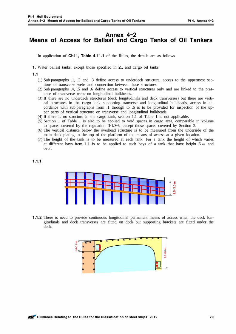
Pt 4 Hull Equipment
Annex 4-2 Means of Access for Ballast and Cargo Tanks of Oil Tankers Pt 4, Annex 4-2
Guidance Relating to the Rules for the Classification of Steel Ships 2012 79
Annex 4-2 Means of Access for Ballast and Cargo Tanks of Oil Tankers
In application of Ch11, Table 4.11.1 of the Rules, the details are as follows.
1. Water ballast tanks, except those specified in 2., and cargo oil tanks
1.1 (1) Sub‐paragraphs .1, .2 and .3 define access to underdeck structure, access to the uppermost sec-
tions of transverse webs and connection between these structures.(2) Sub‐paragraphs .4, .5 and .6 define access to vertical structures only and are linked to the pres-
ence of transverse webs on longitudinal bulkheads.(3) If there are no underdeck structures (deck longitudinals and deck transverses) but there are verti-
cal structures in the cargo tank supporting tranverse and longitudinal bulkheads, access in ac-cordance with sub‐paragraphs from .1 through to .6 is to be provided for inspection of the up-per parts of vertical structure on transverse and longitudinal bulkheads.
(4) If there is no structure in the cargo tank, section 1.1 of Table 1 is not applicable.(5) Section 1 of Table 1 is also to be applied to void spaces in cargo area, comparable in volume
to spaces covered by the regulation II‐1/3‐6, except those spaces covered by Section 2.(6) The vertical distance below the overhead structure is to be measured from the underside of the
main deck plating to the top of the platform of the means of access at a given location.(7) The height of the tank is to be measured at each tank. For a tank the height of which varies
at different bays item 1.1 is to be applied to such bays of a tank that have height 6 and over.
1.1.1
1.6
–3.0
m
1.1.2 There is need to provide continuous longitudinal permanent means of access when the deck lon-gitudinals and deck transverses are fitted on deck but supporting brackets are fitted under the deck.
1.6
–6.
0 m
1.6
–3.0
m
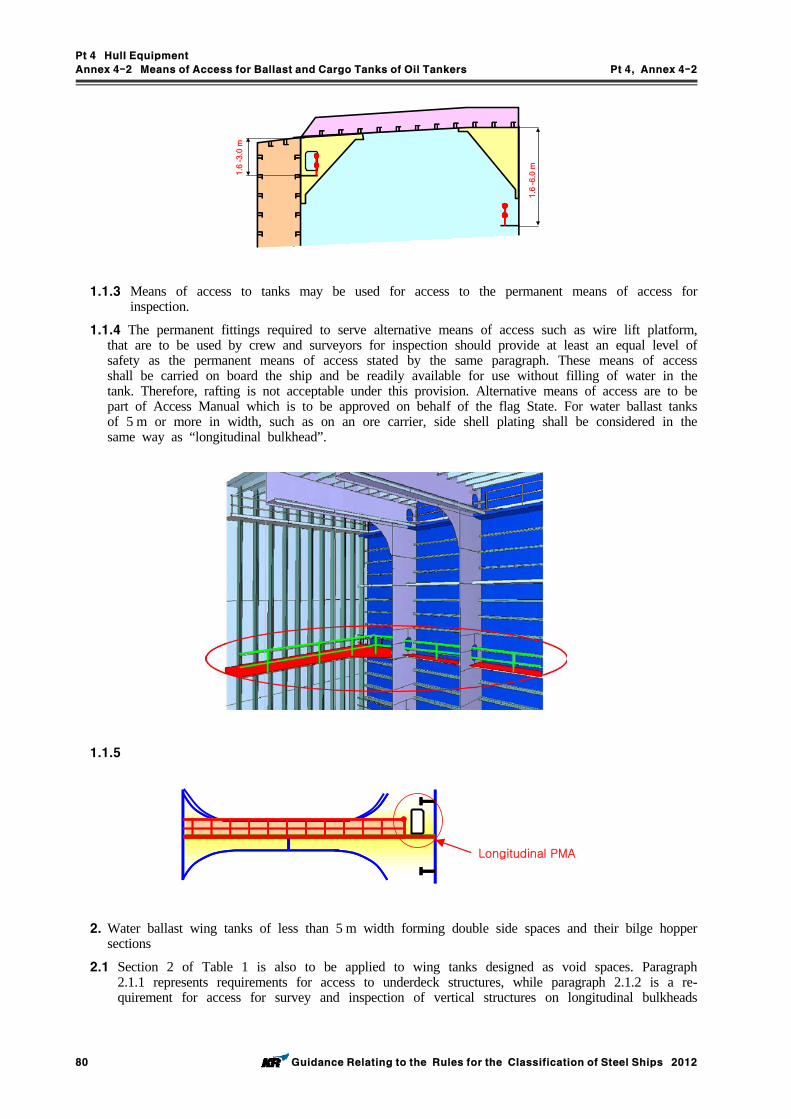
Pt 4 Hull Equipment
Annex 4-2 Means of Access for Ballast and Cargo Tanks of Oil Tankers Pt 4, Annex 4-2
80 Guidance Relating to the Rules for the Classification of Steel Ships 2012
1.6
–3.
0 m
1.6
–6.
0 m
1.1.3 Means of access to tanks may be used for access to the permanent means of access for inspection.
1.1.4 The permanent fittings required to serve alternative means of access such as wire lift platform, that are to be used by crew and surveyors for inspection should provide at least an equal level of safety as the permanent means of access stated by the same paragraph. These means of access shall be carried on board the ship and be readily available for use without filling of water in the tank. Therefore, rafting is not acceptable under this provision. Alternative means of access are to be part of Access Manual which is to be approved on behalf of the flag State. For water ballast tanks of 5 m or more in width, such as on an ore carrier, side shell plating shall be considered in the same way as “longitudinal bulkhead”.
1.1.5
Longitudinal PMA
2. Water ballast wing tanks of less than 5 m width forming double side spaces and their bilge hopper sections
2.1 Section 2 of Table 1 is also to be applied to wing tanks designed as void spaces. Paragraph 2.1.1 represents requirements for access to underdeck structures, while paragraph 2.1.2 is a re-quirement for access for survey and inspection of vertical structures on longitudinal bulkheads
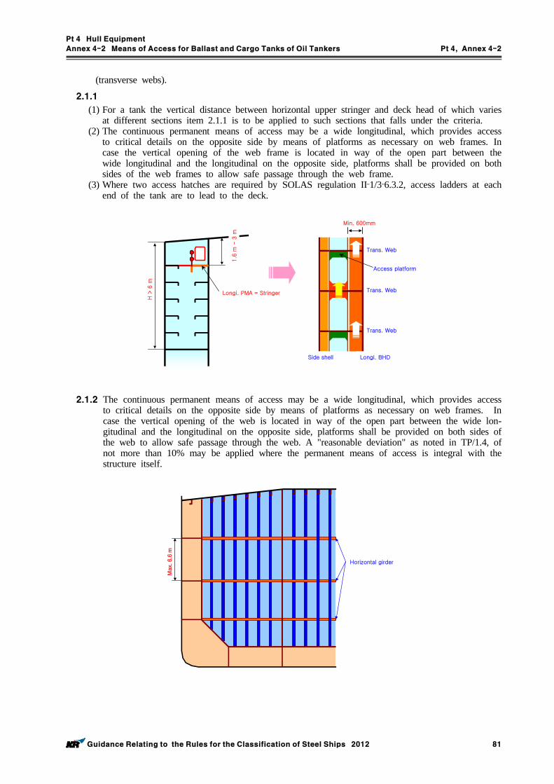
Pt 4 Hull Equipment
Annex 4-2 Means of Access for Ballast and Cargo Tanks of Oil Tankers Pt 4, Annex 4-2
Guidance Relating to the Rules for the Classification of Steel Ships 2012 81
(transverse webs).
2.1.1 (1) For a tank the vertical distance between horizontal upper stringer and deck head of which varies
at different sections item 2.1.1 is to be applied to such sections that falls under the criteria.(2) The continuous permanent means of access may be a wide longitudinal, which provides access
to critical details on the opposite side by means of platforms as necessary on web frames. In case the vertical opening of the web frame is located in way of the open part between the wide longitudinal and the longitudinal on the opposite side, platforms shall be provided on both sides of the web frames to allow safe passage through the web frame.
(3) Where two access hatches are required by SOLAS regulation II‐1/3‐6.3.2, access ladders at each end of the tank are to lead to the deck.
Access platform
Min. 600mm
Trans. Web
Trans. Web
Trans. Web
Side shell Longi. BHD
H >
6 m
Longi. PMA = Stringer
1.6
m -
3 m
2.1.2 The continuous permanent means of access may be a wide longitudinal, which provides access to critical details on the opposite side by means of platforms as necessary on web frames. In case the vertical opening of the web is located in way of the open part between the wide lon-gitudinal and the longitudinal on the opposite side, platforms shall be provided on both sides of the web to allow safe passage through the web. A "reasonable deviation" as noted in TP/1.4, of not more than 10% may be applied where the permanent means of access is integral with the structure itself.
Max
. 6.6
m
Horizontal girder
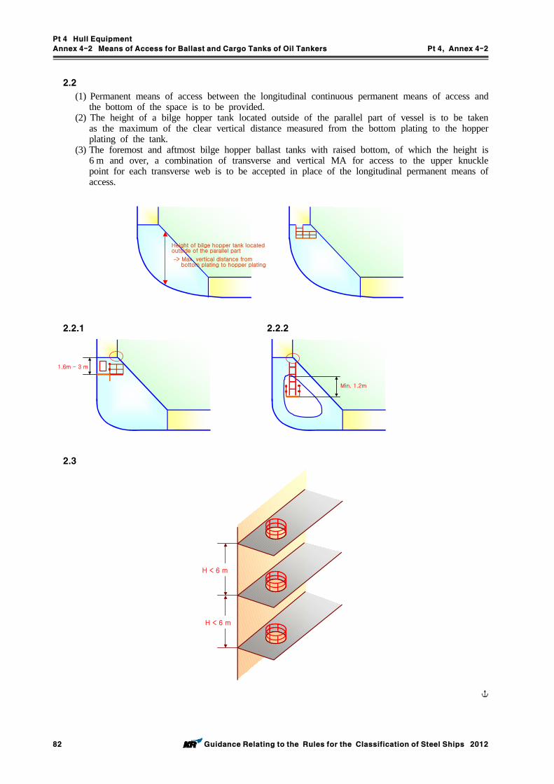
Pt 4 Hull Equipment
Annex 4-2 Means of Access for Ballast and Cargo Tanks of Oil Tankers Pt 4, Annex 4-2
82 Guidance Relating to the Rules for the Classification of Steel Ships 2012
2.2
(1) Permanent means of access between the longitudinal continuous permanent means of access and the bottom of the space is to be provided.
(2) The height of a bilge hopper tank located outside of the parallel part of vessel is to be taken as the maximum of the clear vertical distance measured from the bottom plating to the hopper plating of the tank.
(3) The foremost and aftmost bilge hopper ballast tanks with raised bottom, of which the height is 6 m and over, a combination of transverse and vertical MA for access to the upper knuckle point for each transverse web is to be accepted in place of the longitudinal permanent means of access.
Height of bilge hopper tank located outside of the parallel part
–> Max. vertical distance frombottom plating to hopper plating
2.2.1 2.2.2
1.6m - 3 m
Min. 1.2m
2.3
H < 6 m
H < 6 m
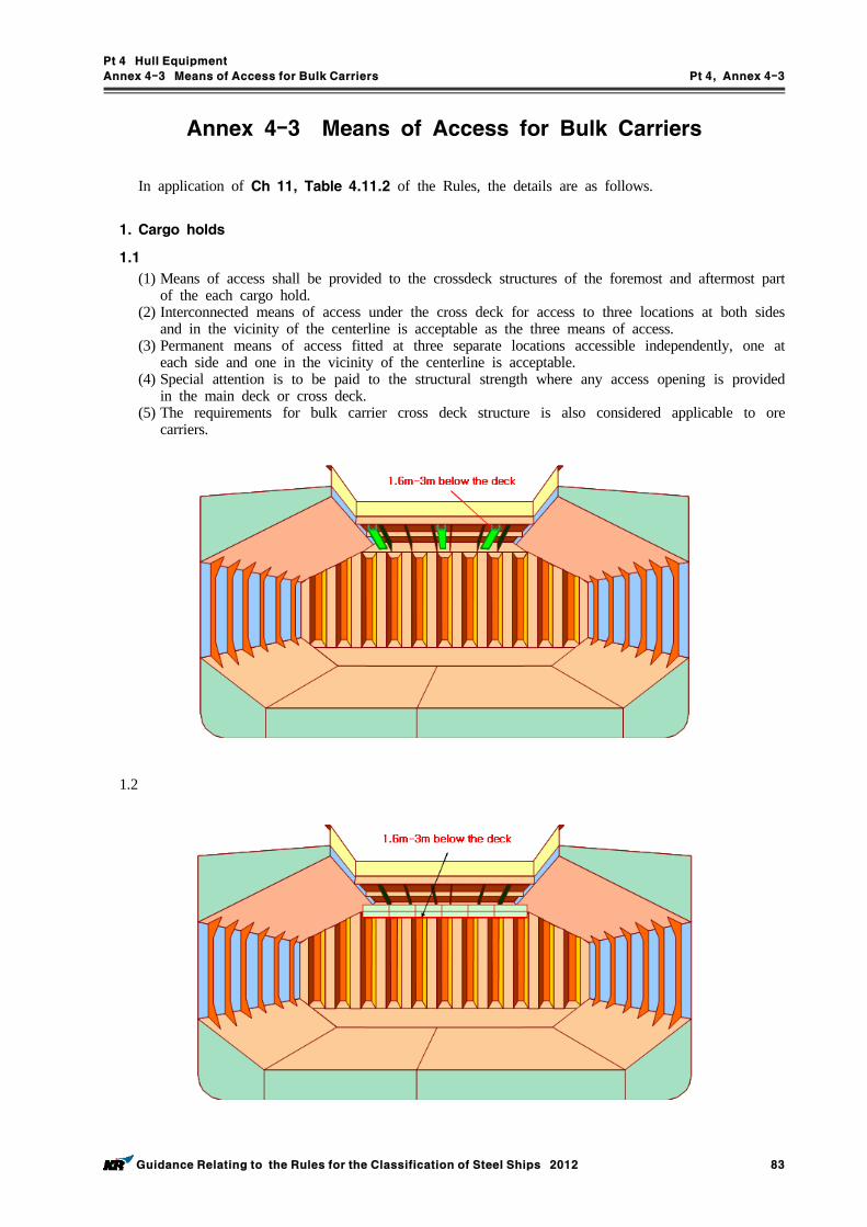
Pt 4 Hull Equipment
Annex 4-3 Means of Access for Bulk Carriers Pt 4, Annex 4-3
Guidance Relating to the Rules for the Classification of Steel Ships 2012 83
Annex 4-3 Means of Access for Bulk Carriers
In application of Ch 11, Table 4.11.2 of the Rules, the details are as follows.
1. Cargo holds
1.1 (1) Means of access shall be provided to the crossdeck structures of the foremost and aftermost part
of the each cargo hold.(2) Interconnected means of access under the cross deck for access to three locations at both sides
and in the vicinity of the centerline is acceptable as the three means of access.(3) Permanent means of access fitted at three separate locations accessible independently, one at
each side and one in the vicinity of the centerline is acceptable. (4) Special attention is to be paid to the structural strength where any access opening is provided
in the main deck or cross deck.(5) The requirements for bulk carrier cross deck structure is also considered applicable to ore
carriers.
1.2
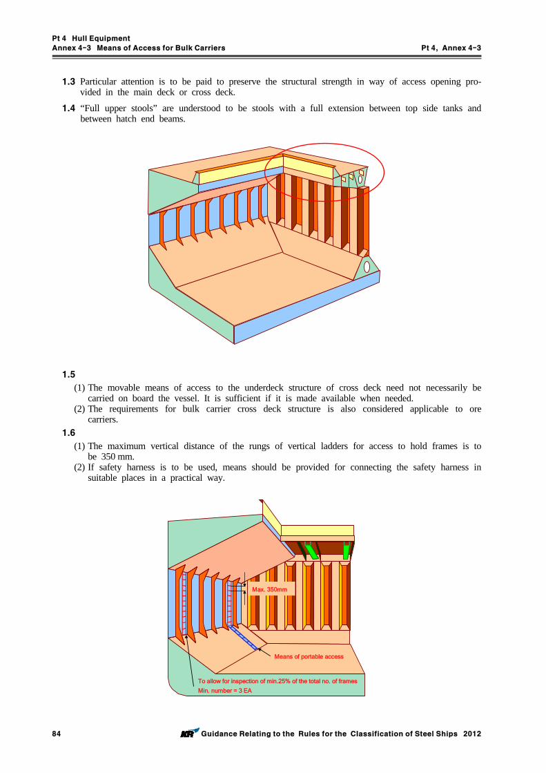
Pt 4 Hull Equipment
Annex 4-3 Means of Access for Bulk Carriers Pt 4, Annex 4-3
84 Guidance Relating to the Rules for the Classification of Steel Ships 2012
1.3 Particular attention is to be paid to preserve the structural strength in way of access opening pro-vided in the main deck or cross deck.
1.4 “Full upper stools” are understood to be stools with a full extension between top side tanks and between hatch end beams.
1.5 (1) The movable means of access to the underdeck structure of cross deck need not necessarily be
carried on board the vessel. It is sufficient if it is made available when needed.(2) The requirements for bulk carrier cross deck structure is also considered applicable to ore
carriers.1.6
(1) The maximum vertical distance of the rungs of vertical ladders for access to hold frames is to be 350 mm.
(2) If safety harness is to be used, means should be provided for connecting the safety harness in suitable places in a practical way.
Max. 350mm
Means of portable access
To allow for inspection of min.25% of the total no. of frames
Min. number = 3 EA
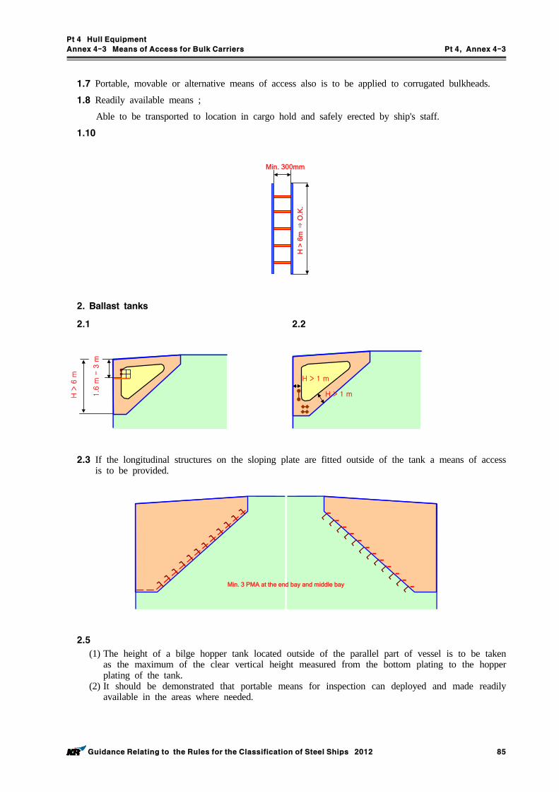
Pt 4 Hull Equipment
Annex 4-3 Means of Access for Bulk Carriers Pt 4, Annex 4-3
Guidance Relating to the Rules for the Classification of Steel Ships 2012 85
1.7 Portable, movable or alternative means of access also is to be applied to corrugated bulkheads.
1.8 Readily available means ;
Able to be transported to location in cargo hold and safely erected by ship's staff.
1.10
Min. 300mm
H >
6m
⇒O
.K.
2. Ballast tanks
2.1 2.2
1.6
m -
3 m
H >
6 m
H > 1 m
H > 1 m
2.3 If the longitudinal structures on the sloping plate are fitted outside of the tank a means of access is to be provided.
Min. 3 PMA at the end bay and middle bay
2.5 (1) The height of a bilge hopper tank located outside of the parallel part of vessel is to be taken
as the maximum of the clear vertical height measured from the bottom plating to the hopper plating of the tank.
(2) It should be demonstrated that portable means for inspection can deployed and made readily available in the areas where needed.
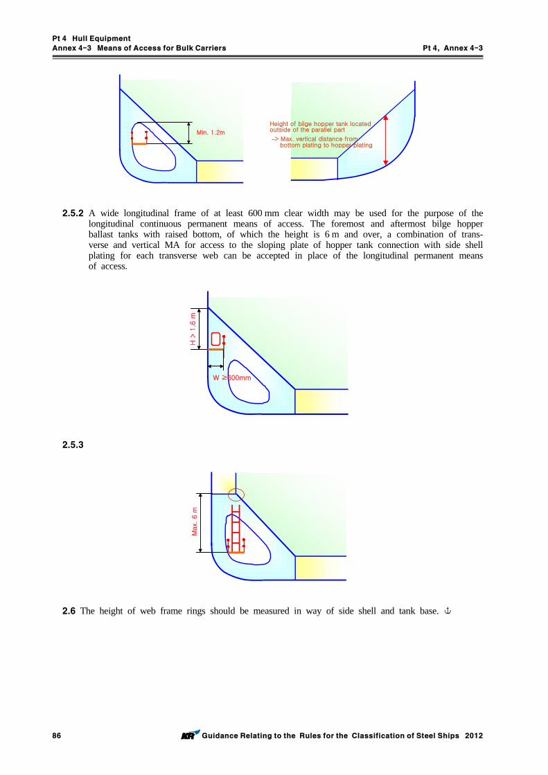
Pt 4 Hull Equipment
Annex 4-3 Means of Access for Bulk Carriers Pt 4, Annex 4-3
86 Guidance Relating to the Rules for the Classification of Steel Ships 2012
Min. 1.2m
Height of bilge hopper tank located outside of the parallel part
–> Max. vertical distance frombottom plating to hopper plating
2.5.2 A wide longitudinal frame of at least 600 mm clear width may be used for the purpose of the longitudinal continuous permanent means of access. The foremost and aftermost bilge hopper ballast tanks with raised bottom, of which the height is 6 m and over, a combination of trans-verse and vertical MA for access to the sloping plate of hopper tank connection with side shell plating for each transverse web can be accepted in place of the longitudinal permanent means of access.
H >
1.6
m
W ≥600mm
2.5.3
Max.
6 m
2.6 The height of web frame rings should be measured in way of side shell and tank base.
Rules for the Classification of Steel ShipsGuidance Relating to the Rules for the Classificationof Steel Ships
PART 4 HULL EQUIPMENT
Published byKOREAN REGISTER OF SHIPPING
90 Gajeongbukro, 23-7 Jang-Dong, Yuseong-Gu,DAEJEON, KOREA
TEL : +82 42 869 9114FAX : +82 42 862 6011
Website : http://www.krs.co.kr
Copyright, ⓒ, 2012 by KOREAN REGISTER OF SHIPPING Printed in Korea
CopyrightⒸ 2012, Korean Register of ShippingReproduction of this Rules and Guidance in whole or in parts is prohibited without permission of the publisher.
Related Documents