Traffic and Road Use Management Volume 4 – Intelligent Transport Systems and Electrical Technology Part 3: Electrical Design for Roadside Devices March 2019

Welcome message from author
This document is posted to help you gain knowledge. Please leave a comment to let me know what you think about it! Share it to your friends and learn new things together.
Transcript
Traffic and Road Use Management Volume 4 – Intelligent Transport Systems and Electrical Technology
Part 3: Electrical Design for Roadside Devices March 2019
Traffic and Road Use Management, Transport and Main Roads, March 2019
Copyright
© The State of Queensland (Department of Transport and Main Roads) 2019.
Licence
This work is licensed by the State of Queensland (Department of Transport and Main Roads) under
a Creative Commons Attribution (CC BY) 4.0 International licence.
CC BY licence summary statement
In essence, you are free to copy, communicate and adapt this work, as long as you attribute the
work to the State of Queensland (Department of Transport and Main Roads). To view a copy of this
licence, visit: https://creativecommons.org/licenses/by/4.0/
Translating and interpreting assistance
The Queensland Government is committed to providing accessible services to
Queenslanders from all cultural and linguistic backgrounds. If you have difficulty
understanding this publication and need a translator, please call the Translating and
Interpreting Service (TIS National) on 13 14 50 and ask them to telephone the
Queensland Department of Transport and Main Roads on 13 74 68.
Disclaimer
While every care has been taken in preparing this publication, the State of Queensland accepts no
responsibility for decisions or actions taken as a result of any data, information, statement or
advice, expressed or implied, contained within. To the best of our knowledge, the content was
correct at the time of publishing.
Feedback
Please send your feedback regarding this document to: [email protected]
Traffic and Road Use Management, Transport and Main Roads, March 2019 i
Contents
1 General electrical requirements ...................................................................................................1
1.1 Introduction ..................................................................................................................................... 1
1.2 Scope .............................................................................................................................................. 1
1.3 Abbreviations and definitions .......................................................................................................... 2
1.4 Legislation and standards ............................................................................................................... 5
1.4.1 Professional Engineer’s Act 2002 ..................................................................................5 1.4.2 Referenced documents ..................................................................................................5
1.5 Design certificate .......................................................................................................................... 10
2 Road lighting requirements ....................................................................................................... 10
2.1 Introduction ................................................................................................................................... 10
2.2 Design philosophy ........................................................................................................................ 11
2.3 Electrical design requirements ...................................................................................................... 11
2.3.1 Design voltage and frequency ..................................................................................... 11 2.3.2 Design current and power factor ................................................................................. 12 2.3.3 Design spare capacity ................................................................................................. 12 2.3.4 Maximum demand ....................................................................................................... 12 2.3.5 Discrimination .............................................................................................................. 12 2.3.6 Disconnect time ........................................................................................................... 12 2.3.7 Cable operating temperature ....................................................................................... 13 2.3.8 Voltage drop ................................................................................................................ 13 2.3.9 Earth fault loop impedance .......................................................................................... 13 2.3.10 Point of supply ............................................................................................................. 13 2.3.11 Switching of road lighting ............................................................................................ 14 2.3.12 Road lighting on bridges or over railway structures .................................................... 14 2.3.13 Road lighting on underpasses ..................................................................................... 14 2.3.14 Road lighting and traffic signals .................................................................................. 14
2.4 Electrical components ................................................................................................................... 14
2.4.1 General ........................................................................................................................ 14 2.4.2 Switchboards ............................................................................................................... 15 2.4.3 Main switch .................................................................................................................. 15 2.4.4 Fuse switches and fuselinks ........................................................................................ 15 2.4.5 Switch disconnectors ................................................................................................... 16 2.4.6 Residual current devices ............................................................................................. 16 2.4.7 Photocell ...................................................................................................................... 16 2.4.8 Contactors ................................................................................................................... 16 2.4.9 Earth and neutral bars ................................................................................................. 16 2.4.10 Cables ......................................................................................................................... 16 2.4.11 Conduits and pits ......................................................................................................... 17
2.5 Design documentation .................................................................................................................. 17
2.6 Schedule of road lighting design information ................................................................................ 18
3 Traffic signal requirements ........................................................................................................ 19
3.1 Introduction ................................................................................................................................... 19
3.2 Design philosophy ........................................................................................................................ 19
3.3 Electrical design requirements ...................................................................................................... 19
3.3.1 Design voltage and frequency ..................................................................................... 19 3.3.2 Design current and power factor ................................................................................. 20 3.3.3 Design spare capacity ................................................................................................. 22 3.3.4 Maximum demand ....................................................................................................... 22
Traffic and Road Use Management, Transport and Main Roads, March 2019 ii
3.3.5 Discrimination .............................................................................................................. 22 3.3.6 Disconnect time ........................................................................................................... 23 3.3.7 Cable operating temperature ....................................................................................... 23 3.3.8 Voltage drop ................................................................................................................ 23 3.3.9 Earth fault loop impedance .......................................................................................... 23 3.3.10 Point of supply ............................................................................................................. 23 3.3.11 Traffic signal controllers mounted on bridges (or other structures) ............................. 23 3.3.12 Traffic signals and road lighting ................................................................................... 24 3.3.13 Connecting communications equipment to controllers ................................................ 24 3.3.14 Controllers connected to generator ............................................................................. 24 3.3.15 Controllers connected to uninterruptible power supplies ............................................ 24
3.4 Electrical components ................................................................................................................... 27
3.4.1 General ........................................................................................................................ 27 3.4.2 Switchboards ............................................................................................................... 27 3.4.3 Residual current devices ............................................................................................. 28 3.4.4 Cables ......................................................................................................................... 28 3.4.5 Conduits and pits ......................................................................................................... 29
3.5 Design documentation .................................................................................................................. 29
3.6 Schedule of traffic signal design information ................................................................................ 30
4 Intelligent transport systems requirements ............................................................................. 31
4.1 Introduction ................................................................................................................................... 31
4.2 Design philosophy ........................................................................................................................ 31
4.3 Electrical design requirements ...................................................................................................... 32
4.3.1 Design voltage and frequency ..................................................................................... 32 4.3.2 Design current and power factor ................................................................................. 32 4.3.3 Design spare capacity ................................................................................................. 32 4.3.4 Maximum demand ....................................................................................................... 32 4.3.5 Discrimination .............................................................................................................. 32 4.3.6 Disconnect time ........................................................................................................... 32 4.3.7 Cable operating temperature ....................................................................................... 33 4.3.8 Voltage drop ................................................................................................................ 33 4.3.9 Earth fault loop impedance .......................................................................................... 33 4.3.10 Point of supply ............................................................................................................. 33 4.3.11 Electrical connection of intelligent transport systems equipment ................................ 33 4.3.12 Intelligent transport systems equipment mounted on structures ................................. 34 4.3.13 Connecting intelligent transport systems equipment to traffic signal controllers ........ 34
4.4 Electrical components ................................................................................................................... 35
4.4.1 General ........................................................................................................................ 35 4.4.2 Switchboards ............................................................................................................... 35 4.4.3 Main switch .................................................................................................................. 35 4.4.4 Fuse switches and ruselinks ....................................................................................... 36 4.4.5 Residual current devices ............................................................................................. 36 4.4.6 Earth and neutral bars ................................................................................................. 36 4.4.7 Cables ......................................................................................................................... 36 4.4.8 Conduits and pits ......................................................................................................... 36
4.5 Design documentation .................................................................................................................. 37
4.6 Schedule of intelligent transport systems design information ...................................................... 38
5 Residual current device protection........................................................................................... 38
5.1 Introduction ................................................................................................................................... 38
5.2 Residual current devices terms and definitions ............................................................................ 39
5.3 What is a residual current device?................................................................................................ 39
5.4 Purpose of a residual current device ............................................................................................ 40
Traffic and Road Use Management, Transport and Main Roads, March 2019 iii
5.5 How residual current devices work ............................................................................................... 40
5.6 Limitations of residual current devices ......................................................................................... 42
5.7 Types of residual current devices ................................................................................................. 44
5.8 Specifying a residual current device ............................................................................................. 45
5.9 Installing the residual current device ............................................................................................ 46
5.10 Testing the residual current device ............................................................................................... 46
5.11 Where residual current devices are required ................................................................................ 47
5.12 AS/NZS 3000 Clause 2.6.3.2.1 Exception 5 ................................................................................. 48
5.12.1 General comments ...................................................................................................... 48 5.12.2 Road lighting installations ............................................................................................ 48 5.12.3 Traffic signals installations .......................................................................................... 48 5.12.4 Pathway lighting installations to AS/NZS 1158 ........................................................... 48 5.12.5 Safety related traffic management devices ................................................................. 49
5.13 AS/NZS 3000 Clause 2.6.3.2.1 Exception 6 ................................................................................. 49
5.13.1 Essential equipment .................................................................................................... 49
5.14 Discussion ..................................................................................................................................... 49
5.14.1 Lift sump pumps connected to socket outlets ............................................................. 50 5.14.2 Busway platform stairway lighting ............................................................................... 50 5.14.3 Non-AS/NZS 1158 pedestrian pathway lighting .......................................................... 50 5.14.4 Non-safety related systems ......................................................................................... 50
5.15 Risk assessment tables ................................................................................................................ 51
5.16 Risk assessment ........................................................................................................................... 53
6 Surge protection ......................................................................................................................... 57
6.1 Introduction ................................................................................................................................... 57
6.2 Surge protective devices technical terms and parameters ........................................................... 57
6.3 What is a surge protection device?............................................................................................... 58
6.4 Purpose of a surge protection device ........................................................................................... 58
6.5 How surge protection devices work .............................................................................................. 59
6.6 Limitations of surge protection devices ........................................................................................ 60
6.7 Causes of surge and surge modes ............................................................................................... 60
6.7.1 Surge generators ......................................................................................................... 60 6.7.2 Surge modes ............................................................................................................... 61
6.8 Surge protection device characteristics ........................................................................................ 62
6.8.1 Method of operation..................................................................................................... 62 6.8.2 Technologies ............................................................................................................... 62 6.8.3 Surge protection device configuration ......................................................................... 64 6.8.4 Classification ............................................................................................................... 67 6.8.5 Standard operating conditions ..................................................................................... 67 6.8.6 Examples of surge protection devices......................................................................... 67
6.9 Surge protection device test waveforms ....................................................................................... 72
6.10 Effect of surge protection devices on test waveform .................................................................... 73
6.11 Determining need for power surge protection devices ................................................................. 74
6.12 Design considerations .................................................................................................................. 76
6.12.1 Area boundary ............................................................................................................. 76 6.12.2 Surge rating ................................................................................................................. 76 6.12.3 Protection characteristics ............................................................................................ 77
Traffic and Road Use Management, Transport and Main Roads, March 2019 iv
6.12.4 Protection distance ...................................................................................................... 78 6.12.5 Prospective life and failure mode ................................................................................ 78 6.12.6 Interaction with other equipment ................................................................................. 78 6.12.7 Coordination with other surge protection devices ....................................................... 78
6.13 Specifying power surge protection devices .................................................................................. 78
6.14 Installation of power surge protection devices .............................................................................. 81
6.14.1 Location ....................................................................................................................... 81 6.14.2 Connection .................................................................................................................. 82 6.14.3 Fusing .......................................................................................................................... 83
6.15 Earthing and bonding .................................................................................................................... 83
6.16 Telecommunications ..................................................................................................................... 84
6.16.1 Determining need for communications surge protection devices ............................... 84 6.16.2 Selecting a communications surge protection device ................................................. 85 6.16.3 Installation of communications surge protection devices ............................................ 88
6.17 Practical applications .................................................................................................................... 89
6.17.1 General ........................................................................................................................ 89 6.17.2 Road lighting ................................................................................................................ 89 6.17.3 Traffic signals .............................................................................................................. 89 6.17.4 Roadway CCTV installations ....................................................................................... 89 6.17.5 Field cabinets .............................................................................................................. 89 6.17.6 Variable message signs on gantries ........................................................................... 89
6.18 Summary ....................................................................................................................................... 90
6.18.1 Power surge protection devices .................................................................................. 90
7 Commentary ................................................................................................................................ 90
7.1 Introduction ................................................................................................................................... 90
7.2 Abbreviations and definitions ........................................................................................................ 91
7.3 Design voltage and frequency ...................................................................................................... 91
7.4 Designing for maximum demand .................................................................................................. 91
7.5 Designing with circuit breakers ..................................................................................................... 92
7.6 Designing with fuses ..................................................................................................................... 94
7.7 Designing with contactors ............................................................................................................. 99
7.8 Designing for cables in conduit ................................................................................................... 100
7.9 Designing with an uninterruptible power supply ......................................................................... 103
7.10 Designing for cable current carrying capacity ............................................................................. 105
7.10.1 Cable materials .......................................................................................................... 105 7.10.2 Standard installation conditions ................................................................................. 106 7.10.3 Derating factors for non-standard installation conditions .......................................... 107 7.10.4 Cable protection ........................................................................................................ 107 7.10.5 Cable operating temperature ..................................................................................... 108 7.10.6 Resistance change with temperature ........................................................................ 110 7.10.7 Cable selection for current carrying capacity ............................................................ 111
7.11 Designing for cable short circuit protection ................................................................................. 112
7.12 Designing for voltage drop .......................................................................................................... 115
7.12.1 Voltage drop .............................................................................................................. 115 7.12.2 Maximum allowable voltage drop .............................................................................. 117 7.12.3 The √3 factor in three-phase ..................................................................................... 118 7.12.4 Relationship between AS/NZS 3008.1.1 Tables 30 and 35, and 42 ......................... 120 7.12.5 Maximum cable length for voltage drop .................................................................... 124
7.13 Designing for earth fault loop impedance ................................................................................... 125
Traffic and Road Use Management, Transport and Main Roads, March 2019 v
7.13.1 Earth fault loop impedance ........................................................................................ 125 7.13.2 Effects of current through the body ........................................................................... 125 7.13.3 Body impedance ........................................................................................................ 127 7.13.4 Touch voltage ............................................................................................................ 129 7.13.5 Disconnect times ....................................................................................................... 132 7.13.6 Relationship between body current parameters ........................................................ 134 7.13.7 Continuing with earth fault loop Impedance .............................................................. 136 7.13.8 The 20 / 80 assumption ............................................................................................. 138 7.13.9 Transformer impedances .......................................................................................... 139 7.13.10 Distribution cable impedances .................................................................................. 141 7.13.11 Calculating external earth fault loop impedance ....................................................... 142 7.13.12 Calculating internal earth fault loop impedance ........................................................ 143 7.13.13 Maximum values of earth fault loop impedance ........................................................ 146
8 Multidisciplinary projects ........................................................................................................ 147
8.1 Introduction ................................................................................................................................. 147
8.2 Electrical design .......................................................................................................................... 147
8.3 Conduit and pits .......................................................................................................................... 148
8.4 Presentation drawings ................................................................................................................ 148
Tables
Table 1.3(a) - Abbreviations .................................................................................................................... 2
Table 1.3(b) – Definitions of terms .......................................................................................................... 3
Table 1.4.2(a) – Legislation (including subordinate legislation) .............................................................. 5
Table 1.4.2(b) – Transport and Main Roads Technical Documents ....................................................... 5
Table 1.4.2(c) – Standards ...................................................................................................................... 7
Table 2.3.2 – Road lighting design currents for HPS luminaires........................................................... 12
Table 2.4.4 – Fuselinks for road lighting ............................................................................................... 15
Table 2.4.11 – Conduits and pits for road lighting ................................................................................. 17
Table 2.6 – Schedule of road lighting design information ..................................................................... 18
Table 3.3.2 – Intersection load calculation sheet .................................................................................. 21
Table 3.3.15.2.10 – Score sheet ........................................................................................................... 27
Table 3.4.4 – Multicore conductor cross sectional areas ...................................................................... 28
Table 3.4.5 – Conduits and pits for traffic signals ................................................................................. 29
Table 3.6 – Schedule of traffic signal design information ...................................................................... 30
Table 4.3.13 – Connecting intelligent transport systems equipment to traffic signal controllers .......... 34
Table 4.4.4 – Standard fuselinks ........................................................................................................... 36
Table 4.4.8 – Conduits and pits for intelligent transport systems ......................................................... 37
Table 4.6 – Design criteria for intelligent transport systems ................................................................. 38
Table 5.2 – Terms and definitions ......................................................................................................... 39
Traffic and Road Use Management, Transport and Main Roads, March 2019 vi
Table 5.8(a) – Typical residual current device characteristics .............................................................. 45
Table 5.8(b) – Typical residual current device specification ................................................................. 46
Table 5.15(a) – Likelihood ..................................................................................................................... 52
Table 5.15(b) – Consequence ............................................................................................................... 52
Table 6.2(a) – Surge protective devices technical terms and parameters ............................................ 57
Table 6.2(b) – Terms and definitions ..................................................................................................... 57
Table 6.8.4 – Manufacturer's classification of surge protection devices (IEC 61643 12) ..................... 67
Table 6.12.2 – Recommended lmax surge ratings for AC power system surge protection devices ....... 77
Table 6.13(a) – Typical specifications for category C3–C2 surge protection devices .......................... 79
Table 6.13(b) – Typical specifications for Category C1-B surge protection devices............................. 79
Table 6.13(c) – Typical specifications for Category A surge protection devices ................................... 80
Table 6.13(d) – Typical specifications for Category A surge reduction filters ....................................... 80
Table 6.14.3 – Circuit protection for surge protection devices .............................................................. 83
Table 7.2 – Abbreviations and definitions ............................................................................................. 91
Table 7.4 – Designing for maximum demand ........................................................................................ 91
Table 7.5 – Circuit breaker curve characteristics .................................................................................. 93
Table 7.6 – Fuse conventional current (AS 60269.1 Table 2) ............................................................... 95
Table 7.7 – Contactor category and typical application ...................................................................... 100
Table 7.8(a) – Enclosure space factors ............................................................................................... 101
Table 7.8(b) – Internal area for rigid poly vinyl chloride conduit.......................................................... 101
Table 7.8(c) – Internal area for galvanised steel pipe ......................................................................... 102
Table 7.8(d) – Typical cable cross-sectional areas ............................................................................. 102
Table 7.8(e) – Example of typical cables in signalised intersection conduit ....................................... 103
Figure 7.9(a) – Tested electrical characteristics Novus FXM UPS 2000 W / V A ............................... 105
Table 7.10.5 – Submains cable operating temperature ...................................................................... 109
Table 7.12.2 – Minimum striking voltage for luminaires ...................................................................... 118
Table 7.13.6(a) – Comparing touch voltage, disconnect time, body impedance and body current .... 134
Table 7.13.6(b) – Residual current device maximum break times ...................................................... 135
Table 7.13.9(a) – Standard transformer data ...................................................................................... 140
Table 7.13.9(b) – Typical transformer characteristics ......................................................................... 141
Table 7.13.13(a) – Maximum values of earth fault loop impedance at 75°C (AS/NZS 3000 Table 8.1)
............................................................................................................................................................. 146
Table 7.13.13(b) – Test maximum values of earth fault loop impedance at 25°C .............................. 147
Traffic and Road Use Management, Transport and Main Roads, March 2019 vii
Figures
Figure 5.5(a) – Operating principle of the residual current release (from ABB – Technical Application
Papers 3) ............................................................................................................................................... 41
Figure 5.5(b) – Configuration of typical residual current device (from Schneider Electric) ................... 42
Figure 5.7 – Common residual current device examples ...................................................................... 44
Figure 5.15(a) – Risk priority chart ........................................................................................................ 51
Figure 5.15(b) – Risk score and statement ........................................................................................... 51
Figure 6.5 – Operation of surge reduction filter (Erico) ......................................................................... 59
Figure 6.7.2.1 – Differential mode transient (AS/NZS 1768) ................................................................. 61
Figure 6.7.2.2 – Common mode transient (AS/NZS 1768) ................................................................... 62
Figure 6.8.3.1(a) – Varistor and spark gap (IEC 61643 12) .................................................................. 65
Figure 6.8.3.1(b) – Combined gas discharge tube and varistor, and bipolar diodes (IEC 61643 12) ... 65
Figure 6.8.3.1(c) – One-port surge protection device with separate input and output
terminals (IEC 61643 12) ....................................................................................................................... 65
Figure 6.8.3.2 – Three- and four-terminal two-port surge protection device (IEC 61643 12) ............... 66
Figure 6.8.3.3 – Multiservice surge protection device (AS/NZS 1768) ................................................. 66
Figure 6.8.6(a) – Typical spark gap surge protection device (Erico) .................................................... 67
Figure 6.8.6(b) – Typical metal oxide varistors (blue) and gas discharge tubes (silver) for power circuit
protection ............................................................................................................................................... 68
Figure 6.8.6(c) – Combined triggered spark gap and metal oxide varistor (Dehn) ............................... 68
Figure 6.8.6(d) – Typical metal oxide varistor (Novaris) ....................................................................... 69
Figure 6.8.6(e) – Typical surge filter (Eaton) ......................................................................................... 69
Figure 6.8.6(f) – Power / Cat 5 multiservice protection (Dehn) ............................................................. 70
Figure 6.8.6(g) – Data protector for RS 232, RS 422 and RS 485 (Novaris) ........................................ 70
Figure 6.8.6(h) – Surge protection device for twisted pair cables (Dehn) ............................................. 71
Figure 6.8.6(i) – Surge protection device for coaxial connection for CCTV (Eaton) ............................. 71
Figure 6.8.6(j) – Combined power and CCTV protector (Novaris) ........................................................ 72
Figure 6.9 – Standard voltage and current waveforms ......................................................................... 72
Figure 6.10(a) – Incoming waveform (IEC 61643 12) ........................................................................... 73
Figure 6.10(b) – Response of voltage limiting (metal oxide varistor) type surge protection
device (IEC 61643 12) ........................................................................................................................... 73
Figure 6.10(c) – Response of voltage switching (air gap) type surge protection device (IEC 61643 12)
............................................................................................................................................................... 73
Traffic and Road Use Management, Transport and Main Roads, March 2019 viii
Figure 6.10(d) – Response of one-port combination (triggered spark gap / metal oxide varistor) type
surge protection device (IEC 61643 12) ................................................................................................ 74
Figure 6.10(e) – Response of two-port combination (triggered spark gap / metal oxide varistor) type
surge protection device (IEC 61643 12) ................................................................................................ 74
Figure 6.10(f) – Response of two-port voltage limiting (metal oxide varistor) type surge protection
device with filtering (IEC 61643 12) ....................................................................................................... 74
Figure 6.12.1 – Protected equipment boundaries (AS/NZS 1768) ....................................................... 76
Figure 6.14.1.5 – Typical surge protection device installation for TN-C-S system (IEC 61643 12
Figure K.5) ............................................................................................................................................. 82
Figure 6.14.2 – Preferred method of connecting surge protection devices (IEC 61643 12 Figure 12). 83
Figure 6.16.2 – Suitable products for various communications protocols (Novaris) ............................. 87
Figure 7.4 – Maximum demand AS/NZS 3000 Table C2 (part) ............................................................ 92
Figure 7.5 – Typical miniature circuit breaker curve ............................................................................. 94
Figure 7.6(a) – Typical high rupture capacity fuse time-current curves ................................................ 96
Figure 7.6(b) – Legrand fuse thermal stress curves ............................................................................. 97
Figure 7.6(c) – Littelfuse fast acting fuse curves ................................................................................... 98
Figure 7.6(d) – Legrand fuse cut-off characteristics .............................................................................. 99
Figure 7.7 – Contactors for switching high intensity discharge luminaires ......................................... 100
Figure 7.10.1 – Limiting temperatures for insulated cables ................................................................ 106
Figure 7.11(a) – Values of constant K for determination of permissible short circuit
currents (AS/NZS 3008.1.1 Table 52) ................................................................................................. 113
Figure 7.11(b) – Temperature limits for insulating materials ............................................................... 114
Figure 7.12.2 – Road lighting schematic for voltage drop ................................................................... 117
Figure 7.12.3(a) – Line and phase values in star connected system .................................................. 118
Figure 7.12.3(b) – Line and phase voltages represented by vectors .................................................. 119
Figure 7.1.12(c) – Parallelogram of voltages ...................................................................................... 120
Figure 7.12.4(a) – Reactance (Xc) at 50 Hz (AS/NZS 3008.1.1 Table 30) ......................................... 121
Figure 7.12.4(b) – ac resistance (Rc) at 50 Hz (AS/NZS 3008.1.1 Table 35) ..................................... 122
Figure 7.12.4(c) – Three-phase voltage drop (Vc) at 50 Hz (AS/NZS 3008.1.1 Table 42) ................. 123
Figure 7.13.2(a) – Conventional time / current zones of effects of ac currents (15 Hz to 100 Hz) on
persons for a current path corresponding to left hand to feet (AS/NZS 60479.1 Fig 20) .................... 126
Figure 7.13.2(b) – Time current zones and physiological effects (AS/NZS 60479.1 Table 11) .......... 126
Figure 7.13.3(a) – Typical frequency dependence of total body impedance (AS/NZS 60479.1
Figure 12) ............................................................................................................................................ 128
Traffic and Road Use Management, Transport and Main Roads, March 2019 ix
Figure 7.13.3(b) – Total body impedances for a current path hand to hand (AS/NZS 60479.1 Table 1)
............................................................................................................................................................. 128
Figure 7.13.4(a) – Voltage drop in typical circuit A ............................................................................. 129
Figure 7.13.4(b) – Voltage drop in typical circuit B ............................................................................. 130
Figure 7.13.4(c) – Voltage gradient at a distance from live electrode ................................................. 132
Figure 7.13.5 – Maximum duration of prospective touch voltage (IEC 61200 413 Figure C.2) .......... 133
Figure 7.13.6(a) – Time / current characteristic points (AS/NZS 60479.1 Fig 20) for 50 V and 100 V
touch voltages ..................................................................................................................................... 135
Figure 7.13.6(b) – Time / current characteristic points (AS/NZS 60479.1 Fig 20) for residual current
device maximum break times .............................................................................................................. 136
Figure 7.13.7(a) – Normal circuit current path..................................................................................... 137
Figure 7.13.7(b) – Active-to-earth fault circuit current path ................................................................. 138
Figure 7.13.10 – Typical distribution network cable characteristics .................................................... 142
Volume 4: Part 3 – Electrical Design for Roadside Devices
Traffic and Road Use Management, Transport and Main Roads, March 2019 1
1 General electrical requirements
1.1 Introduction
These requirements set out the electrical design criteria that must be used for all Transport and Main
Roads electrical installations, both new and modifications to existing installations – in particular, road
lighting, traffic signals and Intelligent Transport Systems (ITS). It is not intended that existing
installations that complied with AS/NZS 3000 Electrical Installations (known as the Australian / New
Zealand Wiring Rules) when they were installed be changed to meet these design criteria; however,
the Electrical Safety Act 2002 requires electrical installations to be electrically safe.
Compliance with AS/NZS 3000 is mandatory and frequent reference is made to the requirements
therein. Compliance requirements include:
• correct discrimination and load / circuit protection / cable selection combination
• cable current carrying capacity
• appropriate cable short-circuit withstand capacity
• circuit voltage drop, and
• earth fault loop impedance.
Designers must make themselves familiar with the conditions and requirements at the site for which
they are carrying out designs.
Prior to commencing design, designers must verify that they have the current version of this
document.
This document is set out in the following sections:
Section 1 General electrical requirements
Section 2 Road lighting requirements
Section 3 Traffic signal requirements
Section 4 Intelligent Transport Systems requirements
Section 5 Residual current device protection
Section 6 Surge protection
Section 7 Commentary
Section 8 Multidisciplinary projects
Unless otherwise stated, the principles of Sections 1 and 8 apply to the other sections.
1.2 Scope
The intent of this manual is to provide designers with the design philosophy required for electrical
design within Transport and Main Roads infrastructure so that consistent and standardised designs
can be achieved. While every attempt has been made to make it comprehensive, it is acknowledged
that engineering design requires customisation for any particular installation. Engineering judgement is
required to apply these principles to project-specific specifications.
Where departure from these requirements is deemed necessary for a particular project, approval must
be given by the Director (Intelligent Transport Systems and Electrical).
Volume 4: Part 3 – Electrical Design for Roadside Devices
Traffic and Road Use Management, Transport and Main Roads, March 2019 2
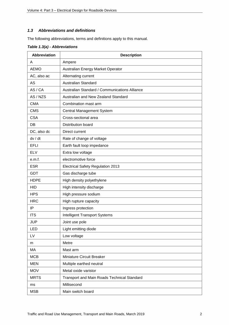
1.3 Abbreviations and definitions
The following abbreviations, terms and definitions apply to this manual.
Table 1.3(a) - Abbreviations
Abbreviation Description
A Ampere
AEMO Australian Energy Market Operator
AC, also ac Alternating current
AS Australian Standard
AS / CA Australian Standard / Communications Alliance
AS / NZS Australian and New Zealand Standard
CMA Combination mast arm
CMS Central Management System
CSA Cross-sectional area
DB Distribution board
DC, also dc Direct current
dv / dt Rate of change of voltage
EFLI Earth fault loop impedance
ELV Extra low voltage
e.m.f. electromotive force
ESR Electrical Safety Regulation 2013
GDT Gas discharge tube
HDPE High density polyethylene
HID High intensity discharge
HPS High pressure sodium
HRC High rupture capacity
IP Ingress protection
ITS Intelligent Transport Systems
JUP Joint use pole
LED Light emitting diode
LV Low voltage
m Metre
MA Mast arm
MCB Miniature Circuit Breaker
MEN Multiple earthed neutral
MOV Metal oxide varistor
MRTS Transport and Main Roads Technical Standard
ms Millisecond
MSB Main switch board
Volume 4: Part 3 – Electrical Design for Roadside Devices
Traffic and Road Use Management, Transport and Main Roads, March 2019 3
Abbreviation Description
MSPD Multiservice Surge Protective Device
NEM National Electricity Market
PEN Combined protective earth and neutral conductor
PSCC Prospective short circuit current
PVC Polyvinylchloride
RCBO Residual current breaker with overload
RCCB Residual current circuit breaker
RCD Residual current device
rms Root mean square
RPDM Road Planning and Design Manual
RPEQ Registered Professional Engineer Queensland
s Second
SAD Silicon avalanche diode
SD Standard Drawings
SDI Single core double insulated
SO Socket outlet
SOA Standing offer arrangement
SPD Surge protection device
SRF Surge reduction filter
TN Technical Note
TPE Thermoplastic elastomer
TRUM Traffic and Road Use Management manual
TSC Traffic signal controller
TSG Triggered spark gap
UPS Uninterruptable power supply
UPVC Unplasticised polyvinylchloride
URD Underground Residential Distribution
XLPE Cross linked polyethylene
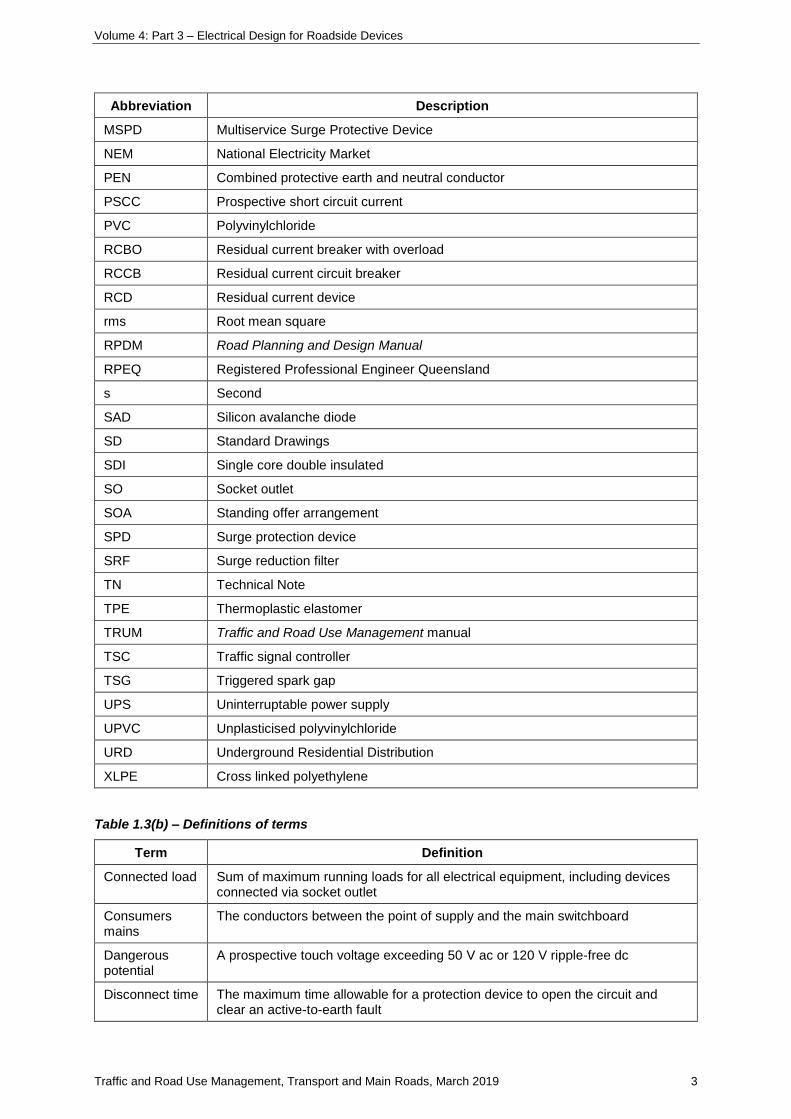
Table 1.3(b) – Definitions of terms
Term Definition
Connected load Sum of maximum running loads for all electrical equipment, including devices connected via socket outlet
Consumers mains
The conductors between the point of supply and the main switchboard
Dangerous potential
A prospective touch voltage exceeding 50 V ac or 120 V ripple-free dc
Disconnect time The maximum time allowable for a protection device to open the circuit and clear an active-to-earth fault
Volume 4: Part 3 – Electrical Design for Roadside Devices
Traffic and Road Use Management, Transport and Main Roads, March 2019 4
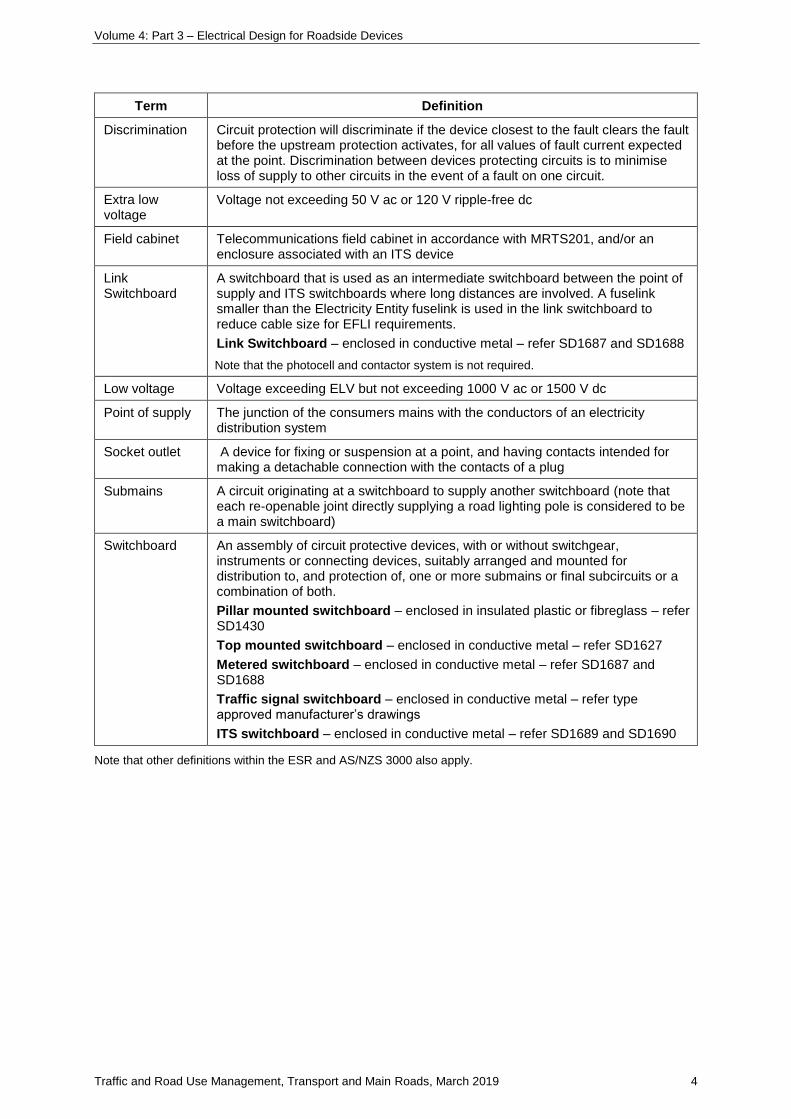
Term Definition
Discrimination Circuit protection will discriminate if the device closest to the fault clears the fault before the upstream protection activates, for all values of fault current expected at the point. Discrimination between devices protecting circuits is to minimise loss of supply to other circuits in the event of a fault on one circuit.
Extra low voltage
Voltage not exceeding 50 V ac or 120 V ripple-free dc
Field cabinet Telecommunications field cabinet in accordance with MRTS201, and/or an enclosure associated with an ITS device
Link Switchboard
A switchboard that is used as an intermediate switchboard between the point of supply and ITS switchboards where long distances are involved. A fuselink smaller than the Electricity Entity fuselink is used in the link switchboard to reduce cable size for EFLI requirements.
Link Switchboard – enclosed in conductive metal – refer SD1687 and SD1688
Note that the photocell and contactor system is not required.
Low voltage Voltage exceeding ELV but not exceeding 1000 V ac or 1500 V dc
Point of supply The junction of the consumers mains with the conductors of an electricity distribution system
Socket outlet A device for fixing or suspension at a point, and having contacts intended for making a detachable connection with the contacts of a plug
Submains A circuit originating at a switchboard to supply another switchboard (note that each re-openable joint directly supplying a road lighting pole is considered to be a main switchboard)
Switchboard An assembly of circuit protective devices, with or without switchgear, instruments or connecting devices, suitably arranged and mounted for distribution to, and protection of, one or more submains or final subcircuits or a combination of both.
Pillar mounted switchboard – enclosed in insulated plastic or fibreglass – refer SD1430
Top mounted switchboard – enclosed in conductive metal – refer SD1627
Metered switchboard – enclosed in conductive metal – refer SD1687 and SD1688
Traffic signal switchboard – enclosed in conductive metal – refer type approved manufacturer’s drawings
ITS switchboard – enclosed in conductive metal – refer SD1689 and SD1690
Note that other definitions within the ESR and AS/NZS 3000 also apply.
Volume 4: Part 3 – Electrical Design for Roadside Devices
Traffic and Road Use Management, Transport and Main Roads, March 2019 5
1.4 Legislation and standards
1.4.1 Professional Engineer’s Act 2002
Designers must comply with the requirements of the Professional Engineers Act 2002. Completed
designs must comply with the requirements of the Electrical Safety Act 2002 and subordinate
legislation.
Attention is drawn to the requirements of the Professional Engineers Act 2002 section 115 as to who
may carry out professional engineering services. Only a practising professional electrical engineer or a
person under the direct supervision of a practising professional electrical engineer who is responsible
for the electrical services may carry out the electrical services.
A person carries out professional engineering services under the direct supervision of a practising
professional engineer only if the engineer directs the person in the carrying out of the services and
oversees and evaluates the carrying out of the services by the person.
Professional engineering service means an engineering service that requires, or is based on, the
application of engineering principles and data to a design, or to a construction, production, operation
or maintenance activity, relating to engineering. As the design principles that follow in this manual
require engineering judgement in their application, the requirement of the Professional Engineers
Act 2002 for these engineering services to be carried out by a practising electrical engineer or under
the direct supervision of a practising electrical engineer must be complied with.
1.4.2 Referenced documents
Clarification of the referenced including regrouping in logical order adding Standard Drawing
references and including definitions for switchboards.
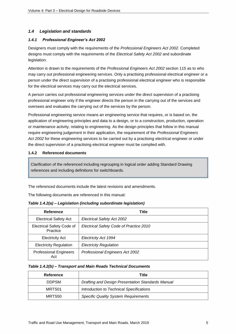
The referenced documents include the latest revisions and amendments.
The following documents are referenced in this manual:
Table 1.4.2(a) – Legislation (including subordinate legislation)
Reference Title
Electrical Safety Act Electrical Safety Act 2002
Electrical Safety Code of Practice
Electrical Safety Code of Practice 2010
Electricity Act Electricity Act 1994
Electricity Regulation Electricity Regulation
Professional Engineers Act
Professional Engineers Act 2002
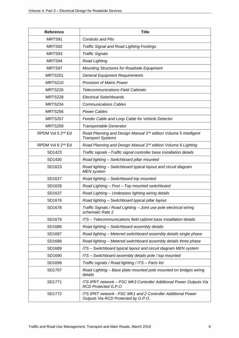
Table 1.4.2(b) – Transport and Main Roads Technical Documents
Reference Title
DDPSM Drafting and Design Presentation Standards Manual
MRTS01 Introduction to Technical Specifications
MRTS50 Specific Quality System Requirements
Volume 4: Part 3 – Electrical Design for Roadside Devices
Traffic and Road Use Management, Transport and Main Roads, March 2019 6
Reference Title
MRTS91 Conduits and Pits
MRTS92 Traffic Signal and Road Lighting Footings
MRTS93 Traffic Signals
MRTS94 Road Lighting
MRTS97 Mounting Structures for Roadside Equipment
MRTS201 General Equipment Requirements
MRTS210 Provision of Mains Power
MRTS226 Telecommunications Field Cabinets
MRTS228 Electrical Switchboards
MRTS234 Communications Cables
MRTS256 Power Cables
MRTS257 Feeder Cable and Loop Cable for Vehicle Detector
MRTS259 Transportable Generator
RPDM Vol 5 2nd Ed Road Planning and Design Manual 2nd edition Volume 5 Intelligent Transport Systems
RPDM Vol 6 2nd Ed Road Planning and Design Manual 2nd edition Volume 6 Lighting
SD1423 Traffic signals –Traffic signal controller base installation details
SD1430 Road lighting – Switchboard pillar mounted
SD1623 Road lighting – Switchboard typical layout and circuit diagram MEN system
SD1627 Road lighting – Switchboard top mounted
SD1628 Road Lighting – Post – Top mounted switchboard
SD1637 Road Lighting – Underpass lighting wiring details
SD1676 Road lighting – Switchboard typical pillar layout
SD1678 Traffic Signals / Road Lighting – Joint use pole electrical wiring schematic Rate 2
SD1679 ITS – Telecommunications field cabinet base installation details
SD1686 Road lighting – Switchboard assembly details
SD1687 Road lighting – Metered switchboard assembly details single phase
SD1688 Road lighting – Metered switchboard assembly details three phase
SD1689 ITS – Switchboard typical layout and circuit diagram MEN system
SD1690 ITS – Switchboard assembly details pole / top mounted
SD1699 Traffic signals / Road lighting / ITS – Parts list
SD1707 Road Lighting – Base plate mounted pole mounted on bridges wiring details
SD1771 ITS IPRT network – PSC MK3 Controller Additional Power Outputs Via RCD Protected G.P.O
SD1772 ITS IPRT network - PSC MK1 and 2 Controller Additional Power Outputs Via RCD Protected by G.P.O.
Volume 4: Part 3 – Electrical Design for Roadside Devices
Traffic and Road Use Management, Transport and Main Roads, March 2019 7
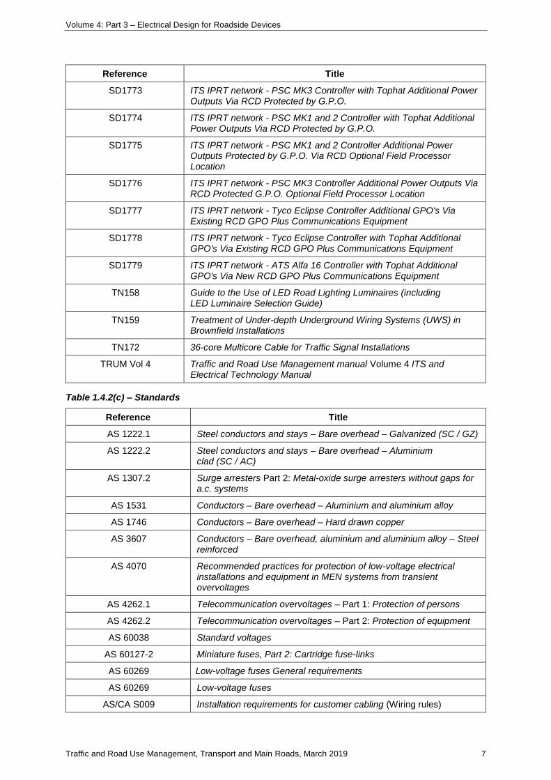
Reference Title
SD1773 ITS IPRT network - PSC MK3 Controller with Tophat Additional Power Outputs Via RCD Protected by G.P.O.
SD1774 ITS IPRT network - PSC MK1 and 2 Controller with Tophat Additional Power Outputs Via RCD Protected by G.P.O.
SD1775 ITS IPRT network - PSC MK1 and 2 Controller Additional Power Outputs Protected by G.P.O. Via RCD Optional Field Processor Location
SD1776 ITS IPRT network - PSC MK3 Controller Additional Power Outputs Via RCD Protected G.P.O. Optional Field Processor Location
SD1777 ITS IPRT network - Tyco Eclipse Controller Additional GPO's Via Existing RCD GPO Plus Communications Equipment
SD1778 ITS IPRT network - Tyco Eclipse Controller with Tophat Additional GPO's Via Existing RCD GPO Plus Communications Equipment
SD1779 ITS IPRT network - ATS Alfa 16 Controller with Tophat Additional GPO's Via New RCD GPO Plus Communications Equipment
TN158 Guide to the Use of LED Road Lighting Luminaires (including LED Luminaire Selection Guide)
TN159 Treatment of Under-depth Underground Wiring Systems (UWS) in Brownfield Installations
TN172 36-core Multicore Cable for Traffic Signal Installations
TRUM Vol 4 Traffic and Road Use Management manual Volume 4 ITS and Electrical Technology Manual
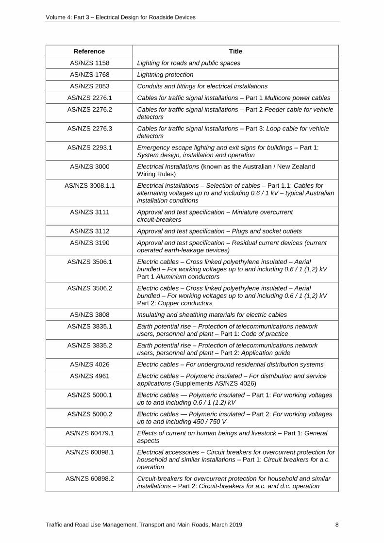
Table 1.4.2(c) – Standards
Reference Title
AS 1222.1 Steel conductors and stays – Bare overhead – Galvanized (SC / GZ)
AS 1222.2 Steel conductors and stays – Bare overhead – Aluminium clad (SC / AC)
AS 1307.2 Surge arresters Part 2: Metal-oxide surge arresters without gaps for a.c. systems
AS 1531 Conductors – Bare overhead – Aluminium and aluminium alloy
AS 1746 Conductors – Bare overhead – Hard drawn copper
AS 3607 Conductors – Bare overhead, aluminium and aluminium alloy – Steel reinforced
AS 4070 Recommended practices for protection of low-voltage electrical installations and equipment in MEN systems from transient overvoltages
AS 4262.1 Telecommunication overvoltages – Part 1: Protection of persons
AS 4262.2 Telecommunication overvoltages – Part 2: Protection of equipment
AS 60038 Standard voltages
AS 60127-2 Miniature fuses, Part 2: Cartridge fuse-links
AS 60269 Low-voltage fuses General requirements
AS 60269 Low-voltage fuses
AS/CA S009 Installation requirements for customer cabling (Wiring rules)
Volume 4: Part 3 – Electrical Design for Roadside Devices
Traffic and Road Use Management, Transport and Main Roads, March 2019 8
Reference Title
AS/NZS 1158 Lighting for roads and public spaces
AS/NZS 1768 Lightning protection
AS/NZS 2053 Conduits and fittings for electrical installations
AS/NZS 2276.1 Cables for traffic signal installations – Part 1 Multicore power cables
AS/NZS 2276.2 Cables for traffic signal installations – Part 2 Feeder cable for vehicle detectors
AS/NZS 2276.3 Cables for traffic signal installations – Part 3: Loop cable for vehicle detectors
AS/NZS 2293.1 Emergency escape lighting and exit signs for buildings – Part 1: System design, installation and operation
AS/NZS 3000 Electrical Installations (known as the Australian / New Zealand Wiring Rules)
AS/NZS 3008.1.1 Electrical installations – Selection of cables – Part 1.1: Cables for alternating voltages up to and including 0.6 / 1 kV – typical Australian installation conditions
AS/NZS 3111 Approval and test specification – Miniature overcurrent circuit-breakers
AS/NZS 3112 Approval and test specification – Plugs and socket outlets
AS/NZS 3190 Approval and test specification – Residual current devices (current operated earth-leakage devices)
AS/NZS 3506.1 Electric cables – Cross linked polyethylene insulated – Aerial bundled – For working voltages up to and including 0.6 / 1 (1,2) kV Part 1 Aluminium conductors
AS/NZS 3506.2 Electric cables – Cross linked polyethylene insulated – Aerial bundled – For working voltages up to and including 0.6 / 1 (1,2) kV Part 2: Copper conductors
AS/NZS 3808 Insulating and sheathing materials for electric cables
AS/NZS 3835.1 Earth potential rise – Protection of telecommunications network users, personnel and plant – Part 1: Code of practice
AS/NZS 3835.2 Earth potential rise – Protection of telecommunications network users, personnel and plant – Part 2: Application guide
AS/NZS 4026 Electric cables – For underground residential distribution systems
AS/NZS 4961 Electric cables – Polymeric insulated – For distribution and service applications (Supplements AS/NZS 4026)
AS/NZS 5000.1 Electric cables — Polymeric insulated – Part 1: For working voltages up to and including 0.6 / 1 (1.2) kV
AS/NZS 5000.2 Electric cables — Polymeric insulated – Part 2: For working voltages up to and including 450 / 750 V
AS/NZS 60479.1 Effects of current on human beings and livestock – Part 1: General aspects
AS/NZS 60898.1 Electrical accessories – Circuit breakers for overcurrent protection for household and similar installations – Part 1: Circuit breakers for a.c. operation
AS/NZS 60898.2 Circuit-breakers for overcurrent protection for household and similar installations – Part 2: Circuit-breakers for a.c. and d.c. operation
Volume 4: Part 3 – Electrical Design for Roadside Devices
Traffic and Road Use Management, Transport and Main Roads, March 2019 9
Reference Title
AS/NZS 60950.1 Information technology equipment – Safety – General requirements
AS/NZS 61000.4.5 Electromagnetic compatibility (EMC) – Part 4.5: Testing and measurement techniques – Surge immunity test
AS/NZS 61008.1 Residual current operated circuit-breakers without integral overcurrent protection for household and similar uses (RCCBs) – Part 1: General rules
AS/NZS 61009.1 Residual current operated circuit-breakers with integral overcurrent protection for household and similar uses (RCBOs) – Part 1: General rules
AS/NZS 61386 Conduit systems for cable management
AS/NZS IEC 60947.3 Low-voltage switchgear and control gear – Part 3 Switches, disconnectors, switch-disconnectors and fuse-combination switches
AS/NZS IEC 60947.4.1 Low-voltage switchgear and control gear – Part 4.1: Contactors and motor-starters — Electromechanical contactors and motor-starters
AS/NZS ISO 31000 Risk management – Principles and guidelines
ENA EG1 2006 Substation Earthing Guide
HB 301 Electrical installations – Designing to the Wiring rules
IEC 61200-413 Electrical installation guide – Part 413: Protection against indirect contact – Automatic disconnection of supply
IEC 61643 11 Low-voltage surge protective devices – Part 11: Surge protective devices connected to low-voltage power systems – Requirements and test methods
IEC 61643 12 Low-voltage surge protective devices – Part 12: Surge protective devices connected to low-voltage power distribution systems – Selection and application principles
IEC 61643 22 Low-voltage surge protective devices – Part 22: Surge protective devices connected to telecommunications and signalling networks – Selection and application principles
IEC 61643-21 Low voltage surge protective devices – Part 21: Surge protective devices connected to telecommunications and signalling networks – Performance requirements and testing methods
SAA HB113 Residual current devices – What they do and how they do it
UL 1449 Standard for Surge Protective Devices
UL 497 Standard for Protectors for Paired-Conductor Communications Circuits
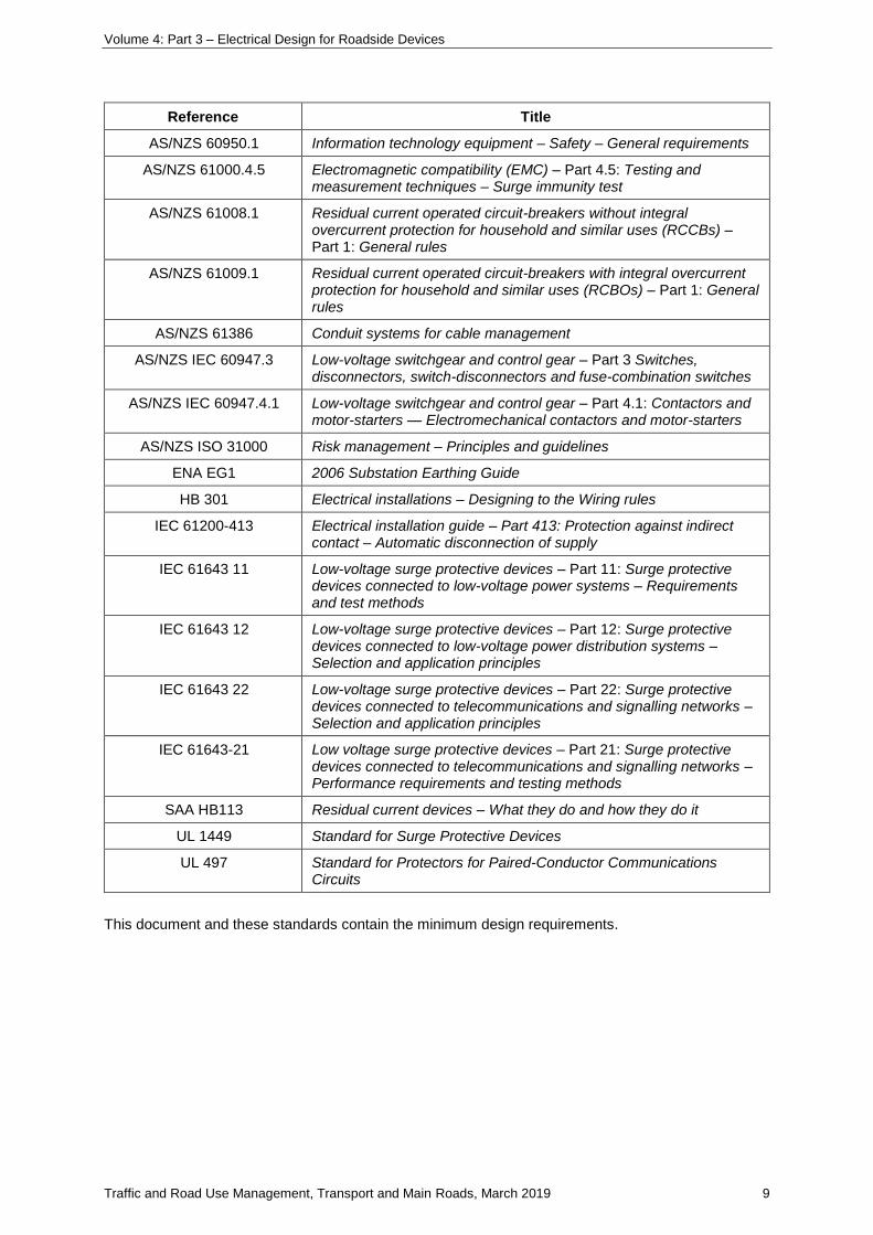
This document and these standards contain the minimum design requirements.
Volume 4: Part 3 – Electrical Design for Roadside Devices
Traffic and Road Use Management, Transport and Main Roads, March 2019 10
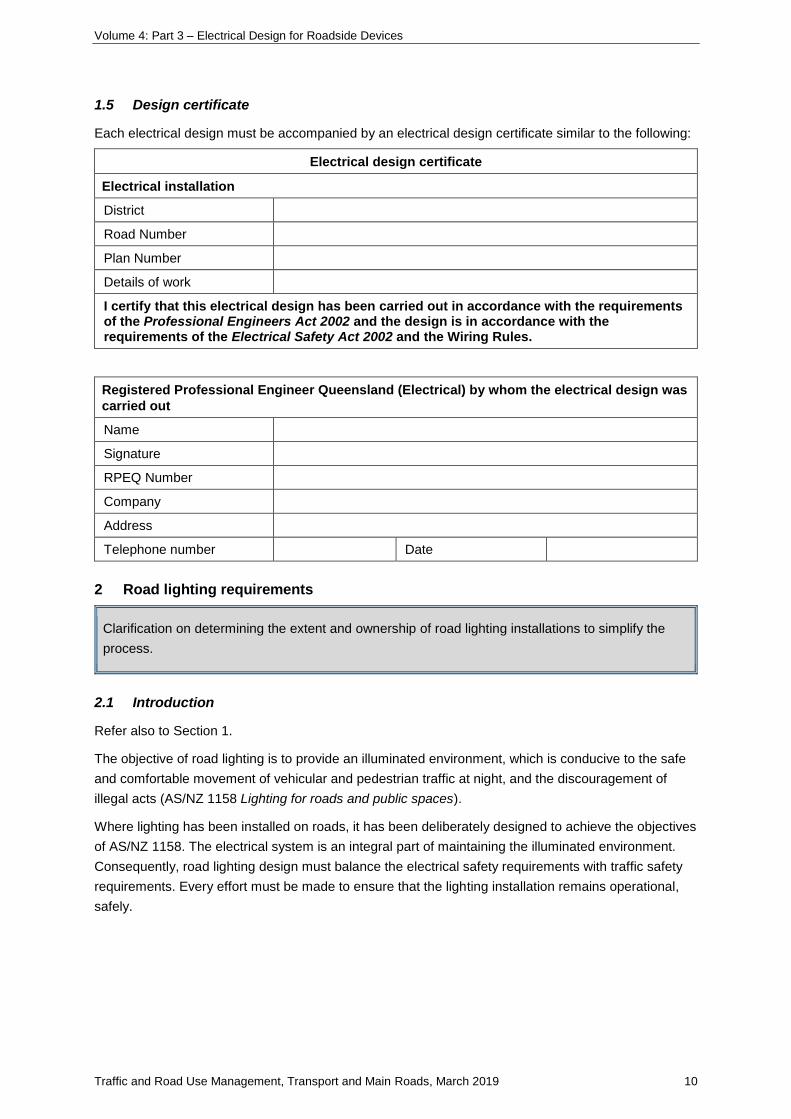
1.5 Design certificate
Each electrical design must be accompanied by an electrical design certificate similar to the following:
Electrical design certificate
Electrical installation
District
Road Number
Plan Number
Details of work
I certify that this electrical design has been carried out in accordance with the requirements of the Professional Engineers Act 2002 and the design is in accordance with the requirements of the Electrical Safety Act 2002 and the Wiring Rules.
Registered Professional Engineer Queensland (Electrical) by whom the electrical design was
carried out
Name
Signature
RPEQ Number
Company
Address
Telephone number Date
2 Road lighting requirements
Clarification on determining the extent and ownership of road lighting installations to simplify the
process.
2.1 Introduction
Refer also to Section 1.
The objective of road lighting is to provide an illuminated environment, which is conducive to the safe
and comfortable movement of vehicular and pedestrian traffic at night, and the discouragement of
illegal acts (AS/NZ 1158 Lighting for roads and public spaces).
Where lighting has been installed on roads, it has been deliberately designed to achieve the objectives
of AS/NZ 1158. The electrical system is an integral part of maintaining the illuminated environment.
Consequently, road lighting design must balance the electrical safety requirements with traffic safety
requirements. Every effort must be made to ensure that the lighting installation remains operational,
safely.
Volume 4: Part 3 – Electrical Design for Roadside Devices
Traffic and Road Use Management, Transport and Main Roads, March 2019 11
There are four main unmetered lighting tariffs available for public area lighting:
• Rate 1 Lighting: Public lighting supplied, installed, owned and maintained by the Electricity
Entity. Electricity Entity design requirements are applicable.
• Rate 2 Lighting: Public lighting supplied and installed by a Public Body, owned and maintained
by the Electricity Entity. Electricity Entity design requirements are applicable.
• Rate 3 Lighting: Public lighting supplied, installed, owned and maintained by the Public Body.
Public Body and AS/NZS 3000 design requirements are applicable.
• Rate 8 Lighting: Public lighting supplied, installed, owned and maintained by a customer who
is not a Public Body. Customer and AS/NZS 3000 design requirements are applicable.
For Queensland, the Electricity Entities are Energex and Ergon, now known as Energy Queensland.
The Public Bodies are Transport and Main Roads and local Councils.
It is essential during the early stages of a road construction project involving road lighting that
representatives of Transport and Main Roads, the local Council (if applicable) and the local Electricity
Entity agree on the ownership of the relevant parts of the final lighting installation and the applicable
standards to be used; then the design can be carried out in accordance with the appropriate
requirements.
Rate 3 road lighting should typically be restricted to motorways, motorway entry and exit ramps up to
the intersection, the motorway overpass between entry / exit ramp intersections, and state-controlled
high-speed / high-volume roads where the Electricity Entity will not maintain the installation.
2.2 Design philosophy
Electrical designs must consider the most effective means of providing safe and reliable road lighting.
For single phase, the two-wire multiple earthed neutral (MEN) system must be used. For three-phase,
the four-wire MEN system must be used. The steel reinforced concrete pole footing embedded directly
in the soil is the earth electrode.
For lighting installations on bridges and structures, a separate earth conductor of minimum size equal
to the cross-sectional area of the active conductor, must also be installed with the two-wire or four-wire
cable (refer to SD1707 Road lighting – Base plate mounted pole mounted on bridges wiring details).
Where three-phase circuits are used, the luminaire load must be balanced across the phases as
evenly as possible. The electrical connection for luminaires must be such that, in a three-phase
connected system, luminaires on adjacent poles must not be on the same phase.
In critical areas, such as motorway entry and exit ramps, three-phase circuits should be used.
2.3 Electrical design requirements
Electrical designs must consider the most effective means of providing safe and reliable lighting.
2.3.1 Design voltage and frequency
The design voltage is 230 V ac.
The design frequency is 50 Hz.
Volume 4: Part 3 – Electrical Design for Roadside Devices
Traffic and Road Use Management, Transport and Main Roads, March 2019 12
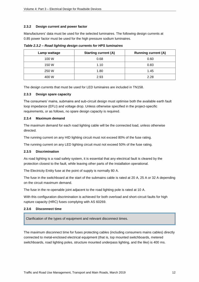
2.3.2 Design current and power factor
Manufacturers’ data must be used for the selected luminaires. The following design currents at
0.85 power factor must be used for the high pressure sodium luminaires.
Table 2.3.2 – Road lighting design currents for HPS luminaires
Lamp wattage Starting current (A) Running current (A)
100 W 0.68 0.60
150 W 1.10 0.83
250 W 1.80 1.45
400 W 2.93 2.28
The design currents that must be used for LED luminaires are included in TN158.
2.3.3 Design spare capacity
The consumers’ mains, submains and sub-circuit design must optimise both the available earth fault
loop impedance (EFLI) and voltage drop. Unless otherwise specified in the project-specific
requirements, or as follows, no spare design capacity is required.
2.3.4 Maximum demand
The maximum demand for each road lighting cable will be the connected load, unless otherwise
directed.
The running current on any HID lighting circuit must not exceed 80% of the fuse rating.
The running current on any LED lighting circuit must not exceed 50% of the fuse rating.
2.3.5 Discrimination
As road lighting is a road safety system, it is essential that any electrical fault is cleared by the
protection closest to the fault, while leaving other parts of the installation operational.
The Electricity Entity fuse at the point of supply is normally 80 A.
The fuse in the switchboard at the start of the submains cable is rated at 20 A, 25 A or 32 A depending
on the circuit maximum demand.
The fuse in the re-openable joint adjacent to the road lighting pole is rated at 10 A.
With this configuration discrimination is achieved for both overload and short-circuit faults for high
rupture capacity (HRC) fuses complying with AS 60269.
2.3.6 Disconnect time
Clarification of the types of equipment and relevant disconnect times.
The maximum disconnect time for fuses protecting cables (including consumers mains cables) directly
connected to metal-enclosed electrical equipment (that is, top mounted switchboards, metered
switchboards, road lighting poles, structure mounted underpass lighting, and the like) is 400 ms.
Volume 4: Part 3 – Electrical Design for Roadside Devices
Traffic and Road Use Management, Transport and Main Roads, March 2019 13
The maximum disconnect time for fuses protecting cables (including consumers mains cables) directly
connected to non-metal, insulated enclosed electrical equipment (that is, pillar mounted switchboards,
dome junction box adjacent to a light pole, and the like) is 5 s.
2.3.7 Cable operating temperature
Cable operating temperature standardised to 75°C for all cable calculations.
The cable operating temperature of 75°C should be used in all cable electrical calculations.
2.3.8 Voltage drop
Total voltage drop in road lighting circuits must allow for consumers mains, submains and sub-circuit
voltage drops including spare design capacity where required, the sum of which must be no greater
than 5%, using the maximum demand currents.
Length of cable used in calculations must include a 2 m coil at each end of each cable segment to
allow the re-openable joint to be lifted clear of the pit for maintenance.
In a three-phase design, as the lighting load is reasonably balanced across the phases, use a
balanced three-phase voltage drop calculation.
Voltage drop calculations must be carried out for the worst case run of each circuit connected to the
switchboard.
Voltage drop in the consumers mains must be based on the higher of 40 A or the actual connected
load up to the maximum allowable of 63 A.
Refer also to Section 7.
2.3.9 Earth fault loop impedance
EFLI calculations must be carried out to demonstrate that the design is compliant for the worst-case
protection and cable length for each of consumers’ mains, submains and final sub-circuits.
The assumed ratio of 20% external and 80% internal impedance has been found not to be valid for
road lighting installations and must not be used.
Obtain the supply transformer and distribution cable parameters from the Electricity Entity and include
these in the calculations. Where exact network data are not available or measurement of supply
characteristics is not practicable, the designer must make an assessment of the relevant parameters
and clearly document these in the design calculations.
Refer also to Section 7.
2.3.10 Point of supply
Points of supply must be agreed with the Electricity Entity to allow the Electricity Entity to carry out any
necessary network modifications.
Where practicable, road lighting and traffic signals should be connected to different points of supply.
Traffic signal controllers must not be connected to road lighting switchboards.
Road lighting circuits must not be connected to a traffic signal controller.
Volume 4: Part 3 – Electrical Design for Roadside Devices
Traffic and Road Use Management, Transport and Main Roads, March 2019 14
ITS circuits may be connected to road lighting switchboards on separate fuses upstream of the lighting
contactor.
Unless otherwise agreed with the Electricity Entity, consumers’ mains (distance from point of supply to
switchboard) should be no longer than 30 m.
2.3.11 Switching of road lighting
In automatic mode, road lighting submains are activated by a standard photocell, located on the top
mounted or metered switchboard or on a pole adjacent to the pillar mounted switchboard, which
controls contactors at the start of each circuit. A Day / Night (photocell bypass) switch provides
manual or photocell operation; hence, submains are live only under manual operation or at night time.
The photocells are designed to fail in the ‘On’ mode.
Control of individual luminaires by a photocell within the luminaire is not acceptable on Transport and
Main Roads Rate 3 installations (note: should a Central Management Lighting Control
System (CMLCS) be installed with the lighting, this requirement may not be applicable; this is to be
confirmed with the Director (Intelligent Transport Systems and Electrical)).
2.3.12 Road lighting on bridges or over railway structures
The bridge cables must be connected to the first pole off the bridge on the supply side in accordance
with SD1707 Road lighting – Base plate mounted pole mounted on bridges wiring details.
Where a bridge passes over a railway overhead wiring network, the lighting equipment may need to
be bonded to the railway traction earthing system. This system and the MEN earthing system need to
be segregated (note that lighting installations in the vicinity of railway traction systems may require
isolation transformers). Liaise with the rail system owner and the local Electricity Entity for its particular
requirements.
2.3.13 Road lighting on underpasses
Where lighting is mounted on underpasses and similar structures, refer SD1637 Road lighting –
Underpass lighting wiring details. Note that a 400 ms disconnect time is required for lights mounted on
underpasses and structures.
Typically a two-core 4 mm² cable with a separate 6 mm² earth is required. Alternatively, single-core
4 mm² cables with 6 mm² earth may be used.
2.3.14 Road lighting and traffic signals
Where Rate 3 road lighting is connected on a JUP or CMA, design in accordance with SD1677 Traffic
signals / Road lighting – Joint use pole / combination mast arm electrical wiring schematic Rate 3.
2.4 Electrical components
2.4.1 General
Refer to SD1699 Traffic signals / Road lighting / ITS – Parts list, which provides details of standard
electrical equipment items. Items approved by ITS and Electrical must be used.
Volume 4: Part 3 – Electrical Design for Roadside Devices
Traffic and Road Use Management, Transport and Main Roads, March 2019 15
2.4.2 Switchboards
Metered and unmetered switchboards available for road lighting.
Road lighting switchboards are:
Unmetered Top mounted Refer SD1623, SD1627, SD1628, SD1686
Unmetered Pillar mounted Refer SD1430 and SD1676
Metered Single phase top mounted Refer SD1687
Metered Three phase plinth mounted Refer SD1688
Use top mounted or metered switchboards to MRTS228.
Only where the Electricity Entity network characteristics are such that the 80 A fuse will not activate
within 400 ms to clear an active-to-earth fault at the top mounted or metered switchboard may a pillar
mounted switchboard be used; however, this should be used only when other cost-effective design
options are not available.
The road lighting switchboard is built with three, three-phase circuits with space for an additional
two, three-phase circuits (or single-phase equivalent). To minimise the loss of operations in the event
of a failure, the maximum number of circuits per switchboard is five, three-phase or equivalent number
of single-phase or combination of single- and three-phase circuits. The additional circuits are typically
used for low wattage ITS equipment.
The maximum connected load for road lighting switchboards must not exceed 63 A three-phase.
2.4.3 Main switch
The main switch must be a labelled, three-phase switch disconnector, lockable in the open position,
with minimum utilisation category AC 22 A, 100 A capacity, and complying with AS/NZS IEC 60947.3.
2.4.4 Fuse switches and fuselinks
Electrical protection for road lighting circuits must be provided by single- or three-phase fuse switches
complying with AS/NZS IEC 60947.3, with minimum utilisation category AC 22A, complete with HRC
fuselinks complying with AS 60269 and utilisation category gG.
Use only the standard fuselinks as follows:
Table 2.4.4 – Fuselinks for road lighting
Fuselink Application
32 A Lighting submains
25 A Lighting submains
20 A Lighting submains
10 A Photocell protection
10 A Lighting sub-circuit in re-openable joint
10 A Lighting sub-circuit in pole where loop-in loop-out configuration is used
10 A Lighting sub-circuit where luminaire mounted on structure
10 A T-off for advertising sign
Volume 4: Part 3 – Electrical Design for Roadside Devices
Traffic and Road Use Management, Transport and Main Roads, March 2019 16
Do not use fuselinks with ratings less than 10 A for road lighting.
2.4.5 Switch disconnectors
Within each slip base and base plate mounted pole a double pole 20 A switch disconnector, with
minimum utilisation category AC 22 A, complying with AS/NZS IEC 60947.3 must be installed between
the incoming cable and the 2.5 mm² luminaire cable.
2.4.6 Residual current devices
RCDs must not be used in road lighting circuits. Nuisance tripping with consequent failure of the
lighting system can be a greater hazard to road users than the potential leakage current.
Protection for persons is provided by:
• designing for a 400 ms disconnect time at the pole, and
• periodic monitoring and maintenance of the network.
Refer also to Section 5.
2.4.7 Photocell
Photocells must have low power consumption, have UV-stabilised window, be minimum IP56 rated, be
suitable for switching HID and LED luminaires, suitable for mains operating voltage, and with
recommended switching levels 30 lux ± 25% ON and 18 lux ± 25% OFF.
2.4.8 Contactors
Contactors complying with AS/NZS IEC 60947.4.1 with minimum utilisation category AC 5a, enclosed
rating 32 A minimum, coil 240 V ac, must be used to control lighting circuits.
2.4.9 Earth and neutral bars
Earth and neutral bars must be suitable for 25 mm² cables.
2.4.10 Cables
For standard road lighting cables, refer MRTS256.
Cables up to and including 6 mm² must comply with AS/NZS 5000.2.
Cables 16 mm² and larger must comply with AS/NZS 5000.1.
Direct buried cables, SDI cables (except as noted previously), neutral screened cables, steel wire
armoured cables, and the like must not be used for road lighting circuits.
Cables, where installed underground or surface mounted, must be installed in an electrical conduit
and pit system.
Where large size cables are used, particularly on long consumers’ mains runs, the cables may be
joined to a suitably sized tail:
• within the switchboard, and
• using a suitable (minimum IP67) waterproof joining method in the pit
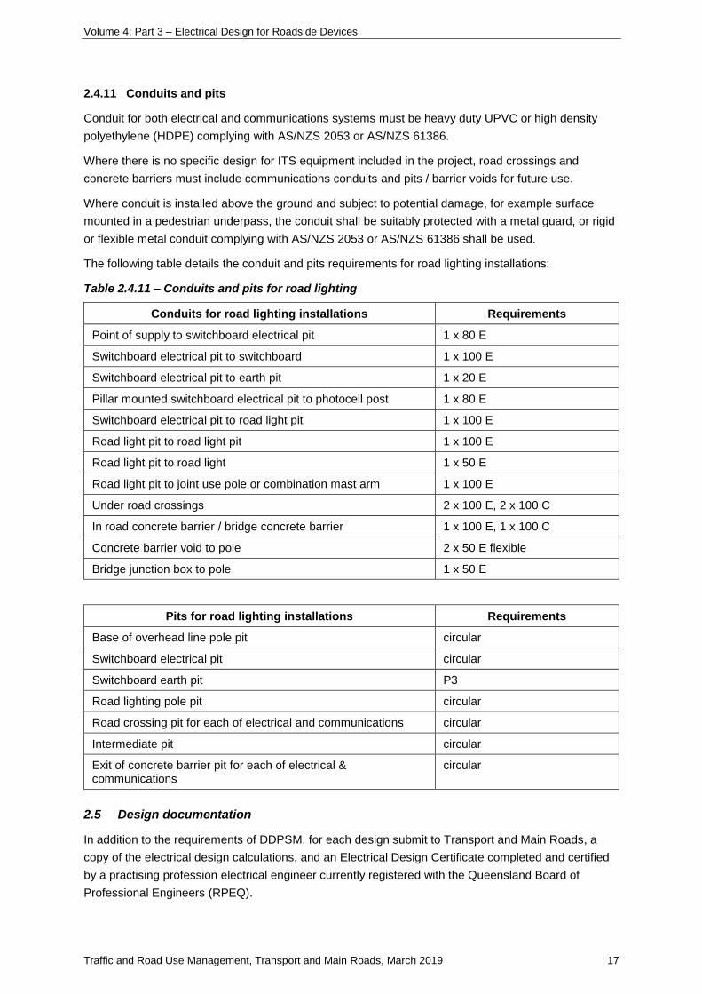
Volume 4: Part 3 – Electrical Design for Roadside Devices
Traffic and Road Use Management, Transport and Main Roads, March 2019 17
2.4.11 Conduits and pits
Conduit for both electrical and communications systems must be heavy duty UPVC or high density
polyethylene (HDPE) complying with AS/NZS 2053 or AS/NZS 61386.
Where there is no specific design for ITS equipment included in the project, road crossings and
concrete barriers must include communications conduits and pits / barrier voids for future use.
Where conduit is installed above the ground and subject to potential damage, for example surface
mounted in a pedestrian underpass, the conduit shall be suitably protected with a metal guard, or rigid
or flexible metal conduit complying with AS/NZS 2053 or AS/NZS 61386 shall be used.
The following table details the conduit and pits requirements for road lighting installations:
Table 2.4.11 – Conduits and pits for road lighting
Conduits for road lighting installations Requirements
Point of supply to switchboard electrical pit 1 x 80 E
Switchboard electrical pit to switchboard 1 x 100 E
Switchboard electrical pit to earth pit 1 x 20 E
Pillar mounted switchboard electrical pit to photocell post 1 x 80 E
Switchboard electrical pit to road light pit 1 x 100 E
Road light pit to road light pit 1 x 100 E
Road light pit to road light 1 x 50 E
Road light pit to joint use pole or combination mast arm 1 x 100 E
Under road crossings 2 x 100 E, 2 x 100 C
In road concrete barrier / bridge concrete barrier 1 x 100 E, 1 x 100 C
Concrete barrier void to pole 2 x 50 E flexible
Bridge junction box to pole 1 x 50 E
Pits for road lighting installations Requirements
Base of overhead line pole pit circular
Switchboard electrical pit circular
Switchboard earth pit P3
Road lighting pole pit circular
Road crossing pit for each of electrical and communications circular
Intermediate pit circular
Exit of concrete barrier pit for each of electrical & communications
circular
2.5 Design documentation
In addition to the requirements of DDPSM, for each design submit to Transport and Main Roads, a
copy of the electrical design calculations, and an Electrical Design Certificate completed and certified
by a practising profession electrical engineer currently registered with the Queensland Board of
Professional Engineers (RPEQ).
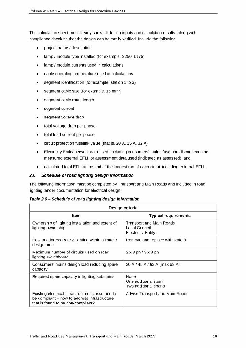
Volume 4: Part 3 – Electrical Design for Roadside Devices
Traffic and Road Use Management, Transport and Main Roads, March 2019 18
The calculation sheet must clearly show all design inputs and calculation results, along with
compliance check so that the design can be easily verified. Include the following:
• project name / description
• lamp / module type installed (for example, S250, L175)
• lamp / module currents used in calculations
• cable operating temperature used in calculations
• segment identification (for example, station 1 to 3)
• segment cable size (for example, 16 mm²)
• segment cable route length
• segment current
• segment voltage drop
• total voltage drop per phase
• total load current per phase
• circuit protection fuselink value (that is, 20 A, 25 A, 32 A)
• Electricity Entity network data used, including consumers’ mains fuse and disconnect time,
measured external EFLI, or assessment data used (indicated as assessed), and
• calculated total EFLI at the end of the longest run of each circuit including external EFLI.
2.6 Schedule of road lighting design information
The following information must be completed by Transport and Main Roads and included in road
lighting tender documentation for electrical design:
Table 2.6 – Schedule of road lighting design information
Design criteria
Item Typical requirements
Ownership of lighting installation and extent of lighting ownership
Transport and Main Roads Local Council Electricity Entity
How to address Rate 2 lighting within a Rate 3 design area
Remove and replace with Rate 3
Maximum number of circuits used on road lighting switchboard
2 x 3 ph / 3 x 3 ph
Consumers’ mains design load including spare capacity
30 A / 45 A / 63 A (max 63 A)
Required spare capacity in lighting submains None One additional span Two additional spans
Existing electrical infrastructure is assumed to be compliant – how to address infrastructure that is found to be non-compliant?
Advise Transport and Main Roads
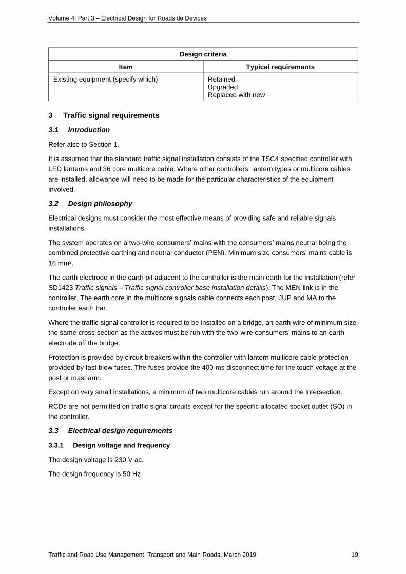
Volume 4: Part 3 – Electrical Design for Roadside Devices
Traffic and Road Use Management, Transport and Main Roads, March 2019 19
Design criteria
Item Typical requirements
Existing equipment (specify which) Retained Upgraded Replaced with new
3 Traffic signal requirements
3.1 Introduction
Refer also to Section 1.
It is assumed that the standard traffic signal installation consists of the TSC4 specified controller with
LED lanterns and 36 core multicore cable. Where other controllers, lantern types or multicore cables
are installed, allowance will need to be made for the particular characteristics of the equipment
involved.
3.2 Design philosophy
Electrical designs must consider the most effective means of providing safe and reliable signals
installations.
The system operates on a two-wire consumers’ mains with the consumers’ mains neutral being the
combined protective earthing and neutral conductor (PEN). Minimum size consumers’ mains cable is
16 mm².
The earth electrode in the earth pit adjacent to the controller is the main earth for the installation (refer
SD1423 Traffic signals – Traffic signal controller base installation details). The MEN link is in the
controller. The earth core in the multicore signals cable connects each post, JUP and MA to the
controller earth bar.
Where the traffic signal controller is required to be installed on a bridge, an earth wire of minimum size
the same cross-section as the actives must be run with the two-wire consumers’ mains to an earth
electrode off the bridge.
Protection is provided by circuit breakers within the controller with lantern multicore cable protection
provided by fast blow fuses. The fuses provide the 400 ms disconnect time for the touch voltage at the
post or mast arm.
Except on very small installations, a minimum of two multicore cables run around the intersection.
RCDs are not permitted on traffic signal circuits except for the specific allocated socket outlet (SO) in
the controller.
3.3 Electrical design requirements
3.3.1 Design voltage and frequency
The design voltage is 230 V ac.
The design frequency is 50 Hz.

Volume 4: Part 3 – Electrical Design for Roadside Devices
Traffic and Road Use Management, Transport and Main Roads, March 2019 20
3.3.2 Design current and power factor
Loads for traffic signal equipment can be found on the Australian Energy Market Operator (AEMO)
website, which should be checked as the tables are updated monthly:
The website is available at http://www.aemo.com.au/About-the-Industry/Energy-Markets/National-
Electricity-Market.
The tables are published under National Energy Market Load Tables for Unmetered Connection
Points.
The design loads from NEM Load Table v1.93 (note that these loads are used for billing purposes and
may not reflect maximum demand of specific equipment).
The following table must be completed and provided to the electricity entity with the design for billing
purposes.
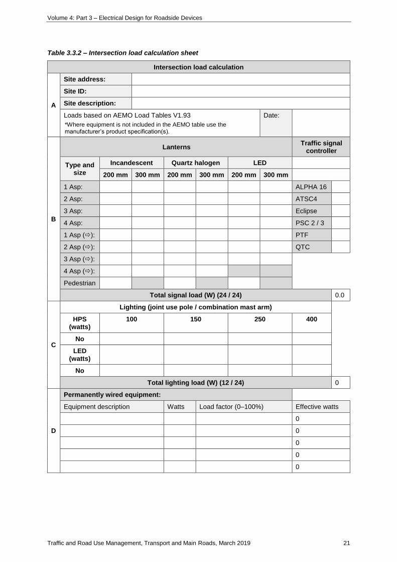
Volume 4: Part 3 – Electrical Design for Roadside Devices
Traffic and Road Use Management, Transport and Main Roads, March 2019 21
Table 3.3.2 – Intersection load calculation sheet
Intersection load calculation
A
Site address:
Site ID:
Site description:
Loads based on AEMO Load Tables V1.93
*Where equipment is not included in the AEMO table use the manufacturer’s product specification(s).
Date:
B
Lanterns Traffic signal
controller
Type and size
Incandescent Quartz halogen LED
200 mm 300 mm 200 mm 300 mm 200 mm 300 mm
1 Asp: ALPHA 16
2 Asp: ATSC4
3 Asp: Eclipse
4 Asp: PSC 2 / 3
1 Asp (): PTF
2 Asp (): QTC
3 Asp ():
4 Asp ():
Pedestrian
Total signal load (W) (24 / 24) 0.0
C
Lighting (joint use pole / combination mast arm)
HPS (watts)
100 150 250 400
No
LED (watts)
No
Total lighting load (W) (12 / 24) 0
D
Permanently wired equipment:
Equipment description Watts Load factor (0–100%) Effective watts
0
0
0
0
0
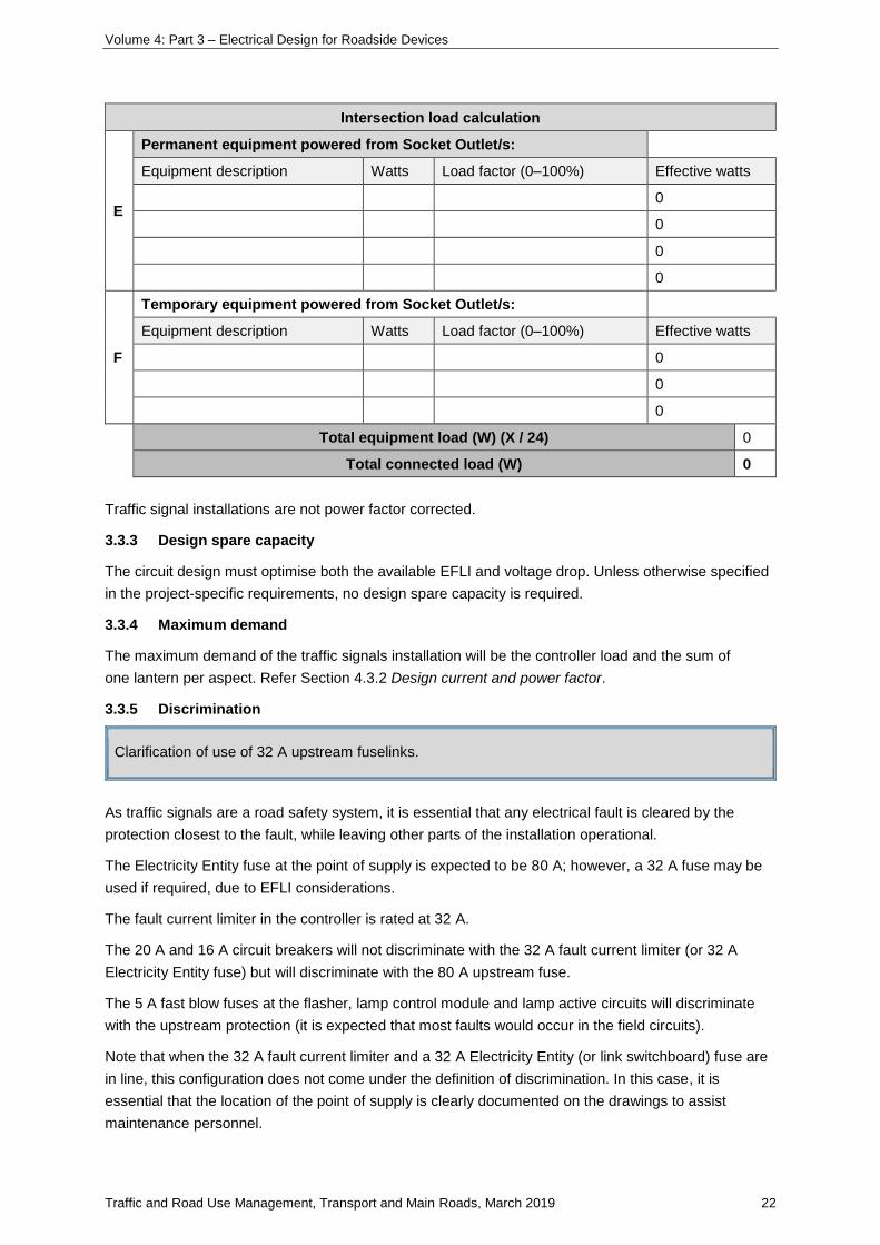
Volume 4: Part 3 – Electrical Design for Roadside Devices
Traffic and Road Use Management, Transport and Main Roads, March 2019 22
Intersection load calculation
E
Permanent equipment powered from Socket Outlet/s:
Equipment description Watts Load factor (0–100%) Effective watts
0
0
0
0
F
Temporary equipment powered from Socket Outlet/s:
Equipment description Watts Load factor (0–100%) Effective watts
0
0
0
Total equipment load (W) (X / 24) 0
Total connected load (W) 0
Traffic signal installations are not power factor corrected.
3.3.3 Design spare capacity
The circuit design must optimise both the available EFLI and voltage drop. Unless otherwise specified
in the project-specific requirements, no design spare capacity is required.
3.3.4 Maximum demand
The maximum demand of the traffic signals installation will be the controller load and the sum of
one lantern per aspect. Refer Section 4.3.2 Design current and power factor.
3.3.5 Discrimination
Clarification of use of 32 A upstream fuselinks.
As traffic signals are a road safety system, it is essential that any electrical fault is cleared by the
protection closest to the fault, while leaving other parts of the installation operational.
The Electricity Entity fuse at the point of supply is expected to be 80 A; however, a 32 A fuse may be
used if required, due to EFLI considerations.
The fault current limiter in the controller is rated at 32 A.
The 20 A and 16 A circuit breakers will not discriminate with the 32 A fault current limiter (or 32 A
Electricity Entity fuse) but will discriminate with the 80 A upstream fuse.
The 5 A fast blow fuses at the flasher, lamp control module and lamp active circuits will discriminate
with the upstream protection (it is expected that most faults would occur in the field circuits).
Note that when the 32 A fault current limiter and a 32 A Electricity Entity (or link switchboard) fuse are
in line, this configuration does not come under the definition of discrimination. In this case, it is
essential that the location of the point of supply is clearly documented on the drawings to assist
maintenance personnel.
Volume 4: Part 3 – Electrical Design for Roadside Devices
Traffic and Road Use Management, Transport and Main Roads, March 2019 23
3.3.6 Disconnect time
The maximum disconnect time for fuses protecting cables (including consumers’ mains cables)
directly connected to metal-enclosed electrical equipment (that is ,UPS, traffic signal controllers, posts,
JUPs, mast arms, CMAs and the like) is 400 ms.
3.3.7 Cable operating temperature
The cable operating temperature of 75°C should be used in all cable electrical calculations.
3.3.8 Voltage drop
Total voltage drop in traffic signal circuits must allow for consumers’ mains and multicore cable voltage
drops, the sum of which must be no greater than 5%, using the circuit maximum demands.
The voltage drop at any point in an extra low voltage circuit must not exceed 10% of the nominal
voltage when all live conductors are carrying the circuit operating current.
Length of multicore cable used in calculations must include a 6 m coil in the pit at each end of each
cable segment, 5 m up and 5 m down the post / mast arm and 2 m in each intermediate pit.
Note that the signal group current on one active core is different from the total current on the
neutral (which consists of all the signal group currents on that cable). Also, the cross-sectional area of
the active (1.5 mm²) is different from the neutral cross-sectional area (4 mm²) for the 36-core
multicore.
Refer also to Section 7.
3.3.9 Earth fault loop impedance
EFLI calculations must be carried out for the longest run.
For traffic signal installations, where the exact point of supply is unknown, the external EFLI should be
assessed based on the typical 80 A Electricity Entity fuse characteristics. The maximum allowable
external EFLI would be of the order of 0.38 Ω at 75°C to provide a disconnect time of 400 ms.
The maximum total circuit impedance based on the 5 A fuse would be 16.5 Ω.
Refer also to Section 7.9.
3.3.10 Point of supply
During the initial stage, the electrical designer should where possible determine potential points of
supply.
Where practicable, road lighting and traffic signals should be connected to different points of supply.
Traffic signal controllers must not be connected to road lighting switchboards.
Road lighting circuits must not be connected to a traffic signal controller.
3.3.11 Traffic signal controllers mounted on bridges (or other structures)
For traffic signal installations mounted on a bridge (or structure), the earth electrode for the controller
must be installed in a pit located in the ground off the bridge (or structure). The main earth conductor,
shall be a minimum cross-sectional area of 6 mm² and, in any case, less than 0.5 Ω impedance and
must be connected between the earth electrode and the controller earth bar. Appropriate labelling
must be provided at the controller and earth pit.
Volume 4: Part 3 – Electrical Design for Roadside Devices
Traffic and Road Use Management, Transport and Main Roads, March 2019 24
3.3.12 Traffic signals and road lighting
Where Rate 3 road lighting is connected on a JUP or CMA, design in accordance with SD1677 Traffic
Signals / Road lighting – Joint use pole / combination mast arm electrical wiring schematic Rate 3.
Refer to SD1678 Traffic Signals / Road lighting – Joint use pole electrical wiring schematic Rate 2 for
joint use pole electrical wiring connections for Rate 2 road lighting.
3.3.13 Connecting communications equipment to controllers
As part of the initial design, only RCD-protected double socket outlets compliant with AS/NZS 3112
may be installed in the cabinet.
Where additional communications equipment is to be installed within the traffic signal controller or in a
top hat section added to the controller, additional power socket outlets to suit the new equipment shall
be installed. Refer SD1771 to SD1779.
Refer also to Section 4 on Intelligent Transport Systems for the connection of ITS equipment to traffic
signal controllers.
3.3.14 Controllers connected to generator
Only generators compliant with MRTS259 Transportable Generator may be connected to traffic signal
controllers. Connection must be in accordance with TRUM Vol 4 Part 9 Temporary Use Electrical
Generators for Traffic Signals. The controller door must be closed and locked when the generator lead
is connected.
Generators must be attended at all times when powering traffic signal installations.
Note that EFLI design must be carried out for mains but not generator supply as the overcurrent
protection unit has been designed to disconnect the generator in the event of a fault condition.
3.3.15 Controllers connected to uninterruptible power supplies
Clarification on the design requirements for connecting traffic signal controllers to UPS.
Only uninterruptible power supplies (UPS) on the ITS and Electrical-approved equipment list may be
connected to traffic signal controllers. The UPS must be installed between the traffic signal controller
and the point of supply.
Batteries must be LiFeP04 technology and on the ITS and Electrical-approved equipment list. The
battery capacity must allow for the project-specific minimum runtime and, at the end of the runtime,
must have sufficient capacity to clear an active-to-earth fault at the end of the longest cable run. The
battery charger must be specifically designed for the LiFeP04 technology.
Design of the signals installation must be such that, should a fault occur anywhere downstream of the
controller in the field equipment, the fault is cleared by the UPS without causing it to shut down. An
internal fault within the controller will cause the UPS to shut down.
Note that EFLI design must be carried out for mains, and for UPS supply only where required in the
project-specific documentation.
Refer also to Section 7.9.
Volume 4: Part 3 – Electrical Design for Roadside Devices
Traffic and Road Use Management, Transport and Main Roads, March 2019 25
3.3.15.1 General
The high cost of UPS systems makes it unfeasible to install them at all intersections; therefore, a
system of evaluating and prioritising intersections is needed to ensure that UPS are installed where
they will result in a significant increase in safety. UPS systems are not an acceptable alternative to
inadequate intersection design and shall only be considered as a last resort.
When assessing the need for a UPS, there are factors to consider, a combination of which may
contribute to the need for a UPS. For this reason, a points system has been developed, which should
help in determining whether an intersection would benefit from having a UPS.
The points system considers a range of characteristics for an intersection. Railway interconnection
and intersection complexity have been given the highest value, as they may pose the greatest risk to
motorists when signals go out. The remaining characteristics also contribute to increased risk to a
lesser extent than the first two.
3.3.15.2 Criteria
Any intersection that scores a high number on the points system can be considered a high priority
candidate for a UPS system; however, this does not mean a UPS should be installed. Assessing
intersections still requires sound engineering judgement and local knowledge.
3.3.15.2.1 Railway crossings
Transport and Main Roads has some intersections that are connected to signalised, at-grade railway
crossings. Generally, the presence of a train will call a special phase, or a series of phases, to clear
the crossing of vehicles. In some cases, these crossings have inadequate storage areas and less than
desirable geometry. This may create a situation where cars queue across the tracks, even when the
signals are operating.
When the signals are out due to power failure, the chance of vehicles queuing across the tracks may
increase. When assessing this type of intersection, attention should be given to the chances of
increased queuing across the tracks.
3.3.15.2.2 Complex intersections
While normal right-of-way rules apply when signal are non-operational, some complex intersections
become confusing and may increase the risk of crashes. When assessing the complexity of an
intersection, sound engineering judgement should be used to determine whether it should be
considered as complex.
Factors to consider when assessing this criterion include:
• number of legs
• sight distance
• multi-lane right turns, and
• presence of separately-controlled bus movements
The effects of poor visibility or inadequate sight distance at an intersection may become more of a
problem when signals are not operational. Intersections with advance flashers may be considered in
this category, as they generally have some problem with visibility or the need for an advanced
warning.
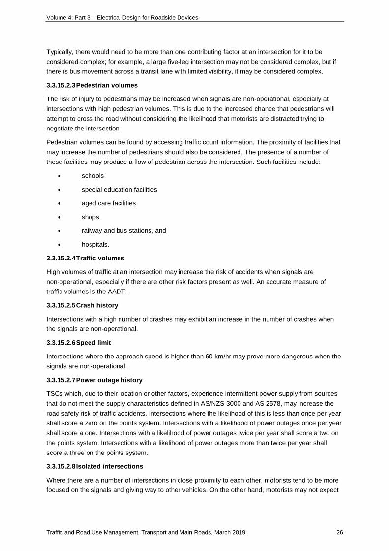
Volume 4: Part 3 – Electrical Design for Roadside Devices
Traffic and Road Use Management, Transport and Main Roads, March 2019 26
Typically, there would need to be more than one contributing factor at an intersection for it to be
considered complex; for example, a large five-leg intersection may not be considered complex, but if
there is bus movement across a transit lane with limited visibility, it may be considered complex.
3.3.15.2.3 Pedestrian volumes
The risk of injury to pedestrians may be increased when signals are non-operational, especially at
intersections with high pedestrian volumes. This is due to the increased chance that pedestrians will
attempt to cross the road without considering the likelihood that motorists are distracted trying to
negotiate the intersection.
Pedestrian volumes can be found by accessing traffic count information. The proximity of facilities that
may increase the number of pedestrians should also be considered. The presence of a number of
these facilities may produce a flow of pedestrian across the intersection. Such facilities include:
• schools
• special education facilities
• aged care facilities
• shops
• railway and bus stations, and
• hospitals.
3.3.15.2.4 Traffic volumes
High volumes of traffic at an intersection may increase the risk of accidents when signals are
non-operational, especially if there are other risk factors present as well. An accurate measure of
traffic volumes is the AADT.
3.3.15.2.5 Crash history
Intersections with a high number of crashes may exhibit an increase in the number of crashes when
the signals are non-operational.
3.3.15.2.6 Speed limit
Intersections where the approach speed is higher than 60 km/hr may prove more dangerous when the
signals are non-operational.
3.3.15.2.7 Power outage history
TSCs which, due to their location or other factors, experience intermittent power supply from sources
that do not meet the supply characteristics defined in AS/NZS 3000 and AS 2578, may increase the
road safety risk of traffic accidents. Intersections where the likelihood of this is less than once per year
shall score a zero on the points system. Intersections with a likelihood of power outages once per year
shall score a one. Intersections with a likelihood of power outages twice per year shall score a two on
the points system. Intersections with a likelihood of power outages more than twice per year shall
score a three on the points system.
3.3.15.2.8 Isolated intersections
Where there are a number of intersections in close proximity to each other, motorists tend to be more
focused on the signals and giving way to other vehicles. On the other hand, motorists may not expect
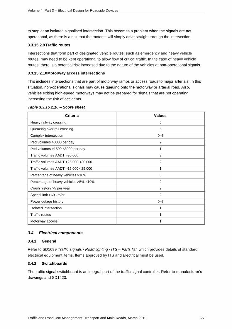
Volume 4: Part 3 – Electrical Design for Roadside Devices
Traffic and Road Use Management, Transport and Main Roads, March 2019 27
to stop at an isolated signalised intersection. This becomes a problem when the signals are not
operational, as there is a risk that the motorist will simply drive straight through the intersection.
3.3.15.2.9 Traffic routes
Intersections that form part of designated vehicle routes, such as emergency and heavy vehicle
routes, may need to be kept operational to allow flow of critical traffic. In the case of heavy vehicle
routes, there is a potential risk increased due to the nature of the vehicles at non-operational signals.
3.3.15.2.10 Motorway access intersections
This includes intersections that are part of motorway ramps or access roads to major arterials. In this
situation, non-operational signals may cause queuing onto the motorway or arterial road. Also,
vehicles exiting high-speed motorways may not be prepared for signals that are not operating,
increasing the risk of accidents.
Table 3.3.15.2.10 – Score sheet
Criteria Values
Heavy railway crossing 5
Queueing over rail crossing 5
Complex intersection 0–5
Ped volumes >3000 per day 2
Ped volumes >1500 <3000 per day 1
Traffic volumes AADT >30,000 3
Traffic volumes AADT >25,000 <30,000 2
Traffic volumes AADT >15,000 <25,000 1
Percentage of heavy vehicles >10% 3
Percentage of heavy vehicles >5% <10% 2
Crash history >5 per year 2
Speed limit >60 km/hr 2
Power outage history 0–3
Isolated intersection 1
Traffic routes 1
Motorway access 1
3.4 Electrical components
3.4.1 General
Refer to SD1699 Traffic signals / Road lighting / ITS – Parts list, which provides details of standard
electrical equipment items. Items approved by ITS and Electrical must be used.
3.4.2 Switchboards
The traffic signal switchboard is an integral part of the traffic signal controller. Refer to manufacturer’s
drawings and SD1423.
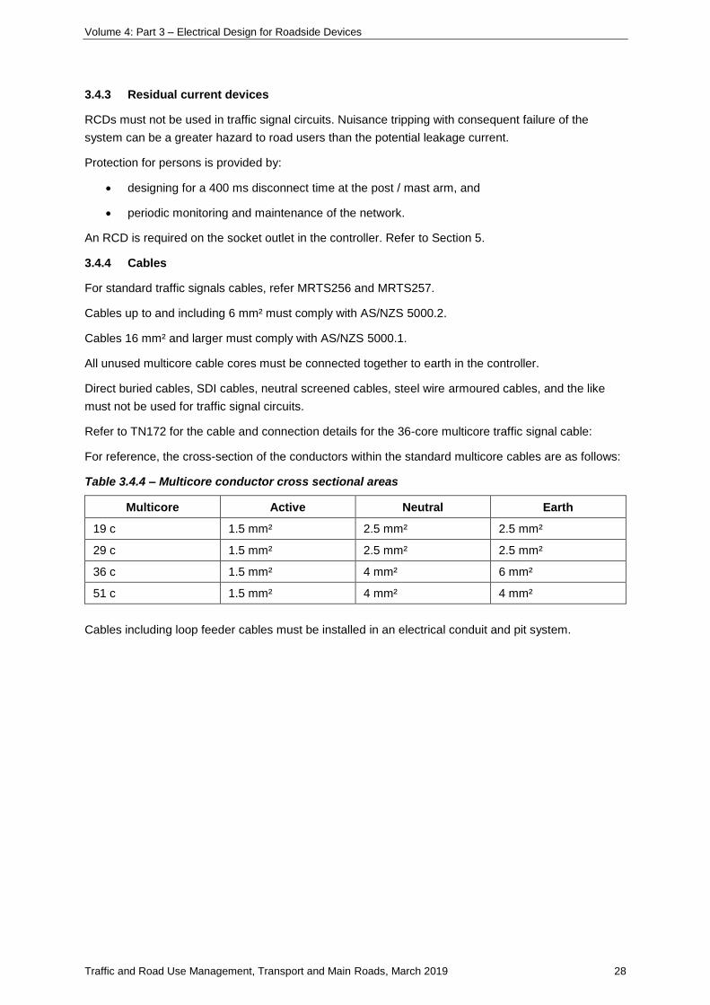
Volume 4: Part 3 – Electrical Design for Roadside Devices
Traffic and Road Use Management, Transport and Main Roads, March 2019 28
3.4.3 Residual current devices
RCDs must not be used in traffic signal circuits. Nuisance tripping with consequent failure of the
system can be a greater hazard to road users than the potential leakage current.
Protection for persons is provided by:
• designing for a 400 ms disconnect time at the post / mast arm, and
• periodic monitoring and maintenance of the network.
An RCD is required on the socket outlet in the controller. Refer to Section 5.
3.4.4 Cables
For standard traffic signals cables, refer MRTS256 and MRTS257.
Cables up to and including 6 mm² must comply with AS/NZS 5000.2.
Cables 16 mm² and larger must comply with AS/NZS 5000.1.
All unused multicore cable cores must be connected together to earth in the controller.
Direct buried cables, SDI cables, neutral screened cables, steel wire armoured cables, and the like
must not be used for traffic signal circuits.
Refer to TN172 for the cable and connection details for the 36-core multicore traffic signal cable:
For reference, the cross-section of the conductors within the standard multicore cables are as follows:
Table 3.4.4 – Multicore conductor cross sectional areas
Multicore Active Neutral Earth
19 c 1.5 mm² 2.5 mm² 2.5 mm²
29 c 1.5 mm² 2.5 mm² 2.5 mm²
36 c 1.5 mm² 4 mm² 6 mm²
51 c 1.5 mm² 4 mm² 4 mm²
Cables including loop feeder cables must be installed in an electrical conduit and pit system.
Volume 4: Part 3 – Electrical Design for Roadside Devices
Traffic and Road Use Management, Transport and Main Roads, March 2019 29
3.4.5 Conduits and pits
Conduit for both electrical and communications systems must be heavy duty UPVC or high density
polyethylene (HDPE) complying with AS/NZS 61386.
The following table details the minimum conduit and pit requirements for traffic signal installations.
Table 3.4.5 – Conduits and pits for traffic signals
Conduits for traffic signals Typical requirements
Telstra point of presence to TSC communications pit 1 x 100 C
TSC communications pit to TSC 1 x 100 C
Point of supply to TSC electrical pit 1 x 80 E
TSC electrical pit to TSC 2 x 100 E
TSC to earth pit 1 x 20 E
TSC electrical pit to post (or JUP, MA, CMA) electrical pit 2 x 100 E
TSC comms pit to post (or JUP, MA, CMA) comms pit 1 x 100 C
Post (or JUP, MA, CMA) electrical pit to post electrical pit 2 x 100 E
Post (or JUP, MA, CMA) comms pit to post comms pit 1 x 100 C
Detection loop to loop pit 1 x 32 E
Loop pit to post pit 1 x 50 E
Post pit to post (or JUP, MA, CMA) 1 x 100 E
Post pit to pedestrian pushbutton post 1 x 80 E
Post pit to bicycle pushbutton post 1 x 80 E
Under road crossings 2 x 100 E
Pits for traffic signals Requirements
TSC electrical pit circular
TSC communications pit circular
TSC earth pit P3
Traffic signal post (or JUP, MA, CMA) pit (electrical and comms) circular
Road crossing pit (electrical and comms) circular
Detection loop pit P3
Intermediate pit P4
Where there are installations with large numbers of cables, the conduit numbers may need to be
increased so that the maximum conduit fill for any conduit does not exceed 40 %.
3.5 Design documentation
In addition to the requirements of DDPSM, for each design, submit to Transport and Main Roads a
copy of the electrical design calculations, and an Electrical Design Certificate completed and certified
by a practising profession electrical engineer currently registered with the Queensland Board of
Professional Engineers (RPEQ).
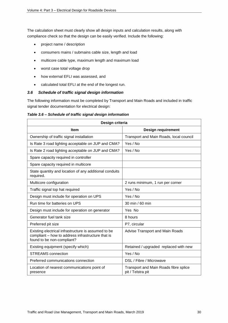
Volume 4: Part 3 – Electrical Design for Roadside Devices
Traffic and Road Use Management, Transport and Main Roads, March 2019 30
The calculation sheet must clearly show all design inputs and calculation results, along with
compliance check so that the design can be easily verified. Include the following:
• project name / description
• consumers mains / submains cable size, length and load
• multicore cable type, maximum length and maximum load
• worst case total voltage drop
• how external EFLI was assessed, and
• calculated total EFLI at the end of the longest run.
3.6 Schedule of traffic signal design information
The following information must be completed by Transport and Main Roads and included in traffic
signal tender documentation for electrical design:
Table 3.6 – Schedule of traffic signal design information
Design criteria
Item Design requirement
Ownership of traffic signal installation Transport and Main Roads, local council
Is Rate 3 road lighting acceptable on JUP and CMA? Yes / No
Is Rate 2 road lighting acceptable on JUP and CMA? Yes / No
Spare capacity required in controller
Spare capacity required in multicore
State quantity and location of any additional conduits required.
Multicore configuration 2 runs minimum, 1 run per corner
Traffic signal top hat required Yes / No
Design must include for operation on UPS Yes / No
Run time for batteries on UPS 30 min / 60 min
Design must include for operation on generator Yes No
Generator fuel tank size 8 hours
Preferred pit size P7, circular
Existing electrical infrastructure is assumed to be compliant – how to address infrastructure that is found to be non-compliant?
Advise Transport and Main Roads
Existing equipment (specify which) Retained / upgraded replaced with new
STREAMS connection Yes / No
Preferred communications connection DSL / Fibre / Microwave
Location of nearest communications point of presence
Transport and Main Roads fibre splice pit / Telstra pit
Volume 4: Part 3 – Electrical Design for Roadside Devices
Traffic and Road Use Management, Transport and Main Roads, March 2019 31
4 Intelligent transport systems requirements
4.1 Introduction
Refer also to Section 1.
ITS are information and communication technologies applied to road infrastructure and vehicles to
improve road safety and efficiency as well as reduce impact on the environment of transportation
systems. They have proven to be an innovative alternative to traditional measures for addressing
transportation problems and needs. ITS applications vary, from simple traffic control and traveller
information systems to the rapidly-evolving automatic incident detection applications and vehicle to
infrastructure cooperative systems.
ITS systems include:
• vehicle detection sites (VDS)
• vehicle counter / classifiers
• closed circuit television (CCTV) systems / Web cameras
• road weather monitoring
• Help phone systems
• variable message signs (VMS)
• changeable message signs (CMS) systems
• road condition information signs (RCIS)
• variable speed limit / lane use signs (VSL / LUMS)
• travel time signs (TTS)
• ramp metering systems
• weigh-in-motion (WIM) systems, and
• automatic number plate recognition (ANPR) systems.
All of these systems require power supplies and, because of the electronic components of many of the
systems, appropriate surge and lightning protection.
4.2 Design philosophy
ITS design must take into account road geometry, landscape design, drainage systems, road
structures, other road furniture such as static signs, lighting, services such as electricity and public
utility plant and supplies. Likewise, these services must consider ITS requirements. This will allow
addressing conflicts that may arise regarding ITS equipment space allowances, conduit routes and
sighting distances with other road services. Site and maintenance access are critical aspects of all
ITS designs.
Electrical designs must consider the most effective means of providing safe and reliable ITS systems.
ITS systems will generally be single phase using the two-wire MEN system. In larger three-phase
power installations, the four-wire MEN system must be used. An earth electrode and MEN link will be
required at the switchboard and field cabinet.
Volume 4: Part 3 – Electrical Design for Roadside Devices
Traffic and Road Use Management, Transport and Main Roads, March 2019 32
Where three-phase circuits are used, the load must be balanced across the phases as evenly as
possible.
4.3 Electrical design requirements
4.3.1 Design voltage and frequency
The design voltage is 230 V ac.
The design frequency is 50 Hz.
4.3.2 Design current and power factor
Manufacturers’ data, where available, must be used for the selected equipment. Where this is not
available, current measurement, load assessment or specified protection size should be used.
4.3.3 Design spare capacity
The consumers’ mains, submains and sub-circuit design must optimise both the available EFLI and
voltage drop. Unless otherwise specified in the project-specific requirements, a single-phase 10 A
design current should be allowed for each field cabinet.
4.3.4 Maximum demand
The maximum demand for each sub-circuit and socket outlet will be the connected load.
The running current load on any circuit must not exceed 80% of the circuit protection rating.
The maximum connected load for switchboards must not exceed 63 A three-phase.
4.3.5 Discrimination
For ITS systems, it is essential that any electrical fault is cleared by the protection closest to the fault,
while leaving other parts of the installation operational.
The electricity entity fuse at the point of supply is expected to be 80 A.
The field cabinet protection fuse is 20 A, unless otherwise specified in the project-specific
requirements. This may be located within the cabinet or within a switchboard, particularly when a
number of cabinets are supplied from the one switchboard.
The surge filter fuse for the field cabinet is rated at 20 A, or to suit the protection fuse size.
Sub-circuit fuses are rated at 10 A.
With this configuration, discrimination is achieved for both overload and short-circuit faults for high
rupture capacity fuses complying with AS 60269.
4.3.6 Disconnect time
The maximum disconnect time for fuses protecting cables (including consumers’ mains cables)
directly connected to metal enclosed electrical equipment (that is, top mounted switchboards, metered
switchboards, ITS switchboards, field cabinets, post / gantry mounted equipment, and the like) is
400 ms.
The maximum disconnect time for fuses protecting cables (including consumers’ mains cables)
directly connected to non-metal, insulated enclosed electrical equipment (that is, pillar mounted
switchboards, and the like) is 5 s.
Volume 4: Part 3 – Electrical Design for Roadside Devices
Traffic and Road Use Management, Transport and Main Roads, March 2019 33
4.3.7 Cable operating temperature
The cable operating temperature of 75°C should be used in all cable electrical calculations.
4.3.8 Voltage drop
Total voltage drop in ITS circuits must allow for consumers’ mains, submains and sub-circuit voltage
drops, the sum of which must be no greater than 5%, using the circuit maximum demands.
The voltage drop at any point in an extra low voltage circuit must not exceed 10% of the nominal
voltage when all live conductors are carrying the circuit operating current.
In addition, voltage drop at any ITS equipment must not be more than that required for safe and
reliable operation of the equipment.
Refer also to Section 7.
4.3.9 Earth fault loop impedance
EFLI calculations must be carried out to demonstrate that the design is compliant for the worst-case
protection and cable length for each of consumers’ mains, submains and final sub-circuits.
The assumed ratio of 20% external and 80% internal impedance has been found not to be valid for
Transport and Main Roads’ field installations and must not be used.
Obtain the supply transformer and distribution cable parameters from the Electricity Entity and include
these in the calculations. Where exact network data are not available or measurement of supply
characteristics is not practicable, the designer must make an assessment of the relevant parameters
and clearly document these in the design calculations.
Refer also to Section 7.
4.3.10 Point of supply
Points of supply must be agreed with the Electricity Entity within a reasonable time frame to allow the
Electricity Entity to carry out any necessary network modifications without delay to the project.
ITS circuits may be connected to road lighting switchboards on separate fuses upstream of the lighting
contactor.
ITS equipment specific for an intersection controlled by a traffic signal controller may be connected to
the controller; however, protection sizes / types for the ITS equipment must be selected to ensure that
total discrimination is achieved with the controller circuits.
4.3.11 Electrical connection of intelligent transport systems equipment
ITS equipment is generally connected to the power supply located within the field cabinet.
One double, general purpose socket outlet is permitted within the field cabinet and this must be
RCD protected.
Individual socket outlets should be used for specific equipment, unless the equipment is designed to
be hardwired.
RCDs are not required on socket outlets (other than the double, general purpose socket outlet),
provided the requirements of AS/NZS 3000 Clause 2.6.3.2.1 Exception 5 are met.
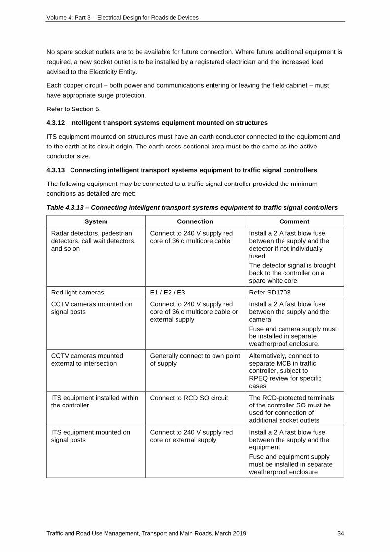
Volume 4: Part 3 – Electrical Design for Roadside Devices
Traffic and Road Use Management, Transport and Main Roads, March 2019 34
No spare socket outlets are to be available for future connection. Where future additional equipment is
required, a new socket outlet is to be installed by a registered electrician and the increased load
advised to the Electricity Entity.
Each copper circuit – both power and communications entering or leaving the field cabinet – must
have appropriate surge protection.
Refer to Section 5.
4.3.12 Intelligent transport systems equipment mounted on structures
ITS equipment mounted on structures must have an earth conductor connected to the equipment and
to the earth at its circuit origin. The earth cross-sectional area must be the same as the active
conductor size.
4.3.13 Connecting intelligent transport systems equipment to traffic signal controllers
The following equipment may be connected to a traffic signal controller provided the minimum
conditions as detailed are met:
Table 4.3.13 – Connecting intelligent transport systems equipment to traffic signal controllers
System Connection Comment
Radar detectors, pedestrian detectors, call wait detectors, and so on
Connect to 240 V supply red core of 36 c multicore cable
Install a 2 A fast blow fuse between the supply and the detector if not individually fused
The detector signal is brought back to the controller on a spare white core
Red light cameras E1 / E2 / E3 Refer SD1703
CCTV cameras mounted on signal posts
Connect to 240 V supply red core of 36 c multicore cable or external supply
Install a 2 A fast blow fuse between the supply and the camera
Fuse and camera supply must be installed in separate weatherproof enclosure.
CCTV cameras mounted external to intersection
Generally connect to own point of supply
Alternatively, connect to separate MCB in traffic controller, subject to RPEQ review for specific cases
ITS equipment installed within the controller
Connect to RCD SO circuit The RCD-protected terminals of the controller SO must be used for connection of additional socket outlets
ITS equipment mounted on signal posts
Connect to 240 V supply red core or external supply
Install a 2 A fast blow fuse between the supply and the equipment
Fuse and equipment supply must be installed in separate weatherproof enclosure
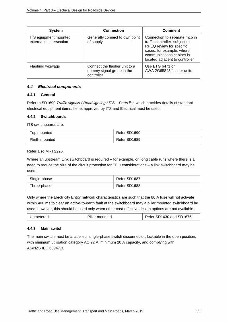
Volume 4: Part 3 – Electrical Design for Roadside Devices
Traffic and Road Use Management, Transport and Main Roads, March 2019 35
System Connection Comment
ITS equipment mounted external to intersection
Generally connect to own point of supply
Connection to separate mcb in traffic controller, subject to RPEQ review for specific cases; for example, where communications cabinet is located adjacent to controller
Flashing wigwags Connect the flasher unit to a dummy signal group in the controller
Use ETG 6471 or AWA 2G65843 flasher units
4.4 Electrical components
4.4.1 General
Refer to SD1699 Traffic signals / Road lighting / ITS – Parts list, which provides details of standard
electrical equipment items. Items approved by ITS and Electrical must be used.
4.4.2 Switchboards
ITS switchboards are:
Top mounted Refer SD1690
Plinth mounted Refer SD1689
Refer also MRTS226.
Where an upstream Link switchboard is required – for example, on long cable runs where there is a
need to reduce the size of the circuit protection for EFLI considerations – a link switchboard may be
used:
Single-phase Refer SD1687
Three-phase Refer SD1688
Only where the Electricity Entity network characteristics are such that the 80 A fuse will not activate
within 400 ms to clear an active-to-earth fault at the switchboard may a pillar mounted switchboard be
used; however, this should be used only when other cost-effective design options are not available.
Unmetered Pillar mounted Refer SD1430 and SD1676
4.4.3 Main switch
The main switch must be a labelled, single-phase switch disconnector, lockable in the open position,
with minimum utilisation category AC 22 A, minimum 20 A capacity, and complying with
AS/NZS IEC 60947.3.
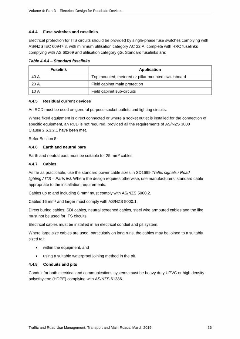
Volume 4: Part 3 – Electrical Design for Roadside Devices
Traffic and Road Use Management, Transport and Main Roads, March 2019 36
4.4.4 Fuse switches and ruselinks
Electrical protection for ITS circuits should be provided by single-phase fuse switches complying with
AS/NZS IEC 60947.3, with minimum utilisation category AC 22 A, complete with HRC fuselinks
complying with AS 60269 and utilisation category gG. Standard fuselinks are:
Table 4.4.4 – Standard fuselinks
Fuselink Application
40 A Top mounted, metered or pillar mounted switchboard
20 A Field cabinet main protection
10 A Field cabinet sub-circuits
4.4.5 Residual current devices
An RCD must be used on general purpose socket outlets and lighting circuits.
Where fixed equipment is direct connected or where a socket outlet is installed for the connection of
specific equipment, an RCD is not required, provided all the requirements of AS/NZS 3000
Clause 2.6.3.2.1 have been met.
Refer Section 5.
4.4.6 Earth and neutral bars
Earth and neutral bars must be suitable for 25 mm² cables.
4.4.7 Cables
As far as practicable, use the standard power cable sizes in SD1699 Traffic signals / Road
lighting / ITS – Parts list. Where the design requires otherwise, use manufacturers’ standard cable
appropriate to the installation requirements.
Cables up to and including 6 mm² must comply with AS/NZS 5000.2.
Cables 16 mm² and larger must comply with AS/NZS 5000.1.
Direct buried cables, SDI cables, neutral screened cables, steel wire armoured cables and the like
must not be used for ITS circuits.
Electrical cables must be installed in an electrical conduit and pit system.
Where large size cables are used, particularly on long runs, the cables may be joined to a suitably
sized tail:
• within the equipment, and
• using a suitable waterproof joining method in the pit.
4.4.8 Conduits and pits
Conduit for both electrical and communications systems must be heavy duty UPVC or high density
polyethylene (HDPE) complying with AS/NZS 61386.
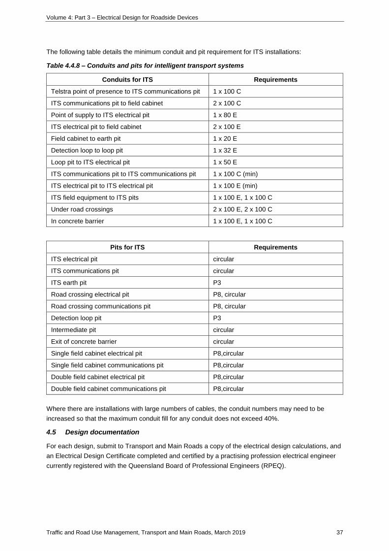
Volume 4: Part 3 – Electrical Design for Roadside Devices
Traffic and Road Use Management, Transport and Main Roads, March 2019 37
The following table details the minimum conduit and pit requirement for ITS installations:
Table 4.4.8 – Conduits and pits for intelligent transport systems
Conduits for ITS Requirements
Telstra point of presence to ITS communications pit 1 x 100 C
ITS communications pit to field cabinet 2 x 100 C
Point of supply to ITS electrical pit 1 x 80 E
ITS electrical pit to field cabinet 2 x 100 E
Field cabinet to earth pit 1 x 20 E
Detection loop to loop pit 1 x 32 E
Loop pit to ITS electrical pit 1 x 50 E
ITS communications pit to ITS communications pit 1 x 100 C (min)
ITS electrical pit to ITS electrical pit 1 x 100 E (min)
ITS field equipment to ITS pits 1 x 100 E, 1 x 100 C
Under road crossings 2 x 100 E, 2 x 100 C
In concrete barrier 1 x 100 E, 1 x 100 C
Pits for ITS Requirements
ITS electrical pit circular
ITS communications pit circular
ITS earth pit P3
Road crossing electrical pit P8, circular
Road crossing communications pit P8, circular
Detection loop pit P3
Intermediate pit circular
Exit of concrete barrier circular
Single field cabinet electrical pit P8,circular
Single field cabinet communications pit P8,circular
Double field cabinet electrical pit P8,circular
Double field cabinet communications pit P8,circular
Where there are installations with large numbers of cables, the conduit numbers may need to be
increased so that the maximum conduit fill for any conduit does not exceed 40%.
4.5 Design documentation
For each design, submit to Transport and Main Roads a copy of the electrical design calculations, and
an Electrical Design Certificate completed and certified by a practising profession electrical engineer
currently registered with the Queensland Board of Professional Engineers (RPEQ).
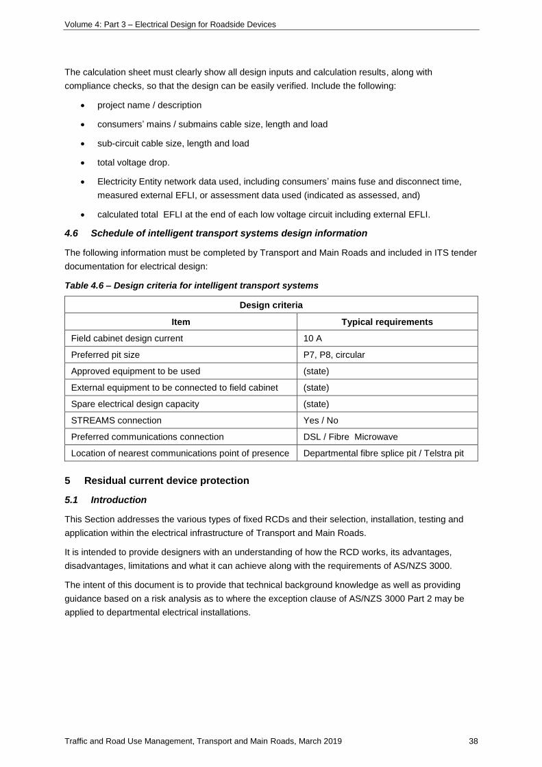
Volume 4: Part 3 – Electrical Design for Roadside Devices
Traffic and Road Use Management, Transport and Main Roads, March 2019 38
The calculation sheet must clearly show all design inputs and calculation results, along with
compliance checks, so that the design can be easily verified. Include the following:
• project name / description
• consumers’ mains / submains cable size, length and load
• sub-circuit cable size, length and load
• total voltage drop.
• Electricity Entity network data used, including consumers’ mains fuse and disconnect time,
measured external EFLI, or assessment data used (indicated as assessed, and)
• calculated total EFLI at the end of each low voltage circuit including external EFLI.
4.6 Schedule of intelligent transport systems design information
The following information must be completed by Transport and Main Roads and included in ITS tender
documentation for electrical design:
Table 4.6 – Design criteria for intelligent transport systems
Design criteria
Item Typical requirements
Field cabinet design current 10 A
Preferred pit size P7, P8, circular
Approved equipment to be used (state)
External equipment to be connected to field cabinet (state)
Spare electrical design capacity (state)
STREAMS connection Yes / No
Preferred communications connection DSL / Fibre Microwave
Location of nearest communications point of presence Departmental fibre splice pit / Telstra pit
5 Residual current device protection
5.1 Introduction
This Section addresses the various types of fixed RCDs and their selection, installation, testing and
application within the electrical infrastructure of Transport and Main Roads.
It is intended to provide designers with an understanding of how the RCD works, its advantages,
disadvantages, limitations and what it can achieve along with the requirements of AS/NZS 3000.
The intent of this document is to provide that technical background knowledge as well as providing
guidance based on a risk analysis as to where the exception clause of AS/NZS 3000 Part 2 may be
applied to departmental electrical installations.
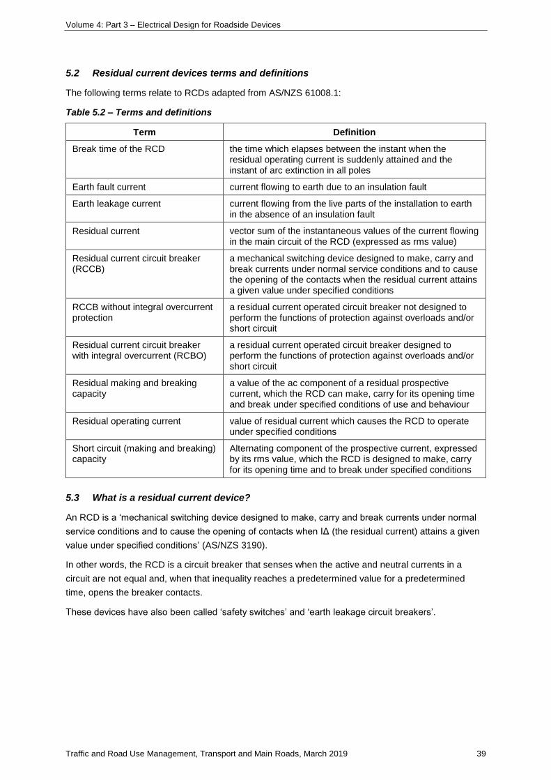
Volume 4: Part 3 – Electrical Design for Roadside Devices
Traffic and Road Use Management, Transport and Main Roads, March 2019 39
5.2 Residual current devices terms and definitions
The following terms relate to RCDs adapted from AS/NZS 61008.1:
Table 5.2 – Terms and definitions
Term Definition
Break time of the RCD the time which elapses between the instant when the residual operating current is suddenly attained and the instant of arc extinction in all poles
Earth fault current current flowing to earth due to an insulation fault
Earth leakage current current flowing from the live parts of the installation to earth in the absence of an insulation fault
Residual current vector sum of the instantaneous values of the current flowing in the main circuit of the RCD (expressed as rms value)
Residual current circuit breaker (RCCB)
a mechanical switching device designed to make, carry and break currents under normal service conditions and to cause the opening of the contacts when the residual current attains a given value under specified conditions
RCCB without integral overcurrent protection
a residual current operated circuit breaker not designed to perform the functions of protection against overloads and/or short circuit
Residual current circuit breaker with integral overcurrent (RCBO)
a residual current operated circuit breaker designed to perform the functions of protection against overloads and/or short circuit
Residual making and breaking capacity
a value of the ac component of a residual prospective current, which the RCD can make, carry for its opening time and break under specified conditions of use and behaviour
Residual operating current value of residual current which causes the RCD to operate under specified conditions
Short circuit (making and breaking) capacity
Alternating component of the prospective current, expressed by its rms value, which the RCD is designed to make, carry for its opening time and to break under specified conditions
5.3 What is a residual current device?
An RCD is a ‘mechanical switching device designed to make, carry and break currents under normal
service conditions and to cause the opening of contacts when IΔ (the residual current) attains a given
value under specified conditions’ (AS/NZS 3190).
In other words, the RCD is a circuit breaker that senses when the active and neutral currents in a
circuit are not equal and, when that inequality reaches a predetermined value for a predetermined
time, opens the breaker contacts.
These devices have also been called ‘safety switches’ and ‘earth leakage circuit breakers’.
Volume 4: Part 3 – Electrical Design for Roadside Devices
Traffic and Road Use Management, Transport and Main Roads, March 2019 40
5.4 Purpose of a residual current device
The fundamental rule for protection against electric shock is that:
1. hazardous live parts shall not be accessible, and
2. accessible conductive parts shall not be hazardous
a. under normal operating conditions, and
b. under a single fault condition.
The normal protection measures against hazardous live parts include:
1. protection by the insulation of live parts
2. protection by means of barriers or enclosures
3. protection by means of obstacles or placing out of reach, and
4. protection by use of extra low voltage.
Sometimes these preventative measures fail due to lack of maintenance, imprudence, carelessness,
normal wear and tear, age or environmental effects.
Where electrical equipment is contained in an earthed metal box, any current leakage from the
equipment is likely to flow in the earthed enclosure. This could lead to dangerous potential differences
between that enclosure and other earthed metalwork which is also open to touch.
The main purpose of the RCD is to limit the severity of electric shock due to indirect contact. This
occurs when a person touches an exposed conductive part that is not normally live but has become
live accidentally, due to some fault condition.
RCDs with a sensitivity of 30 mA are designed to monitor the residual current, operate, and disconnect
the electrical supply, automatically clearing the fault with sufficient speed to prevent serious injury,
fibrillation of the heart, or death by electrocution of a normal healthy human being (refer Section 7 for
the effects of current through the body).
5.5 How residual current devices work
In simple terms, the RCD is a circuit breaker that continuously compares the active current to the
neutral current. The residual current will be the difference between the two. This residual current will
be flowing to earth, because it has left the phase part of the circuit and has not returned in the
neutral (in the MEN system, there are multiple earth return paths available for this current). There will
always be some residual current due to the insulation resistance and capacitance to earth, but in a
healthy circuit, this current will generally be low, seldom exceeding 2 mA.
The main contacts are closed against the pressure of a spring, which provides the energy to open
them when the device trips. Phase and neutral currents pass through identical coils wound in
opposing directions on a magnetic circuit, so that each coil will provide equal but opposing numbers of
ampere turns when there is no residual current. The opposing ampere turns will cancel, and no
magnetic flux will be set up in the magnetic circuit.

Volume 4: Part 3 – Electrical Design for Roadside Devices
Traffic and Road Use Management, Transport and Main Roads, March 2019 41
Figure 5.5(a) – Operating principle of the residual current release (from ABB – Technical
Application Papers 3)
Residual earth current passes to the circuit through the phase coil but returns through the earth path,
thus avoiding the neutral coil, which will therefore carry less current. This means that phase ampere
turns exceed neutral ampere turns and an alternating magnetic flux results in the core. This flux links
with the search coil, which is also wound on the magnetic circuit, inducing an electromotive
force (e.m.f) into it. The value of this e.m.f depends on the residual current. It will drive a current to the
tripping system dependent on the difference between phase and neutral currents. When the amount of
residual current, and hence of tripping current, reaches a pre-determined level, the circuit breaker
trips, opening the main contacts and interrupting the circuit.
For circuit breakers operating at low residual current values, an amplifier may be used in the trip
circuit. Since the sum of the currents in the phases and neutral of a healthy three-phase supply is
always balanced, the system can be used just as effectively with three-phase supplies. In high current
circuits, it is more usual for the phase and neutral conductors to simply pass through the magnetic
core instead of round coils wound on it (extracted from The Electricians Guide 5th edition by John
Whitfield).
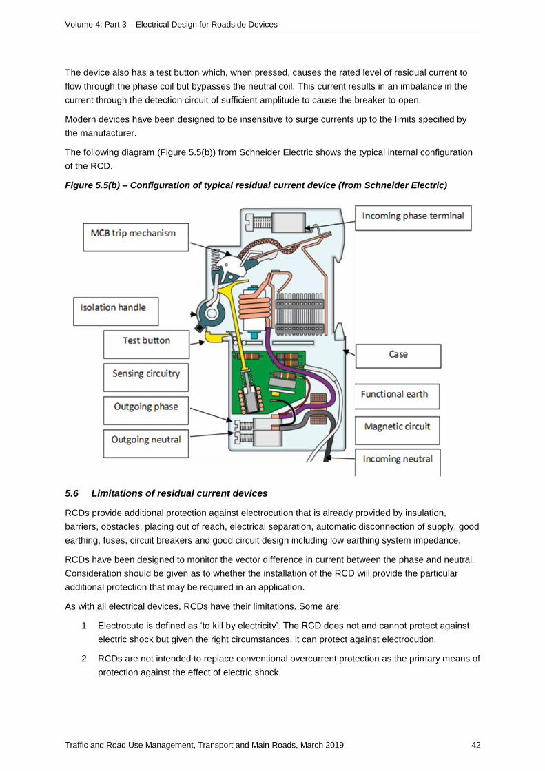
Volume 4: Part 3 – Electrical Design for Roadside Devices
Traffic and Road Use Management, Transport and Main Roads, March 2019 42
The device also has a test button which, when pressed, causes the rated level of residual current to
flow through the phase coil but bypasses the neutral coil. This current results in an imbalance in the
current through the detection circuit of sufficient amplitude to cause the breaker to open.
Modern devices have been designed to be insensitive to surge currents up to the limits specified by
the manufacturer.
The following diagram (Figure 5.5(b)) from Schneider Electric shows the typical internal configuration
of the RCD.
Figure 5.5(b) – Configuration of typical residual current device (from Schneider Electric)
5.6 Limitations of residual current devices
RCDs provide additional protection against electrocution that is already provided by insulation,
barriers, obstacles, placing out of reach, electrical separation, automatic disconnection of supply, good
earthing, fuses, circuit breakers and good circuit design including low earthing system impedance.
RCDs have been designed to monitor the vector difference in current between the phase and neutral.
Consideration should be given as to whether the installation of the RCD will provide the particular
additional protection that may be required in an application.
As with all electrical devices, RCDs have their limitations. Some are:
1. Electrocute is defined as ‘to kill by electricity’. The RCD does not and cannot protect against
electric shock but given the right circumstances, it can protect against electrocution.
2. RCDs are not intended to replace conventional overcurrent protection as the primary means of
protection against the effect of electric shock.
Volume 4: Part 3 – Electrical Design for Roadside Devices
Traffic and Road Use Management, Transport and Main Roads, March 2019 43
3. RCDs cannot replace the long-established MEN protection system where reliance is placed on
an effective and properly installed earthing system.
4. RCDs can provide additional protection in areas where excessive leakage current in the event
of failure of other protection devices could cause significant electrical risk.
5. RCDs do not replace other forms of primary protection – they are in addition to these other
measures. It is taken for granted that good electrical design has already been carried out and
RCDs are added as appropriate to help lower residual risk.
6. RCDs do not provide protection against phase-to-phase or phase-to-neutral faults, including
arcing faults and short circuits (except where the short circuit is to earth).
7. RCDs do not provide protection against overload.
8. RCDs do not provide protection against voltages imported into the electrical installation
earthing system through the supply system neutral conductor.
9. RCDs do not protect against reverse polarity connections.
10. RCDs may require upstream fault limiting protection.
11. RCDs may not operate in very cold conditions or corrosive environments.
12. RCDs cannot differentiate between current flow through an intended load and current flow
through a person.
13. The leakage current normally found in an electrical installation can cause nuisance tripping of
RCDs. Examples:
a. current leakage as a result of the capacitance between live conductors and earth in
electrical cabling installations (this can be minimised in wet underground installations
by using appropriate cable such as cross linked polyethylene (XLPE) / HDPE)
b. current leakage as an integral part of the operation of some electrical equipment such
as fluorescent and HID luminaires and smoothing filters
c. current leakage associated with high frequency currents flowing to earth through
parasitic capacitances due to pulsed DC-type component in equipment such as switch
mode power supplies of electronic equipment, and
d. current leakage resulting from common mode over voltages due to lightning strikes or
distribution system switching causing transient currents to flow to earth via the
installation capacitance.
14. The standard value of residual non-operating current for a 30 mA RCD is 15 mA.
Manufacturers generally calibrate RCDs at 22.5 mA ± 3 mA. Nuisance tripping may therefore
be more of a concern where there is excess leakage current.
15. RCDs are not recognised as a sole means of basic protection against contact with live parts
but may be used in addition to insulation, barriers and obstacles.
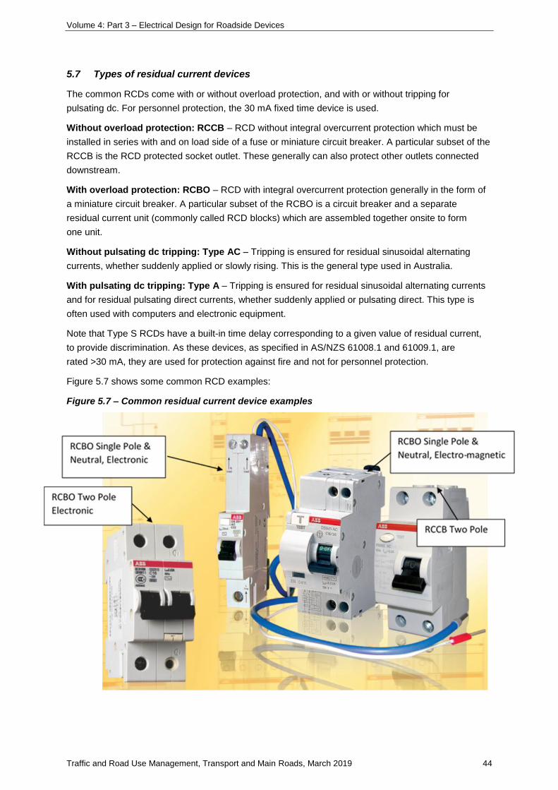
Volume 4: Part 3 – Electrical Design for Roadside Devices
Traffic and Road Use Management, Transport and Main Roads, March 2019 44
5.7 Types of residual current devices
The common RCDs come with or without overload protection, and with or without tripping for
pulsating dc. For personnel protection, the 30 mA fixed time device is used.
Without overload protection: RCCB – RCD without integral overcurrent protection which must be
installed in series with and on load side of a fuse or miniature circuit breaker. A particular subset of the
RCCB is the RCD protected socket outlet. These generally can also protect other outlets connected
downstream.
With overload protection: RCBO – RCD with integral overcurrent protection generally in the form of
a miniature circuit breaker. A particular subset of the RCBO is a circuit breaker and a separate
residual current unit (commonly called RCD blocks) which are assembled together onsite to form
one unit.
Without pulsating dc tripping: Type AC – Tripping is ensured for residual sinusoidal alternating
currents, whether suddenly applied or slowly rising. This is the general type used in Australia.
With pulsating dc tripping: Type A – Tripping is ensured for residual sinusoidal alternating currents
and for residual pulsating direct currents, whether suddenly applied or pulsating direct. This type is
often used with computers and electronic equipment.
Note that Type S RCDs have a built-in time delay corresponding to a given value of residual current,
to provide discrimination. As these devices, as specified in AS/NZS 61008.1 and 61009.1, are
rated >30 mA, they are used for protection against fire and not for personnel protection.
Figure 5.7 shows some common RCD examples:
Figure 5.7 – Common residual current device examples
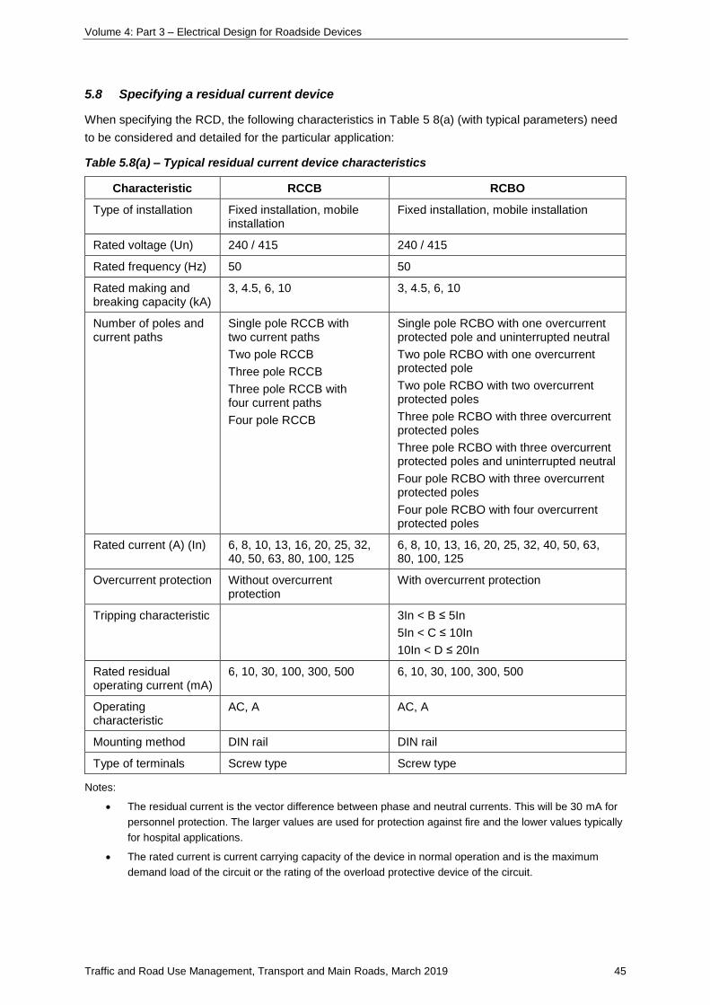
Volume 4: Part 3 – Electrical Design for Roadside Devices
Traffic and Road Use Management, Transport and Main Roads, March 2019 45
5.8 Specifying a residual current device
When specifying the RCD, the following characteristics in Table 5 8(a) (with typical parameters) need
to be considered and detailed for the particular application:
Table 5.8(a) – Typical residual current device characteristics
Characteristic RCCB RCBO
Type of installation Fixed installation, mobile installation
Fixed installation, mobile installation
Rated voltage (Un) 240 / 415 240 / 415
Rated frequency (Hz) 50 50
Rated making and breaking capacity (kA)
3, 4.5, 6, 10 3, 4.5, 6, 10
Number of poles and current paths
Single pole RCCB with two current paths
Two pole RCCB
Three pole RCCB
Three pole RCCB with four current paths
Four pole RCCB
Single pole RCBO with one overcurrent protected pole and uninterrupted neutral
Two pole RCBO with one overcurrent protected pole
Two pole RCBO with two overcurrent protected poles
Three pole RCBO with three overcurrent protected poles
Three pole RCBO with three overcurrent protected poles and uninterrupted neutral
Four pole RCBO with three overcurrent protected poles
Four pole RCBO with four overcurrent protected poles
Rated current (A) (In) 6, 8, 10, 13, 16, 20, 25, 32, 40, 50, 63, 80, 100, 125
6, 8, 10, 13, 16, 20, 25, 32, 40, 50, 63, 80, 100, 125
Overcurrent protection Without overcurrent protection
With overcurrent protection
Tripping characteristic 3In < B ≤ 5In
5In < C ≤ 10In
10In < D ≤ 20In
Rated residual operating current (mA)
6, 10, 30, 100, 300, 500 6, 10, 30, 100, 300, 500
Operating characteristic
AC, A AC, A
Mounting method DIN rail DIN rail
Type of terminals Screw type Screw type
Notes:
• The residual current is the vector difference between phase and neutral currents. This will be 30 mA for
personnel protection. The larger values are used for protection against fire and the lower values typically
for hospital applications.
• The rated current is current carrying capacity of the device in normal operation and is the maximum
demand load of the circuit or the rating of the overload protective device of the circuit.
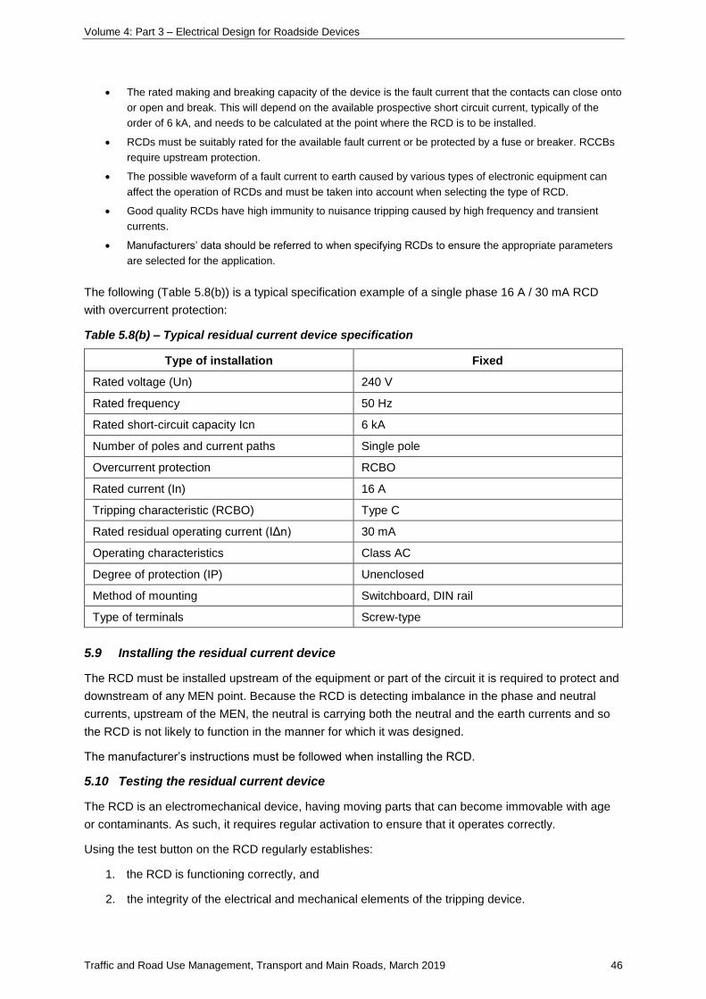
Volume 4: Part 3 – Electrical Design for Roadside Devices
Traffic and Road Use Management, Transport and Main Roads, March 2019 46
• The rated making and breaking capacity of the device is the fault current that the contacts can close onto
or open and break. This will depend on the available prospective short circuit current, typically of the
order of 6 kA, and needs to be calculated at the point where the RCD is to be installed.
• RCDs must be suitably rated for the available fault current or be protected by a fuse or breaker. RCCBs
require upstream protection.
• The possible waveform of a fault current to earth caused by various types of electronic equipment can
affect the operation of RCDs and must be taken into account when selecting the type of RCD.
• Good quality RCDs have high immunity to nuisance tripping caused by high frequency and transient
currents.
• Manufacturers’ data should be referred to when specifying RCDs to ensure the appropriate parameters
are selected for the application.
The following (Table 5.8(b)) is a typical specification example of a single phase 16 A / 30 mA RCD
with overcurrent protection:
Table 5.8(b) – Typical residual current device specification
Type of installation Fixed
Rated voltage (Un) 240 V
Rated frequency 50 Hz
Rated short-circuit capacity Icn 6 kA
Number of poles and current paths Single pole
Overcurrent protection RCBO
Rated current (In) 16 A
Tripping characteristic (RCBO) Type C
Rated residual operating current (IΔn) 30 mA
Operating characteristics Class AC
Degree of protection (IP) Unenclosed
Method of mounting Switchboard, DIN rail
Type of terminals Screw-type
5.9 Installing the residual current device
The RCD must be installed upstream of the equipment or part of the circuit it is required to protect and
downstream of any MEN point. Because the RCD is detecting imbalance in the phase and neutral
currents, upstream of the MEN, the neutral is carrying both the neutral and the earth currents and so
the RCD is not likely to function in the manner for which it was designed.
The manufacturer’s instructions must be followed when installing the RCD.
5.10 Testing the residual current device
The RCD is an electromechanical device, having moving parts that can become immovable with age
or contaminants. As such, it requires regular activation to ensure that it operates correctly.
Using the test button on the RCD regularly establishes:
1. the RCD is functioning correctly, and
2. the integrity of the electrical and mechanical elements of the tripping device.
Volume 4: Part 3 – Electrical Design for Roadside Devices
Traffic and Road Use Management, Transport and Main Roads, March 2019 47
However, this test does not provide a means of checking:
3. the continuity of the main earthing conductor or the associated circuit protective earthing
conductors
4. any earth electrode or other means of earthing, or
5. any other part of the associated electrical installation earthing.
It is recommended that testing of the RCD for correct operation is carried out at least annually by
pressing the test button. More frequent testing may be required, depending on the application. Other
tests may be required in accordance with the manufacturer’s recommendations.
Note: Testing the RCD disconnects power to the downstream equipment for the duration of the test until the RCD
has been reset.
Note: Where RCDs are not installed, EFLI tests must be carried out.
5.11 Where residual current devices are required
AS/NZS 3000 Clause 2.6 states that RCDs are not recognised as a sole means of basic protection but
may be used to augment one of the means set out in AS/NZS 3000. The use of RCDs does not
remove the requirement for correct circuit design using a variety of protection measures.
The requirements for additional protection by RCDs are included in AS/NZS 3000 Clause 1.5.6.3.;
however, the clause most appropriate to Transport and Main Roads installations is Clause 2.6 and, in
particular, Clause 2.6.3.2.1 of AS/NZS 3000.
Note:
Clause 2.6.3.2.1 of AS/NZA 3000 specifies particular final sub-circuits that must be protected by
RCDs, namely:
a. final sub-circuits supplying socket outlets where the rated current of any individual
socket outlet does not exceed 20 A, and
b. final sub-circuits supplying lighting where any portion of the circuit has a rated current
not exceeding 20 A, and
c. final sub-circuits supplying directly connected hand-held electrical equipment, for
example, hair dryers or tools.
Item c addresses hand-held directly-connected equipment such as hair dryers and hand tools. These
are high-risk items as the connecting power lead is subjected to continual flexing and is seldom
maintained.
RCDs may not be installed, as Clause 2.6.3.2.1 of AS/NZS 3000 states:
5. where the disconnection of a circuit by an RCD could cause a danger greater than
earth leakage current (see Section 5.12 following), or
6. where all socket-outlets on a final sub-circuit are installed for the connection of
specific items of equipment, provided that— …
RCDs must be installed in Transport and Main Roads installations in accordance with AS/NZS 3000;
however, where the disconnection of the circuit by the RCD could cause a danger greater than the
earth leakage current, or where all the provisions for specified items of equipment can be met, RCDs
may not be required.
Volume 4: Part 3 – Electrical Design for Roadside Devices
Traffic and Road Use Management, Transport and Main Roads, March 2019 48
Where RCDs are installed for additional protection on specific equipment, only that equipment should
be connected to the RCD – one RCD, one circuit.
5.12 AS/NZS 3000 Clause 2.6.3.2.1 Exception 5
5.12.1 General comments
The Electrical Safety Act 2002 requires that an electrical installation be electrically safe, which means
that the electrical risk to the person or property is as low as reasonably achievable, having regard to
the likelihood of harm and likely severity of harm.
AS/NZS 3000 Clause 1.1 states that guidance is provided so that the electrical installation will function
correctly for the purpose intended.
The intent of these documents is that electrical installations are fit for purpose and function with a
reasonably low level of risk. It is within this framework that particular applications of RCDs within the
Transport and Main Roads infrastructure are considered.
Exception 5 to AS/NZS 3000 Clause 2.6.3.2.1 states that the requirement for additional protection by
RCDs need not apply where the disconnection of a circuit by the RCD could cause a danger greater
than the leakage current.
To determine whether the disconnection of the RCD through nuisance tripping could cause a
danger / risk greater than the earth leakage current, a risk assessment must be carried out.
A general risk assessment has been carried out for a number of electrical installations to determine if
this exception could apply. This assessment is included in Section 5.16.
These consider the risk to a person from vehicular or criminal activity, compared with the risk to a
person from an electrical installation, using the parameters of the likelihood of harm and likely severity
of harm.
5.12.2 Road lighting installations
From the risk analysis, road lighting installations are considered to comply with the requirements of
Exception 5.
5.12.3 Traffic signals installations
From the risk analysis, traffic signals installations and supporting communications equipment are
considered to comply with the requirements of Exception 5.
Safety-related devices supporting traffic signal installations, such as CCTV, Field Processors (FP),
and Network Terminal Units (NTU) assist Traffic Management Centre (TMC) operators in promptly
responding to failures of traffic signals. If these devices cease to function due to nuisance tripping,
it may lead to delayed response to a traffic signal failure event. The risk is magnified for busier
intersections; therefore, these supporting communication devices are also considered to comply
with the requirements of Exception 5.
All non-RCD protected socket outlets must be clearly labelled.
5.12.4 Pathway lighting installations to AS/NZS 1158
From the risk analysis, pedestrian pathway lighting installations to AS/NZS 1158 are considered to
comply with the requirements of Exception 5.
Volume 4: Part 3 – Electrical Design for Roadside Devices
Traffic and Road Use Management, Transport and Main Roads, March 2019 49
5.12.5 Safety related traffic management devices
From the risk analysis, safety related traffic management devices are considered to comply with the
requirements of Exception 5.
5.13 AS/NZS 3000 Clause 2.6.3.2.1 Exception 6
5.13.1 Essential equipment
Essential equipment may come under Exception 6 of AS/NZS 3000 Clause 2.6.3.2.1, provided all of
the following specified requirements are complied with:
Exception 6: Where all socket outlets on a final sub-circuit are installed for the connection of
specific items of equipment, provided that—
The socket outlets are used to connect specific items such as essential ITS equipment or systems.
(a) the connected equipment is required by the owner or operator to perform a function that is
essential to the performance of the installation and that function would be adversely affected
by a loss of supply caused by the RCD operation; and
The equipment is essential and loss of functionality of that equipment as a result of tripping of the
RCD would adversely affect the operation of the system.
(b) the connected equipment is designed, constructed and used in such a manner that is not
likely to present a significant risk of electric shock; and
The equipment is double-insulated or effectively earthed and work procedures are in place
concerning the use of the equipment without RCD protection.
(c) the socket outlet is located in a position that is not likely to be accessed for general
purposes; and
Unprotected socket outlets are for specific essential equipment only and must be separated from
general purpose socket outlets. General purpose socket outlets must be RCD protected.
(d) the socket outlet is clearly marked to indicate the restricted purpose of the socket outlet
and that RCD protection is not provided.
All non-RCD protected socket outlets must be clearly labelled.
5.14 Discussion
In addition to these, a number of other installations were reviewed. These are discussed following.
Volume 4: Part 3 – Electrical Design for Roadside Devices
Traffic and Road Use Management, Transport and Main Roads, March 2019 50
5.14.1 Lift sump pumps connected to socket outlets
Lift sump pumps connected to socket outlets do not require RCD protection if all the requirements of
Exception 6 are complied with; however, the socket outlet must be IP 66-rated, switched, and must be
on a dedicated circuit with no other outlets.
5.14.2 Busway platform stairway lighting
Busway platform stairway lighting circuits and other building lighting including under soffit platform
lighting must be protected by RCDs. This is standard industry practice for buildings.
Luminaires must be selected so they are suitable for the application. Where they are exposed to
weather or in a polluted environment, they must be rated minimum IP 65 to minimise ingress of
moisture, dust and vermin that could result in nuisance tripping of the RCD.
At least two lighting circuits must be provided. Luminaires must be connected evenly across the
circuits and located suitably such that, in the event of RCD tripping, no area is without appropriate
lighting.
5.14.3 Non-AS/NZS 1158 pedestrian pathway lighting
Where a system of emergency and exit lighting is installed, non-emergency lighting and single point
emergency and exit lighting circuits are required to have RCDs.
Where power to emergency and exit lighting is supplied from a central system in accordance with
AS/NZS 2293.1, RCDs must not be incorporated into the lighting circuits.
Circuits supplying emergency and exit lighting should have an auxiliary contact so that an alarm can
be raised when the lights have been activated due to the tripping of the RCD or other cause of loss of
power.
5.14.4 Non-safety related systems
There are a number of systems installed in the roadway that are not directly related to traffic safety.
These include such items as webcams, traffic survey sites, travel time signs, parking guidance
systems, advertising signs and billboards. These must comply with the RCD requirements of
AS/NZS 3000.
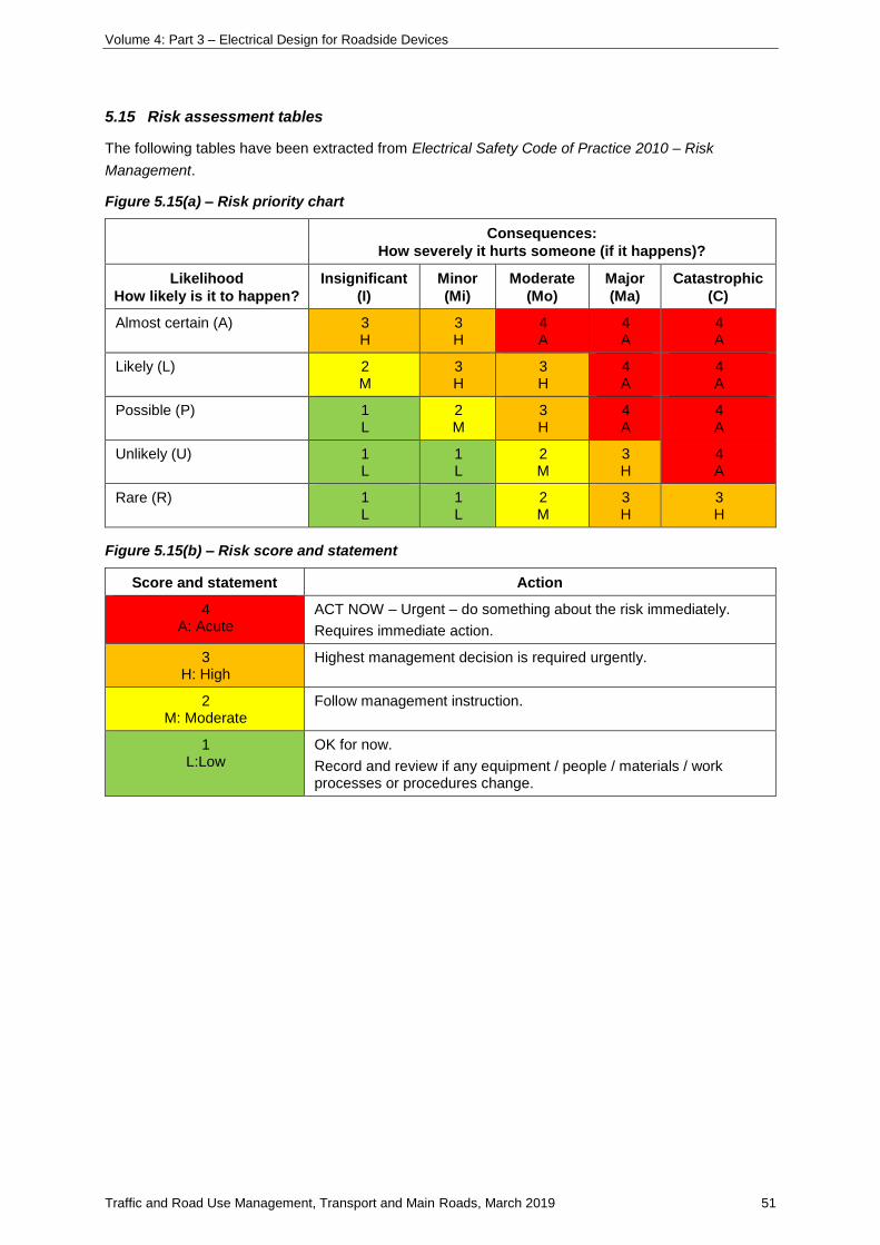
Volume 4: Part 3 – Electrical Design for Roadside Devices
Traffic and Road Use Management, Transport and Main Roads, March 2019 51
5.15 Risk assessment tables
The following tables have been extracted from Electrical Safety Code of Practice 2010 – Risk
Management.
Figure 5.15(a) – Risk priority chart
Consequences:
How severely it hurts someone (if it happens)?
Likelihood
How likely is it to happen?
Insignificant
(I)
Minor
(Mi)
Moderate
(Mo)
Major
(Ma)
Catastrophic
(C)
Almost certain (A) 3 H
3 H
4 A
4 A
4 A
Likely (L) 2 M
3 H
3 H
4 A
4 A
Possible (P) 1 L
2 M
3 H
4 A
4 A
Unlikely (U) 1 L
1 L
2 M
3 H
4 A
Rare (R) 1 L
1 L
2 M
3 H
3 H
Figure 5.15(b) – Risk score and statement
Score and statement Action
4 A: Acute
ACT NOW – Urgent – do something about the risk immediately.
Requires immediate action.
3 H: High
Highest management decision is required urgently.
2 M: Moderate
Follow management instruction.
1 L:Low
OK for now.
Record and review if any equipment / people / materials / work processes or procedures change.
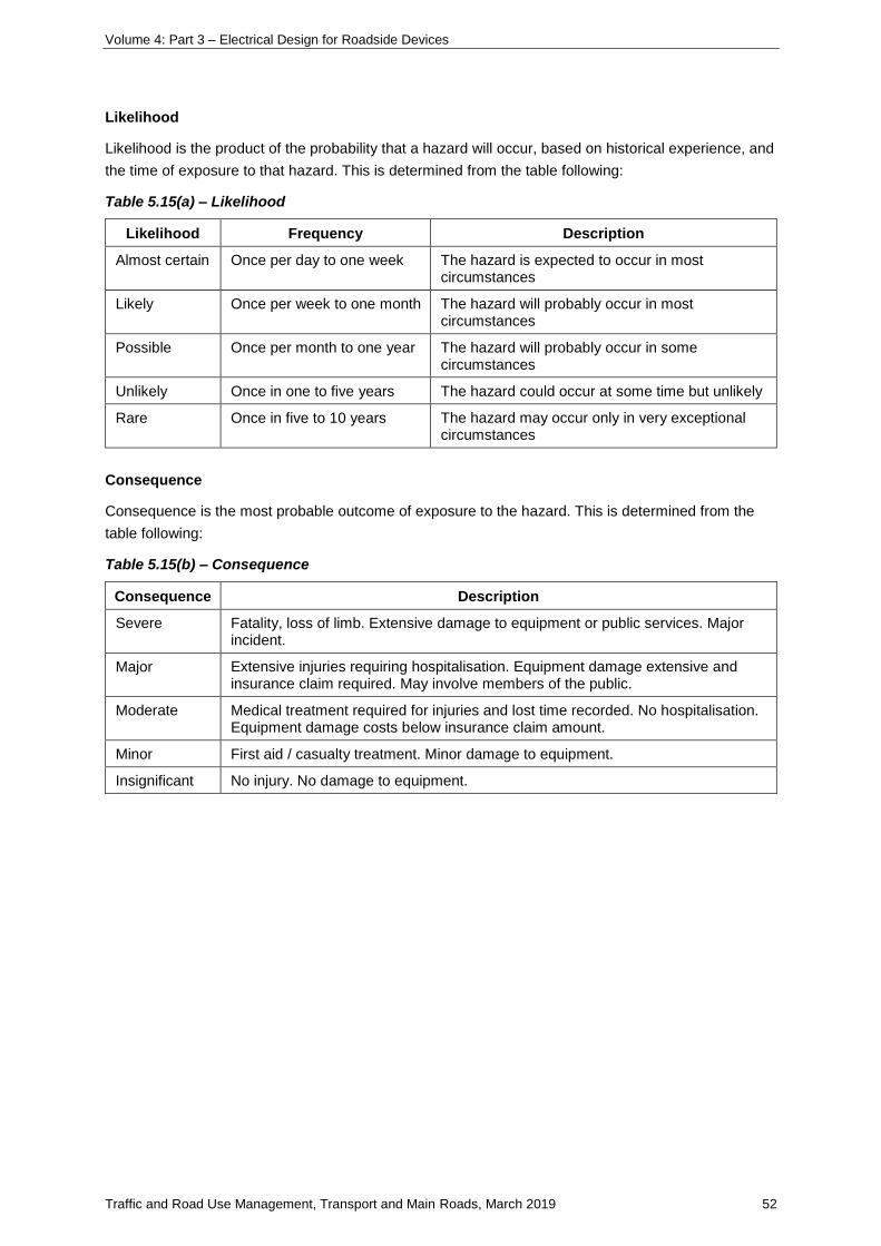
Volume 4: Part 3 – Electrical Design for Roadside Devices
Traffic and Road Use Management, Transport and Main Roads, March 2019 52
Likelihood
Likelihood is the product of the probability that a hazard will occur, based on historical experience, and
the time of exposure to that hazard. This is determined from the table following:
Table 5.15(a) – Likelihood
Likelihood Frequency Description
Almost certain Once per day to one week The hazard is expected to occur in most circumstances
Likely Once per week to one month The hazard will probably occur in most circumstances
Possible Once per month to one year The hazard will probably occur in some circumstances
Unlikely Once in one to five years The hazard could occur at some time but unlikely
Rare Once in five to 10 years The hazard may occur only in very exceptional circumstances
Consequence
Consequence is the most probable outcome of exposure to the hazard. This is determined from the
table following:
Table 5.15(b) – Consequence
Consequence Description
Severe Fatality, loss of limb. Extensive damage to equipment or public services. Major incident.
Major Extensive injuries requiring hospitalisation. Equipment damage extensive and insurance claim required. May involve members of the public.
Moderate Medical treatment required for injuries and lost time recorded. No hospitalisation. Equipment damage costs below insurance claim amount.
Minor First aid / casualty treatment. Minor damage to equipment.
Insignificant No injury. No damage to equipment.
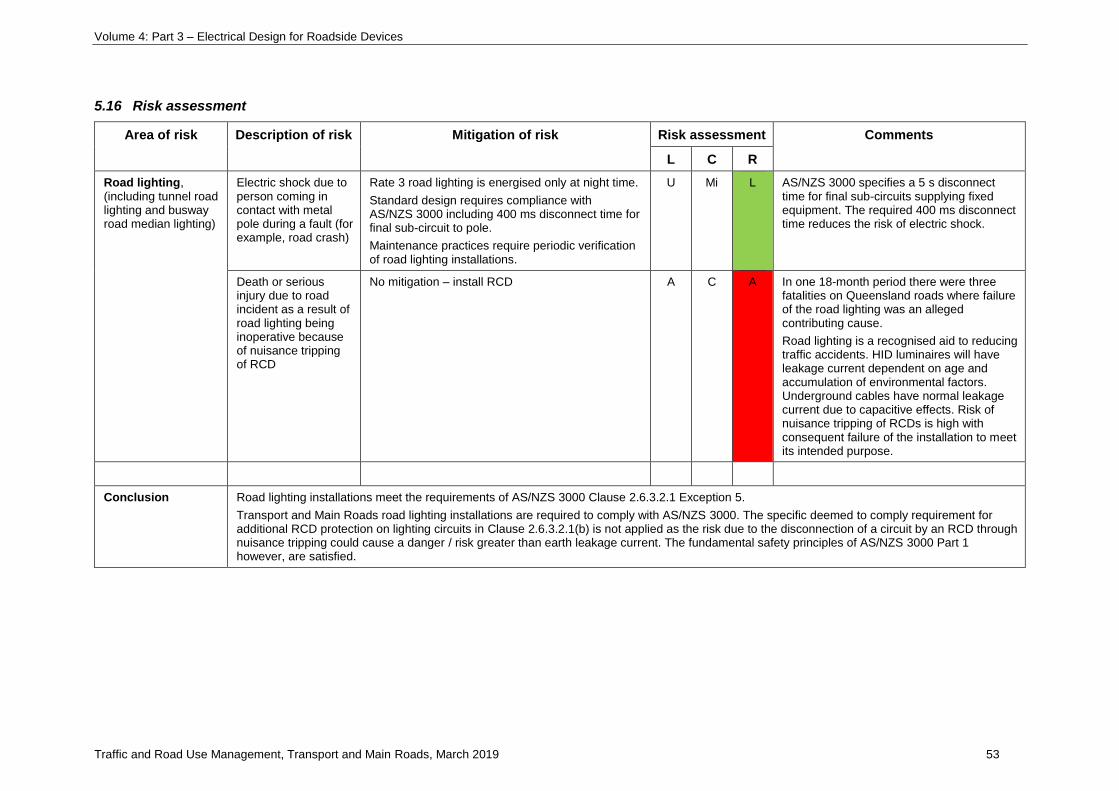
Volume 4: Part 3 – Electrical Design for Roadside Devices
Traffic and Road Use Management, Transport and Main Roads, March 2019 53
5.16 Risk assessment
Area of risk Description of risk Mitigation of risk Risk assessment Comments
L C R
Road lighting, (including tunnel road lighting and busway road median lighting)
Electric shock due to person coming in contact with metal pole during a fault (for example, road crash)
Rate 3 road lighting is energised only at night time.
Standard design requires compliance with AS/NZS 3000 including 400 ms disconnect time for final sub-circuit to pole.
Maintenance practices require periodic verification of road lighting installations.
U Mi L AS/NZS 3000 specifies a 5 s disconnect time for final sub-circuits supplying fixed equipment. The required 400 ms disconnect time reduces the risk of electric shock.
Death or serious injury due to road incident as a result of road lighting being inoperative because of nuisance tripping of RCD
No mitigation – install RCD A C A In one 18-month period there were three fatalities on Queensland roads where failure of the road lighting was an alleged contributing cause.
Road lighting is a recognised aid to reducing traffic accidents. HID luminaires will have leakage current dependent on age and accumulation of environmental factors. Underground cables have normal leakage current due to capacitive effects. Risk of nuisance tripping of RCDs is high with consequent failure of the installation to meet its intended purpose.
Conclusion Road lighting installations meet the requirements of AS/NZS 3000 Clause 2.6.3.2.1 Exception 5.
Transport and Main Roads road lighting installations are required to comply with AS/NZS 3000. The specific deemed to comply requirement for additional RCD protection on lighting circuits in Clause 2.6.3.2.1(b) is not applied as the risk due to the disconnection of a circuit by an RCD through nuisance tripping could cause a danger / risk greater than earth leakage current. The fundamental safety principles of AS/NZS 3000 Part 1 however, are satisfied.
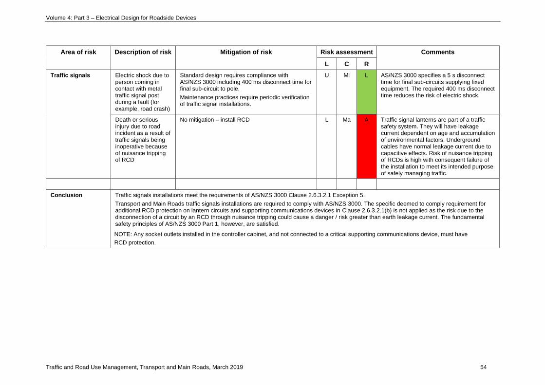
Volume 4: Part 3 – Electrical Design for Roadside Devices
Traffic and Road Use Management, Transport and Main Roads, March 2019 54
Area of risk Description of risk Mitigation of risk Risk assessment Comments
L C R
Traffic signals Electric shock due to person coming in contact with metal traffic signal post during a fault (for example, road crash)
Standard design requires compliance with AS/NZS 3000 including 400 ms disconnect time for final sub-circuit to pole.
Maintenance practices require periodic verification of traffic signal installations.
U Mi L AS/NZS 3000 specifies a 5 s disconnect time for final sub-circuits supplying fixed equipment. The required 400 ms disconnect time reduces the risk of electric shock.
Death or serious injury due to road incident as a result of traffic signals being inoperative because of nuisance tripping of RCD
No mitigation – install RCD L Ma A Traffic signal lanterns are part of a traffic safety system. They will have leakage current dependent on age and accumulation of environmental factors. Underground cables have normal leakage current due to capacitive effects. Risk of nuisance tripping of RCDs is high with consequent failure of the installation to meet its intended purpose of safely managing traffic.
Conclusion Traffic signals installations meet the requirements of AS/NZS 3000 Clause 2.6.3.2.1 Exception 5.
Transport and Main Roads traffic signals installations are required to comply with AS/NZS 3000. The specific deemed to comply requirement for additional RCD protection on lantern circuits and supporting communications devices in Clause 2.6.3.2.1(b) is not applied as the risk due to the disconnection of a circuit by an RCD through nuisance tripping could cause a danger / risk greater than earth leakage current. The fundamental safety principles of AS/NZS 3000 Part 1, however, are satisfied.
NOTE: Any socket outlets installed in the controller cabinet, and not connected to a critical supporting communications device, must have
RCD protection.
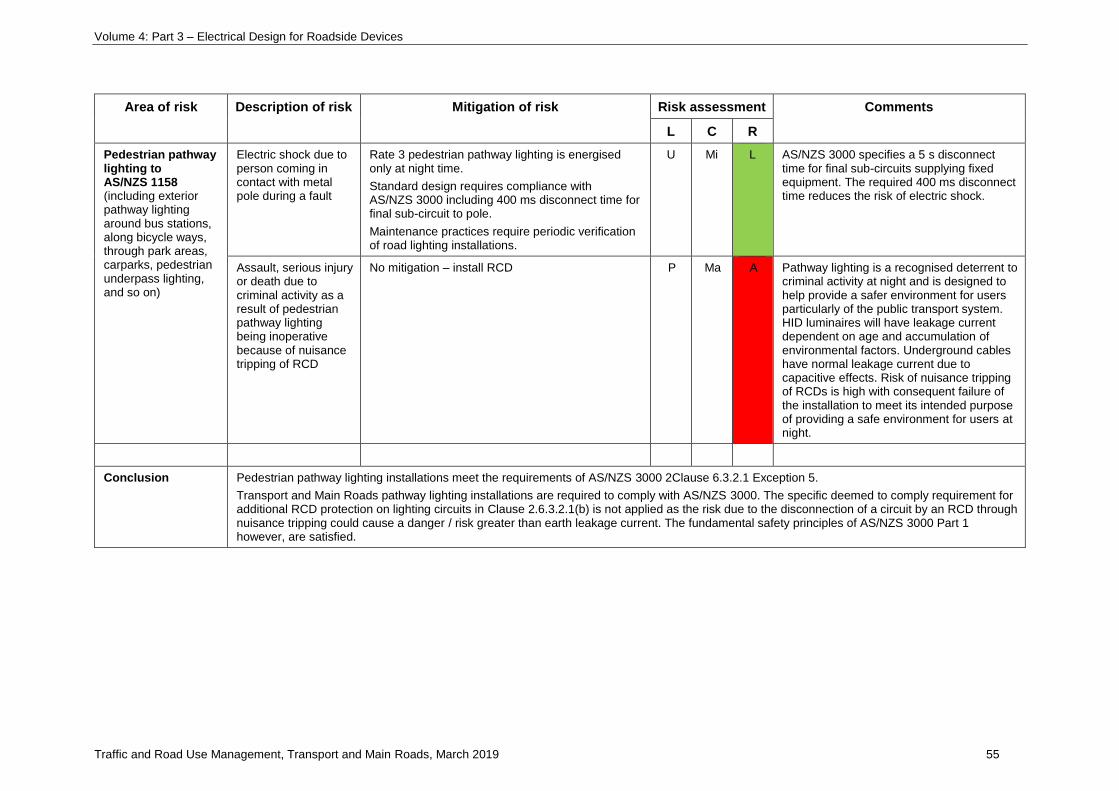
Volume 4: Part 3 – Electrical Design for Roadside Devices
Traffic and Road Use Management, Transport and Main Roads, March 2019 55
Area of risk Description of risk Mitigation of risk Risk assessment Comments
L C R
Pedestrian pathway lighting to AS/NZS 1158 (including exterior pathway lighting around bus stations, along bicycle ways, through park areas, carparks, pedestrian underpass lighting, and so on)
Electric shock due to person coming in contact with metal pole during a fault
Rate 3 pedestrian pathway lighting is energised only at night time.
Standard design requires compliance with AS/NZS 3000 including 400 ms disconnect time for final sub-circuit to pole.
Maintenance practices require periodic verification of road lighting installations.
U Mi L AS/NZS 3000 specifies a 5 s disconnect time for final sub-circuits supplying fixed equipment. The required 400 ms disconnect time reduces the risk of electric shock.
Assault, serious injury or death due to criminal activity as a result of pedestrian pathway lighting being inoperative because of nuisance tripping of RCD
No mitigation – install RCD P Ma A Pathway lighting is a recognised deterrent to criminal activity at night and is designed to help provide a safer environment for users particularly of the public transport system. HID luminaires will have leakage current dependent on age and accumulation of environmental factors. Underground cables have normal leakage current due to capacitive effects. Risk of nuisance tripping of RCDs is high with consequent failure of the installation to meet its intended purpose of providing a safe environment for users at night.
Conclusion Pedestrian pathway lighting installations meet the requirements of AS/NZS 3000 2Clause 6.3.2.1 Exception 5.
Transport and Main Roads pathway lighting installations are required to comply with AS/NZS 3000. The specific deemed to comply requirement for additional RCD protection on lighting circuits in Clause 2.6.3.2.1(b) is not applied as the risk due to the disconnection of a circuit by an RCD through nuisance tripping could cause a danger / risk greater than earth leakage current. The fundamental safety principles of AS/NZS 3000 Part 1 however, are satisfied.
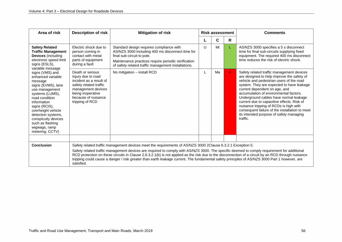
Volume 4: Part 3 – Electrical Design for Roadside Devices
Traffic and Road Use Management, Transport and Main Roads, March 2019 56
Area of risk Description of risk Mitigation of risk Risk assessment Comments
L C R
Safety Related Traffic Management Devices (including electronic speed limit signs (ESLS), variable message signs (VMS) and enhanced variable message signs (EVMS), lane use management systems (LUMS), road condition information signs (RCIS), overheight vehicle detection systems, conspicuity devices such as flashing wigwags, ramp metering, CCTV)
Electric shock due to person coming in contact with metal parts of equipment during a fault
Standard design requires compliance with AS/NZS 3000 including 400 ms disconnect time for final sub-circuit to pole.
Maintenance practices require periodic verification of safety related traffic management installations.
U Mi L AS/NZS 3000 specifies a 5 s disconnect time for final sub-circuits supplying fixed equipment. The required 400 ms disconnect time reduces the risk of electric shock.
Death or serious injury due to road incident as a result of safety related traffic management devices being inoperative because of nuisance tripping of RCD
No mitigation – install RCD L Ma A Safety related traffic management devices are designed to help improve the safety of vehicle and pedestrian users of the road system. They are expected to have leakage current dependent on age, and accumulation of environmental factors. Underground cables have normal leakage current due to capacitive effects. Risk of nuisance tripping of RCDs is high with consequent failure of the installation to meet its intended purpose of safely managing traffic.
Conclusion Safety related traffic management devices meet the requirements of AS/NZS 3000 2Clause 6.3.2.1 Exception 5.
Safety related traffic management devices are required to comply with AS/NZS 3000. The specific deemed to comply requirement for additional RCD protection on these circuits in Clause 2.6.3.2.1(b) is not applied as the risk due to the disconnection of a circuit by an RCD through nuisance tripping could cause a danger / risk greater than earth leakage current. The fundamental safety principles of AS/NZS 3000 Part 1 however, are satisfied.
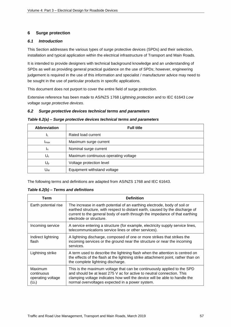
Volume 4: Part 3 – Electrical Design for Roadside Devices
Traffic and Road Use Management, Transport and Main Roads, March 2019 57
6 Surge protection
6.1 Introduction
This Section addresses the various types of surge protective devices (SPDs) and their selection,
installation and typical application within the electrical infrastructure of Transport and Main Roads.
It is intended to provide designers with technical background knowledge and an understanding of
SPDs as well as providing general practical guidance on the use of SPDs; however, engineering
judgement is required in the use of this information and specialist / manufacturer advice may need to
be sought in the use of particular products in specific applications.
This document does not purport to cover the entire field of surge protection.
Extensive reference has been made to AS/NZS 1768 Lightning protection and to IEC 61643 Low
voltage surge protective devices.
6.2 Surge protective devices technical terms and parameters
Table 6.2(a) – Surge protective devices technical terms and parameters
Abbreviation Full title
IL Rated load current
Imax Maximum surge current
In Nominal surge current
Uc Maximum continuous operating voltage
Up Voltage protection level
UW Equipment withstand voltage
The following terms and definitions are adapted from AS/NZS 1768 and IEC 61643.
Table 6.2(b) – Terms and definitions
Term Definition
Earth potential rise The increase in earth potential of an earthing electrode, body of soil or earthed structure, with respect to distant earth, caused by the discharge of current to the general body of earth through the impedance of that earthing electrode or structure.
Incoming service A service entering a structure (for example, electricity supply service lines, telecommunications service lines or other services).
Indirect lightning flash
A lightning discharge, composed of one or more strikes that strikes the incoming services or the ground near the structure or near the incoming services.
Lightning strike A term used to describe the lightning flash when the attention is centred on the effects of the flash at the lightning strike attachment point, rather than on the complete lightning discharge.
Maximum continuous operating voltage (Uc)
This is the maximum voltage that can be continuously applied to the SPD and should be at least 275 V ac for active to neutral connection. This clamping voltage indicates how well the device will be able to handle the normal overvoltages expected in a power system.
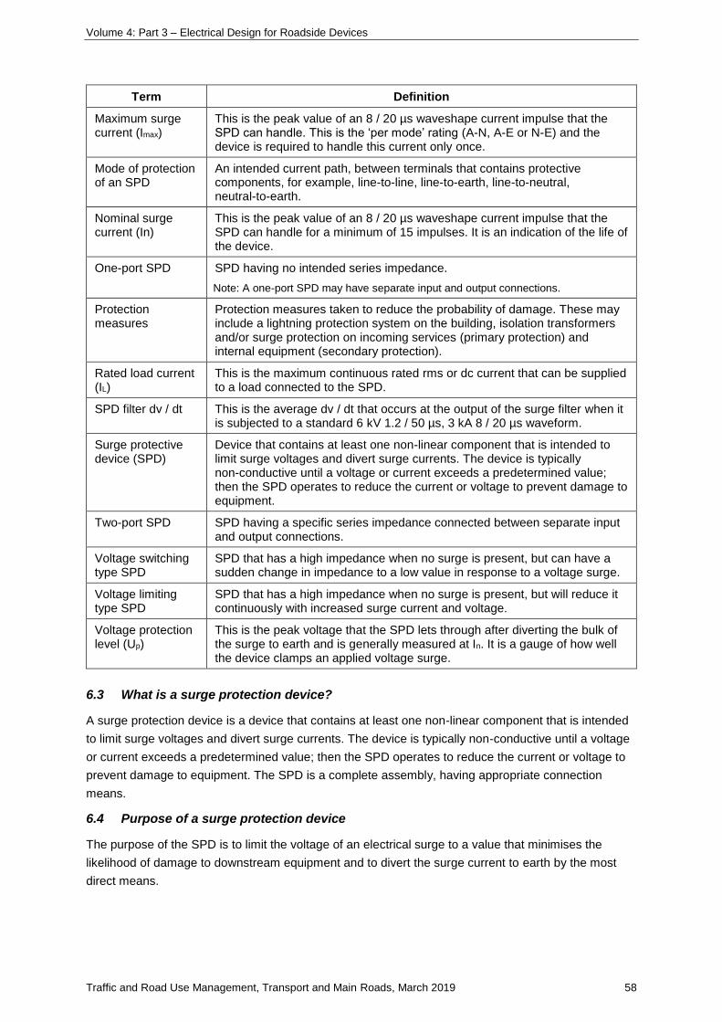
Volume 4: Part 3 – Electrical Design for Roadside Devices
Traffic and Road Use Management, Transport and Main Roads, March 2019 58
Term Definition
Maximum surge current (Imax)
This is the peak value of an 8 / 20 µs waveshape current impulse that the SPD can handle. This is the ‘per mode’ rating (A-N, A-E or N-E) and the device is required to handle this current only once.
Mode of protection of an SPD
An intended current path, between terminals that contains protective components, for example, line-to-line, line-to-earth, line-to-neutral, neutral-to-earth.
Nominal surge current (In)
This is the peak value of an 8 / 20 µs waveshape current impulse that the SPD can handle for a minimum of 15 impulses. It is an indication of the life of the device.
One-port SPD SPD having no intended series impedance.
Note: A one-port SPD may have separate input and output connections.
Protection measures
Protection measures taken to reduce the probability of damage. These may include a lightning protection system on the building, isolation transformers and/or surge protection on incoming services (primary protection) and internal equipment (secondary protection).
Rated load current (IL)
This is the maximum continuous rated rms or dc current that can be supplied to a load connected to the SPD.
SPD filter dv / dt This is the average dv / dt that occurs at the output of the surge filter when it is subjected to a standard 6 kV 1.2 / 50 µs, 3 kA 8 / 20 µs waveform.
Surge protective device (SPD)
Device that contains at least one non-linear component that is intended to limit surge voltages and divert surge currents. The device is typically non-conductive until a voltage or current exceeds a predetermined value; then the SPD operates to reduce the current or voltage to prevent damage to equipment.
Two-port SPD SPD having a specific series impedance connected between separate input and output connections.
Voltage switching type SPD
SPD that has a high impedance when no surge is present, but can have a sudden change in impedance to a low value in response to a voltage surge.
Voltage limiting type SPD
SPD that has a high impedance when no surge is present, but will reduce it continuously with increased surge current and voltage.
Voltage protection level (Up)
This is the peak voltage that the SPD lets through after diverting the bulk of the surge to earth and is generally measured at In. It is a gauge of how well the device clamps an applied voltage surge.
6.3 What is a surge protection device?
A surge protection device is a device that contains at least one non-linear component that is intended
to limit surge voltages and divert surge currents. The device is typically non-conductive until a voltage
or current exceeds a predetermined value; then the SPD operates to reduce the current or voltage to
prevent damage to equipment. The SPD is a complete assembly, having appropriate connection
means.
6.4 Purpose of a surge protection device
The purpose of the SPD is to limit the voltage of an electrical surge to a value that minimises the
likelihood of damage to downstream equipment and to divert the surge current to earth by the most
direct means.
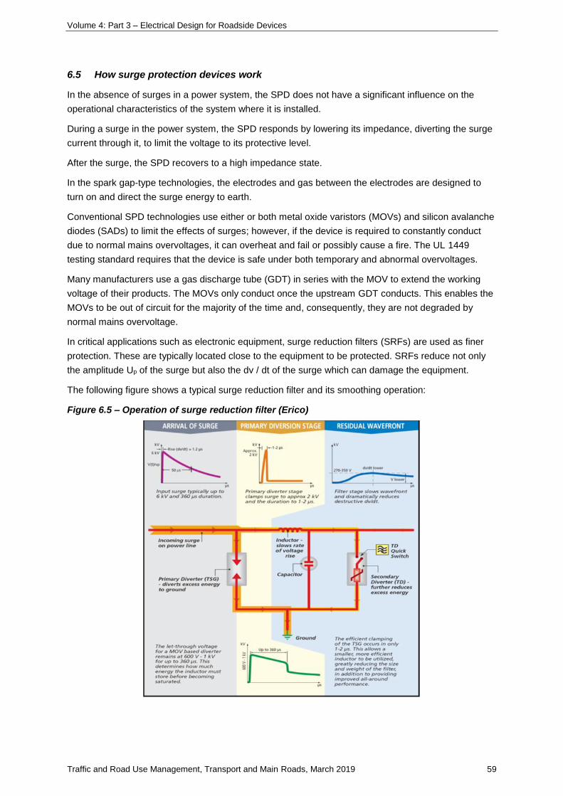
Volume 4: Part 3 – Electrical Design for Roadside Devices
Traffic and Road Use Management, Transport and Main Roads, March 2019 59
6.5 How surge protection devices work
In the absence of surges in a power system, the SPD does not have a significant influence on the
operational characteristics of the system where it is installed.
During a surge in the power system, the SPD responds by lowering its impedance, diverting the surge
current through it, to limit the voltage to its protective level.
After the surge, the SPD recovers to a high impedance state.
In the spark gap-type technologies, the electrodes and gas between the electrodes are designed to
turn on and direct the surge energy to earth.
Conventional SPD technologies use either or both metal oxide varistors (MOVs) and silicon avalanche
diodes (SADs) to limit the effects of surges; however, if the device is required to constantly conduct
due to normal mains overvoltages, it can overheat and fail or possibly cause a fire. The UL 1449
testing standard requires that the device is safe under both temporary and abnormal overvoltages.
Many manufacturers use a gas discharge tube (GDT) in series with the MOV to extend the working
voltage of their products. The MOVs only conduct once the upstream GDT conducts. This enables the
MOVs to be out of circuit for the majority of the time and, consequently, they are not degraded by
normal mains overvoltage.
In critical applications such as electronic equipment, surge reduction filters (SRFs) are used as finer
protection. These are typically located close to the equipment to be protected. SRFs reduce not only
the amplitude Up of the surge but also the dv / dt of the surge which can damage the equipment.
The following figure shows a typical surge reduction filter and its smoothing operation:
Figure 6.5 – Operation of surge reduction filter (Erico)
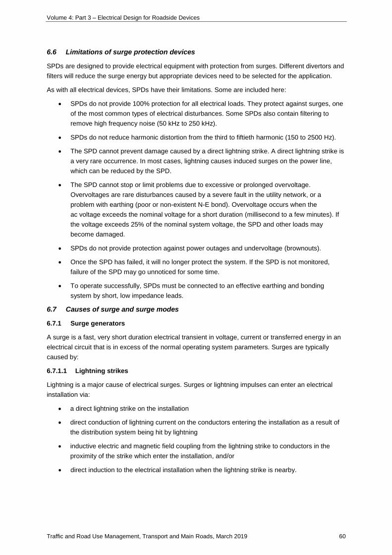
Volume 4: Part 3 – Electrical Design for Roadside Devices
Traffic and Road Use Management, Transport and Main Roads, March 2019 60
6.6 Limitations of surge protection devices
SPDs are designed to provide electrical equipment with protection from surges. Different divertors and
filters will reduce the surge energy but appropriate devices need to be selected for the application.
As with all electrical devices, SPDs have their limitations. Some are included here:
• SPDs do not provide 100% protection for all electrical loads. They protect against surges, one
of the most common types of electrical disturbances. Some SPDs also contain filtering to
remove high frequency noise (50 kHz to 250 kHz).
• SPDs do not reduce harmonic distortion from the third to fiftieth harmonic (150 to 2500 Hz).
• The SPD cannot prevent damage caused by a direct lightning strike. A direct lightning strike is
a very rare occurrence. In most cases, lightning causes induced surges on the power line,
which can be reduced by the SPD.
• The SPD cannot stop or limit problems due to excessive or prolonged overvoltage.
Overvoltages are rare disturbances caused by a severe fault in the utility network, or a
problem with earthing (poor or non-existent N-E bond). Overvoltage occurs when the
ac voltage exceeds the nominal voltage for a short duration (millisecond to a few minutes). If
the voltage exceeds 25% of the nominal system voltage, the SPD and other loads may
become damaged.
• SPDs do not provide protection against power outages and undervoltage (brownouts).
• Once the SPD has failed, it will no longer protect the system. If the SPD is not monitored,
failure of the SPD may go unnoticed for some time.
• To operate successfully, SPDs must be connected to an effective earthing and bonding
system by short, low impedance leads.
6.7 Causes of surge and surge modes
6.7.1 Surge generators
A surge is a fast, very short duration electrical transient in voltage, current or transferred energy in an
electrical circuit that is in excess of the normal operating system parameters. Surges are typically
caused by:
6.7.1.1 Lightning strikes
Lightning is a major cause of electrical surges. Surges or lightning impulses can enter an electrical
installation via:
• a direct lightning strike on the installation
• direct conduction of lightning current on the conductors entering the installation as a result of
the distribution system being hit by lightning
• inductive electric and magnetic field coupling from the lightning strike to conductors in the
proximity of the strike which enter the installation, and/or
• direct induction to the electrical installation when the lightning strike is nearby.
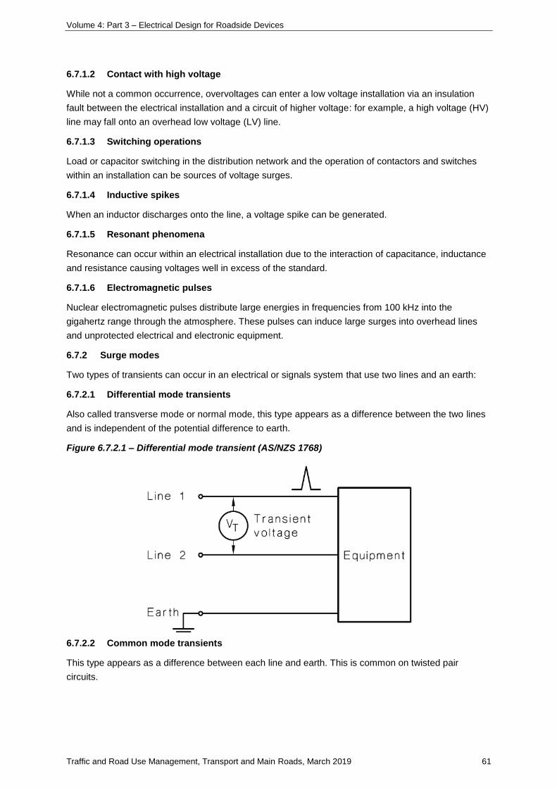
Volume 4: Part 3 – Electrical Design for Roadside Devices
Traffic and Road Use Management, Transport and Main Roads, March 2019 61
6.7.1.2 Contact with high voltage
While not a common occurrence, overvoltages can enter a low voltage installation via an insulation
fault between the electrical installation and a circuit of higher voltage: for example, a high voltage (HV)
line may fall onto an overhead low voltage (LV) line.
6.7.1.3 Switching operations
Load or capacitor switching in the distribution network and the operation of contactors and switches
within an installation can be sources of voltage surges.
6.7.1.4 Inductive spikes
When an inductor discharges onto the line, a voltage spike can be generated.
6.7.1.5 Resonant phenomena
Resonance can occur within an electrical installation due to the interaction of capacitance, inductance
and resistance causing voltages well in excess of the standard.
6.7.1.6 Electromagnetic pulses
Nuclear electromagnetic pulses distribute large energies in frequencies from 100 kHz into the
gigahertz range through the atmosphere. These pulses can induce large surges into overhead lines
and unprotected electrical and electronic equipment.
6.7.2 Surge modes
Two types of transients can occur in an electrical or signals system that use two lines and an earth:
6.7.2.1 Differential mode transients
Also called transverse mode or normal mode, this type appears as a difference between the two lines
and is independent of the potential difference to earth.
Figure 6.7.2.1 – Differential mode transient (AS/NZS 1768)
6.7.2.2 Common mode transients
This type appears as a difference between each line and earth. This is common on twisted pair
circuits.
Volume 4: Part 3 – Electrical Design for Roadside Devices
Traffic and Road Use Management, Transport and Main Roads, March 2019 62
Figure 6.7.2.2 – Common mode transient (AS/NZS 1768)
Electrical and electronic equipment are typically more easily damaged from line to-line or
line-to-neutral transients than from line-to-earth.
For telephone and signalling lines, a three-terminal gas SPD is often used as the primary protection
for both common and differential mode transients.
6.8 Surge protection device characteristics
6.8.1 Method of operation
Overvoltage protection devices fall into two categories depending on their method of operation:
6.8.1.1 Voltage limiting
These have high impedance when no surge is present but reduce impedance with increased voltage
and current, clamping the voltage to a defined upper limit. They are sometimes referred to as clamping
devices and include varistors, and avalanche or suppressor diodes.
6.8.1.2 Voltage switching
These have high impedance when no surge is present but suddenly change to low impedance when
surge arrives. They are sometimes referred to as crowbar devices and include air gaps, gas discharge
tubes, triacs and silicon controlled rectifiers.
6.8.2 Technologies
Fundamental characteristics of circuit components, including filtering and Surge Suppression common
to transient voltage surge suppression device technologies, are summarised as follows:
6.8.2.1 Gas discharge tubes
These devices consist of a glass or ceramic tube filled with inert gas and sealed at each end with a
metal electrode. Breakdown voltage is in the range 70 V to 1 kV. Typical surge current ratings are
5 kA, 10 kA and 20 kA and can be as high as 100 kA. Conduction voltage is much less than the firing
voltage. GDTs are widely used in signal line protection and with MOVs in power circuits.
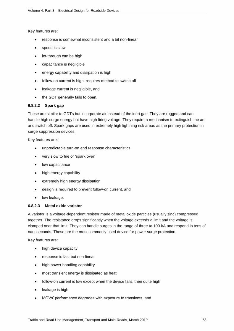
Volume 4: Part 3 – Electrical Design for Roadside Devices
Traffic and Road Use Management, Transport and Main Roads, March 2019 63
Key features are:
• response is somewhat inconsistent and a bit non-linear
• speed is slow
• let-through can be high
• capacitance is negligible
• energy capability and dissipation is high
• follow-on current is high; requires method to switch off
• leakage current is negligible, and
• the GDT generally fails to open.
6.8.2.2 Spark gap
These are similar to GDTs but incorporate air instead of the inert gas. They are rugged and can
handle high surge energy but have high firing voltage. They require a mechanism to extinguish the arc
and switch off. Spark gaps are used in extremely high lightning risk areas as the primary protection in
surge suppression devices.
Key features are:
• unpredictable turn-on and response characteristics
• very slow to fire or ‘spark over’
• low capacitance
• high energy capability
• extremely high energy dissipation
• design is required to prevent follow-on current, and
• low leakage.
6.8.2.3 Metal oxide varistor
A varistor is a voltage-dependent resistor made of metal oxide particles (usually zinc) compressed
together. The resistance drops significantly when the voltage exceeds a limit and the voltage is
clamped near that limit. They can handle surges in the range of three to 100 kA and respond in tens of
nanoseconds. These are the most commonly used device for power surge protection.
Key features are:
• high device capacity
• response is fast but non-linear
• high power handling capability
• most transient energy is dissipated as heat
• follow-on current is low except when the device fails, then quite high
• leakage is high
• MOVs’ performance degrades with exposure to transients, and
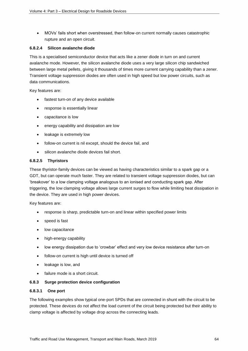
Volume 4: Part 3 – Electrical Design for Roadside Devices
Traffic and Road Use Management, Transport and Main Roads, March 2019 64
• MOVs’ fails short when overstressed, then follow-on current normally causes catastrophic
rupture and an open circuit.
6.8.2.4 Silicon avalanche diode
This is a specialised semiconductor device that acts like a zener diode in turn on and current
avalanche mode. However, the silicon avalanche diode uses a very large silicon chip sandwiched
between large metal pellets, giving it thousands of times more current carrying capability than a zener.
Transient voltage suppression diodes are often used in high speed but low power circuits, such as
data communications.
Key features are:
• fastest turn-on of any device available
• response is essentially linear
• capacitance is low
• energy capability and dissipation are low
• leakage is extremely low
• follow-on current is nil except, should the device fail, and
• silicon avalanche diode devices fail short.
6.8.2.5 Thyristors
These thyristor-family devices can be viewed as having characteristics similar to a spark gap or a
GDT, but can operate much faster. They are related to transient voltage suppression diodes, but can
‘breakover’ to a low clamping voltage analogous to an ionised and conducting spark gap. After
triggering, the low clamping voltage allows large current surges to flow while limiting heat dissipation in
the device. They are used in high power devices.
Key features are:
• response is sharp, predictable turn-on and linear within specified power limits
• speed is fast
• low capacitance
• high-energy capability
• low energy dissipation due to ‘crowbar’ effect and very low device resistance after turn-on
• follow-on current is high until device is turned off
• leakage is low, and
• failure mode is a short circuit.
6.8.3 Surge protection device configuration
6.8.3.1 One port
The following examples show typical one-port SPDs that are connected in shunt with the circuit to be
protected. These devices do not affect the load current of the circuit being protected but their ability to
clamp voltage is affected by voltage drop across the connecting leads.
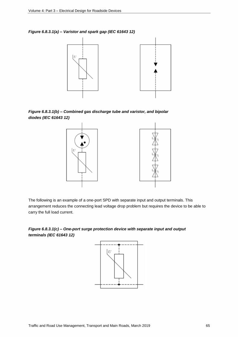
Volume 4: Part 3 – Electrical Design for Roadside Devices
Traffic and Road Use Management, Transport and Main Roads, March 2019 65
Figure 6.8.3.1(a) – Varistor and spark gap (IEC 61643 12)
Figure 6.8.3.1(b) – Combined gas discharge tube and varistor, and bipolar
diodes (IEC 61643 12)
The following is an example of a one-port SPD with separate input and output terminals. This
arrangement reduces the connecting lead voltage drop problem but requires the device to be able to
carry the full load current.
Figure 6.8.3.1(c) – One-port surge protection device with separate input and output
terminals (IEC 61643 12)
Volume 4: Part 3 – Electrical Design for Roadside Devices
Traffic and Road Use Management, Transport and Main Roads, March 2019 66
6.8.3.2 Two-port
Two-port SPDs are connected in series with the circuit to be protected and insert a specific series
impedance that has a current limiting effect. There is virtually no connecting lead voltage drop.
Examples of three- and four-terminal two-port SPDs are:
Figure 6.8.3.2 – Three- and four-terminal two-port surge protection device (IEC 61643 12)
6.8.3.3 Multifunction
In addition to the single function SPDs mentioned previously, some devices combine both power and
communications / signalling protection within the one device. This is an effective method to protect
information technology equipment as the combined unit keeps the SPD earth connections very short,
minimising the potential difference between the services when a surge strikes. The following diagram,
from AS/NZS 1768, shows the typical configuration:
Figure 6.8.3.3 – Multiservice surge protection device (AS/NZS 1768)
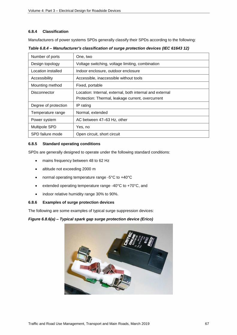
Volume 4: Part 3 – Electrical Design for Roadside Devices
Traffic and Road Use Management, Transport and Main Roads, March 2019 67
6.8.4 Classification
Manufacturers of power systems SPDs generally classify their SPDs according to the following:
Table 6.8.4 – Manufacturer's classification of surge protection devices (IEC 61643 12)
Number of ports One, two
Design topology Voltage switching, voltage limiting, combination
Location installed Indoor enclosure, outdoor enclosure
Accessibility Accessible, inaccessible without tools
Mounting method Fixed, portable
Disconnector Location: Internal, external, both internal and external
Protection: Thermal, leakage current, overcurrent
Degree of protection IP rating
Temperature range Normal, extended
Power system AC between 47–63 Hz, other
Multipole SPD Yes, no
SPD failure mode Open circuit, short circuit
6.8.5 Standard operating conditions
SPDs are generally designed to operate under the following standard conditions:
• mains frequency between 48 to 62 Hz
• altitude not exceeding 2000 m
• normal operating temperature range -5°C to +40°C
• extended operating temperature range -40°C to +70°C, and
• indoor relative humidity range 30% to 90%.
6.8.6 Examples of surge protection devices
The following are some examples of typical surge suppression devices:
Figure 6.8.6(a) – Typical spark gap surge protection device (Erico)
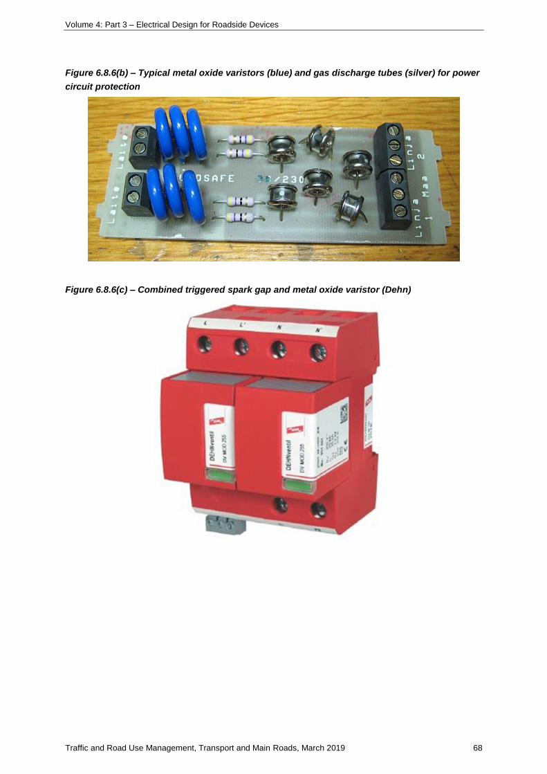
Volume 4: Part 3 – Electrical Design for Roadside Devices
Traffic and Road Use Management, Transport and Main Roads, March 2019 68
Figure 6.8.6(b) – Typical metal oxide varistors (blue) and gas discharge tubes (silver) for power
circuit protection
Figure 6.8.6(c) – Combined triggered spark gap and metal oxide varistor (Dehn)
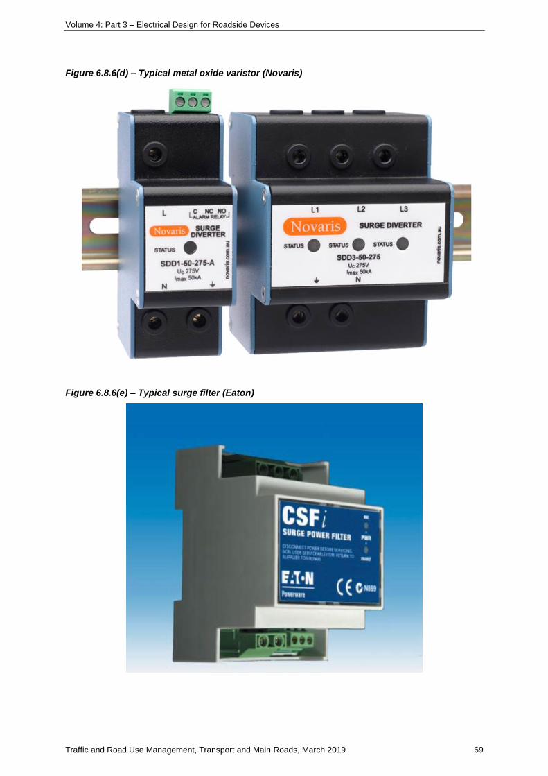
Volume 4: Part 3 – Electrical Design for Roadside Devices
Traffic and Road Use Management, Transport and Main Roads, March 2019 69
Figure 6.8.6(d) – Typical metal oxide varistor (Novaris)
Figure 6.8.6(e) – Typical surge filter (Eaton)
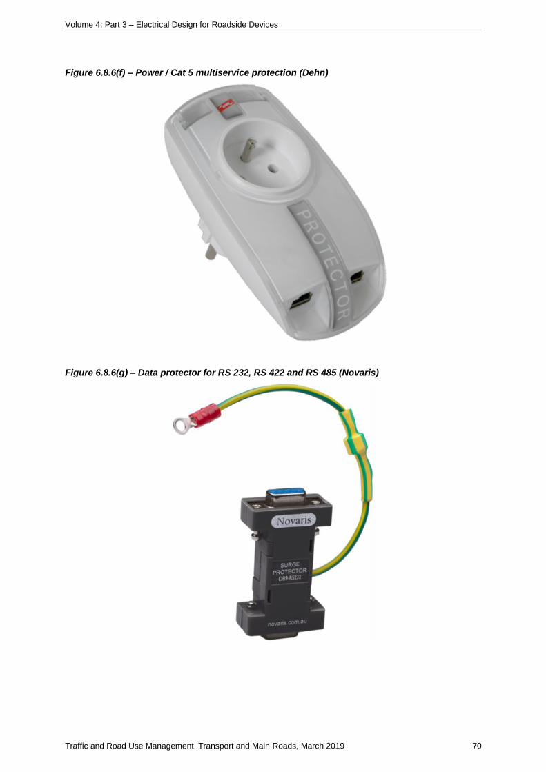
Volume 4: Part 3 – Electrical Design for Roadside Devices
Traffic and Road Use Management, Transport and Main Roads, March 2019 70
Figure 6.8.6(f) – Power / Cat 5 multiservice protection (Dehn)
Figure 6.8.6(g) – Data protector for RS 232, RS 422 and RS 485 (Novaris)
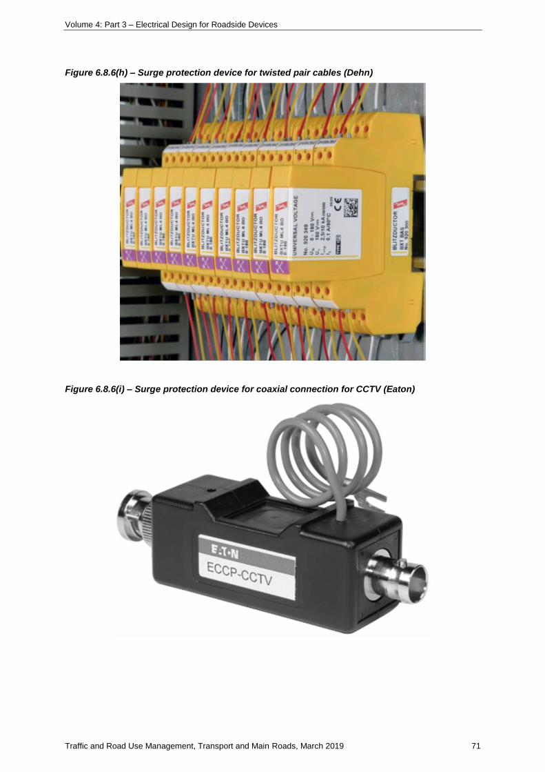
Volume 4: Part 3 – Electrical Design for Roadside Devices
Traffic and Road Use Management, Transport and Main Roads, March 2019 71
Figure 6.8.6(h) – Surge protection device for twisted pair cables (Dehn)
Figure 6.8.6(i) – Surge protection device for coaxial connection for CCTV (Eaton)
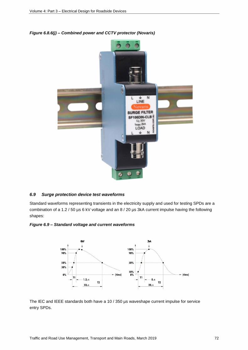
Volume 4: Part 3 – Electrical Design for Roadside Devices
Traffic and Road Use Management, Transport and Main Roads, March 2019 72
Figure 6.8.6(j) – Combined power and CCTV protector (Novaris)
6.9 Surge protection device test waveforms
Standard waveforms representing transients in the electricity supply and used for testing SPDs are a
combination of a 1.2 / 50 µs 6 kV voltage and an 8 / 20 µs 3kA current impulse having the following
shapes:
Figure 6.9 – Standard voltage and current waveforms
The IEC and IEEE standards both have a 10 / 350 µs waveshape current impulse for service
entry SPDs.
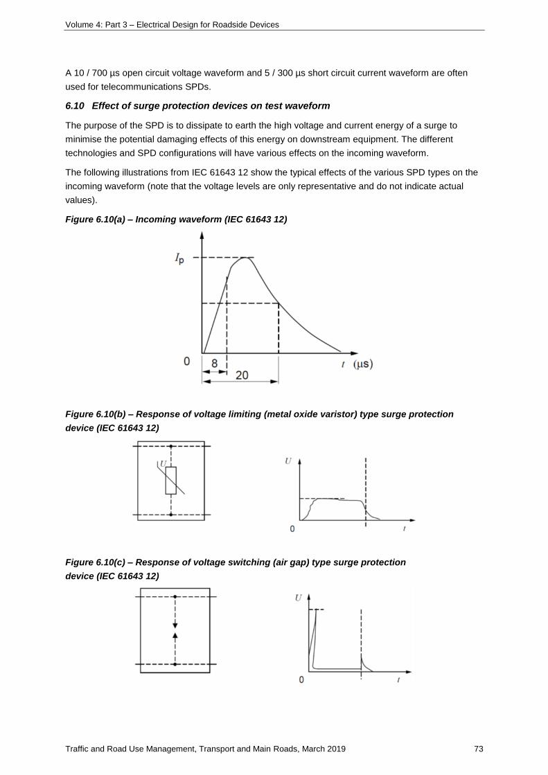
Volume 4: Part 3 – Electrical Design for Roadside Devices
Traffic and Road Use Management, Transport and Main Roads, March 2019 73
A 10 / 700 µs open circuit voltage waveform and 5 / 300 µs short circuit current waveform are often
used for telecommunications SPDs.
6.10 Effect of surge protection devices on test waveform
The purpose of the SPD is to dissipate to earth the high voltage and current energy of a surge to
minimise the potential damaging effects of this energy on downstream equipment. The different
technologies and SPD configurations will have various effects on the incoming waveform.
The following illustrations from IEC 61643 12 show the typical effects of the various SPD types on the
incoming waveform (note that the voltage levels are only representative and do not indicate actual
values).
Figure 6.10(a) – Incoming waveform (IEC 61643 12)
Figure 6.10(b) – Response of voltage limiting (metal oxide varistor) type surge protection
device (IEC 61643 12)
Figure 6.10(c) – Response of voltage switching (air gap) type surge protection
device (IEC 61643 12)
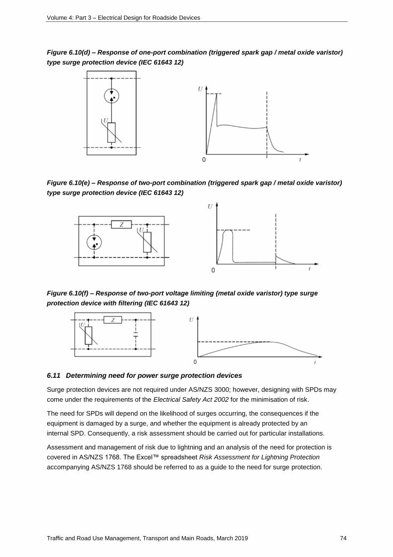
Volume 4: Part 3 – Electrical Design for Roadside Devices
Traffic and Road Use Management, Transport and Main Roads, March 2019 74
Figure 6.10(d) – Response of one-port combination (triggered spark gap / metal oxide varistor)
type surge protection device (IEC 61643 12)
Figure 6.10(e) – Response of two-port combination (triggered spark gap / metal oxide varistor)
type surge protection device (IEC 61643 12)
Figure 6.10(f) – Response of two-port voltage limiting (metal oxide varistor) type surge
protection device with filtering (IEC 61643 12)
6.11 Determining need for power surge protection devices
Surge protection devices are not required under AS/NZS 3000; however, designing with SPDs may
come under the requirements of the Electrical Safety Act 2002 for the minimisation of risk.
The need for SPDs will depend on the likelihood of surges occurring, the consequences if the
equipment is damaged by a surge, and whether the equipment is already protected by an
internal SPD. Consequently, a risk assessment should be carried out for particular installations.
Assessment and management of risk due to lightning and an analysis of the need for protection is
covered in AS/NZS 1768. The Excel™ spreadsheet Risk Assessment for Lightning Protection
accompanying AS/NZS 1768 should be referred to as a guide to the need for surge protection.
Volume 4: Part 3 – Electrical Design for Roadside Devices
Traffic and Road Use Management, Transport and Main Roads, March 2019 75
Where any of the following conditions exist, consideration should be given to the risks involved to the
electrical / electronic installation:
• high prevalence of lightning and thunderstorm activity
• location at end of extensive electrical overhead lines
• location in industrial areas where power disturbances are frequent
• exposed or isolated site
• expensive, critical and / or sensitive electronic equipment is within the installation, and
• surge generators located within the installation.
If protection is required, it should be installed at the entries to the installation. Where equipment likely
to cause surge are installed within the installation, additional protection may be necessary close to
critical equipment.
When equipment to be protected is located close to the main switchboard, or when it has sufficient
overvoltage withstand, one SPD at the switchboard may be sufficient.
Where the voltage protection level (Up₁) (which is the maximum voltage expected across the terminals
of the SPD) of the entry SPD is less than 80% of the withstand voltage (Uw) of the equipment to be
protected, no additional protection is usually necessary close to the equipment.
Additional protection close to the equipment may be necessary where:
• sensitive electronic equipment is present
• distance between the entrance SPD and equipment to be protected is greater than 10 m,
and/or
• electromagnetic fields are generated within the structure.
If Up₁ is greater than 80% of the withstand voltage (Uw) of the equipment to be protected, additional
protection may be necessary close to the equipment. The voltage protection level (Up₂) of this
second SPD should be less than 80% of the equipment withstand voltage.
In summary:
Protection installed at the installation entry is generally sufficient if
𝑈𝑝1 < 0.8 𝑈𝑤
Protection installed at the installation entry and addition protection is generally required if
𝑈𝑝1 < 0.8 𝑈𝑤
For the additional protection
𝑈𝑝2 < 0.8 𝑈𝑤
where
Up₁= voltage protection level of the entry SPD
Up₂ = voltage protection level of SPD adjacent to equipment to be protected
Uw = equipment withstand voltage
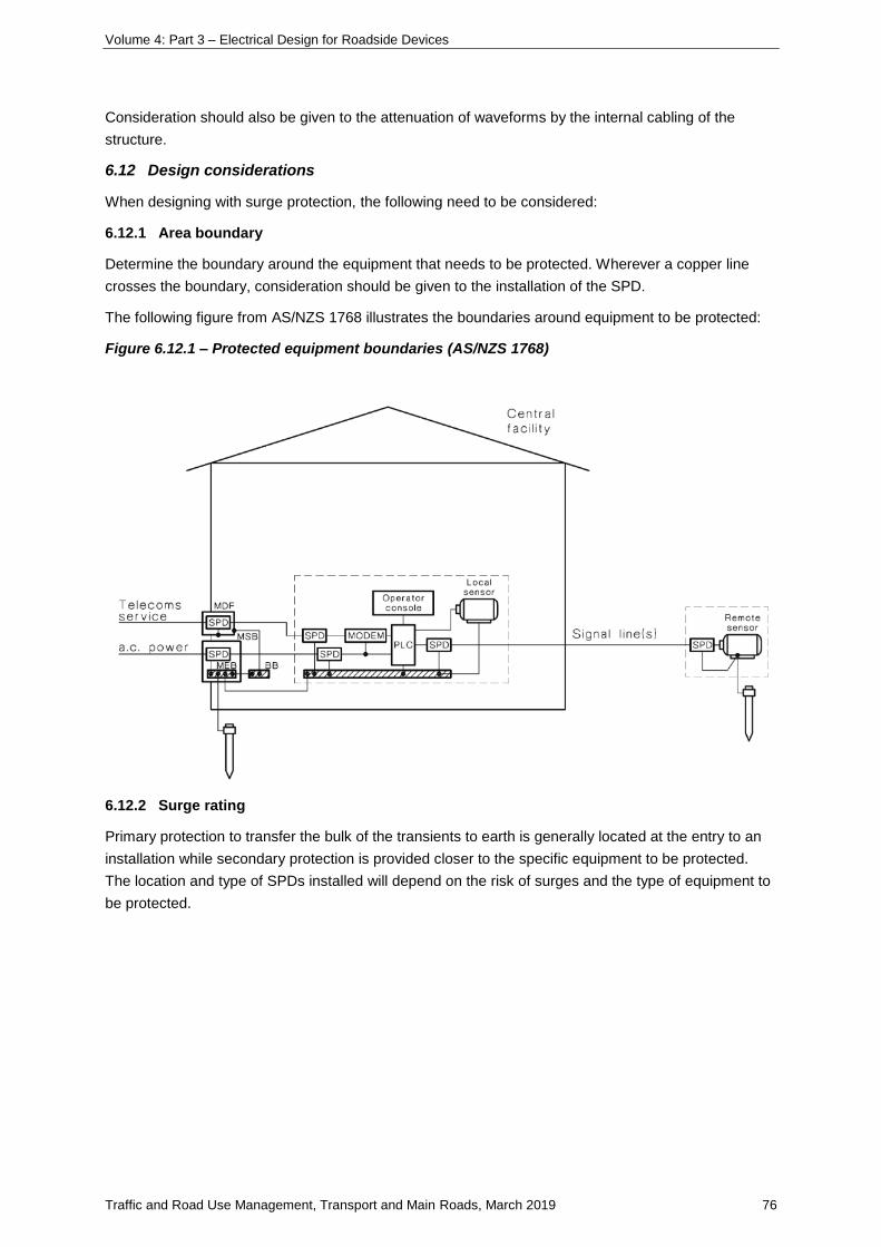
Volume 4: Part 3 – Electrical Design for Roadside Devices
Traffic and Road Use Management, Transport and Main Roads, March 2019 76
Consideration should also be given to the attenuation of waveforms by the internal cabling of the
structure.
6.12 Design considerations
When designing with surge protection, the following need to be considered:
6.12.1 Area boundary
Determine the boundary around the equipment that needs to be protected. Wherever a copper line
crosses the boundary, consideration should be given to the installation of the SPD.
The following figure from AS/NZS 1768 illustrates the boundaries around equipment to be protected:
Figure 6.12.1 – Protected equipment boundaries (AS/NZS 1768)
6.12.2 Surge rating
Primary protection to transfer the bulk of the transients to earth is generally located at the entry to an
installation while secondary protection is provided closer to the specific equipment to be protected.
The location and type of SPDs installed will depend on the risk of surges and the type of equipment to
be protected.
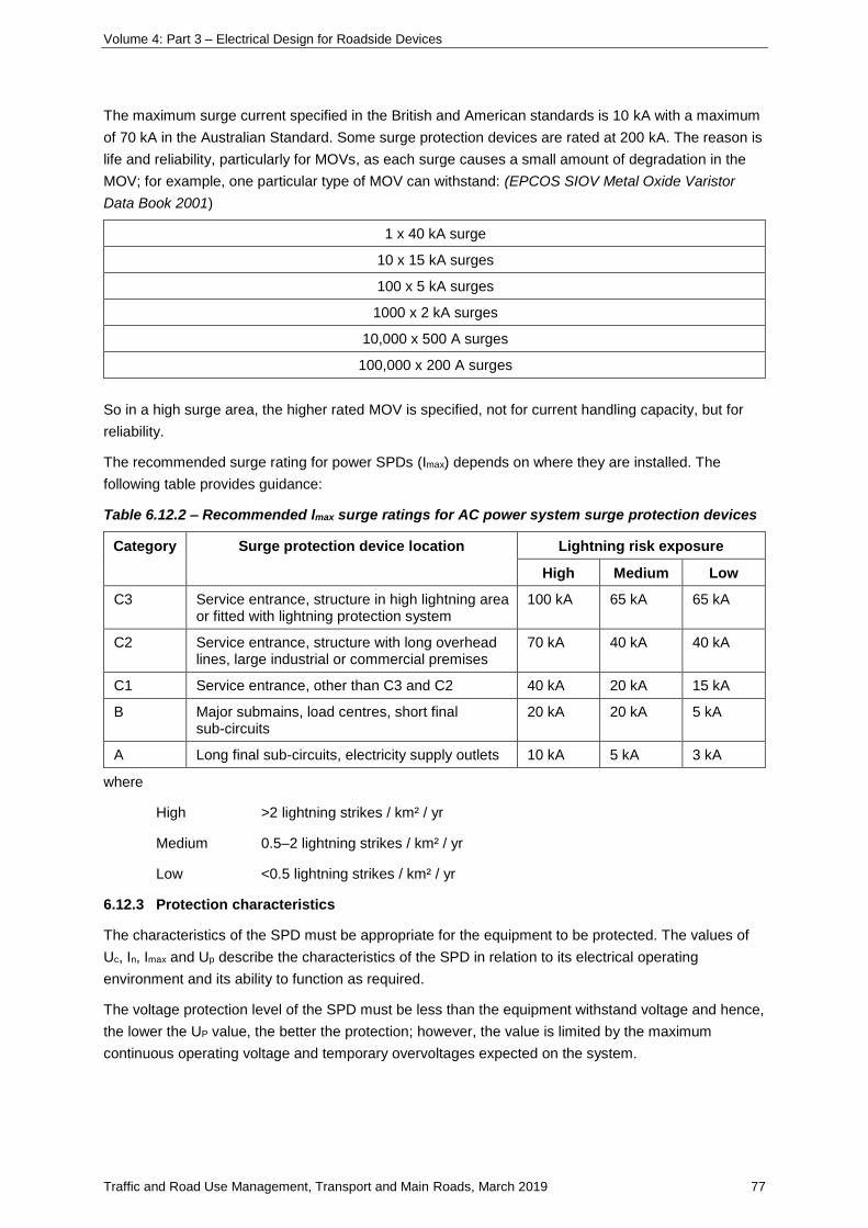
Volume 4: Part 3 – Electrical Design for Roadside Devices
Traffic and Road Use Management, Transport and Main Roads, March 2019 77
The maximum surge current specified in the British and American standards is 10 kA with a maximum
of 70 kA in the Australian Standard. Some surge protection devices are rated at 200 kA. The reason is
life and reliability, particularly for MOVs, as each surge causes a small amount of degradation in the
MOV; for example, one particular type of MOV can withstand: (EPCOS SIOV Metal Oxide Varistor
Data Book 2001)
1 x 40 kA surge
10 x 15 kA surges
100 x 5 kA surges
1000 x 2 kA surges
10,000 x 500 A surges
100,000 x 200 A surges
So in a high surge area, the higher rated MOV is specified, not for current handling capacity, but for
reliability.
The recommended surge rating for power SPDs (Imax) depends on where they are installed. The
following table provides guidance:
Table 6.12.2 – Recommended lmax surge ratings for AC power system surge protection devices
Category Surge protection device location Lightning risk exposure
High Medium Low
C3 Service entrance, structure in high lightning area or fitted with lightning protection system
100 kA 65 kA 65 kA
C2 Service entrance, structure with long overhead lines, large industrial or commercial premises
70 kA 40 kA 40 kA
C1 Service entrance, other than C3 and C2 40 kA 20 kA 15 kA
B Major submains, load centres, short final sub-circuits
20 kA 20 kA 5 kA
A Long final sub-circuits, electricity supply outlets 10 kA 5 kA 3 kA
where
High >2 lightning strikes / km² / yr
Medium 0.5–2 lightning strikes / km² / yr
Low <0.5 lightning strikes / km² / yr
6.12.3 Protection characteristics
The characteristics of the SPD must be appropriate for the equipment to be protected. The values of
Uc, In, Imax and Up describe the characteristics of the SPD in relation to its electrical operating
environment and its ability to function as required.
The voltage protection level of the SPD must be less than the equipment withstand voltage and hence,
the lower the UP value, the better the protection; however, the value is limited by the maximum
continuous operating voltage and temporary overvoltages expected on the system.
Volume 4: Part 3 – Electrical Design for Roadside Devices
Traffic and Road Use Management, Transport and Main Roads, March 2019 78
An important aspect in selecting the SPD is its voltage limiting performance during the expected surge
event. SPDs with a correctly selected low limiting voltage will protect the equipment. SPDs with a high
energy withstand may only result in a longer operating life of the SPD.
6.12.4 Protection distance
The distance between the SPD and equipment to be protected should be as short and straight as
practicable, and not greater than 10 m. Long and curved paths introduce inductance into the line
increasing the dv/dt.
6.12.5 Prospective life and failure mode
The prospective life of the SPD depends on the probability of occurrence of surges exceeding the
maximum discharge capability of the device. Imax rating should be appropriate for the location in which
the device is to be installed. In is an indication of the life of the device.
Failure to short circuit should cause the circuit protection device to open. Failure to open circuit should
put a high impedance in the circuit. In both cases, an indication should be provided that the SPD is no
longer functioning.
6.12.6 Interaction with other equipment
Under normal and fault conditions the SPD should not interfere with other circuit devices. When
conducting a surge at the nominal discharge current, the circuit protective device must not operate.
Refer to manufacturer for fuse and circuit breaker requirements for specific SPDs.
6.12.7 Coordination with other surge protection devices
For coordination of SPDs, the energy dissipated by the downstream device must be less than or equal
to its maximum energy withstand for all values of current up to Imax at the upstream SPD.
Often it is assumed that the peak let-through voltage of the primary protection is sufficiently low so as
not to damage any secondary protection. While coordination is complex, a simple rule of thumb is to
ensure that there is 10–20 m of cabling between the primary and secondary protection as this will
provide additional attenuation for the surge.
6.13 Specifying power surge protection devices
Before specifying SPDs, ensure that the products selected are from reputable manufacturers and are
suitable for the application.
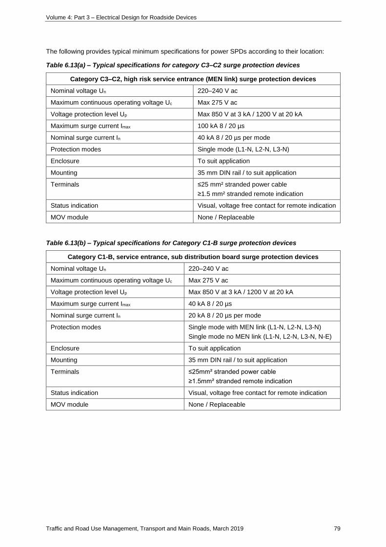
Volume 4: Part 3 – Electrical Design for Roadside Devices
Traffic and Road Use Management, Transport and Main Roads, March 2019 79
The following provides typical minimum specifications for power SPDs according to their location:
Table 6.13(a) – Typical specifications for category C3–C2 surge protection devices
Category C3–C2, high risk service entrance (MEN link) surge protection devices
Nominal voltage Un 220–240 V ac
Maximum continuous operating voltage Uc Max 275 V ac
Voltage protection level Up Max 850 V at 3 kA / 1200 V at 20 kA
Maximum surge current Imax 100 kA 8 / 20 µs
Nominal surge current In 40 kA 8 / 20 µs per mode
Protection modes Single mode (L1-N, L2-N, L3-N)
Enclosure To suit application
Mounting 35 mm DIN rail / to suit application
Terminals ≤25 mm² stranded power cable
≥1.5 mm² stranded remote indication
Status indication Visual, voltage free contact for remote indication
MOV module None / Replaceable
Table 6.13(b) – Typical specifications for Category C1-B surge protection devices
Category C1-B, service entrance, sub distribution board surge protection devices
Nominal voltage Un 220–240 V ac
Maximum continuous operating voltage Uc Max 275 V ac
Voltage protection level Up Max 850 V at 3 kA / 1200 V at 20 kA
Maximum surge current Imax 40 kA 8 / 20 µs
Nominal surge current In 20 kA 8 / 20 µs per mode
Protection modes Single mode with MEN link (L1-N, L2-N, L3-N)
Single mode no MEN link (L1-N, L2-N, L3-N, N-E)
Enclosure To suit application
Mounting 35 mm DIN rail / to suit application
Terminals ≤25mm² stranded power cable
≥1.5mm² stranded remote indication
Status indication Visual, voltage free contact for remote indication
MOV module None / Replaceable
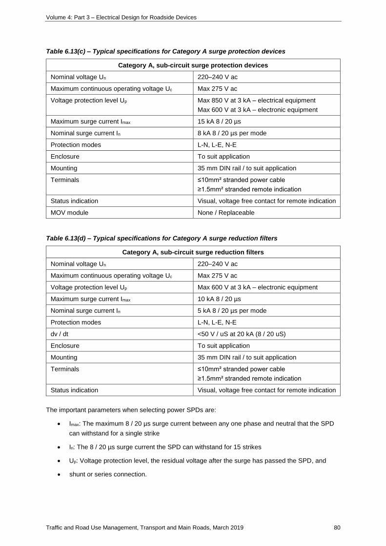
Volume 4: Part 3 – Electrical Design for Roadside Devices
Traffic and Road Use Management, Transport and Main Roads, March 2019 80
Table 6.13(c) – Typical specifications for Category A surge protection devices
Category A, sub-circuit surge protection devices
Nominal voltage Un 220–240 V ac
Maximum continuous operating voltage Uc Max 275 V ac
Voltage protection level Up Max 850 V at 3 kA – electrical equipment
Max 600 V at 3 kA – electronic equipment
Maximum surge current Imax 15 kA 8 / 20 µs
Nominal surge current In 8 kA 8 / 20 µs per mode
Protection modes L-N, L-E, N-E
Enclosure To suit application
Mounting 35 mm DIN rail / to suit application
Terminals ≤10mm² stranded power cable
≥1.5mm² stranded remote indication
Status indication Visual, voltage free contact for remote indication
MOV module None / Replaceable
Table 6.13(d) – Typical specifications for Category A surge reduction filters
Category A, sub-circuit surge reduction filters
Nominal voltage Un 220–240 V ac
Maximum continuous operating voltage Uc Max 275 V ac
Voltage protection level Up Max 600 V at 3 kA – electronic equipment
Maximum surge current Imax 10 kA 8 / 20 µs
Nominal surge current In 5 kA 8 / 20 µs per mode
Protection modes L-N, L-E, N-E
dv / dt <50 V / uS at 20 kA (8 / 20 uS)
Enclosure To suit application
Mounting 35 mm DIN rail / to suit application
Terminals ≤10mm² stranded power cable
≥1.5mm² stranded remote indication
Status indication Visual, voltage free contact for remote indication
The important parameters when selecting power SPDs are:
• Imax: The maximum 8 / 20 µs surge current between any one phase and neutral that the SPD
can withstand for a single strike
• In: The 8 / 20 µs surge current the SPD can withstand for 15 strikes
• Up: Voltage protection level, the residual voltage after the surge has passed the SPD, and
• shunt or series connection.
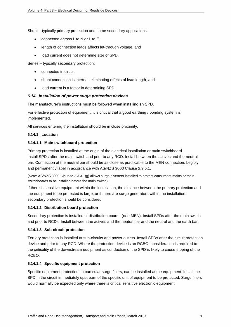
Volume 4: Part 3 – Electrical Design for Roadside Devices
Traffic and Road Use Management, Transport and Main Roads, March 2019 81
Shunt – typically primary protection and some secondary applications:
• connected across L to N or L to E
• length of connection leads affects let-through voltage, and
• load current does not determine size of SPD.
Series – typically secondary protection:
• connected in circuit
• shunt connection is internal, eliminating effects of lead length, and
• load current is a factor in determining SPD.
6.14 Installation of power surge protection devices
The manufacturer’s instructions must be followed when installing an SPD.
For effective protection of equipment, it is critical that a good earthing / bonding system is
implemented.
All services entering the installation should be in close proximity.
6.14.1 Location
6.14.1.1 Main switchboard protection
Primary protection is installed at the origin of the electrical installation or main switchboard.
Install SPDs after the main switch and prior to any RCD. Install between the actives and the neutral
bar. Connection at the neutral bar should be as close as practicable to the MEN connection. Legibly
and permanently label in accordance with AS/NZS 3000 Clause 2.9.5.1.
(Note: AS/NZS 3000 Clauase 2.3.3.1(g) allows surge diverters installed to protect consumers mains or main
switchboards to be installed before the main switch).
If there is sensitive equipment within the installation, the distance between the primary protection and
the equipment to be protected is large, or if there are surge generators within the installation,
secondary protection should be considered.
6.14.1.2 Distribution board protection
Secondary protection is installed at distribution boards (non-MEN). Install SPDs after the main switch
and prior to RCDs. Install between the actives and the neutral bar and the neutral and the earth bar.
6.14.1.3 Sub-circuit protection
Tertiary protection is installed at sub-circuits and power outlets. Install SPDs after the circuit protection
device and prior to any RCD. Where the protection device is an RCBO, consideration is required to
the criticality of the downstream equipment as conduction of the SPD is likely to cause tripping of the
RCBO.
6.14.1.4 Specific equipment protection
Specific equipment protection, in particular surge filters, can be installed at the equipment. Install the
SPD in the circuit immediately upstream of the specific unit of equipment to be protected. Surge filters
would normally be expected only where there is critical sensitive electronic equipment.
Volume 4: Part 3 – Electrical Design for Roadside Devices
Traffic and Road Use Management, Transport and Main Roads, March 2019 82
6.14.1.5 Configuration
Power equipment is generally more susceptible to damage from line-to-line or line-to-neutral than from
line-to-earth. Where MEN (TN-C-S) system switchboards are installed, where the neutral is connected
to the earth, good protection can be obtained by providing L-N protection. For other switchboards, L-N
and N-E protection is recommended.
Figure 6.14.1.5 – Typical surge protection device installation for TN-C-S system (IEC 61643 12
Figure K.5)
This figure is typical of the location and connection for SPDs for the MEN system. At the entrance, the
SPDs are connected between the lines and the PEN conductor. At downstream switchboards, the
SPDs should be connected L-N and N-E.
6.14.2 Connection
The following figure shows the preferred method for the connection of SPDs. Connecting conductors
should be no less than 6 mm² for 50 kA devices, 16 mm² for 100 kA devices, between
300 mm-600 mm total length and there should be no loops in the conductor. Increasing the inductance
of the conductor through length or coiling increases the voltage drop and reduces the effectiveness of
the SPD. The MEN link length should not exceed 150 mm.
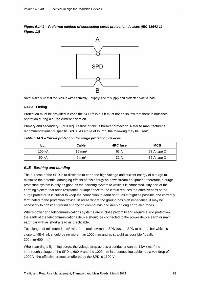
Volume 4: Part 3 – Electrical Design for Roadside Devices
Traffic and Road Use Management, Transport and Main Roads, March 2019 83
Figure 6.14.2 – Preferred method of connecting surge protection devices (IEC 61643 12
Figure 12)
Note: Make sure that the SPD is wired correctly – supply side to supply and protected side to load.
6.14.3 Fusing
Protection must be provided in case the SPD fails but it must not be so low that there is nuisance
operation during a surge current diversion.
Primary and secondary SPDs require fuse or circuit breaker protection. Refer to manufacturer’s
recommendations for specific SPDs. As a rule of thumb, the following may be used:
Table 6.14.3 – Circuit protection for surge protection devices
Imax Cable HRC fuse MCB
100 kA 16 mm² 63 A 63 A type D
50 kA 6 mm² 32 A 32 A type D
6.15 Earthing and bonding
The purpose of the SPD is to dissipate to earth the high voltage and current energy of a surge to
minimise the potential damaging effects of this energy on downstream equipment; therefore, a surge
protection system is only as good as the earthing system to which it is connected. Any part of the
earthing system that adds resistance or impedance to the circuit reduces the effectiveness of the
surge protector. It is critical to keep the connection to earth short, as straight as possible and correctly
terminated to the protection device. In areas where the ground has high impedance, it may be
necessary to consider ground enhancing compounds and deep or long earth electrodes.
Where power and telecommunications systems are in close proximity and require surge protection,
the earth of the telecommunications device should be connected to the power device earth or main
earth bar with as short a lead as practicable.
Total length of minimum 6 mm² wire from main switch to SPD fuse to SPD to neutral bar which is
close to MEN link should be no more than 1000 mm and as straight as possible (ideally
300 mm-600 mm).
When carrying a lightning surge, the voltage drop across a conductor can be 1 kV / m. If the
let-through voltage of the SPD is 600 V and the 1000 mm interconnecting cable had a volt drop of
1000 V, the effective protection offered by the SPD is 1600 V.
Volume 4: Part 3 – Electrical Design for Roadside Devices
Traffic and Road Use Management, Transport and Main Roads, March 2019 84
The main earth bar should be connected to the electrical installation earth electrode with as short a
conductor as possible.
Earthing system resistance should generally be less than 10 Ω and less than 5 Ω for installations with
primarily telecommunications or sensitive electronic equipment.
The objective of equipotential bonding is to reduce the potential difference between various parts of
the structure and the main earth bar.
A bonding bar can be used for the bonding of the various bonding conductors. The bar should be
bonded to the main earth bar with a short bonding conductor, preferably less than 500 mm long, which
includes a disconnect link.
All other bonding conductors should be kept short, preferably less than 1 m, and bonded to the
bonding bar.
6.16 Telecommunications
Many of the principles stated previously relating to power system SPDs are directly applicable to
telecommunications systems. Standards compliance must meet IEC 61643 21 and/or UL 497B as
appropriate.
6.16.1 Determining need for communications surge protection devices
The factors which will assist the assessment of the likelihood of lightning overvoltages occurring at a
telecommunications installation and the need for protection are (from AS4262 Parts 1 and 2):
6.16.1.1 Known lightning damage / injury history
Known damage to telecommunication facilities within a radius of 500 m with similar geographical
features to the location under consideration is considered high risk.
6.16.1.2 Thunderdays per year
A number >40 indicates high risk.
6.16.1.3 Building density
The number of buildings within 100 m of the location under consideration provides a measure of the
number of connections to earth. A number <5 indicates higher risk.
6.16.1.4 Soil resistivity
The higher the soil resistivity, the greater the area of influence of a lightning strike to ground. Soil
resistivity >1000 Ω / m is high risk.
6.16.1.5 Exposed terrain
Elevated locations over 1000 m above sea level or prominences in the terrain, such as clifftops,
ridges, bluffs and hills are considered high risk.
6.16.1.6 Building construction
Concrete slab and metal frame construction constitute an earthed environment. This increases the
probability that a person is in direct or indirect contact with the local earth and hence at higher risk
when using the telecommunication facility during an electrical storm.
Volume 4: Part 3 – Electrical Design for Roadside Devices
Traffic and Road Use Management, Transport and Main Roads, March 2019 85
6.16.1.7 Aerial telecommunication cable construction
A service fed by cable containing more than 200 m of aerial cable within approximately 2 km of the
location is considered to be at high risk.
6.16.1.8 Isolated telecommunications service
A service located in a structure that is not connected to any public electricity supply system or where
the public electricity supply power earth is greater than 100 m from the building housing the
telecommunication facility is considered high risk.
6.16.1.9 Equipment cost
High replacement cost of the equipment compared to the cost of the protection system for that
equipment is considered high risk.
6.16.1.10 Equipment necessity
The nature of the equipment being protected and how critical its operation is to the user determine the
risk. If the equipment is critical and its loss not acceptable, it is considered high risk.
Protection should be installed for any condition constituting high risk. If protection is required, it should
be installed at the entry to the installation which should be close to the main switchboard. Secondary
surge suppression for the protection of equipment is normally provided close to the equipment.
6.16.2 Selecting a communications surge protection device
The selection of the appropriate SPD for telecommunications and signalling networks depends on the
particular equipment to be protected, the signalling protocol and the following:
• maximum continuous operating voltage Uc
• voltage protection level Up
• maximum line current IL
• leakage current between the terminals
• frequency of system operation, and
• connector type and/or impedance.
When installed in the circuit, the characteristics of the SPD can affect the transmission characteristics
of the network. The parameters that may be affected are:
• capacitance
• series resistance
• insertion loss
• return loss
• longitudinal balance, and
• near end cross-talk.
Typically the telecommunications equipment and protocol will define the characteristics of the SPD.
There may only be a need to specify the type of physical connection, the number of lines to be
protected or its surge rating.

Volume 4: Part 3 – Electrical Design for Roadside Devices
Traffic and Road Use Management, Transport and Main Roads, March 2019 86
Equipment user manuals will sometimes have information on specific SPD requirements, where no
internal protection is provided and may also provide the equipment voltage withstand level.
SPD manufacturers will typically design products for specific telecommunications applications. This
makes selection of the product easier. As an example only, Novaris provides the following table for
suitable products for the various communications protocols:
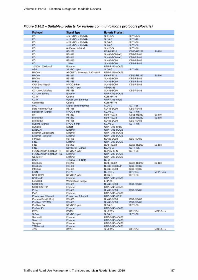
Volume 4: Part 3 – Electrical Design for Roadside Devices
Traffic and Road Use Management, Transport and Main Roads, March 2019 87
Figure 6.16.2 – Suitable products for various communications protocols (Novaris)
Volume 4: Part 3 – Electrical Design for Roadside Devices
Traffic and Road Use Management, Transport and Main Roads, March 2019 88
6.16.3 Installation of communications surge protection devices
Primary surge suppression for the protection of end users is installed at the entry to the structure
between the telecommunications line conductors and earth. The communications main distribution
frame and the main switchboard should be located close together to enable the earthing / bonding of
surge suppression devices. A total earthing conductor (minimum 6 mm²) length of 1.5 m is preferred
and should not exceed 10 m between the surge protection device and the earthing bar of the main
switchboard.
For telephone and signalling lines, a three terminal gas SPD is often used as the primary protection for
both common and differential mode transients. A gas arrester typically provides protection against the
L-E transients. Additional L-L protection can be provided if required by using a solid state device such
as a varistor.
Secondary surge suppression for the protection of equipment is normally provided close to the
equipment. The earth conductor should be of minimum cross-sectional area 2.5 mm² and maximum
length 1.5 m.
The provision of primary and secondary protection must be correctly coordinated so they function
correctly. The primary protection is generally able to handle large surge currents, but may be slow to
operate, and therefore can let relatively high transients through during the operation time. The
secondary stage is usually rated to handle lower energy levels, but is fast to operate. In this manner, it
is able to effectively absorb and clamp the residual transient energy let through from the primary
protection. Generally, for these two protection stages to function correctly, an interposing impedance
needs to be present and this may be the interconnection cable or, more reliably, a deliberate
impedance placed within either protection stage.
When the secondary protection is provided within the equipment to be protected, the supplier should
be contacted to determine if primary protection is required.
Telecommunications equipment may be subjected to both mains overvoltage and overvoltages within
the telecommunications network so surge protection on both systems may be required.
Where cable is provided between two structures, surge suppression should be installed at the entry to
both structures.
For mains powered telecommunications equipment, a Multiservice Surge Protective Device (MSPD)
is, in terms of suitability, cost and ease of installation, one of the best ways of reducing the risk of
damage. These combination units are located immediately adjacent to the equipment being protected
and have the distinct advantage of ensuring that the connection between the mains earth and the
telecommunications SPD earth is kept very short. To provide the best protection possible, all
interconnected equipment (for example, computer, modem and printer) must be connected to the
same MSPD.
While shunt protection provides a certain level of transient protection, it does not attenuate the rate of
rise of voltage up to the clamp voltage of the device. This fast rate of rise of voltage (dV / dt) causes a
variety of problems in computing, communications, instrumentation and other electronic equipment.
The use of a suitably designed low pass filter following the shunt diverter will both reduce the peak
let-through voltage and reduce the rate of rise of that voltage to levels which the connected equipment
can tolerate. This protection option is usually packaged in the one unit which includes both the shunt
protection and the filter.
Volume 4: Part 3 – Electrical Design for Roadside Devices
Traffic and Road Use Management, Transport and Main Roads, March 2019 89
6.17 Practical applications
6.17.1 General
For any particular installation, a risk analysis should first be carried out. This should provide a good
assessment of whether surge protection is required. The particular type of SPD that would provide
appropriate protection can then be selected. The appropriate SPDs can then be specified. Particular
attention then needs to be paid to the installation of the SPD and the earthing system. The SPD needs
to be provided on each copper cable at the boundary of the equipment to be protected.
The following provides some guidance on particular Transport and Main Roads applications:
6.17.2 Road lighting
A MOV SPD is installed within the luminaire to protect the control gear. No further protection is
generally required for standard road lighting installations.
6.17.3 Traffic signals
The TSC4 controller has a MOV SPD with IN rated at 20 kA and voltage protection level of <1450 V.
No further protection would generally be necessary.
6.17.4 Roadway CCTV installations
Roadway CCTV installations would generally be expected to require surge protection on the power
supply and copper communications cables, both at the camera and at the pole mounted equipment or
the field cabinet and at the pole mounted equipment or field cabinet and external connections. Power
and communications SPDs should be installed close together, if not in a combined unit, to ensure that
the earth leads are very short. Good earthing is critical.
6.17.5 Field cabinets
Where fibre optic cables are used as the communications medium between field devices, no surge
protection is required on the communications lines.
Where copper cables are used as the communications medium, the SPD appropriate for the particular
cable and protocol is recommended at both ends of the line.
A power SPD is recommended on the power circuit at the entry to the cabinet.
In general, the SPD device is required on every copper cable that enters the field cabinet.
6.17.6 Variable message signs on gantries
Gantry mounted variable message signs would generally require a power SPD on the incoming power
supply, and incoming communications if it uses copper medium. Communications SPDs would
generally be required on both ends of communications cabling between the controller and the light
modules. Power supply at the light modules may also need protection.
Volume 4: Part 3 – Electrical Design for Roadside Devices
Traffic and Road Use Management, Transport and Main Roads, March 2019 90
6.18 Summary
6.18.1 Power surge protection devices
• Determine if SPDs are required.
• Provide primary line-to-neutral protection at installation entry.
• Provide secondary line-to-neutral and neutral-to-earth protection at DB or equipment if
required.
• Select surge rating in accordance with table for location.
• Ensure 10–20 m cable between primary and secondary protection.
• Provide 32 A or 63 A SPD fuse.
• Keep SPD cables short and straight.
• Design good earthing and bonding.
• Communications surge protection devices
• Determine if SPDs are required.
• Provide primary protection at installation entry close to MSB.
• Provide secondary protection at equipment if required.
• Refer communications equipment manufacturer for SPD recommendations.
• Connect communications SPD earth and power SPD earth to common earth point.
• Connect common earth point to electrical earth.
• Keep SPD cables short and straight.
• Design good earthing and bonding.
7 Commentary
7.1 Introduction
This commentary provides additional background to the requirements presented in the other sections
so that the reader can gain a greater understanding of the subjects covered.
Following a section of miscellaneous topics including design voltage, maximum demand, protection
devices, contactors, maximum number of cables in conduit and a brief example of uninterruptable
power supply usage, design for cable current carrying capacity, cable short circuit withstand, voltage
drop and earth fault loop impedance are addressed.

Volume 4: Part 3 – Electrical Design for Roadside Devices
Traffic and Road Use Management, Transport and Main Roads, March 2019 91
7.2 Abbreviations and definitions
Table 7.2 – Abbreviations and definitions
Abbreviation Full title
I₂ Current ensuring effective operation of device
IB Maximum demand current of the circuit
IN Rated current of the protection device
IZ Continuous current carrying capacity of the cable
7.3 Design voltage and frequency
Addition of pending change in supply voltage to 230 / 400 V +10% to −6%.
The Queensland Electricity Regulation 2006 (current as at 16 March 2018) Section 11 Supply at low
voltage states that the standard voltage for the supply, before 27 October 2018, of electricity supplied
at low voltage from a three-phase system is:
a) between a phase conductor and a neutral conductor:
i. the nominal voltage stated for the system in AS 60038 or
ii. 240 V, and
b) between two phase conductors:
i. the nominal voltage stated for the system in AS 60038 or
ii. 415 V.
The standard voltage for the supply, on or after 27 October 2018, of electricity at low voltage from a
three-phase system or a single-phase system is the nominal voltage stated for the system in
AS 60038
AS 60038 states that the nominal supply voltage for low voltage supply systems in Australia are
230 / 400 V +10% to −6%.
The nominal frequency is 50 Hz.
7.4 Designing for maximum demand
Maximum demand for the installation can be determined by:
Table 7.4 – Designing for maximum demand
Calculation Add all the loads and allow for diversity (AS/NZS 3000 Appendix C)
Assessment Applicable to intermittent / fluctuating loads, large installations, special type of occupancy
Measurement Install a data recorder during time of highest demand
Limitation Demand is limited by size of the circuit protection device
More than one of these methods can be used when determining the overall maximum demand for a
particular in installation.
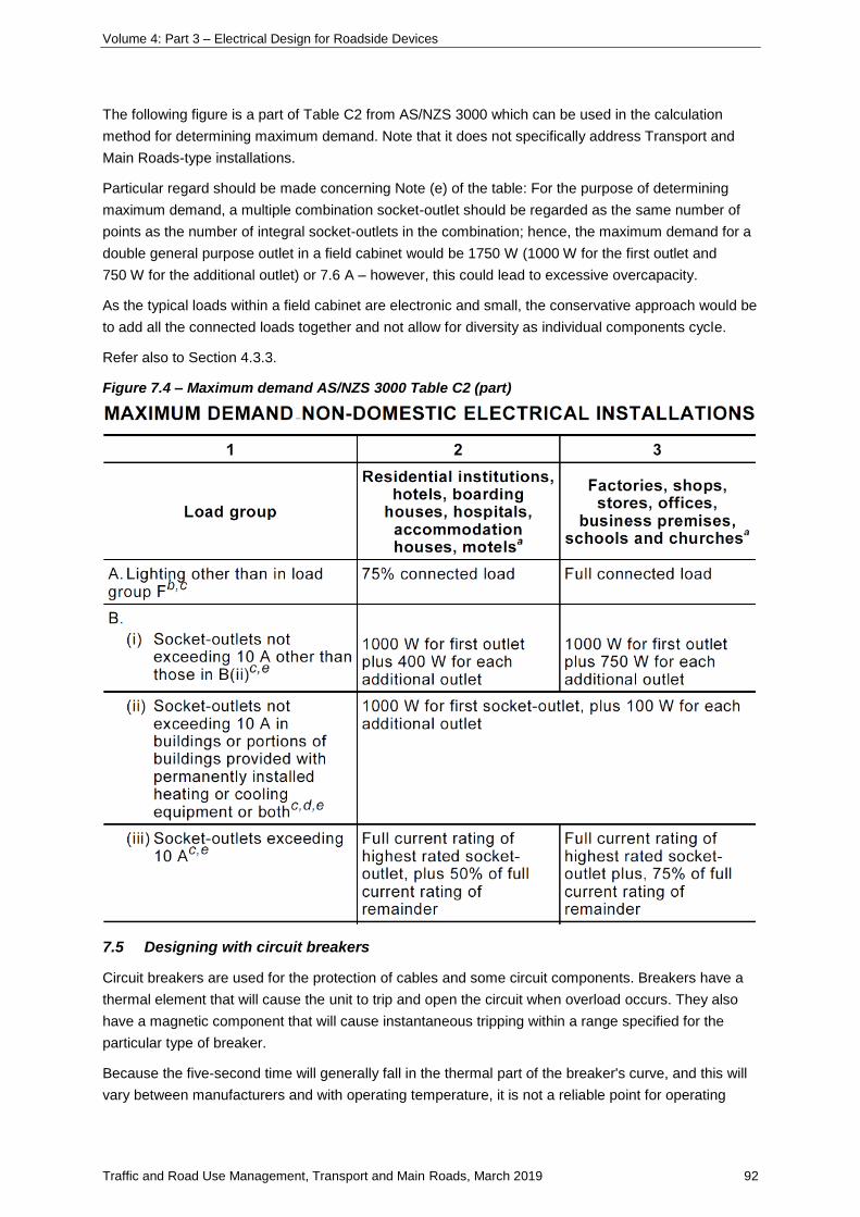
Volume 4: Part 3 – Electrical Design for Roadside Devices
Traffic and Road Use Management, Transport and Main Roads, March 2019 92
The following figure is a part of Table C2 from AS/NZS 3000 which can be used in the calculation
method for determining maximum demand. Note that it does not specifically address Transport and
Main Roads-type installations.
Particular regard should be made concerning Note (e) of the table: For the purpose of determining
maximum demand, a multiple combination socket-outlet should be regarded as the same number of
points as the number of integral socket-outlets in the combination; hence, the maximum demand for a
double general purpose outlet in a field cabinet would be 1750 W (1000 W for the first outlet and
750 W for the additional outlet) or 7.6 A – however, this could lead to excessive overcapacity.
As the typical loads within a field cabinet are electronic and small, the conservative approach would be
to add all the connected loads together and not allow for diversity as individual components cycle.
Refer also to Section 4.3.3.
Figure 7.4 – Maximum demand AS/NZS 3000 Table C2 (part)
7.5 Designing with circuit breakers
Circuit breakers are used for the protection of cables and some circuit components. Breakers have a
thermal element that will cause the unit to trip and open the circuit when overload occurs. They also
have a magnetic component that will cause instantaneous tripping within a range specified for the
particular type of breaker.
Because the five-second time will generally fall in the thermal part of the breaker's curve, and this will
vary between manufacturers and with operating temperature, it is not a reliable point for operating
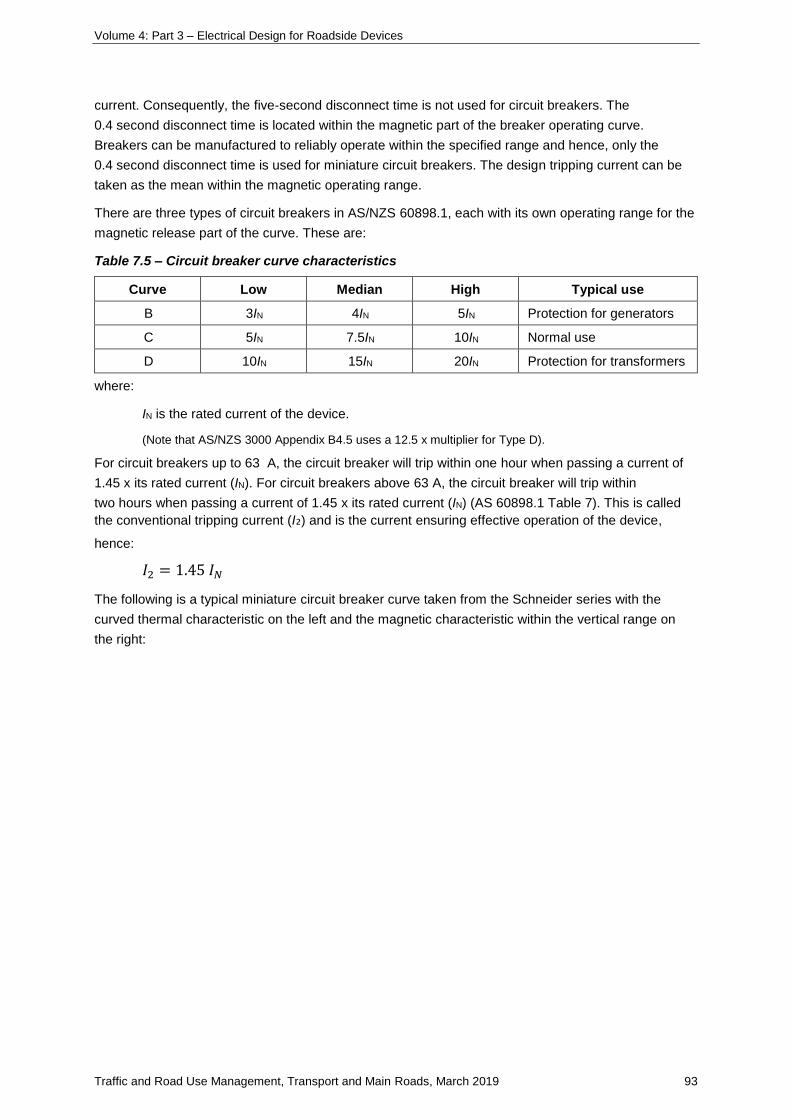
Volume 4: Part 3 – Electrical Design for Roadside Devices
Traffic and Road Use Management, Transport and Main Roads, March 2019 93
current. Consequently, the five-second disconnect time is not used for circuit breakers. The
0.4 second disconnect time is located within the magnetic part of the breaker operating curve.
Breakers can be manufactured to reliably operate within the specified range and hence, only the
0.4 second disconnect time is used for miniature circuit breakers. The design tripping current can be
taken as the mean within the magnetic operating range.
There are three types of circuit breakers in AS/NZS 60898.1, each with its own operating range for the
magnetic release part of the curve. These are:
Table 7.5 – Circuit breaker curve characteristics
Curve Low Median High Typical use
B 3IN 4IN 5IN Protection for generators
C 5IN 7.5IN 10IN Normal use
D 10IN 15IN 20IN Protection for transformers
where:
IN is the rated current of the device.
(Note that AS/NZS 3000 Appendix B4.5 uses a 12.5 x multiplier for Type D).
For circuit breakers up to 63 A, the circuit breaker will trip within one hour when passing a current of
1.45 x its rated current (IN). For circuit breakers above 63 A, the circuit breaker will trip within
two hours when passing a current of 1.45 x its rated current (IN) (AS 60898.1 Table 7). This is called
the conventional tripping current (I₂) and is the current ensuring effective operation of the device,
hence:
𝐼2 = 1.45 𝐼𝑁
The following is a typical miniature circuit breaker curve taken from the Schneider series with the
curved thermal characteristic on the left and the magnetic characteristic within the vertical range on
the right:
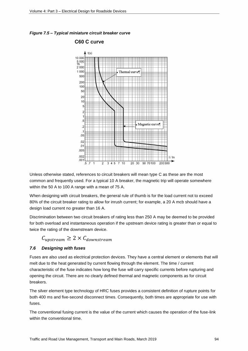
Volume 4: Part 3 – Electrical Design for Roadside Devices
Traffic and Road Use Management, Transport and Main Roads, March 2019 94
Figure 7.5 – Typical miniature circuit breaker curve
Unless otherwise stated, references to circuit breakers will mean type C as these are the most
common and frequently used. For a typical 10 A breaker, the magnetic trip will operate somewhere
within the 50 A to 100 A range with a mean of 75 A.
When designing with circuit breakers, the general rule of thumb is for the load current not to exceed
80% of the circuit breaker rating to allow for inrush current; for example, a 20 A mcb should have a
design load current no greater than 16 A.
Discrimination between two circuit breakers of rating less than 250 A may be deemed to be provided
for both overload and instantaneous operation if the upstream device rating is greater than or equal to
twice the rating of the downstream device.
𝐶𝑢𝑝𝑠𝑡𝑟𝑒𝑎𝑚 ≥ 2 × 𝐶𝑑𝑜𝑤𝑛𝑠𝑡𝑟𝑒𝑎𝑚
7.6 Designing with fuses
Fuses are also used as electrical protection devices. They have a central element or elements that will
melt due to the heat generated by current flowing through the element. The time / current
characteristic of the fuse indicates how long the fuse will carry specific currents before rupturing and
opening the circuit. There are no clearly defined thermal and magnetic components as for circuit
breakers.
The silver element type technology of HRC fuses provides a consistent definition of rupture points for
both 400 ms and five-second disconnect times. Consequently, both times are appropriate for use with
fuses.
The conventional fusing current is the value of the current which causes the operation of the fuse-link
within the conventional time.
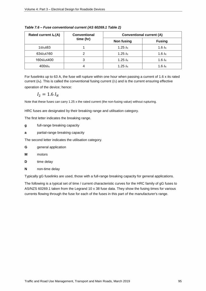
Volume 4: Part 3 – Electrical Design for Roadside Devices
Traffic and Road Use Management, Transport and Main Roads, March 2019 95
Table 7.6 – Fuse conventional current (AS 60269.1 Table 2)
Rated current IN (A) Conventional
time (hr)
Conventional current (A)
Non fusing Fusing
1≤IN≤63 1 1.25 IN 1.6 IN
63≤IN≤160 2 1.25 IN 1.6 IN
160≤IN≤400 3 1.25 IN 1.6 IN
400≤IN 4 1.25 IN 1.6 IN
For fuselinks up to 63 A, the fuse will rupture within one hour when passing a current of 1.6 x its rated
current (IN). This is called the conventional fusing current (I₂) and is the current ensuring effective
operation of the device; hence:
𝐼2 = 1.6 𝐼𝑁
Note that these fuses can carry 1.25 x the rated current (the non-fusing value) without rupturing.
HRC fuses are designated by their breaking range and utilisation category.
The first letter indicates the breaking range.
g full-range breaking capacity
a partial-range breaking capacity
The second letter indicates the utilisation category.
G general application
M motors
D time delay
N non-time delay
Typically gG fuselinks are used, those with a full-range breaking capacity for general applications.
The following is a typical set of time / current characteristic curves for the HRC family of gG fuses to
AS/NZS 60269.1 taken from the Legrand 10 x 38 fuse data. They show the fusing times for various
currents flowing through the fuse for each of the fuses in this part of the manufacturer's range.
Volume 4: Part 3 – Electrical Design for Roadside Devices
Traffic and Road Use Management, Transport and Main Roads, March 2019 96
Figure 7.6(a) – Typical high rupture capacity fuse time-current curves
Selecting the 10 A curve, the five-second point corresponds to a current of approximately 25 A and the
0.4 second point corresponds to a current of approximately 44 A. Either fusing time may be used
when fuses are selected as the protection device, but the time must be appropriate to the particular
application.
Up to approximately 80 A, a smaller current is typically required to rupture a fuse at the 0.4 second
disconnect time than for the Type C circuit breaker of similar rating.
When designing with fuses, the general rule of thumb is for the load current not to exceed 80% of the
fuse rating to allow for inrush current; for example, a 20 A fuse should have a design load current no
greater than 16 A.
To provide discrimination between two fuses, the pre-arcing energy of the upstream device must be
greater than or equal to the total fusing energy of the downstream device.
𝑃𝑟𝑒 − 𝑎𝑟𝑐𝑖𝑛𝑔 𝐼2𝑡 𝐹𝑢𝑝𝑠𝑡𝑟𝑒𝑎𝑚 ≥ 𝑇𝑜𝑡𝑎𝑙 𝐼2𝑡 𝐹𝑑𝑜𝑤𝑛𝑠𝑡𝑟𝑒𝑎𝑚
As a general rule of thumb for fuses >8 A:
𝐹𝑢𝑝𝑠𝑡𝑟𝑒𝑎𝑚 ≥ 2 𝑥 𝐹𝑑𝑜𝑤𝑛𝑠𝑡𝑟𝑒𝑎𝑚
The following I²t characteristic shows the pre-arcing and total operating energy for the range of
Legrand fuses described previously. For discrimination between two fuses, the pre-arcing I2t (shorter
black line) of the upstream fuse must be greater than the total operating I2t (longer black line) of the
downstream fuse; for example, a 6 A and 10 A will not discriminate but a 10 A and 20 A will.
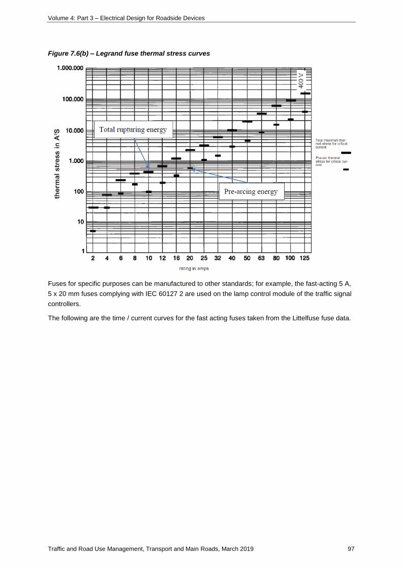
Volume 4: Part 3 – Electrical Design for Roadside Devices
Traffic and Road Use Management, Transport and Main Roads, March 2019 97
Figure 7.6(b) – Legrand fuse thermal stress curves
Fuses for specific purposes can be manufactured to other standards; for example, the fast-acting 5 A,
5 x 20 mm fuses complying with IEC 60127 2 are used on the lamp control module of the traffic signal
controllers.
The following are the time / current curves for the fast acting fuses taken from the Littelfuse fuse data.
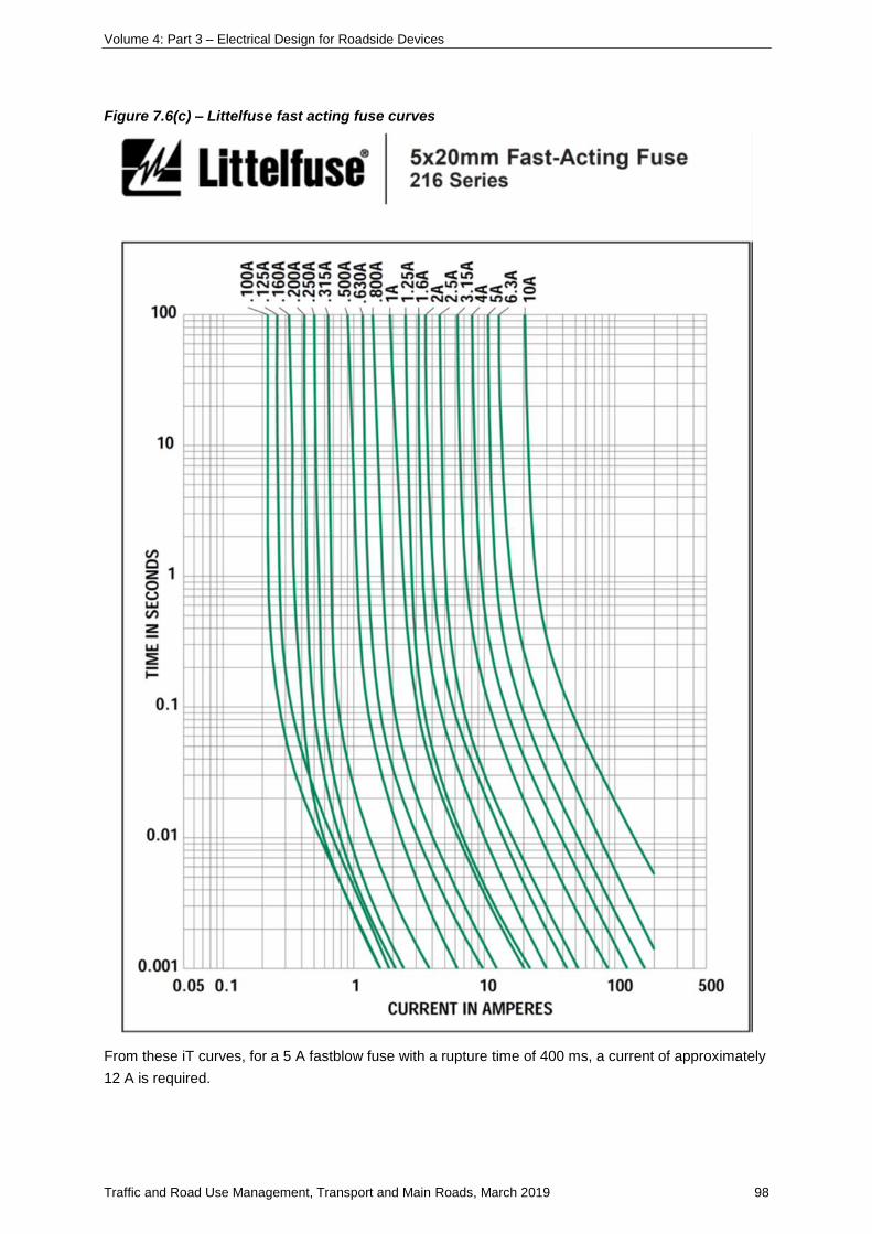
Volume 4: Part 3 – Electrical Design for Roadside Devices
Traffic and Road Use Management, Transport and Main Roads, March 2019 98
Figure 7.6(c) – Littelfuse fast acting fuse curves
From these iT curves, for a 5 A fastblow fuse with a rupture time of 400 ms, a current of approximately
12 A is required.
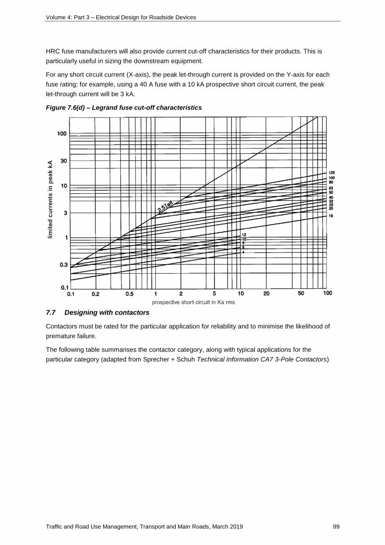
Volume 4: Part 3 – Electrical Design for Roadside Devices
Traffic and Road Use Management, Transport and Main Roads, March 2019 99
HRC fuse manufacturers will also provide current cut-off characteristics for their products. This is
particularly useful in sizing the downstream equipment.
For any short circuit current (X-axis), the peak let-through current is provided on the Y-axis for each
fuse rating; for example, using a 40 A fuse with a 10 kA prospective short circuit current, the peak
let-through current will be 3 kA.
Figure 7.6(d) – Legrand fuse cut-off characteristics
7.7 Designing with contactors
Contactors must be rated for the particular application for reliability and to minimise the likelihood of
premature failure.
The following table summarises the contactor category, along with typical applications for the
particular category (adapted from Sprecher + Schuh Technical Information CA7 3-Pole Contactors)
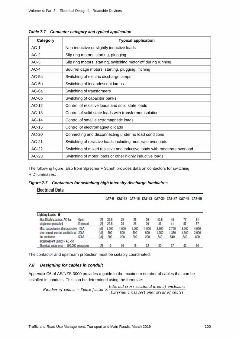
Volume 4: Part 3 – Electrical Design for Roadside Devices
Traffic and Road Use Management, Transport and Main Roads, March 2019 100
Table 7.7 – Contactor category and typical application
Category Typical application
AC-1 Non-inductive or slightly inductive loads
AC-2 Slip ring motors: starting, plugging
AC-3 Slip ring motors: starting, switching motor off during running
AC-4 Squirrel cage motors: starting, plugging, inching
AC-5a Switching of electric discharge lamps
AC-5b Switching of incandescent lamps
AC-6a Switching of transformers
AC-6b Switching of capacitor banks
AC-12 Control of resistive loads and solid state loads
AC-13 Control of solid state loads with transformer isolation
AC-14 Control of small electromagnetic loads
AC-15 Control of electromagnetic loads
AC-20 Connecting and disconnecting under no load conditions
AC-21 Switching of resistive loads including moderate overloads
AC-22 Switching of mixed resistive and inductive loads with moderate overload
AC-23 Switching of motor loads or other highly inductive loads
The following figure, also from Sprecher + Schuh provides data on contactors for switching
HID luminaires:
Figure 7.7 – Contactors for switching high intensity discharge luminaires
The contactor and upstream protection must be suitably coordinated.
7.8 Designing for cables in conduit
Appendix C6 of AS/NZS 3000 provides a guide to the maximum number of cables that can be
installed in conduits. This can be determined using the formulae:
𝑁𝑢𝑚𝑏𝑒𝑟 𝑜𝑓 𝑐𝑎𝑏𝑙𝑒𝑠 = 𝑆𝑝𝑎𝑐𝑒 𝑓𝑎𝑐𝑡𝑜𝑟 ×𝐼𝑛𝑡𝑒𝑟𝑛𝑎𝑙 𝑐𝑟𝑜𝑠𝑠 𝑠𝑒𝑐𝑡𝑖𝑜𝑛𝑎𝑙 𝑎𝑟𝑒𝑎 𝑜𝑓 𝑒𝑛𝑐𝑙𝑜𝑠𝑢𝑟𝑒
𝐸𝑥𝑡𝑒𝑟𝑛𝑎𝑙 𝑐𝑟𝑜𝑠𝑠 𝑠𝑒𝑐𝑡𝑖𝑜𝑛𝑎𝑙 𝑎𝑟𝑒𝑎𝑠 𝑜𝑓 𝑐𝑎𝑏𝑙𝑒𝑠
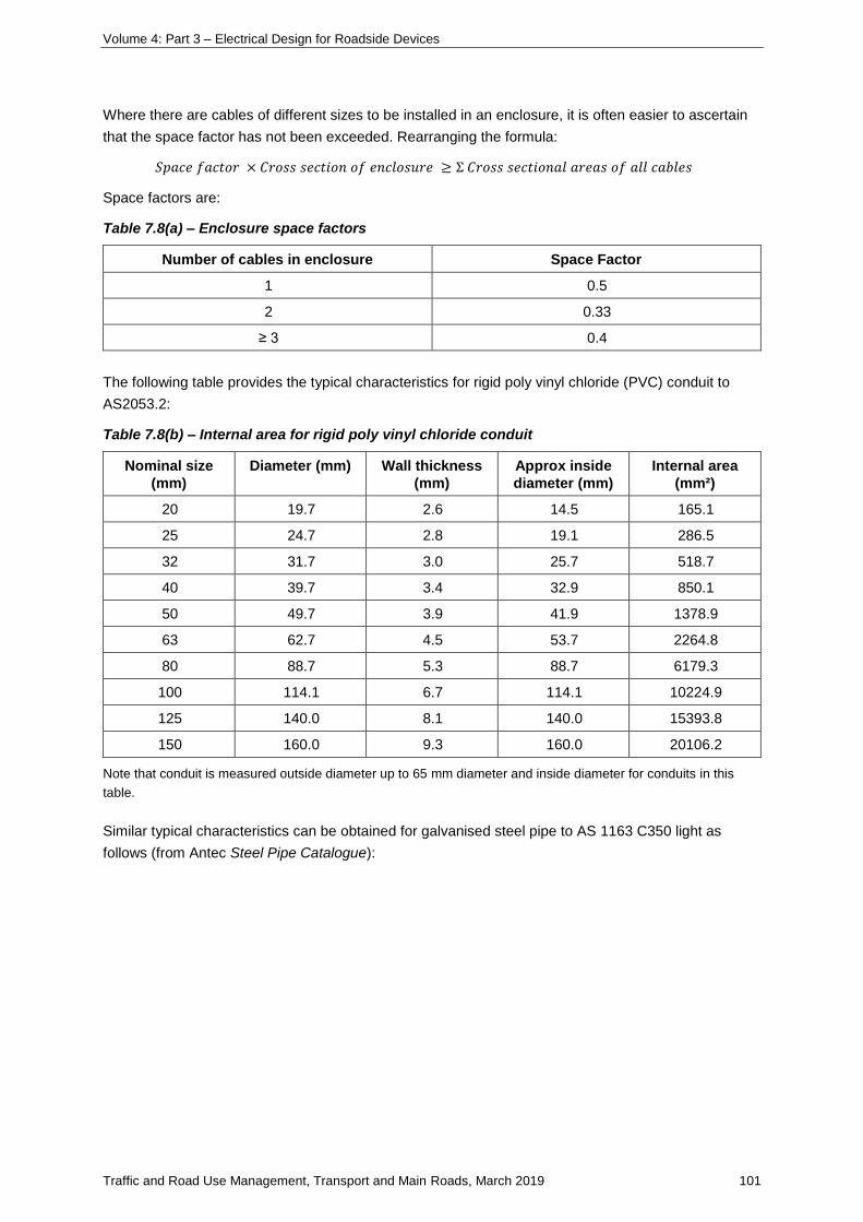
Volume 4: Part 3 – Electrical Design for Roadside Devices
Traffic and Road Use Management, Transport and Main Roads, March 2019 101
Where there are cables of different sizes to be installed in an enclosure, it is often easier to ascertain
that the space factor has not been exceeded. Rearranging the formula:
𝑆𝑝𝑎𝑐𝑒 𝑓𝑎𝑐𝑡𝑜𝑟 × 𝐶𝑟𝑜𝑠𝑠 𝑠𝑒𝑐𝑡𝑖𝑜𝑛 𝑜𝑓 𝑒𝑛𝑐𝑙𝑜𝑠𝑢𝑟𝑒 ≥ Σ 𝐶𝑟𝑜𝑠𝑠 𝑠𝑒𝑐𝑡𝑖𝑜𝑛𝑎𝑙 𝑎𝑟𝑒𝑎𝑠 𝑜𝑓 𝑎𝑙𝑙 𝑐𝑎𝑏𝑙𝑒𝑠
Space factors are:
Table 7.8(a) – Enclosure space factors
Number of cables in enclosure Space Factor
1 0.5
2 0.33
≥ 3 0.4
The following table provides the typical characteristics for rigid poly vinyl chloride (PVC) conduit to
AS2053.2:
Table 7.8(b) – Internal area for rigid poly vinyl chloride conduit
Nominal size
(mm)
Diameter (mm) Wall thickness
(mm)
Approx inside
diameter (mm)
Internal area
(mm²)
20 19.7 2.6 14.5 165.1
25 24.7 2.8 19.1 286.5
32 31.7 3.0 25.7 518.7
40 39.7 3.4 32.9 850.1
50 49.7 3.9 41.9 1378.9
63 62.7 4.5 53.7 2264.8
80 88.7 5.3 88.7 6179.3
100 114.1 6.7 114.1 10224.9
125 140.0 8.1 140.0 15393.8
150 160.0 9.3 160.0 20106.2
Note that conduit is measured outside diameter up to 65 mm diameter and inside diameter for conduits in this
table.
Similar typical characteristics can be obtained for galvanised steel pipe to AS 1163 C350 light as
follows (from Antec Steel Pipe Catalogue):
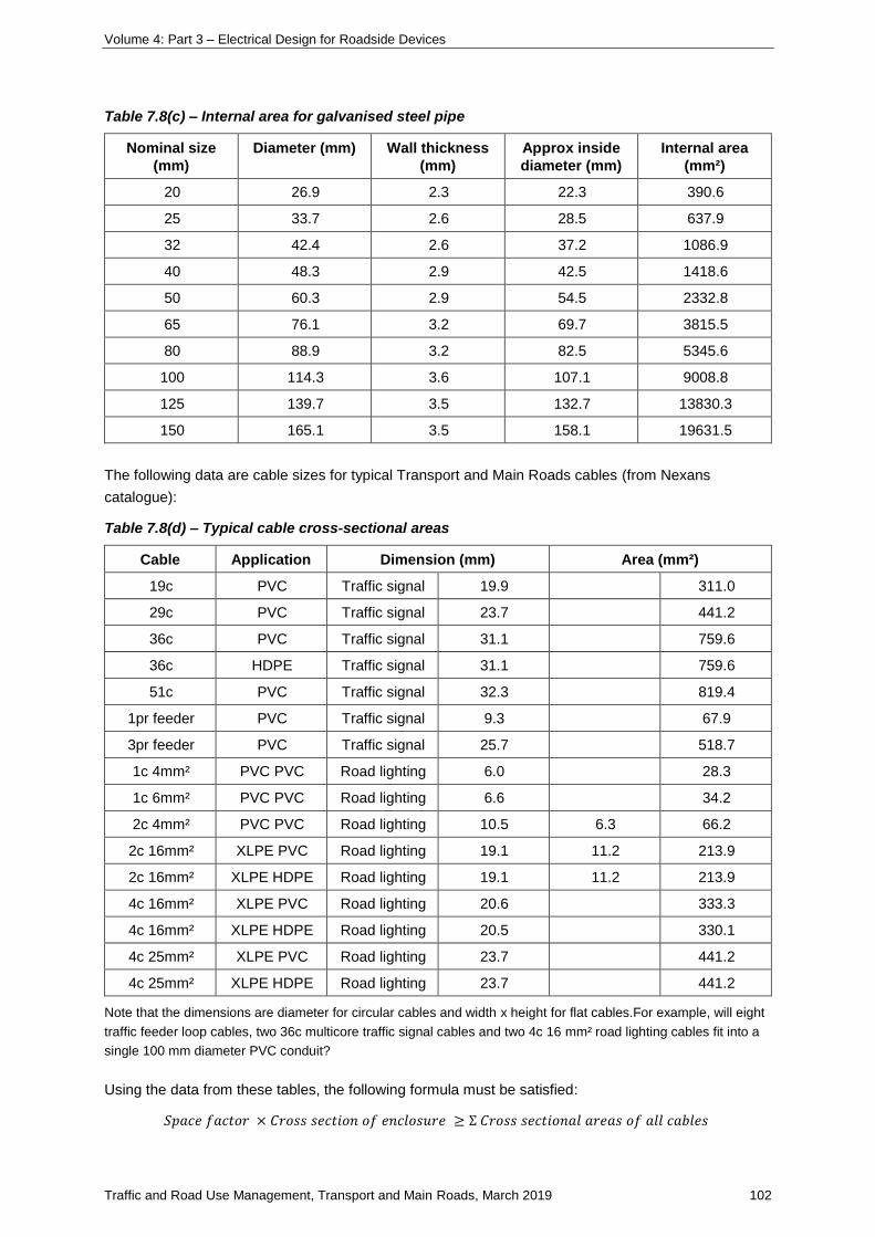
Volume 4: Part 3 – Electrical Design for Roadside Devices
Traffic and Road Use Management, Transport and Main Roads, March 2019 102
Table 7.8(c) – Internal area for galvanised steel pipe
Nominal size
(mm)
Diameter (mm) Wall thickness
(mm)
Approx inside
diameter (mm)
Internal area
(mm²)
20 26.9 2.3 22.3 390.6
25 33.7 2.6 28.5 637.9
32 42.4 2.6 37.2 1086.9
40 48.3 2.9 42.5 1418.6
50 60.3 2.9 54.5 2332.8
65 76.1 3.2 69.7 3815.5
80 88.9 3.2 82.5 5345.6
100 114.3 3.6 107.1 9008.8
125 139.7 3.5 132.7 13830.3
150 165.1 3.5 158.1 19631.5
The following data are cable sizes for typical Transport and Main Roads cables (from Nexans
catalogue):
Table 7.8(d) – Typical cable cross-sectional areas
Cable Application Dimension (mm) Area (mm²)
19c PVC Traffic signal 19.9 311.0
29c PVC Traffic signal 23.7 441.2
36c PVC Traffic signal 31.1 759.6
36c HDPE Traffic signal 31.1 759.6
51c PVC Traffic signal 32.3 819.4
1pr feeder PVC Traffic signal 9.3 67.9
3pr feeder PVC Traffic signal 25.7 518.7
1c 4mm² PVC PVC Road lighting 6.0 28.3
1c 6mm² PVC PVC Road lighting 6.6 34.2
2c 4mm² PVC PVC Road lighting 10.5 6.3 66.2
2c 16mm² XLPE PVC Road lighting 19.1 11.2 213.9
2c 16mm² XLPE HDPE Road lighting 19.1 11.2 213.9
4c 16mm² XLPE PVC Road lighting 20.6 333.3
4c 16mm² XLPE HDPE Road lighting 20.5 330.1
4c 25mm² XLPE PVC Road lighting 23.7 441.2
4c 25mm² XLPE HDPE Road lighting 23.7 441.2
Note that the dimensions are diameter for circular cables and width x height for flat cables.For example, will eight
traffic feeder loop cables, two 36c multicore traffic signal cables and two 4c 16 mm² road lighting cables fit into a
single 100 mm diameter PVC conduit?
Using the data from these tables, the following formula must be satisfied:
𝑆𝑝𝑎𝑐𝑒 𝑓𝑎𝑐𝑡𝑜𝑟 × 𝐶𝑟𝑜𝑠𝑠 𝑠𝑒𝑐𝑡𝑖𝑜𝑛 𝑜𝑓 𝑒𝑛𝑐𝑙𝑜𝑠𝑢𝑟𝑒 ≥ Σ 𝐶𝑟𝑜𝑠𝑠 𝑠𝑒𝑐𝑡𝑖𝑜𝑛𝑎𝑙 𝑎𝑟𝑒𝑎𝑠 𝑜𝑓 𝑎𝑙𝑙 𝑐𝑎𝑏𝑙𝑒𝑠
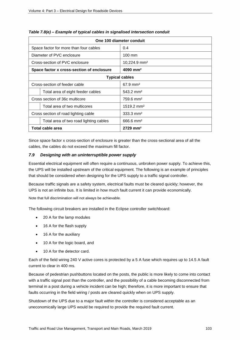
Volume 4: Part 3 – Electrical Design for Roadside Devices
Traffic and Road Use Management, Transport and Main Roads, March 2019 103
Table 7.8(e) – Example of typical cables in signalised intersection conduit
One 100 diameter conduit
Space factor for more than four cables 0.4
Diameter of PVC enclosure 100 mm
Cross-section of PVC enclosure 10,224.9 mm²
Space factor x cross-section of enclosure 4090 mm²
Typical cables
Cross-section of feeder cable 67.9 mm²
Total area of eight feeder cables 543.2 mm²
Cross section of 36c multicore 759.6 mm²
Total area of two multicores 1519.2 mm²
Cross section of road lighting cable 333.3 mm²
Total area of two road lighting cables 666.6 mm²
Total cable area 2729 mm²
Since space factor x cross-section of enclosure is greater than the cross-sectional area of all the
cables, the cables do not exceed the maximum fill factor.
7.9 Designing with an uninterruptible power supply
Essential electrical equipment will often require a continuous, unbroken power supply. To achieve this,
the UPS will be installed upstream of the critical equipment. The following is an example of principles
that should be considered when designing for the UPS supply to a traffic signal controller.
Because traffic signals are a safety system, electrical faults must be cleared quickly; however, the
UPS is not an infinite bus. It is limited in how much fault current it can provide economically.
Note that full discrimination will not always be achievable.
The following circuit breakers are installed in the Eclipse controller switchboard:
• 20 A for the lamp modules
• 16 A for the flash supply
• 16 A for the auxiliary
• 10 A for the logic board, and
• 10 A for the detector card.
Each of the field wiring 240 V active cores is protected by a 5 A fuse which requires up to 14.5 A fault
current to clear in 400 ms.
Because of pedestrian pushbuttons located on the posts, the public is more likely to come into contact
with a traffic signal post than the controller, and the possibility of a cable becoming disconnected from
terminal in a post during a vehicle incident can be high; therefore, it is more important to ensure that
faults occurring in the field wiring / posts are cleared quickly when on UPS supply.
Shutdown of the UPS due to a major fault within the controller is considered acceptable as an
uneconomically large UPS would be required to provide the required fault current.
Volume 4: Part 3 – Electrical Design for Roadside Devices
Traffic and Road Use Management, Transport and Main Roads, March 2019 104
The lanterns should be LED to minimise the load requirements on the protection devices.
The following parameters are important when considering the use of a UPS:
• load current demand of all devices including the controller and lanterns
• Impedance of supply cable from the UPS to the controller
• Impedance of multicore cable
• available fault current
• UPS battery run time, and
• UPS battery charge time.
The following is an example of power consumption loads for an average intersection (the specific
parameters will need to be determined for specific installations):
• Multicore Run 1 load 123.3 W
• Multicore Run 2 load 155.8 W
• Eclipse controller load 41.5 W
• Total controller and lantern load 320.6 W
Assuming a 0.9 power factor:
Load in V A = 320.6 / 0.9 = 356 V A
Load in amps = 356 / 230 = 1.55 A
The Novus FXM UPS 2000 W / VA system has been tested by Transport and Main Roads with the
following performance characteristics recorded following:
• UPS internal impedance: 6.2 Ω
• Prospective short circuit current at UPS terminals @ 230 V: 37 A
• Maximum circuit impedance to clear a 5 A fastblow fuse within 400 ms: 16.5 Ω
The UPS output to the controller must be protected by a *10 A Littlefuse – POWR KLK Series 10 x 38
– part No. 0KLK010.T.
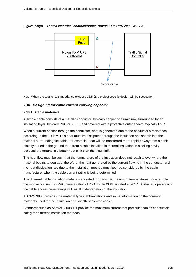
Volume 4: Part 3 – Electrical Design for Roadside Devices
Traffic and Road Use Management, Transport and Main Roads, March 2019 105
Figure 7.9(a) – Tested electrical characteristics Novus FXM UPS 2000 W / V A
Note: When the total circuit impedance exceeds 16.5 Ω, a project specific design will be necessary.
7.10 Designing for cable current carrying capacity
7.10.1 Cable materials
A simple cable consists of a metallic conductor, typically copper or aluminium, surrounded by an
insulating layer, typically PVC or XLPE, and covered with a protective outer sheath, typically PVC.
When a current passes through the conductor, heat is generated due to the conductor’s resistance
according to the i²R law. This heat must be dissipated through the insulation and sheath into the
material surrounding the cable; for example, heat will be transferred more rapidly away from a cable
directly buried in the ground than from a cable installed in thermal insulation in a ceiling cavity
because the ground is a better heat sink than the insul fluff.
The heat flow must be such that the temperature of the insulation does not reach a level where the
material begins to degrade; therefore, the heat generated by the current flowing in the conductor and
the heat dissipation rate due to the installation method must both be considered by the cable
manufacturer when the cable current rating is being determined.
The different cable insulation materials are rated for particular maximum temperatures; for example,
thermoplastics such as PVC have a rating of 75°C while XLPE is rated at 90°C. Sustained operation of
the cable above these ratings will result in degradation of the insulation.
AS/NZS 3808 provides the material types, abbreviations and some information on the common
materials used for the insulation and sheath of electric cables.
Standards such as AS/NZS 3008.1.1 provide the maximum current that particular cables can sustain
safely for different installation methods.
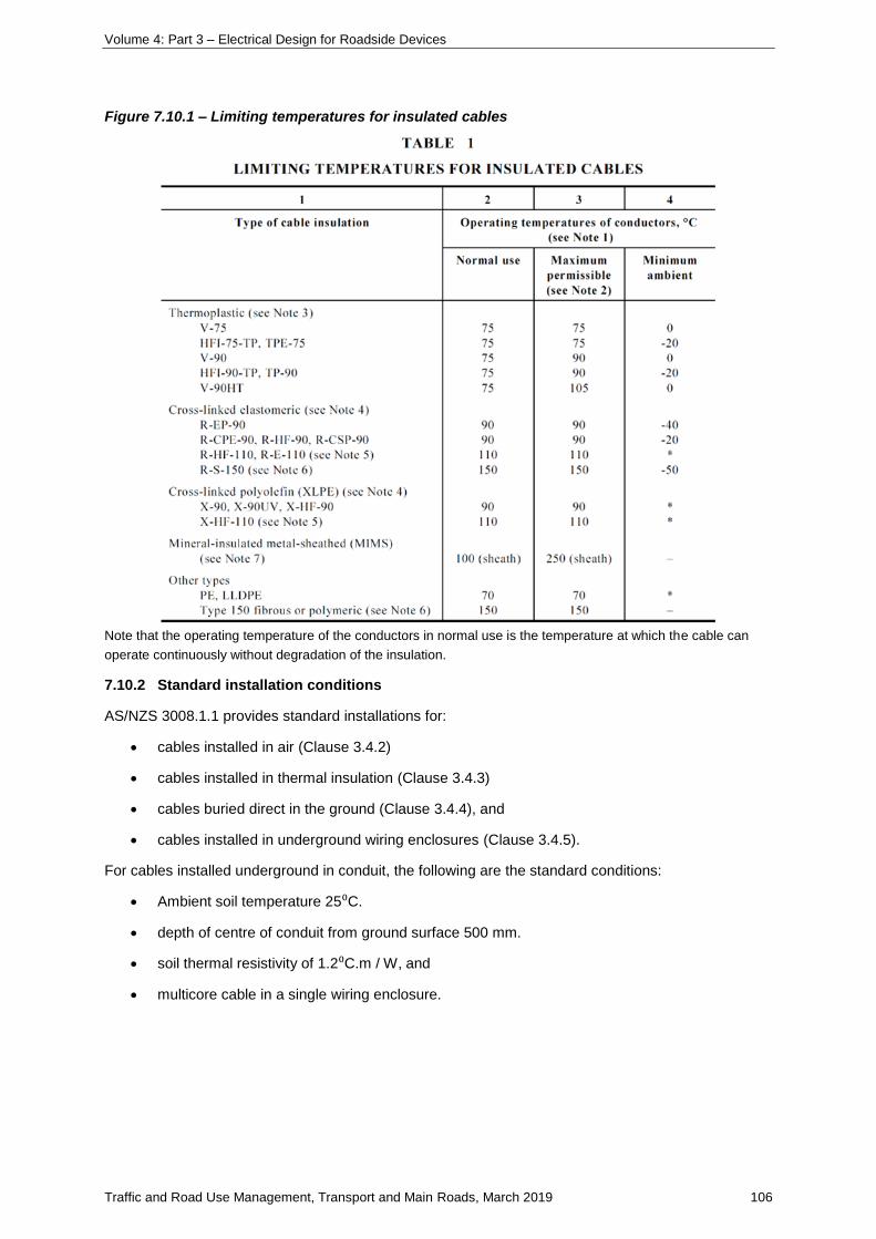
Volume 4: Part 3 – Electrical Design for Roadside Devices
Traffic and Road Use Management, Transport and Main Roads, March 2019 106
Figure 7.10.1 – Limiting temperatures for insulated cables
Note that the operating temperature of the conductors in normal use is the temperature at which the cable can
operate continuously without degradation of the insulation.
7.10.2 Standard installation conditions
AS/NZS 3008.1.1 provides standard installations for:
• cables installed in air (Clause 3.4.2)
• cables installed in thermal insulation (Clause 3.4.3)
• cables buried direct in the ground (Clause 3.4.4), and
• cables installed in underground wiring enclosures (Clause 3.4.5).
For cables installed underground in conduit, the following are the standard conditions:
• Ambient soil temperature 25⁰C.
• depth of centre of conduit from ground surface 500 mm.
• soil thermal resistivity of 1.2⁰C.m / W, and
• multicore cable in a single wiring enclosure.

Volume 4: Part 3 – Electrical Design for Roadside Devices
Traffic and Road Use Management, Transport and Main Roads, March 2019 107
7.10.3 Derating factors for non-standard installation conditions
Where the installation conditions are not in compliance with the standard conditions, derating factors
must be applied to ensure that the temperature of the conductor does not rise to a temperature greater
than the maximum temperature the conductor insulation can withstand when carrying the full rated
current. These are found in AS/NZS 3008.1.1.
Clause Derating factor C Table
3.5.2 derating factors for groups C1 Tables 22–26
3.5.3 derating factors for ambient temperature C2 Table 27
3.5.4 derating factor for depth of laying C3 Table 28
3.5.5 derating factor for soil thermal resistivity C4 Table 29
3.5.6 derating factor for varying load C5
3.5.7 derating factor for thermal insulation C6
3.5.8 derating factor for direct sunlight C7
3.5.9 derating for harmonic currents C8
Where non-standard installation conditions apply, the derated value for IN must be used:
87654321 CCCCCCCC
IN
where
IN = rated current of the protection device
Where the particular derating factor is not applicable, the C value is taken as 1.
Note that where cables are operating at less than 35% of their current carrying capacity, derating for those cables
is not required (AS/NZS 3008.1.1 Clause 3.5.2.2(d)).
7.10.4 Cable protection
Appropriate selection of the cable protection device, whether fuse or circuit breaker, will protect the
cable by limiting the current flow so that the requirements of the Standards can be met and the cable
insulation will be protected from heat degradation.
For continuous operation of the circuit, the maximum demand current must be less than the nominal
operating current of the protection device. Otherwise, the protection could activate and open the
circuit; hence, the maximum demand current (IB) must be less than or equal to the rated current of the
protection device (IN) which also must be less than or equal to the continuous current carrying capacity
of the cable (Iz). Or:
ZNB III
Volume 4: Part 3 – Electrical Design for Roadside Devices
Traffic and Road Use Management, Transport and Main Roads, March 2019 108
A second requirement is that the current ensuring effective operation of the device (I₂) must be less
than or equal to 1.45 x the continuous current carrying capacity of the cable (Iz). Or:
ZII 45.12
where
IB = maximum demand current of the circuit
IN = rated current of the protection device
Iz = continuous current carrying capacity of the cable
I₂ = current ensuring effective operation of device
The current ensuring effective operation of the device (the current required to trip the breaker or
rupture the fuselink) is different for each of the two devices as the design of breakers and fuses is
based on different principles.
For circuit breakers up to 63 A:
NII 45.12
But
ZN
Z
II
II
45.12
Therefore, where circuit breakers are used for protection the overall requirement is:
ZNB III
For fuselinks up to 63 A:
NII 6.12
But
ZN
ZN
Z
II
II
II
9.0
45.16.1
45.12
Therefore, where fuses are used for protection the overall requirement is:
ZNB III 9.0
7.10.5 Cable operating temperature
The cable parameters included in AS/NZS 3008.1.1 are based on standard operating conditions for
the specified type of cable and installation methods and typically allow for the cable carrying the full
load current; however, many cables within Transport and Main Roads installations are not operating at
the full load current. Designs must be carried out using the appropriate conductor temperature, based
on the current the cable will be carrying.
Volume 4: Part 3 – Electrical Design for Roadside Devices
Traffic and Road Use Management, Transport and Main Roads, March 2019 109
Referring to AS/NZS 3008.1.1, an accurate calculation of conductor temperature can be made using
the following equation:
AR
Ao
R
o
I
I
2
where
IO = operating current in amps
IR = cable rated current in amps (AS/NZS 3008.1.1 Tables 4 to 21)
θO = operating temperature of cable in °C when carrying current IO
θR = operating temperature in °C when carrying IR (AS/NZS 3008.1.1 Table 1)
θA = ambient air or soil temperature in °C
= under rated conditions
40°C for air
25°C for ground
Rearranging
AAR
R
o
oI
I
2
The calculated temperature θO is then raised to the nearest temperature 45°C, 60°C, 75°C and so on
for use with Tables 34 to 51 to determine the cable ac resistance and voltage drop.
Examples
Consumers’ mains cable temperature rating should be determined depending on the size of the cable
selected and its maximum demand. The conservative temperature would be 75°C.; however, a 4 c
25 mm² cable would be expected to run at 48°C and a 2 c 16 mm² cable would be expected to run at
53°C if operating at 64 A (80% of the 80 A fuse rating).
Road lighting specified submains and sub-circuit cabling will not be carrying the maximum cable
design load.
For the standard 16 mm² and 25 mm² XLPE / PVC submains cables installed in underground conduit,
with operating current equal to 80% of the protection rating and standard conditions, the cable
operating temperatures are calculated to be:
Table 7.10.5 – Submains cable operating temperature
Single phase cable (T°C) Three phase cable (T°C)
Fuse size (A) 16 mm² 25 mm² 16 mm² 25 mm²
20 26.7 26.0 27.5 26. 5
25 27.7 26.6 29.0 27.3
32 29.4 27.6 31.5 28.7

Volume 4: Part 3 – Electrical Design for Roadside Devices
Traffic and Road Use Management, Transport and Main Roads, March 2019 110
When designing for voltage drop and EFLI for submains cables under these conditions, the 75°C
cable data should be used.
7.10.6 Resistance change with temperature
As temperature increases, the conductivity of metallic materials decreases with the corresponding
increase in resistivity. As resistance is related to resistivity by:
S
LR
where
R = resistance of conductor (W)
ρ = resistivity at temperature T (W mm² / m)
L = length of conductor (m)
S = cross-sectional area of conductor (mm²)
it follows that the resistance of a metallic conductor also rises with temperature.
Thermal changes of resistivity can be calculated using the following formula:
))(1( 00 TT
where
ρ = resistivity at temperature T (W mm² / m)
ρ₀ = resistivity at reference temperature T₀ (W mm² / m)
α = temperature coefficient of resistivity (°C-1)
For commercial copper at 20°C
ρ₀ = 1.7241 x 10⁻² Ω mm² / m
α = 0.00393°C-1
T₀ = 20°C
Therefore
))20(00393.01(107241.1
))(1(
2
00
Tx
TT
At 75°C
mmmx
x
TT
/10097.2
))2075(00393.01(107241.1
))(1(
22
2
00
When designing with conductors that are lightly loaded and overrated for current carrying capacity, the
formula in Section 7.10.5 Cable operating temperature can be used to determine the approximate
cable operating temperature.
When circuit testing is being carried out, particularly on lightly loaded conductors, a more realistic
maximum impedance value can be obtained for reference by calculating the resistivity at 25°C.
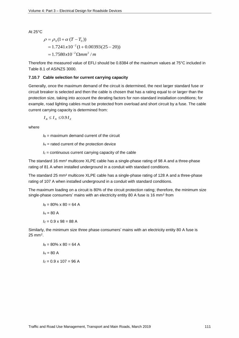
Volume 4: Part 3 – Electrical Design for Roadside Devices
Traffic and Road Use Management, Transport and Main Roads, March 2019 111
At 25°C
mmmx
x
TT
/107580.1
))2025(00393.01(107241.1
))(1(
22
2
00
Therefore the measured value of EFLI should be 0.8384 of the maximum values at 75°C included in
Table 8.1 of AS/NZS 3000.
7.10.7 Cable selection for current carrying capacity
Generally, once the maximum demand of the circuit is determined, the next larger standard fuse or
circuit breaker is selected and then the cable is chosen that has a rating equal to or larger than the
protection size, taking into account the derating factors for non-standard installation conditions; for
example, road lighting cables must be protected from overload and short circuit by a fuse. The cable
current carrying capacity is determined from:
ZNB III 9.0
where
IB = maximum demand current of the circuit
IN = rated current of the protection device
Iz = continuous current carrying capacity of the cable
The standard 16 mm² multicore XLPE cable has a single-phase rating of 98 A and a three-phase
rating of 81 A when installed underground in a conduit with standard conditions.
The standard 25 mm² multicore XLPE cable has a single-phase rating of 128 A and a three-phase
rating of 107 A when installed underground in a conduit with standard conditions.
The maximum loading on a circuit is 80% of the circuit protection rating; therefore, the minimum size
single-phase consumers’ mains with an electricity entity 80 A fuse is 16 mm² from
IB = 80% x 80 = 64 A
IN = 80 A
IZ = 0.9 x 98 = 88 A
Similarly, the minimum size three phase consumers’ mains with an electricity entity 80 A fuse is
25 mm².
IB = 80% x 80 = 64 A
IN = 80 A
IZ = 0.9 x 107 = 96 A
Volume 4: Part 3 – Electrical Design for Roadside Devices
Traffic and Road Use Management, Transport and Main Roads, March 2019 112
The minimum size three-phase cable for Transport and Main Roads road lighting submains from the
road lighting switchboard to the light pole pit is 16 mm² (rated 81 A). The maximum size fuselink in the
switchboard is 32 A.
IB = 80% x 32 = 26 A
IN = 32 A
IZ = 0.9 x 81 = 73 A
Therefore the cable is overrated for the application and will be operating at less than the maximum
allowable cable operating temperature.
The minimum size cable for road lighting sub-circuits from the re-openable joint in the pit to the pole
isolator is 4 mm² and from the pole isolator to the luminaire is 2.5 mm² (rated 23 A). The fuselink size
is 10 A.
IB = 80% x 10 = 8 A
IN = 10 A
IZ = 0.9 x 23 = 20.7 A (for 2.5 mm² PVC / PVC cable)
In all cases the cable / overload protection criteria is met.
7.11 Designing for cable short circuit protection
The cable and protection device must be selected so that, under short circuit conditions, the cable
insulation is not damaged by the heat generated in the conductor during the time the circuit protection
takes to activate and clear the fault.
For typical situations, the generalised form of the adiabatic temperature rise equation can be used to
calculate the minimum cable cross-sectional area for a cable under short circuit conditions. It neglects
heat loss and is accurate for calculating permissible conductor and metallic sheath short circuit
currents up to five seconds in duration. It is applicable to any starting temperature.
222 SKtI
Rearranging:
K
tIS
where
S = minimum cross sectional area of the conductor in mm²
I = short circuit current in amperes (from protection curves typically at 0.4 s)
t = duration of short circuit in seconds (typically 0.4 s)
K = constant from AS / NZS 3008.1.1 Table 52
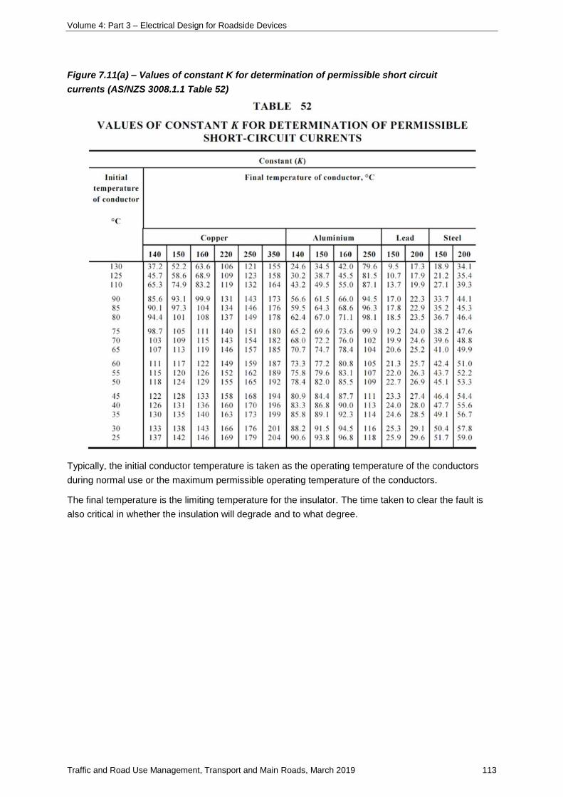
Volume 4: Part 3 – Electrical Design for Roadside Devices
Traffic and Road Use Management, Transport and Main Roads, March 2019 113
Figure 7.11(a) – Values of constant K for determination of permissible short circuit
currents (AS/NZS 3008.1.1 Table 52)
Typically, the initial conductor temperature is taken as the operating temperature of the conductors
during normal use or the maximum permissible operating temperature of the conductors.
The final temperature is the limiting temperature for the insulator. The time taken to clear the fault is
also critical in whether the insulation will degrade and to what degree.
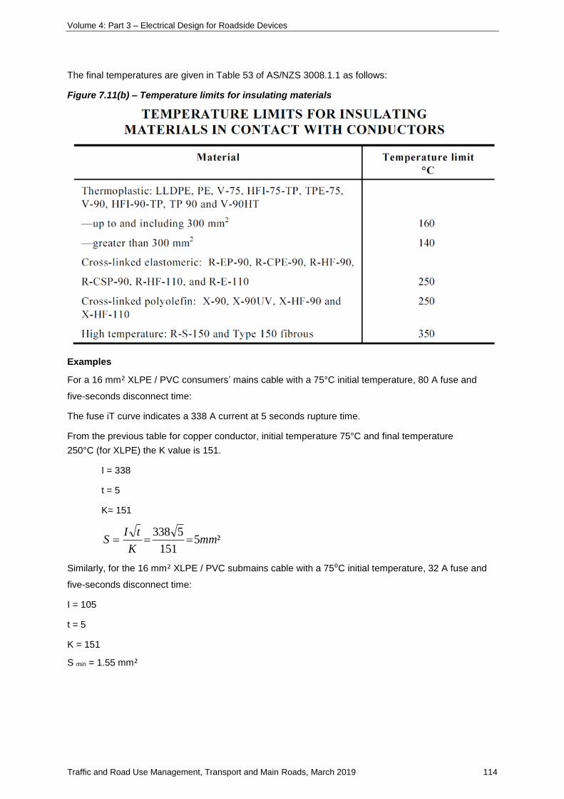
Volume 4: Part 3 – Electrical Design for Roadside Devices
Traffic and Road Use Management, Transport and Main Roads, March 2019 114
The final temperatures are given in Table 53 of AS/NZS 3008.1.1 as follows:
Figure 7.11(b) – Temperature limits for insulating materials
Examples
For a 16 mm² XLPE / PVC consumers’ mains cable with a 75°C initial temperature, 80 A fuse and
five-seconds disconnect time:
The fuse iT curve indicates a 338 A current at 5 seconds rupture time.
From the previous table for copper conductor, initial temperature 75°C and final temperature
250°C (for XLPE) the K value is 151.
I = 338
t = 5
K= 151
²5151
5338mm
K
tIS
Similarly, for the 16 mm² XLPE / PVC submains cable with a 75⁰C initial temperature, 32 A fuse and
five-seconds disconnect time:
I = 105
t = 5
K = 151
S min = 1.55 mm²
Volume 4: Part 3 – Electrical Design for Roadside Devices
Traffic and Road Use Management, Transport and Main Roads, March 2019 115
For the 2.5 mm² PVC / PVC sub-circuit cable with a 75⁰C initial temperature, 10 A fuse and 400 ms
disconnect time:
I = 42
t = 0.4
K = 111
Smin = 0.24 mm²
Therefore, operation under short circuit conditions is not a major consideration when designing with
Transport and Main Roads standard sized cables and protection.
7.12 Designing for voltage drop
7.12.1 Voltage drop
Ohm's Law states that, in an electrical circuit, the current (I in amps) passing through a conductor
between two points is directly proportional to the voltage drop (V in volts) across the two points and
inversely proportional to the resistance (R in ohms) between them. This is expressed mathematically
as:
R
VI
Rearranging
RIV
Therefore the voltage drop in a cable is directly proportional to the current flowing through the
conductor and directly proportional to the impedance of the conductor.
Voltage drop is important because, if the impedance of the cable run is too large, the available voltage
at the connected equipment may be too low for the equipment to operate correctly; hence, there are
limits placed on the allowable voltage drop.
Where inductance and/or capacitance is present in the circuit, the complex generalization of
resistance becomes impedance.
ZIV
where
22 XRZ
and
R = resistance in Ohms
X = reactance in Ohms
The impedance of conductors is usually expressed in units of ohms per meter or ohms per kilometre,
which enables the total impedance for any given conductor length to be readily calculated; for
example, the value of ac resistance in multicore cables with circular conductors is given in Ω / km in
AS/NZS 3008.1.1 Table 35 and the value of reactance also in Ω / km in AS3008.1.1 Table 30.
Volume 4: Part 3 – Electrical Design for Roadside Devices
Traffic and Road Use Management, Transport and Main Roads, March 2019 116
Hence:
1000
cZLI
ZIV
where
ZC = impedance of the cable in ohms / kilometre
L = route length in metres from circuit origin to point of consideration
For straight wire (refer AS/NZS 3008.1.1 Tables 30–39)
1000
cZLIV
For single-phase (that is, two wires), refer AS/NZS 3008.1.1 Tables 30–39 and multiply values by two.
Where both active and neutral conductors are the same cross-sectional area and carrying the same
current, because the electrical circuit length is twice the route (cable) length, the voltage drop for a
single phase circuit is
phaseoneZ
LIV
ZIV
c
1000
)2(
Where the single-phase active and neutral conductors are different cross-sectional areas or they carry
different currents (refer AS/NZS 3008.1.1 Tables 30–39), the voltage drop is the sum of the voltage
drops in the two separate conductors.
phaseoneZLIZLI
ZIV
nnnppp
10001000
For balanced three-phase, refer AS/NZS 3008.1.1 Tables 30–39 and multiply values by √3 or
AS/NZS 3008.1.1 Tables 40–51. For a balanced three-phase circuit, no current flows in the neutral
conductor. At any particular time the current flowing in one phase will be balanced by the currents in
the other two-phase conductors. The voltage drop between phases is 2/3 times the single-phase
voltage drop.
phasethreeZ
LI
ZIV
c
1000
)3(
Note that the √3ZC factor is included in the values in AS/NZS 3008.1.1 Tables 40–51.
When using single phase or unbalanced three-phase design with Tables 40–51, multiply the values by
1.155 [2 / √3].
As the luminaires on three-phase circuits must be balanced across the phases, the maximum
unbalance should typically be the current load of one luminaire (that is, the total number of luminaires
on the circuit may not be an exact multiple of three). Calculations have demonstrated that there is
minimal difference in voltage drop between using the tables listed here for balanced loads and voltage
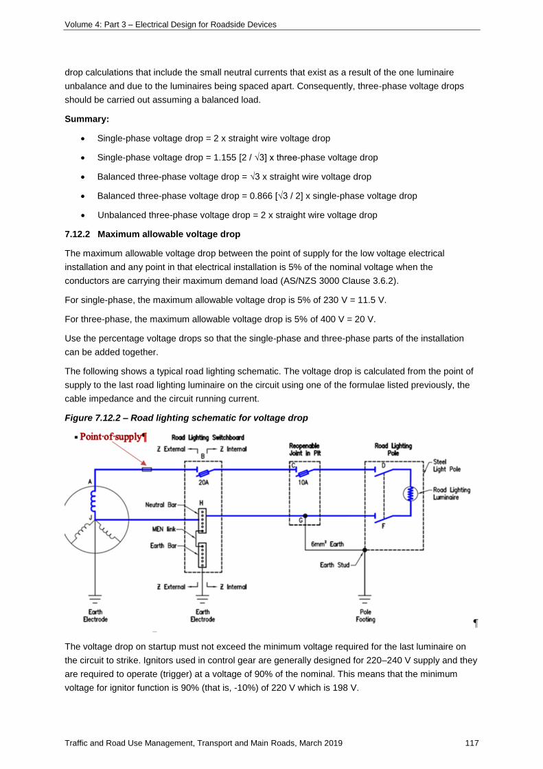
Volume 4: Part 3 – Electrical Design for Roadside Devices
Traffic and Road Use Management, Transport and Main Roads, March 2019 117
drop calculations that include the small neutral currents that exist as a result of the one luminaire
unbalance and due to the luminaires being spaced apart. Consequently, three-phase voltage drops
should be carried out assuming a balanced load.
Summary:
• Single-phase voltage drop = 2 x straight wire voltage drop
• Single-phase voltage drop = 1.155 [2 / √3] x three-phase voltage drop
• Balanced three-phase voltage drop = √3 x straight wire voltage drop
• Balanced three-phase voltage drop = 0.866 [√3 / 2] x single-phase voltage drop
• Unbalanced three-phase voltage drop = 2 x straight wire voltage drop
7.12.2 Maximum allowable voltage drop
The maximum allowable voltage drop between the point of supply for the low voltage electrical
installation and any point in that electrical installation is 5% of the nominal voltage when the
conductors are carrying their maximum demand load (AS/NZS 3000 Clause 3.6.2).
For single-phase, the maximum allowable voltage drop is 5% of 230 V = 11.5 V.
For three-phase, the maximum allowable voltage drop is 5% of 400 V = 20 V.
Use the percentage voltage drops so that the single-phase and three-phase parts of the installation
can be added together.
The following shows a typical road lighting schematic. The voltage drop is calculated from the point of
supply to the last road lighting luminaire on the circuit using one of the formulae listed previously, the
cable impedance and the circuit running current.
Figure 7.12.2 – Road lighting schematic for voltage drop
The voltage drop on startup must not exceed the minimum voltage required for the last luminaire on
the circuit to strike. Ignitors used in control gear are generally designed for 220–240 V supply and they
are required to operate (trigger) at a voltage of 90% of the nominal. This means that the minimum
voltage for ignitor function is 90% (that is, -10%) of 220 V which is 198 V.
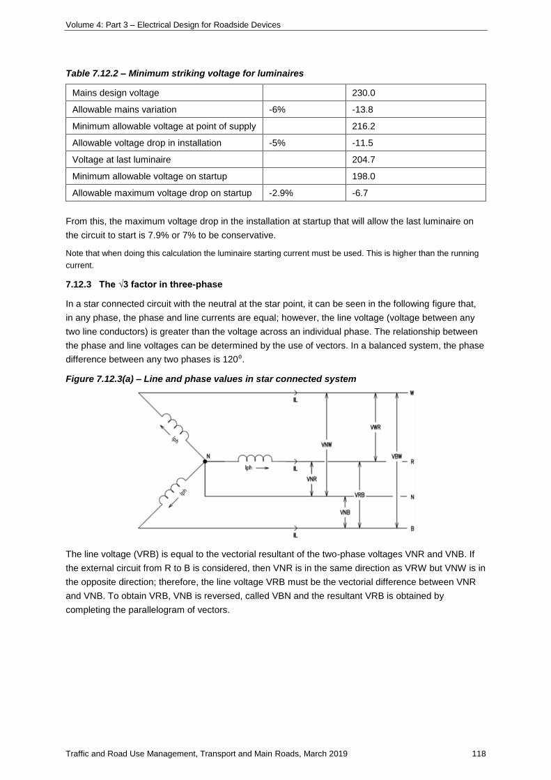
Volume 4: Part 3 – Electrical Design for Roadside Devices
Traffic and Road Use Management, Transport and Main Roads, March 2019 118
Table 7.12.2 – Minimum striking voltage for luminaires
Mains design voltage 230.0
Allowable mains variation -6% -13.8
Minimum allowable voltage at point of supply 216.2
Allowable voltage drop in installation -5% -11.5
Voltage at last luminaire 204.7
Minimum allowable voltage on startup 198.0
Allowable maximum voltage drop on startup -2.9% -6.7
From this, the maximum voltage drop in the installation at startup that will allow the last luminaire on
the circuit to start is 7.9% or 7% to be conservative.
Note that when doing this calculation the luminaire starting current must be used. This is higher than the running
current.
7.12.3 The √3 factor in three-phase
In a star connected circuit with the neutral at the star point, it can be seen in the following figure that,
in any phase, the phase and line currents are equal; however, the line voltage (voltage between any
two line conductors) is greater than the voltage across an individual phase. The relationship between
the phase and line voltages can be determined by the use of vectors. In a balanced system, the phase
difference between any two phases is 120⁰.
Figure 7.12.3(a) – Line and phase values in star connected system
The line voltage (VRB) is equal to the vectorial resultant of the two-phase voltages VNR and VNB. If
the external circuit from R to B is considered, then VNR is in the same direction as VRW but VNW is in
the opposite direction; therefore, the line voltage VRB must be the vectorial difference between VNR
and VNB. To obtain VRB, VNB is reversed, called VBN and the resultant VRB is obtained by
completing the parallelogram of vectors.
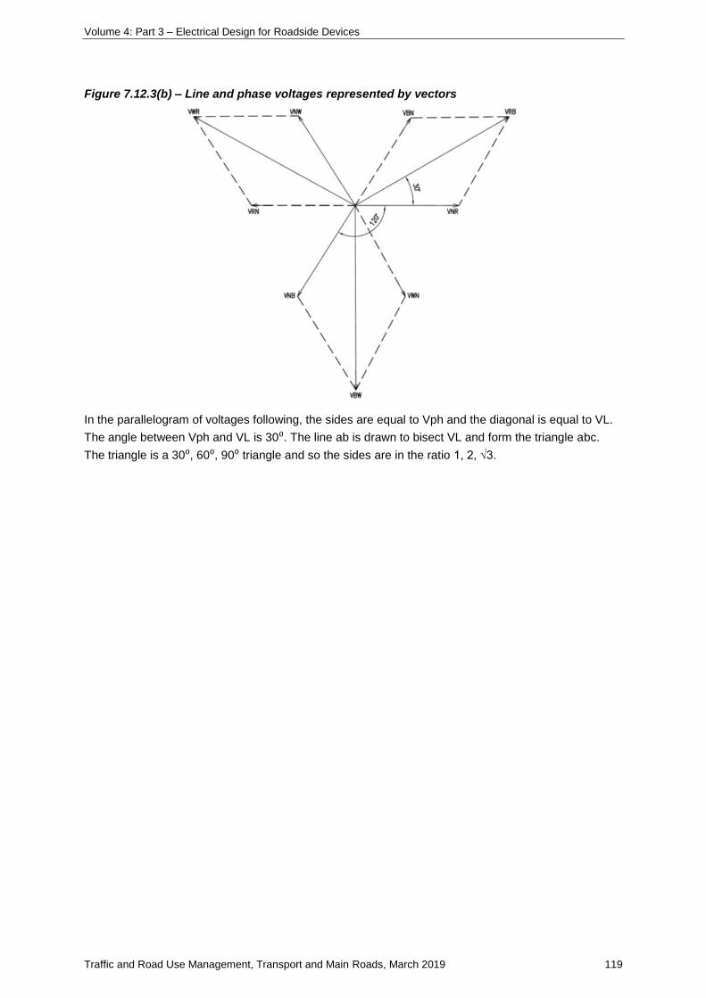
Volume 4: Part 3 – Electrical Design for Roadside Devices
Traffic and Road Use Management, Transport and Main Roads, March 2019 119
Figure 7.12.3(b) – Line and phase voltages represented by vectors
In the parallelogram of voltages following, the sides are equal to Vph and the diagonal is equal to VL.
The angle between Vph and VL is 30⁰. The line ab is drawn to bisect VL and form the triangle abc.
The triangle is a 30⁰, 60⁰, 90⁰ triangle and so the sides are in the ratio 1, 2, √3.
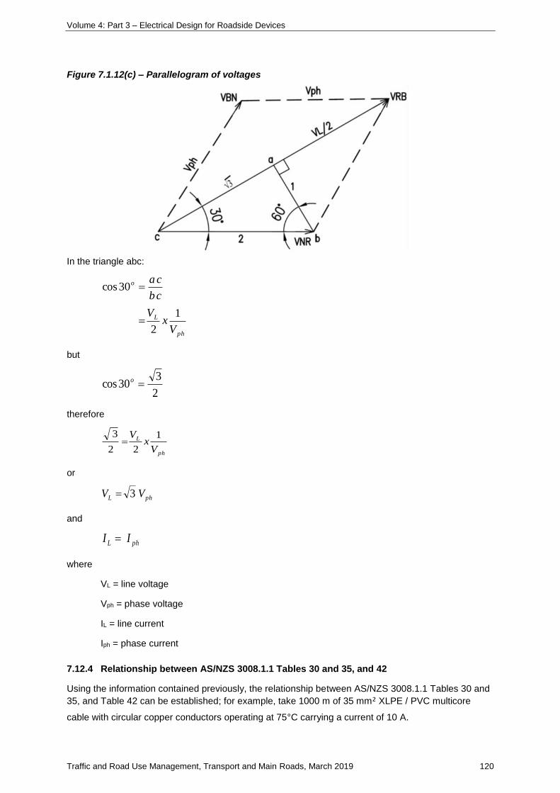
Volume 4: Part 3 – Electrical Design for Roadside Devices
Traffic and Road Use Management, Transport and Main Roads, March 2019 120
Figure 7.1.12(c) – Parallelogram of voltages
In the triangle abc:
ph
L
o
Vx
V
cb
ca
1
2
30cos
but
2
330cos o
therefore
ph
L
Vx
V 1
22
3
or
phL VV 3
and
phL II
where
VL = line voltage
Vph = phase voltage
IL = line current
Iph = phase current
7.12.4 Relationship between AS/NZS 3008.1.1 Tables 30 and 35, and 42
Using the information contained previously, the relationship between AS/NZS 3008.1.1 Tables 30 and
35, and Table 42 can be established; for example, take 1000 m of 35 mm² XLPE / PVC multicore
cable with circular copper conductors operating at 75°C carrying a current of 10 A.
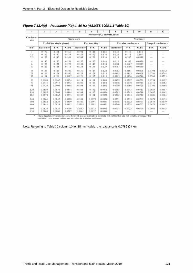
Volume 4: Part 3 – Electrical Design for Roadside Devices
Traffic and Road Use Management, Transport and Main Roads, March 2019 121
Figure 7.12.4(a) – Reactance (Xc) at 50 Hz (AS/NZS 3008.1.1 Table 30)
Note: Referring to Table 30 column 10 for 35 mm² cable, the reactance is 0.0786 Ω / km.
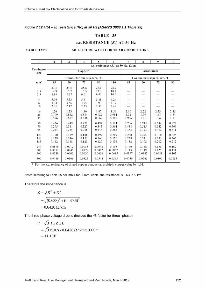
Volume 4: Part 3 – Electrical Design for Roadside Devices
Traffic and Road Use Management, Transport and Main Roads, March 2019 122
Figure 7.12.4(b) – ac resistance (Rc) at 50 Hz (AS/NZS 3008.1.1 Table 35)
Note: Referring to Table 35 column 4 for 35mm² cable, the resistance is 0.638 Ω / km
Therefore the impedance is
/km6428.0
)0786.0()638.0( 22
22
XRZ
The three-phase voltage drop is (include the √3 factor for three -phase)
V
mxkmxAx
LxZxIV
13.11
1000/6428.0103
3
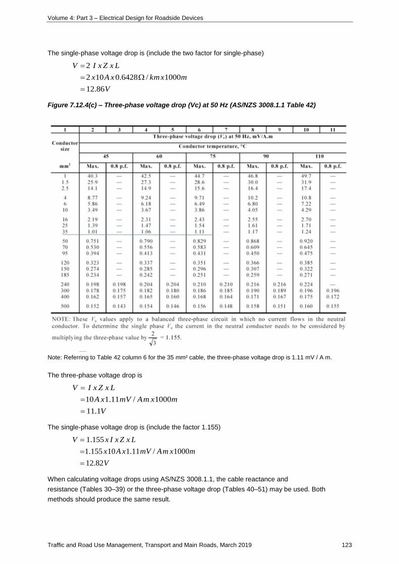
Volume 4: Part 3 – Electrical Design for Roadside Devices
Traffic and Road Use Management, Transport and Main Roads, March 2019 123
The single-phase voltage drop is (include the two factor for single-phase)
V
mxkmxAx
LxZxIV
86.12
1000/6428.0102
2
Figure 7.12.4(c) – Three-phase voltage drop (Vc) at 50 Hz (AS/NZS 3008.1.1 Table 42)
Note: Referring to Table 42 column 6 for the 35 mm² cable, the three-phase voltage drop is 1.11 mV / A m.
The three-phase voltage drop is
V
mxmAmVxA
LxZxIV
1.11
1000/11.110
The single-phase voltage drop is (include the factor 1.155)
V
mxmAmVxAx
LxZxIxV
82.12
1000/11.110155.1
155.1
When calculating voltage drops using AS/NZS 3008.1.1, the cable reactance and
resistance (Tables 30–39) or the three-phase voltage drop (Tables 40–51) may be used. Both
methods should produce the same result.

Volume 4: Part 3 – Electrical Design for Roadside Devices
Traffic and Road Use Management, Transport and Main Roads, March 2019 124
7.12.5 Maximum cable length for voltage drop
For any core of a cable the single-phase voltage drop will be given by the following equation:
1000
ILZV
where
V = voltage drop in the core in volts
I = current in the core in amperes
L = L is the length of the core in metres
Z = Impedance of the core in ohms / km from AS/NZS 3008.1.1 Tables 30 and 35.
For a circuit of active and neutral cores the circuit voltage drop will be the sum of the voltage drops in
the active and neutral cores as follows:
10001000
nnnppp
np
ZLIZLIVV
For any particular circuit, the length of the active and neutral is assumed the same, but the current in
the cores and the core cross-sectional area may be different. The maximum allowable voltage drop in
the circuit (Vd) will be the sum of the voltage drops in the active and neutral (note that this may not be
the full 5% or 11.5 V). Then:
)(
1000
)(1000
max
nnpp
d
nnppd
ZIZI
VL
ZIZIL
V
where
Vd = maximum allowable voltage drop in cable in volts
Lmax = the maximum length of the cable in metres (cable route)
Ip = current in the active in amperes
Zp = impedance of the active in ohms / km from AS/NZS 3008.1.1 Tables 30 and 35
In = current in the neutral in amperes
Zn = impedance of the neutral in ohms / km from AS/NZS 3008.1.1 Tables 30 and 35.
Where the active and neutral currents are the same for a single-phase system and the cores are the
same cross-sectional area:
ZI
VL d
2
1000max
Similarly, for three-phase:
ZI
VL d
3
1000max
Volume 4: Part 3 – Electrical Design for Roadside Devices
Traffic and Road Use Management, Transport and Main Roads, March 2019 125
During the design process, the voltage drop will be proportioned between the consumers’ mains,
submains and the sub-circuits. The maximum voltage drop in these equations is the proportion
appropriate to the selected cable.
Where the cable sizes are small, the reactance is very small compared with the resistance and can be
neglected. In this case, Z = R.
7.13 Designing for earth fault loop impedance
7.13.1 Earth fault loop impedance
The design parameters must be selected and design calculations carried out to demonstrate that, in
the event of an active-to-earth fault occurring at the most distant part of the circuit, the impedance of
the fault path is low enough to allow sufficient current to flow to activate the circuit protection device
within the disconnect time specified to clear the fault.
7.13.2 Effects of current through the body
To gain a better appreciation of the topic of EFLI and why it is important in electrical design, it is
necessary to address some of the underlying principles.
An electric shock is the pathophysiological effect of an electric current as it passes through the body.
As the majority of the body is an aqueous electrolyte, any external electric current can flow relatively
easily through the body once it has passed the skin barrier. The muscular, circulatory and respiratory
systems are mostly affected by this current, but serious burns can also result. If the effects are
sufficiently severe, death by electrocution could be the end result.
The degree of danger that a person may be subjected to depends on a number of parameters,
including:
• the magnitude of the current
• the duration of the current
• the current path through the body
• the age and health of the person
• the skin condition and area of contact with current source
• the body impedance
• the touch voltage
• the frequency of the current
• the occurrence of the shock in relation to the cardiac cycle.
A person who comes into contact with live metal risks getting an electric shock.
The following figure taken from AS/NZS 60479.1 provides the conventional time / current zones of the
effects of alternating currents (between 15 Hz and 100 Hz) on persons for a current path
corresponding to left hand to both feet.
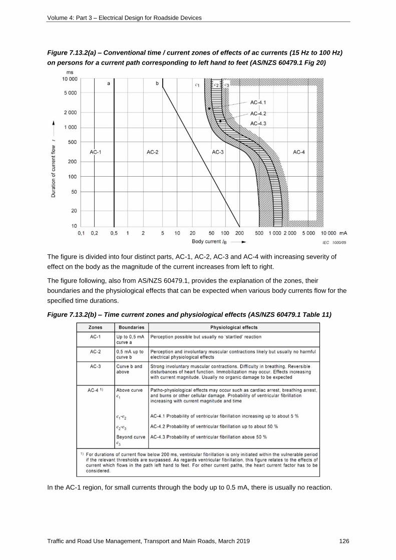
Volume 4: Part 3 – Electrical Design for Roadside Devices
Traffic and Road Use Management, Transport and Main Roads, March 2019 126
Figure 7.13.2(a) – Conventional time / current zones of effects of ac currents (15 Hz to 100 Hz)
on persons for a current path corresponding to left hand to feet (AS/NZS 60479.1 Fig 20)
The figure is divided into four distinct parts, AC-1, AC-2, AC-3 and AC-4 with increasing severity of
effect on the body as the magnitude of the current increases from left to right.
The figure following, also from AS/NZS 60479.1, provides the explanation of the zones, their
boundaries and the physiological effects that can be expected when various body currents flow for the
specified time durations.
Figure 7.13.2(b) – Time current zones and physiological effects (AS/NZS 60479.1 Table 11)
In the AC-1 region, for small currents through the body up to 0.5 mA, there is usually no reaction.
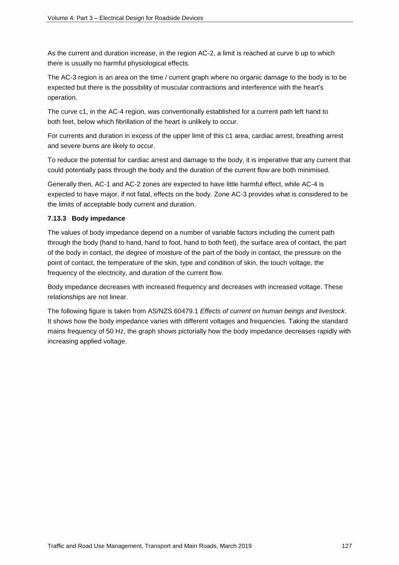
Volume 4: Part 3 – Electrical Design for Roadside Devices
Traffic and Road Use Management, Transport and Main Roads, March 2019 127
As the current and duration increase, in the region AC-2, a limit is reached at curve b up to which
there is usually no harmful physiological effects.
The AC-3 region is an area on the time / current graph where no organic damage to the body is to be
expected but there is the possibility of muscular contractions and interference with the heart's
operation.
The curve c1, in the AC-4 region, was conventionally established for a current path left hand to
both feet, below which fibrillation of the heart is unlikely to occur.
For currents and duration in excess of the upper limit of this c1 area, cardiac arrest, breathing arrest
and severe burns are likely to occur.
To reduce the potential for cardiac arrest and damage to the body, it is imperative that any current that
could potentially pass through the body and the duration of the current flow are both minimised.
Generally then, AC-1 and AC-2 zones are expected to have little harmful effect, while AC-4 is
expected to have major, if not fatal, effects on the body. Zone AC-3 provides what is considered to be
the limits of acceptable body current and duration.
7.13.3 Body impedance
The values of body impedance depend on a number of variable factors including the current path
through the body (hand to hand, hand to foot, hand to both feet), the surface area of contact, the part
of the body in contact, the degree of moisture of the part of the body in contact, the pressure on the
point of contact, the temperature of the skin, type and condition of skin, the touch voltage, the
frequency of the electricity, and duration of the current flow.
Body impedance decreases with increased frequency and decreases with increased voltage. These
relationships are not linear.
The following figure is taken from AS/NZS 60479.1 Effects of current on human beings and livestock.
It shows how the body impedance varies with different voltages and frequencies. Taking the standard
mains frequency of 50 Hz, the graph shows pictorially how the body impedance decreases rapidly with
increasing applied voltage.
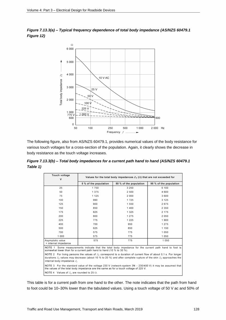
Volume 4: Part 3 – Electrical Design for Roadside Devices
Traffic and Road Use Management, Transport and Main Roads, March 2019 128
Figure 7.13.3(a) – Typical frequency dependence of total body impedance (AS/NZS 60479.1
Figure 12)
The following figure, also from AS/NZS 60479.1, provides numerical values of the body resistance for
various touch voltages for a cross-section of the population. Again, it clearly shows the decrease in
body resistance as the touch voltage increases.
Figure 7.13.3(b) – Total body impedances for a current path hand to hand (AS/NZS 60479.1
Table 1)
This table is for a current path from one hand to the other. The note indicates that the path from hand
to foot could be 10–30% lower than the tabulated values. Using a touch voltage of 50 V ac and 50% of
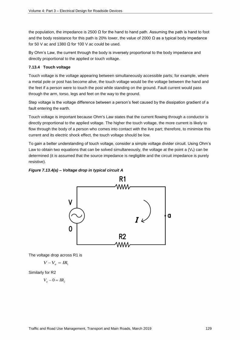
Volume 4: Part 3 – Electrical Design for Roadside Devices
Traffic and Road Use Management, Transport and Main Roads, March 2019 129
the population, the impedance is 2500 Ω for the hand to hand path. Assuming the path is hand to foot
and the body resistance for this path is 20% lower, the value of 2000 Ω as a typical body impedance
for 50 V ac and 1380 Ω for 100 V ac could be used.
By Ohm’s Law, the current through the body is inversely proportional to the body impedance and
directly proportional to the applied or touch voltage.
7.13.4 Touch voltage
Touch voltage is the voltage appearing between simultaneously accessible parts; for example, where
a metal pole or post has become alive, the touch voltage would be the voltage between the hand and
the feet if a person were to touch the post while standing on the ground. Fault current would pass
through the arm, torso, legs and feet on the way to the ground.
Step voltage is the voltage difference between a person’s feet caused by the dissipation gradient of a
fault entering the earth.
Touch voltage is important because Ohm's Law states that the current flowing through a conductor is
directly proportional to the applied voltage. The higher the touch voltage, the more current is likely to
flow through the body of a person who comes into contact with the live part; therefore, to minimise this
current and its electric shock effect, the touch voltage should be low.
To gain a better understanding of touch voltage, consider a simple voltage divider circuit. Using Ohm’s
Law to obtain two equations that can be solved simultaneously, the voltage at the point a (Va) can be
determined (it is assumed that the source impedance is negligible and the circuit impedance is purely
resistive).
Figure 7.13.4(a) – Voltage drop in typical circuit A
The voltage drop across R1 is
1IRVV a
Similarly for R2
20 IRVa
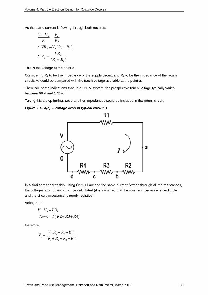
Volume 4: Part 3 – Electrical Design for Roadside Devices
Traffic and Road Use Management, Transport and Main Roads, March 2019 130
As the same current is flowing through both resistors
)(
)(
21
2
212
21
RR
VRV
RRVVR
R
V
R
VV
a
a
aa
This is the voltage at the point a.
Considering R1 to be the impedance of the supply circuit, and R2 to be the impedance of the return
circuit, Va could be compared with the touch voltage available at the point a.
There are some indications that, in a 230 V system, the prospective touch voltage typically varies
between 69 V and 172 V.
Taking this a step further, several other impedances could be included in the return circuit.
Figure 7.13.4(b) – Voltage drop in typical circuit B
In a similar manner to this, using Ohm’s Law and the same current flowing through all the resistances,
the voltages at a, b, and c can be calculated (it is assumed that the source impedance is negligible
and the circuit impedance is purely resistive).
Voltage at a
)432(0
1
RRRIVa
RIVV a
therefore
)(
)(
4321
432
RRRR
RRRVVa

Volume 4: Part 3 – Electrical Design for Roadside Devices
Traffic and Road Use Management, Transport and Main Roads, March 2019 131
Voltage at b
)43(0
)21(
RRIV
RRIVV
b
b
therefore
)(
)(
4321
43
RRRR
RRVVb
Voltage at c
)43(0
)321(
RRIV
RRRIVV
c
c
therefore
)( 4321
4
RRRR
RVV c
Assuming that R2 = R3 = R4 = R and R1 is small compared to R:
0
33.0
66.0
d
c
b
a
V
VV
VV
VV
The potential difference between points a and b is 0.33 V.
The potential difference between points a and c is 0.67 V.
The potential difference between points a and d is V.
Therefore, the further a point is away from a, the greater the potential difference with respect to a. This
is shown following as the typical voltage gradient in the ground at various distances from a ‘live’ pole.
As can be seen, if a person is walking away from the pole, there will be a maximum voltage difference
between his or her two feet due to the voltage gradient in the ground. The voltage difference between
the feet is the step voltage.
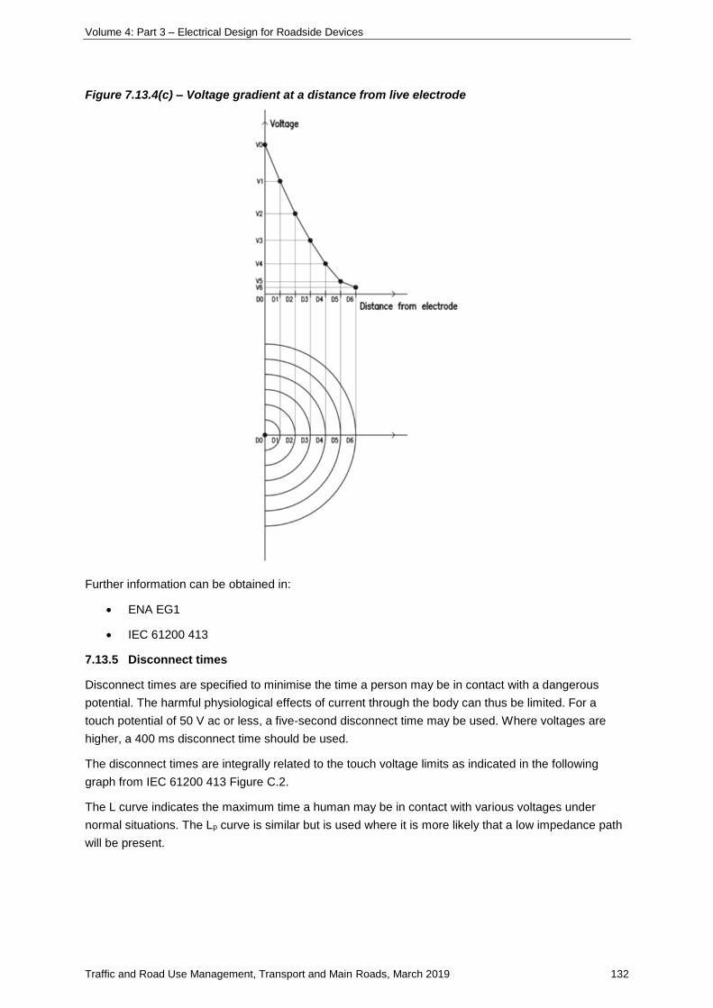
Volume 4: Part 3 – Electrical Design for Roadside Devices
Traffic and Road Use Management, Transport and Main Roads, March 2019 132
Figure 7.13.4(c) – Voltage gradient at a distance from live electrode
Further information can be obtained in:
• ENA EG1
• IEC 61200 413
7.13.5 Disconnect times
Disconnect times are specified to minimise the time a person may be in contact with a dangerous
potential. The harmful physiological effects of current through the body can thus be limited. For a
touch potential of 50 V ac or less, a five-second disconnect time may be used. Where voltages are
higher, a 400 ms disconnect time should be used.
The disconnect times are integrally related to the touch voltage limits as indicated in the following
graph from IEC 61200 413 Figure C.2.
The L curve indicates the maximum time a human may be in contact with various voltages under
normal situations. The Lp curve is similar but is used where it is more likely that a low impedance path
will be present.
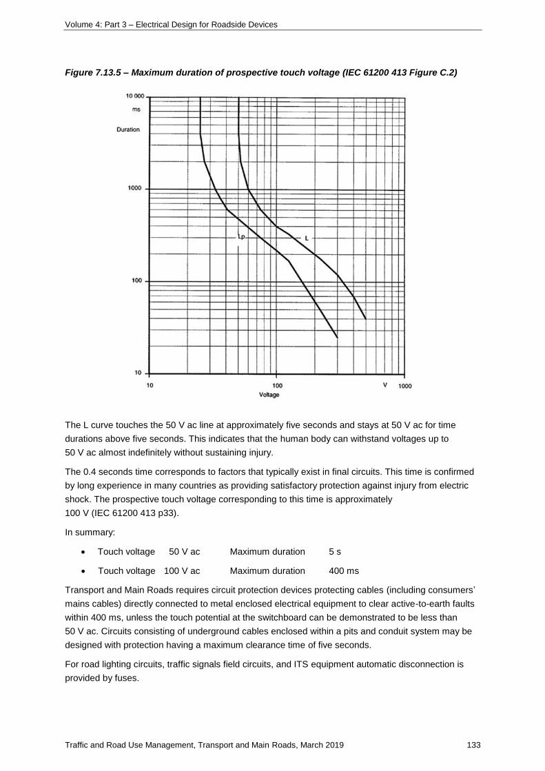
Volume 4: Part 3 – Electrical Design for Roadside Devices
Traffic and Road Use Management, Transport and Main Roads, March 2019 133
Figure 7.13.5 – Maximum duration of prospective touch voltage (IEC 61200 413 Figure C.2)
The L curve touches the 50 V ac line at approximately five seconds and stays at 50 V ac for time
durations above five seconds. This indicates that the human body can withstand voltages up to
50 V ac almost indefinitely without sustaining injury.
The 0.4 seconds time corresponds to factors that typically exist in final circuits. This time is confirmed
by long experience in many countries as providing satisfactory protection against injury from electric
shock. The prospective touch voltage corresponding to this time is approximately
100 V (IEC 61200 413 p33).
In summary:
• Touch voltage 50 V ac Maximum duration 5 s
• Touch voltage 100 V ac Maximum duration 400 ms
Transport and Main Roads requires circuit protection devices protecting cables (including consumers’
mains cables) directly connected to metal enclosed electrical equipment to clear active-to-earth faults
within 400 ms, unless the touch potential at the switchboard can be demonstrated to be less than
50 V ac. Circuits consisting of underground cables enclosed within a pits and conduit system may be
designed with protection having a maximum clearance time of five seconds.
For road lighting circuits, traffic signals field circuits, and ITS equipment automatic disconnection is
provided by fuses.
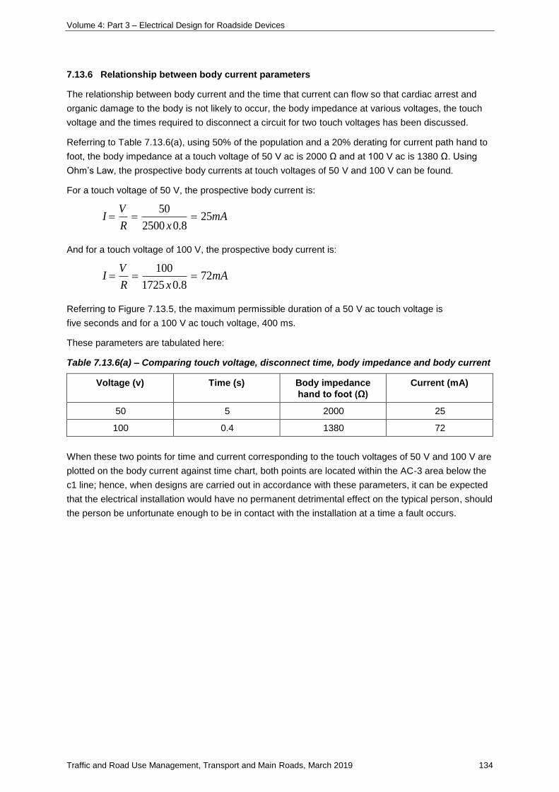
Volume 4: Part 3 – Electrical Design for Roadside Devices
Traffic and Road Use Management, Transport and Main Roads, March 2019 134
7.13.6 Relationship between body current parameters
The relationship between body current and the time that current can flow so that cardiac arrest and
organic damage to the body is not likely to occur, the body impedance at various voltages, the touch
voltage and the times required to disconnect a circuit for two touch voltages has been discussed.
Referring to Table 7.13.6(a), using 50% of the population and a 20% derating for current path hand to
foot, the body impedance at a touch voltage of 50 V ac is 2000 Ω and at 100 V ac is 1380 Ω. Using
Ohm’s Law, the prospective body currents at touch voltages of 50 V and 100 V can be found.
For a touch voltage of 50 V, the prospective body current is:
mAxR
VI 25
8.02500
50
And for a touch voltage of 100 V, the prospective body current is:
mAxR
VI 72
8.01725
100
Referring to Figure 7.13.5, the maximum permissible duration of a 50 V ac touch voltage is
five seconds and for a 100 V ac touch voltage, 400 ms.
These parameters are tabulated here:
Table 7.13.6(a) – Comparing touch voltage, disconnect time, body impedance and body current
Voltage (v) Time (s) Body impedance
hand to foot (Ω)
Current (mA)
50 5 2000 25
100 0.4 1380 72
When these two points for time and current corresponding to the touch voltages of 50 V and 100 V are
plotted on the body current against time chart, both points are located within the AC-3 area below the
c1 line; hence, when designs are carried out in accordance with these parameters, it can be expected
that the electrical installation would have no permanent detrimental effect on the typical person, should
the person be unfortunate enough to be in contact with the installation at a time a fault occurs.
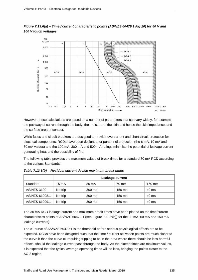
Volume 4: Part 3 – Electrical Design for Roadside Devices
Traffic and Road Use Management, Transport and Main Roads, March 2019 135
Figure 7.13.6(a) – Time / current characteristic points (AS/NZS 60479.1 Fig 20) for 50 V and
100 V touch voltages
However, these calculations are based on a number of parameters that can vary widely, for example
the pathway of current through the body, the moisture of the skin and hence the skin impedance, and
the surface area of contact.
While fuses and circuit breakers are designed to provide overcurrent and short circuit protection for
electrical components, RCDs have been designed for personnel protection (the 6 mA, 10 mA and
30 mA values) and the 100 mA, 300 mA and 500 mA ratings minimise the potential of leakage current
generating heat and the possibility of fire.
The following table provides the maximum values of break times for a standard 30 mA RCD according
to the various Standards:
Table 7.13.6(b) – Residual current device maximum break times
Leakage current
Standard 15 mA 30 mA 60 mA 150 mA
AS/NZS 3190 No trip 300 ms 150 ms 40 ms
AS/NZS 61008.1 No trip 300 ms 150 ms 40 ms
AS/NZS 61009.1 No trip 300 ms 150 ms 40 ms
The 30 mA RCD leakage current and maximum break times have been plotted on the time/current
characteristics points of AS/NZS 60479.1 (see Figure 7.13.6(b)) for the 30 mA, 60 mA and 150 mA
leakage currents).
The c1 curve of AS/NZS 60479.1 is the threshold before serious physiological effects are to be
expected. RCDs have been designed such that the time / current activation points are much closer to
the curve b than the curve c1 requiring tripping to be in the area where there should be less harmful
effects, should the leakage current pass through the body. As the plotted times are maximum values,
it is expected that the typical average operating times will be less, bringing the points closer to the
AC-2 region.
Volume 4: Part 3 – Electrical Design for Roadside Devices
Traffic and Road Use Management, Transport and Main Roads, March 2019 136
Figure 7.13.6(b) – Time / current characteristic points (AS/NZS 60479.1 Fig 20) for residual
current device maximum break times
7.13.7 Continuing with earth fault loop Impedance
The scope of AS/NZS 3000 includes the provision of minimum standards to protect persons from
electric shock. One method to protect against dangers that may arise from contact with exposed
conductive parts that may become live under fault conditions (indirect contact) is by the automatic
disconnection of supply. This is covered in Clause 1.5.5.3 of AS/NZS 3000.
EFLI is an integral part of protection against indirect contact by the automatic disconnection of supply
along with touch voltage limits and disconnection times.
To summarise the requirements:
• If an active-to-earth fault occurs that could cause the voltage on an exposed conductive part to
exceed 50 V ac, a protective device must automatically disconnect the source of supply.
• The characteristics of the circuit protection and the EFLI must allow the protection device to
disconnect the fault current within the specified time.
• The maximum disconnection time is 0.4 s for final sub-circuits to socket outlets, and
five seconds for other circuits where it can be shown that people are not exposed to touch
voltages that exceed safe values.
When an active-to-earth fault occurs in an electrical system, it is imperative that the fault is cleared
automatically within the required disconnect time to minimise any body current that could flow, should
an individual be in contact with an earthed part of the system.
The current / time characteristic of the particular fuse or circuit breaker protecting the circuit will
provide the current required to clear the fault within the required disconnect time.
Ohm’s Law then provides the maximum circuit impedance that will allow this clearing current to flow.
When an active-to-earth fault occurs, the impedance of the circuit around which the fault current flows
limits the prospective fault current. This impedance is referred to as the EFLI. This impedance needs
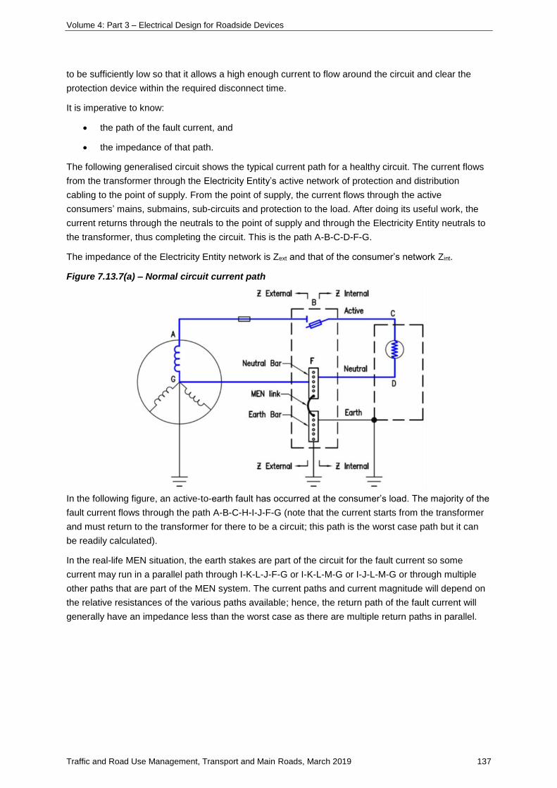
Volume 4: Part 3 – Electrical Design for Roadside Devices
Traffic and Road Use Management, Transport and Main Roads, March 2019 137
to be sufficiently low so that it allows a high enough current to flow around the circuit and clear the
protection device within the required disconnect time.
It is imperative to know:
• the path of the fault current, and
• the impedance of that path.
The following generalised circuit shows the typical current path for a healthy circuit. The current flows
from the transformer through the Electricity Entity’s active network of protection and distribution
cabling to the point of supply. From the point of supply, the current flows through the active
consumers’ mains, submains, sub-circuits and protection to the load. After doing its useful work, the
current returns through the neutrals to the point of supply and through the Electricity Entity neutrals to
the transformer, thus completing the circuit. This is the path A-B-C-D-F-G.
The impedance of the Electricity Entity network is Zext and that of the consumer’s network Zint.
Figure 7.13.7(a) – Normal circuit current path
In the following figure, an active-to-earth fault has occurred at the consumer’s load. The majority of the
fault current flows through the path A-B-C-H-I-J-F-G (note that the current starts from the transformer
and must return to the transformer for there to be a circuit; this path is the worst case path but it can
be readily calculated).
In the real-life MEN situation, the earth stakes are part of the circuit for the fault current so some
current may run in a parallel path through I-K-L-J-F-G or I-K-L-M-G or I-J-L-M-G or through multiple
other paths that are part of the MEN system. The current paths and current magnitude will depend on
the relative resistances of the various paths available; hence, the return path of the fault current will
generally have an impedance less than the worst case as there are multiple return paths in parallel.
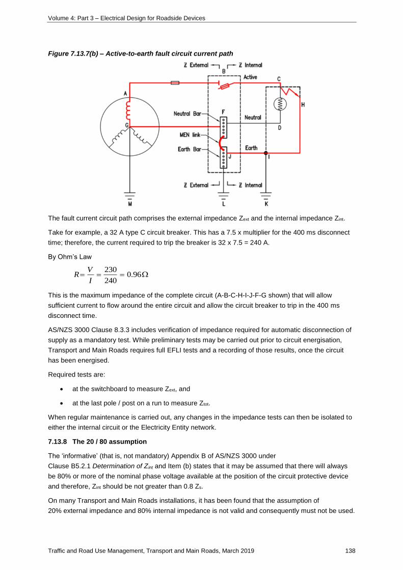
Volume 4: Part 3 – Electrical Design for Roadside Devices
Traffic and Road Use Management, Transport and Main Roads, March 2019 138
Figure 7.13.7(b) – Active-to-earth fault circuit current path
The fault current circuit path comprises the external impedance Zext and the internal impedance Zint.
Take for example, a 32 A type C circuit breaker. This has a 7.5 x multiplier for the 400 ms disconnect
time; therefore, the current required to trip the breaker is 32 x 7.5 = 240 A.
By Ohm’s Law
96.0240
230
I
VR
This is the maximum impedance of the complete circuit (A-B-C-H-I-J-F-G shown) that will allow
sufficient current to flow around the entire circuit and allow the circuit breaker to trip in the 400 ms
disconnect time.
AS/NZS 3000 Clause 8.3.3 includes verification of impedance required for automatic disconnection of
supply as a mandatory test. While preliminary tests may be carried out prior to circuit energisation,
Transport and Main Roads requires full EFLI tests and a recording of those results, once the circuit
has been energised.
Required tests are:
• at the switchboard to measure Zext, and
• at the last pole / post on a run to measure Ztot.
When regular maintenance is carried out, any changes in the impedance tests can then be isolated to
either the internal circuit or the Electricity Entity network.
7.13.8 The 20 / 80 assumption
The ‘informative’ (that is, not mandatory) Appendix B of AS/NZS 3000 under
Clause B5.2.1 Determination of Zint and Item (b) states that it may be assumed that there will always
be 80% or more of the nominal phase voltage available at the position of the circuit protective device
and therefore, Zint should be not greater than 0.8 Zs.
On many Transport and Main Roads installations, it has been found that the assumption of
20% external impedance and 80% internal impedance is not valid and consequently must not be used.
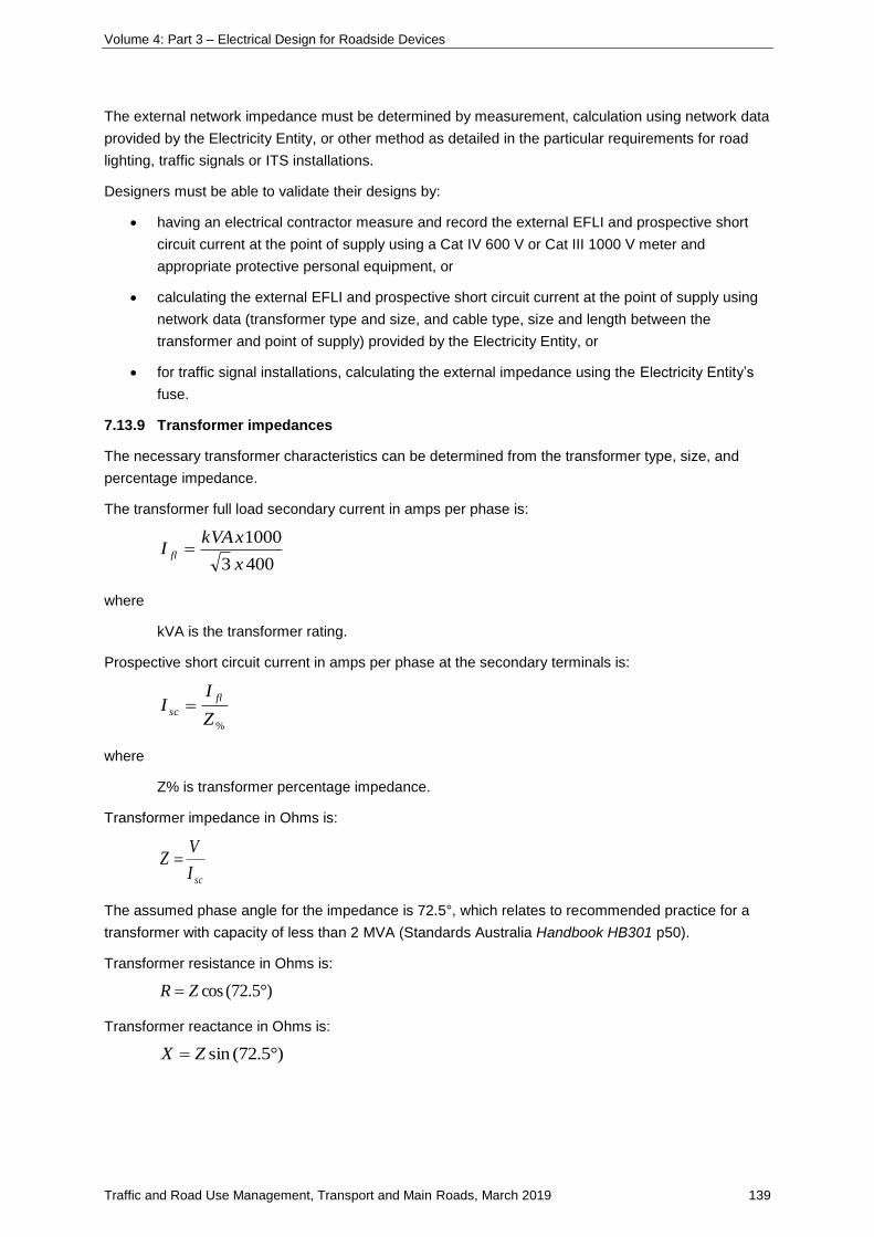
Volume 4: Part 3 – Electrical Design for Roadside Devices
Traffic and Road Use Management, Transport and Main Roads, March 2019 139
The external network impedance must be determined by measurement, calculation using network data
provided by the Electricity Entity, or other method as detailed in the particular requirements for road
lighting, traffic signals or ITS installations.
Designers must be able to validate their designs by:
• having an electrical contractor measure and record the external EFLI and prospective short
circuit current at the point of supply using a Cat IV 600 V or Cat III 1000 V meter and
appropriate protective personal equipment, or
• calculating the external EFLI and prospective short circuit current at the point of supply using
network data (transformer type and size, and cable type, size and length between the
transformer and point of supply) provided by the Electricity Entity, or
• for traffic signal installations, calculating the external impedance using the Electricity Entity’s
fuse.
7.13.9 Transformer impedances
The necessary transformer characteristics can be determined from the transformer type, size, and
percentage impedance.
The transformer full load secondary current in amps per phase is:
4003
1000
x
xkVAI fl
where
kVA is the transformer rating.
Prospective short circuit current in amps per phase at the secondary terminals is:
%Z
II
fl
sc
where
Z% is transformer percentage impedance.
Transformer impedance in Ohms is:
scI
VZ
The assumed phase angle for the impedance is 72.5°, which relates to recommended practice for a
transformer with capacity of less than 2 MVA (Standards Australia Handbook HB301 p50).
Transformer resistance in Ohms is:
)72.5°(cosZR
Transformer reactance in Ohms is:
)72.5°(sinZX
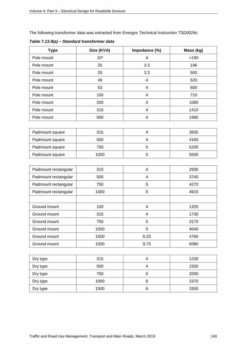
Volume 4: Part 3 – Electrical Design for Roadside Devices
Traffic and Road Use Management, Transport and Main Roads, March 2019 140
The following transformer data was extracted from Energex Technical Instruction TSD0024c.
Table 7.13.9(a) – Standard transformer data
Type Size (KVA) Impedance (%) Mass (kg)
Pole mount 10* 4 <190
Pole mount 25 3.3 196
Pole mount 25 3.3 500
Pole mount 49 4 520
Pole mount 63 4 600
Pole mount 100 4 710
Pole mount 200 4 1080
Pole mount 315 4 1410
Pole mount 500 4 1990
Padmount square 315 4 3835
Padmount square 500 4 4160
Padmount square 750 5 5200
Padmount square 1000 5 5500
Padmount rectangular 315 4 2935
Padmount rectangular 500 4 3740
Padmount rectangular 750 5 4270
Padmount rectangular 1000 5 4915
Ground mount 100 4 1325
Ground mount 315 4 1730
Ground mount 750 5 3170
Ground mount 1000 5 4040
Ground mount 1500 6.25 4760
Ground mount 1500 9.75 6080
Dry type 315 4 1230
Dry type 500 4 1550
Dry type 750 6 2000
Dry type 1000 6 2370
Dry type 1500 6 3300
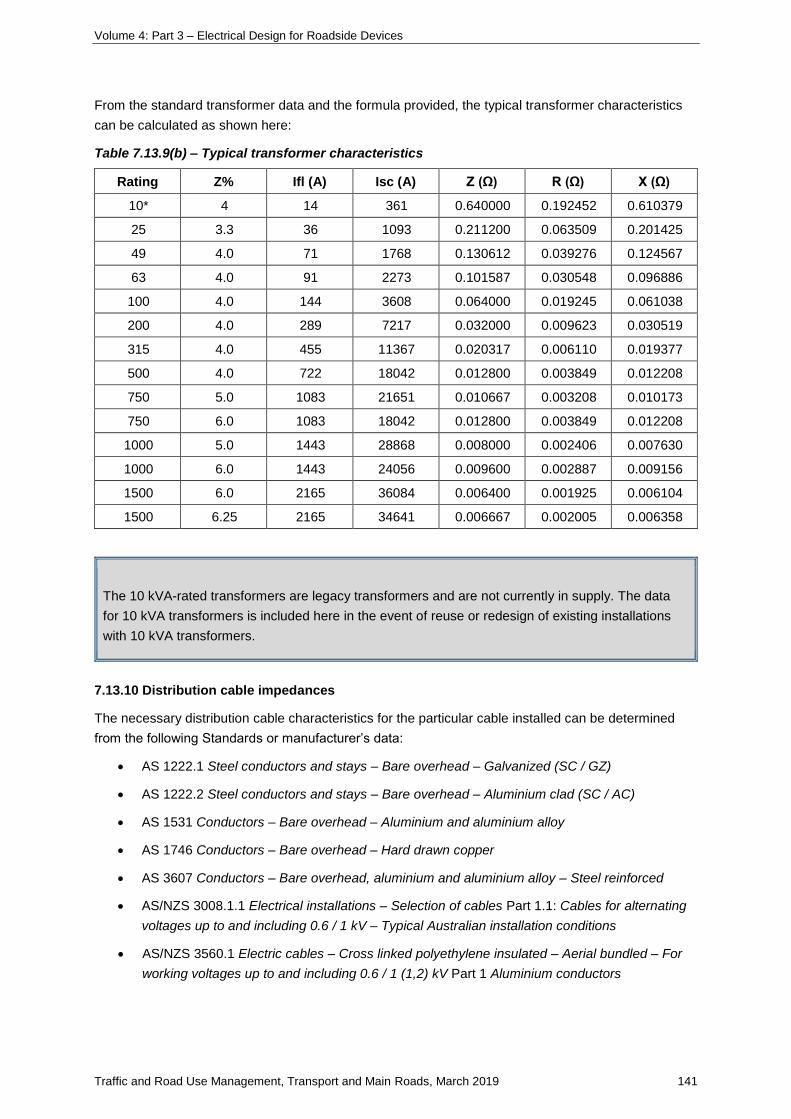
Volume 4: Part 3 – Electrical Design for Roadside Devices
Traffic and Road Use Management, Transport and Main Roads, March 2019 141
From the standard transformer data and the formula provided, the typical transformer characteristics
can be calculated as shown here:
Table 7.13.9(b) – Typical transformer characteristics
Rating Z% Ifl (A) Isc (A) Z (Ω) R (Ω) X (Ω)
10* 4 14 361 0.640000 0.192452 0.610379
25 3.3 36 1093 0.211200 0.063509 0.201425
49 4.0 71 1768 0.130612 0.039276 0.124567
63 4.0 91 2273 0.101587 0.030548 0.096886
100 4.0 144 3608 0.064000 0.019245 0.061038
200 4.0 289 7217 0.032000 0.009623 0.030519
315 4.0 455 11367 0.020317 0.006110 0.019377
500 4.0 722 18042 0.012800 0.003849 0.012208
750 5.0 1083 21651 0.010667 0.003208 0.010173
750 6.0 1083 18042 0.012800 0.003849 0.012208
1000 5.0 1443 28868 0.008000 0.002406 0.007630
1000 6.0 1443 24056 0.009600 0.002887 0.009156
1500 6.0 2165 36084 0.006400 0.001925 0.006104
1500 6.25 2165 34641 0.006667 0.002005 0.006358
The 10 kVA-rated transformers are legacy transformers and are not currently in supply. The data
for 10 kVA transformers is included here in the event of reuse or redesign of existing installations
with 10 kVA transformers.
7.13.10 Distribution cable impedances
The necessary distribution cable characteristics for the particular cable installed can be determined
from the following Standards or manufacturer’s data:
• AS 1222.1 Steel conductors and stays – Bare overhead – Galvanized (SC / GZ)
• AS 1222.2 Steel conductors and stays – Bare overhead – Aluminium clad (SC / AC)
• AS 1531 Conductors – Bare overhead – Aluminium and aluminium alloy
• AS 1746 Conductors – Bare overhead – Hard drawn copper
• AS 3607 Conductors – Bare overhead, aluminium and aluminium alloy – Steel reinforced
• AS/NZS 3008.1.1 Electrical installations – Selection of cables Part 1.1: Cables for alternating
voltages up to and including 0.6 / 1 kV – Typical Australian installation conditions
• AS/NZS 3560.1 Electric cables – Cross linked polyethylene insulated – Aerial bundled – For
working voltages up to and including 0.6 / 1 (1,2) kV Part 1 Aluminium conductors
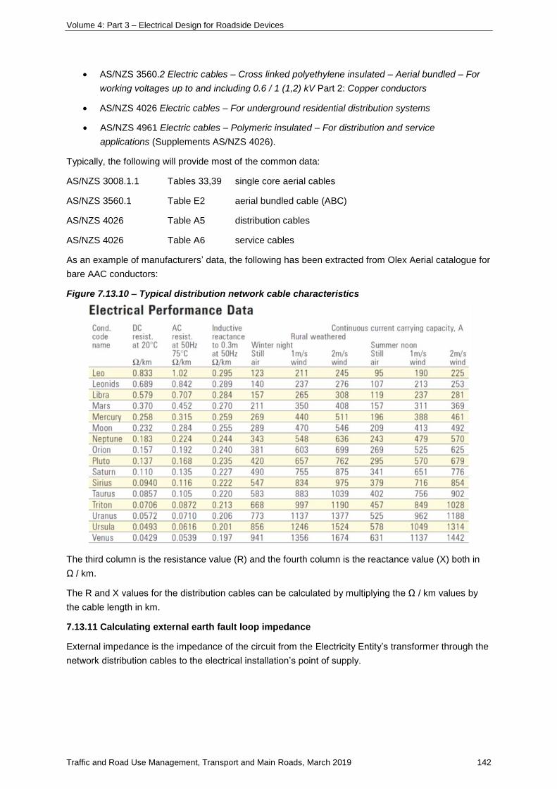
Volume 4: Part 3 – Electrical Design for Roadside Devices
Traffic and Road Use Management, Transport and Main Roads, March 2019 142
• AS/NZS 3560.2 Electric cables – Cross linked polyethylene insulated – Aerial bundled – For
working voltages up to and including 0.6 / 1 (1,2) kV Part 2: Copper conductors
• AS/NZS 4026 Electric cables – For underground residential distribution systems
• AS/NZS 4961 Electric cables – Polymeric insulated – For distribution and service
applications (Supplements AS/NZS 4026).
Typically, the following will provide most of the common data:
AS/NZS 3008.1.1 Tables 33,39 single core aerial cables
AS/NZS 3560.1 Table E2 aerial bundled cable (ABC)
AS/NZS 4026 Table A5 distribution cables
AS/NZS 4026 Table A6 service cables
As an example of manufacturers’ data, the following has been extracted from Olex Aerial catalogue for
bare AAC conductors:
Figure 7.13.10 – Typical distribution network cable characteristics
The third column is the resistance value (R) and the fourth column is the reactance value (X) both in
Ω / km.
The R and X values for the distribution cables can be calculated by multiplying the Ω / km values by
the cable length in km.
7.13.11 Calculating external earth fault loop impedance
External impedance is the impedance of the circuit from the Electricity Entity’s transformer through the
network distribution cables to the electrical installation’s point of supply.
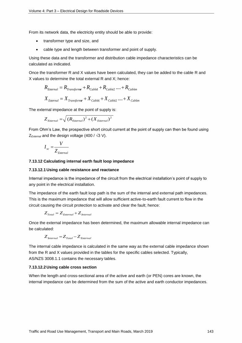
Volume 4: Part 3 – Electrical Design for Roadside Devices
Traffic and Road Use Management, Transport and Main Roads, March 2019 143
From its network data, the electricity entity should be able to provide:
• transformer type and size, and
• cable type and length between transformer and point of supply.
Using these data and the transformer and distribution cable impedance characteristics can be
calculated as indicated.
Once the transformer R and X values have been calculated, they can be added to the cable R and
X values to determine the total external R and X; hence:
nCableCableCablerTransformeExternal RRRRR ....21
nCableCableCablerTransformeExternal XXXXX ....21
The external impedance at the point of supply is:
22 )()( ExternalExternalExternal XRZ
From Ohm’s Law, the prospective short circuit current at the point of supply can then be found using
ZExternal and the design voltage (400 / √3 V).
External
scZ
VI
7.13.12 Calculating internal earth fault loop impedance
7.13.12.1 Using cable resistance and reactance
Internal impedance is the impedance of the circuit from the electrical installation’s point of supply to
any point in the electrical installation.
The impedance of the earth fault loop path is the sum of the internal and external path impedances.
This is the maximum impedance that will allow sufficient active-to-earth fault current to flow in the
circuit causing the circuit protection to activate and clear the fault; hence:
InternalExternalTotal ZZZ
Once the external impedance has been determined, the maximum allowable internal impedance can
be calculated:
ExternalTotalInternal ZZZ
The internal cable impedance is calculated in the same way as the external cable impedance shown
from the R and X values provided in the tables for the specific cables selected. Typically,
AS/NZS 3008.1.1 contains the necessary tables.
7.13.12.2 Using cable cross section
When the length and cross-sectional area of the active and earth (or PEN) cores are known, the
internal impedance can be determined from the sum of the active and earth conductor impedances.
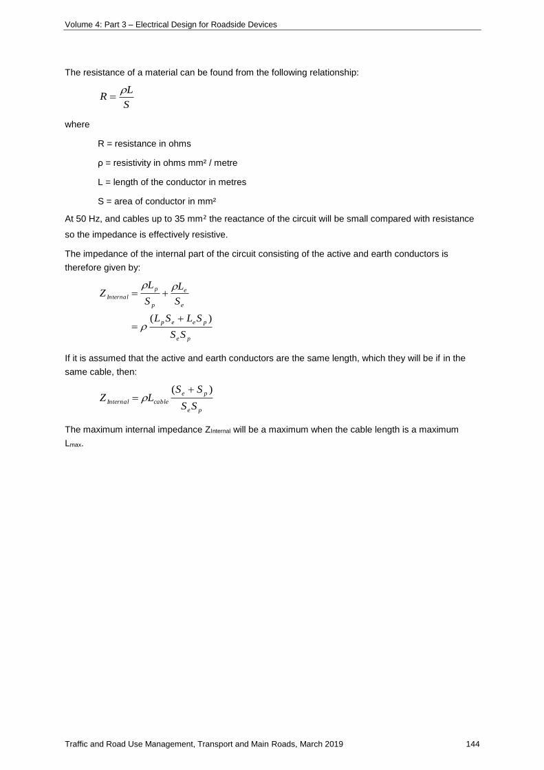
Volume 4: Part 3 – Electrical Design for Roadside Devices
Traffic and Road Use Management, Transport and Main Roads, March 2019 144
The resistance of a material can be found from the following relationship:
S
LR
where
R = resistance in ohms
ρ = resistivity in ohms mm² / metre
L = length of the conductor in metres
S = area of conductor in mm²
At 50 Hz, and cables up to 35 mm² the reactance of the circuit will be small compared with resistance
so the impedance is effectively resistive.
The impedance of the internal part of the circuit consisting of the active and earth conductors is
therefore given by:
pe
peep
e
e
p
p
Internal
SS
SLSL
S
L
S
LZ
)(
If it is assumed that the active and earth conductors are the same length, which they will be if in the
same cable, then:
pe
pe
cableInternalSS
SSLZ
)(
The maximum internal impedance ZInternal will be a maximum when the cable length is a maximum
Lmax.
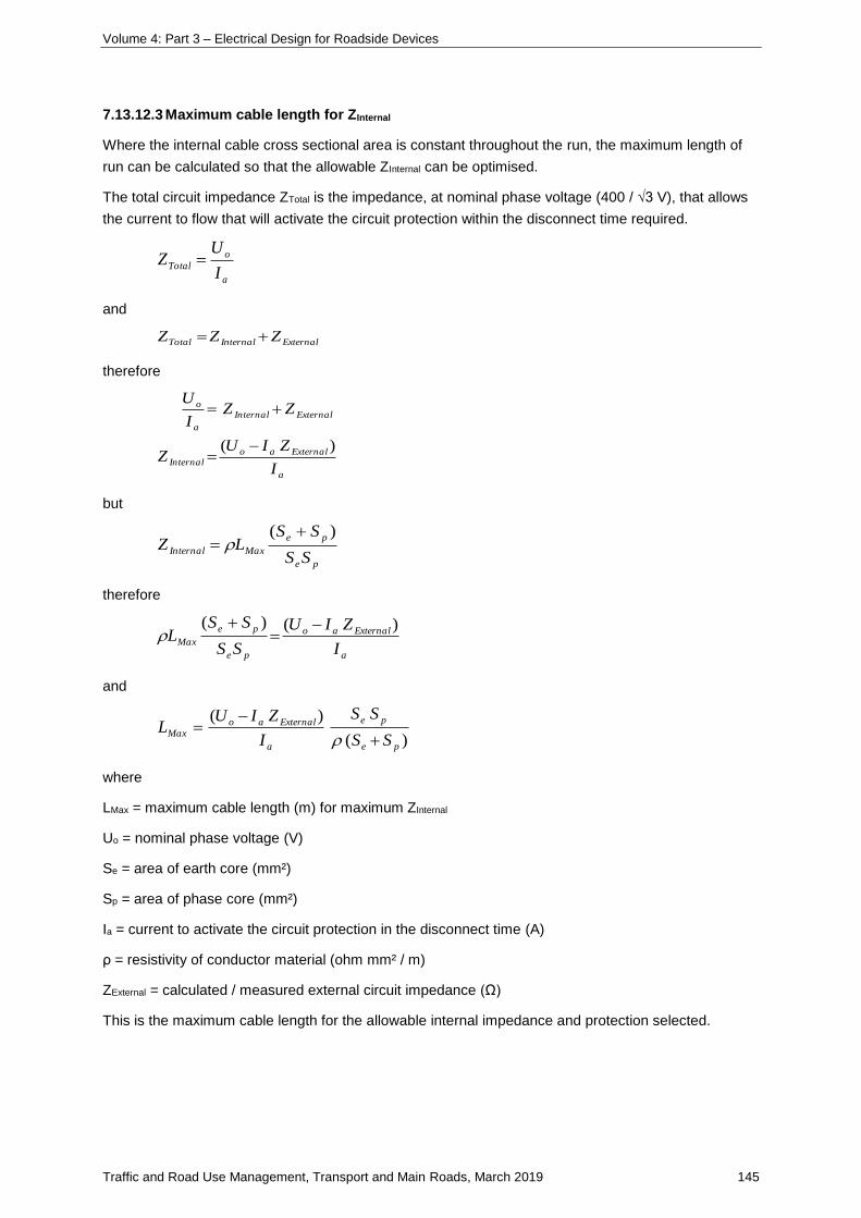
Volume 4: Part 3 – Electrical Design for Roadside Devices
Traffic and Road Use Management, Transport and Main Roads, March 2019 145
7.13.12.3 Maximum cable length for ZInternal
Where the internal cable cross sectional area is constant throughout the run, the maximum length of
run can be calculated so that the allowable ZInternal can be optimised.
The total circuit impedance ZTotal is the impedance, at nominal phase voltage (400 / √3 V), that allows
the current to flow that will activate the circuit protection within the disconnect time required.
a
o
TotalI
UZ
and
ExternalInternalTotal ZZZ
therefore
a
Externalao
Internal
ExternalInternal
a
o
I
ZIUZ
ZZI
U
)(
but
pe
pe
MaxInternalSS
SSLZ
)(
therefore
a
Externalao
pe
pe
MaxI
ZIU
SS
SSL
)()(
and
)(
)(
pe
pe
a
ExternalaoMax
SS
SS
I
ZIUL
where
LMax = maximum cable length (m) for maximum ZInternal
Uo = nominal phase voltage (V)
Se = area of earth core (mm²)
Sp = area of phase core (mm²)
Ia = current to activate the circuit protection in the disconnect time (A)
ρ = resistivity of conductor material (ohm mm² / m)
ZExternal = calculated / measured external circuit impedance (Ω)
This is the maximum cable length for the allowable internal impedance and protection selected.
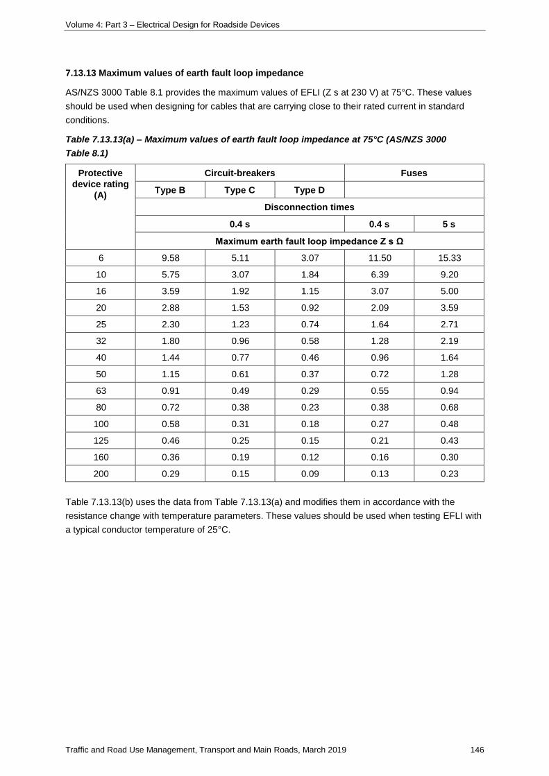
Volume 4: Part 3 – Electrical Design for Roadside Devices
Traffic and Road Use Management, Transport and Main Roads, March 2019 146
7.13.13 Maximum values of earth fault loop impedance
AS/NZS 3000 Table 8.1 provides the maximum values of EFLI (Z s at 230 V) at 75°C. These values
should be used when designing for cables that are carrying close to their rated current in standard
conditions.
Table 7.13.13(a) – Maximum values of earth fault loop impedance at 75°C (AS/NZS 3000
Table 8.1)
Protective
device rating
(A)
Circuit-breakers Fuses
Type B Type C Type D
Disconnection times
0.4 s 0.4 s 5 s
Maximum earth fault loop impedance Z s Ω
6 9.58 5.11 3.07 11.50 15.33
10 5.75 3.07 1.84 6.39 9.20
16 3.59 1.92 1.15 3.07 5.00
20 2.88 1.53 0.92 2.09 3.59
25 2.30 1.23 0.74 1.64 2.71
32 1.80 0.96 0.58 1.28 2.19
40 1.44 0.77 0.46 0.96 1.64
50 1.15 0.61 0.37 0.72 1.28
63 0.91 0.49 0.29 0.55 0.94
80 0.72 0.38 0.23 0.38 0.68
100 0.58 0.31 0.18 0.27 0.48
125 0.46 0.25 0.15 0.21 0.43
160 0.36 0.19 0.12 0.16 0.30
200 0.29 0.15 0.09 0.13 0.23
Table 7.13.13(b) uses the data from Table 7.13.13(a) and modifies them in accordance with the
resistance change with temperature parameters. These values should be used when testing EFLI with
a typical conductor temperature of 25°C.
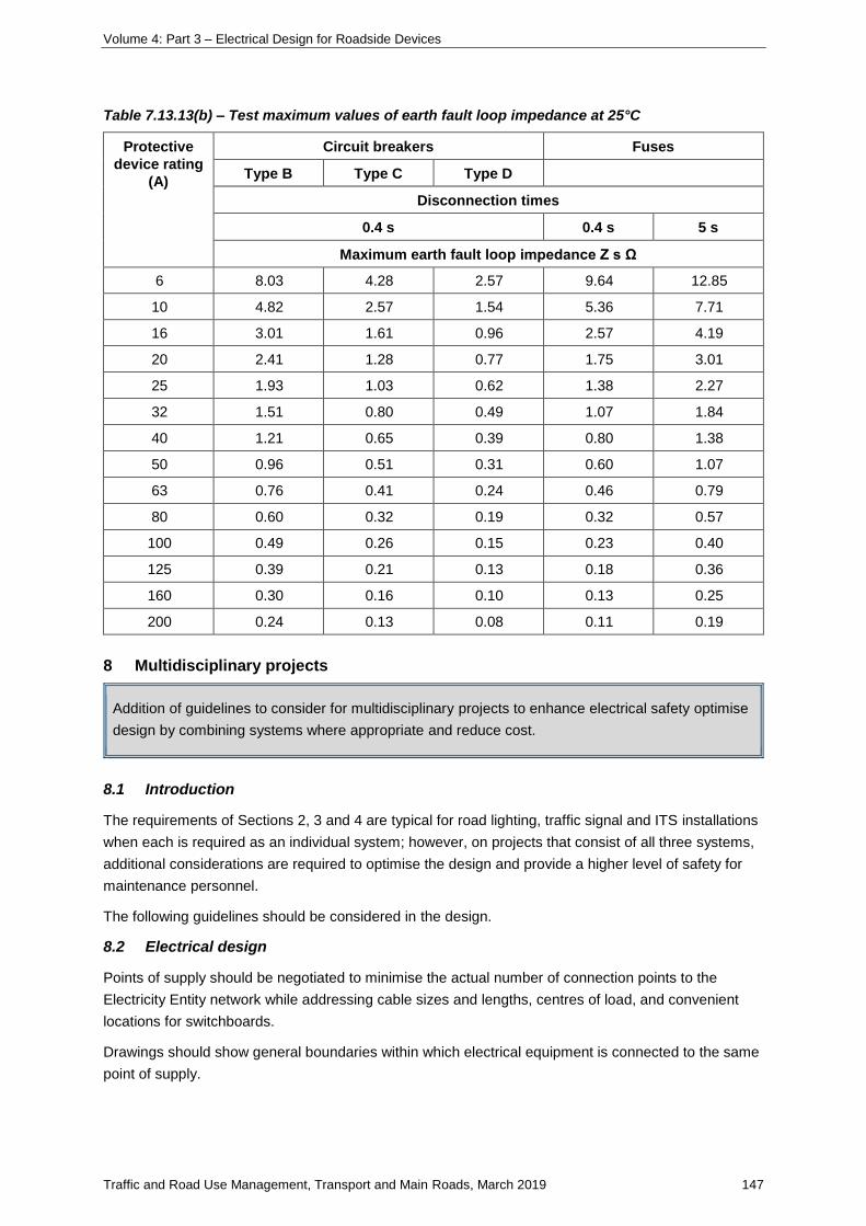
Volume 4: Part 3 – Electrical Design for Roadside Devices
Traffic and Road Use Management, Transport and Main Roads, March 2019 147
Table 7.13.13(b) – Test maximum values of earth fault loop impedance at 25°C
Protective
device rating
(A)
Circuit breakers Fuses
Type B Type C Type D
Disconnection times
0.4 s 0.4 s 5 s
Maximum earth fault loop impedance Z s Ω
6 8.03 4.28 2.57 9.64 12.85
10 4.82 2.57 1.54 5.36 7.71
16 3.01 1.61 0.96 2.57 4.19
20 2.41 1.28 0.77 1.75 3.01
25 1.93 1.03 0.62 1.38 2.27
32 1.51 0.80 0.49 1.07 1.84
40 1.21 0.65 0.39 0.80 1.38
50 0.96 0.51 0.31 0.60 1.07
63 0.76 0.41 0.24 0.46 0.79
80 0.60 0.32 0.19 0.32 0.57
100 0.49 0.26 0.15 0.23 0.40
125 0.39 0.21 0.13 0.18 0.36
160 0.30 0.16 0.10 0.13 0.25
200 0.24 0.13 0.08 0.11 0.19
8 Multidisciplinary projects
Addition of guidelines to consider for multidisciplinary projects to enhance electrical safety optimise
design by combining systems where appropriate and reduce cost.
8.1 Introduction
The requirements of Sections 2, 3 and 4 are typical for road lighting, traffic signal and ITS installations
when each is required as an individual system; however, on projects that consist of all three systems,
additional considerations are required to optimise the design and provide a higher level of safety for
maintenance personnel.
The following guidelines should be considered in the design.
8.2 Electrical design
Points of supply should be negotiated to minimise the actual number of connection points to the
Electricity Entity network while addressing cable sizes and lengths, centres of load, and convenient
locations for switchboards.
Drawings should show general boundaries within which electrical equipment is connected to the same
point of supply.
Volume 4: Part 3 – Electrical Design for Roadside Devices
Traffic and Road Use Management, Transport and Main Roads, March 2019 148
Site wide single line drawings showing the Electricity Entity connection points clearly labelled and the
integrated services connected to each point should be provided up to and including each switchboard,
traffic signal controller and ITS field cabinet.
Switchboards for the different disciplines should be located together wherever practicable, ensuring
accessibility and maintainability.
ITS and traffic signals may be serviced by the same link switchboard connected to the electricity
network to minimise the number of connection points.
Switchboards must be clearly labelled to differentiate usage.
Switchboards, traffic signal controllers and ITS field cabinets should be clearly labelled with source of
supply designation.
8.3 Conduit and pits
Using the requirements for individual road lighting, traffic signals and ITS can result in excessive
overcapacity of conduits and pits in multidisciplinary projects, particularly where systems are running
in parallel.
At signalised intersections, the standard traffic signal installation should be used with only signals
cables and road lighting cable for JUPs and CMAs within the signals conduits. This will also help
minimise the number of pits in the already limited real estate of the intersection. Other cables should
bypass the intersection as much as practicable to minimise intersection congestion and aid in
construction and ongoing maintenance.
Using combined road crossings for road lighting and ITS can minimise the conduits to two electrical
and two communications, particularly if cable usage is accommodated adequately, as well as saving
on pits.
Where there are parallel road lighting and ITS conduit runs, consideration should be given to making
the electrical conduits common use and optimising the overall numbers of conduits to suit the current
cable design as well as allowing adequate capacity for potential future growth. This needs to be
considered on a case-by-case basis as some areas may need more future-proofing than others.
As the trend in communications cabling is away from copper and towards fibre, the spare capacity of
communications conduits needs to be seriously considered.
8.4 Presentation drawings
On multidisciplinary projects, it is essential that integrated electrical single line drawings, clearly
showing all the disciplines together, are provided. An overall single line drawing detailing where all
connections to the electricity network are located, including transformer size and Electricity Entity
identifier, and how switchboards and other major electrical equipment are supplied, improves the
electrical safety of the installation. Also, the time for fault finding in the case of an outage can be
reduced, allowing essential services to come back online with a minimum of delay.
A combined set of road lighting, traffic signal and ITS pits, conduits and footing location drawings
should be provided. This can greatly assist the constructor while providing Transport and Main Roads
with one document to review the underground services. As this set would consist of electrical
equipment, it is required that signoff would be by an electrical RPEQ.
Where road lighting pole footing locations are being shown on a combined set with conduits and pits,
road lighting design must be part of the road lighting drawings.

Related Documents