Part 2 Communication between more than two devices sharing a common direct link

Welcome message from author
This document is posted to help you gain knowledge. Please leave a comment to let me know what you think about it! Share it to your friends and learn new things together.
Transcript
Part 2
Communication between more than two devices sharing a
common direct link
Why Share?
• In most cases, a single Transmitter-Receiver pair does not utilize the whole bandwidth of a link
• Bandwidth can be shared between multiple pairs to increase line efficiency and reduce cost
• Two approaches– Multiplexing– Contention based protocols
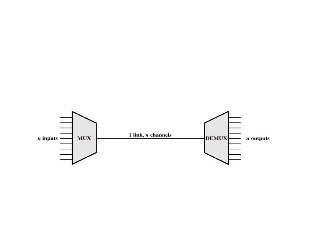
Multiplexing
• Create more than 1 channel out of a link• Each channel has a “share” of the link (in
time, frequency, wavelength etc.)– Time Division Multiplexing (TDM) – each channel
assigned a time slot– Frequency Division Multiplexing (FDM) –each
channel assigned a frequency band– Wavelength Division Multiplexing (WDM) – each
channel assigned a wavelength (optical communication only)
FDM
• Useful bandwidth of medium exceeds required bandwidth of channel
• Each signal is modulated to a different carrier frequency
• Carrier frequencies separated so signals do not overlap (guard bands)
• Channel allocated even if there is no data
• Requires analog signaling & transmission• Bandwidth = sum of inputs + guardbands• Modulates signals so that each occupies a
different frequency band• Standard for radio broadcasting, analog
telephone network, and television (broadcast, cable, & satellite)
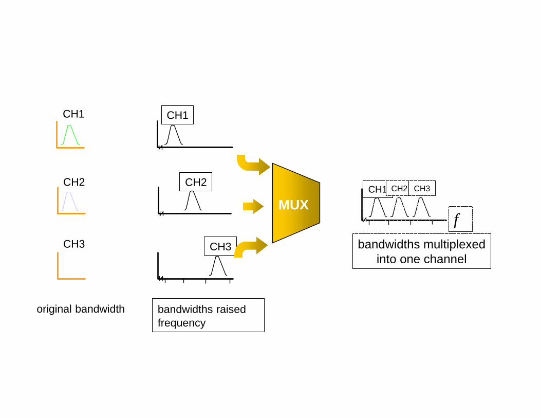
CH2
CH1
CH3
original bandwidth
CH1
CH2
CH3
bandwidths raised infrequency
MUXCH1 CH2 CH3
bandwidths multiplexedinto one channel
f
Synchronous TDM• Multiple digital signals interleaved in time• TDM frame contains time slots• Time slots pre-assigned to sources and fixed• Multiplexer scans each source and puts its data in its
time slot• If there is no data for a source, the slot goes free• Each slot contains 1 bit (bit multiplexing) or 1 byte
(byte multiplexing) usually• TDM frames transmitted using synchronous or
asynchronous transmission
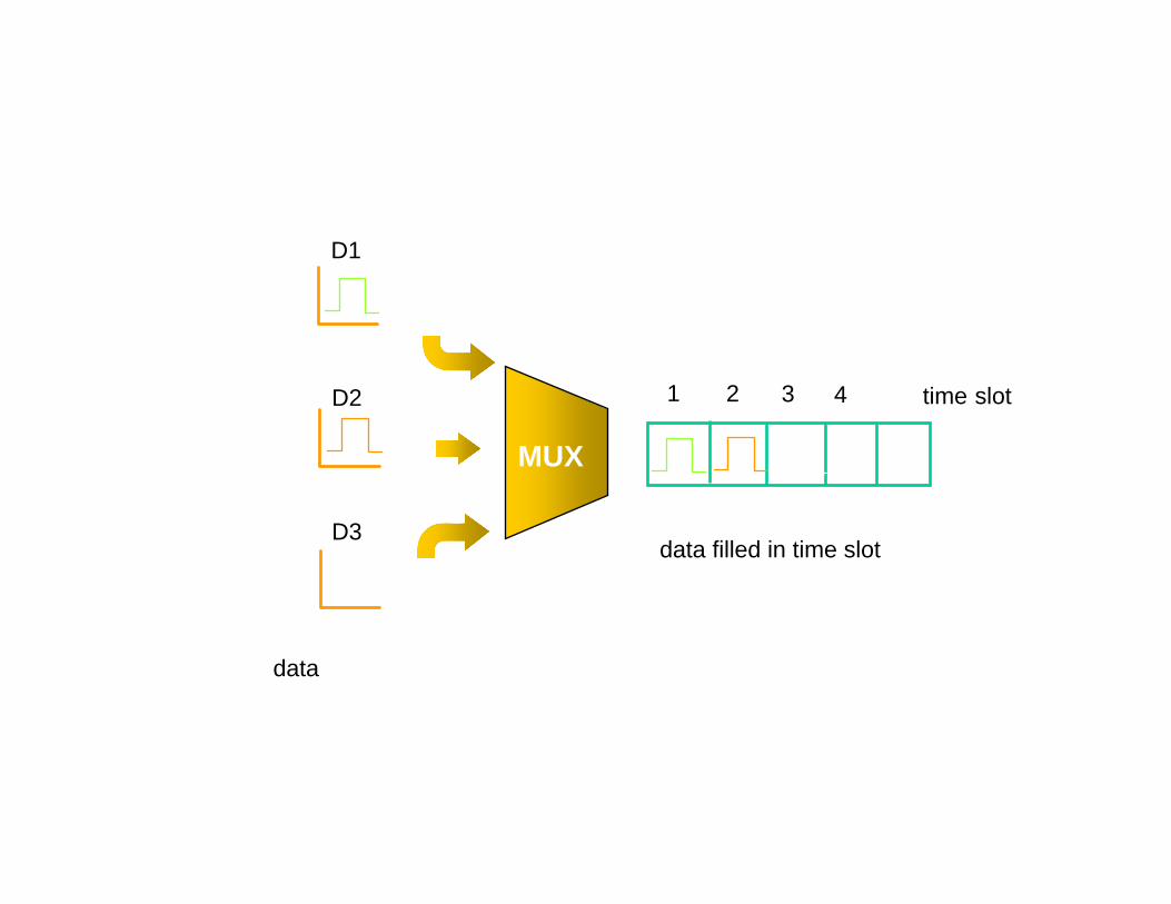
D2
D1
D3
data
MUX
data filled in time slot
time slot1 2 3 4
• Synchronization between mux and demux– Extra framing bit transmitted with each frame for
clock synchronization– Framing bits define a control channel
• Requires data rate of the medium to be greater than sum of the data rate of signals to be transmitted
Statistical TDM
• In Synchronous TDM many slots are wasted• Statistical TDM allocates time slots
dynamically based on demand• Data rate capacity required is below the sum
of connected capacity • Frames are more complex, and so is the mux
and demux
Contention Based Protocols
• Commonly called Medium Access Control (MAC) Protocols
• Defines protocols for multiple stations to access medium at multiple points and successfully send data– Needs to avoid collision, i.e. two or more stations
accessing medium at the same time

ALOHA
• Developed in Univ. of Hawaii in early 70s• For packet radio networks• Transmission to and from a central station• All sources transmit using same frequency,
can transmit anytime• If two sources transmit simultaneously,
collision• If collision, each station waits for a random
time, then tries again
• How is collision detected?– Acknowledgement frames sent by receiver on a
different frequency– If no ack received within some time, sender
assumes collision• Simple• Very inefficient for larger no. of nodes or
higher transmission rates
Slotted ALOHA
• Time divided into slots• Each source should start sending only at the
beginning of a slot• Collision possible only if two sources become
ready at the same slot.• Reduces no. of collisions over ALOHA (why?)

Pure ALOHA / Slotted ALOHA
Throughput versus offered traffic for ALOHA systems.
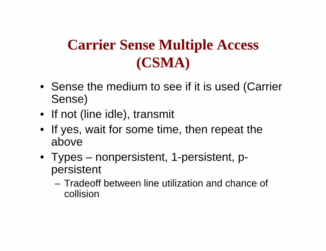
Carrier Sense Multiple Access (CSMA)
• Sense the medium to see if it is used (Carrier Sense)
• If not (line idle), transmit• If yes, wait for some time, then repeat the
above• Types – nonpersistent, 1-persistent, p-
persistent– Tradeoff between line utilization and chance of
collision
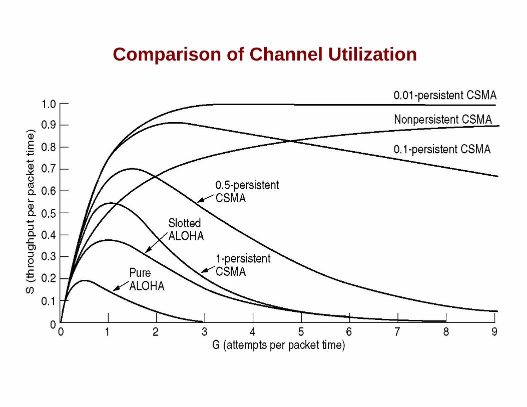
Comparison of Channel Utilization
CSMA/CD (CSMA with Collision Detection)
• Sense medium• If medium is idle, transmit• If medium is busy, apply standard CSMA (non-
persistent, p-persistent,…)• If collision detected during transmission (how?),
transmit a short jamming signal• After sending the jamming signal, wait for a random
backoff time (Binary exponential backoff), then repeat above steps
• Requires minimum frame size for collision detection

CSMA/CA (Collision Avoidace)
• Problems in collision detection in wireless media– Hidden terminal problem– Exposed terminal problem– Weak received signal
• Collision Avoidance proposed as a solution
A B C
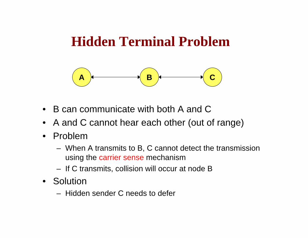
Hidden Terminal Problem
• B can communicate with both A and C• A and C cannot hear each other (out of range)• Problem
– When A transmits to B, C cannot detect the transmission using the carrier sense mechanism
– If C transmits, collision will occur at node B
• Solution– Hidden sender C needs to defer
A B C
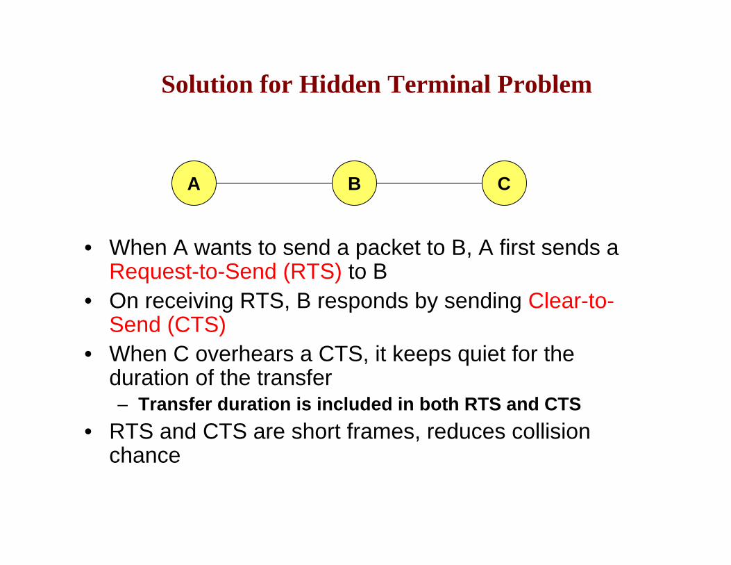
Solution for Hidden Terminal Problem
• When A wants to send a packet to B, A first sends a Request-to-Send (RTS) to B
• On receiving RTS, B responds by sending Clear-to-Send (CTS)
• When C overhears a CTS, it keeps quiet for the duration of the transfer– Transfer duration is included in both RTS and CTS
• RTS and CTS are short frames, reduces collision chance

Exposed Terminal Problem
• B can send to both A and C• C can send to D, but not to A or B• A and C cannot hear each other• Problem
– When B transmits to A, C detects the transmission using the carrier sense mechanism
– So C defers transmitting to D– But C could have sent to D, so blocked unnecessarily
A B C D
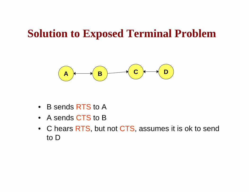
Solution to Exposed Terminal Problem
• B sends RTS to A• A sends CTS to B• C hears RTS, but not CTS, assumes it is ok to send
to D
A B C D
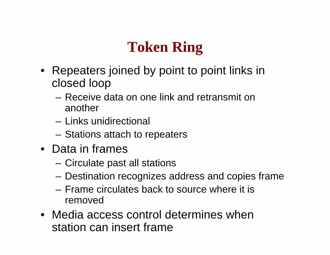
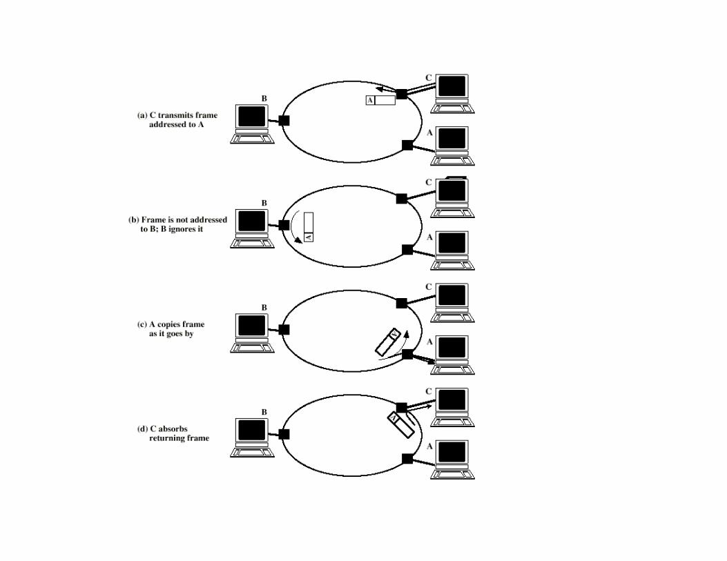
Token Ring• Repeaters joined by point to point links in
closed loop– Receive data on one link and retransmit on
another– Links unidirectional– Stations attach to repeaters
• Data in frames– Circulate past all stations– Destination recognizes address and copies frame– Frame circulates back to source where it is
removed• Media access control determines when
station can insert frame
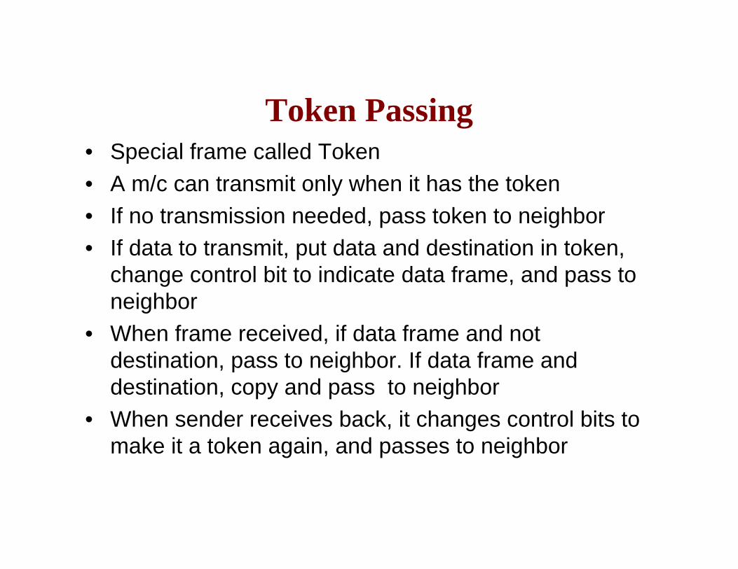
Token Passing• Special frame called Token• A m/c can transmit only when it has the token• If no transmission needed, pass token to neighbor• If data to transmit, put data and destination in token,
change control bit to indicate data frame, and pass to neighbor
• When frame received, if data frame and not destination, pass to neighbor. If data frame and destination, copy and pass to neighbor
• When sender receives back, it changes control bits to make it a token again, and passes to neighbor
Some Basic Concepts for the Next Step
Protocol Architecture
• Task of communication broken up into modules or layers
• Each layer expects some service from its lower layer, and provides some service to its higher layer
• Topmost layer is application (for ex., email)
OSI Layers• Open Systems Interconnection• Developed by the International Organization for
Standardization (ISO)• Seven Layers
– Application– Presentation– Session– Transport– Network– Data Link– Physical
TCP/IP Layers
• De-facto standard• Five Layers
– Application– Transport– Network– Data Link– Physical
Physical Layer
• Physical interface between data transmission device (e.g. computer) and transmission medium or network
• Specifies raw transmission details like connectors, medium, voltage levels, encodings used etc.
• Some of these we studied so far
Data Link Layer
• Ensures reliable communication between two directly connected nodes
• Higher layers can think that a reliable link exists between two machines, and not worry about noise, attenuation, error etc.
• Deals with framing, flow control, error control etc
• Things we studied so far
Network Layer
• Deals primarily with routing – sending packets from source to destination when they are not directly connected
• Packets may not reach in order, get lost etc.• Has some other functionalities• Issues we have not studied so far
Transport Layer
• Reliable, in-order delivery between any two applications (not just machines)
Application Layer
• Application specific services like email, ftp, telnet etc.
• We do not consider session/presentation layer details here as most networks use the TCP/IP stack
Protocol Data Unit (PDU)
• At each layer, protocols are used to communicate to the corresponding layer at the other end
• Data from the higher layer may be broken up into smaller data units
• Control information is added to each data unit at each layer
• PDU at a layer – control info added by the layer + data unit
• Called differently at different layers – frame in datalink layer, packet in network layer, packet/segment in transport layer, message in application layer

Encapsulation
Number of Layers?
• Each layer takes data from higher layer, possibly breaks it up into smaller chunks, and adds its own header to each chunk
• More the no. of layers, more headers are added as the data goes downwards, more wastage
• Too few layers – defeats the purpose of layering (isolating functionalities in layers) itself


Related Documents