Part 13 Geological Survey for Simanggo-2 HEPP

Welcome message from author
This document is posted to help you gain knowledge. Please leave a comment to let me know what you think about it! Share it to your friends and learn new things together.
Transcript
Part 13 Geological Survey for Simanggo-2 HEPP

- - i
PROJECT FOR MASTER PLAN STUDY OF HYDROPOWER DEVELOPMENT IN INDONESIA
SUPPORTING REPORT (2), Part 13
GEOLOGICAL SURVEY FOR SIMMONGO-2 HPP RPOJECT
Table of Contents
Page
1 INTRODUCTION ...................................................................................................................... 1-1 1.1 General ......................................................................................................................... 1-1 1.2 Purpose and Scope of the Geological Survey ................................................................ 1-1 1.3 Methodology of the Geological Survey ........................................................................ 1-2
1.3.1 Geological mapping ........................................................................................ 1-2 1.3.2 Seismic refraction survey ................................................................................ 1-2 1.3.3 Laboratory test for construction materials ..................................................... 1-3
1.4 Quantity of the Geological Survey ................................................................................. 1-3 2 REGIONAL GEOLOGY AND SEISMICITY ........................................................................ 2-1
2.1 General .......................................................................................................................... 2-1 2.2 Regional Geology ......................................................................................................... 2-1 2.3 Regional Tectonic and Seismic Setting ......................................................................... 2-2
2.3.1 Regional tectonic setting ................................................................................. 2-2 2.3.2 Historical and instrumental earthquakes around the project site ................... 2-3
2.4 Estimation of Design Seismic Coefficient .................................................................... 2-5 2.4.1 Seismic design criteria .................................................................................... 2-5 2.4.2 Review of existing similar hydropower projects ............................................ 2-6 2.4.3 Estimation of peak ground acceleration by probabilistic analysis ................. 2-7 2.4.4 Estimation of design seismic coefficient by Indonesia Seismic Map
(ISM) ............................................................................................................... 2-9 2.4.5 Recommended design seismic coefficient for the project ............................ 2-11
3 GEOLOGICAL SURVEY RESULTS ..................................................................................... 3-1 3.1 General ........................................................................................................................... 3-1 3.2 Site Reconnaissance and Geological Mapping .............................................................. 3-1
3.2.1 Surface geological characteristics ................................................................... 3-1 3.2.2 Slope instability ............................................................................................. 3-4
3.4 Seismic Refraction Survey ............................................................................................ 3-5 3.4 Laboratory Tests for Construction Material .................................................................. 3-5
3.4.1 Sand ................................................................................................................ 3-6 3.4.2 Rock block ..................................................................................................... 3-6
4 GEOLOGICAL AND GEOTECHNICAL CONSIDERATION OF THE PROJECT SITE ............................................................................................................................. 4-1
- - ii
4.1 General ........................................................................................................................... 4-1 4.2 Intake Weir Site ............................................................................................................. 4-1
4.2.1 Weir B site....................................................................................................... 4-1 4.2.2 Weir C site ...................................................................................................... 4-3 4.2.3 Weir A site ...................................................................................................... 4-3
4.3 Intermediate Pond Dike Site ......................................................................................... 4-4 4.3.1 Intermediate pond dike B site ......................................................................... 4-4 4.3.2 Intermediate pond dike C site ........................................................................ 4-4
4.4 Connection and Headrace Tunnels (Plan B) ................................................................ 4-5 4.5 Surge Tank and Penstock Area ...................................................................................... 4-6 4.6 Powerhouse Site ............................................................................................................ 4-6
5 CONCLUSIONS AND RECOMMENDATIONS .................................................................... 5-1
5.1 Summary and Conclusions ............................................................................................. 5-1 5.2 Geological Hazards and Recommendations ................................................................... 5-2
5.2.1 Potential geological hazards ........................................................................... 5-2 5.2.2 Recommendations for design and construction of the project ....................... 5-3 5.2.3 Further geological and geotechnical surveys .................................................. 5-4
FIGURES
Figure 1.1 Location of seismic refraction survey ............................................................................ 1-4 Figure 2.1 Regional geological map (Note: Symbols are the same as those in Table 2.1
above) ............................................................................................................................. 2-2 Figure 2.2 Location of earthquake epicenters within ±2 geographical degrees from the
Simonggo-2 weir site in the period since 1973 to 2010 (from USGS seismic database) ........................................................................................................................ 2-4
Figure 2.3 Recent and historical major earthquakes along the SFZ and Subduction Zone (modified from EERI Special Earthquake, May 2007) .................................................. 2-5
Figure 2.4 Location of existing hydropower projects in Sumatra ................................................... 2-7 Figure 2.5 Cumulative number of the earthquakes versus magnitude for the period of 100
years around the Simonggo2 project site ....................................................................... 2-8 Figure 2.6 Cumulative number of the earthquakes versus magnitude for the period of 200
years around the Simonggo2 project site ....................................................................... 2-9 Figure 3.1 Geological map with location of sampling for construction material ............................ 3-9 Figure 3.2 Outcrops of massive sandstone with interbedded slate .................................................. 3-1 Figure 3.3 Highly fractured sandstones due to faulting on road cut slope ...................................... 3-2 Figure 3.4 Outcrops of tuff A, showing massive tuff (A) and columnar joints (B) ......................... 3-2 Figure 3.5 Outcrops of tuff B along the Kasturi stream (A) and (B), as well as on road cut
slope (C) and (D) ............................................................................................................ 3-3 Figure 3.6 Shear zone within sandstones (A) and a series of waterfalls within the tuff A (B) ........ 3-4 Figure 3.7 View of soil collapse and soil erosion in the project site ............................................... 3-5 Figure 3.8 No 6 potential sandstone quarry site .............................................................................. 3-7 Figure 4.1 Geological section of the weir axis alternative B .......................................................... 4-8

- - iii
Figure 4.2 Geological section of the intermediate pond axis alternative B ..................................... 4-9 Figure 4.3 Geological section along the connection and headrace tunnel alignment
alternative B ................................................................................................................. 4-10
TABLES
Table 1.1 Items and Methods of Laboratory Tests Performed for Construction Materials ............. 1-3 Table 1.2 Quantity of Geological Survey for the Simonggo-2 Project ........................................... 1-3 Table 2.1 Regional stratigraphy of the project site .......................................................................... 2-2 Table 2.2 Summary of design seismic coefficients of the similar projects in Sumatra ................... 2-6 Table 2.3 Summary of the estimated peak ground accelerations .................................................... 2-9 Table 2.4 Zone and zone coefficient ............................................................................................. 2-10 Table 2.5 Foundation type and correction factor ........................................................................... 2-10 Table 2.6 Return period and basic earthquake acceleration .......................................................... 2-10 Table 2.7 Design seismic acceleration estimated by ISM ............................................................. 2-10 Table 2.8 Summary of obtained design seismic acceleration ........................................................ 2-11 Table 3.1 Geological classification of seismic units ...................................................................... 3-5 Table 3.2 Location of sand source sampling ................................................................................... 3-6 Table 3.3 Summary of laboratory tests for fine aggregate material ................................................ 3-7 Table 3.4 Location of potential rock quarry Sites ........................................................................... 3-7 Table 3.5 Summary of laboratory tests for coarse aggregate material ............................................ 3-7 Table 4.1 Japanese rock mass classification standard ..................................................................... 4-2 Table 4.2 Estimated rock mass parameters at the weir B site ......................................................... 4-2 Table 4.3 Japanese Rock classification and empirically estimated rock parameters ....................... 4-3 Table 4.4 Estimated rock mass parameters at the weir C site ......................................................... 4-3 Table 4.5 Estimated rock mass parameters at the intermediate pond dike B site ............................ 4-4 Table 4.6 Estimated rock mass parameters at the intermediate pond dike C site ............................ 4-5 Table 4.7 Estimated rock mass parameters for the waterway route ................................................ 4-5 Table 4.8 Estimated rock mass parameters for the surge tank and penstock area ........................... 4-6 Table 4.9 Estimated rock mass parameters for the powerhouse site ............................................... 4-7 Table 5.1 Recommended quantity of boring investigation for feasibility study ............................. 5-4
APPENDIX
Appendix A List of Earthquakes around the Project Site Appendix B Interpreted Seismic Velocity Profiles

Project for Master Plans Study of Hydropower Development Volume IV, Geology In Indonesia Geological Survey for Simanggo-2 HPP
1-1
CHAPTER 1 INTRODUCTION
1.1 GENERAL
Geological survey was carried out for the Pre-feasibility Study for Simonggo-2 Hydroelectric Power Project under the Project for the Master Plan Study of the Hydropower Development in Indonesia. The Simanggo-2 project is a ROR-type scheme and mainly includes intake weir, intermediate pond dike (regulating pondage), connection tunnel, headrace tunnel, surge tank, penstock, powerhouse, etc.
This supporting report presents the results of the geological and geotechnical investigations and recommendations for the proposed Simonggo-2 project scheme. The analyses, conclusions and recommendations provided in this report are based on the understanding of the project scheme and on the geological and geotechnical consideration and evaluation of the existing project site conditions at the time of the geological survey as well as on some engineering judgments.
In addition, the geological survey was done by PT. CONUUSA ENERGINDO, a subcontractor of the Project for the Master Plan Study of Hydropower Development in Indonesia.
1.2 PURPOSE AND SCOPE OF THE GEOLOGICAL SURVEY
The geological survey work for the pre-feasibility study included geological mapping, seismic refraction survey and some laboratory tests for construction materials. The purposes of the geological survey were to explore and evaluate the foundation conditions and slope stability around the planned project structure sites, as shown briefly below:
a) To evaluation the geological and geotechnical suitability of the project sites for the proposed ROR-type hydropower projects;
b) To provide geotechnical data and parameters necessary for geotechnical analyses and design of the proposed projects at the pre-feasibility Study stage; and
c) To foresee and provide solution against geological hazards or problems that may arise due to subsurface conditions.
The scope of the geological survey is enumerated below:
a) Review of previous investigation reports and selected published geologic maps and documents pertinent to the project site;
b) Seismic refraction survey;
Project for Master Plans Study of Hydropower Development Volume IV, Geology In Indonesia Geological Survey for Simanggo-2 HPP
1-2
c) Site reconnaissance and geological mapping;
d) Laboratory tests for construction materials;
f) Geotechnical analyses and evaluations of the data obtained; and
g) Recommendations on mitigation or solutions for the identified geotechnical problems and impact in relation to design and construction of the proposed project structures.
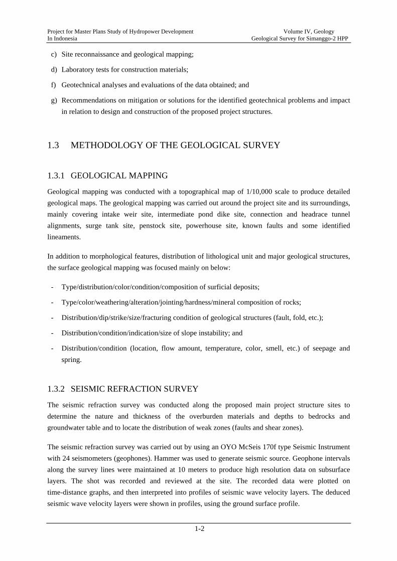
1.3 METHODOLOGY OF THE GEOLOGICAL SURVEY
1.3.1 GEOLOGICAL MAPPING
Geological mapping was conducted with a topographical map of 1/10,000 scale to produce detailed geological maps. The geological mapping was carried out around the project site and its surroundings, mainly covering intake weir site, intermediate pond dike site, connection and headrace tunnel alignments, surge tank site, penstock site, powerhouse site, known faults and some identified lineaments.
In addition to morphological features, distribution of lithological unit and major geological structures, the surface geological mapping was focused mainly on below:
- Type/distribution/color/condition/composition of surficial deposits;
- Type/color/weathering/alteration/jointing/hardness/mineral composition of rocks;
- Distribution/dip/strike/size/fracturing condition of geological structures (fault, fold, etc.);
- Distribution/condition/indication/size of slope instability; and
- Distribution/condition (location, flow amount, temperature, color, smell, etc.) of seepage and spring.
1.3.2 SEISMIC REFRACTION SURVEY
The seismic refraction survey was conducted along the proposed main project structure sites to determine the nature and thickness of the overburden materials and depths to bedrocks and groundwater table and to locate the distribution of weak zones (faults and shear zones).
The seismic refraction survey was carried out by using an OYO McSeis 170f type Seismic Instrument with 24 seismometers (geophones). Hammer was used to generate seismic source. Geophone intervals along the survey lines were maintained at 10 meters to produce high resolution data on subsurface layers. The shot was recorded and reviewed at the site. The recorded data were plotted on time-distance graphs, and then interpreted into profiles of seismic wave velocity layers. The deduced seismic wave velocity layers were shown in profiles, using the ground surface profile.
Project for Master Plans Study of Hydropower Development Volume IV, Geology In Indonesia Geological Survey for Simanggo-2 HPP
1-3
In addition, the seismic wave velocity layers distinguished were geologically and geotechnically interpreted in correlation with the findings in surface geological mapping.
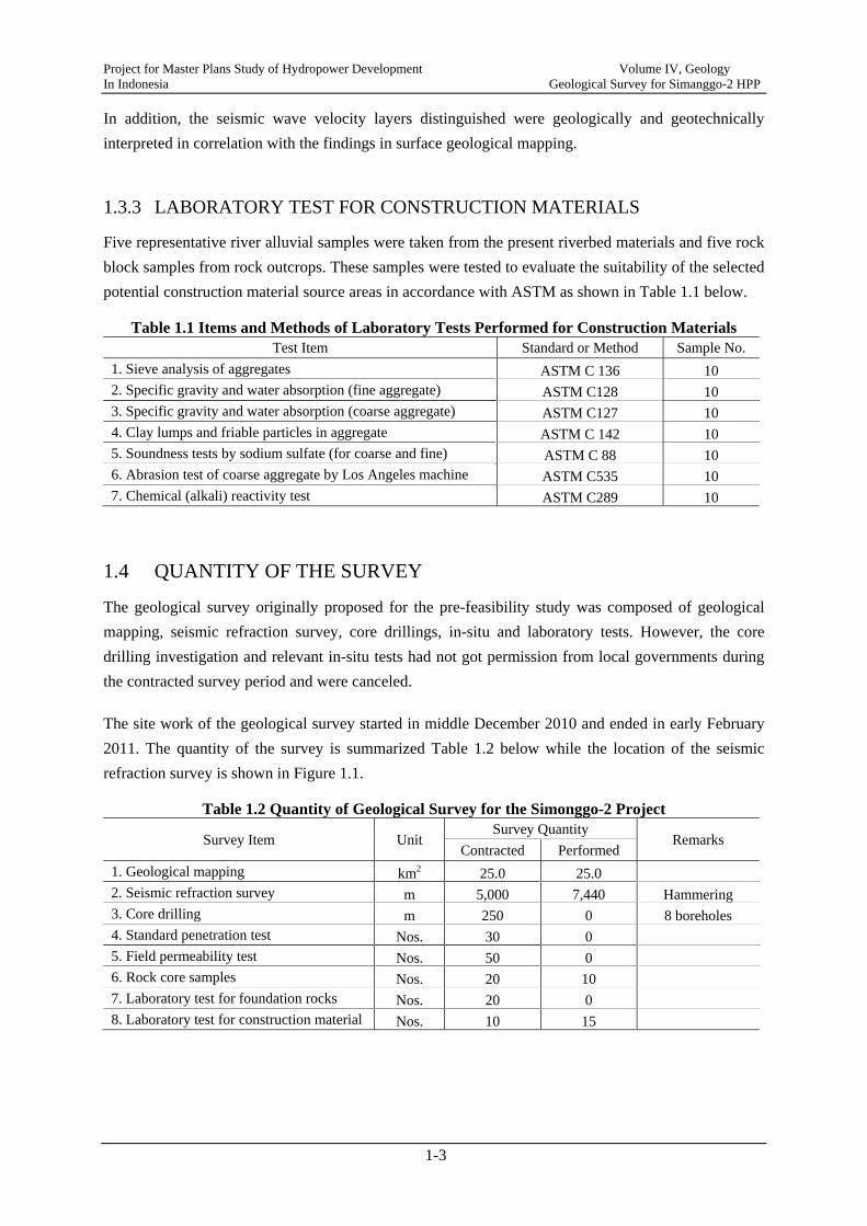
1.3.3 LABORATORY TEST FOR CONSTRUCTION MATERIALS
Five representative river alluvial samples were taken from the present riverbed materials and five rock block samples from rock outcrops. These samples were tested to evaluate the suitability of the selected potential construction material source areas in accordance with ASTM as shown in Table 1.1 below.
Table 1.1 Items and Methods of Laboratory Tests Performed for Construction Materials Test Item Standard or Method Sample No.
1. Sieve analysis of aggregates ASTM C 136 10 2. Specific gravity and water absorption (fine aggregate) ASTM C128 10 3. Specific gravity and water absorption (coarse aggregate) ASTM C127 10 4. Clay lumps and friable particles in aggregate ASTM C 142 10 5. Soundness tests by sodium sulfate (for coarse and fine) ASTM C 88 10 6. Abrasion test of coarse aggregate by Los Angeles machine ASTM C535 10 7. Chemical (alkali) reactivity test ASTM C289 10
1.4 QUANTITY OF THE SURVEY
The geological survey originally proposed for the pre-feasibility study was composed of geological mapping, seismic refraction survey, core drillings, in-situ and laboratory tests. However, the core drilling investigation and relevant in-situ tests had not got permission from local governments during the contracted survey period and were canceled.
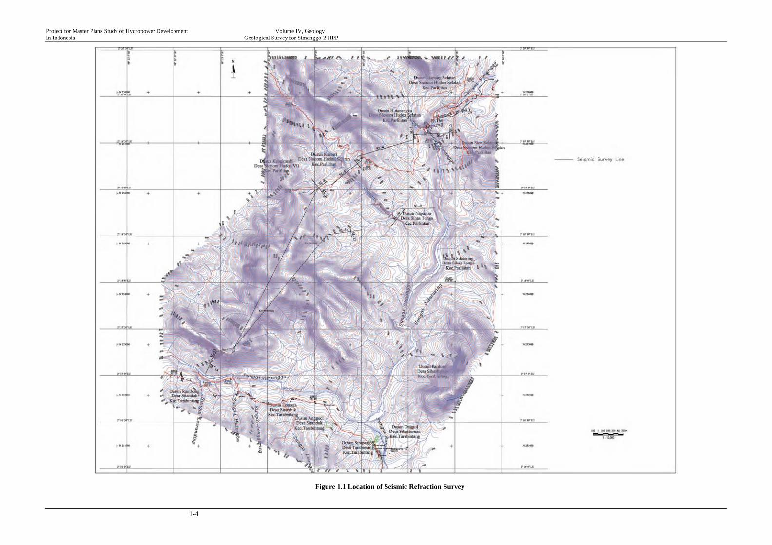
The site work of the geological survey started in middle December 2010 and ended in early February 2011. The quantity of the survey is summarized Table 1.2 below while the location of the seismic refraction survey is shown in Figure 1.1.
Table 1.2 Quantity of Geological Survey for the Simonggo-2 Project
Survey Item Unit Survey Quantity
Remarks Contracted Performed
1. Geological mapping km2 25.0 25.0 2. Seismic refraction survey m 5,000 7,440 Hammering 3. Core drilling m 250 0 8 boreholes 4. Standard penetration test Nos. 30 0 5. Field permeability test Nos. 50 0 6. Rock core samples Nos. 20 10 7. Laboratory test for foundation rocks Nos. 20 0 8. Laboratory test for construction material Nos. 10 15
Project for Master Plans Study of Hydropower Development Volume IV, Geology In Indonesia Geological Survey for Simanggo-2 HPP
1-4
Figure 1.1 Location of Seismic Refraction Survey

Project for Master Plans Study of Hydropower Development Volume IV, Geology In Indonesia Geological Survey for Simanggo-2 HPP
2-1
CHAPTER 2 REGIONAL GEOLOGY AND SEISMICITY
2.1 GENERAL
The Simanggo-2 project is situated approximately at 2°16’ to 2°20’ of the north latitude and 98°22’ to 98°26’ of the east longitude on the middle course of the Simanggo river around Rarabintang village, about 40 km west of Doloksanggul City.
Geologically the project site is located approximately 30 km southwest of the Sumatran Fault Zone (SFZ), also called Great Sumatra Fault System (GSF), one of the most seismically active zones in Indonesia, it is thus imperative to evaluate the seismic hazard at the project site and to design the project facilities to withstand the anticipated ground motions.
This chapter presents the pre-feasibility-level regional geological and seismic hazard assessment and provides the recommended design seismic coefficient for structural design of the project based on existing and published information as well as brief project site inspection. Some similar projects within Sumatra were reviewed to supplementarily determine design seismic parameter.
2.2 REGIONAL GEOLOGY
Physiographically the project site is located on the Barisan Mountains, which are rugged hills with summits from 700m to 2,000m above sea level. The Simanggo River runs on the west slope of the Barisan Mountains and originates from Mt. Simangan Dungi (El. 1,460.0m) and the Mt. Ginjang (El. 1,685.2m). The river first flows to southwest, then joins the Lae Cinendang River and finally discharges into the Indian Ocean.
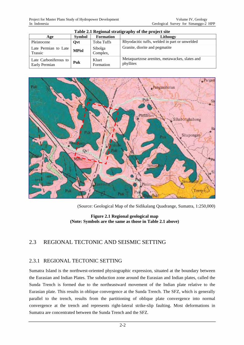
The regional stratigraphy of the project area is given in Table 2.1 and the regional geological map is shown in Figure 2.1. The region is underlain by a basement of Early Permian to Late Carboniferous metamorphic rocks of sedimentary origin. They consist mainly of quartzose sandstones, slates and phyllites. From Late Trassic up to Late Permian intrusions locally took place, represented by Sibolga Complex of granite and diorite. These basements are overlain extensively by Toba Tuffs of Pleistocene age, consisting mainly of partially welded and unwelded ashflow tuffs and occasionally reworked pyroclastic deposits.
The most important geological structure in the region is the NW-trending SFZ, which runs approximately 30 km northeast of the project site. In addition to the SFZ, some small faults, definite and indefinite, are distributed in the vicinity of the project site (Figure 2.1). They are 1) NW-SE fault system and 2) NNW-SSE fault system. The NW-SE fault system is probably subsidiary to the SFZ.
Project for Master Plans Study of Hydropower Development Volume IV, Geology In Indonesia Geological Survey for Simanggo-2 HPP
2-2
Table 2.1 Regional stratigraphy of the project site Age Symbol Formation Lithoogy
Pleistocene Qvt Toba Tuffs Rhyodacitic tuffs, welded in part or unwelded Late Permian to Late Trassic MPisl Sibolga
Complex, Granite, diorite and pegmatite
Late Carboniferous to Early Permian Puk Kluet
Formation Metaquartzose arenites, metawackes, slates and phyllites
(Source: Geological Map of the Sidikalang Quadrange, Sumatra, 1:250,000)
Figure 2.1 Regional geological map (Note: Symbols are the same as those in Table 2.1 above)
2.3 REGIONAL TECTONIC AND SEISMIC SETTING
2.3.1 REGIONAL TECTONIC SETTING
Sumatra Island is the northwest-oriented physiographic expression, situated at the boundary between the Eurasian and Indian Plates. The subduction zone around the Eurasian and Indian plates, called the Sunda Trench is formed due to the northeastward movement of the Indian plate relative to the Eurasian plate. This results in oblique convergence at the Sunda Trench. The SFZ, which is generally parallel to the trench, results from the partitioning of oblique plate convergence into normal convergence at the trench and represents right-lateral strike-slip faulting. Most deformations in Sumatra are concentrated between the Sunda Trench and the SFZ.
Project for Master Plans Study of Hydropower Development Volume IV, Geology In Indonesia Geological Survey for Simanggo-2 HPP
2-3
The SFZ, totally 1,900 km long, traverses the hanging wall block of the Sunda subduction zone, roughly coincident with the active Sumatra volcanic arc. According to Sieh and Natawidjaja (2000), the SFZ is highly segmented and is divided into 19 major segments on the basis of its geomorphic and topographical expressions. These fault segments generally range in length from 35 km to 220 km. The major segments of the SFZ in the proximity of the project site are a) Renun Segment and b) Toru Segment.
The Renun segment (2.0oN to 3.55oN), approximately 225 km long, is the longest segment of the SFZ. The segment traverses the western flanks of the 80-km-long Toba caldera underlain by approximately 73,000-year-old Tobu Tuff. The Runun segment generally strikes 40 degrees northwest and dips vertically. The segment offsets the Toba Tuff approximately 2 km at its most southeastern end and therefore reportedly has a 27 mm/yr slip rate for the fault. The Renun segment was the source of some major historical earthquakes.
The Toru segment (1.2oN to 2.0oN), approximately 95 km long, is well delimited by some bends, and characterized by contractional bend at southeastern end and by dilatational step at the northwestern end, respectively. The Toru segment strikes 45 degrees northwest and dips vertically. The segment accommodates significant components of dip slips and reportedly has a approximately 24 mm/yr slip rate for the fault. The Pahae Jahe earthquake of Ms 6.4 occurred in 1984 at the northern end of the Toru segment.
2.3.2 HISTORICAL AND INSTRUMENTAL EARTHQUAKES AROUND THE PROJECT SITE
The project site is a region of high seismicity. Figure 2.2 shows the distribution of recent earthquake epicenters recorded by seismic instruments for events greater than magnitude 5 from 1973 to present while Appendix A lists the earthquakes searched through USGS National Earthquake Information Center.
Earthquakes are distributed mostly between the subduction zone and the FSZ and especially concentrated along the subduction zone and the FSZ. In addition, the earthquakes around the FSZ generally have deep focal depths – represented by blue and green dots in Figure 2.2, whereas the earthquakes around the subduction zone shows shallow focal depths – represented by yellow and brown dots in Figure 2.2.
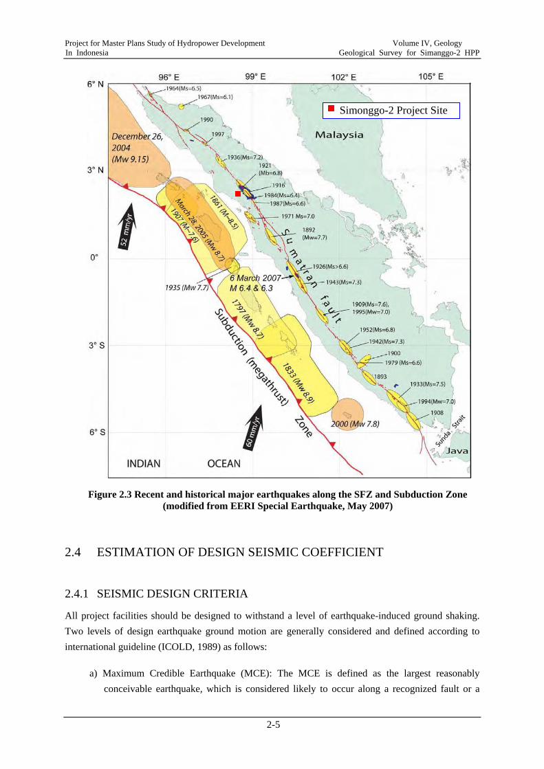
Historical earthquakes have caused surface ruptures along the SFZ. Figure 2.3 gives historical major earthquakes along the SFZ and the subduction zone. The smaller ellipsoid shapes in Figure 2.3 indicate some surface rupture on the some segment of the SFZ, while the larger ellipsoid shapes along the subduction zone in Figure 2.3 indicate recent and historical megathrust events associated with the subduction zone and the SFZ. The seismic sources are dominated by the subduction zone and the strike-slip-type SFZ. The subduction zone and the SFZ are both active and capable to generate earthquakes up to Mw=9.15 (December 26, 2004) and Mw=7.7 (1892), respectively

Project for Master Plans Study of Hydropower Development Volume IV, Geology In Indonesia Geological Survey for Simanggo-2 HPP
2-4
Figure 2.2 Location of earthquake epicenters within ±2 geographical degrees from the Simonggo-2 weir site in the period since 1973 to 2010 (from USGS seismic database)
Notable historical earthquakes in the vicinity of the project site include:
- Along the Renun segment of the SFZ, magnitude mb = 6.8, 22 February 1916, strong shaking at Tarutung valley.
- Along the Renun segment of the SFZ, magnitude mb = 6.8, 24 January 1921, strong shaking similar to the above 1916 earthquake.
- Along the Renun segment, magnitude Ms = 7.2, 1936, strong shaking at Tarutung valley.
- Along the Toru segment of the SFZ, Pahae Jahe earthquake, magnitude Ms = 6.4, 1984.
- Along the Toru segment of the SFZ, magnitude Ms = 6.6, 25 April 1987, approximately 50 km from the Simonggo-2 project site (weir site).
Simonggo-2 weir site
Project for Master Plans Study of Hydropower Development Volume IV, Geology In Indonesia Geological Survey for Simanggo-2 HPP
2-5
Figure 2.3 Recent and historical major earthquakes along the SFZ and Subduction Zone (modified from EERI Special Earthquake, May 2007)
2.4 ESTIMATION OF DESIGN SEISMIC COEFFICIENT
2.4.1 SEISMIC DESIGN CRITERIA
All project facilities should be designed to withstand a level of earthquake-induced ground shaking. Two levels of design earthquake ground motion are generally considered and defined according to international guideline (ICOLD, 1989) as follows:
a) Maximum Credible Earthquake (MCE): The MCE is defined as the largest reasonably conceivable earthquake, which is considered likely to occur along a recognized fault or a
Simonggo-2 Project Site
Project for Master Plans Study of Hydropower Development Volume IV, Geology In Indonesia Geological Survey for Simanggo-2 HPP
2-6
seismological area. The MCE is the upper bond of the expected magnitude on a given seismic source, in general related to 5,000 years to 10,000 years return periods.
b) Operating Basis Earthquake (OBE): The OBE is the level of ground motion that all structures must be able to withstand and still remain functional. Any damage due to earthquake is repairable. The OBE ground motions are expected occur during the lifetime of the structure and generally correspond to 100 years to 500 years return periods.
The selection of seismic design criteria is generally based on the type of structures under consideration and the safety and environmental consequences of failure. The ROR-type Simonggo-2 project mainly include some low risk structures (low impact), such as small and low weir dam, low dike pond and so on. Accordingly, the OBE is considered as design earthquake in the return period of 100 to 200 years.
2.4.2 REVIEW OF EXISTING SIMILAR HYDROPOWER PROJECTS
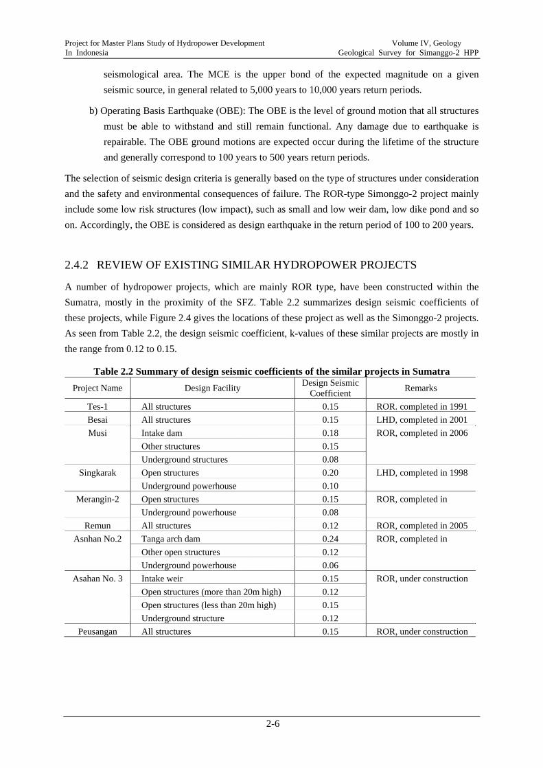
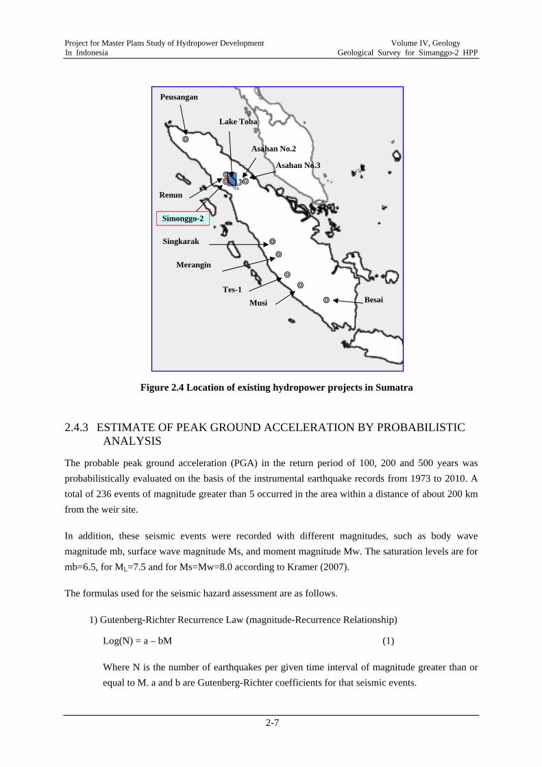
A number of hydropower projects, which are mainly ROR type, have been constructed within the Sumatra, mostly in the proximity of the SFZ. Table 2.2 summarizes design seismic coefficients of these projects, while Figure 2.4 gives the locations of these project as well as the Simonggo-2 projects. As seen from Table 2.2, the design seismic coefficient, k-values of these similar projects are mostly in the range from 0.12 to 0.15.
Table 2.2 Summary of design seismic coefficients of the similar projects in Sumatra Project Name Design Facility Design Seismic
Coefficient Remarks
Tes-1 All structures 0.15 ROR. completed in 1991Besai All structures 0.15 LHD, completed in 2001Musi Intake dam 0.18 ROR, completed in 2006
Other structures 0.15 Underground structures 0.08
Singkarak Open structures 0.20 LHD, completed in 1998 Underground powerhouse 0.10
Merangin-2 Open structures 0.15 ROR, completed in Underground powerhouse 0.08
Remun All structures 0.12 ROR, completed in 2005Asnhan No.2 Tanga arch dam 0.24 ROR, completed in
Other open structures 0.12 Underground powerhouse 0.06
Asahan No. 3 Intake weir 0.15 ROR, under construction Open structures (more than 20m high) 0.12 Open structures (less than 20m high) 0.15 Underground structure 0.12
Peusangan All structures 0.15 ROR, under construction
Project for Master Plans Study of Hydropower Development Volume IV, Geology In Indonesia Geological Survey for Simanggo-2 HPP
2-7
Figure 2.4 Location of existing hydropower projects in Sumatra
2.4.3 ESTIMATE OF PEAK GROUND ACCELERATION BY PROBABILISTIC ANALYSIS
The probable peak ground acceleration (PGA) in the return period of 100, 200 and 500 years was probabilistically evaluated on the basis of the instrumental earthquake records from 1973 to 2010. A total of 236 events of magnitude greater than 5 occurred in the area within a distance of about 200 km from the weir site.
In addition, these seismic events were recorded with different magnitudes, such as body wave magnitude mb, surface wave magnitude Ms, and moment magnitude Mw. The saturation levels are for mb=6.5, for ML=7.5 and for Ms=Mw=8.0 according to Kramer (2007).
The formulas used for the seismic hazard assessment are as follows.
1) Gutenberg-Richter Recurrence Law (magnitude-Recurrence Relationship)
Log(N) = a – bM (1)
Where N is the number of earthquakes per given time interval of magnitude greater than or equal to M. a and b are Gutenberg-Richter coefficients for that seismic events.
Tes-1
Singkarak
Merangin
BesaiMusi
Asahan No.3
Asahan No.2
Lake Toba
Renun
Peusangan
Simonggo-2

Project for Master Plans Study of Hydropower Development Volume IV, Geology In Indonesia Geological Survey for Simanggo-2 HPP
2-8
2) Distance Attenuation Relationship
a = 2000 e 0.8M / (d2 + h2 + 400) Cornell (1968) (2)
a = 5000 e 0.8M / (r + 40)2 Estava (1973) (3)
Where,
M: Magnitude of earthquake in Richter scale d: Distance from epicenter to the project site (or damsite) in km h: Depth of focus in km r: Distance from focus to the project site (or damsite) in km a: Peak ground acceleration in gal or cm/sec2 e: The exponential constant
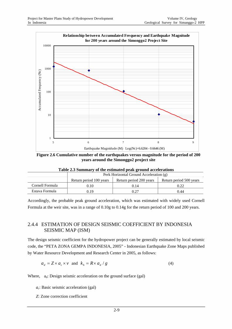
Around the project area, the cumulative number of earthquakes for the period of 100 years and of 200 years is shown in Figures 2.5 and 2.6, respectively. Accordingly, the peak horizontal ground acceleration (a) at the damsite for each earthquake was estimated by the formulas of Cornell and Estava for comparison. In the course of the preliminary seismic hazard assessment, the seismic sources within 200-km radius around the weir site were assumed to be a seismic zone. The estimated peak ground accelerations are summarized in Table 2.3 below.
Figure 2.5 Cumulative number of the earthquakes versus magnitude for the period of 100 years around the Simonggo2 project site
Relationship between Accumulated Frequency and Earthquake Magnitudefor 100 years around the Simonggo2 Project Site
1
10
100
1000
5 6 7 8 9
Earthquake Magnidude (M) Log(Nc)=6.3194 - 0.6646 (M)
Acc
umul
ated
Fre
quen
cy (N
c)
Project for Master Plans Study of Hydropower Development Volume IV, Geology In Indonesia Geological Survey for Simanggo-2 HPP
2-9
Figure 2.6 Cumulative number of the earthquakes versus magnitude for the period of 200 years around the Simonggo2 project site
Table 2.3 Summary of the estimated peak ground accelerations
Perk Horizontal Ground Acceleration (g) Return period 100 years Return period 200 years Return period 500 years Cornell Formula 0.10 0.14 0.22 Estava Formula 0.19 0.27 0.44
Accordingly, the probable peak ground acceleration, which was estimated with widely used Cornell Formula at the weir site, was in a range of 0.10g to 0.14g for the return period of 100 and 200 years.
2.4.4 ESTIMATION OF DESIGN SEISMIC COEFFICIENT BY INDONESIA SEISMIC MAP (ISM)
The design seismic coefficient for the hydropower project can be generally estimated by local seismic code, the “PETA ZONA GEMPA INDONESIA, 2005” - Indonesian Earthquake Zone Maps published by Water Resource Development and Research Center in 2005, as follows:
vaZa cd ××= and gaRk dh /×= (4)
Where, ad: Design seismic acceleration on the ground surface (gal)
ac: Basic seismic acceleration (gal)
Z: Zone correction coefficient
Relationship between Accumulated Frequency and Earthquake Magnitudefor 200 years around the Simonggo2 Project Site
1
10
100
1000
10000
5 6 7 8 9
Earthquake Magnidude (M) Log(Nc)=6.6204 - 0.6646 (M)
Acc
umul
ated
Fre
quen
cy (N
c)
Project for Master Plans Study of Hydropower Development Volume IV, Geology In Indonesia Geological Survey for Simanggo-2 HPP
2-10
v: Correction factor for type of foundation ground
kh: Design horizontal seismic coefficient
R: conversion factor
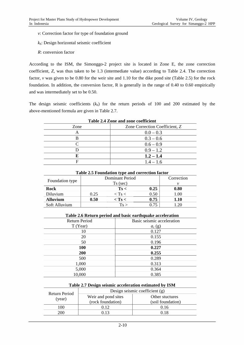
According to the ISM, the Simonggo-2 project site is located in Zone E, the zone correction coefficient, Z, was thus taken to be 1.3 (intermediate value) according to Table 2.4. The correction factor, v was given to be 0.80 for the weir site and 1.10 for the dike pond site (Table 2.5) for the rock foundation. In addition, the conversion factor, R is generally in the range of 0.40 to 0.60 empirically and was intermediately set to be 0.50.
The design seismic coefficients (kh) for the return periods of 100 and 200 estimated by the above-mentioned formula are given in Table 2.7.
Table 2.4 Zone and zone coefficient Zone Zone Correction Coefficient, Z
A 0.0 – 0.3 B 0.3 – 0.6 C 0.6 – 0.9 D 0.9 – 1.2 E 1.2 – 1.4 F 1.4 – 1.6
Table 2.5 Foundation type and correction factor
Foundation type Dominant Period Ts (sec)
Correction v
Rock Ts < 0.25 0.80 Diluvium 0.25 < Ts < 0.50 1.00 Alluvium 0.50 < Ts < 0.75 1.10 Soft Alluvium Ts > 0.75 1.20
Table 2.6 Return period and basic earthquake acceleration Return Period
T (Year) Basic seismic acceleration
ac (g) 10 0.127 20 0.155 50 0.196
100 0.227 200 0.255 500 0.289
1,000 0.313 5,000 0.364
10,000 0.385
Table 2.7 Design seismic acceleration estimated by ISM
Return Period (year)
Design seismic coefficient (g) Weir and pond sites (rock foundation)
Other stuctures (soil foundation)
100 0.12 0.16 200 0.13 0.18
Project for Master Plans Study of Hydropower Development Volume IV, Geology In Indonesia Geological Survey for Simanggo-2 HPP
2-11
2.4.5 RECOMMENDED DESIGN SEISMIC COEFFICIENT FOR THE PROJECT
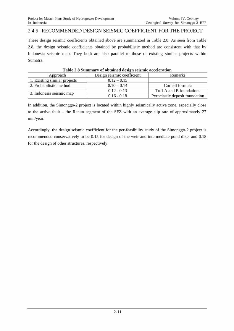
These design seismic coefficients obtained above are summarized in Table 2.8. As seen from Table 2.8, the design seismic coefficients obtained by probabilistic method are consistent with that by Indonesia seismic map. They both are also parallel to those of existing similar projects within Sumatra.
Table 2.8 Summary of obtained design seismic acceleration Approach Design seismic coefficient Remarks
1. Existing similar projects 0.12 – 0.15 2. Probabilistic method 0.10 – 0.14 Cornell formula
3. Indonesia seismic map 0.12 - 0.13 Tuff A and B foundations 0.16 - 0.18 Pyroclastic deposit foundation
In addition, the Simonggo-2 project is located within highly seismically active zone, especially close to the active fault – the Renun segment of the SFZ with an average slip rate of approximately 27 mm/year.
Accordingly, the design seismic coefficient for the per-feasibility study of the Simonggo-2 project is recommended conservatively to be 0.15 for design of the weir and intermediate pond dike, and 0.18 for the design of other structures, respectively.
Project for Master Plans Study of Hydropower Development Volume IV, Geology In Indonesia Geological Survey for Simanggo-2 HPP
3-1
CHAPTER 3 GEOLOGICAL SURVEY RESULTS
3.1 GENERAL
The geological investigation conducted at the prefeasibility stage for the Simanggo-2 project included geological mapping, seismic refraction survey, and some laboratory tests for construction materials. This chapter presents the geological survey results.
3.2 SITE RECONNAISSANCE AND GEOLOGICAL MAPPING
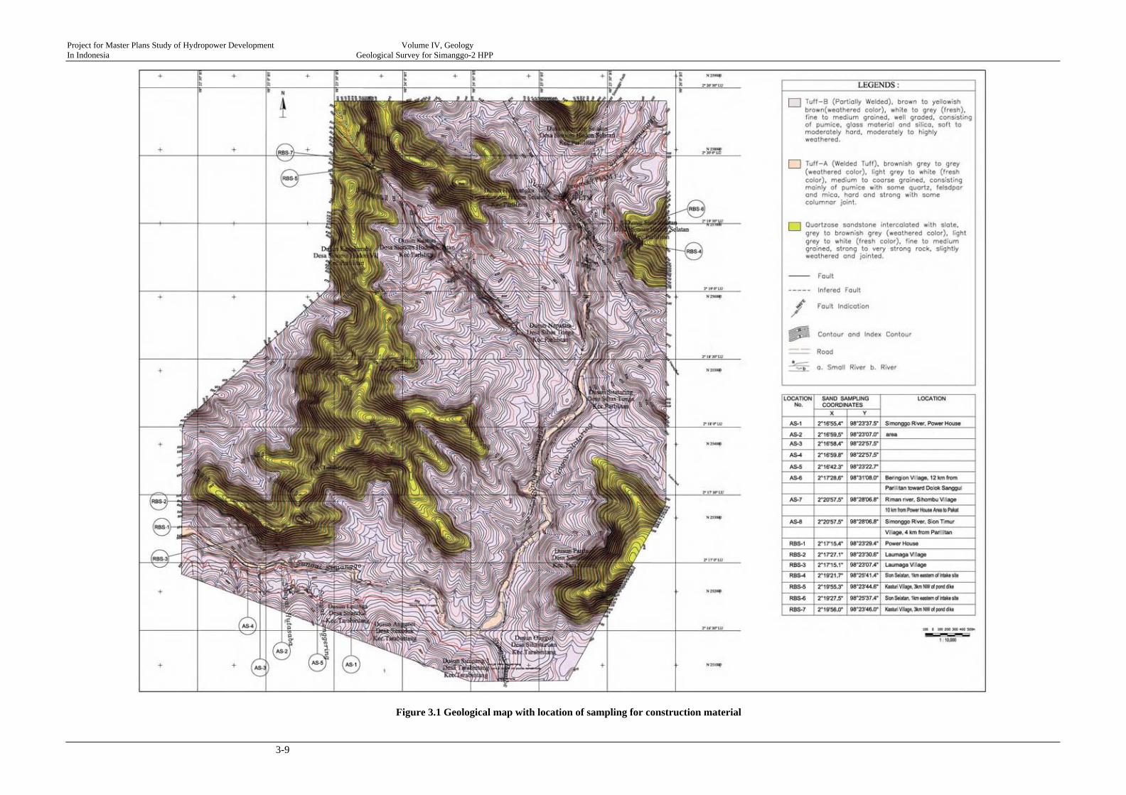
The surface geologic features through geological mapping are shown in Figure 3.1 and are summarized in the following section.
3.2.1 SURFACE GEOLOGICAL CHARACTERISTICS
Four geological units were identified and classified, including 1) Sandstone with some interbedded slate, 2) Tuff A (welded tuff and 3) Tuff B (Partially welded or semi-consolidated tuffs).
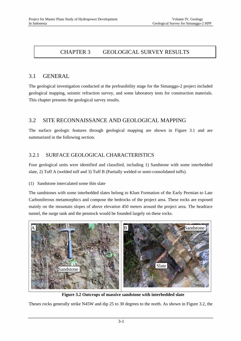
(1) Sandstone intercalated some thin slate
The sandstones with some interbedded slates belong to Kluet Formation of the Early Permian to Late Carboniferous metamorphics and compose the bedrocks of the project area. These rocks are exposed mainly on the mountain slopes of above elevation 450 meters around the project area. The headrace tunnel, the surge tank and the penstock would be founded largely on these rocks.
Figure 3.2 Outcrops of massive sandstone with interbedded slate
Theses rocks generally strike N45W and dip 25 to 30 degrees to the north. As shown in Figure 3.2, the
A B
Slate
Sandstone
Sandstone
Project for Master Plans Study of Hydropower Development Volume IV, Geology In Indonesia Geological Survey for Simanggo-2 HPP
3-2
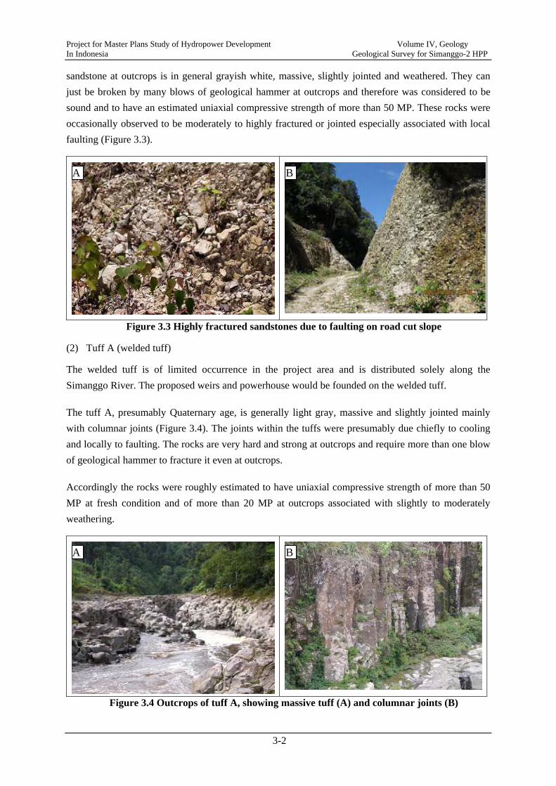
sandstone at outcrops is in general grayish white, massive, slightly jointed and weathered. They can just be broken by many blows of geological hammer at outcrops and therefore was considered to be sound and to have an estimated uniaxial compressive strength of more than 50 MP. These rocks were occasionally observed to be moderately to highly fractured or jointed especially associated with local faulting (Figure 3.3).
Figure 3.3 Highly fractured sandstones due to faulting on road cut slope
(2) Tuff A (welded tuff)
The welded tuff is of limited occurrence in the project area and is distributed solely along the Simanggo River. The proposed weirs and powerhouse would be founded on the welded tuff.
The tuff A, presumably Quaternary age, is generally light gray, massive and slightly jointed mainly with columnar joints (Figure 3.4). The joints within the tuffs were presumably due chiefly to cooling and locally to faulting. The rocks are very hard and strong at outcrops and require more than one blow of geological hammer to fracture it even at outcrops.
Accordingly the rocks were roughly estimated to have uniaxial compressive strength of more than 50 MP at fresh condition and of more than 20 MP at outcrops associated with slightly to moderately weathering.
Figure 3.4 Outcrops of tuff A, showing massive tuff (A) and columnar joints (B)
A B
A B
Project for Master Plans Study of Hydropower Development Volume IV, Geology In Indonesia Geological Survey for Simanggo-2 HPP
3-3
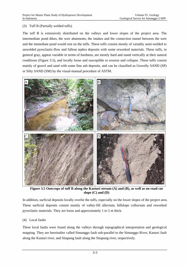
(3) Tuff B (Partially welded tuffs)
The tuff B is extensively distributed on the valleys and lower slopes of the project area. The intermediate pond dikes, the weir abutments, the intakes and the connection tunnel between the weir and the immediate pond would rest on the tuffs. These tuffs consist mostly of variably semi-welded to unwelded pyroclastic-flow and fallout tephra deposits with some reworked materials. These tuffs, in general gray, appear variable in terms of hardness, are mostly hard and stand vertically at their natural conditions (Figure 3.5), and locally loose and susceptible to erosion and collapse. These tuffs consist mainly of gravel and sand with some fine ash deposits, and can be classified as Gravelly SAND (SP) or Silty SAND (SM) by the visual-manual procedure of ASTM.
Figure 3.5 Outcrops of tuff B along the Kasturi stream (A) and (B), as well as on road cut slope (C) and (D)
In addition, surficial deposits locally overlie the tuffs, especially on the lower slopes of the project area. These surficial deposits consist mainly of valley-fill alluvium, hillslope colluvium and reworked pyroclastic materials. They are loose and approximately 1 to 5 m thick.
(4) Local faults
Three local faults were found along the valleys through topographical interpretation and geological mapping. They are hereinafter called Simanggo fault sub-parallel to the Simanggo River, Kasturi fault along the Kasturi river, and Sitapung fault along the Sitapung river, respectively.
A B
C D
Project for Master Plans Study of Hydropower Development Volume IV, Geology In Indonesia Geological Survey for Simanggo-2 HPP
3-4
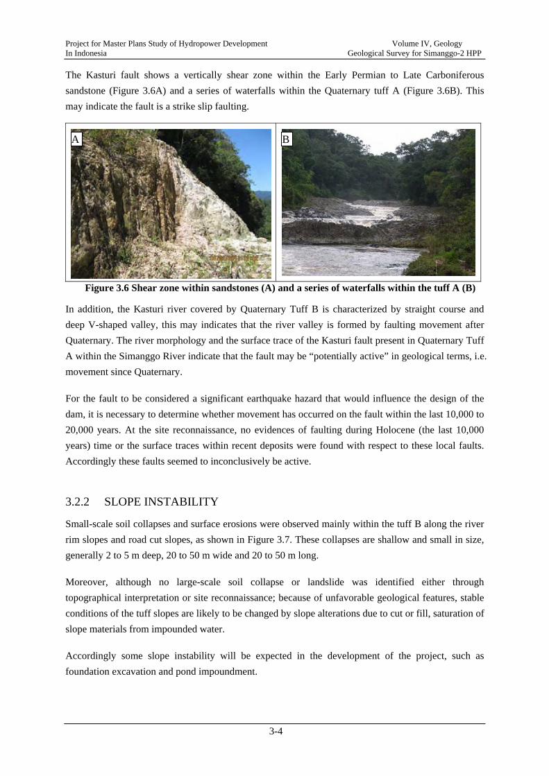
The Kasturi fault shows a vertically shear zone within the Early Permian to Late Carboniferous sandstone (Figure 3.6A) and a series of waterfalls within the Quaternary tuff A (Figure 3.6B). This may indicate the fault is a strike slip faulting.
Figure 3.6 Shear zone within sandstones (A) and a series of waterfalls within the tuff A (B)
In addition, the Kasturi river covered by Quaternary Tuff B is characterized by straight course and deep V-shaped valley, this may indicates that the river valley is formed by faulting movement after Quaternary. The river morphology and the surface trace of the Kasturi fault present in Quaternary Tuff A within the Simanggo River indicate that the fault may be “potentially active” in geological terms, i.e. movement since Quaternary.
For the fault to be considered a significant earthquake hazard that would influence the design of the dam, it is necessary to determine whether movement has occurred on the fault within the last 10,000 to 20,000 years. At the site reconnaissance, no evidences of faulting during Holocene (the last 10,000 years) time or the surface traces within recent deposits were found with respect to these local faults. Accordingly these faults seemed to inconclusively be active.
3.2.2 SLOPE INSTABILITY
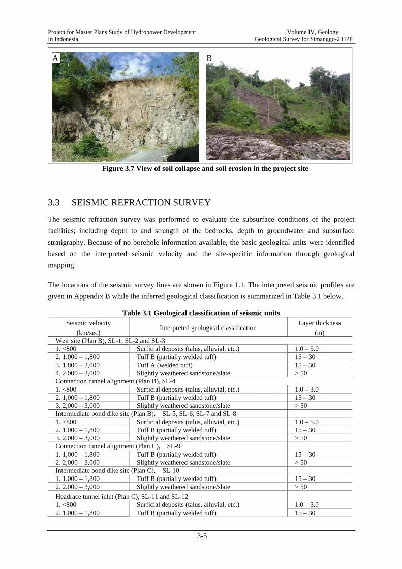
Small-scale soil collapses and surface erosions were observed mainly within the tuff B along the river rim slopes and road cut slopes, as shown in Figure 3.7. These collapses are shallow and small in size, generally 2 to 5 m deep, 20 to 50 m wide and 20 to 50 m long.
Moreover, although no large-scale soil collapse or landslide was identified either through topographical interpretation or site reconnaissance; because of unfavorable geological features, stable conditions of the tuff slopes are likely to be changed by slope alterations due to cut or fill, saturation of slope materials from impounded water.
Accordingly some slope instability will be expected in the development of the project, such as foundation excavation and pond impoundment.
A B
Project for Master Plans Study of Hydropower Development Volume IV, Geology In Indonesia Geological Survey for Simanggo-2 HPP
3-5
Figure 3.7 View of soil collapse and soil erosion in the project site
3.3 SEISMIC REFRACTION SURVEY
The seismic refraction survey was performed to evaluate the subsurface conditions of the project facilities; including depth to and strength of the bedrocks, depth to groundwater and subsurface stratigraphy. Because of no borehole information available, the basic geological units were identified based on the interpreted seismic velocity and the site-specific information through geological mapping.
The locations of the seismic survey lines are shown in Figure 1.1. The interpreted seismic profiles are given in Appendix B while the inferred geological classification is summarized in Table 3.1 below.
Table 3.1 Geological classification of seismic units Seismic velocity
(km/sec) Interpreted geological classification
Layer thickness
(m) Weir site (Plan B), SL-1, SL-2 and SL-3 1. <800 Surficial deposits (talus, alluvial, etc.) 1.0 – 5.0 2. 1,000 – 1,800 Tuff B (partially welded tuff) 15 – 30 3. 1,800 – 2,000 Tuff A (welded tuff) 15 – 30 4. 2,000 – 3,000 Slightly weathered sandstone/slate > 50 Connection tunnel alignment (Plan B), SL-4 1. <800 Surficial deposits (talus, alluvial, etc.) 1.0 – 3.0 2. 1,000 – 1,800 Tuff B (partially welded tuff) 15 – 30 3. 2,000 – 3,000 Slightly weathered sandstone/slate > 50 Intermediate pond dike site (Plan B), SL-5, SL-6, SL-7 and SL-8 1. <800 Surficial deposits (talus, alluvial, etc.) 1.0 – 5.0 2. 1,000 – 1,800 Tuff B (partially welded tuff) 15 – 30 3. 2,000 – 3,000 Slightly weathered sandstone/slate > 50 Connection tunnel alignment (Plan C), SL-9 1. 1,000 – 1,800 Tuff B (partially welded tuff) 15 – 30 2. 2,000 – 3,000 Slightly weathered sandstone/slate > 50 Intermediate pond dike site (Plan C), SL-10 1. 1,000 – 1,800 Tuff B (partially welded tuff) 15 – 30 2. 2,000 – 3,000 Slightly weathered sandstone/slate > 50 Headrace tunnel inlet (Plan C), SL-11 and SL-12 1. <800 Surficial deposits (talus, alluvial, etc.) 1.0 – 3.0 2. 1,000 – 1,800 Tuff B (partially welded tuff) 15 – 30
A B

Project for Master Plans Study of Hydropower Development Volume IV, Geology In Indonesia Geological Survey for Simanggo-2 HPP
3-6
3. 2,000 – 3,000 Slightly weathered sandstone/slate > 50 Powerhouse site (Plan A/B/C), SL-13 and SL-14 1. <800 Surficial deposits (talus, alluvial, etc.) 1.0 – 5.0 2. 1,000 – 1,800 Tuff B (partially welded tuff) 15 – 30 3. 1,800 – 2,000 Tuff A (welded tuff) 15 – 30 4. 2,000 -3,000 Slightly weathered sandstone/slate > 50
The interpreted seismic data indicate four velocity layers underlie the project site. The first layer with velocity of less than 800 m/sec is consistent with surficial loose deposits such as talus, colluvial, and riverbed material. The secondary layer with velocity varying from 1,000 m/sec to 1,800 m/sec is the interpreted tuff B. The third layer has a fairly narrow range of low seismic velocity (1,800 to 2,000 m/sec). The velocity values correlate to slightly weathered, jointed tuff A (welded tuff) observed at outcrops along the Simanggo river. Similarly the fourth layer is consistent with slightly weathered and jointed sandstone/slate observed at rock outcrops along the proposed penstock route.
3.4 LABORATORY TESTS FOR CONSTRUCTION MATERIALS
Laboratory tests as well as field reconnaissance (geological mapping) were conducted to examine the possible source, quantity and quality of construction materials.
3.4.1 SAND
Some sand was needed for the fine aggregates of concrete, grout and mortar. Riverbed deposits on the Simanggo River, around the powerhouse site (AS-1 through AS-5) and about 4 km upstream from the Parlilitan village (AS-8), consisted mainly of fine to coars-grained sand (well graded SAND) and was small in quantity.
On the other hand, riverbed deposits around the Beringin village, about 12 km far from the Parlilitan village (AS-6) and along the Riman River around Sihombu Village, about 10 km far from the powerhouse area (AS-7), were composed mainly of medium to coarse sands and were large in quantity. Table 3.3 summarizes laboratory test results of the samples. Accordingly, the riverbed sand tested are recommendable as fine concrete aggregates.
Table 3.2 Location of sand source sampling Sample No. Coordinate Location
AS-1 2o16’55.4” 98o23’37.5” AS-2 2o16’59.5” 98o23’07.0” AS-3 2o16’58.4” 98o22’57.5” Close to the powerhouse area along the Simango river AS-4 2o16’59.8” 98o22’52.0” AS-5 2o16’42.3” 98o23’22.7”
AS-6 2o17’28.6” 98o31’08.0” Around the Beringin village, 12 km far from Parlilitan village toward Doloksanggul
AS-7 2o14’25.7” 98o27’39.7” Along the Riman River around Sihombu Village, about 10 km far from the powerhouse area toward Pakat
AS-8 2o20’57.5” 98o28’06.8” Along the Simanggo River around the Sion Timur Village, about 4 km far from Parlilitan village
Project for Master Plans Study of Hydropower Development Volume IV, Geology In Indonesia Geological Survey for Simanggo-2 HPP
3-7
Table 3.3 Summary of laboratory tests for fine aggregate material Test Criterion AS-1 AS-2 AS-3 AS-4 AS-5 AS-6 AS-7 AS-8
1. Specific gravity >2.5% 2.68 2.66 2.68 2.68 2.67 2.67 2.68 2.67 2. Absorption <3.0% 3.58 4.14 4.49 4.84 6.34 7.97 9.79 5.15 3. Soundness Na2SO4 12.0% 21.48 4.03 6.83 7.30 4.90 - - - Mg2SO4 15.0% 4. Clay lump <1.0% 0.85 0.65 0.80 1.05 0.45 1.85 1.45 1.25 5. Silt content <3.0% 0.22 0.64 1.48 0.74 0.16 0.36 0.24 0.20 6. Soft particle <1.0%
3.4.2 ROCK BLOCK
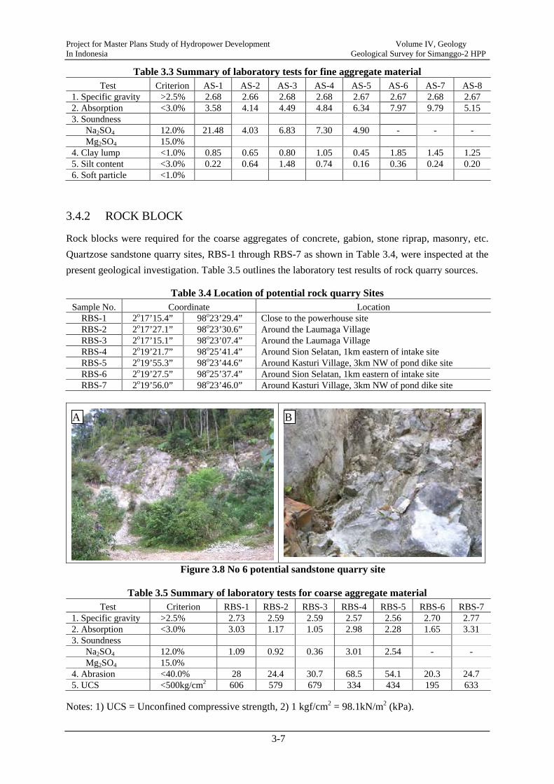
Rock blocks were required for the coarse aggregates of concrete, gabion, stone riprap, masonry, etc. Quartzose sandstone quarry sites, RBS-1 through RBS-7 as shown in Table 3.4, were inspected at the present geological investigation. Table 3.5 outlines the laboratory test results of rock quarry sources.
Table 3.4 Location of potential rock quarry Sites Sample No. Coordinate Location
RBS-1 2o17’15.4” 98o23’29.4” Close to the powerhouse site RBS-2 2o17’27.1” 98o23’30.6” Around the Laumaga Village RBS-3 2o17’15.1” 98o23’07.4” Around the Laumaga Village RBS-4 2o19’21.7” 98o25’41.4” Around Sion Selatan, 1km eastern of intake site RBS-5 2o19’55.3” 98o23’44.6” Around Kasturi Village, 3km NW of pond dike site RBS-6 2o19’27.5” 98o25’37.4” Around Sion Selatan, 1km eastern of intake site RBS-7 2o19’56.0” 98o23’46.0” Around Kasturi Village, 3km NW of pond dike site
Figure 3.8 No 6 potential sandstone quarry site
Table 3.5 Summary of laboratory tests for coarse aggregate material Test Criterion RBS-1 RBS-2 RBS-3 RBS-4 RBS-5 RBS-6 RBS-7
1. Specific gravity >2.5% 2.73 2.59 2.59 2.57 2.56 2.70 2.77 2. Absorption <3.0% 3.03 1.17 1.05 2.98 2.28 1.65 3.31 3. Soundness Na2SO4 12.0% 1.09 0.92 0.36 3.01 2.54 - - Mg2SO4 15.0% 4. Abrasion <40.0% 28 24.4 30.7 68.5 54.1 20.3 24.7 5. UCS <500kg/cm2 606 579 679 334 434 195 633
Notes: 1) UCS = Unconfined compressive strength, 2) 1 kgf/cm2 = 98.1kN/m2 (kPa).
A B

Project for Master Plans Study of Hydropower Development Volume IV, Geology In Indonesia Geological Survey for Simanggo-2 HPP
3-8
As stated in Table 3.5 above, several sandstone quarry sites within and around the project site were available in quality and quantity and therefore were recommended to be used.
Project for Master Plans Study of Hydropower Development Volume IV, Geology In Indonesia Geological Survey for Simanggo-2 HPP
3-9
Figure 3.1 Geological map with location of sampling for construction material
Project for Master Plans Study of Hydropower Development Volume IV, Geology In Indonesia Geological Survey for Simanggo-2 HPP
4-1
CHAPTER 4 GEOLOGICAL AND GEOTECHNICAL CONDITION OF THE PROJECT SITE
4.1 GENERAL
At the prefeasibility study stage, three alternative layouts, Plan A, Plan B and Plan C were proposed for comparison assessment purposes. Plan A, the Simanggo-2 project Site (1-1901-41) originally proposed in HPPS2 in 1989, consisted of an intake weir, headrace tunnel, surge tank, penstock and a surface power station. In order to effectively use the potential for hydropower generation and to provide more peak load hydropower generation, Plan B and Plan C were proposed in the present study. The general layouts of Plan B and Plan C were almost the same and both included an intake weir, intermediate pond, connection and headrace tunnels, surge tank, penstock and a surface power station.
The following presents the preliminary geological conditions for the various project facilities including weir, intermediate pond dike, connection tunnel, headrace tunnel, surge tank, penstock and surface powerhouse.
4.2 INTAKE WEIR SITE
4.2.1 WEIR SITE B
The weir site B for Plan B is located at the beginning of the northsouth course of the Simanggo River immediately downstream of great river bend. The width of the Simanggo River at the weir site is about 50 m. The right and left abutment slopes have an average slope of 25 degrees at the lower part and of 30 degrees at the upper part.
Figure 4.1 shows geological conditions of the weir site B. The right and left abutment slopes are underlain by partially welded tuff (Tuff B) which is covered by overburden of about 1 to 5 m thick. The Simanngo valley is covered by welded tuff (Tuff A).
The tuff A at outcrops is generally massive, slightly jointed and weathered, and locally moderately fractured by local faults or shear zones. The tuffs at outcrops can be classified as CM to CH class rock mass based on Japanese Rock Classification Standard (Table 4.1). On the other hand, the tuff B at the right and left abutment slopes is soft rocks and can be classified as D to CL class rock mass according to Japanese Rock Classification Standard.
On the basis of the above preliminary geological assessment, the proposed weir site was considered to
Project for Master Plans Study of Hydropower Development Volume IV, Geology In Indonesia Geological Survey for Simanggo-2 HPP
4-2
be geologically suitable for the construction of the proposed concrete weir. The overburden overlying the tuff B on the right/left abutment slopes generally ranges in thickness from 1.0 to 5.0 meters and have low strength and high permeability. These deposits should be removed from the weir foundation.
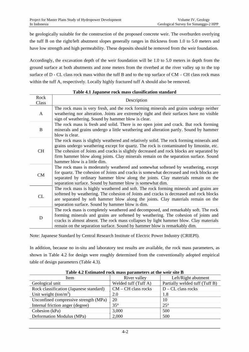
Accordingly, the excavation depth of the weir foundation will be 1.0 to 5.0 meters in depth from the ground surface at both abutments and zone meters from the riverbed at the river valley up to the top surface of D - CL class rock mass within the tuff B and to the top surface of CM – CH class rock mass within the tuff A, respectively. Locally highly fractured tuff A should also be removed.
Table 4.1 Japanese rock mass classification standard Rock Class Description
A The rock mass is very fresh, and the rock forming minerals and grains undergo neither weathering nor alteration. Joints are extremely tight and their surfaces have no visible sign of weathering. Sound by hammer blow is clear.
B The rock mass is fresh and solid. There is no open joint and crack. But rock forming minerals and grains undergo a little weathering and alteration partly. Sound by hammer blow is clear.
CH
The rock mass is slightly weathered and relatively solid. The rock forming minerals and grains undergo weathering except for quartz. The rock is contaminated by limonite, etc. The cohesion of Joints and cracks is slightly decreased and rock blocks are separated by firm hammer blow along joints. Clay minerals remain on the separation surface. Sound hammer blow is a little dim.
CM
The rock mass is moderately weathered and somewhat softened by weathering, except for quartz. The cohesion of Joints and cracks is somewhat decreased and rock blocks are separated by ordinary hammer blow along the joints. Clay materials remain on the separation surface. Sound by hammer blow is somewhat dim.
CL
The rock mass is highly weathered and soft. The rock forming minerals and grains are softened by weathering. The cohesion of Joints and cracks is decreased and rock blocks are separated by soft hammer blow along the joints. Clay materials remain on the separation surface. Sound by hammer blow is dim.
D
The rock mass is completely weathered and decomposed, and remarkably soft. The rock forming minerals and grains are softened by weathering. The cohesion of joints and cracks is almost absent. The rock mass collapses by light hammer blow. Clay materials remain on the separation surface. Sound by hammer blow is remarkably dim.
Note: Japanese Standard by Central Research Institute of Electric Power Industry (CRIEPI).
In addition, because no in-situ and laboratory test results are available, the rock mass parameters, as shown in Table 4.2 for design were roughly determined from the conventionally adopted empirical table of design parameters (Table 4.3).
Table 4.2 Estimated rock mass parameters at the weir site B Item River valley Left/Right abutment
Geological unit Welded tuff (Tuff A) Partially welded tuff (Tuff B)Rock classification (Japanese standard) CM – CH class rocks D – CL class rocks Unit weight (ton/m3) 2.0 1.8 Unconfined compressive strength (MPa) 20 10 Internal friction anger (degree) 35° 25° Cohesion (kPa) 3,000 500 Deformation Modulus (MPa) 2,000 500

Project for Master Plans Study of Hydropower Development Volume IV, Geology In Indonesia Geological Survey for Simanggo-2 HPP
4-3
Table 4.3 Japanese rock classification and empirically estimated rock parameters
Rock class
qu (kgf/cm2)
Es (kgf/cm2)
Ed (kgf/cm2)
c (kgf/cm2)
φ (degree)
V (km/sec)
A-B Over 800 Over 80,000 Over 50,000 Over 40 55 – 65 Over 3.7 CH 800 - 400 80,000 - 40,000 50,000 - 20,000 40 - 20 40 – 55 3.0 – 3.7 CM 400 - 200 40,000 - 15,000 20,000 - 5,000 20 - 10 30 – 40 1.5 – 3.0 D-CL Below 200 Below 15,000 Below 5,000 Below 10 15 - 30 Below 1.7
Source: Rock classification and its application, K. Yoshinaka, et al., Japanese Society of Civil Engineering, 1989.
Note: qu = Unconfined compressive strength, Es = Modulus of elasticity, Ed = Modulus of deformation, c = Cohesion, φ= Internal friction angle, V= Velocity of elastic wave, 1 kgf/cm2
= 100 kPa = 0.1 MPa.
4.2.2 WEIR SITE C
The weir site C for Plan C is located 1,500 m downstream of the weir site B. The width of the Simanggo River at the weir site is about 50 m. The right abutment slope has an average slope of 25 degrees and the left abutment slope has an average slope of 30 degrees. A series of waterfalls are present immediately downstream of the weir site. Consequently the proposed weir site was considered to be topographically suitable for the development of the project.
On the other hand, the geological condition of the weir site C is basically the same as that at the weir site B. Similarly, the rock mass parameters of the weir site C were empirically determined and given in Table 4.4.
Table 4.4 Estimated rock mass parameters at the weir site C Item River valley Left/Right abutment
Geological unit Welded tuff (Tuff A) Partially welded tuff (Tuff B) Rock classification (Japanese standard) CM – CH class rocks D – CL class rocks Unit weight (ton/m3) 2.0 1.8 Unconfined compressive strength (MPa) 20 10 Internal friction anger (degree) 35° 25° Cohesion (kPa) 3,000 500 Deformation Modulus (MPa) 2,000 500
4.2.3 WEIR SITE A
The weir site A for Plan A is located further 500 m downstream of the weir site C. The geological and topographical conditions of the site are generally similar to those at the weir sites B and C. The rock mass parameters for the prefeasibility level design will refer to the above-mentioned.
Project for Master Plans Study of Hydropower Development Volume IV, Geology In Indonesia Geological Survey for Simanggo-2 HPP
4-4
4.3 INTERMEDIATE POND DIKE SITE
4.3.1 INTERMEDIATE POND DIKE SITE B
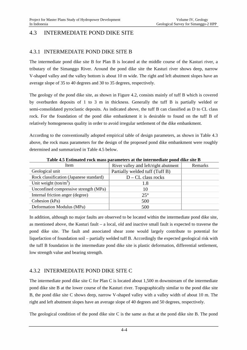
The intermediate pond dike site B for Plan B is located at the middle course of the Kasturi river, a tributary of the Simanggo River. Around the pond dike site the Kasturi river shows deep, narrow V-shaped valley and the valley bottom is about 10 m wide. The right and left abutment slopes have an average slope of 35 to 40 degrees and 30 to 35 degrees, respectively.
The geology of the pond dike site, as shown in Figure 4.2, consists mainly of tuff B which is covered by overburden deposits of 1 to 3 m in thickness. Generally the tuff B is partially welded or semi-consolidated pyroclastic deposits. As indicated above, the tuff B can classified as D to CL class rock. For the foundation of the pond dike embankment it is desirable to found on the tuff B of relatively homogeneous quality in order to avoid irregular settlement of the dike embankment.
According to the conventionally adopted empirical table of design parameters, as shown in Table 4.3 above, the rock mass parameters for the design of the proposed pond dike embankment were roughly determined and summarized in Table 4.5 below.
Table 4.5 Estimated rock mass parameters at the intermediate pond dike site B Item River valley and left/right abutment Remarks
Geological unit Partially welded tuff (Tuff B) Rock classification (Japanese standard) D – CL class rocks Unit weight (ton/m3) 1.8 Unconfined compressive strength (MPa) 10 Internal friction anger (degree) 25° Cohesion (kPa) 500 Deformation Modulus (MPa) 500
In addition, although no major faults are observed to be located within the intermediate pond dike site, as mentioned above, the Kasturi fault – a local, old and inactive small fault is expected to traverse the pond dike site. The fault and associated shear zone would largely contribute to potential for liquefaction of foundation soil – partially welded tuff B. Accordingly the expected geological risk with the tuff B foundation in the intermediate pond dike site is plastic deformation, differential settlement, low strength value and bearing strength.
4.3.2 INTERMEDIATE POND DIKE SITE C
The intermediate pond dike site C for Plan C is located about 1,500 m downstream of the intermediate pond dike site B at the lower course of the Kasturi river. Topographically similar to the pond dike site B, the pond dike site C shows deep, narrow V-shaped valley with a valley width of about 10 m. The right and left abutment slopes have an average slope of 40 degrees and 50 degrees, respectively.
The geological condition of the pond dike site C is the same as that at the pond dike site B. The pond
Project for Master Plans Study of Hydropower Development Volume IV, Geology In Indonesia Geological Survey for Simanggo-2 HPP
4-5
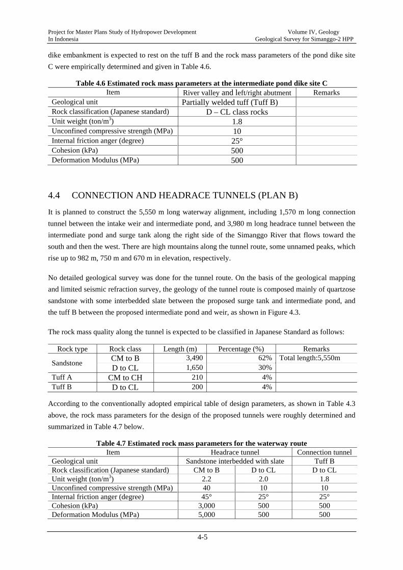
dike embankment is expected to rest on the tuff B and the rock mass parameters of the pond dike site C were empirically determined and given in Table 4.6.
Table 4.6 Estimated rock mass parameters at the intermediate pond dike site C Item River valley and left/right abutment Remarks
Geological unit Partially welded tuff (Tuff B) Rock classification (Japanese standard) D – CL class rocks Unit weight (ton/m3) 1.8 Unconfined compressive strength (MPa) 10 Internal friction anger (degree) 25° Cohesion (kPa) 500 Deformation Modulus (MPa) 500
4.4 CONNECTION AND HEADRACE TUNNELS (PLAN B)
It is planned to construct the 5,550 m long waterway alignment, including 1,570 m long connection tunnel between the intake weir and intermediate pond, and 3,980 m long headrace tunnel between the intermediate pond and surge tank along the right side of the Simanggo River that flows toward the south and then the west. There are high mountains along the tunnel route, some unnamed peaks, which rise up to 982 m, 750 m and 670 m in elevation, respectively.
No detailed geological survey was done for the tunnel route. On the basis of the geological mapping and limited seismic refraction survey, the geology of the tunnel route is composed mainly of quartzose sandstone with some interbedded slate between the proposed surge tank and intermediate pond, and the tuff B between the proposed intermediate pond and weir, as shown in Figure 4.3.
The rock mass quality along the tunnel is expected to be classified in Japanese Standard as follows:
Rock type Rock class Length (m) Percentage (%) Remarks
Sandstone CM to B 3,490 62% Total length:5,550m D to CL 1,650 30%
Tuff A CM to CH 210 4% Tuff B D to CL 200 4%
According to the conventionally adopted empirical table of design parameters, as shown in Table 4.3 above, the rock mass parameters for the design of the proposed tunnels were roughly determined and summarized in Table 4.7 below.
Table 4.7 Estimated rock mass parameters for the waterway route Item Headrace tunnel Connection tunnel
Geological unit Sandstone interbedded with slate Tuff B Rock classification (Japanese standard) CM to B D to CL D to CL Unit weight (ton/m3) 2.2 2.0 1.8 Unconfined compressive strength (MPa) 40 10 10 Internal friction anger (degree) 45° 25° 25° Cohesion (kPa) 3,000 500 500 Deformation Modulus (MPa) 5,000 500 500
Project for Master Plans Study of Hydropower Development Volume IV, Geology In Indonesia Geological Survey for Simanggo-2 HPP
4-6
The D to CL class sandstone with some interbedded slate would be encountered mainly over some meters at the inlet area associated highly weathered and jointed zone. The D to CL class zones including tuff B will require more support and however are not expected to cause any major geological problems during the tunnel excavation.
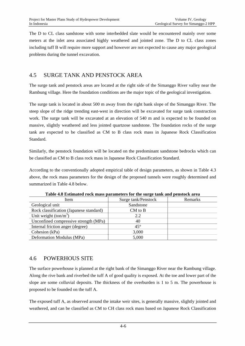
4.5 SURGE TANK AND PENSTOCK AREA
The surge tank and penstock areas are located at the right side of the Simanggo River valley near the Rambung village. Here the foundation conditions are the major topic of the geological investigation.
The surge tank is located in about 500 m away from the right bank slope of the Simanggo River. The steep slope of the ridge trending east-west in direction will be excavated for surge tank construction work. The surge tank will be excavated at an elevation of 540 m and is expected to be founded on massive, slightly weathered and less jointed quartzose sandstone. The foundation rocks of the surge tank are expected to be classified as CM to B class rock mass in Japanese Rock Classification Standard.
Similarly, the penstock foundation will be located on the predominant sandstone bedrocks which can be classified as CM to B class rock mass in Japanese Rock Classification Standard.
According to the conventionally adopted empirical table of design parameters, as shown in Table 4.3 above, the rock mass parameters for the design of the proposed tunnels were roughly determined and summarized in Table 4.8 below.
Table 4.8 Estimated rock mass parameters for the surge tank and penstock area Item Surge tank/Penstock Remarks
Geological unit Sandstone Rock classification (Japanese standard) CM to B Unit weight (ton/m3) 2.2 Unconfined compressive strength (MPa) 40 Internal friction anger (degree) 45° Cohesion (kPa) 3,000 Deformation Modulus (MPa) 5,000
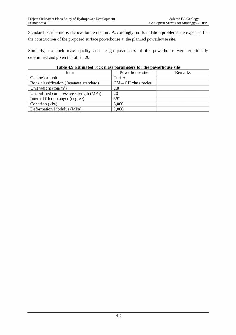
4.6 POWERHOUS SITE
The surface powerhouse is planned at the right bank of the Simanggo River near the Rambung village. Along the rive bank and riverbed the tuff A of good quality is exposed. At the toe and lower part of the slope are some colluvial deposits. The thickness of the overburden is 1 to 5 m. The powerhouse is proposed to be founded on the tuff A.
The exposed tuff A, as observed around the intake weir sites, is generally massive, slightly jointed and weathered, and can be classified as CM to CH class rock mass based on Japanese Rock Classification
Project for Master Plans Study of Hydropower Development Volume IV, Geology In Indonesia Geological Survey for Simanggo-2 HPP
4-7
Standard. Furthermore, the overburden is thin. Accordingly, no foundation problems are expected for the construction of the proposed surface powerhouse at the planned powerhouse site.
Similarly, the rock mass quality and design parameters of the powerhouse were empirically determined and given in Table 4.9.
Table 4.9 Estimated rock mass parameters for the powerhouse site Item Powerhouse site Remarks
Geological unit Tuff A Rock classification (Japanese standard) CM – CH class rocks Unit weight (ton/m3) 2.0 Unconfined compressive strength (MPa) 20 Internal friction anger (degree) 35° Cohesion (kPa) 3,000 Deformation Modulus (MPa) 2,000

Project for Master Plans Study of H
ydropower D
evelopment V
olume IV
, Geology
In Indonesia Geological Survey for Sim
anggo-2 HPP
4-8
Figure 4.1 Geological Section of the Weir Axis Alternative B

Project for Master Plans Study of H
ydropower D
evelopment V
olume IV
, Geology
In Indonesia Geological Survey for Sim
anggo-2 HPP
4-9
Figure 4.2 Geological Section of the Intermediate Pond Axis Alternative B

Project for Master Plans Study of Hydropower Development Volume IV, Geology In Indonesia Geological Survey for Simanggo-2 HPP
4-10
Figure 4.3 Geological Section along the Connection and Headrace Tunnel Alignment Alternative B
Project for Master Plans Study of Hydropower Development Volume IV, Geology In Indonesia Geological Survey for Simanggo-2 HPP
5-1
CHAPTER 5 CONCLUSION AND RECOMMENDATIONS
5.1 SUMMARY AND CONCLUSIONS
The preliminary geological and geotechnical investigations conducted at the pre-feasibility study stage mainly included site reconnaissance, geological mapping, seismic refraction survey and laboratory tests of potential construction materials. On the basis of the preliminary geological and geotechnical investigations results the topographical and geological conditions of the project site were considered suitable for the development of the project.
The mainly investigation results are summarized as follows:
- The geology of the project site consists mainly of Early Permian to Late Carboniferous metamorphic sandstone/slate and Quaternary tuff B (partially welded tuff) with a limited occurrence of Quaternary tuff A (welded tuff). Except for several local and inactive faults, no major faults were observed within the project site.
- The proposed weirs were expected to be founded on the tuff A for the river valley and tuff B for abutments, the intermediate pond dikes on the tuff B, the connection tunnel on the tuff B, the headrace tunnel on the sandstone, the surge tank and penstock on the sandstone, and the powerhouse on the tuff A. These foundation rocks were not expected to cause any major geological problems associated with the construction of the proposed project structures.
- The geological conditions at alternative Plan B and Plan C are similar considering rock mass quality and geological profiles.
- Slope instability associated with the development of the project would occur especially within the tuff B but will be manageable technically and economically because of their small size.
- Some sandstone quarry sites within the project site are appropriate potential construction material sources in quality and quantity, and no noticeable problems were found out by laboratory test. On the other hand, alluvial sands alone the Simanggo River and Riman River in the proximity of the project site are available in quality but small in quantity.
- The project site is located within a region of high seismic activity and the project structures should thus be designed to withstand the expected level of earthquake-induced ground shaking. The design seismic coefficient for the per-feasibility study of the Simonggo-2 project is recommended conservatively to be 0.15 for the design of the weir and intermediate pond dike, and 0.18 for the design of other structures, respectively.
Project for Master Plans Study of Hydropower Development Volume IV, Geology In Indonesia Geological Survey for Simanggo-2 HPP
5-2
5.2 GEOLOGICAL HAZARDS AND RECOMMENDATIONS
5.2.1 POTENTIAL GEOLOGICAL HAZARDS
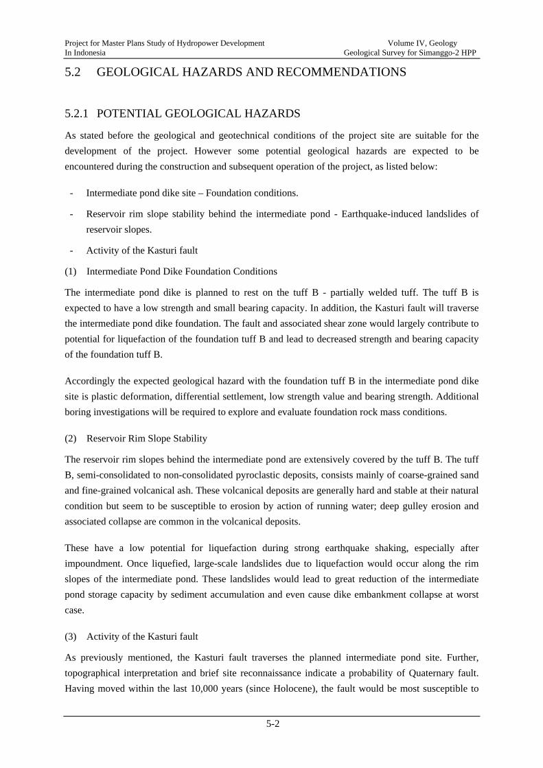
As stated before the geological and geotechnical conditions of the project site are suitable for the development of the project. However some potential geological hazards are expected to be encountered during the construction and subsequent operation of the project, as listed below:
- Intermediate pond dike site – Foundation conditions.
- Reservoir rim slope stability behind the intermediate pond - Earthquake-induced landslides of reservoir slopes.
- Activity of the Kasturi fault
(1) Intermediate Pond Dike Foundation Conditions
The intermediate pond dike is planned to rest on the tuff B - partially welded tuff. The tuff B is expected to have a low strength and small bearing capacity. In addition, the Kasturi fault will traverse the intermediate pond dike foundation. The fault and associated shear zone would largely contribute to potential for liquefaction of the foundation tuff B and lead to decreased strength and bearing capacity of the foundation tuff B.
Accordingly the expected geological hazard with the foundation tuff B in the intermediate pond dike site is plastic deformation, differential settlement, low strength value and bearing strength. Additional boring investigations will be required to explore and evaluate foundation rock mass conditions.
(2) Reservoir Rim Slope Stability
The reservoir rim slopes behind the intermediate pond are extensively covered by the tuff B. The tuff B, semi-consolidated to non-consolidated pyroclastic deposits, consists mainly of coarse-grained sand and fine-grained volcanical ash. These volcanical deposits are generally hard and stable at their natural condition but seem to be susceptible to erosion by action of running water; deep gulley erosion and associated collapse are common in the volcanical deposits.
These have a low potential for liquefaction during strong earthquake shaking, especially after impoundment. Once liquefied, large-scale landslides due to liquefaction would occur along the rim slopes of the intermediate pond. These landslides would lead to great reduction of the intermediate pond storage capacity by sediment accumulation and even cause dike embankment collapse at worst case.
(3) Activity of the Kasturi fault
As previously mentioned, the Kasturi fault traverses the planned intermediate pond site. Further, topographical interpretation and brief site reconnaissance indicate a probability of Quaternary fault. Having moved within the last 10,000 years (since Holocene), the fault would be most susceptible to

Project for Master Plans Study of Hydropower Development Volume IV, Geology In Indonesia Geological Survey for Simanggo-2 HPP
5-3
renewed activity. If so, the fault would pose a surface-rupture hazard to the planned intermediate pond dike. Accordingly the seismic hazard of the fault has to be explored and evaluated in detail in terms of surface rupturing and activity.
5.2.2 RECOMMENDATIONS FOR DESIGN AND CONSTRUCTION OF THE PROJECT
(1) Rock Mass Parameters
Because no laboratory and in-situ test data for foundation rocks are obtained, it is thus difficult to evaluate the rock mass conditions and mechanical properties of the foundation rocks. For the purpose of preliminary design of the project structures, it is recommended to use the roughly estimated rock mass parameters according to the conventionally adopted empirical table of design parameters, as given in Chapter 4, Geological and Geotechnical Conditions of the Project Site.
(2) Cut Slope Stability
The main cut slopes in the project site will be excavated at the following locations:
- In the area of intake weir abutments
- In the area of intermediate pond dike
- In the areas of the inlet and outlet of the connection tunnel
- In the areas of the intake of the headrace tunnel
- In the area of the surge tank
- In the area of the powerhouse
These cut areas or slopes will be associated with the following geological units:
- Tuff B – Partially welded soft rock
- Tuff A – Welded, slightly jointed and weathered soft rock
- Sandstone interbedded with slate – Slightly jointed and weathered, massive, hard rock
Because no geotechnical data are available for determining the strength properties of these rocks to give a reasonable factor of safety for the design of the cut slopes, empirical geometric standards for cut slopes are referred to determine the stable cut slopes.
The slope inclinations adopted for the various geological units are as follows:
- Tuff B: 1:0.8 (Vertical to Horizontal)
- Tuff A: 1:0.5 (Vertical to Horizontal)
- Sandstone/Slate: 1:0.3 (Vertical to Horizontal)

Project for Master Plans Study of Hydropower Development Volume IV, Geology In Indonesia Geological Survey for Simanggo-2 HPP
5-4
In addition, for design of cut slopes, especially within the tuff B, measures are taken in order to drain the slopes and take care of the surface water. Diverting water away from the slope by introducing ditches is often recommendable.
5.2.3 FURTHER GEOLOGICAL AND GEOTECHNICAL SURVEYS
Further geological and geotechnical investigation works for next stage – Feasibility Study are suggested to be conducted in order to further evaluate the foundation conditions and slope stability along and around the proposed project structure areas, as shown briefly below.
1) To explore and evaluate subsurface conditions of the project sites for the development of the ROR-type hydropower projects.
2) To provide geotechnical data and parameters necessary for geotechnical analyses and design of the proposed projects in the Feasibility Study.
3) To confirm and provide solution against geological hazards or problems that may arise due to subsurface conditions.
The geological and geotechnical investigation works is suggested to consist main of 1) Detailed geological mapping around the main project structure sites, 2) Boring investigation and related in-situ tests, and 3) Laboratory test for foundation rocks. Table 5.1 gives the recommended boring investigations and relevant in-situ tests.
Table 5.1 Recommended quantity of boring investigation for feasibility study
Area/Site Borehole No.
Drilling depth (m)
Lugeon test (section)
SPT test (time)
Rock core sample
BW-1 20 4 10 3 Weir BW-2 20 4 0 3
BW-3 20 4 10 3
Intermediate pond dike
BD-1 30 6 15 4 BD-2 20 4 10 3 BD-3 30 6 15 4
Connection tunnel alignment
BC-1 30 6 15 4 BC-2 40 8 20 5
Headrace tunnel alignment
BH-1 30 6 0 4 BH-2 50 10 0 5
Surge tank BS-1 30 6 5 4 Penstock and powerhouse
BP-1 60 12 5 5 BP-2 20 4 5 3
Total 13 bores 400 80 110 50
Appendix A
List of Earthquakes around the Project Site

Appendix A List of Earthquakes around the Simanggo-2 Project
Latitude Longitude Focus Depth DistanceN E (Km) (Km)
1 1973 1.91 99.15 132 5.0 mb 932 1974 2.55 98.97 34 5.6 mb 663 1974 1.27 97.67 33 5.9 mb 1444 1974 1.29 98.56 61 5.7 mb 1165 1974 2.83 98.97 33 5.0 mb 836 1974 1.92 98.02 64 5.0 mb 637 1976 3.17 99.01 180 5.6 mb 1148 1976 1.68 97.28 55 5.0 mb 1459 1976 2.72 99.22 175 5.1 mb 99
10 1977 1.58 99.86 178 5.6 mb 18011 1977 0.67 98.68 40 5.5 mb 18612 1977 1.97 98.06 70 5.0 mb 5613 1978 2.02 97.20 57 5.0 mb 14014 1979 0.69 98.91 72 5.3 mb 19015 1980 1.71 99.62 186 5.0 mb 15016 1980 2.63 99.13 163 5.0 mb 8617 1981 2.06 98.07 69 5.7 mb 4918 1982 3.72 97.42 124 5.0 mb 19019 1982 2.47 97.02 39 5.3 mb 15620 1982 2.86 97.49 58 5.0 mb 11921 1983 1.72 98.08 81 5.2 mb 7722 1984 3.57 97.14 70 5.8 mb 19823 1984 0.96 98.91 109 5.0 mb 16124 1984 1.76 99.07 32 5.2 Ms 9625 1984 1.90 99.18 40 5.4 mb 9726 1984 1.94 98.97 150 5.0 mb 7527 1984 0.85 97.53 42 5.0 mb 19128 1985 1.63 98.78 105 5.3 mb 8729 1985 1.36 98.42 76 5.4 mb 10730 1986 1.14 98.51 92 5.1 mb 13231 1986 2.04 98.00 66 5.4 mb 5632 1986 1.62 98.97 126 5.2 mb 9933 1987 2.24 98.87 11 6.6 Ms 5134 1987 2.05 99.09 19 5.6 mb 8035 1987 3.02 97.12 73 5.1 mb 16436 1988 0.93 99.10 116 5.0 mb 17237 1988 0.58 98.60 60 5.1 mb 19538 1988 1.87 97.13 36 5.5 mb 15239 1989 2.85 99.13 187 5.2 mb 9840 1989 1.01 98.87 110 5.1 mb 15441 1989 1.00 98.81 93 5.0 mb 15442 1990 3.32 98.40 144 5.1 mb 11043 1991 0.57 98.55 57 5.4 Mw 19644 1991 2.24 97.06 33 5.2 mb 15145 1991 0.94 97.41 26 5.1 mb 19046 1992 1.49 99.07 125 5.1 mb 11847 1993 3.14 97.63 67 6.2 Mw 12648 1993 1.46 97.54 36 5.2 mb 13749 1993 2.04 98.12 83 5.3 Mw 4650 1995 1.29 97.88 53 5.4 Mw 13051 1995 2.67 99.07 165 5.4 Mw 8252 1995 3.46 97.27 35 5.1 mb 17953 1996 0.86 99.46 110 5.0 mb 20054 1996 3.44 97.94 33 6.3 Mw 13555 1997 1.66 97.95 33 5.2 Mw 9156 1997 2.88 97.33 57 5.6 Mw 13657 1997 1.07 97.60 24 5.5 Mw 16758 1997 1.07 97.60 28 5.9 Mw 16759 1999 1.93 98.04 63 5.0 mb 6160 2000 2.01 98.04 33 5.1 Mw 55
MagnitudeNo. Year
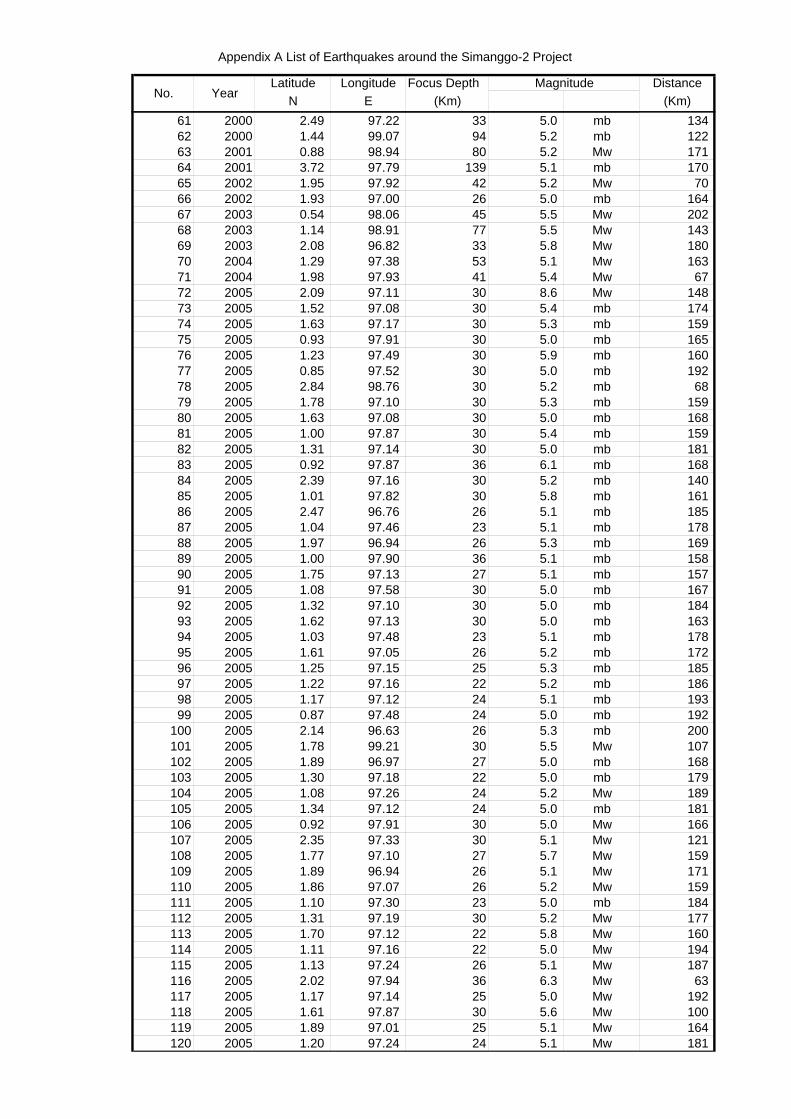
Appendix A List of Earthquakes around the Simanggo-2 Project
Latitude Longitude Focus Depth DistanceN E (Km) (Km)
MagnitudeNo. Year
61 2000 2.49 97.22 33 5.0 mb 13462 2000 1.44 99.07 94 5.2 mb 12263 2001 0.88 98.94 80 5.2 Mw 17164 2001 3.72 97.79 139 5.1 mb 17065 2002 1.95 97.92 42 5.2 Mw 7066 2002 1.93 97.00 26 5.0 mb 16467 2003 0.54 98.06 45 5.5 Mw 20268 2003 1.14 98.91 77 5.5 Mw 14369 2003 2.08 96.82 33 5.8 Mw 18070 2004 1.29 97.38 53 5.1 Mw 16371 2004 1.98 97.93 41 5.4 Mw 6772 2005 2.09 97.11 30 8.6 Mw 14873 2005 1.52 97.08 30 5.4 mb 17474 2005 1.63 97.17 30 5.3 mb 15975 2005 0.93 97.91 30 5.0 mb 16576 2005 1.23 97.49 30 5.9 mb 16077 2005 0.85 97.52 30 5.0 mb 19278 2005 2.84 98.76 30 5.2 mb 6879 2005 1.78 97.10 30 5.3 mb 15980 2005 1.63 97.08 30 5.0 mb 16881 2005 1.00 97.87 30 5.4 mb 15982 2005 1.31 97.14 30 5.0 mb 18183 2005 0.92 97.87 36 6.1 mb 16884 2005 2.39 97.16 30 5.2 mb 14085 2005 1.01 97.82 30 5.8 mb 16186 2005 2.47 96.76 26 5.1 mb 18587 2005 1.04 97.46 23 5.1 mb 17888 2005 1.97 96.94 26 5.3 mb 16989 2005 1.00 97.90 36 5.1 mb 15890 2005 1.75 97.13 27 5.1 mb 15791 2005 1.08 97.58 30 5.0 mb 16792 2005 1.32 97.10 30 5.0 mb 18493 2005 1.62 97.13 30 5.0 mb 16394 2005 1.03 97.48 23 5.1 mb 17895 2005 1.61 97.05 26 5.2 mb 17296 2005 1.25 97.15 25 5.3 mb 18597 2005 1.22 97.16 22 5.2 mb 18698 2005 1.17 97.12 24 5.1 mb 19399 2005 0.87 97.48 24 5.0 mb 192
100 2005 2.14 96.63 26 5.3 mb 200101 2005 1.78 99.21 30 5.5 Mw 107102 2005 1.89 96.97 27 5.0 mb 168103 2005 1.30 97.18 22 5.0 mb 179104 2005 1.08 97.26 24 5.2 Mw 189105 2005 1.34 97.12 24 5.0 mb 181106 2005 0.92 97.91 30 5.0 Mw 166107 2005 2.35 97.33 30 5.1 Mw 121108 2005 1.77 97.10 27 5.7 Mw 159109 2005 1.89 96.94 26 5.1 Mw 171110 2005 1.86 97.07 26 5.2 Mw 159111 2005 1.10 97.30 23 5.0 mb 184112 2005 1.31 97.19 30 5.2 Mw 177113 2005 1.70 97.12 22 5.8 Mw 160114 2005 1.11 97.16 22 5.0 Mw 194115 2005 1.13 97.24 26 5.1 Mw 187116 2005 2.02 97.94 36 6.3 Mw 63117 2005 1.17 97.14 25 5.0 Mw 192118 2005 1.61 97.87 30 5.6 Mw 100119 2005 1.89 97.01 25 5.1 Mw 164120 2005 1.20 97.24 24 5.1 Mw 181
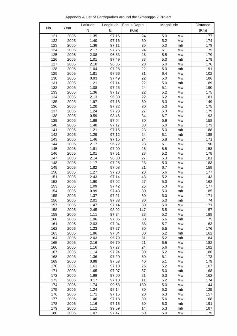
Appendix A List of Earthquakes around the Simanggo-2 Project
Latitude Longitude Focus Depth DistanceN E (Km) (Km)
MagnitudeNo. Year
121 2005 1.35 97.16 24 5.0 Mw 177122 2005 1.40 97.16 30 5.2 Mw 174123 2005 1.38 97.11 26 5.0 mb 179124 2005 2.17 97.76 24 6.1 Mw 75125 2005 2.08 96.83 26 5.5 Mw 179126 2005 1.01 97.49 33 5.0 mb 179127 2005 2.10 96.85 28 5.0 Mw 176128 2005 1.04 97.28 22 5.0 mb 191129 2005 1.81 97.66 31 6.4 Mw 102130 2005 0.93 97.49 22 5.0 Mw 186131 2005 1.21 97.14 22 5.0 mb 189132 2005 1.08 97.25 24 5.1 Mw 190133 2005 1.36 97.17 22 5.2 Mw 175134 2005 2.13 96.80 22 6.2 Mw 181135 2005 1.97 97.13 30 5.3 Mw 149136 2005 1.20 97.32 30 5.0 Mw 175137 2005 1.24 97.23 27 5.3 Mw 179138 2005 0.59 98.46 34 6.7 Mw 193139 2005 1.99 97.04 30 6.9 Mw 158140 2005 1.40 97.17 30 5.0 Mw 173141 2005 1.21 97.15 23 5.0 mb 188142 2005 1.29 97.12 24 5.1 mb 185143 2005 1.46 97.15 24 5.8 Mw 171144 2005 2.17 96.72 23 6.1 Mw 190145 2005 1.81 97.09 25 5.5 Mw 158146 2005 1.01 97.51 23 5.2 Mw 178147 2005 2.14 96.80 27 5.3 Mw 181148 2005 1.17 97.25 23 5.0 Mw 183149 2005 1.82 97.08 21 6.7 Mw 159150 2005 1.27 97.23 23 5.6 Mw 177151 2005 2.43 97.14 43 5.2 Mw 143152 2005 1.90 97.02 27 5.0 Mw 162153 2005 1.09 97.42 25 5.3 Mw 177154 2005 0.99 97.43 30 5.0 mb 185155 2005 1.37 97.21 30 5.0 Mw 171156 2005 2.01 97.83 30 5.0 mb 74157 2005 1.47 97.14 30 5.0 Mw 171158 2005 2.45 98.92 147 5.5 Mw 57159 2005 1.11 97.24 23 5.2 Mw 188160 2005 1.96 97.85 30 5.6 mb 75161 2005 2.03 97.94 38 5.7 Mw 63162 2005 1.23 97.27 30 5.5 Mw 176163 2005 1.86 97.04 30 5.2 mb 162164 2005 2.03 96.79 31 5.2 mb 184165 2005 2.16 96.79 21 6.5 Mw 182166 2005 1.16 97.27 24 5.6 Mw 182167 2005 1.14 97.24 30 5.2 Mw 186168 2005 1.36 97.20 30 5.1 Mw 173169 2006 0.98 97.53 40 5.1 Mw 179170 2006 1.61 97.10 26 5.2 Mw 167171 2006 1.65 97.07 37 5.0 mb 168172 2006 1.99 97.00 21 6.3 Mw 162173 2006 3.17 97.10 11 5.2 Mw 174174 2006 1.74 99.58 180 5.0 Mw 144175 2006 1.24 98.14 30 5.0 mb 125176 2006 1.71 97.15 20 6.3 Mw 157177 2006 1.46 97.18 30 5.6 Mw 168178 2006 1.16 97.15 30 5.0 mb 191179 2006 1.12 99.59 14 5.3 mb 187180 2006 1.07 97.47 50 5.0 Mw 175
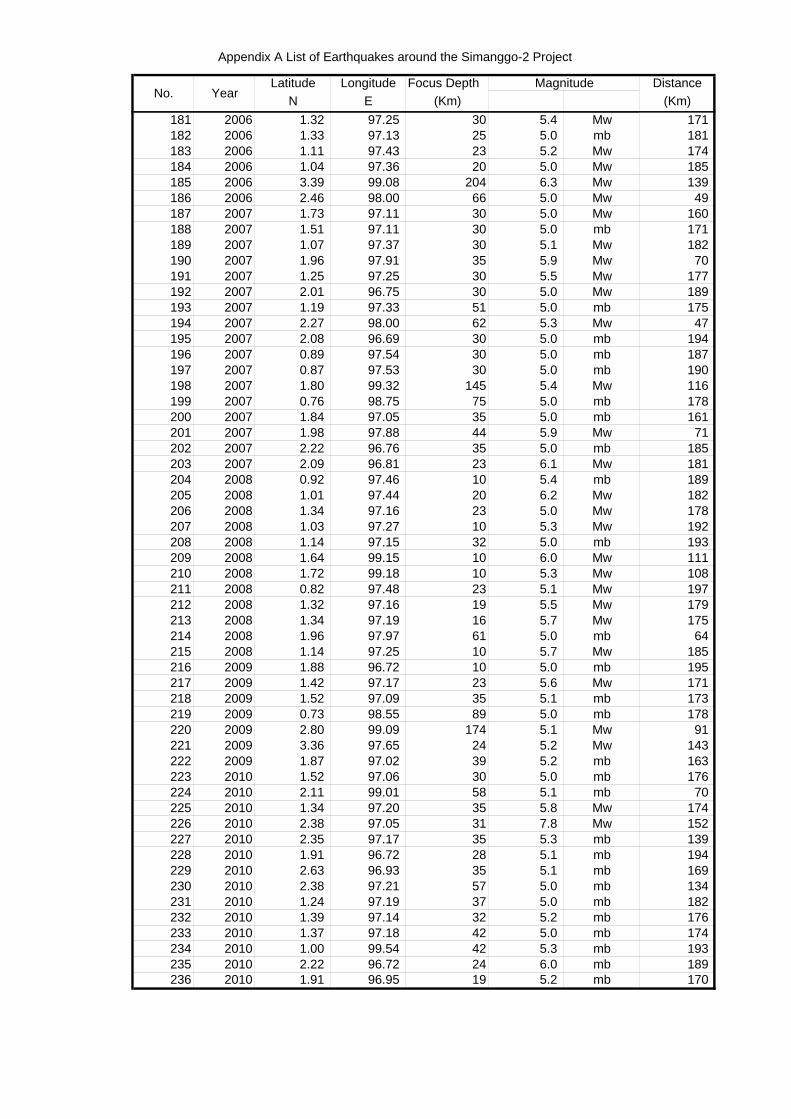
Appendix A List of Earthquakes around the Simanggo-2 Project
Latitude Longitude Focus Depth DistanceN E (Km) (Km)
MagnitudeNo. Year
181 2006 1.32 97.25 30 5.4 Mw 171182 2006 1.33 97.13 25 5.0 mb 181183 2006 1.11 97.43 23 5.2 Mw 174184 2006 1.04 97.36 20 5.0 Mw 185185 2006 3.39 99.08 204 6.3 Mw 139186 2006 2.46 98.00 66 5.0 Mw 49187 2007 1.73 97.11 30 5.0 Mw 160188 2007 1.51 97.11 30 5.0 mb 171189 2007 1.07 97.37 30 5.1 Mw 182190 2007 1.96 97.91 35 5.9 Mw 70191 2007 1.25 97.25 30 5.5 Mw 177192 2007 2.01 96.75 30 5.0 Mw 189193 2007 1.19 97.33 51 5.0 mb 175194 2007 2.27 98.00 62 5.3 Mw 47195 2007 2.08 96.69 30 5.0 mb 194196 2007 0.89 97.54 30 5.0 mb 187197 2007 0.87 97.53 30 5.0 mb 190198 2007 1.80 99.32 145 5.4 Mw 116199 2007 0.76 98.75 75 5.0 mb 178200 2007 1.84 97.05 35 5.0 mb 161201 2007 1.98 97.88 44 5.9 Mw 71202 2007 2.22 96.76 35 5.0 mb 185203 2007 2.09 96.81 23 6.1 Mw 181204 2008 0.92 97.46 10 5.4 mb 189205 2008 1.01 97.44 20 6.2 Mw 182206 2008 1.34 97.16 23 5.0 Mw 178207 2008 1.03 97.27 10 5.3 Mw 192208 2008 1.14 97.15 32 5.0 mb 193209 2008 1.64 99.15 10 6.0 Mw 111210 2008 1.72 99.18 10 5.3 Mw 108211 2008 0.82 97.48 23 5.1 Mw 197212 2008 1.32 97.16 19 5.5 Mw 179213 2008 1.34 97.19 16 5.7 Mw 175214 2008 1.96 97.97 61 5.0 mb 64215 2008 1.14 97.25 10 5.7 Mw 185216 2009 1.88 96.72 10 5.0 mb 195217 2009 1.42 97.17 23 5.6 Mw 171218 2009 1.52 97.09 35 5.1 mb 173219 2009 0.73 98.55 89 5.0 mb 178220 2009 2.80 99.09 174 5.1 Mw 91221 2009 3.36 97.65 24 5.2 Mw 143222 2009 1.87 97.02 39 5.2 mb 163223 2010 1.52 97.06 30 5.0 mb 176224 2010 2.11 99.01 58 5.1 mb 70225 2010 1.34 97.20 35 5.8 Mw 174226 2010 2.38 97.05 31 7.8 Mw 152227 2010 2.35 97.17 35 5.3 mb 139228 2010 1.91 96.72 28 5.1 mb 194229 2010 2.63 96.93 35 5.1 mb 169230 2010 2.38 97.21 57 5.0 mb 134231 2010 1.24 97.19 37 5.0 mb 182232 2010 1.39 97.14 32 5.2 mb 176233 2010 1.37 97.18 42 5.0 mb 174234 2010 1.00 99.54 42 5.3 mb 193235 2010 2.22 96.72 24 6.0 mb 189236 2010 1.91 96.95 19 5.2 mb 170

Appendix B
Interpreted Seismic Profiles
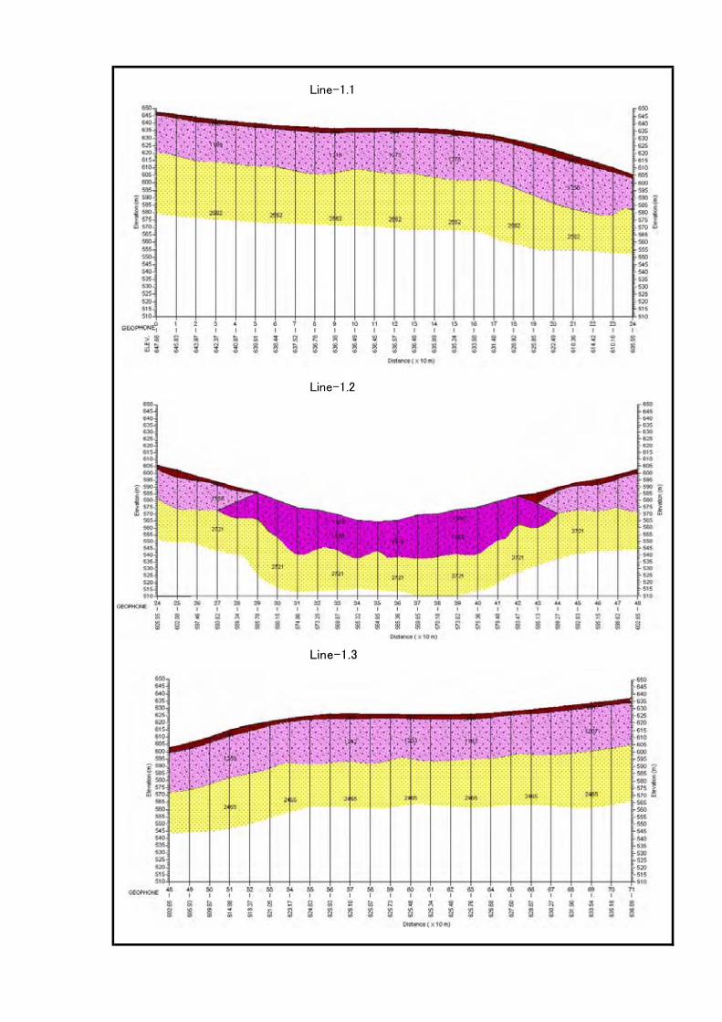
Line-1.1
Line-1.2
Line-1.3
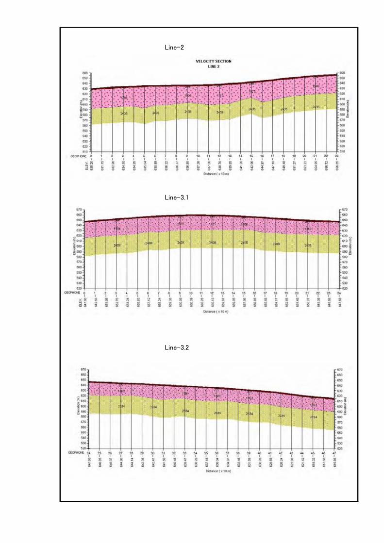
Line-2
Line-3.1
Line-3.2
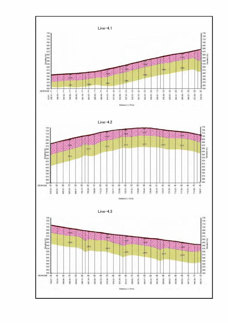
Line-4.1
Line-4.2
Line-4.3
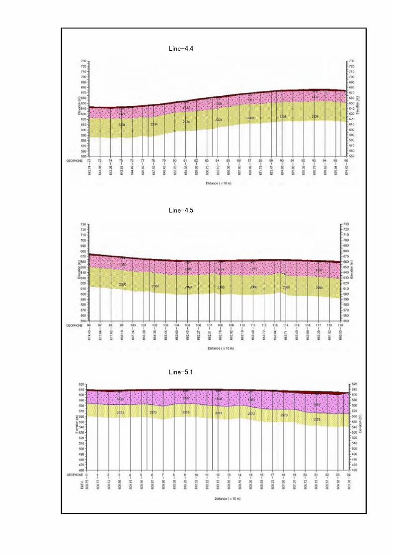
Line-4.4
Line-4.5
Line-5.1
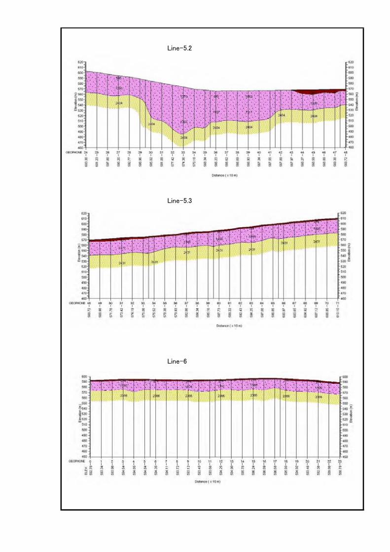
Line-5.2
Line-5.3
Line-6
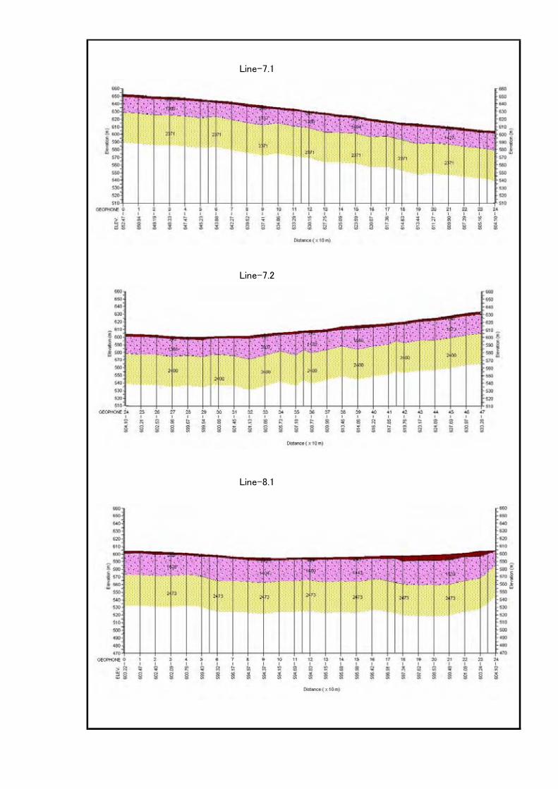
Line-7.1
Line-7.2
Line-8.1
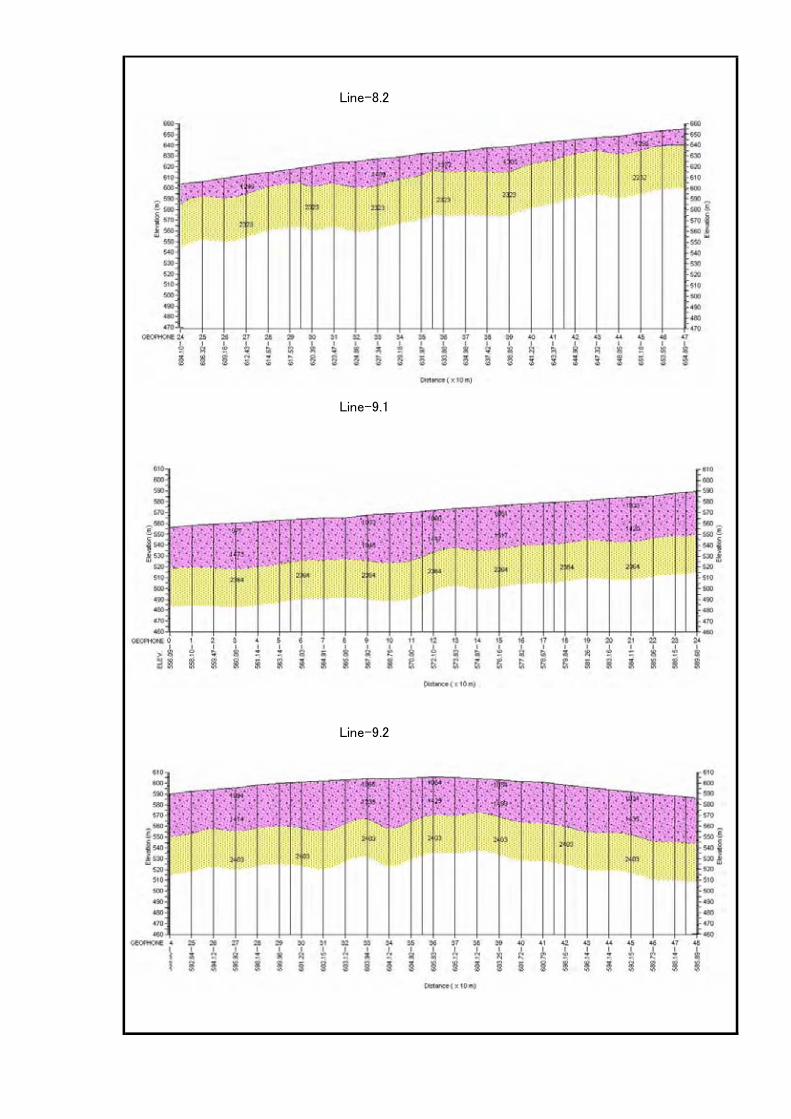
Line-8.2
Line-9.1
Line-9.2
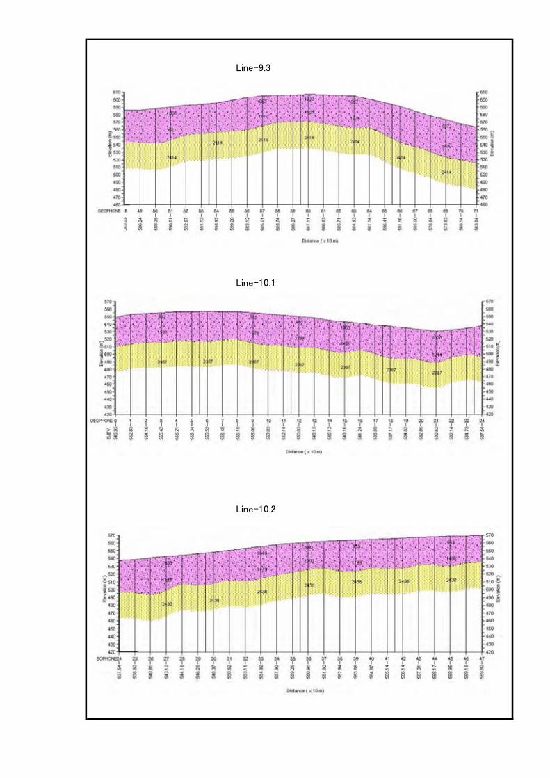
Line-9.3
Line-10.1
Line-10.2
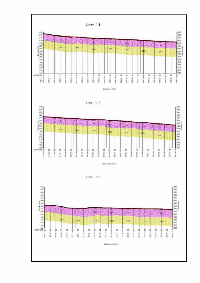
Line-11.1
Line-11.2
Line-11.3

Line-12
Line-13.1
Line-13.2

Line-14
Vp-1 <800m/sec
Vp-2 1,00o - 1,800 m/sec
Vp-3 1,800 - 2,000 m/sec
Vp-4 2,000 - 3,000 m/sec
Related Documents