Birck Nanotechnology Center Transforming Light with Metamaterials Birck Nanotechnology Center Part 1: Electrical & Magnetic Metamaterials Part 2: Negative-Index Metamaterials, NLO, and super/hyper-lens Part 3: Cloaking and Transformation Optics

Welcome message from author
This document is posted to help you gain knowledge. Please leave a comment to let me know what you think about it! Share it to your friends and learn new things together.
Transcript
Birck Nanotechnology Center
Transforming Light with Metamaterials
Birck Nanotechnology Center
Part 1: Electrical & Magnetic Metamaterials
Part 2: Negative-Index Metamaterials, NLO, and super/hyper-lens
Part 3: Cloaking and Transformation Optics
Birck Nanotechnology Center
Transforming Light with Metamaterials
Birck Nanotechnology Center
Part 1: Electrical & Magnetic Metamaterials
Part 2: Negative-Index Metamaterials, NLO, and super/hyper-lens
Part 3: Cloaking and Transformation Optics
Birck Nanotechnology Center
Outline
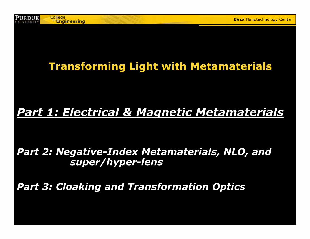
� What are metamaterials?� Early electrical metamaterials
� Magnetic metamaterials
� Negative-index metamaterials
3
� Negative-index metamaterials
� Chiral metamaterials
� Nonlinear optics with metamaterials
� Super-resolution
� Optical Cloaking and Transformation Optics

Birck Nanotechnology Center
Natural Optical Materials
Semiconductors
Crystals
Water
metals
AirE,H ~exp[in(ω/c)z]
n = ±√(εµ)
4
Semiconductors
Birck Nanotechnology Center
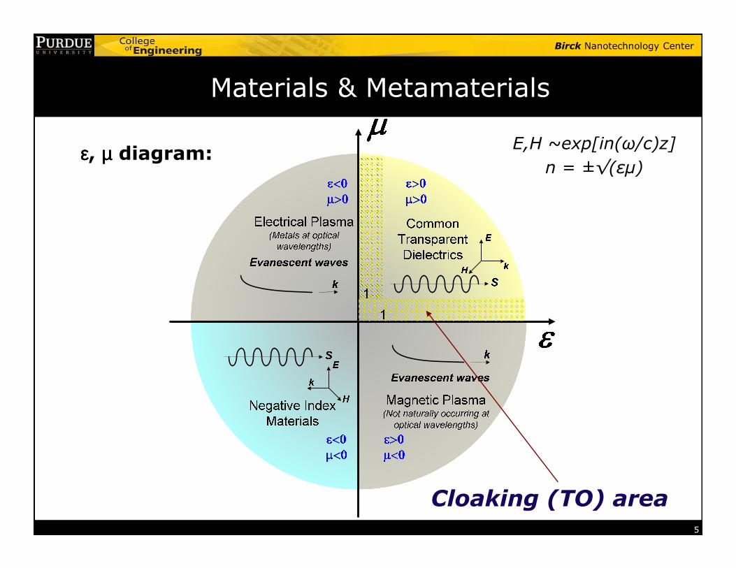
Materials & Metamaterials
εεεε, µµµµ diagram:E,H ~exp[in(ω/c)z]
n = ±√(εµ)
5
Cloaking (TO) area
Birck Nanotechnology Center
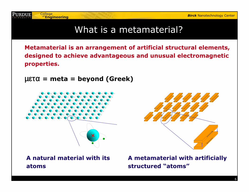
What is a metamaterial?
Metamaterial is an arrangement of artificial structural elements,
designed to achieve advantageous and unusual electromagnetic
properties.
µεταµεταµεταµετα = meta = beyond (Greek)
6
+-
-
A natural material with its
atoms
A metamaterial with artificially
structured “atoms”
Birck Nanotechnology Center
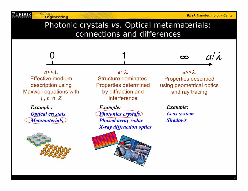
Photonic crystals vs. Optical metamaterials: connections and differences
0 1 a
a<< .
Effective medium
description using
Maxwell equations with
a~
Structure dominates.
Properties determined
by diffraction and
a>>
Properties described
using geometrical optics
and ray tracing
7
, , n, Z interference
Example:
Optical crystals
Metamaterials
Example:
Photonics crystals
Phased array radar
X-ray diffraction optics
Example:
Lens system
Shadows
Birck Nanotechnology Center
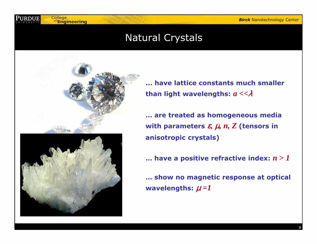
Natural Crystals
... have lattice constants much smaller
than light wavelengths: a <<λλλλ
… are treated as homogeneous media
with parameters εεεε, µµµµ, n, Z (tensors in
8
with parameters εεεε, µµµµ, n, Z (tensors in
anisotropic crystals)
… have a positive refractive index: n > 1
… show no magnetic response at optical
wavelengths: µµµµ =1
Birck Nanotechnology Center
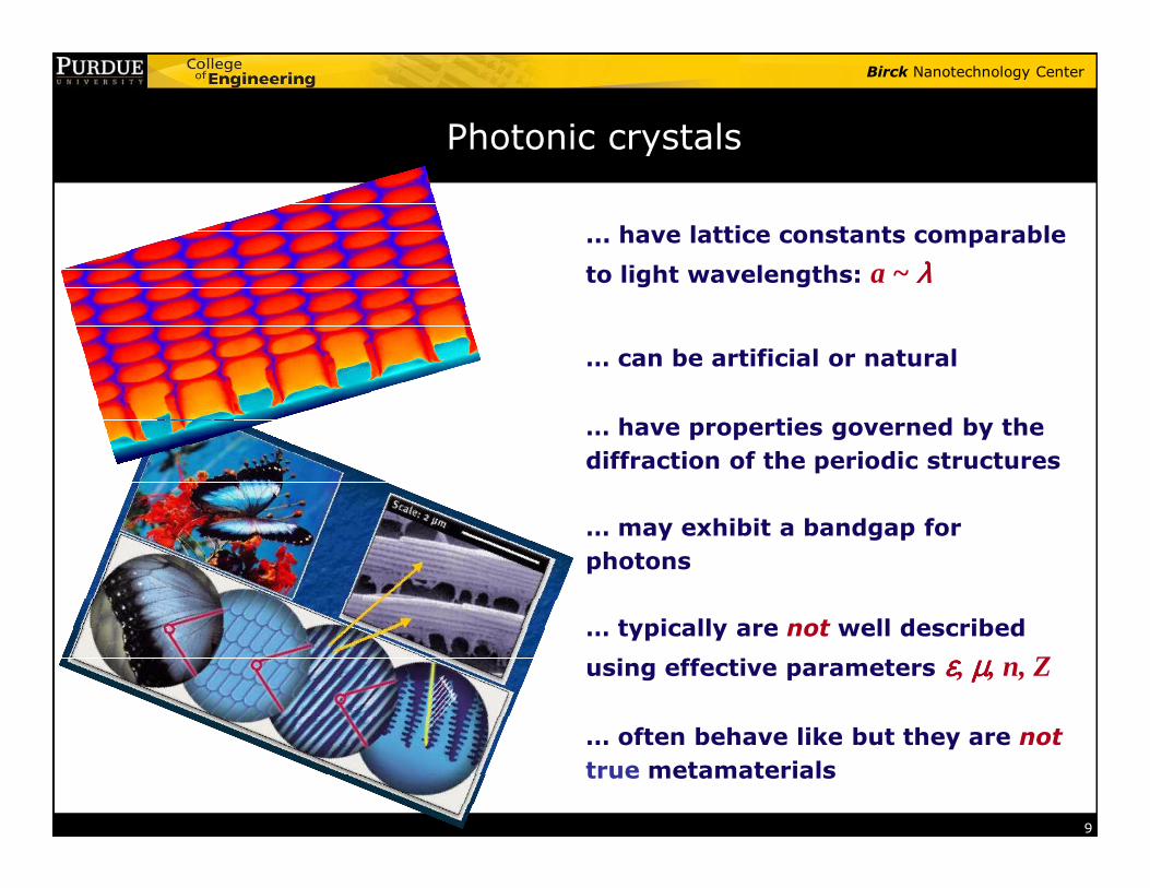
Photonic crystals
... have lattice constants comparable
to light wavelengths: a ~ λλλλ
… can be artificial or natural
… have properties governed by the
9
diffraction of the periodic structures
… may exhibit a bandgap for
photons
… typically are not well described
using effective parameters εεεε, µµµµ, n, Z
… often behave like but they are not
true metamaterials
Birck Nanotechnology Center
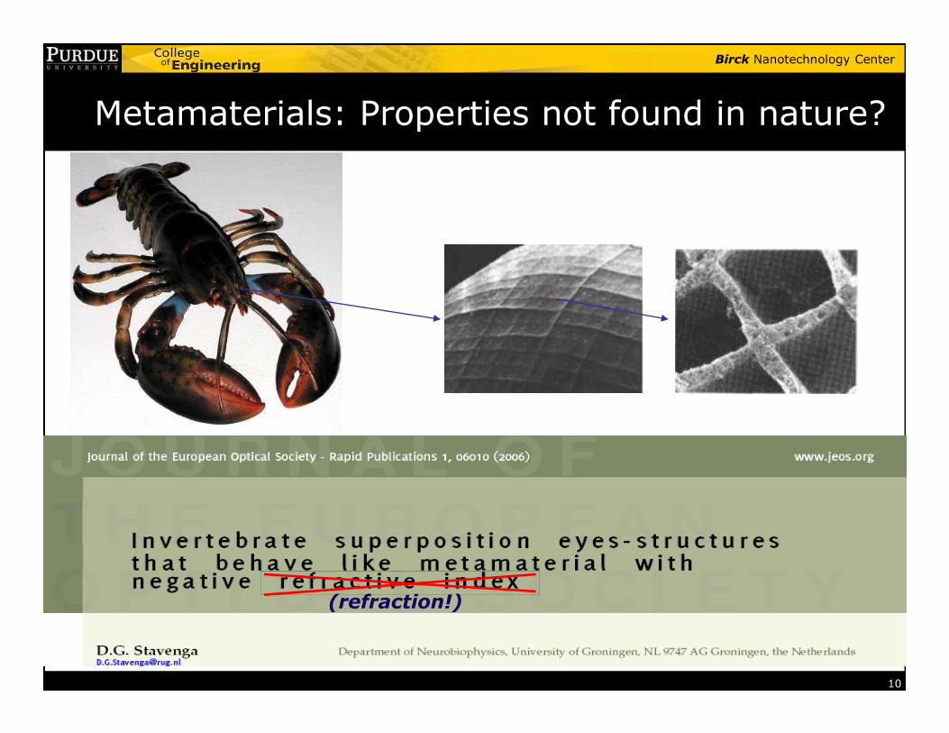
Metamaterials: Properties not found in nature?
10
(refraction!)
Birck Nanotechnology Center
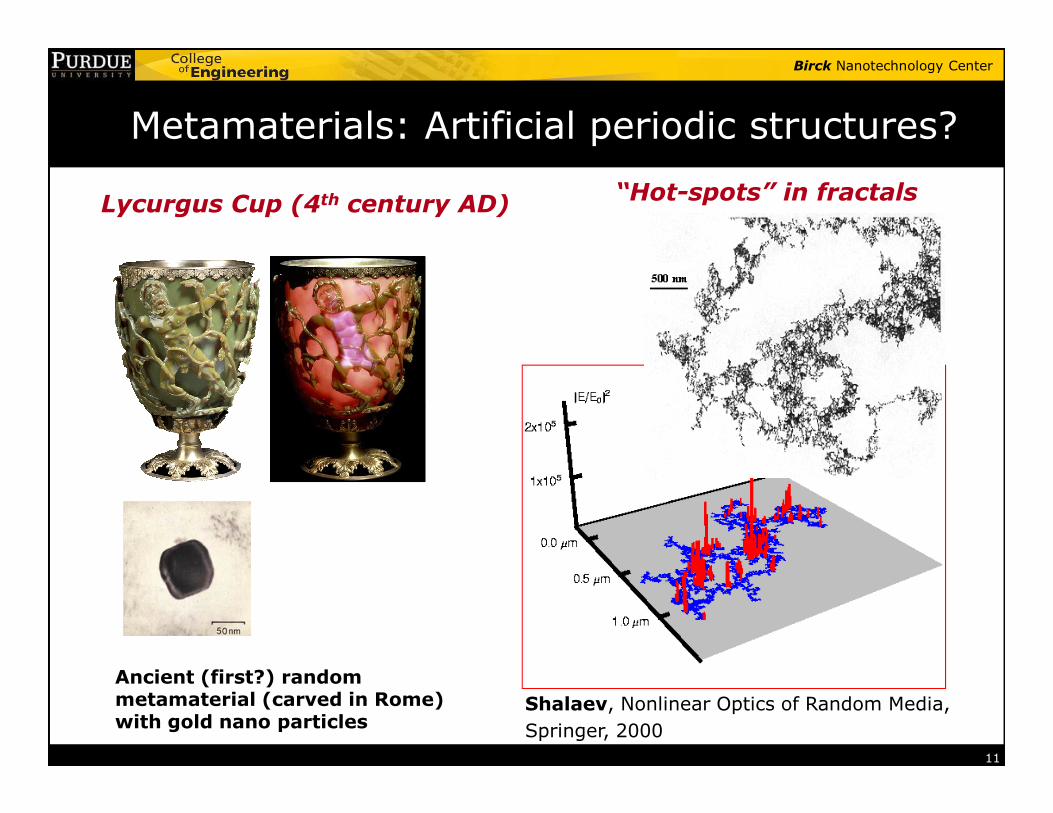
Metamaterials: Artificial periodic structures?
“Hot-spots” in fractalsLycurgus Cup (4th century AD)
11
Shalaev, Nonlinear Optics of Random Media,
Springer, 2000
Ancient (first?) random metamaterial (carved in Rome) with gold nano particles
Birck Nanotechnology Center
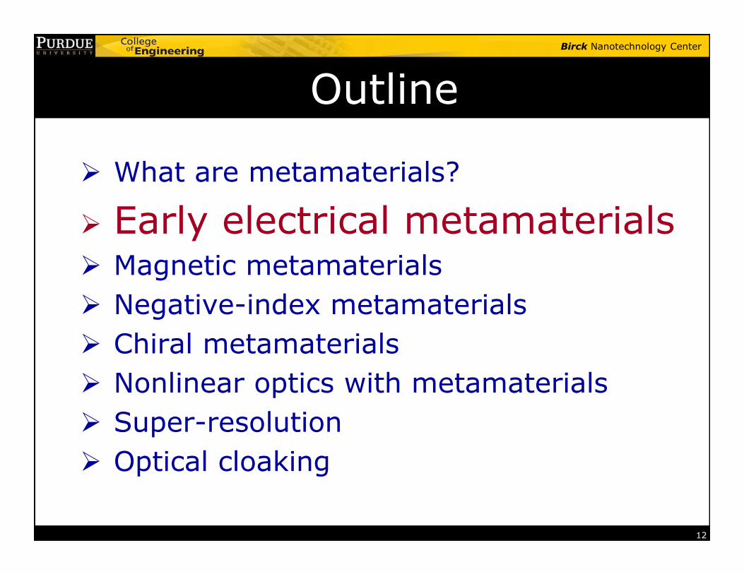
Outline
� What are metamaterials?
� Early electrical metamaterials� Magnetic metamaterials
Negative-index metamaterials
12
� Negative-index metamaterials
� Chiral metamaterials
� Nonlinear optics with metamaterials
� Super-resolution
� Optical cloaking

Birck Nanotechnology Center
Early (first?) Example of Meta-Atoms
Twisted jute elements
Artificial chiral molecules
13
Jagadis C. Bose, Proceeding of Royal Soc. London, 1898
“On the Rotation of Plane of Polarization of Electric Waves by a Twisted Structure”
Birck Nanotechnology Center
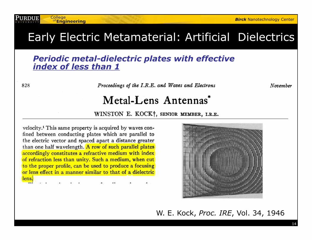
Early Electric Metamaterial: Artificial Dielectrics
Periodic metal-dielectric plates with effective index of less than 1
14
W. E. Kock, Proc. IRE, Vol. 34, 1946

Birck Nanotechnology Center
Noble metal: ε < 1 in nature
-50
0
50
Per
mitt
ivity
of S
ilver
2
0( )( )
p
i
ωε ω ε
ω ω= −
+ Γ
0 5.0
9.216
0.0212p eV
eV
εω
==
Γ =
Drude model for permittivity: Silver parameters:
15
500 1000 1500 2000-250
-200
-150
-100
-50
Wavelength (nm)
Per
mitt
ivity
of S
ilver
Re(ε), experimentIm(ε), experimentRe(ε), DrudeIm(ε), Drude
Experimental data from Johnson & Christy, PRB, 1972
Birck Nanotechnology Center
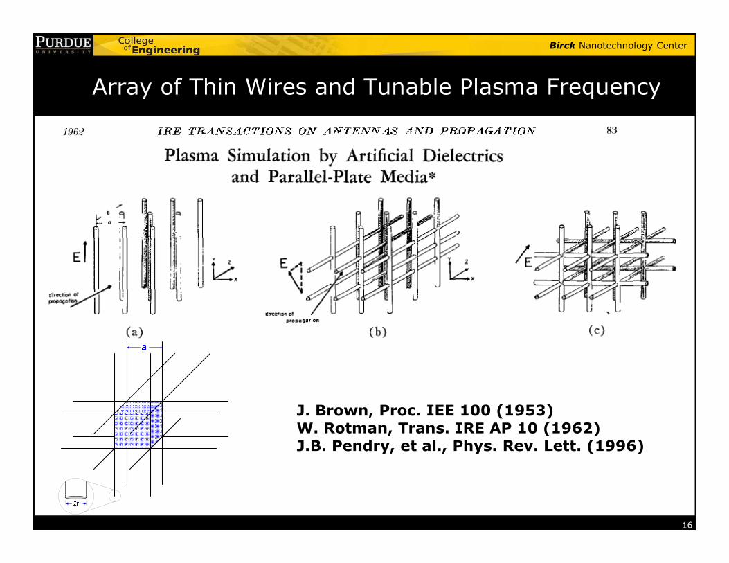
Array of Thin Wires and Tunable Plasma Frequency
16
J. Brown, Proc. IEE 100 (1953)W. Rotman, Trans. IRE AP 10 (1962)J.B. Pendry, et al., Phys. Rev. Lett. (1996)
Birck Nanotechnology Center
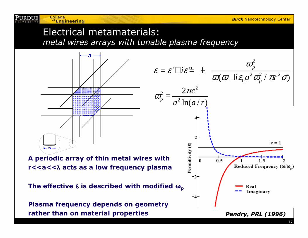
Electrical metamaterials:metal wires arrays with tunable plasma frequency
2
2 2 20
' " 1( / )
p
p
ii a r
ωε ε ε
ω ω ε ω π σ= + = −
+2
22
2
ln( / )p
c
a a r
πω =
17
A periodic array of thin metal wires with
r<<a<<λλλλ acts as a low frequency plasma
The effective εεεε is described with modified ωp
Plasma frequency depends on geometry
rather than on material properties Pendry, PRL (1996)
Birck Nanotechnology Center
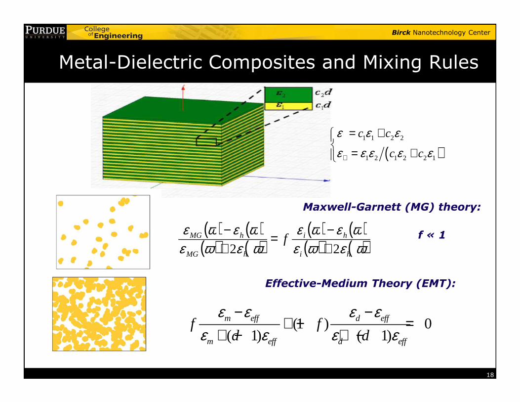
Metal-Dielectric Composites and Mixing Rules
( )1 1 2 2
1 2 1 2 2 1
c c
c c
ε ε εε ε ε ε ε⊥
= + = +
�
Maxwell-Garnett (MG) theory:
18
( ) ( )( ) ( )
( ) ( )( ) ( )ωεωε
ωεωεωεωε
ωεωεhi
hi
hMG
hMG f22 +
−=+−
Maxwell-Garnett (MG) theory:
Effective-Medium Theory (EMT):
(1 ) 0( 1) ( 1)m eff d eff
m eff d eff
f fd d
ε ε ε εε ε ε ε
− −+ − =
+ − + −
f « 1
Birck Nanotechnology Center
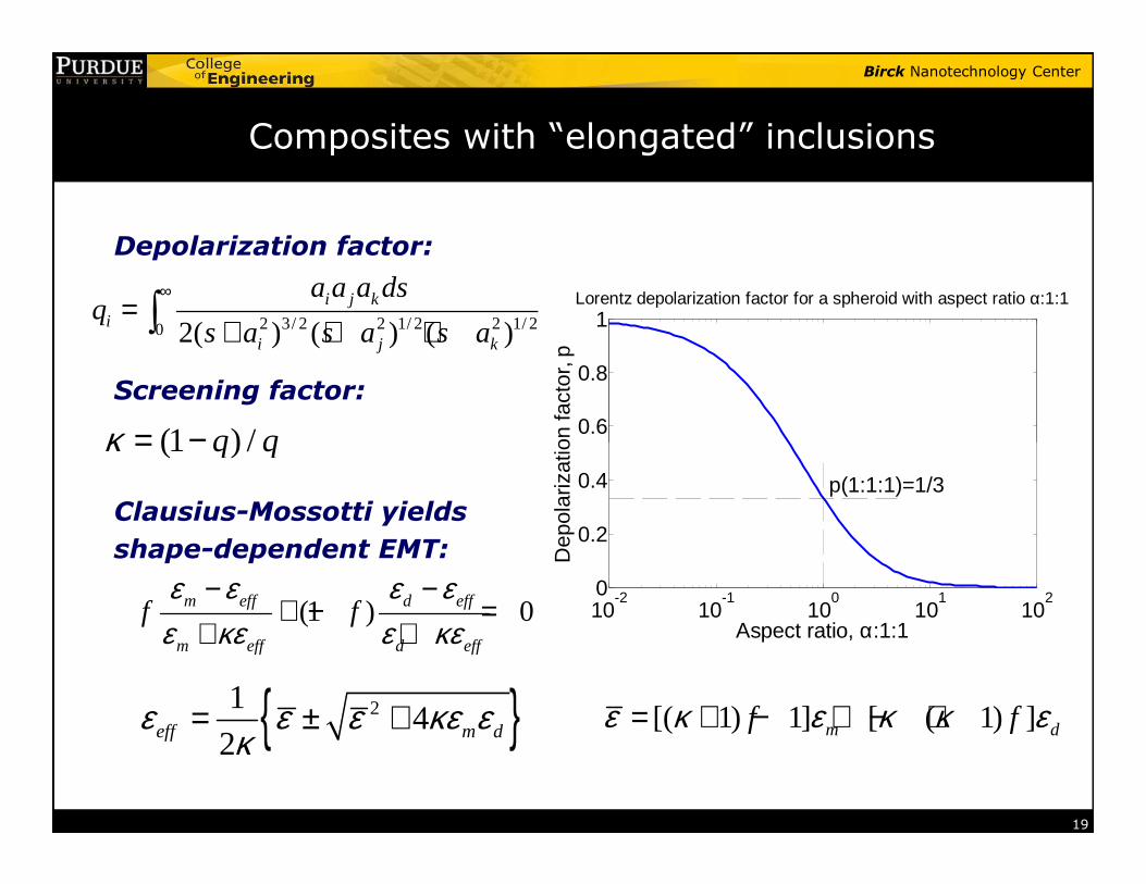
Composites with “elongated” inclusions
2 3/ 2 2 1/ 2 2 1/ 20 2( ) ( ) ( )i j k
ii j k
a a a dsq
s a s a s a
∞=
+ + +∫
(1 ) /q qκ = − 0.6
0.8
1
Dep
olar
izat
ion
fact
or, p
Lorentz depolarization factor for a spheroid with aspect ratio α:1:1
Depolarization factor:
Screening factor:
19
(1 ) /q qκ = −
(1 ) 0m eff d eff
m eff d eff
f fε ε ε ε
ε κε ε κε− −
+ − =+ +
{ }214
2eff m dε ε ε κε εκ
= ± + [( 1) 1] [ ( 1) ]m df fε κ ε κ κ ε= + − + − +
10-2
10-1
100
101
1020
0.2
0.4
Aspect ratio, α:1:1
Dep
olar
izat
ion
fact
or,
p(1:1:1)=1/3Clausius-Mossotti yields
shape-dependent EMT:
Birck Nanotechnology Center
Outline
� What are metamaterials?
� Early electrical metamaterials
� Magnetic metamaterialsNegative-index metamaterials
20
� Negative-index metamaterials
� Chiral metamaterials
� Nonlinear optics with metamaterials
� Super-resolution
� Optical cloaking
Birck Nanotechnology Center
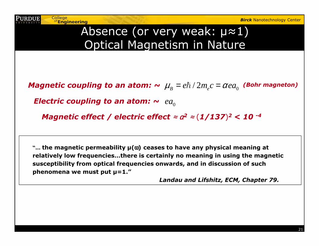
Absence (or very weak: µ≈1) Optical Magnetism in Nature
Magnetic coupling to an atom: ~ 0/ 2B ee m c eaµ α= =ℏ
0eaElectric coupling to an atom: ~
(Bohr magneton)
Magnetic effect / electric effect ≈≈≈≈ αααα2 ≈≈≈≈ (1/137)2 < 10 -4
21
“… the magnetic permeability µ(ωωωω) ceases to have any physical meaning at
relatively low frequencies…there is certainly no meaning in using the magnetic
susceptibility from optical frequencies onwards, and in discussion of such
phenomena we must put µ=1.”
Landau and Lifshitz, ECM, Chapter 79.
Birck Nanotechnology Center
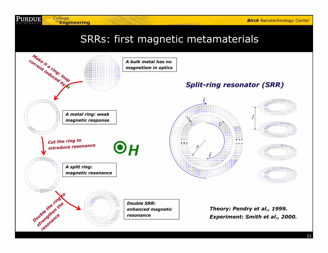
SRRs: first magnetic metamaterials
A bulk metal has no
magnetism in optics
A metal ring: weak
magnetic response
Split-ring resonator (SRR)
22
Theory: Pendry et al., 1999.
HA split ring:
magnetic resonance
Double SRR:
enhanced magnetic
resonance Experiment: Smith et al., 2000.
Birck Nanotechnology Center
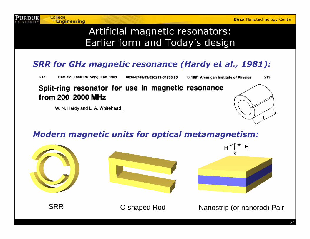
Artificial magnetic resonators: Earlier form and Today’s design
SRR for GHz magnetic resonance (Hardy et al., 1981):
23
Nanostrip (or nanorod) Pair
EHk
SRR C-shaped Rod
Modern magnetic units for optical metamagnetism:
Birck Nanotechnology Center
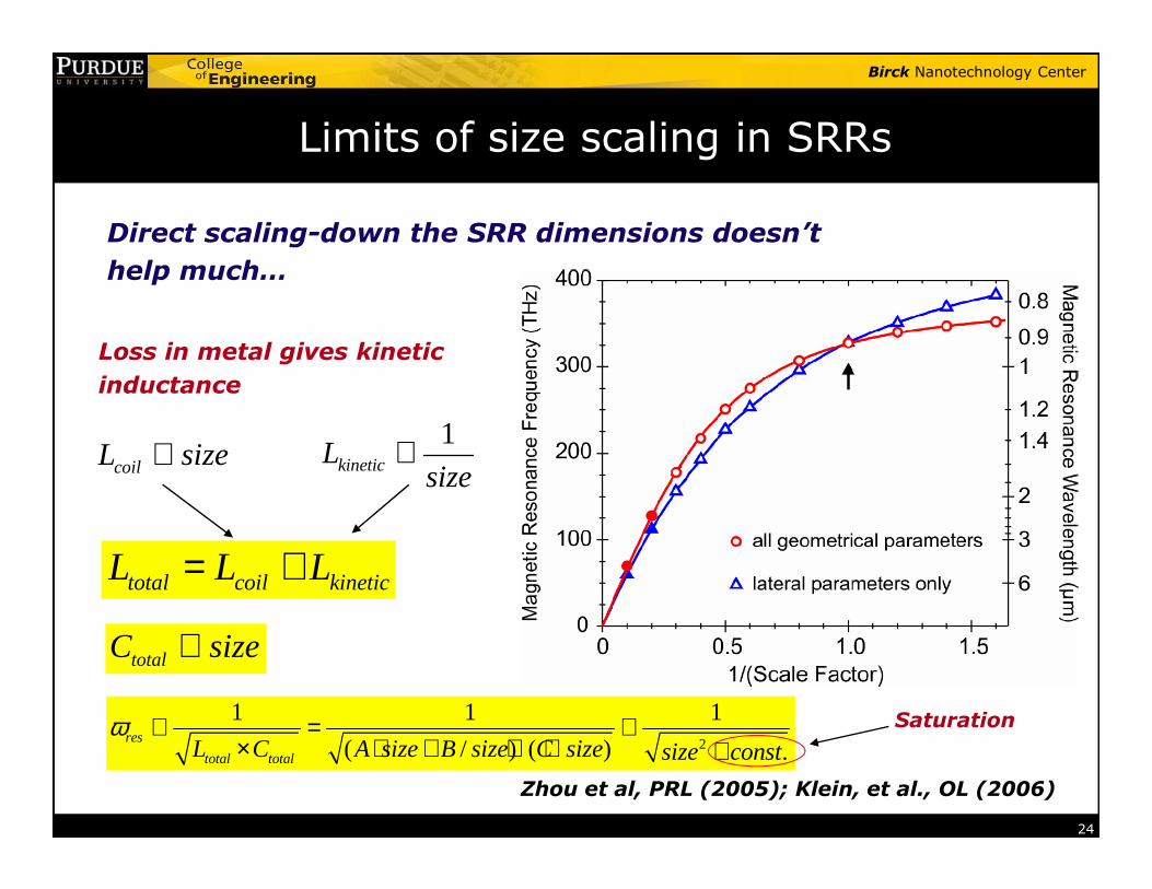
Limits of size scaling in SRRs
Direct scaling-down the SRR dimensions doesn’t
help much…
L size∝1
L ∝
Loss in metal gives kinetic
inductance
24
total coil kineticL L L= +
Zhou et al, PRL (2005); Klein, et al., OL (2006)
coilL size∝1
kineticLsize
∝
totalC size∝
2
1 1 1
( / ) ( ) .res
total totalL C A size B size C size size constω ∝ = ∝
× ⋅ + ⋅ ⋅ +Saturation
Birck Nanotechnology Center
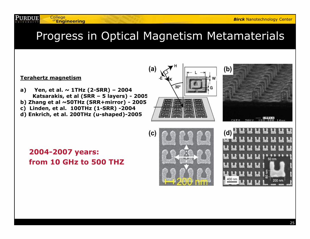
Progress in Optical Magnetism Metamaterials
Terahertz magnetism
a) Yen, et al. ~ 1THz (2-SRR) – 2004 Katsarakis, et al (SRR – 5 layers) - 2005
b) Zhang et al ~50THz (SRR+mirror) - 2005c) Linden, et al. 100THz (1-SRR) -2004d) Enkrich, et al. 200THz (u-shaped)-2005
25
2004-2007 years:
from 10 GHz to 500 THZ

Birck Nanotechnology Center
Magnetic Metamaterial: Nanorod to Nanostrip
E
H
k
Dielectric
Metal
26
Nanorod pair Nanorod pair array Nanostrip pair
Nanostrip pair has a much stronger magnetic response
Lagar’kov, Sarychev PRB (1996) - µ > 0
Podolskiy, Sarychev & Shalaev, JNOPM (2002) - µ < 0 & n < 0
Kildishev et al, JOSA B (2006); Shvets et al JOSA (2006) – strip pairs
(Svirko, et al, APL (2001) - “crossed” rods for chirality)
Birck Nanotechnology Center
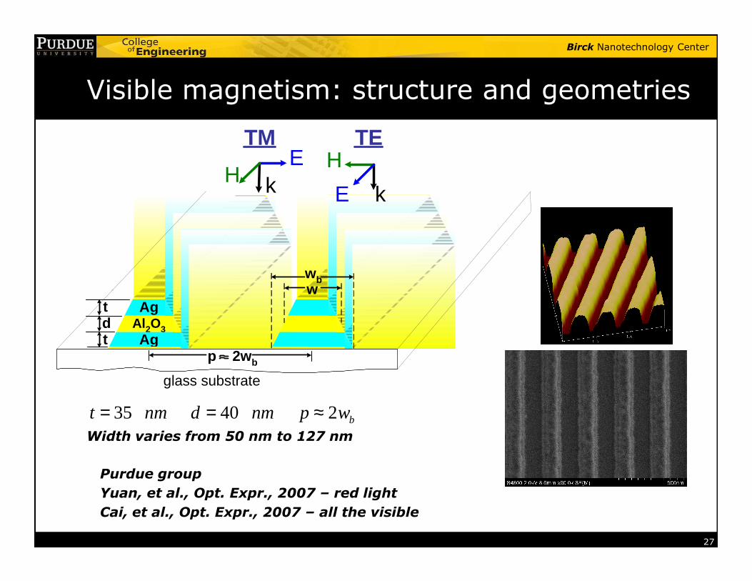
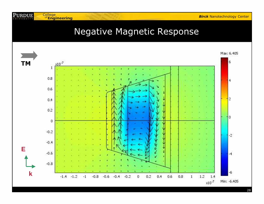
Visible magnetism: structure and geometries
wwb
kE
H
TM
k
H
E
TE
27
35 40 2 bt nm d nm p w= = ≈
Purdue group
Yuan, et al., Opt. Expr., 2007 – red light
Cai, et al., Opt. Expr., 2007 – all the visible
glass substrate
p 2wb
tdt
AgAl2O3Ag
w
Width varies from 50 nm to 127 nm
Birck Nanotechnology Center
TM
Negative Magnetic Response
28
E
k
Birck Nanotechnology Center
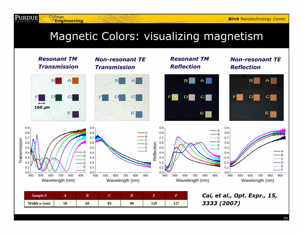
Magnetic Colors: visualizing magnetism
Resonant TM
TransmissionNon-resonant TE
Transmission
Resonant TM
ReflectionNon-resonant TE
Reflection
160 µµµµm
29
Sample # A B C D E F
Width w (nm) 50 69 83 98 118 127
Cai, et al., Opt. Expr., 15,
3333 (2007)
400 500 600 700 800 9000.0
0.1
0.2
0.3
0.4
0.5
0.6
0.7
0.8
0.9
Tra
nsm
issi
on
Wavelength (nm)
A B C D E F
400 500 600 700 800 9000.0
0.1
0.2
0.3
0.4
0.5
0.6
0.7
0.8
0.9
Wavelength (nm)
A B C D E F
400 500 600 700 800 9000.0
0.1
0.2
0.3
0.4
0.5
0.6
0.7
0.8
0.9
Ref
lect
ion
Wavelength (nm)
A B C D E F
400 500 600 700 800 9000.0
0.1
0.2
0.3
0.4
0.5
0.6
0.7
0.8
0.9
Wavelength (nm)
A B C D E F
Birck Nanotechnology Center
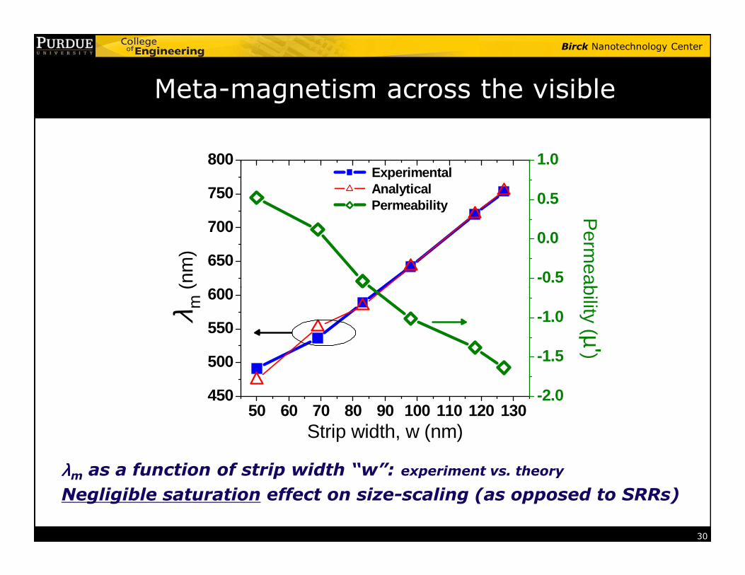
Meta-magnetism across the visible
600
650
700
750
800 Experimental Analytical Permeability
(nm
)
-0.5
0.0
0.5
1.0P
ermeability (
30
λλλλm as a function of strip width “w”: experiment vs. theory
Negligible saturation effect on size-scaling (as opposed to SRRs)
50 60 70 80 90 100 110 120 130450
500
550
600
Strip width, w (nm)
λ m (
nm)
-2.0
-1.5
-1.0
Perm
eability (µ')
Birck Nanotechnology Center
Transforming Light with Metamaterials
Birck Nanotechnology Center
Part 1: Electrical and Magnetic Metamaterials
Part 2: Negative-Index Metamaterials, NLO, and super/hyper-lens
Part 3: Cloaking and Transformation Optics
Birck Nanotechnology Center
Outline
� What are metamaterials?
� Early electrical metamaterials
� Magnetic metamaterials
� Negative-index metamaterials
32
� Negative-index metamaterials� Chiral metamaterials
� Nonlinear optics with metamaterials
� Super-resolution
� Optical cloaking
Birck Nanotechnology Center
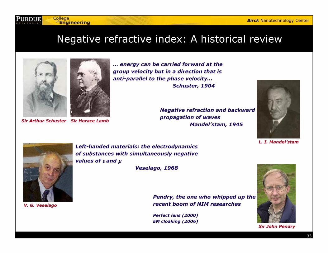
Negative refractive index: A historical review
Sir Arthur Schuster Sir Horace Lamb
… energy can be carried forward at the
group velocity but in a direction that is
anti-parallel to the phase velocity…
Schuster, 1904
Negative refraction and backward
propagation of waves
Mandel’stam, 1945
33
L. I. Mandel’stam
V. G. Veselago
Sir John Pendry
Mandel’stam, 1945
Left-handed materials: the electrodynamics
of substances with simultaneously negative
values of εεεε and µµµµVeselago, 1968
Pendry, the one who whipped up the
recent boom of NIM researches
Perfect lens (2000)
EM cloaking (2006)
Birck Nanotechnology Center
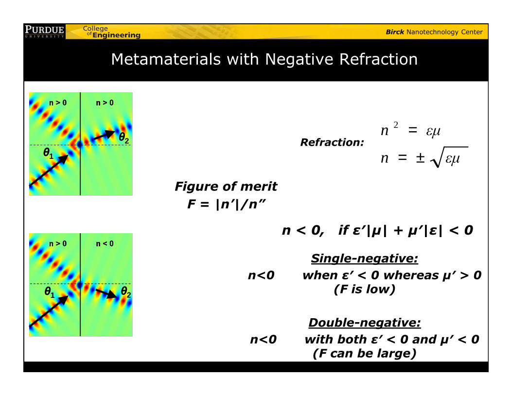
Metamaterials with Negative Refraction
εµn
εµn
±=
=2
Refraction:
Figure of merit
F = |n’|/n”
θ1
θ2
Single-negative:
n<0 when ε′ < 0 whereas µ′ > 0 (F is low)
Double-negative:
n<0 with both ε′ < 0 and µ′ < 0 (F can be large)
n < 0, if ε′|µ| + µ′|ε| < 0
F = |n’|/n”
θ1 θ2
Birck Nanotechnology Center
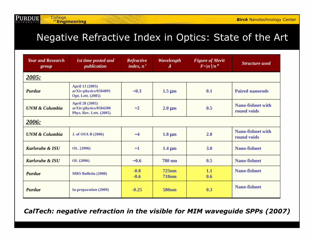
Negative Refractive Index in Optics: State of the Art
Year and Research group
1st time posted and publication
Refractive index, n′′′′
Wavelengthλλλλ
Figure of MeritF=|n′′′′|/n″″″″ Structure used
2005:
PurdueApril 13 (2005)arXiv:physics/0504091Opt. Lett. (2005)
−−−−0.3 1.5 µµµµm 0.1 Paired nanorods
UNM & ColumbiaApril 28 (2005)arXiv:physics/0504208Phys. Rev. Lett. (2005)
−−−−2 2.0 µµµµm 0.5Nano-fishnet with round voids
2006:
CalTech: negative refraction in the visible for MIM waveguide SPPs (2007)
2006:
UNM & Columbia J. of OSA B (2006) −−−−4 1.8 µµµµm 2.0Nano-fishnet with round voids
Karlsruhe & ISU OL. (2006) −−−−1 1.4 µµµµm 3.0 Nano-fishnet
Karlsruhe & ISU OL (2006) −−−−0.6 780 nm 0.5 Nano-fishnet
Purdue MRS Bulletin (2008) -0.8-0.6
725nm710nm
1.10.6
Nano-fishnet
Purdue In preparation (2009) -0.25 580nm 0.3Nano-fishnet
Birck Nanotechnology Center
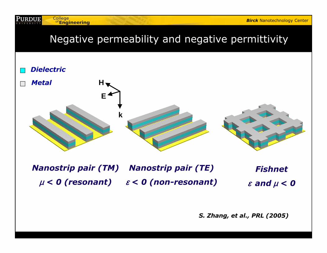
Negative permeability and negative permittivity
E
H
k
Dielectric
Metal
Nanostrip pair (TM)
µµµµ < 0 (resonant)
Nanostrip pair (TE)
εεεε < 0 (non-resonant)Fishnet
ε ε ε ε and µµµµ < 0
S. Zhang, et al., PRL (2005)
Birck Nanotechnology Center
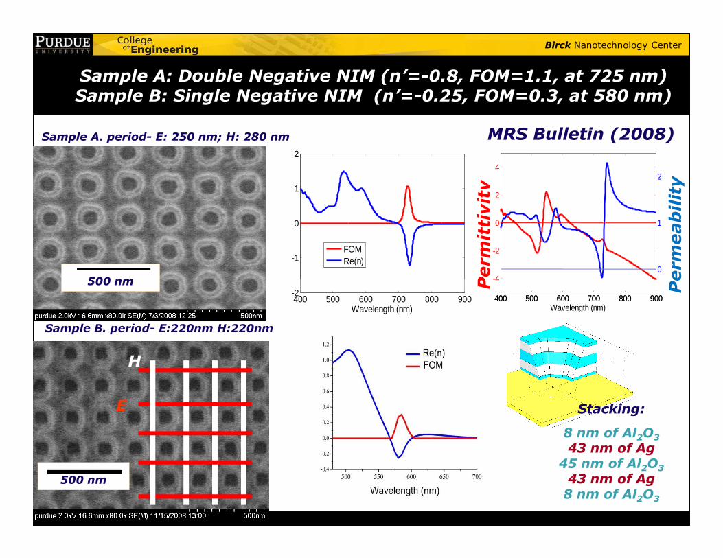
Sample A: Double Negative NIM (n’=-0.8, FOM=1.1, at 725 nm) Sample B: Single Negative NIM (n’=-0.25, FOM=0.3, at 580 nm)
Sample A. period- E: 250 nm; H: 280 nm
-1
0
1
2
FOMRe(n)
Perm
ittivity
Perm
eability
-4
-2
0
2
4
0
1
2
500 nm
MRS Bulletin (2008)
Sample B. period- E:220nm H:220nm
400 500 600 700 800 900-2
Wavelength (nm)
Perm
ittivity
Perm
eability
400 500 600 700 800 900
-4
400 500 600 700 800 900Wavelength (nm)
500 nm
E
H
500 nm
Stacking:
8 nm of Al2O3
43 nm of Ag45 nm of Al2O3
43 nm of Ag8 nm of Al2O3
Birck Nanotechnology Center
Summary on negative refractive index
• A Double Negative NIM (Negative index material) is demonstrated at a wavelength of ~725 nm
38
• A Single Negative NIM behavior is demonstrated at a wavelength of ~580 nm
Birck Nanotechnology Center
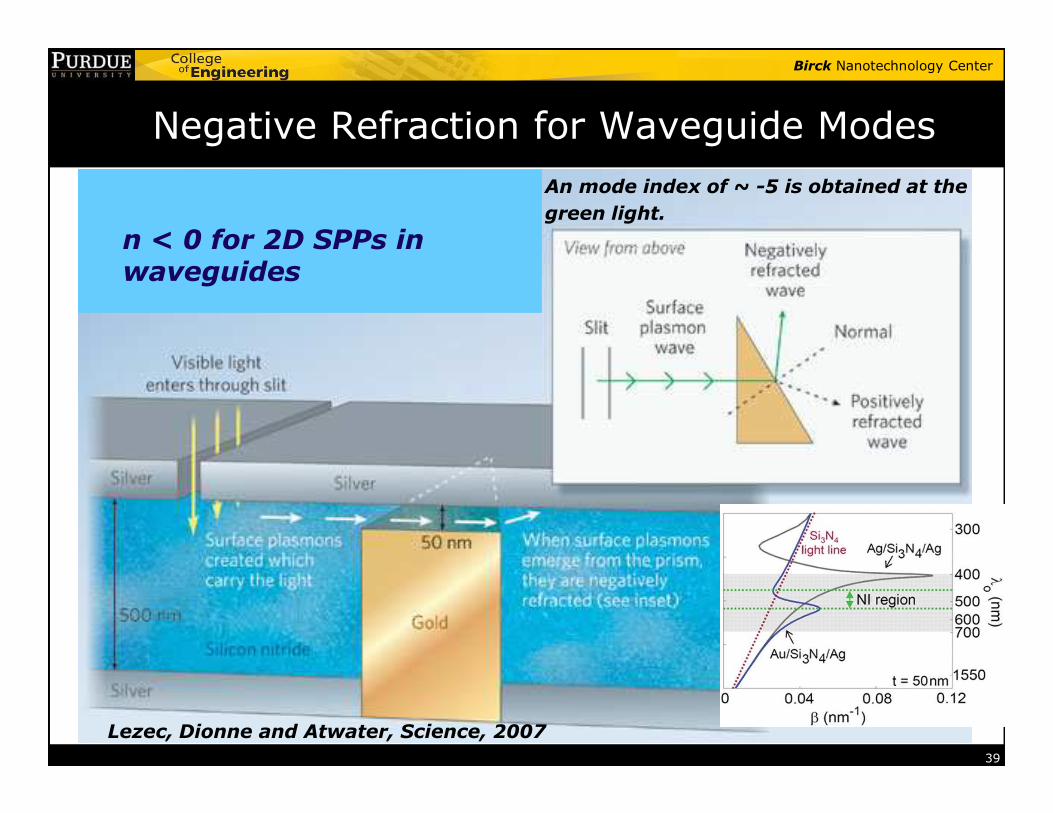
Negative Refraction for Waveguide Modes
An mode index of ~ -5 is obtained at the
green light.
n < 0 for 2D SPPs in waveguides
39
Lezec, Dionne and Atwater, Science, 2007
Birck Nanotechnology Center
Outline
� What are metamaterials?
� Early electrical metamaterials
� Magnetic metamaterials
� Negative-index metamaterials
40
� Negative-index metamaterials
� Chiral metamaterials� Nonlinear optics with metamaterials
� Super-resolution
� Optical cloaking
Birck Nanotechnology Center
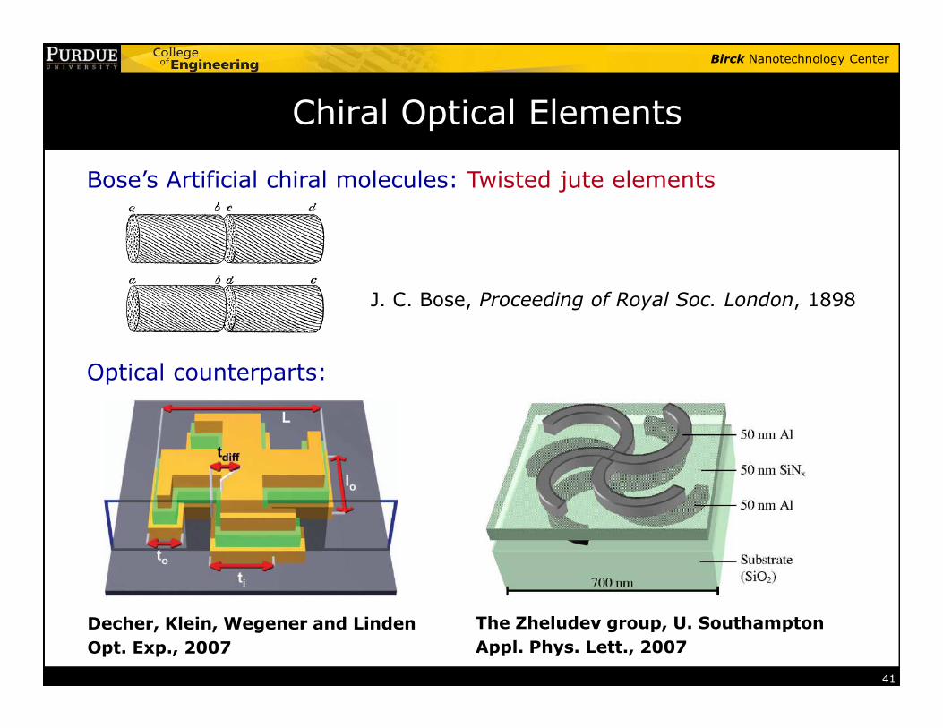
Chiral Optical Elements
Bose’s Artificial chiral molecules: Twisted jute elements
J. C. Bose, Proceeding of Royal Soc. London, 1898
Optical counterparts:
41
Optical counterparts:
Decher, Klein, Wegener and Linden
Opt. Exp., 2007
The Zheludev group, U. Southampton
Appl. Phys. Lett., 2007
Birck Nanotechnology Center
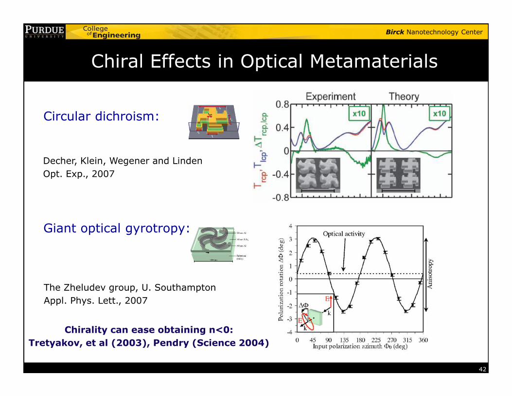
Chiral Effects in Optical Metamaterials
Circular dichroism:
Decher, Klein, Wegener and Linden
Opt. Exp., 2007
42
Giant optical gyrotropy:
The Zheludev group, U. Southampton
Appl. Phys. Lett., 2007
Chirality can ease obtaining n<0:
Tretyakov, et al (2003), Pendry (Science 2004)
Birck Nanotechnology Center
Outline
� What are metamaterials?
� Early electrical metamaterials
� Magnetic metamaterials
� Negative-index metamaterials
43
� Negative-index metamaterials
� Chiral metamaterials
� Nonlinear optics with metamaterials
� Super-resolution
� Optical cloaking

Birck Nanotechnology Center
SHG and THG from Magnetic Metamaterial
Excitation when magnetic resonance is excited (1st pol)
44
SHG: Klein, Enkrich, Wegener, and Linden, Science, 2006
SHG & THG: Klein, Wegener, Feth and Linden, Opt. Express, 2007
Excitation at 2nd pol. (no magnetic resonance)
Birck Nanotechnology Center
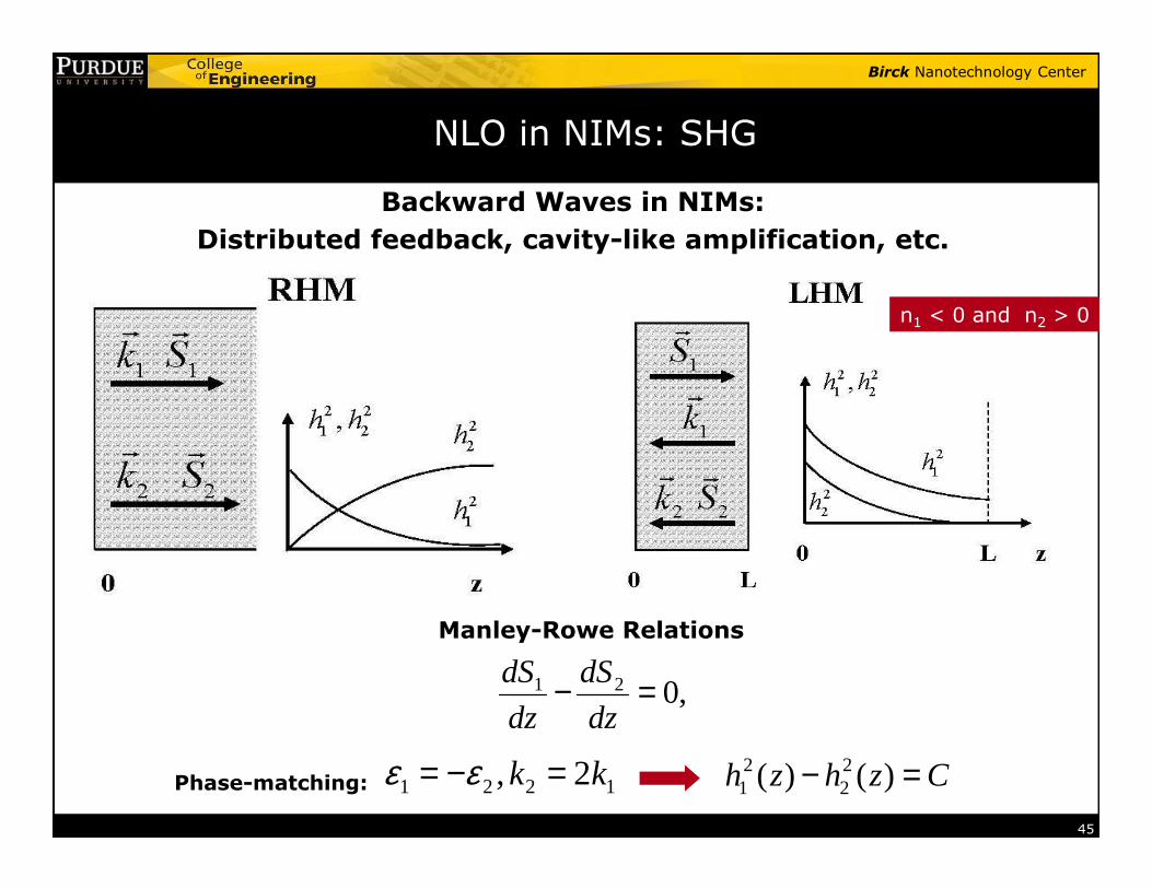
NLO in NIMs: SHG
Backward Waves in NIMs:
Distributed feedback, cavity-like amplification, etc.
02
22
2
221
1
1 =+dz
dhk
dz
dhk
εεCzhzh =− )()( 2
221
n1 < 0 and n2 > 0
45
Manley-Rowe Relations
,021 =−dz
dS
dz
dS
Czhzh =− )()( 22
211221 2, kk =−= εεPhase-matching:
Birck Nanotechnology Center
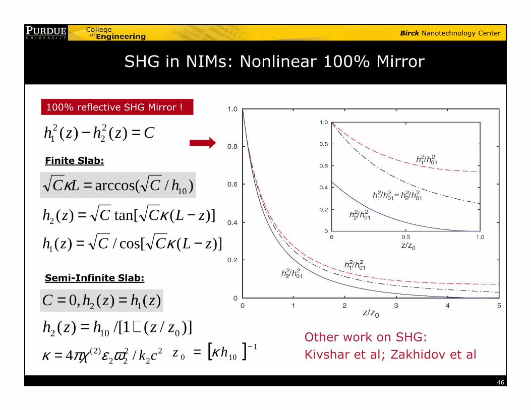
SHG in NIMs: Nonlinear 100% Mirror
−= κ
)/arccos( 10hCLC =κFinite Slab:
100% reflective SHG Mirror !
Czhzh =− )()( 22
21
46
[ ] 1100
−= hz κ22
222
)2( /4 ckωεπχκ =
)](cos[/)(1 zLCCzh −= κ
)](tan[)(2 zLCCzh −= κ
Semi-Infinite Slab:
)()(,0 12 zhzhC ==
)]/(1/[)( 0102 zzhzh +=Other work on SHG:
Kivshar et al; Zakhidov et al
Birck Nanotechnology Center
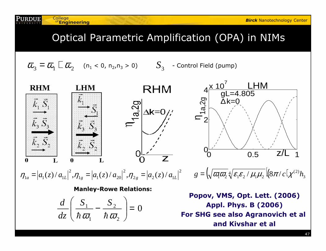
Optical Parametric Amplification (OPA) in NIMs
213 ωωω +=
2
4x 10⁷
η 1a,2
g
gL=4.805∆k=0
LHM
3S - Control Field (pump)(n1 < 0, n2,n3 > 0)
47
Manley-Rowe Relations:
02
2
1
1 =
−
ωω hh
SS
dz
d
0 0.5 10 z/L
2
122
2
2011
2
111 /)(,/)(,/)( LggLa azaazaaza === ηηη ( )( ) 3)2(4
212121 /8/ hcg χπµµεεωω=
Popov, VMS, Opt. Lett. (2006)
Appl. Phys. B (2006)
For SHG see also Agranovich et al
and Kivshar et al
Birck Nanotechnology Center
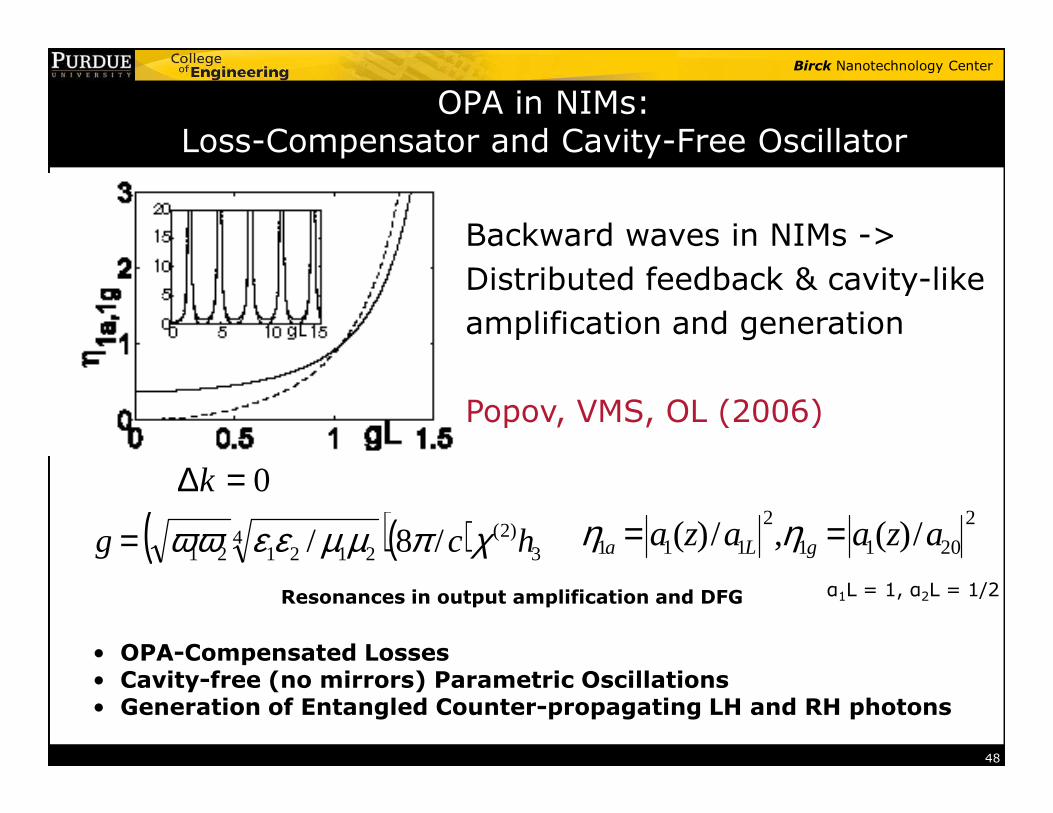
OPA in NIMs:Loss-Compensator and Cavity-Free Oscillator
Backward waves in NIMs ->
Distributed feedback & cavity-like
amplification and generation
Popov, VMS, OL (2006)
48
2
2011
2
111 /)(,/)( azaaza gLa == ηη( )( ) 3)2(4
212121 /8/ hcg χπµµεεωω=Resonances in output amplification and DFG
0=∆k
• OPA-Compensated Losses• Cavity-free (no mirrors) Parametric Oscillations • Generation of Entangled Counter-propagating LH and RH photons
α1L = 1, α2L = 1/2
Popov, VMS, OL (2006)
Birck Nanotechnology Center
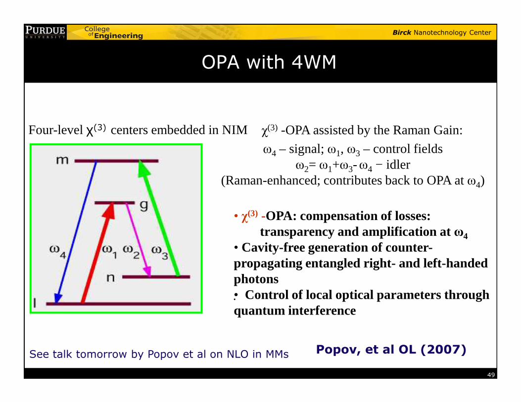
χ(3) -OPA assisted by the Raman Gain:
ω4 – signal; ω1, ω3 – control fields ω2= ω1+ω3-ω4 − idler
(Raman-enhanced; contributes back to OPA at ω4)
Four-level χ(3) centers embedded in NIM
OPA with 4WM
49
.
• χ(3) -OPA: compensation of losses: transparency and amplification at ω4
• Cavity-free generation of counter-propagating entangled right- and left-handed photons• Control of local optical parameters through quantum interference
Popov, et al OL (2007)See talk tomorrow by Popov et al on NLO in MMs
Birck Nanotechnology Center
Outline
� What are metamaterials?
� Early electrical metamaterials
� Magnetic metamaterials
� Negative-index metamaterials
50
� Negative-index metamaterials
� Chiral metamaterials
� Nonlinear optics with metamaterials
� Super-resolution� Optical cloaking
Birck Nanotechnology Center
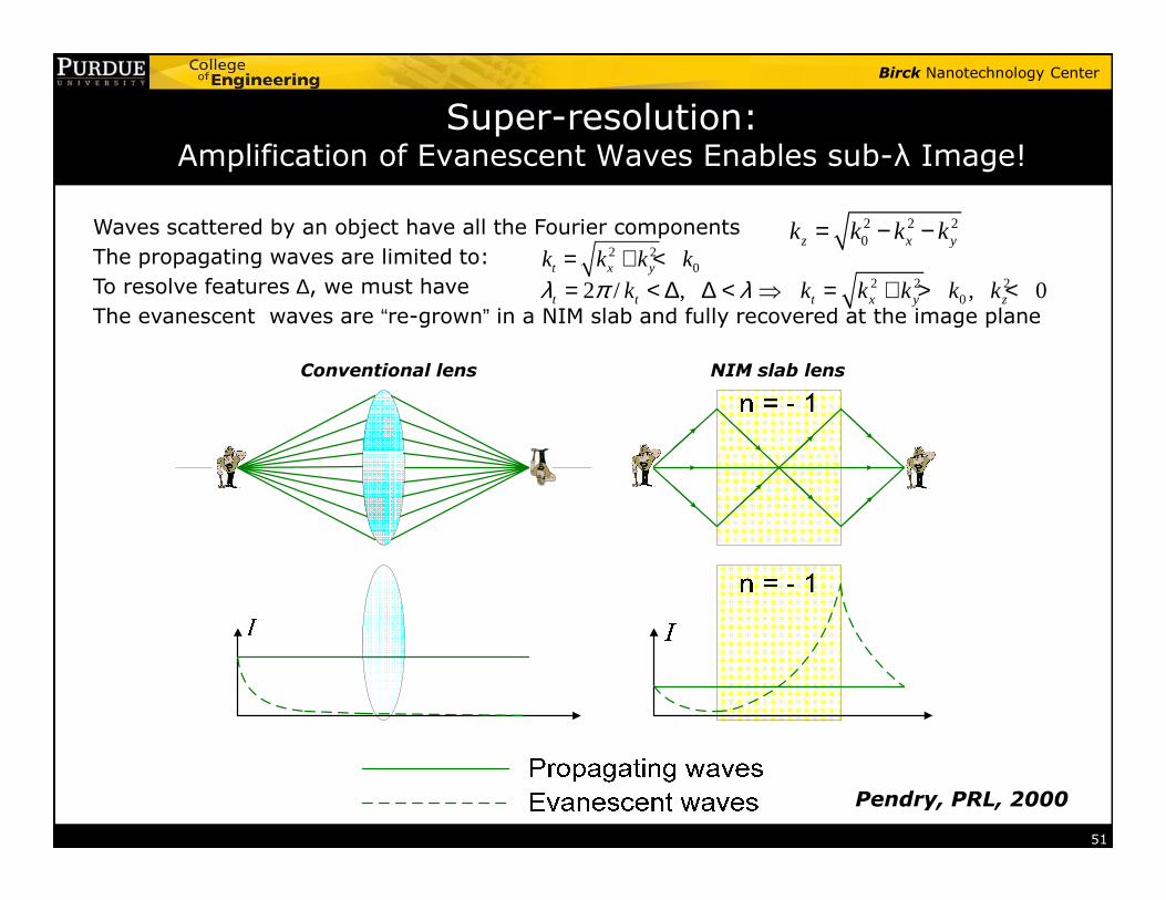
Super-resolution: Amplification of Evanescent Waves Enables sub-λ Image!
Waves scattered by an object have all the Fourier components
The propagating waves are limited to:
To resolve features ∆, we must have
The evanescent waves are “re-grown” in a NIM slab and fully recovered at the image plane
2 2 20z x yk k k k= − −
2 20t x yk k k k= + <
2 2 202 / , , 0t t t x y zk k k k k kλ π λ= < ∆ ∆ < ⇒ = + > <
NIM slab lensConventional lens
51
Pendry, PRL, 2000
Birck Nanotechnology Center
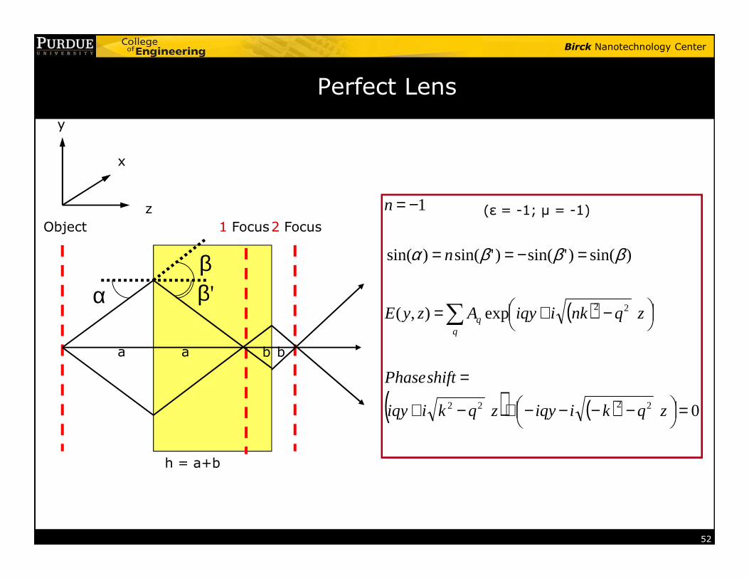
Perfect Lens
y
Object 2 Focus1 Focus
α 'ββ
x
z
)sin()'sin()'sin()sin(
1
=−==
−=
n
n
βββα
(ε = -1; µ = -1)
52
α 'β
a a b b
h = a+b
( )
( ) ( ) 0
exp),(
2222
22
=
−−−−+−+
=
−+=∑
zqkiiqyzqkiiqy
shiftPhase
zqnkiiqyAzyEq
q
Birck Nanotechnology Center
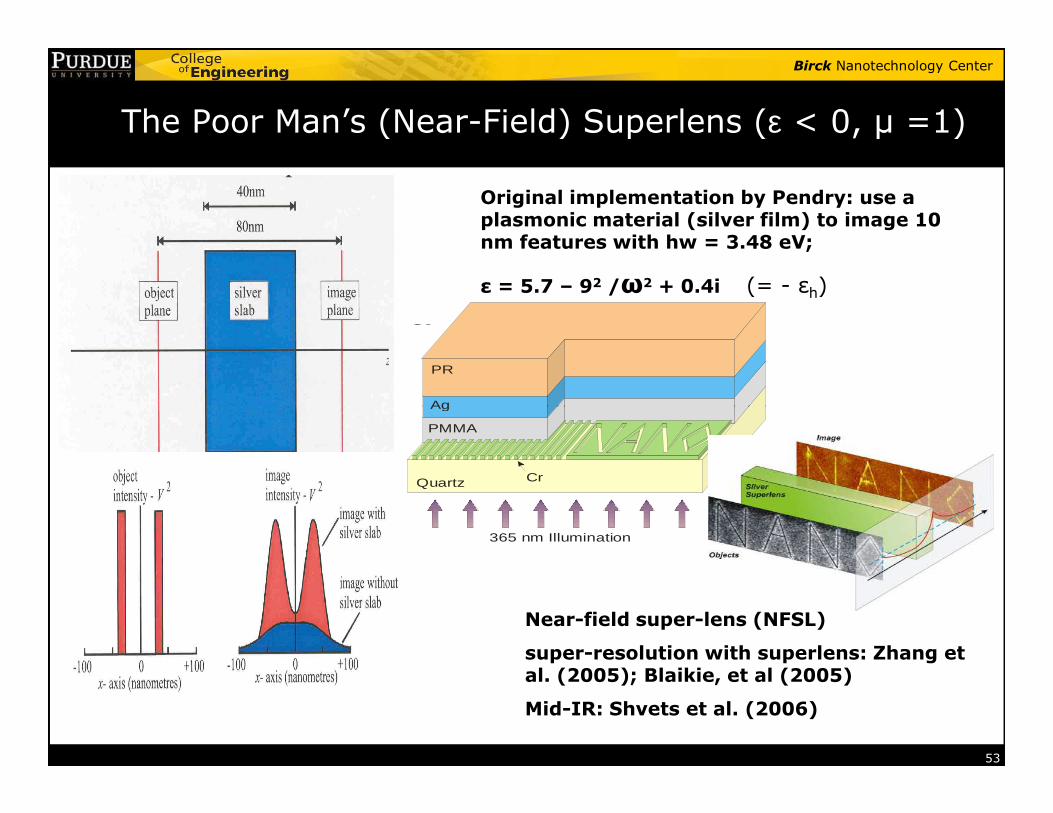
The Poor Man’s (Near-Field) Superlens (ε < 0, µ =1)
Original implementation by Pendry: use a plasmonic material (silver film) to image 10 nm features with hw = 3.48 eV;
ε = 5.7 – 92 /ω2 + 0.4i (= - εh)
PR
Ag
a
53
Near-field super-lens (NFSL)
super-resolution with superlens: Zhang et al. (2005); Blaikie, et al (2005)
Mid-IR: Shvets et al. (2006)
365 nm Illumination
Ag
PMMA
Quartz Cr
Birck Nanotechnology Center
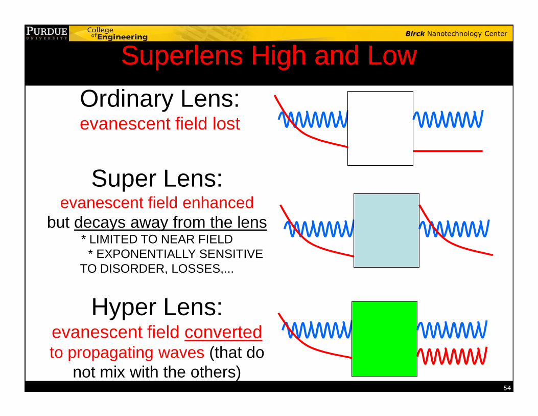
Superlens High and LowSuperlens High and Low
Ordinary Lens:evanescent field lost
Super Lens:evanescent field enhanced
54
evanescent field enhancedbut decays away from the lens
* LIMITED TO NEAR FIELD * EXPONENTIALLY SENSITIVE
TO DISORDER, LOSSES,...
Hyper Lens:evanescent field convertedto propagating waves (that do
not mix with the others)
Birck Nanotechnology Center
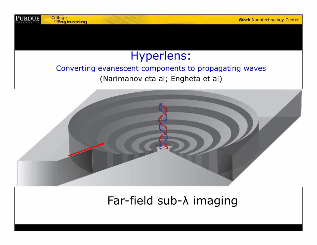
Hyperlens:Converting evanescent components to propagating waves
(Narimanov eta al; Engheta et al)
Far-field sub-λ imaging
Birck Nanotechnology Center
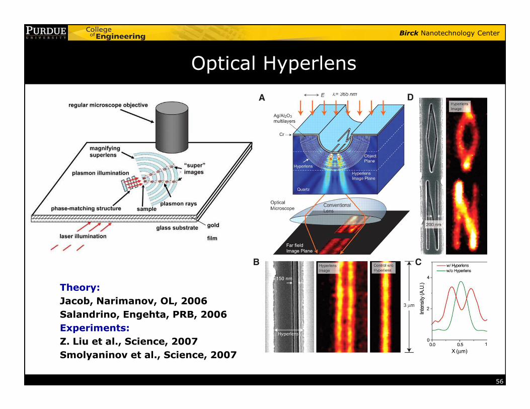
Optical Hyperlens
56
Theory:
Jacob, Narimanov, OL, 2006
Salandrino, Engehta, PRB, 2006
Experiments:
Z. Liu et al., Science, 2007
Smolyaninov et al., Science, 2007
Birck Nanotechnology Center
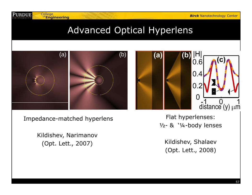
Advanced Optical Hyperlens
(a) (b)
57
Impedance-matched hyperlens
Kildishev, Narimanov
(Opt. Lett., 2007)
Flat hyperlenses:
½- & ‘¼-body lenses
Kildishev, Shalaev
(Opt. Lett., 2008)
Birck Nanotechnology Center
Transforming Light with Metamaterials
Birck Nanotechnology Center
Part 1: Electrical and Magnetic Metamaterials
Part 2: Negative-Index Metamaterials, NLO, and super/hyper-lens
Part 3: Cloaking and Transformation Optics
Birck Nanotechnology Center
Outline
� What are metamaterials?
� Early electrical metamaterials
� Magnetic metamaterials
� Negative-index metamaterials
� Chiral metamaterials
59
� Chiral metamaterials
� Nonlinear optics with metamaterials
� Super-resolution
� Optical cloaking and Transformation Optics
Birck Nanotechnology Center
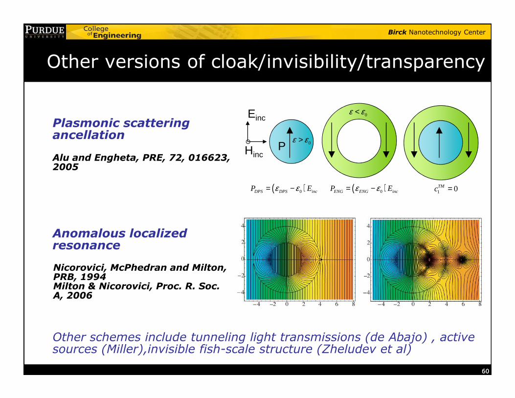
Other versions of cloak/invisibility/transparency
Einc
HincP
( )0DPS DPS incP Eε ε= − ( )0ENG ENG incP Eε ε= −
0ε ε<
0ε ε>
1 0TMc =
Alu and Engheta, PRE, 72, 016623, 2005
Plasmonic scattering ancellation
6060
Anomalous localized resonance
Nicorovici, McPhedran and Milton, PRB, 1994 Milton & Nicorovici, Proc. R. Soc. A, 2006
Other schemes include tunneling light transmissions (de Abajo) , active sources (Miller),invisible fish-scale structure (Zheludev et al)
Birck Nanotechnology Center
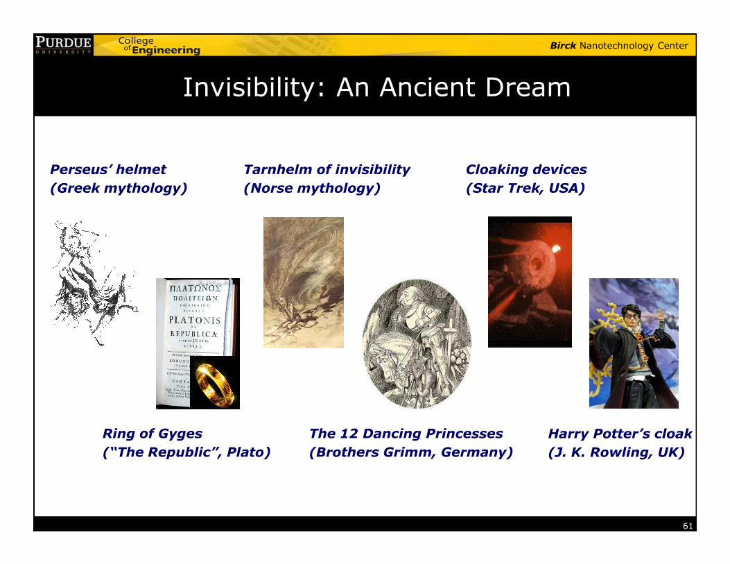
Invisibility: An Ancient Dream
Tarnhelm of invisibility
(Norse mythology)
Perseus’ helmet
(Greek mythology)
Cloaking devices
(Star Trek, USA)
61
Ring of Gyges
(“The Republic”, Plato)
The 12 Dancing Princesses
(Brothers Grimm, Germany)
Harry Potter’s cloak
(J. K. Rowling, UK)
Birck Nanotechnology Center
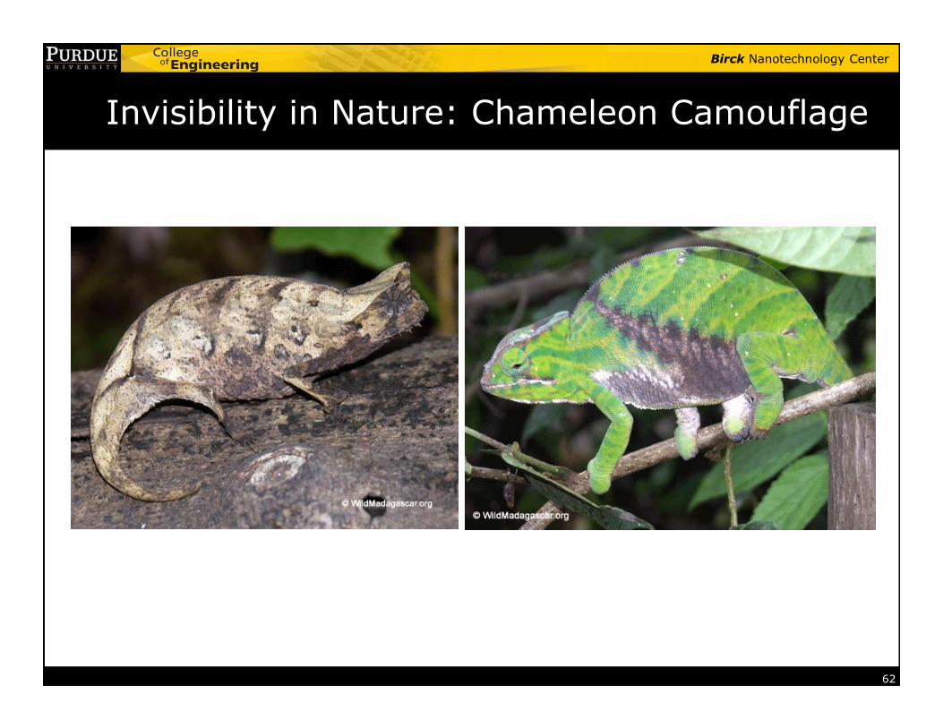
Invisibility in Nature: Chameleon Camouflage
62
Birck Nanotechnology Center
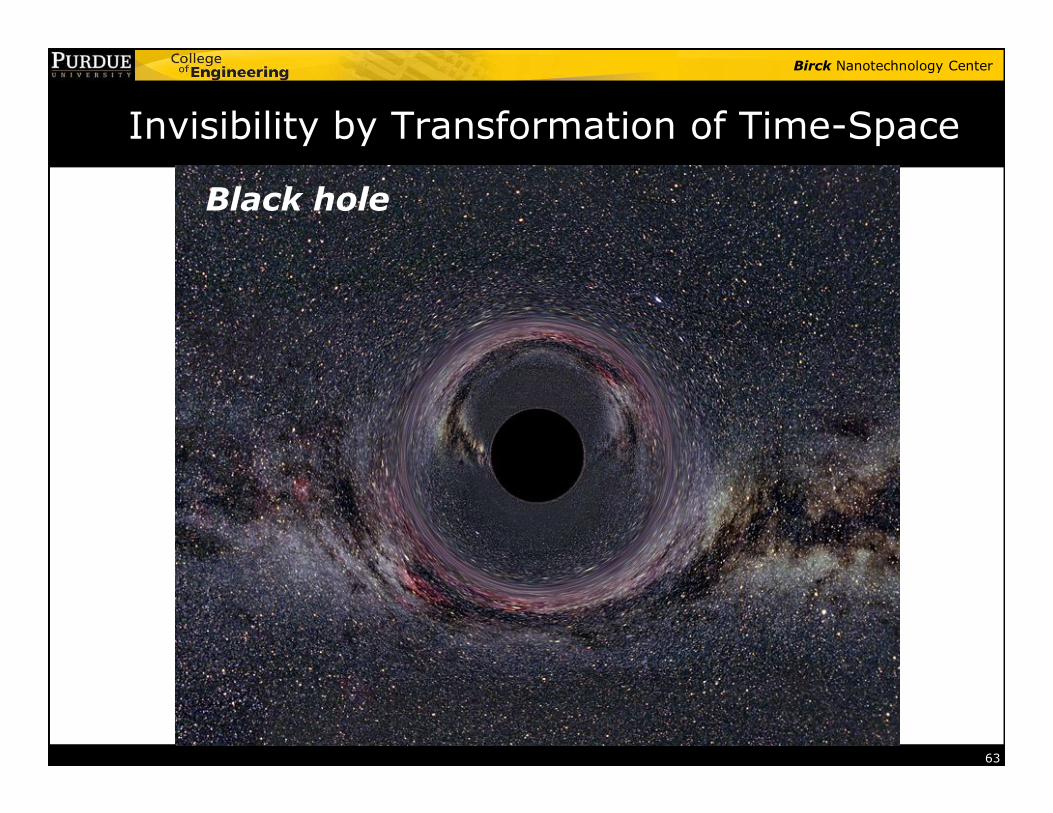
Invisibility by Transformation of Time-Space
Black hole
63
Birck Nanotechnology Center
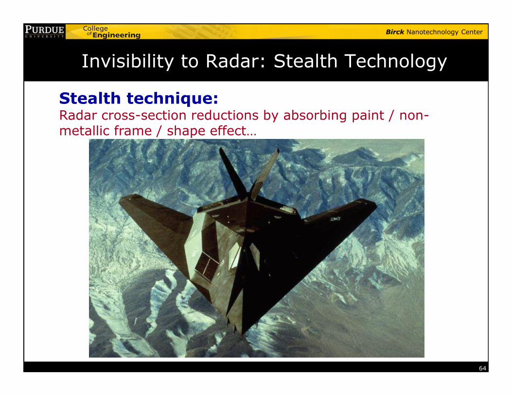
Invisibility to Radar: Stealth Technology
Stealth technique:Radar cross-section reductions by absorbing paint / non-metallic frame / shape effect…
64
Birck Nanotechnology Center
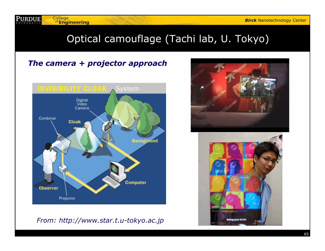
Optical camouflage (Tachi lab, U. Tokyo)
The camera + projector approach
65
From: http://www.star.t.u-tokyo.ac.jp
Birck Nanotechnology Center
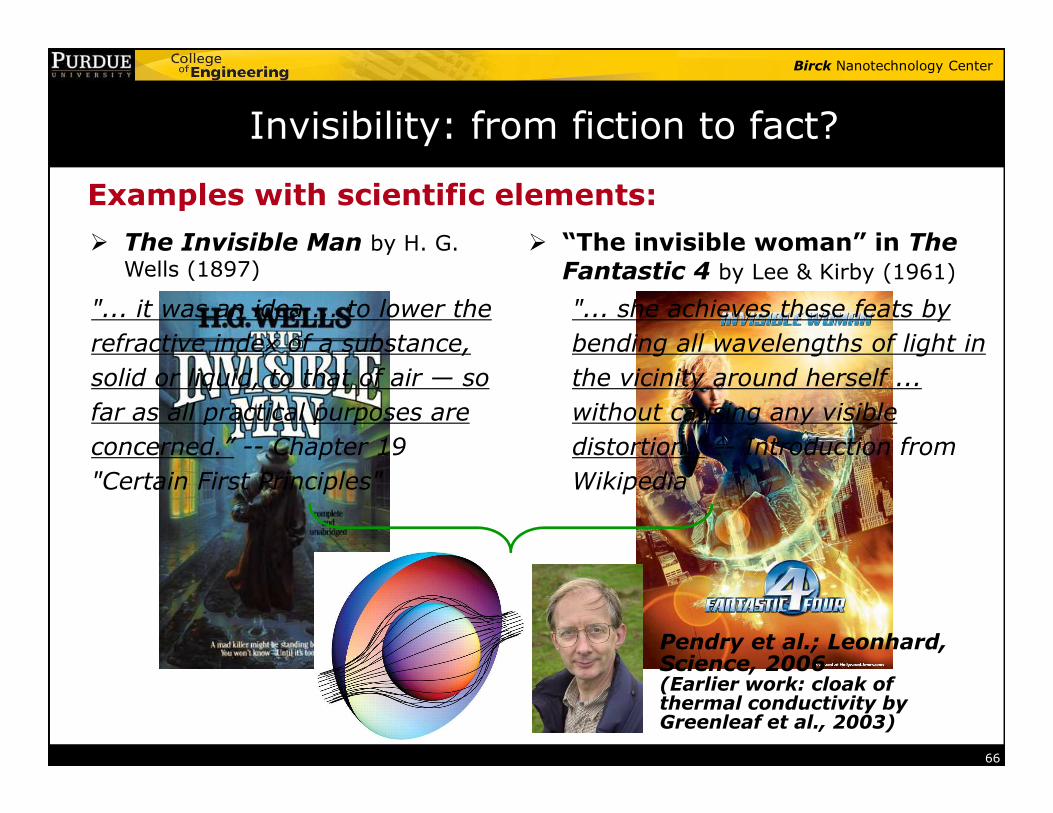
Invisibility: from fiction to fact?
� The Invisible Man by H. G.
Wells (1897)
� “The invisible woman” in The Fantastic 4 by Lee & Kirby (1961)
Examples with scientific elements:
"... it was an idea ... to lower the
refractive index of a substance,
solid or liquid, to that of air — so
far as all practical purposes are
"... she achieves these feats by
bending all wavelengths of light in
the vicinity around herself ...
without causing any visible
66
far as all practical purposes are
concerned.” -- Chapter 19
"Certain First Principles"
without causing any visible
distortion.” -- Introduction from
Wikipedia
Pendry et al.; Leonhard, Science, 2006(Earlier work: cloak of thermal conductivity by Greenleaf et al., 2003)
Birck Nanotechnology Center
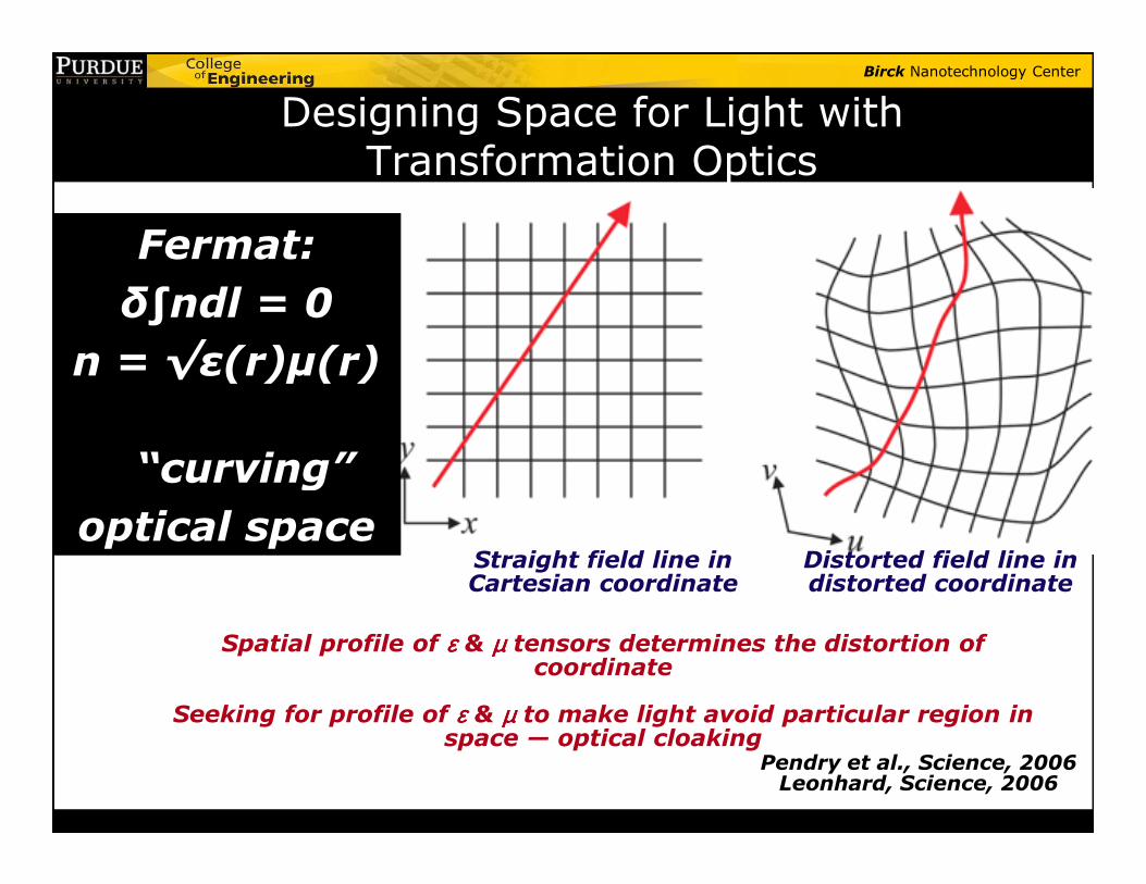
Designing Space for Light with Transformation Optics
Fermat:
δ∫ndl = 0
n = √ε(r)µ(r)
“curving”
Straight field line in Cartesian coordinate
Distorted field line in distorted coordinate
Spatial profile of εεεε & µµµµ tensors determines the distortion of coordinate
Seeking for profile of εεεε & µµµµ to make light avoid particular region in space — optical cloaking
Pendry et al., Science, 2006Leonhard, Science, 2006
“curving”
optical space
Birck Nanotechnology Center
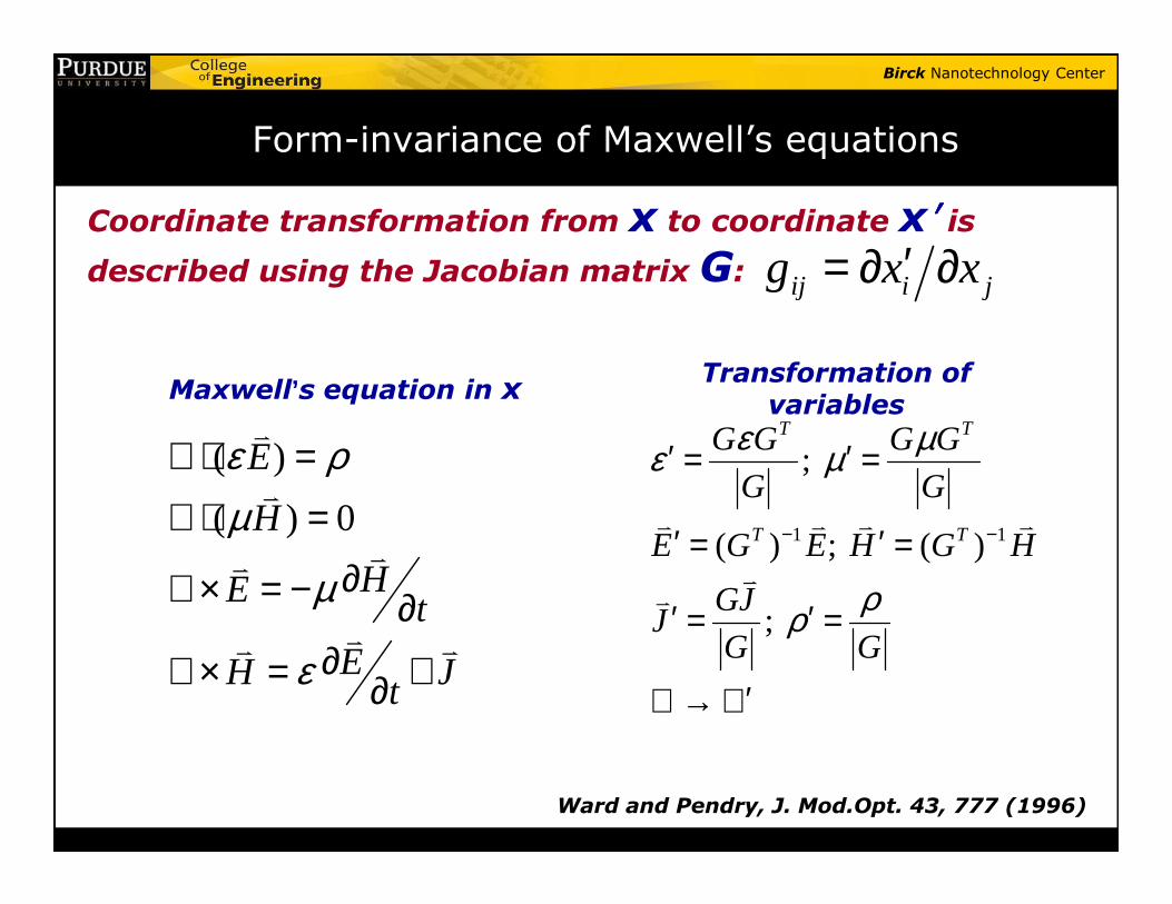
Form-invariance of Maxwell’s equations
Coordinate transformation from x to coordinate x′′′′ is described using the Jacobian matrix G: ij i jg x x′= ∂ ∂
( )Eε ρ∇ ⋅ =v
Maxwell’s equation in x
; T TG G G Gε µε µ′ ′= =
Transformation of variables
( )
( ) 0
E
H
HE t
EH Jt
ε ρµ
µ
ε
∇ ⋅ =∇ ⋅ =
∂∇× = − ∂∂∇× = +∂
v
vv
vv v
1 1
;
( ) ; ( )
;
T T
G G G G
G G
E G E H G H
GJJ
G G
ε µε µ
ρρ
− −
′ ′= =
′ ′= =
′ ′= =
′∇ → ∇
v v v v
vv
Ward and Pendry, J. Mod.Opt. 43, 777 (1996)
Birck Nanotechnology Center
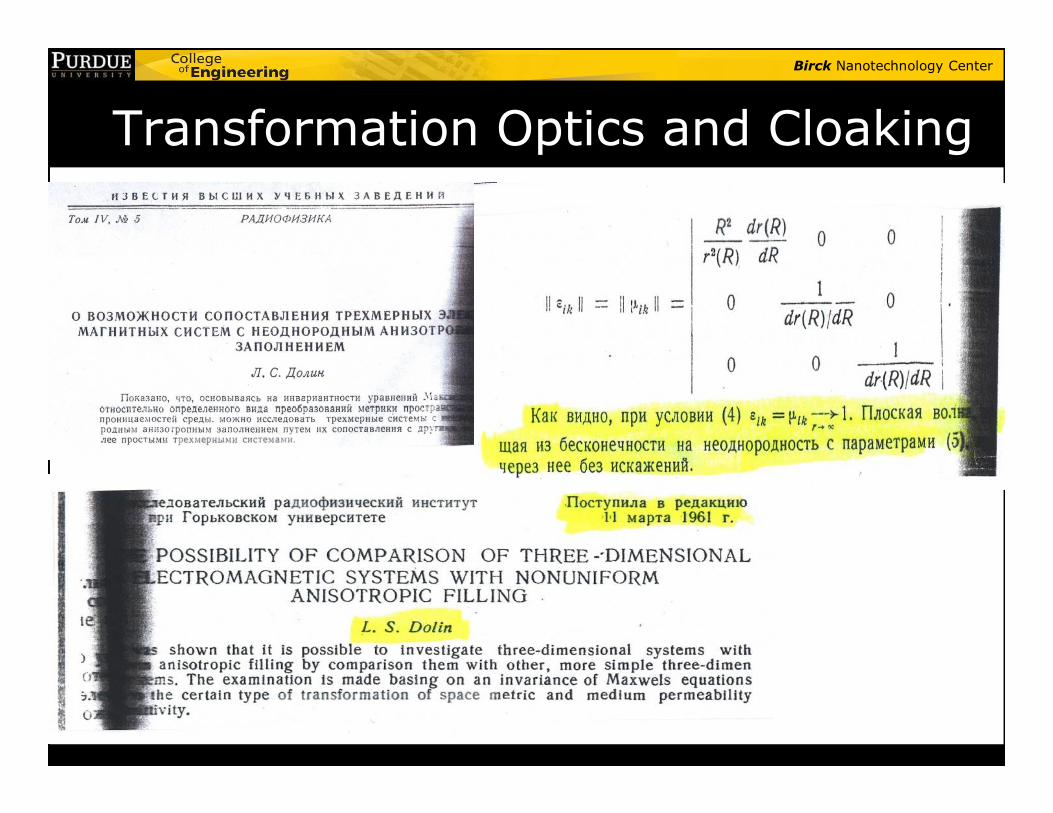
Transformation Optics and Cloaking
Birck Nanotechnology Center
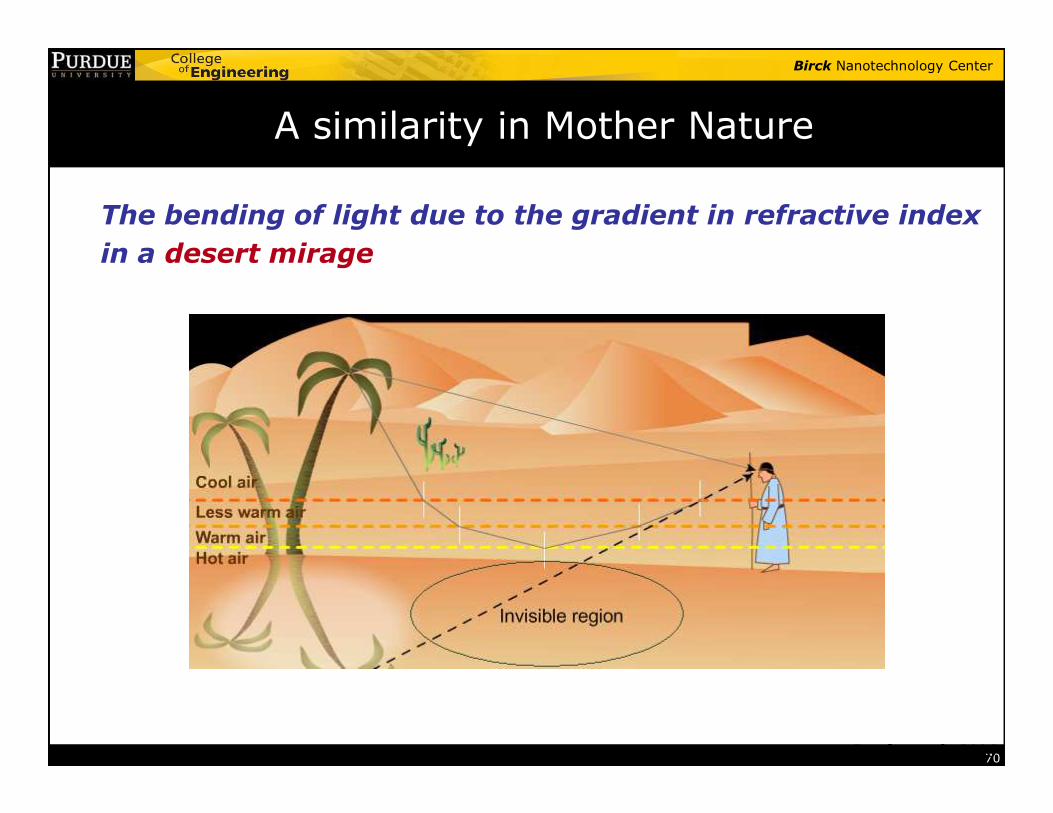
The bending of light due to the gradient in refractive index
in a desert mirage
A similarity in Mother Nature
70Pendry et al., 2006
Birck Nanotechnology Center
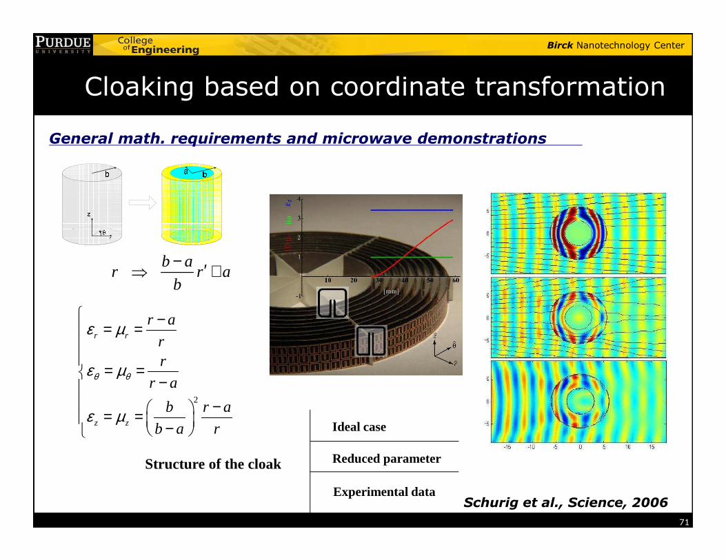
Cloaking based on coordinate transformation
General math. requirements and microwave demonstrations
b ar r a
b
− ′⇒ +
71
2
r r
z z
r a
rr
r a
b r a
b a r
θ θ
ε µ
ε µ
ε µ
−= =
= = − − = = − Ideal case
Reduced parameter
Experimental data
Structure of the cloak
Schurig et al., Science, 2006
r r ab
⇒ +
Birck Nanotechnology Center
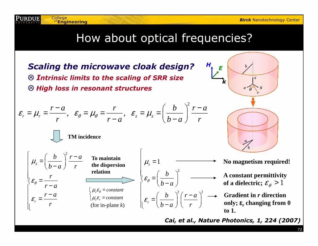
How about optical frequencies?
Scaling the microwave cloak design?���� Intrinsic limits to the scaling of SRR size
���� High loss in resonant structures
2
, ,r r z z
r a r b r a
r r a b a rθ θε µ ε µ ε µ− − = = = = = = − −
HE
k
72
TM incidence
To maintain the dispersion relation
z
z r
constant
constantθµ ε
µ ε=
=
r r a b a r− −
2
z
r
b r a
b a r
r
r ar a
r
θ
µ
ε
ε
− = − = −
− =
2
2 2
1z
r
b
b a
b r a
b a r
θ
µ
ε
ε
= = − − = −
No magnetism required!
A constant permittivity of a dielectric; 1θε >
(for in-plane k)
Gradient in r direction only; εεεεr changing from 0 to 1.
Cai, et al., Nature Photonics, 1, 224 (2007)
Birck Nanotechnology Center
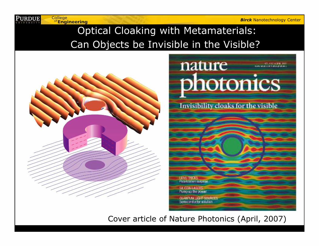
Optical Cloaking with Metamaterials:
Can Objects be Invisible in the Visible?
Nature Photonics (to be published)
Cover article of Nature Photonics (April, 2007)
Birck Nanotechnology Center
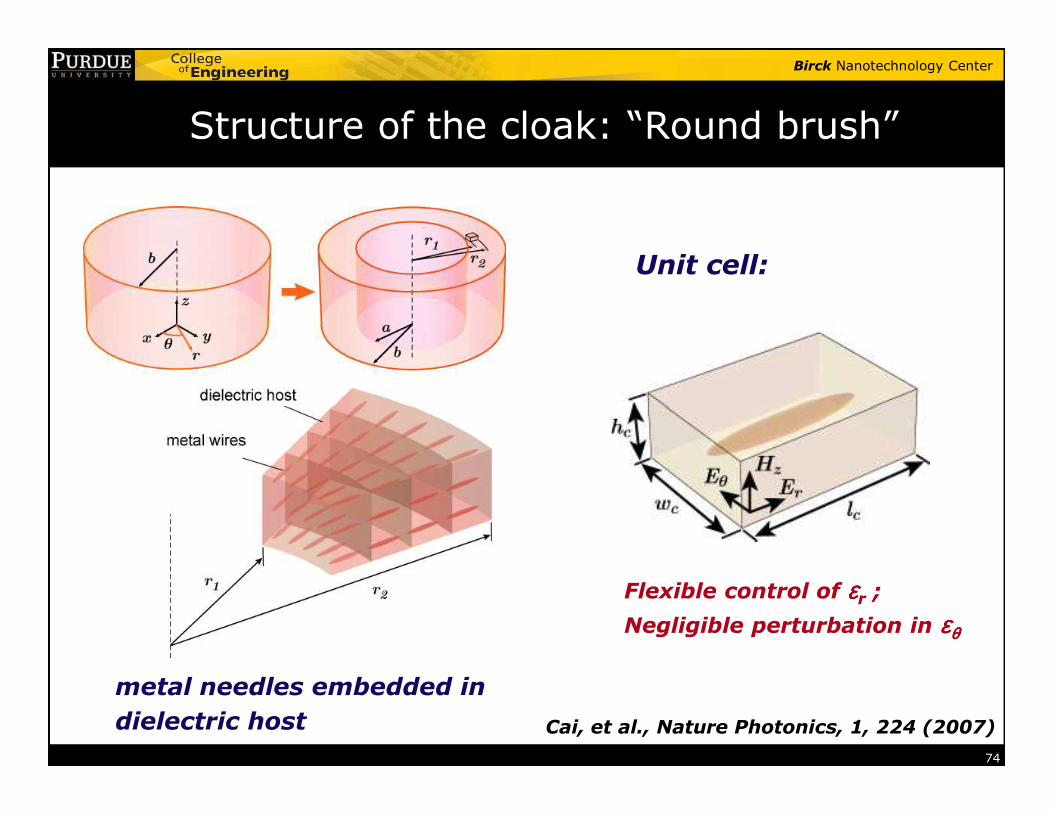
Structure of the cloak: “Round brush”
Unit cell:
74
metal needles embedded in
dielectric host
Flexible control of εεεεr ;Negligible perturbation in εεεεθθθθ
Cai, et al., Nature Photonics, 1, 224 (2007)
Birck Nanotechnology Center
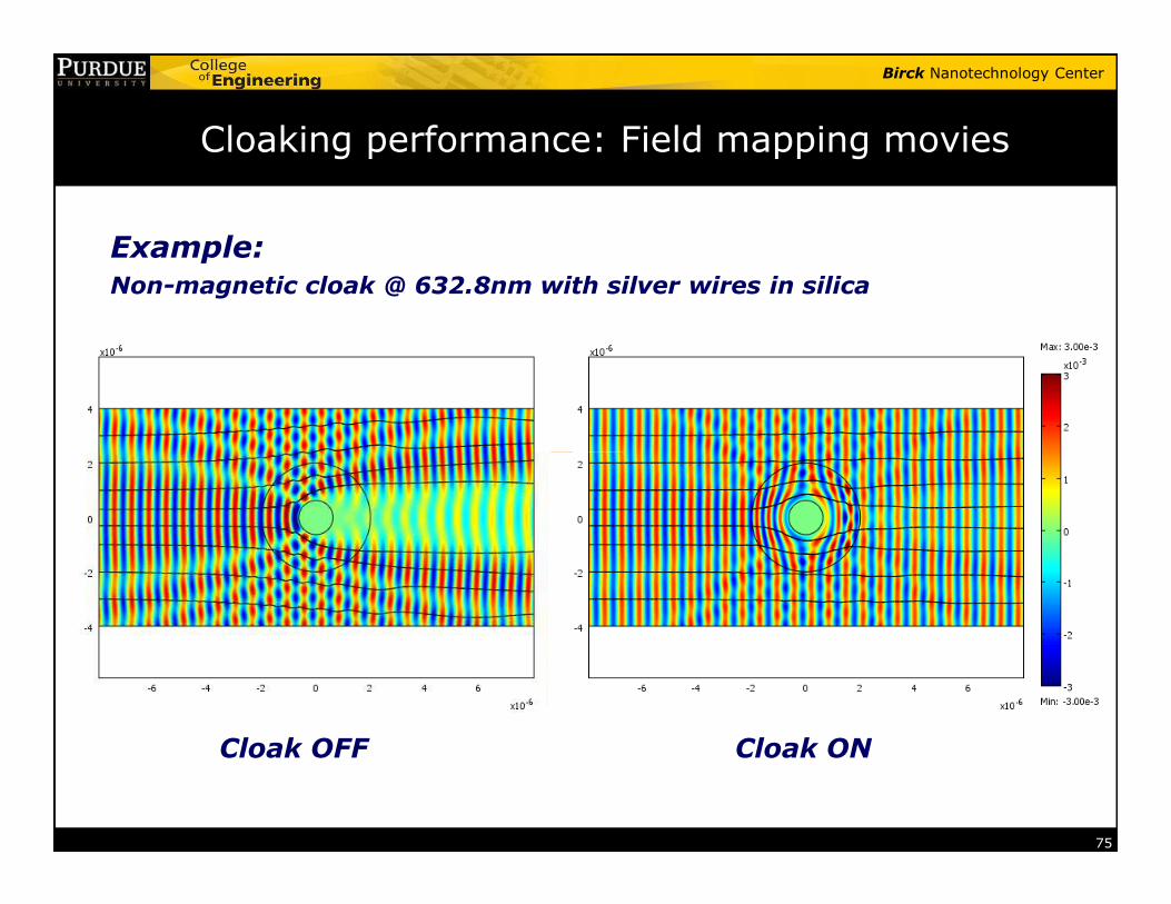
Cloaking performance: Field mapping movies
Example:Non-magnetic cloak @ 632.8nm with silver wires in silica
75
Cloak ONCloak OFF
Birck Nanotechnology Center
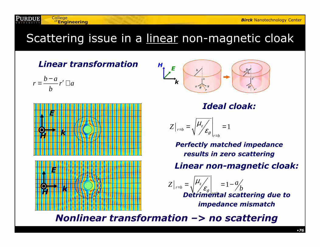
Scattering issue in a linear non-magnetic cloak
E
1zZ µ= =
Ideal cloak:
Linear transformation
b ar r a
b
− ′= +
HE
k
•76
E
kH
kH1z
r b
r b
Zθ
µε=
=
= =
Perfectly matched impedance
results in zero scattering
1zr b
r b
aZ bθ
µε=
=
= = −
Linear non-magnetic cloak:
Detrimental scattering due to
impedance mismatch
Nonlinear transformation –> no scattering
Birck Nanotechnology Center
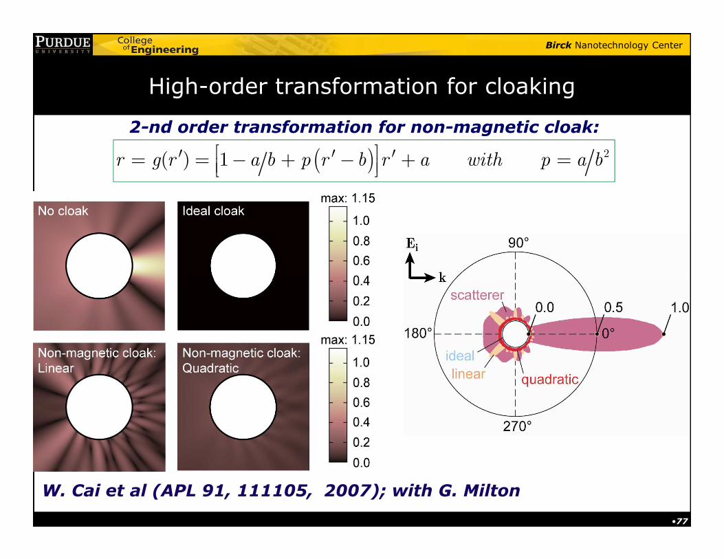
High-order transformation for cloaking
( ) 2( ) 1r g r a b p r b r a with p a b ′ ′ ′= = − + − + =
2-nd order transformation for non-magnetic cloak:
•77
W. Cai et al (APL 91, 111105, 2007); with G. Milton
Birck Nanotechnology Center
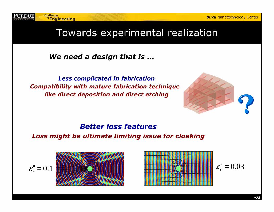
Towards experimental realization
We need a design that is …
Less complicated in fabrication
Compatibility with mature fabrication techniques
like direct deposition and direct etching
•78•78
Better loss featuresLoss might be ultimate limiting issue for cloaking
0.1rε ′′ = 0.03rε ′′ =
Birck Nanotechnology Center
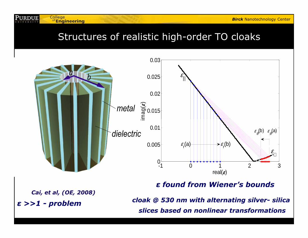
Structures of realistic high-order TO cloaks
0.015
0.02
0.025
0.03
imag
( εε εε)
ε||
-1 0 1 2 30
0.005
0.01
real(εεεε)
imag
(εr(a) εr(b)
εθ(b) εθ(a)
ε⊥
ε found from Wiener’s bounds
cloak @ 530 nm with alternating silver- silica
slices based on nonlinear transformations
Cai, et al, (OE, 2008)
ε >>1 - problem
Birck Nanotechnology Center
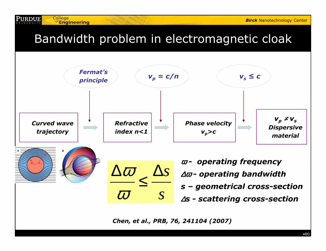
Bandwidth problem in electromagnetic cloak
Curved wave Refractive Phase velocityvp ≠≠≠≠ vs
Dispersive
Fermat’s
principlevp = c/n vs ≤ c
•80
Curved wave
trajectory
Refractive
index n<1
Phase velocity
vp>cDispersive
material
s
s
ωω
∆ ∆≤ωωωω - operating frequency
∆ω∆ω∆ω∆ω - operating bandwidth
s – geometrical cross-section
∆∆∆∆s - scattering cross-section
Chen, et al., PRB, 76, 241104 (2007)
Birck Nanotechnology Center
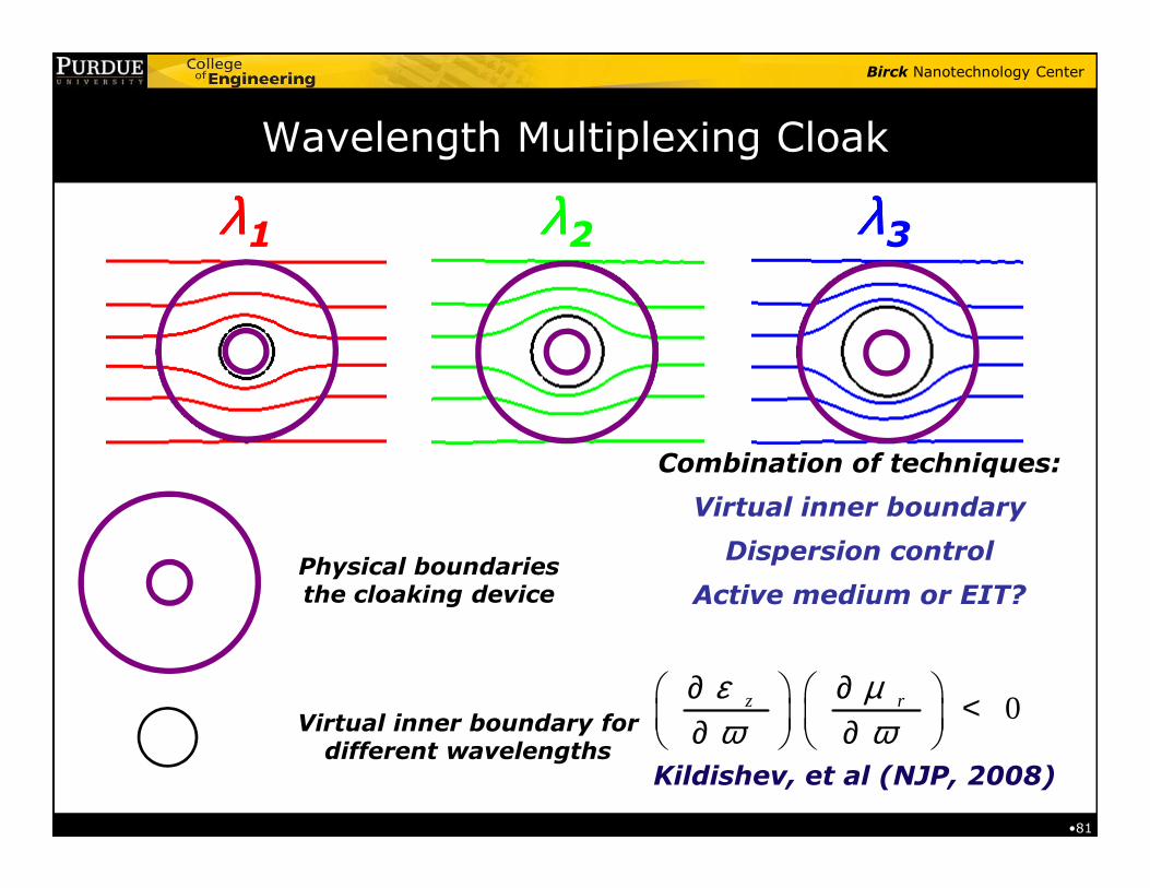
Wavelength Multiplexing Cloak
λλλλ1 λλλλ3λλλλ2
•81
Physical boundaries the cloaking device
Virtual inner boundary for different wavelengths
Combination of techniques:
Virtual inner boundary
Dispersion control
Active medium or EIT?
0z rε µω ω
∂ ∂ < ∂ ∂ Kildishev, et al (NJP, 2008)
Birck Nanotechnology Center
Broadband Optical Cloakingin Tapered Waveguides
I.I. Smolayninov, V.N. Smolyaninova, A.V. Kildishev
and V.M. Shalaev
(PRL , May 29, 2009)
Birck Nanotechnology Center
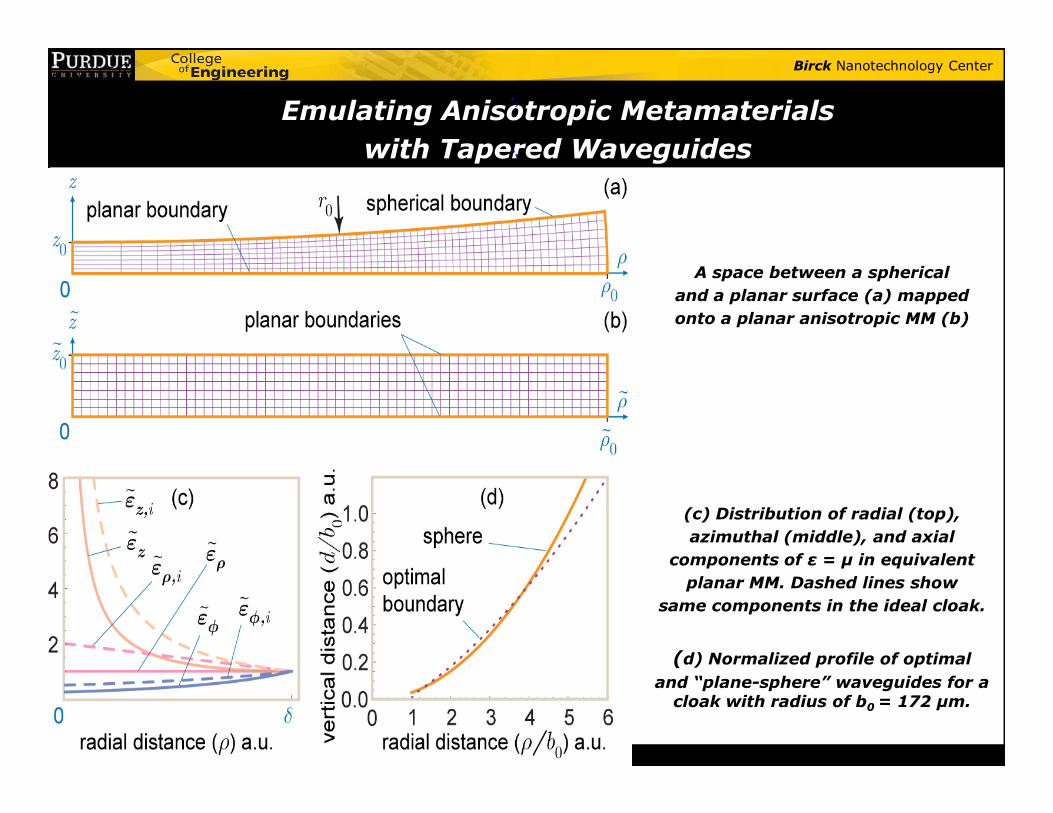
Emulating Anisotropic Metamaterials
with Tapered Waveguides
s
s~
~ 2~ ρε ρ−≈
•,
•,
•
A space between a spherical
and a planar surface (a) mapped
onto a planar anisotropic MM (b)
(c) Distribution of radial (top),
azimuthal (middle), and axial
components of ε = µ in equivalent
planar MM. Dashed lines show
same components in the ideal cloak.
(d) Normalized profile of optimal
and “plane-sphere” waveguides for a cloak with radius of b0 = 172 µm.
Birck Nanotechnology Center
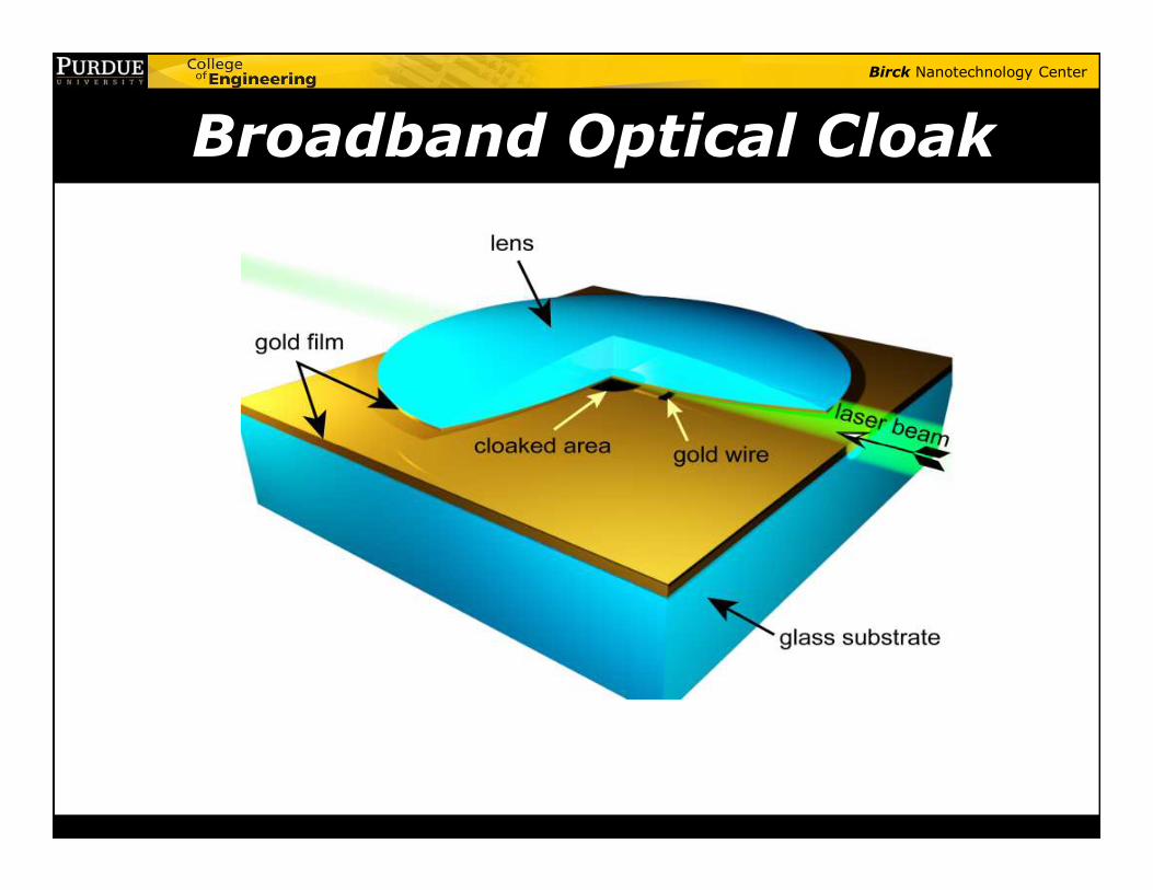
Broadband Optical Cloak
•in Tapered Waveguide
Birck Nanotechnology Center
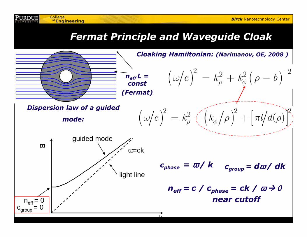
Cloaking Hamiltonian: (Narimanov, OE, 2008 )
Dispersion law of a guided
mode:
neff L = const
(Fermat)
Fermat Principle and Waveguide Cloak
mode:
cphase = ω ω ω ω / k cgroup= dωωωω / dk
neff= c / cphase= ck / ω ω ω ω ���� 0000near cutoff
ω
k
light line
ω=ck
guided mode
neff = 0cgroup = 0
Birck Nanotechnology Center
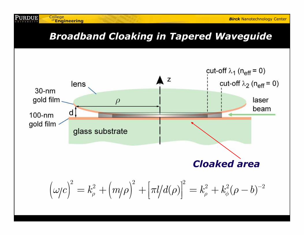
Broadband Cloaking in Tapered Waveguide
( ) ( )2 2 2
2 2 2 2( ) ( )c k m l d k k bρ ρ φω ρ π ρ ρ − = + + = + −
Cloaked area
Birck Nanotechnology Center
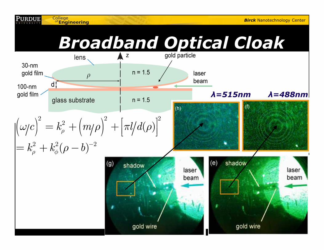
Broadband Optical Cloak
λ=515nm λ=488nm
( ) ( )2 2 2
2 ( )c k m l dω ρ π ρ = + + ( ) ( )2
2 2 2
( )
( )
c k m l d
k k b
ρ
ρ φ
ω ρ π ρ
ρ −
= + +
= + −

Birck Nanotechnology Center
Engineering Meta-Space for Light:via Transformation Optics
• (b)
Fermat: δ∫ndl = 0
n = √ε(r)µ(r)curving & nano”crafting”
optical space
Kildishev, VMS (OL, 2008); VMS, Science 322, 384 (2008)
• Light concentrator
Light concentrator Optical Black Hole
(also, Schurig et al) (Narimanov, Kildishev)
optical space
Planar hyperlens(Magnifies;
no loss problem)
Birck Nanotechnology Center
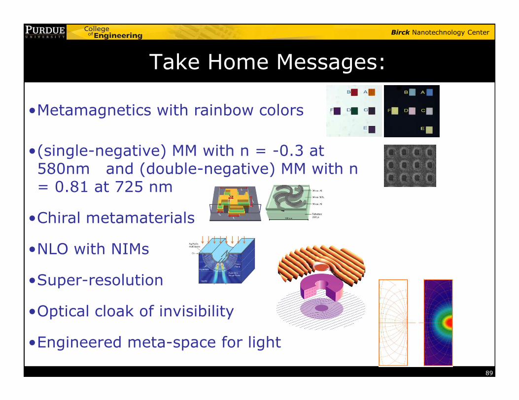
•Metamagnetics with rainbow colors
•(single-negative) MM with n = -0.3 at 580nm and (double-negative) MM with n = 0.81 at 725 nm
Take Home Messages:
89
•Chiral metamaterials
•NLO with NIMs
•Super-resolution
•Optical cloak of invisibility
•Engineered meta-space for light
Birck Nanotechnology Center
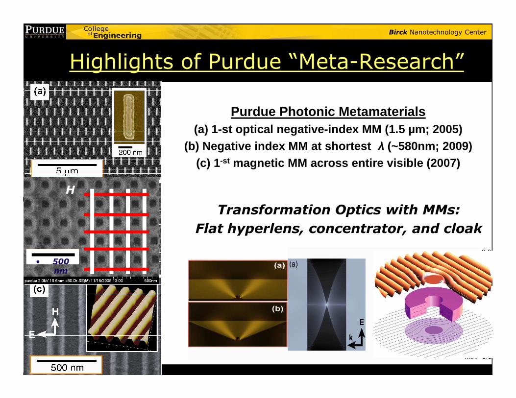
Highlights of Purdue “Meta-Research”
Purdue Photonic Metamaterials(a) 1-st optical negative-index MM (1.5 µm; 2005)
(b) Negative index MM at shortest λ (~580nm; 2009)(c) 1-st magnetic MM across entire visible (2007)
H
Transformation Optics with MMs:
Flat hyperlens, concentrator, and cloak
• 500 nm
Birck Nanotechnology Center
91
Birck Nanotechnology Center
Cast of Characters
92
Related Documents