QQ -SBG ·~ ..,-----hl ..fa .;JJ PARSONS ..,__,.μ,....._, Dorsch Qatar ,, \\ururt.--c., Qitldl CP07-B Lusail Plaza Infrastructure, LRT Station, Contract# Document No. Car Parks and Landscape; Lusail, Qatar 5297 LUS-CP7B-QDSBG-MST-MC- 00173 Title: Method Statement for Installation of Split 0 1 2 3 Rev. No. AC Units X Appendix D: Split AC Units Manufacturer's Installation Detail Split AC Units Manufacturer's Installation Detail P c1 g _ 31 I 31

Welcome message from author
This document is posted to help you gain knowledge. Please leave a comment to let me know what you think about it! Share it to your friends and learn new things together.
Transcript
QQ-SBG ·~ ..,-----hl ..fa .;JJ PARSONS ~~ ~ ..,__,.µ,....._, Dorsch Qatar ,,
\\ururt.--c., Qitldl
CP07-B Lusail Plaza Infrastructure, LRT Station, Contract# Document No.
Car Parks and Landscape; Lusail, Qatar 5297 LUS-CP7B-QDSBG-MST-MC-
00173
Title: Method Statement for Installation of Split 0 1 2 3
Rev. No. AC Units X
Appendix D: Split AC Units Manufacturer's Installation Detail
Split AC Units Manufacturer's
Installation Detail
P c1 g _ 31 I 31
Morpheus
Rectangle
Morpheus
Text Box
www.qaqcconstruction.com
()
()
SRAC-01 , 02, 03, 04 & 05 • TRANE.
Installation
Using the wire controller to set external static pressure
1. You can use the unit's automatic airflow adjustment function to set external static pressure. 2. Automatic airflow adjustment is the volume of blow-off air that has been automatically adjusted to the quantity rated.
• Make sure the test run is done with a dry coil. If the coil is not dry, run the unit for 2 hours in FAN ONLY mode to dry the coil.
• Check that both power supply wiring and duct installation have been completed. Check that any closing dampers are open. Check that the air filter is properly attached to the air suction side passage of the unit
• If there is more than one air inlet and outlet, adjust the dampers so that the airflow rate. of each air inlet and outlet conforms with, the designed airflow rate. Make sure the unit is in FAN ONLY mode. Press and set the airflow adjustment button on the remote control to change the airflow rate from H or L.
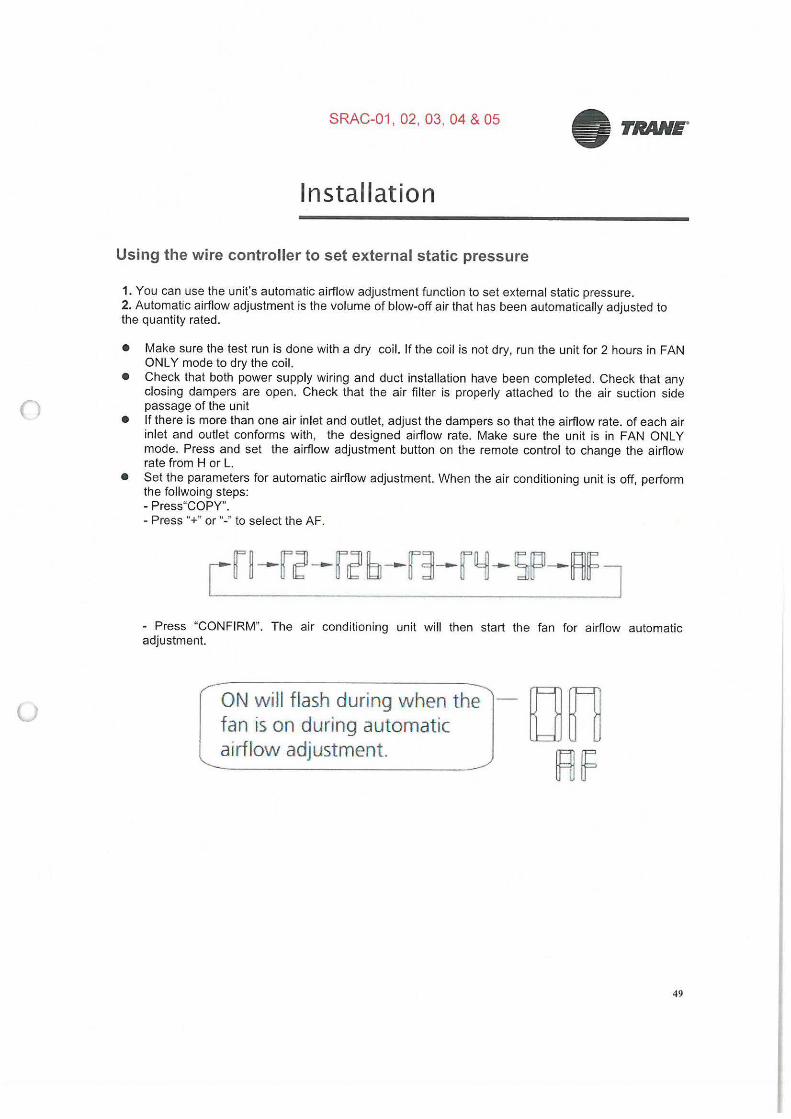
• Set the parameters for automatic airflow adjustment. When the air conditioning unit is off, perform the follwoing steps: - Press"COPY". - Press "+" or "-" to select the AF.
- Press "CONFIRM". The air conditioning unit will then start the fan for airflow automatic adjustment.
ON will flash during when the fan is on during automatic airflow adjustment.
49
n
(J
• TRANE.
Instal lation
A cAUTION
• DO NOT adjust the dampers when automatic airflow adjustment is active. After 3 to 6 minutes, the air conditioning unit stops operating once automatic airflow adjustment has finished.
A CAUTION
50
• If there is no change after airflow adjustment in the ventilation paths, be sure to reset automatic airflow adjustment.
• If there is no change to ventilation paths after airflow adjustment,contact your dealer, especially if this occurs after testing the outdoor unit or if the unit has been moved to a different location.
• Do not use automatic airflow adjustment with remote control,if you are using booster fans, outdoor air processing unit, or a HRV via duct.
• If the ventilation paths have been changed, reset airflow automatic adjustment as described from step 3 onwards.
()
(J
• TRANE"
Installation
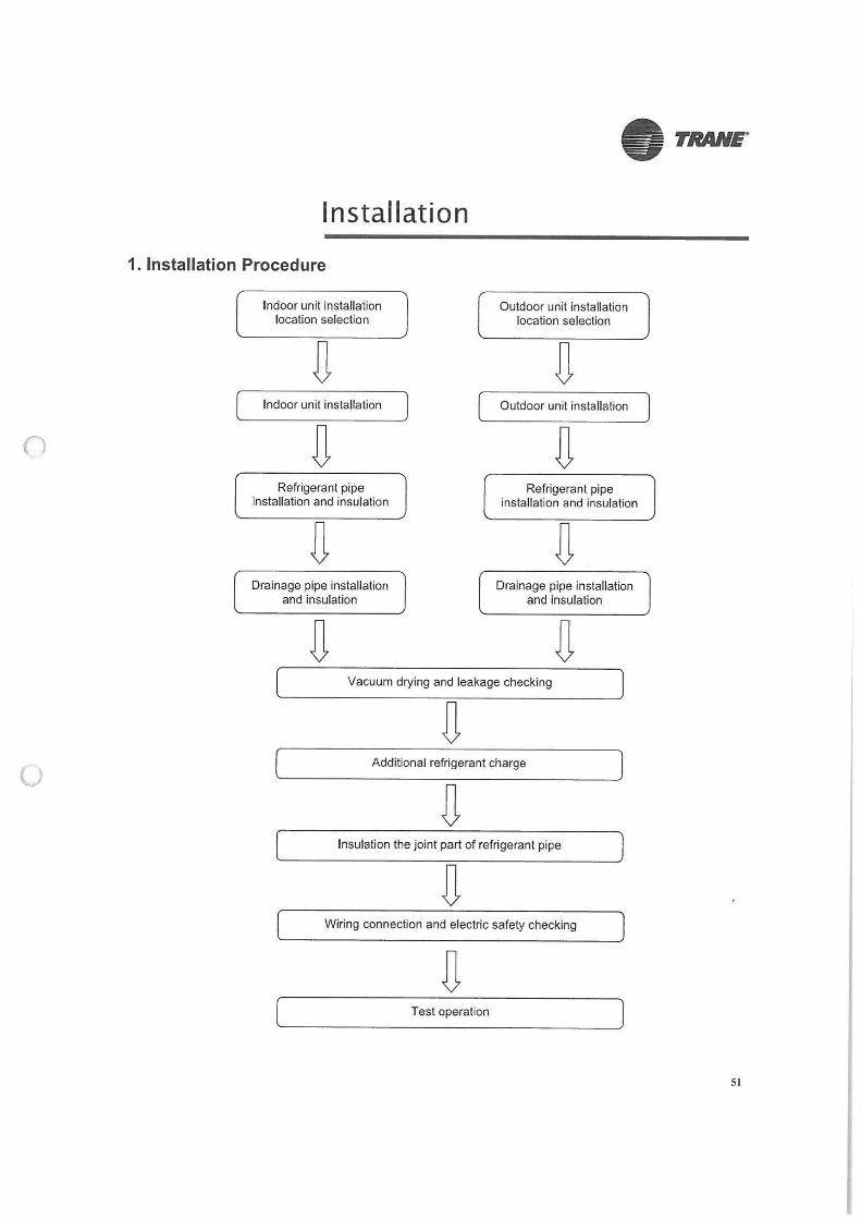
1. Installation Procedure
Indoor unit installation location selection
Indoor unit installation
Refrigerant pipe installation and insulation
Drainage pipe installation and insulation
Outdoor unit installation location selection
Outdoor unit installation
Refrigerant pipe installation and insulation
Drainage pipe installation and insulation
Vacuum drying and leakage checking
Additional refrigerant charge
Insulation the joint part of refrigerant pipe
Wiring connection and electric safety checking
Test operation
SI
(
u
• TRANE.
Installation
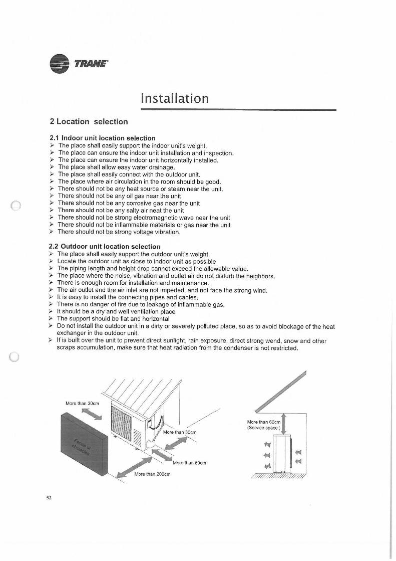
2 Location selection
2.1 Indoor unit location selection ► The place shall easily support the indoor unit's weight. ► The place can ensure the indoor unit installation and inspection. ► The place can ensure the indoor unit horizontally installed. ► The place shall allow easy water drainage. ► The place shall easily connect with the outdoor unit. ► The place where air circulation in the room should be good. ► There should not be any heat source or steam near the unit. ► There should not be any oil gas near the unit ► There should not be any corrosive gas near the unit ► There should not be any salty air neat the unit ► There should not be strong electromagnetic wave near the unit ► There should not be inflammable materials or gas near the unit ► There should not be strong voltage vibration.
2.2 Outdoor unit location selection ► The place shall easily support the outdoor unit's weight. ► Locate the outdoor unit as close to indoor unit as possible ► The piping length and height drop cannot exceed the allowable value. ► The place where the noise, vibration and outlet air do not disturb the neighbors. ► There is enough room for installation and maintenance. ► The air outlet and the air inlet are not impeded, and not face the strong wind. ► It is easy to install the connecting pipes and cables. ► There is no danger of fire due to leakage of inflammable gas. ► It should be a dry and well ventilation place ► The support should be flat and horizontal ► Do not install the outdoor unit in a dirty or severely polluted place, so as to avoid blockage of the heat
exchanger in the outdoor unit. ► If is built over the unit to prevent direct sunlight, rain exposure, direct strong wend, snow and other
scraps accumulation, make sure that heat radiation from the condenser is not restricted.
More than 30cm
52
More than 60cm (Service space )
()
u
• TRANE"
Installation
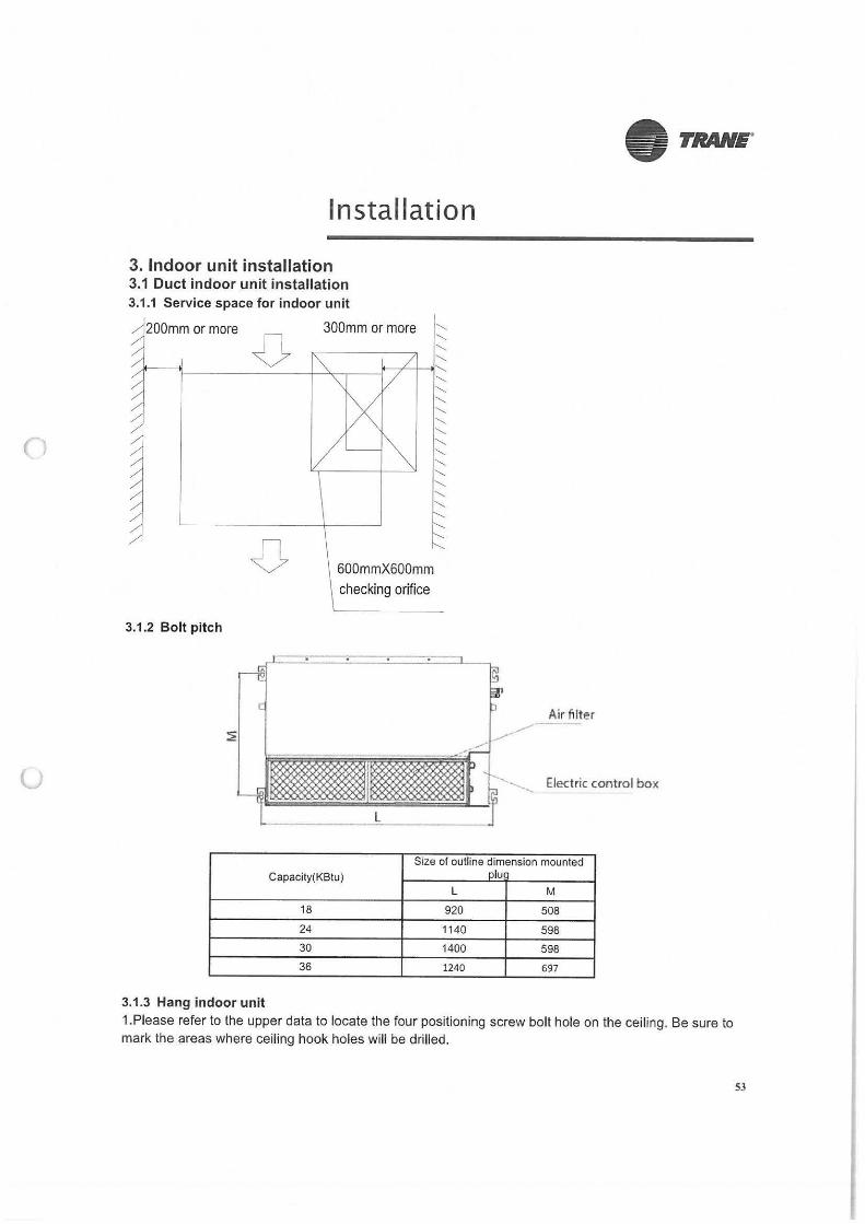
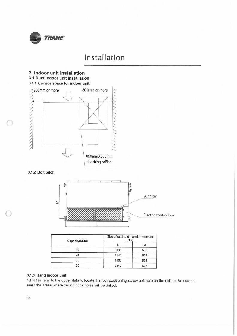
3. Indoor unit installation 3.1 Duct indoor unit installation 3.1.1 Service space for indoor unit
300mm or more '--
,,t---~ ____ 0_::::___-+~~--f71-~~
3.1.2 Bolt pitch
600mmX600mm
checking orifice
--.-----
'-'-'-''-'-'-'-'-'-'-'--
Air filter
'· .___ Electric control box
Size of outline dimension mounted
Capacity(KBtu) olu
L M
18 920 508
24 1140 598
30 1400 598 36 1240 697
11~ Hangindoorunij 1.Please refer to the upper data to locate the four positioning screw bolt hole on the ceiling. Be sure to mark the areas where ceiling hook holes will be drilled.
53
n
u
• TRANE.
Installation
3. Indoor unit installation 3.1 Duct indoor unit installation 3.1.1 Service space for indoor unit
200mm or more
0 300mm or more
2 -1'--1------- -J.---:",,---,------l--~1--,1------
3.1.2 Bolt pitch
600mmX600mm checking orifice
------------------------------------------------------------------------------
Air filter
--, Electric control box
Size of outline dimension mounted Capacity(KBtu) olu 1
L M
18 920 508
24 1140 598
30 1400 598
36 1240 697
3.1.3 Hang indoor unit 1.Please refer to the upper data to locate the four positioning screw bolt hole on the ceiling. Be sure to mark the areas where ceiling hook holes will be drilled.
54
(J
• TRANE"
Installation
2. Carry out the pipe and line operation in the ceiling after finishing the installation of the main body. While choosing where to start the operation, determine the direction of the pipes to be drawn out. Especially in case there is a ceiling, position the refrigerant pipes, drain pipes, indoor & outdoor lines to the connection places before hanging up the machine. 3.The installation of hanging screw bolts.
• Cut off the roof beam. • Strengthen the place that has been cut off, and consolidate the roof beam.
4.After the selection of installation location position the refrigerant pipes, drain pipes, indoor & outdoor wires to the connection places before hanging up the machine. 5. Drill 4 holes 10cm (4") deep at the ceiling hook positions in the internal ceiling. Be sure to hold the drill at a 90° angle to the ceiling. 6. Secure the bolt using the included washers and nuts. 7. Install the four suspension bolts.
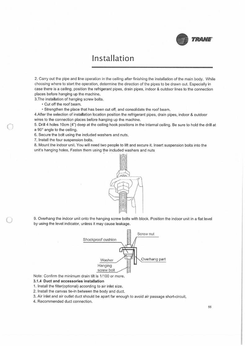
8. Mount the indoor unit. You will need two people to lift and secure it. Insert suspension bolts into the unit's hanging holes. Fasten them using the included washers and nuts - - I
~ r -"i i:-J
1 ---=-- -
9. Overhang the indoor unit onto the hanging screw bolts with block. Position the indoor unit in a flat level by using the level indicator, unless it may cause leakage.
Shockproof cushion
Washer
Hanging screw bolt
Note: Confirm the minimum drain tilt is 1/100 or more. 3.1.4 Duct and accessories installation 1. Install the filter(optional) according to air inlet size. 2. Install the canvas tie-in between the body and duct.
Overhang part
3. Air inlet and air outlet duct should be apart far enough to avoid air passage short-circuit. 4. Recommended duct connection.
55
()
(J
• TRANE"
Installation
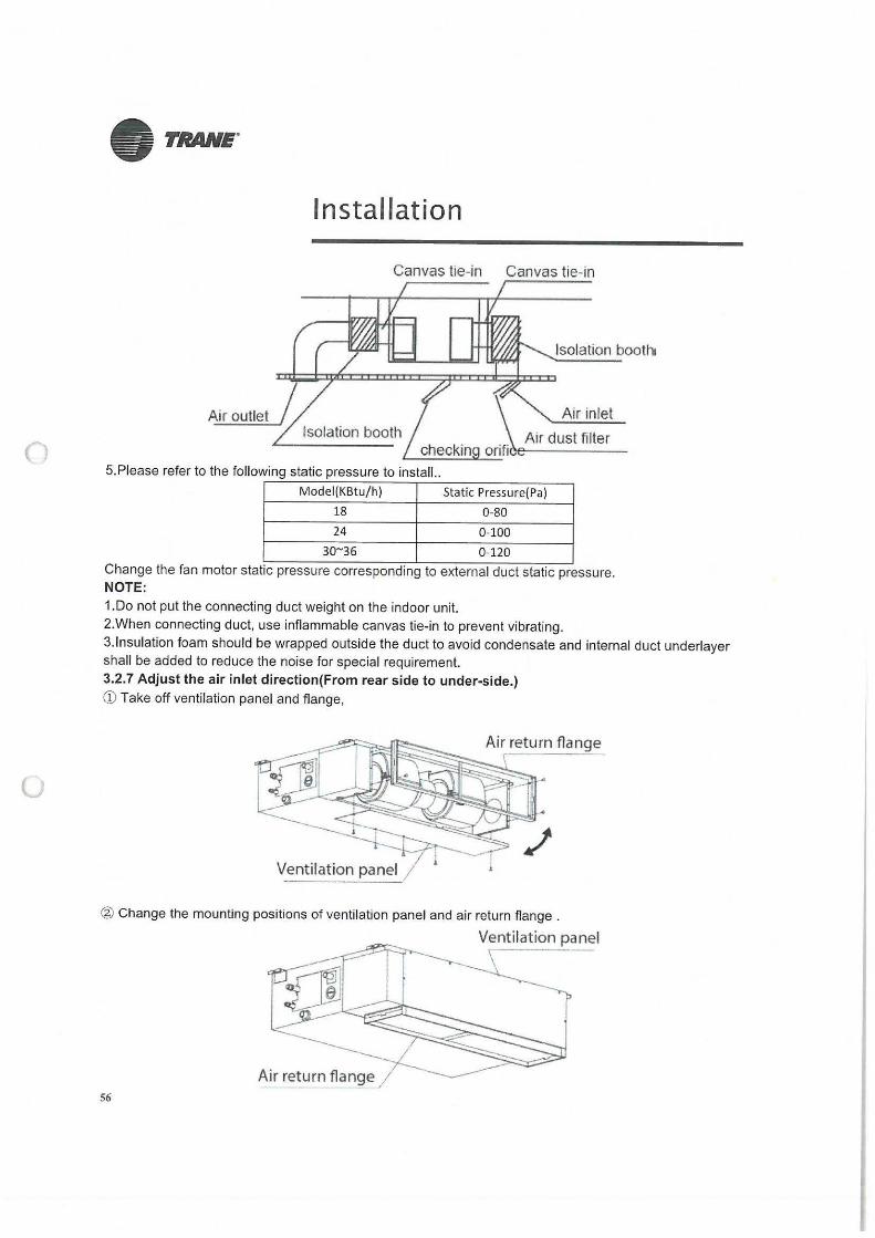
Canvas tie-in Canvas tie-in
Isolation booth
Air outlet
5.Please refer to the following static pressure to install..
Model(KBtu/h) Static Pressure(Pa)
18 0-80
24 0-100
30~35 0-120
Change the fan motor static pressure corresponding to external duct static pressure. NOTE: 1.Do not put the connecting duct weight on the indoor unit. 2.When connecting duct, use inflammable canvas tie-in to prevent vibrating. 3.lnsulation foam should be wrapped outside the duct to avoid condensate and internal duct underlayer shall be added to reduce the noise for special requirement. 3.2.7 Adjust the air inlet direction(From rear side to under-side.) CD Take off ventilation panel and flange,
@ Change the mounting positions of ventilation panel and air return flange .
Ventilation panel
Air return flange 56
(
• TRANE"
Installation
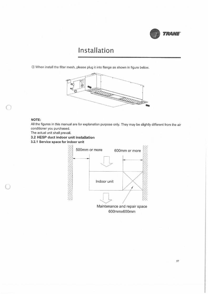
® When install the filter mesh, please plug it into flange as shown in figure below.
--------.
NOTE:
All the figures in this manual are for explanation purpose only. They may be slightly different from the air conditioner you purchased. The actual unit shall prevail.
3.2 HESP duct indoor unit installation 3.2.1 Service space for indoor unit
~ 500mm or more 600mm or more ~
JJ Indoor unit
JJ Maintenance and repair space
600mmx600mm
57
u
• TRANE.
Installation
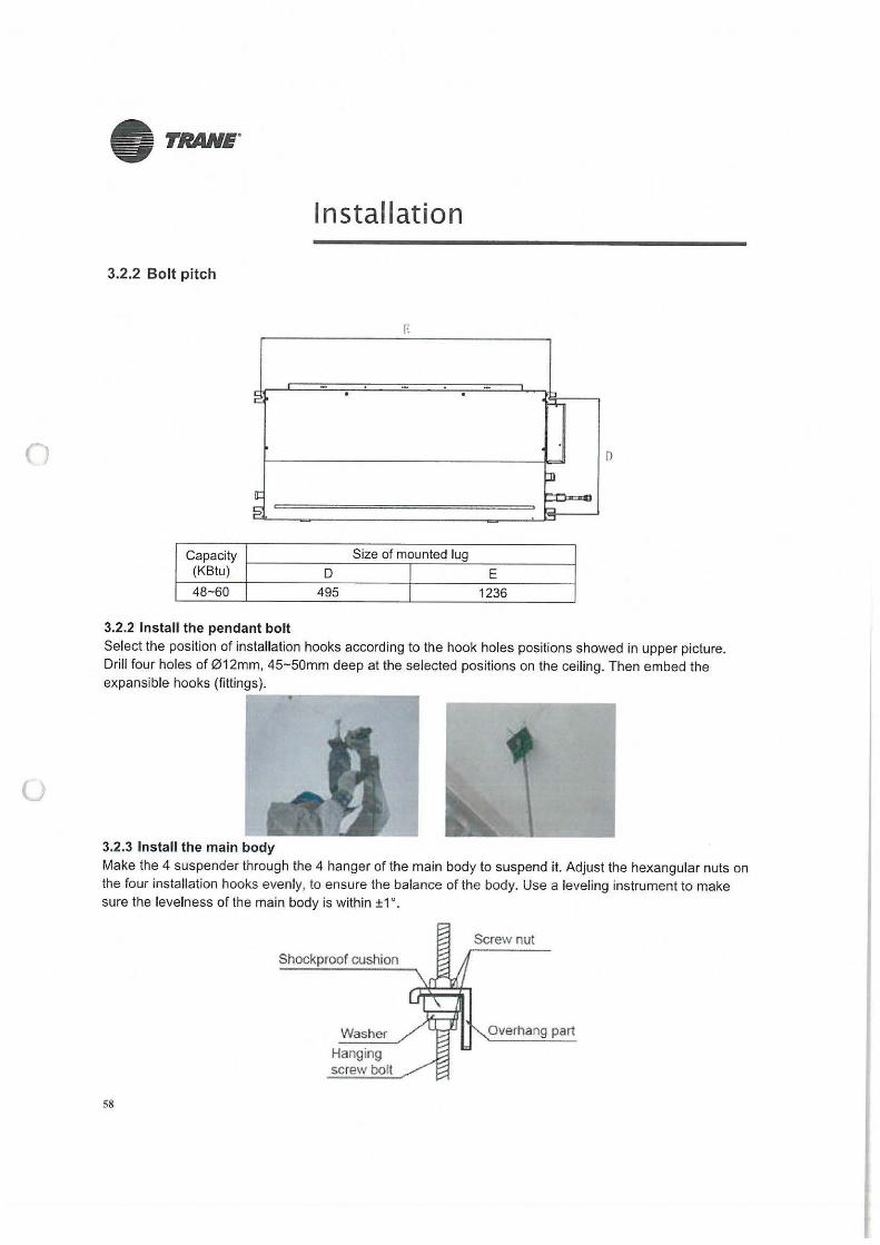
3.2.2 Bolt pitch
E
- -~ -~- . . ,-+
D
JI [I:
l=i. ,-,
Capacity Size of mounted lug (KB tu) D I E
48-60 495 I 1236
3.2.2 Install the pendant bolt Select the position of installation hooks according to the hook holes positions showed in upper picture. Drill four holes of 012mm, 45-50mm deep at the selected positions on the ceiling. Then embed the expansible hooks (fittings). -----------
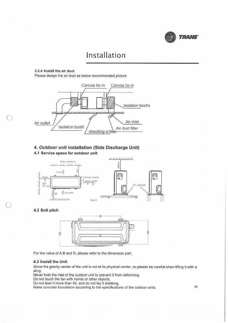
3.2.3 Install the main body Make the 4 suspender through the 4 hanger of the main body to suspend it. Adjust the hexangular nuts on the four installation hooks evenly, to ensure the balance of the body. Use a leveling instrument to make sure the levelness of the main body is within ±1 °.
58
Shockproof cushion
Washer
Hanging screw boll
Overhang part
0
u
Installation
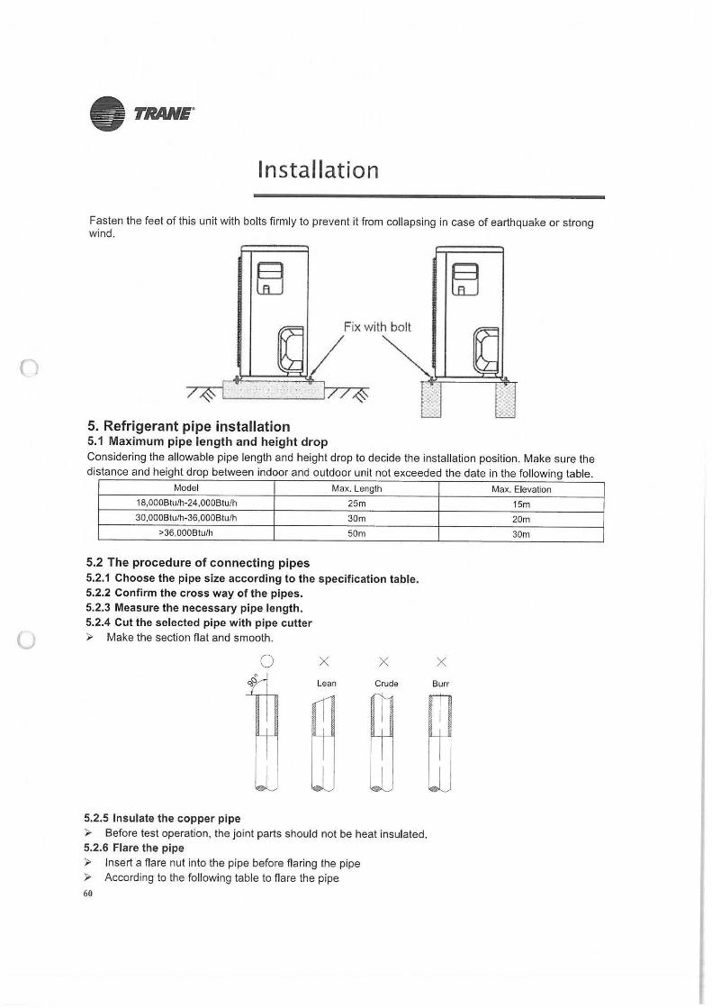
3.2.4 Install the air duct Please design the air duct as below recommended picture
Canvas tie-in Canvas tie-in
Isolation bootra
Air outlet Air inlet
4. Outdoor unit installation (Side Discharge Unit) 4.1 Service space for outdoor unit
>30cm ~ ~======~~7M.11nta1tcti.Jnnol N
¢ Air Wl~t ~ .. -;;;;;;;;;;;;;;;~-:J
i M {} Aoou!lot
4.2 Bolt pitch
>60cm p
~
For the value of A,B and D, please refer to the dimension part.
4.3 Install the Unit
• TRANE"
Since the gravity center of the unit is not at its physical center, so please be careful when lifting it with a sling. Never hold the inlet of the outdoor unit to prevent it from deforming. Do not touch the fan with hands or other objects. Do not lean it more than 45, and do not lay it sidelong. Make concrete foundation according to the specifications of the outdoor units. 59
• TRANE.
Installation
Fasten the feet of this unit with bolts firmly to prevent it from collapsing in case of earthquake or strong wind.
Fix with bolt
~/ 5. Refrigerant pipe installation 5.1 Maximum pipe length and height drop Considering the allowable pipe length and height drop to decide the installation position. Make sure the distance and height drop between indoor and outdoor unit not exceeded the date in the following table.
Model Max. Length
18,000B!u/h-24,000Btu/h 25m
30,000Btu/h-36,000Btu/h 30m
>36,000B!u/h 50m
5.2 The procedure of connecting pipes 5.2.1 Choose the pipe size according to the specification table. 5.2.2 Confirm the cross way of the pipes. 5.2.3 Measure the necessary pipe length. 5.2.4 Cut the selected pipe with pipe cutter
(J ► Make the section flat and smooth.
0 X X
Lean Crude
5.2.5 Insulate the copper pipe ► Before test operation, the joint parts should not be heat insulated. 5.2.6 Flare the pipe ► Insert a flare nut into the pipe before flaring the pipe ► According to the following table to flare the pipe 60
Max. Elevation
15m
20m
30m
X
Burr
u
• TRANE"
Installation
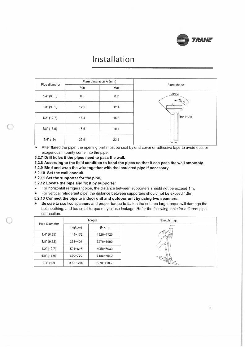
Flare dimension A (mm) Pipe diameter
Min Max Flare shape
G 1/4" (6.35) 8.3 8.7
J 3/8" (9.52) 12.0 12.4 I I
-.:-7
1/2" (12.7) 15.4 15.8 I! \ R0.4-0.8
I ' 5/8" (15.9) 18.6 19.1 I
3/4" (19) 22.9 23.3 I ~
► After flared the pipe, the opening part must be seal by end cover or adhesive tape to avoid duct or exogenous impurity come into the pipe.
5.2.7 Drill holes if the pipes need to pass the wall. 5.2.8 According to the field condition to bend the pipes so that it can pass the wall smoothly. 5.2.9 Bind and wrap the wire together with the insulated pipe if necessary. 5.2.10 Set the wall conduit 5.2.11 Set the supporter for the pipe. 5.2.12 Locate the pipe and fix it by supporter ► For horizontal refrigerant pipe, the distance between supporters should not be exceed 1 m. ► For vertical refrigerant pipe, the distance between supporters should not be exceed 1.5m. 5.2.13 Connect the pipe to indoor unit and outdoor unit by using two spanners. ► Be sure to use two spanners and proper torque to fasten the nut, too large torque will damage the
bellmouthing, and too small torque may cause leakage. Refer the following table for different pipe connection.
Torque Sketch map Pipe Diameter
(kgf.cm) (N.cm) ~
1/4" (6.35) 144-176 1420-1720
3/8" (9.52) 333- 407 3270-3990
1/2" (12.7) 504~616 4950-6030
5/8'" (15.9) 630-770 6180-7540
3/4" (19) 990-1210 9270-11860
61
u
• TRANE.
Installation
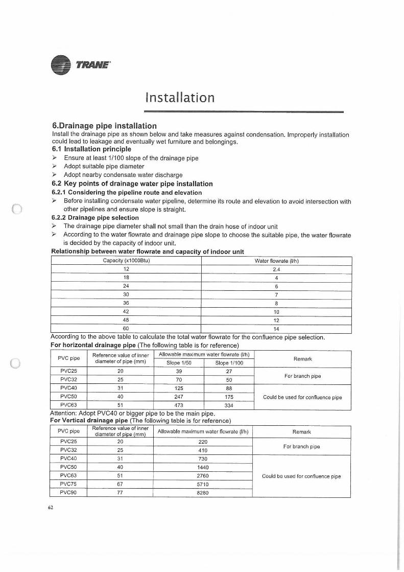
6.Drainage pipe installation Install the drainage pipe as shown below and take measures against condensation. Improperly installation could lead to leakage and eventually wet furniture and belongings. 6.1 Installation principle ► Ensure at least 1/100 slope of the drainage pipe ► Adopt suitable pipe diameter ► Adopt nearby condensate water discharge 6.2 Key points of drainage water pipe installation 6.2.1 Considering the pipeline route and elevation ► Before installing condensate water pipeline, determine its route and elevation to avoid intersection with
other pipelines and ensure slope is straight. 6.2.2 Drainage pipe selection ► The drainage pipe diameter shall not small than the drain hose of indoor unit ► According to the water flowrate and drainage pipe slope to choose the suitable pipe, the water flowrate
is decided by the capacity of indoor unit. Relationship between water flowrate and capacity of indoor unit
Capacity (x1000Btu) Water flowrate (I/h)
12 2.4
18 4
24 6
30 7
36 8
42 10
48 12
60 14
According to the above table to calculate the total water flowrate for the confluence pipe selection. For horizontal drainage pipe (The following table is for reference)
PVC pipe Reference value of inner Allowable maximum water flowrate (1/h)
Remark diameter of pipe (mm) Slope 1/50 Slope 1/1 00
PVC25 20 39 27
PVC32 25 70 50 For branch pipe
PVC40 31 125 88
PVC50 40 247 175 Could be used for confluence pipe
PVC63 51 473 334
Attention: Adopt PVC40 or bigger pipe to be the main pipe. For Vertical drainage pipe (The following table is for reference)
PVC pipe Reference value of inner
Allowable maximum water flowrate (I/h) Remark diameter of pipe (mm) PVC25 20 220
PVC32 25 410 For branch pipe
PVC40 31 730
PVC50 40 1440
PVC63 51 2760 Could be used for confluence pipe
PVC75 67 5710
PVC90 77 8280
62
()
u
Installation
Attention: Adopt PVC40 or bigger pipe to be the main pipe.
6.2.3 Individual design of drainage pipe system
• TRANE.
► The drainage pipe of air conditioner shall be installed separately with other sewage pipe, rainwater pipe and drainage pipe in building.
► The drainage pipe of the indoor unit with water pump should be apart from the one without water pump.
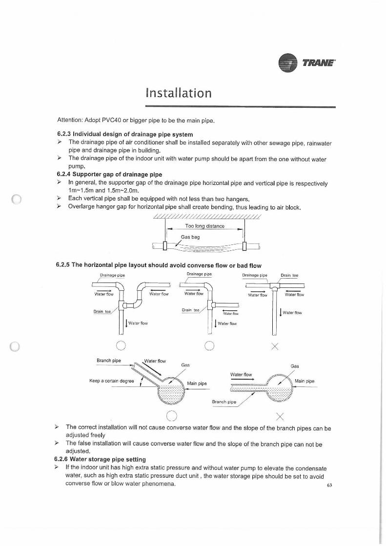
6.2.4 Supporter gap of drainage pipe ► In general, the supporter gap of the drainage pipe horizontal pipe and vertical pipe is respectively
1m-1.5m and 1.5m-2.0m. ► Each vertical pipe shall be equipped with not less than two hangers. ► Overlarge hanger gap for horizontal pipe shall create bending, thus leading to air block.
6.2.5 The horizontal pipe layout should avoid converse flow or bad flow
Drainage pipe
-Water flow
Drain tee
1 Water now
0 Branch pipe
Keep a certain degree
-Water Oow
0
Drainage pipe
-Water flow
Gas
0
Main pipe
-Waler now
l Water flow
Drainage pipe
-Water flow
Water flow
Branch pipe
X
Drain tee
-Water flow
1 Water flow
Gas
Main pipe
X ► The correct installation will not cause converse water flow and the slope of the branch pipes can be
adjusted freely
► The false installation will cause converse water flow and the slope of the branch pipe can not be adjusted.
6.2.6 Water storage pipe setting ► If the indoor unit has high extra static pressure and without water pump to elevate the condensate
water, such as high extra static pressure duct unit , the water storage pipe should be set to avoid converse flow or blow water phenomena. 63
0
u
• TRANE"
Installation
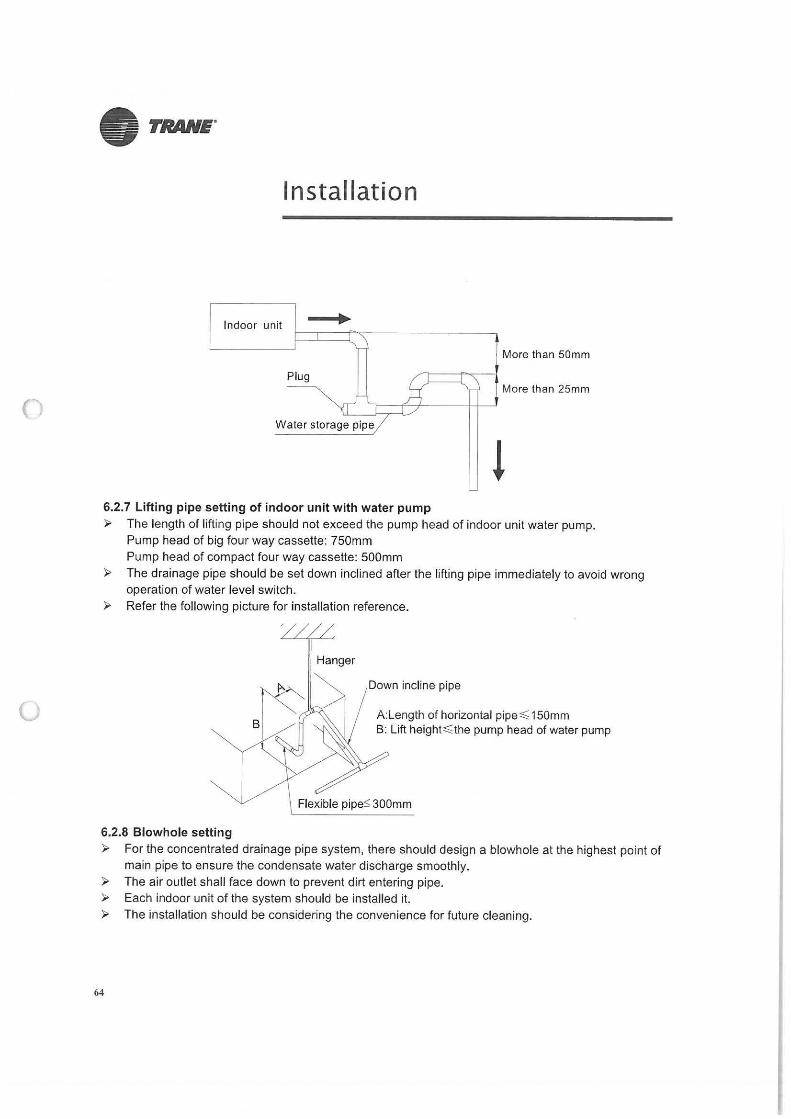
Indoor unit
More than 50mm
Plug More than 25mm
Water storage pipe
6.2. 7 Lifting pipe setting of indoor unit with water pump ► The length of lifting pipe should not exceed the pump head of indoor unit water pump.
Pump head of big four way cassette: 750mm Pump head of compact four way cassette: 500mm
► The drainage pipe should be set down inclined after the lifting pipe immediately to avoid wrong operation of water level switch.
► Refer the following picture for installation reference.
Hanger
Down incline pipe
A:Length of horizontal pipe~ 150mm B: Lift height~ the pump head of water pump
Flexible pipe$ 300mm
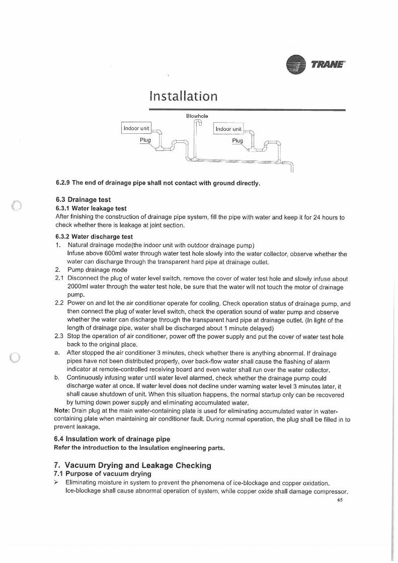
6.2.8 Blowhole setting ► For the concentrated drainage pipe system, there should design a blowhole at the highest point of
main pipe to ensure the condensate water discharge smoothly. ► The air outlet shall face down to prevent dirt entering pipe. ► Each indoor unit of the system should be installed it. ► The installation should be considering the convenience for future cleaning.
64
u
Installation Blowhola
6.2.9 The end of drainage pipe shall not contact with ground directly.
6.3 Drainage test 6.3.1 Water leakage test
• TRANE"
After finishing the construction of drainage pipe system, fill the pipe with water and keep it for 24 hours to check whether there is leakage at joint section.
6.3.2 Water discharge test 1. Natural drainage mode(the indoor unit with outdoor drainage pump)
Infuse above 600ml water through water test hole slowly into the water collector, observe whether the water can discharge through the transparent hard pipe at drainage outlet.
2. Pump drainage mode 2.1 Disconnect the plug of water level switch, remove the cover of water test hole and slowly infuse about
2000ml water through the water test hole, be sure that the water will not touch the motor of drainage pump.
2.2 Power on and let the air conditioner operate for cooling. Check operation status of drainage pump, and then connect the plug of water level switch, check the operation sound of water pump and observe whether the water can discharge through the transparent hard pipe at drainage outlet. {In light of the length of drainage pipe, water shall be discharged about 1 minute delayed)
2.3 Stop the operation of air conditioner, power off the power supply and put the cover of water test hole back to the original place.
a. After stopped the air conditioner 3 minutes, check whether there is anything abnormal. If drainage pipes have not been distributed properly, over back-flow water shall cause the flashing of alarm indicator at remote-controlled receiving board and even water shall run over the water collector.
b. Continuously infusing water until water level alarmed, check whether the drainage pump could discharge water at once. If water level does not decline under warning water level 3 minutes later, it shall cause shutdown of unit. When this situation happens, the normal startup only can be recovered by turning down power supply and eliminating accumulated water.
Note: Drain plug at the main water-containing plate is used for eliminating accumulated water in watercontaining plate when maintaining air conditioner fault. During normal operation, the plug shall be filled in to prevent leakage.
6.4 Insulation work of drainage pipe Refer the introduction to the insulation engineering parts.
7. Vacuum Drying and Leakage Checking 7.1 Purpose of vacuum drying ► Eliminating moisture in system to prevent the phenomena of ice-blockage and copper oxidation.
Ice-blockage shall cause abnormal operation of system, while copper oxide shall damage compressor. 65
()
u
• TRANE"
Installation
► Eliminating the non-condensable gas (air) in system to prevent the components oxidizing, pressure fluctuation and bad heat exchange during the operation of system.
7.2 Selection of vacuum pump ► The ultimate vacuum degree of vacuum pump shall be -756mmHg or above. ► Precision of vacuum pump shall reach 0.02mmHg or above. 7.3 Operation procedure for vacuum drying Due to different construction environment, two kinds of vacuum drying ways could be chosen, namely ordinary vacuum drying and special vacuum drying.
7.3.1 Ordinary vacuum drying 1. When conduct first vacuum drying, connect pressure gauge to the infusing mouth of gas pipe and liquid
pipe, and keep vacuum pump running for 1 hour (vacuum degree of vacuum pump shall be reached -755mmHg).
2 ff the vacuum degree of vacuum pump could not reach -755mmHg after 1 hour of drying, it indicates that there is moisture or leakage in pipeline system and need to go on with drying for half an hour.
3 If the vacuum degree of vacuum pump still could not reach -755mmHg after 1.5 hours of drying, check whether there is leakage source.
4 Leakage test: After the vacuum degree reaches -755mmHg, stop vacuum drying and keep the pressure for 1 hour. If the indicator of vacuum gauge does not go up, it is qualified. If going up, it indicates that there is moisture or leak source.
7.3.2 Special vacuum drying The special vacuum drying method shall be adopted when: 1. Finding moisture during flushing refrigerant pipe. 2. Conducting construction on rainy day, because rain water might penetrated into pipeline. 3. Construction period is long, and rain water might penetrated into pipeline. 4. Rain water might penetrate into pipeline during construction.
Procedures of special vacuum drying are as follows: 1. Vacuum drying for 1 hour. 2. Vacuum damage, filling nitrogen to reach 0.5Kgf/cm2 .
Because nitrogen is dry gas, vacuum damage could achieve the effect of vacuum drying, but this method could not achieve drying thoroughly when there is too much moisture. Therefore, special attention shall be drawn to prevent the entering of water and the formation of condensate water.
3. Vacuum drying again for half an hour. If the pressure reached -755mmHg, start to pressure leakage test. If it can not reached the value, repeat vacuum damage and vacuum drying again for 1 hour.
4 Leakage test: After the vacuum degree reaches -755mmHg, stop vacuum drying and keep the pressure for 1 hour. If the indicator of vacuum gauge does not go up, it is qualified. If going up, it indicates that there is moisture or leak source.
8. Additional refrigerant charge ► After the vacuum drying process is carried out, the additional refrigerant charge process need to be
performed.
66
()
(J
• TRANE"
Installation
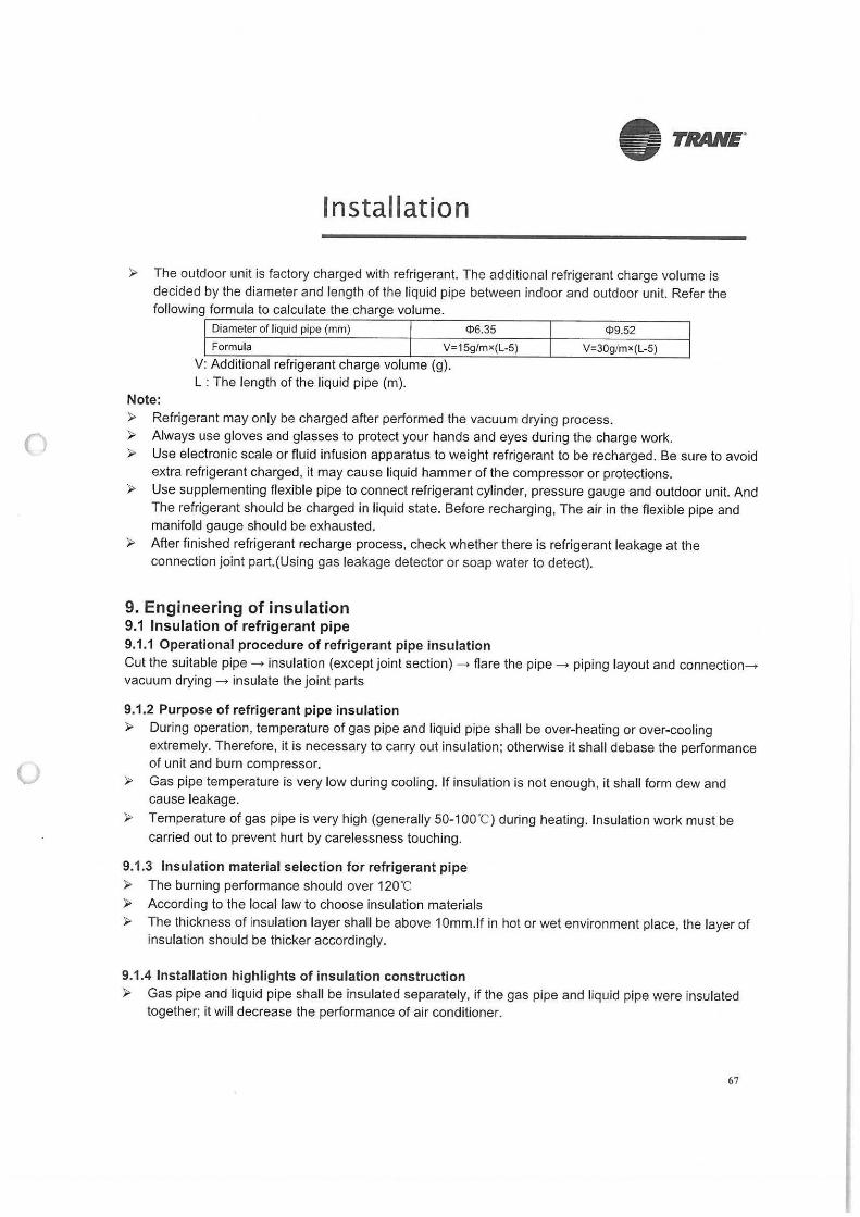
► The outdoor unit is factory charged with refrigerant. The additional refrigerant charge volume is decided by the diameter and length of the liquid pipe between indoor and outdoor unit. Refer the following formula to calculate the charge volume.
Note:
Diameter of liquid pipe (mm) ¢>6.35
Formula V=15g/mx(L-5)
V: Additional refrigerant charge volume (g). L : The length of the liquid pipe (m).
4>9.52
V=30g/mx(L-5)
► Refrigerant may only be charged after performed the vacuum drying process. ► Always use gloves and glasses to protect your hands and eyes during the charge work. ► Use electronic scale or fluid infusion apparatus to weight refrigerant to be recharged. Be sure to avoid
extra refrigerant charged, it may cause liquid hammer of the compressor or protections. ► Use supplementing flexible pipe to connect refrigerant cylinder, pressure gauge and outdoor unit. And
The refrigerant should be charged in liquid state. Before recharging, The air in the flexible pipe and manifold gauge should be exhausted.
► After finished refrigerant recharge process, check whether there is refrigerant leakage at the connection joint part.(Using gas leakage detector or soap water to detect).
9. Engineering of insulation 9.1 Insulation of refrigerant pipe 9.1.1 Operational procedure of refrigerant pipe insulation Cut the suitable pipe---> insulation (except joint section)--> flare the pipe ---> piping layout and connection---> vacuum drying --> insulate the joint parts
9.1.2 Purpose of refrigerant pipe insulation ► During operation, temperature of gas pipe and liquid pipe shall be over-heating or over-cooling
extremely. Therefore, it is necessary to carry out insulation; otherwise it shall debase the performance of unit and burn compressor.
► Gas pipe temperature is very low during cooling. If insulation is not enough, it shall form dew and cause leakage.
► Temperature of gas pipe is very high (generally 50-100"C) during heating. Insulation work must be carried out to prevent hurt by carelessness touching.
9.1.3 Insulation material selection for refrigerant pipe ► The burning performance should over 12o·c ► According to the local law to choose insulation materials ► The thickness of insulation layer shall be above 1 0mm.lf in hot or wet environment place, the layer of
insulation should be thicker accordingly.
9.1.4 Installation highlights of insulation construction ► Gas pipe and liquid pipe shall be insulated separately, if the gas pipe and liquid pipe were insulated
together; it will decrease the performance of air conditioner.
67
()
0
• TRANE.
Installation
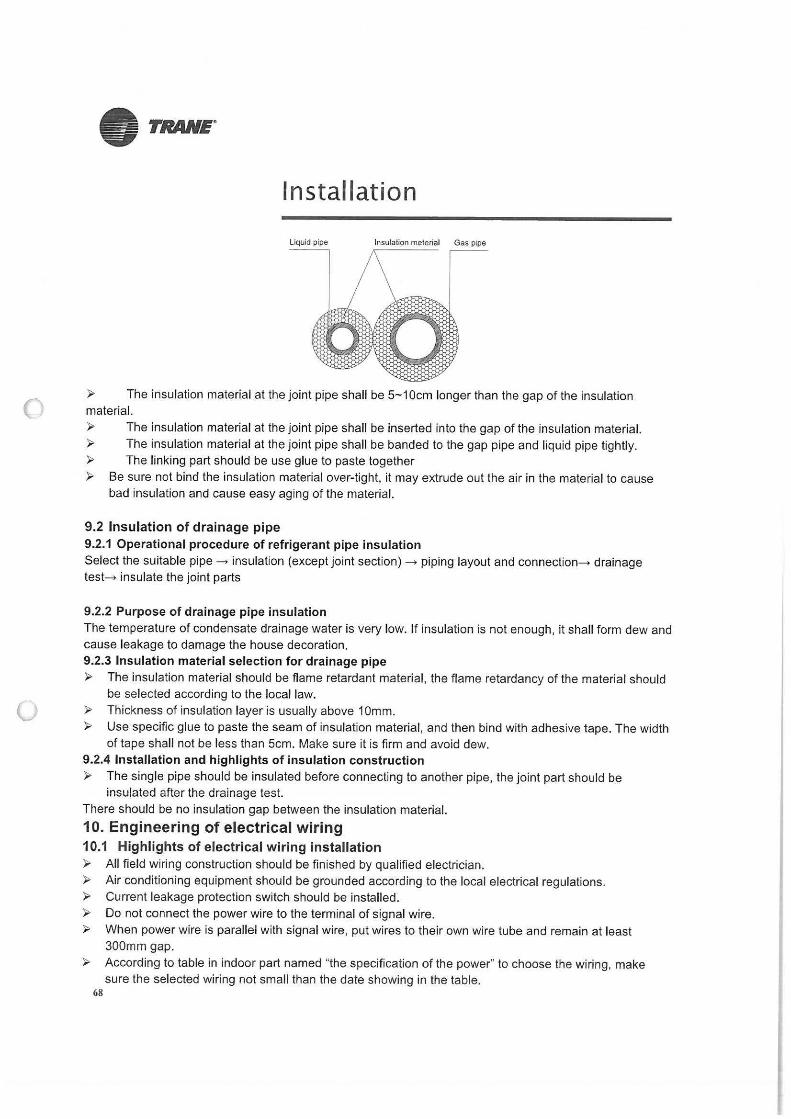
Liquid pipe Insulation meterial Gas pipe
► The insulation material at the joint pipe shall be 5- 10cm longer than the gap of the insulation material.
► The insulation material at the joint pipe shall be inserted into the gap of the insulation material. ► The insulation material at the joint pipe shall be banded to the gap pipe and liquid pipe tightly. ► The linking part should be use glue to paste together ► Be sure not bind the insulation material over-tight, it may extrude out the air in the material to cause
bad insulation and cause easy aging of the material.
9.2 Insulation of drainage pipe 9.2.1 Operational procedure of refrigerant pipe insulation Select the suitable pipe -> insulation (except joint section)-> piping layout and connection-+ drainage test-> insulate the joint parts
9.2.2 Purpose of drainage pipe insulation The temperature of condensate drainage water is very low. If insulation is not enough, it shall form dew and cause leakage to damage the house decoration. 9.2.3 Insulation material selection for drainage pipe ► The insulation material should be flame retardant material, the flame retardancy of the material should
be selected according to the local law. ► Thickness of insulation layer is usually above 10mm. ► Use specific glue to paste the seam of insulation material, and then bind with adhesive tape. The width
of tape shall not be less than 5cm. Make sure it is firm and avoid dew. 9.2.4 Installation and highlights of insulation construction ► The single pipe should be insulated before connecting to another pipe, the joint part should be
insulated after the drainage test. There should be no insulation gap between the insulation material.
10. Engineering of electrical wiring 10.1 Highlights of electrical wiring installation ► All field wiring construction should be finished by qualified electrician. ► Air conditioning equipment should be grounded according to the local electrical regulations. ► Current leakage protection switch should be installed. ► Do not connect the power wire to the terminal of signal wire. ► When power wire is parallel with signal wire, put wires to their own wire tube and remain at least
300mm gap. ► According to table in indoor part named "the specification of the power" to choose the wiring, make
sure the selected wiring not small than the date showing in the table. 68
(
0
• TRANE·
Installation
► Select different colors for different wire according to relevant regulations.
► Do not use metal wire tube at the place with acid or alkali corrosion, adopt plastic wire tube to replace it.
► There must be not wire connect joint in the wire tube If joint is a must, set a connection box at the place.
► The wiring with different voltage should not be in one wire tube. ► Ensure that the color of the wires of outdoor and the terminal No. are same as those of indoor unit
respectively.
11.Test operation 11.1 The test operation must be carried out after the entire installation has been
completed. 11.2 Please confirm the following points before the test operation. The indoor unit and outdoor unit are installed properly. ► Tubing and wiring are correctly completed. ► The refrigerant pipe system is leakage-checked. ► The drainage is unimpeded. ► The ground wiring is connected correctly.
► The length of the tubing and the added stow capacity of the refrigerant have been recorded. ► The power voltage fits the rated voltage of the air conditioner. ► There is no obstacle at the outlet and inlet of the outdoor and indoor units. ► The gas-side and liquid-side stop values are both opened. ► The air conditioner is pre-heated by turning on the power. 11.3 Test operation Set the air conditioner under the mode of "COOLING" by remote controller, and check the following points. Indoor unit ► Whether the switch on the remote controller works well. ► Whether the buttons on the remote controller works well. ► Whether the air flow louver moves normally. ► Whether the room temperature is adjusted well. ► Whether the indicator lights normally. ► Whether the temporary buttons works well. ► Whether the drainage is normal. ► Whether there is vibration or abnormal noise during operation.
Outdoor unit ► Whether there is vibration or abnormal noise during operation. ► Whether the generated wind, noise, or condensed of by the air conditioner have influenced your
neighborhood.
► Whether any of the refrigerant is leaked.
69
(J
• TRANE.
70
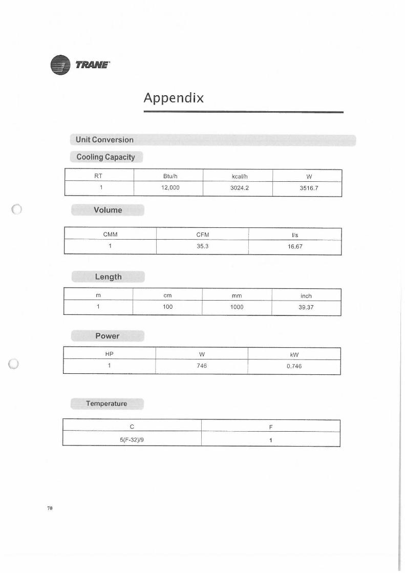
Unit Conversion
Cooling Capacity
RT
Volume
CMM
length
m
Power
HP
Temperature
C
5(F-32)/9
Appendix
Btu/h kcal/h w 12,000 3024.2 3516.7
CFM 1/s
35.3 16.67
cm mm inch
100 1000 39.37
w kW
746 0.746
F
()
()
SUBSTATION 1, 2 & 3 FIRE PUMP ROOM
• TRANE"
STORM WATER PUMPING STATION
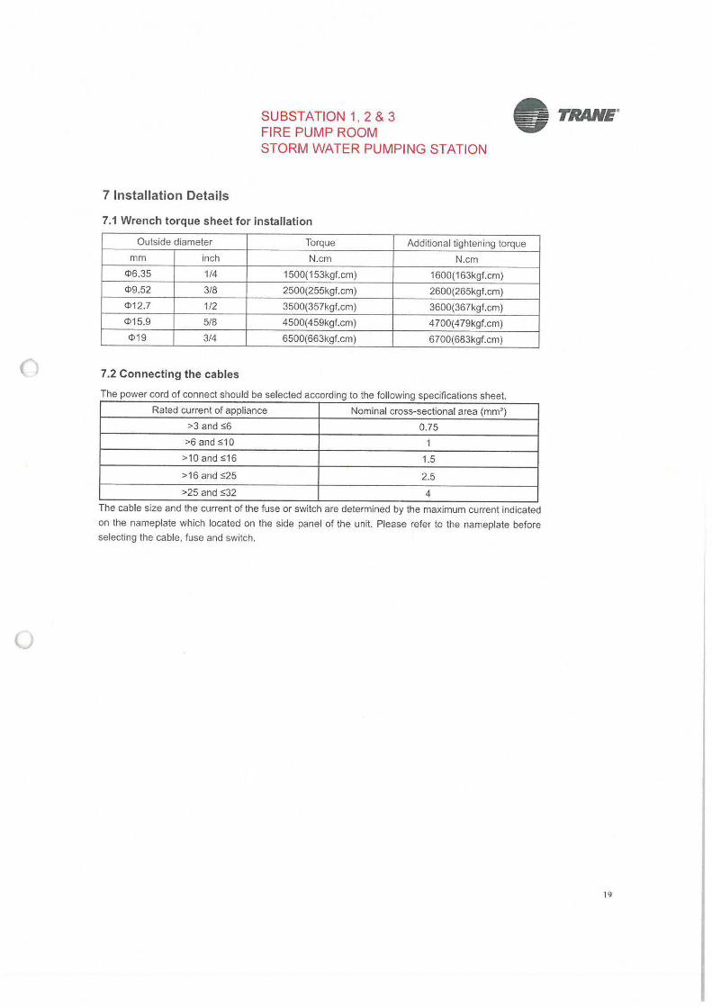
7 Installation Details
7.1 Wrench torque sheet for installation
Outside diameter Torque Additional tightening torque
mm inch N.cm N.cm
4>6.35 1/4 1500(153kgf.cm) 1600(163kgf.cm)
4>9.52 3/8 2500(255kgf.cm) 2600(265kgf.cm)
4>12.7 1/2 3500(357kgf.cm) 3600(367kgf.cm)
4>15.9 5/8 4500(459kgf.cm) 4700(479kgf.cm)
4>19 3/4 6500(663kgf.cm) 6700(683kgf.cm)
7.2 Connecting the cables
The power cord of connect should be selected according to the following specifications sheet.
Rated current of appliance Nominal cross-sectional area (mm2)
>3 and s6 0.75
>6 and s10 1
>10 and s16 1.5
>16 and S25 2.5
>25 and S32 4
The cable size and the current of the fuse or switch are determined by the maximum current indicated
on the nameplate which located on the side panel of the unit. Please refer to the nameplate before
selecting the cable, fuse and switch.
19
()
• TRANE.
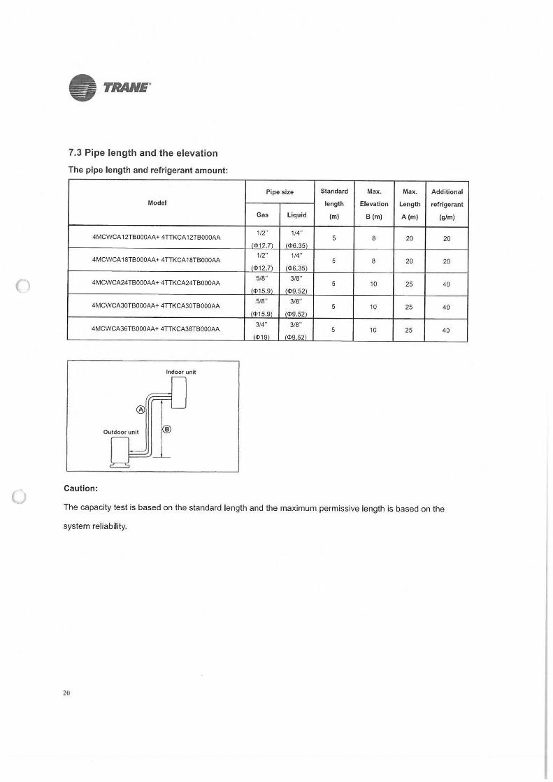
7.3 Pipe length and the elevation
The pipe length and refrigerant amount:
Model
4MCWCA 12TBOOOAA+ 4TTKCA 12TBOOOAA
4MCWCA 18TBOOOAA+ 4TTKCA 18TBOOOAA
4MCWCA24TBOOOAA+ 4TTKCA24TBOOOAA
4MCWCA30TBOOOAA+ 4TTKCA30TBOOOAA
4MCWCA36TBOOOAA+ 4TTKCA36TBOOOAA
Indoor unit
Outdoor unit ®
Caution:
Pipe size
Gas Liquid
1/2" 1/4"
(<!>12.7) (<!>6.35)
1/2" 1/4"
(<!>12.7) (<!>6.35)
5/8" 3/8"
(<!>15.9) (<!>9.52)
5/8" 3/8"
(<!>15.9) (<!>9.52)
3/4" 3/8"
1<!>19\ 1<!>9.52)
Standard Max. Max. Additional
length Elevation Length ref rigerant
(m) B(m) A(m) (g/m)
5 8 20 20
5 8 20 20
5 10 25 40
5 10 25 40
5 10 25 40
The capacity test is based on the standard length and the maximum permissive length is based on the
system reliability.
20
()
u
7.4 Installation for the first time
Air and moisture in the refrigerant system have
undesirable effects as below:
• Pressure in the system rises.
• Operating current rises.
• Cooling or heating efficiency drops.
• Moisture in the refrigerant circuit may
freeze and block capillary tubing.
• Water may lead to corrosion of parts in the
refrigerant system.
Therefore, the indoor units and the pipes
between indoor and outdoor units must be leak
tested and evacuated to remove gas and
moisture from the system.
Gas leak check (Soap water method):
Apply soap water or a liquid neutral
detergent on the indoor unit connections or
outdoor unit connections by a soft brush to
check for leakage of the connecting points of
the piping. If bubbles come out, the pipes have
leakage.
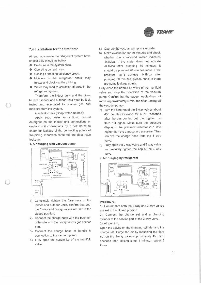
1. Air purging with vacuum pump
1) Completely tighten the flare nuts of the
indoor and outdoor units, confirm that both the 2-way and 3-way valves are set to the
closed position. 2) Connect the charge hose with the push pin
of handle lo to the 3-way valves gas service
port.
3) Connect the charge hose of handle hi
connection to the vacuum pump.
4) Fully open the handle Lo of the manifold
valve.
• TRANE.
5) Operate the vacuum pump to evacuate.
6) Make evacuation for 30 minutes and check
whether the compound meter indicates
-0.1 Mpa. If the meter does not indicate
-0.1 Mpa after pumping 30 minutes, it
should be pumped 20 minutes more. If the
pressure can't achieve -0.1 Mpa after
pumping 50 minutes, please check if there
are some leakage points.
Fully close the handle Lo valve of the manifold
valve and stop the operation of the vacuum
pump. Confirm that the gauge needle does not
move (approximately 5 minutes after turning off
the vacuum pump). 7) Turn the flare nut of the 3-way valves about
45• counterclockwise for 6 or ?seconds
after the gas coming out, then tighten the
flare nut again. Make sure the pressure
display in the pressure indicator is a little
higher than the atmosphere pressure. Then
remove the charge hose from the 3 way
valve. 8) Fully open the 2 way valve and 3 way valve
and securely tighten the cap of the 3 way
valve.
2. Air purging by refrigerant
Procedure: 1 ). Confirm that both the 2-way and 3-way valves
are set to the closed position.
2). Connect the charge set and a charging
cylinder to the service port of the 3-way valve.
3). Air purging. Open the valves on the charging cylinder and the
charge set. Purge the air by loosening the flare
nut on the 2-way valve approximately 45' for 3
seconds then closing it for 1 minute; repeat 3
times.
21
(J
• TRANE.
After purging the air, use a torque wrench to
tighten the flare nut on the 2-way valve.
4). Check the gas leakage.
Check the flare connections for gas leakage.
5). Discharge the refrigerant.
Close the valve on the charging cylinder and
discharge the refrigerant by loosening the flare
nut on the 2-way valve approximately 45' until the
gauge indicates 0.3 to 0.5 Mpa.
6). Disconnect the charge set and the charging
cylinder, and set the 2-way and 3-way valves to
the open position.
Be sure to use a hexagonal wrench to operate the
valve stems.
7). Mount the valve stems nuts and the service
port cap.
Be sure to use a torque wrench to tighten the
service port cap to a torque 18N·m.
Be sure to check the gas leakage.
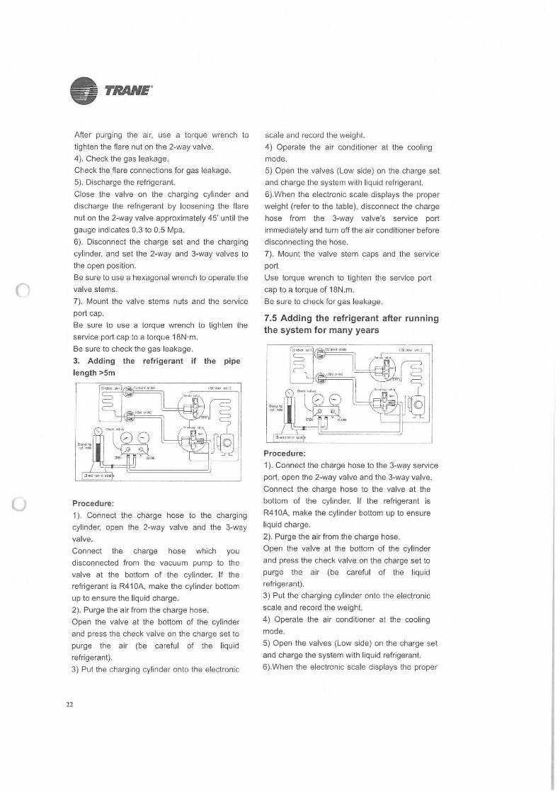
3. Adding the refrigerant if the pipe
length >Sm
Procedure:
1 ). Connect the charge hose to the charging
cylinder, open the 2-way valve and the 3-way
valve.
Connect the charge hose which you
disconnected from the vacuum pump to the
valve at the bottom of the cylinder. If the refrigerant is R41 0A, make the cylinder bottom
up to ensure the liquid charge.
2). Purge the air from the charge hose.
Open the valve at the bottom of the cylinder
and press the check valve on the charge set to
purge the air (be careful of the liquid
refrigerant).
3) Put the charging cylinder onto the electronic
22
scale and record the weight.
4) Operate the air conditioner at the cooling
mode.
5) Open the valves (Low side} on the charge set
and charge the system with liquid refrigerant.
6).When the electronic scale displays the proper
weight (refer to the table), disconnect the charge
hose from the 3-way valve's service port
immediately and turn off the air conditioner before
disconnecting the hose.
7). Mount the valve stem caps and the service
port
Use torque wrench to tighten the service port
cap to a torque of 18N.m.
Be sure to check for gas leakage.
7.5 Adding the refrigerant after running the system for many years
Procedure:
1 ). Connect the charge hose to the 3-way service
port, open the 2-way valve and the 3-way valve.
Connect the charge hose to the valve at the
bottom of the cylinder. If the refrigerant is
R41 0A, make the cylinder bottom up to ensure
liquid charge.
2). Purge the air from the charge hose.
Open the valve at the bottom of the cylinder
and press the check valve on the charge set to
purge the air (be careful of the liquid
refrigerant).
3) Put the charging cylinder onto the electronic
scale and record the weight.
4) Operate the air conditioner at the cooling
mode.
5) Open the valves (Low side) on the charge set
and charge the system with liquid refrigerant.
6).When the electronic scale displays the proper
()
(J
weight (refer to the gauge and the pressure of the
low side), disconnect the charge hose from the
3-way valve's service port immediately and turn
off the air conditioner before disconnecting the
hose.
7). Mount the valve stem caps and the service
port
Use torque wrench to tighten the service port
cap to a torque of 18N.m.
Be sure to check for gas leakage.
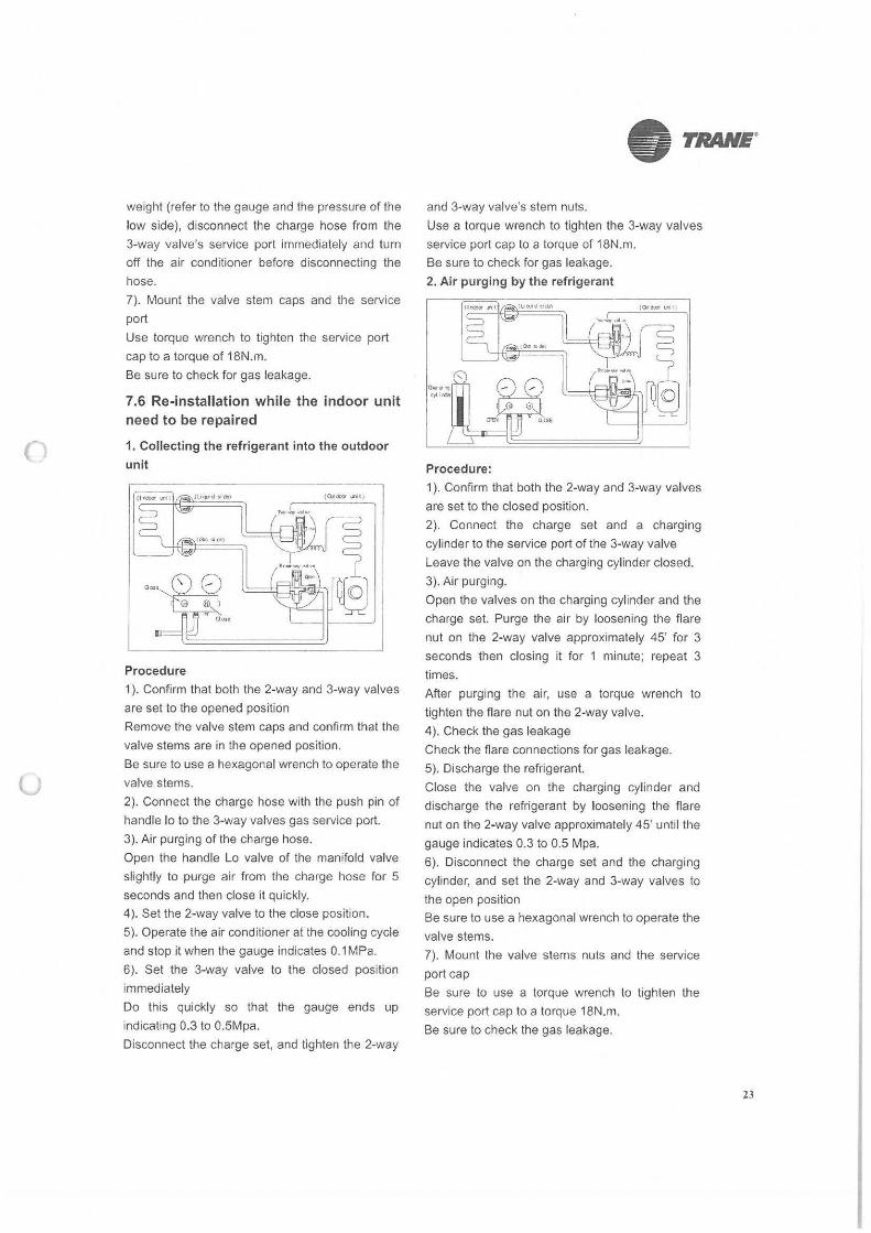
7.6 Re-installation while the indoor unit need to be repaired
1. Collecting the refrigerant into the outdoor
unit
Procedure
1 ). Confirm that both the 2-way and 3-way valves
are set to the opened position
Remove the valve stem caps and confirm that the
valve stems are in the opened position.
Be sure to use a hexagonal wrench to operate the
valve stems.
2). Connect the charge hose with the push pin of
handle lo to the 3-way valves gas service port.
3). Air purging of the charge hose.
Open the handle Lo valve of the manifold valve
slightly to purge air from the charge hose for 5
seconds and then close it quickly.
4). Set the 2-way valve to the close position.
5). Operate the air conditioner at the cooling cycle
and stop it when the gauge indicates 0.1 MPa.
6). Set the 3-way valve to the closed position
immediately
Do this quickly so that the gauge ends up
indicating 0.3 to 0.5Mpa.
Disconnect the charge set, and tighten the 2-way
• TRANE.
and 3-way valve's stem nuts.
Use a torque wrench to tighten the 3-way valves
service port cap to a torque of 18N.m.
Be sure to check for gas leakage.
2. Air purging by the refrigerant
Procedure:
1 ). Confirm that both the 2-way and 3-way valves
are set to the closed position.
2). Connect the charge set and a charging
cylinder to the service port of the 3-way valve
Leave the valve on the charging cylinder closed.
3). Air purging.
Open the valves on the charging cylinder and the
charge set. Purge the air by loosening the flare
nut on the 2-way valve approximately 45' for 3
seconds then closing it for 1 minute; repeat 3
times.
After purging the air, use a torque wrench to
tighten the flare nut on the 2-way valve.
4). Check the gas leakage
Check the flare connections for gas leakage.
5). Discharge the refrigerant.
Close the valve on the charging cylinder and
discharge the refrigerant by loosening the flare
nut on the 2-way valve approximately 45' until the
gauge indicates 0.3 to 0.5 Mpa.
6). Disconnect the charge set and the charging
cylinder, and set the 2-way and 3-way valves to
the open position
Be sure to use a hexagonal wrench to operate the
valve stems.
7). Mount the valve stems nuts and the service
port cap
Be sure to use a torque wrench to tighten the
service port cap to a torque 18N.m.
Be sure to check the gas leakage.
23
()
u
• TRANE"
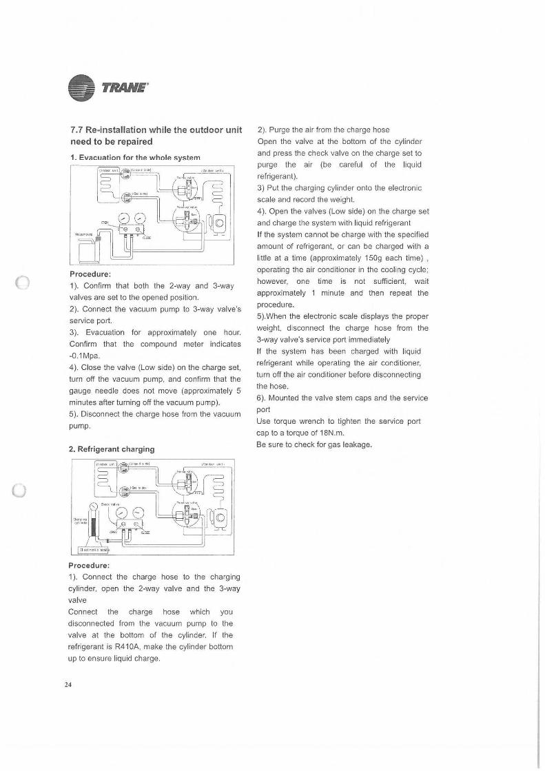
7.7 Re-installation while the outdoor unit need to be repaired
1. Evacuation for the whole system
111'-,•IJD) L<lt:~\,nlj ---"~-, ~------'"---v"-' ...
u Side)
Procedure :
1 ). Confirm that both the 2-way and 3-way
valves are set to the opened position.
2). Connect the vacuum pump to 3-way valve's
service port.
3). Evacuation for approximately one hour.
Confirm that the compound meter indicates
-0.1Mpa.
4). Close the valve (Low side) on the charge set,
turn oft the vacuum pump, and confirm that the
gauge needle does not move (approximately 5
minutes after turning off the vacuum pump).
5). Disconnect the charge hose from the vacuum
pump.
2. Refrigerant charging
Procedure: 1 ). Connect the charge hose to the charging
cylinder, open the 2-way valve and the 3-way
valve
Connect the charge hose which you
disconnected from the vacuum pump to the
valve at the bottom of the cylinder. If the
refrigerant is R41 OA, make the cylinder bottom
up to ensure liquid charge.
24
2). Purge the air from the charge hose
Open the valve at the bottom of the cylinder
and press the check valve on the charge set to
purge the air (be careful of the liquid
refrigerant).
3) Put the charging cylinder onto the electronic
scale and record the weight.
4). Open the valves (Low side) on the charge set
and charge the system with liquid refrigerant
If the system cannot be charge with the specified
amount of refrigerant, or can be charged with a
little at a time (approximately 150g each time) ,
operating the air conditioner in the cooling cycle;
however, one time is not sufficient, wait
approximately 1 minute and then repeat the
procedure.
5).When the electronic scale displays the proper
weight, disconnect the charge hose from the
3-way valve's service port immediately
If the system has been charged with liquid
refrigerant while operating the air conditioner,
turn off the air conditioner before disconnecting
the hose.
6). Mounted the valve stem caps and the service
port
Use torque wrench to tighten the service port
cap to a torque of 18N.m.
Be sure to check for gas leakage.
()
u
• TRANE.
26
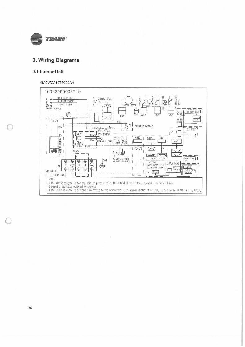
9. Wiring Diagrams
9.1 Indoor Unit
4MCWCA 12TBOOOAA
16022000003719
L ◄-~~~=~----, N •~-~~~~-, © ◄-~=--=; POWER SUPPLY
11 BLACK
JX1 ,-....,~~--+-,~~..,.....,...____. INDOOR UNIT L...::lµ~.1..,:,~..:.::....µ~
TO OUTDOOR -u \OTE: !. The ~iring dia,ram is fnr explanatior. purpo,c Cinlv. The actual shaoe nf the c••mpnn,:,nrs mav be different. 2. Svmboi 1 indicates optional components 3. The Color Of c"ble is different according tn the Stdndards: !EC Standards (BRO~\. Bll'E, Y/G), ll Standard, (BLACK, WlilTE. GREE\)
()
(J
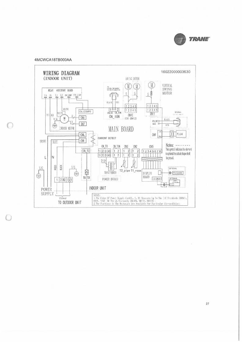
4MCWCA 18TBOOOAA
WIRING DIAGRAM (INDOOR UN IT)
L N
POWER ________ _ SUPPLY ~
3'1.5m,,.2
TO OUTDOOR UN IT
• TRANE"
Si I \G IIOTOR
~L~IN BOARD CURRENT DETECT
POWER BOARD
INDOOR UNIT
\OTES:
16022000003630
\lRT[(AL SWTI\G MOTOR
OPII~
CN_N2 ~ -'B""LA!::!C,,__r-,:~
c,;4
CNS Notes: · • · · · · · · rt~ symbol irxli:ales ~e elemenl ~ op:oo~ !he ajJal shape ~ be irevai.
1. Th(' C1lor Of Pui-t>r St.pply Lord(L \, El ~k•asurcs lp lo 'fnl' 1.:.C S"andards (B!mh1 BILL Yif.) Or Tt,c cl SL011carJs (BLACK, ~IIJTL G~LU) , 2. Thr hnn lm1s ln fhe Rct..ldf1,::!c Ar~ .\va!labl1: For Pc!.! 11rular :\1r-co11ditio1; :
27
0
u
• TRANE"
28
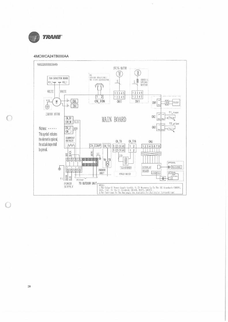
4MCWCA24TB000M
16022000003649
TO FAN CAPACITOR BOARD dX\l,F.11 1:t,~ Ir H\lf.
llR 10\ r;r.~ERATOR PC1_1 PCl_l
SWI\G MOTOR
M 5
M \"ERTi< 'I.. SWING ~OTOR
WHITE 1 2 3 4 5 1 2 3 4 5 ----------,,...L.Lr---j-'-1 -"-2 "--3 .:!...4 '45 - +.--1 ;;-2 3;;--4~5:-t---:----::-
!~DOOR lKl fOR
Notes: · · · · · Th5 s~mllol indica!es !he elemenlis opoon~. ihe actual silai;e s~ai be pf€vai.
1'011/ER Sl-PPI.Y
CN10 CN11
MAIN BOARD
INDOOR _!)lj_l_T_ - - -
CNJO CNJ IN
PO\ER 00\RO
CN9
Ctl2
CN3
CNS
TO OUTDOOR UNIT------------------, fi~~:C,,lvr Of Po,.cr SJpply t,,ri(L. ~. E) ~e,,ures Lp f., Th,• ilC S,andord, (BR•R\, Bllf., \,G) <Jr lhc ll it>ndard, (Bl.,l1<. illllf, GRrE\) . . LThr rur.rtion~ In The Rcctang:k \re- :hailjhic Fur F:u··icu·ar \1r-c0r;rht1on:
c,
u
• TRANE"
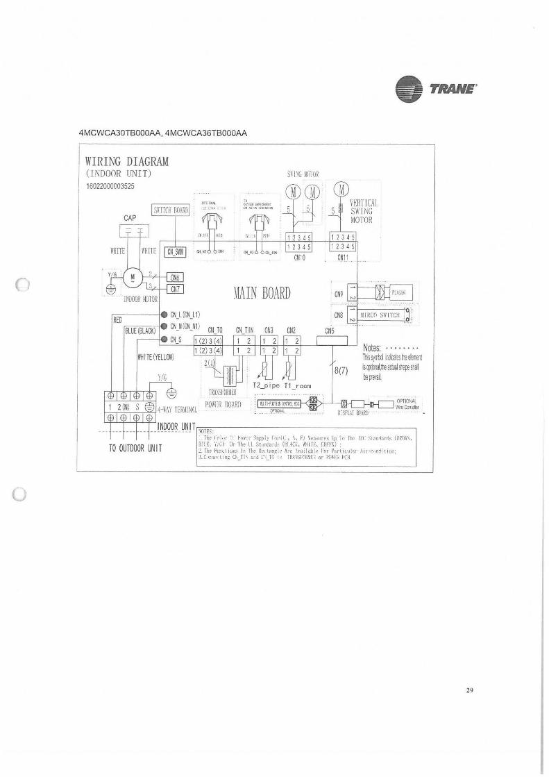
4 MCWCA30TB000AA, 4MCWCA36TB000AA
WIRING DIAGRAM (INDOOR UNIT)
16022000003525
CAP
l'HITE
smrn ROARn
WHITE (YELLOl'I)
Y/G
TO OUTDOOR UN I T
Of>HOHN. ~t . . lll,
" on.~ ~l(>tl(ltl OR».L:JllOUUTOII
~AIN BOARD
TRAWORUER POWER ROARll
CN3 CN2
IJ.ll-fl.l:llOIIXlfllCtFJ
~-
M l'ElfflCAL SWING MOTOR
CN1 i .
CNS
CNS
8(7)
II IRCC1 SWITCH .
Notes: · · · · · · .. llis s1mbol ildio:ales !he e!emenl is ~oo~.lhe aduol st.are sllll be111evai.
OPTIONAL . Wre Cookies
I. The l'<'i,,r r ~"'"1' ,upply fol'd(I, \, fl ~ca,ures Ip lo The !ff Stanrlarrls (RROl\, BllE. \';G) Or The LL St,in<lacds (81 \CK, ii'HITE, CRFPK) : :?. rhe r'imctit.m:-:. In The ~ect,rnglt> Are \vai lable ~or Partu .. ular Air-cor.dltion: :l.(,,cne<tin~ c~_fl\ and ('\ _Tl) j, TR.~~$F(l~\ll:'i or Porn, PCH.
29
u
• TRANE.
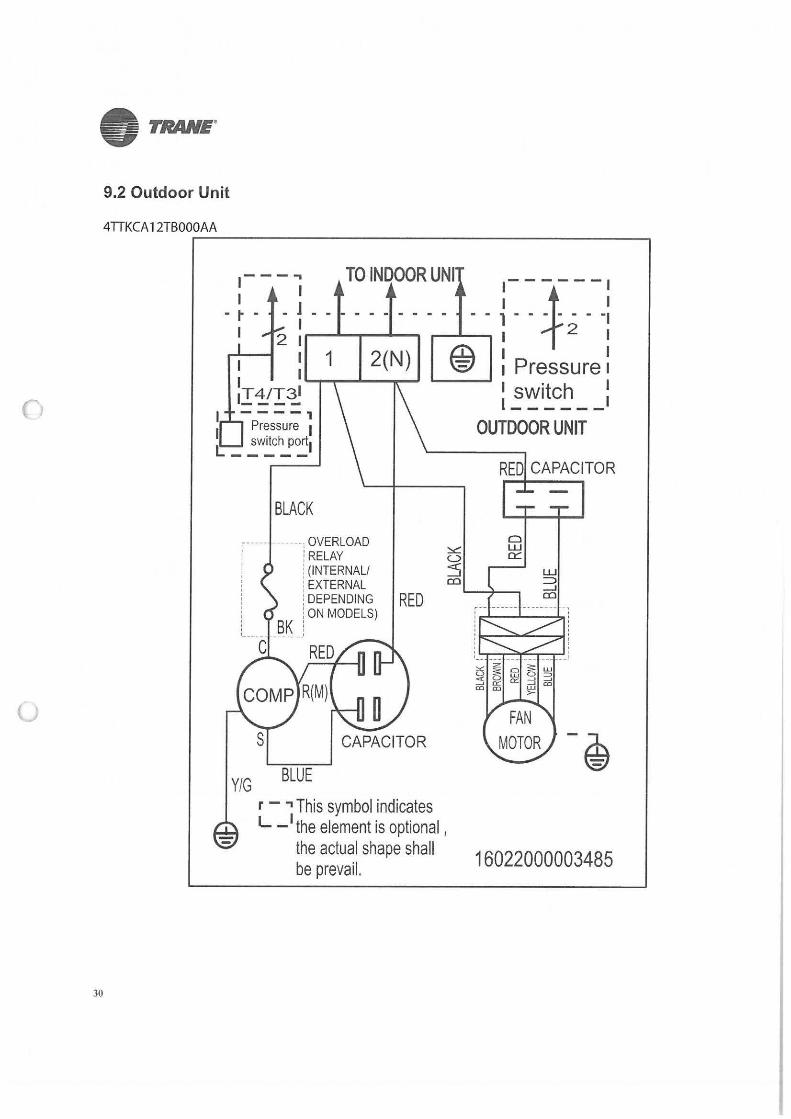
9.2 Outdoor Unit
4TTKCA 12TB00.:.,:0A~A.:...._ _________________ ----,
30
----, 1
Pressure 1 switch port1 c ____ _
BLACK
J::::-, - ------i ~~~:;OAD : (INTERNAL/ :EXTERNAL
::
: [ DEPENDING : ON MODELS)
, BK : t___ _ _ _____ 1
RED
Y/G BLUE
RED
r - ., This symbol indicates L -
1 the element is optional , the actual shape shall be prevail.
RED CAPACITOR
Cl w 0::::
w :=:> __J
co
16022000003485
()
• TRANE.
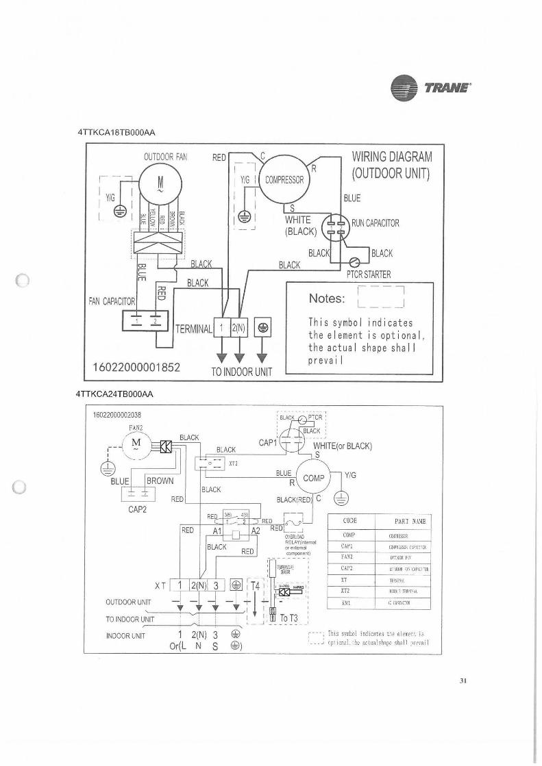
4TTKCA 18TB000AA
OUTDOOR FAN
BLACK
WIRING DIAGRAM (OUTDOOR UNIT)
BLUE
RUN CAPACITOR
BLACK "-----"-~
PTCR STARTER
FAN CAPACITOR Notes:
TERMINAL I 1(N) It 16022000001852 TO INDOOR UNIT
This symbol indicates the element is optional, the actua I shape sha 11 preva i I
4TTKCA24TB000AA
16022000002038
FAN2 / ~ BLACK
,-- -! - t:::::J;;,i;,t:= ---, BLACK 4> ri-1=0==;..:.::X.:.:..Tl ___ ___J
CAP2
BLACK
r-, ~-+----=~c..------'-+"""'--'-:=,.,,.,,...1 CV I RED _ _J
OVERLOAD RELAY{interoal or exlemal component)
' . ' l!lff.l.\U: I R'U! I
I - 7: I XT 1 @ 1T41 ,,-,;:..,-..;.;; ,:
OUTDOOR UNIT - I_ - -;- ~ '--- - - · ': I l '' ' ,, '-----+♦--.__,..i-----!...-.....1-, I I : :
TO INDOOR UNIT I 1 1' To T3 , ,----+-/'..;__:___~' L _ _j I _ _ _ _ _ _ I
CODE PART NA\!E
COMP C-O!IPIESSOI
CAP! CiNl'IESSOI flPIC:TGI
FA~l
CAP2 fll&li fl' CIPl(I ·01
XT
XT2
1: Cv\f.\Clll
INDOOR UNIT 1 2(N) 3 @ ; · · ·: This s,rbol indicate, the elem.t is , ___ ., rptional. ·hr artualshape shall ?mai l Or(L N S @)
31
()
u
i= TRANE"
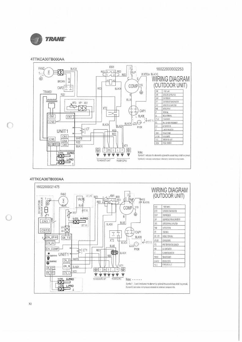
4TTKCA30TB0OOAA
BLACK
TRANS1
~~E:,~-_-"H_j-PROi L--PRO L-PRO :
L. ................................... 1.1
4 TTKCA36TBO0OAA
16022000021475
32
L-PRO 4 . .... ·-··········
KM1 16022000002253 WHITE!or BLACK)
t,IJ!es
WIRING DIAGRAM (OUTDOOR UNIT)
:s> ::lll'!l.<a!~~(.<PJ,(11~
~~ llr.C::~iA'IOA:"r.a!
PT'll 'TCR STAAl:R
'--------,,-' --------- S)'l'lloll m<l!tesit.e1,neniisop1ooailli.aaualshapeshal oeprevai Symbol 2 Yld?.:a:es eomi:ressor l'llem&I OI' ede~ co11ponents.
TO INOCOR UNIT PC'i,,R !lf"I.Y
1
··•··O ScACK PTCR
• No(es: ......
WIRING DIAGRAM (OUTDOOR UNIT)
({J;t PAAT/i..J.!1:
l'Jll 01/i!Y.lY,illIT~:t?al
Cl!f C(Jl.ff.:S..~
Ut CC~sro1,w!W,U.OR
cm OOTOC('Jlf~C-1'\II(ll
fl.~ (l;JimfVI
IT! l!RVr.t
ill.Xil 11.mrtf'.M )Fl.ISi 00!,'i(f<l<S
,n 19EllJI.Pffil.nF£re.lC!!
)'1! I.CIX/f!LTCR
r (lJ,11£,iM!Xlill
frJ.1~1 il'A\.SICf!lR
Ol~'W il:Ssc<".!;s w; ~:~uu
SymbGI I Jardl110,c;;tes~eeleneol~oplior.allhe~n,~stapashal ll,p,eval. Symoof 2 IOOicates compressor ritemal or exlemal COfl'lpO(lenls
• TRANE"
()
lJ
-TRANE Literature Order Number : MS-PRC035A-EN
Dated March 2017
Supersedes NEW
Trane has a policy of continuous product and product data improvement and
reserves the right to change design and specifications without notice.© 2017 Trane
PF/210317/ 1
(
(J
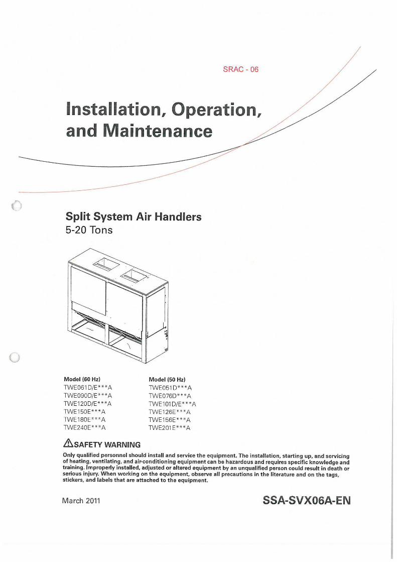
SRAC - 06
Installation, Operation, and Maintenance
Split System Air Handlers 5-20 Tons
Model (60 Hz)
TWE061 D/E***A TWE090D/E***A TWE120D/E***A TWE150E***A TWE180E***A TWE240E* **A
&SAFETY WARNING
Model (50 Hz)
TWE051 D***A TWE076D***A TWE101D/E***A TWE1 26E** *A TWE156E***A TWE201 E***A
Only qualified personnel should install and service the equipment. The installation, starting up, and servicing of heating, ventilating, and air-conditioning equipment can be hazardous and requires specific knowledge and training. Improperly installed, adjusted or altered equipment by an unqualified person could result in death or serious injury. When working on the equipment, observe all precautions in the literature and on the tags, stickers, and labels that are attached to the equipment.
March 2011 SSA-SVX06A-EN
()
u
Warnings, Cautions and Notices
Warnings, Cautions and Notices. Note that warnings, cautions and notices appear at appropriate intervals throughout this manual. Warnings are provided to alert installing contractors to potential hazards that could result in personal injury or death. Cautions are designed to alert personnel to hazardous situations that could result in personal injury, while notices indicate a situation that cou ld result in equipment or property-damage-only accidents.
Your personal safety and the proper operation ofthis machine depend upon the strict observance of these precautions.
ATTENTION: Warnings, Cautions and Notices appear at appropriate sections throughout this literature. Read these carefully.
& WARNING: Indicates a potentially hazardous situation which, if not avoided, could result in death or serious injury.
&cAUTION: Indicates a potentially hazardous situation which, if not avoided, could result in minor or moderate injury. It could also be used to alert against unsafe practices.
NOTICE: Indicates a situation that could result in equipment or property-damage only accidents.
Important Environmental Concerns!
Scientific research has shown that certain man-made chemicals can affect the earth 's naturally occurring stratospheric ozone layer when released to the atmosphere. In particular, several of the identified chemicals that may affect the ozone layer are refrigerants that contain Chlorine, Fluorine and Carbon (CFCs) and those conta ining Hydrogen, Chlorine, Fluorine and Carbon (HCFCs). Not all refrigerants containing these compounds have the same potential impact to the environment. Trane advocates the responsible handling of all refrigerants-including industry replacements for CFCs such as HCFCs and HFCs.
Responsible Refrigerant Practices!
Trane believes that responsible refrigerant practices are important to the environment, our customers, and the air conditioning industry. All technicians who handle refrigerants must be certified. The Federal Clean Air Act (Section 608) sets forth the requirements for handling, reclaiming, recovering and recycling of certain refrigerants and the equipment that is used in these service procedures. In addition, some states or municipalities may have additional requirements that must also be adhered to for responsible management of refrigerants. Know the applicable laws and follow them.
&WARNING R-410A Refrigerant under Higher Pressure than R-22! The unit described in this manual uses R-410A refrigerant which operates at higher pressures than R-22 refrigerant. Use ONLY R-410A rated service equipment or components with this unit. For specific handling concerns with R-410A, please contact your local Trane representative. Failure to use R-410A rated service equipment or components could result in equipment or components exploding under R-410A high pressures which could result in death, serious injury, or equipment damage.
© 2011 Trane All rights reserved SSA-SVX06A-E N
0
0
SSA-SVX06A-EN
Warnings, Cautions and Notices
&WARNING Contains R-410A Refrigerant! System contains oil and refrigerant under high pressure. Recover refrigerant to relieve pressure before opening the system. See unit nameplate for refrigerant type. Do not use non-approved refrigerants, refrigerant substitutes, or refrigerant additives. Failure to follow proper procedures or the use of non-approved refrigerants, refrigerant substitutes, or refrigerant additives could result in death or serious injury or equipment damage.
Important: DO NOT release refrigerant to the atmosphere! If adding or removing refrigerant is required, the service technician must comply with all federal, state, and local laws.
Important: One copy of this document ships inside the control panel of each unit and is customer property. It must be retained by the unit's maintenance personnel.
&WARNING Personal Protective Equipment (PPE) Required! Installing/servicing this unit could result in exposure to electrical, mechanical and chemical hazards.
• Before installing/servicing this unit, technicians MUST put on all Personal Protective Equipment (PPE) recommended for the work being undertaken. ALWAYS refer to appropriate MSDS and OSHA guidelines for proper PPE.
• When working with or around hazardous chemicals, ALWAYS refer to appropriate MSDS and OSHA guidelines for information on allowable personal exposure levels, proper respiratory protection and handling recommendations.
• If there is a risk of arc or flash, technicians MUST put on all Personal Protective Equipment (PPE) in accordance with NFPA70E or other country-specific requirements for arc/flash protection PRIOR to servicing the unit.
Failure to follow recommendations could result in death or serious injury.
This booklet describes proper installation, operation, and maintenance procedures for air cooled systems. By carefully reviewing the information within this manual and following the instructions, the risk of improper operation and/or component damage will be minimized.
It is important that periodic maintenance be performed to help assure trouble free operation. Should equipment failure occur, contact a qualified service organization with qualified, experienced HVAC technicians to properly diagnose and repair this equipment.
Important: All phases of this installation must comply with the NATIONAL, STATE & LOCAL CODES. In addition to local codes, the installation must conform with National Electric Code -ANSI/NFPA NO. 70 LATEST REVISION.
Any individual installing, maintaining, or servicing this equipment must be properly trained, licensed and qualified.
3
Table of Contents
Model Number Description ....................... . ......... . ........ .... 5
General Information .... ........... ................. .. . ................. 6 Installation Checklist ......... ............... .. ................. 6 Unit Inspection .......................... . .............. .. .... 6 Initial Leak Test . ... . ........ . . .................... . .... ....... 6 Lifting Recommendations ........ . .. . . .. ..... ..... .............. 6
Pre-Installation ... ............................. . .. . ............... . . . .. . 8 Reposition ing Drain Pan ........... . . ... .... .. . . . ............... 8 Field Conversion to 460 Volt ................ . ..... .. ............. 9 Refrigerant Piping ............. .. . ... . ................. ... . ... 11 Installations, Limitations and Recommendations .................. 12
Dimensional Data ......... ..... ... . . . ... . ................... . .......... 13
Electrical Data ................................. .... ... ........ ......... 22
Installation ............................................ .. ....... . ... ... 30 Horizontal Suspension . . . . .. .. . . . . .... . . . . ... .. . .... . . . . ... . .. 30 Refrigerant Piping ......... . . .. ... . .... .. . ..... .. ............. 31 Condensate Piping ............ .... ......... . ......... .. ..... . 32 Filters .................. . ....... . . . ..... .. .................. 32 Duct Connections ..... ... ..... . ............... . . . ... . ........ 32 Air Flow Settings ...... ... .. ......... . ................. ...... . 32 Electrical Connections ......................................... 33 Checkout Procedure . ... . ....... . ...... . .... . ... ... ..... . . .. . . 34 Installation Checklist .. ... .. .. . . . . . . . ...... . . . .... ... .......... 34
Electrical W iring .. ............ ..... .. ........ . ...... .... ... .. . . ... 34 Thermostat and Control Connections for Electromechanical Controls . 35 Thermostat and Control Connections for ReliaTel™ Controls ........ 36
u Maintenance .. .... ......... . ....... . ...... . ......... ....... . . ..... .... 38 Fan Belt Adjustment ...... . .. . .... . .................... ....... 38 Monthly ............... ....... ... ... ......... . ............ .. 39 Annually (Cooling Season) ........ . ... .. .. . .... .............. .. 40 Coil Cleaning .. . .... ..... .. .. ..... . ....... . .... .. ............ 40 Precautionary Measures . . . ... . .. ..... ................. ........ 41 First Aid Measures . ......... . ....... . .... . . ....... ... ........ 41 Maintenance Log . .. ... ...... . .................... . ... . . ...... 42
Warranty . . .......... .... ... . ....... . .. . .......... . ... . . . .. . ..... . .... 43
Central Air Conditioner . .. ... ...... ..... ............ ........ ...... . 43 Commercial Equipment Rated 20 Tons and Larger and Related Accessories (Parts Only) . ..... .. . ............ . ............. .. . ........... 43
Wiring Diagram Matrix .... . .. . . ... ..... . ..... . ........... . ............. 45
4 SSA-SVX06A-EN
0
(.J
Model Number Description
SSA-SVX06A-EN
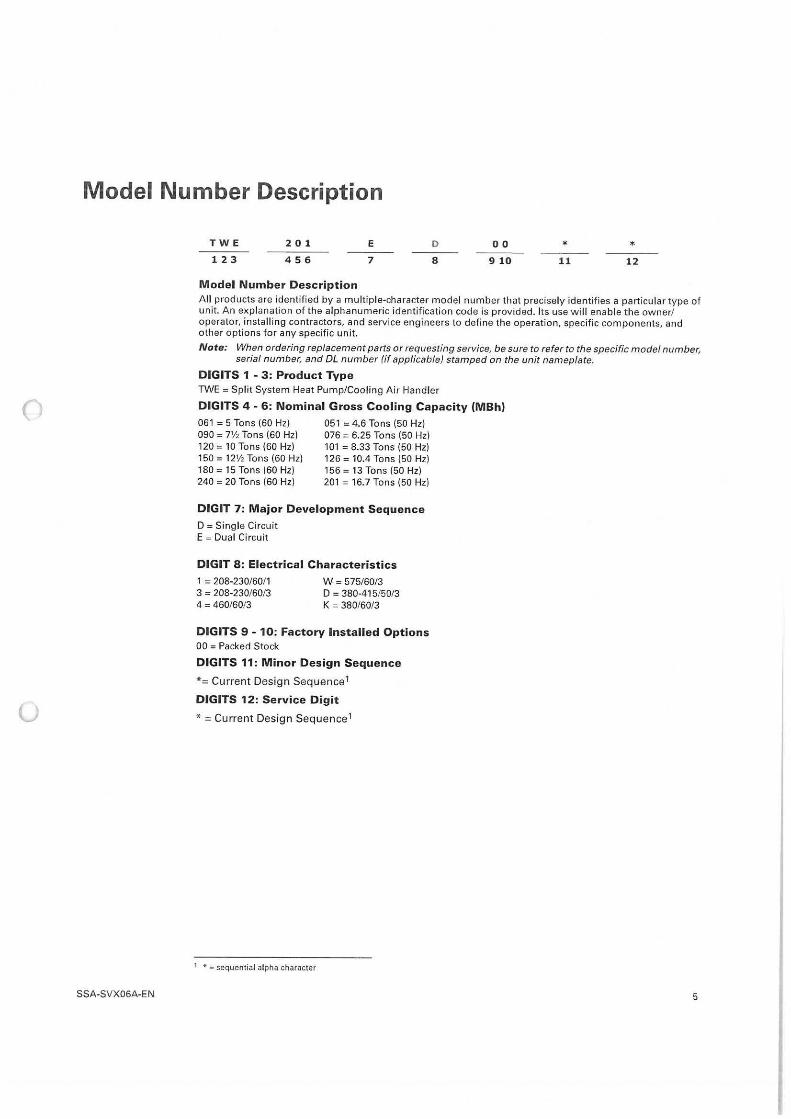
TW E
123
2 0 1
456
M odel Number Descript ion
E D
7 8
0 0 * * 9 10 11 12
All products are identified by a mult iple-character model number that precisely identifies a particu lar type of unit. An explanation of the alphanumeric identification code is provided. Its use will enable the owner/ operator, install ing contractors, and service engineers to define the operation, specific components, and other options for any specific unit.
Note: When ordering replacement parts or requesting service, be sure to refer to the specific model number, serial number, and DL number (if applicable) stamped on the unit nameplate.
DIGITS 1 - 3 : Product Type TWE = Split System Heat Pump/Cooling Air Handler
DIGITS 4 - 6: Nominal G ross Cooling Capacity (MBh)
061 = 5 Tons (60 Hz) 090 = 7½ Tons (60 Hz) 120 = 10 Tons (60 Hz) 150 = 12½ Tons (60 Hz) 180 = 15 Tons (60 Hz) 240 = 20 Tons (60 Hz)
051 = 4.6 Tons (50 Hz) 076 = 6.25 Tons (50 Hz) 101 = 8.33 Tons (50 Hz) 126 = 10.4 Tons (50 Hz) 156 = 13 Tons (50 Hz) 201 = 16. 7 Tons (50 Hz)
DIGIT 7: Major Development Sequence
D = Single Circuit E = Dual Ci rcuit
DIGIT 8: Electrical Characteristics
1 = 208-230/60/1 W = 575/60/3 3 = 208-230/60/3 D = 380-415/50/3 4 = 460/60/3 K = 380/60/3
DIGITS 9 - 10 : Factory Installed Options 00 = Packed Stock
DIGITS 11 : Minor Design Sequence
*= Current Design Sequence 1
DIGITS 12: Se rvice Digit
* = Current Design Sequence 1
1 * = sequential alpha character
5
()
(J
General Information
Installation procedures should be performed in the sequence that they appear in this manual. Do not destroy or remove the manual from the unit.
The manual should remain weather-protected with the unit until all installation procedures are complete.
Note: It is not the intention of this manual to cover all possible variations in systems that may occur or to provide comprehensive information concerning every possible contingency that may be encountered during an installation. If additional information is required or if specific problems arise that are not fully discussed in this manual, contact your local sales office.
This manual covers installation of the TWE air handlers. These air handler models incorporate a single slab coil assembly, improved application flexibility, servicing, maintenance accessibi lity and an improved accessory line. They are fully convertible, (vertical to horizontal discharge) without field removal of the coil assembly. They are shipped ready for horizontal installation.
All units have one drain pan that can be installed in any one of four positions. This allows for vertical or horizontal applications and right or left exit.
Important: All dual circuit (digit 7 = E) have an intertwined coil.
Installation Checklist
Unit Inspection
Initial Leak Test
An " Installation Checklist" is provided atthe end of the installation section of this manual. Use the checklist to verify that all necessary installation procedures have been completed. Do not use the checklist as a substitute for reading the information contained in the manual. Read the entire manual before beginning installation procedures.
Inspect material carefu lly for any shipping damage. If damaged, it must be reported to, and claims made against the transportation company. Compare the information that appears on the unit nameplate w ith ordering and submittal data to ensure the proper unit was shipped. Available power supply must be compatible with electrical characteristics specified on component nameplates. Replace damaged parts with authorized parts only.
All TWE units are shipped with a holding charge of nitrogen in each circuit. Remove the access panel shown in Figure 13, p. 21 . Locate the liquid line or suction l ine access valve for each ci rcuit. Install gauges to determine if the circuits are still pressurized. If not, the charge has escaped. Repair as required to obtain a leak-free circuit.
Lifting Recommendations
6
& WARNING Improper Unit Lift! Each of the cables (chains or slings) used to lift the unit must be capable of supporting the entire weight of the unit. Lifting cables (chains or slings) may not be of the same length. Adjust as necessary for even unit lift. Other lifting arrangements may cause equipment or property-only damage. Failure to properly lift unit could result in death or serious injury. Refer to Table 1 and Table 2 for unit weight.
NOTICE Equipment Damage! Use spreader bars to prevent straps from damaging the unit. Install the bars between lifting straps, both underneath the unit and above the unit. This will prevent the straps from crushing the unit cabinet or damaging the unit finish.
SSA-SVX06A-E N
()
()
General Information
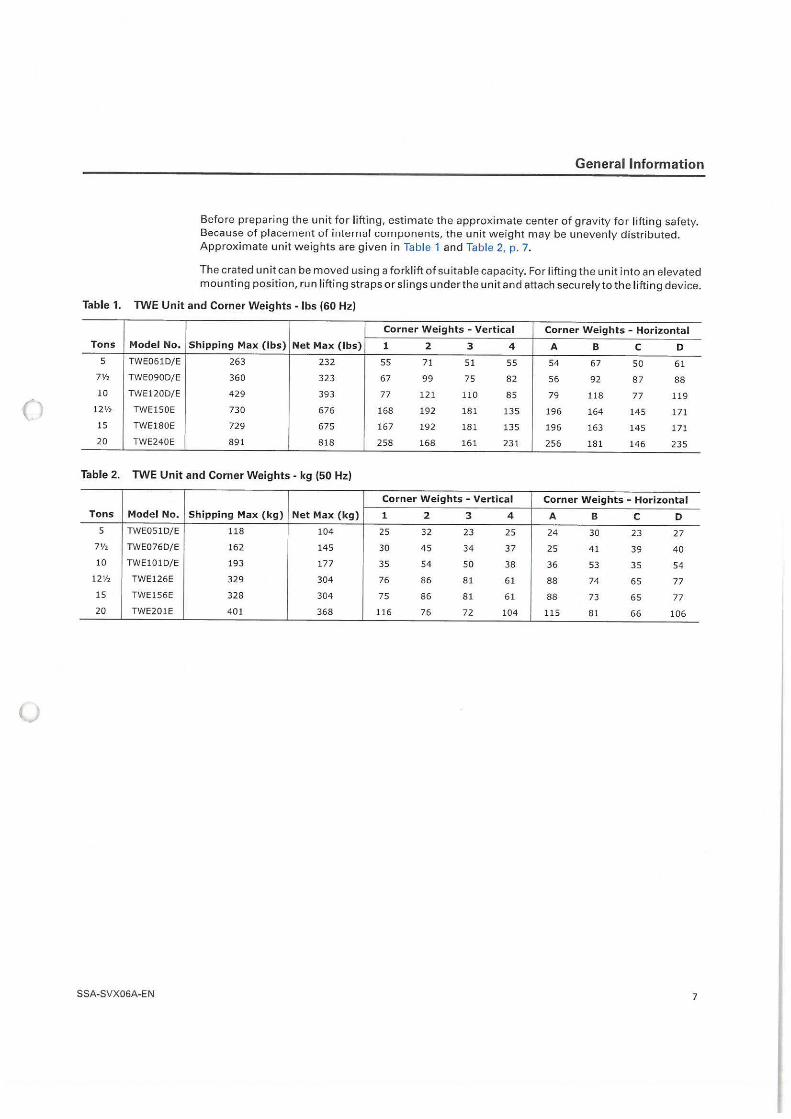
Before preparing the unit for lifting, estimate the approximate center of gravity for lifting safety. Because of placement of internal component:;, the unit weight may be unevenly distributed. Approximate unit weights are given in Table 1 and Table 2, p. 7.
The crated unit can be moved using a forkl ift of suitable capacity. For lifting the unit into an elevated mounting position, run lifting straps or slings under the unit and attach securely to the l ifting device.
Table 1. TWE Unit and Corner Weights - lbs (60 Hz)
Corner Weights - Vertical Corner Weights - Horizontal
Tons Model No. Shipping Max (lbs) Net Max (lbs) 1 2 3 4 A B C D 5 TWE061D/E 263 232 55 71 51 55 54 67 50 61
7½ TWE090D/E 360 323 67 99 75 82 56 92 87 88
10 TWE120D/E 429 393 77 121 110 85 79 118 77 119
12½ TWE150E 730 676 168 192 181 135 196 164 145 171
15 TWE180E 729 675 167 192 181 135 196 163 145 171
20 TWE240E 891 818 258 168 161 231 256 181 146 235
Table 2. TWE Unit and Corner Weights - kg (50 Hz)
Corner Weights - Vertical Corner Weights - Horizontal
Tons Model No. Shipping Max (kg) Net Max (kg) 1 2 3 4 A B C D 5 TWE051D/E 118 104 25 32 23 25 24 30 23 27
7½ TWE076D/ E 162 145 30 45 34 37 25 41 39 40 10 TWE101D/ E 193 177 35 54 50 38 36 53 35 54
12½ TWE126E 329 304 76 86 81 61 88 74 65 77
15 TWE1 56E 328 304 75 86 81 61 88 73 65 77 20 TWE201E 40 1 368 116 76 72 104 115 81 66 106
SSA-S VX06A-EN 7
()
()
8
Pre-Installation
The final position for the air handler must be dictated by required service access to it, weight distribution over structural supports, and by the locations of electrical, refrigerant and condensate drainage connections. After this is determined, the following preparations should be made.
Repositioning Drain Pan
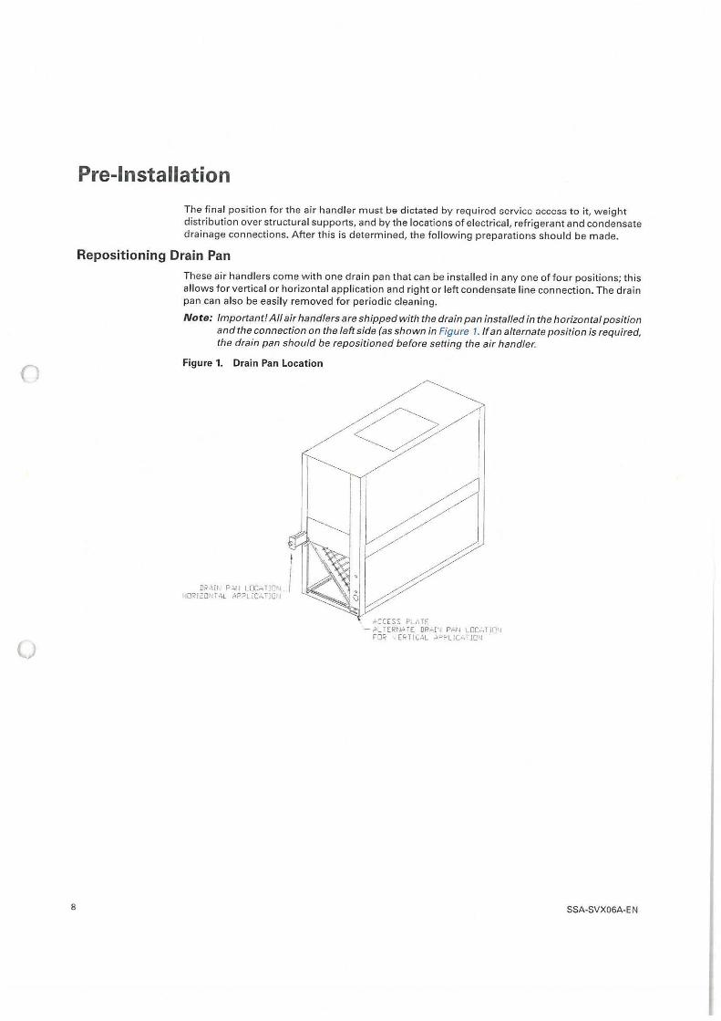
These air handlers come with one drain pan that can be installed in any one of four positions; this allows for vertical or horizontal application and right o r left condensate line connection. The drain pan can also be easily removed for periodic cleaning.
Note: Important! All air handlers are shipped with the drain pan installed in the horizontal position and the connection on the left side (as shown in Figure 1. If an alternate position is required, the drain pan should be repositioned before setting the air handler.
Figure 1. Drain Pan Location
I
0~~111 P;.r r L□cH Tim, j HORIZOIH "'L .\PPL re;, TJ□ rJ
,-,CCESS PLnTE - ALTERt,aTE OR,,rr, PHIi LDCHTJOtr
FOR , ERT IC.\L .\PPLJC,-. TION
SSA-SVX06A-EN
()
u
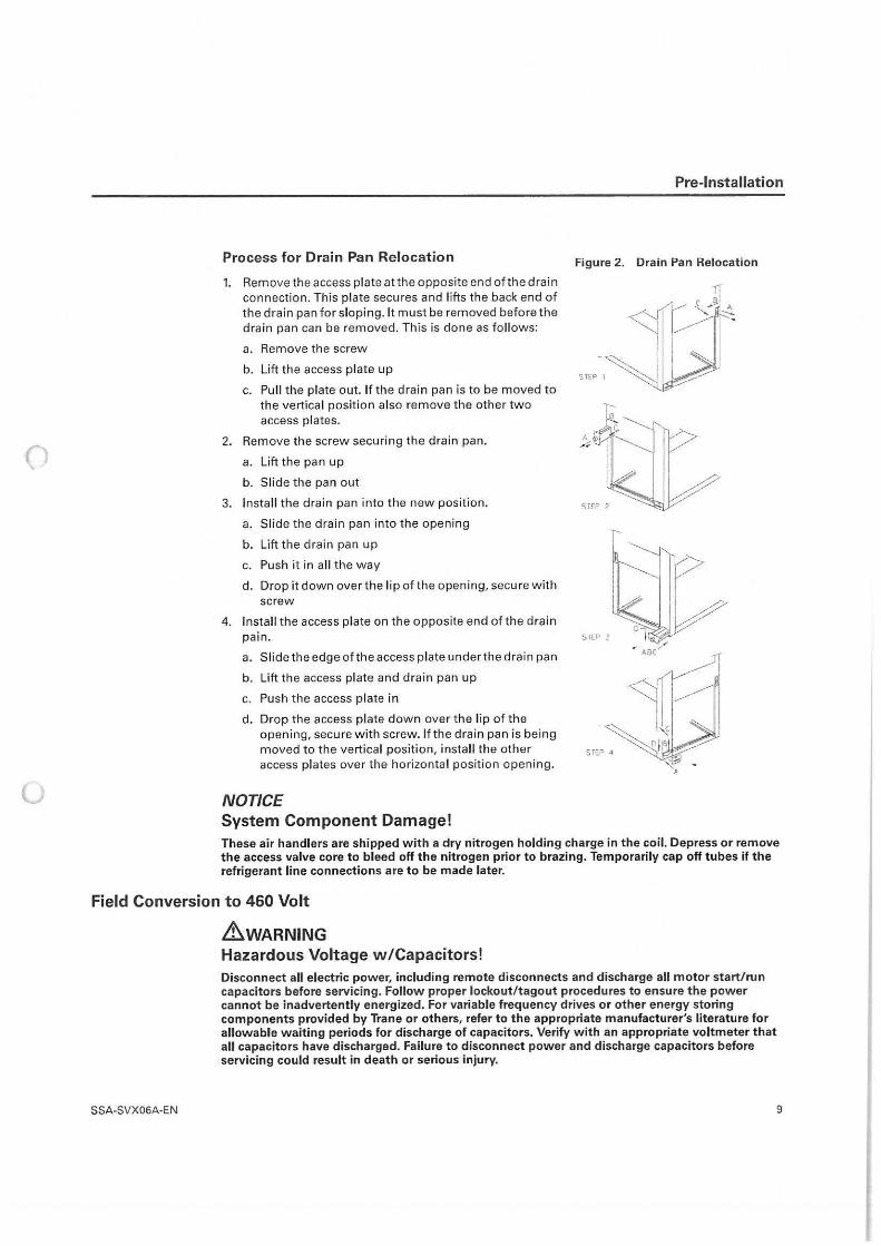
Process for Drain Pan Relocation
1. Remove the access plate at the opposite end of the drain connection. This plate secures and lifts the back end of the drain pan for sloping. It must be removed before the drain pan can be removed. This is done as follows:
a. Remove the screw
b. Lift the access plate up
c. Pull the plate out. If the drain pan is to be moved to the vertical position also remove the other two access plates.
2. Remove the screw securing the drain pan.
a. Lift the pan up
b. Slide the pan out
3. Install the drain pan into the new position.
a. Slide the drain pan into the opening
b. Lift the drain pan up
c. Push it in all the way
d. Drop it down over the l ip of the open ing, secure with screw
4. Install the access plate on the opposite end of the drain
Pre-Installation
Figure 2. Drain Pan Relocation
pain. STEP ~
a. Slide the edge of the access plate under the drain pan
b. Lift the access plate and drain pan up
c. Push t he access plate in
d. Drop the access plate down over the lip of the opening, secure with screw. If the drain pan is being moved to the vertical position, install the other access plates over the horizontal position opening.
NOTICE System Component Damage! These air handlers are shipped with a dry nitrogen holding charge in the coil. Depress or remove the access valve core to bleed off the nitrogen prior to brazing. Temporarily cap off tubes if the refrigerant line connections are to be made later.
Field Conversion to 460 Volt
.&WARNING
SSA-SVX06A-EN
Hazardous Voltage w/Capacitors! Disconnect all electric power, including remote disconnects and discharge all motor start/run capacitors before servicing. Follow proper lockout/tagout procedures to ensure the power cannot be inadvertently energized. For variable frequency drives or other energy storing components provided by Trane or others, refer to the appropriate manufacturer's literature for allowable waiting periods for discharge of capacitors. Verify with an appropriate voltmeter that all capacitors have discharged. Failure to disconnect power and discharge capacitors before servicing could result in death or serious injury.
9
Pre-Installation
()
u
10
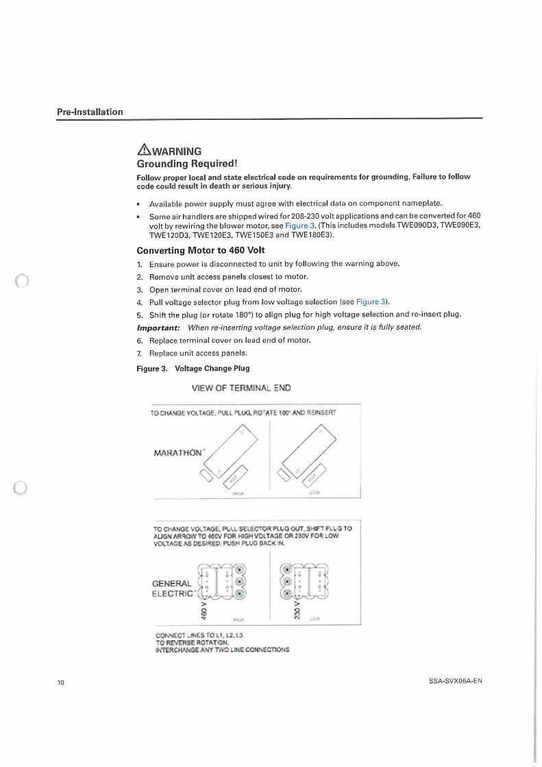
&WARNING Grounding Required! Follow proper local and state electrical code on requirements for grounding. Failure to follow code could result in death or serious injury.
• Available power supply must agree w ith electrical data on component nameplate.
• Some air handlers are shipped wired for 208-230 volt applications and can be converted for 460 volt by rewiring the blower motor, see Figure 3. (This includes models TWE090D3, TWE090E3, TWE120D3, TWE120E3, TWE150E3 and TWE180E3}.
Converting Motor to 460 Volt
1.
2.
3.
4.
Ensure power is disconnected to unit by following the warning above.
Remove unit access panels closest to motor.
Open terminal cover on lead end of motor.
Pull vo ltage selector plug from low voltage selection (see Figure 3).
5. Shift t he plug (or rotate 180°) to align plug for high voltage selection and re-insert plug.
Important: When re-inserting voltage selection plug, ensure it is fully seated.
6. Replace terminal cover on lead end of motor.
7. Replace unit access panels.
Figure 3. Voltage Change Plug
V1EW Of TERMINAL END
TO CHA. -.OE VOLT l<.GE, PULL Kl\.UO.. fl.OT ATE iec" M!Ht:INSERT
tQ CHANG:!; ~'OU NJ(;. P\,1.1,,. SU-eC"Q~ PL:UIJ Wt. SHIFl ~ \.Q TO ALJG..'1\1 M't.OWTO 4~\I f!OO HIOOVOI.TMiECA2aJN FOR LOW VC4. TAQI; A:!, 01;:.1~W. PVSH PLUG eA'.;K IN.
C
GENERAL , I ~ ELECTRIC-(l;J,,
;>
~ 'GI'
CO,,, 'IECT _INES TO LI , l2, ~ TO R_£\16RSE ROTA.T~J. INTERC~ NM TNO LIME COOM1C110NS
SSA-SVX06A-E N
u
Pre-Installation
Refrigerant Piping
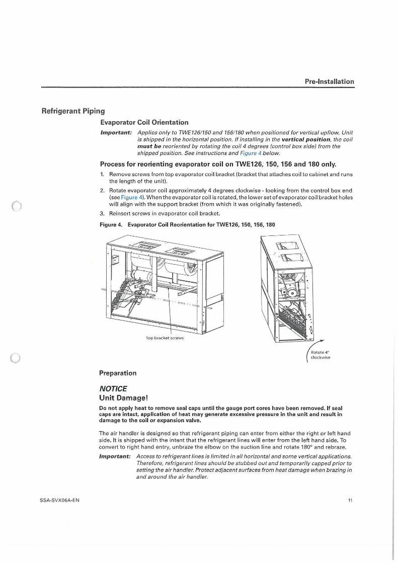
Evaporator Coil Orientation Important: Applies only to TWE126/ 150 and 156/ 180 when positioned for vertical upflow. Unit
is shipped in the horizontal position. If installing in the vertical position, the coil must be reoriented by rotating the coil 4 degrees (control box side) from the shipped position. See instructions and Figure 4 below.
Process for reorienting evaporator coil on TWE126; 150, 156 and 180 only. 1. Remove screws from top evaporator coi l bracket (bracket that attaches coi l to cabinet and runs
the length of the unit).
2. Rotate evaporator co il approximately 4 degrees clockwise - looking from the control box end (see Figure 4). When the evaporator coi l is rotated, the lower set of evaporator coil bracket holes wi ll align with the support bracket (from which it was originally fastened).
3. Reinsert screws in evaporator coil bracket.
Figure 4. Evaporator Coil Reorientation for TWE126, 150, 156, 180
Top b racket screws
Preparation
NOTICE Unit Damage!
Rotate 4° clockwise
Do not apply heat to remove seal caps until the gauge port cores have been removed. If seal caps are intact, application of heat may generate excessive pressure in the unit and result in damage to the coil or expansion valve.
The air handler is designed so that refrigerant piping can enter from either the right or left hand side. It is shipped with the intent that the refrigerant lines will enter from the left hand side. To convert to right hand entry, unbraze the elbow on the suction line and rotate 180° and rebraze.
Important: Access to refrigerant lines is limited in all horizontal and some vertical applications. Therefore, refrigerant lines should be stubbed out and temporarily capped prior to setting the air handler. Protect adjacent surfaces from heat damage when brazing in and around the air handler.
SSA-SVX06A-EN 11
()
u
Pre-Installation
Installations, Limitations and Recommendations
12
NOTICE System Component Damage! Properly insulate all refrigerant gas piping to prevent possible water damage due to condensation and to prevent capacity loss and possible compressor damage.
The general location of the air handler is normally selected by the architect, contractor and/or buyer. For proper installation the following items must be considered.
• Availab le power supply must agree with electrical data on component nameplate.
• If external accessories are insta lled on the unit, additional clearances must be provided.
• All duct work should be properly insulated to prevent condensation and heat loss.
• Refrigerant gas piping must be insulated.
It is recommended that the outline drawings (Figure 6, p. 14 - Figure 13, p. 21 ) be studied and dimensions properly noted and checked against the selected installation site. By noting in advance which features are to be used, proper clearance allowances can be made for installation and possible future service.
Important: When installing these units "free standing" with discharge grills and isolators, a top support with isolator should be added to prevent tipping. Support and isolator can be attached to a wall or other appropriate structure.
Important: If adding external accessories to the unit, additional clearances must be considered for the overall space needed.
For installation of accessories avai lable forth is air handler, follow the instructions packed with each accessory.
SSA-SVX06A-E N
Dimensional Data
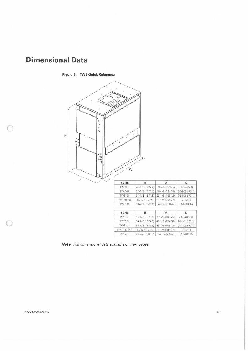
Figure 5. TWE Quick Reference
0 H
60 Hz H w D
TWE06I 48-1 /8 (1222.4) 39-5/8 (1006.5) 23-5/8 (600)
TWE090 54-1/8(13748) 49-1/8 (1247.8) 26-1/2 (673.1)
TWE120 54-1/8(13748) 65-1/8 (1654.2) 26-1/2 (673 I J TWE150, 180 69-1/8 :1756) Rl-l/4(206U) ,o (762)
TWE240 71-7/8 (18066) 94-1/4 12394) 32-1/8(815)
50 Hz H w D
TWEOSI 48-1/8 (1222.4) 39-5/8 (1006.5) 23-5/8 (600)
u TWC076 54-1 /8 (1374.8) 49-1/8 (1247.8) 26-1/2 (6731)
TWEIOl 54-1 /8 (1374.8) 65-1/8 (1654.2) 26-1/2 (673.ll
TWE126, l:>6 69-1/8 (1 /~6) 81 -1/4 (2063.l) 30 (/62)
IWl:201 71-7/8 (1806.6) 94-1/4 (2394) 32-1/8 (816)
Note: Full dimensional data available on next pages,
SSA-SVX06A-EN 13
()
(J
Dimensional Data
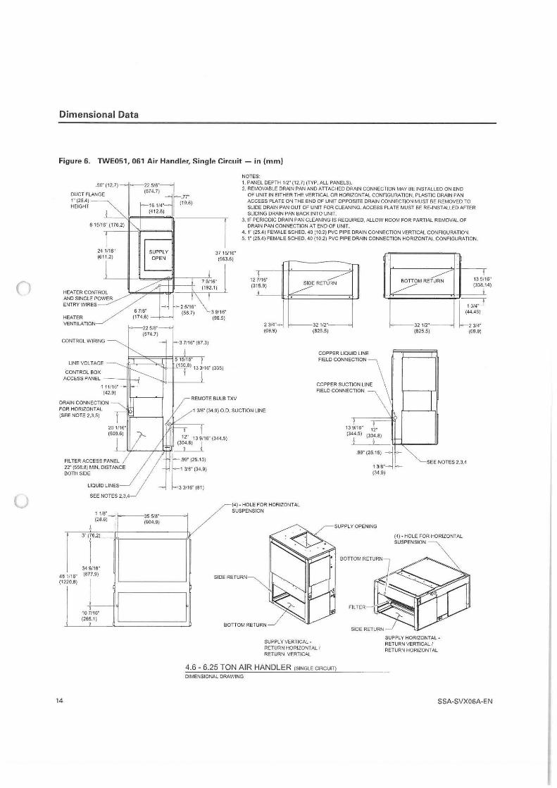
Figure 6. TWE051, 061 Air Handler, Single Circuit - in (mm)
DUCT FLANGE (574.7) _77"
1· (25.4) j (19 6) HEIGHT 16 1/4" ·
(412.8)
NOTES: 1. PANEL DEPTH 112" (12.7) (TYP. ALL PANELS) • 2. REMOVABLE DRAIN PAN AND ATTACHED DRAJN CONNECTION MAY BE INSTALLED ON END
OF UNIT IN EITHER THE VERTICAL OR HORIZONTAL CONFIGURATION, PLASTIC DRAIN PAN ACCESS PLATE ON THE END OF UNIT OPPOSITE DRAIN CONNECTION MUST BE REMOVED TO SLIDE DRAIN PAN OUT OF UNIT FOR CLEANING, ACCESS PLATE MUST BE RE-INSTALLED AFTER SLIDING DRAIN PAN BACK INTO UNIT.
. 50" (12.7) L 225/8"J
615116"(176.2) _I .---_,,.7 3. IF PERIODIC DRAIN PAN CLEANING IS REQUIRED, ALLOW ROOM FOR PARTIAL REMOVAL OF DRAIN PAN CONNECTION AT END OF UNIT.
4. 1" (25.4) FEMALE SCHED. 40 (10.2) PVC PIPE DRAIN CONNECTION VERTICAL CONFIGURATION. 5. 1" (25.4) FEMALE SCHED. 40 (10.2) PVC PIPE DRAIN CONNECTION HORIZONTAL CONFIGURATION.
24 1116" (611.2)
HEATER CONTROL AND SINGLE POWER ENTRY WIRES
HEATER VENTILATION
CONTROL WIRING
LINE VOLT AGE
CONTROL BOX ACCESS PANEL ---l!J.....;
DRAIN CONNECTION FOR HORIZONTAL (SEE NOTE 2,3,5)
FILTER ACCESS PANEL 22' (559.8) MIN. DISTANCE BOTH SIDE
SEE NOTES 2,3.4
SUPPLY OPEN
1 118" 1,......-35 5/8" ! (28.6) (904.9)
81116" 4 (1 220,8)
14
,·r 34 9116" (877.9)
j 10 7116" (26;.1 )
37 15116" (963.6)
7 9116" (192.1)
3 7116" (87.3)
3 9116" (90.5)
REMOTE BULB TXV
12 7116" (315.9)
23/4"J (69.9)
1 3/8" (34.9) O.D. SUCTION LINE
32 112· (825,5)
COPPER LIQUID LINE FIELD CONNECTION
COPPER SUCTION LINE FIELD CONNECTION
13 9116" 12· (344.5) (304.8)
I I
BOTTOM RETURN
32 112· (825.5)
13 5116" (338.14)
~
-;-;.:T 44.45)
2 314· (69.9)
.99"(25.15) j 1 318" (34.9)
SEE NOTES 2,3,4
f
SIDER
(4) • HOLE FOR HORIZONTAL SUSPENSION
BO TTOMRETURN
SUPPLY VERTICAL. RETURN HORIZONTAL I RETURN VERTICAL
4.6 - 6.25 TON AIR HANDLER (SINGLE CIRCUIT)
DIMENSIONAL DRAWING
FILTER
SIDE RETURN
(4) • HOLE FOR HORIZONTAL SUSPENSION
SUPPLY HORIZONTAL· RETURN VERTICAL I RETURN HORIZONTAL
SSA-SVX06A-E N
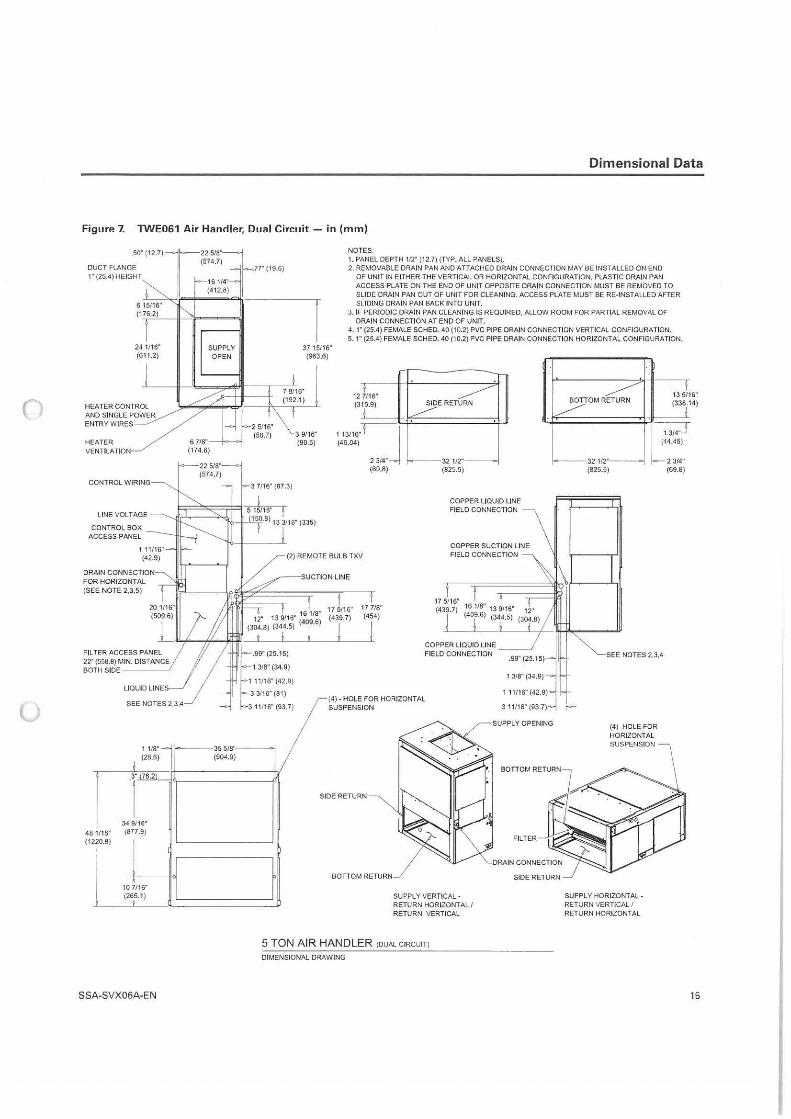
0
u
Dimensional Data
Figure 7. TWE061 Air Handler, Dual Circuit - in (mm)
.so· (12.7)Jrrg1:'~;J DUCT FLANGE .77" (19.6) 1" (25.4) HEIGHT
16 114,,
(412.8)
f1~f!f" ~---,11 NOTES: 1. PANEL DEPTH 112" (12.7) (TYP. ALL PANELS). 2. REMOVABLE DRAIN PAN AND ATTACHED DRAIN CONNECTION MAY BE INSTALLED ON ENO
OF UNIT IN EITHER THE VERTICAL OR HORIZONTAL CONFIGURATION. PLASTIC DRAIN PAN ACCESS PLATE ON THE END OF UNIT OPPOSITE DRAIN CONNECTION MUST BE REMOVED TO SLIDE DRAIN PAN OUT OF UNIT FOR CLEANING. ACCESS PLATE MUST BE RE-INSTALLED AFTER SLIDING DRAIN PAN BACK INTO UNIT.
3. IF PERIODIC DRAIN PAN CLEANING IS REQUIRED, ALLOW ROOM FOR PARTIAL REMOVAL OF DRAIN CONNECTION AT END OF UNIT.
4 . 1" (25.4) FEMALE SCHED. 40 (10,2) PVC PIPE DRAIN CONNECTION VERTICAL CONFIGURATION. 5. 1" (25.4) FEMALE SCHED. 40 (10.2) PVC PIPE DRAIN CONNECTION HORIZONTAL CONFIGURATION.
24 1/16" SUPPLY 37 15116" (611.2) OPEN (963.6)
HEATER VENTILATION
CONTROL WIRING
22518·=1 (574.7)
7 9/16" (192.1)
3 9/16" (90,5)
12 7116" (3 15.9)
113/16"i-J (46.04)
2 3/4" (69.8)
SIDE RETURN
32 112· (825,5)
LINE VOLTAGE
CONTROL BOX ACCESS PANEL
I 3 7116" (87.3)
I I=;:===~ 5 15116" f COPPER LIQUID LINE FIELD CONNECTION
150-8) 13 3/16" (335)
(2) REMOTE BULB TXV
SUCTION LINE
COPPER SUCTION LINE FIELD CONNECTION
DRAIN CONNECTION FOR HORIZONTAL (SEE NOTE 2,3,5)
Fil TEA ACCESS PANEL 22" (558.8) MIN. DISTANCE BOTH SIDE----~
LIDUID LINES__/
SEE NOTES 2 ,3 ,4
12· 13 9116" ('..60~'~; (304.8) (344.5) ! .
I I _
l;9:;8'.2<~:, 11116" (42,9)
3 3/16" (81)
3 11/16" (93. 7)
- ---35 5/8"---o., (904,9)
17 5116" (439.7)
I 17 718" (454)
j
17 5116" (439.7)
COPPER LIQUID LINE F IELD CONNECTION
(4) • HOLE FOR HORIZONTAL SUSPENSION
SIDE RETURN
481/16" (1220.8)
34 9/16· (877.9)
.,~ J l (265.1) IL.. _______ __.I
BOTTOM RETURN
SUPPLY VERTICAL· RETURN HORIZONTAL I RETURN VERTICAL
5 TON AIR HANDLER (DUAi.CiRCUiT)
DIMENSIONAi. DRAWING
SSA-SVX06A-EN
.99" (25.15)j
1 318" (34,9)
1 11116" (42.9)
3 11116" (93.7)
SIDE RETURN
BOTTOM RETURN 13 5/16" (338.14)
32 112" (825.5)
L~ 44.45)
2 3/4" (69.8)
SEE NOTES 2.3.4
(4) HOLE FOR HORIZONTAL
SUPPLY HORIZONTAL· RETURN VERTICAL I RETURN HORIZONTAL
15
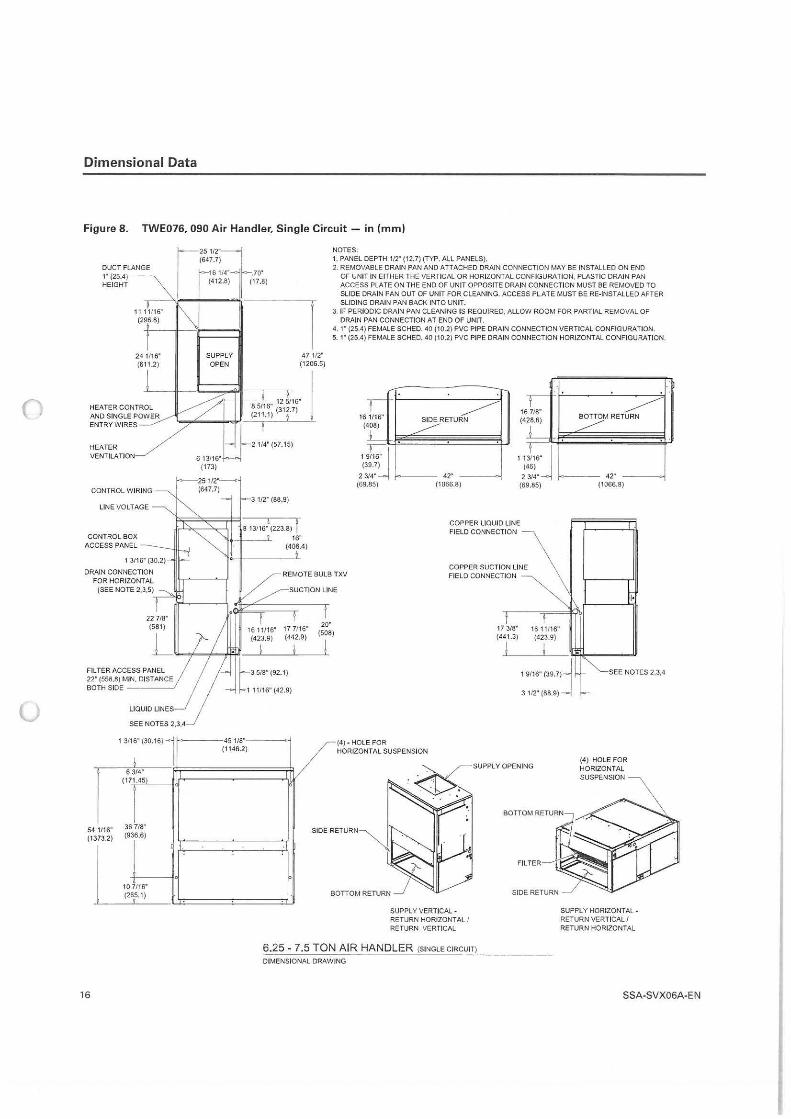
()
u
Dimensional Data
Figure 8. TWE076, 090 Air Handler, Single Circuit - in (mm)
DUCT FLANGE 1· (25.4) HEIGHT
241/16' (611.2)
HEATER VENTILATION
CONTROL WIRING
LINE VOLTAGE
CONTROL BOX ACCESS PANEL
FILTER ACCESS PANEL 22" (558.8) MIN. DISTANCE BOTH SIDE ____ ..,.
1/16~ 54 (1 373.2)
16
1 3/1:" (30.16) 1 6 3/4"
(171.45)
I 36 7/8" (936.6)
10 7/16" (26,5.1)
SUPPLY OPEN
6 13116" (173)
47 112· (1206.5)
8 5116' 12 5/16' (211.1) (312.7)
2 1/4" (57.15)
3 112· (88.9)
NOTES, 1. PANEL DEPTH 1/2" (12.7) (TYP. ALL PANELS). 2. REMOVABLE DRAIN PAN AND ATTACHED DRAIN CONNECTION MAY BE INSTALLED ON END
OF UNIT IN EITHER THE VERTICAL OR HORIZONTAL CONFIGURATION. PLASTIC DRAIN PAN ACCESS PLATE ON THE END OF UNIT OPPOSITE DRAIN CONNECTION MUST BE REMOVED TO SLIDE DRAIN PAN OUT OF UNIT FOR CLEANING. ACCESS PLATE MUST BE RE-INSTALLED AFTER SLIDING DRAIN PAN BACK INTO UNIT.
3. IF PERIODIC DRAIN PAN CLEANING IS REQUIRED, ALLOW ROOM FOR PARTIAL REMOVAL OF DRAIN PAN CONNECTION AT END OF UNIT.
4, 1· (25,4) FEMALE SCHEO. 40 (10.2) PVC PIPE DRAIN CONNECTION VERTICAL CONFIGURATION. 5. 1" (25.4) FEMALE SCHED. 40 (10.2) PVC PIPE DRAIN CONNECTION HORIZONTAL CONFIGURATION.
,-1/16~ 16
( 408)
!
~ 9.7)
314•
1 (3
2 (69.85)
------/RETURN
42" (1066.8)
I 7/8" 16
(4 28.6)
I
11 9 ( 46)
3/4" 2 (69.85)
~ BOTTOM RETURN
----L 42•
(1066.8)
8 13/161 (223.8) I COPPER LIQUID LINE FIELD CONNECTION
45 1/8" (1146.2)
16" (406.4)
REMOTE BULB TXV
SUCTION LINE
COPPER SUCTION LINE FIELD CONNECTION
17 7/16" (442.9)
!
20· (508)
j
SIDER
B
(4) • HOLE FOR HORIZONTAL SUSPENSION
SUPPLY VERTICAL· RETURN HORIZONTAL/ RETURN VERTICAL
6.25 - 7.5 TON AIR HANDLER (SINGLE CIRCUIT)
DIMENSIONAL DRAWING
17 3/8" (44 1.3)
I 1611/16" (423.9)
I 1 9116" (39.7)~
3 112· (88.9)-l
SEE NOTES 2,3,4
(4) HOLE FOR HORIZONTAL SUSPENSION
SUPPLY HORIZONTAL· RETURN VERTICAL/ RETURN HORIZONTAL
SSA-SVX06A-EN
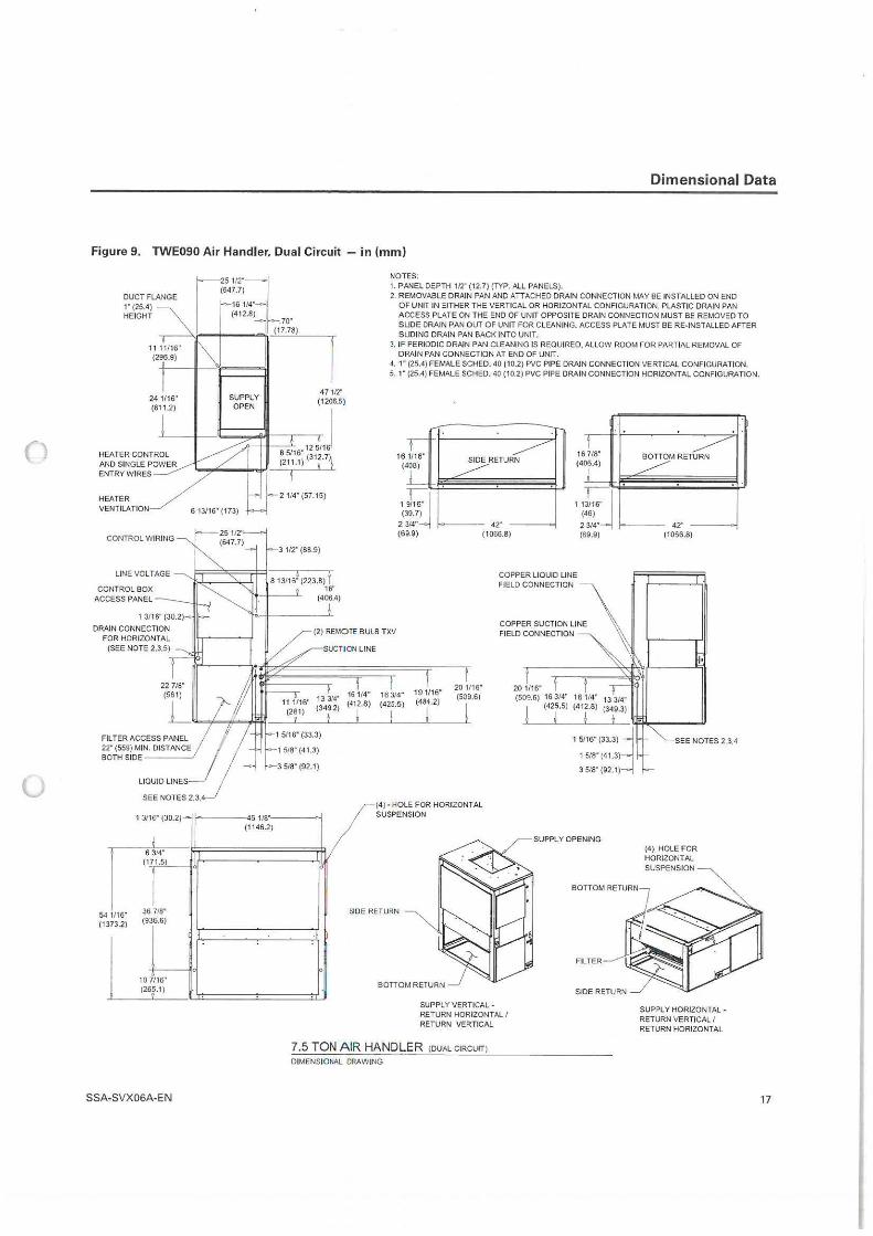
()
u
Dimensional Data
Figure 9. lWE090 Air Handler. Dual Circuit - in (mm)
24 1/16' (611.2)
SUPPLY OPEN
471/2" (1206.5)
j B 5116" 12 5116 (211 .1) (31:.7)1
I 2 114" (57.15)
NOTES: 1. PANEL DEPTH 1/2" (12.7)(TYP. ALL PANELS). 2. REMOVABLE DRAIN PAN AND ATTACHED DRAIN CONNECTION MAY BE INSTALLED ON END
OF UNIT IN EITHER THE VERTICAL OR HORIZONTAL CONFIGURATION, PLASTIC DRAIN PAN ACCESS PLATE ON THE END OF UNIT OPPOSITE DRAIN CONNECTION MUST BE REMOVED TO SLIDE DRAIN PAN OUT OF UNIT FOR CLEANING. ACCESS PLATE MUST BE RE-INSTALLED AFTER SLIDING DRAIN PAN BACK INTO UNIT.
3, IF PERIODIC DRAIN PAN CLEANING IS REQUIRED, ALLOW ROOM FOR PARTIAL REMOVAL OF DRAIN PAN CONNECTION AT END OF UNIT.
4. 1• (25.4) FEMALE SCHED. 40 (10.2) PVC PIPE DRAIN CONNECTION VERTICAL CONFIGURATION. 5. 1" (25.4) FEMALE SCHED. 40 (10.2) PVC PIPE DRAIN CONNECTION HORIZONTAL CONFIGURATION.
161/16" (408)
SIDE RETURN
I 718" 16
(4 06.4)
L. 11
~MRETURN
HEATER VENTILATION 6 13/16" (173) 1 r:-u (39.7) 9 (46)
CONTROL BOX ACCESS PANEL
FILTER ACCESS PANEL
22" (559) MIN. DISTANC~ BOTH SIDE----
LIOUID LINES
1/16" 54 (1 373.2)
SEE NOTES 2,3.4
1 3116" (30.2)-
I 6 3/4" I
(171.5)
l 36 7/8" (936.6)
0
10 7/16" (26~.1)
SSA-SVX06A-EN
3 1/2" (88.9)
2 314" (69.9)
42" ( 1066.8)
314• 2 (69.9)
a 1311511223.8) I 16"
(406.4)
COPPER LIQUID LINE FIELD CONNECTION
45 1/8" (1146.2)
(2) REMOTE BULB TXV
SUCTION LINE
COPPER SUCTION LINE FIELD CONNECTION
13 3'4' 16 1/4~ 16 314· 19 1116" (349.2) {412.8) (425.5) (484.2)
20 1/16" (509.6)
3 518" (92.1)
lo
1 I I I I
SIDER
(4 )-HOLE FOR HORIZONTAL SUSPENSION
ETURN
BOTTOM RETURN
SUPPLY VERTICAL· RETURN HORIZONTAL / RETURN VERTICAL
7.5 TON AIR HANDLER (DUAL CIRCUIT)
DIMENSIONAL DRAWING
20 1/16" (509.6) 16 3/4" 161/4" 13 3/4"
(425.5) (4 12.8) (349.3)
! I I 1 5116" (33.3) j
1 5/8" (41.3)
3 518" (92.1)
42" (1066.8)
SEE NOTES 2,3.4
(4) HOLE FOR HORIZONTAL SUSPENSION
SUPPLY HORIZONTAL · RETURN VERTICAL/ RETURN HORIZONTAL
17
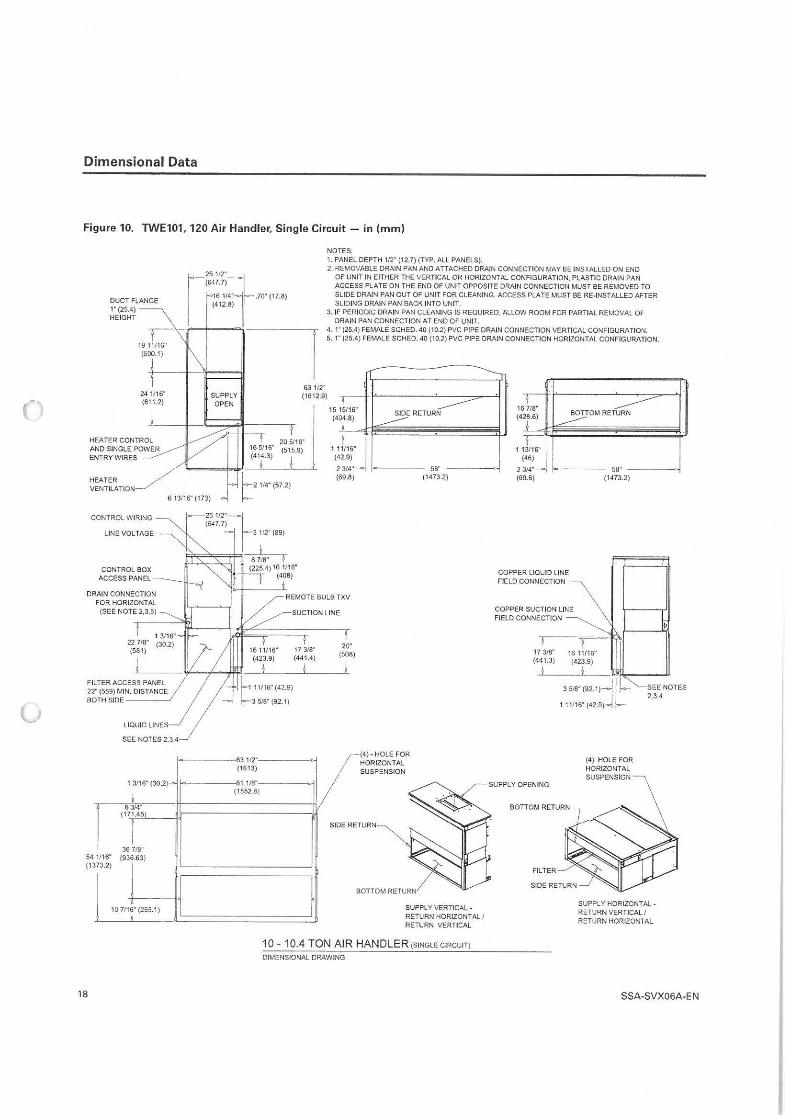
c,
Dimensional Data
Figure 10. TWE101, 120 Air Handler, Single Circuit - in (mm)
DUCT FLANGE 1" (25.4) HEIGHT
25112·
1 (647.7) r 1611•· -.70.(17.8) I (412.8)
NOTES: 1. PANEL DEPTH 112" (12.7) (TYP. ALL PANELS). 2. REMOVABLE DRAIN PAN AND ATTACHED DRAIN CONNECTION MAY BE INSTALLED ON END
OF UNIT IN EITHER THE VERTICAL OR HORIZONTAL CONFIGURATION. PLASTIC DRAIN PAN ACCESS PLATE ON THE END OF UNIT OPPOSITE DRAIN CONNECTION MUST BE REMOVED TO SLIDE DRAIN PAN OUT OF UNIT FOR CLEANING. ACCESS PLATE MUST BE RE-INSTALLED AFTER SLIDING DRAIN PAN BACK INTO UNIT.
3. IF PERIODIC DRAIN PAN CLEANING IS REQUIRED, ALLOW ROOM FOR PARTIAL REMOVAL OF DRAIN PAN CONNECTION AT END OF UNIT.
i-- 7 19 11116" (500.1)
4. 1" (25.4) FEMALE SCHED. 40 (10.2) PVC PIPE DRAIN CONNECTION VERTICAL CONFIGURATION. 5. 1" (25.4) FEMALE SCHEO. 40 (10.2) PVC PIPE DRAIN CONNECTION HORIZONTAL CONFIGURATION.
HEATER VENTILATION
24 1116" (611.2)
SUPPLY OPEN
63 112· (1612.9)
20 5116" ~:t2:;- (515.9)
SIDE RETURN
11/n5•J (42.9) 2 314~ ,______ 58"
(69.8) (1473.2)
6 13/16" (173)
b2 1/4· (57.2)
CONTROL WIRING
LINE VOLTAGE
CONTROL BOX ACCESS PANEL
DRAIN CONNECTION FOR HORIZONTAL
(SEE NOTE 2,3,5)
22 718" (581)
FILTER ACCESS PANEL 22'" (559) MIN. DISTANCE BOTH SIDE ____ ,
SEE NOTES 2,3,4
1 3116" (30.2)-r~ 3/4"
(' 36 718"
1/16" (936.63) 54 (1 373.2)
10 7116" (265.1)
'
18
j
251/2"-lf-(647.7) 3 112" (89)
f 8 11a· I
(225.4) 16 1/16" (408)
REMOTE BULB TXV
SUCTION LINE
17 3/8" (441.4)
j
"""~ (1613)
11/8" (1552.6)
20· (508)
j
(4) - HOLE FOR HORIZONTAL SUSPENSION
SIDER ETURN
f SUPPLY VERTICAL -RETURN HORIZONTAL / RETURN VERTICAL
10 - 10.4 TON AIR HANDLER (SINGLE CIRCUIT)
DIMENSIONAL DRAWING
16 7/8" (428.6)
(46)
BOTTOM RETURN
11-r,:-j,.
23/4" }->----- 58" ------, (69.8) (1473.2)
COPPER LIQUID LINE FIELD CONNECTION
COPPER SUCTION LINE FIELD CONNECTION
17 318" 16 11116" (441.3) (423.9)
3 5/8" (92.1 )j 1 11116" (42.9)
(4) HOLE FOR HORIZONTAL SUSPENSION
BOTTOM RETURN-l
FILTER
SIDE RETURN
-SEE NOTES 2,3.4
SUPPLY HORIZONTAL -RETURN VERTICAL / RETURN HORIZONTAL
SSA-SVX06A-EN
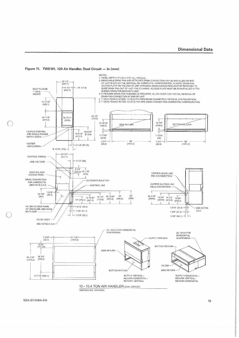
()
u
Dimensional Data
Figure 11. TWE101, 120 Air Handler, Dual Circuit - in (mm)
DUCT FLANGE 1"(25.4) - HEIGHT
~~:-:::1- 70" (17 8)
NOTES: 1. PANEL DEPTH 112" (12.7) (TYP. ALL PANELS). 2. REMOVABLE DR/\IN PAN AND ATTACHED DRAIN CONNECTION MAY BE INSTALLED ON END
OF UNIT IN EITHER THE VERTICAL OR HORIZONTAL CONFIGURATION. PLASTIC DRAIN PAN ACCESS PLATE ON THE END OF UNIT OPPOSITE DRAIN CONNECTION MUST BE REMOVED TO SLIDE DRAIN PAN OUT OF UNIT FOR CLEANING. ACCESS PLATE MUST BE RE-INSTALLED AFTER SLIDING DRAIN PAN BACK INTO UNIT. (412.7) II
19°1~11-16-_--'<-,--1----
1
7 (500.1)
+------l---3. IF PERIODIC DRAIN PAN CLEANING IS REQUIRED. ALLOW ROOM FOR PARTIAL REMOVAL OF
DRAIN PAN CONNECTION AT END OF UNIT. 4. 1" (25.4) FEMALE SCHED. 40 (10.2) PVC PIPE DRAIN CONNECTION VERTICAL CONFIGURATION. 5. 1" (25.4) FEMALE SCHED. 40 (10.2) PVC PIPE DRAIN CONNECTION HORIZONTAL CONFIGURATION.
24 1116" (611 .2)
HEATER CONTROL AND SINGLE POWER ENTRY WIRES
HEATER /
VENTILATION_/
SUPPLY OPEN
63 112· (1613)
20 5116" 16 5116" (515.9) (414.3)
1515116" (404.8)
(429)
SIDE RETURN
1 1ti6"J
2 314" "'""---- 58" (69.8) (1473.2)
6 13116" (173)
t 2 114" (57.15)
CONTROL WIRING
LINE VOLTAGE
CONTROL BOX ACCESS PANEL
DRAIN CONNECTION FOR HORIZONTAL
(SEE NOTE 2.3,5)
22 718" (581)
j Fil TER ACCESS PANEL 22" (558.8) MIN. DISTANCE BOTH SIDE ----J
LIQUID LINES
SEE NOTES 2,3,4
13116"1 j (30.2)
I 1/16" 54
(1 373.2)
6 314" (171.451
I 36 7/8" (936.6)
10 7116" (265.1) I
SSA-SVX06A-E N
j
25 112' (647,7)
3 112· (89)
- 61 118" (1552.6)
SUCTION LINE
f
16 1/4" 16 11116" 19" (412.8) (423.9) (482.6)
1 I I
20· (508)
I
(4) • HOLE FOR HORIZONTAL SUSPENSION
SIDE RETURN
BOTTOM RETURN
SUPPLY VERTICAL -RETURN HORIZONTAL I RETURN VERTICAL
10 - 10.4 TON A IR HANDLER (DUALCIRCUIT)
DIMENSIONAL DRAWING
16 718" (428.6)
(46)
BOTTOM RETURN
1,j/16j
23/4~ .,.._ ____ 58"
(69.8) (1473.2)
COPPER LIQUID LINE FIELD CONNECTION
COPPER SUCTION LINE FIELD CONNECTION
20 1116" 16 314" (509.6) (425.5)
! I 16 114" 13 314" (412.8) (349.3)
I I 1 5116" (33.3j
1 5/8" (41.3)
3 5/8" (92, 1)
(4) HOLE FOR HORIZONTAL SUSPENSION
SUPPLY HORIZONTAL · RETURN VERTICAL/ RETURN HORIZONTAL
19
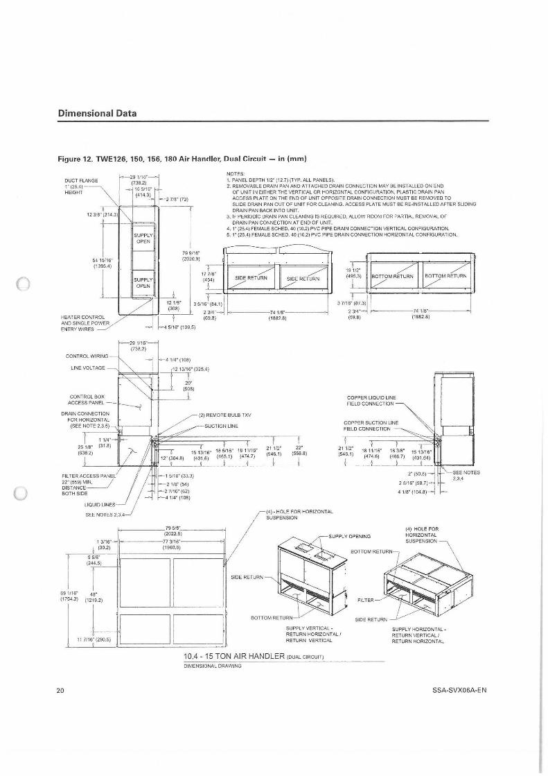
()
u
Dimensional Data
Figure 12. TWE126, 150, 156, 180 Air Handler, Dual Circuit - in (mm)
DUCT FLANGE 1" (25.4)HEIGHT
~ 12 318" (314.3)
54 15116" (1395.4)
~
291/16" (738.2)
16 5116" (414.3)
I
SUPPLY OPEN
SUPPLY OPEN
2 718" (73)
12 118" (308)
79 9116" (2020.9)
3 5116! (84.1) I
NOTES· 1. PANEL DEPTH 112" (12.7) (TYP. ALL PANELS). 2. REMOVABLE DRAIN PAN AND ATTACHED DRAIN CONNECTION MAY BE INSTALLED ON END
OF UNIT IN EITHER THE VERTICAL OR HORIZONTAL CONFIGURATION, PLASTIC DRAIN PAN ACCESS PLATE ON THE END OF UNIT OPPOSITE DRAIN CONNECTION MUST BE REMOVED TO SLIDE DRAIN PAN OUT OF UNIT FOR CLEANING. ACCESS PLATE MUST BE RE-INSTALLED AFTER SLIDING DRAIN PAN BACK INTO UNIT.
3. IF PERIODIC DRAIN PAN CLEANING IS REQUIRED, ALLOW ROOM FOR PARTIAL REMOVAL OF DRAIN PAN CONNECTION AT END OF UNIT.
4, 1" (25.4) FEMALE SCHED. 40 (10.2) PVC PIPE DRAIN CONNECTION VERTICAL CONFIGURATION. 5. 1·• (25.4) FEMALE SCHED. 40 (10.2) PVC PIPE DRAIN CONNECTION HORIZONTAL CONFIGURATION.
HEATER CONTROL AND SINGLE POWER ENTRY WIRES
2 314":.::j f->------741/8"------, ...., ____ '.1·--.-~ (69.8) (1882.8)
l-4 5116" {109.5)
~----- 74 ,,s··-------<>< (1882.8)
CONTROL WIRING
LINE VOLTAGE
CONTROL BOX ACCESS PANEL -
DRAIN CONNECTION FOR HORIZONTAL
29 1/16" (738.2)
{SEE NOTE 2.3,5) - •1~----r
25 118" (638.2)
FILTER ACCESS PAN 22" (559) MIN. / DISTANCE·___/ BOTH SIDE
1/16" 69 (1 754.2)
LIQUID LINES
SEE NOTES 2,3,4
1 3/16~....,. ! (30.2)
9 518" (244.5)
I 48"
{1219.2)
4114" (108)
79 518" (2022.5)
77 3116" (1960.6)
20" (508)
{2) REMOTE BULB TXV
SUCTION LINE
15 13116" 18 5116" 18 11116" (401.6) (465.1) (474.7)
I j
SIDE RETURN
21 112· (546.1)
!
22· {558.8)
I
(4) - HOLE FOR HORIZONTAL SUSPENSION
COPPER LIQUID LINE FIELD CONNECTION
COPPER SUCTION LINE FIELD CONNECTION
21 112" (546.1)
j
18 11/16" (4 74.6)
t
Fil TER
(4) HOLE FOR HORIZONTAL SUSPENSION
2,3,4
DD -11 7116' (290.5)
'
BOTT
SUPPLY VERTICAL -RETURN HORIZONTAL/ RETURN VERTICAL
SIDE RETURN
SUPPLY HORIZONTAL -RETURN VERTICAL I RETURN HORIZONT A l
10.4 - 15 TON AIR HANDLER (DUAL CIRCUIT)
DIMENSIONAL DRAWING
20 SSA-SVX06A-EN
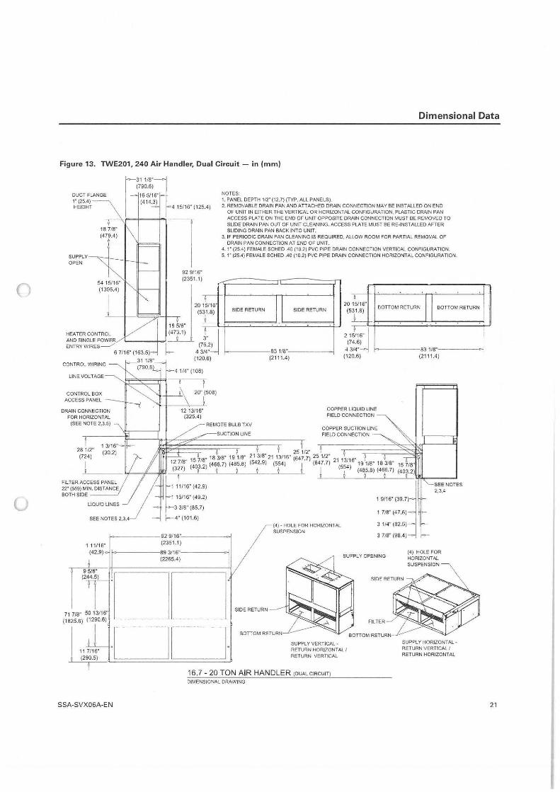
()
0
Dimensional Data
Figure 13. TWE201, 240 Air Handler, Dual Circuit - in (mm)
DUCT FLANGE 1" (25.4) - HEIGHT
SUPPLY OPEN
18 718" (479.4)
HEATER CONTROL AND SINGLE POWER ENTRY WIRES__./
r31 1/8" (790.6)
16 5/16"' (414.3)
6 7/16" (163.5)
CONTROL WIRING
LINE VOLTAGE
CONTROL BOX
DRAIN CONNECTION FOR HORIZONTAL
(SEE NOTE 2,3,5)
281/2" (724)
4 15116" (125.4)
92 9116" (2351 .1)
NOTES: 1. PANEL DEPTH 112" (12,7) (TYP. ALL PANELS), 2. REMOVABLE DRAIN PAN AND A TT ACHED DRAIN CONNECTION MAY BE INST ALL ED ON END
OF UNIT IN EITHER THE VERTICAL OR HORIZONTAL CONFIGURATION, PLASTIC DRAIN PAN ACCESS PLATE ON THE END OF UNIT OPPOSITE DRAIN CONNECTION MUST BE REMOVED TO SLIDE DRAIN PAN OUT OF UNIT CLEANING. ACCESS PLATE MUST BE RE-INSTALLED AFTER SLIDING DRAIN PAN BACK INTO UNIT.
3. IF PERIODIC DRAIN PAN CLEANING IS REQUIRED, ALLOW ROOM FOR PARTIAL REMOVAL OF DRAIN PAN CONNECTION AT END OF UNIT.
4. 1• (25.4) FEMALE SCHED .40 (10.2) PVC PIPE DRAIN CONNECTION VERTICAL CONFIGURATION. 5. 1" (25.4) FEMALE SCHED .40 (10.2) PVC PIPE DRAIN CONNECTION HORIZONTAL CONFIGURATION.
-, ,_ I
15116" 20 (5
15116" 20 (5 r:_~
1 3" 6.2) 14"
(7 43 (120.6)
20" (508)
SIDE RETURN
REMOTE BULB TXV
,...----suCTION LINE
831/8" (2111.4)
SIDE RETURN 31.8) BOTTOM RETURN BOTTOM RETURN
L'"" 21
(7 4.6) J11j
3/4" 4 (120.6)
COPPER LIQUID LINE FIELD CONNECTION
COPPER SUCTION LINE FIELD CONNECTION
83118" (2111.4)
9 8 21 318" 21 13/16" 2554~
127· 25 1/2"
12 718" 15 718" 18 318
" 1 11
" (542.9) (554) ( . ) (647.7) 21 13116" 191/8" 18 318" 15 7/8" ) (403 2) (466.7) (485.8) ! (554)
~---- l.1-....,(l,-.J/111' _ (3~27-~v_· __ l~-~i __ i~-~1~-~ j j (48{8) (46{7) (40~.2)
t 1
11,15• (42.9) ~ 2,3,4
FILTER ACCESS PANEL 22' (559) MIN. DISTANCE BOTH SIDE ---~
::;:~~~:9;;> : :::·(::~~:) SEE NOTES 2,3,4 4" (101 .6)
1 11116" (42.9)
9518" (244.5)
71 718" 50 13/16" (1825.6) (1290.6)
11 7/16" (290.5)
(4) • HOLE FOR HORIZONTAL 3 114" (82.5) SUSPENSION
l->------92 9/16"'---------i 3 718" (98.4) (2351.1)
!<>-------89 3/16"------,; (2265.4)
!□□ ·□□·
SIDE RETURN
SUPPLY VERTICAL· RETURN HORIZONTAL I RETURN VERTICAL
16.7 - 20 TON AIR HANDLER (DUAL CIRCUIT)
DIMENSIONAL DRAWING
(4) HOLE FOR HORIZONTAL SUSPENSION
SUPPLY HORIZONTAL . RETURN VERTICAL I RETURN HORIZONTAL
SSA-SVX06A-EN 21
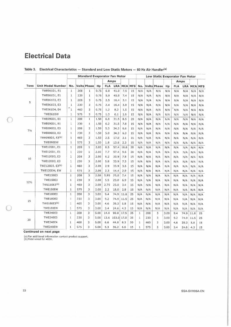
0
0
Electrical Data
Table 3. Electrical Characteristics - Standard and Low Stat ic Motors - 60 Hz Air Handlerfa)
Standard Evaporator Fan Motor
Tons Unit Model N umber No. Volts Phase
TWE061D1 , El 1 208 1
TWE061Dl, El 1 230 1
TWE061D3, E3 1 208 3 5
TWE061D3, E3 1 230 3 . TWE061D4, E4 1 460 3
TWE061DW 1 575 3
TWE090D1, El 1 208 1
TWE090D1, El 1 230 1
TWE090D3, E3 1 208 3 7½
TWE090D3, E3 1 230 3
TWE090D3, E3(b) 1 460 3
TWE090DW 1 575 3
TWE120D1, El 1 208 1
TWE120D1, El 1 230 1
TWE120D3, E3 1 208 3 10
TWE120D3, E3 1 230 3
TWE120D3, E3{b) 1 460 3
TWE120DW, EW 1 575 3
TWE150E3 1 208 3
TWE150E3 1 230 3 12½
TWE150E3(bJ 1 460 3
TWE150EW 1 575 3
TWE180E3 1 208 3
TWE180E3 1 230 3 15
TWE180EJ(b) 1 460 3
TWE180EW 1 575 3
TWE240E3 1 208 3
TWE240E3 1 230 3 20
TWE240E4 1 460 3
TWE240EW 1 575 3
Continued on next page
(a) For additional information contact product support. (b) Field wired for 460V.
22
Amps
Hp FLA LRA MCA
0.75 6.0 41.0 7 .5
0.75 5.9 45,0 7.4
0.75 2.5 16.4 3.1
0.75 2.4 16.4 3.0
0 .75 1.2 8 .2 1.5
0.75 1.3 6.1 1.6
1.50 6.8 31.5 8.5
1.50 6 .2 31.5 7.8
1.50 5,3 34.3 6 .6
1.50 5.0 34.3 6 .3
1.50 2.5 17.0 3.1
1.50 1.8 13,6 2.3
2.00 8.5 57.4 10.6
2.00 7,7 57 .4 9.6
2.00 6 .2 33.9 7.8
2.00 5 .8 33.9 7.3
2.00 2 .9 33.9 3.6
2.00 2.3 14.4 2.9
2 .00 5.95 23.0 7.4
2.00 5.5 23.0 6.9
2.00 2.75 23.0 3.4
2.00 2.2 18.0 2.8
3.00 9.4 74.9 11.8
3.00 9 .2 74 .9 11.5
3.00 4 .6 39.3 5.8
3.00 3.4 24.6 4.3
5.00 14.0 90.8 17.5
5 .00 13.6 103.0 17.0
5 .00 6.6 44 .8 8.3
5.00 5.3 36.2 6.6
Low Static Evaporator Fan Motor
Amps
MFS No. Volts Phase Hp FLA LRA MCA MFS
15 N/A N/A N/A N/ A N/ A N/A N/A N/ A
15 N/A N/A N/A N/A N/ A N/A N/A N/A
15 N/A N/A N/ A N/ A N/A N/A N/A N/A
15 N/A N/A N/A N/A N/A N/A N/A N/ A
15 N/A N/A N/A N/A N/A N/A N/A N/ A 15 N/A N/A N/A N/A N/A N/A N/A N/A
20 N/A N/A N/A N/ A N/A N/A N/A N/A
15 N/A N/A N/A N/A N/A N/A N/A N/A
15 N/A N/A N/A N/A N/A N/A N/A N/ A
15 N/A N/A N/A N/A N/A N/A N/A N/A
15 N/A N/A N/A N/A N/ A N/A N/A N/A
15 N/A N/A N/A N/A N/A N/A N/A N/A
20 N/A N/A N/A N/A N/ A N/A N/ A N/A
20 N/A N/A N/A N/A N/A N/ A N/ A N/A
15 N/A N/A N/A N/A N/A N/A N/A N/A
15 N/A N/A N/A N/A N/A N/A N/A N/A
15 N/A N/A N/A N/A N/A N/A N/A N/A
15 N/A N/A N/A N/A N/A N/A N/A N/A
15 N/A N/A N/A N/A N/A N/A N/A N/A
15 N/A N/A N/A N/A N/ A N/A N/A N/A
15 N/A N/A N/A N/A N/A N/A N/ A N/ A
15 N/A N/A N/A N/A N/A N/A N/ A N/A
25 N/A N/A N/A N/A N/A N/A N/A N/A
25 N/A N/A N/A N/A N/A N/ A N/ A N/A
15 N/A N/A N/ A N/A N/A N/A N/A N/A
15 N/A N/A N/ A N/ A N/A N/A N/A N/A
35 1 208 3 3 .00 9.4 74.9 11.8 25
35 1 230 3 3.00 9.2 74.9 11.5 25
20 1 460 3 3.00 4 .6 39.3 5.8 15
15 1 575 3 3.00 3.4 24.6 4.3 15
SSA-SVX06A-EN
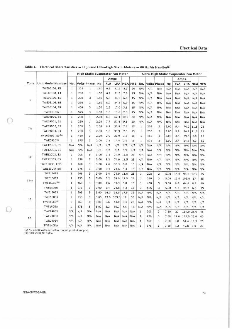
()
u
Electrical Data
Table 4. Electrical Characteristics - High and Ultra-High Static Motors - 60 Hz Air Handlerfal
High Static Evaporator Fan Motor
Tons Unit Model Number No. Volts Phase
TWE061D1, El 1 208 1
TWE061Dl , El 1 230 1
TWE061D3, E3 1 208 3 5
TWE061 D3, E3 1 230 3
TWE061D4, E4 1 460 3
TWE061DW 1 575 3
TWE090D1, El 1 208 1
TWE090D1, El 1 230 1
TWE090D3, E3 1 208 3 7½
TWE090D3, E3 1 230 3
TWE090D3, E3(b) 1 460 3
TWE090DW 1 575 3
TWE120D1, El N/A N/ A N/ A
TWE120D1, El N/A N/ A N/ A
TWE120D3 , E3 1 10
208 3
TWE120D3, E3 1 230 3
TWE1 20D3, E3(b) 1 460 3
TWE120DW, EW 1 575 3
TWE150E3 1 208 3
TWE150E3 1 230 3 12½
TWE150E3(b) 1 460 3
TWE150EW 1 575 3
TWE180E3 1 208 3
TWE180E3 1 230 3 15
TWE180E3(b) 1 460 3
TWE180EW 1 575 3
TWE~40E3 N/A N/ A N/A
TWE240E3 N/ A N/ A N/A 20
TWE240E4 N/ A N/A N/A
TWE240EW N/A N/A N/A
(a) For additional information contact product support. (b) Field wired for 460V.
SSA-S VX06A-EN
Amps
Hp FLA LRA MCA
1.50 6.8 31.5 8.5
1.50 6.2 31.5 7.8
1.50 5.3 34.3 6.6
1.50 5,0 34.3 6.3
1.50 2.5 17.0 3.1
1.50 1.8 13.6 2.3
2.00 8.5 57.4 10.6
2.00 7.7 57.4 9.6
2.00 6.2 33.9 7.8
2.00 5.8 33.9 7.3
2 .00 2.9 33.9 3 .6
2.00 2.3 14.4 2.9
N/A N/ A N/A N/ A
N/A N/ A N/A N/ A
3.00 9.4 74.9 11.8
3.00 9,2 74,9 11.5
3.00 4.6 39 .3 5.8
3 .00 3.4 24.6 4.3
3.00 9.4 74 .9 11.8
3.00 9.2 74.9 11.5
3.00 4.6 39.3 5,8
3.00 3.4 24.6 4.3
5.00 14 .0 98.0 17.5
5.00 13.6 103.0 17
5.00 6 .6 44.8 8 .3
5 .00 5 .2 36.2 6.5
N/ A N/A N/A N/ A
N/ A N/A N/A N/ A
N/ A N/ A N/ A N/ A
N/ A N/ A N/ A N/A
Ultra-High Static Evaporator Fan Motor
Amps
MFS No. Volts Phase Hp FLA LRA MCA MFS
20 N/ A N/ A N/ A N/A N/ A N/ A N/A N/ A
15 N/A N/A N/ A N/A N/ A N/ A N/ A N/A
15 N/A N/ A N/A N/A N/A N/A N/A N/A
15 N/A N/ A N/ A N/A N/A N/ A N/ A N/A
15 N/ A N/A N/ A N/ A N/A N/ A N/ A N/A 15 N/ A N/ A N/ A N/ A N/ A N/A N/A N/ A
20 N/A N/A N/A N/ A N/ A N/A N/ A N/ A
20 N/A N/A N/A N/ A N/ A N/A N/A N/ A
15 1 208 3 3.00 9 .4 74.9 11.8 25
15 1 230 3 3.00 9,2 74.9 11.5 25
15 1 460 3 3.00 4.6 39.3 5.8 15
15 1 575 3 3 .00 3.4 24.6 4.3 15
N/ A N/A N/A N/A N/A N/A N/A N/A N/ A
N/A N/A N/A N/ A N/A N/ A N/ A N/A N/ A
25 N/ A N/ A N/ A N/A N/ A N/ A N/A N/A
25 N/A N/A N/A N/A N/ A N/A N/ A N/ A
15 N/A N/A N/A N/ A N/ A N/ A N/ A N/ A
15 N/A N/A N/A N/A N/A N/ A N/ A N/ A
25 1 208 3 5.00 14.0 98.0 17.5 35
25 1 230 3 5.00 13.6 103.0 17 35
15 1 460 3 5 .00 6.6 44.8 8.3 20
15 1 575 3 5 .00 5.2 36.2 6.5 15
35 N/A N/A N/A N/A N/ A N/A N/A N/ A
35 N/ A N/A N/ A N/A N/ A N/A N/A N/ A 20 N/ A N/ A N/A N/A N/ A N/A N/A N/ A 15 N/A N/ A N/A N/A N/ A N/A N/ A N/A
N/ A 1 208 3 7 .50 20 114.0 25.0 45
N/ A 1 230 3 7. 50 17 ,6 126.0 22.0 40
N/ A 1 460 3 7 .50 9. 0 61.4 11.3 25
N/A 1 575 3 7.50 7 .2 49 .8 9 .0 20
23
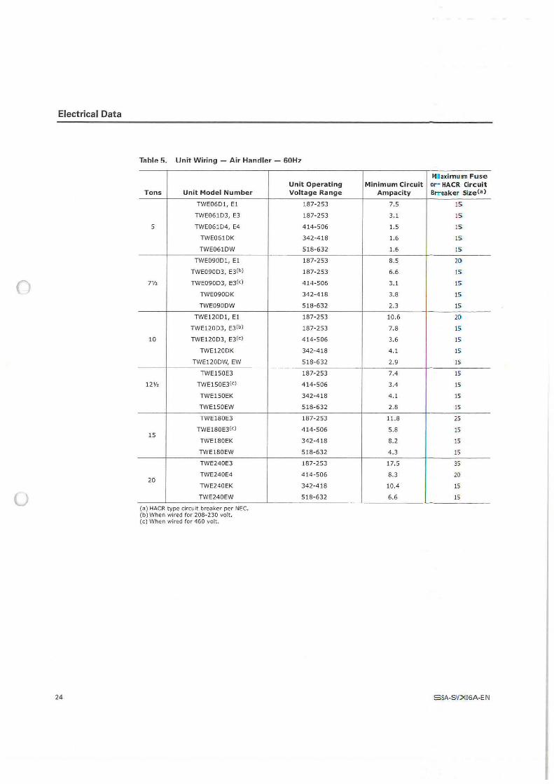
Electrical Data
0
0
24
Table 5. Unit Wiring - Air Handler - 60Hz
Tons Unit Model Number
TWE06D1, El
TWE061D3, E3
5 TWE061D4, E4
TWE061DK
TWE061DW
TWE090D1, El
TWE090D3, E3(b)
7½ TWE090D3, E3(c)
TWE090DK
TWE090DW
TWE120D1, El
TWE120D3, E3(b)
10 TWE120D3, E3(c)
TWE120DK
TWE120DW, EW
TWE150E3
12½ TWE150E3(c)
TWE150EK
TWE150EW
TWE180E3
TWE 180E3(c) 15
TWE180EK
TWE180EW
TWE240E3
TWE240E4 20
TWE240EK
TWE240EW
(a) HACR type circuit breaker per NEC. (b) When wired for 208-230 volt . (c) When wired for 460 volt.
Unit Operating Voltage Range
187-253
187-253
414-506
342-418
518-6 32
187- 253
187-253
414- 506
342-418
518-632
187- 253
187- 253
4 14-506
342-418
518-632
187-253
414-506
342-418
518-632
187-253
414- 506
342-418
518- 632
187-253
414-506
342-418
518-632
M aximu111 Fu se Minimum Circuit or HACR Circ uit
Ampacity BtTeaker Size(a)
7.5 15
3.1 15
1.5 IS
1.6 15
1.6 15
8.5 2D
6.6 15
3.1 lS
3.8 15
2.3 15
10.6 20
7.8 15
3.6 15
4.1 15"
2.9 15
7.4 15
3.4 15
4.1 15
2.8 15
11.8 25
5.8 15
8.2 15
4.3 15
17.S 35
8.3 20
10.4 15
6.6 15
SSA-SV::X06A-E N
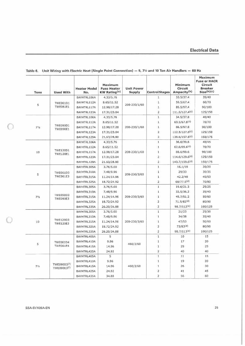
Electrical Data
Table 6. Unit Wiring with Electric Heat (Single Point Connection} - 5, 7½ and 10 Ton Air Handlers - 60 Hz
Maximum Fuse or HACR
Max imum Minimum Circuit Heater Model Fuse Heater Unit Power Circuit Breaker
Tons Used With No. KW RatingCa) Supply Control Stages AmpacityCbl Size(b)(c)
BAYHTRL106A 4 .33/5.76 1 33.5/37.4 35/40
TWE061D1 BAYHTRL11 2A 8.65/11.52 1 59 .5/67.4 60/70 5
TWE061El 208-230/1/60
BAYHTRLl 17 A 12.98/17.28 1 85.5/97.4 90/100
BAYHTRL1 23A l 7.31/23.04 2 lll.5/127.4(d) 125/150
BAYHTRL106A 4,33/5. 76 1 34 .5/37.8 40/40
() BAYHTRL112A 8 .65/ 11.52 1 60.5/67.B(d) 70/70
71/2 TWE090D1
BAYHTRLl 17 A 12.98/17.28 208-230/1/60 1 86 .5/97.8 90/100 TWE090El
BAYHTRL123A 17.31/23 .04 2 112.5/127.8(d) 125/150
BAYHTRL129A 21.63/28,80 2 138.6/157 .8(d) 150/175
BAYHTRL106A 4.33/5, 76 1 36 .6/39.6 40/45
BAYHTRL1 12A 8.65/1 1.52 1 62.6/69.6(d) 70/70
10 TWE 120D1
BAYHTRLl 17 A 12.98/17.28 208- 230/1/60 1 88.6/99.6 90/100 TWE120El
BAYHTRL123A 17.31/23.04 2 114.6/129.6(d) 125/150
BAYHTRL1 29A 21.63/28.80 2 140. 7/159.6(d) 150/175
BAYHTRL305A 3.76/5 .00 1 16.1/18 20/20
TWE061D3 BAYHTRL310A 7.48/9.96 1 29/33 30/35 5
TWE061E3 208-230/3/60
BAYHTRL315A 11.24/14.96 1 42.2/48 45/50
BAYHTRL325A 18.72/24.92 2 68/77.9(d) 70/80
BAYHTRL305A 3 .76/5.00 1 19.6/21.3 25/25
BAYHTRL31 0A 7.48/9.96 1 32.5/36.2 35/40
7V, TWE090D3
BAYHTRL315A 11.24/ 14.96 208-230/3/60 1 45.7/51.2 50/60 TWE090E3
BAYHTRL325A 18.72/24.92 2 71.5/82(d) 80/90
BAYHTRL335A 26.20/34.88 2 98 . 7/112(e) 100/125
BAYHTRL305A 3.76/5.00 1 21/23 25/30
u BAYHTRL310A 7.48/9.96 1 34/38 35/40
10 TWE120D3
BAYHTRL315A 1 1.24/14,96 208-230/3/60 1 47/53 50/60 TWE120E3
BAYHTRL325A 18.72/24.92 2 73/83(d) 80/90
BAYHTRL335A 26.20/34.88 2 98.7/113(e) 100/125
BAYHTRL405A 5 1 10 15
TWE061D4 BAYHTRL410A 9.96 1 17 20 5
TWE061E4 460/3/60
BAYHTRL415A 14.96 1 25 25
BAYHTRL425A 24.92 2 40 40
BAYHTRL405A 5 1 11 15
BAYHTRL410A 9 .96 1 19 20
7V, TWE090D3(f)
BAYHTRL415A 14.96 460/3/60 1 26 30 TWE090E3(f)
BAYHTRL425A 24.92 2 41 45
BAYHTRL435A 34.88 2 56 60
SSA-SVX06A-E N 25
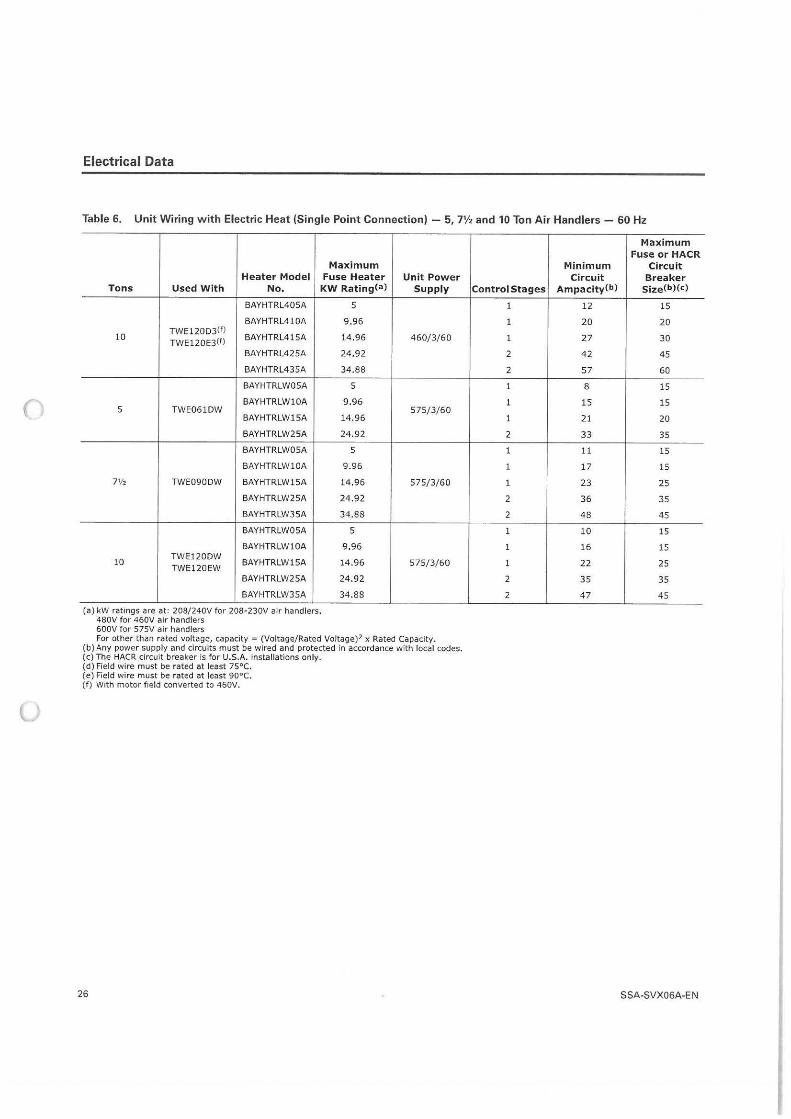
()
u
Electrical Data
Table 6. Unit Wiring w ith Electric Heat {Single Point Connection) - 5 , 7½ and 10 Ton Air Handlers - 60 Hz
Maximum Heater Model Fuse Heater
Tons Used W ith No. KW RatingCa)
BAYHTRL405A
BAYHTRL410A
10 TWE120D3(1J
BAYHTRL415A TWE120E3C1J
BAYHTRL425A
BAYHTRL435A
BAYHTRLW05A
BAYHTRLWl0A 5 TWE061DW
BAYHTRLW15A
BAYHTRLW25A
BAYHTRLW05A
BAYHTRLWl0A
7½ TWE090DW BAYHTRLW15A
BAYHTRLW25A
BAYHTRLW35A
BAYHTRLW05A
BAYHTRLWl0A
10 TWE120DW
BAYHTRLW15A TWE120EW
BAYHTRLW25A
BAYHTRLW35A
(a) kW ratings are at: 208/240V for 208-230V air handlers. 480V for 460V air handlers 600V for 575V air handlers
5
9.96
14.96
24 .92
34.88
5
9.96
14.96
24.92
5
9.96
14.96
24 .92
34.88
5
9 .96
14.96
24.92
34.88
Unit Power Supply
460/ 3/ 60
575/3/60
575/ 3/ 60
575/3/60
For other than rated voltage, capacity = (Voltage/Rated Voltage)2 x Rated Capacity. (b) Any power supply and circuits must be wired and protected in accordance with local codes. (c) The HACR circuit breaker is for U.S.A. installations only. (d) Field wire must be rated at least 75°C. (e) Field wire must be rated at least 90°C. (f ) With motor field converted to 460V.
26
Maximum Fuse or HACR
Minimum Circuit Circuit Breaker
Control Stages AmpacityCbl Size(b)(c)
1 12 15
1 20 20
1 27 30
2 42 45
2 57 60
1 8 15
1 15 15
1 2 1 20
2 33 35
1 11 15
1 17 15
1 23 25
2 36 35
2 48 45
1 10 15
1 16 15
1 22 25
2 35 35
2 47 45
SSA-SVX06A-E N
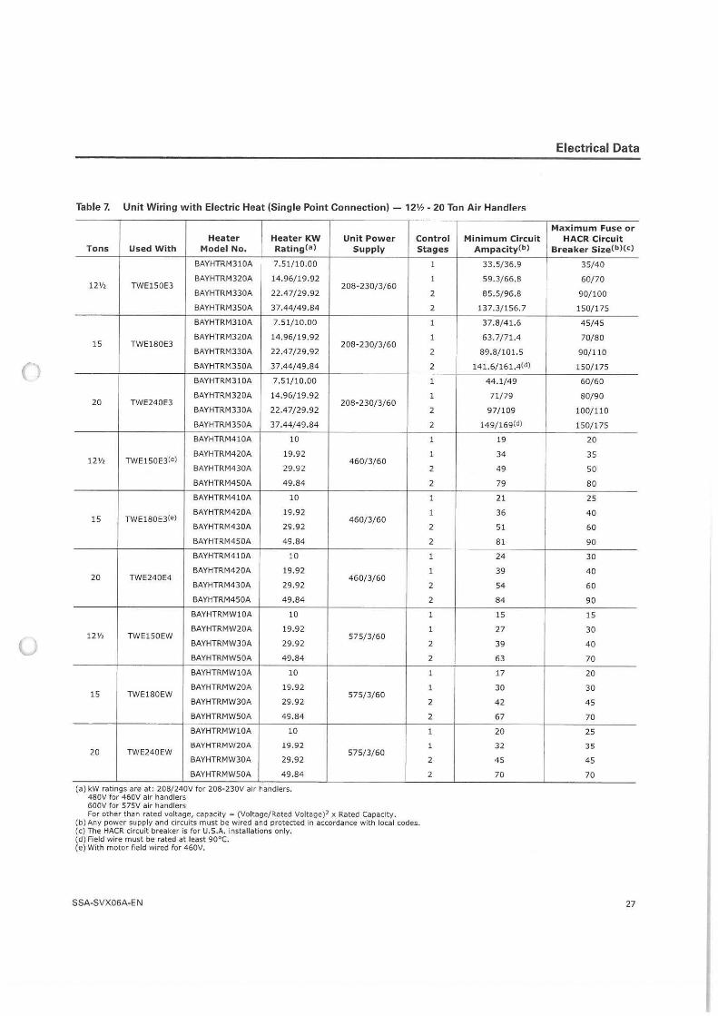
()
u
Table 7. Unit Wiring with Electric Heat (Single Point Connection) - 12½ - 20 Ton Air Handlers
Heater Heater KW Tons Used With Model No. Rating Ca)
BAYHTRM310A 7.51/10.00
BAYHTRM320A 14.96/19.92 12½ TWE1 50E3
BAYHTRM330A 22.47/29.92
BAYHTRM350A 37.44/49.84
BAYHTRM310A 7.51/10.00
BAYHTRM320A 14.96/19.92 15 TWE180E3
BAYHTRM330A 22.47/29.92
BAYHTRM350A 37.44/49.84
BAYHTRM310A 7.51/ 10.00
BAYHTRM320A 14.96/19.92 20 TWE240E3
BAYHTRM330A 22.47/29.92
BAYHTRM350A 37.44/ 49.84
BAYHTRM410A 10
TWE150E3(e) BAYHTRM420A 19 .92
12½ BAYHTRM430A 29.92
BAYHTRM450A 49.84
BAYHTRM410A 10
TWE180E3(e) BAYHTRM420A 19.92
15 BAYHTRM430A 29.92
BAYHTRM450A 49.84
BAYHTRM410A 10
BAYHTRM420A 19.92 20 TWE240E4
8AYHTRM430A 29.92
BAYHTRM450A 49.84
BAYHTRMWlOA 10
BAYHTRMW20A 19.92 12½ TWE150EW
BAYHTRMW30A 29.92
BAYHTRMWSOA 49.84
BAYHTRMWlOA 10
BAYHTRMW20A 19.92 15 TWE180EW
BAYHTRMW30A 29.92
BAYHTRMW50A 49.84
BAYHTRMWlOA 10
BAYHTRMW20A 19.92 20 TWE240EW
BAYHTRMW30A 29.92
BAYHTRMWSOA 49.84
(a) kW ratings are at: 208/ 240V for 208-230V air handlers. 480V for 460V air handlers 600V for 575V air handlers
Unit Power Supply
208-230/3/ 60
208-230/3/ 60
208-230/3/ 60
460/3/60
460/3/60
460/3/60
575/ 3/ 60
575/3/ 60
575/ 3/ 60
For other t han rated voltage, capacity = (Voltage/ Rated Voltage)2 x Rated Capacity.
Control Stages
1
1
2
2
1
1
2
2
1
1
2
2
1
1
2
2
1
1
2
2
1
1
2
2
1
1
2
2
1
1
2
2
1
1
2
2
(bl Any power supply and circuits must be wired and protected in accordance with local codes. (c) The HACR circuit breaker is for U.S.A. installations only. (d) Field wire must be rated at least 90°C. (e) With motor field wired for 460V.
SSA-SVX06A-EN
Minimum Circuit Ampacity(b)
33.5/36.9
59.3/ 66.8
85.5/96.8
137.3/ 156.7
37.8/41.6
63.7/ 71.4
89.8/ 101.5
141.6/ 161.4(d)
44.1/49
71/ 79
97/109
149/ 169(d)
19
34
49
79
21
36
51
81
24
39
54
84
15
27
39
63
17
30
42
67
20
32
45
70
Electrical Data
Maximum Fuse or HACR Circuit
Breaker Size(b)(c)
35/40
60/70
90/ 100
150/175
45/45
70/80
90/110
150/175
60/60
80/90
100/110
150/175
20
35
so 80
25
40
60
90
30
40
60
90
15
30
40
70
20
30
45
70
25
35
45
70
27
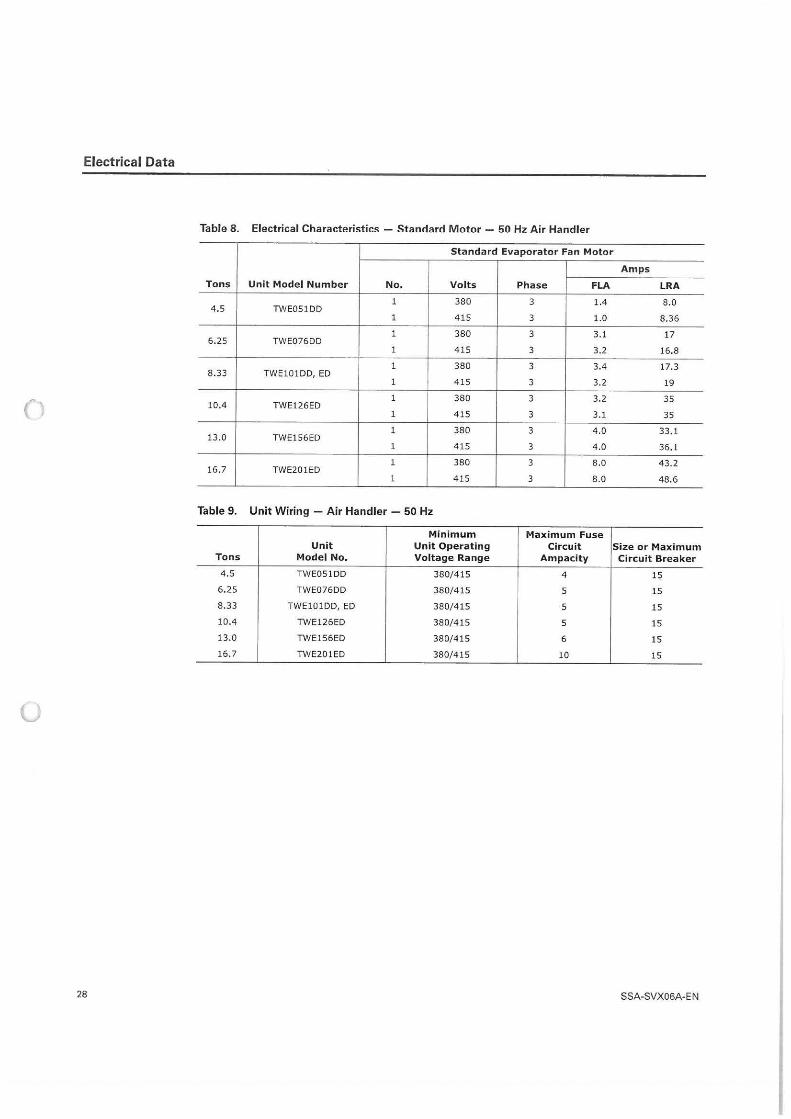
Electrical Data
Table 8. Electrical Characteristics - Standard Motor - 50 Hz Air Handler
Standard Evaporator Fan Motor
Amps
Tons Unit Model Number No. Volts Phase FLA LRA
1 380 4 .5 TWE051DD
3 1.4 8.0
1 415 3 1.0 8.36
1 380 6.25 TWE076DD
3 3.1 17
1 415 3 3 .2 16.8
1 380 8.33 TWElOlDD, ED
3 3.4 17,3
1 415 3 3.2 19
( 1 380 3 3.2 35
10.4 TWE126ED 1 415 3 3.1 35
13.0 TWE156ED 1 380 3 4.0 33, l
1 415 3 4,0 36, l
1 380 16.7 TWE201ED
3 8.0 43.2
1 415 3 8.0 48.6
Table 9. Unit Wiring - Air Handler - 50 Hz
Minimum Maximum Fuse Unit Unit Operating Circuit Size or Maximum
Tons Model No. Voltage Range Ampacity Circuit Breaker
4.5 TWE051DD 380/415 4 15
6.25 TWE076DD 380/4 15 5 15
8.33 TWE101DD, ED 380/415 5 15
10.4 TWE126ED 380/415 5 15
13,0 TWE156ED 380/415 6 15
16.7 TWE201ED 380/415 10 15
u
28 SSA-SVX06A-E N
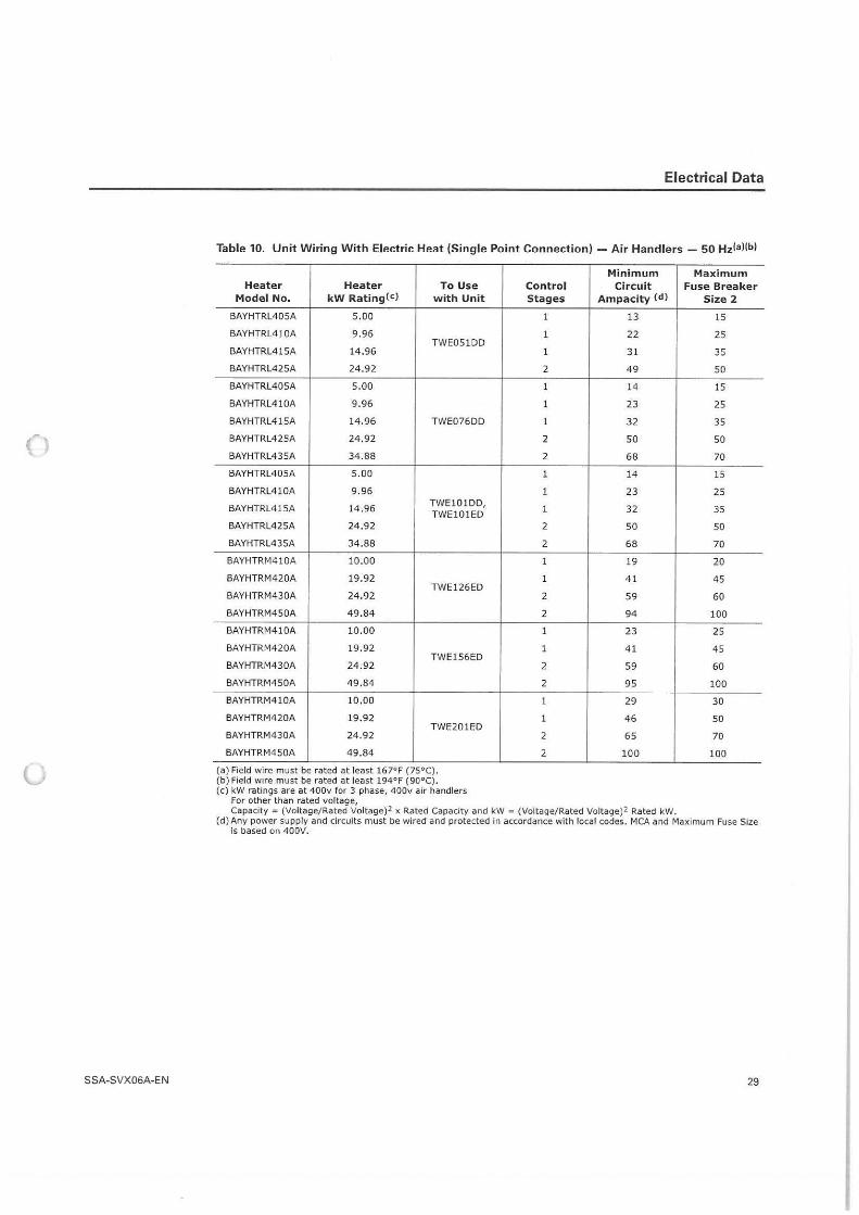
u
SSA-SVX06A-EN
Electrical Data
Table 10. Unit Wiring With Electric Heat (Single Point Connection) - Air Handlers - 50 Hz(a)(b}
Heater Heater To Use Model No. kW RatingCcJ with Unit
BAYHTRL405A 5.00
BAYHTRL410A 9.96 TWE0S l DD
BAYHTRL415A 14.96
BAYHTRL425A 24.92
BAYHTRL405A 5.00
BAYHTRL410A 9 .96
BAYHTRL415A 14.96 TWE076DD
BAYHTRL425A 24.92
BAYHTRL435A 34.88
6AYHTRL405A 5.00
6AYHTRL410A 9 .96
BAYHTRL415A 14.96 TWE101DD, TWE101ED
BAYHTRL4 2SA 24.92
BAYHTRL435A 34.88
BAYHTRM410A 10.00
BAYHTRM420A 19.92 TWE126ED
BAYHTRM430A 24.92
BAYHTRM4 50A 49 .84
BAYHTRM410A 10.00
BAYHTRM420A 19.92 TWE156ED
BAYHTRM430A 24.92
BAYHTRM450A 49.84
BAYHTRM410A 10.00
BAYHTRM420A 19.92 TWE201ED
BAYHTRM430A 24.92
BAYHTRM4S0A 49.84
(a) Field wire must be rated at least 167°F (75°C) . (b) Field wire must be rated at least 194°F (90°C). (c) kW ratings are at 400v for 3 phase, 400v air handlers
For other than rated voltage,
Minimum Maximum Control Circuit Fuse Breaker Stages Ampacity (d) Size 2
1 13 15
1 22 25
1 31 35
2 49 so 1 14 15
1 23 25
1 32 35
2 so so 2 68 70
1 14 15
1 23 25
1 32 35
2 so so 2 68 70
1 19 20
1 41 45
2 59 60
2 94 100
1 23 25
1 41 45
2 59 60
2 95 100
1 29 30
1 46 50
2 65 70
2 100 100
Capacity = (Voltage/Rated Voltage)2 x Rated Capacity and kW = (Voltage/ Rated Voltage)2 Rated kW. (d) Any power supply and circuits must be wired and protected in accordance with local codes. MCA and Maximum Fuse Size
is based on 400V.
29
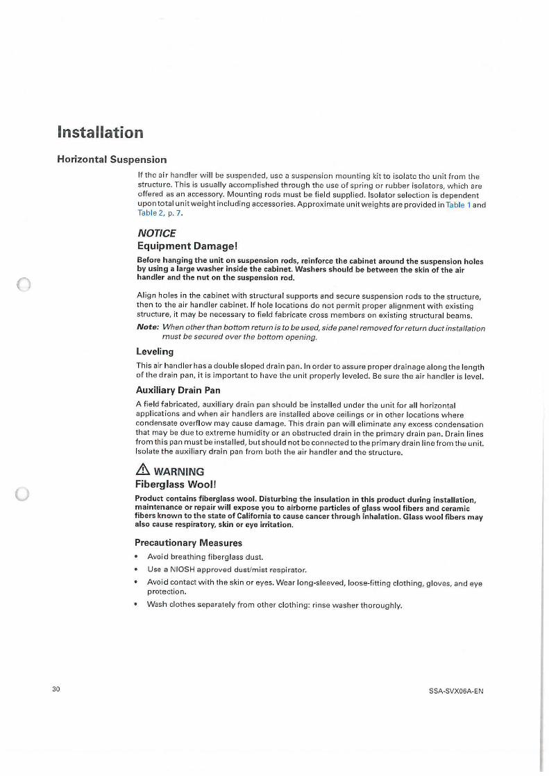
0
0
Installation
Horizontal Suspension
If the air handler w ill be suspended, use a suspension mounting kit to isolate the unit from the structure. This is usually accomplished through the use of spring or rubber isolators, which are offered as an accessory. Mounting rods must be field supplied. Isolator selection is dependent upon total unit weight including accessories. Approximate unit weights are provided in Table 1 and Table 2, p. 7.
NOTICE Equipment Damage! Before hanging the unit on suspension rods, reinforce the cabinet around the suspension holes by using a large washer inside the cabinet. Washers should be between the skin of the air handler and the nut on the suspension rod.
Align holes in the cabinet with structural supports and secure suspension rods to the structure, then to the air handler cabinet. If hole locations do not permit proper alignment with existing structure, it may be necessary to field fabricate cross members on existing structural beams.
Note: When other than bottom return is to be used, side panel removed for return duct installation must be secured over the bottom opening.
Leveling
This air handler has a double sloped drain pan. In order to assure proper drainage along the length of the drain pan, it is important to have the unit properly leveled. Be sure the air handler is level.
Auxiliary Drain Pan
A field fabricated, auxiliary drain pan should be installed under the unit for all horizontal appl ications and when air handlers are installed above ceil ings or in other locations where condensate overflow may cause damage. This drain pan will eliminate any excess condensation that may be due to extreme humidity or an obstructed drain in the primary drain pan. Drain l ines from this pan must be installed, but should not be connected to the primary drain line from the unit. Isolate the auxiliary drain pan from both the air handler and the structure.
& WARNING Fiberglass Wool!
Product contains fiberglass wool. Disturbing the insulation in this product during installation, maintenance or repair will expose you to airborne particles of glass wool fibers and ceramic fibers known to the state of California to cause cancer through inhalation. Glass wool fibers may also cause respiratory, skin or eye irritation.
Precautionary Measures • Avoid breathing fiberglass dust.
• Use a NIOSH approved dust/mist respirator.
• Avoid contact with the skin or eyes. Wear long-sleeved, loose-fitting clothing, gloves, and eye protection.
• Wash clothes separately from other clothing: rinse washer thoroughly.
30 SSA-SVX06A-EN
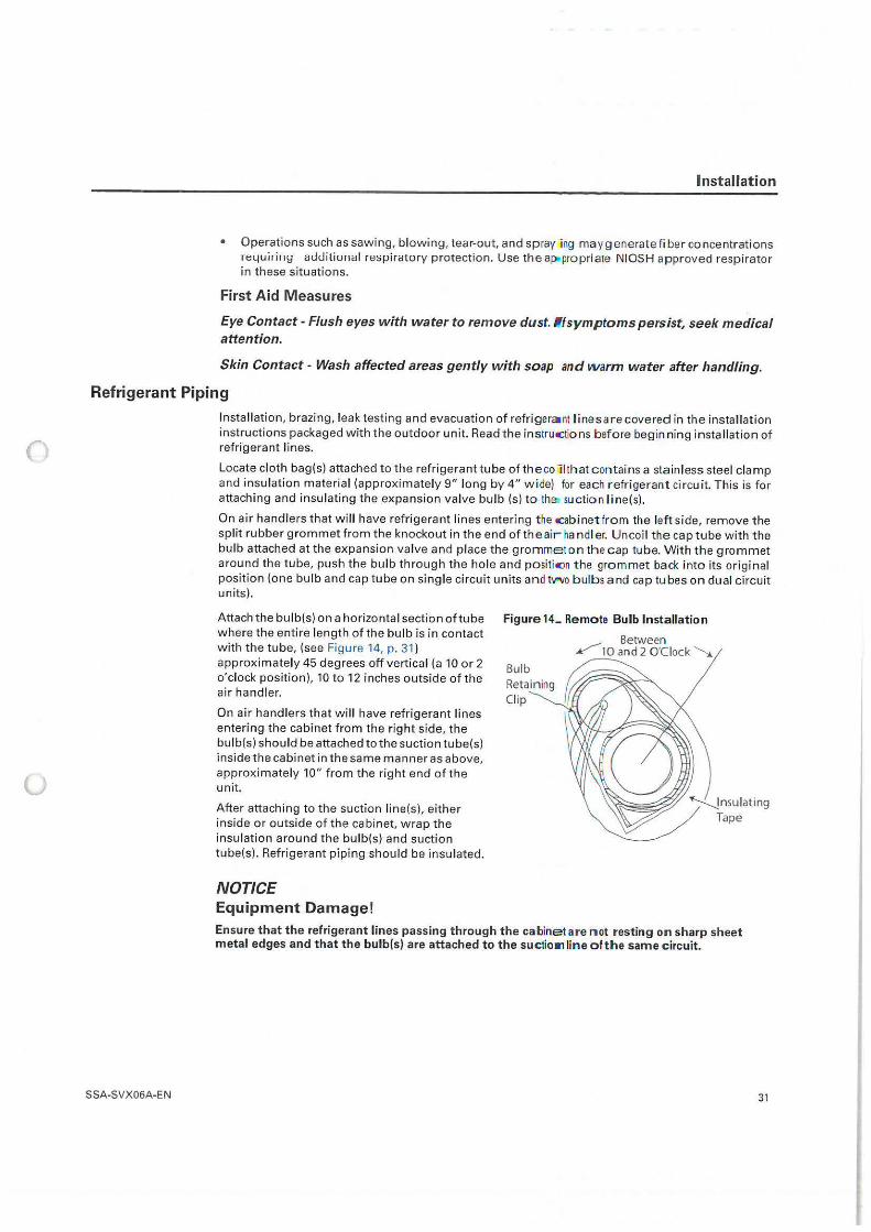
0
(J
Installation
• Operat ions such as sawing, blowing, tear-out, and spray 1ng may generate fiber concentrations requiring additional respiratory protection. Use the ap,,propriate NIOSH approved respirator in these situations.
First Aid Measures
Eye Contact - Flush eyes with water to remove dust. •t symptoms persist, seek medical attention.
Skin Contact - Wash affected areas gently with soap and warm water after handling.
Refrigerant Piping
SSA-SVX06A-EN
Installation, brazing, leak testing and evacuation of refrigeraint lines are covered in the installation instructions packaged with the outdoor unit. Read the instruc tions before beginning insta llation of refrigerant l ines.
Locate cloth bag(s) attached to the refrigerant tube of the co11that c ontains a stainless steel clamp and insulation material (approximately 9" long by 4" wide) for each refrigerant circuit. This is for attaching and insulating the expansion valve bulb (s) to the, suction line(s).
On air handlers that will have refrigerant lines entering t he c abinet from the left side, remove the split rubber grommet from the knockout in the end of the air handl er. Uncoil the cap tube with the bulb attached at the expansion valve and place the gromme t on the cap tube. With the grommet around the tube, push the bulb through the hole and positic:m the grommet back into its original position (one bulb and cap tube on single circuit units and tll<\lo bulbs and cap tubes on dual circuit units).
Attach the bulb(s) on a horizontal section of tube where the entire length of the bulb is in contact with the tube, (see Figure 14, p. 31 ) approximately 45 degrees off vertica l (a 10 or 2 o'clock position), 10 to 12 inches outside of the air handler.
On air handlers that wi ll have refrigerant l ines entering the cabinet from the right side, the bulb(s) should be attached to the suction tube(s) inside the cabinet in the same manner as above, approximately 10" from the right end of the unit.
After attaching to the suction line(s), either inside or outside of the cabinet, wrap the insulation around the bulb(s) and suction tube(s). Refrigerant piping should be insulated.
NOTICE Equipment Damage!
Figure 14- Remote Bulb Installation
Between _.,/"' 1 O and 2 O'Clock '---,..
Bulb Retain ing Clip
Ensure that the refrigerant lines passing through the cabinet are not resting on sharp sheet metal edges and that the bulb{s) are attached to the suctioa, line of the same circuit.
31
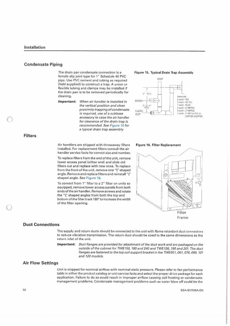
()
()
Installation
Condensate Piping
Filters
The drain pan condensate connection is a female slip joint type for 1" Schedule 40 PVC pipe. Use PVC cement and tubing as required (field supplied) to construct a trap. A union or flexible tubing and clamps may be installed if the drain pan is to be removed periodically for cleaning.
Important: When air handler is installed in the vertical position and close proximity trapping of condensate is required, use of a subbase accessory to raise the air handler for clearance of the drain trap is recommended. See Figure 15 for a typical drain trap assembly.
Figure 15. Typical Drain Trap Assembly
VENT
DRAIN
CLEAN OUT ---,,-'°',-•--- ~-~
Materials 2 each• TEE 2 each - 90• ELL 1 each- PLUG 2 each - 6' NIPPLE 2 each - 2' NIPPLE 1 each• l"NPT to PVC or
COPPER ADAPTER
Air handlers are shipped with throwaway filters Figure 16. Filter Replacement installed. For replacement filters consu lt the air handler service facts for correct size and number.
To replace filters from the end of the unit, remove lower access panel (either end) and slide o ld fi lters out and replace w ith new ones. To replace from the frontofthe unit, remove one "l.'.' shaped angle. Remove and replace filters and reinstall "l.'.' shaped angle. See Figure 16.
To convert from 1" filter to a 2" fi lter on units so equipped, remove lower access panels from both ends of the air handler. Remove screws and rotate the "l.'.' shaped angles from both the top and bottom of the filter track 180° to increase the width of the filter opening.
Filter Frame
Duct Connections
The supply and return ducts should be connected to the unit with flame retardant duct connectors to reduce vibration transmission. The return duct should be sized to the same dimensions as the return inlet of the unit.
Important: Duct flanges are provided for attachment of the duct work and are packaged on the outside of the cabinet for TWE150, 180 and 240 and TWE126, 156 and 201. The duct flanges are fastened to the top coil support bracket in the TWE051, 061, 076, 090, 101 and 120 models.
Air Flow Settings
32
Unit is shipped for nominal airflow with nominal static pressure. Please refer to fan performance table in either the product catalog or unit service facts and select the proper drive package for each application. Failure to do so could result in improper airflow causing coil frosting or condensate management problems. Condensate management problems such as water blow off could be the
SSA-SVX06A-EN
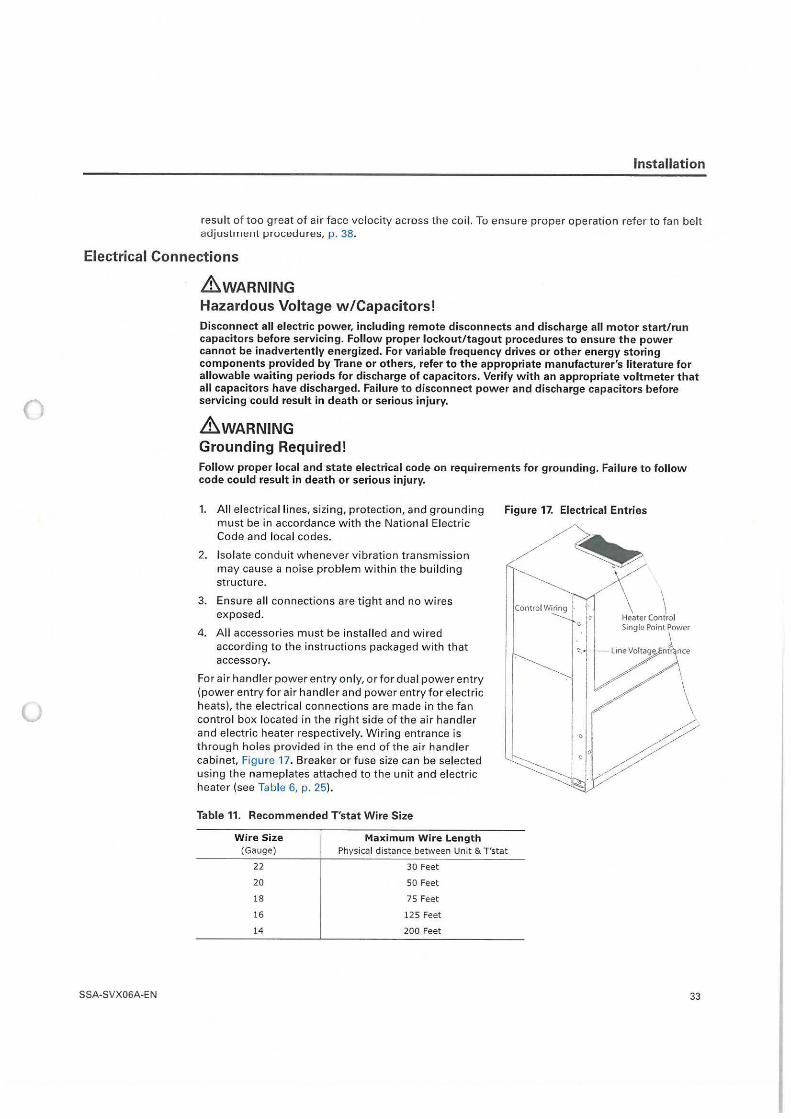
()
u
Installation
result of too great of ai r face velocity across the coil. To ensure proper operation refer to fan belt adjustment procedures, p. 38.
Electrical Connections
SSA-SVX06A-EN
&WARNING Hazardous Voltage w/Capacitors! Disconnect all electric power, including remote disconnects and discharge all motor start/ run capacitors before servicing. Follow proper lockout/ tagout procedures to ensure the power cannot be inadvertently energized. For variable frequency drives or other energy storing components provided by Trane or others, refer to the appropriate manufacturer's literature for allowable waiting periods for discharge of capacitors. Verify with an appropriate voltmeter that all capacitors have discharged. Failure to disconnect power and discharge capacitors before servicing could result in death or serious injury.
&WARNING Grounding Required! Follow proper local and state electrical code on requirements for grounding. Failure to follow code could result in death or serious injury.
1. A ll electrical l ines, sizing, protection, and grounding must be in accordance w ith the National Electric Code and local codes.
Figure 17. Electrical Entries
2. Isolate conduit w henever vibration transmission may cause a noise problem within the build ing st ructure.
3. Ensure all connections are t ight and no wi res exposed.
4. A ll accessories must be installed and wi red according to the instruct ions packaged with that accessory.
For air handler power entry only, or for dual pow er entry (power entry for air handler and power entry for electric heats), the electrical connections are m ade in the fan cont ro l box located in t he right side of the air handler and electric heater respectively. Wiring entrance is through holes provided in the end of the air handler cabinet, Figure 17. Breaker or fuse size can be selected using the nameplates attached to t he unit and elect ric heater (see Table 6, p. 25).
Table 11. Recommended T'stat Wire Size
Wire Size (Gauge)
22
20
18
16
14
Maximum Wire Length Physical d istance between Unit & T'stat
30 Feet
SO Feet
75 Feet
125 Feet
200 Feet
\ Heater Contro l Single Point Power
33
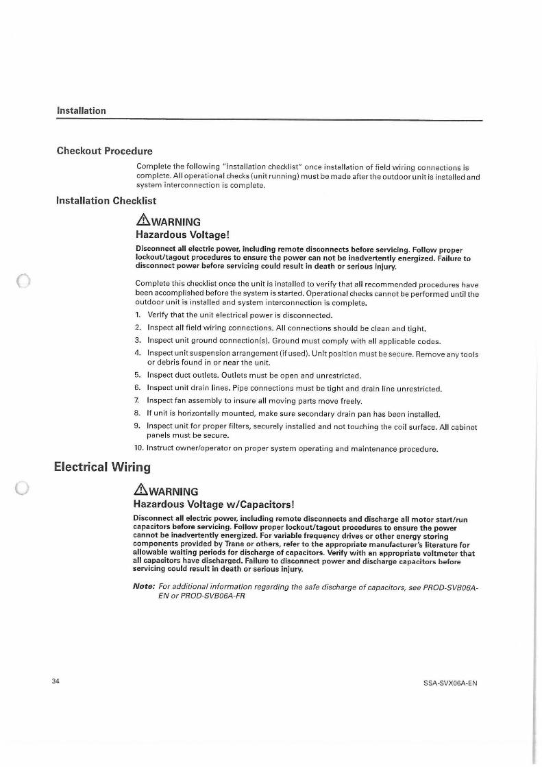
(
()
Installation
Checkout Procedure
Complete the following "installation checklist" once installation of field wiring connections is complete. All operational checks (unit running} must be made after the outdoor unit is installed and system interconnection is complete.
Installation Checklist
.&WARNING Hazardous Voltage! Disconnect all electric power, including remote disconnects before servicing. Follow proper lockout/tagout procedures to ensure the power can not be inadvertently energized. Failure to disconnect power before servicing could result in death or serious injury.
Complete this checklist once the unit is installed to verify that all recommended procedures have been accomplished before the system is started. Operational checks cannot be performed until the outdoor unit is installed and system interconnection is complete.
1. Verify that the unit electrical power is disconnected.
2. Inspect all field wiring connections. All connections should be clean and tight.
3. Inspect unit ground connection(s). Ground must comply with all applicable codes.
4. Inspect unit suspension arrangement (if used). Unit position must be secure. Remove any tools or debris found in or near the unit.
5. Inspect duct outlets. Outlets must be open and unrestricted.
6. Inspect unit drain lines. Pipe connections must be tight and drain line unrestricted.
7. Inspect fan assembly to insure all moving parts move freely.
8. If unit is horizontally mounted, make sure secondary drain pan has been installed.
9. Inspect unit for proper fi lters, securely installed and not touching the coil surface. All cabinet panels must be secure.
10. Instruct owner/operator on proper system operating and maintenance procedure.
Electrical Wiring
.&WARNING
34
Hazardous Voltage w/Capacitors! Disconnect all electric power, including remote disconnects and discharge all motor start/run capacitors before servicing. Follow proper lockout/tagout procedures to ensure the power cannot be inadvertently energized. For variable frequency drives or other energy storing components provided by Trane or others, refer to the appropriate manufacturer's literature for allowable waiting periods for discharge of capacitors. Verify with an appropriate voltmeter that all capacitors have discharged. Failure to disconnect power and discharge capacitors before servicing could result in death or serious injury.
Note: For additional information regarding the safe discharge of capacitors, see PROO-SV806AEN or PROO-SVB06A-FR
SSA-SVX06A-EN
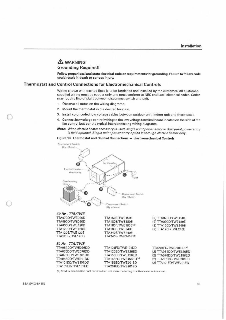
0
u
& WARNING Grounding Required!
Installation
Follow proper local and state electrical code on requirements for grounding. Failure to follow code could result in death or serious injury.
Thermostat and Control Connections for Electromechanical Controls
SSA-SVX06A-EN
Wiring shown with dashed lines is to be furnished and installed by the customer. All customersupplied wiring must be copper only and must conform to NEC and local electrical codes. Codes may require line of sight between disconnect switch and unit.
1. Observe all notes on the wiring diagrams.
2. Mount the thermostat in the desired location.
3. Install color coded low voltage cables between outdoor unit, indoor unit and thermostat.
4. Connect low voltage control wiring to the low voltage terminal board located on the side of the fan control box per the typical interconnect ing wiring diagrams.
Note: When electric heater accessory is used, single point power entry or dual point power entry is field optional. Single point power entry option is through electric heater only.
Figure 18. Thermostat and Control Connections - Electromechanical Controls
60 Hz - TTAITWE TTA073D/TWE090D TTA090D/TWE090D TTA090D/TWE120D TTA1 20D/TWE120D TTA 120E/TWE 120E TTA 120F/TWE 120D
50 Hz - TTAI TWE TTA061 DD/TWE076DD TTA076DD/TWE076DD TTA076DD/TWE101 DD TTA086DD/TWE101 DD TTA 101 DD/TWE 101 DD TTA 101 ED/TWE101 ED
TTA150E/TWE150E TTA 180E/TWE180E TTA 180F/TWE 1 B0E(al TT A 180E/TWE240E TTA240E/TWE240E TTA240F/TWE240Eia)
TTA 101 FD/TWE101 DD TTA1 26ED/TWE126ED TTA156ED/TWE156ED TT A 156FD/TWE 156E Dial TTA156ED/TWE201 ED TTA201 ED/TWE201 ED
(2) TTA073D/TWE150E (2) TTA090D/TWE180E (2) TTA 120D/TWE240E (2) TTA 120F/TWE240E
TTA201 FD/TWE201 ED(al (2) TTA061DD/TWE126ED (2) TTA076DD/TWE156ED (2) TTA101DD/TWE201ED (2) TTA 101 FD/TWE201 ED
(a) Need to manifold the dual circuit indoor unit when connecting to a Manifolded outdoor unit.
35
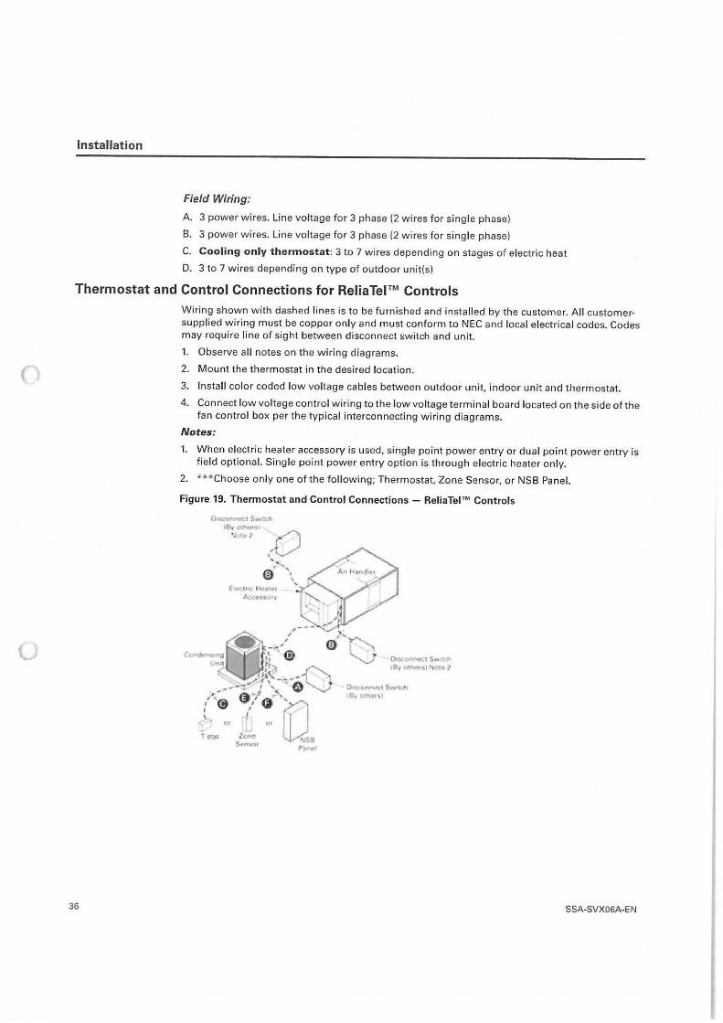
u
Installation
Field Wiring:
A. 3 power wires. Line voltage for 3 phase (2 wires for single phase)
B. 3 power wires. Line voltage for 3 phase (2 wires for single phase)
C. Cooling only thermostat: 3 to 7 wires depending on stages of electric heat
D. 3 to 7 wires depending on type of outdoor unit(s)
Thermostat and Control Connections for ReliaTel™ Controls
36
Wiring shown w ith dashed l ines is to be furnished and installed by the customer. All customersupplied wiring must be copper only and must conform to NEC and local electrical codes. Codes may require line of sight between disconnect switch and unit.
1. Observe all notes on the wiring diagrams.
2. Mount the thermostat in the desired location.
3. Install color coded low voltage cables between outdoor unit, indoor unit and thermostat.
4. Connect low voltage control wiring to the low voltage terminal board located on the side of the fan contro l box per the typical interconnecting wiring diagrams.
Notes:
1. When electric heater accessory is used, single point power entry or dual point power entry is field optional. Single point power entry option is through electric heater only.
2. ***Choose only one of the following; Thermostat, Zone Sensor, or NSB Panel.
Figure 19. Thermostat and Control Connections - ReliaTel™ Controls
SSA-SVX06A-EN
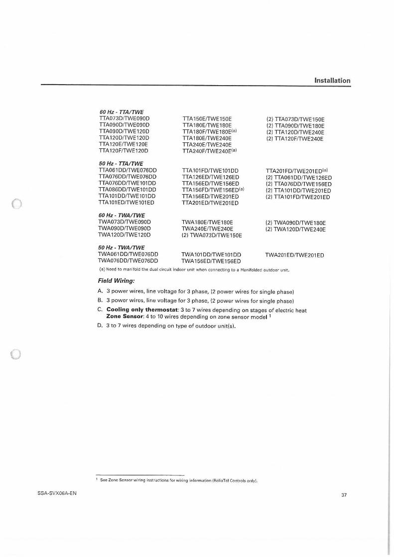
()
0
SSA-SVX06A-EN
Installation
60 Hz - TTAITWE TTA073D!TWE090D TTA150E/TWE150E (2) TTA073D/TWE 150E TTA090D/TWE090D TTA180E!TWE180E (2)TTA090D!TWE180E TTA090D/TWE 120D TTA 1 B0F/TWE 1 B0E!al (2) TTA120D/TWE240E TTA 120D/TWE120D TT A 180E/TWE240E (2) TTA 120F/TWE240E TTA120E/TWE120E TTA240E/TWE240E TTA1 20F/TWE120D TTA240F/TWE240E!a)
50 Hz - TTAITWE TTA061 DD/TWE076DD TTA 101 FD/TWE101 DD TTA201 FD/TWE201 ED(al TTA076DD!TWE076DD TTA126ED/TWE126ED (2) TTA061 DD/TWE126ED TTA076DD!TWE101 DD TTA156ED!TWE156ED (2) TTA076DD/TWE1 56ED TTA086DD/TWE101 DD TTA 156FD!TWE156ED!al (2) TTA101DD/TWE201ED TTA 101 DD!TWE101 DD TTA156ED!TWE201ED (2) TTA 101 FD/TWE201 ED TTA 101 ED!TWE101 ED TTA201ED!TWE201ED
60 Hz - TWAITWE TWA073D/TWE090D TWA180E/TWE180E (2)TWA090D!TWE180E TWA090D/TWE090D TWA240E/TWE240E (2) TWA120D/TWE240E TWA120D!TWE120D (2) TWA073D!TWE150E
50 Hz - TWAITWE TWA061 DD/TWE076DD TWA 101 DD/TWE101 DD TWA201 ED!TWE201 ED TWA076DD/TWE076DD TWA 156ED/TWE156ED
(a) Need to manifold the dual circuit indoor unit when connecting to a Manifolded outdoor unit.
Field Wiring:
A. 3 power wires, l ine voltage for 3 phase, (2 power w ires for single phase)
B. 3 power wires, line voltage for 3 phase, (2 power wires for single phase)
C. Cooling only thermostat: 3 to 7 wires depending on stages of electric heat Zone Sensor: 4 to 10 wires depending on zone sensor model 1
D. 3 to 7 wires depending on type of outdoor unit(s).
1 See Zone Sensor wiring instructions for wiring information (ReliaTel Controls only}.
37
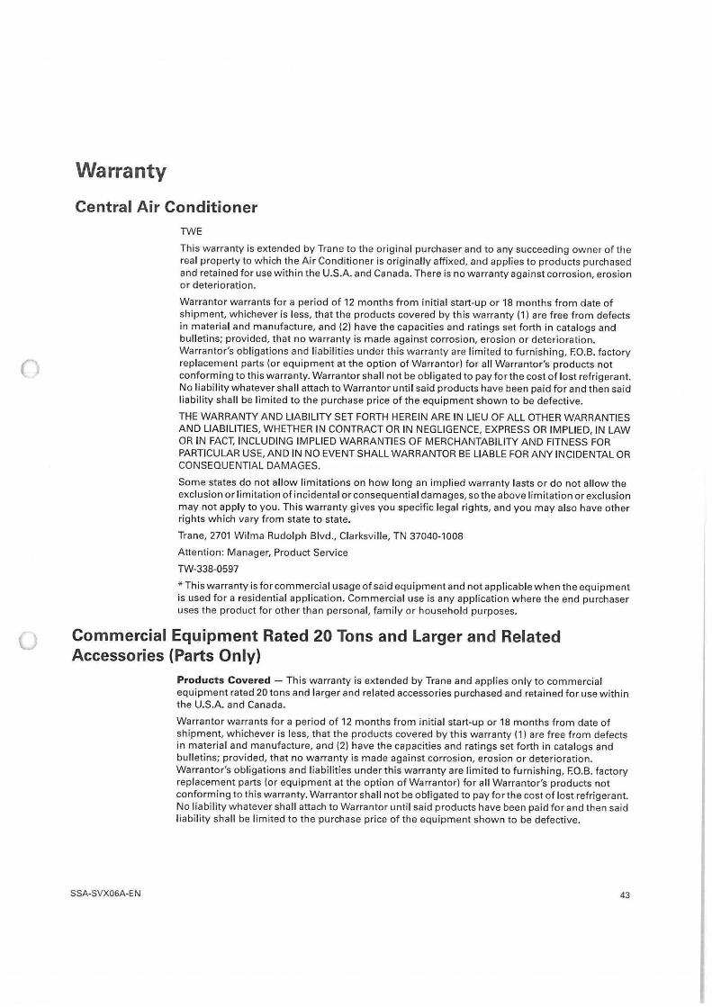
()
Warranty
Central Air Conditioner TWE
This warranty is extended by Trane to the original purchaser and to any succeeding owner of the real property to which the Air Conditioner is originally affixed, and applies to products purchased and retained for use within the U.S.A. and Canada. There is no warranty against corrosion, erosion or deterioration.
Warrantor warrants for a period of 12 months from initial start-up or 18 months from date of shipment, whichever is less, that the products covered by this warranty (1) are free from defects in material and manufacture, and (2) have the capacities and ratings set forth in catalogs and bulletins; provided, that no warranty is made against corrosion, erosion or deterioration. Warrantor's obligations and l iabi lities under this warranty are limited to furnish ing, F.O.B. factory replacement parts (or equipment at the option of Warrantor) for all Warrantor's products not conforming to this warranty. Warrantor shall not be obl igated to pay for the cost of lost refrigerant. No liability whatever shall attach to Warrantor until said products have been paid for and then said liability shall be limited to the purchase price of the equipment shown to be defective.
THE WARRANTY AND LIABILITY SET FORTH HEREIN ARE IN LIEU OF ALL OTHER WARRANTIES AND LIABILITIES, WHETHER IN CONTRACT OR IN NEGLIGENCE, EXPRESS OR IMPLIED, IN LAW OR IN FACT, INCLUDING IMPLIED WARRANTIES OF MERCHANTABILITY AND FITNESS FOR PARTICULAR USE, AND IN NO EVENT SHALL WARRANTOR BE LIABLE FOR ANY INCIDENTAL OR CONSEQUENTIAL DAMAGES.
Some states do not allow limitations on how long an implied warranty lasts or do not allow the exclusion or limitation of incidental or consequential damages, so the above limitation or exclusion may not apply to you. This warranty gives you specific legal rights, and you may also have other rights which vary from state to state.
Trane, 2701 Wilma Rudolph Blvd., Clarksvi lle, TN 37040-1008
Attention: Manager, Product Service
TW-338-0597
* This warranty is for commercial usage of said equipment and not applicable when the equipment is used for a residential application. Commercial use is any application where the end purchaser uses the product for other than personal, family or household purposes.
Commercial Equipment Rated 20 Tons and Larger and Related Accessories (Parts Only)
SSA-SVX06A-EN
Products Covered - This warranty is extended by Trane and applies only to commercial equipment rated 20 tons and larger and related accessories purchased and retained for use with in the U.S.A. and Canada.
Warrantor warrants for a period of 12 months from initial start-up or 18 months from date of shipment, whichever is less, that the products covered by this warranty (1) are free from defects in material and manufacture, and (2) have the capacities and ratings set forth in cata logs and bulletins; provided, that no warranty is made against corrosion, erosion or deterioration. Warrantor's obligations and l iabilities under this warranty are limited to furnishing, F.O.B. factory replacement parts (or equipment at the option of Warrantor) for all Warrantor's products not conforming to th is warranty. Warrantor shall not be obligated to pay for the cost of lost refrigerant. No liability whatever shall attach to Warrantor unt il said products have been paid for and then said liability shall be limited to the purchase price of the equipment shown to be defective.
43
Warranty
u
44
THE WARRANTY AND LIABILITY SET FORTH HEREIN ARE IN LIEU OF ALL OTHER WARRANTIES AND LIABILITIES, W HETHER IN CONTRACT OR IN NEGLIGENCE, EXPRESS OR IMPLIED, IN LAW OR IN FACT, INCLUDING IMPLIED WARRANTIES OF MERCHANTABILITY AND FITNESS FOR PARTICULAR USE, AND IN NO EVENT SHALL WARRANTOR BE LIABLE FOR ANY INCIDENTAL OR CONSEQUENTIA L DAMAGES.
Some states do not allow limitations on how long an implied warranty lasts or do not allow the exclusion or limitatio n of incidental or consequential damages, so the above limitation or exclusion may not apply to you. This warranty gives you specific legal rights, and you may also have other rights which vary from state to state.
Trane -Warrantor, 2701 Wilma Rudolph Blvd., Clarksville, TN 37040
GW-598-4799
SSA-SVX06A-EN
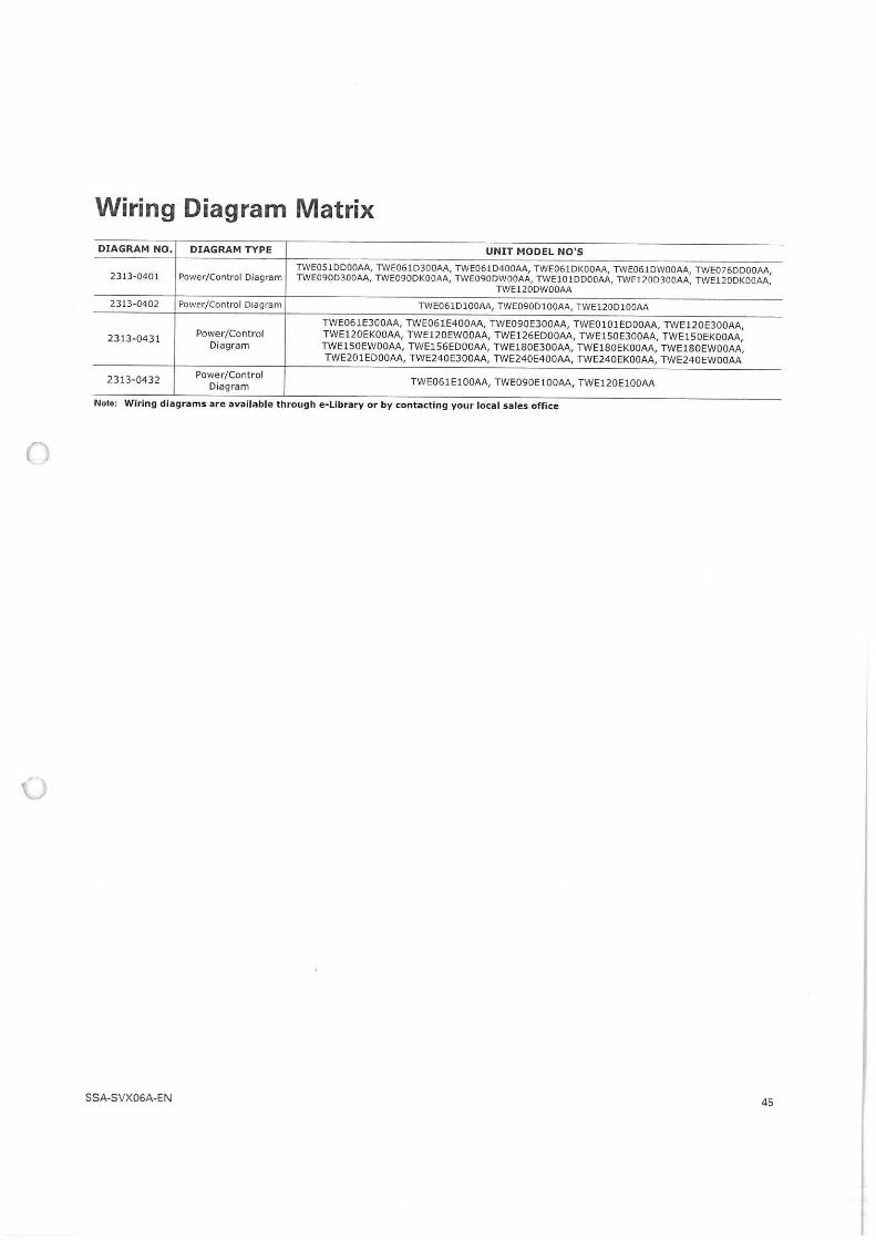
Wiring Diagram Matrix DIAGRAM NO, DIAGRAM TYPE UNIT MODEL NO'S
TWEOS l DDOOAA, TWE061D300AA, TWE061D400AA, TWE061DKOOAA, TWE061DWOOAA, TWE076DDOOAA, 2313-0401 Power/Control Diagram TWE090D300AA, TWE090DKOOAA, TWE090DWOOAA, TWElOlDDOOAA, TWE120D300AA, TWE120DKOOAA,
TWE120DWOOAA
2313-0402 Power/Control Diagram TWE061D100AA, TWE090D100AA, TWE120D100AA
TWE061E300AA, TWE061E400AA, TWE090E300AA, TWE0101EDOOAA, TWE120E300AA,
2313-0431 Power/Control TWE120EKOOAA, TWE120EWOOAA, TWE126EDOOAA, TWE150E300AA, TWElSDEKOOAA, Diagram TWE1SOEWOOAA, TWE156EDOOAA, TWE180E300AA, TWElSOEKDDAA, TWE180EWDOAA,
TWE201EDOOAA, TWE240E300AA, TWE240E400AA, TWE240EKOOAA, TWE240EWDOAA
2313-0432 Power/Control TWE061E100AA, TWE09DE100AA, TWE120E100AA Diagram
Note: Wiring diagram s are available through e-Library or by contacting your local sales office
(
u
SSA-SVX06A-EN 45
Related Documents