Base Realignment and Closure Program Management Office West San Diego, California Draft Parcel G Removal Site Evaluation Work Plan Former Hunters Point Naval Shipyard San Francisco, California June 2018 Naval Facilities Engineering Command SEMS-RM DOCID # 100008043

Welcome message from author
This document is posted to help you gain knowledge. Please leave a comment to let me know what you think about it! Share it to your friends and learn new things together.
Transcript
Base Realignment and Closure Program Management Office West San Diego, California
Draft
Parcel G Removal Site Evaluation Work Plan
Former Hunters Point Naval Shipyard San Francisco, California
June 2018
Naval Facilities Engineering Command
SEMS-RM DOCID # 100008043
Base Realignment and Closure Program Management Office West San Diego, California
Draft
Parcel G Removal Site Evaluation Work Plan
Former Hunters Point Naval Shipyard San Francisco, California
June 2018
Signature Date Quality Assurance Manager
Signature Date Radiation Safety Officer
Signature Date Project Manager
Naval Facilities Engineering Command
III
Executive Summary Background Radiological surveys and remediation were previously conducted at Hunters Point Naval Shipyard (HPNS) as part of a basewide Time-critical Removal Action (TCRA) in accordance with the Action Memorandum (Navy, 2006). Tetra Tech EC, Inc. (TtEC), under contracts with the Department of the Navy (Navy), conducted a large portion of the basewide TCRA from 2006 to 2015. There have been various allegations of data manipulation or falsification committed by TtEC employees and TtEC’s subcontractors during the TCRA. An independent third-party evaluation of previous data found evidence of manipulation and falsification at Parcel G (Navy, 2017, 2018). As a result, the Navy developed this work plan to investigate radiological sites in Parcel G.
Project Purpose The purpose of the investigation presented in this work plan is to determine whether current site conditions are compliant with the remedial action objective (RAO) in the Parcel G Record of Decision (ROD) (Navy, 2009). The RAO for radiologically impacted soil and structures is to prevent receptor exposure to radionuclides of concern (ROCs) in concentrations that exceed remediation goals (RGs) for all potentially complete exposure pathways. Additional reference background areas will also be identified to confirm, or update as necessary, estimates of naturally occurring and man-made background levels for ROCs not attributed to Naval operations at HPNS.
Portions of soil or structures that are not compliant with the RAO will be evaluated for protectiveness based on the United States Environmental Protection Agency’s (USEPA’s) current guidance on Radiation Risk Assessment at CERCLA Sites (USEPA, 2014).
Scope The radiological investigation will be conducted at the following sites:
• Former Sanitary Sewer and Storm Drain Trenches • Buildings 317/364/365 Former Building Site • Building 351A • Building 351 • Building 366 • Building 401 • Former Building 408 Concrete Pad • Building 411 • Building 439
The sites and the locations of work are shown on Table ES-1 and Figure ES-1.
Conceptual Site Model A conceptual site model (CSM) was developed with current knowledge of the site (see Section 2). There is uncertainty whether radiological contamination was present or remains in-place. Examples of uncertainties include the following:
• Allegations of previous sample collection fraud, improper sample and document custody/controls, and data manipulation could indicate that contamination was potentially left at the site.
PARCEL G REMOVAL SITE EVALUATION WORK PLAN
IV
• The previous work relied on a quicker, less accurate method for analyzing radium-226 (226Ra). This method was known by stakeholders at the time to be biased high. A large amount of soil (estimated 80 percent) was likely mischaracterized as contaminated (Argonne National Laboratory, 2011).
• The RGs used previously are within background ranges. Therefore, soil that was considered contaminated could have been attributable to naturally occurring radioactivity or anthropogenic fallout (Argonne National Laboratory, 2011).
The CSM is based largely on the Historical Radiological Assessment (NAVSEA, 2004). A determination as to whether contamination exists at the site cannot be made until additional data are collected, analyzed, and compared to RGs and background concentrations.
Soil Investigations Soil investigations will be conducted at the following areas:
• Former Sanitary Sewer and Storm Drain Trenches • Buildings 317/364/365 Former Building Site • Building 351A Crawl Space
Soil investigation areas will be divided into trench units (TUs) and surface soil survey units (SUs). The size and boundary of the TUs and SUs will be based on the previous plans and reports. The approximate size and boundary of the TUs and SUs are shown on Figure ES-1.
A phased investigation approach is presented in this work plan that was designed to provide a high level of confidence that current site conditions either comply or do not comply with the Parcel G ROD RAO (Navy, 2009).
Phase 1 Investigation Phase 1 includes the radiological investigation on a targeted group of TUs and SUs. Twenty-one of the 63 former sanitary sewer and storm drain TUs were selected for the Phase 1 investigation. Fourteen of the 28 surface soil SUs1 from the Buildings 317/364/365 Former Building Site and Building 351A Crawl Space were selected for the Phase 1 investigation.
The radiological investigation of soil includes the following:
• Collection of systematic soil samples • Gamma scan of 100 percent of the soil • Collection of bias soil samples, where necessary, based on the gamma scan measurements
The targeted TUs and SUs were selected based on the highest potential for radiological contamination. The following information was used to select the units:
• Historical documentation of specific potential upstream sources, spills, or other indicators of potential contamination (NAVSEA, 2004)
• Signs of potential manipulation or falsification from the soil data evaluation (Navy, 2017, 2018)
For TUs associated with former sanitary sewers and storm drains (from 1 to 22 feet deep), 100 percent of the soil will be excavated to the original TU boundaries, as practicable, and gamma scans of the excavated material will be conducted. Excavated soil will be gamma scanned by one of two methods.
1 Previously, 32 SUs were investigated at Buildings 317/364/365 Former Building Site and Building 351A Crawl Space; however, some SU areas overlapped. For the Buildings 317/364/365 Former Building Site, former SU 22 overlaps TU-153 and will be investigated as part of TU-153. For the Building 351A Crawl Space, former SU-R, SU-S, and SU-U overlapped SU-M, SU-N, and SU-O and will be investigated as SU-M, SU-N, and SU-O.
EXECUTIVE SUMMARY
V
Soil may be laid out on Radiological Screening Yard pads for a surface scan, or soil may be processed and scanned using soil segregation technology. Following excavation to the original TU boundaries, additional excavation of approximately 6 inches of the trench sidewalls and floors will be performed to provide ex situ scanning and sampling of the trench sidewalls and floors. Global positioning system (GPS)-location correlated results will be collected.
For surface soil SUs, a surface gamma scan of 100 percent of surface soil will be conducted as walk-over or drive-over surveys. GPS-location correlated results will be collected.
Systematic and bias samples will be collected from the excavated soil from the TUs, within the surrounding soil of the TUs, and from the surface soil SUs. The soil samples will be analyzed for ROCs by accredited offsite laboratories, and the results will be evaluated to determine whether concentrations are below the RGs. Soil sample locations will be surveyed using GPS to facilitate relocation if further investigation is warranted.
To the extent practicable, soil with ROCs at concentrations above the RGs will be evaluated further using USEPA’s current guidance on Radiation Risk Assessment at CERCLA Sites (USEPA, 2014).
Phase 2 Investigation Additional soil sampling will be conducted on the remaining 42 TUs and 14 SUs as part of the Phase 2 investigation. For TUs associated with former sanitary sewers and storm drains (from 1 to 22 feet deep), subsurface soil samples will be collected via borings. The borings will be advanced beyond the floor boundary of the trench or to the point of refusal. Gamma scans of the core will be conducted. Borehole locations will be surveyed using GPS to facilitate relocation if further investigation is warranted.
For surface soil SUs, systematic samples will be collected from underneath the durable cover layers.
The soil samples will be analyzed for ROC analysis by accredited offsite laboratories. Exceedances of the RGs identified in the soil samples will be evaluated further using USEPA’s current guidance on Radiation Risk Assessment at CERCLA Sites (USEPA, 2014).
Building Investigations Investigations of interior surfaces will be performed for the following buildings:
• Building 351A • Building 351 • Building 366 • Building 401 • Former Building 408 Concrete Pad • Building 411 • Building 439
Buildings will be divided into SUs, and the size and boundary of the SUs will be based on the previous plans and reports. The radiological investigation will be conducted to include the following:
• Collection of systematic static alpha-beta measurements
• Alpha and beta scan of surfaces
• Collection of bias static alpha-beta measurement where necessary, based on the alpha-beta scan measurements
• Collection of swipe samples
PARCEL G REMOVAL SITE EVALUATION WORK PLAN
VI
Data Evaluation and Reporting Data from the radiological investigation will be evaluated to determine whether the site conditions are compliant with the Parcel G ROD RAO. If the residual ROC concentrations are below the RGs in the Parcel G ROD, then the site conditions are compliant with the Parcel G ROD RAO.
Various methods will be used to determine whether the residual ROC concentrations are below the RGs:
• Each sample and measurement result will be compared to the corresponding RG.
• Individual samples reporting 226Ra gamma spectroscopy concentrations greater than the RG for 226Ra will be analyzed for uranium-238 (238U) and 226Ra using comparable analytical methods. For that specific sample, the 238U result will be used as a more representative estimate of the background value for 226Ra, and the alpha spectrometry 226Ra concentration will be compared to the RG for 226Ra using the revised background value.
If the investigation results demonstrate that site conditions are compliant with the Parcel G RAO, then a remedial action completion report (RACR) will be developed. The RACR will describe the results of the investigation and will provide a demonstration that the RAO has been met, and that residual radioactivity levels are comparable with background.
If the investigation results demonstrate that site conditions are not compliant with the Parcel G RAO, then the data will be evaluated to determine whether site conditions are protective of human health using USEPA’s current guidance on Radiation Risk Assessment at CERCLA Sites (USEPA, 2014). A removal site evaluation report will be developed to include recommendations for further action.
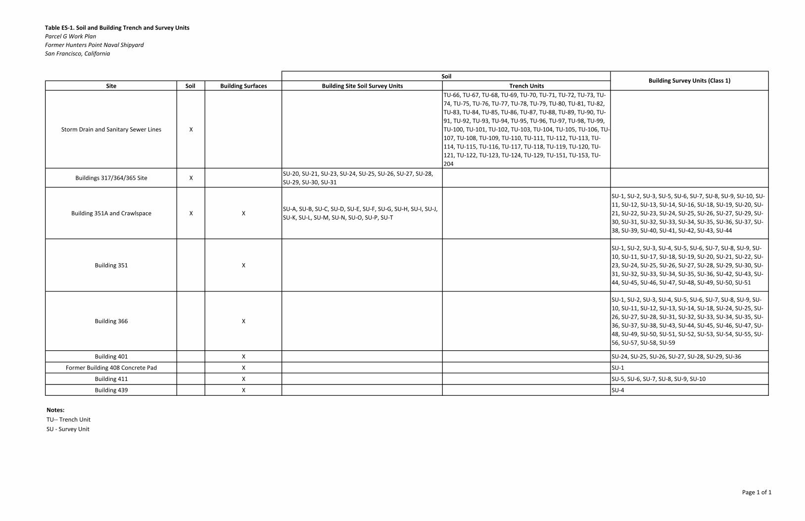
Table ES-1. Soil and Building Trench and Survey UnitsParcel G Work PlanFormer Hunters Point Naval ShipyardSan Francisco, California
Site Soil Building Surfaces Building Site Soil Survey Units Trench Units
Storm Drain and Sanitary Sewer Lines X
TU-66, TU-67, TU-68, TU-69, TU-70, TU-71, TU-72, TU-73, TU-74, TU-75, TU-76, TU-77, TU-78, TU-79, TU-80, TU-81, TU-82, TU-83, TU-84, TU-85, TU-86, TU-87, TU-88, TU-89, TU-90, TU-91, TU-92, TU-93, TU-94, TU-95, TU-96, TU-97, TU-98, TU-99, TU-100, TU-101, TU-102, TU-103, TU-104, TU-105, TU-106, TU-107, TU-108, TU-109, TU-110, TU-111, TU-112, TU-113, TU-114, TU-115, TU-116, TU-117, TU-118, TU-119, TU-120, TU-121, TU-122, TU-123, TU-124, TU-129, TU-151, TU-153, TU-204
Buildings 317/364/365 Site XSU-20, SU-21, SU-23, SU-24, SU-25, SU-26, SU-27, SU-28, SU-29, SU-30, SU-31
Building 351A and Crawlspace X XSU-A, SU-B, SU-C, SU-D, SU-E, SU-F, SU-G, SU-H, SU-I, SU-J, SU-K, SU-L, SU-M, SU-N, SU-O, SU-P, SU-T
SU-1, SU-2, SU-3, SU-5, SU-6, SU-7, SU-8, SU-9, SU-10, SU-11, SU-12, SU-13, SU-14, SU-16, SU-18, SU-19, SU-20, SU-21, SU-22, SU-23, SU-24, SU-25, SU-26, SU-27, SU-29, SU-30, SU-31, SU-32, SU-33, SU-34, SU-35, SU-36, SU-37, SU-38, SU-39, SU-40, SU-41, SU-42, SU-43, SU-44
Building 351 X
SU-1, SU-2, SU-3, SU-4, SU-5, SU-6, SU-7, SU-8, SU-9, SU-10, SU-11, SU-17, SU-18, SU-19, SU-20, SU-21, SU-22, SU-23, SU-24, SU-25, SU-26, SU-27, SU-28, SU-29, SU-30, SU-31, SU-32, SU-33, SU-34, SU-35, SU-36, SU-42, SU-43, SU-44, SU-45, SU-46, SU-47, SU-48, SU-49, SU-50, SU-51
Building 366 X
SU-1, SU-2, SU-3, SU-4, SU-5, SU-6, SU-7, SU-8, SU-9, SU-10, SU-11, SU-12, SU-13, SU-14, SU-18, SU-24, SU-25, SU-26, SU-27, SU-28, SU-31, SU-32, SU-33, SU-34, SU-35, SU-36, SU-37, SU-38, SU-43, SU-44, SU-45, SU-46, SU-47, SU-48, SU-49, SU-50, SU-51, SU-52, SU-53, SU-54, SU-55, SU-56, SU-57, SU-58, SU-59
Building 401 X SU-24, SU-25, SU-26, SU-27, SU-28, SU-29, SU-36
Former Building 408 Concrete Pad X SU-1
Building 411 X SU-5, SU-6, SU-7, SU-8, SU-9, SU-10
Building 439 X SU-4
Notes:TU-- Trench UnitSU - Survey Unit
SoilBuilding Survey Units (Class 1)
Page 1 of 1
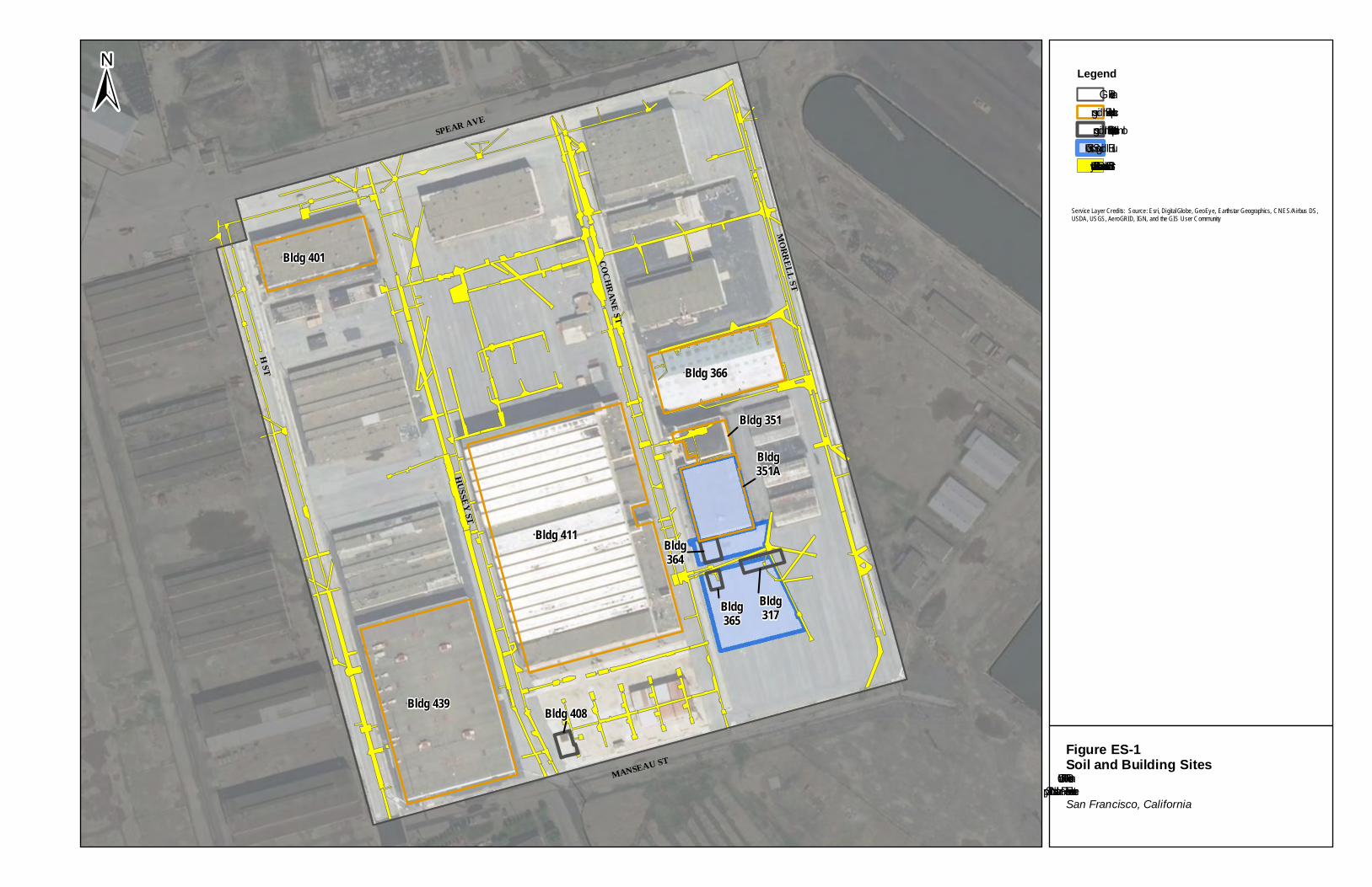
Bldg 401
Bldg 366
Bldg 411
Bldg 351
Bldg351A
Bldg 439
H ST
MORRELL ST
MANSEAU ST
SPEAR AVE
HUSSEYST
COCHRANE ST
Bldg364
Bldg365
Bldg 408
Bldg317
± LegendParcel GImpacted BuildingsDemolished Impacted BuildingsBuilding Site – SoilStorm Drain and Sanitary Sewer Line – Soil
Figure ES-1Soil and Building SitesParcel G Work PlanFormer Hunters Point Naval ShipyardSan Francisco, California
Service Layer Credits: Source: Esri, DigitalGlobe, GeoEye, Earthstar Geographics, CNES/Airbus DS,USDA, USGS, AeroGRID, IGN, and the GIS User Community
CJ CJ
B [=i
VII
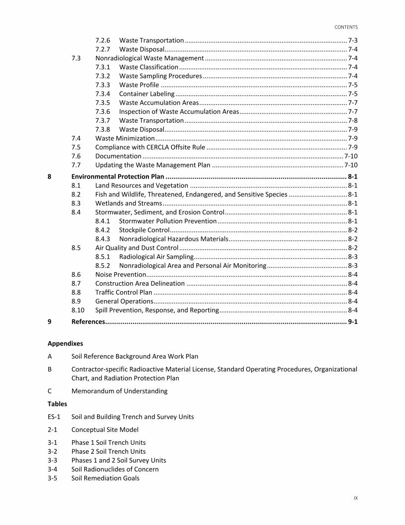
Contents Executive Summary ............................................................................................................................ iii
Acronyms and Abbreviations ............................................................................................................... xi
1 Introduction ......................................................................................................................... 1-1
2 Conceptual Site Model .......................................................................................................... 2-1
3 Soil Investigation Design and Implementation ...................................................................... 3-1 3.1 Data Quality Objectives ................................................................................................... 3-1 3.2 Radionuclides of Concern ................................................................................................ 3-2 3.3 Remediation Goals ........................................................................................................... 3-3
3.3.1 Investigation Levels ............................................................................................. 3-3 3.4 Radiological Investigation Design .................................................................................... 3-4
3.4.1 Number of Samples ............................................................................................ 3-4 3.4.2 Locating Samples ................................................................................................ 3-4 3.4.3 Radiological Background ..................................................................................... 3-5 3.4.4 Phase 1 Trench Unit Design ................................................................................ 3-5 3.4.5 Phase 2 Trench Unit Design ................................................................................ 3-7 3.4.6 Phase 1 Survey Unit Design ................................................................................ 3-7 3.4.7 Phase 2 Survey Unit Design ................................................................................ 3-8
3.5 Instrumentation ............................................................................................................... 3-8 3.5.1 Soil Gamma Scanning Instruments ..................................................................... 3-8 3.5.2 Instrument Detection Calculations ..................................................................... 3-9 3.5.3 Calibration ......................................................................................................... 3-10 3.5.4 Daily Performance Checks ................................................................................ 3-10
3.6 Radiological Investigation Implementation ................................................................... 3-11 3.6.1 Premobilization Activities ................................................................................. 3-11 3.6.2 Mobilization Activities ...................................................................................... 3-12 3.6.3 Phase 1 Trench Unit Investigation .................................................................... 3-13 3.6.4 Phase 2 Trench Unit Investigation .................................................................... 3-17 3.6.5 Phase 1 Survey Unit Investigation .................................................................... 3-19 3.6.6 Phase 2 Survey Unit Investigation .................................................................... 3-20 3.6.7 Site Restoration and Demobilization ................................................................ 3-20 3.6.8 Demobilization .................................................................................................. 3-21
3.7 Radiological Laboratory Analysis ................................................................................... 3-21
4 Building Investigation Design and Implementation ............................................................... 4-1 4.1 Data Quality Objectives ................................................................................................... 4-1 4.2 Radionuclides of Concern ................................................................................................ 4-2 4.3 Remediation Goals ........................................................................................................... 4-2 4.4 Radiological Investigation Design .................................................................................... 4-2
4.4.1 Number of Static Measurements ....................................................................... 4-3 4.4.2 Radiological Background ..................................................................................... 4-3 4.4.3 Survey Units ........................................................................................................ 4-3 4.4.4 Reference Coordinate System ............................................................................ 4-3
4.5 Instrumentation ............................................................................................................... 4-3 4.5.1 Position-sensitive Proportional Counters ........................................................... 4-4 4.5.2 Large-area Gas Proportional Detectors .............................................................. 4-4 4.5.3 Alpha-Beta Sample Counter................................................................................ 4-4 4.5.4 Instrument Efficiencies ....................................................................................... 4-4
PARCEL G REMOVAL SITE EVALUATION WORK PLAN
VIII
4.5.5 Calibration ........................................................................................................... 4-5 4.5.6 Daily Performance Checks .................................................................................. 4-5 4.5.7 Instrument Detection Calculations and Investigation Levels ............................. 4-6
4.6 Radiological Investigation Implementation ................................................................... 4-12 4.6.1 Premobilization Activities ................................................................................. 4-12 4.6.2 Mobilization Activities ...................................................................................... 4-13 4.6.3 Building Investigation Activities ........................................................................ 4-14 4.6.4 Demobilization .................................................................................................. 4-15
5 Data Evaluation and Reporting ............................................................................................. 5-1 5.1 Data Quality Validation .................................................................................................... 5-1 5.2 Data Quality Assessment ................................................................................................. 5-1
5.2.1 Review the Data Quality Objectives and Survey Design ..................................... 5-1 5.2.2 Conduct a Preliminary Data Review ................................................................... 5-2 5.2.3 Draw Conclusions from the Data ........................................................................ 5-3
5.3 Investigation of Potential Areas of Elevated Activity ....................................................... 5-4 5.3.1 Identify Potential Areas of Elevated Activity ...................................................... 5-4 5.3.2 Investigate Potential Areas of Elevated Activity ................................................. 5-4
5.4 NORM Background Evaluation ......................................................................................... 5-5 5.5 Reference Background Area Soil Data ............................................................................. 5-6 5.6 Reporting ......................................................................................................................... 5-6
6 Radioactive Materials Management and Control .................................................................. 6-1 6.1 Project Roles and Responsibilities ................................................................................... 6-1 6.2 Licensing and Jurisdiction ................................................................................................ 6-1 6.3 Radiological Health and Safety ........................................................................................ 6-2 6.4 Radiation Protection ........................................................................................................ 6-2
6.4.1 Radiological Postings .......................................................................................... 6-2 6.4.2 Internal and External Exposure Control and Monitoring ................................... 6-2 6.4.3 Radiological Access Control ................................................................................ 6-3 6.4.4 Personal Protective Equipment .......................................................................... 6-3 6.4.5 Instrumentation .................................................................................................. 6-4 6.4.6 Radiological Training ........................................................................................... 6-4 6.4.7 Health and Safety Training .................................................................................. 6-4
6.5 Radiological Support Surveys ........................................................................................... 6-4 6.5.1 Personnel Surveys ............................................................................................... 6-5
6.6 Equipment Surveys .......................................................................................................... 6-5 6.6.1 Swipe Samples .................................................................................................... 6-5 6.6.2 Exposure Rate Surveys (Dose Rates) .................................................................. 6-5 6.6.3 Equipment Baseline and Unconditional Release Surveys ................................... 6-5
6.7 Documentation and Records Management..................................................................... 6-5 6.7.1 Documentation Quality Standards ..................................................................... 6-6 6.7.2 Laboratory Records ............................................................................................. 6-6 6.7.3 Record Retention ................................................................................................ 6-6
7 Waste Management Plan ...................................................................................................... 7-1 7.1 Project Waste Descriptions .............................................................................................. 7-1 7.2 Radiological Waste Management .................................................................................... 7-2
7.2.1 Waste Classification ............................................................................................ 7-2 7.2.2 Waste Accumulation and Storage ...................................................................... 7-2 7.2.3 Labeling and Posting of Containers Containing Radioactive Waste ................... 7-2 7.2.4 Waste Accumulation Areas ................................................................................. 7-3 7.2.5 Inspection of Waste Accumulation Areas ........................................................... 7-3
CONTENTS
IX
7.2.6 Waste Transportation ......................................................................................... 7-3 7.2.7 Waste Disposal .................................................................................................... 7-4
7.3 Nonradiological Waste Management .............................................................................. 7-4 7.3.1 Waste Classification ............................................................................................ 7-4 7.3.2 Waste Sampling Procedures ............................................................................... 7-4 7.3.3 Waste Profile ...................................................................................................... 7-5 7.3.4 Container Labeling .............................................................................................. 7-5 7.3.5 Waste Accumulation Areas ................................................................................. 7-7 7.3.6 Inspection of Waste Accumulation Areas ........................................................... 7-7 7.3.7 Waste Transportation ......................................................................................... 7-8 7.3.8 Waste Disposal .................................................................................................... 7-9
7.4 Waste Minimization ......................................................................................................... 7-9 7.5 Compliance with CERCLA Offsite Rule ............................................................................. 7-9 7.6 Documentation .............................................................................................................. 7-10 7.7 Updating the Waste Management Plan ........................................................................ 7-10
8 Environmental Protection Plan ............................................................................................. 8-1 8.1 Land Resources and Vegetation ...................................................................................... 8-1 8.2 Fish and Wildlife, Threatened, Endangered, and Sensitive Species ................................ 8-1 8.3 Wetlands and Streams ..................................................................................................... 8-1 8.4 Stormwater, Sediment, and Erosion Control ................................................................... 8-1
8.4.1 Stormwater Pollution Prevention ....................................................................... 8-1 8.4.2 Stockpile Control ................................................................................................. 8-2 8.4.3 Nonradiological Hazardous Materials ................................................................. 8-2
8.5 Air Quality and Dust Control ............................................................................................ 8-2 8.5.1 Radiological Air Sampling .................................................................................... 8-3 8.5.2 Nonradiological Area and Personal Air Monitoring ............................................ 8-3
8.6 Noise Prevention .............................................................................................................. 8-4 8.7 Construction Area Delineation ........................................................................................ 8-4 8.8 Traffic Control Plan .......................................................................................................... 8-4 8.9 General Operations .......................................................................................................... 8-4 8.10 Spill Prevention, Response, and Reporting ...................................................................... 8-4
9 References ............................................................................................................................ 9-1
Appendixes
A Soil Reference Background Area Work Plan
B Contractor-specific Radioactive Material License, Standard Operating Procedures, Organizational Chart, and Radiation Protection Plan
C Memorandum of Understanding
Tables
ES-1 Soil and Building Trench and Survey Units
2-1 Conceptual Site Model
3-1 Phase 1 Soil Trench Units 3-2 Phase 2 Soil Trench Units 3-3 Phases 1 and 2 Soil Survey Units 3-4 Soil Radionuclides of Concern 3-5 Soil Remediation Goals

PARCEL G REMOVAL SITE EVALUATION WORK PLAN
X
3-6 Soil Survey Measurement Investigation Levels 3-7 Gamma Survey Instruments
4-1 Building Radionuclides of Concern 4-2 Building Remediation Goals 4-3 Survey Instrument Efficiencies and Background Count Rates from Manufacturers 4-4 Instrument Scan Investigation Levels 4-5 Probability of Alpha Detection during Scanning 4-6 Beta Scan Minimum Detectable Concentrations 4-7 Instrument Static Investigation Levels 4-8 Instrument Static Minimum Detectable Concentrations
7-1 Waste Management 7-2 Non-LLRW Accumulation Requirements
8-1 Derived Air Concentrations
Figures
ES-1 Soil and Building Sites 1-1 HPNS and Parcel G Location 1-2 Soil and Building Sites
3-1 Soil Investigation Approach 3-2 Performance Criteria for Demonstrating Compliance with the Parcel G ROD - Soil 3-3 Example Phase 1 Trench/Survey Unit and Sample Locations 3-4 Example Phase 2 Trench/Survey Unit and Sample Locations Radiological Data Evaluation
Findings 3-5 Typical Soil Segregation System Layout
4-1 Impacted Buildings and Background Locations 4-2 Building 351A Floor Plan 4-3 Building 351 Floor Plan 4-4 Building 366 Floor Plan 4-5 Building 401 Floor Plan 4-6 Building 408 Floor Plan 4-7 Building 411 Floor Plan 4-8 Building 439 Floor Plan 4-9 Performance Criteria for Demonstrating Compliance with the Parcel G ROD - Buildings 4-10 Example Building Survey Unit and Sample Locations (Building 351A Survey Unit 1)
6-1 HPNS NRC Jurisdictional Boundaries
XI
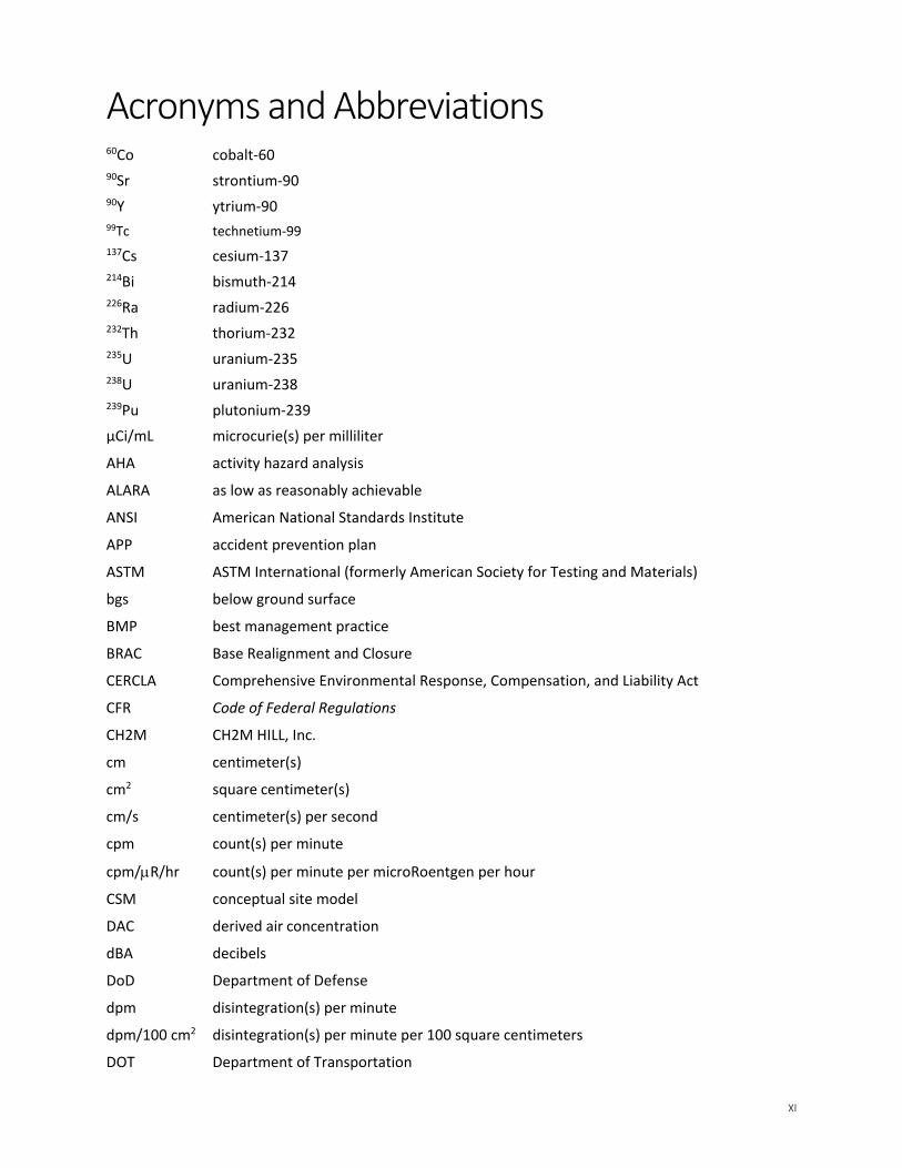
Acronyms and Abbreviations 60Co cobalt-60 90Sr strontium-90 90Y ytrium-90 99Tc technetium-99
137Cs cesium-137 214Bi bismuth-214 226Ra radium-226 232Th thorium-232 235U uranium-235 238U uranium-238 239Pu plutonium-239
µCi/mL microcurie(s) per milliliter
AHA activity hazard analysis
ALARA as low as reasonably achievable
ANSI American National Standards Institute
APP accident prevention plan
ASTM ASTM International (formerly American Society for Testing and Materials)
bgs below ground surface
BMP best management practice
BRAC Base Realignment and Closure
CERCLA Comprehensive Environmental Response, Compensation, and Liability Act
CFR Code of Federal Regulations
CH2M CH2M HILL, Inc.
cm centimeter(s)
cm2 square centimeter(s)
cm/s centimeter(s) per second
cpm count(s) per minute
cpm/µR/hr count(s) per minute per microRoentgen per hour
CSM conceptual site model
DAC derived air concentration
dBA decibels
DoD Department of Defense
dpm disintegration(s) per minute
dpm/100 cm2 disintegration(s) per minute per 100 square centimeters
DOT Department of Transportation
PARCEL G REMOVAL SITE EVALUATION WORK PLAN
XII
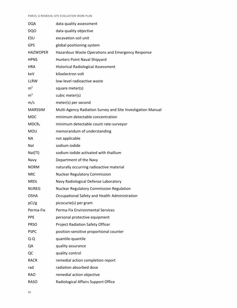
DQA data quality assessment
DQO data quality objective
ESU excavation soil unit
GPS global positioning system
HAZWOPER Hazardous Waste Operations and Emergency Response
HPNS Hunters Point Naval Shipyard
HRA Historical Radiological Assessment
keV kiloelectron volt
LLRW low-level radioactive waste
m2 square meter(s)
m3 cubic meter(s)
m/s meter(s) per second
MARSSIM Multi-Agency Radiation Survey and Site Investigation Manual
MDC minimum detectable concentration
MDCRS minimum detectable count rate-surveyor
MOU memorandum of understanding
NA not applicable
NaI sodium iodide
NaI(Tl) sodium iodide activated with thallium
Navy Department of the Navy
NORM naturally occurring radioactive material
NRC Nuclear Regulatory Commission
NRDL Navy Radiological Defense Laboratory
NUREG Nuclear Regulatory Commission Regulation
OSHA Occupational Safety and Health Administration
pCi/g picocurie(s) per gram
Perma-Fix Perma-Fix Environmental Services
PPE personal protective equipment
PRSO Project Radiation Safety Officer
PSPC position-sensitive proportional counter
Q-Q quantile-quantile
QA quality assurance
QC quality control
RACR remedial action completion report
rad radiation absorbed dose
RAO remedial action objective
RASO Radiological Affairs Support Office
ACRONYMS AND ABBREVIATIONS
XIII
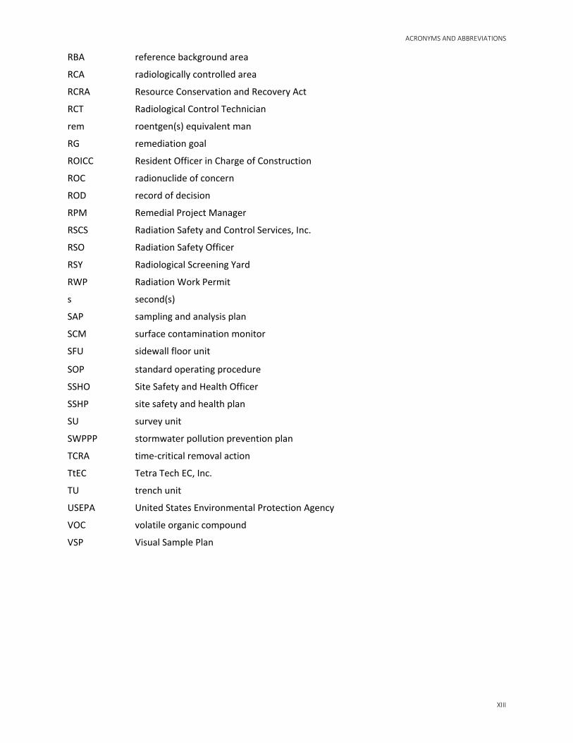
RBA reference background area
RCA radiologically controlled area
RCRA Resource Conservation and Recovery Act
RCT Radiological Control Technician
rem roentgen(s) equivalent man
RG remediation goal
ROICC Resident Officer in Charge of Construction
ROC radionuclide of concern
ROD record of decision
RPM Remedial Project Manager
RSCS Radiation Safety and Control Services, Inc.
RSO Radiation Safety Officer
RSY Radiological Screening Yard
RWP Radiation Work Permit
s second(s)
SAP sampling and analysis plan
SCM surface contamination monitor
SFU sidewall floor unit
SOP standard operating procedure
SSHO Site Safety and Health Officer
SSHP site safety and health plan
SU survey unit
SWPPP stormwater pollution prevention plan
TCRA time-critical removal action
TtEC Tetra Tech EC, Inc.
TU trench unit
USEPA United States Environmental Protection Agency
VOC volatile organic compound
VSP Visual Sample Plan
SECTION 1
1-1
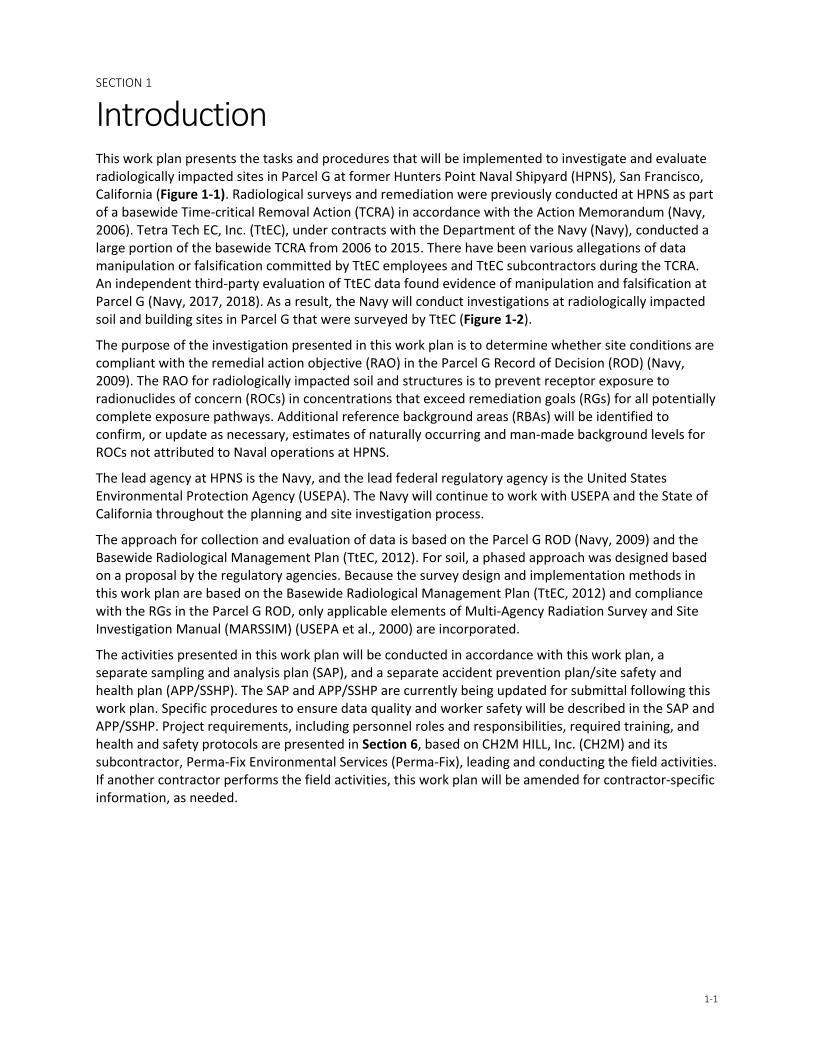
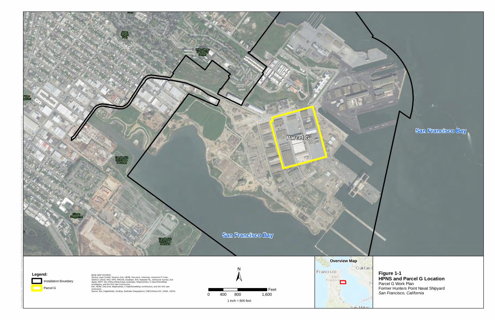
Introduction This work plan presents the tasks and procedures that will be implemented to investigate and evaluate radiologically impacted sites in Parcel G at former Hunters Point Naval Shipyard (HPNS), San Francisco, California (Figure 1-1). Radiological surveys and remediation were previously conducted at HPNS as part of a basewide Time-critical Removal Action (TCRA) in accordance with the Action Memorandum (Navy, 2006). Tetra Tech EC, Inc. (TtEC), under contracts with the Department of the Navy (Navy), conducted a large portion of the basewide TCRA from 2006 to 2015. There have been various allegations of data manipulation or falsification committed by TtEC employees and TtEC subcontractors during the TCRA. An independent third-party evaluation of TtEC data found evidence of manipulation and falsification at Parcel G (Navy, 2017, 2018). As a result, the Navy will conduct investigations at radiologically impacted soil and building sites in Parcel G that were surveyed by TtEC (Figure 1-2).
The purpose of the investigation presented in this work plan is to determine whether site conditions are compliant with the remedial action objective (RAO) in the Parcel G Record of Decision (ROD) (Navy, 2009). The RAO for radiologically impacted soil and structures is to prevent receptor exposure to radionuclides of concern (ROCs) in concentrations that exceed remediation goals (RGs) for all potentially complete exposure pathways. Additional reference background areas (RBAs) will be identified to confirm, or update as necessary, estimates of naturally occurring and man-made background levels for ROCs not attributed to Naval operations at HPNS.
The lead agency at HPNS is the Navy, and the lead federal regulatory agency is the United States Environmental Protection Agency (USEPA). The Navy will continue to work with USEPA and the State of California throughout the planning and site investigation process.
The approach for collection and evaluation of data is based on the Parcel G ROD (Navy, 2009) and the Basewide Radiological Management Plan (TtEC, 2012). For soil, a phased approach was designed based on a proposal by the regulatory agencies. Because the survey design and implementation methods in this work plan are based on the Basewide Radiological Management Plan (TtEC, 2012) and compliance with the RGs in the Parcel G ROD, only applicable elements of Multi-Agency Radiation Survey and Site Investigation Manual (MARSSIM) (USEPA et al., 2000) are incorporated.
The activities presented in this work plan will be conducted in accordance with this work plan, a separate sampling and analysis plan (SAP), and a separate accident prevention plan/site safety and health plan (APP/SSHP). The SAP and APP/SSHP are currently being updated for submittal following this work plan. Specific procedures to ensure data quality and worker safety will be described in the SAP and APP/SSHP. Project requirements, including personnel roles and responsibilities, required training, and health and safety protocols are presented in Section 6, based on CH2M HILL, Inc. (CH2M) and its subcontractor, Perma-Fix Environmental Services (Perma-Fix), leading and conducting the field activities. If another contractor performs the field activities, this work plan will be amended for contractor-specific information, as needed.
San Francisco Bay
San Francisco Bay
Parcel G
\\bro
oksi
defil
es\G
IS_S
HAR
E\EN
BG\0
0_Pr
oj\N
\Nav
y\CL
EAN
\SO
UTH
WES
T\H
UN
TER
S_P
OIN
T_N
S\M
apFi
les\
Wor
kPla
ns\F
igur
e1-1
_Par
celG
_Par
celL
ocat
ions
.mxd
har
tman
d 4/
26/2
018
10:0
1:53
AM
Legend:Installation Boundary
Parcel G
±Overview Map
Figure 1-1HPNS and Parcel G LocationParcel G Work PlanFormer Hunters Point Naval ShipyardSan Francisco, California
BASE MAP SOURCE:Service Layer Credits: Sources: Esri, HERE, DeLorme, Intermap, increment P Corp.,GEBCO, USGS, FAO, NPS, NRCAN, GeoBase, IGN, Kadaster NL, Ordnance Survey, EsriJapan, METI, Esri China (Hong Kong), swisstopo, MapmyIndia, © OpenStreetMapcontributors, and the GIS User CommunityEsri, HERE, DeLorme, MapmyIndia, © OpenStreetMap contributors, and the GIS usercommunitySource: Esri, DigitalGlobe, GeoEye, Earthstar Geographics, CNES/Airbus DS, USDA, USGS,
0 800 1,600400Feet
1 inch = 800 feet
0 I le! 1.
Fr n is.co
S,
'l.
Bldg 401
Bldg 366
Bldg 411
Bldg 351
Bldg351A
Bldg 439
H ST
MORRELL ST
MANSEAU ST
SPEAR AVE
HUSSEYST
COCHRANE ST
Bldg364
Bldg365
Bldg 408
Bldg317
\\brooksidefiles\GIS_SHARE\ENBG\00_Proj\N\Navy\CLEAN\SOUTHWEST\HUNTERS_POINT_NS\MapFiles\WorkPlans\Figure1-2_ParcelG_SoilBldgSites.mxd hartmand 5/10/2018 10:28:06 AM
±
0 200 400100Feet
1 inch = 180 feet
LegendParcel GIm pacted BuildingsDem olished Im pacted BuildingsBuilding Site – SoilStorm Drain and Sanitary Sewer Line – Soil
Figure 1-2Soil and Building SitesParcel G W ork PlanForm er Hunters Point Naval ShipyardSan Francisco, California
Service Layer Credits: Source: Esri, DigitalGlobe, GeoEye, Earthstar Geographics, CNES/Airbus DS,USDA, USGS, AeroGRID, IGN, and the GIS User Community
CJ CJ
B [=i
SECTION 2
2-1
Conceptual Site Model This section provides an updated conceptual site model (CSM) (Table 2-1). The CSM summarizes the site description, history, and current status related to radiologically impacted buildings and former building areas, and former sanitary sewers and storm drains identified in the Historical Radiological Assessment (HRA) (NAVSEA, 2004). The sanitary sewers and storm drains were once a combined system identified as radiologically impacted because of the possibility that radioactive waste materials had been disposed of in sinks and drains, and the potential for the surrounding soil to be impacted by leakage and soil mixing during repairs. A removal action was initiated in 2006 to remove the sanitary sewers and storm drains. The removal action included excavation of overburden soil, removal of pipelines, plugging of open sanitary sewers and storm drains left in place during the removal process, ex situ radiological screening and sampling of the pipeline, and performance of final status surveys of the excavated soil and exposed excavation of trench surfaces. Soil was removed to a minimum of 1 foot below and to the sides of the sanitary sewer and storm drain piping.
Following the investigation and removal actions, there were allegations that TtEC potentially manipulated and falsely represented data. In addition, the onsite laboratory used a screening method2 to analyze radium-226 (226Ra) that may have reported at levels higher than actual radioactivity. TtEC presented CSMs in removal action completion reports that were based on potentially falsified data and screening results for 226Ra reported by the onsite laboratory (results were often biased high).
The results of additional investigation activities presented in this work plan will be used to update the CSM as needed.
2 Analytical results for 226Ra were reported by the onsite laboratory using a screening method based on the 186 kiloelectron volt (keV) energy peak. The offsite laboratory analyzed 226Ra using a definitive method (EPA 901.1 comparable method), allowing the soil samples to equilibrate (21-day in-growth) and reported concentrations using the 609 keV energy peak for bismuth-214 (214Bi) because 214Bi is in secular equilibrium with 226Ra. Comparisons between the onsite laboratory screening results and the offsite laboratory definitive results for 226Ra demonstrate the onsite laboratory results were consistently biased high. The 226Ra analytical results from the onsite laboratory resulted in false exceedances of the RGs, which resulted in the initiation of remediation. Remediation may have been avoided had soil samples been allowed to equilibrate (21-day in-growth) and decisions had been based on the more reliable 214Bi analysis using the 609 keV energy peak.
SECTION 2 – CONCEPTUAL SITE MODEL
2-2
Table 2-1. Conceptual Site Model
Site Name Former Hunters Point Naval Shipyard (Parcel G)
Site Location
Located on San Francisco Bay in the southeastern comer of San Francisco, California. HPNS encompasses approximately 848 acres, including approximately 416 acres on land, at the point of a high, rocky, 2-mile-Iong peninsula projecting southeastward into San Francisco Bay. Parcel G occupies 40 acres in the middle of HPNS (Figure 1-1).
Site Operations and History
• NRDL activities associated with analyzing samples from nuclear weapons tests, scientific studies (fallout, plant,animal, materials), ship decontamination (1946 to 1970, including potential disposal of sand blast grit), andproduction and use of calibration sources.
• Use of radiography sources.• Fallout-impacted surface soil; former surface soil may be subsurface soil today because of fill activities.• Use and potential disposal of radiological commodities, including discrete devices removed from ships (deck
markers, radium dials) and welding rods.• HRA conducted in 2004 (NAVSEA, 2004) to document history of radiological materials, lists “impacted sites” –
sites with potential for radioactive contamination.
Historical Site Conditions
Facility created from fill with some background levels of radionuclides (for example, NORM and fallout). Dredge spoils from local berths were used as fill for some areas. Trenches were backfilled following removal of sewer lines. Trench backfill is mixed, but documentation of source is available (onsite fill, offsite fill, or mixture). Bay mud or bedrock marks bottom extent of fill material.
Site drainage system was designed in the 1940s to discharge to San Francisco Bay and was separated into sanitary sewers and storm drains in 1958, 1973, and 1976, but never completed.
Potential Source Areas
Potential Historical Sources of Radiological
Contamination
• Potential spills and releases from the following:− Storage of samples from nuclear weapons tests at various NRDL facilities− NRDL waste disposal operations:
Liquid waste stored in tank and processed at Building 364 Animal research at Building 364
• Incidental disposal of radioluminescent commodities (for example, dials, deck markers) during maintenance,individually or attached to equipment.
• Leaking radiography and calibration sources could affect buildings listed in HRA Table 6-1, production andmaintenance of calibration sources.
• Small amounts of low-level radioactive liquid waste were authorized for release with dilution to sanitarysewers based on regulations in place at the time.
Release Areas in Parcel G
Known Release Areas (from Page 6-38 of HRA): • Building 351A
– Contaminated sinks and drain lines in Room 47 were removed• Buildings 317/364/365 Site
– “Peanut Spill” (small peanut-shaped spill adjacent to Building 364)– Liquid waste tanks removed– Contamination identified in yard and removed– Contaminated sinks and drain lines connected to the liquid waste tanks, not to the sanitary sewer, were
removedPotential Releases Identified after the HRA: • Building 366 ventilation and potential releases to soil.
PARCEL G REMOVAL SITE EVALUATION WORK PLAN
2-3
Table 2-1. Conceptual Site Model
Impacted Buildings in Parcel G
Impacted Buildings with High Contamination Potential (from Table 8-2 of HRA): • Building 364 (demolished) - Previously a concrete structure, measuring approximately 40 feet by 50 feet, used
as an animal irradiation and research facility, for isotope processing and decontamination studies, and as ageneral research laboratory. Building 364 also contained a hot cell used to perform some of these processes.A liquid radioactive waste collection area was previously located at the rear of the building. Following closureof HPNS, it was leased to a laboratory company, which performed assay operations and has since beendemolished.
Impacted Buildings with Moderate Contamination Potential (from Table 8-2 of HRA): • Building 351 - Vacant three-story reinforced-concrete shop building with a five-story tower at the northwest
corner, covering approximately 35,166 square feet of floor space. Building 351 was previously used as anelectronics work area/shop, optical laboratories, Navy Bureau of Medicine and Surgery storeroom, machineshop (first floor), sampling laboratory, general research laboratories, and biological research laboratories. TheNRDL also used the building as materials and accounts division, technical information division, office servicesbranch, thermal branch, engineering division, and library.
• Building 351A - Vacant one-story concrete building, covering approximately 35,166 square feet of floor space,constructed in 1952 over a crawl space that abuts the southern end of the building. Building 351A was used asa radiation detection, indication and computation repair facility and electronics shop for radiation detectionequipment and a facility for the calibration, repair, and reconditioning of other instruments. The NRDL alsoused the building as a chemistry laboratory, applied research branch, administrative offices, nuclear andphysical chemistry laboratory, and chemical technology division.
• Building 366 - Vacant, one-story, raised-ceiling structure composed of an exterior “sheet metal” shell withinterior room constructed of traditional wood and sheetrock materials, measuring approximately 280 feet by130 feet. The building was built over a full-floor concrete pad with isolated areas of asphalt patching. Building366 was used as administrative offices, applied research and technical development branches, radiologicalsafety branch, management planning division, nucleonics division, instruments evaluation section, generallaboratories, chemical research laboratory, shipyard radiography shop, boat/plastic shop, and othermilitary/navy branch project officers station. NRDL also used the building for instrument calibration andmanagement engineering and comptroller department.
• Building 408 (demolished) – Previously a steel-framed structure enclosing two free-standing furnaces, used forsmelting, that were constructed in 1947. The building was the equivalent of three stories at its northern end,dropping to one story at its southern end, and open-sided on the north. A firebrick-lined hearth occupiedmost of the open area at the north. Natural gas burners were present on the east and west sides of the hearthand a pair of smokestacks extended from the lower rear segment of the building. The building has beendemolished, and the concrete building pad is all that remains.
Impacted Buildings with Low or No Contamination Potential (from Table 8-2 of HRA): • Building 317 (demolished) - Previously a concrete structure measuring approximately 30 feet by 40 feet, used
by NRDL personnel for temporary animal quarters.• Building 365 (demolished) - Previously a wooden structure with a concrete foundation that measured
approximately 30 feet by 40 feet. Building 365 was used as a personnel decontamination facility, changehouse, and storage building. The NRDL also used the building as a small animal facility.
• Building 411 - Vacant curtain-walled, steel-framed building with a flat roof and includes a saw-toothed seriesof rooftop monitors as well as bands of steel industrial sash and large glazed industrial doors, measuringapproximately 185,000 square feet. Building 411 was used for source storage, as a civilian cafeteria, shipfittersand boilermakers shop, and ship repair shop. A leading enclosure measuring approximately 25 feet by 15 feetwas in the building and housed an x-ray machine used for radiography.
Buildings Identified after the HRA: • Building 401 - Vacant two-story building measuring approximately 100 feet by 250 feet. Building 401 was
previously utilized as a supply storehouse, trades shop, and general stores, and by public works as amaintenance shop and offices. In 2005, the civilian tenant had been made aware of the presence of gaugesand dials containing 226Ra and provided the gauges and dials to the Navy.
• Building 439 - Vacant one-story building measuring approximately 250 feet by 400 feet. Building 439 waspreviously used by the Navy as an equipment storage facility. Following closure of HPNS, the building wasleased by a skateboard company for use as a manufacturing and assembly plant. In 2002, Young Laboratories,a civilian tenant, was relocated to a 40-foot by 50-foot enclosed area in the northwest corner of the buildingwith a separate outside entrance. Young Laboratories processed and analyzed metals and other materialscontaining metals as part of its assay operations. Previous investigations in Building 364 identified an old kilnthat was assumed to have been used by Young Laboratories and a subsequent survey identified slag materialinside containing 226Ra. Additional surveys within Building 364 identified areas of elevated 137Cs activity. TheNavy identified Building 439 as potentially impacted based on potential cross-contamination from Building364 during relocation.
Radionuclides of Concern for Parcel G (from Table 8-2 of HRA)
• 226Ra• 137Cs• 90Sr• 60Co (only for interior surfaces of former Buildings 364 and 365 and Building 411)• 232Th (only building interior surfaces)• 235U (only for interior surfaces of former Building 365)• 239Pu (only for interior surfaces of Building 351A and former Buildings 364 and 365)
Potential Migration Pathways
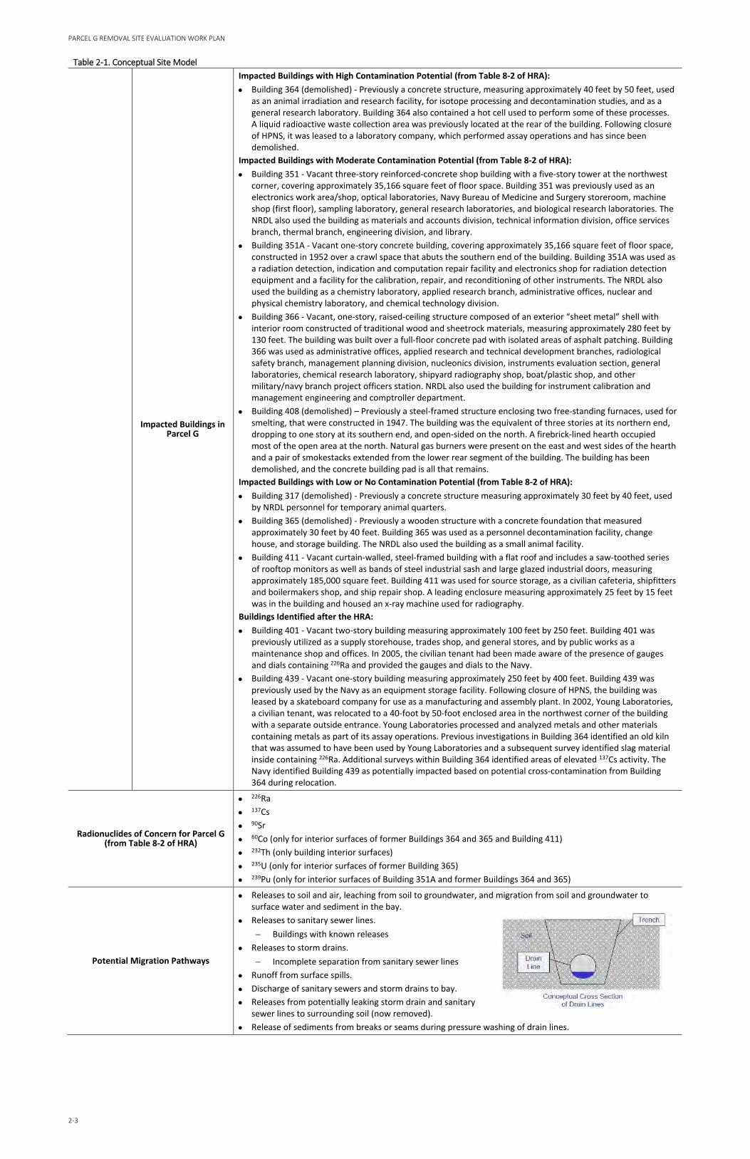
• Releases to soil and air, leaching from soil to groundwater, and migration from soil and groundwater tosurface water and sediment in the bay.
• Releases to sanitary sewer lines.− Buildings with known releases
• Releases to storm drains.− Incomplete separation from sanitary sewer lines
• Runoff from surface spills.• Discharge of sanitary sewers and storm drains to bay.• Releases from potentially leaking storm drain and sanitary
sewer lines to surrounding soil (now removed).• Release of sediments from breaks or seams during pressure washing of drain lines.
Conceptual Cross Section of Drain Lines
SECTION 2 – CONCEPTUAL SITE MODEL
2-4
Table 2-1. Conceptual Site Model
Potential Exposure Pathways
• Soil:− External radiation from ROCs− Incidental ingestion and inhalation of soil and dust with ROCs for intrusive activities disturbing soil beneath
the durable cover (only construction worker receptor) • Building surfaces:
− External radiation from ROCs− Inhalation and incidental ingestion of resuspended radionuclides
Current Status
• HPNS is not an active military installation. In 1991, HPNS was selected for closure pursuant to the terms of theDefense BRAC Act of 1990. For more than 20 years, the Navy leased many HPNS buildings to private tenantsand Navy-related entities for industrial and artistic uses. Current leases include art studios and a policedepartment facility. Parcels A, D-2, and UC-1 have been transferred to the City and County of San Francisco fornondefense use, and the remaining areas of HPNS are also planned to be transferred.
• All known sources removed by Navy using standards at the time.− Follow-up investigations resulted in removal of small volumes of soil to meet current RGs
• Sanitary sewer and storm drain removal investigation conducted at Parcel G from 2007 to 2011.− More than 4 miles of trench lines and 50,000 cubic yards of soil investigated and disposed of or cleared
for use as onsite fill− Trench excavations that have been backfilled now contain homogenized soil from onsite fill, offsite fill, or
a mixture of both
Uncertainties
• Lower potential for radiological contamination than originally described in historical CSMs based on thefollowing lines of evidence:− Known sources have been removed.− Sanitary sewers and storm drains periodically power washed before 2000.− Sanitary sewers and storm drains, and 1 foot of soil surrounding the pipe removed. The sewer lines were
removed to within 10 feet of all buildings. Impacted buildings had remaining lines removed duringsurveys of the buildings. Non-impacted buildings had surveys performed at ends of pipes, and pipeswere capped.
− Any residual concentrations may be modified by radiological decay (shorter-lived radionuclides, such as137Cs and 90Sr) or remobilization (including weathering and migration).
− Sediment data from inside pipe not indicative of a large quantity disposal or contamination (maximum226Ra concentration of 4.2369 pCi/g and maximum 137Cs concentration of 0.87795 pCi/g in Parcel G).
− Overestimate of 226Ra concentrations in soil by the onsite laboratory using an imprecise measurementmethod.
− LLRW bins were tested by the Navy’s independent waste broker at an offsite laboratory using 5-pointcomposites, and only 3 out of 1,411 bins had results with 226Ra above the RGs.
• Potential for data manipulation or falsification.• Data quality deficiencies.• 137Cs and 90Sr are present at HPNS because of global fallout from nuclear testing or accidents, in addition to
Navy activities. Because of backfill activities, 137Cs and 90Sr from fallout and Navy activities are not necessarilyonly on the surface and may be present in both surface and subsurface soil.
• Potential for isolated radiological commodities randomly distributed around the site.• Trenches where scan data exceeded the investigation level and biased soil samples were not collected.
Notes: 60Co = cobalt-60 90Sr = strontium-90 137Cs = cesium-137 232Th = thorium-232 235U = uranium-235 239Pu = plutonium-239 BRAC = Base Realignment and Closure LLRW = low-level radioactive waste NORM = naturally occurring radiological material NRDL = Navy Radiological Defense Laboratory pCi/g = picocurie(s) per gram
SECTION 3
3-1
Soil Investigation Design and Implementation This section describes the data quality objectives (DQOs), ROCs, RGs, investigation levels, and radiological investigation design and implementation for Parcel G soil.
3.1 Data Quality Objectives The DQOs for the soil investigation are as follows:
• Step 1-State the Problem: There have been various allegations of data manipulation or falsificationcommitted by a contractor during past sanitary sewer and storm drain removal actions and currentand former building investigations for soil. The Technical Team evaluated soil data and foundevidence of potential manipulation and falsification. The findings call into question the reliability ofsoil data and there is uncertainty whether radiological contamination was present or remains inplace. Therefore, the property is unable to be transferred as planned. Based on the uncertainty andthe description of radiological activities in the HRA, there is a potential for residual radioactivity tobe present in soil.
• Step 2-Identify the Objective: The primary objective is to determine whether site conditions arecompliant with the Parcel G ROD RAO (Navy, 2009).
• Step 3-Identify Inputs to the Objective: The inputs include surface soil and subsurface soil analyticaldata for ROCs and gamma scan survey measurements to identify bias soil sample locations. RBAsurface and subsurface soil analytical data for ROCs will also be used to confirm, or update asnecessary, estimates of naturally occurring and man-made background levels for ROCs notattributed to Naval operations at HPNS.
• Step 4-Define the Study Boundaries: See Phases 1 and 2 trench units (TUs)/survey units (SUs) listedin Tables 3-1 through 3-3 and shown on Figure 3-1.
• Step 5-Develop Decision Rules:
− If the investigation results demonstrate that site conditions are compliant with the Parcel GRAO, then a remedial action completion report (RACR) will be developed. The RACR will describethe results of the investigation and will provide a demonstration that radioactivity levels meetthe Parcel G RAO or represent background conditions.
− If the investigation results demonstrate that site conditions are not compliant with the Parcel GRAO and exceed background levels, then the data will be evaluated to determine whether siteconditions are protective of human health using USEPA’s current guidance on Radiation RiskAssessment at Comprehensive Environmental Response, Compensation, and Liability Act(CERCLA) Sites (USEPA, 2014). A Removal Site Evaluation Report will be developed to includerecommendations for further action.
• Step 6-Specify the Performance Criteria: The data evaluation process for demonstrating compliancewith the Parcel G ROD RAO is presented herein, depicted on Figure 3-2, and detailed in Section 5.
− Compare each ROC concentration for every sample to the corresponding RG presented inSection 3.3.
If all concentrations for all ROCs for all samples are less than or equal to the RGs, thencompliance with the Parcel G ROD RAO is achieved and a RACR will be prepared.
PARCEL G REMOVAL SITE EVALUATION WORK PLAN
3-2
If any 226Ra gamma spectroscopy concentration is greater than the RG for 226Ra, then the soil sample will be analyzed for 238U and 226Ra using comparable analytical methods (e.g., alpha spectrometry for 238U and radon emanation for 226Ra). For that specific sample, the 238U alpha spectrometry result will be used as a more representative estimate of the background value for 226Ra, and the alpha spectrometry comparable result for 226Ra will be compared to the RG for 226Ra using the revised background value.
If any result is greater than the RG and it cannot be attributed to background levels, then a Removal Site Evaluation Report will be prepared.
• Step 7-Develop the Plan for Obtaining Data:
− Phase 1 TUs/SUs – The radiological investigation will be conducted on a targeted group of 21 of the 63 TUs associated with former sanitary sewers and storm drains and 14 of the 28 SUs3 associated with surface soil at building sites in Parcel G (see Figure 3-1). For Phase 1 TUs, the durable cover (including asphalt, asphalt base course, concrete, gravel, debris, or obstacles) will be removed to expose the target soils. The Phase 1 SUs will be investigated by conducting a 100 percent gamma scan of the surface soil, along with sample collection from systematic and bias locations. For TUs associated with former sanitary sewers and storm drains (from 1 to 22 feet deep), soil will be excavated to the original TU boundaries, as practicable. Following excavation to the original TU boundaries, additional excavation of approximately 6 inches of the trench sidewalls and floors will be performed to provide ex-situ scanning and sampling of the trench sidewalls and floors. Excavated soil will be 100% gamma scanned by one of two methods; soil may be laid out on Radiological Screening Yard (RSY) pads for a surface scan, or soil may be processed and scanned using automated soil segregation technology. Systematic and bias samples will be collected from the excavated soil for offsite analysis.
− Phase 2 TUs/SUs – Additional soil sampling will be conducted on the remaining 42 TUs and 14 SUs in Parcel G (see Figure 3-1). For TUs associated with former sanitary sewers and storm drains (from 1 to 22 feet deep), subsurface soil samples will be collected via borings from soil within the former trench boundaries and from soil representing the former trench walls and floors, as practicable. The borings will be advanced approximately 6 inches below the depth of previous excavation and will be gamma scanned upon retrieval. For surface soil SUs, systematic samples will be collected from underneath the durable cover layer.
− The soil samples collected as part of the Phase 1 and Phase 2 investigations will be analyzed for the applicable ROCs by accredited offsite laboratories and the results will be evaluated as described in Step 6. Global positioning system (GPS) location correlated results will be collected or surveying conducted to facilitate relocation if further investigation is warranted.
3.2 Radionuclides of Concern The ROCs for Parcel G soil are based on the HRA (NAVSEA, 2004) and ROD (Navy, 2009) as presented in Table 3-4.
3 There was previously a total of 32 SUs investigated at Buildings 317/364/365 Former Building Site and Building 351A Crawl Space; however, some SU areas overlapped. For the Buildings 317/364/365 Former Building Site, former SU 22 overlaps TU-153 and will be investigated as part of TU-153. For the Building 351A Crawl Space, former SU-R, SU-S, and SU-U overlapped SU-M, SU-N, and SU-O and will be investigated as SU-M, SU-N, and SU-O.
SECTION 3 – SOIL INVESTIGATION DESIGN AND IMPLEMENTATION
3-3
Table 3-4. Soil Radionuclides of Concern Soil Area Radionuclide of Concern
Former Sanitary Sewer and Storm Drain Lines and Building 351A Crawl Space
137Cs, 226Ra, 90Sr
Former Buildings 317/364/365 Site 137Cs, 226Ra, 90Sr, 239Pu
3.3 Remediation Goals The soil data from the radiological investigation will be evaluated to determine whether site conditions are compliant with the RAO in the Parcel G ROD (Navy, 2009). The RAO is to prevent exposure to ROCs in concentrations that exceed RGs for all potentially complete exposure pathways. The RG for each ROC is presented in Table 3-5. The soil data will be compared to the RGs using a single sample comparison and evaluated as described in Section 5.
Table 3-5. Soil Remediation Goals
Radionuclide Residential Soil Remediation Goala
(pCi/g)
137Cs 0.113
239Pu 2.59
226Ra 1.0
90Sr 0.331 aAll RGs will be applied as concentrations above background.
3.3.1 Investigation Levels Investigation levels are media-specific, radionuclide-specific concentrations, or activity levels based on the RGs that trigger a response, such as further investigation, if the investigation level is exceeded.
Investigation levels are provided in units of the instrument’s response (counts per minute [cpm] or pCi/g), that are used to indicate when additional investigations (Section 5) are required. Investigation levels are established for each instrument and vary with SU classification and measurement type. Scan survey measurements will be flagged when they exceed investigation levels.
For gamma scan survey measurements collected, individual measurement results above the RGs will prompt investigations that may result in the collection of bias samples or additional field measurements to determine the areal extent of the elevated activity. The investigation levels for soil are presented in Table 3-6. Because the investigation levels presented in Table 3-6 are radionuclide-specific, gamma scan surveys will be performed using detector systems equipped with gamma spectroscopy to provide real-time radionuclide-specific measurements. The spectra will be evaluated using regions of interest peak identification tools for the ROCs that correspond to gamma rays at 186 kiloelectron volt (keV) for 226Ra, 609 keV (226Ra daughter bismuth-214 [214Bi]), and 662 keV for 137Cs.
Table 3-6. Soil Survey Measurement Investigation Levels Radionuclide Flag Scan Measurement When: Investigation Level (pCi/g)
226Ra 100% of RG 1.0
137Cs 100% of RG Not Applicablea
PARCEL G REMOVAL SITE EVALUATION WORK PLAN
3-4
Table 3-6. Soil Survey Measurement Investigation Levels Radionuclide Flag Scan Measurement When: Investigation Level (pCi/g) aGamma scan surveys will not detect 137Cs at 0.113 pCi/g.
3.4 Radiological Investigation Design This section describes the design of the radiological investigation, including gamma scan surveys and soil sampling. The radiological investigation design is primarily based on methods, techniques, and instrument systems in the Basewide Radiological Management Plan (TtEC, 2012) with the ultimate requirement to demonstrate compliance with the Parcel G ROD RAO (Navy, 2009). The SAP provides additional guidance on soil sampling, chain-of custody, laboratory analysis, and quality assurance (QA)/quality control (QC) requirements.
There are two types of Parcel G soil investigations discussed in this section to include surveys of:
• Surface and subsurface soil associated with former sanitary sewer and storm drain lines (TUs) • Surface soil areas associated with soil from building sites (SUs)
A phased investigation approach is planned. For surface and subsurface soil associated with former sanitary sewer and storm drain lines, Phase 1 includes the radiological investigation of 21 previously established TUs and Phase 2 includes the remaining 42 TUs in Parcel G. Similarly, for surface soil areas associated with soil from building sites, Phase 1 includes the radiological investigation of 14 of the 28 SUs4 and Phase 2 includes the remaining 14 SUs in Parcel G.
The principal features of the investigation protocol to be applied to the Parcel G soil TUs and SUs are discussed herein and include the following:
• Number of samples • Locating samples • Establishing radiological background • TU design • SU design
To the extent possible, manual data entries will be reduced or eliminated through use of electronic data collection and transfer processes.
3.4.1 Number of Samples Following the previously established protocol (TtEC, 2012), a minimum of 18 systematically located samples will be collected from each TU or SU.
3.4.2 Locating Samples Systematic soil samples will be located using Visual Sample Plan (VSP) software (or equivalent). Each TU or SU will be mapped in VSP, such that at a minimum, 18 systematic soil samples will be collected in each TU or SU. The systematic soil samples will be plotted using a random start triangular grid using the VSP software with GPS coordinates for each systematic sample.
4 There was previously a total of 32 SUs investigated at Buildings 317/364/365 Former Building Site and Building 351A Crawl Space; however, some SU areas overlapped. For the Buildings 317/364/365 Former Building Site, former SU-22 overlaps TU-153 and will be investigated as part of TU-153. For the Building 351A Crawl Space, former SU-R, SU-S, and SU-U overlapped SU-M, SU-N, and SU-O and will be investigated as SU-M, SU-N, and SU-O.
SECTION 3 – SOIL INVESTIGATION DESIGN AND IMPLEMENTATION
3-5
3.4.3 Radiological Background The RGs presented in Table 3-5 are incremental concentrations above background; therefore, RBA samples and measurements will be collected and evaluated to provide generally representative data sets estimating natural background and fallout levels of man-made radionuclides for the majority of soils at HPNS. The RBA characterization will incorporate three survey techniques: gamma scans, surface soil sampling, and subsurface soil sampling to support data evaluations. The details on soil locations, surveying, sampling, and data evaluation are presented in the Soil RBA Work Plan (Appendix A).
3.4.4 Phase 1 Trench Unit Design Radiological investigations will be conducted on a targeted group of 21 of the 63 TUs associated with former sanitary sewer and storm drain lines (Figure 3-1). The former TUs selected for Phase 1 investigation were based on their location adjacent to (downstream/upstream) impacted buildings and considered the recommendations from the Radiological Data Evaluation Findings Report (Navy, 2017). The name, size, and boundary of the TUs will be based on the previous plans and reports (Table 3-1).
The Phase 1 TUs will be re-excavated to the previous excavation limits by making reasonable attempts to ensure accuracy in relocating the former TU boundaries (see Section 3.6.2.1). The excavated soil material will be investigated by gamma scan surveys and systematic and bias soil sample collection following either the automated soil sorting system process (Section 3.6.3.1) or the RSY process (Section 3.6.3.2).
To address the Phase 1 radiological investigations of the former trench sidewalls and floors, a strategy to not only excavate the former trenches to the previous excavation limits, but to over-excavate at least an additional 6 inches outside the estimated previous boundaries of the sidewalls and bottom will be employed. The exhumed over-excavated material will represent the trench sidewalls and bottom and will be gamma scan-surveyed and sampled ex situ, to provide the following benefits:
• Significant improvement of the measurement quality for gamma scan surveys by controlling the measurement geometry.
− Material thickness will not exceed 6 inches − Use of large-volume sodium iodide (NaI) detectors with shielding − Use of large-volume NaI detectors with spectroscopy
• Reducing the potential safety risks associated with in situ trench sidewall and bottom scanning and sampling.
• Reducing the water management required to de-water trenches to provide unsaturated material to investigate.
• Increasing assurance that all potentially impacted materials are investigated because of the inherent limitations of finding exact boundaries.
The over-excavated material (representing sidewalls and floors) will be investigated in the same fashion as the excavated soil by gamma scan surveys and soil sample collection by soil sorting system process (Section 3.6.3.1) or RSY process (Section 3.6.3.2). The over-excavated material representing trench sidewalls and floors will be maintained as separate volumes (e.g., piles) of soil from the original excavated soil. An example Phase 1 TU location is presented on Figure 3-3.
3.4.4.1 Nomenclature of Phase 1 Trench Units The former TUs will be excavated and characterized in “batches” that will be given new unique identifiers at the time of excavation by the geologist or radiation technician. Excavated material representing the backfill material from former TUs will use the following nomenclature format:
PARCEL G REMOVAL SITE EVALUATION WORK PLAN
3-6
AABB-ESU-NNNA
Where: AA = facility (HP for “Hunters Point” will be used in this work plan)
BB = site location (PG for Parcel G will be used in this work plan)
ESU = Excavation Soil Unit
NNN = Former trench unit number
A = alpha-numeric digit (beginning with A, in sequential order)
For example, the third “batch” of backfill TU material excavated from the former TU-69 will be identified as follows:
HPPG-ESU-069C
In this example, “HPPG” identifies Hunters Point Parcel G, “ESU” identifies Excavation Soil Unit, “NNN” identified the unit as being excavated from the former Trench Unit 69, “C” represents the third unit created from excavating this former TU.
Excavated material representing the sidewalls and bottoms of former TUs will use the following nomenclature format:
AABB-SFU-NNNA
Where: AA = facility (HP for “Hunters Point” will be used in this work plan)
BB = site location (PG for Parcel G will be used in this work plan)
SFU = Sidewall Floor Unit
NNN = Former trench unit number
A = alpha-numeric digit (beginning with A, in sequential order)
For example, the first “batch” of sidewall and floor material excavated from the former TU-153 will be identified as follows:
SFU-153A
In this example, “SFU” identifies Sidewall Floor Unit, “NNN” identified the unit as being excavated from the former Trench Unit 153, “A” represents the first unit created from excavating this former trench unit.
3.4.4.2 Size of Phase 1 Trench Units RSY pads are designed to be approximately 1,000 square meters (m2) (TtEC, 2009d and 2012). Using the assumption that material will be assayed in geometries yielding soil column thickness of 6 inches, the volume of a “batch” of excavated material (either ESU or SFU) is calculated as:
1000𝑚𝑚2 × 0.1524𝑚𝑚 (6 𝑖𝑖𝑖𝑖𝑖𝑖ℎ𝑒𝑒𝑒𝑒) = 152𝑚𝑚3
Therefore, an individual ESU or SFU volume will not exceed 152 cubic meters (m3). Converting from m3 to tons of soil (a more commonly used unit), the maximum “batch” size of excavated material will not exceed:
152𝑚𝑚3 ×1.3𝑦𝑦𝑦𝑦3
𝑚𝑚3 ×2,200𝑙𝑙𝑙𝑙𝑒𝑒 𝑒𝑒𝑠𝑠𝑖𝑖𝑙𝑙
𝑦𝑦𝑦𝑦3 ×1𝑡𝑡𝑠𝑠𝑖𝑖
2,000𝑙𝑙𝑙𝑙𝑒𝑒≈ 217 𝑡𝑡𝑠𝑠𝑖𝑖𝑒𝑒 𝑒𝑒𝑠𝑠𝑖𝑖𝑙𝑙
This calculation assumes 2,200 pounds of loose soil per cubic yard, actual field conditions may vary from this assumption. Each former TU will be excavated and managed in no larger than approximately 152 m3 “batches” (that is, ESUs or SFU) and individually stockpiled prior to radiological screening. Using a maximum size of 152 m3, the estimated number of expected ESUs created during the excavation of
SECTION 3 – SOIL INVESTIGATION DESIGN AND IMPLEMENTATION
3-7
backfill from former TUs are listed in Table 3-1. Similarly, using a maximum size of 152m3, the estimated number of expected SFUs created during the over-excavation of former TUs (representing sidewalls and floors) are listed in Table 3-1.
The actual sizes of individual ESUs and SFUs will be determined in the field, based on the actual final excavation limits and volumes of soil material excised from the former trenches.
3.4.5 Phase 2 Trench Unit Design The Phase 2 TUs are listed in Table 3-2 and depicted on Figure 3-1. Investigations of the Phase 2 TUs will consist of a combination of gamma scan surveys and soil samples.
Within the backfill of each previous TU boundary, six systematic locations will be cored down to approximately 6 inches below the depth of previous excavation. Each retrieved core will be scan surveyed along the entire length of the core. Scan measurement results will be evaluated to investigate the potential for small areas of elevated activity in the fill material. A sample will be collected from the top 6 inches of material, and a second sample will be collected from the 6 inches of material just below the previous excavation depth. Additionally, a third sample will be collected from the core segment with the highest scan reading that was not already sampled. A total of at least three samples will be collected from each core. An example graphic showing the sample locations is provided as Figure 3-4.
An additional set of 18 systematic samples will be collected from 6 systematic locations representative of the trench sidewalls. The six systematic core locations will be located approximately 6 inches outside of the previous sidewall excavation limits and will extend 6 inches past the maximum previous excavation depth. In the same fashion described in the previous paragraph, core sections will be retrieved, scanned, and sampled such that at least three samples will be collected from each of the 6 core locations, resulting in at least 18 systematic samples. An example graphic showing the sample locations representing the TU sidewalls is provided as Figure 3-4. The subsurface soil sampling process is detailed in Section 3.6.4.1. The soil samples will be submitted to the offsite analytical laboratory for analysis according to the SAP.
3.4.6 Phase 1 Survey Unit Design Radiological investigations will be conducted on a targeted group of 14 of the 28 SUs associated with soil from building sites where only surface soil scanning and sampling was previously conducted (Figure 3-1). The Phase 1 soil area SUs were selected based on the allegations for potential manipulation or falsification associated with data from the Building 351A Crawl Space (Navy, 2017). The name, size, and boundary of the SUs will be based on the previous plans and reports (Table 3-3).
Each Phase 1 SU will undergo a 100 percent radiological surface gamma scan of accessible areas using an appropriate instrument listed in Section 3.5. The instrument will be composed of a gamma scintillation detector equipped with spectroscopy, which measures gross gamma counts along with radionuclide-specific measurements and is coupled to a data logger that logs the resultant data in conjunction with location. Gross gamma and gamma spectra obtained during the surface gamma scan surveys will be analyzed using region of interest peak identification tools for the ROCs. Elevated areas will be noted on a survey map and flagged in the field for verification. Manual scans using a hand-held instrument may be performed to further delineate suspect areas in the SU. Biased samples will be collected from potential areas of elevated activity displaying gamma scan survey results greater than the investigation level (Section 5.3.1).
Following the completion of the gamma scan surveys, the SU area will be plotted using VSP software (or equivalent) to determine the location of systematic samples. A stylized graphic of an example Phase 1 SU with 18 systematic samples placed using a triangular grid is shown as Figure 3-4. The surface soil sample collection process is detailed in Section 3.6.5.1. The soil samples collected from each SU will be submitted to the offsite analytical laboratory for analysis according to the SAP.
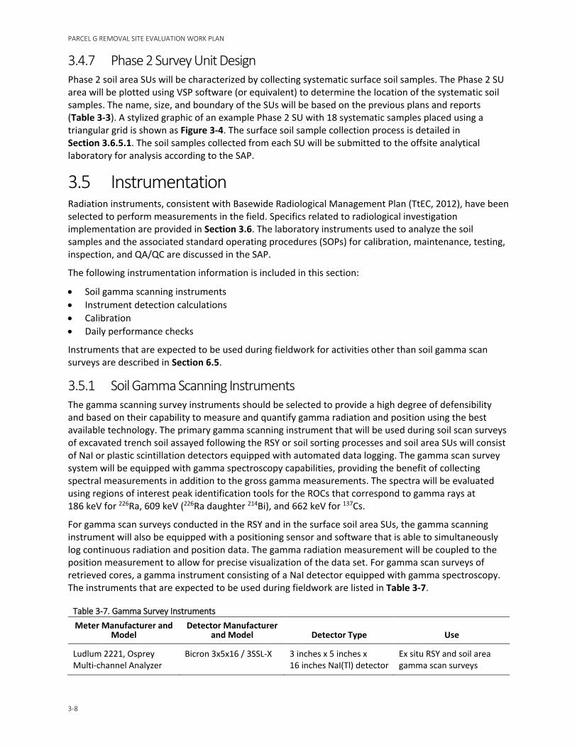
PARCEL G REMOVAL SITE EVALUATION WORK PLAN
3-8
3.4.7 Phase 2 Survey Unit Design Phase 2 soil area SUs will be characterized by collecting systematic surface soil samples. The Phase 2 SU area will be plotted using VSP software (or equivalent) to determine the location of the systematic soil samples. The name, size, and boundary of the SUs will be based on the previous plans and reports (Table 3-3). A stylized graphic of an example Phase 2 SU with 18 systematic samples placed using a triangular grid is shown as Figure 3-4. The surface soil sample collection process is detailed in Section 3.6.5.1. The soil samples collected from each SU will be submitted to the offsite analytical laboratory for analysis according to the SAP.
3.5 Instrumentation Radiation instruments, consistent with Basewide Radiological Management Plan (TtEC, 2012), have been selected to perform measurements in the field. Specifics related to radiological investigation implementation are provided in Section 3.6. The laboratory instruments used to analyze the soil samples and the associated standard operating procedures (SOPs) for calibration, maintenance, testing, inspection, and QA/QC are discussed in the SAP.
The following instrumentation information is included in this section:
• Soil gamma scanning instruments • Instrument detection calculations • Calibration • Daily performance checks
Instruments that are expected to be used during fieldwork for activities other than soil gamma scan surveys are described in Section 6.5.
3.5.1 Soil Gamma Scanning Instruments The gamma scanning survey instruments should be selected to provide a high degree of defensibility and based on their capability to measure and quantify gamma radiation and position using the best available technology. The primary gamma scanning instrument that will be used during soil scan surveys of excavated trench soil assayed following the RSY or soil sorting processes and soil area SUs will consist of NaI or plastic scintillation detectors equipped with automated data logging. The gamma scan survey system will be equipped with gamma spectroscopy capabilities, providing the benefit of collecting spectral measurements in addition to the gross gamma measurements. The spectra will be evaluated using regions of interest peak identification tools for the ROCs that correspond to gamma rays at 186 keV for 226Ra, 609 keV (226Ra daughter 214Bi), and 662 keV for 137Cs.
For gamma scan surveys conducted in the RSY and in the surface soil area SUs, the gamma scanning instrument will also be equipped with a positioning sensor and software that is able to simultaneously log continuous radiation and position data. The gamma radiation measurement will be coupled to the position measurement to allow for precise visualization of the data set. For gamma scan surveys of retrieved cores, a gamma instrument consisting of a NaI detector equipped with gamma spectroscopy. The instruments that are expected to be used during fieldwork are listed in Table 3-7.
Table 3-7. Gamma Survey Instruments Meter Manufacturer and
Model Detector Manufacturer
and Model Detector Type Use
Ludlum 2221, Osprey Multi-channel Analyzer
Bicron 3x5x16 / 3SSL-X 3 inches x 5 inches x 16 inches NaI(Tl) detector
Ex situ RSY and soil area gamma scan surveys
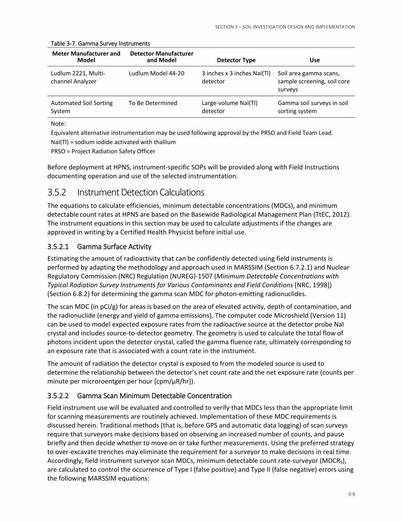
SECTION 3 – SOIL INVESTIGATION DESIGN AND IMPLEMENTATION
3-9
Table 3-7. Gamma Survey Instruments Meter Manufacturer and
Model Detector Manufacturer
and Model Detector Type Use
Ludlum 2221, Multi-channel Analyzer
Ludlum Model 44-20 3 inches x 3 inches NaI(Tl) detector
Soil area gamma scans, sample screening, soil core surveys
Automated Soil Sorting System
To Be Determined Large-volume NaI(Tl) detector
Gamma soil surveys in soil sorting system
Note: Equivalent alternative instrumentation may be used following approval by the PRSO and Field Team Lead. NaI(Tl) = sodium iodide activated with thallium PRSO = Project Radiation Safety Officer
Before deployment at HPNS, instrument-specific SOPs will be provided along with Field Instructions documenting operation and use of the selected instrumentation.
3.5.2 Instrument Detection Calculations The equations to calculate efficiencies, minimum detectable concentrations (MDCs), and minimum detectable count rates at HPNS are based on the Basewide Radiological Management Plan (TtEC, 2012). The instrument equations in this section may be used to calculate adjustments if the changes are approved in writing by a Certified Health Physicist before initial use.
3.5.2.1 Gamma Surface Activity Estimating the amount of radioactivity that can be confidently detected using field instruments is performed by adapting the methodology and approach used in MARSSIM (Section 6.7.2.1) and Nuclear Regulatory Commission (NRC) Regulation (NUREG)-1507 (Minimum Detectable Concentrations with Typical Radiation Survey Instruments for Various Contaminants and Field Conditions [NRC, 1998]) (Section 6.8.2) for determining the gamma scan MDC for photon-emitting radionuclides.
The scan MDC (in pCi/g) for areas is based on the area of elevated activity, depth of contamination, and the radionuclide (energy and yield of gamma emissions). The computer code Microshield (Version 11) can be used to model expected exposure rates from the radioactive source at the detector probe NaI crystal and includes source-to-detector geometry. The geometry is used to calculate the total flow of photons incident upon the detector crystal, called the gamma fluence rate, ultimately corresponding to an exposure rate that is associated with a count rate in the instrument.
The amount of radiation the detector crystal is exposed to from the modeled source is used to determine the relationship between the detector’s net count rate and the net exposure rate (counts per minute per microroentgen per hour [cpm/µR/hr]).
3.5.2.2 Gamma Scan Minimum Detectable Concentration Field instrument use will be evaluated and controlled to verify that MDCs less than the appropriate limit for scanning measurements are routinely achieved. Implementation of these MDC requirements is discussed herein. Traditional methods (that is, before GPS and automatic data logging) of scan surveys require that surveyors make decisions based on observing an increased number of counts, and pause briefly and then decide whether to move on or take further measurements. Using the preferred strategy to over-excavate trenches may eliminate the requirement for a surveyor to make decisions in real time. Accordingly, field instrument surveyor scan MDCs, minimum detectable count rate-surveyor (MDCRS), are calculated to control the occurrence of Type I (false positive) and Type II (false negative) errors using the following MARSSIM equations:
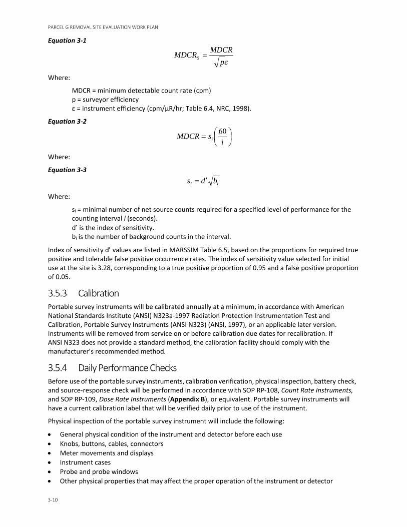
PARCEL G REMOVAL SITE EVALUATION WORK PLAN
3-10
Equation 3-1
Where:
MDCR = minimum detectable count rate (cpm) p = surveyor efficiency ε = instrument efficiency (cpm/µR/hr; Table 6.4, NRC, 1998).
Equation 3-2
Where:
Equation 3-3
Where:
si = minimal number of net source counts required for a specified level of performance for the counting interval i (seconds).
d′ is the index of sensitivity. bi is the number of background counts in the interval.
Index of sensitivity d′ values are listed in MARSSIM Table 6.5, based on the proportions for required true positive and tolerable false positive occurrence rates. The index of sensitivity value selected for initial use at the site is 3.28, corresponding to a true positive proportion of 0.95 and a false positive proportion of 0.05.
3.5.3 Calibration Portable survey instruments will be calibrated annually at a minimum, in accordance with American National Standards Institute (ANSI) N323a-1997 Radiation Protection Instrumentation Test and Calibration, Portable Survey Instruments (ANSI N323) (ANSI, 1997), or an applicable later version. Instruments will be removed from service on or before calibration due dates for recalibration. If ANSI N323 does not provide a standard method, the calibration facility should comply with the manufacturer’s recommended method.
3.5.4 Daily Performance Checks Before use of the portable survey instruments, calibration verification, physical inspection, battery check, and source-response check will be performed in accordance with SOP RP-108, Count Rate Instruments, and SOP RP-109, Dose Rate Instruments (Appendix B), or equivalent. Portable survey instruments will have a current calibration label that will be verified daily prior to use of the instrument.
Physical inspection of the portable survey instrument will include the following:
• General physical condition of the instrument and detector before each use • Knobs, buttons, cables, connectors • Meter movements and displays • Instrument cases • Probe and probe windows • Other physical properties that may affect the proper operation of the instrument or detector
εpMDCRMDCRS =
=
isMDCR i
60
ii bds ′=

SECTION 3 – SOIL INVESTIGATION DESIGN AND IMPLEMENTATION
3-11
Any portable survey instrument or detector having a questionable physical condition will not be used until problems have been corrected. A battery check will be performed to ensure that sufficient voltage is being supplied to the detector and instrument circuitry for proper operation. This check will be performed in accordance with the instrument’s operations manual. The instrument will be exposed to the appropriate (alpha, beta, gamma) check source to verify that the instrument response is within the plus or minus 20 percent range determined during the initial response check. The calibration certificates and daily QA/QC records for each instrument used and the instrument setup test records will be provided in the project report.
If any portable survey instrument, or instrument and detector combination, having a questionable physical condition that cannot be corrected fails any of the operation checks stated in SOP RP-108, Count Rate Instruments, or SOP RP-109, Dose Rate Instruments (Appendix B), or has exceeded its annual calibration date without Project Radiation Safety Officer (PRSO) approval, the instrument will be put in an “out of service” condition. This is done by placing an “out of service” tag or equivalent on the instrument and securing the instrument or the instrument and detector combination in a separate area such that the instrument and instrument and detector combination cannot be issued for use. The PRSO and Radiological Control Technician (RCT) and their respective supervisors will be notified immediately when any survey instrumentation has been placed “out of service.” Instruments tagged as “out of service” will not be returned to service until all deficiencies have been corrected. The results of the daily operation checks, previously discussed, will be documented.
3.6 Radiological Investigation Implementation This section provides guidance on the implementation of radiological investigations for soil.
3.6.1 Premobilization Activities Before initiating field investigations, several premobilization steps will be completed to ensure that the work can be conducted in a safe and efficient manner. The primary premobilization tasks include training of field personnel and procurement of support services.
A list of the various support services that are anticipated to be required are as follows:
• Radiological analytical laboratory services • Drilling subcontractor • Civil surveying subcontractor • Utility location subcontractor • Vegetation clearance subcontractor • Transport (trucking) subcontractor • Concrete coring subcontractor
3.6.1.1 Training Requirements Any non-site-specific training required for field personnel shall be performed before mobilization to the extent practical. Training requirements are outlined in Section 6.
Medical examinations, medical monitoring, and training shall be conducted in accordance with the APP/SSHP and Section 6 requirements.
In addition to health and safety-related training, other training may be required as necessary including but not limited to the following:
• Aerial Lift (for personnel working from aerial lifts) • Fall Protection (for personnel working at heights greater than 5 feet) • Equipment as required (for example, fork lift, skid steer, loader, back hoe, excavator)

PARCEL G REMOVAL SITE EVALUATION WORK PLAN
3-12
3.6.1.2 Permitting and Notification Before initiation of field activities for the radiological investigation, the contractor will notify the Navy Remedial Project Manager (RPM), Resident Officer in Charge of Construction (ROICC), Radiological Affairs Support Office (RASO), and HPNS security as to the nature of the anticipated work. Any required permits to conduct the fieldwork will be obtained before mobilization.
The contractor will notify the California Department of Public Health at least 14 days before initiation of activities involving the Radioactive Material License.
3.6.1.3 Pre-construction Meeting A pre-construction meeting will be held before mobilization of equipment and personnel. The purpose of the meeting will be to discuss project-specific topics, roles and responsibilities of project personnel, project schedule, health and safety concerns, and other topics that require discussions before field mobilization. Representatives of the following will attend the pre-construction meeting:
• Navy (RPM, RASO, ROICC, and others as applicable)
• Contractor (Project Manager, Site Construction Manager, Project QC Manager, PRSO, and Site Safety and Health Officer [SSHO])
• Subcontractors as appropriate
3.6.2 Mobilization Activities Mobilization activities will include site preparation, movement of equipment and materials to the site, and orientation and training of field personnel.
At least 2 weeks before mobilization, the appropriate Navy personnel, including the Navy RPM and ROICC and Caretaker Site Office, will be notified regarding the planned schedule for mobilization and site remediation activities. Upon receipt of the appropriate records and authorizations, field personnel, temporary facilities, and required construction materials will be mobilized to the site.
The temporary facilities will include restrooms, hand-washing stations, and one or more secure storage (Conex) boxes for short- and long-term storage of materials, if needed.
The applicable activity hazard analysis (AHAs) forms will be reviewed prior to starting work.
All equipment mobilized to the site will undergo baseline radioactivity surveys in accordance with Section 6. Surveys will include directs scans, static measurements, and swipe samples. Equipment that fails baseline surveying will be removed from the site immediately.
3.6.2.1 Locating and Confirming Boundaries The first step to begin the radiological investigations is locating and marking the boundaries of the former TUs and SUs. This will be accomplished by using best management practices (BMPs) to identify boundaries and depths of the former TUs and SUs based on the previous TtEC reports (for example, survey reports, drawings, and sketches), field observations (such as GPS locations from geo-referencing, borings, and visual inspection), and durable cover as-built records. Once the boundaries are located, the areas will be marked with paint or pin flags.
3.6.2.2 Site Preparation After boundary location and mark-outs are completed, the following steps will be implemented to prepare the site for investigation and facilitating access.
• A radiologically controlled area (RCA) will be established around work areas and delineated with temporary fencing or caution tape, or equivalent, and have the appropriate warning signage posted. Access control points will be established and maintained. Radiological screening of personnel,
SECTION 3 – SOIL INVESTIGATION DESIGN AND IMPLEMENTATION
3-13
equipment, and materials will be required when exiting the RCA. The RCA will be posted consistent with the requirements of the Radiation Protection Plan and SOP RP-102, Radiological Postings (Appendix B). Routine surveys and inspections will be performed along the fence line, consisting of dose rate measurements and visual inspections. Surveys will be performed to ensure that there is no change in dose readings in accessible areas that could negatively affect the public or environment. Any breaches in the fence during site activities will be repaired.
• Stormwater, sediment, and erosion control measures will be implemented to prevent soil from entering and leaving the site as detailed in Section 8.
• Dust control methods and air monitoring will be implemented during intrusive activities as detailed in Section 8.
• Underground Service Alert will be contacted at least 72 hours before initiating intrusive activities. Colored marking paint (or stakes or equivalent) will be used to mark identified utilities, if any, within the proposed work area. An exclusion area will be placed around active utilities to prevent accidental exposure to the utility, based on the utility hazard or importance. Utility lines encountered will be assumed active, unless specifically determined to be inactive through consultation with the subject utility company and with the CSO representative, ROICC, and RPM.
• For Phase 1 TUs, the durable cover (including asphalt, asphalt base course, concrete, gravel, debris, or obstacles) will be removed to expose the target soils. Because of the inherent difficulty expected to determine the exact horizontal boundaries of the previous excavation and to provide access to the TU, an additional 1 foot of durable cover buffer beyond the former excavation surface boundary will be removed. After the durable cover is removed, attempts will be made to confirm the delineation between fill materials and native soils by reviewing cut-and-fill drawings and visual inspections.
• Durable cover materials, listed above, will require release surveys prior to offsite disposal. Release surveys of the materials will be performed according to SOP RP-105, Unrestricted Release Requirements (Appendix B).
3.6.3 Phase 1 Trench Unit Investigation Once all site preparation activities previously described are completed, TU investigation activities will commence.
Each former TU will be excavated to the original excavation limits and evaluated in approximately 152 m3 ESUs. The excavated material will then undergo radiological assay following either the automated soil sorting process or RSY pad process as described in the following sections. One hundred percent of the Phase 1 ESU soils will undergo scan surveys using real-time gamma spectroscopy equipment in the soil sorting process or the RSY pad process. Details on the scanning instrumentation can be found in Section 3.5.
Once the excavation to the original excavation limits has been complete, over-excavation of at least an additional 6 inches outside the estimated previous boundaries of the sidewalls and bottom will be initiated. This exhumed over-excavated material (SFU) will be maintained separate from the backfill volumes (ESU) and will represent the trench sidewalls and bottom. The over-excavated material (SFUs) will be investigated in the same fashion as the excavated soil (ESU) methodology by gamma scan surveys and soil sample collection (soil sorting system process or RSY process). Following completion of scanning activities, the ESU and SFU material will be returned to the same trench that the material originated from.
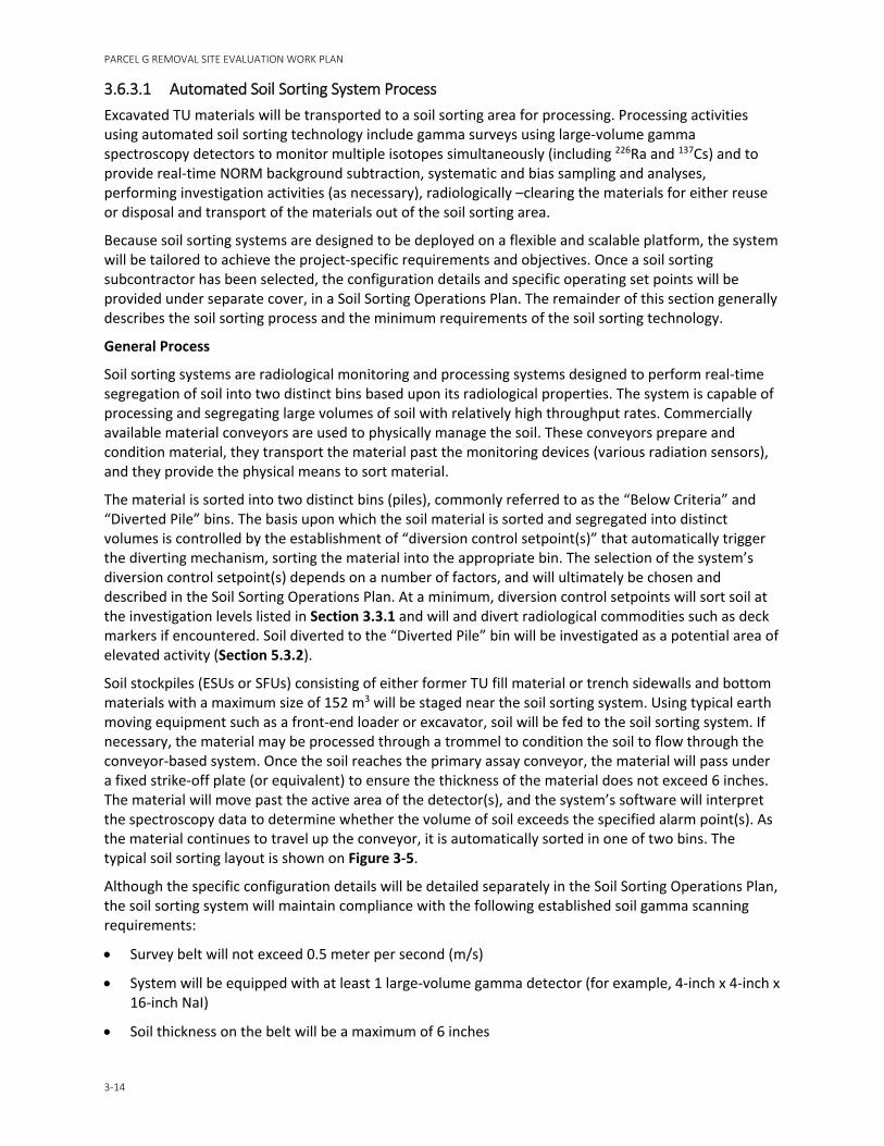
PARCEL G REMOVAL SITE EVALUATION WORK PLAN
3-14
3.6.3.1 Automated Soil Sorting System Process Excavated TU materials will be transported to a soil sorting area for processing. Processing activities using automated soil sorting technology include gamma surveys using large-volume gamma spectroscopy detectors to monitor multiple isotopes simultaneously (including 226Ra and 137Cs) and to provide real-time NORM background subtraction, systematic and bias sampling and analyses, performing investigation activities (as necessary), radiologically –clearing the materials for either reuse or disposal and transport of the materials out of the soil sorting area.
Because soil sorting systems are designed to be deployed on a flexible and scalable platform, the system will be tailored to achieve the project-specific requirements and objectives. Once a soil sorting subcontractor has been selected, the configuration details and specific operating set points will be provided under separate cover, in a Soil Sorting Operations Plan. The remainder of this section generally describes the soil sorting process and the minimum requirements of the soil sorting technology.
General Process
Soil sorting systems are radiological monitoring and processing systems designed to perform real-time segregation of soil into two distinct bins based upon its radiological properties. The system is capable of processing and segregating large volumes of soil with relatively high throughput rates. Commercially available material conveyors are used to physically manage the soil. These conveyors prepare and condition material, they transport the material past the monitoring devices (various radiation sensors), and they provide the physical means to sort material.
The material is sorted into two distinct bins (piles), commonly referred to as the “Below Criteria” and “Diverted Pile” bins. The basis upon which the soil material is sorted and segregated into distinct volumes is controlled by the establishment of “diversion control setpoint(s)” that automatically trigger the diverting mechanism, sorting the material into the appropriate bin. The selection of the system’s diversion control setpoint(s) depends on a number of factors, and will ultimately be chosen and described in the Soil Sorting Operations Plan. At a minimum, diversion control setpoints will sort soil at the investigation levels listed in Section 3.3.1 and will and divert radiological commodities such as deck markers if encountered. Soil diverted to the “Diverted Pile” bin will be investigated as a potential area of elevated activity (Section 5.3.2).
Soil stockpiles (ESUs or SFUs) consisting of either former TU fill material or trench sidewalls and bottom materials with a maximum size of 152 m3 will be staged near the soil sorting system. Using typical earth moving equipment such as a front-end loader or excavator, soil will be fed to the soil sorting system. If necessary, the material may be processed through a trommel to condition the soil to flow through the conveyor-based system. Once the soil reaches the primary assay conveyor, the material will pass under a fixed strike-off plate (or equivalent) to ensure the thickness of the material does not exceed 6 inches. The material will move past the active area of the detector(s), and the system’s software will interpret the spectroscopy data to determine whether the volume of soil exceeds the specified alarm point(s). As the material continues to travel up the conveyor, it is automatically sorted in one of two bins. The typical soil sorting layout is shown on Figure 3-5.
Although the specific configuration details will be detailed separately in the Soil Sorting Operations Plan, the soil sorting system will maintain compliance with the following established soil gamma scanning requirements:
• Survey belt will not exceed 0.5 meter per second (m/s)
• System will be equipped with at least 1 large-volume gamma detector (for example, 4-inch x 4-inch x 16-inch NaI)
• Soil thickness on the belt will be a maximum of 6 inches
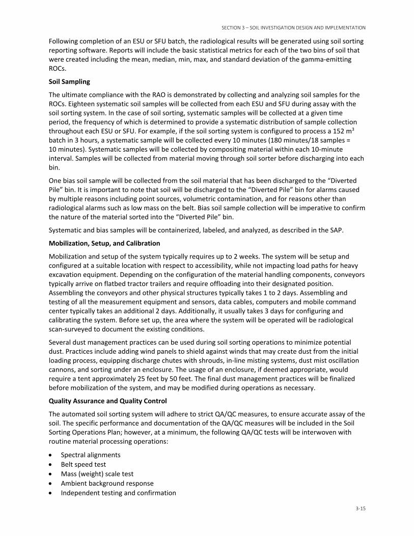
SECTION 3 – SOIL INVESTIGATION DESIGN AND IMPLEMENTATION
3-15
Following completion of an ESU or SFU batch, the radiological results will be generated using soil sorting reporting software. Reports will include the basic statistical metrics for each of the two bins of soil that were created including the mean, median, min, max, and standard deviation of the gamma-emitting ROCs.
Soil Sampling
The ultimate compliance with the RAO is demonstrated by collecting and analyzing soil samples for the ROCs. Eighteen systematic soil samples will be collected from each ESU and SFU during assay with the soil sorting system. In the case of soil sorting, systematic samples will be collected at a given time period, the frequency of which is determined to provide a systematic distribution of sample collection throughout each ESU or SFU. For example, if the soil sorting system is configured to process a 152 m3 batch in 3 hours, a systematic sample will be collected every 10 minutes (180 minutes/18 samples = 10 minutes). Systematic samples will be collected by compositing material within each 10-minute interval. Samples will be collected from material moving through soil sorter before discharging into each bin.
One bias soil sample will be collected from the soil material that has been discharged to the “Diverted Pile” bin. It is important to note that soil will be discharged to the “Diverted Pile” bin for alarms caused by multiple reasons including point sources, volumetric contamination, and for reasons other than radiological alarms such as low mass on the belt. Bias soil sample collection will be imperative to confirm the nature of the material sorted into the “Diverted Pile” bin.
Systematic and bias samples will be containerized, labeled, and analyzed, as described in the SAP.
Mobilization, Setup, and Calibration
Mobilization and setup of the system typically requires up to 2 weeks. The system will be setup and configured at a suitable location with respect to accessibility, while not impacting load paths for heavy excavation equipment. Depending on the configuration of the material handling components, conveyors typically arrive on flatbed tractor trailers and require offloading into their designated position. Assembling the conveyors and other physical structures typically takes 1 to 2 days. Assembling and testing of all the measurement equipment and sensors, data cables, computers and mobile command center typically takes an additional 2 days. Additionally, it usually takes 3 days for configuring and calibrating the system. Before set up, the area where the system will be operated will be radiological scan-surveyed to document the existing conditions.
Several dust management practices can be used during soil sorting operations to minimize potential dust. Practices include adding wind panels to shield against winds that may create dust from the initial loading process, equipping discharge chutes with shrouds, in-line misting systems, dust mist oscillation cannons, and sorting under an enclosure. The usage of an enclosure, if deemed appropriate, would require a tent approximately 25 feet by 50 feet. The final dust management practices will be finalized before mobilization of the system, and may be modified during operations as necessary.
Quality Assurance and Quality Control
The automated soil sorting system will adhere to strict QA/QC measures, to ensure accurate assay of the soil. The specific performance and documentation of the QA/QC measures will be included in the Soil Sorting Operations Plan; however, at a minimum, the following QA/QC tests will be interwoven with routine material processing operations:
• Spectral alignments • Belt speed test • Mass (weight) scale test • Ambient background response • Independent testing and confirmation
PARCEL G REMOVAL SITE EVALUATION WORK PLAN
3-16
3.6.3.2 Radiological Screening Yard Pad Process If a conveyor-based automatic soil sorting system process is not selected, excavated TU material will be assayed using the previously applied RSY process. Excavated TU materials will be transported to an RSY pad and spread approximately 6 inches thick for processing. Processing activities in the RSY pads include gamma scan surveys, using a large-volume gamma scintillator equipped with spectroscopy, systematic and bias sampling and analyses, performing investigation activities (as necessary), radiologically clearing the materials for either reuse or disposal, and transport of the materials off the RSY pads. The objective of the processing activities on the RSY pads is to characterize the material. Material that meets the RGs identified in Table 3-5 will be used as backfill material or shipped offsite as non-LLRW. Before initiating excavation activities at each TU, existing RSY pads will be identified for use or new pads will be constructed. Transport routes between the TU and the selected RSY pads will be established and approved by the Navy before initiating excavation activities at each TU.
Construction of Radiological Screening Yard Pads
If no existing RSY pads are available for use, pads will be constructed to meet the requirements specified in the Basewide Radiological Management Plan (TtEC, 2012) and the RSY Construction Details (TtEC, 2009b). RSY pads will be constructed with a size limit of 1,000 m2. Before construction, the area where the RSY pads will be constructed will be radiological scan-surveyed to document the existing conditions.
Transfer of Excavated Soil for Processing
Excavated TU materials will be transported to the RSY pad by dump truck or other conventional means. Excavated soil entering an RSY must be accompanied by a truck ticket (paper or digital), to facilitate transfer of the material for radiological processing along a designated truck route. This ticket will provide the RSY staff with the following information:
• Location of excavation, including former TU name • Load number • Estimated volume of soil • Date and time of excavation
The RSY personnel will direct the driver to the appropriate RSY pad for soil placement. The truck ticket will be amended with the assigned unique RSY pad number for tracking purposes. Placement of soil on a RSY pad in the RSYs will continue until the soil placed on the RSY pad reaches capacity as identified by the RSY Manager (or designee) and is ready for processing.
Each individual 152 m3 TU stockpile will be loaded into the RSY pad, spread out, and leveled to a maximum depth of 6 inches for investigation.
Investigation
The investigation will include gamma scans over 100 percent of the surface area, systematic, and bias soil sampling. A minimum of 18 systematic soil samples will be collected along with any bias samples based on the results of the gamma scan surveys.
Gamma scans of the soil surfaces will be performed using a GPS coupled to an appropriate gamma scintillation scanning system. The Bicron 3x5x16 NaI detector coupled to a multi-channel analyzer (or equivalent system) will be equipped with spectral capabilities to provide isotopic identification and quantification in additional to gross gamma readings. An instrument-specific SOP will be provided before use.
Using the Bicron 3x5x16 system, the scans will be performed by scanning straight lines at a not-to-exceed rate of 0.5 m/s with a consistent detector distance from the soil surface (4 inches above the surface). Generally, RSY pad lift will be gamma scanned as follows (the following description assumes the RSY area is positioned such that the sides align with north, south, east, west directions):
SECTION 3 – SOIL INVESTIGATION DESIGN AND IMPLEMENTATION
3-17
• Begin with the detector positioned in the southwest corner of the RSY pad at a height of approximately 4 inches above the surface. Orient the system to face north and initiate data collection (detector is automatically logging radiation readings and GPS is automatically logging position readings) so that the system is recording at a rate of one reading per second (or other, as determined by the project Health Physicist).
• Move the detector in the north direction at a not-to-exceed speed of 0.5 m/s.
• Once the detector has reached the edge of the pad, turn the system around (now facing south) and offset the next detector path by the appropriate offset based on the instrument’s detector size (e.g., field of view), to allow for a small overlap in the detector field of view.
• Move the detector in the south direction at a not-to exceed speed of 0.5 m/s.
• Repeat these steps until the RSY pad area has been scan surveyed.
Assuming a 1,000 m2 area for each RSY pad, a survey, as previously described, moving at a speed of 0.5 m/s should result in the collection of a minimum of 2,000 scan measurements per ESU or SFU.
Datasets will be transferred from the data logger onto a personal computer to create spreadsheets and geographic information system-plotted maps. Following completion of the scan survey, the number of scan measurements and the percent coverage (from a plot of the data) will be reviewed to ensure the design parameters of the gamma scan survey were satisfied. Data obtained during the surface gamma scan surveys, including gross gamma, and individual radionuclide spectral measurements, will be analyzed to identify areas where surface radiation levels appear to be greater than the radionuclide-specific investigation levels using regions of interest-peak identification tools. Elevated areas will be noted on a survey map and flagged in the field for verification. Bias samples will be collected from potential areas of elevated activity displaying gamma scan survey results greater than the investigation level (Section 5.3.1).
Each 1,000 m2 RSY pad area will be plotted using VSP software (or equivalent) to determine the location of the 18 systematic soil samples. The systematic soil samples will be plotted using a random start triangular or square grid using the VSP software. Soil samples will be collected from the surface at a depth of 0 to 6 inches. The technique for locating systematic samples is provided in Section 3.4.2. Soil samples will be containerized and submitted to offsite laboratory with appropriate chain-of custody documentation as established in the SAP.
Following completion of scanning activities, the excavated material will be returned to the same trench that the material originated from.
3.6.4 Phase 2 Trench Unit Investigation Investigations of the Phase 2 TUs will consist of a combination of core scan surveys and soil samples.
Six systematic locations will be cored down to approximately 6 inches below the depth of previous excavation within each TU boundary. Soil samples will be collected as described in Section 3.6.4.1. Sanitary sewer and storm drain lines were sometimes installed on bedrock. In these situations, sampling of bedrock will not be performed. If refusal is encountered within 6 inches of the expected depth of the trench, the soil sample will be collected from the deepest section of the core. If refusal is encountered more than 6 inches above the expected depth of the trench, the sample location will be moved to avoid the subsurface obstruction.
To acquire three samples from each location, one surface and one floor sample will be collected from each sample core greater than 4 feet below ground surface (bgs). The sample cores will be scanned for gamma radiation along the entire length of each core using a Ludlum Model 44-20 3-inch by 3-inch NaI (or equivalent) equipped with gamma spectroscopy. Scan measurement results will be evaluated against
PARCEL G REMOVAL SITE EVALUATION WORK PLAN
3-18
the investigation level to identify core section with elevated gamma radiation. Core sections that exceed the investigation level will have bias soil samples collected to investigate the potential for small areas of elevated activity in fill. If no core section exceeds the investigation level, a bias sample will be collected from the core segment with the highest gamma scan reading that was not already sampled, for a total of at least three samples from each core greater than 4 feet. Cores less than 4 feet bgs will have samples collected from the top foot and bottom foot of the core. No scans of the core are required. At least two samples will be collected from each core less than 4 feet.
An additional set of 18 systematic samples will be collected from 6 systematic locations representative of the trench sidewalls. The six core locations will be located within 1 meter of the previous sidewall excavation limits and will extend to the maximum previous excavation depth. In the same action described in the previous paragraph, core sections will be retrieved, scanned, and sampled such that at least three samples will be collected from each of the six core locations, resulting in at least 18 systematic samples when all six cores are greater than 4 feet bgs. An example graphic showing the sample locations representing the TU sidewalls is provided as Figure 3-4.
If GPS reception is available, soil sample locations will be position-correlated with GPS data and recorded. If GPS reception is not available, a reference coordinate system will be established to document gamma scan measurement results and soil sample locations. The reference coordinate system will consist of a grid of intersecting lines referenced to a fixed site location or benchmark. If practical, the GPS coordinates of the fixed location or benchmark will be recorded.
3.6.4.1 Subsurface Soil Sample Collection Subsurface soil samples will be collected by following the Soil Sampling SOP, included in Appendix B. Subsurface soil samples will be collected using drilling-rig-mounted equipment to collect samples with thin-walled tube sampling or split-spoon sampling. Generally, drilling and retrieving the boring using the thin-walled tube method will be as follows:
• Using a drilling rig, a hole is advanced to the desired depth. The samples are then collected following the ASTM International (ASTM) D 1587 standard.
• The sampler is lowered into the hole so that the sample tube’s bottom rests on the bottom of the hole. The sampler is advanced by a continuous, relatively rapid downward motion. The sampler is withdrawn from the soil formation as carefully as possible to minimize disturbance of the sample. To obtain enough volume of sample for subsequent laboratory analysis, use of a 3-inch-internal-diameter sampler may be required.
• Upon removal of the tube from the ground, drill cuttings in the upper end of the tube are removed, and the upper and lower ends of the tube are sealed. The soil tube will be turned over to the project geologist and radiation technician for sample preparation, radiological surveys, and containerization. Once retrieved from the hole, the tube is carefully cut open to maintain the material in the tube.
Generally, drilling and retrieving the boring using the split-spoon sampling method will be performed as follows:
• Using a drilling rig, a hole is advanced to the desired depth. The samples are then collected following the ASTM D 1586 standard.
• The sampler is lowered into the hole and driven to a depth equal to the total length of the sampler; typically, this is 24 inches. The sampler is driven down using a weight (“hammer”). To obtain enough volume of sample for subsequent laboratory analysis, use of a 3-inch-internal-diameter sampler may be required.
SECTION 3 – SOIL INVESTIGATION DESIGN AND IMPLEMENTATION
3-19
• Upon removal of the soil core from the ground, the soil core will be turned over to the project geologist and radiation technician for sample preparation, radiological surveys, and containerization. Once retrieved from the hole, the sampler is carefully split open to maintain the material in the tube.
Once the soil tube has been cut open or the core has been split open, soil examination and sample collection will occur as follows:
• The geologist log will log the soil boring to provide accurate and consistent descriptions of soil characteristics. Soil boring logs will be maintained according to the Logging of Soil Borings SOP, included in Appendix B.
• The sample for radiological analyses will be mixed in the field by breaking the sample into small pieces and removing gravel. The depth, recovery position, and scan measurement information should be correlated to each sample extracted from the core.
• A minimum of 200 grams of soil (approximately 1 cup) are required to complete all required analyses, or 400 grams if the sample is selected as a field duplicate. If sample size requirements are not met by a single sample collection, additional sample volume may be obtained by collecting a sample from below the original sample location within the core and compositing the sample.
• The entire mixed sample will be placed in the designated laboratory sample container and the range of soil depths included in the sample recorded in the field logbook.
• Samples will be identified, labeled, and cataloged according to the SAP, and then placed into the appropriate sample cooler (if required) for transport to the laboratory. Custody of the sample will be maintained according to the Chain-of-Custody SOP, included in Appendix B.
• When a field duplicate sample is required (1 per every 10 field samples collected), the sample will be evenly split following mixing of the material and removal of extraneous material, and each aliquot placed into an appropriately labeled sample container.
3.6.5 Phase 1 Survey Unit Investigation Phase 1 soil SUs will be characterized in a similar fashion as the RSY process described in Section 3.6.3, using a combination of surface soil gamma scan surveys and systematic and bias soil sampling.
Gamma scan surveys will be performed using one or a combination of the gamma detectors listed in Table 3-7. The scan surveys will be performed using the same protocols and methods as those in the RSY pads. One hundred percent of the accessible surface of the Phase 1 SUs will be gamma scan surveyed using a large-volume gamma scintillator, equipped with real-time gamma spectroscopy and data logging.
If GPS reception is available, gamma scan surveys will be position correlated with GPS data. If GPS reception is not available, which is likely for SUs selected for Phase 1 characterization based on the location within a building crawl space, a reference coordinate system will be established to document gamma scan measurement locations. The reference coordinate system will consist of a grid of intersecting lines referenced to a fixed site location or benchmark. If practical, the GPS coordinates of the fixed location or benchmark will be recorded.
Datasets will be transferred from the data logger onto a personal computer to create spreadsheets and, if feasible, gamma scan survey results will be mapped. Data obtained during the surface gamma scan surveys, including gross gamma, and individual radionuclide spectral measurements, will be analyzed to identify areas where surface radiation levels appear to be greater than the radionuclide-specific investigation levels using regions of interest-peak identification tools. Elevated areas will be noted on a survey map (if applicable) and flagged in the field for verification. Bias samples will be collected from
PARCEL G REMOVAL SITE EVALUATION WORK PLAN
3-20
potential areas of elevated activity displaying gamma scan survey results greater than the investigation level (Section 5.3.1). If areas displaying elected activity are collocated, an attempt will be made to locate the area with the highest gamma scan results as the biased sample location to represent the collocated elevated areas.
The location of the 18 systematic soil samples will be determined using VSP software, or equivalent, and located using GPS if available, or the established reference coordinate system used during the gamma scan survey. The systematic and bias soil samples collected from each SU will be collected based on the process described below in Section 3.6.5.1 and submitted to the offsite analytical laboratory for analysis according to the SAP.
3.6.5.1 Surface Soil Sample Collection Prior to surface soil sampling, the necessary gamma scan measurements will be collected as described in Section 3.6.5. Surface soil samples will be collected in accordance with the Soil Sampling SOP, included in Appendix B. Generally, the surface soil sample will be collected as follows:
• A clean shovel, hand auger, or other tool will be used to remove a small area (about 3 inches in diameter) of soil to a depth of 6 inches.
• The removed soil will be transferred directly into a clean stainless-steel bowl for mixing.
• The soils removed from the sample location will be visually described in the field logbook in accordance with the Preparing Field Log Books SOP, included in Appendix B. Color, moisture, texture, and clast composition (i.e., serpentine, shale, sandstone, chert, gabbro) will be identified.
• The sample for radiological analyses will be mixed in the field by breaking the sample into small pieces, removing overburden gravel and biological material. The entire mixed sample, or aliquot thereof, will be placed in the designated laboratory sample container.
• When a field duplicate sample is required (1 per every 10 field samples collected), the duplicate sample will be collected following mixing of the material and splitting the aliquot into an additional sample container.
• Samples will be identified, labeled, and cataloged according to the SAP, and then placed into the appropriate sample cooler (if required) for transport to the contract laboratory. Custody of the sample will be maintained according to Chain-of-Custody SOP, included in Appendix B.
• A minimum of 200 grams of soil (approximately 1 cup) are required to complete all required analyses, or 400 grams if the sample is selected as a field duplicate.
3.6.6 Phase 2 Survey Unit Investigation Phase 2 soil SUs will be characterized by systematic soil sampling as described in Section 3.6.5.1. At least 18 systematic soil samples will be plotted using VSP software, or equivalent, and located using GPS if available, or an established reference coordinate system if GPS is not available. Cores will be extended to a depth sufficient to collect material from the top 6 inches of soil underneath the durable cover layer(s). The systematic soil samples collected from each SU will be submitted to the offsite analytical laboratory for analysis according to the SAP.
3.6.7 Site Restoration and Demobilization The open excavations will be backfilled with the excavated soil upon concurrence from RASO. The excavated material will be returned to the same trench that the material originated from. If additional backfill is required, a clean import source will be identified and used. Imported fill will be sampled and analyzed in accordance with the Basewide Radiological Management Plan (TtEC, 2012) and will be approved by the RASO before use. If the trench excavations are water logged, crushed rock or gravel will
SECTION 3 – SOIL INVESTIGATION DESIGN AND IMPLEMENTATION
3-21
be placed as bridging material. With Navy concurrence, radiologically cleared recycled fill materials (for example, crushed asphalt) may be used for backfill. The backfill will be compacted to 90 percent relative density by test method ASTM D1557. Once the excavated areas have been backfilled, the durable cover will be repaired “in kind” to match pre-excavation action conditions.
3.6.7.1 Deconstruction of Radiological Screening Yard Pads Following completion of radiological screening and with Navy approval, the RSY pads will be deconstructed. Before deconstruction, the RSY pads will be radiologically screened and released in accordance with Section 6. The area will be down-posted for the deconstruction activities. The RSY pad material will be consolidated onsite for offsite disposal at an approved disposal facility. If the RSY pad buffer material cannot be reused onsite, it will be disposed of offsite at an approved disposal facility (Section 7). Following deconstruction, the area will be restored to pre-removal action conditions.
3.6.7.2 Decontamination and Release of Equipment and Tools Decontamination of materials and equipment may be necessary at completion of fieldwork if radioactive materials above RGs are encountered. Numerous decontamination methods are available for use. If practical, manual decontamination methods should be used. Abrasive methods may be necessary if areas of fixed contamination are identified. Chemical decontamination can also be accomplished by using detergents for nonporous surfaces with contamination present. Chemicals should be selected for decontamination that will minimize the creation of mixed waste. Decontamination activities will be conducted using SOP RP-132, Radiological Protective Clothing Selection, Monitoring, and Decontamination (Appendix B).
3.6.8 Demobilization Demobilization will consist of surveying, decontaminating, and removing equipment and materials, cleaning the project site, inspecting the site, and removing temporary facilities. Demobilization activities will also involve collection and disposal of contaminated materials, including decontamination water and disposable equipment for which decontamination is inappropriate (Section 7).
3.7 Radiological Laboratory Analysis Samples will be containerized and submitted to offsite laboratory with appropriate chain-of custody documentation as established in the SAP. All laboratory analyses will be performed by a Department of Defense Environmental Laboratory Accreditation Program or National Voluntary Laboratory Accreditation Program-accredited laboratory certified by the State of California to perform analyses.
Analysis will be based on the site-specific ROCs listed in Table 3-4, and in accordance with the SAP. The soil samples will be assayed using gamma spectroscopy analysis for 137Cs and 226Ra with at least 10 percent of samples receiving gas flow proportional analysis for 90Sr. Additionally, if the laboratory results indicate concentrations of 137Cs above its RG, the sample will be analyzed for 90Sr. If the laboratory results indicated the presence of concentrations of 137Cs or 90Sr at or above the RG, additional analysis via alpha spectrometry for 239Pu will be performed. Gamma spectroscopy data will be reported by the laboratory after a full 21-day ingrowth period. If the results following the full ingrowth are below the RGs shown in Table 3-5, additional analyses are not required.
For samples with 226Ra results at or above the RG, additional analyses are required to complete a NORM evaluation (Section 5.4). Analyses using alpha spectrometry for 238U along with an analytical method for 226Ra comparable with alpha spectrometry for 238U will be performed in accordance with the SAP. Additional NORM evaluation details are provided in Section 5.

PARCEL G REMOVAL SITE EVALUATION WORK PLAN
3-22
All laboratory data packages will have independent data verification and data validation performed to demonstrate that the data meet the project objectives. Following independent data verification and validation, the sample data will be evaluated as described in Section 5.
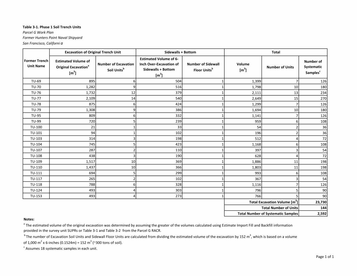
Table 3-1. Phase 1 Soil Trench UnitsParcel G Work PlanFormer Hunters Point Naval ShipyardSan Francisco, Californi a
Estimated Volume of Original Excavationa
[m3]
Number of Excavation Soil Unitsb
Estimated Volume of 6-Inch Over-Excavation of
Sidewalls + Bottom [m3]
Number of Sidewall Floor Unitsb
Volume[m3]
Number of UnitsNumber of Systematic Samplesc
TU-69 895 6 504 1 1,399 7 126TU-70 1,282 9 516 1 1,798 10 180TU-76 1,732 12 379 1 2,111 13 234TU-77 2,109 14 540 1 2,649 15 270TU-78 875 6 424 1 1,299 7 126TU-79 1,308 9 386 1 1,694 10 180TU-95 809 6 332 1 1,141 7 126TU-99 720 5 239 1 959 6 108
TU-100 21 1 33 1 54 2 36TU-101 94 1 102 1 196 2 36TU-103 314 3 198 1 512 4 72TU-104 745 5 423 1 1,168 6 108TU-107 287 2 110 1 397 3 54TU-108 438 3 190 1 628 4 72TU-109 1,517 10 369 1 1,886 11 198TU-110 1,437 10 366 1 1,803 11 198TU-111 694 5 299 1 993 6 108TU-117 265 2 102 1 367 3 54TU-118 788 6 328 1 1,116 7 126TU-124 493 4 303 1 796 5 90TU-153 493 4 273 1 766 5 90
23,730144
2,592Notes:
c Assumes 18 systematic samples in each unit.
a The estimated volume of the original excavation was determined by assuming the greater of the volumes calculated using Estimate Import Fill and Backfill information provided in the survey unit SUPRs or Table 3-1 and Table 3-2 from the Parcel G RACR. b The number of Excavation Soil Units and Sidewall Floor Units are calculated from dividing the estimated volume of the excavation by 152 m3, which is based on a volume of 1,000 m2 x 6-inches (0.1524m) = 152 m3 (~300 tons of soil).
TotalSidewalls + BottomExcavation of Original Trench Unit
Total Excavation Volume [m3]Total Number of Units
Total Number of Systematic Samples
Former Trench Unit Name
Page 1 of 1
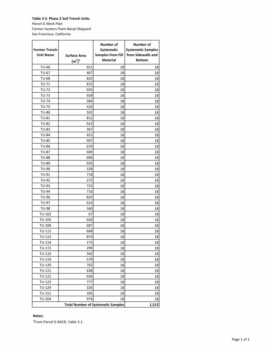
Table 3-2. Phase 2 Soil Trench UnitsParcel G Work PlanFormer Hunters Point Naval ShipyardSan Francisco, California
Former Trench Unit Name Surface Area
[m2]a
Number of Systematic
Samples from Fill Material
Number of Systematic Samples from Sidewalls and
Bottom
TU-66 651 18 18TU-67 467 18 18TU-68 825 18 18TU-71 872 18 18TU-72 935 18 18TU-73 928 18 18TU-74 384 18 18TU-75 410 18 18TU-80 502 18 18TU-81 812 18 18TU-82 913 18 18TU-83 367 18 18TU-84 651 18 18TU-85 907 18 18TU-86 670 18 18TU-87 669 18 18TU-88 690 18 18TU-89 926 18 18TU-90 328 18 18TU-91 718 18 18TU-92 275 18 18TU-93 722 18 18TU-94 716 18 18TU-96 825 18 18TU-97 623 18 18TU-98 560 18 18
TU-102 67 18 18TU-105 650 18 18TU-106 687 18 18TU-112 668 18 18TU-113 874 18 18TU-114 173 18 18TU-115 290 18 18TU-116 342 18 18TU-119 579 18 18TU-120 762 18 18TU-121 638 18 18TU-122 636 18 18TU-123 777 18 18TU-129 326 18 18TU-151 185 18 18TU-204 974 18 18
1,512
Notes:aFrom Parcel G RACR, Table 3-1.
Total Number of Systematic Samples
Page 1 of 1
Table 3-3. Phases 1 and 2 Soil Survey UnitsParcel G Work PlanFormer Hunters Point Naval ShipyardSan Francisco, California
Building Site Former
Survey Unit Name
Area[m2]
Number of Systematic
Samples
Building 351A Crawlspace SU-D 100 18Building 351A Crawlspace SU-E 100 18Building 351A Crawlspace SU-F 100 18Building 351A Crawlspace SU-G 100 18Building 351A Crawlspace SU-H 100 18Building 351A Crawlspace SU-I 100 18Building 351A Crawlspace SU-J 100 18Building 351A Crawlspace SU-K 100 18Building 351A Crawlspace SU-L 100 18Building 351A Crawlspace SU-M 100 18Building 351A Crawlspace SU-N 100 18Building 351A Crawlspace SU-O 100 18Building 351A Crawlspace SU-P 100 18Building 351A Crawlspace SU-T 53 18
Building 351A Crawlspace SU-A 100 18Building 351A Crawlspace SU-B 100 18Building 351A Crawlspace SU-C 100 18Building 317/364/365 Site SU-20 354 18Building 317/364/365 Site SU-21 408 18Building 317/364/365 Site SU-23 155 18Building 317/364/365 Site SU-24 343 18Building 317/364/365 Site SU-25 504 18Building 317/364/365 Site SU-26 436 18Building 317/364/365 Site SU-27 28 18Building 317/364/365 Site SU-28 104 18Building 317/364/365 Site SU-29 848 18Building 317/364/365 Site SU-30 539 18Building 317/364/365 Site SU-31 367 18
504
Phase 1
Phase 2
Total Number of Systematic Samples
Page 1 of 1
Bldg 401
Bldg 366
Bldg 411
Bldg 351
Bldg351A
Bldg 439
Bldg 364
Bldg365
Bldg 408
Bldg317
TU-105
TU-110
TU-72
TU-78
TU-90
TU-96
TU-129
TU-108
TU-123
TU-113
TU-80
TU-75
TU-116
TU-88
TU-67
TU-93
TU-99
TU-109
TU-103
TU-124 TU-83
TU-119
TU-68TU-89
TU-100
TU-94
TU-106
TU-111
TU-73
TU-121
TU-204
TU-70TU-86 TU-91
TU-107
TU-122
TU-76
TU-81
TU-114
TU-117
TU-87
TU-66
TU-79
TU-104
TU-153
TU-84
TU-69
TU-101
TU-97
TU-85
TU-74
TU-112
TU-120
TU-92
TU-102
TU-98
TU-151TU-82
TU-71
TU-115
TU-77
TU-118
TU-95
\\bro
oksi
defil
es\G
IS_S
HAR
E\EN
BG\0
0_Pr
oj\N
\Nav
y\CL
EAN
\SO
UTH
WES
T\H
UN
TER
S_P
OIN
T_N
S\M
apFi
les\
Wor
kPla
ns\F
igur
e3-1
_Par
celG
_Soi
lApp
roac
h.m
xd h
artm
and
5/9/
2018
11:
01:0
1 AM
Legend:Parcel GImpacted BuildingsDemolished Impacted BuildingsPhase 1 Trench/Survey UnitsPhase 2 Trench/Survey Units
± Figure 3-1Soil Investigation ApproachParcel G Work PlanFormer Hunters Point Naval ShipyardSan Francisco, California
BASE MAP SOURCE:Service Layer Credits: Source: Esri, DigitalGlobe, GeoEye, EarthstarGeographics, CNES/Airbus DS, USDA, USGS, AeroGRID, IGN, and
0 200 400100Feet
Buildings 317/364/365 Site
SU-29
SU-30SU-25
SU-21
SU-24
SU-20
SU-23
SU-26
SU-27
SU-31
SU-28SU-31
TU-95
TU-118
TU-153
TU-117
TU-93 TU-99
TU-97
Building 351ACrawlspace
TU-96
TU-153TU-97
TU-115
TU-118
TU-95
SU-D
SU-H
SU-L
SU-P
SU-KSU-JSU-I
SU-MSU-N
SU-O
SU-GSU-F
SU-TSU-E
SU-CSU-BSU-A
1 inch = 180 feet
CJ CJ CJ CJ 1111
...
Compare Each ROC Concentrationto the Parcel G ROD RAO
Is Any ROC Concentration >RG?
Prepare RACRTU/SU Complies With Parcel G ROD RAO
Removal Site Evaluation Report
Is the ROC 226Ra?
Is any 226Ra Concentration >238U Concentration +RG?
Perform Alpha Spectrometry or Comparable Analysis for
238U and 226Ra
Figure 3-2Performance Criteria for Demonstrating Compliance with the Parcel G ROD – SoilParcel G Work PlanFormer Hunters Point Naval Shipyard San Francisco, California
Acronyms: Ra = Radium RACR = removal action completion report
RAO = remedial action objectiveRG = remediation goal
ROC = radionuclide of concernROD = record of decisionSU = survey unit
TU = trench unitU = uranium
Former HPNS Parcel G_Work Plan_AX0510181049SDO
No
Yes
Yes
Yes
No
No
!!
!!!
!!!
!!
!!
!!!
!!
!
!!
!!
!!
!!
!!
!!
!!
!!
!!
!!
!!
!!
!!
!!
!!
!!
!!
!!
!!
!!
!!
!!
!!
!!
!!
!!
!!
TU-153
TU-72
TU-96
TU-93TU-99
TU-94
TU-73
TU-204
TU-117
TU-97
TU-118
TU-95
SU-20
SU-28
SU-21
SU-23
SU-24
SU-25
SU-29
SU-26
SU-30
SU-31
SU-27
SU-H
SU-L
SU-P
SU-K
SU-JSU-I
SU-NSU-O
SU-GSU-F
SU-TSU-E
SU-CSU-BSU-A
Bldg 351A
Bldg 364
Bldg 365
SU-M
\\bro
oksi
defil
es\G
IS_S
HAR
E\EN
BG\0
0_Pr
oj\N
\Nav
y\CL
EAN
\SO
UTH
WES
T\H
UN
TER
S_P
OIN
T_N
S\M
apFi
les\
RD
EF_R
epor
tMap
s\Pa
rcel
G\F
igur
e3-3
_Par
cel_
G_E
xam
ple_
Phas
e_1_
Sam
ple_
Loca
tions
.mxd
har
tman
d 5/
21/2
018
5:00
:01
PM
BASE MAP SOURCE:
Legend:! Systematic Sample Location
SU-MTU-153RSY Pad
Demolished Impacted BuildingsImpacted BuildingsSurvey UnitsTrench Units
±
Figure 3-3Example Phase 1 Trench/SurveyUnit and Sample Locations Radiological Data Evaluation Findings ReportFormer Hunters Point Naval ShipyardSan Francisco, California
Service Layer Credits: Source: Esri, DigitalGlobe, GeoEye, Earthstar Geographics,CNES/Airbus DS, USDA, USGS, AeroGRID, IGN, and the GIS User Community
0 30 6015Feet
Bldg 364Bldg 365
Bldg 351AG
E3 CJ CJ
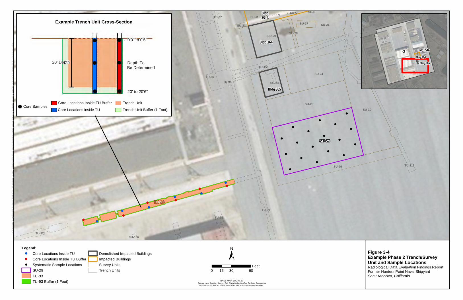
!
!
!
!
!
!
!
!
!
!
!
!
!
!
!
!
!
!
!
!
!
!
!
!
!
!
!!
!!
TU-93
Bldg351A
TU-96
TU-99
TU-94
TU-106
TU-117
TU-153
TU-97
TU-92
TU-118
TU-95
Bldg 364
Bldg 365
SU-20 SU-28
SU-21
SU-23
SU-24
SU-25
SU-26
SU-30
SU-31 SU-27
SU-PSU-M SU-N SU-O
SU-29
R:\E
NBG
\00_
Proj
\N\N
avy\
CLE
AN\S
OU
THW
EST
\HU
NTE
RS_
POIN
T_N
S\M
apFi
les\
RD
EF_R
epor
tMap
s\P
arce
lG\F
igur
e3-6
_Par
cel_
G_E
xam
ple_
Phas
e_2_
Sam
ple_
Loca
tions
.mxd
mbr
own1
9 5/
11/2
018
6:02
:23
PM
BASE MAP SOURCE:
Legend:! Core Locations Inside TU! Core Locations Inside TU Buffer! Systematic Sample Locations
SU-29TU-93TU-93 Buffer (1 Foot)
Demolished Impacted BuildingsImpacted BuildingsSurvey UnitsTrench Units
± Figure 3-4Example Phase 2 Trench/SurveyUnit and Sample Locations Radiological Data Evaluation Findings Report Former Hunters Point Naval ShipyardSan Francisco, California
Service Layer Credits: Source: Esri, DigitalGlobe, GeoEye, Earthstar Geographics,CNES/Airbus DS, USDA, USGS, AeroGRID, IGN, and the GIS User Community
0 30 6015Feet
G Bldg 351ABldg 364
Bldg 365
- 20' to 20'6"
- 0'0" to 0'6"
- Depth ToBe Determined
20' Depth
Core Locations Inside TU
Trench Unit
Trench Unit Buffer (1 Foot)
Core Locations Inside TU Buffer
Example Trench Unit Cross-Section
Core Samples --
CJ CJ CJ
CJ CJ CJ 1111
-D
( \
\\ \ \ \\
.... \\
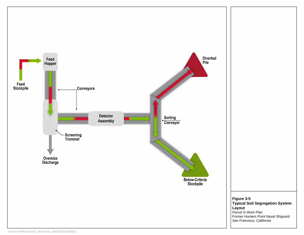
Figure 3-5Typical Soil Segregation System LayoutParcel G Work PlanFormer Hunters Point Naval Shipyard San Francisco, California
Former HPNS Parcel G_Work Plan_AX0510181049SDO
Feed Stockpile
Feed Hopper
7 Conveyors
"--screening Trommel
Oversize Discharge
Detector Assembly
Sorting Conveyor
SECTION 4
4-1
Building Investigation Design and Implementation This section describes the DQOs, ROCs, RGs, investigation levels, and radiological investigation design and implementation for Parcel G buildings.
4.1 Data Quality Objectives The DQOs for the building investigation are as follows:
• Step 1-State the Problem: There have been various allegations of data manipulation or falsification committed by a contractor during past building surveys. The Technical Team evaluated building data and found evidence of potential manipulation and falsification. The findings call into question the reliability of the data and there is uncertainty whether radiological contamination was present or remains in place. Therefore, the property is unable to be transferred as planned. Based on the uncertainty and the description of radiological activities in the HRA, there is a potential for residual radioactivity to be present on building interior surfaces.
• Step 2-Identify the Objective: The primary objective is to determine whether site conditions are compliant with the Parcel G ROD RAO (Navy, 2009).
• Step 3-Identify Inputs to the Objective: The inputs include alpha-beta static, scan, and swipe data on building and reference area surfaces.
• Step 4-Define the Study Boundaries: The study boundaries are accessible interior surfaces of Buildings 351, 351A, 366, 401, 411, and 439, and the concrete pad at former Building 408 (Figure 4-1). See the building floor SUs depicted on Figures 4-2 through 4-8.
• Step 5-Develop Decision Rules:
− If the investigation results demonstrate that site conditions are compliant with the Parcel G RAO, then a RACR will be developed. The RACR will describe the results of the investigation and will provide a demonstration that the RAO has been met and that residual radioactivity levels are comparable with background.
− If the investigation results demonstrate that site conditions are not compliant with the Parcel G RAO, then the data will be evaluated to determine whether site conditions are protective of human health using USEPA’s current guidance on Radiation Risk Assessment at CERCLA Sites (USEPA, 2014). A Removal Site Evaluation Report will be developed to include recommendations for further action.
• Step 6-Specify the Performance Criteria: The data evaluation process for demonstrating compliance with the Parcel G ROD is presented as follows, depicted on Figure 4-9, and described in detail in Section 5:
− Compare each net alpha and net beta result to the corresponding RG presented in Section 4.3.
If all results are less than or equal to the RGs, then compliance with the ROD RAO is achieved and a RACR will be prepared.
If any result is greater than the RG, then a Removal Site Evaluation Report will be prepared
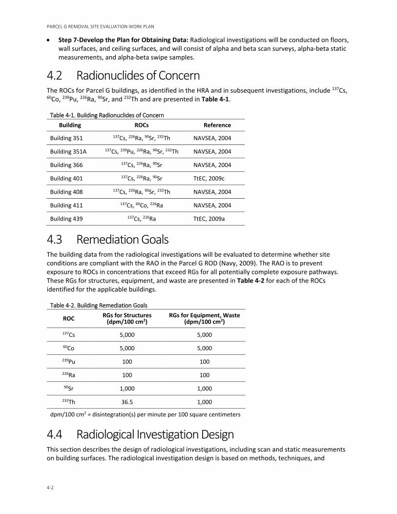
PARCEL G REMOVAL SITE EVALUATION WORK PLAN
4-2
• Step 7-Develop the Plan for Obtaining Data: Radiological investigations will be conducted on floors, wall surfaces, and ceiling surfaces, and will consist of alpha and beta scan surveys, alpha-beta static measurements, and alpha-beta swipe samples.
4.2 Radionuclides of Concern The ROCs for Parcel G buildings, as identified in the HRA and in subsequent investigations, include 137Cs, 60Co, 239Pu, 226Ra, 90Sr, and 232Th and are presented in Table 4-1.
Table 4-1. Building Radionuclides of Concern Building ROCs Reference
Building 351 137Cs, 226Ra, 90Sr, 232Th NAVSEA, 2004
Building 351A 137Cs, 239Pu, 226Ra, 90Sr, 232Th NAVSEA, 2004
Building 366 137Cs, 226Ra, 90Sr NAVSEA, 2004
Building 401 137Cs, 226Ra, 90Sr TtEC, 2009c
Building 408 137Cs, 226Ra, 90Sr, 232Th NAVSEA, 2004
Building 411 137Cs, 60Co, 226Ra NAVSEA, 2004
Building 439 137Cs, 226Ra TtEC, 2009a
4.3 Remediation Goals The building data from the radiological investigations will be evaluated to determine whether site conditions are compliant with the RAO in the Parcel G ROD (Navy, 2009). The RAO is to prevent exposure to ROCs in concentrations that exceed RGs for all potentially complete exposure pathways. These RGs for structures, equipment, and waste are presented in Table 4-2 for each of the ROCs identified for the applicable buildings.
Table 4-2. Building Remediation Goals
ROC RGs for Structures (dpm/100 cm2)
RGs for Equipment, Waste (dpm/100 cm2)
137Cs 5,000 5,000
60Co 5,000 5,000
239Pu 100 100
226Ra 100 100
90Sr 1,000 1,000
232Th 36.5 1,000
dpm/100 cm2 = disintegration(s) per minute per 100 square centimeters
4.4 Radiological Investigation Design This section describes the design of radiological investigations, including scan and static measurements on building surfaces. The radiological investigation design is based on methods, techniques, and
SECTION 4 – BUILDING INVESTIGATION DESIGN AND IMPLEMENTATION
4-3
instrument systems in the Basewide Radiological Management Plan (TtEC, 2012), with the ultimate requirement to demonstrate compliance with the Parcel G ROD RAO.
The principal features of the investigation protocol to be applied to the Parcel G building SUs are discussed herein and include the following:
• Determine the SUs. • Select survey instruments. • Determine instrument investigation levels and MDCs.
To the extent possible, manual data entries will be eliminated through use of electronic data collection and transfer processes.
4.4.1 Number of Static Measurements Static measurements will be performed in each SU and in the RBA. Following the previously established protocols (TtEC, 2012), a minimum of 18 measurements will be performed in each SU and on each RBA surface type. They will consist of measurements in scalar mode for simultaneous alpha-beta counting using the surface contamination monitor (SCM) or a Model 43-37. While 2-minute count times were used in the following example calculations, static count times will be updated during investigations to meet DQOs using instrument-specific information.
4.4.2 Radiological Background Subject to Navy approval, the unimpacted first floor of Building 401 will serve as the RBA in the survey of Parcel G buildings (Figure 4-1). Building 401 is known to have been built after 1942, but before 1946, with similar construction to the other buildings. At least 18 static measurements will be taken on each surface material in the RBA that is representative of the material in the building SUs. Alternate RBAs may be recommended if needed based on site-specific conditions identified during the building investigations.
4.4.3 Survey Units Parcel G buildings will be divided into identifiable SUs similar in area and nomenclature to the previous final status survey of each building. Floor surfaces and the lower two meters of remaining wall surfaces will form survey units of no more than 100 m2 each. The remaining upper wall surfaces and ceilings will form the remaining survey units of no more than 2,000 m2 each. The floor plans and floor SUs are shown for each building on Figures 4-2 through 4-8. Figure 4-10 is an example of a two-dimensional representation for Building 351A, Survey Unit 001, and shows the floors, remaining lower wall surfaces, and intended static measurement and swipe sample locations.
4.4.4 Reference Coordinate System Survey unit scan lanes and static measurement locations will be marked using a consistent reference coordinate system throughout the building. In the absence of other technologies, locations will reference from the southernmost and westernmost points in the SU.
4.5 Instrumentation Investigation data will be collected using position-sensitive proportional counters, gas proportional counters, and swipe sample counters as described herein.
PARCEL G REMOVAL SITE EVALUATION WORK PLAN
4-4
4.5.1 Position-sensitive Proportional Counters Large-area surface scanning and static measurements for alpha and beta radiations will be performed using position-sensitive proportional counters (PSPCs) such as the Radiation Safety and Control Services, Inc. (RSCS) SCM or equivalent. The SCM simultaneously acquires alpha-beta data from motor-controlled dual detectors moving over a surface at a fixed rate between 1.25 and 12.5 cm/s. Detector functions, movement, and response are controlled through a Survey Information Management System (SIMS). The Survey Information Management System is also used to log, display, and interpret investigation data and generate survey reports. The detectors are configured in parallel and the system can identify the location of each reading within 5 centimeters (cm) along a detector’s length. Operated in rolling (dynamic) mode for scanning, the SCM acquires data for each 5 cm of detector width and every 5 cm of forward travel. The data for the resulting 25-square-centimeter (cm2) area is binned, then combined as 1/4 of the overall 100-cm2 response. Operated in corner (static) mode for static measurements, the SCM count cycle is triggered by a timer rather than the precision wheel encoder.
4.5.2 Large-area Gas Proportional Detectors Large-area gas proportional detectors, such as the Ludlum Model 43-37 or equivalent, will be used for scanning and static measurements in areas that are not accessible to or practicable for the SCM. The Model 43-37 detector’ physical size is 2.5 x 15.9 x 46.4 cm (H x W x L) with an active area of 584 cm2. Scanning speed is surveyor-controlled and data are automatically logged when used with an appropriate data-logging scaler/ratemeter, such as the Ludlum Model 2360, or equivalent.
4.5.3 Alpha-Beta Sample Counter Swipe samples to assess removable activity will be performed using an alpha-beta plastic scintillation counter, such as the Ludlum Model 3030 Alpha-Beta Sample Counter or equivalent. The Model 3030 has an active detector area of 20.3 cm2 and simultaneously counts alpha-beta radiation from 5.1-cm swipe papers loaded into a single sample tray.
4.5.4 Instrument Efficiencies Manufacturer-provided parameters are provided in Table 4-3, including the detector physical (active) areas, detector widths in the direction of scanning, total (4π) efficiencies and background count rates. These parameters will be updated during investigation for each instrument used.
Table 4-3. Survey Instrument Efficiencies and Background Count Rates from Manufacturers Parameter SCM Model 43-37 Model 3030
Detector active area, A (cm2) 100 584 20.3
Width in direction of scan, d (cm) 20 15.9 NA
Alpha total efficiency (4π) for 239Pu
0.175 0.37
Alpha total efficiency (4π) for 235U 0.39
Alpha total efficiency (4π) for 230Th 0.32
Alpha total efficiency (4π) for 226Ra 0.188
Beta total efficiency (4π) for 99Tc
0.90
0.20 0.27
Beta total efficiency (4π) for 90Sr/90Y 0.20 0.26
Beta total efficiency (4π) for 137Cs 0.29
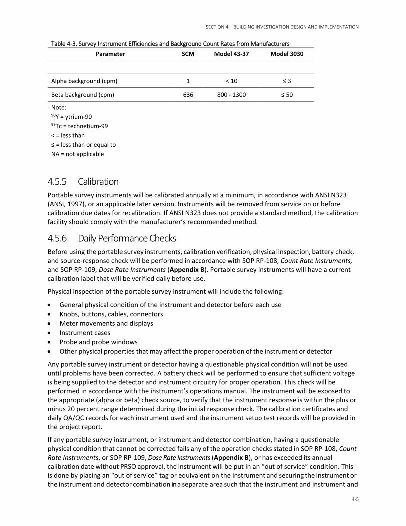
SECTION 4 – BUILDING INVESTIGATION DESIGN AND IMPLEMENTATION
4-5
Table 4-3. Survey Instrument Efficiencies and Background Count Rates from Manufacturers Parameter SCM Model 43-37 Model 3030
Alpha background (cpm) 1 < 10 ≤ 3
Beta background (cpm) 636 800 - 1300 ≤ 50
Note: 90Y = ytrium-90 99Tc = technetium-99 < = less than ≤ = less than or equal to NA = not applicable
4.5.5 Calibration Portable survey instruments will be calibrated annually at a minimum, in accordance with ANSI N323 (ANSI, 1997), or an applicable later version. Instruments will be removed from service on or before calibration due dates for recalibration. If ANSI N323 does not provide a standard method, the calibration facility should comply with the manufacturer’s recommended method.
4.5.6 Daily Performance Checks Before using the portable survey instruments, calibration verification, physical inspection, battery check, and source-response check will be performed in accordance with SOP RP-108, Count Rate Instruments, and SOP RP-109, Dose Rate Instruments (Appendix B). Portable survey instruments will have a current calibration label that will be verified daily before use.
Physical inspection of the portable survey instrument will include the following:
• General physical condition of the instrument and detector before each use • Knobs, buttons, cables, connectors • Meter movements and displays • Instrument cases • Probe and probe windows • Other physical properties that may affect the proper operation of the instrument or detector
Any portable survey instrument or detector having a questionable physical condition will not be used until problems have been corrected. A battery check will be performed to ensure that sufficient voltage is being supplied to the detector and instrument circuitry for proper operation. This check will be performed in accordance with the instrument’s operations manual. The instrument will be exposed to the appropriate (alpha or beta) check source, to verify that the instrument response is within the plus or minus 20 percent range determined during the initial response check. The calibration certificates and daily QA/QC records for each instrument used and the instrument setup test records will be provided in the project report.
If any portable survey instrument, or instrument and detector combination, having a questionable physical condition that cannot be corrected fails any of the operation checks stated in SOP RP-108, Count Rate Instruments, or SOP RP-109, Dose Rate Instruments (Appendix B), or has exceeded its annual calibration date without PRSO approval, the instrument will be put in an “out of service” condition. This is done by placing an “out of service” tag or equivalent on the instrument and securing the instrument or the instrument and detector combination in a separate area such that the instrument and instrument and
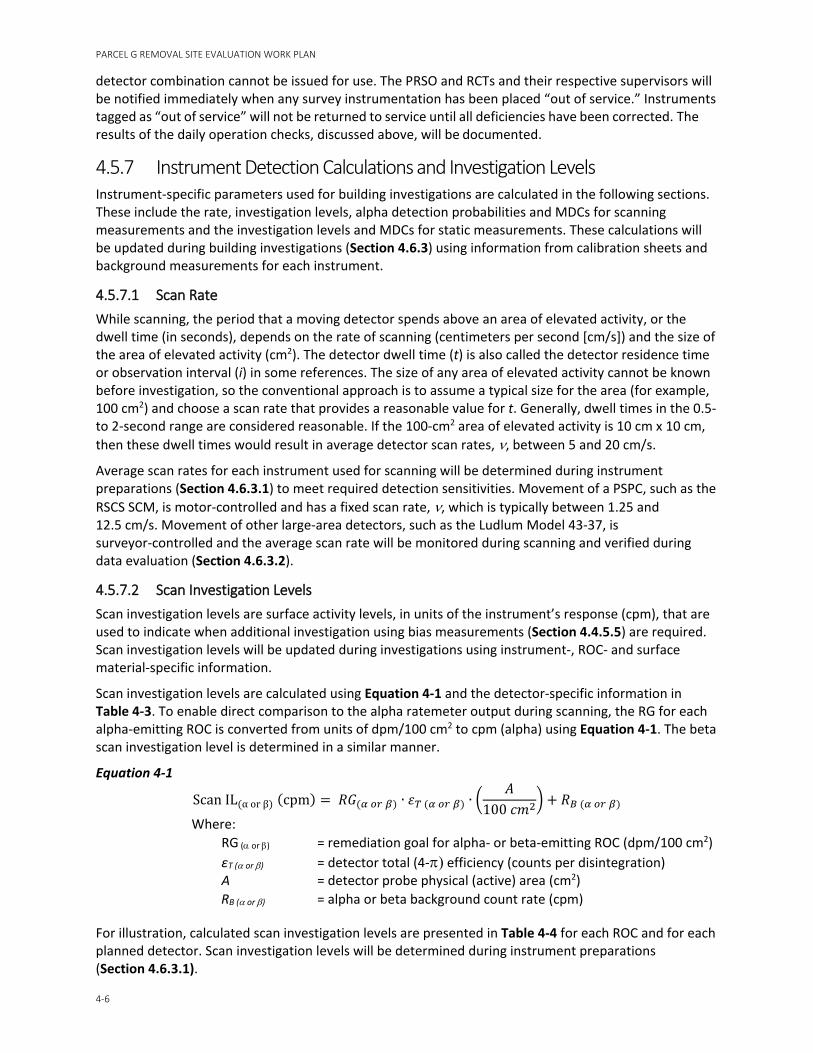
PARCEL G REMOVAL SITE EVALUATION WORK PLAN
4-6
detector combination cannot be issued for use. The PRSO and RCTs and their respective supervisors will be notified immediately when any survey instrumentation has been placed “out of service.” Instruments tagged as “out of service” will not be returned to service until all deficiencies have been corrected. The results of the daily operation checks, discussed above, will be documented.
4.5.7 Instrument Detection Calculations and Investigation Levels Instrument-specific parameters used for building investigations are calculated in the following sections. These include the rate, investigation levels, alpha detection probabilities and MDCs for scanning measurements and the investigation levels and MDCs for static measurements. These calculations will be updated during building investigations (Section 4.6.3) using information from calibration sheets and background measurements for each instrument.
4.5.7.1 Scan Rate While scanning, the period that a moving detector spends above an area of elevated activity, or the dwell time (in seconds), depends on the rate of scanning (centimeters per second [cm/s]) and the size of the area of elevated activity (cm2). The detector dwell time (t) is also called the detector residence time or observation interval (i) in some references. The size of any area of elevated activity cannot be known before investigation, so the conventional approach is to assume a typical size for the area (for example, 100 cm2) and choose a scan rate that provides a reasonable value for t. Generally, dwell times in the 0.5- to 2-second range are considered reasonable. If the 100-cm2 area of elevated activity is 10 cm x 10 cm, then these dwell times would result in average detector scan rates, ν, between 5 and 20 cm/s.
Average scan rates for each instrument used for scanning will be determined during instrument preparations (Section 4.6.3.1) to meet required detection sensitivities. Movement of a PSPC, such as the RSCS SCM, is motor-controlled and has a fixed scan rate, ν, which is typically between 1.25 and 12.5 cm/s. Movement of other large-area detectors, such as the Ludlum Model 43-37, is surveyor-controlled and the average scan rate will be monitored during scanning and verified during data evaluation (Section 4.6.3.2).
4.5.7.2 Scan Investigation Levels Scan investigation levels are surface activity levels, in units of the instrument’s response (cpm), that are used to indicate when additional investigation using bias measurements (Section 4.4.5.5) are required. Scan investigation levels will be updated during investigations using instrument-, ROC- and surface material-specific information.
Scan investigation levels are calculated using Equation 4-1 and the detector-specific information in Table 4-3. To enable direct comparison to the alpha ratemeter output during scanning, the RG for each alpha-emitting ROC is converted from units of dpm/100 cm2 to cpm (alpha) using Equation 4-1. The beta scan investigation level is determined in a similar manner.
Equation 4-1
Scan IL(α or β) (cpm) = 𝑅𝑅𝑅𝑅(𝛼𝛼 𝑜𝑜𝑜𝑜 𝛽𝛽) ∙ 𝜀𝜀𝑇𝑇 (𝛼𝛼 𝑜𝑜𝑜𝑜 𝛽𝛽) ∙ �𝐴𝐴
100 𝑖𝑖𝑚𝑚2� + 𝑅𝑅𝐵𝐵 (𝛼𝛼 𝑜𝑜𝑜𝑜 𝛽𝛽)
Where: RG (α or β) = remediation goal for alpha- or beta-emitting ROC (dpm/100 cm2) εT (α or β) = detector total (4-π) efficiency (counts per disintegration) A = detector probe physical (active) area (cm2) RB (α or β) = alpha or beta background count rate (cpm)
For illustration, calculated scan investigation levels are presented in Table 4-4 for each ROC and for each planned detector. Scan investigation levels will be determined during instrument preparations (Section 4.6.3.1).
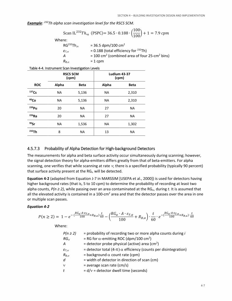
SECTION 4 – BUILDING INVESTIGATION DESIGN AND IMPLEMENTATION
4-7
Example: 232Th alpha scan investigation level for the RSCS SCM.
Scan IL 𝑇𝑇ℎ232 ,α (PSPC)= 36.5 ∙ 0.188 ∙ �100100
� + 1 = 7.9 𝑖𝑖𝑐𝑐𝑚𝑚
Where: RG232Th,α = 36.5 dpm/100 cm2 εT,α = 0.188 (total efficiency for 232Th) A = 100 cm2 (combined area of four 25-cm2 bins) RB,α = 1 cpm
Table 4-4. Instrument Scan Investigation Levels
ROC
RSCS SCM (cpm)
Ludlum 43-37 (cpm)
Alpha Beta Alpha Beta
137Cs NA 5,136 NA 2,310
60Co NA 5,136 NA 2,310
239Pu 20 NA 27 NA
226Ra 20 NA 27 NA
90Sr NA 1,536 NA 1,302
232Th 8 NA 13 NA
4.5.7.3 Probability of Alpha Detection for High-background Detectors The measurements for alpha and beta surface activity occur simultaneously during scanning; however, the signal detection theory for alpha-emitters differs greatly from that of beta-emitters. For alpha scanning, one verifies that while scanning at rate ν, there is a specified probability (typically 90 percent) that surface activity present at the RGα will be detected.
Equation 4-2 (adapted from Equation J-7 in MARSSIM [USEPA et al., 2000]) is used for detectors having higher background rates (that is, 5 to 10 cpm) to determine the probability of recording at least two alpha counts, P(n ≥ 2), while passing over an area contaminated at the RGα, during t. It is assumed that all the elevated activity is contained in a 100-cm2 area and that the detector passes over the area in one or multiple scan passes.
Equation 4-2
𝑃𝑃(𝑖𝑖 ≥ 2) = 1 − 𝑒𝑒− (𝑅𝑅𝑅𝑅𝛼𝛼∙𝐴𝐴∙𝜀𝜀𝑇𝑇,𝛼𝛼
100 +𝑅𝑅𝐵𝐵,𝛼𝛼)∙ 𝑡𝑡60 − �
𝑅𝑅𝑅𝑅𝛼𝛼 ∙ 𝐴𝐴 ∙ 𝜀𝜀𝑇𝑇,𝛼𝛼
100+ 𝑅𝑅𝐵𝐵,𝛼𝛼� ∙
𝑡𝑡60
∙ 𝑒𝑒−(𝑅𝑅𝑅𝑅𝛼𝛼∙𝐴𝐴∙𝜀𝜀𝑇𝑇,𝛼𝛼
100 +𝑅𝑅𝐵𝐵,𝛼𝛼)∙ 𝑡𝑡60
Where:
P(n ≥ 2) = probability of recording two or more alpha counts during i RGα = RG for α-emitting ROC (dpm/100 cm2) A = detector probe physical (active) area (cm2) εT,α = detector total (4-π) α efficiency (counts per disintegration) RB,α = background α count rate (cpm) d = width of detector in direction of scan (cm) ν = average scan rate (cm/s) t = d/ν = detector dwell time (seconds)
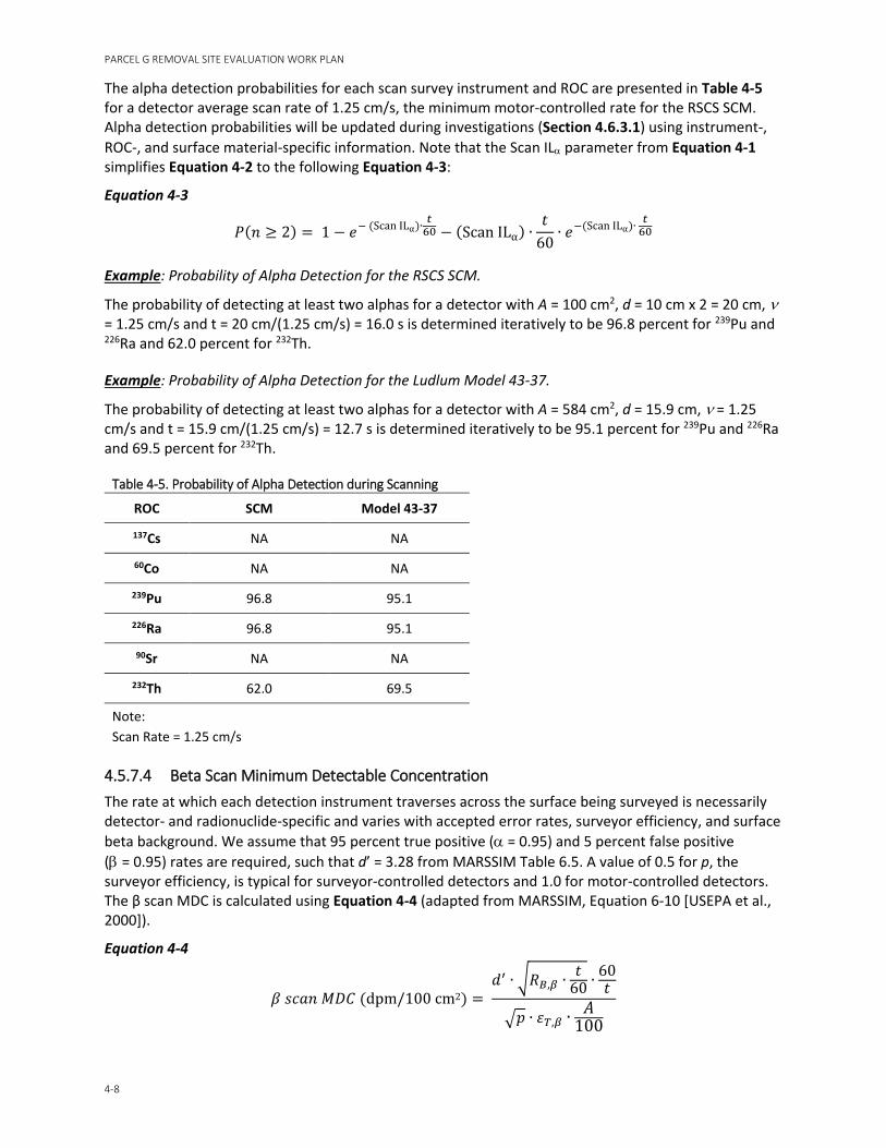
PARCEL G REMOVAL SITE EVALUATION WORK PLAN
4-8
The alpha detection probabilities for each scan survey instrument and ROC are presented in Table 4-5 for a detector average scan rate of 1.25 cm/s, the minimum motor-controlled rate for the RSCS SCM. Alpha detection probabilities will be updated during investigations (Section 4.6.3.1) using instrument-, ROC-, and surface material-specific information. Note that the Scan ILα parameter from Equation 4-1 simplifies Equation 4-2 to the following Equation 4-3:
Equation 4-3
𝑃𝑃(𝑖𝑖 ≥ 2) = 1 − 𝑒𝑒− (Scan ILα)∙ 𝑡𝑡60 − (Scan ILα) ∙
𝑡𝑡60
∙ 𝑒𝑒−(Scan ILα)∙ 𝑡𝑡60
Example: Probability of Alpha Detection for the RSCS SCM.
The probability of detecting at least two alphas for a detector with A = 100 cm2, d = 10 cm x 2 = 20 cm, ν = 1.25 cm/s and t = 20 cm/(1.25 cm/s) = 16.0 s is determined iteratively to be 96.8 percent for 239Pu and 226Ra and 62.0 percent for 232Th.
Example: Probability of Alpha Detection for the Ludlum Model 43-37.
The probability of detecting at least two alphas for a detector with A = 584 cm2, d = 15.9 cm, ν = 1.25 cm/s and t = 15.9 cm/(1.25 cm/s) = 12.7 s is determined iteratively to be 95.1 percent for 239Pu and 226Ra and 69.5 percent for 232Th.
Table 4-5. Probability of Alpha Detection during Scanning
ROC SCM Model 43-37
137Cs NA NA
60Co NA NA
239Pu 96.8 95.1
226Ra 96.8 95.1
90Sr NA NA
232Th 62.0 69.5
Note: Scan Rate = 1.25 cm/s
4.5.7.4 Beta Scan Minimum Detectable Concentration The rate at which each detection instrument traverses across the surface being surveyed is necessarily detector- and radionuclide-specific and varies with accepted error rates, surveyor efficiency, and surface beta background. We assume that 95 percent true positive (α = 0.95) and 5 percent false positive (β = 0.95) rates are required, such that d’ = 3.28 from MARSSIM Table 6.5. A value of 0.5 for p, the surveyor efficiency, is typical for surveyor-controlled detectors and 1.0 for motor-controlled detectors. The β scan MDC is calculated using Equation 4-4 (adapted from MARSSIM, Equation 6-10 [USEPA et al., 2000]).
Equation 4-4
𝛽𝛽 𝑒𝑒𝑖𝑖𝑠𝑠𝑖𝑖 𝑀𝑀𝑀𝑀𝑀𝑀 (dpm/100 cm2) = 𝑦𝑦′ ∙ �𝑅𝑅𝐵𝐵,𝛽𝛽 ∙ 𝑡𝑡
60 ∙ 60𝑡𝑡
�𝑐𝑐 ∙ 𝜀𝜀𝑇𝑇,𝛽𝛽 ∙ 𝐴𝐴100
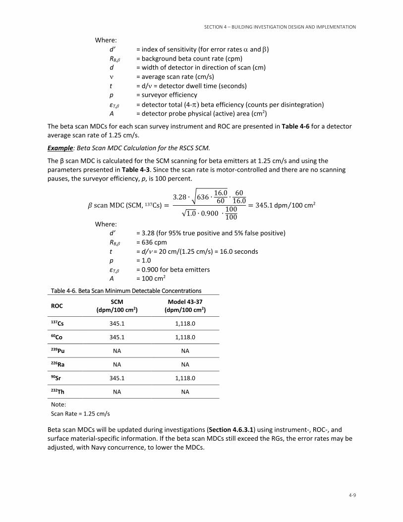
SECTION 4 – BUILDING INVESTIGATION DESIGN AND IMPLEMENTATION
4-9
Where: d’ = index of sensitivity (for error rates α and β) RB,β = background beta count rate (cpm) d = width of detector in direction of scan (cm) ν = average scan rate (cm/s) t = d/ν = detector dwell time (seconds) p = surveyor efficiency εT,β = detector total (4-π) beta efficiency (counts per disintegration) A = detector probe physical (active) area (cm2)
The beta scan MDCs for each scan survey instrument and ROC are presented in Table 4-6 for a detector average scan rate of 1.25 cm/s.
Example: Beta Scan MDC Calculation for the RSCS SCM.
The β scan MDC is calculated for the SCM scanning for beta emitters at 1.25 cm/s and using the parameters presented in Table 4-3. Since the scan rate is motor-controlled and there are no scanning pauses, the surveyor efficiency, p, is 100 percent.
𝛽𝛽 scan MDC (SCM, 137Cs) = 3.28 ∙ �636 ∙ 16.0
60 ∙ 6016.0
√1.0 ∙ 0.900 ∙ 100100
= 345.1 dpm 100 cm2⁄
Where: d’ = 3.28 (for 95% true positive and 5% false positive) RB,β = 636 cpm t = d/ν = 20 cm/(1.25 cm/s) = 16.0 seconds p = 1.0 εT,β = 0.900 for beta emitters A = 100 cm2
Table 4-6. Beta Scan Minimum Detectable Concentrations
ROC SCM (dpm/100 cm2)
Model 43-37 (dpm/100 cm2)
137Cs 345.1 1,118.0
60Co 345.1 1,118.0
239Pu NA NA
226Ra NA NA
90Sr 345.1 1,118.0
232Th NA NA
Note: Scan Rate = 1.25 cm/s
Beta scan MDCs will be updated during investigations (Section 4.6.3.1) using instrument-, ROC-, and surface material-specific information. If the beta scan MDCs still exceed the RGs, the error rates may be adjusted, with Navy concurrence, to lower the MDCs.
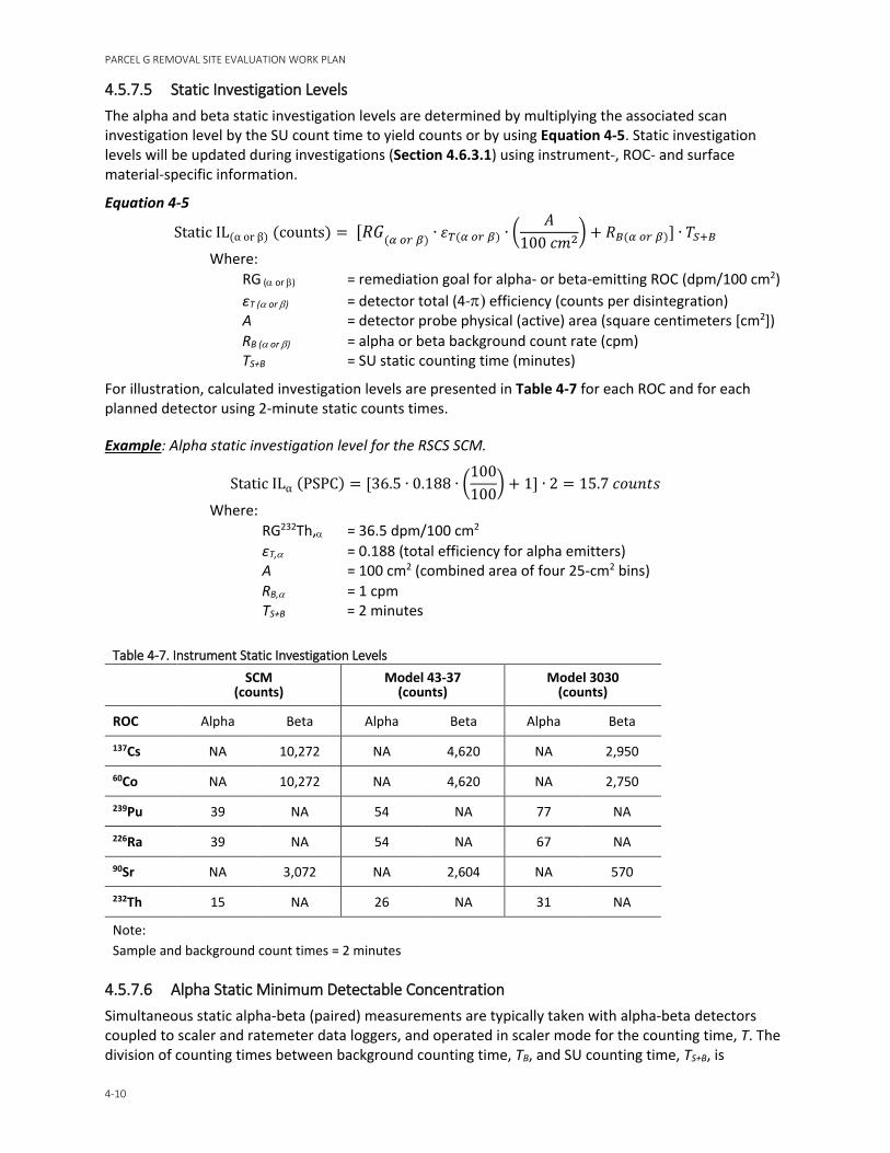
PARCEL G REMOVAL SITE EVALUATION WORK PLAN
4-10
4.5.7.5 Static Investigation Levels The alpha and beta static investigation levels are determined by multiplying the associated scan investigation level by the SU count time to yield counts or by using Equation 4-5. Static investigation levels will be updated during investigations (Section 4.6.3.1) using instrument-, ROC- and surface material-specific information.
Equation 4-5
Static IL(α or β) (counts) = [𝑅𝑅𝑅𝑅(𝛼𝛼 𝑜𝑜𝑜𝑜 𝛽𝛽) ∙ 𝜀𝜀𝑇𝑇(𝛼𝛼 𝑜𝑜𝑜𝑜 𝛽𝛽) ∙ �𝐴𝐴
100 𝑖𝑖𝑚𝑚2� + 𝑅𝑅𝐵𝐵(𝛼𝛼 𝑜𝑜𝑜𝑜 𝛽𝛽)] ∙ 𝑇𝑇𝑆𝑆+𝐵𝐵
Where: RG (α or β) = remediation goal for alpha- or beta-emitting ROC (dpm/100 cm2) εT (α or β) = detector total (4-π) efficiency (counts per disintegration) A = detector probe physical (active) area (square centimeters [cm2]) RB (α or β) = alpha or beta background count rate (cpm) TS+B = SU static counting time (minutes)
For illustration, calculated investigation levels are presented in Table 4-7 for each ROC and for each planned detector using 2-minute static counts times.
Example: Alpha static investigation level for the RSCS SCM.
Static ILα (PSPC) = [36.5 ∙ 0.188 ∙ �100100
� + 1] ∙ 2 = 15.7 𝑖𝑖𝑠𝑠𝑐𝑐𝑖𝑖𝑡𝑡𝑒𝑒
Where: RG232Th,α = 36.5 dpm/100 cm2 εT,α = 0.188 (total efficiency for alpha emitters) A = 100 cm2 (combined area of four 25-cm2 bins) RB,α = 1 cpm TS+B = 2 minutes
Table 4-7. Instrument Static Investigation Levels
SCM (counts)
Model 43-37 (counts)
Model 3030 (counts)
ROC Alpha Beta Alpha Beta Alpha Beta
137Cs NA 10,272 NA 4,620 NA 2,950
60Co NA 10,272 NA 4,620 NA 2,750
239Pu 39 NA 54 NA 77 NA
226Ra 39 NA 54 NA 67 NA
90Sr NA 3,072 NA 2,604 NA 570
232Th 15 NA 26 NA 31 NA
Note: Sample and background count times = 2 minutes
4.5.7.6 Alpha Static Minimum Detectable Concentration Simultaneous static alpha-beta (paired) measurements are typically taken with alpha-beta detectors coupled to scaler and ratemeter data loggers, and operated in scaler mode for the counting time, T. The division of counting times between background counting time, TB, and SU counting time, TS+B, is
SECTION 4 – BUILDING INVESTIGATION DESIGN AND IMPLEMENTATION
4-11
optimized such that the static MDCs will be less than or equal to 50 percent of the applicable RG. The static MDC is the a priori net activity concentration above the critical level that is expected to be detected 95 percent of the time. When the count times for the background and SU measurements are different, the static MDC, for either alpha or beta activity, is calculated using Equation 4-6 (adapted from Strom and Stanbury, 1992). Any areas of elevated activity are assumed to be 100 cm2 in size. Static MDCs will be updated during investigations (Section 4.6.3.1) using instrument-, ROC-, and surface material-specific information.
Equation 4-6
Static MDC (dpm 100 cm2⁄ ) = [3 + 3.29�𝑅𝑅𝐵𝐵 ∙ 𝑇𝑇𝑆𝑆+𝐵𝐵 ∙ �1 + 𝑇𝑇𝑆𝑆+𝐵𝐵
𝑇𝑇𝐵𝐵�]
𝜀𝜀𝑇𝑇 ∙ 𝐴𝐴100 ∙ 𝑇𝑇𝑆𝑆+𝐵𝐵
Where:
RB = background count rate (cpm) TS+B = SU counting time (min) TB = background counting time (min) εT = detector total (4-π) efficiency (counts per disintegration) A = detector probe physical (active) area (cm2)
The α static MDC is calculated for alpha static measurements to validate that the survey instruments are sufficiently sensitive to detect residual activity below the RG for an alpha-emitter.
Example: Alpha Static MDC Calculation for the RSCS SCM.
The α static MDC is calculated for the SCM using the parameters presented in Table 4-3. Using Equation 4-6, the calculated α static MDC of 25.5 dpm/100 cm2.
α Static MDC (SCM) =[3 + 3.29�1 ∙ 2 ∙ �1 + 2
2�]
0.188 ∙ 100100 ∙ 2
= 25.5 dpm/100 cm2
Where: RB,α = 1 cpm TS+B = 2 minutes TB = 2 minutes εT,α = 0.188 A = 100 cm2
4.5.7.7 Beta Static Minimum Detectable Concentration Like the α static MDC, the β static MDC is calculated for beta static measurements to validate that residual activity can be detected below the RG for a beta-emitter.
Example: Beta Static MDC Calculation for the RSCS SCM.
The β static MDC is calculated for the SCM using the parameters presented in Table 4-3. Using Equation 4-6, the β static MDC is 93.9 dpm/100 cm2.
β Static MDC (SCM)=[3+3.29�636·2·(1+ 2
2 )]
0.900· 100100 ·2
=93.9 dpm/100 cm2
PARCEL G REMOVAL SITE EVALUATION WORK PLAN
4-12
Where:
RB,β = 636 cpm TS+B = 2 minutes TB = 2 minutes εT,β = 0.900 A = 100 cm2
The alpha and beta static MDCs for each survey instrument and ROC are presented in Table 4-8 for 1-minute measurements in the SUs and RBAs.
Table 4-8. Instrument Static Minimum Detectable Concentrations
SCM (dpm/100 cm2)
Model 43-37 (dpm/100 cm2)
Model 3030 (dpm/100 cm2)
ROC Alpha Beta Alpha Beta Alpha Beta
137Cs NA 93.9 NA 92.6 NA 61.9
60Co NA 93.9 NA 92.6 NA 66.5
239Pu 25.5 NA 6.2 NA 14.9 NA
226Ra 25.5 NA 6.2 NA 17.3 NA
90Sr NA 93.9 NA 92.6 NA 69.0
232Th 25.5 NA 6.2 NA 14.2 NA
Note: Sample and background count times = 2 minutes
Upon receipt of survey instruments for the building investigations (Section 4.6.3.1), the static MDCs will be updated. If the beta scan MDCs still exceed the RGs, the static measurement count times will be increased accordingly to lower the MDCs.
4.6 Radiological Investigation Implementation Investigations will be generally implemented in the following order of activities: premobilization/mobilization, surveys, additional investigations, and demobilization.
4.6.1 Premobilization Activities Before the start of survey activities, a walkthrough of Parcel G buildings will be completed to accomplish the following:
• Establish building access points and assess security requirements. • Assess survey support needs such as power, lighting, ladders, or scaffolding. • Verify the types of materials in each SU. • Identify safety concerns and inaccessible or difficult-to-survey areas. • Identify radiological protection and control requirements. • Identify materials requiring removal or disposal, and areas requiring cleaning. • Assess methods for marking survey scan lanes and static measurement locations.
Impacted areas that are deemed unsafe for access or surveys, such as the mezzanine of Building 411, will be posted, secured, and annotated in reports.
SECTION 4 – BUILDING INVESTIGATION DESIGN AND IMPLEMENTATION
4-13
4.6.1.1 Training Requirements Any required non-site-specific training required for field personnel shall be performed before mobilization to the extent practical. Training requirements are outlined in Section 6.
Medical examinations, medical monitoring, and training shall be conducted in accordance with the APP/SSHP and Section 6 requirements.
In addition to health and safety-related training, other training may be required as necessary including but not limited to the following:
• Aerial Lift (for personnel working from aerial lifts) • Fall Protection (for personnel working at heights greater than 5 feet) • Equipment as required (for example, fork lift, skid steer, loader, back hoe, excavator)
4.6.1.2 Permitting and Notification Before initiation of field activities for the radiological investigations, the contractor will notify the Navy RPM, ROICC, and RASO and HPNS security as to the nature of the anticipated work. Any required permits to conduct the fieldwork will be obtained before mobilization.
The contractor will notify the California Department of Public Health at least 14 days before initiation of activities involving the Radioactive Material License.
4.6.1.3 Pre-construction Meeting A pre-construction meeting will be held before mobilization of equipment and personnel. The purpose of the meeting will be to discuss project-specific topics, roles and responsibilities of project personnel, project schedule, health and safety concerns, and other topics that require discussions before field mobilization. Representatives of the following will attend the pre-construction meeting:
• Navy (RPM, RASO, ROICC, and others as applicable) • Contractor (Project Manager, Site Construction Manager, Project QC Manager, PRSO, and SSHO) • Subcontractors as appropriate
4.6.2 Mobilization Activities Mobilization activities will include site preparation, movement of equipment and materials to the site, and orientation and training of field personnel.
At least 2 weeks before mobilization, the appropriate Navy personnel, including the Navy RPM, ROICC and CSO, will be notified regarding the planned schedule for mobilization and site remediation activities. Upon receipt of the appropriate records and authorizations, field personnel, temporary facilities, and required construction materials will be mobilized to the site.
The temporary facilities will include restrooms, hand-washing stations, and one or more secure storage (Conex) boxes for short- and long-term storage of materials, if needed.
The applicable AHAs will be reviewed prior to starting work.
All equipment mobilized to the site will undergo baseline radioactivity surveys in accordance with Section 6. Surveys will include directs scans, static measurements, and wipe samples. Equipment that fails baseline surveying will not be removed from site immediately.
Loose, residual debris from past building occupation, investigations, vandalism, or asbestos and lead abatement will be removed for disposal and to prepare the buildings for cleaning. Cleaning will be sufficient to remove loose, surface material that may not be native to the building construction and may inhibit or damage survey instruments. Cleaning activities will be conducted consistent with the radiation protection procedures in Section 6.4. Dust control methods and air monitoring will be implemented, if
PARCEL G REMOVAL SITE EVALUATION WORK PLAN
4-14
warranted, as detailed in Section 8.5. Floors will be cleaned using ride-on floor scrubbers and vacuums. Walls and other surfaces will be cleaned as required during surveying. Wet areas will be dried using vacuums, blowers, or squeegees and may be delineated with spill containment booms if water infiltration is recurrent. Waste from debris removal and cleaning activities will be evaluated as described in Section 6.5.4 and Section 7.
4.6.3 Building Investigation Activities Once all site preparation activities previously described are completed, building investigation activities will commence in the following general sequence:
• Mark SUs. • Prepare instruments. • Investigate SUs and conduct preliminary data review. • Investigate RBA and conduct preliminary data review. • Evaluate and report data as described in Section 5.
4.6.3.1 Instrument Preparation and Background Measurements Upon receipt of survey instruments for the building investigations and completion of performance checks, background measurements will be obtained in the RBA(s) for each instrument and on each surface type (for example, concrete, wood, and sheet rock) that is also present in the SUs. The background measurements will consist of at least 18 static measurements on each surface to match the number performed in each survey unit. The mean instrument- and surface-specific background count rate will be used to update the instrument detection calculations and static count times in Section 4.5.6.
4.6.3.2 Survey Unit Alpha-Beta Scanning Buildings will be durably marked prior to scanning to indicate the intended scan lanes and scan directions. Scan lane widths will be approximately 10 percent smaller than the detector’s active width, in the direction of scanning, to ensure overlapping coverage. While using a PSPC, scanning may traverse multiple SUs at once for efficiency, but scan data will be assigned to, and analyzed by, individual SUs. Areas inaccessible to a PSPC will be scanned using a gas-proportional detector with data logging functions.
The scan rate for the SCM is entered using the Survey Information Management System and results in a fixed, motor-controlled scan rate. At least every 10 survey units of scanning, the SCM scan rate will be verified manually using the distance scanned and scan duration. The distance scanned is the linear distance, in centimeters, traveled by the detector during data acquisition. The scan duration is the total time, in seconds, of data acquisition. Dividing the distance scanned (cm) by the scan duration (s) gives an estimate of the average detector scan rate (cm/s) for that scanning period. Direct observation or review of the positional data from the SCM serve to verify that the detector was in constant motion during scanning. The scan rate for the Model 43-37 is manually controlled by the surveyor and will be verified manually in each survey unit by direct observation and measurement of the time elapsed while scanning a known distance.
The total surface area to be scanned will be 100 percent of accessible floor surfaces and 100 percent of the lower two meters of remaining wall surfaces. Twenty-five percent of the remaining upper wall surfaces and ceilings will be scanned.
A data quality assessment (DQA) of the scan data (Section 5.2) will identify locations that require further investigation (Section 5.3).
SECTION 4 – BUILDING INVESTIGATION DESIGN AND IMPLEMENTATION
4-15
4.6.3.3 Survey Unit Systematic Alpha-Beta Static Measurements Buildings will be durably marked prior to static measurements to indicate the intended measurement type and location. The 18 systematic measurement locations in each floor and lower wall SU will be systematically distributed on a triangular pattern from a random starting point. The survey meter will be operated in scaler mode and measurements made for the updated count duration.
A DQA of the static measurement data (Section 5.2) will identify locations that require further investigation (Section 5.3).
4.6.3.4 Bias Alpha-Beta Static Measurements Bias static measurements will be used to further investigate areas with potential elevated surface activity as described in Section 5.3. The survey meter will be operated in scaler mode and measurements made for the updated count duration.
4.6.3.5 Alpha-Beta Swipe Samples Swipe samples will be taken at all locations of systematic and bias static measurements. They will be taken dry, using moderate pressure, over an area of approximately 100 cm2. Swipe samples will be measured for gross alpha and beta activity using a Ludlum Model 3030 or equivalent. The surface activity on the sample will be compared to the total surface activity measured by the static measurement to assess the removable fraction of surface activity. This information will be used in any dose or risk assessment performed.
4.6.3.6 Assessment of Residual Materials and Equipment Several buildings contain residual materials and equipment from past operations that will undergo radioactivity surveys in accordance with SOP RP-104, Radiological Surveys, and SOP RP-105, Unconditional Release Requirements (Appendix B). These surveys may include a combination of surface scans and static measurements and swipe samples. After data evaluation, disposition decisions, and subsequent investigation of the surfaces below the materials and equipment, will be coordinated with the Navy.
4.6.3.7 Decontamination and Release of Equipment and Tools Decontamination of mobilized materials and equipment may be necessary at completion of fieldwork if radioactive materials above RGs are encountered. Numerous decontamination methods are available for use. If practical, manual decontamination methods should be used. Abrasive methods may be necessary if areas of fixed contamination are identified. Chemical decontamination can also be accomplished by using detergents for nonporous surfaces with contamination present. Chemicals should be selected for decontamination that will minimize the creation of mixed waste. Decontamination activities will be conducted using SOP RP-132, Radiological Protective Clothing Selection, Monitoring, and Decontamination (Appendix B).
4.6.4 Demobilization Demobilization will consist of surveying, decontaminating, and removing equipment and materials used during the investigations, cleaning the project site, inspecting the site, and removing temporary facilities. Demobilization activities will also involve collection and disposal of contaminated materials, including decontamination water and disposable equipment for which decontamination is inappropriate (Section 7).
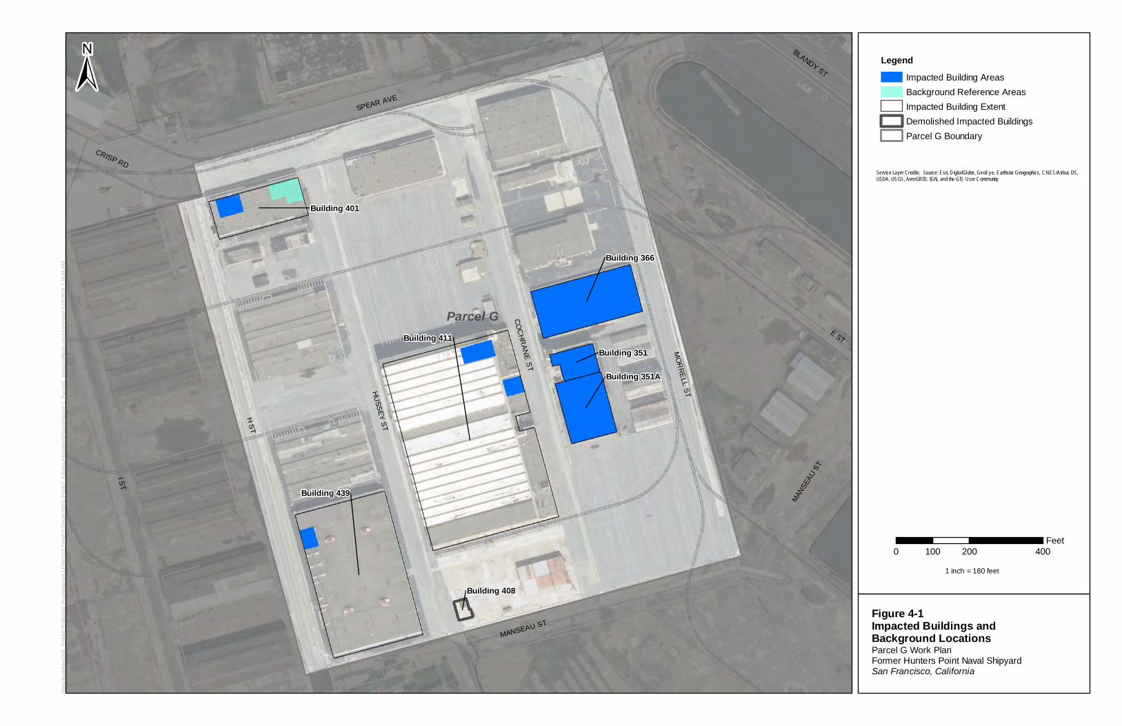
\\bro
oksi
defil
es\G
IS_S
HAR
E\E
NBG
\00_
Proj
\N\N
avy\
CLE
AN\S
OU
THW
EST\
HU
NTE
RS_
PO
INT_
NS\
Map
File
s\W
orkP
lans
\Fig
ure4
-1_P
arce
lG_I
mpa
cted
Blgd
s.m
xd h
artm
and
5/18
/201
8 3:
28:5
6 PM
Parcel G
H ST
MO
RRELL ST
MANSEAU ST
SPEAR AVE
HUSSEY ST
CRISP RD
BLANDY ST
MANSE
AU S
T
E ST
I ST
COC
HRAN
E STBuilding 408
Building 351A
Building 351
Building 366
Building 401
Building 411
Building 439
LegendImpacted Building AreasBackground Reference AreasImpacted Building ExtentDemolished Impacted BuildingsParcel G Boundary
±
Figure 4-1Impacted Buildings and Background LocationsParcel G Work PlanFormer Hunters Point Naval ShipyardSan Francisco, California
Service Layer Credits: Source: Esri, DigitalGlobe, GeoEye, Earthstar Geographics, CNES/Airbus DS,USDA, USGS, AeroGRID, IGN, and the GIS User Community
0 200 400100Feet
1 inch = 180 feet
1111
CJ CJ CJ
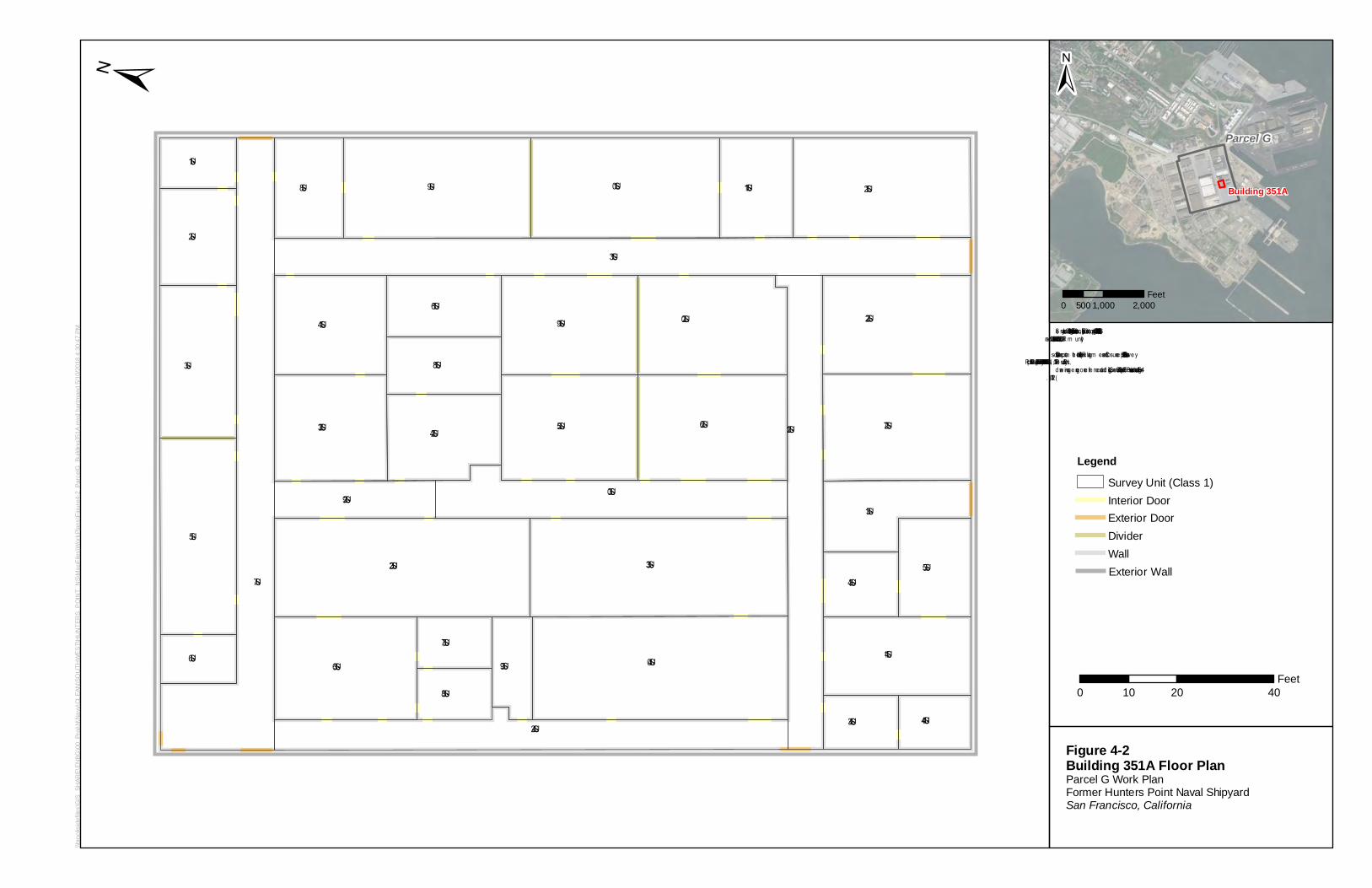
\\bro
oksi
defil
es\G
IS_S
HAR
E\EN
BG\0
0_Pr
oj\N
\Nav
y\CL
EAN
\SO
UTH
WES
T\H
UN
TER
S_P
OIN
T_N
S\M
apFi
les\
Wor
kPla
ns\F
igur
e4-2
_Par
celG
_Bui
ldin
g351
A.m
xd h
artm
and
5/10
/201
8 4:
30:4
7 PM
SU-16
SU-5
SU-1
SU-2
SU-6
SU-7
SU-9SU-8 SU-12SU-11
SU-13
SU-31
SU-22
SU-27
SU-41
SU-43 SU-44
SU-35SU-34
SU-21
SU-40
SU-26
SU-20
SU-30
SU-23 SU-24
SU-18
SU-33SU-32
SU-36
SU-37
SU-38
SU-42
SU-39
SU-10
SU-25
SU-19SU-14
SU-3
SU-29
LegendSurvey Unit (Class 1)Interior DoorExterior DoorDividerWallExterior Wall
±
Figure 4-2Building 351A Floor PlanParcel G Work PlanFormer Hunters Point Naval ShipyardSan Francisco, California
0 20 4010Feet
Se rvice Laye r Cre d its: Source: Esri, DigitalGlobe , GeoEye , Earth star Geograph ics, CNES/Airbus DS, USDA,USGS, AeroGRID, IGN, and th e GIS Use r Com m unityData source: Departm e nt of th e Navy Base Realignm e nt and Closure re port, “Final Final Status Surve yRe sults, July 26, 2010, DCN: ECSD-5713-0072-0015.Rl” pre pare d by TetraTech, CTO No. 0072. Multipled raw ings w e re geore fe re nce d and d igitiz e d in GIS. Surve y Unit and Floor P lan data are base d on Figure 4-1(2010).
Parcel G
Building 351A
±
0 1,000 2,000500Feet
L
i
---
7
\\bro
oksi
defil
es\G
IS_S
HAR
E\EN
BG\0
0_Pr
oj\N
\Nav
y\CL
EAN
\SO
UTH
WES
T\H
UN
TER
S_P
OIN
T_N
S\M
apFi
les\
Wor
kPla
ns\F
igur
e4-3
_Par
celG
_Bui
ldin
g351
.mxd
har
tman
d 5/
10/2
018
4:32
:28
PM
SU-11e le vator1
SU-2
SU-10
SU-9SU-4
SU-6
SU-8SU-3
SU-7
TU-115
SU-1
SU-5
LegendSurvey Unit (Class 1)Interior DoorExterior DoorDividerWall
Exterior Wall!H Column
Trench Unit
±0 20 4010
Feet
Se rvice Lay e r Cre d its: Source: Esri, DigitalGlobe, GeoEy e, Earth starGe ograph ics, CNES/Airbus DS, USDA, USGS, AeroGRID, IGN, and th eGIS Use r Com m unityData source: Departm e nt of th e Navy Base Realignm e nt and Closurere port, “Final Final Status Surve y Results, March 5, 2010, DCN: ECSD-5713-0072-0045.Rl” pre pare d by Te traTech, CTO No. 0072. Multipled raw ings w e re geore fe re nce d and d igitize d in GIS. Surve y Unit andFloor P lan data are base d on section 4 figure s (2010). Tre nch Unitsfrom CH2M P hase 1 re port. Dim e nsions are approxim ate.
Parcel G
Building 351
±
0 1,000 2,000Feet
SU-18
e le vator2
SU-32
SU-29
SU-17
SU-22
SU-21
SU-30
SU-31
SU-27
SU-19
SU-20
SU-23
SU-26
SU-25
SU-24
SU-28
SU-36
SU-35
SU-34
SU-33
stair3be le vator3
SU-46
SU-50
stair3a
SU-45
SU-42 SU-47
SU-43 SU-48
SU-44 SU-49
SU-51
Figure 4-3Building 351 Floor PlanParcel G Work PlanFormer Hunters Point Naval ShipyardSan Francisco, California
Floor 1 Floor 2 Floor 3
., _,,
I
_,,, _,,, '--
0 0 ~
'-
0 '\ J "' '---
0 0 0 0 0 9 r
I \...._
n _J
---
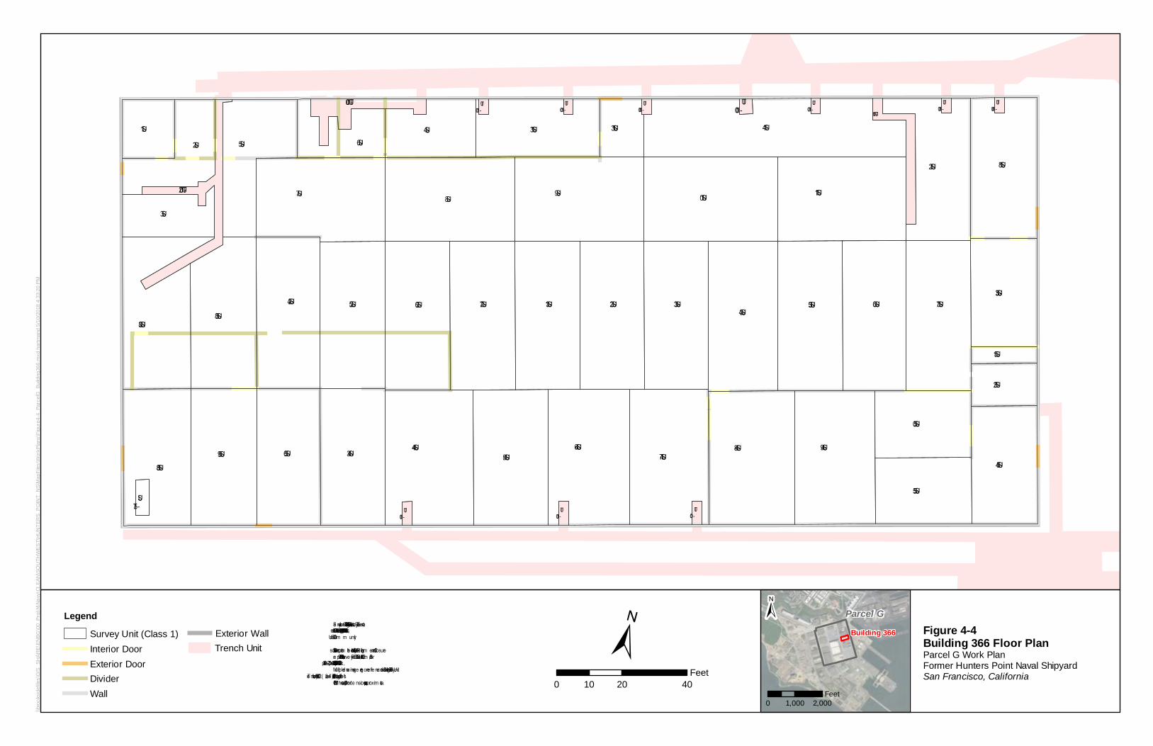
\\bro
oksi
defil
es\G
IS_S
HAR
E\EN
BG\0
0_Pr
oj\N
\Nav
y\CL
EAN
\SO
UTH
WES
T\H
UN
TER
S_P
OIN
T_N
S\M
apFi
les\
Wor
kPla
ns\F
igur
e4-4
_Par
celG
_Bui
ldin
g366
.mxd
har
tman
d 5/
10/2
018
4:33
:20
PM
SU-34
SU-50
SU-46
SU-38
SU-59SU-54
SU-18
SU-53
SU-52
SU-9
SU-2
TU-100
TU-100
TU-100
TU-100
TU-100
TU-100
TU-100
TU-100
TU-100
TU-100
TU-102
TU-100TU-101
SU-58SU-56 SU-43 SU-44
SU-45 SU-47SU-48 SU-49
SU-55
SU-37
SU-12
SU-24
SU-5
SU-28
SU-3
SU-1 SU-14SU-6
SU-4 SU-13
SU-10
SU-25
SU-7
SU-26 SU-27
SU-8
SU-31 SU-32 SU-33 SU-36SU-35
SU-11
SU-57
SU-13
SU-51
LegendSurvey Unit (Class 1)Interior DoorExterior DoorDividerWall
Exterior WallTrench Unit ±
0 20 4010Feet
Se rvice Lay e r Cre d its: Source: Esri, DigitalGlobe, GeoEy e, Earth starGe ograph ics, CNES/Airbus DS, USDA, USGS, AeroGRID, IGN, and th eGIS Use r Com m unityData source: Departm e nt of th e Navy Base Realignm e nt and Closurere port, “Final Final Status Surve y Results, Dece m be r 30, 2009, DCN:ECSD-5713-0072-0043” pre pare d by TetraTech, CTO No. 0072.Multiple d rawings we re ge orefe re nce d and d igitize d in GIS. Surve y Unitdata are base d on figure s 1-2 (2007) and 4-2 (2008). Tre nch Units fromCH2M P hase 1 re port. Dim e nsions are approxim ate.
Parcel GBuilding 366
±
0 1,000 2,000Feet
Figure 4-4Building 366 Floor PlanParcel G Work PlanFormer Hunters Point Naval ShipyardSan Francisco, California
~
L 7J ~ LJ LJ IJ LJ LJ I I LJ LJ
-i::::::::! -
I u ,--
A
D n n n
---
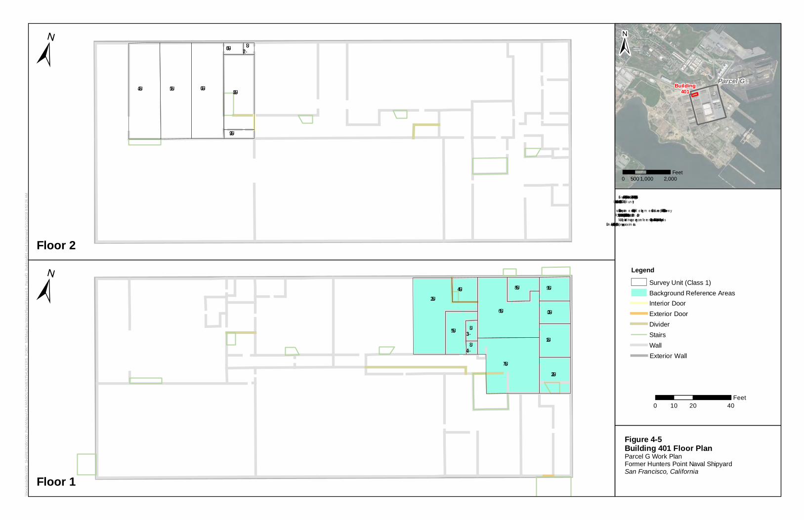
\\bro
oksi
defil
es\G
IS_S
HAR
E\EN
BG\0
0_Pr
oj\N
\Nav
y\CL
EAN
\SO
UTH
WES
T\H
UN
TER
S_P
OIN
T_N
S\M
apFi
les\
Wor
kPla
ns\F
igur
e4-5
_Par
celG
_Bui
ldin
g401
.mxd
har
tman
d 5/
11/2
018
9:52
:26
AM
SU-19SU-32
SU-15
SU-14
SU-22
SU-21
SU-20
SU-18
SU-33SU-34
SU-16
SU-17
LegendSurvey Unit (Class 1)Background Reference AreasInterior DoorExterior DoorDividerStairsWallExterior Wall
0 20 4010Feet
Se rvice Laye r Credits: Source: Esri, DigitalGlobe , GeoEye , Earthstar Geographics, CNES/Airbus DS, USDA,USGS, AeroGR ID, IGN, an d the GIS Use r Com m un ityData source: Departm e n t of the Navy Base R e align m e n t and Closure re port, “Final Final Status Surve yR e sults, Se pte m be r 21, 2009, DCN: ECSD-5713-0072-0015.R l” pre pared by TetraTech, CTO No. 0072.Multiple drawin gs we re ge ore fe re nce d an d digitiz e d in GIS. Surve y Un it data are based on section 4 figure s(2009) and Floor Plan s (2008). Dim e n sion s are approxim ate.
SU-26 SU-28
SU-36
SU-24 SU-25
SU-27
SU-29
Floor 1
Floor 2
Figure 4-5Building 401 Floor PlanParcel G Work PlanFormer Hunters Point Naval ShipyardSan Francisco, California
Parcel GBuilding401
±
0 1,000 2,000500Feet
±
±
---
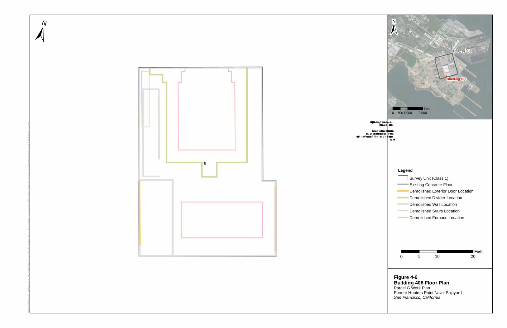
\\bro
oksi
defil
es\G
IS_S
HAR
E\E
NBG
\00_
Proj
\N\N
avy\
CLE
AN\S
OU
THW
EST\
HU
NTE
RS_
PO
INT_
NS\
Map
File
s\W
orkP
lans
\Fig
ure4
-6_P
arce
lG_B
uild
ing4
08.m
xd h
artm
and
5/22
/201
8 5:
27:1
8 PM
SU-1Legend
Survey Unit (Class 1)Existing Concrete FloorDemolished Exterior Door LocationDemolished Divider LocationDemolished Wall LocationDemolished Stairs LocationDemolished Furnace Location
±
Figure 4-6Building 408 Floor PlanParcel G Work PlanFormer Hunters Point Naval ShipyardSan Francisco, California
0 10 205Feet
Service Layer Credits: Source: Es ri, DigitalGlobe, GeoEye, Earths tar Geographics, CNES/Airb us DS, USDA,USGS, AeroGRID, IGN, and the GIS User CommunityData source: Dep artment of the Navy Base Realignment and Clos ure report, “Final Final Status SurveyRes ults, July 8, 2009, DCN: ECSD-S713-0072-0019.Rl” p repared by TetraTech, CTO No. 0072. Multipledrawings were georeferenced and digitized in GIS. Floorplan data are based on Figure 1-1. Dimensions areap p roximate.
Parcel G
Building 408
±
0 1,000 2,000500Feet
r-- J
... -
·-
CJ ---
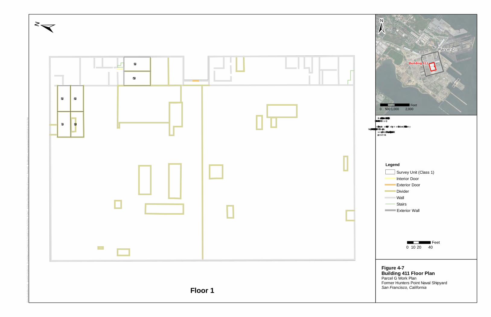
\\bro
oksi
defil
es\G
IS_S
HAR
E\E
NBG
\00_
Proj
\N\N
avy\
CLE
AN\S
OU
THW
EST\
HU
NTE
RS_
PO
INT_
NS\
Map
File
s\W
orkP
lans
\Fig
ure4
-7_P
arce
lG_B
uild
ing4
11.m
xd h
artm
and
5/22
/201
8 5:
33:2
0 PM
SU-9
SU-10
SU-7
SU-5
SU-8
SU-6
LegendSurvey Unit (Class 1)Interior DoorExterior DoorDividerWallStairsExterior Wall
±
Figure 4-7Building 411 Floor PlanParcel G Work PlanFormer Hunters Point Naval ShipyardSan Francisco, California
0 20 4010Feet
Se rvice Laye r Credits: Source: Esri, DigitalGlobe , Ge oEye , Earthstar Geographics, CNES/Airbus DS, USDA,USGS, AeroGR ID, IGN, an d the GIS Use r Com m un ityData source: Departm e n t of the Navy Base R ealign m e n t and Closure re port, “Final Final Status Surve yR e sults, July 6, 2010, DCN: ECSD-S713-0072-0081” pre pared by TetraTech, CTO No. 0072. Multiple draw ingsw e re geore fe re nced and digitiz ed in GIS. Floor 1 data are based on Figure 4-5 (2010). Dim e n sion s areapproxim ate.
Parcel G
Building 411
±
0 1,000 2,000500Feet
Floor 1
!
D
• a --
• 1 ,---, • --
- C]
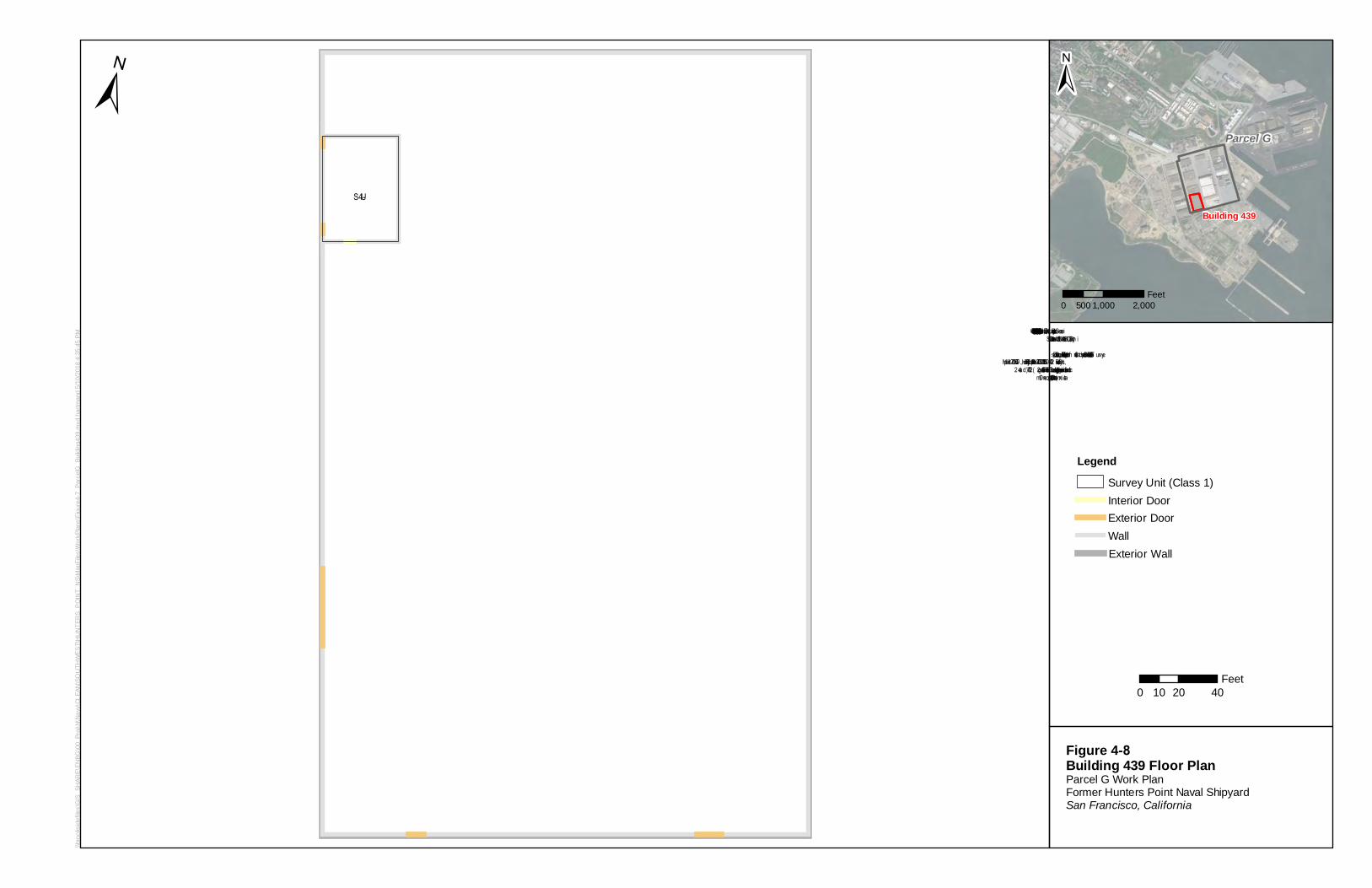
\\bro
oksi
defil
es\G
IS_S
HAR
E\EN
BG\0
0_Pr
oj\N
\Nav
y\CL
EAN
\SO
UTH
WES
T\H
UN
TER
S_P
OIN
T_N
S\M
apFi
les\
Wor
kPla
ns\F
igur
e4-7
_Par
celG
_Bui
ldin
g439
.mxd
har
tman
d 5/
10/2
018
4:35
:45
PM
S U-4
LegendSurvey Unit (Class 1)Interior DoorExterior DoorWallExterior Wall
±
Figure 4-8Building 439 Floor PlanParcel G Work PlanFormer Hunters Point Naval Shipyard San Francisco, California
0 20 4010Feet
S ervice Layer Credits: S o urce: Esri, DigitalGlo be, Geo Eye, Earthstar Geo g raphics, CNES /Airbus DS , US DA,US GS , Aero GRID, IGN, an d the GIS User Co m m unityData so urce: Departm en t o f the Navy Base Realig n m en t and Clo sure repo rt, “Final Final S tatus S urveyResults, July 8, 2009, DCN: ECS D-5713-0072-0021.Rl” prepared by TetraTech, CTO No. 0072. Multipledrawin g s were geo referen ced and digitized in GIS . S urvey Un it data are based o n Figure 1-2 (2007) and 4-2(2009). Dim en sio n s are appro xim ate.
Parcel G
Building 439
±
0 1,000 2,000500Feet
--
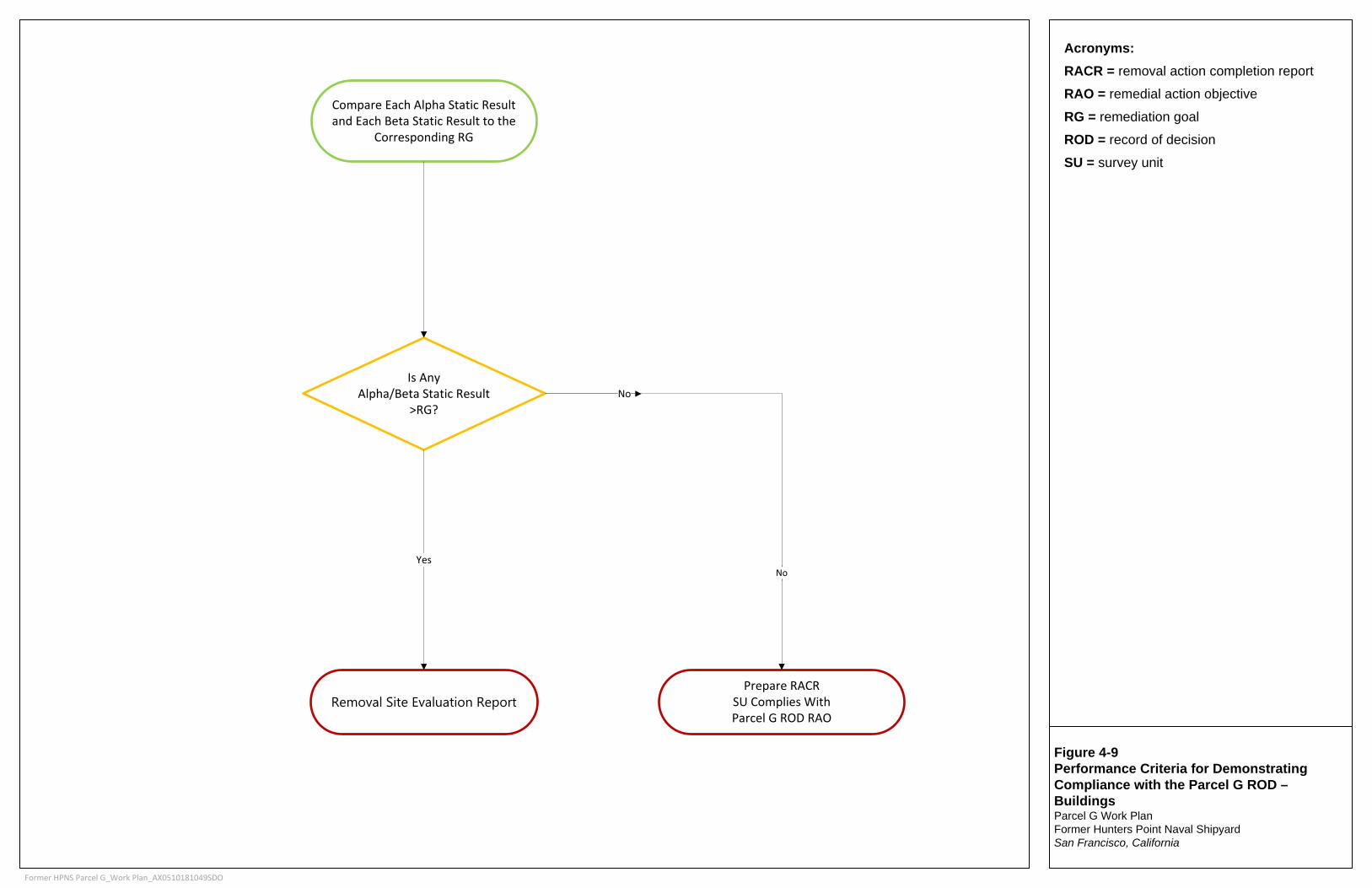
Figure 4-9Performance Criteria for Demonstrating Compliance with the Parcel G ROD – BuildingsParcel G Work PlanFormer Hunters Point Naval Shipyard San Francisco, California
Acronyms: RACR = removal action completion reportRAO = remedial action objective
RG = remediation goalROD = record of decision
SU = survey unit
Former HPNS Parcel G_Work Plan_AX0510181049SDO
Compare Each Alpha Static Result and Each Beta Static Result to the
Corresponding RG
Is Any Alpha/Beta Static Result
>RG?
Prepare RACR SU Complies With Parcel G ROD RAO
Removal Site Evaluation Report
YesNo
No
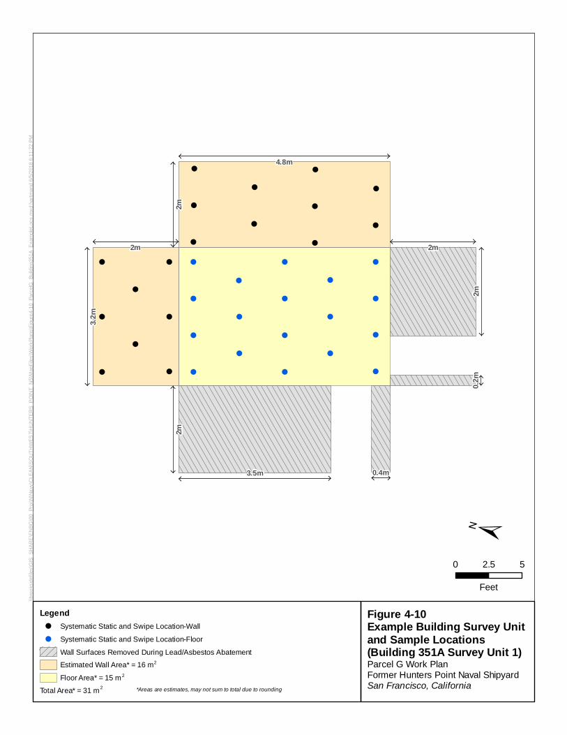
,
,
,
,
,
,
,
,
,
,
,
,
,
, ,
,
,
, ,
,
!!
!!
!!
!
!!
!!
!!
!
!!
!!
!!
!!
!
!!
!!
!
!!
!
!!
!!
!
0.2m
0.4m
2m
2m2m
2m
2m
3.2m
3.5m
4.8m
\\bro
oksi
defil
es\G
IS_S
HAR
E\E
NBG
\00_
Proj
\N\N
avy\
CLE
AN\S
OU
THW
EST\
HU
NTE
RS_
PO
INT_
NS\
Map
File
s\W
orkP
lans
\Fig
ure4
-10_
Parc
elG
_Bui
ldin
g351
A_Ex
ampl
eLoc
s.m
xd h
artm
and
6/5/
2018
6:1
1:22
PM
±
0 52.5
Feet
Total Area* = 31 m2 *Areas are estimates, may not sum to total due to rounding
Figure 4-10Example Building Survey Unit and Sample Locations (Building 351A Survey Unit 1)Parcel G Work PlanFormer Hunters Point Naval ShipyardSan Francisco, California
Legend! Systematic Static and Swipe Location-Wall
! Systematic Static and Swipe Location-Floor
Wall Surfaces Removed During Lead/Asbestos AbatementEstimated Wall Area* = 16 m2
Floor Area* = 15 m2
(!Zl
D D
SECTION 5
5-1
Data Evaluation and Reporting Survey unit data will be evaluated to determine whether the radiological site conditions comply with the Parcel G ROD RAOs. Decisions on compliance with the RGs will be made for each SU; therefore, all data describing radiological conditions in that SU should be available for data evaluation.
In general, the following actions will occur:
• Required soil samples will be collected as described in Section 3 and required building measurements will be performed as described in Section 4.
• Samples will be submitted to the laboratory and backup samples will be archived in a secure area under chain-of-custody protocols.
• Laboratory analyses will be performed as described in the SAP, submitted under separate cover.
• All soil sample and building measurement data will be validated by an independent third party.
• DQA will be performed as described in Section 5.2.
• Determination will be made as to whether the investigation results demonstrate compliance with the Parcel G ROD RAO (Navy, 2009).
• Investigation data will be evaluated against the reference area data to provide a comparison with background.
5.1 Data Quality Validation Analytical data validation will be performed by an independent third party as described in the SAP. Data validation will be performed on all TU/SU data and all RBA data.
5.2 Data Quality Assessment DQA is a scientific and statistical evaluation that determines whether the survey data are the right type, quantity, and quality to support the survey objectives (USEPA, 2006). There are five steps in the DQA process:
1. Review the DQOs and survey design. 2. Conduct a preliminary data review. 3. Select the statistical test. 4. Verify the assumptions of the statistical test. 5. Draw conclusions from the data.
The effort expended during DQA should be consistent with the graded approach used to develop the survey design. The DQA process will be applied to all SU data and all RBA data.
5.2.1 Review the Data Quality Objectives and Survey Design The sampling design and data collection documentation will be reviewed for consistency with the DQOs. At a minimum, this review will include:
• Number of soil samples or measurements in each SU • Location of soil samples and measurements
PARCEL G REMOVAL SITE EVALUATION WORK PLAN
5-2
• Measurement technique (that is, scan, static, sample, or swipe) and instrumentation
− Measurement uncertainty − Detectability (critical level and MDC) − Quantifiability
• Statistical power
The purpose of the review should focus on identifying the information required to complete the evaluation of the data, the determination of whether the survey objectives were achieved will be completed during Step 5 of the DQA Process (see Section 5.2.5).
5.2.2 Conduct a Preliminary Data Review A preliminary data review will be conducted to learn about the structure of the data by identifying patterns, relationships, or potential anomalies. The preliminary data review will include calculating statistical quantities, preparing posting plots of scan and sample data, preparing histograms of scan and sample data, preparing quantile-quantile (Q-Q) plots (sometimes referred to as normal probability plots) of scan and sample data, and preparing retrospective power curves.
5.2.2.1 Convert Survey Results and Calculate Statistical Quantities The RGs for soil (Table 3-5) are stated in units of pCi/g, and soil sample results from analytical laboratories will be reported with units of pCi/g, so no conversion will be necessary for soil sample data. The investigation level for gamma scan survey measurements (Table 3-6) are also stated in units of pCi/g. A Field Instruction or SOP will be provided with details on converting the investigation level for gamma scan survey measurements into units comparable with the output of the instrumentation selected to perform the gamma scan surveys.
The RGs for buildings surfaces (Table 4-2) are stated in units of dpm/100 cm2; however, alpha and beta static measurement results will be reported in units of counts during a specified counting interval, while scan measurement results will be reported in units of cpm. Example investigation levels for alpha and beta scan measurements are provided in Table 4-4 where the RGs have been converted into cpm using Equation 4-1 and example total efficiencies from Table 4-3. Example investigation levels for alpha and beta static measurements are provided in Table 4-7 where the RGs have been converted into counts using Equation 4-5 and example total efficiencies from Table 4-3. Instrument-specific total efficiencies and material-specific backgrounds will be determined in the field, along with instrument-specific investigation levels corresponding with the RGs for alpha and beta static and scan measurements on building surfaces.
Once all the survey results and RGs are available in the same or comparable units, the evaluation of the data can continue.
5.2.2.2 Prepare Posting Plots Posting plots are maps on which measurement results are shown at the location where the measurement was performed. Posting plots will be prepared for scan survey data, and static and swipe data from bias, systematic, and random locations on building surfaces. Posting plots of soil sample locations may also be prepared for Phase 1 and Phase 2 TUs, and Phase 1 and Phase 2 surface soil SUs. Posting plots will be prepared for each SU but are not required for each RBA.
Posting plots are inspected to identify patterns or inconsistencies in the data, especially potential areas of elevated activity requiring additional investigation or spatial trends identifying survey data that are not independent, violating the assumptions of the statistical tests. Posting plots may be prepared using counts, count rates, concentrations, or normalized data (standard deviations or z-scores) allowing
SECTION 5 – DATA EVALUATION AND REPORTING
5-3
comparison of results from multiple detectors or different measurement methods. Posting plots are most useful when presented in the same units as the RGs or investigation levels being evaluated.
5.2.2.3 Prepare Histograms Histograms, or frequency plots, are used to examine the general shape of a data distribution. Histograms will be prepared for scan survey data, static and smear survey data from systematic and random locations, and soil sample data from systematic locations for each SU and RBA. Bias survey data do not need to be included when preparing histograms; however, care should be taken when interpreting histograms that include data collected from bias locations. Histograms reveal obvious departures from symmetry, including skewness, bimodality, or significant outliers.
5.2.2.4 Prepare Q-Q Plots Q-Q plots compare a data distribution to an assumed normal distribution. Q-Q plots will be prepared for scan survey data, static and smear survey data from systematic and random locations, and soil sample data from systematic locations for each SU and RBA. Bias survey data do not need to be included when preparing Q-Q plots; however, care should be taken when interpreting Q-Q plots that include data collected from bias locations.
Background data usually approximate a normal distribution, so comparing SU data to a normal distribution is one technique in comparing survey data to background. Data from a normal distribution appear as a straight line on a Q-Q plot, so deviations from a straight line indicate potential deviations from a normal distribution, or potential deviations from background. Normal probability plots from different data sets, such as a SU and a RBA or adjacent SUs, can be shown on the same graph to allow for direct comparisons between multiple data sets.
5.2.2.5 Prepare Retrospective Power Curves A retrospective power curve provides an evaluation of the survey design and is used to demonstrate enough data were collected to support decisions regarding the radiological status of the SU. Retrospective power curves will be prepared for static and smear survey data from systematic and random locations, and soil sample data from systematic locations for each SU. Bias survey data will not be included when preparing retrospective power curves. The retrospective power curve is compared with the DQOs (Section 3.1 and Section 4.1) and the Type II decision error rates from Section 4.4.6 Basewide Radiological Management Plan (TtEC, 2012), to evaluate whether a sufficient number of samples was collected.
5.2.3 Draw Conclusions from the Data Figures 3-2 and 4-9 present an overview of how decisions for soil and building data, respectively, are combined to draw a final conclusion on whether each TU/SU complies with the Parcel G ROD RAO. If all measurement or sample results from a TU/SU are below the corresponding radionuclide-specific RG values or corresponding investigation level values, the TU/SU complies with the Parcel G ROD RAO. Otherwise a Removal Site Evaluation Report will be prepared providing recommendations to investigate the TU/SU.
The TU/SU data are compared with the RBA data to demonstrate whether the SU is consistent with the background data. If the SU data are consistent with the RBA data, the TU/SU is considered consistent with background. The results of the comparison with background will be incorporated into a Final Status Survey Report, including a description of all remedial activities performed so the California Department of Public Health-Environmental Management Branch can provide recommendations for unrestricted release.
PARCEL G REMOVAL SITE EVALUATION WORK PLAN
5-4
5.3 Investigation of Potential Areas of Elevated Activity The investigation of potential areas of elevated activity consists of comparing each measurement result from every SU with the investigation levels discussed in Section 3.3.1 for soil, Section 4.5.6.2 for building scans, and Section 4.5.6.5 for building static measurements. In general, the investigation levels are consistent with the RG values. This investigation is performed for all measurement results; scans, static measurements, and samples, at systematic, random, and bias locations. The investigation of potential areas of elevated activity ensures unusually high measurement and sample results will receive proper attention, and any area having the potential for significant contributions to total dose will be identified.
5.3.1 Identify Potential Areas of Elevated Activity Scan data, measurement data, and sample data will be evaluated to identify statistical and spatial anomalies indicating potential areas of elevated activity. All scan data will be compared directly to RGs or investigation levels. Posting plots will be used to identify trends and patterns in the scan data to help in identifying potential areas of elevated activity and support defining the areal extent of potential areas of elevated activity. Histograms and Q-Q plots will be used to identify significant outliers and evidence of multiple distributions to identify potential areas of elevated activity. Any sample or measurement exceeding a ROC-specific RG will be investigated as a potential area of elevated activity. In addition, SU areas with multiple lines of evidence indicating a potential increase in localized activity based on posting plots, histograms, and Q-Q plots of scan, static measurement, or sample data will be investigated as a potential area of elevated activity.
If direct measurement or sample results exceed the RG or investigation level for a specific ROC for locations not identified by scan survey, the scan survey technique will be reviewed and investigated to determine whether the scan survey was implemented correctly and whether the scan methodology met the survey objectives.
5.3.2 Investigate Potential Areas of Elevated Activity The objective of investigating potential areas of elevated activity is to characterize the ROCs present and the size, or extent, of all areas of elevated activity. To accomplish this objective, a minimum of one potential area of elevated activity will be investigated in every SU. If no potential areas of elevated activity are identified in a TU/SU based on Section 5.3.1, the location of the maximum scan result will be identified as a potential area of elevated activity.
The first step in investigating potential areas of elevated activity is to confirm the measurement or sample results that indicated the potential area of elevated activity. For alpha and beta scans, this may be accomplished by pausing during scanning to collect additional information, or it may require returning to a location to perform a bias static measurement. For gamma scans this may involve rescanning the area surrounding the potential elevated reading, sifting through near surface soil for a discrete source of activity (for example, deck marker), or collecting a bias soil sample for analysis. The selection of the confirmatory action will depend on the initial results and the decision on whether the original results are confirmed. In general, minimal information is acceptable when deciding to continue with the investigation of a potential area of elevated activity. In most cases, at least one measurement or sample result documenting the lack of elevated activity will be required to support a decision to terminate the investigation of a potential area of elevated activity.
Once the presence of an area of elevated activity has been confirmed, the ROCs present will be identified. In most cases the identification of ROCs can be accomplished using existing data. For building surfaces, it is sufficient to identify the elevated activity as alpha, beta, or a combination of alpha and beta radiation. For soil samples, it is generally necessary to identify the radionuclide based on laboratory analysis.
SECTION 5 – DATA EVALUATION AND REPORTING
5-5
The final step in investigating areas of confirmed elevated activity is determining the area, or extent, of the elevated results. The identification of the ROCs present will assist in determining whether additional data are required to determine the extent of elevated activity, and the number and type of measurements or samples that will be used for that determination. For building surfaces, the posting plot of the scan data is generally all that is needed to determine the extent of elevated readings. The determination may be accomplished similarly for soil areas when the ROC is 226Ra and the elevated activity is readily detected by scan surveys. Determining the extent of elevated activity for ROCs without a significant gamma emission, such as 90Sr and 239Pu, will require collecting additional soil samples or establishing a correlation between the difficult-to-detect ROC and 226Ra. Even when a correlation can be determined, the scan survey objectives will need to be reviewed and adjusted to account for detecting 226Ra at lower activity levels. If the elevated activity is associated with 90Sr or 239Pu results significantly above background, a Field Change Request will be initiated to document the characterization of any potential areas of elevated activity. The results of the investigation should identify an area of elevated activity bounded by measurements or sample results below the RGs or investigation levels.
If all alpha or beta static measurement or ROC-specific soil sample analysis result are less than the RGs or investigation levels, compliance with the Parcel G ROD RAO is achieved.
5.4 NORM Background Evaluation A NORM background evaluation will be performed for every sample where the 226Ra concentration exceeds the average RBA 226Ra concentration by more than the RG of 1.0 pCi/g. The purpose of the NORM background evaluation is to ensure the most representative estimate of background available is used to evaluate 226Ra results for comparison with the RG, not to validate analytical methods.
The 226Ra background at HPNS is known to vary significantly in different areas of the site. Since 238U is not a ROC at HPNS, 238U concentrations are an acceptable representative of background for all radionuclides included in the naturally occurring uranium decay series, which includes 226Ra. By definition, 226Ra concentrations are considered background when 226Ra is in secular equilibrium with 238U, which means the 226Ra concentration is equal to the 238U concentration. Therefore, the 238U concentration can replace the average RBA 226Ra concentration as a more representative estimate of background for a specific sample.
Alpha spectrometry provides 238U analytical results of acceptable quality for the NORM evaluation. However, the gamma spectroscopy results for 226Ra are based on larger volumes of soil and are not always comparable with alpha spectrometry results. Therefore, an analytical method for 226Ra comparable with alpha spectrometry for 238U is required to perform the NORM evaluation. For example, radon emanation analyses for 226Ra have similar sample support in terms of sample preparation and sample volume compared to alpha spectrometry for 238U, and are considered comparable for purposes of the NORM evaluation. Alternatively, gamma spectroscopy uses minimal sample preparation and much greater volumes of soil for analysis, and may result in significantly different results based solely on the analytical method compared to alpha spectrometry and radon emanation.
The NORM background evaluation simply replaces the average RBA 226Ra gamma spectroscopy concentration with a 238U alpha spectrometry concentration as a more representative estimate of background for a specific sample. At the same time, the 226Ra gamma spectroscopy result is replaced with an analytical result using a method comparable to alpha spectrometry (such as radon emanation). If the revised 226Ra result, using an analytical method comparable to alpha spectrometry, exceeds the revised background value based on the 238U alpha spectrometry result by less than the RG of 1.0 pCi/g, the sample demonstrates compliance with the Parcel G ROD RAO. If the revised 226Ra result exceeds background by more than 1.0 pCi/g, additional evaluation may be performed. If the NORM background evaluation is inconclusive, more analysis may be conducted.
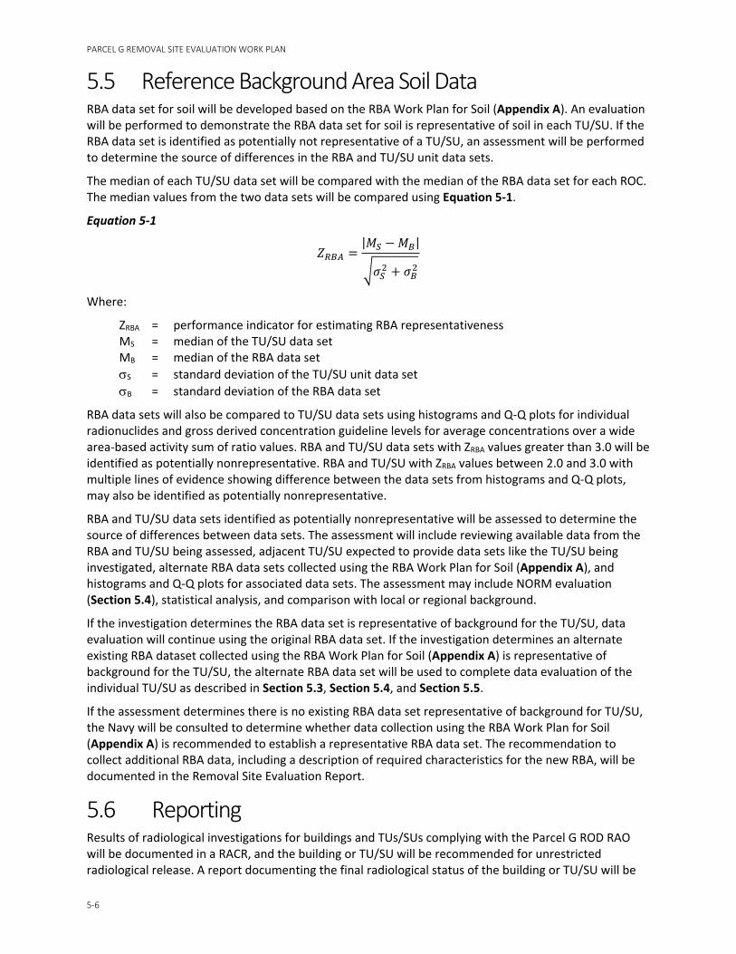
PARCEL G REMOVAL SITE EVALUATION WORK PLAN
5-6
5.5 Reference Background Area Soil Data RBA data set for soil will be developed based on the RBA Work Plan for Soil (Appendix A). An evaluation will be performed to demonstrate the RBA data set for soil is representative of soil in each TU/SU. If the RBA data set is identified as potentially not representative of a TU/SU, an assessment will be performed to determine the source of differences in the RBA and TU/SU unit data sets.
The median of each TU/SU data set will be compared with the median of the RBA data set for each ROC. The median values from the two data sets will be compared using Equation 5-1.
Equation 5-1
𝑍𝑍𝑅𝑅𝐵𝐵𝐴𝐴 =|𝑀𝑀𝑆𝑆 − 𝑀𝑀𝐵𝐵|
�𝜎𝜎𝑆𝑆2 + 𝜎𝜎𝐵𝐵
2
Where:
ZRBA = performance indicator for estimating RBA representativeness MS = median of the TU/SU data set MB = median of the RBA data set σS = standard deviation of the TU/SU unit data set σB = standard deviation of the RBA data set
RBA data sets will also be compared to TU/SU data sets using histograms and Q-Q plots for individual radionuclides and gross derived concentration guideline levels for average concentrations over a wide area-based activity sum of ratio values. RBA and TU/SU data sets with ZRBA values greater than 3.0 will be identified as potentially nonrepresentative. RBA and TU/SU with ZRBA values between 2.0 and 3.0 with multiple lines of evidence showing difference between the data sets from histograms and Q-Q plots, may also be identified as potentially nonrepresentative.
RBA and TU/SU data sets identified as potentially nonrepresentative will be assessed to determine the source of differences between data sets. The assessment will include reviewing available data from the RBA and TU/SU being assessed, adjacent TU/SU expected to provide data sets like the TU/SU being investigated, alternate RBA data sets collected using the RBA Work Plan for Soil (Appendix A), and histograms and Q-Q plots for associated data sets. The assessment may include NORM evaluation (Section 5.4), statistical analysis, and comparison with local or regional background.
If the investigation determines the RBA data set is representative of background for the TU/SU, data evaluation will continue using the original RBA data set. If the investigation determines an alternate existing RBA dataset collected using the RBA Work Plan for Soil (Appendix A) is representative of background for the TU/SU, the alternate RBA data set will be used to complete data evaluation of the individual TU/SU as described in Section 5.3, Section 5.4, and Section 5.5.
If the assessment determines there is no existing RBA data set representative of background for TU/SU, the Navy will be consulted to determine whether data collection using the RBA Work Plan for Soil (Appendix A) is recommended to establish a representative RBA data set. The recommendation to collect additional RBA data, including a description of required characteristics for the new RBA, will be documented in the Removal Site Evaluation Report.
5.6 Reporting Results of radiological investigations for buildings and TUs/SUs complying with the Parcel G ROD RAO will be documented in a RACR, and the building or TU/SU will be recommended for unrestricted radiological release. A report documenting the final radiological status of the building or TU/SU will be
SECTION 5 – DATA EVALUATION AND REPORTING
5-7
prepared and will document the results of the survey, any remedial activities performed for the building or TU/SU, and the results of the comparison with background and attached to the RACR.
A Removal Site Evaluation Report will be prepared for buildings and TUs/SUs where additional information is recommended to support a decision on whether the building or TU/SU complies with the Parcel G ROD RAO. The report will document the results of the radiological investigations, including descriptions of data evaluation results failing to comply with the Parcel G ROD RAO and recommendations on actions required to demonstrate compliance with the Parcel G ROD RAO. Potential recommendations may include further evaluation using USEPA’s current guidance on Radiation Risk Assessment at CERCLA Sites (USEPA, 2014), evaluation of concentrations of ubiquitous fallout to ensure cleanup does not include soil containing only fallout from past nuclear weapons testing, additional investigations of TUs/SUs or RBAs, alternative statistical evaluations, alternative background evaluations, revisions to the Parcel G ROD, or remedial actions to remove contamination.
SECTION 6
6-1
Radioactive Materials Management and Control Project requirements, including personnel roles and responsibilities, required training, and health and safety protocols are presented in this section. This section was prepared based on CH2M and their subcontractor, Perma-Fix, leading and conducting the field activities presented in this work plan and should be amended for contractor-specific information, as needed. Appendix B includes the contractor-specific information including the Radiological Material License, SOPs, Organizational Chart, and Radiation Protection Plan. A separate APP/SSHP will be prepared to outline the health and safety requirements and procedures for the work included in this work plan.
6.1 Project Roles and Responsibilities The personnel responsible for the execution of site activities and program oversight is presented in the Organization Chart in Appendix B. The Field Team Leader is responsible for overseeing all field activities for this project. The Field Team Leader will serve as the primary point of contact for scheduling and field-related issues. The Radiation Safety Officer (RSO) has overall responsibility for ensuring that fieldwork is conducted by trained staff in accordance with the Radioactive Material License and applicable plans and procedures.
The RSO will be supported by radiation protection staff to implement the requirements of the licensed SOPs and for conducting radiological data collection in accordance with Sections 3 and 4 of this work plan.
6.2 Licensing and Jurisdiction The radioactive material license is State of California Radioactive Material License 8188-01 (dated November 15, 2017). The license is attached to this work plan in Appendix B. Under 10 Code of Federal Regulations (CFR) 150.20, Perma-Fix holds a general license to conduct these licensed activities in areas of exclusive federal jurisdiction within the State of California. Authorization will be required from California to work in certain parcels at HPNS. Authorization will be requested and approved before the start of field operations. Figure 6-1 details the location of the specific parcels that are under exclusive federal jurisdiction and will require authorization. Perma-Fix will request reciprocity from the NRC, using NRC Form 241, to utilize Perma-Fix’s State of California Radioactive Material License in areas under NRC jurisdiction. The NRC requires notification a minimum of 3 days prior to beginning licensed activities.
The following are State requirements:
• Under the Radioactive Material License (8188-01) Section 16, Perma-Fix will submit an appropriate notification to the State of California a minimum of 14 days before the start of work.
• Under the Radioactive Material License (8188-01) Section 17, Perma-Fix will obtain an appropriate agreement between Perma-Fix and the Navy. This agreement will be included in the Section 16 submittal.
A Memorandum of Understanding (MOU) for the site has been established and was updated on December 2, 2016 (Appendix C). This MOU supersedes all previous MOUs.
PARCEL G REMOVAL SITE EVALUATION WORK PLAN
6-2
6.3 Radiological Health and Safety Fieldwork will be conducted in accordance with Perma-Fix’s State of California Radioactive Material License and the SOPs associated with it. A list the field radiological SOPs that provide the instructions for conducting field activities involving exposure to radiation and radioactive materials and copies of the SOPs are provided in Appendix B.
Prerequisites for the initiation of survey activities include review of this work plan, radiological evaluation of the designated work areas, and identification of potential safety concerns. Dose rate, contamination, and air monitoring, including initial baseline sampling to determine radiological background conditions, will be performed as necessary and in accordance with this work plan and the supporting procedural documents, including the SOPs in Appendix B. Radiation Work Permits (RWPs) will be prepared in accordance with SOP RP-103, Radiation Work Permits Preparation and Use. RWPs will be used to govern radiological health and safety. Personal protective equipment (PPE) levels will be assigned or modified, according to this work plan and APP/SSHP, and included in SOP RP-132, Radiological Protective Clothing Selection, Monitoring, and Decontamination, such that they are protective of health and safety based on radiological considerations and physical and chemical safety issues. Radiological personnel will prepare, approve, and record monitoring records in accordance with SOP RP-114, Control of Radiation Protection Records.
Key radiological personnel are expected to have the requisite skills necessary to perform these functions. The key radiological personnel include the following:
• Licensed RSO • PRSO • Project Manager for Perma-Fix • Radiation Protection Supervisor • RCTs
Roles may be combined as described in this work plan. Key personnel will be approved in advance by the project manager or field lead.
6.4 Radiation Protection Appendix B contains the Radiation Protection Plan, which includes key Perma-Fix Radiation Protection Program procedures. The Radiation Protection Plan details requirements for activities conducted under the California Radioactive Material License and describes radiation safety practices to be applied in the field and referenced in the APP/SSHP. The Radiation Protection Plan covers project activities that involve the use or handling of licensed by-product, source, or special nuclear material (hereinafter referred to as radioactive material); tasks with the potential for radioactive material to be present based on available data and historical records; and work in posted RCAs.
6.4.1 Radiological Postings Radiological postings are used to delineate the RCAs necessary to conduct investigation activities. Radiological posting requirements are found in SOP RP-102, Radiological Posting (Appendix B).
6.4.2 Internal and External Exposure Control and Monitoring Based on review of historical data, radiation doses are not expected to exceed 100 millirems per year (annual public dose allotment) for any project personnel. Although worker doses are expected to be a small fraction of the annual limits, external dose rates and cumulative doses and internal doses, via airborne concentration measurements will be monitored to ensure worker doses are maintained as low as reasonably achievable (ALARA). The dosimetry requirements are contained in SOP-RP-112, Dosimetry
SECTION 6 – RADIOACTIVE MATERIALS MANAGEMENT AND CONTROL
6-3
Issue. The expectation is that all personnel entering the controlled area except untrained, escorted individuals as described in Section 6.4.3. will be assigned an external monitoring device such as a thermoluminescent dosimeter. Untrained, escorted personnel entries will be logged such that the escort thermoluminescent dosimeter badge results can be used as the monitoring results for that individual if a question arises as to the possible external dose that individual received. Periodic external dose rate measurements will be taken before and during intrusive activities in accordance with SOP RP-104, Radiological Surveys (Appendix B), to ensure worker exposures are maintained ALARA.
6.4.3 Radiological Access Control Access control is necessary to provide a consistent methodology for controlling the access of personnel, equipment, and vehicles into radiological areas. Access control points further control the release of the materials, tools, and equipment from radiological areas. Access control requirements are found in SOP RP-101, Access Control (Appendix B). It is anticipated that areas targeted for investigation as part of this plan, including the soil sorting area or RSYs will be established as RCAs.
Personnel and equipment exiting the boundary of an RCA will be surveyed to ensure their clothing, equipment, and vehicles do not leave the site with contamination levels exceeding RGs.
A RWP is an administrative mechanism used to establish radiological controls for intended work activities. The RWP will provide information to workers on area radiological conditions and entry requirements including PPE. The following summarizes the RWP process for this project:
• RWP creation will be done by the License RSO or designee.
• RWPs will be approved by the License RSO or designee.
• Expected levels of contamination and external exposure rates will be listed in the RWP.
• Current and expected radiological conditions will be listed in the RWP.
• PPE and monitoring requirements will be specified in the RWP.
• Special monitoring instructions, hold points, or action levels may be listed as a part of the RWP requirements.
• RWP approval duration will be for the expected length of the project or until radiological conditions change and a revision is needed.
• Where radiological conditions change such that PPE or monitoring requirements must change, the work will be suspended until a new or revised RWP containing the new RWP requirements is issued.
• Personnel working in the area covered by the RWP will be briefed on the RWP requirements and sign an acknowledgment that they have received and understand the briefing.
RWP requirements are found in SOP RP-103, Radiation Work Permits Preparation and Use (Appendix B).
6.4.4 Personal Protective Equipment PPE will be selected based on the specific hazard and will comply with the APP/SSHP, the RWP, and the AHA specific to the task being performed. Based on historical information, the planned investigation activities are not expected to encounter or generate removable or airborne radioactivity. Therefore, it is expected that fieldwork PPE will consist of wearing Level D PPE and will include the following:
• Long pants • High visibility outer layer • Safety-toed boots • Hard hat • Work gloves
PARCEL G REMOVAL SITE EVALUATION WORK PLAN
6-4
• Eye protection
If the field conditions exceed action levels for additional response (detailed in Perma-Fix procedures SOP RP-101, Access Control; SOP RP-102, Radiological Postings; and SOP RP-103, Radiation Work Permits) (Appendix B), PPE may be upgraded as necessary.
6.4.5 Instrumentation Instruments to be used for worker protection and monitoring will include dose and exposure rate instruments, alpha-beta dual phosphor surface contamination detectors, hand-held 2-inch by 2-inch NaI detectors for gross gamma investigations, and a dual phosphor alpha-beta bench top counter for analysis of surface swipe samples and air samples. Instruments will be operated in accordance with applicable instrument-specific SOPs.
All counting systems and instruments will be calibrated with a National Institute of Standards and Technology-traceable source at intervals not exceeding 12 months, or as recommended by the manufacturer. The source used will be appropriate for the type and the energy of the radiation to be detected. All calibrations will be documented and include the source data.
The minimum training requirements for personnel working in the field at HPNS are provided in the following sections.
6.4.6 Radiological Training Radiological training includes the following modules in accordance with SOP RP-115, Radiation Worker Training (Appendix B):
• General Employee Radiological Training • Radiological Worker Training and Certification • RCT Training and Certification
Visitors and escorted persons must receive a site briefing and will be assigned to a qualified radiation worker or RCT when in a posted RCA.
6.4.7 Health and Safety Training Health and safety training may include, but is not limited to, the following:
• Occupational Safety and Health Administration (OSHA) 40-hour Hazardous Waste Operations and Emergency Response (HAZWOPER) training
• OSHA 8-hour HAZWOPER refresher training • OSHA 8-hour HAZWOPER supervisor training • OSHA-required On the Job training • Site- or task-specific AHA training • Basic first aid training • Cardiopulmonary resuscitation training
6.5 Radiological Support Surveys Personnel, equipment, material, and area surveys will be performed in accordance with this work plan and appendixes. If survey results indicate levels of contamination exceeding RGs, appropriate decontamination methods will be performed in accordance with applicable SOPs (Appendix B).
SECTION 6 – RADIOACTIVE MATERIALS MANAGEMENT AND CONTROL
6-5
6.5.1 Personnel Surveys Personnel surveys will be conducted in accordance with SOP RP-104, Radiological Surveys (Appendix B). Personnel surveys are used to ensure that individuals leaving a radiological area are free of contamination. Hands and feet “frisks” or scans with dual alpha-beta scintillators will be required when individuals exit RCAs.
Scanning will be performed in the alpha plus beta mode of the instrument because of the potential presence of 90Sr, a pure beta emitter, and the fact that there are beta emissions from progeny in the radium decay chain that can be used as a surrogate for potential radium contamination. Where contamination is found or suspected, the PRSO will be contacted and will provide further technical direction for any personnel/clothing decontamination that may be needed.
6.6 Equipment Surveys 6.6.1 Swipe Samples Swipe sampling will be performed to assess the presence of radioactive contamination that is readily removed from a surface. Swipe samples will be taken to evaluate the presence of removable alpha and beta activity. The procedures for collecting swipe samples are discussed in SOP RP-104, Radiological Surveys (Appendix B).
6.6.2 Exposure Rate Surveys (Dose Rates) Exposure rate surveys are performed to measure ambient gamma radiation levels. Exposure rate surveys will be performed prior to and periodically during intrusive activities to confirm exposure levels relative to RWP requirements.
6.6.3 Equipment Baseline and Unconditional Release Surveys Equipment mobilized and demobilized from the site will undergo radioactivity surveys in accordance with RP-104 Radiological Surveys and RP-105 Unconditional Release Requirements (Appendix B). Baseline and Release surveys may include a combination of surface scans and static measurements using dual alpha-beta scintillators and swipe samples.
6.7 Documentation and Records Management The purpose of this section is to define standards for the maintenance and retention of radiological records. Radiological records provide historical data, document radiological conditions, and record personnel exposure. Field documentation requirements are outlined in the SAP and SOP RP-114, Radiological Records Control (Appendix B).
Radiological surveys will be performed and documented in accordance with SOP RP-106, Survey Documentation and Review (Appendix B). Sample collection, field measurements, and laboratory data will be recorded electronically to the extent practicable. Electronically recorded data and information will be backed up to a SharePoint site or equivalent on a nightly basis, or as reasonably practical. Data and information recorded on paper will be recorded using indelible ink. Both electronic and paper records of field-generated data will be reviewed by the PRSO or a designee knowledgeable in the measurement method for completeness, consistency, and accuracy. Data manually transposed to paper from electronic data collection devices will be compared to the original data sets to ensure consistency and to resolve noted discrepancies. Electronic copies of original electronic data sets will be preserved on a nonmagnetic retrievable data storage device. No data reduction, filtering, or modification will be performed on the original electronic versions of data sets.
PARCEL G REMOVAL SITE EVALUATION WORK PLAN
6-6
6.7.1 Documentation Quality Standards Records will be legible and completed with an indelible ink that provides reproducible and legible copies. Records will be dated and contain a verifiable signature of the originator. Errors that may be identified will be corrected by marking a single line through the error and by initialing and dating the correction.
Radiological records will not be corrected using an opaque substance. Shorthand or nonstandardized terms may not be used.
To ensure traceability, each record will clearly indicate the following:
• Name of the project • Specific location • Function and process • Date • Document number (if applicable)
The quantities used in records will be clearly indicated in standard units (e.g., curie, radiation absorbed dose [rad], roentgen equivalent man [rem], disintegration[s] per minute [dpm], Becquerel), including multiples and subdivisions of these units.
6.7.2 Laboratory Records Survey and laboratory data assessment records will be prepared as indicated in the contractor’s QA/QC Plan.
6.7.3 Record Retention Records resulting from implementation of this work plan will be retained as outlined in the SAP.
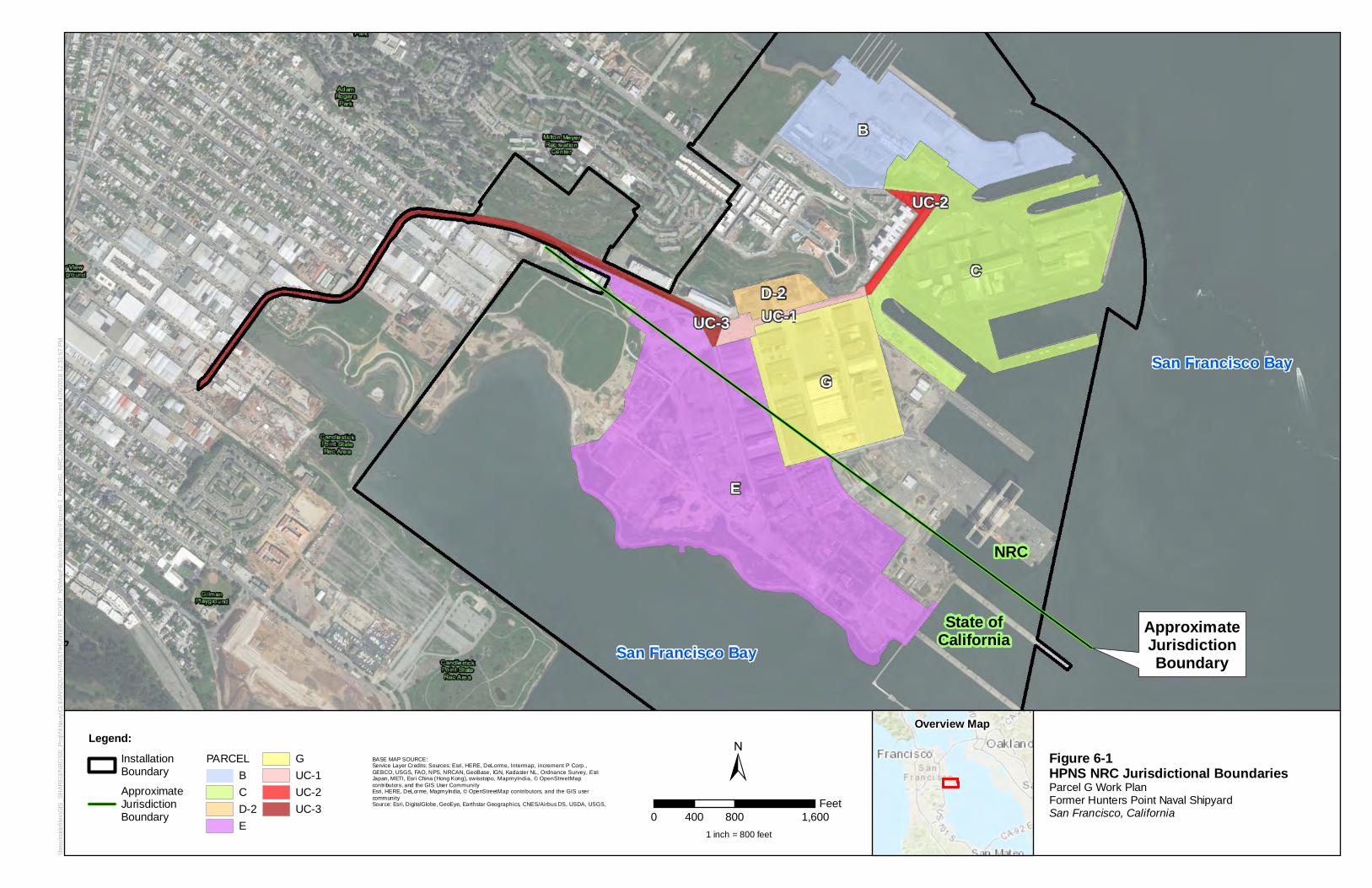
San Francisco Bay
San Francisco BayState of
California
NRC
ApproximateJurisdictionBoundary
UC-3
E
B
D-2
G
UC-1
UC-2
C
\\bro
oksi
defil
es\G
IS_S
HAR
E\EN
BG\0
0_Pr
oj\N
\Nav
y\CL
EAN
\SO
UTH
WES
T\H
UN
TER
S_P
OIN
T_N
S\M
apFi
les\
Wor
kPla
ns\F
igur
e6-1
_Par
celG
_NR
CJu
ris.m
xd h
artm
and
4/26
/201
8 12
:31:
57 P
M
Legend:InstallationBoundary
ApproximateJurisdictionBoundary
PARCELBCD-2E
GUC-1UC-2UC-3
±Overview Map
Figure 6-1HPNS NRC Jurisdictional Boundaries Parcel G Work PlanFormer Hunters Point Naval ShipyardSan Francisco, California
BASE MAP SOURCE:Service Layer Credits: Sources: Esri, HERE, DeLorme, Intermap, increment P Corp.,GEBCO, USGS, FAO, NPS, NRCAN, GeoBase, IGN, Kadaster NL, Ordnance Survey, EsriJapan, METI, Esri China (Hong Kong), swisstopo, MapmyIndia, © OpenStreetMapcontributors, and the GIS User CommunityEsri, HERE, DeLorme, MapmyIndia, © OpenStreetMap contributors, and the GIS usercommunitySource: Esri, DigitalGlobe, GeoEye, Earthstar Geographics, CNES/Airbus DS, USDA, USGS,
0 800 1,600400Feet
1 inch = 800 feet
CJ 1111 Fr n i s.co
CJ 1111 1111
S,
- CJ 1111 1111 (J 'l.
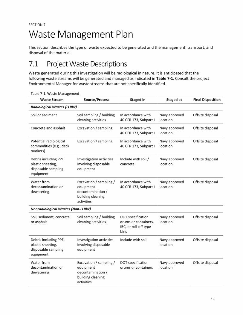
SECTION 7
7-1
Waste Management Plan This section describes the type of waste expected to be generated and the management, transport, and disposal of the material.
7.1 Project Waste Descriptions Waste generated during this investigation will be radiological in nature. It is anticipated that the following waste streams will be generated and managed as indicated in Table 7-1. Consult the project Environmental Manager for waste streams that are not specifically identified.
Table 7-1. Waste Management Waste Stream Source/Process Staged in Staged at Final Disposition
Radiological Wastes (LLRW)
Soil or sediment Soil sampling / building cleaning activities
In accordance with 40 CFR 173, Subpart I
Navy approved location
Offsite disposal
Concrete and asphalt Excavation / sampling In accordance with 40 CFR 173, Subpart I
Navy approved location
Offsite disposal
Potential radiological commodities (e.g., deck markers)
Excavation / sampling In accordance with 40 CFR 173, Subpart I
Navy approved location
Offsite disposal
Debris including PPE, plastic sheeting, disposable sampling equipment
Investigation activities involving disposable equipment
Include with soil / concrete
Navy approved location
Offsite disposal
Water from decontamination or dewatering
Excavation / sampling / equipment decontamination / building cleaning activities
In accordance with 40 CFR 173, Subpart I
Navy approved location
Offsite disposal
Nonradiological Wastes (Non-LLRW)
Soil, sediment, concrete, or asphalt
Soil sampling / building cleaning activities
DOT specification drums or containers, IBC, or roll-off type bins
Navy approved location
Offsite disposal
Debris including PPE, plastic sheeting, disposable sampling equipment
Investigation activities involving disposable equipment
Include with soil Navy approved location
Offsite disposal
Water from decontamination or dewatering
Excavation / sampling / equipment decontamination / building cleaning activities
DOT specification drums or containers
Navy approved location
Offsite disposal
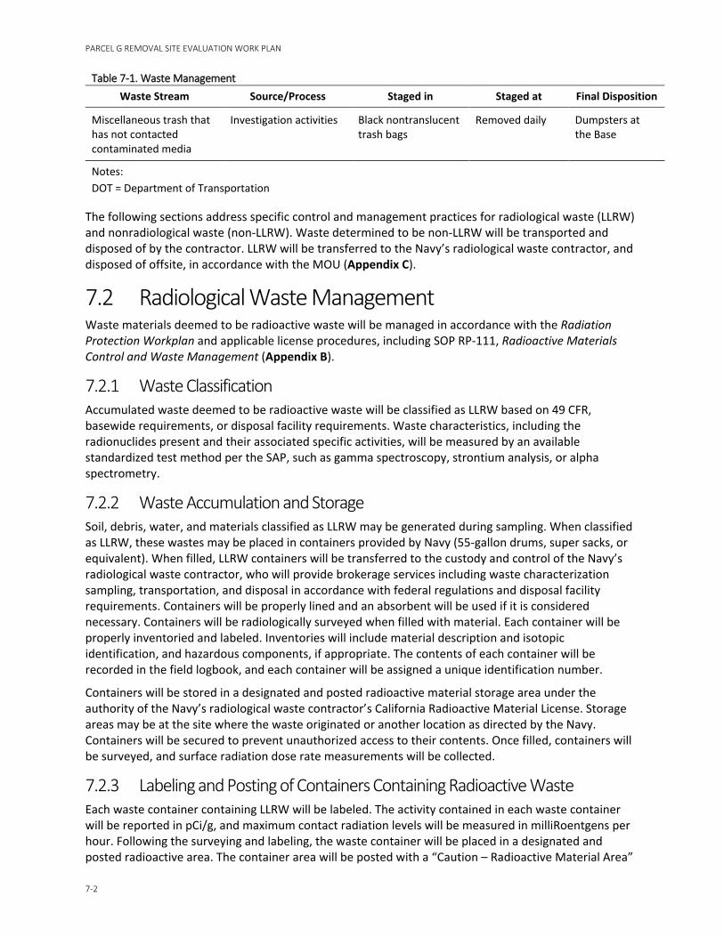
PARCEL G REMOVAL SITE EVALUATION WORK PLAN
7-2
Table 7-1. Waste Management Waste Stream Source/Process Staged in Staged at Final Disposition
Miscellaneous trash that has not contacted contaminated media
Investigation activities Black nontranslucent trash bags
Removed daily Dumpsters at the Base
Notes: DOT = Department of Transportation
The following sections address specific control and management practices for radiological waste (LLRW) and nonradiological waste (non-LLRW). Waste determined to be non-LLRW will be transported and disposed of by the contractor. LLRW will be transferred to the Navy’s radiological waste contractor, and disposed of offsite, in accordance with the MOU (Appendix C).
7.2 Radiological Waste Management Waste materials deemed to be radioactive waste will be managed in accordance with the Radiation Protection Workplan and applicable license procedures, including SOP RP-111, Radioactive Materials Control and Waste Management (Appendix B).
7.2.1 Waste Classification Accumulated waste deemed to be radioactive waste will be classified as LLRW based on 49 CFR, basewide requirements, or disposal facility requirements. Waste characteristics, including the radionuclides present and their associated specific activities, will be measured by an available standardized test method per the SAP, such as gamma spectroscopy, strontium analysis, or alpha spectrometry.
7.2.2 Waste Accumulation and Storage Soil, debris, water, and materials classified as LLRW may be generated during sampling. When classified as LLRW, these wastes may be placed in containers provided by Navy (55-gallon drums, super sacks, or equivalent). When filled, LLRW containers will be transferred to the custody and control of the Navy’s radiological waste contractor, who will provide brokerage services including waste characterization sampling, transportation, and disposal in accordance with federal regulations and disposal facility requirements. Containers will be properly lined and an absorbent will be used if it is considered necessary. Containers will be radiologically surveyed when filled with material. Each container will be properly inventoried and labeled. Inventories will include material description and isotopic identification, and hazardous components, if appropriate. The contents of each container will be recorded in the field logbook, and each container will be assigned a unique identification number.
Containers will be stored in a designated and posted radioactive material storage area under the authority of the Navy’s radiological waste contractor’s California Radioactive Material License. Storage areas may be at the site where the waste originated or another location as directed by the Navy. Containers will be secured to prevent unauthorized access to their contents. Once filled, containers will be surveyed, and surface radiation dose rate measurements will be collected.
7.2.3 Labeling and Posting of Containers Containing Radioactive Waste Each waste container containing LLRW will be labeled. The activity contained in each waste container will be reported in pCi/g, and maximum contact radiation levels will be measured in milliRoentgens per hour. Following the surveying and labeling, the waste container will be placed in a designated and posted radioactive area. The container area will be posted with a “Caution – Radioactive Material Area”
SECTION 7 – WASTE MANAGEMENT PLAN
7-3
posting. An inventory of contents with radionuclide and specific activity (if available) will be maintained by the contractor until the custody of the material is transferred to the Navy’s radiological waste contractor.
7.2.4 Waste Accumulation Areas The contractor working on this project will implement, at a minimum, the following requirements for radioactive waste stored onsite within a designated radioactive materials area:
• Industry standard posting and barrier materials will be displayed with wording that includes the following, “Caution, Radioactive Materials Area,” at each radioactive waste storage area sufficient to be seen from any approach. The signs will be legible and clearly conspicuous for outdoor and indoor locations.
• Aisle space will be maintained to allow for the unobstructed movement of personnel, fire-control equipment, spill-control equipment, and decontamination equipment to any facility operation area, in the event of an emergency, unless aisle space is not needed for any of these purposes.
• The areas will be secured to prevent unauthorized access to the material.
• The following emergency equipment will be located or available to personnel during radioactive waste management activities at each accumulation area:
− A device, such as a telephone or a handheld two-way radio, capable of summoning emergency assistance (adjacent areas with personnel who have communication devices or areas with fixed devices that personnel can access quickly are sufficient)
− Portable fire extinguishers, fire-control equipment, spill-control equipment, and decontamination equipment
Filled containers generated during performance of work will be stored in a material storage location until the contained material can be characterized and appropriately classified. Depending on the characterization results, the material may be moved to another storage location, transported and disposed offsite, or re-used as backfill.
7.2.5 Inspection of Waste Accumulation Areas While all waste accumulation areas will be informally inspected daily during waste generation activities, formal inspections of all container accumulation areas will be conducted and recorded at least weekly in accordance with the appropriate Radioactive Material License requirements. The PRSO or designee will conduct inspections that will be recorded in a dedicated field logbook, and a weekly inspection checklist will be completed. The container storage areas will be inspected and the containers checked to ensure the following:
• The containers will be checked for condition. If a container is not in good condition, the certified waste broker will be informed.
• The containers will be checked to ensure that they remain closed and secured at all times, except when adding or removing waste.
• The container label will be checked to ensure that it is visible and filled out properly.
7.2.6 Waste Transportation In accordance with the MOU, the Navy’s radiological waste contractor will be responsible for transportation of the LLRW in accordance with the DOT Radioactive Material Transportation regulations of 49 CFR for offsite disposal. The contractor may supply DOT contamination surveys and radiation measurements on the outside of the container prior to shipment. The Navy’s radiological waste

PARCEL G REMOVAL SITE EVALUATION WORK PLAN
7-4
contractor will ensure that empty containers being returned to vendors meet the release limits for equipment and materials.
LLRW transported from the site will be accompanied by a radioactive waste manifest or a Uniform Hazardous Waste Manifest, as appropriate. Preparation of the LLRW manifests are the responsibility of the Navy’s radiological waste contractor.
BRAC will receive a copy of the manifest. The remaining copies will be given to the transporter. The manifest will be returned to the Navy signatory official in accordance with the Base’s recordkeeping requirements.
7.2.7 Waste Disposal The Navy’s radiological waste contractor is responsible for the disposal of LLRW. The Navy’s radiological waste contractor will coordinate closely with RASO and contractor to ensure proper transfer of custody of the waste and coordinate the shipment offsite. LLRW inventories will be managed under the appropriate radioactive material license.
7.3 Nonradiological Waste Management 7.3.1 Waste Classification In general, wastes generated during the project will be assessed to determine proper handling and final disposition through chemical analysis, field testing, and possible generator knowledge. The exceptions are uncontaminated wastes (that is, no contact with contaminated media or remediation chemicals) and trash.
Samples of these wastes will be collected and analyzed to determine whether the waste is a Hazardous Waste or a Nonhazardous Waste. Analysis will be based on the requirements of the offsite disposal facility, and may include total petroleum hydrocarbons (typically C4 to C40), volatile organic compounds (VOCs), semivolatile organic compounds, corrosivity (pH), or California Assessment Manual 17 total metals. Based on the results, additional waste characterization may be needed or necessary to have the waste managed at an offsite waste management facility.
The project Environmental Manager should review the analytical data and characterize and classify the waste.
Samples will be collected in accordance with the general procedures in the following section and sent to a properly licensed laboratory for analyses. If the waste is placed in containers, one composite sample (and one grab for VOC analysis, if needed) will be collected per 10 drums of each waste stream. If soil is staged in stockpiles or bins, a 4 to 1 composite will be collected and a grab sample for VOCs. If the waste (liquid) is placed in a tank or container, grab samples are appropriate. Please note that offsite waste management facilities may require specific sampling per volume of waste accumulated under their waste acceptance policy.
7.3.2 Waste Sampling Procedures 7.3.2.1 Liquids Analytical samples for liquid wastes will be collected from the 55-gallon drums before disposal; one composite sample will be collected per 10 drums. Water samples will be collected by the following procedure:
1. Collect a water sample from a drum using a bailer or dipper if the water is homogenous or use a coliwasa if the water has more than one phase.
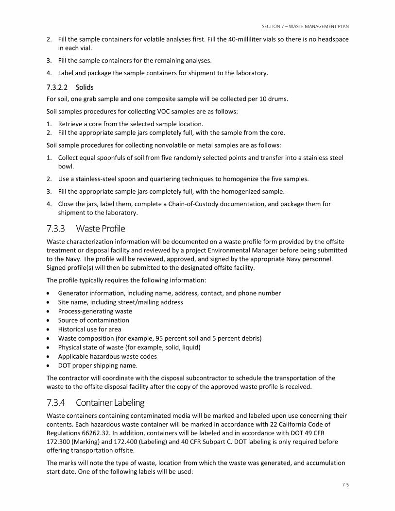
SECTION 7 – WASTE MANAGEMENT PLAN
7-5
2. Fill the sample containers for volatile analyses first. Fill the 40-milliliter vials so there is no headspace in each vial.
3. Fill the sample containers for the remaining analyses.
4. Label and package the sample containers for shipment to the laboratory.
7.3.2.2 Solids For soil, one grab sample and one composite sample will be collected per 10 drums.
Soil samples procedures for collecting VOC samples are as follows:
1. Retrieve a core from the selected sample location. 2. Fill the appropriate sample jars completely full, with the sample from the core.
Soil sample procedures for collecting nonvolatile or metal samples are as follows:
1. Collect equal spoonfuls of soil from five randomly selected points and transfer into a stainless steel bowl.
2. Use a stainless-steel spoon and quartering techniques to homogenize the five samples.
3. Fill the appropriate sample jars completely full, with the homogenized sample.
4. Close the jars, label them, complete a Chain-of-Custody documentation, and package them for shipment to the laboratory.
7.3.3 Waste Profile Waste characterization information will be documented on a waste profile form provided by the offsite treatment or disposal facility and reviewed by a project Environmental Manager before being submitted to the Navy. The profile will be reviewed, approved, and signed by the appropriate Navy personnel. Signed profile(s) will then be submitted to the designated offsite facility.
The profile typically requires the following information:
• Generator information, including name, address, contact, and phone number • Site name, including street/mailing address • Process-generating waste • Source of contamination • Historical use for area • Waste composition (for example, 95 percent soil and 5 percent debris) • Physical state of waste (for example, solid, liquid) • Applicable hazardous waste codes • DOT proper shipping name.
The contractor will coordinate with the disposal subcontractor to schedule the transportation of the waste to the offsite disposal facility after the copy of the approved waste profile is received.
7.3.4 Container Labeling Waste containers containing contaminated media will be marked and labeled upon use concerning their contents. Each hazardous waste container will be marked in accordance with 22 California Code of Regulations 66262.32. In addition, containers will be labeled and in accordance with DOT 49 CFR 172.300 (Marking) and 172.400 (Labeling) and 40 CFR Subpart C. DOT labeling is only required before offering transportation offsite.
The marks will note the type of waste, location from which the waste was generated, and accumulation start date. One of the following labels will be used:
PARCEL G REMOVAL SITE EVALUATION WORK PLAN
7-6
• “Analysis Pending” or “Waste Material”—Temporary label until analytical results are received, reviewed, and determined whether the waste is hazardous or not. This label will include the accumulation start date. An example of this mark is provided as follows:
− Contents: Example – soil from drill / auger cuttings
− Origin of Materials: Former Hunters Point Naval Shipyard
− Address:
− Contact Name and Phone #:
− Accumulation Start Date: Please add under the Contact
• “Non-Hazardous Waste”— If the waste is determined to be non-hazardous, apply the mark below with the following information:
− Shipper: Former Hunters Point Naval Shipyard
− Address:
− Contents: Example – soil from drill / auger cuttings
− Contact Name and Phone#:
− Please add Accumulation Start Date somewhere on the mark
• “Hazardous Waste: If the waste is determined to be hazardous, apply the mark below with the following information:
− Name: Former Hunters Point Naval Shipyard − Address: − Phone: − City: San Francisco − State: CA − Zip: − EPA ID No.: − Manifest number: Add before transportation − EPA Waste No.: EM to provide − CA Waste No. EM to provide − Accumulation Start Date: The date the waste
was first placed in the container − Physical State: Check solid or liquid − Hazardous Properties: Check the appropriate hazard − DOT proper shipping name: EM to provide
If additional assistance is needed in selecting the appropriate marks and labels, please contact the Environmental Manager or waste expert.
THIS CONTAINER • ONHOlD , ,
PENDING ANllYSIS'•, (O'tn:ln
Ole.QI\ ~,-., 111,ttO:W.S
100lE~!I
(U.. l'l,(;T
DO NOT TAMPII WITH CONTAINER AUTHORllED PERSONNEL ONLY
AODRUS _____________ _
cnv.~ATE. ZIP ___________ _
COf.:T8'TS ____________ _
HAZARDOUS WASTE
STAT! NtD llOOW.I.AWS ,of., Ufl'ID'Uletwow. .,l'Oll'IQ.CONl'/ICT.,._, _ _,.NIIIUOAl'Ua.C""l'IV -"· ......... _ «-___ ""_ ....... °" n,~c,,,i., ·OIMJI o,;1>,i1;, '"'11f0/'Y<u,c-,.....ci;.t1 oo,,r"°"'
GC..-I\O,lO'lo11,o,i,w.no,,• -.-...... '°'°" Cll'I' ITAl't ll•
::0.1:::,N). lAA f:t, N;IOI.MAATO, -~"'---~"'--•,-o-." -CO,,,~.~
SECTION 7 – WASTE MANAGEMENT PLAN
7-7
7.3.5 Waste Accumulation Areas Although hazardous waste is not expected, if generated, the contractor will coordinate with the Navy to determine an appropriate site location to store the hazardous waste.
All containers will be physically handled in accordance with the APP/SSHP. Additional management requirements for the containers expected to be put into use can be found in Table 7-2.
Table 7-2. Non-LLRW Accumulation Requirements
Accumulating In: Requirements
Drums/Small Containers
• Inspected upon arrival onsite for signs of contamination or deterioration. Any container arriving with contents or in poor condition shall be rejected.
• No penetrating dents are allowed that could affect the integrity of the drum. Pay special attention to dents at the drum seams.
• Closed head drums: Will be inspected to verify that the bung will close properly. • Open head drums: Drum lids will be inspected to verify that the gasket is in good
shape and that the lid will seat properly on the drum. • Arranged in rows of no more than 2 drums with at least 3 feet between rows. • Each container will be provided with its own mark and label, and the marks and
labels must be visible. • Drums will remain completely closed with all lids, covers, bolts, and locking
mechanisms engaged, as though ready for immediate transport, except when removing or adding waste to the drum.
• Drums and small containers of hazardous waste will be transported using proper drum-handling methods, such as transportation by forklift on wood pallets, with drums secured together. Containers will be transported in a manner that will prevent spillage or particulate loss to the environment.
• Drums will be disposed of with the contents. If the contents are removed from the drums for offsite transportation and treatment or disposal, the drums will be decontaminated prior to re-use or before leaving the site.
• The outsides of the drums and containers must be free of hazardous waste residues. • Ignitable or reactive wastes will be stored at least 50 feet from the property line. • Drums and containers will not be located near a stormwater inlet or stormwater
conveyance. • Drums containing waste liquids, hazardous or incompatible wastes will be provided
with secondary containment capable of holding the contents of the largest tank and precipitation from a 24-hour, 25-year storm.
• Liquid that accumulates in a secondary containment area will be removed and placed in containers within 24 hours. Removed liquids with a sheen will be characterized and classified.
• New empty drums will be marked with the word “Empty”. Drums that are being reused will be marked with “Empty, last contained [previous contents]”
• All containers will be tracked on the field transportation and disposal log
7.3.6 Inspection of Waste Accumulation Areas Waste container accumulation areas will be inspected at least weekly for conditions that could result in a release of waste to the environment. Inspections will focus on conditions such as equipment malfunction, container or containment deterioration, signs of leakage or discharge. Specifically, containers (drums and roll offs) will be inspected for leaks, signs of corrosion, or signs of general deterioration.
PARCEL G REMOVAL SITE EVALUATION WORK PLAN
7-8
Any deficiencies observed or noted during inspection will be corrected immediately. Appropriate measures may include transferring waste from a leaking container to a new container, replacing the liner or cover, or repairing the containment berm.
Inspections will be recorded in the project log book or on an inspection form. Deficiencies and corrections will also be documented. All the following items will be noted in the log book for each inspection:
• The location of the area
• Total number of containers present
• Date
• Verification that all containers are labeled with the accumulation start date, contents, Base point of contact, and any relevant hazards (such as flammable and oxidizer). Labels must be visible, legible, and not faded.
• The condition of containers. Good condition for containers is defined as no severe rusting, dents, structural defects, or leaks.
• The condition of secondary containment. Good condition for containment is defined as no structural defects or leaks.
• Verification that all containers are completely closed with all bolts, lids, and locking mechanisms engaged as though ready for immediate transport.
• Verification that containers are staged in rows not more than two drums wide, with labels facing outward and 3 feet of space between rows.
• Verification that all containers are being tracked on the transportation and disposal log.
• Verification that the accumulation area is clean and free of debris.
Verification that emergency response equipment is present if required for the waste being staged.
7.3.7 Waste Transportation Each transportation vehicle and load of waste will be inspected before leaving the site, and the inspection will be documented in the log book. The quantities of waste leaving the site should be recorded on a transportation and disposal log. A subcontractor licensed for commercial transportation will transport non-hazardous wastes. If the wastes are hazardous, the transporter will have an EPA ID number and will comply with transportation requirements outlined in 49 CFR 171-179 (DOT) and 40 CFR 263.11 and 263.31 (Hazardous Waste Transportation).
The transporter will observe the following practices when hauling and transporting wastes offsite:
• Minimize impacts to general public traffic. • Clean up waste spilled in transit. • Line and cover trucks and trailers used for hauling contaminated waste to prevent releases and
contamination. • Decontaminate vehicles before reuse.
Per the MOU, the Navy’s radiological waste contractor will be responsible for transportation of the LLRW in accordance with the DOT Radioactive Material Transportation regulations of 49 CFR for offsite disposal. The contractor may supply DOT contamination surveys and radiation measurements on the outside of the container prior to shipment. The Navy’s radiological waste contractor will ensure that empty containers being returned to vendors meet the release limits for equipment and materials.
SECTION 7 – WASTE MANAGEMENT PLAN
7-9
Offsite transportation and disposal of hazardous and / or solid wastes will be handled by the selected waste contractor. All hazardous waste transported from the site will be accompanied by a Uniform Hazardous Waste Manifest and solid (nonhazardous waste) will be accompanied by a Non-Hazardous Waste Manifest or Bill of Lading, as appropriate. Navy personnel will be responsible for reviewing and signing all waste documentation, including waste profiles, manifests, and land disposal restriction notifications (manifest packages). Before signing the manifest, the designated Navy official will ensure that pre-transport requirements of packaging, labeling, marking, and placarding are met according to 40 CFR Parts 262.30–262.33, and 49 CFR Parts 100–178.
7.3.8 Waste Disposal Hazardous and solid wastes will be transported offsite for appropriate treatment and disposal.
Hazardous waste will be disposed or managed only at a hazardous waste disposal facility prequalified by the contractor and permitted for the disposal of the particular type of hazardous or solid waste generated.
7.4 Waste Minimization To minimize the volume of hazardous and radioactive waste generated during the project, the following general guidelines will be followed:
• Waste material will not be contaminated unnecessarily.
• Work will be planned.
• Material may be stored in large containers, but the smallest reasonable container will be used to transport the material to its destination.
• Cleaning and extra sampling supplies will be maintained outside any potentially contaminated area to keep them free of contamination and to minimize additional waste generation.
• Mixing of detergents or decontamination solutions will be performed outside potentially contaminated areas.
• When decontaminating radioactively contaminated material, every effort should be made to minimize the generation of mixed waste.
• Contaminated material will not be placed with clean material.
• Wooden pallets inside the exclusion zone will be covered with plastic.
• Material and equipment will be decontaminated and reused when practicable.
• Volume reduction techniques will be used when practicable.
7.5 Compliance with CERCLA Offsite Rule Consistent with the CERCLA Offsite Rule, wastes generated from remediation activities, such as contaminated soil or hazardous waste, at a CERCLA site may be transferred only to offsite facilities that have been deemed acceptable by the USEPA Regional Offsite Contact (40 CFR 300.440). With Naval approval, the contractor will request proof of Offsite Rule approval from the offsite disposal facility before transferring any wastes to an offsite facility.
PARCEL G REMOVAL SITE EVALUATION WORK PLAN
7-10
Other disposal practices to be followed are as follows:
• Hazardous waste (State and Resource Conservation and Recovery Act [RCRA]) will be sent to an offsite, permitted, RCRA Subtitle C treatment, storage, and disposal facility or Wastewater Treatment Facility permitted under Clean Water Act.
• Nonhazardous wastes will be disposed at an offsite RCRA Subtitle D facility permitted to receive such wastes. It is expected that the contaminated soil and debris will be classified as nonhazardous and disposed of at a Subtitle D facility.
• Decontamination water may be discharged to an onsite water treatment facility with written permission from the Base, or disposed offsite at a facility permitted to accept the waste.
• Uncontaminated debris may be sent to municipal landfills, landfills designated for construction/demolition debris or a recycling facility.
• General trash will be disposed in dumpsters on-base.
The designated offsite facility will be responsible for providing a copy of the fully executed waste manifest and a certificate of treatment or disposal for each load of waste received to the generator.
7.6 Documentation Documentation requirements apply to all waste managed during project activities. Field records will be kept of all waste-generating activities. All pages of the field data record log will be signed and dated by the person entering the data. In addition, the following information will be recorded in the log:
• Description of waste-generating activities • Location of waste generation (including depth, if applicable) • Type and volume of waste • Date and time of generation • Description of any waste sampling • Name of person recording information • Name of field manager at time of generation
7.7 Updating the Waste Management Plan The Waste Management Plan section will be updated as changes in site activities or conditions occur, as changes in applicable regulations occur, and as replacement pages are added to this work plan. Revisions to waste management will be reviewed and approved by the Navy. All changes to the plan associated with radioactive or mixed waste will require approval from RASO.

SECTION 8
8-1
Environmental Protection Plan This section briefly describes the environmental protection plan that will be implemented.
8.1 Land Resources and Vegetation Parcel G is within a developed former industrial area with limited to no vegetation. The administrative provisions of the applicable permit programs will be applied to protect wetlands and streams, if appropriate.
8.2 Fish and Wildlife, Threatened, Endangered, and Sensitive Species
Several hundred types of plants and animals are believed to live at or near HPNS. No federally listed endangered or threatened species are known to permanently reside at HPNS or in the vicinity (Levine-Fricke and PRC, 1997); however, San Francisco Bay is a seasonal home to migrating fish and birds.
8.3 Wetlands and Streams Two freshwater streams, Yosemite and Islais Creeks, flow into San Francisco Bay adjacent to the border with HPNS. Surface water resources at the site are limited to small groundwater seeps from exposed bedrock and the surface water in adjacent San Francisco Bay. The administrative provisions of the applicable permit programs will be applied to protect wetlands and streams, if appropriate.
8.4 Stormwater, Sediment, and Erosion Control Stormwater, sediment, and erosion control will be managed through the Stormwater Pollution Prevention Plan (SWPPP), to be prepared under separate cover, and the use of BMPs.
8.4.1 Stormwater Pollution Prevention Stormwater pollution prevention, otherwise known as stormwater management, includes measures that can reduce potential stormwater pollution from industrial activity pollutant sources. Stormwater management includes the following BMPs: a pollution prevention team, risk identification and assessment, preventive maintenance, good housekeeping, site security, spill prevention and response, stormwater pollution prevention, sediment and erosion prevention, inspection and monitoring, and personnel training. These BMPs help to identify and eliminate conditions and practices that could cause stormwater pollution. The SWPPP details the entire program to include the regulatory requirements and methods used to meet these requirements.
Inspections play a large role in the prevention of releases and pollution of stormwater. Qualified contractors and personnel perform inspections as described in the SWPPP. These inspections are documented and retained pursuant to the requirements of Section 6.
PARCEL G REMOVAL SITE EVALUATION WORK PLAN
8-2
8.4.2 Stockpile Control Stockpiles, although not expected, will be managed to ensure that any possible cross contamination with surrounding surfaces will be minimized to the extent possible. These measures will include, at a minimum, the following:
• All excavated material will be placed on plastic to prevent contact with the surface.
• All stockpiles will be covered with plastic or tarps at the end of shift or when stockpile additions or removals are complete and monitored on a weekly basis.
• BMPs (such as bio waddles, straw waddles, and erosion berms) will be used around stockpiles to prevent material migration.
• Stockpiling of known hazardous material will not be allowed. Hazardous material will be packaged as hazardous waste and stored under RCRA controls pending removal by a waste broker.
8.4.3 Nonradiological Hazardous Materials Hazardous material will be managed in accordance with permits, plans, rules and laws. At a minimum, the following will be required:
• Hazardous material will be properly labeled and stored.
• Hazardous waste will be placed into approved containers and stored in designated Satellite Accumulation Areas or Waste Accumulation Areas.
• Hazardous material or waste containers will be kept closed when not in use.
• Before workers opening any container or package with hazardous material, the project Environmental Manager should be consulted to determine whether pre-entry monitoring is required.
8.5 Air Quality and Dust Control All intrusive activities will comply with the substantive requirements of the BAAQMD Rules 40 and regulation 6-305 and 8 pertaining to fugitive dust emissions and maintaining covering and stockpiling materials. Fugitive emissions will be minimized to the extent possible. Subsurface soil within the HPNS is expected to be moist and not require dust suppression. These measures will include, at a minimum, the following:
• Visible dust caused by intrusive methods will require work to be paused and the source of the dust corrected by dust suppression.
• Continuous radiological air samples (general area) will be collected during any intrusive work within areas of known or potential radiological contamination or material.
• Areas with known or suspected radiological material that could become airborne from light winds (fine or powdered material) will be evaluated for a suitable stabilization method (dust control agent, fixatives, surfactants, or covering with erosion control covers).
• Area monitoring with direct reading dust monitors and photoionization detector
• Stationary high-volume area sampling
Additionally, a site-specific dust management plan will be developed. Any air permits (for example, local air quality board) that are required for the performance of work under this contract will be detailed in the project environmental plan.
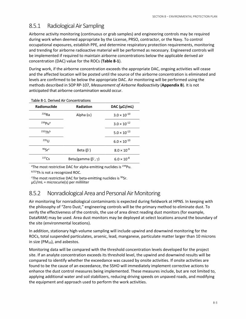
SECTION 8 – ENVIRONMENTAL PROTECTION PLAN
8-3
8.5.1 Radiological Air Sampling Airborne activity monitoring (continuous or grab samples) and engineering controls may be required during work when deemed appropriate by the License, PRSO, contractor, or the Navy. To control occupational exposures, establish PPE, and determine respiratory protection requirements, monitoring and trending for airborne radioactive material will be performed as necessary. Engineered controls will be implemented if required to maintain airborne concentrations below the applicable derived air concentration (DAC) value for the ROCs (Table 8-1).
During work, if the airborne concentration exceeds the appropriate DAC, ongoing activities will cease and the affected location will be posted until the source of the airborne concentration is eliminated and levels are confirmed to be below the appropriate DAC. Air monitoring will be performed using the methods described in SOP RP-107, Measurement of Airborne Radioactivity (Appendix B). It is not anticipated that airborne contamination would occur.
Table 8-1. Derived Air Concentrations Radionuclide Radiation DAC (µCi/mL)
226Ra Alpha (α) 3.0 × 10⁻¹⁰
239Pua 3.0 × 10⁻¹²
232Thb 5.0 × 10⁻¹³
235U 6.0 × 10⁻¹⁰
90Src Beta (β-) 8.0 × 10⁻⁹
137Cs Beta/gamma (β-, γ) 6.0 × 10⁻⁸
aThe most restrictive DAC for alpha-emitting nuclides is 239Pu. b232Th is not a recognized ROC. cThe most restrictive DAC for beta-emitting nuclides is 90Sr. µCi/mL = microcurie(s) per milliliter
8.5.2 Nonradiological Area and Personal Air Monitoring Air monitoring for nonradiological contaminants is expected during fieldwork at HPNS. In keeping with the philosophy of “Zero Dust,” engineering controls will be the primary method to eliminate dust. To verify the effectiveness of the controls, the use of area direct reading dust monitors (for example, DataRAM) may be used. Area dust monitors may be deployed at select locations around the boundary of the site (environmental locations).
In addition, stationary high-volume sampling will include upwind and downwind monitoring for the ROCs, total suspended particulates, arsenic, lead, manganese, particulate matter larger than 10 microns in size (PM10), and asbestos.
Monitoring data will be compared with the threshold concentration levels developed for the project site. If an analyte concentration exceeds its threshold level, the upwind and downwind results will be compared to identify whether the exceedance was caused by onsite activities. If onsite activities are found to be the cause of an exceedance, the SSHO will immediately implement corrective actions to enhance the dust control measures being implemented. These measures include, but are not limited to, applying additional water and soil stabilizers, reducing driving speeds on unpaved roads, and modifying the equipment and approach used to perform the work activities.
PARCEL G REMOVAL SITE EVALUATION WORK PLAN
8-4
Breathing zone action levels will be established for non-radiological contaminants (for example, heavy metals and polychlorinated biphenyls), based on prior soil sampling at the site and task (for example, drilling and excavation). Direct reading monitoring equipment (such as DataRAM and photoionization detector) will be used to verify action levels are not exceeded during work tasks.
Each project task plan will evaluate if nonradiological personal integrated air sampling is required, in addition to direct reading monitoring. The SSHP will be updated via a Field Change Request if additional monitoring is needed based on task-specific chemicals of concern. The APP and SSHP further discuss personal air monitoring requirements of the project.
8.6 Noise Prevention Using standard OSHA occupational noise evaluation methods, the time weighted average for any 8-hour period will not exceed 90 decibels (dBA) to any worker. In addition, the contractor will endeavor to limit noise directly resulting from project work at or below 80 dBA at the task area boundary, or 70 dBA at the HPNS boundary.
8.7 Construction Area Delineation Construction area delineation will be evaluated upon arrival of the advance project personnel. Following this evaluation, minor modifications will be made to the project plans and procedures to reflect the current conditions.
8.8 Traffic Control Plan Not applicable.
8.9 General Operations General operations will be governed under this work plan to ensure any operation conforms to the requirements listed within. These requirements are specific to the type of hazard (for example, radiological, hazardous material, and health and safety) and further require that each task have a corresponding AHA. All work will be released by the cognizant contractor before work is performed. Review of the general operations AHA will include all environmental programs and permits to ensure compliance.
8.10 Spill Prevention, Response, and Reporting The project spill plan is provided in the APP/SSHP.
SECTION 9
9-1
References American National Standards Institute (ANSI). 1997. Radiation Protection Instrumentation Test and Calibration, Portable Survey Instruments. (ANSI) N323a-1997.
Argonne National Laboratory. 2011. Low-Level Radiological Waste Evaluation Associated with Various Base Realignment and Closure Activities. January.
Levine-Fricke Recon, Inc. (Levine-Fricke) and PRC Environmental Management (PRC). 1997. Parcel D Feasibility Study.
Naval Sea Systems Command (NAVSEA). 2004. Historical Radiological Assessment, Hunters Point Annex, Volume II, History of the Uses of General Radioactive Material 1939–2003. August.
Navy. 2006. Basewide Radiological Removal Action, Action Memorandum–Revision 2006, Hunters Point Shipyard, San Francisco, California.
Navy. 2009. Record of Decision for Parcel G. Hunters Point Shipyard, San Francisco, California. February.
Navy. 2017. Radiological Data Evaluation Findings Report for Parcels B and G Soil. Former Hunters Point Naval Shipyard, San Francisco, California. Draft. September.
Navy. 2018. Building Data Initial Evaluation Report. Former Hunters Point Naval Shipyard, San Francisco, California. Draft. February.
Nuclear Regulatory Commission (NRC). 1998. Minimum Detectable Concentrations with Typical Radiation Survey Instruments for Various Contaminants and Field Conditions. NUREG/CR-1507. Washington, D.C.
Strom, Daniel J., and Paul S. Stansbury. 1992. “Minimum Detectable Activity When Background Is Counted Longer Than the Sample.” Health Physics. Vol 63(3). pp. 360-1. October.
Tetra Tech EC, Inc. (TtEC). 2009a. Final Status Survey Results (FSSR), Building 439, Hunters Point Shipyard, San Francisco, California. July 8.
TtEC. 2009b. Hunters Point Shipyard (RSY) 2A and 3 Rad Screening Yard Pad Construction Details, Hunters Point Shipyard, San Francisco, California. July 29.
TtEC. 2009c. Final Status Survey Results (FSSR), Building 401, Hunters Point Shipyard, San Francisco, California. September 21.
TtEC. 2009d. Final Status Survey Results, Building 366, Hunters Point Shipyard, San Francisco, California. December 30.
TtEC. 2012. Basewide Radiological Management Plan, Hunters Point Shipyard, San Francisco, California. February 3.
United States Environmental Protection Agency (USEPA). 2006. Data Quality Assessment: Statistical Methods for Practitioners. EPA QA/G-9S. Office of Environmental Information. EPA/240/B-06/003. February.
USEPA. 2014. Radiation Risk Assessment at CERCLA Sites: Q&A. Office of Superfund Remediation and Technology Information. Directive 9200.4-40. EPA 540-R-012-13. May.
United States Environmental Protection Agency (USEPA), Department of Energy, Nuclear Regulatory Commission, and Department of Defense. 2000. Multi-Agency Radiation Survey and Site Investigation Manual (MARSSIM). NUREG-1575, Rev. 1. EPA 402-R-97-016, Rev. 1. DOE/EH-0624, Rev. 1. August.
Appendix A Soil Reference Background Area
Work Plan
Base Realignment and Closure Program Management Office West San Diego, California
Draft
Soil Reference Background Area Work Plan
Former Hunters Point Naval Shipyard San Francisco, California
June 2018
Naval Facilities Engineering Command
III
Contents Acronyms and Abbreviations ............................................................................................................... v
1 Introduction ......................................................................................................................... 1-1
2 Purpose and Data Quality Objectives .................................................................................... 2-1
3 Survey Design and Implementation ...................................................................................... 3-1 3.1 Survey Design ................................................................................................................... 3-1
3.1.1 Radionuclides of Concern ................................................................................... 3-1 3.1.2 Survey Methodology Summary .......................................................................... 3-2 3.1.3 Reference Background Area Locations ............................................................... 3-2 3.1.4 Number of Samples ............................................................................................ 3-3 3.1.5 Sample Locations ................................................................................................ 3-3 3.1.6 Field Instrumentation, Gamma Detectors .......................................................... 3-5 3.1.7 Laboratory Analysis ............................................................................................. 3-6
3.2 Survey Implementation ................................................................................................... 3-7 3.2.1 Premobilization Activities ................................................................................... 3-7 3.2.2 Site Survey Preparation Activities ....................................................................... 3-8 3.2.3 Scan Measurements ........................................................................................... 3-8 3.2.4 Surface Soil Sampling Process ............................................................................. 3-9 3.2.5 Subsurface Soil Sampling Process ..................................................................... 3-10 3.2.6 Sample Identification ........................................................................................ 3-12 3.2.7 Documentation and Sample Shipping .............................................................. 3-13
4 Data Evaluation and Reporting ............................................................................................. 4-1 4.1 Gamma Scan Data Evaluation .......................................................................................... 4-1
4.1.1 Conduct a Preliminary Data Review ................................................................... 4-1 4.1.2 Identify Outliers .................................................................................................. 4-1 4.1.3 Determine Statistical Differences between Datasets ......................................... 4-2
4.2 Analytical Data Evaluation ............................................................................................... 4-2 4.2.1 Conduct a Preliminary Data Review ................................................................... 4-2 4.2.2 Identify Outliers .................................................................................................. 4-2 4.2.3 Determine of Statistical Differences between Data Sets.................................... 4-4 4.2.4 Establish Background Data Sets .......................................................................... 4-4
4.3 Reporting ......................................................................................................................... 4-4
5 Radioactive Materials Management and Control .................................................................. 5-1
6 References ............................................................................................................................ 6-1
Tables
3-1 Radionuclides of Concern 3-2 Remediation Goals 3-3 RBA Sample Coordinates, RBAs 1 through 4 3-4 RBA Sample Coordinates, RBA-Bayview 3-5 Gamma Survey Instruments 3-6 Analytical Sample Summary

SOIL REFERENCE BACKGROUND AREA WORK PLAN, FORMER HUNTERS RIDGE NAVAL SHIPYARD, SAN FRANCISCO, CALIFORNIA
IV
Figures
3-1 HPNS Reference Background Areas 3-2 Offsite Reference Background Area, Bayview Park 3-3 Example Surface and Subsurface Sample Locations 3-4 HPNS Reference Background Area RBA-1 3-5 HPNS Reference Background Area RBA-2 3-6 HPNS Reference Background Area RBA-3 3-7 HPNS Reference Background Area RBA-4 3-8 Bayview Park Reference Background Area RBA-Bayview
V
Acronyms and Abbreviations 40K potassium-40 90Sr strontium-90 137Cs cesium-137 212Bi bismuth-212 214Bi bismuth-214 214Pb lead-214 226Ra radium-226 228Ac actinium-228 228Th thorium-228 230Th thorium-230 232Th thorium-232 234U uranium-234 235U uranium-235 238U uranium-238 239Pu plutonium-239 240Pu plutonium-240 241Am americium-241
APP accident prevention plan
ASTM American Society for Testing and Materials
bgs below ground surface
CH2M CH2M HILL, Inc.
DQO data quality objective
ft2 square feet
GIS geographic information system
GPS global positioning system
HPNS Hunters Point Naval Shipyard
ID identification
IDW investigation-derived waste
KW Kruskal-Wallis
MCA multi-channel analyzer
NaI(Tl) thallium-doped sodium iodide
NAVFAC Naval Facilities Engineering Command
Navy Department of the Navy
SOIL REFERENCE BACKGROUND AREA WORK PLAN, FORMER HUNTERS RIDGE NAVAL SHIPYARD, SAN FRANCISCO, CALIFORNIA
VI
NORM naturally occurring radiological material
NRC Nuclear Regulatory Commission
NUREG Nuclear Regulatory Commission Regulation
pCi/g picocurie per gram
PRSO Project Radiation Safety Officer
RASO Radiological Affairs Support Office
RBA reference background area
ROC radionuclide of concern
ROICC Resident Officer in Charge of Construction
RPM Remedial Project Manager
SAP sampling and analysis plan
SOP standard operating procedure
SSHP site safety and health plan
TCRA Time-critical Removal Action
SECTION 1
1-1
Introduction This work plan provides the details for the radiological characterization of soil Reference Background Areas (RBAs) in San Francisco, California. Four onsite RBAs, located at the former Hunters Point Naval Shipyard (HPNS), and one offsite RBA, located at the City of San Francisco’s Bayview Park, have been identified for radiological characterization. The radiological characterization will be conducted in accordance with the general approach and methodologies that are provided in the Draft Parcel G Removal Site Evaluation Work Plan (Parcel G Work Plan) (Navy, 2018), a separate Sampling and Analysis Plan (SAP), and a separate Accident Prevention Plan/Site Safety and Health Plan (APP/SSHP). Specific procedures to ensure data quality and worker safety will be described in the SAP and APP/SSHP.
Radiological surveys and remediation have been conducted at HPNS as part of a basewide Time-critical Removal Action (TCRA) in accordance with the Action Memorandum (Navy, 2006). Additional efforts to investigate and if necessary, remediate, radiologically impacted sites in Parcels B, C, D-2, E, G, UC-1, UC-2, and UC-3 are planned. The reference area data will be used to evaluate site investigation data to support a final decision on whether residual radioactivity is found to exceed the remediation goals, requiring further remediation. The reference area data will also be used to support comparisons with background.
SECTION 2
2-1
Purpose and Data Quality Objectives The reference background characterization information obtained during the implementation of this work plan will be used during site investigations at selected radiologically impacted areas in Parcels B, C, D-2, E, G, UC-1, UC-2, and UC-3 at HPNS to support a final decision on whether residual radioactivity is found to exceed the release criteria and require cleanup. The remediation goals, presented in Section 3, specify that the radium-226 (226Ra) remediation goal be set at 1.0 picocurie per gram (pCi/g) above the background concentration. Previous site radiological surveys and remediation activities did not estimate a reference background concentration for other radionuclides, such as cesium (137Cs) and strontium-90 (90Sr). Both 137Cs and 90Sr are common nuclear fission products that are present worldwide as a result of radioactive fallout from weapons testing. This work plan describes methods for obtaining reference background area data sets for the radionuclides of concern (ROCs) by establishing the following:
• Descriptive statistics and distributions of background concentrations, in pCi/g, for the ROCs, including 137Cs, 226Ra, and 90Sr
• Descriptive statistics and distributions of background concentrations for the naturally occurring radioactive material (NORM) radionuclides, including those associated with the uranium decay series, thorium decay series, and potassium (40K)
Additionally, the data collection protocols and reference area data sets may be used for site evaluation scenarios listed in the Parcel G Work Plan and other work plans (e.g., NORM evaluations, comparison to background, alternative statistical evaluations, and dose and risk analyses).
The data quality objectives (DQOs) for the RBA investigation are as follows.
• Step 1-State the Problem: HPNS was expanded over time using fill materials with a range of concentrations for NORM. Construction and remediation projects over the past 60 years have disturbed the surface soil, making a determination of background concentrations for ubiquitous anthropogenic radionuclides from fallout difficult. Previous HPNS soil background values did not provide 226Ra concentrations representative of all fill materials found at HPNS and did not include other NORM or fallout radionuclides.
• Step 2-Identify the Objective: Establish representative background data sets for soil ROCs, NORM radionuclides, and fallout ROCs for comparison and evaluation of soil data collected from the HPNS.
• Step 3-Identify Inputs to the Objective: Soil analytical data for ROCs, NORM radionuclides, and fallout radionuclides using analytical methods are summarized in Section 3 and detailed in the separate SAP. Gamma scan survey measurements were taken of accessible surface soil, including gross gamma and gamma spectroscopy, to support selection of appropriate gamma scan instrumentation based on a priori detectability.
• Step 4-Define the Study Boundaries: Reference background areas at HPNS in Parcels B, C, D-1, D-2 (Figure 3-1), and an undisturbed off-base location (Figure 3-2) will provide a range of background estimates. In Parcels B, C, D-1, and D-2, surface soil samples will be collected from 0 to 6 inches below ground surface (bgs), and subsurface soil samples will be collected from 1- to 2-foot intervals to a depth of up to 10 feet bgs. At the off-base location, surface soil samples will be collected from 0 to 6 inches bgs.
• Step 5-Develop Decision Rules: Reference background area data sets will be compared and evaluated to provide representative reference background area data sets with a description to assist in determining applicability for specific projects at HPNS. The data evaluation process is summarized below and detailed in Section 4.
SOIL REFERENCE BACKGROUND AREA WORK PLAN, FORMER HUNTERS RIDGE NAVAL SHIPYARD, SAN FRANCISCO, CALIFORNIA
2-2
− Identify outliers graphically or statistically using Dixon and Rosner’s tests for outliers by comparing the calculated Q values or R values to the critical value, corresponding to a confidence level of 95 percent.
If outliers are identified graphically or statistically (Q value or R value is greater than critical value), the outlier will be investigated to attempt to determine whether the outlier is the result of contamination, data quality issues, an environmental issue (e.g., different soil type), or an unidentified issue.
If no outliers are identified, the entire data set will be used in its entirety.
− Determine statistical difference between data sets using the non-parametric Kruskal-Wallis (KW) test by comparing the calculated p-value against 0.05 significance level.
If the results of the KW test indicate that two or more data sets are statistically similar (p-value is greater than significance level), those data sets may be combined to form a larger data set representing more of HPNS, such as a larger area, multiple soil depths, or additional soil types.
If the results of the KW test indicate that a data set is statistically different from other data sets (p-value is less than significance level), that data set will not be combined with other data sets and will be representative of a specific area, soil depth, or soil type.
• Step 6-Specify the Performance Criteria: A statistical data evaluation will be conducted to identify appropriate soil background data sets and calculate descriptive statistics to facilitate future comparisons with site-specific data. The purposes of the data evaluation are as follows:
− Identify outliers using Dixon and Rosner’s tests for outliers.
− Determine statistical differences between soil groups using the KW test.
− Compare soil data sets from surface gamma scan surveys, and surface and subsurface analytical concentrations against different identified soil types and against each RBA per sample depth.
− Establish one or more representative reference area data sets.
• Step 7-Develop the Plan for Obtaining Data: Reference background areas will be characterized by collecting gamma scan surveys of 100 percent of surface soil and collecting systematic surface and subsurface soil samples, as follows:
− In Parcels B, C, D-1, and D-2, surface soil samples will be collected from 0 to 6 inches bgs, and subsurface soil samples will be collected from 1- to 2-foot intervals to a depth of up to 10 feet bgs.
− At Bayview Park, an offsite location with undisturbed surface soil since 1937, surface soil samples will be collected from 0 to 6 inches bgs.
− During soil sampling activities, a professional geologist registered in California will annotate the lithologic characteristics and provide accurate and consistent descriptions of soil characteristics.
− Soil samples will be analyzed for the applicable ROCs along with NORM radionuclides and fallout radionuclides by accredited offsite laboratories, and the results will be evaluated as described in Steps 5 and 6.
SECTION 3
3-1
Survey Design and Implementation 3.1 Survey Design The concentrations of NORM radionuclides and ubiquitous fallout radionuclides in soil at HPNS are variable because of the natural variability of native soil and the variability in erosion and deposition of surface soil and fallout radionuclides, and because portions of the site were created with fill materials originating from multiple offsite sources. Much of the fill was obtained by grading the hilltop immediately north of HPNS. The source of fill derived from the hilltop is the Hunters Point Shear Zone, a complex structural mixture of serpentine, shale, sandstone, chert, and gabbro. Fill soil was also obtained from sediment dredged from San Francisco Bay and imported from local quarries and construction sites. Fill soil was generally placed in layers; however, the layering is not contiguous across the shipyard. Soil lithology in filled areas is not readily known at any given location.
Concentrations of fallout radionuclides are variable in soil at HPNS because of deposition and erosion, and from layering and mixing during placement of fill soil. Thus, the concentrations of naturally occurring and ubiquitous fallout radionuclides in soil may vary by location and depth. The anticipated variability, combined with the nature of impacted-area investigation surveys, influence the design of the RBA characterization with the goal of capturing data that are comparable to survey data collected during site investigations at HPNS, and representative of the expected wide range of background concentrations present at HPNS.
Because of the anticipated variability in soil types across HPNS, four distinct onsite RBAs have been identified for characterization. One undisturbed offsite location was selected for characterization of ubiquitous fallout radionuclides. RBAs are geographical areas from which representative radioactivity measurements are collected for comparison with measurements collected in an impacted area (i.e., a survey unit). RBAs are areas that have been identified as non-impacted and should have physical, geological, chemical, radiological, and biological characteristics similar to those of the impacted area being investigated. The RBAs characterization methodology will consist of a combination of radiological gamma surveys and soil sampling to establish the HPNS background conditions. Samples will be collected from independent surface and subsurface soil depth intervals. The analytical soil data from the RBAs will be used to generate background population statistics and establish parameters (e.g., mean, median, standard deviation, range).
3.1.1 Radionuclides of Concern The ROCs are provided in Table 3-1.
Table 3-1. Radionuclides of Concern
Type Radionuclide of Concern
Soil Areas 137Cs, 226Ra, 90Sr, 239Pu
Notes:
Daughter products and naturally occurring isotopes with sufficient probability of detection and half-lives greater than 5.7 years (the shipyard ceased operations in 1974, “43 years” and 7.5 half-lives equals 5.73 years), will be reported in the gamma spectroscopy report, such as 40K, bismuth-214 (214Bi), and lead-214 (214Pb). 239Pu = plutonium-239
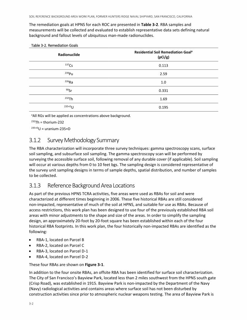
SOIL REFERENCE BACKGROUND AREA WORK PLAN, FORMER HUNTERS RIDGE NAVAL SHIPYARD, SAN FRANCISCO, CALIFORNIA
3-2
The remediation goals at HPNS for each ROC are presented in Table 3-2. RBA samples and measurements will be collected and evaluated to establish representative data sets defining natural background and fallout levels of ubiquitous man-made radionuclides.
Table 3-2. Remediation Goals
Radionuclide Residential Soil Remediation Goala (pCi/g)
137Cs 0.113
239Pu 2.59
226Ra 1.0
90Sr 0.331
232Th 1.69
235+DU 0.195
aAll RGs will be applied as concentrations above background. 232Th = thorium-232 235+DU = uranium-235+D
3.1.2 Survey Methodology Summary The RBA characterization will incorporate three survey techniques: gamma spectroscopy scans, surface soil sampling, and subsurface soil sampling. The gamma spectroscopy scan will be performed by surveying the accessible surface soil, following removal of any durable cover (if applicable). Soil sampling will occur at various depths from 0 to 10 feet bgs. The sampling design is considered representative of the survey unit sampling designs in terms of sample depths, spatial distribution, and number of samples to be collected.
3.1.3 Reference Background Area Locations As part of the previous HPNS TCRA activities, five areas were used as RBAs for soil and were characterized at different times beginning in 2006. These five historical RBAs are still considered non-impacted, representative of much of the soil at HPNS, and suitable for use as RBAs. Because of access restrictions, this work plan has been designed to use four of the previously established RBA soil areas with minor adjustments to the shape and size of the areas. In order to simplify the sampling design, an approximately 20-foot by 20-foot square has been established within each of the four historical RBA footprints. In this work plan, the four historically non-impacted RBAs are identified as the following:
• RBA-1, located on Parcel B • RBA-2, located on Parcel C • RBA-3, located on Parcel D-1 • RBA-4, located on Parcel D-2
These four RBAs are shown on Figure 3-1.
In addition to the four onsite RBAs, an offsite RBA has been identified for surface soil characterization. The City of San Francisco’s Bayview Park, located less than 2 miles southwest from the HPNS south gate (Crisp Road), was established in 1915. Bayview Park is non-impacted by the Department of the Navy (Navy) radiological activities and contains areas where surface soil has not been disturbed by construction activities since prior to atmospheric nuclear weapons testing. The area of Bayview Park is
SECTION 3 – SURVEY DESIGN AND IMPLEMENTATION
3-3
occupied by a single large hill, which rises to a height of 425 feet above mean sea level, with a notable rock formation known as Indian Head Rock on the western side of the hill. In 1937, a former radio station building and transmitter were constructed and currently remain intact near the top of the hill. The land area near the radio station building and transmitter has remained undisturbed since 1937 and has been selected as the location of the offsite RBA (RBA-Bayview). The RBA-Bayview is shown on Figure 3-2.
Both surface gamma scan surveys and surface soil samples will be collected from RBA-Bayview to provide a more accurate surface soil data set to represent undisturbed surface soil areas. Based on field conditions, additional sample locations at Bayview Park or other reference areas may be added as necessary to characterize different soil types and depositional areas.
3.1.4 Number of Samples The minimum number of samples to be collected was determined using the Parcel G Work Plan and Nuclear Regulatory Commission (NRC) criteria. The NRC criteria for providing characterization of a complex site, found in United States Nuclear Regulatory Commission Regulation (NUREG) 1505 (NRC, 1998) is at least 100 samples from at least 5 distinct locations. The Parcel G Work Plan states that a minimum of 18 samples will be collected in each survey unit and each RBA. In order to satisfy both the NRC criteria and the Parcel G Work Plan, the number of samples in each data set was increased to 25 to ensure that sufficient analytical data will be available. Therefore, 25 subsurface soil samples will be collected from RBAs 1 through 4 for a total of 100 onsite subsurface soil samples. Five surface soil samples will be collected from RBAs 1 through 4, for a total of 25 onsite surface soil samples. Additionally, 25 surface soil samples will be collected from RBA-Bayview. Overall, at least 150 soil samples will be collected, as follows:
• 25 subsurface soil samples from RBA-1, located on Parcel B • 25 subsurface soil samples from RBA-2, located on Parcel C • 25 subsurface soil samples from RBA-3, located on Parcel D-1 • 25 subsurface soil samples from RBA-4, located on Parcel D-2 • 25 surface soil samples, five each from RBA-1 through RBA-4 • 25 surface soil samples from RBA-Bayview, located offsite
Additional data sets may be defined based on soil type or other visual observations of the soil samples.
3.1.5 Sample Locations 3.1.5.1 RBA-1 through RBA-4 A central location was randomly selected within RBA-1 through RBA-4. These four randomly selected locations will be used for the center sampling location in each of the four RBAs. Each of the four RBAs are square surface areas measuring approximately 20 feet by 20 feet. Within the 400-square-foot (ft2) surface area, five sampling locations have been established: one at the center of the square, and the other four located near each of the four corners of the square. Surface soil samples and subsurface soil samples will be collected from the five sampling locations. As illustrated on Figure 3-3, surface soil samples will be collected from the top 6 inches of soil material at each location for the surface soil data set; and subsurface soil samples will be collected by drilling to a depth of approximately 10 feet bgs from which five subsurface soil samples will be extracted. The proposed subsurface sample depth intervals are the 1- to 2-foot interval, the 3- to 4-foot interval, the 5- to 6-foot interval, the 7- to 8-foot interval, and the 9- to 10-foot interval. If the geologist determines that lithologic characteristics support modification of the proposed depth increments, additional samples may be collected, or the proposed sample depth may be adjusted to match the lithologic characteristics of the soil column. This is further described in Section 3.2.5.
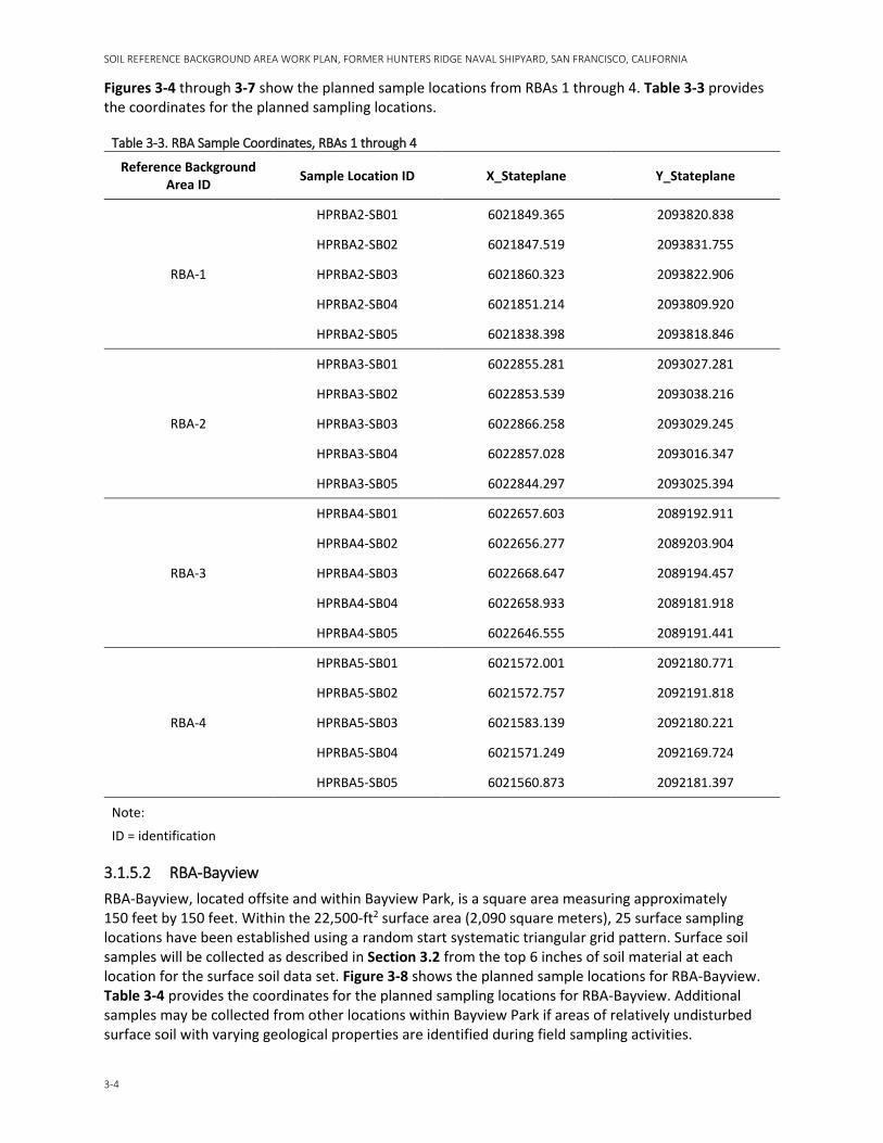
SOIL REFERENCE BACKGROUND AREA WORK PLAN, FORMER HUNTERS RIDGE NAVAL SHIPYARD, SAN FRANCISCO, CALIFORNIA
3-4
Figures 3-4 through 3-7 show the planned sample locations from RBAs 1 through 4. Table 3-3 provides the coordinates for the planned sampling locations.
Table 3-3. RBA Sample Coordinates, RBAs 1 through 4
Reference Background Area ID Sample Location ID X_Stateplane Y_Stateplane
RBA-1
HPRBA2-SB01 6021849.365 2093820.838
HPRBA2-SB02 6021847.519 2093831.755
HPRBA2-SB03 6021860.323 2093822.906
HPRBA2-SB04 6021851.214 2093809.920
HPRBA2-SB05 6021838.398 2093818.846
RBA-2
HPRBA3-SB01 6022855.281 2093027.281
HPRBA3-SB02 6022853.539 2093038.216
HPRBA3-SB03 6022866.258 2093029.245
HPRBA3-SB04 6022857.028 2093016.347
HPRBA3-SB05 6022844.297 2093025.394
RBA-3
HPRBA4-SB01 6022657.603 2089192.911
HPRBA4-SB02 6022656.277 2089203.904
HPRBA4-SB03 6022668.647 2089194.457
HPRBA4-SB04 6022658.933 2089181.918
HPRBA4-SB05 6022646.555 2089191.441
RBA-4
HPRBA5-SB01 6021572.001 2092180.771
HPRBA5-SB02 6021572.757 2092191.818
HPRBA5-SB03 6021583.139 2092180.221
HPRBA5-SB04 6021571.249 2092169.724
HPRBA5-SB05 6021560.873 2092181.397
Note:
ID = identification
3.1.5.2 RBA-Bayview RBA-Bayview, located offsite and within Bayview Park, is a square area measuring approximately 150 feet by 150 feet. Within the 22,500-ft2 surface area (2,090 square meters), 25 surface sampling locations have been established using a random start systematic triangular grid pattern. Surface soil samples will be collected as described in Section 3.2 from the top 6 inches of soil material at each location for the surface soil data set. Figure 3-8 shows the planned sample locations for RBA-Bayview. Table 3-4 provides the coordinates for the planned sampling locations for RBA-Bayview. Additional samples may be collected from other locations within Bayview Park if areas of relatively undisturbed surface soil with varying geological properties are identified during field sampling activities.
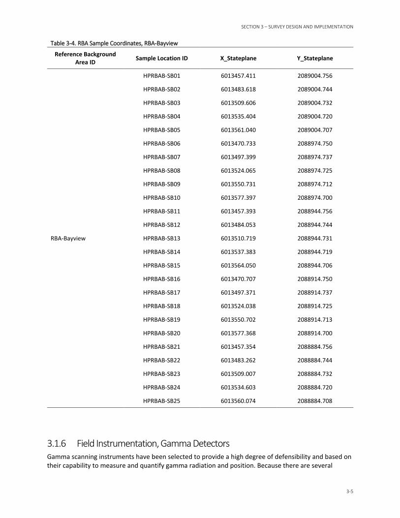
SECTION 3 – SURVEY DESIGN AND IMPLEMENTATION
3-5
Table 3-4. RBA Sample Coordinates, RBA-Bayview
Reference Background Area ID Sample Location ID X_Stateplane Y_Stateplane
RBA-Bayview
HPRBAB-SB01 6013457.411 2089004.756
HPRBAB-SB02 6013483.618 2089004.744
HPRBAB-SB03 6013509.606 2089004.732
HPRBAB-SB04 6013535.404 2089004.720
HPRBAB-SB05 6013561.040 2089004.707
HPRBAB-SB06 6013470.733 2088974.750
HPRBAB-SB07 6013497.399 2088974.737
HPRBAB-SB08 6013524.065 2088974.725
HPRBAB-SB09 6013550.731 2088974.712
HPRBAB-SB10 6013577.397 2088974.700
HPRBAB-SB11 6013457.393 2088944.756
HPRBAB-SB12 6013484.053 2088944.744
HPRBAB-SB13 6013510.719 2088944.731
HPRBAB-SB14 6013537.383 2088944.719
HPRBAB-SB15 6013564.050 2088944.706
HPRBAB-SB16 6013470.707 2088914.750
HPRBAB-SB17 6013497.371 2088914.737
HPRBAB-SB18 6013524.038 2088914.725
HPRBAB-SB19 6013550.702 2088914.713
HPRBAB-SB20 6013577.368 2088914.700
HPRBAB-SB21 6013457.354 2088884.756
HPRBAB-SB22 6013483.262 2088884.744
HPRBAB-SB23 6013509.007 2088884.732
HPRBAB-SB24 6013534.603 2088884.720
HPRBAB-SB25 6013560.074 2088884.708
3.1.6 Field Instrumentation, Gamma Detectors Gamma scanning instruments have been selected to provide a high degree of defensibility and based on their capability to measure and quantify gamma radiation and position. Because there are several
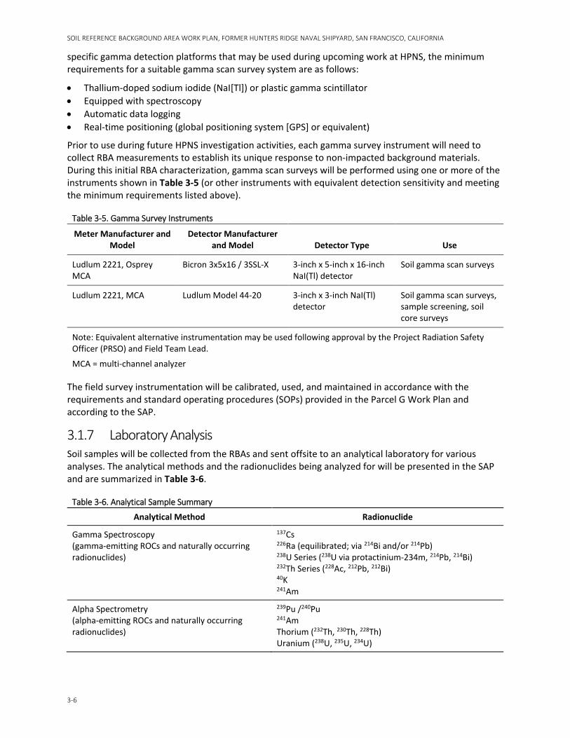
SOIL REFERENCE BACKGROUND AREA WORK PLAN, FORMER HUNTERS RIDGE NAVAL SHIPYARD, SAN FRANCISCO, CALIFORNIA
3-6
specific gamma detection platforms that may be used during upcoming work at HPNS, the minimum requirements for a suitable gamma scan survey system are as follows:
• Thallium-doped sodium iodide (NaI[Tl]) or plastic gamma scintillator • Equipped with spectroscopy • Automatic data logging • Real-time positioning (global positioning system [GPS] or equivalent)
Prior to use during future HPNS investigation activities, each gamma survey instrument will need to collect RBA measurements to establish its unique response to non-impacted background materials. During this initial RBA characterization, gamma scan surveys will be performed using one or more of the instruments shown in Table 3-5 (or other instruments with equivalent detection sensitivity and meeting the minimum requirements listed above).
Table 3-5. Gamma Survey Instruments
Meter Manufacturer and Model
Detector Manufacturer and Model Detector Type Use
Ludlum 2221, Osprey MCA
Bicron 3x5x16 / 3SSL-X 3-inch x 5-inch x 16-inch NaI(Tl) detector
Soil gamma scan surveys
Ludlum 2221, MCA Ludlum Model 44-20 3-inch x 3-inch NaI(Tl) detector
Soil gamma scan surveys, sample screening, soil core surveys
Note: Equivalent alternative instrumentation may be used following approval by the Project Radiation Safety Officer (PRSO) and Field Team Lead.
MCA = multi-channel analyzer
The field survey instrumentation will be calibrated, used, and maintained in accordance with the requirements and standard operating procedures (SOPs) provided in the Parcel G Work Plan and according to the SAP.
3.1.7 Laboratory Analysis Soil samples will be collected from the RBAs and sent offsite to an analytical laboratory for various analyses. The analytical methods and the radionuclides being analyzed for will be presented in the SAP and are summarized in Table 3-6.
Table 3-6. Analytical Sample Summary
Analytical Method Radionuclide
Gamma Spectroscopy (gamma-emitting ROCs and naturally occurring radionuclides)
137Cs 226Ra (equilibrated; via 214Bi and/or 214Pb) 238U Series (238U via protactinium-234m, 214Pb, 214Bi) 232Th Series (228Ac, 212Pb, 212Bi) 40K 241Am
Alpha Spectrometry (alpha-emitting ROCs and naturally occurring radionuclides)
239Pu /240Pu 241Am Thorium (232Th, 230Th, 228Th) Uranium (238U, 235U, 234U)
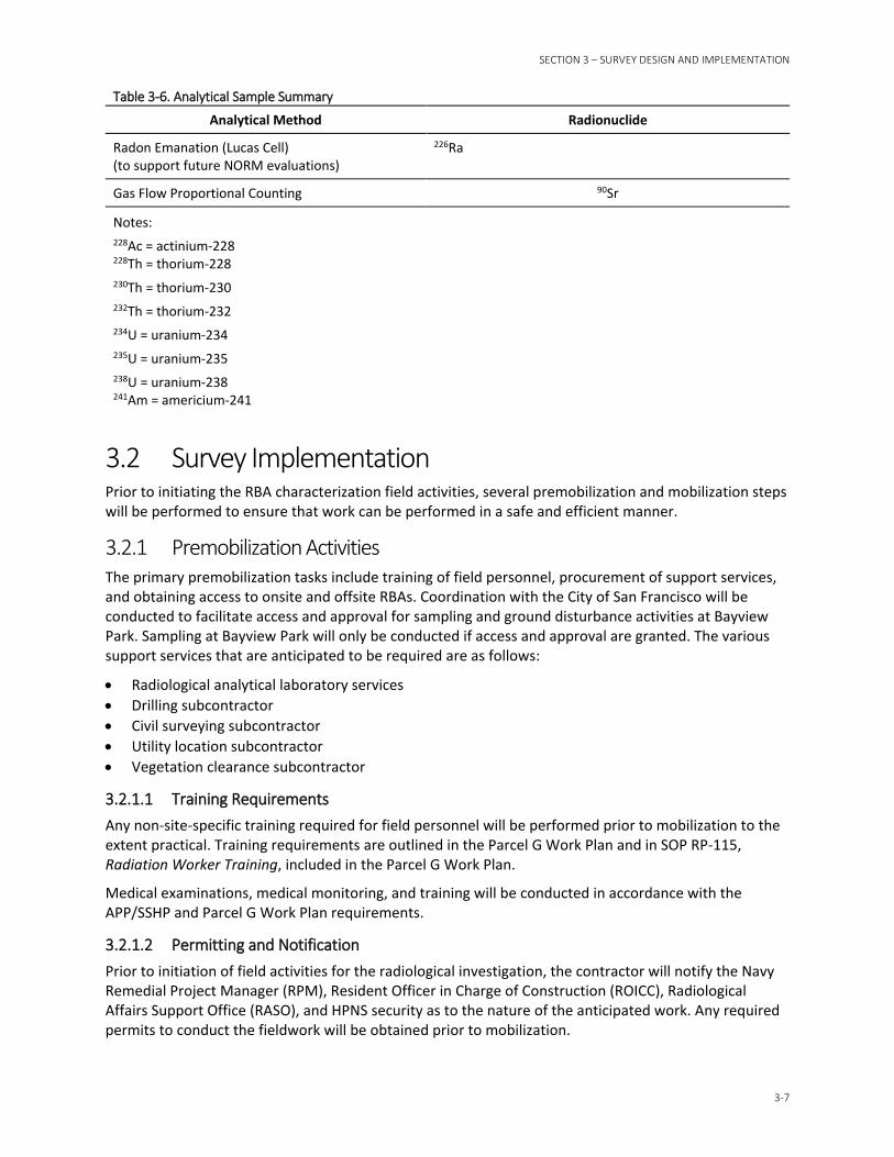
SECTION 3 – SURVEY DESIGN AND IMPLEMENTATION
3-7
Table 3-6. Analytical Sample Summary
Analytical Method Radionuclide
Radon Emanation (Lucas Cell) (to support future NORM evaluations)
226Ra
Gas Flow Proportional Counting 90Sr
Notes: 228Ac = actinium-228 228Th = thorium-228 230Th = thorium-230 232Th = thorium-232 234U = uranium-234 235U = uranium-235 238U = uranium-238 241Am = americium-241
3.2 Survey Implementation Prior to initiating the RBA characterization field activities, several premobilization and mobilization steps will be performed to ensure that work can be performed in a safe and efficient manner.
3.2.1 Premobilization Activities The primary premobilization tasks include training of field personnel, procurement of support services, and obtaining access to onsite and offsite RBAs. Coordination with the City of San Francisco will be conducted to facilitate access and approval for sampling and ground disturbance activities at Bayview Park. Sampling at Bayview Park will only be conducted if access and approval are granted. The various support services that are anticipated to be required are as follows:
• Radiological analytical laboratory services • Drilling subcontractor • Civil surveying subcontractor • Utility location subcontractor • Vegetation clearance subcontractor
3.2.1.1 Training Requirements Any non-site-specific training required for field personnel will be performed prior to mobilization to the extent practical. Training requirements are outlined in the Parcel G Work Plan and in SOP RP-115, Radiation Worker Training, included in the Parcel G Work Plan.
Medical examinations, medical monitoring, and training will be conducted in accordance with the APP/SSHP and Parcel G Work Plan requirements.
3.2.1.2 Permitting and Notification Prior to initiation of field activities for the radiological investigation, the contractor will notify the Navy Remedial Project Manager (RPM), Resident Officer in Charge of Construction (ROICC), Radiological Affairs Support Office (RASO), and HPNS security as to the nature of the anticipated work. Any required permits to conduct the fieldwork will be obtained prior to mobilization.

SOIL REFERENCE BACKGROUND AREA WORK PLAN, FORMER HUNTERS RIDGE NAVAL SHIPYARD, SAN FRANCISCO, CALIFORNIA
3-8
The contractor will notify the California Department of Public Health at least 14 days prior to initiation of activities involving the Radioactive Material License (Section 5).
3.2.1.3 Pre-Construction Meeting A pre-construction meeting will be held prior to mobilization of equipment and personnel. The purpose of the meeting will be to discuss project-specific topics, roles and responsibilities of project personnel, project schedule, health and safety concerns, and other topics that require discussions before field mobilization. Representatives of the following will attend the pre-construction meeting:
• Navy (RPM, RASO, ROICC, and others as applicable)
• Contractor (Project Manager, Site Construction Manager, Project Quality Control Manager, PRSO, and Site Safety and Health Officer)
• Subcontractors as appropriate
3.2.2 Site Survey Preparation Activities The following steps will be implemented to prepare for the sampling activities and to facilitate access:
• Review the applicable activity hazard analyses prior to starting work evolutions.
• Cut brush and weeds (if appropriate) within each RBA to a maximum height of 4 inches to facilitate scanning and sampling activities.
• Locate and mark utilities in the field in accordance with the Locating and Clearing Underground Utilities SOP, included in the Parcel G Work Plan.
• Verify that utilities have been deactivated (to the extent possible) and if not deactivated, the active utilities will be further identified and marked to ensure that field personnel understand the exact location and estimated depth. An exclusion area will be placed around the active utilities to prevent accidental exposure to the utility, based on the utility hazard or importance.
− If utilities are in locations that interfere with planned RBA characterization activities, the 400-ft2 area may be relocated, as long as the area remains within the historical RBA footprint.
• Remove debris or obstacles that could obstruct sampling and survey activities. This includes surface obstructions, such as concrete or asphalt. Surface obstructions preventing access will be removed prior to direct-push activities.
• Remove the durable cover, if applicable, from the 400-ft2 area for the onsite RBAs.
• Locate and mark the planned sample locations (coordinates provided in Table 3-3).
3.2.3 Scan Measurements Following the completion of the site preparation activities, 100 percent of the accessible surface (i.e., ground level surface) of each RBA will be scanned for gamma activity using the instruments specified in Table 3-5 (or equivalent) or any additional radiological gamma instruments that may be used for future radiological investigation activities at HPNS. Both gross gamma and gamma spectral measurements will be collected simultaneously during the gamma scan.
For this initial RBA survey, the gamma scans of the soil surfaces will be performed using a GPS coupled with an appropriate gamma scintillation detector or meter (e.g., Ludlum 44-20 or Bicron 3x5x16/3SSL-X). Along with position, each gamma measurement will be coupled with a date and time stamp. The scans will be performed following a NUREG-1575 protocol by scanning straight lines at a rate of approximately 0.5 meter per second in approximately 1-meter-wide swaths, with a consistent detector distance from the soil surface (4 inches above the surface). Generally, each RBA will be gamma scanned as follows (the
SECTION 3 – SURVEY DESIGN AND IMPLEMENTATION
3-9
following description assumes that the RBA is positioned such that the sides align with northern, southern, eastern, and western directions):
• Begin with the detector positioned in the southwestern corner of the RBA at a height of about 4 inches above the surface. Orient the system to face north and initiate data collection (detector is automatically logging radiation readings and GPS is automatically logging position readings) so that the system is recording at a rate of one reading per second (or other, as determined by the project Health Physicist).
• Move the detector in the northern direction at a not-to-exceed speed of 0.5 meter per second.
• Once the detector has reached the edge of the RBA, turn the system around (now facing south) and offset the next detector path by approximately 1 meter (or appropriate based on the instrument’s detector size) to allow for a small overlap in the detector field of view
• Move the detector in the south direction at a not-to exceed speed of 0.5 meter per second.
• Repeat these steps until the RBA has been scan surveyed.
Assuming a 400-ft2 (37-square-meter) area for each onsite RBA plus 22,500-ft2 (2,090-square-meter) area for the offsite RBA, a survey as described above moving at a speed of 0.5 meter per second should result in the collection of a minimum of 4,400 scan measurements over the five RBAs (assuming 100 percent of each RBA is accessible). Data will be documented and managed as described in Section 3.2.7. Data sets will be transferred from the data logger onto a personal computer to create spreadsheets and geographic information system (GIS)-plotted maps. These data sets will be evaluated in accordance with Section 4. Following the scan survey, the number of data points and the percent coverage (from a plot of the data) will be reviewed to ensure that the design parameters of the gamma scan survey were satisfied.
The gamma spectra will be evaluated using regions of interest peak identification tools for comparisons against future HPNS site soil scan surveys. An instrument-specific SOP will be provided to the Navy prior to initiation of field activities.
3.2.4 Surface Soil Sampling Process Prior to surface sampling, ensure that the necessary gamma scan measurements have been collected as described in Section 3.2.3 and reviewed and accepted as described in Section 4.1. Surface soil samples will be collected in accordance with the Soil Sampling SOP, included in the Parcel G Work Plan. Generally, the surface soil sample will be collected as follows:
• A clean shovel, hand auger, or other tool will be used to remove a small area (about 3 inches in diameter) of soil to a depth of 6 inches.
• The removed soil will be transferred directly into a clean stainless-steel bowl for mixing.
• The soils removed from the sample location will be visually described in the field logbook in accordance with the Preparing Field Log Books SOP, included in the Parcel G Work Plan. Identify the sample as surface soil and include the approximate volume of the extracted soil. Color, moisture, texture, and clast composition (i.e., serpentine, shale, sandstone, chert, gabbro) will be identified.
• The sample for radiological analyses will be mixed in the field by breaking the sample into small pieces, removing overburden gravel and biological material. The entire mixed sample, or aliquot thereof, will be placed in the designated laboratory sample container.
• When a field duplicate sample is required (1 per every 10 field samples collected), the duplicate sample will be collected following mixing of the material and splitting the aliquot into an additional sample container.
SOIL REFERENCE BACKGROUND AREA WORK PLAN, FORMER HUNTERS RIDGE NAVAL SHIPYARD, SAN FRANCISCO, CALIFORNIA
3-10
• Samples will be identified, labeled, and cataloged according to Section 3.2.6, and then placed into the appropriate sample cooler (if required) for transport to the contract laboratory. Custody of the sample will be maintained according to Chain-of-Custody SOP, included in the Parcel G Work Plan.
• Investigation-derived waste (IDW) will be managed in accordance with the Parcel G Work Plan. No extra sample material is expected from surface soil sampling because the entire sample will be sent to the laboratory for analysis. However, if at least 200 grams of extra sample (approximately 1 cup) remain after samples have been packaged for shipment to the laboratory, label the sample and transfer to the Navy for storage and potential future analysis. At least 200 grams of soil are required to perform the required analyses, so quantities less than 200 grams will be treated as IDW.
3.2.5 Subsurface Soil Sampling Process 3.2.5.1 Drilling Area Setup Prior to the commencement of drilling at the sample location (RBAs 1 through 4), the drill site will be prepared by performing the following:
• Clear overhead obstacles, as necessary, to safely operate the drill rig (minimum of 10 feet of clearance between top of drill boom and obstacles).
• Review and ensure that subsurface clearance has been performed and drilling has been approved (refer to the Locating and Clearing Underground Utilities SOP, included in the Parcel G Work Plan).
• If utility or other obstacles prevent safe working conditions, the sample location can be re-located at the discretion of the field team lead. To the extent practical, the new sample location should be moved to a safe location as close to the original planned location, while staying within the 400-ft2 area.
3.2.5.2 Subsurface Soil Sample Collection Prior to subsurface sampling, ensure that the necessary gamma scan measurements have been collected as described in Section 3.2.3 and reviewed and accepted as described in Section 4.1. Subsurface soil samples will be collected by following the Soil Sampling SOP, included in the Parcel G Work Plan. Subsurface soil samples will be collected using drilling-rig-mounted equipment to collect samples with thin-walled tube sampling or split-spoon sampling. Generally, drilling and retrieving the boring using the thin-walled tube method will be as follows:
• Using a drilling rig, a hole is advanced to the desired depth. The samples are then collected following the American Society for Testing and Materials (ASTM) International D 1587 standard.
• The sampler is lowered into the hole so that the sample tube’s bottom rests on the bottom of the hole. The sampler is advanced by a continuous, relatively rapid downward motion. The sampler is withdrawn from the soil formation as carefully as possible to minimize disturbance of the sample. To obtain enough volume of sample for subsequent laboratory analysis, use of a 3-inch-internal-diameter sampler may be required.
• Upon removal of the tube from the ground, drill cuttings in the upper end of the tube are removed, and the upper and lower ends of the tube are sealed. The soil tube will be turned over to the project geologist and radiation technician for sample preparation, radiological surveys, and containerization. Once retrieved from the hole, the tube is carefully cut open to maintain the material in the tube.
SECTION 3 – SURVEY DESIGN AND IMPLEMENTATION
3-11
Generally, drilling and retrieving the boring using the split-spoon sampling method will be performed as follows:
• Using a drilling rig, a hole is advanced to the desired depth. The samples are then collected following the ASTM D 1586 standard.
• The sampler is lowered into the hole and driven to a depth equal to the total length of the sampler; typically, this is 24 inches. The sampler is driven down using a weight (“hammer”). To obtain enough volume of sample for subsequent laboratory analysis, use of a 3-inch-internal-diameter sampler may be required.
• Upon removal of the soil core from the ground, the soil core will be turned over to the project geologist and radiation technician for sample preparation, radiological surveys, and containerization. Once retrieved from the hole, the sampler is carefully split open to maintain the material in the sampler.
Soil tubes and cores will be processed in low background areas; however, because these surveys are performed in reference areas, all locations inside the reference area (not necessarily within the RBA) should be acceptable. One central processing area may be established for the entire investigation, or separate processing areas may be established for each RBA.
Once the soil tube has been cut open or the core has been split open, soil examination and sample collection will occur as follows:
• The geologist will log the soil boring to provide accurate and consistent descriptions of soil characteristics. Soil boring logs will be maintained according to the Logging of Soil Borings SOP, included in the Parcel G Work Plan. The geologist will subdivide the soil boring into the 1-foot increments corresponding to the vertical demarcation in the design. Based on observations of the lithologic characteristics, if there is a visible change in soil types in the vertical column, the geologist may modify the proposed depth increments so that a sample volume is representative of a single soil type. The geologist may also recommend that additional samples be collected to adequately represent the observed soil types.
• The sample for radiological analyses will be mixed in the field by breaking the sample into small pieces and removing gravel. The depth, recovery position, and scan measurement information should be correlated to each sample extracted from the core.
• A minimum of 200 grams of soil (approximately 1 cup) are required to complete all required analyses, or 400 grams if the sample is selected as a field duplicate. If sample size requirements are not met by a single sample collection, additional sample volume may be obtained by collecting a sample from below the original sample location within the core and compositing the sample.
• The entire mixed sample will be placed in the designated laboratory sample container and the range of soil depths included in the sample recorded in the field logbook.
• Samples will be identified, labeled, and cataloged according to Section 3.2.6, and then placed into the appropriate sample cooler (if required) for transport to the contract laboratory. Custody of the sample will be maintained according to the Chain-of-Custody SOP, included in the Parcel G Work Plan.
• When a field duplicate sample is required (1 per every 10 field samples collected), the sample will be evenly split following mixing of the material and removal of extraneous material, and each aliquot placed into an appropriately labeled sample container.
• IDW will be managed in accordance with the Parcel G Work Plan.
SOIL REFERENCE BACKGROUND AREA WORK PLAN, FORMER HUNTERS RIDGE NAVAL SHIPYARD, SAN FRANCISCO, CALIFORNIA
3-12
• Depth intervals that are not identified as samples and sent for analysis will be placed into appropriately labeled sample containers and transferred to the Navy for storage and potential future analysis.
3.2.6 Sample Identification Each surface and subsurface sample will be uniquely identified at the time of collection by the geologist or radiation technician. Samples will be identified as explained in this section.
Sample IDs will use the following format:
AABBBB-CCDD-EEFF-MMYY
Where: AA = facility (HP for “Hunters Point” will be used in this work plan).
BBBB = site location (RBAs 1 through 4 = RBA1, RBA2, RBA3, RBA4; RBA-Bayview = RBAB).
CC = sample type (options include: SS for “surface sample”; SB for “subsurface sample”).
DD = numerical sample location number (within each onsite RBA there will be 01 to 05 sample locations; within the offsite RBA there will be 01 to 25 sample locations; duplicate locations will be assigned the Letter “P” after this number [DDP]).
EEFF = two-digit sample interval in feet bgs (EE feet = top of sample interval / FF feet = bottom of sample interval). Note that EE and FF are whole numbers such that a value of “01” represents “1-foot bgs.” Also note that surface samples (samples collected from the 0.0- to 0.5-foot depth interval) will be designated as “000H”; ‘H’ for half foot. If the surface sample is collected from a depth other than a half foot, the ‘H’ designation will still be used; however, a note will be included in the field book to indicate the actual depth sampled.
MMYY = the two-digit month (MM) and two-digit year (YY) corresponding to the collection month and year. Example for a sample collected in June of 2018 is “MMYY = 0618.”
For example, a surface soil sample collected from RBA-1 at sample location 1 in March 2018 will be identified as follows:
“HPRBA1-SS01-000H-0318”
In this example, “HPRBA1” identifies Hunters Point Reference Background Area 1. “SS01” identifies the sample as a surface sample collected at sample location 01, and “000H” represents the depth interval for a surface sample (“000H” is the agreed-upon code established for surface samples as explained above).
An example of a subsurface sample collected from RBA-4 at sample Location 5 from the 9- to 10-foot interval bgs in April 2018 will be identified as follows:
“HPRBA4-SB05-0910-0418”
A duplicate sample collected from the sample location will be identified as follows:
“HPRBA4-SB05P-0910-0418”
An example of a surface sample collected from RBA-Bayview at sample Location 12 in June 2018 will be identified as follows:
“HPRBAB-SB12-000H-0618”
SECTION 3 – SURVEY DESIGN AND IMPLEMENTATION
3-13
3.2.7 Documentation and Sample Shipping Samples will be documented in accordance with the general requirements in the Preparing Field Log Books and the Chain-of-Custody SOPs included in the Parcel G Work Plan. These SOPs identify the requirements for sample labels, custody seals, and chains-of custody. A digital sample documentation/tracking program may be used during the execution of the work plan to provide additional confidence in sample recordkeeping and to add efficiencies to the process.
Samples will be packaged and shipped for offsite analysis in accordance with the Packaging and Shipping Procedures for Low-Concentration Samples SOP, included in the Parcel G Work Plan.
Radiological surveys will be performed and documented in accordance with SOP RP-106, Survey Documentation and Review, included in the Parcel G Work Plan. Sample collection, field measurements, and laboratory data will be recorded electronically to the extent practicable. Electronically recorded data and information will be backed up to a SharePoint site or equivalent on a nightly basis, or as reasonably practical. Data and information recorded on paper will be recorded using indelible ink. Both electronic and paper records of field-generated data will be reviewed by the PRSO or a designee knowledgeable in the measurement method for completeness, consistency, and accuracy. Data manually transferred to paper from electronic data collection devices will be compared to the original data sets to ensure consistency and to resolve noted discrepancies. Electronic copies of original electronic data sets will be preserved on a nonmagnetic retrievable data storage device. No data reduction, filtering, or modification will be performed on the original electronic versions of data sets.
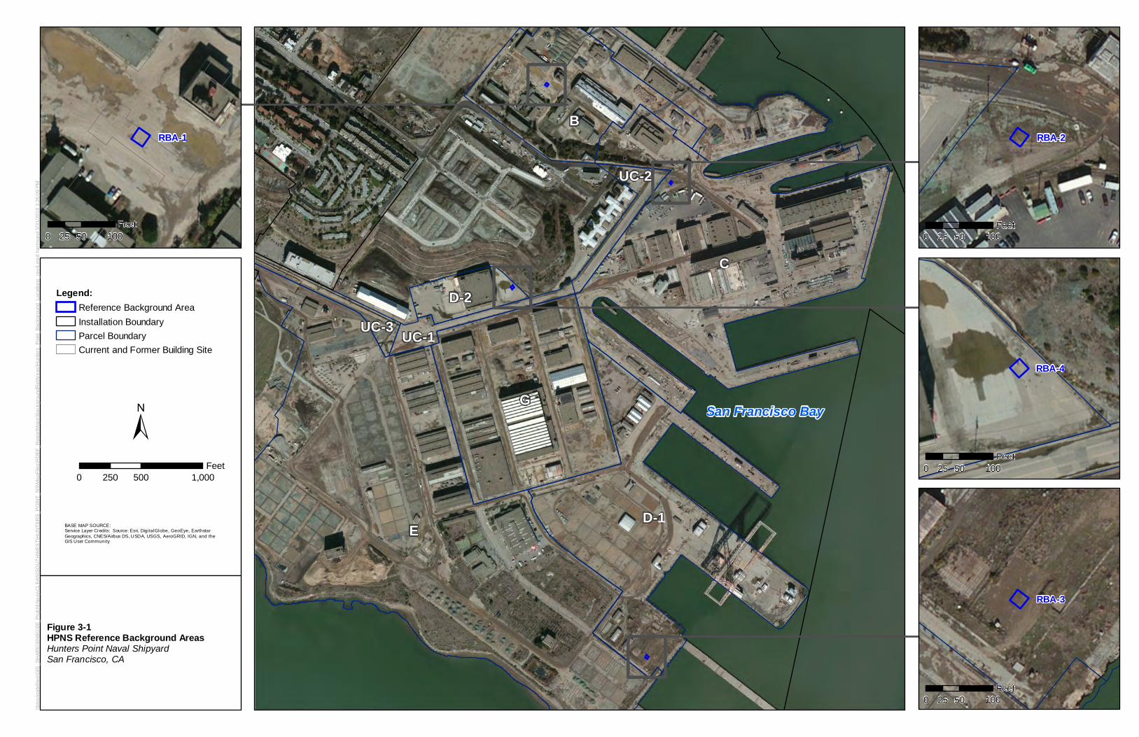
San Francisco Bay
D-1
UC-3
E
B
D-2
G
UC-1
UC-2
C
\\bro
oksi
defil
es\G
IS_S
HAR
E\EN
BG\0
0_Pr
oj\N
\Nav
y\CL
EAN
\SO
UTH
WES
T\H
UN
TER
S_P
OIN
T_N
S\M
apFi
les\
RD
EF_R
epor
tMap
s\Ba
ckgr
ound
Ref
Area
s\H
unte
rs_P
oint
_Bac
kgro
und_
Loca
tions
_rev
4.m
xd h
artm
and
5/31
/201
8 3:
26:0
9 PM
±
BASE MAP SOURCE:Service Layer Credits: Source: Esri, DigitalGlobe, GeoEye, EarthstarGeographics, CNES/Airbus DS, USDA, USGS, AeroGRID, IGN, and theGIS User Community
0 500 1,000250Feet
Figure 3-1HPNS Reference Background AreasHunters Point Naval ShipyardSan Francisco, CA
Legend:Reference Background AreaInstallation BoundaryParcel BoundaryCurrent and Former Building Site
RBA-1 RBA-2
RBA-3
RBA-4
0 50 10025Feet
0 50 10025Feet
0 50 10025Feet
0 50 10025Feet
D D D D
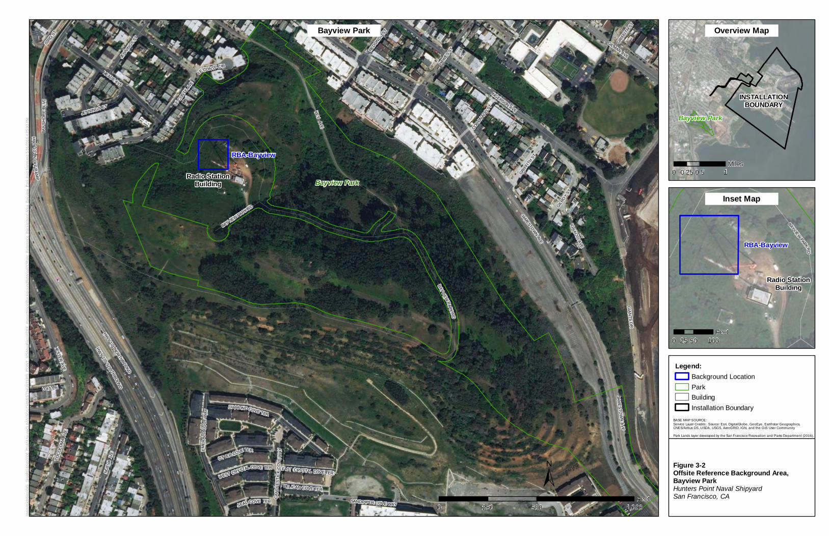
JAMESTOWN
AVE
EME R
A LD
C OVE
WA Y
INGERSON AVE
CAN
DL E
STIC
KC
OV E
WAY
JENNIN
GS ST
JENNINGS CT
GILROY
ST
LECO
NTE
AVE
MEADE AVE
KEY AVE
HWY
101SOUTHBOUND
SANDPIPER COVE WAY
GIAN
TS DR
HESTER AVE
GRIFF
ITH S
T
LECONTE CIR
LOIS LN
DIAMOND COVE TER
HAW
ES S
T
GILMAN AVE
CORONAD
O ST
SEAL COVE TER
PELICAN COVE TER
REDONDO S
T
BAYVIEW PARK RD
EAST CRYSTAL COVE TER
03RD
ST
WEST CRYSTAL COVE TER
GRIFF
ITH S
T
OTTER COVE TER
IGNACIO AVE
HW
Y10 1
NO
F FR
A MP
HWY
101NORTHBOUND
NUEV
A AV
E
BAYVIEWPARK
RD
TOC
OLO
MA
AVE
BAY
SHO
RE
BLVD
JAMESTO
WN
AVE
RBA-Bayview
Bayview ParkRadio StationBuilding
\\bro
oksi
defil
es\G
IS_S
HAR
E\EN
BG\0
0_Pr
oj\N
\Nav
y\CL
EAN
\SO
UTH
WES
T\H
UN
TER
S_P
OIN
T_N
S\M
apFi
les\
RD
EF_R
epor
tMap
s\Ba
ckgr
ound
Ref
Area
s\O
ffsite
_Ref
eren
ce_B
ackg
roun
d Ar
ea_B
ayvi
ew_P
ark.
mxd
har
tman
d 5/
31/2
018
4:25
:03
PM
±
BASE MAP SOURCE:Service Layer Credits: Source: Esri, DigitalGlobe, GeoEye, Earthstar Geographics,CNES/Airbus DS, USDA, USGS, AeroGRID, IGN, and the GIS User Community
Park Lands layer developed by the San Francisco Recreation and Parks Department (2016).
0 500 1,000250Feet
Figure 3-2Offsite Reference Background Area, Bayview ParkHunters Point Naval ShipyardSan Francisco, CA
INSTALLATIONBOUNDARY
Bayview Park
BAYVIEWPARK R
D
RBA-Bayview
Radio StationBuilding
0 50 10025Feet
0 0.5 10.25Miles
Legend:Background LocationParkBuildingInstallation Boundary
Overview Map
Inset Map
Bayview Park
D D D D
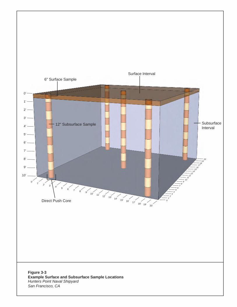
0'
1'
2'
3'
4'
5'
6'
7'
8'
9'
10'
6" Surface SampleSurface Interval
12" Subsurface Sample
0'
0' 1' 2' 3' 4' 5' 6' 7' 8' 9' 10' 11' 12' 13' 14' 15'17'16'
18' 19' 20'
1'2'
3'4'
5'6'
7'8'
9'10'
11'12'
13'14'
15'16'
17'18'
19'20'
Direct Push Core
SubsurfaceInterval
Figure 3-3Example Surface and Subsurface Sample LocationsHunters Point Naval ShipyardSan Francisco, CA
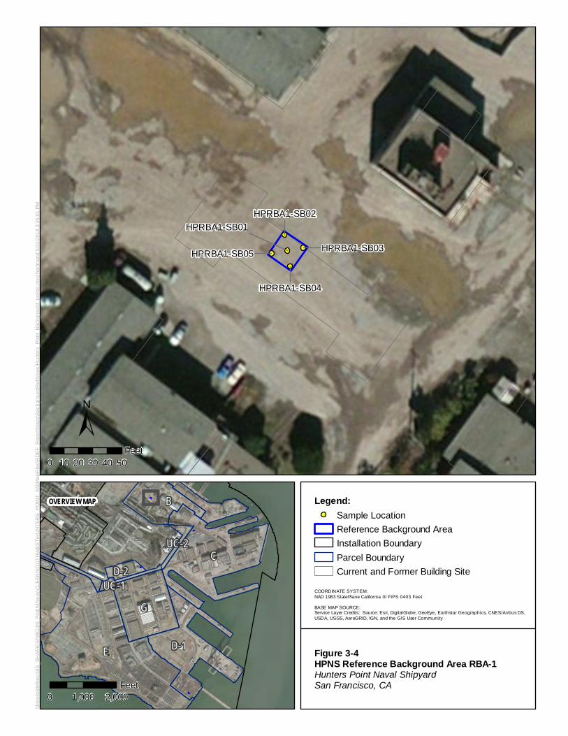
D-1E
B
D-2
GUC-1
UC-2C
HPRBA1-SB02
HPRBA1-SB03
HPRBA1-SB04
HPRBA1-SB05
HPRBA1-SB01
\\bro
oksi
defil
es\G
IS_S
HAR
E\EN
BG\0
0_Pr
oj\N
\Nav
y\CL
EAN
\SO
UTH
WES
T\H
UN
TER
S_P
OIN
T_N
S\M
apFi
les\
RD
EF_R
epor
tMap
s\Ba
ckgr
ound
Ref
Area
s\H
unte
rs_P
oint
_Bac
kgro
und_
poin
ts.m
xd h
artm
and
5/31
/201
8 3:
35:0
1 PM
±
COORDINATE SYSTEM:NAD 1983 StatePlane California III FIPS 0403 Feet
BASE MAP SOURCE:Service Layer Credits: Source: Esri, DigitalGlobe, GeoEye, Earthstar Geographics, CNES/Airbus DS,USDA, USGS, AeroGRID, IGN, and the GIS User Community
0 10 20 30 40 50Feet
Figure 3-4HPNS Reference Background Area RBA-1Hunters Point Naval ShipyardSan Francisco, CA
OVERVIEW MAP
0 1,000 2,000Feet
Legend:Sample LocationReference Background AreaInstallation BoundaryParcel BoundaryCurrent and Former Building Site
0
D D D D
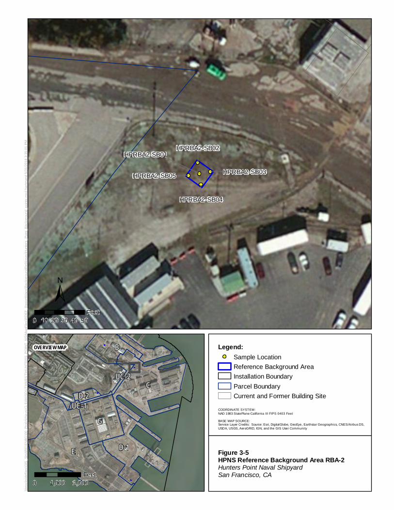
D-1E
B
D-2
GUC-1
UC-2C
HPRBA2-SB02
HPRBA2-SB03
HPRBA2-SB04
HPRBA2-SB05
HPRBA2-SB01
\\bro
oksi
defil
es\G
IS_S
HAR
E\EN
BG\0
0_Pr
oj\N
\Nav
y\CL
EAN
\SO
UTH
WES
T\H
UN
TER
S_P
OIN
T_N
S\M
apFi
les\
RD
EF_R
epor
tMap
s\Ba
ckgr
ound
Ref
Area
s\H
unte
rs_P
oint
_Bac
kgro
und_
poin
ts.m
xd h
artm
and
5/31
/201
8 3:
35:0
1 PM
±
COORDINATE SYSTEM:NAD 1983 StatePlane California III FIPS 0403 Feet
BASE MAP SOURCE:Service Layer Credits: Source: Esri, DigitalGlobe, GeoEye, Earthstar Geographics, CNES/Airbus DS,USDA, USGS, AeroGRID, IGN, and the GIS User Community
0 10 20 30 40 50Feet
Figure 3-5HPNS Reference Background Area RBA-2Hunters Point Naval ShipyardSan Francisco, CA
OVERVIEW MAP
0 1,000 2,000Feet
Legend:Sample LocationReference Background AreaInstallation BoundaryParcel BoundaryCurrent and Former Building Site
0
D D D D
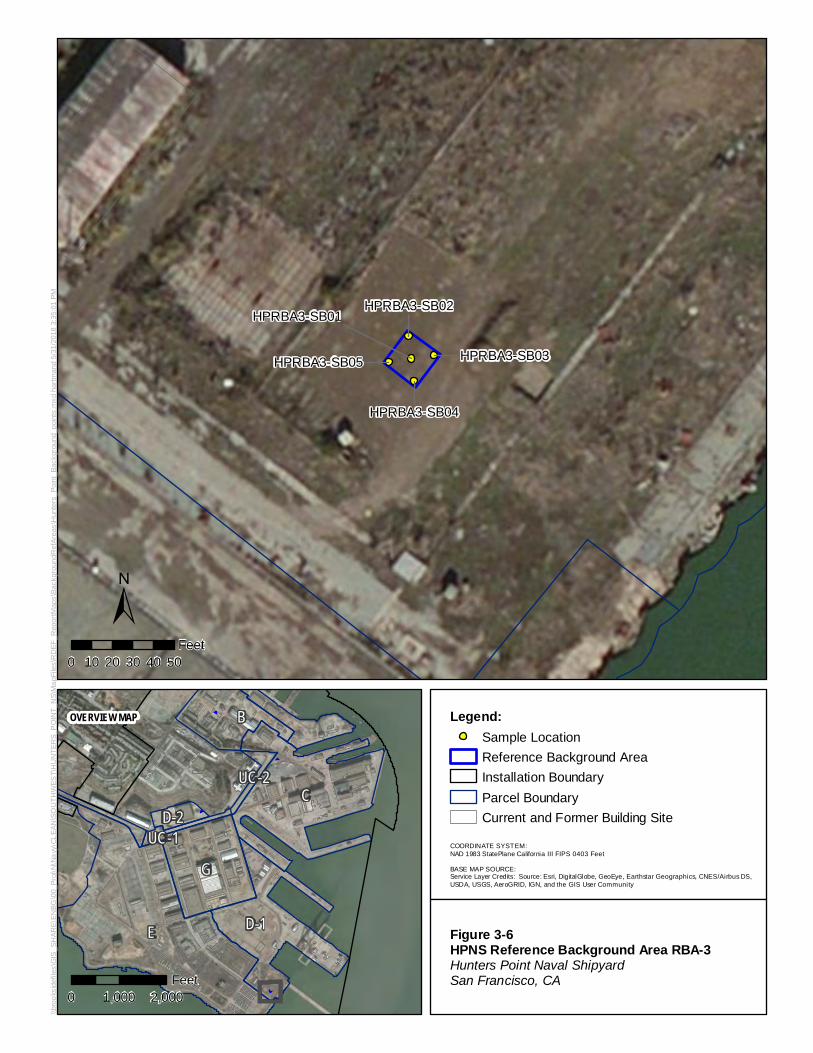
D-1E
B
D-2
GUC-1
UC-2C
HPRBA3-SB02
HPRBA3-SB03
HPRBA3-SB04
HPRBA3-SB05
HPRBA3-SB01
\\bro
oksi
defil
es\G
IS_S
HAR
E\EN
BG\0
0_Pr
oj\N
\Nav
y\CL
EAN
\SO
UTH
WES
T\H
UN
TER
S_P
OIN
T_N
S\M
apFi
les\
RD
EF_R
epor
tMap
s\Ba
ckgr
ound
Ref
Area
s\H
unte
rs_P
oint
_Bac
kgro
und_
poin
ts.m
xd h
artm
and
5/31
/201
8 3:
35:0
1 PM
±
COORDINATE SYSTEM:NAD 1983 StatePlane California III FIPS 0403 Feet
BASE MAP SOURCE:Service Layer Credits: Source: Esri, DigitalGlobe, GeoEye, Earthstar Geographics, CNES/Airbus DS,USDA, USGS, AeroGRID, IGN, and the GIS User Community
0 10 20 30 40 50Feet
Figure 3-6HPNS Reference Background Area RBA-3Hunters Point Naval ShipyardSan Francisco, CA
OVERVIEW MAP
0 1,000 2,000Feet
Legend:Sample LocationReference Background AreaInstallation BoundaryParcel BoundaryCurrent and Former Building Site
0
D D D D
D-1E
B
D-2
GUC-1
UC-2C
HPRBA4-SB02
HPRBA4-SB03
HPRBA4-SB04
HPRBA4-SB05
HPRBA4-SB01
\\bro
oksi
defil
es\G
IS_S
HAR
E\EN
BG\0
0_Pr
oj\N
\Nav
y\CL
EAN
\SO
UTH
WES
T\H
UN
TER
S_P
OIN
T_N
S\M
apFi
les\
RD
EF_R
epor
tMap
s\Ba
ckgr
ound
Ref
Area
s\H
unte
rs_P
oint
_Bac
kgro
und_
poin
ts.m
xd h
artm
and
5/31
/201
8 3:
35:0
1 PM
±
COORDINATE SYSTEM:NAD 1983 StatePlane California III FIPS 0403 Feet
BASE MAP SOURCE:Service Layer Credits: Source: Esri, DigitalGlobe, GeoEye, Earthstar Geographics, CNES/Airbus DS,USDA, USGS, AeroGRID, IGN, and the GIS User Community
0 10 20 30 40 50Feet
Figure 3-7HPNS Reference Background Area RBA-4Hunters Point Naval ShipyardSan Francisco, CA
OVERVIEW MAP
0 1,000 2,000Feet
Legend:Sample LocationReference Background AreaInstallation BoundaryParcel BoundaryCurrent and Former Building Site
0
D D D D
Bayview Park
LATHROP AVE
EMER
AL D
CO
VEW
AY
INGERSON AVE
MEADE AVE
JENN
INGS
ST
TOCO
LOM
A AV
E
HESTER AVEKEY AVE
HARNEY WAY
HAW
ES S
T
GRIFF
ITH ST
PENI
NSUL
A AV
E
CRESCENT WAYBLANKEN AVE
JAMESTOWN
AVE
GIA
NTS
DR
NUEV
A AV
E
GILMAN AVEBAY
SH
OR
E B
LVD
BAYVIEW PARK RD
LOIS LN
HW
Y101
SOUTHBO
UND
HWY
101NO
RTHBOUND
BAYV
IEW
PAR
K RD
Bayview Park
Radio StationBuilding
21
2016
11
106
1
22 23 24 25
17 18 19
12 13 14 15
7 8 9
2 3 4 5
\\bro
oksi
defil
es\G
IS_S
HAR
E\EN
BG\0
0_Pr
oj\N
\Nav
y\CL
EAN
\SO
UTH
WES
T\H
UN
TER
S_P
OIN
T_N
S\M
apFi
les\
RD
EF_R
epor
tMap
s\Ba
ckgr
ound
Ref
Area
s\O
ffsite
_Ref
eren
ce_B
ackg
roun
d_Po
ints
_Bay
view
_Par
k.m
xd h
artm
and
5/31
/201
8 4:
26:0
2 PM
±
COORDINATE SYSTEM:NAD 1983 StatePlane California III FIPS 0403 Feet
BASE MAP SOURCE:Service Layer Credits: Source: Esri, DigitalGlobe, GeoEye, Earthstar Geographics, CNES/Airbus DS,USDA, USGS, AeroGRID, IGN, and the GIS User Community
Park Lands layer developed by the San Francisco Recreation and Parks Department (2016).
0 10 20 30 40 50Feet
Figure 3-8Bayview Park Reference Background Area RBA-BayviewHunters Point Naval ShipyardSan Francisco, CA
OVERVIEW MAP
0 1,000 2,000Feet
Legend:Sample LocationReference Background AreaParkBuilding
0
D D D
SECTION 4
4-1
Data Evaluation and Reporting Various types of radiological data are being collected from multiple RBAs during the execution of this work plan, representing soils with potentially different distributions of naturally occurring and ubiquitous fallout radionuclides. Gamma scan data will be mapped and evaluated as detailed in Section 4.1. Analytical data (i.e., soil sample results) will be compiled and validated in accordance with the SAP. Following data validation, analytical sample results will be evaluated as detailed in Section 4.2. Following evaluation, the RBA characterization data will be compiled and submitted in a Soil Reference Background Area Report as detailed in Section 4.3.
4.1 Gamma Scan Data Evaluation Gamma scan survey data from each RBA will be initially evaluated as individual RBA data sets for both gross gamma and gamma spectra. A statistical data evaluation will be conducted to identify appropriate soil background data sets and calculate descriptive statistics to facilitate future comparisons with site-specific data. The purposes of the data evaluation are the following:
• Conduct a preliminary data review. − Compile basic statistics − Graphical data review
• Identify outliers, or data that are not representative of background conditions. • Determine statistical differences between data sets.
4.1.1 Conduct a Preliminary Data Review The spectra will be analyzed using regions of interest for known gamma-emitting ROCs and naturally occurring radionuclides. Radionuclide-specific (spectra) and gross gamma data set information will be gleaned by compiling basic statistics, including mean, median, minimum, maximum, and standard deviation, and by creating plots such as histograms, box plots, and normal probability plots from each RBA.
Because position measurements were collected in conjunction with the radiological readings, gamma survey maps will be generated using the GPS locations to visually evaluate the geospatial measurements and to confirm the RBA classifications as being non-impacted and suitable for use as an RBA. The gamma survey map will be created as follows:
• Using GIS software, the gamma measurement will be spatially plotted using the GPS coordinates recorded during the scan survey.
• Measurements collected outside of the RBA footprints will be digitally cropped out of the survey maps so that only the designated RBAs will contain gamma measurements.
• Using kriging functions in GIS, a contiguous surface will be created and color-coded for visualization of the readings.
Using each gamma scan survey data set (either combined or individual), the detector’s response to background radiation will be established for gross gamma and radionuclide-specific gamma-emitters identified in the spectra.
4.1.2 Identify Outliers The gamma scan survey data will undergo an outlier evaluation using Dixon’s and Rosner’s outlier tests. Dixon’s test is valid for data sets with up to 25 data points while Rosner’s test is recommended for larger
SOIL REFERENCE BACKGROUND AREA WORK PLAN, FORMER HUNTERS RIDGE NAVAL SHIPYARD, SAN FRANCISCO, CALIFORNIA
4-2
data sets. Details of Dixon’s and Rosner’s tests for outliers is provided in Section 4.2.2. Both Dixon’s and Rosner’s tests assume that the data values (aside from those being tested as potential outliers) are normally distributed. Because environmental data tend to be right-skewed, a test that relies on an assumption of a normal distribution may identify a relatively large number of mathematical outliers. Outliers identified in this evaluation will be reviewed to determine whether any suitable reasons (e.g., a potential analytical error) exist to exclude them from further calculations.
4.1.3 Determine Statistical Differences between Datasets The five RBA scan data sets will be compared to each other by applying the KW statistical test, detailed in Section 13.2 of NUREG-1505 (NRC, 1998), to determine whether the reference areas have similar or significantly different background levels. To conduct the KW test, the acceptable Type I error rate (alpha, α) is specified as 0.05, which is the acceptable probability of concluding that the reference areas have different average concentrations, when in fact, they are the same. The null hypothesis H0, therefore, is that the reference areas have the same average (or median) concentration.
If there are data sets that are similar (i.e., pass the KW test), they will be combined. If data sets are significantly different (i.e., they fail the KW test), further evaluation will be performed to determine the potential causes of the differences, such as soil type.
4.2 Analytical Data Evaluation A statistical data evaluation will be conducted to identify appropriate soil background data sets and calculate descriptive statistics to facilitate future comparisons with site-specific data. The purposes of the data evaluation are the following:
• Conduct a preliminary data review. − Compile basic statistics − Graphical data review
• Identify outliers, or data that are not representative of background conditions. • Determine statistical differences between data sets.
4.2.1 Conduct a Preliminary Data Review Analytical data set information will be gleaned by compiling basic statistics, including mean, median, minimum, maximum, and standard deviation. Graphical comparisons will be made using posting plots, histograms, box and whisker plots, and normal probability plots from each RBA. Review of the basic statistics and plots will provide useful information, such as revealing homogeneity or heterogeneities, spatial trends, data distributions, and skewness. RBA data from individual RBAs are assumed to follow a normal or log-normal distribution without bi-modalities or skewness. The results of the normality testing can be used to validate a data set as being consistent with assumptions concerning background.
4.2.2 Identify Outliers Perform an outlier evaluation of the graphical plots by looking for indications of data values outside of the expected distribution (i.e., potential outlier).
Perform an outlier evaluation using Dixon’s and Rosner’s statistical outlier tests. Dixon’s test is valid for data sets with up to 25 data points while Rosner’s test is recommended for larger data sets. Both Dixon’s and Rosner’s tests assume that the data values (aside from those being tested as potential outliers) are normally distributed. Both statistical outlier tests will be performed using statistical software or spreadsheets, and are described here. The Dixon test will be performed by arranging the concentrations of a specific nuclide in ascending order from X1 to XN and using Equation 4-1:
SECTION 4 – DATA EVALUATION AND REPORTING
4-3
Equation 4-1
𝑄𝑄𝑒𝑒𝑒𝑒𝑒𝑒 =𝑋𝑋2 − 𝑋𝑋1𝑋𝑋𝑁𝑁 − 𝑋𝑋1
Where:
Qexp = experimental Q-value
XN = Highest value of measurements
X1 = Value of smallest measurement
X2 = Value of second smallest measurement
The corresponding Qexp value is compared to the critical value (Qcrit) obtained from a confidence level of 95 percent.
Because Dixon’s test is appropriate for samples sizes with up to 25 data points, Rosner’s test for outliers will be performed for sample sizes larger than 25. The Rosner’s test is performed as follows:
1. Arrange the concentrations of a specific nuclide in ascending order, and by simple inspection, identify the maximum number of possible outliers r0.
2. Compute the mean and standard deviation of the data and determine the measurement furthest from the mean.
3. Delete the measurement from the data set and compute the sample mean and standard deviation from the remaining observations. Again, find the value in the reduced data set furthest from the mean.
4. Delete the measurement and recompute the mean and standard deviation until all potential outliers have been removed.
5. Perform test for outliers, using Equation 4-2:
Equation 4-2
𝑅𝑅𝑟𝑟−1 =�𝑦𝑦(𝑟𝑟−1) − �̅�𝑥(𝑟𝑟−1)�
𝑠𝑠(𝑟𝑟−1)
Where:
Rr-1 = test statistic for potential r outlier
y(r-1) = measurement value of outlier
x(r-1) = mean of reduced data set without y(r-1) value
s(r-1) = standard deviation of reduced data set with y(r-1) value
1. Compare the test statistic (Rr-1) to the critical value corresponding to a confidence level of 95 percent.
2. Perform the test statistic for the other possible outliers identified in Step 1 in the same fashion until the possible outliers have either been identified or Rosner’s test finds no outliers.
Because environmental data tend to be right-skewed, a test that relies on an assumption of a normal distribution may identify a relatively large number of mathematical outliers. Outliers identified in this evaluation will be reviewed to determine whether any suitable reasons (e.g., a potential analytical error) exist to exclude them from further calculations. Confirmed outliers will be removed from individual data sets.
SOIL REFERENCE BACKGROUND AREA WORK PLAN, FORMER HUNTERS RIDGE NAVAL SHIPYARD, SAN FRANCISCO, CALIFORNIA
4-4
4.2.3 Determine of Statistical Differences between Data Sets Background concentrations from each RBA for surface soil and subsurface soil will be compared statistically to test for differences between surface soil and subsurface soil concentrations and to test for differences among soil groups. If the data sets are not significantly different, then they will be combined to create a larger background data set. If the data sets are significantly different, then they will be treated separately for comparisons of site-specific data to background.
Statistical tests for a normal distribution (symmetry) will be performed using computer software to conduct the Shiparo-Wilk/Lillifors testing for normality. In addition to graphical inspection, central tendency comparisons will be performed to determine whether the centers of the distributions of the surface soil and subsurface soil data, and between the various soil groups, are different or similar.
The RBA data sets will be compared to each other by applying the KW statistical test, detailed in Section 13.2 of NUREG-1505 (NRC, 1998) and described in Section 4.1.3, to determine whether the reference areas have similar or significantly different background levels. If there are data sets that are similar (i.e., pass the KW test), they may be combined. If data sets are significantly different (i.e., they fail the KW test), further evaluation will be performed to determine the potential causes of the differences such as soil type or depth bgs. Data may be plotted on site maps or plotted against gamma-scan data to look for visual clues as to ROC distribution and to evaluate spatial independence.
4.2.4 Establish Background Data Sets Once a determination has been made about combining data from the RBAs, one or more RBA data sets for each radionuclide will be established. Pending approval for their use, the data sets will be used for comparison with trench or surface soil data sets as described in the Parcel G Work Plan.
While the focus of the analytical evaluation will be on radioactivity, the evaluations may also identify and record relationships and correlations between lithologic characteristics of the samples and the radioactivity.
4.3 Reporting The Parcel G Work Plan discusses documentation and records management requirements for data generated during this project. Corrective action reports, data validation reports, quality assurance management reports, and assessment reports are discussed in the SAP.
Following completion of RBA soil data evaluation, a report will be prepared to include a summary of the field activities, results of gamma scan surveys, and analytical and geotechnical data, along with the results of the data evaluation. Based on the statistical evaluations, the report will include recommendations for combining similar data sets, and recommendations for selecting values or data sets representing background in soil, and conditions identifying situations when specific values or data sets may not be appropriate. Information from other San Francisco Bay Area radiological background studies may be referenced in the report as appropriate.
SECTION 5
5-1
Radioactive Materials Management and Control This work plan was prepared based on CH2M HILL, Inc. (CH2M) and its subcontractor, Perma-Fix, leading and conducting the field activities presented in this work plan. Prior to initiating field activities at HPNS, Perma-Fix will invoke their radioactive materials license, as described in the Parcel G Work Plan. The Parcel G Work Plan includes the following contractor-specific information: Radiological Material License, SOPs, Organizational Chart, and Radiation Protection Plan. The APP/SSHP outlines the health and safety requirements and procedures for the field activities included in this work plan.
SECTION 6
6-1
References Navy. 2018. Parcel G Removal Site Evaluation Work Plan, Former Hunters Point Naval Shipyard, San Francisco, California. Draft.
Navy. 2006. Basewide Radiological Removal Action, Action Memorandum–Revision 2006, Hunters Point Shipyard, San Francisco, California.
Nuclear Regulatory Commission (NRC). 1998. A Nonparametric Statistical Methodology for the Design and Analysis of Final Status Decommissioning Surveys. NUREG-1505. Revision 1.
Appendix B Contractor-specific Radioactive
Material License, Standard Operating Procedures, Organizational Chart, and
Radiation Protection Plan
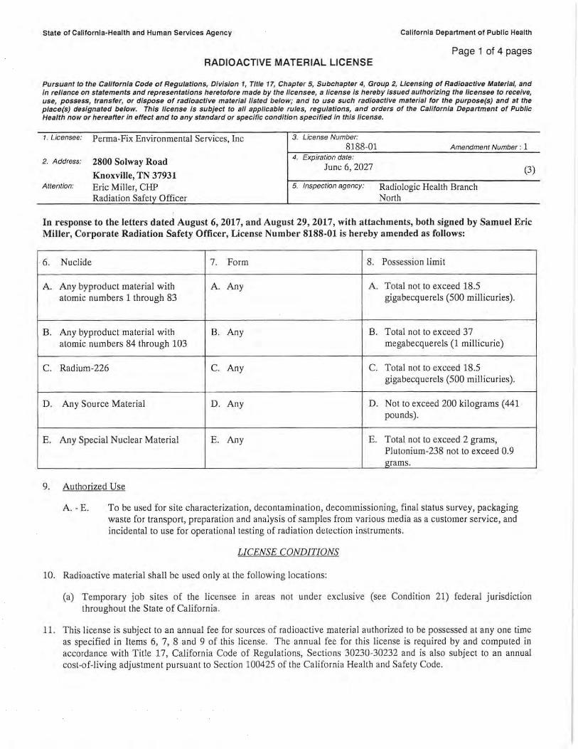
State of Callfornla-Health and Human Services Agency California Department of Public Health
Page 1 of 4 pages RADIOACTIVE MATERIAL LICENSE
Pursuant to the Ca/lfornla Code of Regulations, Dfvisfon 1, Title 17, Chapter 5, Subchapter 4, Group 2, Lfcensing of Radloactfve Materfal, and fn reliance on statements and representations heretofore made by the 1/censee, a license is hereby issued authorizing the 1/censee to receive, use, possess, transfer, or dispose of radioactive material listed below; and to use such radfoactfve material for the purpose(s) and at the place(s) designated below. This license is subject to all apptlcable rules, regulations, and orders of the Callfornfa Department of Public Health now or hereafter in effect and to any standard or specific condition specified In this license.
1. Licensee: Perma-Fix Environmental Services, Inc 3. License Number: 8188-01 Amendment Number : 1
2. Address: 2800 Solway Road
Knoxville, TN 37931 Attention: Eric Miller, CHP
Radialion Safety Officer
4. Expiration date:
June 6, 2027
5. Inspection agency: Radiologic Health Branch North
(3)
In response to the letters dated August 6, 2017, and August 29, 2017, with attachments, both signed by Samuel Eric Miller, Corporate Radiation Safety Officer, License Number 8188-01 is hereby amended as follows:
6. Nuclide 7 . Form 8. Possession limit
A. Any byproduct material with A. Any A. Total nol to exceed 18.5 atomic numbers 1 through 83 gigabecquerels (500 millicuries).
B. Any byproduct material with B. Any B. Total not to exceed 37 atomic numbers 84 through 103 megabecquerels (1 millicurie)
C. Radium -226 C. Any C. Total not to exceed 18.5 gigabecquerels (500 millicuries).
D. Any Source Material D. Any D. Not to exceed 200 kilograms (441 pounds).
E. Any Special Nuclear Material E. Any E. Total not to exceed 2 grams, Plutonium-238 not to exceed 0.9 grams.
9. Authorized Use
A . - E. To be used for site characterization, decontamination, decommissioning, final status survey, packaging waste for transport, preparation and analysis of samples from various media as a customer service, and incidental to use for operational testing of radiation detection instruments.
LICENSE CONDITIONS
10. Radioactive material shall be used only al the following locations:
(a) Temporary job sites of the licen ee in areas not under exclusive (see Condition 21) federal jurisdiction throughout the State of California.
11. This license is subject lo an annual fee for sources of radioactive material authorized to be possessed al any one time as specified in Items 6, 7, 8 and 9 of this license. The annual fee for this license is required by and computed in accordance with Tille 17, California Code of Regulations, Sections 30230-30232 and is also subject to an annual cost-of-living adjustment pursuant to Section 100425 of the California Health and Safety Code.
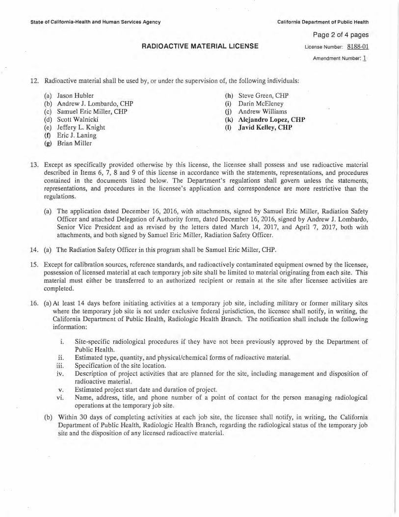
State of California-Health and Human Services Agency California Department of Public Health
RADIOACTIVE MATERIAL LICENSE
12. Radioactive material shall be used by, or under the upervision of, the following individuals:
(a) Jason Hubler (b) Andrew J. Lombardo, CHP (c) Samuel Eric Miller, CHP (d) Sc.:ott Walnicki (e) Jeffery L. Knight (f) Eric J. Laning (g) Brian Miller
(h) Steve Green, CHP (i) Darin McEleney (j) Andrew Williams (k) Alejandro Lopez, CHP (I) Javid Kelley, CHP
Page 2 of 4 pages
License Number: 8188-01
Amendment Number: 1
13. Except as specifically provided otherwise by this license, the licensee shall possess and use radioactive material described in Items 6, 7, 8 and 9 of this license in accordance with the statements, representations, and procedures contained in the documents listed below. The Department' s reguJations shall govern unless the statements, representations, and procedures in the licensee's application and correspondence are more restrictive than the regulations.
(a) The application dated December 16, 2016, with attachments, signed by Samuel Eric Miller, Radiation Safety Officer and attached Delegation of Authority form, dated December 16, 2016, signed by Andrew J. Lombardo, Senior Vice President and as revised by the Jeuers dated March 14, 2017, and April 7, 2017, both with attachments, and both signed by Samuel Eric Miller, Radiation Safety Officer.
14. (a) The Radiation Safety Officer in this program shall be Samuel Eric Miller, CHP.
15. Except for calibration sources, reference standards, and radioactively contaminated equipment owned by the licensee, possession of licensed material at each temporary job site shall be limited to material originating from each site. This material mu t ei ther be transferred to an authorized recipient or remain at 1he si te after licensee activities are completed.
16. (a) At least 14 days before initiating activities at a temporary job site, including mili tary or forme r miWary sites where the temporary job site is not under exclusive federal jurisdiction, the licensee hall notify, in writing, the California Department of Public H ealth , Rad iologic Health Branch. The notification shall include the following information:
1. Site-specific radiological procedures if they have not been previously approved by the Department of Public Health.
11. Estimated type, quantity, and physical/chemical forms of radioactive material. 111 . Specification of the site location. iv. Description of project activities that are planned for the site, including management and disposition of
radioactive material. v. Estimated project start date and duration of project.
vi. Name, address, title, and phone number of a point of contact for the pe rson managing radiological operations at the temporary job site.
(b) Within 30 days of comple ting activities at each job site, the licensee hall notify, in writing, the California D epartment of Public Health, Radiologic Hea lth Branch, regarding che radiological talus of the temporary job site and the disposition of any licensed radioactive material.
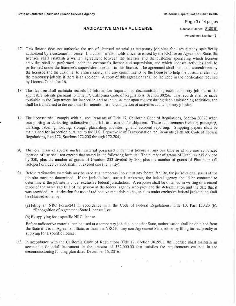
State of California-Health and Human Services Agency
RADIOACTIVE MATERIAL LICENSE
California Department of Publlc Health
Page 3 of 4 pages
License Number: 8188-01
Amendment Number: l
17. This license does not authorize the use of licensed material at temporary job sites for uses already specifically authorized by a customer 's license. If a customer also holds a li cense issued by the NRC or an Agreement tate, the licen ec shall establish a wrillen agreement between the licensee and the customer specifying which licensee activities shall be performed under the customer's license and supervi ion, and which licensee activities shall be performed under the licensee 's supervision pursuant to this license, The agreement shall include a commitment by the licensee and the customer to ensure safety, and any commitments by the licensee to help the customer clean up the temporary job site if there is an accident. A copy of th is agreement shall be included in the notificatio n required by License Condition 16.
18. The licensee shall maintain records of information important to decommissioning each temporary job ite at the applicable job site pursuant to Title 17, California Code of Regulations, Section 30256. The records shall be made available to the Department for inspeccion and 10 the customer upon request during decommissioning activities, and shall be transferred to the customer for retention at the completion of activities al a temporary job site.
19. The licensee shall comply with all requirements of Title 17, California Code of Regulations, Section 30373 when transporting or delivering radioactive materials lo a carrier for shipment. These requirements include; packaging, marking, labeling, loading, storage, placarding, monitoring, and accident reporting. Shipping papers shall be maintained for inspection pursuant to the U.S. Department of Transportation requirements (Tille 49, Code of Federal Regulations, Part 172, Sections 172.200 through 172.204 ).
20. The Iota! mass of special nuclear material possessed under thi license at any one time or at any one authorized location of use hall not exceed that stated in the following formula: The number of grams of Uranium 235 divided by 350, plus the number of grams of Uranium 233 divided by 200, plus the number of grams of Plutonium (all isotopes) divided by 200, shall not exceed one (i.e. unity) .
21. Before radioactive materials may be used at a temporary job site at any federal faci lity, the jurisdictional talus of the job site must be determined. If the jurisdictional status i unknown, the fede ral agency should be contacted to determine if the job site is under exclusive federal jurisdiction. A response shall be obtained in writing or a record made of the name and title of the person al the federal agency who provided the determination and the date that it was provided. Authorization for use of radioactive materials at the job sites under exclusive federal j urisdiclion shall be obtained either by :
(a)Filing an NRC Form-241 in accordance with the Code of Federal Regulations, Title 10, Part 150.20 (b), ' Recognition of Agreement State Licenses" or
(b) By applying for a specific NRC license.
Before radioactive material can be used al a temporary job site in another State, authorization shall be obtained from the State if it is an Agreement Stace, or from the NRC for any non-Agreement State, either by filing for reciprocity or applying for a specific license.
22. In accordance with the California Code of Regulations Tille 17, Section 30195.1, lhe licensee shall maintain an acceptable financi al instrument in the amou nl of $52,000.00 that satisfie the requirements outlined in the decommissioning funding plan dated December 16, 2016.
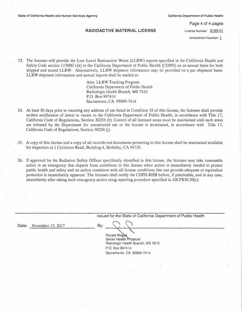
State of Calilornla-Health and Human Services Agency
RADIOACTIVE MATERIAL LICENSE
California Department of Public Health
Page 4 of 4 pages
License Number: 8188-01
Amendment Number: 1
23. The licensee will provide the Low Level Radioactive Was te (LLRW) reports pecified in the California Health and Safety Code section 115000.l(h) to the California Department of Public Health (CDPH) on an annual bas is for both shipped and stored LLRW. Alternatively, LLRW shipment information may be provided on a per shipment basis. LLRW shipment information and annual reports shall be mailed to:
Attn : LLRW Tracking Program California Department of Public Health Rad iologic Health Branch, MS 7610 P.O. Box 997414 Sacramento, CA 95899-7414
24. At least 30 days prior to vacating any address of use lis ted in Condition 10 of this license, the licensee shall provide written notification of jntent to vacate to the California Department of Public Health, in accordance with Title 17, California Code of Regulations, Sectfon 30256 (b) . Con trol of all licensed areas must be maintained until such areas are released by the Department fo r unrestricted use or the license is terminated , in accordance with Title 17, California Code of Regulations, Section 30256 U) .
25 . A copy of this license and a copy of all records and documen ts pertaining to this license shall be maintained available for inspection at l Cyclotron Road, Building 4 Berkeley CA 94720.
26. If approved by the Radiation Safety Officer specifically identified in this lice nse, the licensee may take reasonable action in an emergency that departs from condi tio ns in this license whe n action is immediately needed to protect public health and safety and no ac tion consistent with all license conditions that can provi de adequate or equivalent protection is immediately apparent The licensee ·hall notify the CDPH-RHB before, if practicable, and in any case, im mediately after taking such emergency action using report ing procedure specified in 10CFR30.50(c).
Date: November 15, 2017
Issued for the State of Cal ifornia Department of Public Health
Ronald Rog Senior Health hysicist Rad iologic Health Branch, MS 7610
P.O. Box 997414
Sacramento , CA 95899-7414
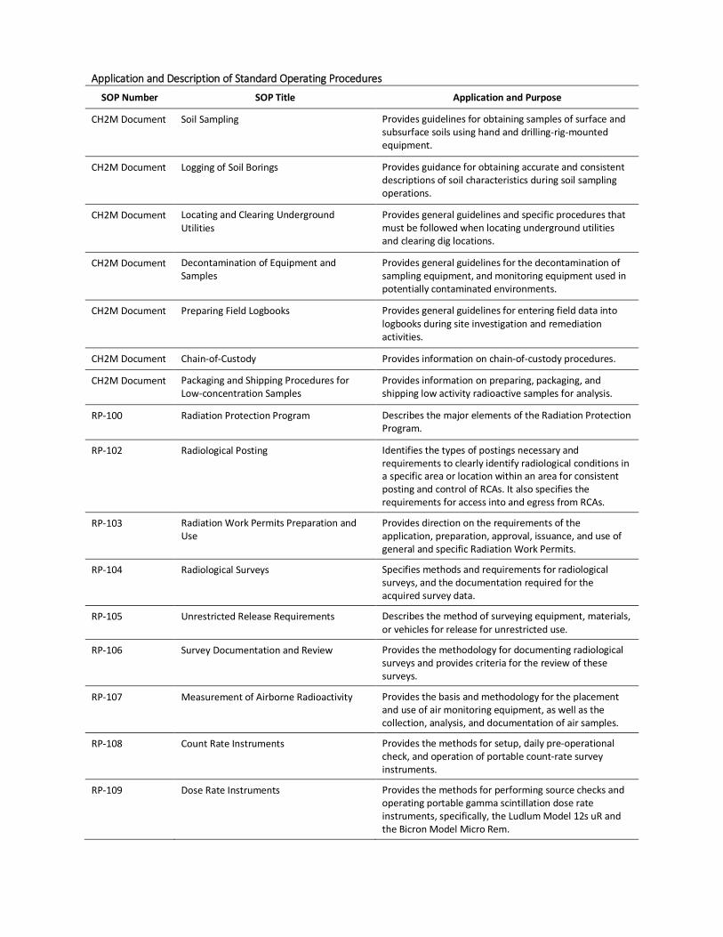
Application and Description of Standard Operating Procedures
SOP Number SOP Title Application and Purpose
CH2M Document Soil Sampling Provides guidelines for obtaining samples of surface and subsurface soils using hand and drilling-rig-mounted equipment.
CH2M Document Logging of Soil Borings Provides guidance for obtaining accurate and consistent descriptions of soil characteristics during soil sampling operations.
CH2M Document Locating and Clearing Underground Utilities
Provides general guidelines and specific procedures that must be followed when locating underground utilities and clearing dig locations.
CH2M Document Decontamination of Equipment and Samples
Provides general guidelines for the decontamination of sampling equipment, and monitoring equipment used in potentially contaminated environments.
CH2M Document Preparing Field Logbooks Provides general guidelines for entering field data into logbooks during site investigation and remediation activities.
CH2M Document Chain-of-Custody Provides information on chain-of-custody procedures.
CH2M Document Packaging and Shipping Procedures for Low-concentration Samples
Provides information on preparing, packaging, and shipping low activity radioactive samples for analysis.
RP-100 Radiation Protection Program Describes the major elements of the Radiation Protection Program.
RP-102 Radiological Posting Identifies the types of postings necessary and requirements to clearly identify radiological conditions in a specific area or location within an area for consistent posting and control of RCAs. It also specifies the requirements for access into and egress from RCAs.
RP-103 Radiation Work Permits Preparation and Use
Provides direction on the requirements of the application, preparation, approval, issuance, and use of general and specific Radiation Work Permits.
RP-104 Radiological Surveys Specifies methods and requirements for radiological surveys, and the documentation required for the acquired survey data.
RP-105 Unrestricted Release Requirements Describes the method of surveying equipment, materials, or vehicles for release for unrestricted use.
RP-106 Survey Documentation and Review Provides the methodology for documenting radiological surveys and provides criteria for the review of these surveys.
RP-107 Measurement of Airborne Radioactivity Provides the basis and methodology for the placement and use of air monitoring equipment, as well as the collection, analysis, and documentation of air samples.
RP-108 Count Rate Instruments Provides the methods for setup, daily pre-operational check, and operation of portable count-rate survey instruments.
RP-109 Dose Rate Instruments Provides the methods for performing source checks and operating portable gamma scintillation dose rate instruments, specifically, the Ludlum Model 12s uR and the Bicron Model Micro Rem.
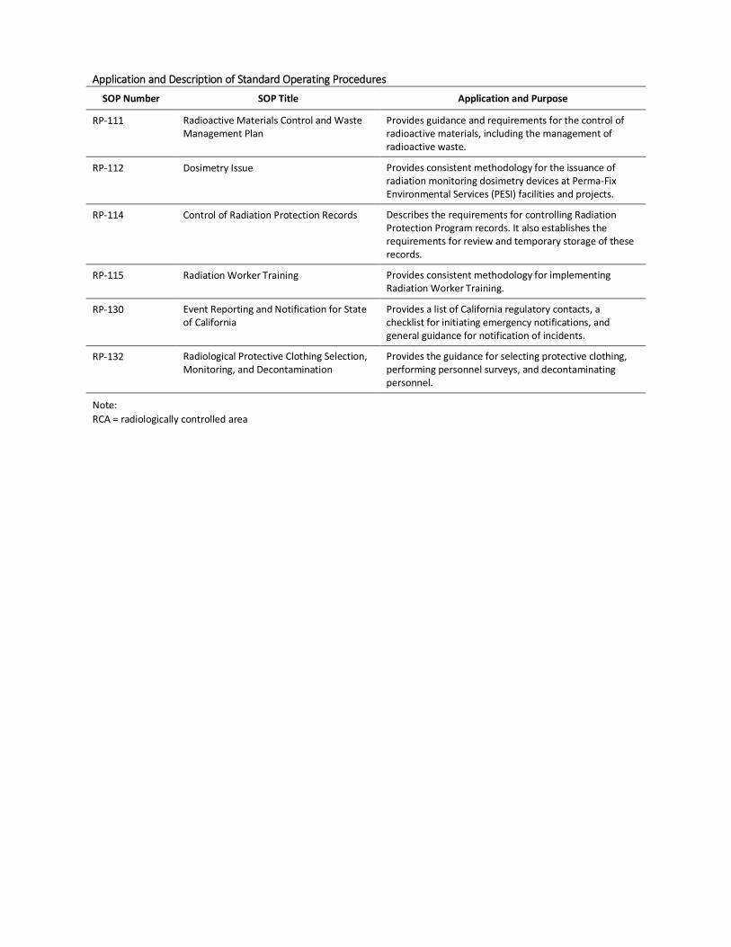
Application and Description of Standard Operating Procedures
SOP Number SOP Title Application and Purpose
RP-111 Radioactive Materials Control and Waste Management Plan
Provides guidance and requirements for the control of radioactive materials, including the management of radioactive waste.
RP-112 Dosimetry Issue Provides consistent methodology for the issuance of radiation monitoring dosimetry devices at Perma-Fix Environmental Services (PESI) facilities and projects.
RP-114 Control of Radiation Protection Records Describes the requirements for controlling Radiation Protection Program records. It also establishes the requirements for review and temporary storage of these records.
RP-115 Radiation Worker Training Provides consistent methodology for implementing Radiation Worker Training.
RP-130 Event Reporting and Notification for State of California
Provides a list of California regulatory contacts, a checklist for initiating emergency notifications, and general guidance for notification of incidents.
RP-132 Radiological Protective Clothing Selection, Monitoring, and Decontamination
Provides the guidance for selecting protective clothing, performing personnel surveys, and decontaminating personnel.
Note: RCA = radiologically controlled area
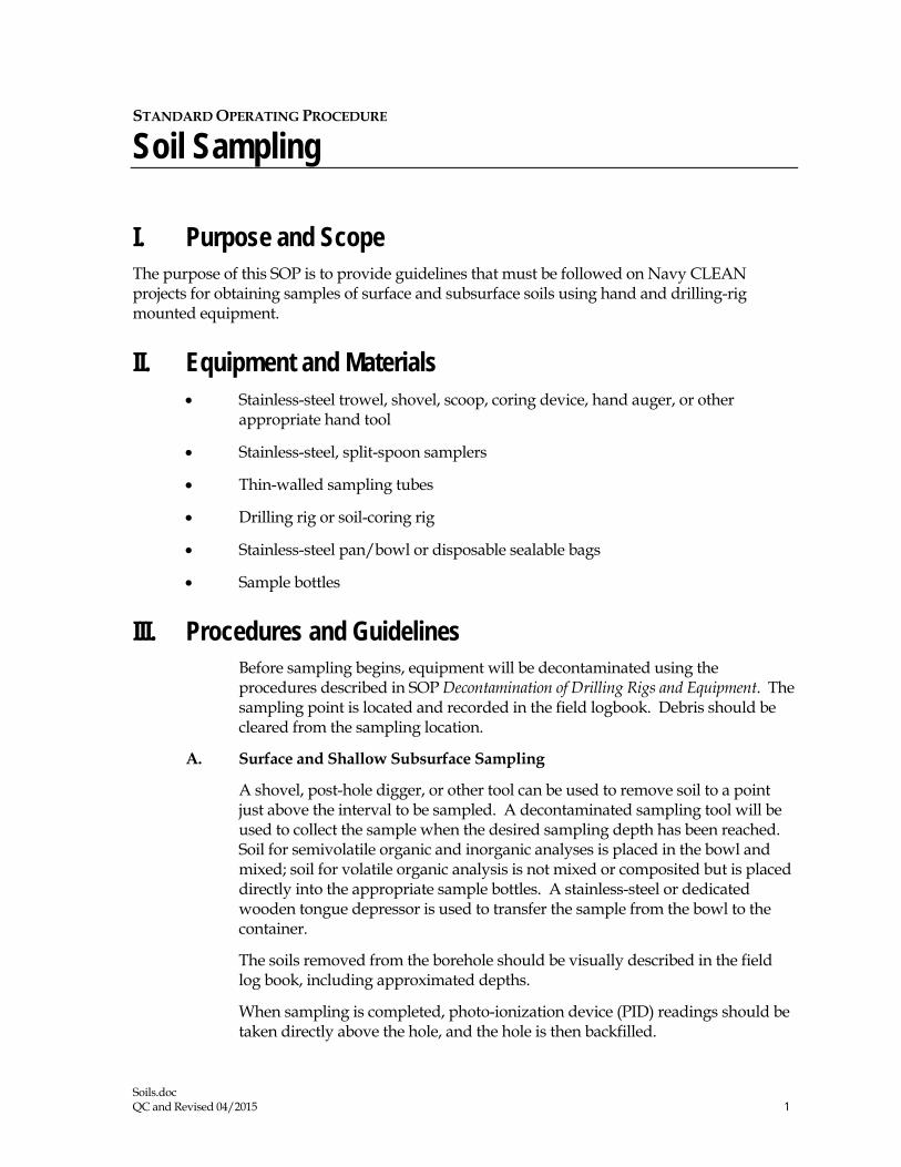
Soils.doc QC and Revised 04/2015 1
STANDARD OPERATING PROCEDURE
Soil Sampling
I. Purpose and Scope The purpose of this SOP is to provide guidelines that must be followed on Navy CLEAN projects for obtaining samples of surface and subsurface soils using hand and drilling-rig mounted equipment.
II. Equipment and Materials • Stainless-steel trowel, shovel, scoop, coring device, hand auger, or other
appropriate hand tool
• Stainless-steel, split-spoon samplers
• Thin-walled sampling tubes
• Drilling rig or soil-coring rig
• Stainless-steel pan/bowl or disposable sealable bags
• Sample bottles
III. Procedures and Guidelines Before sampling begins, equipment will be decontaminated using the procedures described in SOP Decontamination of Drilling Rigs and Equipment. The sampling point is located and recorded in the field logbook. Debris should be cleared from the sampling location.
A. Surface and Shallow Subsurface Sampling
A shovel, post-hole digger, or other tool can be used to remove soil to a point just above the interval to be sampled. A decontaminated sampling tool will be used to collect the sample when the desired sampling depth has been reached. Soil for semivolatile organic and inorganic analyses is placed in the bowl and mixed; soil for volatile organic analysis is not mixed or composited but is placed directly into the appropriate sample bottles. A stainless-steel or dedicated wooden tongue depressor is used to transfer the sample from the bowl to the container.
The soils removed from the borehole should be visually described in the field log book, including approximated depths.
When sampling is completed, photo-ionization device (PID) readings should be taken directly above the hole, and the hole is then backfilled.
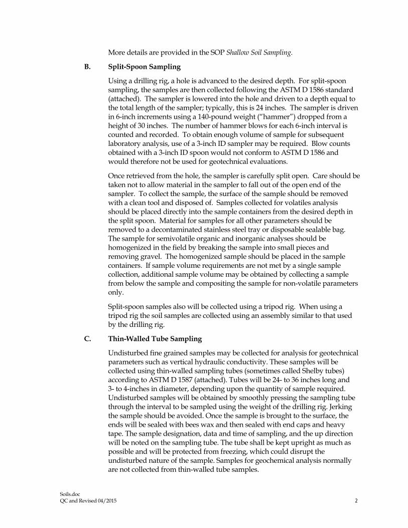
Soils.doc QC and Revised 04/2015 2
More details are provided in the SOP Shallow Soil Sampling.
B. Split-Spoon Sampling
Using a drilling rig, a hole is advanced to the desired depth. For split-spoon sampling, the samples are then collected following the ASTM D 1586 standard (attached). The sampler is lowered into the hole and driven to a depth equal to the total length of the sampler; typically, this is 24 inches. The sampler is driven in 6-inch increments using a 140-pound weight (“hammer”) dropped from a height of 30 inches. The number of hammer blows for each 6-inch interval is counted and recorded. To obtain enough volume of sample for subsequent laboratory analysis, use of a 3-inch ID sampler may be required. Blow counts obtained with a 3-inch ID spoon would not conform to ASTM D 1586 and would therefore not be used for geotechnical evaluations.
Once retrieved from the hole, the sampler is carefully split open. Care should be taken not to allow material in the sampler to fall out of the open end of the sampler. To collect the sample, the surface of the sample should be removed with a clean tool and disposed of. Samples collected for volatiles analysis should be placed directly into the sample containers from the desired depth in the split spoon. Material for samples for all other parameters should be removed to a decontaminated stainless steel tray or disposable sealable bag. The sample for semivolatile organic and inorganic analyses should be homogenized in the field by breaking the sample into small pieces and removing gravel. The homogenized sample should be placed in the sample containers. If sample volume requirements are not met by a single sample collection, additional sample volume may be obtained by collecting a sample from below the sample and compositing the sample for non-volatile parameters only.
Split-spoon samples also will be collected using a tripod rig. When using a tripod rig the soil samples are collected using an assembly similar to that used by the drilling rig.
C. Thin-Walled Tube Sampling
Undisturbed fine grained samples may be collected for analysis for geotechnical parameters such as vertical hydraulic conductivity. These samples will be collected using thin-walled sampling tubes (sometimes called Shelby tubes) according to ASTM D 1587 (attached). Tubes will be 24- to 36 inches long and 3- to 4-inches in diameter, depending upon the quantity of sample required. Undisturbed samples will be obtained by smoothly pressing the sampling tube through the interval to be sampled using the weight of the drilling rig. Jerking the sample should be avoided. Once the sample is brought to the surface, the ends will be sealed with bees wax and then sealed with end caps and heavy tape. The sample designation, data and time of sampling, and the up direction will be noted on the sampling tube. The tube shall be kept upright as much as possible and will be protected from freezing, which could disrupt the undisturbed nature of the sample. Samples for geochemical analysis normally are not collected from thin-walled tube samples.
Soils.doc QC and Revised 04/2015 3
IV. Attachments ASTM D 1586 Standard Penetration Test Method for Penetration Test and Split-Barrel Sampling of Soils (ASTM D1586.pdf)
ASTM D 1587 Standard Practice for Thin-Walled Tube Sampling of Soils (ASTM D1587.pdf)
V. Key Checks and Preventative Maintenance • Check that decontamination of equipment is thorough.
• Check that sample collection is swift to avoid loss of volatile organics during sampling.

A Designation: D 1586 - 08 . ..... 7
INTVINATIOHAL
Standard Test Method for Standard Penetration Test (SPT) and Split-Barrel Sampling of Soils1
rh1, ,t,nutuc.11, ,,,u~c.J u11dtr 1hc 11>-CLI Jc:-is)!ll,ttltill D 1~,-;t,_ th~ numhc:r 11n111cJ1 . .t1dy tt,Jl,1\\111~ the J1.~,11n~1wn Ul\JU ...... Jh~\ tht JC..U ul ,1nti! int1I ,1<l11ptH,n ,,r. 111 the ~"' c,1 re-. L~l"-'n. 1hc )C'at 01 la.,t te\l,mf\. 1\ numh.:r tn ,,..1rcmhc,c" mJ, .. -..1c, th< ,c.1r uf la.,, n:Jpr,to\ itl \ ,u~•~·npt C'Jhtlon i() 10<.lh.:at~ .u1 e'-l1letn.'1 ch;.m_ec ""'"":~ the la.,1 rc\'l\itm 01 reappt,n,tl
Jbn H1m,l,m/ lt,o b~1'n ,,,,prmrd (,,, ,nr /,, ,,i:,•m 1e·s ,,f tl,r f>~f"-l'lt,,,·rtr o( /),ft,t\t'
I. Scope* I I ·nH, te,t method de,cn!)e, the procedure. generall}'
kno~n a, Lhc Standard Penetr..111nn Te,t (SPT). for dnvmg a ,plit ham.:I ,ampler to obtain a repre,entati, e ui,turhed ,nil "11npk for 1de111ihca11nn purpo,e .... ~ind me,1-u~ the rc,1,tam.:e ,it thi: ,oil w pene1ra1mn of 1he ,ampler Am,ther methou (Te,1 \lcthod D l';"iO) lO Jme ., ,plit-harrel ,.1mplcr to nht:11n a repre,en1a11ve ,ml ,ample "a,:ulable hut the hammer energ) 1, not ,1andardil'c<l
I 2 Practice I>< 111 , !!_l\e, .1 guiuc to detc::rm111111l( tht: nurmahti:d penetrnt1un re,1~tance of -...rnd, for energy a~1ustment, of '\-value 10 a corn,tant energy le,el for e, .. 1lua1111g llquefac-11011 poten11al.
1.J Te,t re,u lt, ,tntl 1de1111hcatmn 111format1on are u,cd to
e,11111ate ,u!)surfm:e conditmn, tor foundation dc,1gn. I ~ Penetwtinn rc,Nance te,11ng 1s t}p1rnlly pcrlormed ,II
5-li><>t depth rnten al, or" hen a ,1gnilicant ch:mge of materi.il, 1, oh,eneu uunng drilhng. unle,; ,1the1w1,e ,~c1hed
1.5 Tim tc,t method ,, limited w u,e Ill nonltlhdted ,oil!and ,011, who!-e maximum pamck ,i,e " approximately le,;, than one-h.tlf ol the ,ampler diameter.
1.6 Th1, test method 111\'0hes use of rotary dnl hng equip· mcnt tGu1de I) ~"s 1, Practu.:e 11 < I: ). Other drilling and ,amphng procedurl'' ( Guiue I 1 .• Guide I • t I ,, ) are arntlahle ,Hid ma} he mme appropriate Con,1dcrat10ns for hand Jn, mg or , hallow , amplmg without horehnlc, are not ,tdJrc"cd 5uh,urlace 111ve,11g:1111111, ,hould he recnrued 111 ac-1:mdam:e ~nh Practice I 5amplt:, ,hould he prc,eneJ an<l tra1hpo11cc.J 111 accon.larn:e \\ llh Pracuce I I u,mg umup 8. S\11I \ample, ,hould be 1denutied b} gwup name and ,~ mbol 111 accordance with PraL11ce I' '
1.7 i\11 oh,ened anu cakulated \aim:, ,hall conlon1110 the gu1delinl'., for ,1gn1hcan1 dig11, and mundmg e,tahhshed 111
Practice D n 6. unle,~ ,upen.eued hy 1h1, te<.t method. 1.8 The , alue, ,tated 111 inch-pound Ulllh are to he regarded
a, ,t:rndard. e\cept a, noted hclo~. The \'alue, g1\en 111
' ltw~ mcthuJ 1, unJ~r the.• 1uri~J1,·th1n ol 1\:)l\1 lonunH14:L' DIX llll Soil .inJ R,..:k .,nJ "1he Juc.i r('f!\'""h1III} ,,( Sul..:ummma, lllX.Ul ,,11 Sampling JJW RcunrJ F1dJ Tc,unr fr>r \<>ii t::,·alu.tti,,n,
CuITTnl eJ11ie1n appr,1wJ fd1 I. 10011 PuhlishcJ ."1.,n;h ~OOS Ongmall)· appn»(J on l<l~X. b,t pr.•,wu, eJ,111111 •rrw•eJ m 111'1'I ." D l~!\ti - 'l9
parenthe,e, are mathemaucal con\'er:-1011, to SI umt,. "htch are provided for 1nlonnat10n onl) and are 1101 c1m,1dcred standard.
I .S. I The gravit.11ional ,y~tcm of mch-pounu unih 1, u,cd \\ h.:n Jealing w11h mch-pound unm,. In th1, ,y,tem. the pound ( Jhl) repre,enh a unll nl force ( weight 1. "hlle the umt for ma" i, ,Jug,
1.9 Penetratmn re,1,tance me;t,uremcnh olten will 111v11he ,afet) planning . .idm1111,1ration .• ind documcnui11on Thi, tl.'st method Joe, not purport 10 addrc,, all a,pech ot C\plor.1111,n anJ ,1te ,atety. Th11 Ha11cfard clm•l 1101 purport 10 addr1·11 a/1,,j !ht· wfu, n1111·1•rm. if a111. t1.1wcia1ecl 11'ith tis IIH" // ,, tire rmp{}IHib,/1/y of 1h1• uwr <>} 1ltis ,umdard 10 1•11t1h/tsl, appm• prwtc w/dY and health pral'lic·c, 1111d dercrminc 1/,1· 11pplin1• b1h11· ofn•gufaron l11111rattc•m priO/ to un• Pe1fonnanct: ot the test uwally 11wolve, the of a drill ng: therefore. ,.itet~ reqmremenh as outlined Ill applicahle ,,1fet) ,tandanh (tor e\ample. OSHA regulauorP,.1 '\DA Dnlling Safet) Guide.' drilling ,afet) manual,. and 01her ,tpphc:ihle ,tat<! and lucal regulations) mu,t he oh,ervcd
2. Referenced Ducumenll> 2 I ,\ STM Standardf: ~ I> Tem1inology Relating tn S01I. Rock. anu Co111a111cd
Flu1th ' , ~e,t Method, fur 'ipe...:ifit. C...ravny of Srnl Snhd~ h~
\J\ .1ter P) cnumeter Prac11cc for Thin-Walled f'uh1. Samplmg 11I S1,1!
for Gl.'otcch111cal Purpo,e, 0:? Tt:,l \1cthods lor Lahoratnl) Detern1111at1on Ill \\,1
ter (!\101,tureJ Content of S011 and Rock by Ma~-. I) Pr:1ct1cc for Cla,,1fica11on nf Smb for rngrnecrinµ
Purpo,es (Umhed Soll Cla,,1fica11on System) I) - Practice for Descnpllun and lden11fication of Suil,
' \, u1l.1hk f111m lkcupJllnnJI SulCI) Jnd HC"Jlth ,\dm1m,1r;111nn !Cl" I\, :tMl Cnu-.muit,,11 4\~~ .• ~\\ \\'a"illihftiJn. rx.• iO:!IU. hup://wv.,\ o,ha g<w
,\1d1)Jhk lrom ~1e ~.ittunal Dnlhn~ '"'"1.111110 1'\J I Center Kd Su11, •• Hruri<'• 1cl... OH .w~ t 2. h11p•/1v, wv. nd.i-lu c111n
' fo1 rckrenl'cJ AS1 \I ,t;uuJ.,rtl<. '"II the .\ST\1 \\Ch\llc. "'"" hlnt,•rlJ. "' \.4'nlJ~·· \~l\1 CU'-l(llll(f Sc:n 11,'C' Jt ~rncclt2,tm.ur~ r,,, •t,rmu,/ /fo,,J.. "' ..-\ 'i/ \I ,;,4111r/, rrl\ \·olumc: utlormallt'" , rcftr tu the ,tan<larJ·, Dt-.:umcm Summ.,') pa,ge ''" th.- ,s·1 \I .-c1',11c.
· \ ~ununar) of Change, scnion uppc:i,-.. al the end of lh h ~landard.
Copyngrll CASTM lnt<Mnatl0O..i'. 100 Hart Ma·t>O D -,1: PO Bo• roo West Consn~ .. A t 4~a•~r, l., 1teo 518196
~,tq:Lf 45,TM i~
P•er,,>ded t,,y lhS &,ndl,r ac..... .-,lh AS™ lc:et\-..-HeffiOon. A.'!19b04S8008. UNt"'"Cartat L,.. ~ ~ttOn o, n«~,,g ~1"41 'N'U\ol.l,l IIC-tf\Sa l,om IHS Hol foo" ~ Nr11,'200108 08 12 MOT

dlffi.i. 0 1586 - 08 ~
t \'i,ual-:-.t.rnual Procedure)
n ,~ Pr.u.:ucc- 11,r Thick Wall. Ring-L.111ed. Split 13arrel.
Dm e Sampling 111 S1,t1,
D ~- Pr.iwce tt,, \1rn,mum Rc4ui~mem, for Agcnc,e,
Engaged 111 the ·1c,1111g an<l/01 l11,1">Ccti1111 ol Sorl and R01:k
,h U,ed 111 En_!!rneenng De,1g11 ,1nd C11n,1nKtllln
_ I Pracu~·e,-. tor Pre,ervrng and Tran,porting S111I
S.11nplc, re,t ~1cth1,<l for Energy \1ca,urement 1111 I)~ narnic
Pene1rn111e1e1,
I> 5-1, liur<le for f-tcld 1.oggrng nt Suh,urta .. ·c l!-,plora-
111,n, 111 Soll ,tnd Rock
I> 'i7X liurde for U,e of Di11:c1 R,11:.ir: Drilling wnh
\\',11er-Ba,e<l Drilling r-tu,d lllr Geoem 1ronmen1al 1~,plu-
1at1on and thl' ln,1alla11011 ol Suh,urf.u.;e \\'ater Quality
,\lomtonng De\ 1cc,
D t Pr,,cti .. e for L,rng S1gmlican1 Digih in Gco1ech111-
c,1I D,,1,1
DI Pracuce tor De1e1rnining the '\ormali,ed Pene1ra-
1i1,n Re,i,tance of Sand, tor E\'alua11,1n of I.iqud":c1t·1i1111
Pntentic1I I) t>I 'i I Pracuce (or U,111g Hnllm~ -Stem Auger, 1111 Geo•
technical E,pl11rc111on ,ind Sotl S,1111plrng
IJ Cil(,0 Guide tor Sclecuon 11t Sotl and Ro .. k Samplrng
De,,c:e, U,ed Wnh Dnll Rig, lnr Emmmmental ln,e,11-
g,ttion,
I) 6:!86 Guide for Selection of Drilling Method, for En\'i•
ronmental S11e Characterizatmn
I) {,I) f l lt•,1 \1ethod, for Part1ck-S11e Di,uibution (Grada-
111,n 1 01 Snrl, l',rnp '-;1ne \nil,,,
. t lerminoloio
, . 1 f)cJ111111011.1 Detim1111n, ot term, mclude<l 111 lenrnnol
og) I) 65• ,pccrtil. to thl' practice are:
J .1.1 catllt'ad. 11-the rotJtrng drum nr win<lla" 111 the
rupe-cathead lift ,y,tem around ,, h1ch the operator ,, rap, a
mpe 10 lifl and drop the hammer by ,ucce-.,1, elv t1ghte111ng and
11,n,emng. the rope turri... around the dntm.
J . I.'.! drill md.\. 11-rmh u,ed to trnn,mit dov. nv.,ird force
and lllrque 111 the dnll hu while drilling a horehnlc
3. 1.3 N-1·al11l'. 11 the hlPw c,1unt repre,cmaunn nr the
pene1rauon re,i,1ance ol the ,oil. The ,\-,.llue. reported 111
hlov., per 10111, equ,,b the wm of the num~r of hlow, (NI
required 10 dnve the ,ampler over the depth intenul of 6 10 18
in. I 150 to -t50 mm) hee" \)
3.1 A S11111r/11rd Pml'trmicm fr.II ( SPTJ. 11-a test pnx:e,, IO
the bottom of the borehole \\ here a -.pht-harrel <;ampler ha, mg
;111 in,1<le d1ame1er nf ct1hc1 1- 1/:?-in. (38.1 rnml 01 I J/81n
( q _1;1111m1 (',el.' ) i, dnn:n a \!1, en d1,1.mce ol 1.0 ft (0.30
ml alter ,1 ,eating 1111enal ol 0.5 It cO.l'i 1111 u,rng a hamme1
wc1gh111g .1ppro,1111;1tel) 1-tO lht !62'-'\I l.1lling JO.::. 1.0 in.
I 0. 7h Ill - O.OJO Ill l for ead1 hammer hkl\\
3 2 Dcj1111tim11 id frm1.1 .S1u•c(fic 111 Tim 5twulorcl:
J:! I am·if. 11-that port11111 of the dri\e ,,eight J,,emhl}
which the hammer ,tnke, and through "h1ch the h.1mmer
energy ra"e' into the dri II rod,.
ccr,rd1tASNlfQrTWt,1cnaf ~ 1tr tHS ~, lit.-.. W4h ASTM :i,•~o,~~.-o..tllltanletfOffllttS
3.'.!.2 Jr11·t• 11·dr:ht a\11•11,/1/y. 11-an a,,embl) that con,1,i...
of the hammer. ,u1vil. h.tmmer fall guide ,y,tem. drill rn<l
,lltad1ment ') ,tl'lll, and JO) hammer drop sy,tem hnr-.ting
a11achmcm,. '\,'.!.3 hm1111wr. 11-that purtwn l,I the drl\e-\\c1gh1 ""'embl)
c11m,i ... ting ot the l•W = 2 lhf (6'.!3 = 9 '\ 11mpact weight whu:h
i, ,ucce ...... i, ely hlte<l .111<l dropped to prm 1de the.: cnerl!) 1h,11
accompli,he.., the ,amphng ,md penelratinn.
3.:!A ltamm,·r dmp 1ntt•111. 11-tha1 portion ol thl! <l1ne
~eight a"cmhl) by which the operntor m automatic ,y,1c111
:K·comph,hc, the lifting and dn,pprng ol the hammer ro
prn<lu 'l · he tilo\\ 3 .2 " l111111ma Jitff ~,,,,1,. 11-1ha1 r,trt ol lhe dri\l'·\I etl,!hl
a"emhl) u,ed 10 guide the 1,111 11t the hammer.
3.2.6 1111111h,•r oj ropt 111,111 . 11-the tot.ii comact anfle
lictv.een the rope and the c.tthe.i<l at lht: hegum111g 11f the
lipcrator·-. rope ,lad.c11111g 10 drc1p the hammer. d1v1ded h: 360' (sec I 1g I 1.
3.2.7 ,\1111111/i,r~ md1. 11-rod, that connect the drive-weight
a"emhly Ill the ,ampler. Drill rod, .m~ often l1'Cd for thi,
purp<N~.
-t 'iignificance mid U,c
-t . 1 TI1i, te,t method pro, ide, a J,...turbed "" I ,ample lor
mni,ture nmtent determination. lot identtfic.:allon .111d da ..... 111-
calitin ( Pr:ic.:tice, ·,7 and I) 2J!!8) purp0,cs. and tor l..1bo
ra1ory te,t, appmpnme tor ,oil ohtained tmm .1 ,.1111phn that
"ill produce large ,hear ,trJtn di,1urbar1t·e in the -.1111ple ,ud1
u, Te,t ~lcthnd, " •· . l 2216. :md D fi9 I Sor I <lepo,ib
cnnt,linmg grn\cr.... cohtile,. ot boulder, typtcally re,ult 111
Jll'nc1rati1,n retu,al .inti damage tl' the equipment
-t.2 Thb 1c,1 method pr()\ 1Je, .1 d1,turheJ ,011 ,ample tor
mo1'ture Cllntent deterrmnation and l.1hnrator;, ide1111hl'.tllon .
Sample qualrty 1, gencr.1lly not ,uitabk for ad, anced l,1hnra-
11,r} te,1ing tor engineering prop.:nte,. rhe pr1>ee" ol <lm rng
the ,.1111plcr v. 111 .. au,e d1,turhance of the ,otf .md change thl'
engrncering propertie,. U,e of the th111 wall tuhe ,.1111pler
(Pr.,cu.:e I) , ., , I may rewh in le" d1,1urhance in ,oil ""''· Cnring technique, may re!>ult in les, d1,turhance than <;P l
,amphng ll>r harder'°'''· but it 1, nm ,1lwa}, the ca,e that 1,
,ome cemented ,nib ma.), heeome loo,ened hy water ,Kllllll
tluring coring: ,ee Pra,trce I) 6 I 51 •• md Ciui<lc IH1I (
4,3 ll11, 1c,t method" u,ed e,tcn,J\l'I} in a gn:at variet} 1,1
geoteehnrc:11 e'Cplora110n proJecr,. ~tan) local corrclati1i11, anJ
\\ rdt!I: publl\he<l correl,1t1011, v. h1ch relate hluw cou111. or
N-ndue. and the cngtneenng behannr of e,inhworb and
foundation, are ava1 I able. Fur c, aluatrng the liquclJl 11<111
potential of \and, <lunng an earthquake event. the \ , alue
,lllluld he nnnnali,ed to a ,1andar<l o\'erburden ,tre" le, el.
Practice I) 6066 prO\ ,de, methods 1c1 11h1arn a rei:or<l nf
nor111alr1cd re,i,tance ol ,.md, to the penetrat1(111 ol a ,unJar<l
,ampler drl\en hv a ,iandard encrg). The penetr.111011 re .... ,tance
1, .1dju,ted to dnll rod enl'rg) ra111, of 60 '·~ h: u,ing a hammer
,y,tcm With e1the1 an e,umated cnerp} delivery m dm:crly
mea,uring drill rod ,ire" \I ave energ} u,ing Tc,t l\ktho<l
D .th;~-
:-;on, I - The rd1ah1ht} ol cfata and an1crpr.:t;itwn, )!O:nnalcd h~ Jhl\
rractin: i, Jcp.:mlcnl nn thi: ,nmp.:1-,11.:.: ot th.: pcr--onnl.'I p.:rfor111111g 11
'-',_ VM,~5e001. u..r,,c.,,., tNol to, - O<ll 1'20011 DII Ol 11 MOT

0 0 1586-08
A
2
A
(a) coun1ercloclw.1se rotat,on approx,mately l!\o turns
8
(b) cfockv.,se ro tat,on approx,mately 2 1 • turns
Ca thead
Section A- A
Section 8-8
FIG. 1 Definitions of the Number of Rope Turns and the Angle for (a) Counterclockw1se Rotation and (b) Clockwise Rotation of the Cathead
.,n,I th,• ,u,rnh,ht) of th,· cqutp,ncnt a11J 1oc 1li1tl'S u~cd \)!cnc,e, that 111,cl
the ,·mc11a of P1:1.i1cc n .. l' !_!Cncrall) ,II<' u,n,,dered capabk 111 .. ,mpc:h:111 te,11ng l 'w, ol 1111, prac11cc an: caut11,ncd that nllltphancc ,, 1th Pr,1.t1ce I) ~, 1 doc, not a"urc rd,ablc tt•,ting. Rcliahk 1e,11n!!dcpcnd, on ,t·vcral lm.:1nr, anJ P111t11ee D 17JIJ provide, u mean, ol e, aluJllng \llllle uf these fa,tnr, . P111.t1u; I) 17J0 1,a, dcvcloP<'<l for
Uj!C0'1e, cnµaµcd m the 1c,11nl!, in,p.:ction. t'r both. ot ,o,I, and rod .. \, ,uch. II"""' tutnllv appltcabk Ill agem:ic, pcrtonmng. th,, practice. U,er, of th1' 1c,1 method , 111,uld rcc<'gm1c th.II the trJnw\\orl ol Prathse n r !() , ~ apprnprialc h•r cva.luJtin!? the 4ualit~ ,,f Jn a!!ent·y p.:rtimning th1, i.: ,1 mcth,,.I Currcnll}. there" no lno\\114uahf)lll!\ nal1<>nal authont) that 111,p,:-,h .1gt'nC1c, 1h,11 pcrtnnn this tl', t nwth,><I
5 . . \pparatu,
5 1 Dr11/i11g [ q11111111rnl- AJ1} Jnlhng equipment that pro\"ide, at the time of ,amphng a ,uitable boreho le before 1n,crt1on of the \Jmpler and ensure, that the penetration te,t i, pertnnm:d on undi,wrhed ,011 ,hall he acceptable. The lollowing piece, of equipment h,1\e proven 10 be ,unable for .td\.tncing a borehole III some ,ub,url.1ce conditions:
5.1.1 Drag. Choppi1111. mu/ F,sht11il 8t1f le,, than 6 1 2 in. 1165 mm> and greater than 21,:, rn . {57 mm) 111 diameter may be u,ed 111 cnn1unc110n wtth open-hole rotaf) clnlh ng or cas111g"1d, anrerncnt dnlhng methnth. To a, oi<l d1,turham:e of the untkrly1ng ,01I. bonom d1'charge bit, are not pcm1iued; only ,1de d1,c.:harge h1h are pennined.
~~ASTM ll~O'\oJ P,O'l'dedt,ylHSwllCWk.,.._.OASTM N,-, recM'Qdutto, o, Mt"'°",-0 pel'rn,n_, ¥1-•"""-l ltt.9ntf l,um ltt!i
'i I 2 Rollt!r-Cm11 llm. le" than bl/2 in 116.'i mml ,t11d gre.itcr than 21·• 111 <57 mm) in diameter muy he u,ed in con1unc11on with open-hole rotar:,., dnl11ng or ca,111gadvancement drilling methods if the dnllmg fluid d1,charge " dellected.
5. 1.3 Hollcrn -Siem Cc1111i111mm l·l111h1 \ ugcn. wtth or Mth• out u l'enter bit n~sembl) may be w,ed to dnll the hon:hnle. The in,ide diameter of the hollo\\ -,tern auger~ ,hall he le" than 61.i in. ( 165 mm) and not le,, than 21• 111 (''7 mm>.
5.1.4 S11lul. Cm/f111110111 F/1glt1. Hur J..er ,111tl /land \ugl'n. le" than 6 1'2 in . ( I 6.'i mm) ,ind nm le:" than 21 • 1n. { 'i7 mm > 1n d1ami:tcr may he u,ed ti the ,otl nn the , 1de ol the borehole d,ie, not ca\ e onto rhe , .unpler or ,.1111pling rod, dunng ,amplmg.
'i 2 ':iampl111s: Rods- I lu,h-1oint ,teel dnll rod, ,hall he u,ed to connect the ,pin-barrel sampler to the <lm e-\1,.eigh t a,!',embly. The ,ampl1ng rod , hall have a \tt flne,, (moment of inenial equal to or gremer than that of para llel w,111 .. A .. nx! la steel md that has :.in out'1de diameter 0f 1-5/8 111. (41.3 mm.I and an im,1de diameter of 1- 1 /8 in. (28.5 111111) .
5 3 .S11li1-Barrel '>ampler- The ,trmdard ,ampler dimen • ,1t1n, are ,ho"'n 111 l 1,. The ,ampler ha, an ouhtdc diameter nt 2.00 111 (50.!! mm). rhe 111~1de d1ame1er of the nt the ,phi barrel (d1111c1ht0n I) 111 l J can he e11her l'"'!•in. 1.'\!U
lC~Kf'ftOOl'I \'~$8008 UMf7C.,,.r, UH Not to, R4'1'Mto fl,C•t 1,?COp; 08-0S 12 MOT

0 D 1586-08
OPEN SH E
E
l r---~ -, G A
A = 1 O lo 2.0 ,n (25 10 50 mm) 8 z 18.0 10 30 0 m tO 457 to 0.762 m) C = 1 375 • 0005 1n (3~ 93 • 0.13 mm) D = 1.50 • 0 05 - 0.00 ,n (38 1 • 1 3 - o o mm, E = 0 10 • 0 02 tn 12.54 · 0.25 mm) F = 200 · 005 - 0001n (508 • 13 - 0.0 mml G = 150• 10230
F
B
HAD
BALL VENT
(2 ar 3/a in. diameter J
FIG. 2 Split-Barrel Sampler
mm J or I ' ,-in. l 14 9 mm) hCl' HI! :! ,. ,\ 16-gaug.t· hni:r (.an hi: u".:d 111,1de th<! fl,2-111. C.38 I mm! ,plit barn:1 ,ampler. fhi: dri1,111g ,hoe ,h..ill be of hardeni:d ,1eel and ,hall bl! replaci:d or repa,ri:d ,,h.:n n bccom.:, tknted or <l1,torted. The penetrallng .:net oi the dml! ,hot: ma) be ,light!) wunded. n1e ,pht-barrt:I ,ampler mu,t he equipped with a hall check and H!nt. \letal or pla,tte ha,J..eh ma) he u,ed tn ret,un ,011 ,ample,
c\mt ::! 811th llll'nt) ,tnd ,1vml:1hlc 1..-,1 datJ ,U!c)!,,I lh,il \ '. , ·,1111,•, 111'1)' thlkr a, 11\l"h .,, JO lo ,o 'k ~I\\Cl!n a ,,,nqJnl m,11k ,h,11111.'t,1 ,;1mpk1 11nJ up,ct \\ ,di ,,1111pk1 , II II 1' 11.:,c--,.11: h> corr.:d lrn lhl' up,..-1 \\all ,amrkr ,er,·, '" l'ra.:11,c ! lf1h In :--.1111h ,\1111.'ll<:-1. 11 1, 1111\\ ,C\11\lnllO
r1 ,1.:ll,1.' le) 11,~ JO up,d ,,all ,amph:r \\ 11h an ,n,,d,: J1;11nl.'l1.'I ,11 I h'" ,\I ,,n,: tmtl.'. lrn~rs \\l'll' u,.:d hut prac1t,;e cnihcd to u,e rhc up,cr wall ,ampkr "'11huu1 liner,. l ,._. ,,t an up,cr w~ll ,Jmph:r allt>\\, Im u,,. 111 ,~1a1ncr, 1t n,·cJl.'d, reduce, tn'IJ,· lnc11nn. and impru\e, rcc·11wr)' \Ian~ ,,thcr .:ountn..:, ,till uw a C\lll,t,mt ID ,ptir-ham:I ,ampler "h1d1 w,1, thr ,m)!inal .1andan.l and ,11II an·cptahlc "11hm tlm ,iandard
5.4 nrm -abght \nemblv: 5 -t I /-lw11111cr and :\111'1/-The hammt:r ,hall weigh 1-t0 -
2 lhf t623 - 9 Nl and ,h,111 bi: a rigid nwtalli..: ma" I11e hammcr ,hall ,1nJ..e the ,111\ 11 and make ,teel on steel contact \\ hen 11 1s dropped. A hammer tall guide pc11111tt111g an unimpeded fall ,hall ht: u,ed. I 1g ~ ,how, a ,chemallc of ,uch hammer. Hammers u,ed with the c:nheatl and rope method ,hall have ,111 ummpcded over lift capacity of .1t least 4 111 { I 00 mml. For ,afety rea,nns. the use of a hammer a~,l!mhly with an 111ternal an\ll 1, encouraged •" ,hm"n in . rhe tot..il ma,, 01· th<' hammer ..i,,embl) heanng 011 the dnll rod, ,houltl not he nmre than 250 - 10 lhtn f 11 l :: 'i 1-.g).
N ia J It 1, ,u1111c,1,·J 1ha1 th,· h.unmcr l,1II ~111dl.' be pc1 m,mentl) mar~,·.J Ill cnahk 1he 11pcr.1111r or m,pcct,H 11, JU<IJ;l' rlw hanum:r dr,1p
hclfht.
~•--g"IIASTil .,.,.,,..t-anal P~ed r,y ttS uMM kerlH wt-.ASTM No ~ap,odult,on 01 n.t...or- ng ~11.a """tnout 11~ trOffl IHS
5 4.:! l!a111111cr /)mp ,·v.\11:m-Rorc-catheau. tnp. ,e1111-..iutom.1tie or ..iutomauc hummer drop') ,tcms. as ,hm\n in F111 1 may he u,ed. pro\ 1d111g the lthmg apparaw, will nut cau,e penet1ation of the ,ampler while re-engagmg and hftmg the hammer
5.5 Acce1.1orv t;q11ip111e111-Acces,ones ,uch a, labels. ,ample t·onta111er,. data ,hel!h . .ind irniundwmer level mea,uring de\ 1cc, shall he pm, 1tleJ 111 .11:cordanrt' w11h 1he requiri:menh ul the prnjeer anti other A ST\1 ,tandJrtl,.
<i. Drilling Procedure
b. I J'he borehole ,hall he JJ, ant·cd mcrcment,111~ to pennn mtermtllent or contmuou-. ,an1pling. Test 1ntenah and loc·;itinn, are normally stipul,ttetl by the proJect engrneer m gl!olog1,1. Typically. the intenab ,elected are 5 fl ( 15 mJ or le,, in homngcneou, ,trnt:1 w 1th te~t and ,..impltng locatwns .,t every change ol <,trata. Record the tlcpth of dnll,ng to the ne.ire,t 0 I It (0.030 m I.
6 . .2 Any drilling procedure that prm 1tle, .1 wttahl) clean and ,t,tble hnrchnle hclore 111,cr11on of the ,ampl<!r anti ~"'urc, that the peni:trat1on 1e,t 1, performed un l!"entially undl\turbeJ soil shall he acceptable. Each ol the tollowmg pro..:edurc, ha, pmven to he accept..ibl<! lor ,ome ,uhwrface cnnd1t1on,. The ,ubsurface condition<, ant1t1pated ,hould he con,1dercd ,, hen ,dectmg the drilling method to be u,ed
6.2. I OJ)l!n-hole rota!) drilhng method 6.?.. 2 Cnntmuou, llrght hollow-,1e111 auger method. 6.2.3 Wash boring method. 6.2.-t C.\111t111uou, night ,111iJ auger rncthotl 6.3 Se1er,il dnllrng method, produce unacccptJhlt' hl•re
hole,. Tht: proce" of 1ctt111g through an open tub<! .... unpler and
l ~Hemdorl VMW,0,68008 usenean., LU Ndlof'R.-., ~11'20080808 12MDT

0 D 1586-08
,----,.___COUPLING OR COLLAR
~- DONUT HA~'MER
GUIDE TUBE OR ROD
-- DRIVE HEAD COUPL ING--"w
OR ANVIL
OR SUB
i---DRILL ROD
DONUT HAl.'MER SAFETY HAMl.•EP.
FIG. 3 Schematic Drawing of the Donut Hammer and Safety Hammer
Lhen ,amplinJ! when the de,ircd depth i, readied ,hall nm he permiued. The t·ont111uou, tligh1 ,ohd auger method ,hall nol t>e u-,ed for ,1dvanc111g the borehole below a water table or beln\\ the upper confining bed of J confined non-cohe!->i,e ,tralutn th;1t i, under artesian pres,ure. Ca-..mg may not be ad,anced below the sampling elevauon pnor 10 ,amphng. ,.\lhancing a borehole wllh bo11om d1,charg.e hit, 1, not pe1 m1,,1ble. It 1-.. 1101 penrn,sible tu advance the horcholc flir ,ub,equent 111,e111nn ot the ,ampler ,oldy b;r me,111, of pre,iou, ,amphng v.llh the SfYf -.ampler.
6.4 The dnlhng llu1d le,el \\llhHl the borehole or hnllc,,\,tem auger, ,hall be maintained ~ll or ah\1\.l th.- in ,itu gmundv.atcr level at ,11111111c, <luring drilling. remmal of dnll roJ, . .in<l ,amphng.
7. Sampling and Te!>ling Procedure
7. I After the borehole ha, heen ad, am:ed w the <le,11eJ sampling ele"ation and e>.ce,sive cutting, ha,c heen 1emo,ed. record the cleanoul depth lO the nearest 0.1 ft CO.CHO ml. and prel)are for the test\.\ ith the follo\.\.111g w4uenLe of operation,:
7. I. I A11,1ch en her ,plit-harrel ,ampler T, pe A or B to the ,ampling rod, and lowe1 11110 the borehok Do not .tl!O\.\. the ,ample, to drop 01110 the -,ml to be ,ampled.
7.1.2 Pos1t1on the hammer abt)\e and illlach the anvil lo the top of the ,amphng rod-.. This ma) be done beforl.! the ,ampling rod, ,u1d ,ampler are lower!.!cl into the borehole
7.1.3 Re,t th!.! dead weight of the ,ampler. nxh. annl. and dn,e weight on the holtom of the bnreholc. Record the ,ampltng. ,tan depth lo the ncare,t 0.1 ft CII rno 1111 Compare
~ q,tASTllltl'"'ff\lllCltll.1 P1'0Ytd90DVIHS~kenM w-l.,AS'O.' No t~CltM~"!'.19 ~...,.1h0ul K90&e ,ram IH'S
C
the -,amplmg ,tan depth to the cle:,noul depth 111 7 I If execs"' o;: cutting, are enLountered at the bouom ul the borehole. remove the ,ampler and -,amphng rod, from tht· borehvle and remove the cutting,.
7.1.4 Marl.. the drill rod, 111 three successl\e 0.5-fool (D.15 ml incremems ,o thal the advance ol the -,ampler under the impact of the hammer cnn be ea.-.11) obsened lor each 0.5-t{,nl t0. I 'i m) increment.
7 .2 Dme the ,ampler with him,, lrom the 1-l0-lhf (6~.1-', hJ111111e1 .ind u,unl the number nf hlow, ,1pphcd 111 e;1Lh 05-foot c0.15-m > innement until une 11f the following 0L·cur,:
1 2.1 A tell al ul 50 him\, ha\ e hcen .tpphed dunng any 11nL· of th!.! three 0.5- tnot (() 15-m) 1m:remcn1, de,crihed 1n 7 I I.
7.2.2 A total of 100 hlow, hu,e been appht:cl. 7.2.3 There 1, no oh,en·ed ,id, ance of the ,amph:r dunng
I.he application of 10 ~uccc,,t\C blov.-, of the hammer 7.2.-l The ... ampler 1, adv,mced the rnmrlete 15 fl. (0,45 1111
w11hout the l11nit111g hlow counts on:urring a, de,cnhed 111 7-: . . or
., 2. 'i It 1hc -...11npler ,mk..., under the we1gh1 of the hammer. weight of rod,, nr bmh. record the length ol 1r;.l\el to the neare,t 0.1 h (().()30 m), and dm,e th!.! ,ampler through 1he remainder of the 1e~t 1111en al. l f the ,ampler ,inks the crnnplete 1111!.!rval. ~top the penetrallon, remll\C the ,ampler and "1mpling rod, from the borehole. and advance the borehole through the very ,oft or \ery loose materials lo the next de,ired , amphng l.!fe,:Hinn. Record the 1\-value a, either v.-e,ght of hammer. \\eight 111' rod,, or hoth
~HemOotl VA/~960458008_ ~C.rter Lisa NIX~RMM l>'r11'1008080$12~0T
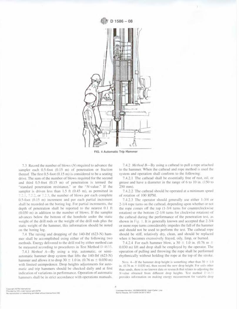
0 D 1586-08
FIG. 4 Automatic Trip Hammer
7 3 Rcnird 1he numher ot hlo...,, tNI required to advance the ,ampler each 0.5-foot (0 15 ml of penetr.111011 or fracuon thereof. The fiN 0.5-foot (0.15 ml,., cons1<lered 10 be a ,eatmg Jri\e. The ,um of the number ol blow~ required for the ,econd aml third 0.5-foot (0.15 m) ,11 penetrauon i, termed the ··standard penetration re,1,1;@.:e. · or the "V-,aluc ·• II the ,n111pk1 b dm en less than I .5 ft (().-15 m), a:.. penrnttcd in
"' ' . 01 . the number or hhm s per each complete U.5-lllot ro 15 nn increment and pa each partial 1m:remcn1 ,h,1II hc recordeJ <Ill the bonng log . f'nr pllmal 1nae1111.:nt,. the depth of penctrauon ,hall he reported to the nearest 0.1 It (0.030 ml 111 add1uon tn the numher nl blow-.. II the \iHnpler .id,ancc~ beltm the hnttom ol the borehole under the ,1.111t \\eight ol the drill rods 01 the weight of the dnll rod, plu, the ,tauc "eight of the hm111ner. thi, 111formauo11 ,hould he noted on the boring log.
7 .-1 fhe r.i1,1ng and droppmg of the 1-10-lhf (623-N) hammer ,hall be accompli,hed u,ing either Lll the f111low111g two me1ho1h. Energ, delivered to the dnll ri,d h) cithcr method can be mea,ured according to pro.:edure, 111 Tc,t l\lethod I r
7.4.1 Aft'thod A-By using a tnp. ;1utomat1c, or ,em1-automattc hammer drop "Y"tem that ltf't-.. the 140-lbf (623-'i'> hammer and allows ll to drop 30 = 1.0 in. (0 76 m ::: 0.030 m) with lim11ed unimpcdence. Drop heights adjustment, for automatic and trip hammer, ,hould he chccked datly and at tiN ind1cJtion ot v.iriation, 111 performam:e Operauon of automauc hammer, ,hall be 111 ,trict ,1c,ordance \\ 1th operauons manual,.
Copyr~ ASTll Jntemero-,a• Pfo-,,idaCJ t,y 1-4$""""' ~"" ri, ASTM No ;~on O' ner,.,:,,"ta"IQ • .,,.ltl'ld wl!'K>UI bCUhH t•om tt-i'J
7A.2 lfrtlmtl fJ - By m,mg a cathead tu pull a rope attached to the hammer When the cathe.id and rl'l)I.' method 1, u,ed th<' ,y ,tern and upemtion ,hall conform to the follow mg
7.-1.2.1 The cathead ,hall he e,,entially free of ru,t. oil , lll grea,e and ha, e a diameter in the mnge of 6 to IO 111 1 150 to 250 mm).
7 ..J.2.2 The cathead ,hould he operated at a rrnmmum ,peed nf rot.1tion ot I 00 RP:>.1
7.-1.2.3 The opcr;itor ,hould gene1ally u,e euher I -3/-1 or 2- 1 /-1 rope turn, on the ,athead. dependmg upon \\ hether m 1w1 the rnpe ,·nrnc, oil the ltlp (1·3/4 turn, for coun1erclnek\\1,e rot,1tton) or the l'l1morn ( 2-1/-1 tum, t<,r dock wi,c n11.11ion, ut the cathead dunng the pertnrmance nl the penetratmn te,1. a, ,ho\~n in I 1)-! I It i, generally kmmn and .iccepted th,lt 2-Jl.t or more rope turn, cons1derabl) impede, the fall 11f the hJmlller and ~hould not he u,ed to perform the te,1. The cathead rope ,hould be ,utr, rela11vel} df). dean. and ,houlJ b1.: replaced when it become~ e."<cesw,el) fra)ed. oil). ltmp, or burned
7.4.2.4 For e.ich hammer hlO\\. a 30 ::: 1.0 in. (0.76 rn = 0.030 m) lilt and drop ,hall he emplo)'ed h} the operator The operation of pullmg and throwing the rope ,hall be perfornwd rhythmically without holdmg the rope at the top ol the ,truke.
:-.'on. 4-lf the hJ111111cr drop h~ight i, -.>1nl'lhrng other lha.n ,Q - t 0 in 10 71> m - () <HO n11 , then record rhe nc" drop height. lw sn11' <>lhcr 1han ,and,. then, 1\ nn 1-.nown data 01 rc,car,h thal rcla1.-, 11, ad111,uni;- thc ,\l. \alut> oh1,11ncd Imm dilfrrcnl drop hc1~ht, fr,1 lllcth,-..t I> I , • prm ad~, 111forma11on on mai.;rn!! encr!!) 1m:.1,urc111cnt tor , ,,nahlc drop
l,Jir,_-.=Nllrnoon VA:596™58008 Us4N'Z'Ca.,.., t... Hof to,, Rf!UJ9,041 tQ0080808 t1A.,10T
0 01586-08
hc1i:l11, ;,nd PtJdice I) C,(lr,f, 11"" iJc~ int(lrma11nn ,,n au1u,1mcn1 ol \ ., aluc 1,, J "'n,tanl cner;:y k, cl 11,0 ~ ,,f tlwnrcr,eal. NNll. Pra.:11cc 1l 1,1l!, .,Um" rlw h.1111111cr <lrnp hc1gh1 h• l,c ad1u,1ctl to pnw1Jc 60 %
t:llt."t ')
7 5 Bring the "unpler IO the ,urlace and open. Rccon.l the percent reco,cf) ICl the neare,t I "f or the length of ,ample recmered to the neare,t 0.01 tt (5 mm/ Cla~,ify the ,oil ,.imple, recm crcd a\ tn. m au:ordance with Practu:e I l 2188. then place one or more reprc,entati, e por11m1, of the ,ample in111 -.cal;1hle mrn,111re prool l'llnta1m:r, I.Jal"', 1 without ramming or di,tnrtin!! ,Ill} .1ppa1e1ll ,1rat1l1<t.llinn Sc..11 each l011ta111cr Lo
pn:,cnt c, apora11011 nl ,oil mn1,1ure Affi, lahcl, to the l'llnt,uner, hearing Jllh dc,1gna11nn. h,inng 11umher. ,ample Jcpth. and the blow count per 0.5-fo,11 ell 15-m I incremem, Protect the "'mples aga111,1 extreme temperature change,. ll there 1, a ,ml d1angc with111 the ,ampler. make a Jar for each ,tratum anJ note 1h location in the ,ampler ban-el. Sample, ,hould he pre,en cd and transported in accord,111ce wtth PrJ~·tice 11 rn n u,ing Group 8
8. Data %t't'W,,/FormbJ
X I Data obuuned m each bureholc ,hall he recorded 111 ,iccordJnct: ,,1th the Suh,urfo1.:e Loj?gm!? Gurde ll a, required h) the e,plora11nn program. An e,ample ol a ,ample data ,hcet 1s mcluded m \ 1 1~
S 2 Dnlhng mfonnat1on ,hall be reconkd m the held and ,hall 111clude the followmg:
8.2.1 \lamc and loc.itum of job. 8.2 2 '1.1mc, of crt:\~, X.2 , T~ pe and make ol tlnlling machine. S.2 .• \\t'atha cond1tllln,. X.2 5 D.ue ,rnJ t11ne ol ,tart anu llm,h ,11 borehole. 8.2.t'I Boring number and locatrnn htJtmn and cooru111atc~.
if availahlt' and applJc,,ble /. 8 .l."' Surtace clc, aunn. rf a, ailablc. S.2."i ~lethod ol ad, ancmg and cleaning lhc borehole. l-..2 9 \1ethod nf J..eeping borehole ,,pen, 8.2.10 Depth of water -urtare to the nt'are,t 0.1 ft ((UHO ml
,1nd drilling depth to the ne,m:st ti I ft 1110:m 111) at the 11me of a nutt'd lo" ,1f dnlhng llu1d. anJ lime and date when reading or n,,1,111011 W..t)i matlt.
S 2. I I L11<.:atron of ,trata change,. to the nearest 0.5 ft ( 15
cm!. !i.2 12 ~11e of ca,i ng. depth nt ca,t'd portion ol borehole to
the nt'are,1 O I ft t0.030 1111.
Cop) 1'1f}nl .-,STl,t ~ I
Pt¢-.ded t-'f IH~ u,.. lcenN•·lfl ASTM N-t'J,~cn Ol ~'tg pe,l"Tl!n-S w,lrtOul lieef\~tt lf'Offl ....-s
.,
X.2.1 ~ Equipment and :\lethocl A ,ir B ol dm1ng st11nplc1. S.2.1 • S.11nple1 length and in,1de d1amcter ol harrcl. and ii
a ,ample ha,kt!t retainer i, u,ed. X 2 IS S11e. type. and ,eninn length ol the ,amphng ro,1'.
and 8.2.16 Remark,. X. ~ Data ohtarned !or each ,ample ,hall he rec11rded 111 the
l1eld and ,hall 111clude the following: 8.3. 1 Tur of ,ample:! depth !Cl the nt!are,1 0.1 ft ((J.1)30 m 1
and rf u1rl11cd. the <.ample numher. ~ 3 2 0C,l.11p111111 ~)f ,oil. 8 1 1 Strnta d1ange, v. ith111 ,ample. 8.3 -I S.nnplcr pcnctr:1tinn and recm cl') length, 111 the nc:ir
e,t 0.1 lt t0.0.10 m ). and h 3 5 's umher ol hlo\,., p..:r O 5 toot W.015 mJ 111 p,1nial
increment.
9. Precision and Bias
9 I Prcn,11111-Te,t data on prec1,ion 1~ not pre,cnted due w the nature uf lhl!> tt!,t 1m:thod. It 1:-. either not fca,1hlc or Ill\>
1:11,tl) .11 th1, lime to ha,e ten 1,r more agenc.1e, panic1patc 111 an m ,itu 1e,1111g program ,tl a gi\en ,ite.
9.1 I The Suhrnmm1ttee 18.02 i, ,eek1ng additional d~11a from the u,e,-., o t this 1e,1 method that mrght he u,cd w make a horned ,1atement on preci,ion . Pre!>ent k1101,1 )edgc 1nthcate, the tollu,-.111g·
9.1.1 I Vanat1on, tn \-\alue, of 100 ''< or more h,I\C h..:cn oh,er\'ed \\ hen w,ing ddlert!nl -,1,indard penetratrnn tc,1 appi.l • r~m1v and dnllcf' for ad1acent horehole, in the \.Hile ,oil frn matmn Cmrem opinion, ha,ecl on fldd c,pcn.:ncc. ind1-c.11e, that v.hen u,1n!! the ,:unc apparatu, ,1nd driller. \ \;due, 111 thl ,amc ,ml can he reprodu~·ed w11h a cnclfic1en1 nt , ariat1t1n ,,f about IO '..i
() , 1.1.2 ·1 he u,e 111 l,Hllt) equ1p111ent. such a, .111 extreme)) m.i,,i\ e nr damaged ,1nvd. J ru,ty cath.:.id. a Inv. ,peed cathead. an old, 011} roJ'(:. or ma,,1ve or poorly lubricated rope ,hea\,e, can !>lgnihcantly 1:ontrihutt! to differences 111 N-,alue, ohta111ed between operalm-drill rig ,y,tem,.
9,2 /1ia.1-There " no accepteJ rclercncc value lor lht, tt''>t method. therefore, b1a, cannot he determined
l 0. Ke) \I ord,;
I 0.1 hlow cnum: 111-,ttu te,t penetration rc,1,1ance; ,111I. ~pht-harrel ,.impling. -.1andarcl p..:netratinn tc,1
~ '!"Hemc!ot,. VA.'59&Q.t58008. 1.JMrsearte, Uu Nol to,' ~.aie O.;t 1'2008 08 0e 12 MOT
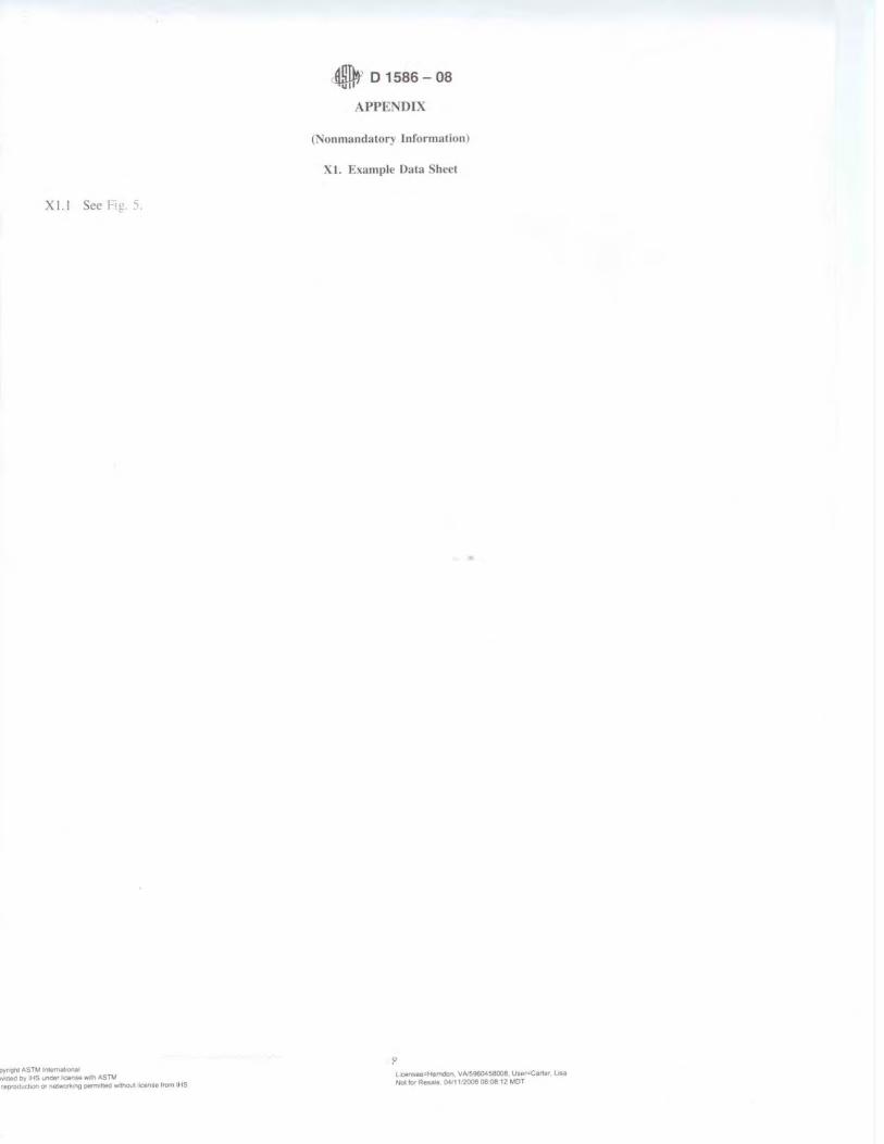
Xl.lScelt!,'5.
::>yr'Qhl ASTM lnta~I
w~ by IHS ullekt' litet'cH"" th ASTM feproducl:,on Of n~ ng oer,t,,1180 w,thQut a.e.nMt trom IHS
0 D 1586-08
APPENDIX
(Nonmandatory Information)
XL Example Data Sheet
LJ(enue•t-ta-mdon. VA.5960458008, User-Car1ot LIN Notto,.ReuNI oc·11.~oeoe12-..0T
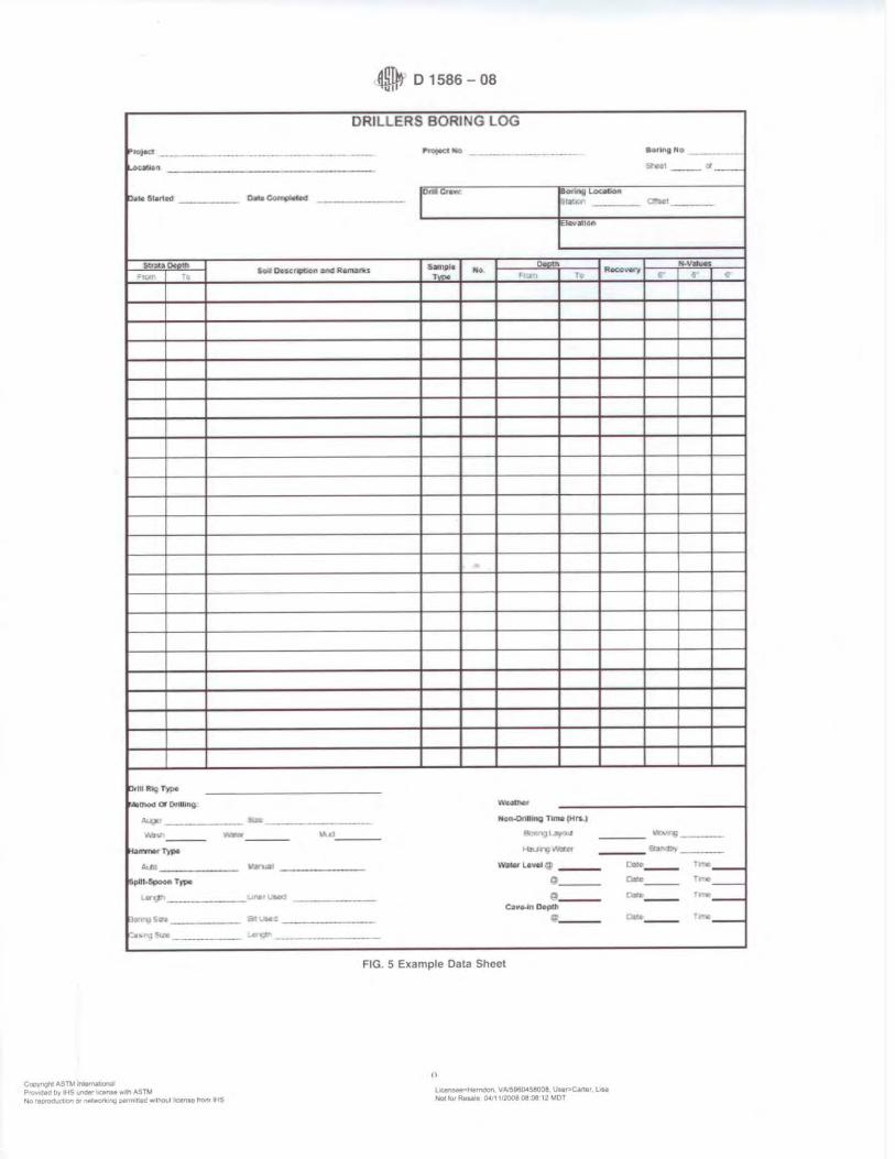
~ D 1586-08
DRILLERS BORING LOG
P ,oi-c, ------------- ----- .._. .... ---------- SOflf'fNO ___
k,.out1 ..
D•~&IMled
&rx~ 0r----
D<lh f\"V T'/pe
,..._ or o~u,119
Au~ ,
<\'1111. ----Ha-~ -l!lplll•6ooon T1,-
&Ai d'
~ ,_. -•· ·----- -
Cooyn;n1 AS TM ltutN!lDna~ PIO\loaed b'f' ~S Ul"Oe" lcllnM 'tlll-th ASllJ N<) rfP"C)dut1;0, f/1 ~ oe,maed wtnou1 IICOflMI "°"' IHS
;,I' --- (I --
0.0.~ r9 C..W. lor""' Loa<,oo
~ !]l'.-IY, Clll<1 - - --C.1M>'MICW\
... v ..... a-p1• ~u. "°'9 OKcr~fl llN1 "R•~ltts "" R.co.....,
F '" T•-
-51:a --------- -IIIQ T.,,_ IH~l
..... ~ l' J ----• CNJ-,; •Y:irlf
11'.ar\.al \\'i1W U~•f ----"---
w,,,i-, ll c~" .. '" Dejllllh----
e,~,..e -----.M"f? -
FIG. 5 Example Data Sheet
,, ~:1Hetn0on. VA,590()il58008 \.)Mlr,,Ca'11Ar LIM Not tot~ O,& 11'200808 08 12 MOT
'-11: .. ..-,4; ____ . ..,,,., ----a.,._ f ·-Dore --- ~r.._ Dvec ___ ,-_
--- 1-_

41 D 1586-08
SllMt\1 \RY OF CH.\NGES
Commntee DI 8 hi!, identi tieu Lhe lnca1111n of ,ele-ctcJ change, 11, th,, ,tandard ,mcc the la,t '"ue II) 1586 94) th,ll may impact 1h1: u,e ol thi, ,tanJ:ird !Approved J"ehru,ir) I. 2008.)
I/ 1 l'herc ha,e hccn numcrou, ch,mgc, to th,, standard 10 11,1 them ,cpa.r.ncl). From the lllt1't recent main halllll pr,itt;,,. mlduion;II ch,mge, were reque,1ed and incorporated inw thh nc\\e,1 rc\:1,1011. Stated below 1, a highlight of ,omc nf the change,
(-IJ lerminolog) added ,ecllon on Detint11n11,. (51 S1gn1hca11cc ,ind L ,e clantied u,c ol the SPT te,1. (61 App,mlltl',. general ed1wrial change,. ( "'I Sampling ,111d Tc,trng Prncedure general ed11onal change,.
{.:I 'ln•pc \H1, complctel~ re, ,,ed. (8) Data Shcct,trnnm,. genernl cduonal change, { i I Rdcr..:nced Docurne11t, upd;11cd to include llC\\ ,rnndarJ,. (<JI Pren,wn aml Uia,. added Sccunm, I I ,111d 1 1 I '
Cl)OW'r".t'lf ASW ~O'loll
ASTM lnterna11ona' takes no posir,on respecting the val"11ty of any patenr ng/lrs assened ,n connec11on wirh any ,rem mentioned ,n 1111s standarcJ Users of 111,s standard .1re expressly .advised that determmar1on of the valld1tv of any such patent r,ghts and the nsk of ,n/nngemenl of suclt r,ghrs. me entirely 1/Je,r own responsio.hty
T/11s standard IS sub1ec1 to re1-,s1011 at any 11me by the responsible tectln,ca/ committee and musf t>e revrewea every five years and If not revised. either reappr011ed or ... thdrawn Your cxm,ments are invited either for rev1s1on of this standard or /or additional standards and should tJe addressed to ASTM /ntemat,onal Headquaffers Your commenfs ,,,,11 receive careful consraeration at II meellnQ of the responsible technical comm,:tee which you may attend. If you lee/ that your rommenfs heve nor received a lair hearing you. should make your views known to rhe ASTM Commmee on Standards, Bf the address shewn below
This srandard 1s copyTlghled by ASTM tntem11r,onal. tOO Barr HartJOr Dn•e. PO Box ClOO. West Conshohoe1<en PA 19428·2959. u11,ted Status /na,v,dua 1 rePflrl/s tsmgle or m,,//rplc• cop,es/ or 111,s srm1dard may be oora,ned by contdcling ASTM af the above address or at 610·832-951'5 (phone}, 610·832·:1555 11axl. or servtt:·,,C:astm.org /e-ma,1), or tnroug/J me ASTM webs,re 1www asrm org)
l'l Ptov-dea Dr lt4S .,.,.,.~ w,111AS™ ~ .. ~. \IA.'!:IQ604.58008, Lhr;.,w-Carw- Lia
No;iti;>tR..,.;e 04J1ti'20080808·12tJIOT No 'tpfOOl,DIOn O' W"4'0"-..ng ~Had ... ,th0t1I iw....nse 'l'O"' IHS
A Designation: D 1587 - 00 (Reapproved 2007}"1
•u 11 7 INTERHAn oNAJ.
Standard Practice for Thin-Walled Tube Sampling of Soils for Geotechnical Purposes1
nu, ,t.1ndmJ 1~ 1·hueJ "'"'-lcr lb~ fi,iat ,k,1~n,1t1on ll f ~~7 the numher 1mmed,.11~1y 1,,llov. mi: th~ Ji:,1~n.t.ui-11 uk.111 .... t.(, lht'.' year ,,t ,,n}!tn,tl j_Jnp11,,11 or. 1n 1hc a,;c (ll rc\1,1,in lhl· H'alr ,ll I.a~, rr,1s1,m /\ 11umlxr 111 f'Jlt'nlhl·,c, mdh...Ui',,_. lh&? )c:~u ot In,~ rc.:..tppwv,11 ,\ ,upcf'\.'rlfll cp,1lnn ,r, 1nJ1,,u.:-s an rd1tnrul , ·h;m~i: ,111,:e 1hc la,r 1ev1,1cm 111 rt ... Jpp1uv;d
• ' :-.,111 l:d11<1n,1J ch,,ng.:, ,,..-re 111.t<ic III Jun~ 2!Xl7
I. \ copr* I I Thi, practice cO\er, a procedure for u,ing .1 1hin-walle<l
metal tube 10 recO\er relall\el~ un<li.,turbcd ,011 ... ample ... ,unahle tor laborato1) te,t, ol engineering propcrt1c, ,uch a, ,trength. cnmpre,,1b1l1t}. pcnm:ah1li1). an<l den,11). Thinwalled tube, u,ed in p1,ton. plug. or rotary-I~ pc ,amplers ,hnuld cnmply \\ ith Section , , of 1h1, pracuce whit'h de,cnhe, the th1n-walled tuhe,.
.\,,1 .. l nu, prac1tcc dnc, m,1 appl~ It' hn,·r, u,cd w11h1n the ,ampler,.
l.2 Thb Prac11t·e i, lin111ed tn ,011' that can he penetrated b) the thtn•\\ ,tiled cuhe Thi\ ,Hmpling method 1, not rc.:com 111e11dcd lor ,.impltng ,oil, t'011t,11111n)! gr.n el 01 larger ,11.t: -...)ti p,1rt1cle, .:emented or ,er) hard ,oth 01lter ,oil ,ampler, ma) he u,ed for ,ampl111g the,e ,oil l}(>C' Sud, ,.1mpler, 1r1du<le Jm en ,pill bm rel ,ampler-. amJ ,uil c,,nng de, ice, (I• I> 3:'i -u. ;mJ ) r I ) l·nr informallon on appropriale u,e ol other ,oil ,ampler, refer w lJlllbll.
1.3 This pracucc i, often u-,ed in cnnJuncllon with fluid rt,tar} dnlhng (I> 1 I~ , I) 5783) or holl<m-stem auger.. (I> (,I 'i 1. Sub,urf,tcc geotechnical e:,,plora11on, ,hould he reponec.l Ill accordance with prat'til·e ( 0 I Tiw, practice J1,.:u,,t·, ,0111e a,pe,1' ol ,ample prc".:n a11nn after the ,amphng C\'Cllt. 1 :or 111lorma11on nn pre,cn a11on and 1ra11,porta111.1n proce" ol ,01I ,ample,. cm1,ult Practice n • nu, practice Joe, not addre,, c11 \.'lro11mental ,amphng: con,ult I) , 1 and I) c,~llfor 1ntorma11on on .,amphng for emmmmentaJ 11we,11-ga1ion,.
I .4 The \ alue, , 1a1ed in inch-pound unn, are to be regarded a, the ,tan<lard. The SI \'alue, gn en in parenthe,e, are pnwide<l for rnlorma11on purpo,e, onl) The tubing toler,1111.:e, pre,e111ed 111 I I arc from ,nurce, ,I\ ai lahle 111 \lorth
lh1, pr.1d1l-r 1, unJct Ilic 1un,J1, u,•n ,,1 \.\T\t r·,mun11tt·c..· PIS ,,n Sml .mJ K,11:l .and "the c..luc:d ri:,111l1i-,.1h1IH~ ,,1 ~ul11;;41mm11tt<~ 1>1\.02 on S,11nplin~ and kd,11c-J I-Jehl Tl!,tllh! 1111 Sl1JI r.,alUJlll11)\
l urrcn1 c,lo11<111 .,,;pn"cJ \la) I. :0117 Puhh~hcJ J11l) 1tMl7 On~on.tll:, Jpprn,e,I In 19.'~ I.a,, rn:, .. ,u, cdmnn aprruvcd in Wll) '" IJ 15117 - 0.1
Ameril·a. u.,e of metrk: e4ul\ ,tlent '" alceptable a,- long a, thtckne" and proptmion, are ,1mllar to tho,e requireJ 111 this ,tand,ml
I 'i 71m \lellldard dot'\ r,11/ purport 111 ,ultlr,,,,. oil ,f 1/w .\ll/l'I\ ,·011Ct'rll.1, t{ <IIIY cJ ,wc-iatcc/ \\'illt Ill II.IC If 1.1 lite
n•,p1m.1ihility of the 111t·r oJ t/1i.1 11c111dard to t•1tahf1Ih tlf'/ll"fl
priatt· 1<1/t'fJ anti hl'alth /11'//c'llr.t',, and deu•r111i11I' 1/11· upp/1t a
hilit, of rc.~11/at11n• /11111/llllon I prior to me. 1.6 Thi, practice offer~ a .,e, of in,trucuon, fot pertnm1ing
one or more specific operation,. This document \.'annot rcplan· educa11on nr experience and .,houlJ be u-,ed 111 conJuncllon \\ 11h prnlc,,1<H1al 1udgment. 1\01 all aspects ot th1, prac11c..- Ill.I) be ,1ppltc,1hle 1n ,ill ciru11n,1.uices. lh1, .'\S f'M ,1ambrd i, nut 1ntende<l tl1 rcpn:,e 111 or replat'e the ,1anJa1d ol c.irc b, 'hh1ch the a<lcquaq of a gi\cn prole,,ional ,entce mu,1 h~ 1udge<l. 1101 ,houlJ 1h1, document he applied \\ 11hou1 c1>11,idera11nn 111
,1 projc..:t", man} unique a,pect-. . The word "Standard" in the title of tlw, document mean, lll11~ that the documl!nt hJ, ht:en apprmed through the ASTM con,em,u, proce,,
2. Referenced Documents
2 I AST\-f Stw1darcl1. ' Dr " lerm111olog) Rela1111g to liml. Rocle m,d Comained
Fluid, Practice IC'\r Sml lme,11~a110n and Sampling b)
Auger Bonng, "'il-- Te,1 Method tor Penetration Te,1 and Split-Barrel
Sampling of S01b Prac11ce tor Description and ldcntilit·,mon ol ">nil,
I Vi,ual- \.lanual Procedure) I> v,1 Practice for Tlm:k Wall. R1ng.-Lined. Spill Barrel.
Dn\'C Sampling of Sml, r> Pr~1c11cc lor \.1t111mu111 Requirement', tor '1.genl'1c,
Engaged 111 the Tes1111g and/or tn ... pecuon ul Sllll and R1x:k
.. rur rctc11:l1L't'J ,\ST~I ~hmJ.1rJ1-. \l\lt 1hr" ,,s-r,1 \\Ch:\tU.·. \,\\\'"" J,lm ,,,~ 111
t:um • .u.·t 4\ST\1 Cu,tnmcr Scnic.: .H ,cno1c-r<e:a,1mA1r}: , fc,,r ~\11111111/ /lt.,.,,J. ,4 ,,rt,\I \tanJu,J\ \ulurnc mlontMlitnl. rctc.·r tn rhc ,.,Jnd.ud·~ l),k:umcnl Summ;ar~ p.,~r on 1hc ASThl "~h"1c
· \ Summa!') or Chuni:t"' wttion a ppear<. ut the end of thi, standurcl.
Ccr,llghl 01\STM lnlerna1,on81 100 B.,u HatOot t:,,,, ~ PO & , C700 Wesl Conshoho,;.,t.e,, PA •.s428-~•5~ UMed S1.Jles
c.,..,.,on,AS™t-PJ'OY-,cea tlV lkS YhOtl lc¥IMI ,.-,vi AS f1l No~ Ot ~ ng PW"'\'ttfG lllo•lhOul lar,se from IHS
~tt.mdo,\ VA'5436(),S8008 ~,,,_, L;aa
Nt'llbR--. 041t1f"J0080809JO~OT
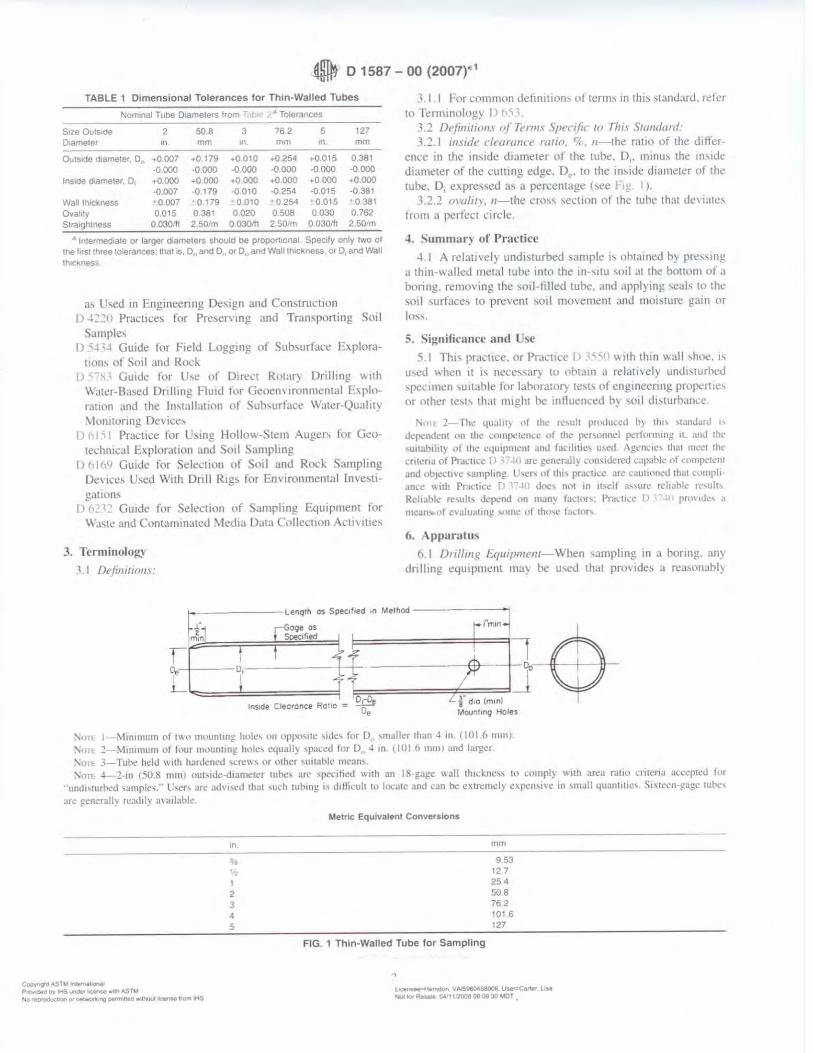
0 D 1587 - 00 (2007)E1
TABLE 1 Dimensional Tolerances for Thin-Walled Tubes
Nominal Tube D1ame1ers irom • Tolerances
Size Ouis,oe 2 508 3 76 2 5 127 D1ame1er in mm on. mm '" mm
0..1slde diameter. D,, • 0.007 •0.179 .0010 ..0254 ..0.015 0381 •0.000 -0000 •0 .000 -0.000 -0000 -0000
Inside oiamet"-r, D +0000 +0.000 +0.000 +0000 ~oooo +0.000 ·0.007 -0.179 -0010 -0254 -0.015 ·0381
wan I tlit•ness ·0007 • 0.179 ·0010 •0254 •0.015 •o :is1 0,alily 0.015 0381 0020 0508 0.030 0.762 S1r;1,gh1ness 0.030111 250/m 0030111 250/m 0.030,h 2.SO•m
A lnlermed1a1e or larger o,ameters sh<>uld be propor11onal Specify only two of the l1rs1 lhroo lolerances: lhal 1s, D., !lnO D. or D.,and Wall lh,ckness. or D, and Wall 1ruc,na~
a, L ,ed 111 Engmeenng D.:,.1gn and Con,trncllon Pracllce!. ror Pre~ening and Tran,poning Sml
S.imple, I) , I Guide ti,r Field Logging of Suh,urlJcc fxplora
tmn, nl 5ml ,111d Rod, Guide tor U,e of Dtn."LI Rola!) Dri lling "'1th
\A.,11cr-Ba,cd Drilling Fluid ti1r Geoen, 1runmental L,ptoratllln and 1he ln,tall,nion ol Sub,urtace Water-Quality ~lonllonng Devin:,
I) C1l Practice tor U,ing Hollo\\-Stem Auger, fo1 Gco-1ech111cal Lxploratmn and Soil Sampling
1 1 -1 Guide fo1 Sdect1on ot Sml and Rock Sampling. De, ice, U,ed With Dnll Rig, for I::.n,,rnnmemal lme,tig.it1on,
I) 6_ Gwde for Sekct1on ot Sampling E4u1 r1111ent for Wa,1c and Con1am111a1cd \ kd1.i D,11;1 Cnllcct1on \ cu, 111c,
3. Tcrmiuoloio
t I /h/i111r1r111.1:
J .1.1 1·1,1 c11111mon dchn111,m, ol ll'rm, in 1hi, ,1andarJ. relcr to Tl'nninolng)' I 1
' .2 D,,ji11111011.1 o( Term\ Spt·cifir ro 7111.1 '11a1I1lard: 3.2.1 ,mule clnuann mlio, i;;. 11-lhe ratio of the Jitkr
ence in the 1n,1de diameter of the tul:le, 01• 1111nu, 1he 111'-llk diameter ol the cu1t111g e<lgc. De. to the m,1tlc diam.:ter of lht· tube. D, e,pres,ed a, J pereen1age (,ee 1.
3.2.2 ornltr,., 11-the cro,, ,ection of tht> tuhe 1hnt di!, 1a1I!, from a perfect circle
-t Summar) ol' Practice
-l I A rel::tttvel) und1,turbed ,ampk 1, ohrained h) pr!.!"111!! a thin-\\ alkd metal 1Uhe into the in-,11u sml ,11 lhc bottom ol ,1
bonng. removing the so1l-lilled IUhc. and ,1pplying ,cal, to the ,ml surlace, 10 pre\'ent ,oil movement and mm,turc g:1111 c,r In,,.
5. Significance and ~e -; I lb1, prac11ce or Pr,1ct1cc [) ~,, w11h th 111 wall ,hoc.,,
u,ed "hen ,t ,, neces,al') ll1 11hta111 J ,e!Jm,cl) und1,1urhcc.l ,pcc11nen ,u11.ihle for laboratory tc,h cil cng1nccnng propcme, nr ,llh~·, 1e,1-, 1ha1 might l:lc intluenu:c.l h: ,rnl d1'turb,1nce.
l'\,nt ~ I h~ qu:illl} ,11 the rc,uh p1o<lucc<l b) th" ,1,111JJ1d ,, Jcpcmknt (lll lhl' 1.'lllll()CICll,C ol lhc pcr,nnm:I pcrh•fllllll)! II. ;111J the ,u1tab1ht) ul 1hc .:4111pmc11t ant.I IJcihu.:, llWd i\g.:n..:rc, that 1111.'Cl !hr lnlcri.1 ol l'r,1.:111:c O arl· gcner:tll} ,011,1dn.:<l .:apJhk ut i:o111p,:1cn1 ant.I ob1ccll\·c ,ampltng L/,c,, ,,1 th,, pruc111.c arc .:,1u11011cd 1h,11 compli
Jn.:~ \\ ith Prnctic.: - 'l",W J,-.c, nm m 11,elt ·'"ur,· rdiJl>k rc,ull, Rcltahk rc\ult, 1kpcnd on man)' la,11>1,; Ptadu:c I)~ i I prt>\IJl', d
me·111-.,,1 c,11lu,1trng ,nm.: nl tho....: l,1d1>r,
6. .\ pparatu,
t>. I l)r,J/111g J:.q1111m1e111-\v hen ,ampl111g 111 a boring. um dnlhng equ1pm!.!nl ma} be u,ed that prm 1de\ a rca,011ahl)
~-:b_.-,;1:::::=:::0,===G_:;=1
:;~o==l, S~i 1
_" Me-lhod===;=r"m---,-H-&
R ~ Ll' d 10 (mtnl tns,de Cleoronce 0110 = De • Moun1in9 Holes
'.\ rm; 1 M11111num nt mn 1m1unt1ng hull', 0n nppo,nc ,ide, h>r D,, ,m.111..-r 1han 4 ,n (llll 6111111). :,._ an: ~ - .\11m111urn n l lilur 111<111n11ng h,,lc, cquall) ,paced Im D , 4 in. 1 IUI 6 1111111 und lurgc1.
Nnn: J-Tuhe hclu with hur<lcncd Slfl!\\, M llthcr ,u1u11>lc mcun,. ,\;,-1Th 4-2-tn (50.8 mrnJ oui-1<lc-<l1ame1,:r tub,:, urc ,pcdhcd with 1111 llS•g~!?" \\all 1h1cknc,, hl ~omply wrlh an:;1 ra110 ,rn<na ,1cc.:p1cu for
"unt.11,1urhcd ,umpk,." u,cr, an: ad\'i,cJ that ,uch wbrnj! "<l1flicuh 10 lo.:ate anJ can be c~cn:mdy cxp,:rN\'C in smJII 4ua11111,c, <;,xtccn-)!ag,· tut>c,
ar~ 11cnerJII\ readily ,l\,11labli:
Coc,y~,ohtASTM~I.ICln&,I Pro,.,.a"o ~ tHS. wnc:w l(:.efiM""' t", ASTM N,) ,~ or ,-t"°":ng ~too""' lnQIJI Jlte,\-t.G tro,n IHS
in
""' ,.., I 2 3 4
5
Metric: Equ!valenl Conversions
FIG. 1 Thin-Walled Tube for Sampling
mm
953 12.7 25 4 508 76 2 101 6 127
Lc:iense. • ~f!'OD'l VM9604$8008, l),.,...c.n.,r l M N,)ekJt~ OC11,10080f'09lO~OT
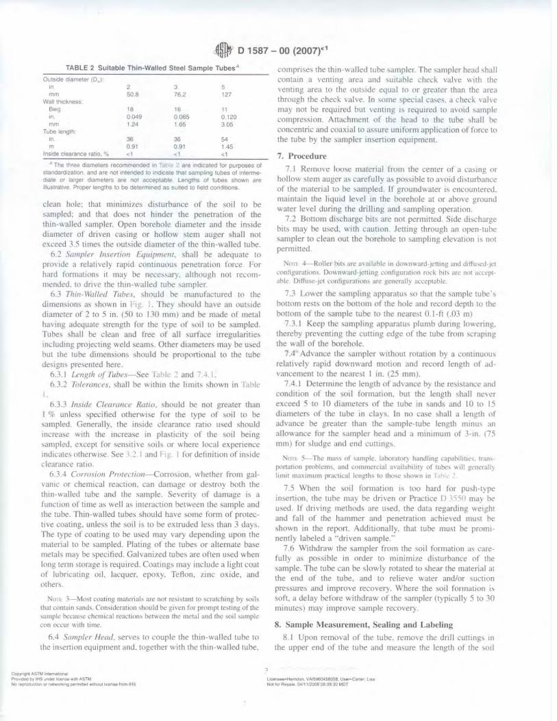
0 D 1587 - 00 (2007t1
TABLE 2 Suitable Thin-Walled Steel Sample TubesA
Outside o,ameter ,o, 1 In 2 3 5 mm 50.8 76.2 127
Wall 1mc11ness B"'!I 18 16 II ,n 00,,9 0065 0.120 mm 124 1.65 305
Tulle length m 36 36 54 m 091 091 145
Inside clearance ra110, •;. <1 <1 <1
,. 'The three d1ameIers recommended In T"' 2 are 1nd1caled for purposes of stal!dara1zat1on, and are not intended to 1r1<hcate thal sampling tubes or ,n1ermed1ate or larger oiame1ers are no, acceptable LengthS of tubes shown are Dlus1rn11ve Prooer lengths to be deferm1ned as suited to field cond1t1ons
clean hl>le; that 111111t11111c-. d1,turbance of the ,oil Lo ht! ,ampled. and that doe, not hinder the penetration or the thin-walled ,ampler Open borehole diameter and the in'ide dmmeter of dmen ca,ing or hollow stem auger ,hall nOl e,cet!d ,.5 time, lht! out,ide diameter nf the 1h111-walled tube.
6.2 S1111111/er /11.1er/1011 t.q111p111c111. ,h,tll be ackquate to pronde a n:l.111\·el) rapid l·ontmuou, penetratwn fon.:c. For hard fom1.i11011, II ma} be nece,,.il'). although not ree11111-111ended. Ill dmc the 1hrn-w;1llcd tuhe qmpkr.
fl., 1h111-\\'alll'd T11hn. ,hould he manufactured t<• the dimen,10n, a'> ,hm1 n in F,g I. They .,houltl have an oul\1de diameter of:! 10 5 111. (50 to 130 111111) and he made ot metal ha\'ini atlequa1e ,1reng1h for the type ot ,rnl 111 be ,amplecl l'uhe, ,h,tll he clean and tree of all ,urface 1rregulan11e,
1111.:luding prn1ec1111g weld ,cam,. Other diameters may be u~ed hut the tube dimen,inn, ,hould he pmpo111on,ll to the 1uhe de,ig11' prt!,e111e<l here.
6.1. 1 u·11~1h o/ foho-~ee I .ii and 6.J . .:! lo/aann .1. ,hall he w11h111 the hm1h ,hov.11 rn lat,le
! .
6. 3. ~ hwdr CIC'armtet' Rmw. ,hould he not greater than I % unb, ,pecilicd otherwN: for the l)'pe or ,oil 10 be ,ampled Generally. the ll1'ttle de,tram:e ra110 u,ed ,hould 111..:re;N' wnh the 111crea,c m pla,11t·1ty ot the ,01I heing ,,unpled. e,cepl for ,en:-.111,e ,otl, or where hx;tl e:-.penence 111dica1c, 01hcrw1Sc See and 11,: I tor detini11on of rn,1de clear .. mee ratio
6.J • Con,11,011 Pmrcuim1-Corro,1011, "hetlwr from gal, ·a111c M chemic.ii reaction. can d;im.,gc or de,1rny hoth the thin-walled tuhc and the ,ample. Sc\ellt~ of damage " a function ol lime a, well ,h 1me1ac11on between the sample and the tube. Thm-walled tuhe, ,houltl ha\'e ,omc form ot prmec-1i,e coatrng. unle,, the ,01I ,, 10 bc e.,truded le,, tJ1,1n 3 da}·'· The type ol coating to he u,etl ma} var) depend111g upon the m.uenal lo he ,ampled. Plaung of the tube, or alternate ba,e met.ii, may he i.pccifictl. Gahani,ecl tube, are often uc;ed \\ hen long 1enn ,111rage 1-. required Cnat111g, ma) 111dudc a light com ot lubrit·;i1111g rnL lacquer. ep1.1,}. Teflon, /lltt. oxide, and other~.
N-r11 L l - \10,1 coat111g matcnah an• nm re'l,1'111110 ,,nllchtnj! b) ""h th~t c,,111.1in ,anJ,. Con,11.kratiun should bc gl\cn lnr pmmpl 1e,1ing of 1hc ,ample! bcc,1u,c .:hcnttcal rcaclivn, ll<'l\l.ccn th~ 111c1al and 1hc ,oil ,ampk ,,,n ,11.·,ur \\ 1th 11mt•
6.4 '>011111/a /lead, ,en·t!, w couple the thin-,, a lied tuhe 10 the rn,cnton equipment anti. together with the thm-walletl 1uhe.
CopyiQl'C AS™ 1~,0"ll; P '(I...-CleOll't'IHSvnotw"~""t"IASTM N<>,~or ~-Ilg ~eel \,lj llloul Qnse ftotn IHS
compme, the thtn-1\ .illetl tube ,.implcr. The ... umplcr he:1d ,h.,11 cvnt;un u ,entin~ area and ,uitahle ched, vahe 1d1h th•· 1 cntmg area to the nm,u.le equal 111 or greater than lhl are.i thmugh the ched. \alve. In ,ome ,peci.il t·a,e, .• , ched, vahc may not be required hut \enung 1, required to '" 01d 'itmple c.:ompres,ion. Allm:hmt!nl of the head lo the lllhe ,h;11l he c.:oncentric and c.;oa,1al to .1,,ure uniform applicatwn or force tc• the tube hy the ,ampler ,n,enion equipment
7. Procedure
7 I Remol'e looc;e material Imm the center 01 a ca,rng or hollow ,tem ,mg.er a, carefull) a, po"1hle 10 avmtl d1,1urbancc of the matenal t11 he ,ampled, ff gmund,,a1er ,, encnunteretl. milintain tht: hqutd le, el 111 the borehole at or ,tbm e ground water level dunng the dnlhng and ,amphng operaunn.
1 2 Bollom d1,chargc bit, .ire not pcn11111cd Stele clt,l'harge bu, may be u,ed. w11h cauuon Jeumg through an upen-tuhe ,ampler to clean t1u1 the borehole to ,amphng clevauon 1, n<ll pem1ined,
:--1, 11, 4-Rl>llcr b11s ,ire ,J\;uf,1ht., ,n do\\nward•J\!lllng and d1tlu,cd t\!I
conhgur,11111n,. Dm,n1,1,ard ,w11ing c-onrif?ur.111011 n,,:k b11, .ir.: 1101 an·cpl• ,thle D1ff11sc•1l't ,·0111igur;11ion, 1m: gcncr.1lly :nxcp1ahlc
7.3 Lnwer the ,amphng appar.1tu, ,o that the "1111ple tube·, tiomim rest\ on the h1mo111 of the hole and record tlepth to the !lot torn of the -..ample tuhe 10 the neare:-.1 0 I-fl c .()3 m)
7.3. 1 Keep the ,ampling .,pparatu, plumb dunng lowering, thereb) preventing the cumng edge ol the tube from ,craping 1he wall of the borehole
; .4 Ad, .mce the ,ampler wi1hom rota11on hy a ..:01111nu111i-, relamel) rnpid dO\\IIWard motmn and record length ot .1d\,:tncemen1 to thr neare~, I in. (:!.~ mmJ.
7 • .1 , I Detenrnne the length ol ad,ance b) the re-..1,tance ;111d contl11ton ol the ,ml formation. hut the length ,hall ne,i.:r e,ceed 5 Lo IO diameter-. ut' the tuhe Ill ,anti, and IO to 15 diameter-. ot the tube 111 day,. In no c.1~e ,hall a length ol advance he greater th.in the ,ample-tube length rmnu, an alln\\ance tor the ,ampler head and a mm1111um of J-111. 175 mml for ,tudge ,md end cu11ing-..
:,;,nb 5- Thl' mass of ,mnplc. lahorah,() handltn!! ~.1pah1h11,·,. 11,m, pon:1111>11 pmhlcm,. and ..:omm.:rciJI ,na1lah1ht) ol 111hl!, \\ 111 !!cn,·111II} l11ntl m,txnnum pr.1~11c.1I length, h> 1hmc ,h,,...,11 u, •
7 5 \\ hen the ,rnl lorma1111n " 1110 hard Im pu,h-t) pc in,en1l1n, tht! tube ma) be dnven or Pracuce I , ma) be u,etl If dm 111g method, :tre u,e-0. the data regarding l\e1gh1 and foll of lhe hammer and penetration achieved mu,1 he ,hm,. n 111 the report . l\dchuonall}, that tube mu~1 he prom,ncnll} labeled a ··umen ,ample."
7 (l Withdraw the ,ampler from the ,011 formation a, carefull) J, pos,1ble 111 order to minim11e cll\lllrhance ot the ,ample. The tube can he , lo\\ I} rotated w ,hear the material al the end of the tube. .inti to reheve \\ ater and/or ,uc11on pre,-,ure-. and improve recovef)-. \vhere the ~Oil fom1a11011 " \Oft . .i dela) before '-"ith<lraw ot the -;ampler (typica l! ) 5 10 10 minute,> may 1111pro,e i.ample recovery.
R. "iamplc l\lea<;urement, Sealing and Labeling
8 I Upon removal of the tube. remo,e the unit 1.:u111ng, 111
the upper end nl the tube and mea,ure the length ol the ,01I
\JcWls..-t.-nc,on. V~\lfiOl58008, User-C.'19' UM N•-- Aot ff ... ia CW11~080930~DT
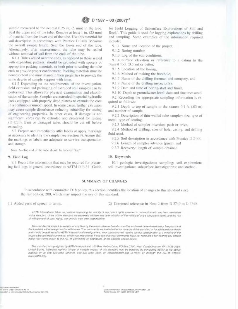
4@t O 1587 - 00 (2007}" 1
'-lmplc.: recmered to the neare,t 0.2:'> m. (5 111111) m the tuhe Seal the upper end ol the tube. R.::1110\e at lea,t I tn (::!5 1t11llJ ol m,11crial lrom the lower end nl the tul>e. tr,e th,, material tor ,rnl de,cnpuon in ncwrdance w11h Pr.tcticc () 2.t~ l\foa,urc the O\t:1all ,ample length. Seal the )(l\\ er end llf the tube Altcm,1ti\CI)'. after measurement. the rube may be scaled wnhout remO\al ol ,o,I from the emh of the tuhe.
li.1.1 Tube, ,ea led o\er the end\, a, oppo,cd to tho-,e ,e,,led \\ 11h c,panding packer,. ,hould be proYided with ,pacer, or appr11priate packing matenab. or holh prior to ,cahng the 1ubc emh tn prO\ 1<le proper conlinement. Pack mg matcnab mu,1 he nonah,nrl.11:!nt and mu,t 111a1111H111 their propcrtie, Ill prn\ idc the ,ame dt.>grcc 11f ,ample ,upp1.,r1 \\ i1h urnc
8.1.2 Dep,:11ding on the requirement, tlf the i0\c,11gat1011. field c,tru,,on and pal'kaging ol c\lru1..lt!d ,oil "'mple, can he performed. Thi\ nllow, for phy,1cal examin,uion and da,,,tication or the ,ample. Sample, nre e..:trudl.'d ,n ,pec1al hydraulk 1ad,, equipped w11h properly ,1zed platen, to e\lrude the core in a contmuou, \mooth speed In ,ome c:"e,. funher exlnt'IOn 111ay cau,e ,ample di,turbarK·e rcducrng ,uitah1hty for 1e,ting ot engrncenng propeme\. In other c,Ni,. ti damage ,, 1101 ,ignilkant. core, can he e,truded and prc,ervcd tor 1e,1111g
~~I 1. Bent or Jamagcd tube, ,hnultl he nil oil belorl' extrud111g.
lL! Prepare and immedralel~ allh laheb or ,rpply marking-. a, ncce\\ar) 10 rdenllf) the !.ample t,ee Section I A-,,ure that 1he mnrkmg, or lnhel, are ;rdequate w ,un 1vc tran,ponauon ,ind ,1<1rage.
\;m• ~~ I "I' ,·ml "' 1h, 111hc ,huultl he lalx-lctl "'lnp··
IJ. Fitld Log
9.1 Rernnl the 10forma11nn that ma) be rcquirc:d fC'lr prepar-mg field log, 111 general accord,tnce Ill AS1 \I I) c;4 .. Guide
for Field l oggrng of Suh,urlacc E.\ploratmn, ol Soil ,lnd Rod:·. Th,, guide I!, u\ed for logging e,plornt1on, b) drilling and ,amphng. Some exmnples of the rnf'nrrnalton rc4u1red 1nclude,
9. 1 I :\nme and locntron of the prn,1cct. 9. I :! Boring numher,
9.1.3 Log of the ,orl cnnditiC'ln,
9. 1 ...I Surt.tce ele, a Iron or reference to a da1um 10 1he ne;irest loot (0 5 111) or better.
lJ I 'i l .ucat1011 uf the bonng,
lJ I .6 \le1hod nl 111.ikrng the borehole. 9 I ., '-amc nl the dnllmg lnreman and compan), ,md
9. 1 8 '\.1me ut the dnllmg in,pedorr:-).
<J. I 9 DJte and t11nc of hllring-stan and ti111,h.
9.1 IO Depth 10 groundwatcr level Jatc and 11me measured. 9 2 Recording 1he appmprrale ,ampling information 1, re-
quired ,1, lollm",:
9.2.1 Depth to top of ~ample to the neare!i.t 0.1 It, ( .03 1111 and number of ,ample.
9.2.2 Dc,cnpllon ol thm-walled rube ~ampler: ,11e. type llf metal. type of coa11ng.
9.2 3 :\-1ethod ol ,ampler in,ert1011: pu,h or dmc. lJ.2.4 \,1ethod of tln ll111g, ,i1e ot hole. c,l'>ing and drtlling
Hmd u,ed,
l) 2.5 Soll dc,cnptwn in acl'ordance with Practice I I z.t:-;8, 9.2.6 Leng.th of sampler ad, ance (pu-,h ) . .ind
9 2 ... Rern,el) · length nl ,::11nr,le ohtamed.
Ill. k epvord<,
10. I gcolog1c 1nve,11ga11on,: sJmphng: soil e\plorallon, ,nil inw,11g.11io11,· ,ubsurtace 10\,estig,ll1on,: und1,1urhcd
SUMMARY OF CH\ GCS
In acconfonce with comrmnee DI Ii polk~. thi, ,ect1011 1dcntihe, the lo.:ation of change, to thi, ,tam.lJrd \Ince the la,1 edition. :!00, which may imp.u:1 the u-,e of 1h1-. standard.
I I l AddcJ part, ol ,peed, to term,. (::!) Corrected reference 111 Nmc ~ from D 5740 10 IJ n Ill.
AS1M lnternst1ona1 takes no pos,1,or, 1espec1tng Ille va/lCJ1ty or any patent nghts sssenea m connecr,on with any item mentioned "'m,s standard Use,s ol 1h1s standara are expressly sav,sed lhiil detennmat,on ot the vatid1ty of any such patent nghts and me nsk of mlr,ngemem of sucn rtgnts. are ent"e/y tnelf own respons,b1hty
Th,s standard 1s subJect to rev1s,on at any t,me by the responsible techmcat commlltee arid must be 1ev1ewed eve,y frve years and 1f not revised. either reapproved or w,tndra .vn Yout comments ate ,nv,ted either for revrs,or, of th/S standard or for add,t,or,al standards and should be addressed to ASTM lntema11ona/ Headquaners Your comments 1>•11 ,ece,ve careful cons,dera11on at a meeting of the respons,bte technical comm'"ee wh,cn yov mav al/end If you feel that .vo<1r commenls have not received a fa,, near,ng you snould fTla~e )'Our v,ews known to the ASTM Committee on Standards at the address shown below
This standard 1s copyrrghted by ASTM lnremar,onat. 100 Barr HartJor D11ve. PO Box ClOO. West ConshOhOcl<en PA 19428·2959 United States lndtviduat repr,nrs /single or mutt,ple copies) of this standard may bB obtained by contacting AS TM at the abOve address or at 610·832·9585 (pllone) 610·832·9555 (fax). 01 ser,rcettastm org (e-ma,I). or thtough the ASTM webs11e rw•»• asrm org)
,itit A.STM ltM1tm&l.O'll'i .cib'f'IHSUNJeir~"":Wt"5TM )l'l)du,e,t,OA 01 ~ pa,,mi11ud wmout ~ l,o,n M-iS
·' ~ VN5960CS8003 UMr=Cartet, llu NOl,O,RMMi 0i&·ttnoo&0809JOWT
SBLog.doc QC and Reviewed 04/2015 1
STANDARD OPERATING PROCEDURE
Logging of Soil Borings
I. Purpose and Scope This SOP provides guidance to obtain accurate and consistent descriptions of soil characteristics during soil-sampling operations. The characterization is based on visual examination and manual tests, not on laboratory determinations.
II. Equipment and Materials • Indelible pens • Tape measure or ruler • Field logbook • Spatula • HCL, 10 percent solution • Squirt bottle with water • Rock- or soil-color chart (e.g., Munsell) • Grain-size chart • Hand lens • Unified Soil Classification System (USCS) index charts and tables to help with
soil classification (attached)
III. Procedures and Guidelines This section covers several aspects of soil characterization: instructions for completing the CH2M HILL soil boring log Form D1586 (attached), field classification of soil, and standard penetration test procedures.
A. Instructions for Completing Soil Boring Logs
Soil boring logs will be completed in the field log books or on separate soil boring log sheets. Information collected will be consistent with that required for Form D1586 (attached), a standard CH2M HILL form (attached), or an equivalent form that supplies the same information.
The information collected in the field to perform the soil characterization is described below.
Field personnel should review completed logs for accuracy, clarity, and thoroughness of detail. Samples also should be checked to see that information is correctly recorded on both jar lids and labels and on the log sheets.
SBLog.doc QC and Reviewed 04/2015 2
B. Heading Information
Boring/Well Number. Enter the boring/well number. A numbering system should be chosen that does not conflict with information recorded for previous exploratory work done at the site. Number the sheets consecutively for each boring.
Location. If station, coordinates, mileposts, or similar project layout information is available, indicate the position of the boring to that system using modifiers such as “approximate” or “estimated” as appropriate.
Elevation. Elevation will be determined at the conclusion of field activities through a survey.
Drilling Contractor. Enter the name of the drilling company and the city and state where the company is based.
Drilling Method and Equipment. Identify the bit size and type, drilling fluid (if used), and method of drilling (e.g., rotary, hollow-stem auger). Information on the drilling equipment (e.g., CME 55, Mobile B61) also is noted.
Water Level and Date. Enter the depth below ground surface to the apparent water level in the borehole. The information should be recorded as a comment. If free water is not encountered during drilling or cannot be detected because of the drilling method, this information should be noted. Record date and time of day (for tides, river stage) of each water level measurement.
Date of Start and Finish. Enter the dates the boring was begun and completed. Time of day should be added if several borings are performed on the same day.
Logger. Enter the first and last name.
C. Technical Data
Depth Below Surface. Use a depth scale that is appropriate for the sample spacing and for the complexity of subsurface conditions.
Sample Interval. Note the depth at the top and bottom of the sample interval.
Sample Type and Number. Enter the sample type and number. SS-1 = split spoon, first sample. Number samples consecutively regardless of type. Enter a sample number even if no material was recovered in the sampler.
Sample Recovery. Enter the length to the nearest 0.1-foot of soil sample recovered from the sampler. Often, there will be some wash or caved material above the sample; do not include the wash material in the measurement. Record soil recovery in feet.
Standard Penetration Test Results. In this column, enter the number of blows required for each 6 inches of sampler penetration and the "N" value, which is the sum of the blows in the middle two 6-inch penetration intervals. A typical standard penetration test involving successive blow counts of 2, 3, 4, and 5 is recorded as 2-3-4-5 and (7). The standard penetration test is terminated if the sampler encounters refusal. Refusal is a penetration of less than 6 inches with a blow count of 50. A
SBLog.doc QC and Reviewed 04/2015 3
partial penetration of 50 blows for 4 inches is recorded as 50/4 inches. Penetration by the weight of the slide hammer only is recorded as “WOH.”
Samples should be collected using a 140-pound hammer and 2-inch diameter split spoons. Samples may be collected using direct push sampling equipment. However, blow counts will not be available. A pocket penetrometer may be used instead to determine relative soil density of fine grained materials (silts and clays).
Sample also may be collected using a 300-pound hammer or 3-inch-diameter split-spoon samples at the site. However, use of either of these sample collection devices invalidates standard penetration test results and should be noted in the comments section of the log. The 300-pound hammer should only be used for collection of 3-inch-diameter split-spoon samples. Blow counts should be recorded for collection of samples using either a 3-inch split-spoon, or a 300-pound hammer. An “N” value need not be calculated.
Soil Description. The soil classification should follow the format described in the “Field Classification of Soil” subsection below.
Comments. Include all pertinent observations (changes in drilling fluid color, rod drops, drilling chatter, rod bounce as in driving on a cobble, damaged Shelby tubes, and equipment malfunctions). In addition, note if casing was used, the sizes and depths installed, and if drilling fluid was added or changed. You should instruct the driller to alert you to any significant changes in drilling (changes in material, occurrence of boulders, and loss of drilling fluid). Such information should be attributed to the driller and recorded in this column.
Specific information might include the following:
• The date and the time drilling began and ended each day • The depth and size of casing and the method of installation • The date, time, and depth of water level measurements • Depth of rod chatter • Depth and percentage of drilling fluid loss • Depth of hole caving or heaving • Depth of change in material • Health and safety monitoring data • Drilling interval through a boulder
D. Field Classification of Soil
This section presents the format for the field classification of soil. In general, the approach and format for classifying soils should conform to ASTM D 2488, Visual-Manual Procedure for Description and Identification of Soils (attached).
The Unified Soil Classification System is based on numerical values of certain soil properties that are measured by laboratory tests. It is possible, however, to estimate these values in the field with reasonable accuracy using visual-manual procedures (ASTM D 2488). In addition, some elements of a complete soil
SBLog.doc QC and Reviewed 04/2015 4
description, such as the presence of cobbles or boulders, changes in strata, and the relative proportions of soil types in a bedded deposit, can be obtained only in the field.
Soil descriptions should be precise and comprehensive without being verbose. The correct overall impression of the soil should not be distorted by excessive emphasis on insignificant details. In general, similarities rather than differences between consecutive samples should be stressed.
Soil descriptions must be recorded for every soil sample collected. The format and order for soil descriptions should be as follows:
1. Soil name (synonymous with ASTM D 2488 Group Name) with appropriate modifiers. Soil name should be in all capitals in the log, for example “POORLY-GRADED SAND.”
2. Group symbol, in parentheses, for example, “(SP).”
3. Color, using Munsell color designation
4. Moisture content
5. Relative density or consistency
6. Soil structure, mineralogy, or other descriptors
This order follows, in general, the format described in ASTM D 2488.
E. Soil Name
The basic name of a soil should be the ASTM D 2488 Group Name on the basis of visual estimates of gradation and plasticity. The soil name should be capitalized.
Examples of acceptable soil names are illustrated by the following descriptions:
• A soil sample is visually estimated to contain 15 percent gravel, 55 percent sand, and 30 percent fines (passing No. 200 sieve). The fines are estimated as either low or highly plastic silt. This visual classification is SILTY SAND WITH GRAVEL, with a Group Symbol of (SM).
• Another soil sample has the following visual estimate: 10 percent gravel, 30 percent sand, and 60 percent fines (passing the No. 200 sieve). The fines are estimated as low plastic silt. This visual classification is SANDY SILT. The gravel portion is not included in the soil name because the gravel portion was estimated as less than 15 percent. The Group Symbol is (ML).
The gradation of coarse-grained soil (more than 50 percent retained on No. 200 sieve) is included in the specific soil name in accordance with ASTM D 2488. There is no need to further document the gradation. However, the maximum size and angularity or roundness of gravel and sand-sized particles should be recorded. For fine-grained soil (50 percent or more passing the No. 200 sieve), the name is modified by the appropriate plasticity/elasticity term in accordance with ASTM D 2488.
SBLog.doc QC and Reviewed 04/2015 5
Interlayered soil should each be described starting with the predominant type. An introductory name, such as “Interlayered Sand and Silt,” should be used. In addition, the relative proportion of each soil type should be indicated (see Table 1 for example).
Where helpful, the evaluation of plasticity/elasticity can be justified by describing results from any of the visual-manual procedures for identifying fine-grained soils, such as reaction to shaking, toughness of a soil thread, or dry strength as described in ASTM D 2488.
F. Group Symbol
The appropriate group symbol from ASTM D 2488 must be given after each soil name. The group symbol should be placed in parentheses to indicate that the classification has been estimated.
In accordance with ASTM D 2488, dual symbols (e.g., GP-GM or SW-SC) can be used to indicate that a soil is estimated to have about 10 percent fines. Borderline symbols (e.g., GM/SM or SW/SP) can be used to indicate that a soil sample has been identified as having properties that do not distinctly place the soil into a specific group. Generally, the group name assigned to a soil with a borderline symbol should be the group name for the first symbol. The use of a borderline symbol should not be used indiscriminately. Every effort should be made to first place the soil into a single group.
G. Color
The color of a soil must be given. The color description should be based on the Munsell system. The color name and the hue, value, and chroma should be given.
H. Moisture Content
The degree of moisture present in a soil sample should be defined as dry, moist, or wet. Moisture content can be estimated from the criteria listed on Table 2.
I. Relative Density or Consistency
Relative density of a coarse-grained (cohesionless) soil is based on N-values (ASTM D 1586 [attached]). If the presence of large gravel, disturbance of the sample, or non-standard sample collection makes determination of the in situ relative density or consistency difficult, then this item should be left out of the description and explained in the Comments column of the soil boring log.
Consistency of fine-grained (cohesive) soil is properly based on results of pocket penetrometer or torvane results. In the absence of this information, consistency can be estimated from N-values. Relationships for determining relative density or consistency of soil samples are given in Tables 3 and 4.
J. Soil Structure, Mineralogy, and Other Descriptors
Discontinuities and inclusions are important and should be described. Such features include joints or fissures, slickensides, bedding or laminations, veins, root holes, and wood debris.
SBLog.doc QC and Reviewed 04/2015 6
Significant mineralogical information such as cementation, abundant mica, or unusual mineralogy should be described.
Other descriptors may include particle size range or percentages, particle angularity or shape, maximum particle size, hardness of large particles, plasticity of fines, dry strength, dilatancy, toughness, reaction to HCl, and staining, as well as other information such as organic debris, odor, or presence of free product.
K. Equipment and Calibration
Before starting the testing, the equipment should be inspected for compliance with the requirements of ASTM D 1586. The split-barrel sampler should measure 2-inch or 3-inch O.D., and should have a split tube at least 18 inches long. The minimum size sampler rod allowed is “A” rod (1-5/8-inch O.D.). A stiffer rod, such as an “N” rod (2-5/8-inch O.D.), is required for depths greater than 50 feet. The drive weight assembly should consist of a 140-pound or 300-pound hammer weight, a drive head, and a hammer guide that permits a free fall of 30 inches.
IV. Attachments Soil Boring Log (Sample Soil Boring Log.xls)
CH2M HILL Form D1586 and a completed example (Soil_Log_Examp.pdf)
ASTM D 2488 Standard Practice for Description and Identification of Soils (Visual-Manual Procedures) (ASTM D2488.pdf)
ASTM 1586 Standard Test Method for Penetration Test and Split-Barrel Sampling of Soils (ASTM D1586.pdf)
Tables 1 through 4 (Tables 1-4.pdf)
V. Key Checks and Preventive Maintenance • Check entries to the soil-boring log and field logbook in the field; because the
samples will be disposed of at the end of fieldwork, confirmation and corrections cannot be made later.
• Check that sample numbers and intervals are properly specified.
• Check that drilling and sampling equipment is decontaminated using the procedures defined in SOP Decontamination of Drilling Rigs and Equipment.
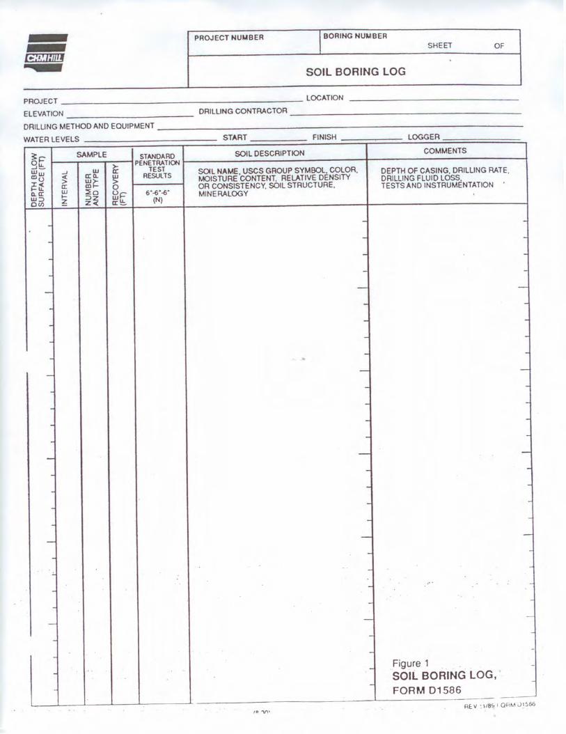
PROJECT NUMBER I BORING NUMBER SHEET OF
SOIL BORING LOG
PROJECT _______ ________________ LOCATION
ELEVATION ___________ _ DRILLING CONTRACTOR _____________________ _
DRILLING MElHODAND EQUIPMENT ________________________________ _
WATER LEVELS START FINISH LOGGER
~I=' SAMPLE STANDARD SOIL DESCRIPTION COMMENTS
Ou. ~
PENETRATION J- TEST SOIL NAME, uses GROUP SYMBOL. COLOR, Ww _J w DEPTH OF CASING. DRILLING RATE. Clo < a: 0.. w RESUlTS MOISTURE CONTENT. RELATIVE DENSITY DRILLING FLUID LOSS. > ~~ > ~~ a: 0 OR CONSISTENCY. SOIL STRUCTURE, TESTS AND INSTRUMENTATION 0.. a: w ~o oi::- 6"-6"-6" MINERALOGY w:::, I- :::,z WU. (N) ou, z Z< a:_
- - .
- - .
. - .
. . .
- - -
. . .
- - -
- - -
- - . . - - -. - .
. - .
- - .
. - .
- - -- - -
- -
. - -
. - -
- - -- -
-.:. - -
- -·· --. - .
- --
- - -
- - -
. - Figure 1 -SOIL BORING LOG, -
- -FORM 01586
- ---- ---f P -V,•
RE: 11 l/8~ 1 Ql<M J1S66
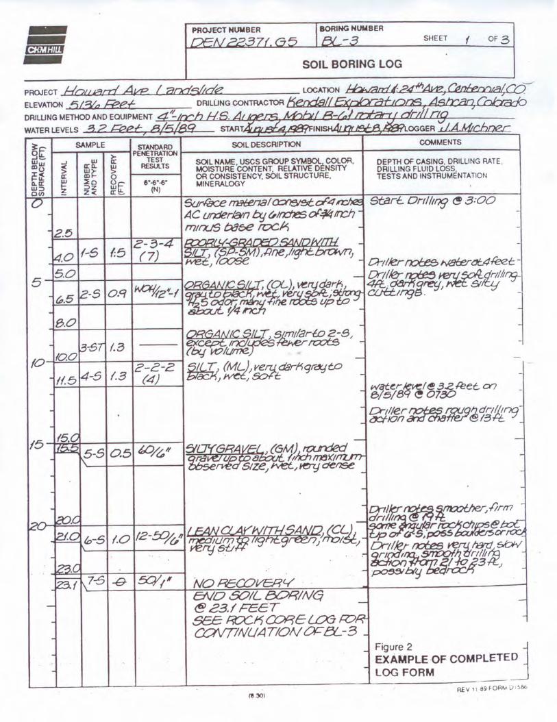
SHEET f OF ,3
SOIL BORING LOG
PROJECT Hoaeai Ake I aocfs/KI~ ELEVATION ,5/3(.,z /£et DRILLING METHOD ANO EQUIPMENT ~~n':l....f.7.:.f::.~lL.k,-;e.J.:aM~ti..fr-LAi.'..a.ti!:t,µ:.1t°n'.il"]4 ____ _ WATER LEVELS f"3 2 Feet:, 8,/5/89
COMMENTS
O~C .....__SA_M_P_LE.------4 STANDARD SOILOESCRIPTION
IL .- PENETRATION t-------------t-----------------1 ..J- >- TEST Ww ..J a:~ IC SOILNAME,USCSGROUPSYMBOL COLOR, ~~ a:~ ~~ ~O RESULTS MOISTURE CONTENT. RELATIVE DENSITY 1-- OR CONSISTENCY, SOIL STRUCTURE, a. a: ~- ~ ~ [rlc &•-6·-6· MINERALOGY ~~ Z Z< a:\!:.. (N)
t,.5
8.0
ENO S?IL BC:>R/Nq ~c3.IFEET Se£ ~K CORElLXl R:J. COVTINUATIONC¥="ei..-3
DEPTH OF CASING, DRILLING RATE, DRILLING FLUID LOSS, TESTS AND INSTRUMENTATION
Start.. Ortllmg ~ 3 :00
EXAMPLE OF COMPLETED LOG FORM
Figure 2 :J L------'L-------'--____.__--L. _ __ ..L..-___ _________ ......__ _ _______ _
REV 11 69 FOR"-' LJ,!,6t,
(1130)
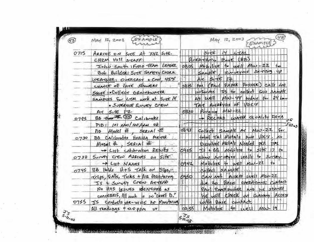
~m~ Designation: D 2488 - 00
Standard Practice for Description and Identification of Soils (Visual-Manual Procedure) 1
TIIIS Sl3nJard " is,uet! under 1hc lhcd dcS1gnJ1ton D 24K~; l/1c number 1mmcd1utdy following the Jc,,1gnallon 1nd1c.1tc-- the )CBr of onJ!onut oooptmn or, on the .:a..-c of re, "'on. the year of ta,1 re, isoon A number on part'nlflc,,c,, ond1c;o1c5 1hc )<:.tr l\f ta>t rOIJ'!l<DVJI. A ~upcr-cnp1 cp51lon !t) mdicalc<- an cd1tor13t chungc since the t"-'t rc""on or n:approval
I. cope * 1.1 This practice covers procedures for the description or
soils for engmeenng purposes. 1.2 This practice also describes a procedure for identifying
soils, at the option or Lhe user. based on the class1ficat1on system de..~cribed in Test Method D 2487. The 1dentificat1on 1s based on visual examination and manual tests. It must be clearly stated in reporting an 1dentifica11on that it is based on visual-manual procedures.
1.2. 1 When precise class1ficati0n of soils for engmeermg purposes is required. the procedures prescribed m Test Method D 2487 shall be used.
1.2.2 In this practice, the identification portion assigning a group symbol und name is l11n11ed to sotl particles smaller than 3 tn . (75 mm)
1.2.3 The 1denufication portion of this practice is limned to naturally occurring soils (disturbed and undisturbed).
~011 t This prnc11ce may be u,;ed as a descnpuve S)Slcm upphed 10 such malenal, a, shale. clnystonc. shells. crushed rock. c1c (sec Append!' :c,
I 3 TI1e descriptive 111fonnat1on in this prncl1ce may be w;ed \>,llh other soil classificnt1on syscems or for matenals other than naturally occumng soib.
I 4 The values staled in mch-pound units are to be regarded as the standard.
I 5 This wandard does nor purport to address all of the sufety prohlems. if any. associated with its use. It is the re~ponsihilirr of the user of thi~ standard to establish appropriate safe fl and health practice~ and determine /he applicah,lity oj reg11latory limitations prior r,, 11w.> For specific precautionary statements see ec11on 8
1.6 Thi.1 prac11ce o[len a W.>I of i11struc11011s jiJr performing ant or more ~pect/ic operallons This document ,·annot l'l'/llace education or experience and should hi' used in C011J1111ction w11h pro.fessio11alj11dg111e111. Not all aspects 0ft/11s practice may he applicable in all drc11rnsta11ces. Tim AST\/ wandard 1s not intended to represelll or replace the mmdard of care hy which
1 Thi, prJ<11cc "under the Jt1mJ1ctton of >\'-'f\1 C.unm,uce D-l~ on S011 and Roe~ anJ" the dirccl r~">p1>nsibihty of Sulx:omm111cc Dt8 07 on ldcn11hca11on and C: l • .-,1hco11<>n of Soils
Cuncni ,·t.hmin nprru,cd Feb. 10. ~000 l'ubll,hcd '-fa> WOO. Ongonall~ puhh,hcd .1, 0 24Sk (,(, T Lo,,l pr~, mu~ c;ht1<111 D 24~l\ 11_1' 1
the t1£lequuc1 nf a Kive11 professio11ul 1·erl'ice 11111st he Judged nor should thn dun1met11 he appl,ed "11hn111 consideration of a pm1ect .1· manr 1111iq11e aspect.~ The word 'Standard in the ti lie of this docume/11 means 0 11(1· that the documenl ha., hecn appro, ed through 1he ASTM conse11.rn., process.
2. Referenced Documents
2. I AST.\f S1undards: D 653 Tem1inology Relating to Soil Rock, and Contained
Fluid~~ D 1452 Practice for Soil lll\esttgation nnd Sampling by
Auger Borings2
D 1586 Test Method for Penetmllon Test and Split-Barrel Sampling of SoilsJ
D 1587 Practice for Thin-Walled Tube Sampling of So11s2
D 2 113 Practice for Diamond Core Dnllmg for Site lnvestigation2
D 2487 Class1ficauon of Soils for Eng111eenng Purposes (Unified Soil Classification Systemf
D 1740 Practice for Minimum Requirements for Agencies Fngaged 111 the Testing and or Inspection of Soil and rock as Used Ill Engineering Design and Cons1ruction3
D 4083 Practice for Descnpt1on of frozen Soils (Visual\.lanual Proceduref
3. Terminology
3.1 Definitions-Except as listed below, all <lefiniuons are 111 accordance with Tenninology D 653.
"Ion 2 For pnmcles retained on a 3-m ("75-mm J l S stu.ndar<l s1c,c, 1hc fullO\~mg dcfint11ons are suggcs1ed: Cnbh/n - pantcles of rock 1ha1 wtll pas~ a 1:!-m (300-mml ,;quarc opening und be retained on a 3-m. (75-mmJ sie,e. an<l 8011/d,:rs-pamctcs of rock 1h01 will not pa,, n t 2-m tJ00-mm) ...quare
opening.
3.1.1 c/a_1~soil passing a No. 200 (75-µm) sieve that can be made to exhibit plasticity (putty-like propen1esJ within a range of water contents. and that exhibits considerable strength \\ hen a1r-dr). For classification, a clay 1s a fine-gra111ed soil, or the fine-grained portion of a soil, wilh a plasticity index equal lo or greater than 4. and the plot of plas11city mdex versus ltqu1d
: .~nnri,1/ &H>~ Of tsnt S1,111J<1rtl•. Vol 04 Cl~ 'An11u<1/ &,,,A of AST\/ St,mdor./,, '11"1 <>4.(IY.
•,\ l:>ummal) of C hanges section appear, a t the end of this s tandard.
Couy•,~hl O ASTM, 100 Barr Harbo< Orova. Wast Co,,shohco<en. PA 19426-2959. United States
Coovr"7", ASTM tntarn,ll.OII• ~ r,y ft{S \AW licet\ae w•tfl ASW Nor~Ot~,,V ~J""lt!ed ~tl~fram IHS
l.iunsePCH2'-4 Hcl/Ml80'58001 ~Can• Lu ""'"" - 0&1)Cr.1005 oa 22 6V .. or
~ITT), D 2488
l11nit falls on or abo,,;: the "A" line (see Fig. , of Test 'vlethod D2487).
3.1.::! J!,mn•/ pa111cles of rock that will pass a J-m (75-mm) ,1ev1: and t,e retained l)l1 a l\o. 4 (4 75-mm) ,1e,1: \\1th the foll,l\\ mg subdl\ 1s1ons:
u •«ntL pas,es J )-111 (15-tnllll sieve and is retamed on a 1 ~-1n. t 19-mm) s1e\e.
/ /1/t pa:-.~c,-, :1 1 ,-111 119-mm) sic, e and is retained on ,1 l\o 4 t-1 .,5-mm) ~IC\'C
3 I 3 m~onic clc11 a cla~ with sulfic1ent orgamc content to intluence the soil propenies. For class111\:a11on, an orgamc cla~ is a soil that would be cl,1ssified as a clay. except that Its liquid l11nit \'alue a her lWen drvmg 1s les~ than 75 '} n of its hqu1<l l11ni1 \'alue bctore CI\Cn dryrng.
J I -l lll)!OIIK ,,Ir a silt ,, 11h sutlic1ent orga111c content to • influence the soil propentes For class1ficatmn, an organic silt ts a soil that ,, ould be class1fit:d as a sill C:\Cept that tts liquid 1111111 ,·,tlue alkr 0\\!11 drving ,,. Jess than 75 % llf tis li4u1d l1m11 \'alue before 0\ en di) mg.
3 I 5 peat a suit composed primarily of , ·egetable ttssue m \'anous stages of decompos1t1011 usually with an organic odor. a dark hrov,n 10 black color, a spongy consistency, and a texture rangmg from librous to amorphou!'>.
:U .6 ,cmd- parucles of rnck that ,,ill pas-. a I\,). 4 (4 ~'i
mm) sie,e and he re1a111e<l on u :--:o. '.!00 (75-µm) ,1e,e wtlh lhe follu1,1;in1.; -;ubd1, 1st0ns:
co,1n; pa~se, a l\o. -I t-1 75-nun) slc\'e and 1s retained on a '\o 10 !:!OIi-mm) sieve.
1111·,lium- passe~ a No. 10 (2 OO-mml sie,e and 1s rctamcd on a 1',0 40 t425-µm) sieve
/me passes a No 40 ( 425-im, l sieve and ts ret:11ne<l on a '\u. 200 ,.,5-µm) sieve.
3 I ~ Hit -soil passing a No 200 (75-µm) s1e,e Lhat is nonplnsuc or very s l1ghtl;, plas1i1: and Lhut e:\hihtt-. ltllle or no .;1rength \\hen air dry. 1·or·dassification. a silt •~ a fine-gramed ,otl. or the tine-gramed portmn of a sotl. "1th J plasttLity mde\ lt:ss than 4. rn the plot of plastictty inde, ,e~u~ ltqt11d hmll t,1l b belm, the ·· ;\ .. ltne (see Fig. 3 of Test \1ethod D 248"').
~- Summar) of Practice
4 I Usmg visual examination and simple manual Lests. this prac11ce gives standardized criteria an<l procedures for describing and 1den11fy111g soils.
-1.2 Tht' sotl can bi: g1\en an 1dent1lica11on bv ,1ss1gnmg a gr,1up symholt s) and name The flow charts. rig. I a and Fig 1 b fur fint:-1?ra111ed ,-,oils. and Fig. 2. for l:'.oarse-gm1ncd soils, c,111 b1: used to assign the ,ippmpr7ate group s,mrn1I(,) anJ nami:. If the soil has properttes ,1,h1ch do not d1s11nctl) place it mto a ,pecific group. borderline S}mbols may he m,ed. see Append1\ \J
~ r,r1 3 It " ,uggc,tcd 1hat ;i dist111ct1l•ll be made b.:twccn dual n m/>of< Jilt.I hnrder/111, n'llll><>f~.
n,,.,/ Sm1f,,,1/ \ du.ii s)mbol 1, 1,,,l ~~ rnl><>ls 5cpar.ttcd by ,1 hyphen. for n:implc (iP-C,\1, SW-SC. . CL-.\ IL 11,cd ro md1ca1c Lhat the soil hJ, been 1dcn11ficd a., ha, mg thc prupcn1c, of :i cla,s1lica1iun m accord,1m:,: ,«th Tesl \kthod I) 24l0 where tw v ,~ rnb<.•ls .m: requtrcd r"u ') mbvb .trc rc,11nrcd when the soil Im, bd"c,:n 5 and 12 "" fine, ,,r ,, hen 1hc hqutd htnll .111d ('l.,,tu:11, mdc, valucs plut tn 1hc C'L-\-1 I. area of till' plasticll) d1.1r1
~ ASTM lnl.wnalo,a Rac,,oduc.ect DI t1S ~ ....,._ ••In ASTM f'+> ,~ or "et'tw0f1r""IJ ~nad \lftfhQut lio.n .. twom fHS
Bonl.-rlt11,· Sm1bo/ \ htlrdcrhm: ,yrnhul ,, '"" ') rnbol~ separated h) " ,ta.,h. for C\Jmpk. CLC! I, C,~t SM. C' IJ,\11 •• \ horderlmc ' >111bul should be u,cd 10 indiCJ!C that the ,ml hJ~ l>c.:n 1dcnt1lied "" hd, mi: pn,per11c, th.11 d,l not di-imcll) place the , ,l1l 11110 ., , p.:olk group t scc ,\ppcndl\ \:1 I
5. Significance and l,~c
5 I The descnpll\C 111fom1ation required 111 this prac111:e can be used to describe ,1 soil to .:iid m the evaluation of its s1gmlicant propcr11c, for engineering use.
5 2 The descripti\'e information re.:1u1red m tlm practice should be u:,ed to supplement the class1hcatton of a ,oil a,-, dete1111ined hv Test Method D 24K7.
5.3 Thi~ p~acuce mu;, be used 1111den1tf) mg smls 11s111g the classilicati1111 group symbols and names as pn:scnhed 111 lest .\tethml D 2487 Since the name,-, and symbols used 111 this practice to 1den1tly the soils are the same as those used 111 Test vlethod D 2487, ll shall be dearl) ~t.lled 1n reports and all other ,ippropnate documents. that the class1fica11on symbol and name are based on visual-manual procedures.
5.-1 This practice 1s to be used not onl} tor 1den11fica11011 of soils m the field, but abo m the oflice, laboratory. or \\here\er soil samples are inspected and descrtbed.
5 '> Tius pracllcl! has panicular value in grouping ,11111lar ,ml samples ,u 1ha1 011I} a minimum number orlaboratory tt.'SI', need be rnn for pos1t1,c ,011 classilicauon.
~ .,, 4 TI1c Jh1lil) 111 dc,_.-nbc and tdcnll l) , 01b ,,,rrc<:tl} h k ,1rncd 1m1rc n.-.1d1ly undcr the !,!u1d:111ce ul c,pcncnu:d per.-onncl, but 11 ma) ,,!,(, t,,: acq1111cd , ) , 1cm.i11cally b:,, cornpann)! numcri ~al lah11r,11111- 1.-,1 result s for 1yptcJI ,01b ur each type w11h their ~tsual Jnd rnauual diaractcn,11,·~.
5.6 \\ hen describtng and 1dent1fymg ~oil ~amples from a given bormg. test pit, or group of bonngs or plls. 11 i- 001 nece-.sary w follow all of the procedures 111 this practice for C\ ery sample. Soils,, h1ch appear to be simil.1r can be grouped together: one ,ample completely described and 1de11111ted with the others referred to as s1mtlar ba-;ed on perfonnmg uni:,, a le!,, of the descriptive and tde1111fica11011 procedures described 111
lh1~ pmc11ce " ~ This prac11ce may be used in combmatmn with Pracuce
D 40113 when working w1tb tr\l1en ,oils.
!\,,.1 '\ ~OI\\ 11hsta11d111g lhc sl:llc.:mcnts un prcc1si,>11 and hi1h ,·u11• t.11ned m 1h1s slllnd.ml· The prccis1un uf 1h1> tc-'I mctlmd is dependent on 1he Cl>ntpctcnc.: of 1hc pcr,.unnd perfonrnng 11 Jnd thc su11.1t>1h1y of lhc c:qu1pmc111 anti 1;11;1h11cs u,cJ .\genc1e, thut mcct thc u11cna ul' Pr.1.-m·c f) l,40 arc gcnt:rally con>1dcred c.1pablc of ,0111p.:h:n1 ,rnd oh_t-CIIH· 1e,1111e. User. ,,r 1h1, 1c,1 mc1hod urc c:iu111:mcd Lhul co111phuncc "1th P1,1e1;,c D 3740 Jl,c, 11,,1 ut 1L~cll .1,,ur~ n·liabk tc,1111g. RdtJbk 1c,t1 11!_! d...-pcnd., on ,c\cral fa~·tors: Prnc11c.: U 3740 p10, 1dc, a m,Mn, for c, .tlUJIIII!! ,umc nr thosc foct,,r.
t,. \pparatu~
ti. I Rec1111rcd ApparCIIU~. 6. I l Pocket Knife or Small Spatula (1.2 l.,sefu/ Auxilim:I' fppart1111\·: 6.2 I Small Tot Tube and Swpp,•r (or J:U' \\ 1th ;1 ltd) 6.2 2 Small /land Ll!n~.
7. Reagen,~
, I />urit1 of Heiler- Unless othcrn,ise md1catl!d, references to ,,:11cr sh~ll ·he under.;tood to mean water from a cit) \\ater
L~:ooCH2J.i ~58001 Uaerz-C•f"lor l .. M1t tor Jt..... OMM/2005 08 22 59 ~OT
~ITT!, D 2488
GROUP SYMBOL GROUP NAME
< <30'1(, phJ, No. 200 ~ < 15% plus No 200 ~ ----<• Lun clay
--- 15-25% phn No. 200 --------==:: 'It .. net 2:% g<aftl - Lun clav with sand
Cl ----• % .. nc1 < % grllffl - Lun clav with g,aw.t %,and 2!%ofgrav.t ~ < 15%grllffl ___ __.• Sandylunclav
2:30% plu, No. 200 -~------ -+- 2:15% gt8"1 Sandy IHn clay with 11favel % .. nc1 < % e,avel --=:::::::::::: < 15" Mnet ____ __ Gra .. ny lean clay
2:15% ,and Gravelly,._, clay wrth ..net
< < JO% pkn No. 200 -----=: • < 15% plu, No. 200 -=---• Sih --- 15-25% pku No. 200 ---=.::::::::: 'll. Mnd 2:.% grn•I-Slh with Mnet
ML -==----• % sand < % 11•••.t - Silt wrth ., ... , "sand 2:% of gr..,.I -=-:::::::.:::: < 15% g,Hel - --- • Sandy sdt
2:30% plus No. 200 -=-----<• 2:15% gte¥el Sandy silt with gravel % sand < % llfeYRI ~ < 15% Mnd Grav.tty silt
----- 2:.15% sand----- Gravelly silt with .. net
< ~ plu1 No. 200 -=::::::: < 15% plu, No. 200 >-=--- -- Fet clay 15-25% plus No. 200 ---=:::::::::::"' Mnd 2:.% !lfa .. 1 -F•t clay with sand
CH ----•%sand < % 11'• .. I-Fat clay with 11'•••1 % 11nd 2!% of gravel ---=.::::::::: < 15% gra .. 1 Sandy lat clay
2:30% pku No. 200 -=---<• 2:.15% ll'•ve4_-_ -_ -_ ----- -- -~• Sandy lat clrt wnh grant % sand <'Jt. grav.t ----==:::.::::: < 15% sand G,a .. uy lat clay
2:.15% Mnd ------Gra .. lly fat clay with und
<3°" plus No. 200 --=-::= • < 15% ph,s No. 200 -=--- --<• Elastic 11lt
< --_ 15-25% plu1 No. 200 --------==::%sand 2:.% gra••I-Elastic 11lt with .. nc1
MH .....,,-----a•" sand < % orH•I - Elasuc: stlt with gr•••I % sand 2:.% ol 9re .. 1 -e:::::= • < 15% granl Sandy elastic: 1111
2:3°" pluJ No 20()-- ---------- 2:_15% graffl __ - -_ -_ -_ -_ -_ -_ ..... _,•• Sandy elastic: Jilt With gra .. l -----% sand < % gravel ~ --'.15% 11nd G, .. ellv elastic 1ilt
---2:.15% sand-----+- Gra .. lly elastic: silt with sand NOTE 1-Percentages are based on esbmaling amounts of fines. sand. and gravel 10 !he nearest 5 %
FIG. 1a Flow Chart for Identifying Inorganic Fine-Grained Soil (50 % or more fines)
GROUP SYMBOL GROUP NAME
< < 30% plus No 200 -C..::::::::::: < 15% plu, No 200 Oreanlc so,I
15-25% plus No. 200 ~%Mind 2:% 9ravo Orea,,lc soil with sand OL/OH -~------ --"'M1nd <%1r•••I -o,,onocso,lwittogro••I
--% Mind 2:% travel --=:_ • < 15% 9raHI Sandy or90n1c: 1011 2:30% plus No. 200 ---- ____ -----• ~ 15% 9rav.t --- - • Sandy ortonte soil with 9re .. 1
'X, .. nc:1 < 'Jt. tr•••• ----=-=-===-:. < 15% ,and Gro .. lly ortonic soil ~ 15% Mind Gra•olly orpn,c 1011 wi1h sand
NOTE 1-Percentages are based on eshmat,ng amounts or fines. sand and gravel to the nearest 5 %
FIG. 1 b Flow Chart for Identifying Organic Fine-Grained Soil (50 ¾ or more fines)
supply or 11:11ural <;C1urcc. including non-rotable water. 7.2 llnlmd1/r,r1c fricl \ small bottle o f dilute h:idrochlo
m: acid. IICI. one pan I ICI ( 10 \) to three pJrts \\ater (This reagent 1, opttonal for use \\ 1th this practtce) See Sectton 8
8. a fcl~ Precoutions
X I When preparing the d ilute I ICI solution o f one part concentrated hydrochloric acid ( IO A) to three pans of d1sulled water, slowl) add aCICJ into water followmg necessary ,;afety precaulltm,. llandle \\ 1th caution and ,tore safely. If solution comes into contact ,,·1th the skin. nnse thoroughly "1th water.
8.2 C.aution Do not add water to aud
9. nm p ling
9 I I he sample shall be cons idered to be representall\e of 1he stratum from "lm:.h 11 \\ as obtained by an appropriate. accepted. or standard procedure.
'l;,,11 (, Prefombly. the sampling pwcedure shuultl he 1den11tictl as
t,ghCASWIIW"l~ OOuc.c:I tiv tHS ur,,oeir lcar1M ..,,_, A.Sl\il ,~,Qf'I or ~.l'lg Det....a.G w~il k~ff f,om IHS
3
h,I\ mg hcen .:ontlu,11:tl m accortl,mcc w11h Prat·11cc, D 145~. [) J '\~7. nr I) '.! 113, "r lc,1 Method I) I 5St.
9.2 171.: sample ,hall he carefully idcnulicd a~ to origin.
:-.:mt. 7 Remarks "" lU lhc ung111 mu) 1.ike the form Pl u boring number Jilt.I ,.,n1plc number in con11mc11on "ith a 10b number, " gcol<>!!1t· slratum, a petlolugk hon1on or n location d1..-si:np11011 w11h re,pcc1 tu a pcnmtncnl ml•numcnl, a gnd ,y~1e111 or ,1 slallon numbcr und oil sci \\ 11h respect to a ,lated centerline und a dcp1h t>r clc\a111•n
9 3 for accurate di:scnption and idemific:uion. the mimmum amount of the spec1111en to bi: exammcd shall be 111
accordanci: w11h the followmg ,chedule: Max,mum Pan,de Sizo
s,e~e Opening
4 75 mm (No •1 95mm(¾1n) 19 0 mm(¾ on) 38 1 mm (1'4 ,n 1 75.0 mm (3 In.)
la,nt,N!cCH2t,t f.f\l,<$.N(),5eoc,t ~ Uta Notto,R- ~"20t'SOll225tM0T
M,n,mum Spec,men Size. Ory Weight
100 g (0 25 lb) 200 g (0.5 lb) 1 .0 kg (2.2 lb) 80 kg (18 lb) 60 0 kg (132 lb)
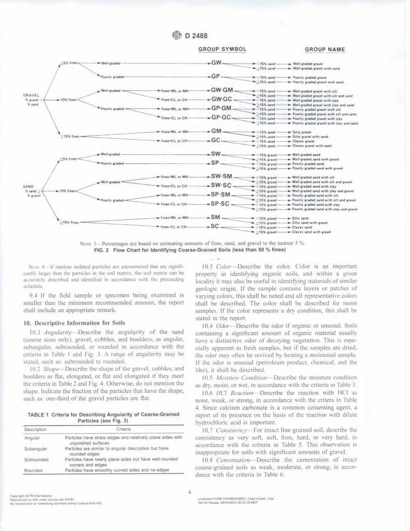
~lffi? D 2488
GROUP SYMBOL GROUP NAME
/.SS""tinH~---Well-ffact.ed--------------- GW-==---- -- 15% And-. w.11 .. ,acf .. ,, ..... 1
c'?15"' nM _.. WtO g,aded tr•nl wtlh 11nd
Poorly gud.d---------------GP- "'===--• , 15~ nnd-----. Poorfy 9tlded 9,n,1 ,Z:15% And_____,.. Poorly 9rac:Md gravtl with ti1rid
lO~ fu,u
w.1, .. radtd ~ l,nt r M Lor Mt,f---.. GW--GM ~ 1s, wnd-------.-WtU-1rldtd ,,,,11 with 11ll
-------... Z,15$ wnd-------.- W1U1r.aed gravel with ,,It and 11nd l1ne1• Cl o, CH GW-GC -=::::--• 15,. And- w,11,.rtdod grevel w,th cl,v
Gp··GM ~ 15% wncf--• Well 9rMled grnel w11h cl1y •l'Mf ,100 Poo,ty 9r1ldlld"""::::-----f1nt, ... ML or MH---- • 15% .. nd-.... P00tlY 91.cjed orevel Wllh ult
Gp·GC _!15,. ,.nd _ Poorly 9'>dtd gre,11 woth "" end ••nd f1ntt•Cl or CH---• 15,r. u ncl ___.. Poorly 9Qdtd granl wrr111h cl•Y
~ l S" nnd _______..,.. Poorly graded 9rH1I w11h elev •nd ~
______ fmea•M L or MH---• GM sc:::::::::::=t c... 15% t.1nd--.. S1trv tfl•ttl
15% hnH-~=======-===---- GC -----... ~,s~ Mt'd~ S,ltv 9rtv1I with und t,nu•Cl Of CH---• - -=---<...15% uind -.. Clayey 9ravtl
~15'A uind-...... Ctev•v grtwel •Ith sand
_____ w,11-,,ec1td---------------SW- ==--... < ,s,. ,,..,,-w.11-,,tdtd ,anc1
, 5,i. t,net_______ _ ~ 15,-_ 9rn•I Wtll-tnd~ 1-aJld wit h 9rau:I
/
- .,Poortypad.d SP < 15%orue-1~Poorlyg,.t«ts:end 2 1s,r. ,,awal ~ Poor ly traded sand with 1r•W!;f
f1n11• ML or MH----SW•SM - =--• 151' gr• • t l • Wtll-tuded Mnd with ult
Wdl-9nded SW·SC l 15" 9rao,11tl-----.. W•O•t tadtd und with 1111 tnd vrutt SAND ,. .. nd
f1nH•Cl o, CH---• -==-- < 15~ 9rawe.t ._.... Wen11rMfed sand w,th cl1v 2 15~ gu•.t _.. Welt1,tdkf pnd with clay •nd 9'1, 11
-=======fintPML orMH----SP·SM < 1S~ 9r1HI- • Poortv9rlcftdMndw1th ult
Poortv 1'-'ed ~ 15"- g,•••1.-.. Poo,fv 9,.cttcf und with silt and tr•"' l ones•Cl or CH SP·SC <15'!< gnv•I- Poo,ly 9ndecll1nd woth cllV
, 16~ 9uvtl __.. Poorly er.ct~ sand with clay and 91awtl
--=============t,nu•ML01MH- - .... SM - =---- t5"-9rnet-....S11tvMnd .,:161' f 1no ~ 1s,r. 9ranl __. Stlty sand w11h gravel flnh'"'CL o, CH--- • SC - ==---- 15~ 9,-.ve1 .--. Ct•v•v Mnd
t!. t5~ tra'f'tl ._.. Claver Mnd with 9rawtl
No11 I Percentaee~ are b~ed on est1maune amount,, of fine&. ~Jnd. and gravel 10 the neare,1 5 ~ • . FIG. 2 Flo;., Chart for Identifying Coarse-Grained Soils (les s than 50 % fines)
:--.1, 1 X If rJndom 1Sola1ed p,in,de, .,re cn.:ount.:rcd 1ha1 arc '1gn1fic.1n1l y l,trc.:r llun the pctrlldc, tn lht· ,u,I main,. th.: s111I mntn, can he ,,.,·111.old) Llc..cnt,.:d ;ind 1den11licd m ~cc,•rJ;m.:i: "llh 1h,· prcccc,hng ,d1.:duk
9 -t If the field sample or specimen being exJ111tne<l 1s smaller than lhe mrnimum recommended amount. the report shall 111clude an appropriate remark.
I 0. Dc~criptivc Informa tion for oil!.
l(l.l l11gulant1c Describe the angularll\ of the sand (uJar,e srzes onlvl. gravel. cohbles, and houldn-.. as angular. -.uban1rnlar. ,uhmunded. nr rounded m m:cor<lance w11h the cnten:, 111 Y-ahl<! I ,.111d I rg. 3 A range or angulant} may he statt·d. ,uch .ts suhrounded 10 roundt.'d.
IO 2 \/rape Describe tht! shape ot' the grm t.'I cobble,. and h,,uldcr, as nat. elongated. or lfot and e longa1e<l r f the} meet the nitcna in rahle :! and fig. 4 . Othen, ise. do not mentl\lll lht! shape lnd1calc the Ii-action o f the particle~ that have the shape, such as nne-third of the gravel part11:les are flat.
TABLE 1 Criteria for Describing Angularity of Coarse-Grained Particles (see Fig. 3)
Oescnptoon
Angular
Suoangular
Subrounded
Rounded
Cu1,,,,gt11 ~STI.t IN~I
Cnlena
Particles have sharp edges and relatively plane sides with unpolished surfaces
Particles are similar to angular descnpuon bul have rounded edges
Particles have nearly plane SKles but have well-rounded comers and edges
Particles have smoothly curved sides and no edges
R~uc»o ir, IMS~~ A',"\ASTM Nil ~odllaOo'\Ol ,-.~:)l"W. 'IO permllltlel w,.tho!JI ~u frarft liS
4
I 0.3 Colm Describe! the color. Cnlor ts an 1mporuun property in 1denllf)'tng organic so1k and w1lhrn a g1,en local ii) II may also he useful in 1dcntd) mg materwb o l s1m1lar g.e1.1log11: ongm 11 1he sample contains layer.; or pah.:he-. ol ,·arving colors. this shal l be nott!d and all represcntat1w colors shail he described. The color shall be descnbt'd for nwist samples. If 1he color represents a d1:· cond111on. this shall be stated 111 the repo11
I 0.-t Odor Describe the odor if organic or unusual. Soil, contarnrng a significant amoum ol organic material usualh ha, e a d1stmc11w odor o l decaymg vegeta11on J"h1s rs e,pectall~ apparent 111 lresh samples. but ,r the samples are dnoo. thi: (IUor ma) oltcn he re, 1ved b) heating a moistened ,ample Ir the odor 1, unusual (petroleum product. chemical. and th\." like I. 11 shall be descnhed
I 0.5 Mm,111n Co11dit1CJ11 De~cnbe the moisture cond11wn as dry. moist. or wet. rn accordan1.e ,.,.·jth the cntcna 111 rahle ~
I 0.6 /IC/ Rl'act,011 Descnbe the reaction with IICI O\
none. weak. or strong. in accordance with the cntera in IJblt: 4. Since calcium carbonate 1s u common cememing agent. a repon of 11s presence on the basis or tht' react ion v.Jth d1h11e hyc.lrochlonc acid rs important.
10.7 Comi1re11c1' for 111tall line-grained soil. describe the com,1~1enc) as ,cl"} soil. soil. firm. hard. or , ery hard. in accorJancc v. 1th the critcna rn Table 5. This ob sen n1mn 1s mappropnate for soils \\ llh s1gmficant amoums or gra,el
I O.S Cc111i.:111arwn Describe the cementat1on of intact coarse-grained soils as weak. moderate, or strong. in accordance w11h the cntena 111 Table 6 .
t....:MNN=C.ti.2~ HJi.'5900'58001 UNP~ LN NOi to, Rtsa• 0&0&'200$ 08 22 SP MOT
~I D 2488
IR,_ tu \n1u •
"-· .
I
I ! • ~ ,s rw,
FIG. 3 Typical Angularity of Bulky Grains
TABLE 2 Criteria for Describing Particle Shape (see Fig. 4)
The particJe shape shall be descnbed as follows where length. width. and thickness refer to the greatest. intermediate. and least dimensions or a part,cie. respecllvely
Flat Particles w,lh widlhlthrclmess > 3 Elongated Particles With lenglh/wldlh > 3 Flat and elongated Particles meet cntena for both ffat and elongated
I 0.9 S1rttUlll"l Dt:scnbe the structurt: of intact soils 111
accMdam:i: \\Ith the cntcna 111 Tablt! -. I 0.1 O Ra11~, of Ptmh h '>i:t, For gr.:i"el and ,and com
pont:nh. (lcst:rthc the range of partide c;11t:s \vtlhtn each com1wnent as dt:tined 111 3.1 ::! and J.1.6. l·or e,amplc. abou1 20 'ln tine lo course gra,el. aboul -10 "·o tine to coar-e sand.
I 0. 11 \ /a.·w1111111 Partic:le Si:e Descnbe the ma""<11num particle size found rn the snmple m accordance with the followmg t11fom1a11on·
10 11 I Sand S,:e-lf the maximum parttcle size ts a sand ,11e. descnbe as tine. medium. or coa~e as defined Ill 3.1.6. Fl)r example ma,m1um particle size. medium sand.
10.11.::! Grm-d ~·i:e If the maximum part icle size ts a gravel s11e. describe the maximum particle s11e as the smallest s1e, e openmg that the parttcle \\111 pa~s. For example. ma,1-mum particle s11e. I 1 ':? in. (will pass a 11 ~-in. square opening but not a ~'~-m. square opening}.
10.11.3 Cobb/,., or Boulder Sb: -If the maximum parttde s11e ts a cobble or boulder size. describe 1he maximum dimension 01 1lw largest parttck For example ma:-.imum d1men,ion. lli m (450 111ml.
IO 12 l lardnt \ .1· Describe the hardness of co,tr,e sand and larger particles as hard, or slate "hat happens \\ hen the particles arc hll by a hammer. for example. gra, el-s11i: particles fracture \\ nh t:ons1derable hammer blo\1, some gravel- 11c par1tdes cn11nble with hammer blo1, . "I lard" means particles do nnt crack. fracture. or crumble under a hammer blO\\ .
Coc,yr•Qh4ASW lnlr'llik:11\a ~t,y-l-tSunderlCltloM*•lt1ASTl.t N<> ttprOductO'I o, ~ P9'""f'l'lla(I ~ ltie>UI 11tense trom tHS
5
PARTICLE SHAPE
W=WIDTH T = THICKNESS L = LENGTH
FLAT: W/ T>3 ELONGATED: L/W >3 FLAT AND ELONGATED:
- meets both cr i terio
FIG. 4 Criteria for Particle Shape
I 0. 13 Add1t1onal comment, shall be noted. ~uch as the presence of roots or roo1 holes. dtfficuhy 111 dri lling or augenng
~H2M H,l 59&CM58001 UMPC&r1• UN Nolb- OM)0=08225!1MOT
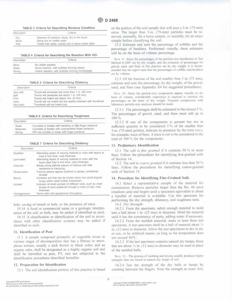
~ml? D 2488
TABLE 3 Criteria for Describing Moisture Condition
Desct1pl1"'' l.flfe 111
Orv Moist Wet
- ---------------------Absence of moisture dust) dry :o the touch Damp bul no v1s1ble water V1s1ble free water. usuai!y soil ,s belo,,, water table
TABLE 4 Criteria for Describing the Reaction With HCI
on the portk,n of the soil sample that will pass a 3-in ( 75-mm) ,ieH!. rile lnri?er than '-in. ('5-mm) particle~ mu,t he remm ed. manual I). tor a loo,e s,1111ple. or mentally. f'or an rnta..:1 sample before dassil)tng the ~oil.
12 2 Fst11nate (md note the percl!ntage of cobbles and ttw percentage of boulder, Performed ,isually, these estunate, "111 be on the basis ol volume percentage
Descnphon Cnteria '-· 1 '' ';mcc the rcn:cnt,1gc, of the r:imdc-,11c dismbuuon m r c,t --------------------------- \lcthod I) 2-IS., .m: b} dry "eight. and th,: c,t11natcs ol pcrccntafc, for None No ,is1ble reactron Wea, Some reaction. with bubbles f0tming slowly gra,d. ,and. ;ind fine, m th 1, prat·t1.:.: an: b) J~ "-Ctght, ii is rccom-Slrong VIOient reacllon. with oobbtes forming immediately mt."lldcd th.ll the n:port sliltc that the pcn:enwg.:, ,,f cobl>k, ,111d t,,,uldcr, .:....;:...,.:: _____ _:__:__:.;_.:....;_:_.:.._.:..__:_ __ _::.._.:.._;_;__:.. _____ .ire h) , 11tum,:
12.3 Of the fraltton ll l the soil ,mailer than 3 Ill . (7'i 1111111,
_____ T_A_B_L_E_s_c_r_it_e_ri_a_f_o_r_D_e_s_c_ri_b_in.:...g=--D_il_a_ta_n_c.:...y ______ esmnatc and note the percentage. by dt: \\Ctght. or the '1rtt,el. _0e_~_cr_10_1_10_n ___________ c_ri1_e_na __________ sand, and lilll~ (sec Appendix X-1 for suggested procedurc~). Very sol! Soft
Thumb w,11 penetrate sorl more than 1 in, (25 mm) Thumb will penetrate sod about I In ,25 mm) 1'0ll I Cl ';nKc the partrdc-sl/C component, appc;ir "'uall; nn the Thumb will Indent soil about ;,,n. c6 mm] ba,i, 01 ,oh1111c. constdcmhlc c,p,:ncncc 1, n:4l11r~d 1,1 csllfnatc thc Firm
Hara Thumb will not Indent soil but readily indented w,lh thumbnail pcrc-.:ntagc, on the l>,is,, uf di) \\<:ight I rcqucnl ,0111pa11"1ns w11h \_·e.:...ry..:.._h_aro ____ Th_ u_m_bn.:...a_,1_w.:...1l.:...I n_o.:...t_tn.:...d.:...e_nt_so_ ,1 ____________ l,1bor:IIUI) part1dc-suc ,m,11\sc, ,hould bc made
Desct1pt,on
Wea~. MOd<lrale S110ng
TABLE 6 Criteria for Describing Toughness
Cri1ena
Crumbles or breaks w1lh hand~ng or lillle ringer pressure Crumbles or breaks with consideraDle finger pressure W•II not crumble or break w11l1 finger pressure
TABLE 7 Criteria for Describing Dilatancy
Oes~.1,p1,on Cniena
S1ra11f,e<1 I\Jlemaung layers of varymg malenal or color w1lh layers at least 6 mm lh,ck, note thickness
Laminated Allemating layers of varying matenal or color with Iha layers less than 6 mm thick: note lh1cllness
Fissured Breaks along definite planes of fracture v.1th ltllle resistance to fracturing
Shckensn:led Fracture planes appear l)Ol1slled or glOssy, somebmes striated
Block~ Cohesive so,I tnal can be broken down into small angular lumps which resist further brea,dov.n
Lensed Inclusion of small pockets of 01f!arent soils such as small lenses of sand scattered through a mass of clay; note thickness
Homogeneou~ Same color and appearance u1roughoul
hole. ca\in~ of trench or hole. or the pre~ence llf 1111ca. I 0.1 • ,\ local or commercial name or a geologic fnterpre-
tauon of the sod. or both. rnny be added if identified as such. I 0.15 A class1ficat1on or 1dent1 llcauon of the sml 111 necor
dance \\ ith other class1ficauo11 sy ... tems ma) he added 11' 1denutied ,is such
11. Identification of Peat
11 I \ ~ample composed primaril, of , cget~1bk t1s,u.: 111 , Jnous ,tages ol decomp1)s1uon 1hat has a fihrous to amorphous texture. u-..uall) a dark brown to black color, and an organic odor. shall be designated a, a highl) organtc soil and ,hall be idenutied as peat, PT. and not subJec1ed to the 1dent1ficat1on procedures described hereafter.
12. Preparation fur Identification
12 I Ilic soil 1c.lent1ticut1on portton of 1hi-.. prac11ce is based
CeliCNrq,c A.SW~ ReproaJC«J Dy ltiS .nW licer!M ""''" "'5TM No rllO'OOJd,on or ~(IQ ~140 w-1nou1 l~'lllft trr.m lhS
I :!.3.1 The percentages ~hall be estimated 10 the closest 'i ".,
1l1e percentages of gravel. ,and, and tines must add up to 100 °:,.
I :!J.:! If one ol the components 1s present but nnt 1n
,uft1c1e111 quantity to be considered 5 ° n of the smalh:r than 3-m. (75-mm) portion. md1cate 11' presence hy the tenn 1ruu! ,
for example. trace of fines A trace 1s not 10 he con~1dcred 111 the total of 100 °·,, for the components
13. Prclimlnar) Identification
I JI The sot I ts /111,' grc1111nl if it contains 50 °-o Clr more linh f·ollow the procedures for identifying fine-grained :;oib of <;,ec11on 14
13.2 ll1e sorl ts 1·1>c1nt grc1i11ed if it contams less than 50 % fines. Folio,, the prncec.lures for idem, I) mg coa~e-gramcd soib ol Section 15
14. Procedure for I dent if) ing Fine-Grained ~oils
14 I Select .i represenlall\e ,;,11nple of the material !tor
exammatmn Remme pan,cles larger than the No. 40 sieve 1mec.l1um sand and larger) until a ,pecimen equivalent 10 aboul a handtul of material 1s a,·mlable L'se th,~ <;pcc1111en for perfonnmg the dr) ,trength. d1latancy. and toughness tests
14.2 Dn· Srnm~tlr 14.2. t From 1he specimen. select enough material tl) mole.I
into a ball ahnut I in. (25 mm) m diameter. \fold the matenal until it ha:; the consistency of putt;. adding water if necessal)
14 2.2 From the molded material. make at least three test ,pecim1.:n~ ,\ test spec1111en shall be a hall of m;itenol abuut 1 ~ 111 . 1 t 2 mm) 111 dttuncter .\llo\.\ 1hc te,t spcctmen-.. to dry 111 an, m sun. or by a111ticinl mean,. a:> long as the tempemturc Jue, not exc1.:ed o0°C
14 2.3 Ir the test spec11nen contains natural dry lumps. those that arc about 1 • m. 1 I :! mm) 111 diameter may he used in pl act: ot' the molded halls.
'I, • 11 The pmcc,s of molJtng and drymg u,u,11ly produce, h1!!hcr
,tr~n!!th, 1h:m .m· found in natural dry lump, of ~uil
14.24 fest the strength llf the di:· balls or lumps h) crushing hemeen the lingers. ~ote the slrcngth as none. low,
La,.~t2U Htl ~96CM.!»8001 ~t Liu ...,...,R_ OLC4'200SDft2259MOr
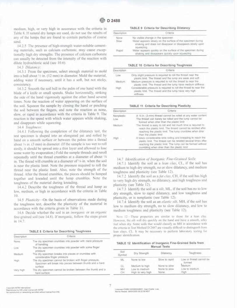
~@, D 2488
mcdaum. high. or ver)' high 111 accoram:e \\ ith 1hc criteria in Tahk li. If natural dry lumps are u"ed. do 1101 use the results or any 0f the lumps 1ha1 are found to contain particles nf coar!,e ,and
14.:?.5 ll1c presence or h1gh-s1reng1h water-soluhle cementing malt'raals. such .a~ c:dcaum c:·arhonatc. may cause ..:,cep-11onall) hii;h <lr> strengths. The pre,encc \ll calcium carbonate c,111 U!>Uilll) he dett:cted from 1he intensity or tht' reaction \\ ith dilute hydrnchlonc acid (st:e 10 .6).
14.3 D1/urann 14.3. 1 From the specimen. sdl."ct enough ma1cnal to mold
into :i ball about 1 • 111. ( 12 111111) 111 diameter \told the ,natenal. adding \\ ,Iler 11' necessary, untal it ha, a -.oft. but not sticky. consistency.
14.3:? <:;mnoth the soi l hall 111 the palm of one hand ,,·ith the blade ot :1 knife or small spatula. Shake hon.t0n1.1lly, ,;triking the ,.,de ol the hand , ag,l)rousl) ag.aan,;t the otlwr hand sewral umes. '\ok tht: reactton or,, ,tier appcarmg. on the surfacc of the ,011 ':iquee7e the sample by closmg the hand or p1111:h111g 1hc ,oil between the fingers, and note the reaction as none. slo,,. or rapid 111 accordance v. 1th the cntena 111 Table 9. The reaction 1s the speed ,,1th \\ hach ,>.mer appears while shaking. and &,appears ,, hile squeezing.
14 4 7i>11gh11l I\'
14.-U follcm mg the compleuon of the dilatam:y test . the test ,pecimen 1s ~hapcd mt<l ,an dongated pat and ml led by hand Lin a smooth ,urface or bet\\ een the palm, 111111 a thread about 1/2 111. (3 mm) 111 diameter. llfthe sample as too wet lO roll ea,il). 11 should be spread 111t1, a th111 hi)er and allowed to lose -;ome water bv evaporation.) fold the sample threads and reroll repeated!) unul the 1hread crumbles at a diameter of about I
M
111. ll1c thread ,,111 crumble at a diameter of I in \\ hen the soil is near the pl:isttc 1111111. Note the pressure reqmred to roll the thread 11ear the plastic l11nat. '\lso. note 1he strength of the thread After the thread crumbles, the piece, should be lumped together and kneaded unul the lump crnmhles Note the toughne,, nl the material durmg kneading.
14.'l.2 Describe the toughness of the thread and lump a.., low, medmm. or high 111 accordance with the critena 111 Table 10.
14.5 Plmll('l/1- 011 the basis of obser\'ations made during the toughness te,t. describe the plasticity of the material in a1:c,,rdam:c "nh the criteria gt\ en in Table 11
14.6 De,·ade ,, h<!ther the soal is an i11t11~1111ic or an m:i:,anic tine-grained soil (see 14.8) lfanorganic. ti:)IIO\\ the ,1cps ga,en Ill J-l ,,
Oescnphon
None
Law
Medium
H,gh
TABLE 8 Criter ia for Describing Toughness
Cnte,,a
The dry specimen c:rumbles into powder with mere pressure of handling
The dry specimen crumbles into powder with some finger pressure
The dry specimen breaks onto p,eces or crumbles wrlh considerable finger pressure
The dry specimen c:annot be broken ..,,th ringer pressure. Spec,men will brea~ into pieces belween lhumb and a hard
surface The dry specimen cannot be broken beaween the lhumb and a
hard surface
COO'f',ght4STM~!ona! ft9!D"Oduc:edO,HS~~1111thA$TM Ni:1 •IOfQOudlGn or Mtwor~ ·t"Q p.,,,n,neo ""'"Tnl'JIJI Jil;enM t,o,n IHS
7
TABLE 9 Criteria for Descr1b1ng D,tatancy
Oescop11on Criteria
None No v1sIble c:hange ,n lhe spec:1me" Slow Water appears slOwly on lhe surfaoe o{ lhe specimen dur,119
shaking and does nol disappear or disappears slowly upor, SQueezlng
Rapid Waler appears qu1t+:ly on lhe surface of lhe specunen during shaking and disappears quickly upon sque1wng
TABLE 10 Criteria for Describing Toughness
Oescnpt,on Cr1tena
low Only slight pressure 1s requ1rea to roll the thread near lhe plaslic: 11mIt The thread and lhe lump are weak and soil
Medoum Medium pressure Is required to roll the thread to near lhe plasuc: limit . The lhreaa and lne lump have medium shffnes.s
H1gt, Considerable pressure 1s requrred 10 roll the ahread lo near lt>e
Nonplasbc low
MediUm
plastic limit The thread end the lump havr, very high stiffness
TABLE 11 Criteria for Describing Plasticity
Cnloria
A 1A-1n 13-mm) lhread cannol be rollea at any water content The thread can barely be rolled and the lump cannot be
formed when dner than tne ptas1,c 1tm11 The lhread 1s easy to roll and no1 much time as requ1rea lo
,each lhe ptastoc l11T11I TM lhread cannot be rerolleo aNer reaching lhe l)last/c 11m1I The lump c:rumbles when dner then the ptastrc l1m1t
II takes considerable lime rolling and kneading to reach IM plashc limit The lhread can be rerolled sever al limes afle1 reaching the plastic 11m,1 The lump can be 1ormed w,lhaut crumbling when dr~r lhan tne p1as11c llm11
1-l. 7 lck1111/1caric111 o/ lnu1~u11ic Fi111:-v/Ullll'd Soil.I 14.7.1 ldenltl') the sotl as a lc<111 elm·. Cl. ,r the s01l ha,;
medium to high dry strength. no or sil"' d1 latanc). i!nd medium toughnc-,, and plnsuc11y l see Table I 2 ).
14.7 ~ lde111tfv the soil as a /al day. Cl I. if the sotl has high w ',Cl') high <ll) strength, no dalatanC). and high toughnes, anJ plasticit) (,el! Tabk 12)
l-17,3 ldenufy the soil as a vilr. 'vlL. if the sotl ha, no 10 low dry -;trcngth. sltm to raptd dilatancy. and hm wughness and plasticit), or as nonplastac (see Table 12).
14.7.4 Identify the soi l as an ela~tic \ill. 'vi i I. 11 the ,oal ha~ low to medium di) strength, no to ,lo\\ dalatancy and hH\ to mcdium toughness and 11lasticll} (see Table I 2J.
~n 1 12 The-so' propcr11c, Jrc ,u111lJr o tl1<is.· for a lean l'IJ)
lkmc,c1, the ,ah \\ill dry <tuickl\ on the hand aud ha,c J srnuoah. ,111.} fr:d \\hen dry Sums· ,011, 1h.i1 \\ould cta,saf} a, 1\111 tn uccordam:c \\llh the cn11:n:1111 k,1 \h:thod I) :!-IS7 an.:, 1,u.,II~ d111i,·11lt 10 d1>tmgu1sh frum l.:an d.,~,. Cl~ It 111;11 he necessary lo r,.:rfor111 t.1ho1 .1t,11}' tc,trng f11r prop.er 1dcnt1tic.1111.111.
TABLE 12 Identification of tnorgan1c Fine-Grained Soils from Manual Tests
Sot! Dry Strenglh 01latancy Symbol
ML None to low s10 .. 10 rapid
CL Medium to htgh None to slaw
MH Law lo medium None to sloY. CH High to very high None
L~JH~~58001 UtePCar1•( L-u H1:JC.,, RNa.• oa.'tl.s 200s oe 22 so ..-or
Toughness
Law or lhread cannot be formed
Medium Low to medium High
~ID 2488
1-l :,. ldt•1111fl( atio11 nl Orxanw F111e-Grai1wd C.,'111/r
1-U<. I ldentll) the soil as an mxt.1111'' rn,/, OI 011. 1r the soil contain, enough orgn111c particles to influence the soil properue~. Organic soils usually have a dark brown to black color and may ha, e :in nrgan1c odor. Often. organic so1b \\I ll change col(lr. for example. black to brov. n. when exposed tu the a,r '>1lme organic soils \\Ill lighten in colllr -.ignificant ly when air dried Organic ,oils nonnally \\'ill not have a high 1oughne~s or plas11c11y. The thread for the toughne'-:. test will he spong)
:\,,n 13 In ,omc .:.iscs. lhr,,ugh pr,11:1I,·, ,md c,,,cru:n~c. 11 111.1) he
ru--1hk lo fur1hcr 1Jcn11fy the <lr!!anic Slllls "' llr!,!11111(.' ,rlt- '" ,,rga111, cl.ivs, ()( ,,r Oil CondJll\llh hcl\\,-cn thc d1l.1t,m9. dt) ,trcngth.
t,,ughoc,., test,. and lal>orulL>I') 1c,1, ,·an he rn.,J,: h> 11!.:nHI} ,,r~a111,· "'•'-
111 ,cn.1111 .Jcpchrls lll snmlar 111atcr1Jls of lrn,mn !!cok•gll origm
l-t9 If the soi l ts csllmatt:d to ha,e 15 to 2'- 0 ·o sand or gr,I\ el. or both. the words "\\ 1th sand" or "wllh gravel" rwh1chewr 1s more predommam) ~hall be added to tht: group name. I tir e,ample· ··Jean cla) wnh sand. CL" or "silt \\llh gra,cl. ~IL" (,cc fig. la and fig. lb) lf1he percentage of sand i, c:qual to the percentage of gravel. use .. ,, 1th ,;and."
14. IO Ir the ,011 1s esllmated to ha\'e 30 °·n l'f more sand cir gra,el, or hoth. the words "sandy" or .. g.ra,elly shall be added to the group name. Add the word "sandy" 1f there appeal"> to he more sand than gra\t:I. '\ud the word "gr..t\·dl:(' 11' there appears 10 be more gravel than sand. For example "sandy Ieai1 clay, CL". "gra,elly fat c la:>, Cl r·. or "sand) silt.\ 1 L" (see ftg. I a and I ig. I b) If the percentage of sand ts t:qual lo the percent ,,f gra\,cl. use "sand) ...
15. Procedure for ldcntil)ing Coar~r-Graincd Soil~ ( ( onta1n,- less than 'i(l O u fines)
15.1 '!he ,otl ts a ~mrd tf the percentage nf gra,el 1, e,tnnated to be more than tht: percentage of sand
15.2 Th..- sll!I 1s a sand ,r the percentage of gra, el i, e,11mated to be equal to or les5 than the percentage of sand.
15.3 The sod Is a clean grc11•e/ or dl'lm .wnd if the percentage of fines Is e,11ma1ed to be 5 °-u or less
15.3. I ldenllf) the sod as n wefl-.1!.raded >!rtll'cl. Cr\.\. or as a ,rdl-gradcd ~<111.t. SW. 1111 ha, a \\Ide range of particle s11e, and substantrnl amounL-, of the tnlermed1ate part icle ,tzes.
15 3.2 ldentlf) lhe soil as a ponrl,· graded gm,·el. GP. or as J po,,rfr 1m1eled l'<Jlld, SP. tf II consists predominantly of one s111: (unifonnh graded). or it has a ....,ide range of sizes ,,.,th some 1111em1ediate si1es obviously 1mssing (gap or skip graded).
15 -l Tht: soil is ellher a gnin-/ with j111e, or a 1'(111(/ 11·11/1 fine., 1f the percentage of fines 1s est11na1cd 10 he 15 n,;, or more.
15-+ I Iden II I) the soil as a d,11·c1· grar<'I. GC. or a c /un•y ,and ')(. 11 the fines arc.; daye\. as detcn11111cd b} the pnicedurcs m Section 14.
15 4 2 ldentif) the soil as a ~tit) gra,'t'I. G:V1. or ..i ~i/1.1 ,and, S\I. 1f the fines are silty as d.:tenmned b~ the procedures 111
~ecllon 1-l 15 5 lf 1he soil , .. estimated w contatn IO "o lines. give the
soil a du,11 identification ustng ,,, o group symbols 1,.5 I The firs! group symbol ,;hall correspond lo a clean
grnwl or sJud (GW. G P, SW. SP) and the second s}mbol shall correspond 10 a gravel or ~and wllh fine~ (GC. G.\I. SC, SM)
1,.s ~ J'hc group name shall corre-.pond to the fir,t group
eoo,,,o,,1 ASHA -Roc,,o(lv(.a(I OT' lf1S .,.,_ ........ -w .t•1 A.SN No•~ or ~1 pa,m,11.tO ,,.,.11tout lanMt from IHS
8
symhol plu~ the words ··wtth day" or "with ,tit'' Ill 111d1ca1e the plasticity charnctenst1cs of the fines for e\amplc ",\ellg.rnded gravel \\ 1th cla)'. GV.-GC" or "poorly graded sand \\ 1th ,11!. SP-S'vf" (see Fig. 2).
I <i.o Ir the ,pec1mc:n 1s predommantly sand or gra, cl but contains an estimated 15 °nor more of the other cnar'>e-gramed constttucnt. the words "with gra, el" or "\\ 1th ,and'' ,hall he added to tht: group mime. For example· "poorl) graded gra\d with sand. GP" or "clayc) sand w11h gra,el. 's(" (see Fig 21
15., 1 f the field sample con tams any c11bhles Clr l1ln1l<lers. llr both, 1he word, "\\ 1t h cobbles" or ··w11h cobble, and boulc.ie~" \hall bt: added to the grnup name. for example "silt) gra,el \\ llh Cllbhk,. (, \1. ..
16. Report
16.1 lbc report shall include the infon11a11011 as to ong1n. and the: Hems 111d1catcd 111 table 13.
1\1, -l L\w11µ/e C '/m·,•1· Gr,11 t!l 11·ith ,\,md and Cohb/t•,. &(
,,1><,u1 50 "'• tine to c,,arsc. subroumkc.l 1,, ,ub:ingul:or gra, d ; ,.1t,ou1 lO •• line tu ,oarsc. ,ul>roun.J~c.l ,and, olmut :W •;, fine," nh 111,:d111rn pl;i-llcll). hr!!h dry ,1n:ng1h, no d1lutan,), mcdnun t,iughncs-. •.,cal.. 1c:11:II,111 "Hh IIC'I: ongm,tl ticld sample had ab<•ut 5 'lo lh) volume) ,uhruun<lc.J
cobhlt!,, m.1>.1mum duncnsron 150 mm ln-?ta,·c Condrllon, l'um. homogcncnu,, Jr)' bru11n
Gcolug11: lt11erprc1,111on l\llu, ,al fan !\1111 15 Othcr c,umplc~ ,,r ,011 d,-,,,npI1ons .. md 1dcn11fic.111on arc
given Ill , \ppcndtx '\ I ,111c.l \ppencJ1, x~. ~ .. n H, If dc,1r.:d. 1hc pcrccntag.:, ofgia,ct. ,.1n,I nnd line, m.1~ tie
s1,11<:c.l m lcmt~ mt.hcatiog ,, rnng<: .>f pcrn11tagc;., J, folio"' f,un• Pan11.:lc:. ,m: prt.-scnl hu1 c,11111atL-d tu b,· le" thttn 'i O "
/·("11 :- 10 10 • " lm!t> 1, it, ~5 °1,
Snme 1() h,, ..t 5 1'·0
\fo<IIV- .50 It> 1110 •:,,
TABLE 13 Checklist for Description of Soils
1. Groop <1ame 2 Group symbol 3, Peroenl or cobbles or boulders. or boln (by volume) 4 . Percenl or gravel. sand. or fines, or all lhree (by dry we,gnt} 5. Particie-StZe range.
Gravet~fine. coarse Sand-fine, med,um. coarse
6. Particle angulanty angular, subangular, subrounded, rounded 7 P3t1ide shape (If appropnale) ffal, eiongat<!d, nat ana elongaled 8 Ma,omum panrcle size or dImensIon 9 Hardness of coarse sand and larger pan,ctes
10 P1a&1,c1ly of frnes· nonplashc. low medium, h,gh 11 Dry st1en9lh none. low, medium. hrgh, very n,gh 12. Dilatancy none slow rapid 13. Toogrmess. tow. medium, high 14 Color (In moist condItron1 15 Odor 1mentIon only ,r organoc or unusual) 16 Mo,sture · dry. moist, wet 17 React«>n w,th HCI none weak, slrong For ,n1acr samples 18 Consis1ency (fine.grained sorts only) very sort. sofl firm. hard, very ha1d 19 S1ruc1ure. slrat,fied. IamIneted, fissured, sfickens,ded lensed. homo-
ger>eous 20 Cementat,on: weak, moderale. slrong 21 Local name 22. Geologic interpretalton 23 AddIl<0nal comments: presence of roors or rool holes presence of m,ca
gypsum. elc., surface coa~ngs on coarse.grained pano<:les. caving or sloughing or auger hole or trench s,des, difficully rn augering or e~ca,along. etc
~-CH2M H.JJS\1604S8001 v..-=carw, L-Nol lo< R..,. Otl/04'2005 08 21 59 MOT
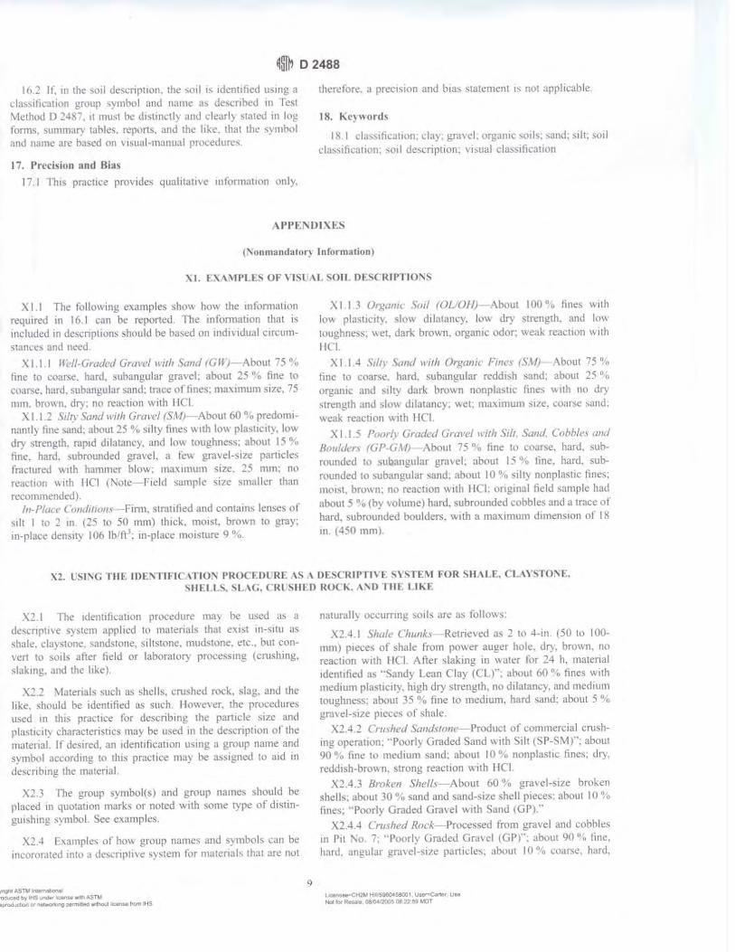
~ffil, D 2488
I h 2 If. 111 the \c1il tkscnp11011, the -.oil 1s 1den11fied using a d:hsification gr\lup ,ymbol and n,1me as de,crihed in fest \i!t.:thod D 24X7, ll must b~ d1..,t111c.:tly ,md clc,trl) ,ta1ed in 1<,g forms. summ,1ry tat>les, reporL~. and th..: like. that lht• ,ymhol and name are b;1sed on , rsual-manual proc.:edun:,.
I 7. Precision and Bias
17 I fh1s practice pro, ides qualitative 111fom1ation only.
1her<!lore, a prec1~ion and bias ,wtemenl 1, not applicable
18. ~ e~,,ord~
l}i. l d,i...s1ticu11011. cl:t), gravel. t,rganrt· soils; ,and: silt: soil das,ifkation: ,011 de,i.:npt1on: , isual cla~s1tication
(:\onm11nch11tir) Information)
'-1. I:,'-\ \!PU.~ OF VISL, \L <;OJL DE~CRIPT101'~
\ I I n,e following examples sho,, ho" the 111fommtton re4u1reu m 16 I can be reponed n,e infr1m1a1ion that i~ included in dcscnption\ ,hould be ha:,,c::d on indi\ldual circum,1.1111.:6 and need
XI.I.I lli•l/-6mded Ciru1•e/ ll'ii/1 S1111d (GWJ About 7 5 "11
fine to coarse. hard. subangular gra,·el. about 25 "n hne lo Ct),tr:,,c, hard. subangular sand: 1race of tines: mn"l.imum si7e, 75 111111. bro\, 11. dry. no reaction w11h I ICI
'\ I I 2 Si/tr Sand ll'1th (iml'c/ (SM1 .\bout 60 °,o predominant I) line s,111d. about 25 "·o silly fines '"'th lo\\ pl:i-;11c1t:, Inv. dry ,trength. rnp1d dilatancy. and Im, toughness: ahout I "i '\, hne. hard. ,ubrounded gravel. a It:,, grawl-,1zc parucks fractured \\llh hammc1 blow: maximum ~1ze. 25 mm. no rcact1on v. 11h l lCI (1'otc held sample s17e smaller than rccommcndecl l
/11-P/acc Com/1/iom Firm. slraulied and contains lenses ol ,ilt I tn 2 m (25 to 50 mm) thick. moist, brown to gray; 111-place de1i-1l) I (Jo th Ii 1: 111-place mo1smre 9 °,u.
>. I I .. l 01)!,,llllt Soil (Ol Of I) \bt)Ut I 00 "'o tines w11h lov., plast1uty. sk)\\ ddutancy. lo"" dry strength. and ltm loughne,s. ,,et. dark brov.,11. organic odor: weak reaction \\Ith IICI.
XI I 4 s,ltr !>,md \l'//h Orgcmh· Finl\ (\.HJ ,\bout 15 '!o fine L,1 coaN!. hard. ,ubangular reddish sand; abou1 25 11
:,
organic and ,1lty dark brown nonplasttc lines \\ uh no dry stn:ngth and slov .. drlatancy. v..el: ma"l.imum s11e . .:llarsc ,and; weak reactrnn v. ith I !Cl
X 1.1.5 Poor(\' Ciradcd C,rcll'l'I 11·111, ,ih. Sumi, Cnhhle1 a11d flr,u/clcr., rGl'•Ci \IJ !\bou1 75 ° • lint: to i:our~e. hard. suhrounded to subangular gravel. about 15 "·i, line. hard. suhmunded tu subnngular sand; about IO 0
·,. ,illy nonplas11c fines. moist, brown: no reai:t1on w11h Ill l: ongmal field sample had about 5 "·u (by volume) hard. subrounded cobbks and a trace of hard. subrounded boulders. w11h a maximum dimension of 18 m (• 50 mml
\ 1 L s1, c HIE IDf~TIFIC \1"10:\ PRO( EDl Rf \S \ OESCRIPTl\'E S\ "iTE\.I FOR \H,\LE. Cl \ \''iTO:\E. ',HEU\. ~L.\C,. CRL \IILD HOC."· \ ,o TIil II Kt
'G I The 1de1111fo:a11on procedure ma~ he useJ as a dcscnpt1, e system appl 1ed to matc::rials that e"1.1st 111-,11u as shale. claystone. sandstone. siltsmne. mudstone. etc .• but con\'ert 10 soil, after field or laborntor) proccss111g (cnish1ng. slaking. and the ltke).
X2.2 \ ,1atenals suc.h as shells. cnished rock. slag. and 1he like. should be 1dent1fied as such I ll1we,er, the procedures u~ed m this practice for describing the particlt' sue and plast11.:.1ly i.:haracteris11cs ma; be used 111 the description or the matenal. If c.les1red. an 1den1ificat1on usmg a group name and symbol accordmg to 1h1s pracuce ma} 11c assigned to aid Ill
desn1brng. the material
,2.3 fhe group symbol(s) and group names should be placed 111 quolatJon marks or nntcd with some type of d1stingui'hing ')1nbol See examples.
X2 4 F.,amplcs "r how group name-; and symbol,; can he 111coror.ited inlu a descnp11ve system for materials that are not
l',gt,I AS Tli~ l'llefMl,(IN 'Qd!IC,IQ tty IHS""°9'"~ .-,~A.STU turOGIJdlOl'I o, f'l6'W0'\"1G :,etmlleO w-thO.lt iic:arUe fro.,, IHS
g
na1urall) occurring soil, an: as follow~·
\'.2.-U Shale Chunks Retne, ed as 2 to 4-in ( SU to I 00-mm) pieces of shale from power auger hole. di"). brown. no reac.l1on wllh I Kl Afier slakrng 111 \\ater for 24 h. ma1enal 1demilied us .. Sand) Lean Clay (CL)": ahou1 60 "., fines wnh medium plasucity. high dry strength. no dilatam.y. anc.l mcd1ut11 toughness. ,ibout 35 n.11 fine to me<.hum. hard sand: about S % gra, d-s1ze pieces of shule.
X2.4 .2 Cni,h11J S1111d\flm1 Product of commercial cru~h-mg operation. "Poorly Graded Snnd \\ 1th ~11t (SP-S\-1 )": about 90 °,., fine to medmm sand. about 10 "11 nonplas11c fines. di) . reddish-bro\\ n. ~trong reacuon \\ 11h I !Cl
,'-2.4 3 Broken Shelfs About '10 °n gra,el-~12e broken shells, about 30 u." sand anu sand-size shell pieces: abou1 IO 0o
fines ... Poorly Graded Gnnel w11h Sand 1GP)."' >,,.2 • 4 CnHhed Rock Processed from gra,·el and cobblc::s
in P1l "-o. 7: ··Poorly Gradec.l GrJvel (GP(: about 90 "11 tine. hard. angular gra\'el-s11c part1de:,,; ahout IO 0 1ci coarse, hard,
L :.-"1..-.<t® Hl.~MGIS80C\, Usar-Canar LIU Noe f<Jf R..- C$(M.t20Q5 08 '22. 59 MOT
~I D 2488
angul.1r :-.and-'ize pmt1cles: JI"). tan. no re;ict1on \\ ith I It I
XJ. \LGGESTF:D PROCtDLRE FOR l ~l'\C \ BOR0FRLI'\£. \\ \1801. FOR SOIi ~\\I r11 I\\ 0 1'0\~IBLE IOI\.-.; 111-1(. \ 1'10'\\.
XJ. I Stnce this f)rnct1ce b ha~ed on c,t11na1cs or particle ,ize d1•an1'u11un and plasllcll) charactensuc,, 11 may he <l1tlicuh to clearly 1dcn11f) the soil a~ 1'elongmg to one category To im.h.:a1e that the $Oil may fa ll into one of t\\0 possible ha,ic groups. a borderline symbol may he w,ed wnh the two ~ymbols ~erarateJ h) a slash. For exmnple ~C Cl or CL Cl I
X3 I.I A borderline symbol ma) be used ,.,,hen the percentage of tines 1s estimated to be bet:wt'.cn 45 and 5::; ~o. One symbol should be lor a coarse-grained ,oil \\ 1th Imes and the other for a tine-gnuned s1)1l for e,ample G\I "-1L or CL \C
X3.1.2 :\ horderline S) mbol may he used \\ hen the percent.ige l)f' ,:ind and the percentage nf gr;l\ el are e,t11nated to be ahnut the -.amc for example: GP <,P. c;;c GC. G\11 SM It '" practically impossible Ill have a ,oil that would have a b,mlerllnc :-.:mbol ofGW S\.\..
X3 1.3 A borderline symhol ma) be used "hen the soil could bc ct1her well graded or poorly graded for example: GW uP. <.;\\ '::iP
X3 I 4 A borderline symbol may be useJ '-"hen the soil could either be a slit or a cla:,. For example· CL \/IL. C l! '\111, <;(' S~I
'\3.1 5 ,\ borderline S) mbol may be m,ed when a finegramcd soil hus propcrt1es that indicate that ll is at the boundal) between a soil or lo~ compress1bl111y and a soil or high compressib1hty. ~or example· CL Cl I. \111 'v1L
:"d.2 The order of 1he borderline symbols ,huuld reflect ,;111111:imy 10 surrounding or ad_1acent so1b, I-or example· -;011-. 111 a borro" urea ha\e been 1den11fied as Cl I. One sample 1,
con,idered to have a borderline symbol of <. L and CII ro ,ho\, snmlarity. the borderline symbul shoulJ be Cl I CL
XJJ The group name for a soil w11h a borderline -.ymb1,I should be the gmup name for the first ~} mb11I, except tor
CL Cl I lean to fol clay
:-.1L CL claye;- sill
CL \.11 silly cla;-
.'0.4 fhe use of a borderline ,ymhol :--h11Uld nlll be usi:d indiscriminately L\.el) effort shall be made 10 first place thc ,oil into a smgle group
x~. SlGGESTED PROCEDLRES FOR ESTIM \Tl'\G rm: PCRCE~ l'\GE OF GR\\ F.I., s \ '\D. ,\;\'D FINES I'\ \ <iOIL S \\lPLE
X4 I Jar \felhml The relat1\·e percentagc of coarse- and fine-grained matenol may be es11111ated by thomughlv ,hakmg .1 ml\tun: of soil ,md w,ller 111 a 1e,t lllhc or jar. and then alllm 111g the nm.lure to seule The coarse pa111ch:s \\ ill foll to the bottom and -,uccessl\cly liner p:1r11cle, \\ 111 be deposned wnh 111cn:as111g lime; the san<l s17e, will foll out of suspension 111 20 to 30 " l'he rela11ve proportions can be csumate<l from the relat1\e \'Olu111e of each size 'iepar-Jle. This method should be correlated 10 particle-size laborat:ol) de1enrnnat1ons
\-L! I i.mal \1t>flmd \llentally \ 1suah2c the gravel size particles placed 111 a sack (or other container) or sacks Then. do the s:11ne ,, 1th the san<l size part11Jes ,.md the lines. [hen. mcntall'.1- cnmpare the number of sack, to e~11ma1c the percentage ol plus 1\o. 4 sieve ~,Le and minus l\o. 4 sieve ~11e present.
The pen:entages of sand and line, 111 tl1e rn1nu:- s1e\"c ,,1 ✓c l\o 4 mutenal can thcn be estimated from the \\"1sh test ( \'.4 3 l
X-t) llash frst (/or relatin• f1t't'r:c11h1)l.c~ "I .mll(/ c1ml ji11e~J ~clcct and mmsten enough minus :--o. 4 '1c,·e ,11c ma1enal 10 fonn a l-111 (25-mm) cube of soil . Cut tl1e cube 111
half, ,e1 one-hall w the side. and pk11.:e lhe 01her half 111 a small dish. \\'ash and decant the tines out of the matcn.11 111 the d1,h unul the wash water 1,; clear and then compare the two ,ample, and es11mate the percentage of sand and fines. Remember that the percentage is ba~cd on wetghl. nol volume I lowe,er .. tht' \·olume compa11Son ~ 111 pro\lde a reasonable 111chca11on ol gr.1111 s11e percentage,.
X-l 3 I \\h1lc washing. it may be necc,sary to hreak <lo\\11 lumps of fines \\ ith the finger to get the correct percentages.
'XS. \88Rf\l .\TED \OIL Cl \SSH IC \TIO'\ SYMBOLS
'\5.1 In some cases. because of lack of space, an abbre,1-aced sjstem ma) be useful to mdicnte the soil classification ~) mbol and nmne F,amplcs nf such ca,es would be graphical lugs. d.1t;1hase,. tables. etc
\5 2 This ahbre\lated sy,tcm is not a substitute for the full name and descnpt1\ e 1nlonnation hut can be used 111 ~upple-
Copyr,,ghl A,$1l,A ,~1 RIPrOdotedb'r fHS wnG8'k:enN wt.tlASlM Nil l'90f0C31.1Ct1on Ot~'1'1Q ptnnlllOd ,...tl'\OI.Jt li<"en• from lHS
10
menlary presentations when the complete description 1s referenced
X.5 .3 The abbreviated sys1em should consist of the soil class1ficat1on symbol hasi:<l on 1lw, 'itandard with appropriate lower case lt11e1 prcfhes and sufll,es as:
L~,.. ~91104~1 u...,ean .. L ..
""'"" R_,. DMM'21l05 oa 22 59 ... or
Sun,x.
s sandy s w,th sand g gravelly g with gravel
C wdh cobbles b ,,,in boulders
~I D 2488
Group Symbol and Full Name
CL Sand~ lean clay SP-SM. Poorly graded sand w,lh s,11 and gravel GP, poorly graded gravel with sand, cobbles, and bOulders
Tht.> sc,tl du,~itication ~vmh,,I 1, to he em:loscd in parcnthi:s1-.. Some c,ample~ \\\ll!ld bc:
ML gravelly s1lt w,th sand and cobbles
~l,J\1\lAR, or CHA:'\GL:~
Abbrevoated
s(CL) (SP-SM)g (GP)scb
g(ML)sc:
In accordance\\ 1th Commiuce DIX policy. this section identifies the loca11011 nf changes to thb stumlurd ~1111:c
the last edition ( I 993· 1) that may impact the use ol this standard.
( I l Adi.led Practice D 3740 Ill 'iecttnn 2. (2) ,\ddcd Note 5 under 5.7 and rcnumbt'red ,uhscqucnt note~
Cc>c:rv•11'1l"5Tl,(~,
Tne Amencan Soc,ety for Tesr,n9 and Marena/s takes no pos,r,on respecI,ng I/le va/ld1(y of a11y parent nghts asserled III ronnP.r.l,on 11nl/1 any 11em rne11t,on,;d ,n th,s standard IJsws of rh,s srandard a,,. e}(pre»ti,· iHl~•sed mar derermmat,011 of tne ~al,d,ty al any such patent nghls. ancl tne r,sk of tnfnngement of such rights are entire!} lhett ow11 respans,1>,1,ty
This stanclarcl ,s sub1eel to rev,s,on at anv time t>y /ht! ,e_~pons/t,le technica, committee and must be rev,ewed eve,y hve years and ,t nor revised either reapproved or w,th<frawn. Your comments are invited either for revision of this stanclard or for adcl,tional standards ancl sho11/d oe aclclressecl ro ASTM Headquarters Your comments w,11 rece,-"11 careful conslc/erahon at a meer,ng of the responsible recnmcal committee. wh,ch you may atrencl. If you feel that your oommerits have nor receIvecl a fa,r hearing )'OU snoulcl make your v,ews known to tile ASTM Committee on StanclarrJs, at tne address shown b<-01v
Th,s stanclard rs OOP)r,gmed oyASTM. 100 Barr Harbor Dr,ve. PO Bo>r ClOO West Conshohocken PA 19428-2959. United Stares tnc/MdtJal repnnrs tsmgIe or mult•ple cop,es) of this standarcl ma_v /Je 001a,ned by oontac11ng ASTM at the above address or at 610-832-9585 (phone/. 610-832-9555 (fax/. or servrce@astm org je-mad), or through the ASTM ><eos1te (wwwastm or9J
II R~ br- aHS ~ b'le...,.,t., ASW ~•12M H,1.'598045.8001 UMf'>1Car\ef U..
f'l6oC WRnale OMM1?005 08.22 S9 MOT No,~ 0t ,_~ Clll'ffi'taG W'\MYt Lc:enp fTQffl N1S
A Designation: D 1586 - 08 . ..... 7
INTVINATIOHAL
Standard Test Method for Standard Penetration Test (SPT) and Split-Barrel Sampling of Soils1
rh1, ,t,nutuc.11, ,,,u~c.J u11dtr 1hc 11>-CLI Jc:-is)!ll,ttltill D 1~,-;t,_ th~ numhc:r 11n111cJ1 . .t1dy tt,Jl,1\\111~ the J1.~,11n~1wn Ul\JU ...... Jh~\ tht JC..U ul ,1nti! int1I ,1<l11ptH,n ,,r. 111 the ~"' c,1 re-. L~l"-'n. 1hc )C'at 01 la.,t te\l,mf\. 1\ numh.:r tn ,,..1rcmhc,c" mJ, .. -..1c, th< ,c.1r uf la.,, n:Jpr,to\ itl \ ,u~•~·npt C'Jhtlon i() 10<.lh.:at~ .u1 e'-l1letn.'1 ch;.m_ec ""'"":~ the la.,1 rc\'l\itm 01 reappt,n,tl
Jbn H1m,l,m/ lt,o b~1'n ,,,,prmrd (,,, ,nr /,, ,,i:,•m 1e·s ,,f tl,r f>~f"-l'lt,,,·rtr o( /),ft,t\t'
I. Scope* I I ·nH, te,t method de,cn!)e, the procedure. generall}'
kno~n a, Lhc Standard Penetr..111nn Te,t (SPT). for dnvmg a ,plit ham.:I ,ampler to obtain a repre,entati, e ui,turhed ,nil "11npk for 1de111ihca11nn purpo,e .... ~ind me,1-u~ the rc,1,tam.:e ,it thi: ,oil w pene1ra1mn of 1he ,ampler Am,ther methou (Te,1 \lcthod D l';"iO) lO Jme ., ,plit-harrel ,.1mplcr to nht:11n a repre,en1a11ve ,ml ,ample "a,:ulable hut the hammer energ) 1, not ,1andardil'c<l
I 2 Practice I>< 111 , !!_l\e, .1 guiuc to detc::rm111111l( tht: nurmahti:d penetrnt1un re,1~tance of -...rnd, for energy a~1ustment, of '\-value 10 a corn,tant energy le,el for e, .. 1lua1111g llquefac-11011 poten11al.
1.J Te,t re,u lt, ,tntl 1de1111hcatmn 111format1on are u,cd to
e,11111ate ,u!)surfm:e conditmn, tor foundation dc,1gn. I ~ Penetwtinn rc,Nance te,11ng 1s t}p1rnlly pcrlormed ,II
5-li><>t depth rnten al, or" hen a ,1gnilicant ch:mge of materi.il, 1, oh,eneu uunng drilhng. unle,; ,1the1w1,e ,~c1hed
1.5 Tim tc,t method ,, limited w u,e Ill nonltlhdted ,oil!and ,011, who!-e maximum pamck ,i,e " approximately le,;, than one-h.tlf ol the ,ampler diameter.
1.6 Th1, test method 111\'0hes use of rotary dnl hng equip· mcnt tGu1de I) ~"s 1, Practu.:e 11 < I: ). Other drilling and ,amphng procedurl'' ( Guiue I 1 .• Guide I • t I ,, ) are arntlahle ,Hid ma} he mme appropriate Con,1dcrat10ns for hand Jn, mg or , hallow , amplmg without horehnlc, are not ,tdJrc"cd 5uh,urlace 111ve,11g:1111111, ,hould he recnrued 111 ac-1:mdam:e ~nh Practice I 5amplt:, ,hould he prc,eneJ an<l tra1hpo11cc.J 111 accon.larn:e \\ llh Pracuce I I u,mg umup 8. S\11I \ample, ,hould be 1denutied b} gwup name and ,~ mbol 111 accordance with PraL11ce I' '
1.7 i\11 oh,ened anu cakulated \aim:, ,hall conlon1110 the gu1delinl'., for ,1gn1hcan1 dig11, and mundmg e,tahhshed 111
Practice D n 6. unle,~ ,upen.eued hy 1h1, te<.t method. 1.8 The , alue, ,tated 111 inch-pound Ulllh are to he regarded
a, ,t:rndard. e\cept a, noted hclo~. The \'alue, g1\en 111
' ltw~ mcthuJ 1, unJ~r the.• 1uri~J1,·th1n ol 1\:)l\1 lonunH14:L' DIX llll Soil .inJ R,..:k .,nJ "1he Juc.i r('f!\'""h1III} ,,( Sul..:ummma, lllX.Ul ,,11 Sampling JJW RcunrJ F1dJ Tc,unr fr>r \<>ii t::,·alu.tti,,n,
CuITTnl eJ11ie1n appr,1wJ fd1 I. 10011 PuhlishcJ ."1.,n;h ~OOS Ongmall)· appn»(J on l<l~X. b,t pr.•,wu, eJ,111111 •rrw•eJ m 111'1'I ." D l~!\ti - 'l9
parenthe,e, are mathemaucal con\'er:-1011, to SI umt,. "htch are provided for 1nlonnat10n onl) and are 1101 c1m,1dcred standard.
I .S. I The gravit.11ional ,y~tcm of mch-pounu unih 1, u,cd \\ h.:n Jealing w11h mch-pound unm,. In th1, ,y,tem. the pound ( Jhl) repre,enh a unll nl force ( weight 1. "hlle the umt for ma" i, ,Jug,
1.9 Penetratmn re,1,tance me;t,uremcnh olten will 111v11he ,afet) planning . .idm1111,1ration .• ind documcnui11on Thi, tl.'st method Joe, not purport 10 addrc,, all a,pech ot C\plor.1111,n anJ ,1te ,atety. Th11 Ha11cfard clm•l 1101 purport 10 addr1·11 a/1,,j !ht· wfu, n1111·1•rm. if a111. t1.1wcia1ecl 11'ith tis IIH" // ,, tire rmp{}IHib,/1/y of 1h1• uwr <>} 1ltis ,umdard 10 1•11t1h/tsl, appm• prwtc w/dY and health pral'lic·c, 1111d dercrminc 1/,1· 11pplin1• b1h11· ofn•gufaron l11111rattc•m priO/ to un• Pe1fonnanct: ot the test uwally 11wolve, the of a drill ng: therefore. ,.itet~ reqmremenh as outlined Ill applicahle ,,1fet) ,tandanh (tor e\ample. OSHA regulauorP,.1 '\DA Dnlling Safet) Guide.' drilling ,afet) manual,. and 01her ,tpphc:ihle ,tat<! and lucal regulations) mu,t he oh,ervcd
2. Referenced Ducumenll> 2 I ,\ STM Standardf: ~ I> Tem1inology Relating tn S01I. Rock. anu Co111a111cd
Flu1th ' , ~e,t Method, fur 'ipe...:ifit. C...ravny of Srnl Snhd~ h~
\J\ .1ter P) cnumeter Prac11cc for Thin-Walled f'uh1. Samplmg 11I S1,1!
for Gl.'otcch111cal Purpo,e, 0:? Tt:,l \1cthods lor Lahoratnl) Detern1111at1on Ill \\,1
ter (!\101,tureJ Content of S011 and Rock by Ma~-. I) Pr:1ct1cc for Cla,,1fica11on nf Smb for rngrnecrinµ
Purpo,es (Umhed Soll Cla,,1fica11on System) I) - Practice for Descnpllun and lden11fication of Suil,
' \, u1l.1hk f111m lkcupJllnnJI SulCI) Jnd HC"Jlth ,\dm1m,1r;111nn !Cl" I\, :tMl Cnu-.muit,,11 4\~~ .• ~\\ \\'a"illihftiJn. rx.• iO:!IU. hup://wv.,\ o,ha g<w
,\1d1)Jhk lrom ~1e ~.ittunal Dnlhn~ '"'"1.111110 1'\J I Center Kd Su11, •• Hruri<'• 1cl... OH .w~ t 2. h11p•/1v, wv. nd.i-lu c111n
' fo1 rckrenl'cJ AS1 \I ,t;uuJ.,rtl<. '"II the .\ST\1 \\Ch\llc. "'"" hlnt,•rlJ. "' \.4'nlJ~·· \~l\1 CU'-l(llll(f Sc:n 11,'C' Jt ~rncclt2,tm.ur~ r,,, •t,rmu,/ /fo,,J.. "' ..-\ 'i/ \I ,;,4111r/, rrl\ \·olumc: utlormallt'" , rcftr tu the ,tan<larJ·, Dt-.:umcm Summ.,') pa,ge ''" th.- ,s·1 \I .-c1',11c.
· \ ~ununar) of Change, scnion uppc:i,-.. al the end of lh h ~landard.
Copyngrll CASTM lnt<Mnatl0O..i'. 100 Hart Ma·t>O D -,1: PO Bo• roo West Consn~ .. A t 4~a•~r, l., 1teo 518196
~,tq:Lf 45,TM i~
P•er,,>ded t,,y lhS &,ndl,r ac..... .-,lh AS™ lc:et\-..-HeffiOon. A.'!19b04S8008. UNt"'"Cartat L,.. ~ ~ttOn o, n«~,,g ~1"41 'N'U\ol.l,l IIC-tf\Sa l,om IHS Hol foo" ~ Nr11,'200108 08 12 MOT
dlffi.i. 0 1586 - 08 ~
t \'i,ual-:-.t.rnual Procedure)
n ,~ Pr.u.:ucc- 11,r Thick Wall. Ring-L.111ed. Split 13arrel.
Dm e Sampling 111 S1,t1,
D ~- Pr.iwce tt,, \1rn,mum Rc4ui~mem, for Agcnc,e,
Engaged 111 the ·1c,1111g an<l/01 l11,1">Ccti1111 ol Sorl and R01:k
,h U,ed 111 En_!!rneenng De,1g11 ,1nd C11n,1nKtllln
_ I Pracu~·e,-. tor Pre,ervrng and Tran,porting S111I
S.11nplc, re,t ~1cth1,<l for Energy \1ca,urement 1111 I)~ narnic
Pene1rn111e1e1,
I> 5-1, liur<le for f-tcld 1.oggrng nt Suh,urta .. ·c l!-,plora-
111,n, 111 Soll ,tnd Rock
I> 'i7X liurde for U,e of Di11:c1 R,11:.ir: Drilling wnh
\\',11er-Ba,e<l Drilling r-tu,d lllr Geoem 1ronmen1al 1~,plu-
1at1on and thl' ln,1alla11011 ol Suh,urf.u.;e \\'ater Quality
,\lomtonng De\ 1cc,
D t Pr,,cti .. e for L,rng S1gmlican1 Digih in Gco1ech111-
c,1I D,,1,1
DI Pracuce tor De1e1rnining the '\ormali,ed Pene1ra-
1i1,n Re,i,tance of Sand, tor E\'alua11,1n of I.iqud":c1t·1i1111
Pntentic1I I) t>I 'i I Pracuce (or U,111g Hnllm~ -Stem Auger, 1111 Geo•
technical E,pl11rc111on ,ind Sotl S,1111plrng
IJ Cil(,0 Guide tor Sclecuon 11t Sotl and Ro .. k Samplrng
De,,c:e, U,ed Wnh Dnll Rig, lnr Emmmmental ln,e,11-
g,ttion,
I) 6:!86 Guide for Selection of Drilling Method, for En\'i•
ronmental S11e Characterizatmn
I) {,I) f l lt•,1 \1ethod, for Part1ck-S11e Di,uibution (Grada-
111,n 1 01 Snrl, l',rnp '-;1ne \nil,,,
. t lerminoloio
, . 1 f)cJ111111011.1 Detim1111n, ot term, mclude<l 111 lenrnnol
og) I) 65• ,pccrtil. to thl' practice are:
J .1.1 catllt'ad. 11-the rotJtrng drum nr win<lla" 111 the
rupe-cathead lift ,y,tem around ,, h1ch the operator ,, rap, a
mpe 10 lifl and drop the hammer by ,ucce-.,1, elv t1ghte111ng and
11,n,emng. the rope turri... around the dntm.
J . I.'.! drill md.\. 11-rmh u,ed to trnn,mit dov. nv.,ird force
and lllrque 111 the dnll hu while drilling a horehnlc
3. 1.3 N-1·al11l'. 11 the hlPw c,1unt repre,cmaunn nr the
pene1rauon re,i,1ance ol the ,oil. The ,\-,.llue. reported 111
hlov., per 10111, equ,,b the wm of the num~r of hlow, (NI
required 10 dnve the ,ampler over the depth intenul of 6 10 18
in. I 150 to -t50 mm) hee" \)
3.1 A S11111r/11rd Pml'trmicm fr.II ( SPTJ. 11-a test pnx:e,, IO
the bottom of the borehole \\ here a -.pht-harrel <;ampler ha, mg
;111 in,1<le d1ame1er nf ct1hc1 1- 1/:?-in. (38.1 rnml 01 I J/81n
( q _1;1111m1 (',el.' ) i, dnn:n a \!1, en d1,1.mce ol 1.0 ft (0.30
ml alter ,1 ,eating 1111enal ol 0.5 It cO.l'i 1111 u,rng a hamme1
wc1gh111g .1ppro,1111;1tel) 1-tO lht !62'-'\I l.1lling JO.::. 1.0 in.
I 0. 7h Ill - O.OJO Ill l for ead1 hammer hkl\\
3 2 Dcj1111tim11 id frm1.1 .S1u•c(fic 111 Tim 5twulorcl:
J:! I am·if. 11-that port11111 of the dri\e ,,eight J,,emhl}
which the hammer ,tnke, and through "h1ch the h.1mmer
energy ra"e' into the dri II rod,.
ccr,rd1tASNlfQrTWt,1cnaf ~ 1tr tHS ~, lit.-.. W4h ASTM :i,•~o,~~.-o..tllltanletfOffllttS
3.'.!.2 Jr11·t• 11·dr:ht a\11•11,/1/y. 11-an a,,embl) that con,1,i...
of the hammer. ,u1vil. h.tmmer fall guide ,y,tem. drill rn<l
,lltad1ment ') ,tl'lll, and JO) hammer drop sy,tem hnr-.ting
a11achmcm,. '\,'.!.3 hm1111wr. 11-that purtwn l,I the drl\e-\\c1gh1 ""'embl)
c11m,i ... ting ot the l•W = 2 lhf (6'.!3 = 9 '\ 11mpact weight whu:h
i, ,ucce ...... i, ely hlte<l .111<l dropped to prm 1de the.: cnerl!) 1h,11
accompli,he.., the ,amphng ,md penelratinn.
3.:!A ltamm,·r dmp 1ntt•111. 11-tha1 portion ol thl! <l1ne
~eight a"cmhl) by which the operntor m automatic ,y,1c111
:K·comph,hc, the lifting and dn,pprng ol the hammer ro
prn<lu 'l · he tilo\\ 3 .2 " l111111ma Jitff ~,,,,1,. 11-1ha1 r,trt ol lhe dri\l'·\I etl,!hl
a"emhl) u,ed 10 guide the 1,111 11t the hammer.
3.2.6 1111111h,•r oj ropt 111,111 . 11-the tot.ii comact anfle
lictv.een the rope and the c.tthe.i<l at lht: hegum111g 11f the
lipcrator·-. rope ,lad.c11111g 10 drc1p the hammer. d1v1ded h: 360' (sec I 1g I 1.
3.2.7 ,\1111111/i,r~ md1. 11-rod, that connect the drive-weight
a"emhly Ill the ,ampler. Drill rod, .m~ often l1'Cd for thi,
purp<N~.
-t 'iignificance mid U,c
-t . 1 TI1i, te,t method pro, ide, a J,...turbed "" I ,ample lor
mni,ture nmtent determination. lot identtfic.:allon .111d da ..... 111-
calitin ( Pr:ic.:tice, ·,7 and I) 2J!!8) purp0,cs. and tor l..1bo
ra1ory te,t, appmpnme tor ,oil ohtained tmm .1 ,.1111phn that
"ill produce large ,hear ,trJtn di,1urbar1t·e in the -.1111ple ,ud1
u, Te,t ~lcthnd, " •· . l 2216. :md D fi9 I Sor I <lepo,ib
cnnt,linmg grn\cr.... cohtile,. ot boulder, typtcally re,ult 111
Jll'nc1rati1,n retu,al .inti damage tl' the equipment
-t.2 Thb 1c,1 method pr()\ 1Je, .1 d1,turheJ ,011 ,ample tor
mo1'ture Cllntent deterrmnation and l.1hnrator;, ide1111hl'.tllon .
Sample qualrty 1, gencr.1lly not ,uitabk for ad, anced l,1hnra-
11,r} te,1ing tor engineering prop.:nte,. rhe pr1>ee" ol <lm rng
the ,.1111plcr v. 111 .. au,e d1,turhance of the ,otf .md change thl'
engrncering propertie,. U,e of the th111 wall tuhe ,.1111pler
(Pr.,cu.:e I) , ., , I may rewh in le" d1,1urhance in ,oil ""''· Cnring technique, may re!>ult in les, d1,turhance than <;P l
,amphng ll>r harder'°'''· but it 1, nm ,1lwa}, the ca,e that 1,
,ome cemented ,nib ma.), heeome loo,ened hy water ,Kllllll
tluring coring: ,ee Pra,trce I) 6 I 51 •• md Ciui<lc IH1I (
4,3 ll11, 1c,t method" u,ed e,tcn,J\l'I} in a gn:at variet} 1,1
geoteehnrc:11 e'Cplora110n proJecr,. ~tan) local corrclati1i11, anJ
\\ rdt!I: publl\he<l correl,1t1011, v. h1ch relate hluw cou111. or
N-ndue. and the cngtneenng behannr of e,inhworb and
foundation, are ava1 I able. Fur c, aluatrng the liquclJl 11<111
potential of \and, <lunng an earthquake event. the \ , alue
,lllluld he nnnnali,ed to a ,1andar<l o\'erburden ,tre" le, el.
Practice I) 6066 prO\ ,de, methods 1c1 11h1arn a rei:or<l nf
nor111alr1cd re,i,tance ol ,.md, to the penetrat1(111 ol a ,unJar<l
,ampler drl\en hv a ,iandard encrg). The penetr.111011 re .... ,tance
1, .1dju,ted to dnll rod enl'rg) ra111, of 60 '·~ h: u,ing a hammer
,y,tcm With e1the1 an e,umated cnerp} delivery m dm:crly
mea,uring drill rod ,ire" \I ave energ} u,ing Tc,t l\ktho<l
D .th;~-
:-;on, I - The rd1ah1ht} ol cfata and an1crpr.:t;itwn, )!O:nnalcd h~ Jhl\
rractin: i, Jcp.:mlcnl nn thi: ,nmp.:1-,11.:.: ot th.: pcr--onnl.'I p.:rfor111111g 11
'-',_ VM,~5e001. u..r,,c.,,., tNol to, - O<ll 1'20011 DII Ol 11 MOT
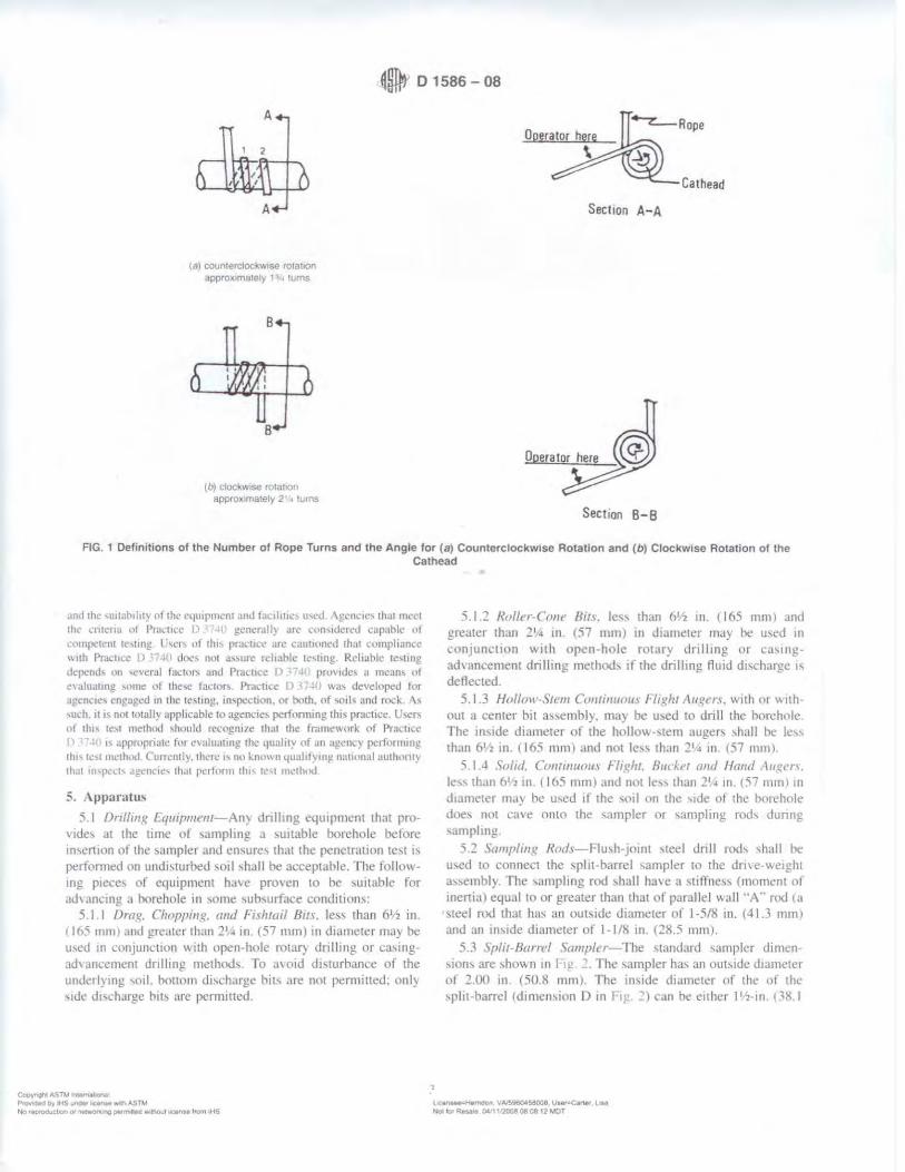
0 0 1586-08
A
2
A
(a) coun1ercloclw.1se rotat,on approx,mately l!\o turns
8
(b) cfockv.,se ro tat,on approx,mately 2 1 • turns
Ca thead
Section A- A
Section 8-8
FIG. 1 Definitions of the Number of Rope Turns and the Angle for (a) Counterclockw1se Rotation and (b) Clockwise Rotation of the Cathead
.,n,I th,• ,u,rnh,ht) of th,· cqutp,ncnt a11J 1oc 1li1tl'S u~cd \)!cnc,e, that 111,cl
the ,·mc11a of P1:1.i1cc n .. l' !_!Cncrall) ,II<' u,n,,dered capabk 111 .. ,mpc:h:111 te,11ng l 'w, ol 1111, prac11cc an: caut11,ncd that nllltphancc ,, 1th Pr,1.t1ce I) ~, 1 doc, not a"urc rd,ablc tt•,ting. Rcliahk 1e,11n!!dcpcnd, on ,t·vcral lm.:1nr, anJ P111t11ee D 17JIJ provide, u mean, ol e, aluJllng \llllle uf these fa,tnr, . P111.t1u; I) 17J0 1,a, dcvcloP<'<l for
Uj!C0'1e, cnµaµcd m the 1c,11nl!, in,p.:ction. t'r both. ot ,o,I, and rod .. \, ,uch. II"""' tutnllv appltcabk Ill agem:ic, pcrtonmng. th,, practice. U,er, of th1' 1c,1 method , 111,uld rcc<'gm1c th.II the trJnw\\orl ol Prathse n r !() , ~ apprnprialc h•r cva.luJtin!? the 4ualit~ ,,f Jn a!!ent·y p.:rtimning th1, i.: ,1 mcth,,.I Currcnll}. there" no lno\\114uahf)lll!\ nal1<>nal authont) that 111,p,:-,h .1gt'nC1c, 1h,11 pcrtnnn this tl', t nwth,><I
5 . . \pparatu,
5 1 Dr11/i11g [ q11111111rnl- AJ1} Jnlhng equipment that pro\"ide, at the time of ,amphng a ,uitable boreho le before 1n,crt1on of the \Jmpler and ensure, that the penetration te,t i, pertnnm:d on undi,wrhed ,011 ,hall he acceptable. The lollowing piece, of equipment h,1\e proven 10 be ,unable for .td\.tncing a borehole III some ,ub,url.1ce conditions:
5.1.1 Drag. Choppi1111. mu/ F,sht11il 8t1f le,, than 6 1 2 in. 1165 mm> and greater than 21,:, rn . {57 mm) 111 diameter may be u,ed 111 cnn1unc110n wtth open-hole rotaf) clnlh ng or cas111g"1d, anrerncnt dnlhng methnth. To a, oi<l d1,turham:e of the untkrly1ng ,01I. bonom d1'charge bit, are not pcm1iued; only ,1de d1,c.:harge h1h are pennined.
~~ASTM ll~O'\oJ P,O'l'dedt,ylHSwllCWk.,.._.OASTM N,-, recM'Qdutto, o, Mt"'°",-0 pel'rn,n_, ¥1-•"""-l ltt.9ntf l,um ltt!i
'i I 2 Rollt!r-Cm11 llm. le" than bl/2 in 116.'i mml ,t11d gre.itcr than 21·• 111 <57 mm) in diameter muy he u,ed in con1unc11on with open-hole rotar:,., dnl11ng or ca,111gadvancement drilling methods if the dnllmg fluid d1,charge " dellected.
5. 1.3 Hollcrn -Siem Cc1111i111mm l·l111h1 \ ugcn. wtth or Mth• out u l'enter bit n~sembl) may be w,ed to dnll the hon:hnle. The in,ide diameter of the hollo\\ -,tern auger~ ,hall he le" than 61.i in. ( 165 mm) and not le,, than 21• 111 (''7 mm>.
5.1.4 S11lul. Cm/f111110111 F/1glt1. Hur J..er ,111tl /land \ugl'n. le" than 6 1'2 in . ( I 6.'i mm) ,ind nm le:" than 21 • 1n. { 'i7 mm > 1n d1ami:tcr may he u,ed ti the ,otl nn the , 1de ol the borehole d,ie, not ca\ e onto rhe , .unpler or ,.1111pling rod, dunng ,amplmg.
'i 2 ':iampl111s: Rods- I lu,h-1oint ,teel dnll rod, ,hall he u,ed to connect the ,pin-barrel sampler to the <lm e-\1,.eigh t a,!',embly. The ,ampl1ng rod , hall have a \tt flne,, (moment of inenial equal to or gremer than that of para llel w,111 .. A .. nx! la steel md that has :.in out'1de diameter 0f 1-5/8 111. (41.3 mm.I and an im,1de diameter of 1- 1 /8 in. (28.5 111111) .
5 3 .S11li1-Barrel '>ampler- The ,trmdard ,ampler dimen • ,1t1n, are ,ho"'n 111 l 1,. The ,ampler ha, an ouhtdc diameter nt 2.00 111 (50.!! mm). rhe 111~1de d1ame1er of the nt the ,phi barrel (d1111c1ht0n I) 111 l J can he e11her l'"'!•in. 1.'\!U
lC~Kf'ftOOl'I \'~$8008 UMf7C.,,.r, UH Not to, R4'1'Mto fl,C•t 1,?COp; 08-0S 12 MOT
0 D 1586-08
OPEN SH E
E
l r---~ -, G A
A = 1 O lo 2.0 ,n (25 10 50 mm) 8 z 18.0 10 30 0 m tO 457 to 0.762 m) C = 1 375 • 0005 1n (3~ 93 • 0.13 mm) D = 1.50 • 0 05 - 0.00 ,n (38 1 • 1 3 - o o mm, E = 0 10 • 0 02 tn 12.54 · 0.25 mm) F = 200 · 005 - 0001n (508 • 13 - 0.0 mml G = 150• 10230
F
B
HAD
BALL VENT
(2 ar 3/a in. diameter J
FIG. 2 Split-Barrel Sampler
mm J or I ' ,-in. l 14 9 mm) hCl' HI! :! ,. ,\ 16-gaug.t· hni:r (.an hi: u".:d 111,1de th<! fl,2-111. C.38 I mm! ,plit barn:1 ,ampler. fhi: dri1,111g ,hoe ,h..ill be of hardeni:d ,1eel and ,hall bl! replaci:d or repa,ri:d ,,h.:n n bccom.:, tknted or <l1,torted. The penetrallng .:net oi the dml! ,hot: ma) be ,light!) wunded. n1e ,pht-barrt:I ,ampler mu,t he equipped with a hall check and H!nt. \letal or pla,tte ha,J..eh ma) he u,ed tn ret,un ,011 ,ample,
c\mt ::! 811th llll'nt) ,tnd ,1vml:1hlc 1..-,1 datJ ,U!c)!,,I lh,il \ '. , ·,1111,•, 111'1)' thlkr a, 11\l"h .,, JO lo ,o 'k ~I\\Cl!n a ,,,nqJnl m,11k ,h,11111.'t,1 ,;1mpk1 11nJ up,ct \\ ,di ,,1111pk1 , II II 1' 11.:,c--,.11: h> corr.:d lrn lhl' up,..-1 \\all ,amrkr ,er,·, '" l'ra.:11,c ! lf1h In :--.1111h ,\1111.'ll<:-1. 11 1, 1111\\ ,C\11\lnllO
r1 ,1.:ll,1.' le) 11,~ JO up,d ,,all ,amph:r \\ 11h an ,n,,d,: J1;11nl.'l1.'I ,11 I h'" ,\I ,,n,: tmtl.'. lrn~rs \\l'll' u,.:d hut prac1t,;e cnihcd to u,e rhc up,cr wall ,ampkr "'11huu1 liner,. l ,._. ,,t an up,cr w~ll ,Jmph:r allt>\\, Im u,,. 111 ,~1a1ncr, 1t n,·cJl.'d, reduce, tn'IJ,· lnc11nn. and impru\e, rcc·11wr)' \Ian~ ,,thcr .:ountn..:, ,till uw a C\lll,t,mt ID ,ptir-ham:I ,ampler "h1d1 w,1, thr ,m)!inal .1andan.l and ,11II an·cptahlc "11hm tlm ,iandard
5.4 nrm -abght \nemblv: 5 -t I /-lw11111cr and :\111'1/-The hammt:r ,hall weigh 1-t0 -
2 lhf t623 - 9 Nl and ,h,111 bi: a rigid nwtalli..: ma" I11e hammcr ,hall ,1nJ..e the ,111\ 11 and make ,teel on steel contact \\ hen 11 1s dropped. A hammer tall guide pc11111tt111g an unimpeded fall ,hall ht: u,ed. I 1g ~ ,how, a ,chemallc of ,uch hammer. Hammers u,ed with the c:nheatl and rope method ,hall have ,111 ummpcded over lift capacity of .1t least 4 111 { I 00 mml. For ,afety rea,nns. the use of a hammer a~,l!mhly with an 111ternal an\ll 1, encouraged •" ,hm"n in . rhe tot..il ma,, 01· th<' hammer ..i,,embl) heanng 011 the dnll rod, ,houltl not he nmre than 250 - 10 lhtn f 11 l :: 'i 1-.g).
N ia J It 1, ,u1111c,1,·J 1ha1 th,· h.unmcr l,1II ~111dl.' be pc1 m,mentl) mar~,·.J Ill cnahk 1he 11pcr.1111r or m,pcct,H 11, JU<IJ;l' rlw hanum:r dr,1p
hclfht.
~•--g"IIASTil .,.,.,,..t-anal P~ed r,y ttS uMM kerlH wt-.ASTM No ~ap,odult,on 01 n.t...or- ng ~11.a """tnout 11~ trOffl IHS
5 4.:! l!a111111cr /)mp ,·v.\11:m-Rorc-catheau. tnp. ,e1111-..iutom.1tie or ..iutomauc hummer drop') ,tcms. as ,hm\n in F111 1 may he u,ed. pro\ 1d111g the lthmg apparaw, will nut cau,e penet1ation of the ,ampler while re-engagmg and hftmg the hammer
5.5 Acce1.1orv t;q11ip111e111-Acces,ones ,uch a, labels. ,ample t·onta111er,. data ,hel!h . .ind irniundwmer level mea,uring de\ 1cc, shall he pm, 1tleJ 111 .11:cordanrt' w11h 1he requiri:menh ul the prnjeer anti other A ST\1 ,tandJrtl,.
<i. Drilling Procedure
b. I J'he borehole ,hall he JJ, ant·cd mcrcment,111~ to pennn mtermtllent or contmuou-. ,an1pling. Test 1ntenah and loc·;itinn, are normally stipul,ttetl by the proJect engrneer m gl!olog1,1. Typically. the intenab ,elected are 5 fl ( 15 mJ or le,, in homngcneou, ,trnt:1 w 1th te~t and ,..impltng locatwns .,t every change ol <,trata. Record the tlcpth of dnll,ng to the ne.ire,t 0 I It (0.030 m I.
6 . .2 Any drilling procedure that prm 1tle, .1 wttahl) clean and ,t,tble hnrchnle hclore 111,cr11on of the ,ampl<!r anti ~"'urc, that the peni:trat1on 1e,t 1, performed un l!"entially undl\turbeJ soil shall he acceptable. Each ol the tollowmg pro..:edurc, ha, pmven to he accept..ibl<! lor ,ome ,uhwrface cnnd1t1on,. The ,ubsurface condition<, ant1t1pated ,hould he con,1dercd ,, hen ,dectmg the drilling method to be u,ed
6.2. I OJ)l!n-hole rota!) drilhng method 6.?.. 2 Cnntmuou, llrght hollow-,1e111 auger method. 6.2.3 Wash boring method. 6.2.-t C.\111t111uou, night ,111iJ auger rncthotl 6.3 Se1er,il dnllrng method, produce unacccptJhlt' hl•re
hole,. Tht: proce" of 1ctt111g through an open tub<! .... unpler and
l ~Hemdorl VMW,0,68008 usenean., LU Ndlof'R.-., ~11'20080808 12MDT
0 D 1586-08
,----,.___COUPLING OR COLLAR
~- DONUT HA~'MER
GUIDE TUBE OR ROD
-- DRIVE HEAD COUPL ING--"w
OR ANVIL
OR SUB
i---DRILL ROD
DONUT HAl.'MER SAFETY HAMl.•EP.
FIG. 3 Schematic Drawing of the Donut Hammer and Safety Hammer
Lhen ,amplinJ! when the de,ircd depth i, readied ,hall nm he permiued. The t·ont111uou, tligh1 ,ohd auger method ,hall nol t>e u-,ed for ,1dvanc111g the borehole below a water table or beln\\ the upper confining bed of J confined non-cohe!->i,e ,tralutn th;1t i, under artesian pres,ure. Ca-..mg may not be ad,anced below the sampling elevauon pnor 10 ,amphng. ,.\lhancing a borehole wllh bo11om d1,charg.e hit, 1, not pe1 m1,,1ble. It 1-.. 1101 penrn,sible tu advance the horcholc flir ,ub,equent 111,e111nn ot the ,ampler ,oldy b;r me,111, of pre,iou, ,amphng v.llh the SfYf -.ampler.
6.4 The dnlhng llu1d le,el \\llhHl the borehole or hnllc,,\,tem auger, ,hall be maintained ~ll or ah\1\.l th.- in ,itu gmundv.atcr level at ,11111111c, <luring drilling. remmal of dnll roJ, . .in<l ,amphng.
7. Sampling and Te!>ling Procedure
7. I After the borehole ha, heen ad, am:ed w the <le,11eJ sampling ele"ation and e>.ce,sive cutting, ha,c heen 1emo,ed. record the cleanoul depth lO the nearest 0.1 ft CO.CHO ml. and prel)are for the test\.\ ith the follo\.\.111g w4uenLe of operation,:
7. I. I A11,1ch en her ,plit-harrel ,ampler T, pe A or B to the ,ampling rod, and lowe1 11110 the borehok Do not .tl!O\.\. the ,ample, to drop 01110 the -,ml to be ,ampled.
7.1.2 Pos1t1on the hammer abt)\e and illlach the anvil lo the top of the ,amphng rod-.. This ma) be done beforl.! the ,ampling rod, ,u1d ,ampler are lower!.!cl into the borehole
7.1.3 Re,t th!.! dead weight of the ,ampler. nxh. annl. and dn,e weight on the holtom of the bnreholc. Record the ,ampltng. ,tan depth lo the ncare,t 0.1 ft CII rno 1111 Compare
~ q,tASTllltl'"'ff\lllCltll.1 P1'0Ytd90DVIHS~kenM w-l.,AS'O.' No t~CltM~"!'.19 ~...,.1h0ul K90&e ,ram IH'S
C
the -,amplmg ,tan depth to the cle:,noul depth 111 7 I If execs"' o;: cutting, are enLountered at the bouom ul the borehole. remove the ,ampler and -,amphng rod, from tht· borehvle and remove the cutting,.
7.1.4 Marl.. the drill rod, 111 three successl\e 0.5-fool (D.15 ml incremems ,o thal the advance ol the -,ampler under the impact of the hammer cnn be ea.-.11) obsened lor each 0.5-t{,nl t0. I 'i m) increment.
7 .2 Dme the ,ampler with him,, lrom the 1-l0-lhf (6~.1-', hJ111111e1 .ind u,unl the number nf hlow, ,1pphcd 111 e;1Lh 05-foot c0.15-m > innement until une 11f the following 0L·cur,:
1 2.1 A tell al ul 50 him\, ha\ e hcen .tpphed dunng any 11nL· of th!.! three 0.5- tnot (() 15-m) 1m:remcn1, de,crihed 1n 7 I I.
7.2.2 A total of 100 hlow, hu,e been appht:cl. 7.2.3 There 1, no oh,en·ed ,id, ance of the ,amph:r dunng
I.he application of 10 ~uccc,,t\C blov.-, of the hammer 7.2.-l The ... ampler 1, adv,mced the rnmrlete 15 fl. (0,45 1111
w11hout the l11nit111g hlow counts on:urring a, de,cnhed 111 7-: . . or
., 2. 'i It 1hc -...11npler ,mk..., under the we1gh1 of the hammer. weight of rod,, nr bmh. record the length ol 1r;.l\el to the neare,t 0.1 h (().()30 m), and dm,e th!.! ,ampler through 1he remainder of the 1e~t 1111en al. l f the ,ampler ,inks the crnnplete 1111!.!rval. ~top the penetrallon, remll\C the ,ampler and "1mpling rod, from the borehole. and advance the borehole through the very ,oft or \ery loose materials lo the next de,ired , amphng l.!fe,:Hinn. Record the 1\-value a, either v.-e,ght of hammer. \\eight 111' rod,, or hoth
~HemOotl VA/~960458008_ ~C.rter Lisa NIX~RMM l>'r11'1008080$12~0T

0 D 1586-08
FIG. 4 Automatic Trip Hammer
7 3 Rcnird 1he numher ot hlo...,, tNI required to advance the ,ampler each 0.5-foot (0 15 ml of penetr.111011 or fracuon thereof. The fiN 0.5-foot (0.15 ml,., cons1<lered 10 be a ,eatmg Jri\e. The ,um of the number ol blow~ required for the ,econd aml third 0.5-foot (0.15 m) ,11 penetrauon i, termed the ··standard penetration re,1,1;@.:e. · or the "V-,aluc ·• II the ,n111pk1 b dm en less than I .5 ft (().-15 m), a:.. penrnttcd in
"' ' . 01 . the number or hhm s per each complete U.5-lllot ro 15 nn increment and pa each partial 1m:remcn1 ,h,1II hc recordeJ <Ill the bonng log . f'nr pllmal 1nae1111.:nt,. the depth of penctrauon ,hall he reported to the nearest 0.1 It (0.030 ml 111 add1uon tn the numher nl blow-.. II the \iHnpler .id,ancc~ beltm the hnttom ol the borehole under the ,1.111t \\eight ol the drill rods 01 the weight of the dnll rod, plu, the ,tauc "eight of the hm111ner. thi, 111formauo11 ,hould he noted on the boring log.
7 .-1 fhe r.i1,1ng and droppmg of the 1-10-lhf (623-N) hammer ,hall be accompli,hed u,ing either Lll the f111low111g two me1ho1h. Energ, delivered to the dnll ri,d h) cithcr method can be mea,ured according to pro.:edure, 111 Tc,t l\lethod I r
7.4.1 Aft'thod A-By using a tnp. ;1utomat1c, or ,em1-automattc hammer drop "Y"tem that ltf't-.. the 140-lbf (623-'i'> hammer and allows ll to drop 30 = 1.0 in. (0 76 m ::: 0.030 m) with lim11ed unimpcdence. Drop heights adjustment, for automatic and trip hammer, ,hould he chccked datly and at tiN ind1cJtion ot v.iriation, 111 performam:e Operauon of automauc hammer, ,hall be 111 ,trict ,1c,ordance \\ 1th operauons manual,.
Copyr~ ASTll Jntemero-,a• Pfo-,,idaCJ t,y 1-4$""""' ~"" ri, ASTM No ;~on O' ner,.,:,,"ta"IQ • .,,.ltl'ld wl!'K>UI bCUhH t•om tt-i'J
7A.2 lfrtlmtl fJ - By m,mg a cathead tu pull a rope attached to the hammer When the cathe.id and rl'l)I.' method 1, u,ed th<' ,y ,tern and upemtion ,hall conform to the follow mg
7.-1.2.1 The cathead ,hall he e,,entially free of ru,t. oil , lll grea,e and ha, e a diameter in the mnge of 6 to IO 111 1 150 to 250 mm).
7 ..J.2.2 The cathead ,hould he operated at a rrnmmum ,peed nf rot.1tion ot I 00 RP:>.1
7.-1.2.3 The opcr;itor ,hould gene1ally u,e euher I -3/-1 or 2- 1 /-1 rope turn, on the ,athead. dependmg upon \\ hether m 1w1 the rnpe ,·nrnc, oil the ltlp (1·3/4 turn, for coun1erclnek\\1,e rot,1tton) or the l'l1morn ( 2-1/-1 tum, t<,r dock wi,c n11.11ion, ut the cathead dunng the pertnrmance nl the penetratmn te,1. a, ,ho\~n in I 1)-! I It i, generally kmmn and .iccepted th,lt 2-Jl.t or more rope turn, cons1derabl) impede, the fall 11f the hJmlller and ~hould not he u,ed to perform the te,1. The cathead rope ,hould be ,utr, rela11vel} df). dean. and ,houlJ b1.: replaced when it become~ e."<cesw,el) fra)ed. oil). ltmp, or burned
7.4.2.4 For e.ich hammer hlO\\. a 30 ::: 1.0 in. (0.76 rn = 0.030 m) lilt and drop ,hall he emplo)'ed h} the operator The operation of pullmg and throwing the rope ,hall be perfornwd rhythmically without holdmg the rope at the top ol the ,truke.
:-.'on. 4-lf the hJ111111cr drop h~ight i, -.>1nl'lhrng other lha.n ,Q - t 0 in 10 71> m - () <HO n11 , then record rhe nc" drop height. lw sn11' <>lhcr 1han ,and,. then, 1\ nn 1-.nown data 01 rc,car,h thal rcla1.-, 11, ad111,uni;- thc ,\l. \alut> oh1,11ncd Imm dilfrrcnl drop hc1~ht, fr,1 lllcth,-..t I> I , • prm ad~, 111forma11on on mai.;rn!! encr!!) 1m:.1,urc111cnt tor , ,,nahlc drop
l,Jir,_-.=Nllrnoon VA:596™58008 Us4N'Z'Ca.,.., t... Hof to,, Rf!UJ9,041 tQ0080808 t1A.,10T

0 01586-08
hc1i:l11, ;,nd PtJdice I) C,(lr,f, 11"" iJc~ int(lrma11nn ,,n au1u,1mcn1 ol \ ., aluc 1,, J "'n,tanl cner;:y k, cl 11,0 ~ ,,f tlwnrcr,eal. NNll. Pra.:11cc 1l 1,1l!, .,Um" rlw h.1111111cr <lrnp hc1gh1 h• l,c ad1u,1ctl to pnw1Jc 60 %
t:llt."t ')
7 5 Bring the "unpler IO the ,urlace and open. Rccon.l the percent reco,cf) ICl the neare,t I "f or the length of ,ample recmered to the neare,t 0.01 tt (5 mm/ Cla~,ify the ,oil ,.imple, recm crcd a\ tn. m au:ordance with Practu:e I l 2188. then place one or more reprc,entati, e por11m1, of the ,ample in111 -.cal;1hle mrn,111re prool l'llnta1m:r, I.Jal"', 1 without ramming or di,tnrtin!! ,Ill} .1ppa1e1ll ,1rat1l1<t.llinn Sc..11 each l011ta111cr Lo
pn:,cnt c, apora11011 nl ,oil mn1,1ure Affi, lahcl, to the l'llnt,uner, hearing Jllh dc,1gna11nn. h,inng 11umher. ,ample Jcpth. and the blow count per 0.5-fo,11 ell 15-m I incremem, Protect the "'mples aga111,1 extreme temperature change,. ll there 1, a ,ml d1angc with111 the ,ampler. make a Jar for each ,tratum anJ note 1h location in the ,ampler ban-el. Sample, ,hould he pre,en cd and transported in accord,111ce wtth PrJ~·tice 11 rn n u,ing Group 8
8. Data %t't'W,,/FormbJ
X I Data obuuned m each bureholc ,hall he recorded 111 ,iccordJnct: ,,1th the Suh,urfo1.:e Loj?gm!? Gurde ll a, required h) the e,plora11nn program. An e,ample ol a ,ample data ,hcet 1s mcluded m \ 1 1~
S 2 Dnlhng mfonnat1on ,hall be reconkd m the held and ,hall 111clude the followmg:
8.2.1 \lamc and loc.itum of job. 8.2 2 '1.1mc, of crt:\~, X.2 , T~ pe and make ol tlnlling machine. S.2 .• \\t'atha cond1tllln,. X.2 5 D.ue ,rnJ t11ne ol ,tart anu llm,h ,11 borehole. 8.2.t'I Boring number and locatrnn htJtmn and cooru111atc~.
if availahlt' and applJc,,ble /. 8 .l."' Surtace clc, aunn. rf a, ailablc. S.2."i ~lethod ol ad, ancmg and cleaning lhc borehole. l-..2 9 \1ethod nf J..eeping borehole ,,pen, 8.2.10 Depth of water -urtare to the nt'are,t 0.1 ft ((UHO ml
,1nd drilling depth to the ne,m:st ti I ft 1110:m 111) at the 11me of a nutt'd lo" ,1f dnlhng llu1d. anJ lime and date when reading or n,,1,111011 W..t)i matlt.
S 2. I I L11<.:atron of ,trata change,. to the nearest 0.5 ft ( 15
cm!. !i.2 12 ~11e of ca,i ng. depth nt ca,t'd portion ol borehole to
the nt'are,1 O I ft t0.030 1111.
Cop) 1'1f}nl .-,STl,t ~ I
Pt¢-.ded t-'f IH~ u,.. lcenN•·lfl ASTM N-t'J,~cn Ol ~'tg pe,l"Tl!n-S w,lrtOul lieef\~tt lf'Offl ....-s
.,
X.2.1 ~ Equipment and :\lethocl A ,ir B ol dm1ng st11nplc1. S.2.1 • S.11nple1 length and in,1de d1amcter ol harrcl. and ii
a ,ample ha,kt!t retainer i, u,ed. X 2 IS S11e. type. and ,eninn length ol the ,amphng ro,1'.
and 8.2.16 Remark,. X. ~ Data ohtarned !or each ,ample ,hall he rec11rded 111 the
l1eld and ,hall 111clude the following: 8.3. 1 Tur of ,ample:! depth !Cl the nt!are,1 0.1 ft ((J.1)30 m 1
and rf u1rl11cd. the <.ample numher. ~ 3 2 0C,l.11p111111 ~)f ,oil. 8 1 1 Strnta d1ange, v. ith111 ,ample. 8.3 -I S.nnplcr pcnctr:1tinn and recm cl') length, 111 the nc:ir
e,t 0.1 lt t0.0.10 m ). and h 3 5 's umher ol hlo\,., p..:r O 5 toot W.015 mJ 111 p,1nial
increment.
9. Precision and Bias
9 I Prcn,11111-Te,t data on prec1,ion 1~ not pre,cnted due w the nature uf lhl!> tt!,t 1m:thod. It 1:-. either not fca,1hlc or Ill\>
1:11,tl) .11 th1, lime to ha,e ten 1,r more agenc.1e, panic1patc 111 an m ,itu 1e,1111g program ,tl a gi\en ,ite.
9.1 I The Suhrnmm1ttee 18.02 i, ,eek1ng additional d~11a from the u,e,-., o t this 1e,1 method that mrght he u,cd w make a horned ,1atement on preci,ion . Pre!>ent k1101,1 )edgc 1nthcate, the tollu,-.111g·
9.1.1 I Vanat1on, tn \-\alue, of 100 ''< or more h,I\C h..:cn oh,er\'ed \\ hen w,ing ddlert!nl -,1,indard penetratrnn tc,1 appi.l • r~m1v and dnllcf' for ad1acent horehole, in the \.Hile ,oil frn matmn Cmrem opinion, ha,ecl on fldd c,pcn.:ncc. ind1-c.11e, that v.hen u,1n!! the ,:unc apparatu, ,1nd driller. \ \;due, 111 thl ,amc ,ml can he reprodu~·ed w11h a cnclfic1en1 nt , ariat1t1n ,,f about IO '..i
() , 1.1.2 ·1 he u,e 111 l,Hllt) equ1p111ent. such a, .111 extreme)) m.i,,i\ e nr damaged ,1nvd. J ru,ty cath.:.id. a Inv. ,peed cathead. an old, 011} roJ'(:. or ma,,1ve or poorly lubricated rope ,hea\,e, can !>lgnihcantly 1:ontrihutt! to differences 111 N-,alue, ohta111ed between operalm-drill rig ,y,tem,.
9,2 /1ia.1-There " no accepteJ rclercncc value lor lht, tt''>t method. therefore, b1a, cannot he determined
l 0. Ke) \I ord,;
I 0.1 hlow cnum: 111-,ttu te,t penetration rc,1,1ance; ,111I. ~pht-harrel ,.impling. -.1andarcl p..:netratinn tc,1
~ '!"Hemc!ot,. VA.'59&Q.t58008. 1.JMrsearte, Uu Nol to,' ~.aie O.;t 1'2008 08 0e 12 MOT

Xl.lScelt!,'5.
::>yr'Qhl ASTM lnta~I
w~ by IHS ullekt' litet'cH"" th ASTM feproducl:,on Of n~ ng oer,t,,1180 w,thQut a.e.nMt trom IHS
0 D 1586-08
APPENDIX
(Nonmandatory Information)
XL Example Data Sheet
LJ(enue•t-ta-mdon. VA.5960458008, User-Car1ot LIN Notto,.ReuNI oc·11.~oeoe12-..0T

~ D 1586-08
DRILLERS BORING LOG
P ,oi-c, ------------- ----- .._. .... ---------- SOflf'fNO ___
k,.out1 ..
D•~&IMled
&rx~ 0r----
D<lh f\"V T'/pe
,..._ or o~u,119
Au~ ,
<\'1111. ----Ha-~ -l!lplll•6ooon T1,-
&Ai d'
~ ,_. -•· ·----- -
Cooyn;n1 AS TM ltutN!lDna~ PIO\loaed b'f' ~S Ul"Oe" lcllnM 'tlll-th ASllJ N<) rfP"C)dut1;0, f/1 ~ oe,maed wtnou1 IICOflMI "°"' IHS
;,I' --- (I --
0.0.~ r9 C..W. lor""' Loa<,oo
~ !]l'.-IY, Clll<1 - - --C.1M>'MICW\
... v ..... a-p1• ~u. "°'9 OKcr~fl llN1 "R•~ltts "" R.co.....,
F '" T•-
-51:a --------- -IIIQ T.,,_ IH~l
..... ~ l' J ----• CNJ-,; •Y:irlf
11'.ar\.al \\'i1W U~•f ----"---
w,,,i-, ll c~" .. '" Dejllllh----
e,~,..e -----.M"f? -
FIG. 5 Example Data Sheet
,, ~:1Hetn0on. VA,590()il58008 \.)Mlr,,Ca'11Ar LIM Not tot~ O,& 11'200808 08 12 MOT
'-11: .. ..-,4; ____ . ..,,,., ----a.,._ f ·-Dore --- ~r.._ Dvec ___ ,-_
--- 1-_
41 D 1586-08
SllMt\1 \RY OF CH.\NGES
Commntee DI 8 hi!, identi tieu Lhe lnca1111n of ,ele-ctcJ change, 11, th,, ,tandard ,mcc the la,t '"ue II) 1586 94) th,ll may impact 1h1: u,e ol thi, ,tanJ:ird !Approved J"ehru,ir) I. 2008.)
I/ 1 l'herc ha,e hccn numcrou, ch,mgc, to th,, standard 10 11,1 them ,cpa.r.ncl). From the lllt1't recent main halllll pr,itt;,,. mlduion;II ch,mge, were reque,1ed and incorporated inw thh nc\\e,1 rc\:1,1011. Stated below 1, a highlight of ,omc nf the change,
(-IJ lerminolog) added ,ecllon on Detint11n11,. (51 S1gn1hca11cc ,ind L ,e clantied u,c ol the SPT te,1. (61 App,mlltl',. general ed1wrial change,. ( "'I Sampling ,111d Tc,trng Prncedure general ed11onal change,.
{.:I 'ln•pc \H1, complctel~ re, ,,ed. (8) Data Shcct,trnnm,. genernl cduonal change, { i I Rdcr..:nced Docurne11t, upd;11cd to include llC\\ ,rnndarJ,. (<JI Pren,wn aml Uia,. added Sccunm, I I ,111d 1 1 I '
Cl)OW'r".t'lf ASW ~O'loll
ASTM lnterna11ona' takes no posir,on respecting the val"11ty of any patenr ng/lrs assened ,n connec11on wirh any ,rem mentioned ,n 1111s standarcJ Users of 111,s standard .1re expressly .advised that determmar1on of the valld1tv of any such patent r,ghts and the nsk of ,n/nngemenl of suclt r,ghrs. me entirely 1/Je,r own responsio.hty
T/11s standard IS sub1ec1 to re1-,s1011 at any 11me by the responsible tectln,ca/ committee and musf t>e revrewea every five years and If not revised. either reappr011ed or ... thdrawn Your cxm,ments are invited either for rev1s1on of this standard or /or additional standards and should tJe addressed to ASTM /ntemat,onal Headquaffers Your commenfs ,,,,11 receive careful consraeration at II meellnQ of the responsible technical comm,:tee which you may attend. If you lee/ that your rommenfs heve nor received a lair hearing you. should make your views known to rhe ASTM Commmee on Standards, Bf the address shewn below
This srandard 1s copyTlghled by ASTM tntem11r,onal. tOO Barr HartJOr Dn•e. PO Box ClOO. West Conshohoe1<en PA 19428·2959. u11,ted Status /na,v,dua 1 rePflrl/s tsmgle or m,,//rplc• cop,es/ or 111,s srm1dard may be oora,ned by contdcling ASTM af the above address or at 610·832-951'5 (phone}, 610·832·:1555 11axl. or servtt:·,,C:astm.org /e-ma,1), or tnroug/J me ASTM webs,re 1www asrm org)
l'l Ptov-dea Dr lt4S .,.,.,.~ w,111AS™ ~ .. ~. \IA.'!:IQ604.58008, Lhr;.,w-Carw- Lia
No;iti;>tR..,.;e 04J1ti'20080808·12tJIOT No 'tpfOOl,DIOn O' W"4'0"-..ng ~Had ... ,th0t1I iw....nse 'l'O"' IHS
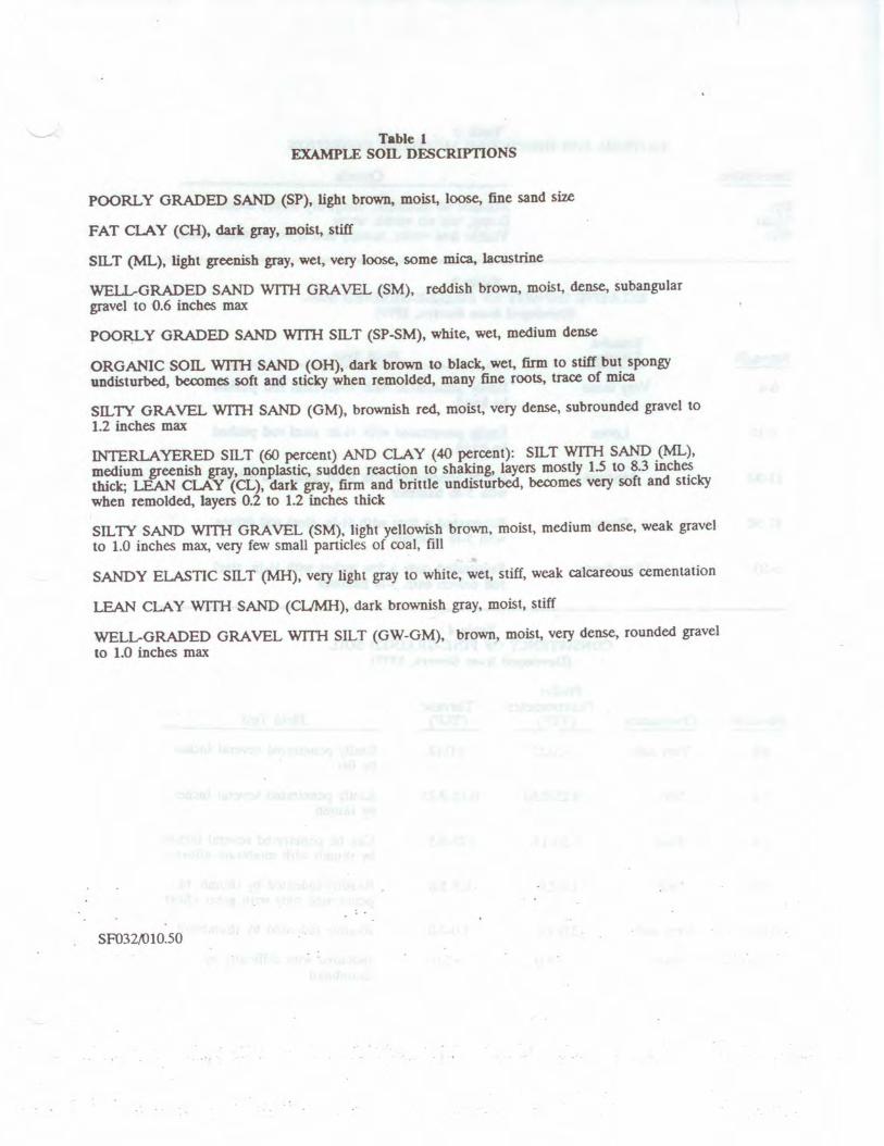
Table l EXAMPLE son, DESCRIPTIONS
POORLY GRADED SAND (SP), light brown, moist, loose, fine sand size
FAT CLAY (CH), dark gray, moist, stiff
Sll.,T (ML), light greenish gray, wet, very loose, some mica, lacustrine
WELL-GRADED SAND WITH GRAVEL (SM), reddish brown, moist, dense, subangular
gravel to 0.6 inches max
POO~ Y GRADED SAND WITH Sil., T (SP-SM), white, wet, medium dense
ORGANIC son., WITH SAND (OH), dark brown to black, wet, firm to stiff but spongy
undisturbed, becomes soft and sticky when remolded. many fine roots, trace of mica
Sll.,TY GRAVEL WITH SAND (GM), brownish red, moist, very dense, subrounded gravel to
1.2 inches max
INTERLAYERED Sll.,T (60 percent) AND CLAY (40 percent): Sll.,T WITH SAND (ML),
medium greenish gray, nonplastic, sudden reaction to shaking, layers mostly 1.5 to 83 inch~
thick; LEAN ClA Y (CL), dark gray, firm and brittle undisturbed, becomes very soft and sucky
when remolded, layers 0.2 to 1.2 inches thick
SIL TY SAND WITH GRAVEL (SM), light yellowish brown, moist, medium dense, weak gravel
to 1.0 inches max., very few small panicles of coal, fill
SANDY ELASTIC SILT (MH), very light gray to white, wet, stiff, weak calcareous cementation
LEAN CLAY WITH SAND (Cl.JMH), dark brownish gray, moist, stiff
WELL-GRADED GRAVEL WITH SILT (GW-GM), brown, moist, very dense, rounded gravel
to 1.0 inches max
SF03WI0.50
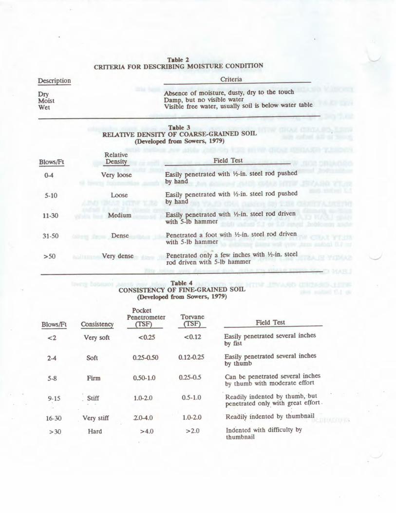
Description
Dry Moist Wet
Blows/Ft
0-4
5-10
11-30
31-50
>50
Blows/Ft
<2
2-4
5-8
9-15
16-3()
>30
Table 2 CRITERIA FOR DF.sCRIBING MOISTIJRE CONDmON
Criteria
Absence of moisture, dusty, dry to the touch Damp, but no visible water Visible free water, usually soil is below water table
Table 3 RELATIVE DENSI1Y OF COARSE.GRAINED son.
(Devdoped from Sowers, 1979)
Relative Density Field Test
Very loose Easily penetrated with ½-in. steel rod pushed by hand
Loose Easily penetrated with ½-in. steel rod pushed by hand
Medium Easily penetrated with ½-in. steel rod driven with 5-lb hammer
Dense Penetrated a foot with ½-in. steel rod driven with 5-lb hammer
Very dense Penetrated only a few inches with ½-in. steel rod driven ·with 5-lb hammer
Table 4 CONSISTENCY OF FINE.GRAINED SOIL
(Developed from Sowers, 1979)
Pocket Penetrometer Torvane
Consistency (fSF) (fSF) Field Test
Very soft <0.25 <0.12 Easily penetrated several inches by fist
Soft 0.25--0.50 0.12--0.25 Easily penetrated several inches by thumb
Fltm 0.50-1.0 0.25--0.5 Can be penetrated several inches by thumb with moderate effort
. Stiff 1.0-20 0.5-1.0 Readily indented by thumb, but penetrated only_ with great effort .
Very still 20-4.0 1.0-2.0 Readily indented by thumbnail
Hard >4.0 >2.0 Indented with difficulty by thumbnail
-
Utility Location_General.doc QC and Reviewed 02/2017 1
Standard Operating Procedure
Locating and Clearing Underground Utilities
I. Purpose The purpose of this SOP is to provide general guidelines and specific procedures that must be followed on Navy CLEAN projects for locating underground utilities and clearing dig locations in order to maximize our ability to avoid hitting underground utilities and to minimize liabilities to CH2M HILL and its subcontractors and health and safety risks to our project staff.
This SOP shall be used by Activity Managers and Project Managers to, in-turn, develop Activity-specific and project-specific utility location procedures. The activity and project-specific procedures will become part of work plans and project instructions and will be used to prepare scopes of work (SOWs) for the procurement of utility location subcontractors to meet the needs of individual projects.
This SOP also identifies the types of utility locating services that are available from subcontractors and the various tools that are used to locate utilities, and discusses when each type of service and tool may or may not be applicable.
II. Scope Depending on the Navy/Marine Activity we typically find ourselves in one of two scenarios:
Scenario 1 The Activity provides utility locating (or dig clearance) services through the public works department or similar organization, or has a contract with an outside utility clearance service. Some of these services are provided in the form of dig permits which are required before you can dig or drill. In other cases, no official permit is required and the process is somewhat vague. Scenario 2 The Activity does not get involved in any utility locating processes aside from possibly providing the most recent utility maps, and relies on CH2M HILL to clear the dig locations.
Table 1 provides an up to date summary of which scenarios apply to the various primary Activities served under the Navy CLEAN program.
Scenario 1 is preferred because under this scenario the Navy tends to assume the responsibility if the location is improperly cleared, a utility is struck, and property damage results. However, our experience has been that the clearance services provided by the Navy do not meet the standards that we consider to be adequate, in that they often simply rely on available base maps to mark utilities and do not verify locations
Utility Location_General.doc QC and Reviewed 02/2017 2
using field geophysics. And if they do use locating tools, they do not provide adequate documentation or marking to confirm that a location has been cleared. So while the Navy’s process may protect us from liability for property damage, it does not adequately protect our staff and subcontractors from health risks nor does it compensate us for down time, should a utility be hit.
Therefore, regardless of what services the Navy provides, in most cases we still need to supplement this effort with clearance services from our own third party utility location subcontractor following the procedures and guideline outlined in Section IV of this SOP. The cost implications of providing this service will range from $500 to several $1,000 depending on the size of the project.
The scope of services that we ask our subcontractors to provide can involve utility marking/mapping or the clearing of individual dig locations. In the former we ask our subs to mark all utilities within a “site” and often ask them to prepare a map based on their work. In the later, we ask them to clear (identify if there are any utilities within) a certain radius of a proposed dig/drill location.
The appropriate requested scope of services for a project will depend on the project. Clearing individual boreholes is often less expensive and allows the sub to concentrate their efforts on a limited area. However, if the scope of the investigation is fluid (all borehole locations are not predetermined) it may be best to mark and map an entire site or keep the subcontractor on call.
Clearance of individual dig locations should be done to a minimum 20-foot radius around the location.
An example SOW for a utility subcontractor procurement is provided in Attachment A.
III. Services and Equipment This section provides a general description of the services available to help us locate subsurface utilities and describes the types of equipment that these services may (or may not) use to perform their work. It identifies the capabilities of each type of equipment to help the PM specify what they should require from our utility location subs.
Services The services that are available to us for identifying and marking underground utilities are:
• The local public/private utility-run service • Utility location subcontractors (hired by us) Attachment B provides a detailed description of each type of organization. It also provides contact numbers and web sites for the various organizations in the areas where we do work for the Navy and contacts and services provided by several subcontractors that we have used or spoken to in the past.
Utility Location_General.doc QC and Reviewed 02/2017 3
Equipment Attachment C provides a summary of the various types of equipment used for subsurface utility location. It describes the capabilities and limitations of each in order to help the PM determine if the equipment being used by a subcontractor is adequate.
It is important to make the potential subcontractors aware of the possible types of utilities (and utility materials) that are at the site, and to have them explain in their bid what types of equipment they will use to locate utilities /clear dig locations, and what the limitations of these equipment are.
A list of in-house experts that can be used to help you evaluate bids or answer questions you may have is provided in Appendix C.
IV. Procedures and Guidelines This section presents specific procedures to be followed for the utility location work to be conducted by CH2M HILL and our subcontractors. In addition, a PM will have to follow the procedures required by the Activity to obtain their approvals, clearances and dig permits where necessary. These “dig permit” requirements vary by Activity and must be added to the project-specific SOP, or project instructions. It is preferable that the Activity perform their clearance processes before we follow up with our clearance work.
Activity Notification and Dig Permit Procedures Identify Activity-specific permit and/or procedural requirements for excavation and drilling activities. Contact the Base Civil Engineer and obtain the appropriate form to begin the clearance process.
Activity Specific: To be provided by Activity or Project Manager
CH2M HILL Utility Clearance Procedures Do not begin subsurface construction activities (e.g., trenching, excavation, drilling, etc.) until a check for underground utilities and similar obstructions has been conducted by CH2M HILL as a follow-up to the services provided by the Navy. The use of as-built drawings and utility company searches must be supplemented with a geophysical or other survey by a qualified, independent survey contractor (subcontracted to CH2M HILL) to identify additional and undiscovered buried utilities.
Examples of the type of geophysical technologies include (these are further described in Attachment C):
• Ground Penetrating Radar (GPR), which can detect pipes, including gas pipes, tanks, conduits, cables etc, both metallic and non-metallic at depths up to 30 feet depending on equipment. Sensitivity for both minimum object size and maximum depth detectable depends on equipment selected, soil conditions, etc.
• Radio Frequency (RF), involves inducing an RF signal in the pipe or cable and using a receiver to trace it. Some electric and telephone lines emit RF naturally and can be detected without an induced signal. This method requires knowing where the conductive utility can be accessed to induce RF field if necessary.
Utility Location_General.doc QC and Reviewed 02/2017 4
• Dual RF, a modified version of RF detection using multiple frequencies to enhance sensitivity but with similar limitations to RF
• Ferromagnetic Detectors, are metal detectors that will detect ferrous and non-ferrous utilities. Sensitivity is limited, e.g. a 100 mm iron disk to a depth of about one meter or a 25 mm steel paper clip to a depth of about 20 cm.
• Electronic markers, are emerging technologies that impart a unique electronic signature to materials such as polyethylene pipe to facilitate location and tracing after installation. Promising for future installations but not of help for most existing utilities already in place.
The following procedures shall be used to identify and mark underground utilities during subsurface construction activities on the project:
• Contact utility companies or the state/regional utility protection service (such as Miss Utility) at least two (2) working days prior to intrusive activities to advise of the proposed work, and ask them to establish the location of the utility underground installations prior to the start of actual excavation: this is a law. These services will only mark the location of public-utility-owned lines and not Navy-owned utilities. In many cases there will not be any public-utility-owned lines on the Activity. There may also be Base-access issues to overcome.
• Procure and schedule the independent survey.
• The survey contractor shall determine the most appropriate geophysical technique or combinations of techniques to identify the buried utilities on the project site, based on the survey contractor’s experience and expertise, types of utilities anticipated to be present and specific site conditions. The types of utilities must be provided to the bidding subcontractors in the SOW and procedures to be used must be specified by the bidder in their bid. It is extremely helpful to provide the sub with utility maps, with the caveat that all utilities are not necessarily depicted.
• The survey subcontractor shall employ the same geophysical techniques used to identify the buried utilities, to survey the proposed path of subsurface investigation/construction work to confirm no buried utilities are present.
• Obtain utility clearances for subsurface work on both public and private property.
• Clearances provided by both the “Miss Utility” service and the CH2M HILL-subcontracted service are to be in writing, signed by the party conducting the clearance. The Miss Utility service will have standard notification forms/letters which typically simply state that they have been to the site and have done their work. The CH2M HILL subcontractor shall be required to fill out the form provided in Attachment D (this can be modified for a particular project) indicating that each dig/drill location has been addressed. This documentation requirement (with a copy of the form) needs to be provided in the subcontractor SOW.
• Marking shall be done using the color coding presented in Attachment E. The type of material used for marking must be approved by the Activity prior to marking. Some base commanders have particular issues with persistent spray paint on their
Utility Location_General.doc QC and Reviewed 02/2017 5
sidewalks and streets. Any particular marking requirements need to be provided in the subcontractor SOW.
• Protect and preserve the markings of approximate locations of facilities until the markings are no longer required for safe and proper excavations. If the markings of utility locations are destroyed or removed before excavation commences or is completed, the Project Manager must notify the utility company or utility protection service to inform them that the markings have been destroyed.
• Perform a field check prior to drilling/digging (preferably while the utility location sub is still at the site) to see if field utility markings coincide with locations on utility maps. Look for fire hydrants, valves, manholes, light poles, lighted signs, etc to see if they coincide with utilities identified by the subcontractor.
• Underground utility locations must be physically verified (or dig locations must be physically cleared) by hand digging using wood or fiberglass-handled tools, air knifing, or by some other acceptable means approved by CH2M HILL, when the dig location (e.g. mechanical drilling, excavating) is expected to be within 5 feet of a marked underground system. Hand clearance shall be done to a depth of four feet unless a utility cross-section is available that indicates the utility is at a greater depth. In that event, the hand clearance shall proceed until the documented depth of the utility is reached.
• Conduct a site briefing for employees at the start of the intrusive work regarding the hazards associated with working near the utilities and the means by which the operation will maintain a safe working environment. Detail the method used to isolate the utility and the hazards presented by breaching the isolation.
• Monitor for signs of utilities during advancement of intrusive work (e.g., sudden change in advancement of auger or split spoon during drilling or change in color, texture or density during excavation that could indicate the ground has been previously disturbed).
IV. Attachments A- Example SOW for Utility Location Subcontractor Procurement B - Services Available for Identifying and Marking Underground Utilities C – Equipment Used for Identifying Underground Utilities D – Utility Clearance Documentation Form E – Utility Marking Color Codes
Utility Location_General.doc QC and Reviewed 02/2017 6
Attachment A – Example SOW for Subcontracting Underground Utilities Locating Services
CTO-FZ12
Scope of Work
Subsurface Utility Locating
Site XX
Radiological Data Evaluation and Confirmation Survey, Former Hunter’s Point Naval Shipyard
San Francisco, CA A licensed and insured utility locator will be subcontracted to identify and mark out subsurface utilities for an environmental investigation/remediation project at Site XX of Hunter’s Point Naval Shipyard, San Francisco, CA. The subcontractor will need to be available beginning at <<insert time>> on <<insert date>>. It is estimated that the work can be completed within XX days.
Proposed Scope of Work The subcontractor will identify and mark all subsurface utilities (CHOOSE 1) that lie within a radius of 20 feet of each of XX sampling locations at Site XX shown on the attached Figure 1; (OR) that lie within the bounds of Site XX as delineated on the attached Figure 1. (If multiple sites are to be cleared, provide maps of each site with sample locations or clearance boundaries clearly delineated and a scale provided.)
Utilities will be identified using all reasonably available as-built drawings, electronic locating devices, and any other means necessary to maintain the safety of drilling and sampling personnel and the protection of the base infrastructure. The location of utilities identified from as-built drawings or other maps must be verified in the field prior to marking.
Base utility drawings for the Site(s) (CHOOSE 1) can be found at <<insert specific department and address or phone number on the base>> and should be reviewed by the subcontractor and referenced as part of the utility locating. (OR), will be provided to the subcontractor by CH2M HILL upon the award of the subcontract. (OR), are not available. Utility drawings shall not be considered definitive and must be field verified.
Utility Location_General.doc QC and Reviewed 02/2017 7
Field verification will include detection using nonintrusive subsurface detection equipment (magnetometers, GPR, etc) as well as opening manhole covers to verify pipe directions. As part of the bid, the Subcontractor shall provide a list of the various subsurface investigation tools they propose to have available and use at the site and what the limitations are of each tool.
A CH2M HILL representative shall be present to coordinate utility clearance activities and identify points and features to be cleared.
Field Marking and Documentation All utilities located within (CHOOSE 1) a 20-ft radius of the XX proposed soil boring locations (OR) within the boundary of the site(s) as identified on the attached figure(s) will be marked using paint (some Bases such as the WNY may have restrictions on the use of permanent paint) and/or pin flags color coded to indicate electricity, gas, water, steam, telephone, TV cable, fiber optic, sewer, etc. The color coding shall match the industry standard as described on the attached form. In addition, the Buried Utility Location Tracking Form (attached) will be completed by the Subcontractor based upon what is identified in the field during the utility locating and submitted back to CH2M HILL (field staff or project manager) within 24 hours of completing the utility locating activities.
(OPTIONAL) The subcontractor shall also provide a map (or hand sketch) of the identified utilities to the Engineer within XX days of field demobilization. The map shall include coordinates or ties from fixed surface features to each identified subsurface utility.
Bid Sheet/Payment Units The subcontractor will bid on a time and materials basis for time spent on site and researching utility maps. Mobilization (including daily travel to the site) should be bid as a lump sum, as well as the preparation of the AHA and any required mapping. The per diem line item should be used if the field crew will require overnight accommodations at the project site.
Health and Safety Requirements The utility locating subcontractor is to provide and assume responsibility for an adequate corporate Health and Safety Plan for onsite personnel. Standard personal safety equipment including: hard hat, safety glasses, steel-toed boots, gloves are recommended for all project activities. Specific health and safety requirements will be established by the Subcontractor for each project. The health and safety requirements will be subject to the review of CH2M HILL.
The subcontractor shall also prepare and provide to the Engineer, at least 48 hours prior to mobilization, an acceptable Activity Hazard Analysis (AHA) using the attached AHA form or similar.
It is also required that all subcontractor personnel who will be on site attend the daily 15-minute health and safety tailgate meeting at the start of each day in the field.
Utility Location_General.doc QC and Reviewed 02/2017 8
Subcontractor personnel showing indications of being under the influence of alcohol or illegal drugs will be sent off the job site and their employers will be notified. Subcontractor personnel under the influence of prescription or over-the-counter medication that may impair their ability to operate equipment will not be permitted to do so. It is expected that the subcontractor will assign them other work and provide a capable replacement (if necessary) to operate the equipment to continue work.
Security The work will be performed on US Navy property. CH2M HILL will identify the Subcontractor personnel who will perform the work to the appropriate Navy facility point-of-contact, and will identify the Navy point-of-contact to the Subcontractor crew. The Subcontractor bears final responsibility for coordinating access of his personnel onto Navy property to perform required work. This responsibility includes arranging logistics and providing to CH2M HILL, in advance or at time of entry as specified, any required identification information for the Subcontractor personnel. Specifically, the following information should be submitted with the bid package for all personnel that will perform the work in question (this information is required to obtain a base pass):
• Name • Birth Place • Birth Date • Social Security Number • Drivers License State and Number • Citizenship
Please be advised that no weapons, alcohol, or drugs will be permitted on the Navy facility at any time. If any such items are found, they will be confiscated, and the Subcontractor will be dismissed.
Quality Assurance The Subcontractor will be licensed and insured to operate in the State of California and will comply with all applicable federal, state, county and local laws and regulations. The subcontractor will maintain, calibrate, and operate all electronic locating instruments in accordance with the manufacturer’s recommendations. Additionally, the Subcontractor shall make all reasonable efforts to review as-built engineering drawings maintained by Base personnel, and shall notify the CH2M HILL Project Manager in writing (email is acceptable) whenever such documentation was not available or could not be reviewed.
Subcontractor Standby Time At certain periods during the utility locating activities, the Subcontractor’s personnel may be asked to stop work and standby when work may normally occur. During such times, the Subcontractor will cease activities until directed by the CH2M HILL representative to resume operations. Subcontractor standby time also will include potential delays caused by the CH2M HILL representative not arriving at the site by the agreed-upon meeting time for start of the work day. Standby will be paid to the
Utility Location_General.doc QC and Reviewed 02/2017 9
Subcontractor at the hourly rate specified in the Subcontractor’s Bid Form attached to these specifications.
Cumulative Subcontractor standby will be accrued in increments no shorter than 15 minutes (i.e., an individual standby episode of less than 15 minutes is not chargeable).
During periods for which standby time is paid, the surveying equipment will not be demobilized and the team will remain at the site. At the conclusion of each day, the daily logs for the Subcontractor and CH2M HILL representative will indicate the amount of standby time incurred by the Subcontractor, if any. Payment will be made only for standby time recorded on CH2M HILL’s daily logs.
Down Time Should equipment furnished by the Subcontractor malfunction, preventing the effective and efficient prosecution of the work, or inclement weather conditions prevent safe and effective work from occurring, down time will be indicated in the Subcontractor’s and CH2M Hill representative’s daily logs. No payment will be made for down time.
Schedule It is anticipated that the subsurface utility locating activities will occur on <<insert date>>. It is estimated that the above scope will be completed within XXX days.
Utility Location_General.doc QC and Reviewed 02/2017 10
Attachment B - Services Available for Identifying and Marking Underground Utilities
The services that are available to us for identifying and marking underground utilities are:
• The Activity’s PWC (or similar organization) • The local public/private utility -run service such as Miss Utility • Utility location subcontractors (hired by CH2M HILL)
Each are discussed below.
Navy Public Works Department A Public Works Department (PWD) is usually present at each Activity. The PWD is responsible for maintaining the public works at the base including management of utilities. In many cases, the PWD has a written permit process in place to identify and mark-out the locations of Navy-owned utilities [Note: The PWD is usually NOT responsible for the locations/mark-outs of non-Navy owned, public utilities (e.g., Washington Gas, Virginia Power, municipal water and sewer, etc.). Therefore, it is likely that we will have to contact other organizations besides the PWD in order to identify non-Navy owned, public utilities].
At some Activities, there may not be a PWD, the PWD may not have a written permit process in place, or the PWD may not take responsibility for utility locating and mark-outs. In these cases, the PWD should still be contacted since it is likely that they will have the best understanding of the utility locations at the Activity (i.e., engineering drawings, institutional knowledge, etc.). Subsequently, the PWD should be brought into a cooperative arrangement (if possible) with the other services employed in utility locating and mark-out in order to have the most comprehensive assessment performed.
At all Activities we should have a contact (name and phone number), and preferably an established relationship, with PWD, either directly or through the NAVFAC Atlantic, Midlant, or Washington NTR or Activity Environmental Office that we can work with and contact in the event of problems.
Miss Utility or “One Call” Services for Public Utility Mark-outs Miss Utility or “One Call” service centers are information exchange centers for excavators, contractors and property owners planning any kind of excavation or digging. The “One Call” center notifies participating public utilities of the upcoming excavation work so they can locate and mark their underground utilities in advance to prevent possible damage to underground utility lines, injury, property damage and service outages. In some instances, such with southeastern Virginia bases, the Navy has entered into agreement with Ms. Utilities and is part of the response process for Miss Utilities. Generally, a minimum of 48 hours is required for the public utility mark-outs
Utility Location_General.doc QC and Reviewed 02/2017 11
to be performed. The “One Call” services are free to the public. Note that the “One Call” centers only coordinate with participating public utilities. There may be some public utilities that do NOT participate in the “One Call” center which may need to be contacted separately. For example, in Washington, DC, the Miss Utility “One Call” center does not locate and mark public sewer and water lines. Therefore, the municipal water and sewer authority must be contacted separately to have the sewer and water lines marked out. The AM should contact the appropriate one-call center to determine their scope of services.
For the Mid-Atlantic region, the following “One Call” service centers are available.
Name Phone Website Comments Miss Utility of DELMARVA
800-257-7777 www.missutility.net Public utility mark-outs in Delaware, Maryland, Washington, DC, and Northern Virginia
Miss Utility of Southern Virginia (One Call)
800-552-7001 not available Public utility mark-outs in Southern Virginia
Miss Utility of Virginia 800-257-7777 800-552-7007
www.missutilityofvirginia.com General information on public utility mark-outs in Virginia, with links to Miss Utility of DELMARVA and Miss Utility of Southern Virginia (One Call)
Miss Utility of West Virginia, Inc
800-245-4848 none Call to determine what utilities they work with in West Virginia
North Carolina One Call Center
800-632-4949 www.ncocc.org/ncocc/default.htm Public Utility Markouts in North Carolina
Private Subcontractors 1. Utility-locating support is required at some level for most all CH2M HILL field
projects in "clearing" proposed subsurface boring locations on the project site. Utility location and sample clearance can include a comprehensive effort of GIS map interpretation, professional land surveying, field locating, and geophysical surveying. Since we can usually provide our own GIS-related services for projects and our professional land surveying services are normally procured separately, utility-locating subcontractors will normally only be required for some level of geophysical surveying support in the field. This level of geophysical surveying support can range widely from a simple electromagnetic (EM) survey over a known utility line, to a blind geophysical effort, including a ground-penetrating radar (GPR) survey and/or a comprehensive EM survey to delineate and characterize all unknown subsurface anomalies.
The level of service required from the subcontractor will vary depending on the nature of the site. At sites where utility locations are well defined on the maps and recent construction is limited, CH2M HILL may be confident with a limited effort from a traditional utility-locating subcontractor providing a simple EM survey. At sites where utility locations are not well defined, where recent constructions may have altered utility locations, or the nature of the site makes utility location difficult,
Utility Location_General.doc QC and Reviewed 02/2017 12
CH2M HILL will require the services of a comprehensive geophysical surveying subcontractor, with a wide range of GPR and EM services available for use on an "as-needed" basis. Typical costs for geophysical surveying subcontractors will range from approximately $200 per day for a simple EM effort (usually one crew member and one instrument) to approximately $1,500 per day for a comprehensive geophysical surveying effort (usually a two-person crew and multiple instruments). Comprehensive geophysical surveying efforts may also include field data interpretation (and subsequent report preparation) and non-destructive excavation to field-verify utility depths and locations.
The following table provides a list of recommended geophysical surveying support subcontractors that can be used for utility-locating services:
Company Name and Address
Contact Name and Phone
Number
Equipment1 Other Services2
1 2 3 4 5 A B C
US Radar, Inc.* PO Box 319 Matawan, NJ 07747
Ron LaBarca
732-566-2035
4
Utilities Search, Inc.* Jim Davis
703-369-5758
4 4 4 4 4
So Deep, Inc.* 8397 Euclid Avenue Manassas Park, VA 20111
703-361-6005 4 4 4 4
Accurate Locating, Inc. 1327 Ashton Rd., Suite 101 Hanover, MD 21076
Ken Shipley
410-850-0280
4 4
NAEVA Geophysics, Inc. P.O. Box 7325 Charlottesville, VA 22906
Alan Mazurowski
434-978-3187
4 4 4 4 4 4 4 4
Earth Resources Technology. Inc. 8106 Stayton Rd. Jessup, MD 20794
Peter Li
240-554-0161
4 4 4 4 4 4 4
Geophex, Ltd 605 Mercury Street Raleigh, NC 27603
I. J. Won
919-839-8515
4 4 4 4 4 4 4 4
Utility Location_General.doc QC and Reviewed 02/2017 13
Notes:
*Companies denoted with an asterisk have demonstrated reluctance to assume responsibility for damage to underground utilities or an inability to accommodate the insurance requirements that CH2M HILL requests for this type of work at many Navy sites.
1Equipment types are: 1. Simple electromagnetic instruments, usually hand-held 2. Other, more innovative, electromagnetic instruments, including larger instruments for more area
coverage 3. Ground-penetrating radar systems of all kinds 4. Audio-frequency detectors of all kinds 5. Radio-frequency detectors of all kinds
2Other services include:
A. Data interpretation and/or report preparation to provide a permanent record of the geophysical survey results and a professional interpretation of the findings, including expected accuracy and precision.
B. Non-destructive excavation to field-verify the depths, locations, and types of subsurface utilities. C. Concrete/asphalt coring and pavement/surface restoration.
Utility Location_General.doc QC and Reviewed 02/2017 14
Attachment C – Equipment Used for Identifying Underground Utilities
This attachment provides a summary of the various types of equipment used for subsurface utility location. It describes the capabilities and limitations of each in order to help the AM and PM determine if the equipment being proposed by a subcontractor or Navy is adequate. A list of in-house experts that can be used to answer questions you may have is provided below.
CH2M HILL In-house Utility Location Experts
Tamir Klaff/WDC
Home Office Phone – 703-669-9611
Electromagnetic Induction (EMI) Methods
EMI instruments, in general, induce an electromagnetic field into the ground (the primary field) and then record the response (the secondary field), if any. Lateral changes in subsurface conductivity, such as caused by the presence of buried metal or by significant soil variations, cause changes in the secondary field recorded by the instrument and thus enable detection and mapping of the subsurface features. It should be noted that EMI only works for electrically conductive materials--plastic or PVC pipes are generally not detected with EMI. Water and gas lines are commonly plastic, although most new lines include a copper “locator” strip on the top of the PVC to allow for detection with EMI.
EMI technology encompasses a wide range of instruments, each with inherent strengths and weaknesses for particular applications. One major division of EMI is between “time-domain” and “frequency-domain” instruments that differ in the aspect of the secondary field they detect. Another difference in EMI instruments is the operating frequency they use to transmit the primary field. Audio- and radio-frequencies are often used for utility detection, although other frequencies are also used. Consideration of the type of utility expected, surface features that could interfere with detection, and the “congestion” of utilities in an area, should be made when choosing a particular EMI instrument for a particular site.
One common EMI tool used for utility location is a handheld unit that can be used to quickly scan an area for utilities and allows for marking locations in “real time”. This method is most commonly used by “dig-safe” contractors marking out known utilities prior to excavation. It should be noted that this method works best when a signal (the primary field) can be placed directly onto the line (i.e., by clamping or otherwise connecting to the end of the line visible at the surface, or for larger utilities such as sewers, by running a transmitter through the utility). These types of tools also have a limited capability to scan an area for unknown utilities. Usually this requires having enough area to separate a hand held transmitter at least a hundred feet from the
Utility Location_General.doc QC and Reviewed 02/2017 15
receiver. Whether hunting for unknown, or confirming known, utilities, this method will only detect continuous lengths of metallic conductors.
In addition to the handheld EMI units, larger, more powerful EMI tools are available that provide more comprehensive detection and mapping of subsurface features. Generally, data with these methods are collected on a regular grid in the investigation area, and are then analyzed to locate linear anomalies that can be interpreted as utilities. These methods will usually detect all subsurface metal (above a minimum size), including pieces of abandoned utilities. In addition, in some situations, backfill can be detected against native soils giving information on trenching and possible utility location. Drawbacks to these methods are that the secondary signals from utilities are often swamped (i.e., undetectable) close to buildings and other cultural features, and that the subsurface at heavily built-up sites may be too complicated to confidently interpret completely.
Hand-held metal detectors (treasure-finders) are usually based on EMI technology. They can be used to locate shallow buried metal associated with utilities (e.g., junctions, manholes, metallic locators). Advantages of these tools is the ease of use and real-time marking of anomalies. Drawbacks include limited depths of investigations and no data storage capacity.
Ground Penetrating Radar (GPR)
GPR systems transmit radio and microwave frequency (e.g., 80 megaHertz to 1,000 megaHertz) waves into the ground and then record reflections of those waves coming back to the surface. Reflections of the radar waves typically occur at lithologic changes, subsurface discontinuities, and subsurface structures. Plastic and PVC pipes can sometimes be detected in GPR data, especially if they are shallow, large, and full of a contrasting material such as air in a wet soil, or water in a dry soil. GPR data are usually collected in regular patterns over an area and then analyzed for linear anomalies that can be interpreted as utilities. GPR is usually very accurate in x-y location of utilities, and can be calibrated at a site to give very accurate depth information as well. A significant drawback to GPR is that depth of investigation is highly dependant on background soil conductivity, and it will not work on all sites. It is not uncommon to get only 1-2 feet of penetration with the signal in damp, clayey environments. Another drawback to GPR is that sites containing significant fill material (e.g., concrete rubble, scrap metal, garbage) will result in complicated anomalies that are difficult or impossible to interpret.
Magnetic Field Methods
Magnetic field methods rely on detecting changes to the earth’s magnetic field caused by ferrous metal objects. This method is usually more sensitive to magnetic metal (i.e., deeper detection) than EMI methods. A drawback to this method is it is more susceptible to being swamped by surface features such as fences and cars. In addition, procedures must usually be implemented that account for natural variations in the earth’s background field as it changes throughout the day. One common use of the method is to measure and analyze the gradient of the magnetic field, which eliminates most of the drawbacks to the method. It should be noted this method only detects
Utility Location_General.doc QC and Reviewed 02/2017 16
ferrous metal, primarily iron and steel for utility location applications. Some utility detector combines magnetic and EMI methods into a single hand-held unit.
Optical Methods
Down the hole cameras may be useful in visually reviewing a pipe for empty conduits and/or vaults.
Utility Location_General.doc QC and Reviewed 02/2017 17
Attachment D – Utility Clearance Documentation Form
Utility Location_General.doc QC and Reviewed 02/2017 18
Attachment E – Utility Marking Color Codes
The following is the standard color code used by industry to mark various types of utilities and other features at a construction site.
White – Proposed excavations and borings
Pink – Temporary survey markings
Red – Electrical power lines, cables, conduits and lighting cables
Yellow – Gas, oil, steam, petroleum or gaseous materials
Orange – Communication, alarm or signal lines, cables, or conduits
Blue – Potable water
Purple – Reclaimed water, irrigation and slurry lines
Green – Sewer and storm drain lines
Buried Utility Location Tracking Form (Submit to CH2M HILL PM within 24 hrs of location activities)
Project Location: CH2M HILL Purchase Order:CH2M HILL Project No.: CH2M HILL Project Manager: Name/Phone: Utility Location Subcontractor:
Fax: Subcontractor POC: Email:
CH2M HILL Field Team Leader: Name/Phone:
Dates of location activities:
Station ID
Gas
(Yel
low
)
Elec
tric
(Red
)
Fibe
r opt
ic (O
rang
e)
Cab
le (O
rang
e)
Wat
er (B
lue)
San.
Sew
er (G
reen
)
Stor
m S
ewer
(Gre
en)
Stea
m (Y
ello
w)
Petr
oleu
m (Y
ello
w)
Com
pres
sed
air (
Yello
w)
Oth
er _
____
___
Oth
er _
____
___
Oth
er _
____
___
Oth
er _
____
___
Dat
e co
mpl
eted
Tech
nici
an in
itial
s
Not
es (m
etho
ds/to
ols
use d
The findings of the buried utility location activities summarized herein were conducted in strict accordance with the CH2M HILL scope of work.
Subcontractor's Date
Check each box using an "X" if a buried utility is present within 5 feet of a marked Station ID. If color of the flag or paint differs from listed color, note change in color on the form.
Decon.doc QC and revised 06/2015 1
STANDARD OPERATING PROCEDURE
Decontamination of Personnel and Equipment
I. Purpose To provide general guidelines for the decontamination of personnel, sampling equipment, and monitoring equipment used in potentially contaminated environments.
II. Scope This is a general description of decontamination procedures.
III. Equipment and Materials • Demonstrated analyte-free, deionized (“DI”) water (specifically, ASTM Type
II water or lab-grade DI water)
• Potable water; must be from a municipal water supplier, otherwise an analysis must be run for appropriate volatile and semivolatile organic compounds and inorganic chemicals (e.g., Target Compound List and Target Analyte List chemicals)
• 2.5% (W/W) Liquinox and water solution
• Concentrated (V/V) pesticide grade isopropanol (DO NOT USE ACETONE)
• Large plastic pails or tubs for Liquinox and water, scrub brushes, squirt bottles for Liquinox solution, methanol and water, plastic bags and sheets
• DOT approved 55-gallon drum for disposal of waste
• Personal Protective Equipment as specified by the Health and Safety Plan
• Decontamination pad and steam cleaner/high pressure cleaner for large equipment
IV. Procedures and Guidelines A. PERSONNEL DECONTAMINATION
To be performed after completion of tasks whenever potential for contamination exists, and upon leaving the exclusion zone.
Decon.doc QC and revised 06/2015 2
1. Wash boots in Liquinox solution, then rinse with water. If disposable latex booties are worn over boots in the work area, rinse with Liquinox solution, remove, and discard into DOT-approved 55-gallon drum.
2. Wash outer gloves in Liquinox solution, rinse, remove, and discard into DOT-approved 55-gallon drum.
3. Remove disposable coveralls (“Tyveks”) and discard into DOT-approved 55-gallon drum.
4. Remove respirator (if worn).
5. Remove inner gloves and discard.
6. At the end of the work day, shower entire body, including hair, either at the work site or at home.
7. Sanitize respirator if worn.
B. SAMPLING EQUIPMENT DECONTAMINATION—GROUNDWATER SAMPLING PUMPS
Sampling pumps are decontaminated after each use as follows.
1. Don phthalate-free gloves.
2. Spread plastic on the ground to keep equipment from touching the ground
3. Turn off pump after sampling. Remove pump from well and remove and dispose of tubing. Place pump in decontamination tube.
4. Turn pump back on and pump 1 gallon of Liquinox solution through the sampling pump.
5. Rinse with 1 gallon of 10% isopropanol solution pumped through the pump. (DO NOT USE ACETONE). (Optional)
6. Rinse with 1 gallon of tap water.
7. Rinse with 1 gallon of deionized water.
8. Keep decontaminated pump in decontamination tube or remove and wrap in aluminum foil or clean plastic sheeting.
9. Collect all rinsate and dispose of in a DOT-approved 55-gallon drum.
10. Decontamination materials (e.g., plastic sheeting, tubing, etc.) that have come in contact with used decontamination fluids or sampling equipment will be disposed of in either DOT-approved 55-gallon drums or with solid waste in garbage bags, dependent on Facility/project requirements.
Decon.doc QC and revised 06/2015 3
C. SAMPLING EQUIPMENT DECONTAMINATION—OTHER EQUIPMENT
Reusable sampling equipment is decontaminated after each use as follows.
1. Don phthalate-free gloves.
2. Before entering the potentially contaminated zone, wrap soil contact points in aluminum foil (shiny side out).
3. Rinse and scrub with potable water.
4. Wash all equipment surfaces that contacted the potentially contaminated soil/water with Liquinox solution.
5. Rinse with potable water.
6. Rinse with distilled or potable water and isopropanol solution (DO NOT USE ACETONE). (Optional)
7. Air dry.
8. Rinse with deionized water.
9. Completely air dry and wrap exposed areas with aluminum foil (shiny side out) for transport and handling if equipment will not be used immediately.
10. Collect all rinsate and dispose of in a DOT-approved 55-gallon drum.
11. Decontamination materials (e.g., plastic sheeting, tubing, etc.) that have come in contact with used decontamination fluids or sampling equipment will be disposed of in DOT-approved 55-gallon drums or with solid waste in garbage bags, dependent on Facility/project requirements.
D. HEALTH AND SAFETY MONITORING EQUIPMENT DECONTAMINATION
1. Before use, wrap soil contact points in plastic to reduce need for subsequent cleaning.
2. Wipe all surfaces that had possible contact with contaminated materials with a paper towel wet with Liquinox solution, then a towel wet with methanol solution, and finally three times with a towel wet with distilled water. Dispose of all used paper towels in a DOT-approved 55-gallon drum or with solid waste in garbage bags, dependent on Facility/project requirements.
E. SAMPLE CONTAINER DECONTAMINATION
The outsides of sample bottles or containers filled in the field may need to be decontaminated before being packed for shipment or handled by personnel without hand protection. The procedure is:
Decon.doc QC and revised 06/2015 4
1. Wipe container with a paper towel dampened with Liquinox solution or immerse in the solution AFTER THE CONTAINERS HAVE BEEN SEALED. Repeat the above steps using potable water.
2. Dispose of all used paper towels in a DOT-approved 55-gallon drum or with solid waste in garbage bags, dependent on Facility/project requirements.
F. HEAVY EQUIPMENT AND TOOLS
Heavy equipment such as drilling rigs, drilling rods/tools, and the backhoe will be decontaminated upon arrival at the site and between locations as follows:
1. Set up a decontamination pad in area designated by the Facility
2. Steam clean heavy equipment until no visible signs of dirt are observed. This may require wire or stiff brushes to dislodge dirt from some areas.
V. Attachments None.
VI. Key Checks and Items • Clean with solutions of Liquinox, Liquinox solution (optional), and
distilled water. • Do not use acetone for decontamination. • Drum all contaminated rinsate and materials. • Decontaminate filled sample bottles before relinquishing them to anyone.
Field Books QC and Reviewed 04/2015 1
STANDARD OPERATING PROCEDURE
Preparing Field Log Books
I. Purpose This SOP provides general guidelines for entering field data into log books during site investigation and remediation activities.
II. Scope This is a general description of data requirements and format for field log books. Log books are needed to properly document all field activities in support of data evaluation and possible legal activities.
III. Equipment and Materials • Log book
• Indelible pen
IV. Procedures and Guidelines Properly completed field log books are a requirement for much of the work we perform under the Navy CLEAN contract. Log books are legal documents and, as such, must be prepared following specific procedures and must contain required information to ensure their integrity and legitimacy. This SOP describes the basic requirements for field log book entries.
A. PROCEDURES FOR COMPLETING FIELD LOG BOOKS
1. Field notes commonly are kept in bound, hard-cover logbooks used by surveyors and produced, for example, by Peninsular Publishing Company and Sesco, Inc. Pages should be water-resistant and notes should be taken only with water-proof, non-erasable permanent ink, such as that provided in Sanford Sharpie permanent markers.
2. On the inside cover of the log book the following information should be included:
• Company name and address
• Log-holders name if log book was assigned specifically to that person
• Activity or location

Field Books QC and Reviewed 04/2015 2
• Project name
• Project manager’s name
• Phone numbers of the company, supervisors, emergency response, etc.
3. All lines of all pages should be used to prevent later additions of text, which could later be questioned. Any line not used should be marked through with a line and initialed and dated. Any pages not used should be marked through with a line, the author’s initials, the date, and the note “Intentionally Left Blank.”
4. If errors are made in the log book, cross a single line through the error and enter the correct information. All corrections shall be initialed and dated by the personnel performing the correction. If possible, all corrections should be made by the individual who made the error.
5. Daily entries will be made chronologically.
6. Information will be recorded directly in the field log book during the work activity. Information will not be written on a separate sheet and then later transcribed into the log book.
7. Each page of the log book will have the date of the work and the note takers initials.
8. The final page of each day’s notes will include the note-takers signature as well as the date.
9. Only information relevant to the subject project will be added to the log book.
10. The field notes will be copied and the copies sent to the Project Manager or designee in a timely manner (at least by the end of each week of work being performed).
B. INFORMATION TO BE INCLUDED IN FIELD LOG BOOKS
1. Entries into the log book should be as detailed and descriptive as possible so that a particular situation can be recalled without reliance on the collector’s memory. Entries must be legible and complete.
2. General project information will be recorded at the beginning of each field project. This will include the project title, the project number, and project staff.
3. Scope: Describe the general scope of work to be performed each day.
4. Weather: Record the weather conditions and any significant changes in the weather during the day.
5. Tail Gate Safety Meetings: Record time and location of meeting, who was present, topics discussed, issues/problems/concerns identified,
Field Books QC and Reviewed 04/2015 3
and corrective actions or adjustments made to address concerns/ problems, and other pertinent information.
6. Standard Health and Safety Procedures: Record level of personal protection being used (e.g., level D PPE), record air monitoring data on a regular basis and note where data were recording (e.g., reading in borehole, reading in breathing zone, etc). Also record other required health and safety procedures as specified in the project specific health and safety plan.
7. Instrument Calibration; Record calibration information for each piece of health and safety and field equipment.
8. Personnel: Record names of all personnel present during field activities and list their roles and their affiliation. Record when personnel and visitors enter and leave a project site and their level of personal protection.
9. Communications: Record communications with project manager, subcontractors, regulators, facility personnel, and others that impact performance of the project.
10. Time: Keep a running time log explaining field activities as they occur chronologically throughout the day.
11. Deviations from the Work Plan: Record any deviations from the work plan and document why these were required and any communications authorizing these deviations.
12. Heath and Safety Incidents: Record any health and safety incidents and immediately report any incidents to the Project Manager.
13. Subcontractor Information: Record name of company, record names and roles of subcontractor personnel, list type of equipment being used and general scope of work. List times of starting and stopping work and quantities of consumable equipment used if it is to be billed to the project.
14. Problems and Corrective Actions: Clearly describe any problems encountered during the field work and the corrective actions taken to address these problems.
15. Technical and Project Information: Describe the details of the work being performed. The technical information recorded will vary significantly between projects. The project work plan will describe the specific activities to be performed and may also list requirements for note taking. Discuss note-taking expectations with the Project Manager prior to beginning the field work.
16. Any conditions that might adversely affect the work or any data obtained (e.g., nearby construction that might have introduced excessive amounts of dust into the air).
Field Books QC and Reviewed 04/2015 4
17. Sampling Information; Specific information that will be relevant to most sampling jobs includes the following:
• Description of the general sampling area – site name, buildings and streets in the area, etc.
• Station/Location identifier • Description of the sample location – estimate location in
comparison to two fixed points – draw a diagram in the field log book indicating sample location relative to these fixed points – include distances in feet.
• Sample matrix and type • Sample date and time • Sample identifier • Draw a box around the sample ID so that it stands out in the
field notes • Information on how the sample was collected – distinguish
between “grab,” “composite,” and “discrete” samples • Number and type of sample containers collected • Record of any field measurements taken (i.e. pH, turbidity,
dissolved oxygen, and temperature, and conductivity) • Parameters to be analyzed for, if appropriate • Descriptions of soil samples and drilling cuttings can be
entered in depth sequence, along with PID readings and other observations. Include any unusual appearances of the samples.
C. SUGGESTED FORMAT FOR RECORDING FIELD DATA
1. Use the left side border to record times and the remainder of the page to record information (see attached example).
2. Use tables to record sampling information and field data from multiple samples.
3. Sketch sampling locations and other pertinent information.
4. Sketch well construction diagrams.
V. Attachments Example field notes.
COC.doc QC and Reviewed 04/2015 1
STANDARD OPERATING PROCEDURE
Chain-of-Custody
I Purpose The purpose of this SOP is to provide information on chain-of-custody procedures to be used under the CLEAN Program.
II Scope This procedure describes the steps necessary for transferring samples through the use of Chain-of-Custody Records. A Chain-of-Custody Record is required, without exception, for the tracking and recording of samples collected for on-site or off-site analysis (chemical or geotechnical) during program activities (except wellhead samples taken for measurement of field parameters). Use of the Chain-of-Custody Record Form creates an accurate written record that can be used to trace the possession and handling of the sample from the moment of its collection through analysis. This procedure identifies the necessary custody records and describes their completion. This procedure does not take precedence over region specific or site-specific requirements for chain-of-custody.
III Definitions Chain-of-Custody Record Form - A Chain-of-Custody Record Form is a printed two-part form that accompanies a sample or group of samples as custody of the sample(s) is transferred from one custodian to another custodian. One copy of the form must be retained in the project file.
Custodian - The person responsible for the custody of samples at a particular time, until custody is transferred to another person (and so documented), who then becomes custodian. A sample is under one’s custody if:
• It is in one’s actual possession.
• It is in one’s view, after being in one’s physical possession.
• It was in one’s physical possession and then he/she locked it up to prevent tampering.
• It is in a designated and identified secure area.
Sample - A sample is physical evidence collected from a facility or the environment, which is representative of conditions at the point and time that it was collected.
COC.doc QC and Reviewed 04/2015 2
IV. Procedures The term “chain-of-custody” refers to procedures which ensure that evidence presented in a court of law is valid. The chain-of-custody procedures track the evidence from the time and place it is first obtained to the courtroom, as well as providing security for the evidence as it is moved and/or passed from the custody of one individual to another.
Chain-of-custody procedures, recordkeeping, and documentation are an important part of the management control of samples. Regulatory agencies must be able to provide the chain-of-possession and custody of any samples that are offered for evidence, or that form the basis of analytical test results introduced as evidence. Written procedures must be available and followed whenever evidence samples are collected, transferred, stored, analyzed, or destroyed.
Sample Identification The method of identification of a sample depends on the type of measurement or analysis performed. When in situ measurements are made, the data are recorded directly in bound logbooks or other field data records with identifying information.
Information which shall be recorded in the field logbook, when in-situ measurements or samples for laboratory analysis are collected, includes:
• Field Sampler(s), • Contract Task Order (CTO) Number, • Project Sample Number, • Sample location or sampling station number, • Date and time of sample collection and/or measurement, • Field observations, • Equipment used to collect samples and measurements, and • Calibration data for equipment used
Measurements and observations shall be recorded using waterproof ink.
Sample Label Samples, other than for in situ measurements, are removed and transported from the sample location to a laboratory or other location for analysis. Before removal, however, a sample is often divided into portions, depending upon the analyses to be performed. Each portion is preserved in accordance with the Sampling and Analysis Plan. Each sample container is identified by a sample label (see Attachment A). Sample labels are provided, along with sample containers, by the analytical laboratory. The information recorded on the sample label includes:
• Project - CTO Number.
• Station Location - The unique sample number identifying this sample.
• Date - A six-digit number indicating the day, month, and year of sample collection (e.g., 08/21/12).
COC.doc QC and Reviewed 04/2015 3
• Time - A four-digit number indicating the 24-hour time of collection (for example: 0954 is 9:54 a.m., and 1629 is 4:29 p.m.).
• Medium - Water, soil, sediment, sludge, waste, etc.
• Sample Type - Grab or composite.
• Preservation - Type and quantity of preservation added.
• Analysis - VOA, BNAs, PCBs, pesticides, metals, cyanide, other.
• Sampled By - Printed name of the sampler.
• Remarks - Any pertinent additional information.
Using only the work assignment number of the sample label maintains the anonymity of sites. This may be necessary, even to the extent of preventing the laboratory performing the analysis from knowing the identity of the site (e.g., if the laboratory is part of an organization that has performed previous work on the site). The field team should always follow the sample ID system prepared by the project EIS and reviewed by the Project Manager.
Chain-of-Custody Procedures After collection, separation, identification, and preservation, the sample is maintained under chain-of-custody procedures until it is in the custody of the analytical laboratory and has been stored or disposed.
Field Custody Procedures • Samples are collected as described in the site Sampling and Analysis Plan. Care
must be taken to record precisely the sample location and to ensure that the sample number on the label matches the Chain-of-Custody Record exactly.
• A Chain-of-Custody Record will be prepared for each individual cooler shipped and will include only the samples contained within that particular cooler. The Chain-of-Custody Record for that cooler will then be sealed in a zip-log bag and placed in the cooler prior to sealing. This ensures that the laboratory properly attributes trip blanks with the correct cooler and allows for easier tracking should a cooler become lost during transit.
• The person undertaking the actual sampling in the field is responsible for the care and custody of the samples collected until they are properly transferred or dispatched.
• When photographs are taken of the sampling as part of the documentation procedure, the name of the photographer, date, time, site location, and site description are entered sequentially in the site logbook as photos are taken. Once downloaded to the server or developed, the electronic files or photographic prints shall be serially numbered, corresponding to the logbook descriptions; photographic prints will be stored in the project files. To identify sample
COC.doc QC and Reviewed 04/2015 4
locations in photographs, an easily read sign with the appropriate sample location number should be included.
• Sample labels shall be completed for each sample, using waterproof ink unless prohibited by weather conditions (e.g., a logbook notation would explain that a pencil was used to fill out the sample label if the pen would not function in freezing weather.)
Transfer of Custody and Shipment Samples are accompanied by a Chain-of-Custody Record Form. A Chain-of-Custody Record Form must be completed for each cooler and should include only the samples contained within that cooler. A Chain-of-Custody Record Form example is shown in Attachment B. When transferring the possession of samples, the individuals relinquishing and receiving will sign, date, and note the time on the Record. This Record documents sample custody transfer from the sampler, often through another person, to the analyst in the laboratory. The Chain-of-Custody Record is filled out as given below:
• Enter header information (CTO number, samplers, and project name).
• Enter sample specific information (sample number, media, sample analysis required and analytical method grab or composite, number and type of sample containers, and date/ time sample was collected).
• Sign, date, and enter the time under “Relinquished by” entry.
• Have the person receiving the sample sign the “Received by” entry. If shipping samples by a common carrier, print the carrier to be used in this space (i.e., Federal Express).
• If a carrier is used, enter the airbill number under “Remarks,” in the bottom right corner;
• Place the original (top, signed copy) of the Chain-of-Custody Record Form in a plastic zipper-type bag or other appropriate sample-shipping package. Retain the copy with field records.
• Sign and date the custody seal, a 1-inch by 3-inch white paper label with black lettering and an adhesive backing. Attachment C is an example of a custody seal. The custody seal is part of the chain-of-custody process and is used to prevent tampering with samples after they have been collected in the field. Custody seals shall be provided by the analytical laboratory.
• Place the seal across the shipping container opening (front and back) so that it would be broken if the container were to be opened.
• Complete other carrier-required shipping papers.
COC.doc QC and Reviewed 04/2015 5
The custody record is completed using waterproof ink. Any corrections are made by drawing a line through and initialing and dating the change, then entering the correct information. Erasures are not permitted.
Common carriers will usually not accept responsibility for handling Chain-of-Custody Record Forms; this necessitates packing the record in the shipping container (enclosed with other documentation in a plastic zipper-type bag). As long as custody forms are sealed inside the shipping container and the custody seals are intact, commercial carriers are not required to sign the custody form.
The laboratory representative who accepts the incoming sample shipment signs and dates the Chain-of-Custody Record, completing the sample transfer process. It is then the laboratory’s responsibility to maintain internal logbooks and custody records throughout sample preparation and analysis.
V Quality Assurance Records Once samples have been packaged and shipped, the Chain-of-Custody copy and airbill receipt become part of the quality assurance record.
VI Attachments A. Sample Label B. Chain of Custody Form C. Custody Seal
VII References USEPA. User’s Guide to the Contract Laboratory Program. Office of Emergency and Remedial Response, Washington, D.C. (EPA/540/P-91/002), January 1991.
COC.doc
Attachment A
Example Sample Label
•
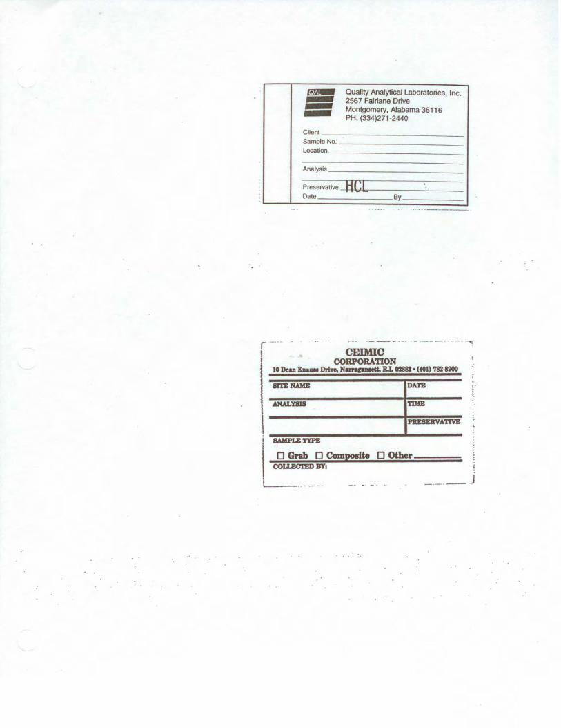
~ - Quality Analytical Laboratories, Inc. 2567 Fair1ane Drive Montgomery. Alabama 36116 PH. (334)271-2440
Client _____________ _ Sample No. ___________ _ Location ____________ _
Analysis ____________ _
Preservative -+H.,C__,...[r---- ----=---Da1e _______ By _____ _
r -··· .. ... ·---·-· ·-----· ·--·--. CEIMIC
CORPOBA110N I 10 Dean XnauN Drhe, Narncawtt. BJ. 0288S • (401) '18U900
DATE ,. i •.
ANALTSIS TDIB
I !
~~ Composite D Other Uz.cn:DBT1
·-· ---- -- - - · .. -··-··- J
Attachment B
Example Chain-of-Custody Record
COC.doc
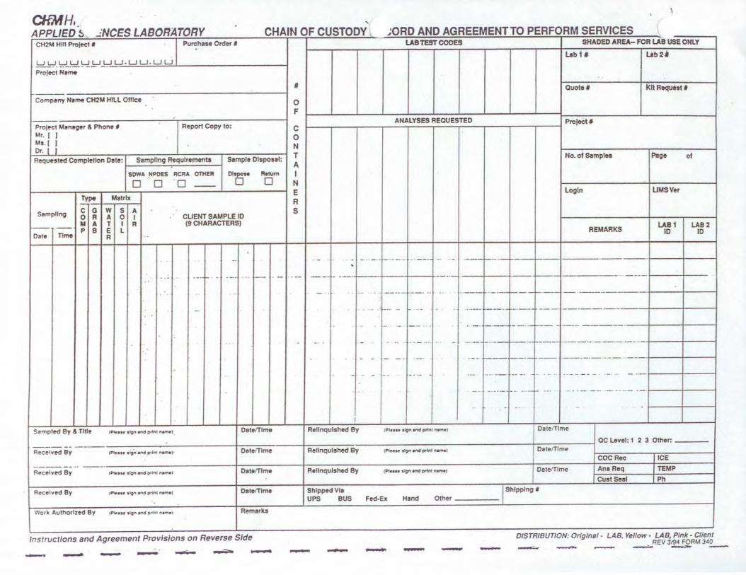
CHMH,. APPLIED~ - -'NCES LABORATORY - CHAIN OF CUSTODY ;ORD AND AGREEMENT TO PERFORM SERVICES
CH2M Hrn ProfKI • Purchase Order I
uuuuuuuu.uu.uu Profecl N•.,,.
# '
Com~ny N11M CH2M Hill Olffce 0 F
,
ProlN:t M•nao•r & Phone • Report Copy to: C Mr. I I 0 Ms I I N Or. I I RequHted Completion D111: 1 Simpling Requirements S1mpl1 Olsposal: T
. A SOWA !'IPDES RCRA OTHER D19poM Retum I
D D ·o -- D D N
Type M1trtx E R
Sampling C 0 w s A s 0 R A 0 l CLIENT SAMPLE 10 M A T I R (9 CHARACTERS) - -- p B E L
Oat• TllM R
.. . - . . ... ·--~ --· ... .__ . - .. -- -- - ----..
• ' ... -
-
--
--
I
Sampled By & TIiie ,,....,. t9" M'td print f'IM'Wl Oatemme Rellnqulshed By
-----Reulved By (Pluu -~ • rid prlttl "•.,...>- Oetemme Relfnqulshed By
-------- ---· Received By IPlt•H t.i,g,t ..-.d pt'WII Nifl'W• Oat.mm• Rellnqulshed By
Received 8y . ..... ., •~ .-ltd p,tnt M'l'Nl Oatemme Shipped VI• UPS BUS
Work Authorized 8y rJll'-'•H 'llQf'I Md p,\ftt ~ ) Remarks
Instructions snd Agreement Provisions on Reverse Side - - - - - - -
U8TEST CODES SHADED AREA- FOR ua US£ ONLY
l.abt1 t.ib2i
.. Quot•• kit Request t
ANALYSES REQUESTED PToJectl
No. of Slmpln Pig• ot
login UMSVer
U81 LA82 REMARKS ID ID
- . _ ,. - ··· -- . -·--- .. ·- ·---- -·- ·----·
---- ... -----. --·•-- ·--· ·· .. ----- -- ·----~-- ----- ··- .. . .. . ---- ---- - ·- --- -------
- ·- - - · . - · --- r-- ·- ~- . ·---
- .. . ·- ... .. ···-'--• .._ ___ -----·-------- ·-
- - - - - ·- · . --· ·- -- --·-----·- --
- - .. - .. ·- ··- ·-··- -- -· . • ·· - ·• -- ~- ... -· -----· ---·- -- -. -- ... ---- --- ----- - - -- ·
.. . . . - .
tPIIUH tlgn ~ (Prinl n..,,.I OatefTlme
QC Level: 1 2 3 Other:
(Ph-111" t-lQin .-.d prlr-1._,,.l Oale'Tlme COCRec ICE
(P'I.-.... •Jon.end swtn• NfM) Oalel'fJme Ana Req TEMP CustSe• I Ph
Fed-Ex Hand Other I Shipping•
- - - - DISTRIBUTION: Orlgfnaf • LAB. Yeflow - LAB, Pink• Cllent REV 319~ FORM 3~0
,,......;... -..0. -=---..,... -
COG.doc
Attachment C
Example Custody Seal
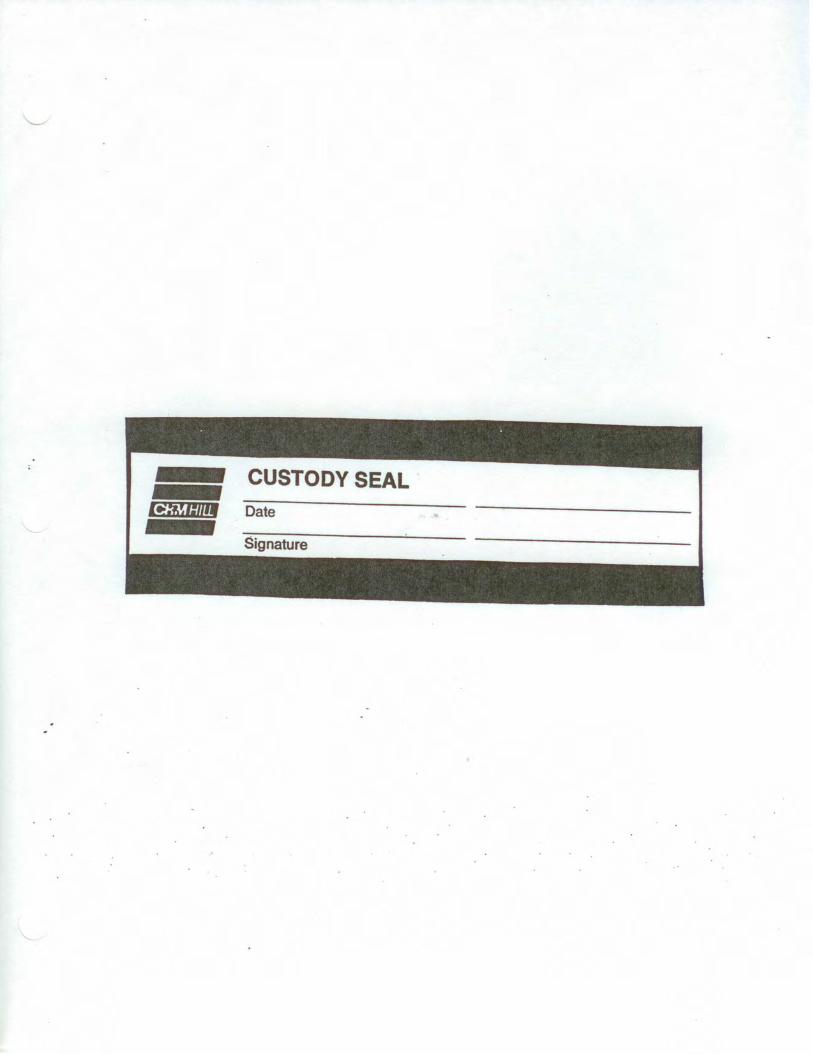
- CUSTODY SEAL -1-::M®lf Date - Signature
ShipLowConc.doc QC and Reviewed 04/2015 1
STANDARD OPERATING PROCEDURE
Packaging and Shipping Procedures for Low-Concentration Samples
I. Purpose and Scope The purpose of this guideline is to describe the packaging and shipping of low-concentration samples of various media to a laboratory for analysis.
II. Scope The guideline only discusses the packaging and shipping of samples that are anticipated to have low concentrations of chemical constituents. Whether or not samples should be classified as low-concentration or otherwise will depend upon the site history, observation of the samples in the field, odor, and photoionization-detector readings.
If the site is known to have produced high-concentration samples in the past or the sampler suspects that high concentrations of contaminants might be present in the samples, then the sampler should conservatively assume that the samples cannot be classified as low-concentration. Samples that are anticipated to have medium to high concentrations of constituents should be packaged and shipped accordingly.
If warranted, procedures for dangerous-goods shipping may be implemented. Dangerous goods and hazardous materials pose an unreasonable risk to health, safety, or property during transportation without special handling. As a result, only employees who are trained under CH2M HILL Dangerous Goods Shipping course may ship or transport dangerous goods. Employees should utilize the HAZMAT ShipRight tool on the Virtual Office and/or contact a designated CH2M HILL HazMat advisor with questions.
III. Equipment and Materials • Coolers • Clear tape • “This Side Up” labels • “Fragile” labels • Vermiculite • Ziplock bags or bubble wrap • Ice • Chain-of-Custody form (completed) • Custody seals
ShipLowConc.doc QC and Reviewed 04/2015 2
IV. Procedures and Guidelines Low-Concentration Samples
A. Prepare coolers for shipment:
• Tape drains shut.
• Affix “This Side Up” labels on all four sides and “Fragile” labels on at least two sides of each cooler.
• Place mailing label with laboratory address on top of coolers.
• Fill bottom of coolers with about 3 inches of vermiculite or absorbent pads.
B. Arrange decontaminated sample containers in groups by sample number. Consolidate VOC samples into one cooler to minimize the need for trip blanks.
C. Affix appropriate adhesive sample labels to each container. Protect with clear label protection tape.
D. Seal each sample bottle within a separate ziplock plastic bag or bubble wrap, if available. Tape the bag around bottle. Sample label should be visible through the bag.
E. Arrange sample bottles in coolers so that they do not touch.
F. If ice is required to preserve the samples, cubes should be repackaged in zip-lock bags and placed on and around the containers.
G. Fill remaining spaces with vermiculite or absorbent pads.
H. Complete and sign chain-of-custody form (or obtain signature) and indicate the time and date it was relinquished to Federal Express or the courier.
J Close lid and latch.
K. Carefully peel custody seals from backings and place intact over lid openings (right front and left back). Cover seals with clear protection tape.
L. Tape cooler shut on both ends, making several complete revolutions with strapping tape. Cover custody seals with tape to avoid seals being able to be peeled from the cooler.
M. Relinquish to Federal Express or to a courier arranged with the laboratory. Place airbill receipt inside the mailing envelope and send to the sample documentation coordinator along with the other documentation.
ShipLowConc.doc QC and Reviewed 04/2015 3
Medium- and High-Concentration Samples: Medium- and high-concentration samples are packaged using the same techniques used to package low-concentration samples, with potential additional restrictions. If applicable, the sample handler must refer to instructions associated with the shipping of dangerous goods for the necessary procedures for shipping by Federal Express or other overnight carrier. If warranted, procedures for dangerous-goods shipping may be implemented. Dangerous goods and hazardous materials pose an unreasonable risk to health, safety, or property during transportation without special handling. As a result, only employees who are trained under CH2M HILL Dangerous Goods Shipping course may ship or transport dangerous goods. Employees should utilize the HAZMAT ShipRight tool on the Virtual Office and/or contact a designated CH2M HILL HazMat advisor with questions.
V. Attachments None.
VI. Key Checks and Items • Be sure laboratory address is correct on the mailing label • Pack sample bottles carefully, with adequate vermiculite or other packaging and
without allowing bottles to touch • Be sure there is adequate ice • Include chain-of-custody form • Include custody seals
PERMA-FIX ENVIRONMENTAL SERVICES
TITLE: Radiation Protection Program
NO.: RP-100
PAGE: 1 of 6
DATE: May 2013
APPROVED:
______________________________________5/31/13_____ Technical Services Manager Date
______________________________________5/31/13____ Corporate Certified Health Physicist Date
1.0 PURPOSE
This administrative procedure describes the major elements of the Radiation Protection Program for Perma-Fix Environmental Services, Inc. (PESI). As applicable, this administrative procedure references sections in the Radiation Protection Plan and project procedures which describe the program in more detail.
2.0 APPLICABILITY
These program descriptions apply to personnel who plan, review, supervise, or perform work involving radiation protection activities during remediation.
3.0 REFERENCES
References are listed in the specific Project Procedures that comprise this Radiation Protection Program.
4.0 DEFINITIONS
Radiation Work Permit (RWP): A document or series of documents prepared by Radiation Protection to inform workers of the radiological and industrial hygiene conditions that exist in the work area and the radiological requirements for the job.
Radioactive Material: Material activated or contaminated by the operation or remediation of the site and byproduct material procured and used to support the operation or remediation.
Radiological Area: Any area within a Restricted Area which require posting as a Radiation Area, Contamination Area, Airborne Radioactivity Area, High Contamination Area, or High Radiation Area.
Restricted Area: An area to which access is limited to protect individuals against undue risks from exposure to radiation, radioactive materials, and chemical contaminants. All posted radiological or chemical areas are Restricted Areas.
Perm - e IX
environmental services
A Nudear Services and Waste Management Company
qc: > 7
~~~-C:-
TITLE: NO.: RP-100
Radiation Protection Program PAGE: 2 of 6
5.0 RESPONSIBILITIES
5.1 Radiation Safety Officer (RSO)
The RSO advises project management on all aspects of Radiation Protection and Operational Health Physics. The RSO directs all radiological safety activities on the project. The RSO has the authority to suspend operations and / or restrict personnel access at the project as a result of nonconformance to this SSHP, or other applicable regulations, and when radiological conditions change beyond the scope of an HWP. The RSO is responsible for:
Implementing and ensuring compliance with RPP’s policies and procedures.
Inspect work activities to ensure operations, including off-normal activities, are being conducted according to the facility or project requirements, applicable federal regulations, and industry accepted As-Low-As-Reasonably-Achievable (ALARA) principles.
Reviewing and approving work plans, Radiation Work Permits, and RPP procedures.
Trending radiation work performance of project personnel including contamination and radiation exposure control.
Identifying, reviewing, and documenting nonconformance, their causes and corrective actions for incidents associated with radiation protection.
Ensuring an effective ALARA Program including conducting onsite radiation safety and health briefings.
Ensuring documentation of any RPP safety violation.
Reviewing survey data.
Conducting briefings concerning radiological work activities.
Ensuring that radiological records are complete, clear and legible, meet the intended purpose, and are regularly transmitted to document control for archive.
Ensuring Restricted Areas are correctly identified, posted and marked.
Performing or coordinating regular internal audits of the RPP.
5.2 Radiation Protection Technicians (RPTs)
RPTs report directly to the RSO. RPTs are assigned by the RSO to provide support to each major field activity for implementation of RPP requirements. RPTs provide guidance in RPP matters to field personnel. RPTs have stop-work authority for radiological safety matters and activities that could result in an unsafe condition being present. RPTs are responsible for the following:
Conducting routine and job-specific radiological surveys (i.e., radiation, contamination, and airborne radioactivity).
Establishing radiological postings.
Implementing the personal protective equipment (PPE) and respiratory protection programs for the purpose of keeping radiation exposures ALARA.
TITLE: NO.: RP-100
Radiation Protection Program PAGE: 3 of 6
Maintaining and operating portable Health Physics survey instrumentation used
in the performance of Radiation Protection (RP) activities.
Performing unconditional release surveys of material from the restricted area.
Performing transportation radiological surveys according to applicable U.S. Department of Transportation (DOT) regulations.
Assisting the SSHO with IH&S monitoring and inspections to a level commensurate with training and experience.
5.3 Project Supervisors
All Project Supervisors are responsible for:
Ensuring personnel under their direction comply with RPP requirements.
Providing information on projected work activities to the RPP organization.
Notifying RP personnel of any radiological problems encountered.
Ensuring workers are prepared for tasks with tools, equipment and training to minimize time spent in radiological areas.
5.4 Project Radiation Workers
All Project Radiation Workers and individuals entering radiologically controlled areas are responsible for:
Obeying promptly “stop-work” and “evacuate” orders from RP personnel and the SSHO.
Obeying posted, oral and written radiological control instructions and procedures, including instructions on Radiation Work Permits and those in the SSHP.
Immediately reporting lost dosimetry devices to RP personnel.
Reporting medical radiation treatments to the RSO and supervisor.
Keeping tack of personal radiation exposure status to ensure that administrative dose limits are not exceeded.
Notifying RP personnel of faulty or alarming radiation protection equipment, and unsafe radiological conditions.
6.0 PREREQUISITES
None
7.0 PRECAUTIONS AND LIMITATIONS
None
8.0 APPARATUS
None
9.0 RECORDS
None
TITLE: NO.: RP-100
Radiation Protection Program PAGE: 4 of 6
10.0 PROCEDURE
10.1 Radiation Protection Organization
1. The RPP Organization will provide appropriate personnel and resources to verify and maintain a radiologically safe working environment.
2. RPP staffing levels will be periodically reviewed to ensure that adequate staffing levels are maintained consistent with current and planned remediation activities.
3. The Project RPP Organization will have access to engineering and other personnel needed to support the Radiation Protection Program.
4. The development and control of RPP Project Procedures will be in accordance with the following guidelines:
Clearly defined scope, tasks, applicability, limiting conditions, precautions, consideration of special controls, reference to acceptance criteria and quality requirements.
Clearly understood text, using standard grammar, nomenclature and punctuation, concise instruction steps in a logical sequence, and references.
Review, approval, issuance, and control of changes and permanent revisions.
10.2 ALARA Program
All activities involving radiation and radioactive materials shall be conducted in such a manner that radiation exposure to workers and the general public are maintained As-Low-As-Reasonably-Achievable (ALARA), taking into account current technology and the economics of radiation exposure reduction in relationship to the benefits of health and safety. ALARA concepts are implemented throughout the entire RPP. ALARA-program requirements include:
1. Administrative controls and procedures endeavor to reduce individual and collective radiation exposures ALARA. Minimizing radiation exposure is accomplished by preliminary planning and scheduling, using proven and innovative engineering techniques and performing engineering reviews of proposed work plan changes.
2. Worker involvement and acceptance in minimizing radiation exposure is a key component of the ALARA Program. Workers are responsible to incorporate ALARA principles into work performance.
3. Work shall be planned in accordance with ALARA principles, involving input from discipline engineers, the project RPP staff and implementing supervisors.
4. An Embryo-Fetus Protection Program has been established for the Project and is specified in RPP-113, “Embryo-Fetus Protection”
10.3 Radiation Protection Audit Program
1. Internal / External Audits of the Radiation Protection Program should be performed, documented, and be of sufficient scope, depth, and frequency to
TITLE: NO.: RP-100
Radiation Protection Program PAGE: 5 of 6
identify and resolve actual or potential performance deficiencies before significant quality problems are encountered. Audit frequency and criteria is determined by the RSO and / or SSHO.
2. The RSO and / or SSHO shall perform an annual review of RPP content and implementation as specified in 10 CFR 20.1101(c).
10.4 External and Internal Dosimetry Program
Internal and external dosimetry and exposure control requirements are defined in the PESI Radiation Protection Plan and includes:
A discussion of applicable regulatory limits for occupational workers and members of the public.
ALARA goals.
Monitoring requirements.
Recordkeeping requirements.
Reporting requirements for both normal operations and incidents.
10.5 Radiation Protection Instrumentation Program
All instrumentation used to measure radiation and radioactive material will be maintained in accordance with their respective technical manuals and operating procedures This includes establishing criteria and requirements for the operation, calibration, response testing, maintenance, inventory and control of radiation protection instrumentation and equipment to comply with applicable regulations and conform with applicable ANSI standards. The Instrumentation Program is detailed by specific procedures including RP-108, RP-109, and RP-110.
10.6 Access Control Program
Access controls to radiological areas will be maintained at all times at the PESI. The administrative and physical measures used to control access to Restricted and/or Radiological Areas are established procedures RP-101, RP-102, and RP-103
10.7 Radiation Protection Surveillance Program
The Radiation Protection Surveillance Program provides for the conduct of radiological surveys in all areas controlled for the purpose of radiation and/or radioactivity. The Program encompasses both routine and non-routine surveys to be performed within the PESI. The specific requirements for conducting and documenting radiological surveys at the PESI are detailed in procedures RP-104, RP-105, RP-106, and RP-107
10.8 Radioactive Material Control Program
This Program provides guidance and requirements for control of radioactive materials. The Radioactive Material Control Program includes receipt, inventory, handling, and release of materials. It also provides for radioactive sealed source control, control of materials entering Restricted Areas and control of contaminated tools and equipment. The requirements of this program are established in RP-111
TITLE: NO.: RP-100
Radiation Protection Program PAGE: 6 of 6
10.9 Respiratory Protection Program
It is not expected that respirators will be widely used by PESI staff for radiation protection purposes at PESI. As such the Respiratory Protection Program will be administered by the SSHO in accordance with the PESI Site Safety and Health Plan. The SSHO will consult with the RSO when respiratory protection is required for radiological purposes.
10.10 Radiological Training
The Radiological Training is required for PESI employees and/or subcontractors who perform work near, or in areas controlled for the purpose of radiation and/or radioactive materials as defined in Section 8.1 of the PESI Radiation Protection Plan. There are two basic levels of training: General Employee Radiation Training for visitors and non-radiation workers, Radiation Worker Training for workers who access Restricted Areas.
10.11 Radiation Protection Records
Radiation Protection Records are routinely developed to document all aspects of the Radiation Protection Program. Records are generated using clear concise text using standard grammar and punctuation. Records are reviewed for adequacy and completeness and transmitted to the Document Control organization for long-term retention.
RP-101 Access Control
PERMA-FIX ENVIRONMENTAL SERVICES
TITLE: Access Control
NO.: RP-101
PAGE: 1 of 6
DATE: May 2014
APPROVED:
______________________________________5/31/14_____ Technical Services Manager Date
______________________________________5/31/14___ Corporate Certified Health Physicist Date
1.0 PURPOSE
The purpose of this procedure is to provide consistent methodology for controlling the access of personnel, equipment, and vehicles into radiological areas.
2.0 APPLICABILITY This procedure applies to all Project personnel and visitors, equipment, and vehicles entering Restricted Areas.
3.0 REFERENCES 1. 10 CFR 19, “Notices, Instructions and Reports to Workers Inspection.”
2. 10 CFR 20, “Standards for Protection Against Radiation.”
3. Perma-Fix Environmental Services (PESI) Radiation Protection Plan (RPP)
4. RPP-102, “Radiological Posting Requirements.”
5. RPP-103, “Radiation Work Permits Preparation and Use.”
6. 29 CFR 1910.120, “Hazardous Waste Operations and Emergency Response.”
TITLE: Access Control NO.: RP-101 PAGE: 2 of 8
PESI-RP-101
4.0 GENERAL 4.1 Discussion
Access controls are used to ensure the radiological safety of personnel entering into Restricted Areas. These controls include, but are not limited to Training, Dosimetry, Posting, Area Monitoring, and Radiation Work Permits (RWP).
4.2 Definitions
ALARA: Means as low as reasonably achievable.
GET: General Employee Training
GERT: General Employee Radiation Training
HAZWOPER: 40-Hour Hazardous Waste Operations and Emergency Response training in accordance with 29 CFR 1910.120
Radiation Worker: An individual who accesses any Restricted Area unescorted. Radiation Workers shall have successfully completed all requisite medical and training requirements for performing work in Restricted Areas. RPT: Radiation Protection Technician
Radiation Work Permit (RWP): A document or series of documents prepared by the Radiation Protection Group to inform workers of the radiological, industrial hygiene and other safety conditions which exist in the work area and task-related radiological and other safety requirements.
RSO: Radiation Safety Officer
SSHO: Site Safety and Health Officer
SRD: Self-Reading Dosimeter
Visitor: An individual who accesses the project site for purposes other than for assignment as a Project Worker (e.g., site visit, performance of an essential short-term task).
5.0 RESPONSIBILITIES 5.1 Site Safety & Health Officer (SSHO)
The SSHO is responsible for ensuring that all activities performed within this procedure conform to the requirements of the PESI Site Safety & Health Plan (SSHP).
Authorizing escorted visitor entries into Restricted Areas. This responsibility may be designated.
Evaluating visitor entries to Restricted Areas to minimize or eliminate exposure risk to personnel who lack adequate training.
5.2 Radiation Safety Officer (RSO) Implementing this procedure. Approving RWPs to control access to Restricted Areas. Reviewing and approving training programs related to work in Restricted Areas. Implementing the requirements of the PESI Radiological Protection Program. Providing direction to the Project Personnel regarding radiological matters.
TITLE: Access Control NO.: RP-101 PAGE: 3 of 8
PESI-RP-101
Authorizing escorted visitor entries into Restricted Areas. This responsibility may be designated.
Evaluating visitor entries to Restricted Areas to minimize or eliminate exposure risk to personnel who lack adequate training.
5.3 Radiation Protection Technician (RPT) Identifying and posting Restricted Areas. Providing RWP briefings to individuals entering Restricted Areas. Conducting radiation and contamination surveys, and keeping legible records. Monitoring work activities to ensure compliance with the requirements of the
Radiological Protection Program.
5.4 Project Supervisor Ensuring that personnel assigned to work in Restricted Areas or with radioactive
material, attend required training and perform work in a radiologically sound and safe manner.
Contacting the RSO or designee, to obtain approval to bring escorted visitors into Restricted Areas.
Notifying the RSO or designee, in advance (when possible) of the need to bring any non-project owned equipment / vehicles into the Restricted Area to arrange for baseline contamination surveys.
5.5 Project Personnel Attending designated training classes.
Following directions from the RPT with regards to Safety and Health.
Maintaining their personnel exposures ALARA.
Limiting the amount of material taken into Restricted Areas to that necessary for task performance.
Working in a manner so as to prevent spread of contamination and reduce airborne radiological emissions to the extent possible.
6.0 PREREQUISITES 6.1 Individuals requiring unescorted access into a Restricted Area shall submit the following
documentation to the RSO prior to entry:
Evidence of initial 40-Hour and 8-Hour Refresher OSHA HAZWOPER Training (if applicable)
Current medical examination performed within the past 12 months.
Evidence of successful completion of Site Orientation Training (GET/GERT) and Radiation Worker Training (RWT).
6.2 Individuals requiring unescorted access into a Restricted Area shall meet the requirements for Restricted Area access and have the following at a minimum:
Thermoluminescence Dosimeter (TLD) or Self-Reading Dosimeter (SRD). Personal Protective Equipment (PPE) specified by posting and/or RWP.
TITLE: Access Control NO.: RP-101 PAGE: 4 of 8
PESI-RP-101
6.3 Visitor access into Restricted Areas is limited to essential tasks which meet all of the following requirements:
The task cannot be performed by appropriately trained Project Personnel
The task is time critical in nature and would have a negative impact on safety & health or project operations if not performed.
The task cannot be deferred until the Restricted Area is remediated or down posted.
7.0 PRECAUTIONS AND LIMITATIONS No unessential visitors shall be allowed access to the restricted areas.
Visitors shall receive visitor specific site orientation training prior to accessing a restricted area. Training shall be documented.
Personnel, equipment, and vehicle entry control shall be maintained for each radiological area.
No radiological control(s) shall be installed in any area that would prevent the rapid evacuation of personnel in an emergency situation.
Trained emergency response personnel (Fire Dept., Ambulance/EMT, Law Enforcement) responding to on-site emergencies are exempt from the requirements of this procedure.
Any member of the public exposed to radiation and / or radioactive material shall not exceed 0.1 rem Total Effective Dose Equivalent per year.
All visitors entering into a Restricted Area shall be escorted at all times by a qualified radiation worker. The RSO and SSHO or designee(s) shall approve these entries. The escort is responsible for visitor compliance with site protocols.
Visitors may not enter a posted High Contamination Area, Radiation Area, High Radiation Area, or Airborne Radioactivity Area.
Visitors shall not perform any work of an intrusive nature (i.e., digging, drilling, sampling, etc.) or an abrasive nature (i.e., welding, sanding, grinding, etc.) in Controlled Areas unless evaluated and approved by the RSO or designee.
Visitors may only enter those areas where hazardous atmospheres do not exceed 50% of the Permissible Exposure Limit and where radiation exposures would not exceed the annual dose limit to a member of the public as specified in 10 CFR 20.
The RSO shall ensure that risk of exposure to hazardous materials is minimized or eliminated prior to authorizing visitor entry into Restricted Areas. No work of an intrusive nature that may produce radioactive airborne particulates shall take place during visitor access to a restricted area.
Visitors shall not be allowed to come into contact with tools, vehicles or materials that are contaminated above the release levels established in the SSHP.
Project personnel who are required to escort individuals into a Restricted Area shall have successfully completed Radiation Worker Training (RWT), which includes training on the requirements of this procedure, and have a demonstrated knowledge of the site layout, site history, and emergency response protocols.
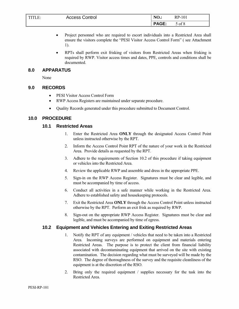
TITLE: Access Control NO.: RP-101 PAGE: 5 of 8
PESI-RP-101
Project personnel who are required to escort individuals into a Restricted Area shall ensure the visitors complete the “PESI Visitor Access Control Form” ( see Attachment 1).
RPTs shall perform exit frisking of visitors from Restricted Areas when frisking is required by RWP. Visitor access times and dates, PPE, controls and conditions shall be documented.
8.0 APPARATUS None
9.0 RECORDS PESI Visitor Access Control Form RWP Access Registers are maintained under separate procedure.
Quality Records generated under this procedure submitted to Document Control.
10.0 PROCEDURE 10.1 Restricted Areas
1. Enter the Restricted Area ONLY through the designated Access Control Point unless instructed otherwise by the RPT.
2. Inform the Access Control Point RPT of the nature of your work in the Restricted Area. Provide details as requested by the RPT.
3. Adhere to the requirements of Section 10.2 of this procedure if taking equipment or vehicles into the Restricted Area.
4. Review the applicable RWP and assemble and dress in the appropriate PPE.
5. Sign-in on the RWP Access Register. Signatures must be clear and legible, and must be accompanied by time of access.
6. Conduct all activities in a safe manner while working in the Restricted Area. Adhere to established safety and housekeeping protocols.
7. Exit the Restricted Area ONLY through the Access Control Point unless instructed otherwise by the RPT. Perform an exit frisk as required by RWP.
8. Sign-out on the appropriate RWP Access Register. Signatures must be clear and legible, and must be accompanied by time of egress.
10.2 Equipment and Vehicles Entering and Exiting Restricted Areas 1. Notify the RPT of any equipment / vehicles that need to be taken into a Restricted
Area. Incoming surveys are performed on equipment and materials entering Restricted Areas. The purpose is to protect the client from financial liability associated with decontaminating equipment that arrived on the site with existing contamination. The decision regarding what must be surveyed will be made by the RSO. The degree of thoroughness of the survey and the requisite cleanliness of the equipment is at the discretion of the RSO.
2. Bring only the required equipment / supplies necessary for the task into the Restricted Area.
TITLE: Access Control NO.: RP-101 PAGE: 6 of 8
PESI-RP-101
3. When practicable, use contamination prevention methods such as wrapping or sleeving of equipment taken into a CA or ARA.
4. Remove as much packaging material as possible (i.e., plastic or cardboard) prior to entering a Restricted Area.
5. Notify the RPT of any equipment / vehicles that need to be removed from a Restricted Area.
10.3 Visitor Escorts 1. Discuss planned activities, work locations, and site hazards with the Visitor.
Discuss any restrictions on where the Visitor may go and what the Visitor may do within the Restricted Areas. Define the obligations of the Visitor with respect to following instructions of the escort and of safety personnel.
2. Provide the Visitor with a copy of the PESI Visitor Access Control Form (Attachment 1).
3. Instruct the Visitor to review the form, complete the top portion, and sign.
4. Answer any questions the Visitor may have. RP personnel are available to answer questions as needed.
5. Sign the PESI Visitor Access Control Form acknowledging escort responsibilities.
6. Obtain RSO and SSHO signature permitting Restricted Area access.
7. Give completed form to RP Personnel.
8. RP Personnel should assign a personnel dosimeter to the Visitor or group of visitors (this is a TLD unless otherwise instructed by the RSO). Note Self-Reading Dosimeter (SRD) in/out readings, if used, on the RWP Access Register.
9. Review the appropriate RWP with the Visitor, and ensure the Visitor dons PPE and signs and records the time of entry onto the RWP Access Register.
10. Escort the Visitor into the Restricted Area observing all escort responsibilities.
11. Upon completion of activities, assist visitor with PPE removal, and RWP sign-out. An RPT will perform the exit frisking.
12. Escort the Visitor out of the Restricted Area.
13. Take the personnel dosimeter and give it to the RP personnel. RP Personnel shall notify the RSO immediately if SRD readings indicate a personnel exposure.
11.0 ATTACHMENT Attachment 1 PESI Visitor Access Control Form (FRONT & BACK)
TITLE: Access Control NO.: RP-101 PAGE: 7 of 8
PESI-RP-101
ATTACHMENT 1 PESI VISITOR ACCESS CONTROL FORM (FRONT)
Name ______________________________ Representing ____________________________________ SSN _____ -_____ - _______ Mailing Address____________________________________ _____________ Some work at the PESI involves exposure to hazardous environments, radiation or radioactive materials. In keeping with the provisions of the Code of Federal Regulations Title 10, Part 19, this is to inform you of the extent of the hazards to which you may be exposed. Radiation and radioactive materials on this project site are confined within clearly posted and delineated areas. Other hazardous materials may be present in these areas. Signs in these areas are magenta or purple and yellow in color and contain the international symbol for radiation, a trefoil or three-bladed design. (ESCORT: SHOW VISITOR AN EXAMPLE OF A RADIOLOGICAL POSTING). During your visit, you will be provided with an escort. You must remain with your escort at all times. In the unlikely event of an incident involving radioactive or other hazardous materials, your escort will provide you with instructions. Comply with the instructions of your escort. If exit frisking is required by the RWP, Radiation Protection Personnel will perform the exit frisk. Do not enter any areas posted “RADIATION AREA” “HIGH CONTAMINATION AREA” or “AIRBORNE RADIOACTIVITY AREA.” Do not perform work of an intrusive nature (i.e., digging, drilling, sampling, etc.) or any abrasive work (i.e., welding, sanding, grinding, etc.) without specific written approval of the RSO. Nuclear Regulatory Guide 8.13, “Instructions Concerning Pre-natal Radiation Exposure” is available for review upon request. Address any questions you may have to your escort or to the person you are visiting. Questions may also be directed to the Safety & Health Department. I have read and understand the above. I agree to comply with the terms of this form. Visitor Signature Date I have reviewed the above with the visitor and agree to comply in full with PESI established radiological escort protocols including, but not limited to, those specific requirements specified on the back of this form. Escort Signature Date Restricted Area Access Authorized: RSO or designee Signature Date SSHO or designee Signature Date ALL SIGNATURES MUST BE PRESENT ON THIS FORM PRIOR TO RESTRICTED AREA ACCESS!
TITLE: Access Control NO.: RP-101 PAGE: 8 of 8
RP-101 Access Control
ATTACHMENT 1 (BACK OF FORM) PESI VISITOR ACCESS CONTROL FORM
SSHO/RSO Requirements to Minimize or Eliminate Exposure Risks: _____________________________________________________________________________________ _____________________________________________________________________________________ _____________________________________________________________________________________ _____________________________________________________________________________________ _____________________________________________________________________________________ _____________________________________________________________________________________ _____________________________________________________________________________________ SSHO/RSO Remarks: _____________________________________________________________________________________ _____________________________________________________________________________________ _____________________________________________________________________________________ _____________________________________________________________________________________ _____________________________________________________________________________________ _____________________________________________________________________________________ SSHO Initials: __________ RSO Initials: ____________
RP-102 Radiological Posting
PERMA-FIX ENVIRONMENTAL SERVICES
TITLE: Radiological Postings
NO.: RP-102
PAGE: 1 of 6
DATE: May 2014
APPROVED:
______________________________________5/31/14_____ Technical Services Manager Date
______________________________________5/31/14___ Corporate Certified Health Physicist Date
1.0 PURPOSE
The purpose of this procedure is to provide consistent methodology for posting requirements for various radiological hazard areas on PESI Projects.
2.0 APPLICABILITY This procedure applies to all which require radiological postings.
3.0 REFERENCES 1. 10 CFR 19, “Notices, Instructions, and Reports to Workers; Inspection.”
2. 10 CFR 20, “Standards for Protection Against Radiation.”
3. Perma-Fix Environmental Services (PESI) Radiation Protection Plan (RPP)
4.0 GENERAL 4.1 Discussion
Radiological postings are used to delineate areas containing radiological hazards and to inform personnel of hazards. In addition, supplemental or informational postings may be included which provide personnel with entry requirements or protective equipment requirements. Barriers may be used in conjunction with postings to ensure that personnel do not inadvertently enter into an area with a radiological hazard. Barriers at the PESI and the vicinity properties are normally composed of rope, tape, or fencing.
4.2 Definitions Posting: A standardized sign or label which bears the standard trefoil radiation symbol in magenta or black on a yellow background and information concerning a specific radiological hazard.
TITLE: Radiological Posting Requirements NO.: RPP-102 PAGE: 2 of 4
RP-102 Radiological Posting
5.0 RESPONSIBILITIES 5.1 Site Safety & Health Officer (SSHO)
The SSHO is responsible for ensuring all activities performed within this procedure conform to the requirements of the SSHP.
5.2 Radiation Safety Officer (RSO) Implementation of this procedure.
Reviewing pertinent survey data and making periodic tours to verify all areas within the PESI are properly posted.
Authorizing the de-posting or down-posting of areas.
Providing technical direction to the Radiation Protection Technicians (RPTs).
5.3 Radiation Protection Technician (RPT) Directing the placement of radiological postings and barriers. Performing periodic radiation / contamination surveys to ensure radiological
conditions have not changed.
5.4 Project Supervisor Ensuring that personnel working in their particular area obey all radiological
postings.
5.5 Project Personnel Obeying all radiological postings. Following directions from the RPT with regards to radiological postings. Maintaining their personnel exposures as low as reasonably achievable (ALARA).
6.0 PREREQUISITES RPTs will be trained to assess and recognize the various radiological hazards present at the PESI.
7.0 PRECAUTIONS AND LIMITATIONS Barriers and other means shall be used as required to maintain control of areas requiring
posting.
At a minimum, all access / egress points to areas requiring radiological posting shall be conspicuously posted with the appropriate signs which includes area descriptions and specific requirements for entry.
Appropriate signs should be placed approximately every 40 feet around the perimeter of a posted area. At least one sign should be placed on each side of an area’s boundary, visible from any normal avenue of approach. These signs require only area identifiers (e.g., Restricted Area, Radioactive Materials Area, Radiation Area, etc.) in addition to the standard “Caution” or “Warning” and the tre-foil.
An RPT with the appropriate field survey instrumentation may serve as the radiological posting in situations where the task is of a short duration or at the discretion of the RSO.
No radiological control(s) shall be installed in any area that would prevent the rapid evacuation of personnel in an emergency situation.
TITLE: Radiological Posting Requirements NO.: RPP-102 PAGE: 3 of 4
RP-102 Radiological Posting
Trained emergency response personnel (Fire Dept, Ambulance / EMT, Law Enforcement) responding to on-site emergencies are exempt from the requirements of this procedure.
Postings should be as clear and concise as possible to prevent confusion on the part of personnel desiring to enter an area.
Postings should not be hung from ladders, electrical wire, switches, vehicles, or any other item that could be damaged, moved, or could cause injury to personnel.
If more than one level of radiological posting is required in an area, posting for each unique condition shall be identified starting with the highest hazard potential. However, it is not required to post areas with area identifiers that are superceded by postings identifying a higher hazard potential (e.g., posting a Contamination Area as a Radioactive Materials Area, etc.).
Radiological postings shall not be moved or altered without approval from the RSO or the RPT covering the work.
8.0 APPARATUS Yellow and magenta barrier supplies (e.g., rad-rope, rad-tape, rad-ribbon, etc.) Signs and inserts as required Radioactive Material Labels or tags Stands or Stanchions
9.0 RECORDS All surveys performed for radiological posting placement will be forwarded to project document control.
10.0 PROCEDURE 10.1 Controlled Areas
All access points to areas meeting the definition of a Controlled Area shall be posted with the words “CONTROLLED AREA,” or “US GOVERNMENT PROPERTY” plus any additional verbiage deemed appropriate by Project Management.
10.2 Restricted Areas All access points to areas meeting the definition of a Restricted Area shall be posted with the words “RESTRICTED AREA.”
10.3 Contamination Areas All access points to areas meeting the definition of a Contamination Area shall be posted with the words “CAUTION, CONTAMINATION AREA,” and with the words “RESTRICTED AREA,” as well as any special instructions deemed necessary by the RSO.
10.4 High Contamination Areas All access points to areas meeting the definition of a Contamination Area shall be posted with the words “CAUTION, HIGH CONTAMINATION AREA,” and with the words “RESTRICTED AREA,” as well as any special instructions deemed necessary by the RSO.
TITLE: Radiological Posting Requirements NO.: RPP-102 PAGE: 4 of 4
RP-102 Radiological Posting
10.5 Radiation Areas All access points to areas meeting the definition of a Radiation Area shall be posted with the words “CAUTION, RADIATION AREA” as well as any special instructions deemed necessary by the RSO.
10.6 High Radiation Areas All access points to areas meeting the definition of a High Radiation Area shall be posted with the words “DANGER, HIGH RADIATION AREA” as well as any special instructions deemed necessary by the RSO.
10.7 Radioactive Materials Areas All access points to areas meeting the definition of a Radioactive Materials Area shall be posted with the words “CAUTION, RADIOACTIVE MATERIALS AREA” as well as any special instructions deemed necessary by the RSO.
10.8 Airborne Radioactivity Area All access points to areas meeting the definition of an Airborne Radioactivity Area shall be posted with the words “CAUTION, AIRBORNE RADIOACTIVITY AREA” as well as any special instructions deemed necessary by the RSO.
10.9 Posting / De-Posting / Down-Posting Posting, De-posting, and Down-posting activities should be noted in the appropriate technician logbook with reference to applicable survey number(s).
11.0 ATTACHMENTS None
PERMA-FIX ENVIRONMENTAL SERVICES
TITLE: Radiation Work Permits
Preparation and Use
NO.: RP-103
PAGE: 1 of 7
DATE: May 2014
APPROVED:
______________________________________5/31/14_____ Technical Services Manager Date
______________________________________5/31/14___ Corporate Certified Health Physicist Date
1.0 PURPOSE
This procedure describes the conditions under which a Radiation Work Permit (RWP) is required on PESI Projects. This procedure establishes consistent methodology and responsibilities for developing, utilizing and terminating an RWP. The procedure also describes the functions of the RWP (a sample is given in Attachment 1).
2.0 APPLICABILITY
This procedure applies to RWP requests, preparation, use, and termination. All personnel working on a task for which a RWP is required are required to comply with its conditions.
3.0 REFERENCES
1. Title 17, California Code of Regulations, Section 30255, “Notices, Instructions and Reports to Workers, Inspections, and Investigations.”
2. Title 17, California Code of Regulations, Division 1, Chapter 5, Subchapter 4 “Standards for Protection Against Radiation.”
3. RP-101, “Access Control.”
4.0 DEFINITIONS
Airborne Radioactivity Area: Means any area where the measured concentrations of airborne radioactivity above natural background exceed, or are likely to exceed, 25% of the Derived Air Concentration (DAC) values identified in Section 6.0 of the Radiation Protection Plan; and as listed in 10 CFR 20, Appendix B, Table I, Column 3
Contamination Area (CA): Means any area accessible to personnel with loose surface contamination values in excess of the values specified in the United States Army Corps of Engineers (USACE) Radiation Protection Manual, “Acceptable Surface Contamination Levels,” (also refer to Table 1 of the Radiation Protection Plan; and procedure RPP-104, “Radiological Surveys,”) or any additional area specified by the Radiation Safety Officer (RSO). The
Perm - e IX
environmental services
A Nudear Services and Waste Management Company
qc: > 7
~~~-C:-
TITLE:
Radiation Work Permits Preparation and Use
NO.: RPP-103 PAGE: 2 of 7
Contamination Area posting requirement is more restrictive than the Radioactive Material Area posting requirement. Any area posted as a Contamination Area shall also be considered to be a Radioactive Materials Area.
Radiation Work Permit (RWP): Means a document or series of documents prepared by Radiation Protection to inform workers of the radiological and industrial hygiene conditions which exist in the work area and the radiological requirements for the job.
Radiation Area (RA): Means any area, accessible to personnel, where the whole body dose rate exceeds 5 mrem/hr but less than 100 mrem/hr at 30 cm from the source.
Radiological Area: Any area within a Restricted Area which require posting as a Radiation Area, Contamination Area, Airborne Radioactivity Area, High Contamination Area, or High Radiation Area.
High Radiation Area (HRA): Means any area accessible to personnel where the whole body dose rate exceeds 100 mrem/hr at 30 cm (12 inches) from the radiation source.
Radioactive Materials Area (RMA): Any area or room where quantities of radioactive materials in excess of 10 times the 10 CFR 20, Appendix C quantities are used or stored, or any area designated by the RSO which does not exceed the site Contamination Area criteria.
Restricted Area: Means any area to which access is limited by Project Management for the purpose of protecting individuals against exposure to radiation and radioactive materials.
5.0 RESPONSIBILITIES
5.1 Radiation Safety Officer (RSO)
Implementation of this procedure. Approving all protective measures incorporated into the RWP with regards to
Radiological Safety.
5.2 Radiation Protection Technician (RPT)
Conducting radiation and contamination surveys and keeping legible records. Preparing RWPs to control access to and activities in radiological areas. Monitoring worker compliance with RWP requirements.
5.3 Project Personnel
Reviewing the correct RWP for the task to be performed.
Accurately and legibly completing required information on the RWP Access Register.
Observing radiological postings.
Obeying oral and written radiological and industrial hygiene control instructions and procedures, including instructions on RWPs.
Maintaining an awareness of radiological and industrial hygiene conditions in the work area.
6.0 PREREQUISITES
1. A RWP shall be required for the following:
All tasks requiring entries into Radiological Areas.
TITLE:
Radiation Work Permits Preparation and Use
NO.: RPP-103 PAGE: 3 of 7
As specified by the RSO or their designees.
2. Prior to use of an RWP, the RSO or designee shall:
Define an access location appropriate for the RWP.
Review the inventory at the applicable Access Control Points and shall verify that Personal Protection Equipment (PPE), instruments and other safety-related equipment necessary to support the requirements of the RWP are available.
3. Prior to entry, all personnel working under an RWP must:
Satisfy medical and training requirements as established in the Access Control procedure.
Be adequately briefed by the Radiation Protection Group regarding:
Work to be performed and the associated RWP requirements. Safety procedures to be followed for its completion.
7.0 PRECAUTIONS AND LIMITATIONS
Personnel shall not deviate from the requirements, precautions, or other instructions on the RWP without authorization from the RSO or designees.
A copy of the RWP shall be posted at the work site. The original shall remain at a central location (Safety and Health office). Associated support documents containing environmental conditions (soil activities, contamination surveys, etc.) shall be maintained by the RSO and are available upon request.
An RWP is not required when responding to emergency situations where serious consequences could result if time were taken to prepare the RWP.
8.0 APPARATUS
None
9.0 RECORDS
Hazardous Work Permit (RWP) Hazardous Work Permit Access Register
10.0 PROCEDURE
10.1 Active RWP Use
1. The RP group will activate the RWP upon review and signature by the RSO.
2. A copy of active RWPs will be maintained at applicable Access Control Points.
3. The RSO or designee shall review the inventory and shall verify that PPE, instruments and other safety-related equipment necessary to support the requirements of the RWP are available at the applicable Access Control Points. Inventory reviews shall also be performed, as necessary, during the course of work on the RWP.
4. All workers who will be working on tasks supported by an RWP will be provided an initial briefing on the RWP by a Safety and Health representative:
TITLE:
Radiation Work Permits Preparation and Use
NO.: RPP-103 PAGE: 4 of 7
Upon their entry on the RWP. Upon initial entry following revision of a RWP. When significant changes occur in the work area.
5. The purpose of the briefing is to ensure:
All Safety and Health conditions, requirements, special precautions, are fully understood by the workers.
Ensure that all anticipated tools, materials, and equipment are assembled for the work.
Ensure that work party members have been issued any radiological monitoring or protective devices specified for the work.
6. All personnel will read and verify that they understand and agree to comply with the terms of the RWP by signing in on the RWP Access Register (Attachment 2).
7. While working under an RWP, personnel are responsible to know and understand:
The tasks that fall under the RWP. Procedural controls and precautions taken to:
Reduce spread of contamination.
Reduce airborne emissions of radionuclides.
Reduce dose to workers and the public as low as reasonably achievable (ALARA).
Requirements to apply the sound radiological and safe work practices taught in indoctrination and continuing training.
8. The RSO or the attending RPT have stop work authority for all phases of work under an RWP. Stop work authority can be implemented when personnel safety is jeopardized due to:
A change in the radiological (or other hazard) environment occurs, requiring additional controls and / or precautions.
If poor work practices are employed.
If RWP, ALARA, or procedural controls and / or precautions are violated.
9. Personnel shall sign in / out on the RWP Access Register for each entry into and egress from an area including when exiting the area for short break periods and when transferring to work on a different RWP.
10. Upon completion of work or at the end of the shift the Work Party Supervisor shall ensure that:
Access Control Point and Work Area conditions are satisfactory. This includes housekeeping, safe storage of equipment, ensuring any required contamination control measures are implemented, and accurate completion of RWP Access Registers.
TITLE:
Radiation Work Permits Preparation and Use
NO.: RPP-103 PAGE: 5 of 7
All radiological and Industrial Hygiene monitoring and protection devices
that were issued have been returned to the Safety and Health (S&H) Group.
10.2 Termination of RWP
1. If the work was not or cannot be completed within the duration period of the RWP, an extension of the RWP should be requested.
2. An RWP is considered “terminated upon:
Signature by the RSO, or designee(s) in the appropriate section on the original RWP.
If the duration period for the RWP is been exceeded and the RWP was not extended.
3. Upon Completion of an RWP task, the Work Party Supervisor shall ensure that:
Access Control Point and Work Area conditions are satisfactory. This includes housekeeping, safe storage of equipment, ensuring any required contamination control measures are implemented, and accurate completion of RWP Access Registers.
All radiological and Industrial Hygiene monitoring and protection devices that were issued have been returned to the RP Group.
4. Upon completion of the job, the RWP copy and RWP Access register shall be returned to the RP Group for disposition.
5. Completed RWP forms (originals) and RWP Access Registers are quality records. These documents shall be maintained by the RP Group until transmitted to Project Records.
11.0 ATTACHMENTS
Note: Attachments may be revised without formal review of this procedure and are attached as examples only. Please contact the RSO for a current copy of these attachments.
Attachment 1 Radiation Work Permit (Typical)
Attachment 2 Radiation Work Permit Access Register (Typical)
TITLE: NO.: RP-103 Radiation Work Permits Preparation and Use PAGE: 6 of 7
Attachment 1 (Typical)
PESI RADIATION WORK PERMIT (RWP)
NO. -
Revision Number
WORK DESCRIPTION: WORK LOCATION(S):
Start Date /Time:
Est. Completion Date:
Requested by:
Request Date:
HAZARDOUS CONDITIONS
IS A RADIOLOGICAL / ALARA REVIEW REQUIRED ? No Yes
I.H. LIMITS: RADIOLOGICAL LIMITS CURRENT CONDITIONS
O2: Exposure Rate:
IH/Rad conditions are evaluated by Safety & Health personnel, as necessary,
during job coverage. The adjacent IH/Rad limits are the maximum allowed
by this RWP.
LeL: Alpha Contamination: Org. Vapors: DUST: General Area Airborne: H2S: Limiting Isotope / DAC Value:
REQUIRED PERSONAL PROTECTIVE CLOTHING & EQUIPMENT (PPE)
HEAD / EYES FEET / LEGS BODY
Hard Hat
Sturdy Work Shoes
Cotton Coveralls Safety Glasses
Disposable Shoe Covers
Tyvek Coveralls (Regular) Monogoggles
Rubber Over Shoes / Boots
Tyvek Coveralls (Coated) Face Shield Other (Specify): Other (Specify)
RESPIRATORY HANDS MISCELLANEOUS
Full Face (Negative Pressure) * Cotton / Work Gloves Tape Gloves & Boots to Coveralls
Powered Air Purifying* Nitrile Surgeons Gloves Fall Protection * Specify Cartridge or Canister Type Below Rubber Gloves Hearing Protection
Other (specify) Other (Specify): Other (Specify)
ADDITIONAL REQUIREMENTS / SPECIAL INSTRUCTIONS / MONITORING REQUIREMENTS
Additional Requirements Special Instructions Dosimetry Indiv. Group
"Buddy System" in Effect TLD Badge
S&H Tech Job Coverage ( Intermittent / Continuous) Extremity TLD
Confined Space Entry Permit Other (Specify):
HotWork Permit
Lockout-Tagout Permit
Excavation Permit Air Monitoring Indiv. Group
Review MSDS Lapel-Breathing Zone
Emergency Response Equipment Low Volume
Communication Method ( Radio / Voice ) Dust
Portable Eyewash Station PID / FID
Pre-Entry Monitoring 4 Gas
S&H Tech Notification Prior to Work ( Daily / Each Entry )
Personnel Frisking Required ( Whole-Body / Hand & Feet ) Expiration Date/Time: __________________________________________________ This permit will be reviewed for
revision as conditions change and at 1-year from date of implementation.
__________________________________________________
__________________________________________________
APPROVALS DATE TERMINATION DATE
RSO RSO or SSHO SSHO Reason:
I I I I
TITLE: NO.: RPP-103 Radiation Work Permits Preparation and Use PAGE: 7 of 7
Attachment 2 (Typical)
PESI RWP ACCESS REGISTER RWP # __ __ - __ __ __
WORK LOCATION: ______________________________ DATE: ___ ___ / ___ ___ / ___ ___ Sheet: ___ of ___
ENTRANT
BADGE NUMBER (1)
ENTRANT
SIGNATURE
(2)
TIME
IN
(3)
TIME
OUT
TIME
IN
TIME
OUT
TIME
IN
TIME
OUT
TIME
IN
TIME
OUT
TOTAL
HOURS
(RP USE)
Notes: (1) If no badge number assigned, print name (Last, FI, MI) (2) Entrant signature acknowledges understanding of and agreement to comply with RWP requirements, including required personnel monitoring. Entrants are to immediately
report any frisker alarms or indications of personnel contamination to RP Personnel. Escorts shall initial after entrant signature for visitors. (3) Use Military Time (24 Hour) for ALL entry/exit times (ex. 7:15 AM = 0715 or 3:25 PM =1525). Log each entry/exit, including break periods. REGISTER REVIEW / DATA ENTRY: ____________________________________
RRP-104 Radiological Surveys
PERMA-FIX ENVIRONMENTAL SERVICES
TITLE: Radiological Surveys
NO.: RP-104
PAGE: 1 of 6
DATE: May 2014
APPROVED:
______________________________________5/31/14_____ Technical Services Manager Date
______________________________________5/31/14___ Corporate Certified Health Physicist Date
1.0 PURPOSE
This procedure establishes consistent methodology for performing radiation and contamination surveys at Perma-Fix Environmental Services (PESI) facilities and projects.
2.0 APPLICABILITY This procedure is applicable to all personnel trained and qualified to perform radiation and contamination surveys at PESI.
3.0 REFERENCES 1. 10 CFR 20, “Standards for Protection Against Radiation.”
2. PESI “Radiation Protection Plan (RPP)
3. RP-101, “Access Control.”
4. RP-105, “Unrestricted Release of Requirements.”
5. RP-106, “Survey Documentation and Review
4.0 GENERAL 4.1 Discussion
Radiological surveys are performed to detect and assess radiological conditions, which may be encountered at PESI.
4.2 Definitions Contact Dose Rate: A radiation dose rate as measured at contact or within 1/2 inch of the surface being measured.
CPM: Counts per minute
Dose Rate: The quantity of absorbed dose delivered per unit of time.
DPM: Disintegrations per minute
TITLE: Radiological Surveys NO.: RP-104 PAGE: 2 of 9
RRP-104 Radiological Surveys
General Area Dose Rate (GA Dose Rate): The highest radiation dose rate accessible to any portion of the whole body measured at a distance of 30 cm (12 inches) from a significant radiation source or combination of sources.
LAW: Large area Wipe (i.e., Masslinn)
MDA: Minimum Detectable Activity
Survey: An evaluation of the radiation hazards incident to the production, use, release, disposal, or presence of radioactive materials or other sources of ionizing radiation under a specific set of conditions.
5.0 RESPONSIBILITIES 5.1 Radiation Safety Officer (RSO)
Implementation of this procedure.
Ensuring appropriate radiation surveys are performed to measure and document radiation levels.
Ensuring all completed surveys are adequately reviewed.
Providing technical direction to the RPTs.
5.2 Radiation Protection Technician (RPT) Conducting and documenting radiation surveys. Performing all necessary pre / post use operability checks. Creating neat, legible, and concise records.
6.0 PREREQUISITES Prior to performing a radiation survey, personnel should review previous survey data and
familiarize themselves with possible radiological hazards.
7.0 PRECAUTIONS AND LIMITATIONS Personal Protective Equipment (PPE) should be appropriate for the level of contamination
expected and shall be in compliance with Site Safety & Health Plan (SSHP), Radiation Work Permits (RWPs), or other work specific controlling documents. At a minimum, gloves or tweezers should be used when handling swipes.
Direct probe surveys may be used to demonstrate compliance with removable limits given in Attachment 1 (Acceptable Surface Contamination Levels), and discussed in RPP-105, “Unrestricted Release of Requirements.” When instrumentation is used in this manner it should be capable of achieving the removable minimum detectable count (MDC) requirements.
Surface contamination limits are contained in Attachment 1.
Instruments used in surveys should be capable of achieving a Minimum Detectable Activity (MDA) that is less than the applicable release limits.
In high background areas it may not be possible to achieve the required survey MDAs for beta / gamma instruments.
8.0 APPARATUS Radiation and contamination survey instruments
TITLE: Radiological Surveys NO.: RP-104 PAGE: 3 of 9
RRP-104 Radiological Surveys
Smears Masslinn Personal Protection Equipment
9.0 RECORDS Survey documentation to be completed per RPP-106, “Survey Documentation and Review.”
10.0 PROCEDURE 10.1 General Instructions
1. Select the survey instrument based on the anticipated hazards and dose rates as determined by a review of previous survey data and ongoing work activities.
2. Perform pre-operational and response checks in accordance with the operating procedures for the instrument.
3. Remove any defective instrument from service.
4. Obtain survey forms and any other material required to document survey results.
5. Contamination Surveys are normally done for alpha emitting constituents. In certain circumstances the RSO can dictate that a survey be performed for both alpha and beta emitting constituents.
10.2 Routine Survey Frequencies 1. The RSO shall specify areas for routine monitoring surveys and the frequency
of such surveys. The RSO should maintain a routine survey frequency schedule. The schedule is NOT considered a record, and does not need to be retained.
2. The following areas should be considered for a routine survey on a DAILY basis:
Access Control Points. Designated eating, drinking, and smoking areas within Restricted
Areas. Radiological Counting Labs and sample prep areas. Any other area specified by the RSO.
3. The following areas should be considered for a routine survey on a WEEKLY basis:
High Traffic areas on the PESI Site. Operating high-efficiency particulate air (HEPA) exhaust areas. Highly occupied areas within the radioactive Materials Area that
could be a source of personnel contamination or an intake of radioactive materials (e.g., the boot change area, equipment floorboards, and workshops).
4. The following areas and equipment should be considered for a routine survey on a MONTHLY basis:
Occupied offices. Storage areas.
TITLE: Radiological Surveys NO.: RP-104 PAGE: 4 of 9
RRP-104 Radiological Surveys
Occupied areas within the radioactive Materials Area that could be a source of personnel contamination or an intake of radioactive materials (e.g., equipment storage areas).
5. The following should be done on an as-needed basis:
Incoming Surveys
The RSO can direct that incoming surveys be performed on equipment and materials arriving onto the site. The purpose of an incoming survey is to protect the client from financial liability associated with decontaminating equipment that arrived on the site with existing contamination. The degree of thoroughness of the survey and the requisite cleanliness of the equipment is at the discretion of the RSO.
Surveys of Materials Vehicles, and Personnel leaving Restricted Areas
All materials, vehicles, and personnel shall perform surveys upon leaving Restricted Areas that have a potential for spread of contamination. The RSO or designee can direct that additional surveys be performed as needed to monitor for spread of contamination.
Direct Total Contamination Surveys 1. All items being surveyed should appear to be clean prior to being surveyed.
To the extent possible, all interior and exterior surfaces should be free from oil and visible dirt. The RSO may dictate the required degree of cleanliness, based on the purpose of the survey and the history of the item being surveyed.
2. Obtain proper instrumentation for the survey. Ensure that the instruments are currently calibrated and have been performance checked prior to the survey.
3. Determine and record the background count in the area to be surveyed. Ensure that the background is representative of the measurement to be taken. Calculate and record the MDA on the appropriate survey form. Verify the MDA has been calculated for the background at the point of use and is less than the applicable site release criteria. In no case shall the background count time be less than the sample count time.
4. Perform a scanning survey of the item. Concentrate survey measurements on areas most likely to be contaminated. The fraction of the total area scanned is subjective, based on technician experience, an item’s use history, and RSO guidance. Typically, the scan frequency is a minimum of 10% of accessible surface areas.
5. Obtain static measurements at locations with the highest potential for contamination. The number of survey points selected is subjective, based on technician experience, an item’s use history, and RSO guidance. The count time should be consistent with the MDA calculation. A typical count times is one minute for digital scalers and until the meter reading stabilizes for analog ratemeters.
TITLE: Radiological Surveys NO.: RP-104 PAGE: 5 of 9
RRP-104 Radiological Surveys
6. Record and identify all locations surveyed on the appropriate survey form(s). The use of diagrams or sketches is recommended.
Beta-Gamma Probe - In high background areas it may not be possible to achieve the required survey MDAs. This should be noted on the survey cover sheet, and should be brought to the attention of the RSO.
Alpha Probe - The performance check background may be used in place of background count in the area to be surveyed. A good practice is to check the probe for light leaks or for faulty cables if positive results begin appearing.
7. All measurements shall be reported in units of “dpm” unless otherwise directed by the RSO. Examples include “dpm/100 cm²,” and “dpm/probe.”
8. Direct non-smearable hot spots may be averaged over 1 square meter to determine compliance with release levels. If the entire item is less than 1 square meter in area, the entire surface area may be averaged. Bolt on parts of a vehicle should not be considered separate items.
The method for determining an average activity is to mark a 1 square meter area on the piece to be surveyed that is roughly centered on the hot spot. Take 1 measurement at the highest activity point of the hot spot. Take 4 (or more) other measurements within the square meter at locations representative of the whole square meter. Record count-rate of each individual measurement. Calculate the activity of all measurements being averaged, including those that are less than the MDA and those with a calculated activity less than zero. Calculate the average of all measurements and record on the survey form.
9. Complete the appropriate survey form.
10.3 Removable Contamination With RSO approval, removable contamination surveys may be disregarded, provided that direct survey measurements and instrument MDAs are below site removable contamination limits for release.
1. All items being surveyed shall be clean prior to being surveyed. All interior and exterior surfaces should be free from oil and visible dirt. The RSO may dictate the required degree of cleanliness, based on the purpose of the survey and the history of the item being surveyed.
2. Wipe each location of interest with moderate pressure area using a standard 1 ¾-inch swipe. The area wiped should be approximately 100 cm². Larger areas may be wiped. It can be inferred that if the wipe meets the required limit for 100 cm² when it was actually taken from a larger area, the object will pass the 100 cm² criteria. No special documentation is required if the wiped area exceeds 100 cm². If the object is smaller than 100 cm², the area of the entire object should be wiped.
3. Large area wipes (LAW), also commonly referred to by the trade name “Masslinn” may be used to supplement smear surveys for removable
TITLE: Radiological Surveys NO.: RP-104 PAGE: 6 of 9
RRP-104 Radiological Surveys
contamination. The use of LAWs should be documented on the survey form with the notation “LAW,” or equivalent.
4. Ensure each used swipe (i.e., smear or large area wipe) is handled, stored, and transferred in such a fashion as to prevent to loss of sampled material or cross-contamination with other personnel and other swipe samples.
5. Record the location of each wipe on the appropriate survey form. It is preferable to record the location by circling the sequential number location on a survey map where the wipe was taken.
10.4 Analyzing Swipes 1. Smear samples should be counted using available scintillation or gas-flow
proportional laboratory counters, when practicable. Field instruments may be used for smear counting at the discretion of the RSO.
2. LAW samples may be counted using field instruments. The use of laboratory counters is inappropriate.
3. Determine and record the background count-rate. Calculate and record the MDA on the appropriate survey form. Verify the MDA has been calculated for the background at the point of use and is less than the applicable site release criteria. In no case shall the background count time be less than the sample count time.
4. Remove each swipe from the paper backing, as needed. The use of tweezers is recommended.
5. Place the swipe in the counter and close.
6. Count for the designated counting time.
7. Record the gross result under cpm in the appropriate column (either alpha or beta-gamma) of the survey form.
8. Calculate and record the activity. Removable contamination survey results shall be reported in units of “dpm” unless otherwise directed by the RSO. Examples include “dpm/100 cm2” and “dpm/LAW.”
10.5 Gamma Surveys 1. Routine gamma surveys may be used to detect the gradual buildup of
gamma emitting contaminated materials in soils. This may occur at heavy equipment, heavy traffic, or egress points from contaminated areas. Normal uncontaminated trash should be gamma surveyed prior to leaving the site.
2. Obtain proper instrumentation for the survey. Ensure that the instruments are currently calibrated and have been performance checked prior to the survey.
3. Perform the survey with the appropriate detector using techniques specified by the RSO.
4. Complete the appropriate survey form.
10.6 Gamma Dose Rate Surveys Obtain proper instrumentation. Ensure that the instrument is currently calibrated
and has been performance checked prior to the survey.
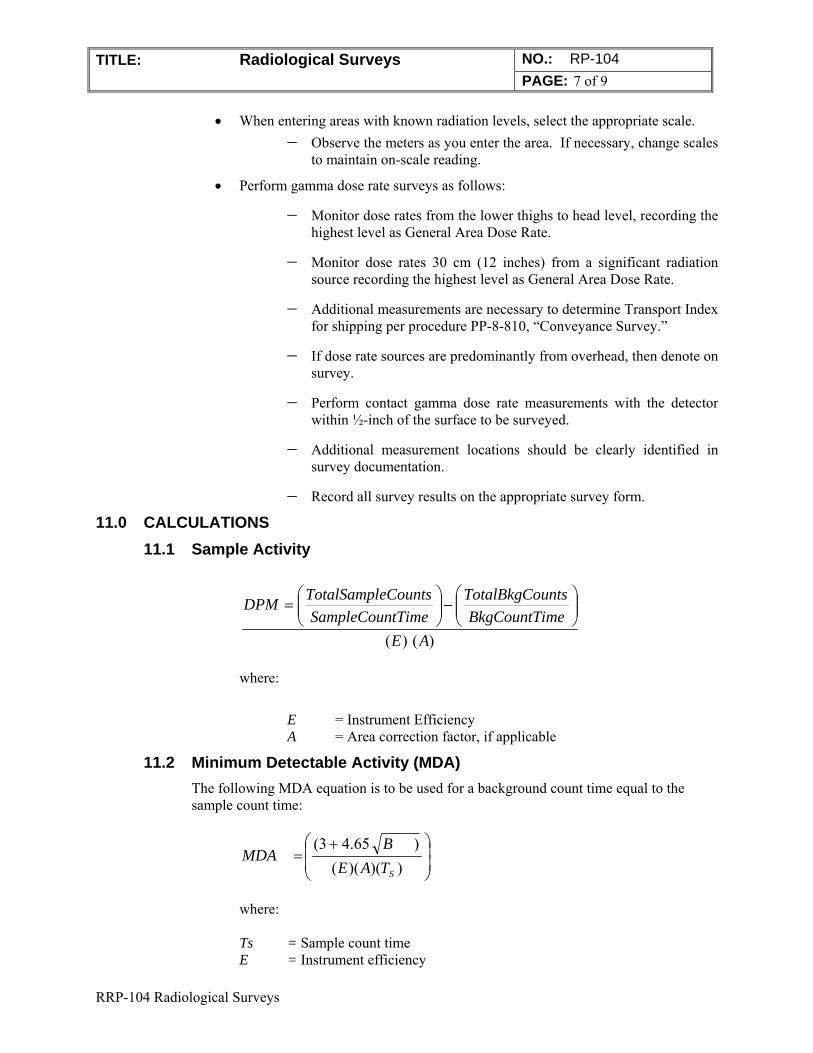
TITLE: Radiological Surveys NO.: RP-104 PAGE: 7 of 9
RRP-104 Radiological Surveys
When entering areas with known radiation levels, select the appropriate scale. Observe the meters as you enter the area. If necessary, change scales
to maintain on-scale reading.
Perform gamma dose rate surveys as follows:
Monitor dose rates from the lower thighs to head level, recording the highest level as General Area Dose Rate.
Monitor dose rates 30 cm (12 inches) from a significant radiation source recording the highest level as General Area Dose Rate.
Additional measurements are necessary to determine Transport Index for shipping per procedure PP-8-810, “Conveyance Survey.”
If dose rate sources are predominantly from overhead, then denote on survey.
Perform contact gamma dose rate measurements with the detector within ½-inch of the surface to be surveyed.
Additional measurement locations should be clearly identified in survey documentation.
Record all survey results on the appropriate survey form.
11.0 CALCULATIONS 11.1 Sample Activity
)()( AE
meBkgCountTi
untsTotalBkgCo
tTimeSampleCoun
eCountsTotalSamplDPM
where:
E = Instrument Efficiency
A = Area correction factor, if applicable
11.2 Minimum Detectable Activity (MDA) The following MDA equation is to be used for a background count time equal to the sample count time:
))()(()65.43(
STAE
BMDA
where: Ts = Sample count time E = Instrument efficiency
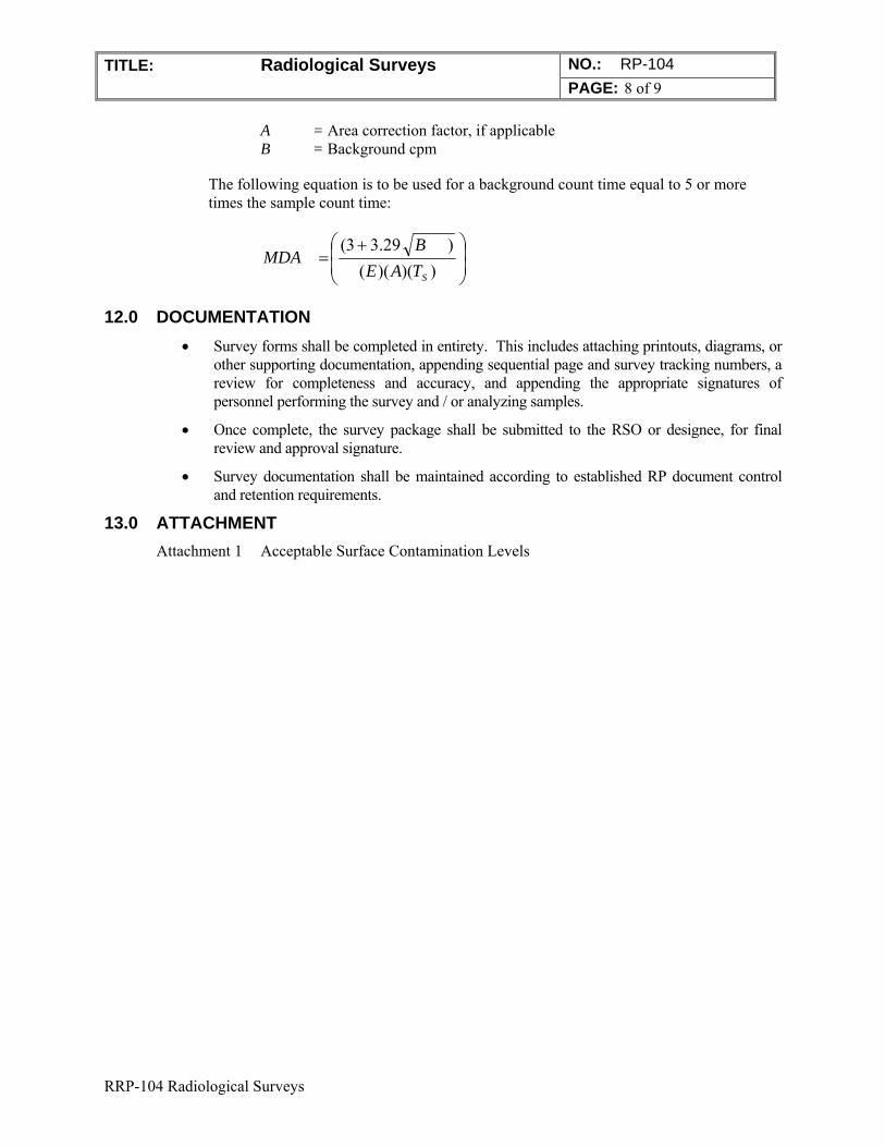
TITLE: Radiological Surveys NO.: RP-104 PAGE: 8 of 9
RRP-104 Radiological Surveys
A = Area correction factor, if applicable B = Background cpm
The following equation is to be used for a background count time equal to 5 or more times the sample count time:
))()(()29.33(
STAE
BMDA
12.0 DOCUMENTATION
Survey forms shall be completed in entirety. This includes attaching printouts, diagrams, or other supporting documentation, appending sequential page and survey tracking numbers, a review for completeness and accuracy, and appending the appropriate signatures of personnel performing the survey and / or analyzing samples.
Once complete, the survey package shall be submitted to the RSO or designee, for final review and approval signature.
Survey documentation shall be maintained according to established RP document control and retention requirements.
13.0 ATTACHMENT Attachment 1 Acceptable Surface Contamination Levels
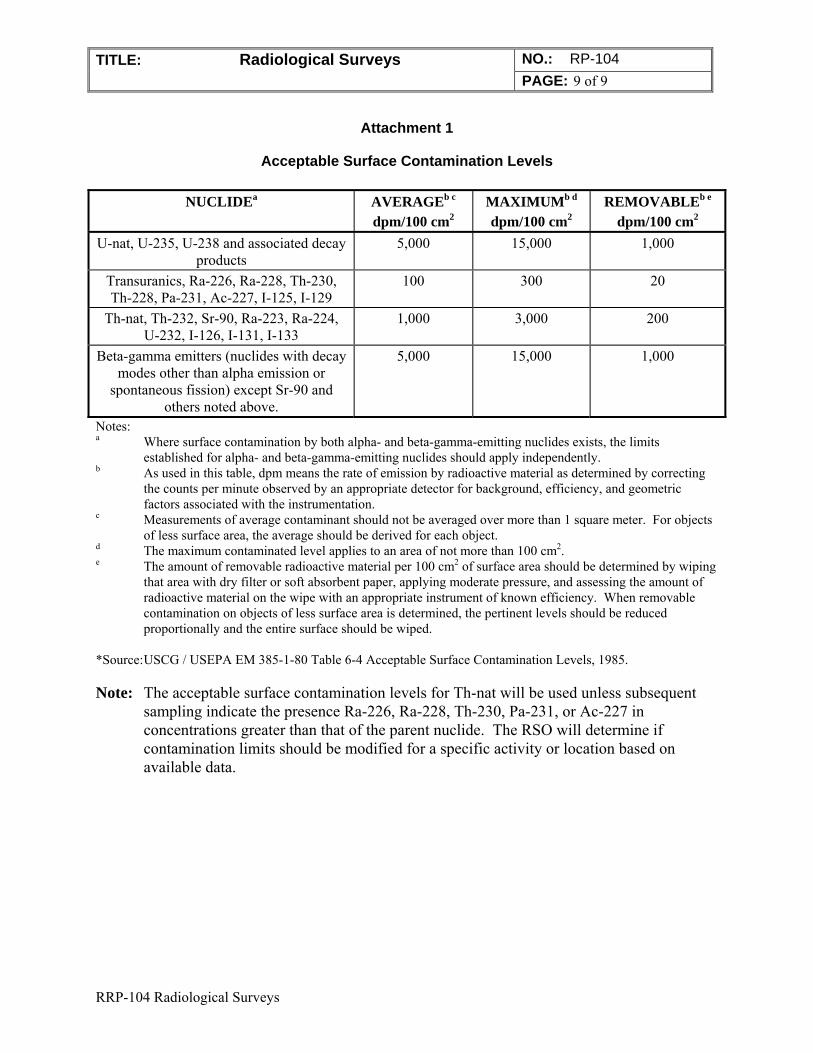
TITLE: Radiological Surveys NO.: RP-104 PAGE: 9 of 9
RRP-104 Radiological Surveys
Attachment 1
Acceptable Surface Contamination Levels
NUCLIDEa AVERAGEb c dpm/100 cm2
MAXIMUMb d dpm/100 cm2
REMOVABLEb e dpm/100 cm2
U-nat, U-235, U-238 and associated decay products
5,000 15,000 1,000
Transuranics, Ra-226, Ra-228, Th-230, Th-228, Pa-231, Ac-227, I-125, I-129
100 300 20
Th-nat, Th-232, Sr-90, Ra-223, Ra-224, U-232, I-126, I-131, I-133
1,000 3,000 200
Beta-gamma emitters (nuclides with decay modes other than alpha emission or
spontaneous fission) except Sr-90 and others noted above.
5,000 15,000 1,000
Notes: a Where surface contamination by both alpha- and beta-gamma-emitting nuclides exists, the limits
established for alpha- and beta-gamma-emitting nuclides should apply independently. b As used in this table, dpm means the rate of emission by radioactive material as determined by correcting
the counts per minute observed by an appropriate detector for background, efficiency, and geometric factors associated with the instrumentation.
c Measurements of average contaminant should not be averaged over more than 1 square meter. For objects of less surface area, the average should be derived for each object.
d The maximum contaminated level applies to an area of not more than 100 cm2. e The amount of removable radioactive material per 100 cm2 of surface area should be determined by wiping
that area with dry filter or soft absorbent paper, applying moderate pressure, and assessing the amount of radioactive material on the wipe with an appropriate instrument of known efficiency. When removable contamination on objects of less surface area is determined, the pertinent levels should be reduced proportionally and the entire surface should be wiped.
*Source: USCG / USEPA EM 385-1-80 Table 6-4 Acceptable Surface Contamination Levels, 1985. Note: The acceptable surface contamination levels for Th-nat will be used unless subsequent
sampling indicate the presence Ra-226, Ra-228, Th-230, Pa-231, or Ac-227 in concentrations greater than that of the parent nuclide. The RSO will determine if contamination limits should be modified for a specific activity or location based on available data.
PERMA-FIX ENVIRONMENTAL SERVICES
TITLE: Unrestricted Release Requirements
NO.: RP-105
PAGE: 1 of 5
DATE: May 2014
APPROVED:
______________________________________5/31/14_____ Technical Services Manager Date
______________________________________5/31/14___ Corporate Certified Health Physicist Date
1.0 PURPOSE
This project procedure describes the method of surveying equipment, materials, or vehicles for release for unrestricted use at Perma-Fix Environmental Services (PESI) facilities and projects.
2.0 APPLICABILITY
This project procedure applies to all site personnel responsible for the unrestricted release of equipment and materials used in a Restricted Area. This procedure is not used for vehicles that are transporting radioactive materials. Vehicles conveying radioactive materials also must follow USDOT Regulation 49 CFR Part 173.
3.0 REFERENCES
1. Title 17, California Code of Regulations, Division 1, Chapter 5, Subchapter 4 “Standards for Protection Against Radiation.”
2. PESI “Radiation Protection Plan (RPP)
3. NRC Regulatory Guide 1.86.
4. RP-104, “Radiological Surveys”
4.0 DEFINITIONS
CPM: Counts per minute
DPM: Disintegrations per minute
Equipment and Material: Equipment and material refers to any item used in a Restricted Area to support work activities (i.e., hand tools, heavy equipment, plastic, etc.).
LAW: Large Area Wipe (i.e., Masslinn)
Unrestricted Release: Release of equipment and / or material to the general public.
Perm - e IX
environmental services
A Nudear Services and Waste Management Company
qc: > 7
~~~-C:-
TITLE: NO.: RPP-105 Unrestricted Release Requirements PAGE: 2 of 5
5.0 RESPONSIBILITIES
5.1 Radiation Safety Officer (RSO)
Ensuring adequate staffing, facilities, and equipment are available to perform the survey tasks assigned to Radiation Protection personnel.
Approving purchase or acquisition of equipment necessary to perform surveys.
Ensuring that surveys take place in appropriately posted areas.
Reviewing results of survey data as required to determine acceptability for release of items.
Dispositioning materials that cannot be released based on survey results.
Investigating and initiating corrective actions for the improper release of radiologically contaminated material.
5.2 Radiation Protection Technician (RPT)
Identify equipment and material to be surveyed for unrestricted release. Performing and documenting contamination surveys. Posting, securing and controlling radioactive material that cannot be released. Releasing material in accordance with this and implementing procedures.
5.3 Project Personnel
Adhering to all policies, procedures and other instructions, verbal and written, regarding control and minimization of radioactive material and contaminated material.
Reporting any concerns about the control and minimization of radioactive material and contaminated material to supervision.
Maintaining good housekeeping at work sites and assisting in preventing the build-up and spread of contamination.
6.0 EQUIPMENT AND MATERIAL
Alpha Detector Beta-Gamma Detector Portable Ratemeter / Scaler Scintillation or Gas-Flow Proportional Lab Alpha / Beta Counter Survey forms Cloth smears MasslinnTM type cloths
7.0 INSTRUCTIONS
7.1 General Instructions
Prior to conducting any surveys, ensure that all survey instrumentation has been response checked, is in operating within control limits and has not been removed from service.
Response checks shall be performed daily.
Background measurements are to be taken prior to use at the point of use. The background count time shall be greater than or equal to the sample count time.
TITLE: NO.: RPP-105 Unrestricted Release Requirements PAGE: 3 of 5
Verify that the MDA has been calculated for the background at the point of use
and is less than the applicable site release criteria. Refer to RPP-104, “Radiological Surveys,” for the MDA calculation.
Survey results are converted from counts per minute (cpm) to disintegrations per minute (dpm). A sample “cpm to dpm” calculation is attached for review and use at the end of this procedure.
7.2 Release of Items for Unrestricted Use
1. Surveys for both total and removable contamination shall be made in accordance with Section 7.3 (below) on all equipment, materials or vehicles which have either been in a Restricted Area or which may be potentially contaminated.
2. With RSO approval, removable contamination surveys may be disregarded, provided that direct survey measurements and instrument MDAs are below site removable contamination limits for release.
3. RP personnel will determine which items located outside a Restricted Area may be potentially contaminated based on their use, site history, or previous survey data. The potential for these objects to have become contaminated by airborne radioactive materials must be considered. This could include items that are used to support site activities, such as office equipment, cleaning devices, furniture, trailers, etc., even though direct contact may not have occurred.
4. Items which have a potential for internal contamination of inaccessible surfaces shall be evaluated by the RSO or designee prior to release.
5. All items to be released shall be surveyed in such a manner as to fully demonstrate that accessible surfaces comply with the surface contamination release criteria specified in RP-104, “Radiological Surveys.”
6. Items that do not meet release criteria shall be decontaminated until release criteria is met or shall be disposed of as radiological waste.
7. Air intakes / filters on motorized equipment should be surveyed as an indicator of potential internal contamination. Notify the RSO or designee if air intake / filter surfaces indicate the presence of contamination. Contaminated air filters shall be removed and disposed of as radiological waste.
8. To the extent practicable, visible dirt and mud or other material shall be removed from surfaces prior to survey.
9. The RSO or designee, shall review all survey data prior to the release from the Controlled Area.
7.3 Direct Surveys Scans and Static Measurements
1. Surfaces shall be dry and cleaned, to the extent practicable prior to performing direct alpha measurements.
2. The RSO may authorize the short-term relocation or staging of equipment / vehicles for direct measurements in any portion of the Controlled Area. This is provided that the item has been verified to be clean of removable
TITLE: NO.: RPP-105 Unrestricted Release Requirements PAGE: 4 of 5
contamination prior to removal from a Restricted Area and fixed contamination producing general area dose rates greater than 0.2 mrem/hr is not anticipated.
3. Alpha detectors should be placed within ¼-inch of the surface to be surveyed. Beta detectors should be placed within ½-inch of the surface to be surveyed. Use caution to not contaminate or damage the detector surface.
4. Perform a scanning survey of the item. Concentrate survey measurements on areas most likely to be contaminated. The fraction of the total area scanned is subjective, based on technician experience, an item’s use history, and RSO guidance. Typically, the scan frequency is a minimum of 10% of accessible surface areas.
5. Obtain static measurements at locations with the highest potential for contamination. The number of survey points selected is subjective, based on technician experience, an item’s use history, and RSO guidance.
6. Static measurement count times shall be appropriate for desired MDAs. Typical count times are one minute for digital scalers and until the meter reading stabilizes for analog ratemeters.
7. Record and identify all locations surveyed on the appropriate survey form(s). The use of diagrams or sketches is recommended.
8. All measurements shall be reported in units of “dpm” unless otherwise directed by the RSO. Examples include “dpm/100 cm²” and “dpm/probe.”
7.4 Removable Contamination Surveys
1. “Cloth” smears shall be used for smear surveys.
2. A notation (e.g., smear number, date, time, location, etc.) should be made on the smear envelopes to ensure proper smear tracking. Smears may also be numbered using a pen or marker prior to use.
3. Using moderate pressure, swipe an area of 100 cm² (4-inch square area or equivalent) of the surface at the selected location. Smear surveys should be performed at the same location that direct surveys were performed.
4. Large Area Wipes (LAW), also commonly referred to by the trade name “Masslinn,” may be used to supplement smear surveys for removable contamination. The use of LAWs should be documented on the survey form with the notation “LAW” or equivalent.
5. Ensure each used swipe (i.e., smear or large area wipe) is handled, stored, and transferred in such a fashion as to prevent to loss of sampled material or cross-contamination with other personnel and other swipe samples.
6. Smear samples should be counted using available scintillation or gas-flow proportional laboratory counters, when practicable. Field instruments may be used for smear counting at the discretion of the RSO.
7. LAW samples may be counted using field instruments. The use of laboratory counters is inappropriate.
8. Removable contamination survey results shall be reported in units of “dpm” unless otherwise directed by the RSO. Examples include “dpm/100cm2” and “dpm/LAW.”
TITLE: NO.: RPP-105 Unrestricted Release Requirements PAGE: 5 of 5
9. Ensure all results are documented on the appropriate survey form. Lab
printouts may be attached and referenced on the survey form.
8.0 CALCULATIONS
MDA and Sample Activity formulas are located in RPP-104, “Radiological Surveys.” 9.0 DOCUMENTATION
Survey forms shall be completed in entirety. This includes attaching printouts, diagrams, or other supporting documentation, appending sequential page and survey tracking numbers, a review for completeness and accuracy, and appending the appropriate signatures of personnel performing the survey and / or analyzing samples.
Once complete, the survey package shall be submitted to the RSO or designee, for final review and approval signature.
Survey documentation shall be maintained according to established RP document control and retention requirements.
10.0 ATTACHMENT
None
RRP-106 Survey Documentation and Review
PERMA-FIX ENVIRONMENTAL SERVICES
TITLE: Survey Documentation and Review
NO.: RP-106
PAGE: 1 of 6
DATE: May 2014
APPROVED:
______________________________________5/31/14_____ Technical Services Manager Date
______________________________________5/31/14___ Corporate Certified Health Physicist Date
1.0 PURPOSE
This procedure establishes consistent methodology for documenting radiological surveys and provides criteria for the review of these surveys.
2.0 APPLICABILITY This procedure is applicable to all radiological surveys excluding air samples.
3.0 REFERENCES 1. 10 CFR 20, “Standards for Protection Against Radiation.”
2. PESI “Radiation Protection Plan (RPP)
3. RP-104, “Radiological Surveys.”
4.0 GENERAL 4.1 Discussion
The results of surveys will be documented on survey forms or in designated logs as approved by the Radiation Safety Officer (RSO). Survey data will contain enough detail to provide personnel with adequate information concerning radiological conditions existing in the area surveyed.
The RSO or designee will review completed survey documentation to ensure appropriate, adequate and complete information is recorded. The individual reviewing the survey will ensure that the recorded results are legible, in accordance with Radiological Protection Program (RPP) implementing procedures, consistent with anticipated levels, and will determine the reason for any variances.
TITLE: Survey Documentation and Review NO.: RP-106 PAGE: 2 of 7
RRP-106 Survey Documentation and Review
4.2 Definitions Airborne Radioactivity Area (ARA): Means any area where the measured concentrations of airborne radioactivity above natural background exceed, or are likely to exceed, 25% of the Derived Air Concentration (DAC) values listed in 10 CFR 20, Appendix B, Table I, Column 3.
Contamination Area (CA): Means any area accessible to personnel with loose surface contamination values in excess of the values specified in RP-104 , “Radiological Surveys, or any additional area specified by the Radiation Safety Officer (RSO). The Contamination Area posting requirement is more restrictive than the Radioactive Material Area posting requirement. Any area posted as a Contamination Area shall also be considered to be a Radioactive Materials Area.
Contact Dose Rate: A radiation dose rate as measured at contact or within 1/2 inch of the surface being measured.
General Area Dose Rate (GA Dose Rate): The highest radiation dose rate accessible to any portion of the whole body measured at a distance of 30 cm (12 inches) from a significant radiation source or combination of sources.
Radiation Work Permit (RWP): Means a document or series of documents prepared by Radiation Protection to inform workers of the radiological and industrial hygiene conditions, which exist in the work area and the radiological requirements for the job.
Radiation Area (RA): Means any area, accessible to personnel, where the whole body dose rate can exceed 5 mrem in 1 hour at 30 cm from the source.
Radioactive Material: Material activated or contaminated by the operation or remediation activities and by-product material procured and used to support the operations.
Radioactive Materials Area (RMA): Any area or room where quantities of radioactive materials in excess of 10 times the 10 CFR 20, Appendix C quantities are used or stored, or any area designated by the RSO which does not exceed the site Contamination Area criteria.
Radiological Area: Any area within a Restricted Area which require posting as a Radiation Area, Contamination Area, Airborne Radioactivity Area, High Contamination Area, or High Radiation Area.
Restricted Area: An area to which access is limited to protect individuals against undue risks from exposure to radiation, radioactive materials, and chemical contaminants. All posted radiological or chemical areas are Restricted Areas.
5.0 RESPONSIBILITIES 5.1 Radiation Safety Officer (RSO)
The Radiation Safety Officer (RSO) or designee is responsible for reviewing radiological surveys performed by Radiation Protection Technicians (RPT).
5.2 Radiation Protection Technician (RPT) RPTs are responsible for documenting surveys in a legible manner on approved
forms.
TITLE: Survey Documentation and Review NO.: RP-106 PAGE: 3 of 7
RRP-106 Survey Documentation and Review
6.0 PREREQUISITES Surveys for radiation and contamination have been performed in accordance with RP-104
“Radiological Surveys”.
7.0 PRECAUTIONS AND LIMITATIONS Surveys for airborne radioactivity will be documented in accordance with RP-107,
“Measurement of Airborne Radioactivity.”
8.0 APPARATUS Survey Forms
9.0 RECORDS PESI Survey Form (Attachment 1) PESI Survey Log Number Form (Attachment 2) Radiation Protection Technician (RPT) Logbooks
10.0 PROCEDURE The methods outlined in this procedure are intended to assure the clear and concise transfer of survey information. Variations or deviations from the protocols in this procedure are permitted if the clear transfer of information is maintained.
10.1 Documentation 10.1.1 General
1. Record all information on survey forms in a neat and legible manner.
2. Document all surveys on a form with approved project heading. Technician logbooks may be used for documenting surveys (e.g., daily routines, material transfers, minor posting changes, etc.) as authorized by the RSO and providing instrument serial numbers are documented with survey data.
3. When recording information on survey forms, check all appropriate boxes and circle all appropriate answers.
4. Use a survey form with pre-drawn diagrams when available. If not, draw a diagram or picture of the object surveyed. Should a diagram not be appropriate, use a lined survey form.
5. Assign the next sequential survey number to the survey from the survey number logbook.
6. Complete the following information for all surveys:
Date and time of survey
Location of survey
Instrument type and serial numbers and associated supporting information (i.e., detector efficiencies, calibration dates, background values, etc.)
HWP number, if applicable
Reason for survey
TITLE: Survey Documentation and Review NO.: RP-106 PAGE: 4 of 7
RRP-106 Survey Documentation and Review
Name and signature of surveyor
7. Indicate Radiological Hazard Area boundaries on the survey form using x's and -'s (-x-x or **).
8. Note the posted Radiological Hazard using common designator such as
Contamination Area = CA Radiation Area = RA Radioactive Material Area = RMA Airborne Radioactivity = ARA
9. The use of Greek alphabet and other nuclear industry standard nomenclature (e.g., “k” = 1000) is acceptable when documenting surveys.
10.1.2 Survey Log Number Book:
1. Survey log number book is to be used to assign a unique sequential number to each survey form package. This number provides the ability to track individual surveys as well as ensuring the submittal of a complete documentation package for archiving.
2. Unless otherwise directed by the RSO, survey numbers will be assigned with the following format:
NFSSyyRS.xxxx
“NFSS” corresponds to “Niagara Falls Storage Site, ” yy is the last two digits in the year, “RS” refers to “Radiological Survey,” and xxxx refers to the sequential survey number.
3. As surveys are generated, the RPT will take the next sequential number on the form and fill in the remaining boxes with a brief description of the reason for the survey as well as the date and RPT’s initials.
10.1.3 Radiation Surveys
1. Indicate GA dose rates by underlining the radiation level on the Survey Form at the appropriate location (Example: 25 uR/hr).
2. Indicate CONTACT dose rates by recording the radiation level with an asterisk on the Survey Form at the appropriate location (Example: * 25 ur/hr). If there are corresponding 30 cm and GA readings, document them as follows:
* CONTACT / @ 30 cm / GA
3. Use a legend to inform the reviewer of any other notation utilized or if deviating from standard protocol.
10.1.4 Contamination Surveys
1. Indicate survey locations by placing sequential numbers within a circle on the Survey Sheet. The Survey Sheet has corresponding direct and transferable columns for both alpha and beta / gamma activity.
2. Use a legend to inform the reviewer of any other notation utilized or if deviating from standard protocol.
3. The use of the letter “k” to indicate units of a thousand is acceptable.
TITLE: Survey Documentation and Review NO.: RP-106 PAGE: 5 of 7
RRP-106 Survey Documentation and Review
10.2 Technician Review and Evaluation 10.2.1 After completing the surveys, evaluate the results against previous surveys or
anticipated results.
10.2.2 Verify that radiological boundaries and postings are correct in accordance with RPP-102, "Radiological Posting Requirements."
10.2.3 Take any immediate actions required based on survey results.
10.2.4 Ensure all relevant supporting documentation (e.g., count room print-outs, etc.) are attached to the survey package and that the package is properly paginated.
10.2.5 Submit documentation to the RSO or designee for supervisory review.
10.3 Supervisory Review 10.3.1 Ensure that the survey form is complete and legible.
10.3.2 Ensure that all required information has been completed.
10.3.3 Ensure that any changes, single line cross-outs, or deletions are initialed and dated at time performed.
10.3.4 Verify that results are consistent with those anticipated.
10.3.5 If results are not consistent, ensure that appropriate actions have been taken to explain the results or re-examine the area.
10.3.6 Sign-off in the appropriate review section of the survey form and submit package to RP Document Control for retention / transmittal to Project Files.
11.0 ATTACHMENTS Note: Attachments may be revised without formal review of this procedure and are attached as examples only. Please contact the RSO for a current copy of these attachments.
Attachment 1 PESI Survey Form (Typical)
Attachment 2 PESI Survey Log Number Form (Typical)
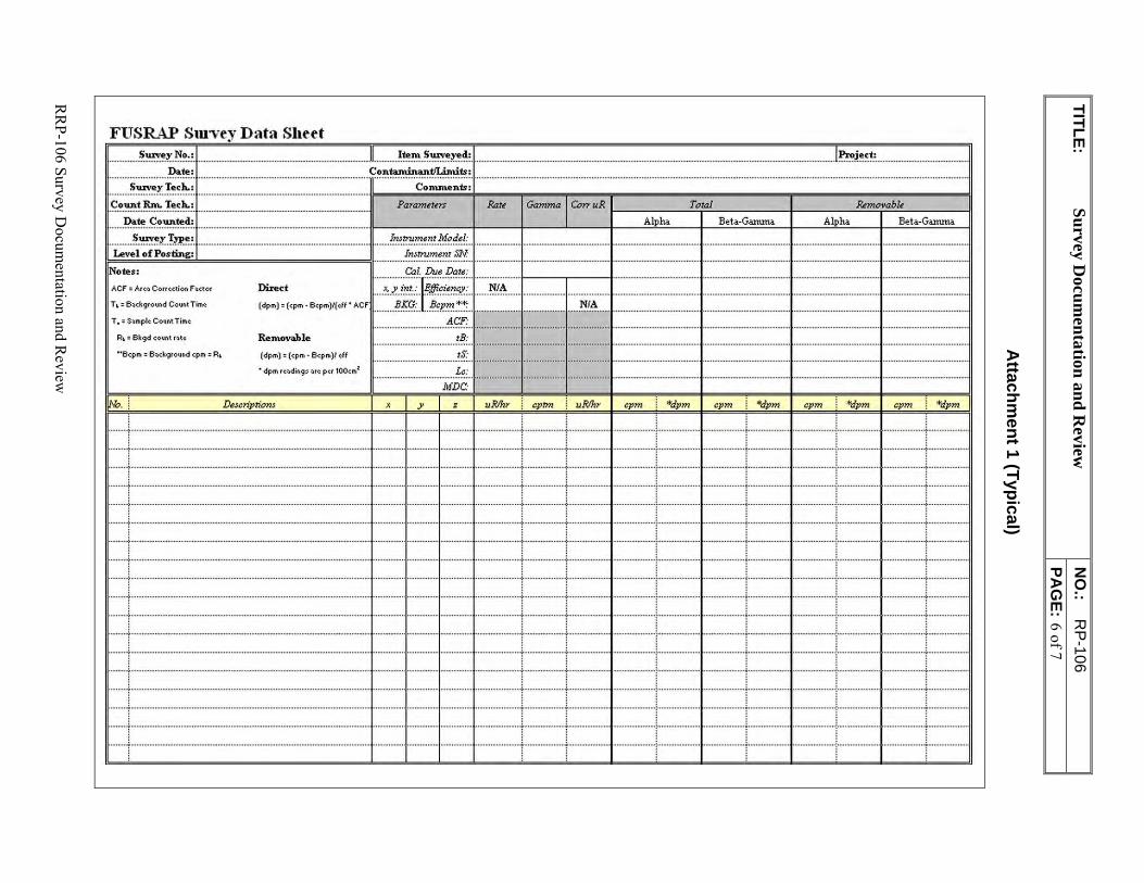
TITLE: S
urvey D
ocum
entation
and
Review
N
O.:
RP-106
PA
GE: 6 of 7
RR
P-106 Survey Docum
entation and Review
Attachm
ent 1 (Typical)
FUSRAP Survey Data Shtet
-------························································'Project: ................................................ .
.............. S,uve~:~: L ..................................................................................... tn~=~:.1 .......................................................................................................................................................... ----··················· .... ···························································U S,uvey Tech.: Comment.: ·c~::~·:::~; ····························································································it===P,=a=ra=m=~t=,=rs=="?=.Ra=i=~=;=Ga=m=m=a==r=Co=n-=u=R=.===A=lp=ha===T,=o=ta=l=B=et=a= .. G=an=una==,===A=lp=ha==&=m=o=va=b=l;=e=t=a= .. G=anuna====l1
ACF = Arc.a Com~clion f .actor
T ~ = B.ack9ro1.ind Count Time
T. = S.amplc Count Time
A~= Bkgd count rtitc
""B c:pm = B::ickground cpm : Rl
Direct
(dpm) = (cpm · Bcpm)l(tlf • AC F
Removable
(dpm) = (cpm - Bcpm)I tff
• dpm re-tiding~ .arc per 100cmz
Ds,cn'ptiom
........ !.'!.~~.'!3.~.l'!.r.¥,odel: ................................... •--------f-- ................................... ,.,_ ___ .................... j ...... , ____ _
lmtrum•mSN
Cal. Due Dats:
:~~~•·~~• : ~•:j===:-1 ::~ :!. ···•· :: ········• ;·· --------- + - - • ---- -- <,
tB: ll ······· .. ···•················· .. ··· .. ············ .. ··l··· .. ·· .. ··· .. ·· ... · ... ··I
............................................ tS:··+·· ........ .. , ........ ,.+ .................. ·+ .............. ,,., .... , .. .... . Le: . MDC· 1 ........ , ........ ... ... ........ , .............. ....... , •••....••.•••. ____ ...1 ............ ......... ... ..... .................. , ..••.•• .••.• .••..•..•.••.•. ..•.•••• . ..••...••. 1·-----·
X J' z uR/hr cptm cpm "'dpm cpm "'dpm CE_m "'dE_m
........................... .......................................... ......... .................. ................................... ................................... 1, ................ . ............................ ,_, .............. . ... ....................... : ........................ ..... ................ ,;- ..... ............ ···t·· .. ··· .. · .... · ... · .. ··:•• ········· .. ····· .. ···t
................................................................................................................................. , ................. 1 ................. 1 .. •··• ........... , ........................ t .................... ..
:::: _:: :::::1:: :i:::::r: 1: ]::1· -i: 1--1-: :'. :::' ,_ ·····················••·••·············"·"
'
' .................•................. l················· • ········•········•···•··t•··········· ·······•··+····•···•·· ··•········ · : : __ : L L_ L -!::J ::!:::::!: :::\--
..... 0, .................... .
'
TITLE: Survey Documentation and Review NO.: RP-106 PAGE: 7 of 7
RRP-106 Survey Documentation and Review
Attachment 2 (Typical)
FMSS SURVEY TRACKING LOG (2002)
PERMA-FIX ENVIRONMENTAL SERVICES
TITLE: Measurement of Airborne
Radioactivity
NO.: RP-107
PAGE: 1 of 12
DATE: May 2014
APPROVED:
______________________________________5/31/14_____ Technical Services Manager Date
______________________________________5/31/14___ Corporate Certified Health Physicist Date
1.0 PURPOSE
This procedure establishes the basis and methodology for the placement and use of air monitoring equipment, as well as the collection, analysis, and documentation of air samples. Radiological air sampling and analysis is performed to monitor concentrations of radionuclides in the air for purposes of tracking internal radiation exposure to occupational radiation workers, determining appropriate respiratory protection devices, establishing radiological posting boundaries, verifying effluent airborne radioactivity concentrations, and providing information on radiological conditions in the work area.
2.0 APPLICABILITY
This procedure applies to all radiological air monitoring activities performed in support of Perma-Fix Environmental Services (PESI) activities.
3.0 REFERENCES
1. Title 17, California Code of Regulations, Division 1, Chapter 5, Subchapter 4 “Standards for Protection Against Radiation.”
2. Perma-Fix Environmental Services (PESI), “Radiation Protection Plan (RPP)
3. Rock, R.L., Sampling Mine Atmospheres for Potential Alpha Energy Due to the
Presence of Radon-220 (Thoron) Daughters, Informational Report No. 1015, United States Department of the Interior, Mining Enforcement and Safety Administration, 1975.
4. Kusnetz, H.L., Radon Daughters in Mine Atmospheres, A Field Method for Determining Concentrations, Am. Ind. Hyg. Assoc. Quat., Vol. 17, No. 87, 1956.
5. ANSI N13.1, Guide to Sampling Airborne Radioactive Materials in Nuclear Facilities.
6. Regulatory Guide 8.25, Air Sampling in the Workplace.
7. 29 CFR 1910.1096, United States Occupational Health & Safety, Ionizing Radiation.
Perm - e IX
environmental services
A Nudear Services and Waste Management Company
qc: > 7
~~~-C:-
TITLE: NO.: RP-107
Measurement of Airborne Radioactivity PAGE: 2 of 12
4.0 DEFINITIONS
Airborne Radioactivity: Radioactive material in any chemical or physical for that is dissolved, misted, suspended, or otherwise entrained in air.
Ambient Air: Air in the volume of interest, such as room atmosphere, as distinct from a specific stream or volume of air that may have different properties.
Annual Limit on Intake (ALI): The derived limit for the amount of radioactive material taken into the body of an adult worker by inhalation or ingestion in a year. ALI is the smaller value of intake of a given radionuclide in a year by the reference man that would result in a committed effective dose equivalent (CEDE) of 5 rems or a committed dose equivalent (CDE) of 50 rems to any organ or tissue.
Breathing Zone (BZ): A uniform description of the volume of air around the worker’s upper body and head which may be drawn into the lungs during the course of breathing.
Committed Dose Equivalent (CDE): The dose equivalent to tissues or organs of reference that will be received from an intake of radioactive material by an individual during the 50-year period following the intake.
Committed Effective Dose Equivalent (CEDE): The sum of committed dose equivalents (CDEs) to various tissues in the body, each multiplied by the appropriate weighting factors found in 10 CFR 20.
Derived Air Concentration (DAC): The concentration of a given radioactive nuclide in air which, if breathed by the reference man for a working year of 2000 hours under conditions of light work (1.2 m3 of air per hour), would result in an intake of one (1) ALI.
DAC-hour (DAC-hr): The product of the concentration of radioactive material in air (expressed as a fraction or multiple of the DAC for each radionuclide) and the time of exposure to that radionuclide in hours. A facility may take 2000 DAC-hr to represent 1 ALI.
Grab Sample: A single sample of ambient air collected over a short time.
Maximum Permissible Concentration (MPC): That concentration of radionuclides in air or water that will result in the Maximum Permissible Body Burden or Organ Burden and result in a whole body or organ receiving the annual dose limit if breathed in by a worker for 2000 hours.
Monitoring: The measurement of radiation levels, airborne radioactivity concentrations, radioactive contamination levels, quantities of radioactive material, or individual doses and the use of the results of these measurements to evaluate radiological hazards or potential and actual doses resulting from exposures to ionizing radiation.
MPC-hour (MPC-hr): The product of the concentration of radioactive material in air (expressed as a fraction or multiple of the MPC for each radionuclide) and the time of exposure to that radionuclide in hours.
Occupational Dose: An individual’s ionizing radiation dose (external and internal) received as a result of that individual’s work assignment.
Protection Factor: The degree of protection given by a respirator. The protection factor is used to estimate radioactive material concentrations inhaled by the wearer and is expressed as the ratio
TITLE: NO.: RP-107
Measurement of Airborne Radioactivity PAGE: 3 of 12
of ambient concentration of airborne radioactive materials to the concentration that can be maintained inside the respirator during use.
Representative: Sampling in such a manner that the sample closely approximates both the amount of activity and the physical and chemical properties of the material (e.g., particle size and solubility in the case of aerosol to which workers are exposed). Air sampling performed within the Breathing Zone (BZ) is considered representative of the airborne radioactive material concentration inhaled by the worker.
Restricted Area: An area to which access is limited to protect individuals against undue risks from exposure to radiation, radioactive materials, and chemical contaminants. All posted radiological or chemical areas are Restricted Areas.
5.0 RESPONSIBILITIES
5.1 Radiation Safety Officer (RSO)
Manages the implementation of this procedure.
Ensures technicians performing activities under this procedure are competent and have sufficient experience to perform assigned tasks.
5.2 Radiation Protection Technician (RPT)
Initiates, collects, submits, counts, and documents air samples according to the requirements of this procedure, and the SSHP.
Ensures he / she has sufficient experience and / or knowledge to perform assigned duties under this procedure.
6.0 PRECAUTIONS AND LIMITATIONS
Running air samplers for extended periods may cause excessive dust loading of the filter media. The frequency of filter change-out should be increased if excessive dust loading is observed.
Air samplers shall not be used in combustible / explosive atmospheres.
Air sampling and sample counting equipment shall not be operated beyond their respective calibration periods.
Air samples shall be taken in such a manner as to not contaminate the filter with materials that were not airborne during the sample interval or by re-suspension of loose contamination from surfaces near the sampling head.
Sampler exhaust may cause the re-suspension of loose surface contamination if the sampler is positioned improperly.
Consider higher volume air samplers when covering short duration tasks.
The decision to provide individual monitoring devices to workers is influenced by the expected levels of intake, likely variations in dose among workers, and the complexity of measurement and interpretation of results.
TITLE: NO.: RP-107
Measurement of Airborne Radioactivity PAGE: 4 of 12
7.0 ACTION STEPS
7.1 Air Monitoring Methods
1. Utilize the following monitoring methods to implement the radiological air monitoring program:
General Area (GA) Air Monitoring Breathing Zone (BZ) Air Monitoring Passive Radon Monitoring Particulate Radon Grab Samples Perimeter Monitoring, frequently referred to as Air Environmental (AE)
2. Air sampling equipment should be placed so as to:
Not directly contact a contaminated (transferable) surface. Minimize interference with the performance of work. Be easily accessible for changing filters and servicing. Be downstream of potential release points. Minimize the influence of supply airflow.
3. An airflow study of any indoor area to be monitored should be performed prior to placement of the sampler (other than BZ samplers). Additional studies should be performed after changes in the work area setup, ventilation systems, or seasons, if seasonal changes may affect airflow patterns.
4. Perform BZ air sampling in occupied areas where, under typical conditions, a worker is likely to be exposed to an air concentration of 10 % or more of the DAC.
7.2 General Area (GA) Air Sampling
1. GA samples are typically taken with low volume samplers such as LV-1 or equivalent. Specific instructions on the use and calibration of the LV-1 sampler are detailed in RP-110 Operation of Low Volume Air Samplers.
2. GA sampling shall be performed with instrumentation operating at volumes capable of meeting the Minimum Detectable Concentration (MDC) values established in the Technical Basis Document for Dosimetry and Air Sampling.
3. GA samples should be collected:
During work activities as a supplement to Breathing Zone (BZ) sampling as deemed appropriate.
At site boundaries to confirm effluent air discharge concentrations. These are the Air Environmental (AE) type samples.
At discharge points to determine the worst case airborne radiological conditions.
4. Document airflow studies, if performed in the appropriate project logbook or as directed by the RSO.
TITLE: NO.: RP-107
Measurement of Airborne Radioactivity PAGE: 5 of 12
5. Select a calibrated low / high volume sampler with the appropriate glass fiber air filter and place the sample head into position. The fuzzy side of the filter should face outwards.
6. Turn the sampler ON. At a minimum, document the following information on the air filter envelope or log sheet:
Sampling station identifier (as determined by the RSO) Sampler model Serial number Date / time on Flow rate On by (individual starting sampler)
7. When air monitoring is complete, observe the sampler flow rate and turn the sampler off. At a minimum, document the following information on the air filter envelope or logsheet:
Date / time off Flow rate Off by (individual terminating sample)
8. Remove and / or replace the sample head and filter using caution to prevent cross-contamination.
9. Store the filter in a protective container to minimize the loss of collected material.
10. Submit sample to counting lab for analysis.
7.3 Breathing Zone (BZ)
1. Specific instructions on the use and calibration of Lapel Samplers are detailed in RP-110 Operation of Low Volume Air Samplers.
2. Collect BZ samples during entries into posted airborne radioactivity areas and during activities which have a reasonable potential of producing airborne radioactivity (e.g., excavating contaminated soils, surface destructive activities on surfaces with fixed contamination) as determined by the RSO.
3. Position the sampler on the individual representative of the worst-case exposure for the group if a single lapel sampler is used for multiple members of a work group. Base this selection on operating experience and consultation with the RSO. A single lapel sampler should be used for a group of no more than four workers spending greater than one hour in the work area under the same RWP.
4. Ensure the sample head is positioned as close to the breathing zone as practical without interfering with the work or the worker.
5. Operate lapel samplers according to the appropriate instrument use procedure. At a minimum, document the following information on the air filter envelope or log sheet:
Wearer’s name(s) Applicable Hazardous Work Permit (HWP) number
TITLE: NO.: RP-107
Measurement of Airborne Radioactivity PAGE: 6 of 12
Sampler model / serial numbers Date / time On Flow rate (sampler must be running) On by (individual starting sampler)
6. Upon exit from the work area, note the flow rate, turn the sampler OFF and detach from the worker / object. Note that sampling may be suspended / restarted during the workday to facilitate break periods. Accurate volume tracking is crucial during these periods of non-operation.
7. Perform necessary post-operation sampler checks according to the specific instrument use procedure.
8. Carefully, remove the air filter from the sample head and place in air filter envelope. Complete the pre-printed air filter envelope or sample log sheet:
Date / time off
Flow rate
Off by (individual stopping sampler)
9. Submit sample to Counting Room for analysis.
7.4 Radon and Thoron Progeny
1. High volume or low volume grab samplers such as HV-1, LV-1, or RAS-1 (typically in the 35-75 lpm range) should be used for collecting radon and thoron samples.
2. Radon and thoron samples should be collected:
During work activities as deemed appropriate by the RSO or designee.
At restricted area boundaries as deemed appropriate by the RSO or designee.
Each frequently occupied work location should have its own samplers.
Airflow patterns should be considered in placing samplers so that the sampler is likely to be in the airflow downstream of the source.
A simultaneous background sample shall be taken upwind of all activities when radon and thoron sampling is performed. This sample is critically important.
When collecting a radon and thoron breathing zone sample, the sampler should be located in the breathing zone for the worker. Preferably it should be held immediately downwind of the worker and moved around with the worker.
3. Select a calibrated high volume sampler with a 47 mm filter and place the sample head into position. The preferred filter is a membrane filter such as the F&J Specialty Products, Inc. model number A020A047A or equivalent. Alternatively, a glass fiber filter such as the F&J Specialty Products, Inc. model number AE-47 or equivalent can be used
TITLE: NO.: RP-107
Measurement of Airborne Radioactivity PAGE: 7 of 12
4. Turn the sampler ON and complete the required information on the air filter envelope to include:
RWP number, if appropriate Sampler model and serial number On date, time, and flow rate On by (site worker initials) Sample location
5. Collect a sample for exactly 5 minutes, with no more than a 5-second uncertainty. Exercise caution when handling sample head so as not to cross-contaminate the air filter.
6. Remove air filter from sample head and place in air filter envelope. Complete the required information on the air filter envelope including:
Off date, time, and flow rate Site worker stopping the sampler
7. Submit the sample to the counting room within 30 minutes after collection. Samples must be counted between 40 and 90 minutes, or they will be void.
8. Analyze the sample in accordance with Sections 8.1 or 8.2, whichever is appropriate.
9. Alternate industry-accepted methods for Radon-Thoron monitoring may be used at the discretion of the RSO with concurrence from the Project Certified Health Physicist.
7.5 Perimeter Environmental Air (AE) Sampling
1. Perimeter samples are taken with low volume samplers such as LV-1 or equivalent. Specific instructions on the use and calibration of the LV-1 sampler are detailed in RP-110 Operation of Low Volume Air Samplers.
2. Perimeter samples are collected to verify compliance with off-site release criteria.
3. Samples are collected at locations designated by the RSO. The air sampling locations should be established at the most likely downwind perimeter boundary, as determined by evaluation of local meteorological data, and / or the nearest perimeter boundary from active work areas.
4. Perimeter samplers should be operated 24 hours a day 7 days a week if possible.
5. Filters from continuously operating perimeter air samplers are normally changed out weekly. Filter change-out of perimeter air samplers will be performed at a frequency long enough to ensure acceptable counting statistics and short enough to maintain consistent sampler flow rates.
6. Perimeter sampler operation shall be verified on a daily basis around locations when airborne generating activities are in progress. This requirement may be relaxed by the RSO for samplers with data logging capability.
TITLE: NO.: RP-107
Measurement of Airborne Radioactivity PAGE: 8 of 12
7. Document daily verification (i.e., flow rate) and notify the RSO of any discrepancies. Replace filter and investigate pump operation if daily flow rates vary by greater than 20%.
8. Any sampler that is out of service due to malfunction for more than 1 hour and any invalid samples should be brought to the attention of the RSO.
9. Samples are to be collected in accordance with Section 7.2, Steps 5-10.
7.6 Passive Radon Monitoring
1. Passive radon monitoring methods include the use of either alpha track-etch detectors or electrets.
2. Detectors should be placed for a length of time, so that the minimum detectable concentration is 0.1 pCi/l or less, following manufacturer guidelines. The length of placement is generally 1 month or greater. Locations selected should be representative of the breathing zone, when practical. A simultaneous background sample should always be taken at a location unaffected by site activities. This sample is critically important.
3. Open the bag containing the detector and place the detector in a protective container to allow for air circulation. Follow manufacturer guidelines to activate the detector, as necessary.
4. Record in the logbook:
Sample location Date and time of placement Serial number of the detector Initials of the worker placing the detectors
5. Ship the detector to the manufacturers processing center to read the results.
8.0 ANALYSIS OF AIR SAMPLES
General Area (GA), Breathing Zone (BZ), and Perimeter Air (PA) samples should be submitted to a counting room or off-site laboratory for gross alpha/beta analysis. Samples may be sent to an outside laboratory for isotopic analysis as necessary per the RSO.
8.1 Analysis for Radon and Thoron Progeny from a 5-Minute Low
Volume Grab Sample
8.1.1 Count the sample twice for alpha activity using a Ludlum 2929, Ludlum 2000, or Equivalent. The first count should start at least 40 minutes after the end of the sample, but not greater than 90 minutes at the end of sample collection. The second count should start at least 5 hours after the end of the count, but not greater than 17 hours after the end of the first count. Count the sample for 5 minutes each time.
NOTE: It is not recommended that a gas flow proportional counter be used for this analysis as there is a reasonably high probability of contaminating the instrument with radon and / or thoron progeny.
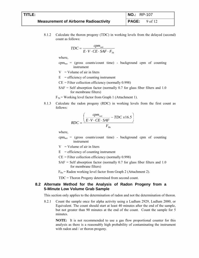
TITLE: NO.: RP-107
Measurement of Airborne Radioactivity PAGE: 9 of 12
8.1.2 Calculate the thoron progeny (TDC) in working levels from the delayed (second) count as follows:
Th
net
FSAFCEVE
cpmTDC
where, cpmnet = (gross counts/count time) - background cpm of counting
instrument V = Volume of air in liters E = efficiency of counting instrument CE = Filter collection efficiency (normally 0.998) SAF = Self absorption factor (normally 0.7 for glass fiber filters and 1.0
for membrane filters) FTh = Working level factor from Graph 1 (Attachment 1).
8.1.3 Calculate the radon progeny (RDC) in working levels from the first count as follows:
Rn
net
F
xTDCSAFCEVE
cpm
RDC
5.16
where, cpmnet = (gross counts/count time) - background cpm of counting
instrument V = Volume of air in liters E = efficiency of counting instrument CE = Filter collection efficiency (normally 0.998) SAF = Self absorption factor (normally 0.7 for glass fiber filters and 1.0
for membrane filters) FRn = Radon working level factor from Graph 2 (Attachment 2).
TDC = Thoron Progeny determined from second count.
8.2 Alternate Method for the Analysis of Radon Progeny from a
5-Minute Low Volume Grab Sample
This section only applies to the determination of radon and not the determination of thoron.
8.2.1 Count the sample once for alpha activity using a Ludlum 2929, Ludlum 2000, or Equivalent. The count should start at least 40 minutes after the end of the sample, but not greater than 90 minutes at the end of the count. Count the sample for 5 minutes.
NOTE: It is not recommended to use a gas flow proportional counter for this analysis as there is a reasonably high probability of contaminating the instrument with radon and / or thoron progeny.
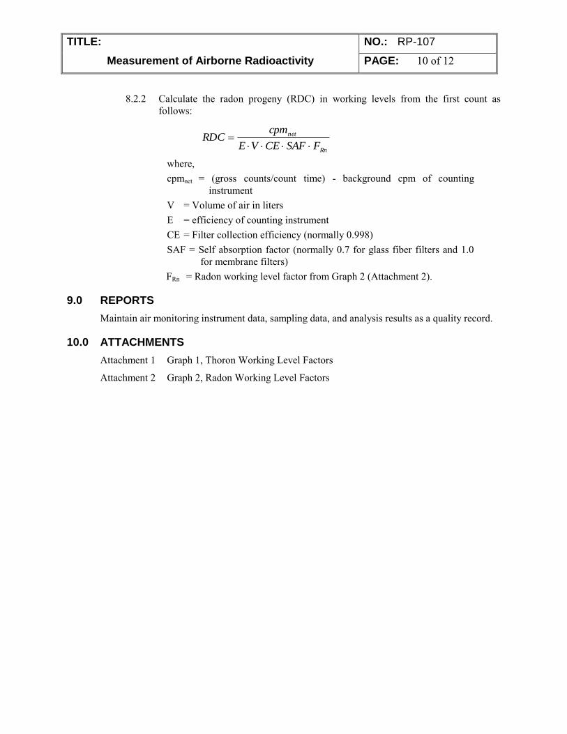
TITLE: NO.: RP-107
Measurement of Airborne Radioactivity PAGE: 10 of 12
8.2.2 Calculate the radon progeny (RDC) in working levels from the first count as follows:
Rn
net
FSAFCEVE
cpmRDC
where, cpmnet = (gross counts/count time) - background cpm of counting
instrument V = Volume of air in liters E = efficiency of counting instrument CE = Filter collection efficiency (normally 0.998) SAF = Self absorption factor (normally 0.7 for glass fiber filters and 1.0
for membrane filters) FRn = Radon working level factor from Graph 2 (Attachment 2).
9.0 REPORTS
Maintain air monitoring instrument data, sampling data, and analysis results as a quality record.
10.0 ATTACHMENTS
Attachment 1 Graph 1, Thoron Working Level Factors
Attachment 2 Graph 2, Radon Working Level Factors
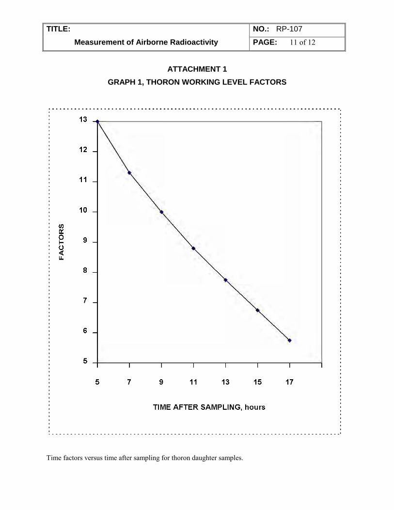
TITLE: NO.: RP-107
Measurement of Airborne Radioactivity PAGE: 11 of 12
ATTACHMENT 1
GRAPH 1, THORON WORKING LEVEL FACTORS
Time factors versus time after sampling for thoron daughter samples.
~ 0 .... 0 <( LL
13
12
11
10
9
8
7
6
5
5 7 9 11 13 15 17
TIME AFTER SAMPLING, hours
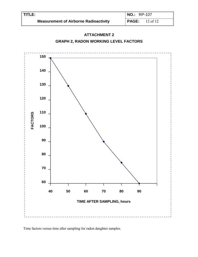
TITLE: NO.: RP-107
Measurement of Airborne Radioactivity PAGE: 12 of 12
ATTACHMENT 2
GRAPH 2, RADON WORKING LEVEL FACTORS
60
70
80
90
100
110
120
130
140
150
40 50 60 70 80 90
TIME AFTER SAMPLING, hours
FA
CT
OR
S
Time factors versus time after sampling for radon daughter samples.
~ ......................................... . .. .................................................................... ,
-- - -·
RRP-108 Count Rate Instruments
PERMA-FIX ENVIRONMENTAL SERVICES
TITLE: Count Rate Instruments
NO.: RP-108
PAGE: 1 of 6
DATE: May 2014
APPROVED:
______________________________________5/31/14_____ Technical Services Manager Date
______________________________________5/31/14___ Corporate Certified Health Physicist Date
1.0 PURPOSE
This procedure specifies the methods for set-up, daily pre-operational check, and operation of portable count-rate survey instruments. These instruments are used for the detection of radioactivity on personnel, on or within material surfaces, and in the environment. This procedure does not include associated instrument calibrations or cover the operation of exposure rate instruments.
2.0 APPLICABILITY This procedure specifically addresses those meter-probe combinations that report values in units of counts or counts per minute (cpm) such as Ludlum Measurements models 2221 and 2241 Scaler-Ratemeters; and the Ludlum Model 177 Alarming Ratemeter or equivalent. These meters are mated to probes including the Ludlum Model 44-10, 44-20, and 44-62 NaI Detectors, the Ludlum Model 43-5 Alpha Scintillation Detector, and the Ludlum Model 44-9 Pancake Geiger-Mueller detectors or equivalent. Additional equivalent meters and probes may be used under this procedure without revision as approved by the RSO.
3.0 REFERENCES 1. ANSI N323A-1997, Radiation Protection Instrumentation Test and Calibration,
Portable Survey Instruments.
2. Instrument Technical Manuals.
3. Perma-Fix Environmental Services (PESI) Radiation Protection Plan (RPP)
4. RP-104, Radiological Surveys
4.0 DEFINITIONS cpm: counts per minute
DFSCL: Daily Field Source Check Logsheet.
dpm: disintegrations per minute
HV: High Voltage
TITLE: Portable Count Rate Survey Instruments NO.: RP-108 PAGE: 2 of 9
RRP-108 Count Rate Instruments
MDA: Minimum Detectable Activity
5.0 RESPONSIBILITIES 5.1 Radiation Safety Officer (RSO)
Reviewing and approving changes to this procedure and ensuring compliance with applicable regulations.
Ensuring an adequate inventory of Radiation Protection instruments are available to support remediation activities.
Overseeing the issue, control, and accountability of Radiation Protection instrumentation per the requirements of this procedure.
Ensuring transmittal of all issue, control and accountability records to the appropriate document control authority when applicable.
5.2 Radiation Protection Technician (RPT) Maintaining instrument documentation and records as required by this procedure.
Maintaining adequate instrument and equipment availability.
Verifying current calibration and response test dates prior to issue or use of instruments.
Promptly returning instruments to their proper location when work is complete.
Ensuring that instruments are properly surveyed for contamination and decontaminated as necessary after use.
6.0 PREREQUISITES Only personnel with appropriate documented training shall issue or use RP instrumentation.
Instruments and detectors shall be inspected for mechanical damage, and response tested prior to issue.
Any instrument to be used shall have a current calibration label affixed to the instrument.
7.0 PRECAUTIONS AND LIMITATIONS Portable count rate survey instrumentations are susceptible to damage from physical and
environmental stresses.
QA/QC requirements established by an approved survey plan (e.g., Master Final Status Survey Plan) supercede the requirements of this procedure.
8.0 APPARATUS Appropriate survey instruments
9.0 RECORDS Portable Instrument Set-Up Sheet Daily Field Source Check Logsheet
TITLE: Portable Count Rate Survey Instruments NO.: RP-108 PAGE: 3 of 9
RRP-108 Count Rate Instruments
10.0 PROCEDURE 10.1 General
1. Ensure the meter-probe combination selected is within their acceptable calibration periods. The swapping of probes between meters is permitted, but not encouraged. The following precautions and limitations must be observed and the following action steps must be taken:
If the meter-probe combination is calibrated as a set, Probe swapping is not permitted, without specific RSO approval.
The HIGH VOLTAGE (HV) and THRESHOLD settings for the meter-probe combination shall be identical. Note that the Ludlum 177 and 2241 do not have user adjustable settings for HV and THRESHOLD.
An initial set-up must be performed for each meter-probe combination prior to field use.
A source with known pedigree must be counted to verify the efficiency is within 10% of the calibrated efficiency, as applicable.
2. The RP Group will coordinate the calibration of boxes and probes on a minimum annual basis and after major repair operations. Battery and / or cable change-outs do not require re-calibration. Calibration procedures are outside of the scope of this instruction.
3. Pre-operational checks are required daily prior to use. Post-operational checks are performed as specified in work plans or procedures. Instruments used in the performance of daily activities do not normally require a post-operational check..
4. Instruments that fail operational checks or malfunction during use should be tagged or labeled “Out-of-Service” or “Do Not Use” and segregated from operational instruments. If possible, describe the problem on the tag / label and add initials and date.
5. Instruments leaving RP Group control (i.e., repair, calibration, excess, etc.) shall be surveyed for unconditional release according to the contamination criteria established in Table 1 of the Site RPP. The repair / calibration center may request a copy of the survey accompany any shipments of RP instruments.
6. Ensure meters with a “WINDOW” or “WIN” setting are set to “OUT.”
7. Instruments may be operated in the FAST response mode if necessary. This setting is recommended if the audible response cannot be heard. SLOW response shall be used when performing instrument set-up and operational checks.
8. Ludlum NaI crystals are located in the end of the probe opposite of the cable connection. Use this end for surveys.
9. Calibration stickers are attached to the instruments and detectors. Illegible stickers should be replaced prior to instrument use.
10. Instrument set-up and subsequent operational checks should be performed in the same location, with consistent temperature and background radiation levels.
TITLE: Portable Count Rate Survey Instruments NO.: RP-108 PAGE: 4 of 9
RRP-108 Count Rate Instruments
11. Source positioning devices (i.e., jigs) may be used to ensure a reproducible geometry between instrument checks. Source geometry must be consistent between initial instrument set-up and subsequent operational checks.
12. Instruments that do not have scaler capability should be set-up and checked by replacing 1-minute timed counts with static count rate measurements. Each static measurement should last until the meter reading fully stabilizes.
10.2 Instrument Set-Up 1. Inspect the meter-probe combination for physical damage or defect.
2. Complete Section A of the Portable Instrument Set-Up Sheet (Attachment 1).
3. Perform 10 1-minute source counts alternating with 10 1-minute background counts. Remove / replace the source and reposition the probe after each count. During alternating background counts, ensure that the source is sufficiently shielded so as not to impact background values.
NOTE: Counts (Source and Background) performed with a Ludlum 43-5, or other large surface area probe, should be alternated between the Heel, Center, and Toe Positions, if the source surface is smaller than the active surface area of the probe. Instrument response can vary greatly across the probe surface.
4. Document each count on the Portable Instrument Set-Up Sheet.
5. Calculate and record the net count value by subtracting the corresponding background count from each source count.
NOTE: Determining Sigma (Standard Deviation) values is useful when specific plans or activities require higher data quality objectives and / or when the development of control charts is necessary.
6. Calculate and record the following values from the obtained background counts:
Avg. Value (Sum of values / # of counts) Sigma Value (Standard Deviation of all counts) 20% Value (Avg. Value * 0.20)
7. Calculate and record the +/- 20% Values and the +/- 1,2, and 3 Sigma values using the AVG. VALUE as a reference point.
8. Repeat the previous two steps for determining NET COUNT acceptable ranges. The 3 Sigma value must be less than the +/- 20% value.
9. Obtain a blank Daily Field Source Check Logsheet (DFSCL) (Attachment 2) and transfer the instrument, source, and acceptable range data, as applicable, from the Portable Instrument Set-Up Sheet.
10. Place the DFSCL in the designated use location and forward the completed Portable Instrument Set-Up Sheet and submit to the RSO, or designee for review.
11. Ensure sources are stored properly after use in the designated source storage location.
TITLE: Portable Count Rate Survey Instruments NO.: RP-108 PAGE: 5 of 9
RRP-108 Count Rate Instruments
10.3 Operational Check 1. Obtain the selected meter-probe combination and corresponding DFSCL
(Attachment 2).
2. Record the date and time on the DFSCL.
3. Perform and document the following checks on the DFSCL, as applicable:
Perform a physical inspection. Observe for instrument damage. Alpha probes should be checked for light leaks by inverting the probe face towards a light source and observing instrument response. If the instrument fails to respond at all or over-responds this may be an indication of a light leak and should be investigated further, prior to proceeding.
Perform a battery check. Instrument Models differ in method. Some meters have a visible battery range on the meter face. The Ludlum Model 2241 has a battery indicator in the digital display that lights if the batteries require replacement. The Ludlum Model 2221 has a BAT button that brings up the battery level in the digital display. Ensure this value is at least 5.0v. Change batteries and retest as necessary.
Verify and adjust the HV, when possible, to match the initial set-up data. Minute differences in HV (+/- 5v) are acceptable without adjustment.
Perform an audio response check..
4. Perform and record a 1-minute background count. Report any abnormal background responses to the RSO, prior to instrument use. Normally acceptable background levels < 5 cpm for alpha probes, and < 300 cpm for Pancake G-M probes. Acceptable background levels for NaI probes are variable due to crystal size and based on technician experience.
5. Perform and record a 1-minute source gross count using the same source and geometry applied during initial set-up.
6. Calculate and record the net count value.
7. Compare the net count value to the acceptable range. If the instrument response is outside the acceptable range, the process may be repeated a maximum of 1 additional time before placing the instrument out-of-service.
8. If the instrument fails the pre-operational checks, mark FAIL, initial the DFSCL, and place the instrument out-of-service. Deliver completed DFSCL to the RSO or designee, and explain the failed condition(s).
9. If all checks pass, mark PASS, initial the DFSCL, and return form to designated in-use storage location. This may be a binder, folder, or cabinet. The instrument is now ready for use.
10. If the instrument will be used for routine personnel exit monitoring ensure the alarm threshold is set to alarm and actuates at a level below the site removable contamination limits identified in Table 6-1 of the Site Safety & Health Plan (SSHP). Make adjustments as necessary.
TITLE: Portable Count Rate Survey Instruments NO.: RP-108 PAGE: 6 of 9
RRP-108 Count Rate Instruments
11. Ensure sources are stored properly after use in the designated source storage location.
10.4 Operations 1. Operate instrument in a manner that minimizes the potential for
cross-contamination and physical damage.
2. Evaluate the surface or area to be surveyed for potential scanning interferences. For example, thin layers of water or soil can prevent the detection of alpha contamination. Another example is the use of a NaI probe to qualify soil contamination. The presence of standing water can have a significant impact on instrument response. Initiate necessary corrective actions prior to survey or note conditions during survey reporting.
3. Most instruments will operate in temperatures between 10 and 120 degrees Fahrenheit. However, anytime the temperature is outside of the 32 degree (freezing) or 100 degrees ranges, observe the following precautions:
Use particular caution with NaI crystals that may shatter under extreme temperature changes. If the temperature difference is greater than 30 degrees between storage and usage locations, wrap the probe tightly in a cloth towel or other insulator and allow warming or cooling over at least one hour prior to use.
Periodically check the instrument against a known source of radiation or contamination. If the instrument appears to be responding incorrectly contact the RSO or designee for guidance.
Contact the RSO for guidance anytime work is planned outside of the 10 to 120 degree range.
4. Protect instruments to the extent possible from exposure to moisture (i.e., rain, snow, etc.) during use. Instruments shall be stored in a safe manner when not in use.
5. Minimum Detectable Activities (MDA) for each survey should be determined by evaluating field background levels, not background values obtained during operational checks. Calculate MDA using the formula provided in PP-8-805, “Radiological Surveys.”
6. Determining activity in disintegrations per minute (dpm) should be performed using the instrument efficiency obtained during calibration. Efficiencies are normally not established for NaI probes, and therefore should not be used for quantifying activity concentrations. The use of NaI probes for activity quantification shall be evaluated by the RSO prior to performance.
7. Observe the following when performing survey scans and static measurements:
Alpha probes should be held within ¼-inch of the surface being surveyed. Probe speed should not exceed 1 probe width per second.
Beta probes should be held within ½-inch of the surface being surveyed. Survey speed should not exceed one probe width per second.
TITLE: Portable Count Rate Survey Instruments NO.: RP-108 PAGE: 7 of 9
RRP-108 Count Rate Instruments
NaI probes should be held as close as possible to the surface being surveyed without contaminating the probe housing. Note that the crystal is located in the probe end opposite the cable connection. Use appropriate sleeving or wrapping in wet or dirty environments.
The scan speed for performing Gamma Walkover Surveys is approximately 0.5 m/sec. Move the detector side to side using a 1-meter path length. Each side-side swing should take 2 seconds to traverse the 1-meter path. Advance the probe forward as you go at a rate of approximately 0.5 m/sec. Use the audio function. When increased counts are detected, slow down and locate the source as would be done in a normal survey. Walk parallel paths to ensure that 100% of the area is surveyed. Ensure that the survey extends to the boundaries of the survey unit. Pay particular attention to low lying areas, ditches, and points of possible contamination.
Static measurements should be performed in any location were scans indicated the presence of activity. This is due to the fact that instrument MDAs are normally based on a 1-minute static measurement.
All static measurements should be at least 1 minute, if the instrument has a scaler function. If the instrument is a ratemeter only, static measurements should last until the meter reading has fully stabilized.
8. Perform a post-operational check after use if directed by work plan, procedure, or the RSO.
11.0 ATTACHMENTS Note: Attachments may be revised without formal review of this procedure and are attached as examples only. Please contact the RSO for a current copy of these attachments.
Attachment 1 Portable Instrument Set-Up Sheet (Typical)
Attachment 2 Daily Field Source Check Logsheet (Typical)
TITLE: Portable Count Rate Survey Instruments NO.: RP-108 PAGE: 8 of 9
RRP-108 Count Rate Instruments
Attachment 1 Portable Instrument Set-Up Sheet (Typical)
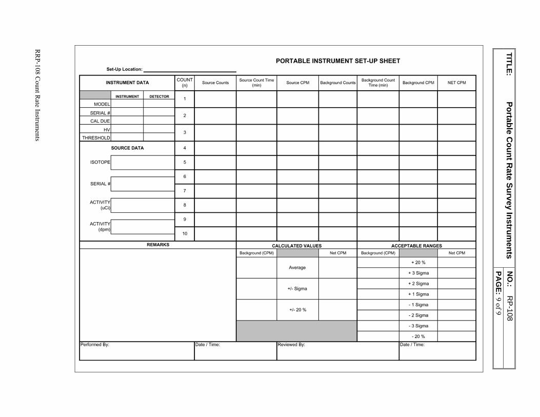
TITLE: Portable C
ount Rate Survey Instrum
ents N
O.:
RP-108
PA
GE: 9 of 9
RR
P-108 Count R
ate Instruments
PORTABLE INSTRUMENT SET-UP SHEET Set-Up Locat ion : _________________ _
INSTRUMENT DATA COUNT
Source Counts Source Count Time
Source CPM Background Counts Background Count
Background CPM NETCPM (n) (min) Time(min)
INSTRUMENT DETECTOR 1
MODEL
SERIAL# 2
CAL DUE
HV 3
THRESHOLD
SOURCE DATA 4
ISOTOPE 5
6
SERIAL#
7
ACTIVITY 8
(uCi)
9 ACTIVITY
(dpm) 10
REMARKS CALCULATED VALUES ACCEPTABLE RANGES
Background (CPM) NetCPM Background (CPM) NetCPM
+20 % Average
+ 3 Sigma
+ 2 Sigma +/-Sigma
+ 1 Sigma
-1 Sigma +/- 20 %
-2 Sigma
- 3 Sigma
-20%
Performed By: Date/Time: Reviewed By: Date/Time:
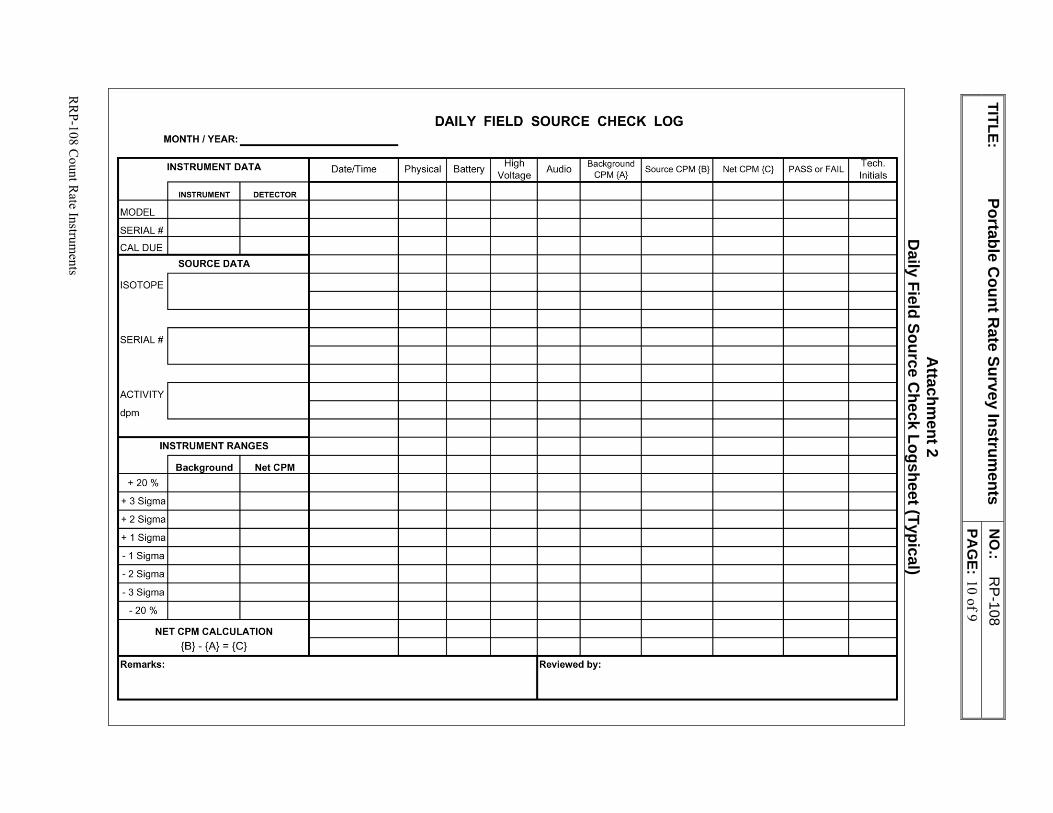
TITLE: Portable C
ount Rate Survey Instrum
ents N
O.:
RP-108
PA
GE: 10 of 9
RR
P-108 Count R
ate Instruments
Attachm
ent 2 D
aily Field Source Check Logsheet (Typical)
DAILY FIELD SOURCE CHECK LOG MONTH / YEAR: -----------INSTRUMENT DATA Date/Time Physical Battery
High Audio
Background Source CPM {B} NetCPM {C} PASS or FAIL Tech.
Voltaoe CPM {A} Initials
INSTRUMENT DETECTOR
MODEL
SERIAL#
CAL DUE
SOURCE DATA
ISOTOPE
SERIAL#
ACTIVITY
dpm
INSTRUMENT RANGES
Backaround Net CPM
+ 20 %
+ 3 Sigma
+ 2 Sigma
+ 1 Sigma
-1 Sigma
- 2 Sigma
- 3 Sigma
- 20 %
NET CPM CALCULATION
{B} - {A} = {C}
Remarks: Reviewed by:
RP-109 Dose Rate Instruments
PERMA-FIX ENVIRONMENTAL SERVICES
TITLE: Dose Rate Instruments
NO.: RP-109
PAGE: 1 of 6
DATE: May 2014
APPROVED:
______________________________________5/31/14_____ Technical Services Manager Date
______________________________________5/31/14___ Corporate Certified Health Physicist Date
1.0 PURPOSE
This procedure specifies the methods for performing source checks and operating portable Gamma scintillation dose rate instruments, specifically, the Ludlum Model 12s uR and the Bicron Model Micro Rem. These instruments are used for the evaluation of exposure rates from radioactive materials and determining environmental radiation levels.
2.0 APPLICABILITY This procedure addresses those instruments that measure dose rate from a scintillation detector and have displays that read in uR/hr, uRem/hr and/or mRem/hr such as Ludlum 12s, Bicron Micro Rem, or Eberline RO-2. Equivalent instruments that operate in a similar fashion to those identified in this section may be operated under this Project Procedure with RSO approval.
3.0 REFERENCES 1. ANSI N323-1978, Radiation Protection Instrument Test and Calibration. 2. Instrument Technical Manuals. 3. Perma-Fix Environmental Services (PESI) RPP
4.0 DEFINITIONS None
5.0 RESPONSIBILITIES 5.1 Radiation Safety Officer (RSO)
Reviewing and approving changes to this procedure and ensuring compliance with applicable regulations.
Ensuring an adequate inventory of Radiation Protection instruments are available to support remediation activities.
Overseeing the issue, control and accountability of Radiation Protection instrumentation per the requirements of this procedure.
TITLE: Dose Rate Instruments
NO.: RP-109
PAGE: 2 of 8
RRP-109 Dose Rate Instruments
Ensuring transmittal of all issue, control and accountability records to the appropriate document control authority when applicable.
5.2 Radiation Protection Technician (RPT) Maintaining instrument documentation and records as required by this procedure.
Maintaining adequate instrument and equipment availability.
Verifying current calibration and response test dates prior to issue or use of instruments.
Promptly returning instruments to their proper location when work is complete.
Ensuring that instruments are properly surveyed for contamination and decontaminated as necessary, after use.
6.0 PREREQUISITES Only personnel with documented training shall issue or use RP instrumentation.
Instruments and detectors shall be inspected for mechanical damage, and response tested prior to issue.
Any instrument to be used shall have a current calibration label affixed to the instrument.
7.0 PRECAUTIONS AND LIMITATIONS Portable count rate survey instrumentations are susceptible to damage from physical and
environmental stresses.
8.0 APPARATUS Survey instrument Tech source Source positioning device (jig)
9.0 RECORDS Daily Field Source Check Log – Exposure Rate Instruments (Attachment 1)
Exposure Rate Instrument Set-Up Sheet (Attachment 2)
10.0 PROCEDURE 10.1 General
1. Ensure the instrument selected is within their acceptable calibration periods. This is indicated on an attached calibration sticker. Illegible stickers should be replace prior to instrument use.
2. The RP Group will coordinate instrument calibration on a minimum annual basis and after major repair operations. Battery change-outs do not require re-calibration. Calibration procedures are outside of the scope of this instruction.
3. Pre-operational source checks are required daily, or prior to each intermittent use, whichever is less frequent. Post-operational source checks are performed as specified in work plans or procedures. Instruments used in the performance of daily activities do not normally require a post-operational source check.
TITLE: Dose Rate Instruments
NO.: RP-109
PAGE: 3 of 8
RRP-109 Dose Rate Instruments
4. Instrument set-up and subsequent operational checks should be performed in the same location, with consistent temperature and radiation background levels.
5. Use a gamma check source with an activity sufficient to produce contact exposure rates at least ten times higher than background. Cs-137 is typically since it emits 662 keV gamma rays which are representative of the mid-range of gamma energies encountered at NFSS. Alternate sources may be used with RSO approval.
6. Source positioning devices (i.e., jigs) should be used to ensure a reproducible geometry between instrument checks. Source geometry must be consistent between initial instrument set-up and subsequent operational checks.
7. The Ludlum 12s may be operated in the FAST response mode. Switch to SLOW response for obtaining precise readings.
8. Internal scintillation crystals are orientated towards the front of the instrument. Meter cases have visible indicators showing optimum locations to obtain measurements (i.e. effective detector center).
9. Allow instrument readings to maximize prior to recording instrument reading. This may take up to twenty seconds. Note that the needle may not rest on a single value, but may fluctuate slightly between two points on the scale. If this is the case, an average reading should be obtained by summing these two end points and dividing by two.
10. Instruments should be allowed to warm-up for at least one minute prior to obtaining readings.
11. Report any abnormal instrument readings (e.g., unstable analog meter fluctuations), or background inconsistencies to the RSO, prior to continuing instrument use.
12. Instruments that fail operational checks or malfunction during use should be tagged or labeled “Out-of-Service,” or “Do Not Use,” and segregated from operational instruments. If possible, describe the problem on the tag / label and add initials and date.
13. Instruments leaving RPP Group control (i.e., repair, calibration, excess, etc.) shall be surveyed for unconditional release. The repair / calibration center may request a copy of the survey to accompany shipments of RP instruments.
10.2 Instrument Source Check 1. Obtain the selected instrument.
2. Obtain the corresponding Daily Field Source Check Log – Exposure Rate Instruments form, Attachment 1. This form will be referred to as the “Source Check Log.” Initiate a new Source Check Log, if necessary.
3. Perform a physical inspection of the instrument. Place particular emphasis on the following items:
Instrument case is not visibly damaged beyond minor scrapes and scratches.
Analog display is not cracked or otherwise damaged.
TITLE: Dose Rate Instruments
NO.: RP-109
PAGE: 4 of 8
RRP-109 Dose Rate Instruments
Switches and buttons are functional.
Audio, if present, is functional.
Calibration labels are legible and instrument is within calibration period.
4. Note results of physical inspection on the Source Check Log.
5. Verify the battery level is within the acceptable range on the analog display. Replace batteries and re-verify, as necessary.
6. Note battery check results on the Source Check Log.
7. Verify the high voltage (HV) level is within the acceptable range on the analog display, if present. Place the instrument out-of-service if the HV is outside the acceptable range.
8. Note the HV check results on the Source Check Log.
9. If acceptable background ranges have not been established, perform the following:
Obtain a blank NFSS Exposure Rate Instrument Set-Up Sheet, Attachment 2. This form will be referred to as the “Set-Up Sheet.”
Record the basic source and instrument information at the top of the form.
Using the instrument and the source jig (without source), obtain and record ten background readings. The instrument should be removed from the source jig and repositioned after each reading is obtained. Make sure the location where readings are obtained has stable background levels and is the location used for subsequent source checks.
Calculate and record the average background value and +/- 20% values on both the set-up and source check logsheets.
10. Obtain and record an average background reading on the source check log.
11. Compare the average background reading to the acceptable range. If background response is outside this range, report the condition to the RSO for evaluation, otherwise continue with source check process.
12. Obtain the source to be used for instrument source checks.
13. If acceptable source check ranges have not been established, perform the following:
Obtain the Set-Up Sheet used to determine acceptable background ranges for the instrument.
Using the instrument and the source jig (with source), obtain and record ten contact source readings. The instrument and source should be removed from the source jig and repositioned after each reading is obtained. Make sure the location where readings are obtained is the same location where previous background readings were obtained.
Calculate and record the average source value and +/- 20% values on both the set-up and source check logsheets.
TITLE: Dose Rate Instruments
NO.: RP-109
PAGE: 5 of 8
RRP-109 Dose Rate Instruments
14. Load the source and instrument onto the source jig.
15. Obtain and record the “CONTACT” reading.
16. Verify the contact reading is within the acceptable range (+/- 20%).
17. If the contact source reading falls outside the acceptable range, tag the instrument out of service and notify the RSO, otherwise continue.
18. Complete the source check log including technician initials. The instrument is now ready for use.
19. Ensure sources and forms are stored properly after use in the designated storage location. Forms are retained in RP Instrument logbooks of field files during instrument use (i.e. calibration) cycle. Records are then reviewed by the RSO, or designee for completeness and forward to Project Records for retention.
10.3 Operations 1. Verify that required source checks have been performed prior to initial instrument
use.
2. Operate instrument in a manner that minimizes the potential for cross-contamination and physical damage.
3. Limit readings taken while the instrument is positioned sideways to minimize the effects of “geotropism” on the analog needle.
4. Obtain readings by positioning the instrument as close to the detector’s “effective center” as possible. The detector effective center is represented on the instrument housing a cross inside a circle on the Bicron Micro Rem, and a small circular depression on the Ludlum 12s. Overall optimum readings are collected from the front of the instrument housing.
5. Most instruments will operate in temperatures between 10 and 120 degrees Fahrenheit. However, anytime the temperature is outside of the 32 degree (freezing) or 100 degree ranges, observe the following precautions:
Be observant of instrument response to background. If the instrument begins to show a decreased response to expected background levels contact the RSO, or designee for guidance.
If practicable, perform a period response check of the instrument against a known source of radiation. If the instrument appears to be responding incorrectly contact the RSO or designee for guidance.
Contact the RSO for guidance anytime work is planned outside of the 10 to 120 degree range.
6. Protect instruments, to the extent possible, from exposure to moisture (i.e. rain, snow, etc.) during use. Instruments shall be stored in a safe manner when not in use.
7. Perform a post-operational source check after use, if directed by work plan, procedure, or the RSO.
TITLE: Dose Rate Instruments
NO.: RP-109
PAGE: 6 of 8
RRP-109 Dose Rate Instruments
11.0 ATTACHMENTS Attached forms are examples and may be modified by the RSO, as needed, without revision to this procedure.
Attachment 1 Daily Field Source Check Log – Exposure Rate Instruments (Typical)
Attachment 2 Exposure Rate Instrument Set-Up Sheet (Typical)
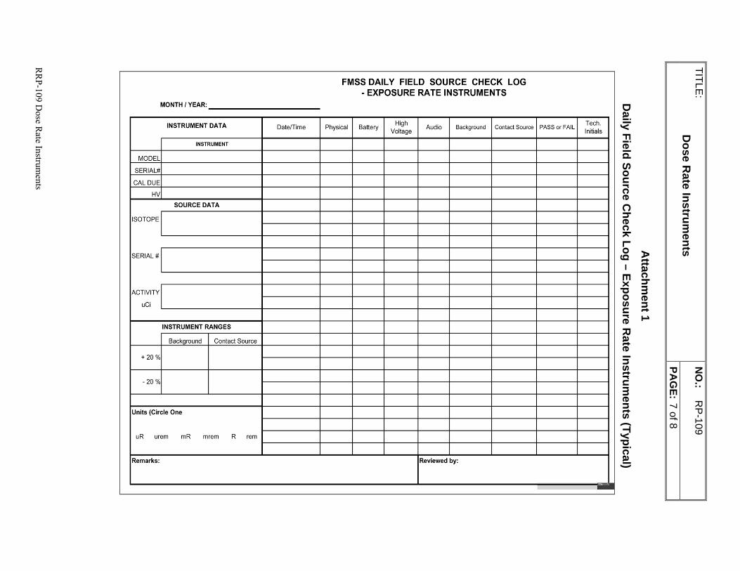
TITLE:
Dose R
ate Instruments
NO
.: R
P-109
PA
GE: 7 of 8
RR
P-109 Dose R
ate Instruments
Attachm
ent 1 D
aily Field Source Check Log – Exposure R
ate Instruments (Typical)
FMSS DAILY FIELD SOURCE CHECK LOG - EXPOSURE RA TE INSTRUMENTS
MONTH / YEAR:
INSTRUMENT DATA Date/Time Physical Battery High
Audio Background Contact Source PASS or FAIL Tech.
Voltage Initials
INSTRUMENT
MODEL
SERIAL#
CAL DUE
HV
SOURCE DATA
ISOTOPE
SERIAL#
ACTIVITY
uCi
INSTRUMENT RANGES
Background Contact Source
+ 20 %
- 20 %
Units (Circle One
uR urem mR mrem R rem
Remarks: Reviewed by:
--
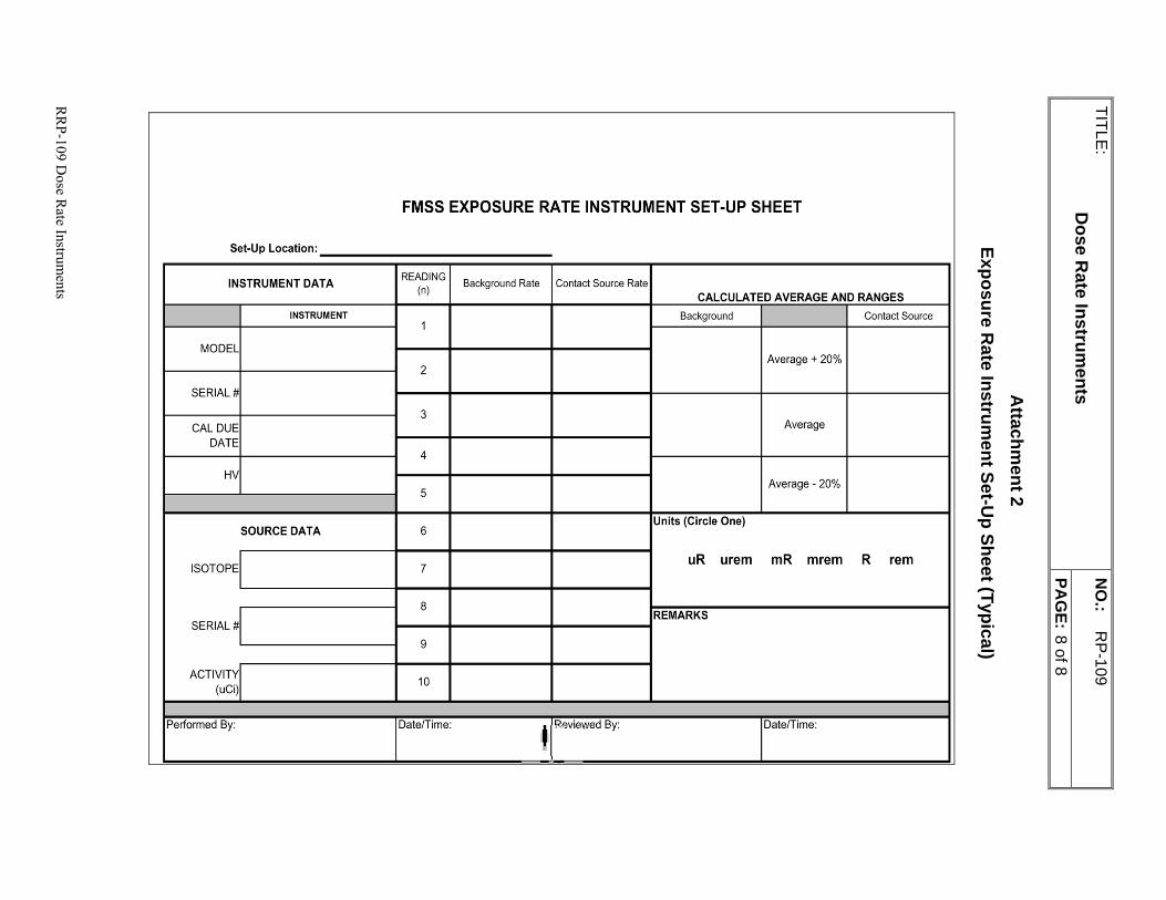
TITLE:
Dose R
ate Instruments
NO
.: R
P-109
PA
GE: 8 of 8
RR
P-109 Dose R
ate Instruments
Attachm
ent 2 Exposure R
ate Instrument Set-U
p Sheet (Typical)
FMSS EXPOSURE RATE INSTRUMENT SET-UP SHEET
Set-Up Location:
INSTRUMENT DATA READING Background Rate Contact Source Rate (n)
CALCULATED AVERAGE AND RANGES
INSTRUMENT Background Contact Source 1
MODEL
2 Average + 20%
SERIAL #
3 CAL DUE Average
DATE 4
HV
5 Average - 20%
SOURCE DATA 6 Units (Circle One)
ISOTOPE 7 uR urem mR mrem R rem
8 REMARKS
SERIAL#
9
ACTIVITY 10
(uCi)
Performed By: Date/Time: ' Reviewed By: DatefTime:
TITLE: Radioactive Material Control Program
NO.: RP-111 PAGE: 1 of 14
RP-111 Radioactive Materials Control and Waste Management Plan
PERMA-FIX ENVIRONMENTAL SERVICES
TITLE: Radioactive Materials Control and
Waste Management Program
NO.: RP-111
PAGE: 1 of 6
DATE: March 2017
APPROVED:
___________________________________03/03/17___ Technical Services Manager Date
___________________________________03/03/17___ Corporate Certified Health Physicist Date
1.0 PURPOSE
This procedure provides guidance and requirements for the control of radioactive materials including the management of radioactive waste. The Radioactive Materials Control and Waste Management Program applies to the receipt, inventory, storage and handling of radioactive materials; the release of materials from Restricted Areas; the control of radioactive sealed sources; the control of materials and contaminated tools and equipment entering and/or leaving Restricted Areas; and the management of waste including transportation and disposal.
2.0 APPLICABILITY
This procedure applies to all PESI Project personnel and all decommissioning projects that involve radioactive materials. This procedure does not apply to the monitoring of liquid and gaseous effluents, radiological environmental monitoring, or final termination surveys of the reactor or facilities.
3.0 REFERENCES
1. Title 17, California Code of Regulations, Division 1, Chapter 5, Subchapter 4 “Radiation.”
2. Title 22, California Code of Regulations, Division 4.5; Environmental Health Standards for the Management of Hazardous Waste
3. California Executive Order D-62-02 regarding disposal of decommissioned materials.
4. 10 Code of Federal Regulations (CFR) 20; Standards for Protection Against Radiation, and Transfer and Disposal and Manifests
5. 49 CFR, Subchapter C “Transportation – Hazardous materials Regulations”
-
Perm - GD
IX environmental services
A Nuclear Services and Waste Management Company
~c: -
~
7'
~~~~
TITLE: Radioactive Material Control Program
NO.: RP-111 PAGE: 2 of 14
RRP-111 Radioactive Materials Control and Waste Management Plan
6. 40 CFR, Subchapter I “Solid Wastes”
7. 40 CFR Part 260-273 “Hazardous Waste Management System”
7. USNRC Circular 81-07, "Control of Radioactively Contaminated Materials."
8. USNRC IE Information Notice No. 80-22, "Breakdowns in Contamination Control Programs."
9. ANSI N13.2-1969, "USA Standard Guide for Administrative Practices in Radiation Monitoring (A Guide for Management)."
10. RP -102, “Radiological Posting Requirements.”
11. RP -104, “Radiological Surveys."
12. RP- 105, “Unrestricted Release Requirements.”
13. RP -114, “Control of Radiation Protection Records.”
4.0 GENERAL
4.1 Discussion
Radioactive material controls are established to provide positive control of radioactive material, prevent inadvertent release of radioactive material to uncontrolled areas, ensure personnel are not unknowingly exposed to radiation from lost or misplaced radioactive material, and to minimize the amount of radioactive waste material generated during PESI activities.
4.2 Definitions
Aggregate Material: Items or materials that by their physical nature do not lend themselves to being effectively surveyed using portable instrumentation and require bulk or composite survey techniques or representative sampling and analysis.
Conditional Release of Material: Items or materials that do not meet unconditional release criteria and that are released under the control of Radiation Protection personnel.
Contamination Area (CA): Means any area with loose surface contamination values in excess of the applicable values specified in RP-104 Acceptable Surface Contamination Levels that is accessible to personnel, or any additional area specified by the RSO. The Contamination Area posting is defined as more restrictive than Radioactive Material Areas, hence all Contamination Area postings are considered to be Radioactive Material postings.
TITLE: Radioactive Material Control Program
NO.: RP-111 PAGE: 3 of 14
RRP-111 Radioactive Materials Control and Waste Management Plan
Minimum Detectable Activity (MDA): The smallest amount or concentration of radioactive material in a sample that will yield a net count, above system background, that will be detected with 95% probability with only 5% probability of falsely concluding that a blank observation represents a "real" signal. MDA depends upon the type of instrument, the counting geometry, and the radionuclide to be detected. MDA has the same meaning as Lower Limit of Detection (LLD). (ANSI N13.3, 1989).
Radioactive Material: Material activated or contaminated by the operation or remediation of the site and by-product material procured and used to support the operation or remediation.
Radioactive Material Area: Any area or room where quantities of radioactive materials in excess of ten times the 10 CFR 20 Appendix C quantities are used or stored, or any area designated a RMA by the RSO which does not exceed the site Contamination Area criteria.
Restricted Area: An area to which access is limited to protect individuals against undue risks from exposure to radiation, radioactive materials, and chemical contaminants. All posted radiological or chemical areas are Restricted Areas.
Unconditional Release of Material: Release of equipment or material to the general public. The equipment and / or material are deemed to meet site release criteria for both total and removable contamination.
5.0 RESPONSIBILITIES
5.1 Radiation Safety Officer (RSO)
The RSO is responsible for:
Ensuring adequate staffing, facilities and equipment are available to perform the radioactive material control functions assigned to Radiation Protection personnel.
Investigating and initiating corrective actions for the improper handling of radioactive material.
Approving purchase or acquisition of radioactive sources.
Ensuring a source inventory and leak testing program is established.
Authorizing the establishment of radioactive material and sealed source storage locations.
Packaging and transferring radioactive material to appropriate authorities.
Administering receipt / release survey programs of radioactive material.
Administering radioactive source inventory and leak testing.
Ensuring correct posting of radiological area.
Reviewing results of sample analysis and survey data as required to determine acceptability for release of items.
Ensuring packages for transport and disposal meet applicable regulations for integrity and dose limits.
TITLE: Radioactive Material Control Program
NO.: RP-111 PAGE: 4 of 14
RRP-111 Radioactive Materials Control and Waste Management Plan
5.2 Certified Waste Shipper
The certified (as required by 49 CFR 172, Subpart H) waste shipper is responsible for:
Identifying proper packaging and posting requirements for all offsite transport of radioactive and/or mixed wastes.
Reviewing results of conveyance package radiation surveys and performing inspections of conveyance packages prior to approving packages to leave a site.
Maintaining records of all waste shipments.
Assisting the RSO in proper characterization, classification and sampling of any potentially radioactive or mixed waste
Selecting the treatment, storage and disposal facility (TSDF) to be used for processing, treatment, and/or disposal of radioactive or mixed waste
Preparing profiles and shipping paperwork for disposal of radioactive or mixed wastes generated
Directing and performing inspections, marking, labeling and placarding of radioactive or mixed waste prior to shipment
Selecting the proper packages to use for radioactive or mixed waste
Maintaining an inventory of radioactive and mixed waste onsite and shipped off the project.
Ensuring periodic inspections as required by regulation are performed and documented
5.3 Radiation Protection Technicians (RPTs)
The RPT is responsible for:
Performing and documenting radiation and contamination surveys, inspections and leak tests.
Posting, securing, and controlling radioactive material and source storage areas.
Safely opening packages of radioactive material.
Identifying radioactive material.
Releasing material in accordance with this and implementing procedures.
Notifying the RSO or designee on arrival of radioactive material.
Performing pre-transportation surveys of radioactive materials packaging and conveyance vehicles.
5.4 Project Personnel
TITLE: Radioactive Material Control Program
NO.: RP-111 PAGE: 5 of 14
RRP-111 Radioactive Materials Control and Waste Management Plan
Project personnel are responsible for:
Adhering to all policies, procedures and other instructions, verbal and written, regarding control and minimization of radioactive material and contaminated material.
Reporting any concerns about the control and minimization of radioactive material and contaminated material to supervision.
Maintaining good housekeeping at work sites and assisting in preventing the build-up and spread of contamination.
Obtaining RSO authorization prior to accepting receipt of radioactive material at the project. This includes, but is not limited to items such as sealed sources, liquid standards, and contaminated equipment from other sites, and waste generated outside normal project remediation activities. This is to ensure that required receipt surveys are scheduled, appropriate ALARA considerations are implemented, and that the source term is evaluated for possible effects to the project waste stream criteria.
Complying with direction from RP personnel regarding the proper methods for receipt, handling, decontamination, packaging, storage, transport and disposal of radioactive material.
6.0 PREREQUISITES
None
7.0 PRECAUTIONS AND LIMITATIONS
Packages of radioactive material or sources shall NOT be opened until the required receipt survey is performed by RP personnel.
Packages of radioactive waste shall not leave a site until approval to do so is granted by the Certified Waste Shipper.
8.0 RECORDS
Receipt radiological surveys
Radiological release surveys
Radiological transportation surveys
Source Inventory which includes Leak Test Results
Transportation records including manifests, transportation checklists, and a transportation log
Records generated shall be transmitted to Project Document Control for filing according to procedure RPP-114.
9.0 PROCEDURE
9.1 Receipt of Radioactive Material
TITLE: Radioactive Material Control Program
NO.: RP-111 PAGE: 6 of 14
RRP-111 Radioactive Materials Control and Waste Management Plan
1. Obtain RSO authorization prior to accepting receipt of radioactive material at the project.
Radioactive materials which may be received include, but are not limited to, items such as sealed sources, liquid standards, contaminated equipment from other sites, waste generated outside normal project remediation activities and shipments of radioactive materials from vicinity properties to the PESI for storage and / or transportation and disposal. This is to ensure that required receipt surveys are scheduled, appropriate ALARA considerations are implemented, and that the source term is evaluated for possible effects to the project waste stream criteria.
Refer to 10 CFR 71.4 and Appendix A to 10 CFR 71 for definition and limits for “Type A Quantities” of radioactive materials.
The RSO may direct receipt surveys to be performed on any incoming radioactive material shipment.
2. If an expected package exceeds Type A quantities, the package requestor shall make arrangements with RP and the carrier to receive or pick-up the shipment when the carrier makes notification of package availability.
3. RP personnel perform receipt inspections and surveys of incoming radioactive material shipments which exceed a Type A quantity (refer to 10 CFR 71.4 and Appendix A of 10 CFR 71) as follows:
The inspection and survey shall be performed within three hours of receipt. If received after normal work hours, the survey is required with three hours from the beginning of the next business day.
Don latex gloves, at a minimum, when performing incoming inspections and surveys.
Inspect the package for leaks or apparent damage.
Ensure the contents match the packing slip or shipping papers.
Perform a radiation survey of the package exterior.
Perform a removable contamination survey of the package interior and exterior.
4. RP Personnel shall store the package in a secure, radiologically posted area, notify the RSO or designee if any the following conditions are observed during receipt of a radioactive material shipment:
Contents do not match packing slip or shipping papers
The contents of the package do not contain the isotopes or quantities of material as ordered or expected.
Package is leaking or sufficiently damaged to compromise package contents.
The receipt survey results exceed any of the following limits:
Radiation (mrem/hr) – 200 @ Contact or 10 @ 1 meter from the package
Removable Contamination (dpm/100cm2) – 2200 Beta-Gamma, 220 Alpha
TITLE: Radioactive Material Control Program
NO.: RP-111 PAGE: 7 of 14
RRP-111 Radioactive Materials Control and Waste Management Plan
9.2 Identification of Radioactive Material
1. Radioactive material exceeding limits specified in 10 CFR 20, Appendix C shall be identified and labeled by Radiation Protection personnel:
On receipt of packages containing radioactive material or sources.
During removal of items or material from contaminated systems or areas, or from radioactive materials areas.
In the course of performing area and job specific surveys.
In the course of surveying items for release.
2. Items that meet or exceed the contamination limits established in the PESI RPP should be labeled radioactive material.
3. Use the following guidance, as a minimum, when labeling radioactive material:
Labels shall only be placed or removed by Radiation Protection personnel.
Unique features (e.g., yellow plastic bags, yellow and magenta tags, purple paint, etc.) should be used to clearly identify the physical and radiological parameters of the material.
Labeling shall state "CAUTION - RADIOACTIVE MATERIAL."
4. Exceptions to labeling requirements for radioactive material are as follows:
The item or material is under the direct control of personnel who are aware of the contents and the associated radiological hazards.
The material is radiation protection equipment (e.g., respirators, instruments. etc.).
The material consists of radiological samples being analyzed or sampling equipment controlled by Radiation Protection personnel.
The material is packaged and labeled in accordance with DOT regulations while awaiting transport.
The material is contained in permanently installed equipment and / or potentially contaminated systems.
The material consists of permanently installed equipment or components, including check sources installed in radiation monitoring equipment, which have manufacturer supplied check source labels affixed. Radiation level posting requirements shall remain applicable.
The material consists of laundered protective clothing:
a. In controlled use, inside the Restricted Area; or
b. Stored in designated laundry containers.
The material consists of check sources or sealed sources and source storage containers identified as radioactive material with identifiable labels affixed to the source.
TITLE: Radioactive Material Control Program
NO.: RP-111 PAGE: 8 of 14
RRP-111 Radioactive Materials Control and Waste Management Plan
The material is stored or in-use in a posted Contamination Area or Airborne Radioactivity Area. All items in these areas are considered potentially radioactive/contaminated until properly dispositioned by RP personnel.
The material consists of contaminated items (e.g., hand tools) impractical to label, that are marked with magenta paint.
5. Project personnel should notify Radiation Protection of any items or containers with lost or damaged radioactive material labels.
6. Material requiring labeling as radioactive material which is found uncontrolled and outside a Restricted Area shall be brought to the immediate attention of RP Personnel.
9.3 Storage of Radioactive Material
1. Radioactive Material Storage Areas shall be posted in accordance with RP -102, “Radiological Posting Requirements."
2. Radiation Protection personnel should consider the following when specifying radiological requirements for Radioactive Material Storage Areas:
Changes to radiation levels in an area as a result of material storage.
External environmental conditions are such that significant container degradation does not occur during storage.
Material is adequately packaged and controlled to minimize the potential for loss of radioactive material control
3. Unsealed radioactive materials e.g. soil, debris, liquids will be posted and controlled in accordance with RP-102, Radiological Posting Requirements.
4. Soil, debris, and materials will be staged in appropriate containers/bags or covered with tarps as necessary to prevent migration outside of radiological boundaries.
5. Liquids will be stored in appropriate containers (e.g. drums, totes, etc.) 6. All storage containers will be labeled with pertinent information including
description and radiological data. 7. PPE requirements for handling radioactive materials are established in the applicable
RWP and procedure RP-132, Selection and Use of Radiological PPE.
9.4 Special Considerations for Control of Accountable Radioactive
Sources
1. The RSO, or designee shall serve as the Source Custodian and shall be responsible for the following:
Ensuring that all accountable radioactive sources are stored in their designated storage location when not in use.
Maintaining a source inventory that includes accountable source identification, isotopic content, activity, assay date, designated storage location, and date and results of most recent semi-annual leak test.
TITLE: Radioactive Material Control Program
NO.: RP-111 PAGE: 9 of 14
RRP-111 Radioactive Materials Control and Waste Management Plan
2. Any individual planning to procure a radioactive source for the project shall request approval from the RSO in writing. This request shall include a justification for bringing additional sources onto the project and shall include all necessary source information to update the source inventory.
3. Licensed sources under the control of a licensee (e.g., radiography sources, soil density gauges, etc.) are not maintained in the project accountable source inventory. Project personnel requesting such vendor services shall ensure that the RSO receives evidence of the following prior to source mobilization to the project:
Source license including isotope and source activity
Semi-annual leak testing performed by the licensee
4. Source Custodian, or designee shall ensure that a leak test is performed and documented for any accountable source in inventory under any the following conditions:
Upon source receipt in inventory
Semi-annually
Prior to transfer to a new permanent storage location
Prior to disposal
If source integrity is compromised
5. A source leak test consists of a physical source inventory, a visual inspection for source integrity and a contamination survey capable of detecting the presence of 0.005 microcuries (200 Bq) of removable radioactivity.
6. If direct contact with the source is impractical (i.e., inaccessible, unsafe from an ALARA standpoint, or could potentially compromise source integrity) the source container or storage location may be surveyed as representative of the leak test.
7. All accountable sealed radioactive sources or their individual storage containers shall bear a durable label or tag which includes the following minimum information:
Source Identification
Radionuclide(s)
Source Activity
Assay Date
Source Custodian Name and Contact Number
8. The RSO shall establish designated locations for the storage of accountable radioactive sources using the following guidance:
Sources should be stored in a lockable location
Sources should be stored to minimize exposure to fire or combustible materials
Sources should be stored in such a manner to minimize radiation exposure to personnel routinely present in the area.
TITLE: Radioactive Material Control Program
NO.: RP-111 PAGE: 10 of 14
RRP-111 Radioactive Materials Control and Waste Management Plan
9.5 Movement of Radioactive Material
1. Radioactive material or contaminated material shall be properly contained before moving to minimize radiation levels and prevent spread of contamination.
2. Obtain direction from the Project Transportation Specialist and / or the RSO prior to transporting radioactive materials across public highways or railroads regulated by the Department of Transportation. Transport shall be performed in accordance with this procedure and all applicable local, state, and federal regulations.
9.6 Control of Tools, Equipment and Material
1. All items to be released from radiological controls shall be surveyed by RP personnel.
2 The RSO may authorize the establishment of “Hot Tool” storage areas for reusable contaminated tools, components, equipment and material. If labeling of these items (e.g., hand tools) is impractical, magenta paint may be used to identify the item as radioactive material.
3. Project Management should ensure that adequate supplies of clean and “hot” tools are available project personnel. This maximizes worker effectiveness in radiological areas, minimizes survey and decontamination efforts, and reduces radioactive waste generated.
4. Radioactive waste receptacles will be established and maintained for the disposal of items.
9.7 Release of Items from Radioactive Material Controls
1. RP personnel shall perform surveys to release items from radioactive material controls, with the following exception:
Hand-carried items (e.g., pens, paper, flashlights, logbooks, clipboards, safety glasses, dosimetry, badges, etc.) under a single individual’s control and that are not expected to have come into contact with potentially contaminated surfaces may be monitored by that individual during the personnel frisking process.
2. RP personnel will survey items designated for unrestricted release according to RPP-105, “Unrestricted Release of Equipment.”
3. RP personnel shall ensure the labeling is appropriate and direct Project personnel as how to best disposition the item (i.e., decontamination, packaging, storage, or disposal as radioactive waste) if an item is contaminated and cannot be released for unrestricted use.
4. RP personnel shall ensure that any labeling or marking identifying the item as radioactive material is removed or thoroughly defaced if the release survey indicates that the item may be released for unrestricted use.
9.8 Transportation and Disposal of Radioactive Waste
TITLE: Radioactive Material Control Program
NO.: RP-111 PAGE: 11 of 14
RRP-111 Radioactive Materials Control and Waste Management Plan
1. Characterization sampling and analysis of waste for radioactive and hazardous constituents shall be performed to ensure waste meets the selected waste facility’s Waste Acceptance Criteria.
2. Waste which is considered “decommissioned waste” (waste with residual radioactivity distinguishable from background regardless if it meets alternative requirements for unrestricted release) shall not be disposed of in a Class III California land fill or in a California unclassified waste management unit in accordance with California Executive Order D-62-02.
3. Packaging of waste shall be commensurate with the radionuclide(s) activity and the physical form of the waste in accordance with 49 CFR 178.350 (if applicable).
4. Labeling and placarding of waste packages shall be performed in accordance with 49 CFR 178.350 (if applicable).
5. Radiation surveys shall be performed on waste packaging and/or conveyance vehicles. These surveys shall include dose rates as required by 49 CFR 173 and offsite transportation shall not be permitted if applicable dose limits are exceeded.
6. A transportation inspection shall be performed and documented on the “Transportation Checklist Form” (Attachment 1) prior to waste shipments leaving a site.
7. Proper shipping paperwork shall be completed and shall accompany all transports of radioactive waste.
8. Emergency response guidance and contact information shall be provided to all conveyors of radioactive waste (refer to Attachment 2).
9. Records of waste disposal shall be maintained sufficient to meet the requirements of CDPH 5314 (to support eventual license termination). Information required includes inventory of waste, dates of transfer, and recipient information. These records should be maintained even if license termination is not the immediate goal of a project.
10.0 ATTACHMENTS
1. Transportation Checklist Form
2. Emergency Response Instructions
TITLE: Radioactive Material Control Program
NO.: RP-111 PAGE: 12 of 14
RRP-111 Radioactive Materials Control and Waste Management Plan
Attachment 1
Transportation Checklist Form
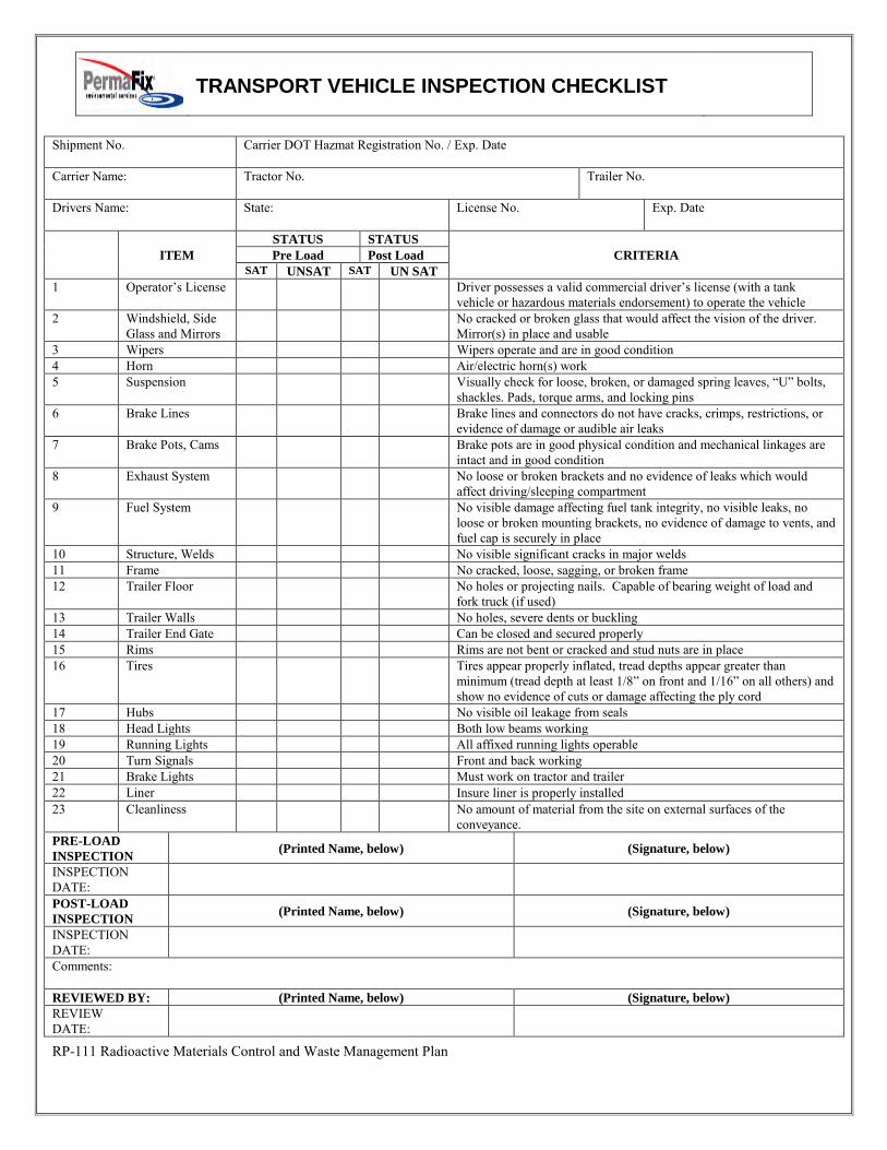
TRANSPORT VEHICLE INSPECTION CHECKLIST
RP-111 Radioactive Materials Control and Waste Management Plan
Shipment No. Carrier DOT Hazmat Registration No. / Exp. Date
Carrier Name:
Tractor No. Trailer No.
Drivers Name:
State: License No. Exp. Date
ITEM
STATUS STATUS
CRITERIA Pre Load Post Load
SAT UNSAT SAT UN SAT
1 Operator’s License Driver possesses a valid commercial driver’s license (with a tank vehicle or hazardous materials endorsement) to operate the vehicle
2 Windshield, Side Glass and Mirrors
No cracked or broken glass that would affect the vision of the driver. Mirror(s) in place and usable
3 Wipers Wipers operate and are in good condition 4 Horn Air/electric horn(s) work 5 Suspension Visually check for loose, broken, or damaged spring leaves, “U” bolts,
shackles. Pads, torque arms, and locking pins 6 Brake Lines Brake lines and connectors do not have cracks, crimps, restrictions, or
evidence of damage or audible air leaks 7 Brake Pots, Cams Brake pots are in good physical condition and mechanical linkages are
intact and in good condition 8 Exhaust System No loose or broken brackets and no evidence of leaks which would
affect driving/sleeping compartment 9 Fuel System No visible damage affecting fuel tank integrity, no visible leaks, no
loose or broken mounting brackets, no evidence of damage to vents, and fuel cap is securely in place
10 Structure, Welds No visible significant cracks in major welds 11 Frame No cracked, loose, sagging, or broken frame 12 Trailer Floor No holes or projecting nails. Capable of bearing weight of load and
fork truck (if used) 13 Trailer Walls No holes, severe dents or buckling 14 Trailer End Gate Can be closed and secured properly 15 Rims Rims are not bent or cracked and stud nuts are in place 16 Tires Tires appear properly inflated, tread depths appear greater than
minimum (tread depth at least 1/8” on front and 1/16” on all others) and show no evidence of cuts or damage affecting the ply cord
17 Hubs No visible oil leakage from seals 18 Head Lights Both low beams working 19 Running Lights All affixed running lights operable 20 Turn Signals Front and back working 21 Brake Lights Must work on tractor and trailer 22 Liner Insure liner is properly installed 23 Cleanliness No amount of material from the site on external surfaces of the
conveyance. PRE-LOAD
INSPECTION (Printed Name, below) (Signature, below)
INSPECTION DATE:
POST-LOAD
INSPECTION (Printed Name, below) (Signature, below)
INSPECTION DATE:
Comments: REVIEWED BY: (Printed Name, below) (Signature, below)
REVIEW DATE:
I
I I I
TITLE: Radioactive Material Control Program
NO.: RP-111 PAGE: 14 of 14
RRP-111 Radioactive Materials Control and Waste Management Plan
TITLE: Radioactive Material Control Program
NO.: RP-111 PAGE: 15 of 14
RP-111 Radioactive Materials Control and Waste Management Plan
Attachment 2
Emergency Response Instructions
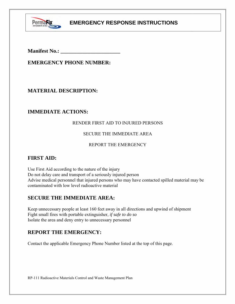
EMERGENCY RESPONSE INSTRUCTIONS
RP-111 Radioactive Materials Control and Waste Management Plan
Manifest No.: ______________________ EMERGENCY PHONE NUMBER:
MATERIAL DESCRIPTION: IMMEDIATE ACTIONS:
RENDER FIRST AID TO INJURED PERSONS
SECURE THE IMMEDIATE AREA
REPORT THE EMERGENCY FIRST AID: Use First Aid according to the nature of the injury Do not delay care and transport of a seriously injured person Advise medical personnel that injured persons who may have contacted spilled material may be contaminated with low level radioactive material SECURE THE IMMEDIATE AREA: Keep unnecessary people at least 160 feet away in all directions and upwind of shipment Fight small fires with portable extinguisher, if safe to do so Isolate the area and deny entry to unnecessary personnel REPORT THE EMERGENCY: Contact the applicable Emergency Phone Number listed at the top of this page.
PERMA-FIX ENVIRONMENTAL SERVICES
TITLE: Dosimetry Issue
NO.: RP-112
PAGE: 1 of 4
DATE: May 2014
APPROVED:
______________________________________5/31/14_____ Technical Services Manager Date
______________________________________5/31/14___ Corporate Certified Health Physicist Date
1.0 PURPOSE
This procedure provides consistent methodology for the issuance of radiation monitoring dosimetry devices at Perma-Fix Environmental Services (PESI) facilities and projects.
2.0 APPLICABILITY This procedure applies to all Safety and Health personnel issuing dosimetry devices.
3.0 REFERENCES 1. Title 17, California Code of Regulations, Division 1, Chapter 5, Subchapter 4 “Standards
for Protection Against Radiation.”
4.0 GENERAL 4.1 Discussion
This procedure describes the requirements for the issuance of standard dosimetry devices to visitors and radiation workers accessing restricted areas of the remediation project.
The Thermoluminescent Dosimeter (TLD) normally provides the dose of record, while the Self-Reading Dosimeter (SRD) provides a means of deep dose tracking prior to TLD processing, as well as verifying the reasonableness of the results
4.2 Definitions Radiation Worker: An individual who accesses any Radiological Area unescorted. Radiation Workers shall have successfully completed all requisite medical and training requirements for performing work in Radiological Areas.
Radiological Area: Any area within a Restricted Area which require posting as a Radiation Area, Contamination Area, Airborne Radioactivity Area, High Contamination Area, or High Radiation Area.
Perm - e IX
environmental services
A Nudear Services and Waste Management Company
qc: > 7
~~~-C:-
TITLE: Dosimetry Issue
NO.: RP-112
PAGE: 2 of 4
Restricted Area: An area to which access is limited to protect individuals against undue risks from exposure to radiation, radioactive materials, and chemical contaminants. All posted radiological or chemical areas are Restricted Areas.
Self-Reading Dosimeter (SRD): A radiation monitoring device (either electrostatic or electronic) that can be read by the wearer at any time and indicates total accumulated dose.
Thermoluminescent Dosimeter (TLD): An integrating detector where radiation energy is absorbed (trapped) and can be read out later by thermal excitation of the detector (ANSI N13.15-1985).
Visitor: An individual who accesses the project site for purposes other than working (e.g., tour the site or meet with an individual).
5.0 RESPONSIBILITIES 5.1 Radiation Safety Officer (RSO)
The RSO is responsible for implementing this procedure.
5.2 Radiation Protection Technicians (RPTs) RPTs are responsible for the performance of this procedure.
5.3 Project Personnel Provide the RP Dosimetry Group with required personal information to track and
report radiation exposures (e.g., Social Security/ID Number, Address, Date of Birth, Exposure History from Other Sites, etc.)
Complying with Radiation Protection Program (RPP) requirements, including dosimetry care & use requirements identified in Attachment 1.
6.0 PREREQUISITES Individuals who are planning to visit other radiologically monitored facilities while being monitored at PESI shall notify RSO prior to going to the other monitored facility(s).
7.0 PRECAUTIONS AND LIMITATIONS The NRC Form-4 for individuals with current year recorded or estimated exposures
from other site(s) shall be reviewed by the RSO prior to issuance of dosimetry. The purpose of this review is to ensure that individuals would not exceed the quarterly exposure limit of 1.25 rem, or the annual exposure limit of 5 rem Total Effective Dose Equivalent.
Any individual entering a Restricted Area, or performing work under a Radiation Work Permit shall wear dosimetry.
TLDs will be changed out on a quarterly basis.
Employee personal information shall be accessible only to personnel authorized by the RSO, SSHO, or Project Manager.
8.0 APPARATUS Self-Reading Dosimeters Thermoluminescent Dosimeters
TITLE: Dosimetry Issue
NO.: RP-112
PAGE: 3 of 4 9.0 RECORDS
Occupational External Radiation Exposure History (NRC Form-4) TLD Issue Form (e.g., TLD Processor Chain-of-Custody)
TLD Use & Care Acknowledgement
10.0 PROCEDURE 10.1 Dosimetry Issuance for Visitors
Dosimetry is issued to escorted visitors accessing Restricted Areas, and as required by the RSO.
10.2 Dosimetry Issuance for Radiation Workers 1. Ensure that Radiation Worker Training has been successfully completed by the
worker prior to dosimetry issue.
2. Ensure the individual has completed an NRC Form 4 “Occupational Radiation Exposure History.”
3. Ensure the individual has completed the “TLD Use & Care Acknowledgement” form.
4. Ensure the worker understands the administrative dose limit and the fraction remaining (available dose) for the current year.
5. Review all other paperwork for completeness and legibility.
6. Issue a TLD to the individual by recording the pertinent information on the TLD Issue Form.
11.0 ATTACHMENTS Attachments may be revised without formal review of this procedure and are attached as examples only. Please contact the RSO for a current copy of these attachment(s).
Attachment 1 Dosimetry Care & Use Acknowledgement Form
TITLE: Dosimetry Issue
NO.: RP-112
PAGE: 4 of 4
Attachment 1
DOSIMETRY CARE & USE ACKNOWLEDGEMENT
1. Use only dosimetry specifically issued to you.
2. Verify that you are wearing the appropriate dosimetry prior to entering Restricted Areas.
3. Unless otherwise directed by the RSO, Dosimetry shall be worn facing out, and
attached to clothing/lanyard on the front of the upper torso. Do not attach dosimetry to waist belt loops, safety glasses, or hard hats.
4. Dosimetry shall be stored in the designated location during non-work periods.
5. Dosimetry shall not be worn off-site or to another radiological facility unless
specifically authorized by RSO.
6. If dosimetry is misplaced or damaged, perform the following:
a. Place work in a safe condition and exit the radiological area; b. Report the lost dosimeter to RP Personnel; c. RP shall initiate a Radiological Occurrence Report (ROR); and d. Obtain RSO authorization to issue replacement dosimetry.
7. Do not tamper with or expose dosimetry to excessive heat, security x-rays, or
medical radiation sources. Report instances of tampering or unnecessary exposure to the RSO immediately.
Dosimetry is used to monitor your exposure as required by Federal Law and
Company Policy. Failure to comply with these or other Radiation Protection
Program requirements implemented for your safety, and for the protection of the
public and environment may result in revocation of RadWorker Training
credentials and Restricted Area access privileges.
I have read and understood the information presented and will comply with Radiation Protection Program requirements as established in the FMSS Site Safety & Health Plan.
__________________________________ ______________________ Signature Date
RRP-114 Rad Records Control
PERMA-FIX ENVIRONMENTAL SERVICES
TITLE: Control of Radiation Protection Records
NO.: RP-114
PAGE: 1 of 6
DATE: May 2014
APPROVED:
______________________________________5/31/14_____ Technical Services Manager Date
______________________________________5/31/14___ Corporate Certified Health Physicist Date
1.0 PURPOSE This project procedure defines the requirements for controlling Radiation Protection Program records. It also establishes the requirements for review and temporary storage of these records at PESI Sites prior to transmittal to Document Control.
2.0 APPLICABILITY The requirements of this procedure are applicable to records generated by the Radiation Protection Group, and apply to all documents considered to be records.
3.0 REFERENCES 1. 10 CFR 20 “Standards for Protection Against Radiation.” 2. PESI, “Radiation Protection Plan (RPP)
4.0 DEFINITIONS Non-record: Non-record material includes those classes of documentary or other material that shall be disposed of without archival authority. Examples are copies of records transmitted to Document Control, paper copies of e-mail, and informal notes.
Records: For the purpose of this procedure, records shall be interpreted as radiation protection records. A record is considered to have been “generated” when it has been completed, signed (or initialed) by the generator, and completed required reviews. Examples of records are all survey forms and original Radiation Work Permits (RWP).
Retention Period: The period of time that a record may be retained by the Radiation Protection Group, prior to transmittal to Document Control.
TITLE: NO.: RP-114 Control of Radiation Protection Records PAGE: 2 of 3
RRP-114 Rad Records Control
5.0 RESPONSIBILITIES 5.1 Radiation Safety Officer (RSO)
Implementing this procedure, and performing oversight activities to ensure compliance with the requirements of this document.
Establishing an RP Record Retention Schedule.
Ensuring adequate storage space and personnel are available to perform Records Management activities.
5.2 Radiation Protection Records Coordinator (RC) Acts as the departmental contact for records. Ensures that records are adequately controlled according to this procedure.
Ensures that records are transmitted to Document Control in a timely fashion, as defined by this procedure.
5.3 Radiation Protection Technicians (RPT) Complying with the requirement for this procedure. Protecting records in their possession from loss or damage.
6.0 PROCEDURE 6.1 Radiation Protection Group Functions
6.1.1 All personnel assigned to the group shall control records in accordance with applicable requirements of this procedure beginning when a record is first generated.
6.1.2 Records shall be prepared in accordance with Project Procedures. Preparation of these documents shall conform to the following:
Document content, including signatures, shall be:
Legible and reproducible Appropriate for the particular activity performed Complete per the applicable requirements Traceable to the activity or item to which it applies
6.1.3 If records are damaged (i.e., torn, lost, illegible, or incomplete), action shall be taken and documented to ensure that re-created records are as complete and accurate as possible. Re-created records shall be identified as copies and be signed and dated by the generator.
6.2 Records Coordinator (RC) 6.2.1 The Radiation Protection RC shall:
Ensure that all records received for transmittal are included on the Record Retention Schedule. The RSO should be notified if any record is not on the schedule.
Review the records for acceptability by ensuring the content of the record complies with this procedure. The RC shall review each record ensuring that the record is legible, complete, signed and dated, and that the record contains sufficient information to fulfill the intended purpose of the record.
TITLE: NO.: RP-114 Control of Radiation Protection Records PAGE: 3 of 3
RRP-114 Rad Records Control
NOTE: The RC is not responsible for the technical adequacy or correctness of the record.
Coordinate appropriate corrective action with the RSO when the condition of the records is not acceptable.
Transmit records according to Document Control
Prepare a document transmittal form, attach the completed form to the documentation package, and forward the records to Document Control.
Retain a copy of the returned document transmittal form, which documents transmittal to Document Control.
Maintain a Records Retention Schedule, approved by the RSO and provide a copy to Document Control.
6.3 Control of Records 6.3.1 Records shall be controlled and properly maintained from the time the record is
generated until it is transmitted to Document Control
6.3.2 Records shall be stored in a controlled environment that protects the records from damage (i.e., winds, floods, fires, high and low temperatures and humidity and infestation of insects, mold, or rodents).
6.3.3 Each record shall be reviewed by the RSO to ensure that:
The record contains sufficient information to fulfill the intended purpose of the document.
The content of the record is accurate and complete.
6.3.4 Records monitoring transmittal to Document Control shall be stored in a 1-hour fire-rated container, if possible.
6.3.5 Storage facilities or cabinets with confidential information should be locked when unattended. Storage facilities for other document should be locked when unattended as is practicable.
6.3.6 Records that are in the process of being generated may be controlled by electronic storage, provided there is data back-up available.
6.3.7 Following transmittal, Document Control shall review the documentation to ensure that it is complete as indicated on the transmittal form, sign and date the transmittal form signifying receipt of the record package, and return a copy of the signed and dated form to Radiation Protection RC.
7.0 ATTACHMENTS None
RP-115 Radiation Worker Training
PERMA-FIX ENVIRONMENTAL SERVICES
TITLE: Radiation Worker Training
NO.: RP-115
PAGE: 1 of 6
DATE: May 2014
APPROVED:
______________________________________5/31/14_____ Technical Services Manager Date
______________________________________5/31/14___ Corporate Certified Health Physicist Date
1.0 PURPOSE
The purpose of this procedure is to provide consistent methodology for implementing Radiation Worker Training (RWT) at Perma-Fix Environmental Services, Inc. (PESI) Sites.
2.0 APPLICABILITY RWT is applicable to ALL PESI employees and subcontractors who perform work within Restricted Areas.
3.0 REFERENCES 10 CFR 19, “Notices, Instructions and Reports to Workers: Inspections and
Investigations.”
10 CFR 20, “Standards for Protection against Radiation.”
4.0 GENERAL 4.1 Discussion
Successful completion of the RWT will qualify employees for unescorted access into Restricted Areas, provided other access requirements are met as specified in procedure RP-101, “Access Control”. Qualified individuals with a demonstrated knowledge of radiological concepts should provide RWT instruction. The RSO approves RWT Instructors.
4.2 Definitions Controlled Area: An area under the control of PESI management area to which access is limited by Project Management.
FMSS RADIATION PROTECTION PROGRAM NO.: RP-115
RADIATION WORKER TRAINING (RWT) PAGE: 2 of 4
RP-115 Radiation Worker Training
Practical Factors: The “performance-based” portion of RWT that focuses on demonstration and evaluation of safe radiation worker practices. Particular emphasis is given to the donning and doffing of protective clothing and self-monitoring for radioactive contamination.
Radiation Worker: An individual who accesses any Restricted Area unescorted. Radiation Workers shall have successfully completed all requisite medical and training requirements for performing work in Restricted Areas as specified this procedure.
Restricted Area: An area to which access is limited to protect individuals against undue risks from exposure to radiation, radioactive materials, and chemical contaminants. All posted radiological or chemical areas are Restricted Areas.
5.0 RESPONSIBILITIES The RSO is responsible for implementation of this procedure and approval of course content and materials.
6.0 PREREQUISITES Prior to obtaining RWT qualification, individuals shall have submitted evidence of completion of other medical / training requirements established in the PESI Site Safety & Health Plan.
7.0 PRECAUTIONS AND LIMITATIONS RWT shall be required on a bi annual basis. Active site personnel may be granted
up to a 90-day extension beyond the RWT anniversary date, with RSO approval.
Individuals must have documented evidence of completing both academic and Practical Factors objectives before being allowed to work unsupervised in a Restricted Area.
Personnel may be allowed to challenge the academic examination portion of this training by passing the examination.
Bi-Annual re-qualification of the Practical Factors portion of RWT may be by observation of actual work practices.
A minimum passing score on the RWT exam and Practical Factors is 80%.
Trained emergency response personnel (Fire Department, Ambulance/EMT, Law Enforcement) responding to on-site emergencies are exempt from this training.
The RSO may waive the classroom portion of RWT provided the individual is able to show documented proof of successful completion of an equivalent level of training from another facility during the previous 12-month period.
RP technicians are exempt from this training.
8.0 APPARATUS None
FMSS RADIATION PROTECTION PROGRAM NO.: RP-115
RADIATION WORKER TRAINING (RWT) PAGE: 3 of 4
RP-115 Radiation Worker Training
9.0 RECORDS The Site Safety & Health Group shall maintain a copy of the RWT certificate or attendance roster in each employee file.
10.0 PROCEDURE 10.1 RWT Classroom Training
A. At a minimum, the following topics shall be discussed during RWT:
Fundamental of Radioactivity Prenatal Exposure Risks Shaw Group Radiation Protection Plan Site Specific Radiological Hazards / contaminants ALARA Concepts Radiological Postings / Barriers Emergency Response / Evacuation Routes
B. Provide the trainees with a copy of the course materials and all pertinent training forms.
C. Present the course material including overhead slides. D. Lecture on the associated concepts. E. Answer any questions the trainees may have. F. Review the material with the trainees prior to administering the exam. G. Administer the RWT exam. H. The proctor will grade the test and review incorrect answers with the trainee. I. Submit the completed exam to RP Document Control.
10.2 RWT Practical Factors Training A. At a minimum, the following topics shall be discussed as part of Practical
Factors training:
Proper PPE donning and doffing procedures Use of RWP Recognition of postings Utilization of ALARA concepts (time, distance, shielding) Use of frisking equipment and proper frisking techniques
B. Develop a mock-up area from which trainees may be evaluated. Include the following:
RWP Radiological postings Ropes / barriers Radiological hazards Whole body frisking instrument In-use work areas may be used, with RSO approval, and provided that
airborne generating activities are not underway.
FMSS RADIATION PROTECTION PROGRAM NO.: RP-115
RADIATION WORKER TRAINING (RWT) PAGE: 4 of 4
RP-115 Radiation Worker Training
C. Introduce the practical training by relating it back to the academics the trainees have just completed.
D. Explain what will be expected of each trainee. E. Demonstrate how to perform the tasks, talk about good practices while doing
so. F. Allow the participants to practice as you coach. G. Proceed to the Mock-Up area and begin Practical Factors evaluation. H. Complete a Practical Factors Evaluation Form. I. Review evaluation results with the trainee and forward form to RP Document
Control.
11.0 ATTACHMENTS None
Event Reporting and Notification for State of California
Approvals Procedure No.: RP-130
E. Laning 12/21/16
Revision: 0 Technical Services Manager Date
S.E. Miller 12/21/16 Procedure Date: 01/05/17
Corporate Certified Health Physicist Date Pages: 1 of 4
1.0 Purpose This procedure provides a list of California regulatory contacts, a checklist for initiating
emergency notifications, and general guidance for notification of incidents.
2.0 Applicability This procedure applies to all Perma-Fix (PESI) project personnel, subcontractors, and visitors who
access California PESI project sites that are working under PESI’s California Radioactive Material
License.
3.0 References Title 17, California Code of Regulations, Division 1, Chapter 5, Subchapter 4 “Standards for
Protection Against Radiation.”
PESI “Radiation Protection Plan (RPP)
4.0 Definitions None specific to this procedure.
5.0 Responsibilities All project personnel have a responsibility to immediately notify the RSO and project supervision
of any condition that may result in a reportable event. All project personnel have “stop work”
authority for any situation that may pose an imminent threat to personnel or the environment.
5.1 Radiation Safety Officer (RSO) The RSO will have lead responsibility for initiating reports to the State, if required. The RSO will
have primary responsibility for determining the need for reporting. Authorized users may assist
the RSO in the performance of this procedure.
Perm - ®
IX environmental services
A Nuclear Services and Waste Management Company
~
~/JL
RP-130, Event Reporting and Notification for State of California Page 2 of 4
6.0 Prerequisites None
7.0 Precautions and Limitations None
8.0 Records Records generated as a result of emergency notification to the State or other regulatory
authority shall be maintained.
9.0 Procedure
9.1 Immediate Notifications The California Radiological Health Bureau shall be notified as soon as possible but within 4 hours
after the discovery of an event that prevents immediate protective actions necessary to avoid
exposures to radiation or radioactive materials that could exceed regulatory limits.
9.2 24 Hour Notifications The California Radiological Health Bureau shall be notified within 24 hours after discovery of any
of the following events:
A. An unplanned contamination event that:
1) Requires access to the contaminated area by workers or the public, to be restricted for
more than 24 hours by imposing additional radiological controls or by prohibiting entry
into the area;
2) Involves a quantity of material greater than five times the lowest annual limit on intake
specified in Appendix B of Title 10, Code of Federal Regulations, part 20, incorporated by
reference in section 30253 for the material; and
3) Has access to the area restricted for a reason other than to allow isotopes with a half-life
of less than 24 hours to decay prior to decontamination.
B. An event in which equipment is disabled or fails to function as designed when:
1) The equipment is required by regulation or license condition to prevent releases
exceeding regulatory limits, to prevent exposures to radiation and radioactive materials
exceeding regulatory limits, or to mitigate the consequences of an accident;
2) The equipment is required to be available and operable when it is disabled or fails to
function; and
3) No redundant equipment is available and operable to perform the required safety
function.
C. An event that requires unplanned medical treatment at a medical facility of an individual with
spreadable radioactive contamination on the individual's clothing or body.
D. An unplanned fire or explosion damaging any licensed material or any device, container, or
equipment containing licensed material when:
ix"
RP-130, Event Reporting and Notification for State of California Page 3 of 4
1) The quantity of material involved is greater than five times the lowest annual limit on
intake specified in Appendix B of Title 10, Code of Federal Regulations, part 20,
incorporated by reference in section 30253 for the material; and
2) The damage affects the integrity of the licensed material or its container.
9.3 Reports A. All reports made as required by this procedure and California regulation shall include the
following information:
1) The caller's name and call back telephone number;
2) A description of the event, including date and time;
3) The exact location of the event;
4) The isotopes, quantities, and chemical and physical form of the licensed material
involved; and
5) Any personnel radiation exposure data available.
B. All verbal reports shall be followed up with written reports to the BRH within 30 days of the
initial report. Written reports shall include the following:
1) A description of the event, including the probable cause and the manufacturer and model
number (if applicable) of any equipment that failed or malfunctioned;
2) The exact location of the event;
3) The isotopes, quantities, and chemical and physical form of the licensed material
involved;
4) Date and time of the event;
5) Corrective actions taken or planned and the results of any evaluation or assessment; and
6) The extent of exposure of individuals to radiation or to radioactive materials without
identification of individuals by name.
10.0 Attachments Attachment 1, California Contact Information
ix"
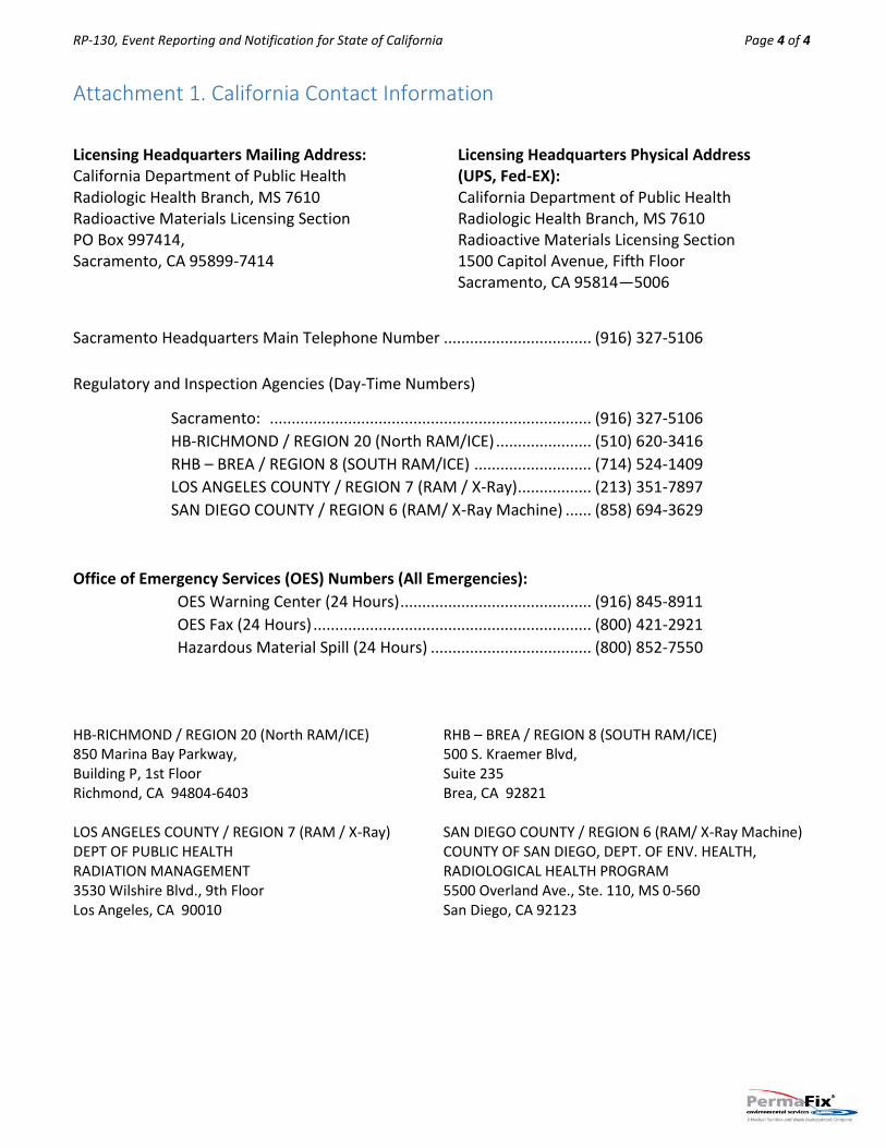
RP-130, Event Reporting and Notification for State of California Page 4 of 4
Attachment 1. California Contact Information
Licensing Headquarters Mailing Address: California Department of Public Health Radiologic Health Branch, MS 7610 Radioactive Materials Licensing Section PO Box 997414, Sacramento, CA 95899-7414
Licensing Headquarters Physical Address (UPS, Fed-EX): California Department of Public Health Radiologic Health Branch, MS 7610 Radioactive Materials Licensing Section 1500 Capitol Avenue, Fifth Floor Sacramento, CA 95814—5006
Sacramento Headquarters Main Telephone Number .................................. (916) 327-5106
Regulatory and Inspection Agencies (Day-Time Numbers)
Sacramento: .......................................................................... (916) 327-5106
HB-RICHMOND / REGION 20 (North RAM/ICE) ...................... (510) 620-3416
RHB – BREA / REGION 8 (SOUTH RAM/ICE) ........................... (714) 524-1409
LOS ANGELES COUNTY / REGION 7 (RAM / X-Ray) ................. (213) 351-7897
SAN DIEGO COUNTY / REGION 6 (RAM/ X-Ray Machine) ...... (858) 694-3629
Office of Emergency Services (OES) Numbers (All Emergencies):
OES Warning Center (24 Hours) ............................................ (916) 845-8911
OES Fax (24 Hours) ................................................................ (800) 421-2921
Hazardous Material Spill (24 Hours) ..................................... (800) 852-7550
HB-RICHMOND / REGION 20 (North RAM/ICE) 850 Marina Bay Parkway, Building P, 1st Floor Richmond, CA 94804-6403
RHB – BREA / REGION 8 (SOUTH RAM/ICE) 500 S. Kraemer Blvd, Suite 235 Brea, CA 92821
LOS ANGELES COUNTY / REGION 7 (RAM / X-Ray) DEPT OF PUBLIC HEALTH RADIATION MANAGEMENT 3530 Wilshire Blvd., 9th Floor Los Angeles, CA 90010
SAN DIEGO COUNTY / REGION 6 (RAM/ X-Ray Machine) COUNTY OF SAN DIEGO, DEPT. OF ENV. HEALTH, RADIOLOGICAL HEALTH PROGRAM 5500 Overland Ave., Ste. 110, MS 0-560 San Diego, CA 92123
ix"
PERMA-FIX ENVIRONMENTAL SERVICES
TITLE: RADIOLOGICAL PROTECTIVE
CLOTHING SELECTION,
MONITORING, AND
DECONTAMINATION
NO.: RP-132
PAGE: 1 of 9
DATE: March 2017
APPROVED:
___________________________________03/10/17___ Technical Services Manager Date
___________________________________0310/17___ Corporate Certified Health Physicist Date
1.0 PURPOSE
This procedure provides the guidance for selecting protective clothing, performing personnel surveys, and decontaminating personnel.
2.0 APPLICABILITY
This procedure will be used by Tetra Tech EC, Inc. (TtEC) personnel and its subcontractors while performing activities in areas with known or suspected radioactive contamination.
3.0 REFERENCES
1. Title 17, California Code of Regulations, Division 1, Chapter 5, Subchapter 4 “Radiation.”
2. Title 22, California Code of Regulations, Division 4.5; Environmental Health Standards for the Management of Hazardous Waste
3. California Executive Order D-62-02 regarding disposal of decommissioned materials.
4. 10 Code of Federal Regulations (CFR) 20; Standards for Protection Against Radiation, and Transfer and Disposal and Manifests
8. USNRC IE Information Notice No. 80-22, "Breakdowns in Contamination Control Programs."
9. ANSI N13.2-1969, "USA Standard Guide for Administrative Practices in Radiation Monitoring (A Guide for Management)."
10. RP -102, “Radiological Posting Requirements.”
11. RP -103, “Radiation Work Permits."
Perm - e IX
environmental services
A Nudear Services and Waste Management Company
qc: - ,. 7'"
~~
4.0 GENERAL
4.1 Discussion Radioactive material controls are established to provide positive control of radioactive material, prevent inadvertent release of radioactive material to uncontrolled areas, ensure personnel are not unknowingly exposed to radiation from lost or misplaced radioactive material, and to minimize the amount of radioactive waste material generated during PESI activities.
4.2 Definitions Contamination Area (CA): Means any area with loose surface contamination values in excess of the applicable values specified in RP-104 Acceptable Surface Contamination Levels that is accessible to personnel, or any additional area specified by the RSO. The Contamination Area posting is defined as more restrictive than Radioactive Material Areas, hence all Contamination Area postings are considered to be Radioactive Material postings.
Minimum Detectable Activity (MDA): The smallest amount or concentration of radioactive material in a sample that will yield a net count, above system background, that will be detected with 95% probability with only 5% probability of falsely concluding that a blank observation represents a "real" signal. MDA depends upon the type of instrument, the counting geometry, and the radionuclide to be detected. MDA has the same meaning as Lower Limit of Detection (LLD). (ANSI N13.3, 1989).
Radioactive Material: Material activated or contaminated by the operation or remediation of the site and by-product material procured and used to support the operation or remediation.
Radioactive Material Area: Any area or room where quantities of radioactive materials in excess of ten times the 10 CFR 20 Appendix C quantities are used or stored, or any area designated a RMA by the RSO which does not exceed the site Contamination Area criteria.
Restricted Area: An area to which access is limited to protect individuals against undue risks from exposure to radiation, radioactive materials, and chemical contaminants. All posted radiological or chemical areas are Restricted Areas.
5.0 RESPONSIBILITIES
5.1 Radiation Safety Officer (RSO) The RSO is responsible for:
Identifying the radiological personal protective equipment (PPE) and, when appropriate, ensuring that the radioactive work permit lists the proper radiological PPE.
Providing guidance and direction for decontamination of personnel.
Notifying the corporate RSO of any personnel contamination event.
Reviewing the Personnel Contamination Report and verifying all information is accurate.
Requesting support from the qualified medical personnel regarding management of personnel who have been exposed to radiological contamination, when appropriate.
Determining reimbursements and disposition of personal property that cannot be decontaminated.
5.3 Radiation Protection Technicians (RPTs) The RPT is responsible for:
Ensuring that workers don and doff the correct PPE properly, and performing decontamination of personnel under the guidance and direction of the RSO.
Performing and documenting radiation and contamination surveys.
Posting, securing, and controlling radioactive material and source storage areas.
5.4 Project Personnel Project personnel are responsible for:
Adhering to all policies, procedures and other instructions, verbal and written, regarding control and minimization of radioactive material and contaminated material.
Reporting any concerns about the control and minimization of radioactive material and contaminated material to supervision.
Maintaining good housekeeping at work sites and assisting in preventing the build-up and spread of contamination.
Complying with direction from RP personnel regarding the proper methods for donning and doffing of PPE.
6.0 PREREQUISITES
None
7.0 PRECAUTIONS AND LIMITATIONS
PPE should be fully inspected prior to use.
8.0 RECORDS
Personnel Contamination Reports
Radiological surveys
Records generated shall be transmitted to Project Document Control for filing according to procedure RPP-114.
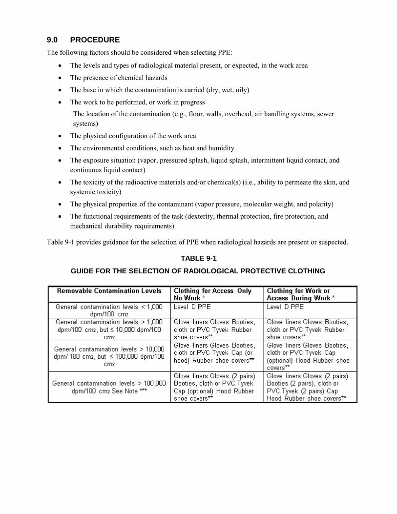
9.0 PROCEDURE
The following factors should be considered when selecting PPE:
The levels and types of radiological material present, or expected, in the work area
The presence of chemical hazards
The base in which the contamination is carried (dry, wet, oily)
The work to be performed, or work in progress The location of the contamination (e.g., floor, walls, overhead, air handling systems, sewer systems)
The physical configuration of the work area
The environmental conditions, such as heat and humidity
The exposure situation (vapor, pressured splash, liquid splash, intermittent liquid contact, and continuous liquid contact)
The toxicity of the radioactive materials and/or chemical(s) (i.e., ability to permeate the skin, and systemic toxicity)
The physical properties of the contaminant (vapor pressure, molecular weight, and polarity)
The functional requirements of the task (dexterity, thermal protection, fire protection, and mechanical durability requirements)
Table 9-1 provides guidance for the selection of PPE when radiological hazards are present or suspected.
TABLE 9-1
GUIDE FOR THE SELECTION OF RADIOLOGICAL PROTECTIVE CLOTHING
Removable Contamination Levels Clothing for Access Only Clothing for Work or No Work• Access Durinu Work •
General contamination levels < 1 ,000 Level D PPE Level D PPE dpm/100 cm2
General contamination levels > 1 ,000 Glove liners Gloves Booties, Glove liners Gloves Booties, dpm/100 cm2, but ;; 10,000 dpm/100 cloth or PVC Tyvek Rubber cloth or PVC Tyvek Rubber
cm2 shoe covers- shoe covers-
General contamination levels > 10,000 Glove liners Gloves Booties, Glove liners Gloves Booties,
dpm/ 100 cm2, but ;; 100,000 dpm/100 cloth or PVC Tyvek Cap (or cloth or PVC Tyvek Cap hood) Rubber shoe covers- (optional) Hood Rubber shoe cm2 covers""' Glove liners Gloves (2 pairs) Glove liners Gloves (2 pairs)
General contamination levels > 100,000 Booties, cloth or PVC Tyvek Booties (2 pairs), cloth or dpm/100 cm2 See Note - Cap (optional) Hood Rubber PVC Tyvek (2 pairs) Cap
shoe covers- Hood Rubber shoe covers-
The guidelines for PPE selection specified in Table 9-1 may be modified under certain circumstances, such as the following:
Wet areas – Where splashing water or spray is present, use rain suits in addition to the protective clothing listed in Table 9-1. A second set of coveralls may not be necessary when a rain suit is worn.
Standing water – In addition to the clothing requirements for wet areas, use hip boots or waders for deep standing water areas.
Face shields – Consider for use when there is significant beta radiation, or a likelihood of water splashing and respirators are not required.
High temperature areas – Consult with the RSO and Site Health and Safety Specialist (SHSS) prior to working in high temperature areas.
9.1 DONNING PROTECTIVE CLOTHING
Select the appropriate PPE. Inspect coveralls, cotton glove liners, gloves, shoe covers, and hoods for rips, tears, and holes, or
other indications of damage. If damaged, do not wear the damaged PPE and remove the PPE from service.
Do not wear PPE that does not fit properly. Place dosimetry, if worn, in the upper body area on the interior of the breast tab with the window
of the dosimeter facing out. When coveralls that do not have a breast tab or pocket are worn, dosimetry should be attached per the direction of the RSOR or designee. The dosimeter shall not be worn inside clothing or placed in pockets if exposure of bare skin to beta radiation is expected.
If a respirator is specified in the Radiation Work Permit (RWP), then ensure that he individual using the respirator has been medically cleared for respirator use and is respirator qualified.; and a respirator fit test has been performed.
Don the respirator.
Don the hood, if required, allowing it to overlap the rubber around the lens of the face piece and fall over the shoulder.
If required, tape the hood to the respirator and to the coveralls.
Ensure that any required hood is slack enough around the shoulders to allow for full head movement.
Don rubber gloves.
Tape the innermost pair of rubber gloves to the coverall sleeves.
Leather work gloves may be substituted for outer rubber gloves on some jobs as specified in the corresponding radiation work permit.
If specified on the RWP, don additional PPE as required.
9.2 DOFFING OF PROTECTIVE CLOTHING
Before stepping out of the contamination area or airborne radioactivity area to the step-off pad, the worker should:
Remove exposed tape and place it in the appropriate container.
Remove rubber overshoes and place them in the appropriate container.
Remove the outer pair of gloves and place them in the appropriate container.
Remove the hood, from front to rear, and place it in the appropriate container.
Remove coveralls, inside out, touching the inside only and place them in the appropriate container.
Remove the respirator, as applicable, by bending forward at the waist slightly, pulling the respirator away from the face, and then rolling the straps/headbands to remove the respirator, and place it in the appropriate container.
Take down the barrier closure, as applicable.
Remove any tape or fastener from the inner shoe cover and place it in the appropriate container.
Remove a shoe cover and place it in the appropriate container while simultaneously stepping onto the clean step-off pad with the shoe whose shoe cover was just removed. Repeat this process with the other shoe.
Remove the cloth glove liners and place them in the appropriate container.
Replace the barrier closure, as applicable.
Have the Radiological Control Technician (RCT) commence whole body frisking.
Monitor the dosimeter.
The sequence for the removal of primary and supplemental dosimetry is dependent upon where the dosimetry was worn and the potential for contamination. The sequence for removal of respiratory protection devices may be altered if it is determined that the potential for inhalation of airborne contamination or the spread of surface contamination is reduced by keeping respiratory protection devices on until all protective garments have been removed.
The sequence for protective clothing removal may vary from that described above, under the following circumstances:
At the discretion of the RCT providing job coverage.
As designated in the assigned RWP.
Depending on radiological and hazardous material conditions encountered during the work evolution.
It is important to be aware that pushing clothing or trash into an already full collection container to compress the contents is forbidden as the act can result in the potential for airborne radioactivity.
9.3 MONITORING
During exit surveys, the following procedures should be followed.
Use the portable instrument staged for the area of concern, which should have both a visual and an audible response.
Ensure that the instrument is set on slow response, if available, and operating with an audible response.
Verify that the instrument is operational on the lowest scale and that the area background count rate is acceptable.
Hold the detector with the window approximately 1/4 inch from the surface being monitored. Move the detector over the surface being monitored at a rate not to exceed 2 inches per second. It
should take at least 3 minutes to perform a whole body frisk. If an increase in the audible response is noted, then cease moving the detector and allow the
meter 5 to 10 seconds to stabilize. Pause (approximately 5 seconds) at the nose and mouth area to check for indications of
inhalation/ingestion of radioactive material. Pay particular attention to hands, feet (shoes), elbows, knees, or other areas with a high potential
for contamination. If no contamination can be detected, as indicated by an alarm or by an audible or visual response
distinguishable from background, then exit the area. If an audible or visual response distinguishable from background is noted, then the RCT will
further investigate to verify if contamination is present. If personnel are found to be contaminated, proceed to the procedures outlined in Section 9.3.1.
9.3.1 CONTAMINATED PERSONNEL
When dealing with contaminated personnel, the following procedures should be followed.
1. Notify the RSOR of any individual with known or suspected contamination. 2. If the contamination is on a personal article of clothing, then perform the following:
Survey the inside surface that was against the skin.
Verify that no contamination was transferred to the skin.
3 .If the contamination is on the skin, determine if the contamination is in the form of a hot particle.
4 If the contamination is a hot particle, then:
Quickly evaluate the particle size, radiation type, and visible characteristics.
Attempt to collect and retain the particle for subsequent evaluation.
Decontaminate the individual in accordance with Section 9.3.2.
5. If the contamination is not a particle, then:
Evaluate the contamination levels.
Decontaminate the individual in accordance with Section 9.
6. Complete the applicable parts of the Personnel Contamination Report (Attachment 1).
9.3.2 PERSONNEL DECONTAMINATION
The steps to follow for personnel decontamination are presented below.
1. Perform personnel decontamination in a manner that prevents the spread of contamination to other body parts, or the ingestion or inhalation of radioactive material.
2. Take appropriate precautions to minimize the spread of contamination when proceeding from the control point or step-off pad to the decontamination area.
3. Refrain from releasing personnel if detectable skin contamination is present, unless authorized by the RSOR.
4. Perform skin decontamination as follows: Exercise care to avoid damaging the skin.
Discontinue the decontamination and notify the RSOR if skin irritation becomes apparent.
Record results after each decontamination attempt.
indicate the method of decontamination used.
Decontaminate ears, eyes and mouth using damp swabs, water, or saline solution rinses that are performed by the individual. Perform further decontamination under the direction of qualified medical personnel.
Decontaminate nasal passages by having the individual repeatedly blow the nose. Perform supplemental nasal irrigations under the direction of qualified medical personnel, as required.
Use decontamination processes or materials other than those listed in Table 9-2, only under the specific direction of qualified medical personnel.
Report incidents of individual contamination immediately to the RSOR.
Note the final survey results and time of the survey.
Record the area of the skin contaminated in square centimeters (cm2) on the
Personnel Contamination Report (Attachment 1).
Assume the measured activity is distributed over the probe area (the area of a typical
pancake probe is 15.5 cm2) for contamination distributed over an area greater than or
equal to the area of the probe.
Determine the actual area of the activity if the area of contamination is less than the
area of the probe but greater than 1 cm2,
Assume an area of 1 cm2 if the contamination area is less than or equal to 1 cm
2.
Obtain the information needed to complete the Personnel Contamination Report (Attachment 1) when skin decontamination has been successfully completed.
Complete the applicable parts of the Personnel Contamination Report (Attachment 1).
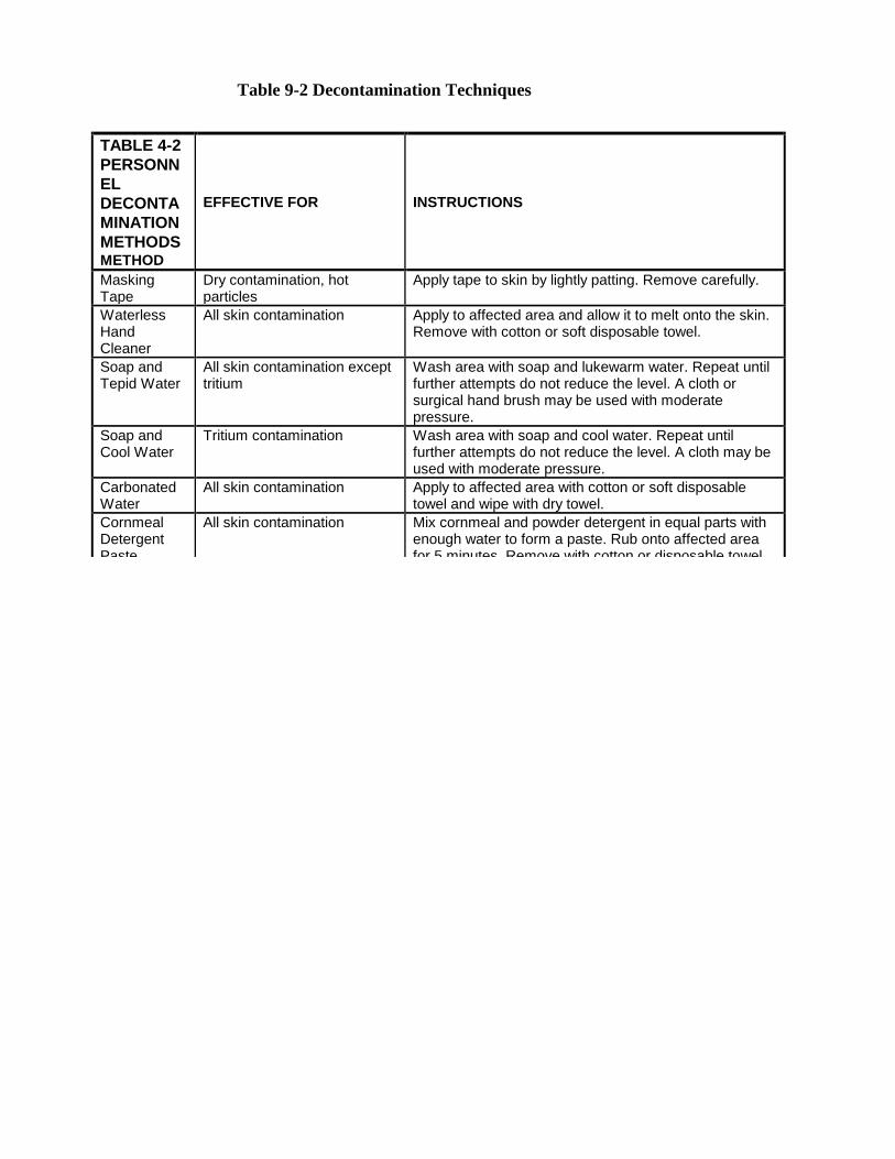
Table 9-2 Decontamination Techniques
TABLE 4-2
PERSONN
EL
DECONTA
MINATION
METHODS METHOD
EFFECTIVE FOR INSTRUCTIONS
Masking Tape
Dry contamination, hot particles
Apply tape to skin by lightly patting. Remove carefully.
Waterless Hand Cleaner
All skin contamination Apply to affected area and allow it to melt onto the skin. Remove with cotton or soft disposable towel.
Soap and Tepid Water
All skin contamination except tritium
Wash area with soap and lukewarm water. Repeat until further attempts do not reduce the level. A cloth or surgical hand brush may be used with moderate pressure.
Soap and Cool Water
Tritium contamination Wash area with soap and cool water. Repeat until further attempts do not reduce the level. A cloth may be used with moderate pressure.
Carbonated Water
All skin contamination Apply to affected area with cotton or soft disposable towel and wipe with dry towel.
Cornmeal Detergent Paste
All skin contamination Mix cornmeal and powder detergent in equal parts with enough water to form a paste. Rub onto affected area for 5 minutes. Remove with cotton or disposable towel. Rinse skin.
Shampoo Hair contamination Wash hair and rinse. Repeat as necessary. Parafilm All particulate contamination Apply to affected area of skin. Remove. Sweating All skin contaminations Cover affected area with impermeable cover (plastic,
glove, Parafilm) to cause sweating. Remove after sweating has occurred and wipe area.
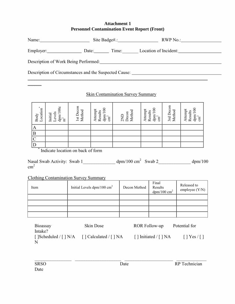
Attachment 1
Personnel Contamination Event Report (Front)
Name: Site Badge#.: RWP No.: Employer: Date: Time:_______ Location of Incident: Description of Work Being Performed: Description of Circumstances and the Suspected Cause: ____________________________________________________________________________________
Skin Contamination Survey Summary
Bod
y Lo
catio
n*
Initi
al
Leve
ls
dpm
/100
cm
2
1st D
econ
M
etho
d
Atte
mpt
R
esul
ts
dpm
/100
cm
2
2ND
D
econ
M
etho
d
Atte
mpt
R
esul
ts
dpm
/100
cm
2
3rd
Dec
on
Met
hod
Atte
mpt
R
esul
ts
dpm
/100
cm
2
A B C D
* Indicate location on back of form Nasal Swab Activity: Swab 1______________ dpm/100 cm2 Swab 2______________ dpm/100 cm2 Clothing Contamination Survey Summary
Item Initial Levels dpm/100 cm2 Decon Method Final Results dpm/100 cm2
Released to employee (Y/N)
Bioassay Skin Dose ROR Follow-up Potential for Intake? [ ]Scheduled / [ ] N/A [ ] Calculated / [ ] NA [ ] Initiated / [ ] NA [ ] Yes / [ ] N ________________ ____________________ _____________________ _____________ SRSO Date RP Technician Date
Attachment 1 (Back of Form)
Personnel Contamination Event Report Comments and additional detail (identify by letter and include estimated area in square cm):
________________________________________________________________________________________________________________________________________________________________________________________________________________________________________________________________________________________________________________________________________________________________________________________________________________________________________________________________________________________________________________________________________________________________________________________________________________________________________________________________________________________________ RP SURVEY INSTRUMENT(S) INFORMATION Instrument Model Serial Number Cal. Due Date
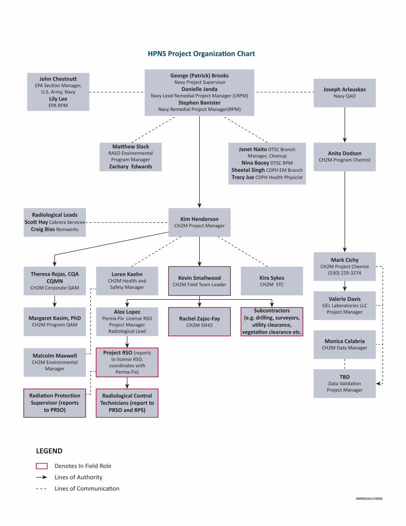
HPNS Project Organization Chart
LEGEND
Denotes In Field Role
Lines of Authority
Lines of CommunicationEN0505161113SDO
Theresa Rojas, CQA CQMN
CH2M Corporate QAM
Margaret Kasim, PhDCH2M Program QAM
Alex LopezPerma-Fix License RSO
Project ManagerRadiological Lead
Malcolm Maxwell CH2M Environmental
Manager
Radiation Protection Supervisor (reports
to PRSO)
Loren KaehnCH2M Health and Safety Manager
Mark CichyCH2M Project Chemist
(530) 229-3274
Anita DodsonCH2M Program Chemist
Joseph ArlauskasNavy QAO
Kim HendersonCH2M Project Manager
Radiological LeadsScott Hay Cabrera Services
Craig Bias Remwerks
Matthew Slack RASO Environmental
Program ManagerZachary Edwards
John ChestnuttEPA Section Manager,
U.S. Army, NavyLily Lee EPA RPM
Janet Naito DTSC Branch Manager, Cleanup
Nina Bacey DTSC RPMSheetal Singh CDPH EM Branch Tracy Jue CDPH Health Physicist
George (Patrick) Brooks Navy Project Supervisor
Danielle JandaNavy Lead Remedial Project Manager (LRPM)
Stephen BanisterNavy Remedial Project Manager(RPM)
Valerie DavisGEL Laboratories LLC
Project Manager
Monica CalabriaCH2M Data Manager
TBDData Validation
Project Manager
Rachel Zajac-FayCH2M SSHO
Kevin SmallwoodCH2M Field Team Leader
Subcontractors(e.g. drilling, surveyors,
utility clearance, vegetation clearance etc.
Kira Sykes CH2M STC
Project RSO (reports to license RSO,
coordinates with Perma-Fix)
Radiological Control Technicians (report to
PRSO and RPS)
CJ
' '
' '
' '
' '
'
' '
' '
' '
' '
-------
' '
' '
' ' l
--•
Draft
Radiation Protection Work Plan Radiological Data Evaluation and
Confirmation Survey
Former Hunters Point Naval Shipyard San Francisco, California
Department of the Navy Naval Facilities Engineering Command
Base Realignment and Closure Program Management Office West
III
Contents Acronyms and Abbreviations ........................................................................................................................... v
1 Purpose/Introduction .......................................................................................................................... 1 1.1 Policy .................................................................................................................................................. 1 1.2 Project-specific Radiation Protection Plan ........................................................................................ 1 1.3 As Low as Reasonably Achievable ..................................................................................................... 1 1.4 Authorization to Stop Work ............................................................................................................... 1 1.5 Scope of Work.................................................................................................................................... 2 1.6 Quality Control and Auditing ............................................................................................................. 2
1.6.1 Self-assessment, Management Reviews, and Audits ........................................................... 2 1.6.2 Responses and Corrective Actions........................................................................................ 2 1.6.3 Daily Instrumentation Check ................................................................................................ 2
2 Radiation Protection Personnel ........................................................................................................... 2 2.1 President of Perma-Fix ...................................................................................................................... 3 2.2 License Radiation Safety Officer ........................................................................................................ 3 2.3 Project Radiation Safety Officer ........................................................................................................ 4 2.4 Project Manager ................................................................................................................................ 5 2.5 Radiation Protection Supervisor ........................................................................................................ 5 2.6 Radiological Control Technicians ....................................................................................................... 5 2.7 Radiation Workers (Field Personnel) ................................................................................................. 6 2.8 Stop Work Authority .......................................................................................................................... 6
3 Task-specific Hazard Analysis/Controls ................................................................................................ 7 3.1 Identification of Radiation Risks ........................................................................................................ 7 3.2 Controlling Documents ...................................................................................................................... 7 3.3 Evaluation of Potential Exposure to Workers .................................................................................... 7 3.4 Evaluation of Public Dose .................................................................................................................. 7 3.5 Training Program ............................................................................................................................... 8
3.5.1 Site Briefing ........................................................................................................................... 8 3.5.2 Radiation Worker Training.................................................................................................... 8 3.5.3 Radiological Control Technician Training Qualification ........................................................ 9
3.6 Declared Pregnant Worker ................................................................................................................ 9 3.7 As Low as Reasonably Achievable Program ....................................................................................... 9 3.8 External Exposure Control ................................................................................................................. 9 3.9 Internal Exposure Control .................................................................................................................. 9 3.10 Monitoring and Measuring External Exposure ................................................................................ 10 3.11 Monitoring and Measuring Internal Exposure ................................................................................ 10 3.12 Surveys and Monitoring for Radiological Controls .......................................................................... 10
3.12.1 Surveys of Equipment and Materials .................................................................................. 10 3.13 Action Levels for Radiological Control ............................................................................................. 10 3.14 Radiologically Controlled Areas and Posting ................................................................................... 11
3.14.1 Controlled Area ................................................................................................................... 11 3.14.2 Access Control Point ........................................................................................................... 11 3.14.3 Radiologically Controlled Area ........................................................................................... 11 3.14.4 Radioactive Materials Area ................................................................................................. 11 3.14.5 Contamination Area............................................................................................................ 12 3.14.6 High Contamination Area ................................................................................................... 12 3.14.7 Radiation Area .................................................................................................................... 12 3.14.8 High Radiation Area ............................................................................................................ 12 3.14.9 Airborne Radioactivity Area ................................................................................................ 12
RADIATION PROTECTION WORKPLAN RADIOLOGICAL SUPPORT
IV
3.15 Contamination Control .................................................................................................................... 13 3.15.1 Physical Boundary ............................................................................................................... 13 3.15.2 Entry .................................................................................................................................... 13 3.15.3 Exit ...................................................................................................................................... 13 3.15.4 Limitations on Entry ............................................................................................................ 13 3.15.5 Control of Items .................................................................................................................. 13
3.16 Instrumentation Calibration ............................................................................................................ 13 3.17 Control of Radiological Work ........................................................................................................... 14
3.17.1 Radiation Work Permits ...................................................................................................... 14 3.17.2 Task-specific Plans .............................................................................................................. 14
3.18 Procurement, Receipt, and Inventory of Sealed Radioactive Sources ............................................ 14 3.18.1 Leak Testing ........................................................................................................................ 14 3.18.2 Transport of Sources ........................................................................................................... 14 3.18.3 Reporting Lost, Damaged, or Stolen Sources ..................................................................... 14
3.19 Shipping and Transportation of Radioactive Materials ................................................................... 15 3.20 Control of Radioactive Waste .......................................................................................................... 15 3.21 Radiation Protection Records .......................................................................................................... 15 3.22 Reports and Notifications ................................................................................................................ 15 3.23 Licenses ............................................................................................................................................ 15 3.24 Review and Approvals of Radiation Protection Plans...................................................................... 15 3.25 Planned Special Exposures .............................................................................................................. 16
4 Personal Protective Equipment .......................................................................................................... 16 4.1 Selection of Personal Protective Equipment ................................................................................... 16 4.2 Donning and Doffing PPE ................................................................................................................. 16
5 Decontamination Procedures ............................................................................................................ 16
6 Shipping and Transportation of Radioactive Materials ....................................................................... 16
7 References ........................................................................................................................................ 17
Attachment
1 Radiation Protection Workplan Acknowledgment Form
V
Acronyms and Abbreviations AEC Atomic Energy Commission ALARA as low as reasonably achievable APP Accident Prevention Plan
CDPH California Department of Public Health CFR Code of Federal Regulations CRSO Corporate Radiation Safety Officer
DAC derived air concentration DOT Department of Transportation
EHS Environmental Health and Safety
HRA Historical Radiological Assessment
LLMW low-level mixed waste LLRW low-level radioactive waste
millirem milliroentgen equivalent man mSv millisievert
Navy Department of the Navy NRC U.S. Nuclear Regulatory Commission NRRPT National Registry of Radiation Protection Technologists
Perma-Fix Perma-Fix Environmental Services, Inc. PM Project Manager PPE personal protective equipment PRSO Radiation Safety Officer Representative
QC quality control
RASO Radiological Affairs Support Office RCA Radiologically Controlled Area RCT Radiological Control Technician rem roentgen equivalent man RMA Radioactive Materials Area RML Radioactive Material License RPS Radiation Project Supervisor RPWP Radiation Protection Workplan RSO Radiation Safety Officer RWP Radiation Work Permit
SOP Standard Operating Procedure SSHP Site Safety and Health Plan
TEDE total effective dose equivalent TSP task-specific plan
1
1 Purpose/Introduction This Radiation Protection Workplan (RPWP) details Perma-Fix Environmental Services, Inc. (Perma-Fix) requirements for activities conducted as part of the radiological support activities at the former Hunters Point Naval Shipyard (HPNS), San Francisco, California. Work will be performed in accordance with the Perma-Fix State of California Radioactive Material License Number 8188-01 which is subject to all applicable rules, regulations, and orders of the California Department of Public Health (CDPH) and any standard or specific condition specified in the license. The following activities are subject to this RPWP: project activities that involve the use and/or handling of licensed by-product, source, and/or special nuclear material (hereafter referred to as radioactive material); tasks with the potential for radioactive material to be present based on available data and historical records; and work in locations posted and controlled because of radioactive material. Project activities will incorporate the requirements within this RPWP to maintain compliance with Perma-Fix’s licensed Radiation Protection Program, RP-100.
Project activity performance steps are detailed in the site-specific work plans, standard operating procedures (SOPs), task-specific plans (TSPs), etc. (Agencies that may have jurisdiction over or an interest in project activities are also identified in such documents.) Project staff tasked to perform assignments involving the presence of radioactive material (for example, those identified in the applicable portions of Section 2) will complete a review of this document and indicate an understanding of all requirements by completing a Radiation Protection Plan Acknowledgement Form (Attachment 1).
1.1 Policy It is Perma-Fix’s policy that work with radioactive material be purposeful and performed in a manner that protects project staff, members of the general public, and the environment. Radiological work may not begin unless it can be performed in a safe and reliable manner that is compliant with the exposure reduction rules, regulations, and principles described in Section 1.3.
1.2 Project-specific Radiation Protection Plan Perma-Fix’s procedure RP-100, Radiation Protection Program, provides the foundation for the RPWP and its use for any project or activity that involves the possession or use of radioactive materials, including the subsequent potential for exposure to ionizing radiation. Content provided within this RPWP reflects corporate policy and provides the guidance needed for project management to execute the scope of work in a safe manner. Site-specific guidance for radiological safety and control is further detailed in SOPs. SOPs are subject to approval by the Radiation Safety Officer (RSO) or designee and may be revised separately from the RPWP.
1.3 As Low as Reasonably Achievable Work involving radioactive material and any corresponding exposure to ionizing radiation must be purposeful and performed in a manner sufficient to ensure the protection of staff, members of the public, and the environment. Perma-Fix applies industry recognized principles to radiological work so that exposure to ionizing radiation is maintained as low as reasonably achievable (ALARA).
1.4 Authorization to Stop Work In accordance with RP-100, Radiation Protection Program, and as detailed in Section 2.9, employees are authorized to stop work if an unsafe condition exists or safety protocol is being violated, and immediately report the condition to project management.
Work performed under a Radiation Work Permit (RWP) will stop, and the Radiological Affairs Support Office (RASO) will be notified if any of the following atypical work site conditions are encountered:
• Individual total effective dose equivalent (TEDE) exceeding 500 milliroentgen equivalent man (millirem) • Collective TEDE for the job exceeding 1 roentgen equivalent man (rem)

RADIATION PROTECTION WORKPLAN RADIOLOGICAL SUPPORT
2
• Individual airborne exposures exceeding 10 derived air concentration (DAC) hours in a 7-day period • General area exposure rates exceeding limits of current radiological posting • Contamination levels exceeding 100 times the limits requiring classification of an area as a Contaminated Area
In cases where the Department of the Navy (Navy) must be notified, the license RSO, with concurrence from the Navy, must approve the RWP prior to restarting work.
1.5 Scope of Work The project-specific scope of work involves the following activities:
• Task-specific training of personnel
• Site controls and establishment of work zones at sites with, or having the potential for, radioactive commodities or contaminants.
• Handling and management of collected radioactive commodities, radiologically contaminated soil, or other radiologically contaminated material
• Site investigation and characterization surveys and sampling, screening for and removal of commodities, and surveys and sampling to document final conditions
1.6 Quality Control and Auditing To maintain continued compliance and evaluate overall RPWP effectiveness, quality control (QC) measures including self-assessment and management reviews will be used. Formal audits, including those conducted at field projects, will be coordinated and tracked to completion by the RSO/designee as will any need for adjustments to audit frequencies
1.6.1 Self-assessment, Management Reviews, and Audits A self-assessment and management review of RPWP use, as detailed in RP-100 will be conducted. Project personnel including the Project Manager (PM), project Radiation Safety Officer/Designee, and onsite personnel will support and cooperate with any audit conducted. At a minimum, Perma-Fix will perform an onsite audit of the project if the field work exceeds more than 90 calendar days in duration with a minimum frequency of at least once a year. Results of the audit will be documented and submitted to CH2M for approval.
1.6.2 Responses and Corrective Actions Radiological deficiencies must be responded to in a timely fashion. Deficiencies that represent an imminent threat to radiological control or safety (such as compromise of procedural protocol) will be immediately reported to CH2M, the RSO, PM, or designee. Subsequent corrective actions will be tracked to completion by the RSO or designee. Radiological deficiencies, including corrective actions, will be promptly reported by the RSO to CH2M for submittal to the project client. Responses to findings will be documented by the RSO or designee for review, approval, and final disposition and submitted to CH2M.
1.6.3 Daily Instrumentation Check As addressed in Section 3.16, survey instruments used during fieldwork will have proof of current calibrations in accordance with the manufacturers’ procedures, employing applicable standards and sources traceable to the National Institute of Standards and Technology. Copies of instrument calibration certificates will be maintained onsite for reference. Instruments will be response-checked daily in accordance with applicable SOPs.
2 Radiation Protection Personnel This section details the radiological safety responsibilities vested with key Perma-Fix personnel within the project as it relates to the radioactive material license. (Non-radiological safety responsibilities will be detailed in a separate project-specific Accident Prevention Plan [APP]/Site Safety and Health Plan [SSHP]). If a conflict exists in
RADIATION PROTECTION WORKPLAN RADIOLOGICAL SUPPORT
3
Perma-Fix roles and responsibilities between this section and the Work Plan, the Work Plan shall take precedence. All contractor personnel shall be submitted to CH2M in advance for approval.
2.1 President of Perma-Fix The President of Perma-Fix has overall responsibility for Perma-Fix’s safety operations. The President of Perma-Fix is responsible for the following:
• Ensuring proper maintenance of the RPWP consistent with applicable regulatory mandates, Perma-Fix corporate policy, and recognized industry practice
• Establishing and maintaining all necessary management oversight specific to the RPWP
• Implementing a management review process to ensure applicable use of RPWP requirements
2.2 License Radiation Safety Officer The Corporate Radiation Safety Officer (CRSO) is appointed by the President of Perma-Fix. The CRSO responsibilities are as follows:
• Review and make recommended revisions to:
− The RPWP and associated procedures, radiation protection guidelines, and supporting documents
− Project plans involving the use or handling of radioactive materials, or access to areas of radiological concern to ensure compliance with RPWP requirements and supporting guidelines
• Designate a Project Radiation Safety Officer (PRSO) to provide day-to-day guidance on radiological protection issues.
• Ensure communication with CH2M (prime contractor)
• Compliance as the license RSO, to include:
− Serve as primary point of contact for all communications for license requirements to the U.S. Nuclear Regulatory Commission (NRC) and CDPH.
− Identify and train Radioactive Material License (RML) authorized users.
− Coordinate investigations involving radiological occurrences to include review and approval of a resulting Corrective Action Plan.
− Provide advance NRC and/or CDPH notification in writing at least 14 days before initiating, at a temporary job site under Perma-Fix RML jurisdiction, any activity, or change to scope involving new activities, in areas of radiological concern (excluding routine packaging or repackaging for purposes of transporting and not requiring a job-or site-specific work package, and characterization and/or final surveys where radioactive materials and/or radiation are not likely to be detected).
− Refrain from taking ownership of licensed materials in excess of possession limits without prior notification and written NRC and/or CDPH approval.
− Provided advance NRC and/or CDPH notification in writing within 30 days of the temporary job site completion status involving decontamination and decommissioning activities, and disposition of any licensed material as related to RML jurisdiction.
− Maintain radiological exposure records.
− Develop and/or approve radiation safety training materials and/or courses.
− Perform program audits as detailed in RP-100, Radiation Protection Program.
− Provide guidance on radiological protection issues.
− Identify appropriate project staffing needs to implement RPWP requirements.
RADIATION PROTECTION WORKPLAN RADIOLOGICAL SUPPORT
4
− Assist with the development of site Environmental Health and Safety (EHS) plans and approval of EHS plans for projects that involve the use or handling of radioactive materials or access to areas of radiological concern.
• Delegate project responsibilities to company health physicists as necessary.
2.3 Project Radiation Safety Officer The PRSO is assigned by the CRSO and is vested with corporate-level authority to implement the RPWP and the Perma-Fix RML at a project site. Whenever radiological work is actively ongoing under the Perma-Fix RML, the PRSO or designee identified as an authorized user will be present at the project site. The PRSO is vested with the following responsibilities at projects subject to jurisdiction involving the Perma-Fix RMLs:
• Provide health physics guidance on an as-needed basis.
• Conduct required radiological safety training.
• Review and approve project field procedures that involve the handling of radioactive materials or access to areas of radiological concern.
• Conduct radiation incident investigations and project inspections.
• Maintain a project site file that details radiological protection training provided, dosimetry records generated, radiological surveys performed, and other documentation pertinent to the RPWP, RML procedures, radiation protection guidelines, and supporting documents; copies of these will be provided to the Certified Health Physics Manager at the conclusion of the project.
• Arrange for and assist in program radiation protection audits as detailed in the most current version of RP-100, Radiation Protection Program.
• Assist in the development and approval of the site EHS plan.
• Help in the identification of project radiological analysis needs and selection of analytical support contractors.
• Coordinate required ALARA reviews.
• Ensure appropriate staff work practices are employed to maintain occupational radiation exposures ALARA.
• Ensure items needed to perform work in accordance with the RPWP and supporting documents are available, such as appropriate instrumentation, protective devices, dosimetry, etc.
• Direct the preparation, review and approval of RWPs.
• Stop work if necessary to ensure radiological safety.
• Communicate with the PM and CRSO as needed to ensure the RPWP is implemented correctly.
• Ensure proper operation of radiation-measuring equipment, including the performance of daily function and QC tests, and removing out-of-compliance instruments from service.
• Maintain radiation-measuring equipment in accordance with manufacturers’ recommendations.
• Direct and supervise the performance of radiological surveys and sampling in accordance with the most current version of this RPWP and supporting Perma-Fix SOPs.
• Review survey reports and instrument performance data for accuracy, completeness, and compliance with project, procedural, and regulatory requirements.
• Ensure work is performed in accordance with current versions of project plans, procedures, and the RPWP.
The PRSO reports to and receives technical direction from the CRSO, advises the PM on radiation protection and radiological operation matters, coordinates with the PM on day-to-day project activities, and communicates and coordinates radiation protection and radiological operation activities with the CRSO and the client.
RADIATION PROTECTION WORKPLAN RADIOLOGICAL SUPPORT
5
2.4 Project Manager The Perma-Fix PM is responsible for:
• Ensuring the safe conduct of work in compliance with all permits, client contracts, and other controlling documents that apply
• Confirming exposure to radiation by project staff is maintained ALARA
• Allocation of adequate resources and staffing to develop and implement this RPWP in compliance with applicable regulations and requirements. The PM reports to the Perma-Fix Program Manager
• Ensuring coordination between the PRSO and other field personnel
2.5 Radiation Protection Supervisor The Radiation Protection Supervisor (RPS) is the Perma-Fix representative responsible for overseeing Radiological Control Technicians (RCTs) and corresponding field operations conducted in areas of radiological concern. The PRSO may act as the RPS. Designated as an authorized user at projects subject to jurisdiction under the Perma-Fix RML, the RPS is vested with the following responsibilities:
• Supporting required ALARA reviews
• Coordinating plans for field activities with the to ensure exposure to radiation is maintained ALARA and in accordance with corresponding RWPs
• Supervising the preparation and review of RWPs
• Stopping work if necessary to ensure radiation safety
• Maintaining communication with the PRSO, PM, as needed to ensure the RPWP is fully implemented
• Confirming proper operation of radiation survey instruments, including the validation of daily function and QC checks, and removing noncompliant instruments from service
• Ensuring radiation survey instruments are maintained in a way that complies with manufacturer instructions and recommendations
• Directing and supervising the performance of radiological survey and sampling practices in accordance with the RPWP, current versions of applicable SOPs, and corresponding RWPs
• Validating field survey reports and instrument performance data for accuracy, completeness, and compliance with the RPWP, applicable SOPs, and corresponding RWPs
• Participating in periodic internal and external reviews of RPWP content and implementation
• Supporting self-assessments and management reviews as needed and correcting identified deficiencies within the allotted time frame
The PRS reports to and receives technical direction from the PRSO.
2.6 Radiological Control Technicians The RCTs are responsible for:
• Ensuring occupational exposure to radiation is maintained ALARA
• Preparing, using, and adhering to RWPs
• Stopping work if necessary to ensure radiological safety
• Performing radiation surveys and other radiological safety tasks in accordance with the RPWP, applicable SOPs, and corresponding RWPs
RADIATION PROTECTION WORKPLAN RADIOLOGICAL SUPPORT
6
• Confirming proper operation of assigned radiation survey instruments prior to field use to include verification of daily function and QC performance checks, and removing noncompliant instruments from service
• Using radiation survey instruments in accordance with the RPWP, applicable SOPs, and corresponding RWPs and maintaining the instruments in a way that complies with manufacturers’ instructions and recommendations
The RCTs report to and receive technical direction from the PRSO and RTS, as applicable. All RCT’s shall be qualified as senior RCT’s (</= 5 years as a qualified and documented RCT, either U.S. Department of Energy core, North East Utility Exam, National Registry of Radiation Protection Technologists [NRRPT], etc.). On a case by case basis, Jr RCT’s will be evaluated by CH2M.
2.7 Radiation Workers (Field Personnel) Project staff (including the general labor force associated with the company and subcontractors) who have the potential to receive occupational exposure to radiation while on the job site, and who are expected to work under the requirements of this RPWP as radiation workers, will:
• Receive sufficient training, prior to beginning work, in accordance with the most current version of document RP-115, Radiation Worker Training.
• Report to the RPS or RCT non-occupational radiation exposures that result from the use of medical or dental applications more aggressive than a standard X-ray.
• Comply with requirements of all procedures and guidelines applicable to the project.
• As required, exercise stop work authority and immediately report radiological safety issues or concerns, including incidents and unplanned events, to project management verbally or in writing, and respond promptly to any stop-work and/or evacuation orders.
• Adhere to industry-recognized radiological work practices when inside areas of radiological concern, and conform promptly to instructions when provided by RCTs.
• Strictly adhere to radiological control procedures, guidelines, and postings including information provided in RWPs.
• Immediately report lost dosimetry devices to the RCT.
• Report planned medical radiation treatments in advance to supervision and the PRSO and prior to entering areas of radiological concern or wearing dosimetry.
• Periodically confirm personal radiation exposure status and ensure that administrative dose guidelines are not exceeded.
• Notify the RCT of faulty or alarming radiological protection equipment.
When in areas of radiological concern, workers report to the PRSO or RPS, as applicable.
2.8 Stop Work Authority CH2M, company, and subcontractor personnel will have the responsibility and authority to stop work when controls are inadequate or imminent danger exists.
In any situation in which stop work authority is used, the following requirements will apply:
• Exercise stop work authority in a justifiable and responsible manner.
• Once work is stopped, do NOT resume until proper controls have been established.
• Resumption of work will require concurrence by CH2M, the PM or designee, as well as the PRSO if the work stoppage was related to radiation safety.
RADIATION PROTECTION WORKPLAN RADIOLOGICAL SUPPORT
7
3 Task-specific Hazard Analysis/Controls A task-specific hazard analysis is performed on a daily basis to allow for risk identification associated with site work, including physical, chemical, and radiological components. (Radiation exposures that result from naturally occurring background sources and medical applications conducted under the care of a physician are examples of dose that is independent of occupational monitoring requirements but considered when planning task assignments. In instances of verifiable therapeutic applications, employee-furnished notifications will be used as an informational reference and included as part of a corresponding radiation exposure file.) Risk-based hazards and controls are defined in a site-specific Activity Hazard Analysis. Anticipated physical and chemical risks are described in detail in the project-specific APP/SSHP. Radiological risk controls are categorized in the sections to follow, and protective measures apply as defined in task-specific RWPs and corresponding SOPs.
3.1 Identification of Radiation Risks Project tasks subject to RPWP protocol indicate a known or suspected likelihood of activities occurring in radiologically impacted areas (for example, locations with sources of radium-226, areas with similar radionuclides of concern as identified in the site-specific Historical Radiological Assessment [HRA]).
3.2 Controlling Documents Unless indicated otherwise in Section 1, work conducted under the RPWP will be subject to requirements detailed in Perma-Fix RML No. 8188-01 and in accordance with any project-specific Memorandum of Understanding criteria and applicable radiological control work documents (for example, site-specific Radiological Plan, SOPs). Perma-Fix will incorporate site-specific versions of SOPs as needed to implement and satisfy license commitments. Title 10 of the Code of Federal Regulations Part 20 (10 CFR Part 20) applies to the RPWP standards used. In parallel, industrial safety requirements and United States Environmental Protection Agency regulations detailed in 29 CFR and 40 CFR also have applicability for a variety of regulatory subjects including Comprehensive Environmental Response, Compensation, and Liability Act of 1980; the Resource Conservation and Recovery Act; and the National Emission Standards for Hazardous Air Pollutants.
3.3 Evaluation of Potential Exposure to Workers RPWP dose limits for the control of occupational exposure to ionizing radiation are listed in 10 CFR 20.1201–1208. Dose limits for individual members of the pubic are detailed in 10 CFR 20.1301– 1302. Occupational exposures for project personnel will be maintained below Perma-Fix administrative values for annual TEDE. Occupational dose, if any, is expected to originate from external sources (for example, radium-226, cesium-137, strontium-90, or similar known radionuclides of concern as listed in a site-specific reference document [for example, HRA]). Dose resulting from internal exposures is not anticipated. External exposure controls are addressed in Section 3.8, and controls to prevent or limit internal exposures are detailed in Section 3.9. Dose rates for general area work sites are expected to reflect naturally occurring background values.
3.4 Evaluation of Public Dose Based on the scope of planned work, the limited activity of radionuclides expected, and low concentration of naturally occurring radioactive material anticipated, public dose associated with tasks performed under this RPWP is not projected. To validate the maintenance of public dose goals, Perma-Fix will implement necessary survey and sampling protocols in areas of intrusive work, conspicuously post and restrict access to intrusive work locations that require monitoring (for example, areas where soil excavations and/or handling, etc., may disturb sources of radioactive material), and validate survey and sampling results and frequencies to ensure established controls are effective.
RADIATION PROTECTION WORKPLAN RADIOLOGICAL SUPPORT
8
3.5 Training Program Site radiation training will be conducted in accordance with Perma-Fix procedure RP-115 Radiation Worker Training. Site personnel tasked to conduct project-oriented activities must satisfy corresponding APP/SSHP and RPWP training requirements, depending on roles and responsibilities performed. Persons subject to assignments involving a known or suspected potential for occupational radiation dose will receive additional training commensurate with radiological awareness requirements as defined in 10 CFR 19.12, Instructions to Workers. Visitors and escorted persons must receive a site briefing and will be assigned to a qualified radiation worker aide when in an area of radiological concern (i.e. controlled or restricted areas).
3.5.1 Site Briefing An RPWP site briefing is designed for an escorted person and is presented when access is needed to radiologically impacted locations. Specific to the area(s) of concern where access is needed, the RPWP brief will cover at a minimum:
• Applicable portions of 10 CFR 19, 10 CFR 20, the RPWP, RWPs, site-specific reference documents (for example, HRA), and supporting SOPs
• A description of radiation exposure risks and monitoring requirements
• Access and egress protocol specific to the radiologically impacted location(s) requiring entry
• Radiation exposure reduction techniques for an embryo/fetus
• Completion of applicable briefing/exposure monitoring documentation
• Notification of contacts as needed to complete training requirements
3.5.2 Radiation Worker Training Radiation Worker training (RWT) is provided when unescorted access is needed to impacted site locations subject to radiological control. Inclusive of material that may be required by project-specific Work Plans and documents (for example, APP/SSHP), training may be presented in the form of a group overview, video presentation, etc., with use of printed handouts approved by the PRSO. The RWT requirements are listed in RP-115 Radiation Worker Training and include a classroom based and practical training modules. At a minimum the classroom training includes:
• Fundamental of Radioactivity
• Prenatal Exposure Risks
• Perma-Fix Radiation Protection Plan
• Site Specific Radiological Hazards / contaminants
• ALARA Concepts
• Radiological Postings / Barriers
• Emergency Response / Evacuation Routes
• Applicable portions of 10 CFR 19, 10 CFR 20, the RPWP, site-specific reference documents (for example, Hunters Point Naval Shipyard HRA), and supporting SOPs specific to task performance
• Required contacts and expected actions in the event of an emergency (in accordance with the current version of RP-130, Event Reporting and Notification for State of California
• Expected actions and contacts if radioactive material is discovered in an area where it is not expected
• Understanding the requirements for and compliance with RWPs including protocol for dosimetry and personal protective equipment (PPE)
RADIATION PROTECTION WORKPLAN RADIOLOGICAL SUPPORT
9
3.5.3 Radiological Control Technician Training Qualification Perma-Fix will evaluate and ensure acceptable qualification of RCTs. RCTs are required to have successfully completed a RWT course within the past year (or refresher training), or have current NRRPT credentials or an equivalent RCT training/certification program. When selected for project assignment, RCT qualifications are evaluated in accordance with the requirements detailed in RML No. 8188-01. Project-specific training is provided to RCTs commensurate with anticipated duties and assignments.
3.6 Declared Pregnant Worker To maintain embryo/fetus radiation exposure ALARA, female employees who are pregnant or attempting to become pregnant are encouraged to declare this information to project management in writing to allow for criteria to be exercised as detailed in:
• 10 CFR 20.1208, Dose Equivalent to an Embryo/Fetus
• NRC Regulatory Guide 8.13, Instruction Concerning Prenatal Radiation Exposure, Revision 3, Washington, D.C. (NRC, 1999)
• NRC Regulatory Guide 8.29, Instruction Concerning Risks from Occupational Radiation Exposure, Revision 1, Washington, D.C. (NRC, 1996)
Because of the small anticipated annual dose for workers associated with project activities (that is, less than 10 millirem/year) it is unlikely in instances of pregnancy that separate dose tracking for the embryo/fetus will be necessary. Managing occupational exposures for all staff within annual Perma-Fix administrative TEDE guidelines is expected to satisfy the requirement of less than 500 millirem total dose for any declared pregnant female worker over the course of an entire gestation period.
3.7 As Low as Reasonably Achievable Program Perma-Fix is committed to maintaining radiation exposure to workers and the public as far below company guidelines and regulatory limits as practical. RPWP requirements are established for field operations in an effort to meet that commitment in accordance with the current version of procedure RP-100, Radiation Protection Program.
3.8 External Exposure Control The following steps will be taken to control external radiation exposure to levels that are ALARA:
• Employ basic dose reduction strategies as detailed in Perma-Fix RP procedures using the ALARA concepts of time, distance, and shielding.
• Use instruments at frequencies sufficient to accurately determine the level and extent of radiation fields.
• Present adequate staff training to ensure the ability to recognize situations involving objects that might be radioactive, to be wary of objects that are unfamiliar, and to rely on valid instrument readings to limit and safely manage external exposure.
3.9 Internal Exposure Control Internal exposure is expected to be below all the recognized DAC values as specified in 10 CFR 20. If air sampling is required, air sampling will be performed in accordance with Section 3.11. Should the potential for internal dose be confirmed during fieldwork, the activity will be temporarily suspended and the work area secured pending determination and use of corrective protocol as decided among the PRSO and PM with concurrence from CH2M.
RADIATION PROTECTION WORKPLAN RADIOLOGICAL SUPPORT
10
3.10 Monitoring and Measuring External Exposure A vendor accredited by the National Voluntary Laboratory Accreditation Program will be used to provide project-related dosimetry services. Dosimetry applications and considerations will apply to field staff designated as radiation workers (that is, personnel needing unescorted access to impacted site locations subject to radiological control). Prior to dosimetry issue, a radiation worker will have satisfactorily completed requirements as detailed in Section 3.5.2.
3.11 Monitoring and Measuring Internal Exposure The monitoring of work practices conducted in areas of radiological concern will be at frequencies established in RP-104, Radiological Surveys, necessary to confirm the application of correct techniques and PPE to minimize potential transfer of external contaminants inside the body.
Air sampling will be performed during intrusive activities conducted in areas of radiological concern in accordance with RP-107, Measurement of Airborne Radioactivity. Air sample results will be reviewed and tracked to determine whether trends (for example, concentrations greater than 10 percent of DAC) exist that require re-engineering of task-specific contamination controls or temporary pause of work activities.
3.12 Surveys and Monitoring for Radiological Controls Protection of workers, the public, and the environment depends on accurate assessment and interpretation of past historic information as compared to present-day survey data collected in accordance with prescribed procedures and project support documents.
In situations subject to this RPWP, guidance for determining radiation protection survey frequency and technique is detailed in applicable portions of procedures RP-101, Access Control; RP-111, Radioactive Material Controls and Waste Management Plan; RP-104, Radiological Surveys; and RP-106 Survey Documentation and Review. Further detail is contained in RP-108, Count Rate Instruments, and RP-109, Dose Rate Instruments.
3.12.1 Surveys of Equipment and Materials Equipment and material passing through areas controlled for radiological concern will be subject to survey criteria and techniques detailed in applicable portions of procedure RP-101, Access Control. This will include performing an incoming characterization survey of equipment and material. Further detail is contained in RP-105, Unrestricted Release Requirements and RP-111 Radioactive Materials Control and Waste Management Plan. If survey results indicate levels of contamination exceeding the release criteria provided in the RPWP for incoming equipment and material the equipment or material will not be used at the Site. If survey results indicate levels of contamination exceeding the release criteria provided in the RPWP for outgoing equipment or materials, appropriate decontamination methods will be performed using methods described in RP-132, Radiological Protective Clothing Selection, Monitoring, and Decontamination. Prior to offsite removal, unrestricted releases of materials and equipment will be submitted to CH2M for approval.
Release criteria are provided in the RMP.
3.13 Action Levels for Radiological Control Action levels represent transition points at which concentrations of radioactivity require additional response (e.g., PPE upgrades or increased work technique controls). Action levels for radiological controls are detailed in procedure RP-101, Access Control, RP-102 Radiological Postings, and RP-103 Radiation Work Permits. These action levels are specific to radiological controls and are not associated with project specific requirements, such as, the need for further investigation or site release.
RADIATION PROTECTION WORKPLAN RADIOLOGICAL SUPPORT
11
3.14 Radiologically Controlled Areas and Posting Site structures, outdoor locations, and/or perimeter boundaries posted with yellow and magenta markings are established to identify areas designated for radiological control, prevent (to the extent practical) access by unauthorized persons, and protect members of the public from exposure to radiation. A description of scenarios and postings employed for control purposes are detailed in applicable portions of procedure RP-101 Access Control, RP-102 Radiological Postings.
3.14.1 Controlled Area A Controlled Area may be established where access to impacted portions of a work site requires specialized qualification and approval. A Controlled Area (which may also be called a Restricted Area) is intended to serve as the outermost boundary around planned and established work zones.
Controlled Area access requires prior authorization and use of PPE as defined in a project-specific APP/SSHP. Visitors must have requisite training as specified in an SSHP. Personnel who enter a Controlled Area may not cross into more restrictive areas posted within unless prior authorization is obtained.
Where the perimeter to a Controlled Area is first encountered for radiological purposes, posting applications will have the wording “Caution Controlled Area” (or Restricted Area) and provide a contact phone number. (Supplemental information as specified by the PRSO or designee may also be included as magenta [preferred], purple, or black markings on a yellow [preferred] or white background). A minimum of one sign will be posted on each straight run of the Controlled Area (or Restricted Area) boundary. Note that areas not typically accessed by pedestrians (for example, windows) need not be posted. Additional signs should be placed at approximately 30-meter intervals on long runs of any boundary.
3.14.2 Access Control Point When used, an Access Control Point is part of a Controlled Area (or Restricted Area) boundary. Intended to serve as a transition corridor, an Access Control Point allows for the accountability of personnel, tools, and equipment that pass through. When established as a radiological control mechanism, an Access Control Point RCT will be present any time activities within are ongoing. During periods of inactivity, control point gates (part of the contiguous area boundary) are closed
3.14.3 Radiologically Controlled Area A Radiologically Controlled Area (RCA) represents an area in which a person who works for 1 year might receive a whole body dose in excess of 100 millirem from all pathways (excluding natural background and medical exposures). For external sources, the RCA is typically posted when an area, accessible to individuals, could exposure an individual to a dose equivalent in excess of 0.005 rem (0.05 millisievert [mSv]) in 1 hour at 30 centimeters from the radiation source (equivalent to a “Radiation Area” in 10 CFR 20.1003). The RCA may be modified at the discretion of the PRSO based on accurately assessed occupancy factors. Intended to include (for posting purposes) the nearest boundary or perimeter associated with the affected area, RCA restrictions and corresponding access protocol can be located in site-specific documentation (for example, Hunters Point Naval Shipyard Action Memorandum) and authorized by the PRSO for use if more restrictive.
When used, a minimum of one sign will be posted on each straight run of the RCA boundary. Additional signs should be placed at approximately 30-meter intervals on long runs of any boundary. For waterfront areas, signs should be posted at areas accessible by watercraft.
3.14.4 Radioactive Materials Area A Radioactive Materials Area (RMA) identifies any area or room in which there is used or stored amount of licensed material exceeding 10 times the quantity of such material specified in Appendix C to Title 10 Part 20 of the CFR. Intended to warn of the potential for occupational dose, a description of RMA scenarios and postings employed for control purposes can be located in applicable portions of procedures RP-111, Radioactive Material Controls and Waste Management Plan, and RP-102 Radiological Postings. When used, a minimum of one sign will
RADIATION PROTECTION WORKPLAN RADIOLOGICAL SUPPORT
12
be posted on each straight run of the RMA boundary. Additional signs should be placed at approximately 30-meter intervals on long runs of any boundary.
3.14.5 Contamination Area A Contaminated Area is any area, accessible to individuals, where removable surface contamination levels exceed or are likely to exceed the removable surface contamination values specified in Regulatory Guide 1.86, Termination of Operating Licenses for Nuclear Reactors (AEC, 1974), but do not exceed 100 times those values. Contamination is radioactive material that is deposited on a surface where it is unwanted. Subject to license control, a description of Contaminated Area scenarios and postings employed for control purposes can be found in applicable portions of SOP RP-102, Radiological Postings. When used, a minimum of one sign will be posted on each straight run of the RCA boundary. Additional signs should be placed at approximately 30-meter intervals on long runs of any boundary.
3.14.6 High Contamination Area A High Contamination Area is any area, accessible to individuals, where removable surface contamination levels exceed or are likely to exceed 100 times the removable surface contamination values specified in Regulatory Guide 1.86 (AEC, 1974). When used, a minimum of one sign will be posted on each straight run of the High Contamination Area boundary. Additional signs should be placed at approximately 30-meter intervals on long runs of any boundary. High contamination areas are not anticipated for this project.
3.14.7 Radiation Area A Radiation Area means any area accessible to individuals in which radiation levels could result in an individual receiving a deep dose equivalent in excess of 5 mRem/hr (0.05 mSv per hour [hr]) at 30 centimeters, but does not exceed 100 mRem/hr (1 mSv/hr) at 30 centimeters from the source or from any surface that the radiation penetrates. A description of Radiation Area scenarios and postings employed for control purposes can be found in applicable portions of procedure RP-102, Radiological Postings. When used, a minimum of one sign will be posted on each straight run of the Radiation Area boundary. Additional signs should be placed at approximately 30-meter intervals on long runs of any boundary.
3.14.8 High Radiation Area A High Radiation Area means any area, accessible to individuals, in which radiation levels could result in an individual receiving a deep dose equivalent equal to or greater than 100 mRem/hr (1 mSv/hr) in 1 hour at 30 centimeters from the radiation source or from any surface that the radiation penetrates, but less than 500 RAD/hr. A description of High Radiation Area scenarios and postings employed for control purposes can be located in applicable portions of procedure RP-102, Radiological Postings.
When used, a minimum of one sign will be posted on each straight run of the High Radiation Area boundary. Additional signs should be placed at approximately 30-meter intervals on long runs of any boundary. High radiation areas are not anticipated for this project.
3.14.9 Airborne Radioactivity Area An Airborne Radioactivity Area is a room, enclosure, or area in which airborne radioactive materials, composed wholly or partly of licensed material, exist in concentrations:
• In excess of the DACs specified in Appendix B to 10 CFR 20.1001–20.2401, or
• To such a degree that an individual present in the area without respiratory protective equipment could exceed, during the hours an individual is present in a week, an intake of 0.6 percent of the annual limit on intake or 12 DAC hours.
As an example, for radium-226, the most likely airborne contaminant at Navy radiological remediation projects, the applicable DAC value is 3.0E-10 microcuries/milliliter. A description of Airborne Radioactivity Area scenarios and postings employed for control purposes can be located in applicable portions of procedure RP-102,
RADIATION PROTECTION WORKPLAN RADIOLOGICAL SUPPORT
13
Radiological Postings. When used, a minimum of one sign will be posted on each straight run of the Airborne Radioactivity Area boundary. Additional signs should be placed at approximately 30-meter intervals on long runs of any boundary. Airborne Radioactivity Areas are not anticipated for this project.
3.15 Contamination Control Contamination control practices are established to preclude the spread of contaminants into uncontrolled areas. Recognized applications are detailed in procedures RP-111, Radioactive Materials Control and Waste Management, and RP-105, Unrestricted Release Requirements.
3.15.1 Physical Boundary A physical boundary will be established using criteria referenced in Section 3.14 to fully enclose a location established as a Contaminated Area.
3.15.2 Entry Entry into a Contaminated Area will be compliant with pre-established requirements as detailed on a job-specific RWP. In such instances, an RCT will be present to assist in radiological control and support. (See Section 3.17.1 for details related to RWP use.)
3.15.3 Exit Exit from a Contaminated Area will be compliant with pre-established requirements as detailed on a job-specific RWP. In such instances, an RCT will be present to assist in radiological control and support. (See Section 3.17.1 for details related to RWP use.)
3.15.4 Limitations on Entry Personnel with open wounds or sores are not generally granted access into a Contaminated Area. Entry may be authorized by the PRSO or designee, on a case-by-case basis, if appropriate protection of the wound or sore is verified, planned work activities are unlikely to compromise the protection, and there is no other medical reason to restrict entry. Unescorted personnel entering an RCA must be in compliance with RP-115 Radiation Worker Training.
Jewelry and personal items are not allowed in Contaminated Areas; only project-furnished tools, materials, and equipment necessary to accomplish the planned task are acceptable. Container wrappings, packing, and similar materials must be segregated from essential items prior to entry.
3.15.5 Control of Items Items such as equipment and tools to be removed from a Contaminated Area must meet unrestricted release criteria as detailed in applicable portions of procedures RP-111, Radioactive Materials Control and Waste Management, and RP-105, Unrestricted Release Requirements.
3.16 Instrumentation Calibration All instruments will have current calibrations for the radiations and energies found at the Site, using National Institute of Standards and Technology-traceable standards. Operational and background checks will be performed at the beginning of each day of survey activity and whenever there is reason to question instrument performance. A defective instrument will be removed from service, and data obtained with that instrument since its previous acceptable performance will be reviewed for acceptability.
All portable instrumentation will be QC source-checked on a daily basis to ensure instruments are responding within manufacturer specifications. QC checks will be conducted by comparing the instrument’s response to a designated radiation source and to ambient background.
RADIATION PROTECTION WORKPLAN RADIOLOGICAL SUPPORT
14
QC source checks will consist of one-minute integrated counts for detectors coupled to scaling instruments and enough time to establish a consistent response for rate meters with the designated source position in a reproducible geometry, performed at the designated location. Background checks will be performed in an identical fashion with the source removed. The results of the background and QC checks will be recorded in a field logbook.
3.17 Control of Radiological Work All radiological work activities will be planned in consultation with the CH2M, PRSO, the PM, and other project personnel tasked with oversight responsibilities. Work performed in areas of radiological concern require establishment of an RWP, which details radiologically based requirements and protective measures.
3.17.1 Radiation Work Permits RWPs detail the protective measures and controls needed to perform tasks in areas of radiological concern. Information considered during RWP development is detailed in applicable portions of procedure RP-103, Radiation Work Permits. RWPs will be submitted to CH2M for review.
3.17.2 Task-specific Plans TSPs are used to supplement RWP requirements and address in greater detail corresponding activities planned while personnel are inside areas of radiological concern. These instructions are required for tasks scheduled to occur in locations as determined by the CH2M, the PM, PRSO, or the Construction Manager. The PRSO or designee will finalize, control, and issue radiologically based TSPs.
3.18 Procurement, Receipt, and Inventory of Sealed Radioactive Sources
It is not anticipated that field projects will receive radioactive material shipments other than exempt-quantity radioactive check sources. As detailed in procedures RP-111, Radioactive Materials Control and Waste Management Sealed Radioactive Source Control, check sources are controlled, stored, posted, and managed as radioactive material.
3.18.1 Leak Testing Radioactive sealed sources will be leak-tested as detailed in applicable portions of procedures RP-111, Radioactive Materials Control and Waste Management upon receipt of sources at the Site, prior to transport from the Site, and/or annually
3.18.2 Transport of Sources Check sources will be used on field projects only for the period of time necessary to execute planned work, will not be introduced onto a project location prior to project initiation, and will be returned to the provider immediately following the completion of planned field activities.
Check sources will be maintained as detailed in applicable portions of procedures RP-111, Radioactive Materials Control and Waste Management.
3.18.3 Reporting Lost, Damaged, or Stolen Sources As detailed in applicable portions of procedures RP-111, Radioactive Materials Control and Waste Management if a check source is lost, damaged, or stolen, the event will be reported immediately to the PRSO or designee. The PRSO will immediately notify the RSO, the PM, and the client (Navy) and initiate appropriate recovery actions. In consultation with the client, a report will be filed by the RSO or designee with the appropriate law enforcement agency if it is determined that radioactive material was stolen. The RSO will make any necessary notifications to the NRC and/or CDPH.
RADIATION PROTECTION WORKPLAN RADIOLOGICAL SUPPORT
15
3.19 Shipping and Transportation of Radioactive Materials Offsite shipment of radioactive materials other than exempt-quantity radioactive check sources by Perma-Fix is not anticipated. Information pertinent to an authorized shipper for a field project is provided in Section 6.
3.20 Control of Radioactive Waste Radioactive waste will be minimized by compliance with contamination control practices (Section 3.15) combined with segregation and survey practices. A waste shipment provider contracted to the client (for example, the Navy through the Army Joint Munitions Command) will provide brokerage services including waste characterization sampling, waste containers, and transportation of radioactive materials/waste generated from a field project. Soil and used PPE will typically be processed for final disposition in disposal bins, or other appropriate container. When filled, containers will be transferred to the custody and control of the authorized shipper. As detailed in procedure RP-111, Radioactive Materials Control and Waste Management, commodities are stored in a locked radioactive materials storage area, controlled by the PRSO or designee, and will periodically be packaged and transferred to the authorized shipper for disposal. Radioactive material will be packaged, stored, shipped, and disposed of as required by Department of Transportation (DOT) regulations. Additional controls will be implemented if the radioactive waste material also contains chemical hazards (i.e. storage, accumulation areas, etc.).
3.21 Radiation Protection Records As detailed in the applicable portions of procedure RP-114, Radiological Protection Records, the PRSO or designee is responsible for ensuring that airborne monitoring, contamination surveys, and exposure/dose rate surveys are reviewed for accuracy and completeness as an on-going process. Individual exposure records including dosimetry and bioassay reports for personnel are reviewed for results as generated.
Project specific documentation is provided in Radiation Management Plan (Appendix B of the Work Plan for Radiological Data Evaluation and Confirmation Sampling).
3.22 Reports and Notifications Workers who have previous occupational work history with radiological environments will supply the RSO or designee with prior estimated or reported dose histories on an NRC Form 4 or equivalent as defined in 10 CFR 20.2104.
Records of radiation exposures to workers who have been issued external dosimetry monitoring devices will be maintained. Dosimetry monitoring results for workers will be reported to the RSO annually at a minimum. Annual occupational exposure records will be provided to each employee monitored.
3.23 Licenses Entities subject to the use of this RPWP will conduct radiologically based tasks with use of Perma-Fix RML No. 8188-01. Perma-Fix will ensure that the RPWP and work practices are implemented and performed in accordance with the RML requirements and the RWP. A certified waste broker contracted by the DoD Executive Agency for low-level radioactive waste (LLRW) will be used for all packaging, shipping, manifesting, transportation, and disposal of LLRW and low-level mixed waste (LLMW). The certified waste broker will coordinate closely with RASO. LLRW and LLMW inventories will be managed under the appropriate NRC license due to the radioactive constituents.
3.24 Review and Approvals of Radiation Protection Plans The RSO or designee will prepare the RPWP, which will then be reviewed for approval by subject matter experts (for example, the PM or PRSO). In addition, the client CH2M and ultimate client (the Navy) will have an
RADIATION PROTECTION WORKPLAN RADIOLOGICAL SUPPORT
16
opportunity to review the draft content, provide input, and indicate acceptance of the plan. Changes to the RPWP will be reviewed and accepted following the same process.
3.25 Planned Special Exposures No anticipated event within work scopes subject to this RPWP will require use of a planned special exposure. In the event it is necessary to initiate such a need, an activity-specific TSP including a formal ALARA review and an RWP will be prepared and submitted for acceptance following the same process as the RPWP submittal in Section 3.24.
4 Personal Protective Equipment Minimum PPE requirements based on chemical contaminants are established by the Health and Safety Manager (in a project- and task-specific APP/SSHP). This primary level of PPE, Modified Level D, is historically sufficient for radiological work activities and is supplemented by activity-specific RWPs based on the radiological conditions and field tasks required to perform planned activities. Information considered for PPE during RWP development is detailed in applicable portions of procedure RP-101, Access Control; RP-102, Radiological Postings; and RP-103, Radiation Work Permits.
4.1 Selection of Personal Protective Equipment Personnel must wear PPE commensurate with contamination hazards associated with both the work area and the planned activity as detailed RP-132, Selection and Use of Radiological PPE. Activities that require heavy physical effort or that have an increased potential for damage to PPE may require additional layers or different PPE materials, even in areas of low contamination. Site- or task-specific PPE requirements beyond the minimum traditionally used will be detailed in a corresponding RWP.
4.2 Donning and Doffing PPE To prevent contamination of personnel or the spread of contamination, PPE must be donned and doffed in a specific manner. Directions for donning and doffing standard PPE ensembles are provided in the applicable sections of procedure RP-115, Radiation Worker Training. Additional instructions for non-standard site-or task-specific PPE requirements will be provided in the applicable RWP.
5 Decontamination Procedures Personnel and equipment decontamination is conducted following details identified in applicable portions of procedure RP-111, Radioactive Material Control and Waste Management Plan, RP-105 Unrestricted Release Requirements, and RP-132, Radiological Protective Clothing Selection, Monitoring, and Decontamination.
6 Shipping and Transportation of Radioactive Materials
Field projects subject to the use of this RPWP will conduct radiologically based activities with use of RML No. 8188-01. The client-designated waste broker associated with a field project may implement its RML to conduct waste characterization sampling of waste material in support of low-level radioactive waste shipment and disposal. Wastes sent off site for disposal will be done so in accordance with the DOT Radioactive Material Transportation regulations of 49 CFR, by a certified waste broker. Personnel having the required DOT training will perform all DOT functions as needed.
Additionally, hazardous wastes will be sent off site for disposal or recycling with appropriate land disposal restriction (LDR) certification notices per 40 CFR, Part 268, and 22 CCR, Section 66268. In addition, all broker,
RADIATION PROTECTION WORKPLAN RADIOLOGICAL SUPPORT
17
shipper, waste management, transporter and disposal contractors will be subject to the subcontractor qualification process. Under no circumstances will Perma-Fix personnel sign hazardous waste manifests.
If material is hazardous, it will be managed and shipped under the appropriate hazard class. All hazardous waste will be transported under DOT hazardous material regulations. Each shipment of a suspected hazardous material will be properly classed using the Hazardous Material Table in 49 CFR, Part 172.101. DOT-trained personnel will make all determinations. All waste shipments will be reviewed and approved by the Navy (of approved contractor), prior to release of the shipment.
7 References Atomic Energy Commission (AEC). 1974. Regulatory Guide 1.86. Termination of Operating Licenses for Nuclear Reactors. June.
U.S. Nuclear Regulatory Commission (NRC). 1996. Regulatory Guide 8.29, Instruction Concerning Risks from Occupational Radiation Exposure, Revision 1, Washington, D.C. February.
NRC. 1999. Regulatory Guide 8.13, Instruction Concerning Prenatal Radiation Exposure, Revision 3, Washington, D.C. June.
Attachment 1 Radiation Protection Workplan
Acknowledgment Form

Radiation Protection Workplan Acknowledgment Form I have reviewed, understand, and agree to follow the Radiation Protection Workplan for the Hunters Point Naval Shipyard project. Additionally, I understand that there are additional non-radiological health and safety requirements, which are presented in the Site Safety and Health Plan. I agree to abide by the requirements of the Radiation Protection Plan for the work that I will perform.
Printed Name Signature Representing Date
Appendix C Memorandum of Understanding
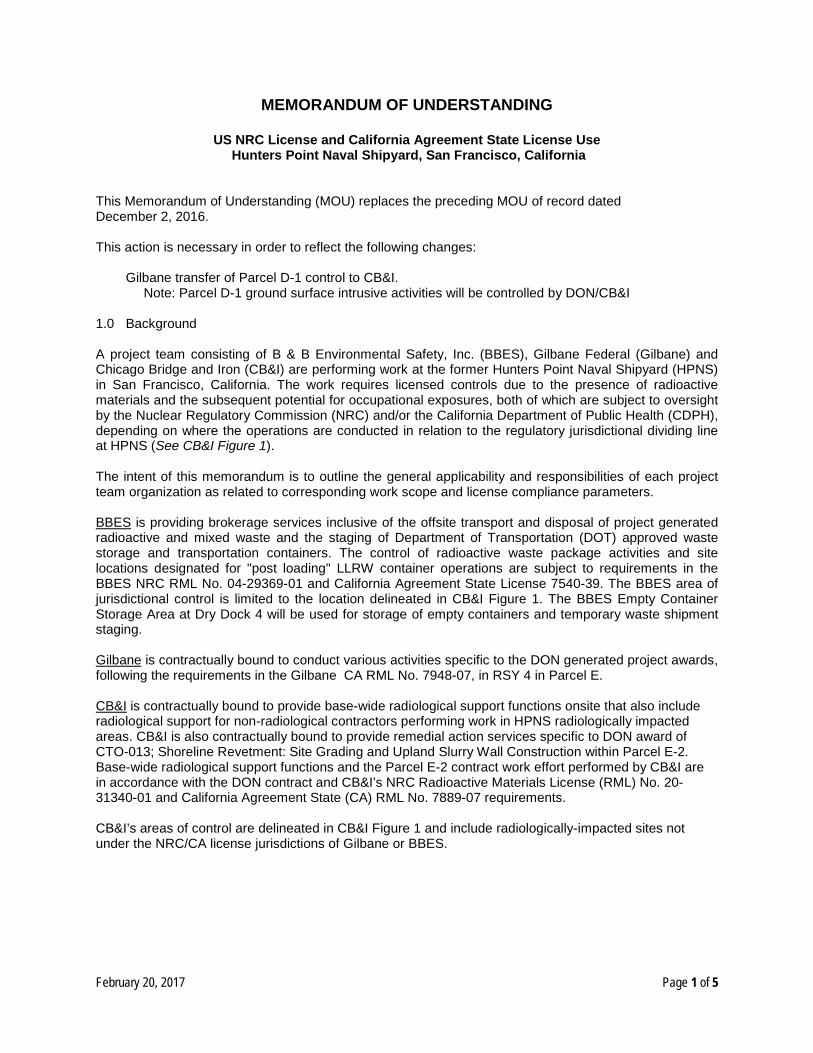
MEMORANDUM OF UNDERSTANDING
US NRC License and California Agreement State License Use Hunters Point Naval Shipyard, San Francisco, California
This Memorandum of Understanding (MOU) replaces the preceding MOU of record dated December 2, 2016. This action is necessary in order to reflect the following changes:
Gilbane transfer of Parcel D-1 control to CB&I.
Note: Parcel D-1 ground surface intrusive activities will be controlled by DON/CB&I 1.0 Background A project team consisting of B & B Environmental Safety, Inc. (BBES), Gilbane Federal (Gilbane) and Chicago Bridge and Iron (CB&I) are performing work at the former Hunters Point Naval Shipyard (HPNS) in San Francisco, California. The work requires licensed controls due to the presence of radioactive materials and the subsequent potential for occupational exposures, both of which are subject to oversight by the Nuclear Regulatory Commission (NRC) and/or the California Department of Public Health (CDPH), depending on where the operations are conducted in relation to the regulatory jurisdictional dividing line at HPNS (See CB&I Figure 1). The intent of this memorandum is to outline the general applicability and responsibilities of each project team organization as related to corresponding work scope and license compliance parameters. BBES is providing brokerage services inclusive of the offsite transport and disposal of project generated radioactive and mixed waste and the staging of Department of Transportation (DOT) approved waste storage and transportation containers. The control of radioactive waste package activities and site locations designated for "post loading" LLRW container operations are subject to requirements in the BBES NRC RML No. 04-29369-01 and California Agreement State License 7540-39. The BBES area of jurisdictional control is limited to the location delineated in CB&I Figure 1. The BBES Empty Container Storage Area at Dry Dock 4 will be used for storage of empty containers and temporary waste shipment staging. Gilbane is contractually bound to conduct various activities specific to the DON generated project awards, following the requirements in the Gilbane CA RML No. 7948-07, in RSY 4 in Parcel E. CB&I is contractually bound to provide base-wide radiological support functions onsite that also include radiological support for non-radiological contractors performing work in HPNS radiologically impacted areas. CB&I is also contractually bound to provide remedial action services specific to DON award of CTO-013; Shoreline Revetment: Site Grading and Upland Slurry Wall Construction within Parcel E-2. Base-wide radiological support functions and the Parcel E-2 contract work effort performed by CB&I are in accordance with the DON contract and CB&I’s NRC Radioactive Materials License (RML) No. 20-31340-01 and California Agreement State (CA) RML No. 7889-07 requirements. CB&I’s areas of control are delineated in CB&I Figure 1 and include radiologically-impacted sites not under the NRC/CA license jurisdictions of Gilbane or BBES.
February 20, 2017 Page 1 of 5
1.1 General Use of Individual Licenses Each organization within the team has distinct areas of operation and responsibility as defined by their respective clients (BBES for the Army Joint Munitions Command [AJMC], and Gilbane and CB&I for the DON). In parallel, each of the team members identified for license implementation will maintain specific controls associated with the following items and activities as applicable to respective work scope/areas and/or license requirements: Training and record maintenance for employees of each company:
• BBES for BBES site staff • Gilbane for Gilbane site staff • CB&I for CB&I site staff
Training and record maintenance for site visitors and non-radiological contractors performing work:
• BBES for BBES areas • Gilbane for Gilbane sites • CB&I for CB&I sites
Airborne radioactivity monitoring: • Gilbane for Gilbane sites • CB&I for CB&I sites
Dosimetry (internal/external) management and associated record maintenance for onsite personnel:
• BBES for BBES site staff • Gilbane for Gilbane staff • CB&I for CB&I site staff
Note: Visitors or subcontractors entering a radiologically controlled area for less than one shift (8 hours) will not require dosimetry if escorted by a trained staff person with dosimetry who represents the responsible licensee. Dosimetry management will be conducted by the licensee (Gilbane, BBES, or CB&I) and will include site-specific radiological training for assigned personnel and contractors. Use of dosimetry by an individual demonstrates completion of prerequisite training for radiologically controlled area access. Control of radioactive materials used for calibration or operational checks of radiation detection and laboratory equipment:
• BBES for BBES owned sources at HPNS • Gilbane for Gilbane owned sources at HPNS • CB&I for CB&I owned sources at HPNS
Control of individual work areas contractually designated for activities where radioactive materials are known or suspected to exist; incorporating postings that reflect a company identifier/symbol and which provides a point of control contact for such areas:
• BBES for site locations designated for LLRW container operations • Gilbane for RSY 4 in Parcel E • CB&I for all impacted sites excluding sites under Gilbane or BBES control
Control of waste materials in designated work areas:
• BBES for its designated LLRW container operations • Gilbane for Gilbane sites • CB&I for CB&I sites
February 20, 2017 Page 2 of 5
Issuance and maintenance of Radiation Work Permits for controlled work:
• BBES for designated LLRW container operations • Gilbane for Gilbane sites • CB&I for CB&I sites and for non-radiological contractors performing work in radiologically
impacted sites not under Gilbane or BBES control
Control of shipments failing portal monitor and/or handheld radiological surveys: • Gilbane for Gilbane sites • CB&I for CB&I and non-radiological contractors performing work in radiologically impacted sites
not under Gilbane or BBES control Inventories of radioactive materials, including waste:
• BBES for the BBES areas • Gilbane for Gilbane sites • CB&I for CB&I sites
Reports and other administrative requirements including those to the Radiological Affairs Support Office (RASO) and other regulatory agencies:
• BBES for the BBES areas • Gilbane for Gilbane sites • CB&I will provide a report indicating where radiological support was provided and what it
consisted of for non-radiological contractors performing work in radiologically impacted sites not under Gilbane or BBES control
2.0 Handling and Control of Radioactive Materials
Transfer of radioactive materials from one licensee to another licensee is anticipated for certain routine activities including the transfer of packaged and/or containerized waste. 2.1 Packaged and/or Accumulated Waste 2.1.1 BBES LLRW Containers: Radioactive material accumulated and identified as waste thus generated, will require ultimate transfer to the BBES designated storage and processing area. The radioactive material collection and transfer process will proceed as follows:
• Gilbane or CB&I will request BBES to deliver prepared LLRW containers for radioactive material accumulation to designated areas.
• Gilbane or CB&I will be responsible for control and maintenance of LLRW containers in their custody.
• Gilbane or CB&I are each responsible to properly load characterized waste into LLRW containers, per BBES recommendations, and shall facilitate the transfer and control of such materials by providing the following information on a corresponding BBES Radioactive Movement Form 1 for containers assayed as radioactive and BBES Commercial Commodity Transport Form for non-radioactive shipments. Form information includes but is not limited to:
1. A brief description of the material involved 2. An inventory of packages to include total number of packages and contents 3. A label identifying the maximum dose rate and location, known or suspected isotope(s)
and a curie content approximation for the package. Note that BBES provides the final curie content for the package based on the final weight determination and radioisotopic sampling
4. Date, time, and signature of person(s) completing the transfer
February 20, 2017 Page 3 of 5
• Gilbane or CB&I will notify BBES when a BBES LLRW container in their custody is full, request that the LLRW container be moved to the BBES storage area, and provide BBES, at the time of transfer, the corresponding BBES transport form container weights will be determined by BBES.
• BBES shall move filled LLRW containers from Gilbane or CB&I controlled areas to the BBES controlled storage yard for preparation for off-site disposal. LLRW containers are to be filled as full as practical up to a maximum net weight of approximately 48,000 lbs. depending on the type of material being loaded. LLRW containers may be returned to the generator for weight adjustment if deemed necessary by BBES.
• BBES will reference internal RASO authorized procedures and work instructions when coordinating the transfer of LLRW containers leaving a Gilbane or CB&I radiologically controlled area. Using RASO approved protocol detailed in the BBES HPNS Radiation Protection Plan (RPP) and supporting Base wide procedures/work instructions, Gilbane and CB&I will initiate RCA release surveys of the corresponding BBES LLRW container/truck, and monitor the assigned driver before the truck leaves a Gilbane or CB&I site. In conjunction with the exit survey, BBES will complete a visual assessment for removable contaminants on the exterior of the LLRW container itself.
2.1.1.1 BBES Management of Radioactive Waste As documented on a completed BBES Transfer Document and when satisfactory contamination survey results are verified by BBES. LLRW container custody will transfer at the time of pick up and removal from the Gilbane or CB&I maintained RCA. Upon receipt of the filled LLRW container, BBES will begin the process of sampling, profiling, and preparation for transportation of the radioactive waste to an authorized and approved treatment and/or disposal facility. Subsequent BBES responsibilities include processes specific to waste handling, storage, sampling, required inspections, off-site shipment activities, and management and control of the LLRW container storage area. If, after transfer to the LLRW container storage area, BBES identifies non-conforming material in an LLRW container, the entire LLRW container will be returned to the party initiating the transfer (i.e., the returned non-conforming material will revert back to the NRC/CA license inventory of the initiating party for further processing) with details documented on the corresponding Hunters Point Field Content Sheet and Transfer Document (HPFCS &TD). In addition to the minimum requirements for the transfer, BBES will also identify the non-conforming material that would need to be removed or further processed. The non-conforming material will be stored in an area controlled by the party initiating the transfer (e.g., Gilbane or CB&I) until the non-conforming material issue is resolved. 3.0 Occurrence Reporting The responsible RSO (or RSO representative) will notify all other site RSOs (or designated representatives), as soon as practical, of any of the following occurrences that may affect personnel from other organization(s):
• Contamination events that require decontamination (personnel or equipment) • Contamination levels including airborne radioactivity/dose rate events that stop operations • Any regulatory reporting event • Any noncompliance with the requirements of this MOU
The RSO or RSO representative of the responsible party shall report non-compliance issues to the applicable regulatory and/or oversight agencies.
February 20, 2017 Page 4 of 5
4.0 Jurisdictional Issues and Changes
Jurisdictional issues or specific situations not covered under this agreement will be discussed between BBES, Gilbane or CB&I for resolution. Signatures placed within this MOU by each Radiation Safety Officer (or RSO representative) will indicate approval of the contents within this document, and concurrence with the resultant agreement. Acknowledgment of the above referenced modification by designated Radiation Safety Officers or Radiation Safety Officer Representatives for the HPNS project teams is indicated by their signature as entered below. ______________________________________________ _________________ Jerry Cooper, Gilbane Radiation Safety Officer Date ______________________________________________ _________________ Kenneth Baugh, BBES Radiation Safety Officer Date ______________________________________________ _________________ Mark O. Somerville, CB&I Radiation Safety Officer Date Cc: All signatories
Zachary Edwards, Radiological Affairs Support Office, United States Navy Matthew Slack, Radiological Affairs Support Office, United States Navy Allen Stambaugh, Radiological Affairs Support Office, United States Navy Steve Doremus, Radiological Affairs Support Office, United States Navy Danielle Janda, Base Realignment and Closure Office, United States Navy Leslie Howard, Base Realignment and Closure Office, United States Navy
February 20, 2017 Page 5 of 5
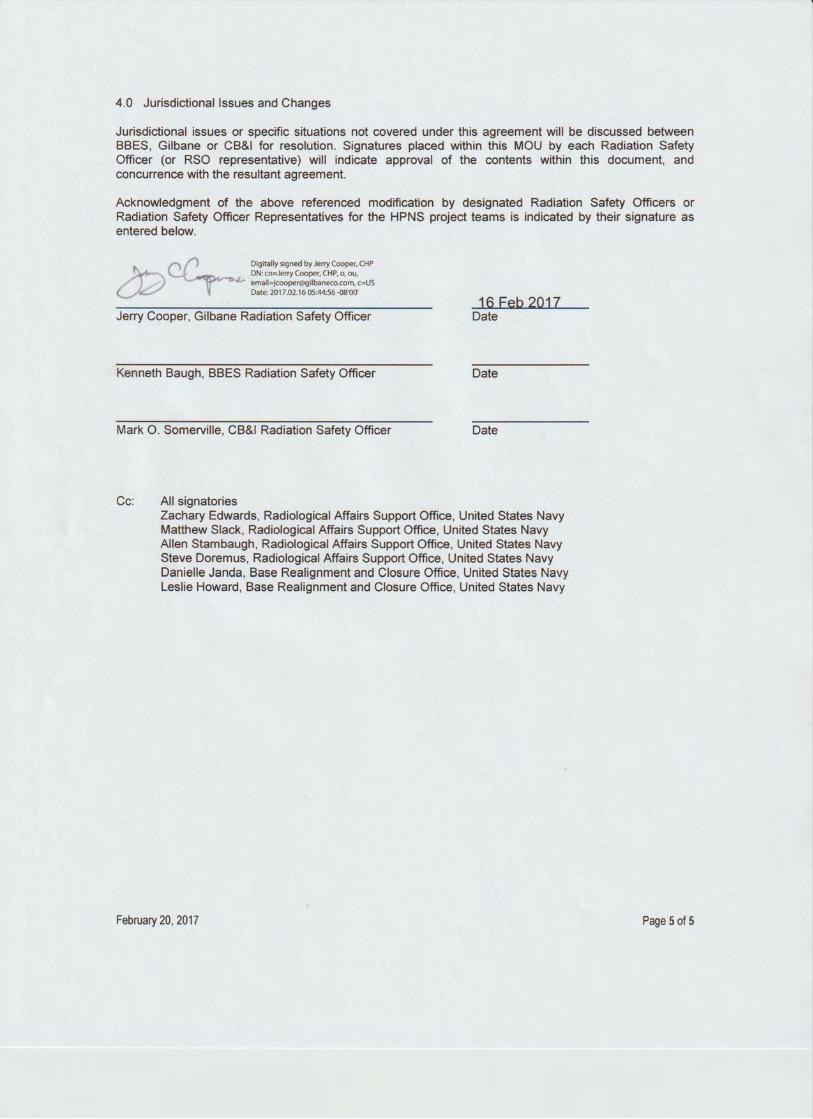
4.0 Jurisdictional Issues and Changes
Jurisdictional issues or specific situations not covered under this agreement will be discussed between BBES, Gilbane or CB&I for resolution. Signatures placed within this MOU by each Radiation Safety Officer (or RSO representative) will indicate approval of the contents within this document, and concurrence with the resultant agreement.
Acknowledgment of the above referenced modification by designated Radiation Safety Officers or Radiation Safety Officer Representatives for the HPNS project teams is indicated by their signature as entered below.
16 Feb 2017 Jerry Cooper, Gilbane Radiation Safety Officer Date
Kenneth Baugh, BBES Radiation Safety Officer Date
Mark 0 . Somerville, CB&I Radiation Safety Officer Date
Cc: All signatories Zachary Edwards, Radiological Affairs Support Office. United States Navy Matthew Slack, Radiological Affairs Support Office, United States Navy Allen Stambaugh, Radiological Affairs Support Office, United States Navy Steve Doremus, Radiological Affairs Support Office, United States Navy Danielle Janda, Base Realignment and Closure Office, United States Navy Leslie Howard, Base Realignment and Closure Office, United States Navy
February 20, 2017 Page 5 of 5
4.0 Jurisdictional Issues and Changes
Jurisdictional issues or specific situations not covered under this agreement will be discussed between BBES, Gilbane or CB&I for resolution. Signatures placed within this MOU by each Radiation Safety Officer (or RSO representative) will indicate approval of the contents within this document, and concurrence with the resultant agreement.
Acknowledgment of the above referenced modification by designated Radiation Safety Officers or Radiation Safety Officer Representatives for the HPNS project teams is indicated by their signature as entered below.
Jerry Cooper, Gilbane Radiation Safety Officer
Kenneth Baugh, BBES Radiation Safety Officer
Mark 0 . Somerville, CB&I Radiation Safety Officer
Cc: All signatories
Date
February 16, 2017
Date
Date
Zachary Edwards, Radiological Affairs Support Office, United States Navy Matthew Slack, Radiological Affairs Support Office, United States Navy Allen Stambaugh, Radiological Affairs Support Office, United States Navy Steve Doremus, Radiological Affairs Support Office, United States Navy Danielle Janda, Base Realignment and Closure Office, United States Navy Leslie Howard, Base Realignment and Closure Office, United States Navy
February 20, 2017 Page 5 of 5
4.0 Jurisdictional Issues and Changes
Jurisdictional issues or specific situations not covered under this agreement will be discussed between BBES, Gilbane or CB&I for resolution. Signatures placed within this MOU by each Radiation Safety Officer (or RSO representative) will indicate approval of the contents within this document, and concurrence with the resultant agreement.
Acknowledgment of the above referenced modification by designated Radiation Safety Officers or Radiation Safety Officer Representatives for the HPNS project teams is indicated by their signature as entered below.
Jerry Cooper, Gilbane Radiation Safety Officer
Kenneth Baugh, BBES Radiation Safety Officer "9"'~-.,,,...,,.0.SorneNlllo ON-; 01~cti; 0. Sot'ntfviQe, o-CB&I fedtt~I ~es. OU-RadtahCtl Safety. ~ll~bif~c-US Date: 20l7.02.1606:S1:12-08'00'
Mark 0 . Somerville, CB&I Radiation Safety Officer
Cc: All signatories
Date
Date
2/16/2017 Date
Zachary Edwards, Radiological Affairs Support Office, United States Navy Matthew Slack, Radiological Affairs Support Office, United States Navy Allen Stambaugh, Radiological Affairs Support Office, United States Navy Steve Doremus, Radiological Affairs Support Office, United States Navy Danielle Janda, Base Realignment and Closure Office, United States Navy Leslie Howard, Base Realignment and Closure Office, United States Navy
February 20, 201 7 Page 5 of 5
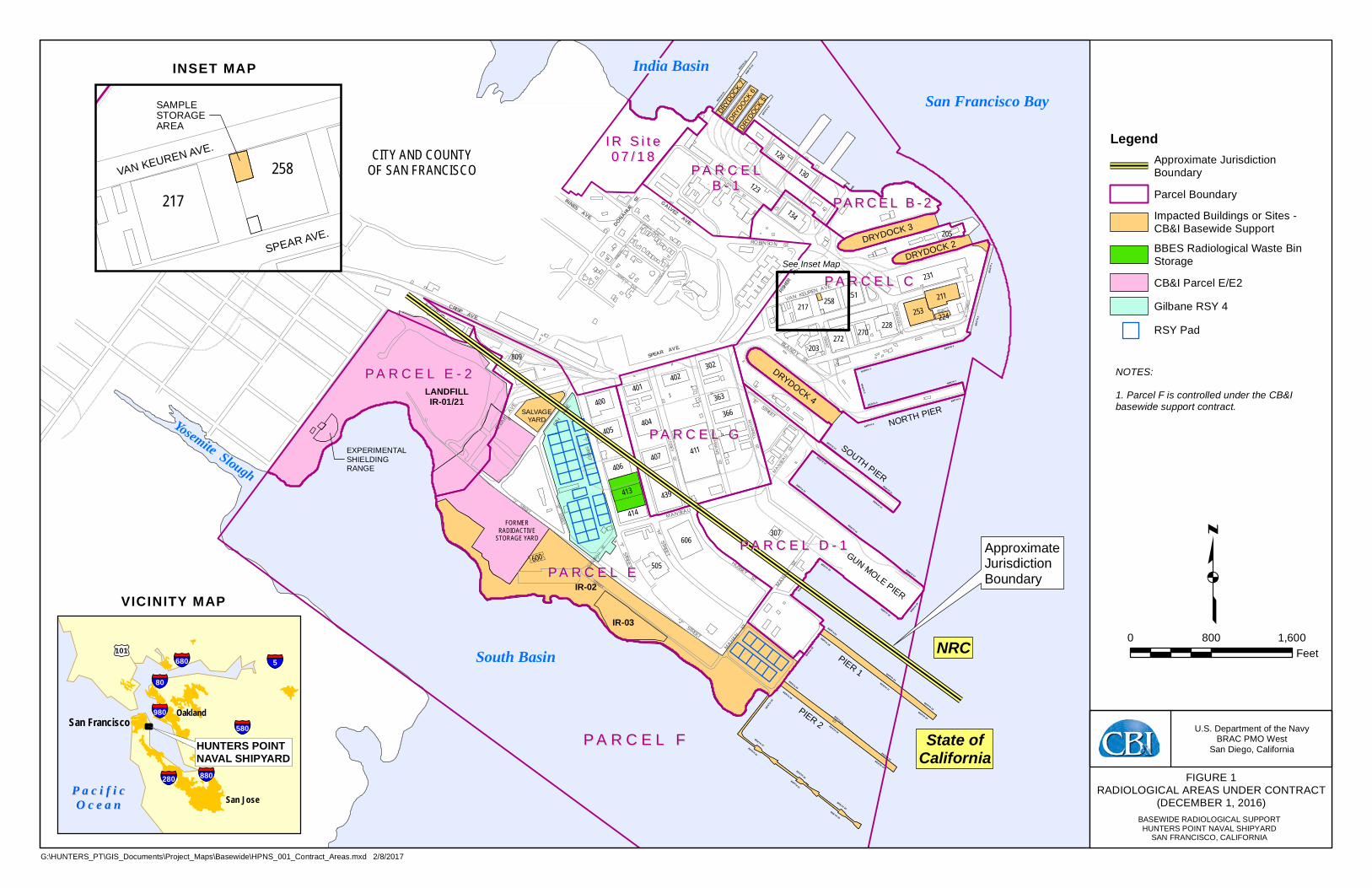
BERTH 7
BERT H 16
BER TH 8
BERT H 9
BERTH 6
BERTH18
BERTH 20 BERTH 17
BERT H 19
BERT
H2
B ERTH
21BERTH
29
BERTH 15
BERTH 32
BERTH 35
BERTH 13
BERTH64
BER TH 40
BERT
H1
BERTH63
BERTH
36
BERTH 27
BERTH 12
BERTH 28
BERT H 42
BERTH
62
BERTH 34
BERTH 26
BERT H 37
BERTH 41
BERTH 30
BERT H 11
BERTH 31
BERTH
61
BERTH 10
BERT H 39
BERT H 23
BERTH 38
BERTH 25
BERTH 33
BERTH 24
BERTH 3
B ERTH 4
BERT H5
INNESAVE.
FISHER
AVE.
FRIED
ELST.
GALVEZAVE.
MORRELLST.
ROBINSON ST.
HUS SEYST.
LOCKWOODST.
BLANDYST.
SPEAR AVE.
"E" STREET
HUDSON AVE.
COLEMAN
ST.COCHRANE
ST.
"C"STR EET
MAHAN S
T.
MANSEAU
ST.
"A"
STRE E
T
"I"S TREET
LOCKWOOD
ST
"J" STREET
"R"STREE T
VAN KEUREN AVE.
CRISP AVE.
6THAVE.
MANSEAU
ST.
"I"STREET
MAHAN ST.
HUSSEY ST.
SPEAR
AVE.
DONAHUEST.
JERROLDAVE.
"K" STREET
"H"STREET
MANSEAU ST.
"J" STREET
South Basin
Yosemite Slough
India BasinSan Francisco Bay
CITY AND COUNTYOF SAN FRANCISCO
ApproximateJurisdictionBoundary
State ofCalifornia
NRC
P A R C E L E - 2P A R C E L E - 2
P A R C E L EP A R C E L E
P A R C E L D - 1P A R C E L D - 1
P A R C E L CP A R C E L C
P A R C E L FP A R C E L F
P A R C E LP A R C E LB - 1B - 1
IR-03
IR-02
LANDFILLIR-01/21
SALVAGEYARD
EXPERIMENTALSHIELDINGRANGE
SOUTH PIER
GUN MOLE PIER
PIER 1
PIER 2
DRYDOCK 4
DRYDOCK 2DRYDOCK 3
DRYDOCK
5
DRYDOCK
7DRY
DOCK 6
NORTH PIER
FORMERRADIOACTIVE
STORAGE YARD
PA R C E L B - 2PA R C E L B - 2
I R S i t eI R S i t e0 7 / 1 80 7 / 1 8
P A R C E L GP A R C E L G
See Inset Map
411
231
439
123
606
211253
404400
405
407406
134
228
366
217
272
130
413
414
302
128
401402
363
270
251258
203809
205
600
224
307
505 p0 800 1,600
Feet
LegendApproximate JurisdictionBoundary
Parcel Boundary
Impacted Buildings or Sites -CB&I Basewide Support
BBES Radiological Waste BinStorage
CB&I Parcel E/E2
Gilbane RSY 4
RSY Pad
FIGURE 1RADIOLOGICAL AREAS UNDER CONTRACT
(DECEMBER 1, 2016)BASEWIDE RADIOLOGICAL SUPPORTHUNTERS POINT NAVAL SHIPYARD
SAN FRANCISCO, CALIFORNIA
U.S. Department of the NavyBRAC PMO West
San Diego, California
G:\HUNTERS_PT\GIS_Documents\Project_Maps\Basewide\HPNS_001_Contract_Areas.mxd 2/8/2017
P a c i f i cP a c i f i cO c e a nO c e a n
San Francisco
San Jose
Oakland
HUNTERS POINTNAVAL SHIPYARD
§̈¦5§̈¦680
§̈¦80
§̈¦280
£¤101
§̈¦980
§̈¦880
§̈¦580
SAMPLESTORAGEAREA
VAN KEUREN AVE.
SPEAR AVE.
217258
VICINITY MAP
INSET MAP
NOTES:1. Parcel F is controlled under the CB&Ibasewide support contract.
I I I I I I •
-----
=
Related Documents