Journal of American Science, 2012;8(5) http://www.americanscience.org http://www.americanscience.org [email protected] 100 Parameters’ Effect on Weld Quality for Dissimilar Spot Welding Between Ferritic Stainless Steel and Low Carbon Steel Sheets M. El-Shennawy 1 and S. M. Khafagy 2 1 Mechanical Engineering Department, Faculty of Engineering, Helwan University, Helwan, Cairo, Egypt 2 Tabbin Institute for Metallurgical Studies (TIMS), P.O.B 109 Helwan, Cairo, Egypt. E-mail: [email protected]; [email protected] Abstract: This work discusses the effect of main controlling parameters of spot welding process on the quality of dissimilar welded joint between ferritic stainless steel grade 430, FSS with 0.5 mm thickness and low carbon steel, LCS with 0.6 mm thickness sheets. Parameters studied were welding current, welding time and electrode pressure. Metallurgical and mechanical characteristics were determined through microstructure, tensile shear and microhardness examinations. The results of this study showed that the suitable electrode pressure in this dissimilar combination of steels; FSS and LCS; was 0.2MPa (2 bar). It was found also that the welding current is the most influential parameter on weld quality. The best weld strength was obtained at 3.4 KA. Increasing welding current and welding time up to certain level increases the joint strength, after this level the joint strength decreases. Investigations showed also that the dominant structure of the nugget is martensite. The fracture due to tensile shear test was mainly intergranular in ferritic stainless steel side and the fracture mode was button pullout. Microhardness values recorded their highest values at locations where carbides existed beside the martensite of the nugget. [M. El-Shennawy and S. M. Khafagy. Parameters’ Effect on Weld Quality for Dissimilar Spot Welding Between Ferritic Stainless Steel and Low Carbon Steel Sheets. J Am Sci. 2012;8(5):100-107]. (ISSN: 1545-1003). http://www.americanscience.org . 14 Keywords: Spot welding; dissimilar welding; weld quality; controlling parameters; ferritic stainless steel; metallurgical and mechanical characteristics. 1. Introduction Because of its high speed and adaptability for automation in high-rate production of sheet metal assemblies, resistance spot welding is widely used and applied in many industrial productions. It is also faster than arc welding or brazing and requires less skill to perform which make the process of resistance spot welding economical in many job shop operations [1]. Under the pressure of the requirements for lower cost and less weight of the products, dissimilar sheet metal assemblies are now being applied in automotive industries [2]. It is used for joining low carbon steel components for the bodies and chassis of automobiles, buses, trucks and office furniture [3–5]. Austenitic stainless steels and low carbon steels are welded similarly [6-7] and dissimilarly [8-9] by using resistance spot welding technique. Dissimilar welding between ferritic stainless steel and low carbon steel by using spot welding received limited attention and, therefore limited information about it is available. Ferritic stainless steel AISI 430 grade and low carbon steel were the dissimilar materials selected for this study. Effect of main welding parameters on weld quality of these steels has been studied. Those parameters included welding current, welding pressure (electrode force) and welding time. Weld quality was evaluated based mainly on weld strength. Therefore, microstructure investigation and microhardness and tensile shear examination for the dissimilar weld were carried out to determine the main spot welding parameters’ effect on the weldability of ferritic stainless steel and low carbon steel sheets. 2. Materials and Experimental Methods 2.1. Materials and welding process Two steel grades were used in this study; 430 grade ferritic stainless steel and low-carbon grade steel having 0.5 mm and 0.6 mm thickness, respectively. Chemical compositions and mechanical properties of both steels are given in Tables 1 and 2, respectively. Both materials were cut into pieces in dimensions of 150 mm x 25 mm. Sheet materials were spot welded using spot welding machine capable of 0–17.5 kA weld current. Welding was carried out by using water cooled conical electrode. Welding was performed by overlapping the plates linearly to fabricate the specimens for tensile shear test shown as schematically in Fig. 1. Various parameters were applied to examine their effects on weld quality as given in Table 3. The effect of welding current, applied pressure and welding time were the parameters investigated in this study. Fractured samples of the resistance spot dissimilar welded specimens after tensile shear test are shown in Fig. 2. 2.2 Mechanical testing and metallographic examination Mechanical testing for spot welded specimens included tensile shear test and Vickers microhardness examination. Tensile shear test was carried out for all

Welcome message from author
This document is posted to help you gain knowledge. Please leave a comment to let me know what you think about it! Share it to your friends and learn new things together.
Transcript
Journal of American Science, 2012;8(5) http://www.americanscience.org
http://www.americanscience.org [email protected] 100
Parameters’ Effect on Weld Quality for Dissimilar Spot Welding Between Ferritic Stainless Steel and Low
Carbon Steel Sheets
M. El-Shennawy1 and S. M. Khafagy
2
1Mechanical Engineering Department, Faculty of Engineering, Helwan University, Helwan, Cairo, Egypt
2Tabbin Institute for Metallurgical Studies (TIMS), P.O.B 109 Helwan, Cairo, Egypt.
E-mail: [email protected]; [email protected]
Abstract: This work discusses the effect of main controlling parameters of spot welding process on the quality of
dissimilar welded joint between ferritic stainless steel grade 430, FSS with 0.5 mm thickness and low carbon steel, LCS
with 0.6 mm thickness sheets. Parameters studied were welding current, welding time and electrode pressure.
Metallurgical and mechanical characteristics were determined through microstructure, tensile shear and microhardness
examinations. The results of this study showed that the suitable electrode pressure in this dissimilar combination of
steels; FSS and LCS; was 0.2MPa (2 bar). It was found also that the welding current is the most influential parameter
on weld quality. The best weld strength was obtained at 3.4 KA. Increasing welding current and welding time up to
certain level increases the joint strength, after this level the joint strength decreases. Investigations showed also that the
dominant structure of the nugget is martensite. The fracture due to tensile shear test was mainly intergranular in ferritic
stainless steel side and the fracture mode was button pullout. Microhardness values recorded their highest values at
locations where carbides existed beside the martensite of the nugget.
[M. El-Shennawy and S. M. Khafagy. Parameters’ Effect on Weld Quality for Dissimilar Spot Welding Between
Ferritic Stainless Steel and Low Carbon Steel Sheets. J Am Sci. 2012;8(5):100-107]. (ISSN: 1545-1003).
http://www.americanscience.org. 14
Keywords: Spot welding; dissimilar welding; weld quality; controlling parameters; ferritic stainless steel; metallurgical
and mechanical characteristics.
1. Introduction
Because of its high speed and adaptability for
automation in high-rate production of sheet metal
assemblies, resistance spot welding is widely used and
applied in many industrial productions. It is also faster
than arc welding or brazing and requires less skill to
perform which make the process of resistance spot
welding economical in many job shop operations [1].
Under the pressure of the requirements for lower cost
and less weight of the products, dissimilar sheet metal
assemblies are now being applied in automotive
industries [2]. It is used for joining low carbon steel
components for the bodies and chassis of automobiles,
buses, trucks and office furniture [3–5].
Austenitic stainless steels and low carbon steels
are welded similarly [6-7] and dissimilarly [8-9] by
using resistance spot welding technique. Dissimilar
welding between ferritic stainless steel and low carbon
steel by using spot welding received limited attention
and, therefore limited information about it is available.
Ferritic stainless steel AISI 430 grade and low carbon
steel were the dissimilar materials selected for this
study. Effect of main welding parameters on weld
quality of these steels has been studied. Those
parameters included welding current, welding pressure
(electrode force) and welding time. Weld quality was
evaluated based mainly on weld strength. Therefore,
microstructure investigation and microhardness and
tensile shear examination for the dissimilar weld were
carried out to determine the main spot welding
parameters’ effect on the weldability of ferritic
stainless steel and low carbon steel sheets.
2. Materials and Experimental Methods
2.1. Materials and welding process
Two steel grades were used in this study; 430
grade ferritic stainless steel and low-carbon grade steel
having 0.5 mm and 0.6 mm thickness, respectively.
Chemical compositions and mechanical properties of
both steels are given in Tables 1 and 2, respectively.
Both materials were cut into pieces in dimensions of
150 mm x 25 mm. Sheet materials were spot welded
using spot welding machine capable of 0–17.5 kA weld
current. Welding was carried out by using water cooled
conical electrode. Welding was performed by
overlapping the plates linearly to fabricate the
specimens for tensile shear test shown as schematically
in Fig. 1. Various parameters were applied to examine
their effects on weld quality as given in Table 3. The
effect of welding current, applied pressure and welding
time were the parameters investigated in this study.
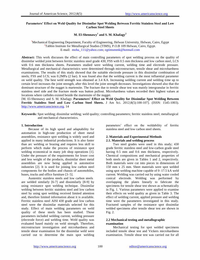
Fractured samples of the resistance spot dissimilar
welded specimens after tensile shear test are shown in
Fig. 2.
2.2 Mechanical testing and metallographic
examination
Mechanical testing for spot welded specimens
included tensile shear test and Vickers microhardness
examination. Tensile shear test was carried out for all
Journal of American Science, 2012;8(5) http://www.americanscience.org
http://www.americanscience.org [email protected] 101
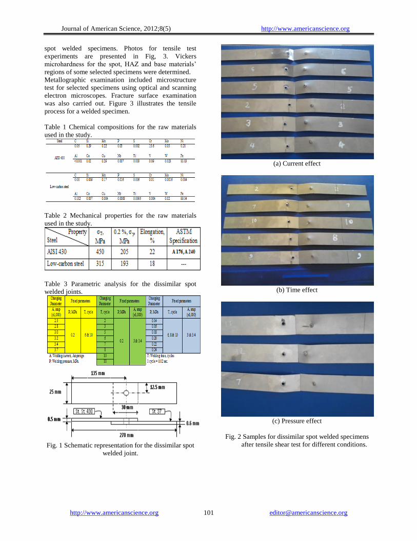
spot welded specimens. Photos for tensile test
experiments are presented in Fig, 3. Vickers
microhardness for the spot, HAZ and base materials’
regions of some selected specimens were determined.
Metallographic examination included microstructure
test for selected specimens using optical and scanning
electron microscopes. Fracture surface examination
was also carried out. Figure 3 illustrates the tensile
process for a welded specimen.
Table 1 Chemical compositions for the raw materials
used in the study.
Table 2 Mechanical properties for the raw materials
used in the study.
Table 3 Parametric analysis for the dissimilar spot
welded joints.
Fig. 1 Schematic representation for the dissimilar spot
welded joint.
(a) Current effect
(b) Time effect
(c) Pressure effect
Fig. 2 Samples for dissimilar spot welded specimens
after tensile shear test for different conditions.
Journal of American Science, 2012;8(5) http://www.americanscience.org
http://www.americanscience.org [email protected] 102
Fig. 3 Tensile test for the spot welded specimens.
3. Results and Discussion
3.1 Effect of welding pressure
The resistance R in the heat formula, Q = I2Rt
where Q is heat generated, I is current applied and t is
duration of current, is influenced by welding pressure
through its effect on contact resistance at the interface
between the workpieces. Welding pressure is produced
by the force exerted on the joint by the electrodes [1].
Therefore, the welding pressure is considered as an
indirect controlling parameter on heat generated. Its
effect on weld strength has been discussed through the
applications of various welding pressures and
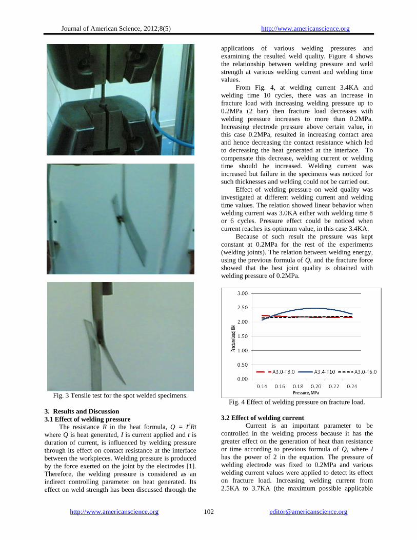
examining the resulted weld quality. Figure 4 shows
the relationship between welding pressure and weld
strength at various welding current and welding time
values.
From Fig. 4, at welding current 3.4KA and
welding time 10 cycles, there was an increase in
fracture load with increasing welding pressure up to
0.2MPa (2 bar) then fracture load decreases with
welding pressure increases to more than 0.2MPa.
Increasing electrode pressure above certain value, in
this case 0.2MPa, resulted in increasing contact area
and hence decreasing the contact resistance which led
to decreasing the heat generated at the interface. To
compensate this decrease, welding current or welding
time should be increased. Welding current was
increased but failure in the specimens was noticed for
such thicknesses and welding could not be carried out.
Effect of welding pressure on weld quality was
investigated at different welding current and welding
time values. The relation showed linear behavior when
welding current was 3.0KA either with welding time 8
or 6 cycles. Pressure effect could be noticed when
current reaches its optimum value, in this case 3.4KA.
Because of such result the pressure was kept
constant at 0.2MPa for the rest of the experiments
(welding joints). The relation between welding energy,
using the previous formula of Q, and the fracture force
showed that the best joint quality is obtained with
welding pressure of 0.2MPa.
Fig. 4 Effect of welding pressure on fracture load.
3.2 Effect of welding current
Current is an important parameter to be
controlled in the welding process because it has the
greater effect on the generation of heat than resistance
or time according to previous formula of Q, where I
has the power of 2 in the equation. The pressure of
welding electrode was fixed to 0.2MPa and various
welding current values were applied to detect its effect
on fracture load. Increasing welding current from
2.5KA to 3.7KA (the maximum possible applicable
Journal of American Science, 2012;8(5) http://www.americanscience.org
http://www.americanscience.org [email protected] 103
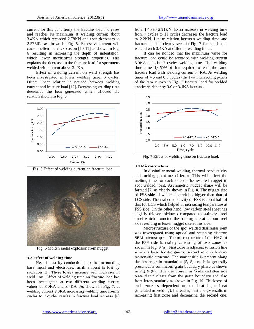
current for this condition), the fracture load increases
and reaches its maximum at welding current about
3.4KA which recorded 2.78KN and then decreases to
2.57MPa as shown in Fig. 5. Excessive current will
cause molten metal explosion [10-11] as shown in Fig.
6 resulting in increasing the depth of indentation,
which lower mechanical strength properties. This
explains the decrease in the fracture load for specimens
welded with current above 3.4KA.
Effect of welding current on weld strength has
been investigated at lower welding time, 6 cycles.
Direct linear relation is noticed between welding
current and fracture load [12]. Decreasing welding time
decreased the heat generated which affected the
relation shown in Fig. 5.
Fig. 5 Effect of welding current on fracture load.
Fig. 6 Molten metal explosion from nugget.
3.3 Effect of welding time
Heat is lost by conduction into the surrounding
base metal and electrodes; small amount is lost by
radiation [1]. These losses increase with increases in
weld time. Effect of welding time on fracture load has
been investigated at two different welding current
values of 3.0KA and 3.4KA. As shown in Fig. 7, at
welding current 3.0KA increasing welding time from 2
cycles to 7 cycles results in fracture load increase [6]
from 1.45 to 2.91KN. Extra increase in welding time
from 7 cycles to 11 cycles decreases the fracture load
to 2.2KN. Linear relation between welding time and
fracture load is clearly seen in Fig. 7 for specimens
welded with 3.4KA at different welding times.
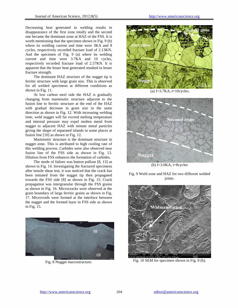
It can be noticed that the maximum value for
fracture load could be recorded with welding current
3.0KA and abt. 7 cycles welding time. This welding
time is nearly 50% of that required to reach the same
fracture load with welding current 3.4KA. At welding
times of 4.5 and 8.5 cycles (the two intersecting points
of the two curves in Fig. 7 fracture load for welded
specimen either by 3.0 or 3.4KA is equal.
Fig. 7 Effect of welding time on fracture load.
3.4 Microstructure
In dissimilar metal welding, thermal conductivity
and melting point are different. This will affect the
melting time for each side of the resulted nugget in
spot welded joint. Asymmetric nugget shape will be
formed [7] as clearly shown in Fig. 8. The nugget size
of FSS side of welded material is bigger than that of
LCS side. Thermal conductivity of FSS is about half of
that for LCS which helped in increasing temperature at
FSS side. On the other hand, low carbon steel sheet has
slightly thicker thickness compared to stainless steel
sheet which promoted the cooling rate at carbon steel
side resulting in lesser nugget size at this side.
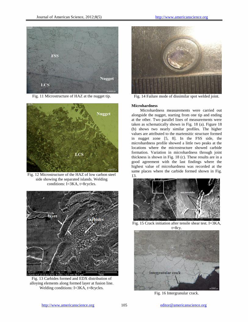
Microstructure of the spot welded dissimilar joint
was investigated using optical and scanning electron
SEM microscopes. The microstructure of the HAZ of
the FSS side is mainly consisting of two zones as
shown in Fig. 9 (a). First zone is adjacent to fusion line
which is large ferritic grains. Second zone is ferritic-
martensitic structure. The martensitic is present along
the ferrite grain boundaries [5, 8] and it is generally
present as a continuous grain boundary phase as shown
in Fig. 9 (b). It is also present as Ẅidmanstatten side
plate that nucleate from the grain boundary and also
from intergranularly as shown in Fig. 10. Thickness of
each zone is dependent on the heat input (heat
generated in welding). Increasing heat energy results in
increasing first zone and decreasing the second one.
Journal of American Science, 2012;8(5) http://www.americanscience.org
http://www.americanscience.org [email protected] 104
Decreasing heat generated in welding results in
disappearance of the first zone totally and the second
one became the dominant zone at HAZ of the FSS. It is
worth mentioning that the specimen shown in Fig. 9 (b)
where its welding current and time were 3KA and 8
cycles, respectively recorded fracture load of 2.13KN.
And the specimen of Fig. 9 (a) where its welding
current and time were 3.7KA and 10 cycles,
respectively recorded fracture load of 2.57KN. It is
apparent that the lesser heat generated resulted in lesser
fracture strength.
The dominant HAZ structure of the nugget tip is
ferritic structure with large grain size. This is observed
for all welded specimens at different conditions as
shown in Fig. 11.
At low carbon steel side the HAZ is gradually
changing from martensitic structure adjacent to the
fusion line to ferritic structure at the end of the HAZ
with gradual decrease in grain size in the same
direction as shown in Fig. 12. With increasing welding
time, weld nugget will far exceed melting temperature
and internal pressure may expel molten metal from
nugget to adjacent HAZ with minute metal particles
giving the shape of separated islands in some places at
fusion line [10] as shown in Fig. 12.
Martensitic structure is the dominant structure in
nugget zone. This is attributed to high cooling rate of
this welding process. Carbides were also observed near
fusion line of the FSS side as shown in Fig. 13.
Dilution from FSS enhances the formation of carbides.
The mode of failure was button pullout [8, 13] as
shown in Fig. 14. Investigating the fractured specimens
after tensile shear test, it was noticed that the crack has
been initiated from the nugget tip then propagated
towards the FSS side [8] as shown in Fig. 15. Crack
propagation was intergranular through the FSS grains
as shown in Fig. 16. Microcracks were observed at the
grain boundary of large ferritic grains as shown in Fig.
17. Microvoids were formed at the interface between
the nugget and the formed layer in FSS side as shown
in Fig. 15.
Fig. 8 Nugget macrostructure.
(a) I=3.7KA, t=10cycles.
(b) I=3.0KA, t=8cycles
Fig. 9 Weld zone and HAZ for two different welded
joints.
Fig. 10 SEM for specimen shown in Fig. 8 (b).
Journal of American Science, 2012;8(5) http://www.americanscience.org
http://www.americanscience.org [email protected] 105
Fig. 11 Microstructure of HAZ at the nugget tip.
Fig. 12 Microstructure of the HAZ of low carbon steel
side showing the separated islands. Welding
conditions: I=3KA, t=8cycles.
Fig. 13 Carbides formed and EDX distribution of
alloying elements along formed layer at fusion line.
Welding conditions: I=3KA, t=8cycles.
Fig. 14 Failure mode of dissimilar spot welded joint.
Microhardness
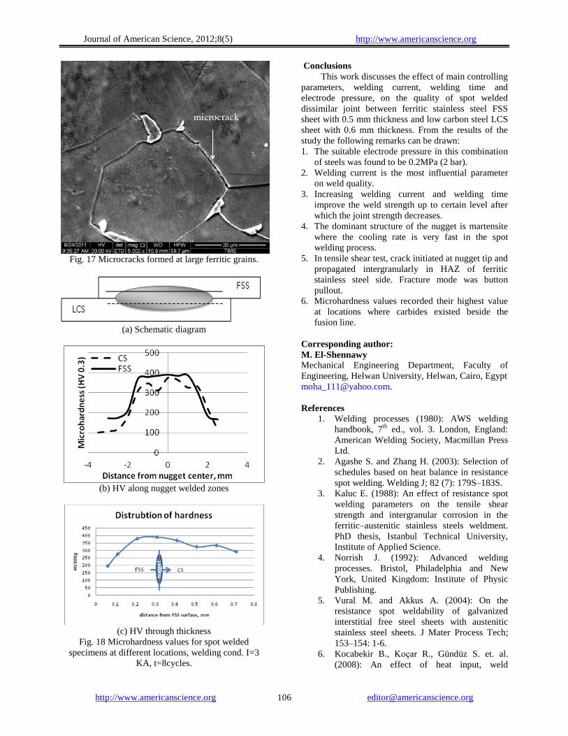
Microhardness measurements were carried out
alongside the nugget, starting from one tip and ending
at the other. Two parallel lines of measurements were
taken as schematically shown in Fig. 18 (a). Figure 18
(b) shows two nearly similar profiles. The higher
values are attributed to the martensitic structure formed
in nugget zone [5, 8]. In the FSS side, the
microhardness profile showed a little two peaks at the
locations where the microstructure showed carbide
formation. Variation in microhardness through joint
thickness is shown in Fig. 18 (c). These results are in a
good agreement with the last findings where the
highest value of microhardness was recorded at the
same places where the carbide formed shown in Fig.
13.
Fig. 15 Crack initiation after tensile shear test. I=3KA,
t=8cy.
Fig. 16 Intergranular crack.
Journal of American Science, 2012;8(5) http://www.americanscience.org
http://www.americanscience.org [email protected] 106
Fig. 17 Microcracks formed at large ferritic grains.
(a) Schematic diagram
(b) HV along nugget welded zones
(c) HV through thickness
Fig. 18 Microhardness values for spot welded
specimens at different locations, welding cond. I=3
KA, t=8cycles.
Conclusions
This work discusses the effect of main controlling
parameters, welding current, welding time and
electrode pressure, on the quality of spot welded
dissimilar joint between ferritic stainless steel FSS
sheet with 0.5 mm thickness and low carbon steel LCS
sheet with 0.6 mm thickness. From the results of the
study the following remarks can be drawn:
1. The suitable electrode pressure in this combination
of steels was found to be 0.2MPa (2 bar).
2. Welding current is the most influential parameter
on weld quality.
3. Increasing welding current and welding time
improve the weld strength up to certain level after
which the joint strength decreases.
4. The dominant structure of the nugget is martensite
where the cooling rate is very fast in the spot
welding process.
5. In tensile shear test, crack initiated at nugget tip and
propagated intergranularly in HAZ of ferritic
stainless steel side. Fracture mode was button
pullout.
6. Microhardness values recorded their highest value
at locations where carbides existed beside the
fusion line.
Corresponding author:
M. El-Shennawy Mechanical Engineering Department, Faculty of
Engineering, Helwan University, Helwan, Cairo, Egypt
References
1. Welding processes (1980): AWS welding
handbook, 7th
ed., vol. 3. London, England:
American Welding Society, Macmillan Press
Ltd.
2. Agashe S. and Zhang H. (2003): Selection of
schedules based on heat balance in resistance
spot welding. Welding J; 82 (7): 179S–183S.
3. Kaluc E. (1988): An effect of resistance spot
welding parameters on the tensile shear
strength and intergranular corrosion in the
ferritic–austenitic stainless steels weldment.
PhD thesis, Istanbul Technical University,
Institute of Applied Science.
4. Norrish J. (1992): Advanced welding
processes. Bristol, Philadelphia and New
York, United Kingdom: Institute of Physic
Publishing.
5. Vural M. and Akkus A. (2004): On the
resistance spot weldability of galvanized
interstitial free steel sheets with austenitic
stainless steel sheets. J Mater Process Tech;
153–154: 1-6.
6. Kocabekir B., Koҫar R., Gündüz S. et. al.
(2008): An effect of heat input, weld
Journal of American Science, 2012;8(5) http://www.americanscience.org
http://www.americanscience.org [email protected] 107
atmosphere and weld cooling conditions on
the resistance spot weldability of 316L
austenitic stainless steel, J Mater Proc Tech;
195: 327-335.
7. Haanbaşoğlu A. and Kaҫar R. (2007):
Resistance spot weldability of dissimilar
materials (AISI 316L-DIN 10130-99 steels), J
Mater & Design; 28: 1794-1800.
8. Marashi P., Pouranvari M., Amirabdollahian
S. et. al. (2008): Microstructure and failure
behavior of dissimilar resistance spot welds
between low carbon galvanized and austenitic
stainless steels, J Mater Sci & Engng A.; 480:
175-180.
9. Sun X., Stephens E. V., Khaleel M. A., et. al.
(2004): Resistance spot welding of aluminum
alloy to steel with transition material — from
process to performance — Part I:
Experimental study, Welding Journal; 83 (6):
188-s to 195-s.
10. Zhang H. and Senkara J. (2006): Resistance
welding fundamentals and applications, CRC
Press; 61-67.
11. Pouravari M., Mousavizadeh S. M., Marashi
S. P. H et. al. (2011): Influence of fusion zone
size and failure mode on mechanical
performance of dissimilar resistance spot
welds of AISI 1008 low carbon steel and
DP600 advanced high strength steel, J Mater
& Design; 32: 1390-1398.
12. Pereira A. M., Ferreira J. M., Loureiro A. et.
al. (2010): Effect of process parameters on the
strength of resistance spot welds in 6082-T6
aluminium alloy, J Mater & Design; 31: 2454-
2463.
13. Hayat F. (2011): The effects of the welding
current on heat input, nugget geometry, and
the mechanical and fractural properties of
resistance spot welding on Mg/Al dissimilar
materials, J Mater & Design; 32: 2476-2484.
4/2/2012
Related Documents