Parallel phase modulation scheme for interferometric gravitational-wave detectors M. T. Hartman, 1,* V. Quetschke, 2 D. B. Tanner, 1 D. H. Reitze, 1,3 and G. Mueller 1 1 Department of Physics, University of Florida, P O Box 118440, Gainesville, Florida 32611, USA 2 Department of Physics and Astronomy, University of Texas at Brownsville, 80 Fort Brown, Brownsville, Texas 78520, USA 3 LIGO Laboratory, California Institute of Technology, MS 100-36, Pasadena, California 91125, USA * [email protected]fl.edu Abstract: Advanced LIGO (aLIGO) requires multiple frequency side- bands to disentangle all of the main interferometer’s length signals. This paper presents the results of a risk reduction experiment to produce two sets of frequency sidebands in parallel, avoiding mixed ‘sidebands on sidebands’. Two phase modulation frequencies are applied to separate Electro-Optic Modulators (EOMs), with one EOM in each of the two arms of a Mach-Zehnder interferometer. In this system the Mach-Zehnder’s arm lengths are stabilized to reduce relative intensity noise in the recombined carrier beam by feeding a corrective control signal back to the Rubidium Titanyl Phosphate (RTP) EOM crystals to drive the optical path length difference to zero. This setup’s use of the RTP crystals as length actuators provides enough bandwidth in the feedback to meet arm length stability requirements for aLIGO. © 2014 Optical Society of America OCIS codes: (250.0250) Optoelectronics; (230.0230) Optical devices; (120.3180) Interferom- etry; (060.2630) Frequency modulation; (350.1270) Astronomy and astrophysics. References and links 1. B. Abbot and the LIGO Scientific Collaboration, “LIGO: the laser interferometer gravitational-wave observa- tory,” Rep. Prog. Phys. 72, 076901 (2009). 2. G. M. Harry for the LIGO Scientific Collaboration, “Advanced LIGO: the next generation of gravitational wave detectors,” Class. Quantum Grav. 27, 084006 (2010). 3. B. Abbot and the LIGO Scientific Collaboration, “First upper limits from LIGO on gravitational wave bursts,” Phys. Rev. D 69, 102001 (2004). 4. B. Abbot and the LIGO Scientific Collaboration and the Virgo Collaboration, “An upper limit on the stochastic gravitational-wave background of cosmological origin,” Nature 460, 990–994 (2009). 5. J. Abadie and the LIGO Scientific Collaboration and the Virgo Collaboration, “Directional limits on persistent gravitational waves using LIGO S5 science data,” Phys. Rev. Lett. 107, 271102 (2011). 6. J. Aasi and the LIGO Scientific Collaboration, “Prospects for localization of gravitational wave transients by the advanced LIGO and advanced virgo observatories,” Living Rev. Relat., in press. (arXiv:1304.0670 [gr-qc], LIGO-P1200087). 7. H. Grote, A. Freise, M. Malec, G. Heinzel, B. Willke, H. Lck, K. A. Strain, J. Hough, K. Danzmann, “Dual recycling for GEO 600,” Class. Quantum Grav. 21, S473 (2004). 8. E. D. Black, “An introduction to pound–drever–hall laser frequency stabilization,” Am J Phys 69, 79–87 (2001). #221497 - $15.00 USD Received 26 Aug 2014; revised 1 Oct 2014; accepted 10 Oct 2014; published 6 Nov 2014 (C) 2014 OSA 17 November 2014 | Vol. 22, No. 23 | DOI:10.1364/OE.22.028327 | OPTICS EXPRESS 28327

Welcome message from author
This document is posted to help you gain knowledge. Please leave a comment to let me know what you think about it! Share it to your friends and learn new things together.
Transcript
Parallel phase modulation scheme forinterferometric gravitational-wave
detectors
M. T. Hartman,1,∗ V. Quetschke,2 D. B. Tanner,1 D. H. Reitze,1,3and G. Mueller1
1Department of Physics, University of Florida,P O Box 118440, Gainesville, Florida 32611, USA
2Department of Physics and Astronomy, University of Texas at Brownsville,80 Fort Brown, Brownsville, Texas 78520, USA
3LIGO Laboratory, California Institute of Technology,MS 100-36, Pasadena, California 91125, USA
Abstract: Advanced LIGO (aLIGO) requires multiple frequency side-bands to disentangle all of the main interferometer’s length signals. Thispaper presents the results of a risk reduction experiment to produce twosets of frequency sidebands in parallel, avoiding mixed ‘sidebands onsidebands’. Two phase modulation frequencies are applied to separateElectro-Optic Modulators (EOMs), with one EOM in each of the two armsof a Mach-Zehnder interferometer. In this system the Mach-Zehnder’s armlengths are stabilized to reduce relative intensity noise in the recombinedcarrier beam by feeding a corrective control signal back to the RubidiumTitanyl Phosphate (RTP) EOM crystals to drive the optical path lengthdifference to zero. This setup’s use of the RTP crystals as length actuatorsprovides enough bandwidth in the feedback to meet arm length stabilityrequirements for aLIGO.
© 2014 Optical Society of America
OCIS codes: (250.0250) Optoelectronics; (230.0230) Optical devices; (120.3180) Interferom-etry; (060.2630) Frequency modulation; (350.1270) Astronomy and astrophysics.
References and links1. B. Abbot and the LIGO Scientific Collaboration, “LIGO: the laser interferometer gravitational-wave observa-
tory,” Rep. Prog. Phys. 72, 076901 (2009).2. G. M. Harry for the LIGO Scientific Collaboration, “Advanced LIGO: the next generation of gravitational wave
detectors,” Class. Quantum Grav. 27, 084006 (2010).3. B. Abbot and the LIGO Scientific Collaboration, “First upper limits from LIGO on gravitational wave bursts,”
Phys. Rev. D 69, 102001 (2004).4. B. Abbot and the LIGO Scientific Collaboration and the Virgo Collaboration, “An upper limit on the stochastic
gravitational-wave background of cosmological origin,” Nature 460, 990–994 (2009).5. J. Abadie and the LIGO Scientific Collaboration and the Virgo Collaboration, “Directional limits on persistent
gravitational waves using LIGO S5 science data,” Phys. Rev. Lett. 107, 271102 (2011).6. J. Aasi and the LIGO Scientific Collaboration, “Prospects for localization of gravitational wave transients by
the advanced LIGO and advanced virgo observatories,” Living Rev. Relat., in press. (arXiv:1304.0670 [gr-qc],LIGO-P1200087).
7. H. Grote, A. Freise, M. Malec, G. Heinzel, B. Willke, H. Lck, K. A. Strain, J. Hough, K. Danzmann, “Dualrecycling for GEO 600,” Class. Quantum Grav. 21, S473 (2004).
8. E. D. Black, “An introduction to pound–drever–hall laser frequency stabilization,” Am J Phys 69, 79–87 (2001).
#221497 - $15.00 USD Received 26 Aug 2014; revised 1 Oct 2014; accepted 10 Oct 2014; published 6 Nov 2014(C) 2014 OSA 17 November 2014 | Vol. 22, No. 23 | DOI:10.1364/OE.22.028327 | OPTICS EXPRESS 28327

9. K. A. Strain, G. Mueller, T. Delker, D. H. Reitze, D. B. Tanner, J. E. Mason, P. A. Willems, D. A. Shaddock,M. B. Gray, C. Mow-Lowry, D. E. McClelland, “Length sensing in advanced LIGO,” Appl. Opt. 42, 1244–1256(2003).
10. R. Abbott, R. Adhikari, S. Ballmer, L. Barsotti, M. Evans, P. Fritschel, V. Frolov, G. Mueller, B. Slagmolen, andS. Waldman, “Advanced LIGO length sensing and control final design,” (2010). LIGO-T1000298-T.
11. B. W. Barr, O. Miyakawa, S. Kawamura, A. J. Weinstein, R. Ward, S. Vass, and K. A. Strain, “Control sidebandgeneration for dual-recycled laser interferometric gravitational wave detectors,” Class. Quantum Grav. 23, 5661(2006).
12. O. Miyakawa, S. Kawamura, B. Abbott, R. Bork, P. Fritschel, L. Goggin, J. Heefner, A. Ivanov, F. Kawazoe,C. Mow-Lowry, A. Ourjoumtsev, S. Sakata, M. Smith, K. A. Strain, R. Taylor, D. Ugolini, S. Vass, R. Ward,A. Weinstein, “Sensing and control of the advanced LIGO optical configuration,” SPIE 5500, Gravitational Waveand Partical Astrophysics pp. 92–104 (2004).
13. M. Arain, A. Lucianetti, R. Martin, G. Mueller, V. Quetschke, D. Reitze, D. Tanner, and W. Wu, “AdvLIGOphase modulator assembly document,” (2009). LIGO-T0900475-v2.
14. S. Wise, “Sensitivity enhancement in future interferometric gravitational wave detectors,” Ph.D. thesis, The Uni-versity of Florida (2006).
15. S. Kawamura and O. Miyakawa, “Effect of mach zehnder residual displacement noise on the 40m detuned rseinterferometer,” (2004). LIGO-T040166.
16. K. L. Dooley, M. A. Arain, D. Feldbaum, V. V. Frolov, M. Heintze, D. Hoak, E. A. Khazanov, A. Lucianetti,R. M. Martin, G. Mueller, O. Palashov, V. Quetschke, D. H. Reitze, R. L. Savage, D. B. Tanner, L. F. Williams, andW. Wu, “Thermal effects in the input optics of the enhanced laser interferometer gravitational-wave observatoryinterferometers,” Rev. Sci. Instrum. 83, 033109 (2012).
17. New Focus 1611 Photodetector (2011). http://assets.newport.com/webDocuments-EN/images/15178.pdf.18. Raicol RTP Specifications (2006). http://www.optoscience.com/maker/raicol/pdf/catalog%20raicol screen.pdf.19. J. J. Carvajal, P. Segonds, A. Pena, J. Zaccaro, B. Boulanger, F. Dıaz, and M. Aguilo, “Structural and optical
properties of RbTiOPO4 : Nb crystals,” J. Phys.: Condens. Matter 19, 116214 (2007).20. O. Gobert, N. Fedorov, G. Mennerat, D. Lupinski, D. Guillaumet, M. Perdrix, A. Bourgeade, and M. Comte,
“Wavelength dispersion measurement of electro-optic coefficients in the range of 520 to 930 nm in rubidiumtitanyl phosphate using spectral interferometry,” Appl. Opt. 51, 594–599 (2012).
21. K. Somiya, Y. Chen, S. Kawamura, and N. Mio, “Frequency noise and intensity noise of next-generationgravitational-wave detectors with RF/DC readout schemes,” Phys. Rev. D 73, 122005 (2006).
1. Introduction
The advanced Laser Interferometer Gravitational-Wave Observatory (aLIGO) consists of twodetectors located in Hanford, WA and Livingston, LA. These 4 km long Michelson interferom-eters are built to detect gravitational waves in the 10 Hz to 10 kHz frequency band [1,2]. InitialLIGO set multiple important limits on the generation of gravitational waves [3–5]. Upgradesto the interferometers, which are currently nearing completion, are expected to yield the firstdetections within the next few years [6]. A basic sketch of the upgraded aLIGO interferometerdesign is shown in Fig. 1. The interferometer’s mirrors act as test masses, experiencing a lengthdisplacement resulting from the strain of a passing gravitational wave. The gravitational wavesignal is read out as the differential arm length changes (DARM) in the interferometer. This sig-nal is enhanced by using Fabry-Perot resonant cavities as the interferometer’s arms. In additionto the arm cavities (which are formed by the input test mass (ITM) and end test mass (ETM)mirrors) LIGO also uses a power recycling mirror (PRM) to increase the power circulating inthe arm cavities; furthermore, aLIGO adds a signal recycling mirror (SRM) to form the signalrecycling cavity, which adds the ability to tune the frequency response of the detector [7].
For aLIGO to operate, the laser must remain on resonance with the two arm cavities as wellas the power recycling cavity. Several longitudinal degrees of freedom need to be controlled tokeep the interferometer at this operating point. The aLIGO interferometer uses a phase modu-lation/demodulation scheme [8–10] to produce the necessary control signals for feedback. Twosets of radio frequency sidebands are imprinted on the carrier by phase modulation in an electro-optic modulator (EOM). Beat signals, produced by the interaction of the phase-modulated lightwith the interferometer, are detected and demodulated at various points in the interferometer(see eg. POP and REFL in Fig. 1) to create the error signals for feedback.
#221497 - $15.00 USD Received 26 Aug 2014; revised 1 Oct 2014; accepted 10 Oct 2014; published 6 Nov 2014(C) 2014 OSA 17 November 2014 | Vol. 22, No. 23 | DOI:10.1364/OE.22.028327 | OPTICS EXPRESS 28328
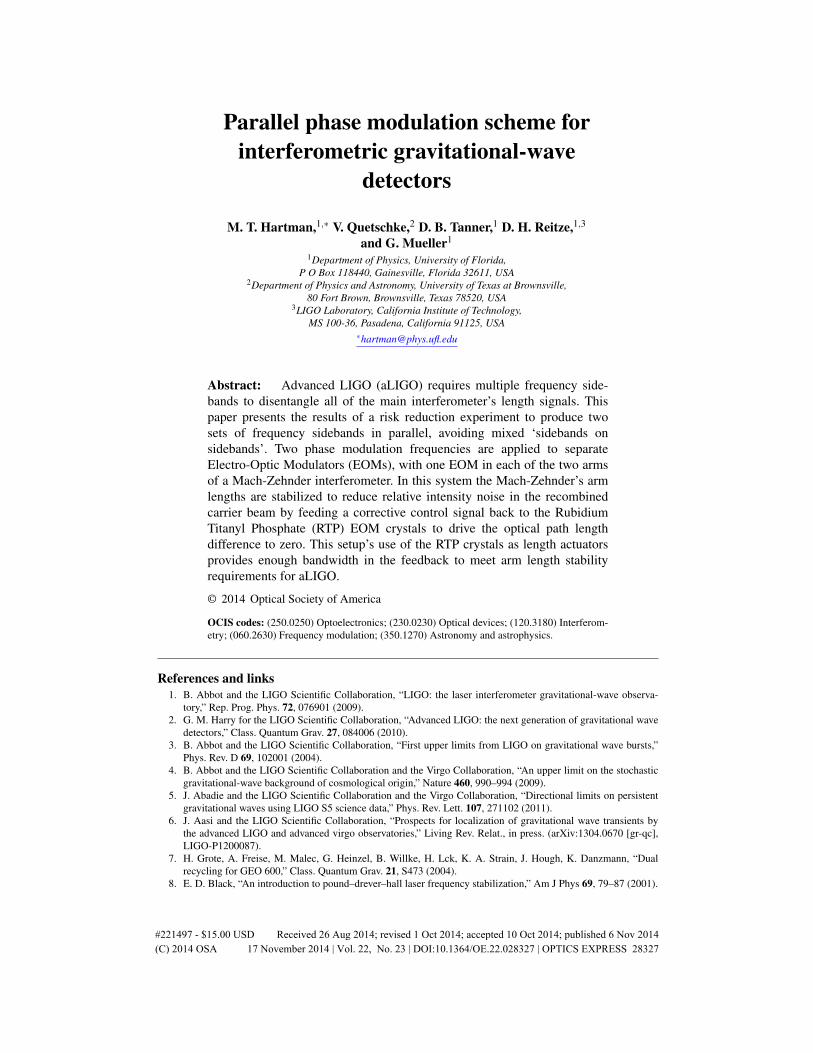
A scheme for producing two sets of frequency sidebands by phase modulating the laserfield in the two arms of a Mach-Zehnder (MZ) interferometer has been explored [11], alongwith the effect of carrier-sideband relative phase noise (due to MZ arm length noise) on aLIGO heterodyne RF-readout scheme. The aLIGO detectors use a homodyne (DC) readout ofDARM, which is less susceptible to carrier-sideband phase noise, but still has a requirementon laser power noise which couples into detector strain noise via radiation pressure noise. Thispaper discusses a novel method for stabilizing MZ arm lengths in a parallel phase modulationscheme as well the effect of MZ differential arm length noise on laser power noise in the contextof the requirements in aLIGO.
Fig. 1. The aLIGO interferometer is composed of the Fabry-Perot arm cavities as well asthe power-recycling and the signal-recycling cavity. Three of the photodetector output portsare labeled: The reflected light pickoff (REFL), the power recycling cavity pickoff (POP),and the interferometer’s anti-symetric port (AS). The carrier (red) and two sidebands (blueand green) are designed to be resonant in different parts of the interferometer.
2. Background
Radio frequency sidebands are imprinted onto the laser carrier by phase modulation in the‘RF Modulation’ portion of the Input Optics shown in Fig. 1. The sidebands are created in anElectro-Optic Modulator (EOM) by passing the laser light through an electro-optic crystal andapplying a time varying electric field (with voltage V1sin(Ω1t)) across the crystal (of thicknessd). The modulated laser field exiting the EOM, Emod1, is the result of the incident laser field(Einc = E0eiω0t ) gaining a time-dependent phase term (m1sin(Ω1t)), with a modulation depth(m1) proportional to the field applied across the crystal and the crystal’s electro-optic coefficient(r). The phase modulated laser field can be expanded in terms of Bessel functions, Jn, using theJacobi-Anger expansion. This shows that for small modulation depths the modulated light iscomposed of three frequency components: the carrier and the two sidebands that are offsetfrom the carrier frequency by the modulation frequency, ± f1 =±Ω1/2π . The amplitude of thefield components are proportional to the Bessel functions of the modulation depth:
Emod1 = E0ei[ω0t+m1 sin(Ω1t)] = E0eiω0t+∞
∑ℓ=−∞
Jℓ(m1)eiℓ(Ω1t)
≈ E0[J0(m1)eiω0t + J1(m1)ei(ω0+Ω1)t − J1(m1)ei(ω0−Ω1)t ] (1)
An illustration of the carrier and sideband spectrum is shown in Fig. 2(a).
#221497 - $15.00 USD Received 26 Aug 2014; revised 1 Oct 2014; accepted 10 Oct 2014; published 6 Nov 2014(C) 2014 OSA 17 November 2014 | Vol. 22, No. 23 | DOI:10.1364/OE.22.028327 | OPTICS EXPRESS 28329
2.1. Phase modulation in aLIGO
The aLIGO interferometer has five main longitudinal degrees of freedom to control [10]. Thesedegrees of freedom (DOFs) are: the differential motion of the interferometer’s arms (DARM),the common motion of the arms (CARM), the length of the short Michelson (MICH), the lengthof the power recycling cavity (PRCL), and the length of the signal recycling cavity (SRCL). TheDOFs are outlined in Table 1.
Relative length information for controlling the optics’ positions is contained in the beatsbetween the different frequency components of the laser. The length error signals for eachdegree of freedom are formed by demodulating the laser at one of the photodetector portswith the appropriate frequency. In order to produce the error signals necessary to control thesedegrees of freedom two sets of frequency sidebands are added to the carrier at f1 ≈ 9 MHz andf2 = 5 f1 ≈ 45 MHz. These sideband frequencies were chosen, along with the lengths of theSignal Recycling Cavity (SRC) and Power Recycling Cavity (PRC), to allow both frequenciesto be resonant in the PRC, but with only f2 resonant in the SRC. The carrier alone is resonantin the two arm cavites (Fig. 1). The arm cavity degrees of freedom are formed by the beatbetween the carrier and itself for DARM and the demodulation of the beat between the carrierand a sideband (Ω1) to produce the CARM error signal. The error signals for the non-arm-cavity degrees of freedom (MICH, SRCL, PRCL) need to be independent of the Fabry-Perotarm lengths. Originally, to produce these non-arm-cavity length signals a double demodulationscheme was proposed. Under this scheme the non-arm-cavity length signals would have beenread from the beat between the two sidebands instead of between the carrier and a sideband [12].The outline of this previous demodulation scheme is given in Table 1.
Table 1. Summary of themajor DOFs in the aLIGO interferometer along with a previousdemodulation scheme for error signal formation. Lengths and ports are defined in Fig. 1.
DOF Length Definition Sensing Port Demod FreqDARM Lx −Ly AS DCCARM Lx +Ly REFL Ω1MICH lx − ly AS Ω1 ⊗Ω2
PRCL lprm +lx+ly
2 REFL Ω1 ⊗Ω2
SRCL lsrm +lx+ly
2 POP Ω1 ⊗Ω2
2.1.1. Modulation in series
The baseline design for aLIGO phase modulation is to produce multiple sidebands by modu-lating the laser in series [13]. A second EOM (driven by V2 sinΩ2t) modulates the output of thefirst EOM, Emod1, given in Eq. (1). This AC voltage causes the laser to pick up a second timedependent phase term (m2 sinΩ2t) which mixes with the first to give the laser field Emod2:
Emod2 = Emod1eim2 sinΩ2t
≈ E0[J0(m1)J0(m2)eiω0t + J0(m1)J1(m2)ei(ω0+Ω2)t − J0(m1)J1(m2)ei(ω0−Ω2)t
+ J1(m1)J0(m2)ei(ω0+Ω1)t − J1(m1)J0(m2)ei(ω0−Ω1)t + J1(m1)J1(m2)ei(ω0+Ω1+Ω2)t
− J1(m1)J1(m2)ei(ω0+Ω1−Ω2)t − J1(m1)J1(m2)ei(ω0−Ω1+Ω2)t + J1(m1)J1(m2)ei(ω0−Ω1−Ω2)t ](2)
where other terms of similar magnitude to J1J1 (ie J0J2) are omitted for brevity. Equation (2)shows the first pair of frequency sidebands are offset from the carrier by Ω1 and have an am-
#221497 - $15.00 USD Received 26 Aug 2014; revised 1 Oct 2014; accepted 10 Oct 2014; published 6 Nov 2014(C) 2014 OSA 17 November 2014 | Vol. 22, No. 23 | DOI:10.1364/OE.22.028327 | OPTICS EXPRESS 28330

Fig. 2. Illustrations of the spectra of light produced by three different modulation schemes.
plitude proportional to J1(m1)J0(m2); likewise, the second pair of sidebands are proportionalto J0(m1)J1(m2). The mixed sidebands, the terms proportional to J1(m1)J1(m2), are termed“sidebands on sidebands”. The spectrum of light modulated in series is illustrated in Fig. 2(b).
A problem arises when series phase modulation is used in a double demodulation schemedue to these sidebands on sidebands producing extraneous length signals of the same order asthe length signals desired for feedback [11]. Double demodulation retrieves length informationstored in the beat between the two sidebands by demodulating first with one and then with thesecond sideband frequency, effectively demodulating at the sum and difference frequency of thetwo sidebands. This produces an error signal whose amplitude is proportional to the product ofthe amplitudes of the two sidebands: errs1×s2 ∝ J1(m1)J0(m2)× J0(m1)J1(m2). When usingseries modulation, sidebands on sidebands are created and exist at the same sum/difference fre-quencies. These sidebands on sidebands beat with the carrier, whose phase information dependson the two arm-cavity DOFs (DARM and CARM). Double demodulation will include this beatand will produce a term that is proportional to the product of the carrier and sidebands on side-bands: errcarrier×sos ∝ J0(m1)J0(m2)× J1(m1)J1(m2). Because the unwanted carrier/sideband-on-sideband term is of the same order as the beat between the sidebands it can be difficultto separate the non-arm-cavity degrees of freedom from the CARM and DARM degrees offreedom; this difficulty was observed at the LIGO 40m prototype at Caltech and is shown inthe large off-diagonal terms of the signal matrix derived from optical simulation in [12]. Themodern baseline length sensing and control scheme does not use double demodulation to formsensing signals for MICH or PRCL. It does demodulate the REFL signal with f2 ∓ f1 fre-quencies for the formation of the SRCL error signals, however, the off-diagonal terms fromsidebands on sidebands in the modeled sensing matrices are small and not expected to be prob-lematic [10]. As a risk reduction experiment, a parallel phase modulator creates two sets offrequency sidebands without sidebands on sidebands.
#221497 - $15.00 USD Received 26 Aug 2014; revised 1 Oct 2014; accepted 10 Oct 2014; published 6 Nov 2014(C) 2014 OSA 17 November 2014 | Vol. 22, No. 23 | DOI:10.1364/OE.22.028327 | OPTICS EXPRESS 28331

2.1.2. Modulation in parallel
Sidebands on sidebands can be avoided using an interferometric parallel phase modulationscheme [12]. An example setup is shown in Fig. 3. The incoming beam is split and modulatedin both arms separately. The beams from the x and y arms being recombined at the beam splitterare described as:
Ex,y =E0√
2e−i(ω0t+m jsinΩ jt+ϕL j), j = 1,2 (3)
where ω0 is the laser carrier frequency, m j is the modulation depth, Ω j is the modulation fre-quency applied in EOM j, and ϕL j is the phase gained by the beam traversing its respectivearm. The beams are then recombined at the beam splitter. The field leaving the interferometer’sbright port (BP) is given by:
EBP = Ex +Ey
≈ E0
2e−iϕL1 [J0(m1)e−iω0t + J1(m1)e−i(ω0+Ω1)t − J1(m1)e−i(ω0−Ω1)t ]
+E0
2e−iϕL2 [J0(m2)e−iω0t + J1(m2)e−i(ω0+Ω2)t − J1(m2)e−i(ω0−Ω2)t ] (4)
The bright port of the interferometer contains the carrier and two sets of sidebands withoutsidebands on sidebands, its spectrum is shown in Fig. 2(c). Parallel phase modulation has beentested [14] and implemented in the LIGO 40 m prototype [15] using a PZT actuated mirror forfeedback to control the Mach-Zehnder’s arm lengths. PZT actuation limited the bandwidth inthe feedback loop, limiting the suppression of differential arm length noise. This paper exploresa setup which uses the modulator’s RTP electro-optic crystals for phase correction allowing formuch greater bandwidth and actuation of the MZ arm lengths at higher frequencies.
Fig. 3. The Mach-Zehnder experimental setup.
3. Mach-Zehnder experimental implementation
A parallel phase modulation scheme would mean adding a new optical system and control loopto the very sensitive aLIGO interferometers. It is thus a fruitful endeavor to have a parallel phasemodulation scheme designed and characterized to meet aLIGO power noise requirements so,should the need arise, it could be implemented without adding excessive noise to the aLIGO
#221497 - $15.00 USD Received 26 Aug 2014; revised 1 Oct 2014; accepted 10 Oct 2014; published 6 Nov 2014(C) 2014 OSA 17 November 2014 | Vol. 22, No. 23 | DOI:10.1364/OE.22.028327 | OPTICS EXPRESS 28332
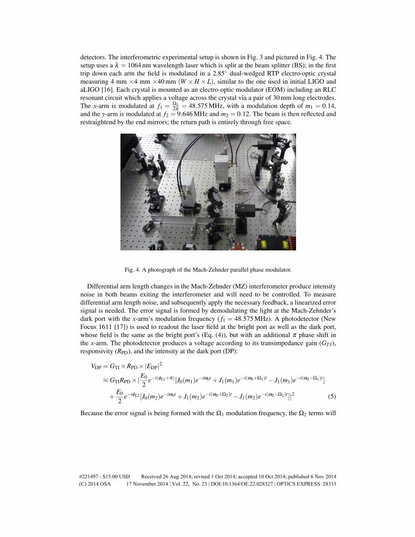
detectors. The interferometric experimental setup is shown in Fig. 3 and pictured in Fig. 4. Thesetup uses a λ = 1064 nm wavelength laser which is split at the beam splitter (BS); in the firsttrip down each arm the field is modulated in a 2.85 dual-wedged RTP electro-optic crystalmeasuring 4 mm ×4 mm ×40 mm (W ×H ×L), similar to the one used in initial LIGO andaLIGO [16]. Each crystal is mounted as an electro-optic modulator (EOM) including an RLCresonant circuit which applies a voltage across the crystal via a pair of 30 mm long electrodes.The x-arm is modulated at f1 = Ω1
2π = 48.575 MHz, with a modulation depth of m1 = 0.14,and the y-arm is modulated at f2 = 9.646 MHz and m2 = 0.12. The beam is then reflected andrestraightend by the end mirrors; the return path is entirely through free space.
Fig. 4. A photograph of the Mach-Zehnder parallel phase modulator.
Differential arm length changes in the Mach-Zehnder (MZ) interferometer produce intensitynoise in both beams exiting the interferometer and will need to be controlled. To measuredifferential arm length noise, and subsequently apply the necessary feedback, a linearized errorsignal is needed. The error signal is formed by demodulating the light at the Mach-Zehnder’sdark port with the x-arm’s modulation frequency ( f1 = 48.575 MHz). A photodetector (NewFocus 1611 [17]) is used to readout the laser field at the bright port as well as the dark port,whose field is the same as the bright port’s (Eq. (4)), but with an additional π phase shift inthe x-arm. The photodetector produces a voltage according to its transimpedance gain (GT I),responsivity (RPD), and the intensity at the dark port (DP):
VDP = GTI ×RPD ×|EDP|2
≈ GTIRPD ×|E0
2e−i(ϕL1+π)[J0(m1)e−iω0t + J1(m1)e−i(ω0+Ω1)t − J1(m1)e−i(ω0−Ω1)t ]
+E0
2e−iϕL2 [J0(m2)e−iω0t + J1(m2)e−i(ω0+Ω2)t − J1(m2)e−i(ω0−Ω2)t ]|2 (5)
Because the error signal is being formed with the Ω1 modulation frequency, the Ω2 terms will
#221497 - $15.00 USD Received 26 Aug 2014; revised 1 Oct 2014; accepted 10 Oct 2014; published 6 Nov 2014(C) 2014 OSA 17 November 2014 | Vol. 22, No. 23 | DOI:10.1364/OE.22.028327 | OPTICS EXPRESS 28333

not show up after mixing and filtering so we can ignore the Ω2 terms:
VDP = GTIRPDP0
42+ J0(m1)[e−i(ϕL1−ϕL2+π)+ ei(ϕL1−ϕL2+π)]
+2J1(m1)sin(Ω1t)[ei(ϕL1−ϕL2+π)− e−i(ϕL1−ϕL2+π)]
VDP = GTIRPDP0
21+ J0(m1)cos(∆ϕ +π)−2J1(m1)sin(Ω1t)sin(∆ϕ) (6)
where P0 is the laser power entering the interferometer and ∆ϕ = ϕL1 −ϕL2 is the phase differ-ence between the recombined beams. The error signal is formed by demodulating and filteringthe dark port signal with the original modulation signal, sin(Ω1t +ϕEO), where ϕEO is demod-ulation phase difference. This gives the error signal:
Verr =P0
2GTIRPDJ1(m1)cos(ϕEO)sin(∆ϕ) (7)
The demodulation phase ϕEO can easily be zeroed, by either adding appropriate length of cableor using a phase shifter, maximizing the error signal slope. The error signal is a sine function ofthe path length difference between the two arms and has the needed zero crossing and linearityat the dark fringe to be an effective feedback control signal. This error signal has the advantageof an infinite locking range, allowing the arm length difference to be pushed to zero startingfrom any microscopic path length difference, but the disadvantage of having a relatively smallerror signal slope compared to other demodulation techniques, such as finesse enhanced Fabry-Perot cavity phase demodulation. A similar signal can be derived at the bright port.
10-15
10-14
10-13
10-12
10-11
10-10
10-9
10-8
100
101
102
103
104D
iffe
ren
tial
Arm
No
ise
[m /
sq
rt(H
z)]
Frequency [Hz]
Free Running Mach-Zehnder Length Noise
Dark-Port Demod 48MHzBright-Port Demod 9MHz
Fig. 5. Differential arm noise of the free-running Mach-Zehnder measured by demodulatingthe bright and dark ports (purple and green) at 48.575 and 9.646 MHz respectively.
The linear portion of the dark and bright-port demodulated error signals were independentlycalibrated then simultaneously measured in time; computing the power spectral density of theselength fluctuations reveals the frequency components of the free-running Mach-Zehnder’s dif-ferential arm length changes in open air (Fig. 5). The agreement between the dark and brightport demodulated signals indicate the error signals are dominated by the actual length noisesignal and that the error signals are well calibrated.
The electro-optic crystals used for modulation are also used as length actuators in the armlength feedback system. Applying the control signal’s voltage across the crystal changes its
#221497 - $15.00 USD Received 26 Aug 2014; revised 1 Oct 2014; accepted 10 Oct 2014; published 6 Nov 2014(C) 2014 OSA 17 November 2014 | Vol. 22, No. 23 | DOI:10.1364/OE.22.028327 | OPTICS EXPRESS 28334
index of refraction. This adjusts the arm’s optical path length, compensating for the arm lengthchanges. We used Rubidium Titanyl Phosphate (RTP) crystals obtained from Raicol [18], withthe same dimensions and material as the electro-optic crystals used in aLIGO. The Sellmeiercoefficients for the index of refraction have been measured for RTP [19] to give an index ofrefraction n0z = 1.8580 at 1064nm. The electro-optic coefficient r33 has been measured in therange from 520 to 930 nm [20]; using these fitted Sellmeier coefficients gives an EO coefficientof r33 = 34.35 pm
V at 1064nm.In order to make use of the largest electro-optic coefficient, r33, the laser propagates through
the crystal with polarization in the z-direction (p-polarization) and has the external drivingelectric field in the z-direction (Ez). It is convenient to describe the response of EO crystals interms of the voltage required to produce an optical path length change of λ
2 or π radians:
Vπ =λd
n30zr33L
(8)
where d = 4 mm is the crystal thickness and L = 30 mm is the length of the electrodes applyingthe field across the crystal. We measured the response of the crystals by driving the crystalswith a triangular wave with an amplitude of A = 2kV and frequency of fd , producing fringesat a rate of f f = fd
2AVπ
and monitoring the fringes by DC readout of the Mach-Zehnder. Thisproduced a measured response in the aLIGO frequency band of Vπ ≈ 660 V for one crystal,or ≈ 330V for two crystals in a push-pull configuration. We observed a yet unexplained 10%decrease in the responsivity of the crystals when driven below 1 Hz.
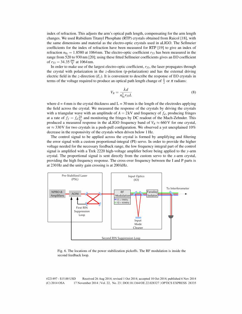
The control signal to be applied across the crystal is formed by amplifying and filteringthe error signal with a custom proportional-integral (PI) servo. In order to provide the highervoltage needed for the necessary feedback range, the low frequency integral part of the controlsignal is amplified with a Trek 2220 high-voltage amplifier before being applied to the y-armcrystal. The proportional signal is sent directly from the custom servo to the x-arm crystal,providing the high frequency response. The cross-over frequency between the I and P parts isat 230 Hz and the unity gain crossing is at 200 kHz.
Fig. 6. The locations of the power stabilization pickoffs. The RF modulation is inside thesecond feedback loop.
#221497 - $15.00 USD Received 26 Aug 2014; revised 1 Oct 2014; accepted 10 Oct 2014; published 6 Nov 2014(C) 2014 OSA 17 November 2014 | Vol. 22, No. 23 | DOI:10.1364/OE.22.028327 | OPTICS EXPRESS 28335

10-15
10-14
10-13
10-12
10-11
10-10
10-9
10-8
100
101
102
103
104
Dif
fere
nti
al A
rm N
ois
e [m
/ s
qrt
(Hz)
]
Frequency [Hz]
Mach-Zehnder Differential Arm Noise
Free-Running Arm NoiseCalculated In-Loop
Measured In-LoopMeasured Out-of-Loop
RIN Requirements
Fig. 7. The Mach-Zehnder’s measured closed-loop differential arm noise (In-loop (Blue)and Out-of-loop (Red)). The calculated level of suppressed noise (Cyan) is based on thefeedback and the free-running noise (Magenta). The requirement for aLIGO, based on theequivalent RIN produced from MZ differential arm motion, is shown in Black.
4. Results and conclusion
Feedback is necessary to stabilize the Mach-Zehnder’s arm lengths and reduce fluctuationsin the laser power leaving the interferometer. The transfer function of aLIGO’s laser’s relativeintensity noise (RIN) to aLIGO’s strain sensitivity shows that laser power noise couples to strainnoise at low frequencies mostly through radiation pressure imbalance in the two arms [21].LIGO’s technical noise requirement (that no technical noise source should produce more than10% of the aLIGO design strain noise) puts a noise limitation on the RIN of the laser enteringthe aLIGO interferometer of 2×10⁻⁹ Hz−1/2 at 10 Hz.
The power stabilization in aLIGO consists of two feedback loops, shown in Fig. 6. Thefirst loop reduces power noise down to 2×10⁻⁸ Hz−1/2 at 10 Hz, and a second feedback loopwill reduce it further to the interferometer’s requirement. LIGO’s RF modulation lies after thefirst power stabilization loop, but inside the second power stabilization loop. The goal of theMach-Zehnder’s arm length stabilization is to reduce length noise such that intensity noise inthe LIGO band due to the Mach-Zehnder’s arm length noise is not a burden on the secondpower stabilization loop. The power exiting the Mach-Zehnder interferometer as a function ofits differential arm length, ∆L, is:
P(∆L) =P0
2[1+ cos(
2πλ
∆L)] (9)
To calculate the RIN due to Mach-Zehnder arm length noise, δL, we expand this about thedifferential arm locking point, LRMS, which gives
RIN =2π2
λ 2 LRMSδL (10)
#221497 - $15.00 USD Received 26 Aug 2014; revised 1 Oct 2014; accepted 10 Oct 2014; published 6 Nov 2014(C) 2014 OSA 17 November 2014 | Vol. 22, No. 23 | DOI:10.1364/OE.22.028327 | OPTICS EXPRESS 28336
where LRMS, the rms distance of the locking point from the dark fringe, is due to the unavoidable(but suppressed) RMS of the differential arm noise as well as any possible unwanted electronicoffset. LRMS was measured to be 0.3 nm, giving the RIN equivalent length noise requirementseen in Fig. 7.
The closed loop differential arm noise was measured by recording the in-loop and out-of-loop length error signals. Figure 7 shows that the linear spectral density of the in-loop errorsignal (blue) is reduced to the level calculated (cyan), based on the free-running length noise(magenta) and the feedback components’ transfer functions. The actual differential arm lengthnoise is best seen in the out-of-loop noise spectrum (red). This meets, by a factor of 5 at lowfrequencies and 30 at high frequencies, the arm length stability requirements (black) to notinduce excessive power fluctuations in the laser carrier entering the gravitational wave detectorinterferometer.
Mechanical resonances of the optics can be seen as peaks in the hundred hertz through kilo-hertz range, most notably the lines at 680 and 550 Hz corresponding to the resonance of x andy end mirrors of the Mach-Zehnder. These are excited acoustically and scale with this environ-mental noise. The feedback servo was designed specifically to bring these peaks down to therequirement level, and in the unlikely case the environment is noisier at the gravitational-wavedetector more gain can be added in the Mach-Zehnder feedback loop. The gain at these higherfrequencies is enabled by this setup’s use of the electro-optic crystals as high-speed length ac-tuators. This allowed us to achieve a unity gain frequency of 200 kHz, an order of magnitudehigher than the PZT actuated parallel modulation scheme [11]. The level of noise suppressionthrough the entire aLIGO band makes this setup a tested and viable solution for creating multi-ple RF sidebands without sidebands on sidebands, should the need arise.
Acknowledgments
This work was supported by NSF grants PHY-0969935 and PHY-1205512. The authors grate-fully acknowledge fruitful discussions within the LIGO Scientific Collaboration about thiswork.
#221497 - $15.00 USD Received 26 Aug 2014; revised 1 Oct 2014; accepted 10 Oct 2014; published 6 Nov 2014(C) 2014 OSA 17 November 2014 | Vol. 22, No. 23 | DOI:10.1364/OE.22.028327 | OPTICS EXPRESS 28337
Related Documents