NASA Technical Paper 3429 Parallel Grid Generation Algorithm for Distributed Memory Computers Stuti Moitra and Anutosh Moitra February 1994

Welcome message from author
This document is posted to help you gain knowledge. Please leave a comment to let me know what you think about it! Share it to your friends and learn new things together.
Transcript

NASA Technical Paper 3429
Parallel Grid Generation Algorithmfor Distributed Memory Computers
Stuti Moitra and Anutosh Moitra
February 1994

NASA Technical Paper 3429
Parallel Grid Generation Algorithmfor Distributed Memory ComputersStuti MoitraLangley Research Center � Hampton, Virginia
Anutosh MoitraHigh Technology Corporation � Hampton, Virginia
National Aeronautics and Space AdministrationLangley Research Center � Hampton, Virginia 23681-0001
February 1994


The use of trademarks or names of manufacturers in this
report is for accurate reporting and does not constitute an
o�cial endorsement, either expressed or implied, of such
products or manufacturers by the National Aeronautics and
Space Administration.
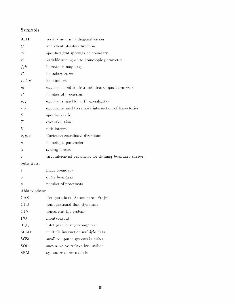
Symbols
A;B vectors used in orthogonalization
C analytical blending function
ds speci�ed grid spacings at boundary
E variable analogous to homotopic parameter
f; h homotopic mappings
H boundary curve
I; J; K loop indices
m exponent used to distribute homotopic parameter
P number of processors
p; q exponents used for orthogonalization
r; s exponents used to remove intersection of trajectories
S speed-up ratio
T execution time
U unit interval
x; y; z Cartesian coordinate directions
� homotopic parameter
� scaling function
� circumferential parameter for de�ning boundary shapes
Subscripts:
i inner boundary
o outer boundary
p number of processors
Abbreviations:
CAS Computational Aerosciences Project
CFD computational uid dynamics
CFS concurrent �le system
I/O input/output
iPSC Intel parallel supercomputer
MIMD multiple instruction multiple data
SCSI small computer systems interface
SOR successive overrelaxation method
SRM system resource module
iii

Summary
A careful examination of the algebraic schemefor grid generation based on homotopic relations hasrevealed highly parallelizable characteristics. Im-plementation of this parallel scheme on the InteliPSC/860 computer has resulted in e�cient soft-ware that demonstrates good correlation of speed-up ratios with the number of processors used. Thesoftware accepts discrete point data sets as inputgeometries. It also generates blended wing-body con-�gurations by a semianalytic procedure. The Intelconcurrent �le system (CFS) is used for e�cient im-plementation of parallel I/O operations. The num-ber of points in each coordinate direction is normallychosen to be a multiple of the number of processorsfor perfect scalability; however, this is not a strictrequirement. The algebraic procedure for grid gener-ation is explicit and therefore requires minimal inter-processor communication overhead. The grid is gen-erated in cross-sectional planes that are stacked alongthe longitudinal axis of the input geometry to pro-duce a quasi-three-dimensional grid system. Multiplelevels of parallelism are investigated in this report. Inthe �rst level of parallelism, the cross-sectional planesare distributed over the processors in an interleavedmanner. The second level of parallelism is achievedby distributing the radial lines of a cross-sectionalplanar grid over the processors. The Express1 systemof software tools has been used to enhance portabilityof the grid-generation software. The Express versionof the code has been implemented successfully on theIntel iPSC/860 computer as well as a network of Sunworkstations. Test cases for the programming modesconsist of a blended wing-body con�guration in thecase of the analytically generated input geometry anda high-speed civil-transport con�guration for the dis-crete case. The analytical geometry is de�ned by64 cross-sectional planes, each containing 32 pointsalong the circumference. The discretely de�ned geo-metry contains 64 cross-sectional planes, each with42 circumferential points on the surface. The num-ber of grid points in the radial direction is 49 in bothcases. All cases demonstrate the parallel behavior ofthe software in all programming modes and on allhardware platforms used.
Introduction
Grid generation is an indispensable pre-requisite for computational uid dynamics (CFD) re-search. Given the importance and computationallyintensive nature of the grid-generation process, evi-dence of parallel grid-generation methods in existingliterature is surprisingly scant.
1 Express is a registered trademark of ParaSoft Corporation.
Current grid-generation methods are essentiallysequential. These methods generally compute near-orthogonal trajectories that span the gap betweenspeci�ed inner and outer boundaries. Computa-tion of each point on a trajectory is usually heav-ily dependent on the coordinates of the neighboringpoints. The dependence is larger for grid genera-tors employing systems of partial di�erential equa-tions than for those generators based on algebraicinterpolation schemes; nevertheless, parallelization ofthe scheme in either case generally involves exten-sive communication between processors to transferrelevant information about surrounding points.
In view of the CFD issues outlined by Holst et al.(ref. 1), development of advanced parallel algorithmsfor generating grids for computation of ows aboutaerospace vehicles is a major requirement. The ad-vent of high-performance parallel computers has al-ready prompted substantial research in the realm ofparallel ow solvers. In comparison, the develop-ment of parallel grid-generation methods is laggingbehind. Future time-dependent multidisciplinary ap-plications in the NASA Computational AerosciencesProject (CAS) require integrating a regridding stepinto the CFD simulation software in order to re ectchanges in aircraft location and aerodynamic controlsurface positions. This goal can only be achieved bydeveloping parallel grid-generation algorithms thatcan be coupled with parallel ow solvers for executionon massively parallel computers.
One parallel scheme for grid generation consists ofdecomposing the computational domain into as manyparts as there are processors in the hardware and dis-tributing the computational work for these parts asevenly as possible among the processors. A broadoverview of the desirable characteristics of parallelgrid-generation systems has been given by Gentzsch(ref. 2). The levels of performance of these systemsare mainly determined by four factors: (1) the de-gree of parallelism in the algorithm, (2) the evennessof computational load balancing, (3) the amount ofinterprocessor communication necessary, and (4) cor-relation of performance with the number of proces-sors. In the ideal system, these requirements are inperfect harmony. Most currently available serial orvector algorithms are not optimally suited for achiev-ing this harmony. These existing algorithms were de-veloped for scalar computers and are often di�cultto parallelize because of their sheer complexity, (e.g.,their implicitness, nonlinearity, and recursion). It isimperative that future research be directed towarddevelopment of special parallel algorithms that fa-cilitate near-optimal mapping of advanced hardwareand topology. This goal can be met by simple explicit

algorithms that minimize interprocessor communica-tion. Parallel implementation of such methods en-tails little more than distributing the main loop indexover the processors.
A parallel grid-generation scheme must addressseveral key issues unique to problems of computa-tional geometry and grid generation. Generally, astructured grid must be body conforming, smoothlyvarying, properly clustered, and nearly orthogonalat relevant boundaries. In addition, the grid mustnot be discontinuous or overly skewed, and it shouldnot waste points in regions of the domain where lit-tle change in the relevant physical properties takesplace. The above considerations make it clear thatgrid generation often necessitates a global knowledgeof the domain to be generated. However, this globalconcept is di�cult to maintain when the domain isdecomposed and distributed to individual processorsand constitutes a major obstacle in developing trulyparallel grid-generation algorithms.
Two implementations of a structured grid-generation algorithm that solve partial di�erentialgoverning equations by a successive overrelaxation(SOR) method have been reported by Gentzsch andH�auser (ref. 2). The �rst implementation on theAlliant FX/80 shared memory computer is based ondividing the computational domain into smaller por-tions, which are simultaneously processed on indi-vidual processors. Each �rst and last inner grid lineof a partition is a boundary grid line of the neigh-boring partitions. After each iteration of the SORalgorithm, the boundary data are exchanged amongneighboring grids through interprocessor communi-cation. A synchronization point is needed at the endof every iteration to ensure that all segments beginthe next iteration with updated boundary data. Thesecond implementation is for the distributed mem-ory, tree-structured system TX3 of iP-Systems. Inthis model, the problem is successively divided intotwo subtasks of identical complexity. Because thepartitioning of the complex physical domain is highlyunstructured, the organization of the communicationpattern between the processors is a complex task.
A parallel algorithm for automatic mesh re�ne-ment has been presented by Berger (ref. 3). Thisscheme uses nested grids with recursively re�nedmesh spacings in regions where greater resolution isneeded in the solution. The �ner grids are super-imposed on the underlying coarser grids. A binarydecomposition technique is used to partition the do-main so that the workload is distributed as evenly aspossible. An a priori estimate of the computationalwork over the entire domain is essential for applyingthis technique. The partition is a function of time
because a repartitioning is necessary whenever thegrid hierarchy is changed.
L�ohner et al. (ref. 4) have reported an interestingalgorithm for parallel unstructured triangular grids.This algorithm is based on an advancing front tech-nique for �lling empty space that introduces pointswith distribution prescribed by background grids. Acrucial condition for achieving parallelism is that theneighborhoods of the points to be introduced do notoverlap. Therefore, distance enables parallelism. Un-structured grids are free from the constraints of or-thogonality and continuity of grid lines. However,smoothness of variations in shape and size of gridcells is still a constraint. A Laplace smoother is usedin each subdomain to improve the uniformity of thegrid. A communication scheme for exchange of infor-mation between processors allows movement of theboundary points at subdomain interfaces. This al-gorithm has been implemented with the host-nodeprogramming model on the Intel hypercube.
The algorithm presented in this paper employs analgebraic homotopic procedure that develops into acompletely explicit numeric scheme. (A homotopy isessentially a family of maps of smooth lines betweentwo given surfaces.) The maps are generated by thesmooth variation of a parameter in a unit intervalbetween the given surfaces. The resulting procedureis inherently parallel. This algorithm has been im-plemented on the Intel iPSC/860 hypercube machineand a network of Sun workstations. A sequential ver-sion of the algorithm (refs. 5 and 6) has been usedfor high-speed ow simulation for aircraft over thepast several years. The basic method, which is com-pletely explicit, allows arbitrary decomposition of thedomain into blocks that can be processed on individ-ual processors in parallel. The software has a built-inprovision for analytically generating blended wing-body surface geometries, but it also accepts inputgeometries speci�ed as a set of discrete points. Thegrid generation scheme uses a homotopic blendingtechnique for generating surfaces between the bodysurface and a speci�ed outer boundary surface whilemaintaining near-orthogonal trajectories in the vicin-ity of the body surface. The grid is generated incross-sectional planes along the longitudinal axis ofthe input geometry. For the analytically generatedinput geometry, the schemes for generating the bodysurface and the grid points can be integrated into oneprocedure that allows the computation of each gridpoint independently of other grid points. Any re-quired boundary data can be generated in each indi-vidual processor, thus virtually eliminating the needfor expensive interprocessor communications. In the
2

discrete case, necessary boundary data can be readin parallel into each processor from the CFS.
Theory and Mathematical Development
Grid Generation
The grid is generated through determination ofa family of curves representing a smooth and grad-ual transition from the given inner boundary (xi; yi)to the outer boundary (xo; yo) in two-dimensionalplanes at each z-station. Assuming that the bodysurface coordinates are available, either as an ana-lytic description or as a set of discrete points, a distri-bution of a homotopic parameter � is speci�ed. The� distribution may be speci�ed by means of poly-nomials, exponents, or trigonometric functions whileensuring that � = 0 on the body surface and � = 1 onthe outer boundary. A shape transition function C
for the grid is then speci�ed by
C(�) = 1� �m (1)
where m is a positive exponent providing control overline spacing near boundaries. Thus C = 1 on the in-ner boundary and C = 0 on the outer boundary, witha smoothly varying distribution between boundaries.The function C is taken to be independent of z; itretains the same value at each z-station. Essentiallythe transition curves are de�ned by a family of mapsgiven by the homotopy�
h� : A! Bj�"U
(2)
where U is the unit interval [0; 1]. The inner andouter boundaries Hi and Ho are two homotopic mapssuch that ho = Hi and h1 = Ho. A scaling func-tion � for the grid lines is then de�ned such that�i < � < �o, where �i and �o are the scaling functionvalues associated with the inner and outer bound-aries. Since the size of the inner surface and possiblythat of the outer surface vary with z, � is not inde-pendent of z. The grid is de�ned at each z-stationin terms of the functions C(�) and �(�), and a nat-ural correspondence is established between the gridpoints at the various z-stations. Coordinates of eachboundary are expressed in terms of a parameter � .For the inner boundary
xi = xi(�)
yi = yi(�)
)(3)
and similar expressions denote the coordinates ofthe outer boundary. In polar coordinates, � couldrepresent the angular coordinate. If y can be ex-pressed as a single-valued function of x, then � = x.
For shapes of greater complexity, the choice of vari-ables varies. An arithmetic averaging between theboundaries yields the simplest family of grid linesgiven by
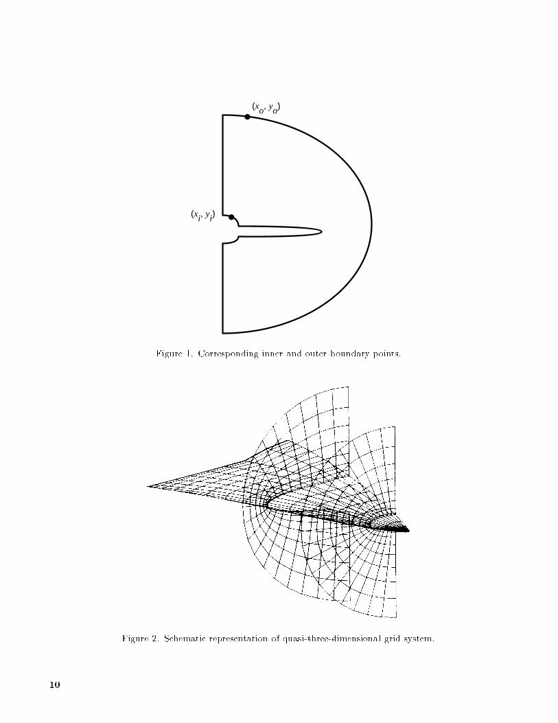
x(�; � ) = �fC(�)xi(� ) + [1�C(�)] xo(� )g
y(�; � ) = �fC(�) yi(� ) + [1�C(�)] yo(� )g
)(4)
where (xi; yi) and (xo; yo) are corresponding pointson the inner and outer boundaries, as shown in �g-ure 1. Geometric averaging may be used for smoothertransition in cases involving complex geometries withsharp corners.
Smooth variations of the inner and outer bound-aries with respect to z results in smoothly varyinggrid lines in the z-direction. Particular constant val-ues of the �-parameter generate speci�c curves ofthe family described by equations (4), and a pre-chosen distribution of � determines the spacing ofthe resulting set of curves in each cross-sectionalplane. Judicious modi�cations of the function C(�)and the distribution of � result in approximate or-thogonality of grid lines at physical boundaries andconcentration of grid lines near boundaries. The pla-nar grids are stacked along the Z-axis to produce athree-dimensional grid system, as shown in �gure 2.
Orthogonality and Spacing Control
Orthogonality and prescribed spacing near phys-ical boundaries are two important characteristics ofgrid systems used in CFD studies. The grid mustalso be smooth and free from intersecting grid linesof the same family. The present method providesorthogonality and control over spacing while main-taining smoothness and preventing grid intersectionsby a technique for local perturbation of the homo-topic parameter. The required amount of perturba-tion is derived from the boundary data exploiting thestability properties of homotopic maps under pertur-bation. A property is said to be stable if whereverfo : x! y possesses the property and ft : x! y is ahomotopy of fo, then for some " > 0, each ft witht < " also possesses the property. The properties ofsmoothness of the grid and conformity of the over-all grid with the given boundaries are stable underslight deformations of the map caused by small per-turbations of the homotopic parameter. The basicinterpolation scheme, equations (4), may be writtenin a modi�ed form as
x = xiEp+ xo(1�Ep)
y = yiEq + yo(1� Eq)
)(5)
3

where
E = 1� �m (6)
The subscripts i and o denote the inner and outerboundaries. Here E is analogous to a homotopicparameter. Modi�cations of E , therefore, causeslight deformations of a given map and may beused to achieve orthogonality and prescribed spacingat the inner boundary. This control is providedthrough the use of the exponents p and q. Theseexponents are not constants and their values mustbe determined from the boundary data subject to theconstraints of orthogonality and required spacing.
The orthogonality condition requires that the vec-tors A and B in �gure 3 be orthogonal. The vectorAis found by connecting the point (xi; yi) on the in-ner boundary and the point (x; y) lying just o� theboundary on the trajectory in question. The secondvector B passes through the point (xi; yi) and a point(x0; y0) on the line passing through (xi; yi) and par-allel to the line joining (xi+1; yi+1) and (xi�1; yi�1)on the inner boundary. The orthogonality conditionis satis�ed if the dot product of the vectors A and Bis zero, that is,
A �B = 0 (7)
which translates to
(x� xi)�x0 � xi
�+ (y � yi)
�y0 � yi
�= 0 (8)
Substituting equations (5) into equation (8) oneobtains
(xo � xi) (1�Ep)�x0� xi
�+ (yo� yi) (1�Eq)
�y0� yi
�= 0
(9)
The second condition, that of speci�ed spacing ds in�gure 3, can be written as
(x� xi)2+ (y � yi)
2 = ds2 (10)
Substitution of equations (5) into equation (10) re-sults in
[(xo � xi) (1� Ep)]2 + [(yo � yi) (1� Eq)]2 = ds2
(11)
The exponents p and q can be solved from equa-tions (9) and (11) and are given by
p =lnf1 +B(y0 � yi)
�[(xo� xi)(x
0 � yi)]g
lnE(12)
and
q =lnf1� [B=(yo � yi)]g
lnE(13)
where
B =dsq
1 + (y0 � yi)2�(x0 � xi)2
(14)
and E has the value corresponding to the homotopiccurve lying next to the inner boundary. The valuesof p and q given by equations (12) and (13) will resultin constant spacing ds between the �rst homotopiccurve and the boundary as well as near orthogonalitybetween the trajectory emanating from (xi; yi) andthe inner boundary.
Strict imposition of orthogonality in regions ofhigh boundary curvature often results in intersectionof the trajectories. Intersecting trajectories can beseparated through modi�cation of p and q by the useof further exponents r and s, such that
x = xiEpr
+ xo(1�Epr
) (r < 1:0)
y = yiEqs
+ yo(1� Eqs
) (s < 1:0)
)(15)
Using constant values for r and s, however, reducesorthogonality. In order to maintain orthogonalitynear the boundary, r and s are made to decay as oneproceeds along trajectories outward from the innerboundary. This decay is achieved by making r and s
functions of E such that r and s = 1 at the innerboundary and r and s = 0 at the outer boundary.
Surface Geometry De�nition
As mentioned before, the input surface geometrymay be de�ned either analytically or discretely. Inthe analytic case any explicit analytic formula maybe used. A semianalytic method for de�ning blendedwing-body con�gurations has been described in refer-ence 5. The analytic expressions for surface de�nitioncan be integrated into the grid-generation scheme toproduce one set of governing equations for de�ningany grid point. The exact form of these analytic ex-pressions is of no consequence to the grid-generationscheme. In the discrete case, all that is required isthat the surface be de�ned as an ordered set of pointsdescribing each cross section of the geometry.
Parallel Hardware Platforms
The grid-generation software was implemented ontwo MIMD platforms. One of them was the InteliPSC/860 computer and the other was a network ofSun workstations con�gured to simulate a MIMDsystem. Salient features of the two systems arediscussed below.
4
Intel iPSC/860
The Intel iPSC/860 is based on a 64-bit 40-MHzi860 microprocessor. A single computational node ofthe Langley iPSC/860 system consists of the i860,8 MB dynamic random access memory, and hard-ware for communication with other nodes. The sys-tem consists of 32 computational nodes arrangedin a 5-dimensional hypercube using the direct con-nect routing module and the hypercube interconnecttechnology of the earlier 80386-based iPSC/2. Thepoint-to-point aggregate bandwidth is 2.8 MB/secper channel and the latency for message passing isabout 74 �s for message lengths over 100 bytes. Inter-processor communication takes place through thesend and receive system calls. Any processor cansend a message to any other processor; however, thedestination processor does not acquire the messageunless it issues a receive. The message passing proto-cols are implemented with software resulting in highcommunication overhead.
The complete system is controlled by a systemresource module (SRM), which is based on an Intel80386 processor. This system handles compilationand linking of source programs as well as loading ofthe executable code into the hypercube nodes andinitiating execution.
Network of Sun Workstations
A collection of Sun workstations was used inthis study as an alternative parallel computing plat-form. The Express programming environment al-lows con�guration of a group of networked Sun work-stations in order to emulate a multinode parallelcomputer. Each individual workstation serves asone node of the resulting parallel system. In thepresent study, a total of eight dissimilar Sun work-stations were used. The collection consisted of oneSPARCstation 2, two SPARCstation SLC's, and �veSPARCstation IPC's. The workstations were con-nected to each other via Ethernet sockets. Inter-process communications among Express programsrunning on the network are performed using stan-dard UNIX shared memory and semaphore opera-tions. The three classes of workstations used in thisstudy are characterized by widely di�erent processingspeeds.
Programming Models
The grid-generation software was implementedusing the node programming model under the na-tive Fortran environment on the iPSC/860. Theequivalent model in the Express environment iscalled the cubix model. This programming modelis characterized by the following features:
1. There is no host or master controller program.
2. A single program is written and compiled.
3. This program is loaded into all nodes.
4. The program executes independently on eachnode.
5. The nodes operate independently on their owndata.
6. Nodes share data through message passing.
The most important bene�t of this programmingmodel is that the underlying code is essentially thesame as if it were executing on a conventional se-quential computer. This permits the programmer toutilize usual intuitions when writing, developing, anddebugging the code.
Parallel Algorithm and Notes on
Implementation
Parallelism
The main grid-generator equations are given bythe algebraic relations in equations (15). Once thesurface geometries have been speci�ed either ana-lytically or discretely, all parameters can be gener-ated by explicit algebraic formulas. The completegrid-generation procedure is therefore explicit andconsequently inherently parallelizable. This inher-ent parallelism is exploited by devising a strategyfor dividing the algorithm into several independentprocesses to run simultaneously on many processors.The strategy consists of mapping the grid onto a reg-ular computational domain and splitting this domainso that
1. The load on the processors is balanced.
2. Communication among processors is minimized.
For the present algorithm, satisfaction of these re-quirements is straightforward. To achieve the �rstgoal, the region is subdivided into a number of sub-regions that equals the number P of processors inthe parallel system. The completely explicit natureof the algorithm allows this partitioning to be donein a way that ensures equal amounts of computa-tion in all subregions. The initial surface data arethe only relevant data required by the processors.Once these data have been read or generated analyt-ically, the computation of each subregion proceedsindependently and requires no interprocessor com-munication. In the present study, the partitioningstrategy was applied at two levels of parallelism, aslisted below:
5
1. At the primary level of parallelism, each planargrid is computed on a di�erent processor of thedistributed computing system (�g. 4).
2. At the secondary level of parallelism, each pla -nar grid is broken into several segments. Eachsegment is a collection of several radial lines ofthe planar grid. These segments are processed inparallel on di�erent processors (�g. 5).
Partitioning of the grid at levels 1 and 2 can be di-rectly a�ected by simply distributing relevant loopindices over the processors. The main body of thecomputation is comprised of a three-level nested loop.Let us denote the loop indices by I, J , and K. Theindex I is associated with the outermost loop and de-notes the number of planar grids in the grid system.The indices J and K are associated with the inter-mediate and inner loops and they denote the circum-ferential and radial points, respectively, in a planargrid. Partitioning at level 1 entails distributing theI index in an interleaved fashion over the processors.Level 2, in turn, requires an interleaved distributionof the J index. The particular values of the distrib-uted index of any processor can be easily computedin individual processors as a function of the proces-sor number and the maximum value of the index inthe grid system. According to this strategy the codeloaded into each processor is essentially identical.
Input/Output
At the end of the computation, the distributedgrid segments processed on di�erent processors mustbe collected in one place to store the ordered ag-gregate grid system for later use. The usual wayof accomplishing this is to have each processor sendits portion of the grid to a master node via inter-processor communication. This collection results insubstantial communication overhead. In the presentstudy the need for this expensive communicationhas been obviated by implementing the collectionprocedure by means of the CFS available on theiPSC/860 computer. The CFS provides the nodeswith high-speed simultaneous access to secondarystorage. Files reside on a number of disks that con-nect to the hypercube through SCSI's on I/O nodes.A concurrent �le is distributed over the disk drivesin blocks ordered in a round-robin fashion.
Parallel read and write statements for the CFSsystem are available under both the native Intel pro-tocol and the Express protocol. The input geom-etry for the discretely de�ned body surface is readinto each node using the parallel read operation. Forlevel 1 parallelism, illustrated in �gure 4, surface datafor sections belonging to each node are read simulta-neously. Under the Intel protocol the read operation
loads consecutive blocks of data of a speci�ed blocksize into the nodes in the order of increasing nodenumbers. This order has the e�ect of distributing thesections over the processors in an interleaved fashion;hence, there is need for an interleaved distribution ofthe I index. The Express implementation requires anadditional seek operation to determine the startingaddress of the block to be read into each node. In thecase of level 2 parallelism, illustrated in �gure 5, allsurface points de�ning one cross section of the geom-etry are read into each node even though the nodesprocess only a portion of the sectional grid. Thisstep is done to eliminate interprocessor communica-tion that would be required for transferring adjacentboundary point data for orthogonality calculations.
In the output phase the nodes write their seg-ments of the computed grid as consecutive blocksof equal size. The block size equals the number ofpoints in a sectional grid for level 1 and the numberof points in the collection of radial lines in each nodefor level 2. As in the input phase, the nodes outputtheir blocks in the order of increasing node numbers.Because of the interleaved distribution of loop in-dices with a stride equal to the number of nodes inthe system, the output aggregate grid on CFS pre-serves the global conceptual I, J , and K ordering ofthe three-dimensional grid system.
There is an important systemic di�erence betweenthe Intel and Express implementations of the CFSsystem. The interface to the CFS used by Expressis based on the Intel low level I/O system. The cu-bix programming model under Express requires thata CFS �le be opened on each node to allow simul-taneous I/O access. The Intel system, however, hasno concept of a �le that is open on every node. Thisdi�erence has been circumvented by implementingthe Express interface by opening the �le only onnode 0 and funneling all data to and from the CFS vianode 0. This process has the consequence that CFSoperations under Express are somewhat slower thanthose with the optimized Intel libraries, and somerestrictions are placed on which I/O modes can besupported.
Results and Discussion
Description of Test Cases
Two test cases were used to validate the grid-generation methodology and the programmingmodes. A blended wing-body con�guration geom-etry was used as the test case for the analytic inputgeometry case. This con�guration was de�ned by64 cross-sectional planes, each containing 32 pointsalong the circumference of the cross section of the
6

body surface. Each planar grid for this case con-tained 49 points along each radial line. A represen-tative body geometry along with two cross-sectionalgrids is shown in �gure 6. A single planar grid forthis case is presented in �gure 7. Near orthogonalityof grid lines and clustering in the vicinity of the bodysurface are clearly demonstrated in the enlarged viewpresented in �gure 8.
A high-speed transport aircraft was chosen tobe the test geometry for the discretely de�ned in-put geometry case. This geometry was speci�ed by64 cross-sectional shapes of the surface geometry,each with 42 points along the circumference. Thenumber of radial grid portions was 49, as in the pre-vious case. A representative grid system for this caseis shown in �gure 9.
Performance Analysis
A detailed account of the performance of thealgorithm on all computing platforms and in allprogramming modes described above is presented inthis section. The execution times reported here areaveraged values for several runs in each category.It is important to note that the execution time onthe iPSC/860 for an individual case may vary foridentical consecutive runs even in the single-usermode. The execution times are a�ected by a numberof subtle factors such as network contention, messagetiming, caching, and data alignment. It is alsoimportant to note that network �le transfer tra�cto and from the CFS can cause congestion on thecommunication links in the hypercube because theI/O nodes use the hypercube links to communicatewith each other and the service node.
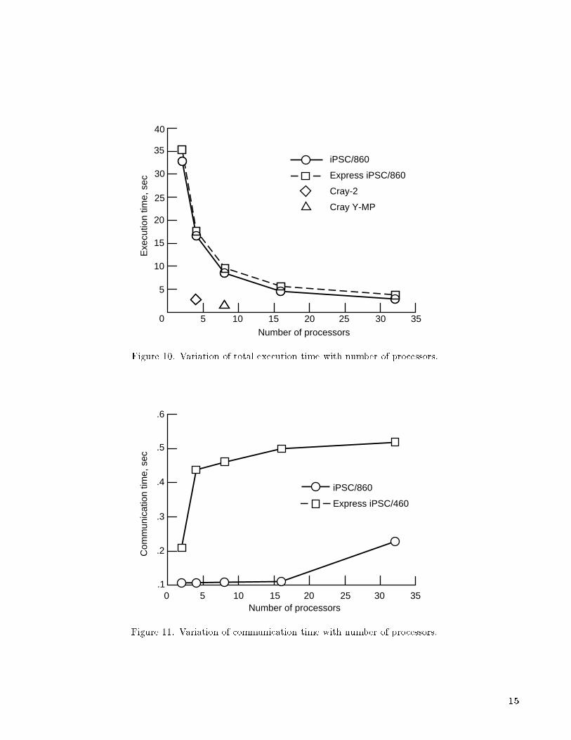
Total execution times in four di�erent categoriesare presented in tables 1 to 4. These execution timesinclude both computation times and interprocessorcommunication times. The interprocessor commu-nication times were measured by timing the exe-cution of relevant portions of the code which dealtwith passing data between processors. Executiontimes for the complete grid system in the analyticgeometry case are reported with the correspondingnumber of processors used in table 1. Both the na-tive Intel programming model and the Express pro-gramming model display decreasing execution timeas the number of processors in the hypercube is in-creased from 2 to 32. The Express execution timesare slightly higher than the corresponding Intel runsbecause of the communication overhead associatedwith the Express software. Another factor contribut-ing to the increase in the execution time is the factthat CFS operation is slower with Express, as men-tioned previously. Similar trends are seen in the
execution times for the discretely de�ned geometrycase presented in table 2. Execution times for theIntel and the Express programming modes in the an-alytic geometry case are plotted against the numberof processors in �gure 10. Execution times obtainedfor a fully vectorized version of the code on a four-processor Cray-2 and an eight-processor Cray Y-MPare also plotted in �gure 10. Single-processor exe-cution times for the Cray machines are included forreference. The execution time for the parallel codeapproaches the Cray execution times as the num-ber of processors increases. An indication of typicalinterprocessor communication times associated withthe algorithm is given in �gure 11, wherein commu-nication time has been plotted against the numberof processors in the analytic input geometry case.The communication time is shown to be a small frac-tion of the total execution time. Execution timesobtained for level 2 parallelism are presented in ta-bles 3 and 4. At this level, a collection of radial linesbelonging to a single planar grid is computed on eachprocessor. The amount of computational activity ineach processor is very small in this case, and the to-tal execution time is dominated by I/O activity. TheCFS I/O activity does not depend on the number ofprocessors; the result being an insigni�cant reductionin execution time as the number of processors is in-creased. Note that the Express execution times areconsistently higher than the corresponding times forthe Intel programming mode because CFS activity isessentially serialized under Express.
The next series of �gures illustrates the variationof the execution time speed-up ratios with the num-ber of processors used. The speed-up ratio Sp is de-�ned as follows:
Sp =T1
Tp
where Tp is the execution time of p processors and T1is the execution time for a single processor. Speed-up ratios of the analytic input geometry are plottedagainst the number of processors in �gure 12. Re-sults for both the Intel programming mode and theExpress programming mode are presented. These re-sults are for level 1 parallelism (i.e., for the completethree-dimensional grid system). Both programmingmodes result in good correlation of the speed-up ra-tio with the number of processors used. Ideally thespeed-up ratio Sp for P processors should be equalto p; however, in a realistic application, the pres-ence of nonscalable factors such as overhead, broad-casting of initial run-control parameters to all proces-sors, and certain I/O operations will lower the valueof Sp somewhat. The speed-up-ratio curves in �g-ure 12 are nearly linear an indication of consistent
7
reductions in execution time as the number of proces-sors is increased. The speed-up ratios in the Expressmode are lower than the corresponding ratios for theIntel programming mode because of overhead andslower CFS operations associated with the Expressenvironment. Speed-up ratios plotted against thenumber of processors in the discrete geometry caseare presented in �gure 13. Similar variations inspeed-up ratios are again noted in both the Intelmode and the Express mode.
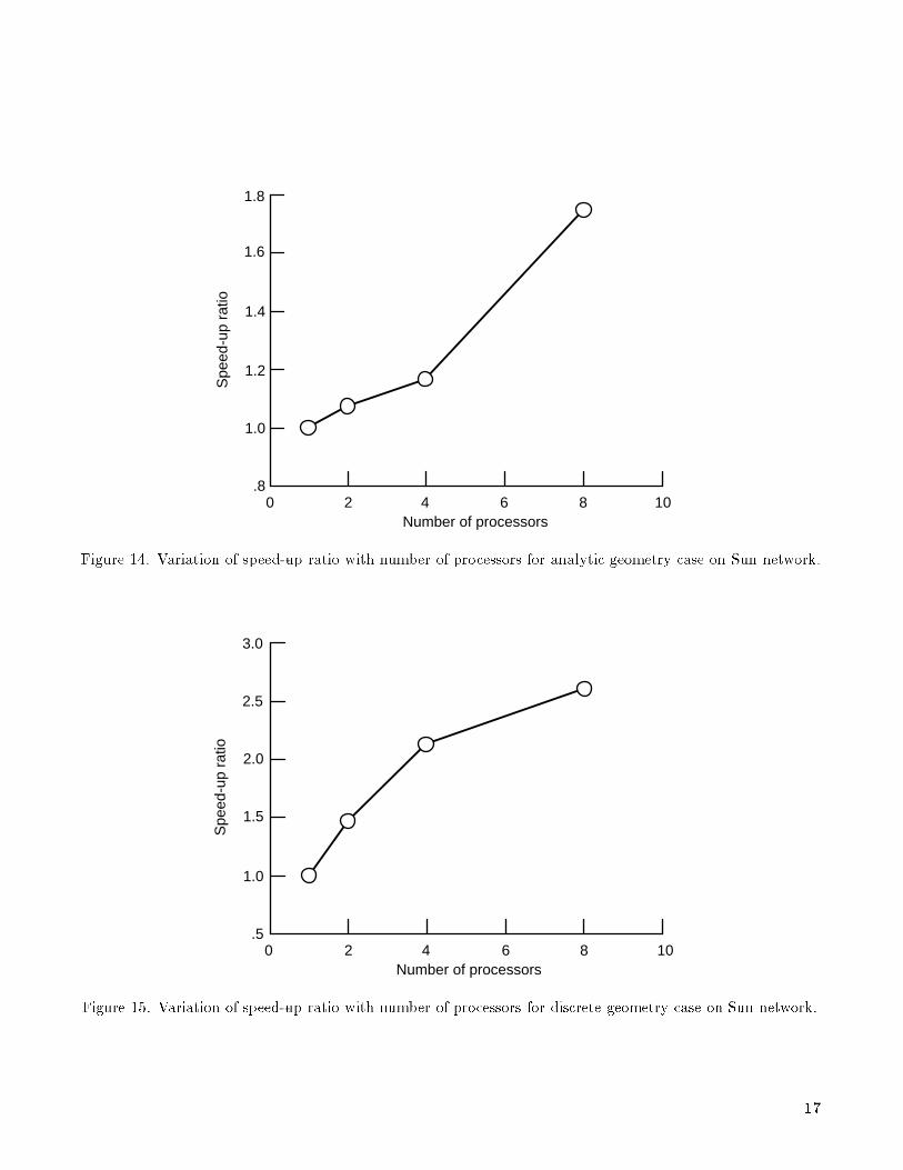
Performance results obtained by running the codeunder the Express environment on a network ofeight Sun workstations are presented in the next twoplots. Figures 14 and 15 illustrate the performanceof the algorithm while computing the complete three-dimensional grid system in the analytic and discreteinput geometry cases, respectively. Speed-up ratiosincreased with increasing numbers of processors.However, it is important to remember that the work-stations in the network varied widely in their com-puting power and characteristics, and consequently, aconsistent correlation to performance is not expected.
Conclusions
An algebraic grid-generation method based onhomotopic relations has been demonstrated to behighly parallelizable at several levels of domain de-composition. Performance of the algorithm on theIntel iPSC/860 machine with 32 nodes has displayedconsistent correlation of speed-up ratios with thenumber of processors. A strength of the algorithmis its relatively low need for interprocessor commu-nications. The Express algorithm was also executedsuccessfully on a network of Sun workstations to vali-date the possibility of running parallel codes without
a true parallel machine. The consistency of speed-up ratios correlating with the number of processorson a network of workstations is expected to improvewith uniformity of the computing characteristics ofthe individual workstations.
NASA Langley Research Center
Hampton, VA 23681-0001December 3, 1993
References
1. Holst, Terry L.; Salas, Manuel D.; and Claus, Russell W.:
The NASA Computational Aerosciences Program|
Toward TeraFLOPS Computing. AIAA Paper No.92-0558, Jan. 1992.
2. Gentzsch, W.; and H�auser, J.: Mesh Generation on Par-
allel Computers. Numerical Grid Generation in Com-
putational Fluid Mechanics '88, S. Sengupta, J. H�auser,
P. R. Eiseman, and J. F. Thompson, eds., PineridgePress,
Ltd. (Swansea,Wales), 1988, pp. 113{123.
3. Berger, Marsha J.: Adaptive Mesh Re�nement for Paral-
lel Processors. Parallel Processing for Scienti�c Comput-
ing, Soc. for Industrial and Applied Mathematics, 1989,pp. 182{194.
4. L�ohner, Rainald; Camberos, Jose; and Merriam,
Marshal: Parallel Unstructured Grid Generation. A Col-
lection of Technical Papers|Tenth AIAA Computational
Fluid Dynamics Conference, June 1991, pp. 627{637.
(Available as AIAA-91-1582.)
5. Moitra, Anutosh: An Algebraic Homotopy Method for
Generating Quasi-Three-Dimensional Grids for High-
Speed Con�gurations. NASA CR-4242, 1989.
6. Moitra, Anutosh: HOMAR: A ComputerCode for Gener-
atingHomotopicGrids UsingAlgebraicRelations|Users'
Manual. NASA CR-4243, 1989.
8

Table 1. Execution Time for Complete Grid in Analytic Geometry Case
Execution time, sec Speed-up ratio
Number ofprocessors iPSC/860 Express-iPSC/860 iPSC/860 Express-iPSC/860
1 65.12 69.91 1.00 1.002 32.89 35.31 1.98 1.984 16.54 17.70 3.93 3.948 8.43 9.50 7.72 7.3616 4.55 5.58 14.31 12.5232 2.81 3.70 23.17 18.89
Table 2. Execution Time for Complete Grid in Discrete Geometry Case
Execution time, sec Speed-up ratio
Number ofprocessors iPSC/860 Express-iPSC/860 iPSC/860 Express-iPSC/860
1 119.63 121.22 1.00 1.002 60.73 63.80 1.97 1.904 30.91 33.60 3.87 3.608 16.68 17.99 7.63 6.7416 8.44 10.38 14.17 11.6832 4.87 6.99 24.56 17.35
Table 3. Execution Time for Single Planar Grid
in Analytic Geometry Case
Execution time, sec
Number ofprocessors iPSC/860 Express-iPSC/860a
2 0.766 2.564 .514 2.728 .412 2.8116 .381 3.02
aExpress serializes CFS I/O operations.
Table 4. Execution Time for Single Planar Grid
in Discrete Geometry Case
Execution time, sec
Number ofprocessors iPSC/860 Express-iPSC/860a
2 1.200 3.194 .835 3.998 .659 4.4016 .630 4.5432 .582 5.39
aExpress serializes CFS I/O operations.
9
(xo, yo)
(xi, yi)
Figure 1. Corresponding inner and outer boundary points.
Figure 2. Schematic representation of quasi-three-dimensional grid system.
10

(x, y)
(x', y') (xi, yi)
(xi-1, yi-1)
(xi+1, yi+1)
Ads
B
Figure 3. Vectors used in grid orthogonalization.
Processors P3P1 P2 PnP4
Figure 4. Schematic of parallelism at primary level.
11
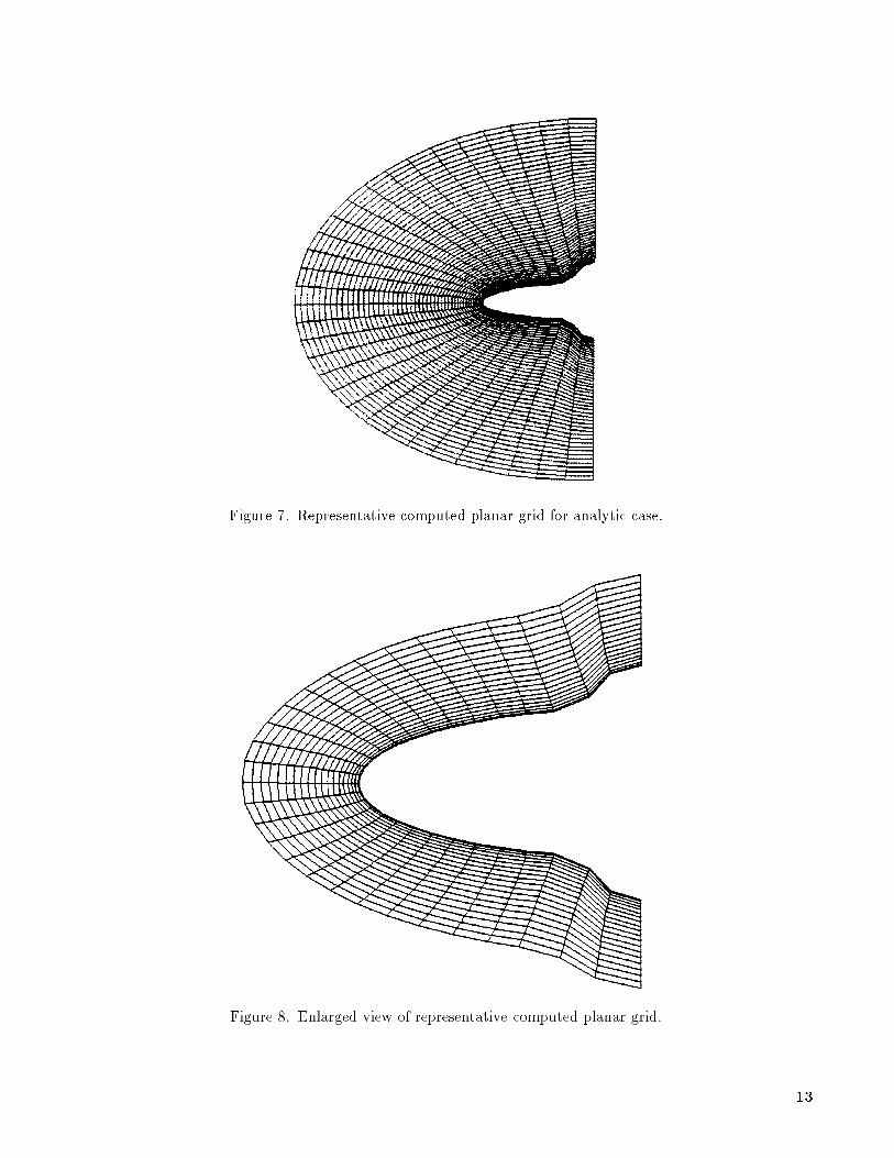
Figure 7. Representative computed planar grid for analytic case.
Figure 8. Enlarged view of representative computed planar grid.
13
Exe
cutio
n tim
e, s
ec
5 10 15 20 35
Number of processors
3025
iPSC/860
Express iPSC/860
Cray-2
Cray Y-MP
5
10
15
20
35
30
25
40
0
Figure 10. Variation of total execution time with number of processors.
Com
mun
icat
ion
time,
sec
0 5 10 15 20 35Number of processors
3025
iPSC/860
Express iPSC/460
.6
.5
.4
.3
.2
.1
Figure 11. Variation of communication time with number of processors.
15

5 10 15 20 35
Number of processors
Spe
ed-u
p ra
tio
3025
Intel
Express
Perfect
5
30
25
20
15
10
35
0
Figure 12. Variation of speed-up ratio with number of processors for analytic geometry case on iPSC/860
machine.
0 5 10 15 20 35Number of processors
Spe
ed-u
p ra
tio
Intel ExpressPerfect
3025
35
5
10
15
20
25
30
Figure 13. Variation of speed-up ratio with number of processors for discrete geometry case on iPSC/860
machine.
16
0 2 4 6 8 10Number of processors
Spe
ed-u
p ra
tio
1.0
1.2
1.4
1.6
1.8
.8
Figure 14. Variation of speed-up ratio with number of processors for analytic geometry case on Sun network.
0 2 4 6 8 10Number of processors
.5
1.0
1.5
2.0
2.5
3.0
Spe
ed-u
p ra
tio
Figure 15. Variation of speed-up ratio with number of processors for discrete geometry case on Sun network.
17

Figure 5. Schematic of parallelism at secondary level.
Figure 6. Representative computed grid for analytic case.
Figure 9. Representative computed grid for discrete case.

REPORT DOCUMENTATION PAGEForm Approved
OMB No. 0704-0188
Public reporting burden for this collection of information is estimated to average 1 hour per response, including the time for reviewing instructions, searching existing data sources,gathering and maintaining the data needed, and completing and reviewing the collection of information. Send comments regarding this burden estimate or any other aspect of thiscollection of information, including suggestions for reducing this burden, toWashington Headquarters Services, Directorate for Information Operations and Reports, 1215 Je�ersonDavis Highway, Suite 1204, Arlington, VA 22202-4302, and to the O�ce of Management and Budget, Paperwork Reduction Project (0704-0188), Washington, DC 20503.
1. AGENCY USE ONLY(Leave blank) 2. REPORT DATE 3. REPORT TYPE AND DATES COVERED
February 1994 Technical Paper
4. TITLE AND SUBTITLE
Parallel Grid Generation Algorithm for Distributed Memory
Computers
6. AUTHOR(S)
Stuti Moitra and Anutosh Moitra
7. PERFORMING ORGANIZATION NAME(S) AND ADDRESS(ES)
NASA Langley Research Center
Hampton, VA 23681-0001
9. SPONSORING/MONITORING AGENCY NAME(S) AND ADDRESS(ES)
National Aeronautics and Space Administration
Washington, DC 20546-0001
5. FUNDING NUMBERS
WU 505-90-53-02
8. PERFORMING ORGANIZATION
REPORT NUMBER
L-17249
10. SPONSORING/MONITORING
AGENCY REPORT NUMBER
NASA TP-3429
11. SUPPLEMENTARY NOTES
Stuti Moitra: Langley Research Center, Hampton, VA; and Anutosh Moitra: High Technology Corporation,Hampton, VA.
12a. DISTRIBUTION/AVAILABILITY STATEMENT 12b. DISTRIBUTION CODE
Unclassi�ed{Unlimited
Subject Category 61
13. ABSTRACT (Maximum 200 words)
A parallel grid-generation algorithm and its implementation on the Intel iPSC/860 computer are described.The grid-generation scheme is based on an algebraic formulation of homotopic relations. Methods for utilizingthe inherent parallelism of the grid-generation scheme are described, and implementation of multiple levelsof parallelism on multiple instruction multiple data machines are indicated. The algorithm is capable ofproviding near orthogonality and spacing control at solid boundaries while requiring minimal interprocessorcommunications. Results obtained on the Intel hypercube for a blended wing-body con�guration are used todemonstrate the e�ectiveness of the algorithm. Fortran implementations based on the native programmingmodel of the iPSC/860 computer and the Express system of software tools are reported. Computational gainsin execution time speed-up ratios are given.
14. SUBJECT TERMS 15. NUMBER OF PAGES
Grid generation; Parallel algorithm 20
16. PRICE CODE
A0317. SECURITY CLASSIFICATION 18. SECURITY CLASSIFICATION 19. SECURITY CLASSIFICATION 20. LIMITATION
OF REPORT OF THIS PAGE OF ABSTRACT OF ABSTRACT
Unclassi�ed Unclassi�ed
NSN 7540-01-280-5500 Standard Form 298(Rev. 2-89)Prescribed by ANSI Std. Z39-18298-102
Related Documents