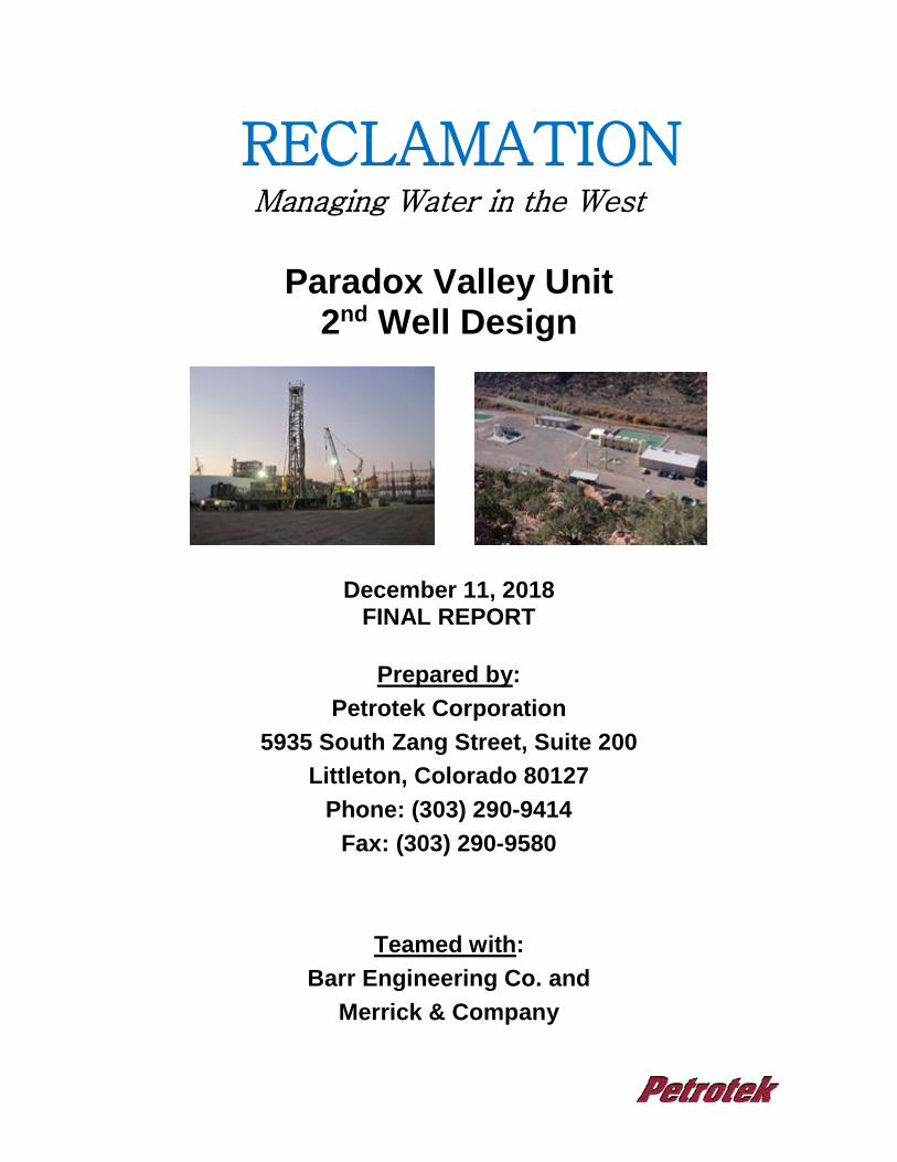
RECLAMATION Managing Water in the West Paradox Valley Unit 2 nd Well Design December 11, 2018 FINAL REPORT Prepared by: Petrotek Corporation 5935 South Zang Street, Suite 200 Littleton, Colorado 80127 Phone: (303) 290-9414 Fax: (303) 290-9580 Teamed with: Barr Engineering Co. and Merrick & Company

Welcome message from author
This document is posted to help you gain knowledge. Please leave a comment to let me know what you think about it! Share it to your friends and learn new things together.
Transcript
RECLAMATION
Managing Water in the West
Paradox Valley Unit
2nd Well Design
December 11, 2018 FINAL REPORT
Prepared by:
Petrotek Corporation 5935 South Zang Street, Suite 200
Littleton, Colorado 80127 Phone: (303) 290-9414
Fax: (303) 290-9580
Teamed with:
Barr Engineering Co. and Merrick & Company
140R4018C0001 Bureau of Reclamation Paradox Valley Unit 2nd Well Design Upper Colorado Region
FINAL – December 11, 2018 i
TABLE OF CONTENTS
1.0 INTRODUCTION AND BACKGROUND ........................................................... 1-1 1.1 Introduction ............................................................................................. 1-1 1.2 Cross Reference Between Statement of Work and Report ..................... 1-3 2.0 STATEMENT OF WORK SUMMARY, ASSUMPTIONS AND LIMITATIONS .. 2-1 2.1 Assumptions and Limitations .................................................................. 2-3 2.1.1 Closure Assumptions and Limitations (General Task 1) .............. 2-4 2.1.1.1 Plugging and Abandonment of PVU #1 .......................... 2-4 2.1.1.1.1 Plugging and Abandonment of PVU #1 –
General Assumptions ..................................... 2-5 2.1.1.2 Closure of Injection Facilities .......................................... 2-6 2.1.1.2.1 Reclamation Responsibilities (Excluded from
Estimate): ....................................................... 2-6 2.1.1.2.2 Closure of Injection Facilities Assumptions ..... 2-6 2.1.2 Automation Assumptions and Limitations (General Task 2) ......... 2-9 2.1.2.1 Cost Development Approach and Assumptions ............. 2-9 2.1.2.2 Risks and Limitations Associated with New Automation
2-11 2.1.3 Well Site Suitability Assumptions and Limitations (Tasks
MM-1, BIF2-1, BIF3-1) ............................................................... 2-12 2.1.4 Exploratory Well Assumptions and Limitations (Tasks MM-2,
BIF2-2, BIF3-2) .......................................................................... 2-12 2.1.5 Class V Injection Well Assumptions and Limitations (Tasks
MM-3, BIF2-3, BIF3-3) ............................................................... 2-14 2.1.6 Injection Facility Assumptions and Limitations (Tasks MM-4,
BIF2-4, BIF3-4) .......................................................................... 2-16 2.1.6.1 Injection Facility Assumptions ....................................... 2-17 2.1.6.2 Limitations Regarding the Application of Technologies
2-18 2.1.6.3 Limitations Regarding Cost Estimates .......................... 2-18 2.1.7 Schedule Assumptions and Limitations (Tasks MM-5, BIF2-5,
BIF3-5) ...................................................................................... 2-19 3.0 TASKS .............................................................................................................. 3-1 3.1 General Task 1 - Closure of PVU #1 Injection Well, Pumping Plant,
and Associated Surface Facilities ........................................................... 3-1
140R4018C0001 Bureau of Reclamation Paradox Valley Unit 2nd Well Design Upper Colorado Region
FINAL – December 11, 2018 ii
3.1.1 Description of Facilities ................................................................ 3-1 3.1.1.1 Injection Well .................................................................. 3-2 3.1.1.2 Current Injection Facilities .............................................. 3-4 3.1.2 Closure Methodology and Description ......................................... 3-5 3.1.2.1 Injection Well .................................................................. 3-5 3.1.2.1.1 BHP and Options to Kill .................................. 3-6 3.1.2.1.2 Plugging Material Identification and Compatibility
....................................................................... 3-6 3.1.2.1.3 Rig and Equipment Requirements .................. 3-7 3.1.2.1.4 HSE Requirements ......................................... 3-7 3.1.2.1.5 PVU #1 P&A Prognosis .................................. 3-8 3.1.2.2 Injection Facilities ........................................................... 3-9 3.1.3 Closure Costs............................................................................. 3-13 3.1.3.1 Injection Well ................................................................ 3-13 3.1.3.2 Surface Facilities .......................................................... 3-14 3.2 General Task 2 - Cost Benefit of Automation of Injection Facility ......... 3-16 3.2.1 Injection Well Automation Design and Description ..................... 3-16 3.2.2 Automation Approach ................................................................. 3-16 3.2.3 Proposed Design Basis .............................................................. 3-17 3.2.3.1 PLC System .................................................................. 3-17 3.2.3.2 Basic Controls............................................................... 3-17 3.2.3.3 Capacity ........................................................................ 3-17 3.2.3.4 Workstations and Controls ............................................ 3-18 3.2.3.5 Security ......................................................................... 3-18 3.2.3.6 Communications ........................................................... 3-18 3.2.3.7 Monitoring and Operations ........................................... 3-18 3.2.3.8 Alarms .......................................................................... 3-19 3.2.3.9 Data Storage and Retrieval .......................................... 3-19 3.2.3.10 Proposed Plant Controls .............................................. 3-20 3.2.3.11 EPA Compliance .......................................................... 3-20 3.2.4 Communication Between the Injection Well Pump Facility and
Reclamation HQ Office. ............................................................. 3-21 3.2.4.1 Cellular Option .............................................................. 3-21
140R4018C0001 Bureau of Reclamation Paradox Valley Unit 2nd Well Design Upper Colorado Region
FINAL – December 11, 2018 iii
3.2.4.2 Fiber Optic Option ......................................................... 3-22 3.2.4.3 Security Issues ............................................................. 3-22 3.2.5 Cost of Proposed Automation System ....................................... 3-22 3.2.6 Conclusions ............................................................................... 3-24 3.3 Monogram Mesa MM E1 and MM1 ....................................................... 3-24 3.3.1 30% Design of Exploratory Well, MM E1 ................................... 3-24 3.3.1.1 MM E1 Data Needs and Considerations ....................... 3-25 3.3.1.2 Monitoring Technologies ............................................... 3-25 3.3.1.3 MM E1 Well Design ...................................................... 3-27 3.3.1.4 MM E1 Well Plan .......................................................... 3-30 3.3.1.5 Feasibility of Completing MM E1 as Long Term
Observation Well .......................................................... 3-32 3.3.1.6 MM E1 Exploratory Well Cost Estimate ........................ 3-33 3.3.1.6.1 MM E1 Well Cost .......................................... 3-33 3.3.1.6.2 Cost to Convert MM E1 to Long Term
Observation Well .......................................... 3-35 3.3.1.6.3 Cost to Abandon MM E1 ............................... 3-35 3.3.2 30% Design Class V Well, MM1 ................................................. 3-36 3.3.2.1 MM1 Data Needs and Considerations .......................... 3-36 3.3.2.2 Monitoring Technologies ............................................... 3-36 3.3.2.3 MM1 Well Design .......................................................... 3-36 3.3.2.4 MM1 Well Plan .............................................................. 3-39 3.3.2.5 MM1 Class V Well Cost Estimate ................................. 3-42 3.3.3 30% Design Injection Well Injection Facility ............................... 3-42 3.3.3.1 Basis of Design ............................................................. 3-43 3.3.3.2 Pump Design ................................................................ 3-46 3.3.3.2.1 Reciprocating Plunger Pump ........................ 3-47 3.3.3.2.2 Progressive Cavity Pump ............................. 3-47 3.3.3.2.3 Multi-Stage Centrifugal Pump ....................... 3-48 3.3.3.2.4 Refurbish Existing Pumps ............................. 3-49 3.3.3.3 Tankage and Pond Storage Requirements ................... 3-49 3.3.3.4 Injection Pumps and Piping .......................................... 3-50 3.3.3.5 Well Annulus Monitoring System (WAMS) .................... 3-51
140R4018C0001 Bureau of Reclamation Paradox Valley Unit 2nd Well Design Upper Colorado Region
FINAL – December 11, 2018 iv
3.3.3.6 Civil Site Preparation .................................................... 3-52 3.3.3.7 Electrical Systems and Structural Requirements .......... 3-53 3.3.3.8 Safety and Health Considerations ................................ 3-55 3.3.3.9 Surge and Transient Calculations ................................. 3-56 3.3.3.10 Injection Facility Cost Estimate .................................... 3-56 3.3.3.11 Annual Operating and Maintenance Costs .................. 3-58 3.3.4 Schedule for Drilling, Testing, Well Completion, and Injection
Facility Installation ...................................................................... 3-58 3.4 Brine Injection Facility No. 2, BIF2 ........................................................ 3-59 3.4.1 30% Design Exploratory Well ..................................................... 3-59 3.4.2 30% Design Class V Well, BIF2 ................................................. 3-60 3.4.2.1 BIF2 Data Needs and Considerations .......................... 3-60 3.4.2.2 Monitoring Technologies ............................................... 3-60 3.4.2.3 BIF2 Well Design .......................................................... 3-60 3.4.2.4 Well Plan, BIF2 Injection Well Only .............................. 3-63 3.4.3 30% Design Injection Well Injection Facility ............................... 3-66 3.4.4 Schedule for Drilling, Testing, Well Completion, and Injection
Facility Installation ...................................................................... 3-67 3.5 Brine Injection Facility No. 3, BIF E1 and BIF3 ..................................... 3-67 3.5.1 30% Design Exploratory Well, BIF E1 ........................................ 3-68 3.5.1.1 BIF E1 Data needs and Considerations: Well Design
Criteria .......................................................................... 3-68 3.5.1.2 Monitoring Technologies ............................................... 3-68 3.5.1.3 BIF E1 Well Design ....................................................... 3-68 3.5.1.4 BIF E1 Well Plan ........................................................... 3-70 3.5.1.5 Feasibility of Completing BIF E1 Well As Long Term
Observation Well .......................................................... 3-73 3.5.1.6 BIF E1 Well Cost Estimate ........................................... 3-73 3.5.1.6.1 Cost to Convert BIF E1 to Long Term
Observation Well .......................................... 3-73 3.5.1.6.2 Cost to Abandon BIF E1 ............................... 3-74 3.5.2 30% Design Class V Well, BIF3 ................................................. 3-74 3.5.2.1 BIF3 Data Needs and Considerations .......................... 3-74 3.5.2.2 Monitoring Technologies ............................................... 3-74
140R4018C0001 Bureau of Reclamation Paradox Valley Unit 2nd Well Design Upper Colorado Region
FINAL – December 11, 2018 v
3.5.2.3 BIF3 Well Design .......................................................... 3-75 3.5.2.4 BIF3 Well Plan .............................................................. 3-77 3.5.2.5 BIF3 Class V Well Cost Estimate .................................. 3-80 3.5.3 30% Design Injection Well Injection Facility ............................... 3-81 3.5.4 Schedule for Drilling, Testing, Well Completion and Injection
Facility Installation ...................................................................... 3-81 3.6 Well Cost Allocation .............................................................................. 3-82 4.0 EVALUATION AND SUITABILITY OF SITES .................................................. 4-1 4.1 Description of the Suitability Assessment and Evaluation Methodology
................................................................................................................ 4-4 4.1.1 Drilling Risks ................................................................................ 4-5 4.1.2 Geologic Risks ............................................................................. 4-5 4.1.3 Operational Risks ......................................................................... 4-6 4.1.4 Summary of Results ..................................................................... 4-6 5.0 SUMMARY AND CONCLUSIONS .................................................................... 5-1 5.1 Scope of Work and Deliverables ............................................................. 5-1 5.2 Approach to the Work ............................................................................. 5-3 5.3 Results from Completion of the Work ..................................................... 5-5 6.0 REFERENCE LIST ............................................................................................ 6-1 List of Figures
Figure 1-1 Paradox Basin Location Map and Location of the PVU Injection Well Figure 1-2 Brine Production Wells/Treatment Facility and BIF/PVU #1 Location Map Figure 1-3 BIF2, BIF3 and TBIF 1.5 Location Map Figure 1-4 MM1, TMM1 and MM E1 Location Map Figure 2-1 MM1 Directional Well Proposed Profile Figure 2-2 BIF3 Directional Well Proposed Profile Figure 3-1 Paradox Valley Injection Well No. 1 Current Well Construction Diagram Figure 3-2 Brine Injection Facility (BIF) Current Injection Facility Drawing Figure 3-3 MM E1 Exploratory Well Proposed Construction Diagram Figure 3-4 MM1 Injection Well Proposed Construction Diagram Figure 3-5 MM1 Directional Well Proposed Plan Figure 3-6 BIF2 Injection Well Proposed Construction Diagram Figure 3-7 BIF2 Brine Pipeline Profile Looking West Figure 3-8 BIF E1 Exploratory Well Proposed Construction Diagram Figure 3-9 BIF3 Injection Well Proposed Construction Diagram Figure 3-10 BIF3 Directional Well Proposed Plan Figure 3-11 MM1 Directional and MM E1 Vertical Well Cost Breakdown
140R4018C0001 Bureau of Reclamation Paradox Valley Unit 2nd Well Design Upper Colorado Region
FINAL – December 11, 2018 vi
List of Tables
Table 1-1 SOW Element and Report Cross Comparison Table 2-1 Statement of Work Allocation Table 3-1A Demolition Statement of Work Equipment Table 3-1B Equipment, Piping, and Electrical Statement of Work details Table 3-2 Cost Estimate for PVU #1 Plugging and Abandonment of PVU #1 Table 3-3 Cost Estimate for Demolition of BIF Facility Table 3-4 Comparison of Lifetime O&M Costs With and Without Automation 2019
Dollars and No Escalation Table 3-5 MM E1 Casing Design Table 3-6 Summary of Well Costs, MM E1, MM1, BIF E1, BIF2, BIF3 Table 3-7 MM1 Casing Design Table 3-8 Injection Facility Design Considerations Table 3-9 Injection Facility Cost Estimate Table 3-10 BIF2 Injector Well Casing Design Table 3-11 BIF E1 Well Casing Design Table 3-12 BIF3 Injector Well Casing Design Table 4-1 Category Risk Rankings Table 5-1 Well Cost Estimate Summary Table
List of Attachments
Attachment A Merrick & Company: Automation Cost Benefit Analysis, H2S and High Pressure Fluid Hazards, and Injection Facility Demolition Cost Estimate
Attachment B Barr Engineering: 30% Injection Facility Design and Cost Estimate
Attachment C Directed Drilling Technologies Horizontal Brine Conduit and Correspondence
List of Acronyms
AACE American Association of Cost Engineers AI Analog Inputs AICE Aspen In-Plan Cost Estimator API American Petroleum Institute BGL Below Ground Level BHA Bottomhole Assembly BHP Bottomhole Pressure BIF Brine Injection Facility BIF2 Brine Injection Well No. 2 BIF3 Brine Injection Well No. 3
140R4018C0001 Bureau of Reclamation Paradox Valley Unit 2nd Well Design Upper Colorado Region
FINAL – December 11, 2018 vii
BIF E1 Brine Injection Facility Exploratory Well BOP Blowout Preventer BOR Bureau of Reclamation CIBP Cast Iron Bridge Plug CRA Corrosion Resistant Alloys CTU Coil Tubing Unit DI Digital Inputs DO Digital Outputs DTD Directed Technologies Drilling EPA Environmental Protection Agency FRC Flame Resistant Clothing FRP Fiber Reinforced Plastic GAL Gallons gpm Gallons per Minute H2S Hydrogen Sulfide HART Highway Addressable Remote Transducer HMI Human Machine Interface HP Horse Power HQ Headquarters HSE Health Safety and Environment HVAC Heating, Ventilation, and Air Conditioning ID Inside Diameter JSA Job Safety Analysis KB Kelly Bushing ksi 1,000 psi KOP Kickoff Point LCM Lost Circulation Material LS Logical Systems MASIP Maximum Allowable Surface Injection Pressure MAWP Maximum Allowable Working Pressure MCC Motor Control Centers MD Measured Depth MGSC Midwest Geological Sequestration Consortium MM Monogram Mesa MM E1 Monogram Mesa Exploratory Well MOV Motor Operated Valve O&M Observations and Measurements OCIP Owner Controlled Insurance Program OD Outside Diameter P&A Plugging and Abandonment P&ID Piping and Instrumentation Diagram PBR Polished Bore Receptacle PBTD Plugged Back Total Depth PEMB Pre-engineered Metal Building PG Progressive Cavity PLC Programmable Logic Controller
140R4018C0001 Bureau of Reclamation Paradox Valley Unit 2nd Well Design Upper Colorado Region
FINAL – December 11, 2018 viii
PMI Positive Material Identification PPE Personal Protective Equipment ppg Pounds per Gallon psi Pounds per Square Inch psig Pounds per Square Inch Gauge PVC Polyvinyl Chloride PVU Paradox Valley Unit ROM Rough Order of Magnitude RTD Resistance Temperature Detector sx Sacks SOP Standard Operating Procedure SOW Statement of Work STF Surface Treatment Facility TBIF 1.5 Brine Injection Facility - Target Bottomhole Location, also referred to as
TBIF 1.5 TD Total Depth TLECC Timber Line Electric & Control Corporation TMM Monogram Mesa - Target Bottomhole Location, also referred to as TMM 1 TSA Tubing Seal Assembly TVD True Vertical Depth USDW Underground Source Drinking Water USEPA United States Environmental Protection Agency VFD Variable Frequency Drive V Volt VSP Vertical Seismic Profile WAMS Well Annulus Monitoring System WPF Weight per Foot WTP Water Treatment Plant
140R4018C0001 Bureau of Reclamation Paradox Valley Unit 2nd Well Design Upper Colorado Region
FINAL – December 11, 2018 1-1
1.0 INTRODUCTION AND BACKGROUND
1.1 Introduction
The Bureau of Reclamation (Reclamation) operates a Class V injection well in the
Paradox Valley, which is located in the northeastern portion of the Paradox Basin in
southwestern Colorado (Figure 1-1). The Paradox Valley Unit #1 well (PVU #1) injects
brine water almost 16,000 feet below ground surface into the Leadville Formation, and
has actively operated since 1996.
The Paradox Valley overlies a naturally occurring salt anticline. When groundwater
encounters the salt anticline, a highly salt-saturated brine is created that discharges to
the Dolores River. Using shallow groundwater production wells, the saturated brine is
captured, treated, and ultimately disposed via the PVU #1 Class V injection well. This
process is critical to mitigating brine concentrations in the Dolores River, which is a major
tributary to the Colorado River that is a critical source of water to the United States and
Republic of Mexico. Figure 1-2 presents the location of the existing brine production and
injection wells, and associated treatment and pumping facilities. The process facilities are
located at two separate sites: the production wells and Surface Treatment Facility (STF)
are located on the floor of the valley along the Dolores River and the Brine Injection
Facility (BIF) and PVU #1 injection well are located approximately three miles southwest
in the Dolores River Canyon.
From 2008 to 2012, the pressure required to inject brine into PVU #1 steadily increased
and began to approach the maximum allowable surface injection pressure (MASIP) of
5,350 psig, as permitted by the U.S. Environmental Protection Agency (USEPA). The rate
of near-well induced seismicity also increased. The flow rate was reduced in 2013 in
response to a M 4.4 (moment magnitude) earthquake 8.2 km from the well; another
decrease in flow rate was implemented in March 2017 in response to increased seismicity
and injection pressures. Recent increases in pressures and seismicity rates indicate that
the beneficial effects of the operational changes are diminishing and additional reductions
140R4018C0001 Bureau of Reclamation Paradox Valley Unit 2nd Well Design Upper Colorado Region
FINAL – December 11, 2018 1-2
in injection rates likely will be required in the future. Since the environmental benefits are
decreasing, a second injection well (PVU #2) is under consideration. Reclamation
conducted or contracted numerous technical studies to identify specific sites that are likely
to have suitable subsurface reservoir and operational properties, and to appraise the
feasibility of drilling and completing a second injection well at those sites (Block et al,
2017; Petrotek, 2017). An independent technical review panel evaluated those studies
and issued recommendations (EMPSi, 2017). Based on those studies, the
recommendations from the review panel, and various environmental and operational
factors, Reclamation identified three potential injection wellhead/surface locations, two
potential exploratory wellhead locations, and two bottomhole target locations. This report
evaluates the locations provided by Reclamation, and is based on data and assumptions
specified by Reclamation.
Facilities at the BIF and PVU #1 and the potential for a second Class V injection well are
the subject of this study. This study evaluates the feasibility and cost of closing the current
PVU #1 well and BIF, and replacing these units with a new well and injection facility. The
cost and 30% design of three well location alternatives were evaluated (Figures 1-3 and
1-4). These scenarios include five different wells: three alternative Class V injection wells
with surface locations at BIF2 and BIF3 (both with a target bottomhole location referred
to as TBIF 1.5) and Monogram Mesa (MM1 with TMM 1 bottomhole location). In addition
to the three Class V injection well alternatives, two vertical exploratory wells to
characterize the sites were evaluated, with each well extending from ground surface to
the TBIF 1.5 and TMM 1 bottom-hole locations. The cost and 30% design for a new
injection facility were also evaluated, along with costs for facility automation, and costs
and activities to remove the existing injection facility and plug and abandon PVU #1. The
following describes nomenclature used in this report for each of the five wells:
• BIF2 = injection well with injection facility location at BIF2 and bottom hole location at TBIF 1.5
• BIF3 = directional injection well with surface location at BIF3 and bottom hole location at TBIF 1.5
• BIF E1 = exploratory vertical well with bottom hole location at TBIF 1.5 • MM1 = directional injection well with bottom hole location at TMM 1 • MM E1 = exploratory vertical well with bottom hole location at TMM 1
140R4018C0001 Bureau of Reclamation Paradox Valley Unit 2nd Well Design Upper Colorado Region
FINAL – December 11, 2018 1-3
1.2 Cross Reference Between Statement of Work and Report
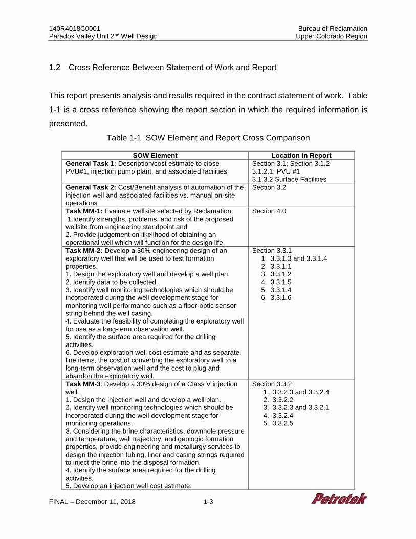
This report presents analysis and results required in the contract statement of work. Table
1-1 is a cross reference showing the report section in which the required information is
presented.
Table 1-1 SOW Element and Report Cross Comparison
SOW Element Location in Report General Task 1: Description/cost estimate to close PVU#1, injection pump plant, and associated facilities
Section 3.1; Section 3.1.2 3.1.2.1: PVU #1 3.1.3.2 Surface Facilities
General Task 2: Cost/Benefit analysis of automation of the injection well and associated facilities vs. manual on-site operations
Section 3.2
Task MM-1: Evaluate wellsite selected by Reclamation. 1.Identify strengths, problems, and risk of the proposed wellsite from engineering standpoint and 2. Provide judgement on likelihood of obtaining an operational well which will function for the design life
Section 4.0
Task MM-2: Develop a 30% engineering design of an exploratory well that will be used to test formation properties. 1. Design the exploratory well and develop a well plan. 2. Identify data to be collected. 3. Identify well monitoring technologies which should be incorporated during the well development stage for monitoring well performance such as a fiber-optic sensor string behind the well casing. 4. Evaluate the feasibility of completing the exploratory well for use as a long-term observation well. 5. Identify the surface area required for the drilling activities. 6. Develop exploration well cost estimate and as separate line items, the cost of converting the exploratory well to a long-term observation well and the cost to plug and abandon the exploratory well.
Section 3.3.1 1. 3.3.1.3 and 3.3.1.4 2. 3.3.1.1 3. 3.3.1.2 4. 3.3.1.5 5. 3.3.1.4 6. 3.3.1.6
Task MM-3: Develop a 30% design of a Class V injection well. 1. Design the injection well and develop a well plan. 2. Identify well monitoring technologies which should be incorporated during the well development stage for monitoring operations. 3. Considering the brine characteristics, downhole pressure and temperature, well trajectory, and geologic formation properties, provide engineering and metallurgy services to design the injection tubing, liner and casing strings required to inject the brine into the disposal formation. 4. Identify the surface area required for the drilling activities. 5. Develop an injection well cost estimate.
Section 3.3.2 1. 3.3.2.3 and 3.3.2.4 2. 3.3.2.2 3. 3.3.2.3 and 3.3.2.1 4. 3.3.2.4 5. 3.3.2.5
140R4018C0001 Bureau of Reclamation Paradox Valley Unit 2nd Well Design Upper Colorado Region
FINAL – December 11, 2018 1-4
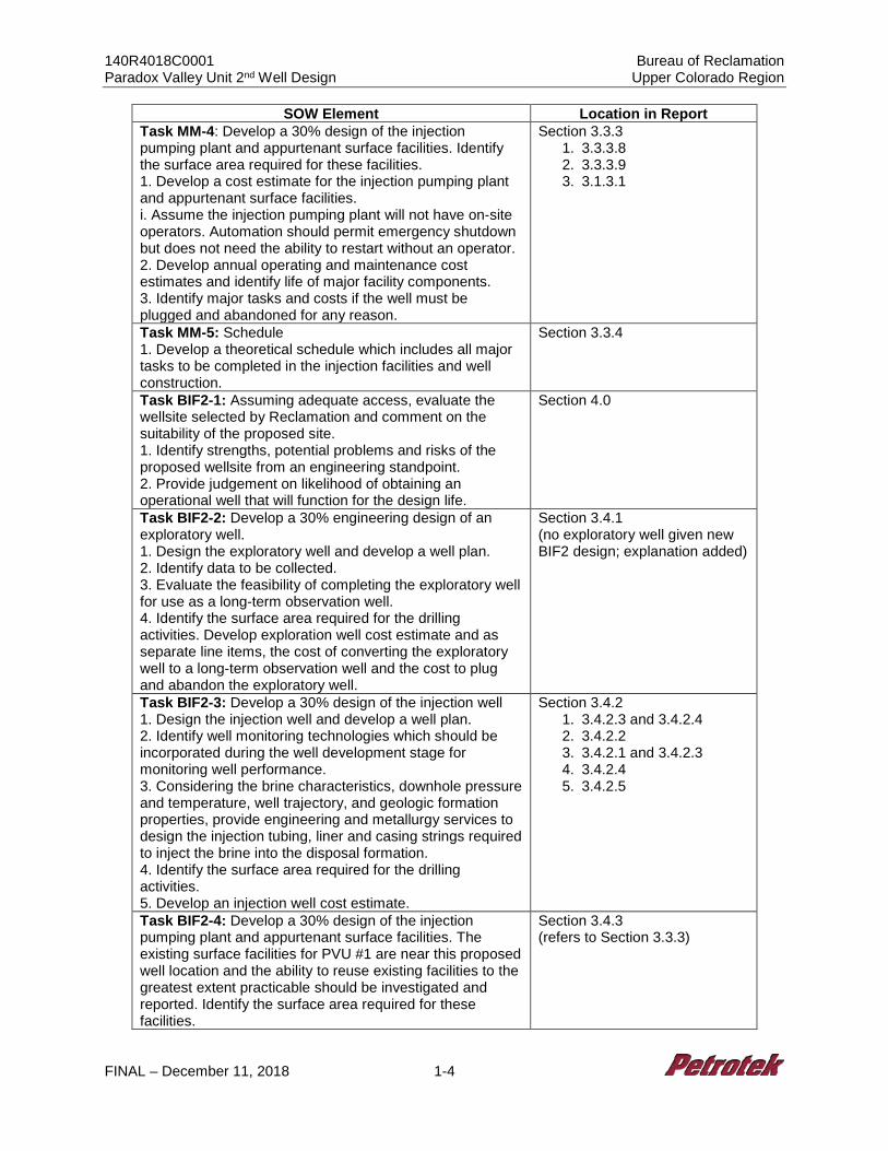
SOW Element Location in Report Task MM-4: Develop a 30% design of the injection pumping plant and appurtenant surface facilities. Identify the surface area required for these facilities. 1. Develop a cost estimate for the injection pumping plant and appurtenant surface facilities. i. Assume the injection pumping plant will not have on-site operators. Automation should permit emergency shutdown but does not need the ability to restart without an operator. 2. Develop annual operating and maintenance cost estimates and identify life of major facility components. 3. Identify major tasks and costs if the well must be plugged and abandoned for any reason.
Section 3.3.3 1. 3.3.3.8 2. 3.3.3.9 3. 3.1.3.1
Task MM-5: Schedule 1. Develop a theoretical schedule which includes all major tasks to be completed in the injection facilities and well construction.
Section 3.3.4
Task BIF2-1: Assuming adequate access, evaluate the wellsite selected by Reclamation and comment on the suitability of the proposed site. 1. Identify strengths, potential problems and risks of the proposed wellsite from an engineering standpoint. 2. Provide judgement on likelihood of obtaining an operational well that will function for the design life.
Section 4.0
Task BIF2-2: Develop a 30% engineering design of an exploratory well. 1. Design the exploratory well and develop a well plan. 2. Identify data to be collected. 3. Evaluate the feasibility of completing the exploratory well for use as a long-term observation well. 4. Identify the surface area required for the drilling activities. Develop exploration well cost estimate and as separate line items, the cost of converting the exploratory well to a long-term observation well and the cost to plug and abandon the exploratory well.
Section 3.4.1 (no exploratory well given new BIF2 design; explanation added)
Task BIF2-3: Develop a 30% design of the injection well 1. Design the injection well and develop a well plan. 2. Identify well monitoring technologies which should be incorporated during the well development stage for monitoring well performance. 3. Considering the brine characteristics, downhole pressure and temperature, well trajectory, and geologic formation properties, provide engineering and metallurgy services to design the injection tubing, liner and casing strings required to inject the brine into the disposal formation. 4. Identify the surface area required for the drilling activities. 5. Develop an injection well cost estimate.
Section 3.4.2 1. 3.4.2.3 and 3.4.2.4 2. 3.4.2.2 3. 3.4.2.1 and 3.4.2.3 4. 3.4.2.4 5. 3.4.2.5
Task BIF2-4: Develop a 30% design of the injection pumping plant and appurtenant surface facilities. The existing surface facilities for PVU #1 are near this proposed well location and the ability to reuse existing facilities to the greatest extent practicable should be investigated and reported. Identify the surface area required for these facilities.
Section 3.4.3 (refers to Section 3.3.3)
140R4018C0001 Bureau of Reclamation Paradox Valley Unit 2nd Well Design Upper Colorado Region
FINAL – December 11, 2018 1-5
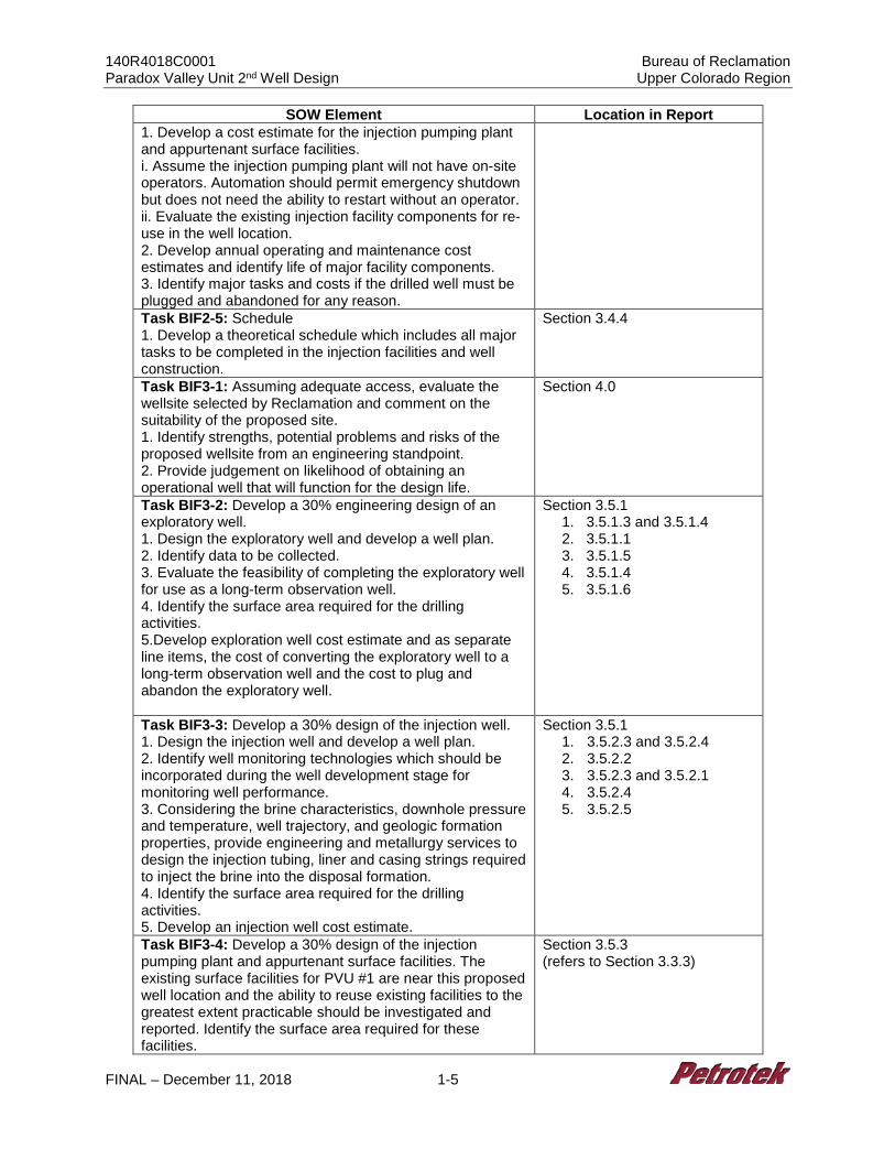
SOW Element Location in Report 1. Develop a cost estimate for the injection pumping plant and appurtenant surface facilities. i. Assume the injection pumping plant will not have on-site operators. Automation should permit emergency shutdown but does not need the ability to restart without an operator. ii. Evaluate the existing injection facility components for re-use in the well location. 2. Develop annual operating and maintenance cost estimates and identify life of major facility components. 3. Identify major tasks and costs if the drilled well must be plugged and abandoned for any reason. Task BIF2-5: Schedule 1. Develop a theoretical schedule which includes all major tasks to be completed in the injection facilities and well construction.
Section 3.4.4
Task BIF3-1: Assuming adequate access, evaluate the wellsite selected by Reclamation and comment on the suitability of the proposed site. 1. Identify strengths, potential problems and risks of the proposed wellsite from an engineering standpoint. 2. Provide judgement on likelihood of obtaining an operational well that will function for the design life.
Section 4.0
Task BIF3-2: Develop a 30% engineering design of an exploratory well. 1. Design the exploratory well and develop a well plan. 2. Identify data to be collected. 3. Evaluate the feasibility of completing the exploratory well for use as a long-term observation well. 4. Identify the surface area required for the drilling activities. 5.Develop exploration well cost estimate and as separate line items, the cost of converting the exploratory well to a long-term observation well and the cost to plug and abandon the exploratory well.
Section 3.5.1 1. 3.5.1.3 and 3.5.1.4 2. 3.5.1.1 3. 3.5.1.5 4. 3.5.1.4 5. 3.5.1.6
Task BIF3-3: Develop a 30% design of the injection well. 1. Design the injection well and develop a well plan. 2. Identify well monitoring technologies which should be incorporated during the well development stage for monitoring well performance. 3. Considering the brine characteristics, downhole pressure and temperature, well trajectory, and geologic formation properties, provide engineering and metallurgy services to design the injection tubing, liner and casing strings required to inject the brine into the disposal formation. 4. Identify the surface area required for the drilling activities. 5. Develop an injection well cost estimate.
Section 3.5.1 1. 3.5.2.3 and 3.5.2.4 2. 3.5.2.2 3. 3.5.2.3 and 3.5.2.1 4. 3.5.2.4 5. 3.5.2.5
Task BIF3-4: Develop a 30% design of the injection pumping plant and appurtenant surface facilities. The existing surface facilities for PVU #1 are near this proposed well location and the ability to reuse existing facilities to the greatest extent practicable should be investigated and reported. Identify the surface area required for these facilities.
Section 3.5.3 (refers to Section 3.3.3)
140R4018C0001 Bureau of Reclamation Paradox Valley Unit 2nd Well Design Upper Colorado Region
FINAL – December 11, 2018 1-6
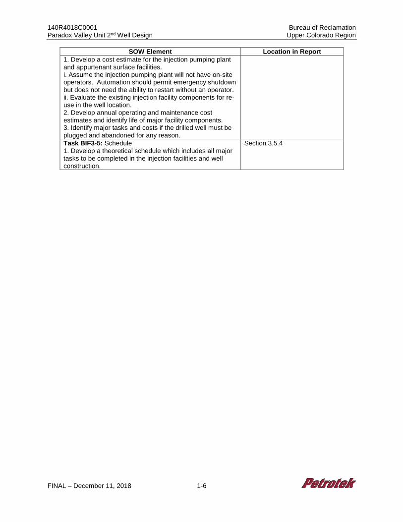
SOW Element Location in Report 1. Develop a cost estimate for the injection pumping plant and appurtenant surface facilities. i. Assume the injection pumping plant will not have on-site operators. Automation should permit emergency shutdown but does not need the ability to restart without an operator. ii. Evaluate the existing injection facility components for re-use in the well location. 2. Develop annual operating and maintenance cost estimates and identify life of major facility components. 3. Identify major tasks and costs if the drilled well must be plugged and abandoned for any reason. Task BIF3-5: Schedule 1. Develop a theoretical schedule which includes all major tasks to be completed in the injection facilities and well construction.
Section 3.5.4
140R4018C0001 Bureau of Reclamation Paradox Valley Unit 2nd Well Design Upper Colorado Region
FINAL – December 11, 2018 2-1
2.0 STATEMENT OF WORK SUMMARY, ASSUMPTIONS AND LIMITATIONS
The Paradox Valley Unit (PVU) process operations consist of Brine Production Wells, the
Surface Treatment Facility (STF), the Brine Injection Facility (BIF), and Injection Well No.
1 (PVU #1). Figure 1-2 presents the location of these components, which are located in
two separate sites: the Production Wells and STF are located on the valley floor along
the Dolores River, and the BIF and PVU #1 are located approximately three miles
upstream in the Dolores River Canyon. Note that this project does not include redesign
or closure of the Brine Production Wells and the STF, so these operations are not
addressed herein. The BIF and PVU #1 are the subject of this Report which addresses
various options associated with closure and/or redesign and replacement of the BIF and
PVU #1.
The BIF includes two 25,000 gallon underground storage tanks, guard filters, injection
pumps and associated piping with control systems. Brine is removed from the subsurface
at nine production wells and transferred to the BIF. During initial operations, as the brine
entered the BIF, filtered fresh water was added to the brine stream before the mixture
flowed to the two underground storage tanks; fresh water addition ceased in 2002. The
liquid in the storage tanks is naturally blanketed by the H2S gas evolving from the brine
into the tank headspace. Brine from the injection well storage tanks is pumped by a
centrifugal horizontal charge pump to a bank of four injection well guard filters equipped
with 3-micron filter bags. Once filtered, the injectate is fed to the injection pumps at
approximately 50 - 80 psig. The current brine injection pumps are Wheatley-Gaso HP-
600 quintuplex plunger pumps driven by 400 hp AC motors, each delivering pressures up
to 5,460 psig. Due to induced seismicity concerns, and the increasing wellhead pressures
required for injection that are a natural response to 20+ years of operation, the current
operating scenario is now limited to two pumps running simultaneously at a combined
flow rate averaging 168 gpm. Brine from the high pressure injection pumps enters the
well and flows to the Leadville Formation injection zone through the tubing string. The
current injection tubing is a high nickel alloy (Hastelloy C-276), and is contained within
the larger diameter intermediate casing. The intermediate casing is a sour service,
140R4018C0001 Bureau of Reclamation Paradox Valley Unit 2nd Well Design Upper Colorado Region
FINAL – December 11, 2018 2-2
95,000 psi minimum yield strength, controlled hardness carbon steel alloy designed for
the particular needs of this project. The well annulus was originally filled with diesel fuel,
however it is now filled with freshwater and a small amount of corrosion inhibitor. To
ensure integrity of both the injection string and the well casing, the annulus is monitored
continuously.
The objective of this project is to provide a 30% engineering design and well plan for a
replacement deep brine injection well and associated injection facilities. The 30% design
and well plan was limited to the specific sites identified by Reclamation, using existing
studies, data, and information provided by Reclamation. Additionally, the cost to
decommission and remove the existing injection facilities is assessed, along with the cost
to automate injection facility operations. While the amount of information available to
perform this project was substantial, the following data sources were primary to this
analysis:
• Excel Geophysical Services and International Reservoir Technologies, Inc. Paradox Valley Unit 2D Phase 3 Seismic Report Detailed Site Interpretation, Paradox Valley, Colorado, January, 2017
• U.S. Department of the Interior: Bureau of Reclamation. “Integrated Subsurface Geologic Model, Paradox Valley, Colorado.” Reclamation – Managing Water in the West. Technical Memorandum 85-833000-2017-15. June 2018.
• U.S. Department of the Interior: Bureau of Reclamation. “Paradox Valley Unit 2nd Well Design.” Reclamation – Managing Water in the West. Award No. 140R4018C0001. 2018.
• Veolia, Standard Operating Procedures, Various Dates
• Petrotek Engineering Corporation, Bureau of Reclamation, Deep Well Appraisal and Feasibility Study Paradox Valley Final Report, June 2017
• EPA UIC Permit No CO50108-00647 UIC Permit Reauthorization Paradox Salinity Control Well No. 1, August, 2011
• PVU Electrical and Mechanical Drawings
140R4018C0001 Bureau of Reclamation Paradox Valley Unit 2nd Well Design Upper Colorado Region
FINAL – December 11, 2018 2-3
The Petrotek Team included Petrotek Corporation, Barr Engineering, and Merrick &
Company. Each team member accomplished specific tasks with respect to the Statement
of Work, as identified in Table 2-1 below.
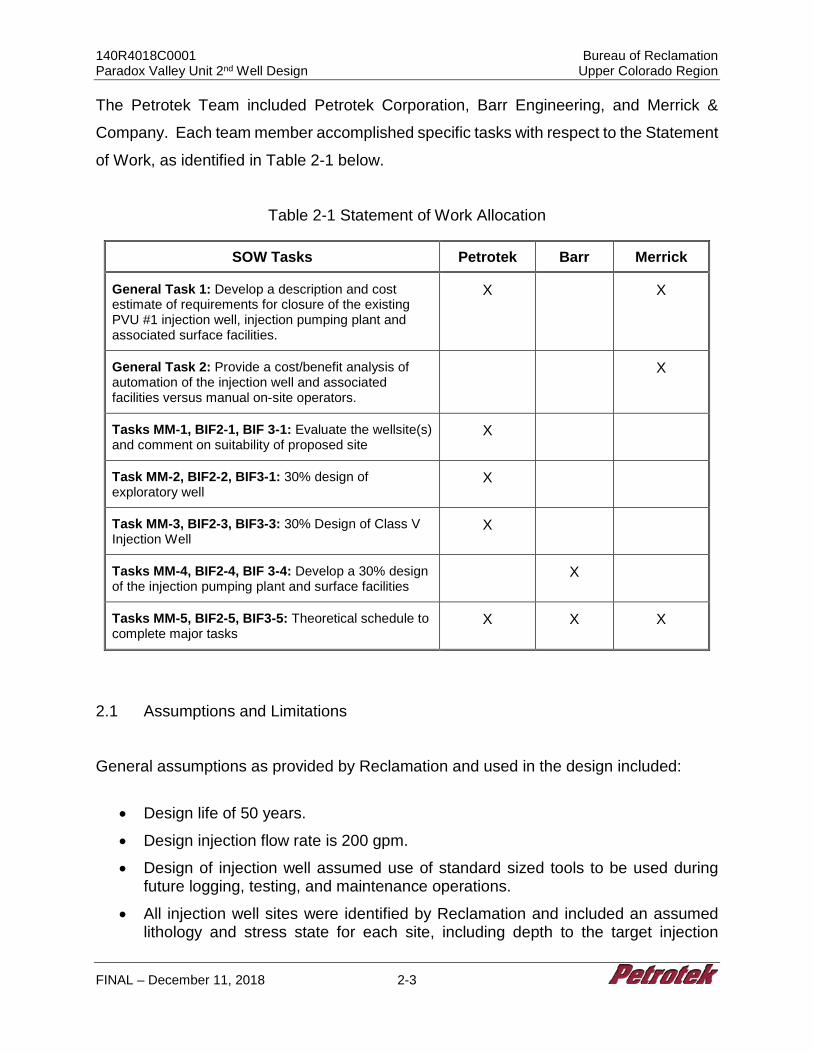
Table 2-1 Statement of Work Allocation
SOW Tasks Petrotek Barr Merrick
General Task 1: Develop a description and cost estimate of requirements for closure of the existing PVU #1 injection well, injection pumping plant and associated surface facilities.
X X
General Task 2: Provide a cost/benefit analysis of automation of the injection well and associated facilities versus manual on-site operators.
X
Tasks MM-1, BIF2-1, BIF 3-1: Evaluate the wellsite(s) and comment on suitability of proposed site
X
Task MM-2, BIF2-2, BIF3-1: 30% design of exploratory well
X
Task MM-3, BIF2-3, BIF3-3: 30% Design of Class V Injection Well
X
Tasks MM-4, BIF2-4, BIF 3-4: Develop a 30% design of the injection pumping plant and surface facilities
X
Tasks MM-5, BIF2-5, BIF3-5: Theoretical schedule to complete major tasks
X X X
2.1 Assumptions and Limitations
General assumptions as provided by Reclamation and used in the design included:
• Design life of 50 years.
• Design injection flow rate is 200 gpm.
• Design of injection well assumed use of standard sized tools to be used during future logging, testing, and maintenance operations.
• All injection well sites were identified by Reclamation and included an assumed lithology and stress state for each site, including depth to the target injection
140R4018C0001 Bureau of Reclamation Paradox Valley Unit 2nd Well Design Upper Colorado Region
FINAL – December 11, 2018 2-4
formation, salt thickness, location of major faults, and other properties determined from seismic reflection data, logs from existing wells in the area, etc.
• Surface facilities design included, at a minimum, a building to house the infrastructure, all equipment and supporting features necessary to accept the brine from a Reclamation pipeline at 10 psi, pressurization of the injection tubing, pressurization of the wellbore annulus, and delivery of the high-pressure brine to the injection well connection. This also included all electrical and motor control panels.
• Cost estimates were based on information and data obtained during investigations for each alternative. These estimates are used to: (1) Assist in the selection of a preferred plan; (2) Determine the economic feasibility of a project; and (3) Support seeking construction funding from Congress. Per Reclamation instruction, the cost estimates included a 10% allowance for Unlisted Items and 25% for Contingencies.
The following additional assumptions and limitations were identified specific to tasks
assigned in the Statement of Work (Table 2-1).
2.1.1 Closure Assumptions and Limitations (General Task 1)
General Task 1 involves the development of a description and cost estimate of
requirements for closure of the existing PVU #1 injection well, and the injection pumping
plant and associated surface facilities. As directed by Reclamation, activities and costs
for closure of the existing BIF were evaluated. Activities include the plugging and
abandonment of the PVU #1 well and demolition of existing surface facilities. Specific
assumptions and limitations for closure of PVU #1 and demolition of surface facilities are
discussed in Sections 2.1.1.1 and 2.1.1.2, respectively.
2.1.1.1 Plugging and Abandonment of PVU #1
The currently approved plugging and abandonment plan from the EPA Class V UIC
Permit CO5108-00647, Appendix C states the following:
The UIC Director has determined that this well plugging and abandonment plan adequately protects the USDWS…After receiving approval from the appropriate Regional EPA office, the permitted injection well will be plugged in accordance with the Plugging and Abandonment Plan as follows:
140R4018C0001 Bureau of Reclamation Paradox Valley Unit 2nd Well Design Upper Colorado Region
FINAL – December 11, 2018 2-5
1. Plug #1: Install a bridge plug 14,080 feet to 14,185 feet below ground level (BGL).
2. Plug #2: Unlatch polished bore receptacle/liner hanger at 12,884 feet (BGL) and recover the 5 1/2-inch 0.0304 wall 125 ski (sic) C-276 BDS injection tubing.
3. Plug #3: Cement tubing from bridge plug to 12,900 feet (BGL). 4. Plug #4: Bentonite slurry to fill annulus casing to 1,000 feet (BGL) 5. Plug #5: Cement annulus casing to surface and provide surface marker.
Assumptions pertaining to the plugging and abandonment of PVU #1 activity and cost are
summarized below. See Section 3.1.2 for additional closure detail and procedures. Note
that these procedures exceed the minimum EPA requirements.
2.1.1.1.1 Plugging and Abandonment of PVU #1 – General Assumptions
• The estimate is based on Q1 2019 dollars; prices are subject to change based on
market conditions.
• The plugging plan will need to be modified from the current permit as the wellbore below 14,080 feet KB (14,048 GL) is inaccessible due to collapsed pipe based on Reclamation records. Reclamation must submit a new plan and receive approval from US EPA prior to mobilizing equipment and personnel to the site.
• The new plugging and abandonment plan will include setting two cast iron bridge plugs at approximately 14,060 and 14,050 feet KB to isolate the perforated interval from the injection tubing. Procedures and costs assume that the liner hanger and liner remain in the well and that the injection tubing and seal assembly are successfully pulled from the well without issue. If the seal assembly does not release properly, the tubing will have to be shot-off or cut above the seal assembly depth, which would require additional procedures and incur additional costs beyond those reported in Sections 3.1.3.1.5 and 3.1.4.1, respectively.
• The new plugging plan will incorporate the use of more robust cement with 6% bentonite in place of a bentonite slurry.
• The disposal of any produced fluids, kill fluid, or waste from the well has not been accounted for in the cost estimate or procedures and may be addressed during final design.
• The handling, storage and/or disposal of all well and wellhead components removed from the PVU #1 well may be addressed during the final design.
140R4018C0001 Bureau of Reclamation Paradox Valley Unit 2nd Well Design Upper Colorado Region
FINAL – December 11, 2018 2-6
• Demolition of any communications, internet, intranet, and extranet systems associated with well monitoring equipment may be addressed during the final design.
• Costs include the required regulatory reporting to EPA following completion of plugging operations.
2.1.1.2 Closure of Injection Facilities
Demolition activities and costs for removal of the existing BIF were evaluated.
Attachment A (Merrick & Co.) includes the complete report prepared addressing this
evaluation. Several assumptions were made pertaining to responsibilities of Reclamation
and hence not included in the demolition activity and cost exercise; these assumptions
are summarized below (see Attachment A for full detail).
2.1.1.2.1 Reclamation Responsibilities (Excluded from Estimate):
• The disposal and remediation of existing hazardous material or waste, chemicals and supply systems such as caustic, cooling water chemicals, and rotating equipment oils, and any raw material and/or inventory of brine in existing pipelines.
• Demolition of any communications, internet, intranet, and extranet systems.
• All land cost, right of ways, easements, loans and capitalized interest, deferred capital, deferred operating cost, legal, consulting, and insurance related costs.
• Operating and maintenance services.
• Demolition of laboratory equipment, analyzers, or supplies, except those identified as included.
2.1.1.2.2 Closure of Injection Facilities Assumptions
The following assumptions were made with respect to scope of the injection facility
closure effort (see Attachment A for additional detail):
• Mechanical - No pipe or equipment painting is required for demolition. - Pipe and equipment insulation is calcium silicate with aluminum jacketing. - Piping lengths were estimated from the equipment layout.
140R4018C0001 Bureau of Reclamation Paradox Valley Unit 2nd Well Design Upper Colorado Region
FINAL – December 11, 2018 2-7
• Civil / Structural - Seismic design basis is Site Class ‘D’, Risk Category II. - Soil basis for foundations is AICE “Soft Clay” type, with a soil loading of 2,000
PSF, and a soil density of 60 PCF.
• Electrical / Instrumentation - Power distribution is via 4-wire system. - Instrumentation is via a conventional wired transmission system. - Average distance from instrument to junction box is 50 feet. - No instrument transmitters have freeze protection.
• All underground piping will be cleared of contents and capped to prevent any future environmental release.
• All above ground piping will be cleared of contents and removed from site.
• All electrical equipment to associated pumps will be removed from site.
• All instruments, network cabling, conduits, and cable trays will be demolished and removed from site.
• All pumps located at the Brine Injection Facility site will be isolated, purged, and removed from site.
• The “Floc” and “Decant” ponds will have any sludge/sediments removed and disposed of by Reclamation. The associated pond liners will be removed and disposed of by Reclamation. No environmental remediation costs are anticipated or included.
• All HVAC, lighting, and power receptacles will remain functional within the BIF building.
• Structural steel for pipe supports and access to the injection well filters will be demolished and removed from site.
• The potable water system will be demolished and removed from site.
Cost estimates were determined based on the following assumptions (see Attachment A
for additional assumption detail):
• AICE V10.1 is used to generate the estimate, which has Q1 2017 pricing as a cost basis.
• This estimate is in Q1 2019 dollars. Escalation of AICE pricing basis is as follows: - 3.75% per year for materials - 4.5% per year for construction - 3.0% per year for design engineering
140R4018C0001 Bureau of Reclamation Paradox Valley Unit 2nd Well Design Upper Colorado Region
FINAL – December 11, 2018 2-8
- 3.5% per year for construction management
• Contracting Strategy: - The estimate is based on having a single construction firm performing the
work.
• Labor: - Field wages are as shown in the recommended wage rate table in the
Appendices, derived from Davis-Bacon and local means rates. See Attachment A for additional wage-related assumptions.
- The standard work week is 40 hours and assumed no overtime. - AICE baseline productivity is based on a 42-minute hour, which is a
productivity factor of 0.7. This productivity is appropriate for the scope and conditions of this project.
- Indirect costs for field labor such as per diem, etc., are included in the Indirect Section 6.3 of Attachment A.
The following costs were assumed incurred by Reclamation and were not included in the
closure cost estimate:
• The disposal and remediation of existing hazardous material or waste.
• Disposal of chemicals and supply systems such as caustic, cooling water chemicals, and rotating equipment oils.
• Disposal of any raw material and/or inventory.
• Demolition of any communications, internet, intranet, and extranet systems.
• All land cost, right of ways, and easements.
• All loans and capitalized interest.
• All deferred capital.
• All deferred operating cost.
• All legal, accounting, consulting, and other organizational cost.
• Surety provisions including any letters of credit or other financial instruments.
• Program insurance including OCIPs.
• Operating and maintenance services (Owner or third-party provider).
• Demolition of laboratory equipment, analyzers, or supplies, except those identified as included.
140R4018C0001 Bureau of Reclamation Paradox Valley Unit 2nd Well Design Upper Colorado Region
FINAL – December 11, 2018 2-9
A 12-week decommissioning duration was assumed. Additional detail regarding
assumptions and limitations pertaining to indirect costs (i.e., construction contracting, field
labor costs, engineering, freight and taxes), exclusions, and the engineering discipline
basis (i.e., mechanical, civil/structural, electrical/instrumentation) are addressed in the full
Demolition Class 3 Cost Estimate included in Attachment A.
2.1.2 Automation Assumptions and Limitations (General Task 2)
General Task 2 requires provision of a cost/benefit analysis of automation of the injection
well and associated facilities versus manual on-site operators. The current injection well
control system is Rockwell Control Logix, wherein the well facility PLC is connected to the
surface treatment facility PLC using a modem and datalink. The current facility has one
operator station that is used to monitor and control the injection well site. The current
control system does not allow for remote monitoring or control of the facility.
As part of either an update to the existing system or a new injection facility and well,
Reclamation is considering implementing new controls and monitoring which will enhance
the plant operation. A new system must monitor the data on continuous basis, and store
it for historical recording, trending, and report generation. The plant will require continuous
control of pumps, valves and other equipment to support safe operation. The requirement
for continuous monitoring and controls for the injection well facility necessitates selection
of an automation system that can perform these tasks on a continuous basis, therefore,
a fully automated control system was chosen.
2.1.2.1 Cost Development Approach and Assumptions
Costs were derived by first developing a preliminary IO count for the new PLC based
control system based on the existing plant Piping and Instrumentation Diagrams (P&IDs)
for the brine injection well facility. The human-machine interface (HMI) graphic count was
based on existing PLC HMI screens. The new PLC-based control system IO count with
20% spare IO assumed the following:
140R4018C0001 Bureau of Reclamation Paradox Valley Unit 2nd Well Design Upper Colorado Region
FINAL – December 11, 2018 2-10
• Digital Inputs (DI) - 110
• Digital Outputs (DO) - 60
• Analog Inputs (AI) - 40
• HMI Screens - 10
The above PLC IO count, HMI screen count, and number of operator and engineering
workstations were given to PLC integrators to develop Rough Order of Magnitude (ROM)
cost for the new PLC based system.
EPA permit conditions impact the required controls and instrumentation. It was assumed
that the following controls and monitoring features will be provided in the brine injection
well control system to support future EPA permit requirements, which are assumed to be
consistent with current permit requirements:
• The well site instruments will be capable of continuously monitoring the following parameters with an accuracy of 95% or greater. All the parameters will be monitored and recorded at no greater than 1 second interval. Monitoring of injection pressure, flow rate, cumulative volume, and casing/tubing annulus pressure is required.
• Reclamation will provide and maintain in good operating condition two (2) one-inch fittings isolated by a needle valve or equivalent and located: 1) at the wellhead on the tubing and 2) on the tubing/casing annulus.
• These valves will be positioned to allow the attachment of 1-inch maximum injection pressure gauges of an appropriate rating.
• Injection pressure, measured at the surface, will not exceed permitted limit of 5,350 psig.
• All critical parameters will be stored in historian for recoding and trending. All readings will be time stamped. For critical parameters monitored, daily averages will be developed. Daily averages will be averaged monthly.
• A paired reading of the annulus and injection pressures will be taken at the same time on a weekly basis. Daily and monthly averages along with the weekly paired readings will be reported quarterly to the EPA Region 8 in accordance with the permit conditions.
140R4018C0001 Bureau of Reclamation Paradox Valley Unit 2nd Well Design Upper Colorado Region
FINAL – December 11, 2018 2-11
The following design features will be included in the plant design to support EPA permit
compliance:
• Required instrumentation will be added to the plant design – to be shown on P&IDs.
• Required valves will be added to the plant design – to be shown on P&IDs and piping drawings.
• Correct pump design with PLC and pop-off system will be selected to ensure that the measured pressure at the surface does not exceed 5,350 psig.
• Plant control system will monitor and record the compliance parameters at 1 second rate and store the data on historian.
• The historian stored data will be used to develop the daily, weekly, and monthly averages for reporting to EPA office. Each critical parameter average, min, and max values also will be stored in the historian.
2.1.2.2 Risks and Limitations Associated with New Automation
The proposed automation system has been successfully implemented on multiple
industrial facilities. However, following are some of the risks associated with implementing
the new controls:
• The operation and maintenance staff need to be trained on using the new controls.
• Spare parts inventory must be kept for the new PLC.
• The new control system must go through regular system updates and software patch implementation.
• With reduced staffing levels to support the operation from a remote location, the response time to attend to any site problem will be increased. Someone will have to drive to the BIF site to attend to major problems. Round the clock support on site will not be available.
• In case the communication link between the well site and remote office is lost, operators will have to be sent to site to support the operation, and re-establish communication.
• Operating the plant from remote location over a network connection will require robust cybersecurity measures to prevent unauthorized access.
The new automation system will be designed to manage these risks as follows:
• Training for operation staff on new control system will be included as part of scope.
140R4018C0001 Bureau of Reclamation Paradox Valley Unit 2nd Well Design Upper Colorado Region
FINAL – December 11, 2018 2-12
• Two years O&M spare parts will be included as part of the scope.
• BOR will add operation procedures to the injection site to implement regular system upgrades and software patches.
• To reduce risk of failures on the new automation system, critical components like controller, power supplies, and network communication will be specified to be redundant.
• Selection of redundant communication paths will reduce the risk of communication failure.
• Proper encryption, firewalls, and username/password protections will be implemented to prevent unauthorized access to the system.
2.1.3 Well Site Suitability Assumptions and Limitations (Tasks MM-1, BIF2-1, BIF3-1)
Tasks MM-1, BIF2-1, and BIF3-1 involve the evaluation of the wellsite(s) and comment
on suitability of the proposed sites. Assumptions and limitations related to different well
sites are discussed in Section 4.0.
2.1.4 Exploratory Well Assumptions and Limitations (Tasks MM-2, BIF2-2, BIF3-2)
Tasks MM-2, BIF2-2 and BIF3-2 involve the 30% design of two vertical exploratory wells
at the bottomhole locations for the Monogram Mesa and BIF well scenario, as prescribed
by Reclamation. Figures 1-3 and 1-4 present the bottomhole locations TBIF 1.5 and
TMM-1; the exploratory wells MM E1 and BIF E1 would be vertically installed from ground
surface to these bottomhole locations.
The following design assumptions pertain to exploratory wells and conversion of
exploratory wells to injection wells:
• Due to substantial costs of drilling separate exploratory wells, a dual purpose design option was used for all the exploratory wells. This design approach included installation of a 5 1/2-inch CRA Liner with a carbon steel 5 1/2-Inch tieback string. If testing indicates the location is suitable for an injection well and conversion to an injection well is designated by Reclamation, the exploratory well would then be completed as an injection well with a 5 1/2-inch CRA tieback string.
• Per Reclamation, the design of these wells is based on the PVU #1 well due to its exceptional functional endurance.
140R4018C0001 Bureau of Reclamation Paradox Valley Unit 2nd Well Design Upper Colorado Region
FINAL – December 11, 2018 2-13
• Design life of the well is 50 years, including the wellhead, casings, cement, injection tubing and packer.
• Expected injectate (brine) specific gravity is 1.17.
• Expected bottomhole temperature is 230 degrees Fahrenheit.
• Formation tops are noted in Table 2-1.
• Geological overburden and pore pressure are expected to conform to normal pressure regimes, and are expected to increase to a nominal value, significantly above normal, of 1.0 to 1.3 psi/ft below the salt in Leadville. The 1.3 psi/ft is an upper limit safety factor value assumed to increase the expected project longevity (e.g., 50-year design life). The 1.3 psi/ft is a combination of 1.0 psi/ft overburden stress and an approximately 0.30 psi/ft reservoir pressure increase due to injection (4,320 psi at a depth of 14,100 feet).
• Unless otherwise noted, all tubular products are assumed to conform to API minimum strength specifications.
• Based on typical industry standards, the following design safety factors were used: - Collapse 1.20 - Joint and Body (Tensile) 1.60 - Internal Yield Pressure (Burst) 1.20
• Due to concern about salt loading exceeding industry norms, heavy wall casing is specified across the Paradox Salt interval and 1,000 feet above.
• All strings of casing and tubing will be certified as new with mill test reports and verification via third party positive material identification (PMI). Carbon steel tubular goods will be inspected with electromagnetic induction testing (Amolog IV or equivalent), with full length drift and special end area evaluations. Alloy tubular goods will be inspected using ultrasonic transverse and radial techniques with full length drift and special end area inspection.
• All tubular goods will be shipped with thread protectors and loaded onto trucks using suitable stripping between layers. Alloy will be protected from body wall contact with isolation rings of rubber or composite material.
• All tubular goods will be offloaded at the site using a forklift to protect from damage while handling. Threads will be cleaned and new thread compound will be installed prior to installation. Special handling tools and power tongs designed for alloy tubular goods will be used during the installation of alloy equipment.
• The first 6,000 feet of vertical hole will be air drilled to mitigate lost circulation issues. When a depth of approximately 6,000 feet is reached, the borehole will be filled with oil based mud and surface casing set.
• Tubular strengths for corrosion resistant alloys (CRA’s) are taken from specifications for PVU #1 but also were a verified with analytical calculations. It is
140R4018C0001 Bureau of Reclamation Paradox Valley Unit 2nd Well Design Upper Colorado Region
FINAL – December 11, 2018 2-14
assumed that the tubular goods used in these wells will meet or exceed the material specifications used in the PVU #1 well.
• Completion of exploratory well liners is designed to be identical to injection wells, to facilitate conversion into injection wells at a later date, and to avoid the premature liner collapse observed in the PVU #1 well.
• Collapse loading is expected to be at its greatest in and below salt. An overburden gradient of 1.0 psi per foot was assumed in the salt. Based on results from PVU #1, there is potential for greater than 1.0 psi/ft pressure gradient.
• Most casing design collapse scenarios for casing installation include the loading from 16.4 pounds per gallon (ppg) cement displaced with water. The exception was 14.0 ppg cement for intermediate casing.
• Most casing design burst scenarios include casing full of 16.4 ppg cement with an evacuated annulus. The exception was 14.0 ppg cement for intermediate casing.
• Worst case tension is calculated at the top joint, and based on the entire string weight hanging in air. This is a conservative calculation because some of the pipe weight will be supported by laying on the side of the borehole and by buoyancy, but the material strength is necessary to withstand torque and drag forces.
• Each tubing completion was evaluated to perform under 5,000 psi internal pressure with inhibited fresh water as the fluid in the annulus providing hydrostatic head. Brine waste was assumed to be 9.76 ppg on average at a flow rate of 200 gpm and a conservative lower bounding temperature of 40 degrees Fahrenheit.
• Though the exploratory well tieback tubing will not be subjected to injection pressure from the surface, it is possible that it could be exposed to injection pressure downhole from the adjacent injector well.
• Coring will be performed in the salt and injection interval as per recommendation from the Consultant Review Board (see email on Oct 4, 2018 at 12:57 PM Wood, Christopher <[email protected]>) (Attachment C).
• Per instruction from Reclamation an expendable exploratory well option was evaluated but was not pursued due to design risk and small cost savings (see Section 3.3.1.6.1).
2.1.5 Class V Injection Well Assumptions and Limitations (Tasks MM-3, BIF2-3, BIF3-3)
Tasks MM-3, BIF2-3 and BIF3-3 involve the 30% design of three injection well
alternatives, as prescribed by Reclamation. Figures 1-3 and 1-4 present the proposed
well surface and bottomhole locations. Figures 2-1 and 2-2 present the well profiles for
directionally drilled wells MM1 and BIF3.
140R4018C0001 Bureau of Reclamation Paradox Valley Unit 2nd Well Design Upper Colorado Region
FINAL – December 11, 2018 2-15
The design of the wells for this project was based on the SOW and the PVU #1 well
design. In this regard, the operational success of the PVU #1 well has been a testament
to the original drilling and material design employed. The design has been upgraded
where necessary as dictated by operational results. For example, the liner in the Leadville
completion has collapsed and hence the 5 1/2-inch liner design has been modified to
greater collapse strength. Therefore, the design basis draws from successful aspects of
the current well design.
The following assumptions were made when developing the Class V Well designs:
• Per Reclamation requirements, the design life of the well (including the wellhead, casings, cement, injection tubing and packer) is expected to be 50 years.
• Expected injectate (brine) specific gravity is 1.17.
• Expected bottomhole temperature is 230 degrees Fahrenheit.
• Geological overburden and pore pressure are expected to conform to normal pressure regimes, and are expected to increase to a nominal value, significantly above normal, of 1.0 to 1.3 psi/ft below the salt in the Leadville.
• Unless otherwise noted all tubular products are assumed to conform to API minimum strength specifications.
• Based on typical industry standards, the following design safety factors were used: - Collapse 1.20 - Joint and Body (Tensile) 1.60 - Internal Yield Pressure (Burst) 1.20
• Due to concern about salt loading exceeding industry norms, heavy wall casing is specified across the Paradox Salt interval and 1,000 feet above.
• All strings of casing and tubing will be certified as new with mill test reports and verification via third party positive material identification (PMI). Carbon steel tubular goods will be inspected with electromagnetic induction testing (Amolog IV or equivalent), with full length drift and special end area evaluations. Alloy tubular goods will be inspected using ultrasonic transverse and radial techniques with full length drift and special end area inspection.
• All tubular goods will be shipped with thread protectors and loaded onto trucks using suitable stripping between layers. Alloy will be protected from body wall contact with isolation rings of rubber or composite material.
• All tubular goods will be offloaded at the site using a forklift to protect from damage while handling. Threads will be cleaned and new thread compound will be installed
140R4018C0001 Bureau of Reclamation Paradox Valley Unit 2nd Well Design Upper Colorado Region
FINAL – December 11, 2018 2-16
prior to installation. Special handling tools and power tongs designed for alloy tubular goods will be used during the installation of alloy equipment.
• The first 2,000 feet of vertical hole will be air drilled to mitigate lost circulation issues. When a depth of approximately 2,000 feet is reached, the borehole should be filled with water-based mud and preparations should be made to commence underbalanced drilling with a parasite string to reduce potential lost circulation problems. Water-based mud will be displaced with oil-based mud at approximately 2,000 feet above the first salt.
• Tubular strengths for corrosion resistant alloys (CRA’s) are taken from specifications for PVU #1; those values were manually checked using the approach and equations noted in Section 3. With the exception of the Leadville liner, it is assumed that the tubular goods used in these wells will meet or exceed the material specifications used in the PVU #1 well. (See Appendix A.)
• Collapse loading is expected to be at its greatest in and below the salt interval. An overburden gradient of 1.0 psi per foot was assumed in the salt. Based on results from PVU #1, there is potential for greater than 1.0 psi/ft pressure gradient.
• For most casing design, collapse scenarios for casing installation include the loading from 16.4 ppg cement displaced with water. The exception was 14.0 ppg cement for intermediate casing.
• For most casing design, burst scenarios include casing full of 16.4 ppg cement with an evacuated annulus. The exception was 14.0 ppg cement for intermediate casing.
• Worst case tension is calculated at the top joint, and based on the entire string weight hanging in air. This is a conservative calculation because some of the pipe weight will be supported by laying on the side of the borehole and by buoyancy, but the material strength is necessary to withstand torque and drag forces.
• Each tubing completion was evaluated to survive 5,000 psi internal pressure with inhibited freshwater as the fluid in the annulus providing hydrostatic head. Brine waste was assumed to be 9.76 ppg on average at a flow rate of 200 gpm and a conservative lower bounding temperature of 40 degrees Fahrenheit.
2.1.6 Injection Facility Assumptions and Limitations (Tasks MM-4, BIF2-4, BIF3-4)
Tasks MM-4, BIF2-4, and BIF3-4 involved the development of a 30% design of the
injection pumping plant and surface facilities. Design of new surface facilities as part of
planning and budgeting for a new brine injection well facility was developed to
approximately a 30% level of completion. As with any facility at this level of design
completion, new information may come to light and further development of design may
result in changes that cannot be anticipated at this time. Provided below is a summary of
140R4018C0001 Bureau of Reclamation Paradox Valley Unit 2nd Well Design Upper Colorado Region
FINAL – December 11, 2018 2-17
the assumptions and limitations made in developing the design and cost estimate for this
report.
2.1.6.1 Injection Facility Assumptions
New facility design was prepared to meet the design criteria established by Reclamation
and was modeled after the existing system for the PVU #1 facility. Design criteria are
identified in the Basis of Design (see Attachment B), with key elements listed below.
Changes in some of these criteria would result in greater deviation from the cost estimate
than others. For example, if either design flow rate or pressure criteria were made more
stringent (i.e., design flow rate is increased or design system pressure is increased), costs
could increase to a substantial degree. Likewise, selection of another type of pump could
also result in changes to the cost estimate. Key design criteria assumed were:
• Design flow rate = 200 gpm;
• Design injection pressure = 5,000 psig at surface;
• Maximum surface injection pressure = 5,350 psig;
• Design pressure of mechanical components > 5,500 psig;
• Brine delivered to site at 10 psig in a Reclamation pipeline (pipeline is not part of the injection facility design);
• Sodium chloride concentration is approximately 260,000 mg/L;
• Hydrogen sulfide concentration is approximately 80 – 100 mg/L;
• Three injection pumps at 50% of design flow rate each;
• Maximum Allowable Working Pressure (MAWP) >5,500 psig;
• Wetted parts shall be made of Inconel 625 or Hastelloy C-276;
• Speed and capacity control by variable frequency drive (VFD);
• Inconel 625 or Hastelloy C-276 pipe for all high-pressure brine conveyance;
• Electrical equipment will be 480V;
• Electrical system will not require intrinsically safe design requirements; and,
• Civil site work will be limited to minor site grading, aggregate surfacing, and perimeter fence installation
140R4018C0001 Bureau of Reclamation Paradox Valley Unit 2nd Well Design Upper Colorado Region
FINAL – December 11, 2018 2-18
Market prices for key metals that go into the construction of high-pressure pipe and pump
wet ends that are proposed for this project will also have an impact on final construction
cost. Should market prices rise before materials are ordered, project cost will rise in
accordance with the price changes. The alloys of choice, Hastelloy C-276 and Inconel
625, contain large amounts of nickel. Project cost could be impacted if the market price
for nickel changes significantly from current pricing.
As stated above, the design has been developed to approximately 30% of completion.
Design has focused on the primary system components, which include the components
that will have the greatest impact on construction cost. A significant contingency should
be allowed for unscoped features, such as architectural components, ancillary water
supply and piping, system controls details, site and building lighting, and miscellaneous
building mechanical components. A reasonable contingency at this level of design is 10%
of the scoped work; however, depending on decisions made during final design, costs for
items that are not scoped at this time may be greater than 10%.
2.1.6.2 Limitations Regarding the Application of Technologies
The design on which the cost estimate is based relies on high pressure piping and positive
displacement plunger pumps with wetted parts constructed of Inconel 625 or Hastelloy C-
276. While these alloys have been determined to be the metal of choice for this design,
if other materials are selected for the project, project costs may be affected.
2.1.6.3 Limitations Regarding Cost Estimates
The American Association of Cost Engineers International (AACE International,
aacei.org) lists the following five characteristics as important to successful cost
estimating: project definition, end use of the estimate, methodology of preparing the
estimate, required accuracy range, and preparation effort. The most important cost
estimating characteristic is the level of project definition available to the cost estimator.
The level of project definition can be also described as the percentage of the design that
140R4018C0001 Bureau of Reclamation Paradox Valley Unit 2nd Well Design Upper Colorado Region
FINAL – December 11, 2018 2-19
has been completed (30% in the case of this work). The level of project definition defines
the extent and types of input information available to the estimating process. Such inputs
may include project scope definition, regulatory and other requirements, specifications,
project plans, drawings, calculations, information from past projects, etc.
With a design completion of 30%, it is anticipated that the cost estimate is primarily
based on project type and scale compared to other projects, combined with vendor
quotes for more costly components of the project. It is recommended that the estimated
project cost include a 30% contingency for unscoped work. AACE International guidance
recommends that an accuracy range of -20% to +30% of the base cost estimate be used
to account for potential inaccuracies resulting from a project definition at a 30% level of
completion. For budgetary purposes, we recommend that the project cost estimate
(including the 10% unlisted items) plus 25% of the project cost estimate be used to
account for potential cost estimate inaccuracies.
2.1.7 Schedule Assumptions and Limitations (Tasks MM-5, BIF2-5, BIF3-5)
Tasks MM-5, BIF2-5 and BIF3-5 involve development of a theoretical schedule to
complete major tasks. Assumptions and limitations regarding schedule for construction
of each proposed injection facility and injection well (i.e. well drilling, testing and
completion) include the following:
• All operations take place outside of winter months.
• Reclamation provides and maintains road access to the construction site throughout the construction process.
• The drilling schedule for each well is based on: (1) drilling days required for the PVU #1 well; (2) advancements in drilling technology since the drilling of PVU #1; (3) a bit program and estimated drilling time curve provided by Smith Bits, (4) extensive formation testing and logging as directed by Reclamation; (5) collection of six whole cores (two in the Paradox Salt – confining interval; and four in the Leadville Formation – injection interval); and (6) Petrotek Team experience.
• There is no recent, nearby offset deep drilling data and drilling days may vary from what has been projected for each well based on: (1) down hole conditions, especially regarding the salt formation(s) encountered; (2) high pressure communication from the PVU #1 fault block to adjacent fault blocks in deep
140R4018C0001 Bureau of Reclamation Paradox Valley Unit 2nd Well Design Upper Colorado Region
FINAL – December 11, 2018 2-20
formations; (3) additional (unidentified) geologic structures and salt/salt weld; and (4) drilling and/or running/cementing casing across various mapped or unmapped faults.
• The injection facility construction schedule assumes final design has been completed.
• Access to the site will need to accommodate a maximum semi-trailer length of approximately 120 feet and a load width of approximately 16 feet with 12 axles weighing up to 170,000 lbs. The average load would weigh less than 110,000 lbs., have a length of less than 70 feet and a width of approximately 12 feet. It is estimated that approximately 1,200 loads would require ingress and egress over the course of the construction project. The site would accommodate approximately 30 personnel during daily operations.
140R4018C0001 Bureau of Reclamation Paradox Valley Unit 2nd Well Design Upper Colorado Region
FINAL – December 11, 2018 3-1
3.0 TASKS
As previously indicated, the purpose of this report is to:
1. Provide costs and other information pertaining to closure of the current PVU #1 well and associated BIF (see Figures 3-1 and 3-2).
2. Provide cost estimates associated with automation of the current or a new BIF. 3. Provide technical information and costs associated with the following:
a. Vertical exploratory wells MM E1 and BIF E1 with bottomhole locations at TMM-1 and TBIF 1.5 and (Figures 1-3 and 1-4).
b. Provide technical information and cost estimates for three (3) Class V wells (Figures 1-3 and 1-4):
• BIF2 (surface location) to bottomhole location at TBIF 1.5
• BIF3 (surface location) to bottomhole location at TBIF 1.5
• MM1 (surface location) to bottomhole location at TMM-1 c. New BIF design and cost at each Class V surface location (i.e. BIF2, BIF3, and
MM1) d. Provide estimated schedule for the installation of new facilities (well and BIF)
as well as demolition of the existing BIF.
Each of these requirements are reflected in specific tasks in Sections 3.1 – 3.5, below.
Note that an additional required task, Evaluation and Suitability of Sites, is addressed in
Section 4.0.
3.1 General Task 1 - Closure of PVU #1 Injection Well, Pumping Plant, and Associated
Surface Facilities
3.1.1 Description of Facilities
140R4018C0001 Bureau of Reclamation Paradox Valley Unit 2nd Well Design Upper Colorado Region
FINAL – December 11, 2018 3-2
3.1.1.1 Injection Well
Current Well Design
The PVU #1 well was originally drilled to a total depth of 15,827 feet BGL and perforated
between 14,080 and 15,827 feet KB. (KB height is 32’). The Paradox Salinity Control
Well No. 1 (PVU #1) was designed to: (1) protect the USDWs; (2) withstand collapse from
flowing salt; and (3) provide resistance to corrosion from the injected brine. The well was
drilled and cased in five stages starting with a 30-inch hole and ending with and 8.5-inch
hole at approximately 16,000 feet. A tapered intermediate casing string (9 5/8” x 10.98”)
was installed at 14,020 feet BGL.
The 5 1/2-inch injection tubing and liner runs from the surface to 15,901 feet BGL. The
tubing is made of Hastelloy C-276 alloy to provide corrosion resistance and design
strength to resist the bottomhole pressures expected at that time. In 2001, logging tools
encountered an obstruction at 14,070 feet KB that indicated liner collapse had occurred
(Subsurface Report 60D5207). However, operation of the well continued without a
noticeable effect on well performance. Standard operating procedure calls for
maintaining pressure in the well annulus slightly over equilibrium at the seal to prevent
brine from entering and corroding the annulus. To provide corrosion protection for the
long string casing, the casing-tubing annulus is filled with filtered fresh water and a
corrosion inhibitor from the liner hanger/PBR to surface. Below 13,068 feet to 15,808 feet
(plugged back total depth, PBTD) this annulus is filled with cement.
Figure 3-1 presents the current PVU #1 well design. Salient features include:
• The 9 5/8-inch intermediate well casing extends from the christmas tree at the surface to 14,020 feet BGL.
• The 5 1/2-inch Hastelloy C-276 injection tubing string runs inside the intermediate well casing and extends from the christmas tree at the surface to 12,808 feet BGL.
• At 12,808 feet, the Tubing Seal Assembly (TSA) and the Polished Bore Receptacle (PBR) connect the 5 1/2-inch injection tubing string to the injection liner.
140R4018C0001 Bureau of Reclamation Paradox Valley Unit 2nd Well Design Upper Colorado Region
FINAL – December 11, 2018 3-3
• The Hastelloy C-276 liner extends to approximately 15,901 feet BGL TD, and has 3 perforated intervals at varying depths below 14,080 feet.
• The space between the 9 5/8-inch casing and the injection tubing is the well annulus, which is filled with filtered fresh water.
Plugging and Abandonment of PVU #1
The current USEPA permit requires the following regarding injection well abandonment:
“The method for plugging and abandonment of any injection well shall not
allow the movement of a fluid containing any contaminant into any USDW
if the presence of that contaminant may cause a violation of the primary
drinking water standards under 40 CFR Part 141, other health based
standards, or may otherwise adversely affect the health of persons.
• Notice of Plugging and Abandonment: The permittee shall notify the Director forty five (45) days before conversion, workover, or abandonment of the well.
• Plugging and Abandonment Plan: The Permittee shall plug and abandon the well as provided in the Plugging and Abandonment Plan, Appendix C of the permit.
The permitted injection well will be plugged in accordance with the Plugging
and Abandonment Plan as follows:
1. Plug #1: Install a bridge plug 14,080 feet to 14,185 feet below ground level (BGL).
2. Plug #2: Unlatch polished bore receptacle/liner at 12,884 feet (BGL) and recover the 5 1/2-inch 0.0304 wall 125 ski (sic) C-276 BDS injection tubing.
3. Plug #3: Cement tubing from bridge plug to 12,900 feet (BGL). 4. Plug #4: Bentonite slurry to fill annulus casing to 1,000 feet (BGL). 5. Plug #5: Cement annulus casing to surface and provide surface
marker.”
140R4018C0001 Bureau of Reclamation Paradox Valley Unit 2nd Well Design Upper Colorado Region
FINAL – December 11, 2018 3-4
3.1.1.2 Current Injection Facilities
Figure 3-2 presents the current BIF facility schematic. Brine is transferred from the
surface treatment facility (STF) to the BIF via pipeline. As the brine enters the BIF, it flows
to the two 26,500 gallon underground fiberglass injection well storage tanks that are piped
to allow parallel operation or single tank operation. Brine from the injection well storage
tanks is pumped by a horizontal centrifugal charge pump to a bank of four injection well
guard filters. Once filtered, the injectate is fed to the high pressure displacement pumps
that deliver injectate to PVU #1.
To support the above process, the BIF includes several units such as the underground
brine storage tanks, Water Treatment Plant (WTP), the BIF Building and Well Annulus
Monitoring System (WAMS) Building, and various ponds. These are described below,
noting that this simplified description does not include piping, additional pumps, cables,
electrical systems, and other elements that are required to support brine injection at the
BIF.
• There are two 26,500 gallon underground storage tanks adjacent to the BIF Building. The purpose of the injection well storage tanks is to provide flow equalization for brine flows from the Surface Treatment Facility (STF) and the brine transfer pipeline for downstream processes.
• Initially the WTP plant supplied clean, fresh water to be blended with brine prior to the brine being injected into PVU #1. It was anticipated the brine must be diluted with at least 30% fresh water to prevent precipitation of calcium sulfate due to increased temperatures down hole. Later, operational data indicated this was not a concern as the operations caused the injection formation to cool in temperature; hence brine dilution ceased after 2001.
• The WTP also supplies all Paradox Valley Unit facilities with utility and potable water. The fresh water is taken from the Dolores Riverand pumped to the Flocculation (Floc) Pond where suspended solids are allowed to settle. The water is then pumped to filter system which removes the remaining silt from the river water. Fresh water leaving the filter goes to a holding tank called the backwash tank.
• The BIF Building houses the injection pumps and controls for the well system. The WAMS Building, near the injection well itself, holds the annulus tank and monitoring system for the injection well.
140R4018C0001 Bureau of Reclamation Paradox Valley Unit 2nd Well Design Upper Colorado Region
FINAL – December 11, 2018 3-5
• A Decant Pond, Floc Pond, and Blow off Pond are also present at the BIF area. The Floc Pond is the primary settling basin for water pumped from the river to be used for fresh water to the facilities. The Decant pond receives backwash flows from the WTP, and may serve as a primary settling basin for high turbidity river water during high spring runoff. The Blow off Pond receives flow from the injection pump pressure relief valves, as necessary.
3.1.2 Closure Methodology and Description
PVU #1 and associated BIF may be closed as injection rates are further reduced and
the current facility becomes uneconomical to operate. Methods to closure both the PVU
#1 well and existing BIF are presented below.
3.1.2.1 Injection Well
The basis and assumptions and technical approach for the plugging and abandonment
of PVU #1 include the following:
• All necessary permit modifications listed in Section 2.1.1.1 for the plugging and abandonment plan are approved by EPA.
• Regulatory negotiations will be the responsibility of Reclamation.
• The well can be killed (put in static condition) by pumping a full column of fluid (drilling mud) from surface.
• A coil tubing unit (CTU) with 2 3/8-inch sour service coil is available for the plugging operation and the CTU vendor will allow cement to be pumped through it.
• A workover rig with a hook load/pulling capacity of 300,000 lbs (dry tubing weight with 1.2x safety factor) or more is available to remove the injection string from the well.
• Plugging activities can be completed in 15 field days and are conducted outside of winter months.
The closure methodology and description for the PVU #1 well are addressed in the
Sections that follow.
140R4018C0001 Bureau of Reclamation Paradox Valley Unit 2nd Well Design Upper Colorado Region
FINAL – December 11, 2018 3-6
3.1.2.1.1 BHP and Options to Kill
When the well is initially shut down, a pressure of 3,500-4,500 psi remains at the surface.
Prior to entering PVU #1, the well must be killed or brought to a static pressure condition.
The most common method of killing a well is to pump a full column of weighted brine from
the surface which overcomes the injection formation pressure with the hydrostatic head
or weight of a full column of kill fluid. An alternative method is to use a snubbing unit which
runs tools into a well while under pressure. However, due to safety concerns, a snubbing
operation should be avoided if other options exist. Therefore, procedures and costs have
been provided for killing the well with fluid pumped from the surface.
Based on information provided by Reclamation, the bottomhole pressure (BHP) of PVU
#1 is approximately 12,000 psi. In order to kill the well, a full column of 16.1 ppg fluid
(approximately 330 bbls) is needed. As a precautionary measure, a total kill fluid volume
of 450 bbls weighing 16.5 ppg is advised. As noted previously, weighted brine is typically
used as kill fluid. In this case, the zinc bromide brine would be needed to reach the
required density. In addition to elevated costs for this fluid, there are significant HSE
issues associated with its use. The use of zinc bromide will cost approximately $2,000
per barrel for a total of approximately $900,000. However, because 1) the well would be
plugged after pumping the kill fluid and 2) the injectivity need not be preserved, weighted
drilling mud can be used as a kill fluid instead of brine. As such, procedures and costs
have been provided using 16.5 ppg kill mud at an approximate cost of $70 per barrel for
a total of approximately $31,500. The estimated cost savings to use mud versus zinc
bromide is approximately $868,500.
3.1.2.1.2 Plugging Material Identification and Compatibility
The plugging material identified in the current EPA Class V permit for plugging and
abandonment is a bentonite slurry which would be used to fill the existing borehole from
total depth to surface. The recommended plugging plan which would need to be approved
by EPA uses a more robust material, cement with 6% bentonite. This approach is more
protective of the USDW, human health, and the environment.
140R4018C0001 Bureau of Reclamation Paradox Valley Unit 2nd Well Design Upper Colorado Region
FINAL – December 11, 2018 3-7
3.1.2.1.3 Rig and Equipment Requirements
The workover rig used to remove the tubing from PVU #1 should have a minimum pulling
capacity of approximately 300,000 lbs. This value is based on dry tubing weight (19.2 lb/ft
x 12,844 feet with a 1.2x safety factor). The CTU should have a 2 3/8-inch coil suited for
sour service and be equipped with enough tubing to set two cast iron bridge plugs (CIBP)
at approximately 14,060 feet and be prepared to pump cement through the coil in five
stages from 14,060 feet to surface.
Additional equipment needs include the following:
• 11-inch, 10,000 psi, double ram BOPs
• Anchors set per rig specifications
• Two (2) 10,000 psi rated CIBPs to set on CTU
• Pipe laydown machine
• Handling tools for 5 1/2-inch injection string
• Pipe racks to accommodate at least 12,844 feet of 5 1/2-inch injection tubing
• Pump truck to pump approximately 330 bbls kill mud at up to 5,500 psi
• 500 bbl Frac tank to hold kill mud
• Open top tank to take kill mud returns once displaced by cement
• Telehandler/loader with forks to move pipe and equipment as needed
• HSE - H2S contingency plan with escape packs for all crew members
• HSE - H2S monitors for personnel and site air monitors 3.1.2.1.4 HSE Requirements
General HSE requirements for the plugging and abandonment of PVU #1 include the
following procedures and equipment:
• All personnel and visitors must sign in and out
• All visitors must have Level D PPE at a minimum and be escorted while on site
• Level D PPE (hard hat, steel toe boots, gloves and safety glasses)
140R4018C0001 Bureau of Reclamation Paradox Valley Unit 2nd Well Design Upper Colorado Region
FINAL – December 11, 2018 3-8
• Flame resistant clothing (FRCs)
• Personal H2S monitors for all personnel
• H2S site monitors (minimum of 2) and a wind sock
• Daily job safety analysis (JSA) review
• JSA review with new personnel and visitors on site
• JSA review prior to a new, detailed or particularly hazardous operation (e.g., welding, confined space entry, pumping cement)
3.1.2.1.5 PVU #1 P&A Prognosis
The general prognosis provided for the plugging and abandonment (P&A) of PVU #1
assumes that a revised plan negotiated by Reclamation has been approved by the EPA.
Note additional or modified steps may be required based on field or well conditions. The
general P&A procedures include the following:
1. Notify EPA at least 45 days prior to commencing P&A operations 2. Set new (or test existing) rig anchors per workover rig vendor specifications 3. Spot two (2) 500 bbl frac tanks 4. Haul in 450 bbls of 16.5 ppg kill mud and put into one frac tank 5. Haul in 1,000 bbls fresh water and put into two frac tanks 6. Rig-up pump truck to top of tree 7. Pump 450 bbls 16.5 ppg kill mud into well 8. Ensure well is dead (0 psi on wellhead gauge) and rig-down pump truck 9. Rig-up CTU with 2 3/8” sour service coil, 10,000 psi BOP, and support equipment 10. Run casing scraper on CTU to approximately 14,070 feet 11. Set 10,000 psi CIBP at approximately 14,060 feet 12. Set second 10,000 psi CIBP at approximately 14,050 feet 13. Rig-down CTU 14. Use nipple down crew to disassemble tree 15. Rig-up 10,000 psi, double ram BOPs 16. Rig-up workover rig with 300,000 lb working capacity and support equipment 17. Pressure test BOPs 18. Rig-up casing crew
140R4018C0001 Bureau of Reclamation Paradox Valley Unit 2nd Well Design Upper Colorado Region
FINAL – December 11, 2018 3-9
19. Sting out of polished bore receptacle (PBR) 20. Pull all 5 1/2-inch injection tubing from well (approx. 12,844 feet) 21. Rig-down workover rig/casing crew and release same 22. Rig-up CTU and cementers 23. Run in hole with CTU and tag CIBP at approximately 14,050 feet 24. Mix cement with 6% bentonite (total cement required is approximately 3,050
sacks (sx); total water required is approximately 660 bbls) 25. Spot 1st cement plug from approximately 14,050 feet to 12,700 feet (approx. 150
sx) displacing kill mud into frac tank 26. Wait on cement for approximately 8 hours 27. Pump remaining cement in 4 stages (approx. 3,173 ft/stage; 730 sx/stage) filling
casing to surface displacing kill mud to frac tank 28. Rig-down and demobilize all equipment 29. Cut casing approximately 3 feet below ground surface and set permanent marker 30. Survey well location for P&A Report 31. Complete P&A report on EPA Form 7520-13 and provide to Reclamation for
submittal to EPA within 60 days
3.1.2.2 Injection Facilities
As shown in Figure 3-2, the existing BIF includes several system components such as
decant and flocculation ponds, a warehouse, water treatment building and system,
underground storage tanks, and the Brine Injection Facility (BIF) building that houses
injection pumps and related controls. The demolition statement of work encompasses
demolishing and removing all above ground piping, instrumentation, process electrical
power distribution, and associated equipment of the brine injection, fresh water and
potable water systems from the BIF. Specifically and as presented in Section 2.1.1.2, the
statement of work includes:
• Clearing and capping of underground piping;
• Clearing and removal of above ground piping;
• Demolishing of network cabling, conduits, and cable trays and removal from site;
• Removal of all pumps from the BIF building;
• Removal of all existing fiberglass catwalk infrastructure.
140R4018C0001 Bureau of Reclamation Paradox Valley Unit 2nd Well Design Upper Colorado Region
FINAL – December 11, 2018 3-10
• Removal of sediments from the Floc and Decant ponds and removal of pond liners;
• Retention of HVAC, lighting and power within the BIF building;
• Demolition and removal of structural steel pipe supports and access to the injection wells systems, and
• Demolition and removal of the potable water system.
The specific equipment identified for demolition includes:
• Injection Well Filters (x4)
• Injection Pumps (x4)
• Injection Well Storage Tanks (x2)
• Brine Charge Pump
• Backwash & Freshwater Storage Tanks (x6)
• Freshwater Blend Pump
• River Pump
• Filter Pump
• Filter Backwash Pump
• Decant Pump
• River Water Clarifier
• River Water Filter Vessel
Attachment A includes detailed information pertaining to the closure process and cost
estimate. Statement of Work details presented therein show the specific equipment or
item to undergo removal and detailed notes concerning characteristics of that item (e.g.
pump design information, piping information). Additionally, electrical and I&C demolition
items are presented. The statement of work details are presented in Table 3-1A, below,
that forms a basis for demolition cost estimates. Table 3-1B presents equipment, piping
and electrical statement of work information used in the closure analysis.
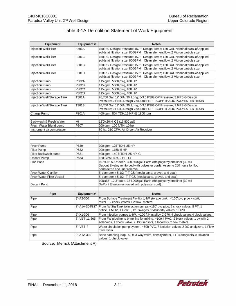
140R4018C0001 Bureau of Reclamation Paradox Valley Unit 2nd Well Design Upper Colorado Region
FINAL – December 11, 2018 3-11
Table 3-1A Demolition Statement of Work Equipment
Equipment Equipment # Notes Injection Well Filter F301A 150 PSI Design Pressure; 150°F Design Temp; 120 GAL Nominal; 90% of Applied
solids at filtration size; 800GPM Clean element flow; 2 Micron particle size. Injection Well Filter F301B 150 PSI Design Pressure; 150°F Design Temp; 120 GAL Nominal; 90% of Applied
solids at filtration size; 800GPM Clean element flow; 2 Micron particle size. Injection Well Filter F301C 150 PSI Design Pressure; 150°F Design Temp; 120 GAL Nominal; 90% of Applied
solids at filtration size; 800GPM Clean element flow; 2 Micron particle size. Injection Well Filter F301D 150 PSI Design Pressure; 150°F Design Temp; 120 GAL Nominal; 90% of Applied
solids at filtration size; 800GPM Clean element flow; 2 Micron particle size. Injection Pump P302A 115 gpm, 5500 psig, 400 HP Injection Pump P302B 115 gpm, 5500 psig, 400 HP Injection Pump P302C 115 gpm, 5500 psig, 400 HP Injection Pump P302D 115 gpm, 5500 psig, 400 HP Injection Well Storage Tank T301A 26,700 Gal; 12' DIA; 30' Long; 0-3.5 PSIG OP Pressure; 3.9 PSIG Design
Pressure; 0 PSIG Design Vacuum; FRP ISOPHTHALIC POLYESTER RESIN Injection Well Storage Tank T301B 26,700 Gal; 12' DIA; 30' Long; 0-3.5 PSIG OP Pressure; 3.9 PSIG Design
Pressure; 0 PSIG Design Vacuum; FRP ISOPHTHALIC POLYESTER RESIN Charge Pump P301A 400 gpm, 80ft TDH,15 HP @ 1800 rpm Backwash & Fresh Water
x6 12'Dx20'H, CS (16,800 gal)
Fresh Water Blend pump P607 200 gpm, 100 ft TH, 10 hp Instrument air compressor 50 hp, 210 CFM, Air Dryer, Air Receiver River Pump P630 300 gpm, 125' TDH, 25 HP Filter Pump P632 200 gpm, 115ft, 5 HP Filter Backwash pump P631 400 gpm, 140 ft TDH, 25 HP, CI Decant Pump P633 120 GPM, 40ft, 2 HP, CI Floc Pond 107'x95', 5.67' deep, 320,500 gal; Earth with polyethylene liner (32 mil
Dupont Elvaloy reinforced with polyester cord). Assume 250 hours for floc pond demo and liner removal.
River Water Clarifier 6' diameter x 5 1/2' T-T CS (media sand, gravel, and coal) River Water Filter Vessel 6' diameter x 5 1/2’ T-T CS (media sand, gravel, and coal) Decant Pond
108'x68', 12.3' deep, 134,000 gal; Earth with polyethylene liner (32 mil DuPont Elvaloy reinforced with polyester cord).
Pipe Equipment # Notes
Pipe 8"-A2-300 From Surface Treatment Facility to IW storage tank. ~'100' pvc pipe + static mixer + 2 check valves + 2 flow meters
Pipe 8"-A1A-304/337 From IW Stg Tank to injection pumps.~150' pvc pipe, 2 check valves, 8 PT, 1 orifice, 1 MOV, 1 Flow T, 12 swages, 15 butterfly valves, 1 DPIT
Pipe 5"-X1-306 From Injection pumps to IW. ~100 ft Hastelloy C-276, 4 check valves,4 block valves, Pipe 6"-VBT-11-365 From FW pipeline to brine line for mixing. ~100 ft PVC, 2 block valves, 1 cv with 2
solenoids, 1 check valve. 2 DO sensors, 1 local PG, 2 flow meters. Pipe 6"-VBT-? Water circulation pump system. ~50ft PVC, 7 Isolation valves. 2 DO analyzers, 1 Flow
transmitter Pipe 2"-ATA-339 Brine sampling loop. 50 ft, 3-way valve, density meter, TT, 4 analyzers, 8 isolation
valves, 1 check valve. Source: Merrick (Attachment A)
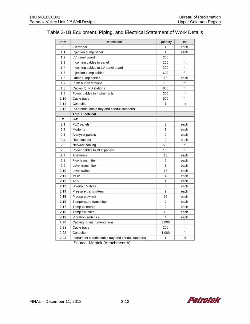
140R4018C0001 Bureau of Reclamation Paradox Valley Unit 2nd Well Design Upper Colorado Region
FINAL – December 11, 2018 3-12
Table 3-1B Equipment, Piping, and Electrical Statement of Work Details
Item Description Quantity Unit 1 Electrical 1 each
1.1 Injection pump panel 1 each 1.2 LV panel board 200 ft 1.3 Incoming cables to panel 200 ft 1.4 Incoming cables to LV panel board 200 ft 1.5 Injection pump cables 600 ft 1.6 Other pump cables 15 each 1.7 Push button stations 750 ft 1.8 Cables for PB stations 850 ft 1.9 Power cables to instruments 200 ft
1.10 Cable trays 500 ft 1.11 Conduits 1 lot 1.12 PB stands, cable tray and conduit supports
Total Electrical 2 I&C
2.1 PLC panels 2 each 2.2 Modems 5 each 2.3 Analyzer panels 2 each 2.4 HMI stations 2 each 2.5 Network cabling 500 ft 2.6 Power cables to PLC panels 100 ft 2.7 Analyzers 13 each 2.8 Flow transmitter 5 each 2.9 Level transmitter 5 each
2.10 Level switch 13 each 2.11 MOV 4 each 2.12 AOV 1 each 2.13 Solenoid Valves 6 each 2.14 Pressure transmitters 9 each 2.15 Pressure switch 16 each 2.16 Temperature transmitter 2 each 2.17 Temp elements 2 each 2.18 Temp switches 10 each 2.19 Vibration switches 4 each 2.20 Cabling for instrumentations 5,000 ft 2.21 Cable trays 200 ft 2.22 Conduits 1,000 ft 2.23 Instrument stands, cable tray and conduit supports 1 lot
Source: Merrick (Attachment A)
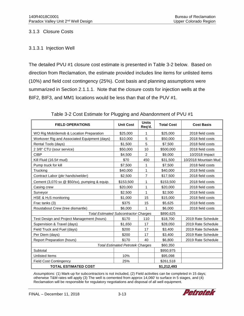
140R4018C0001 Bureau of Reclamation Paradox Valley Unit 2nd Well Design Upper Colorado Region
FINAL – December 11, 2018 3-13
3.1.3 Closure Costs
3.1.3.1 Injection Well
The detailed PVU #1 closure cost estimate is presented in Table 3-2 below. Based on
direction from Reclamation, the estimate provided includes line items for unlisted items
(10%) and field cost contingency (25%). Cost basis and planning assumptions were
summarized in Section 2.1.1.1. Note that the closure costs for injection wells at the
BIF2, BIF3, and MM1 locations would be less than that of the PUV #1.
Table 3-2 Cost Estimate for Plugging and Abandonment of PVU #1
FIELD OPERATIONS Unit Cost Units Req'd. Total Cost Cost Basis
WO Rig Mob/demob & Location Preparation $25,000 1 $25,000 2018 field costs Workover Rig and Associated Equipment (days) $10,000 5 $50,000 2018 field costs Rental Tools (days) $1,500 5 $7,500 2018 field costs 2 3/8" CTU (sour service) $50,000 10 $500,000 2018 field costs CIBP $4,500 2 $9,000 10/2018 Impact Kill Fluid (16.5# mud) $70 450 $31,500 10/2018 Mountain Mud Pump truck for kill $7,500 1 $7,500 2018 field costs Trucking $40,000 1 $40,000 2018 field costs Contract Labor (pkr hands/welder) $2,500 7 $17,500 2018 field costs Cement (3,070 sx @ $50/sx), pumping & equip. $153,500 1 $153,500 2018 field costs Casing crew $20,000 1 $20,000 2018 field costs Surveyor $2,500 1 $2,500 2018 field costs HSE & H2S monitoring $1,000 15 $15,000 2018 field costs Frac tanks (3) $375 15 $5,625 2018 field costs Roustabout Crew (tree dismantle) $6,000 1 $6,000 2018 field costs
Total Estimated Subcontractor Charges $890,625 Test Design and Project Management (hours) $170 110 $18,700 2019 Rate Schedule Supervision & Travel (days) $1,650 17 $28,050 2019 Rate Schedule Field Truck and Fuel (days) $200 17 $3,400 2019 Rate Schedule Per Diem (days) $200 17 $3,400 2019 Rate Schedule Report Preparation (hours) $170 40 $6,800 2019 Rate Schedule
Total Estimated Petrotek Charges $60,350 Subtotal $950,975 Unlisted Items 10% $95,098 Field Cost Contingency 25% $261,518
TOTAL ESTIMATED COST $1,212,493
Assumptions: (1) Mark-up for subcontractors is not included, (2) Field activities can be completed in 15 days; otherwise T&M rates will apply (3) The well is cemented from approx 14,060' to surface in 5 stages, and (4) Reclamation will be responsible for regulatory negotiations and disposal of all well equipment.
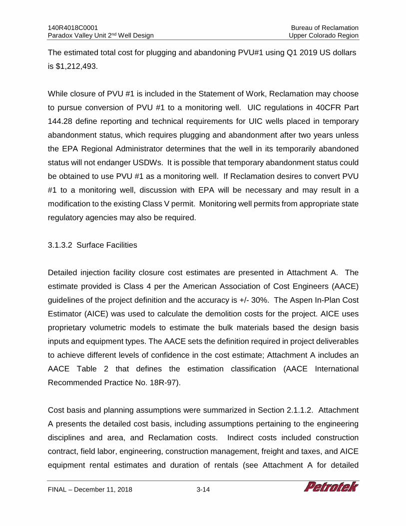
140R4018C0001 Bureau of Reclamation Paradox Valley Unit 2nd Well Design Upper Colorado Region
FINAL – December 11, 2018 3-14
The estimated total cost for plugging and abandoning PVU#1 using Q1 2019 US dollars
is $1,212,493.
While closure of PVU #1 is included in the Statement of Work, Reclamation may choose
to pursue conversion of PVU #1 to a monitoring well. UIC regulations in 40CFR Part
144.28 define reporting and technical requirements for UIC wells placed in temporary
abandonment status, which requires plugging and abandonment after two years unless
the EPA Regional Administrator determines that the well in its temporarily abandoned
status will not endanger USDWs. It is possible that temporary abandonment status could
be obtained to use PVU #1 as a monitoring well. If Reclamation desires to convert PVU
#1 to a monitoring well, discussion with EPA will be necessary and may result in a
modification to the existing Class V permit. Monitoring well permits from appropriate state
regulatory agencies may also be required.
3.1.3.2 Surface Facilities
Detailed injection facility closure cost estimates are presented in Attachment A. The
estimate provided is Class 4 per the American Association of Cost Engineers (AACE)
guidelines of the project definition and the accuracy is +/- 30%. The Aspen In-Plan Cost
Estimator (AICE) was used to calculate the demolition costs for the project. AICE uses
proprietary volumetric models to estimate the bulk materials based the design basis
inputs and equipment types. The AACE sets the definition required in project deliverables
to achieve different levels of confidence in the cost estimate; Attachment A includes an
AACE Table 2 that defines the estimation classification (AACE International
Recommended Practice No. 18R-97).
Cost basis and planning assumptions were summarized in Section 2.1.1.2. Attachment
A presents the detailed cost basis, including assumptions pertaining to the engineering
disciplines and area, and Reclamation costs. Indirect costs included construction
contract, field labor, engineering, construction management, freight and taxes, and AICE
equipment rental estimates and duration of rentals (see Attachment A for detailed
140R4018C0001 Bureau of Reclamation Paradox Valley Unit 2nd Well Design Upper Colorado Region
FINAL – December 11, 2018 3-15
information pertaining to cost basis). The overall cost summary for demolition of the
scoped elements is presented in Table 3-3, below.
Table 3-3 Cost Estimate for Demolition of BIF Facility
Project Title: Paradox Valley Unit 2nd Well Design Project Location: US Job No. 63089995 Date: 22OCT18 11:05:06
Prepared By: JCS Est. Class: 4 Currency: DOLLARS USD
Overall Project Summary - Key Qty Basis Unit Wage Labor Unit Matl Total
Account Key Qty MH MH Rate Cost Matl Cost Cost
(2) Equipment Demolition 2,639 39.60 104,496 104,496 (3) AG Pipe Demolition 726 51.95 37,724 37,724
(4) Earthwork 3 LS 668 40.19 26,837 26,837
(4) Other Sitework 2 LS 83 36.58 3,031 3,031
(4) Other Civil Demolition 4 LS 2,792 33.77 94,284 94,284
(5) Steel Demolition 247 38.52 9,530 9,530
(6) Instrumentation Demolition 902 56.58 51,035 51,035
(7) AG Electrical Demolition 587 56.19 32,990 32,990
Direct Totals 8,645 359,927 359,827
Const Equip & Indirects 304,887
Const Mgt, Staff, Supv 123,554
Freight
Taxes and Permits
Engineering 19,096
Other Project Costs 78,837
Contingency 177,260
Indirect Totals 703,633
Project Totals: 8,397
350,397
1,063,560
Source: Merrick (Attachment A)
The estimated total demolition cost using Q1 2019 US dollars is:
$887,000 +/-30%, plus $177,000 of contingency, for a total of $1,064,000.
Costs are detailed in Attachment A and summaries represent an AACE Class 4 estimate,
which matches the current level of project definition. Detailed cost reports are also
included in Attachment A.
140R4018C0001 Bureau of Reclamation Paradox Valley Unit 2nd Well Design Upper Colorado Region
FINAL – December 11, 2018 3-16
3.2 General Task 2 - Cost Benefit of Automation of Injection Facility
As discussed in Section 2.1.2, the existing controls cannot be re-used in a new facility,
nor is the level and sophistication of the existing well optimum for a new well. Further,
Reclamation requests a current evaluation of modern automation and controls for a
remote facility, including technical and economic factors, remaining in compliance with
EPA regulations and the existing permit. The following analysis addresses the proposed
implementation of automation at a new BIF. This summary is taken from the detailed
report found in Attachment A.
3.2.1 Injection Well Automation Design and Description
The current control system for PVU #1 is an Allen-Bradley ControlLogix System. It
includes monitor levels and flow with some automatic controls and manual switching of
filters. Automation of the control system was evaluated with respect to design and cost
benefit.
3.2.2 Automation Approach
The automation approach was designed to address automated monitoring, reporting, and
mandatory controls, and to compare the relative cost of integrating automation against
the cost of using the very limited automation as present in the existing brine well via a
Cost/Benefit Analysis. For the new brine injection well facility, it is important to monitor
the data on continuous basis, store it for historical recording, trending and report
generation. The plant will also require continuous control of pumps, valves and other
equipment to support safe operation and automated emergency shutdown. The
requirement for continuous monitoring and controls for the injection well facility
necessitates selection of automation system that can perform these tasks on continuous
basis. Based on the operations and controls requirements, a fully automated control of
the facility with monitoring and data recording facility was chosen.
140R4018C0001 Bureau of Reclamation Paradox Valley Unit 2nd Well Design Upper Colorado Region
FINAL – December 11, 2018 3-17
3.2.3 Proposed Design Basis
Key elements of the design are described briefly here. Details are contained in Appendix
A of Attachment A.
3.2.3.1 PLC System
The proposed Programmable Logic Controller (PLC) based system will use the latest
version of Campbell Scientific PLC or Rockwell’s AllenBradley (A-B) ControlLogix family
controllers, or equivalent. Reclamation staff has experience with both systems in general,
and selection of a PLC system would make for ease of upgrade, usage, and maintenance.
A PLC will support seamless controls and monitoring of brine injection well facility
systems including analog controls, digital controls, sequencing, operator graphic
interface, control face plates, alarm management, historian, trending, and an anti-virus
suite.
3.2.3.2 Basic Controls
The PLC will support various IO devices such as 4-20 mA transmitters, HART, RTD,
Thermocouple inputs, switches, and proximity switches. The PLC will be able to control
pumps, control valves, MOVs, On-Off and solenoid valves, and motor controls. Cycling
time will be less than 1 second.
3.2.3.3 Capacity
The PLC will have 20% spare IO for each type of IO distributed throughout the PLC-based
control system. A 20% spare rack capacity will be provided.
140R4018C0001 Bureau of Reclamation Paradox Valley Unit 2nd Well Design Upper Colorado Region
FINAL – December 11, 2018 3-18
3.2.3.4 Workstations and Controls
The brine injection well facility will have two operator workstations with two 24" LED HMI
screens connected to each operator workstation. One of the operator workstations will
have engineering capabilities. The PLC cabinet will include network switches, modems,
routers, media converter for communication interfaces, and a laser printer.
3.2.3.5 Security
The PLC will control access by operators, supervisors, engineers and system
administrators. The PLC operator / engineer workstation will have both network and
internet security.
3.2.3.6 Communications
PLC communications will include interface with the existing Rockwell Control Logix PLC
in the surface treatment facility and the remote operator workstation in the Reclamation
headquarter (HQ) office building. It will be possible to access the PLC based control
system from anywhere with an internet connection so that management or other
authorized staff can access to the control system from locations outside the plant or
Reclamation HQ office. The system will send notices either via text message and/or
email. These would include operation notifications operation alarms, compliance alarms,
operation shutdowns, compliance shutdowns.
3.2.3.7 Monitoring and Operations
The PLC will monitor and operate the brine injection well facility from the operator
workstation in the facility itself, a remote operator workstation in the Reclamation HQ
office or any other remote location with internet access as designated by Reclamation.
As indicated prior and detailed in Section 3.2.4.3, cybersecurity will be implemented to
ensure access by only Reclamation approved personnel. Brine injection pump start will
140R4018C0001 Bureau of Reclamation Paradox Valley Unit 2nd Well Design Upper Colorado Region
FINAL – December 11, 2018 3-19
be possible locally from the facility only. Remote starting of injection pumps will not be
allowed. All major equipment is monitored, including pumps, filter system, charge pump,
and motor controls.
3.2.3.8 Alarms
There will be three levels of alarms in PLC: compliance alarms, operational alarms and
alerts. Compliance alarms will have highest priority followed by operational alarms and
alerts. Compliance alarms will have thresholds to alert the operator before compliance
trip setpoints are reached (e.g. injection well annulus high pressure alarms will have high,
high-high and trip setpoints). The different alarm and alerts are as defined below:
• Compliance Alarms: Alarms and Shutdowns related to the conditions in the EPA permit for the operation of the well, including well pressure, flow, etc. Details are found in the permit renewal (2011).
• Operational Alarms: Alarms and Shutdowns related to the safe operation and protection of equipment, such as the low-level alarm, the shutdown of pump on low level, excess vibration, etc.
• Alerts: Normal Operational Changes, such as filter changes, automatic switch of low-pressure pumps, etc.
• Workstations in the Bureau HQ and used by local operators in the facility will be set up to display these alarms and alerts.
• The operator will be required to acknowledge the alarms by instructions on the Alarm Screen that appears upon the alarm. The alarms that are cleared will be removed from the alarm screen. The latest alarm will be on the top of the screen.
• BOR is required to shut down the brine injection well facility if a Seismic Event is felt at the BOR facility. Plant shutdown based on a seismic event will be considered as a compliance alarm. Though installation of seismic monitoring is not part of this project scope, BOR will have to make provisions for monitoring seismic events separately. Monitoring of seismic events will require addition of a Seismometer. The well parameters such as a change in well pressure (higher or lower) and/or flow, etc., may be indicative of seismic event.
3.2.3.9 Data Storage and Retrieval
The PLC historian will be able to store data for all plant tags for a duration of at least one
year, or as specified by permit requirements. It is assumed that the PLC system engineer
140R4018C0001 Bureau of Reclamation Paradox Valley Unit 2nd Well Design Upper Colorado Region
FINAL – December 11, 2018 3-20
will take backup of historian data on a CD/DVD or external hard drive periodically as
determined by Reclamation to retain necessary records as required by the EPA permit.
The PLC will support development of logs and reports including operator action logs,
maintenance logs, production reports etc. Reclamation staff will also be able to download
the historian data from the local HMI station in the facility or remote operator workstation
in Reclamation HQ.
3.2.3.10 Proposed Plant Controls
P&ID style HMI screens will be provided for plant control. The remote operator
workstation in Reclamation HQ will be used as the primary operator interface for
monitoring the facility during normal operation. The operator will be able to monitor the
facility, and acknowledge the alarms from this workstation. The brine injection well pumps
will be provided with VFDs that will be controlled from plant PLC. Stopping of injection
pumps and operation of other facility equipment will be possible from remote locations
although remote start will not be an option. Local operation of pumps from VFDs will be
possible if PLC workstations are not operational.
The PLC graphics will have permissive windows to indicate if all the interlocks are
satisfied before start of any pump. The operation of other pumps in facility such as brine
charge pump, water pumps and filtration system will be controlled using automatic
operation. In case the working pump trips, the stand by pump will start automatically. An
alarm will be generated on PLC workstation if pump shutdown occurs.
3.2.3.11 EPA Compliance
The following controls and monitoring features will be provided in the brine injection well
control system specifically to support the EPA requirements laid out in the well permit
renewal.
140R4018C0001 Bureau of Reclamation Paradox Valley Unit 2nd Well Design Upper Colorado Region
FINAL – December 11, 2018 3-21
• The well site instruments will be capable of continuously monitoring the following parameters with an accuracy of 95% or greater. All the parameters will be monitored and recorded at no greater than a 1 second interval.
• Injection pressure, will not exceed 5,350 psig.
• No upper limit flow rate is in the EPA permit but a maximum of 200 gpm will be applied by Reclamation.
• A cumulative volume is not given in the permit renewal.
• Casing / tubing annulus pressure.
• The operator will provide and maintain in good operating condition two (2) 1-inch fittings isolated by a needle valve or equivalent and located.
Additionally, records will be kept for up to one year; Reclamation will transfer by CD/ROM
or other storage media to Reclamation record retention as specified by permit or other
Reclamation requirements. Automation may also necessitate changes to current UIC
permit seismic monitoring conditions, and it is assumed these changes would be reflected
in the UIC permit for the replacement injection well.
3.2.4 Communication Between the Injection Well Pump Facility and Reclamation HQ
Office.
Communications between the well facility/injection facility and other locations, particularly
Reclamation’s HQ office are critical to maintaining remote operations. Several options
were considered.
3.2.4.1 Cellular Option
Owing to the variations in location and topography, communication between the selected
well site PLC and operator station in the Reclamation HQ office, cellular modems over
cellular network is the preferred communication method. This will require cell service
availability at the well site. Based on the proposed site locations, the two sites in the valley
may not have any cell service, while sites on top of the mesa should have cell service.
For locations where cell service is not available, high frequency radios can be used to
establish communication. If there is no clear line of sight between the site location and
140R4018C0001 Bureau of Reclamation Paradox Valley Unit 2nd Well Design Upper Colorado Region
FINAL – December 11, 2018 3-22
office building, intermediate repeaters will be required. These intermediate repeater
stations will require power. Small solar panels with batteries can be installed to power
the repeater station if utility power supply is not available.
3.2.4.2 Fiber Optic Option
Running fiber between the injection well site and office location along with the pipeline is
another option to establish communication. It would, however be far more expensive to
accomplish than the cellular approach.
3.2.4.3 Security Issues
The communication between the injection well site and the Reclamation HQ office
building must be secured using proper encryption. The controls network will be separate
from the Reclamation LAN to prevent outside access to the controls network. Establishing
a separate VLAN or guest network with proper encryption and permissions for the controls
network in the Reclamation HQ office site is the preferred approach. Once the internet
access is available to the controls network, it can be used to establish remote
communication, remote desktop login for plant monitoring and controls, and sending out
operator call outs (email or text messages) in case of alarm conditions.
The Reclamation IT / Security group should be involved during the final design phase to
streamline the approval process. The type of encryption (256 bit / 512 bit), security
provided on the control system and communication side should be specified to support
the final decision.
3.2.5 Cost of Proposed Automation System
Budgetary quotes were obtained for a PLC-based control and monitoring system from
two potential vendors (see Attachment A). Logical Systems, LLC (LS), estimated a capital
cost of $247,000, excluding installation. It was assumed that installation costs will be
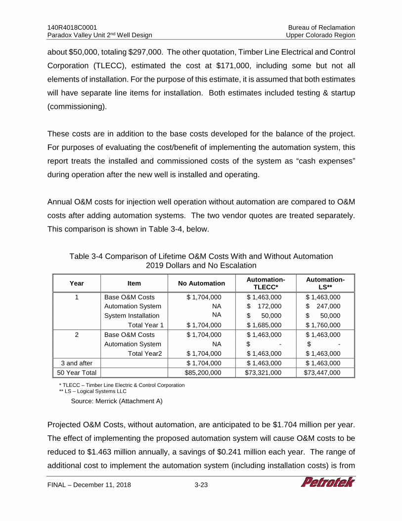
140R4018C0001 Bureau of Reclamation Paradox Valley Unit 2nd Well Design Upper Colorado Region
FINAL – December 11, 2018 3-23
about $50,000, totaling $297,000. The other quotation, Timber Line Electrical and Control
Corporation (TLECC), estimated the cost at $171,000, including some but not all
elements of installation. For the purpose of this estimate, it is assumed that both estimates
will have separate line items for installation. Both estimates included testing & startup
(commissioning).
These costs are in addition to the base costs developed for the balance of the project.
For purposes of evaluating the cost/benefit of implementing the automation system, this
report treats the installed and commissioned costs of the system as “cash expenses”
during operation after the new well is installed and operating.
Annual O&M costs for injection well operation without automation are compared to O&M
costs after adding automation systems. The two vendor quotes are treated separately.
This comparison is shown in Table 3-4, below.
Table 3-4 Comparison of Lifetime O&M Costs With and Without Automation 2019 Dollars and No Escalation
Year Item No Automation Automation- TLECC*
Automation- LS**
1 Base O&M Costs $ 1,704,000 $ 1,463,000 $ 1,463,000 Automation System NA $ 172,000 $ 247,000 System Installation NA
$ 50,000 $ 50,000
Total Year 1 $ 1,704,000 $ 1,685,000 $ 1,760,000 2 Base O&M Costs $ 1,704,000 $ 1,463,000 $ 1,463,000
Automation System NA $ - $ - Total Year2 $ 1,704,000 $ 1,463,000 $ 1,463,000
3 and after $ 1,704,000 $ 1,463,000 $ 1,463,000 50 Year Total $85,200,000 $73,321,000 $73,447,000
* TLECC – Timber Line Electric & Control Corporation ** LS – Logical Systems LLC
Source: Merrick (Attachment A)
Projected O&M Costs, without automation, are anticipated to be $1.704 million per year.
The effect of implementing the proposed automation system will cause O&M costs to be
reduced to $1.463 million annually, a savings of $0.241 million each year. The range of
additional cost to implement the automation system (including installation costs) is from

140R4018C0001 Bureau of Reclamation Paradox Valley Unit 2nd Well Design Upper Colorado Region
FINAL – December 11, 2018 3-24
$222,000 for TLECC’s proposal to $297,000 for LS’s proposal. Since the new controls
will allow the plant monitoring and control from Bureau headquarter office or other offsite
locations, the need for continuous operator and technical support on brine injection well
site will be reduced considerably. The support staff will be reduced considerably, however
the remaining staff will be required to be “on call” 24/7 and could result in some
occasionally increased workloads for the remaining staff.
Adoption of the TLECC proposed cost would result in a net savings of O&M costs by
about $170,000 in the first year even after the installation of the automation system. Using
the LS system would cause the first year’s O&M costs to rise by $56,000. Starting in the
second year, the installation of an automation system will save approximately $241,000
annually, regardless of vendor.
Over the life of the new well, O&M costs are projected to be over $85 million. The addition
of automation will reduce the lifetime O&M costs to just over $73 million, regardless of
system installed.
3.2.6 Conclusions
The automation system described in this Section 3.2 will create significant improvements
from current technologies, in data collection and monitoring, reporting, and in controlling
the operations to allow remote operations of the new brine well. This in turn, will result in
significantly lower annual O&M costs through the 50-year life of the well (after the first
year).
3.3 Monogram Mesa MM E1 and MM1
3.3.1 30% Design of Exploratory Well, MM E1
As shown in Figure 1-4, Monogram Mesa includes evaluation of an exploratory well MM
E1 with a surface location above the bottomhole TMM-1.
140R4018C0001 Bureau of Reclamation Paradox Valley Unit 2nd Well Design Upper Colorado Region
FINAL – December 11, 2018 3-25
3.3.1.1 MM E1 Data Needs and Considerations
Assumptions and design criteria for all vertical and directional wells are summarized in
Section 2.1.4. The MM E1 well surface location is to be above the bottomhole injection
target TMM-1. The preliminary hole and casing sizes have been designed to withstand
estimated geologic and reservoir conditions and promote completion to total target depth.
3.3.1.2 Monitoring Technologies
Permanent downhole monitoring technologies may be incorporated in wellbore designs
to continually monitor parameters, such as downhole temperature and pressure, during
well operation. For example, fiber optics may be deployed in (1) conjunction with an oil
or gas well production tubing string to obtain distributed temperature measurements or
(2) in hydrocarbon secondary production injection wells for water injection profiling, acid
injection profiling, and hydraulic fracture diagnosis.
Downhole monitoring was employed as early as 1973. Today, Schlumberger’s
WellWatcher is an example of a permanent monitoring system that integrates permanent
downhole measurement technology with surface data acquisition so that bottomhole
conditions may be remotely monitored. Pressure, temperature, density of borehole fluids,
and flow rate data are among the typical information types that are obtained.
Hydrocarbon producers use this monitoring to acquire information from wells where
monitoring by other means, such as production logging, is “impractical, uneconomical, or
impossible, including highly deviated wells and wells with restricted access”
(Schlumberger, 2018). Most often, these techniques are used in offshore or remote
areas, and are not installed in every well due to cost limitations. The average oil field
dowhhole permanent monitoring system for a deviated borehole of up to 16,000 feet in
length is several million dollars. Note that this equipment, like a satellite, is placed
downhole with no ability for subsequent repair or maintenance.
140R4018C0001 Bureau of Reclamation Paradox Valley Unit 2nd Well Design Upper Colorado Region
FINAL – December 11, 2018 3-26
The current permit for PVU #1 requires that monitoring be performed at surface facilities
prior to or during injection, including chemical analysis of injectate fluid, and “continuous
recordings of the injection pressure, flow rate, cumulative volume, and annulus pressure”
that is averaged daily (EPA, 2011). Mechanical integrity testing is required as
Reclamation must ensure that the injection well maintains mechanical integrity at all times
including demonstration that there is 1) no significant leak in the casing, tubing, or packer
(Part I); and 2) no significant fluid movement into an USDW through vertical channels
adjacent to the injection well bore (Part II). The permit mandates the following to ensure
absence of leaks:
The absence of significant leaks in the casing, tubing, and/or packer has been and shall be demonstrated on a continuing basis by monitoring the pressure on the casing/tubing annulus. This monitoring procedure was formalized in adopting a Standard Operating Procedure (SOP) for the Well Annulus Monitoring System (WAMS) on March 2, 2009 (Appendix ). The permittee shall place sufficient pressure on the annular space such that the range of pressure fluctuations caused by injection operations, such as temperature variations of the injected fluids shall be maintained in the positive range. Abnormal increases in annulus pressure shall be reported to the Director, and the cause of the increase shall be investigated. If the increase is determined to be related to leaks in either tubing or packer, the well shall be shut-in until repairs have been completed. This test is to be performed every year as part of the requirements of this permit”.
These permit requirements rely solely on surface monitoring to obtain data.
Permanent downhole monitoring at either the monitoring or injection well location would
obtain scientific information but would not substitute for already-mandated surface
monitoring. Reclamation would determine whether this additional information could
serve other purposes pertaining to geologic characterization or other uses outside the
scope of well operation, but a permanent downhole monitoring system is not required to
achieve full compliance with injection well regulations, nor would it likely substitute for
current monitoring requirements as presented in regulation.
140R4018C0001 Bureau of Reclamation Paradox Valley Unit 2nd Well Design Upper Colorado Region
FINAL – December 11, 2018 3-27
The permit mandates seismic monitoring, and there are permanent downhole monitoring
applications that could support this activity. The Midwest Geological Sequestration
Consortium (MGSC), led by the Illinois State Geological Survey, is currently injecting CO2
in a Class VI injection well that is a 3 year demonstration of carbon sequestration from a
biofuel source. Induced seismicity is a concern, so a Schlumberger WellWatcher PS3
passive seismic sensing system was installed in the injection well to provide continuous
real-time monitoring of microseismic activity. Schlumberger (2018) described the system
as follows:
Carbon Services opted to use a combination of four-component sensors of the WellWatcher PS3 system in the injection well and three-component vertical seismic profile (VSP) array sensors permanently installed in a nearby shallow geophysical monitoring well at the IBDP. Deployed near the injection zone of the CO2 injection well, the WellWatcher PS3 system array performed well, yielding high-fidelity microseismic observations. Microseismic data from the injection well were supplemented by data obtained from a shallow, permanently installed VSP sensor array in a nearby geophysical monitoring well. Together, the two arrays provided a cost-effective technical solution to the measurement challenges and directly resulted in a gain in operational efficiency.
Based on the above, one potential use of permanent monitoring systems is for seismic
monitoring. However, the lifespan of the above system was only 3+ years. If a system
was installed in a monitoring well rather than injection well, the viability of re-entering the
well to refurbish or repair a downhole system may be an option if it were designed for this
purpose, although the cost of such a system could be prohibitive.
3.3.1.3 MM E1 Well Design
Figure 3-3 presents the proposed well construction diagram for the Monogram Mesa
Exploratory Well (MM E1). The exploratory well at Monogram Mesa No. 1 is proposed to
be a vertical well drilled to a depth of 13,131’ feet BGL for the purposes of: (1) confirming
the geology and reservoir properties projected in the vicinity of the well; (2) to characterize
the proposed injection formation; and (3) test the injectivity of the formation. Based on
140R4018C0001 Bureau of Reclamation Paradox Valley Unit 2nd Well Design Upper Colorado Region
FINAL – December 11, 2018 3-28
requirements due to the geologic setting, consideration is being provided in this
evaluation for future conversion of the exploratory well into an injection well.
As stated in Section 2, minimum design criteria are 1.2 for single axis stress, 1.2 for triaxial
stress, and 1.6 for tensile stress. The design presented for this well resulted in a minimum
safety factor of 1.6 in tension at 100,000 lbs of overpull, and 1.85 under triaxial conditions.
Minimum design safety factors for single axis stresses range between 1.2 and 1.3 for
industry standard applications. Minimum triaxial design safety factor is usually 1.25. Risks
associated with a fifty (50) year design life dictated a stronger design. Limiting
assumptions for triaxial stress analysis in most scenarios include limiting conditions of
0.433 psi/ft fresh water inside the tubular goods, and 0.852 psi/ft (based on 16.4 ppg
cement) fluid on the outside of the tubular goods. Note that surface casing, set to 6,000
feet BGL and intermediate, set to 13,502 feet, must be cemented with a cement no greater
than 14 ppg density. Considerations such as foamed cement or other cement de-
weighting methods might be able to be used to increase the safety factor allowing for
lower strength, somewhat less costly tubulars to be used in the well. However, based on
evaluation at this stage it is likely that cost savings could only be gained at some risk of
lesser life expectancy and increased sensitivity to other uncertainties. Such
considerations are not included in this 30% design but may be addressed in future work.
Heavy wall 10.98-inch diameter casing is specified across the Paradox Salt interval and
to a depth of 1,000 feet above this zone to account for uncertainty in projected depths.
This design criteria has been included to reduce the potential for collapse at a 1.0 psi/ft
pressure gradient from the salt. The preliminary casing design includes clearance and
space for an additional 7- inch drilling liner to be run, to allow for contingency associated
with drilling uncertainty that may be encountered. Table 3-5 contains the proposed tubular
program for this well. All tubular goods are anticipated to have buttress or premium
threads.
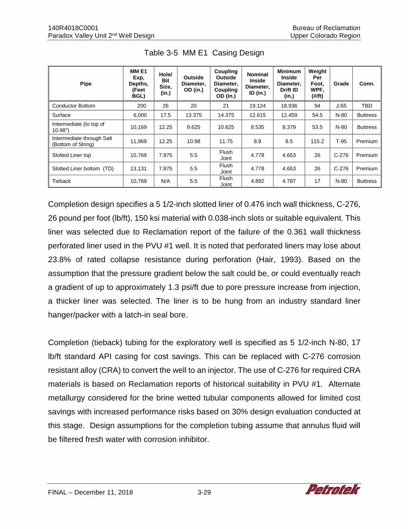
140R4018C0001 Bureau of Reclamation Paradox Valley Unit 2nd Well Design Upper Colorado Region
FINAL – December 11, 2018 3-29
Table 3-5 MM E1 Casing Design
Pipe
MM E1 Exp,
Depths, (Feet BGL)
Hole/Bit
Size, (in.)
Outside Diameter, OD (in.)
Coupling Outside
Diameter, Coupling OD (in.)
Nominal Inside
Diameter, ID (in.)
Minimum Inside
Diameter, Drift ID
(in.)
Weight Per
Foot, WPF, (#/ft)
Grade Conn.
Conductor Bottom 200 26 20 21 19.124 18.936 94 J-55 TBD
Surface 6,000 17.5 13.375 14.375 12.615 12.459 54.5 N-80 Buttress Intermediate (to top of 10.98") 10,169 12.25 9.625 10.625 8.535 8.379 53.5 N-80 Buttress
Intermediate through Salt (Bottom of String) 11,969 12.25 10.98 11.75 8.8 8.5 115.2 T-95 Premium
Slotted Liner top 10,769 7.875 5.5 Flush Joint 4.778 4.653 26 C-276 Premium
Slotted Liner bottom (TD) 13,131 7.875 5.5 Flush Joint 4.778 4.653 26 C-276 Premium
Tieback 10,769 N/A 5.5 Flush Joint 4.892 4.787 17 N-80 Buttress
Completion design specifies a 5 1/2-inch slotted liner of 0.476 inch wall thickness, C-276,
26 pound per foot (lb/ft), 150 ksi material with 0.038-inch slots or suitable equivalent. This
liner was selected due to Reclamation report of the failure of the 0.361 wall thickness
perforated liner used in the PVU #1 well. It is noted that perforated liners may lose about
23.8% of rated collapse resistance during perforation (Hair, 1993). Based on the
assumption that the pressure gradient below the salt could be, or could eventually reach
a gradient of up to approximately 1.3 psi/ft due to pore pressure increase from injection,
a thicker liner was selected. The liner is to be hung from an industry standard liner
hanger/packer with a latch-in seal bore.
Completion (tieback) tubing for the exploratory well is specified as 5 1/2-inch N-80, 17
lb/ft standard API casing for cost savings. This can be replaced with C-276 corrosion
resistant alloy (CRA) to convert the well to an injector. The use of C-276 for required CRA
materials is based on Reclamation reports of historical suitability in PVU #1. Alternate
metallurgy considered for the brine wetted tubular components allowed for limited cost
savings with increased performance risks based on 30% design evaluation conducted at
this stage. Design assumptions for the completion tubing assume that annulus fluid will
be filtered fresh water with corrosion inhibitor.
140R4018C0001 Bureau of Reclamation Paradox Valley Unit 2nd Well Design Upper Colorado Region
FINAL – December 11, 2018 3-30
3.3.1.4 MM E1 Well Plan
Based on the assumptions outlined and a 30% design, the following general drilling and
completion procedure has been designed for the installation of the proposed vertical well.
The procedure and depths may be modified as part of the final design and altered slightly
during field operations as warranted based on the actual downhole conditions ultimately
encountered during drilling.
1. Survey and prepare the location for an all-weather operation. (Location access to be provided by Reclamation.) Drilling pad should be a minimum of 450 feet by 450 feet, roughly centered on the well surface location. Install an 8-foot diameter corrugated metal pipe cellar to a depth of 4 feet. Drilling water of up to 2,000 bbls/day (58 gpm) is to be supplied to location by Reclamation. Water will be hauled to the site or a water supply well will be drilled. The location will be lined with an impervious liner and matting boards will be installed to protect the liner. Drainage ditches will surround the location to prevent accidental release of liquids. Electricity will be provided by generator with the drilling rig. Fuel will be hauled to the site and stored using appropriate secondary containment onsite.
2. Mobilize an air drilling rig and support equipment. Prepare a polyvinyl (16-ounce or equivalent) liner with berms and drainage sumps. Install the liner as the rig is erected. The liner will be placed under the rig, pumps, and tanks. Rig up a “zero discharge” closed loop solids control system.
3. Rig up air drilling rig on location with appropriate anchoring and an air drilling system with sufficient compressor capacity to clean the hole. Inventory all tubulars (drillpipe and drill collars) on location. Drill 26-inch hole to 200 feet, install 20-inch conductor casing with a cement shoe at TD.
4. Cement conductor to surface using a standard cement. Rig up a full service (24 hr/day) mud logger. Catch drill cutting samples approximately every 30 feet, from the surface to total depth.
5. After a wait on cement time per cement vendor program, air drill with 17 1/2-inch bit to 6,000 feet. The target for maximum vertical deviation is to not exceed 1.5° increase from the previous survey or 1° per 1,000 feet of hole.
6. Fill hole with water and lost circulation material (LCM). Condition hole and conduct a surface casing open-hole logging program consisting of spontaneous potential (SP), induction-resistivity (IND), 6-arm caliper, neutron/density (ND) and gamma ray (GR). Calculate the surface casing cement volumes, and add 50% excess to the annulus volume. In areas where the caliper log cannot measure the hole diameter, add 100% excess.
7. Run 6,000 feet of 13 3/8-inch, 54.5 lb/ft, J-55 Buttress casing equipped with a float shoe on the bottom and a float collar one joint off of the bottom. Centralizers will be installed near the float shoe, at the center of the first joint, near the float
140R4018C0001 Bureau of Reclamation Paradox Valley Unit 2nd Well Design Upper Colorado Region
FINAL – December 11, 2018 3-31
collar, on the collars of the second and third joints, and on every third collar thereafter, or per cement vendor recommendation.
8. Establish circulation and circulate at least one casing volume of drilling fluid. Cement the 13 3/8-inch casing and circulate the cement back to the surface. The slurry will consist of light-weight lead cement and a tail slurry of standard, premium cement. Displace the wiper plug to the float collar. Ensure that the floats are holding by checking for flow back.
9. Center the casing in the rotary table, drain and flush the diverter stack and allow the cement to set per service company recommendations. Install and test BOP system. Conduct a temperature survey at the optimal time recommended by the service company after displacing the plug to locate the top of cement.
10. After a wait on cement time appropriate for cementing program, run in hole and drill the shoe +10 feet, conduct shoe test. Drill a 12 1/4-inch hole to approximately 11,969 feet with a 12 1/4-inch bottom-hole assembly (BHA) including MWD gamma ray. This section should be drilled with oil-based mud to ensure torque and drag limitations are not exceeded.
11. Core salt per Reclamation. Circulate the hole clean and make a wiper trip to the surface prior to open-hole logging. Measure (strap) the drillpipe.
NOTE: Run desander, desilter, and centrifuge during drilling. Maintain an appropriate mud weight to control wellbore stability and target a viscosity of 35 to 70 sec/qt as appropriate for effective hole cleaning.
12. Condition hole and conduct the long-string casing open-hole logging program to include caliper logs, SP, IND, ND, GR and possibly dipole sonic from 6,000 feet to 11,969 feet BGL. Calculate long-string cement volumes, plus 50% excess to the annulus volume according to the cement stage collar placement intervals, use 100% excess in areas where the caliper cannot measure the hole diameter.
13. Run intermediate casing string consisting of 1,800 feet of 10.98 inch, 115.2 lb/ft, T95, premium connection, extra heavy wall, custom casing, equipped with a float shoe on the bottom and a float collar one joint off of the bottom. Then run a crossover with 10,169 feet of 9 5/8-inch, 53.5 lb/ft, N-80 Buttress casing. Centralizers will be installed near the float shoe, at the center of the first joint, near the float collar, on the collars of the second and third joints, and on every third collar thereafter, or per cement vendor recommendation.
14. Cement the intermediate casing back to the surface in the following two stages per cement vendor recommendation:
Stage One - Establish circulation. Circulate at least one casing volume of drilling fluid prior to pumping pre-flush. Monitor drilling fluid properties and circulate until the properties are consistent with cement vendor recommendation. Cement the intermediate casing and circulate the cement back to the surface. Cement design to be per cement company recommendation. Displace the wiper plug to the float collar. Ensure that the floats are holding by checking for flow back.
140R4018C0001 Bureau of Reclamation Paradox Valley Unit 2nd Well Design Upper Colorado Region
FINAL – December 11, 2018 3-32
Stage Two - Drop the opening device and open the stage tool. Circulate the drilling fluid through the stage tool for a minimum of 8 hours or as recommended by the service company based on field conditions, noting if the cement is returned to the surface. Pump the second stage with a light-weight lead cement, followed by a standard, premium tail cement to fill 500 feet of annulus above the stage tool. Circulate the second cement back to the surface. Displace the plug to the stage tool, bumping the plug to close the stage tool. Release the pressure and ensure that the stage tool is holding by monitoring for flow back. Wash any excess cement out of the BOP stack and drain the stack and casing head. Do not move the casing. Allow the second cement stage to set per service company recommendations.
15. After wait on cement time appropriate for cement program, drill shoe and conduct shoe test. Drill through casing to TVD of 13,131 feet with 7 7/8-inch bit and BHA including MWD & GR. Core as necessary per Reclamation request. Make wiper trip and laydown BHA.
16. Commence open hole logging and fluid sampling program as directed by Reclamation. Assume that logs include Spectra, GR and Nuclear Magnetic Resonance (NMR). Make wiper trip.
17. On drill pipe, run liner hanger and 2,362 feet of 5 1/2-inch, 25 lb/ft, 0.476 inch wall, 0.038 slot, C-276 Hastelloy, 150 ksi material slotted liner and set liner from approximately 10,769 feet to 13,131 feet across injection interval.
18. Set liner hanger and test liner hanger packer. 19. Run approximately 10,769 feet of 5 1/2-inch, 17 lb/ft, N-80, casing as a tieback
string. Latch into liner hanger with approximately 10,000 psi down force. 20. Rig down drilling rig and rig up completion rig. 21. Conduct additional fluid sampling, pressure transient injectivity testing and
production logging as directed by Reclamation.
3.3.1.5 Feasibility of Completing MM E1 as Long Term Observation Well
Based on typical safety factors and drilling practices and recommended risk tolerance, at
this 30% design phase no alternative options for the MM E1 exploratory well were
identified that were substantially different from those identified for the MM1 injection well.
It is recommended that both well types provide a casing program sufficient to allow for a
contingency 7-inch drilling liner, and therefore significantly lower cost options were not
identified at this time. As a result, the exploratory well 30% designs are very similar to
PVU #1, and are suitable for conversion to injection wells or long-term observation wells.
Long term observation could be complicated by the proximity of the bottomhole location
140R4018C0001 Bureau of Reclamation Paradox Valley Unit 2nd Well Design Upper Colorado Region
FINAL – December 11, 2018 3-33
of the exploratory well to the bottomhole location of the anticipated injection wells, in the
event that both were drilled. Consideration should be given to the idea of drilling the
observation well to a different bottomhole location if long term observation is a primary
goal.
3.3.1.6 MM E1 Exploratory Well Cost Estimate
3.3.1.6.1 MM E1 Well Cost
The estimated cost of $31,243,083 for MM E1 assumes the well is completed with 5 1/2-
inch, 26 lb/ft, C-276 Hastelloy liner, 5 1/2-inch 17 lb/ft N-80 tieback tubing and a 5 1/8-
inch 10M carbon steel tree. The detailed cost and general well information is summarized
in Table 3-6 below along with the cost for other proposed wells for comparison purposes.
Due to depth, the geologic complexity and presence of salt, design requirements and
associated costs for both exploratory and injection wells are significant. The base
exploratory well design included intermediate casing size (9 5/8 and 10.98-inch) large
enough to allow for installation of a 7-inch drilling liner if severe hole problems were
encountered. With the option for installation of a 7-inch liner, the confidence for drilling
and completing the planned wells is high. The cost for exploratory wells are
approximately $32MM.
Per request from Reclamation to develop a less expensive exploratory well design, we
evaluated an “expendable” well design. That design that would be suitable for data
collection but would not meet 50-year design criteria or allow for installation of a 7-inch
drilling liner. Because no drilling liner could be installed, the confidence for drilling and
completing the “expendable” wells is lower, and the estimated well cost approximately
$9MM less (estimated cost $22.9MM). Due to the risk of the “expendable” well design
and the small cost savings, the “expendable” exploration well approach is not
recommended.
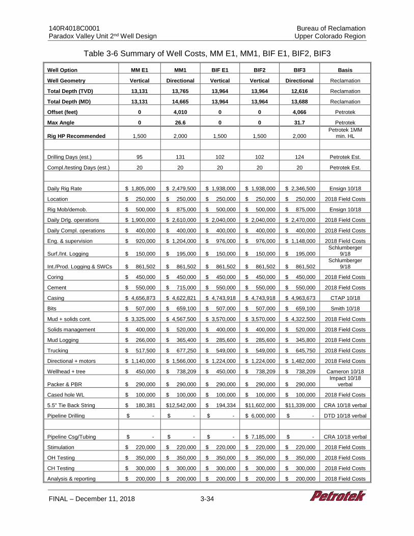
140R4018C0001 Bureau of Reclamation Paradox Valley Unit 2nd Well Design Upper Colorado Region
FINAL – December 11, 2018 3-34
Table 3-6 Summary of Well Costs, MM E1, MM1, BIF E1, BIF2, BIF3
Well Option MM E1 MM1 BIF E1 BIF2 BIF3 Basis
Well Geometry Vertical Directional Vertical Vertical Directional Reclamation
Total Depth (TVD) 13,131 13,765 13,964 13,964 12,616 Reclamation
Total Depth (MD) 13,131 14,665 13,964 13,964 13,688 Reclamation
Offset (feet) 0 4,010 0 0 4,066 Petrotek
Max Angle 0 26.6 0 0 31.7 Petrotek
Rig HP Recommended 1,500 2,000 1,500 1,500 2,000 Petrotek 1MM
min. HL
Drilling Days (est.) 95 131 102 102 124 Petrotek Est.
Compl./testing Days (est.) 20 20 20 20 20 Petrotek Est.
Daily Rig Rate $ 1,805,000 $ 2,479,500 $ 1,938,000 $ 1,938,000 $ 2,346,500 Ensign 10/18
Location $ 250,000 $ 250,000 $ 250,000 $ 250,000 $ 250,000 2018 Field Costs
Rig Mob/demob. $ 500,000 $ 875,000 $ 500,000 $ 500,000 $ 875,000 Ensign 10/18
Daily Drlg. operations $ 1,900,000 $ 2,610,000 $ 2,040,000 $ 2,040,000 $ 2,470,000 2018 Field Costs
Daily Compl. operations $ 400,000 $ 400,000 $ 400,000 $ 400,000 $ 400,000 2018 Field Costs
Eng. & supervision $ 920,000 $ 1,204,000 $ 976,000 $ 976,000 $ 1,148,000 2018 Field Costs
Surf./Int. Logging $ 150,000 $ 195,000 $ 150,000 $ 150,000 $ 195,000 Schlumberger
9/18
Int./Prod. Logging & SWCs $ 861,502 $ 861,502 $ 861,502 $ 861,502 $ 861,502 Schlumberger
9/18
Coring $ 450,000 $ 450,000 $ 450,000 $ 450,000 $ 450,000 2018 Field Costs
Cement $ 550,000 $ 715,000 $ 550,000 $ 550,000 $ 550,000 2018 Field Costs
Casing $ 4,656,873 $ 4,622,821 $ 4,743,918 $ 4,743,918 $ 4,963,673 CTAP 10/18
Bits $ 507,000 $ 659,100 $ 507,000 $ 507,000 $ 659,100 Smith 10/18
Mud + solids cont. $ 3,325,000 $ 4,567,500 $ 3,570,000 $ 3,570,000 $ 4,322,500 2018 Field Costs
Solids management $ 400,000 $ 520,000 $ 400,000 $ 400,000 $ 520,000 2018 Field Costs
Mud Logging $ 266,000 $ 365,400 $ 285,600 $ 285,600 $ 345,800 2018 Field Costs
Trucking $ 517,500 $ 677,250 $ 549,000 $ 549,000 $ 645,750 2018 Field Costs
Directional + motors $ 1,140,000 $ 1,566,000 $ 1,224,000 $ 1,224,000 $ 1,482,000 2018 Field Costs
Wellhead + tree $ 450,000 $ 738,209 $ 450,000 $ 738,209 $ 738,209 Cameron 10/18
Packer & PBR $ 290,000 $ 290,000 $ 290,000 $ 290,000 $ 290,000 Impact 10/18
verbal
Cased hole WL $ 100,000 $ 100,000 $ 100,000 $ 100,000 $ 100,000 2018 Field Costs
5.5" Tie Back String $ 180,381 $12,542,000 $ 194,334 $11,602,000 $11,339,000 CRA 10/18 verbal
Pipeline Drilling $ - $ - $ - $ 6,000,000 $ - DTD 10/18 verbal
Pipeline Csg/Tubing $ - $ - $ - $ 7,185,000 $ - CRA 10/18 verbal
Stimulation $ 220,000 $ 220,000 $ 220,000 $ 220,000 $ 220,000 2018 Field Costs
OH Testing $ 350,000 $ 350,000 $ 350,000 $ 350,000 $ 350,000 2018 Field Costs
CH Testing $ 300,000 $ 300,000 $ 300,000 $ 300,000 $ 300,000 2018 Field Costs
Analysis & reporting $ 200,000 $ 200,000 $ 200,000 $ 200,000 $ 200,000 2018 Field Costs
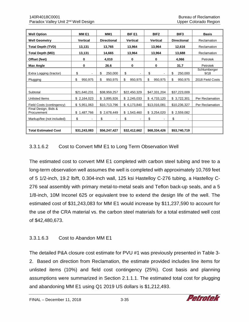
140R4018C0001 Bureau of Reclamation Paradox Valley Unit 2nd Well Design Upper Colorado Region
FINAL – December 11, 2018 3-35
Well Option MM E1 MM1 BIF E1 BIF2 BIF3 Basis
Well Geometry Vertical Directional Vertical Vertical Directional Reclamation
Total Depth (TVD) 13,131 13,765 13,964 13,964 12,616 Reclamation
Total Depth (MD) 13,131 14,665 13,964 13,964 13,688 Reclamation
Offset (feet) 0 4,010 0 0 4,066 Petrotek
Max Angle 0 26.6 0 0 31.7 Petrotek
Extra Logging (tractor) $ - $ 250,000 $ - $ - $ 250,000 Schlumberger
9/18
Plugging $ 950,975 $ 950,975 $ 950,975 $ 950,975 $ 950,975 2018 Field Costs
Subtotal $21,640,231 $38,959,257 $22,450,329 $47,331,204 $37,223,009
Unlisted Items $ 2,164,023 $ 3,895,926 $ 2,245,033 $ 4,733,120 $ 3,722,301 Per Reclamation
Field Costs (contingency) $ 5,951,063 $10,713,796 $ 6,173,840 $13,016,081 $10,236,327 Per Reclamation Final Design, Bids & Procurement $ 1,487,766 $ 2,678,449 $ 1,543,460 $ 3,254,020 $ 2,559,082
Markup/fee (not included) $ - $ - $ - $ - $ -
Total Estimated Cost $31,243,083 $56,247,427 $32,412,662 $68,334,426 $53,740,719
3.3.1.6.2 Cost to Convert MM E1 to Long Term Observation Well
The estimated cost to convert MM E1 completed with carbon steel tubing and tree to a
long-term observation well assumes the well is completed with approximately 10,769 feet
of 5 1/2-inch, 19.2 lb/ft, 0.304-inch wall, 125 ksi Hastelloy C-276 tubing, a Hastelloy C-
276 seal assembly with primary metal-to-metal seals and Teflon back-up seals, and a 5
1/8-inch, 10M Inconel 625 or equivalent tree to extend the design life of the well. The
estimated cost of $31,243,083 for MM E1 would increase by $11,237,590 to account for
the use of the CRA material vs. the carbon steel materials for a total estimated well cost
of $42,480,673.
3.3.1.6.3 Cost to Abandon MM E1
The detailed P&A closure cost estimate for PVU #1 was previously presented in Table 3-
2. Based on direction from Reclamation, the estimate provided includes line items for
unlisted items (10%) and field cost contingency (25%). Cost basis and planning
assumptions were summarized in Section 2.1.1.1. The estimated total cost for plugging
and abandoning MM E1 using Q1 2019 US dollars is $1,212,493.
140R4018C0001 Bureau of Reclamation Paradox Valley Unit 2nd Well Design Upper Colorado Region
FINAL – December 11, 2018 3-36
3.3.2 30% Design Class V Well, MM1
3.3.2.1 MM1 Data Needs and Considerations
Assumptions and design criteria for all vertical and directional wells are summarized in
Section 2.1.5. The well surface location is to be at the top of Monogram Mesa as
designated by Reclamation, and the bottomhole location is to be offset approximately
4,011 feet to reach the target injection zone. The preliminary directional trajectory has
been estimated to manage torque and drag and promote completion to total target depth
while reducing encounters with the most significant geologic hazards.
3.3.2.2 Monitoring Technologies
Refer to Section 3.3.1.2 for Monitoring Technology Information.
3.3.2.3 MM1 Well Design
Figure 3-4 presents the well design for the injection well at MM1. This well is proposed
to be a directional well drilled to a total depth of 13,863 feet BGL (14,765 feet MD) for the
purpose of brine disposal from the PVU facility. This 30% design is based on currently
available data and is intended to be revised, if necessary, based on data acquired from
drilling and testing of MM E1.
As stated in Section 2, minimum design criteria are 1.2 for single axis stress, 1.2 for triaxial
stress, and 1.6 for tensile stress. The design presented for this well resulted in minimum
safety factor of 1.6 in tension at 100,000 lbs of overpull, and 1.76 under triaxial conditions.
Minimum design safety factors for single axis stresses range between 1.2 and 1.3 for
industry standard applications, Minimum triaxial design safety factor is usually 1.25. Risks
associated with a fifty (50) year design life dictated a stronger design. Limiting
assumptions for triaxial stress analysis in most scenarios include limiting conditions of
140R4018C0001 Bureau of Reclamation Paradox Valley Unit 2nd Well Design Upper Colorado Region
FINAL – December 11, 2018 3-37
0.433 psi/ft fresh water inside the tubulars, and 0.852 psi/ft (based on 16.4 ppg cement)
fluid on the outside of the tubulars. To meet collapse and burst design requirements,
surface and intermediate casing must be cemented with a cement weighing no more than
12 ppg and 14 ppg, respectively. Considerations such as foamed cement or other cement
de-weighting methods might be able to be used to increase the safety factor allowing for
lower strength, somewhat less costly tubulars to be used in the well. However, based on
evaluation at this stage it is likely that cost savings could only be gained at some risk of
lesser life expectancy and increased sensitivity to other uncertainties. Such
considerations are not included in this 30% design but may be addressed in future work.
Heavy wall 10.75-inch casing is specified across the Paradox Salt interval and 1,000 feet
above this zone to account for uncertainty in projected depths. These design criteria have
been included to reduce the potential for collapse at a 1.0 psi/ft pressure gradient from
the salt.
The preliminary casing design includes clearance and space for an additional 7-inch
drilling liner to be run, to allow contingency associated with drilling uncertainty that may
be encountered. Table 3-7 contains the proposed tubular program for this well. All tubular
goods are anticipated to have buttress or premium threads.
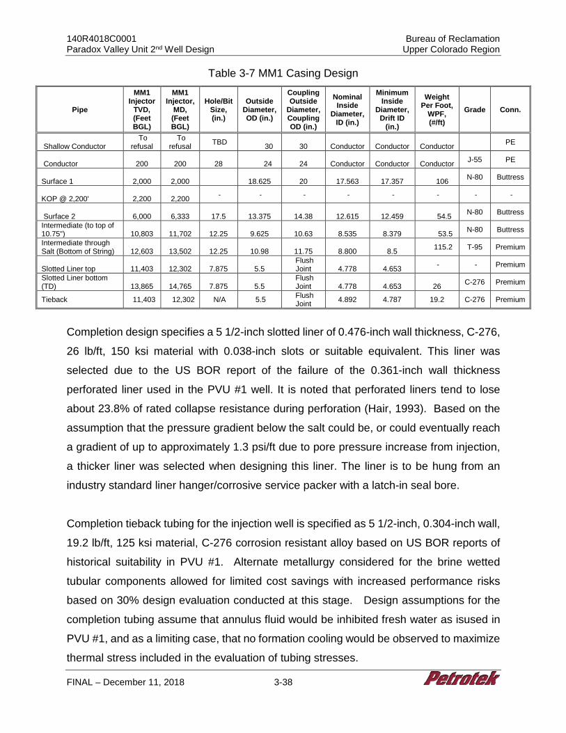
140R4018C0001 Bureau of Reclamation Paradox Valley Unit 2nd Well Design Upper Colorado Region
FINAL – December 11, 2018 3-38
Table 3-7 MM1 Casing Design
Pipe
MM1 Injector
TVD, (Feet BGL)
MM1 Injector,
MD, (Feet BGL)
Hole/Bit Size, (in.)
Outside Diameter, OD (in.)
Coupling Outside
Diameter, Coupling OD (in.)
Nominal Inside
Diameter, ID (in.)
Minimum Inside
Diameter, Drift ID
(in.)
Weight Per Foot,
WPF, (#/ft)
Grade Conn.
Shallow Conductor To
refusal To
refusal TBD 30
30
Conductor
Conductor
Conductor PE
Conductor
200
200
28
24
24
Conductor
Conductor
Conductor J-55 PE
Surface 1
2,000
2,000 18.625
20
17.563
17.357
106 N-80 Buttress
KOP @ 2,200'
2,200
2,200 - - - - - - - -
Surface 2
6,000
6,333
17.5
13.375
14.38
12.615
12.459
54.5 N-80 Buttress
Intermediate (to top of 10.75")
10,803
11,702
12.25
9.625
10.63
8.535
8.379
53.5 N-80 Buttress
Intermediate through Salt (Bottom of String)
12,603
13,502
12.25
10.98
11.75
8.800
8.5 115.2 T-95 Premium
Slotted Liner top
11,403
12,302
7.875
5.5 Flush Joint
4.778
4.653 - - Premium
Slotted Liner bottom (TD)
13,865
14,765
7.875
5.5
Flush Joint
4.778
4.653
26 C-276 Premium
Tieback 11,403 12,302 N/A 5.5 Flush Joint 4.892 4.787 19.2 C-276 Premium
Completion design specifies a 5 1/2-inch slotted liner of 0.476-inch wall thickness, C-276,
26 lb/ft, 150 ksi material with 0.038-inch slots or suitable equivalent. This liner was
selected due to the US BOR report of the failure of the 0.361-inch wall thickness
perforated liner used in the PVU #1 well. It is noted that perforated liners tend to lose
about 23.8% of rated collapse resistance during perforation (Hair, 1993). Based on the
assumption that the pressure gradient below the salt could be, or could eventually reach
a gradient of up to approximately 1.3 psi/ft due to pore pressure increase from injection,
a thicker liner was selected when designing this liner. The liner is to be hung from an
industry standard liner hanger/corrosive service packer with a latch-in seal bore.
Completion tieback tubing for the injection well is specified as 5 1/2-inch, 0.304-inch wall,
19.2 lb/ft, 125 ksi material, C-276 corrosion resistant alloy based on US BOR reports of
historical suitability in PVU #1. Alternate metallurgy considered for the brine wetted
tubular components allowed for limited cost savings with increased performance risks
based on 30% design evaluation conducted at this stage. Design assumptions for the
completion tubing assume that annulus fluid would be inhibited fresh water as isused in
PVU #1, and as a limiting case, that no formation cooling would be observed to maximize
thermal stress included in the evaluation of tubing stresses.
140R4018C0001 Bureau of Reclamation Paradox Valley Unit 2nd Well Design Upper Colorado Region
FINAL – December 11, 2018 3-39
3.3.2.4 MM1 Well Plan
Figure 3-5 presents the MM1 Direction Well Plan. Based on the assumptions outlined
and a 30% design, the following general drilling and completion procedure has been
designed for the installation of the proposed directional well. The procedure and depths
may be modified as part of the final design and altered slightly during field operations as
warranted based on the actual downhole conditions ultimately encountered during drilling.
1. Survey and prepare the location for an all-weather operation (location access to be provided by Reclamation). Drilling pad should be a minimum of 450 feet by 450 feet, roughly centered on the well surface location. Install an 8-foot diameter corrugated metal pipe cellar to a depth of 4 feet. Drilling water of up to 2,000 bbls/day (58 gpm) is to be supplied to location by Reclamation. Water will be hauled to the site or a water supply well will be drilled. The location will be lined with an impervious liner and matting boards will be installed to protect the liner. Drainage ditch will surround the location to prevent accidental release of liquids.
2. Mobilize an air drilling rig and support equipment and rig up on location with appropriate anchoring. Prepare a polyvinyl (16-ounce or equivalent) liner with berms and drainage sumps. Install the liner as the rig is erected. The liner will be placed under the rig, pumps, and tanks. Rig up a “zero discharge” closed loop solids control system.
3. Set 30-inch OD x 0.75-inch wall shallow conductor casing to approximately 200 feet.
4. Rig up an air drilling system with sufficient compressor capacity to clean the hole. Inventory all tubulars (drillpipe and drill collars) on location. Drill 28-inch hole to 200 feet, install 24-inch, J-55, Plain End conductor casing.
5. Cement conductor to surface using a standard cement. Rig up a full service (24 hr/day) mud logger. Catch drill cutting samples approximately every 30 feet, from the surface to total depth.
6. After a wait on cement time per cement/vendor program, air drill with 20-inch bit to 2,000 feet. The target for maximum vertical deviation is to not exceed 1.5° increase from the previous survey or 1° per 1,000 feet of hole. Fill hole with water based mud.
7. Fill hole with water and lost circulation material (LCM). Condition hole and conduct a surface casing open-hole logging program consisting of spontaneous potential (SP), induction-resistivity (IND), 6-arm caliper, neutron/density (ND) and gamma ray (GR). Calculate the surface casing cement volumes, and add 50% excess to the annulus volume. In areas where the caliper log cannot measure the hole diameter, add 100%.
140R4018C0001 Bureau of Reclamation Paradox Valley Unit 2nd Well Design Upper Colorado Region
FINAL – December 11, 2018 3-40
8. Run 2,000 feet of 18 5/8-inch, 106 lb/ft, N-80 Buttress casing equipped with a float shoe on the bottom and a float collar one joint off of the bottom. Centralizers will be installed near the float shoe, at the center of the first joint, near the float collar, on the collars of the second and third joints, and on every third collar thereafter, or where applicable.
9. Center the casing in the rotary table, drain and flush the diverter stack and allow the cement to set per service company recommendations. Install and test BOP system. Conduct a temperature survey at the optimal time recommended by the service company after displacing the plug to locate the top of cement.
10. Drill a 17 1/2-inch hole to a measured depth of 6,333 feet (6,000 feet TVD) with a 17 1/2-inch bottom-hole assembly (BHA) on 5-inch drillpipe. Conduct a deviation survey below the surface casing, every 500 feet, and on trips. Begin directional drilling, KOP is at 2,200 feet, and maximum build rate is 2.00 degrees per 100 feet. Target inclination angle is 26.6 degrees.
NOTE: Run desander, desilter, and centrifuge during drilling. Maintain an appropriate mud weight to control wellbore stability and target a viscosity of 35 to 70 sec/qt as appropriate for effective hole cleaning.
11. Fill hole with water and lost circulation material (LCM). Condition hole and conduct a surface casing open-hole logging program consisting of spontaneous potential (SP), induction-resistivity (IND), 6-arm caliper, neutron/density (ND) and gamma ray (GR). Calculate the surface casing cement volumes, and add 50% excess to the annulus volume. In areas where the caliper log cannot measure the hole diameter, add 100% excess per regulatory requirements.
12. Run 6,333 feet of 13 3/8 inch, 54.5 lb/ft, N-80, Buttress casing equipped with a float shoe on the bottom and a float collar one joint off of the bottom. Centralizers will be installed near the float shoe, at the center of the first joint, near the float collar, on the collars of the second and third joints, and on every third collar thereafter, or per cement vendor recommendation.
13. Establish circulation and circulate at least one casing volume of drilling fluid. Monitor drilling fluid properties and circulate until the properties are similar to the expected cement slurry properties. Cement the 13 3/8-inch casing and circulate the cement back to the surface. The slurry will consist of light-weight lead cement and a tail slurry of standard, premium cement. Displace the wiper plug to the float collar. Ensure that the floats are holding by checking for flow back.
14. Center the casing in the rotary table, drain and flush the diverter stack and allow the cement to set per service company recommendations. Conduct a temperature survey at the optimal time recommended by the service company after displacing the plug to locate the top of cement.
15. After a wait on cement time appropriate for cementing program, run in hole and drill the shoe +10 feet, conduct a shoe test. Drill directionally to a measured depth of 11,234 feet (10,372 feet TVD), and begin drop to vertical. Conduct a deviation survey below the surface casing, every 500 feet, and on trips. Maximum drop rate is 2.00 degrees per 100 feet. This, and all further sections of the well, should
140R4018C0001 Bureau of Reclamation Paradox Valley Unit 2nd Well Design Upper Colorado Region
FINAL – December 11, 2018 3-41
be drilled with petroleum-based mud to ensure torque and drag limitations are not exceeded.
16. Stop drilling at 13,502 (12,603 feet TVD) feet. 17. Condition hole and conduct the long-string casing open-hole logging program to
include caliper logs from 6,333 feet to 13,502 feet MD, BGL (12,603 feet TVD). Calculate long-string cement volumes, plus 50% excess to the annulus volume according to the cement stage collar placement intervals. (Use 100% excess in areas where the caliper cannot measure the hole diameter).
18. Run Intermediate casing string consisting of 1,800 feet of 10.98-inch, 115.2 lb/ft, T95, Premium connection, heavy wall casing, equipped with a float shoe on the bottom and a float collar one joint off of the bottom. Then run a crossover to 11,702 feet of 9 5/8-inch 53.5 lb/ft N-80 Buttress casing. Centralizers will be installed near the float shoe, at the center of the first joint, near the float collar, on the collars of the second and third joints, and on every third collar thereafter, or per vendor recommendation.
19. Cement the intermediate casing back to the surface in the following two stages per cement vendor recommendation:
Stage One - Establish circulation. Circulate at least one casing volume of drilling fluid prior to pumping pre-flush. Monitor drilling fluid properties and circulate until the properties are consistent with cement vendor recommendation. Cement the intermediate casing and circulate the cement back to the surface. Cement design to be per cement company recommendation. Displace the wiper plug to the float collar. Ensure that the floats are holding by checking for flow back.
Stage Two - Drop the opening device and open the stage tool. Circulate the drilling fluid through the stage tool for a minimum of 8 hours or as recommended by the service company based on field conditions, noting if the cement is returned to the surface. Pump the second stage with a light-weight lead cement, followed by a standard, premium tail cement to fill 500 feet of annulus above the stage tool. Circulate the second cement back to the surface. Displace the plug to the stage tool, bumping the plug to close the stage tool. Release the pressure and ensure that the stage tool is holding by monitoring for flow back. Wash any excess cement out of the BOP stack and drain the stack and casing head. Do not move the casing. Allow the second cement stage to set per service company recommendations.
20. After wait on cement time appropriate for cement program, drill the shoe and conduct shoe test.
21. Drill to MD of 14,765 feet (13,865 feet TVD) with 7 7/8-inch bit and BHA including MWD and GR. Core as necessary per Reclamation request. Make wiper trip and laydown BHA.
22. Commence open hole logging and fluid sampling program as directed by Reclamation. Assume that logs include spectra, GR and NMR. Make wiper trip.
140R4018C0001 Bureau of Reclamation Paradox Valley Unit 2nd Well Design Upper Colorado Region
FINAL – December 11, 2018 3-42
23. On drill pipe, run liner hanger and 2,463 feet of 5 1/2-inch, 25 lb/ft, 0.476 inch wall, 0.038-inch slot, C-276 Hastelloy, 150 ksi material slotted liner and set liner from approximately 12,302 feet (11,403 feet TVD) to 14,765 feet (13,865 feet TVD) across injection interval.
24. Set liner hanger and test liner hanger packer. 25. Run approximately 12,302 feet of 5 1/2-inch, 19.2 lb/ft, C-276, 125 ksi material
strength, premium connection, casing as a tieback string. Latch into liner hanger with approximately 10,000 psi down force.
26. Rig down drilling rig and rig up completion rig. 27. Conduct additional fluid sampling, pressure transient injectivity testing and
production logging as directed by Reclamation.
3.3.2.5 MM1 Class V Well Cost Estimate
The estimated cost of $56,247,427 for the MM1 assumes the well is completed with
approximately 12,542 feet of 5 1/2-inch, 19.2 lb/ft, 0.304-inch wall, 125 ksi Hastelloy C-
276 tubing, a Hastelloy C-276 seal assembly with primary metal-to-metal seals and Teflon
back-up seals, and a 5 1/8-inch 10M Inconel 625 or equivalent tree to extend the design
life of the well. The cost and general well information is summarized in the table below
along with the cost for other proposed wells for comparison purposes. The detailed cost
estimate is provided as Table 3-6.
3.3.3 30% Design Injection Well Injection Facility
A 30% design for a new brine injection injection facility that will replace the existing brine
injection was developed by Barr Engineering Co. (Attachment B). Because the historical
design has worked well, the design mirrors the existing design as is practicable, except
where apparent engineering improvements can be made and where there is the potential
for modern developments from remote/monitoring capabilities. Information pertaining to
potential costs and/or cost savings that might be realized with modern monitoring/controls
is presented in Section 3.2. Attachment B includes design assumptions (basis),
information, figures, drawings, and cost estimate pertaining to the proposed injection
facility design as summarized below.
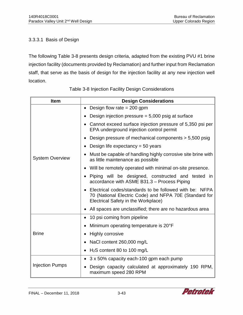
140R4018C0001 Bureau of Reclamation Paradox Valley Unit 2nd Well Design Upper Colorado Region
FINAL – December 11, 2018 3-43
3.3.3.1 Basis of Design
The following Table 3-8 presents design criteria, adapted from the existing PVU #1 brine
injection facility (documents provided by Reclamation) and further input from Reclamation
staff, that serve as the basis of design for the injection facility at any new injection well
location.
Table 3-8 Injection Facility Design Considerations
Item Design Considerations
System Overview
• Design flow rate = 200 gpm
• Design injection pressure = 5,000 psig at surface
• Cannot exceed surface injection pressure of 5,350 psi per EPA underground injection control permit
• Design pressure of mechanical components > 5,500 psig
• Design life expectancy = 50 years
• Must be capable of handling highly corrosive site brine with as little maintenance as possible
• Will be remotely operated with minimal on-site presence.
• Piping will be designed, constructed and tested in accordance with ASME B31.3 – Process Piping
• Electrical codes/standards to be followed with be: NFPA 70 (National Electric Code) and NFPA 70E (Standard for Electrical Safety in the Workplace)
• All spaces are unclassified; there are no hazardous area
Brine
• 10 psi coming from pipeline
• Minimum operating temperature is 20°F
• Highly corrosive
• NaCl content 260,000 mg/L
• H2S content 80 to 100 mg/L
Injection Pumps • 3 x 50% capacity each-100 gpm each pump
• Design capacity calculated at approximately 190 RPM, maximum speed 280 RPM
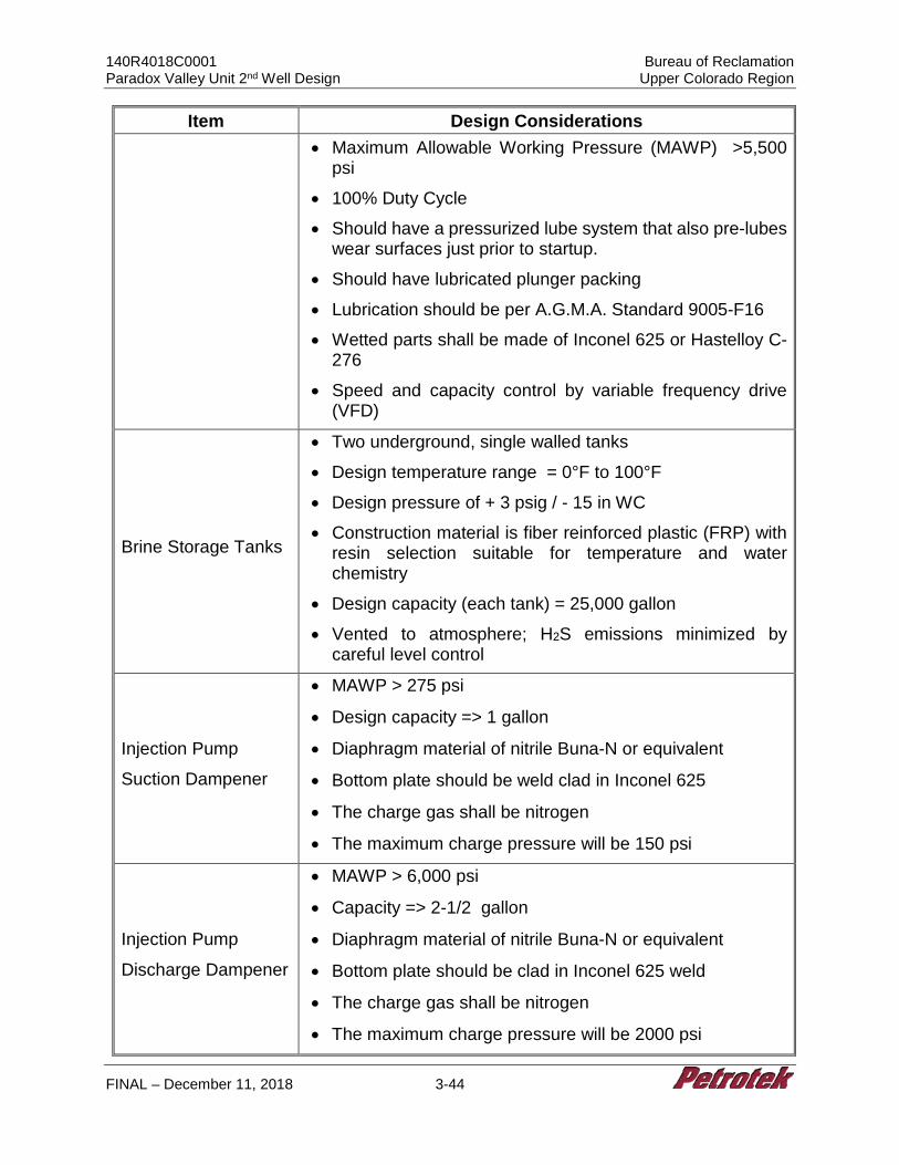
140R4018C0001 Bureau of Reclamation Paradox Valley Unit 2nd Well Design Upper Colorado Region
FINAL – December 11, 2018 3-44
Item Design Considerations • Maximum Allowable Working Pressure (MAWP) >5,500
psi
• 100% Duty Cycle
• Should have a pressurized lube system that also pre-lubes wear surfaces just prior to startup.
• Should have lubricated plunger packing
• Lubrication should be per A.G.M.A. Standard 9005-F16
• Wetted parts shall be made of Inconel 625 or Hastelloy C-276
• Speed and capacity control by variable frequency drive (VFD)
Brine Storage Tanks
• Two underground, single walled tanks
• Design temperature range = 0°F to 100°F
• Design pressure of + 3 psig / - 15 in WC
• Construction material is fiber reinforced plastic (FRP) with resin selection suitable for temperature and water chemistry
• Design capacity (each tank) = 25,000 gallon
• Vented to atmosphere; H2S emissions minimized by careful level control
Injection Pump
Suction Dampener
• MAWP > 275 psi
• Design capacity => 1 gallon
• Diaphragm material of nitrile Buna-N or equivalent
• Bottom plate should be weld clad in Inconel 625
• The charge gas shall be nitrogen
• The maximum charge pressure will be 150 psi
Injection Pump
Discharge Dampener
• MAWP > 6,000 psi
• Capacity => 2-1/2 gallon
• Diaphragm material of nitrile Buna-N or equivalent
• Bottom plate should be clad in Inconel 625 weld
• The charge gas shall be nitrogen
• The maximum charge pressure will be 2000 psi
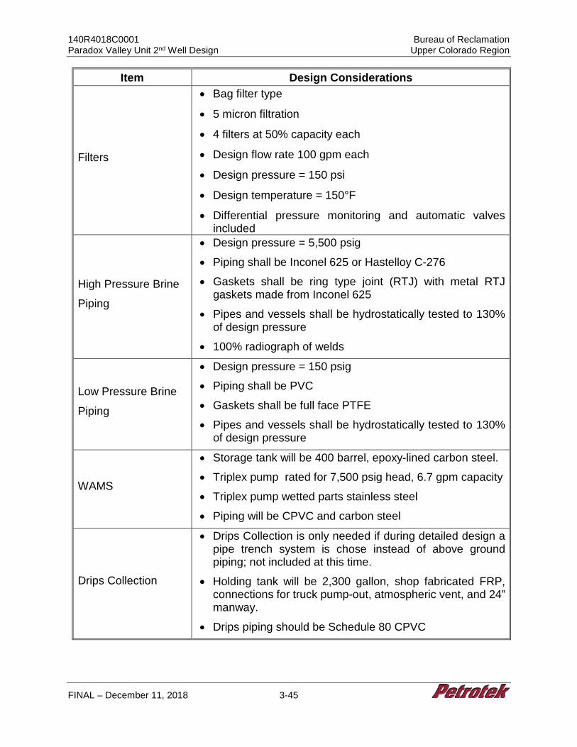
140R4018C0001 Bureau of Reclamation Paradox Valley Unit 2nd Well Design Upper Colorado Region
FINAL – December 11, 2018 3-45
Item Design Considerations
Filters
• Bag filter type
• 5 micron filtration
• 4 filters at 50% capacity each
• Design flow rate 100 gpm each
• Design pressure = 150 psi
• Design temperature = 150°F
• Differential pressure monitoring and automatic valves included
High Pressure Brine
Piping
• Design pressure = 5,500 psig
• Piping shall be Inconel 625 or Hastelloy C-276
• Gaskets shall be ring type joint (RTJ) with metal RTJ gaskets made from Inconel 625
• Pipes and vessels shall be hydrostatically tested to 130% of design pressure
• 100% radiograph of welds
Low Pressure Brine
Piping
• Design pressure = 150 psig
• Piping shall be PVC
• Gaskets shall be full face PTFE
• Pipes and vessels shall be hydrostatically tested to 130% of design pressure
WAMS
• Storage tank will be 400 barrel, epoxy-lined carbon steel.
• Triplex pump rated for 7,500 psig head, 6.7 gpm capacity
• Triplex pump wetted parts stainless steel
• Piping will be CPVC and carbon steel
Drips Collection
• Drips Collection is only needed if during detailed design a pipe trench system is chose instead of above ground piping; not included at this time.
• Holding tank will be 2,300 gallon, shop fabricated FRP, connections for truck pump-out, atmospheric vent, and 24” manway.
• Drips piping should be Schedule 80 CPVC
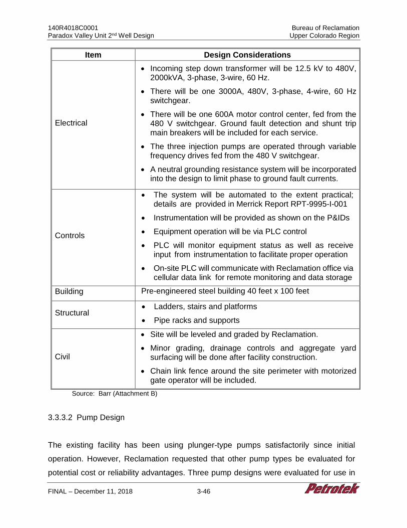
140R4018C0001 Bureau of Reclamation Paradox Valley Unit 2nd Well Design Upper Colorado Region
FINAL – December 11, 2018 3-46
Item Design Considerations
Electrical
• Incoming step down transformer will be 12.5 kV to 480V, 2000kVA, 3-phase, 3-wire, 60 Hz.
• There will be one 3000A, 480V, 3-phase, 4-wire, 60 Hz switchgear.
• There will be one 600A motor control center, fed from the 480 V switchgear. Ground fault detection and shunt trip main breakers will be included for each service.
• The three injection pumps are operated through variable frequency drives fed from the 480 V switchgear.
• A neutral grounding resistance system will be incorporated into the design to limit phase to ground fault currents.
Controls
• The system will be automated to the extent practical; details are provided in Merrick Report RPT-9995-I-001
• Instrumentation will be provided as shown on the P&IDs
• Equipment operation will be via PLC control
• PLC will monitor equipment status as well as receive input from instrumentation to facilitate proper operation
• On-site PLC will communicate with Reclamation office via cellular data link for remote monitoring and data storage
Building Pre-engineered steel building 40 feet x 100 feet
Structural • Ladders, stairs and platforms
• Pipe racks and supports
Civil
• Site will be leveled and graded by Reclamation.
• Minor grading, drainage controls and aggregate yard surfacing will be done after facility construction.
• Chain link fence around the site perimeter with motorized gate operator will be included.
Source: Barr (Attachment B)
3.3.3.2 Pump Design
The existing facility has been using plunger-type pumps satisfactorily since initial
operation. However, Reclamation requested that other pump types be evaluated for
potential cost or reliability advantages. Three pump designs were evaluated for use in
140R4018C0001 Bureau of Reclamation Paradox Valley Unit 2nd Well Design Upper Colorado Region
FINAL – December 11, 2018 3-47
the design and the results are summarized below.
3.3.3.2.1 Reciprocating Plunger Pump
The existing PVU pumps are quintuplex reciprocating plunger pumps that have operated
satisfactorily. Traditionally, this type of pump has been the preferred choice because of
its ability to meet the hydraulic performance requirements efficiently and reliably. The
current pumps are positive displacement pumps, meaning that the only practical method
for capacity control is the use of variable frequency drives. Disadvantages of this type of
pump are vibration, pressure, and flow pulsations resulting from the reciprocating
operation. At installations where the pump foundation or pipe supports are not sufficiently
stiff, fatigue and cracking of piping and attached components can be a problem.
The existing pumps have the following material selection:
Discharge header/cylinders INCO Alloy 625 Suction header INCO Alloy 625 Plungers Tungsten carbide clad over 316 SST Valves Nitronic 50 stainless steel Valve springs Inconel Stuffing boxes INCO Alloy 625
Recommendation: These materials are well suited to the chloride content of the PVU
brine. Other suitable materials would be Hastelloy C or C-276, rubber-lined or epoxy-
coated steel.
3.3.3.2.2 Progressive Cavity Pump
In recent years, progressive cavity (PG) pumps have been gaining popularity for low-
flow/high-pressure applications to replace reciprocating pumps. Advantages include
insignificant vibration and no pressure or flow pulsations. PG pumps are a form of positive
displacement pump, and theoretically operate efficiently at the hydraulic conditions
required. PG pumps are available with a wide selection of rotor materials and stator
140R4018C0001 Bureau of Reclamation Paradox Valley Unit 2nd Well Design Upper Colorado Region
FINAL – December 11, 2018 3-48
materials. The rotor is typically metallic such as stainless steel, Hastelloy, or Inconel; the
stator is typically an elastomer such as rubber, polypropylene, or Buna-N. For the
Paradox Valley application, an Inconel rotor and natural rubber or EPDM stator would
likely be appropriate.
PG pumps are not capable of the high discharge pressures available in reciprocating
pumps. The maximum pressure capability of the PG pump models typically used for salt
water disposal is about 2,000 psig. While it may be possible to find a model capable of
pressure up to 5,500 psig, there is very little operating experience at that pressure, so
long-term reliability is unknown.
Recommendation: A PG pump is not recommended for this application because the
required pressure is outside the typical range of these pumps.
3.3.3.2.3 Multi-Stage Centrifugal Pump
Centrifugal pumps are the most common general-use pump because of their reasonable
cost and exceptional longevity. However, because they are a dynamic pump, their
efficiency and flow stability is strongly dependent upon the hydraulic conditions. The best
combination of efficiency, cost, and reliability is typically achieved when the specific speed
is about 2,000-3,000 (unitless). Due to the very high pressure required in comparison to
the flow rate, the pump would require multiple stages or would need to run at very high
speed (requiring a gearbox) or both in order for each stage to operate at the preferred
specific speed. Consequently, the models required for this application are specialty
pumps, and there are few manufacturers able to meet these hydraulic conditions. One
appropriate selection would be a Sundyne HMP-5000. However, because it operates at
such high speed, requires a gearbox, and will be handling an aggressive liquid, it will not
exhibit the reliability expected of a typical centrifugal pump. When compared to a
reciprocating plunger pump, the Sundyne HMP-5000 pump is not likely to be as reliable,
will be less efficient, and will be at least as costly.
140R4018C0001 Bureau of Reclamation Paradox Valley Unit 2nd Well Design Upper Colorado Region
FINAL – December 11, 2018 3-49
Recommendation: A centrifugal pump is not recommended at these hydraulic conditions
because of the limited selection, poorer efficiency, limited cost information, and reliability
disadvantages.
3.3.3.2.4 Refurbish Existing Pumps
One option for pumps at the new facility is to refurbish the existing pumps, replacing all
wearable components, sizing the plungers for the new hydraulic conditions, and fitting
them with motors sized for the new duty. The existing pumps have demonstrated very
satisfactory performance. The pumps can be factory rebuilt with the specified alloys and
brought to a nearly new condition, providing Reclamation with confidence in a proven
pumping package. The cost is expected to be somewhat less than purchasing new
pumps would be, but not likely significantly less.
Since the present facility has four pumps and only three pumps are planned to be
installed at the new facility, the remaining pump would be stored as a warehouse spare.
When the time comes for one of the installed pumps to be rebuilt, it could be swapped
out with the warehouse spare and sent off-site so the facility would always have three
installed pumps available for operation. Although this option does not likely have a very
large cost advantage, the operational flexibility may make it worth considering. However,
given the historical use of the existing system, expected wear, possible fatigue, and the
50-year design requirement for the new pump system, re-use of the major pump
components is unlikely to be justified.
3.3.3.3 Tankage and Pond Storage Requirements
Brine storage is currently provided in two, underground, 26,500-gallon fiberglass tanks.
No deficiencies have been identified with the existing design. The 30% design will be
developed on the same basis of two underground fiberglass tanks. The tanks will be
single walled, with all connections on the top. Instrumentation and any electrical
equipment on the tank will be explosion proof. If double walled tanks or above-ground
140R4018C0001 Bureau of Reclamation Paradox Valley Unit 2nd Well Design Upper Colorado Region
FINAL – December 11, 2018 3-50
tanks with secondary containment are required during detailed design, site layout design
will be affected, and cost will be increased accordingly.
One fresh water tank will be provided for the well annulus monitoring system (WAMS).
Since fresh water is not available at the site, this tank will be periodically refilled by truck.
The tank is 400 bbls and designed for atmospheric pressure, and will be made of steel
with epoxy coating. The tank will be freeze-protected with a thermostatically controlled
electric immersion heater. The tank will be insulated with a closed cell foam for heat
conservation in the winter and anti-sweat in the summer.
A chemical dosing system is provided for the fresh water tank. The existing operation
does not use an injection system, but rather batch doses the tank periodically. If it is
determined during detailed design that chemical injection is not necessary for the fresh
water, the system can be applied to a different use or eliminated.
The storage ponds at the existing facility hold river water, which is used for fresh water
needs and for blending into the brine. Fresh water will not be needed in the amounts
previously required or provided at the new facility, so storage ponds will not be
constructed at PVU #2.
3.3.3.4 Injection Pumps and Piping
The P&IDs are provided on drawings P-001 through P-004 (Attachment B). All low
pressure piping will be PVC from the inlet of the brine at the end of the pipeline to the
suction side of the injection pumps. All high pressure piping will be Inconel 625 or
Hastelloy C-276 with design pressure capabilities of at least 6,000 psig from the
discharge of the injection pumps to the injection well. This means that schedule 160
piping is for three-inch and four-inch nominal pipe size, and schedule XXS piping is for
six-inch nominal pipe size.
140R4018C0001 Bureau of Reclamation Paradox Valley Unit 2nd Well Design Upper Colorado Region
FINAL – December 11, 2018 3-51
Piping that conveys brine is at risk for leaks so may be located in covered trenches if
deemed appropriate during detailed design. The 30% design presented with this
memorandum calls for all piping to be routed above grade. Inside the building the piping
is routed overhead. Spray shields will be fitted on all flanges. All piping with operating
pressure exceeding 1,000 psig will be 100% radiograph tested. All piping will be
hydrotested at 130% of design pressure. The high pressure injection piping will have
drains routed back to the brine storage tank to be used for maintenance.
It is believed that leak detection is not currently required for salt water pipelines in
Colorado. Consequently, no provisions or budget has been included for leak detection.
If leak detection is required, then a qualified consultant with leak detection expertise
should be retained to specify and implement any additional instrumentation and
algorithms.
3.3.3.5 Well Annulus Monitoring System (WAMS)
The WAMS and pressure maintenance pumps are shown on P&ID P-005 (Attachment
B). Overall design of the new WAMS will closely follow the existing monitoring system
at the existing PVU. This includes a fresh water tank as described above, a fresh water
charge pump, a chemical storage tank, a chemical metering pump, and a triplex
reciprocating plunger pump. The design considerations for this pump are similar in
scope to those of the injection pumps but do not require the chloride and H2S resistance
or the flow capacity of the injection pumps since the WAMS will only interact with fresh
water. The piping for the WAMS from the discharge of the triplex pump to the well will
be carbon steel with design pressure capabilities of at least 8,000 psig, while the piping
up to the inlet of the triplex pump will be PVC.
The well annulus pressure is monitored and controlled by the automated control system.
The control valve is electrically operated and powered from the Emergency Service
MCC.
140R4018C0001 Bureau of Reclamation Paradox Valley Unit 2nd Well Design Upper Colorado Region
FINAL – December 11, 2018 3-52
The existing system does not have a charge pump for the WAMS. However, the nature
of reciprocating pumps causes high instantaneous changes in flow rate with resultant
high pressure drops, so use of a charge pump is recommended to improve the injection
pump performance and durability. The additional cost for a pump this small is minimal.
3.3.3.6 Civil Site Preparation
The site general arrangement is provided on drawing # GA-002 (Attachment B). Site
development activities will include grading to level, establishing drainage controls,
surfacing all work areas with road aggregate, and constructing a perimeter fence with
access gates as needed. Quantities are based on the existing PVU facilities except that
the new PVU #2 yard area is assumed to be about 60% of the area of the yard for the
existing yard because some of the facilities (e.g., fresh water storage and blending
facilities) will not be constructed within the new yard.
Reclamation has directed the team to assume that the new injection well site will be
relatively level and ready for construction. The cost estimate has assumed that fine
grading to an average cut depth of one foot will be needed to prepare the final yard area.
The grading plan is assumed to balance on-site cut and fill quantities so that there is no
import or export of soils to reach design subgrade. After a final site is selected, a
topographic survey needs to be conducted to obtain site-specific information so that a
site design can be prepared to better estimate earthwork quantities. Costs for site
development may be higher than projected if more earthwork than described in this
section is needed to prepare the site for the new surface facilities.
After site grading has been completed, the yard area will be surfaced with road
aggregate and a chain-link fence will be installed around the site perimeter with access
gates where needed.
140R4018C0001 Bureau of Reclamation Paradox Valley Unit 2nd Well Design Upper Colorado Region
FINAL – December 11, 2018 3-53
3.3.3.7 Electrical Systems and Structural Requirements
The P&ID drawings for the 30% Injection Facility Design are included in Attachment B.
An overview design of the electrical system is shown on electrical drawing # E-001-1.
The power system for the injection facility will require 480V and 120V AC power. All the
injection, WAMS, and accessory equipment will run on 480V, while the utility power and
lighting will run on 120V. Power entering the facility will be stepped down from
transmission voltage to 480V via a pad-mounted transformer in the substation area.
From there, power will be fed to the 480V switchgear, then to the 480V MCC. A 30 kVA
transformer will step down the voltage from the MCC to 120V for utility power. The three
injection pumps will be fed from the 480V switchgear via VFDs, and the rest of the
equipment will be fed via 3-phase, 3-wire, 480V service from the MCC.
There will be two 480V MCCs, the Main Service MCC and the Emergency Service MCC.
The Emergency Service MCC can be fed either with utility power through the 480V
switchgear or by an emergency generator. When there is an electrical outage, the
emergency generator will automatically start and an automatic transfer switch will
transfer the power supply to the emergency generator. The emergency generator will
be fueled by propane, and rated 100kW at 480VAC.
The building to house the pumps, electrical equipment, and control room will consist of
a pre-engineered metal building with 16-foot eaves, steel siding, insulation, and interior
liner panels. A 10-ton bridge crane for pump maintenance with a 12-foot hook height will
be supported off of the building steel. Three 14-foot clear height, roll-up doors will
provide access to the pump and motors for maintenance.
The electrical area for the motor control centers (MCC) and variable frequency drives
(VFD) will be isolated from the rest of the space by a concrete block wall and fire rated
cap. The penetrations through the concrete wall for conduit and cable trays will be sealed
with fire stop compound. The control room will be isolated from the pump area as well by
a concrete masonry block wall and cap. A window will be located in the wall between the
140R4018C0001 Bureau of Reclamation Paradox Valley Unit 2nd Well Design Upper Colorado Region
FINAL – December 11, 2018 3-54
control room and pump room so the operator on watch can visually monitor the space.
The HVAC system will be located above the control room on the concrete cap.
The pump area will be ventilated by roof-mounted exhaust fans and wall intake louvers
near the floor. There will be two H2S sensors in the pump area and one H2S sensor in
the control room. If any of the H2S sensors detect levels above the allowable limit of 10
ppm, all of the buildings exhaust fans will be automatically started, regardless of
temperature.
The building layout is provided on drawing # GA-001 (Attachment B). The injection facility
will include a pre-engineered metal building (PEMB) which will be fabricated off site and
erected on site after the foundation is complete. The structure will be designed for local
snow, ice, wind, and seismic loadings per the local adopted building codes. The building
will be designed to comply with local energy codes and to provide protection to the
equipment inside of the building. The final building foundation design will be determined
based on geotechnical borings and consultant recommendations. For purposes of
developing the cost estimate, frost-protected footings and a perimeter grade wall with a
six-inch reinforced slab throughout were assumed. Mass concrete foundations will be
provided for the injection pumps to provide stability and vibration dampening. The pump
foundations will be independent of the floor slab, isolated by expansion joints, and sealed
with silicon sealant. Concrete reinforcement is to be epoxy-coated, and exposed concrete
is to be coated with an epoxy resin for resistivity to chlorides.
The building floor may be constructed with trenches for drainage and pipe routing if
deemed appropriate during final design. The trenches would be about 3-4 feet deep,
covered with fiberglass grating, and fitted with H2S monitors. The present 30% design
does not include trenches, but the probable locations of the trenches are shown as the
hatched area on DWG # GA-001.
The overhead crane will have capacity of ten tons to provide maintenance for the injection
pumps and motors. Overhead doors with motor operations, concrete aprons, and
140R4018C0001 Bureau of Reclamation Paradox Valley Unit 2nd Well Design Upper Colorado Region
FINAL – December 11, 2018 3-55
protection bollards will be provided alongside each pump and motor for maintenance and
load-out access. A smaller, manually operated overhead door will be provided near the
chemical injection skids for refilling the chemical storage tanks. Single and double doors
with concrete pads will be provided at each corner of the building for egress.
3.3.3.8 Safety and Health Considerations
The dissolved concentration of hydrogen sulfide (H2S) in the brine is close to the 100 ppm
threshold for Immediate Danger to Life and Health (IDLH). When exposed in a significant
brine spill, this dissolved H2S will release from the brine creating a higher concentration
in the air, so H2S monitors are planned at strategic locations throughout the facility. The
pump building will have powered exhaust fans and passive louvers for ventilation. The
location and type of ventilation equipment will be determined during detailed design to
minimize the accumulation of H2S and provide for its effective and efficient removal.
Monitors will be set to sound at 10 ppm for high alarm and 20 ppm for high-high alarm.
The building exhaust fans will be all started on the high alarm and a strobe light will
activate. On the high-high alarm a horn will also sound. The strobe and horns will be
located at each area where H2S is monitored: inside the pump building; inside the control
room; and near the underground storage tanks. A wind sock will be installed near the
storage tanks to indicate wind direction so that a safe evacuation path may be quickly
determined.
The control room will be pressurized to prevent infiltration of H2S into the occupied
space. The HVAC system will maintain a positive pressure of two inches of H2O in the
control room, provide two air exchanges per hour, and maintain a controlled temperature
between 66 and 74 degrees Fahrenheit. The HVAC system will provide forced ventilation
for the electrical area to maintain the minimum temperature above 40 degrees Fahrenheit
and maximum ambient temperature of 120 degrees Fahrenheit. The air intake for the
control room will be located at least 12 feet above grade and on the side of the building
away from the underground storage tanks. The prevailing wind direction will be
140R4018C0001 Bureau of Reclamation Paradox Valley Unit 2nd Well Design Upper Colorado Region
FINAL – December 11, 2018 3-56
considered while finalizing the layout of the tanks and building. The inlet air duct will have
a H2S monitor installed to automatically stop the fan when high level is detected.
Concentration in the brine is insufficient to reach the lower explosive limit (LEL) for H2S
(40,000 ppm). Since monitors will alarm at 10 ppm and automatically operate the exhaust
fans (described above), the danger of reaching the LEL is very low. Therefore, explosion-
proof design is not required for the equipment in this facility.
Physical site security is provided by fencing and a key-card controlled gate. Security
cameras will be deployed at sensitive locations and around the perimeter. Additional
requirements and equipment specifications will be made by a security consultant during
detailed design. Additionally, the Office of Infrastructure Protection in the US
Department of Homeland Security will be consulted for their recommendations.
3.3.3.9 Surge and Transient Calculations
During detailed design when final configuration information is available, a transient
calculation will be performed to determine the requirements for surge protection of the
pipeline(s). The calculation is expected to include several scenarios including but not
limited to well field collection pumps trip off, charge/injection pumps trip off, inlet failures,
and value malfunctions. The calculation will be used to specify the engineered and
operation controls required to prevent damage to the equipment or injury to personnel
in each scenario.
3.3.3.10 Injection Facility Cost Estimate
Sections 3.3.3.1 through 3.3.3.9 address the conceptual design and design elements
that were used to develop the Injection Facility cost estimates. The detailed preliminary
cost estimate for the new injection facility based on the 30% design is presented in
Attachment B and is summarized below. Attachment B below lists the equipment and
components of the new injection facility with the expected costs. Equipment listed in
140R4018C0001 Bureau of Reclamation Paradox Valley Unit 2nd Well Design Upper Colorado Region
FINAL – December 11, 2018 3-57
Table 3-9 below reflects understanding of the project after developing the design to
approximately 30% of completion. Additional work will be needed to develop a final
design that would comprehensively identify all project components. Final design work
may identify the need for additional equipment (and cost) that has not been identified at
this time.
Table 3-9 Injection Facility Cost Estimate
Cost Type Cost Engineering and Design $ 754,000.00 Overhead and Contractor Costs 681,000.00 Mechanical (pumps, tanks, pipe, valves, misc. mechanical equipment, mechanical installation & testing)
5,649,000.00
Structural 1,683,000.00 Electrical, Instrumentation, Controls 1,491,000.00 Civil Materials and Construction 269,000.00 Engineering, Equipment and Installation Total $ 10,527,000.00 Unlisted Items 1,053,000.00 Transportation and Freight 500,000.00 Tax 0.00 Estimated Base Cost 12,080,000.00 Field Contingency 3,020,000.00 Estimated Budget (excluding field contingency) 12,080,000.00
Source: Barr (Attachment B)
The injection facility design was developed to approximately 30% of completion. Design
focused on the primary system components, which include the components that will have
the greatest impact on construction cost. A significant contingency should be allowed for
un-scoped features, such as architectural components, ancillary water supply and piping,
system controls details, site and building lighting, and miscellaneous building mechanical
components. A contingency at this level of design is typically 30% of the scoped work.
Based on direction from Reclamation, a line item for 10% to cover unlisted items and a
25% field cost contingency is included. The total preliminary cost for new surface facilities
is approximately $12,080,000. Note that this cost does not include the 25% field
140R4018C0001 Bureau of Reclamation Paradox Valley Unit 2nd Well Design Upper Colorado Region
FINAL – December 11, 2018 3-58
contingency cost. A 25% contingency would be approximately $3,003,000, bringing the
estimated budget to a total of $15,100,000.
3.3.3.11 Annual Operating and Maintenance Costs
As requested by Reclamation, the annual operating costs are presented as an initial fixed
cost of $1,679,144 that is raised to $1,859,144 for a majority of years and maintained
without escalation during the 50 year facility operational lifespan. Attachment B includes
detail pertaining to operations and maintenance costs for the 50 year facility operational
lifespan.
3.3.4 Schedule for Drilling, Testing, Well Completion, and Injection Facility Installation
The schedule for well completion does not account for pre-drilling tasks including the
following:
• Regulatory negotiations
• Final permit stipulations
• Any variance for changes to proposed well construction in the final design phase
• Drilling rig availability or contracts
• Construction of location access (e.g., roads and bridges)
Please see Section 2.1.7 Schedule Assumptions and Limitations for additional detail.
Assuming all previous tasks are completed, the following generalized schedule can be
projected for drilling through completion of the well:
• Site preparation, rig move and rig-up: 25 days
• Drilling and Testing: 131 days
• Completion: 20 days
• Reporting: 90 days
140R4018C0001 Bureau of Reclamation Paradox Valley Unit 2nd Well Design Upper Colorado Region
FINAL – December 11, 2018 3-59
• Total estimated days for drilling-completion: 266 days
Assuming that final design has been completed, the following schedule is projected for
the injection facility construction:
• Building – 63 days
• Mechanical/electrical – 42 days
• Testing & commissioning – 28 days
3.4 Brine Injection Facility No. 2, BIF2
3.4.1 30% Design Exploratory Well
The original Statement of Work required 30% Exploratory Well design, monitoring, and
planning, as well as cost for exploratory well installation, closure or well conversion. The
exploratory well associated with the BIF2 scenario was a vertical well drilled from ground
surface to the bottomhole TBIF 1.5 location (see Figure 1-3). However, since the
proposed BIF2 Class V well design incorporates a vertical well at the same location as
the proposed exploratory well, installation of an exploratory well was deemed duplicative.
Therefore, Tasks BIF2-2 and BIF2-3 were combined, with the understanding that the
single vertical hole would include key elements of the exploratory well, such as coring, as
part of the Class V well design. Reclamation representatives clarified this approval as
follows (Attachment C):
“Reclamation recognizes Petrotek has proposed a unique solution which would potentially have significant benefits to the implementation of this alternative. The proposal, in simple terms, is to utilize the exploratory well for BIF2 as the long-term injection well. Then a directional bore would need to be drilled from the exploratory well surface location to the BIF2 location, which is near the existing well and injection facility. Reclamation recognizes this solution results in the combination of Tasks BIF2-2 and BIF2-3 and moving forward they will be identified as one task. This is acceptable to Reclamation, the deliverables have the same level of effort, and the solution is completely within the scope of this contract as well as the ongoing Paradox Valley Unit EIS.” (email from Frederick Busch 10-10-18)
140R4018C0001 Bureau of Reclamation Paradox Valley Unit 2nd Well Design Upper Colorado Region
FINAL – December 11, 2018 3-60
3.4.2 30% Design Class V Well, BIF2
3.4.2.1 BIF2 Data Needs and Considerations
Assumptions and design criteria for all vertical and directional wells are summarized in
Section 2.1.5. The well surface location for BIF2 is at the top of the mesa vertically above
the TBIF 1.5 bottomhole location designated by Reclamation. BIF2 is a vertical injection
well with a horizontally drilled pipeline to the surface location for BIF2, where surface
facilities would be located that supply brine to the well.
3.4.2.2 Monitoring Technologies
See Section 3.3.1.2 for Monitoring Technology information.
3.4.2.3 BIF2 Well Design
The BIF2 injection well construction diagram is presented in Figure 3-6. The injection
well at the BIF2 location is a vertical well drilled from the top of the mesa to 13,964 feet
BGL for the purposes of: (1) confirming the geology and reservoir properties projected in
the vicinity of the well; (2) to characterize the proposed injection formation; (3) to test the
injectivity of the formation; and (4) to perform brine disposal from the Paradox facility. In
addition, a shallow pipeline will be installed from the vertical surface location to BIF2.
Figure 3-7 shows the preliminary Brine Pipeline Profile.
As stated in Section 2, minimum design criteria are 1.2 for single axis stress, 1.2 for triaxial
stress, and 1.6 for tensile stress. The design presented for this well resulted in a minimum
safety factor of 2.15 in tension at 100,000 lbs of overpull, and 2.26 under triaxial
conditions. Minimum design safety factors for single axis stresses range between 1.2 and
1.3 for industry standard applications. Minimum triaxial design safety factor is usually
1.25. Risks associated with a fifty (50) year design life dictated a stronger design. Limiting
assumptions for triaxial stress analysis in most scenarios include limiting conditions of
140R4018C0001 Bureau of Reclamation Paradox Valley Unit 2nd Well Design Upper Colorado Region
FINAL – December 11, 2018 3-61
0.433 psi/ft fresh water inside the tubular good, and 0.728 psi/ft (based on 14.0 ppg
cement) fluid on the outside of the tubular goods. To meet collapse and burst design
requirements, surface casing to 6,000 feet and intermediate casing to 13,964 feet must
be cemented with a cement weighing no more than 14 ppg. Considerations such as
foamed cement or other cement de-weighting methods might be able to be used to
increase the safety factor allowing for lower strength, somewhat less costly tubulars to be
used in the well. However, based on evaluation at this stage it is likely that cost savings
could only be gained at some risk of lesser life expectancy and increased sensitivity to
other uncertainties. Such considerations are not included in this 30% design but may be
addressed in future work.
Heavy wall 10.98-inch diameter casing is specified across the Paradox Salt interval and
to a depth of 1,000 feet above this zone to account for uncertainty in projected depths.
This design criteria has been included to reduce the potential for collapse at a 1.0 psi/ft
pressure gradient from the salt. The preliminary casing design includes clearance and
space for an additional 7-inch drilling liner to be run, to allow for contingency associated
with drilling uncertainty that may be encountered. Table 3-10 contains the proposed
tubular program for this well. All tubular goods are anticipated to have buttress or premium
threads. Completion design specifies a 5 1/2-inch slotted liner of 0.476-inch wall
thickness, Hastelloy C-276, 26 lb/ft, 150 ksi material with 0.038-inch slots or suitable
equivalent. This liner was selected due to Reclamation report of the failure of the 0.361-
inch wall thickness perforated liner used in the PVU #1 well. It is noted that perforated
liners tend to lose about 23.8% of rated collapse resistance during perforation (Hair,
1993). Based on the assumption that the pressure gradient below the salt could
eventually reach a gradient of up to approximately 1.3 psi/ft due to pore pressure increase
from injection, a thicker liner was selected. The liner is to be hung from an industry
standard liner hanger/packer with a latch-in seal bore.
Completion tieback tubing for the exploratory well is specified as 5 1/2-inch, N-80, 17 lb/ft
standard API casing for cost savings. This can be replaced with Hastelloy C-276 corrosion
resistant alloy (CRA) to convert the well to an injector. The use of Hastelloy C-276 for
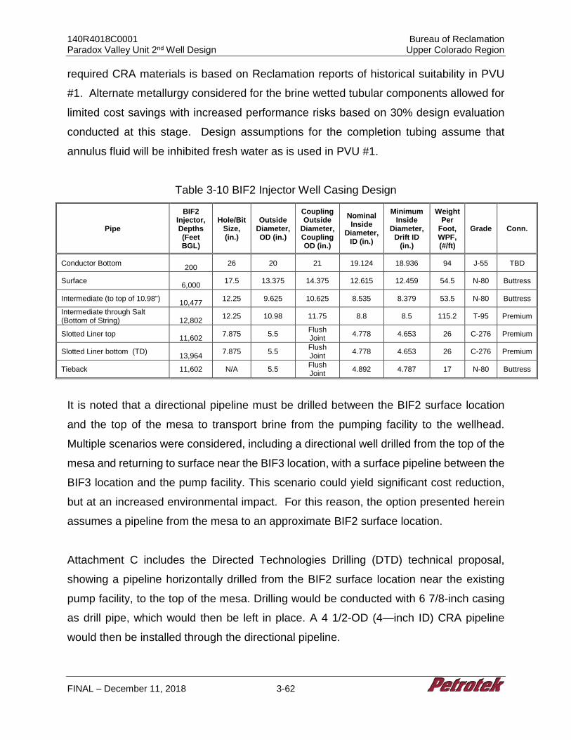
140R4018C0001 Bureau of Reclamation Paradox Valley Unit 2nd Well Design Upper Colorado Region
FINAL – December 11, 2018 3-62
required CRA materials is based on Reclamation reports of historical suitability in PVU
#1. Alternate metallurgy considered for the brine wetted tubular components allowed for
limited cost savings with increased performance risks based on 30% design evaluation
conducted at this stage. Design assumptions for the completion tubing assume that
annulus fluid will be inhibited fresh water as is used in PVU #1.
Table 3-10 BIF2 Injector Well Casing Design
Pipe
BIF2 Injector, Depths (Feet BGL)
Hole/Bit Size, (in.)
Outside Diameter, OD (in.)
Coupling Outside
Diameter, Coupling OD (in.)
Nominal Inside
Diameter, ID (in.)
Minimum Inside
Diameter, Drift ID
(in.)
Weight Per
Foot, WPF, (#/ft)
Grade Conn.
Conductor Bottom 200 26 20 21 19.124 18.936 94 J-55 TBD
Surface 6,000 17.5 13.375 14.375 12.615 12.459 54.5 N-80 Buttress
Intermediate (to top of 10.98") 10,477 12.25 9.625 10.625 8.535 8.379 53.5 N-80 Buttress
Intermediate through Salt (Bottom of String)
12,802 12.25 10.98 11.75 8.8 8.5 115.2 T-95 Premium
Slotted Liner top 11,602 7.875 5.5 Flush
Joint 4.778 4.653 26 C-276 Premium
Slotted Liner bottom (TD) 13,964 7.875 5.5 Flush
Joint 4.778 4.653 26 C-276 Premium
Tieback 11,602 N/A 5.5 Flush Joint 4.892 4.787 17 N-80 Buttress
It is noted that a directional pipeline must be drilled between the BIF2 surface location
and the top of the mesa to transport brine from the pumping facility to the wellhead.
Multiple scenarios were considered, including a directional well drilled from the top of the
mesa and returning to surface near the BIF3 location, with a surface pipeline between the
BIF3 location and the pump facility. This scenario could yield significant cost reduction,
but at an increased environmental impact. For this reason, the option presented herein
assumes a pipeline from the mesa to an approximate BIF2 surface location.
Attachment C includes the Directed Technologies Drilling (DTD) technical proposal,
showing a pipeline horizontally drilled from the BIF2 surface location near the existing
pump facility, to the top of the mesa. Drilling would be conducted with 6 7/8-inch casing
as drill pipe, which would then be left in place. A 4 1/2-OD (4—inch ID) CRA pipeline
would then be installed through the directional pipeline.
140R4018C0001 Bureau of Reclamation Paradox Valley Unit 2nd Well Design Upper Colorado Region
FINAL – December 11, 2018 3-63
Friction losses between the pump house and the wellhead would be approximately 50
psi higher for the pipeline than the losses in a directional well drilled between BIF2 and
the proposed injection target. Wellhead pressure would be lower than pump output
pressure due to the elevation difference. There would be negligible difference between
the injection pressure at TD between the directional well plan and the vertical well plan.
Final design and regulatory considerations to be resolved prior to drilling a pipeline
include determining the minimum depth for a drilled pipeline under a river crossing, and
determining whether directionally drilled pipelines must be cemented in place or if any
annulus monitoring will be required. To drill this pipeline, shallow geology studies would
need to be reviewed or conducted along the proposed path.
The drilled pipeline, in contrast to the initial concept of a directional well drilled from the
BIF2 location to the TBIF 1.5 target, would eliminate the significant inherent risks in drilling
a long lateral directional well from the BIF2 location to the proposed injection target, and
would require minimal facilities at the top of the mesa to include annulus pressure
maintenance, valving and wellhead monitoring equipment. As presented in Attachment
C, drilling of the proposed horizontal pipeline appears to be technically viable using
common construction practices and readily available construction materials, although
more information is necessary to verify feasibility.
Per Section 3.4.1, the injection well herein described is identical to the exploratory well
addressed under task BIF2.2.
3.4.2.4 Well Plan, BIF2 Injection Well Only
Based on the assumptions outlined in Section 2, and a 30% design, the following general
drilling and completion procedure has been designed for the installation of the proposed
vertical well. The procedure and depths may be modified as part of the final design and
altered slightly during field operations as warranted based on the actual downhole
conditions ultimately encountered during drilling.
140R4018C0001 Bureau of Reclamation Paradox Valley Unit 2nd Well Design Upper Colorado Region
FINAL – December 11, 2018 3-64
1. Survey and prepare the location for an all-weather operation. (Location access to be provided by Reclamation.) Drilling pad should be a minimum of 450 feet by 450 feet, roughly centered on the well surface location. Install an 8-foot diameter corrugated metal pipe cellar to a depth of 4 feet. Drilling water of up to 2,000 bbls/day (58 gpm) is to be supplied to location by Reclamation. Water will be hauled to the site or a water supply well will be drilled. The location will be lined with an impervious liner and matting boards will be installed to protect the liner. Drainage ditches will surround the location to prevent accidental release of liquids.
2. Mobilize an air drilling rig and support equipment. Prepare a polyvinyl (16-ounce or equivalent) liner with berms and drainage sumps. Install the liner as the rig is erected. The liner will be placed under the rig, pumps, and tanks. Rig up a “zero discharge” closed loop solids control system.
3. Rig up air drilling rig on location with appropriate anchoring and an air drilling system with sufficient compressor capacity to clean the hole. Inventory all tubulars (drillpipe and drill collars) on location. Drill 26-inch hole to 200 feet, install 20-inch conductor casing with a cement shoe at TD.
4. Cement conductor to surface using a standard cement. Rig up a full service (24 hr/day) mud logger. Catch drill cutting samples approximately every 30 feet, from the surface to total depth.
5. After a wait on cement time per cement vendor program, air drill with 17 1/2-inch bit to 6,000 feet. The target for maximum vertical deviation is to not exceed 1.5° increase from the previous survey or 1° per 1,000 feet of hole.
6. Fill hole with water and lost circulation material (LCM). Condition hole and conduct a surface casing open-hole logging program consisting of spontaneous potential (SP), induction-resistivity (IND), 6-arm caliper, neutron/density (ND) and gamma ray (GR). Calculate the surface casing cement volumes, and add 50% excess to the annulus volume. In areas where the caliper log cannot measure the hole diameter, add 100%.
7. Run 6,000 feet of 13 3/8-inch, 54.5 lb/ft, N-80 Buttress casing equipped with a float shoe on the bottom and a float collar one joint off of the bottom. Centralizers will be installed near the float shoe, at the center of the first joint, near the float collar, on the collars of the second and third joints, and on every third collar thereafter.
8. Establish circulation and circulate at least one casing volume of drilling fluid. Cement the 13 3/8-inch casing and circulate the cement back to the surface. The slurry will consist of light-weight lead cement and a tail slurry of standard, premium cement. Displace the wiper plug to the float collar. Ensure that the floats are holding by checking for flow back.
9. Center the casing in the rotary table, drain and flush the diverter stack and allow the cement to set per service company recommendations. Install and test BOP system. Conduct a temperature survey at the optimal time recommended by the service company after displacing the plug to locate the top of cement.
140R4018C0001 Bureau of Reclamation Paradox Valley Unit 2nd Well Design Upper Colorado Region
FINAL – December 11, 2018 3-65
10. After a wait on cement time appropriate for cementing program, run in hole and drill the shoe +10 feet, conduct shoe test. Drill a 12 1/4-inch hole to approximately 12,802 feet with a 12 1/4-inch bottom-hole assembly (BHA) on 5-inch drillpipe. This section should be drilled with petroleum-based mud to ensure torque and drag limitations are not exceeded. In the event that petroleum-based mud is deemed too costly, the section must be drilled with super saturated salt brine to minimize formation salt dissolution. Conduct a deviation survey below the surface casing, every 500 feet, and on trips. The target for maximum vertical deviation is to not exceed 1° increase from the previous survey or 1° per 1,000 feet of hole. Circulate the hole clean and make a wiper trip to the surface prior to open-hole logging. Measure (strap) the drillpipe.
NOTE: Run desander, desilter, and mud cleaners during drilling. Run the centrifuge as needed. Maintain an appropriate mud weight to control wellbore stability and target a viscosity of 35 to 70 sec/qt as appropriate for effective hole cleaning.
11. Condition hole and conduct the long-string casing open-hole logging program to include caliper logs, SP, IND, GR and possibly dipole sonic from 6,000 feet to 12,802 feet BGL. Calculate long-string cement volumes, plus 50% excess to the annulus volume according to the cement stage collar placement intervals. (Use 100% excess in areas where the caliper cannot measure the hole diameter).
12. Run intermediate casing string consisting of 2,325 feet of 10.98-inch, 115.2 lb/ft, T95, premium connection, extra heavy wall, custom, casing, equipped with a float shoe on the bottom and a float collar one joint off of the bottom. Then run a crossover with 10,477 feet of 9 5/8-inch, 53.5 lb/ft N-80 Buttress casing. Centralizers will be installed near the float shoe, at the center of the first joint, near the float collar, on the collars of the second and third joints, and on every third collar thereafter, or per cement vendor recommendation.
13. Cement the intermediate casing back to the surface in the following two stages per cement vendor recommendation:
Stage One - Establish circulation. Circulate at least one casing volume of drilling fluid prior to pumping pre-flush. Monitor drilling fluid properties and circulate until the properties are consistent with cement vendor recommendation. Cement the intermediate casing and circulate the cement back to the surface. Cement design to be per cement company recommendations. Displace the wiper plug to the float collar. Ensure that the floats are holding by checking for flow back.
Stage Two - Drop the opening device and open the stage tool. Circulate the drilling fluid through the stage tool for a minimum of 8 hours or as recommended by the service company based on field conditions, noting if the cement is returned to the surface. Pump the second stage with a light-weight lead cement, followed by a standard, premium tail cement to fill 500 feet of annulus above the stage tool. Circulate the second cement back to the surface. Displace the plug to the stage tool, bumping the plug to close the stage tool. Release the pressure and ensure that the stage tool is holding by monitoring for flow back. Wash any excess cement out of the BOP stack and drain the stack and casing head. Do
140R4018C0001 Bureau of Reclamation Paradox Valley Unit 2nd Well Design Upper Colorado Region
FINAL – December 11, 2018 3-66
not move the casing. Allow the second cement stage to set per service company recommendations.
14. After wait on cement time appropriate for cement program, drill the shoe and conduct shoe test. Drill through casing to TVD of 13,964 feet with 7 7/8-inch bit and BHA including MWD and GR. Core as necessary per Reclamation request. Make wiper trip and laydown BHA.
15. Commence open hole logging and fluid sampling program as directed by Reclamation. Assume that logs include spectra, GR and NMR. Make wiper trip.
16. On drill pipe, run liner hanger and 2,362 feet of 5 1/2-inch, 25 lb/ft, 0.476-inch wall, 0.038 slot, C-276 Hastelloy, 150 ksi material slotted liner and set liner from approximately 11,602 feet to 13,964 feet across injection interval
17. Set liner hanger and test liner hanger packer. 18. Run approximately 11,602 feet of 5 1/2-inch, 19.2 lb/ft, 0.304-inch wall, C-276
CRA, 125 ksi material casing as an injection tubing string. Latch into liner hanger with approximately 10,000 psi down force.
19. Rig down drilling rig and rig up completion rig. 20. Conduct additional fluid sampling, pressure transient injectivity testing and
production logging as directed by Reclamation.
3.4.2.5 BIF2 Class V Well Cost Estimate
The estimated cost of $68,334,426 for the BIF2 Class V injection well assumes the well
is completed with approximately 11,602 feet of 5 1/2-inch, 19.2 lb/ft, 0.304-inch wall, 125
ksi Hastelloy C-276 tubing, a Hastelloy C-276 seal assembly with primary metal-to-metal
seals and Teflon back-up seals, and a 5 1/8-inch 10M Inconel 625 or equivalent tree to
extend the design life of the well. In addition, the estimated cost assumes an underground
pipeline is drilled and installed from the well location to the BIF2 injection facility. The
pipeline cost is based on installation of 9,580 feet of 4.5-inch, 13.5 lb/ft, 0.290-inch wall,
125 ksi Hastelloy C-276 pipe. The cost and general well information is summarized in the
table below along with the cost for other proposed wells for comparison purposes. The
detailed cost estimate is provided as Table 3-6.
3.4.3 30% Design Injection Well Injection Facility
See Section 3.3.3 for injection facility design and cost information.
140R4018C0001 Bureau of Reclamation Paradox Valley Unit 2nd Well Design Upper Colorado Region
FINAL – December 11, 2018 3-67
3.4.4 Schedule for Drilling, Testing, Well Completion, and Injection Facility Installation
The schedule for well completion does not account for pre-drilling tasks including the
following:
• Regulatory negotiations.
• Final permit stipulations.
• Any variance for changes to proposed well construction in the final design phase.
• Drilling rig availability or contracts.
• Construction of location access (e.g., roads and bridges).
Please see Section 2.1.7 Schedule Assumptions and Limitations for additional detail.
Assuming all previous tasks are completed, the following generalized schedule can be
projected for drilling through completion of the well:
• Site preparation, rig move and rig-up: 25 days
• Drilling and Testing: 131 days
• Completion: 20 days
• Reporting: 90 days
• Total estimated days for drilling-completion: 266 days
• Pipeline drilling and installation 90 days
• Total estimated days for project 327 days
See Section 3.3.4 for injection facility schedule information.
3.5 Brine Injection Facility No. 3, BIF E1 and BIF3
140R4018C0001 Bureau of Reclamation Paradox Valley Unit 2nd Well Design Upper Colorado Region
FINAL – December 11, 2018 3-68
3.5.1 30% Design Exploratory Well, BIF E1
3.5.1.1 BIF E1 Data needs and Considerations: Well Design Criteria
Assumptions and design criteria for all vertical and directional wells are summarized in
Section 2.1.4. The BIF E1 is a vertical well with well surface location above the TBIF 1.5
bottomhole location. The preliminary hole and casing sizes have been designed to
withstand estimated conditions and promote completion to total target depth.
3.5.1.2 Monitoring Technologies
See Section 3.3.3 for Monitoring Technology information.
3.5.1.3 BIF E1 Well Design
Figure 3-8 presents the BIF E1 construction diagram. BIF E1 proposed to be a vertical
well drilled to a depth of 13,964 feet BGL for the purposes of: (1) confirming the geology
and reservoir properties projected in the vicinity of the well; (2) to characterize the
proposed injection formation; and (3) test the injectivity of the formation. Based on
requirements due to the geologic setting, consideration is being provided in this
evaluation for future conversion of the exploratory well into an injection well.
As stated in Section 2, minimum design criteria are 1.2 for single axis stress, 1.2 for triaxial
stress, and 1.6 for tensile stress. The design presented for this well resulted in a minimum
safety factor of 1.6 in tension at 100,000 lbs of overpull, and 1.85 under triaxial conditions.
Minimum design safety factors for single axis stresses range between 1.2 and 1.3 for
industry standard applications. Minimum triaxial design safety factor is usually 1.25. Risks
associated with a fifty (50) year design life dictated a stronger design. Limiting
Assumptions for triaxial stress analysis in most scenarios include limiting conditions of
0.433 psi/ft fresh water inside the tubular good, and 0.852 psi/ft (based on 16.4 ppg
cement) fluid on the outside of the tubular goods. To meet collapse and burst design
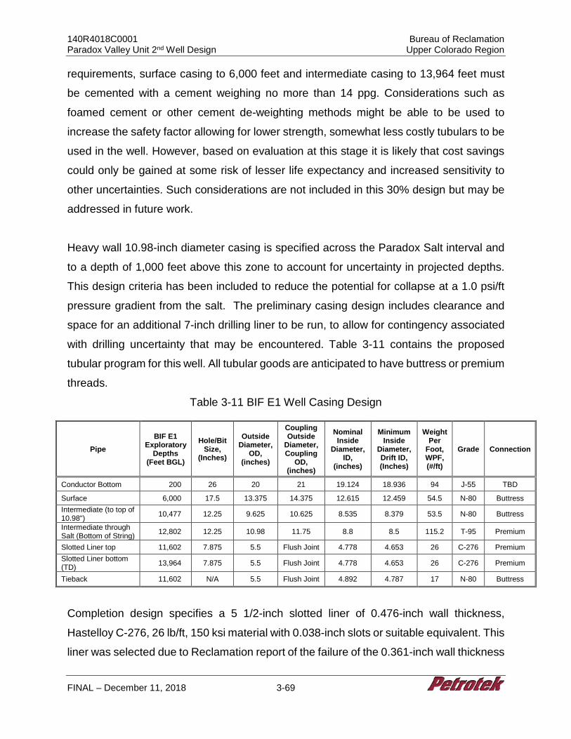
140R4018C0001 Bureau of Reclamation Paradox Valley Unit 2nd Well Design Upper Colorado Region
FINAL – December 11, 2018 3-69
requirements, surface casing to 6,000 feet and intermediate casing to 13,964 feet must
be cemented with a cement weighing no more than 14 ppg. Considerations such as
foamed cement or other cement de-weighting methods might be able to be used to
increase the safety factor allowing for lower strength, somewhat less costly tubulars to be
used in the well. However, based on evaluation at this stage it is likely that cost savings
could only be gained at some risk of lesser life expectancy and increased sensitivity to
other uncertainties. Such considerations are not included in this 30% design but may be
addressed in future work.
Heavy wall 10.98-inch diameter casing is specified across the Paradox Salt interval and
to a depth of 1,000 feet above this zone to account for uncertainty in projected depths.
This design criteria has been included to reduce the potential for collapse at a 1.0 psi/ft
pressure gradient from the salt. The preliminary casing design includes clearance and
space for an additional 7-inch drilling liner to be run, to allow for contingency associated
with drilling uncertainty that may be encountered. Table 3-11 contains the proposed
tubular program for this well. All tubular goods are anticipated to have buttress or premium
threads.
Table 3-11 BIF E1 Well Casing Design
Pipe BIF E1
Exploratory Depths
(Feet BGL)
Hole/Bit Size,
(Inches)
Outside Diameter,
OD, (inches)
Coupling Outside
Diameter, Coupling
OD, (inches)
Nominal Inside
Diameter, ID,
(inches)
Minimum Inside
Diameter, Drift ID, (Inches)
Weight Per
Foot, WPF, (#/ft)
Grade Connection
Conductor Bottom 200 26 20 21 19.124 18.936 94 J-55 TBD
Surface 6,000 17.5 13.375 14.375 12.615 12.459 54.5 N-80 Buttress Intermediate (to top of 10.98") 10,477 12.25 9.625 10.625 8.535 8.379 53.5 N-80 Buttress
Intermediate through Salt (Bottom of String) 12,802 12.25 10.98 11.75 8.8 8.5 115.2 T-95 Premium
Slotted Liner top 11,602 7.875 5.5 Flush Joint 4.778 4.653 26 C-276 Premium Slotted Liner bottom (TD) 13,964 7.875 5.5 Flush Joint 4.778 4.653 26 C-276 Premium
Tieback 11,602 N/A 5.5 Flush Joint 4.892 4.787 17 N-80 Buttress
Completion design specifies a 5 1/2-inch slotted liner of 0.476-inch wall thickness,
Hastelloy C-276, 26 lb/ft, 150 ksi material with 0.038-inch slots or suitable equivalent. This
liner was selected due to Reclamation report of the failure of the 0.361-inch wall thickness
140R4018C0001 Bureau of Reclamation Paradox Valley Unit 2nd Well Design Upper Colorado Region
FINAL – December 11, 2018 3-70
perforated liner used in the PVU #1 well. It is noted that perforated liners tend to lose
about 23.8% of rated collapse resistance during perforation (Hair, 1993). Based on the
assumption that the pressure gradient below the salt could be, or could eventually reach
a gradient of up to approximately 1.3 psi/ft due to pore pressure increase from injection,
a thicker liner was selected. The liner is to be hung from an industry standard liner
hanger/packer with a latch-in seal bore.
Completion tieback tubing for the exploratory well is specified as 5 1/2-inch N-80, 17 lb/ft
standard API casing for cost savings. This can be replaced with C-276 corrosion resistant
alloy (CRA) to convert the well to an injector. The use of C-276 for required CRA materials
is based on Reclamation reports of historical suitability in PVU #1. Alternate metallurgy
considered for the brine wetted tubular components allowed for limited cost savings with
increased performance risks based on 30% design evaluation conducted at this stage.
Design assumptions for the completion tubing assume that annulus fluid will be inhibited
fresh water as is used in PVU #1.
3.5.1.4 BIF E1 Well Plan
Based on the assumptions outlined and a 30% design, the following general drilling and
completion procedure has been designed for the installation of BIF E1. The procedure
and depths may be modified as part of the final design and altered slightly during field
operations as warranted based on the actual downhole conditions ultimately encountered
during drilling.
1. Survey and prepare the location for an all-weather operation. (Location access to be provided by Reclamation.) Drilling pad should be a minimum of 450 feet by 450 feet, roughly centered on the well surface location. Install an 8-foot diameter corrugated metal pipe cellar to a depth of 4 feet. Drilling water of up to 2,000 bbls/day (58 gpm) is to be supplied to location by Reclamation. Water will be hauled to the site or a water supply well will be drilled. The location will be lined with an impervious liner and matting boards will be installed to protect the liner. Drainage ditches will surround the location to prevent accidental release of liquids.
2. Mobilize an air drilling rig and support equipment. Prepare a polyvinyl (16-ounce or equivalent) liner with berms and drainage sumps. Install the liner as the rig is
140R4018C0001 Bureau of Reclamation Paradox Valley Unit 2nd Well Design Upper Colorado Region
FINAL – December 11, 2018 3-71
erected. The liner will be placed under the rig, pumps, and tanks. Rig up a “zero discharge” closed loop solids control system.
3. Drive 30-inch OD x 0.75-inch wall shallow conductor casing with a drive shoe to refusal (150 blows per foot) with a hammer. Have 200 feet of 30” pipe available on site.
4. Rig up air drilling rig on location with appropriate anchoring and an air drilling system with sufficient compressor capacity to clean the hole. Inventory all tubulars (drillpipe and drill collars) on location. Drill 26-inch hole to 200 feet, install 20-inch conductor casing with a cement shoe at TD.
5. Cement conductor to surface using a standard cement. Rig up a full service (24 hr/day) mud logger. Catch drill cutting samples approximately every 30 feet, from the surface to total depth.
6. After a wait on cement time per cement vendor, air drill with 17 1/2-inch bit to 6,000 feet. The target for maximum vertical deviation is to not exceed 1.5° increase from the previous survey or 1° per 1,000 feet of hole.
7. Fill hole with water and loss control material (LCM). Condition hole and conduct a surface casing open-hole logging program consisting of spontaneous potential (SP), induction-resistivity (IND), 6-arm caliper, neutron/density (ND) and gamma ray (GR). Calculate the surface casing cement volumes, and add 50% excess to the annulus volume. In areas where the caliper log cannot measure the hole diameter, add 100%.
8. Run 6,000 feet of 13 3/8-inch, 54.5 lb/ft, N-80 Buttress casing equipped with a float shoe on the bottom and a float collar one joint off of the bottom. Centralizers will be installed near the float shoe, at the center of the first joint, near the float collar, on the collars of the second and third joints, and on every third collar thereafter, or where applicable.
9. Establish circulation and circulate at least one casing volume of drilling fluid. Cement the 13 3/8-inch casing and circulate the cement back to the surface. The slurry will consist of light-weight lead cement and a tail slurry of standard, premium cement. Displace the wiper plug to the float collar. Ensure that the floats are holding by checking for flow back.
10. Center the casing in the rotary table, drain and flush the diverter stack and allow the cement to set per service company recommendations. Install and test BOP system. Conduct a temperature survey at the optimal time recommended by the service company after displacing the plug to locate the top of cement
11. After a wait on cement time appropriate for cementing program, run in hole and drill the shoe +10 feet, conduct shoe test. Drill a 12 1/4-inch hole to approximately 12,802 feet with a 12 1/4-inch bottom-hole assembly (BHA) including MWD and GR. This section should be drilled with oil-based mud to ensure torque and drag limitations are not exceeded. In the event that oil-based mud is deemed too costly, the section must be drilled with saturated salt brine to minimize formation salt dissolution. Circulate the hole clean and make a wiper trip to the surface prior to open-hole logging. Measure (strap) the drillpipe.
140R4018C0001 Bureau of Reclamation Paradox Valley Unit 2nd Well Design Upper Colorado Region
FINAL – December 11, 2018 3-72
NOTE: Run desander, desilter, and centrifuge during drilling. Maintain an appropriate mud weight to control wellbore stability and target a viscosity of 35 to 70 sec/qt as appropriate for effective hole cleaning.
12. Condition hole and conduct the long-string casing open-hole logging program to include caliper logs, SP, IND, GR and possibly dipole sonic from 6,000 feet to 12,802 feet BGL. Calculate long-string cement volumes, plus 50% excess to the annulus volume according to the cement stage collar placement intervals. (Use 100% excess in areas where the caliper cannot measure the hole diameter).
13. Run Intermediate casing string consisting of 2,325 feet of 10.98-inch, 115.2 lb/ft, T95, premium connection, extra heavy wall, custom casing, equipped with a float shoe on the bottom and a float collar one joint off of the bottom. Then run a crossover with 10,477 feet of 9 5/8-inch, 53.5 lb/ft N-80 Buttress casing. Centralizers will be installed near the float shoe, at the center of the first joint, near the float collar, on the collars of the second and third joints, and on every third collar thereafter, or per cement vendor recommendation.
14. Cement the intermediate casing back to the surface in the following two stages per cement vendor recommendation:
Stage One - Establish circulation. Circulate at least one casing volume of drilling fluid prior to pumping pre-flush. Monitor drilling fluid properties and circulate until the properties are consistent with cement vendor recommendation. Cement the intermediate casing and circulate the cement back to the surface. Cement design to be per cement company recommendations. Displace the wiper plug to the float collar. Ensure that the floats are holding by checking for flow back.
Stage Two –Drop the opening device and open the stage tool. Circulate the drilling fluid through the stage tool for a minimum of 8 hours or as recommended by the service company based on field conditions, noting if the cement is returned to the surface. Pump the second stage with a light-weight lead cement, followed by a standard, premium tail cement to fill 500 feet of annulus above the stage tool. Circulate the second cement back to the surface. Displace the plug to the stage tool, bumping the plug to close the stage tool. Release the pressure and ensure that the stage tool is holding by monitoring for flow back. Wash any excess cement out of the BOP stack and drain the stack and casing head. Do not move the casing. Allow the second cement stage to set per service company recommendations.
15. After wait on cement time appropriate for cement program, drill shoe and conduct shoe test. Drill through casing to TVD of 13,964 feet with 7 7/8-inch bit and BHA including MWD and GR. Core as necessary per Reclamation request. Make wiper trip and laydown BHA.
16. Commence open hole logging and fluid sampling program as directed by Reclamation. Assume that logs include spectra, GR and NMR. Make wiper trip.
17. On drill pipe, run liner hanger and 2,362 feet of 5 1/2-inch, 25 lb/ft, 0.476 inch wall, 0.038 slot, C-276 Hastelloy, 150 ksi material slotted liner and set liner from approximately 11,602 feet to 13,964 feet across injection interval
140R4018C0001 Bureau of Reclamation Paradox Valley Unit 2nd Well Design Upper Colorado Region
FINAL – December 11, 2018 3-73
18. Set liner hanger and test liner hanger packer. 19. Run approximately 11,602 feet of 5 1/2-inch, 17 lb/ft, N-80, casing as a tieback
string. Latch into liner hanger with approximately 10,000 psi down force. 20. Rig down drilling rig and rig up completion rig. 21. Conduct additional fluid sampling, pressure transient injectivity testing and
production logging as directed by Reclamation.
3.5.1.5 Feasibility of Completing BIF E1 Well As Long Term Observation Well
Based on typical safety factors and drilling practices and recommended risk tolerance, at
this 30% design phase no alternative options for the exploratory well were identified that
were substantially different from those identified for the injection well. It is recommended
that both well types provide a casing program sufficient to allow for a contingency 7-inch
drilling liner, and therefore significantly lower cost options were not identified at this time.
As a result, the exploratory well 30% designs are very similar to PVU #1, and are suitable
for conversion to injection wells or long-term observation wells. Long term observation
could be complicated by the proximity of the bottomhole location of the exploratory well
to the bottomhole location of the anticipated injection wells, in the event that both were
drilled. Consideration should be given to the idea of drilling the observation well to a
different bottomhole location if long term observation is a primary goal.
3.5.1.6 BIF E1 Well Cost Estimate
The estimated cost of $31,412,662 for the BIF E1 assumes the well is completed with a
5 1/2-inch 26 ppf C-276 Hastelloy liner and 5 1/2-inch, 17 N-80 tieback tubing and a 5
1/8-inch 10M carbon steel tree. The cost and general well information is summarized in
the table below along with the cost for other proposed wells for comparison purposes.
The detailed cost estimate is provided as Table 3-6.
3.5.1.6.1 Cost to Convert BIF E1 to Long Term Observation Well
The estimated cost to convert BIF E1 completed with carbon steel tubing and tree to a
long-term observation well assumes the well is completed with approximately 11,602 feet
140R4018C0001 Bureau of Reclamation Paradox Valley Unit 2nd Well Design Upper Colorado Region
FINAL – December 11, 2018 3-74
of 5 1/2-inch, 19.2 lb/ft, 0.304-inch wall, 125 ksi Hastelloy C-276 tubing, a Hastelloy C-
276 seal assembly with primary metal-to-metal seals and Teflon back-up seals, and a 5
1/8-inch 10M Inconel 625 or equivalent tree to extend the design life of the well. The
estimated cost of $32,412,662 for BIF E1 would increase by $12,084,543 to account for
the use of the CRA material vs. the carbon steel materials for a total estimated well cost
of $44,497,204.
3.5.1.6.2 Cost to Abandon BIF E1
The detailed closure cost estimate was previously presented in Table 3-2. Based on
direction from Reclamation, the estimate provided includes line items for unlisted items
(10%) and field cost contingency (25%). Cost basis and planning assumptions were
summarized in Section 2.1.1.1. The estimated total cost for plugging and abandoning
BIF3 exploratory well using Q1 2019 US dollars is $1,212,493.
3.5.2 30% Design Class V Well, BIF3
3.5.2.1 BIF3 Data Needs and Considerations
Assumptions and design criteria for all vertical and directional wells are summarized in
Section 2.1.5. The well surface location is to be at the BIF3 location as designated by
Reclamation, and the bottomhole location is to be offset approximately 4,066 feet to reach
the target injection zone. The preliminary directional trajectory has been estimated to
manage torque and drag and promote completion to total target depth while reducing
encounters with the most significant geologic hazards.
3.5.2.2 Monitoring Technologies
See Section 3.3.1.2 for Monitoring Technology information.
140R4018C0001 Bureau of Reclamation Paradox Valley Unit 2nd Well Design Upper Colorado Region
FINAL – December 11, 2018 3-75
3.5.2.3 BIF3 Well Design
Figure 3-9 presents the BIF3 injection well construction diagram. The injection well at the
BIF3 location is proposed to be a directional well drilled to a total depth of 12,716 feet
BGL (13,788 feet MD) for the purpose of brine disposal from the Paradox facility. This
30% design is based on currently available data and is intended to be revised, if
necessary, based on data acquired from a 3D seismic survey, and drilling and testing of
the Exploratory Well.
As stated in Section 2, minimum design criteria are 1.2 for single axis stress, 1.2 for triaxial
stress, and 1.6 for tensile stress. The design presented for this well resulted in a minimum
safety factor of 1.6 in tension at 100,000 lbs of overpull, and 1.72 under triaxial conditions.
Minimum design safety factors for single axis stresses range between 1.2 and 1.3 for
industry standard applications. Minimum triaxial design safety factor is usually 1.25. Risks
associated with a fifty (50) year design life dictated a stronger design. Limiting
assumptions for triaxial stress analysis in most scenarios include limiting conditions of
0.433 psi/ft fresh water inside the tubular good, and 0.852 psi/ft (based on 16.4 ppg
cement) fluid on the outside of the tubular goods. To meet collapse and burst design
requirements, surface casing to 6,483 feet and intermediate casing to 13,788 feet must
be cemented with a cement weighing no more than 14 ppg. Considerations such as
foamed cement or other cement de-weighting methods might be able to be used to
increase the safety factor allowing for lower strength, somewhat less costly tubulars to be
used in the well. However, based on evaluation at this stage it is likely that cost savings
could only be gained at some risk of lesser life expectancy and increased sensitivity to
other uncertainties. Such considerations are not included in this 30% design but may be
addressed in future work.
Heavy wall 10.98-inch casing is specified across the Paradox Salt interval and 1,000 feet
above this zone to account for uncertainty in projected depths. These design criteria have
been included to reduce the potential for collapse at a 1.0 psi/ft pressure gradient from
the salt. The preliminary casing design includes clearance and space for an additional 7-
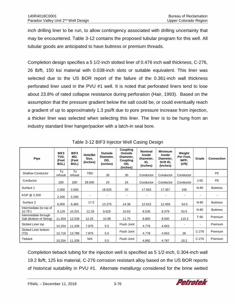
140R4018C0001 Bureau of Reclamation Paradox Valley Unit 2nd Well Design Upper Colorado Region
FINAL – December 11, 2018 3-76
inch drilling liner to be run, to allow contingency associated with drilling uncertainty that
may be encountered. Table 3-12 contains the proposed tubular program for this well. All
tubular goods are anticipated to have buttress or premium threads.
Completion design specifies a 5 1/2-inch slotted liner of 0.476 inch wall thickness, C-276,
26 lb/ft, 150 ksi material with 0.038-inch slots or suitable equivalent. This liner was
selected due to the US BOR report of the failure of the 0.361-inch wall thickness
perforated liner used in the PVU #1 well. It is noted that perforated liners tend to lose
about 23.8% of rated collapse resistance during perforation (Hair, 1993). Based on the
assumption that the pressure gradient below the salt could be, or could eventually reach
a gradient of up to approximately 1.3 psi/ft due to pore pressure increase from injection,
a thicker liner was selected when selecting this liner. The liner is to be hung from an
industry standard liner hanger/packer with a latch-in seal bore.
Table 3-12 BIF3 Injector Well Casing Design
Pipe BIF3 TVD, (Feet BGL)
BIF3 MD, (Feet BGL)
Hole/Bit Size,
(Inches)
Outside Diameter,
OD, (inches)
Coupling Outside
Diameter, Coupling
OD, (inches)
Nominal Inside
Diameter, ID,
(inches)
Minimum Inside
Diameter, Drift ID, (Inches)
Weight Per Foot,
WPF, (#/ft)
Grade Connection
Shallow Conductor To refusal
To refusal TBD
30
30
Conductor
Conductor
Conductor PE
Conductor 200
200
28.000
24
24
Conductor
Conductor
Conductor J-55 PE
Surface 1 2,000
2,000
18.625
20
17.563
17.357
106 N-80 Buttress
KOP @ 2,200' 2,200
2,200 - - - - - - - -
Surface 2 6,000
6,483 17.5
13.375
14.38
12.615
12.459
54.5 N-80 Buttress
Intermediate (to top of 10.75")
9,129
10,201
12.25
9.625
10.63
8.535
8.379
53.5 N-80 Buttress
Intermediate through Salt (Bottom of String)
11,454
12,539
12.25
10.98
11.75
8.800
8.500
115.2 T-95 Premium
Slotted Liner top 10,254
11,339
7.875
5.5 Flush Joint
4.778
4.653 - - Premium
Slotted Liner bottom (TD)
12,716
13,788
7.875
5.5 Flush Joint
4.778
4.653
26 C-276 Premium
Tieback 10,254
11,339 N/A
5.5 Flush Joint 4.892
4.787
19.2 C-276 Premium
Completion tieback tubing for the injection well is specified as 5 1/2-inch, 0.304-inch wall
19.2 lb/ft, 125 ksi material, C-276 corrosion resistant alloy based on the US BOR reports
of historical suitability in PVU #1. Alternate metallurgy considered for the brine wetted
140R4018C0001 Bureau of Reclamation Paradox Valley Unit 2nd Well Design Upper Colorado Region
FINAL – December 11, 2018 3-77
tubular components allowed for limited cost savings with increased performance risks
based on 30% design evaluation conducted at this stage. Design assumptions for the
completion tubing assume that annulus fluid would be inhibited fresh water as is used in
PVU #1, and as a limiting case, that no formation cooling would be observed to maximize
thermal stress included in the evaluation of tubing stresses.
3.5.2.4 BIF3 Well Plan
Figure 3-10 is the BIF3 Direction Plan. Based on the assumptions outlined in Section 2,
and a 30% design, the following general drilling and completion procedure has been
designed for the installation of the proposed directional well. The procedure and depths
may be modified as part of the final design and altered slightly during field operations as
warranted based on the actual downhole conditions ultimately encountered during drilling.
1. Survey and prepare the location for an all-weather operation. (Location access to be provided by Reclamation.) Drilling pad should be a minimum of 450 feet by 450 feet, roughly centered on the well surface location. Install an 8-foot diameter corrugated metal pipe cellar to a depth of 4 feet. Drilling water of up to 2,000 bbls/day (58 gpm) is to be supplied to location by Reclamation. Water will be hauled to the site or a water supply well will be drilled. The location will be lined with an impervious liner and matting boards will be installed to protect the liner. Drainage ditches will surround the location to prevent accidental release of liquids.
2. Mobilize an air drilling rig and support equipment and rig up on location with appropriate anchoring. Prepare a polyvinyl (16-ounce or equivalent) liner with berms and drainage sumps. Install the liner as the rig is erected. The liner will be placed under the rig, pumps, and tanks. Rig up a “zero discharge” closed loop solids control system.
3. Drive 30-inch OD x 0.75-inch wall shallow conductor casing with a drive shoe to refusal (150 blows per foot) with a hammer. Have 200 feet of 30” pipe available on site.
4. Rig up an air drilling system with sufficient compressor capacity to clean the hole. Inventory all tubulars (drillpipe and drill collars) on location. Drill 28-inch hole to 200 feet, install 24-inch, J-55, Plain End conductor casing.
5. Cement conductor to surface using a standard cement. Rig up a full service (24 hr/day) mud logger. Catch drill cutting samples approximately every 30 feet, from the surface to total depth.
140R4018C0001 Bureau of Reclamation Paradox Valley Unit 2nd Well Design Upper Colorado Region
FINAL – December 11, 2018 3-78
6. After a wait on cement time per cement vendor program, air drill with 20 bit to 2,000 feet. The target for maximum vertical deviation is to not exceed 1.5° increase from the previous survey or 1° per 1,000 feet of hole.
7. Fill hole with water and lost circulation material (LMC). Condition hole and conduct a surface casing open-hole logging program consisting of spontaneous potential (SP), induction-resistivity (IND), 6-arm caliper, neutron/density (ND) and gamma ray (GR). Calculate the surface casing cement volumes, and add 50% excess to the annulus volume. In areas where the caliper log cannot measure the hole diameter, add 100%.
8. Run 2,000 feet of 18 5/8-inch, 106 lb/ft, N-80 Buttress casing equipped with a float shoe on the bottom and a float collar one joint off of the bottom. Centralizers will be installed near the float shoe, at the center of the first joint, near the float collar, on the collars of the second and third joints, and on every third collar thereafter, or per cement vendor recommendation.
9. Center the casing in the rotary table, drain and flush the diverter stack and allow the cement to set per service company recommendations. Install and test BOP system. Conduct a temperature survey at the optimal time recommended by the service company after displacing the plug to locate the top of cement.
10. Drill a 17 1/2-inch hole to a measured depth of 6,483 feet (6,000 feet TVD) with a 17 1/2-inch bottom-hole assembly (BHA) on 5-inch drillpipe. Conduct a deviation survey below the surface casing, every 500 feet, and on trips. Begin directional drilling, KOP is at 2,200 feet, and maximum build rate is 2.00 degrees per 100 feet. Target inclination angle is 26.6 degrees.
NOTE: Run desander, desilter, and centrifuge during drilling. Maintain an appropriate mud weight to control wellbore stability and target a viscosity of 35 to 70 sec/qt as appropriate for effective hole cleaning.
11. Fill hole with water and lost circulation material (LCM). Condition hole and conduct a surface casing open-hole logging program consisting of spontaneous potential (SP), induction-resistivity (IND), 6-arm caliper, neutron/density (ND) and gamma ray (GR). Calculate the surface casing cement volumes, and add 50% excess to the annulus volume. In areas where the caliper log cannot measure the hole diameter, add 100% excess per regulatory requirements.
12. Run 6,483 feet of 13 3/8 inch, 54.5 lb/ft, N-80, Buttress casing equipped with a float shoe on the bottom and a float collar one joint off of the bottom. Centralizers will be installed near the float shoe, at the center of the first joint, near the float collar, on the collars of the second and third joints, and on every third collar thereafter, or where applicable.
13. Establish circulation and circulate at least one casing volume of drilling fluid. Monitor drilling fluid properties and circulate until the properties are similar to the expected cement slurry properties. Cement the 13 3/8-inch casing and circulate the cement back to the surface. The slurry will consist of light-weight lead cement and a tail slurry of standard, premium cement. Displace the wiper plug to the float collar. Ensure that the floats are holding by checking for flow back.
140R4018C0001 Bureau of Reclamation Paradox Valley Unit 2nd Well Design Upper Colorado Region
FINAL – December 11, 2018 3-79
14. Center the casing in the rotary table, drain and flush the diverter stack and allow the cement to set per service company recommendations. Conduct a temperature survey at the optimal time recommended by the service company after displacing the plug to locate the top of cement.
15. After a wait on cement time appropriate for cementing program, run in hole and drill the shoe +10 feet, conduct a shoe test. Drill directionally to a measured depth of 9,900 feet (8,908 feet TVD), and begin drop to vertical. Conduct a deviation survey below the surface casing, every 500 feet, and on trips. Maximum drop rate is 2.00 degrees per 100 feet. This, and all further sections of the well, should be drilled with petroleum-based mud to ensure torque and drag limitations are not exceeded.
16. Well should return to vertical by a measured depth of 11,485 feet (10,416 feet TVD). Drill to 12,539 feet (11,454 feet TVD), The target for maximum vertical deviation is to not exceed 1° increase from the previous survey or 1° per 1,000 feet of hole.
17. Condition hole and conduct the long-string casing open-hole logging program to include caliper logs, SP, IND, GR and possibly dipole sonic, from 6,483 feet to 12,539 feet MD (11,454 feet TVD). Calculate long-string cement volumes, plus 50% excess to the annulus volume according to the cement stage collar placement intervals (use 100% excess in areas where the caliper cannot measure the hole diameter).
18. Run intermediate casing string consisting of 2,338 feet of 10.98-inch, 115.2 lb/ft, T95, Premium connection, heavy wall custom casing, equipped with a float shoe on the bottom and a float collar one joint off of the bottom. Then run a crossover to 10,201 feet of 9 5/8-inch, 53.5 lb/ft, N-80 Buttress casing. Centralizers will be installed near the float shoe, at the center of the first joint, near the float collar, on the collars of the second and third joints, and on every third collar thereafter or per cement vendor recommendation.
19. Cement the intermediate casing back to the surface in the following two stages per cement vendor recommendation:
Stage One - Establish circulation. Circulate at least one casing volume of drilling fluid prior to pumping pre-flush. Monitor drilling fluid properties and circulate until the properties are consistent with cement vendor recommendation. Cement the intermediate casing and circulate the cement back to the surface. Cement design to be per cement company recommendations. Displace the wiper plug to the float collar. Ensure that the floats are holding by checking for flow back.
Stage Two - Drop the opening device and open the stage tool. Circulate the drilling fluid through the stage tool for a minimum of 8 hours or as recommended by the service company based on field conditions, noting if the cement is returned to the surface. Pump the second stage with a light-weight lead cement, followed by a standard, premium tail cement to fill 500 feet of annulus above the stage tool. Circulate the second cement back to the surface. Cement design to be per cement company recommendations. Displace the plug to the stage tool,
140R4018C0001 Bureau of Reclamation Paradox Valley Unit 2nd Well Design Upper Colorado Region
FINAL – December 11, 2018 3-80
bumping the plug to close the stage tool. Release the pressure and ensure that the stage tool is holding by monitoring for flow back. Wash any excess cement out of the BOP stack and drain the stack and casing head. Do not move the casing. Allow the second cement stage to set per service company recommendations.
20. After wait on cement time appropriate for cement program, drill shoe and conduct shoe test. Continue drilling directionally until reaching vertical. Maximum drop rate is 2.00 degrees per 100 feet.
21. Drill to MD of 13,788 feet (12,716 feet TVD) with 7 7/8-inch bit and BHA including MWD and GR. Core as necessary per Reclamation request. Make wiper trip and laydown BHA.
22. Commence open hole logging and fluid sampling program as directed by Reclamation. Assume that logs include spectra GR and Magnetic Resonance (NMR). Make wiper trip.
23. On drill pipe, run liner hanger and 2,449 feet of 5 1/2-inch, 25 lb/ft, 0.476-inch wall, 0.038-inch slot, C-276 Hastelloy, 150 ksi material slotted liner and set liner from approximately 11,339 feet (10,254 feet TVD) to 13,788 feet (12,716 feet TVD) across injection interval.
24. Set liner hanger and test liner hanger packer. 25. Run approximately 11,399 feet of 5 1/2-inch 19.2 lb/ft, C-276, 125 ksi material
strength, premium connection casing as a tieback string. Latch into liner hanger with approximately 10,000 psi down force.
26. Rig down drilling rig and rig up completion rig.
3.5.2.5 BIF3 Class V Well Cost Estimate
The estimated cost of $56,247,427 for the BIF3 Class V injection well assumes the well
is completed with approximately 11,339 feet of 5 1/2-inch, 19.2 lb/ft, 0.304-inch wall, 125
ksi Hastelloy C-276 tubing, a Hastelloy C-276 seal assembly with primary metal-to-metal
seals and Teflon back-up seals, and a 5 1/8-inch 10M Inconel 625 or equivalent tree to
extend the design life of the well. The cost and general well information is summarized in
the table below along with the cost for other proposed wells for comparison purposes.
The detailed cost estimate is provided as Table 3-6.
140R4018C0001 Bureau of Reclamation Paradox Valley Unit 2nd Well Design Upper Colorado Region
FINAL – December 11, 2018 3-81
3.5.3 30% Design Injection Well Injection Facility
See Section 3.3.3 for the injection facility design and cost.
3.5.4 Schedule for Drilling, Testing, Well Completion and Injection Facility Installation
The schedule for well completion does not account for pre-drilling tasks including the
following:
• Regulatory negotiations
• Final permit stipulations
• Any variance for changes to proposed well construction in the final design phase
• Drilling rig availability or contracts
• Construction of location access (e.g., roads and bridges)
Please see Section 2.1.7 Schedule Assumptions and Limitations for additional detail.
Assuming all previous tasks are completed, the following generalized schedule can be
projected for drilling through completion of the well:
• Site preparation, rig move and rig-up: 25 days
• Drilling and Testing: 124 days
• Completion: 20 days
• Reporting: 90 days
• Total estimated days for drilling-completion: 259 days
See Section 3.3.4 for injection facility schedule information.
140R4018C0001 Bureau of Reclamation Paradox Valley Unit 2nd Well Design Upper Colorado Region
FINAL – December 11, 2018 3-82
3.6 Well Cost Allocation
Costs for a well are largely a function of depth and complexity. The Paradox Basin
disposal wells are all complex due to stress regimes associated with salt, and the depth
at which the wells are to be completed. Complexity and depth result in extended rig time
and well costs. In general, the fixed costs of the well, such as cement, or tubular products
are a smaller percentage of the overall cost of the installation than the daily drilling costs.
To generally characterize well costs, the following data categories were evaluated:
1. Rig costs include:
a. Location development b. Daily Drilling Operations (Day rate for rig, Communications, Rentals,
Housing, etc.) c. Rig mobilization and demobilization
2. Bits, Mud, Motors & Directional include: a. Bits b. Mud and solids control c. Solids management d. Directional services and tool rental
3. Personnel and Supervision to include: a. Engineering supervision b. Mud logging c. Analysis and reporting
4. Tubular Products & Cement to include: a. Cement b. Casing c. Packer & PBR d. Injection Tubing, or Tieback
5. Completion to include: a. Daily Operations (Communications, Rentals, Housing, etc.) b. Wellhead and Tree c. Cased hole wireline logging, i.e. CBL
140R4018C0001 Bureau of Reclamation Paradox Valley Unit 2nd Well Design Upper Colorado Region
FINAL – December 11, 2018 3-83
d. Stimulation and well development 6. Logging and Testing include:
a. Surface and Intermediate logging prior to casing b. Intermediate and Production logging and SWC’s c. Coring d. Open hole testing e. Cased hole testing f. Tractoring (if needed for wireline logs)
7. Logistics to include: a. Misc. Trucking
8. Plugging to include a. Cost to plug well at end of life
Figure 3-11 presents typical cost distributions by cost category for MM1, a directional
injection well, and MM E1, a vertical exploratory well. From the figures, it is apparent that
between 69% and 80% of the total drilling cost is from the three cost categories identified
as (a) Rig Costs, (b) Bits, Mud, Motors & Directional Services, and (c) Tubular Products
and Cement. It is noted that all of the other proposed wells follow this general cost
breakdown, with slightly different percentages due to drilling duration.
It is noted that drilling costs for the project are high due to depth and estimated drilling
days required. In this regard, the previous PVU #1 well required 254 drilling days. Due
to depth, tubular costs are relatively fixed, but will vary based on market conditions.
Because of new drilling bit and mud motor design and efficiency, we have assumed that
the new injection wells can be drilled in 95 days (vertical wells) to 131 days (directional
well). It is possible that the wells could be drilled even faster than the assumptions used
in this report. For example, wells in the DJ basin to similar depths (13,000 feet MD) are
requiring only 20-30 drilling days, including drilling through difficult anhydrite and
carbonate sections. However, in the DJ Basin, there are ample offset data on which to
base well design; this is not the case for the PVU project. If greater rate of penetration
was achieved at PVU, well costs could be reduced by 10%-20%.
140R4018C0001 Bureau of Reclamation Paradox Valley Unit 2nd Well Design Upper Colorado Region
Final – December 11, 2018 4-1
4.0 EVALUATION AND SUITABILITY OF SITES
As specified in the SOW, site suitability was evaluated to:
1. Identify the strengths, potential problems, and risks of the proposed well sites from
an engineering standpoint, and,
2. Provide judgement on the likelihood of obtaining an operational well that will
function for the design life.
As a result of this analysis, 30% design cost estimates were developed for the locations
identified in previous studies that Reclamation considered to be feasible sites.
Additionally, the engineering feasibility includes evaluation of the risks and identification
of key uncertainties.
Initially, Reclamation provided three injection well locations (options) to be evaluated:
a. Monogram Mesa (MM1)-TMM1
• Direction well with surface location at MM1 and bottomhole location at TMM1 (MM1-TMM1)
b. BIF (BIF2-TBIF 1.5)
• Direction well surface location at BIF2 and bottomhole location at TBIF 1.5 (BIF2-TBIF 1.5)
• Direction well surface location at BIF3 and bottomhole location at TBIF 1.5 (BIF3-TBIF 1.5)
c. BIF (BIF3-TBIF 1.5)
The original BIF2-TBIF 1.5 well design required over 8,000 feet of offset (displacement)
from the surface location to the TBIF bottomhole location. This well design has significant
risk due to: (1) the great total well depth (over 16,700 feet MD), (2) high angle required
to achieve the displacement (58 degrees), (3) large offset (over 8,000 feet), (4) the
presence of salt and numerous structural elements (identified and unidentified), (5)
significant torque and drag that would be encountered, and (6) the well could require one
or more sidetracks to reach completion depth. As a result of these risks, it is uncertain
140R4018C0001 Bureau of Reclamation Paradox Valley Unit 2nd Well Design Upper Colorado Region
Final – December 11, 2018 4-2
whether this well could be drilled for any reasonable cost, or at all. Hence this well was
removed from further consideration.
However, understanding the need to evaluate the potential for a surface facility near the
BIF2 surface location and to utilize a TBIF 1.5 bottomhole injection location, an alternate
to the BIF2-TBIF 1.5 well design was developed. This option, discussed in Section 3.4.2
and Attachment C, includes: (1) a vertical well drilled from the top of Skein Mesa (e.g.,
near BIF E1) to a TBIF 1.5 bottomhole location, (2) a surface facility located near BIF2,
and (3) a horizontal pipeline from the BIF2 surface location to the well on top of the mesa.
It is noted that there are risks associated with a horizontal pipeline, but this type of
pipeline has been installed before (see Lattimore, 1987, in Attachment C). Further, the
risks of the horizontal pipeline are much lower than the risk of an extended reach
directional well (the original BIF2-BIF 1.5), and the management of the risk for a pipeline
likely would be much less expensive than for a complex directional well.
The directional exploratory wells MM1-TMM1 and BIF3-TBIF 1.5 were found to be
technically viable. Discussion of these options, from a design and cost standpoint, are
presented in Section 3.0 of this report. Given that both BIF wells target the same
bottomhole location (TBIF 1.5), and the complications of the BIF2-TBIF 1.5 well, the three
directional locations are reduced to two; namely, Monogram Mesa (MM) (MM1-TMM1)
and BIF3-TBIF 1.5. For both of the locations, Reclamation requested evaluation and
costing for (1) a near-vertical exploration well (less than 50-year design life), and (2) a
directional injection well with a 50-year design life. Discussion of those options from a
design and cost standpoint has been presented in Section 3.0 of this Report.
To advance geologic understanding and reduce risk, the SOW indicated that the
evaluation should include drilling separate vertical exploratory and injection wells for
each alternative location, i.e. at BIF and Monogram Mesa. It was assumed that the cost
of an exploratory well would be minor compared to an injection well. However, based
on the cost estimates included in this Report, the cost of exploratory wells is significant
(i.e., on the order of 55-60% of the cost of the injection wells).
140R4018C0001 Bureau of Reclamation Paradox Valley Unit 2nd Well Design Upper Colorado Region
Final – December 11, 2018 4-3
It is understood that the ultimate decision regarding the future of the project will depend
on the viability of the injection wells. Hence, from an engineering standpoint, the
evaluation of suitability, risk and cost is reduced to two alternative sites: MM-TMM1 and
BIF (either BIF3-TBIF 1.5 as a directional well, or BIF2-TBIF 1.5 via a pipeline from BIF2
to the top of Skein Mesa). Additional comparison of these options is presented in Section
4.1
The suitability of each option was evaluated based on “risk” criteria including depth,
angle, salt thickness, drilling through faults, etc. One of the dominant factors in the risk
evaluation was well configuration (depth, offset, angle) which is fairly well known. The
other dominant factor in the risk analysis is geology, which is less known due to lack of
detailed subsurface data.
As noted in the Statement of Work (Section 3.0, Task 8) Reclamation is responsible for
providing geologic information to be used in this study (see below).
8. All potential sites will be identified to the contractor by Reclamation, based on separate studies, such as interpretation of 2D seismic reflection data, well-log data, formation properties, drilling and logging data from exiting PVU well, aeromagnetic data, geologic structure, induced seismicity, environmental impacts, and the feasibility of constructing and operating surface infrastructure. Data provided by Reclamation will include an assumed lithology and stress state for each site, including depth to the target injection formation, salt thickness, location of major faults, and other properties determined from seismic reflection data, logs from existing wells in the area, etc.
According to Reclamation, the following limitations apply to the current geologic
understanding of the project:
• Detailed fault structures are not well-defined by the sparse 2-D seismic reflection data available.
• Leadville thickness is known only at the locations of the previous deep wellbores in the area (Leadville thickness cannot be determined from the 2-D seismic data).
• Since Leadville thickness varies considerably in the Paradox Valley area, the thickness at the proposed well sites are rough estimates.
140R4018C0001 Bureau of Reclamation Paradox Valley Unit 2nd Well Design Upper Colorado Region
Final – December 11, 2018 4-4
It is anticipated that future 3-D seismic studies will provide a higher level of certainty with
regard to these issues, and that information will be incorporated into Final Design for the
selected well options.
4.1 Description of the Suitability Assessment and Evaluation Methodology
An assessment was conducted to evaluate each potential well configuration using the
general methodology developed during the last phase of the PVU #2 FS work (Petrotek,
2017). As discussed prior, there are only two directional injection well options and an
alternative horizontal pipeline/vertical injection well that form the decision basis for the
project moving forward. Further, it was also determined that the cost of installing a vertical
exploratory well was much greater than anticipated. However, for the sake of
completeness and comparison, information related to the exploratory wells is included in
the table below.
The configurations evaluated were:
1. MM1 (surface) – TMM1 (target); Injection Well 2. BIF3 (surface) - TBIF 1.5 (target); Injection Well 3. MM E1 (surface) – TMM1 (target) (Exploratory Well) 4. BIF E1/BIF2 (surface) - TBIF 1.5 (target) (Includes BIF2 vertical injection well and
BIF E1 exploratory well)
A summary of the well information is provided in Table 4-1. From a drilling standpoint the
exploratory well BIF E1 and the injection well at BIF2 are nearly identical and are hence
presented as a single configuration. Primary risk considerations for each configuration
were distributed among three categories: drilling, geology, and operational feasibilities.
The detailed risk analysis is presented below. Note that the BIF2–TBIF 1.5 drilling option
has been replaced with #4 above serviced by a BIF2 pipeline. The specific risks
associated with installation and maintenance of this high-pressure pipeline are not
included in this analysis. However, example project descriptions are provided in
Attachment C and additional historical information is included in Latimore (1987).
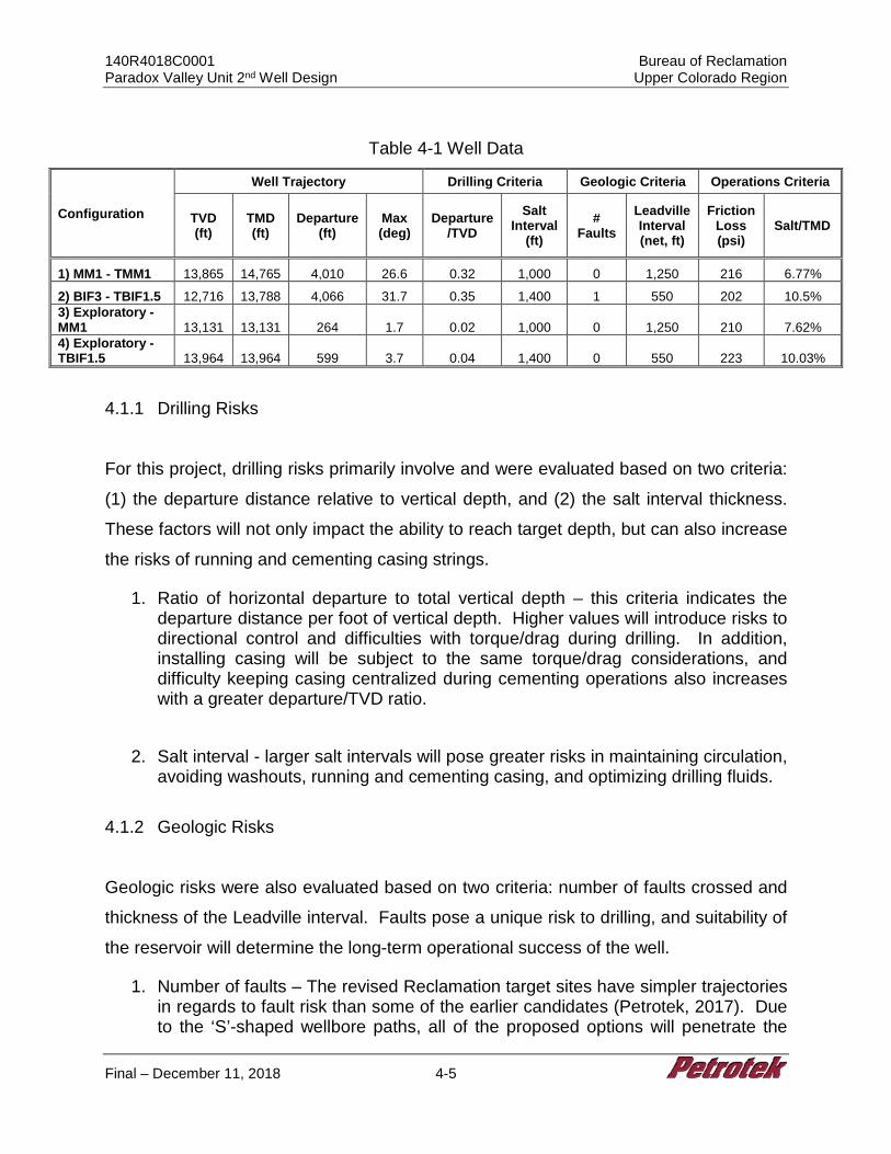
140R4018C0001 Bureau of Reclamation Paradox Valley Unit 2nd Well Design Upper Colorado Region
Final – December 11, 2018 4-5
Table 4-1 Well Data
Configuration
Well Trajectory Drilling Criteria Geologic Criteria Operations Criteria
TVD (ft)
TMD (ft)
Departure (ft)
Max (deg)
Departure/TVD
Salt Interval
(ft) #
Faults Leadville Interval (net, ft)
Friction Loss (psi)
Salt/TMD
1) MM1 - TMM1 13,865 14,765 4,010 26.6 0.32 1,000 0 1,250 216 6.77%
2) BIF3 - TBIF1.5 12,716 13,788 4,066 31.7 0.35 1,400 1 550 202 10.5% 3) Exploratory - MM1 13,131 13,131 264 1.7 0.02 1,000 0 1,250 210 7.62% 4) Exploratory - TBIF1.5 13,964 13,964 599 3.7 0.04 1,400 0 550 223 10.03%
4.1.1 Drilling Risks
For this project, drilling risks primarily involve and were evaluated based on two criteria:
(1) the departure distance relative to vertical depth, and (2) the salt interval thickness.
These factors will not only impact the ability to reach target depth, but can also increase
the risks of running and cementing casing strings.
1. Ratio of horizontal departure to total vertical depth – this criteria indicates the departure distance per foot of vertical depth. Higher values will introduce risks to directional control and difficulties with torque/drag during drilling. In addition, installing casing will be subject to the same torque/drag considerations, and difficulty keeping casing centralized during cementing operations also increases with a greater departure/TVD ratio.
2. Salt interval - larger salt intervals will pose greater risks in maintaining circulation,
avoiding washouts, running and cementing casing, and optimizing drilling fluids.
4.1.2 Geologic Risks
Geologic risks were also evaluated based on two criteria: number of faults crossed and
thickness of the Leadville interval. Faults pose a unique risk to drilling, and suitability of
the reservoir will determine the long-term operational success of the well.
1. Number of faults – The revised Reclamation target sites have simpler trajectories in regards to fault risk than some of the earlier candidates (Petrotek, 2017). Due to the ‘S’-shaped wellbore paths, all of the proposed options will penetrate the
140R4018C0001 Bureau of Reclamation Paradox Valley Unit 2nd Well Design Upper Colorado Region
Final – December 11, 2018 4-6
Leadville vertically, and only the BIF3 surface locations will result in a single fault crossing, approximately mid-wellbore. The main risk of drilling across faults are (1) potential change in reservoir pressure, (2) Borehole instability and (3) problems with running and cementing casing
2. Net Leadville interval – In addition to the gross Leadville interval, consideration was taken to the extent of nearby structural constraints present in the Leadville. The BIF reservoir location has a Leadville fault to the northeast. This structural constraint is not present in the Monogram Mesa location, but there is uncertainty with regard to the salt weld location at MM.
4.1.3 Operational Risks
This category includes wellbore integrity and operational challenges during the desired
50-year life that are not directly encompassed by drilling or geological data. The two
criteria considered were:
1. Friction loss – a function of total measured depth, this criterion accounts for potential injection constraints due to increased pressure losses down a longer tubing string.
2. Ratio of salt interval to total measured depth – as salt has the ability to deform and flow over time, a greater portion of the wellbore exposed to salt increases the risk of mechanical wellbore integrity issues. Additionally, salt may have a detrimental effect on the cement job and the long-term survivability of the cement seal. This risk is amplified as this ratio increases.
4.1.4 Summary of Results
The results of this work indicate:
1. Injection wells for both the MM and BIF locations are feasible from an engineering
perspective.
2. Both locations provide the opportunity for a Class V well completed in the Leadville
with a 50-year design life.
3. The BIF location will have more uncertainty due to (a) higher angle, (b) greater salt
thickness, (c) potential for more structural elements (faults) and requirement for a
horizontal pipeline (BIF2).
4. There is also uncertainty at MM due to the location of salt weld.
140R4018C0001 Bureau of Reclamation Paradox Valley Unit 2nd Well Design Upper Colorado Region
Final – December 11, 2018 4-7
5. For both project locations, the geologic uncertainty will be reduced in the future if
detailed 3-D seismic data become available.
It is noted that the horizontal pipeline option could be applied at both the BIF2 and BIF3
locations. The complexity of the pipeline would be reduced at BIF3 compared to BIF2,
but more infrastructure would be required (e.g., river crossings).
Both locations (MM and BIF) are feasible from an engineering standpoint. There is a high
level of confidence that the 30% design included in this Report can be adapted to future
final design and a well with a 50-year design life can be successfully installed.
Risks associated with each location have been evaluated and assessed in this Report,
and measures to reduce risk (e.g., additional geologic characterization from future 3-D
seismic studies) have been identified. It is anticipated that, based on future work and
evaluation, selection of the optimum site can be achieved.
The information provided in this Report is considered sufficient such that the benefits,
risks, and costs the injection well option can be evaluated against other options under
consideration by Reclamation.
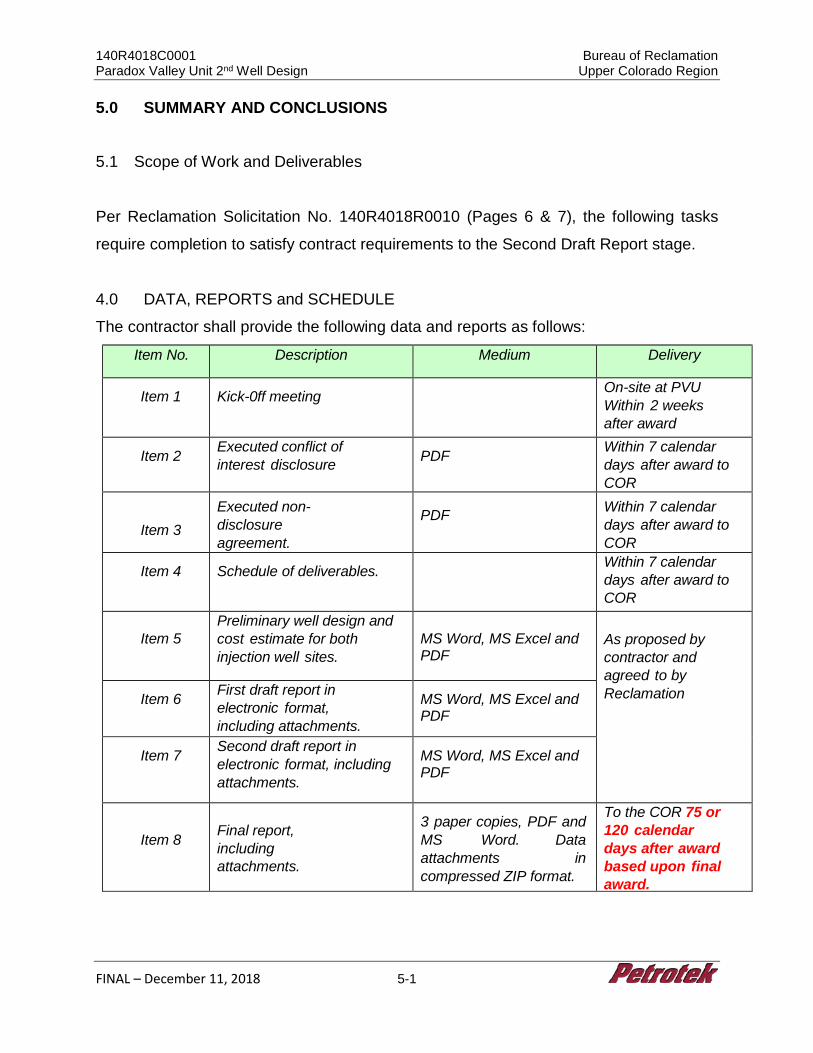
140R4018C0001 Bureau of Reclamation Paradox Valley Unit 2nd Well Design Upper Colorado Region
FINAL – December 11, 2018 5-1
5.0 SUMMARY AND CONCLUSIONS
5.1 Scope of Work and Deliverables
Per Reclamation Solicitation No. 140R4018R0010 (Pages 6 & 7), the following tasks
require completion to satisfy contract requirements to the Second Draft Report stage.
4.0 DATA, REPORTS and SCHEDULE
The contractor shall provide the following data and reports as follows:
Item No. Description Medium Delivery
Item 1 Kick-0ff meeting On-site at PVU Within 2 weeks after award
Item 2 Executed conflict of interest disclosure PDF Within 7 calendar
days after award to COR
Item 3 Executed non-disclosure agreement.
PDF Within 7 calendar
days after award to COR
Item 4 Schedule of deliverables. Within 7 calendar days after award to COR
Item 5
Preliminary well design and cost estimate for both injection well sites.
MS Word, MS Excel and PDF
As proposed by contractor and agreed to by Reclamation Item 6 First draft report in
electronic format, including attachments.
MS Word, MS Excel and PDF
Item 7 Second draft report in electronic format, including attachments.
MS Word, MS Excel and PDF
Item 8
Final report, including attachments.
3 paper copies, PDF and MS Word. Data attachments in compressed ZIP format.
To the COR 75 or 120 calendar days after award based upon final award.
140R4018C0001 Bureau of Reclamation Paradox Valley Unit 2nd Well Design Upper Colorado Region
FINAL – December 11, 2018 5-2
5.0 DELIVERABLES
The contractor shall submit the following reports in accordance with paragraph 5.0, “DATA AND REPORTS”:
1. Signed conflict of interest disclosure statement must be provided to the COR. The conflict of interest form will be provided by Reclamation at the time of award.
2. Executed non-disclosure agreement (NDA) must be provided to the Contracting Officer. The NDA will be provided by Reclamation at the time of award.
3. Executed conflict of interest disclosure must be provided to the Contracting Officer. The conflict of interest disclosure will be provided by Reclamation at the time of award.
4. Preliminary well design and cost estimate for both injection well sites. Shall be provided in MS Word, MS Excel, and PDF format, as applicable. All electronic files shall be delivered in an unlocked format.
5. First draft report in electronic format, including attachments. Shall be provided in MS Word, MS Excel and PDF format, as applicable. All electronic files shall be delivered in an unlocked format.
6. Second draft report in electronic format, including attachments. Shall be provided in MS Word, MS Excel and PDF format, as applicable. All electronic files shall be delivered in an unlocked format.
7. Final report, including 3 paper copies in addition to the electronic copies (MS Word, MS Excel and PDF as applicable) and attachments. Data attachments shall be provided in compressed ZIP format. All electronic files shall be delivered in an unlocked format.
Additional detail with regard to the Solicitation SOW and completion of tasks identified in
the SOW is included in Section 1.2 of this Report.
Key activities and deliverables included:
• Weekly updates with regard to: (1) project status, (2) questions for clarification, (3) engineering design options and suggestions for improvement, and (4) cost impacts for various options have been provided via weekly Team conference calls (Reclamation, Petrotek, Barr and Merrick staff).
• A preliminary cost estimate memo for the identified scope (Item 5) was delivered to Reclamation on October 24, 2018.
• A detailed discussion to review project status and further refine design was completed at a Team meeting in Denver on November 6, 2018.
• Delivery of the first Draft Report on November 9, 2018.
140R4018C0001 Bureau of Reclamation Paradox Valley Unit 2nd Well Design Upper Colorado Region
FINAL – December 11, 2018 5-3
• Delivery of this Second Draft Report which satisfies Item 6 of the required deliverables list.
• Delivery of the Final Report which satisfies Item 7 of the required deliverable list.
5.2 Approach to the Work
The SOW items were allocated to various Project Team members based on technical
experience and expertise. Petrotek was the Project Lead and managed all the injection
well design work as well as the project administration and reporting. Barr Engineering
performed the engineering design and costing for a new surface facility. Conceptual
approach and costing for (1) abandonment and decommissioning of the existing PVU
surface injection facility and (2) automation of the surface facility operation was the
responsibility of Merrick & Company.
Design approach and general assumptions included:
• The 30% design approach and assumptions were either (1) provided by Reclamation, (2) based on historical documents related to the site, or (3) based on industry standards, common practice and the experience of the Project Team. Well surface locations and bottomhole targets were provided by Reclamation.
• Surface facility design was based on pumping salt brine (approximately 260,000 mg/l NaCl + 80-100 ppm H2S) at a design rate of 200 gpm and a maximum pressure of 5,000 psi.
• Cost estimates were provided including a 10% addition for unlisted items, and a 25% contingency. Where possible, costs were based on vendor quotes and are provided in 2019 US dollars. Costs for alloy materials (Inconel 625 and/or C-276 Hastelloy) may vary widely due to challenges regarding material availability and delivery.
• API standards for tubular (casing and tubing design) and AACE standards for facility costing were applied.
• Given the long-term successful operation of the PVU #1 well and existing surface injection facility, the designs in this Report incorporated much of the historical engineering design for the project. This approach was discussed with and supported by Reclamation staff.
• In addition, Team members considered changes to the design for the surface injection facility and the exploratory/injection wells with regard to both cost and likely operational life. Examples of this process resulted in (1) a modified
140R4018C0001 Bureau of Reclamation Paradox Valley Unit 2nd Well Design Upper Colorado Region
FINAL – December 11, 2018 5-4
design/approach for the BIF2 location (serviced via a bored pipeline), (2) upgrading collapse design of the 5 ½-inch liner (based on collapse of the liner in the PVU #1 well, and (3) modifying the number of injection pumps (from 4 to 3) and adding VFD controllers to the pumps.
• Well design included consideration of depth, potential lost-circulation zones, gas, thick salt sections, faults, high stress (collapse, in particular) and torque and drag evaluation.
• The exploratory and injection wells were evaluated with regard to engineering design, risk and a comparative suitability assigned to each well.
An evaluation of the various well options was performed based on “risk” criteria including
depth, angle, salt thickness, drilling through faults, etc. One of the dominant factors in
the risk evaluation were well configuration (depth, offset, angle) which are fairly well
known. The other dominant factor in the risk analysis is geology, which is less known
due to lack of detailed subsurface data.
As noted in the Statement of Work (Section 3.0, Task 8) Reclamation is responsible for
providing geologic information to be used in this study and Reclamation data were used
for the analysis in this Report.
According to Reclamation, the following limitations apply to the current geologic
understanding for the project:
• Detailed fault structures are not well-defined by the sparse 2-D seismic reflection data available.
• Leadville thickness is known only at the locations of the previous deep wellbores in the area (Leadville thickness cannot be determined from the 2-D seismic data).
• Since Leadville thickness varies considerably in the Paradox Valley area, the thickness at the proposed well sites are rough estimates.
It is anticipated that future 3-D seismic studies will provide a higher level of certainty with
regard to these issues, and that information will be incorporated into Final Design for the
selected well options.
140R4018C0001 Bureau of Reclamation Paradox Valley Unit 2nd Well Design Upper Colorado Region
FINAL – December 11, 2018 5-5
5.3 Results from Completion of the Work
Based on the review of historical documents, the Reclamation SOW, and instructions
from Reclamation staff, the project Team completed 30% engineering design and costs
associated with five main tasks:
1. Plugging and abandonment of the existing PVU #1 well. 2. Decommissioning of the existing PVU surface injection facility. 3. Evaluating options and cost for automation of the PVU injection surface facility. 4. Risk, design, suitability evaluation and cost for the exploratory wells. 5. Risk, design, suitability evaluation and cost for the Class V injection wells.
The design basis and details have been presented in this Report (main text body and
Attachments).
5.3.1 Key Findings
Key findings from the work detailed in the Report include:
1. The historical facility design generally was suitable for the intended service and has performed well for many years under severe service conditions;
2. Reclamation has made minor modifications to the surface/injection facility (e.g., plungers in the injection pumps) to enhance operational life and material compatibility;
3. Based on information to date, the only major injection well design change that is warranted is increased collapse design for the 5 ½’ liner;
4. Consideration given to automation of the surface facility operation is warranted and beneficial from a cost perspective;
5. A new surface facility with similar design to the existing facility can be constructed and costs for such a facility are included in this Report;
6. An injection well design from BIF2 to TBIF 1.5 is not feasible or recommended from risk, cost and engineering perspectives;
7. A directional injection well targeting the Leadville from Monograph Mesa and BIF (BIF 3 or BIF 2 via a pipeline) with a 50-year design life is feasible.
8. Based on information available, the risks for a well at MM and BIF have been evaluated and estimated well costs prepared. The primary risks are (1) engineering (depth, vertical displacement, salt, and structural features) and (2)
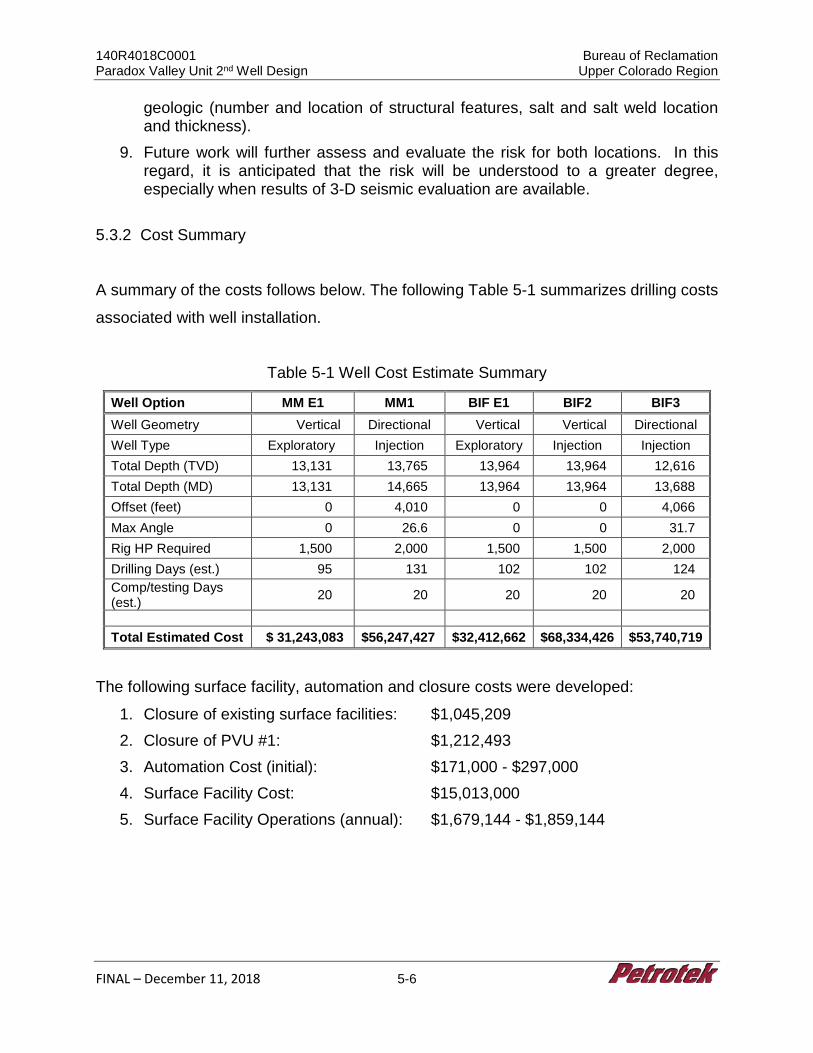
140R4018C0001 Bureau of Reclamation Paradox Valley Unit 2nd Well Design Upper Colorado Region
FINAL – December 11, 2018 5-6
geologic (number and location of structural features, salt and salt weld location and thickness).
9. Future work will further assess and evaluate the risk for both locations. In this regard, it is anticipated that the risk will be understood to a greater degree, especially when results of 3-D seismic evaluation are available.
5.3.2 Cost Summary
A summary of the costs follows below. The following Table 5-1 summarizes drilling costs
associated with well installation.
Table 5-1 Well Cost Estimate Summary
Well Option MM E1 MM1 BIF E1 BIF2 BIF3 Well Geometry Vertical Directional Vertical Vertical Directional Well Type Exploratory Injection Exploratory Injection Injection Total Depth (TVD) 13,131 13,765 13,964 13,964 12,616 Total Depth (MD) 13,131 14,665 13,964 13,964 13,688 Offset (feet) 0 4,010 0 0 4,066 Max Angle 0 26.6 0 0 31.7 Rig HP Required 1,500 2,000 1,500 1,500 2,000 Drilling Days (est.) 95 131 102 102 124 Comp/testing Days (est.) 20 20 20 20 20
Total Estimated Cost $ 31,243,083 $56,247,427 $32,412,662 $68,334,426 $53,740,719
The following surface facility, automation and closure costs were developed:
1. Closure of existing surface facilities: $1,045,209 2. Closure of PVU #1: $1,212,493 3. Automation Cost (initial): $171,000 - $297,000 4. Surface Facility Cost: $15,013,000 5. Surface Facility Operations (annual): $1,679,144 - $1,859,144
140R4018C0001 Bureau of Reclamation Paradox Valley Unit 2nd Well Design Upper Colorado Region
FINAL – December 11, 2018 6-1
6.0 REFERENCE LIST Block, L. V., 2017. Trends of Induced Seismicity and Pressures Following the 2013
Change in Injection Operations at the Paradox Valley Unit, Colorado. Technical Memorandum TM-85-833000-2017-10. US Bureau of Reclamation, Denver, Colorado.
Excel Geophysical Services and International Reservoir Technologies, Inc. Paradox
Valley Unit 2D Phase 3 Seismic Report Detailed Site Interpretation, Paradox Valley, Colorado, January, 2017
EMPSi, U.S. Department of the Interior: Bureau of Reclamation. “Technical studies and
Evaluations for the Second Injection Well Alternative at the Paradox Valley Unit: Report from the Consultant Review Board.” Reclamation – Managing Water in the West, September 2017.
Hair, CC, Mobil North Sea Ltd, and B. E. Schwind, E& P Technical Center. “Evaluation
and Design Optimization of Perforated Casing” – Offshore Technology Conference 25th Annual OTC Huston TX, U.S.A. 3-6 May, 1993
Lattimore, G.M. and R.S. Carden, Crace, Shursen, Moore & Assoc., and T. Fischer, U.S.
Dept of the Interior, SPE/IADC 16169, 1987.
Petrotek Engineering Corporation, Bureau of Reclamation, Deep Well Appraisal and
Feasibility Study Paradox Valley Final Report, June 2017
PVU Electrical and Mechanical Drawings
Schlumberger, 2018, https://www.slb.com/services/completions/wellwatcher.aspx
U.S. Department of the Interior: Bureau of Reclamation. “Integrated Subsurface Geologic
Model, Paradox Valley, Colorado.” Reclamation – Managing Water in the West. Technical Memorandum 85-833000-2017-15. June 2018.
140R4018C0001 Bureau of Reclamation Paradox Valley Unit 2nd Well Design Upper Colorado Region
FINAL – December 11, 2018 6-2
U.S. Department of the Interior: Bureau of Reclamation. “Paradox Valley Unit 2nd Well Design.” Reclamation – Managing Water in the West. Award No. 140R4018C0001. 2018.
U.S. EPA UIC Permit No CO50108-00647 UIC Permit Reauthorization Paradox Salinity
Control Well No. 1, August, 2011 Veolia, Standard Operating Procedures, Various Dates
Related Documents
![Playbook Tetuan Valley Startup School for Dummies - July 2012 [2nd Edition]](https://static.cupdf.com/doc/110x72/5450022fb1af9f1c168b4887/playbook-tetuan-valley-startup-school-for-dummies-july-2012-2nd-edition.jpg)