Seminar On Design & Construction Prestressed Concrete Cable-Stayed Bridges Design And Construction of Putrajaya Bridge BR8 ______________________________________________________________________________ PWD Malaysia/JICA August 2002 HYBRID STRUCTURE CABLE-STAYED-ARCH BRIDGE DESIGN AND CONSTRUCTION OF PUTRAJAYA BRIDGE BR8 Yamout, Michael (PJSI Consultants) MALAYSIA ABSTRACT Bridge BR8 – Jambatan Seri Saujana – located in Putrajaya, the new Administrative Centre of the Federal Government of Malaysia is the world’s first cable-stayed arch bridge. This landmark bridge serves as one of the main entrances to the new administrative city. The design concept is to build a transparent and futuristic slender looking structure to emphasize the leading spirit of this location. Bridge BR8 is a combination of an overhead inclined arch structure and a twin inclined pylon cable-stayed bridge. The main span is 300 m. The centre spine of the bridge deck is suspended to a uni-planar stay cable arrangement, whereas its wings are supported by the arch hangers. The arches are made of rolled steel pipes erected on temporary scaffolding towers and welded on site. Both arches are stabilized by K-bracings also consisting of steel pipes. The bridge deck is a cast in-situ prestressed concrete double-box girder with a beautiful smoothly round shaped soffit.

Welcome message from author
This document is posted to help you gain knowledge. Please leave a comment to let me know what you think about it! Share it to your friends and learn new things together.
Transcript
Seminar On Design & Construction Prestressed Concrete Cable-Stayed Bridges
Design And Construction ofPutrajaya Bridge BR8
______________________________________________________________________________
PWD Malaysia/JICA August 2002
HYBRID STRUCTURE CABLE-STAYED-ARCH BRIDGE DESIGN AND CONSTRUCTION OF PUTRAJAYA BRIDGE BR8
Yamout, Michael (PJSI Consultants)
MALAYSIA
ABSTRACT Bridge BR8 – Jambatan Seri Saujana – located in Putrajaya, the new Administrative Centre of the Federal Government of Malaysia is the world’s first cable-stayed arch bridge. This landmark bridge serves as one of the main entrances to the new administrative city. The design concept is to build a transparent and futuristic slender looking structure to emphasize the leading spirit of this location. Bridge BR8 is a combination of an overhead inclined arch structure and a twin inclined pylon cable-stayed bridge. The main span is 300 m. The centre spine of the bridge deck is suspended to a uni-planar stay cable arrangement, whereas its wings are supported by the arch hangers. The arches are made of rolled steel pipes erected on temporary scaffolding towers and welded on site. Both arches are stabilized by K-bracings also consisting of steel pipes. The bridge deck is a cast in-situ prestressed concrete double-box girder with a beautiful smoothly round shaped soffit.
Seminar On Design & Construction Prestressed Concrete Cable-Stayed Bridges
Design And Construction ofPutrajaya Bridge BR8
______________________________________________________________________________
PWD Malaysia/JICA August 2002
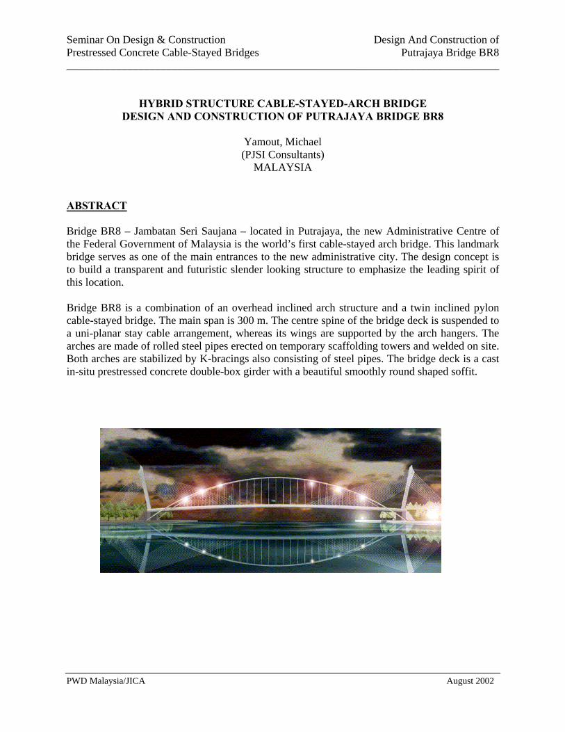
Figure 1: Bridge BR8 - Jambatan Seri Saujana
INTRODUCTION Putrajaya is the new Administrative Centre of the Federal Government of Malaysia. It is a completely new ‘Intelligent Garden City’ designed to host more than 300,000 people. All ministries, the office and the residence of the Prime Minister, the King’s palace as well as the National Mosque will be located here. Commercial, recreational and residential areas will be mixed. The place is set to reflect a new National identity and lifestyle. It will be linked to the world of information by the ‘Multi Media Super Corridor’. Cyberjaya – the corresponding IT city – is under construction in the ‘Peripheral Area’. The ‘Core Area’ will be surrounded by a huge artificial lake which is bridged by outstanding structures. The government explicitly wanted to erect important landmarks to emphasize the leading spirit of this location. Bridge BR8 – Jambatan Seri Saujana – the world’s first cable stayed arch bridge was handed over in June 2002 just after inundation of the main part of the lake. This landmark bridge serves as one of the main entrances to the new administrative city, linking the western residential area and the commercial zone at the core island. This paper reviews its design and construction.

Seminar On Design & Construction Prestressed Concrete Cable-Stayed Bridges
Design And Construction ofPutrajaya Bridge BR8
______________________________________________________________________________
PWD Malaysia/JICA August 2002
Figure 2: Putrajaya Master Plan
THE BRIDGE Design Concept The design concept was to build a transparent and futuristic slender looking structure to emphasize the leading spirit of this location. It was also designed to be built by local contractors using mostly locally available materials The Structure Bridge BR8 is a combination of an overhead inclined arch structure and a twin inclined pylon cable-stayed bridge. The main span is 300 m and the pylons are 73.43 m high. The centre spine of the 32 m wide deck is suspended to a uni-planar stay cable arrangement, whereas its wings are supported by the arch hangers. The arches are made of steel pipes (2.10 m in diameter with wall thicknesses of 40mm to 61mm), erected on temporary steel towers and welded on site. The crown of the arches is 34.0 m above the deck. They are anchored onto four buttresses at the abutments. Both arches are stabilized by K-bracings also consisting of steel pipes.

Seminar On Design & Construction Prestressed Concrete Cable-Stayed Bridges
Design And Construction ofPutrajaya Bridge BR8
______________________________________________________________________________
PWD Malaysia/JICA August 2002
The deck is 32.00 m wide. It is a cast in-situ prestressed concrete double-box girder with a beautiful smoothly round shaped soffit. Transverse diaphragms are provided at every 10-m intervals to coincide with the hanger locations. The deck is pre-stressed in both the longitudinal and lateral directions and acts therefore as a tie-beam for the arch. There is no expansion joint, temperature variations – limited in the local climate – are covered by camber changes of the deck. The pylons inclining 12 degrees from the vertical towards back are each 73.43m high from the top of the pile-cap. The lower 41.8m of the pylon is constructed in reinforced concrete. The upper portion is a composite of an outer structural steel shell in-filled with reinforced concrete.
Figure 3: Bridge Deck Soffit Figure 4: Stay Cables At Pylon Head 42 stay cables radiate from each pylon head. 22 of these cables are front stay cables, which are arranged in a single plane and anchored to the centre spine of the deck at 5 m spacing. The balance 20 cables are back-stay cables arranged in two planes and anchored to a pair of counterweight boxes filled with earth at each abutment. The cable system comprises of 15.2mm diameter seven wire strands, which are individually greased and wrapped in HDPE sleeves. The individual strands within each stay cable are further protected by HDPE pipes, which are cement grouted. There are 23 pairs of hangers which support the two wings of the bridge deck. They are made up of 36mm diameter high tensile bars which are placed inside steel tubes that are in-filled with cement grout. The foundation system comprises 900mm diameter to 1300mm diameter bored piles. The abutment and back-stay counterweight boxes are connected by a network of ground tie-beams. Since the final geometry and the force distribution of this structure depended not only on precise construction but also on a well-known material behavior, extensive testing was carried out. For the cables, the short term and long term modulus of elasticity and creep for steel and concrete, the concrete density for each pour was recorded and interpolated to predict the final force in the cables as well as in the arch hangers.

Seminar On Design & Construction Prestressed Concrete Cable-Stayed Bridges
Design And Construction ofPutrajaya Bridge BR8
______________________________________________________________________________
PWD Malaysia/JICA August 2002
CONSTRUCTION STAGES Substructure Due to the creation of the man-made lake, high embankment fills of 13m to 22m were required at the abutments. Construction began with the backfilling works up to the pile-cap level followed by the installation of the bored pile foundations for the abutments, pylons, and backstay counterweight boxes. The 1200mm and 1300mm diameter bored piles were founded on weathered shale at an average depth of about 24 m. The integrated pile-cap for the main abutment and pylon was then constructed to enable the construction of reinforced concrete portion of the pylon, which lie on the critical path, to proceed. Works on the back-stay counterweight boxes and tie beams were concurrently being carried in tandem with the pylon construction.
Figure 5 : Backstay Counterweight Box Figure 6: Tandem Lifting Of Pylon Head Module Construction Of Pylons The lower reinforced concrete portion of the pylon was erected using jump-forms in ten lifts of 4m. The upper 31m composite pylon head has a complex 3-D geometry to house the front and back stay-cable anchorages. To ensure accurate placement of the stay cable guide tubes and anchorages, the entire pylon head steel shell was fabricated as a single unit in the fabricator’s yard in Lumut. It was then cut into nine modules for transportation and installation. The number of modules was governed mainly by logistics reasons such as available crane lifting capacities and limited working platform. Two 150-ton cranes lifting in tandem ere used to install the pylon head steel modules. Construction Of Bridge Deck At the time of construction, the lake was not yet inundated. This enabled the reinforced concrete box deck to be constructed cast in-situ. Temporary steel towers were used to support deck during construction. The deck was cast in thirty 10-metre segments. The bottom slab cast first, followed

Seminar On Design & Construction Prestressed Concrete Cable-Stayed Bridges
Design And Construction ofPutrajaya Bridge BR8
______________________________________________________________________________
PWD Malaysia/JICA August 2002
by the webs and the top slab. Longitudinal and transverse prestressing were progressively installed and stresssed.
Figure 7: Temporary Support Towers Figure 8: Bridge Deck Construction For Bridge Deck In Progress Installation Of Stay Cables Deck erection on scaffolding and jump-forming of the pylons took place simultaneously. Two initial front stay cables have been installed in an early stage to stabilize the pylons. Stay cable installation and stressing started once a major part of the deck was cast. The initial cable tensioning compensated the concrete dead load. Therefore the supporting towers were released to a small stabilizing force. The casting of the deck box girder was completed with the exception of the closing pour. The centre portion was only closed after completion of the arch to allow for creep and shrinking of the concrete under prestressing. Construction Of Steel Arch And Installation Of Hangers Each steel arch consisted of 19 segments which were fabricated by rolling steel plates. After rolling and welding of the arch shell, internal stiffeners and diaphragms were then fitted on. The individual segments were checked for alignment on a master jig at the fabrication yard to ensure proper fit before transportation to the site. The bridge deck forms that working platform for the arch installation. Temporary steel towers at 10m spacing and resting on the cast bridge deck were used to support the arch segments during erection. Two 50-tonne cranes were utilised for the lifting operations. The first arch segment was fixed onto the reinforced concrete buttress springing from the abutment pile-cap by means of post-tensioned bars. Subsequent segments were welded onto preceding segments until the entire arch was completed. Stabilizing K-bracings were also progressively welded onto the arch and the vertical hangers progressively installed.

Seminar On Design & Construction Prestressed Concrete Cable-Stayed Bridges
Design And Construction ofPutrajaya Bridge BR8
______________________________________________________________________________
PWD Malaysia/JICA August 2002
For logistic reasons the assembly and welding of the arch segments were pushed ahead on the North side, whereas the cable installation and stressing took place on the Southern part of the bridge. Once both operations reached the centre, the teams were switched to complete the opposite part of the work. By October 2001, the arch and cable erection had been completed. Stay cables were stressed to compensate the concrete dead weight (see section ‘Stay Cable Stressing Sequence’. The arches were joined at the centre but still resting on the temporary supports. The hangers had also been installed but not yet tensioned. By end of the year 2001 all temporary supports were dismantled and the inundation of the lake began.
Figure 7: Threading Strands To Assemble Figure 8: Installation Of One Of The Back-Stay Cable Arch Segments CONTRIBUTION OF ARCH AND STAYS The core question to this structure is ‘what is the contribution of the arch versus the cable stayed bridge?’. The load distribution given by a simple elastic analysis by the computer program is definitely not what we were looking for. This structure is highly statically indeterminate in longitudinal and lateral directions – a unique opportunity for the engineer to actively impose a particular service state condition. He is able to manipulate the tensioning of all cables and hangers in order to define the load participation as well as the alignment of the various structural members.

Seminar On Design & Construction Prestressed Concrete Cable-Stayed Bridges
Design And Construction ofPutrajaya Bridge BR8
______________________________________________________________________________
PWD Malaysia/JICA August 2002
The Design Approach For Determining The Stay Cable & Hanger Forces The engineer has full control over the load distribution in the deck, arches and pylon due to permanent load and he can decide to assign appropriate initial stressing forces for each individual stay cable and arch hanger. A brief description of the general design approach for the load distribution to the various structural systems is as follows: -
a. Considering the construction method and erection sequence. The intended load distribution to the cable stays and arches systems was determined under the permanent load condition. It was envisaged that the arches would be erected after completion of the concrete deck structure; therefore, the intended load distribution applied to stay cable system should balance the concrete deck self weight so that the deck could be lifted off from the temporary staging underneath to allow the removal of the deck temporary supports before the lake inundation. To allow for the concrete elastic shortening during the stressing stage a closure strip was introduced at the mid span.
b. The remaining portion of permanent load comprising mainly the superimposed dead load
and equivalent to almost 25% of the concrete deck self-weight, would be taken by the arch-hanger system.
c. Under the transient load condition, all loads would be distributed to three load carrying
systems; the arches, the deck and the say cables, relative with their respective structural stiffness. A parametrical study on the stiffness of these three systems has been carefully investigated to ensure that there would be no overstress of any member of each individual system under the applied loads.
After defining the load sharing mechanism for the cable stay system and the arches, the initial stressing forces of each stay and hanger would be determined by using ‘zero displacement’ method respectively. As the effect of applying a force to one stay will change the movements of deck at the adjacent stay nodes in this type of highly indeterminate structure, it is generally impossible to resolve this dependency by the trial and error approach. A more systematic approach is required to determinate the initial stressing force of cable stay system and is briefly described below:-
a. Obtain the vertical deck deflection and the horizontal pylon movement at each stay anchorage nodes under the intended applied loads and assembly to form {Bi1} matrix.
b. For each stay, apply a unit load (or elongation) to that stay member and then obtain the
movement change in the remaining stay nodes to form a matrix {Aij}, where Aij is the movement change at stay node i under an unit load on stay member j.
Seminar On Design & Construction Prestressed Concrete Cable-Stayed Bridges
Design And Construction ofPutrajaya Bridge BR8
______________________________________________________________________________
PWD Malaysia/JICA August 2002
c. Pre-determine the required deformation of deck or pylon at all stay nodes, and then get {Di1} matrix.
d. As the accumulated movement of any stay nodes j is the summation of the movement
changes at that node due to cable force on stays i, i.e. ∑Aij x Tj1 where i=1 to n. Hence, by solving the simultaneous equation {Aij} x {Tj1} = {Bi1} + {Di1}, the initial force Tj1 of each stay can be obtained.
The similar procedure was applied to determine the initial force of the arch hangers. General, the solution obtained would be further fine-tuned to cater for effects of structure such as the as-built deck weight. The initial stressing forces obtained from the above procedures are not the jacking forces to be applied to the stays and hangers at site, as this needs ‘step by step’ consideration of the stressing sequence of the front and back stays. Matrix Method of Cable Tensioning Influence matrix method of cable tension optimization for this cable-stayed bridge is particularly developed. In this method, various object functions are uniformly expressed by cable tensions and influence matrices in the concept of general influence matrix. By this method, the designers were able to determine the optimum cable tensions for the cable stay and the hangers both during erection and upon completion. The method includes the mechanical effect of pre-stressed cables automatically and gives the self-selected object, weight and constraint, which enabled the designers to select the best set of forces. STAY CABLE STRESSING SEQUENCE The stay cable installation and stressing took place under the following circumstances:
- The pylon was completely erected and kept in the ’zero position’ by one initial front stay - The deck partly cast was supported on temporary towers, - The arches were under construction, whereas their self weight and the temporary towers
were resting on the deck.
Therefore no deck lifting was expected at this stage. The structural model (3D) for the evaluation of the stressing sequence covered one pylon, 22 front stays and 20 back stays. All stays were considered fixed at their bottom anchorages. The stressing of the deck and back stays was balanced in order to maintain the pylon alignment at all times. Installation started from the bottom. The deck stay S1 was already there when the pylon reached completion. Therefore the stressing sequence started with the installation of the back stays BS1.
Seminar On Design & Construction Prestressed Concrete Cable-Stayed Bridges
Design And Construction ofPutrajaya Bridge BR8
______________________________________________________________________________
PWD Malaysia/JICA August 2002
The tension in S1 was now increased to the required level with simultaneous stressing of the back stays to keep the pylon in position. Subsequently stay by stay was installed, always observing the balance of forces to hold the pylon unmoved. The only thing that happened to the pylon during the stressing campaign was the shortening due to increased compressive stress and secondary bending moments. Extensive site surveys at every step of stressing ensured that the pylon was always maintained at the reference line. HANGER STRESSING SEQUENCE The tensioning of the hangers was executed with the below premises:
- The deck and both pylons were completed, the arch was erected and welded - The closing pour of the deck was cast - All temporary arch supports were released and a few hangers (H4/H8/H12/H16/H20)
were stressed to a low level to prevent arch instability
According to the overall bridge analysis the deck was not supposed to go up. However, the temporary deck supports were expected to be completely released. This implied that the deck dead load fully would be supported by stay and hanger system and the deck alignment would be maintained. These assumptions again allowed for a simplification of the structural model. Both arches as well as 2x23 hangers were modelled. The arch was considered fully fixed in the concrete abutments, whereas hanger bottom anchors were supported with a hinge. The hangers were tensioned to the final elongations in one step. The operation started from both ends by stressing of the stabilisation hangers H4/H8/H12/H16/H20. In a second round the remaining hangers with even numbers followed. In a last step all odd numbered hangers were tensioned, again operated from the ends towards the center of the bridge. Four sets of equipment allowed a symmetric operation (e.g. H4 East/West and H20 East/West at once). Thermal effects played a major role in this process since the behavior of the arch and stay system are contradictory. It transpired that the arch increased ints contribution to the load transfer during daytime with raising temperatures and vice versa.

Seminar On Design & Construction Prestressed Concrete Cable-Stayed Bridges
Design And Construction ofPutrajaya Bridge BR8
______________________________________________________________________________
PWD Malaysia/JICA August 2002
Figure 9: Stressing Of Front Stay Cable Figure 10: Stressing Of Hanger From From Deck Soffit Inside The Arch INITIAL MONITORING AND FINE-TUNING After the complete removal of the temporary deck supports and application of the superimposed dead load, the bridge deflections were surveyed and monitored. Lift offs were also carried out on the stay cables and hangers and fine-tuning carried out on them. Initial monitoring indicated that the force distribution between the stay cables and arch are as predicted. The bridge was opened to traffic in July 2002. It is performing very well to expectations. CONCLUSION The design and successful completion of the Bridge BR8 – Jambatan Seri Saujana in Putrajaya indicate the feasibility combining the arch and stay cable structural systems. This unorthodox fusion also contributed significantly towards an aesthetically pleasing design.

Seminar On Design & Construction Prestressed Concrete Cable-Stayed Bridges
Design And Construction ofPutrajaya Bridge BR8
______________________________________________________________________________
PWD Malaysia/JICA August 2002
Related Documents