Numerical modelling of dissipative pin devices for brace-column connections Lucia Tirca ⁎, Nicolae Danila, Cristina Caprarelli Department of Building, Civil and Environmental Engineering, Concordia University Montreal, 1455 De Maisonneuve Blvd. West, H3G1M8 Montreal, Canada abstract article info Article history: Received 22 January 2013 Accepted 13 November 2013 Available online xxxx Keywords: Numerical modelling Single-pin connection device Double-pin connection device Brace member Inelastic behaviour Strain Stress Hysteresis loops Energy dissipation Plastic hinge In this paper, the behaviour of dissipative brace-column connection devices is emphasized. The computation is carried out for a single- and double-pin connection device, where the pins are displaced in two configurations: in-parallel and in-line. The study is conducted by using the theoretical and the OpenSees beam model under monotonic and cyclic quasi-static displacement loading. The proposed OpenSees model of the single-pin connec- tion was calibrated against experimental test results found in the literature and the validation was completed when both the experimental and simulated models provided a good match in terms of hysteresis loops and cu- mulative dissipated energy. Using the same approach, the double-pin connection, in both configurations, was studied through numerical modelling only. The purpose of installing dissipative single- or double-pin connec- tions at the brace-column joints is to preserve brace members to behave in the elastic range, while maintaining their buckling resistance. © 2013 Elsevier Ltd. All rights reserved. 1. Introduction of the CBF system equipped with fuses Earthquake resistant concentrically braced frames (CBF) are able to provide adequate strength and stiffness when subjected to lateral load- ing. Brace members performing in tension and compression are de- signed to dissipate energy through tension yielding and inelastic buckling, while the remaining framing components behave elastically. In agreement with the CSA/S16 standard [1], brace factored resistance should be equal to or greater than the effect of factored loads, the slen- derness ratio must be less than 200 and the width-to-thickness ratio of the brace element should comply with Class 1 sections. To allow the de- formation of the braces in the plastic range, the factored resistance of brace connections shall equal to or exceed both: the probable tensile re- sistance and 1.2 times the probable compressive resistance of bracing members. In general, the computed design forces for the brace connec- tions may significantly exceed those corresponding to the designed fac- tored shear force obtained in accordance with the NBCC 2010 provisions [2]. Although the above requirements are considered for the design of braces, the amount of energy dissipated in tension is much larger than that in compression, which diminutes in the post-buckling range with the number of cycles [3]. Moreover, in the conventional design ap- proach, the occurrence of inelastic deformations results in the softening of the CBF system [4]. To reduce the probable tensile strength of brace members and, in consequence, minimizing the design force transferred from tensile brace to gusset plate connections while maintaining its buckling resis- tance, alternative solutions consisting of incorporating ductile fuses within the brace members or their connections have been proposed. When ductile fuses are introduced in series with braces, they are de- signed to yield in tension at a lower force than the brace tensile strength [5–7]. Similarly, the bracing system of CBF structures may be preserved to behave elastically when the brace's gusset plate connections are re- placed by dissipative connections, such as pin connections [8] or cast steel yielding fuse connections [9]. Thus, by incorporating fuses in the brace–frame connections, the fundamental period of the building elon- gates, the seismic demand quantified in term of design base shear de- creases, while braces are protected against buckling [10]. The purpose of this paper is to illustrate the behaviour of dissipative single- and double-pin connections through numerical modelling and parametric studies by using the OpenSees framework [11]. The pro- posed design methodology and numerical models are validated by means of results obtained from existing experimental tests. The innova- tive double-pin connection with pins displaced in-parallel and in-line, proposed herein, has large redundancy and is recommended in design. 2. Dissipative pin connections The single-pin fuse integrated in brace connection was initially pro- posed and experimentally tested in the frame of the European INERD Journal of Constructional Steel Research 94 (2014) 137–149 ⁎ Corresponding author. E-mail address: [email protected] (L. Tirca). 0143-974X/$ – see front matter © 2013 Elsevier Ltd. All rights reserved. http://dx.doi.org/10.1016/j.jcsr.2013.11.007 Contents lists available at ScienceDirect Journal of Constructional Steel Research

Welcome message from author
This document is posted to help you gain knowledge. Please leave a comment to let me know what you think about it! Share it to your friends and learn new things together.
Transcript
Numerical modelling of dissipative pin devices forbrace-column connections
Lucia Tirca ⁎, Nicolae Danila, Cristina CaprarelliDepartment of Building, Civil and Environmental Engineering, Concordia University Montreal, 1455 De Maisonneuve Blvd. West, H3G1M8 Montreal, Canada
a b s t r a c ta r t i c l e i n f o
Article history:Received 22 January 2013Accepted 13 November 2013Available online xxxx
Keywords:Numerical modellingSingle-pin connection deviceDouble-pin connection deviceBrace memberInelastic behaviourStrainStressHysteresis loopsEnergy dissipationPlastic hinge
In this paper, the behaviour of dissipative brace-column connection devices is emphasized. The computation iscarried out for a single- and double-pin connection device, where the pins are displaced in two configurations:in-parallel and in-line. The study is conducted by using the theoretical and the OpenSees beam model undermonotonic and cyclic quasi-static displacement loading. The proposed OpenSeesmodel of the single-pin connec-tion was calibrated against experimental test results found in the literature and the validation was completedwhen both the experimental and simulated models provided a good match in terms of hysteresis loops and cu-mulative dissipated energy. Using the same approach, the double-pin connection, in both configurations, wasstudied through numerical modelling only. The purpose of installing dissipative single- or double-pin connec-tions at the brace-column joints is to preserve brace members to behave in the elastic range, while maintainingtheir buckling resistance.
© 2013 Elsevier Ltd. All rights reserved.
1. Introduction of the CBF system equipped with fuses
Earthquake resistant concentrically braced frames (CBF) are able toprovide adequate strength and stiffness when subjected to lateral load-ing. Brace members performing in tension and compression are de-signed to dissipate energy through tension yielding and inelasticbuckling, while the remaining framing components behave elastically.In agreement with the CSA/S16 standard [1], brace factored resistanceshould be equal to or greater than the effect of factored loads, the slen-derness ratio must be less than 200 and the width-to-thickness ratio ofthe brace element should complywith Class 1 sections. To allow the de-formation of the braces in the plastic range, the factored resistance ofbrace connections shall equal to or exceed both: the probable tensile re-sistance and 1.2 times the probable compressive resistance of bracingmembers. In general, the computed design forces for the brace connec-tions may significantly exceed those corresponding to the designed fac-tored shear force obtained in accordancewith theNBCC2010 provisions[2]. Although the above requirements are considered for the design ofbraces, the amount of energy dissipated in tension is much larger thanthat in compression, which diminutes in the post-buckling range withthe number of cycles [3]. Moreover, in the conventional design ap-proach, the occurrence of inelastic deformations results in the softeningof the CBF system [4].
To reduce the probable tensile strength of brace members and, inconsequence, minimizing the design force transferred from tensilebrace to gusset plate connections while maintaining its buckling resis-tance, alternative solutions consisting of incorporating ductile fuseswithin the brace members or their connections have been proposed.When ductile fuses are introduced in series with braces, they are de-signed to yield in tension at a lower force than the brace tensile strength[5–7]. Similarly, the bracing system of CBF structures may be preservedto behave elastically when the brace's gusset plate connections are re-placed by dissipative connections, such as pin connections [8] or caststeel yielding fuse connections [9]. Thus, by incorporating fuses in thebrace–frame connections, the fundamental period of the building elon-gates, the seismic demand quantified in term of design base shear de-creases, while braces are protected against buckling [10].
The purpose of this paper is to illustrate the behaviour of dissipativesingle- and double-pin connections through numerical modelling andparametric studies by using the OpenSees framework [11]. The pro-posed design methodology and numerical models are validated bymeans of results obtained from existing experimental tests. The innova-tive double-pin connection with pins displaced in-parallel and in-line,proposed herein, has large redundancy and is recommended in design.
2. Dissipative pin connections
The single-pin fuse integrated in brace connection was initially pro-posed and experimentally tested in the frame of the European INERD
Journal of Constructional Steel Research 94 (2014) 137–149
⁎ Corresponding author.E-mail address: [email protected] (L. Tirca).
0143-974X/$ – see front matter © 2013 Elsevier Ltd. All rights reserved.http://dx.doi.org/10.1016/j.jcsr.2013.11.007
Contents lists available at ScienceDirect
Journal of Constructional Steel Research
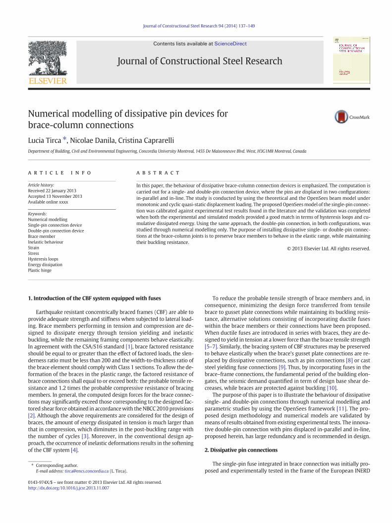
project [12]. The brace-column pin connection consists of two outer-plates welded or bolted to column flanges, two inner-plates welded tothe brace and a rectangular pin member with rounded corners runningthrough the four plates. As illustrated in Fig. 1a, the configuration of pindevice depends on the size and depth of the CBF column's cross-sectionthat governs the pin's length, Lpin, while the size of the pin member de-pends on the probable compressive resistance of the connected brace,Cu, and the distance between the inner-plates (Lpin-2a). As illustratedin Fig. 1b, parameter a is the distance between the outer-plate and thecenterline of the inner-plate. The pin element is proportioned to yieldin flexure under a force equating 60% Cu of the attached hollow structur-al section brace, HSS [10].
In this study, the behaviour of single-pin device is analysed throughnumerical modelling, developed in the OpenSees framework version2.2.0 [11]. Then, the single-pin connection model is calibrated againstresults obtained from experimental tests, conducted at Technical Uni-versity of Lisbon, Portugal [12].When large axial forces need to be trans-ferred from braces to CBF columns through connections, the availablesizes of single-pin member may not be sufficient. To overcome thislimit, the authors proposed an innovative double-pin connection withpins displaced either in-parallel or in-line, as illustrated in Fig. 2. Byemploying the same design approach as that used for the single-pin de-vice, the proposed double-pin connection is analysed in both configura-tions through theoretical and numerical modelling with the aim ofsizing the specimens and preparing the upcoming experimental tests.
3. Design and behaviour of single-pin connection device
To validate the design method for the single-pin connection device,two numerical models are employed and defined as follows: the theo-retical beam model and the OpenSees beam model. Regarding the the-oretical beam model, the same approach considered by Vayas andThanopoulos [13] and refined by Tirca et al. [8] is used to size the pincross-section and the connection's components. Then, the theoreticalbeam model was replicated in the OpenSees framework with the aimof investigating the stress versus strain development along the pincross-section, as well as the length of plastic zone resulted under incre-mental static loading up to failure. By using data from both theoreticaland OpenSees beam models, the authors replicate two experimentaltests conducted at the Technical University of Lisbon under quasi-static displacement loading. The calibration of the model is validatedwhen both the experimental and simulated models match in terms ofhysteresis loops generated from plotting the force versus displacementand the cumulative dissipated energy.
3.1. Theoretical beam model
The behaviour of the single-pin device in terms of its capacity to dis-sipate energy under cyclic loading is influenced by the following param-eters: the length of the pin, Lpin, its cross-sectional shape and size, as
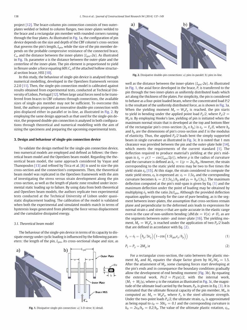
well as the distance between the inner-plates (Lpin-2a). As illustratedin Fig. 1, the axial force developed in the brace, P, is transferred to thepin through the two inner-plates as uniformly distributed loads whichact along the thickness of the plates. For simplicity, the pin is consideredto behave as a four-point loaded beam,where the concentrated load P/2is the resultant of the uniformly distributed force, as is shown in Fig. 3a.When the yielding moment My = WyFy is reached, the pin startsto yield in bending under the applied point load Py/2, where Py/2 =My/a. By employing Hooke's law, yielding of pin is initiated when themaximum normal strain that is developed at the top and bottom fiberof the rectangular pin's cross-section (bp x hp) is εy = Fy/E, where bpand hp are the dimensions of pin's cross-section and E is the modulusof elasticity. Thus, the applied Py/2 loads bent the simply supportedbeam in single curvature as illustrated in Fig. 3c. It is noted that 1 mmclearance was provided between the pin and the outer-plate hole [14],which meets the requirements of the current standard [1]. Thedeflection required to produce material's yielding at the pin's mid-span is δy = ρ(1 − cos(Lpin/2ρ)), where ρ is the radius of curvatureand the curvature is defined as ky = 1/ρ = 2εy/hp. However, the straincorresponding to the static yield stress may be two to five times theyield strain εy [15]. At this stage, the strain considered to compute thestatic yield stress, εI, is expressed as: εI = 1.5εy and the correspondingcurvature becomes kI = 2(1.5εy)/hp and ρI = hp/(3εy). The maximumdeflection computed at the pin's mid-span is given by Eq. (1) and themaximum deflection under the point of loading may be obtained bymultiplying δy with the ratio 2a/Lpin. Although the provided deflectionequation applies rigorously for the case of pure bending, as is the seg-ment between inner-plates, the assumption that cross-sections remainplane and perpendicular to the deformed axis leads to expressions fornormal strain ε and stress σ that are quite accurate in the elastic rangeeven in the case of non-uniform bending (dM/dx = V(x) ≠ 0), as arethe segments between outer- and inner-plate [16]. The yielding mo-ment, My = WyFy, is reached under the application of two Py/2 loadsthat are defined in accordance with Eq. (2).
δy ¼ δI ¼ hp=3εy� �
1– cos 1:5Lpinεy=hp� �� �
ð1Þ
PI ¼ Py ¼ 2My=a ð2Þ
For a rectangular cross-section, the ratio between the plastic mo-ment Mp and My equates the shape factor given by Wy/Wp = 1.5.After the attainment of My, some clamping forces start developing atthe pin's ends and in consequence the boundary conditions graduallyallow the development of end bending moment (Fig. 3b). By equatingthe external work, Pδ/2 = P(φa)/2, with the internal work,(M1 + M2)φ, where φ is the rotation as illustrated in Fig. 3c, themagni-tude of the ultimate load carried by the beam, PII, is given in Eq. (3). It isestimated that the ultimate flexural capacity of the pin member, Mu, iscomputed as: Mu = WpFu, where Fu is the steel ultimate strength.Under the two-point loads Pu/2, the ultimate strain, εII, is approximatedas being equal to εII = 50εy = 0.1 and the corresponding curvature iskII = 2εII/hp = 0.2/hp. The value of the ultimate plastic rotation, φu,
b)a)
Fig. 1. Dissipative single-pin connection: a) 3-D view; b) detail.
Fig. 2. Dissipative double-pin connections: a) pins in-paralel; b) pins in-line.
138 L. Tirca et al. / Journal of Constructional Steel Research 94 (2014) 137–149
becomes φu = kIIlp = lp(0.2)/hp radians. Herein, the length of the plas-tic hinge, lp, is anticipated as being 1.25 times the height of the pin'scross-section, hp. As presented hereafter, the development of the plastichinge length may vary with the distance between the inner-plates andthe magnitude of the applied forces. The ultimate deflection, δII, at dis-tance a from the pin's support is given in Eq. (4).
PII ¼ Pu ¼ 2 M1 þM2ð Þ=a e 4Mu=a ð3Þ
δII ¼ φIIa ¼ δu ¼ lp=hp� �
0:2að Þ ¼ 1:25 0:2að Þ ð4Þ
During the incursions in plastic range, the magnitude of load PIImayslightly increase due to material strain hardening to a value PIII, whilethe maximum deflection of pin at failure is estimated to be δIII = 0.4a[13,14]. The failure mechanism is depicted in Fig. 3d and is formedwhen plastic hinges are developed at the location where maximumbending moment is reached. By employing Eqs. (1) to (4) and the pa-rameters at failure: PIII and δIII, the pin response follows a tri-linearcurve as illustrated in Fig. 3e.
3.2. OpenSees beam model
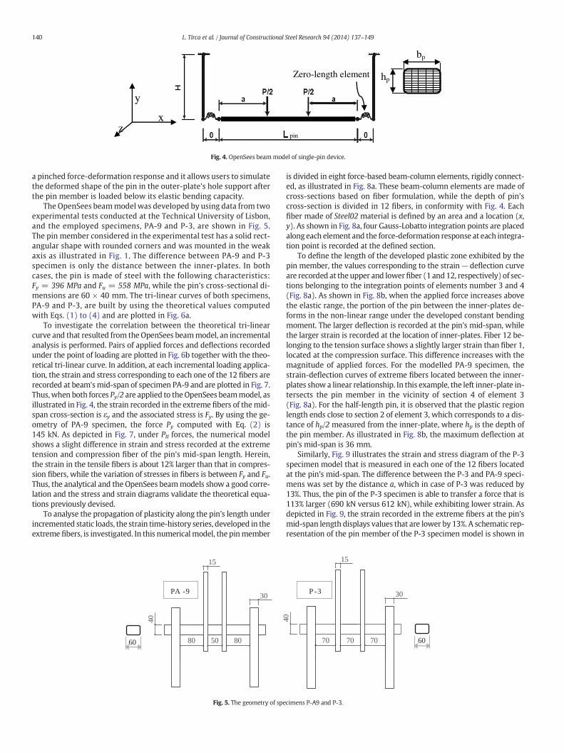
The purpose of developing the OpenSees beammodel is to simulatethe behaviour of the pin in its outer-plate supports and to measure thedeveloped strains, stresses, and deformations. Thus, until the yieldingmoment is reached, the pin behaves as a simply supported beam.Then, by increasing the applied loads, the pin member behaves in theplastic range and its deformed shape causes bearingpressure to the con-tact surface of the outer-plate hole, which is the pin's support. In thisstage, bendingmoment is generated at both pin ends and itsmagnitudeis incremented until the pin reaches its failuremechanism. The develop-ment of bending moment diagram across the pin's length depends onthe pin-to-outer-plate stiffness ratio, (Ipin/Lpin)/(Iop/Hop). When theaforementioned ratio approaches zero, the pin member imposes no re-straint on joint rotation and it behaves as a pure fixed–fixed member,while it triggers the largest axial compression force. It is desirable to
optimize the size of outer-plates such that the mid-span bending mo-ment to be slightly larger than that developed at the pin's support. Tosatisfy this demand, the outer-plate should be sized to comply withthe following expression: (Ipin/Lpin)/(Iop/Hop) = 0.5. The OpenSeesbeammodel simulates the behaviour of the pinmember acting in elasticrange as a four-point loaded beam and in the non-linear range as aclamped–clamped member, as previously described.
The model shown in Fig. 4 consists of eight nonlinear beam-column elements with distributed plasticity and four integrationpoints per element. The pin's cross-section is made up of 60 fibers.Among them, 12 fibers are assigned along the height of the cross-section, hp, and 5 along its width, bp, as illustrated in Fig. 4. The lengthof the pin, Lpin, is the clear span between the outer-plates, which actas supports. Herein, the pin's supports (outer-plates) are modelledas rigid links of length Hop, which represents the free length. Whenthe applied forces increase, large bearing stresses develop in thepin's hole support. Further, due to the enlargement of these holespinching occurs. To simulate this behaviour, a zero-length elementobject that is defined between two nodes generated at the same loca-tion is added at the connection between pin and outer-plates, as il-lustrated in Fig. 4. These nodes of identical coordinates areconnected by springs, with the aim to represent the force–deforma-tion relationship exhibited by the pin in the outer-plate supports.The uniaxial material assigned to the pin member and rigid links isSteel02, which is also known as Giuffre-Menegotto-Pinto material.It is recommended that the steel strength of plates to be the samewith that of the pin. Nonetheless, the length and thickness of theouter-plates influence the behaviour of the connection, while the de-flection of the pin controls the transversal deflection of outer-plates.When the pin member behaves elastically, both links (outer-plates)act as cantilever members with a stiffness Kop = 3EopIop/Hop
3 , whereEopIop is the flexural stiffness of the link. To simulate the non-linearbehaviour of pin member in the outer-plate supports, two transla-tional springs were added in the zero-length element, in the x-direction and one is the y-direction. Among them, one spring ismade of Steel02 material and others of Pinching4 material that is de-fined in the OpenSees library [17]. The Pinching4material represents
a)
b) d)
c) e)
Fig. 3. Theoretical beam model: a) elastic; b) plastic; c) deformed shape; d) plastic mechanism; e) tri-linear curve.
139L. Tirca et al. / Journal of Constructional Steel Research 94 (2014) 137–149
a pinched force-deformation response and it allows users to simulatethe deformed shape of the pin in the outer-plate's hole support afterthe pin member is loaded below its elastic bending capacity.
The OpenSees beammodel was developed by using data from twoexperimental tests conducted at the Technical University of Lisbon,and the employed specimens, PA-9 and P-3, are shown in Fig. 5.The pin member considered in the experimental test has a solid rect-angular shape with rounded corners and was mounted in the weakaxis as illustrated in Fig. 1. The difference between PA-9 and P-3specimen is only the distance between the inner-plates. In bothcases, the pin is made of steel with the following characteristics:Fy = 396 MPa and Fu = 558 MPa, while the pin's cross-sectional di-mensions are 60 × 40 mm. The tri-linear curves of both specimens,PA-9 and P-3, are built by using the theoretical values computedwith Eqs. (1) to (4) and are plotted in Fig. 6a.
To investigate the correlation between the theoretical tri-linearcurve and that resulted from the OpenSees beammodel, an incrementalanalysis is performed. Pairs of applied forces and deflections recordedunder the point of loading are plotted in Fig. 6b together with the theo-retical tri-linear curve. In addition, at each incremental loading applica-tion, the strain and stress corresponding to each one of the 12 fibers arerecorded at beam'smid-span of specimen PA-9 and are plotted in Fig. 7.Thus,when both forces Py/2 are applied to the OpenSees beammodel, asillustrated in Fig. 4, the strain recorded in the extreme fibers of themid-span cross-section is εy and the associated stress is Fy. By using the ge-ometry of PA-9 specimen, the force Py computed with Eq. (2) is145 kN. As depicted in Fig. 7, under PII forces, the numerical modelshows a slight difference in strain and stress recorded at the extremetension and compression fiber of the pin's mid-span length. Herein,the strain in the tensile fibers is about 12% larger than that in compres-sion fibers, while the variation of stresses in fibers is between Fy and Fu.Thus, the analytical and the OpenSees beammodels show a good corre-lation and the stress and strain diagrams validate the theoretical equa-tions previously devised.
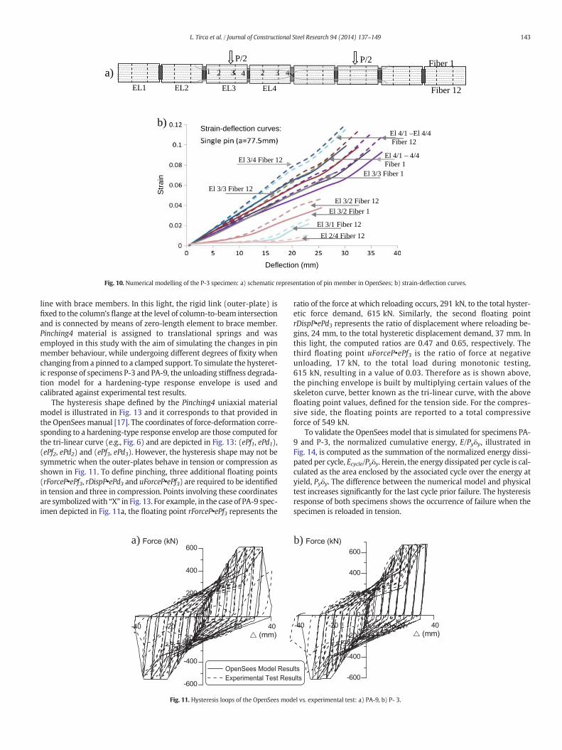
To analyse the propagation of plasticity along the pin's length underincremented static loads, the strain time-history series, developed in theextreme fibers, is investigated. In this numericalmodel, the pinmember
is divided in eight force-based beam-column elements, rigidly connect-ed, as illustrated in Fig. 8a. These beam-column elements are made ofcross-sections based on fiber formulation, while the depth of pin'scross-section is divided in 12 fibers, in conformity with Fig. 4. Eachfiber made of Steel02 material is defined by an area and a location (x,y). As shown in Fig. 8a, four Gauss-Lobatto integration points are placedalong each element and the force-deformation response at each integra-tion point is recorded at the defined section.
To define the length of the developed plastic zone exhibited by thepin member, the values corresponding to the strain — deflection curveare recorded at the upper and lowerfiber (1 and12, respectively) of sec-tions belonging to the integration points of elements number 3 and 4(Fig. 8a). As shown in Fig. 8b, when the applied force increases abovethe elastic range, the portion of the pin between the inner-plates de-forms in the non-linear range under the developed constant bendingmoment. The larger deflection is recorded at the pin's mid-span, whilethe larger strain is recorded at the location of inner-plates. Fiber 12 be-longing to the tension surface shows a slightly larger strain than fiber 1,located at the compression surface. This difference increases with themagnitude of applied forces. For the modelled PA-9 specimen, thestrain-deflection curves of extreme fibers located between the inner-plates show a linear relationship. In this example, the left inner-plate in-tersects the pin member in the vicinity of section 4 of element 3(Fig. 8a). For the half-length pin, it is observed that the plastic regionlength ends close to section 2 of element 3, which corresponds to a dis-tance of hp/2 measured from the inner-plate, where hp is the depth ofthe pin member. As illustrated in Fig. 8b, the maximum deflection atpin's mid-span is 36 mm.
Similarly, Fig. 9 illustrates the strain and stress diagram of the P-3specimen model that is measured in each one of the 12 fibers locatedat the pin's mid-span. The difference between the P-3 and PA-9 speci-mens was set by the distance a, which in case of P-3 was reduced by13%. Thus, the pin of the P-3 specimen is able to transfer a force that is113% larger (690 kN versus 612 kN), while exhibiting lower strain. Asdepicted in Fig. 9, the strain recorded in the extreme fibers at the pin'smid-span length displays values that are lower by 13%. A schematic rep-resentation of the pin member of the P-3 specimen model is shown in
Fig. 4. OpenSees beammodel of single-pin device.
50
15
80
40
80
30P-A9
15
40
70
P-3
7070
30
60 60
PA -9 P -3
Fig. 5. The geometry of specimens P-A9 and P-3.
140 L. Tirca et al. / Journal of Constructional Steel Research 94 (2014) 137–149

Fig. 10a and the time-history series of strain-deflection curves of the ex-treme tension and compression fibers (12 and 1) are depicted inFig. 10b. In the case of P-3 specimenmodel, the strain-deflection curvesshow a weaving behaviour with a sharp increasing in strain for forceslarger than 612 kN. The maximum strain is experienced by fiber 12 ofelement 3, section 4, located in vicinity of inner-plate. It displays a defor-mation of 20 mm for a tensile strain of 0.08 or 40εy and 30 mmat failurewhen the associated strain is about 0.12. In comparison with the PA-9pinmodel, the fiber 12 of element 3, section 4 of both pin specimens ex-perienced the same strain for a 20 mmdeflection, but at the state of fail-ure, the corresponded strain and deflection value experienced by thesame fiber of pin P-3 have dropped by 13%. In addition, by comparingthe tensile and compression strain recorded at pin's mid-span (fibers12 and 1 of element 4, section 4) the P-3 pin developed lower strainvalues (Fig. 10b).
The difference in behaviour is due to a/Lpin ratio. In the case of P-3specimen, a/Lpin = 0.323 where a = 77.5 mm and Lpin = 240 mm. Byconsidering the pin and outer-plate cross sections 60 × 40 mm and180 × 30 mm, respectively, the computed pin-to-outer-plate stiffnessratio is (Ipin/Lpin)/(Iop/Hop) = 0.5, where Ipin = 60 × 403/12, Iop =180 × 303/12 and Hop = 150 mm. When the point of applied forcemoves toward the middle of the pin (PA-9 specimen), slightly largerouter-plate stiffness is required to sustain the same applied force. Inthe case of PA-9, a = 87.5 mm, a/Lpin = 0.365 and the change in thea/Lpin ratio with respect to the previous case is 113% (e.g., 0.365/
0.323 = 1.13). As noted above, the ratio between the maximum forcecarried by P-3 specimen and PA-9 specimen is 1.13 (692 kN versus612 kN). In addition, from previous studies [13,14] it was found thatclamping effect increases until the thickness of outer-plates reaches0.75 hp.
In the nonlinear range, axial compression force is developed in addi-tion to bendingmomentwhichmagnitude is slightly larger at pin'smid-span than at its support. The compression force developed between theinner-plates is smaller than that developed between the inner-plate andouter-plate due to the tangential component of applied load that acts inopposite direction. Failure of pin occurs under the combined effect ofaxial force and bending moment. From data collected for both speci-mens P-3 and PA-9 it was found that the normalized bending momentcomponent has the largest weight in the interaction equation whilethe normalized axial force component is less than 10% in the mid-spansegment and less than 15% at pin's support.
To summarize, the behaviour of pinmember is influenced by the dis-tance between the inner- and outer-plate that is expressed by parame-ter a, as well as by the dimensions of outer-plates. When the distancebetween inner-plates (Lpin-2a) increases (e.g. P-3 specimen vs. PA-9),the portion of pin that is subjected to plastic deformation expandsacross the pin's length, while the maximum strain decreases. From nu-merical computations, the length of plastic hinge developed over thepin member is approximated as being: (Lpin-2a + hp). However, bothPA-9 and P-3 pins experience the same deflection at the mid-span
a) b)
Fig. 6. Tri-linear curve of the PA-9 and P-3 devices: a) theoretical, b) OpenSees model.
a) Strain b) Stress
Fig. 7. Strain and stress diagram of the PA-9 pin recorded at the pin's mid-span length.
141L. Tirca et al. / Journal of Constructional Steel Research 94 (2014) 137–149

length and display larger strain in tension than in compression. TheOpenSees beammodel was used to emphasise the distribution of strainand stress across the pin's length.
3.3. Validation of the OpenSees model of PA-9 and P-3 joints against exper-imental test results
The two selected specimens PA-9 and P-3were tested on a box standunder the ECCS cyclic quasi-static loading protocol [18]. The displace-ment loading applied to the PA-9 sample has 25 cycles with a rate ofloading of 0.45 mm/s and a maximum displacement in the last cycleof 40 mm. The displacement loading protocol applied to the P-3 samplehas 21 cycles, a rate of loading 0.33 mm/s and a maximum displace-ment of 45 mm. In both cases, three consecutive cycles reachingthe same displacement amplitude were considered. The force-displacement hysteresis loops that characterize the behaviour of speci-mens PA-9 and P-3 are shown in Fig. 11. In both cases, the failure of thepin occurred at one of the two points of load application, when it wasreloaded in tension [12], as illustrated in Fig. 11. Thus, in the case ofspecimen PA-9, when the distance between the outer- and inner-plate
is larger than the distance between inner-plates, the failure occurs inthe longer pin segment at the external face of the inner-plate which ro-tates in the direction of the radius of curvature (Fig. 12a). In the case ofspecimen P-3, the failure occurred in themiddle segment at the internalface of the inner-plate as showed in Fig. 12b. For both specimens, thesame stiffness degradation occurred during reloading. Although bothspecimens reached approximately the same magnitude of maximumdeformation in bending, 37 mm, the corresponding ultimate tensileforces of PA-9 (615 kN) is lower than that recorded for P-3 (694 kN).On the other hand, for both specimens the capacity in tension is largerthan that in compression by 13%. This difference in strength is due tothe out-of-plane bending of outer-plates, which implies an increaseddistance between the pin's supports in the outer-plate hole. In thiscase, the outer-plates deflect toward the exterior, as is shown inFig. 12b. As a result, the stiffness and the thickness of outer-plates influ-ence the behaviour of pin connection. As discussed above, it is recom-mended that the stiffness of the outer-plate to be two times largerthan the stiffness of the pin and top ≥ 0.75hp.
The purpose of developing the OpenSees model for pin connectionsis to study the behaviour of CBFs equipped with pin devices placed in-
EL1 EL2 EL3 EL4
2 3 41 2 3 4 1Fiber 1
Fiber 12
P/2
44
P/2
El 3/4 Fiber 12
El 4/1 – 4/4 Fiber 12 El 4/4 – 4/1 Fiber 1
El 3/4 Fiber 1
El 3/2 Fiber 1El 3/2 Fiber 12
El 3/3 Fiber 1
b)
a)
Fig. 8. Numerical modelling of the PA-9 specimen: a) schematic representation of pin member in OpenSees; b) strain-deflection curves.
a) Strain b) Stress
Fig. 9. Strain and stress diagram of the P-3 pin recorded at the pin's mid-span length.
142 L. Tirca et al. / Journal of Constructional Steel Research 94 (2014) 137–149
line with brace members. In this light, the rigid link (outer-plate) isfixed to the column's flange at the level of column-to-beam intersectionand is connected by means of zero-length element to brace member.Pinching4 material is assigned to translational springs and wasemployed in this study with the aim of simulating the changes in pinmember behaviour, while undergoing different degrees of fixity whenchanging from a pinned to a clamped support. To simulate the hysteret-ic response of specimens P-3 and PA-9, the unloading stiffness degrada-tion model for a hardening-type response envelope is used andcalibrated against experimental test results.
The hysteresis shape defined by the Pinching4 uniaxial materialmodel is illustrated in Fig. 13 and it corresponds to that provided inthe OpenSees manual [17]. The coordinates of force-deformation corre-sponding to a hardening-type response envelop are those computed forthe tri-linear curve (e.g., Fig. 6) and are depicted in Fig. 13: (ePf1, ePd1),(ePf2, ePd2) and (ePf3, ePd3). However, the hysteresis shape may not besymmetric when the outer-plates behave in tension or compression asshown in Fig. 11. To define pinching, three additional floating points(rForceP•ePf3, rDispP•ePd3 and uForceP•ePf3) are required to be identifiedin tension and three in compression. Points involving these coordinatesare symbolizedwith “X” in Fig. 13. For example, in the case of PA-9 spec-imen depicted in Fig. 11a, the floating point rForceP•ePf3 represents the
ratio of the force at which reloading occurs, 291 kN, to the total hyster-etic force demand, 615 kN. Similarly, the second floating pointrDispP•ePd3 represents the ratio of displacement where reloading be-gins, 24 mm, to the total hysteretic displacement demand, 37 mm. Inthis light, the computed ratios are 0.47 and 0.65, respectively. Thethird floating point uForceP•ePf3 is the ratio of force at negativeunloading, 17 kN, to the total load during monotonic testing,615 kN, resulting in a value of 0.03. Therefore as is shown above,the pinching envelope is built by multiplying certain values of theskeleton curve, better known as the tri-linear curve, with the abovefloating point values, defined for the tension side. For the compres-sive side, the floating points are reported to a total compressiveforce of 549 kN.
To validate the OpenSees model that is simulated for specimens PA-9 and P-3, the normalized cumulative energy, E/Pyδy, illustrated inFig. 14, is computed as the summation of the normalized energy dissi-pated per cycle, Ecycle/Pyδy. Herein, the energy dissipated per cycle is cal-culated as the area enclosed by the associated cycle over the energy atyield, Pyδy. The difference between the numerical model and physicaltest increases significantly for the last cycle prior failure. The hysteresisresponse of both specimens shows the occurrence of failure when thespecimen is reloaded in tension.
1
EL1 EL2 EL3 EL4
2 3 41 2 3 4
P/2P/2 Fiber 1
Fiber 12
22 33 41 3
El 4/1 –El 4/4Fiber 12
El 4/1 – 4/4Fiber 1
El 3/4 Fiber 12
El 3/3 Fiber 12
El 3/2 Fiber 12
El 3/1 Fiber 12
El 2/4 Fiber 12
El 3/3 Fiber 1
El 3/2 Fiber 1
Deflection (mm)
Str
ain
Strain-deflection curves:b)
a)
Fig. 10. Numerical modelling of the P-3 specimen: a) schematic representation of pin member in OpenSees; b) strain-deflection curves.
a) b)
Fig. 11. Hysteresis loops of the OpenSees model vs. experimental test: a) PA-9, b) P- 3.
143L. Tirca et al. / Journal of Constructional Steel Research 94 (2014) 137–149

Thus, the OpenSees model is able to replicate the global behaviour ofsingle-pin connection. The P-3 specimen was subjected to 21 cycles,while the PA-9 specimen to 25 cycles. To summarize, under similar condi-tions (equal number of cycles), the single-pin connection with larger dis-tance between inner-plates possesses a larger dissipative energy capacity.
4. Numerical modelling of double-pin connection device
When concentrically braced frames are designed to withstand earth-quake forces computed for moderate to high seismic areas, a large shearforce demand is expected to develop at the lower part of multi-storey
P - A9
Failure of pin
Failureof pin
Inflection point
P - 3
a) b)
Fig. 12. Failure mechanism of specimens PA-9 and P-3 (Courtesy of Prof. Luis Calado).
(rForceP•ePf3, rDispP•ePd3)(uForceP•ePf3,*)
Fig. 13. Pinching4 material definition.
Fig. 14. Normalized cumulative dissipated energy of numerical model versus physical test: a) PA-9 specimen, b) P-3 specimen.
144 L. Tirca et al. / Journal of Constructional Steel Research 94 (2014) 137–149
Equivalent pin
P I = 74 kNδ I = 1.18 mm
P III = 319 kNδ III = 35 mm
PII = 312 kNδ II = 21 mm
P III = 638 kNδ III = 35 mm
P II = 624 kNδ II = 21 mm
PI = 148 kNδI = 1.18 mm
a) b)
Fig. 15. Double-pin connection with pins placed in-parallel: a) tri-linear curve; b) three- dimensional model.
b) Stressa) Strain
Fig. 16. Stress and strain diagram of one of the two pins placed in-parallel, recorded at pin's mid-span length.
El 3/4 Fiber 12
El 4/1 -4/4 Fiber 12
El 4/4-4/1 Fiber 1
El 3/3 Fiber 1
El 3/2 Fiber 12
Deflection (mm)
Str
ain
Strain-deflection curves: Pins placed in parallel
Fig. 17. Strain-deflection curves of one of the two pins placed in-parallel.
145L. Tirca et al. / Journal of Constructional Steel Research 94 (2014) 137–149

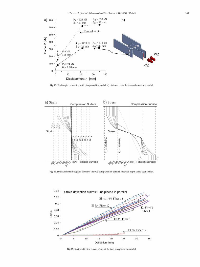
buildings. Thus, to transfer large axial force triggered in bracemembers tobrace-column connections, the capacity of the single-pin device may notsatisfy the demand. For this case, authors proposed the double-pin con-nection device, whereas the pin member may be displaced either in-parallel or in-line, as illustrated in Fig. 2. To prepare further experimentaltests, the double-pin connection is analysed throughnumericalmodels byfollowing the same approach that was used for the single-pin. In thisstudy, only the case with a larger outer- to inner-plate distance is consid-ered (a = 87.5 mm). For comparison purposes, two small pins of rectan-gular shape 40 × 35 mm that possess an equivalent flexural stiffnesswith that of single-pin 60 × 40 mm are selected for investigation.
4.1. Modelling and behaviour of double-pin connection with pins placed in-parallel
As illustrated in Fig. 2a, the double-pin connectionwithpins placed in-parallel (DP-PP) has a symmetrical geometry. Due to its symmetry, thestudy canbe conducted for half of thedevice and its behaviour is expectedto be similar with that for a single-pin. Thus, each pin must be propor-tioned to carry half of the force triggered in the brace, while undergoingthe same deflection that is expected to be experienced by an equivalentsingle-pin device. In this example, the same geometry of pin's length,outer- and inner-plates as that illustrated for the specimenPA-9 is consid-ered and used in the single-pin OpenSees beammodel depicted in Fig. 4.The theoretical tri-linear curve computed for each pin displaced in-parallel may be plotted similarly with that developed for a single-pin.The tri-linear curve and three-dimensional model of the DP–PP connec-tion are illustrated in Fig. 15. The strain and stress diagram correspondingto each one of the two pins subjected to incremental static loading, isshown in Fig. 16. Data was recorded for each one of the 12 fibers(Fig. 4) that represent the pin's cross-section located at pin's mid-spanlength. From Fig. 16, it is observed that slightly larger strain is developedin tension than compression upon failure. The values of strain and stress,
recorded for one of the two pins when subjected to half of the force ap-plied to PA-9 specimen, show almost the same values with those plottedin Fig. 8. The 40 × 35 pinmember is subdivided in 8 elements as depictedin Fig. 8a. Similarities in the strain-deflection time-history series depictedfor the 40 × 35 pin and shown in Fig. 17 were also observed.
As illustrated, themaximumstrain is recorded in the extreme tensilefiber (fiber 12) at the location of section 4 that belongs to element 3. Inaddition, the length of plastic region is similar with that illustrated forPA-9 pin model, while the time-history strain-deflection curves showa linear relationship for fibers located between the inner-plates. Thus,by doubling the pin member, the load-carrying capacity of connectionincreases two times, while the deflection remains the same as that ex-perienced by an equivalent single-pin device.
4.2. Modelling and behaviour of double-pin device placed in-line
The three-dimensional scheme of double-pin connection with pinsplaced in-line (DP–PL) is shown in Fig. 18 and the OpenSees model is il-lustrated in Fig. 19. Each one of the two pins is composed of 8 force-based nonlinear beam-column elements with distributed plasticityalong the member length and four integration points per element asdepicted in Fig. 8a. Pins cross-sections are made of 60 fibers distributedas illustrated in Fig. 4. Steel02material was assigned at all fibers. A zero-length element is placed at each pin ends in order to simulate the com-plexity of pin's support in the outer-plate hole. In addition, zero-lengthelements are placed at the connection between pinmembers and inner-plates. Through design, the pin members of the DP-PL connection areassumed to dissipate energy in flexure, while the remaining compo-nents such as the outer- and inner-plates behave elastically. In thismodel, both outer- and inner-plates were made of fibers and Steel02material was assigned. Due to the large stiffness of the inner-plate inthe plane of loading, both pins are subjected to equal deformation,while the system composed of two pins connected by the two inner-plates behaves as an equivalent W-shape beam where both flangesare supported in the four outer-plates holes. In this example, the dis-tance between the centerline of the two pins is 2.5 hp (100 mm) andit can be increased to 3 hp, the thickness of the outer-plates is 30 mm(top ≥ 0.75 hp), while that of inner-plate is 20 mm (tip ≥ 0.5 hp). Thenet area of outer-plate across the pin hole, normal to the axis of themember, shall be at least 1.33 times the cross-sectional area of the pinmember. In the same time, the distance from the edge of the pin holeto the edge of the outer-plate member, measured transverse to theaxis of themember, shall not exceed four times the thickness of thema-terial at the pin hole (e.g., thewidth of outer-plate is bop = 180 mm and(180 − 40)/2 ≤ 4top where top = 30 mm). This verification is appliedto inner-plates as well (e.g., for bip = 180 mm it results (180 − 40)/2 ≤ 4tip where tip = 20 mm).
To simulate the connection between the pin member and the outer-plate support, three translational and one torsional spring are assigned
Lower pin
Upper pin
Fig. 18. Three-dimensional scheme of double-pin connection device with pins placed in-line.
x
y
z
pin
Outer-plates
Inner-plates
Upper Pin
Lower Pin
Fig. 19. The OpenSees model of double-pin connection with pins placed in-line.
146 L. Tirca et al. / Journal of Constructional Steel Research 94 (2014) 137–149
in the zero-length element illustrated in Fig. 19. Among them, twotranslational springs are placed in the x-direction and one in the y-direction, while the torsional spring assures that no twist occurs in thez-axis. One of the two translational springs, made of Steel02 materialand assigned in the x-direction, simulates the effect of the outer-plate.The second translational spring, assigned in the x-direction, is made ofPinching4material and represents the pinched force–deformation rela-tionship that controls the pin behaviour. On the other hand, betweenthe inner-plate and the pin member is a pinned connection that is sim-ulated by two translational and one torsional spring, assigned in thezero-length element. Among the two translational springs, made ofSteel02 material, one is placed in the x- and the other in the y-direction, while the torsional spring is added to restrain torsion about z.
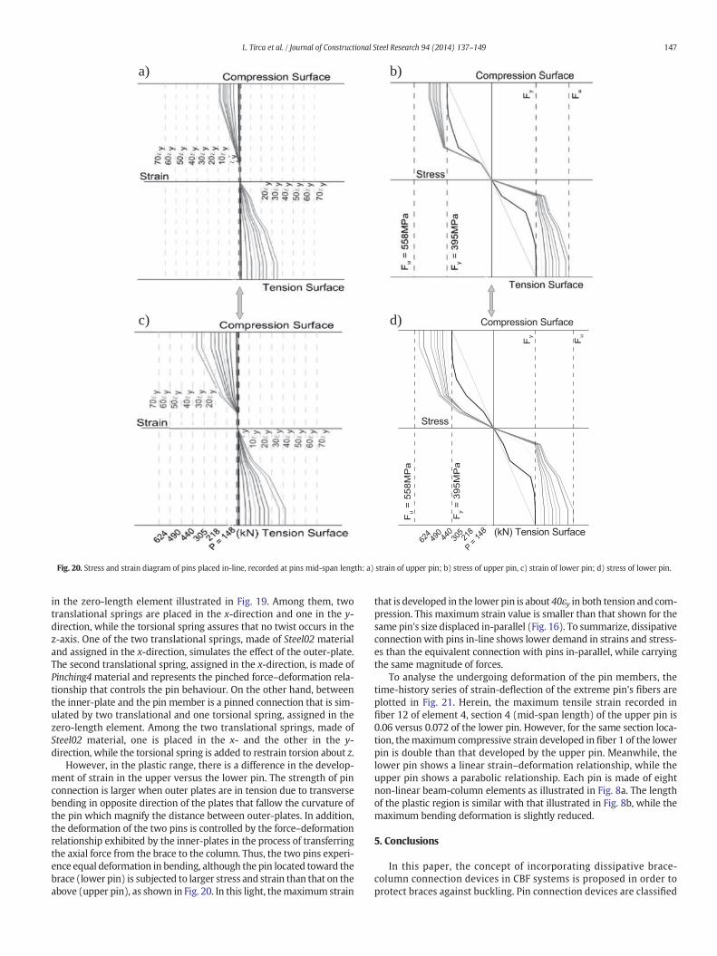
However, in the plastic range, there is a difference in the develop-ment of strain in the upper versus the lower pin. The strength of pinconnection is larger when outer plates are in tension due to transversebending in opposite direction of the plates that fallow the curvature ofthe pin which magnify the distance between outer-plates. In addition,the deformation of the two pins is controlled by the force–deformationrelationship exhibited by the inner-plates in the process of transferringthe axial force from the brace to the column. Thus, the two pins experi-ence equal deformation in bending, although the pin located toward thebrace (lower pin) is subjected to larger stress and strain than that on theabove (upper pin), as shown in Fig. 20. In this light, themaximum strain
that is developed in the lower pin is about 40εy in both tension and com-pression. This maximum strain value is smaller than that shown for thesame pin's size displaced in-parallel (Fig. 16). To summarize, dissipativeconnectionwith pins in-line shows lower demand in strains and stress-es than the equivalent connection with pins in-parallel, while carryingthe same magnitude of forces.
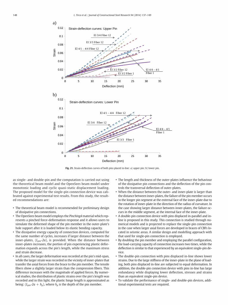
To analyse the undergoing deformation of the pin members, thetime-history series of strain-deflection of the extreme pin's fibers areplotted in Fig. 21. Herein, the maximum tensile strain recorded infiber 12 of element 4, section 4 (mid-span length) of the upper pin is0.06 versus 0.072 of the lower pin. However, for the same section loca-tion, themaximum compressive strain developed in fiber 1 of the lowerpin is double than that developed by the upper pin. Meanwhile, thelower pin shows a linear strain–deformation relationship, while theupper pin shows a parabolic relationship. Each pin is made of eightnon-linear beam-column elements as illustrated in Fig. 8a. The lengthof the plastic region is similar with that illustrated in Fig. 8b, while themaximum bending deformation is slightly reduced.
5. Conclusions
In this paper, the concept of incorporating dissipative brace-column connection devices in CBF systems is proposed in order toprotect braces against buckling. Pin connection devices are classified
a)
c)
b)
d)
Fig. 20. Stress and strain diagram of pins placed in-line, recorded at pins mid-span length: a) strain of upper pin; b) stress of upper pin, c) strain of lower pin; d) stress of lower pin.
147L. Tirca et al. / Journal of Constructional Steel Research 94 (2014) 137–149
as single- and double-pin and the computation is carried out usingthe theoretical beam model and the OpenSees beam model undermonotonic loading and cyclic quasi-static displacement loading.The proposed model for the single-pin connection device was cali-brated against experimental test results. From this study, the result-ed recommendations are:
• The theoretical beam model is recommended for preliminary designof dissipative pin connections.
• TheOpenSees beammodel employs the Pinching4materialwhich rep-resents a pinched force-deformation response and it allows users tosimulate the deformed shape of the pin member in the outer-plate'shole support after it is loaded below its elastic bending capacity.
• The dissipative energy capacity of connection devices, computed forthe same number of cycles, increases if larger distance between theinner-plates, (Lpin-2a), is provided. When the distance betweeninner-plates increases, the portion of pin experiencing plastic defor-mation expands across the pin's length, while the maximum stressand strain decrease.
• In all cases, the larger deformationwas recorded at thepin'smid-span,while the larger strainwas recorded in the vicinity of inner-plates thattransfer the axial forces from the brace to the pinmember. The tensilefibers show a slightly larger strain than the compression fibers. Thisdifference increases with the magnitude of applied forces. By numer-ical studies, the distribution of plastic strains over the pin's lengthwasrecorded and in this light, the plastic hinge length is approximated asbeing: (Lpin-2a + hp), where hp is the depth of the pin member.
• The length and thickness of the outer-plates influence the behaviourof the dissipative pin connections and the deflection of the pin con-trols the transversal deflection of outer-plates.
• When the distance between the outer- and inner-plate is larger thanthe distance between inner-plates, the failure of the pinmember occursin the longer pin segment at the external face of the inner-plate due tothe rotation of inner-plate in the direction of the radius of curvature. Inthe case showing larger distance between inner-plates, the failure oc-curs in the middle segment, at the internal face of the inner-plate.
• A double-pin connection device with pins displaced in-parallel and in-line is proposed in this study. This connection is studied through nu-merical models and is projected to replace the single-pin connectionin the case when larger axial forces are developed in braces of CBFs lo-cated in seismic areas. A similar design and modelling approach withthat used for single-pin connection is employed.
• By doubling the pinmember and employing the parallel configuration,the load-carrying capacity of connection increases two times, while thedeflection is similar to that experienced by an equivalent single-pin de-vice.
• The double-pin connection with pins displaced in-line shows lowerstrains. Due to the large stiffness of the inner-plate in the plane of load-ing, both pins displaced in-line are subjected to equal deformation. Inaddition, the double-pin connection device with pins in-line has largeredundancy while displaying lower deflection, stresses and strainsthan an equivalent single-pin device.
• To validate the performance of single- and double-pin devices, addi-tional experimental tests are required.
Deflection (mm)
Str
ain
Str
ain
Deflection (mm)
El 4/4 – 4/1Fiber 1
El 3/4 Fiber 12
El 3/3 Fiber 12
El 4/1 – 4/4 Fiber 12
El 3/2 Fiber 12El 3/2 Fiber 1
Strain-deflection curves: Upper Pin
El 4/4 – 4/1Fiber 1
El 3/3 Fiber 1
El 4/1 – 4/4 Fiber 12
El 3/4 Fiber 12
Strain-deflection curves: Lower Pin
a)
b)
Fig. 21. Strain-deflection curves of both pins placed in-line: a) upper pin; b) lower pin.
148 L. Tirca et al. / Journal of Constructional Steel Research 94 (2014) 137–149
Acknowledgements
Financial support from the Natural Sciences and Engineering Re-search Council of Canada (NSERC) is gratefully acknowledged. Authorsexpress their gratitude to Prof. Luis Calado for providing experimentaltest results.
References
[1] CAN/CSA. Canadian Standard Association. CSA/S16-2009: Design of Steel Structures.Toronto, Ontario; 2009.
[2] NRCC. National Building Code of Canada 2010. 13th ed. Ottawa, ON: National Re-search Council of Canada; 2010.
[3] Tremblay R, St-Onge E, Rogers C, Morrison T, Legeron F, Desjardins E, et al. Overviewof ductile seismic brace fuse systems in Canada. EUROSteel conf., Budapest; 2011.p. 939–45.
[4] Constantinou MC, Symans MD. Seismic response of structures with supplementaldamping. Struct Des Tall Build 1993;2:77–92.
[5] Kassis D, Tremblay R. Brace fuse system for cost-effective design of low-rise steelbuildings. Proc. CSCE 2008 Annual Conference, Quebec, QC, Paper No. 248; 2008.
[6] St-Onge E. Comportement et conception sismique des fusibles ductiles pour lesstructures en acier. (Master thesis) Montreal, Canada: Ecole Polytechnique; 2012.
[7] Desjardins E, Légeron F. Method to reduce seismic demand on connections of con-centrically braced systems. 2nd International Structures Specialty Conf., CSCE, Win-nipeg, Manitoba, 2010; 2010.
[8] Tirca L, Caprarelli C, Danila N, Calado L. Modelling and design of dissipative connec-tions for brace to column joints. In: Dubina D, Grecea D, editors. 7th Int. workshopon connections in steel structures, Timisoara; 2012. p. 503–14.
[9] Gray MG, Christopoulos C, Packer JA. Cast steel yielding fuse for concentricallybraced frames. Proc. 9th U.S. Nat. & 10th Can. Conf. on Earthquake Eng., Toronto,ON, Paper No. 595; 2010.
[10] Caprarelli C. Modelling and design of earthquake resistant low-rise concentricallybraced frames with dissipative single-pin connections. (Master thesis) Montreal,Canada: Concordia University; 2012.
[11] McKenna F, Fenves GL, Scott MH, et al. Open system for earthquake engineering sim-ulation. OpenSees software version 2.2.0; 2009.
[12] Plumier A, Doneux C, Castiglioni C, Brescianini J, Crespi A, Dell'Anna S,et al. Two innovations for earthquake resistant design. European Commis-sion, Technical Steel Research, Report EUR 22044 EN. ISBN 92-79-01694-6; 2006.
[13] Vayas I, Thanopoulos P. Innovative dissipative (INERD) pin connections for seismicresistant braced frames. Int J Steel Struct 2005;5.
[14] Thanopoulos P. Behaviour of seismic resistant steel framewith energy absorbingdevices. (PhD thesis) Greece: National Technical University of Athens; 2006.
[15] Ziemian R. Guide to stability design criteria for metal structures. J. Wiley & Sons; 2010.[16] Craig Jr R. Mechanics of materials. J. Wiley & Sons; 2000.[17] Mazzoni S,McKenna F, ScottMH, FenvesGL. OpenSees command languagemanual Pa-
cific Earthquake Engineering Research Center. Berkeley: University of California; 2007.[18] ECCS-TWG 1.3 seismic design recommended testing procedure for assessing the be-
haviour of structural steel elements under cyclic loads. European Convention forConstructional Steelwork, Technical Committee — Structural safety and loading,Brussels, Belgium; 1986.
149L. Tirca et al. / Journal of Constructional Steel Research 94 (2014) 137–149
Related Documents