CONSEIL INTERNATIONAL DES MACHINES A COMBUSTION INTERNATIONAL COUNCIL ON COMBUSTION ENGINES PAPER NO.: 293 2-Stage Turbocharging – Flexibility for Engine Optimisation Ennio Codan, ABB Turbo Systems Ltd, Switzerland Christoph Mathey, ABB Turbo Systems Ltd, Switzerland Adrian Rettig, ABB Turbo Systems Ltd, Switzerland Abstract: With demand for greater economy, lower emissions and higher output continuing to in- fluence engine development, a wider range of flexi- bility is required in modern engine designs. 2-stage turbocharging can make a significant contribution to- wards satisfying these requirements. Parallel with its participation in different research and develop- ment projects, such as HERCULES and HERCULES- Beta, ABB Turbo Systems Ltd in recent years has developed turbochargers specifically for 2-stage turbocharging. Several studies have been carried out in connection with these activities which show the po- tential of 2-stage turbocharging on diesel and gas en- gines, not only in terms of actual performance, but also in respect of the improved flexibility it offers modern engine design. This paper shows and discusses some of the pos- sibilities offered by 2-stage turbocharging regarding engine output increase, emissions reduction and, last but not least, fuel consumption improvements. A large number of engine cycle simulations, some of them ver- ified by engine tests, have been performed for diesel engines in different applications as well as for gas en- gines of either spark-ignition or dual-fuel design. Dif- ferent control modes, e.g. variable valve timing or the use of an exhaust waste gate, and emission reduc- tion methods such as exhaust gas recirculation or se- lective catalytic reduction, have also been taken into account. The results of these investigations served equally well as boundary conditions for the develop- ment of the specific 2-stage turbochargers and their major components. Also presented is the design of a newly devel- oped 2-stage turbocharging system that is currently undergoing an extensive validation and qualification program in ABB’s turbocharger test centre. ABB has invested considerably in new turbocharger test rigs for 2-stage turbocharging in recent years, and as a result turbocharger performance tests can be per- formed under realistic conditions. The design of these turbochargers with overall pressure ratios of 8 and above differs considerably from that of conventional turbochargers, especially with respect to the high- pressure stage. First prototypes have already been tested on several engines. The first engines with these 2-stage turbocharging systems are scheduled for field operation in 2010. c CIMAC Congress 2010, Bergen

Welcome message from author
This document is posted to help you gain knowledge. Please leave a comment to let me know what you think about it! Share it to your friends and learn new things together.
Transcript
CONSEIL INTERNATIONALDES MACHINES A COMBUSTION
INTERNATIONAL COUNCILON COMBUSTION ENGINES
PAPER NO.: 293
2-Stage Turbocharging – Flexibility for EngineOptimisation
Ennio Codan, ABB Turbo Systems Ltd, SwitzerlandChristoph Mathey, ABB Turbo Systems Ltd, Switzerland
Adrian Rettig, ABB Turbo Systems Ltd, Switzerland
Abstract: With demand for greater economy,lower emissions and higher output continuing to in-fluence engine development, a wider range of flexi-bility is required in modern engine designs. 2-stageturbocharging can make a significant contribution to-wards satisfying these requirements. Parallel withits participation in different research and develop-ment projects, such as HERCULES and HERCULES-Beta, ABB Turbo Systems Ltd in recent yearshas developed turbochargers specifically for 2-stageturbocharging. Several studies have been carried outin connection with these activities which show the po-tential of 2-stage turbocharging on diesel and gas en-gines, not only in terms of actual performance, but alsoin respect of the improved flexibility it offers modernengine design.
This paper shows and discusses some of the pos-sibilities offered by 2-stage turbocharging regardingengine output increase, emissions reduction and, lastbut not least, fuel consumption improvements. A largenumber of engine cycle simulations, some of them ver-ified by engine tests, have been performed for dieselengines in different applications as well as for gas en-gines of either spark-ignition or dual-fuel design. Dif-
ferent control modes, e.g. variable valve timing or theuse of an exhaust waste gate, and emission reduc-tion methods such as exhaust gas recirculation or se-lective catalytic reduction, have also been taken intoaccount. The results of these investigations servedequally well as boundary conditions for the develop-ment of the specific 2-stage turbochargers and theirmajor components.
Also presented is the design of a newly devel-oped 2-stage turbocharging system that is currentlyundergoing an extensive validation and qualificationprogram in ABB’s turbocharger test centre. ABB hasinvested considerably in new turbocharger test rigsfor 2-stage turbocharging in recent years, and as aresult turbocharger performance tests can be per-formed under realistic conditions. The design of theseturbochargers with overall pressure ratios of 8 andabove differs considerably from that of conventionalturbochargers, especially with respect to the high-pressure stage. First prototypes have already beentested on several engines.
The first engines with these 2-stage turbochargingsystems are scheduled for field operation in 2010.
c©CIMAC Congress 2010, Bergen
© CIMAC Congress 2010, Bergen Paper No. 293 2
INTRODUCTION
The concept of 2-stage turbocharging has been known in applications on large engines since the early 1960s. However this technology has not been capable of establishing itself in general usage since it was only applied when single stage turbocharging pressure ratios would not have been sufficient. 2-stage turbocharging thus led a niche existence and was reserved for specific applications.
Large engine development continues to target higher power density, reduced emissions and improved fuel consumption. Because the potential of single-stage turbocharging at high pressure ratios is becoming ever more limited, new opportunities are arising for 2-stage turbocharging.
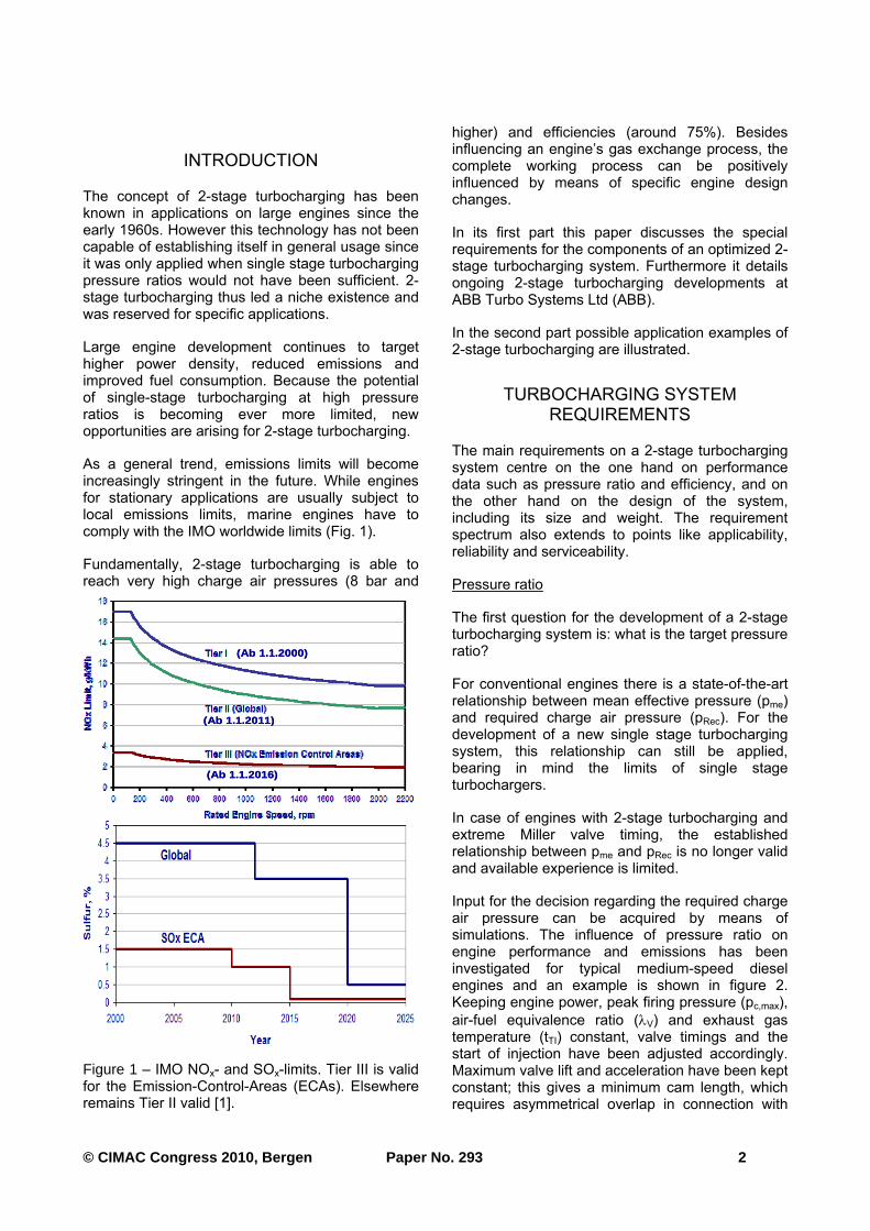
As a general trend, emissions limits will become increasingly stringent in the future. While engines for stationary applications are usually subject to local emissions limits, marine engines have to comply with the IMO worldwide limits (Fig. 1).
Fundamentally, 2-stage turbocharging is able to reach very high charge air pressures (8 bar and
higher) and efficiencies (around 75%). Besides influencing an engine’s gas exchange process, the complete working process can be positively influenced by means of specific engine design changes.
In its first part this paper discusses the special requirements for the components of an optimized 2-stage turbocharging system. Furthermore it details ongoing 2-stage turbocharging developments at ABB Turbo Systems Ltd (ABB).
In the second part possible application examples of 2-stage turbocharging are illustrated.
TURBOCHARGING SYSTEM REQUIREMENTS
The main requirements on a 2-stage turbocharging system centre on the one hand on performance data such as pressure ratio and efficiency, and on the other hand on the design of the system, including its size and weight. The requirement spectrum also extends to points like applicability, reliability and serviceability.
Pressure ratio
The first question for the development of a 2-stage turbocharging system is: what is the target pressure ratio?
For conventional engines there is a state-of-the-art relationship between mean effective pressure (pme) and required charge air pressure (pRec). For the development of a new single stage turbocharging system, this relationship can still be applied, bearing in mind the limits of single stage turbochargers.
In case of engines with 2-stage turbocharging and extreme Miller valve timing, the established relationship between pme and pRec is no longer valid and available experience is limited.
Input for the decision regarding the required charge air pressure can be acquired by means of simulations. The influence of pressure ratio on engine performance and emissions has been investigated for typical medium-speed diesel engines and an example is shown in figure 2. Keeping engine power, peak firing pressure (pc,max),
air-fuel equivalence ratio (λV) and exhaust gas temperature (tTI) constant, valve timings and the start of injection have been adjusted accordingly. Maximum valve lift and acceleration have been kept constant; this gives a minimum cam length, which requires asymmetrical overlap in connection with
(Ab 1.1.2000)
(Ab 1.1.2011)
(Ab 1.1.2016)
(Ab 1.1.2000)
(Ab 1.1.2011)
(Ab 1.1.2016)
Figure 1 – IMO NOx- and SOx-limits. Tier III is valid for the Emission-Control-Areas (ECAs). Elsewhere remains Tier II valid [1].
© CIMAC Congress 2010, Bergen Paper No. 293 3
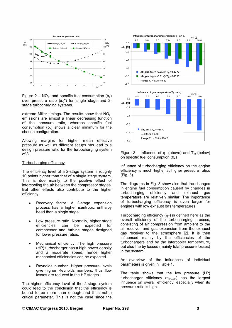
extreme Miller timings. The results show that NOx-emissions are almost a linear decreasing function of the pressure ratio, whereas specific fuel consumption (be) shows a clear minimum for the chosen configuration.
Allowing margins for higher mean effective pressure as well as different setups has lead to a design pressure ratio for the turbocharging system of 8.
Turbocharging efficiency
The efficiency level of a 2-stage system is roughly 10 points higher than that of a single stage system. This is due mainly to the positive effect of intercooling the air between the compressor stages. But other effects also contribute to the higher efficiency:
• Recovery factor. A 2-stage expansion process has a higher isentropic enthalpy head than a single stage.
• Low pressure ratio. Normally, higher stage efficiencies can be expected for compressor and turbine stages designed for lower pressure ratios.
• Mechanical efficiency. The high pressure (HP) turbocharger has a high power density and a moderate speed; hence higher mechanical efficiencies can be expected.
• Reynolds number. Higher pressure levels give higher Reynolds numbers, thus flow losses are reduced in the HP stages.
The higher efficiency level of the 2-stage system could lead to the conclusion that the efficiency is bound to be more than enough and thus not a critical parameter. This is not the case since the
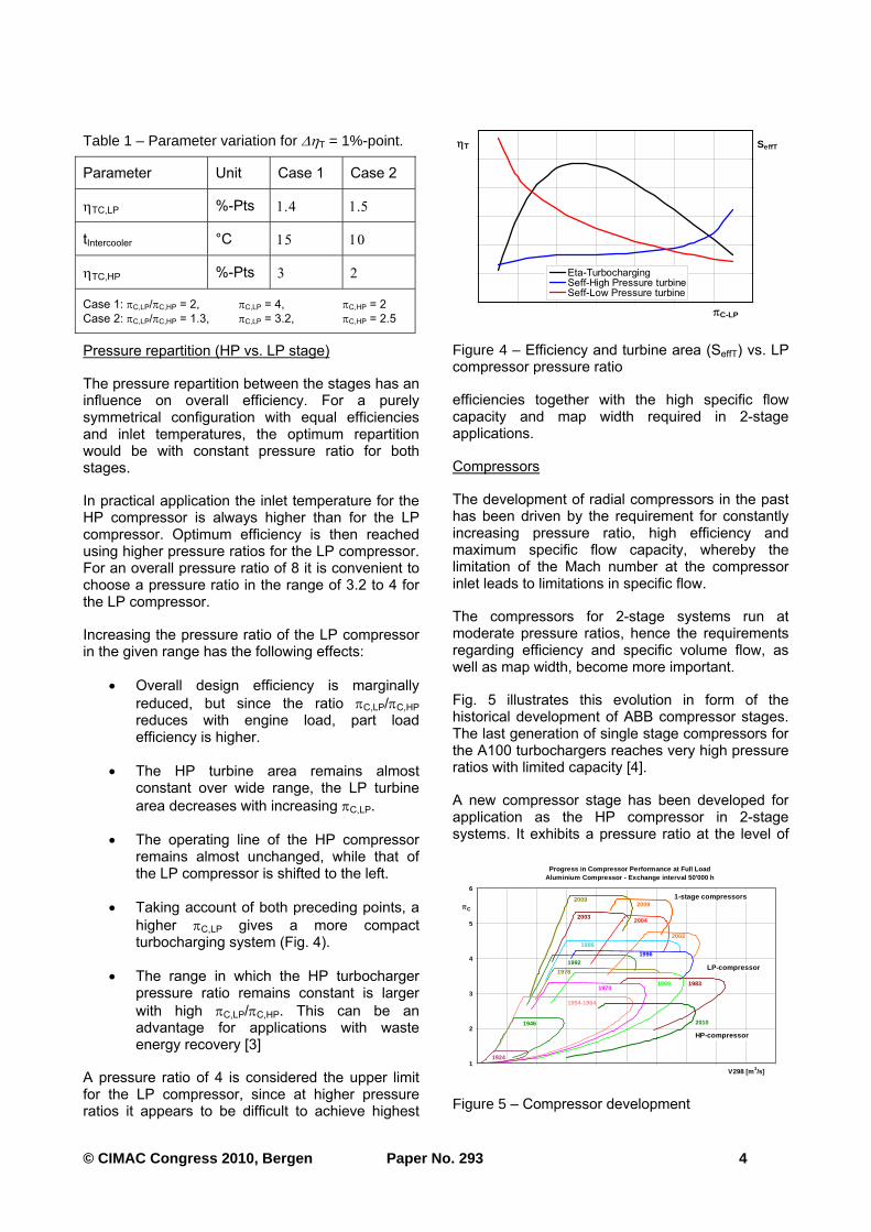
influence of turbocharging efficiency on the engine efficiency is much higher at higher pressure ratios (Fig. 3).
The diagrams in Fig. 3 show also that the changes in engine fuel consumption caused by changes in turbocharging efficiency and exhaust gas temperature are relatively similar. The importance of turbocharging efficiency is even larger for engines with low exhaust gas temperatures.
Turbocharging efficiency (ηT) is defined here as the overall efficiency of the turbocharging process, consisting of air compression from ambient to the air receiver and gas expansion from the exhaust gas receiver to the atmosphere [2]. It is then influenced mainly by the efficiencies of the turbochargers and by the intercooler temperature, but also the by losses (mainly total pressure losses) in the system.
An overview of the influences of individual parameters is given in Table 1.
The table shows that the low pressure (LP)
turbocharger efficiency (ηTC,LP) has the largest influence on overall efficiency, especially when its pressure ratio is high.
be, NOx vs. pressure ratio
80
85
90
95
100
105
110
4 5 6 7 8 9 10 11 12πC*
be [%]
50
60
70
80
90
100
110
NOx[%]
1-stage_be_rel 2-stage_be_rel
1-stage_NOx_rel 2-stage_NOx_rel
Figure 2 – NOx- and specific fuel consumption (be)
over pressure ratio (πC*) for single stage and 2-stage turbocharging systems.
Influence of turbocharging efficiency ηT on b e
-1.0
-0.8
-0.6
-0.4
-0.2
0.0
4.5 5.0 6.0 7.0 8.0 9.0 10.0
πC* [-]
Δbe [%]
dbe per +1 point EtaT @ TTI = 520°C
dbe per +1 point EtaT @ TTI = 550°C
Δbe per T = +0.01 @ TTI = 520 °C
Δbe per T = +0.01 @ TTI = 550 °C
Range ηT = 0.75 ÷ 0.80
Influence of turbocharging efficiency ηT on b e
-1.0
-0.8
-0.6
-0.4
-0.2
0.0
4.5 5.0 6.0 7.0 8.0 9.0 10.0
πC* [-]
Δbe [%]
dbe per +1 point EtaT @ TTI = 520°C
dbe per +1 point EtaT @ TTI = 550°C
Δbe per T = +0.01 @ TTI = 520 °C
Δbe per T = +0.01 @ TTI = 550 °C
Range ηT = 0.75 ÷ 0.80
Influence of gas temperature T TI on b e
-1.0
-0.8
-0.6
-0.4
-0.2
0.04.5 5.0 6.0 7.0 8.0 9.0 10.0
πC* [-]
Δbe [%]
dbe [%] per +10K TTIΔbe per ΔTTI = +10 °C
ηT = 0.76 ÷ 0.78
Range T TI = 520 ÷ 550 °C
Influence of gas temperature T TI on b e
-1.0
-0.8
-0.6
-0.4
-0.2
0.04.5 5.0 6.0 7.0 8.0 9.0 10.0
πC* [-]
Δbe [%]
dbe [%] per +10K TTIΔbe per ΔTTI = +10 °C
ηT = 0.76 ÷ 0.78
Range T TI = 520 ÷ 550 °C
Figure 3 – Influence of ηT (above) and TTI (below) on specific fuel consumption (be)
© CIMAC Congress 2010, Bergen Paper No. 293 4
Table 1 – Parameter variation for ΔηT = 1%-point.
Parameter Unit Case 1 Case 2
ηTC,LP %-Pts 1.4 1.5
tIntercooler °C 15 10
ηTC,HP %-Pts 3 2
Case 1: πC,LP/πC,HP = 2, πC,LP = 4, πC,HP = 2
Case 2: πC,LP/πC,HP = 1.3, πC,LP = 3.2, πC,HP = 2.5
Pressure repartition (HP vs. LP stage)
The pressure repartition between the stages has an influence on overall efficiency. For a purely symmetrical configuration with equal efficiencies and inlet temperatures, the optimum repartition would be with constant pressure ratio for both stages.
In practical application the inlet temperature for the HP compressor is always higher than for the LP compressor. Optimum efficiency is then reached using higher pressure ratios for the LP compressor. For an overall pressure ratio of 8 it is convenient to choose a pressure ratio in the range of 3.2 to 4 for the LP compressor.
Increasing the pressure ratio of the LP compressor in the given range has the following effects:
• Overall design efficiency is marginally
reduced, but since the ratio πC,LP/πC,HP reduces with engine load, part load efficiency is higher.
• The HP turbine area remains almost constant over wide range, the LP turbine
area decreases with increasing πC,LP.
• The operating line of the HP compressor remains almost unchanged, while that of the LP compressor is shifted to the left.
• Taking account of both preceding points, a
higher πC,LP gives a more compact turbocharging system (Fig. 4).
• The range in which the HP turbocharger pressure ratio remains constant is larger
with high πC,LP/πC,HP. This can be an advantage for applications with waste energy recovery [3]
A pressure ratio of 4 is considered the upper limit for the LP compressor, since at higher pressure ratios it appears to be difficult to achieve highest
efficiencies together with the high specific flow capacity and map width required in 2-stage applications.
Compressors
The development of radial compressors in the past has been driven by the requirement for constantly increasing pressure ratio, high efficiency and maximum specific flow capacity, whereby the limitation of the Mach number at the compressor inlet leads to limitations in specific flow.
The compressors for 2-stage systems run at moderate pressure ratios, hence the requirements regarding efficiency and specific volume flow, as well as map width, become more important.
Fig. 5 illustrates this evolution in form of the historical development of ABB compressor stages. The last generation of single stage compressors for the A100 turbochargers reaches very high pressure ratios with limited capacity [4].
A new compressor stage has been developed for application as the HP compressor in 2-stage systems. It exhibits a pressure ratio at the level of
πC-LP
ηT SeffT
Eta-TurbochargingSeff-High Pressure turbineSeff-Low Pressure turbine
Figure 4 – Efficiency and turbine area (SeffT) vs. LP compressor pressure ratio
Progress in Compressor Performance at Full LoadAluminium Compressor - Exchange interval 50'000 h
1
2
3
4
5
6
V298 [m 3/s]
πC
2003
1996
1996
2003
2004
1992
1989
1978
1970
1946
1954-1964
1924
20092009
1983
2010
1-stage compressors
LP-compressor
HP-compressor
Figure 5 – Compressor development
© CIMAC Congress 2010, Bergen Paper No. 293 5
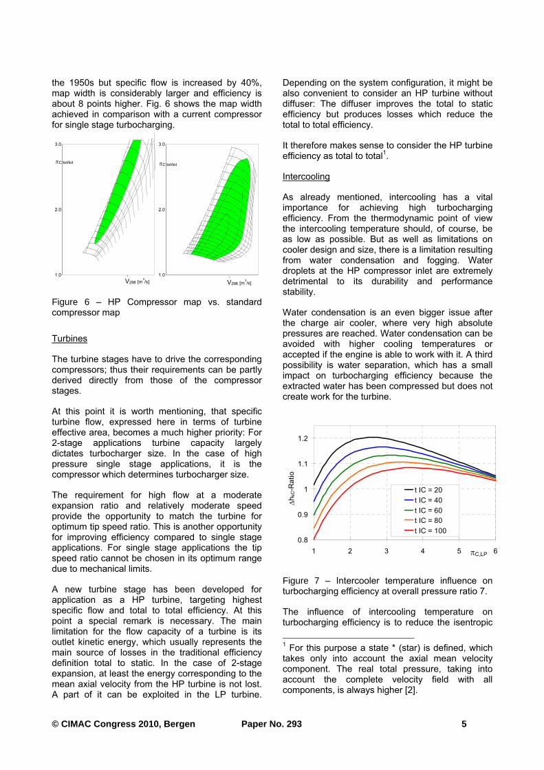
the 1950s but specific flow is increased by 40%, map width is considerably larger and efficiency is about 8 points higher. Fig. 6 shows the map width achieved in comparison with a current compressor for single stage turbocharging.
Turbines
The turbine stages have to drive the corresponding compressors; thus their requirements can be partly derived directly from those of the compressor stages.
At this point it is worth mentioning, that specific turbine flow, expressed here in terms of turbine effective area, becomes a much higher priority: For 2-stage applications turbine capacity largely dictates turbocharger size. In the case of high pressure single stage applications, it is the compressor which determines turbocharger size.
The requirement for high flow at a moderate expansion ratio and relatively moderate speed provide the opportunity to match the turbine for optimum tip speed ratio. This is another opportunity for improving efficiency compared to single stage applications. For single stage applications the tip speed ratio cannot be chosen in its optimum range due to mechanical limits.
A new turbine stage has been developed for application as a HP turbine, targeting highest specific flow and total to total efficiency. At this point a special remark is necessary. The main limitation for the flow capacity of a turbine is its outlet kinetic energy, which usually represents the main source of losses in the traditional efficiency definition total to static. In the case of 2-stage expansion, at least the energy corresponding to the mean axial velocity from the HP turbine is not lost. A part of it can be exploited in the LP turbine.
Depending on the system configuration, it might be also convenient to consider an HP turbine without diffuser: The diffuser improves the total to static efficiency but produces losses which reduce the total to total efficiency.
It therefore makes sense to consider the HP turbine efficiency as total to total
1.
Intercooling
As already mentioned, intercooling has a vital importance for achieving high turbocharging efficiency. From the thermodynamic point of view the intercooling temperature should, of course, be as low as possible. But as well as limitations on cooler design and size, there is a limitation resulting from water condensation and fogging. Water droplets at the HP compressor inlet are extremely detrimental to its durability and performance stability.
Water condensation is an even bigger issue after the charge air cooler, where very high absolute pressures are reached. Water condensation can be avoided with higher cooling temperatures or accepted if the engine is able to work with it. A third possibility is water separation, which has a small impact on turbocharging efficiency because the extracted water has been compressed but does not create work for the turbine.
The influence of intercooling temperature on turbocharging efficiency is to reduce the isentropic
1 For this purpose a state * (star) is defined, which
takes only into account the axial mean velocity component. The real total pressure, taking into account the complete velocity field with all components, is always higher [2].
1.0
2.0
3.0
πC tot/tot
η*sV
.V298 [m
3/s]
1.0
2.0
3.0
.V298 [m
3/s]
πC tot/tot
η*sV
Figure 6 – HP Compressor map vs. standard compressor map
0.8
0.9
1
1.1
1.2
1 2 3 4 5 6πC,LP
Δh
sC-R
atio
t IC = 20
t IC = 40
t IC = 60
t IC = 80
t IC = 100
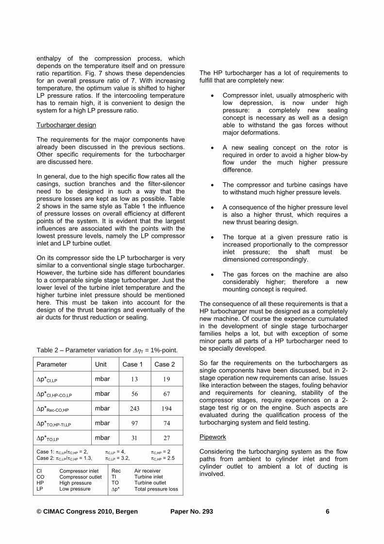
Figure 7 – Intercooler temperature influence on turbocharging efficiency at overall pressure ratio 7.
© CIMAC Congress 2010, Bergen Paper No. 293 6
enthalpy of the compression process, which depends on the temperature itself and on pressure ratio repartition. Fig. 7 shows these dependencies for an overall pressure ratio of 7. With increasing temperature, the optimum value is shifted to higher LP pressure ratios. If the intercooling temperature has to remain high, it is convenient to design the system for a high LP pressure ratio.
Turbocharger design
The requirements for the major components have already been discussed in the previous sections. Other specific requirements for the turbocharger are discussed here.
In general, due to the high specific flow rates all the casings, suction branches and the filter-silencer need to be designed in such a way that the pressure losses are kept as low as possible. Table 2 shows in the same style as Table 1 the influence of pressure losses on overall efficiency at different points of the system. It is evident that the largest influences are associated with the points with the lowest pressure levels, namely the LP compressor inlet and LP turbine outlet.
On its compressor side the LP turbocharger is very similar to a conventional single stage turbocharger. However, the turbine side has different boundaries to a comparable single stage turbocharger. Just the lower level of the turbine inlet temperature and the higher turbine inlet pressure should be mentioned here. This must be taken into account for the design of the thrust bearings and eventually of the air ducts for thrust reduction or sealing.
Table 2 – Parameter variation for ΔηT = 1%-point.
Parameter Unit Case 1 Case 2
Δp*CI,LP mbar 13 19
Δp*CI,HP-CO,LP mbar 56 67
Δp*Rec-CO,HP mbar 243 194
Δp*TO,HP-TI,LP mbar 97 74
Δp*TO,LP mbar 31 27
Case 1: πC,LP/πC,HP = 2, πC,LP = 4, πC,HP = 2
Case 2: πC,LP/πC,HP = 1.3, πC,LP = 3.2, πC,HP = 2.5
CI Compressor inlet CO Compressor outlet HP High pressure LP Low pressure
Rec Air receiver TI Turbine inlet TO Turbine outlet
Δp* Total pressure loss
The HP turbocharger has a lot of requirements to fulfill that are completely new:
• Compressor inlet, usually atmospheric with low depression, is now under high pressure: a completely new sealing concept is necessary as well as a design able to withstand the gas forces without major deformations.
• A new sealing concept on the rotor is required in order to avoid a higher blow-by flow under the much higher pressure difference.
• The compressor and turbine casings have to withstand much higher pressure levels.
• A consequence of the higher pressure level is also a higher thrust, which requires a new thrust bearing design.
• The torque at a given pressure ratio is increased proportionally to the compressor inlet pressure; the shaft must be dimensioned correspondingly.
• The gas forces on the machine are also considerably higher; therefore a new mounting concept is required.
The consequence of all these requirements is that a HP turbocharger must be designed as a completely new machine. Of course the experience cumulated in the development of single stage turbocharger families helps a lot, but with exception of some minor parts all parts of a HP turbocharger need to be specially developed.
So far the requirements on the turbochargers as single components have been discussed, but in 2-stage operation new requirements can arise. Issues like interaction between the stages, fouling behavior and requirements for cleaning, stability of the compressor stages, require experiences on a 2-stage test rig or on the engine. Such aspects are evaluated during the qualification process of the turbocharging system and field testing.
Pipework
Considering the turbocharging system as the flow paths from ambient to cylinder inlet and from cylinder outlet to ambient a lot of ducting is involved.
© CIMAC Congress 2010, Bergen Paper No. 293 7
Careful ducting design is required for a compact, efficient and durable system. For thermodynamic evaluation pressure losses are relevant. The influences shown in Table 2 are still valid for the pressure losses in the ducts.
Two further aspects can be mentioned here:
• The connection between the turbines is critical, because it should transfer not only static pressure but also a considerable amount of kinetic energy from the HP turbine outlet to the LP turbine inlet.
• The inlet and exhaust manifolds could possibly be reduced in volume, since gas density is higher and velocity lower in comparison with a single stage system. Reduced volumes would help to improve engine transient behaviour, preserving some degree of pulse effect and, last but not least, reducing costs.
2-STAGE TURBOCHARGER PRODUCT DEVELOPMENT
High-pressure turbocharger
The HP turbocharger mentioned above is a completely new machine. Its development was started in 2007. The turbocharger is now undergoing its qualification phase. The qualification process has been newly defined based on the established qualification process of single stage turbochargers with adapted boundary conditions as well as some new qualification tests dictated by 2-stage operation.
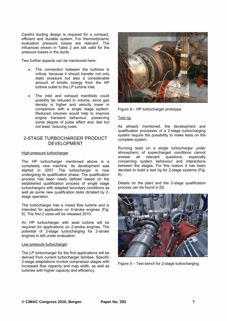
The turbocharger has a mixed flow turbine and is intended for application on 4-stroke engines (Fig. 8). The first 2 sizes will be released 2010.
An HP turbocharger with axial turbine will be required for applications on 2-stroke engines. The potential of 2-stage turbocharging for 2-stroke engines is still under evaluation.
Low pressure turbocharger
The LP turbocharger for the first applications will be derived from current turbocharger families. Specific 2-stage adaptations involve compressor stages with increased flow capacity and map width, as well as turbines with higher capacity and efficiency.
Test rig
As already mentioned, the development and qualification processes of a 2-stage turbocharging system require the possibility to make tests on the complete system.
Running tests on a single turbocharger under atmospheric of supercharged conditions cannot answer all relevant questions, especially concerning system behaviour and interactions between the stages. For this reason it has been decided to build a test rig for 2-stage systems (Fig. 9).
Details on the plant and the 2-stage qualification process can be found in [5].
Figure 8 – HP turbocharger prototype.
Figure 9 – Test bench for 2-stage turbocharging.
HP-TL LP-TL
© CIMAC Congress 2010, Bergen Paper No. 293 8
PRACTICAL APPLICATION EXAMPLES
The potential that can be realized on the engine by introducing 2-stage turbocharging will be shown by means of case studies for different engine types.
It must be kept in mind that introducing 2-stage turbocharging cannot be seen as a mere substitution of a single stage system just to gain a small step in pressure ratio.
A lot of development work is also required on the engine side in order to realize the huge potential available. The Miller process allows improvements in the efficiency and emissions of the closed cycle; the high turbocharging efficiency allows improved efficiency in the gas exchange cycle.
The latter is only applicable directly to a 4-stroke engine. In case of 2-stroke engines the strokes of the gas exchange process are missing. Considerations have been made for alternative solutions to increase pressure ratio and to profit from the high turbocharging efficiency [3].
4-STROKE DIESEL ENGINE (MEDIUM-SPEED)
Many studies on the effects of extreme Miller valve timing in connection with 2-stage turbocharging on diesel engines have been performed and published [3, 6, 7]. The main results are summarized here:
• The Miller process allows the reduction of charge air temperature at the beginning of the compression stroke by means of in-cylinder expansion of the charge air from the pressure produced by the turbocharging system.
• Appropriate valve timing is required, which leads to very short inlet cams. High accelerations are required for reaching high valve lifts within this short time.
• For optimum expansion cooling of the charge air, very high turbocharging pressures are required, which can only be realized in an efficient way with 2-stage turbocharging.
• The effect of charge air cooling is a closed cycle with higher efficiency, because at lower temperatures the specific heat of the gas in the cylinder is lower and consequently the conversion of the fuel heat into temperature and finally into mechanical work is more efficient.
Additionally the heat losses through the cylinder walls are reduced.
• The lower temperature of the closed cycle also allows a significant reduction in NOx-formation during combustion.
• A limit for this cooling process is given by the minimum compression temperature (about 580°C) needed for good diesel ignition and combustion. This temperature is also influenced by the charge air temperature and the compression ratio.
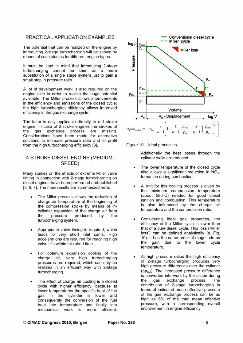
• Considering ideal gas properties, the efficiency of the Miller cycle is lower than that of a pure diesel cycle. This loss (‘Miller loss’) can be defined analytically (s. Fig. 10). It has the same order of magnitude as the gain due to the lower cycle temperature.
• At high pressure ratios the high efficiency of 2-stage turbocharging produces very high pressure differences over the cylinder
(ΔpCyl). The increased pressure difference is converted into work by the piston during the gas exchange process. The contribution of 2-stage turbocharging in terms of indicated mean effective pressure of the gas exchange process can be as high as 6% of the total mean effective pressure, with a corresponding overall improvement in engine efficiency.
log p
log VVh - DisplacementVc
pmaxpc
p瀞Recp瀞TIpRec
pTI
pac
pex
1
1瀞
Volume
Conventional diesel cycleMiller cycle
Pres
sure
Miller loss
1瀞瀞
log p
log VVh - DisplacementVc
pmaxpc
p瀞Recp瀞TIpRec
pTI
pac
pex
1
1瀞
Volume
Conventional diesel cycleMiller cycleConventional diesel cycleMiller cycle
Pres
sure
Miller lossMiller loss
1瀞瀞
⎟⎟⎟
⎠
⎞
⎜⎜⎜
⎝
⎛
⎟⎟⎠
⎞⎜⎜⎝
⎛⋅
−−⋅
−+
−⋅−=Δ
κ
κκ
κεε
1
ReReRe 11
11
1 ac
c
ac
ccMiller p
p
p
pppmi
Figure 10 – Ideal processes.
© CIMAC Congress 2010, Bergen Paper No. 293 9
• In order to fully exploit the potential of 2-stage turbocharging the exhaust gas temperature should be kept at a relatively high level (520 to 550 °C) by reducing valve overlap.
Trade-off curves
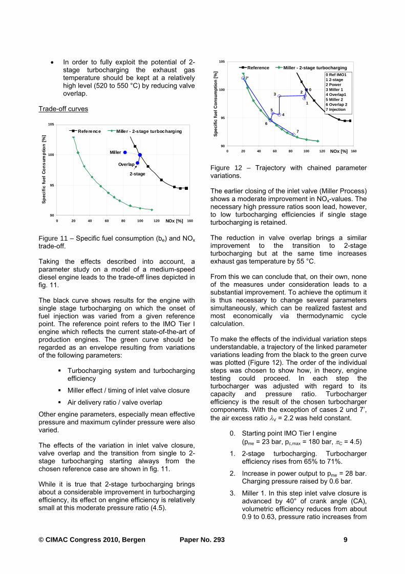
Taking the effects described into account, a parameter study on a model of a medium-speed diesel engine leads to the trade-off lines depicted in fig. 11.
The black curve shows results for the engine with single stage turbocharging on which the onset of fuel injection was varied from a given reference point. The reference point refers to the IMO Tier I engine which reflects the current state-of-the-art of production engines. The green curve should be regarded as an envelope resulting from variations of the following parameters:
Turbocharging system and turbocharging efficiency
Miller effect / timing of inlet valve closure
Air delivery ratio / valve overlap
Other engine parameters, especially mean effective pressure and maximum cylinder pressure were also varied.
The effects of the variation in inlet valve closure, valve overlap and the transition from single to 2-stage turbocharging starting always from the chosen reference case are shown in fig. 11.
While it is true that 2-stage turbocharging brings about a considerable improvement in turbocharging efficiency, its effect on engine efficiency is relatively small at this moderate pressure ratio (4.5).
The earlier closing of the inlet valve (Miller Process) shows a moderate improvement in NOx-values. The necessary high pressure ratios soon lead, however, to low turbocharging efficiencies if single stage turbocharging is retained.
The reduction in valve overlap brings a similar improvement to the transition to 2-stage turbocharging but at the same time increases exhaust gas temperature by 55 °C.
From this we can conclude that, on their own, none of the measures under consideration leads to a substantial improvement. To achieve the optimum it is thus necessary to change several parameters simultaneously, which can be realized fastest and most economically via thermodynamic cycle calculation.
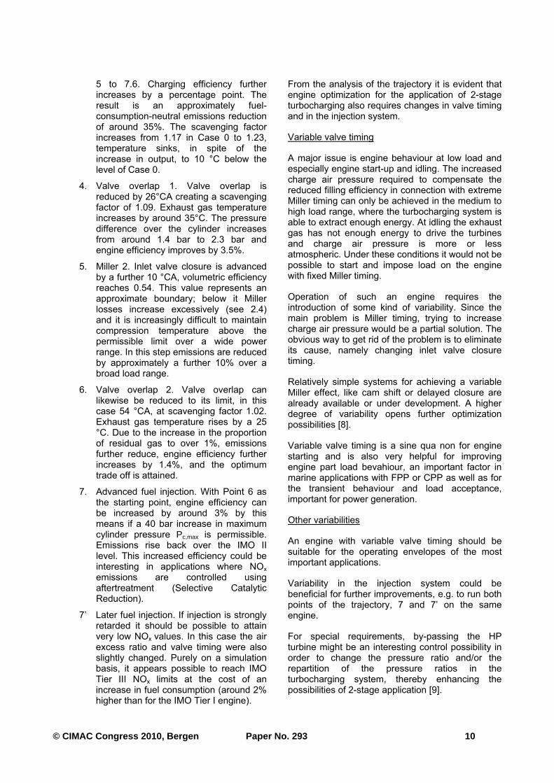
To make the effects of the individual variation steps understandable, a trajectory of the linked parameter variations leading from the black to the green curve was plotted (Figure 12). The order of the individual steps was chosen to show how, in theory, engine testing could proceed. In each step the turbocharger was adjusted with regard to its capacity and pressure ratio. Turbocharger efficiency is the result of the chosen turbocharger components. With the exception of cases 2 und 7’,
the air excess ratio λV = 2.2 was held constant.
0. Starting point IMO Tier I engine
(pme = 23 bar, pc,max = 180 bar, πC = 4.5)
1. 2-stage turbocharging. Turbocharger efficiency rises from 65% to 71%.
2. Increase in power output to pme = 28 bar. Charging pressure raised by 0.6 bar.
3. Miller 1. In this step inlet valve closure is advanced by 40° of crank angle (CA), volumetric efficiency reduces from about 0.9 to 0.63, pressure ratio increases from
2-stage
Miller
Overlap
90
95
100
105
0 20 40 60 80 100 120 14 0 160NOx [%]
Sp
ecifi
c fu
el C
on
sum
ptio
n [
%]
Reference Miller - 2-stage turbocharging
Figure 11 – Specific fuel consumption (be) and NOx trade-off.
7'
7
6
45
3 2
1
0
90
95
100
105
0 20 40 60 80 100 120 140 160NOx [%]
Spe
cific
fuel
Con
sum
ptio
n [%
]
Reference Miller - 2-stage turbocharging
0 Ref IMO11 2-stage2 Power3 Miller 14 Overlap15 Miller 26 Overlap 27 Injection
Figure 12 – Trajectory with chained parameter variations.
© CIMAC Congress 2010, Bergen Paper No. 293 10
5 to 7.6. Charging efficiency further increases by a percentage point. The result is an approximately fuel-consumption-neutral emissions reduction of around 35%. The scavenging factor increases from 1.17 in Case 0 to 1.23, temperature sinks, in spite of the increase in output, to 10 °C below the level of Case 0.
4. Valve overlap 1. Valve overlap is reduced by 26°CA creating a scavenging factor of 1.09. Exhaust gas temperature increases by around 35°C. The pressure difference over the cylinder increases from around 1.4 bar to 2.3 bar and engine efficiency improves by 3.5%.
5. Miller 2. Inlet valve closure is advanced by a further 10 °CA, volumetric efficiency reaches 0.54. This value represents an approximate boundary; below it Miller losses increase excessively (see 2.4) and it is increasingly difficult to maintain compression temperature above the permissible limit over a wide power range. In this step emissions are reduced by approximately a further 10% over a broad load range.
6. Valve overlap 2. Valve overlap can likewise be reduced to its limit, in this case 54 °CA, at scavenging factor 1.02. Exhaust gas temperature rises by a 25 °C. Due to the increase in the proportion of residual gas to over 1%, emissions further reduce, engine efficiency further increases by 1.4%, and the optimum trade off is attained.
7. Advanced fuel injection. With Point 6 as the starting point, engine efficiency can be increased by around 3% by this means if a 40 bar increase in maximum cylinder pressure Pc,max is permissible. Emissions rise back over the IMO II level. This increased efficiency could be interesting in applications where NOx
emissions are controlled using aftertreatment (Selective Catalytic Reduction).
7’ Later fuel injection. If injection is strongly retarded it should be possible to attain very low NOx values. In this case the air excess ratio and valve timing were also slightly changed. Purely on a simulation basis, it appears possible to reach IMO Tier III NOx limits at the cost of an increase in fuel consumption (around 2% higher than for the IMO Tier I engine).
From the analysis of the trajectory it is evident that engine optimization for the application of 2-stage turbocharging also requires changes in valve timing and in the injection system.
Variable valve timing
A major issue is engine behaviour at low load and especially engine start-up and idling. The increased charge air pressure required to compensate the reduced filling efficiency in connection with extreme Miller timing can only be achieved in the medium to high load range, where the turbocharging system is able to extract enough energy. At idling the exhaust gas has not enough energy to drive the turbines and charge air pressure is more or less atmospheric. Under these conditions it would not be possible to start and impose load on the engine with fixed Miller timing.
Operation of such an engine requires the introduction of some kind of variability. Since the main problem is Miller timing, trying to increase charge air pressure would be a partial solution. The obvious way to get rid of the problem is to eliminate its cause, namely changing inlet valve closure timing.
Relatively simple systems for achieving a variable Miller effect, like cam shift or delayed closure are already available or under development. A higher degree of variability opens further optimization possibilities [8].
Variable valve timing is a sine qua non for engine starting and is also very helpful for improving engine part load bevahiour, an important factor in marine applications with FPP or CPP as well as for the transient behaviour and load acceptance, important for power generation.
Other variabilities
An engine with variable valve timing should be suitable for the operating envelopes of the most important applications.
Variability in the injection system could be beneficial for further improvements, e.g. to run both points of the trajectory, 7 and 7’ on the same engine.
For special requirements, by-passing the HP turbine might be an interesting control possibility in order to change the pressure ratio and/or the repartition of the pressure ratios in the turbocharging system, thereby enhancing the possibilities of 2-stage application [9].
© CIMAC Congress 2010, Bergen Paper No. 293 11
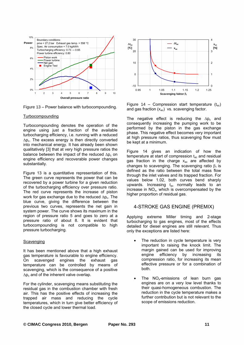
Turbocompounding
Turbocompounding denotes the operation of the engine using just a fraction of the available turbocharging efficiency, i.e. running with a reduced
Δpc. The excess energy is then directly converted into mechanical energy. It has already been shown qualitatively [3] that at very high pressure ratios the
balance between the impact of the reduced Δpc on engine efficiency and recoverable power changes substantially.
Figure 13 is a quantitative representation of this. The green curve represents the power that can be recovered by a power turbine for a given reduction of the turbocharging efficiency over pressure ratio. The red curve represents the increase of piston
work for gas exchange due to the reduced Δpc. The blue curve, giving the difference between the previous two curves, represents the net gain in system power. The curve shows its maximum in the region of pressure ratio 5 and goes to zero at a pressure ratio of about 8. It is evident that turbocompounding is not compatible to high pressure turbocharging.
Scavenging
It has been mentioned above that a high exhaust gas temperature is favourable to engine efficiency. On scavenged engines the exhaust gas temperature can be controlled by means of scavenging, which is the consequence of a positive
Δpc and of the inherent valve overlap.
For the cylinder, scavenging means substituting the residual gas in the combustion chamber with fresh air. This has the positive effects of increasing the trapped air mass and reducing the cycle temperatures, which in turn give better efficiency of the closed cycle and lower thermal load.
The negative effect is reducing the Δpc and consequently increasing the pumping work to be performed by the piston in the gas exchange phase. This negative effect becomes very important at high pressure ratios, thus scavenging flow must be kept at a minimum.
Figure 14 gives an indication of how the temperature at start of compression tac and residual gas fraction in the charge xac are affected by
changes to scavenging. The scavenging ratio βl is defined as the ratio between the total mass flow through the inlet valves and its trapped fraction. For values below 1.02, both curves bend sharply upwards. Increasing tac normally leads to an increase in NOx, which is overcompensated by the higher proportion of residual gas.
4-STROKE GAS ENGINE (PREMIX)
Applying extreme Miller timing and 2-stage turbocharging to gas engines, most of the effects detailed for diesel engines are still relevant. Thus only the exceptions are listed here:
• The reduction in cycle temperature is very important to raising the knock limit. The margin gained can be used for improving engine efficiency by increasing its compression ratio, for increasing its mean effective pressure or for a combination of both.
• The NOx-emissions of lean burn gas engines are on a very low level thanks to their quasi-homogeneous combustion. The reduction in the cycle temperature makes a further contribution but is not relevant to the scope of emissions reduction.
0%
2%
4%
6%
8%
10%
1 2 3 4 5 6 7 8 9 10
Overall pressure ratio
Power
Piston workPower turbineNet gainEngine Test
Boundary conditions:
pme = 27.2 bar Exhaust gas temp. = 558 °C
Spec. Air consumption = 7.0 kg/kWh
Turbocharging efficiency: 0.73 s 0.65
Power turbine efficiency: 0.80
Figure 13 – Power balance with turbocompounding.
-10
0
10
20
30
0.95 1 1.05 1.1 1.15 1.2 1.25
Scavenging faktor βl
Δtac
[°C]
0
1
2
3
4
xac
[%]
tac
xac
Δtac
xac
-10
0
10
20
30
0.95 1 1.05 1.1 1.15 1.2 1.25
Scavenging faktor βl
Δtac
[°C]
0
1
2
3
4
xac
[%]
tac
xac
Δtac
xac
Figure 14 – Compression start temperature (tac) and gas fraction (xac) vs. scavenging factor.
© CIMAC Congress 2010, Bergen Paper No. 293 12
• The highest levels of turbocharging efficiency are not available on gas engines because they need control of the air to fuel ratio. The turbocharging system must then be matched to a higher pressure ratio than needed at any stationary operating point (control margin). Depending on the choice of the control device, more or less turbocharging efficiency is destroyed.
Optimum pressure ratio
As for diesel engines (see Fig. 2) a variation in pressure ratio has been performed for a gas engine with atmospheric gas mixer (“premix”). The pressure ratio of the turbocharging system and the Miller effect were varied under constant mean effective pressure.
In doing this, the boundary conditions from Table 1 were maintained.
Table 3 : Boundary conditions for parameter variations.
single stage 2-stage
pme 24 bar 24 and 30 bar
Air excess ratio constant
Compression ratio
Adjusted for constant compression temperature
Valve timing late and early Miller
early Miller
Ignition timing constant
Turbocharging efficiency
Standard scalable characteristics derived from
existing components
Mixture cooling temperatures
Adjusted with 10°C margin against water condensation
It must be noted that with a constant air excess ratio and ignition timing, and with increasing compression ratio, firing pressure also increases along the curves. It is assumed here that the engine has a margin of safety to its mechanical limits.
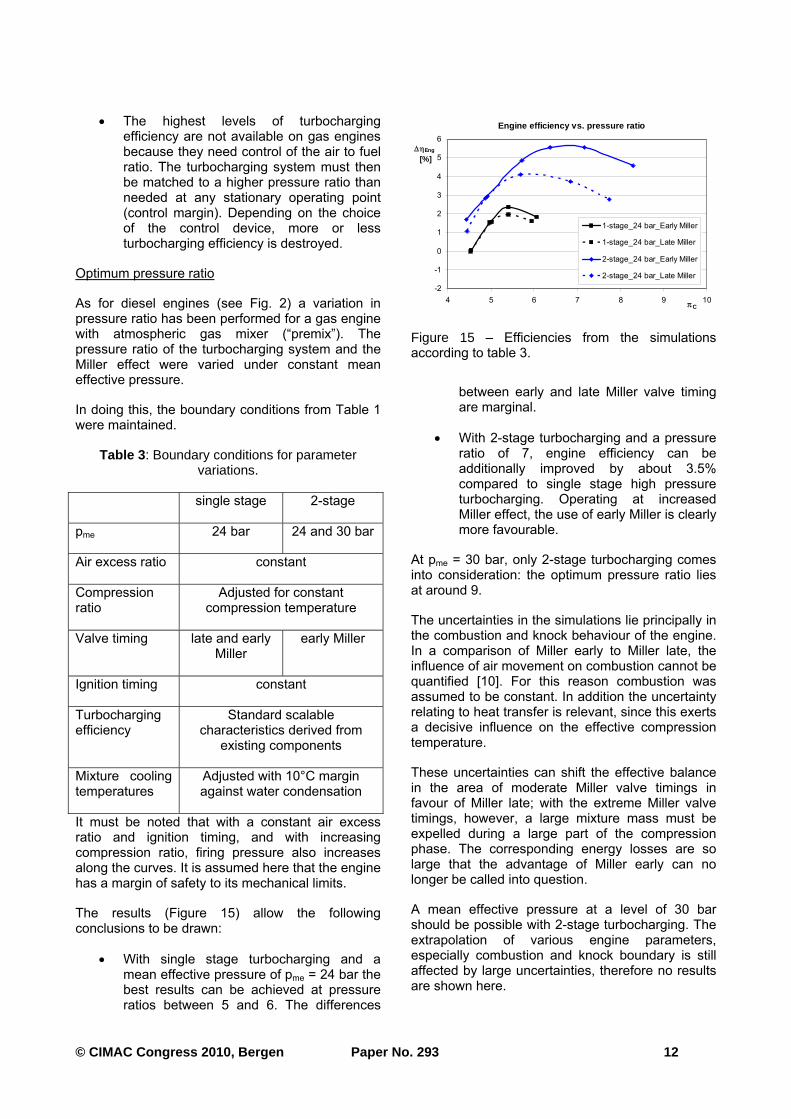
The results (Figure 15) allow the following conclusions to be drawn:
• With single stage turbocharging and a mean effective pressure of pme = 24 bar the best results can be achieved at pressure ratios between 5 and 6. The differences
between early and late Miller valve timing are marginal.
• With 2-stage turbocharging and a pressure ratio of 7, engine efficiency can be additionally improved by about 3.5% compared to single stage high pressure turbocharging. Operating at increased Miller effect, the use of early Miller is clearly more favourable.
At pme = 30 bar, only 2-stage turbocharging comes into consideration: the optimum pressure ratio lies at around 9.
The uncertainties in the simulations lie principally in the combustion and knock behaviour of the engine. In a comparison of Miller early to Miller late, the influence of air movement on combustion cannot be quantified [10]. For this reason combustion was assumed to be constant. In addition the uncertainty relating to heat transfer is relevant, since this exerts a decisive influence on the effective compression temperature.
These uncertainties can shift the effective balance in the area of moderate Miller valve timings in favour of Miller late; with the extreme Miller valve timings, however, a large mixture mass must be expelled during a large part of the compression phase. The corresponding energy losses are so large that the advantage of Miller early can no longer be called into question.
A mean effective pressure at a level of 30 bar should be possible with 2-stage turbocharging. The extrapolation of various engine parameters, especially combustion and knock boundary is still affected by large uncertainties, therefore no results are shown here.
Engine efficiency vs. pressure ratio
-2
-1
0
1
2
3
4
5
6
4 5 6 7 8 9 10πC
Eng
[%]
1-stage_24 bar_Early Miller
1-stage_24 bar_Late Miller
2-stage_24 bar_Early Miller
2-stage_24 bar_Late Miller
Figure 15 – Efficiencies from the simulations according to table 3.
© CIMAC Congress 2010, Bergen Paper No. 293 13
Gas engine control
Over a wide operating range the turbocharged diesel engine can only be controlled on the basis of
injected fuel, since it can function in a wide λV
window (air to fuel equivalence ratio). Gas engines, by contrast, always need control of gas quantity
and λV, i.e. charging pressure must usually be controlled.
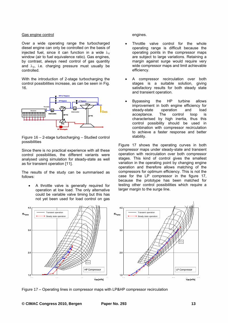
With the introduction of 2-stage turbocharging the control possibilities increase, as can be seen in Fig. 16.
Since there is no practical experience with all these control possibilities, the different variants were analysed using simulation for steady-state as well as for transient operation [11].
The results of the study can be summarised as follows:
• A throttle valve is generally required for operation at low load. The only alternative could be variable valve timing but this has not yet been used for load control on gas
engines.
• Throttle valve control for the whole operating range is difficult because the operating points in the compressor maps are subject to large variations. Retaining a margin against surge would require very wide compressor maps and limit achievable efficiency.
• A compressor recirculation over both stages is a suitable solution, giving satisfactory results for both steady state and transient operation.
• Bypassing the HP turbine allows improvement in both engine efficiency for steady-state operation and load acceptance. The control loop is characterised by high inertia, thus this control possibility should be used in combination with compressor recirculation to achieve a faster response and better stability.
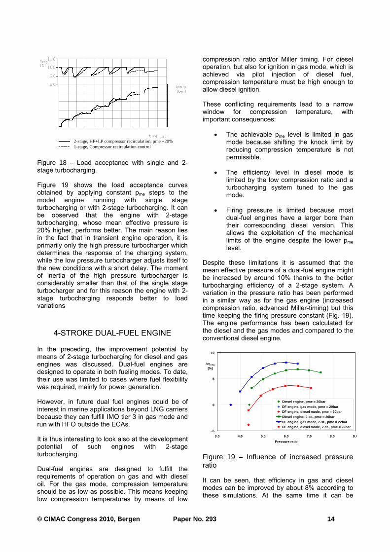
Figure 17 shows the operating curves in both compressor maps under steady-state and transient operation with recirculation over both compressor stages. This kind of control gives the smallest variation in the operating point by changing engine operation and therefore allows matching of the compressors for optimum efficiency. This is not the case for the LP compressor in the figure 17, because the prototype has been matched for testing other control possibilities which require a larger margin to the surge line.
Intercooler
HP Wastegate
LP Bypass
Intercooler
VCG
Throttle
Gas
HP Bypass
HP+LP Bypass
Receiver
VCG
VTG
HP TCLP TC
Intercooler
HP Wastegate
LP Bypass
Intercooler
VCG
Throttle
Gas
HP Bypass
HP+LP Bypass
Receiver
VCG
VTG
HP TCLP TC
Figure 16 – 2-stage turbocharging – Studied control possibilities
0.0 0.5 1.0 1.51.0
2.0
3.0
4.0
. V298 [m3/s]
πvtot/tot
η*sV
Transient operation
Steady state operation
HP Compressor
0.0 0.5 1.0 1.51.0
2.0
3.0
4.0
. V298 [m3/s]
πvtot/tot
η*sV
Transient operation
Steady state operation
HP Compressor
0.0 1.0 2.0 3.01.0
2.0
3.0
4.0
. V298 [m3/s]
πvtot/tot
η*sV
Transient operation
Steady state operation
LP Compressor
0.0 1.0 2.0 3.01.0
2.0
3.0
4.0
. V298 [m3/s]
πvtot/tot
η*sV
Transient operation
Steady state operation
LP Compressor
Figure 17 – Operating lines in compressor maps with LP&HP compressor recirculation
© CIMAC Congress 2010, Bergen Paper No. 293 14
Figure 19 shows the load acceptance curves obtained by applying constant pme steps to the model engine running with single stage turbocharging or with 2-stage turbocharging. It can be observed that the engine with 2-stage turbocharging, whose mean effective pressure is 20% higher, performs better. The main reason lies in the fact that in transient engine operation, it is primarily only the high pressure turbocharger which determines the response of the charging system, while the low pressure turbocharger adjusts itself to the new conditions with a short delay. The moment of inertia of the high pressure turbocharger is considerably smaller than that of the single stage turbocharger and for this reason the engine with 2-stage turbocharging responds better to load variations
4-STROKE DUAL-FUEL ENGINE
In the preceding, the improvement potential by means of 2-stage turbocharging for diesel and gas engines was discussed. Dual-fuel engines are designed to operate in both fueling modes. To date, their use was limited to cases where fuel flexibility was required, mainly for power generation.
However, in future dual fuel engines could be of interest in marine applications beyond LNG carriers because they can fulfill IMO tier 3 in gas mode and run with HFO outside the ECAs.
It is thus interesting to look also at the development potential of such engines with 2-stage turbocharging.
Dual-fuel engines are designed to fulfill the requirements of operation on gas and with diesel oil. For the gas mode, compression temperature should be as low as possible. This means keeping low compression temperatures by means of low
compression ratio and/or Miller timing. For diesel operation, but also for ignition in gas mode, which is achieved via pilot injection of diesel fuel, compression temperature must be high enough to allow diesel ignition.
These conflicting requirements lead to a narrow window for compression temperature, with important consequences:
• The achievable pme level is limited in gas mode because shifting the knock limit by reducing compression temperature is not permissible.
• The efficiency level in diesel mode is limited by the low compression ratio and a turbocharging system tuned to the gas mode.
• Firing pressure is limited because most dual-fuel engines have a larger bore than their corresponding diesel version. This allows the exploitation of the mechanical limits of the engine despite the lower pme level.
Despite these limitations it is assumed that the mean effective pressure of a dual-fuel engine might be increased by around 10% thanks to the better turbocharging efficiency of a 2-stage system. A variation in the pressure ratio has been performed in a similar way as for the gas engine (increased compression ratio, advanced Miller-timing) but this time keeping the firing pressure constant (Fig. 19). The engine performance has been calculated for the diesel and the gas modes and compared to the conventional diesel engine.
It can be seen, that efficiency in gas and diesel modes can be improved by about 8% according to these simulations. At the same time it can be
2-stage, HP+LP compressor recirculation, pme +20%1-stage, Compressor recirculation control
2-stage, HP+LP compressor recirculation, pme +20%1-stage, Compressor recirculation control
Figure 18 – Load acceptance with single and 2-stage turbocharging.
-5
0
5
10
3.0 4.0 5.0 6.0 7.0 8.0 9.0
Pressure ratio
eng
[%]
Diesel engine, pme = 26bar
DF engine, gas mode, pme = 20barDF engine, diesel mode, pme = 20bar
Diesel engine, 2-st., pme = 26bar
DF engine, gas mode, 2-st., pme = 22barDF engine, diesel mode, 2-st., pme = 22bar
Figure 19 – Influence of increased pressure ratio

© CIMAC Congress 2010, Bergen Paper No. 293 15
observed that the efficiency gap between the dual-fuel engine in diesel mode and the pure diesel engine can be reduced but not eliminated.
OUTLOOK
Engine tests are running with medium-speed diesel and high-speed gas engines using the newly developed 2-stage turbocharging system. The provisional results confirm to a large extent the expectations given by simulations.
Field test are scheduled for the second half of 2010. The results will provide a reference for fixing the boundary conditions for the first generation of 2-stage turbochargers from ABB. Extension to other engine types / sizes, as well as development of further turbocharger sizes, will follow depending on market demand.
It is expected that the introduction of more stringent emissions regulations in the coming years will produce very important changes in the large engine world. Solutions like SCR, EGR, Miller, wet technologies and dual-fuel engines are still under evaluation. All of them profit from the introduction of 2-stage turbocharging.
CONCLUSIONS
2-stage turbocharging systems for pressure ratio up to 8 and higher and turbocharging efficiencies in the area of 75% are under development at ABB Turbo Systems Ltd.
The analysis of component requirements shows that new components are required to be designed for this specific application.
Engine development potential with 2-stage turbocharging has been studied for different engine types and leads to the conclusion that 2-stage turbocharging will play an important role whatever the final engine configuration will be.
REFERENCES
[1] VDMA, 2008, Exhaust Emission Legislation, Diesel- and Gas engines, VDMA Engines and Systems, Frankfurt am Mein (D),
(www.vdma.org/engines)
[2] CIMAC, 2007, Turbocharging Efficiencies – Definitions and guidelines for measurement and calculation, Recommendation Nr. 27, Conseil International des Machines à Combustion, Frankfurt am Mein (D),
(www.cimac.com)
[3] Codan, E., Mathey, Ch. and Vögeli, S., 2009, Applications and Potentials of 2-stage Turbocharging, 14. Aufladetechnische Konferenz, Dresden (D).
[4] Neuenschwander, P., Thiele, M.and Haueisen, V., 2010, New turbochargers for more powerful engines running under stricter emissions regimes, 26
th CIMAC
World Congress in Bergen (N)
[5] Fitzky, G., Bothien, M., Zbinden, S., Codan, E. and Vögeli, S., 2010, Testing and Qualification of 2 Stage Turbocharging Systems, 9th International Conference on Turbochargers and Turbocharging, London
[6] Codan, E. and Mathey, Ch., 2007, Emissions – a new challenge for turbocharging, 25
th CIMAC World Congress
in Vienna, Austria
[7] Wik, Ch. and Hallbäck, B., 2007, Utilisation of 2-stage turbo charging as an emission reduction mean on a Wartsila 4-stroke medium-speed diesel engine, 25
th CIMAC
World Congress in Vienna, Austria
[8] Mathey, Ch., 2010, Variable valve timing – A necessity for future large diesel and gas engines, 26
th CIMAC World Congress in
Bergen (N)
[9] Codan, E., Bernasconi, S. and Born, H., 2010, IMO III emission regulation: Impact on the turbocharging system, 26
th CIMAC
World Congress in Bergen (N)
[10] Schutting, E., A. Neureiter, C. Fuchs, T. Schatzberger, M. Klell, H. Eichlseder and T. Kammerdiener, 2007, Miller- und Atkinson-Zyklus am aufgeladenen Dieselmotor, MTZ 06/2007, p. 480-485.
[11] Codan, E., Mathey, Ch. and Vögeli, S., 2008, Hochdruckaufladung bei Gasmotoren, 13. Aufladetechnische Konferenz, Dresden (D).
© CIMAC Congress 2010, Bergen Paper No. 293 16
Authors:
Ennio Codan
ABB Turbo Systems Ltd Department ZTA Bruggerstrasse 71a CH-5401 Baden Tel.: +41 58 585 40 64 Fax: +41 58 585 42 21 E-Mail: [email protected]
Christoph Mathey
ABB Turbo Systems Ltd Department ZVN-7 Bruggerstrasse 71a CH-5401 Baden Tel.: +41 58 585 57 54 Fax: +41 58 585 58 30 E-Mail: [email protected]
Adrian Rettig
ABB Turbo Systems Ltd Department ZTA-1 Bruggerstrasse 71a CH-5401 Baden Tel.: +41 58 585 27 49 Fax: +41 58 585 42 21 E-Mail: [email protected]
Related Documents