©2013 by NACE International. Requests for permission to publish this manuscript in any form, in part or in whole, must be in writing to NACE International, Publications Division, 1440 South Creek Drive, Houston, Texas 77084. The material presented and the views expressed in this paper are solely those of the author(s) and are not necessarily endorsed by the Association. Paper No. 3980 Standards for Evaluating Oil Field Corrosion Inhibitors in the Laboratory Sankara Papavinasam CorrMagnet Consulting Inc. 6, Castlemore Street Ottawa, Ontario, Canada, K2G 6K8 Email: [email protected] ABSTRACT The success of a corrosion inhibitor in controlling internal corrosion depends on (1) when the application of it has started, (2) efficiency of it, (3) interference of it with other chemicals and processes, and (4) presence of intact inhibitor film on the surface to be protected. Several standards and industry best practices are available to evaluate these properties. They include: ASTM (A) G170, “Standard Guide for Evaluating and Qualifying Oilfield and Refinery Corrosion Inhibitors in the Laboratory” ASTM G184, “Standard Practice for Evaluating and Qualifying Oil Field and Refinery Corrosion Inhibitors using Rotating Cage” ASTM G185, “Standard Practice for Evaluating and Qualifying Oil Field and Refinery Corrosion Inhibitors using Rotating Cylinder Electrode” ASTM G202, “Standard Test Method for Using Atmospheric Pressure Rotating Cage” ASTM G205, “Standard Guide for Determining Corrosivity of Crude Oils” ASTM G208, “Standard Practice for Evaluating and Qualifying Oil Field and Refinery Corrosion Inhibitors using Jet Impingement” NACE 1D182, “Wheel Test Method Used for Evaluation of Film-Persistent Corrosion Inhibitors for Oil Field Applications” NACE 1D196, “Laboratory Test Methods for Evaluating Oil Field Corrosion Inhibitors” European Federation of Corrosion (EFC) (B) , “Test Methods for Corrosion Inhibitors”, Working Party Report #11 (1985) EFC, “Corrosion Inhibitors for Oil and Gas Production”, Working Party Report #39, 2004 This paper describes these standards, explains hierarchy of standards, and provides guidelines to obtain reliable and relevant data on corrosion inhibitors from laboratory. Key words: corrosion inhibitors, standards, rotating cage, rotating cylinder electrode, jet impingement, wheel test, kettle test (A) ASTM International, 100 Barr Harbor Drive, PO Box C700, West Conshohocken, PA, 19428-2959, USA. (B) European Federation of Corrosion, Suite 1C, Joseph’s Well, Hanover Walk, Leeds, LS3 1AB, UK

Welcome message from author
This document is posted to help you gain knowledge. Please leave a comment to let me know what you think about it! Share it to your friends and learn new things together.
Transcript

©2013 by NACE International.Requests for permission to publish this manuscript in any form, in part or in whole, must be in writing toNACE International, Publications Division, 1440 South Creek Drive, Houston, Texas 77084.The material presented and the views expressed in this paper are solely those of the author(s) and are not necessarily endorsed by the Association.
Paper No.
3980
Standards for Evaluating Oil Field Corrosion Inhibitors in the Laboratory
Sankara Papavinasam
CorrMagnet Consulting Inc.
6, Castlemore Street
Ottawa, Ontario, Canada, K2G 6K8
Email: [email protected]
ABSTRACT
The success of a corrosion inhibitor in controlling internal corrosion depends on (1) when the
application of it has started, (2) efficiency of it, (3) interference of it with other chemicals and processes,
and (4) presence of intact inhibitor film on the surface to be protected. Several standards and industry
best practices are available to evaluate these properties. They include:
ASTM(A) G170, “Standard Guide for Evaluating and Qualifying Oilfield and Refinery Corrosion Inhibitors in
the Laboratory”
ASTM G184, “Standard Practice for Evaluating and Qualifying Oil Field and Refinery Corrosion Inhibitors
using Rotating Cage”
ASTM G185, “Standard Practice for Evaluating and Qualifying Oil Field and Refinery Corrosion Inhibitors
using Rotating Cylinder Electrode”
ASTM G202, “Standard Test Method for Using Atmospheric Pressure Rotating Cage”
ASTM G205, “Standard Guide for Determining Corrosivity of Crude Oils”
ASTM G208, “Standard Practice for Evaluating and Qualifying Oil Field and Refinery Corrosion Inhibitors
using Jet Impingement”
NACE 1D182, “Wheel Test Method Used for Evaluation of Film-Persistent Corrosion Inhibitors for Oil Field
Applications”
NACE 1D196, “Laboratory Test Methods for Evaluating Oil Field Corrosion Inhibitors”
European Federation of Corrosion (EFC)(B), “Test Methods for Corrosion Inhibitors”, Working Party Report
#11 (1985)
EFC, “Corrosion Inhibitors for Oil and Gas Production”, Working Party Report #39, 2004
This paper describes these standards, explains hierarchy of standards, and provides guidelines to obtain
reliable and relevant data on corrosion inhibitors from laboratory.
Key words: corrosion inhibitors, standards, rotating cage, rotating cylinder electrode, jet impingement,
wheel test, kettle test
(A)ASTM International, 100 Barr Harbor Drive, PO Box C700, West Conshohocken, PA, 19428-2959, USA. (B) European Federation of Corrosion, Suite 1C, Joseph’s Well, Hanover Walk, Leeds, LS3 1AB, UK

©2013 by NACE International.Requests for permission to publish this manuscript in any form, in part or in whole, must be in writing toNACE International, Publications Division, 1440 South Creek Drive, Houston, Texas 77084.The material presented and the views expressed in this paper are solely those of the author(s) and are not necessarily endorsed by the Association.
INTRODUCTION
Addition of corrosion inhibitors is a time-tested and proven methodology to control internal corrosion of
oil production infrastructures, transmission pipelines, and refineries1. Corrosion inhibitors are used to
control general corrosion, pitting corrosion, under-deposit corrosion (UDC), and top-of-the-line
corrosion (TLC). The ability of the inhibitors to control specific type of corrosion must be evaluated in
the laboratory before they can be used in the field.
Success of inhibitor in controlling internal corrosion depends on (1) when during the operation, the
application of it has started, (2) efficiency of it, (3) interference of it with other chemicals and processes,
and (4) presence of intact corrosion inhibitor film on the surface to be protected.
Industry normally assumes that corrosion conditions do not exist if the percentage of water is less than
30, i.e., percentage oil is 70 (or above) and water is 30 (or below). Under these conditions, corrosion
inhibitors are not normally applied. This practice, however, does not consider the properties of oil and
water phases. Field experiences have indicated that corrosion may occur even with 1% water or may not
occur even in the presence of 99% water. For this reason, the ability of crude oils and other
hydrocarbons (e.g., condensates) in inhibiting corrosion must be evaluated. ASTM G205 provides
guidelines to determine the ability of crude oils to inhibit corrosion based on three properties: emulsion
tendency, wettability, and influence of oil-phase on water-phase corrosivity2.
Efficiency of corrosion inhibitors depends on several parameters including flow, pressure, temperature,
as well as compositions of material (e.g. carbon steel), oil phase, water phase, and gas phase. Standards
and industry guidelines to evaluate the efficiency of corrosion inhibitors include ASTM G1843, ASTM
G1854, ASTM 2025, ASTM 2086, NACE 1D1827, NACE 1D1968, EFC WP Report #119, and EFC WP
Report #3910.
The corrosion must be compatible with other chemicals (e.g., biocides and scale inhibitors), must meet
environmental regulations, and must not cause any side effects (e.g., foaming and emulsion). ASTM
G170 describes several secondary corrosion inhibitor properties and laboratory methodologies to
evaluate them11.
Even the best corrosion inhibitor would fail, if it was not applied properly. For this reason, the inhibitor
must be properly applied so as to form intact film on the surface to be protected.
This paper describes standards to evaluate corrosion inhibitors, explains hierarchy of different standards,
and provides guidelines to obtain reliable and relevant data from the laboratory.
STANDARDS FOR PREDICTING CONDITIONS TO APPLY CORROSION INHIBITORS
For corrosion to take place, water (or any other conducting electrolyte) phase must be in contact with the
metallic surface. Corrosion may not take place, if the water is prevented from contacting with the
metallic surface. This situation occurs when the water is emulsified with oil or when the metallic
surface has greater affinity towards crude oil, i.e., oil-wet.
Crude oils cannot dissolve ionic water because of their non-polar nature. But they can form emulsion
with water. Type of emulsion and its stability depends on type of crude oil, composition of water,
operating pressure, temperature, and flow rate.
There are two kinds of emulsion: water-in-oil and oil-in-water. In water-in-oil emulsion, non-ionic
(non-conducting) oil is continuous phase in which ionic water is dispersed. Therefore, corrosion does

©2013 by NACE International.Requests for permission to publish this manuscript in any form, in part or in whole, must be in writing toNACE International, Publications Division, 1440 South Creek Drive, Houston, Texas 77084.The material presented and the views expressed in this paper are solely those of the author(s) and are not necessarily endorsed by the Association.
not occur in the presence of water-in-oil. On the other hand, ionic (conducting) water is continuous
phase in oil-in-water emulsion. Therefore, corrosion can occur in the presence of oil-in-water. The
percentage of water at which water-in-oil emulsion inverts into oil-in-water is known as “emulsion
inversion point (EIP)”2. The EIP depends on several parameters including the physical interactions
between oil and water phases, constituents of oil and water phases, flow velocity, and pipeline profile.
ASTM G205 describes a methodology to determine the EIP under atmospheric pressure conditions
(Fig.1)2. This methodology measures the conductivity of the emulsion under flowing conditions to
determine the type of emulsion. Though the EIP apparatus can be operated at elevated pressure
conditions, ASTM G205 does not provide guidelines for performing tests at high-pressure conditions.
Probability of corrosion in the presence of oil-in-water emulsion or free water depends on the
wettability. When oil phase preferentially wets the surface (oil-wet), corrosion does not take place;
when water phase preferentially wets the surface (water-wet), corrosion takes place; and when no phase
preferentially wets the surface (mixed-wet), corrosion may or may not take place.
ASTM G205 describes two methodologies to determine the wettability: contact angle method and
spreading method. Figure 2 presents a schematic diagram of the spreading method2. This methodology
measures conductivity between two steel pins to determine the wettability of the surface. The test can
be carried out both under atmospheric and elevated pressure conditions.
Contact angle method is extensively used to determine the wettability of various liquids both on metallic
and on non-metallic surfaces. During contact angle measurement, oil and water may be added in two
sequences: oil-first, water-next sequence or water-first, oil-next sequence. The first sequence represents
the case of oil transmission pipelines but measuring contact angle using this sequence is relatively
difficult. Due to the dark background of the oil, the apparatus should be illuminated. For this reason,
the contact angle is normally measured following water-first, oil-next sequence. However, this sequence
does not truly represent oil transmission pipeline operating conditions. Further, the contact angle
method cannot be easily used under elevated pressure conditions.
The spreading method overcomes these difficulties. However, boundary to differentiate different
wettability, i.e., oil-wet, water-wet, and mixed-wet, is arbitrary. Though the apparatus can be operated
at elevated pressures, procedures to carry out tests under flow conditions are not described in ASTM
G205.
It should be pointed out that emulsion and wettability are two different properties. The emulsion
depends on the interaction between two phases: water phase and oil phase whereas wettability depends
on three phases: water phase, oil phase, and solid phase (e.g., pipeline steel). For these reasons, a crude
oil may have high EIP, i.e., may hold water in the water-in-oil phase, but as soon as the EIP is exceeded,
water may drop out and wet the surface. On the other hand, the crude oil may have low EIP, i.e., water
drops out of emulsion at low concentration, but metallic surface may continue to be oil-wet.
In the presence of oil-in-water emulsion or in the presence of free water phase, on a water-wet surface,
corrosion may take place. The crude oil phase surrounding the water phase may influence corrosion rate
by partitioning water-soluble species (Fig.3)2:
If the water soluble species in oil phase is inhibitory in nature, then corrosivity of the aqueous phase
would be less than that observed in the absence of oil phase. Under this condition, addition of
corrosion inhibitor may not be necessary.

©2013 by NACE International.Requests for permission to publish this manuscript in any form, in part or in whole, must be in writing toNACE International, Publications Division, 1440 South Creek Drive, Houston, Texas 77084.The material presented and the views expressed in this paper are solely those of the author(s) and are not necessarily endorsed by the Association.
If there is no water soluble species in present in the oil phase or the water soluble species does not
have any influence of corrosivity of aqueous phase, then corrosivity of aqueous phase would be
unaffected by the presence of oil phase. Under this condition addition of corrosion inhibitors may be
necessary.
If the water soluble species in oil phase is corrosive in nature, then the corrosivity of the aqueous
phase would be more than that observed in the absence of oil phase. Under this condition the
addition of corrosion inhibitors is necessary.
STANARDS FOR DETERMINING CORROSION INHIITOR EFFICIENCY
One of the primary criteria for selecting a chemical as corrosion inhibitor is its efficiency to control
corrosion. Several laboratory methodologies are available for determining the efficiency of corrosion
inhibitors.
Based on the comparison of laboratory and field data, a study ranked rotating cage (Fig. 4) as the most
appropriate methodology to simulate field operating conditions12. This study found that the rotating
cage simulated both general as well as localized pitting corrosion observed in the field.
The method uses a well-defined rotating cage setup and determines the corrosion rates from mass loss
measurements. ASTM Standard Practice G184 provides step-by-step procedures for evaluating
corrosion inhibitor efficiency in a rotating cage apparatus3. Separate procedures for conducting the tests
at atmospheric pressure and elevated pressure are provided in the standard.
ASTM G202 presents detailed procedure for conducting rotating cage test at atmospheric pressure. As
part of developing this standard, ASTM coordinated round robin tests. Ten laboratories from Canada,
India, USA, and Venezuela participated. All ten laboratories conducted the tests using rotating cage
manufactured to the same specification, at same operating conditions, and for same duration of time.
Each laboratory repeated the tests at least four times. Based on statistical analysis of more than 400 data
points, ASTM established uninhibited general corrosion rate of carbon steel as 23 + 2 mpy (0.58 + 0.05
mm/y)5.
Rotating cylinder electrode (RCE) uses a well-defined rotating specimen setup and mass loss and/or
electrochemical measurements to determine corrosion rates. Measurements can be made at a number of
rotation rates to evaluate the inhibitor performance under increasingly severe hydrodynamic conditions.
ASTM Standard Practice G185 provides detailed step-by-step procedures for evaluating corrosion
inhibitor efficiency in a RCE apparatus (Fig.5)4. Separate procedures for conducting the tests at
atmospheric pressure and elevated pressure are provided in the standard.
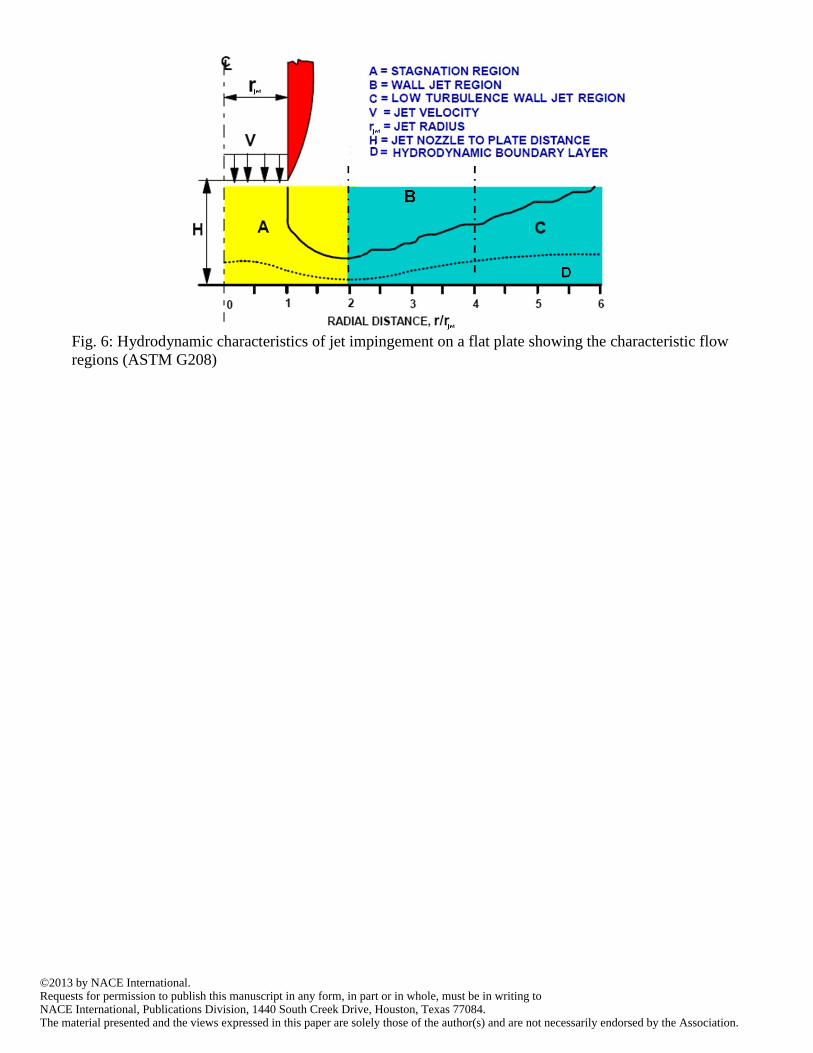
Jet impingement (JI) uses a well-defined impinging jet set up and mass loss and/or electrochemical
measurements to determine corrosion rates. Figure 6 presents schematic diagram of flow pattern in a JI
apparatus6. There are three different designs of JI. ASTM Standard Practice G208 describes details of
these three designs and provides procedures for evaluating corrosion inhibitor efficiency in a JI
apparatus.
Kettle (bubble) and wheel tests are used to evaluate corrosion inhibitor efficiency under low or no flow
conditions. NACE report 1D196 describes procedures to carry out the kettle (bubble) and wheel tests.
During the development of 1D196, NACE coordinated round-robin tests using kettle and wheel tests8.
Most repeated ranking of three inhibitors was obtained in 5 out of the 9 laboratories for the wheel test
and by 6 out of the 8 laboratories for kettle test. These results indicate that better reproducibility was

©2013 by NACE International.Requests for permission to publish this manuscript in any form, in part or in whole, must be in writing toNACE International, Publications Division, 1440 South Creek Drive, Houston, Texas 77084.The material presented and the views expressed in this paper are solely those of the author(s) and are not necessarily endorsed by the Association.
obtained in the kettle test (75% reproducibility) than the wheel test (55% reproducibility). NACE report
1D182 presents additional procedures for performing wheel test.7
EFC working party reports describe wheel test, bubble test, RCE, flow loop, jet impingement, and
rotating cage methodologies to evaluate corrosion inhibitor efficiency.9, 10 These report suggest bubble
tests for preliminary screening, and RCE, flow loop, rotating cage, and jet impingement methodologies
for final evaluation of corrosion inhibitors.
STANDARDS FOR EVALAUTING SECONDARY CORROSION INHIBITOR PROPERTIES
Several other properties (commonly known as secondary inhibitor properties) are evaluated, before a
chemical is used in the field as corrosion inhibitor. These properties include water/oil partitioning,
solubility, emulsification tendency, foam tendency, thermal stability, toxicity, and compatibility with
other additives/materials. ASTM Standard G170 describes methodologies and procedures to evaluate
these properties11. NACE Task group 330 is currently developing another report for providing
guidelines to evaluate secondary properties of corrosion inhibitors.
STANDARDS FOR ELUSIDATING INHIBITOR AVAILABLITY
It is important to ensure that the inhibitor reaches the surface where corrosion takes place and forms
protective film on it. This may not happen for several reasons; some of which are described in the
following paragraphs.
Inhibitor film may not adequately form on the surface due to “logistic issues”, e.g., improper working of
inhibitor injection pumps, inhibitor tank is not timely refilled, etc. No laboratory methodologies can be
developed to provide solutions for logistic issues. They can only be overcome by implementing
appropriate best practices in the field. Papers describing some industry best practices to overcome
logistics issues are available3-15.
There are at least two types of corrosion mechanisms for which traditional methods of applying
corrosion inhibitors would not ensure intact inhibitor film on the surface where corrosion takes place.
They are “top-of-the line corrosion (TLC) and under-deposit corrosion (UDC). Though several
laboratory methodologies have been developed, none of them adequately simulate the field conditions16-
20. Consequently, no consensus standard for evaluating corrosion inhibitors to control TLC and UDC
currently exists; however, NACE TG 380 is currently developing a standard for simulating UDC.
HIERARCHY OF STANDARDS
Standards are developed by technical associations, such as NACE International, when practical
knowledge has sufficiently matured and when the industry, regulatory body, and other stakeholders
require them. Standards are developed so that methodologies/best practices can be uniformly adopted
and implemented throughout the industry.
Standards are developed based on inputs and participation of many people who are knowledgeable of
subject matter. They are mutually agreed upon minimum procedures/best practices with which
suppliers, users, producers, third-party laboratories, academicians, and scientists are comfortable. They
are based on the current state of knowledge on a particular subject matter. Standards have a fixed
lifetime, i.e., they must be reapproved periodically (typically every 4, 5, 7, or 10 years).

©2013 by NACE International.Requests for permission to publish this manuscript in any form, in part or in whole, must be in writing toNACE International, Publications Division, 1440 South Creek Drive, Houston, Texas 77084.The material presented and the views expressed in this paper are solely those of the author(s) and are not necessarily endorsed by the Association.
Standards may be developed under various categories. With respect to inhibitor evaluation there are
three categories of standards:
Test Method (Gold)
Standard Practice (Silver)
Guide or Report (Bronze)
Table 1 presents various categories of standards available to evaluate corrosion inhibitors in the
laboratory.
Test Methods (Gold) are the highest level of standards. They provide clear direction for using a
methodology, step-by-step procedure, conditions of using the standard, and, more importantly,
anticipated test result, i.e., the user must reproduce the anticipated results to demonstrate that they met
the requirements of the standard. The anticipated results are determined based on round-robin tests
conducted in several laboratories. The round-robin tests are completed before the Standard Test Method
is published or within a short-duration after the standard is first published.
The Standard Test Methods present “repeatability” value, i.e., what is the variation in the result if the
same operator repeats the same test following the same procedure. Normally four independent test data
are used to establish the “repeatability.
The Standard Test Methods also present “reproducibility” value, i.e., what is the variation in the result if
different operators repeat the same test following the same procedure. Normally the reproducibility
value is higher than the repeatability value, i.e., variation of the results is high when different operators
are involved. For example, the uninhibited corrosion rate of (carbon steel in CO2 saturated brine
solution) 23 + 2 mpy (0.58 + 0.05 mm/y) presented in ASTM G202 is the reproducibility data. This
data confirms that the reliable test data can be produced using rotating cage by different operators.
Because the corrosion rate in uninhibited conditions has been established in ASTM G202 Test Method,
the users may simply specify a two-step procedure for evaluating corrosion inhibitors in commercial
(third party) laboratories:
Ensure that the ASTM G202 baseline general corrosion rate of 23 + 2 mpy (0.58 + 0.05 mm/y) is
obtained under uninhibited conditions
Identify an inhibitor that produces “XX%” of efficiency at “XX” ppm concentration with respect to
the ASTM G202 baseline general corrosion rate.
It should be noted that the uninhibited general corrosion rate may vary if the conditions prescribed in the
ASTM G202 are changed. Under this condition, the user may change the requirements as follows:
Ensure that the ASTM G202 baseline general corrosion rate of 23 + 2 mpy (0.58 + 0.05 mm/y) is
obtained under uninhibited conditions (This step may be used to qualify the laboratory, personnel,
and apparatus)
Repeat the test using the modified conditions prescribed
Identify an inhibitor that produces “XX%” of efficiency at “XX” ppm concentration when tested
under modified condition.
Standard Practices (Silver) present specific aspects of a methodology, step-by-step procedures to
conduct tests using the methodology, and specific limitations of the methodology. However they do
not provide anticipated results, i.e., the user of the standard should determine if all aspects of the
standard are properly and adequately followed.

©2013 by NACE International.Requests for permission to publish this manuscript in any form, in part or in whole, must be in writing toNACE International, Publications Division, 1440 South Creek Drive, Houston, Texas 77084.The material presented and the views expressed in this paper are solely those of the author(s) and are not necessarily endorsed by the Association.
Guides or Reports (Bronze) are just state-of-the-art documents providing general guidelines on various
aspects of the methodologies. They present general aspects of a methodology, general procedures to
conduct test using the methodology, and general limitations of the methodology.
SUMMARY
1. Standards for evaluating corrosion inhibitors in the laboratory have been reviewed.
2. The hierarchy of various standards has been presented.
3. ASTM G202 on rotating cage methodology is currently the top-level (Gold) standard for evaluating
the efficiency of corrosion inhibitors for oil field application.
4. Using ASTM G202 standard the most reliable corrosion inhibitor to control internal general and
pitting corrosion can be selected.
5. Currently no Standard Test Method is available for any other laboratory methodologies to evaluate
efficiency of corrosion inhibitors.
6. Currently no standard is available to evaluate corrosion inhibitors to control top-of-the line corrosion
and underdeposit corrosion.
REFERENCES
1. S. Papavinasam, “Corrosion Control in the Oil and Gas Industry”, Chapter 7, Elsevier, ISBN:
9780123970220, Oct. 28, 2013.
2. ASTM G205, “Standard Guide for Determining Corrosivity of Crude Oils”, ASTM International,
West Conshohocken, PA.
3. ASTM G 184, “Standard Practice for Evaluating and Qualifying Oil field and Refinery Corrosion
Inhibitors using Rotating Cage”, ASTM International, West Conshohocken, PA.
4. ASTM G185, “Standard Practice for Evaluating and Qualifying Oil field and Refinery Corrosion
Inhibitors using Rotating Cylinder Electrode”, ASTM International, West Conshohocken, PA..
5. ASTM G202, “Standard Test Method for Using Atmospheric Pressure Rotating Cage”, ASTM
International, West Conshohocken, PA.
6. ASTM G208, “Standard Practice for Evaluating and Qualifying Oil field and Refinery Corrosion
Inhibitors using Jet Impingement Apparatus”, ASTM International, West Conshohocken, PA.
7. NACE Task Group T-1D-8 Technical Committee Report, Wheel Test Method Used for Evaluation
of Film Persistent Inhibitors for Oil Field Applications, NACE Publication 1D182, December 1982.
8. NACE Task Group T-1D-34 Technical Committee Report, Laboratory Test Methods for Evaluating
Oil field Corrosion Inhibitors, NACE Publication 1D196, December 1996.
9. European Federation of Corrosion Working Party on Inhibitors, Report #11 Test Methods for
Corrosion Inhibitors, British Corrosion Journal, 20 (2), 1985, p. 61.
10. European Federation of Corrosion Working Party on Corrosion Inhibitors for Oil and Gas
Production, Report #39, 2004.
11. ASTM G170, “Standard Guide for Evaluating and Qualifying Oil field and Refinery Corrosion
Inhibitors in the Laboratory”, ASTM International, West Conshohocken, PA.
12. S. Papavinasam, R.W. Revie, M. Attard, A. Demoz, and K. Michaelian, Comparison of Laboratory
Methodologies to Evaluate Corrosion Inhibitors for Oil and Gas Pipelines, Corrosion, 59 (10), 2003,
p. 897.
13. B. Hedges, D. Paisley, R. C. Woollam, "The Corrosion Inhibitor Availability Model", CORROSION
2000, Paper # 34, NACE International, Houston, Texas, USA (2000).
14. D. I. Horsup, J. C. Clark, B.P. Binks, and P.D.I. Fletcher, “I put it in, where does it go?” – Fate of
Corrosion Inhibitors in Multiphase Systems”, CORROSION 2007, Paper #7617, NACE
International, Houston, Texas, USA (2007).
15. M.J.J.S. Thomas, “Corrosion Inhibitor Selection – Feedback from the Field”, CORROSION 2000,
Paper #0056, NACE International, Houston, Texas, USA (2000).

©2013 by NACE International.Requests for permission to publish this manuscript in any form, in part or in whole, must be in writing toNACE International, Publications Division, 1440 South Creek Drive, Houston, Texas 77084.The material presented and the views expressed in this paper are solely those of the author(s) and are not necessarily endorsed by the Association.
16. J. Vera, “Under Deposit Corrosion (UDC) in the Oil and Gas Industry: A Review of Mechanisms
Testing, and Mitigation”, CORROSION 2012, Paper # 01379, NACE International, Houston, Texas
(2012).
17. J. Been, T.D. Place, B. Crozier, M. Mosher, A. Teeter, J. Soderberg, C. Cathrea, M. Holm, D.
Archibald, “Development of a Test Protocol for the Evaluation of Underdeposit Corrosion Inhibitors
in Large Diameter Crude Oil Pipelines”, CORROSION 2011, Paper #11263, NACE International,
Texas, USA (2011).
18. A. Turnbull, G. Hinds, P. Cooling, S. Zhou “A Multi-Electrode Approach to Evaluating Inhibition of
Underdeposit Corrosion in CO2 Environments”, CORROSION 2009, Paper #09445, NACE
International, Texas, USA (2009).
19. Y. Gunaltum, U. Kaewpradap, and M. Singer, and S. Nesic, “Progress in the prediction of top of the
line corrosion and challenges to predict corrosion rates measured in gas pipelines”, CORROSION
2010, Paper #10093, NACE International, Texas, USA (2010).
20. R. Nyborg and A. Dugstad, “Top-of-the line corrosion and water condensation rates in wet gas
pipelines, CORROSION 2007, Paper #7555, NACE International, Texas, USA (2007).
TABLE 1: Categories of Standards to Evaluate Corrosion Inhibitors in the Laboratory
Evaluation of Application Standard category
Report/Guide
(Bronze)
Practice
(Silver)
Test Method
(Gold)
Conditions to add
corrosion inhibitor
To control general
and pitting
corrosion ASTM G205
Inhibitor
efficiency
To control general
and pitting
corrosion
NACE 1D182
NACE 1D196
EFC WPR 11
EFC WPR 39
ASTM G184
ASTM G185
ASTM G208
ASTM G202
Secondary
inhibitor
properties
To avoid side
effects from
adding corrosion
inhibitors
ASTM G170
Inhibitor
availability
To control top-of-
the-line corrosion
and under-deposit
corrosion
No standard is currently available

©2013 by NACE International.Requests for permission to publish this manuscript in any form, in part or in whole, must be in writing toNACE International, Publications Division, 1440 South Creek Drive, Houston, Texas 77084.The material presented and the views expressed in this paper are solely those of the author(s) and are not necessarily endorsed by the Association.
Fig. 1: Schematic Diagram of the Experimental Section of Emulsion Inversion Point Apparatus (ASTM
G205)
Fig. 2: Schematic Diagram of an Apparatus to Determine Wettability by Spreading Method

©2013 by NACE International.Requests for permission to publish this manuscript in any form, in part or in whole, must be in writing toNACE International, Publications Division, 1440 South Creek Drive, Houston, Texas 77084.The material presented and the views expressed in this paper are solely those of the author(s) and are not necessarily endorsed by the Association.
Fig. 3: Flow Chart to Determine the Condition to Apply Corrosion Inhibitor (ASTM G205)
(Addition of corrosion inhibitors may not be necessary in the presence of preventive and inhibitor
hydrocarbons but is necessary in the presence of neutral and corrosive hydrocarbons)
Fig. 4: Rotating Cage (ASTM G184)

©2013 by NACE International.Requests for permission to publish this manuscript in any form, in part or in whole, must be in writing toNACE International, Publications Division, 1440 South Creek Drive, Houston, Texas 77084.The material presented and the views expressed in this paper are solely those of the author(s) and are not necessarily endorsed by the Association.
FIG.5: Schematic of a High-Temperature, High-Pressure RCE System: 1. Electrical Contact Unit; 2.
Techometer (Rotation Speed Display) ; 3. Rotation controller; 4. Electrochemical Instruments; 5.
Rotating electrode units (working electrode); 6. Reference Electrode; 7. Water Cooler Coil; 8. Inlet
(Gases and Solution); 9. Thermocouple; 10. Outlet (Gases and Solutions); 11. Counter Electrode; 12.
Autoclave Body; 13. Solution; and 14. TFE-fluorocarbon Liner (ASTM G185).
©2013 by NACE International.Requests for permission to publish this manuscript in any form, in part or in whole, must be in writing toNACE International, Publications Division, 1440 South Creek Drive, Houston, Texas 77084.The material presented and the views expressed in this paper are solely those of the author(s) and are not necessarily endorsed by the Association.
Fig. 6: Hydrodynamic characteristics of jet impingement on a flat plate showing the characteristic flow
regions (ASTM G208)
Related Documents