Ultrasound assisted synthesis of Mn 3 O 4 nanoparticles anchored graphene nanosheets for supercapacitor applications Balasubramaniam Gnana Sundara Raj a , Rajasekharan Nair Radhika Ramprasad a , Abdullah M. Asiri b , Jerry J Wu c , Sambandam Anandan a, * a Nanomaterials and Solar Energy Conversion Lab Department of Chemistry, National Institute of Technology, Trichy 620 015, India b The Center of Excellence for Advanced Materials Research, King Abdulaziz University, Jeddah 21413, P.O. Box 80203, Saudi Arabia c Department of Environmental Engineering and Science, Feng Chia University, Taichung 407, Taiwan A R T I C L E I N F O Article history: Received 10 October 2014 Received in revised form 10 December 2014 Accepted 12 January 2015 Available online 13 January 2015 Keywords: Ultrasound Mn 3 O 4 nanoparticles Graphene nanosheets Nanocomposite Supercapacitors A B S T R A C T Mn 3 O 4 nanoparticles anchored graphene nanosheets (MG) have been successfully synthesized by a simple ultrasound assisted synthesis at room temperature without the use of any templates or surfactants for supercapacitor applications. Upon ultrasound assisted synthesis, the formation of Mn 3 O 4 nanoparticles and the graphene oxide reduction occurs simultaneously. The crystalline structure of thus prepared MG nanocomposite have been characterized by the powder X-ray diffraction (XRD) analysis. Thermo Gravimetric Analysis (TGA) is used to determine the mass content of graphene (17 wt%) in the MG nanocomposite. Transmission electron microscopy (TEM) and Atomic force microscopy (AFM) studies shows that the Mn 3 O 4 nanoparticles (4–8 nm) were uniformly anchored on the surface of graphene nanosheets. The electrochemical properties of the MG nanocomposite were investigated by employing cyclic voltammetry (CV), galvanostatic charge-discharge and electrochemical impedance spectroscopy (EIS). The capacitive properties of MG nanocomposite studied in the presence of 1 M Na 2 SO 4 exhibited high specific capacitance of 312 F g 1 which was approximately three times greater than that of pristine Mn 3 O 4 (113 F g 1 ) at the same current density of 0.5 mA cm 2 in the potential range from -0.1 to +0.9 V. About 76% of the initial capacitance was retained even after 1000 cycles establishes the fact that MG nanocomposite exhibited good electrochemical stability and capacitance retention capability also. ã 2015 Elsevier Ltd. All rights reserved. 1. Introduction Metal oxide nano particles due to their versatile structural properties leading to a wide variety of nano architectures finds innumerable applications in catalysis [1], energy storage devices [2], fuel cells [3], degradation and absorption of dyes [4] and even removal of heavy metal ions from real water samples [5]. Due to the depleting energy sources all around the world, the energy storage applications of metal oxides have been vastly investigated by the scientific community. Even though several electrochemical energy storage and consumption devices were developed in the past decades such as lithium ion batteries, supercapacitors and fuel cells etc, supercapacitors separate among them with their amazing properties like enormous charge–discharge in seconds and ability to store huge power density in an astounding low cost of manufacture have various potential applications in hybrid electrical vehicles, new generation electronic devices and power back up systems [6,7]. Classifications based on their ability of charge - storage mechanisms the supercapacitors have been categorized into two types namely –electrical double layer capacitors (EDLCs) and pseudo capacitors [8]. Carbon materials with their astonishing speed of absorption/desorption of electro- lyte ions on their surface serves the purpose of electrode in electrical double layer capacitors [9,10], while faradic electron transfer process enables the storage of the charge and their release on pseudo capacitors by the means of conducting polymers and metal oxides [11–15]. Conducting polymers had been extensively studied for the fabrication of supercapacitors but the major disadvantage of it is the poor cycling performance due to continuous charge–discharge process [16]. To overcome these difficulties, different metal oxides have been investigated for the successful replacement of conducting polymers as the alternative electrode material for supercapacitors. This will increase the specific capacitance by the rate of charge- discharge process with a better cycling performance and in addition enhance the energy density. * Corresponding author. Tel.: +91 431 2503639; fax: +91 431 2500133. E-mail addresses: [email protected], [email protected] (S. Anandan). http://dx.doi.org/10.1016/j.electacta.2015.01.052 0013-4686/ ã 2015 Elsevier Ltd. All rights reserved. Electrochimica Acta 156 (2015) 127–137 Contents lists available at ScienceDirect Electrochimica Acta journa l home page : www.e lsevier.com/loca te/ele cta cta

Welcome message from author
This document is posted to help you gain knowledge. Please leave a comment to let me know what you think about it! Share it to your friends and learn new things together.
Transcript

Electrochimica Acta 156 (2015) 127–137
Ultrasound assisted synthesis of Mn3O4 nanoparticles anchoredgraphene nanosheets for supercapacitor applications
Balasubramaniam Gnana Sundara Raj a, Rajasekharan Nair Radhika Ramprasad a,Abdullah M. Asiri b, Jerry J Wuc, Sambandam Anandan a,*aNanomaterials and Solar Energy Conversion Lab Department of Chemistry, National Institute of Technology, Trichy 620 015, Indiab The Center of Excellence for Advanced Materials Research, King Abdulaziz University, Jeddah 21413, P.O. Box 80203, Saudi ArabiacDepartment of Environmental Engineering and Science, Feng Chia University, Taichung 407, Taiwan
A R T I C L E I N F O
Article history:Received 10 October 2014Received in revised form 10 December 2014Accepted 12 January 2015Available online 13 January 2015
Keywords:UltrasoundMn3O4 nanoparticlesGraphene nanosheetsNanocompositeSupercapacitors
A B S T R A C T
Mn3O4 nanoparticles anchored graphene nanosheets (MG) have been successfully synthesized by asimple ultrasound assisted synthesis at room temperature without the use of any templates orsurfactants for supercapacitor applications. Upon ultrasound assisted synthesis, the formation of Mn3O4
nanoparticles and the graphene oxide reduction occurs simultaneously. The crystalline structure of thusprepared MG nanocomposite have been characterized by the powder X-ray diffraction (XRD) analysis.Thermo Gravimetric Analysis (TGA) is used to determine the mass content of graphene (17 wt%) in the MGnanocomposite. Transmission electron microscopy (TEM) and Atomic force microscopy (AFM) studiesshows that the Mn3O4 nanoparticles (4–8 nm) were uniformly anchored on the surface of graphenenanosheets. The electrochemical properties of the MG nanocomposite were investigated by employingcyclic voltammetry (CV), galvanostatic charge-discharge and electrochemical impedance spectroscopy(EIS). The capacitive properties of MG nanocomposite studied in the presence of 1 M Na2SO4 exhibitedhigh specific capacitance of 312 F g�1 which was approximately three times greater than that of pristineMn3O4 (113 F g�1) at the same current density of 0.5 mA cm�2 in the potential range from -0.1 to +0.9 V.About 76% of the initial capacitance was retained even after 1000 cycles establishes the fact that MGnanocomposite exhibited good electrochemical stability and capacitance retention capability also.
ã 2015 Elsevier Ltd. All rights reserved.
Contents lists available at ScienceDirect
Electrochimica Acta
journa l home page : www.e l sev ier .com/ loca te /e le cta cta
1. Introduction
Metal oxide nano particles due to their versatile structuralproperties leading to a wide variety of nano architectures findsinnumerable applications in catalysis [1], energy storage devices[2], fuel cells [3], degradation and absorption of dyes [4] and evenremoval of heavy metal ions from real water samples [5]. Due tothe depleting energy sources all around the world, the energystorage applications of metal oxides have been vastly investigatedby the scientific community. Even though several electrochemicalenergy storage and consumption devices were developed in thepast decades such as lithium ion batteries, supercapacitors and fuelcells etc, supercapacitors separate among them with their amazingproperties like enormous charge–discharge in seconds and abilityto store huge power density in an astounding low cost ofmanufacture have various potential applications in hybrid
* Corresponding author. Tel.: +91 431 2503639; fax: +91 431 2500133.E-mail addresses: [email protected], [email protected] (S. Anandan).
http://dx.doi.org/10.1016/j.electacta.2015.01.0520013-4686/ã 2015 Elsevier Ltd. All rights reserved.
electrical vehicles, new generation electronic devices and powerback up systems [6,7]. Classifications based on their ability ofcharge - storage mechanisms the supercapacitors have beencategorized into two types namely –electrical double layercapacitors (EDLCs) and pseudo capacitors [8]. Carbon materialswith their astonishing speed of absorption/desorption of electro-lyte ions on their surface serves the purpose of electrode inelectrical double layer capacitors [9,10], while faradic electrontransfer process enables the storage of the charge and their releaseon pseudo capacitors by the means of conducting polymers andmetal oxides [11–15]. Conducting polymers had been extensivelystudied for the fabrication of supercapacitors but the majordisadvantage of it is the poor cycling performance due tocontinuous charge–discharge process [16]. To overcome thesedifficulties, different metal oxides have been investigated for thesuccessful replacement of conducting polymers as the alternativeelectrode material for supercapacitors. This will increase thespecific capacitance by the rate of charge- discharge process with abetter cycling performance and in addition enhance the energydensity.

128 B.G.S. Raj et al. / Electrochimica Acta 156 (2015) 127–137
Transition metal oxides have multiple oxidation states and theirsimultaneous existence for considerably long potential rangewithout any phase transitions, the versatility to accommodateprotons in their lattice positions during reduction process makes itis a potential candidate for electrode materials in supercapacitors[17]. Ruthenium oxide have been widely synthesized and vastlyexploited because of its outstanding specific capacitance, electricalconductivity and good chemical stability. In spite of its high specificcapacitance (720 F g�1), it has limited practical applications due tohigh cost of manufacturing and toxic effects [18]. Mean while thecurrent research works focus on utilizing the capacitanceproperties of comparatively low cost transition metal oxides likeNiO [19], Co3O4 [20], MnO2 [21] and Mn3O4 [22]. Manganeseoxides, which were believed to be a successful replacement forRuO2, because of its low cost synthesis and comparatively highspecific capacitance generation due to its capability to exist inseven different crystalline forms having Mn in different oxidationstates such as Mn2+, Mn3+ and Mn4+ [23,24]. In the case ofmanganese oxides, Mn3O4 have a normal spinel structure in roomtemperature in which Mn3+ occupying the octahedral sites andMn2+ occupying the tetrahedral sites. Even though Mn3O4 was alsofound to be environmentally benign but its intrinsic insulatingproperties (�10�7 to 10�8 S/cm) [25] limited practical applicationsof it. To enhance the electronic conductivity and in order to rise thecapacitance of the Mn3O4, a promising approach is to makecomposite electrodes with Mn3O4 nanoparticles anchored withhighly conductive porous matrix materials.
2D material graphene, exhibits an extremely high surface area(2630 m2g�1) [26], huge Young’s modulus (1100 GPa) [27], hightensile strength, ballistic electrical conductivity (200000 cm2 v�1
s�1) and thermal stability (�4840–5300 Wm�1 K�1) [28]. Theseinteresting properties make graphene an excellent candidate to
Fig. 1. Schematic representation of the formation mechanism of Mn3O4 nano
host active nanomaterials for many applications such as energystorage devices [29] and sensors [30]. Several transition metaloxide/hydroxide - graphene composites were then reported suchas RuO2 [31], NiO [32], Co3O4 [33], and manganese oxide [34,35]have been anchored on graphene as electrode materials forsupercapacitors by using chemical reactions or physical mixing,which exhibited remarkable higher capacitances in comparisonwith pure graphene or individual metal oxides. However, theelectrochemical capacitive properties of Mn3O4–graphene com-posites have received relatively little attention. Recently, variousattempts have been made to prepare Mn3O4–graphene nano-composite as an electrode material for using energy storageapplications by following different synthetic approaches [36–41].Wang et al. reported a two-step solution-phase method forgrowing Mn3O4 nanoparticles on graphene surface to form Mn3O4/graphene nanocomposite for Li-ion battery applications [36].Zhang et al. reported a solvothermal method for the preparation ofMn3O4–graphene nanocomposite with a specific capacitance of147 F g�1 in 1 M Na2SO4 [37]. Wang et al. reported that Mn3O4
nanoparticles deposited on the both sides of the graphenenanosheets by a hydrothermal method exhibits a specificcapacitance of 236 F g�1 in 2 M KOH solution [38]. Fan et al.reported that the Mn3O4 nanoparticles anchored on graphenenanosheets were synthesized using a facile in situ one-pothydrothermal method generates a specific capacitance of 171 F g�1
in 1 M Na2SO4 aqueous electrolyte [39]. Subramani et al. reportedthat chemical decomposition of the manganese hexacyanoferratecomplex directly on the graphene surface yields Mn3O4–reducedgraphene oxide nanocomposites with a high specific capacitance of131 F g�1 in 1 M Na2SO4 electrolyte at a current density of 0.5 A g�1
[40]. Zhu et al. [41] reported that Mn3O4/graphene composite isobtained by using KMnO4 as both the oxidant and Mn source in a
particles anchored graphene nanosheets (MG) by sonochemical synthesis.

Fig. 2. a) The XRD patterns of Graphene Oxide (GO), Graphene, (b) pristine Mn3O4, MG composite samples.
Fig. 3. FT-IR spectra of Graphene Oxide (GO), MG composite samples.
B.G.S. Raj et al. / Electrochimica Acta 156 (2015) 127–137 129
modified Hummers’ method. It exhibits the specific capacitance of271.5 F g�1 in 6 M KOH at the current density of 0.1 A g�1. Eventhough as mentioned above, most of the works related Mn3O4-graphene explains that the method of preparation, size, morphol-ogy of the Mn3O4, and the nature of the electrolyte used to examinethe supercapacitance performance. To achieve a better electrodeperformance, Mn3O4 nanoparticles may uniformly anchored onthe graphene and further the particle size, morphology andporosity of the materials mainly depend on the method ofpreparation.
Hence in this manuscript, a facile one-step sonochemicalapproach was followed to prepare Mn3O4 nanoparticles anchoredgraphene nanosheets (MG) at room temperature without the useof any templates or surfactants for supercapacitor applications.Under Ultrasound irradiation, the conversion of graphene oxide tographene and manganese acetate to Mn3O4 takes place simulta-neously. The results showed uniform distribution of Mn3O4
nanoparticles all around the surface of graphene nanosheets,which may responsible for enhancing the capacitive properties ofthe metal oxide by dramatic increase in the conductivity.Electrochemical studies revealed a steep increase in the capaci-tance of Mn3O4–graphene composite while compared with that ofpristine Mn3O4.
2. Experimental
2.1. Materials
Graphite powder (99%) purchased from Sigma-Aldrich, India.Sodium nitrate (NaNO3, 99 wt%), Potassium permanganate(KMnO4, 99.5 wt%), Hydrogen peroxide (H2O2, 30 wt%), Hydrazinehydrate (H6N2O, 99 wt%), Sulphuric acid (H2SO4, 98 wt%), Manga-nese acetate [Mn (CH3COO)2, 95wt%], Dimethylformamide werepurchased from Merck Co.Ltd., Sodium hydroxide pellets (NaOH,98 wt%) and Ethanol (CH2CH2OH, 99 wt%) were purchased fromSRL Pvt. Ltd India. Vulcan XC-72, poly-vinylidene fluoride (PVdF)was purchased from Fluka. N-methyl-2-pyrrolidone (NMP) waspurchased from Merck. All purchased chemicals and reagents wereof analytical grade and used as received without any furtherpurification.
2.2. Synthesis of Mn3O4 nanoparticles anchored graphene nanosheets(MG)
Natural graphite powder obtained from Sigma-Aldrich hadbeen used for the synthesis of Graphene Oxide (GO) by modifiedHummer’s method as previously reported [42]. Then, 70 mg of GO
synthesized by Hummer’s method was dispersed on a solution(100 mL) containing DMF and water in a ratio of 10:1. To the browncolored solution, 5 mL of 0.05 M Manganese acetate was thenadded drop wise under sonication. After 6 h of sonication, solutioncolor changes from brown to black indicating the formation ofMn3O4 nanoparticles anchored graphene nanosheets (MG). Theresulted MG composite was washed with double distilled water forseveral times and centrifuged. Finally, the product was dried undervacuum oven at 60 �C overnight to obtain pure MG composite. Byfollowing the same procedure for preparation of pristine Mn3O4
without graphene was synthesized for comparative studies.
2.3. Characterization of materials
In order to confirm the crystal structure and phase purity of theproduct, powder X-ray diffraction patterns were recorded on aPhilips XPertPro X-ray diffractometer with Cu Ka (l = 0.15418 nm)radiation. FT-IR spectra were obtained with a Thermo ScientificNicolet iS5 FT-IR spectrometer using a KBr pellet. TGA spectra wererecorded in the TGA 4000-PerkinElmer in the range of 0–600 �C at aheating rate of 10 �C/min in air atmosphere. The morphology andstructural properties of the MG composite were studied using aJEOL 7401 F (Scanning electron microscope) and JEOL JEM 2010(High resolution transmission electron microscope) model. Atomicforce microscope (AFM) images were studied under non-contactmode with a XE-100 scanning probe microscope, Park systems,South Korea.

Fig. 4. The TG analysis spectrum of pristine Mn3O4, MG composite samples in air.
130 B.G.S. Raj et al. / Electrochimica Acta 156 (2015) 127–137
2.4. Electrochemical measurements
A supercapacitor device was fabricated using a high-puritystainless steel (SS) plate as a current collector. The plate waspolished with successive grades of emery paper, cleaned with soapsolution, washed with DD water, rinsed with acetone, dried andweighed. The working electrode is made up of MG composite(75 wt.%) as an active material, Vulcan XC-72 carbon (20 wt.%) as aconductive agent, PVdF (5 wt.%) as a binder were ground in amortar, and a few drops of NMP was added to form slurry. It wascoated onto the pretreated SS plate (coating electrode area is1.0 cm2) and dried at 100 �C in vacuum for 12 h. Cyclic voltammetry(CV), galvanostatic charge–discharge and electrochemical imped-ance spectroscopy (EIS) techniques were carried at roomtemperature by using a potentiostat/galvanostat (AUTOLAB302 N module) testing system.
The supercapacitance studies were carried out in a standardthree-electrode system containing the MG composite coatedstainless steel plate as a working electrode, Pt foil as a counterelectrode and Ag/AgCl as a reference electrode. The electrolyteused was aqueous solution of 1 M Na2SO4. The performance ofsupercapacitor studies were evaluated by cyclic voltammetry (CV)and galvanostatic charge–discharge techniques within the poten-tial range of - 0.1 to +0.9 V at different scan rates (5, 10, 20, 40,80 and 160 mV s�1) and different current densities (0.5–15 mAcm�2) respectively. Electrochemical impedance spectroscopymeasurements were performed under open circuit voltage in analternating current frequency range of 0.1–1,00,000 Hz with anexcitation signal of 10 mV. As a comparison, the electrochemicalperformance of pristine Mn3O4 was also investigated under thesame conditions.
3. Results and discussion
The formation of Mn3O4 nanoparticles anchored on graphenesurface layer as shown in Fig.1 and is explained on the basis of XRD,FTIR and TEM results. Firstly, the manganese acetate solution wasslowly added into GO dispersion to form a stable aqueoussuspension. As it is well-known that the GO nanosheets consistsof plentiful carboxyl and epoxide functionalities, they arehydrophilic and intrinsically negatively charged [43]. In aqueoussolution, manganese ions are positively charged. So in the solution,Mn2+ ions get coordinated to GO nanosheets by electrostaticinteraction via several number of oxygenated groups like epoxy,hydroxyl and carboxylic acid [44]. It is reported that in alkalineatmosphere, GO gets reduced to graphene [45] and also Mn+2 ionoxidized to Mn+3 ion which leads to the formation of Mn3O4.However, DMF: H2O mixture is used here which generates a goodsource of hydroxyl ions by hydrolysis mechanism [46] (see Eq.(1))and in addition ultrasound also produces hydroxyl radicals thusmaintains the basic medium. As produced hydroxyl ions contributethe conversion of GO to graphene and Mn2+ ion are oxidized to Mn3
+ ion which leads to the formation Mn3O4 simultaneously.
The XRD patterns of the graphene oxide (GO), graphene,pristine Mn3O4 and Mn3O4-graphene composite (MG) are shownin Fig. 2a & b. In the case of GO, the diffraction peak at 10.5� denotesthe interlayer spacing between graphene oxide nanosheets of0.85 nm. GO reduced by DMF and water solution will give two verybroad peaks at 26� and 41� which corresponds to that of graphenenanosheets having random arrangement of material resemblinggraphite. The positions and relative intensities of the peaksassociated with the MG composite and pristine Mn3O4 can beindexed perfectly and matches well with the reported tetragonalstructure of Mn3O4 nanoparticles (JCPDS no. 024-0734). There is noany other impurity peaks were observed in the XRD pattern,indicating the high phase purity of the prepared samples. Inaddition to that, the obtained diffraction peaks are relatively broadand of low intensity, suggesting that the prepared samples arecomparatively small in particle size. The diffraction peaks ofgraphene cannot be detected in the MG composite indicates thatthe graphene nanosheets are stacked in a disordered manner witha low degree of graphitization because the Mn3O4 nanoparticlesloaded on the graphene nanosheets prevented graphene nano-sheets from restacking [47].
The FT-IR spectra of the prepared GO, MG composite are shownin Fig. 3. Various functional groups are present on GO such ashydroxyl, epoxy, carboxyl, alkoxy and carbonyl groups. The strongpeak observed at around 3432 cm�1 corresponds to the presencehydroxyl groups in GO nanosheets. The C–H stretching peak at2923 cm�1, a peak around at 1742 cm�1 assigned to carbonyl/carboxyl C¼O, 1627 cm�1 assigned to aromatic C¼C, C–O in C–OH/C–O–C functional moieties can be seen at 1078 cm�1, respectively
(1)
B.G.S. Raj et al. / Electrochimica Acta 156 (2015) 127–137 131
[40]. The MG composite showed two new peaks at 625 cm�1 and527 cm�1 representing to the vibration of the Mn-O stretchingmodes of tetrahedral and octahedral sites, respectively. Moreover,the intensity of all of these absorption peaks related to the oxygencontaining functional groups decreased significantly in thespectrum of MG composite, indicating the complete reductionof GO and restored aromatic nature in the composite [38]. Inaddition, a new absorption peak that appears around at 1594 cm�1
represents to the C¼C stretching vibration of aromatic skeleton ofthe graphene nanosheets, and its presence further confirms thereduction of GO.
The mass percentage of Mn3O4 and graphene in MG compositewas determined by thermo gravimetric analysis (TGA). The TGAcurves of MG composite compared with pristine Mn3O4 are shownin Fig. 4. The weight loss occurring at above 100 �C is reasonablyattributed to the evaporation of physically and chemicallyadsorbed water in the case of pristine Mn3O4 and the same forMG composite also. The weight loss starting from 150–400 �Cindicates the decomposition of graphene into CO2 and H2O. Whilereaching 500 �C, the entire graphene content has been removedfrom MG composite. Generally, graphene and graphene oxide arecompletely burned to CO2 in air below 500 �C [49]. Pristine Mn3O4
does not undergo any degradation after 500 �C, indicating thatMn3O4 is very stable within the temperature region of TGA. Theweight loss of graphene in MG composite is calculated as 17%,which suggests that the mass percentage of Mn3O4 is 83%.
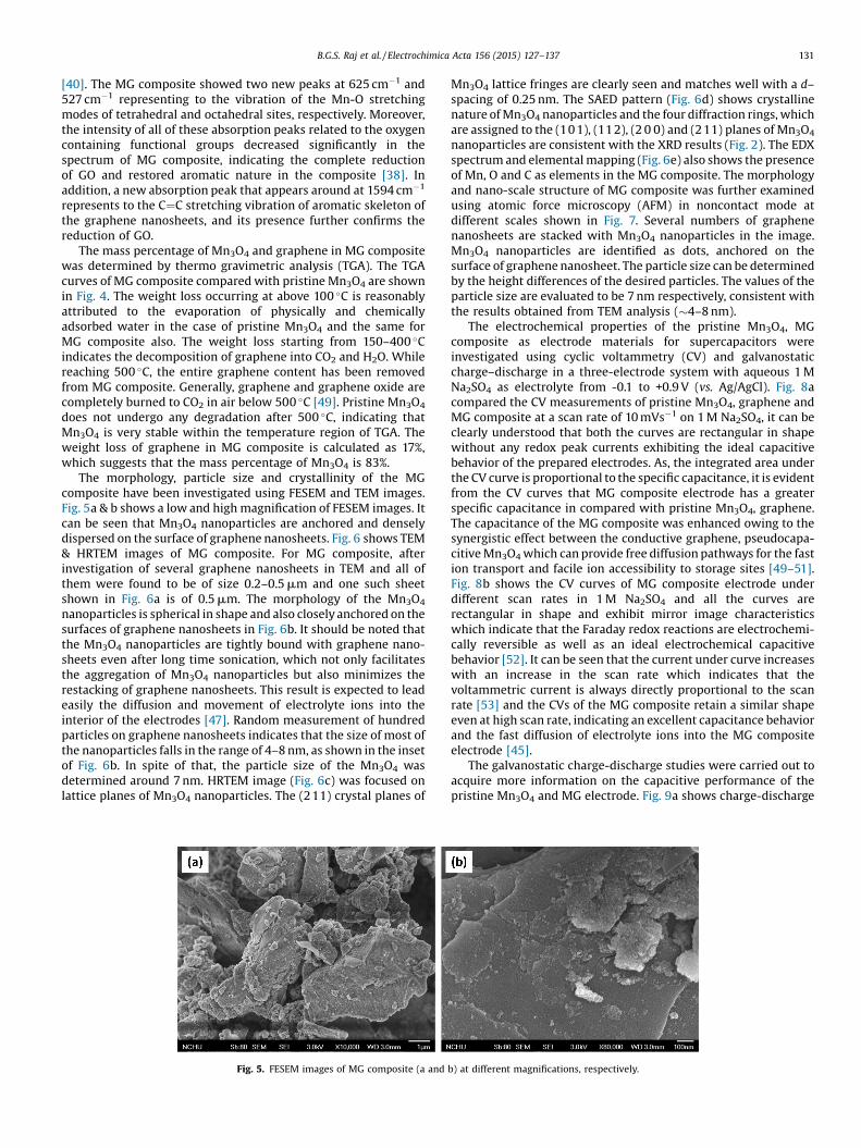
The morphology, particle size and crystallinity of the MGcomposite have been investigated using FESEM and TEM images.Fig. 5a & b shows a low and high magnification of FESEM images. Itcan be seen that Mn3O4 nanoparticles are anchored and denselydispersed on the surface of graphene nanosheets. Fig. 6 shows TEM& HRTEM images of MG composite. For MG composite, afterinvestigation of several graphene nanosheets in TEM and all ofthem were found to be of size 0.2–0.5 mm and one such sheetshown in Fig. 6a is of 0.5 mm. The morphology of the Mn3O4
nanoparticles is spherical in shape and also closely anchored on thesurfaces of graphene nanosheets in Fig. 6b. It should be noted thatthe Mn3O4 nanoparticles are tightly bound with graphene nano-sheets even after long time sonication, which not only facilitatesthe aggregation of Mn3O4 nanoparticles but also minimizes therestacking of graphene nanosheets. This result is expected to leadeasily the diffusion and movement of electrolyte ions into theinterior of the electrodes [47]. Random measurement of hundredparticles on graphene nanosheets indicates that the size of most ofthe nanoparticles falls in the range of 4–8 nm, as shown in the insetof Fig. 6b. In spite of that, the particle size of the Mn3O4 wasdetermined around 7 nm. HRTEM image (Fig. 6c) was focused onlattice planes of Mn3O4 nanoparticles. The (211) crystal planes of
Fig. 5. FESEM images of MG composite (a and
Mn3O4 lattice fringes are clearly seen and matches well with a d–spacing of 0.25 nm. The SAED pattern (Fig. 6d) shows crystallinenature of Mn3O4 nanoparticles and the four diffraction rings, whichare assigned to the (10 1), (11 2), (2 0 0) and (211) planes of Mn3O4
nanoparticles are consistent with the XRD results (Fig. 2). The EDXspectrum and elemental mapping (Fig. 6e) also shows the presenceof Mn, O and C as elements in the MG composite. The morphologyand nano-scale structure of MG composite was further examinedusing atomic force microscopy (AFM) in noncontact mode atdifferent scales shown in Fig. 7. Several numbers of graphenenanosheets are stacked with Mn3O4 nanoparticles in the image.Mn3O4 nanoparticles are identified as dots, anchored on thesurface of graphene nanosheet. The particle size can be determinedby the height differences of the desired particles. The values of theparticle size are evaluated to be 7 nm respectively, consistent withthe results obtained from TEM analysis (�4–8 nm).
The electrochemical properties of the pristine Mn3O4, MGcomposite as electrode materials for supercapacitors wereinvestigated using cyclic voltammetry (CV) and galvanostaticcharge–discharge in a three-electrode system with aqueous 1 MNa2SO4 as electrolyte from -0.1 to +0.9 V (vs. Ag/AgCl). Fig. 8acompared the CV measurements of pristine Mn3O4, graphene andMG composite at a scan rate of 10 mVs�1 on 1 M Na2SO4, it can beclearly understood that both the curves are rectangular in shapewithout any redox peak currents exhibiting the ideal capacitivebehavior of the prepared electrodes. As, the integrated area underthe CV curve is proportional to the specific capacitance, it is evidentfrom the CV curves that MG composite electrode has a greaterspecific capacitance in compared with pristine Mn3O4, graphene.The capacitance of the MG composite was enhanced owing to thesynergistic effect between the conductive graphene, pseudocapa-citive Mn3O4which can provide free diffusion pathways for the fastion transport and facile ion accessibility to storage sites [49–51].Fig. 8b shows the CV curves of MG composite electrode underdifferent scan rates in 1 M Na2SO4 and all the curves arerectangular in shape and exhibit mirror image characteristicswhich indicate that the Faraday redox reactions are electrochemi-cally reversible as well as an ideal electrochemical capacitivebehavior [52]. It can be seen that the current under curve increaseswith an increase in the scan rate which indicates that thevoltammetric current is always directly proportional to the scanrate [53] and the CVs of the MG composite retain a similar shapeeven at high scan rate, indicating an excellent capacitance behaviorand the fast diffusion of electrolyte ions into the MG compositeelectrode [45].
The galvanostatic charge-discharge studies were carried out toacquire more information on the capacitive performance of thepristine Mn3O4 and MG electrode. Fig. 9a shows charge-discharge
b) at different magnifications, respectively.

132 B.G.S. Raj et al. / Electrochimica Acta 156 (2015) 127–137
curves of pristine Mn3O4, graphene and MG composite electrode atcurrent density of 0.5 mA cm�2 in 1 M Na2SO4 as electrolytesolution in the potential range between -0.1 to 0.9 V (vs. Ag/AgCl). Alinear variation of the potential with time during charging anddischarging processes can be seen with the electrodes, which isanother criterion for capacitive behavior of the material. But in theMG composite, the charge curve is almost symmetric with itscorresponding discharge counterpart, with a small internalresistance (IR) drop, indicating the pseudocapacitive contribution,along with the double layer contribution [54]. The increase in the
Fig. 6. TEM images of MG composite (a, b). The inset in (b) is a statistical histogram of thcomposite (c), corresponding SAED pattern (d) and EDX (e) spectrum.
charging and discharging time indicates the higher capacitance ofthe MG composite. The discharge specific capacitance (SC) ofelectrode material at different current densities can be calculatedusing the following formula
SC = I t/m DE (2)
where, I is the charge–discharge current in amps, t is the dischargetime in seconds, m is the mass of the active material present on theelectrode in grams and DE is the operating potential window involts of charge or discharge. The specific capacitance calculated
e sizes of Mn3O4 nanoparticles anchored on graphene surface. HRTEM image of MG

Fig. 7. AFM images of MG composite at different scales.
B.G.S. Raj et al. / Electrochimica Acta 156 (2015) 127–137 133
from the discharge curves (Fig. 9a) is 312 F g�1 for the MGcomposite, which is much higher than that for the pristine Mn3O4
(113 F g�1) and graphene (153 F g�1) at a current density of0.5 mA cm�2 in 1 M Na2SO4 electrolyte, respectively. Approximate-ly, the specific capacitance of the MG composite is three timeslarger than that of pristine Mn3O4. The significantly enhancedcapacitance of the MG composite is probably attributed to theimproved electrical conductivity of the doped graphene and a highutilization speed of electro active Mn3O4 nanoparticles [47]. Fig. 9bshows the galvanostatic charge discharge curves of MG compositeelectrode at a current density of 0.5 mA cm�2. Table 1 summarizeselectrochemical performance reported in literature for Mn3O4/Graphene composites as a supercapacitor electrode material.
As the good cycling stability are most important criteria forsupercapacitors. The cycling stability of the MG composite wasexamined by charge–discharge cycling at a current density of0.5 mA cm�2 in 1 M Na2SO4 as electrolyte (Fig. 9c). The MGcomposite retained 76% of the initial specific capacitance evenafter 1000 cycles, indicating the excellent electrochemical stabilityand hence capacitance retention capability. Fig. 9d. shows thegalvanostatic charging-discharging curves of the MG composite at
Fig. 8. CV curve for (a) pristine Mn3O4, graphene and MG composite at 10 mV s�1 sca20 mV s�1, 40 mV s�1, 80 mV s�1, and 160 mV s�1 in the potential range of -0.1 to 0.9 V v
different current densities (0.5–15 mA cm�2) and their specificcapacitances were shown in Fig. 9e. The specific capacitance was312, 307, 297, 274, 255, 236, 221, 220 and 219 F/g at 0.5, 1, 3, 5, 7, 9,11, 13 and 15 mA cm�2 current density, respectively. This phenom-enon can be explained by the inconsistent insertion-deinsertionbehavior of ions from the electrolyte to electrode materials [55]. Inthis cycling test, charge/discharge time increased at low currentdensity, as the ions from the electrolyte can be fully occupied theactive sites at electrode/electrolyte interface. Similarly, charge/discharge time decreased at high current density, as the ionsoccupy the limited number of active sites at electrode/electrolyteinterface. It reveals that the specific capacitance is inverselyproportional to the current density [56]. When the current rate isincreased from 0.5 to 15 mA cm�2 (312 to 219 F g�1), 70% of thecapacitance was retained. This implies that the MG composite hasan excellent rate capability at high current density, which is acrucial key factor for evaluating the power applications ofsupercapacitors.
The electrochemical impedance spectroscopy (EIS) measure-ments were evaluated to study the mechanistic characteristics ofpristine Mn3O4 and MG composite electrode over a frequency
n rate, (b) CV curve for MG composite at different scan rates 5 mV s�1, 10 mV s�1,s. Ag/AgCl in aqueous solution of 1 M Na2SO4 as electrolyte (a-f).

134 B.G.S. Raj et al. / Electrochimica Acta 156 (2015) 127–137
range of 0.1 to 100000 Hz. Fig. 10(a) shows the Nyquist plots of theEIS for pristine Mn3O4 and MG composite. According to theanalysis, the MG composite exhibited a semicircle over the highfrequency region, followed by a vertical part in the low frequencyrange. The diameter of the semicircle in the plot corresponds to thecharge transfer resistance (Rct), which is mainly generated at theelectrode/electrolyte interface [39,56]. Obviously, the smallersemicircle in MG composite means charge transfer resistance
Fig. 9. a) Charge–discharge cycles of pristine Mn3O4, graphene and MG composite in aq+0.9 V vs. Ag/AgCl. Area of the electrode: 1.0 cm2 (b) Charge–discharge cycles of MG comGalvanostatic charge–discharge curves at different current densities 0.5 mA cm�2, 1 mAdensities.
decreased extremely when compared to pristine Mn3O4 electrodecan be attributed to the presence of conductive graphene, revealingthat the graphene facilitates the conductivity. Low charge transferresistance implies that the electrolyte ions can easily diffuse intothe pores of the electrode material and access the surface of activeelectrode material. At low frequencies, the vertical shape is anindication of pure capacitive behaviour and low diffusionresistance of ions in the structure of MG composite electrode.
ueous solution of 1 M Na2SO4 at a current density of 0.5 mA cm�2 between -0.1 toposite at a current density of 0.5 mA cm�2 (c) Cycling behavior of MG composite (d)
cm�2, 3 mA cm�2, 5 mA cm�2 (e) Specific capacitance variation at different current
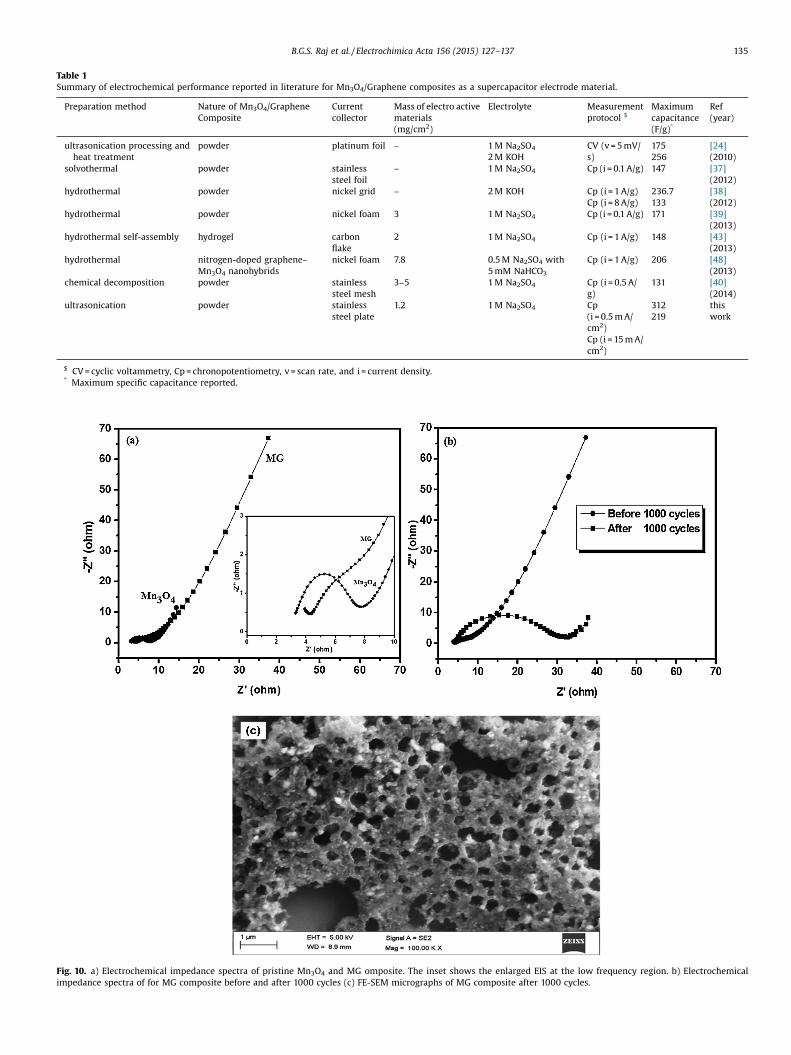
Table 1Summary of electrochemical performance reported in literature for Mn3O4/Graphene composites as a supercapacitor electrode material.
Preparation method Nature of Mn3O4/GrapheneComposite
Currentcollector
Mass of electro activematerials(mg/cm2)
Electrolyte Measurementprotocol $
Maximumcapacitance(F/g)*
Ref(year)
ultrasonication processing andheat treatment
powder platinum foil – 1 M Na2SO4
2 M KOHCV (v = 5 mV/s)
175256
[24](2010)
solvothermal powder stainlesssteel foil
– 1 M Na2SO4 Cp (i = 0.1 A/g) 147 [37](2012)
hydrothermal powder nickel grid – 2 M KOH Cp (i = 1 A/g)Cp (i = 8 A/g)
236.7133
[38](2012)
hydrothermal powder nickel foam 3 1 M Na2SO4 Cp (i = 0.1 A/g) 171 [39](2013)
hydrothermal self-assembly hydrogel carbonflake
2 1 M Na2SO4 Cp (i = 1 A/g) 148 [43](2013)
hydrothermal nitrogen-doped graphene–Mn3O4 nanohybrids
nickel foam 7.8 0.5 M Na2SO4 with5 mM NaHCO3
Cp (i = 1 A/g) 206 [48](2013)
chemical decomposition powder stainlesssteel mesh
3–5 1 M Na2SO4 Cp (i = 0.5 A/g)
131 [40](2014)
ultrasonication powder stainlesssteel plate
1.2 1 M Na2SO4 Cp(i = 0.5 m A/cm2)Cp (i = 15 m A/cm2)
312219
thiswork
$ CV = cyclic voltammetry, Cp = chronopotentiometry, v = scan rate, and i = current density.* Maximum specific capacitance reported.
Fig. 10. a) Electrochemical impedance spectra of pristine Mn3O4 and MG omposite. The inset shows the enlarged EIS at the low frequency region. b) Electrochemicalimpedance spectra of for MG composite before and after 1000 cycles (c) FE-SEM micrographs of MG composite after 1000 cycles.
B.G.S. Raj et al. / Electrochimica Acta 156 (2015) 127–137 135

136 B.G.S. Raj et al. / Electrochimica Acta 156 (2015) 127–137
Fig. 10(b) shows Nyquist plots of the EIS for MG composite beforeand after 1000 cycles, the measured charge transfer resistance (Rct)was increased from 3 to 33 V cm2, this further leads to the decreasein specific capacitance after long term cyclic stability test. Suchobserved significant changes in the MG composite after the longcyclic stability tests may be due to morphology changes takes placeat the electrode which is analyzed to FE-SEM. The FE-SEM image(Fig. 10(c)) revealed the dissolution, aggregation, and the volumechange occurred in the electrode material after 1000 cycleswhich may in turn decrease the specific capacitance of theelectrodes.
The electrochemical parameters, such as energy and powerdensity, play an important role in the capacitive behavior of theelectrochemical cells. The energy and power density can beevaluated using Eqs. (3) and (4),[57]
E = (I*t*V)/(7.2*M) Wh/kg (3)
P = 3.6 E/t W/kg (4)
where E and P is the energy and power density respectively. Iis the applied current (mA), t is the discharge time of theactive material (s), V is the potential window (V) and M is the massof the active material (mg). The calculated energy density andpower density of the composite electrodes were evaluated43 Wh kg�1and 207 W kg�1 at a discharge current density of0.5 mA cm2.
The high capacitance, good cycle performance and excellentrate capability delivered in the case of MG composite electrodecan be illuminated by the following factors. First, the graphenenanosheets provide as a conductive matrix to promote fastFaradaic charging and discharging property of the Mn3O4
nanoparticles, favoring the long-term electrochemical stabilityand the excellent rate performance. Second, well-dispersedMn3O4 nanoparticles anchored on the graphene nanosheetscan significantly improve the electrochemical utilization ofMn3O4 and hence minimize the transport length of Na+ duringthe charge–discharge process. Third, the graphene preventsaggregation of the Mn3O4 nanoparticles, preserving the highinterfacial area between the Mn3O4 nanoparticles and theelectrolyte. As an overall results clearly demonstrate that theMG composite have considerably improved electrochemicalperformance compared with pristine Mn3O4. The MG compositeis expected to be a promising electrode material having greatpotential application in manufacture of electrochemical super-capacitors.
4. Conclusions
In summary, Mn3O4 nanoparticles anchored graphene nano-sheets (MG) has been synthesized by a simple ultrasound assistedsynthesis at room temperature without the use of any templatesor surfactants. The phase composition, morphology, and structureof the as-prepared products were studied in detail. Theelectrochemical performance of MG composite delivers a highspecific capacitance of 312 F g�1 which was approximately threetimes greater than that of pristine Mn3O4 (113 Fg�1) at 0.5 mAcm�2 current density in the potential range from -0.1 to +0.9 V. Inaddition to that a good rate capability of 219 F g�1 at 15 mA cm�2
and long cycling life with 76% capacitance retention after1000 cycles was exhibited by MG composite. Since MG compositehas these attractive and enhanced properties like highcapacitance, good rate capability and capacitance retention webelieve that it is promising candidate for supercapacitorapplications.
Acknowledgements
The research work was financially supported by Council ofScientific and Industrial Research (CSIR), New Delhi (CSIRReference No.02 (0021)/11/EMR-II).
References
[1] D.A. Peña, B.S. Uphade, P.G. Smirniotis, J. Catal. 221 (2004) 421.[2] V. Augustyn, P. Simon, B. Dunn, Energ. Environ. Sci. 7 (2014) 1597.[3] L. Fan, B. Zhu, M. Chen, C. Wang, R. Razaa, H. Qin, X. Wang, X. Wang, Y. Ma, J.
Power Sources 203 (2012) 65.[4] B.X. Wei, L. Zhao, T.J. Wang, H. Gao, H.X. Wu, Y. Jin, Adv. Powder Technol. 24
(2013) 708.[5] X. Li, S. Xiong, J. Li, J. Bai, Y. Qian, J. Mater. Chem 22 (2012) 14276.[6] M. Winter, R.J. Brodd, Chem. Rev 104 (2004) 4245.[7] L.T. Lam, R. Louey, J. Power Sources 158 (2006) 1140.[8] B.E. Conway, Electrochemical supercapacitors: Scientific Fundamentals and
Technological Applications, Kluwer Acedamic/Plenum Publishers, New York,1999.
[9] W. Xing, C.C. Huang, S.P. Zhuo, X. Yuan, G.Q. Wang, D. Hulicova-Jurcakova, Z.F.Yan, G.Q. Lu, Carbon 47 (2009) 1715.
[10] M.H. Chakrabarti, C.T.J. Low, N.P. Brandon, V. Yufit, M.A. Hashim, M.F. Irfan, J.Akhtar, E. Ruiz-Trejo, M.A. Hussain, Electrochim. Acta 107 (2013) 425.
[11] R. Ramya, R. Sivasubramanian, M.V. Sangaranarayanan, Electrochim. Acta 101(2013) 109.
[12] S.I. Cho, S.B. Lee, Accounts Chem. Res. 41 (2008) 699.[13] S. Anandan, B. Gnana Sundara Raj, G.J. Lee, J.J. Wu, Mater. Res. Bull. 48 (2013)
3357.[14] J. Li, W. Zhao, F. Huang, A. Manivannan, N. Wu, Nanoscale 3 (2011) 5103.[15] Y. Munaiah, B. Gnana Sundara Raj, T. Prem Kumar, P. Ragupathy, J. Mater. Chem.
A 1 (2013) 4300.[16] G.A. Snook, P. Kao, A.S. Best, J. Power Sources 196 (2011) 1.[17] A. Devadas, S. Baranton, T.W. Napporn, C. Coutanceau, J. Power Sources 196
(2011) 4044.[18] J.P. Zheng, P.J. Cygan, T.R. Jow, J. Electrochem. Soc 142 (1995) 2699.[19] F. Lei, T. Le, G. Rong, Cryst. Eng. Comm. 13 (2011) 7246.[20] C. Yuan, L. Yang, L. Hou, L. Shen, X. Zhang, W. (David) Lou, Energ. Environ. Sci. 5
(2012) 7883.[21] B. Gnana Sundara Raj, A.M. Asiri, A.H. Qusti, J.J. Wu, S. Anandan, Ultrason.
Sonochem. 21 (2014) 1933.[22] K. Vijaya Sankar, D. Kalpana, R. Kalai Selvan, J. Appl. Electrochem. 42 (2012)
463.[23] C.C. Hu, Y.T. Wu, K.H. Chang, Chem. Mater. 20 (2008) 2890.[24] B. Wang, J. Park, C. Wang, H. Ahn, G. Wang, Electrochim. Acta 55 (2010)
6812.[25] W. Wei, X. Cui, W. Chen, D.G. Ivey, Chem. Soc. Rev. 40 (2011) 1697.[26] M.D. Stoller, S. Park, Y. Zhu, J. An, R.S. Ruoff, Nano Lett. 8 (2008) 3498.[27] C. Lee, X. Wei, J.W. Kysar, J. Hone, Science 321 (2008) 385.[28] K.S. Novoselov, A.K. Geim, S.V. Morozov, D. Jiang, Y. Zhang, S.V. Dubonos, I.V.
Grigorieva, A.A. Firsov, Science 306 (2004) 666.[29] D.A.C. Brownson, D.K. Kampouris, C.E. Banks, J. Power Sources 196 (2011) 4873.[30] S. Radhakrishnan, K. Krishnamoorthy, C. Sekar, J. Wilson, S.J. Kim, Appl. Catal.
B-Environ 148–149 (2014) 22.[31] Z.S. Wu, D.W. Wang, W. Ren, J. Zhao, G. Zhou, F. Li, H.M. Cheng, Adv. Funct.
Mater. 20 (2010) 3595.[32] M.L. Huang, C.D. Gu, X. Ge, X.L. Wang, J.P. Tu, J. Power Sources 259 (2014) 98.[33] C. Xiang, M. Li, M. Zhi, A. Manivannan, N. Wu, J. Power Sources 226 (2013) 65.[34] Z.S. Wu, W. Ren, D.W. Wang, F. Li, B. Liu, H.M. Cheng, ACS Nano 4 (2010) 5835.[35] S. Chen, J. Zhu, X. Wang, ACS Nano 4 (2010) 6212.[36] H. Wang, L.F. Cui, Y. Yang, H.S. Casalongue, J.T. Robinson, Y. Liang, Y. Cui, H. Dai,
J. Am. Chem. Soc. 132 (2010) 13978.[37] X. Zhang, X. Sun, Y. Chen, D. Zhang, Y. Ma, Mater. Lett. 68 (2012) 336.[38] D. Wang, Y. Li, Q. Wang, T. Wang, Eur. J. Inorg. Chem. 2012 (2012) 628.[39] Y. Fan, X. Zhang, Y. Liu, Q. Cai, J. Zhang, Mater. Lett. 95 (2013) 153.[40] K. Subramani, D. Jeyakumar, M. Sathish, Phys. Chem. Chem. Phys. 16 (2014)
4952.[41] L. Zhu, S. Zhang, Y. Cui, H. Song, X. Chen, Electrochim. Acta 89 (2013) 18.[42] Z. Xiong, L.L. Zhang, J. Ma, X.S. Zhao, Chem. Comm. 46 (2010) 6099.[43] L. Li, Z. Hu, Y. Yang, P. Liang, A. Lu, H. Xu, Y. Hu, H. Wu, Chin. J. Chem. 31 (2013)
1290.[44] S. Mandal, M. Baskey, S.K. Saha, Carbon 61 (2013) 254.[45] X. Fan, W. Peng, Y. Li, X. Li, S. Wang, G. Zhang, F. Zhang, Adv. Mater. 20 (2008)
4490.[46] G.R. Gattorno, P.S. Jacinto, L.R. Vazquez, J. Nemeth, I. Dekany, D. Diaz, J. Phys.
Chem. B 107 (2003) 12597.[47] S. Yang, X. Song, P. Zhang, L. Gao, J. Mater. Chem. A 1 (2013) 14162.[48] W. Chen, L. Yan, P.R. Bangal, Carbon 48 (2010) 1146.[49] L. Zhang, G. Shi, J. Phys. Chem. C 115 (2011) 17206.[50] B.G. Choi, Y.S. Huh, W.H. Hong, H.J. Kim, H.S. Park, Nanoscale 4 (2012) 5394.[51] B.G. Choi, Y.S. Huh, W.H. Hong, D. Erickson, H.S. Park, Nanoscale 5 (2013) 3976.[52] F. Zhang, X.G. Zhang, L. Hao, Mater. Chem. Phys. 126 (2011) 853.[53] W. Li, K. Xu, L. An, F. Jiang, X. Zhou, J. Yang, Z. Chen, R. Zou, J. Hu, J. Mater. Chem.
A 2 (2014) 1443.

B.G.S. Raj et al. / Electrochimica Acta 156 (2015) 127–137 137
[54] L. Li, K.H. Seng, Z. Chen, H. Liu, I.P. Nevirkovets, Z. Guo, Electrochim. Acta 87(2013) 801.
[55] V. Subramanian, H. Zhu, R. Vajtai, P.M. Ajayan, B. Wei, J. Phys. Chem. B 109(2005) 20207.
[56] Y. Liu, W. Wang, Y. Wang, Y. Ying, L. Sun, X. Peng, RSC Adv. 4 (2014) 16374.[57] G. Veerasubramani, K. Krishnamoorthy, S. Radhakrishnan, N.J. Kim, S.J. Kim,
Int. J. Hydrogen. Energ. 39 (2014) 5186.
Related Documents


![MODEL QUESTION PAPER ENGLISH [PAPER – 1]](https://static.cupdf.com/doc/110x72/61a48d7f6d0a2c0c5a6b5252/model-question-paper-english-paper-1.jpg)