Pantron Automation, Inc. 109 Hubbard Street Belmont, NC 28012 1-800-211-9468 www.pantron.com/us [email protected] Pantron high-powered photoelectric sensors provide reliable performance in harsh environments. Pantron Infrared Photoelectric Sensor Catalog NEW adjustable fork light barriers! Multiplexers to control multiple sets of photo eyes simultaneously without crosstalk!

Welcome message from author
This document is posted to help you gain knowledge. Please leave a comment to let me know what you think about it! Share it to your friends and learn new things together.
Transcript
Pantron Automation, Inc.
109 Hubbard Street
Belmont, NC 28012
1-800-211-9468 www.pantron.com/us
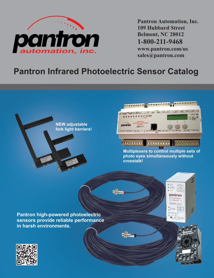
Pantron high-powered photoelectric sensors provide reliable performance in harsh environments.
Pantron Infrared Photoelectric Sensor Catalog
NEW adjustable fork light barriers!
Multiplexers to control multiple sets of photo eyes simultaneously without crosstalk!
2
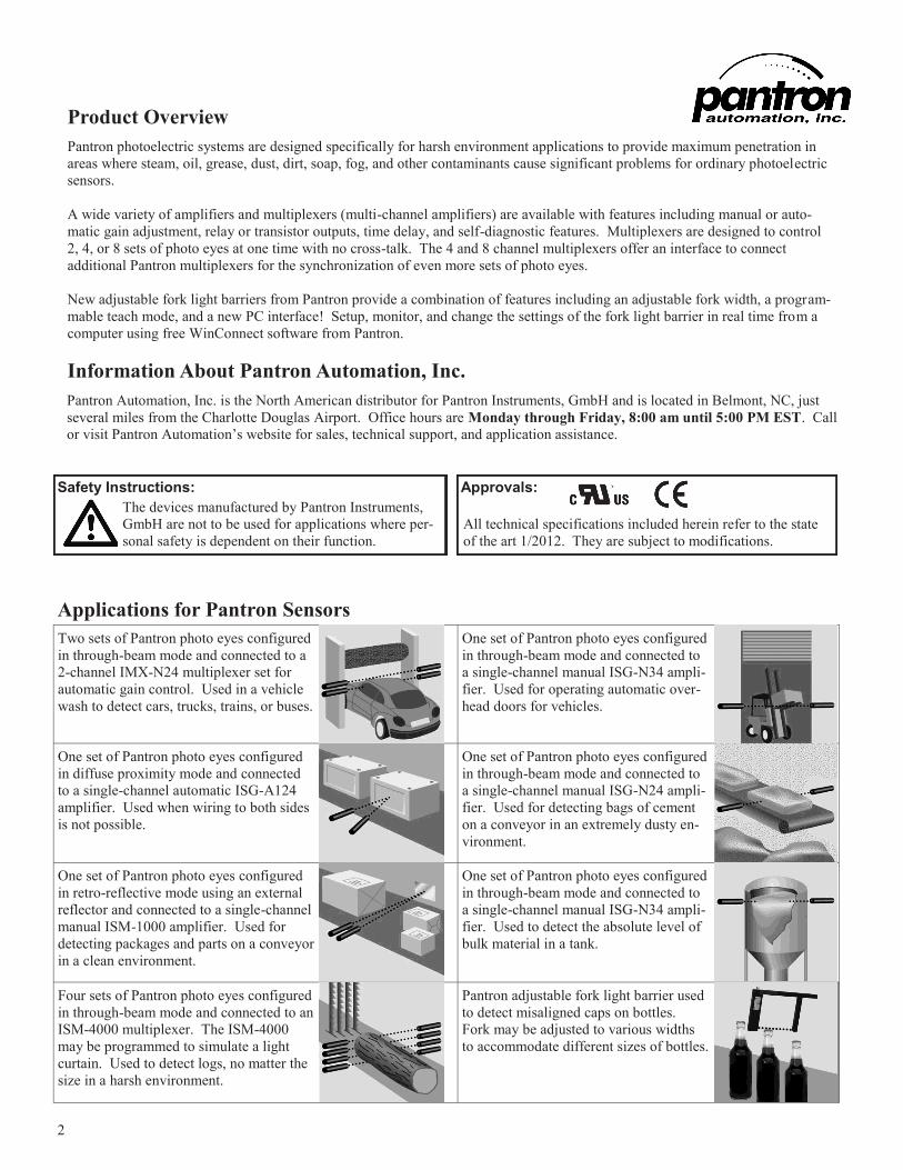
Applications for Pantron Sensors
Pantron photoelectric systems are designed specifically for harsh environment applications to provide maximum penetration in
areas where steam, oil, grease, dust, dirt, soap, fog, and other contaminants cause significant problems for ordinary photoelectric
sensors.
A wide variety of amplifiers and multiplexers (multi-channel amplifiers) are available with features including manual or auto-
matic gain adjustment, relay or transistor outputs, time delay, and self-diagnostic features. Multiplexers are designed to control
2, 4, or 8 sets of photo eyes at one time with no cross-talk. The 4 and 8 channel multiplexers offer an interface to connect
additional Pantron multiplexers for the synchronization of even more sets of photo eyes.
New adjustable fork light barriers from Pantron provide a combination of features including an adjustable fork width, a program-
mable teach mode, and a new PC interface! Setup, monitor, and change the settings of the fork light barrier in real time from a
computer using free WinConnect software from Pantron.
Product Overview
Two sets of Pantron photo eyes configured
in through-beam mode and connected to a
2-channel IMX-N24 multiplexer set for
automatic gain control. Used in a vehicle
wash to detect cars, trucks, trains, or buses.
One set of Pantron photo eyes configured
in through-beam mode and connected to
a single-channel manual ISG-N34 ampli-
fier. Used for operating automatic over-
head doors for vehicles.
One set of Pantron photo eyes configured
in diffuse proximity mode and connected
to a single-channel automatic ISG-A124
amplifier. Used when wiring to both sides
is not possible.
One set of Pantron photo eyes configured
in through-beam mode and connected to
a single-channel manual ISG-N24 ampli-
fier. Used for detecting bags of cement
on a conveyor in an extremely dusty en-
vironment.
One set of Pantron photo eyes configured
in retro-reflective mode using an external
reflector and connected to a single-channel
manual ISM-1000 amplifier. Used for
detecting packages and parts on a conveyor
in a clean environment.
One set of Pantron photo eyes configured
in through-beam mode and connected to
a single-channel manual ISG-N34 ampli-
fier. Used to detect the absolute level of
bulk material in a tank.
Four sets of Pantron photo eyes configured
in through-beam mode and connected to an
ISM-4000 multiplexer. The ISM-4000
may be programmed to simulate a light
curtain. Used to detect logs, no matter the
size in a harsh environment.
Pantron adjustable fork light barrier used
to detect misaligned caps on bottles.
Fork may be adjusted to various widths
to accommodate different sizes of bottles.
All technical specifications included herein refer to the state
of the art 1/2012. They are subject to modifications.
The devices manufactured by Pantron Instruments,
GmbH are not to be used for applications where per-
sonal safety is dependent on their function.
Safety Instructions: Approvals:
Information About Pantron Automation, Inc.
Pantron Automation, Inc. is the North American distributor for Pantron Instruments, GmbH and is located in Belmont, NC, just
several miles from the Charlotte Douglas Airport. Office hours are Monday through Friday, 8:00 am until 5:00 PM EST. Call
or visit Pantron Automation’s website for sales, technical support, and application assistance.
3
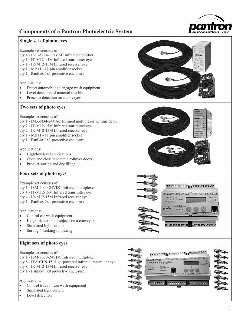
Components of a Pantron Photoelectric System
Single set of photo eyes
Example set consists of:
qty 1 - ISG-A124-115VAC Infrared amplifier
qty 1 - IT-M12-15M Infrared transmitter eye
qty 1 - IR-M12-15M Infrared receiver eye
qty 1 - MB11 - 11 pin amplifier socket
qty 1 - PanBox 1x1 protective enclosure
Applications:
Detect automobile to engage wash equipment
Level detection of material in a bin
Presence detection on a conveyor
Two sets of photo eyes
Example set consists of:
qty 1 - IMX-N34-24VAC Infrared multiplexer w/ time delay
qty 2 - IT-M12-15M Infrared transmitter eye
qty 2 - IR-M12-15M Infrared receiver eye
qty 1 - MB11 - 11 pin amplifier socket
qty 1 - PanBox 1x1 protective enclosure
Applications:
High/low level applications
Open and close automatic rollover doors
Product sorting and dry filling
Four sets of photo eyes
Example set consists of:
qty 1 - ISM-4000-24VDC Infrared multiplexer
qty 4 - IT-M12-15M Infrared transmitter eye
qty 4 - IR-M12-15M Infrared receiver eye
qty 1 - PanBox 1x4 protective enclosure
Applications:
Control car wash equipment
Height detection of objects on a conveyor
Simulated light curtain
Sorting / stacking / indexing
Eight sets of photo eyes
Example set consists of:
qty 1 - ISM-8000-24VDC Infrared multiplexer
qty 8 - ITA-CLN-15 High-powered infrared transmitter eye
qty 8 - IR-M12-15M Infrared receiver eye
qty 1 - PanBox 1x8 protective enclosure
Applications:
Control truck / train wash equipment
Simulated light curtain
Level detection
4 * Other cable lengths by request.
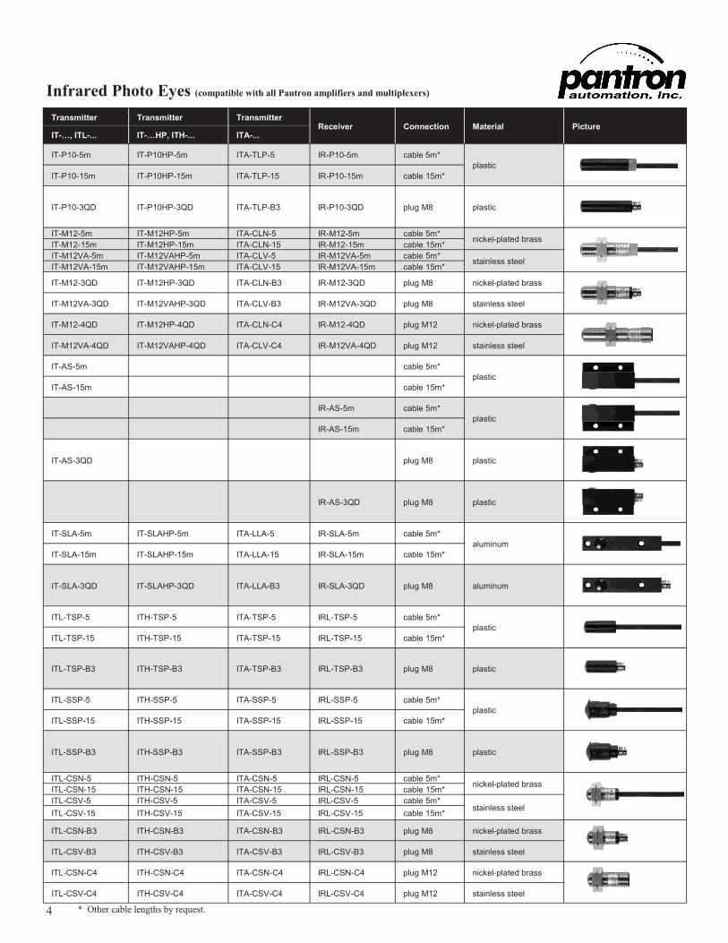
Infrared Photo Eyes (compatible with all Pantron amplifiers and multiplexers)
Transmitter Transmitter Transmitter Receiver Connection Material Picture
IT-…, ITL-... IT-…HP, ITH-... ITA-...
IT-P10-5m IT-P10HP-5m ITA-TLP-5 IR-P10-5m cable 5m*
plastic IT-P10-15m IT-P10HP-15m ITA-TLP-15 IR-P10-15m cable 15m*
IT-P10-3QD IT-P10HP-3QD ITA-TLP-B3 IR-P10-3QD plug M8 plastic
IT-M12-5m IT-M12HP-5m ITA-CLN-5 IR-M12-5m cable 5m* nickel-plated brass
IT-M12-15m IT-M12HP-15m ITA-CLN-15 IR-M12-15m cable 15m*
IT-M12VA-5m IT-M12VAHP-5m ITA-CLV-5 IR-M12VA-5m cable 5m* stainless steel
IT-M12VA-15m IT-M12VAHP-15m ITA-CLV-15 IR-M12VA-15m cable 15m*
IT-M12-3QD IT-M12HP-3QD ITA-CLN-B3 IR-M12-3QD plug M8 nickel-plated brass
IT-M12VA-3QD IT-M12VAHP-3QD ITA-CLV-B3 IR-M12VA-3QD plug M8 stainless steel
IT-M12-4QD IT-M12HP-4QD ITA-CLN-C4 IR-M12-4QD plug M12 nickel-plated brass
IT-M12VA-4QD IT-M12VAHP-4QD ITA-CLV-C4 IR-M12VA-4QD plug M12 stainless steel
IT-AS-5m cable 5m*
plastic IT-AS-15m cable 15m*
IR-AS-5m cable 5m*
plastic IR-AS-15m cable 15m*
IT-AS-3QD plug M8 plastic
IR-AS-3QD plug M8 plastic
IT-SLA-5m IT-SLAHP-5m ITA-LLA-5 IR-SLA-5m cable 5m*
aluminum IT-SLA-15m IT-SLAHP-15m ITA-LLA-15 IR-SLA-15m cable 15m*
IT-SLA-3QD IT-SLAHP-3QD ITA-LLA-B3 IR-SLA-3QD plug M8 aluminum
ITL-TSP-5 ITH-TSP-5 ITA-TSP-5 IRL-TSP-5 cable 5m*
plastic ITL-TSP-15 ITH-TSP-15 ITA-TSP-15 IRL-TSP-15 cable 15m*
ITL-TSP-B3 ITH-TSP-B3 ITA-TSP-B3 IRL-TSP-B3 plug M8 plastic
ITL-SSP-5 ITH-SSP-5 ITA-SSP-5 IRL-SSP-5 cable 5m*
plastic ITL-SSP-15 ITH-SSP-15 ITA-SSP-15 IRL-SSP-15 cable 15m*
ITL-SSP-B3 ITH-SSP-B3 ITA-SSP-B3 IRL-SSP-B3 plug M8 plastic
ITL-CSN-5 ITH-CSN-5 ITA-CSN-5 IRL-CSN-5 cable 5m* nickel-plated brass
ITL-CSN-15 ITH-CSN-15 ITA-CSN-15 IRL-CSN-15 cable 15m*
ITL-CSV-5 ITH-CSV-5 ITA-CSV-5 IRL-CSV-5 cable 5m* stainless steel
ITL-CSV-15 ITH-CSV-15 ITA-CSV-15 IRL-CSV-15 cable 15m*
ITL-CSN-B3 ITH-CSN-B3 ITA-CSN-B3 IRL-CSN-B3 plug M8 nickel-plated brass
ITL-CSV-B3 ITH-CSV-B3 ITA-CSV-B3 IRL-CSV-B3 plug M8 stainless steel
ITL-CSN-C4 ITH-CSN-C4 ITA-CSN-C4 IRL-CSN-C4 plug M12 nickel-plated brass
ITL-CSV-C4 ITH-CSV-C4 ITA-CSV-C4 IRL-CSV-C4 plug M12 stainless steel
5 * Lexan is a registered trademark for SABIC Innovative Plastics
Photo Eye Information
Transmitter
Receiver IRL-… IR-… IRL-… IR-… IRL-… IR-…
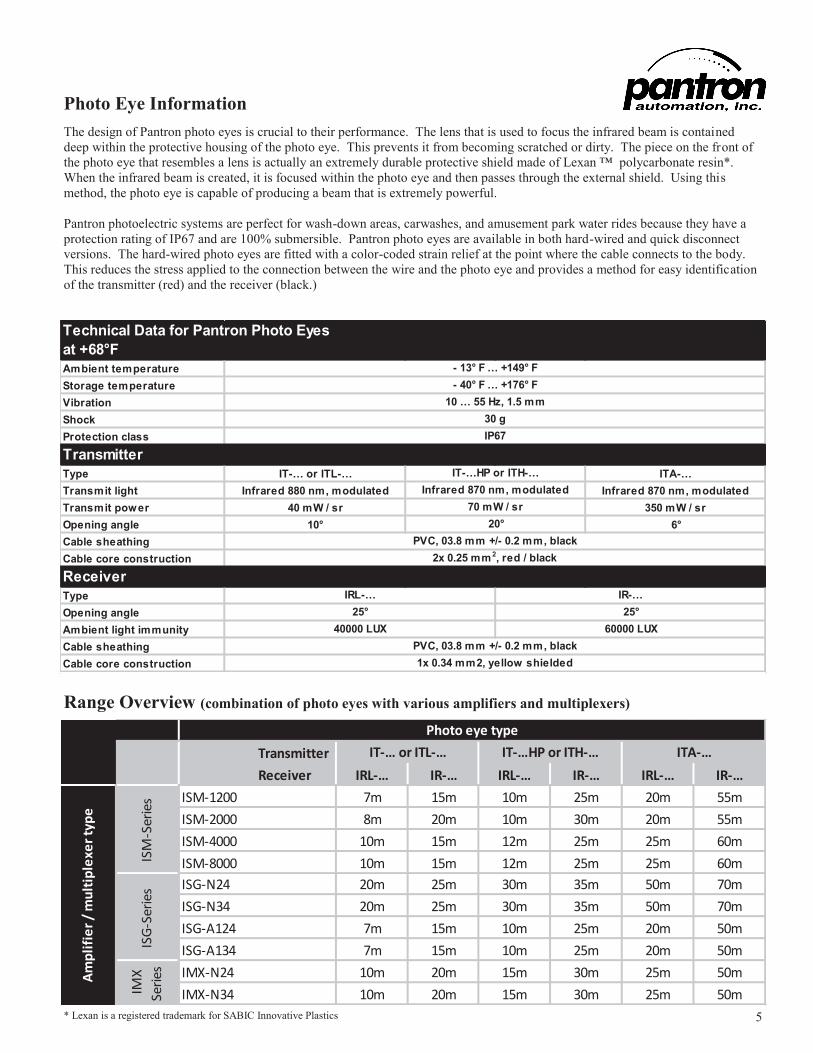
ISM-1200 7m 15m 10m 25m 20m 55m
ISM-2000 8m 20m 10m 30m 20m 55m
ISM-4000 10m 15m 12m 25m 25m 60m
ISM-8000 10m 15m 12m 25m 25m 60m
ISG-N24 20m 25m 30m 35m 50m 70m
ISG-N34 20m 25m 30m 35m 50m 70m
ISG-A124 7m 15m 10m 25m 20m 50m
ISG-A134 7m 15m 10m 25m 20m 50m
IMX-N24 10m 20m 15m 30m 25m 50m
IMX-N34 10m 20m 15m 30m 25m 50m
Am
pli
fie
r /
mu
ltip
lexe
r ty
pe
Photo eye type
IMX
Seri
esIS
M-S
erie
sIS
G-S
erie
s
IT-… or ITL-… IT-…HP or ITH-… ITA-…
Range Overview (combination of photo eyes with various amplifiers and multiplexers)
The design of Pantron photo eyes is crucial to their performance. The lens that is used to focus the infrared beam is contained
deep within the protective housing of the photo eye. This prevents it from becoming scratched or dirty. The piece on the front of
the photo eye that resembles a lens is actually an extremely durable protective shield made of Lexan ™ polycarbonate resin*.
When the infrared beam is created, it is focused within the photo eye and then passes through the external shield. Using this
method, the photo eye is capable of producing a beam that is extremely powerful.
Pantron photoelectric systems are perfect for wash-down areas, carwashes, and amusement park water rides because they have a
protection rating of IP67 and are 100% submersible. Pantron photo eyes are available in both hard-wired and quick disconnect
versions. The hard-wired photo eyes are fitted with a color-coded strain relief at the point where the cable connects to the body.
This reduces the stress applied to the connection between the wire and the photo eye and provides a method for easy identification
of the transmitter (red) and the receiver (black.)
Technical Data for Pantron Photo Eyes
at +68°F
Ambient temperature
Storage temperature
Vibration
Shock
Protection class
Transmitter
Type IT-… or ITL-… ITA-…
Transmit light Infrared 880 nm, modulated Infrared 870 nm, modulated
Transmit power 40 mW / sr 350 mW / sr
Opening angle 10° 6°
Cable sheathing
Cable core construction
Receiver
Type
Opening angle
Ambient light immunity
Cable sheathing
Cable core construction
Infrared 870 nm, modulated
70 mW / sr
20°
IRL-…
25°
40000 LUX
IR-…
25°
60000 LUX
PVC, 03.8 mm +/- 0.2 mm, black
1x 0.34 mm2, yellow shielded
PVC, 03.8 mm +/- 0.2 mm, black
2x 0.25 mm 2, red / black
- 13° F … +149° F
- 40° F … +176° F
10 … 55 Hz, 1.5 mm
30 g
IP67
IT-…HP or ITH-…
6 * IMX series multiplexers are not shown in this publication. Please visit www.pantron.com/us for more details.
Part # Nu
mb
er o
f ch
an
nel
s
Sw
itch
ing
mo
de l
igh
t /
da
rk
/ b
oth
Nu
mb
er o
f
freq
uen
cies
Bu
ilt-
in d
iag
no
stic
s
Sw
itch
ing
del
ay
Tes
t im
pu
t
Tra
nsi
sto
r o
utp
ut
Rel
ay
ou
tpu
t
Ala
rm o
utp
ut
Ba
sic
tra
nsm
it lev
els
Au
tom
ati
c g
ain
con
tro
l
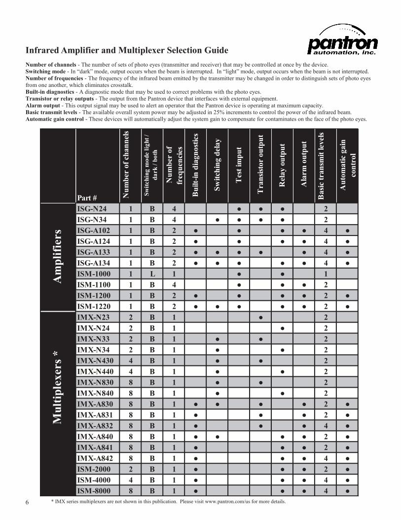
ISG-N24 1 B 4 ● ● ● 2
ISG-N34 1 B 4 ● ● ● ● 2
ISG-A102 1 B 2 ● ● ● ● 4 ●
ISG-A124 1 B 2 ● ● ● ● 4 ●
ISG-A133 1 B 2 ● ● ● ● ● 4 ●
ISG-A134 1 B 2 ● ● ● ● ● 4 ●
ISM-1000 1 L 1 ● ● 1
ISM-1100 1 B 4 ● ● ● 2
ISM-1200 1 B 2 ● ● ● ● 2 ●
ISM-1220 1 B 2 ● ● ● ● ● 2 ●
IMX-N23 2 B 1 ● 2
IMX-N24 2 B 1 ● 2
IMX-N33 2 B 1 ● ● 2
IMX-N34 2 B 1 ● ● 2
IMX-N430 4 B 1 ● ● 2
IMX-N440 4 B 1 ● ● 2
IMX-N830 8 B 1 ● ● 2
IMX-N840 8 B 1 ● ● 2
IMX-A830 8 B 1 ● ● ● ● 2 ●
IMX-A831 8 B 1 ● ● ● 2 ●
IMX-A832 8 B 1 ● ● ● 4 ●
IMX-A840 8 B 1 ● ● ● ● 2 ●
IMX-A841 8 B 1 ● ● ● 2 ●
IMX-A842 8 B 1 ● ● ● 4 ●
ISM-2000 2 B 1 ● ● ● 2 ●
ISM-4000 4 B 1 ● ● ● 4 ●
ISM-8000 8 B 1 ● ● ● 4 ●
Mu
ltip
lex
ers
*A
mp
lifi
ers
Infrared Amplifier and Multiplexer Selection Guide
Number of channels - The number of sets of photo eyes (transmitter and receiver) that may be controlled at once by the device.
Switching mode - In “dark” mode, output occurs when the beam is interrupted. In “light” mode, output occurs when the beam is not interrupted.
Number of frequencies - The frequency of the infrared beam emitted by the transmitter may be changed in order to distinguish sets of photo eyes
from one another, which eliminates crosstalk.
Built-in diagnostics - A diagnostic mode that may be used to correct problems with the photo eyes.
Transistor or relay outputs - The output from the Pantron device that interfaces with external equipment.
Alarm output - This output signal may be used to alert an operator that the Pantron device is operating at maximum capacity.
Basic transmit levels - The available overall system power may be adjusted in 25% increments to control the power of the infrared beam.
Automatic gain control - These devices will automatically adjust the system gain to compensate for contaminates on the face of the photo eyes.
7
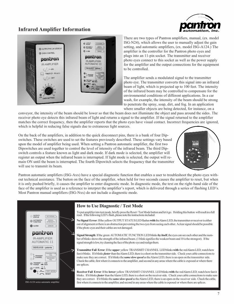
Infrared Amplifier Information
There are two types of Pantron amplifiers, manual, (ex. model
ISG-N24), which allows the user to manually adjust the gain
setting, and automatic amplifiers, (ex. model ISG-A124.) The
amplifier is the controller for the Pantron photo eyes and
plugs into an 11-pin socket. The transmitter and receiver
photo eyes connect to this socket as well as the power supply
for the amplifier and the output connections for the equipment
to be controlled.
The amplifier sends a modulated signal to the transmitter
photo eye. The transmitter converts this signal into an infrared
beam of light, which is projected up to 100 feet. The intensity
of the infrared beam may be controlled to compensate for the
environmental conditions of different applications. In a car
wash, for example, the intensity of the beam should be strong
to penetrate the spray, soap, dirt, and fog. In an application
where smaller objects are being detected, for instance, on a
conveyor, the intensity of the beam should be lower so that the beam does not illuminate the object and pass around the sides. The
receiver photo eye detects this infrared beam of light and returns a signal to the amplifier. If the signal returned to the amplifier
matches the correct frequency, then the amplifier reports that the photo eyes have visual contact. Incorrect frequencies are ignored,
which is helpful in reducing false signals due to extraneous light sources.
On the back of the amplifiers, in addition to the quick disconnect pins, there is a bank of four Dip-
switches. These switches are used to set the features previously described. These settings vary based
upon the model of amplifier being used. When setting a Pantron automatic amplifier, the first two
Dipswitches are used together to control the level of intensity of the infrared beam. The third Dip-
switch controls a feature known as light and dark mode. If dark mode is selected, the amplifier will
register an output when the infrared beam is interrupted. If light mode is selected, the output will re-
main ON until the beam is interrupted. The fourth Dipswitch selects the frequency that the transmitter
will use to transmit its beam.
Pantron automatic amplifiers (ISG-Axx) have a special diagnostic function that enables a user to troubleshoot the photo eyes with-
out technical assistance. The button on the face of the amplifier, when held for two seconds causes the amplifier to reset, but when
it is only pushed briefly, it causes the amplifier to enter diagnostic mode. In diagnostic mode, the text on the right-hand side of the
face of the amplifier is used as a reference to interpret the amplifier’s report, which is delivered through a series of flashing LED’s.
Most Pantron manual amplifiers (ISG-Nxx) do not include a diagnostic mode.
How to Use Diagnostic / Test Mode To put amplifier into test mode, briefly press the Reset / Test Mode button and let it go. Holding this button will result in a full reset. If the following LED’s flash, please note the instructions included:
No Signal Error: If the yellow OUTPUT STATUS LED flashes with the Alarm LED, the transmitter or receiver is either
out of alignment or there is an obstruction preventing the two eyes from seeing each other. A clear signal should be possible
if the photo eyes and their cables are not damaged.
Signal Strength: If the green AUTOMATIC FUNCTION LED blinks by itself, the eyes can see each other and the num-
ber of blinks shows the strength of the infrared beam. (1 blink signifies the weakest beam and 10 is the strongest). If the
signal strength is low, try cleaning the face of the photo eye and realign them.
Transmitter Fail Error: If the upper yellow TRANSMIT CHANNEL LED blinks with the red Alarm LED, watch how
fast it blinks. If it blinks faster than the Alarm LED, there is a short on the transmitter side. Check your cable connections to
make sure they are correct. If it blinks the same slow speed as the Alarm LED, there is an open on the transmitter side.
Check the cable, first where it connects to the amplifier, and second in any areas where the cable is exposed or where there
are splices.
Receiver Fail Error: If the lower yellow TRANSMIT CHANNEL LED blinks with the red Alarm LED, watch how fast it blinks. If it blinks faster than the Alarm LED, there is a short on the receiver side. Check your cable connections to make sure
they are correct. If it blinks the same slow speed as the Alarm LED, there is an open on the receiver side. Check the cable,
first where it connects to the amplifier, and second in any areas where the cable is exposed or where there are splices. ISG-A124 series automatic amplifier
8 * Available in 24VAC, 24VDC, 115VAC, and 230VAC
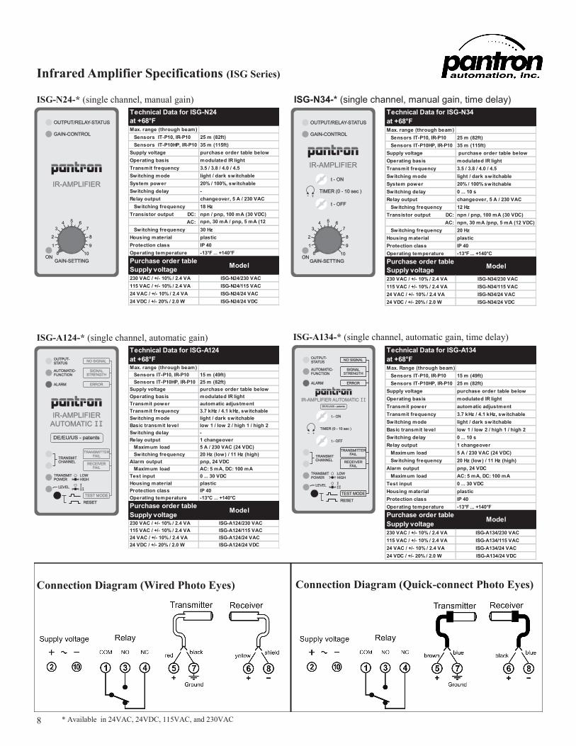
Infrared Amplifier Specifications (ISG Series)
ISG-N24-* (single channel, manual gain) ISG-N34-* (single channel, manual gain, time delay)
ISG-A124-* (single channel, automatic gain) ISG-A134-* (single channel, automatic gain, time delay)
Technical Data for ISG-N24
at +68°F
Max. range (through beam)
Sensors IT-P10, IR-P10 25 m (82ft)
Sensors IT-P10HP, IR-P10 35 m (115ft)
Supply voltage purchase order table below
Operating basis modulated IR light
Transmit frequency 3.5 / 3.8 / 4.0 / 4.5
Switching mode light / dark switchable
System power 20% / 100%, switchable
Switching delay -
Relay output changeover, 5 A / 230 VAC
Switching frequency 18 Hz
Transistor output DC: npn / pnp, 100 mA (30 VDC)
AC: npn, 30 mA / pnp, 5 mA (12
VDC) Switching frequency 30 Hz
Housing material plastic
Protection class IP 40
Operating temperature -13°F ... +140°F
Purchase order table
Supply voltage
230 VAC / +/- 10% / 2.4 VA ISG-N24/230 VAC
115 VAC / +/- 10% / 2.4 VA ISG-N24/115 VAC
24 VAC / +/- 10% / 2.4 VA ISG-N24/24 VAC
24 VDC / +/- 20% / 2.0 W ISG-N24/24 VDC
Model
Technical Data for ISG-N34
at +68°F
Max. range (through beam)
Sensors IT-P10, IR-P10 25 m (82ft)
Sensors IT-P10HP, IR-P10 35 m (115ft)
Supply voltage purchase order table below
Operating basis modulated IR light
Transmit frequency 3.5 / 3.8 / 4.0 / 4.5
Switching mode light / dark switchable
System power 20% / 100% switchable
Switching delay 0 ... 10 s
Relay output changeover, 5 A / 230 VAC
Switching frequency 12 Hz
Transistor output DC: npn / pnp, 100 mA (30 VDC)
AC: npn, 30 mA /pnp, 5 mA (12 VDC)
Switching frequency 20 Hz
Housing material plastic
Protection class IP 40
Operating temperature -13°F ... +140°C
Purchase order table
Supply voltage
230 VAC / +/- 10% / 2.4 VA ISG-N34/230 VAC
115 VAC / +/- 10% / 2.4 VA ISG-N34/115 VAC
24 VAC / +/- 10% / 2.4 VA ISG-N34/24 VAC
24 VDC / +/- 20% / 2.0 W ISG-N34/24 VDC
Model
Technical Data for ISG-A124
at +68°FMax. range (through beam)
Sensors IT-P10, IR-P10 15 m (49ft)
Sensors IT-P10HP, IR-P10 25 m (82ft)
Supply voltage purchase order table below
Operating basis modulated IR light
Transmit power automatic adjustment
Transmit frequency 3.7 kHz / 4.1 kHz, switchable
Switching mode light / dark switchable
Basic transmit level low 1 / low 2 / high 1 / high 2
Switching delay -
Relay output 1 changeover
Maximum load 5 A / 230 VAC (24 VDC)
Switching frequency 20 Hz (low) / 11 Hz (high)
Alarm output pnp, 24 VDC
Maximum load AC: 5 mA, DC: 100 mA
Test input 0 ... 30 VDC
Housing material plastic
Protection class IP 40
Operating temperature -13°C ... +140°C
Purchase order table
Supply voltage230 VAC / +/- 10% / 2.4 VA ISG-A124/230 VAC
115 VAC / +/- 10% / 2.4 VA ISG-A124/115 VAC
24 VAC / +/- 10% / 2.4 VA ISG-A124/24 VAC
24 VDC / +/- 20% / 2.0 W ISG-A124/24 VDC
Model
Technical Data for ISG-A134
at +68°F
Max. Range (through beam)
Sensors IT-P10, IR-P10 15 m (49ft)
Sensors IT-P10HP, IR-P10 25 m (82ft)
Supply voltage purchase order table below
Operating basis modulated IR light
Transmit power automatic adjustment
Transmit frequency 3.7 kHz / 4.1 kHz, switchable
Switching mode light / dark switchable
Basic transmit level low 1 / low 2 / high 1 / high 2
Switching delay 0 ... 10 s
Relay output 1 changeover
Maximum load 5 A / 230 VAC (24 VDC)
Switching frequency 20 Hz (low) / 11 Hz (high)
Alarm output pnp, 24 VDC
Maximum load AC: 5 mA, DC: 100 mA
Test input 0 ... 30 VDC
Housing material plastic
Protection class IP 40
Operating temperature -13°F ... +140°F
Purchase order table
Supply voltage
230 VAC / +/- 10% / 2.4 VA ISG-A134/230 VAC
115 VAC / +/- 10% / 2.4 VA ISG-A134/115 VAC
24 VAC / +/- 10% / 2.4 VA ISG-A134/24 VAC
24 VDC / +/- 20% / 2.0 W ISG-A134/24 VDC
Model
Connection Diagram (Wired Photo Eyes) Connection Diagram (Quick-connect Photo Eyes)
9
mm mm mm
* Available in 24VAC, 24VDC, 115VAC, and 230VAC
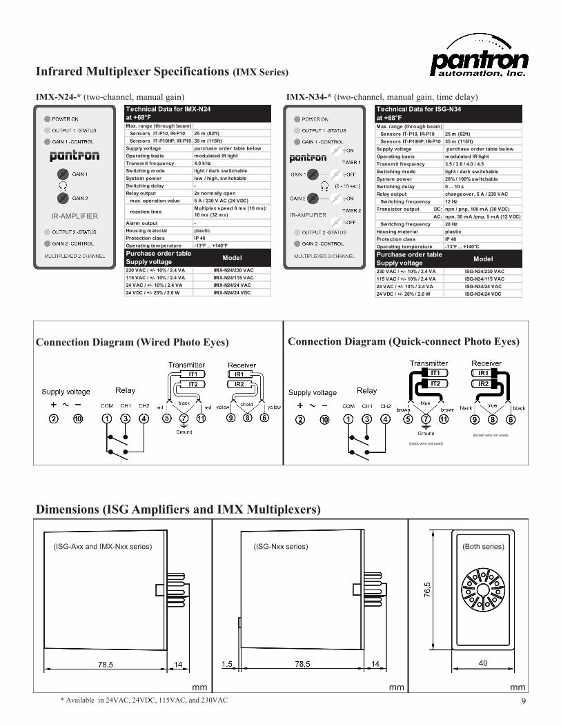
Infrared Multiplexer Specifications (IMX Series)
IMX-N24-* (two-channel, manual gain) IMX-N34-* (two-channel, manual gain, time delay)
Technical Data for ISG-N34
at +68°F
Max. range (through beam)
Sensors IT-P10, IR-P10 25 m (82ft)
Sensors IT-P10HP, IR-P10 35 m (115ft)
Supply voltage purchase order table below
Operating basis modulated IR light
Transmit frequency 3.5 / 3.8 / 4.0 / 4.5
Switching mode light / dark switchable
System power 20% / 100% switchable
Switching delay 0 ... 10 s
Relay output changeover, 5 A / 230 VAC
Switching frequency 12 Hz
Transistor output DC: npn / pnp, 100 mA (30 VDC)
AC: npn, 30 mA /pnp, 5 mA (12 VDC)
Switching frequency 20 Hz
Housing material plastic
Protection class IP 40
Operating temperature -13°F ... +140°C
Purchase order table
Supply voltage
230 VAC / +/- 10% / 2.4 VA ISG-N34/230 VAC
115 VAC / +/- 10% / 2.4 VA ISG-N34/115 VAC
24 VAC / +/- 10% / 2.4 VA ISG-N34/24 VAC
24 VDC / +/- 20% / 2.0 W ISG-N34/24 VDC
Model
Connection Diagram (Wired Photo Eyes) Connection Diagram (Quick-connect Photo Eyes)
(black wire not used)
(brown wire not used)
Technical Data for IMX-N24
at +68°F
Max. range (through beam)
Sensors IT-P10, IR-P10 25 m (82ft)
Sensors IT-P10HP, IR-P10 35 m (115ft)
Supply voltage purchase order table below
Operating basis modulated IR light
Transmit frequency 4.0 kHz
Switching mode light / dark switchable
System power low / high, switchable
Switching delay -
Relay output 2x normally open
max. operation value 5 A / 230 V AC (24 VDC)
Alarm output -
Housing material plastic
Protection class IP 40
Operating temperature -13°F ... +140°F
Purchase order table
Supply voltage
230 VAC / +/- 10% / 2.4 VA IMX-N24/230 VAC
115 VAC / +/- 10% / 2.4 VA IMX-N24/115 VAC
24 VAC / +/- 10% / 2.4 VA IMX-N24/24 VAC
24 VDC / +/- 20% / 2.0 W IMX-N24/24 VDC
Model
Multiplex speed 8 ms (16 ms):
16 ms (32 ms) reaction time
Dimensions (ISG Amplifiers and IMX Multiplexers)
(ISG-Axx and IMX-Nxx series) (ISG-Nxx series) (Both series)
10
mm mm mm
* Available with Screw or Plug Terminals
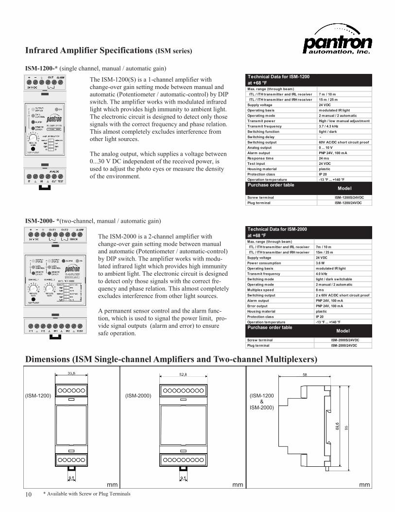
Infrared Amplifier Specifications (ISM series)
ISM-1200-* (single channel, manual / automatic gain)
ISM-2000- *(two-channel, manual / automatic gain)
Technical Data for ISM-1200
at +68 °F
Max. range (through beam)
ITL / ITH transmitter and IRL receiver 7 m / 10 m
ITL / ITH transmitter and IRH receiver 15 m / 25 m
Supply voltage 24 VDC
Operating basis modulated IR light
Operating mode 2 manual / 2 automatic
Transmit power High / low manual adjustment
Transmit frequency 3.7 / 4.3 kHz
Switching function light / dark
Switching delay -
Switching output 60V AC/DC short circuit proof
Analog output 0 ... 10 V
Alarm output PNP 24V, 100 mA
Response time 24 ms
Test input 24 VDC
Housing material plastic
Protection class IP 20
Operation temperature -13 °F ... +140 °F
Purchase order table
Screw terminal ISM-1200S/24VDC
Plug terminal ISM-1200/24VDC
Model
Technical Data for ISM-2000
at +68 °F
Max. range (through beam)
ITL / ITH transmitter and IRL receiver 7m / 10 m
ITL / ITH transmitter and IRH receiver 15m / 25 m
Supply voltage 24 VDC
Power consumption 3.6 W
Operating basis modulated IR light
Transmit frequency 4.0 kHz
Switching mode light / dark switchable
Operating mode 2 manual / 2 automatic
Multiplex speed 8 ms
Switching output 2 x 60V AC/DC short circuit proof
Alarm output PNP 24V, 100 mA
Error output PNP 24V, 100 mA
Housing material plastic
Protection class IP 20
Operation temperature -13 °F ... +140 °F
Purchase order table
Screw terminal ISM-2000S/24VDC
Plug terminal ISM-2000/24VDC
Model
Dimensions (ISM Single-channel Amplifiers and Two-channel Multiplexers)
The ISM-1200(S) is a 1-channel amplifier with
change-over gain setting mode between manual and
automatic (Potentiometer / automatic-control) by DIP
switch. The amplifier works with modulated infrared
light which provides high immunity to ambient light.
The electronic circuit is designed to detect only those
signals with the correct frequency and phase relation.
This almost completely excludes interference from
other light sources.
The analog output, which supplies a voltage between
0...30 V DC independent of the received power, is
used to adjust the photo eyes or measure the density
of the environment.
The ISM-2000 is a 2-channel amplifier with
change-over gain setting mode between manual
and automatic (Potentiometer / automatic-control)
by DIP switch. The amplifier works with modu-
lated infrared light which provides high immunity
to ambient light. The electronic circuit is designed
to detect only those signals with the correct fre-
quency and phase relation. This almost completely
excludes interference from other light sources.
A permanent sensor control and the alarm func-
tion, which is used to signal the power limit, pro-
vide signal outputs (alarm and error) to ensure
safe operation.
(ISM-1200) (ISM-2000) (ISM-1200 &
ISM-2000)
11
mm mm
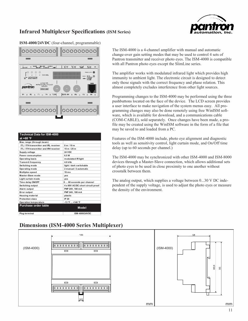
ISM-4000/24VDC (four-channel, programmable)
Infrared Multiplexer Specifications (ISM Series)
Dimensions (ISM-4000 Series Multiplexer)
The ISM-4000 is a 4-channel amplifier with manual and automatic
change-over gain setting modes that may be used to control 4 sets of
Pantron transmitter and receiver photo eyes. The ISM-4000 is compatible
with all Pantron photo eyes except the SlimLine series.
The amplifier works with modulated infrared light which provides high
immunity to ambient light. The electronic circuit is designed to detect
only those signals with the correct frequency and phase relation. This
almost completely excludes interference from other light sources.
Programming changes to the ISM-4000 may be performed using the three
pushbuttons located on the face of the device. The LCD screen provides
a user interface to make navigation of the system menus easy. All pro-
gramming changes may also be done remotely using free WinISM soft-
ware, which is available for download, and a communications cable
(COM-CABLE), sold separately. Once changes have been made, a pro-
file may be created using the WinISM software in the form of a file that
may be saved to and loaded from a PC.
Features of the ISM-4000 include, photo eye alignment and diagnostic
tools as well as sensitivity control, light curtain mode, and On/Off time
delay (up to 60 seconds per channel.)
The ISM-4000 may be synchronized with other ISM-4000 and ISM-8000
devices through a Master-Slave connection, which allows additional sets
of photo eyes to be used in close proximity to one another without
crosstalk between them.
The analog output, which supplies a voltage between 0...30 V DC inde-
pendent of the supply voltage, is used to adjust the photo eyes or measure
the density of the environment.
Technical Data for ISM-4000
at +68 °F
Max. range (through beam)
ITL / ITH transmitter and IRL receiver 8 m / 10 m
ITL / ITH transmitter and IRH receiver 15 m / 25 m
Supply voltage 24 VDC
Power consumption 6.5 W
Operating basis modulated IR light
Transmit frequency 4.0 kHz
Switching mode light / dark switchable
Operating mode 2 manual / 2 automatic
Multiplex speed 18 ms
Master-Slave mode yes
Light curtain mode yes
Time delay ON/OFF 0 … 60 seconds per channel
Switching output 4 x 60V AC/DC short circuit proof
Alarm output PNP 24V, 100 mA
Error output PNP 24V, 100 mA
Housing material plastic
Protection class IP 20
Operation temperature -13 °F ... +140 °F
Purchase order table
Plug terminal ISM-4000/24VDC
Model
(ISM-4000) (ISM-4000)
12
mm mm
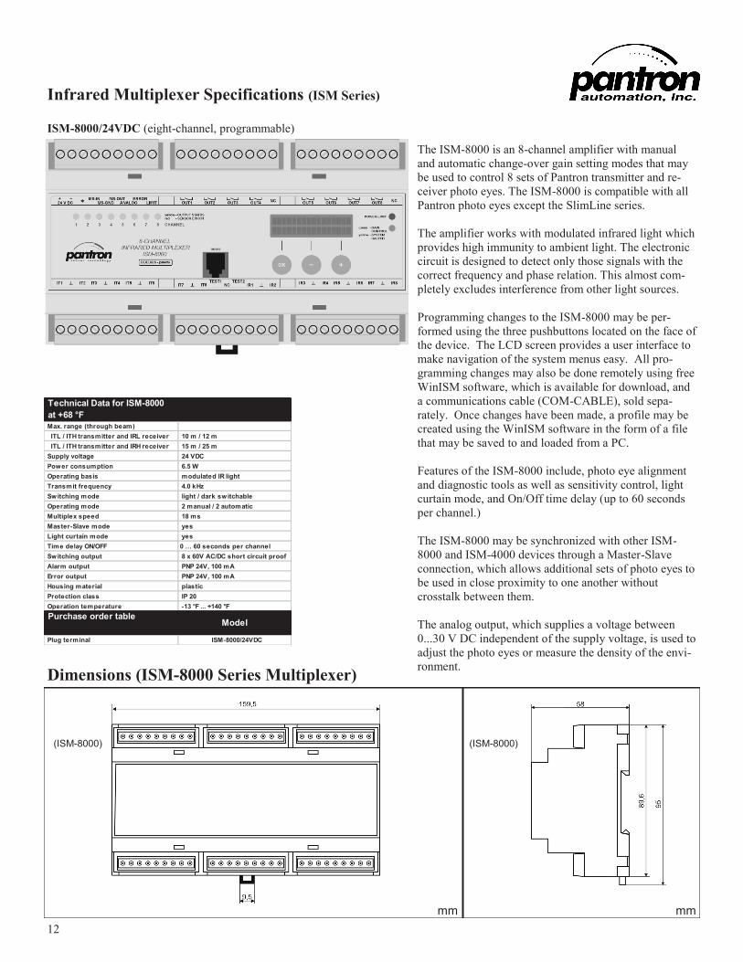
ISM-8000/24VDC (eight-channel, programmable)
Infrared Multiplexer Specifications (ISM Series)
Dimensions (ISM-8000 Series Multiplexer)
The ISM-8000 is an 8-channel amplifier with manual
and automatic change-over gain setting modes that may
be used to control 8 sets of Pantron transmitter and re-
ceiver photo eyes. The ISM-8000 is compatible with all
Pantron photo eyes except the SlimLine series.
The amplifier works with modulated infrared light which
provides high immunity to ambient light. The electronic
circuit is designed to detect only those signals with the
correct frequency and phase relation. This almost com-
pletely excludes interference from other light sources.
Programming changes to the ISM-8000 may be per-
formed using the three pushbuttons located on the face of
the device. The LCD screen provides a user interface to
make navigation of the system menus easy. All pro-
gramming changes may also be done remotely using free
WinISM software, which is available for download, and
a communications cable (COM-CABLE), sold sepa-
rately. Once changes have been made, a profile may be
created using the WinISM software in the form of a file
that may be saved to and loaded from a PC.
Features of the ISM-8000 include, photo eye alignment
and diagnostic tools as well as sensitivity control, light
curtain mode, and On/Off time delay (up to 60 seconds
per channel.)
The ISM-8000 may be synchronized with other ISM-
8000 and ISM-4000 devices through a Master-Slave
connection, which allows additional sets of photo eyes to
be used in close proximity to one another without
crosstalk between them.
The analog output, which supplies a voltage between
0...30 V DC independent of the supply voltage, is used to
adjust the photo eyes or measure the density of the envi-
ronment.
(ISM-8000) (ISM-8000)
Technical Data for ISM-8000
at +68 °F
Max. range (through beam)
ITL / ITH transmitter and IRL receiver 10 m / 12 m
ITL / ITH transmitter and IRH receiver 15 m / 25 m
Supply voltage 24 VDC
Power consumption 6.5 W
Operating basis modulated IR light
Transmit frequency 4.0 kHz
Switching mode light / dark switchable
Operating mode 2 manual / 2 automatic
Multiplex speed 18 ms
Master-Slave mode yes
Light curtain mode yes
Time delay ON/OFF 0 … 60 seconds per channel
Switching output 8 x 60V AC/DC short circuit proof
Alarm output PNP 24V, 100 mA
Error output PNP 24V, 100 mA
Housing material plastic
Protection class IP 20
Operation temperature -13 °F ... +140 °F
Purchase order table
Plug terminal ISM-8000/24VDC
Model
13
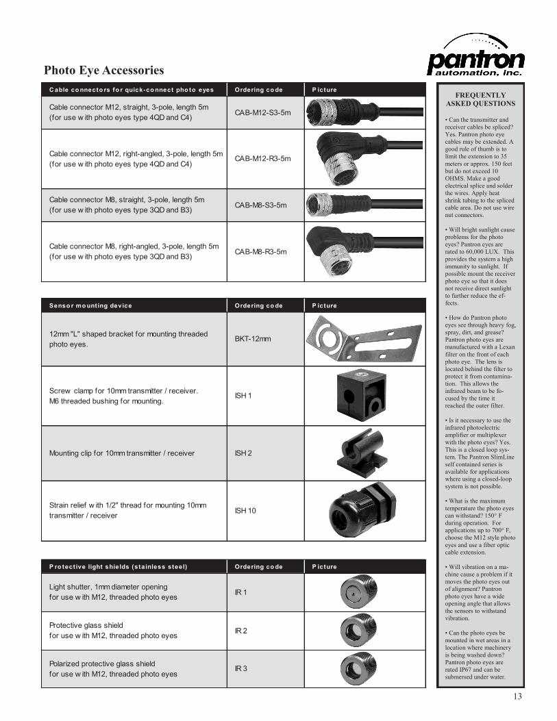
C able co nnecto rs fo r quick-co nnect pho to eyes Ordering co de P icture
Cable connector M12, straight, 3-pole, length 5m
(for use w ith photo eyes type 4QD and C4)CAB-M12-S3-5m
Cable connector M12, right-angled, 3-pole, length 5m
(for use w ith photo eyes type 4QD and C4)CAB-M12-R3-5m
Cable connector M8, straight, 3-pole, length 5m
(for use w ith photo eyes type 3QD and B3)CAB-M8-S3-5m
Cable connector M8, right-angled, 3-pole, length 5m
(for use w ith photo eyes type 3QD and B3)CAB-M8-R3-5m
Photo Eye Accessories
Senso r mo unting device Ordering co de P icture
Mounting clip for 10mm transmitter / receiver ISH 2
Strain relief w ith 1/2" thread for mounting 10mm
transmitter / receiverISH 10
12mm "L" shaped bracket for mounting threaded
photo eyes.BKT-12mm
Screw clamp for 10mm transmitter / receiver.
M6 threaded bushing for mounting.ISH 1
P ro tect ive light shields (stainless steel) Ordering co de P icture
Polarized protective glass shield
for use w ith M12, threaded photo eyesIR 3
Light shutter, 1mm diameter opening
for use w ith M12, threaded photo eyesIR 1
Protective glass shield
for use w ith M12, threaded photo eyesIR 2
FREQUENTLY
ASKED QUESTIONS
• Can the transmitter and
receiver cables be spliced?
Yes. Pantron photo eye
cables may be extended. A
good rule of thumb is to
limit the extension to 35
meters or approx. 150 feet
but do not exceed 10
OHMS. Make a good
electrical splice and solder
the wires. Apply heat
shrink tubing to the spliced
cable area. Do not use wire
nut connectors.
• Will bright sunlight cause
problems for the photo
eyes? Pantron eyes are
rated to 60,000 LUX. This
provides the system a high
immunity to sunlight. If
possible mount the receiver
photo eye so that it does
not receive direct sunlight
to further reduce the ef-
fects.
• How do Pantron photo
eyes see through heavy fog,
spray, dirt, and grease?
Pantron photo eyes are
manufactured with a Lexan
filter on the front of each
photo eye. The lens is
located behind the filter to
protect it from contamina-
tion. This allows the
infrared beam to be fo-
cused by the time it
reached the outer filter.
• Is it necessary to use the
infrared photoelectric
amplifier or multiplexer
with the photo eyes? Yes.
This is a closed loop sys-
tem. The Pantron SlimLine
self contained series is
available for applications
where using a closed-loop
system is not possible.
• What is the maximum
temperature the photo eyes
can withstand? 150° F
during operation. For
applications up to 700° F,
choose the M12 style photo
eyes and use a fiber optic
cable extension.
• Will vibration on a ma-
chine cause a problem if it
moves the photo eyes out
of alignment? Pantron
photo eyes have a wide
opening angle that allows
the sensors to withstand
vibration.
• Can the photo eyes be
mounted in wet areas in a
location where machinery
is being washed down?
Pantron photo eyes are
rated IP67 and can be
submersed under water.

14
P anbo x 1x1 enclo sure fo r pro tect ing o ne ISG series, o ne 2-channel IM X series, o r o ne 1 o r 2 channel ISM series
P anbo x 1x8 enclo sure fo r pro tect ing mult iple ISG and IM X series, two 4 channel ISM series o r o ne 8 channel ISM series
A mplif ier / mult iplexer mo unting Ordering co de P icture
11-pole socket for DIN rail mounting
(required for all ISG and 2-channel IMX series)MB11
Retaining clip for DIN socket MB11
(recommended for applications w ith heavy vibration)RTC 11
Glass f iber o pt ic cables Ordering co de P icture
1m cable w ith M12 threaded end
(for use w ith photo eyes type M12, CLN, CLV, CSN, CSV)PIT.156-1m
3m cable w ith M12 threaded end
(for use w ith photo eyes type M12, CLN, CLV, CSN, CSV)PIT.156-3m
5m cable w ith M12 threaded end
(for use w ith photo eyes type M12, CLN, CLV, CSN, CSV)PIT.156-5m
1m cable w ith M12 threaded 90° end
(for use w ith photo eyes type M12, CLN, CLV, CSN, CSV)PIAT.156-1m
3m cable w ith M12 threaded 90° end
(for use w ith photo eyes type M12, CLN, CLV, CSN, CSV)PIAT.156-3m
5m cable w ith M12 threaded 90° end
(for use w ith photo eyes type M12, CLN, CLV, CSN, CSV)PIAT.156-5m
Photo Eye Accessories
Additional styles, including cables
with bifurcated ends are available
Enclosures for Protecting Amplifiers and Multiplexers
Dimensions in mm
Dimensions in mm
15
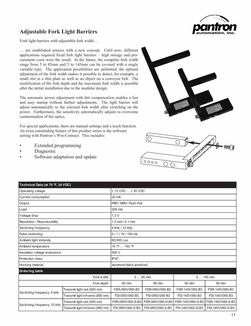
Adjustable Fork Light Barriers
Fork light barriers with adjustable fork width…
… are established sensors with a new concept. Until now, different
applications required fixed fork light barriers – high storage and pro-
curement costs were the result. In the future, the complete fork width
range from 5 to 85mm and 5 to 145mm can be covered with a single
variable type. The application possibilities are unlimited; the optimal
adjustment of the fork width makes it possible to detect, for example, a
small slot in a thin plate as well as an object on a conveyor belt. The
modification of the fork depth and the maximum fork width is possible
after the initial installation due to the modular design.
The automatic power adjustment with dirt compensation enables a fast
and easy startup without further adjustments. The light barrier will
adjust automatically to the selected fork width after switching on the
power. Furthermore, the sensitivity automatically adjusts to overcome
contamination of the optics.
For special applications, there are manual settings and a teach function.
An extra outstanding feature of this product series is the software
setting with Pantron’s Win-Connect. This includes:
• Extended programming
• Diagnostic
• Software adaptation and update
Ordering table
60 mm 90 mm 60 mm 90 mm
Transmit light red (650 nm) FSR-085V060-B3 FSR-085V090-B3 FSR-145V060-B3 FSR-145V090-B3
Transmit light infrared (890 nm) FSI-085V060-B3 FSI-085V090-B3 FSI-145V060-B3 FSI-145V090-B3
Transmit light red (650 nm) FSR-085V060-S-B3 FSR-085V090-S-B3 FSR-145V060-S-B3 FSR-145V090-S-B3
Transmit light infrared (890 nm) FSI-085V060-S-B3 FSI-085V090-S-B3 FSI-145V060-S-B3 FSI-145V090-S-B3
1.3 V
1.0 mm / 0.1 mm
4 kHz / 10 kHz
14 °F … 140 °F
500 V
IP 67
aluminum black anodizedHousing material
Ambient temperature
Insulation voltage endurance
Protection class
0 / 1 / 10 / 100 ms
60,000 Lux
Sw itching frequency
Pulse stretching
Ambient light immunity
Technical Data (at 70 °F, 24 VDC)
+ 12 VDC … + 30 VDC
20 mA
PNP / NPN / Push-Pull
200 mA
Resolution / Reproducibility
Operating voltage
Current consumption
Output
Load
Voltage drop
5 … 145 mm
Sw itching frequency 10 kHz
Sw itching frequency 4 kHz
Fork w idth
Fork depth
5 … 85 mm

Pantron Automation, Inc.
109 Hubbard Street
Belmont, NC 28012
1-800-211-9468 www.pantron.com/us
For more information about
Pantron products, use a QR
scanner application on a
smart phone to scan this code
and be instantly connected to
Pantron’s mobile website.
Related Documents