Power Source : AC AUTO 110-240V, 50/60 Hz Power Consumption : 67W Aerial Impedance : 75Ω unbalanced Coaxial type Receiving System : 17 Systems Receiving Channels : VHF 2-13 (U.S.A. STANDARD) UHF 14-69 (U.S.A. STANDARD) CATV 1-125 (U.S.A. STANDARD) Video / Audio Terminals : DVD Y 1.0Vp-p, 75Ω PB 0.7Vp-p, 75Ω PR 0.7Vp-p, 75Ω AV 1,2,3 Video In 1Vp-p, 75Ω Audio In Approx. 0.5V, 47kΩ Monitor Out Video Out 1Vp-p, 75Ω Audio Out Approx. 0.5V, 1kΩ Intermediate Frequency : Video 38.0 MHz © 2006 Matsushita Electric Industrial Co., Ltd. All rights reserved. Unauthorized copying and distribution is a violation of law. TC-21FX20P GP41 Chassis Sound 31.5 MHz (D, K, K1) 32 MHz (I) 32.5 MHz (B, G) 33.5 MHz (M) Colour 33.57 MHz (PAL) 33.6 MHz (SECAM) 33.75 MHz (SECAM) 34.42 MHz (NTSC) High Voltage : 27.5kV ±1.5V at zero beam current Picture Tube : A51LYZ295X 50.0cm (21 inches) Measured diagonally, 90° deflection Audio Output : 16.0W Dimensions : Height : 472 mm Width : 648 mm Depth : 488 mm Mass : 24 kg (Net Wt.) Specifications are subject to change without notice. Mass and dimensions shown are approximate. Colour Television Specifications ORDER NO. MTV0601423CE

Welcome message from author
This document is posted to help you gain knowledge. Please leave a comment to let me know what you think about it! Share it to your friends and learn new things together.
Transcript
Power Source : AC AUTO 110-240V, 50/60 Hz
Power Consumption : 67W
Aerial Impedance : 75Ω unbalanced
Coaxial type
Receiving System : 17 Systems
Receiving Channels :VHF 2-13 (U.S.A. STANDARD)
UHF 14-69 (U.S.A. STANDARD)
CATV 1-125 (U.S.A. STANDARD)
Video / Audio Terminals :DVD
Y 1.0Vp-p, 75Ω
PB 0.7Vp-p, 75Ω
PR 0.7Vp-p, 75Ω
AV 1,2,3
Video In 1Vp-p, 75Ω
Audio In Approx. 0.5V, 47kΩ
Monitor Out
Video Out 1Vp-p, 75Ω
Audio Out Approx. 0.5V, 1kΩ
Intermediate Frequency :Video 38.0 MHz
© 2006 Matsushita Electric Industrial Co., Ltd. Allrights reserved. Unauthorized copying anddistribution is a violation of law.
TC-21FX20PGP41 Chassis
Sound 31.5 MHz (D, K, K1)
32 MHz (I)
32.5 MHz (B, G)
33.5 MHz (M)
Colour 33.57 MHz (PAL)
33.6 MHz (SECAM)
33.75 MHz (SECAM)
34.42 MHz (NTSC)
High Voltage : 27.5kV ±1.5V
at zero beam current
Picture Tube : A51LYZ295X
50.0cm (21 inches)
Measured diagonally,
90° deflection
Audio Output : 16.0W
Dimensions : Height : 472 mm
Width : 648 mm
Depth : 488 mm
Mass : 24 kg (Net Wt.)
Specifications are subject to change without notice.Mass and dimensions shown are approximate.
Colour Television
Specifications
ORDER NO. MTV0601423CE
1 Safety Precautions 3 1.1. General Guide Lines 3
1.2. Leakage Current Cold Check 3
1.3. Leakage Current Hot Check (Fig. 1) 3
1.4. X-Radiation 3
1.5. GP41 Chassis Block Diagram 4
2 Service Hints 5 2.1. Service Position for E-Board 5
2.2. Factory Mode Adjustment 5
2.3. Adjustment for White Balance 7
2.4. Adjustment for CRT CUT OFF 7
2.5. Adjustment Procedure 8
2.6. Adjustment 9
3 Conductor Views 12 4 Schematic Diagram 13
4.1. A Board 15
4.2. L Board 20
5 Parts Locations 23 6 Replacement Parts List 24
6.1. Replacement Parts List 25
CONTENTS Page Page
2
TC-21FX20P

1 Safety Precautions1.1. General Guide Lines 1. It is advisable to insert an isolation transformer in the AC supply before servicing this hot chassis. 2. When servicing, observe the original lead dress, especially the lead dress in the high voltage circuits. If a short circuit is found,
replace all parts which have been overheated or damaged by the short circuit. 3. After servicing, see to it that all the protective devices such as insulation barriers, insulation papers, shields and isolation R-C
combinations, are properly installed. 4. When the receiver is not to be used for a long period of time, unplug the power cord from the AC cord outlet. 5. Potential, as high as 29.0kV is present when this receiver is in operation. Operation of the receiver without the rear cover
involves the danger of a shock hazard from the receiver power supply. Servicing should not be attempted by anyone who is notthoroughly familiar with the precautions necessary when working on high voltage equipment. Always discharge the anode of thepicture tube to the receiver chassis before handling the tube. After servicing make the following leakage current checks toprevent the customer from being exposed to shock hazards.
1.2. Leakage Current Cold Check 1. Unplug the AC cord and connect a jumper between the two prongs on the plug. 2. Turn on the receiver’s power switch.
Measure the resistance value, with an ohmmeter, between the jumper AC plug and each exposed metallic cabinet part on thereceiver, such as screw heads, aerials, connectors, control shafts, etc. When the exposed metallic part has a return path to thechassis, the reading should be between 4 MΩ and 20 MΩ. When the exposed metal does not have a return path to the chassis,the reading must be infinite.
1.3. Leakage Current Hot Check (Fig. 1) 1. Plug the AC cord directly into the AC outlet. Do not use an isolation transformer for this check. 2. Check a 2 kΩ non-inductive resistor and an AC/DC current meter, in series with each exposed metallic part on the receiver in
turn and an earth such as a water pipe.The current from any point should not exceed 0.7 mA peak AC or 2 mA DC. In the case of a measurement being outside ofthese limits specified, there is a possibility of a shock hazard and the receiver should be repaired and rechecked before it isreturned to the customer.
Fig. 1
1.4. X-RadiationWarning:The potential sources of X-Radiation in TV set are the EHT section and the picture tube. When using a picture tube test jig forservice, ensure that jig is capable of handling 29.0kV without causing X-Radiation.Note: It is important to use an accurate periodically calibrated high voltage meter. 1. Set the brightness to minimum. 2. Use the remocon to get into Service Mode. 3. Measure the EHT. The meter reading should indicate 27.5±1.5kV. If the meter indication is out of tolerance, immediate service
and correction is required to prevent the possibility of premature component failure. 4. To prevent the possibility X-Radiation, it is essential to use the specified picture tube, if service replacement becomes
necessary.
3
TC-21FX20P
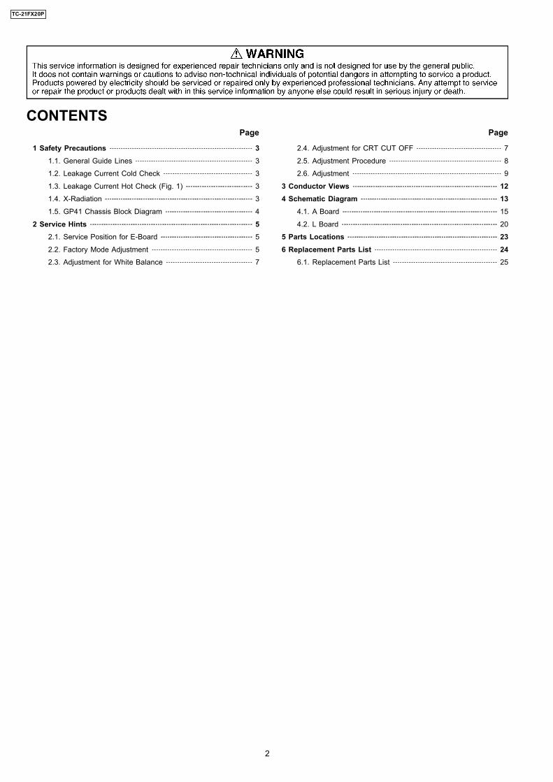
1.5. GP41 Chassis Block Diagram
GP
41 C
HA
SSIS
BL
OC
K D
IAG
RA
M
CR
Tde
fl.
coil
CR
TD
RIV
E
VM
DR
IVE
L
FR
ON
T I
NP
UT
SA
V2
: V
/L/R
MA
INP
OW
ER
SWIT
CH
G GE
OM
AG
NE
TIC
WO
OF
ER
AM
PIC
2401
PV
PIC
1801 R
/G/B
SC
L
SD
A
CV
BS
IN
RE
AR
IN
PU
TS
AV
1 :
V/L
/R
AV
3 :
YU
V/V
/L/R
VC
T-I
FIC
601
V_INC
VB
S O
UT
MO
N_O
UT
R G B
R/G
/B
MO
N_O
UT
V/L
/R
EE
PR
OM
IC11
01
VM
SC
L S
DA
A_IN
IFH
A
AU
DIO
OU
T
V
SPE
AK
ER
AU
DIO
AM
PIC
2301
V O
UT
H O
UT
TU
NE
R
FR
ON
T I
NP
UT
SA
V2
: V
/L/R
PP
29
" m
od
els
PIP
mo
del
s
4
TC-21FX20P
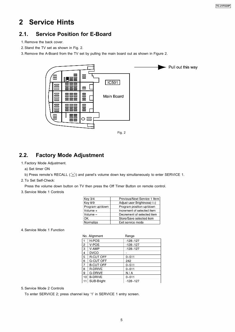
2 Service Hints2.1. Service Position for E-Board 1. Remove the back cover. 2. Stand the TV set as shown in Fig. 2. 3. Remove the A-Board from the TV set by pulling the main board out as shown in Figure 2.
Fig. 2
2.2. Factory Mode Adjustment 1. Factory Mode Adjustment.
a) Set timer ONb) Press remote’s RECALL ( ) and panel’s volume down key simultaneously to enter SERVICE 1.
2. To Set Self-Check:Press the volume down button on TV then press the Off Timer Button on remote control.
3. Service Mode 1 Controls
4. Service Mode 1 Function
5. Service Mode 2 ControlsTo enter SERVICE 2; press channel key ‘1’ in SERVICE 1 entry screen.
5
TC-21FX20P
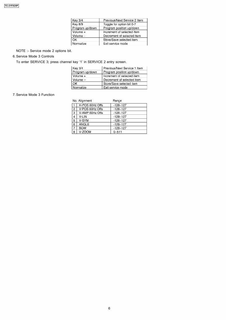
NOTE :- Service mode 2 options bit. 6. Service Mode 3 Controls
To enter SERVICE 3; press channel key ‘1’ in SERVICE 2 entry screen.
7. Service Mode 3 Function
6
TC-21FX20P
2.3. Adjustment for White BalancePreparation: 1. Receive the white balance pattern and aging should have been performed over 30 minutes. 2. Set the picture menu to DYNAMIC NORMAL. 3. Degausse the CRT face. 4. Fix the CRT colour analyzer receiver unit to CRT face.
Adjustment of Low Light. 1. Adjustment Sub Bright, so that Y = 6.5 ± 1.0 nit. 2. Adjustment R-CUT OFF, so that X = 0.245 ± 0.015 nit. 3. Adjustment G-CUT OFF, so that Y = 0.274 ± 0.015 nit.
Adjustment of High Light 1. Adjustment Sub Bright, so that Y = 150 nit. 2. Adjustment R-Drive, so that X = 0.261 ± 0.015 nit. 3. Adjustment B-Drive, so that Y = 0.267 ± 0.015 nit.
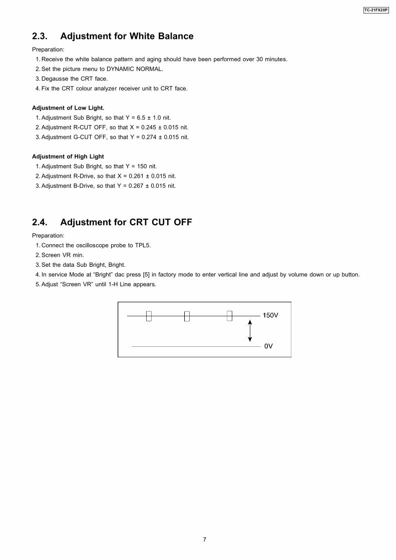
2.4. Adjustment for CRT CUT OFFPreparation: 1. Connect the oscilloscope probe to TPL5. 2. Screen VR min. 3. Set the data Sub Bright, Bright. 4. In service Mode at “Bright” dac press [5] in factory mode to enter vertical line and adjust by volume down or up button. 5. Adjust “Screen VR” until 1-H Line appears.
7
TC-21FX20P
2.5. Adjustment Procedure2.5.1. +B VoltageItem / preparation 1. Operate the TV set. 2. Set control as follows :
Brightness ........... minimumContrast ............... minimum
Adjustment procedure 1. Confirm the DC voltage at the indicated test points, as follows :
TPA 15 : 3.35 ± 0.2VTPA 16 : 141 ± 2VTPA 17 : 8.2 ± 0.5VTPA 18 : 1.9 ± 0.2VTPA 19 : 5.2 ± 0.2VTPA 20 : 175 ± 15V
2.5.2. High VoltageItem / preparation 1. Receive the crosshatch pattern. 2. Set to 0 Beam.
Screen VR .......... minimumContrast .............. minimum
Adjustment procedure 1. Connect a DC voltage meter to TPA 16 and confirm the +B voltage is 141.0 ± 2V. 2. Connect a high frequency voltmeter to heater and confirm that voltage reads 6.3 ± 0.24 (VRMS). 3. Normalize the brightness and contrast.
8
TC-21FX20P
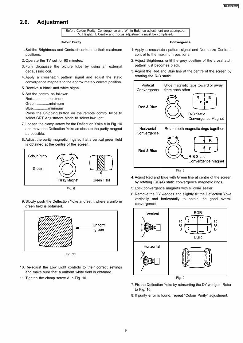
Colour Purity
1. Set the Brightness and Contrast controls to their maximumpositions.
2. Operate the TV set for 60 minutes. 3. Fully degausse the picture tube by using an external
degaussing coil. 4. Apply a crosshatch pattern signal and adjust the static
convergence magnets to the approximately correct position. 5. Receive a black and white signal. 6. Set the control as follows:
Red................minimumGreen.............minimumBlue...............minimumPress the Shipping button on the remote control twice toselect CRT Adjustment Mode to select low light.
7. Loosen the clamp screw for the Deflection Yoke A in Fig. 10and move the Deflection Yoke as close to the purity magnetas possible.
8. Adjust the purity magnetic rings so that a vertical green fieldis obtained at the centre of the screen.
Fig. 6
9. Slowly push the Deflection Yoke and set it where a uniformgreen field is obtained.
Fig. 21
10. Re-adjust the Low Light controls to their correct settingsand make sure that a uniform white field is obtained.
11. Tighten the clamp screw A in Fig. 10.
Convergence
1. Apply a crosshatch pattern signal and Normalize Contrastcontrol to the maximum positions.
2. Adjust Brightness until the grey position of the crosshatchpattern just becomes black.
3. Adjust the Red and Blue line at the centre of the screen byrotating the R-B static.
Fig. 8
4. Adjust Red and Blue with Green line at centre of the screenby rotating (RB)-G static convergence magnetic rings.
5. Lock convergence magnets with silicone sealer. 6. Remove the DY wedges and slightly tilt the Deflection Yoke
vertically and horizontally to obtain the good overallconvergence.
Fig. 9
7. Fix the Deflection Yoke by reinserting the DY wedges. Referto Fig. 10.
8. If purity error is found, repeat “Colour Purity” adjustment.
2.6. AdjustmentBefore Colour Purity, Convergence and White Balance adjustment are attempted,
V. Height, H. Centre and Focus adjustments must be completed.
9
TC-21FX20P
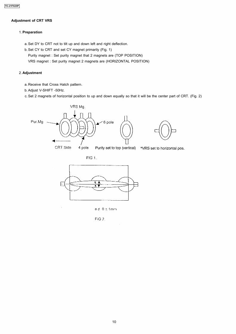
Adjustment of CRT VRS
1. Preparation
a. Set DY to CRT not to tilt up and down left and right deflection. b. Set CY to CRT and set CY magnet primarily (Fig. 1)
Purity magnet : Set purity magnet that 2 magnets are (TOP POSITION)VRS magnet : Set purity magnet 2 magnets are (HORIZONTAL POSITION)
2. Adjustment
a. Receive that Cross Hatch pattern. b. Adjust V-SHIFT -50Hz. c. Set 2 magnets of horizontal position to up and down equally so that it will be the center part of CRT. (Fig. 2)
10
TC-21FX20P
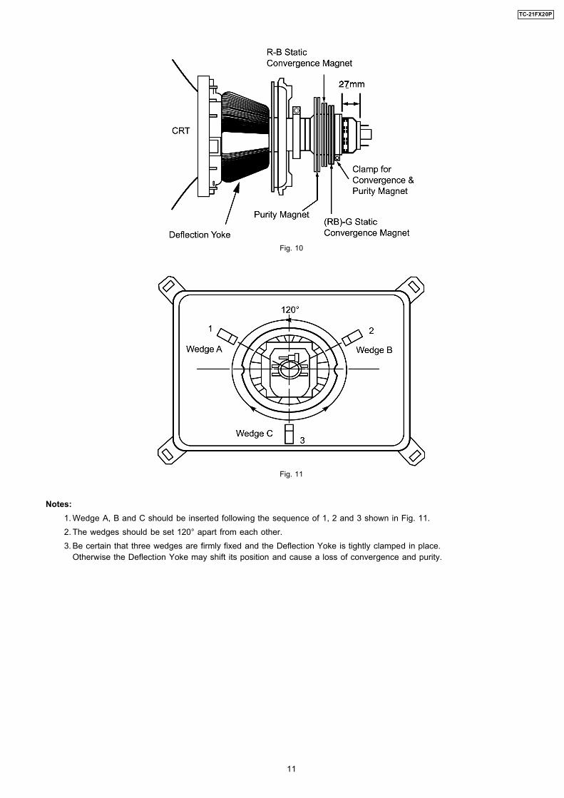
Fig. 10
Fig. 11
Notes: 1. Wedge A, B and C should be inserted following the sequence of 1, 2 and 3 shown in Fig. 11. 2. The wedges should be set 120° apart from each other. 3. Be certain that three wedges are firmly fixed and the Deflection Yoke is tightly clamped in place.
Otherwise the Deflection Yoke may shift its position and cause a loss of convergence and purity.
11
TC-21FX20P
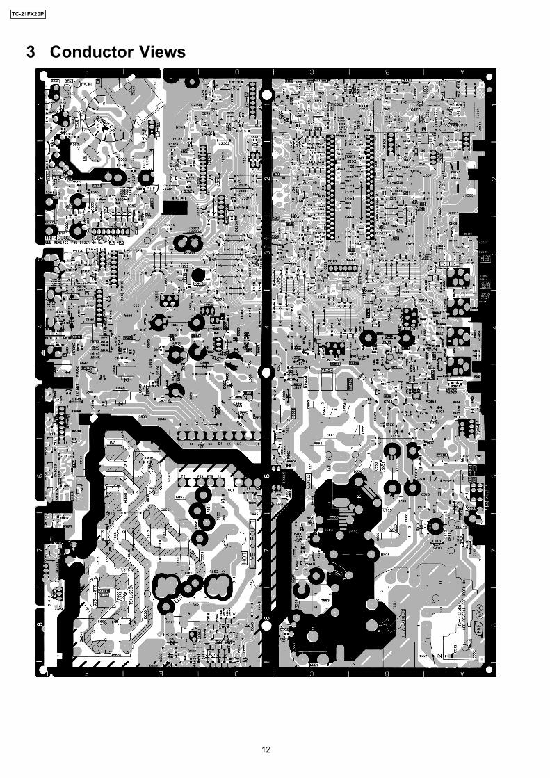
3 Conductor Views
12
TC-21FX20P
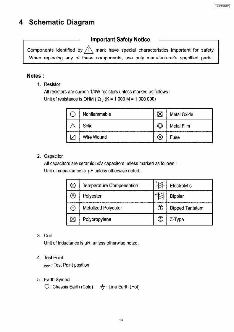
4 Schematic Diagram
13
TC-21FX20P
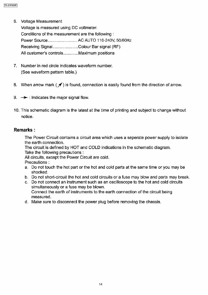
14
TC-21FX20P
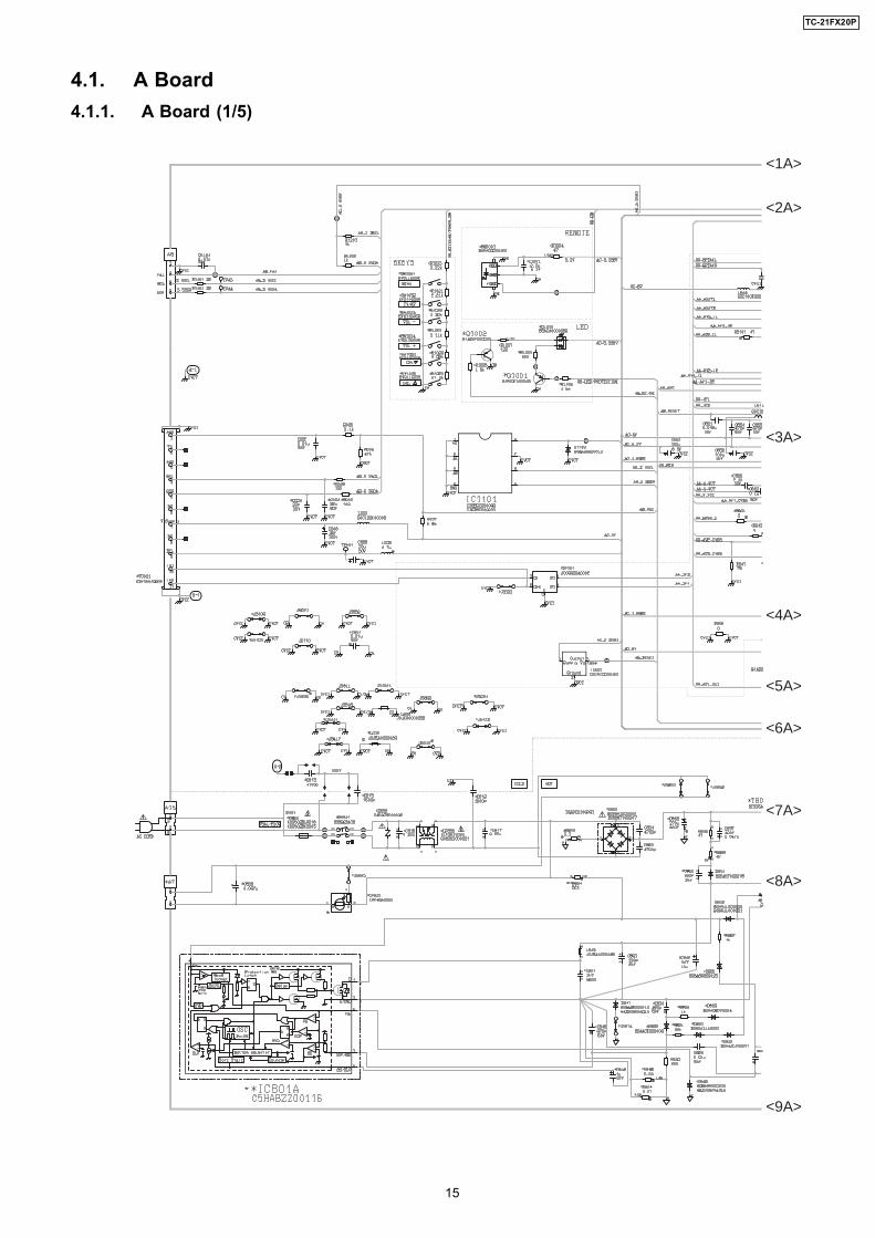
4.1. A Board4.1.1. A Board (1/5)
<1A>
<2A>
<3A>
<4A>
<5A>
<6A>
<7A>
<8A>
<9A>
15
TC-21FX20P
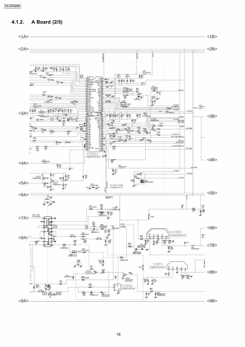
4.1.2. A Board (2/5)
<1A>
<2A>
<3A>
<4A>
<5A>
<6A>
<7A>
<8A>
<9A>
<1B>
<2B>
<3B>
<4B>
<5B>
<6B>
<7B>
<8B>
<9B>
16
TC-21FX20P
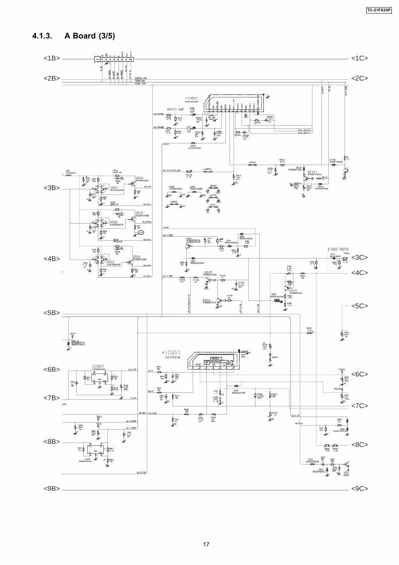
4.1.3. A Board (3/5)
<1B>
<2B>
<3B>
<4B>
<5B>
<6B>
<7B>
<8B>
<9B>
<1C>
<2C>
<3C>
<4C>
<5C>
<6C>
<7C>
<8C>
<9C>
17
TC-21FX20P
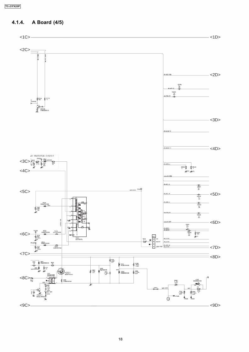
4.1.4. A Board (4/5)
<1C>
<2C>
<3C>
<4C>
<5C>
<6C>
<7C>
<8C>
<9C>
<1D>
<2D>
<3D>
<4D>
<5D>
<6D>
<7D>
<8D>
<9D>
18
TC-21FX20P
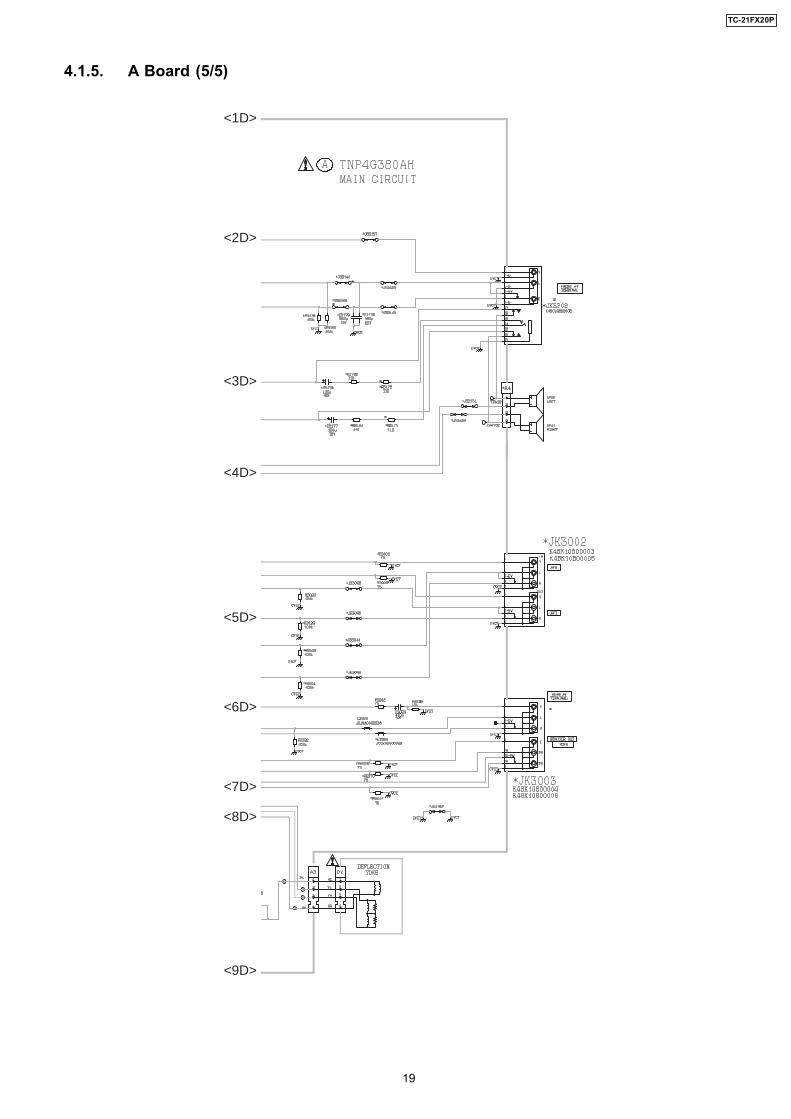
4.1.5. A Board (5/5)
<1D>
<2D>
<3D>
<4D>
<5D>
<6D>
<7D>
<8D>
<9D>
19
TC-21FX20P
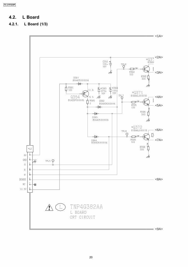
4.2. L Board4.2.1. L Board (1/3)
<1A>
<2A>
<3A>
<4A>
<5A>
<6A>
<7A>
<8A>
<9A>
20
TC-21FX20P
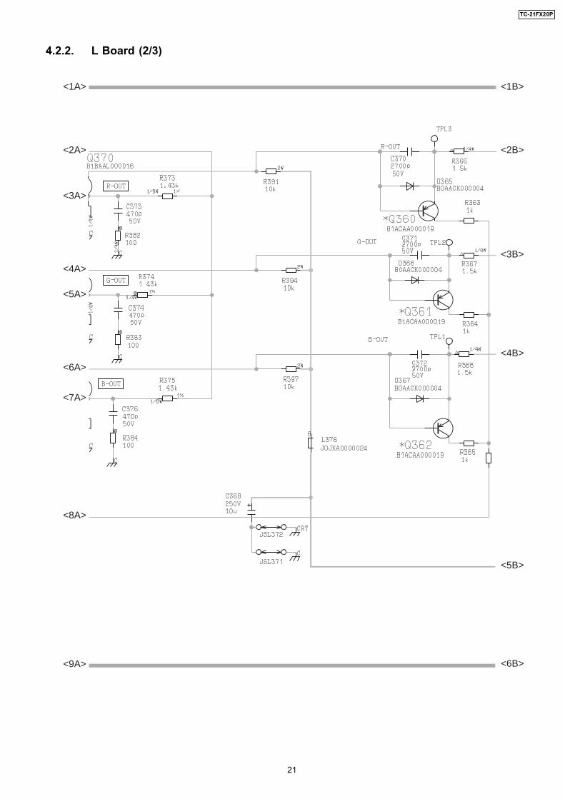
4.2.2. L Board (2/3)
<1A>
<2A>
<3A>
<4A>
<5A>
<6A>
<7A>
<8A>
<9A>
<1B>
<2B>
<3B>
<4B>
<5B>
<6B>
21
TC-21FX20P
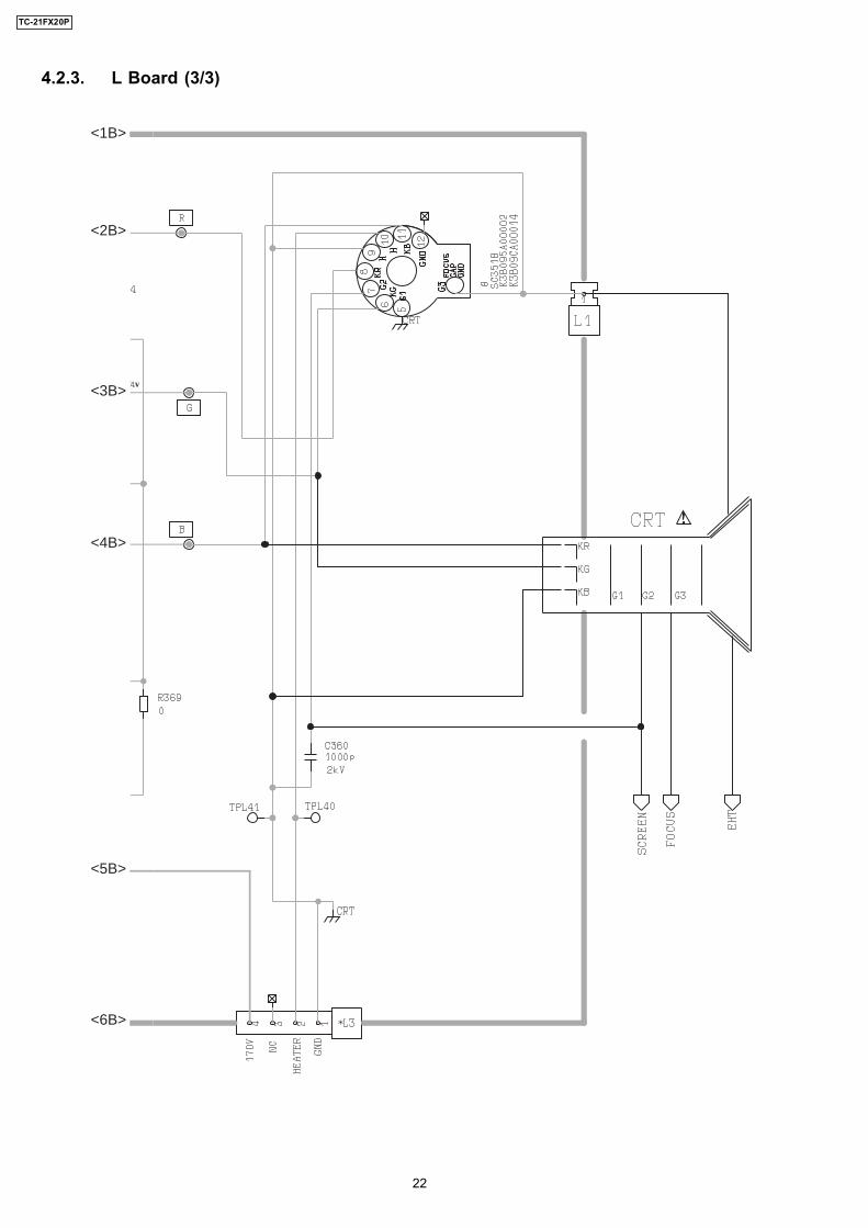
4.2.3. L Board (3/3)
<1B>
<2B>
<3B>
<4B>
<5B>
<6B>
22
TC-21FX20P
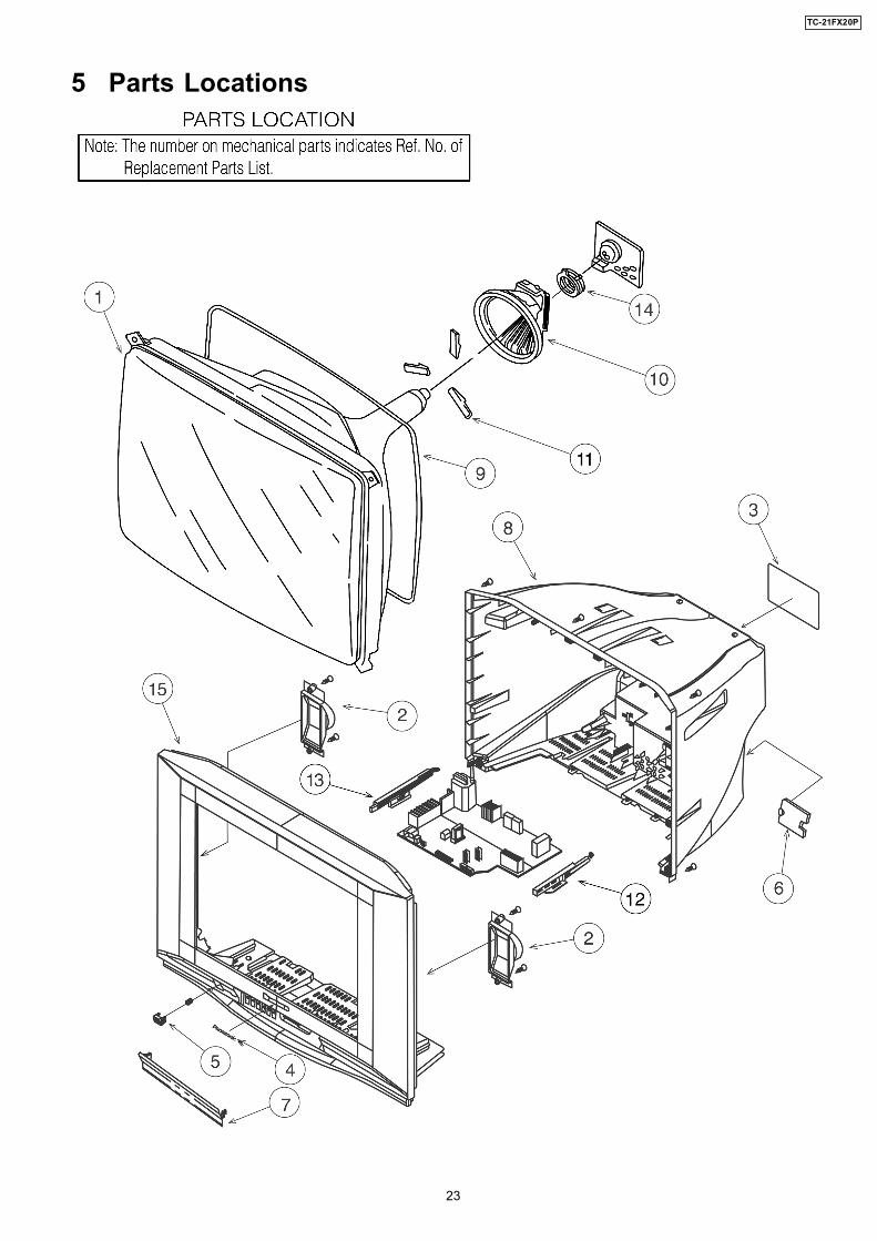
5 Parts Locations
23
TC-21FX20P
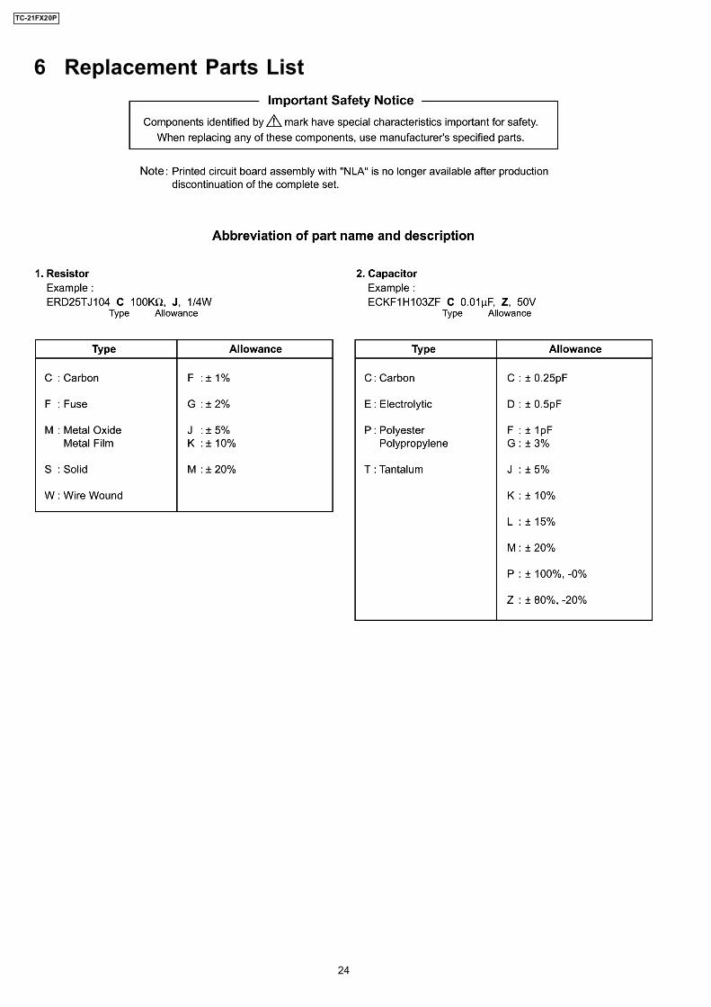
6 Replacement Parts List
24
TC-21FX20P
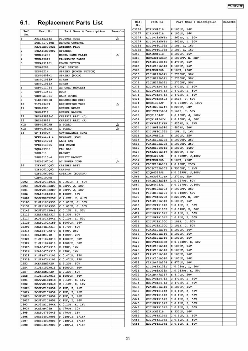
6.1. Replacement Parts ListRef.No.
Part No. Part Name & Description Remarks
1 A51LYZ295X PICTURE TUBE
EUR7717040R REMOTE CONTROL
K2JZ2B000021 ANTENNA PLUG
2 L0AA11C00002 SPEAKER
3 TBM4G1296 MODEL NAME PLATE
4 TBM4G3017 PANASONIC BADGE
5 TBX4G91101 POWER BUTTON
TES4G206 COIL SPRING
TES4G214 SPRING (POWER BUTTON)
TES4G409-1 SPRING (DOOR)
THT4G10139 SCREW
THT4G1014J SCREW
6 TKP4G11744 AC CORD BRACKET
7 TKP4G13471 DOOR
8 TKU4GA1351 BACK COVER
9 TLK4G9096X DEGAUSSING COIL
10 TLY4G348T DEFLECTION YOKE
11 TMM4G503 RUBBER WEDGE
TMM4G516 RUBBER WASHER
12 TMZ4G9818-1 CHASSIS RAIL (L)
13 TMZ4G9824 CHASSIS RAIL (R)
NLA TNP4G380AH A BOARD
NLA TNP4G382AA L BOARD
13 TP-5400PW CONVERGENCE YOKE
TPD4G1171-1 CUSHION (TOP)
TPE4G14003 LAMI BAG
TPE4G14025 SET COVER
TQB4G3996 FAN BAG
TSMA011 MAGNET
TSN63115-4 PURITY MAGNET
TSX4G167L-1 AC POWER CORD
14 TXFKY01DQ03 CABINET ASSY
TXFPC01DQ03 CARTON
TXFPD06DS02 CUSHION (BOTTOM)
CAPACITORS
C002 ECJ1VF1H103Z C 0.01UF, Z, 50V
C003 ECJ1VC1H220J C 22PF, J, 50V
C004 ECJ1VC1H220J C 22PF, J, 50V
C006 F2A1C101A310 E 100UF, 16V
C1001 ECJ2FB0J225K C 2.2UF, J, 6.3V
C1103 F1J1H103A590 C 0.01UF, J, 50V
C1131 F1J1H103A590 C 0.01UF, J, 50V
C1142 ECJ1VF1H104Z C 0.1UF, Z, 50V
C2113 F2A1H3R3A317 E 3.3UF, 50V
C2117 ECJ1VF1H104Z C 0.1UF, Z, 50V
C2129 F2A1C102A159 E 1000UF, 16V
C2303 F2A1H4R7A317 E 4.7UF, 50V
C2314 F2A1E470A270 E 47UF, 25V
C2315 ECA1EM471B E 470UF, 25V
C2321 F1J1H102A018 E 1000UF, 50V
C2322 F1J1H102A018 E 1000UF, 50V
C2325 F2A1C470A310 E 47UF, 16V
C2326 F2A1C470A310 E 47UF, 16V
C2328 F1J1E474A101 C 0.47UF, 25V
C2329 F1J1E474A101 C 0.47UF, 25V
C253 ECEA1HN2R2U E 2.2UF, 50V
C254 F1J1H102A018 E 1000UF, 50V
C257 ECEA1HN2R2U E 2.2UF, 50V
C258 F1J1H102A018 E 1000UF, 50V
C301 ECJ2VB1C104K C 0.1UF, K, 16V
C302 ECJ2VB1C104K C 0.1UF, K, 16V
C3023 ECJ1VF1C105Z C 1UF, Z, 16V
C3024 ECJ1VF1C105Z C 1UF, Z, 16V
C3025 ECJ1VF1C105Z C 1UF, Z, 16V
C3027 ECJ1VF1C105Z C 1UF, Z, 16V
C303 ECJ2VB1C104K C 0.1UF, K, 16V
C3034 ECA1AM471B E 470UF, 10V
C305 F2A1C4710045 E 470UF, 16V
C306 D0GB240JA008 F 24UF,J, 1/16W
C307 D0GB240JA008 F 24UF,J, 1/16W
C308 D0GB240JA008 F 24UF,J, 1/16W
Ref.No.
Part No. Part Name & Description Remarks
C3176 ECA1CM101B E 100UF, 16V
C3177 ECA1CM101B E 100UF, 16V
C3178 ECJ1VC1H561J C 560PF, J, 50V
C3179 ECJ1VC1H561J C 560PF, J, 50V
C3184 ECJ1VF1C105Z C 1UF, Z, 16V
C3185 ECJ1VF1C105Z C 1UF, Z, 16V
C350 ECA1CM101B E 100UF, 16V
C360 ECKW3D102KBP C 1000PF, K, 2KV
C363 F2A1C4710045 E 470UF, 16V
C366 F2A1C101A310 E 100UF, 16V
C368 ECA2EM100B E 10UF, 250V
C370 F1J1H272A021 C 2700PF, 50V
C371 F1J1H272A021 C 2700PF, 50V
C372 F1J1H272A021 C 2700PF, 50V
C373 ECJ1VC1H471J C 470PF, J, 50V
C374 ECJ1VC1H471J C 470PF, J, 50V
C376 ECJ1VC1H471J C 470PF, J, 50V
C401 ECJ1VC1H560J C 56PF, J, 50V
C404 ECQB1333JF P 0.033UF, J, 100V
C406 F2A1H221A247 E 220UF, 50V
C407 ECJ1VC1H560J C 56PF, J, 50V
C408 ECQB1154JF P 0.15UF, J, 100V
C454 ECQV1H154JM P 0.15UF, J, 50V
C502 ECKR3A821KBP C 820PF, K, 1KV
C504 F1J1H681A590 C 680PF, 50V
C507 ECJ1VF1C105Z C 1UF, Z, 16V
C511 ECA1VM101B E 100UF, 35V
C514 F2A1E102A225 E 1000UF, 25V
C516 F2A1E102A225 E 1000UF, 25V
C519 F2A2C1010015 E 100UF, 160V
C520 F2A0J221A317 E 220UF, 6.3V
C550 ECQM4223JZ P 0.022UF, J,400V
C552 ECA2EM100B E 10UF, 250V
C554 F0C2E184A039 P 0.18UF, 250V
C559 F0C3C752A002 P 7500PF, 1.6kV
C560 ECQM4393JZ P 0.039UF, J,400V
C561 ECKW3D271JBR C 270PF, 2kV
C565 F0A1H273A039 C 0.027UF, 50V
C567 ECQM4473JZ P 0.047UF, J,400V
C568 F0C3D102A003 P 1000PF, 2kV
C601 F1J1H183A021 C 0.018UF, 50V
C602 ECJ1VB1H222K C 2200PF, K, 50V
C604 F2A1C101A310 E 100UF, 16V
C606 ECJ1VF1H104Z C 0.1UF, Z, 50V
C607 ECJ1VF1H103Z C 0.01UF, Z, 50V
C611 ECJ1VF1H104Z C 0.1UF, Z, 50V
C613 ECJ1VF1H104Z C 0.1UF, Z, 50V
C614 ECJ1VC1H100C C 10PF, C, 50V
C615 ECJ1VC1H100C C 10PF, C, 50V
C616 F2A1C101A310 E 100UF, 16V
C618 F2A1C101A310 E 100UF, 16V
C619 F2A1C101A310 E 100UF, 16V
C620 ECJ1VB1H333K C 0.033UF, K, 50V
C622 F2A1C101A310 E 100UF, 16V
C623 F2A1C101A310 E 100UF, 16V
C626 F2A1C101A310 E 100UF, 16V
C627 F2A1C101A310 E 100UF, 16V
C628 F2A1A471A274 E 470UF, 10V
C630 ECJ1VF1H103Z C 0.01UF, Z, 50V
C631 ECJ1VB1H333K C 0.033UF, K, 50V
C632 F2A1H4R7A317 E 4.7UF, 50V
C633 ECJ1VC1H471J C 470PF, J, 50V
C634 ECJ1VC1H471J C 470PF, J, 50V
C635 F2A1C101A310 E 100UF, 16V
C639 ECJ1VF1H104Z C 0.1UF, Z, 50V
C640 ECJ1VF1H104Z C 0.1UF, Z, 50V
C642 ECJ1VF1H104Z C 0.1UF, Z, 50V
C645 ECJ1VF1H104Z C 0.1UF, Z, 50V
C646 ECJ1VF1H104Z C 0.1UF, Z, 50V
C650 ECA1CM331B E 330UF, 16V
C652 ECJ1VF1H104Z C 0.1UF, Z, 50V
C654 ECJ1VF1H104Z C 0.1UF, Z, 50V
C655 ECJ1VF1H104Z C 0.1UF, Z, 50V
25
TC-21FX20P
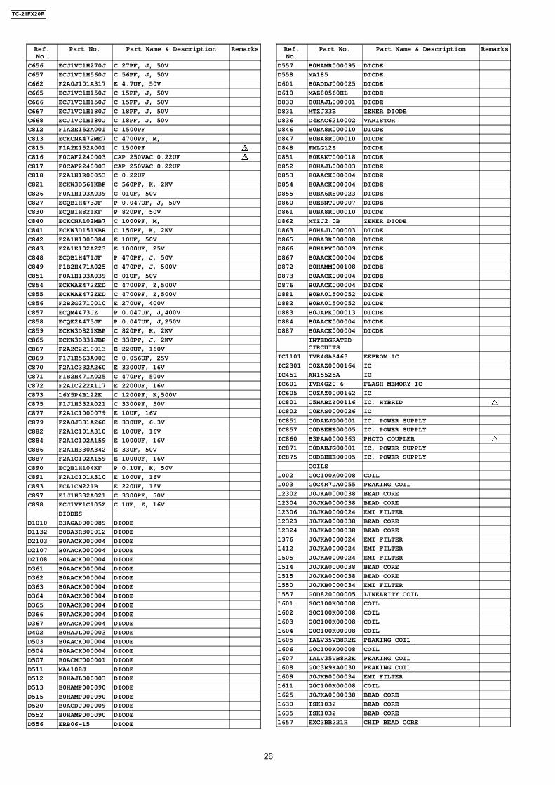
Ref.No.
Part No. Part Name & Description Remarks
C656 ECJ1VC1H270J C 27PF, J, 50V
C657 ECJ1VC1H560J C 56PF, J, 50V
C662 F2A0J101A317 E 4.7UF, 50V
C665 ECJ1VC1H150J C 15PF, J, 50V
C666 ECJ1VC1H150J C 15PF, J, 50V
C667 ECJ1VC1H180J C 18PF, J, 50V
C668 ECJ1VC1H180J C 18PF, J, 50V
C812 F1A2E152A001 C 1500PF
C813 ECKCNA472ME7 C 4700PF, M,
C815 F1A2E152A001 C 1500PF
C816 F0CAF2240003 CAP 250VAC 0.22UF
C817 F0CAF2240003 CAP 250VAC 0.22UF
C818 F2A1H1R00053 C 0.22UF
C821 ECKW3D561KBP C 560PF, K, 2KV
C826 F0A1H103A039 C 01UF, 50V
C827 ECQB1H473JF P 0.047UF, J, 50V
C830 ECQB1H821KF P 820PF, 50V
C840 ECKCNA102MB7 C 1000PF, M,
C841 ECKW3D151KBR C 150PF, K, 2KV
C842 F2A1H1000084 E 10UF, 50V
C843 F2A1E102A223 E 1000UF, 25V
C848 ECQB1H471JF P 470PF, J, 50V
C849 F1B2H471A025 C 470PF, J, 500V
C851 F0A1H103A039 C 01UF, 50V
C854 ECKWAE472ZED C 4700PF, Z,500V
C855 ECKWAE472ZED C 4700PF, Z,500V
C856 F2B2G2710010 E 270UF, 400V
C857 ECQM4473JZ P 0.047UF, J,400V
C858 ECQE2A473JF P 0.047UF, J,250V
C859 ECKW3D821KBP C 820PF, K, 2KV
C865 ECKW3D331JBP C 330PF, J, 2KV
C867 F2A2C2210013 E 220UF, 160V
C869 F1J1E563A003 C 0.056UF, 25V
C870 F2A1C332A260 E 3300UF, 16V
C871 F1B2H471A025 C 470PF, 500V
C872 F2A1C222A117 E 2200UF, 16V
C873 L6Y5P4B122K C 1200PF, K,500V
C875 F1J1H332A021 C 3300PF, 50V
C877 F2A1C1000079 E 10UF, 16V
C879 F2A0J331A260 E 330UF, 6.3V
C882 F2A1C101A310 E 100UF, 16V
C884 F2A1C102A159 E 1000UF, 16V
C886 F2A1H330A342 E 33UF, 50V
C887 F2A1C102A159 E 1000UF, 16V
C890 ECQB1H104KF P 0.1UF, K, 50V
C891 F2A1C101A310 E 100UF, 16V
C893 ECA1CM221B E 220UF, 16V
C897 F1J1H332A021 C 3300PF, 50V
C898 ECJ1VF1C105Z C 1UF, Z, 16V
DIODES
D1010 B3AGA0000089 DIODE
D1132 B0BA3R800012 DIODE
D2103 B0AACK000004 DIODE
D2107 B0AACK000004 DIODE
D2108 B0AACK000004 DIODE
D361 B0AACK000004 DIODE
D362 B0AACK000004 DIODE
D363 B0AACK000004 DIODE
D364 B0AACK000004 DIODE
D365 B0AACK000004 DIODE
D366 B0AACK000004 DIODE
D367 B0AACK000004 DIODE
D402 B0HAJL000003 DIODE
D503 B0AACK000004 DIODE
D504 B0AACK000004 DIODE
D507 B0ACMJ000001 DIODE
D511 MA4108J DIODE
D512 B0HAJL000003 DIODE
D513 B0HAMP000090 DIODE
D515 B0HAMP000090 DIODE
D520 B0ACDJ000009 DIODE
D552 B0HAMP000090 DIODE
D556 ERB06-15 DIODE
Ref.No.
Part No. Part Name & Description Remarks
D557 B0HAMR000095 DIODE
D558 MA185 DIODE
D601 B0ADDJ000025 DIODE
D610 MAZ80560HL DIODE
D830 B0HAJL000001 DIODE
D831 MTZJ33B ZENER DIODE
D836 D4EAC6210002 VARISTOR
D846 B0BA8R000010 DIODE
D847 B0BA8R000010 DIODE
D848 FMLG12S DIODE
D851 B0EAKT000018 DIODE
D852 B0HAJL000003 DIODE
D853 B0AACK000004 DIODE
D854 B0AACK000004 DIODE
D855 B0BA6R800023 DIODE
D860 B0EBNT000007 DIODE
D861 B0BA8R000010 DIODE
D862 MTZJ2.0B ZENER DIODE
D863 B0HAJL000003 DIODE
D865 B0BA3R500008 DIODE
D866 B0HAPV000009 DIODE
D867 B0AACK000004 DIODE
D872 B0HAMM000108 DIODE
D873 B0AACK000004 DIODE
D876 B0AACK000004 DIODE
D881 B0BA01500052 DIODE
D882 B0BA01500052 DIODE
D883 B0JAPK000013 DIODE
D884 B0AACK000004 DIODE
D887 B0AACK000004 DIODE
INTEDGRATEDCIRCUITS
IC1101 TVR4GAS463 EEPROM IC
IC2301 C0ZAZ0000164 IC
IC451 AN15525A IC
IC601 TVR4G20-6 FLASH MEMORY IC
IC605 C0ZAZ0000162 IC
IC801 C5HABZZ00116 IC, HYBRID
IC802 C0EAS0000026 IC
IC851 C0DAEJG00001 IC, POWER SUPPLY
IC857 C0DBEHE00005 IC, POWER SUPPLY
IC860 B3PAA0000363 PHOTO COUPLER
IC871 C0DAEJG00001 IC, POWER SUPPLY
IC875 C0DBEHE00005 IC, POWER SUPPLY
COILS
L002 G0C100K00008 COIL
L003 G0C4R7JA0055 PEAKING COIL
L2302 J0JKA0000038 BEAD CORE
L2304 J0JKA0000038 BEAD CORE
L2306 J0JKA0000024 EMI FILTER
L2323 J0JKA0000038 BEAD CORE
L2324 J0JKA0000038 BEAD CORE
L376 J0JKA0000024 EMI FILTER
L412 J0JKA0000024 EMI FILTER
L505 J0JKA0000024 EMI FILTER
L514 J0JKA0000038 BEAD CORE
L515 J0JKA0000038 BEAD CORE
L550 J0JKB0000034 EMI FILTER
L557 G0D820000005 LINEARITY COIL
L601 G0C100K00008 COIL
L602 G0C100K00008 COIL
L603 G0C100K00008 COIL
L604 G0C100K00008 COIL
L605 TALV35VB8R2K PEAKING COIL
L606 G0C100K00008 COIL
L607 TALV35VB8R2K PEAKING COIL
L608 G0C3R9KA0030 PEAKING COIL
L609 J0JKB0000034 EMI FILTER
L611 G0C100K00008 COIL
L625 J0JKA0000038 BEAD CORE
L630 TSK1032 BEAD CORE
L635 TSK1032 BEAD CORE
L657 EXC3BB221H CHIP BEAD CORE
26
TC-21FX20P
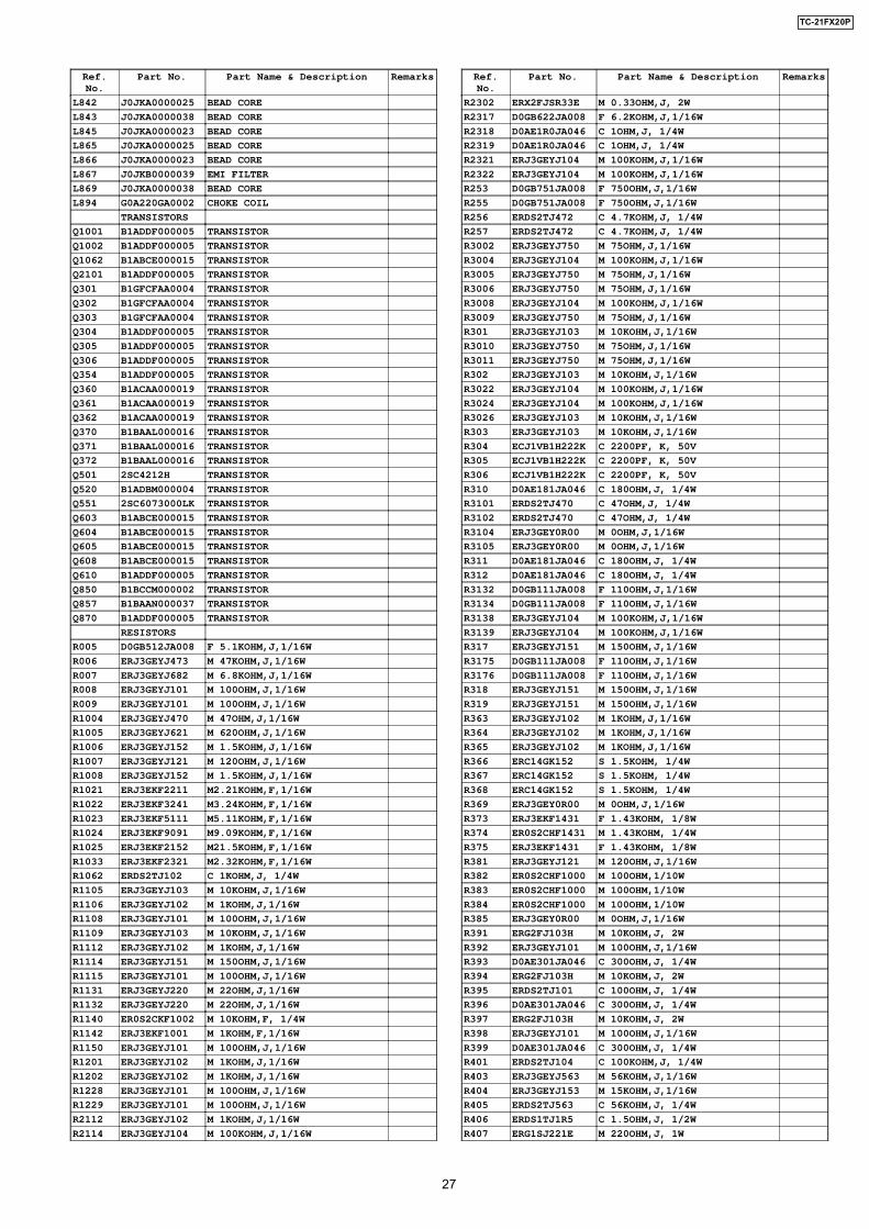
Ref.No.
Part No. Part Name & Description Remarks
L842 J0JKA0000025 BEAD CORE
L843 J0JKA0000038 BEAD CORE
L845 J0JKA0000023 BEAD CORE
L865 J0JKA0000025 BEAD CORE
L866 J0JKA0000023 BEAD CORE
L867 J0JKB0000039 EMI FILTER
L869 J0JKA0000038 BEAD CORE
L894 G0A220GA0002 CHOKE COIL
TRANSISTORS
Q1001 B1ADDF000005 TRANSISTOR
Q1002 B1ADDF000005 TRANSISTOR
Q1062 B1ABCE000015 TRANSISTOR
Q2101 B1ADDF000005 TRANSISTOR
Q301 B1GFCFAA0004 TRANSISTOR
Q302 B1GFCFAA0004 TRANSISTOR
Q303 B1GFCFAA0004 TRANSISTOR
Q304 B1ADDF000005 TRANSISTOR
Q305 B1ADDF000005 TRANSISTOR
Q306 B1ADDF000005 TRANSISTOR
Q354 B1ADDF000005 TRANSISTOR
Q360 B1ACAA000019 TRANSISTOR
Q361 B1ACAA000019 TRANSISTOR
Q362 B1ACAA000019 TRANSISTOR
Q370 B1BAAL000016 TRANSISTOR
Q371 B1BAAL000016 TRANSISTOR
Q372 B1BAAL000016 TRANSISTOR
Q501 2SC4212H TRANSISTOR
Q520 B1ADBM000004 TRANSISTOR
Q551 2SC6073000LK TRANSISTOR
Q603 B1ABCE000015 TRANSISTOR
Q604 B1ABCE000015 TRANSISTOR
Q605 B1ABCE000015 TRANSISTOR
Q608 B1ABCE000015 TRANSISTOR
Q610 B1ADDF000005 TRANSISTOR
Q850 B1BCCM000002 TRANSISTOR
Q857 B1BAAN000037 TRANSISTOR
Q870 B1ADDF000005 TRANSISTOR
RESISTORS
R005 D0GB512JA008 F 5.1KOHM,J,1/16W
R006 ERJ3GEYJ473 M 47KOHM,J,1/16W
R007 ERJ3GEYJ682 M 6.8KOHM,J,1/16W
R008 ERJ3GEYJ101 M 100OHM,J,1/16W
R009 ERJ3GEYJ101 M 100OHM,J,1/16W
R1004 ERJ3GEYJ470 M 47OHM,J,1/16W
R1005 ERJ3GEYJ621 M 620OHM,J,1/16W
R1006 ERJ3GEYJ152 M 1.5KOHM,J,1/16W
R1007 ERJ3GEYJ121 M 120OHM,J,1/16W
R1008 ERJ3GEYJ152 M 1.5KOHM,J,1/16W
R1021 ERJ3EKF2211 M2.21KOHM,F,1/16W
R1022 ERJ3EKF3241 M3.24KOHM,F,1/16W
R1023 ERJ3EKF5111 M5.11KOHM,F,1/16W
R1024 ERJ3EKF9091 M9.09KOHM,F,1/16W
R1025 ERJ3EKF2152 M21.5KOHM,F,1/16W
R1033 ERJ3EKF2321 M2.32KOHM,F,1/16W
R1062 ERDS2TJ102 C 1KOHM,J, 1/4W
R1105 ERJ3GEYJ103 M 10KOHM,J,1/16W
R1106 ERJ3GEYJ102 M 1KOHM,J,1/16W
R1108 ERJ3GEYJ101 M 100OHM,J,1/16W
R1109 ERJ3GEYJ103 M 10KOHM,J,1/16W
R1112 ERJ3GEYJ102 M 1KOHM,J,1/16W
R1114 ERJ3GEYJ151 M 150OHM,J,1/16W
R1115 ERJ3GEYJ101 M 100OHM,J,1/16W
R1131 ERJ3GEYJ220 M 22OHM,J,1/16W
R1132 ERJ3GEYJ220 M 22OHM,J,1/16W
R1140 ER0S2CKF1002 M 10KOHM,F, 1/4W
R1142 ERJ3EKF1001 M 1KOHM,F,1/16W
R1150 ERJ3GEYJ101 M 100OHM,J,1/16W
R1201 ERJ3GEYJ102 M 1KOHM,J,1/16W
R1202 ERJ3GEYJ102 M 1KOHM,J,1/16W
R1228 ERJ3GEYJ101 M 100OHM,J,1/16W
R1229 ERJ3GEYJ101 M 100OHM,J,1/16W
R2112 ERJ3GEYJ102 M 1KOHM,J,1/16W
R2114 ERJ3GEYJ104 M 100KOHM,J,1/16W
Ref.No.
Part No. Part Name & Description Remarks
R2302 ERX2FJSR33E M 0.33OHM,J, 2W
R2317 D0GB622JA008 F 6.2KOHM,J,1/16W
R2318 D0AE1R0JA046 C 1OHM,J, 1/4W
R2319 D0AE1R0JA046 C 1OHM,J, 1/4W
R2321 ERJ3GEYJ104 M 100KOHM,J,1/16W
R2322 ERJ3GEYJ104 M 100KOHM,J,1/16W
R253 D0GB751JA008 F 750OHM,J,1/16W
R255 D0GB751JA008 F 750OHM,J,1/16W
R256 ERDS2TJ472 C 4.7KOHM,J, 1/4W
R257 ERDS2TJ472 C 4.7KOHM,J, 1/4W
R3002 ERJ3GEYJ750 M 75OHM,J,1/16W
R3004 ERJ3GEYJ104 M 100KOHM,J,1/16W
R3005 ERJ3GEYJ750 M 75OHM,J,1/16W
R3006 ERJ3GEYJ750 M 75OHM,J,1/16W
R3008 ERJ3GEYJ104 M 100KOHM,J,1/16W
R3009 ERJ3GEYJ750 M 75OHM,J,1/16W
R301 ERJ3GEYJ103 M 10KOHM,J,1/16W
R3010 ERJ3GEYJ750 M 75OHM,J,1/16W
R3011 ERJ3GEYJ750 M 75OHM,J,1/16W
R302 ERJ3GEYJ103 M 10KOHM,J,1/16W
R3022 ERJ3GEYJ104 M 100KOHM,J,1/16W
R3024 ERJ3GEYJ104 M 100KOHM,J,1/16W
R3026 ERJ3GEYJ103 M 10KOHM,J,1/16W
R303 ERJ3GEYJ103 M 10KOHM,J,1/16W
R304 ECJ1VB1H222K C 2200PF, K, 50V
R305 ECJ1VB1H222K C 2200PF, K, 50V
R306 ECJ1VB1H222K C 2200PF, K, 50V
R310 D0AE181JA046 C 180OHM,J, 1/4W
R3101 ERDS2TJ470 C 47OHM,J, 1/4W
R3102 ERDS2TJ470 C 47OHM,J, 1/4W
R3104 ERJ3GEY0R00 M 0OHM,J,1/16W
R3105 ERJ3GEY0R00 M 0OHM,J,1/16W
R311 D0AE181JA046 C 180OHM,J, 1/4W
R312 D0AE181JA046 C 180OHM,J, 1/4W
R3132 D0GB111JA008 F 110OHM,J,1/16W
R3134 D0GB111JA008 F 110OHM,J,1/16W
R3138 ERJ3GEYJ104 M 100KOHM,J,1/16W
R3139 ERJ3GEYJ104 M 100KOHM,J,1/16W
R317 ERJ3GEYJ151 M 150OHM,J,1/16W
R3175 D0GB111JA008 F 110OHM,J,1/16W
R3176 D0GB111JA008 F 110OHM,J,1/16W
R318 ERJ3GEYJ151 M 150OHM,J,1/16W
R319 ERJ3GEYJ151 M 150OHM,J,1/16W
R363 ERJ3GEYJ102 M 1KOHM,J,1/16W
R364 ERJ3GEYJ102 M 1KOHM,J,1/16W
R365 ERJ3GEYJ102 M 1KOHM,J,1/16W
R366 ERC14GK152 S 1.5KOHM, 1/4W
R367 ERC14GK152 S 1.5KOHM, 1/4W
R368 ERC14GK152 S 1.5KOHM, 1/4W
R369 ERJ3GEY0R00 M 0OHM,J,1/16W
R373 ERJ3EKF1431 F 1.43KOHM, 1/8W
R374 ER0S2CHF1431 M 1.43KOHM, 1/4W
R375 ERJ3EKF1431 F 1.43KOHM, 1/8W
R381 ERJ3GEYJ121 M 120OHM,J,1/16W
R382 ER0S2CHF1000 M 100OHM,1/10W
R383 ER0S2CHF1000 M 100OHM,1/10W
R384 ER0S2CHF1000 M 100OHM,1/10W
R385 ERJ3GEY0R00 M 0OHM,J,1/16W
R391 ERG2FJ103H M 10KOHM,J, 2W
R392 ERJ3GEYJ101 M 100OHM,J,1/16W
R393 D0AE301JA046 C 300OHM,J, 1/4W
R394 ERG2FJ103H M 10KOHM,J, 2W
R395 ERDS2TJ101 C 100OHM,J, 1/4W
R396 D0AE301JA046 C 300OHM,J, 1/4W
R397 ERG2FJ103H M 10KOHM,J, 2W
R398 ERJ3GEYJ101 M 100OHM,J,1/16W
R399 D0AE301JA046 C 300OHM,J, 1/4W
R401 ERDS2TJ104 C 100KOHM,J, 1/4W
R403 ERJ3GEYJ563 M 56KOHM,J,1/16W
R404 ERJ3GEYJ153 M 15KOHM,J,1/16W
R405 ERDS2TJ563 C 56KOHM,J, 1/4W
R406 ERDS1TJ1R5 C 1.5OHM,J, 1/2W
R407 ERG1SJ221E M 220OHM,J, 1W
27
TC-21FX20P
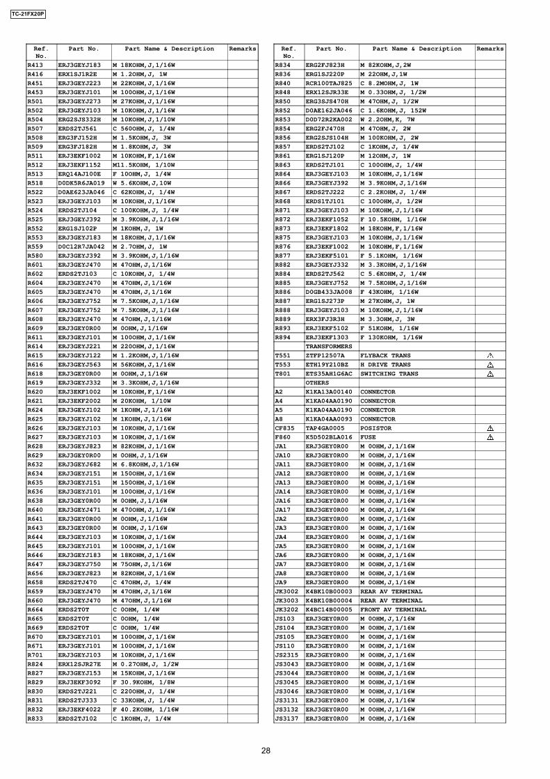
Ref.No.
Part No. Part Name & Description Remarks
R413 ERJ3GEYJ183 M 18KOHM,J,1/16W
R416 ERX1SJ1R2E M 1.2OHM,J, 1W
R451 ERJ3GEYJ223 M 22KOHM,J,1/16W
R453 ERJ3GEYJ101 M 100OHM,J,1/16W
R501 ERJ3GEYJ273 M 27KOHM,J,1/16W
R502 ERJ3GEYJ103 M 10KOHM,J,1/16W
R504 ERG2SJS332H M 10KOHM,J,1/10W
R507 ERDS2TJ561 C 560OHM,J, 1/4W
R508 ERG3FJ152H M 1.5KOHM,J, 3W
R509 ERG3FJ182H M 1.8KOHM,J, 3W
R511 ERJ3EKF1002 M 10KOHM,F,1/16W
R512 ERJ3EKF1152 M11.5KOHM, 1/10W
R513 ERQ14AJ100E F 10OHM,J, 1/4W
R518 D0DK5R6JA019 W 5.6KOHM,J,10W
R522 D0AE623JA046 C 62KOHM,J, 1/4W
R523 ERJ3GEYJ103 M 10KOHM,J,1/16W
R524 ERDS2TJ104 C 100KOHM,J, 1/4W
R525 ERJ3GEYJ392 M 3.9KOHM,J,1/16W
R552 ERG1SJ102P M 1KOHM,J, 1W
R553 ERJ3GEYJ183 M 18KOHM,J,1/16W
R559 D0C12R7JA042 M 2.7OHM,J, 1W
R580 ERJ3GEYJ392 M 3.9KOHM,J,1/16W
R601 ERJ3GEYJ470 M 47OHM,J,1/16W
R602 ERDS2TJ103 C 10KOHM,J, 1/4W
R604 ERJ3GEYJ470 M 47OHM,J,1/16W
R605 ERJ3GEYJ470 M 47OHM,J,1/16W
R606 ERJ3GEYJ752 M 7.5KOHM,J,1/16W
R607 ERJ3GEYJ752 M 7.5KOHM,J,1/16W
R608 ERJ3GEYJ470 M 47OHM,J,1/16W
R609 ERJ3GEY0R00 M 0OHM,J,1/16W
R611 ERJ3GEYJ101 M 100OHM,J,1/16W
R614 ERJ3GEYJ221 M 220OHM,J,1/16W
R615 ERJ3GEYJ122 M 1.2KOHM,J,1/16W
R616 ERJ3GEYJ563 M 56KOHM,J,1/16W
R618 ERJ3GEY0R00 M 0OHM,J,1/16W
R619 ERJ3GEYJ332 M 3.3KOHM,J,1/16W
R620 ERJ3EKF1002 M 10KOHM,F,1/16W
R621 ERJ3EKF2002 M 20KOHM, 1/10W
R624 ERJ3GEYJ102 M 1KOHM,J,1/16W
R625 ERJ3GEYJ102 M 1KOHM,J,1/16W
R626 ERJ3GEYJ103 M 10KOHM,J,1/16W
R627 ERJ3GEYJ103 M 10KOHM,J,1/16W
R628 ERJ3GEYJ823 M 82KOHM,J,1/16W
R629 ERJ3GEY0R00 M 0OHM,J,1/16W
R632 ERJ3GEYJ682 M 6.8KOHM,J,1/16W
R634 ERJ3GEYJ151 M 150OHM,J,1/16W
R635 ERJ3GEYJ151 M 150OHM,J,1/16W
R636 ERJ3GEYJ101 M 100OHM,J,1/16W
R638 ERJ3GEY0R00 M 0OHM,J,1/16W
R640 ERJ3GEYJ471 M 470OHM,J,1/16W
R641 ERJ3GEY0R00 M 0OHM,J,1/16W
R643 ERJ3GEY0R00 M 0OHM,J,1/16W
R644 ERJ3GEYJ103 M 10KOHM,J,1/16W
R645 ERJ3GEYJ101 M 100OHM,J,1/16W
R646 ERJ3GEYJ183 M 18KOHM,J,1/16W
R647 ERJ3GEYJ750 M 75OHM,J,1/16W
R656 ERJ3GEYJ823 M 82KOHM,J,1/16W
R658 ERDS2TJ470 C 47OHM,J, 1/4W
R659 ERJ3GEYJ470 M 47OHM,J,1/16W
R660 ERJ3GEYJ470 M 47OHM,J,1/16W
R664 ERDS2T0T C 0OHM, 1/4W
R665 ERDS2T0T C 0OHM, 1/4W
R669 ERDS2T0T C 0OHM, 1/4W
R670 ERJ3GEYJ101 M 100OHM,J,1/16W
R671 ERJ3GEYJ101 M 100OHM,J,1/16W
R701 ERJ3GEYJ103 M 10KOHM,J,1/16W
R824 ERX12SJR27E M 0.27OHM,J, 1/2W
R827 ERJ3GEYJ153 M 15KOHM,J,1/16W
R829 ERJ3EKF3092 F 30.9KOHM, 1/8W
R830 ERDS2TJ221 C 220OHM,J, 1/4W
R831 ERDS2TJ333 C 33KOHM,J, 1/4W
R832 ERJ3EKF4022 F 40.2KOHM, 1/16W
R833 ERDS2TJ102 C 1KOHM,J, 1/4W
Ref.No.
Part No. Part Name & Description Remarks
R834 ERG2FJ823H M 82KOHM,J,2W
R836 ERG1SJ220P M 22OHM,J,1W
R840 RCR100TAJ825 C 8.2MOHM,J, 1W
R848 ERX12SJR33E M 0.33OHM,J, 1/2W
R850 ERG3SJS470H M 47OHM,J, 1/2W
R852 D0AE162JA046 C 1.6KOHM,J, 152W
R853 D0D72R2KA002 W 2.2OHM,K, 7W
R854 ERG2FJ470H M 47OHM,J, 2W
R856 ERG2SJS104H M 100KOHM,J, 2W
R857 ERDS2TJ102 C 1KOHM,J, 1/4W
R861 ERG1SJ120P M 12OHM,J, 1W
R863 ERDS2TJ101 C 100OHM,J, 1/4W
R864 ERJ3GEYJ103 M 10KOHM,J,1/16W
R866 ERJ3GEYJ392 M 3.9KOHM,J,1/16W
R867 ERDS2TJ222 C 2.2KOHM,J, 1/4W
R868 ERDS1TJ101 C 100OHM,J, 1/2W
R871 ERJ3GEYJ103 M 10KOHM,J,1/16W
R872 ERJ3EKF1052 F 10.5KOHM, 1/16W
R873 ERJ3EKF1802 M 18KOHM,F,1/16W
R875 ERJ3GEYJ103 M 10KOHM,J,1/16W
R876 ERJ3EKF1002 M 10KOHM,F,1/16W
R877 ERJ3EKF5101 F 5.1KOHM, 1/16W
R882 ERJ3GEYJ332 M 3.3KOHM,J,1/16W
R884 ERDS2TJ562 C 5.6KOHM,J, 1/4W
R885 ERJ3GEYJ752 M 7.5KOHM,J,1/16W
R886 D0GB433JA008 F 43KOHM, 1/16W
R887 ERG1SJ273P M 27KOHM,J, 1W
R888 ERJ3GEYJ103 M 10KOHM,J,1/16W
R889 ERX3FJ3R3H M 3.3OHM,J, 3W
R893 ERJ3EKF5102 F 51KOHM, 1/16W
R894 ERJ3EKF1303 F 130KOHM, 1/16W
TRANSFORMERS
T551 ZTFP12507A FLYBACK TRANS
T553 ETH19Y210BZ H DRIVE TRANS
T801 ETS35AH1G6AC SWITCHING TRANS
OTHERS
A2 K1KA13A00140 CONNECTOR
A4 K1KA04AA0190 CONNECTOR
A5 K1KA04AA0190 CONNECTOR
A8 K1KA04AA0093 CONNECTOR
CF835 TAP4GA0005 POSISTOR
F860 K5D502BLA016 FUSE
JA1 ERJ3GEY0R00 M 0OHM,J,1/16W
JA10 ERJ3GEY0R00 M 0OHM,J,1/16W
JA11 ERJ3GEY0R00 M 0OHM,J,1/16W
JA12 ERJ3GEY0R00 M 0OHM,J,1/16W
JA13 ERJ3GEY0R00 M 0OHM,J,1/16W
JA14 ERJ3GEY0R00 M 0OHM,J,1/16W
JA16 ERJ3GEY0R00 M 0OHM,J,1/16W
JA17 ERJ3GEY0R00 M 0OHM,J,1/16W
JA2 ERJ3GEY0R00 M 0OHM,J,1/16W
JA3 ERJ3GEY0R00 M 0OHM,J,1/16W
JA4 ERJ3GEY0R00 M 0OHM,J,1/16W
JA5 ERJ3GEY0R00 M 0OHM,J,1/16W
JA6 ERJ3GEY0R00 M 0OHM,J,1/16W
JA7 ERJ3GEY0R00 M 0OHM,J,1/16W
JA8 ERJ3GEY0R00 M 0OHM,J,1/16W
JA9 ERJ3GEY0R00 M 0OHM,J,1/16W
JK3002 K4BK10B00003 REAR AV TERMINAL
JK3003 K4BK10B00004 REAR AV TERMINAL
JK3202 K4BC14B00005 FRONT AV TERMINAL
JS103 ERJ3GEY0R00 M 0OHM,J,1/16W
JS104 ERJ3GEY0R00 M 0OHM,J,1/16W
JS105 ERJ3GEY0R00 M 0OHM,J,1/16W
JS110 ERJ3GEY0R00 M 0OHM,J,1/16W
JS2315 ERJ3GEY0R00 M 0OHM,J,1/16W
JS3043 ERJ3GEY0R00 M 0OHM,J,1/16W
JS3044 ERJ3GEY0R00 M 0OHM,J,1/16W
JS3045 ERJ3GEY0R00 M 0OHM,J,1/16W
JS3046 ERJ3GEY0R00 M 0OHM,J,1/16W
JS3131 ERJ3GEY0R00 M 0OHM,J,1/16W
JS3132 ERJ3GEY0R00 M 0OHM,J,1/16W
JS3137 ERJ3GEY0R00 M 0OHM,J,1/16W
28
TC-21FX20P
Ref.No.
Part No. Part Name & Description Remarks
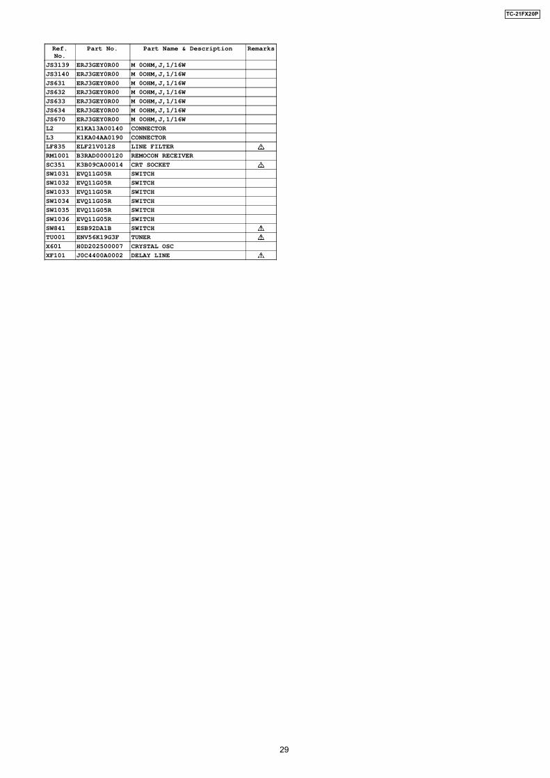
JS3139 ERJ3GEY0R00 M 0OHM,J,1/16W
JS3140 ERJ3GEY0R00 M 0OHM,J,1/16W
JS631 ERJ3GEY0R00 M 0OHM,J,1/16W
JS632 ERJ3GEY0R00 M 0OHM,J,1/16W
JS633 ERJ3GEY0R00 M 0OHM,J,1/16W
JS634 ERJ3GEY0R00 M 0OHM,J,1/16W
JS670 ERJ3GEY0R00 M 0OHM,J,1/16W
L2 K1KA13A00140 CONNECTOR
L3 K1KA04AA0190 CONNECTOR
LF835 ELF21V012S LINE FILTER
RM1001 B3RAD0000120 REMOCON RECEIVER
SC351 K3B09CA00014 CRT SOCKET
SW1031 EVQ11G05R SWITCH
SW1032 EVQ11G05R SWITCH
SW1033 EVQ11G05R SWITCH
SW1034 EVQ11G05R SWITCH
SW1035 EVQ11G05R SWITCH
SW1036 EVQ11G05R SWITCH
SW841 ESB92DA1B SWITCH
TU001 ENV56K19G3F TUNER
X601 H0D202500007 CRYSTAL OSC
XF101 J0C4400A0002 DELAY LINE
29
TC-21FX20P
Related Documents